1
Industrial
Hydraulics
Electric Drives
and Controls
Linear Motion and
Assembly Technologies
Pneumatics
Service
Automation
Mobile
Hydraulics
Rexroth IndraControl VCP 20
Rexroth VCP-Operating Concept
Application Manual
R911305038
Edition 01
II
Bosch Rexroth AG | Electric Drives and Controls
Title
Type of Documentation
Document Typecode
Internal File Reference
Purpose of Documentation
Rexroth VCP-Operating Concept | R911305038 / 01
Rexroth VCP-Operating Concept
Application Manual
DOK-SUPPL*-VIC*BEDIEN*-AW01-EN-P
Document Number, 120-2100-B350-01/EN
This document serves to describe the possible uses of small operator
terminals of the VCP series.
Record of Revisions
Copyright
Description
Release
Date
Notes
120-2100-B350-01/EN
09.2004
First Edition
©
Bosch Rexroth AG, 2004
Copying this document, giving it to others and the use or
communication of the contents thereof without express authority, are
forbidden. Offenders are liable for the payment of damages. All rights
are reserved in the event of the grant of a patent or the registration of a
utility model or design (DIN 34-1).
Validity
Published by
Note
The specified data is for product description purposes only and may
not be deemed to be guaranteed unless expressly confirmed in the
contract. All rights are reserved with respect to the content of this documentation and the availability of the product.
Bosch Rexroth AG
Bgm.-Dr.-Nebel-Str. 2
D-97816 Lohr a. Main
Tel.: +49 (0) 93 52 / 40-0
Fax: +49 (0) 93 52 /40-45 85
http://www.boschrexroth.com/
Abt.: BRC/EPY (NH)
This document has been printed on chlorine-free bleached paper.
R911305038 / 01 | Rexroth VCP-Operating Concept
Electric Drives and Controls | Bosch Rexroth AG
III
Contents
Contents
1
1.1
1.1.1
1.2
2
2.1
2.1.1
2.1.2
2.2
3
3.1
3.2
3.3
3.4
3.5
3.6
3.7
3.8
3.9
3.10
3.11
3.12
4
4.1
4.1.1
4.2
4.2.1
4.2.2
5
5.1
5.2
5.2.1
5.2.2
5.3
5.4
Important Notes........................................... 1–1
Symbols ........................................................................... 1–1
General Symbols .......................................................... 1–1
Target Group ................................................................... 1–1
Important Directions for Use...................... 2–1
Appropriate Use............................................................... 2–1
Introduction ................................................................... 2–1
Areas of Use and Application ....................................... 2–2
Inappropriate Use ............................................................ 2–2
Safety Instructions for Electric Drives and
Controls ....................................................... 3–1
Introduction...................................................................... 3–1
Explanations .................................................................... 3–1
Hazards by Improper Use................................................ 3–2
General Information......................................................... 3–2
Protection Against Contact with Electrical Parts.............. 3–4
Protection Against Electric Shock by Protective Low
Voltage (PELV) ................................................................ 3–5
Protection Against Dangerous Movements ..................... 3–6
Protection Against Magnetic and Electromagnetic
Fields During Operation and Mounting ............................ 3–7
Protection Against Contact with Hot Parts....................... 3–8
Protection During Handling and Mounting ....................... 3–9
Battery Safety .................................................................. 3–9
Protection Against Pressurized Systems....................... 3–10
Application Description for Small Operator
Terminals4–1
The Concept .................................................................... 4–1
Uniform Device Features .............................................. 4–1
Programming Small Operator Terminals ......................... 4–3
Hardware Prerequisites ................................................ 4–3
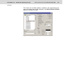
Installing VI Composer.................................................. 4–4
Standard Mode ............................................ 5–1
Setting the Operating Mode............................................. 5–1
Behavior of the Operating Device During Start-Up.......... 5–3
With Valid Project ......................................................... 5–3
Without a Valid Project ................................................. 5–3
Communication with a Controller..................................... 5–4
Masks .............................................................................. 5–4
IV
Bosch Rexroth AG | Electric Drives and Controls
Rexroth VCP-Operating Concept | R911305038 / 01
Contents
5.4.1
5.4.2
5.4.2.1
5.4.2.2
5.4.2.3
5.4.2.4
5.4.2.5
5.4.2.6
5.4.2.7
5.4.2.8
5.4.3
5.4.3.1
5.4.3.2
5.4.3.3
5.4.4
5.4.5
5.5
5.5.1
5.5.2
5.5.3
5.5.3.1
5.5.3.2
5.5.3.3
5.5.3.4
5.5.3.5
5.5.3.6
5.5.3.7
5.5.3.8
5.5.3.9
5.5.3.10
5.5.4
5.5.4.1
5.5.4.2
5.5.4.3
5.5.4.4
5.5.5
5.5.5.1
5.5.5.2
5.5.5.3
5.5.5.4
5.5.6
5.5.7
5.5.8
5.5.8.1
5.5.8.2
5.5.9
5.5.9.1
5.5.9.2
5.5.9.3
5.5.9.4
5.5.10
5.5.10.1
5.5.10.2
5.5.10.3
Mask Structure ............................................................. 5–4
Mask Parameters ......................................................... 5–5
Mask Number ............................................................ 5–5
Access Level.............................................................. 5–5
Background Color ...................................................... 5–6
Help Mask.................................................................. 5–6
Variables Management Topdown .............................. 5–6
Automatic Data Release ............................................ 5–6
Reset Password......................................................... 5–6
Activate Help Mask .................................................... 5–7
System Masks .............................................................. 5–7
Setup Mask................................................................ 5–7
Start-up Mask ............................................................ 5–8
Password Mask ......................................................... 5–9
Input/Output Masks .................................................... 5–10
Help Masks................................................................. 5–10
Variables ....................................................................... 5–11
Symbolic Name .......................................................... 5–12
Controller Address...................................................... 5–12
Representation Type .................................................. 5–12
Decimal Number ...................................................... 5–12
Alphanumeric........................................................... 5–15
Selection Text .......................................................... 5–16
Selection Image ....................................................... 5–18
Floating Point Number ............................................. 5–18
Hexadecimal Number .............................................. 5–19
Binary Number......................................................... 5–20
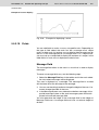
Bars ......................................................................... 5–21
Curve ....................................................................... 5–24
Fields ....................................................................... 5–25
Field Type................................................................... 5–27
Input......................................................................... 5–27
Output ...................................................................... 5–28
Password ................................................................. 5–28
Cyclical .................................................................... 5–28
Format ........................................................................ 5–29
Only Positive............................................................ 5–29
Display Leading Zeros ............................................. 5–29
Field Length ............................................................. 5–29
Fractional Digits ....................................................... 5–29
Documentation Value ................................................. 5–29
Limits .......................................................................... 5–30
Scaling........................................................................ 5–31
Scaled Input............................................................. 5–31
Scaled Output .......................................................... 5–31
Communication Definition........................................... 5–33
PLC Handshake....................................................... 5–33
With Enter ................................................................ 5–35
With +, –, or Enter.................................................... 5–35
For all changes ........................................................ 5–35
Access Type ............................................................... 5–35
Normal ..................................................................... 5–35
Selective .................................................................. 5–35
Article Administration ............................................... 5–36
R911305038 / 01 | Rexroth VCP-Operating Concept
Electric Drives and Controls | Bosch Rexroth AG
V
Contents
5.5.11
5.5.11.1
5.5.11.2
5.5.12
5.5.12.1
5.5.12.2
5.5.12.3
5.5.12.4
5.5.12.5
5.5.12.6
5.5.13
5.5.14
5.5.15
5.5.15.1
5.5.15.2
5.5.16
5.5.16.1
5.5.17
5.5.17.1
5.5.17.2
5.5.17.3
5.5.17.4
5.5.17.5
5.5.17.6
5.5.17.7
5.5.17.8
5.5.17.9
5.5.17.10
5.5.17.11
5.5.17.12
5.5.17.13
5.5.17.14
5.5.17.15
5.5.17.16
5.5.17.17
5.5.17.18
5.5.17.19
5.5.17.20
5.5.17.21
5.6
5.6.1
5.6.2
5.6.3
5.6.4
5.6.5
5.6.6
5.6.7
5.6.8
5.7
5.7.1
5.8
5.9
5.10
5.10.1
Variable Type.............................................................. 5–38
Standard .................................................................. 5–38
BCD Number............................................................ 5–38
Attributes (Static or Dynamic) ..................................... 5–38
Global....................................................................... 5–38
Inverse ..................................................................... 5–38
Flashing ................................................................... 5–38
Underline.................................................................. 5–39
Invisible .................................................................... 5–39
Non-Editable ............................................................ 5–39
Font............................................................................. 5–40
Help Mask ................................................................... 5–40
Output Variables ......................................................... 5–40
One-Off and Cyclical Output Variables .................... 5–40
Formatted Output ..................................................... 5–41
Input Variables ............................................................ 5–42
Plausibility Check ..................................................... 5–42
System Variables ........................................................ 5–43
Basic Functions........................................................ 5–43
Communication SER1.............................................. 5–48
Error Statistics SER1 ............................................... 5–52
Communication SER2.............................................. 5–52
Real-Time Clock....................................................... 5–55
Serial Message System ........................................... 5–57
Parallel Message System......................................... 5–65
Printer Control .......................................................... 5–68
Menu Control / Keys................................................. 5–70
Password ................................................................. 5–79
Recipes .................................................................... 5–82
Running Time Meters............................................... 5–90
Loop-Through Operation.......................................... 5–90
Loadable Character Set ........................................... 5–91
Maintenance ............................................................ 5–91
Editors ...................................................................... 5–94
Help.......................................................................... 5–95
Print Logs ................................................................. 5–97
Compact Flash Card ................................................ 5–99
Set of Curves (Graph) ............................................ 5–102
Sound..................................................................... 5–103
Dynamic Attributes ...................................................... 5–104
Underline .................................................................. 5–105
Inverse ...................................................................... 5–105
Flashing .................................................................... 5–105
Invisible ..................................................................... 5–105
Non-Editable ............................................................. 5–105
Foreground ............................................................... 5–105
Background............................................................... 5–106
Attribute Priorities ..................................................... 5–106
Set of Curves (Graph) ................................................. 5–107
Data Logger .............................................................. 5–107
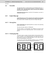
Images ......................................................................... 5–108
Symbols ....................................................................... 5–108
Buttons ........................................................................ 5–109
Content of Buttons .................................................... 5–109
VI
Bosch Rexroth AG | Electric Drives and Controls
Rexroth VCP-Operating Concept | R911305038 / 01
Contents
5.10.2
5.10.3
5.10.3.1
5.11
5.11.1
5.11.2
5.11.3
5.11.4
5.11.5
5.11.6
5.11.7
5.12
5.13
5.13.1
5.13.2
5.13.3
5.13.4
5.13.5
5.14
5.14.1
5.14.2
5.14.3
5.14.4
5.14.5
5.15
5.15.1
5.15.2
5.15.3
5.15.4
5.15.5
5.15.6
5.16
5.16.1
5.16.2
5.16.3
5.16.4
5.16.5
5.16.6
5.16.7
5.16.8
5.16.9
5.16.10
5.16.11
5.16.12
5.16.13
5.16.14
5.16.15
5.16.16
5.16.17
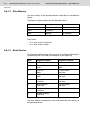
Functions of Buttons................................................. 5–110
Representation of Buttons ........................................ 5–110
Frames for Buttons ................................................ 5–111
Function Keys/Softkeys............................................... 5–113
Direct Selector Keys ................................................. 5–114
Function Keys in the Controller ................................ 5–114
Softkeys.................................................................... 5–114
Reaction Time of Function and Soft Keys ................ 5–116
Using Control Keys as Function Keys ...................... 5–116
Function Keys Controlling Parallel Outputs .............. 5–116
Status LEDs of Function Keys.................................. 5–117
Running Time Meter.................................................... 5–117
Read Coordination Byte .............................................. 5–119
Editing Request ........................................................ 5–120
Editing Status ........................................................... 5–120
Refresh Request....................................................... 5–120
Liveness Flag ........................................................... 5–121
Data Set Download Active........................................ 5–121
Write Coordination Byte .............................................. 5–121
External Data Release.............................................. 5–122
Refresh Acknowledgment......................................... 5–122
Delete Password ...................................................... 5–122
Liveness Flag ........................................................... 5–123
Data Set Download Release .................................... 5–123
The Cyclical Polling Area ............................................ 5–124
Byte-Oriented Polling Area ....................................... 5–125
Word-Oriented Polling Area...................................... 5–126
Serial Message Channel .......................................... 5–126
Image of the Status LEDs......................................... 5–127
Polling Time.............................................................. 5–127
Size of the Polling Area ............................................ 5–128
Control Codes ............................................................. 5–128
Delete Data Logger .................................................. 5–130
Trigger Data Logger ................................................. 5–130
Write Values of Running Time Meters to Controller . 5–130
Switch to Another Language .................................... 5–130
Automatic Data Release for Scanner Module .......... 5–131
Reload Event-Controlled Variable Values ................ 5–131
Transfer Single Data Set from Operating Device to
Controller .................................................................. 5–131
Delete Acknowledged Messages from Serial
Message Memory ..................................................... 5–131
Cancel Printing the Print Log.................................... 5–132
Printing a Print Log ................................................... 5–132
Printing a Data Set ................................................... 5–132
Set Clock in Operating Device.................................. 5–133
Data Set Transfer from Controller to Operating
Device (Block Mode) ................................................ 5–133
Data Set Transfer from Operating Device to
Controller .................................................................. 5–133
Send Keyboard Image to Controller ......................... 5–134
Data Set Transfer from Controller to Operating
Device (Single Mode) ............................................... 5–134
Erase Serial Message Memory ................................ 5–134
R911305038 / 01 | Rexroth VCP-Operating Concept
Electric Drives and Controls | Bosch Rexroth AG
VII
Contents
5.16.18
5.17
5.17.1
5.17.2
5.17.3
5.18
5.18.1
5.18.2
5.18.3
5.19
5.19.1
5.19.2
5.19.3
5.19.4
5.20
5.20.1
5.21
5.21.1
5.21.2
5.21.3
5.21.4
5.21.5
5.21.6
5.21.7
5.21.8
5.21.8.1
5.21.9
5.21.10
5.21.11
5.21.12
5.21.13
5.22
5.22.1
5.22.2
5.22.2.1
5.22.2.2
5.22.2.3
5.22.2.4
5.22.2.5
5.22.2.6
5.22.2.7
5.22.2.8
5.22.2.9
5.22.2.10
5.22.2.11
5.22.2.12
5.22.2.13
5.22.2.14
5.22.2.15
5.22.2.16
5.22.2.17
5.22.2.18
5.22.2.19
5.22.2.20
Refresh Message System......................................... 5–134
Password Protection.................................................... 5–135
Password Management ............................................ 5–136
Reactivate Password Protection ............................... 5–138
Password Mask and Password Functions ................ 5–138
Real Time Clock in the Operating Device.................... 5–138
Date and Time Image ............................................... 5–139
Setting the Real Time Clock from the Controller....... 5–140
Transferring the Real-Time to the Controller ............ 5–140
Help System ................................................................ 5–141
Default Help Mask .................................................... 5–141
Help Mask for Masks ................................................ 5–141
Help Mask for Input Variable .................................... 5–141
Help Mask for Message Masks................................. 5–142
Print Logs .................................................................... 5–143
Escape Sequences for Print Logs ............................ 5–143
System Parameters ..................................................... 5–144
General Parameters ................................................. 5–144
Polling Area .............................................................. 5–146
Terminal Clock .......................................................... 5–146
Running Time Meters ............................................... 5–147
Message System ...................................................... 5–147
Variant Options ......................................................... 5–149
Password Management ............................................ 5–150
Communication SER2 .............................................. 5–150
Connecting a Scanner............................................ 5–150
Gateway.................................................................... 5–151
Data Set Transfer ..................................................... 5–151
Parallel Outputs ........................................................ 5–152
Touch Parameters .................................................... 5–152
Print Logs.................................................................. 5–153
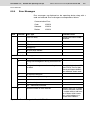
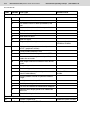
Message System ......................................................... 5–154
Internal Messages .................................................... 5–154
System Messages .................................................... 5–154
System Message 1 - Wrong format........................ 5–156
System Message 2 - Value too large ..................... 5–156
System Message 3 - Value too small..................... 5–157
System Message 4 - Replace battery .................... 5–157
System Message 5 - Message overflow ................ 5–157
System Message 6 - New message....................... 5–157
System Message 7 - Message buffer full ............... 5–157
System Message 8 - Invalid mask no ................... 5–158
System Message 9 - Invalid message no. ............ 5–158
System Message 10 - Print log invalid ................... 5–158
System Message 11 - Interface in use................... 5–158
System Message 12 - Invalid Password ................ 5–158
System Message 13 - Password unchanged......... 5–158
System Message 14 - Overvoltage ........................ 5–158
System Message 15 - Data set protected .............. 5–158
System Message 16 - Illegal data set .................... 5–159
System Message 17 - Data set unknown............... 5–159
System Message 18 - Data set memory full .......... 5–159
System message 19 - Data set active.................... 5–159
System Message 20 - Data set transfer................. 5–159
VIII
Bosch Rexroth AG | Electric Drives and Controls
Rexroth VCP-Operating Concept | R911305038 / 01
Contents
5.22.2.21
5.22.2.22
5.22.2.23
5.22.2.24
5.22.2.25
5.22.2.26
5.22.2.27
5.22.2.28
5.22.2.29
5.22.2.30
5.22.2.31
5.22.2.32
System Message 21 - Password missing .............. 5–159
System Message 22 - Editing mode active............ 5–159
System Message 23 - Data set file error ............... 5–159
System Message 24 - Data set format .................. 5–160
System Message 25 - Number invalid ................... 5–160
System Message 26 - Loop-through active ........... 5–160
System Message 27 - No data set address........... 5–160
System Message 28 - Recipe unknown ................ 5–160
System Message 29 - Data set download ............. 5–160
System Message 30 - Scanner error ..................... 5–160
System Message 31 - Print log unknown .............. 5–160
System Message 32 - Error on changing the
language ................................................................ 5–161
5.22.2.33
System Message 33 - Flash card information ....... 5–161
5.22.2.34
System Message 34 - New appl. necessary.......... 5–161
5.22.3
Suppressing the Display of System Messages ........ 5–161
5.22.4
Error messages ........................................................ 5–161
5.22.5
External Messages ................................................... 5–165
5.22.5.1
Structure of an External Message ......................... 5–165
5.22.5.2
Size of Message Memory ...................................... 5–167
5.22.5.3
Message Sorting.................................................... 5–167
5.22.5.4
Message Priority for Direct Display........................ 5–168
5.22.5.5
Printing the Message Memory ............................... 5–168
5.22.5.6
Direct Call of the Message Mask ........................... 5–169
5.22.5.7
Message Output Formats ...................................... 5–169
5.22.5.8
Zooming Messages ............................................... 5–171
5.22.5.9
Acknowledging Messages ..................................... 5–171
5.22.6
Serial Message System............................................ 5–171
5.22.6.1
Full-Page Message Output .................................... 5–172
5.22.6.2
Outputting Messages to a Logging Printer ............ 5–172
5.22.6.3
Erasing the Message Memory Externally .............. 5–173
5.22.7
Parallel Message System (Status Messages) .......... 5–173
5.22.7.1
Settings for Status Messages ................................ 5–174
5.23
Recipes ....................................................................... 5–176
5.23.1
Structure of a Recipe................................................ 5–179
5.23.2
Working with Recipes and Data Sets ....................... 5–179
5.23.2.1
Selecting a Recipe................................................. 5–179
5.23.2.2
Selecting a Data Set .............................................. 5–180
5.23.2.3
Copying a Data Set................................................ 5–180
5.23.2.4
Deleting a Data Set................................................ 5–181
5.23.2.5
Modifying a Data Set ............................................. 5–181
5.23.3
Data Set Transfer to/from Controller ........................ 5–182
5.23.3.1
Transfer to the Controller (Operator-Controlled).... 5–183
5.23.3.2
Transfer to the Operating Device (OperatorControlled) ............................................................. 5–184
5.23.3.3
Transferring Data Sets to / from a PC ................... 5–184
5.23.3.4
Transfer to a PC .................................................... 5–185
5.23.3.5
Transfer from a PC ................................................ 5–185
5.23.3.6
Structure of a Data Set File ................................... 5–186
5.23.3.7
Printing Data Sets.................................................. 5–188
5.23.3.8
Memory Requirement for Data Sets ...................... 5–189
5.24
Memory Requirement for Messages and Data Sets ... 5–189
5.25
Application ID .............................................................. 5–190
5.26
Version Number .......................................................... 5–191
R911305038 / 01 | Rexroth VCP-Operating Concept
Electric Drives and Controls | Bosch Rexroth AG
IX
Contents
5.27
5.28
5.29
5.30
5.30.1
5.30.1.1
5.30.1.2
5.30.1.3
5.30.1.4
5.30.1.5
5.30.1.6
5.30.1.7
5.31
5.31.1
5.31.2
5.32
6
6.1
6.1.1
6.1.1.1
6.1.1.2
6.1.1.3
6.1.1.4
6.1.1.5
6.1.1.6
6.1.1.7
6.1.2
6.1.3
6.1.3.1
6.1.3.2
6.1.4
6.1.4.1
6.1.4.2
6.1.5
6.2
6.2.1
6.2.1.1
6.2.1.2
6.2.2
6.2.2.1
6.2.2.2
6.2.3
6.2.3.1
6.2.3.2
6.2.3.3
6.2.4
6.2.5
6.2.5.1
Image of Mask Number ............................................... 5–191
Image of User Mode Switch ........................................ 5–192
Screen Saver ............................................................... 5–192
Documentation ............................................................ 5–192
Documentation Parameters ...................................... 5–192
Global Settings....................................................... 5–192
Projects .................................................................. 5–193
Masks..................................................................... 5–193
Recipes .................................................................. 5–193
Help Masks ............................................................ 5–194
System Messages.................................................. 5–194
Messages............................................................... 5–195
Downloading a Project................................................. 5–196
Automatic Download Function .................................. 5–196
Download Cable 25 Pin ............................................ 5–197
Simulation Without a Controller (Demo Mode) ............ 5–198
Controller and Bus Connections ............... 6–1
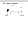
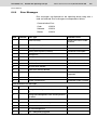
3964 RK512..................................................................... 6–2
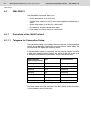
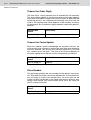
Procedure of the 3964 Protocol .................................... 6–2
Telegram for Connection Setup ................................. 6–2
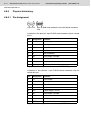
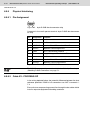
Data Request Telegram ............................................. 6–3
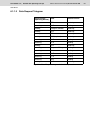
Data Request Telegram Header ................................ 6–4
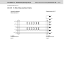
Response Telegram................................................... 6–5
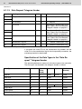
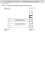
Data Transmission Telegram ..................................... 6–6
Data Transmission Telegram Header ........................ 6–6
Special Features of the 3964R Protocol .................... 6–7
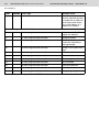
Data Types ................................................................... 6–8
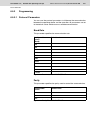
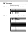
Programming ................................................................ 6–9
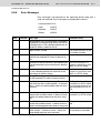
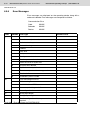
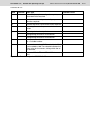
Protocol Parameters .................................................. 6–9
Input Syntax ............................................................. 6–15
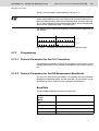
Physical Interfacing..................................................... 6–16
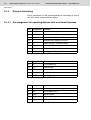
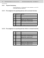
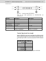
Pin assignment for operating devices with a
universal interface .................................................... 6–16
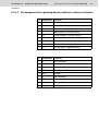
Pin assignment for operating devices without a
universal interface .................................................... 6–17
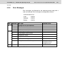
Error Messages .......................................................... 6–19
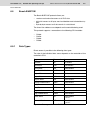
3S Serial ........................................................................ 6–21
Data Types ................................................................. 6–21
Single Variables ....................................................... 6–21
String Variables........................................................ 6–21
Programming .............................................................. 6–22
Protocol Parameters ................................................ 6–22
System Parameters.................................................. 6–24
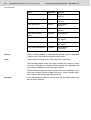
Physical Interfacing..................................................... 6–26
Pin assignment for operating devices with a
universal interface .................................................... 6–26
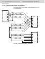
Cable X3 SER1 RS232 - Rexroth PPC-R ................ 6–27
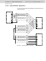
Cable X3 SER1 RS485 - Rexroth PPC-R ................ 6–28
Error Messages .......................................................... 6–29
Applications ................................................................ 6–30
IndraLogic Version 1.0 or Higher ............................. 6–30
X
Bosch Rexroth AG | Electric Drives and Controls
Rexroth VCP-Operating Concept | R911305038 / 01
Contents
6.3
6.3.1
6.3.1.1
6.3.1.2
6.3.2
6.3.2.1
6.3.2.2
6.3.3
6.3.3.1
6.3.3.2
6.3.3.3
6.3.4
6.3.5
6.3.5.1
6.4
6.4.1
6.4.2
6.4.2.1
6.4.2.2
6.4.3
6.4.3.1
6.4.3.2
6.4.3.3
6.4.3.4
6.4.4
6.5
6.5.1
6.5.2
6.5.2.1
6.5.2.2
6.5.3
6.5.3.1
6.5.3.2
6.5.3.3
6.5.3.4
6.5.4
6.6
6.6.1
6.6.1.1
6.6.1.2
6.6.1.3
6.6.1.4
6.6.1.5
6.6.1.6
6.6.2
6.6.2.1
6.6.2.2
IndraLogic...................................................................... 6–34
Data Types ................................................................. 6–34
Single Variables....................................................... 6–34
String Variables ....................................................... 6–34
Programming .............................................................. 6–34
Protocol Parameters ................................................ 6–34
System Parameters ................................................. 6–37
Physical Interfacing .................................................... 6–38
Pin assignment for operating devices with a
universal interface.................................................... 6–38
Cabel X3 SER1 RS232 - Rexroth PPC-R................ 6–39
Cabel X3 SER1 RS485 - Rexroth PPC-R................ 6–40
Error Messages .......................................................... 6–41
Applications ................................................................ 6–42
IndraLogic Version 1.0 or Higher ............................. 6–42
Bosch BUEP19.............................................................. 6–46
Data Types ................................................................. 6–46
Programming .............................................................. 6–47
Protocol Parameters ................................................ 6–47
Input Syntax............................................................. 6–51
Physical Interfacing .................................................... 6–52
Pin assignment for operating devices with a
universal interface.................................................... 6–52
Pin assignment for operating devices without a
universal interface.................................................... 6–52
Cable X3 SER1 TTY / 20 mA - Bosch PU ............... 6–53
Cable X2 TTY / 20 mA - Bosch PU.......................... 6–54
Error Messages .......................................................... 6–55
Bosch BUEP19E ........................................................... 6–57
Data Types ................................................................. 6–57
Programming .............................................................. 6–59
Protocol Parameters ................................................ 6–59
Input Syntax............................................................. 6–63
Physical Interfacing .................................................... 6–64
Pin assignment for operating devices with a
universal interface.................................................... 6–64
Pin assignment for operating devices without a
universal interface.................................................... 6–64
Kabel X3 SER1 TTY / 20 mA - Bosch PG ............... 6–65
Kabel X2 TTY / 20 mA - Bosch PG.......................... 6–66
Error Messages .......................................................... 6–67
DeviceNet...................................................................... 6–69
Explicit Message......................................................... 6–69
Storing Data............................................................. 6–69
Exchanging Data ..................................................... 6–69
Data Memory ........................................................... 6–70
Read Service ........................................................... 6–70
Write Service ........................................................... 6–71
Fragmentation.......................................................... 6–72
Poll I/O Connection..................................................... 6–72
Receive Data of the Operating Device (Consumed
Data) ........................................................................ 6–72
Transmit Data of the Operating Device (Produced
R911305038 / 01 | Rexroth VCP-Operating Concept
Electric Drives and Controls | Bosch Rexroth AG
XI
Contents
6.6.2.3
6.6.3
6.6.3.1
6.6.3.2
6.6.3.3
6.6.3.4
6.6.4
6.6.4.1
6.6.4.2
6.6.4.3
6.6.4.4
6.6.5
6.6.6
6.6.7
6.6.7.1
6.6.8
6.6.9
6.6.9.1
6.7
6.7.1
6.7.1.1
6.7.1.2
6.7.1.3
6.7.2
6.7.2.1
6.7.2.2
6.7.3
6.7.4
6.7.5
6.7.5.1
6.7.6
6.7.6.1
6.7.6.2
6.7.6.3
6.7.6.4
6.7.7
6.8
6.8.1
6.8.2
6.8.2.1
6.8.2.2
6.8.2.3
6.8.3
6.8.3.1
6.8.4
6.8.4.1
6.8.4.2
6.8.4.3
Data) ........................................................................ 6–73
Module /Network Status ........................................... 6–74
Programming .............................................................. 6–75
Protocol Parameters ................................................ 6–75
Input Syntax ............................................................. 6–77
Variables .................................................................. 6–77
System Variables ..................................................... 6–78
Object Definitions........................................................ 6–79
Identity Object .......................................................... 6–79
DeviceNet Object ..................................................... 6–80
Assembly Object ...................................................... 6–80
Connection Object.................................................... 6–80
Format of the Explicit Message High Byte .................. 6–85
EDS File...................................................................... 6–87
Physical Interfacing..................................................... 6–87
Cable X2.1 / X2.2 - DeviceNet ................................. 6–88
Error Messages .......................................................... 6–89
Applications ................................................................ 6–90
Rexroth PPC ............................................................ 6–90
DIN Measurement Bus .................................................. 6–91
DIN Measurement Bus Master.................................... 6–91
Extended Poll Area .................................................. 6–92
Cache Function for Read-Only Data ........................ 6–94
Network Status......................................................... 6–94
Programming .............................................................. 6–95
Protocol Parameters for the PLC Connection .......... 6–95
Protocol Parameters for the DIN Measurement
Bus Master ............................................................... 6–95
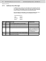
Additional Error Messages.......................................... 6–98
DIN Measurement Bus Slave ..................................... 6–99
Programming .............................................................. 6–99
Protocol Parameters for the DIN Measurement
Bus Slave ................................................................. 6–99
Physical Interfacing................................................... 6–103
Pin assignment for operating devices with a
universal interface .................................................. 6–103
Pin assignment for operating devices without a
universal interface .................................................. 6–103
Cable X3 SER1 RS485 - Master/Slave.................. 6–104
Cable X2 RS485 - Master/Slave ............................ 6–105
Error Messages ........................................................ 6–106
INTERBUS MMICOM raw ........................................... 6–107
Integration of the Operating Devices ........................ 6–107
MMICOM Profile ....................................................... 6–107
Direct Process Data Channel................................. 6–107
Indirect Process Data Channel .............................. 6–107
Parameter Channel ................................................ 6–108
Connecting the Operating Device ............................. 6–108
Specification for INTERBUS .................................. 6–109
Programming ............................................................ 6–110
Protocol Parameters .............................................. 6–110
Additional Functions............................................... 6–110
Data Types............................................................. 6–112
XII
Bosch Rexroth AG | Electric Drives and Controls
Rexroth VCP-Operating Concept | R911305038 / 01
Contents
6.8.4.4
6.8.5
6.8.5.1
6.8.5.2
6.8.5.3
6.8.6
6.9
6.9.1
6.9.1.1
6.9.2
6.9.2.1
6.9.3
6.9.3.1
6.9.3.2
6.9.4
6.9.5
6.9.5.1
6.9.5.2
6.9.6
6.9.7
6.9.7.1
Input Syntax........................................................... 6–113
Physical Interfacing .................................................. 6–114
Pin Assignment...................................................... 6–114
2-Wire Remote Bus Cable ..................................... 6–115
Converting from 8-Wire Protocol to 2-Wire
Protocol.................................................................. 6–116
Error Messages ........................................................ 6–117
PROFIBUS-DP raw ..................................................... 6–119
Specification for PROFIBUS-DP .............................. 6–119
Diagnosis ............................................................... 6–120
Data Profile............................................................... 6–120
Structure of the Data Profile .................................. 6–121
Programming ............................................................ 6–124
Protocol Parameters .............................................. 6–124
System Parameters ............................................... 6–126
Input Syntax.............................................................. 6–127
Physical Interfacing .................................................. 6–128
Pin Assignment...................................................... 6–128
Cable X2 - PROFIBUS-DP .................................... 6–128
Error Messages ........................................................ 6–130
Applications .............................................................. 6–132
Rexroth Controllers................................................ 6–132
7
Shielding D-SUB Connectors .................... 7–1
8
List of Figures ............................................. 8–1
9
Index............................................................. 9–1
10
Service & Support..................................... 10–1
10.1
10.2
10.3
10.4
10.5
10.5.1
10.5.2
10.5.3
10.5.4
10.5.5
10.5.6
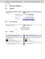
Helpdesk ....................................................................... 10–1
Service-Hotline .............................................................. 10–1
Internet .......................................................................... 10–1
Vor der Kontaktaufnahme... - Before contacting us... ... 10–2
Kundenbetreuungsstellen - Sales & Service Facilities .. 10–2
Deutschland - Germany.............................................. 10–2
Europa (West) - Europe (West) .................................. 10–3
Europa (Ost) - Europe (East)...................................... 10–4
Afrika, Asien, Australien (inkl. Pazifischer Raum) Africa, Asia, Australia (incl. Pacific Rim)..................... 10–5
Nordamerika - North America..................................... 10–6
Südamerika - South America...................................... 10–6
R911305038 / 01 | Rexroth VCP-Operating Concept
Electric Drives and Controls | Bosch Rexroth AG
1-1
Important Notes
1
Important Notes
1.1
Symbols
The symbols in this document are used to draw your attention on notes
and dangers.
1.1.1
General Symbols
Danger
This symbol is used to refer to instructions which, if ignored or not carefully
followed could result in personal injury.
Note
This symbol indicates application tips or supplementary notes.
Reference to source of information
This symbol refers to detailed sources of information on the current topic.
1.2
Target Group
All configuration and programming work in connection with the automation system must be performed by trained personnel only (e.g. qualified
electricians, electrical engineers)
The configuration and programming personnel must be familiar with
the safety concepts of automation technology.
1-2
Bosch Rexroth AG | Electric Drives and Controls
Important Notes
Rexroth VCP-Operating Concept | R911305038 / 01
R911305038 / 01 | Rexroth VCP-Operating Concept
Electric Drives and Controls | Bosch Rexroth AG
2-1
Important Directions for Use
2
Important Directions for Use
2.1
Appropriate Use
2.1.1
Introduction
Rexroth products represent state-of-the-art developments and manufacturing. They are tested prior to delivery to ensure operating safety
and reliability.
The products may only be used in the manner that is defined as appropriate. If they are used in an inappropriate manner, then situations can
develop that may lead to property damage or injury to personnel.
Bosch Rexroth, as manufacturer, is not liable for any damages resulting
from inappropriate use. In such cases, the guarantee and the right to
payment of damages resulting from inappropriate use are forfeited. The
user alone carries all responsibility of the risks.
Before using Rexroth products, make sure that all the pre-requisites for
appropriate use of the products are satisfied:
• Personnel that in any way, shape or form uses our products must first
read and understand the relevant safety instructions and be familiar
with appropriate use.
• If the product takes the form of hardware, then they must remain in
their original state, in other words, no structural changes are permitted. It is not permitted to decompile software products or alter source
codes.
• Do not mount damaged or faulty products or use them in operation.
• Make sure that the products have been installed in the manner described in the relevant documentation.
2-2
Bosch Rexroth AG | Electric Drives and Controls
Rexroth VCP-Operating Concept | R911305038 / 01
Important Directions for Use
2.1.2
Areas of Use and Application
The VCP-operating concept contains hardware and project planning
software that allows to operate and control machines and installations
and serves to visualize the information about the machine/installation
to be operated required by the user.
Operation is only permitted in the specified configurations and combinations of hardware components and with the software and firmware specified in this documentation and in the relevant project planning manuals.
Typical applications are:
•
•
•
•
2.2
Handling and assembly systems
Packaging and foodstuff machines
Printing and paper processing machines
Machine tools
Inappropriate Use
Applying the hardware and project planning software used in combination with the VCP operating concept outside of the above-referenced
areas of application or under operating conditions other than described
in the document and the technical data specified is defined as "inappropriate use".
The hardware and project planning software may not be used, if
• they are subject to operating conditions that do not meet the above
specified ambient conditions.
• Bosch Rexroth has not specifically released them for that intended
purpose. Please note the specifications outlined in the general Safety Guidelines!
R911305038 / 01 | Rexroth VCP-Operating Concept
Electric Drives and Controls | Bosch Rexroth AG
3-1
Safety Instructions for Electric Drives and Controls
3
Safety Instructions for Electric Drives and Controls
3.1
Introduction
Read these instructions before the initial startup of the equipment in
order to eliminate the risk of bodily harm or material damage. Follow
these safety instructions at all times.Do not attempt to install or start up
this equipment without first reading all documentation provided with the
product. Read and understand these safety instructions and all user
documentation of the equipment prior to working with the equipment at
any time. If you do not have the user documentation for your equipment, contact your local Bosch Rexroth representative to send this
documentation immediately to the person or persons responsible for
the safe operation of this equipment. If the equipment is resold, rented
or transferred or passed on to others, then these safety instructions
must be delivered with the equipment.
WARNING
Improper use of this equipment, failure to follow the safety instructions in this document or tampering with the product, including
disabling of safety devices, may result in material damage, bodily
harm, electric shock or even death!
3.2
Explanations
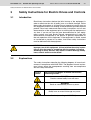
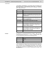
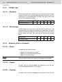
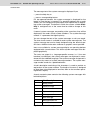
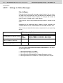
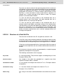
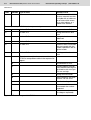
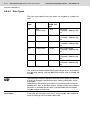
The safety instructions describe the following degrees of hazard seriousness in compliance with ANSI Z535. The degree of hazard seriousness informs about the consequences resulting from non-compliance
with the safety instructions.
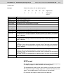
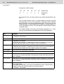
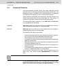
Warning
symbol
Signal word and degree of hazard seriousness
according to ANSI
DANGER
Death or severe bodily harm will occur.
WARNING
Death or severe bodily harm may occur.
CAUTION
Bodily harm or material damage may occur.
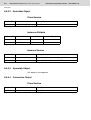
Fig. 3-1:
Hazard classification (according to ANSI Z535)
3-2
Bosch Rexroth AG | Electric Drives and Controls
Rexroth VCP-Operating Concept | R911305038 / 01
Safety Instructions for Electric Drives and Controls
3.3
Hazards by Improper Use
DANGER
High voltage and high discharge current! Danger to life or severe bodily
harm by electric shock!
DANGER
Dangerous movements! Danger to life, severe bodily harm or material
damage by unintentional motor movements!
WARNING
High electrical voltage due to wrong connections! Danger to life or bodily
harm by electric shock!
WARNING
Health hazard for persons with heart pacemakers, metal implants and
hearing aids in proximity to electrical equipment!
CAUTION
Surface of machine housing could be extremely hot! Danger of injury!
Danger of burns!
CAUTION
Risk of injury due to improper handling! Bodily harm caused by crushing, shearing, cutting and mechanical shock or incorrect handling of
pressurized systems!
CAUTION
Risk of injury due to incorrect handling of batteries!
3.4
General Information
• Bosch Rexroth AG is not liable for damages resulting from failure to
observe the warnings provided in this documentation.
• Read the operating, maintenance and safety instructions in your language before starting up the machine. If you find that you cannot
completely understand the documentation for your product, please
ask your supplier to clarify.
• Proper and correct transport, storage, assembly and installation as
well as care in operation and maintenance are prerequisites for optimal and safe operation of this equipment.
• Only persons who are trained and qualified for the use and operation
of the equipment may work on this equipment or within its proximity.
R911305038 / 01 | Rexroth VCP-Operating Concept
Electric Drives and Controls | Bosch Rexroth AG
3-3
Safety Instructions for Electric Drives and Controls
• Furthermore, they must be trained, instructed and qualified to switch
electrical circuits and equipment on and off in accordance with technical safety regulations, to ground them and to mark them according
to the requirements of safe work practices. They must have adequate safety equipment and be trained in first aid.
• Only use spare parts and accessories approved by the manufacturer.
• Follow all safety regulations and requirements for the specific application as practiced in the country of use.
• The equipment is designed for installation in industrial machinery.
• The ambient conditions given in the product documentation must be
observed.
• Use only safety features and applications that are clearly and explicitly approved in the Project Planning Manual.
• For example, the following areas of use are not permitted: construction cranes, elevators used for people or freight, devices and vehicles to transport people, medical applications, refinery plants,
transport of hazardous goods, nuclear applications, applications
sensitive to high frequency, mining, food processing, control of protection equipment (also in a machine).
• The information given in the documentation of the product with regard to the use of the delivered components contains only examples
of applications and suggestions.
The machine and installation manufacturer must
• make sure that the delivered components are suited for his individual
application and check the information given in this documentation
with regard to the use of the components,
• make sure that his application complies with the applicable safety
regulations and standards and carry out the required measures,
modifications and complements.
• Startup of the delivered components is only permitted once it is sure
that the machine or installation in which they are installed complies
with the national regulations, safety specifications and standards of
the application.
• Operation is only permitted if the national EMC regulations for the application are met.
• The instructions for installation in accordance with EMC requirements can be found in the documentation "EMC in Drive and Control
Systems".
• Technical data, connections and operational conditions are specified
in the product documentation and must be followed at all times.
The machine or installation manufacturer is responsible for compliance
with the limiting values as prescribed in the national regulations.
• Technical data, connections and operational conditions are specified
in the product documentation and must be followed at all times.
3-4
Bosch Rexroth AG | Electric Drives and Controls
Rexroth VCP-Operating Concept | R911305038 / 01
Safety Instructions for Electric Drives and Controls
3.5
Protection Against Contact with Electrical Parts
This section refers to equipment and drive components with voltages
above 50 Volts.
Touching live parts with voltages of 50 Volts and more with bare hands
or conductive tools or touching ungrounded housings can be dangerous and cause electric shock. In order to operate electrical equipment,
certain parts must unavoidably have dangerous voltages applied to
them.
DANGER
High electrical voltage! Danger to life, severe bodily harm by electric shock!
• Only those trained and qualified to work with or on electrical equipment are permitted to operate, maintain or repair this equipment.
• Follow general construction and safety regulations when working on
high voltage installations.
• Before switching on power the ground wire must be permanently
connected to all electrical units according to the connection diagram.
• Do not operate electrical equipment at any time, even for brief measurements or tests, if the ground wire is not permanently connected
to the points of the components provided for this purpose.
• Before working with electrical parts with voltage higher than 50 V, the
equipment must be disconnected from the mains voltage or power
supply. Make sure the equipment cannot be switched on again unintended.
• The following should be observed with electrical drive and filter components:
Wait five (5) minutes after switching off power to allow capacitors to discharge before beginning to work. Measure the voltage on the capacitors
before beginning to work to make sure that the equipment is safe to
touch.
• Never touch the electrical connection points of a component while
power is turned on.
• Install the covers and guards provided with the equipment properly
before switching the equipment on. Prevent contact with live parts at
any time.
• A residual-current-operated protective device (RCD) must not be
used on electric drives! Indirect contact must be prevented by other
means, for example, by an overcurrent protective device.
• Electrical components with exposed live parts and uncovered high
voltage terminals must be installed in a protective housing, for example, in a control cabinet.
R911305038 / 01 | Rexroth VCP-Operating Concept
Electric Drives and Controls | Bosch Rexroth AG
3-5
Safety Instructions for Electric Drives and Controls
To be observed with electrical drive and filter components:
DANGER
High electrical voltage on the housing! High leakage current! Danger to life, danger of injury by electric shock!
• Connect the electrical equipment, the housings of all electrical units
and motors permanently with the safety conductor at the ground
points before power is switched on. Look at the connection diagram.
This is even necessary for brief tests.
• Connect the safety conductor of the electrical equipment always permanently and firmly to the supply mains. Leakage current exceeds
3.5 mA in normal operation.
• Use a copper conductor with at least 10 mm2 cross section over its
entire course for this safety conductor connection!
• Prior to startups, even for brief tests, always connect the protective
conductor or connect with ground wire. Otherwise, high voltages can
occur on the housing that lead to electric shock.
3.6
Protection Against Electric Shock by Protective Low Voltage
(PELV)
All connections and terminals with voltages between 0 and 50 Volts on
Rexroth products are protective low voltages designed in accordance
with international standards on electrical safety.
WARNING
High electrical voltage due to wrong connections! Danger to life,
bodily harm by electric shock!
• Only connect equipment, electrical components and cables of the
protective low voltage type (PELV = Protective Extra Low Voltage)
to all terminals and clamps with voltages of 0 to 50 Volts.
• Only electrical circuits may be connected which are safely isolated
against high voltage circuits. Safe isolation is achieved, for example,
with an isolating transformer, an opto-electronic coupler or when
battery-operated.
3-6
Bosch Rexroth AG | Electric Drives and Controls
Rexroth VCP-Operating Concept | R911305038 / 01
Safety Instructions for Electric Drives and Controls
3.7
Protection Against Dangerous Movements
Dangerous movements can be caused by faulty control of the connected motors. Some common examples are:
• improper or wrong wiring of cable connections
• incorrect operation of the equipment components
• wrong input of parameters before operation
• malfunction of sensors, encoders and monitoring devices
• defective components
• software or firmware errors
Dangerous movements can occur immediately after equipment is
switched on or even after an unspecified time of trouble-free operation.
The monitoring in the drive components will normally be sufficient to
avoid faulty operation in the connected drives. Regarding personal
safety, especially the danger of bodily injury and material damage, this
alone cannot be relied upon to ensure complete safety. Until the integrated monitoring functions become effective, it must be assumed in
any case that faulty drive movements will occur. The extent of faulty
drive movements depends upon the type of control and the state of
operation.
DANGER
Dangerous movements! Danger to life, risk of injury, severe bodily
harm or material damage!
• Ensure personal safety by means of qualified and tested higher-level
monitoring devices or measures integrated in the installation. Unintended machine motion is possible if monitoring devices are disabled, bypassed or not activated.
Pay attention to unintended machine motion or other malfunction
in any mode of operation.
• Keep free and clear of the machine’s range of motion and moving
parts. Possible measures to prevent people from accidentally entering the machine’s range of motion:
– use safety fences
– use safety guards
– use protective coverings
– install light curtains or light barriers
R911305038 / 01 | Rexroth VCP-Operating Concept
Electric Drives and Controls | Bosch Rexroth AG
3-7
Safety Instructions for Electric Drives and Controls
• Fences and coverings must be strong enough to resist maximum
possible momentum, especially if there is a possibility of loose parts
flying off.
• Mount the emergency stop switch in the immediate reach of the operator. Verify that the emergency stop works before startup. Don’t
operate the machine if the emergency stop is not working.
• Isolate the drive power connection by means of an emergency stop
circuit or use a starting lockout to prevent unintentional start.
• Make sure that the drives are brought to a safe standstill before accessing or entering the danger zone. Safe standstill can be achieved
by switching off the power supply contactor or by safe mechanical
locking of moving parts.
• Secure vertical axes against falling or dropping after switching off the
motor power by, for example:
– mechanically securing the vertical axes
– adding an external braking/ arrester/ clamping mechanism
– ensuring sufficient equilibration of the vertical axes
The standard equipment motor brake or an external brake controlled directly by the drive controller are not sufficient to guarantee personal
safety!
• Disconnect electrical power to the equipment using a master switch
and secure the switch against reconnection for:
– maintenance and repair work
– cleaning of equipment
– long periods of discontinued equipment use
• Prevent the operation of high-frequency, remote control and radio
equipment near electronics circuits and supply leads. If the use of
such equipment cannot be avoided, verify the system and the installation for possible malfunctions in all possible positions of normal
use before initial startup. If necessary, perform a special electromagnetic compatibility (EMC) test on the installation.
3.8
Protection Against Magnetic and Electromagnetic Fields During
Operation and Mounting
Magnetic and electromagnetic fields generated near current-carrying
conductors and permanent magnets in motors represent a serious
health hazard to persons with heart pacemakers, metal implants and
hearing aids.
WARNING
Health hazard for persons with heart pacemakers, metal implants and
hearing aids in proximity to electrical equipment!
3-8
Bosch Rexroth AG | Electric Drives and Controls
Rexroth VCP-Operating Concept | R911305038 / 01
Safety Instructions for Electric Drives and Controls
• Persons with heart pacemakers, hearing aids and metal implants are
not permitted to enter the following areas:
– Areas in which electrical equipment and parts are mounted, being
operated or started up.
– Areas in which parts of motors with permanent magnets are being
stored, operated, repaired or mounted.
• If it is necessary for a person with a heart pacemaker to enter such
an area, then a doctor must be consulted prior to doing so. Heart
pacemakers that are already implanted or will be implanted in the future, have a considerable variation in their electrical noise immunity.
Therefore there are no rules with general validity.
• Persons with hearing aids, metal implants or metal pieces must consult a doctor before they enter the areas described above. Otherwise, health hazards will occur.
3.9
Protection Against Contact with Hot Parts
CAUTION
Housing surfaces could be extremely hot! Danger of injury! Danger
of burns!
• Do not touch housing surfaces near sources of heat! Danger of
burns!
• After switching the equipment off, wait at least ten (10) minutes to allow it to cool down before touching it.
• Do not touch hot parts of the equipment, such as housings with integrated heat sinks and resistors. Danger of burns!
R911305038 / 01 | Rexroth VCP-Operating Concept
Electric Drives and Controls | Bosch Rexroth AG
3-9
Safety Instructions for Electric Drives and Controls
3.10
Protection During Handling and Mounting
Under certain conditions, incorrect handling and mounting of parts and
components may cause injuries.
CAUTION
Risk of injury by incorrect handling! Bodily harm caused by crushing, shearing, cutting and mechanical shock!
• Observe general installation and safety instructions with regard to
handling and mounting.
• Use appropriate mounting and transport equipment.
• Take precautions to avoid pinching and crushing.
• Use only appropriate tools. If specified by the product documentation, special tools must be used.
• Use lifting devices and tools correctly and safely.
• For safe protection wear appropriate protective clothing, e.g. safety
glasses, safety shoes and safety gloves.
• Never stand under suspended loads.
• Clean up liquids from the floor immediately to prevent slipping.
3.11
Battery Safety
Batteries contain reactive chemicals in a solid housing. Inappropriate
handling may result in injuries or material damage.
CAUTION
Risk of injury by incorrect handling!
• Do not attempt to reactivate discharged batteries by heating or other
methods (danger of explosion and cauterization).
• Never charge non-chargeable batteries (danger of leakage and explosion).
• Never throw batteries into a fire.
• Do not dismantle batteries.
• Do not damage electrical components installed in the equipment.
Be aware of environmental protection and disposal! The batteries contained in the product should be considered as hazardous material for
land, air and sea transport in the sense of the legal requirements (danger of explosion). Dispose batteries separately from other waste. Observe the legal requirements in the country of installation.
3-10
Bosch Rexroth AG | Electric Drives and Controls
Rexroth VCP-Operating Concept | R911305038 / 01
Safety Instructions for Electric Drives and Controls
3.12
Protection Against Pressurized Systems
Certain motors and drive controllers, corresponding to the information
in the respective Project Planning Manual, must be provided with pressurized media, such as compressed air, hydraulic oil, cooling fluid and
cooling lubricant supplied by external systems. Incorrect handling of
the supply and connections of pressurized systems can lead to injuries
or accidents. In these cases, improper handling of external supply systems, supply lines or connections can cause injuries or material damage.
CAUTION
Danger of injury by incorrect handling of pressurized systems!
• Do not attempt to disassemble, to open or to cut a pressurized system (danger of explosion).
• Observe the operation instructions of the respective manufacturer.
• Before disassembling pressurized systems, release pressure and
drain off the fluid or gas.
• Use suitable protective clothing (for example safety glasses, safety
shoes and safety gloves)
• Remove any fluid that has leaked out onto the floor immediately.
Environmental protection and disposal! The media used in the operation
of the pressurized system equipment may not be environmentally compatible. Media that are damaging the environment must be disposed
separately from normal waste. Observe the legal requirements in the
country of installation.
R911305038 / 01 | Rexroth VCP-Operating Concept
Electric Drives and Controls | Bosch Rexroth AG
4-1
Application Description for Small Operator Terminals
4
Application Description for Small Operator Terminals
4.1
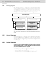
The Concept
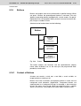
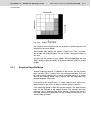
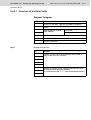
A uniform functionality and operating structure constitute key aspects
of the operating and monitoring concept across the entire product family.
The small operator terminal of construction type VCP relieves the controller completely of operating and monitoring tasks.
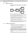
This applies to the operating mode Standard Mode in particular. In this
mode, devices reach their full performance capacity. In this context, the
small-sized operating terminal reads all required data independently
from the controller, and processes this further internally. On request,
the device writes data or data sets (of recipes) to the controller. The
device independently controls the display and the status LEDs.
You can also run the small operator terminal as an ANSI terminal in the
operating mode Transparent Mode. In this context, the device writes
each key actuation to the controller as a press and release code. The
controller uses escape sequences to control the display and the status
LEDs of the device.
All small operator terminals of construction type VCP are programmed
in the same way using the programming software VI Composer.
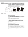
4.1.1
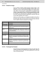
Uniform Device Features
All small operator terminals of the VCP model are equipped with:
– Displays with temperature-compensated contrast or brightness control
– Flash memory
– Buffered RAM
– Real-time clock
– Watchdog timer
– Lithium battery with voltage monitoring
– An interface for downloads, uploads, the logging printer, a scanner
– Standard or field bus interfaces for communication with the controller
– a user mode switch.
All small operator terminals with a keyboard are additionally equipped
with:
– Editing keys
– Control keys
4-2
Bosch Rexroth AG | Electric Drives and Controls
Rexroth VCP-Operating Concept | R911305038 / 01
Application Description for Small Operator Terminals
– Function keys with status LEDs
– Slide-in identification strips for the function keys
The operating system of all small operator terminals offers:
– The operating mode 'Standard Mode'
– Application ID
– Multilingual applications
– Option to customize the interface parameters
– Automatic error correction
– Softkey functionality for all function keys
– A help system for masks and variables
– Password protection function for masks and variables
– Scaling of variable values
– Dynamic attributes for texts and variables
– A message system for status messages
– A message system for error messages
– Recipe data management function
– Print logs
– Running time meters
– System variables for internal functions.
Small operator terminals with graphics displays additionally offer:
– Use of any Windows fonts
– Display of images
– Display of sets of curves.
Small operator terminals with a keyboard additionally offer:
– The operating mode 'Transparent Mode'
Small-sized operating terminals with a touch screen additionally offer:
– Full-graphics user interface including buttons
– A keyboard that is shown automatically when a variable is selected
R911305038 / 01 | Rexroth VCP-Operating Concept
Electric Drives and Controls | Bosch Rexroth AG
4-3
Application Description for Small Operator Terminals
4.2
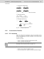
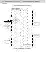
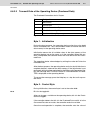
Programming Small Operator Terminals
You program the small operator terminals of construction type VCP in
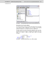
the same way using the programming software VI Composer.
For this purpose, install the programming software on you PC.
– Start the software and select the corresponding entries for the device type and the desired communication protocol.
– Create all of the componentes of the project, consisting of languages
and a controller.
– Compile the project into a S3 file and load the file into the operating
device using the download cable.
– Connect the operating device to the controller or simulate the basic
functions without a controller connected.
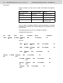
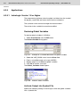
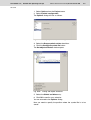
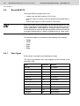
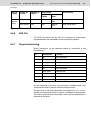
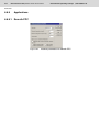
4.2.1
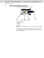
Hardware Prerequisites
To carry out the installation, you need a basic knowledge of Microsoft
Windows. This information is not provided here. If you have any queries in this regard, refer to the Microsoft Windows manuals or online
help.
Hardware Requirements
Your computer should fulfill the following hardware and software
requirements, to run the programming software VI Composer:
–
–
–
–
–
–
–
Pentium processor with 100 MHz (preferably 266 MHz)
32 MByte working memory (RAM) (preferably 64 MByte)
100 MByte free hard disk memory
CD ROM drive
Mouse
Windows NT 4, Windows 95, Windows 98, or Windows 2000
One free serial interface
4-4
Bosch Rexroth AG | Electric Drives and Controls
Rexroth VCP-Operating Concept | R911305038 / 01
Application Description for Small Operator Terminals
4.2.2
Installing VI Composer
The installation of the programing software VI Composer includes all
required directories, files and entries in Windows.
VI Composer runs under the operating systems Windows NT 4, Windows 95, Windows 98, Windows 2000, and Windows XP.
To install VI Composer, insert the installation CD, select the desired
language and start the installation process. Follow the instructions in
the installation dialog box.
R911305038 / 01 | Rexroth VCP-Operating Concept
Electric Drives and Controls | Bosch Rexroth AG
5-1
Standard Mode
5
Standard Mode
The small operator terminals are usually used in the Standard Mode of
operation. The devices deliver maximum performance in this mode.
5.1
Setting the Operating Mode
Make sure that you set the operating mode when the device is switched
off. This ensures that the device accepts the new operating mode.
Note the switch positions ON and OFF marked on the user mode switch.
Depending on the user mode switch, the position of the switches may
vary.
The factory setting for all operating devices is the Standard Mode of
operation. You use the user mode switch to set the operating mode.
Refer to the user manual for the device for more information on the position of the user mode switch.
After you switch on the power supply, the switch position is only read
and evaluated once, that is, during the initialization phase.
To set the user mode switch with four switches to the operating mode
Standard Mode:
Switch
Position
1
ON
2
OFF
3
OFF
4
OFF
Fig. 5-1:
User mode switch with four switches set to Standard Mode
If switch 1 is OFF the small operator terminal is in „Transparent Mode“.
The „Transparent Mode“ is not described in this manual, because
Rexroth applications do not use it, yet.
5-2
Bosch Rexroth AG | Electric Drives and Controls
Rexroth VCP-Operating Concept | R911305038 / 01
Standard Mode
To set the user mode switch with eight switches to the operating mode
Standard Mode:
Switch
Position
1
ON
2
OFF
3
OFF
4
OFF
5
Not used
6
Not used
7
Not used
8
Not used
Fig. 5-2:
User mode switch with eight switches set to Standard Mode
To set the user mode switch with four switches to the operating mode
Demo Mode:
Switch
Position
1
ON
2
OFF
3
ON
4
OFF
Fig. 5-3:
User mode switch with four switches set to Demo Mode
To set the user mode switch with eight switches to the operating mode
Demo Mode:
Switch
Position
1
ON
2
OFF
3
ON
4
OFF
5
Not used
6
Not used
7
Not used
8
Not used
Fig. 5-4:
User mode switch with eight switches set to Demo Mode
R911305038 / 01 | Rexroth VCP-Operating Concept
Electric Drives and Controls | Bosch Rexroth AG
5-3
Standard Mode
5.2
Behavior of the Operating Device During Start-Up
5.2.1
With Valid Project
When you apply the supply voltage, all LEDs on the operating device
are activated. A system test is then carried out, to check and initialize
the modules in the operating device.
The system test may issue different system and error messages. If the
device contains a valid project, the start-up mask or the mask entered
as the start-up mask in the language parameter is displayed. This
mask is displayed five seconds. This time is set as a fixed value. You
can use this time to check whether the LEDs and the display are functioning correctly.
Once this time has expired, the main mask, or the mask set as the
main mask in the language parameters, is displayed. This mask is also
the first mask of user interface.
If the main mask contains a controller variable, and communication
with the controller fails, an error message is displayed (instead of the
main mask), which provides details about the communication error that
occurred.
If you press the Enter key or similar button while the start-up mask is
being displayed, the setup mask or the mask set in the language
parameters is displayed. In this mask, for example, parameters are
assigned to the interfaces. If you press any key before the start-up
mask appears, an error message is generated when the keyboard is
being checked. The error message includes the data for clock frequency, memory size, firmware level, protocol driver, programming
software version, and the project name.
The display of the setup mask may be delayed if the message memory
contains several messages of the serial message system. This is
because time may be required to set up message management structures. However, this initialization time considerably reduces the time
subsequently required to sort messages. A corresponding message is
displayed during this time period.
5.2.2
Without a Valid Project
If no valid project exists, the Flash memory is erased, and the operating device automatically switches to the download operating mode.
The message 'DOWNLOAD 1' remains on the screen. This message
indicates that the operating device is now ready to receive a valid
project via the download interface. If no valid project is available in the
memory, there is no communication with a connected controller, and
the keyboard will not execute any functions.
5-4
Bosch Rexroth AG | Electric Drives and Controls
Rexroth VCP-Operating Concept | R911305038 / 01
Standard Mode
5.3
Communication with a Controller
Communication between a controller (host computer, for example) and
an operating device may occur in standard mode with any interface,
except those for the logging printer and parallel outputs. The interface
used always depends on the connected counterpart or on the network.
For more information on the interfaces themselves, see the manual for
the corresponding operating device.
More detailed information is available on possible connections to different controllers and networks.
See chapter “Controller and Bus Connections“ on page 6-1.
A standard cable, measuring about 3 m (9.843 ft), is available to
ensure a secure connection for each connection option.
5.4
Masks
A mask refers to the content of a display page. This means that masks
vary in size, depending on the operating device being used.
A mask corresponds to the screen displayed at a particular time on the
screen of the operating device.
You can display and enter texts and variables (250) in input and output
masks. You can determine the layout of these masks, and use images
to tailor them to your specific requirements.
For each mask, you can program specific soft keys or function keys
that will automatically link you to other masks. You can also program
cursor keys to open other masks.
You can also program function keys to change the values of variables.
If you use the same mask names in all languages, you can use global
mask elements to design similar masks. Global mask elements (for
example, global variables) appear in each mask with the same name.
5.4.1
Mask Structure
Masks with specific functions form the basic components of the mask
structure.
System masks:
•
•
•
•
Setup mask
Start-up mask
Password mask
Main mask
R911305038 / 01 | Rexroth VCP-Operating Concept
Electric Drives and Controls | Bosch Rexroth AG
5-5
Standard Mode
User mask:
• Input/output mask
The mask structure is made up of a network of input and output masks.
There is no hierarchy. Input and output masks are located at nodes of
the network. These masks contain a selection field from which you can
choose the names of other masks.
In each input/output mask you can use control keys, function keys and
buttons to access all other masks.
You can select different system masks for each language of a project.
5.4.2
Mask Parameters
Each mask parameter is valid for each individual mask of a project.
Mask parameters are:
•
•
•
•
•
•
•
•
5.4.2.1
Mask number
Access level
Background color
Help mask
Variables management topdown
Automatic data release
Reset password
Activate help mask
Mask Number
You can use the mask number to:
• Enter masks in a text list and display as a mask menu
• Switch masks over from the controller
• Write documentation for masks
5.4.2.2
Access Level
The access level corresponds to a threshold value for password management. You use it to determine when operators must enter a password.
Values between 0 and 255 are valid access level parameters.
The initial access level default value for each mask is 0. This corresponds to the status general release.
5-6
Bosch Rexroth AG | Electric Drives and Controls
Rexroth VCP-Operating Concept | R911305038 / 01
Standard Mode
If the threshold value is above the view level, the operator can only display this mask if you enter the correct password.
If the threshold value is above the edit level, the operator can only
change the variables contained in the mask if you enter the correct
password.
5.4.2.3
Background Color
For each mask, you can select a separate color for the entire mask
area. All elements that may be contained in a mask cover over the
background color!
You can only use this parameter for operating devices that use gray
scales or color display.
5.4.2.4
Help Mask
You can create a specific help mask for each mask, and display it by
selecting the Help key or a corresponding button.
5.4.2.5
Variables Management Topdown
If you activate this parameter, the variables in a mask are selected in
sequence from top to bottom.
If this parameter is not activated, the variables are selected from left to
right.
5.4.2.6
Automatic Data Release
Switching to this mask automatically activates data release.
Otherwise you have to select the Data Release button to be able to
change the value of a variable.
Automatic data release cannot be used with operating devices that use
a touch screen.
5.4.2.7
Reset Password
Exiting this mask reactivates password protection. When you go back
to this mask, you must enter your password again.
R911305038 / 01 | Rexroth VCP-Operating Concept
Electric Drives and Controls | Bosch Rexroth AG
5-7
Standard Mode
5.4.2.8
Activate Help Mask
If you are using a touch-screen operating device, you can select the
unused display area to display the help mask.
You cannot use the 'Activate Help Mask' parameter for operating
devices equipped with a keyboard.
5.4.3
System Masks
System masks are based on the input/output mask type. Some restrictions apply, due to the compulsory initialization phase and the fact that
no communication has yet taken place with the controller.
System masks facilitate programming, and allow the system to become
directly operable. In this way, the initialization phase becomes a fixed
component of the project.
You can select any mask as the system mask.
As all masks are created on a language-specific basis, you can define
other masks as system masks for each language.
As no communication has yet been established with the controller during the initialization phase, the following restrictions apply to system
masks.
• The setup mask and start-up mask cannot be accessed by selecting
a mask externally
• No controller variables can be displayed on the setup mask and startup mask
5.4.3.1
Setup Mask
The operator can only access the operating device’s setup mask if you
select the Enter key or the Setup button during the initialization phase
(the start-up mask is displayed for five seconds).
On the setup mask, it may be useful to include the following functions:
• Activate/deactivate download function
• Set protocol parameters
• Select PLC protocol
• Set date and time
• Display firmware level of the operating device
If you program these functions using system variables, the operator
can select the corresponding parameter from text lists.
5-8
Bosch Rexroth AG | Electric Drives and Controls
Rexroth VCP-Operating Concept | R911305038 / 01
Standard Mode
Password Protection for Setup Mask
A special procedure applies to password protection on the setup mask.
If you set the system variable MskchgPasswd as the first editable variable on the setup mask, you can enter the password independently of
the access level (exception 255). This also allows you to set password
protection for the setup mask.
For the setup mask, the access level only impacts at the edit level,
meaning the content is always visible to the operator.
Suppressing the Setup Mask
You can choose to hide the setup mask if you do not need to display it.
To do this, set the access level for this mask to the value 255. The
setup mask can then not be accessed from the start-up mask (using
the Enter key or the Enter button).
5.4.3.2
Start-up Mask
The start-up mask appears for about five seconds after you switch on
the operating device. This time is fixed, and this cannot be changed.
On the start-up mask, you can only display static texts and system variables. Due to the time sequence used, it is not possible to enter variables here.
When the start-up mask is being displayed, you can press the Enter
key to go to the setup mask. You cannot go to the setup mask if the
access level of the setup mask is set to 255.
On the start-up mask, you can display the following information, for
example:
• Service address
• Machine type
• Program version
R911305038 / 01 | Rexroth VCP-Operating Concept
Electric Drives and Controls | Bosch Rexroth AG
5-9
Standard Mode
5.4.3.3
Password Mask
In a project in which specific masks or variables are to be protected
from unauthorized access, you must create a password mask.
In your password mask, you must create the system variable MskchgPasswd.
Select the name of the password mask in the language parameters, to
activate the password mask.
You can create your own password mask for each language used in
the project.
See chapter “Password Mask and Password Functions“ on page 5-138.
See chapter “MskChgPasswd“ on page 5-79.
5-10
Bosch Rexroth AG | Electric Drives and Controls
Rexroth VCP-Operating Concept | R911305038 / 01
Standard Mode
5.4.4
Input/Output Masks
The user interface of a project is primarily made up of input and output
masks. These masks may contain the following:
• Static text
• Text fields
• Variables
• System variables
• Background images
• Set of curves (graph)
• Buttons
• Recipe fields
• Table fields
• Message fields
You can also assign the following functions to an input/output mask:
•
•
•
•
5.4.5
Sub-masks
Help mask
Background color
Key functions (soft key function)
Help Masks
To optimize usability, you can create a help mask for each mask and
each input variable. To call help on the operating devices, press the
Help key or the button that has been programmed accordingly.
If data release is not requested, a help text appears for the screen. The
help text for the variable that is currently selected appears, provided
the Editor for entering a variable value has been activated.
The default help mask appears if no specific help mask has been
linked to a mask or a variable.
A help mask is the same size as a normal mask. You can insert static
text, background images, output variables, and tables in a help mask.
You can also link help masks to sub-masks, to ensure that help masks
have a uniform appearance.
See chapter “Password Mask and Password Functions“ on page 5-138.
R911305038 / 01 | Rexroth VCP-Operating Concept
Electric Drives and Controls | Bosch Rexroth AG
5-11
Standard Mode
5.5
Variables
All operating devices support standard usage variable types. The connected controller determines the number of variable types permitted.
The variable type determines the range of values and the number of
significant places.
Type
Size
Range of Values
Bit
1 Bit
0, 1
Byte
1 Byte
–128 to +127
Byte
1 Byte
0 to 255
Word
2 Bytes
–32768 to +32767
Word
2 Bytes
0 to 65535
LWord
4 Bytes
–2147483648 to +2147483647
LWord
4 Bytes
0 to 4294967295
LWord
4 Bytes
±1,2 x 10-38 to ±3,4 x 10+38
ASCII
42 Bytes
0 to 255
Fig. 5-5:
Variable types
In the programming software, you define a variable as a mask element.
The mask element Variable is made up of the:
–
–
–
–
–
–
–
–
–
–
–
–
–
–
–
Symbolic name
Controller address
Representation type
Field type
Field length
Format
Documentation value
Limits
Scaling
Communication type
Editor
Variable type
Attributes (static or dynamic)
Character set
Help mask
5-12
Bosch Rexroth AG | Electric Drives and Controls
Rexroth VCP-Operating Concept | R911305038 / 01
Standard Mode
5.5.1
Symbolic Name
In the programming software, you assign a symbolic name to each
variable. This name can have up to 255 characters.
5.5.2
Controller Address
You use the controller address to specify the storage location in the
controller.
Note whether a variable will be accessed on a byte, word, or doubleword basis.
Depending on the protocol selected, the system carries out a syntax
check. To avoid incorrect input, you can call a syntax diagram for each
protocol in the online help for the programming software.
5.5.3
Representation Type
You can choose from the following options for displaying variables on
the operating device
–
–
–
–
–
–
–
–
–
5.5.3.1
Decimal number
Alphanumeric
Selection text
Selection image
Floating point number
Hexadecimal number
Binary number
Bars
Curves
Decimal Number
Standard
The significance of the displayed digits increases from right to left. You
can display places either with leading zeros and/or a decimal point.
The representation refers to the data types bit, byte, word, and Lword.
The maximum length depends on the data type. There are no blanks
between the characters. The variable appears in the controller either in
binary format or in special timer or counter formats.
R911305038 / 01 | Rexroth VCP-Operating Concept
Electric Drives and Controls | Bosch Rexroth AG
5-13
Standard Mode
A decimal number with two decimal places.
Example:
103
102
101
100
10-1
10-2
Significance
0
1
2
3
4
5
Displayed =
123,45
Key
Function
0 to 9
Enters the numbers 0 to 9.
Decimal point
Enters the decimal point.
Cursor Right
Moves the cursor one position to the right.
0 to 9
Enters the numbers 0 to 9.
Decimal point
Enters the decimal point.
Cursor Right
Moves the cursor one position to the right.
Cursor Left
Moves the cursor one position to the left.
Cursor Up
Moves the cursor to the next highest, editable variable in the display, and selects
it. If the cursor is already positioned at the top-level variable, the lowest-level variable is selected.
Cursor Down
Moves the cursor to the next lowest, editable variable in the display, and selects
it. If the cursor is already positioned at the lowest-level variable, the top-level variable is selected.
Plus
1st case: Variable is selected. The value is deleted and you can enter a new
value.
2nd case: Cursor was moved within a positive value. The value is not changed.
3rd case: Cursor was moved within a negative value. The negative sign for the
value is deleted.
Minus
1st case: Variable is selected. The value is deleted, and a negative sign is inserted at the least-significant position. You can enter a new value.
2nd case: Cursor was moved within a positive value. A negative sign is placed in
front of the value.
3rd case: Cursor was moved within a negative value. The value is not changed.
Delete
Deletes the position where the cursor is located, and also deletes the sign.
Fig. 5-6:
Key functions for decimal numbers of the type Standard
BCD Format
The significance of the displayed digits increases from right to left. You
can display integers as BCD numbers with leading zeros.
The representation refers to the data types bit, byte, word, and Lword.
The maximum length is 8 digits. There are no blanks between the characters. The variable appears in BCD format in the controller.
For one byte, the range of values spans from 00 to 99.
5-14
Bosch Rexroth AG | Electric Drives and Controls
Rexroth VCP-Operating Concept | R911305038 / 01
Standard Mode
Example for a BCD number:
103
102
101
100
10-1
10-2
Significance
0
1
2
3
4
5
Displayed =
1234D
It is important that you take particular care when inputting BCD numbers.
You can enter numeric values as standard decimal numbers using the
Standard editor. You can also increment or decrement each individual
digit of the BCD value using the Mixmode editor. You can only use the
Increment editor to make incremental changes to individual digits in a
value with decimal transfer. This corresponds to the procedure used by
a decade switch.
For scaled variables, the value in the controller changes by +/- 1. However, the value displayed also depends on the scaling specified.
Key
Function
0 to 9
1. Standard and Mixmode - Enter the numbers 0 to 9
2. Increment - No function
Decimal point
Enters the decimal point.
Plus
1. Standard - No function
2. Mixmode and Increment - Increments the value at the cursor and influences
the more significant digits when the range of values is exceeded.
Minus
1. Standard - No function
2. Mixmode and Increment - Decrements the value at the cursor and influences
the more significant digits when the range of values is not reached.
Cursor Right
Moves the cursor one position to the right.
Cursor Left
Moves the cursor one position to the left.
Cursor Up
Moves the cursor to the next highest, editable variable in the display, and selects
it. If the cursor is already positioned at the top-level variable, the lowest-level variable is selected.
Cursor Down
Moves the cursor to the next lowest, editable variable in the display, and selects
it. If the cursor is already positioned at the lowest-level variable, the top-level variable is selected.
Delete
1. Standard and Mixmode - Variable is selected: The value is deleted and you can
enter a new value.
2. Standard and Mixmode - Cursor was moved within the value: The character is
deleted and the more significant digits are moved to the left.
3. Increment - No function
Fig. 5-7:
Key functions for decimal numbers of the type BCD
R911305038 / 01 | Rexroth VCP-Operating Concept
Electric Drives and Controls | Bosch Rexroth AG
5-15
Standard Mode
5.5.3.2
Alphanumeric
For alphanumeric display, ASCII strings are read in byte format from
the controller, and displayed in the operating device. The number of
characters displayed varies, depending on the options offered by the
operating device. A variable of the type Alphanumeric cannot be longer
than one display line. Longer texts are truncated.
The controller address specifies the start of the string. It does not contain a length byte, as this is not required.
You can use the plus and minus keys to input alphanumeric characters. The system variables Shift and ShiftCase are also available for
upper case (Shift) and lower case (ShiftCase) respectively. You can
use these keys to enter the additional characters displayed on the
numeric keys.
To use the system variables, link the system variables as press and
release variables with a function key to the mask. During input, the
operator must press the function key and the corresponding numeric
key.
You can use the Password field type to enable concealed password
entry on the operating device. However, you can only enter numbers
here. An “X” appears for each digit you enter.
See chapter “Password Protection“ on page 5-135.
Key
Function
With
Shift
With ShiftCase
0
Enters the number 0
()°0
()°0
1
Enters the number 1
STU1
STUstu1
2
Enters the number 2
VWX2
VWXvwx2
3
Enters the number 3
YZ%3
YZ%yz%3
4
Enters the number 4
JKL4
JKLjkl4
5
Enters the number 5
MNO5
MNOmno5
6
Enters the number 6
PQR6
PQRpqr6
7
Enters the number 7
ABC7
ABCabc7
8
Enters the number 8
DEF8
DEFdef8
9
Enters the number 9
GHI9
GHIghi9
Decimal point
Enters the decimal point.
:?!.
:?!:?!.
Plus
Enters the numbers 0 to 9, the letters A to Z and a to z <=>+
Fig. 5-8:
Key functions for alphanumeric variables
<=><=>+
5-16
Bosch Rexroth AG | Electric Drives and Controls
Rexroth VCP-Operating Concept | R911305038 / 01
Standard Mode
Key
Function
Minus
Enters the numbers 0 to 9, the letters A to Z and a to z \*/-
Cursor Right
Moves the cursor one position to the right.
Cursor Left
Moves the cursor one position to the left.
Cursor Up
Moves the cursor to the next highest, editable variable
in the display, and selects it. If the cursor is already positioned at the top-level variable, the lowest-level variable is selected.
Cursor Down
Moves the cursor to the next lowest, editable variable
in the display, and selects it. If the cursor is already positioned at the lowest-level variable, the top-level variable is selected.
Delete
Deletes the character at the cursor position.
Fig. 5-8:
5.5.3.3
With
Shift
With ShiftCase
\*/\*/-
Key functions for alphanumeric variables
Selection Text
You can choose to display a text instead of a numeric value. To do this,
you must create a text list.
In the text list, you assign numeric values to the corresponding texts.
The operating device reads the value of the variable from the controller, replaces the numeric value with text, and displays this text. If a
value is read from the controller, and you have not defined a corresponding text for this value, the system displays a number of question
marks.
If the Selection Text type is used for an input variable, you can choose
to limit the field height to one or several lines.
R911305038 / 01 | Rexroth VCP-Operating Concept
Electric Drives and Controls | Bosch Rexroth AG
5-17
Standard Mode
If you specify a field height of 1, the system always only displays one
text from the text list. If the field height is greater than 1, a correspondingly higher number of texts from the text list is displayed. The active
text is displayed inversely.
Key
Function
0-9
No function
Decimal point
No function
Plus
Selection in ascending order (after the final value in
the text list is reached, the value at top of the text list
is selected next).
Minus
Selection in descending order (after the first value in
the text list is reached, the value at the bottom of the
text list is selected next).
Cursor Right
Moves the cursor one position to the right.
Cursor Left
Moves the cursor one position to the left.
Cursor Up
Moves the cursor to the next highest, editable variable in the display, and selects it. If the cursor is already positioned at the top-level variable, the lowest-level variable is selected.
Cursor Down
Moves the cursor to the next lowest, editable variable in the display, and selects it. If the cursor is already positioned at the lowest-level variable, the
top-level variable is selected.
Delete
Deletes the character at the cursor position.
Fig. 5-9:
Example:
Key functions for selection texts
For the parity of an interface the text items „no parity“, „odd“ and „even“
should be displayed instead of „0“, „1“ and „3“. Therefore create a text
list in the programming software with the following entries:
Value
Text
0
no parity
1
odd
2
even
Fig. 5-10:
Example of a text list
In the „selection text“ dialog of the programming software select the
name of the text list. Im Dialogfenster „Auswahltext“ von der Projektierungssoftware wählen Sie anschließend den Namen der Textliste
aus. With this step you link the field for displaying the variable value
with the text list.
5-18
Bosch Rexroth AG | Electric Drives and Controls
Rexroth VCP-Operating Concept | R911305038 / 01
Standard Mode
5.5.3.4
Selection Image
You can choose to display images instead of numeric values, in the
same way as you can use text to represent numeric values. In an
image list, first of all assign individual images to the numeric values.
The numeric values do not need to be contiguous or sorted consecutively. Then, in a mask create a variable field for the selection image
variable. In the dialog field for the representation type Selection Image,
link the variable with the image list. The corresponding image will then
be displayed in the operating device, depending on the controller values used. The default image will be displayed for controller values that
have not been specified in the image list.
Note that all of the images in an image list must be the same size, to
ensure that they cover each other completely. Furthermore, make sure
that the images used are not too large, to avoid slow display build-up.
You may need to modify the polling time accordingly.
Key
Function
0-9
No function
Decimal point
No function
Plus
Selection in ascending order (after the final value in the
image list is reached, the value at top of the image list is
selected next).
Minus
Selection in descending order (after the first value in the
image list is reached, the value at the bottom of the image
list is selected next).
Cursor Right
No function
Cursor Left
No function
Cursor Up
Moves the cursor to the next highest, editable variable in
the display, and selects it. If the cursor is already positioned at the top-level variable, the lowest-level variable
is selected.
Cursor Down
Moves the cursor to the next lowest, editable variable in
the display, and selects it. If the cursor is already positioned at the lowest-level variable, the top-level variable
is selected.
Delete
No function
Fig. 5-11:
Key functions for selection images
5.5.3.5
Floating Point Number
The significance of the displayed digits increases from right to left. The
number can optionally be displayed with a decimal point. Scaling is
only carried out using a factor. The operating device can also form the
inverse value before display.
R911305038 / 01 | Rexroth VCP-Operating Concept
Electric Drives and Controls | Bosch Rexroth AG
5-19
Standard Mode
There are no blanks between the characters. In the controller, the variable appears in special floating point formats, for example, IEEE. Only
some controllers support floating point numbers.
Key
Function
0 to 9
Enters the numbers 0 to 9.
Decimal point
Enters the decimal point.
Cursor Right
Moves the cursor one position to the right.
Cursor Left
Moves the cursor one position to the left.
Cursor Up
Moves the cursor to the next highest, editable variable in
the display, and selects it. If the cursor is already positioned at the top-level variable, the lowest-level variable
is selected.
Cursor Down
Moves the cursor to the next lowest, editable variable in
the display, and selects it. If the cursor is already positioned at the lowest-level variable, the top-level variable
is selected.
Plus
1st case: Variable is selected. The value is deleted and
you can enter a new value.
2nd case: Cursor was moved within a positive value. The
value is not changed.
3rd case: Cursor was moved within a negative value. The
negative sign for the value is deleted.
Minus
1st case: Variable is selected. The value is deleted, and
a negative sign is inserted at the least-significant position.
You can enter a new value.
2nd case: Cursor was moved within a positive value. A
negative sign is placed in front of the value.
3rd case: Cursor was moved within a negative value. The
value is not changed.
Delete
Deletes the position where the cursor is located, and also
deletes the sign.
Fig. 5-12:
Key functions for floating point numbers
5.5.3.6
Hexadecimal Number
The significance of the displayed digits increases from right to left.
Hexadecimal numbers are displayed with the digits 0 to 9 and A to F in
upper case, and with leading zeros.
The representation refers to the data types byte, word, and LWord. The
maximum length is 8 digits. There are no blanks between the characters.
5-20
Bosch Rexroth AG | Electric Drives and Controls
Rexroth VCP-Operating Concept | R911305038 / 01
Standard Mode
A hexadecimal number:
Example:
164
163
162
161
160
Significance
0
E
4
5
A
Displayed =
0E45AH
Key
Function
0 to 9
Enters the numbers 0 to 9.
Decimal point
No function
Cursor Right
Moves the cursor one position to the right.
Cursor Left
Moves the cursor one position to the left.
Cursor Up
Moves the cursor to the next highest, editable variable in
the display, and selects it. If the cursor is already positioned at the top-level variable, the lowest-level variable
is selected.
Cursor Down
Moves the cursor to the next lowest, editable variable in
the display, and selects it. If the cursor is already positioned at the lowest-level variable, the top-level variable
is selected.
Plus
Enters the characters 0 to 9 and A to F in ascending order.
Minus
Enters the characters 0 to 9 and A to F in descending order.
Delete
No function
Fig. 5-13:
Key functions for hexadecimal numbers
5.5.3.7
Binary Number
You use binary numbers to display individual bits, bytes, words, and
Lwords. Select the number of bits and blank spaces for display. Both
values are used to determine the entire field length.
There are a maximum of 32 bits for each variable. There can be no
more than 255 blank spaces between the bits.
The significance of the displayed digits can be displayed in ascending
order from either left to right or from right to left.
R911305038 / 01 | Rexroth VCP-Operating Concept
Electric Drives and Controls | Bosch Rexroth AG
5-21
Standard Mode
Example for displaying a binary number with or without blank spaces:
0
1
0
0
0
1
0
0
1
0
0
Blanks = 1
0
Blanks = 2
Key
Function
0 and 1
Enters the numbers 0 and 1.
2 to 9
No function
Decimal point
No function
Cursor Right
Moves the cursor one position to the right.
Cursor Left
Moves the cursor one position to the left.
Cursor Up
Moves the cursor to the next highest, editable variable in the display, and selects it. If the cursor is already positioned at the top-level variable, the lowest-level variable is selected.
Cursor Down
Moves the cursor to the next lowest, editable variable in the display, and selects it. If the cursor is already positioned at the lowest-level variable, the
top-level variable is selected.
Plus
Enters the characters 0 and 1.
Minus
Enters the characters 0 and 1.
Delete
No function
Fig. 5-14:
5.5.3.8
Blanks = 0
Key functions for binary numbers
Bars
You can use the representation type Bars only to output variable values.
The variable values are refreshed either cyclically or one time, when
the mask is opened.
5-22
Bosch Rexroth AG | Electric Drives and Controls
Rexroth VCP-Operating Concept | R911305038 / 01
Standard Mode
You use the height and width values to determine whether the bars run
horizontally or vertically. From a particular reference point, the dimension of a bar can be:
– in a positive direction
– in a negative direction
– in both directions
Specify the width and height in the unit 'Character'. The entire bar can
only ever accept the size of a multiple of a character. When the controller values are output, however, the bar changes its dimension by pixel
size.
You use two values to define the range of values that a bar will display.
Use the first value to definethe value of the bar on the left or bottom
end.
Use the second value to define the value of the bar on the right or top
end.
Fig. 5-15:
Horizontal bars
R911305038 / 01 | Rexroth VCP-Operating Concept
Electric Drives and Controls | Bosch Rexroth AG
5-23
Standard Mode
Fig. 5-16:
Vertical bars
The range of values is limited to values from -32768 to +32767.
To display several bars in a mask, ensure that the controller addresses
are consecutive and contiguous. This will speed up data transfer.
You can use four fill patterns for bars:
1. For the empty area of the bar (background).
2. For the filled area of the bar (foreground).
3. For the bar, if the lower value is not reached.
4. For the bar, if the higher value is exceeded.
The programming software contains four standard fill patterns. You can
use any other images as fill patterns. Prior to use, you must import
these images into the programming software or insert them as OLE.
See chapter “Images“ on page 5-108.
5-24
Bosch Rexroth AG | Electric Drives and Controls
Rexroth VCP-Operating Concept | R911305038 / 01
Standard Mode
Example of fill status display:
Four graphics have been created for the example. They display a container that is either empty or full. The word MIN is used to demonstrate
a situation in which the value is not reached. And the word MAX to
depict a situation in which the value is exceeded. The container in the
middle depicts a container for a case where the operating device displays a mid-point controller value for the variables.
Fig. 5-17:
5.5.3.9
Example of fill status display
Curve
Use the representation type Curve to display a value table as a row of
points in the operating device.
The address for the controller variable represents the start of the value
table in the controller. Each value in the table describes one pixel of the
curve.
A curve is defined by the following parameters:
– Maximum width (54 pixels for each curve variable)
– Maximum height (height of the display in the operating device)
Specify a length and height to determine the dimension of the curve in
the unit 'Character'.
To produce a curve with a width of 54 pixels, several curve variables
next to each other are required.
Insert a coordinate grid as a background image.
The operating device reads the variable values as an array from the
controller, and inserts these as continuous consecutive height data.
The value with the starting address (address +0) is displayed on the
very left. Each subsequent piece of height data (address +n) is offset
one pixel position to the right.
The height data for the curve is cyclically refreshed.
R911305038 / 01 | Rexroth VCP-Operating Concept
Electric Drives and Controls | Bosch Rexroth AG
5-25
Standard Mode
Example of a curve display:
Fig. 5-18:
Example for displaying a curve
5.5.3.10 Fields
You can add fields to masks, to carry out specific tasks. Depending on
the type of field added, the mask can be a message mask, recipe
mask, or table mask. At runtime, you can display the messages sent by
the PLC in the message field of a message mask. For a recipe mask,
you must set up a recipe field to display the contents of a recipe. In the
table field of a mask, data is displayed in tabular form.
Message Field
The message field refers to the area in a mask that is used to display
messages.
To create a message field, carry out the following steps:
1. Select the Message Field icon in the toolbar and in the mask select
the area where messages will be displayed.
This area is displayed as a rectangle. The message field is marked
with the letter M on the left edge of the rectangle.
2. You can use the sizing handles to change the height of the area. You
cannot change the width of the area.
3. In the Message System area, determine whether messages of the
parallel message system or the serial message system will be displayed in the current message field.
You can determine the height of the message field in the Height of
Message Field area. A message field can have a maximum height of
60 lines.
5-26
Bosch Rexroth AG | Electric Drives and Controls
Rexroth VCP-Operating Concept | R911305038 / 01
Standard Mode
In the Representation of Message area, you can specify data that can
be changed when the operating device is running.
Global settings:
If this parameter is active, default settings from the system parameters
are used for the message system.
Message group:
The system outputs the group identifier before the message text.
Message number:
The system outputs the message number before the message text.
Message date:
The system outputs today’s date before the message text. In the date,
the year can either be output as two digits or four digits. The value of
the date is frozen with the message.
Time of message:
The system outputs the time before the message text. The value of the
date is frozen with the message.
The maximum number of lines per message specifies that only the
number of lines entered here will be displayed. The standard value is
the maximum value of 255 lines.
In the Time Period area, you can specify the time period from which
messages will be displayed.
Chronicle:
The system displays all messages.
Old list:
The system only displays acknowledged messages that do not have
the status Disappeared.
In the Group Assignment area, you can select whether you would like
to display message groups in the current message field, and if you
would, specify the corresponding groups. Next to the group number,
the system also displays the group identifier that you set up. Select the
check box next to the group number, to select the required group. Any
number of combinations are possible. If you do not select any check
box, the system can display all groups.
The Font area specifies the character set used to display all elements
of a message field on the operating device. To display all elements of a
message field in another font, click the New button.
Recipe Field
The Recipe field classifies the area in a mask used to display recipes.
Select the Recipe Field icon in the toolbar and in the mask select the
area where recipes will be displayed. This area is displayed as a rectangle. The recipe field is marked with the letter R on the left edge of the
rectangle. You can use the sizing handles to change the height of the
area. You cannot change the width of the area.
Select the name of the recipe for which you want to set up a recipe
field.
R911305038 / 01 | Rexroth VCP-Operating Concept
Electric Drives and Controls | Bosch Rexroth AG
5-27
Standard Mode
Just below, enter the height for the recipe field in the mask
The Font area specifies the character set used to display all elements
of a recipe field on the operating device. To display all elements of a
recipe field in another font, click the New Font button.
Table Field
The Table field classifies the area in a mask used to display values in a
table.
Select the Table Field icon in the toolbar and in the mask select the
area where the table will be displayed. This area is displayed as a rectangle. The table field is marked with the letter T on the left edge of the
rectangle. You can use the sizing handles to change the height of the
area. You cannot change the width of the area.
Specify here, how many lines the table field will have and how many
elements can be displayed in this table field.
The Font area specifies the character set used to display all elements
of the table on the operating device. To display all elements of a table
in another font, click the New button.
To display variable values in the table, create a variable frame in the
table field. Specify the address for the variable and select the representation type.
Variables displayed in a button that has a frame cannot be dragged
with the mouse to the table field. Frames of buttons cannot be displayed in tables.
You have 256 elements you want to be displayed in a table which has
four columns. The operating device has screen with 20 lines.16 of
these lines are to be used to display elements. Therefore, create a
table field with a height of 16. Enter 64 (16 lines x 4 elements) for the
number of table elements.
Example:
5.5.4
Field Type
By selecting a field type, you determine whether the operator will be
able to modify the variable's value or whether the value is just displayed.
For password entry, you can specify the field type in more detail.
5.5.4.1
Input
Select the field type Input to enable operators to change the value of a
variable on the operating device.
5-28
Bosch Rexroth AG | Electric Drives and Controls
Rexroth VCP-Operating Concept | R911305038 / 01
Standard Mode
The value of the variables is loaded from the controller when the mask
is accessed.
If you select the attribute Cyclical, the system constantly updates the
value of the variables, based on the interval specified in the polling
time.
Before input, the operator must press the Data Release key. The operator can only change the value of the variables once the status LED for
the data release is lit. Use the Enter key to write the value to the controller. The operator must then press the Data Release key. The status
LED for the data release switches off.
5.5.4.2
Output
Select the field type Output to only display the value of the variables,
but not allow the operator to change the value.
The value of the variables is loaded from the controller when the mask
is accessed.
If you select the attribute Cyclical, the system constantly updates the
value of the variables, based on the interval specified in the polling
time.
5.5.4.3
Password
You can use the additional attribute Password to determine for an
alphanumeric variable that the password is not visible on the operating
device when it is entered.
Instead of displaying the values entered, the system displays the operator a string of “X“ when the password is entered.
5.5.4.4
Cyclical
The operating device always polls the controller for the value of a variable when the operator goes to a mask in which a value is to be displayed. However, to display actual values, the value must be
continuously updated. Therefore, always select the field type Cyclical
for displaying actual values.
The system will then continuously update the value of the variables,
based on the interval set as the polling time.
R911305038 / 01 | Rexroth VCP-Operating Concept
Electric Drives and Controls | Bosch Rexroth AG
5-29
Standard Mode
5.5.5
Format
5.5.5.1
Only Positive
Use the attribute Only Positive to display variable values that are to be
displayed without a sign. This means that the range of values that can
be displayed changes, for example, for a byte, from between -128 and
+127 to between 0 and 255.
You can also display positive decimal numbers with leading zeros.
5.5.5.2
Display Leading Zeros
For positive decimal numbers, you can display more significant digits
with a value of zero as zeros.
For example:
If the field length is 5 digits, the number 25 is displayed with leading
zeros as follows:
00025
5.5.5.3
Field Length
The field length of a variable is made up of:
– The sign
– The number of digits
– The decimal point
For the representation type Binary Number, the number of blank
spaces is added to the number of digits, to determine the field length.
5.5.5.4
Fractional Digits
You can define the number of fractional digits for decimal and floating
point numbers.
This does not change the field length, however, one digit for displaying
the decimal point is lost.
5.5.6
Documentation Value
The documentation value for displaying a variable is a placeholder
when you program. Depending on the representation type you are
using, The programming software specifies another documentation
value, for example, 'F' for hexadecimal numbers or '9' for decimal numbers.
5-30
Bosch Rexroth AG | Electric Drives and Controls
Rexroth VCP-Operating Concept | R911305038 / 01
Standard Mode
The documentation value is also used for project documentation
instead of a real controller value.
See chapter “Documentation“ on page 5-192.
5.5.7
Limits
In the programming software, you can specify a lower and an upper
limit for each variable to restrict operator input.
The lower limit is automatically set to 0 for variable values that are displayed with the attribute Only Positive.
If the operator tries to enter a value outside of these limits, one of the
following system messages is issued:
– Value too small
– Value too large
The operator can ignore these system messages, but he must enter a
value that lies between the limits, or use the Cursor Up or Cursor Down
keys to go to another variable in the mask. The system then accepts
the current controller value again.
R911305038 / 01 | Rexroth VCP-Operating Concept
Electric Drives and Controls | Bosch Rexroth AG
5-31
Standard Mode
5.5.8
Scaling
5.5.8.1
Scaled Input
To modify the values that the operator enters in the operating device in
line with the values used in the connected controller, inverse scaling
must be carried out.
The system uses the following formula to scale the input:
=
Controller Value
Input Value of
the Unit
-
Summand
x
Divisor
Factor
Fig. 5-19:
Scaling of the input variables in the operating device
A rounding error may occur during scaling which is calculated using the
following formula.
of
( InputtheValue
Unit
x Factor
Fig. 5-20:
5.5.8.2
)
<
( Upper Limit
-
Divisor
/ 2
)
Rounding of the input variables in the operating device
Scaled Output
You can scale output to modify the range of values to suit user interface requirements. The scaling data is used for both output and input in
the operating device. This does not restrict the range of values for the
variable. Scaling is only carried out in the operating device.
You use the following operands for scaling:
– Factor,
– Divisor and
– Addend.
Note that a factor or divisor with the value 0 is not permitted.
5-32
Bosch Rexroth AG | Electric Drives and Controls
Rexroth VCP-Operating Concept | R911305038 / 01
Standard Mode
Operand
Range of Values
Factor
–32768 to –1, +1 to +32767
Divisor
+1 to +32767
Addend
–32768 to +32767
Fig. 5-21:
Scaling decimal numbers
Operand
Range of Values
Factor
–999999999,99999999 to –
0,00000001+0,00000001 to +999999999,99999999
Divisor
–999999999,99999999 to –
0,00000001+0,00000001 to +999999999,99999999
Addend
–999999999,99999999 to +999999999,99999999
Fig. 5-22:
Scaling floating point numbers
The operating device uses the following formula to scale the output:
Output Value
of the Unit
Controller Value
x
Factor
=
+
Summand
Divisor
Fig. 5-23:
Scaling of the output variables in the operating device
Use the following formula to determine the operands.
Current
Controller Value
Current
Terminal Value
Lower Limit
- Controller Values
-
Lower Limit
Output Values
Fig. 5-24:
=
Upper Limit
Controller Values
-
Lower Limit
Controller Values
Upper Limit
Output Values
-
Lower Limit
Output Values
Scaling of the output variables
The following example will help you determine the operands.
Example:
Range of values for output values:
Lower limit for output value = 0
Upper limit for output value = 100
Current value in operating device = x
Range of values for controller values:
Lower limit for controller values = -4096
Upper limit for controller values = 4096
Current controller value = y
R911305038 / 01 | Rexroth VCP-Operating Concept
Electric Drives and Controls | Bosch Rexroth AG
5-33
Standard Mode
1. Inserting the variable values:
y - (-4096)
4096 - (-4096)
=
x-0
100 - 0
4096 + 4096
y + 4096
=
x
100
Fig. 5-25:
Inserting the variable values in the formula
2. Solving the equation:
100 y + 409600
Fig. 5-26:
=
8192 x
Solving the equation
3. Solving the equation for x:
100
x
=
409600
y+
8192
8192
Factor
Summand
100
x
y + 50
=
8192
Divisor
Fig. 5-27:
Solving the equation for x
5.5.9
Communication Definition
5.5.9.1
PLC Handshake
Select the attribute PLC Handshake to inform the controller that the
values of the subsequent controller variables of the current mask
are to be changed.
To do this, you must:
– Create a variable for the Read Coordination byte AND
– Create a variable for the polling area
See chapter “Read Coordination Byte“ on page 5-119.
See chapter “Write Coordination Byte“ on page 5-121.
The attribute PLC Handshake allows you to:
– Create your own recipe management system
– Inform the controller that a specific variable value will be changed
5-34
Bosch Rexroth AG | Electric Drives and Controls
Rexroth VCP-Operating Concept | R911305038 / 01
Standard Mode
The PLC handshake process runs as follows:
Jump to mask with variable,
which has the attribute PLC
handshake
Operator presses the data
release key
Terminal sets the "Edit Request
bit" in CBR to 1
Controlller sets the "Refresh
Acknowledge Bit" in CBW to 1
Terminal sets the "Refresh
Request Bit" in CBR to 0
Controller sets the "Refresh
Acknowledge Bit" in CBW to 0
No
"External
Data Release bit"
in CBW set to 1?
Terminal reads the refreshed
controller variables again
Yes
Terminal activates the data
release internally
Terminal activates the data
release internally
Operator enters new
variable values
Terminal sets the "Editing Status
Bit" in CBR
Operator presses the
enter key
Operator enters a variable
value
Operator presses the data
release key
Operator presses the
enter key
Terminal inactivates the data
release internally
Terminal sets the "Refresh
Request Bit" in CBR to 1
Terminal sets the "Editing Status
Bit" in CBR to 0
Terminal inactivates the data
release internally
Terminal sets the "Editing
Request Bit" in CBR to 0
Controller refreshes the relevant
variables with current values
Controller sets the "External Data
Release Bit" in CBW to 0 (not
mandatorily required)
Controller sets the
"External Data Release
Bit" in CBW to 1
Status LED "Data
Release" switches
ON
Status LED "Data
Release" flashes
End of procedure
Fig. 5-28:
Flow diagram for PLC handshake
Status LED "Data
Release" is ON
Status LED "Data
Release" switches
OFF
R911305038 / 01 | Rexroth VCP-Operating Concept
Electric Drives and Controls | Bosch Rexroth AG
5-35
Standard Mode
5.5.9.2
With Enter
The operator must press the Enter key to transfer the value of the variables from the operating device to the controller.
5.5.9.3
With +, –, or Enter
Each time the operator presses the Plus and Minus keys, he transfers
the incremented or decremented value to the controller. If the operator
uses the 0 to 9 keys to enter the value, he must then press the Enter
key.
5.5.9.4
For all changes
The operator can change the value of a variable only with the Plus and
Minus keys. The changed value is transferred to the controller each
time you select the Plus and Minus keys.
5.5.10
Access Type
5.5.10.1 Normal
Use the access type Regular for accessing selection text, or selection
image variables for projects that do not use any variant options. The
system then displays for selection all entries in a text list or an image
list.
5.5.10.2 Selective
Use the access type Selective to only display the selection texts or
selection images that are “released“ using a controller variable. Each
bit of the controller variable represents an entry in the text or image list.
5-36
Bosch Rexroth AG | Electric Drives and Controls
Rexroth VCP-Operating Concept | R911305038 / 01
Standard Mode
Control Byte
7
0
0
0
Fig. 5-29:
0
1
0
1
1
1
Text list
Value
Text
0
Mixer 1
1
Mixer 2
2
Mixer 3
3
Mixer 4
4
Mixer 5
5
Mixer 6
6
Mixer 7
7
Mixer 8
Selective access
You can use the control byte depicted in the Selective Access image to
only display the first four entries in the text list.
The controller variable is only read once, when the operating device is
being initialized!
Enter the name of the controller variable in the Variant Buffer field of
the Variant Option dialog box.
5.5.10.3
Article Administration
To administrate the article data by means of the small operator terminal
the article number and article name of each article is loaded from the
controller to the small operator terminal.
The operator can select an article by an apropriate selection field.
Therefore the stored article names are served as selection text items
and the article numbers are the values transferred to the controller,
when the data release key is pressed.
Generating the Article List
After a cold- or warm boot the article list in the small operator terminal
is empty. This means that, i.e. after a communication error the whole
article list must be transferred to the small operator terminal.
Enlarging the article list by one item is performed by means of the DINMeasurement bus service New Entry to Article List. The new item
consists of an article name and an article number as parameter. The
length of the article name ist limited by the width of the small operator
terminal display. The size of the article number is two byte.
The new entry is added to the end of the article list. The order of the
entries in the article list influences the order of the text items displayed
R911305038 / 01 | Rexroth VCP-Operating Concept
Electric Drives and Controls | Bosch Rexroth AG
5-37
Standard Mode
in the selection text field of the mask.
The maximum amount of entries in the article list is 255 items.
Marking an Artikel as Active
By means of the DIN-Measurement bus service Report Current Article you can mark an article of the list as active. The service contains
the article number as parameter.
The article marked as active is not displayed in a selection text field
used to delete article data from the controller.
After a cold or warm boot or after deleting the active entry in the article
list no article is marked as active.
Access on the Article List
The article list serves as data base for selection fields in which you
select the articles stored in the controller.
To parameterize the selection field in the programming software you
must select „spec. selection“ as type of selection. A dialog for entering
the customer identity appears. Please enter the code Bosch in this dialog.
Next an additional dialog appears where you can select whether a
selection text field is set-up with a complete article list (general article
selection) or an article list without the active marked article (article
selection when deleting).
Entering the values and text items for the selection text field is not necessary, because these data is delivered by the artice list.
Selecting an article at the small operator terminal is performed by the
"+" and "-" keys and is acknowledged by the enter key. The corresponding article number is then transferred to the controller.
If a data set must be copied to another address before you can continue working, the access can be temporarily denied by means of the
PLC handshake bit.
Article Administration (delete)
Deleting an entry in the article list is performed by means of the DINMeasurement bus service Delete entry in article list. The service contains the article number as parameter.
Deleting the whole content in the article list is performed by means of
the DIN-Measurement bus service Delete all entries in article list.
5-38
Bosch Rexroth AG | Electric Drives and Controls
Rexroth VCP-Operating Concept | R911305038 / 01
Standard Mode
5.5.11
5.5.11.1
Variable Type
Standard
The standard type is the variable type most frequently used to display
decimal numbers. The maximum length depends on the data type. The
significance of the displayed digits increases from right to left. There
are no blanks between the digits.
5.5.11.2
Significance
103
102
101
100
10-1
10-2
Displayed 123,45D
0
1
2
3
4
5
BCD Number
A BCD number must be saved in the controller in BCD format. The
operating device can interpret and display up to eight digits. The significance of the displayed digits increases from right to left. There are no
blanks between the digits. The value can be displayed with leading
zeros.
5.5.12
5.5.12.1
Significance
104
103
102
101
100
Displayed 1234D
0
1
2
3
4
Attributes (Static or Dynamic)
Global
Variables with the attribute Global:
– Appear in all languages for a project
– Appear in all masks with the same name
– Appear in the same position
If you change the parameters of these variables, the changes apply to
all masks with the same name and to all languages for the project.
5.5.12.2
Inverse
Variables with the attribute Inverse are displayed so that the foreground and background colors are swapped.
5.5.12.3
Flashing
Variables with the attribute Flashing are displayed so that the fore-
R911305038 / 01 | Rexroth VCP-Operating Concept
Electric Drives and Controls | Bosch Rexroth AG
5-39
Standard Mode
ground and background colors change at specific intervals. The
attribute Flashing cannot be displayed in the programming software.
The result only appears in the operating device.
5.5.12.4 Underline
Variables with the attribute Underline are displayed with a line under
the entire variable value.
5.5.12.5 Invisible
The attribute Invisible is only evaluated together with a control variable. In all other cases, the attribute Invisible results in an error message during compilation, and no S3 file is generated.
Static texts and one-off variables (variables that are output only once)
with the attribute Invisible are not output.
Cyclical variables with the attribute Invisible are overwritten with
blanks. This erases any existing obsolete value on the screen.
If background images and cyclical variables are being used simultaneously, the background image is not updated!
Regarding input variables, note that the operator cannot enter the range
of values for the attribute Invisible. If an input value is in the area of the
attribute Invisible, the edit process is not started. The operator then has
no possibility to change the value again.
5.5.12.6 Non-Editable
The Non-editable attribute selectively prevents variable values from
being changed. The system then only outputs the variable value oneoff or cyclically.
You can only use the Non-Editable attribute in conjunction with a control variable.
5-40
Bosch Rexroth AG | Electric Drives and Controls
Rexroth VCP-Operating Concept | R911305038 / 01
Standard Mode
5.5.13
Font
The Font attribute determines the font in which the characters are displayed in a mask.
Note:
–
–
–
–
–
5.5.14
Only some operating devices can display fonts up to any size.
The names of the fonts cannot be changed.
You can select a separate font for each static text in a mask.
The system displays all messages using the same font.
The system displays all elements in a recipe using the same font.
Help Mask
To optimize usability, you can create a help mask for all masks and all
variables. To call this help mask in the operating device, press the
Help key or a corresponding button.
On operating devices equipped with a keyboard, the help mask is only
displayed for as long as you keep the Help key pressed.
A help mask is the same size as a standard mask. You can insert static
text, background images, output variables, and tables in a help mask.
You can also link help masks to sub-masks, to ensure that help masks
have a uniform appearance.
If a mask or variable is not linked with a help mask, only the default
help mask is displayed. You can also design the default help mask to
suit your own needs.
The help text for a mask is displayed until data release is requested.
Otherwise the help is displayed for the variable that is currently being
edited.
5.5.15
Output Variables
Output variables are numeric or alphanumeric memory content from
the connected controller. The variable values are requested from the
controller if required, and displayed at the program location using the
corresponding representation type.
5.5.15.1
One-Off and Cyclical Output Variables
Pure output variables are transferred once from the controller when the
mask is being called-up, and are displayed in the mask. Outputting the
variable only once helps improve communication performance, and
can be used for all variables, such as setpoint values, constants, and
parameters that rarely or never change. All output variables can be dis-
R911305038 / 01 | Rexroth VCP-Operating Concept
Electric Drives and Controls | Bosch Rexroth AG
5-41
Standard Mode
played as scaled or formatted.
Cyclical output variables are used to display actual values and values
that continuously change while a mask is being output.
You specify the cycle time with the polling time. This means that you
know at this stage how often the display of the actual values will be
refreshed.
To improve the performance of transfer to the controller, use data types
identically and ensure that the address ranges of a mask are as continuous as possible.
The scaling and formatting of cyclical output variables, in particular of
decimal numbers as floating point numbers, requires a corresponding
computing time, and as a result the data is not output in real time.
For these applications, select cycle times > 500 ms.
The more cyclical data is transferred, the longer the reaction time to
new values from the controller.
5.5.15.2 Formatted Output
You can format a numeric variable value to suit an output area.
Formatting consists of:
– Field Length
– Fractional Digits
– Positive Values Only
– Display Leading Zeros
The field length determines the entire length of the output value, including signs, decimal points, and fractional digits.
The number of fractional digits gives the operator the impression that a
value has been divided, however, in reality no value has been divided.
However, the variable value must exist in the controller in a correspondingly high resolution.
Example:
In the controller, the value of a length is stored as a word.The range of
values is between 0 and 65535. The following settings are made for
display:
–
–
–
–
–
Decimal number
Output
Only positive
Field length = 6 (5 + decimal point)
Fractional digits = 2 (absolute)
5-42
Bosch Rexroth AG | Electric Drives and Controls
Rexroth VCP-Operating Concept | R911305038 / 01
Standard Mode
The display area is between 0,00 and 655,35. If the check box Only
Positive is not selected, the display area changes. The value is displayed with a sign. You must specify an additional position in the field
length for the sign. The following data is required:
– Decimal number
– Output
– Field length = 7 (5 + decimal point + sign)
– Fractional digits = 2 (absolute)
The display range is then between –327.68 and +327.67.
5.5.16
Input Variables
When displaying input variables for the first time in the operating
device, the system uses the same approach as for one-off output variables (output variables that are output only once). This also applies to
scaling, which works from the controller’s viewpoint.
Input variables are processed by editors in the operating device.
5.5.16.1
Plausibility Check
The system carries out a plausibility check for all input variables. During this check, it compares the value entered with the range limits
stored in the variable list.
If the limits are not adhered to, the system issues one of the following
system messages:
– 'Value too large' or
– 'Value too small'
The incorrect value is not written to the controller. If an error occurs, the
previously valid value is retained.
To prevent the above-mentioned system messages from appearing,
you must delete them in the programming software. When you do this,
the following applies:
– If the value is exceeded, the value of the upper limit is entered
– If the value is not reached, the value of the lower limit is entered
R911305038 / 01 | Rexroth VCP-Operating Concept
Electric Drives and Controls | Bosch Rexroth AG
5-43
Standard Mode
5.5.17
System Variables
You can use system variables to control the operating device’s internal
functions.
You can display and change the value of system variables either in a
mask or using any suitable representation type, function or soft key.
When you link a system variable with a function key or soft key, the following rules apply:
– Do not use the same key to link a mask change and a system variable.
– You do not have to link Set (1) and Reset (0) with the same key, except if you are setting up a jogging mode.
Do not add the names of system variables to the variable list! In the
same way as you use the name of a system variable for a controller variable, the function is lost for the operating device.
5.5.17.1 Basic Functions
IntEraseEprom
Function
Deletes the project from the Flash memory and places the operating
device into the download mode.
Data type
Numeric
Representation
type
Positive decimal number, alphanumeric, selection text, selection image, hexadecimal number, binary number
Configurable values
0
Inactive
1
Deletes the project
MainVersion
Function
Displays the current firmware version.
Data type
Alphanumeric
Representation
type
Alphanumeric, field length = 8
Configurable values
Format determined by the manufacturer.
The value of the variable is stored retentively. The stored value is automatically used again after a power failure.
5-44
Bosch Rexroth AG | Electric Drives and Controls
Rexroth VCP-Operating Concept | R911305038 / 01
Standard Mode
ComVersion
Function
Displays the type and version number of the current protocol.
Data type
Alphanumeric
Representation
type
Alphanumeric, field length = 8
Configurable values
Format determined by the manufacturer.
UserVersion
Function
Displays the project's version number.
Data type
Numeric
Representation
type
Positive decimal number, alphanumeric, selection text, selection image, hexadecimal number, binary number
Configurable values
0 to 255
Boot
Function
Boots the operating device (system restart).
Data type
Numeric
Representation
type
Positive decimal number, alphanumeric, selection text, selection image, hexadecimal number, binary number
Configurable values
0
Inactive
1
Boot
LcdContrast
Function
Sets the contrast of LC displays.
Data type
Numeric
Representation
type
Positive decimal number, alphanumeric, selection text, selection image, hexadecimal number, binary number
Configurable values
Depends on the operating device type.
The value of the variable is stored retentively. The stored value is automatically used again after a power failure.
R911305038 / 01 | Rexroth VCP-Operating Concept
Electric Drives and Controls | Bosch Rexroth AG
5-45
Standard Mode
Adhere to the values for the upper and lower limits, as specified in the
user manual for the relevant operating device.
LcdBackground
Function
Displays masks in inverted format on operating devices equipped
with a LC display.
Data type
Numeric
Representation
type
Positive decimal number, alphanumeric, selection text, selection image, hexadecimal number, binary number
Configurable values
0
Not inverted
1
Inverted
LcdBackLight
Function
Brightness of the backlighting of LC displays.
Data type
Numeric
Representation
type
Positive decimal number, alphanumeric, selection text, selection image, hexadecimal number, binary number
Configurable values
Depends on the operating device type.
The value of the variable is stored retentively. The stored value is automatically used again after a power failure.
Adhere to the values for the upper and lower limits, as specified in the
user manual for the relevant operating device.
TurnOnTemp
Function
Temperature value at which the display is automatically switched
on.
Data type
Numeric
Representation
type
Positive decimal number, alphanumeric, selection text, selection image, hexadecimal number, binary number
Configurable values
0
Display OFF
1
Display ON
5-46
Bosch Rexroth AG | Electric Drives and Controls
Rexroth VCP-Operating Concept | R911305038 / 01
Standard Mode
OsLanguage
Function
For multilingual projects, this variable is used for online language
selection.
Data type
Numeric
Representation
type
Positive decimal number, alphanumeric, selection text, selection image, hexadecimal number, binary number
Configurable values
0
First language
N
n–th language
The value of the variable is stored retentively. The stored value is automatically used again after a power failure.
IdentName
Function
Displays the name of the current project (application ID).
Data type
Alphanumeric
Representation
type
Alphanumeric
Configurable values
Max. 13 characters
The value of the variable is stored retentively. The stored value is automatically used again after a power failure.
IdentVersion
Function
Displays the version of the current project (application ID).
Data type
Alphanumeric
Representation
type
Alphanumeric
Configurable values
Max. 5 characters
R911305038 / 01 | Rexroth VCP-Operating Concept
Electric Drives and Controls | Bosch Rexroth AG
Standard Mode
IdentDate
Function
Displays the date of the current project (application ID).
Data type
Alphanumeric
Representation
type
Alphanumeric
Configurable values
Max. 6 characters
IdentTime
Function
Displays the time of the current project (application ID).
Data type
Alphanumeric
Representation
type
Alphanumeric
Configurable values
Max. 6 characters
IdentCount
Function
Displays the counter value of the current project (application ID).
Data type
Alphanumeric
Representation
type
Alphanumeric
Configurable values
Max. 4 characters
IdentRandom
Function
Displays the current project's ending (application ID).
Data type
Alphanumeric
Representation
type
Alphanumeric
Configurable values
Max. 2 characters
5-47
5-48
Bosch Rexroth AG | Electric Drives and Controls
Rexroth VCP-Operating Concept | R911305038 / 01
Standard Mode
ComErrorRetry
Function
Displays the number of communication errors.
Data type
Numeric
Representation
type
Positive decimal number, alphanumeric, selection text, selection image, hexadecimal number, binary number
Configurable values
0 to n
Number of communication errors
The value of the variable is stored retentively. The stored value is automatically used again after a power failure.
5.5.17.2
Communication SER1
ComDataLenA
Function
Sets the number of data bits for SER1.
Data type
Numeric
Representation
type
Positive decimal number, alphanumeric, selection text, selection image, hexadecimal number, binary number
Configurable values
0
5 Bit
1
6 Bit
2
7 Bit
3
8 Bit
ComParityA
Function
Sets the parity for SER1.
Data type
Numeric
Representation
type
Positive decimal number, alphanumeric, selection text, selection image, hexadecimal number, binary number
Configurable values
0
No parity
1
Odd parity
2
Even parity
R911305038 / 01 | Rexroth VCP-Operating Concept
Electric Drives and Controls | Bosch Rexroth AG
Standard Mode
ComStopBitsA
Function
Sets the number of stop bits for SER1.
Data type
Numeric
Representation
type
Positive decimal number, alphanumeric, selection text, selection image, hexadecimal number, binary number
Configurable values
0
1 Bit
1
1,5 Bit
2
2 Bit
ComBaudrateA
Function
Sets the baud rate for SER1.
Data type
Numeric
Representation
type
Positive decimal number, alphanumeric, selection text, selection image, hexadecimal number, binary number
Configurable values
0
300 Baud
1
600 Baud
2
1200 Baud
3
2400 Baud
4
4800 Baud
5
9600 Baud
6
19200 Baud
7
38400 Baud
8
57600 Baud (operating devices with 386 CPU only)
ComHandshakeA
Function
Sets the handshake method for SER1.
Data type
Numeric
Representation
type
Positive decimal number, alphanumeric, selection text, selection image, hexadecimal number, binary number
Configurable values
0
No handshake
1
Hardware handshake (RTS/CTS)
2
Software handshake (XON/XOFF)
5-49
5-50
Bosch Rexroth AG | Electric Drives and Controls
Rexroth VCP-Operating Concept | R911305038 / 01
Standard Mode
ComDefaultA
Function
Activates the interface parameters for SER1.
Data type
Numeric
Representation
type
Positive decimal number, alphanumeric, selection text, selection image, hexadecimal number, binary number
Configurable values
0
Inactive
1
Activates the interface parameters entered by the operator.
2
Activates the interface parameters that were specified in the programming software.
ComTimeout
Function
Sets the timeout watchdog time for SER1.
Data type
Numeric
Representation
type
Positive decimal number, alphanumeric, selection text, selection image, hexadecimal number, binary number
Configurable values
0
No timeout watchdog (Initial state)
1 to
65535
Timeout watchdog time in ms
ComRetryTimeout
Function
Sets the waiting time (delay) after which another connection setup
is attempted for SER1. This time period allows to span the time period required for the PLC-specific power-up phase, thereby preventing error messages from being generated.
Data type
Numeric
Representation
type
Positive decimal number, alphanumeric, selection text, selection image, hexadecimal number, binary number
Configurable values
0 to
65535
Waiting time in ms
R911305038 / 01 | Rexroth VCP-Operating Concept
Electric Drives and Controls | Bosch Rexroth AG
5-51
Standard Mode
ComSlaveNr
Function
Sets the slave number for an operating device connected to a network.
Data type
Numeric
Representation
type
Positive decimal number, alphanumeric, selection text, selection image, hexadecimal number, binary number
Configurable values
0 to
255
Slave number
ComErrorCode
Function
Displays the last error code issued for a COMMUNICATION, SYSTEM, or FATAL error.
Data type
Numeric
Representation
type
Positive decimal number, alphanumeric, selection text, selection image, hexadecimal number, binary number
Configurable values
0 to
99999
By inserting this system variable into the message text of a message,
the error code will be stored in the message memory in addition to the
message.
See chapter “Serial Message System“ on page 5-171.
ComErrorSubcode
Function
Displays the last error subcode (low word) issued for a COMMUNICATION, SYSTEM, or FATAL error.
Data type
Numeric
Representation
type
Positive decimal number, alphanumeric, selection text, selection image, hexadecimal number, binary number
Configurable values
0 to
99999
By inserting this system variable into the message text of a message,
the error code will be stored in the message memory in addition to the
message.
See chapter “Serial Message System“ on page 5-171.
5-52
Bosch Rexroth AG | Electric Drives and Controls
Rexroth VCP-Operating Concept | R911305038 / 01
Standard Mode
5.5.17.3
Error Statistics SER1
ComParityCount
Function
Displays the number of parity errors for SER1. Is deleted at every
download.
Data type
Numeric
Representation
type
Positive decimal number, alphanumeric, selection text, selection image, hexadecimal number, binary number
Configurable values
0 to
65535
Number of parity errors
ComOverrunCount
Function
Displays the number of overrun errors.
Data type
Numeric
Representation
type
Positive decimal number, alphanumeric, selection text, selection image, hexadecimal number, binary number
Configurable values
0 to
65535
Number of overrun errors
ComFrameCount
Function
Displays the number of framing errors.
Data type
Numeric
Representation
type
Positive decimal number, alphanumeric, selection text, selection image, hexadecimal number, binary number
Configurable values
5.5.17.4
0 to
65535
Number of framing errors
Communication SER2
ComDataLenB
Function
Sets the number of data bits for SER2.
Data type
Numeric
Representation
type
Positive decimal number, alphanumeric, selection text, selection image, hexadecimal number, binary number
R911305038 / 01 | Rexroth VCP-Operating Concept
Electric Drives and Controls | Bosch Rexroth AG
Standard Mode
Configurable values
0
5 Bit
1
6 Bit
2
7 Bit
3
8 Bit
ComParityB
Function
Sets the parity for SER2.
Data type
Numeric
Representation
type
Positive decimal number, alphanumeric, selection text, selection image, hexadecimal number, binary number
Configurable values
0
No parity
1
Odd parity
2
Even parity
ComStopBitsB
Function
Sets the number of stop bits for SER2.
Data type
Numeric
Representation
type
Positive decimal number, alphanumeric, selection text, selection image, hexadecimal number, binary number
Configurable values
0
1 Bit
1
1,5 Bit
2
2 Bit
5-53
5-54
Bosch Rexroth AG | Electric Drives and Controls
Rexroth VCP-Operating Concept | R911305038 / 01
Standard Mode
ComBaudrateB
Function
Sets the baud rate for SER2.
Data type
Numeric
Representation
type
Positive decimal number, alphanumeric, selection text, selection image, hexadecimal number, binary number
Configurable values
0
300 Baud
1
600 Baud
2
1200 Baud
3
2400 Baud
4
4800 Baud
5
9600 Baud
6
19200 Baud
7
38400 Baud
8
57600 Baud (operating devices with 386 CPU only)
ComHandshakeB
Function
Sets the handshake for SER2.
Data type
Numeric
Representation
type
Positive decimal number, alphanumeric, selection text, selection image, hexadecimal number, binary number
Configurable values
0
No handshake
1
Hardware handshake (RTS/CTS)
2
Software handshake (XON/XOFF)
ComDefaultB
Function
Activates the interface parameters for SER2.
Data type
Numeric
Representation
type
Positive decimal number, alphanumeric, selection text, selection image, hexadecimal number, binary number
Configurable values
0
Inactive
1
Activates the interface parameters entered by the operator.
2
Activates the interface parameters that were specified in the programming software.
R911305038 / 01 | Rexroth VCP-Operating Concept
Electric Drives and Controls | Bosch Rexroth AG
5-55
Standard Mode
5.5.17.5 Real-Time Clock
The values for the real-time clock can be set from the operating device
and from the controller.
See chapter “Date and Time Image“ on page 5-139.
RTCSec
Function
Sets the seconds of the real-time clock.
Data type
Numeric
Representation
type
Decimal number, alphanumeric, selection text, selection image,
hexadecimal number, binary number, bar
Configurable values
0 to 59
Seconds
RTCMin
Function
Sets the minutes of the real-time clock.
Data type
Numeric
Representation
type
Decimal number, alphanumeric, selection text, selection image,
hexadecimal number, binary number, bar
Configurable values
0 to 59
Minutes
RTCHour
Function
Sets the hours of the real-time clock.
Data type
Numeric
Representation
type
Decimal number, alphanumeric, selection text, selection image,
hexadecimal number, binary number, bar
Configurable values
0 to 23
Hours
5-56
Bosch Rexroth AG | Electric Drives and Controls
Rexroth VCP-Operating Concept | R911305038 / 01
Standard Mode
RTCDay
Function
Sets the day of the date for the real-time clock.
Data type
Numeric
Representation
type
Positive decimal number, alphanumeric, selection text, selection image, hexadecimal number, binary number
Configurable values
0 to 31
Number of days depends on the month. Invalid settings are corrected by the real-time clock next time when the date changes.
RTCMonth
Function
Sets the month of the real-time clock.
Data type
Numeric
Representation
type
Positive decimal number, alphanumeric, selection text, selection image, hexadecimal number, binary number
Configurable values
1 to 12
RTCYear
Function
Sets the year of the real-time clock.
Data type
Numeric
Representation
type
Positive decimal number, alphanumeric, selection text, selection image, hexadecimal number, binary number
Configurable values
0 to 99
Only the year and decade are influenced.
RTCDayOfWeek
Function
Sets the day of the week of the real-time clock.
Data type
Numeric
Representation
type
Positive decimal number, alphanumeric, selection text, selection image, hexadecimal number, binary number
Configurable values
0 to 6
Only for operating devices with TMP Z84 CPU or RISC–CPU
1 to 7
Only for operating devices with 386 CPU
R911305038 / 01 | Rexroth VCP-Operating Concept
Electric Drives and Controls | Bosch Rexroth AG
Standard Mode
RTCDateFmt
Function
Sets the date format for the message output.
Data type
Numeric
Representation
type
Positive decimal number, alphanumeric, selection text, selection image, hexadecimal number, binary number
Configurable values
0
Europe DD MM YY
1
USA MM DD YY
2
Japan YY MM DD
RTCYear2000
Function
Sets a 4-digit year of the real-time clock.
Data type
Numeric
Representation
type
Positive decimal number, alphanumeric, selection text, selection image, hexadecimal number, binary number
Configurable values
0 to
9999
5.5.17.6 Serial Message System
RepmanSortCrit
Function
Defines the sorting criteria for message output.
Data type
Numeric
Representation
type
Positive decimal number, alphanumeric, selection text, selection image, hexadecimal number, binary number
Configurable values
0
By priority of message number
1
In order of arrival (most recent first)
2
In order of arrival (oldest first)
3
By group
5-57
5-58
Bosch Rexroth AG | Electric Drives and Controls
Rexroth VCP-Operating Concept | R911305038 / 01
Standard Mode
ClearRepBuf
Function
Erases the memory for the serial messages.
Data type
Numeric
Representation
type
Positive decimal number, alphanumeric, selection text, selection image, hexadecimal number, binary number
Configurable values
0
Inactive
1
Delete all messages from the message memory
2
Delete only the acknowledged messages from the message memory
RepmanRepPrint
Function
Is used to have messages output to a printer.
Data type
Numeric
Representation
type
Positive decimal number, alphanumeric, selection text, selection image, hexadecimal number, binary number
Configurable values
0
Inactive
1
Formatted output, the interface is used permanently.
2
Complete output, the interface is used permanently.
3
Formatted output, the interface is used temporarily.
4
Complete output, the interface is used temporarily.
The value of the variable is stored retentively. The stored value is automatically used again after a power failure.
If you use the interface permanently for message output, it will not be
possible to send any other print jobs to the printer.
If you use the interface temporarily for message output, messages will
not be printed while other print jobs are being printed.
RepoutNr
Function
Allows you to output a message number along with the message.
Data type
Numeric
Representation
type
Positive decimal number, alphanumeric, selection text, selection image, hexadecimal number, binary number
Configurable values
0
OFF
1
ON
R911305038 / 01 | Rexroth VCP-Operating Concept
Electric Drives and Controls | Bosch Rexroth AG
Standard Mode
RepoutDate
Function
Allows you to output the date along with the message.
Data type
Numeric
Representation
type
Positive decimal number, alphanumeric, selection text, selection image, hexadecimal number, binary number
Configurable values
0
OFF
1
ON
RepoutTime
Function
Allows you to output the time along with the message.
Data type
Numeric
Representation
type
Positive decimal number, alphanumeric, selection text, selection image, hexadecimal number, binary number
Configurable values
0
OFF
1
ON
RepoutAnzYear
Function
Specifies how the date appears when the message is output.
Data type
Numeric
Representation
type
Positive decimal number, alphanumeric, selection text, selection image, hexadecimal number, binary number
Configurable values
0
Year with 2 digits
1
Year with 4 digits
RepoutRepText
Function
Displays the most recent serial message. The message is displayed
in accordance with the specified representation settings.
Data type
Alphanumeric
Representation
type
Alphanumeric
Configurable values
5-59
5-60
Bosch Rexroth AG | Electric Drives and Controls
Rexroth VCP-Operating Concept | R911305038 / 01
Standard Mode
Repout RepText21
Function
Displays the most recent serial message beginning from the 21st
character. The message is displayed in accordance with the specified representation settings.
Data type
Alphanumeric
Representation
type
Alphanumeric
Configurable values
RepoutRepText41
Function
Displays the most recent serial message beginning from the 41st
character. The message is displayed in accordance with the specified representation settings.
Data type
Alphanumeric
Representation
type
Alphanumeric
Configurable values
RepoutRepText61
Function
Displays the most recent serial message beginning from the 61st
character. The message is displayed in accordance with the specified representation settings.
Data type
Alphanumeric
Representation
type
Alphanumeric
Configurable values
R911305038 / 01 | Rexroth VCP-Operating Concept
Electric Drives and Controls | Bosch Rexroth AG
5-61
Standard Mode
RepmanQuitKey
Function
Simulates the function of the Acknowledge key.
Data type
Numeric
Representation
type
Positive decimal number, alphanumeric, selection text, selection image, hexadecimal number, binary number
Configurable values
0
Inactive
1
Function of the Acknowledge key active
You must edit the value of this variable with a function key or a button.
You cannot use any other input form.
RepmanChgMask
Function
Lets you jump to the mask which is linked with the selected message.
Data type
Numeric
Representation
type
Positive decimal number, alphanumeric, selection text, selection image, hexadecimal number, binary number
Configurable values
0
Inactive
You must edit the value of this variable with a function key or a button.
You cannot use any other input form.
RepoutQuitText
Function
Displays the most recent unacknowledged serial message. The
message is displayed in accordance with the specified representation settings.
Data type
Alphanumeric
Representation
type
Alphanumeric
Configurable values
If the operator acknowledges the displayed message, the system automatically displays the next unacknowledged message.
5-62
Bosch Rexroth AG | Electric Drives and Controls
Rexroth VCP-Operating Concept | R911305038 / 01
Standard Mode
RepoutQuitText21
Function
Displays the most recent unacknowledged serial message beginning from the 21st character. The message is displayed in accordance with the specified representation settings.
Data type
Alphanumeric
Representation
type
Alphanumeric
Configurable values
RepoutQuitText41
Function
Displays the most recent unacknowledged serial message beginning from the 41st character. The message is displayed in accordance with the specified representation settings.
Data type
Alphanumeric
Representation
type
Alphanumeric
Configurable values
RepoutQuitText61
Function
Displays the most recent unacknowledged serial message beginning from the 61st character. The message is displayed in accordance with the specified representation settings.
Data type
Alphanumeric
Representation
type
Alphanumeric
Configurable values
R911305038 / 01 | Rexroth VCP-Operating Concept
Electric Drives and Controls | Bosch Rexroth AG
Standard Mode
RepoutQuitAnz
Function
Displays the number of messages that still need to be acknowledged.
Data type
Numeric
Representation
type
Positive decimal number, alphanumeric, selection text, selection image, hexadecimal number, binary number
Configurable values
RepoutMarker
Function
Indicates the current position of the messages within the message
box.
Data type
Numeric
Representation
type
Decimal number, alphanumeric, selection text, selection image,
hexadecimal number, binary number, bar
Configurable values
0
The message with the highest priority is visible.
1
Neither the message with the highest priority nor the message with
the lowest priority is visible.
2
The message with the lowest priority is visible.
3
The message with the highest priority and the message with the lowest priority is visible.
4
No message is visible within the message box.
5-63
5-64
Bosch Rexroth AG | Electric Drives and Controls
Rexroth VCP-Operating Concept | R911305038 / 01
Standard Mode
RepoutSelectGroup
Function
Sets the group numbers whose messages are displayed.
Data type
Numeric
Representation
type
Positive decimal number, alphanumeric, selection text, selection image, hexadecimal number, binary number
Configurable values
0x01h
to
0x80h
Group number 1 to 8
Each group is represented by one bit of a byte. A logical '1' in bit 0 activates group1, in bit 1 activates group2 and so on.
The settings for a message field override the settings for this system
variable! To prevent the settings in the operating device from being
overridden, you must activate the Global Settings function for the message field.
RepoutSelectTime
Function
Specifies the time rule according to which messages are displayed.
Data type
Numeric
Representation
type
Positive decimal number, alphanumeric, selection text, selection image, hexadecimal number, binary number
Configurable values
1
All messages in chronological order.
2
All acknowledged messages that do not have the attribute "Disappear".
3
All messages that do not have the attribute "Acknowledged".
RepoutGroup
Function
Allows you to output a group number along with the message.
Data type
Numeric
Representation
type
Positive decimal number, alphanumeric, selection text, selection image, hexadecimal number, binary number
Configurable values
0
OFF
1
ON
R911305038 / 01 | Rexroth VCP-Operating Concept
Electric Drives and Controls | Bosch Rexroth AG
5-65
Standard Mode
5.5.17.7 Parallel Message System
RepmanSortCritP
Function
Defines the sorting criteria for message output.
Data type
Numeric
Representation
type
Positive decimal number, alphanumeric, selection text, selection image, hexadecimal number, binary number
Configurable values
0
By priority of message number
1
In order of arrival (most recent first)
2
In order of arrival (oldest first)
The value of the variable is stored retentively. The stored value is automatically used again after a power failure.
RepoutNrP
Function
Allows you to output a message number along with the message.
Data type
Numeric
Representation
type
Positive decimal number, alphanumeric, selection text, selection image, hexadecimal number, binary number
Configurable values
0
OFF
1
ON
RepoutDateP
Function
Allows you to output the date along with the message.
Data type
Numeric
Representation
type
Positive decimal number, alphanumeric, selection text, selection image, hexadecimal number, binary number
Configurable values
0
OFF
1
ON
5-66
Bosch Rexroth AG | Electric Drives and Controls
Rexroth VCP-Operating Concept | R911305038 / 01
Standard Mode
RepoutTimeP
Function
Allows you to output the time along with the message.
Data type
Numeric
Representation
type
Positive decimal number, alphanumeric, selection text, selection image, hexadecimal number, binary number
Configurable values
0
OFF
1
ON
RepoutAnzYearP
Function
Specifies how the date appears when the message is output.
Data type
Numeric
Representation
type
Positive decimal number, alphanumeric, selection text, selection image, hexadecimal number, binary number
Configurable values
0
Year with 2 digits
1
Year with 4 digits
RepoutRepTextP
Function
Displays the most recent parallel message. The message is displayed in accordance with the specified representation settings.
Data type
Alphanumeric
Representation
type
Alphanumeric
Configurable values
Repout RepText21P
Function
Displays the most recent parallel message beginning from the 21st
character. The message is displayed in accordance with the specified representation settings.
Data type
Alphanumeric
Representation
type
Alphanumeric
Configurable values
R911305038 / 01 | Rexroth VCP-Operating Concept
Electric Drives and Controls | Bosch Rexroth AG
5-67
Standard Mode
RepoutRepText41P
Function
Displays the most recent parallel message beginning from the 41st
character. The message is displayed in accordance with the specified representation settings.
Data type
Alphanumeric
Representation
type
Alphanumeric
Configurable values
RepoutRepText61P
Function
Displays the most recent parallel message beginning from the 61st
character. The message is displayed in accordance with the specified representation settings.
Data type
Alphanumeric
Representation
type
Alphanumeric
Configurable values
RepoutSelectGroupP
Function
Sets the group numbers whose messages are displayed.
Data type
Numeric
Representation
type
Positive decimal number, alphanumeric, selection text, selection image, hexadecimal number, binary number
Configurable values
0 to
256
Each group is represented by one bit of a byte. A logical '1' in bit 0 activates group1, in bit 1 activates group2 and so on.
The settings for a message field override the settings for this system
variable! To prevent the settings in the operating device from being
overridden, you must activate the Global Settings function for the message field.
5-68
Bosch Rexroth AG | Electric Drives and Controls
Rexroth VCP-Operating Concept | R911305038 / 01
Standard Mode
RepoutGroupP
Function
Allows you to output a group number along with the message.
Data type
Numeric
Representation
type
Positive decimal number, alphanumeric, selection text, selection image, hexadecimal number, binary number
Configurable values
5.5.17.8
0
OFF
1
ON
Printer Control
StopPrint
Function
Stops the current print process.
Data type
Numeric
Representation
type
Positive decimal number, alphanumeric, selection text, selection image, hexadecimal number, binary number
Configurable values
0
Inactive
1
Stops the print process.
BlockPrint
Function
Starts to print the selected messages.
Data type
Numeric
Representation
type
Positive decimal number, alphanumeric, selection text, selection image, hexadecimal number, binary number
Configurable values
0
Inactive
1
Starts the print process.
R911305038 / 01 | Rexroth VCP-Operating Concept
Electric Drives and Controls | Bosch Rexroth AG
Standard Mode
PrintAllRep
Function
Starts to print all of the serial messages.
Data type
Numeric
Representation
type
Positive decimal number, alphanumeric, selection text, selection image, hexadecimal number, binary number
Configurable values
0
Inactive
1
Starts printing using the current formatting.
2
Starts printing using all of the formatting options.
PrintAllState
Function
Starts to print all parallel messages.
Data type
Numeric
Representation
type
Positive decimal number, alphanumeric, selection text, selection image, hexadecimal number, binary number
Configurable values
0
Inactive
1
Starts the print process.
BlockPrintLong
Function
Starts printing the selected messages using all of the formatting options.
Data type
Numeric
Representation
type
Positive decimal number, alphanumeric, selection text, selection image, hexadecimal number, binary number
Configurable values
0
Inactive
1
Starts the print process.
5-69
5-70
Bosch Rexroth AG | Electric Drives and Controls
Rexroth VCP-Operating Concept | R911305038 / 01
Standard Mode
5.5.17.9
Menu Control / Keys
NewMask
Function
Changes to the mask with the indicated number.
Data type
Numeric
Representation
type
Positive decimal number, alphanumeric, selection text, selection image, hexadecimal number, binary number
Configurable values
1 to
9999
Mask number
VarTablenR0
Function
Creates a continuous numbering in tables, beginning with 0.
Data type
Numeric
Representation
type
Positive decimal number, alphanumeric, selection text, selection image, hexadecimal number, binary number
Configurable values
0 to n
VarTablenR1
Function
Creates a continuous numbering in tables, beginning with 1.
Data type
Numeric
Representation
type
Positive decimal number, alphanumeric, selection text, selection image, hexadecimal number, binary number
Configurable values
1 to n
HardCopy
Function
Loads the current mask image from the operating device to the PC.
Data type
Numeric
Representation
type
Positive decimal number, alphanumeric, selection text, selection image, hexadecimal number, binary number
Configurable values
0
Inactive
1
Start upload
R911305038 / 01 | Rexroth VCP-Operating Concept
Electric Drives and Controls | Bosch Rexroth AG
5-71
Standard Mode
This system variable applies only to operating devices with a Z80-CPU
with a firmware release older than version 6.3 (Hx00063x).
Connect the PC to the operating device using the download cable before starting the upload. Use a terminal program like e.g. HyperTerminal©.
TabLeft
Function
Is used to move to the left column of a table.
Data type
Numeric
Representation
type
Positive decimal number, alphanumeric, selection text, selection image, hexadecimal number, binary number
Configurable values
0
Inactive
1
Move to left column
TabRight
Function
Is used to move to the right column of a table.
Data type
Numeric
Representation
type
Positive decimal number, alphanumeric, selection text, selection image, hexadecimal number, binary number
Configurable values
0
Inactive
1
Move to right column
TabPgUp
Function
Is used to page up within a table.
Data type
Numeric
Representation
type
Positive decimal number, alphanumeric, selection text, selection image, hexadecimal number, binary number
Configurable values
0
Inactive
1
Page up
5-72
Bosch Rexroth AG | Electric Drives and Controls
Rexroth VCP-Operating Concept | R911305038 / 01
Standard Mode
TabPgDn
Function
Is used to page down within a table.
Data type
Numeric
Representation
type
Positive decimal number, alphanumeric, selection text, selection image, hexadecimal number, binary number
Configurable values
0
Inactive
1
Page down
Shift
Function
Enables alphanumerical character input.
Data type
Numeric
Representation
type
Positive decimal number, alphanumeric, selection text, selection image, hexadecimal number, binary number
Configurable values
0
Initial state, only numerical input possible
1
Upper-case alphanumerical character input enabled
Key
Letters (Characters)
0
()°0
1
STU1
2
VWX2
3
YZ%3
4
JKL4
5
MNO5
6
PQR6
7
ABC7
8
DEF8
9
GHI9
Decimal point
:?!.
Plus
<=>+
Minus
\*/–
R911305038 / 01 | Rexroth VCP-Operating Concept
Electric Drives and Controls | Bosch Rexroth AG
Standard Mode
ShiftCase
Function
Enables alphanumerical character input.
Data type
Numeric
Representation
type
Positive decimal number, alphanumeric, selection text, selection image, hexadecimal number, binary number
Configurable values
0
Initial state, only numerical input possible
1
Upper case and lower case alphanumerical character input enabled
Key
Letters (Characters)
0
()°0
1
STUstu1
2
VWXvwx2
3
YZ%yx%3
4
JKLjkl4
5
MNOmno5
6
PQRpqr6
7
ABCabc7
8
DEFdef8
9
GHIghi9
Decimal point
:?!.
Plus
<=>+
Minus
\*/–
ShiftTouch
Function
Displays the state of the shift mode.
Data type
Numeric
Representation
type
Positive decimal number, alphanumeric, selection text, selection image, hexadecimal number, binary number
Configurable values
0
OFF
1
ON
5-73
5-74
Bosch Rexroth AG | Electric Drives and Controls
Rexroth VCP-Operating Concept | R911305038 / 01
Standard Mode
KeyCursLeft
Function
Simulates the key function of the Cursor Left key.
Data type
Numeric
Representation
type
Positive decimal number, alphanumeric, selection text, selection image, hexadecimal number, binary number
Configurable values
0
Inactive
1
Key function Cursor Left active
KeyCursRight
Function
Simulates the key function of the Cursor Right key.
Data type
Numeric
Representation
type
Positive decimal number, alphanumeric, selection text, selection image, hexadecimal number, binary number
Configurable values
0
Inactive
1
Key function Cursor Right active
KeyCursUp
Function
Simulates the key function of the Cursor Up key.
Data type
Numeric
Representation
type
Positive decimal number, alphanumeric, selection text, selection image, hexadecimal number, binary number
Configurable values
0
Inactive
1
Key function Cursor Up active
KeyCursDown
Function
Simulates the key function of the Cursor Down key.
Data type
Numeric
Representation
type
Positive decimal number, alphanumeric, selection text, selection image, hexadecimal number, binary number
Configurable values
0
Inactive
1
Key function Cursor Down active
R911305038 / 01 | Rexroth VCP-Operating Concept
Electric Drives and Controls | Bosch Rexroth AG
Standard Mode
KeyHome
Function
Simulates the key function of the Cursor Home key.
Data type
Numeric
Representation
type
Positive decimal number, alphanumeric, selection text, selection image, hexadecimal number, binary number
Configurable values
0
Inactive
1
Key function Cursor Home active
KeyHelp
Function
Simulates the key function of the Help key.
Data type
Numeric
Representation
type
Positive decimal number, alphanumeric, selection text, selection image, hexadecimal number, binary number
Configurable values
0
Inactive
1
Key function Help active
KeyDot
Function
Simulates the key function of the Decimal Point key.
Data type
Numeric
Representation
type
Positive decimal number, alphanumeric, selection text, selection image, hexadecimal number, binary number
Configurable values
0
Inactive
1
Key function Decimal Point active
KeyClear
Function
Simulates the key function of the Clear key.
Data type
Numeric
Representation
type
Positive decimal number, alphanumeric, selection text, selection image, hexadecimal number, binary number
Configurable values
0
Inactive
1
Key function Clear active
5-75
5-76
Bosch Rexroth AG | Electric Drives and Controls
Rexroth VCP-Operating Concept | R911305038 / 01
Standard Mode
Key0
Function
Simulates the key function of the key '0'.
Data type
Numeric
Representation
type
Positive decimal number, alphanumeric, selection text, selection image, hexadecimal number, binary number
Configurable values
0
Inactive
1
Key function 0 active
Key1
Function
Simulates the key function of the key '1'.
Data type
Numeric
Representation
type
Positive decimal number, alphanumeric, selection text, selection image, hexadecimal number, binary number
Configurable values
0
Inactive
1
Key function 1 active
Key2
Function
Simulates the key function of the key '2'.
Data type
Numeric
Representation
type
Positive decimal number, alphanumeric, selection text, selection image, hexadecimal number, binary number
Configurable values
0
Inactive
1
Key function 2 active
Key3
Function
Simulates the key function of the key '3'.
Data type
Numeric
Representation
type
Positive decimal number, alphanumeric, selection text, selection image, hexadecimal number, binary number
Configurable values
0
Inactive
1
Key function 3 active
R911305038 / 01 | Rexroth VCP-Operating Concept
Electric Drives and Controls | Bosch Rexroth AG
Standard Mode
Key4
Function
Simulates the key function of the key '4'.
Data type
Numeric
Representation
type
Positive decimal number, alphanumeric, selection text, selection image, hexadecimal number, binary number
Configurable values
0
Inactive
1
Key function 4 active
Key5
Function
Simulates the key function of the key '5'.
Data type
Numeric
Representation
type
Positive decimal number, alphanumeric, selection text, selection image, hexadecimal number, binary number
Configurable values
0
Inactive
1
Key function 5 active
Key6
Function
Simulates the key function of the key '6'.
Data type
Numeric
Representation
type
Positive decimal number, alphanumeric, selection text, selection image, hexadecimal number, binary number
Configurable values
0
Inactive
1
Key function 6 active
Key7
Function
Simulates the key function of the key '7'.
Data type
Numeric
Representation
type
Positive decimal number, alphanumeric, selection text, selection image, hexadecimal number, binary number
Configurable values
0
Inactive
1
Key function 7 active
5-77
5-78
Bosch Rexroth AG | Electric Drives and Controls
Rexroth VCP-Operating Concept | R911305038 / 01
Standard Mode
Key8
Function
Simulates the key function of the key '8'.
Data type
Numeric
Representation
type
Positive decimal number, alphanumeric, selection text, selection image, hexadecimal number, binary number
Configurable values
0
Inactive
1
Key function 8 active
Key9
Function
Simulates the key function of the key '9'.
Data type
Numeric
Representation
type
Positive decimal number, alphanumeric, selection text, selection image, hexadecimal number, binary number
Configurable values
0
Inactive
1
Key function 9 active
KeyPlus
Function
Simulates the key function of the Plus key.
Data type
Numeric
Representation
type
Positive decimal number, alphanumeric, selection text, selection image, hexadecimal number, binary number
Configurable values
0
Inactive
1
Key function Plus active
KeyMinus
Function
Simulates the key function of the Minus key.
Data type
Numeric
Representation
type
Positive decimal number, alphanumeric, selection text, selection image, hexadecimal number, binary number
Configurable values
0
Inactive
1
Key function Minus active
R911305038 / 01 | Rexroth VCP-Operating Concept
Electric Drives and Controls | Bosch Rexroth AG
Standard Mode
KeyEnter
Function
Simulates the key function of the Enter key.
Data type
Numeric
Representation
type
Positive decimal number, alphanumeric, selection text, selection image, hexadecimal number, binary number
Configurable values
0
Inactive
1
Key function Enter active
KeyEdit
Function
Simulates the key function of the Data Release key.
Data type
Numeric
Representation
type
Positive decimal number, alphanumeric, selection text, selection image, hexadecimal number, binary number
Configurable values
5.5.17.10
0
Inactive
1
Key function Edit active
Password
MskChgPasswd
Function
Variable for password input.
Data type
Alphanumeric
Representation
type
Alphanumeric
Configurable values
11 characters
5-79
5-80
Bosch Rexroth AG | Electric Drives and Controls
Rexroth VCP-Operating Concept | R911305038 / 01
Standard Mode
MskChgResPasswd
Function
Deletes the currently entered passwordand resets the access authorization.
Data type
Numeric
Representation
type
Positive decimal number, alphanumeric, selection text, selection image, hexadecimal number, binary number
Configurable values
0
Inactive
1
Delete password and reset access authorization
ChangePasswd
Function
Changes a password.
Data type
Alphanumeric
Representation
type
Alphanumeric
Configurable values
11 characters
FlashPasswd
Function
Resets the passwords to the values specified in the programming
software.
Data type
Numeric
Representation
type
Positive decimal number, alphanumeric, selection text, selection image, hexadecimal number, binary number
Configurable values
0
Inactive
1
Reset passwords
Before you use this system variable, make sure to save the password
with the highest-level access authorizations!
R911305038 / 01 | Rexroth VCP-Operating Concept
Electric Drives and Controls | Bosch Rexroth AG
5-81
Standard Mode
PasswdInactive
Function
Deactivates password protection.
Data type
Numeric
Representation
type
Positive decimal number, alphanumeric, selection text, selection image, hexadecimal number, binary number
Configurable values
0
Password protection active, inactive during initial initialization
1
Password protection active, edit and view level = 255
The value of the system variable is stored retentively. The stored value
is automatically used again after a power failure.
ActViewLevel
Function
Displays the current view level.
Data type
Numeric
Representation
type
Positive decimal number, alphanumeric, selection text, selection image, hexadecimal number, binary number
Configurable values
0 to
255
ActEditLevel
Function
Displays the current edit level.
Data type
Numeric
Representation
type
Positive decimal number, alphanumeric, selection text, selection image, hexadecimal number, binary number
Configurable values
0 to
255
5-82
Bosch Rexroth AG | Electric Drives and Controls
Rexroth VCP-Operating Concept | R911305038 / 01
Standard Mode
5.5.17.11
Recipes
SelectDSNr
Function
Number of the current data set.
Data type
Numeric
Representation
type
Selection text, decimal number
Configurable values
0 to
250
SelectDSName
Function
Name of the current data set.
Data type
Alphanumeric
Representation
type
Selection Text
Configurable values
30 characters
DestDSNr
Function
Number of the destination data set.
Data type
Numeric
Representation
type
Positive decimal number, alphanumeric, selection text, selection image, hexadecimal number, binary number
Configurable values
1 to
250
R911305038 / 01 | Rexroth VCP-Operating Concept
Electric Drives and Controls | Bosch Rexroth AG
Standard Mode
DSCopy
Function
Copies the current data set to the destination indicated in DestDSNr.
Data type
Numeric
Representation
type
Positive decimal number, alphanumeric, selection text, selection image, hexadecimal number, binary number
Configurable values
0
Inactive
1
Copy to destination in DestDSNr
2
Automatically copy and search a free data set
3
Copy to destination in DestDSNr and overwrite any data set existing
DSDelete
Function
Deletes the current data set.
Data type
Numeric
Representation
type
Positive decimal number, alphanumeric, selection text, selection image, hexadecimal number, binary number
Configurable values
0
Inactive
1
Deletes the active data set and activates the first data set of the recipe.
2
Deletes all data sets of the current recipe and activates the default
data set of the recipe.
ActDSName
Function
Name of the current data set.
Data type
Alphanumeric
Representation
type
Alphanumeric
Configurable values
30 characters
5-83
5-84
Bosch Rexroth AG | Electric Drives and Controls
Rexroth VCP-Operating Concept | R911305038 / 01
Standard Mode
SelectRezeptNr
Function
Number of the currently active recipe.
Data type
Numeric
Representation
type
Positive decimal number, alphanumeric, selection text, selection image, hexadecimal number, binary number
Configurable values
You can only enter the numbers of existing recipes. Invalid entries are
ignored
SelectRezeptName
Function
Name of the current recipe.
Data type
Numeric
Representation
type
Alphanumeric
Configurable values
The programming software provides the texts automatically (30
characters).
You can only select the names of existing recipes. The programming
software automatically generates a text list with the names of existing
recipes and links it to this system variable.
DSDeleteState
Function
Displays the status of the data set delete process.
Data type
Numeric
Representation
type
Positive decimal number, alphanumeric, selection text, selection image, hexadecimal number, binary number
Configurable values
0
Delete inactive
1
Delete active (the current data set of the current recipe is deleted)
R911305038 / 01 | Rexroth VCP-Operating Concept
Electric Drives and Controls | Bosch Rexroth AG
Standard Mode
LoadRezName
Function
Name of the last recipe transferred.
Data type
Alphanumeric
Representation
type
Alphanumeric
Configurable values
Up to 30 characters
If the recipe was deleted after being transferred, a number of question marks '????' are displayed instead of the name.
DSDownload
Function
Loads the current data set to the controller.
Data type
Numeric
Representation
type
Positive decimal number, alphanumeric, selection text, selection image, hexadecimal number, binary number
Configurable values
0
Inactive
1
Loads the content of the recipe buffer to the controller.
2
Loads the content of the single variable to the controller.
DSDnloadBreak
Function
Ends the data set transfer currently in progress.
Data type
Numeric
Representation
type
Positive decimal number, alphanumeric, selection text, selection image, hexadecimal number, binary number
Configurable values
0
Inactive
1
Stop data set transfer
5-85
5-86
Bosch Rexroth AG | Electric Drives and Controls
Rexroth VCP-Operating Concept | R911305038 / 01
Standard Mode
DSDnloadState
Function
Displays the status of the data set transfer to the controller.
Data type
Numeric
Representation
type
Positive decimal number, alphanumeric, selection text, selection image, hexadecimal number, binary number
Configurable values
0
Inactive
1
Data set transfer is requested, but not yet released by the controller.
2
Data set transfer in progress
LoadDSName
Function
Name of the last data set transferred.
Data type
Alphanumeric
Representation
type
Alphanumeric
Configurable values
Up to 30 characters
If the data set was deleted after being transferred, a number of
question marks '????' are displayed instead of the name.
StartSave
Function
Loads data sets to the PC.
Data type
Numeric
Representation
type
Positive decimal number, alphanumeric, selection text, selection image, hexadecimal number, binary number
Configurable values
0
Initial state
1
Transfers a single data set to the PC
2
Transfers all data sets of a recipe to the PC
3
Transfers all data sets to the PC
R911305038 / 01 | Rexroth VCP-Operating Concept
Electric Drives and Controls | Bosch Rexroth AG
Standard Mode
SaveState
Function
Displays the status of the data set transfer to the PC.
Data type
Numeric
Representation
type
Positive decimal number, alphanumeric, selection text, selection image, hexadecimal number, binary number
Configurable values
0
Inactive
1
Transfers a single data set.
2
Transfers all data sets of a recipe.
3
Transfers all data sets in the operating device
StartRestore
Function
Controls the transfer process from the PC to the operating device.
Data type
Numeric
Representation
type
Positive decimal number, alphanumeric, selection text, selection image, hexadecimal number, binary number
Configurable values
0
Initial state
1
Activate ready-to-receive
2
Stop transfer
RestoreState
Function
Displays the status of the data transfer to the operating device.
Data type
Numeric
Representation
type
Positive decimal number, alphanumeric, selection text, selection image, hexadecimal number, binary number
Configurable values
0
Inactive
1
Data transfer in progress
5-87
5-88
Bosch Rexroth AG | Electric Drives and Controls
Rexroth VCP-Operating Concept | R911305038 / 01
Standard Mode
RestoreLineNr
Function
Current line number in the data set file.
Data type
Numeric
Representation
type
Positive decimal number, alphanumeric, selection text, selection image, hexadecimal number, binary number
Configurable values
1 to 255
StartRezPrint
Function
Starts printing a data set.
Data type
Numeric
Representation
type
Positive decimal number, alphanumeric, selection text, selection image, hexadecimal number, binary number
Configurable values
0
Initial state
1
Start printing
2
Stop printing
RezPrintState
Function
Displays the status of the data set print process.
Data type
Numeric
Representation
type
Positive decimal number, alphanumeric, selection text, selection image, hexadecimal number, binary number
Configurable values
0
Inactive
1
Printing in progress
R911305038 / 01 | Rexroth VCP-Operating Concept
Electric Drives and Controls | Bosch Rexroth AG
Standard Mode
StartUpload
Function
Loads the data set which is currently active in the controller to the
operating device.
Data type
Numeric
Representation
type
Positive decimal number, alphanumeric, selection text, selection image, hexadecimal number, binary number
Configurable values
0
Inactive
1
Loads one variable at a time to the destination indicated in UploadDSNr.
2
Loads variables as a block from the recipe buffer to the destination
indicated in UploadDestNr.
3
Loads one variable at a time and saves them automatically to a free
data set. System message 18 is displayed if no free data set is available.
4
Loads variable as a block from the recipe buffer and saves them automatically to a free data set. System message 18 is displayed if no
free data set is available.
UploadDSNr
Function
Number of the destination data set for the upload.
Data type
Numeric
Representation
type
Positive decimal number, alphanumeric, selection text, selection image, hexadecimal number, binary number
Configurable values
1 to
250
UploadState
Function
Displays the status of the data set upload.
Data type
Numeric
Representation
type
Positive decimal number, alphanumeric, selection text, selection image, hexadecimal number, binary number
Configurable values
0
Inactive
1
Upload active
5-89
5-90
Bosch Rexroth AG | Electric Drives and Controls
Rexroth VCP-Operating Concept | R911305038 / 01
Standard Mode
5.5.17.12
Running Time Meters
Counter1 to Counter8
Function
Running time meter 1 to 8. The counter is incremented when the bit
is set.
Data type
Numeric
Representation
type
Positive decimal number, alphanumeric, selection text, selection image, hexadecimal number, binary number
Configurable values
0 to 4.294.967.295
The function of the Running Time Meter is dependent on other parameters.
See chapter “Running Time Meter“ on page 5-117.
5.5.17.13
Loop-Through Operation
Pg2Sps
Function
Enables/disables the loop-through mode.
Data type
Numeric
Representation
type
Positive decimal number, alphanumeric, selection text, selection image, hexadecimal number, binary number
Configurable values
0
Inactive
1
Upload active
Provisions must be made to be able to use the loop-through operation
with the PG protocol !
R911305038 / 01 | Rexroth VCP-Operating Concept
Electric Drives and Controls | Bosch Rexroth AG
5-91
Standard Mode
Pg2SpsState
Function
Displays the status of the upload process of the loop-through mode.
Data type
Numeric
Representation
type
Positive decimal number, alphanumeric, selection text, selection image, hexadecimal number, binary number
Configurable values
5.5.17.14
0
Inactive
1
Request loop-through mode
2
Loop-through mode is possible
3
Loop-through mode active
Loadable Character Set
ChrsetName
Function
Displays the name of the current character set.
Data type
Alphanumeric
Representation
type
Alphanumeric
Configurable values
Default (character set NORMAL or ZOOM used for display)
5.5.17.15
Character set name (user-created character sets used for display)
Maintenance
User1 bis User5
Function
For free use.
Data type
Alphanumeric
Representation
type
Positive decimal number, alphanumeric, selection text, selection image, hexadecimal number, binary number
Configurable values
Any, up to 16 bit
The data is stored retentively in the operating device. The stored value
is automatically used again after a power failure.
5-92
Bosch Rexroth AG | Electric Drives and Controls
Rexroth VCP-Operating Concept | R911305038 / 01
Standard Mode
LCDADCInput
Function
Current input value of the AD converter for contrast control.
Data type
Numeric
Representation
type
Positive decimal number, alphanumeric, selection text, selection image, hexadecimal number, binary number
Configurable values
0 to
255
LCDDACOutput
Function
Current input value of the DA converter for contrast control.
Data type
Numeric
Representation
type
Positive decimal number, alphanumeric, selection text, selection image, hexadecimal number, binary number
Configurable values
0 to
255
Break
Function
Cancels the current input process.
Data type
Numeric
Representation
type
Positive decimal number, alphanumeric, selection text, selection image, hexadecimal number, binary number
Configurable values
0
Inactive
1
Cancel input process
The input values are not transferred to the controller!
R911305038 / 01 | Rexroth VCP-Operating Concept
Electric Drives and Controls | Bosch Rexroth AG
5-93
Standard Mode
StartCalibrationTouch
Function
Starts the calibration process for the touch-screen.
Data type
Numeric
Representation
type
Positive decimal number, alphanumeric, selection text, selection image, hexadecimal number, binary number
Configurable values
0
Inactive
1
Starts the calibration process
Once you have set the system variable to the value 1, the next two touch
screen touches are used for calibration! You must set up the system
variable StateCalibrationTouch to ensure that operators will know how
to proceed.
StateCalibrationTouch
Function
Displays the calibration status.
Data type
Numeric
Representation
type
Positive decimal number, alphanumeric, selection text, selection image, hexadecimal number, binary number
Configurable values
0
Touch to calibrate (the operator starts the calibration process with
the next touch)
1
Touch left pixel (the operator needs to touch a specific coordinate at
the top left)
2
Touch right pixel (the operator needs to touch a specific coordinate
at the lower right)
3
Calibration successful (calibration process complete)
For the user interface, we recommend that you create a text list or an
image list, and that you present the instructions to the operator as selection text or a selection image.
MaskStartupTime
Function
Displays how much time (in milliseconds) has elapsed for mask
build-up.
Data type
Numeric
Representation
type
Positive decimal number, alphanumeric, selection text, selection image, hexadecimal number, binary number
Configurable values
---
Milliseconds
5-94
Bosch Rexroth AG | Electric Drives and Controls
Rexroth VCP-Operating Concept | R911305038 / 01
Standard Mode
KeyResponseTime
Function
Shows how much time (in milliseconds) elapses to modify a variable
in the controller.
Data type
Numeric
Representation
type
Positive decimal number, alphanumeric, selection text, selection image, hexadecimal number, binary number
Configurable values
---
Milliseconds
You can use this system variable only with touch panels.
5.5.17.16
Editors
EditInvers
Function
Displays the variable inverse while it is edited.
Data type
Numeric
Representation
type
Positive decimal number, alphanumeric, selection text, selection image, hexadecimal number, binary number
Configurable values
0
Not inverted
1
Inverted
EditEnter
Function
Controls the cursor when the Enter key is pressed.
Data type
Numeric
Representation
type
Positive decimal number, alphanumeric, selection text, selection image, hexadecimal number, binary number
Configurable values
0
Cursor changes to the next input variable
1
Cursor remains at the current position
R911305038 / 01 | Rexroth VCP-Operating Concept
Electric Drives and Controls | Bosch Rexroth AG
5-95
Standard Mode
StatePerm
Function
Displays the status of the status-LED for the data release.
Data type
Numeric
Representation
type
Positive decimal number, alphanumeric, selection text, selection image, hexadecimal number, binary number
Configurable values
5.5.17.17
0
Status-LED OFF
1
Status-LED ON
2
Status-LED FLASHING
Help
StateHelp
Function
Displays the status of the help status-LED.
Data type
Numeric
Representation
type
Positive decimal number, alphanumeric, selection text, selection image, hexadecimal number, binary number
Configurable values
0
Status-LED OFF
1
Status-LED ON
2
Status-LED FLASHING
Message
Function
Displays the current system message.
Data type
Numeric
Representation
type
Positive decimal number, alphanumeric, selection text, selection image, hexadecimal number, binary number
Configurable values
0
Initial state
1 to 29
Number of the system message
To prevent a system message from being issued, you must delete the
message text for the system message. This means, however, that the
system message will not appear in any display forms.
5-96
Bosch Rexroth AG | Electric Drives and Controls
Rexroth VCP-Operating Concept | R911305038 / 01
Standard Mode
QuitMessage
Function
Acknowledge the system message which is currently displayed.
Data type
Numeric
Representation
type
Positive decimal number, alphanumeric, selection text, selection image, hexadecimal number, binary number
Configurable values
0
Status-LED OFF
1
Status-LED ON
2
Status-LED FLASHING
For operating devices equipped with a keyboard, this function is permanently linked with the Help key. There are a number of options for acknowledging a system message for touch-screen-operated operating
devices.
See chapter “Buttons“ on page 5-109.
StatusText
Function
Displays the most recent parallel message. The message is displayed in accordance with the specified representation settings.
Data type
Alphanumeric
Representation
type
Alphanumeric
Configurable values
StatusText21
Function
Displays the most recent parallel message beginning from the 21st
character. The message is displayed in accordance with the specified representation settings.
Data type
Alphanumeric
Representation
type
Alphanumeric
Configurable values
R911305038 / 01 | Rexroth VCP-Operating Concept
Electric Drives and Controls | Bosch Rexroth AG
Standard Mode
StatusText41
Function
Displays the most recent parallel message beginning from the 41st
character. The message is displayed in accordance with the specified representation settings.
Data type
Alphanumeric
Representation
type
Alphanumeric
Configurable values
StatusText61
Function
Displays the most recent parallel message beginning from the 61st
character. The message is displayed in accordance with the specified representation settings.
Data type
Alphanumeric
Representation
type
Alphanumeric
Configurable values
5.5.17.18
Print Logs
SelectPrintLog
Function
Number of the currently selected print log.
Data type
Numeric
Representation
type
Positive decimal number, alphanumeric, selection text, selection image, hexadecimal number, binary number
Configurable values
0 to
255
5-97
5-98
Bosch Rexroth AG | Electric Drives and Controls
Rexroth VCP-Operating Concept | R911305038 / 01
Standard Mode
StartPrintLog
Function
Starts to print the currently selected print log.
Data type
Numeric
Representation
type
Positive decimal number, alphanumeric, selection text, selection image, hexadecimal number, binary number
Configurable values
0
Initial state
1
Start printing
2
Stop printing
StatePrintLog
Function
Status of the current print process.
Data type
Numeric
Representation
type
Positive decimal number, alphanumeric, selection text, selection image, hexadecimal number, binary number
Configurable values
0
Ready
1
Printing in progress
2
Print process stopped by operator
3
Error while printing
PageNumber
Function
Current page of the current print job. Can be combined with the representation type "Bar" to create a progress indicator.
Data type
Numeric
Representation
type
Positive decimal number, alphanumeric, selection text, selection image, hexadecimal number, binary number
Configurable values
R911305038 / 01 | Rexroth VCP-Operating Concept
Electric Drives and Controls | Bosch Rexroth AG
5-99
Standard Mode
5.5.17.19
Compact Flash Card
Small operator terminals of the VCP type can only use Compact Flash
cards formatted as FAT16. By default, the Windows XP® operating system formats Compact Flash cards in FAT32 format! Make sure to
change the settings to activate the FAT16 format when formatting a
Compact Flash card using Windows XP®!
CardFileName
Function
Name of a file which you want to access in write mode or read mode.
Enter the file name including the file extension. The file name cannot
exceed a length of 40 characters including the dot and the file extension!
Data type
Alphanumeric
Representation
type
Selection Text
Configurable values
You can display the content of the Compact Flash card using this system variable. The items for the text list are generated automatically.
CardApplicationMove
Function
Starts a firmware update from the Compact Flash card. The name
of the S3 file must be entered in the system variable CardFileName.
Data type
Numeric
Representation
type
Positive decimal number, alphanumeric, selection text, selection image, hexadecimal number, binary number
Configurable values
0
Initial state
1
Start firmware update
5-100
Bosch Rexroth AG | Electric Drives and Controls
Rexroth VCP-Operating Concept | R911305038 / 01
Standard Mode
CardDataSetMove
Function
Starts the transfer of data sets from the Compact Flash card to the
operating device or vice versa. To be able to transfer data sets from
the Compact Flash card to the operating device, the name of the
data set must be entered in the system variable CardFileName. All
of the data sets of the current recipe are transmitted during the
transfer from the operating device to the Compact Flash card. The
first 20 characters of the data set name are used as a file name. The
file has the extension .TXT.
Data type
Numeric
Representation
type
Positive decimal number, alphanumeric, selection text, selection image, hexadecimal number, binary number
Configurable values
0
Initial state
1
Transfer to the Compact Flash card
2
Transfer to the operating device
CardFileDelete
Function
Deletes the file specified in the system variable CardFileName from
the Compact Flash card.
Data type
Numeric
Representation
type
Positive decimal number, alphanumeric, selection text, selection image, hexadecimal number, binary number
Configurable values
0
Initial state
1
Deletes the file from the Compact Flash card.
R911305038 / 01 | Rexroth VCP-Operating Concept
Electric Drives and Controls | Bosch Rexroth AG
5-101
Standard Mode
CardFileError
Function
Displays errors that occurred while using the Compact Flash card.
The error number has different meanings depending on the type of
operating device.
Data type
Numeric
Representation
type
Positive decimal number, alphanumeric, selection text, selection image, hexadecimal number, binary number
Possible Values
for TesiMod operating devices
0
No error
1
No Compact Flash card inserted.
2
The specified file does not exist on the Compact Flash card or cannot be read.
3
The Compact Flash card is full or write-protected.
4
The file already exists on the Compact Flash card.
5
The file has the wrong data type (.S3 for application and Firmware,
.TXT for data sets)
6
The S3 file was generated for another operating device. Select a different S3 file or generate a new S3 file for the corresponding operating device.
7
The S3 file is for an operating device equipped with a different memory size. Select a different S3 file or generate a new S3 file for the
corresponding operating device.
8
The Compact Flash card was detected.
5-102
Bosch Rexroth AG | Electric Drives and Controls
Rexroth VCP-Operating Concept | R911305038 / 01
Standard Mode
CFCardError
Function
Displays errors that occurred while using the Compact Flash card.
Data type
Numeric
Representation
type
Positive decimal number, alphanumeric, selection text, selection image, hexadecimal number, binary number
Configurable values
5.5.17.20
0
No error
1
No Compact Flash card in device.
2
The requested file does not exist on the Compact Flash card.
3
The Compact Flash card is full or write-protected.
4
The file already exists on the Compact Flash card.
5
File has the wrong file extension.
6
S3 file is for the wrong device type.
7
S3 file is for the wrong memory type.
8
The Compact Flash card was detected.
Set of Curves (Graph)
DataLogTrig
Function
Release a trigger event for a data logger.
Data type
Numeric
Representation
type
Positive decimal number, alphanumeric, selection text, selection image, hexadecimal number, binary number
Configurable values
0
Initial state
1
Trigger for data logger 1
2
Trigger for data logger 2
3
Trigger for data logger 3
4
Trigger for data logger 4
R911305038 / 01 | Rexroth VCP-Operating Concept
Electric Drives and Controls | Bosch Rexroth AG
5-103
Standard Mode
DataLogClear
Function
Erase the memory of a data logger
Data type
Numeric
Representation
type
Positive decimal number, alphanumeric, selection text, selection image, hexadecimal number, binary number
Configurable values
5.5.17.21
0
Initial state
1
Erase the memory of data logger 1
2
Erase the memory of data logger 2
3
Erase the memory of data logger 3
4
Erase the memory of data logger 4
Sound
Volume
Function
Volume of the loudspeaker. Only for Dornier MedTech. devices.
Data type
Numeric
Representation
type
Positive decimal number, alphanumeric, selection text, selection image, hexadecimal number, binary number
Configurable values
0 to 15
0 = low15 = high
5-104
Bosch Rexroth AG | Electric Drives and Controls
Rexroth VCP-Operating Concept | R911305038 / 01
Standard Mode
5.6
Dynamic Attributes
For the mask elements Static Text, Text Field, and Variable, you can
assign 255 ranges of values for dynamic attributes.
Dynamic attributes change the display of a text or variable value in the
operating device, based on a variable or control variable value.
You can display up to 25 objects with dynamic attributes in a mask.
The system displays the values for the upper and lower limit in a list
box. In the same line, it displays the attributes for values that are within
the limits. You cannot enter overlapping value ranges!
1. Enter the values for the upper and lower limit under the list box.
2. Select the corresponding attributes in the relevant check boxes.
3. Assign the attributes to the range of values. The range of values and
its attributes are simultaneously entered in the list box.
The dynamic attributes are either derived directly from the value of a
variable or from the value of a corresponding control variable.
For variables in input and output masks, the entry of a control variable
is optional.
In general, no control variables are permitted in recipes. Here, the
dynamic attributes can only be derived from the value of the variables.
For texts in input/output masks, a control variable is always required to
control the attributes.
You cannot assign dynamic attributes for texts in recipes.
To assign dynamic attributes, carry out the following steps:
1. Click one of the lines in the list box.
2. Enter limit values into the appropriate fields.
3. Select the corresponding attributes.
4. Enter the name of the control variable, if needed.
5. Click the Assign button.
You can assign the following attributes:
•
•
•
•
•
•
•
Underline
Inverse
Flashing
Invisible
Non-editable
Foreground
Background
R911305038 / 01 | Rexroth VCP-Operating Concept
Electric Drives and Controls | Bosch Rexroth AG
5-105
Standard Mode
5.6.1
Underline
You can assign the (dynamic) attribute Underline to variables and
static texts.
Fig. 5-30:
5.6.2
Text with the Underline attribute
Inverse
You can assign the (dynamic) attribute Inverse to variables and static
texts. This format is particularly suitable if you want to emphasize the
variable that is currently selected.
Fig. 5-31:
5.6.3
Text with the Inverse attribute
Flashing
You can assign the (dynamic) attribute Flashing to variables and static
texts. Note that an element that is assigned this attribute is displayed in
the strikethrough format and not as flashing text.
Fig. 5-32:
5.6.4
Text with the Flashing attribute
Invisible
You can assign the dynamic attribute Invisible to variables and static
text, to ensure that they do not appear below or above specific controller values.
5.6.5
Non-Editable
You can assign the dynamic attribute Non-Editable to variables, to
ensure that they cannot be changed below or above specific controller
values.
5.6.6
Foreground
You can assign the (dynamic) attribute 'Foreground' to variables and
static text, to ensure that they are (when values are below or above
specific controller values) are displayed with a specific color.
5-106
Bosch Rexroth AG | Electric Drives and Controls
Rexroth VCP-Operating Concept | R911305038 / 01
Standard Mode
5.6.7
Background
You can assign the (dynamic) attribute 'Foreground' to variables and
static text, to ensure that they are (when values are below or above
specific controller values) are displayed in front of a specific background.
5.6.8
Attribute Priorities
1. First, the attributes of the variable or text set in the normal dialog box
for the mask element are used.
2. If a control variable exists, its value and the range of values definition
are used to define the dynamic attribute.
3. If no control variable exists, the value of the PLC variables and the
range of values definition are used to determine the dynamic attribute. (Not in the case of static texts).
4. If value-specific attributes were defined in the text list for selection
texts, these attributes are used.
R911305038 / 01 | Rexroth VCP-Operating Concept
Electric Drives and Controls | Bosch Rexroth AG
5-107
Standard Mode
5.7
Set of Curves (Graph)
You use sets of curves to graphically display the values that are
recorded by one or more data loggers.
Extension of the graph element X-axis
Maximum number of values
Position of the
graph element
Graph element
Graph area
Y-axis direction
Y-axis distance
Origin of the graph area
Fig. 5-33:
5.7.1
X-axis distance
X-axis direction
Extension of the
graph element Y-axis
Maximum value
Y-axis scale marks
X-axis scale marks
Structure of a set of curves
Data Logger
You can program four independent data loggers.
The data loggers record cyclical or event-driven values between 0 and
254 from the controller. These values are displayed graphically in a set
of curves.
For each data logger, you assign a name and a byte address in the
controller.
5-108
Bosch Rexroth AG | Electric Drives and Controls
Rexroth VCP-Operating Concept | R911305038 / 01
Standard Mode
You can specify a recording type for each data logger:
• Plotter continuous (single values): The plotter moves over the output
area and, in doing so, outputs the values (like an oscilloscope).
• Plotter static (single values): The curve is drawn continuously from
the left or right edge (like an ECG plotter).
• Flash light (all values): The values for the curve are read as a snapshot from the controller and displayed in full (copy of all data at a
point in time)
The number of data points must be specified for the horizontal direction.
You can also select the display orientation.
5.8
Images
You can use images as:
• Background images in masks
• Content for image lists that represent variable values
• Icons for internal error messages
• Images for buttons
• A frame for buttons
You can import images or embed them as objects.
All images that you create are available in the programming software at
the location where you can work with images.
Double-click an embedded object to open the application program that
you used to create the object. You can now edit the object directly. The
system enters the changes to the object into the programming software
after you close the application.
5.9
Symbols
Symbols are images with two colors that are displayed on touch screen
operating devices.
The advantage of using symbols is that you can customize the foreground and background color. If symbols are used in buttons, the colors of the icon are determined depending on the color settings of the
button (for example, you can program a button to change color when it
is pressed).
It is also easy to reuse symbols as the color is determined by the button or the background.
R911305038 / 01 | Rexroth VCP-Operating Concept
Electric Drives and Controls | Bosch Rexroth AG
5-109
Standard Mode
5.10
Buttons
Buttons are graphic areas that are linked with a specific function. When
you press a button, the preconfigured function is activated. This only
applies to operating devices equipped with a touch screen. On operating devices with a full graphics display, buttons can only be used to display images, variables or texts.
A button can be broken down into the following:
Button
Contents
(static text,
variable,
image/symbol)
Functionality
(key function,
key simulation)
Display
(frame, colors of foreand background, ...)
Fig. 5-34:
Button
The button content, the functions and the representation (display
frame, other attributes) can, for the most part, be programmed independently of each other.
5.10.1
Content of Buttons
A button can contain a static text, a text field, a mask variable, an
image/symbols or nothing at all.
Buttons that have no content are displayed without a frame and are
transparent mask elements. (Application: Transparent buttons are
superimposed on a background image, for example, a plant overview
to map “hot areas“ on an image. When you select this area, a specific
action is carried out, for example, the system opens another mask).
5-110
Bosch Rexroth AG | Electric Drives and Controls
Rexroth VCP-Operating Concept | R911305038 / 01
Standard Mode
5.10.2
Functions of Buttons
A button can trigger the following functions:
• Open another mask
• Write a value (byte) to a PLC or system variable when you press the
button
• Write a value (byte) to a PLC or system variable when you release
the button
• Simulate any key
• Generate a free tone
• Activate or open the Editor for an input variable
• No action
5.10.3
Representation of Buttons
Attributes for displaying a button are:
– Foreground and background color for the pressed and released
states
– Position and dimension of the button
– Frame for the pressed and released states
Note:
• When you program an input variable in the same way as for a keyboard-operated operating device, a button is automatically generated around the variable.
• Buttons can only overlap with background images.
• Buttons in tables that contain a variable have no frame and have one
line.
• Buttons in input and output masks are not allowed to contain any input variables.
• When you program a button with an input variable of the type Selection Text or Selection Image, the Enter button is automatically created (on request). In other words, no input or output mask is linked
for both of these types. The user presses the button to navigate in
the corresponding list. If the selection text variable only has one line,
the variable value is decremented when you press the left half of the
button, and incremented when you select the right half. For multi-line
selection text variables and for selection image variables in general,
the variable value is decremented when you press the top half of the
button, and incremented when you press the bottom half.
The following image depicts a button that has a horizontal layout.
This type is activated for selection text that only has one line.
R911305038 / 01 | Rexroth VCP-Operating Concept
Electric Drives and Controls | Bosch Rexroth AG
5-111
Standard Mode
Fig. 5-35:
Button with horizontal layout
The following image depicts a button that has a vertical layout.
This type is activated for selection texts and selection images with several lines.
Fig. 5-36:
Button with vertical layout
5.10.3.1 Frames for Buttons
The frame for a button is created as an image that is saved in the programming software as an image. This image is then made available by
the programming software, and you can use it for button frames.
In the following example, a frame is created that depicts a button when
it is not pressed (released state).
The image for this frame looks like this:
Fig. 5-37:
Image for a basic frame
This image is made up of four subareas.
5-112
Bosch Rexroth AG | Electric Drives and Controls
Rexroth VCP-Operating Concept | R911305038 / 01
Standard Mode
Fig. 5-38:
Image split into four areas
The programming software automatically splits an image into these
four areas.
The pixels for the edges are then determined and inserted a number of
times, depending on the dimension of the button.
Fig. 5-39:
Determining and expanding frame edges
In this context, only the top left and bottom right corners are taken into
account. For the following image, each frame edge has been expanded
by two pixels.
R911305038 / 01 | Rexroth VCP-Operating Concept
Electric Drives and Controls | Bosch Rexroth AG
5-113
Standard Mode
Fig. 5-40:
Button: Final result
The arrows in the image illustrate the directions in which the pixels are
inserted for the frame edges.
The hatched area depicts the button’s usable area. Texts, variables,
and images are displayed here. You can assign a background color to
this area.
You can use the formats bit map (BMP), device-independent bit map
(DIB), Windows Metafile (WMF) or Enhanced Metafile (EMF) to create
images.
5.11
Function Keys/Softkeys
Another important feature, in addition to the masks, are the function
keys and their LEDs. Function keys are user-programmable. They can
be used as direct selector keys to switch to another mask or as control
keys for the machine. When used as control keys, the integrated LEDs
provide feedback information.
Programming the function keys as direct selector keys allows fast,
direct access to the masks as well as to entire menu structures.
If the operating device is fitted with parallel outputs, any eight function
keys can be assigned to the outputs directly. The reaction time after
pressing a key is approximately 30 ms. Before a function key signal is
provided, the terminal debounces the key, thereby ensuring that it has
actually been ‘pressed’.
5-114
Bosch Rexroth AG | Electric Drives and Controls
Rexroth VCP-Operating Concept | R911305038 / 01
Standard Mode
In the programming system, the combination of direct selection and
control function can be programmed for function keys and for soft keys.
Only the press codes of the keys should be evaluated in this mode of
operation. This is because, depending on the length of time the key is
pressed and the nature of the assigned mask, the stop code may have
already changed!
5.11.1
Direct Selector Keys
Direct selector keys are function keys programmed to directly call up a
specific mask. Pressing this function key thereby allows you to directly
change to another mask.
This change of mask is not possible if the data release has been
requested (status LED in the Data Release key is flashing or lights up)
in a mask without automatic data release.
Direct selector keys allow speedy and convenient operation.
5.11.2
Function Keys in the Controller
In addition to programming function keys as direct selector keys, they
can be programmed to carry out a function in the controller. To do this,
instead of assigning a mask change to a function key, assign it the
symbolic name of a controller variable in the application description.
When you press the key, it can set or reset the variable, and the same
functions are assigned to it when you release the key. If you assign the
set function to the key, the value entered is assigned to the data type.
In other words:
If the digit 1 is entered as the value:
• A flag bit receives logical 1
• A flag byte receives the value 01h
• A flag word receives the value 0001h
• A double word receives the value 00000001h
For values greater than 1, you must specify at least a byte address for
the variable.
5.11.3
Softkeys
Soft keys are function keys that carry out a different function, depending on the mask in which the appear. The current function of a soft key
is described in the current mask. In this context, you can use images,
background images, selection images, static texts, and selection texts.
R911305038 / 01 | Rexroth VCP-Operating Concept
Electric Drives and Controls | Bosch Rexroth AG
5-115
Standard Mode
If you use a selection text to label soft keys, you can use the function
key for several functions within a mask.
The action to be performed is determined by the:
• Mask number
• Number of the selection text
• Variable value transferred with the softkey.
Depending on the operating device, the number of keys you can use as
soft keys varies.
Example:
We want a softkey (F1) in mask 10 to be able to switch a pump on and
off.
1. Create a text list (pump) with two entries.
Value
Text
0
Switch Pump OFF
1
Switch Pump ON
Fig. 5-41:
Text list for example softkey.
2. Define the variables.
Symbolic Name
Address (Example)
Soft Key Labeling
M100.0
Softkey Status
M100.1
Mask Image
MW110
Fig. 5-42:
Variables for example softkey.
3. Create the mask (number 10).
Set up a controller variable (M 100.0) next to or above a function key.
Link the controller variable with the representation type Selection Text
for cyclical output with the text list (pump).
Link the function key F1 of the mask with the variable Soft Key Status
(M 100.1), (set/reset).
4. Create the controller program to perform the following: Output A32.0
is to be used to control the pump.
Evaluate the mask number (MW 110); (must have the value 10).
Evaluate the edge for M 100.1.
Create a ELTACO function for pump output A32.0.
Use it to set flag M 100.0 to 0 when the pump is on.
Use it to set flag M 100.0 to 1 when the pump is off
5-116
Bosch Rexroth AG | Electric Drives and Controls
Rexroth VCP-Operating Concept | R911305038 / 01
Standard Mode
5.11.4
Reaction Time of Function and Soft Keys
Whenever function keys need to influence PLC variables, they are
given highest priority when transferred via the protocol. The reaction
times during the transfer procedure are protocol-specific and range
from 60 to 120 ms. This is the period of time which elapses after a key
has been pressed until an output is set or reset in the PLC. The reaction time varies depending on the protocol itself, the load on the protocol (cyclical data, etc.) and the cycle time of the PLC.
Note that reaction times can be influenced by the polling times of the
variables, messages and images of the LEDs.
5.11.5
Using Control Keys as Function Keys
Control keys can alternatively be used as function keys to trigger certain actions in the PLC. They can be defined to carry out the same
functions as function keys, i.e. they are capable of assigning any values to a variable. The transfer procedure is independent of the mask
parameter assignment. Thus, if a control key is to carry out a specific
function in a mask, it should not be programmed as a ‘mask selector
key’ at the same time. The mask-specific evaluation is identical to that
of the function key.
5.11.6
Function Keys Controlling Parallel Outputs
Groups of eight function keys can be linked to parallel outputs (semiconductor outputs). The keys are read in by the software, debounced
and then mapped to the outputs. The reaction time to the outputs is
around 30 ms. The parallel output option offers users the advantage
that the keys act on the PLC very quickly and independently of the protocol. They are ideal for controlling axes or for programming jogging
mode!
The power output allows direct control of PLC inputs.
If a PLC variable has been programmed for the function key in addition
to the output, it is of course also sent to the controller, though with a
small time delay.
R911305038 / 01 | Rexroth VCP-Operating Concept
Electric Drives and Controls | Bosch Rexroth AG
5-117
Standard Mode
5.11.7
Status LEDs of Function Keys
For each function key status LED, a 2-bit piece of information is available in the cyclical polling area. One bit activates or deactivates the
corresponding status LED, the other bit displays the flashing attribute
of the status LED. The status LEDs can only be influenced by the controller.
See chapter “CFCardError“ on page 5-102.
The following exceptions apply:
• You have programmed a function key as a direct selector key for a
message mask
• You have entered a value greater than 0 (zero) as the message priority.
In these cases, the status LED of this function key cannot be influenced by the controller! In these situations, the status LED can only be
controlled using the message functions.
If the operating device you are using has less status LEDs than can be
controlled here, the superfluous bits have no function.
To minimize the transfer times, select the length of the polling area so
that only the bytes required for status LEDs are transferred.
5.12
Running Time Meter
Each operating device has 8 running time meters.
Control Byte
Each running time meter is assigned a bit in the control byte. Using the
control byte, the controller can influence the running time meters in the
operating device.
If bit X is set in the control byte when polling is carried out, the running
time meter X is incremented. In each case, the value of the running
time meter is stored in the system variable CounterX.
Bit
Counter
System Variable
0
1
Counter1
1
2
Counter2
2
3
Counter3
3
4
Counter4
4
5
Counter5
Fig. 5-43:
Control byte of the running time meter
5-118
Bosch Rexroth AG | Electric Drives and Controls
Rexroth VCP-Operating Concept | R911305038 / 01
Standard Mode
Reset Byte
Bit
Counter
System Variable
5
6
Counter6
6
7
Counter7
7
8
Counter8
Fig. 5-43:
Control byte of the running time meter
Each running time meter is assigned a bit in the reset byte. Using the
reset byte, the controller can reset the running time meters in the operating device.
If bit X is set in the reset byte when polling is carried out, the running
time meter X is reset to 0.
Polling Time
Bit
Counter
System Variable
0
1
Counter1
1
2
Counter2
2
3
Counter3
3
4
Counter4
4
5
Counter5
5
6
Counter6
6
7
Counter7
7
8
Counter8
Fig. 5-44:
Reset byte of the running time meter
You use the polling time to specify the time intervals at which the operating device reads from the controller the variables for the control byte
and the reset byte.
The running time meters are activated in the operating device as soon
as you have entered a variable name for the control byte and specified
a value for the polling time. If the polling time is 0 or if there is no
address for the control byte, the Running Time Meter function in the
operating device is off.
Transferring counter value
For each running time meter, you can enter a variable name in the controller. The operating device stores the value of the corresponding running time meter if the controller requests that the operating device to do
so.
For this purpose, the controller writes the hexadecimal code 7FCF into
the serial message channel of the polling area.
For each variable, a 32-bit memory area must be available in the controller!
R911305038 / 01 | Rexroth VCP-Operating Concept
Electric Drives and Controls | Bosch Rexroth AG
5-119
Standard Mode
For example:
You want to set up a running time meter for a maintenance interval of
50 hours. The polling time for the counter = 60 seconds (the counter
increases by one each minute).
System Variable
Counter1
Representation Type
Decimal Number
Format
Field length
4
Fractional digits
1
Only positive
Scaling
Factor
1
Divisor
6
Addend
0
After 150 polling cycles, the operating device displays a value of 2.5
hours.150 / 6 + 0 = 25Using the format 'Fractional Digits=1', the value
25 is displayed as 2.5!This example has a precision of +/- 6 minutes.
5.13
Read Coordination Byte
The Read Coordination byte is used for handshake and data coordination with the controller.
If necessary, the controller reads the Read Coordination byte and evaluates the individual bits.
Bit
Abbreviation
Function
0
EA
Editing Request
1
EZ
Editing Status
2
RA
Refresh Request
3
LM
Liveness Flag
4
DDA
Data Set Download Active
5
Not used
6
7
Fig. 5-45:
Structure of the Read coordination byte
The Read Coordination byte only works together with the Write Coordination byte.
5-120
Bosch Rexroth AG | Electric Drives and Controls
Rexroth VCP-Operating Concept | R911305038 / 01
Standard Mode
5.13.1
Editing Request
The operating device uses the Editing Request bit to indicate to the
controller that the value of a variable will be changed.
For this purpose, the operating device writes a logical 1 to the Editing
Request bit in the Read Coordination byte.
To allocate an editing release to the operating device, the controller
writes a logical 1 to the Editing Release bit in the Write Coordination
byte.
5.13.2
Editing Status
The operating device uses the Editing Status bit to indicate to the controller that the value of a variable could be changed.
Once the operating device has received the Editing Release from the
controller, the device sets the Editing Status bit in the Read Coordination byte to logical 1.
The operator can now change the variable value. To send the changed
variable value to the controller, the operator must select the Enter key
to complete the entry.
The operator can then change other variable values.
Then, the operator must press the Data Release key. This resets the
Editing Status bit to logical 0.
The Refresh Request and Refresh Acknowledgment bits are used
to write the new variable value to the controller.
Once the controller has read the new variable value, it uses the
Refresh Acknowledgment bit to indicate of the Write Coordination
byte that the Editing Status bit can once again be reset to logical 0.
5.13.3
Refresh Request
If you changed a variable value in the operating device, and selected
the Data Release key, the Refresh Requestbit in the Read coordination byte must be set to logical 1.
This triggers the read process in the controller, and then confirms it
with the Refresh Acknowledgment bit in the Write Coordination byte.
R911305038 / 01 | Rexroth VCP-Operating Concept
Electric Drives and Controls | Bosch Rexroth AG
5-121
Standard Mode
5.13.4
Liveness Flag
In some communication protocols, you cannot control the operability of
the interface in the controller. The Liveness flag has been developed
to address this shortfall. This is a simple function, which has proven
very effective in practice.
Whenever the controller needs to know whether the connection is still
active, it writes a logical 1, and subsequently a logical 0, to bit 3 of the
Write Coordination byte.
The operating device constantly monitors the Liveness flag in the Write
Coordination byte and compares it with the status of the Liveness flag
in the Read Coordination byte. As soon as the two bytes are no longer
the same, the operating device copies bit 3 from the Write Coordination
byte to the Read Coordination byte.
Within a timeout time, the controller must now also check whether both
statuses are identical.
When you determine the timeout time, remember to take the transfer
times and polling times into account.
5.13.5
Data Set Download Active
As soon as the operating device transfers a data set to the controller, it
writes a logical 1 to the Data Set Download Active bit. After all data
were sent, the operating device writes a logical 0 to the Data Set
Download Active bit. The controller can now work with the new data set
values.
5.14
Write Coordination Byte
The term Write Coordination byte indicates that the controller writes
this byte.
The Write Coordination byte is only read by the operating device. This
byte is used together with the Read Coordination byte for the handshake and data coordination with the controller.
Here, the controller indicates its current status to the operating device.
5-122
Bosch Rexroth AG | Electric Drives and Controls
Rexroth VCP-Operating Concept | R911305038 / 01
Standard Mode
The individual bits are independent of each other.
Bit
Abbreviation
Function
0
ED
External Data Release
1
RQ
Refresh Acknowledgment
2
PL
Delete Password
3
LM
Liveness Flag
4
DDF
Data Set Download Release
5
Free
6
7
Fig. 5-46:
Structure of the Write coordination byte
The Write Coordination byte only works together with the Read Coordination byte.
5.14.1
External Data Release
The controller can use the External Data Release bit to influence data
release in the operating device. If the operator would like to change a
value in the operating device, he must first request data release. For
this purpose, the operating device writes a logical 1 to the Editing
Request bit in the Read Coordination byte. During this time, the Data
Release status LED flashes.
Once the controller establishes that the Editing Request bit in the Read
Coordination byte is set to logical 1, it can release the editing process
in the operating device by setting the External Data Release bit in the
Write Coordination byte to logical 1. The Data Release status LED is
then lit.
5.14.2
Refresh Acknowledgment
Once the controller has read the Refresh Request bit in the Read Coordination byte as logical 1, it can read in the changed variable value.
When finished, the controller can write a logical 1 to the Refresh
Acknowledgment bit, and confirm execution to the operating device.
5.14.3
Delete Password
When the operator exits a mask for which he requires a password for
access, password protection needs to be activated again for this mask.
This can be forced by the controller by entering a logical 1 in the Delete
Password bit.
R911305038 / 01 | Rexroth VCP-Operating Concept
Electric Drives and Controls | Bosch Rexroth AG
5-123
Standard Mode
5.14.4
Liveness Flag
In some communication protocols, you cannot control the operability of
the interface in the controller. The Liveness flag has been developed
to address this shortfall. This is a simple function, which has proven
very effective in practice.
Whenever the controller needs to know whether the connection is still
active, it writes a logical 1, and subsequently a logical 0, to bit 3 of the
Write Coordination byte.
The operating device constantly monitors the Liveness flag in the Write
Coordination byte and compares it with the status of the Liveness flag
in the Read Coordination byte. As soon as the two bytes are no longer
the same, the operating device copies bit 3 from the Write Coordination
byte to the Read Coordination byte.
Within a timeout time, the controller must now also check whether both
statuses are identical.
When you determine the timeout time, remember to take the transfer
times and polling times into account.
5.14.5
Data Set Download Release
The controller determines the start time of a data set transfer from the
operating device to the controller by writing a logical 1 in the Data Set
Download Release bit.
5-124
Bosch Rexroth AG | Electric Drives and Controls
Rexroth VCP-Operating Concept | R911305038 / 01
Standard Mode
5.15
The Cyclical Polling Area
The cyclical polling area is a freely definable memory area in the controller.
The controller writes to this memory area.
The operating device polls this memory area cyclically. In other words,
it reads the content in regular intervals.
The polling area is created in a byte-oriented or word-oriented manner.
The controller must be able to access this memory area bit-by-bit, and
the memory area must be continuous.
The operating device accesses this memory area byte-by-byte or wordby-word.
The polling area is broken down into three zones:
1. Write Coordination byte (1 byte)
2. Serial message channel (2 bytes – high byte and low byte)
3. Control bytes for the status LEDs of the function keys (number depends on the operating device type)
You must enter the starting address for the polling area in the system
parameters for the polling area.
Here, enter the length of the polling area and the polling time as well.
The length of the polling area is based on the number of status LEDs
on the operating device that is being used.
The polling time is based on the total system load. Note the cycle times
for other variables!
The structures of byte- and word-oriented polling areas are a little different. Therefore, a selection cannot be changed once made.
R911305038 / 01 | Rexroth VCP-Operating Concept
Electric Drives and Controls | Bosch Rexroth AG
5-125
Standard Mode
5.15.1
Byte-Oriented Polling Area
The byte-oriented polling area is located on a byte address. The controller must be able to access this area in bit-mode!
Bit 7
Bit 6
Bit 5
Bit 4
Bit 3
Bit 2
Bit 1
Bit 0
DDF
LM
PL
RQ
ED
Byte
Address +0
Write Coordination Byte
Byte
Address +1
Serial Message Channel Low Byte
Byte
Address +2
Serial Message Channel High Byte
Byte
Address +3
LED1
On/Off
LED1
LED2
Flashing On/Off
LED2
LED3
Flashing On/Off
LED3
LED4
Flashing On/Off
LED4
Flashing
Byte
Address +4
LED5
On/Off
LED5
LED6
Flashing On/Off
LED6
LED7
Flashing On/Off
LED7
LED8
Flashing On/Off
LED8
Flashing
Byte
Address +5
LED9
On/Off
LED9
LED10
Flashing On/Off
LED10
LED11
Flashing On/Off
LED11
LED12
Flashing On/Off
LED12
Flashing
Byte
Address +6
LED13
On/Off
LED13
LED14
Flashing On/Off
LED14
LED15
Flashing On/Off
LED15
LED16
Flashing On/Off
LED16
Flashing
Byte
Address +7
LED17
On/Off
LED17
LED18
Flashing On/Off
LED18
LED19
Flashing On/Off
LED19
LED20
Flashing On/Off
LED20
Flashing
Byte
Address +8
LED21
On/Off
LED21
LED22
Flashing On/Off
LED22
LED23
Flashing On/Off
LED23
LED24
Flashing On/Off
LED24
Flashing
Byte
Address +9
LED25
On/Off
LED25
LED26
Flashing On/Off
LED26
LED27
Flashing On/Off
LED27
LED28
Flashing On/Off
LED28
Flashing
Byte
LED29
Address +10 On/Off
LED29
LED30
Flashing On/Off
LED30
LED31
Flashing On/Off
LED31
LED32
Flashing On/Off
LED32
Flashing
Byte
LED33
Address +11 On/Off
LED33
LED34
Flashing On/Off
LED34
LED35
Flashing On/Off
LED35
LED36
Flashing On/Off
LED36
Flashing
Byte
LED37
Address +12 On/Off
LED37
LED38
Flashing On/Off
LED38
LED39
Flashing On/Off
LED39
LED40
Flashing On/Off
LED40
Flashing
Byte
LED41
Address +13 On/Off
LED41
LED42
Flashing On/Off
LED42
LED43
Flashing On/Off
LED43
LED44
Flashing On/Off
LED44
Flashing
Byte
LED45
Address +14 On/Off
LED45
LED46
Flashing On/Off
LED46
LED47
Flashing On/Off
LED47
LED48
Flashing On/Off
LED48
Flashing
Fig. 5-47:
Free
Free
Free
Byte-oriented polling area
Word Address +4
Word Address +5
Word Address +6
Word Address +7
LED17
On/Off
LED17
Flashing
LED18
On/Off
LED18
Flashing
LED19
On/Off
LED19
Flashing
LED20
On/Off
LED20
Flashing
LED21
On/Off
LED21
Flashing
LED22
On/Off
LED22
Flashing
LED23
On/Off
LED23
Flashing
LED24
On/Off
LED24
Flashing
LED9
On/Off
LED9
Flashing
LED10
On/Off
LED10
Flashing
LED11
On/Off
LED11
Flashing
LED12
On/Off
LED12
Flashing
LED13
On/Off
LED13
Flashing
LED14
On/Off
LED14
Flashing
LED15
On/Off
LED15
Flashing
LED16
On/Off
LED16
Flashing
Word Address +3
LED25
On/Off
LED25
Flashing
LED26
On/Off
LED26
Flashing
LED27
On/Off
LED27
Flashing
LED28
On/Off
LED28
Flashing
LED29
On/Off
LED29
Flashing
LED30
On/Off
LED30
Flashing
LED31
On/Off
LED31
Flashing
LED32
On/Off
LED32
Flashing
LED1
On/Off
LED1
Flashing
LED2
On/Off
LED2
Flashing
LED3
On/Off
LED3
Flashing
LED4
On/Off
LED4
Flashing
LED5
On/Off
LED5
Flashing
LED6
On/Off
LED6
Flashing
LED7
On/Off
LED7
Flashing
LED8
On/Off
LED8
Flashing
Word Address +2
LED33
On/Off
LED33
Flashing
LED34
On/Off
LED34
Flashing
LED35
On/Off
LED35
Flashing
LED36
On/Off
LED36
Flashing
LED37
On/Off
LED37
Flashing
LED38
On/Off
LED38
Flashing
LED39
On/Off
LED39
Flashing
LED40
On/Off
LED40
Flashing
Word Address +0
Write Coordination Byte
Word Address +1
Serial Message Channel High Byte
Bit
12
Fig. 5-48:
Word-oriented polling area
5.15.3
Serial Message Channel
Bit
7
Bit
6
Bit
5
Bit
4
Bit
3
Bit
2
Bit
1
Bit
0
Free
Free
Free
Free
Free
Free
Bit
8
Free
Bit
9
ED
Bosch Rexroth AG | Electric Drives and Controls
Free
Bit
10
RQ
Bit
11
PL
LM
Bit
13
DDF
Bit
14
Free
Bit
15
Free
Free
5.15.2
LED41
On/Off
LED41
Flashing
LED42
On/Off
LED42
Flashing
LED43
On/Off
LED43
Flashing
LED44
On/Off
LED44
Flashing
LED45
On/Off
LED45
Flashing
LED46
On/Off
LED46
Flashing
LED47
On/Off
LED47
Flashing
LED48
On/Off
LED48
Flashing
5-126
Rexroth VCP-Operating Concept | R911305038 / 01
Standard Mode
Word-Oriented Polling Area
The word-oriented polling area is located on a word address. The controller must be able to access this area in bit-mode!
Serial Message Channel Low Byte
The serial message channel is a part of the cyclical polling area and is
used to transfer 16-bit information. The numbers of serial messages,
selection of message masks, external selection of masks and transfer
of control codes are made possible via this data channel.
The following handshake is used for the information transfer:
The PLC stores a value (> 0) in this data word. This value is then transferred to the operating device which will write the value 0 into this data
word again. This indicates to the PLC that it can now transfer the next
R911305038 / 01 | Rexroth VCP-Operating Concept
Electric Drives and Controls | Bosch Rexroth AG
5-127
Standard Mode
value. The value is interpreted by the operating terminal and its function is executed.
Values can be:
• Message numbers
• Mask numbers (mask number + 8000H)
• Control Codes
5.15.4
Image of the Status LEDs
The LED image enables the controller to control the status LEDs of the
function keys of the connected operating device. The functions ON,
OFF, or FLASHING can be set for each status LED. As soon as the
controller sets a bit, the assigned LED on the operating device is influenced accordingly.
In this context, it is important that the length of the polling area and the
polling time were also set correctly. If these additional parameters were
not set correctly, problems may occur during the LED control.
For a function key that leads directly to the message mask, the status
LED is influenced by the message system. In this way, the message
system indicates that a new message has been received and has not
yet been acknowledged. To influence the status LED of this function
key from the controller, you must set the message priority to 0 (zero).
Bit 1
Bit 2
Status of the LED
0
0
OFF
0
1
OFF, FLASHING is preset
1
0
ON
1
1
FLASHING
Fig. 5-49:
5.15.5
Truth table for a status LED
Polling Time
The polling time specifies the intervals the operating device will use to
read the variable for the cyclical polling area. You set the polling time in
the system parameters for the polling area. The polling of this variable
also covers the Write Coordination byte, the serial message channel,
and the image of the status LEDs.
Settings in or around a half a second have proven useful in most protocols. If the cycle time set is too low, the interface protocol can no longer
follow requests, and reaction performance deteriorates.
There is no universal recipe, however.
5-128
Bosch Rexroth AG | Electric Drives and Controls
Rexroth VCP-Operating Concept | R911305038 / 01
Standard Mode
The options available primarily depend on the individual project. However, at the very least, times greater than 100 ms should be preselected. For further information, please contact our support hotline.
5.15.6
Size of the Polling Area
Depending on the data type and operating device, the polling area has
a length of up to 23 bytes. The entry allows adjustment to suit the area
actually used, if you can avoid using the image of the status LED or
part of this. The basic setting for all operating devices is a length of 12
bytes.
5.16
Control Codes
You can use hexadecimal control codes to control special functions on
the operating device. The control codes are transferred to the operating device using the polling area. The operating device interprets the
control code and subsequently triggers the corresponding function.
The following functions can be requested by the controller:
Code
Function
7FC7
Delete data logger 1
7FC8
Delete data logger 2
7FC9
Delete data logger 3
7FCA
Delete data logger 4
7FCB
Trigger data logger 1
7FCC
Trigger data logger 2
7FCD
Trigger data logger 3
7FCE
Trigger data logger 4
7FCF
Write values of the running time meters to the controller
7FEx
Switch to another language (x = language number)
7FF2
Automatic data release for scanner module
7FF3
Reload event-controlled variable values
7FF4
Transfer single data set from the controller
7FF5
Delete acknowledged messages from serial message memory
7FF6
Cancel printing the print log
7FF7
Printing a print log
7FF8
Printing a data set
Fig. 5-50:
Control Codes
R911305038 / 01 | Rexroth VCP-Operating Concept
Electric Drives and Controls | Bosch Rexroth AG
5-129
Standard Mode
Code
Function
7FF9
Set clock in operating device
7FFA
Data set transfer from controller to operating device (block
mode)
7FFB
Data set transfer from operating device to controller
7FFC
Send keyboard image to controller
7FFD
Data set transfer from controller to operating device (single
mode)
7FFE
Erase serial message memory
7FFF
Refresh message system
Fig. 5-50:
Control Codes
5-130
Bosch Rexroth AG | Electric Drives and Controls
Rexroth VCP-Operating Concept | R911305038 / 01
Standard Mode
5.16.1
Delete Data Logger
You can use the following control codes from the controller, to have the
operating device delete the data logger values.
Hexadecimal code:
7FC7h deletes data logger 1
7FC8h deletes data logger 2
7FC9h deletes data logger 3
7FCAh deletes data logger 4
5.16.2
Trigger Data Logger
You can use the following control codes from the controller, to have the
operating device trigger a data logger to log a new value.
Hexadecimal code:
7FCBh triggers data logger 1
7FCCh triggers data logger 2
7FCDh triggers data logger 3
7FCEh triggers data logger 4
5.16.3
Write Values of Running Time Meters to Controller
You can use the following control code from the controller, to have the
operating device pass the values of the running time meters to the controller.
Only the values of active running time meters are transferred.
Hexadecimal code:
5.16.4
7FCFh
Switch to Another Language
You can use the following control code from the controller, to have the
operating device switch to another language.
The number of the language is the least significant digit of the hexcode.
Valid hexadecimal values for the language number are 7FE0h to
7FEFh.
Valid decimal values for the language number in the Language Parameters dialog are 1 to 16.
Hexadecimal code:
7FExh
R911305038 / 01 | Rexroth VCP-Operating Concept
Electric Drives and Controls | Bosch Rexroth AG
5-131
Standard Mode
You want to load the language with the number 4.
Example 1:
Write the hexadecimal number 7FE3 to the address of the serial message channel.
You want to load the language with the number 12. Write the hexadecimal number 7FEB to the address of the serial message channel.
Example 2:
5.16.5
Automatic Data Release for Scanner Module
You can use the following control code from the controller, to have the
operating device automatically read in the values from the connected
scanner.
Hexadecimal code:
5.16.6
7FF2h
Reload Event-Controlled Variable Values
You can use the following control code from the controller, to instruct
the operating device to read all variable values from the controller
again that are currently displayed in a mask and have the property
Event-Controlled.
Hexadecimal code:
5.16.7
7FF3h
Transfer Single Data Set from Operating Device to Controller
You can use the following control code from the controller, to have a
single data set transferred from the operating device to the controller.
You must write the number of the data set to the variable defined for
this purpose. In addition, you need to define the corresponding variables for the transfer buffers.
Hexadecimal code:
5.16.8
7FF4h
Delete Acknowledged Messages from Serial Message Memory
You can use the following control code from the controller, to have all
acknowledged messages of the operating device's serial message system erased.
In addition, the delete variable must contain the value E216h. This is to
help avoid unintentional deletion. The delete variable is deleted in the
system parameters for the serial message system.
Hexadecimal code:
7FF5h
5-132
Bosch Rexroth AG | Electric Drives and Controls
Rexroth VCP-Operating Concept | R911305038 / 01
Standard Mode
5.16.9
Cancel Printing the Print Log
You can use the following control code from the controller, to instruct
the printer connected to the operating device to cancel the current print
job for a print log.
Hexadecimal code:
7FF6h
5.16.10 Printing a Print Log
You can use the following control code from the controller, to instruct
the printer connected to the operating device to print the print log
whose number was written to the variable defined for this purpose.
Hexadecimal code:
7FF7h
The operating device will write one of the following four values back to
the variable for the print log number to allow the print process to be
monitored.
Value
Description
0
Print log printed with no errors.
1
Printing of the data set with the desired data set number is
not possible
2
The selected print log does not exist.
3
Print process stopped.
Fig. 5-51:
Return values from operating device
5.16.11 Printing a Data Set
You can use the following control code from the controller, to instruct
the printer connected to the operating device to print the current data
set.
Hexadecimal code:
7FF8h
The operating device will write one of the following two hexcodes back
to allow the print process to be monitored.
Value
Description
0x0h
Data set printout OK
0XFF
Printing of the data set with the desired data set number is
not possible
Fig. 5-52:
Return values from operating device
R911305038 / 01 | Rexroth VCP-Operating Concept
Electric Drives and Controls | Bosch Rexroth AG
5-133
Standard Mode
5.16.12 Set Clock in Operating Device
You can use the following control code from the controller, to have the
operating device set the real time clock in the device as specified in a
defined control word.
For the clock, the year can be set as two digits only.
Hexadecimal code:
7FF9h
See chapter “Date and Time Image“ on page 5-139.
5.16.13 Data Set Transfer from Controller to Operating Device (Block
Mode)
You can use the following control code from the controller, to have a
data set transferred from the controller to the operating device. The
data are transferred in block mode.
The number of the data set must be written to the variable defined for
this purpose.
In addition, the corresponding variables for the transfer buffers must be
defined.
Hexadecimal code:
7FFAh
5.16.14 Data Set Transfer from Operating Device to Controller
You can use the following control code from the controller, to have the
operating device transfer a data set from the operating device to the
controller.
The number of the data set must be written to the variable defined for
this purpose.
In addition, the corresponding variables for the transfer buffers must be
defined.
Hexadecimal code:
7FFBh
5-134
Bosch Rexroth AG | Electric Drives and Controls
Rexroth VCP-Operating Concept | R911305038 / 01
Standard Mode
5.16.15 Send Keyboard Image to Controller
You can use the following control code from the controller, to have the
current keyboard status transferred from the operating device to the
controller.
Hexadecimal code:
7FFCh
5.16.16 Data Set Transfer from Controller to Operating Device (Single
Mode)
You can use the following control code from the controller, to have a
data set transferred from the controller to the operating device. The
data are read in single mode.
The number of the data set must be written to the variable defined for
this purpose.
In addition, the corresponding variables for the transfer buffers must be
defined.
Hexadecimal code:
7FFDh
5.16.17 Erase Serial Message Memory
You can use the following control code from the controller, to have the
entire message memory of the operating device's serial message system erased.
Hexadecimal code:
7FFEh
5.16.18 Refresh Message System
You can use the following control code from the controller, to have the
operating device load all new parallel messages.
This allows implementation of an event-controlled message system.
Hexadecimal code:
7FFFh
R911305038 / 01 | Rexroth VCP-Operating Concept
Electric Drives and Controls | Bosch Rexroth AG
5-135
Standard Mode
5.17
Password Protection
Password protection prevents masks from being accessed and the
data they contain from being altered without proper authorization. The
protective function is available in every operating device. It is achieved
by assigning access levels to masks and by using passwords.
Unless otherwise specified by the programmer, the access levels for all
masks automatically default to the lowest level (=0). That means, no
password is required to access masks with this access level.
Two authorization levels, referred to as the edit level and view level,
are assigned to every password.
View level
View level means that the next mask can be viewed after the password is entered; but the values in it cannot be edited.
Edit level
Edit level means that the mask can be viewed after the password is
entered and the values in it can be edited.
The following rules apply to passwords:
– Access is permitted if the view level and edit level values are greater
than or equal to the values specified for the access level.
– The edit level must be equal or less than the view level.
– The higher the values for the view level and edit level, the higher the
degree of authorization.
– The valid range of values for the view level and edit level is 0 to 255.
– The default setting for both is 0.
– The authorization levels are automatically set to 0 if you enter an incorrect password.
– If you select the Data Release key for an edit level that is too low, no
function is implemented when you select the key.
You can enter a password in all masks. The only special case is the
setup mask. The system variable MskchgPasswd is available for
entry.
See chapter “MskChgPasswd“ on page 5-79.
In the programming software, you can select the Password Editor,
which allows hidden password entry on the operating device. An X then
appears for each character you enter in the operating device.
5-136
Bosch Rexroth AG | Electric Drives and Controls
Rexroth VCP-Operating Concept | R911305038 / 01
Standard Mode
Master Password
During programming, we advise you to ensure that at least one password, a master password, has the highest authorization level. The first
password entered in the programming system is of particular significance as a master password. Unlike all other passwords, the master
password cannot be changed in the operating device. It also allows you
to reset all changed passwords to the standard values entered in the
programming software.
Example for using access
levels:
Access level for mask 5 = 10
Access level for mask 6 = 20
Access level for mask 7 = 30
Password 4712 has the edit level = 15 and the view level = 25
The following accesses are possible after the password 4712 has been
entered:
– Mask 5 will be displayed, editing of values is authorized.
– Mask 6 will be displayed, editing of values is not authorized.
– Mask 7 will not be displayed, editing of values is not authorized.
Start-up mask
The access level for the start-up mask is always 0.
Setup mask
The setup mask is an exception with regards to the password and
external data release functions. Since no communication is taking
place when the setup mask is displayed, the external data release
function is not applicable.
To restrict access, passwords must be used!
By defining the die system variable MskchgPasswd as the first editable variable in the setup mask, all further variables can be protected
against unauthorized access. The view level does not apply when
accessing the setup mask. Viewing is always permitted if a value less
than or equal to 254 is selected for the access level of the setup mask.
The edit level for all variables of the setup mask, with the exception of
the system variable MskchgPasswd, is the same as that defined as
the access level.
Access to the mask is always denied if an access level of 255 is
defined for the setup mask. This means that the setup mask will no
longer be displayed during initialization of the operating device and can
therefore not be selected. However, all device-specific parameters can
also be edited in any other mask. The new parameters become effective by restarting the operating device or with the system variable Boot.
5.17.1
Password Management
In the password management function of the programming software,
you can define up to eight different passwords, each with a length of 11
R911305038 / 01 | Rexroth VCP-Operating Concept
Electric Drives and Controls | Bosch Rexroth AG
5-137
Standard Mode
characters. When you are allocating the different passwords, think of
how you want to structure access authorizations.
Example:
– Password for the manufacturer of the plant, machine, and so on
– Password for on-site service
– Password for the person setting up the machine, foreman, overseer
– Password for the operator of the system
The passwords are stored in the operating device’s Flash memory.
These passwords are the basic setting that is active when you first start
up the system after each download. The passwords are also stored in
the operating device’s RAM.
You can reactivate the passwords stored in the Flash memory by writing to the system variable FlashPasswd.
See chapter “FlashPasswd“ on page 5-80.
You can change all passwords from the operating device, except for
the master password (first password in the list). To do this, write the
password to be changed to the system variable MskchgPasswd.
See chapter “MskChgPasswd“ on page 5-79.
You must then write the new password twice to the system variable
ChangePasswd. The new password is valid immediately, provided
you enter the same new password twice. If this is not the case, a corresponding system message is issued and the password is reset.
See chapter “ChangePasswd“ on page 5-80.
Passwords are stored and compared as 11-character strings. Use the
alphanumeric editor to enter the passwords in the operating device.
Program passwords globally, and not on a language-specific basis.
5-138
Bosch Rexroth AG | Electric Drives and Controls
Rexroth VCP-Operating Concept | R911305038 / 01
Standard Mode
5.17.2
Reactivate Password Protection
The access authorization for a mask or variable is reset when the following is carried out:
–
–
–
–
–
5.17.3
The operating device is switched off and back on again.
The wrong password is entered.
A logical 1 is written to the PR bit of the Write coordination byte.
The system variable MskchgResPasswd is activated.
The option Reset Password is selected in the mask parameters of
the password-protected mask.
Password Mask and Password Functions
You can create a password query mask. This mask will then appear
when you try to go to a password-protected mask, and you have not
already entered a password with sufficient authorization.
As soon as you enter a password with sufficient authorization in the
password query mask, and select the Data Release key, the system
opens the mask previously selected. No restrictions apply to the other
content (for example, texts, other variables, and soft keys) in the mask.
For each mask of the user interface, you can specify whether password
protection will be activated after you exit the mask.
If the operator has not entered a valid password, it must be possible to
exit the mask. You can program the cursor key Home to do this, for
example.
If you do not create a password query mask, the operator must enter a
password in masks specifically provided for this purpose.
You can deactivate password protection entirely by writing the value 1
to the system variable PasswdInactive.
See chapter “PasswdInactive“ on page 5-81.
The operating device then behaves as if each mask were created with
an edit and view level of 0. The system variable is battery-backed, that
is, the deactivation still has an impact after you switch on the operating
device again.
5.18
Real Time Clock in the Operating Device
Each operating device has a real time clock. You set the parameters of
the real time clock in the system parameters. You use system variables
to set the time, date, and weekday in the operating device, and insert
R911305038 / 01 | Rexroth VCP-Operating Concept
Electric Drives and Controls | Bosch Rexroth AG
5-139
Standard Mode
these variables in any mask.
You can transfer the data for the real time clock to the connected controller cyclically or on request, or provide values from the controller to
the real time clock on request.
To allow the values to be exchanged, you must agree on a variable in
which the image of date and time is stored. Enter the name of this variable in the system parameters of the real time clock either for setting
the real-time clock or for transferring the real-time clock to the controller.
5.18.1
Date and Time Image
The time and date image describes the structure of the array variables
that must be defined for setting and updating the time.
The date and time image is exchanged in the BCD format. For the
image, you require an array variable with up to 8 bytes.
The length of the array variable is based on the length of the year specified. The following table illustrates the image with a 4-digit year:
Address + 0
H
H
Century (00 to 99)
Address + 1
J
J
Year (00 to 99)
Address + 2
M
M
Month (01 to 12)
Address + 3
T
T
Day (01 to 31)
Address + 4
h
h
Hour (00 to 23)
Address + 5
m
m
Minute (00 to 59)
Address + 6
s
s
Seconds (00 to 59)
Address + 7
W
W
Weekday (0 to 6 or 1 to 7)
Fig. 5-53:
Image of date and time with a 4-digit year
Address + 0
J
J
Year (00 to 99)
Address + 1
M
M
Month (01 to 12)
Address + 2
T
T
Day (01 to 31)
Address + 3
h
h
Hour (00 to 23)
Address + 4
m
m
Minute (00 to 59)
Address + 5
s
s
Seconds (00 to 59)
Address + 6
W
W
Weekday (0 to 6 or 1 to 7)
Fig. 5-54:
Image of date and time with a 2-digit year
5-140
Bosch Rexroth AG | Electric Drives and Controls
Rexroth VCP-Operating Concept | R911305038 / 01
Standard Mode
The byte for the weekday is independent of the calendar and always
runs Modulo 6.
Create the names of the weekdays in a text list. To display the weekdays in the operating device, in any mask create the system variable
RTCDayofWeek with the representation type Selection Text. Link this
variable with the weekday text list.
You must order the names of the weekdays in the correct sequence.
You can select any starting point.
5.18.2
Value
Text
0
Saturday
1
Sunday
2
Monday
3
Tuesday
4
Wednesday
5
Thursday
6
Friday
Fig. 5-55:
Text list for operating devices with a Z80-CPU or RISC-CPU
Setting the Real Time Clock from the Controller
To update the real time clock data in the operating device from the controller, you must firstly create a variable in which the controller will store
the date and time image. Enter this variable in the system parameters
for the real time clock in the field Setup.
Finally, write the control code 7FF9h in the serial message channel.
This instructs the operating device to read the date and time image
once from the agreed variable.
5.18.3
Transferring the Real-Time to the Controller
To transfer the real time clock data from the operating device to the
controller, you must firstly create a variable in which the operating
device will store the date and time image. Enter this variable in the system parameters for the real time clock in the field Update.
Then specify a polling time with which you want the operating device to
write data at cyclical intervals into the variable.
R911305038 / 01 | Rexroth VCP-Operating Concept
Electric Drives and Controls | Bosch Rexroth AG
5-141
Standard Mode
5.19
Help System
For each mask and each input variable in the project, you can create a
help mask, and link these masks with each other. If you do not create
or link any help masks, the default help mask is displayed.
The help texts are always limited to the size of one single mask.
5.19.1
Default Help Mask
The default help mask is always displayed if you have not linked any
help mask to the mask or input variables. The default help mask is
always available and only displays a blank page if it is not programmed.
5.19.2
Help Mask for Masks
You can create a separate help mask for each mask.
You can link the help mask with the mask using the mask parameters.
If the operator is in a mask and data release has not been requested,
the help mask appears for this mask for the length of time you select
the Help key, or after he has chosen a button that has been programmed accordingly.
In order for the button to simulate the key function of the Help key, you
must create the Help key using the key simulation function, and link it
with the system variable KeyHelp.
See chapter “KeyHelp“ on page 5-75.
5.19.3
Help Mask for Input Variable
You can create a separate help mask for each input variable.
You can link the help mask with the variable using the variable parameters.
If the operator is in a mask that contains a variable and data release
has been requested, the cursor must be located at the variable. In this
case, the help mask appears for the length of time he presses the Help
key, or presses the button that has been programmed accordingly.
The help mask for an input variable is specifically designed for specifying the permitted range of values for the current input variable.
5-142
Bosch Rexroth AG | Electric Drives and Controls
Rexroth VCP-Operating Concept | R911305038 / 01
Standard Mode
In order for the button to simulate the key function of the Help key, you
must create the Help key using the key simulation function, and link it
with the system variable KeyHelp.
See chapter “KeyHelp“ on page 5-75.
5.19.4
Help Mask for Message Masks
You can only create one help mask for a mask that contains a message field. You cannot call a help mask for any programmed input variables in the message mask.
If the operator is in a mask which contains a message field and data
release has not been requested, the help mask appears for this mask
for the length of time you select the Help key, or after he has chosen a
button that has been programmed accordingly.
In order for the button to simulate the key function of the Help key, you
must create the Help key using the key simulation function, and link it
with the system variable KeyHelp.
See chapter “KeyHelp“ on page 5-75.
R911305038 / 01 | Rexroth VCP-Operating Concept
Electric Drives and Controls | Bosch Rexroth AG
5-143
Standard Mode
5.20
Print Logs
A print log is made up of the printer page layout, static texts, and output
variables. Print logs cannot contain graphic elements.
The print logs cannot be displayed on the operating device. Instead,
they are only managed by the operating device and output using the
interface SER2.
The logs do not necessarily have to be output to a printer. The data
sent can also be read in by a higher-level system (host computer) and
processed further to any degree.
A prefix and a postfix can be selected for each individual print log.
Prefixes and postfixes are control sequences that are transferred
before and after the actual print log. The sequences are entered in a
list within the system parameters for the print logs.
To ensure that print logs have a uniform layout, and to simplify the
input of elements that are always the same, you can create sub-print
logs, and link them with the print log.
You can use the following options to select default settings for the Print
Log Editor.
• Font
• Grid/grid color
• Color of non-printable elements
• Color of output variables
• Zoom factor when opening the Log Editor
In the system parameters, you can select other settings for print logs.
•
•
•
•
5.20.1
Page settings for the printer
Symbolic name for the transfer variable of the log number
Length of transfer variables
Escape sequences for the printer
Escape Sequences for Print Logs
You can have one or several escape sequences sent to the printer
before (prefix) and/or after (postfix) each print log. You can use these
to:
•
•
•
•
•
Generate a line feed
Generate a page feed
Change font
Change font size
Change font style
5-144
Bosch Rexroth AG | Electric Drives and Controls
Rexroth VCP-Operating Concept | R911305038 / 01
Standard Mode
See the printer documentation for more information on the escape
sequences you can define for your logging printer.
Enter the escape sequences with a unique name in a list. This list is
then available for selecting the attributes for a print log.
5.21
System Parameters
The system parameters which you can specify in the programming
software are stored in the operating device. You can set system
parameters for the following areas:
•
•
•
•
•
•
•
•
•
•
•
•
•
5.21.1
General parameters
Polling area
Terminal clock
Running time meters
Message system
Variant options
Password management
Communication SER2
Gateway
Data set transfer
Parallel outputs
Touch screen and
Print logs
General Parameters
Specify a time period in seconds for the polling time of the cyclical variables. Another data exchange process with the controller takes place
after this time has elapsed.
Selecting the Enable Automatic Download check box will cause the
operating device to automatically detect and activate downloading,
without having to switch the corresponding user mode switch on the
operating device. This function can only be used if a project with this
setting has been loaded into the operating device using the standard
procedure.
The same conditions apply to the Enable automatic upload check
box.
R911305038 / 01 | Rexroth VCP-Operating Concept
Electric Drives and Controls | Bosch Rexroth AG
5-145
Standard Mode
Select the Deactivate password function if mask change is initiated by PLC check box if
• The mask change is to be initiated by the controller.
• A currently active password protection for the controller is to be deactivated.
• You still want the operator to have to enter passwords to be able to
access the same mask.
Select the Enable mask change for active editor check box if you
want to allow the operator to change to another mask even when the
data release is active.
The Screen Saver area allows you to determine if
A. no screen saver is to be used
B. the screen saver is to be activated for masks without cyclical variables only
C. the screen saver is to be activated for masks with cyclical output variables
also
The turn-on time for the screen saver specifies the time interval
allowed to elapse after the last action before the display of the operating device is blanked. The LED in the help key will flash during this
time.
The screen saver is not available for use in all operating devices. Therefore, while options for selection will be available, a delay time cannot always be entered.
The Input Variables area allows you determine if
A. the input variable is to be displayed in inverse format while it is edited
B. pressing the Enter key lets you go to the next input variable
The Table Editor area allows you to determine if the cursor is to
advance to the next row or the next column when you press the Enter
key.
The Symbolic addresses for... area allows you to enter symbolic
addresses for the image of the mask number, the image of the DIP
switch (user mode switch), the Read coordination byte, the table index
and the image of the keyboard.
5-146
Bosch Rexroth AG | Electric Drives and Controls
Rexroth VCP-Operating Concept | R911305038 / 01
Standard Mode
5.21.2
Polling Area
The polling area consists of three segments:
1. Read coordination byte (1 byte or 1 word)
2. Serial message channel (2 bytes or 1 word)
3. Segment for controlling the status LEDs in the function keys
You can
• operate the entire polling area with a single field variable OR
• operate each segment of the polling area with separate variables.
If you operate the polling area with 1 variable:
1. Specify the name of the variable for the polling area.
2. Specify the polling time.
3. Specify the size of the polling area.
If you operate the polling area with 3 variables:
1. Specify the name of the variable for the Read coordination byte.
2. Specify the name of the variable for the serial message channel.
3. Specify the name of the variable for controlling the status LED in the
function keys
See chapter “Read Coordination Byte“ on page 5-119.
See chapter “Write Coordination Byte“ on page 5-121.
See chapter “The Cyclical Polling Area“ on page 5-124.
See chapter “Status LEDs of Function Keys“ on page 5-117.
5.21.3
Terminal Clock
Here you can specify the name of the variable used for the data associated with the date, the time and the day of the week in the controller as
well as the polling time for data exchange.
Select the elements that are to be transferred. If no element is
selected, no data transfer will take place. For the date, choose whether
you want the year to be transmitted as a 2 or 4-digit value.
The terminal clock can be set from within the controller. For this purpose, a variable must be specified, where the time to be set is stored.
See chapter “Set Clock in Operating Device“ on page 5-133.
See chapter “Real Time Clock in the Operating Device“ on page 5-138.
See chapter “Date and Time Image“ on page 5-139.
See chapter “Setting the Real Time Clock from the Controller“ on page
5-140.
See chapter “Transferring the Real-Time to the Controller“ on page 5140.
R911305038 / 01 | Rexroth VCP-Operating Concept
Electric Drives and Controls | Bosch Rexroth AG
5-147
Standard Mode
5.21.4
Running Time Meters
Eight running time meters are available in the operating device.
For the control byte, enter the variable name which constitutes the
address where the controller can influence the running time meters in
the operating device.
If bit X is set in the control byte when polling is carried out, the running
time meter X is incremented.
Using the address of the variable in the Reset Byte field, you can reset
the running time meters in the operating device.
The polling time specifies the time intervals at which the operating
device refreshes the running time meters.
The running time meters are activated in the operating device as soon
as you have entered a variable name for the control byte and specified
a value for the polling time. If the polling time is 0 or if there is no
address for the control byte, the Running Time Meter function in the
operating device is off.
You can specify an address in the controller for each running time
meter. The operating device stores the value of the corresponding running time meter to this address when requested by the controller to do
so. For this purpose, the controller needs to write the hexadecimal
code 7FCFh into the serial message channel of the polling area.
For each variable, you must provide a 32-bit memory area in the controller!
See chapter “Running Time Meter“ on page 5-117.
See chapter “Write Values of Running Time Meters to Controller“ on
page 5-130.
5.21.5
Message System
You can specify general parameters and parameters for the serial and
the parallel message system.
General Parameters
You can enter a message number to display a message directly. The
message number also indicates its priority. The lowest message number has the highest priority and the highest message number has the
lowest priority.
All messages that have a higher priority than the message number
specified here are handled using a special procedure in the operating
device when they appear. These messages are indicated by flashing of
the status LED in the direct selection key of the message mask or are
signaled by a system message.
5-148
Bosch Rexroth AG | Electric Drives and Controls
Rexroth VCP-Operating Concept | R911305038 / 01
Standard Mode
Using the Size of Message Buffer, you define how many messages can
be stored in the operating device. Specify the maximum number of
messages to be managed by the operating device.
You can have the messages displayed in indented format. To do so,
specify the number of characters by which the lines are to be indented
after the first line. The value you enter here refers only to the display of
messages in the operating device's message field.
The same options are available for outputting messages to the logging
printer.
You can choose from four variants for outputting to the printer.
1. Print the entire message, SER2 reserved exclusively for message
output
2. Formatted printout, SER2 reserved exclusively for message output
3. Print the complete message, SER2 reserved only temporarily for
message output
4. Formatted printout, SER2 reserved only temporarily for message
output
Serial Message System
From the controller, you can erase all acknowledged messages if
you write the bit pattern E216h to the controller address Delete Messages and write the control code 7FF5h to the serial message channel.
If you want to delete all messages, you need to write the control code
7FFEh to the serial message channel. If you want to use this function
of the operating device, you must assign a variable for deleting messages.
Parallel Message System
For the parallel message system, you must enter a Variable for Status
Messages as the start address of the data area where the messages
are stored in the controller in bit-coded form.
You can also specify a name for a Variable for Acknowledging Status
Messages of the same size.
You also define the number of bytes to define the Size in Bytes of the
area for the status messages in the controller.
You can define a maximum of 256 bytes for this area.
By entering the polling time, you also specify the interval at which the
operating device reads the data area of the status messages from the
controller.
For the polling time, you can enter values from 0 to 25.5 seconds.
The active messages are displayed in an I/O screen with a message
field for parallel messages. The status messages can be sorted
R911305038 / 01 | Rexroth VCP-Operating Concept
Electric Drives and Controls | Bosch Rexroth AG
5-149
Standard Mode
according to various criteria.
See chapter “Delete Acknowledged Messages from Serial Message
Memory“ on page 5-131.
See chapter “Erase Serial Message Memory“ on page 5-134.
See chapter “Serial Message System“ on page 5-171.
See chapter “Parallel Message System (Status Messages)“ on page 5173.
5.21.6
Variant Options
Variant options are required if you want to
• implement a selection field to allow selection of variants in your
project
• allow the number of fractional digits (precision) to be influenced depending on the variant used
• implement different user interface systems depending on the variant
used
The variant selection can be configured in the Variant Buffer area.
Enter the name of the variable for the variant buffer. In addition, you
need to specify the size of the buffer in bytes.
The maximum buffer size is 32 bytes.
The variant buffer is read only once during the initialization phase!
Using the variant buffer, you transfer a sequence of binary values to
the operating device in order to enable or disable elements of a variant
selection.
Example for variant selection
In the Fractional Digit Control area, enter the name of the variable that
is used to define the number of places to follow the decimal point (fractional digits) globally. For variables, it is possible to specify the following for the formatting: fractional digits + offset or fractional digits –
offset. The offset is entered into this variable.
If 2 fractional digits are specified for variable display and the variable
for the fractional digit control contains the value '1', the following
applies:
for + offset - 3 digits after the point are displayed (XXXX.xxx)
for - offset - 1 digit after the point (XXXX.x).
Example for factional digit
control
In the Mask Reference List Control area, enter the name of the controller variable you want to use to specify the mask number.
5-150
Bosch Rexroth AG | Electric Drives and Controls
Rexroth VCP-Operating Concept | R911305038 / 01
Standard Mode
5.21.7
Password Management
The password management function basically consists of an assignment of passwords to authorization levels.
See chapter “Password Protection“ on page 5-135.
5.21.8
Communication SER2
The operating device is equipped with a RS232 interface. This interface is used when the project is downloaded/uploaded during the programming phase. During normal operation, use the connection for a
logging printer or a scanner.
Depending on the operating device, the interface is designed as a 9-pin
or 25-pin DSUB plug-in connector.
The X3 / SER2 interface defaults to the following values when the programming system is started for the first time.
Parameter
Value
Baud rate
19200 Baud
Parity
Odd
Data bit
7
Stop Bits
1
Handshake
Software handshake
Fig. 5-56:
Default values for SER2
You can also configure the interface for a scanner.
5.21.8.1
Connecting a Scanner
You need to define a number of parameters before a scanner can be
connected via the X3 / SER2 interface of the operating device.
These parameters initialize the scanner and define the specific data
transfer information.
The parameters entered cannot be validated since you cannot select a
specific scanner type.
You can connect any scanner with a RS232 interface that transmits
ASCII characters.
In the Scanner Parameters area, you define a default and initialization parameter.
R911305038 / 01 | Rexroth VCP-Operating Concept
Electric Drives and Controls | Bosch Rexroth AG
5-151
Standard Mode
In the Default field, you enter an ASCII string that activates the scanner.
In the Initialization field, you enter an ASCII string that configures the
scanner.
For more detailed information on initializing the scanner, please refer to
the documentation provided by the scanner manufacturer.
For current information on how to use a scanner, refer to the online help
of the programming software.
5.21.9
Gateway
Specifying gateway parameters is only relevant for operating devices
that are equipped with the necessary firmware.
You can specify the following parameters for these devices:
•
•
•
•
•
•
•
Smallest possible slave number
Largest possible slave number
Polling time for text list
Cache size
Polling time for cache
Variable for cache address
Variable for network status address.
5.21.10 Data Set Transfer
The variables for the data set transfer are required when you intend to
use recipes in your project. These variables are used to handle the
data set transfer from the operating device to the controller.
A data set is clearly identified in the operating device by a unique recipe number and data set number.
The first two variables are used when the operator wants to transfer a
data set from the operating device to the controller. These variables
allow the controller to identify the data set being transferred. The transfer is initiated by a bit in the Read coordination byte.
The two bottom variables allow the controller to request the transfer of
a data set from the operating device. For this process, the controller
writes the recipe number and the data set number of the respective
data set to the two variables and signals the request via a bit in the
Write coordination byte.
5-152
Bosch Rexroth AG | Electric Drives and Controls
Rexroth VCP-Operating Concept | R911305038 / 01
Standard Mode
5.21.11 Parallel Outputs
You can define a cyclical variable for the parallel outputs allowing you
to control eight binary outputs via the operating device.
Specify the polling time for the repetition rate at which the variable is
read from the controller.
Choose the outputs you want to influence.
The cyclical variable addresses a word (2 bytes) in the controller. Two
bits of this word correspond to one output.
The following bit combinations apply:
Bit 1
Bit 2
Status of the LED
0
0
OFF
0
1
OFF, FLASHING is preset
1
0
ON
1
1
FLASHING
Fig. 5-57:
Truth table for a parallel output
5.21.12 Touch Parameters
You can define the following default settings for touch-sensitive operating devices:
• Default sound
• Duration of the sound
• Default image for system icon.
Default sound:
This is the default setting for the signal tone that sounds when the button is pressed.
The following options are available:
•
•
•
•
•
No sound
Sound when pressed
Sound when released
Sound when pressed and released
Continuous sound while pressed.
Duration of the sound:
Enter a time in seconds.
Default image for system
icon:
Enter the default image here that is needed when system icons are
used.
R911305038 / 01 | Rexroth VCP-Operating Concept
Electric Drives and Controls | Bosch Rexroth AG
5-153
Standard Mode
5.21.13 Print Logs
The general print log parameters include the printer setup (page settings) and the variables defining the transfer of the print log number
from the controller to the operating device.
For the printer Page Settings you can specify the Lines in Page and
Characters in Line.
For detailed information on defining the page size, please refer to your
printer manual.
A variable must be defined to be able to transfer the print log number
from the controller to the operating device. If the controller transmits a
command to print a print log, the operating device uses the log number
currently stored in this variable.
To initialize the print log from the controller, the control code 7FF7h
must be written to the polling area.
The operating device writes the status of the print process to the same
controller address.
The following statuses are transferred:
Value
Status
0
Printing complete
1
Printer in use
2
Print log not found
3
Print log stopped
Fig. 5-58:
Parameters for print logs
5-154
Bosch Rexroth AG | Electric Drives and Controls
Rexroth VCP-Operating Concept | R911305038 / 01
Standard Mode
5.22
Message System
The message system is an integral part of the user interface. Messages are reactions to events that are communicated to the operator in
an intelligible form. A distinction is made between internally and externally generated messages, depending on where the event occurred.
The diagram below shows the structure of the message system.
Message system
Internal messages
External messages
System messages
Serial message
system
Error messages
Parallel message
system
Fig. 5-59:
Structure of the messages system
The areas shown in gray color can be freely designed during programming.
5.22.1
Internal Messages
Internal messages are all messages that are generated by the operating system. A distinction is made between system messages and error
messages. The user (programmer) cannot influence the generation of
these messages.
5.22.2
System Messages
System messages are generated by the operating system as a result of
internal plausibility checks. A system message is activated immediately
after the corresponding event has occurred.
Pending system messages are signaled to the operator
• by a flashing Help key status LED and
• setting the system variable StateHelp to the logical value '1'.
R911305038 / 01 | Rexroth VCP-Operating Concept
Electric Drives and Controls | Bosch Rexroth AG
5-155
Standard Mode
The message text of the system message is displayed if you
• press the Help key or
• press a corresponding button.
For key-operated devices, the system message is displayed for the
length of time the key is pressed. For operating devices with a touch
screen, you can configure an input/output mask specifically for displaying system messages. The button in which the system variable StateHelp is configured can at the same time be used to change to this
mask.
If several system messages are pending at the same time, they will be
displayed in the order of their system numbers. The system message
number "1" represents the highest priority.
You can change the text of the system messages to suit you needs.
The size of one screen is available for each system message text. The
system message text can be freely designed using the terminal-specific fonts. Additional character attributes or graphics are not possible.
Icons are available for system message display on operating devices
equipped with a touch screen. This allows system messages to be displayed graphically.
The texts are output in a language-specific manner, i.e. if the user
interface is multilingual, the system messages are displayed in accordance with the selected language. The system message assignment is
carried out by means of system message numbers. The system message number stands for a predefined event.
A brief description consisting of 20 characters is used to provide an
explanation of the system number. The length of the texts is designed
to allow them to be displayed on one line, even on the smallest operating device's display.
A newly created system contains the following system messages with
brief descriptions:
Number
Brief Descriptions
1
Wrong format
2
Value too large
3
Value too small
4
Replace battery
5
Message overflow
6
New message
7
Message buffer full
8
Invalid mask no
Fig. 5-60:
System Messages
5-156
Bosch Rexroth AG | Electric Drives and Controls
Rexroth VCP-Operating Concept | R911305038 / 01
Standard Mode
5.22.2.1
Number
Brief Descriptions
9
Invalid message no.
10
Print log invalid
11
Interface in use
12
Invalid password
13
Password unchanged
14
Overvoltage
15
Data set protected
16
Illegal data set
17
Data set unknown
18
Data set memory full
19
Data set active
20
Data set transfer
21
Password missing
22
Editing mode active
23
Data set file error
24
Data set format
25
Number invalid
26
Loop-through active
27
No data set address
28
Recipe unknown
29
Data set download
Fig. 5-60:
System Messages
System Message 1 - Wrong format
You are attempting to enter an invalid data format into a variable field
of the numerical editor. For example, the number of places entered
before the decimal point exceeds the setting specified in the user interface.
5.22.2.2
System Message 2 - Value too large
You are attempting to enter a value into a variable field of the editor
that exceeds the variable's upper limit. The upper limit is defined in the
user interface.
R911305038 / 01 | Rexroth VCP-Operating Concept
Electric Drives and Controls | Bosch Rexroth AG
5-157
Standard Mode
If you delete the system message text from the user interface, no system message will be issued, but the maximum permitted value will be
entered instead.
5.22.2.3 System Message 3 - Value too small
You are attempting to enter a value into a variable field of the editor
that is below the variable's lower limit. The lower limit is defined in the
user interface.
If you delete the system message text from the user interface, no system message will be issued, but the minimum permitted value will be
entered instead.
5.22.2.4 System Message 4 - Replace battery
A test performed on the battery indicated that its capacity has fallen
below the limit value. This test is repeated every 60 minutes. To avoid
loss of data when replacing the battery, the information in the respective operating device's user manual must be complied with.
The same message appears when you remove the battery, switching
the device off at this point will, however, result in the battery-backed
data being lost!
5.22.2.5 System Message 5 - Message overflow
Indicates that the system is unable to process the external messages
quickly enough. Upon display of this message, one message has
already been lost.
5.22.2.6 System Message 6 - New message
This text is displayed when the operating device has received a new
external message whose priority exceeds the programmed threshold
value and no direct selector key has been assigned to the message
mask.
5.22.2.7 System Message 7 - Message buffer full
This text is displayed as a warning that the next external messages
may overwrite the oldest or lowest-priority messages (depending on
the configuration).
5-158
Bosch Rexroth AG | Electric Drives and Controls
Rexroth VCP-Operating Concept | R911305038 / 01
Standard Mode
5.22.2.8
System Message 8 - Invalid mask no
This text is displayed to indicate that a non-existing mask number has
been transmitted by the controller via the serial message channel.
5.22.2.9
System Message 9 - Invalid message no.
This text is displayed to indicate that the controller has transmitted a
message number that does not exist in the user interface.
5.22.2.10
System Message 10 - Print log invalid
The operator or the controller attempted to start a print log that does
not exist in the user interface.
5.22.2.11
System Message 11 - Interface in use
Interface X3 is already being used by another print job. You are
attempting to transmit different types of data to the printer at the same
time (e.g. to print recipes and messages).
5.22.2.12
System Message 12 - Invalid Password
You entered a password which does not exist in the password management function. With this message, the previous access authorizations (view and edit level) are reset.
5.22.2.13
System Message 13 - Password unchanged
The operator did not enter the same new password twice in a row.
5.22.2.14
System Message 14 - Overvoltage
The operating device has detected that the supply voltage is too high.
Switch the device off immediately to avoid damage. Check supply voltage.
5.22.2.15
System Message 15 - Data set protected
You attempted to modify individual values of a data set stored in the
Flash or to delete the entire data set.
R911305038 / 01 | Rexroth VCP-Operating Concept
Electric Drives and Controls | Bosch Rexroth AG
5-159
Standard Mode
5.22.2.16
System Message 16 - Illegal data set
The data set number you specified as the destination for the data set
copy process exists already or is outside the valid range (for example,
Flash). The upload destination for a data set transfer is invalid (e. g.
zero).
5.22.2.17
System Message 17 - Data set unknown
The data set with the number you selected does not exist in the data
set list.
5.22.2.18
System Message 18 - Data set memory full
You attempted to create a new data set but the data set memory is full.
5.22.2.19
System message 19 - Data set active
You attempted to erase or to copy to the active data set, or to select a
data set even though the active data set is currently being edited.
5.22.2.20
System Message 20 - Data set transfer
You attempted to initiate a data set transfer to the controller even
though the previously initiated transfer has not yet been completed.
5.22.2.21
System Message 21 - Password missing
You attempted to switch to a password-protected mask or to edit a
password-protected mask without having entered a password with sufficient authorization.
5.22.2.22
System Message 22 - Editing mode active
You attempted to change to another mask while the operating device
was in editing mode.
5.22.2.23
System Message 23 - Data set file error
The data set file loaded from the PC to the operating device contains a
syntax error. The error can be located by means of the line number
system variable.
5-160
Bosch Rexroth AG | Electric Drives and Controls
Rexroth VCP-Operating Concept | R911305038 / 01
Standard Mode
5.22.2.24
System Message 24 - Data set format
The size or internal version identifier of a data set loaded from the PC
to the operating device and the corresponding values in the programming software do not match.
5.22.2.25
System Message 25 - Number invalid
The bit pattern read from the controller is not valid for a floating point
number. The number is output as 0,0.
5.22.2.26
System Message 26 - Loop-through active
The selected action was not performed due to an active loop-through
operation.
5.22.2.27
System Message 27 - No data set address
The addresses for the data set transfer did not exist at the time of the
controller's request.
5.22.2.28
System Message 28 - Recipe unknown
You attempted to select a recipe that does not exist in the operating
device.
5.22.2.29
System Message 29 - Data set download
You initiated a data set transfer to the controller (download), but the
Data Set Download Release bit in the Write coordination byte (bit 4)
has not yet been set by the controller.
5.22.2.30
System Message 30 - Scanner error
Three different types of errors may have occurred:
1. A value was scanned, but the editor required was not open yet.
2. The scanner does not support this variable type.
3. The parameter settings for the scanner (prefix and postfix) are not
correct.
5.22.2.31
System Message 31 - Print log unknown
You selected a print log that does not exist.
R911305038 / 01 | Rexroth VCP-Operating Concept
Electric Drives and Controls | Bosch Rexroth AG
5-161
Standard Mode
5.22.2.32
System Message 32 - Error on changing the language
The language number you want to switch to, does not exist.
5.22.2.33
System Message 33 - Flash card information
The following errors may have occurred:
• Data error while downloading a project from the Compact Flash card.
• You inserted the Compact Flash card into the operating device.
• You removed the Compact Flash card from the operating device.
You can use the system variable CFCardError to display the type of
error.
See chapter “CFCardError“ on page 5-102.
5.22.2.34
System Message 34 - New appl. necessary
The project in the operating device or the project in the controller has
been modified and the operating device is trying to access variables
that meanwhile have been modified.
5.22.3
Suppressing the Display of System Messages
You can prevent system messages from being displayed by deleting
the corresponding text. The entry of the system message in the project
management function remains existent.
Example:
System message 7 - "Message buffer full" is to be suppressed. Older
messages or messages with a lower priority are to be overwritten.
Delete the system message text in the project management function.
By suppressing the display of this system message, the user agrees
that incoming messages automatically overwrite the oldest messages
or those with the lowest priority once the message buffer is full.
5.22.4
Error messages
The messages listed here are displayed by the operating system in
English. The size of the texts has been chosen in such a way that they
can be displayed on every operating device.
The text output cannot be suppressed and the texts cannot be modified. The term "error message" is used because the terminal does not
5-162
Bosch Rexroth AG | Electric Drives and Controls
Rexroth VCP-Operating Concept | R911305038 / 01
Standard Mode
operate in accordance with the true meaning of the standard mode
while these messages are displayed. In addition to true system errors,
various conditions and processes are also described.
This message is generated for all types of protocol and interface errors.
The error codes (CODE X) and SUBCODE (X) are protocol-specific
and are listed in the respective description in the chapter on controller
and bus connections. The connection with the communication partner
has been interrupted. RETRIES displays the number of unsuccessful
attempts to establish a connection. This number is incremented while
the device is running. The number of retries depends on the protocol
that is being used.
This message may be displayed during a download. The S3 file
addresses physical addresses in the operating device. The transmission is aborted as soon as invalid addresses are detected during this
process. The starting address of the invalid line in the S3 file is specified in hexadecimal format.
Is displayed during a download if the Flash Eprom cannot be programmed. This message indicates that the application memory is
defective. The starting address of the invalid line in the S3 file is specified in hexadecimal format.
Error during transmission of the application description. The error has
either occurred during the serial transmission or the S3 file contains
invalid lines or no valid S3 file has been transmitted. Recompile the
application description and attempt to retransmit.
Error during transmission of the application description. An error was
detected in the S3 file of the application description. More bytes were
received in one of the transmission lines than specified in the byte
count.
Transmission format of the application description contains errors. The
output file used has not been generated by this programming system.
The transmitted file did not contain S0, S3 or S7 lines, no S3 format
was used.
The user mode switch S4 was at the "on" position when the supply voltage for the operating device was switched on. The Flash data will be
retained if the following instructions are complied with. Switch the
device off, set S4 to "off" position, switch device on - data will be
retained and the device will function as before. If S4 is set to the offposition while power is on - data will be lost, the device switches to the
download mode!
The version of the programming system and the operating system in
the operating device are not compatible. This error occurs if the wrong
operating system version was selected for compilation of the application description. The two program versions must match.
The protocol driver loaded via the programming system and the operating device’s operating system do not match. The two program versions
R911305038 / 01 | Rexroth VCP-Operating Concept
Electric Drives and Controls | Bosch Rexroth AG
5-163
Standard Mode
must match.
The parameters of the interface SER1 (X2) were modified. To achieve
an operational connection, both communication partners must be set to
the new parameters. This message is used for informational purposes
if the connection to the communication partner cannot be established.
The operating system cannot find a protocol driver in the application
description loaded. Select a protocol, recompile the application
description and activate another download.
The protocol selected in the programming system when creating the
application description and the operating device's hardware are not
compatible. For example, the Interbus protocol driver has been loaded
to a device with standard interfaces.
A self-test is performed and the keyboard is checked when the operating device is switched on. Make sure no keys are pressed during this
process. Please follow the request. If this message is issued when no
key is pressed, it indicates that the keyboard is defective!
When the operating device is switched on, all messages in the operating device are sorted. This initialization process requires a certain
length of time based on the number of stored messages. The message
is always generated, but is only displayed for a very short time period
or is not visible at all.
Is displayed while the mask memory is being erased. All of the programmed data are erased at this point.
This message appears after the delete process is completed. Interface
SER2 (X3) is initialized for download operating mode.
The operating device indicates that it is ready for a download with a
baud rate of 19200 Bd via interface X3. A new project can now be
loaded or new interface parameters for the transfer can be exchanged.
The operating device indicates that it is ready for a download with the
new interface parameters. If no data are received within 20 s, the operating device will return to the DOWNLOAD 1 state.
The operating device will reboot after a few seconds.
The operating device reports its parameters during the startup process:
•
•
•
•
CPU frequency in MHz
Size of Flash memory in Kbytes
Version number XXXXXXXX
Loaded PLC driver YYYYYYYY
5-164
Bosch Rexroth AG | Electric Drives and Controls
Rexroth VCP-Operating Concept | R911305038 / 01
Standard Mode
The Flash memory type used is being identified.
The voltage applied to the operating device is too high! This message
will not disappear until the specified supply voltage has been reached.
Initialization of the serial interface (unit 0 or unit 1) failed.
The program release of the SUCOnet K card and the current protocol
driver are not compatible. Retrofit the operating device or use the
appropriate driver version. The subcode specifies the level of the
SUCOnet K card.
The program level of the keyboard card and the current firmware are
not compatible. Retrofit the operating device. The subcode specifies
the level of the keyboard card.
Indicates a successful update operation. The operating device reboots
automatically.
A fatal error has been encountered. If this error message is displayed,
contact your local Bosch Rexroth service. Before calling, make a note
of the firmware and hardware version.
An unexpected interrupt has occurred. Contact your local Bosch
Rexroth service. Before calling, make a note of the interrupt number
(NR) and the program counter number (IP).
Is displayed after the device has been switched on or prior to a download to indicate that the Flash Eprom cannot be erased.
Is displayed at the beginning of a download to indicate that the S3 file
is not the correct type for the operating device being used.
This message is displayed to indicate that no Flash supported by the
programming algorithm can be detected.
The application description stored in the FLASH contains errors. This
error may occur at the end of a transmission, e.g. if the transmission
was incomplete or after a device, with a defective memory, is switched
on.
An attempt has been made to load a S3 file which was intended for
another device type. When this error occurs, the correct type for this
operating device is displayed where "XXXX" appears. Recompile using
this selection in the programming system.
An attempt has been made to load a S3 file which was created for a
larger mask memory. The amount of memory space requested by the
S3 file and the memory available in the terminal do not match. When
R911305038 / 01 | Rexroth VCP-Operating Concept
Electric Drives and Controls | Bosch Rexroth AG
5-165
Standard Mode
this error occurs, the memory size available in the device is specified,
in Kbytes, where "XXX" appears. This value must be specified in the
programming system when compiling.
An error message that should never occur, but which exists nevertheless. The terminal's operating system generates this error if proper
operation is no longer possible due to a lack of plausibility. To be able
to reproduce the incident, we need to know the code and subcode
number as well as the software versions of the operating system and
programming software. Do not hesitate to call our hotline and we will
help you.
If this error message is displayed, contact your local Bosch Rexroth
service. Before calling, make a note of the firmware and hardware version. The operating system of the operating device switches into an
endless loop to prevent damage to the device.
A checksum error was detected when checking the memory areas of
the recipe data sets. Either the battery or the RAM memory is defective.
5.22.5
External Messages
External messages are generated by the connected controller and forwarded to the operating terminal as information on the monitored process. The user can choose two separate message systems.
Depending on the requirements, message transfers to the operating
device can be either serial or parallel. This is regardless of whether the
messages are process messages or fault messages.
Messages can consist of the message text and a scaled and formatted
variable. Every variable type available in the system is valid.
The information in the message memory can be used for statistical
evaluations. The message is assigned between the operating device
and the controller by means of a message number. The associated
texts and variable specifications are stored in the operating device
together with the application description. The function of a message
and its contents are determined by the user when the application
description is created in the programming system.
All of the external messages are stored in the message memory in
chronological order or in order of priority. You can optionally store parallel messages in the serial message memory to ensure that they are
evaluated statistically as well. If the message contains a variable, its
value will be frozen in the message memory.
5.22.5.1 Structure of an External Message
An external message is made up of the following:
• A message number from 1 to 9999
5-166
Bosch Rexroth AG | Electric Drives and Controls
Rexroth VCP-Operating Concept | R911305038 / 01
Standard Mode
•
•
•
•
Date
Time
Message text with up to 255 characters
The values of up to two variables, from the time the message appears (only if available)
When a new project is being created, existing messages can be transferred individually or completely.
Message Number
For external messages, the message number also determines the priority of the message. The message with the number 1 has the highest
priority, and the message with the number 9999 has the lowest priority.
You do not have to assign continuous message numbers.
The assignment of the message numbers in the area for status messages always starts with 1.
Make sure that the serial and parallel message systems do not overlap!
If you want both message systems to be independent of each other,
make sure that the message numbers of the serial system start above
the status messages.
f you would like to program full-page message outputs, you must harmonize the message and mask numbers.
See chapter “Full-Page Message Output“ on page 5-172.
From the system, you can also use status message texts in the serial
message system.
Message Text and Variable
The text length must not exceed 255 characters, including a formatted
variable. The programming system will not allow you to enter texts
longer than this.
The standard size of all characters of the operating device specified in
each case is permitted. Each message text can contain two output variables.
The output format of the variables is identical to the one-off output variables in input/output masks. In this way, for example, coded texts can
be used to modify individual messages or to use them for several statuses.
The output format of the message line can be changed online in a configuration mask for the message mask.
R911305038 / 01 | Rexroth VCP-Operating Concept
Electric Drives and Controls | Bosch Rexroth AG
5-167
Standard Mode
The same options exist for serial and parallel messages.
Complete message format:
Example:
No.
Date
Time
Text 1
Variable 1
Text 2
Variable 2
1234
25 Aug
92
11:30:00
Temperature
285
°C at station
07
Explanation of the message structure:
1234
4-digit message number
25 Aug 92
Date - is recorded when the message is detected in the operating device
11:30:00
Time - is recorded when the message is detected in the operating device
Temperature
Text 1 in front of variable 1
285
value of variable 1 at the time of message generation, is stored in the operating device
°C at station
Text 2 between variable 1 and 2
07
value of variable 2 at the time of message generation, is stored in the operating device
5.22.5.2 Size of Message Memory
The maximum message memory size allows management of up to
3000 message entries. As the amount of data is considerable, a high
performance level is required when sorting the messages, and during
resorting and initialization.
As you usually do not require this many entries, you can set the maximum memory size for messages as needed. The basic setting for the
message memory allows 500 entries.
When making the setting, take note that for example, you will need
about 50 pages of paper to print an entire message memory containing
3000 messages.
The message buffer is output in the message mask. You can use a
system variable to define message sorting.
5.22.5.3 Message Sorting
You can optionally display messages in the message mask according
to their time of arrival or according to their priority. The desired sorting
option can be selected when the system is programmed.
If both possible message systems are used, it is possible to select the
sorting settings separately. The settings are stored in the system variables RepmanRepSortCrit and RepmanSortCritP. You can use
5-168
Bosch Rexroth AG | Electric Drives and Controls
Rexroth VCP-Operating Concept | R911305038 / 01
Standard Mode
these system variable to change the settings online on the operating
device (using a configuration mask, for example).
If you do not give the operator a configuration option, the preselected
sorting settings will apply.
Sorting options for the serial message system:
0 - by priority
1 - by time of arrival (most recent first)
2 - by time of arrival (oldest first)
3 - by group
Sorting options for the parallel message system:
0 - by priority
1 - by time of arrival (most recent first)
2 - by time of arrival (oldest first)
3 - by group
5.22.5.4
Message Priority for Direct Display
The priority of a message is determined by its message number.
The higher the message number, the lower the message priority.
The value that represents the upper limit for the message number that
is to be indicated on arrival by a flashing LED or by outputting a system
message can be entered into the system parameters of the message
system.
If you enter the value 0, you will not be notified of newly arrived messages!
5.22.5.5
Printing the Message Memory
The memory contents of the serial and parallel message systems can
be printed either in full or in part.
The entire content of the message memory of the serial message system is printed if the system variable PrintAllRep is set to the value '1'
(formatted printout) or the value '2' (full-length printout).
The entire content of the message memory of the parallel message
system is printed if you press a softkey or button linked to the system
variable PrintAllState.
R911305038 / 01 | Rexroth VCP-Operating Concept
Electric Drives and Controls | Bosch Rexroth AG
5-169
Standard Mode
To print the message memory in part, the messages to be printed must
be selected in the message mask. This is done by pressing the Data
Release key in the message mask (or a corresponding button) and
selecting the messages in the message field using the Cursor Up and
Cursor Down keys.
The print job is started by pressing a soft key (or button) linked to the
system variable BlockPrint (prints visible part of the selected block) or
BlockPrintLong (prints messages of the selected block in full length).
The system variables can additionally be included in a configuration
mask and be edited online.
5.22.5.6 Direct Call of the Message Mask
In the programming software, you can link a function key or button with
a message mask. You can use this function key (the button must be
available in each mask) to go from each mask to the message mask.
As well as accessing the message mask from a selection menu, you
can then also use the function key to access the message mask. The
integrated LED of the function key then takes on the task of indicating
when new messages have been received. In this case, the LED flashes
when a new message has been received.
When you select the flashing function key, the system goes directly to
the message mask. When you select the function key again, the system automatically returns to the previous mask. The usual flashing help
key LED is not available when programming a function key.
5.22.5.7 Message Output Formats
The following information is available for each external message:
•
•
•
•
•
Message Number
Date
Time
Message text
The values of up to two variables, from the time the message appears (only if available)
You can use different system parameters to influence message display
in a message mask or on a printer. You can set these parameters
online in a programmed configuration mask.
5-170
Bosch Rexroth AG | Electric Drives and Controls
Rexroth VCP-Operating Concept | R911305038 / 01
Standard Mode
System variables are then used to select and deselect message elements.
Serial Messages
Parallel Messages
Affects
RepoutNr
RepoutNrP
Message Number
RepoutDate
RepoutDateP
Date
RepoutTime
RepoutTimeP
Time
RepoutAnzYear
RepoutAnzYearP
2-digit or 4-digit display of the year
Fig. 5-61:
System variables for messages
You can select or deselect individual message elements to influence
the length of a message line. These settings do not influence the information saved.
The following output variants are available for selection:
Complete message format:
No.
Date
Time
Text 1
Variable 1
Text 2
Variable 2
1234
25 Aug
92
11:30:00
Temperature
285
°C at station
07
Variants:
25 Aug
92
11:30:00
1234
25 Aug
92
Temperature
285
°C at station
07
1234
11:30:00
Temperature
285
°C at station
07
1234
Temperature
285
Temperature
285
°C at station
°C at station
07
07
11:30:00
Temperature
285
°C at station
07
25 Aug
92
Temperature
285
°C at station
07
Temperature
285
°C at station
07
R911305038 / 01 | Rexroth VCP-Operating Concept
Electric Drives and Controls | Bosch Rexroth AG
5-171
Standard Mode
5.22.5.8 Zooming Messages
Messages are displayed in a one-line format in the message mask for
the sake of clarity. In order to display a longer message in its full
length, the message must first be selected and then the Enter key
pressed.
Line of the message mask on an operating device displaying 20 characters per line:
1234
25 Aug
92
11:30:00
Station 137
Zoomed view:
1234
25 Aug
92
11:30:00
Station 137 in the furnace has a
temperature of
285
°C
The zoomed view remains active for as long as you hold the Data
Release key down. With smaller displays (for example, with 4 x 20
characters) only the message text is zoomed. The device type that is to
be used must be considered when the text is programmed, to ensure
the lines are wrapped correctly.
5.22.5.9 Acknowledging Messages
Message acknowledgment in the controller can be carried out by
means of variables. Various editors or function keys (soft keys) are
suitable for this purpose. The acknowledgment enables the controller
to delete the message and initiate another verification.
5.22.6
Serial Message System
Two bytes are reserved in the cyclical polling area for the transfer of
serial messages. These two bytes are referred to as the 'serial message channel'. The byte order depends on the selected data type of the
polling area (see Polling Area). The controller writes a 16 bit message
number in this message channel.
The operating device polls the entire polling area of the controller at
cyclical intervals and transfers the serial message in the process.
Upon detecting a message (message number > 0), the operating
device stores this message in the internal message memory and resets
the serial message channel in the controller to zero (0). The value 0
indicates to the controller that the message has been picked up by the
5-172
Bosch Rexroth AG | Electric Drives and Controls
Rexroth VCP-Operating Concept | R911305038 / 01
Standard Mode
operating device. The polling time for the serial message channel is
configurable.
The same procedure is used to address external masks and message
masks. Whenever the number transmitted corresponds to a mask number, this mask is displayed. If a mask and a message text exist for this
number, the mask (message mask, full-page fault message text) is displayed and the associated message text is entered into the message
memory.
Make sure that the message number is always written to the serial message channel with a 16 bit command!
As a result of asynchronous processing of some data transfer protocols,
evaluation of the message number may lead to problems if the message
number has been entered with single-byte commands.
5.22.6.1
Full-Page Message Output
The full-page message is a combination of message processing and
external mask selection.
For full-page message mask output, a mask and a message text must
be programmed with the same number.
The controller calls up the 'external mask' through the serial message
channel. When it is called up, the mask is displayed and the associated
message text is entered into the message memory. As you can choose
the display content freely, it is possible to implement a message mask,
full-page error output or other content types.
To be able to return to the previous mask from here, at least one mask
parameter must be programmed with the function 'previous mask'.
Message masks can also consist of several masks or even complete
structures for troubleshooting. A separate, full-page help text can be
configured for each full-page message.
5.22.6.2
Outputting Messages to a Logging Printer
When serial messages are logged directly, the printer always runs synchronously. Every new message arriving via the serial message channel is printed immediately and is transferred to the message memory in
parallel. Here, attention must be paid that the printer can only process
one print job at one time. Every print request must be ended before any
further print request is started by the system.
You can influence message output to a printer with the system variable
RepmanRepPrint.
The settings that apply when the formatted type of printout is selected
are the same as those selected for the display of messages in the message mask.
R911305038 / 01 | Rexroth VCP-Operating Concept
Electric Drives and Controls | Bosch Rexroth AG
5-173
Standard Mode
The settings for the printout can be changed online on the operating
device.
As the output consists of a pure text file, the message can also be read
by a host computer or a PC. With a further system variable PrintAllRepLong, the full length of the message can be output.
5.22.6.3 Erasing the Message Memory Externally
The internal message memory of the serial message system can be
erased externally, that is from the controller. To do this, a symbolic
variable name for the delete variable must be specified in the Message
System option of the system parameters in the programming software.
Two bytes are needed in the controller for the variable.
The operating device always checks the delete variable in the controller once it has received the delete sequence (write the control code
7FFEH to the serial message channel). The internal message memory
is erased when the delete variable contains the bit pattern E216H. The
delete variable increases protection against unintentional deletion.
If deletion is not required, you should reset the variable or specify no
symbolic name in the programming software.
5.22.7
Parallel Message System (Status Messages)
The parallel message system supplements the serial message system.
The messages are transferred in parallel and evaluated in the operating device. In this context, the current message status is compared
with the previous status in the operating device. The messages that no
longer exist are automatically deleted from the memory, and new messages are added to the memory. The current status of the messages
can be output.
All messages have a date and time, to enable you to determine when a
message appeared for the first time.
The length of the message buffer cannot exceed 256 bytes.
Set the length in the system parameters for the message system in the
programming software. Certain restrictions may apply to the length,
depending on the protocol used.
Status messages are only retained in the message memory for the
length of time they are reported by the controller. To set up a message
system with acknowledgment, you must have the messages of the parallel message system written to the serial message memory. You must
set the transfer of a message from the parallel to the serial message
memory separately for each message.
Status messages can be transferred on a time- and/or event-controlled
basis.
5-174
Bosch Rexroth AG | Electric Drives and Controls
Rexroth VCP-Operating Concept | R911305038 / 01
Standard Mode
5.22.7.1
Settings for Status Messages
Size in Bytes
Enter the size of the parallel message system in bytes. You can transfer eight status messages per byte. The absolute size depends on the
data type used (address of the variables). For example, the number of
bytes is always rounded up for a word address.
The maximum size for the parallel message system is limited to 256
bytes.
Depending on the operating device, different storage quantities are
available, which are also used differently for messages and data sets.
This is how you determine the memory requirement in your operating
device:
CPU in Operating Device
Z80
32 Bit RISC
Available Memory Space in Bytes About
116000
About 116000 for FW version 1.07 or lower
About 147000 for FW version 1.08 or higher
Memory Requirement per Message (=1 Memory Location)
24 Bytes
32 Bytes
Memory Requirement per Data
Set without User Data
33 Bytes
44 Bytes
Fig. 5-62:
Memory space / memory requirement
You must expect three times the memory requirement for the following message variants:
1.
2.
3.
4.
Messages containing 2 variables
Messages with 'Appear/Disappear'
Messages with acknowledgment ('Appear/Disappear' active).
Messages whose first variable has a size of greater than 4 bytes
R911305038 / 01 | Rexroth VCP-Operating Concept
Electric Drives and Controls | Bosch Rexroth AG
5-175
Standard Mode
The following table illustrates the memory use for 500 messages and a
maximum number of data sets containing 22 bytes of user data:
CPU in Operating Device
Z80
32 Bit RISC
Available Memory Space in Bytes About
116000
About 116000 for FW version 1.07 or lower
About 147000 for FW version 1.08 or higher
Memory Requirement per Message in Bytes
24 x 500 =
12000
32 x 500 = 16000
Remaining Memory Capacity in
Bytes
104000
About 100000 for FW version 1.07 or lower
About 12*4000 for FW version 1.08 or higher
Possible Number of Data Sets
104000 /
(22+33) =
1890
100000 / (22 + 44) = 1515 for FW version 1.07 or
lower
1294000 / (22+44) = 1960 for FW version 1.08 or
higher
Fig. 5-63:
Memory use for 500 messages
You can use the following formula to determine the exact message
buffer size:
G >= M1 + M3 + 20
G = Size of message buffer
B = Size of parallel message system in bytes
M1 = Number of messages which: require only 1 memory location, are
entered in the message editor and have message numbers smaller
than B x 8
M3 = Number of messages which: require 3 memory locations, are
entered in the message editor and have message numbers smaller
than B x 8
20 = Minimum size of message buffer
Polling Time
The polling time determines the intervals at which the variables for status messages are read again.
5-176
Bosch Rexroth AG | Electric Drives and Controls
Rexroth VCP-Operating Concept | R911305038 / 01
Standard Mode
Variables for Status Messages
You must specify the memory address for the parallel message system
as a symbolic variable in the system parameters for messages . All
variable types that the controller can access bit-by-bit, and the operating device can access byte-by-byte or word-by-word are permitted.
Word
High-Byte
Low-Byte
Byte
2
1
Bit
7
6
5
4
3
2
1
0
7
6
5
4
3
2
1
0
Message
no.
16
15
14
13
12
11
10
9
8
7
6
5
4
3
2
1
Fig. 5-64:
Structure of variables for status messages with 2 bytes
A bit set in a byte activates the corresponding status message in the
operating device.
Variable for Acknowledging Messages
The variable for acknowledging messages has the same structure as
the variable for the messages themselves.
Each bit set in a byte represents the acknowledgment of the corresponding message.
5.23
Recipes
Various logically related variables can be organized into units known
as recipes. Unlike mask variables, recipe variables are not transferred
to the controller immediately after being entered, but are stored in the
operating device as data sets. These data sets are protected against
power failure. The data sets can be loaded to the controller as a unit as
and when required.
The maximum number of recipes that can be created at programming
time is 250. For each recipe, up to 250 data sets can be created. The
data sets can either be created at programming time and be stored in
the operating device's Flash memory together with the project or can
be entered online on the operating device and are then stored in the
battery-backed RAM.
You must copy data sets stored in the Flash memory to the RAM first
before you can edit them. Data sets that have been edited remain in
the battery-backed RAM.
R911305038 / 01 | Rexroth VCP-Operating Concept
Electric Drives and Controls | Bosch Rexroth AG
5-177
Standard Mode
Example for using recipes:Settings of a machine for manufacturing various products
Variable
Value
Material
ST37-3
Feedrate
25,00
mm/s
Setpoint Value Axis 1
43,5
mm
Setpoint Value Axis 2
56,30
mm
Cutting Angle
30
°
Cutting Speed
110
mm/s
Fig. 5-65:
Unit
Recipe for the product 'clamp'
Variable
Value
Material
X20Cr13
Feedrate
20,00
mm/s
Setpoint Value Axis 1
45,6
mm
Setpoint Value Axis 2
51,20
mm
Cutting Angle
45
°
Cutting Speed
76
mm/s
Fig. 5-66:
Unit
Recipe for the product 'shaft'
The variables Material, Feedrate, Setpoint Value Axis 1, Setpoint Value
Axis 2, Cutting Angle and Cutting Speed can be organized into the recipe "Machine Settings for Products".
The variables Feedrate, Setpoint Value Axis 1 and Setpoint Value Axis
2 are defined as floating point numbers or fixed point numbers. The
variable Cutting Angle is defined as an integer and the variable Material as a selection text (coded text).
The values for manufacturing the products Clamp and Shaft must be
stored as data sets. Whenever another product is to be manufactured,
the data set of the product to be manufactured next can be loaded into
the controller.
The following check list contains all of the elements that are required
and useful for creating and handling a recipe with data sets:
•
•
•
•
•
•
The recipe itself (texts and variables)
Data sets with data set number, data set name and variable offset
I/O mask for the recipe
Recipe field in the mask
Recipe buffer (address for the data area in the controller)
Variable Data Set Number for Transfer from operating device
5-178
Bosch Rexroth AG | Electric Drives and Controls
Rexroth VCP-Operating Concept | R911305038 / 01
Standard Mode
•
•
•
•
Variable Recipe Number for Transfer from operating device
Variable Data Set Number for Request from controller
Variable Recipe Number for Request from controller
System variables:
System Variable
Linked to
Description
SelectDSNr
Selection Text/Decimal Number
Display/Select Data Set Number
SelectDSName Selection Text Variable
Display/Select Data Set Names
DestDSNr
Positive Decimal Number
Destination Data Set Number for Copy Process
DSCopy
Softkey / Selection Text Variable
Activate 'Copy Data Set'
DSDelete
Softkey / Selection Text Variable
Delete Data Set
DSDownload
Softkey / Selection Text Variable
Load Data Set in Controller
DSDnloadBreak
Softkey / Selection Text Variable
Stop Data Set Transfer
DSDnloadState Selection Text Variable
Display Transfer Status
ActDSName
Alphanumeric Variable
Enter Name for RAM Data Set
SelectRezeptNr
Selection Text/Decimal Number
Display/Select Recipe Number
TabPgUp
Softkey
Page Up
TabPgDn
Softkey
Page Down
Break
Softkey
Cancel Input
LoadDSName
Selection Text Variable
Display Name of Last Data Set Transferred
StartSave
Softkey / Selection Text Variable
Data Set Transfer from Operating Device to
PC
SaveState
Selection Text Variable
Display Transfer Status
StartRestore
Softkey / Selection Text Variable
Data Set Transfer from PC to Operating Device
RestoreState
Selection Text Variable
Display Transfer Status
RestoreLineNr
Positive Decimal Number
Display Current Transfer Line
StartRezPrint
Softkey / Selection Text Variable
Print Active Data Set
RezPrintState
Selection Text Variable
Display Printer Status
StartUpload
Softkey / Selection Text Variable
Data Set Transfer from Controller to Operating Device
UploadDSNr
Positive Decimal Number
Destination Data Set Number for Upload
UploadState
Selection Text Variable
Display Transfer Status
Fig. 5-67:
System variables for recipes
R911305038 / 01 | Rexroth VCP-Operating Concept
Electric Drives and Controls | Bosch Rexroth AG
5-179
Standard Mode
5.23.1
Structure of a Recipe
A recipe comprises a maximum of 255 variables. In addition, up to 255
explanatory texts can be programmed. The variables and texts can be
spread out over a maximum of 255 lines (with each line stretching
across the entire width of the screen). A help text can be programmed
for every variable.
The recipe is displayed in a recipe field, within an I/O mask, that
extends over the entire width of the screen. The height of the recipe
field can be as small as one line or as large as the entire height of the
screen. The Cursor keys can be used to scroll through long recipes in
the recipe field.
All one-line display formats can be used for recipe variables. Multipleline formats can not be used (for example, multiple-line selection fields,
tables, etc.). In addition, neither variables nor texts can be displayed
with the zoom option.
5.23.2
Working with Recipes and Data Sets
The majority of the operations described below refer to the active data
set. In order to activate a data set, first select the recipe to which it
belongs and then the data set itself. How to select recipes and data
sets is explained in the next two sections.
5.23.2.1 Selecting a Recipe
Each recipe is assigned a number from 1 to 250 when the recipes are
programmed.
You can select a recipe as follows:
• By means of a fixed assignment between the recipe and a mask. This
means, that whenever you open the corresponding mask, the recipe
field will contain the recipe that was specified when programming
was carried out. If you do not permanently assign a recipe to a mask
with a recipe field during the programming phase, the last recipe that
was processed appears when the mask is opened.
• By means of the system variable SelectRezeptNr. You can edit the
system variable using any Editor. It is a good idea, however, to use
a selection text (coded text) and assign meaningful recipe names to
each recipe number.
See chapter “SelectRezeptNr“ on page 5-84.
5-180
Bosch Rexroth AG | Electric Drives and Controls
Rexroth VCP-Operating Concept | R911305038 / 01
Standard Mode
5.23.2.2
Selecting a Data Set
Data sets can be assigned both a number from 1 to 250 and a name.
You assign the data set numbers and names when the data sets are
created, in other words either when programming is carried out for the
data sets stored in the Flash memory or on the operating device in the
case of data sets stored in the RAM. The maximum data set name
length is 15 characters. Data set names need not necessarily be
unique (though it is recommended that they are).
You can select a data set as follows:
• Select a new recipe. The associated data set with the lowest number
is then selected for the new recipe automatically.
• By means of the system variable SelectDSNr. You can edit this system variable only as a selection text. In this case, only the numbers
of those data sets that are available for the active recipe are displayed.
• By means of the system variable SelectDSName. You can edit the
system variable only as a selection text. In this case, only the names
of those data sets that are available for the active recipe are displayed.
See chapter “SelectDSNr“ on page 5-82.
See chapter “SelectDSName“ on page 5-82.
5.23.2.3
Copying a Data Set
You can only copy the active data set. To do so, write the number of
the destination data set to the system variable DestDSNr and then
write the value 1 to the system variable DSCopy.
The following conditions must be fulfilled in order for the data set to be
copied successfully:
• The number of the destination data set must be in the range of 1 to
250.
• There must not already be a data set with the same number for the
active recipe (unless DSCopyis set to 3).
• The active data set cannot be edited at the same time.
• There must be enough free RAM on the operating device.
If any of these conditions is not satisfied, the data set is not copied and
a system message is output.
The destination data set becomes the active data set after it has been
copied.
R911305038 / 01 | Rexroth VCP-Operating Concept
Electric Drives and Controls | Bosch Rexroth AG
5-181
Standard Mode
After it has been copied, the name of the destination data set consists
merely of blanks. You can use the system variable ActDSName to
change the name.
See chapter “DestDSNr“ on page 5-82.
See chapter “DSCopy“ on page 5-83.
See chapter “ActDSName“ on page 5-83.
5.23.2.4 Deleting a Data Set
You can only delete the active data set. To do so, you need to write the
value 1 to the system variable DSDelete.
The following conditions must be fulfilled in order for the data set to be
deleted successfully:
• The active data set cannot be edited at the same time.
• The data set must be stored in the RAM.
If any of these conditions is not satisfied, the data set is not deleted and
a system message is output.
After the deletion, the data set with the lowest number in the current
recipe becomes the active data set.
See chapter “DSDelete“ on page 5-83.
5.23.2.5 Modifying a Data Set
The active data set can be modified, providing it is stored in the RAM.
To change the contents of a data set, the variables must be edited in
the recipe window. Note, however, that the new values are not written
in the data set as soon as the Enter key is pressed, but are first stored
in a temporary buffer.
The Data Release key must then be pressed in order to enter them into
the data set. If the new data is not to be entered, the system variable
Break can be set to 1 to discard the contents of the buffer. For ease of
use, you might want to program one of the softkeys or a specific button
to the system variable Break.
You cannot select another data set until the buffer contents has either
been accepted or discarded.
5-182
Bosch Rexroth AG | Electric Drives and Controls
Rexroth VCP-Operating Concept | R911305038 / 01
Standard Mode
If the controller changes to a different mask while a data set is being
modified, or if the external data release is canceled again before you
press the Data Release key, the buffer contents will likewise be discarded.
The modified data set is not transferred to the controller automatically.
An explicit command from you or the controller is necessary first.
See chapter “Break“ on page 5-92.
See chapter “Transfer Single Data Set from Operating Device to Controller“ on page 5-131.
5.23.3
Data Set Transfer to/from Controller
You can load the data sets in the operating device to the controller.
You can also load (any changed) data sets from the controller to the
operating device. In this context, the data set transfer is always initiated
by the operating device, but only when the controller has activated the
corresponding release (Data Set Download Release bit in the Write
Coordination byte).
R911305038 / 01 | Rexroth VCP-Operating Concept
Electric Drives and Controls | Bosch Rexroth AG
5-183
Standard Mode
5.23.3.1 Transfer to the Controller (Operator-Controlled)
Start
Initiation of the transmission by the
operator via the system variable
DSDownload
1 = transfer to recipe buffer
2 = transfer to single addresses
Terminal initializes transfer
variables
transfer from the terminal
with the values of the system
variables SelectRezeptNr and
SelectDSNr
No
DDR-bit in WCB = 1?
WCB in the poll area
Write Co-ordination Byte
free
free
free
DDR
LF
DP
RA
No
Abort by operator via
system variable
DSDnloadBreak
Yes
EDR
Yes
DDR-bit in RCB is set by the
terminal
RCB
Read Co-ordination Byte
free
free
free
DDR
LF
DP
RA
EDR
Start of data transmission
Abort of data transmission by
loss of voltage or abort of
communication?
Ja
No
DDR-bit in the RCB is
reset by the terminal
Initialization of transfer variables
transfer from the terminal
by the terminal
recipe no. = 0
data set no. = FF
PLC resets the DDF-bit in the WCB
End
Fig. 5-68:
Data transfer to the controller (operator-controlled)
5-184
Bosch Rexroth AG | Electric Drives and Controls
Rexroth VCP-Operating Concept | R911305038 / 01
Standard Mode
5.23.3.2
Transfer to the Operating Device (Operator-Controlled)
Start
new
data set
Recipe buffer
PLC single
address
Recipe buffer
Initialization of the
system variable
StartUpload
with the value 3 by
the operator
Input of the
destination data set
number via the
system variable
UploadDSNr
Input of the
destination data set
number via the
system variable
UploadDSNr
Initialization of the
system variable
StartUpload
with the value 2 by
the operator
Initialization of the
system variable
StartUpload
with the value 1 by
the operator
Upload from .. ?
Initialization of the
system variable
StartUpload
with the value 4 by
the operator
existing
data set
Upload to ...?
Not enough memory?
Yes
Yes
No
PLC single
address
Upload from .. ?
Not enough memory or
data set is protected?
No
Data transmission to the next
free data set within the
terminal memory
Indication of the error
message via the
status-LED "Help"
Data transmission to the data
set which is defined in the
system variable
UploadDSNr
End
Fig. 5-69:
5.23.3.3
Data transfer to the operating device (operator-controlled)
Transferring Data Sets to / from a PC
It is possible to transfer data sets to or from a PC via the interface X3,
in order to back up the data sets that have been stored in the operating
device, process the data or supply the operating device with new data
sets.
It is also particularly important to back up the data sets if a new application description is loaded in the operating device, as all the data sets in
the RAM are then deleted. If the recipe structure remains unchanged,
R911305038 / 01 | Rexroth VCP-Operating Concept
Electric Drives and Controls | Bosch Rexroth AG
5-185
Standard Mode
however, they can be reloaded into the operating device again after the
application description has been loaded. If changes have been made
to the structure of any of the recipes (number of variables, position of
the variables in the data set buffer, etc.), only the data sets of the other,
unchanged recipes can be reloaded into the operating device .
The data sets are transferred in a format that can be edited using a
Text Editor (see section 3.8.4.3 Structure of the Data Set File).
The parameters for the X3 interface can be freely configured by means
of the corresponding system variables. Merely make sure that the
same parameters are set at the PC end. You can send or receive at the
PC end with any suitable program, such as Windows Terminal (1).
5.23.3.4 Transfer to a PC
The transfer of data sets to the PC is initiated by writing a value to the
system variable StartSave. The number of data sets that are transferred depends on the value that is written to the system variable. The
following are valid values:
System variable value = 1: Only the active data set is transferred.
System variable value = 2: All of the data sets of the active recipe are
transferred.
System variable value = 3: All of the data sets of all recipes are transferred.
The process can be monitored by the operator with the aid of the system variable SaveState.
5.23.3.5 Transfer from a PC
The operating device is placed to the Ready-to-Receive state when the
system variable StartRestore is set to 1. The data sets can then be
sent by the PC. The operating device recognizes the end of the data
set transfer automatically by analyzing the data it has received. It then
returns to its normal state.
To cancel the Ready-to-Receive state again without receiving data, the
value of the system variable StartRestore must be changed to 2.
The system variable RestoreState indicates whether or not the terminal
is ready to receive.
If a formatting error is detected in the received data, a system message
to this effect is output and the receive process is terminated. The position of the formatting error can be located, at least approximately, with
the aid of the system variable RestoreLineNr. This system variable
contains the number of the last line to have been received.
5-186
Bosch Rexroth AG | Electric Drives and Controls
Rexroth VCP-Operating Concept | R911305038 / 01
Standard Mode
Data sets can only be stored in the operating device if their structure is
still identical to the data set structure specified for the corresponding
recipe in the application description. This can be checked by the operating device on the basis of a version number (see Structure of Data
Set File). If a data set which is found to be invalid is received, it is
rejected and a system message to this effect is output. The receive
process is not terminated, however.
If a data set with the same number as the transferred data set is
already stored in the Flash Eprom, the newly received data set is
rejected without any warning to the operator.
If a data set with the same number as the transferred data set is
already stored in the RAM, a parameter setting in the received data
(see Structure of Data Set File) determines whether or not the existing
data set is overwritten. If it is not supposed to be overwritten, and
another data set with the same number already exists in the operating
device, the newly received data set is similarly rejected without any
warning to the operator.
5.23.3.6
Structure of a Data Set File
The data sets transferred to the PC are generally stored in a file.
If this file is only used for backup purposes, the operator does not necessarily be familiar with its structure. In this case, the file can merely be
transferred back to the operating device unchanged when it is needed.
If the data are to be processed further, for example, within the scope of
production data acquisition, the user should understand the structure of
the file.
All of the data in the data set file are represented by a simple language
specifically developed for this purpose.
The following are elements of this language:
Key words:
S + two further letters. They normally appear at the beginning of a line.
Example: SDW or SFA
Decimal number:
Any number of the digits 0-9, preceded by a negative sign when
required. Example: 999 or -1234567
Hexadecimal number:
H + any number of the digits 0-9 or letters A-F or a-f. Example: H999 or
H123abCD4
Hexadecimal string:
C + any even number of the digits 0-9 or letters A-F or a-f.
Example: C12 or CAAFF33
ASCII string:
Any string of characters enclosed between two backslash characters
(\) .
R911305038 / 01 | Rexroth VCP-Operating Concept
Electric Drives and Controls | Bosch Rexroth AG
5-187
Standard Mode
Example: \This is one ASCII string\
Comment:
Any string of characters enclosed between two dollar signs ($). Comments can be inserted in the data set backup file at any position and
can stretch across several lines.
Example: $This is a comment$
Any number of separators (blanks, tab characters or line feed characters) can be placed between these language elements.
The above-mentioned language elements are used to create a file with
the following structure:
• Start of file identifier
• Any number of data sets
• End of file identifier
A data set consists of:
• Data set header
• Any number of data set variables
• End of data set identifier
Start of File Identifier
Key
SFA
Parameter
none (date and time are output by the operating device
as a comment)
Fig. 5-70:
Start of file identifier
End of File Identifier
Key
SFE
Parameter
none
Fig. 5-71:
End of file identifier
Data Set Header
Key
SDK
Parameter
Recipe number, data set number, data set name (as an
ASCII string), data set size in bytes, recipe version
number, write-over identifier
Fig. 5-72:
Data set header
Data Set Variables
Key
SDW
Parameter
Offset of the variables in the recipe, variable size in
bytes, value of the variables (as a hexadecimal string)
Fig. 5-73:
Data set variables
5-188
Bosch Rexroth AG | Electric Drives and Controls
Rexroth VCP-Operating Concept | R911305038 / 01
Standard Mode
End of Data Set Identifier
Key
SDE
Parameter
none
Fig. 5-74:
End of data set identifier
Explanations:
Recipe version number
On creating or changing the recipe description in the programming
software, this version number is increased automatically whenever the
structure of the data sets has changed. To be able to load a data set
from the PC to the operating device, the downloaded version number
and the version number stored in the operating device for the recipe
involved must match. The downloaded data set will not be stored if the
version numbers do not match.
Write-over identifier:
The value 1 means that the downloaded data set is to overwrite any
data set with the same number that may already exist in the operating
device. The value 0 means that the downloaded set is to be rejected if
a data set with the same number already exists. Only those data sets
can be overwritten that are not stored in the Flash memory, i.e. that
were loaded into the operating device together with the project.
5.23.3.7
Printing Data Sets
The data set printout can be started from both the operating device and
the controller.To be able to initiate a printout from the operating device,
either the system variable StartRezPrint must be placed into a mask
or a soft key must be assigned accordingly. The active data set can be
printed via interface SER1 by writing the value 1 to the system variable.
Writing the value 2 to the same system variable will cancel the print
process. A heading including the recipe number, data set number and
data set name will be printed at the beginning of each data set. The
status of the print process can be displayed through the system variable RezPrintState. To be able to control a print job from the controller,
the data set number and recipe number must be entered into the
appropriate variables first. The print job is then started by writing the
value 7FF8H to the address of the serial message channel.
A value of 0 (zero) in the variable for the recipe number (for request
from the operating device) will indicate that the data set is being
printed.
If another print job is currently being printed so that the printer can not
print the specified data set, the value 255 will be written to the variable
for the recipe number (for request from the operating device).
R911305038 / 01 | Rexroth VCP-Operating Concept
Electric Drives and Controls | Bosch Rexroth AG
5-189
Standard Mode
5.23.3.8 Memory Requirement for Data Sets
The RAM in the operating device that is not required by the system
(approximately 110000 bytes) is used to store messages as well as
data sets that have been stored in the RAM.
The size of the message buffer is configurable. Each message takes
up 24 bytes. This makes a total of 12000 bytes for the default message
buffer size (500 messages), so that a further 98000 bytes are available
for storing data sets.
Space is also needed to store the data set name and management
information (additional 28 bytes per data set).
Example:
If the data set size is programmed as 22 bytes, a total of
98000 / (22 + 28) = 1960
data sets can be saved in the RAM (message buffer size: 500). Other,
fixed programmed data sets can also be stored in the Flash Eprom.
5.24
Memory Requirement for Messages and Data Sets
Depending on the operating device, different storage quantities are
available, which are also used differently for messages and data sets.
Z80-CPU
32 Bit RISC CPU
Available Memory Space in Bytes About
116000
About 116000 for FW version 1.07 or lower
About 147000 for FW version 1.08 or higher
Memory Requirement per Message (=1 Memory Location)
24 Bytes
32 Bytes
Memory Requirement per Data
Set without User Data
33 Bytes
44 Bytes
Fig. 5-75:
Memories in operating devices in comparison
You must expect three times the memory requirement for the following
message variants:
1.
2.
3.
4.
Messages containing 2 variables
Messages with 'Appear/Disappear'
Messages with acknowledgment ('Appear/Disappear' active).
Messages whose first variable has a size of greater than 4 bytes
5-190
Bosch Rexroth AG | Electric Drives and Controls
Rexroth VCP-Operating Concept | R911305038 / 01
Standard Mode
The following table illustrates the memory use for 500 messages and a
maximum number of data sets containing 22 bytes of user data:
Z80-CPU
32 Bit RISC CPU
Available Memory Space in Bytes About
116000
About 116000 for FW version 1.07 or lower
About 147000 for FW version 1.08 or higher
Memory Requirement for Message in Bytes
24 x 500 =
1200
32 x 500 = 16000
Remaining Memory Capacity in
Bytes
104000
About 100000 for FW version 1.07 or lower
About 1294000 for FW version 1.08 or higher
Possible Number of Data Sets
104000 /
(22+33) =
1890
100000 / (22+44) = 1515 for FW version 1.07 or
lower
1294000 / (22+44) = 1960 for FW version 1.08 or
higher
Fig. 5-76:
Memory use for 500 messages in comparison
You can use the following formula to determine the exact message
buffer size:
G >= M1 + M3 + 20
G = Size of message buffer
B = Size of parallel message system in bytes
M1 = Number of messages which: require only 1 memory location, are
entered in the message editor and have message numbers smaller
than B x 8
M3 = Number of messages which: require 3 memory locations, are
entered in the message editor and have message numbers smaller
than B x 8
20 = Minimum size of message buffer
5.25
Application ID
You can use the application ID to identify any application.
The application ID is stored in the project’s S3 file and is therefore
stored in the operating device after the download. The same ID is
stored in the project management file.
You can compare the IDs of a project management file with that of an
S3 file.
You can also compare the IDs of an S3 file and operating device content. To do this, you must establish a connection between the PC and
the operating device (download cable).
R911305038 / 01 | Rexroth VCP-Operating Concept
Electric Drives and Controls | Bosch Rexroth AG
5-191
Standard Mode
The application ID is made up of the following elements:
•
•
•
•
•
•
ID text
Version
Date
Time
Counter
Postfix
ID Text
The ID text has up to 13 characters. This means that the file name of
the project can be entered in 8.3 format. You can edit the ID text as
required.
Version
The version of the programming software has up to 5 characters. This
text cannot be changed.
Date
The creation date has six characters. This text cannot be changed.
Time
The time of the translation of the project is provided using six characters. This text cannot be changed.
Counter
The counter has four characters and specifies the number of translation runs. This text cannot be changed.
Postfix
The postfix is a random number made up of two characters. This number cannot be changed.
5.26
Version Number
You can use the version number to store any value in the operating
device.
The valid range of values is 0 to 255.
The value is saved in the system variable UserVersion.
You can output this system variable in any input/output mask.
There is no other functional link in the operating device. You cannot
change the value in the operating device.
See chapter “UserVersion“ on page 5-44.
5.27
Image of Mask Number
You can have the number of the current mask of the operating device
written to a controller variable. The controller variable must be a 16-bit
variable.
5-192
Bosch Rexroth AG | Electric Drives and Controls
Rexroth VCP-Operating Concept | R911305038 / 01
Standard Mode
For each mask change, the operating device writes the current mask
number in this variable. The mask number represents a mask-specific
code.
This means that you can access the user interface from the controller.
5.28
Image of User Mode Switch
In standard mode, the image of the user mode switch is transferred to
the controller after the initialization phase is complete. You can choose
to have any unassigned DIP-switches evaluated by the controller. This
allows you to call up specific programs or to create queries in a service
routine.
5.29
Screen Saver
Some operating devices are fitted with a screen saver. This function
monitors all outputs to the display. If the system detects that nothing is
being output to the display, a timeout begins to elapse. After the timeout has elapsed, the display is blanked and the status LED in the Help
key begins to flash. The display can be reactivated by pressing any
key. Activation of the screen saver can be made dependent on the display of cyclical variables.
The monitoring time can be defined in 0.1 second steps. If you enter
the value 0 for the time, the screen saver remains deactivated.
5.30
Documentation
You can document the entire content of a project in an RTF file. To
determine the scope of documentation, select the required project elements that are arranged in a tree structure.
You can fine-tune the documentation layout by selecting and deselecting different documentation parameters.
5.30.1
Documentation Parameters
You can use the documentation parameters to influence the layout of
the documentation to be generated for the selected elements of a
project.
5.30.1.1
Global Settings
Select whether you would like the mask reference lists in the document
to be specified by name, or whether the current mask will be specified
for a predefined variable value.
R911305038 / 01 | Rexroth VCP-Operating Concept
Electric Drives and Controls | Bosch Rexroth AG
5-193
Standard Mode
If you only specify the mask reference list by name, a reference to the
list appears in the documentation. The content of the list is not output.
You can also specify the current mask to which the system will go if the
variable value comes up that you enter in the field beside the corresponding selection button.
A page feed can be inserted after each documentation element to
improve presentation.
5.30.1.2 Projects
You can select whether the documentation will take account of all elements entered in the general project information.
5.30.1.3 Masks
You can have the position of variables created in a mask documented
either in pixels or grid units. The grid unit is based on the font NORMAL.
If necessary, you can display the variables of a mask with sequential
numbers. The system then specifies the variable's sequential number
in the left position of the variable frame.
You can also activate the description of a mask’s variable.
Variables for which you have not specified a documentation value are
displayed as an empty frame, if necessary.
For variables of the type Selection Text, you can output the entries of
the linked text list, if necessary.
The number specified for the maximum number of text list entries must
exceed the actual number of text list entries, to ensure that the texts are
listed. This will ensure the selective documentation of all text lists in a
mask that are under a specific number of entries.
If necessary, you can have documentation written for the functions of
the function keys in a mask.
5.30.1.4 Recipes
You can have the position of recipe elements documented either in pixels or grid units. The grid unit is based on the font NORMAL.
If necessary, you can display the variables of a recipe with sequential
numbers. The system then specifies the variable's sequential number
in the left position of the variable frame.
5-194
Bosch Rexroth AG | Electric Drives and Controls
Rexroth VCP-Operating Concept | R911305038 / 01
Standard Mode
You can also activate the description of a recipe’s variable.
For variables of the type Selection Text, you can output the entries of
the linked text list, if necessary.
The number specified for the maximum number of text list entries must
exceed the actual number of text list entries, to ensure that the texts are
listed. This will ensure the selective documentation of all text lists in a
recipe that are under a specific number of entries.
In addition, you can specify whether the values of the recipe data sets
are to be documented as well.
5.30.1.5
Help Masks
You can have the position of variables created in a help mask documented either in pixels or grid units. The grid unit is based on the font
NORMAL.
If necessary, you can display the variables of a help mask with sequential numbers. The system then specifies the variable's sequential number in the left position of the variable frame.
You can also activate the description of a help mask’s variable.
For variables of the type Selection Text, you can output the entries of
the linked text list, if necessary.
The number specified for the maximum number of text list entries must
exceed the actual number of text list entries, to ensure that the texts are
listed. This will ensure the selective documentation of all text lists in a
help mask that are under a specific number of entries.
5.30.1.6
System Messages
You can have the position of variables created in a system message
documented either in pixels or grid units. The grid unit is based on the
font NORMAL.
You can also activate the description of a system message’s variable.
For variables of the type Selection Text, you can output the entries of
the linked text list, if necessary.
The number specified for the maximum number of text list entries must
exceed the actual number of text list entries, to ensure that the texts are
listed. This will ensure the selective documentation of all text lists in a
help mask that are under a specific number of entries.
R911305038 / 01 | Rexroth VCP-Operating Concept
Electric Drives and Controls | Bosch Rexroth AG
5-195
Standard Mode
5.30.1.7 Messages
You can have the position of variables created in a message documented either in pixels or grid units. The grid unit is based on the font
NORMAL.
You can also activate the description of a message’s variable.
For variables of the type Selection Text, you can output the entries of
the linked text list, if necessary.
The number specified for the maximum number of text list entries must
exceed the actual number of text list entries, to ensure that the texts are
listed. This will ensure the selective documentation of all text lists in a
message that are under a specific number of entries.
5-196
Bosch Rexroth AG | Electric Drives and Controls
Rexroth VCP-Operating Concept | R911305038 / 01
Standard Mode
5.31
Downloading a Project
The Download function describes how you can load a new project into
the Flash memory of the operating device. To do this, you must connect the operating device with the PC and set it to the download operating mode.
To do this:
• In a mask, enter the value 1 in the system variable IntEraseEprom
OR
• Switch off the supply voltage, set the user mode switch S4 to ON,
switch on the device again, and - after the system message appears
- switch the user mode switch S4 to OFF again under operating voltage.
If, instead of a Flash memory, the operating device contains a UV-erasable EPROM, the system recognizes this and prevents a deletion or
programming process.
The following error message is displayed:
Fig. 5-77:
Error message FLASH MEMORY FAILURE
This error message indicates that a write process was not completed
successfully.
During programming, we recommend that you activate the automatic
download function. By starting the download on the PC, you automatically set the operating device to the download operating mode.
5.31.1
Automatic Download Function
You activate the automatic download function in the project’s system
parameters. Before you can use the function, you must (one time) load
the project conventionally to the operating device using the automatic
download function.
You can force each subsequent download when the operating device
is running, by starting the download on the PC.
If you do this, the following data is lost in the operating device:
• Message data from the message memory
• All RAM data sets that were not saved
• All system parameters that were changed online (values of system
variables, interfaces, passwords).
R911305038 / 01 | Rexroth VCP-Operating Concept
Electric Drives and Controls | Bosch Rexroth AG
5-197
Standard Mode
5.31.2
Download Cable 25 Pin
This download cable applies to operating devices with a universal interface only.
Operating
device
Personal
Computer
6
4
1
CTS
RTS
TD
RD
SGND
5
YE
YE
7
4
GN
GN
8
2
WH
WH
2
3
BN
BN
3
7
GN
GN
5
D-SUB
male connector
25 pin
DSR
DTR
DCD
RTS
CTS
RD
TD
GND
D-SUB
female connector
9 pin
Both ends of the shield are connected to the metallic housing of the
connector.
5-198
Bosch Rexroth AG | Electric Drives and Controls
Rexroth VCP-Operating Concept | R911305038 / 01
Standard Mode
5.32
Simulation Without a Controller (Demo Mode)
You can test the entire user interface for a project on the operating
device without having a controller connected. Although this simulation
permits the entry of variable values, the values are not transferred. As
a result, you can test the range limits when values are being entered.
You can also call help information for variables and masks, and test
mask changes.
No communication occurs even if you connect a controller.
See chapter “Setting the Operating Mode“ on page 5-1.
R911305038 / 01 | Rexroth VCP-Operating Concept
Electric Drives and Controls | Bosch Rexroth AG
6-1
Controller and Bus Connections
6
Controller and Bus Connections
For more information on the individual connections possible for small
operator terminals in the standard or bus models, see the following
chapters. The same 25 pin D-SUB connector is used for small operator
terminals of the standard model with a universal interface. For devices
of the bus model, different connectors are used for the connection.
6-2
Bosch Rexroth AG | Electric Drives and Controls
Rexroth VCP-Operating Concept | R911305038 / 01
3964 RK512
6.1
3964 RK512
The 3964/RK512 protocol allows you
– direct read-access to all PLC data
– indirect write-access to all PLC data if the supplied function block is
used
– direct write-access to all data in a data block
– bit-access to all byte-oriented data types
– byte access to all data words in a data block.
6.1.1
Procedure of the 3964 Protocol
6.1.1.1
Telegram for Connection Setup
The connection setup is initiated by the active partner. If the connection
cannot be established successfully (passive partner sends NAK), the
active partner will repeat the attempt 3 times.
If the connection setup is successful, but the passive partner transmits
a NAK after receiving the data block, the active partner will make up to
6 attempts to establish the connection and to transmit the data.
Active Partner
(Operating Device)
Data
Passive Partner
Sending
STX
Receiving
Receiving
DLE (NAK)
Sending
Sending
Data
Receiving
Sending
DLE
Receiving
Sending
ETX
Receiving
Sending
BCC (optional)
Receiving
Receiving
DLE (NAK)
Sending
Fig. 6-1:
Connection set-up telegram for the 3964 procedure
The block check must be activated if the BCC (block check character)
is to be added to the transmission.
R911305038 / 01 | Rexroth VCP-Operating Concept
Electric Drives and Controls | Bosch Rexroth AG
3964 RK512
6.1.1.2
Data Request Telegram
Active Partner
(Operating Device)
Data
Passive Partner
Sending
STX
Receiving
Receiving
DLE
Sending
Sending
Telegram Header
Receiving
Sending
DLE
Receiving
Sending
ETX
Receiving
Sending
BCC (optional)
Receiving
Receiving
DLE
Sending
Receiving
STX
Sending
Sending
DLE
Receiving
Receiving
Response Telegram Sending
Receiving
Data
Sending
Receiving
DLE
Sending
Receiving
ETX
Sending
Receiving
BCC
Sending
Sending
DLE
Receiving
Fig. 6-2:
Data Request telegram for the 3964 procedure
6-3
6-4
Bosch Rexroth AG | Electric Drives and Controls
Rexroth VCP-Operating Concept | R911305038 / 01
3964 RK512
6.1.1.3
Data Request Telegram Header
Byte No.
Meaning
1
Telegram ID
ASCII
Hex
Comment
00
Value is always 00
45
E = Request
2
3
Data direction
E
4
Command
See chapter „Specification of the
Data Types in the "Data Request"
Telegram Header“ on page 6-4.
5
Source
See chapter „Specification of the
Data Types in the "Data Request"
Telegram Header“ on page 6-4.
Number
See chapter „Specification of the
Data Types in the "Data Request"
Telegram Header“ on page 6-4.
9
Coordination Flag No.
FF = Without Coordination Flag
10
Coordination Flag Bit
xF = Without Coordination Flag
6
7
8
Fig. 6-3:
Data Request Telegram header for the 3964 procedure
If you enter the value FFH for the coordination flag number and the
value FH for the coordination flag bit into the protocol parameters, the
monitoring function is deactivated.
Specification of the Data Types in the "Data Request" Telegram Header
The operating device can access all of the data types of the controller.
The data types are decoded in the telegram header as follows.
Data Type
Mnemonics Byte 4
(Command)
Byte 5
Byte 6
Byte 7 + 8
(Number)
Input Bit
E
E
Offset
Bit No.
1 Byte
Input Byte
EB
E
Offset
n Bytes
Input Word
EW
E
Offset
n Bytes
Input Double-Word
ED
E
Offset
n Bytes
Output Bit
A
A
Offset
Output Byte
AB
A
Offset
n Bytes
Output Word
AW
A
Offset
n Bytes
Output Double-Word
AD
A
Offset
n Bytes
Fig. 6-4:
Bit No.
Specification of the data types in the "Data Request" telegram header
1 Byte
R911305038 / 01 | Rexroth VCP-Operating Concept
Electric Drives and Controls | Bosch Rexroth AG
6-5
3964 RK512
Data Type
Mnemonics Byte 4
(Command)
Byte 5
Byte 6
Byte 7 + 8
(Number)
Flag Bit
M
M
Offset
Bit No.
1 Byte
Flag Byte
MB
M
Offset
n Bytes
Flag Word
MW
M
Offset
n Bytes
Flag Double-Word
MD
M
Offset
n Bytes
Data Word
DW
D
DB
DW
n Words
Data Word Left (High)
DL
D
DB
DW
1 Word
Data Word Right (Low)
DR
D
DB
DW
1 Word
Data Double-Word
DD
D
DB
DW
n Words
Timer
T
T
Offset
n Words
Counter
Z
Z
Offset
n Words
Fig. 6-4:
Specification of the data types in the "Data Request" telegram header
If you specified a coordination flag in the protocol parameters, this flag
is set in the passive partner upon receipt of data. After processing the
received data, the coordination flag is reset.
If the passive partner's coordination flag is set when it receives data,
then the passive partner sends a response telegram to the active partner thereby indicating this as an error.
6.1.1.4
Response Telegram
Byte No.
Meaning
1
Telegram ID
ASCII
Hex
Comment
00
Value is always 00
2
3
4
Fig. 6-5:
Value is always 00
Error Code
xx
Response telegram for the 3964 procedure
6-6
Bosch Rexroth AG | Electric Drives and Controls
Rexroth VCP-Operating Concept | R911305038 / 01
3964 RK512
6.1.1.5
Data Transmission Telegram
Active Partner
(Operating Device)
Data
Passive Partner
Sending
STX
Receiving
Receiving
DLE
Sending
Sending
Telegram Header
Receiving
Sending
DLE
Receiving
Sending
ETX
Receiving
Sending
BCC (optional)
Receiving
Receiving
DLE
Sending
Receiving
STX
Sending
Sending
DLE
Receiving
Receiving
Response Telegram
Sending
Receiving
DLE
Sending
Receiving
ETX
Sending
Receiving
BCC
Sending
Sending
DLE
Receiving
Fig. 6-6:
6.1.1.6
Data transmission telegram for the 3964 procedure
Data Transmission Telegram Header
The "Data Transmission" telegram header of the 3964 procedure has a
size of 10 bytes.
When transmitting data, the destination is always a data block.
Byte No.
Meaning
1
Telegram ID
ASCII
Hex
Comment
00
Value is always 00
2
3
Data direction
A
41
A = Transmission
4
Command
D
44
D = Data Block
5
Destination
6
7
Fig. 6-7:
Data Block
Data Word
Number
Number of Words
Data transmission telegram header for the 3964 procedure
R911305038 / 01 | Rexroth VCP-Operating Concept
Electric Drives and Controls | Bosch Rexroth AG
6-7
3964 RK512
Byte No.
Meaning
ASCII
Hex
Comment
8
9
Coordination Flag No.
FF = Without Coordination Flag
10
Coordination Flag Bit
xF = Without Coordination Flag
Fig. 6-7:
Data transmission telegram header for the 3964 procedure
If you enter the value FFH for the coordination flag number and the
value FH for the coordination flag bit into the protocol parameters, the
monitoring function is deactivated.
6.1.1.7
Special Features of the 3964R Protocol
A write-access to data is possible in data blocks only. That means, only
the data type DW allows a direct write-access to the respective destination.
To make sure you are still able to write-access all of the destinations,
write the data into the data block you specified in the protocol parameters.
In this case, you need to add the destination specification (4 bytes) in
front of the actual data.
Destination Information for a Write-Access via a
Data Block
The destination information specified within the 4 bytes transmitted
before the actual data is decoded as folllows.
Data Type
Mnemonics Byte 1
(Command)
Byte 2
(Number)
Byte 3
Byte 4
Input Bit
E
10
1 Byte
Bit No.
Offset
Input Byte
EB
1
n Bytes
Offset
Input Word
EW
1
n Bytes
Offset
Input Double-Word
ED
1
n Bytes
Offset
Output Bit
A
11
1 Byte
Bit No.
Output Byte
AB
2
n Bytes
Offset
Output Word
AW
2
n Bytes
Offset
Output Double-Word
AD
2
n Bytes
Offset
Flag Bit
M
12
1 Byte
Bit No.
Fig. 6-8:
Specifying the destination information for a write-access via a data block
Offset
Offset
6-8
Bosch Rexroth AG | Electric Drives and Controls
Rexroth VCP-Operating Concept | R911305038 / 01
3964 RK512
Data Type
Mnemonics Byte 1
(Command)
Byte 2
(Number)
Byte 3
Flag Byte
MB
3
n Bytes
Offset
Flag Word
MW
3
n Bytes
Offset
Flag Double-Word
MD
3
n Bytes
Offset
Data-Word Left (High)
DL
26
1 Byte
DB
DW
Data-Word Right (Low)
DR
27
1 Byte
DB
DW
Timer
T
20
n Bytes
Offset
Counter
Z
21
n Bytes
Offset
Fig. 6-8:
Byte 4
Specifying the destination information for a write-access via a data block
If you specified a coordination flag in the protocol parameters, this flag
is set in the passive partner upon receipt of data. After processing the
received data, the coordination flag is reset.
If the passive partner's coordination flag is set when it receives data,
then the passive partner sends a response telegram to the active partner thereby indicating this as an error.
Restrictions of the 3964R Protocol
With the 3964R protocol, a maximum of 128 bytes of data can be transmitted per telegram. No continuation telegrams are transmitted or processed.
6.1.2
Data Types
Direct access is possible to the following data types.
The size of each data area depends on the CPU of the PLC.
Type
Mnemonics Access
Input Bit
E
Bit Access (Read Access Only)
Input Byte
EB
Byte Access (Read Access Only)
Input Word
EW
Word Access (Read Access Only)
Input Double-Word
ED
Double-Word Access (Read Access Only)
Output Bit
A
Bit Access
Output Byte
AB
Byte Access
Output Word
AW
Word Access
Output Double-Word
AD
Double-Word Access
Fig. 6-9:
3964 RK512 data types
R911305038 / 01 | Rexroth VCP-Operating Concept
Electric Drives and Controls | Bosch Rexroth AG
6-9
3964 RK512
Type
Mnemonics Access
Flag Bit
M
Bit Access
Flag Byte
MB
Byte Access
Flag Word
MW
Word Access
Flag Double-Word
MD
Double-Word Access
Data Word
DW
Word Access
Data-Word Left (High)
DL
Word Access
Data-Word Right (Low)
DR
Word Access
Data Double-Word
DD
Double-Word Access
Timer
T
Word Access (Read Access Only)
Counter
Z
Word Access (Read Access Only)
Fig. 6-9:
3964 RK512 data types
6.1.3
Programming
6.1.3.1
Protocol Parameters
With the protocol parameters, you can adapt the communication of the
controller used.
Baud Rate
This parameter specifies the communication rate.
Configurable
Values
(Baud)
Default value
300
600
1200
2400
4800
9600
X
19200
38400
Fig. 6-10:
Baud rate, 3964 RK512
6-10
Bosch Rexroth AG | Electric Drives and Controls
Rexroth VCP-Operating Concept | R911305038 / 01
3964 RK512
Configurable
Values
(Baud)
Default value
57600
76800
115200
Fig. 6-10:
Baud rate, 3964 RK512
Parity
This parameter specifies the parity used to control the communication.
Configurable
Values
Default value
None
Even
X
Odd
Fig. 6-11:
Parity, 3964 RK512
Handshake
This parameter specifies the method used to control the communication.
Configurable
Values
Default value
No Handshake
X
Hardware
Software
Fig. 6-12:
Handshake, 3964 RK512
R911305038 / 01 | Rexroth VCP-Operating Concept
Electric Drives and Controls | Bosch Rexroth AG
6-11
3964 RK512
Data Bits
This parameter specifies the number of data bits.
Configurable
Values
Default value
5
6
7
8
Fig. 6-13:
X
Data bits, 3964 RK512
Stop Bits
This parameter specifies the number of stop bits.
Configurable
Values
Default value
1
1.5
2
Fig. 6-14:
X
Stop bits, 3964 RK512
Use Coordination Flag
This parameter specifies whether you are using a coordination flag for
the communication.
Configurable
Values
Default value
OFF
X
ON
Fig. 6-15:
Use coordination flag, 3964 RK512
6-12
Bosch Rexroth AG | Electric Drives and Controls
Rexroth VCP-Operating Concept | R911305038 / 01
3964 RK512
Coordination Flag
This parameter contains the number of the coordination flag you want
to use for the communication. Specifying a value of 255 in conjunction
with the bit number 15 deactivates the coordination function.
Configurable
Values
Default value
0 to 255
0
Fig. 6-16:
Coordination flag, 3964 RK512
Bit Number
This parameter specifies the number of the bit in the coordination flag.
Specifying a value of 15 in conjunction with the coordination flag number 255 deactivates the coordination function.
Configurable
Values
Default value
0 to 15
0
Fig. 6-17:
Bit number, 3964 RK512
Data Block Number
This parameter contains the number of the data block to be used for
the exchange of controller data.
Configurable
Values
Default value
Any values within the
addressing range.
10
Fig. 6-18:
Data block number, 3964 RK512
Data Block Word
This parameter specifies the offset of the data within the data block.
Configurable
Values
Default value
Any values within the
addressing range.
0
Fig. 6-19:
Data block Word, 3964 RK512
R911305038 / 01 | Rexroth VCP-Operating Concept
Electric Drives and Controls | Bosch Rexroth AG
6-13
3964 RK512
Floating Point Number in the Siemens Format
This parameter specifies whether floating point numbers are
exchanged in the Siemens-specific format or IEEE format.
Configurable
Values
Default value
IEEE Format
Siemens Format
Fig. 6-20:
X
Floating point number, 3964 RK512
Block Check
This parameter specifies the block check to be performed for the communication. The block check increases the communication speed.
Configurable
Values
Default value
OFF
X
ON
Fig. 6-21:
Block check, 3964 RK512
CPU Number
This parameter specifies the number of the CPU to be used for the
communication.
Configurable
Values
Default value
0 to 15
0
Fig. 6-22:
CPU number, 3964 RK512
Full Duplex
This parameter specifies whether the communication is performed in
full duplex mode.
Configurable
Values
Default value
OFF
X
ON
Fig. 6-23:
Full duplex, 3964 RK512
6-14
Bosch Rexroth AG | Electric Drives and Controls
Rexroth VCP-Operating Concept | R911305038 / 01
3964 RK512
Half Duplex
This parameter specifies whether the communication is performed in
half duplex mode.
Configurable
Values
Default value
OFF
X
ON
Fig. 6-24:
Half duplex, 3964 RK512
R911305038 / 01 | Rexroth VCP-Operating Concept
Electric Drives and Controls | Bosch Rexroth AG
6-15
3964 RK512
6.1.3.2
Input Syntax
The following figure illustrates the structure of the input syntax for variables in the programming software.
M
Number
.
Number
DR
E
A
AB
AW
AD
EB
EW
ED
MB
MW
MD
T
Z
DB
DX
DL
DW
DD
Fig. 6-25:
Syntax diagram
Number
6-16
Bosch Rexroth AG | Electric Drives and Controls
Rexroth VCP-Operating Concept | R911305038 / 01
3964 RK512
6.1.4
Physical Interfacing
Plug-in connections on the operating device for connecting to controllers with various communication modules.
6.1.4.1
Pin assignment for operating devices with a universal interface
Pin Designation
Function
10
T+
Transmitted Data, Positive Polarity
12
S1+
Power Source 1, Positive Polarity
13
R+
Received Data, Positive Polarity
14
R-
Received Data, Negative Polarity
16
S2+
Power Source 2, Positive Polarity
19
T-
Transmitted Data, Negative Polarity
21
S1-
Current Sink 1, Negative Polarity
24
S2-
Current Sink 2, Negative Polarity
Fig. 6-26:
Pin assignment TTY / 20 mA, active
Pin Designation
Function
6
TD
Transmitted Data
15
CTS
Clear to Send
17
RTS
Request to Send
18
RD
Received Data
25
SGND
Signal Ground
Fig. 6-27:
Pin assignment SER1 RS232
Pin Designation
Function
8
T(A)
Transmitted Data (-)
9
T(B)
Transmitted Data (+)
11
SGND
Signal Ground
22
R(A)
Received Data (-)
23
R(B)
Received Data (+)
Fig. 6-28:
Pin assignment RS485
R911305038 / 01 | Rexroth VCP-Operating Concept
Electric Drives and Controls | Bosch Rexroth AG
6-17
3964 RK512
6.1.4.2
Pin assignment for operating devices without a universal interface
Pin Designation
Function
1
Shield
Shielding
2
T+
Transmitted Data, Positive Polarity
3
S1+
Power Source 1, Positive Polarity
4
R+
Received Data, Positive Polarity
5
S2+
Power Source 2, Positive Polarity
6
T-
Transmitted Data, Negative Polarity
7
S1-
Current Sink 1, Negative Polarity
8
R-
Received Data, Negative Polarity
9
S2-
Current Sink 2, Negative Polarity
Fig. 6-29:
Pin assignment TTY / 20 mA, active
Pin Designation
Function
1
nc
Not Connected
2
RD
Received Data
3
TD
Transmitted Data
4
DTR
Data Terminal Ready
5
GND
Ground
6
nc
Not Connected
7
RTS
Request to Send
8
CTS
Clear to Send
9
nc
Not Connected
Fig. 6-30:
Pin assignment RS232
6-18
Bosch Rexroth AG | Electric Drives and Controls
Rexroth VCP-Operating Concept | R911305038 / 01
3964 RK512
Pin Designation
Function
1
Schirm
Shielding
2
T(A)
Transmitted Data (-)
3
R(A)
Received Data (-)
4
RTS(A)
Request to Send (-)
5
CTS(A)
Clear to Send (-)
6
nc
Not Connected
7
nc
Not Connected
8
SG
Signal Ground
9
T(B)
Transmitted Data (+)
10
R(B)
Received Data (+)
11
RTS(B)
Request to Send (+)
12
CTS(B)
Clear to Send (+)
13
nc
Not Connected
14
nc
Not Connected
15
nc
Not Connected
Fig. 6-31:
Pin assignment X2 RS485
R911305038 / 01 | Rexroth VCP-Operating Concept
Electric Drives and Controls | Bosch Rexroth AG
6-19
3964 RK512
6.1.5
Error Messages
Error messages are displayed on the operating device along with a
code and subcode. Error messages are composed as follows.
Communication Error
Code
Code
XXXXX
Subcode
XXXXX
Retries
XXXXX
Subcode Type of Error
Possible Cause
1
Slave not ready
Wrong slave address or
connecting cable not
plugged-in properly
2
Wrong character
Wrong interface parameters specified
3
Byte framing error
4
Waiting time elapsed (Timeout)
5
CRC or BCC error
6
Wrong parity
7
Send process aborted
8
Receive process aborted
9
Cyclic buffer overrun
10
No cyclic data defined
11
Cyclic data already defined
15
Protocol error
16
Receive buffer overrun
40
System variable error
50
Invalid acknowledgement during connection setup
51
Invalid acknowledgement after transmission of
data
52
No response telegram
Fig. 6-32:
Error messages - 3964/RK512
Connection interrupted.
Cyclic buffer too small
The selected protocol is not
supported.
Undefined system variable
6-20
Bosch Rexroth AG | Electric Drives and Controls
Rexroth VCP-Operating Concept | R911305038 / 01
3964 RK512
Code
Subcode Type of Error
53
Incorrect number of data received
Possible Cause
Check if the mask, in which
the error occured, contains
a variable with an odd number of bytes which accesses a word address or a
double-word address.
Errors reported by the PLC via the response telegram.
61
10 from PLC
No connection to PLC
62
16 from PLC
Wrong command in telegram
63
20 from PLC
Wrong destination
addressed
64
50 from PLC
Coordination flag is still set
65
52 from PLC
Number of data transmitted
does not comply with the
number specified in the telegram header
66
54 from PLC
Awaiting continuation telegram
70
The subcode contains the error transmitted by a
CP525 or compatible module in the response telegram.
10
No connection to PLC
12
Starting address too high.
Use of coordination flag not
permitted for this data type.
CPU no. too high.
16
Wrong command letter
20
Illegal command. DB does
not exist. DB too short.
50
Coordination flag still set
52
The number of data received exceeds the number
requested.
54
Synchron. error (continuation telegram expected).
Fig. 6-32:
Error messages - 3964/RK512
R911305038 / 01 | Rexroth VCP-Operating Concept
Electric Drives and Controls | Bosch Rexroth AG
6-21
3S Serial
6.2
3S Serial
The protocol provides random read and write access to all global data
objects of the controller.
The programming software adopts the data objects of the
project_name.SYM file which are created when the IndraLogic project
is compiled.
The connected operating device uses the symbolic name to access a
data object.
6.2.1
Data Types
The length of a variable is determined by the length defined in the programming software IndraLogic.
6.2.1.1
Single Variables
You can access variables of the following type: BOOL, BYTE, WORD,
DWORD, SINT, INT, DINT, USINT, UINT, UDINT, REAL, and
STRING. Floating point numbers are interpreted in IEEE format. The
variable type REAL is required for this purpose.
6.2.1.2
String Variables
For string variables, the variable type STRING(N) is used, where N is
the length of the string.
6-22
Bosch Rexroth AG | Electric Drives and Controls
Rexroth VCP-Operating Concept | R911305038 / 01
3S Serial
6.2.2
Programming
6.2.2.1
Protocol Parameters
Baud rate
This parameter specifies the communication rate.
Configurable
Values
(Baud)
Default Value
4800
9600
19200
38400 X
Fig. 6-33:
Baud rate
Parity
This parameter specifies the parity used to control the communication.
Configurable
Values
Default Value
None
X
Even
Odd
Fig. 6-34:
Parity
Data Bits
This parameter specifies the number of data bits.
Configurable
Values
Default Value
5
6
7
8
Fig. 6-35:
X
Data bits
R911305038 / 01 | Rexroth VCP-Operating Concept
Electric Drives and Controls | Bosch Rexroth AG
6-23
3S Serial
Stop Bits
This parameter specifies the number of stop bits.
Configurable
Values
Default Value
1
X
1.5
2
Fig. 6-36:
Stop bits
Waiting Time for Response
Specify a waiting time for the Produced Data toggle bit monitoring.
Configurable
Values
Default Value
0 ms, 50 ms to
65000 ms
500 ms
Fig. 6-37:
Waiting time for response
Delay until Connection Set-Up
This parameter specifies the waiting time after which the operating
device starts the communication.
Configurable
Values
Default Value
5 s to 255 s
5s
Fig. 6-38:
Delay until Connection Set-Up
Byte Order
This parameter specifies the destination hardware's CPU type.
Configurable
Values
Default Value
Intel
Motorola
Fig. 6-39:
X
Byte order
6-24
Bosch Rexroth AG | Electric Drives and Controls
Rexroth VCP-Operating Concept | R911305038 / 01
3S Serial
Controllers
This parameter is reserved for future extensions.
Configurable
Values
Default Value
Standard
X
PLCWinNT
Fig. 6-40:
Controllers
Path for Variable List *.sym
This parameter specifies the directory in which the variable list *.sym is
stored.
To select a directory, click the Browse button.
The variable list *.sym is created by the programming software IndraLogic when compilation takes place.
6.2.2.2
System Parameters
Poll Area
The poll area is used to manage the write coordination byte, the serial
message channel and the LEDs in the function keys. This area is continuously polled by the operating device.
This protocol requires you to set up the poll area with three single variables.
Area
Permitted Data Types
CBW
BYTE
Message Channel
WORD
LEDs in the Function Keys
ARRAY[1..N] OF BYTE
Fig. 6-41:
Dats types for the poll area
R911305038 / 01 | Rexroth VCP-Operating Concept
Electric Drives and Controls | Bosch Rexroth AG
6-25
3S Serial
Status Messages
Status messages are the static assignment of flags (bits) in the controller to plain text messages in the operating device. For status message
addressing, use the data types ARRAY[1..N] OF BYTE or
ARRAY[1..N] OF WORD.
Data Type
Length of the message system in bytes
ARRAY OF BYTE
N
ARRAY OF WORD
Nx2
Fig. 6-42:
Length of the Message System in Bytes
Date and Time
The variables for synchronizing the time and date must use the data
type ARRAY [1..N] OF BYTE.
Variable
Length
Date with a 2-digit year
3 Bytes
Date with a 4-digit year
4 Bytes
Time
3 Bytes
Weekday
1 Byte
Fig. 6-43:
Byte lengths for the date and time
6-26
Bosch Rexroth AG | Electric Drives and Controls
Rexroth VCP-Operating Concept | R911305038 / 01
3S Serial
6.2.3
Physical Interfacing
Plug-in connectors on the operating device for connection to the controller.
6.2.3.1
Pin assignment for operating devices with a universal interface
Pin Designation
Function
6
TD
Transmitted Data
15
CTS
Clear to Send
17
RTS
Request to Send
18
RD
Received Data
25
SGND
Signal Ground
Fig. 6-44:
Pin assignment SER1 RS232
Pin Designation
Function
8
T(A)
Transmitted Data (-)
9
T(B)
Transmitted Data (+)
11
SGND
Signal Ground
22
R(A)
Received Data (-)
23
R(B)
Received Data (+)
Fig. 6-45:
Pin assignment RS485
R911305038 / 01 | Rexroth VCP-Operating Concept
Electric Drives and Controls | Bosch Rexroth AG
6-27
3S Serial
6.2.3.2
Cable X3 SER1 RS232 - Rexroth PPC-R
The following cabling diagram applies to operating devices with a universal interface only.
Operating device
RTS
CTS
TD
RD
SGND
Rexroth
PPC-R
17
15
6
BN
BN
3
18
WH
WH
2
25
GY
GY
7
D-SUB
male connector
25 pin
RxD
TxD
SGND
D-SUB
male connector
15 pin
Both ends of the shield are connected to the metallic housing.
6-28
Bosch Rexroth AG | Electric Drives and Controls
Rexroth VCP-Operating Concept | R911305038 / 01
3S Serial
6.2.3.3
Cable X3 SER1 RS485 - Rexroth PPC-R
The following cabling diagram applies to operating devices with a universal interface only.
Operating device
Rexroth
PPC-R
390R
150R
390R
12
10
+5V
GND
1 0
R(A)
R(B)
T(A)
T(B)
SGND
22
YE
4
YE
11
23
GN
3
GN
9
8
BN
2
BN
5
9
WH
1
WH
4
11
GY
5
GY
7
D-SUB
male connector
25 pin
TxD-
TxD+
RxD-
RxD+
SGND
D-SUB
male connector
9 pin
Both ends of the shield are connected to the metallic housing.
R911305038 / 01 | Rexroth VCP-Operating Concept
Electric Drives and Controls | Bosch Rexroth AG
6-29
3S Serial
6.2.4
Error Messages
Error messages are displayed on the operating device along with a
code and subcode. Error messages are composed as follows.
Communication Error
Code
XXXXX
Subcode
XXXXX
Retries
XXXXX
Code
Subcode Error Type
50
03
Framing error on serial interface
05
CRC error on serial interface
06
Parity error on serial interface
10
Wrong telegram length
20
Wrong telegram Ident Number
30
Wrong block number
40
Wrong checksum
50
Negative acknowledgement
60
Waiting time exceeded: No response
60
70
Fig. 6-46:
Error from the controller
Error messages for 3S serial
Possible Cause
Cable interruption,
connection cut-off,
wrong baud rate
6-30
Bosch Rexroth AG | Electric Drives and Controls
Rexroth VCP-Operating Concept | R911305038 / 01
3S Serial
6.2.5
Applications
6.2.5.1
IndraLogic Version 1.0 or Higher
The programming software takes the global variables from the symbol
file project_name.SYM and inserts them into the variable list.
The symbolic names cannot be longer than 80 characters.
The entries in the variable list cannot be modified.
Declaring Global Variables
To declare global variables in CoDeSys:
1. Select Auto Declare from the Edit menu.
The Declare Variable dialog opens.
Fig. 6-47:
Example of a variable declaration for global variables
2. Select the VAR_GOBAL class from the Class field.
3. Enter a name (Message) and a type (WORD).
4. Repeat step 3 for all additional global variables.
5. Click OK to confirm your input.
The Global_Variables window opens.
Fig. 6-48:
Window 'Global variables'
Activate Output into Symbol File
Specify the following settings in IndraLogic to write the global variables
into a symbolic file.
R911305038 / 01 | Rexroth VCP-Operating Concept
Electric Drives and Controls | Bosch Rexroth AG
6-31
3S Serial
1. Select Options from the Project menu.
2. Select Symbol configuration.
The Options dialog will look as follows.
Fig. 6-49:
Dialog 'Options' - symbol configuration
3. Select the Dump symbol entries check box.
4. Click the Configure symbol file button.
The Set object attributes window opens.
Fig. 6-50:
Dialog 'Set object attributes'
5. Select the Global variables entry.
6. Click OK to confirm your selection.
You are returned to the Options dialog.
Now you need to specify the position where the symbol file is to be
stored.
6-32
Bosch Rexroth AG | Electric Drives and Controls
Rexroth VCP-Operating Concept | R911305038 / 01
3S Serial
1. Select Directories from the Options dialog.
The Options dialog will look as follows.
Fig. 6-51:
Dialog 'Options' - directories
2. From the Project area, select a directory for the compile files.
3. Click OK to confirm your selection.
You are returned to the Options dialog.
The symbol file will not be created until a compilation process takes
place and is stored in the same directory as the project!
Variable List
The programming software automatically places the symbolic variable
entries created in the example into the variable list if you specified the
correct directory and name in the communications parameters.
Fig. 6-52:
Variable list
R911305038 / 01 | Rexroth VCP-Operating Concept
Electric Drives and Controls | Bosch Rexroth AG
6-33
3S Serial
This makes the variables globally available in the programming software and allows them to be selected in the Mask element Variable
dialog as controller variables.
Fig. 6-53:
Dialog 'Mask element Variable'
6-34
Bosch Rexroth AG | Electric Drives and Controls
Rexroth VCP-Operating Concept | R911305038 / 01
IndraLogic
6.3
IndraLogic
The protocol provides random read and write access to all global data
objects of the controller.
The programming software adopts the data objects of the
project_name.SYM file which are created when the IndraLogic project
is compiled.
The connected operating device uses the symbolic name to access a
data object.
6.3.1
Data Types
The length of a variable is determined by the length defined in the programming software IndraLogic.
6.3.1.1
Single Variables
You can access variables of the following type: BOOL, BYTE, WORD,
DWORD, SINT, INT, DINT, USINT, UINT, UDINT, REAL, and
STRING. Floating point numbers are interpreted in IEEE format. The
variable type REAL is required for this purpose.
6.3.1.2
String Variables
For string variables, the variable type STRING(N) is used, where N is
the length of the string.
6.3.2
Programming
6.3.2.1
Protocol Parameters
Baud rate
This parameter specifies the communication rate.
Configurable
Values
(Baud)
Default Value
4800
Fig. 6-54:
Baud rate
R911305038 / 01 | Rexroth VCP-Operating Concept
Electric Drives and Controls | Bosch Rexroth AG
6-35
IndraLogic
Configurable
Values
(Baud)
Default Value
9600
19200
38400 X
Fig. 6-54:
Baud rate
Parity
This parameter specifies the parity used to control the communication.
Configurable
Values
Default Value
None
X
Even
Odd
Fig. 6-55:
Parity
Data Bits
This parameter specifies the number of data bits.
Configurable
Values
Default Value
5
6
7
8
Fig. 6-56:
X
Data bits
6-36
Bosch Rexroth AG | Electric Drives and Controls
Rexroth VCP-Operating Concept | R911305038 / 01
IndraLogic
Stop Bits
This parameter specifies the number of stop bits.
Configurable
Values
Default Value
1
X
1.5
2
Fig. 6-57:
Stop bits
Waiting Time for Response
This parameter specifies how long the operating device waits for a
response from the PLC.
Configurable
Values
Default Value
100 ms to 25500 ms
1000 ms
Fig. 6-58:
Waiting Time for Response
Delay until Connection Set-Up
This parameter specifies the waiting time after which the operating
device starts the communication.
Configurable
Values
Default Value
5 s to 255 s
5s
Fig. 6-59:
Delay until Connection Set-Up
Byte Order
This parameter specifies the destination hardware's CPU type.
Configurable
Values
Default Value
Intel
Motorola
Fig. 6-60:
X
Byteorder
R911305038 / 01 | Rexroth VCP-Operating Concept
Electric Drives and Controls | Bosch Rexroth AG
6-37
IndraLogic
Controllers
This parameter is reserved for future extensions.
Configurable
Values
Default Value
Standard
X
PLCWinNT
Fig. 6-61:
Control
Path for Variable List *.sym
This parameter specifies the directory in which the variable list *.sym is
stored.
To select a directory, click the Browse button.
The variable list *.sym is created by the programming software IndraLogic when compilation takes place.
6.3.2.2
System Parameters
Poll Area
The poll area is used to manage the write coordination byte, the serial
message channel and the LEDs in the function keys. This area is continuously polled by the operating device.
This protocol requires you to set up the poll area with three single variables.
Area
Valid Data Types
KBS (write coordination
byte)
BYTE, USINT, WORD, UINT
Message Channel
WORD, UINT
Function Key LEDs
BYTE, USINT, WORD, UINT, DWORD,
UDINT, ARRAY[1..N]
Fig. 6-62:
Data types for the poll area
Status Messages
Status messages are the static assignment of flags (bits) in the controller to plain text messages in the operating device. For status message
addressing, use the data types BYTE, USINT, WORD, UINT, DWORD,
UDINT, or ARRAY[1..N]. The following applies when using ARRAY:
6-38
Bosch Rexroth AG | Electric Drives and Controls
Rexroth VCP-Operating Concept | R911305038 / 01
IndraLogic
The type size multiplied by N provides the size of the message system
in bytes.
Date and Time
The variables for synchronizing the time and date must use the data
types USINT or ARRAY [1..N] OF BYTE.
Variable
Length
Date with a 2-digit year
3 Bytes
Date with a 4-digit year
4 Bytes
Time
3 Bytes
Weekday
1 Byte
Fig. 6-63:
6.3.3
Byte lengths for the date and time
Physical Interfacing
Plug-in connectors on the operating device for connection to the controller.
6.3.3.1
Pin assignment for operating devices with a universal interface
Pin Designation
Function
6
TD
Transmitted Data
15
CTS
Clear to Send
17
RTS
Request to Send
18
RD
Received Data
25
SGND
Signal Ground
Fig. 6-64:
Pin assignment SER1 RS232
Pin Designation
Function
8
T(A)
Transmitted Data (-)
9
T(B)
Transmitted Data (+)
11
SGND
Signal Ground
22
R(A)
Received Data (-)
23
R(B)
Received Data (+)
Fig. 6-65:
Pin assignment RS485
R911305038 / 01 | Rexroth VCP-Operating Concept
Electric Drives and Controls | Bosch Rexroth AG
6-39
IndraLogic
6.3.3.2
Cabel X3 SER1 RS232 - Rexroth PPC-R
The following cabling diagram applies to operating devices with a universal interface only.
Operating device
RTS
CTS
TD
RD
SGND
Rexroth
PPC-R
17
15
6
BN
BN
3
18
WH
WH
2
25
GY
GY
7
D-SUB
male connector
25 pin
RxD
TxD
SGND
D-SUB
male connector
15 pin
Both ends of the shield are connected to the metallic housing.
6-40
Bosch Rexroth AG | Electric Drives and Controls
Rexroth VCP-Operating Concept | R911305038 / 01
IndraLogic
6.3.3.3
Cabel X3 SER1 RS485 - Rexroth PPC-R
The following cabling diagram applies to operating devices with a universal interface only.
Operating device
Rexroth
PPC-R
390R
150R
390R
12
10
+5V
GND
1 0
R(A)
R(B)
T(A)
T(B)
SGND
22
YE
4
YE
11
23
GN
3
GN
9
8
BN
2
BN
5
9
WH
1
WH
4
11
GY
5
GY
7
D-SUB
male connector
25 pin
TxD-
TxD+
RxD-
RxD+
SGND
D-SUB
male connector
9 pin
Both ends of the shield are connected to the metallic housing.
R911305038 / 01 | Rexroth VCP-Operating Concept
Electric Drives and Controls | Bosch Rexroth AG
6-41
IndraLogic
6.3.4
Error Messages
Error messages are displayed on the operating device along with a
code and subcode. Error messages are composed as follows.
Communication Error
Code
XXXXX
Subcode
XXXXX
Retries
XXXXX
Code
Subcode Error Type
50
03
Framing error on serial interface
05
CRC error on serial interface
06
Parity error on serial interface
10
Error on polling area
10
Wrong telegram length
20
Wrong telegram Ident Number
30
Wrong block number
40
Wrong checksum
50
Negative acknowledgement
60
Waiting time exceeded: No response
60
70
80
Possible Cause
No polling area defined
Cable interruption,
connection cut-off,
wrong baud rate
Error from the controller
50
No service
Wrong service code
51
No variables list
Variables list missing in
controller
20
Different variable types
You must compile the project with the latest symbol
file and transfer it to the
operating device again.
30
Invalid symbol
40
Waiting time exeeded
Fig. 6-66:
Error messages, IndraLogic
There is no valid symbol list
in the controller.
Enter a larger value for the
parameter delay until connection setup.
6-42
Bosch Rexroth AG | Electric Drives and Controls
Rexroth VCP-Operating Concept | R911305038 / 01
IndraLogic
6.3.5
Applications
6.3.5.1
IndraLogic Version 1.0 or Higher
The programming software takes the global variables from the symbol
file project_name.SYM and inserts them into the variable list.
The symbolic names cannot be longer than 80 characters.
The entries in the variable list cannot be modified.
Declaring Global Variables
To declare global variables in CoDeSys:
1. Select Auto Declare from the Edit menu.
The Declare Variable dialog opens.
Fig. 6-67:
Example of a variable declaration for global variables
2. Select the VAR_GOBAL class from the Class field.
3. Enter a name (Message) and a type (WORD).
4. Repeat step 3 for all additional global variables.
5. Click OK to confirm your input.
The Global_Variables window opens.
Fig. 6-68:
Window 'Global variables'
Activate Output into Symbol File
Specify the following settings in IndraLogic to write the global variables
into a symbolic file.
R911305038 / 01 | Rexroth VCP-Operating Concept
Electric Drives and Controls | Bosch Rexroth AG
6-43
IndraLogic
1. Select Options from the Project menu.
2. Select Symbol configuration.
The Options dialog will look as follows.
Fig. 6-69:
Dialog 'Options' - symbol configuration
3. Select the Dump symbol entries check box.
4. Click the Configure symbol file button.
The Set object attributes window opens.
Fig. 6-70:
Dialog 'Set object attributes'
5. Select the Global variables entry.
6. Click OK to confirm your selection.
You are returned to the Options dialog.
Now you need to specify the position where the symbol file is to be
stored.
6-44
Bosch Rexroth AG | Electric Drives and Controls
Rexroth VCP-Operating Concept | R911305038 / 01
IndraLogic
1. Select Directories from the Options dialog.
The Options dialog will look as follows.
Fig. 6-71:
Dialog 'Options' - directories
2. From the Project area, select a directory for the compile files.
3. Click OK to confirm your selection.
You are returned to the Options dialog.
The symbol file will not be created until a compilation process takes
place and is stored in the same directory as the project!
Variable List
The programming software automatically places the symbolic variable
entries created in the example into the variable list if you specified the
correct directory and name in the communications parameters.
Fig. 6-72:
Variable list
R911305038 / 01 | Rexroth VCP-Operating Concept
Electric Drives and Controls | Bosch Rexroth AG
6-45
IndraLogic
This makes the variables globally available in the programming software and allows them to be selected in the Mask element Variable
dialog as controller variables.
Fig. 6-73:
Dialog 'Mask element Variable'
6-46
Bosch Rexroth AG | Electric Drives and Controls
Rexroth VCP-Operating Concept | R911305038 / 01
Bosch BUEP19
6.4
Bosch BUEP19
The Bosch BUEP19 protocol allows you:
– random read and write access to all PLC data
– bit-by-bit access to all byte, word and double-word oriented data types
– byte-by-byte access to all data words in a data block.
When the system writes to individual bits and individual bytes of a flag
word, a read-access is performed first. Then, the entire data structure
can be accessed for a write operation. During this type of access, you
must therefore take care that the operating device and the controller do
not modify individual bits in a byte (or individual bytes in a data word).
The size of the address area depends on the controller being used.
This protocol supports a connection to the following CPU modules:
–
–
–
–
–
6.4.1
ZE300
ZE301
R300
R301
R600
Data Types
Direct access is possible to the following data types.
The size of the individual data areas depends on the controller of the
controller's CPU.
Type
Mnemonic
Access
Input Bit
BE
Bit Access
Input Byte
BYE
Byte Access
Input Word
WE
Word Access
Input Double-Word
DWE
Word Access
Output Bit
BA
Bit Access
Output Byte
BYA
Byte Access
Output Word
WA
Word Access
Output Double-Word
DWA
Word Access
Flag Bit
BM
Bit Access
Flag Byte
BYM
Byte Access
Flag Word
WM
Word Access
Fig. 6-74:
Data types for Bosch BUEP19
R911305038 / 01 | Rexroth VCP-Operating Concept
Electric Drives and Controls | Bosch Rexroth AG
6-47
Bosch BUEP19
Type
Mnemonic
Access
Flag Double-Word
DWM
Word Access
Timer Word
WT
Word Access, R300 and
R600 read-only
Counter Word
WZ
Word Access, R300 and
R600 read-only
Data Buffer Word
WDP
Word Access0 to 510 for
ZE300
Access is possible to evennumbered addresses only.
Data Word
DBxWD
Word Access0 to 510
Access is possible to evennumbered addresses only
Data Double-Word
DBxDWD
Word Access
Access is possible to evennumbered addresses only
Fig. 6-74:
Data types for Bosch BUEP19
Counter:
When a counter address is accessed, the counter value is interpreted
in binary form. The maximum counter value is 8191.
Timer:
Timer values are made up of a time value and a time base.
The operating device reads the 2-byte variable and converts it internally into an imaginary, unsigned 4-byte variable, that represents the
time value in reference for the base 0.01 seconds.
Before the operating device writes a timer value to the controller, it converts the unsigned 4-byte variable back into a 2-byte variable with a
time value for the smallest possible time base.
6.4.2
Programming
6.4.2.1
Protocol Parameters
With the protocol parameters, you can adapt the communication of the
controller used. All parameters are set to the default values which
ensure a reliable communication.
6-48
Bosch Rexroth AG | Electric Drives and Controls
Rexroth VCP-Operating Concept | R911305038 / 01
Bosch BUEP19
Baud Rate
This parameter specifies the communication rate.
Configurable
Values
(Baud)
Default value
300
600
1200
2400
4800
9600
19200 X
38400
57600
76800
115200
Fig. 6-75:
Baud rate, Bosch BUEP19
Parity
This parameter specifies the parity used to control the communication.
Configurable
Values
Default value
None
Even
X
Odd
Fig. 6-76:
Parity, Bosch BUEP19
R911305038 / 01 | Rexroth VCP-Operating Concept
Electric Drives and Controls | Bosch Rexroth AG
6-49
Bosch BUEP19
Handshake
This parameter specifies the method used to control the communication.
Configurable
Values
Default value
No Handshake
X
Hardware
Software
Fig. 6-77:
Handshake, Bosch BUEP19
Data Bits
This parameter specifies the number of data bits.
Configurable
Values
Default value
5
6
7
8
Fig. 6-78:
X
Data bits, Bosch BUEP19
Stop Bits
This parameter specifies the number of stop bits.
Configurable
Values
Default value
1
X
1.5
2
Fig. 6-79:
Stop bits, Bosch BUEP19
6-50
Bosch Rexroth AG | Electric Drives and Controls
Rexroth VCP-Operating Concept | R911305038 / 01
Bosch BUEP19
Use Coordination Flag
This parameter specifies whether you are using a coordination flag for
the communication.
Configurable
Values
Default value
OFF
X
ON
Fig. 6-80:
Use coordination flag, Bosch BUEP19
Coordination Flag
This parameter contains the number of the coordination flag you want
to use for the communication.
Configurable
Values
Default value
0 to 255
0
Fig. 6-81:
Coordination flag, Bosch BUEP19
Bit Number
This parameter specifies the number of the bit in the coordination flag.
Configurable
Values
Default value
0 to 7
0
Fig. 6-82:
Bit number, Bosch BUEP19
Destination Module
This parameter specifies the CPU module you are using.
Configurable
Values
Default value
ZE300/ZE301
X
R300/R300B
R600/R600B
Fig. 6-83:
Destination module, Bosch BUEP19
R911305038 / 01 | Rexroth VCP-Operating Concept
Electric Drives and Controls | Bosch Rexroth AG
6-51
Bosch BUEP19
Block Check
This parameter specifies the block check to be performed for the communication.
Configurable
Values
Default value
CRC16
LRC8
Fig. 6-84:
6.4.2.2
X
Block check, Bosch BUEP19
Input Syntax
The following figure illustrates the structure of the input syntax for variables in the programming software.
Block A
M
E
A
B
Block A
BY
Block A
W
Block A
Number
.
W
D
T
Z
DP
DW
Block A
BA
Number
DW
Fig. 6-85:
Syntax diagram for Bosch BUEP19
Number
6-52
Bosch Rexroth AG | Electric Drives and Controls
Rexroth VCP-Operating Concept | R911305038 / 01
Bosch BUEP19
6.4.3
Physical Interfacing
Plug-in connectors on the operating device for connection to the controller.
6.4.3.1
Pin assignment for operating devices with a universal interface
Pin Designation
Function
10
T+
Transmitted Data, Positive Polarity
12
S1+
Power Source 1, Positive Polarity
13
R+
Received Data, Positive Polarity
14
R-
Received Data, Negative Polarity
16
S2+
Power Source 2, Positive Polarity
19
T-
Transmitted Data, Negative Polarity
21
S1-
Current Sink 1, Negative Polarity
24
S2-
Current Sink 2, Negative Polarity
Fig. 6-86:
6.4.3.2
Pin assignment TTY / 20 mA, active
Pin assignment for operating devices without a universal interface
Pin Designation
Function
1
Shield
Shielding
2
T+
Transmitted Data, Positive Polarity
3
S1+
Power Source 1, Positive Polarity
4
R+
Received Data, Positive Polarity
5
S2+
Power Source 2, Positive Polarity
6
T-
Transmitted Data, Negative Polarity
7
S1-
Current Sink 1, Negative Polarity
8
R-
Received Data, Negative Polarity
9
S2-
Current Sink 2, Negative Polarity
Fig. 6-87:
Pin assignment TTY / 20 mA, active
R911305038 / 01 | Rexroth VCP-Operating Concept
Electric Drives and Controls | Bosch Rexroth AG
6-53
Bosch BUEP19
6.4.3.3
Cable X3 SER1 TTY / 20 mA - Bosch PU
The following cabling diagram applies to operating devices with a universal interface only.
Operating device
Transmitter active
Receiver active
S1+
T+
S2+
R+
R-
S2-
T-
S1-
Bosch
e.g. Z301
Transmitter passive
Receiver passive
12
10
16
13
14
YE
YE
23
24
GN
GN
13
19
BN
BN
22
21
WH
WH
12
T+
T-
R+
R-
1
D-SUB
male connector
25 pin
D-SUB
male connector
25 pin
Both ends of the shield are connected to the metallic housing.
6-54
Bosch Rexroth AG | Electric Drives and Controls
Rexroth VCP-Operating Concept | R911305038 / 01
Bosch BUEP19
6.4.3.4
Cable X2 TTY / 20 mA - Bosch PU
The following cabling diagram does not apply to operating devices with
a universal interface.
Operating device
Transmitter active
Receiver active
S1+
T+
S2+
R+
R-
S2-
T-
S1-
Shield
Bosch
e.g. Z301
Transmitter passive
Receiver passive
3
2
5
4
8
YE
YE
23
9
GN
GN
13
6
BN
BN
22
7
WH
WH
12
T+
T-
R+
R-
1
D-SUB
male connector
9 pin
D-SUB
male connector
25 pin
Both ends of the shield are connected to the metallic housing.
R911305038 / 01 | Rexroth VCP-Operating Concept
Electric Drives and Controls | Bosch Rexroth AG
6-55
Bosch BUEP19
6.4.4
Error Messages
Error messages are displayed on the operating device along with a
code and subcode. Error messages are composed as follows.
Communication Error
Code
Code
XXXXX
Subcode
XXXXX
Retries
XXXXX
Subcode Error Type
1
Slave not ready
2
Packets out of sequence
3
Error in protocol frame
4
Waiting time elapsed (Timeout)
6
Wrong parity
7
Send process aborted
8
Receive process aborted
9
Cyclic buffer overrun
10
No cyclic data defined
12
Cyclic data already defined
15
Protocol error
16
Receive buffer overrun
40
System variable error
Bosch-Specific Error Messages
50
No connection set-up
51
Wrong acknowledgement during connection setup
52
Wrong acknowledgement after sending information block
53
No response telegram
54
Timeout - No response telegram
55
Block time exceeded
56
No acknowledgement
57
EOT - Aborted by controller
Fig. 6-88:
Error Messages for Bosch BUEP19
Possible Cause
Wrong baud rate or cable
defective
Connection interrupted.
Cyclic buffer too small
The selected protocol is not
supported.
Undefined system variable
6-56
Bosch Rexroth AG | Electric Drives and Controls
Rexroth VCP-Operating Concept | R911305038 / 01
Bosch BUEP19
Code
Subcode Error Type
58
Incorrect number of data received
Possible Cause
Check if the mask, in which
the error occured, contains
a variable with an odd number of bytes which accesses a word address or a
double-word address.
Error from Programmable Controller
62
32 from programmable controller
Write access to T or Z to
module not allowed.
67
37 from programmable controller
Wrong parameter
68
38 from programmable controller
Number of bytes received
is incorrect according to
message header
69
39 from programmable controller
Wrong P1 for system message
71
41 from programmable controller
Direction not defined
72
42 from programmable controller
DB too small
74
44 from programmable controller
DB not programmed
76
46 from programmable controller
DB not defined
78
48 from programmable controller
Block type unknown
79
49 from programmable controller
Parameter 2 is 0
94
64 from programmable controller
Wrong telegram type
Fig. 6-88:
Error Messages for Bosch BUEP19
R911305038 / 01 | Rexroth VCP-Operating Concept
Electric Drives and Controls | Bosch Rexroth AG
6-57
Bosch BUEP19E
6.5
Bosch BUEP19E
The Bosch BUEP19E protocol allows you:
– random read and write access to all PLC data
– bit-by-bit access to all byte, word and double-word oriented data types
– byte-by-byte access to all data words in a data block.
The size of the address area depends on the controller being used.
This protocol supports a connection to the following CPU modules:
–
–
–
–
6.5.1
CL200
CL350
CL400
CL500
Data Types
Direct access is possible to the following data types.
The size of the individual data areas depends on the controller of the
controller's CPU.
Type
Mnemonic
Access
Input Bit
BE
Bit Access
Input Byte
BYE
Byte Access
Input Word
WE
Word Access
Input Double-Word
DWE
Word Access
Output Bit
BA
Bit Access
Output Byte
BYA
Byte Access
Output Word
WA
Word Access
Output Double-Word
DWA
Word Access
Flag Bit
BM
Bit Access
Flag Byte
BYM
Byte Access
Flag Word
WM
Word Access
Flag Double-Word
DWM
Word Access
Timer Word
WT
Word Access
0 to 127
Counter Word
WZ
Word Access
0 to 127
Fig. 6-89:
Data types for Bosch BUEP19E
6-58
Bosch Rexroth AG | Electric Drives and Controls
Rexroth VCP-Operating Concept | R911305038 / 01
Bosch BUEP19E
Type
Mnemonic
Access
Data Buffer Byte
BYDP
Byte Access
0 to 511
Data Buffer Word
WDP
Word Access
0 to 511
Data Block Byte
DBxBYD
Byte Access
0 to 511
Data Block Word
DBxWD
Word Access
0 to 511
Data Block DoubleWord
DBxDWD
Word Access
Data Field Byte
BLxBYDF
Byte Access
0 to 24575
Data Field Word
BLxWDF
Word Access
0 to 24575
Data Field Double-Word BLxDWDF
Fig. 6-89:
Word Access
0 to 24575
Data types for Bosch BUEP19E
Counter:
When a counter address is accessed, the counter value is interpreted
in binary form. The maximum counter value is 8191.
Timer:
Timer values are made up of a time value and a time base.
The operating device reads the 2-byte variable and converts it internally into an imaginary, unsigned 4-byte variable, that represents the
time value in reference for the base 0.01 seconds.
Before the operating device writes a timer value to the controller, it converts the unsigned 4-byte variable back into a 2-byte variable with a
time value for the smallest possible time base.
Data field:
If you defined the data field as a linear area, the data field number must
be set to the value 255.
R911305038 / 01 | Rexroth VCP-Operating Concept
Electric Drives and Controls | Bosch Rexroth AG
6-59
Bosch BUEP19E
6.5.2
Programming
6.5.2.1
Protocol Parameters
You can use the protocol parameters to influence the communication
between the operating device and the controller. All parameters are set
to the default values which ensure a reliable communication.
Baud Rate
This parameter specifies the communication rate.
Configurable
Values
(Baud)
Default value
300
600
1200
2400
4800
9600
19200
X
38400
57600
76800
115200
Fig. 6-90:
Baud rate, Bosch PU BUEP19E
Parity
This parameter specifies the parity used to control the communication.
Configurable
Values
Default value
None
Even
X
Odd
Fig. 6-91:
Parity, Bosch PU BUEP19E
6-60
Bosch Rexroth AG | Electric Drives and Controls
Rexroth VCP-Operating Concept | R911305038 / 01
Bosch BUEP19E
Handshake
This parameter specifies the method used to control the communication.
Configurable
Values
Default value
No Handshake
X
Hardware
Software
Fig. 6-92:
Handshake, Bosch PU BUEP19E
Data Bits
This parameter specifies the number of data bits.
Configurable
Values
Default value
5
6
7
8
Fig. 6-93:
X
Data bits, Bosch PU BUEP19E
Stop Bits
This parameter specifies the number of stop bits.
Configurable
Values
Default value
1
X
1.5
2
Fig. 6-94:
Stop bits, Bosch PU BUEP19E
R911305038 / 01 | Rexroth VCP-Operating Concept
Electric Drives and Controls | Bosch Rexroth AG
6-61
Bosch BUEP19E
Use Coordination Flag
This parameter specifies whether you are using a coordination flag for
the communication.
Configurable
Values
Default value
OFF
X
ON
Fig. 6-95:
Use coordination flag, Bosch PU BUEP19E
Coordination Flag
This parameter contains the number of the coordination flag you want
to use for the communication.
Configurable
Values
Default value
0 to 255
0
Fig. 6-96:
Coordination flag, Bosch PU BUEP19E
Process Coordination Flag
This parameter specifies the number of the process coordination flag.
Configurable
Values
Default Value
0 (System stop
state)
X
1 (System RUN
state)
2 (I/O status)
3 (I/O status or STOP
4 (PE)
5 (PE or STOP)
6 (OB1)
7 (OB1 or STOP)
15 (no process coordination)
Fig. 6-97:
Process coordination flag, Bosch PU BUEP19E
6-62
Bosch Rexroth AG | Electric Drives and Controls
Rexroth VCP-Operating Concept | R911305038 / 01
Bosch BUEP19E
Destination Module
This parameter specifies the CPU module you are using.
Configurable
Values
Default value
CL500
X
CL350/CL400
CL200
Fig. 6-98:
Destination module, Bosch PU BUEP19E
Block Check
This parameter specifies the block check to be performed for the communication.
Configurable
Values
Default value
CRC16
LRC8
Fig. 6-99:
X
Block check, Bosch PU BUEP19E
R911305038 / 01 | Rexroth VCP-Operating Concept
Electric Drives and Controls | Bosch Rexroth AG
6-63
Bosch BUEP19E
6.5.2.2
Input Syntax
The following figure illustrates the structure of the input syntax for variables in the programming software.
Block A
Block B
Block C
M
DP
BY
E
DF
W
A
DW
B
Block A
BY
Block A
Number
.
Block B
BZ
W
Block A
Block B
T
Z
DW
Block A
Block B
DB
Number
Block C
D
BL
Number
Block C
DF
Fig. 6-100:
Syntax diagram for Bosch BUEP19E
Number
6-64
Bosch Rexroth AG | Electric Drives and Controls
Rexroth VCP-Operating Concept | R911305038 / 01
Bosch BUEP19E
6.5.3
Physical Interfacing
Steckverbindungen am Bediengerät für den Anschluss an die PGSchnittstelle der Bosch Steuerung.
6.5.3.1
Pin assignment for operating devices with a universal interface
Pin Designation
Function
10
T+
Transmitted Data, Positive Polarity
12
S1+
Power Source 1, Positive Polarity
13
R+
Received Data, Positive Polarity
14
R-
Received Data, Negative Polarity
16
S2+
Power Source 2, Positive Polarity
19
T-
Transmitted Data, Negative Polarity
21
S1-
Current Sink 1, Negative Polarity
24
S2-
Current Sink 2, Negative Polarity
Fig. 6-101:
6.5.3.2
Pin assignment TTY / 20 mA, active
Pin assignment for operating devices without a universal interface
Pin Designation
Function
1
Shield
Shielding
2
T+
Transmitted Data, Positive Polarity
3
S1+
Power Source 1, Positive Polarity
4
R+
Received Data, Positive Polarity
5
S2+
Power Source 2, Positive Polarity
6
T-
Transmitted Data, Negative Polarity
7
S1-
Current Sink 1, Negative Polarity
8
R-
Received Data, Negative Polarity
9
S2-
Current Sink 2, Negative Polarity
Fig. 6-102:
Pin assignment TTY / 20 mA, active
R911305038 / 01 | Rexroth VCP-Operating Concept
Electric Drives and Controls | Bosch Rexroth AG
6-65
Bosch BUEP19E
6.5.3.3
Kabel X3 SER1 TTY / 20 mA - Bosch PG
The following cabling diagram applies to operating devices with a universal interface only.
Bediengerät
Sender aktiv
Empfänger aktiv
S1+
T+
S2+
R+
R-
S2-
T-
S1-
Bosch
z.B. SK500
Sender passiv
Empfänger passiv
12
10
16
13
14
YE
YE
23
24
GN
GN
13
19
BN
BN
22
21
WH
WH
12
T+
T-
R+
R-
1
D-SUB
Stiftstecker
25-polig
D-SUB
Stiftstecker
25-polig
Both ends of the shield are connected to the metallic housing.
6-66
Bosch Rexroth AG | Electric Drives and Controls
Rexroth VCP-Operating Concept | R911305038 / 01
Bosch BUEP19E
6.5.3.4
Kabel X2 TTY / 20 mA - Bosch PG
The following cabling diagram does not apply to operating devices with
a universal interface.
Bediengerät
Sender aktiv
Empfänger aktiv
S1+
T+
S2+
R+
R-
S2-
T-
S1-
PG
Bosch
z.B. SK500
Sender passiv
Empfänger passiv
3
2
5
4
8
YE
YE
23
9
GN
GN
13
6
BN
BN
22
7
WH
WH
12
T+
T-
R+
R-
1
D-SUB
Stiftstecker
9-polig
D-SUB
Stiftstecker
25-polig
Both ends of the shield are connected to the metallic housing.
R911305038 / 01 | Rexroth VCP-Operating Concept
Electric Drives and Controls | Bosch Rexroth AG
6-67
Bosch BUEP19E
6.5.4
Error Messages
Error messages are displayed on the operating device along with a
code and subcode. Error messages are composed as follows.
Communication Error
Code
XXXXX
Subcode
XXXXX
Retries
XXXXX
Code
Subcode Error Type
Possible Cause
1
1
Slave not ready
Wrong baud rate or cable
defective
3
Error in protocol frame
5
CRC error
6
Wrong parity
10
No cyclic data defined
16
Receive buffer overrun
Bosch-Specific Error Messages
1
2
50
No connection set-up
51
Wrong acknowledgement during connection setup
52
Wrong acknowledgement after sending informa- Wrong block check set, PG
tion block
uses LRC8. The first peripheral participant determines the block check used !
53
No response telegram
54
Timeout - No response telegram
55
Block time exceeded
56
No acknowledgement
57
EOT - Aborted by controller
58
Incorrect number of data received
Fig. 6-103:
Error Messages for Bosch BUEP19E
Check if the mask, in which
the error occured, contains
a variable with an odd number of bytes which accesses a word address or a
double-word address.
6-68
Bosch Rexroth AG | Electric Drives and Controls
Rexroth VCP-Operating Concept | R911305038 / 01
Bosch BUEP19E
Code
Subcode Error Type
Possible Cause
Error from Programmable Controller
3
4
1
Addressed module does not exist
16
Module cannot be addressed
35
The address field has been protected by the
user
36
Access to this address field is not permitted
37
Writing to timer is not allowed
38
Block number too large
39
Block does not exist
40
Block too small
147
Flag area (CL200 only) exceeded
32
Addressed data type (command code) unknown
in PST (peripheral station)
33
Protocol code unknown in PST
35
Specified coordination flag unknown in PST
37
Parameter code in telegram and specified parameters do not match
38
Block length and actual number of data do not
match
40
Telegram type unknown
41
Command type unknown
58
Starting address and operand type do not match
(word at odd address)
59
Starting address outside of specified address
range
60
Invalid parameter for specified command
61
Invalid operand type
64
PST has not received an identification telegram
99
Specified data length greater than addressed
data area
210
Coordination flag is disabled
Flag area defined is outside
of BYM0 to BYM191
Defective R500 module
possible
Error from Operating Device
40
Fig. 6-103:
System variable error
Error Messages for Bosch BUEP19E
Undefined system variable
R911305038 / 01 | Rexroth VCP-Operating Concept
Electric Drives and Controls | Bosch Rexroth AG
6-69
DeviceNet
6.6
DeviceNet
The operating device is incorporated into the DeviceNet network as a
DeviceNet slave. The communication between a controller (master or
scanner) and the operating device (slave) is based on the Predefined
Master/Slave Connection Set.
Explicit Message Connections and Poll I/O Connections are used as
Connection Instances.
6.6.1
Explicit Message
Explicit Messages are used to exchange data between the operating
device and the controller. This requires you to create a function block in
the controller which assembles the payload into Explicit Messages.
6.6.1.1
Storing Data
All data displayed by the operating device are stored in the operating
device’s data memory.
The size of the data memory is 2500 words.
The data memory is word-oriented. The addresses are always word
addresses, both from the operating device's and the controller's perspective.
6.6.1.2
Exchanging Data
You need to create a program (function block) in the controller which is
used to establish a data exchange between the operating device and
the controller by means of Explicit Messages. For this, make sure that
the data on both devices are consistent.
You can carry out the data exchange cyclically or carry it out eventcontrolled through the controller using the I/O Poll Telegram.
Operating Unit (DeviceNet Slave)
read
Display and
Operating
Unit
write
Fig. 6-104:
Explicit Message
read
write
Data
Memory
Controller / PLC
DeviceNet
Slave
read
write
DeviceNet
Master
Explicit Message
write
Data exchange, DeviceNet
Controller
Unit
read
6-70
Bosch Rexroth AG | Electric Drives and Controls
Rexroth VCP-Operating Concept | R911305038 / 01
DeviceNet
6.6.1.3
Data Memory
The data memory in the operating device is referred to as the Memory
Object.
The Memory Object Address has the following values.
Address
Name
0x8A
Class ID
0x01
Instance ID
0x01
Attribute
Fig. 6-105:
Comment
Not required
Memory object addresses
The service
– for a read access is 0x33 and
– for a write access is 0x35.
6.6.1.4
Read Service
The following table illustrates the structure of the Explicit Message for
the Read service. Each field of the telegram is one byte long.
Byte
Request telegram
Response telegram
1
MAC ID
MAC ID
2
Service ID
0x33
Service ID
0xB3
3
Class ID
0x8A
1st Data Word
Low Byte
4
Instance ID
0x01
1st Data Word
High Byte
5
Word Address
Low Byte
2nd Data Word
Low Byte
6
Word Address
High Byte
2nd Data Word
High Byte
7
Number of Bytes
Low Byte
8
Number of Bytes
High Byte
Fig. 6-106:
Structure of the Explicit Message for the Read service
The word address corresponds to the offset within the data memory in
the operating device.
R911305038 / 01 | Rexroth VCP-Operating Concept
Electric Drives and Controls | Bosch Rexroth AG
6-71
DeviceNet
The byte order for the
– word address,
– number of bytes and
– data word
can be specified in the communication parameters.
See chapter „Byte Order“ on page 6-76.
6.6.1.5
Write Service
The following table illustrates the structure of the Explicit Message for
the Write service. Each field of the telegram is one byte long.
Byte
Request Telegram
Response Telegram
1
MAC ID
MAC ID
2
Service ID
0x35
Service ID
0xB5
3
Class ID
0x8A
4
Instance ID
0x01
5
Word Address
Low Byte
6
Word Address
High Byte
7
1st Data Word
Low Byte
8
1st Data Word
High Byte
9
2nd Data Word
Low Byte
10
2nd Data Word
High Byte
Fig. 6-107:
Structure of the Explicit Message for the Write service
The word address corresponds to the offset within the data memory in
the operating device.
6-72
Bosch Rexroth AG | Electric Drives and Controls
Rexroth VCP-Operating Concept | R911305038 / 01
DeviceNet
The byte order for the
– word address,
– number of bytes and
– data word
can be specified in the communication parameters.
See chapter „Byte Order“ on page 6-76.
6.6.1.6
Fragmentation
By means of fragmentation, up to 384 bytes can be transferred in one
explicit message.
6.6.2
Poll I/O Connection
The Poll I/O Connection can be used for event-controlled exchange of
data between the master and the slave.
On account of the EDS data, the Poll I/O Connection is installed automatically between the DeviceNet master and the operating device.
With this connection, 2 bytes are transferred cyclically from the controller’s OUT area to the operating device and 5 bytes are transferred from
the operating device to the IN area of the controller.
6.6.2.1
Receive Data of the Operating Device (Consumed Data)
The Consumed Connection Size is 2 bytes.
Byte
Designation
1
Initialization
2
Control Byte
Fig. 6-108:
Structure of the Consumed Data
R911305038 / 01 | Rexroth VCP-Operating Concept
Electric Drives and Controls | Bosch Rexroth AG
6-73
DeviceNet
6.6.2.2
Transmit Data of the Operating Device (Produced Data)
The Produced Connection size is 5 bytes.
Byte
Designation
1
Initialization
2
Control Byte
3
Word Address - Low Byte
4
Word Address - High Byte
5
Number of Altered Bytes
Fig. 6-109:
Structure of the Produced Data
Byte 1 - Initialization
During the boot process, the operating device writes the value 0x00
into its Produced Data. Thus, the controller needs to initialize the entire
data memory in the operating device once.
Initialization means that all variable values in the data memory of the
operating device are set the same as in the controller. When this process is completed, the controller writes the value 0xC3 into the Consumed Data.
The operating device acknowledges by writing the value 0xC3 into the
Produced Data.
After the boot process, the operating device waits for the initialization to
complete, before it accesses the data memory. If the initialization is not
performed within the time period set for the Delay until Connection SetUp, the message WAIT FOR INITIZING OF DATA-MEMORY BY MASTER is displayed on the operating device.
To remove the message, press the Help key or a key that calls up another mask.
Byte 2 - Control Byte
During initialization, the control byte is set to the value 0x00.
Bit 0
Bit 0 is the toggle bit.
After you change a variable on the operating device, bit 0 in the Produced Data toggles.
If the controller detects that bit 0 in the Produced Data and bit 0 in the
Consumed Data do not match, the controller reads the variable.
Once the read operation is complete, the controller sets the value of
6-74
Bosch Rexroth AG | Electric Drives and Controls
Rexroth VCP-Operating Concept | R911305038 / 01
DeviceNet
bit 0 in the Consumed Data to the same value as that of bit 0 in the
Produced Data.
If the controller detects that bit 0 in the Produced Data and bit 0 in the
Consumed Data differ, bit 0 in the Consumed Data must be set to the
same value as that of bit 0 in the Produced Data!
This also applies if cyclic data exchange is used.
If no bit synchronization takes place, the operating device displays the
error message Timeout Error: Code 60, Subcode1“.
Bit 1 to bit 7
Bits 1 to 7 are reserved.
Byte 3 and Byte 4 - Word Address
Bytes 3 and 4 in the Produced Data contain the word address starting
from which a variable has changed. The variable can be several bytes
long. The controller uses this word address to selectively read the
changed variable from the data memory of the operating device.
Byte 5 - Number of Bytes
Byte 5 in the Produced Data contains the number of bytes as the size
information for the changed variable.
6.6.2.3
Module /Network Status
The operating devices are not equipped with diagnostic LEDs for
DeviceNet status indication.
To indicate the module/network status, use the system variable ComBaudrateA instead.
See chapter „ComBaudrateA“ on page 5-49.
R911305038 / 01 | Rexroth VCP-Operating Concept
Electric Drives and Controls | Bosch Rexroth AG
6-75
DeviceNet
6.6.3
Programming
6.6.3.1
Protocol Parameters
With the protocol parameters, you can adapt the communication of the
controller used.
Baud Rate
This parameter specifies the communication rate.
Configurable
Values
(kBaud)
Default Value
125
X
250
500
Fig. 6-110:
Baud rate, DeviceNet
Node Number
Use the node number to set the MAC ID for the operating device.
Configurable
Values
Default Value
0 to 63
0
Fig. 6-111:
Node number, DeviceNet
Delay until Connection Set-Up
Specify this value to set the period of time the operating device waits
before it sends the first Duplicate MAC ID Check Request Message.
Messages arriving before this time has elapsed are not evaluated.
Configurable
Values
Default Value
5 s to 255 s
5s
Fig. 6-112:
Delay until connection set-up, DeviceNet
6-76
Bosch Rexroth AG | Electric Drives and Controls
Rexroth VCP-Operating Concept | R911305038 / 01
DeviceNet
Waiting Time for Response
Specify a waiting time for the Produced Data toggle bit monitoring.
Configurable
Values
Default Value
0 ms, 50 ms to
65000 ms
500 ms
Fig. 6-113:
Waiting time for response, DeviceNet
See chapter „Byte 2 - Control Byte“ on page 6-73.
Attribute
The Attribute parameter is not required in the Explicit Message to
access the Memory Object. Some controllers do, however, force and
transfer the Attribute parameter to generate an Explicit Message.
In this case, select the check box: Explicit Message Contains the Parameter 'Attribute'.
Configurable
Values
Default Value
OFF
ON
Fig. 6-114:
X
Explicit Message contains the Attribute parameter, DeviceNet
Byte Order
The byte order for the DeviceNet protocol is Low-High.
See Appendix J in Volume 1 of the DeviceNet Specification.
The experience of some users has shown that some controllers do not
use this byte order. In these cases, a byte-swap must be performed in
the controller. For ease of programming, the user also has the option of
swapping the byte order in the operating device.
R911305038 / 01 | Rexroth VCP-Operating Concept
Electric Drives and Controls | Bosch Rexroth AG
6-77
DeviceNet
Select two selection fields depending on the actual byte order:
Configurable
Values
Default Value
Address/Length Low- X
High
Data Low-High
X
Address/Length
High-Low
Data High-Low
Fig. 6-115:
6.6.3.2
Byte order
Input Syntax
The following figure illustrates the structure of the input syntax for variables in the programming software.
W
Number
DW
Fig. 6-116:
6.6.3.3
h
Number
Syntax diagram for DeviceNet
Variables
The variable addresses specify an offset in the data memory of the
operating device.
Variable name
Address
Word Access to Address 127
W 127
Word Access to the Highest Address
W 2500
Double-Word Access to Address 371
DW 371
Double-Word Access to the Highest Address
DW 2499
Bit Access to Bit 5 in Address 500
Bit Field Access to Bit 3 - Bit 12 in Address 1500
Fig. 6-117:
Low Byte
High Byte
W 500
5
5
W 1500
3
12
Addresses in the data memory of the operating device
6-78
Bosch Rexroth AG | Electric Drives and Controls
Rexroth VCP-Operating Concept | R911305038 / 01
DeviceNet
6.6.3.4
System Variables
Since the operating devices do not have diagnostic LEDs, you need to
use system variables to indicate specific DeviceNet statuses. You can
create these system variables within any mask as output variables. To
do so, select the representation type Selection Text and link the variable with a text list containing a text string for each status.
ComBaudrateA
This system variable can be used to indicate the statuses of the
module/network LED.
Value
Text
0
LED Off
1
LED Green
Device is assigned
2
LED flashes green
DUP_MAC_ID test is OK
but a connection has not
been established
3
LED Flashes Red
Connection terminated after a time delay
4
LED Red
BUS-OFF status
5
LED flashes red and green
DUP_MAC_ID error
Fig. 6-118:
Meaning
Statuses of the module/network LED
ComHandshakeA
This system variable allows you to indicate whether the data memory
has been initialized by the master.
See chapter „Byte 1 - Initialization“ on page 6-73.
Value
Status
0
Not initialized
1
Initialized
Fig. 6-119:
Initialization states of the data memory
R911305038 / 01 | Rexroth VCP-Operating Concept
Electric Drives and Controls | Bosch Rexroth AG
DeviceNet
6.6.4
Object Definitions
Class ID
Object Name
0x01
Identity Object
0x02
Message Router (not supported)
0x03
DeviceNet Object
0x04
Assembly Object (not supported)
0x05
Connection Object
0x8A
BT Object
Fig. 6-120:
6.6.4.1
Object definitions
Identity Object
Instance Attribute
Attribute ID
Attribute Name
Access Rule
Data Size (Byte)
Attribute Value
0x01
Vendor ID
Get
2 (6-2.2)
0x238
0x02
Device Type
Get
2
0x00
0x03
Product Code
Get
2
0x01
0x04
Revision
Get
2
0x0101 (1.001)
0x05
Status
Get
2
0x06
Serial Number
Get
4
0x01
0x07
Product Name
Get
32
DeviceNet for BT series
Fig. 6-121:
Instance Attribute of the Identity Object
Instance Service
Service ID
Service Name
Description
0x0E
Get_Attribute_Single
Returns the Contents of the Specific Attribute
0x05
Reset
Invoke the Reset Service in the BT
Fig. 6-122:
Instance Service of the Identity Object
Message Router Object
This object is not supported.
6-79
6-80
Bosch Rexroth AG | Electric Drives and Controls
Rexroth VCP-Operating Concept | R911305038 / 01
DeviceNet
6.6.4.2
DeviceNet Object
Class Service
Service ID
Service Name
Description
0x0E
Get_Attribute_Single
Read Attribute
Fig. 6-123:
Class Service of the DeviceNet Object
Instance Attribute
Attribute ID
Attribute Name
Access Rule
Data Size (Byte)
0x01
MAC ID
Get
1
0x02
BaudRate
Get
1
Fig. 6-124:
Instance Attribute of the DeviceNet Object
Instance Service
Service ID
Service Name
Description
0x0E
Get_Attribute_Single
Returns the Contents of the Specific Attribute
0x05
Reset
Invoke the Reset Service in the BT
Fig. 6-125:
6.6.4.3
Instance Service of the Identity Object
Assembly Object
This object is not supported.
6.6.4.4
Connection Object
Class Service
Service ID
Service Name
Description
0x0E
Get_Attribute_Single
Read Attribute
Fig. 6-126:
Class Service of the Connection Object
R911305038 / 01 | Rexroth VCP-Operating Concept
Electric Drives and Controls | Bosch Rexroth AG
DeviceNet
Instance Attribute
Attribute ID
Attribute Name
Access
Rule
Data Size
(Byte)
Value
Expl.
Value IOPoll
0x01
State
Get
1
3
1
0x02
Instance Type
Get
1
0
1
0x03
TransportClass_Trigger
Get
1
0x38
0x82
0x04
Produced Connection ID
Get
2
0x05
Consumer Connection ID
Get
2
0x06
Initial Comm Characteristics
Get
1
0x21
0x01
0x07
Produced Connection Size
Get
2
5
0x08
Consumed Connection Size
Get
2
2
0x09
Expected Packed Rate
Get/Set
2
0x9C4
0
0x0C
Watchdog TimeoutAction
Get
1
3
0
0x0D
Produced Connection Path
Length
Get
2
0
0
0x0E
Produced Connection Length
Get
6
0x0F
Consumed Connection Path
Length
Get
2
0
0
0x10
Consumed Connection Path
Get
6
Fig. 6-127:
Instance Attribute of the Connection Object
Instance Service
Service ID
Service Name
Description
0x0E
Get_Attribute_Single
Read Attribute
0x10
Set_Attribute_Single
Write Attribute
Fig. 6-128:
Instance Service of the Connection Object
BT Object
Instance Service
Service ID
Service Name
Description
0x33
Block StringN Read
Read Data by Each Data Unit
0x35
Block StringN Write
Write Data by Each Data Unit
Fig. 6-129:
Instance Service of the BT Object
0
6-81
6-82
Bosch Rexroth AG | Electric Drives and Controls
Rexroth VCP-Operating Concept | R911305038 / 01
DeviceNet
Service ID = 0x33 (Block
StringN Read)
Byte
Designation
1
MAC ID
2
Service ID (0x33)
3
Class ID (0x8A)
4
Instance ID (0x01)
5
Word Address Low Byte *
6
Word Address High Byte *
7
Word Number of Bytes Low Byte *
8
Word Number of Bytes High Byte *
Fig. 6-130:
Request without Attribute parameter
Byte
Designation
1
MAC ID
2
Service ID (0xB3)
3
1st Data Word Low Byte **
4
1st Data Word High Byte **
5
2. Data Word Low Byte **
6
2nd Data Word High Byte **
Fig. 6-131:
Response without Attribute parameter
Byte
Designation
1
MAC ID
2
Service ID (0x33)
3
Class ID (0x8A)
4
Instance ID (0x01)
5
Attribute (0x01)
6
Word Address Low Byte *
7
Word Address High Byte *
8
Word Number of Bytes Low Byte *
9
Word Number of Bytes High Byte *
Fig. 6-132:
Request with Attribute parameter
R911305038 / 01 | Rexroth VCP-Operating Concept
Electric Drives and Controls | Bosch Rexroth AG
DeviceNet
Byte
Designation
1
MAC ID
2
Service ID (0xB3)
3
1st Data Word Low Byte **
4
1st Data Word High Byte **
5
2nd Data Word Low Byte **
6
2nd Data Word High Byte **
Fig. 6-133:
Response with Attribute parameter
Service ID = 0x35 (Block
StringN Write)
Byte
Designation
1
MAC ID
2
Service ID (0x35)
3
Class ID (0x8A)
4
Instance ID (0x01)
5
Word Address Low Byte *
6
Word Address High Byte *
7
1st Data Word Low Byte **
8
1st Data Word High Byte **
9
2nd Data Word Low Byte **
10
2nd Data Word High Byte **
Fig. 6-134:
Request without Attribute parameter
Byte
Designation
1
MAC ID
2
Service ID (0xB5)
Fig. 6-135:
Response without Attribute parameter
Byte
Designation
1
MAC ID
2
Service ID (0x35)
3
Class ID (0x8A)
4
Instance ID (0x01)
5
Attribute (0x01)
6
Word Address Low Byte *
Fig. 6-136:
Request with Attribute parameter
6-83
6-84
Bosch Rexroth AG | Electric Drives and Controls
Rexroth VCP-Operating Concept | R911305038 / 01
DeviceNet
Byte
Designation
7
Word Address High Byte *
8
1st Data Word Low Byte **
9
1. Data Word High Byte **
10
2nd Data Word Low Byte **
11
2. Data Word High Byte **
Fig. 6-136:
Request with Attribute parameter
Byte
Designation
1
MAC ID
2
Service ID (0xB5)
Fig. 6-137:
Response with Attribute parameter
* Depends on the protocol parameter Byte Order for Address/Length.
** Depends on the protocol parameter Byte Order for Data.
See chapter „Byte Order“ on page 6-76.
R911305038 / 01 | Rexroth VCP-Operating Concept
Electric Drives and Controls | Bosch Rexroth AG
DeviceNet
6.6.5
Format of the Explicit Message High Byte
Class ID
(1 Byte)
Service ID
(1 Byte)
0x01
(Identity
Object)
Instance ID
(1 Byte)
Service Data
Attribute ID
(1 Byte)
Data (n
Byte)
0x01
0x01
Vendor ID
Get Attribute SingleVendor
ID
0x02
Product
Type
Get Attribute SingleProduct
Type
0x03
Product
Code
Get Attribute SingleProduct
Code
0x04
VendorRevi- Get Attribute SingleVendor
sion
Revision
0x05
ID Status
Get Attribute SingleID Status
0x06
Serial Number
Get Attribute SingleSerial
Number
0x07
Product
Name
Get Attribute SingleProduct
Name
0x05
0x03 (De- 0x0E (Get)
viceNet
Object)
Fig. 6-138:
Service Name
N/A or 0x01
0x01
RESET
0x01
MAC ID
Get Attribute Single MAC
ID
0x02
Baud Rate
Get Attribute SingleBaud
Rate
0x03
BOI
Get Attribute Single BOI
0x04
Bus Off
Counter
Get Attribute SingleBus Off
Counter
0x05
AllocationIn- Get Attribute SingleAllocaformation
tion Information
Format of the Explicit Message
6-85
6-86
Bosch Rexroth AG | Electric Drives and Controls
Rexroth VCP-Operating Concept | R911305038 / 01
DeviceNet
Class ID
(1 Byte)
Service ID
(1 Byte)
Instance ID
(1 Byte)
Service Data
0x05
(Connection Object)
0x0E (Get)
0x01 (Expli- 0x01
cit Message)
0x02 (Polled
I/O)
0x03 (Bit
Strobed I/O)
0x02
Instance
Type
Get Attribute
SingleInstance Type
0x03
Transport
Class Trigger
Get Attribute
SingleTransport
Class Trigger
0x04
Produced
Connection
ID
Get Attribute
SingleProduced Connection ID
0x05
Consumed
Connection
ID
Get Attribute
SingleConsumed Connection ID
0x06
Initial
Get Attribute
Comm. Cha- Single Initial
racteristics
Comm. Characteristics
0x07
Produced
Connection
Size
Get Attribute
SingleProduced Connection Size
0x08
Consumed
Connection
Size
Get Attribute
SingleConsumed Connection Size
0x09
Expected
Packet Rate
Get Attribute
SingleExpected Packet Rate
0x0C
Watchdog
TimeoutAction
Get Attribute
SingleWatchdog
Timeout Action
0x0D
Produced
Connection
Path Length
Get Attribute
SingleProduced Connection Path
Length
Attribute ID
(1 Byte)
Service Name
Data (n
Byte)
State
Get Attribute Single State
R911305038 / 01 | Rexroth VCP-Operating Concept
Electric Drives and Controls | Bosch Rexroth AG
6-87
DeviceNet
Class ID
(1 Byte)
Service ID
(1 Byte)
0x8A
(Memory
Object)
Fig. 6-138:
6.6.6
Instance ID
(1 Byte)
Service Data
Service Name
Attribute ID
(1 Byte)
Data (n
Byte)
0x33 (Read) 0x01
0x01
Service
Data
Block String Read
0x35 (Write)
0x01
Service
Data
Block String Write
0x01
Format of the Explicit Message
EDS File
The EDS file ensures that the Poll I/O Connection is automatically
installed between the DeviceNet master and operating device.
6.6.7
Physical Interfacing
Plug-in connectors on the operating device for connection to the
DeviceNet bus.
Pin
Designation
Function
1
nc
Not Connected
2
CAN_L
CAN_L Bus Line (Dominant LOW)
3
CAN_GND
CAN Ground
4
nc
Not Connected
5
nc
Not Connected
6
CAN_GND
CAN Ground
7
CAN_H
CAN_H Bus Line (Dominant HIGH)
8
nc
Not Connected
9
nc
Not Connected
Fig. 6-139:
Pin assignment X2.1 / X2.2 CAN bus
For the connection to the bus, use twisted pair, shielded cables only.
Terminate both ends of the bus with terminating resistors.
All signal lines in the operating device are bridged from X2.1 to X2.2.
Connect the connecting cables to all pins, including the reserved pins.
This allows continued use of the cables, even if the bus specification is
extended in the future.
6-88
Bosch Rexroth AG | Electric Drives and Controls
Rexroth VCP-Operating Concept | R911305038 / 01
DeviceNet
6.6.7.1
Cable X2.1 / X2.2 - DeviceNet
Operating device
CAN_H
CAN_L
CAN_GND
Next
DeviceNet
participant
7
BN
BN
7
2
WH
WH
2
3
GNYE
GNYE
3
D-SUB
male connector
9 pin
CAN_H
CAN_L
CAN_GND
D-SUB
female connector
9 pin
Both ends of the shield are connected to the metallic housing.
Contrary to the recommendations made in the CiA Draft Standard 102,
the cable is only equipped with the wires needed to meet the current
communication requirements.
R911305038 / 01 | Rexroth VCP-Operating Concept
Electric Drives and Controls | Bosch Rexroth AG
6-89
DeviceNet
6.6.8
Error Messages
Error messages are displayed on the operating device along with a
code and subcode. Error messages are composed as follows.
Communication Error
Code
Code
XXXXX
Subcode
XXXXX
Retries
XXXXX
Subcode Error Type
50
Possible Cause
Hardware error
1
CAN controller error (stuff error)
2
CAN controller error (form error)
3
CAN controller error (acknowledge error)
Device is not connected to
the bus.
4
CAN controller error (bit 1 Error)
Short-circuit between the
CAN_L and CAN_H line.
5
CAN controller error (bit 0 error)
Short-circuit between the
CAN_L and CAN_H line.
6
Error from CAN controller (CRC error)
60
Data exchange error
1
Fig. 6-140:
Toggle bit in the control byte is not processed by
the controller or the DeviceNet master.
DeviceNet error messages
If the controller detects that
the toggle bit in the Produced Data and the toggle bit
in the Consumed Data differ, the toggle bit in the
Consumed Data must be
set to the same value as
that of the toggle bit in the
Produced Data.
6-90
Bosch Rexroth AG | Electric Drives and Controls
Rexroth VCP-Operating Concept | R911305038 / 01
DeviceNet
6.6.9
Applications
6.6.9.1
Rexroth PPC
Fig. 6-141:
Protocol parameters for Rexroth PPC
R911305038 / 01 | Rexroth VCP-Operating Concept
Electric Drives and Controls | Bosch Rexroth AG
6-91
DIN Measurement Bus
6.7
DIN Measurement Bus
You can connect a small operator terminal as a slave to a controller
and then use this device as a gateway for other slaves in a DIN Measurement Bus.
Operating
Terminal
(Slave)
Operating
Terminal
(Gateway as
Bus Master)
Host
Controller
(Master)
Operating
Terminal
(Slave)
Fig. 6-142:
DIN Measurement Bus structure
When the operating device is connected to the controller (host computer) this is usually a point-to-point connection. In this case, the controller is the master and the operating device is the slave.
The small operator terminal in turn acts as the gateway and bus master
in the DIN Measurement Bus. You can connect additional small operator terminals as slaves to this operating device.
A detailed description of the connection between the host computer
and gateway is provided for each type of connection.
The firmware used in the small operator terminal that operates as the
DIN Measurement Bus master differs from the firmware used in the
connected small operator terminals functioning as slaves.
6.7.1
DIN Measurement Bus Master
Any process computer can be used as a DIN Measurement Bus master, provided that it complies with the following requirements:
– Communication takes place according to DIN66348 part 2 (specifies
data link layers 1 and 2 of the ISO/OSI layer model).
– Data contents interpreted as per specifications.
The services (DIN Measurement Bus user data contents) are defined
independently of addresses. A number of different address formats is
provided for the connection. An internal address format is used for indirect PLC connections. Linear, byte-oriented memory addressing with
an address space of 224 bits is used for general process computer
connections.
If you choose to use a small operator terminal as a bus master, it offers
the full range of functions of a small operator terminal that manages
6-92
Bosch Rexroth AG | Electric Drives and Controls
Rexroth VCP-Operating Concept | R911305038 / 01
DIN Measurement Bus
connection to the controller using interface X2 and handles the DIN
Measurement Bus protocol using interface X3.
This small operator terminal therefore does not feature the following
functions:
– Printout of messages, logs and so on
– Barcode scanner connection
When used as a gateway, the small operator terminal has the following
additional functions not included with the standard small operator terminal:
– Extended poll area
– Cache function for read-only data
– Network status image.
6.7.1.1
Extended Poll Area
With the cyclic poll area, you can access the following functions on the
master or slave operating device:
– Write coordination byte (WCB)
– Serial message channel
– Status LEDs for function keys
The function has been enhanced to offer more than the standard poll
area for direct PLC connection. Rather than being statically mapped to
the operating device functions, this poll area is event-controlled and
transmitted for each specific slave by means of the trigger byte. In
other words, the controller fills the poll area and then transfers it to the
gateway using bit 7 (value 0x80) of the trigger byte. Once the function
has been executed, the gateway writes the return value and the code
0x40 into the trigger byte. The controller then resumes control of the
data area.
The poll area has the following set layout, which may be either byte-oriented or word-oriented, depending on the address specified:
R911305038 / 01 | Rexroth VCP-Operating Concept
Electric Drives and Controls | Bosch Rexroth AG
6-93
DIN Measurement Bus
Request from PLC
Response from gateway
High byte
15
8
Byte y
Trigger byte
1
Low byte
14
7
0
Return value
Byte y+1
Function mark
Byte y+3
Data 1
Byte y+5
Data 3
Byte y+7
Data 5
Byte y+9
Data 7
Byte y+11
Data 9
Byte y+13
Reserved
Byte y+15
Word x
1
Slave number
Byte y+2
Data 0
Byte y+4
Data 2
Byte y+6
Data 4
Byte y+8
Data 6
Byte y+10
Data 8
Byte y+12
Data 10
Byte y+14
Fig. 6-143:
Word x+1
Word x+2
Word x+3
Word x+4
Word x+5
Word x+6
Word x+7
Structure of poll area for DIN Measurement Bus
Byte
Bit
Function
Slave Number
0
Data are intended for the gateway itself
1 to 31
Slave number to which the event is
transmitted by order-only
1
Transfer new Write co-ordination byte
2
Transmit message
3
Activate/deactivate LEDs
0
Ok-acknowledge signal
1
Slave is not ready to receive
2
General DIN Measurement Bus error
3
Invalid function code
4
Slave not synchronized
Function Code
Return Value
Function "Transmit new Write coordination byte (WCB)"
Data 0
WCB (Write coordination byte)
Data 1
Available
Function "Transmit message"
Data 0
Message number high byte
Data 1
Message number low byte
Fig. 6-144:
Function of the individual bytes
6-94
Bosch Rexroth AG | Electric Drives and Controls
Rexroth VCP-Operating Concept | R911305038 / 01
DIN Measurement Bus
Byte
Bit
Function
Function "Activate/deactivate LEDs"
Data 0
LED 1 to LED 4
Data 1
LED 5 to LED 8
Data 2
LED 9 to LED 12
Data 3
LED 13 to LED 16
Data 4
LED 17 to LED 20
Data 5
LED 21 to LED 24
Data 6
LED 25 to LED 28
Data 7
LED 29 to LED 32
Data 8
LED 33 to LED 36
Data 9
LED 37 to LED 40
Data 10
LED 41 to LED 44
Fig. 6-144:
6.7.1.2
Function of the individual bytes
Cache Function for Read-Only Data
The cache function reads a memory area of up to 62 bytes from the
PLC and broadcasts the information to all connected slaves at cyclic
intervals. This greatly reduces the load on the bus and allows simultaneous transmission of the data to all operating devices.
The broadcast service on communication layer 2 is not monitored,
therefore, the slaves implement a definable timeout to monitor receipt
of the broadcasted data packets.
If a slave has a read request which is located within the cache area, no
communication will be carried out via the gateway to the PLC, but the
data will be copied locally from the cache of the gateway operating
device.
Variables that are displayed once and which are located within the
cache area, will be displayed once more after receipt of the next cache
packet. The gateway operating device transmits the cache data in an
equidistant fashion thus permitting a high-priority and speedy output
which is independent of the general output cycle.
6.7.1.3
Network Status
A 4-byte area is used by the gateway to transmit the status of the network to the PLC. Each slave which is detected on the network and
R911305038 / 01 | Rexroth VCP-Operating Concept
Electric Drives and Controls | Bosch Rexroth AG
6-95
DIN Measurement Bus
which is synchronized is represented by a bit set to "1".
If a slave is being synchronized (i.e. its bit changes from "0" to "1"), the
external data release for this slave will be reset and the function keys for
this slave will be inactive (the write coordination byte assumes the value
"0"). In such an event, the controller might have to return the operating
device to the appropriate state via the poll area!
The 4-byte area is either byte-oriented or word-oriented, depending on
the address.
15
7
8
0
Byte y
Slave
8
Byte y+2
24
Fig. 6-145:
0
0
Slave
1
Slave
7
7
Word x
16
9
Slave
17
Byte y+1
Byte y+3
31
Word x+1
25
Structure of the 4-byte area for the network status
6.7.2
Programming
6.7.2.1
Protocol Parameters for the PLC Connection
The protocol parameters for the PLC connection are the same as the
procotol parameters for the standard connection to the relevant controller.
6.7.2.2
Protocol Parameters for the DIN Measurement Bus Master
You can use the protocol parameters to influence the communication
between the operating device and the controller. All parameters are set
to the default values which ensure a reliable communication.
Baud Rate
This parameter specifies the communication rate.
Configurable
Values
(Baud)
Default Value
300
600
1200
2400
Fig. 6-146:
Baud rate, DIN Measurement Bus master
6-96
Bosch Rexroth AG | Electric Drives and Controls
Rexroth VCP-Operating Concept | R911305038 / 01
DIN Measurement Bus
Configurable
Values
(Baud)
Default Value
4800
9600
X
19200
38400
57600
76800
115200
Fig. 6-146:
Baud rate, DIN Measurement Bus master
Parity
This parameter specifies the parity used to control the communication.
Configurable
Values
Default Value
None
Even
X
Odd
Fig. 6-147:
Parity, DIN Measurement Bus master
Handshake
This parameter specifies the method used to control the communication.
Configurable
Values
Default Value
No Handshake
X
Hardware
Software
Fig. 6-148:
Handshake, DIN Measurement Bus master
R911305038 / 01 | Rexroth VCP-Operating Concept
Electric Drives and Controls | Bosch Rexroth AG
6-97
DIN Measurement Bus
Data Bits
This parameter specifies the number of data bits.
Configurable
Values
Default Value
5
6
7
X
8
Fig. 6-149:
Data bits, DIN Measurement Bus master
Stop Bits
This parameter specifies the number of the stop bits.
Configurable
Values
Default Value
1
X
1.5
2
Fig. 6-150:
Stop bits, DIN Measurement Bus master
Slave Number
You can enter the slave number for the relevant slave terminal here. To
load the same project on all slave terminals, you can set an invalid
slave number here. You must then use the system variable ComSlaveNr. in the setup mask during runtime to set a correct slave number.
Any invalid values are set to the value 255 (0xFF) when the operating
device is started up.
Configurable
Values
Default Value
1 to 31
0
Fig. 6-151:
Slave number, DIN Measurement Bus master
6-98
Bosch Rexroth AG | Electric Drives and Controls
Rexroth VCP-Operating Concept | R911305038 / 01
DIN Measurement Bus
6.7.3
Additional Error Messages
In addition to the "normal" error messages for this connection, the gateway operating device displays error messages associated with its use
as a gateway. The subcode of these error messages always indicates
the error numbers of the respective communication protocol.
Error messages are displayed on the operating device along with a
code and subcode. Error messages are composed as follows.
Communication Error
Code
Code
XXXXX
Subcode
XXXXX
Retries
XXXXX
Subcode Error Tzpe
41
Error reading the cache from the controller
42
Error reading the gateway poll area
43
Error writing the gateway poll area
44
Wrong address syntax
45
Error writing the network status to the controller
46
No gateway parameters
Fig. 6-152:
Additional error messages, DIN Measurement Bus
Possible Cause
One of the slave terminals
contains a variable with an
address syntax which is not
compatible with the protocol of the gateway
R911305038 / 01 | Rexroth VCP-Operating Concept
Electric Drives and Controls | Bosch Rexroth AG
6-99
DIN Measurement Bus
6.7.4
DIN Measurement Bus Slave
You can operate up to 30 slave terminals simultaneously on one DIN
Measurement Bus. The slave terminals access the data of the bus
master. All of the slave terminals function in the same way as when
directly connected to a controller. You only have to adjust the interface
parameters to the DIN Measurement Bus.
The bus master (process computer or gateway to PLC) and slave are
connected via the DIN Measurement Bus, as specified in DIN 66348.
The services required for data exchange (user data of the DIN Measurement Bus protocol) are defined in an own specification.
To reduce the workload on the bus, each slave terminal may have its
own read-only data cache. The address location and length of the
cache are negotiated during synchronization between the bus master
and slave terminal. The bus master performs an equidistant transfer of
the cache data by broadcasting them to all slave terminals and each
slave terminal then saves this data locally.
If a slave terminal has a read request that is located within this cache
area, no communication process takes place via the gateway to the
PLC. Instead, the data is copied locally from the terminal cache.
Variables that are output just once and are contained within the cache
area are output again once the next cache package is received. Since
the gateway performs an equidistant transfer of cache data, this means
that a rapid output with higher priority can be executed (independently
of the general output cycle).
6.7.5
Programming
6.7.5.1
Protocol Parameters for the DIN Measurement Bus Slave
You can use the protocol parameters to influence the communication
between the operating device and the controller. All parameters are set
to the default values which ensure a reliable communication.
6-100
Bosch Rexroth AG | Electric Drives and Controls
Rexroth VCP-Operating Concept | R911305038 / 01
DIN Measurement Bus
Baud Rate
This parameter specifies the communication rate. You must specify the
same baud rate for the gateway and the slave.
Configurable
Values
(Baud)
Default Value
300
600
1200
2400
4800
9600
19200
X
38400
57600
76800
115200
Fig. 6-153:
Baud rate, DIN Measurement Bus slave
Parity
This parameter specifies the parity used to control the communication.
Configurable
Values
Default Value
None
Even
X
Odd
Fig. 6-154:
Parity, DIN Measurement Bus slave
R911305038 / 01 | Rexroth VCP-Operating Concept
Electric Drives and Controls | Bosch Rexroth AG
6-101
DIN Measurement Bus
Handshake
This parameter specifies the method used to control the communication.
Configurable
Values
Default Value
No Handshake
X
Hardware
Software
Fig. 6-155:
Handshake, DIN Measurement Bus slave
Data Bits
This parameter specifies the number of data bits.
Configurable
Values
Default Value
5
6
7
X
8
Fig. 6-156:
Data bits, DIN Measurement Bus slave
Stop Bits
This parameter specifies the number of the stop bits.
Configurable
Values
Default Value
1
1.5
X
2
Fig. 6-157:
Stop bits, DIN Measurement Bus slave
6-102
Bosch Rexroth AG | Electric Drives and Controls
Rexroth VCP-Operating Concept | R911305038 / 01
DIN Measurement Bus
Timeout for Order Reply
The slave starts a timer whenever data is required from the controller.
This timer checks whether or not the slave terminal has been polled by
the master and whether a reply from the bus master has been received
during this period. If not using timeout monitoring, you must enter the
value 0. The absolute timer value depends on the numbers of stations
on the network. But it should be roughly between 2,000 and 5,000 milliseconds.
Configurable
Values
Default Value
0 ms to 65000 ms
2000 ms
Fig. 6-158:
Timeout for order reply, DIN Measurement Bus slave
Timeout for Cache Update
Since the receiver cannot acknowledge the broadcast service, the
slave terminal uses a timeout to monitor the exact time when broadcast
data was received. This ensures that the local cache data is not from
any "random time in the past". The value of this timeout depends on
the cache update time of the bus master (see gateway parameters).
Configurable
Values
Default Value
0 ms to 65000 ms
10000 ms
Fig. 6-159:
Timeout for cache update, DIN Measurement Bus slave
Slave Number
This parameter specifies the slave number for the relevant slave terminal. To be able to load the same mask definition into all slave terminals,
you can enter an invalid slave number here. You must then use the
system variable ComSlaveNr. in the setup mask during runtime to set a
correct slave number. Any invalid values will be set to the value 255
(OxFF) at terminal startup.
Configurable
Values
Default Value
1 to 31ms
0
Fig. 6-160:
Slave number, DIN Measurement Bus slave
R911305038 / 01 | Rexroth VCP-Operating Concept
Electric Drives and Controls | Bosch Rexroth AG
6-103
DIN Measurement Bus
6.7.6
Physical Interfacing
Plug-in connections on the operating device for connection to the DIN
Measurement Bus master or Gateway.
6.7.6.1
Pin assignment for operating devices with a universal interface
Pin Designation
Function
8
T(A)
Transmitted Data (-)
9
T(B)
Transmitted Data (+)
11
SGND
Signal Ground
22
R(A)
Received Data (-)
23
R(B)
Received Data (+)
Fig. 6-161:
6.7.6.2
Pin assignment RS485
Pin assignment for operating devices without a universal interface
Pin Designation
Function
1
Schirm
Shielding
2
T(A)
Transmitted Data (-)
3
R(A)
Received Data (-)
4
RTS(A)
Request to Send (-)
5
CTS(A)
Clear to Send (-)
6
nc
Not Connected
7
nc
Not Connected
8
SG
Signal Ground
9
T(B)
Transmitted Data (+)
10
R(B)
Received Data (+)
11
RTS(B)
Request to Send (+)
12
CTS(B)
Clear to Send (+)
13
nc
Not Connected
14
nc
Not Connected
15
nc
Not Connected
Fig. 6-162:
Pin assignment X2 RS485
6-104
Bosch Rexroth AG | Electric Drives and Controls
Rexroth VCP-Operating Concept | R911305038 / 01
DIN Measurement Bus
6.7.6.3
Cable X3 SER1 RS485 - Master/Slave
The following cabling diagram applies to operating devices with a universal interface only.
Master
R(A)
3
BN
10
WH
2
YE
9
GN
8
GY/PK
R
R(B)
T(A)
Slave n
T
T(B)
SG
Schirm
YE
22
GN
23
BN
8
WH
9
GV/PK
11
R(A)
R(B)
1
R
1
T(A)
T(B)
SGND
Schirm
T
Slave 1
YE
22
GN
23
BN
8
WH
9
GV/PK
11
R(A)
R
R(B)
T(A)
T
1
Fig. 6-163:
Cable X3 SER1 RS485 - master/slave
T(B)
SGND
Schirm
R911305038 / 01 | Rexroth VCP-Operating Concept
Electric Drives and Controls | Bosch Rexroth AG
6-105
DIN Measurement Bus
6.7.6.4
Cable X2 RS485 - Master/Slave
The following cabling diagram does not apply to operating devices with
a universal interface.
Master
R(A)
3
BN
10
WH
2
YE
9
GN
8
GY/PK
R
R(B)
T(A)
Slave n
T
T(B)
SG
Schirm
YE
3
GN
10
BN
2
WH
9
GV/PK
8
R(A)
R(B)
1
R
1
T(A)
T(B)
SG
Schirm
T
Slave 1
YE
3
GN
10
BN
2
WH
9
GV/PK
8
R(A)
R
R(B)
T(A)
T
1
Fig. 6-164:
Cable X2 RS485 - master/slave
T(B)
SG
Schirm
6-106
Bosch Rexroth AG | Electric Drives and Controls
Rexroth VCP-Operating Concept | R911305038 / 01
DIN Measurement Bus
6.7.7
Error Messages
Error messages are displayed on the operating device along with a
code and subcode. Error messages are composed as follows.
Communication Error
Code
Code
XXXXX
Subcode
XXXXX
Retries
XXXXX
Subcode Error Type
30
Slave is unable to send transmission data to
master
31
Slave is unable to send transmission data to
master (timeout)
32
Slave was unable to transmit its order within the
timeout
33
Waiting time for receiving the order reply
elapsed
34
Slave unable to receive the cache broadcast
data within the timeout
Fig. 6-165:
Error messages, DIN Measurement Bus
Possible Cause
R911305038 / 01 | Rexroth VCP-Operating Concept
Electric Drives and Controls | Bosch Rexroth AG
6-107
INTERBUS MMICOM raw
6.8
INTERBUS MMICOM raw
6.8.1
Integration of the Operating Devices
INTERBUS is an open field bus concept that is supported by a number
of manufacturers of sensor technology and actuator devices. This
means that, in addition to using the same bus to connect to the operating devices, several other participants can be connected to the controller (for example, decentralized inputs and outputs).
The operating device is integrated as a slave in the 2-wire remote bus.
In this context, the operating device occupies a data width of 4 words
or 8 bytes on the INTERBUS. The controller maps each operating
device with 8 bytes IN data and 8 bytes OUT data in the memory map.
If the Physical Addressing operating mode is selected in the controller
board, the participants’ input and output areas are placed sequentially
in the memory of the controller in the same order that they are physically installed in the bus.
If the Logical Address operating mode is selected in the controller
board, the location of the input and output areas can be placed freely in
the controller memory. The location of these areas is also independent
of the sequence of bus participants.
6.8.2
MMICOM Profile
The MMICOM profile distinguishes between the following three basic
data channels on the INTERBUS:
1. Direct process data channel
2. Indirect process data channel
3. Parameter channel.
6.8.2.1
Direct Process Data Channel
Direct process data is cyclical data that remains constant while the
device is in operation. They are not acknowledged and are incorporated cyclically into the process data channel (for example, 16 inputs of
an input module or bit information of a key field - device class A1 or
B1).
6.8.2.2
Indirect Process Data Channel
Indirect process data is data that does not remain constant while the
device is in operation, and changes depending on external events or
requirements. Process data identifiers (PD index) are used to determine the structure of this data. The handshake between both communication partners is defined using a status/control byte.
6-108
Bosch Rexroth AG | Electric Drives and Controls
Rexroth VCP-Operating Concept | R911305038 / 01
INTERBUS MMICOM raw
6.8.2.3
Parameter Channel
In addition to the process data channel, the parameter channel allows
an FMS-like background communication to be carried out. In this context, the bytes of a saved log are sequentially transferred via the
INTERBUS. This process is usually advantageous for slower communication processes where larger data volumes are being used, and it
does not delay the equidistant transfer of time-critical data.
6.8.3
Connecting the Operating Device
In the INTERBUS, the operating device is run in the indirect process
data channel. Neither the parameter channel nor the direct process
data channel is used. The user data is interpreted in accordance with
the MMICOM profile.
The connection to the bus is implemented using dc-decoupled RS485
drivers. The actual bus protocol is handled by the INTERBUS protocol
chip.
On the controller side, a manufacturer-specific INTERBUS master controller board is required, preferably with dc-decoupling.
If the controller board in the controller has an 8-wire remote bus interface (25 pin), use the bus terminal IBS 24 BK/LC2 to convert to the 2wire remote bus (9 pin).
Both the INTERBUS connection and the MMICOM protocol are independent of the controller. As a result, only variable numbers and no
real controller addresses are transferred in the MMICOM protocol. The
variable number is referenced to the variable in the controller.
A function block must be called in the controller’s main program. This
function block is assigned the parameters for the location of the IN and
OUT data, and must be called for each connected operating device. If
necessary, the function block interpretes the requests received from
the operating device. In this context, either a read or a write function is
carried out, which makes the assignment between the variable number
and the actual controller variable. If necessary, the data is copied in the
controller in an event-controlled manner. As a result, the controller has
a say in what data is written and read by the operating device.
All services (requests) required to run the operating device originate in
the operating device. The operating device has client functionality. The
controller only reacts to the requests of the operating device, and
therefore fulfils the functions of a server.
R911305038 / 01 | Rexroth VCP-Operating Concept
Electric Drives and Controls | Bosch Rexroth AG
6-109
INTERBUS MMICOM raw
6.8.3.1
Specification for INTERBUS
The following parameters are used to run operating devices on the
INTERBUS:
Parameter
Value
Width of the Data Chan- Indirect Process Data 4 Words / 8 Bytes
nel
with Status Word
Direct Process Data
None
Parameter Channel
None
Identcode
PD Channel with Input and Output Data
2Fh / 47d
Function group specification within the MMICOM
B3
Variable Input
G1
Variable Request
MMICOM Services
Used
PD-Index 0x14
Write Variable 1
Byte (Mandatory)
PD-Index 0x15
Write Variable 2
Bytes (Mandatory)
PD-Index 0x16
Write Variable 4
Bytes
PD-Index 0x40
Read Variable 1
Byte (Mandatory)
PD-Index 0x41
Read Variable 2
Bytes (Mandatory)
PD-Index 0x42
Read Variable 4
Bytes
PD-Index 0x84
Write Bit to Byte
PD-Index 0x85
Write Bit to Word
Fig. 6-166:
Parameters for the operating devices on the INTERBUS
6-110
Bosch Rexroth AG | Electric Drives and Controls
Rexroth VCP-Operating Concept | R911305038 / 01
INTERBUS MMICOM raw
6.8.4
Programming
6.8.4.1
Protocol Parameters
With the protocol parameters, you can adapt the communication of the
controller used.
MMICOM Handshake Timeout
This parameter specifies how long the operating device waits for an
acknowledgement from the controller.
Configurable
Values
Default Value
0 ms to 65535 ms
100 ms
Fig. 6-167:
MMICOM handshake timeout
Delay until Connection Set-Up
This parameter specifies the waiting time after which the operating
device starts the communication.
Configurable
Values
Default Value
0 s to 20 s
10 s
Fig. 6-168:
Delay until connection set-up
Floating Point Number in the Siemens Format
This parameter specifies whether floating point numbers are
exchanged in the Siemens-specific format or IEEE format.
Configurable
Values
Default Value
IEEE Format
Siemens Format
Fig. 6-169:
6.8.4.2
X
Floating point number in the Siemens format
Additional Functions
Only accesses up to four bytes are supported in the MMICOM profile.
You must therefore use several accesses to implement the system
parameters polling areaand status messages.
R911305038 / 01 | Rexroth VCP-Operating Concept
Electric Drives and Controls | Bosch Rexroth AG
6-111
INTERBUS MMICOM raw
To achieve a defined byte order, you must always use 2-byte accesses
to implement the system parameters. Always select the access W
(word) when assigning the start-up variable number.
Poll Area
The polling area is used to manage the write coordination byte (WCB),
the serial message channel and the LEDs in the function keys. This
area is continuously polled by the operating device. The polling area is
structured as follows:
Bit Number
15
Variable X
WCB
Reserved
Variable X+1
Serial Message Channel High
Byte
Serial Message Channel Low
Byte
Variable X+2
LED 1 to 4
LED 5 to 8
Variable X+3
LED 9 to 12
LED 13 to 16
Variable X+4
LED 17 to 20
LED 21 to 24
Variable X+5
LED 25 to 28
LED 29 to 32
Fig. 6-170:
8 7
0
Additional function - polling area, MMICOM
Status Messages
Status messages are the static assignment of flags (bits) in the controller to plain text messages in the operating device.
The area for the status messages has the following structure:
Bit Number
15
8 7
0
Variable X
Message
16 to 9
Message
8 to 1
Variable X+1
Message
32 to 25
Message
24 to 17
Variable X+2
Message
48 to 41
Message
40 to 33
Fig. 6-171:
Status messages, MMICOM
6-112
Bosch Rexroth AG | Electric Drives and Controls
Rexroth VCP-Operating Concept | R911305038 / 01
INTERBUS MMICOM raw
6.8.4.3
Data Types
The data types specify how many bytes are assigned to a single variable.
Data
Type
Access to
Length of
Single Variable
Comment
BY
Byte
(and Bit also)
1 Byte
Next Byte
is Located 1 Address Higher
W
Word
2 Bytes
Next Word
is Located 1 Address Higher
W-2
Word
2 Bytes
Next Word
is Located 2 Address Higher
DW
Double Word
4 Bytes
Next Double Word
is Located 1 Address Higher
DW-2
Double Word
4 Bytes
Next Double Word
is Located 2 Address Higher
DW-4
Double Word
4 Bytes
Next Double Word
is Located 4 Address Higher
Fig. 6-172:
Data types, MMICOM
The access parameter determines the data length that is evaluated by
the operating device, and the MMICOM service used to handle the
variable.
The following convention applies to data with a data length of more than
4 bytes (for example, alphanumeric texts, tables, polling area, status
messages):
Depending on the access type, the data is processed with the corresponding one-, two-, or four-byte access. If there is other data to be processed, it is assumed that this data is located under the next higher
variable number in each case.
For example:
A text with ten characters that starts at the variable 100 (access W word) is made up of the variables 100 to 104.
R911305038 / 01 | Rexroth VCP-Operating Concept
Electric Drives and Controls | Bosch Rexroth AG
6-113
INTERBUS MMICOM raw
6.8.4.4
Input Syntax
The following figure illustrates the structure of the input syntax for variables in the programming software.
BY
Number
W
h
DW
Number
,
W-2
h
Number
,
h
DW-2
DW-4
Fig. 6-173:
Syntax diagram
Variable addresses written with a comma are decoded as follows:
Variable address = Figure 1 (high-byte) x 25610 + figure 2 (low-byte)
You can enter figure 1 and figure 2 as a decimal or hexadecimal, but
you must use each to the same base (for example, DW16,16 or
DWh10,h10).
Variable Number
The MMICOM profile is used to assign the data on a controller-independent basis, based on a variable number. A fixed controller address
is only assigned to a variable number in the controller (for example, the
variable number 50 will be assigned to the flag 32.0). The variable
number can either be entered as a decimal (without an ID) or as a
hexadecimal (with a leading h).
Example
Variable number 100 or H64
A linear, ascending variable number area must be reserved for data
structures greater than 4 bytes (for example, alphanumeric texts, tables,
polling area, status messages). This number area must be determined
by the size of the data structure and the access used in each case.
When you start up the operating device, a one-byte read access is carried out on the variable with the number zero. In this context, the data
read is not interpreted, and the read function block does not have to decode this variable number.
6-114
Bosch Rexroth AG | Electric Drives and Controls
Rexroth VCP-Operating Concept | R911305038 / 01
INTERBUS MMICOM raw
6.8.5
Physical Interfacing
6.8.5.1
Pin Assignment
Fig. 6-174:
9 pin D-SUB male connector strip and female connector
strip
Connector in the terminal: 9 pin D-SUB male connector strip for remote
bus in.
Pin Designation
Function
1
DO
Data Output
2
DI
Data Input
3
GND
Ground
4
nc
Not Connected
5
nc
Not Connected
6
/DO
Data Output, Inverted
7
/DI
Data Input, Inverted
8
nc
Not Connected
9
nc
Not Connected
Fig. 6-175:
Pin assignment remote bus in (INTERBUS)
Connector in the terminal: 9 pin D-SUB female connector strip for
remote bus out.
Pin Designation
Function
1
DO
Data Output
2
DI
Data Input
3
GND
Ground
4
nc
Not Connected
5
+5 V
Power Supply +5 VDC
6
/DO
Data Output, Inverted
7
/DI
Data Input, Inverted
8
nc
Not Connected
9
RBST
Remote Bus Status
Fig. 6-176:
Pin assignment remote bus out (INTERBUS)
R911305038 / 01 | Rexroth VCP-Operating Concept
Electric Drives and Controls | Bosch Rexroth AG
INTERBUS MMICOM raw
6.8.5.2
2-Wire Remote Bus Cable
Operating device
Remote bus IN
Remote bus OUT
5
9
DO
/DO
DI
/DI
GND
1
1
6
6
2
2
7
7
3
3
D-SUB
male connector
9 pin
+5V
RBST
DO
/DO
DI
/DI
GND
D-SUB
male connector
9 pin
6-115
6-116
Bosch Rexroth AG | Electric Drives and Controls
Rexroth VCP-Operating Concept | R911305038 / 01
INTERBUS MMICOM raw
6.8.5.3
Converting from 8-Wire Protocol to 2-Wire Protocol
Operating device
Remote bus IN
Remote bus OUT
11
12
13
25
DO
/DO
DI
/DI
GND
1
5
6
18
2
9
7
22
3
14
D-SUB
male connector
9 pin
DO
/DO
DI
/DI
GND
D-SUB
male connector
9 pin
R911305038 / 01 | Rexroth VCP-Operating Concept
Electric Drives and Controls | Bosch Rexroth AG
6-117
INTERBUS MMICOM raw
6.8.6
Error Messages
Error messages are displayed on the operating device along with a
code and subcode. Error messages are composed as follows.
Communication Error
Code
Code
XXXXX
Subcode
XXXXX
Retries
XXXXX
Subcode Error Type
Possible Cause
2
The controller has transferred data to the operating device, but the operating device has not requested the data. The subcode specifies the received PD index in decimal format.
40
Illegal system variable.
50
Malfunction bit not set by controller.The subcode
specifies the received PD Index in decimal format.
51
Online bit not set by controller.The subcode spe- Bus is not running, PLC
cifies the received status control byte in decimal program is missing or contformat.
roller is in STOP mode.
52
Standard bit and/or index bit not set by controller.The subcode specifies the received status
control byte in decimal format.
53
Wrong PD index received. The subcode specifies the received PD Index in decimal format.
54
Handshake error (receive timeout). The subcode indicates the variable number - in decimal
format - which was being edited when the error
occurred.
55
Handshake error (send timeout). The subcode PLC program is missing or
indicates the variable number - in decimal format controller is in STOP mode.
- which was being edited when the error occurred.
56
Variable has wrong base size. The subcode in- Wrong access type specidicates the variable number - in decimal format - fied.
which was being edited when the error occurred.
57
Handshake error. The subcode indicates the va- Handshake bits were not
riable number - in decimal format - which was
set correctly by controller.
being edited when the error occurred.
Fig. 6-177:
Error Messages - MMICOM
The project contains an illegal system variable.
Bus is not running, PLC
program is missing or controller is in STOP mode.
PLC program is missing or
controller is in STOP mode
or the function block for the
operating device is not active.
6-118
Bosch Rexroth AG | Electric Drives and Controls
Rexroth VCP-Operating Concept | R911305038 / 01
INTERBUS MMICOM raw
Code
Subcode Error Type
Possible Cause
58
Access error. The subcode indicates the variable number - in decimal format - which was
being edited when the error occurred.
No valid data cycles are
executed on the INTERBUS.
59
Wrong variable number received. The subcode
indicates the variable number - in decimal format
- which was being edited when the error occurred.
The 8 byte user data are
not consistent. There is an
error within the controller
board.
60
Wrong PD index received. The subcode specifies the received PD Index in decimal format.
The 8 byte user data are
not consistent. There is an
error within the controller
board.
Fig. 6-177:
Error Messages - MMICOM
By setting up the following system variables in one of the masks in the
projects, you can log the error messages with the operating device.
– ComParityCount to log the number of the error codes 59.
– ComOverrunCount to log the number of the error codes 60.
– ComFrameCount to log the number of all other error codes.
R911305038 / 01 | Rexroth VCP-Operating Concept
Electric Drives and Controls | Bosch Rexroth AG
6-119
PROFIBUS-DP raw
6.9
PROFIBUS-DP raw
Profibus DP provides a manufacturer- and controller-independent data
transmission protocol. The Profibus DP is a speed-optimized Profibus
variant that is specially tailored to communication between programmable controllers and decentralized peripheral devices.
Profibus DP is implemented in the operating device and meets the
requirements of parts 1 and 3 of the German standard DIN 19245. It
also corresponds to the European field bus standard EN 50170.
As the operating device fulfills standardization requirements, it can be
successfully integrated as a slave into the Profibus DP.
All operating devices can be linked using an integrated Profibus DP
additional module. You can also link several operating devices to one
master controller.
The entire PROFIBUS DP protocol is handled by the protocol chip
SPC3. Transfer speeds of up to 12 MBaud are possible.
The operating device is used in the bus as a decentralized module that
occupies up to 256 inputs and outputs. The size can be programmed
from between 8- and 32-byte IN data, and between 8- and 32-byte
OUT data. Data transfer is carried out via the peripheral area.
The input/output image is exchanged cyclically between the master
and operating device via the bus. In this context, the operating device
uses the cyclical input/output image for data exchange between the
master and the slave. The data content to be interpreted is defined for
both partners in a data profile.
All services required for running the operating device originate in the
operating device. The operating device has client functions.
The controller reacts to the requests of the operating device. It has server functions.
The master module must interpret the incoming data according to the
profile and also respond according to the profile. This is carried out
using a function block in the controller that is able to interpret the
requests in the IN data, and write a response to the OUT data.
6.9.1
Specification for PROFIBUS-DP
The specification of the operating device in PROFIBUS DP is defined
using the device data base (GSD) file RX01081A.GSD.
6-120
Bosch Rexroth AG | Electric Drives and Controls
Rexroth VCP-Operating Concept | R911305038 / 01
PROFIBUS-DP raw
6.9.1.1
Diagnosis
The operating device implements the station-related diagnosis.
5-byte user diagnosis data is transferred
– 1st byte = error number (1 = communication error in the operating
device)
– 2nd and 3rd byte communication error code
– 4th and 5th byte communication error subcode
The communication-error code and subcode are the values that are
also displayed on the operating device.
6.9.2
Data Profile
To allow direct data access to the different data areas in a controller, a
data profile must be agreed between the master and the slave.
The first four bytes of the telegram length set are used as follows:
– Telegram sequential number and length
– Definition of the access
– Definition of the data area
R911305038 / 01 | Rexroth VCP-Operating Concept
Electric Drives and Controls | Bosch Rexroth AG
6-121
PROFIBUS-DP raw
6.9.2.1
Structure of the Data Profile
Request Telegram
Byte
Content
1
Number of user data, sequential number of telegram
2
Access
3
Offset (Depends on Byte
Order Setting)
4
Byte 1
5
User Data 1st Byte
6
User Data 2nd Byte
n
User Data nth Byte
Fig. 6-178:
Request telegram
Low (High)
High (Low)
Number of User Data
Bit
Content
0
Number of User Data in Byte.Specifies the number of
bytes for the user data transfer.
1
2
3
4
5
6
Sequential Number of the Telegram.Identification number for each communication process.
(0 = initialization cycle, 1 - 7 = normal sequential number)
7
Fig. 6-179:
Number of User Data
6-122
Bosch Rexroth AG | Electric Drives and Controls
Rexroth VCP-Operating Concept | R911305038 / 01
PROFIBUS-DP raw
Byte 2
Access
Bit
Content
0
Byte Number
For Word Access 0 = First Byte, 1 = Second Byte
1
Reserved
2
3
4
5
6
Access:
00 = Bit
01 = Byte
02 = Word
03 = Double Word
7
Data Direction:
0 = Read
1 = Write
Fig. 6-180:
Access
Bytes 3 and 4
These bytes contain the address for accessing a data area.
Byte 5 ff
The user data are located from byte 5 onwards to the end of the telegram.
Response Telegram
Byte
Content
1
Number of User Data
2
Access
3
Return Code
4
Error
0x00
5
User Data 1st Byte
6
User Data 2nd Byte
n
User Data nth Byte
Fig. 6-181:
Response telegram
R911305038 / 01 | Rexroth VCP-Operating Concept
Electric Drives and Controls | Bosch Rexroth AG
6-123
PROFIBUS-DP raw
User Data
The user data are located from byte 5 onwards to end of the telegram.
Reading and Writing Bytes
Depending on the telegram length and access, up to 28 bytes of user
data can be transferred during reading and writing operations.
When bytes are being read and written, the user data appears in the
telegram as of byte five.
Reading Bits
When the system reads bits, it reads a byte, word or double word,
based on the address width of the data area to be read.
The operating device masks out the requested bits, and displays the
data in line with the display settings.
Writing Bits
Only an individual bit is set or deleted.
The controller receives a bit mask and link information from the operating device via the request telegram. The bit is set or deleted in the target address using the bit mask and the link information.
The byte order of the bit mask for word addresses is oriented to the
protocol parameters specified for the byte order.
Byte
Content
5
Bit Mask
6
Logical Operation
0 = AND
1 = OR
Fig. 6-182:
Writing to a byte address
Byte
Content
5
Bit Mask LOW
6
Bit Mask HIGH
7
Logical Operation
0 = AND
1 = OR
Fig. 6-183:
Writing to a word address
6-124
Bosch Rexroth AG | Electric Drives and Controls
Rexroth VCP-Operating Concept | R911305038 / 01
PROFIBUS-DP raw
6.9.3
Programming
6.9.3.1
Protocol Parameters
With the protocol parameters, you can adapt the communication of the
controller used.
Maximum Waiting Time for Response
Set a period of time that the operating device will wait for a response
from the controller. If the operating device does not receive a response
in this period, it will issue an error message.
Configurable
Values
Default Value
1 ms to 65535 ms
1000 ms
Fig. 6-184:
Maximum waiting time for response, PROFIBUS-DP
Delay Until Connection Set-Up
This value specifies the time delay after which the operating device
starts the first connection setup.
Configurable
Values
Default Value
1000 ms to 65535 ms 5000 ms
Fig. 6-185:
Delay until connection setup, PROFIBUS-DP
Station Number
Specifies the station number of the operating device within the PROFIBUS-DP structure. The station numbers 0 to 2 are reserved.
Configurable
Values
Default Value
3 to 124
3
Fig. 6-186:
Station number, PROFIBUS-DP
R911305038 / 01 | Rexroth VCP-Operating Concept
Electric Drives and Controls | Bosch Rexroth AG
6-125
PROFIBUS-DP raw
Telegram Length
The telegram length is set in the PROFIBUS configuration. Specify the
same value in the PROFIBUS programming software.
Configurable
Values
Default Value
8 bytes to 32 bytes
20 bytes
Fig. 6-187:
Telegram length, PROFIBUS-DP
Floating Point Format
Enter the interpretation form for floating point numbers. This is also the
setting for a timer and counter in the Siemens DCS format.
Configurable
Values
Default Value
Siemens Format
IEEE Format
Fig. 6-188:
X
Floating point format, PROFIBUS-DP
Byte Order
Specify the byte order for word and double-word addresses. (Siemens
= High-Low, Bosch = Low-High)
Configurable
Values
Default Value
Low-High
X
High-Low
Fig. 6-189:
Byte order, PROFIBUS-DP
6-126
Bosch Rexroth AG | Electric Drives and Controls
Rexroth VCP-Operating Concept | R911305038 / 01
PROFIBUS-DP raw
Address Width
Specify the address width you want the operating device to use when
accessing controller addresses.
Configurable
Values
Default Value
1 = Byte Address
2 = Word Address
X
4 = Double-Word
Address
Fig. 6-190:
6.9.3.2
Address width, PROFIBUS-DP
System Parameters
Poll Area
Limits applying to the poll area:
–
–
–
–
The variable must be word-oriented.
The area must be contiguous.
The controller must be able to access this area in bit-mode.
The operating device must be able to access this area in word-mode.
See chapter „Word-Oriented Polling Area“ on page 5-126.
R911305038 / 01 | Rexroth VCP-Operating Concept
Electric Drives and Controls | Bosch Rexroth AG
6-127
PROFIBUS-DP raw
6.9.4
Input Syntax
The following figure illustrates the structure of the input syntax for variables in the programming software.
B
S7
Number
DB
Number
B
DB
Number
DBX
Fig. 6-191:
.
Number
Syntax diagram for bit access, PROFIBUS-DP.
(1)
BY
S7
Number
DB
Number
BY
DB
Number
DBB
Fig. 6-192:
.
Number
(2)
Number
Syntax diagram for byte access, PROFIBUS-DP.
1 The number in front of the point is a word or double-word address.
The number after the point specifies the byte number within the
word/double word.
2 The number in front of the point is a byte address.
W
S7
Fig. 6-193:
Number
DB
Number
W
DB
Number
DBW
Syntax diagram for word access, PROFIBUS-DP.
DW
S7
Fig. 6-194:
Number
DB
Number
DW
DB
Number
DBD
Syntax diagram for double-word access, PROFIBUS-DP
6-128
Bosch Rexroth AG | Electric Drives and Controls
Rexroth VCP-Operating Concept | R911305038 / 01
PROFIBUS-DP raw
6.9.5
Physical Interfacing
6.9.5.1
Pin Assignment
Fig. 6-195:
9-pin D-SUB female connector strip
Connector in the small operator terminal: 9-pin D-SUB female connector strip
Pin
Designation Function
1
nc
Not Connected
2
nc
Not Connected
3
RxD/TxD-P
Received Data / Transmitted Data Plus
4
CNTR-P
Repeater Control Signal Plus
5
DGND
Data Transmission Potential
6
VP
Supply Voltage of Terminators Plus
7
nc
Not Connected
8
RxD/TxD-N
Received Data / Transmitted Data Minus
9
CNTR-N
Repeater Control Signal Minus
Fig. 6-196:
Pin assignment PROFIBUS DP
The D-SUB connector strips must be shielded sufficiently. See chapter
„Shielding D-SUB Connectors“ on page 7-1.
6.9.5.2
Cable X2 - PROFIBUS-DP
In the wiring depicted below, the potential difference between the data
reference potentials DGND of all connections are NOT to exceed +/7 V.
Ensure that no compensating current flow through the bus cable shield.
Install a separate equipotential bonding conductor.
R911305038 / 01 | Rexroth VCP-Operating Concept
Electric Drives and Controls | Bosch Rexroth AG
6-129
PROFIBUS-DP raw
RxD/TxD-P
RxD/TxD-N
3
WH
WH
3
8
BN
BN
8
Fig. 6-197:
RxD/TxD-P
RxD/TxD-N
Connecting cable PROFIBUS-DP
There are two cable specifications for PROFIBUS-FMS
PROFIBUS-DP:
Parameter
Cable type A
Wave Impedance
135 to 165 Ohm (for f = 3 to 20 MHz) 100 to 135 Ohm (for f > 100 MHz
Cable capacity
< 30 pF/m
< 60 pF/m
Wire cross-section
> 0.34 mm2
> 0.22 mm2
Loop Impedance
< 110 Ohm/km
---
Signal attentuation
max. 9 dB
max. 9 dB
Cable type
twisted-pair 1 x 2 / 2 x 2 / 1 x 4 wires twisted-pair1x 2 / 2 x 2 / 1 x 4 wires
Shielding
Copper braided shielding or braided
shielding + foil shielding
Fig. 6-198:
and
Cable type B
Copper braided shielding or braided
shielding + foil shielding
Cable specification for PROFIBUS
Transfer Speed and Line Length
With the PROFIBUS, data can be transferred using different transfer
speeds. However, the higher the transfer speed, the shorter the maximum permitted line length. The values listed in the following table apply
to the cable type A which is more closely specified in DIN E 19245 part
3.
Baud Rate (Bit/s) Line Length (m)
187 500 1000
500 000 400
1 500 000 200
3 000 000 100
6 000 000 100
12 000 000 100
Fig. 6-199:
Transfer speed versus line length for PROFIBUS
6-130
Bosch Rexroth AG | Electric Drives and Controls
Rexroth VCP-Operating Concept | R911305038 / 01
PROFIBUS-DP raw
6.9.6
Error Messages
Error messages are displayed on the operating device along with a
code and subcode. Error messages are composed as follows.
Communication Error
Code
Code
XXXXX
Subcode
XXXXX
Retries
XXXXX
Subcode Error Type
1
1
Slave is currently not ready
2
Packets out of sequence
3
Protocol framing error
4
Timeout
5
CRC error
6
Parity error
7
Send process aborted
8
Receive process aborted
9
Buffer too small for cyclic data
10
No cyclic data defined
12
Cyclic data already defined
15
The selected protocol is not supported
16
Receive buffer overrun
40
Undefined system variable
50
Error initializing the SPC3
1
Buffer too large
2
No initialization of SPC3
4
No memory for telegram buffer
60
No configuration from master
61
Wrong input length
62
Wrong output length
63
Error in configuration data, reparameterization
required
Fig. 6-200:
Error Messages for PROFIBUS-DP
Possible Cause
R911305038 / 01 | Rexroth VCP-Operating Concept
Electric Drives and Controls | Bosch Rexroth AG
PROFIBUS-DP raw
Code
Subcode Error Type
64
Protocol chip requires configuration update, reparameterization required.
65
No communication via protocol chip, reparameterization required.
66
Protocol chip reset, reparameterization required.
67
Watchdog time error, reparameterization required.
70
Operating device is not polled
71
0
Distinguishing feature for manufacturer
1
Distinguishing feature for manufacturer
xxx
No response to order.
xxx = variable number
100
Base no. for error from PLC function block. PLC
error is added to 100. The subcode indicates the
offset value for the access, during which the error occurred.
z.B. 102
Fig. 6-200:
Access to DB via FB111 / FB112 DB does not
exist
Error Messages for PROFIBUS-DP
Possible Cause
6-131
6-132
Bosch Rexroth AG | Electric Drives and Controls
Rexroth VCP-Operating Concept | R911305038 / 01
PROFIBUS-DP raw
6.9.7
Applications
The controller program, which is usually a function block, must handle
the requests of the operating device in line with the data profile.
The details depend on the controller. The following sections explain the
controller-specific applications that have been developed to date.
The device data base (GSD) file RX01081A.GSD can be used to set
the parameters of the operating devices in the PLC software. This file
is available in a subdirectory of the programming software and in our
Internet download area.
6.9.7.1
Rexroth Controllers
The PLC program communicates with the PROFIBUS DP via the input/
output peripheral area.
Each participant, including each operating device in the PROFIBUS
DP, is assigned an IN and OUT data channel.
The channel is assigned using the parameterization of the Bosch controller’s PROFIBUS DP master module. The module MP-DP12 is used
in Bosch controllers.
Configuration in IndraLogic
Library IL_VCP_DP.lib
For PROFIBUS communication with the small operator terminal library
IL_VCP_DP must be inserted in the IndraLogic programming interface.
Then, the following function blocks are available:
• VCP_PBS16_A4096 (with a data capacity of 16 bytes)
• VCP_PBS32_A4096 (with a data capacity of 32 bytes)
• VCP_PB32_A65536 (with a data capacity of 32 bytes)
After inserting a communication block you must globally declare the following variables in the PLC program for every instance:
<Var.-name> AT %IB<Address of the VCP in Str.konf.> ARRAY[0..<(data capacity of VCP)-1>]OF BYTE
<Var.-name> AT %QB<Address of the VCP in Str.konf.> ARRAY[0..<(data capacity of VCP)-1>]OF BYTE
<Var.-name> ARRAY[0..4096] OF BYTE or
<Var.-name> ARRAY[0..65536] OF BYTE when block VCP_PB32_A65536 is used.
R911305038 / 01 | Rexroth VCP-Operating Concept
Electric Drives and Controls | Bosch Rexroth AG
6-133
PROFIBUS-DP raw
Fig. 6-201:
Variable declaration to insert the communication FBs
Description of the Function Blocks
The function blocks activate the Profibus DP protocol for the small operator terminals VCPxx. Additionally, the I/O image of the physical
addresses between PLC and operator terminal is generated.
The data capacity of the data transmission depends on the used function block and is 16 or 32 bytes. The seize of the address area available via an ARRAY is 4096 or 65536 bytes (inputs and output
included).
Fig. 6-202:
Example function block VCP_PBS32_A4096
6-134
Bosch Rexroth AG | Electric Drives and Controls
Rexroth VCP-Operating Concept | R911305038 / 01
PROFIBUS-DP raw
VAR_IN
VAR_IN_OUT
VAR_OUT
Fig. 6-203:
Name
Type
Comment
Enable
BOOL
TRUE FB is executed
FALSE: FB is not executed
Reset_Error
BOOL
TRUE: Reset of "Error" (to
FALSE) and "ErrorNo" is set to 0
Data_in
ARRAY OF BYTE [0..15] or
ARRAY OF BYTE [0..31]
Data to connect the physical inputs of the small operator terminal.
Data_out
ARRAY OF BYTE [0..15] or
ARRAY OF BYTE [0..31]
Data to connect the physical outputs of the small operator terminal.
TVar
ARRAY OF BYTE [0..4096] or
ARRAY OF BYTE [0..65535]
Array to read from and write on
the operator terminal.
Active
BOOL
TRUE, as long as "Enable" is also
TRUE.
Error
BOOL
TRUE, when an error occurs.
Can be reset with "Reset-Error".
ErrorNo
USINT
Error type:
4: Calculation error
Interface of the function blocks
VI-Composer
During the configuration with the Rexroth VI Composer the addresses
of the variable list refer to the respective byte in array "TVar", that is
used in the PLC program to exchange data.
Error Handling
As soon as an error occurs, the communication is interrupted and the
display of the small operator terminal indicates "COMMUNICATION
ERROR, ERROR CODE 110".
The error type (ErrorNo) indicates that the error is an address calculation error (CalculationError).
Configuration in WINSPS
Evaluation of the control bytes in the PLC Program:
The PLC program must cyclically poll the peripheral area that is assigned to the operating device. Using the sequential number, it must
check whether a new request has been received from the operating
device. In addition, bytes 1 and 2 must be copied, unchanged, from the
request telegram to the response telegram, and 0x00 must be written
to byte 3.
R911305038 / 01 | Rexroth VCP-Operating Concept
Electric Drives and Controls | Bosch Rexroth AG
6-135
PROFIBUS-DP raw
You require the following modules for this task. They are contained in a
subfolder of the programming software’s installation folder.
Controller
Function Block
CL200
..\FBs\Profibus\BOSCH\WINSPS\CL200\BT_PB2.pxl
CL300
..\FBs\Profibus\BOSCH\WINSPS\CL345\BT_PB345.pxl
CL400
..\FBs\Profibus\BOSCH\WINSPS\CL345\BT_PB345.pxl
CL500
..\FBs\Profibus\BOSCH\WINSPS\CL345\BT_PB345.pxl
SoftPLC
..\FBs\Profibus\BOSCH\WINSPS\PLC\BT_PBPLC.pxl
Fig. 6-204:
Function blocks for the programming software WINSPS
Error Handling in the PLC Program:
Errors can be entered in the return code, byte 4 of the response telegram. If no error occurs, byte 4 must be deleted. Possible errors are:
• DB does not exist.
Function Blocks Supplied:
You must configure the operating device as the slave using 'n Byte
kons. Daten E/A' (n byte cons. data I/O) in the DP master module.
If you are using interrupts, you must save the scratch flags and the four
registers used in the interrupt OB.
Inserting the Library Files in WINSPS:
1. Start WinSPS.
2. Copy the corresponding pxl file to the ZSO directory of the PLC project.
You can only copy the file to the appropriate project directory as modules of the incorrect controller type are not recognized!
3. Assign the library in the toolbar.
Example:
FC10, R BT_PB345
4. Open the editor in the PLC software.
Example:
OB1
Select the PROFIBUS block from the 'Edit/Parameter list' menu.
6-136
Bosch Rexroth AG | Electric Drives and Controls
Rexroth VCP-Operating Concept | R911305038 / 01
PROFIBUS-DP raw
Parameterizing the call-up function:
Example:
For two operating devices:
...
;DEF für Gerät 1
DEF 10,-EZ_Basisn
DEF 10,-AZ_Basisn
DEF DB50,-DBNR
DEF 0,-WDNR
DEF 20,-TLNG
;DEF für Gerät 2
DEF 10,-EZ_Basisn2
DEF 10,-AZ_Basisn2
DEF DB50,-DBNR2
DEF 0,-WDNR2
DEF 20,-TLNG2
;Aufruf Gerät 1
BA -BT_345,5 FC10
P0 W -EZ_Basisn
P1 W -AZ_Basisn
P2 -DBNR
P3 W -WDNR
P4 W -TLNG
;Aufruf Gerät 1
BA -BT_345,5 FC10
P0 W -EZ_Basisn2
P1 W -AZ_Basisn2
P2 -DBNR2
P3 W -WDNR2
P4 W -TLNG2
...
Function Block BT_PB345:
The function block BT_DP345 is used to decode the transfer protocol
of the operating devices. It ensures consistent data transfer.
When you program the controller, note that a total of 64 bytes as of the
address DB[P2] W[P3] are reserved for processing the protocol. Other
program components cannot use this area!
The function block BT_PB345 uses the following parameters:
Parameter
Function
P0
EZ Base Address
P1
AZ Base Address
P2
Data block for storing the EZ/AZ data
P3
Base Address in Data Block [P2]
P4
Telegram Length
corresponds to the number of EZ/AZ data of the slave
configuration (8, 12, 16, 20, 28, or 32 bytes)
Fig. 6-205:
Parameters for function block BT_PB345
R911305038 / 01 | Rexroth VCP-Operating Concept
Electric Drives and Controls | Bosch Rexroth AG
6-137
PROFIBUS-DP raw
Configuration in PROFI
Controller
Function Block
CL200
..\FBs\Profibus\BOSCH\PROFI\CL200\BT_MAIN.PBO
..\FBs\Profibus\BOSCH\PROFI\CL200\BT_READ.PBO
..\FBs\Profibus\BOSCH\PROFI\CL200\BT_WRITE.PBO
..\FBs\Profibus\BOSCH\PROFI\CL200\OB1.PBO
CL300
..\FBs\Profibus\BOSCH\PROFI\CL350400/
BT_MAIN.PCO
..\FBs\Profibus\BOSCH\PROFI\CL350400\BT_READ.PCO
..\FBs\Profibus\BOSCH\PROFI\CL350400\BT_WRITE.PCO
..\FBs\Profibus\BOSCH\PROFI\CL350400\OB1.PCO
CL400
..\FBs\Profibus\BOSCH\PROFI\CL350400/
BT_MAIN.PCO
..\FBs\Profibus\BOSCH\PROFI\CL350400\BT_READ.PCO
..\FBs\Profibus\BOSCH\PROFI\CL350400\BT_WRITE.PCO
..\FBs\Profibus\BOSCH\PROFI\CL350400\OB1.PCO
CL500
..\FBs\Profibus\BOSCH\PROFI\CL500/BT_MAIN.P5O
..\FBs\Profibus\BOSCH\PROFI\CL350400\BT_READ.P5O
..\FBs\Profibus\BOSCH\PROFI\CL350400\BT_WRITE.P5O
..\FBs\Profibus\BOSCH\PROFI\CL350400\OB1.P5O
Fig. 6-206:
Function blocks for the programming software PROFI
6-138
Bosch Rexroth AG | Electric Drives and Controls
Rexroth VCP-Operating Concept | R911305038 / 01
PROFIBUS-DP raw
Function Block BT_MAIN
Structure of the block:
Terminal 1
Terminal 2
EZ10
EZ20
Byte 1 to 4
EZ-Area Inputs
MB250
MB251
MB252
MB253
0x00
MB250
MB251
MB252
BT_MAIN
MB253
Byte 1 to 4
Scatch Flags
AZ-Area Outputs
AZ10
Fig. 6-207:
Scatch Flags
AZ20
Structure of the BT_MAIN
Function Block BT_MAIN Call-Up
Example:
Call-up in OB1
;OB1 Organisationsbaustein
;*****************************************
;Profibus-DP-Koomunikation mit Bediengerät
;Beispiel zur Einbindung im OB1
;*****************************************
;Befehle notwendig für Profibus
L W EZ2,A ;Adresse muss mit Koppeladresse übereinstimmen
T W A,AZ2 ;nur für CL400
;Einmal pro Bediengerät aufrufen
BA -BT_MAIN,4 ;Aufruf für das erste Bediengerät
; +---+
P0 W K10 ; < ! Adresse des Eingangsbereichs
P1 W K10 ; < ! Adresse des Ausgangsbereichs
P2 W DB0 ; < ! Nummer des Datenbausteins
P3 W D0 ; < ! Datenwortnummer
; +---+
PE
R911305038 / 01 | Rexroth VCP-Operating Concept
Electric Drives and Controls | Bosch Rexroth AG
6-139
PROFIBUS-DP raw
Function Block BT_READ
The function block BT_READ interprets the subsequent bytes in the
telegram as follows:
– Byte 2, bit 0 is interpreted as a byte code for a byte access to a word
address.
Value
Meaning
0
Odd Address - Low Byte
1
Even Address - High Byte
Fig. 6-208:
Byte code in byte 2
– Byte 3 contains the data block number.
– Byte 4 contains the data word number within the DB.
The program module doubles the data word number for the even-numbered byte number in the DB.
Function Block BT_WRITE
The function block BT_WRITE interprets the subsequent bytes in the
telegram as follows:
– Byte 2, bit 0 is interpreted as a byte code for a byte access to a word
address.
Value
Meaning
0
Odd Address - Low Byte
1
Even Address - High Byte
Fig. 6-209:
Byte code in byte 2
– Byte 3 contains the data block number within the DB.
– Byte 4 contains the data word number within the DB (0 to 255).
– Byte 5 and
– Byte 6 contain the bit mask for the logical operation.
– Byte 7 contains the logical instruction (AND / OR).
Parameterization of the BM-DP12 Module
Set the parameters for the module using the Bosch DP software.
The device data base (GSD) file RX01081A.GSD which is supplied is
directly read in by the DP software. This means that the data required
to set the parameters of the operating devices are automatically available.
Select the operating device with the required data width.
The function block copies bytes 1 and 2, unchanged, from the request
telegram to the response telegram, and writes 0x00 to byte 3.
6-140
Bosch Rexroth AG | Electric Drives and Controls
Rexroth VCP-Operating Concept | R911305038 / 01
PROFIBUS-DP raw
The function block uses MW248 to MW254 as scratch flags.
For each operating device, the program block also requires any data
word of a data block. The data word is transferred as a parameter
during the call. The telegram sequential number is saved in this data
word.
The function block cyclically checks the content of byte 1 – bits 5 to 7.
If the value 0 is contained here, the telegram number memory is reset.
If in byte 1, bits 5 to 7 are not equal to the content of the telegram number memory, a new request telegram has been received from the operating device, and this must be evaluated and a response sent.
The function block is called cyclically in OB1 with the corresponding
parameters for each operating device.
Protocol Parameters for BM DP12
Set the following parameters for the protocol:
Parameter
Value
Maximum Waiting Time for Response [ms]
1000
Delay Until Connection Set-Up [ms]
5000
Station Number
3
Telegram Length
16
Floating Point Number in the Siemens Format
Inactive
Byte Order is High-Low
Inactive
Address Width
2
Fig. 6-210:
Protocol parameters for the Bosch CL series
Set the parameters using the Bosch DP software. The supplied device
data base file RX01081A.GSD is directly imported by the DP software.
Therefore, the data required to set the parameters of the operating
devices are available in the DP software. You can specify 8, 12, or 16
bytes for the telegram length.
R911305038 / 01 | Rexroth VCP-Operating Concept
Electric Drives and Controls | Bosch Rexroth AG
6-141
PROFIBUS-DP raw
Protocol Parameters for the Bosch CL Series
Set the following parameters for the protocol:
Parameter
Value
Maximum Waiting Time for Response [ms]
1000
Delay Until Connection Set-Up [ms]
5000
Station Number
3
Telegram Length
20
Floating Point Number in the Siemens Format
Inactive
Byte Order is High-Low
Inactive
Address Width
2
Fig. 6-211:
Protocol parameters for the Bosch CL series
Defining Variables
Specify the variable addresses in either the hexadecimal notation or
using the following syntax formats:
B
DB
.
Number
Number
B
Number
Fig. 6-212:
Bit access for PROFIBUS using the Bosch CL series
(1)
BY
DB
.
Number
(2)
BY
Number
Fig. 6-213:
Byte access for PROFIBUS using the Bosch CL series
W
Number
DB
Fig. 6-214:
Number
W
Word access for PROFIBUS with the Bosch CL series
DW
DB
Fig. 6-215:
Number
Number
Number
DW
Double-word access for PROFIBUS using the Bosch CL
series
6-142
Bosch Rexroth AG | Electric Drives and Controls
Rexroth VCP-Operating Concept | R911305038 / 01
PROFIBUS-DP raw
In the variable list of the programming software, you can also enter the
addresses in hexadecimal notation:
Variable Name
Address (hex)
Var1
PLC
Access
PLC Address
DW H124B
Double
Word
DB18 D150 to D153
Var2
W H124B
Word
DB18 D150 and D151
Var3
BY H124B
Byte
DB18 D151
Var4
BY H124B
1
1
Bit
DB18 D150 Bit 5
Var5
B H124B
13
13
Bit
DB18 D151 Bit 5
Fig. 6-216:
LowBit
HighBit
Hexadecimal notation for addresses
R911305038 / 01 | Rexroth VCP-Operating Concept
Electric Drives and Controls | Bosch Rexroth AG
7-1
Shielding D-SUB Connectors
7
Shielding D-SUB Connectors
You must shield D-SUB connectors as follows:
Fig. 7-1:
Shielding D-SUB connectors
1 D-SUB connector
2 Shield
3 Cable clip
4 Cable
The shield must be folded back into a flat position over the cable
sheath.
When fastening the cable with the cable clip, as much of the shielding
as possible must be in contact with the housing and sufficient strain
relieve must be ensured.
7-2
Bosch Rexroth AG | Electric Drives and Controls
Shielding D-SUB Connectors
Rexroth VCP-Operating Concept | R911305038 / 01
R911305038 / 01 | Rexroth VCP-Operating Concept
Electric Drives and Controls | Bosch Rexroth AG
List of Figures
8
List of Figures
Fig. 3-1:
Fig. 5-1:
Fig. 5-2:
Fig. 5-3:
Fig. 5-4:
Fig. 5-5:
Fig. 5-6:
Fig. 5-7:
Fig. 5-8:
Fig. 5-9:
Fig. 5-10:
Fig. 5-11:
Fig. 5-12:
Fig. 5-13:
Fig. 5-14:
Fig. 5-15:
Fig. 5-16:
Fig. 5-17:
Fig. 5-18:
Fig. 5-19:
Fig. 5-20:
Fig. 5-21:
Fig. 5-22:
Fig. 5-23:
Fig. 5-24:
Fig. 5-25:
Fig. 5-26:
Fig. 5-27:
Fig. 5-28:
Fig. 5-29:
Fig. 5-30:
Fig. 5-31:
Fig. 5-32:
Fig. 5-33:
Fig. 5-34:
Fig. 5-35:
Fig. 5-36:
Fig. 5-37:
Fig. 5-38:
Fig. 5-39:
Fig. 5-40:
Fig. 5-41:
Hazard classification (according to ANSI Z535) 3-1
User mode switch with four switches set to Standard
Mode 5-1
User mode switch with eight switches set to Standard
Mode 5-2
User mode switch with four switches set to Demo
Mode 5-2
User mode switch with eight switches set to Demo
Mode 5-2
Variable types 5-11
Key functions for decimal numbers of the type
Standard 5-13
Key functions for decimal numbers of the type
BCD 5-14
Key functions for alphanumeric variables 5-15
Key functions for selection texts 5-17
Example of a text list 5-17
Key functions for selection images 5-18
Key functions for floating point numbers 5-19
Key functions for hexadecimal numbers 5-20
Key functions for binary numbers 5-21
Horizontal bars 5-22
Vertical bars 5-23
Example of fill status display 5-24
Example for displaying a curve 5-25
Scaling of the input variables in the operating
device 5-31
Rounding of the input variables in the operating
device 5-31
Scaling decimal numbers 5-32
Scaling floating point numbers 5-32
Scaling of the output variables in the operating
device 5-32
Scaling of the output variables 5-32
Inserting the variable values in the formula 5-33
Solving the equation 5-33
Solving the equation for x 5-33
Flow diagram for PLC handshake 5-34
Selective access 5-36
Text with the Underline attribute 5-105
Text with the Inverse attribute 5-105
Text with the Flashing attribute 5-105
Structure of a set of curves 5-107
Button 5-109
Button with horizontal layout 5-111
Button with vertical layout 5-111
Image for a basic frame 5-111
Image split into four areas 5-112
Determining and expanding frame edges 5-112
Button: Final result 5-113
Text list for example softkey. 5-115
8-1
8-2
Bosch Rexroth AG | Electric Drives and Controls
Rexroth VCP-Operating Concept | R911305038 / 01
List of Figures
Fig. 5-42:
Fig. 5-43:
Fig. 5-44:
Fig. 5-45:
Fig. 5-46:
Fig. 5-47:
Fig. 5-48:
Fig. 5-49:
Fig. 5-50:
Fig. 5-51:
Fig. 5-52:
Fig. 5-53:
Fig. 5-54:
Fig. 5-55:
Fig. 5-56:
Fig. 5-57:
Fig. 5-58:
Fig. 5-59:
Fig. 5-60:
Fig. 5-61:
Fig. 5-62:
Fig. 5-63:
Fig. 5-64:
Fig. 5-65:
Fig. 5-66:
Fig. 5-67:
Fig. 5-68:
Fig. 5-69:
Fig. 5-70:
Fig. 5-71:
Fig. 5-72:
Fig. 5-73:
Fig. 5-74:
Fig. 5-75:
Fig. 5-76:
Fig. 5-77:
Fig. 6-1:
Fig. 6-2:
Fig. 6-3:
Fig. 6-4:
Fig. 6-5:
Fig. 6-6:
Fig. 6-7:
Fig. 6-8:
Fig. 6-9:
Fig. 6-10:
Variables for example softkey. 5-115
Control byte of the running time meter 5-117
Reset byte of the running time meter 5-118
Structure of the Read coordination byte 5-119
Structure of the Write coordination byte 5-122
Byte-oriented polling area 5-125
Word-oriented polling area 5-126
Truth table for a status LED 5-127
Control Codes 5-128
Return values from operating device 5-132
Return values from operating device 5-132
Image of date and time with a 4-digit year 5-139
Image of date and time with a 2-digit year 5-139
Text list for operating devices with a Z80-CPU or RISCCPU 5-140
Default values for SER2 5-150
Truth table for a parallel output 5-152
Parameters for print logs 5-153
Structure of the messages system 5-154
System Messages 5-155
System variables for messages 5-170
Memory space / memory requirement 5-174
Memory use for 500 messages 5-175
Structure of variables for status messages with 2
bytes 5-176
Recipe for the product 'clamp' 5-177
Recipe for the product 'shaft' 5-177
System variables for recipes 5-178
Data transfer to the controller (operatorcontrolled) 5-183
Data transfer to the operating device (operatorcontrolled) 5-184
Start of file identifier 5-187
End of file identifier 5-187
Data set header 5-187
Data set variables 5-187
End of data set identifier 5-188
Memories in operating devices in comparison 5-189
Memory use for 500 messages in comparison 5-190
Error message FLASH MEMORY FAILURE 5-196
Connection set-up telegram for the 3964 procedure 6-2
Data Request telegram for the 3964 procedure 6-3
Data Request Telegram header for the 3964
procedure 6-4
Specification of the data types in the "Data Request" telegram header 6-4
Response telegram for the 3964 procedure 6-5
Data transmission telegram for the 3964 procedure 6-6
Data transmission telegram header for the 3964
procedure 6-6
Specifying the destination information for a write-access
via a data block 6-7
3964 RK512 data types 6-8
Baud rate, 3964 RK512 6-9
R911305038 / 01 | Rexroth VCP-Operating Concept
Electric Drives and Controls | Bosch Rexroth AG
List of Figures
Fig. 6-11:
Fig. 6-12:
Fig. 6-13:
Fig. 6-14:
Fig. 6-15:
Fig. 6-16:
Fig. 6-17:
Fig. 6-18:
Fig. 6-19:
Fig. 6-20:
Fig. 6-21:
Fig. 6-22:
Fig. 6-23:
Fig. 6-24:
Fig. 6-25:
Fig. 6-26:
Fig. 6-27:
Fig. 6-28:
Fig. 6-29:
Fig. 6-30:
Fig. 6-31:
Fig. 6-32:
Fig. 6-33:
Fig. 6-34:
Fig. 6-35:
Fig. 6-36:
Fig. 6-37:
Fig. 6-38:
Fig. 6-39:
Fig. 6-40:
Fig. 6-41:
Fig. 6-42:
Fig. 6-43:
Fig. 6-44:
Fig. 6-45:
Fig. 6-46:
Fig. 6-47:
Fig. 6-48:
Fig. 6-49:
Fig. 6-50:
Fig. 6-51:
Fig. 6-52:
Fig. 6-53:
Fig. 6-54:
Fig. 6-55:
Fig. 6-56:
Fig. 6-57:
Fig. 6-58:
Fig. 6-59:
Fig. 6-60:
Fig. 6-61:
Fig. 6-62:
Fig. 6-63:
Parity, 3964 RK512 6-10
Handshake, 3964 RK512 6-10
Data bits, 3964 RK512 6-11
Stop bits, 3964 RK512 6-11
Use coordination flag, 3964 RK512 6-11
Coordination flag, 3964 RK512 6-12
Bit number, 3964 RK512 6-12
Data block number, 3964 RK512 6-12
Data block Word, 3964 RK512 6-12
Floating point number, 3964 RK512 6-13
Block check, 3964 RK512 6-13
CPU number, 3964 RK512 6-13
Full duplex, 3964 RK512 6-13
Half duplex, 3964 RK512 6-14
Syntax diagram 6-15
Pin assignment TTY / 20 mA, active 6-16
Pin assignment SER1 RS232 6-16
Pin assignment RS485 6-16
Pin assignment TTY / 20 mA, active 6-17
Pin assignment RS232 6-17
Pin assignment X2 RS485 6-18
Error messages - 3964/RK512 6-19
Baud rate 6-22
Parity 6-22
Data bits 6-22
Stop bits 6-23
Waiting time for response 6-23
Delay until Connection Set-Up 6-23
Byte order 6-23
Controllers 6-24
Dats types for the poll area 6-24
Length of the Message System in Bytes 6-25
Byte lengths for the date and time 6-25
Pin assignment SER1 RS232 6-26
Pin assignment RS485 6-26
Error messages for 3S serial 6-29
Example of a variable declaration for global
variables 6-30
Window 'Global variables' 6-30
Dialog 'Options' - symbol configuration 6-31
Dialog 'Set object attributes' 6-31
Dialog 'Options' - directories 6-32
Variable list 6-32
Dialog 'Mask element Variable' 6-33
Baud rate 6-34
Parity 6-35
Data bits 6-35
Stop bits 6-36
Waiting Time for Response 6-36
Delay until Connection Set-Up 6-36
Byteorder 6-36
Control 6-37
Data types for the poll area 6-37
Byte lengths for the date and time 6-38
8-3
8-4
Bosch Rexroth AG | Electric Drives and Controls
Rexroth VCP-Operating Concept | R911305038 / 01
List of Figures
Fig. 6-64:
Fig. 6-65:
Fig. 6-66:
Fig. 6-67:
Fig. 6-68:
Fig. 6-69:
Fig. 6-70:
Fig. 6-71:
Fig. 6-72:
Fig. 6-73:
Fig. 6-74:
Fig. 6-75:
Fig. 6-76:
Fig. 6-77:
Fig. 6-78:
Fig. 6-79:
Fig. 6-80:
Fig. 6-81:
Fig. 6-82:
Fig. 6-83:
Fig. 6-84:
Fig. 6-85:
Fig. 6-86:
Fig. 6-87:
Fig. 6-88:
Fig. 6-89:
Fig. 6-90:
Fig. 6-91:
Fig. 6-92:
Fig. 6-93:
Fig. 6-94:
Fig. 6-95:
Fig. 6-96:
Fig. 6-97:
Fig. 6-98:
Fig. 6-99:
Fig. 6-100:
Fig. 6-101:
Fig. 6-102:
Fig. 6-103:
Fig. 6-104:
Fig. 6-105:
Fig. 6-106:
Fig. 6-107:
Fig. 6-108:
Fig. 6-109:
Fig. 6-110:
Fig. 6-111:
Fig. 6-112:
Fig. 6-113:
Fig. 6-114:
Pin assignment SER1 RS232 6-38
Pin assignment RS485 6-38
Error messages, IndraLogic 6-41
Example of a variable declaration for global
variables 6-42
Window 'Global variables' 6-42
Dialog 'Options' - symbol configuration 6-43
Dialog 'Set object attributes' 6-43
Dialog 'Options' - directories 6-44
Variable list 6-44
Dialog 'Mask element Variable' 6-45
Data types for Bosch BUEP19 6-46
Baud rate, Bosch BUEP19 6-48
Parity, Bosch BUEP19 6-48
Handshake, Bosch BUEP19 6-49
Data bits, Bosch BUEP19 6-49
Stop bits, Bosch BUEP19 6-49
Use coordination flag, Bosch BUEP19 6-50
Coordination flag, Bosch BUEP19 6-50
Bit number, Bosch BUEP19 6-50
Destination module, Bosch BUEP19 6-50
Block check, Bosch BUEP19 6-51
Syntax diagram for Bosch BUEP19 6-51
Pin assignment TTY / 20 mA, active 6-52
Pin assignment TTY / 20 mA, active 6-52
Error Messages for Bosch BUEP19 6-55
Data types for Bosch BUEP19E 6-57
Baud rate, Bosch PU BUEP19E 6-59
Parity, Bosch PU BUEP19E 6-59
Handshake, Bosch PU BUEP19E 6-60
Data bits, Bosch PU BUEP19E 6-60
Stop bits, Bosch PU BUEP19E 6-60
Use coordination flag, Bosch PU BUEP19E 6-61
Coordination flag, Bosch PU BUEP19E 6-61
Process coordination flag, Bosch PU BUEP19E 6-61
Destination module, Bosch PU BUEP19E 6-62
Block check, Bosch PU BUEP19E 6-62
Syntax diagram for Bosch BUEP19E 6-63
Pin assignment TTY / 20 mA, active 6-64
Pin assignment TTY / 20 mA, active 6-64
Error Messages for Bosch BUEP19E 6-67
Data exchange, DeviceNet 6-69
Memory object addresses 6-70
Structure of the Explicit Message for the Read
service 6-70
Structure of the Explicit Message for the Write
service 6-71
Structure of the Consumed Data 6-72
Structure of the Produced Data 6-73
Baud rate, DeviceNet 6-75
Node number, DeviceNet 6-75
Delay until connection set-up, DeviceNet 6-75
Waiting time for response, DeviceNet 6-76
Explicit Message contains the Attribute parameter,
R911305038 / 01 | Rexroth VCP-Operating Concept
Electric Drives and Controls | Bosch Rexroth AG
8-5
List of Figures
Fig. 6-115:
Fig. 6-116:
Fig. 6-117:
Fig. 6-118:
Fig. 6-119:
Fig. 6-120:
Fig. 6-121:
Fig. 6-122:
Fig. 6-123:
Fig. 6-124:
Fig. 6-125:
Fig. 6-126:
Fig. 6-127:
Fig. 6-128:
Fig. 6-129:
Fig. 6-130:
Fig. 6-131:
Fig. 6-132:
Fig. 6-133:
Fig. 6-134:
Fig. 6-135:
Fig. 6-136:
Fig. 6-137:
Fig. 6-138:
Fig. 6-139:
Fig. 6-140:
Fig. 6-141:
Fig. 6-142:
Fig. 6-143:
Fig. 6-144:
Fig. 6-145:
Fig. 6-146:
Fig. 6-147:
Fig. 6-148:
Fig. 6-149:
Fig. 6-150:
Fig. 6-151:
Fig. 6-152:
Fig. 6-153:
Fig. 6-154:
Fig. 6-155:
Fig. 6-156:
Fig. 6-157:
Fig. 6-158:
Fig. 6-159:
Fig. 6-160:
Fig. 6-161:
Fig. 6-162:
Fig. 6-163:
Fig. 6-164:
DeviceNet 6-76
Byte order 6-77
Syntax diagram for DeviceNet 6-77
Addresses in the data memory of the operating
device 6-77
Statuses of the module/network LED 6-78
Initialization states of the data memory 6-78
Object definitions 6-79
Instance Attribute of the Identity Object 6-79
Instance Service of the Identity Object 6-79
Class Service of the DeviceNet Object 6-80
Instance Attribute of the DeviceNet Object 6-80
Instance Service of the Identity Object 6-80
Class Service of the Connection Object 6-80
Instance Attribute of the Connection Object 6-81
Instance Service of the Connection Object 6-81
Instance Service of the BT Object 6-81
Request without Attribute parameter 6-82
Response without Attribute parameter 6-82
Request with Attribute parameter 6-82
Response with Attribute parameter 6-83
Request without Attribute parameter 6-83
Response without Attribute parameter 6-83
Request with Attribute parameter 6-83
Response with Attribute parameter 6-84
Format of the Explicit Message 6-85
Pin assignment X2.1 / X2.2 CAN bus 6-87
DeviceNet error messages 6-89
Protocol parameters for Rexroth PPC 6-90
DIN Measurement Bus structure 6-91
Structure of poll area for DIN Measurement Bus 6-93
Function of the individual bytes 6-93
Structure of the 4-byte area for the network status 6-95
Baud rate, DIN Measurement Bus master 6-95
Parity, DIN Measurement Bus master 6-96
Handshake, DIN Measurement Bus master 6-96
Data bits, DIN Measurement Bus master 6-97
Stop bits, DIN Measurement Bus master 6-97
Slave number, DIN Measurement Bus master 6-97
Additional error messages, DIN Measurement Bus 6-98
Baud rate, DIN Measurement Bus slave 6-100
Parity, DIN Measurement Bus slave 6-100
Handshake, DIN Measurement Bus slave 6-101
Data bits, DIN Measurement Bus slave 6-101
Stop bits, DIN Measurement Bus slave 6-101
Timeout for order reply, DIN Measurement Bus
slave 6-102
Timeout for cache update, DIN Measurement Bus
slave 6-102
Slave number, DIN Measurement Bus slave 6-102
Pin assignment RS485 6-103
Pin assignment X2 RS485 6-103
Cable X3 SER1 RS485 - master/slave 6-104
Cable X2 RS485 - master/slave 6-105
8-6
Bosch Rexroth AG | Electric Drives and Controls
Rexroth VCP-Operating Concept | R911305038 / 01
List of Figures
Fig. 6-165:
Fig. 6-166:
Fig. 6-167:
Fig. 6-168:
Fig. 6-169:
Fig. 6-170:
Fig. 6-171:
Fig. 6-172:
Fig. 6-173:
Fig. 6-174:
Fig. 6-175:
Fig. 6-176:
Fig. 6-177:
Fig. 6-178:
Fig. 6-179:
Fig. 6-180:
Fig. 6-181:
Fig. 6-182:
Fig. 6-183:
Fig. 6-184:
Fig. 6-185:
Fig. 6-186:
Fig. 6-187:
Fig. 6-188:
Fig. 6-189:
Fig. 6-190:
Fig. 6-191:
Fig. 6-192:
Fig. 6-193:
Fig. 6-194:
Fig. 6-195:
Fig. 6-196:
Fig. 6-197:
Fig. 6-198:
Fig. 6-199:
Fig. 6-200:
Fig. 6-201:
Fig. 6-202:
Fig. 6-203:
Fig. 6-204:
Fig. 6-205:
Fig. 6-206:
Fig. 6-207:
Fig. 6-208:
Fig. 6-209:
Fig. 6-210:
Error messages, DIN Measurement Bus 6-106
Parameters for the operating devices on the
INTERBUS 6-109
MMICOM handshake timeout 6-110
Delay until connection set-up 6-110
Floating point number in the Siemens format 6-110
Additional function - polling area, MMICOM 6-111
Status messages, MMICOM 6-111
Data types, MMICOM 6-112
Syntax diagram 6-113
9 pin D-SUB male connector strip and female connector
strip 6-114
Pin assignment remote bus in (INTERBUS) 6-114
Pin assignment remote bus out (INTERBUS) 6-114
Error Messages - MMICOM 6-117
Request telegram 6-121
Number of User Data 6-121
Access 6-122
Response telegram 6-122
Writing to a byte address 6-123
Writing to a word address 6-123
Maximum waiting time for response,
PROFIBUS-DP 6-124
Delay until connection setup, PROFIBUS-DP 6-124
Station number, PROFIBUS-DP 6-124
Telegram length, PROFIBUS-DP 6-125
Floating point format, PROFIBUS-DP 6-125
Byte order, PROFIBUS-DP 6-125
Address width, PROFIBUS-DP 6-126
Syntax diagram for bit access, PROFIBUS-DP 6-127
Syntax diagram for byte access, PROFIBUS-DP 6-127
Syntax diagram for word access,
PROFIBUS-DP 6-127
Syntax diagram for double-word access,
PROFIBUS-DP 6-127
9-pin D-SUB female connector strip 6-128
Pin assignment PROFIBUS DP 6-128
Connecting cable PROFIBUS-DP 6-129
Cable specification for PROFIBUS 6-129
Transfer speed versus line length for PROFIBUS 6-129
Error Messages for PROFIBUS-DP 6-130
Variable declaration to insert the communication
FBs 6-133
Example function block VCP_PBS32_A4096 6-133
Interface of the function blocks 6-134
Function blocks for the programming software
WINSPS 6-135
Parameters for function block BT_PB345 6-136
Function blocks for the programming software
PROFI 6-137
Structure of the BT_MAIN 6-138
Byte code in byte 2 6-139
Byte code in byte 2 6-139
Protocol parameters for the Bosch CL series 6-140
R911305038 / 01 | Rexroth VCP-Operating Concept
Electric Drives and Controls | Bosch Rexroth AG
8-7
List of Figures
Fig. 6-211:
Fig. 6-212:
Fig. 6-213:
Fig. 6-214:
Fig. 6-215:
Fig. 6-216:
Fig. 7-1:
Protocol parameters for the Bosch CL series 6-141
Bit access for PROFIBUS using the Bosch CL
series 6-141
Byte access for PROFIBUS using the Bosch CL
series 6-141
Word access for PROFIBUS with the Bosch CL
series 6-141
Double-word access for PROFIBUS using the Bosch CL
series 6-141
Hexadecimal notation for addresses 6-142
Shielding D-SUB connectors 7-1
8-8
Bosch Rexroth AG | Electric Drives and Controls
List of Figures
Rexroth VCP-Operating Concept | R911305038 / 01
R911305038 / 01 | Rexroth VCP-Operating Concept
Electric Drives and Controls | Bosch Rexroth AG
Index
9
Index
Numbers
3964 RK512 6-2
3S serial 6-21
A
Access type 5-35
Normal 5-35
Selective 5-35
Application ID 5-190
Attributes 5-38
B
Bosch BUEP19 6-46
Bosch BUEP19E 6-57
Buttons 5-109
C
Cabel X3 SER1 RS485
Rexroth PPC-R 6-40
Cable X2
PROFIBUS-DP 6-128
Cable X2 RS485
DIN Measurement Bus master/slave
Cable X2 TTY / 20 mA
Bosch PU 6-54
Cable X2.1/X2.2
DeviceNet 6-88
Cable X3 SER1 RS232
Rexroth PPC-R 6-27,
6-39
Cable X3 SER1 RS485
DIN Measurement Bus master/slave
Rexroth PPC-R 6-28
Cable X3 SER1 TTY / 20 mA
Bosch PU 6-53
Communication definition 5-33
For all Changes 5-35
PLC handshake 5-33
With +, -, or Enter 5-35
With Enter 5-35
Compact Flash card 5-99
Control codes 5-128
7FC7 5-130
7FC8 5-130
7FC9 5-130
7FCA 5-130
7FCB 5-130
7FCC 5-130
7FCD 5-130
7FCE 5-130
7FEx 5-130
7FF2 5-131
7FF3 5-131
6-105
6-104
9-1
9-2
Bosch Rexroth AG | Electric Drives and Controls
Rexroth VCP-Operating Concept | R911305038 / 01
Index
7FF4
7FF5
7FF6
7FF7
7FF8
7FF9
7FFA
7FFB
7FFC
7FFD
7FFE
7FFF
5-131
5-131
5-132
5-132
5-132
5-133
5-133
5-133
5-130,
5-134
5-134
5-134
5-134
D
Data logger 5-107
Default help mask 5-40,
5-141
DeviceNet 6-69
Explicit message 6-69
Format 6-85
Module /network status 6-74
Object definitions 6-79
Poll I/O connection 6-72
DIN Measurement Bus master 6-91
Documentation parameters 5-192
Global settings 5-192
Help mask 5-194
Masks 5-193
Messages 5-195
Projects 5-193
Recipes 5-193
System messages 5-194
Documentation value 5-29
Download
Automatic 5-196
Cable 25 pin 5-197
Project 5-196
F
Field type 5-27
Cyclical 5-28
Input 5-27
Output 5-28
Password 5-28
Fields 5-25
Message field 5-25
Recipe field 5-26
Table field 5-27
Font 5-40
Format 5-29
Display leading zeros 5-29
Field length 5-29
Fractional digits 5-29
Only positive 5-29
R911305038 / 01 | Rexroth VCP-Operating Concept
Electric Drives and Controls | Bosch Rexroth AG
Index
Formatted output
Display leading zeros 5-41
Field length 5-41
Fractional digits 5-41
Positive values only 5-41
Frames for buttons 5-111
Function keys 5-113
H
Help mask 5-10,
5-40
Help mask for input variable 5-141
Help mask for message masks 5-142
Help masks for masks 5-141
Help system 5-141
I
Image
Mask number 5-191
User mode switch 5-192
Images 5-108
IndraLogic 6-34
Input syntax
Bosch BUEP19E 6-63
Input/output masks 5-10
INTERBUS MMICOM raw 6-107
K
Kabel X2 TTY / 20 mA
Bosch PG 6-66
Kabel X3 SER1 TTY / 20 mA
Bosch PG 6-65
L
Limits 5-30
Lower limit 5-42
M
Mask parameters
Access level 5-5
Activate help mask 5-7
Automatic data release 5-6
Background color 5-6
Help mask 5-6
Mask number 5-5
Reset password 5-6
Variables management topdown
Mask structure 5-4
Masks 5-4
MMICOM
MMICOM profile 6-107
O
Output variables 5-40
Cyclical 5-40
5-6
9-3
9-4
Bosch Rexroth AG | Electric Drives and Controls
Rexroth VCP-Operating Concept | R911305038 / 01
Index
Formatted output
One-off 5-40
5-41
P
Pin assignment
INTERBUS 6-114
PROFIBUS DP 6-128
Polling area
Size 5-128
Polling time 5-127
Print logs 5-97,
5-143
Escape sequences 5-143
PROFIBUS-DP
Data profile 6-120
PROFIBUS-DP raw 6-119
R
Real-time clock
Setting 5-140
Recipe
Structure 5-179
Working with 5-179
Recipes 5-176
Representation type 5-12
Alphanumeric 5-15
Bars 5-21
Binary number 5-20
Counter
BCD format 5-13
Curve 5-24
Decimal number 5-12
Floating point number 5-18
Hexadecimal number 5-19
Selection image 5-18
Selection text 5-16
Standard 5-12
S
Scaled Input 5-31
Scaled output 5-31
Scaling 5-31
Addend 5-31
Divisor 5-31
Factor 5-31
Screen saver 5-192
Set of curves 5-102,
5-107
Data logger 5-107
Setting the operating mode 5-1
Simulation without a controller 5-198
Softkeys 5-113,
5-114
Standard Mode 5-1
Symbols 5-108
General 1-1
R911305038 / 01 | Rexroth VCP-Operating Concept
Electric Drives and Controls | Bosch Rexroth AG
Index
System masks 5-7
System parameter
Polling area 5-146
System parameters 5-144,
6-24,
Communication SER2 5-150
Data set transfer 5-151
Gateway 5-151
General parameters 5-144
Message system 5-147
Parallel outputs 5-152
Password management 5-150
Print logs 5-153
Running time meters 5-147
Terminal clock 5-146
Touch parameters 5-152
Variant options 5-149
System variables 5-43
Basic functions 5-43
Communication SER1 5-48
Communication SER2 5-52
Editors 5-94
Help 5-95
Loadable character set 5-91
Loop-through operation 5-90
Maintenance 5-91
Menu control / keys 5-70
Parallel message system 5-65
Password 5-79
Printer control 5-68
Real-time clock 5-55
Recipes 5-82
Running time meters 5-90
Serial message system 5-57
Sound 5-103
T
Target Group
1-1
U
Upper limit 5-42
User mode switch
Demo mode 5-2
Standard mode 5-1,
V
Value too large 5-42
Value too small 5-42
Variable type 5-38
Variables 5-11
ASCII 5-11
Bit 5-11
Byte 5-11
DeviceNet 6-77
LWord 5-11
5-2
6-37,
6-126
9-5
9-6
Bosch Rexroth AG | Electric Drives and Controls
Index
Word 5-11
Version number
5-191
Rexroth VCP-Operating Concept | R911305038 / 01
R911305038 / 01 | Rexroth VCP-Operating Concept
Electric Drives and Controls | Bosch Rexroth AG
10-1
Service & Support
10
Service & Support
10.1
Helpdesk
Unser Kundendienst-Helpdesk im Hauptwerk Lohr
am Main steht Ihnen mit Rat und Tat zur Seite.
Sie erreichen uns
-
telefonisch - by phone:
über Service Call Entry Center
- via Service Call Entry Center
10.2
49 (0) 9352 40 50 60
Mo-Fr 07:00-18:00
Mo-Fr 7:00 am - 6:00 pm
+49 (0) 9352 40 49 41
-
per Fax - by fax:
-
per e-Mail - by e-mail: service.svc@boschrexroth.de
Service-Hotline
Außerhalb der Helpdesk-Zeiten ist der Service
direkt ansprechbar unter
oder - or
10.3
Our service helpdesk at our headquarters in Lohr am
Main, Germany can assist you in all kinds of inquiries.
Contact us
After helpdesk hours,
department directly at
contact
our
service
+49 (0) 171 333 88 26
+49 (0) 172 660 04 06
Internet
Unter www.boschrexroth.com finden Sie
ergänzende Hinweise zu Service, Reparatur und
Training sowie die aktuellen Adressen *) unserer
auf den folgenden Seiten aufgeführten Vertriebsund Servicebüros.
Verkaufsniederlassungen
Niederlassungen mit Kundendienst
Außerhalb Deutschlands nehmen Sie bitte zuerst Kontakt mit
unserem für Sie nächstgelegenen Ansprechpartner auf.
*) Die Angaben in der vorliegenden Dokumentation können
seit Drucklegung überholt sein.
At www.boschrexroth.com you may find
additional notes about service, repairs and training
in the Internet, as well as the actual addresses *)
of our sales- and service facilities figuring on the
following pages.
sales agencies
offices providing service
Please contact our sales / service office in your area first.
*) Data in the present documentation may have become
obsolete since printing.
10-2
Bosch Rexroth AG | Electric Drives and Controls
Rexroth VCP-Operating Concept | R911305038 / 01
Service & Support
10.4
Vor der Kontaktaufnahme... - Before contacting us...
Wir können Ihnen schnell und effizient helfen wenn
Sie folgende Informationen bereithalten:
For quick and efficient help, please have the
following information ready:
1.
detaillierte Beschreibung der Störung und der
Umstände.
1.
Detailed description
circumstances.
2.
Angaben
auf
dem
Typenschild
der
betreffenden
Produkte,
insbesondere
Typenschlüssel und Seriennummern.
2.
Information on the type plate of the affected
products, especially type codes and serial
numbers.
3.
Tel.-/Faxnummern und e-Mail-Adresse, unter
denen Sie für Rückfragen zu erreichen sind.
3.
Your phone/fax numbers and e-mail address,
so we can contact you in case of questions.
of
the
10.5
Kundenbetreuungsstellen - Sales & Service Facilities
10.5.1
Deutschland - Germany
vom Ausland:
from abroad:
failure
(0) nach Landeskennziffer weglassen!
don’t dial (0) after country code!
Vertriebsgebiet Mitte
Germany Centre
SERVICE
SERVICE
SERVICE
Rexroth Indramat GmbH
Bgm.-Dr.-Nebel-Str. 2 / Postf. 1357
97816 Lohr am Main / 97803 Lohr
CALL ENTRY CENTER
MO – FR
von 07:00 - 18:00 Uhr
HOTLINE
MO – FR
von 17:00 - 07:00 Uhr
from 5 pm - 7 am
+ SA / SO
Tel.: +49 (0)172 660 04 06
oder / or
Tel.: +49 (0)171 333 88 26
ERSATZTEILE / SPARES
verlängerte Ansprechzeit
- extended office time i nur an Werktagen
- only on working days -
Kompetenz-Zentrum Europa
Tel.:
Fax:
+49 (0)9352 40-0
+49 (0)9352 40-4885
from 7 am – 6 pm
Tel. +49 (0) 9352 40 50 60
service.svc@boschrexroth.de
i von 07:00 - 18:00 Uhr
- from 7 am - 6 pm Tel. +49 (0) 9352 40 42 22
Vertriebsgebiet Süd
Germany South
Vertriebsgebiet West
Germany West
Gebiet Südwest
Germany South-West
Bosch Rexroth AG
Landshuter Allee 8-10
80637 München
Bosch Rexroth AG
Regionalzentrum West
Borsigstrasse 15
40880 Ratingen
Bosch Rexroth AG
Service-Regionalzentrum Süd-West
Siemensstr.1
70736 Fellbach
Tel.: +49 (0)89 127 14-0
Fax: +49 (0)89 127 14-490
Tel.:
Fax:
Tel.: +49 (0)711 51046–0
Fax: +49 (0)711 51046–248
Vertriebsgebiet Nord
Germany North
Vertriebsgebiet Mitte
Germany Centre
Vertriebsgebiet Ost
Germany East
Vertriebsgebiet Ost
Germany East
Bosch Rexroth AG
Walsroder Str. 93
30853 Langenhagen
Bosch Rexroth AG
Regionalzentrum Mitte
Waldecker Straße 13
64546 Mörfelden-Walldorf
Bosch Rexroth AG
Beckerstraße 31
09120 Chemnitz
Bosch Rexroth AG
Regionalzentrum Ost
Walter-Köhn-Str. 4d
04356 Leipzig
Tel.: +49 (0) 61 05 702-3
Fax: +49 (0) 61 05 702-444
Tel.:
Fax:
Tel.:
Fax:
Tel.:
Service:
Fax:
Service:
+49 (0) 511 72 66 57-0
+49 (0) 511 72 66 57-256
+49 (0) 511 72 66 57-93
+49 (0) 511 72 66 57-783
+49 (0)2102 409-0
+49 (0)2102 409-406
+49 (0)2102 409-430
+49 (0)371 35 55-0
+49 (0)371 35 55-333
+49 (0)341 25 61-0
+49 (0)341 25 61-111
and
R911305038 / 01 | Rexroth VCP-Operating Concept
Electric Drives and Controls | Bosch Rexroth AG
10-3
Service & Support
10.5.2
Europa (West) - Europe (West)
vom Ausland: (0) nach Landeskennziffer weglassen,
from abroad: don’t dial (0) after country code,
Italien: 0 nach Landeskennziffer mitwählen
Italy: dial 0 after country code
Austria - Österreich
Austria – Österreich
Belgium - Belgien
Denmark - Dänemark
Bosch Rexroth GmbH
Electric Drives & Controls
Stachegasse 13
1120 Wien
Tel.:
+43 (0)1 985 25 40
Fax:
+43 (0)1 985 25 40-93
Bosch Rexroth GmbH
Electric Drives & Controls
Industriepark 18
4061 Pasching
Tel.:
+43 (0)7221 605-0
Fax:
+43 (0)7221 605-21
Bosch Rexroth NV/SA
Henri Genessestraat 1
1070 Bruxelles
BEC A/S
Zinkvej 6
8900 Randers
Tel: +32 (0) 2 582 31 80
Fax: +32 (0) 2 582 43 10
info@boschrexroth.be
service@boschrexroth.be
Tel.:
Fax:
Great Britain – Großbritannien
Finland - Finnland
France - Frankreich
France - Frankreich
Bosch Rexroth Ltd.
Electric Drives & Controls
Broadway Lane, South Cerney
Cirencester, Glos GL7 5UH
Bosch Rexroth Oy
Electric Drives & Controls
Ansatie 6
017 40 Vantaa
Tel.:
+44 (0)1285 863000
Fax:
+44 (0)1285 863030
sales@boschrexroth.co.uk
service@boschrexroth.co.uk
Tel.:
Fax:
Bosch Rexroth SAS
Electric Drives & Controls
Avenue de la Trentaine
(BP. 74)
77503 Chelles Cedex
Tel.:
+33 (0)164 72-70 00
Fax:
+33 (0)164 72-63 00
Hotline: +33 (0)608 33 43 28
Bosch Rexroth SAS
Electric Drives & Controls
ZI de Thibaud, 20 bd. Thibaud
(BP. 1751)
31084 Toulouse
Tel.: +33 (0)5 61 43 61 87
Fax: +33 (0)5 61 43 94 12
France – Frankreich
Italy - Italien
Italy - Italien
Italy - Italien
Bosch Rexroth SAS
Electric Drives & Controls
91, Bd. Irène Joliot-Curie
69634 Vénissieux – Cedex
Tel.: +33 (0)4 78 78 53 65
Fax: +33 (0)4 78 78 53 62
Bosch Rexroth S.p.A.
Via G. Di Vittorio, 1
20063 Cernusco S/N.MI
Hotline: +39 02 92 365 563
Tel.:
+39 02 92 365 1
Service: +39 02 92 365 326
Fax:
+39 02 92 365 500
Service: +39 02 92 365 503
Bosch Rexroth S.p.A.
Via Paolo Veronesi, 250
10148 Torino
Bosch Rexroth S.p.A.
Via Mascia, 1
80053 Castellamare di Stabia NA
Tel.:
Fax:
Tel.:
Fax:
Italy - Italien
Italy - Italien
Netherlands - Niederlande/Holland
Netherlands – Niederlande/Holland
Bosch Rexroth S.p.A.
Via del Progresso, 16 (Zona Ind.)
35020 Padova
Bosch Rexroth S.p.A.
Via Isonzo, 61
40033 Casalecchio di Reno (Bo)
Bosch Rexroth B.V.
Kruisbroeksestraat 1
(P.O. Box 32)
5281 RV Boxtel
Tel.:
Fax:
Tel.:
Fax:
Bosch Rexroth Services B.V.
Technical Services
Kruisbroeksestraat 1
(P.O. Box 32)
5281 RV Boxtel
Tel.:
+31 (0) 411 65 16 40
+31 (0) 411 65 17 27
Fax:
+31 (0) 411 67 78 14
+31 (0) 411 68 28 60
services@boschrexroth.nl
+39 049 8 70 13 70
+39 049 8 70 13 77
+358 (0)9 84 91-11
+358 (0)9 84 91-13 60
+39 051 29 86 430
+39 051 29 86 490
+39 011 224 88 11
+39 011 224 88 30
+45 (0)87 11 90 60
+45 (0)87 11 90 61
+39 081 8 71 57 00
+39 081 8 71 68 85
Tel.:
+31 (0) 411 65 19 51
Fax:
+31 (0) 411 65 14 83
www.boschrexroth.nl
Norway - Norwegen
Spain - Spanien
Spain – Spanien
Sweden - Schweden
Bosch Rexroth AS
Electric Drives & Controls
Berghagan 1
or: Box 3007
1405 Ski-Langhus
1402 Ski
Bosch Rexroth S.A.
Electric Drives & Controls
Centro Industrial Santiga
Obradors s/n
08130 Santa Perpetua de Mogoda
Barcelona
Tel.:
+34 9 37 47 94 00
Fax:
+34 9 37 47 94 01
Goimendi S.A.
Electric Drives & Controls
Parque Empresarial Zuatzu
C/ Francisco Grandmontagne no.2
20018 San Sebastian
Bosch Rexroth AB
Electric Drives & Controls
- Varuvägen 7
(Service: Konsumentvägen 4, Älfsjö)
125 81 Stockholm
Tel.:
+34 9 43 31 84 21
- service: +34 9 43 31 84 56
Fax:
+34 9 43 31 84 27
- service: +34 9 43 31 84 60
sat.indramat@goimendi.es
Tel.:
Fax:
Sweden - Schweden
Switzerland East - Schweiz Ost
Switzerland West - Schweiz West
Bosch Rexroth AB
Electric Drives & Controls
Ekvändan 7
254 67 Helsingborg
Tel.:
+46 (0) 42 38 88 -50
Fax:
+46 (0) 42 38 88 -74
Bosch Rexroth Schweiz AG
Electric Drives & Controls
Hemrietstrasse 2
8863 Buttikon
Tel.
+41 (0) 55 46 46 111
Fax
+41 (0) 55 46 46 222
Bosch Rexroth Suisse SA
Av. Général Guisan 26
1800 Vevey 1
Tel.:
+47 (0) 64 86 41 00
Fax:
+47 (0) 64 86 90 62
Hotline: +47 (0)64 86 94 82
jul.ruud@rexroth.no
Tel.:
Fax:
+41 (0)21 632 84 20
+41 (0)21 632 84 21
+46 (0)8 727 92 00
+46 (0)8 647 32 77
10-4
Bosch Rexroth AG | Electric Drives and Controls
Rexroth VCP-Operating Concept | R911305038 / 01
Service & Support
10.5.3
Europa (Ost) - Europe (East)
vom Ausland: (0) nach Landeskennziffer weglassen
from abroad: don’t dial (0) after country code
Czech Republic - Tschechien
Czech Republic - Tschechien
Hungary - Ungarn
Poland – Polen
Bosch -Rexroth, spol.s.r.o.
Hviezdoslavova 5
627 00 Brno
Tel.:
+420 (0)5 48 126 358
Fax:
+420 (0)5 48 126 112
DEL a.s.
Strojírenská 38
591 01 Zdar nad Sázavou
Tel.:
+420 566 64 3144
Fax:
+420 566 62 1657
Bosch Rexroth Kft.
Angol utca 34
1149 Budapest
Tel.:
+36 (1) 422 3200
Fax:
+36 (1) 422 3201
Bosch Rexroth Sp.zo.o.
ul. Staszica 1
05-800 Pruszków
Tel.:
+48 22 738 18 00
– service: +48 22 738 18 46
Fax:
+48 22 758 87 35
– service: +48 22 738 18 42
Poland – Polen
Romania - Rumänien
Romania - Rumänien
Russia - Russland
Bosch Rexroth Sp.zo.o.
Biuro Poznan
ul. Dabrowskiego 81/85
60-529 Poznan
Tel.:
+48 061 847 64 62 /-63
Fax:
+48 061 847 64 02
East Electric S.R.L.
Bdul Basarabia no.250, sector 3
73429 Bucuresti
Tel./Fax:: +40 (0)21 255 35 07
+40 (0)21 255 77 13
Fax:
+40 (0)21 725 61 21
eastel@rdsnet.ro
Bosch Rexroth Sp.zo.o.
Str. Drobety nr. 4-10, app. 14
70258 Bucuresti, Sector 2
Tel.:
+40 (0)1 210 48 25
+40 (0)1 210 29 50
Fax:
+40 (0)1 210 29 52
Bosch Rexroth OOO
Wjatskaja ul. 27/15
127015 Moskau
Tel.:
+7-095-785 74 78
+7-095 785 74 79
Fax:
+7 095 785 74 77
laura.kanina@boschrexroth.ru
Russia - Russland
Turkey - Türkei
Turkey - Türkei
Slowenia - Slowenien
ELMIS
10, Internationalnaya
246640 Gomel, Belarus
Tel.:
+375/ 232 53 42 70
+375/ 232 53 21 69
Fax:
+375/ 232 53 37 69
elmis_ltd@yahoo.com
Bosch Rexroth Otomasyon
San & Tic. A..S.
Fevzi Cakmak Cad No. 3
34630 Sefaköy Istanbul
Servo Kontrol Ltd. Sti.
Perpa Ticaret Merkezi B Blok
Kat: 11 No: 1609
80270 Okmeydani-Istanbul
DOMEL
Otoki 21
64 228 Zelezniki
Tel.:
Fax:
Tel:
+90 212 320 30 80
Fax:
+90 212 320 30 81
remzi.sali@servokontrol.com
www.servokontrol.com
Tel.:
+386 5 5117 152
Fax:
+386 5 5117 225
brane.ozebek@domel.si
+90 212 541 60 70
+90 212 599 34 07
R911305038 / 01 | Rexroth VCP-Operating Concept
Electric Drives and Controls | Bosch Rexroth AG
Service & Support
10.5.4
Afrika, Asien, Australien (inkl. Pazifischer Raum) - Africa, Asia,
Australia (incl. Pacific Rim)
Australia - Australien
Australia - Australien
China
China
AIMS - Australian Industrial
Machinery Services Pty. Ltd.
28 Westside Drive
Laverton North Vic 3026
Melbourne
Bosch Rexroth Pty. Ltd.
No. 7, Endeavour Way
Braeside Victoria, 31 95
Melbourne
Shanghai Bosch Rexroth
Hydraulics & Automation Ltd.
Waigaoqiao, Free Trade Zone
No.122, Fu Te Dong Yi Road
Shanghai 200131 - P.R.China
Shanghai Bosch Rexroth
Hydraulics & Automation Ltd.
4/f, Marine Tower
No.1, Pudong Avenue
Shanghai 200120 - P.R.China
Tel.:
+61 3 93 14 3321
Fax:
+61 3 93 14 3329
Hotlines: +61 3 93 14 3321
+61 4 19 369 195
enquires@aimservices.com.au
Tel.:
+61 3 95 80 39 33
Fax:
+61 3 95 80 17 33
mel@rexroth.com.au
Tel.:
Fax:
Tel:
Fax:
China
China
China
China
Bosch Rexroth China Ltd.
15/F China World Trade Center
1, Jianguomenwai Avenue
Beijing 100004, P.R.China
Bosch Rexroth China Ltd.
Guangzhou Repres. Office
Room 1014-1016, Metro Plaza,
Tian He District, 183 Tian He Bei Rd
Guangzhou 510075, P.R.China
Bosch Rexroth (China) Ltd.
A-5F., 123 Lian Shan Street
Sha He Kou District
Dalian 116 023, P.R.China
Melchers GmbH
BRC-SE, Tightening & Press-fit
13 Floor Est Ocean Centre
No.588 Yanan Rd. East
65 Yanan Rd. West
Shanghai 200001
Tel.: +86 10 65 05 03 80
Fax: +86 10 65 05 03 79
Tel.:
Tel.:
Fax:
Tel.:
Fax:
+86 20 8755-0030
+86 20 8755-0011
+86 20 8755-2387
Fax:
+86 21 58 66 30 30
+86 21 58 66 55 23
+86 21 68 86 15 88
+86 21 58 40 65 77
richard.yang_sh@boschrexroth.com.cn
gf.zhu_sh@boschrexroth.com.cn
+86 411 46 78 930
+86 411 46 78 932
+86 21 6352 8848
+86 21 6351 3138
Hongkong
India - Indien
India - Indien
India - Indien
Bosch Rexroth (China) Ltd.
th
6 Floor,
Yeung Yiu Chung No.6 Ind Bldg.
19 Cheung Shun Street
Cheung Sha Wan,
Kowloon, Hongkong
Bosch Rexroth (India) Ltd.
Electric Drives & Controls
Plot. No.96, Phase III
Peenya Industrial Area
Bangalore – 560058
Bosch Rexroth (India) Ltd.
Electric Drives & Controls
Advance House, II Floor
Ark Industrial Compound
Narol Naka, Makwana Road
Andheri (East), Mumbai - 400 059
Bosch Rexroth (India) Ltd.
S-10, Green Park Extension
New Delhi – 110016
Tel.:
Fax:
Tel.:
Fax:
Tel.: +91 22 28 56 32 90
+91 22 28 56 33 18
Fax: +91 22 28 56 32 93
Tel.:
mohanvelu.t@boschrexroth.co.in
singh.op@boschrexroth.co.in
koul.rp@boschrexroth.co.in
Indonesia - Indonesien
Japan
Japan
Korea
PT. Bosch Rexroth
Building # 202, Cilandak
Commercial Estate
Jl. Cilandak KKO, Jakarta 12560
Bosch Rexroth Automation Corp.
Service Center Japan
Yutakagaoka 1810, Meito-ku,
NAGOYA 465-0035, Japan
Bosch Rexroth Automation Corp.
Electric Drives & Controls
2F, I.R. Building
Nakamachidai 4-26-44, Tsuzuki-ku
YOKOHAMA 224-0041, Japan
Bosch Rexroth-Korea Ltd.
Electric Drives and Controls
Bongwoo Bldg. 7FL, 31-7, 1Ga
Jangchoong-dong, Jung-gu
Seoul, 100-391
Tel.: +62 21 7891169 (5 lines)
Fax: +62 21 7891170 - 71
rudy.karimun@boschrexroth.co.id
Tel.: +81 52 777 88 41
+81 52 777 88 53
+81 52 777 88 79
Fax: +81 52 777 89 01
Tel.: +81 45 942 72 10
Fax: +81 45 942 03 41
Tel.:
Fax:
Korea
Malaysia
Singapore - Singapur
South Africa - Südafrika
Bosch Rexroth-Korea Ltd.
1515-14 Dadae-Dong, Saha-gu
Electric Drives & Controls
Pusan Metropolitan City, 604-050
Bosch Rexroth Sdn.Bhd.
11, Jalan U8/82, Seksyen U8
40150 Shah Alam
Selangor, Malaysia
Bosch Rexroth Pte Ltd
15D Tuas Road
Singapore 638520
TECTRA Automation (Pty) Ltd.
71 Watt Street, Meadowdale
Edenvale 1609
Tel.:
+82 51 26 00 741
Fax:
+82 51 26 00 747
eunkyong.kim@boschrexroth.co.kr
Tel.:
+60 3 78 44 80 00
Fax:
+60 3 78 45 48 00
hockhwa@hotmail.com
rexroth1@tm.net.my
Tel.:
+65 68 61 87 33
Fax:
+65 68 61 18 25
sanjay.nemade
@boschrexroth.com.sg
Tel.:
+27 11 971 94 00
Fax:
+27 11 971 94 40
Hotline: +27 82 903 29 23
georgv@tectra.co.za
Taiwan
Thailand
Bosch Rexroth Co., Ltd.
Taichung Branch
1F., No. 29, Fu-Ann 5th Street,
Xi-Tun Area, Taichung City
Taiwan, R.O.C.
NC Advance Technology Co. Ltd.
59/76 Moo 9
Ramintra road 34
Tharang, Bangkhen,
Bangkok 10230
Tel :
+886 - 4 -23580400
Fax:
+886 - 4 -23580402
charlie.chen@boschrexroth.com.tw
jim.lin@boschrexroth.com.tw
david.lai@boschrexroth.com.tw
Tel.:
+852 22 62 51 00
+852 27 41 33 44
alexis.siu@boschrexroth.com.hk
+91 80 51 17 0-211...-218
+91 80 83 94 345
+91 80 83 97 374
+66 2 943 70 62
+66 2 943 71 21
Fax:
+66 2 509 23 62
Hotline
+66 1 984 61 52
sonkawin@hotmail.com
Fax:
+91 11 26 56 65 25
+91 11 26 56 65 27
+91 11 26 56 68 87
+82 234 061 813
+82 222 641 295
10-5
10-6
Bosch Rexroth AG | Electric Drives and Controls
Rexroth VCP-Operating Concept | R911305038 / 01
Service & Support
10.5.5
Nordamerika - North America
USA
Headquarters - Hauptniederlassung
USA Central Region - Mitte
USA Southeast Region - Südwest
Bosch Rexroth Corporation
Electric Drives & Controls
Central Region Technical Center
1701 Harmon Road
Auburn Hills, MI 48326
Bosch Rexroth Corporation
Electric Drives & Controls
Southeastern Technical Center
3625 Swiftwater Park Drive
Suwanee, Georgia 30124
Tel.:
+1 847 6 45 36 00
Fax:
+1 847 6 45 62 01
servicebrc@boschrexroth-us.com
repairbrc@boschrexroth-us.com
Tel.:
Fax:
Tel.:
Fax:
USA East Region – Ost
USA Northeast Region – Nordost
USA West Region – West
Bosch Rexroth Corporation
Electric Drives & Controls
Charlotte Regional Sales Office
14001 South Lakes Drive
Charlotte, North Carolina 28273
Bosch Rexroth Corporation
Electric Drives & Controls
Northeastern Technical Center
99 Rainbow Road
East Granby, Connecticut 06026
Bosch Rexroth Corporation
7901 Stoneridge Drive, Suite 220
Pleasant Hill, California 94588
Tel.:
Tel.:
Fax:
Tel.:
Fax:
Bosch Rexroth Corporation
Electric Drives & Controls
5150 Prairie Stone Parkway
Hoffman Estates, IL 60192-3707
+1 704 5 83 97 62
+1 704 5 83 14 86
+1 248 3 93 33 30
+1 248 3 93 29 06
+1 860 8 44 83 77
+1 860 8 44 85 95
USA SERVICE-HOTLINE
- 7 days x 24hrs -
+1-800-REX-ROTH
+1 770 9 32 32 00
+1 770 9 32 19 03
+1 800 739 7684
+1 925 227 10 84
+1 925 227 10 81
Canada East - Kanada Ost
Canada West - Kanada West
Mexico
Mexico
Bosch Rexroth Canada Corporation
Burlington Division
3426 Mainway Drive
Burlington, Ontario
Canada L7M 1A8
Bosch Rexroth Canada Corporation
5345 Goring St.
Burnaby, British Columbia
Canada V7J 1R1
Bosch Rexroth Mexico S.A. de C.V.
Calle Neptuno 72
Unidad Ind. Vallejo
07700 Mexico, D.F.
Bosch Rexroth S.A. de C.V.
Calle Argentina No 3913
Fracc. las Torres
64930 Monterrey, N.L.
Tel.:
+1 905 335 5511
Fax:
+1 905 335 4184
Hotline: +1 905 335 5511
michael.moro@boschrexroth.ca
Tel.
+1 604 205 5777
Fax
+1 604 205 6944
Hotline: +1 604 205 5777
david.gunby@boschrexroth.ca
Tel.:
Fax:
Tel.:
+52 55 57 54 17 11
+52 55 57 54 50 73
mariofelipe.hernandez@boschrexroth.com.mx
Fax:
+52 81 83 65 22 53
+52 81 83 65 89 11
+52 81 83 49 80 91
+52 81 83 65 52 80
mario.quiroga@boschrexroth.com.mx
10.5.6
Südamerika - South America
Argentina - Argentinien
Argentina - Argentinien
Brazil - Brasilien
Brazil - Brasilien
Bosch Rexroth S.A.I.C.
"The Drive & Control Company"
Rosario 2302
B1606DLD Carapachay
Provincia de Buenos Aires
NAKASE
Servicio Tecnico CNC
Calle 49, No. 5764/66
B1653AOX Villa Balester
Provincia de Buenos Aires
Bosch Rexroth Ltda.
Av. Tégula, 888
Ponte Alta, Atibaia SP
CEP 12942-440
Bosch Rexroth Ltda.
R. Dr.Humberto Pinheiro Vieira, 100
Distrito Industrial [Caixa Postal 1273]
89220-390 Joinville - SC
Tel.:
Tel.:
+54 11 4768 36 43
Fax:
+54 11 4768 24 13
Hotline: +54 11 155 307 6781
nakase@usa.net
nakase@nakase.com
gerencia@nakase.com (Service)
Tel.:
Tel./Fax: +55 47 473 58 33
Mobil:
+55 47 9974 6645
prochnow@zaz.com.br
+54 11 4756 01 40
+54 11 4756 02 40
+54 11 4756 03 40
+54 11 4756 04 40
Fax:
+54 11 4756 01 36
+54 11 4721 91 53
victor.jabif@boschrexroth.com.ar
Columbia - Kolumbien
Reflutec de Colombia Ltda.
Calle 37 No. 22-31
Santafé de Bogotá, D.C.
Colombia
Tel.:
+57 1 368 82 67
+57 1 368 02 59
Fax:
+57 1 268 97 37
reflutec@neutel.com.co
reflutec@007mundo.com
+55 11 4414 56 92
+55 11 4414 56 84
Fax sales: +55 11 4414 57 07
Fax serv.: +55 11 4414 56 86
alexandre.wittwer@rexroth.com.br
Bosch Rexroth AG
Electric Drives and Controls
P.O. Box 13 57
97803 Lohr, Germany
Bgm.-Dr.-Nebel-Str. 2
97816 Lohr, Germany
Phone +49 (0)93 52-40-50 60
Fax
+49 (0)93 52-40-49 41
service.svc@boschrexroth.de
www.boschrexroth.com
R911305038
Printed in Germany
DOK-SUPPL*-VIC*BEDIEN*-AW01-EN-P