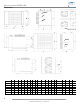
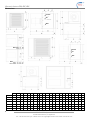
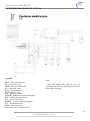
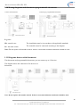
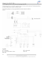
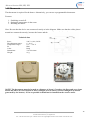
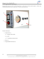
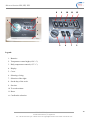
1
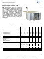
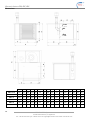
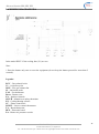
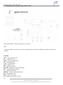
www.ecocaloria.com
INSTALLATION AND OPERATION MANUAL
WARM AIR HEATERS
of EBA, EBC, EBV type
ECO CALORIA Sp. z o.o.
27-200 Starachowice, ul. Zgodna 2
Tel.: +48 41 274 14 41 fax: +48 41 273 71 47 office@ecocaloria.com www.ecocaloria.com
Warm air heaters EBA, EBC, EBV
Contents
FOREWORD
1.1
1.2
1.3
1.4
1.5
1.6
1.7
1.8
1.9
1.10
1.11
1.12
1.13
1.14
1.15
1.16
GENERAL WARNINGS .............................................................................................................................................................. 3
GENERAL FEATURES AND OPERATING MODES ......................................................................................................................... 4
SPECYFICATIONS TYPES EBA 19-86 ........................................................................................................................................ 5
SPECIFICATIONS TYPES EBC 19-86 ......................................................................................................................................... 7
SPECYFICATIONS TYPES EBV 19-86 ........................................................................................................................................ 9
WIRING DIAGRAM EBA .......................................................................................................................................................... 11
WIRING DIAGRAM EBC, EBV 19-50........................................................................................................................................ 12
WIRING DIAGRAM EBC, EBV 86.............................................................................................................................................. 13
WIRING DIAGRAM EBC, EBV 86.............................................................................................................................................. 14
DIAGRAMS HEATERS THERMOSTAT ...................................................................................................................................... 15
DIAGRAMS HEATERS WITH THERMOSTAT ............................................................................................................................. 15
DIAGRAMS HEATER WITH THERMOSTAT PROGRAMMABLE ................................................................................................... 16
THERMOSTAT ....................................................................................................................................................................... 17
THERMOSTAT PROGRAMMABLE ........................................................................................................................................... 18
FUEL TYPES .......................................................................................................................................................................... 19
MOUNTING BRACKETS ......................................................................................................................................................... 20
OPERATION
2.1
2.2
2.3
2.4
2.5
2.6
2.7
NOTICE TO USERS ................................................................................................................................................................... 21
CLEANING ............................................................................................................................................................................. 22
MAINTENANCE ...................................................................................................................................................................... 22
OPERATION: WINTER MODE (HEATING).................................................................................................................................. 22
OPERATION: SUMMER MODE (COOLING) ................................................................................................................................ 22
OFF ........................................................................................................................................................................................ 23
WARNING LED ....................................................................................................................................................................... 24
INSTALATION
3.1 NOTICE TO USERS ............................................................................................................................................................ 25
3.2 INSTALLATION DISTANCES........................................................................................................................................... 26
3.3 MULTIPLE LOCATION IN ONE ROOM HEATERS ........................................................................................................ 27
3.4 MOUNTING BRACKETS ................................................................................................................................................... 28
3.4.1 STANDARD BRACKET FOR 19-50 MODELS HEATERS ............................................................................................... 28
3.4.2 STANDARD BRACKET FOR 64-86 MODELS HEATERS ............................................................................................... 30
3.4.3 BRACKET FOR HEATERS ECB TILT AND EBV MODELS 19-50 ..................................................................................... 33
3.4.4 MOUNT STANDARD FOR HEATERS ECB AND EBV MODELS 64-86 .......................................................................... 35
3.5 AIR SUPPLY CONNECTING AND EXHAUST .................................................................................................................... 39
3.5.1 COAXIAL CONNECTION FOR WALL HEATERS EBA / ECB MODELS 19-32 ............................................................ 39
3.5.2 CONNECTIONS COAXIAL ROOF FOR HEATERS EBA / ECB MODELS 19-32 ........................................................... 40
3.5.3 EXHAUST CONNECTION FOR HEATERS EBA / ECB MODELS 19-32 ........................................................................ 41
3.5.4 COAXIAL CONNECTION FOR WALL HEATERS EBA / ECB MODELS 41-86 ............................................................ 42
3.5.5 CONNECTIONS COAXIAL ROOF FOR HEATERS EBA / ECB MODELS 41-86 ........................................................... 43
3.5.6 EXHAUST CONNECTION FOR HEATERS EBA / ECB MODELS 41-86 ........................................................................ 44
3.5.7 CHANNEL FOR COMBUSTION HEATERS MOUNTED ON THE OUTSIDE................................................................ 45
3.6 ELECTRICAL CONNECTION ........................................................................................................................................... 46
3.7 GAS SYSTEM...................................................................................................................................................................... 46
SERVICE
4.1
4.2
4.3
4.4
2
GENERAL NOTES .............................................................................................................................................................. 47
MAINTENANCE ................................................................................................................................................................. 47
GAS INSTALLATIONS .............................................................................................................................................................. 48
TROUBLESHOOTING ....................................................................................................................................................... 53
ECO CALORIA Sp. z o.o.
27-200 Starachowice, ul. Zgodna 2
Tel.: +48 41 274 14 41 fax: +48 41 273 71 47 office@ecocaloria.com www.ecocaloria.com
Warm air heaters EBA, EBC, EBV
Thank you for choosing a product of ECO CALORIA Sp. z o.o.!!!
We are glad to have you as our customers, we believe that you will be satisfied with the use of our heaters.
Following the manual and caring out of installation and maintenance by qualified staff ensures proper
and safe operation of the device. Not following the manufacturer’s recommendations will void the device’s
warranty.
Foreword
1.1 GENERAL WARNINGS
The manual is a vital, integral part of the product and must be handed over to the user.
Read the warnings contained herein as they provide important information on how to install, use and
maintain the unit safely.
Keep the manual safe for future reference.
The unit must be installed in compliance with the regulations in force, following the Manufacturer’s
instructions, by professionally qualified personnel. By professionally qualified personnel we mean persons
with specific technical competence in working with heat system components and, more specifically,
Servicing Centers authorized by the Manufacturer.
Incorrect installation may result in injury to people and animals and damage to property, for which the
Manufacturer is not responsible.
Once you have removed all packaging, check contents for damage.
If in any doubt, do not use the equipment, and get in touch with the supplier.
Packaging must not be left within reach of children as it is a potential source of danger.
Before commencing cleaning or maintenance work of any kind, wait for the unit to cool down, disconnect it
from the power mains using the system’s master switch and cut off supplies to the unit with the relevant
shutoff devices fitted.
Never obstruct the intake grille protecting the fan or the heater’s outlet for any reason. This can result in
irreparable damage to the unit and endanger people, animals and property.
If the unit breaks down and/or malfunctions, turn it off and refrain from attempting repairs or other work
yourself.
Call in professionally qualified personnel only for the job.
If products need repairing, this must be performed only by a Servicing Center authorized by the
Manufacturer, using Original Spare Parts only.
Failure to comply with the above instructions may compromise the unit’s safety.
It is essential to have professionally qualified personnel carry out periodic maintenance following the
Manufacturer’s instructions if the unit is to work properly and efficiently.
If you decide not to use the unit, all parts that may constitute a potential source of danger must be rendered
harmless.
ECO CALORIA Sp. z o.o.
27-200 Starachowice, ul. Zgodna 2
Tel.: +48 41 274 14 41 fax: +48 41 273 71 47 office@ecocaloria.com www.ecocaloria.com
3
Warm air heaters EBA, EBC, EBV
If the unit is sold or transferred to a new owner, always make sure this manual goes with the unit so that it
can be consulted by the new owner and/or maintenance operative.
When replacing parts on any unit featuring accessories or kits (electrical ones included), use Original
Accessories only.
This unit must be used solely for the purpose for which it was expressly intended.
Note that any other use is improper and hence dangerous.
The Manufacturer is relieved of any contractual or non-contractual liability for damage caused by incorrect
installation or use, or by non-compliance with the instructions issued by the actual Manufacturer.
IMPORTANT NOTE: These units must be installed in rooms with a sufficient supply of air only, except
when they feature a sealed connection. The heater’s proper operation depends on the unit being installed and
put into operation correctly. Failure to comply with these rules shall make the warranty void forthwith and
hence relieve the Manufacturer of any liability. The unit must be installed and maintained in conformity
with the regulations in force and in a thoroughly professional manner.
1.2 General features and operating modes
Seria EB T-series heaters, which can be fuelled with methane gas or LPG (if you choose LPG, this must be
specified when placing the order), meet the heating needs of medium and large industrial and commercial
facilities etc.. They come in three different versions to give the installer a solution to every need:
• EBA types - types suitable for installation inside the environment being heated, for direct air throw.
• EBC types - types suitable for installation inside the environment being heated, for delivery through
ducts and outlets,
• EBV types - for outside use, types suitable for installation outdoors, designed for connection to
delivery ducts and outlets.
A complete set of accessories can be supplied with the unit, making the product functional and flexible and,
at the same time, easy to install.
ECOair heater of EBA, EBC, EBV type is designed so that, in winter mode, its operation is slaved to a
room thermostat or remote control (accessories, not standard issue). When the thermostat is appropriately
set, the flame control device triggers the burner’s ignition after a purge time lasting approx. 10 seconds. The
air pressure switch enables the unit’s switch-on if it finds the air supply for combustion is correct. The flame
detection electrode is responsible for checking whether there is actually a flame or not: if there is no flame,
the unit locks out. If ignition is completed correctly, a green indicator light on the lower part of the heater
comes on. As soon as the exchanger reaches its operating temperature, the fan-thermostat triggers the air
delivery fan’s automatic start, thus initiating the room’s heating. By fitting this thermostat, we have
overcome the possible problem of cold air being sent into the room. Airflow direction can be altered by
adjusting the angle of the horizontal and vertical louvers. Exchanger overheating is prevented by a limit
thermostat, which trips when the preset temperature of 90°C is reached, cutting off the gas valve’s supply.
This results in fuel being cut off to the burner, hence causing the burner to shut down also.
ECOair heater of EBA, EBC, EBV can also work in summer mode, just to cause air to circulate in the
environment being served. This option is activated with the relevant summer-winter selector. When using
programmable thermostat, this selector comes ready fitted. When using the room thermostat, however, you
are required to fit an appropriate additional selector. To operate the unit in ventilation-only mode, you must
leave the room thermostat set to OFF or to the lowest setting and turn the selector to summer
4
ECO CALORIA Sp. z o.o.
27-200 Starachowice, ul. Zgodna 2
Tel.: +48 41 274 14 41 fax: +48 41 273 71 47 office@ecocaloria.com www.ecocaloria.com
Warm air heaters EBA, EBC, EBV
1.3 Specyfications types EBA 19-86
EBA series heaters are suitable for installation inside
the environment being heated. They feature a highcapacity low-noise helical fan. Two rows of adjustable
slats mean direct air throw can be directed to cover an
extensive target area with considerable range.
Model
EBA 19
EBA26
EBA 32
EBA 41
EBA 50
EBA 64
EBA 86
Thermal capacity
kW
21.0
28.0
34.5
45.0
55.0
71.0
95.0
Heat output
kW
18.9
25.2
31.5
40.5
49.5
63.9
85.5
Efficiency
%
90
90
90
90
90
90
90
1
2050
2250
16
1
2900
3250
23
1
4000
4400
26
1
4900
5400
28
1
5800
6400
30
2
8000
8800
35
Number of fans
Air flow rate at 15 °C
Air flow rate at 50 °C
Range
m3/h
m
1
1450
1625
12
Air thermal head
°C
40
36
32
30
30
32
32
Gas flow rate at 15 °C
m3/h
m3/h
kg/h
2.22
2.46
1.64
2.96
3.29
2.18
3.70
4.11
2.73
4.76
5.28
3.51
5.82
6.43
4.30
7.40
8.22
5.46
10.00
11.10
7.40
G 20 20 mbar
G25 mbar
G30/G31 28/37 mbar
Gas intake
Ø
Flue gas exhaust outlet diameter mm
Air inlet diameter
mm
1/2"
80/125
80/125
Power supply
80/125
3/4"
100
130
130
130
100
130
130
130
Single phase 230 V AC IP42
Electric Power
W
300
310
320
350
500
580
750
Weight
Sound pressure level At 6
meters in free field
kg
82
82
90
105
127
145
185
dB (A)
43
46
49
51
52
53
55
ECO CALORIA Sp. z o.o.
27-200 Starachowice, ul. Zgodna 2
Tel.: +48 41 274 14 41 fax: +48 41 273 71 47 office@ecocaloria.com www.ecocaloria.com
5
Warm air heaters EBA, EBC, EBV
Dimensions:
Fumes
Air
For
Gas
For
Fumes
Air
Gas
A
6
B
D
F
G
H
J
K
L
M
N
O
P
Q
R
T
U
V
Z
X
Y
EBA 19
1040 676,5 800 250 40
460
50 50 750
360
233,5 250 193 130
-
300
-
160 235,5 765 39,5
EBA 26
1040 676,5 800 250 40
460
50 50 750
360
233,5 250 193 130
-
300
-
160 235,5 765 39,5
EBA 32
1040 676,5 820 250 40
510
50 50 750
410
233,5 250 193 130
-
325
-
185 235,5 765 39,5
EBA 41
1040 676,5 820 250 40
570
50 50 750
470
233,5 250 193 130
0
230 140 200 235,5 765 39,5
EBA 50
1040 676,5 840 250 40
700
50 50 750
600
233,5 250 193 130
0
295 140 405 235,5 765 39,5
EBA 64
1120 676,5 840 330 40
825
50 50 750
725
233,5 250 193 135 58 240 217 365 315,5 765 39,5
EBA 86
1120 676,5 840 330 40 1120 50 50 750 1020 233,5 250 193 107 77 434 211 430 315,5 765 39,5
ECO CALORIA Sp. z o.o.
27-200 Starachowice, ul. Zgodna 2
Tel.: +48 41 274 14 41 fax: +48 41 273 71 47 office@ecocaloria.com www.ecocaloria.com
Warm air heaters EBA, EBC, EBV
1.4 Specifications types EBC 19-86
EBC series heaters are suitable for installation indoors.
They feature a high-capacity low-noise dual-intake
centrifugal fan. This heater has a flange coupling for
straightforward connection to a ducted delivery system.
That way, air can be conveyed to where it is actually
needed inside the environment served. A fan casing with
return air intake grille is standard issue.
Model
Thermal capacity
Heat output
Efficiency
Number of fans
kW
kW
%
Air flow rate at 15 °C
Air flow rate at 50 °C
m3/h
Range
EBC 19 EBC 26 EBC 32 EBC 41 EBC 50 EBC 64 EBC 86
21.0
28.0
34.5
45.0
55.0
71.0
95.0
18.9
25.2
31.5
40.5
49.5
63.9
85.5
90
90
90
90
90
90
90
1
1
1
1
1
1
2
1450
1625
2050
2250
2900
3250
4000
4400
4900
5400
5800
6400
8000
8800
m
12
16
23
26
28
30
35
Air thermal head
°C
40
36
32
30
30
32
32
Gas flow rate at 15 °C
m3/h
m3/h
kg/h
2.22
2.46
1.64
2.96
3.29
2.18
3.70
4.11
2.73
4.76
5.28
3.51
5.82
6.43
4.30
7.40
8.22
5.46
10.00
11.10
7.40
G 20 20 mbar
G25 mbar
G30/G31 28/37 mbar
Gas intake
Ø
Flue gas exhaust outlet diameter
Air inlet diameter
Power supply
Electric Power
Weight
Sound pressure level At 6 meters in free field
mm
mm
W
kg
dB (A)
1/2"
80/125
80/125
600
97
43
600
97
46
100
130
100
130
Single phase 230 V AC IP42
750
1100
1470
105
120
147
49
51
52
80/125
ECO CALORIA Sp. z o.o.
27-200 Starachowice, ul. Zgodna 2
Tel.: +48 41 274 14 41 fax: +48 41 273 71 47 office@ecocaloria.com www.ecocaloria.com
3/4"
130
130
130
130
2200
170
53
2200
215
55
7
Warm air heaters EBA, EBC, EBV
Dimensions:
Fumes
Air
Gas
For
Fumes
Air
Gas
For
8
A
B
D
E
F
G
H
J
K
L
M
N
O
P
Q
R
T
U
V
Z
X
Y
EBC 19
1040
EBC 26
1040
676
449
1125
250
40
460
50
50
750
360
233
250
193
130
-
300
-
160
235
765
39,5
676
449
1125
250
40
460
50
50
750
360
233
250
193
130
-
300
-
160
235
765
39,5
EBC 32
1040
676
499
1275
250
40
510
50
50
750
410
233
250
193
130
-
325
-
185
235
765
39,5
EBC 41
1040
676
599
1275
250
40
570
50
50
750
470
233
250
193
130
0
230
140
200
235
765
39,5
EBC 50
1040
676
599
1275
250
40
700
50
50
750
600
233
250
193
130
0
295
140
405
235
765
39,5
EBC 64
1120
676
599
1275
330
40
825
50
50
750
725
233
250
193
135
58
240
217
365
315
765
39,5
EBC 86
1120
676
599
1275
330
40
1120
50
50
750
1020
233
250
193
107
77
434
211
430
315
765
39,5
ECO CALORIA Sp. z o.o.
27-200 Starachowice, ul. Zgodna 2
Tel.: +48 41 274 14 41 fax: +48 41 273 71 47 office@ecocaloria.com www.ecocaloria.com
Warm air heaters EBA, EBC, EBV
1.5 Specyfications types EBV 19-86
EBV series heaters for outside use are suitable for
installation outdoors. Standard-issue models come
with a rainshield and sealed intake/exhaust kit and
feature a high-capacity low-noise dual-intake
centrifugal fan. This heater has a flange coupling for
straightforward connection to a ducted delivery
system, essential for passing through the outside wall
of the room heated. That way, air can be conveyed to
where it is actually needed inside the environment
served. A fan casing with return air intake grille is
standard issue.
Dane techniczne:
Model
Thermal capacity
Heat output
Efficiency
Number of fans
kW
kW
%
Air flow rate at 15 °C
Air flow rate at 50 °C
m3/h
Range
EBV 19 EBV 26 EBV 32 EBV 41 EBV 50 EBV 64 EBV 86
21.0
28.0
34.5
45.0
55.0
71.0
95.0
18.9
25.2
31.5
40.5
49.5
63.9
85.5
90
90
90
90
90
90
90
1
1
1
1
1
1
2
1450
1625
2050
2250
2900
3250
4000
4400
4900
5400
5800
6400
8000
8800
m
12
16
23
26
28
30
35
Air thermal head
°C
40
36
32
30
30
32
32
Gas flow rate at 15 °C
m3/h
m3/h
kg/h
2.22
2.46
1.64
2.96
3.29
2.18
3.70
4.11
2.73
4.76
5.28
3.51
5.82
6.43
4.30
7.40
8.22
5.46
10.00
11.10
7.40
G 20 20 mbar
G25 mbar
G30/G31 28/37 mbar
Gas intake
Ø
Flue gas exhaust outlet diameter
Air inlet diameter
Power supply
Electric Power
Weight
Sound pressure level At 6 meters in free field
mm
mm
W
kg
dB (A)
1/2"
80/125
80/125
600
97
43
600
97
46
100
130
100
130
Jedna faza 230 V AC IP42
750
1100
1470
105
120
147
49
51
52
80/125
ECO CALORIA Sp. z o.o.
27-200 Starachowice, ul. Zgodna 2
Tel.: +48 41 274 14 41 fax: +48 41 273 71 47 office@ecocaloria.com www.ecocaloria.com
3/4"
130
130
130
130
2200
170
53
2200
215
55
9
Warm air heaters EBA, EBC, EBV
Dimensions:
Fumes
Air
Gas
10
A
B
D
F
G
H
J
K
L
M
N
O
P
Z
EBV 19-26
1040
676
800
250
40
500
50
100
750
360
233
250
193
235
765 39.5
EBV 32
1040
676
820
250
40
550
50
100
750
410
233
250
193
235
765 39.5
EBV 41
1040
676
820
250
40
610
50
100
750
470
233
250
193
235
765 39.5
EBV 50
1040
676
840
250
40
740
50
100
750
600
233
250
193
235
765 39.5
EBV 64
1120
676
840
330
40
865
50
100
750
725
233
250
193
315
765 39.5
EBV 86
1120
676
840
330
40
1170
50
100
750
1020
233
250
193
315
765 39.5
ECO CALORIA Sp. z o.o.
27-200 Starachowice, ul. Zgodna 2
Tel.: +48 41 274 14 41 fax: +48 41 273 71 47 office@ecocaloria.com www.ecocaloria.com
X
Y
Warm air heaters EBA, EBC, EBV
1.6 WIRING DIAGRAM EBA
In the model IHP T 95 the cooling fans (V1) are two.
Note:
1 Press the button only once to reset the equipment (do not keep the button pressed for more than 5
seconds).
Legenda:
EGV – Gas solenoid valve
V1 – Air delivery fan
MVE – Flue gas exhaust fan
SI – Ionization probe
FAN – Fan thermostat
Reset – Burner reset
EA – Ignition electrode
SICUR – Manual reset safety thermistat
E/I – Cooling/heating selector
CC – Flame control unit
LIMIT – Limit or control thermostat
TA – Room thermostat
RFP – Electronic board
PA – Burner air pressuere-switch
ECO CALORIA Sp. z o.o.
27-200 Starachowice, ul. Zgodna 2
Tel.: +48 41 274 14 41 fax: +48 41 273 71 47 office@ecocaloria.com www.ecocaloria.com
11
Warm air heaters EBA, EBC, EBV
1.7 WIRING DIAGRAM EBC, EBV 19-50
In the model IHP T 95 the cooling fans (V1) are two.
Note:
1 Press the button only once to reset the equipment (do not keep the button pressed for more than 5
seconds).
Legenda:
EGV – Gas solenoid valve
V1 – Air delivery fan
MVE – Flue gas exhaust fan
SI – Ionization probe
FAN – Fan thermostat
Reset – Burner reset
EA – Ignition electrode
SICUR – Manual reset safety thermistat
E/I – Cooling/heating selector
CC – Flame control unit
LIMIT – Limit or control thermostat
TA – Room thermostat
RFP – Electronic board
PA – Burner air pressuere-switch
12
ECO CALORIA Sp. z o.o.
27-200 Starachowice, ul. Zgodna 2
Tel.: +48 41 274 14 41 fax: +48 41 273 71 47 office@ecocaloria.com www.ecocaloria.com
Warm air heaters EBA, EBC, EBV
1.8 WIRING DIAGRAM EBC, EBV 64
Legenda:
Note:
EGV – Gas solenoid valve
V1 – Air delivery fan
MVE – Flue gas exhaust fan
SI – Ionization probe
FAN – Fan thermostat
Reset – Burner reset
EA – Ignition electrode
SICUR – Manual reset safety thermistat
E/I – Cooling/heating selector
CC – Flame control unit
LIMIT – Limit or control thermostat
TA – Room thermostat
RFP – Electronic board
PA – Burner air pressuere-switch
1 Press the button only once to reset the
equipment (do not keep the button pressed for
more than 5 seconds).
ECO CALORIA Sp. z o.o.
27-200 Starachowice, ul. Zgodna 2
Tel.: +48 41 274 14 41 fax: +48 41 273 71 47 office@ecocaloria.com www.ecocaloria.com
13
Warm air heaters EBA, EBC, EBV
1.9 WIRING DIAGRAM EBC, EBV 86
Legenda:
Note:
EGV – Gas solenoid valve
V1 – Air delivery fan
MVE – Flue gas exhaust fan
SI – Ionization probe
FAN – Fan thermostat
Reset – Burner reset
EA – Ignition electrode
SICUR – Manual reset safety thermistat
E/I – Cooling/heating selector
CC – Flame control unit
LIMIT – Limit or control thermostat
TA – Room thermostat
RFP – Electronic board
PA – Burner air pressuere-switch
1 Press the button only once to reset the
equipment (do not keep the button pressed for
more than 5 seconds).
14
ECO CALORIA Sp. z o.o.
27-200 Starachowice, ul. Zgodna 2
Tel.: +48 41 274 14 41 fax: +48 41 273 71 47 office@ecocaloria.com www.ecocaloria.com
Warm air heaters EBA, EBC, EBV
1.10 Wiring diagrams and thermostat programmable thermostat
Connect the thermostat:
Connecting a programmable thermostat:
Legenda:
SD - transfer case
The installation must be in accordance with applicable standards.
IG - the main switch
The controller must be connected according to the diagram.
Note: Do not replace with another neutral. If there is no neutral isolation transformer should be used.
1.11 Diagrams heaters with thermostat
The thermostat and programmable thermostat, you can connect up to 12 devices.
The diagram shows the connection of 4 devices to a
thermostat:
Note: Do not replace with another neutral. If there is no neutral isolation transformer should be used.
ECO CALORIA Sp. z o.o.
27-200 Starachowice, ul. Zgodna 2
Tel.: +48 41 274 14 41 fax: +48 41 273 71 47 office@ecocaloria.com www.ecocaloria.com
15
Warm air heaters EBA, EBC, EBV
1.12 Diagrams heater with thermostat programmable
The thermostat allows to control the operation of up to 12 devices at the same time. The thermostat allows
the heater funkncjowanie summer ventilation mode.
The following diagram sets the programmable thermostat connection with four
heaters:
Legenda:
T1 – thermostat
S1 – mode switch summer / winter
SB –lamp
16
IG – main switch
R1– reset
ECO CALORIA Sp. z o.o.
27-200 Starachowice, ul. Zgodna 2
Tel.: +48 41 274 14 41 fax: +48 41 273 71 47 office@ecocaloria.com www.ecocaloria.com
Warm air heaters EBA, EBC, EBV
1.13 Thermostat
The thermostat is required for the heater. Alternatively, you can use a programmable thermostat.
Features:
1. Switching on and off.
2. Setting the temperature in the room.
3. Resetting the heater.
Note: Be sure that the device was connected exactly as in the diagram. Make sure that the cables phase /
neutral are connected correctly, because the heater and the controller may be damaged.
Technical data
Powe:
The adjustment range:
Temperature range:
IP:
Color:
Dimensions:
Weight:
230 V ± 10%, 50 Hz
6 - 30 °C
0 °C - + 50 °C
IP20
Biały
75x75x34 mm
95 g
NOTE! The thermostat must be located at a distance of about 1.5 m above the floor and away from
drafts and where it is not exposed to direct sunlight or heat sources (such as sunlight or warm air
generated by the heaters). As far as possible it should not be installed on the exterior walls.
ECO CALORIA Sp. z o.o.
27-200 Starachowice, ul. Zgodna 2
Tel.: +48 41 274 14 41 fax: +48 41 273 71 47 office@ecocaloria.com www.ecocaloria.com
17
Warm air heaters EBA, EBC, EBV
1.14 Programmable thermostat
Programmable thermostat has the following features: weekly timer, selector switch summer / winter reset.
The thermostat allows you to control up to 12 devices at the same time.
(1)
(2)
(3)
Features thermostat::
• Switch I/0/II (1)
a) I: heating (winter mode)
b) 0: OFF
c) II: Ventilation (summer mode)
• Reset (2)
• Programmable thermostat (3)
18
ECO CALORIA Sp. z o.o.
27-200 Starachowice, ul. Zgodna 2
Tel.: +48 41 274 14 41 fax: +48 41 273 71 47 office@ecocaloria.com www.ecocaloria.com
Warm air heaters EBA, EBC, EBV
8
9
10
11
12
7
2
1
4
2
3
5
3
6
Legend:
1. Batteries.
2. Temperature control night (6-20 ° C).
3. Daily temperature control (6-35 ° C).
4. Display.
5. Cover.
6. Selecting a living.
7. Selection of the night.
8. Set the day of the week.
9. Set time.
10. To set the minute.
11. Reset.
12. Confirm the selection.
ECO CALORIA Sp. z o.o.
27-200 Starachowice, ul. Zgodna 2
Tel.: +48 41 274 14 41 fax: +48 41 273 71 47 office@ecocaloria.com www.ecocaloria.com
19
Warm air heaters EBA, EBC, EBV
ECO CALORIA Sp. z o.o.
ul. Zgodna 2
27-200 STARACHOWICE
tel.: +48 41 274 14 41, fax.: +48 41 273 71 47
www.ecocaloria.com
office@ecocaloria.com
20
ECO CALORIA Sp. z o.o.
27-200 Starachowice, ul. Zgodna 2
Tel.: +48 41 274 14 41 fax: +48 41 273 71 47 office@ecocaloria.com www.ecocaloria.com