1
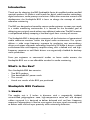
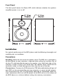
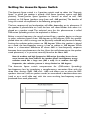
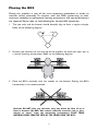
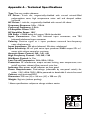
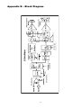
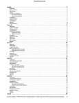
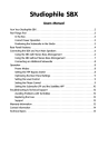
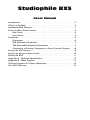
Studiophile BX5
Users Manual
Introduction . . . . . . . . . . . . . . . . . . . . . . . . . . . . . . . . . . . . . . . . . . . . .2
What’s in the Box? . . . . . . . . . . . . . . . . . . . . . . . . . . . . . . . . . . . . . . . .2
Studiophile BX5 Features . . . . . . . . . . . . . . . . . . . . . . . . . . . . . . . . . . .2
Front and Rear Panel Features . . . . . . . . . . . . . . . . . . . . . . . . . . . . . . .4
Rear Panel . . . . . . . . . . . . . . . . . . . . . . . . . . . . . . . . . . . . . . . . . . .4
Front Panel . . . . . . . . . . . . . . . . . . . . . . . . . . . . . . . . . . . . . . . . . .6
Installation . . . . . . . . . . . . . . . . . . . . . . . . . . . . . . . . . . . . . . . . . . . . . .6
Precautions . . . . . . . . . . . . . . . . . . . . . . . . . . . . . . . . . . . . . . . . . .6
XLR Balanced Connection . . . . . . . . . . . . . . . . . . . . . . . . . . . . . . .7
TRS Balanced/Unbalanced Connection . . . . . . . . . . . . . . . . . . . . .7
Connecting to Preamp, Computer or Game Console Outputs . . .8
Setting the EQ Switches . . . . . . . . . . . . . . . . . . . . . . . . . . . . . . . . . . . .8
Setting the Acoustic Space Switch . . . . . . . . . . . . . . . . . . . . . . . . . . . .10
Placing the BX5 . . . . . . . . . . . . . . . . . . . . . . . . . . . . . . . . . . . . . . . . .11
Appendix A - Technical Specifications . . . . . . . . . . . . . . . . . . . . . . . . .12
Appendix B - Block Diagram . . . . . . . . . . . . . . . . . . . . . . . . . . . . . . .13
Technical Support & Contact Information . . . . . . . . . . . . . . . . . . . . . .14
Your BX5 Warranty . . . . . . . . . . . . . . . . . . . . . . . . . . . . . . . . . . . . . .15
Introduction
Thank you for choosing the BX5 Studiophile Series bi-amplified studio nearfield
monitor speakers. M-Audio is well known for digital audio interface technology,
digital converters, audio preamps and mixers. Now, after extensive research and
development, the Studiophile BX5 is born to change the concept of studio
reference monitoring.
The BX5 was designed and tested by veteran audio engineers to meet your needs
in a studio monitoring environment. It is focused on the functional goal of
delivering pure, original sound without any additional coloration.The BX5 monitor
is self-powered, directly accepting a line level signal from a variety of sources.
The Studiophile BX5 is designed to overcome all the limitations of conventional
studio reference monitors within the digital audio environment. This system
delivers a wide range frequency response by employing two extraordinary
drivers and unique crossover technology licensed by M-Audio. It boasts a stable
and balanced low-mid frequency response along with a defined mid- and highfrequency response as well. Both drivers are magnetically shielded for desktop
music production.
From pro engineers at commercial studios to home studio owners, the
Studiophile BX5 sets a new affordable standard in studio monitoring.
What’s in the Box?
Your Studiophile BX5 box contains:
•
•
•
•
Two BX5 speakers
Two detachable AC power cords
This manual
Actual test results of the BX5 you purchased
Studiophile BX5 Features
1. Woofer
The woofer unit is 5 inches in diameter with a magnetically shielded
mineral-filled polypropylene cone, high-temperature voice coil and damped
rubber surround. It is designed to deliver balanced mid- and low- frequency
response. Polypropylene is used to react against the input signals accurately and
to deliver even minimal input precisely while minimizing distortion.
2
2. Tweeter
By employing a specially developed 1-inch silk dome with magnetic shielding, the
tweeter can deliver distortion-free original sound and offer extremely natural
response. It minimizes reaction time by using fabric silk for excellent delivery,
and also minimizes resonance by adapting a unique internal damping technology.
3. Sub-Frequency Port
The hole in the rear panel is called a Sub-Frequency Port and is designed to
discharge extreme low frequencies under 60 Hz.
4. EQ and Acoustic Space Controls
Back panel controls on the BX5s give you compensation for room EQs as well
as compensation for the positioning of the speakers within your room. High
frequency cuts, mid-range boost, and low frequency cutoffs offer a great deal of
control over the sound and presence of the BX5s, while the “Acoustic Space”
settings account for a variety of speaker placements.
5. Enclosure
Just as other components do, the BX5’s enclosure has an important role. In
order to provide more stable performance, the BX5’s enclosure employs a
special high-density MDF and unique interior reinforcement designed to absorb
vibration and impact generated under extreme conditions.
6. Network & Power Amplifiers
The active crossover networks & power amplifiers for the BX5 are specially
designed for this woofer and tweeter.The network properly distributes low, mid,
and high frequencies to the components in order to reduce distortion and loss
of sound, thus achieving a naturally balanced sound.
In order to generate powerful, ultra-crisp sound, there are two separate power
amplifiers inside the BX5 to drive the woofer and tweeter separately in a highend bi-amp structure. The power delivered to the woofer driver at a rated
distortion is 38W, and 38W is also delivered to the tweeter.
3
Front and Rear Panel Features
Rear Panel
1. XLR INPUT: This jack accepts XLR input connections with either balanced or
unbalanced wiring. The input wiring of an XLR connector should be as follows:
XLR PIN 1
XLR PIN 2
XLR PIN 3
Signal ground (Shield)
Signal positive (+)
Signal negative (–)
2. TRS INPUT: This jack accepts 1/4” connections with either balanced or
unbalanced wiring. For balanced wiring, a three-conductor TRS plug is necessary.
The input wiring of a TRS connector should be as follows:
TRS TIP
TRS RING
TRS SLEEVE
Signal positive (+)
Signal negative (–)
Signal ground (Shield)
Unbalanced 1/4” wiring can be done with either a two- or three-conductor (TS
or TRS) plug. A two-conductor (TS) plug automatically grounds the signal
negative input, whereas a three-conductor (TRS) plug, wired unbalanced,
provides the option of leaving the negative input open or grounded. We
recommend that you ground the unused negative input (this can be done by
wiring the ring and sleeve of the TRS plug together).
4
The TRS input is summed through a balanced input amplifier with the XLR input,
allowing both inputs to be used simultaneously. Input specifications apply to
both.
3. PRODUCT LABEL: This label contains the model and serial number information.
4. VENT PORT: This port aids in reproduction of very low frequencies by
discharging frequencies below 60 Hz.
5. VOLUME CONTROL: Use the volume control to set the output sound pressure
from the BX5 to proper levels as required.
6. LOW CUTOFF: This 3-position switch sets the bass rolloff frequency.The lowest
setting, 56Hz, is essentially a low cutoff bypass as it does not attenuate the BX5’s
frequency response. Other settings are 80Hz and 100Hz.
7. MID-BOOST: Two selections are available, “In” and “Out.” The Out setting
produces a flat frequency response curve, while the In setting gives a boost in
the mid-range frequencies.
8. HIGH FREQ: Three settings are possible, -2dB, 0dB, and +2dB. 0dB is a “flat”
setting with no attenuation, while the -2dB and +2dB settings will attenuate or
boost the high frequencies (3kHz shelf) by -2dB and +2dB respectively.
9. ACOUSTIC SPACE: This 3-position switch is designed to compensate for
different speaker placements. Please see the section “Setting the Acoustic Space
Switch” for more information.
10. POWER SWITCH:This switch turns the monitor on and off.The on position is
indicated with the marking “.” (a white dot).
11. POWER RECEPTACLE: Accepts a detachable 3-circuit line cord in order to
power the monitor.
12. FUSE HOLDER: Holds the external main fuse.
13. VOLTAGE-SELECT SWITCH: Provides 2 selections, 115VAC and 230VAC, and
should be set to match the “house supply” (receptacle) voltage of the country
or location in which the speaker is used.The 115V setting is correct for the USA,
while the 230V setting is correct for most of the UK and Europe.
5
Front Panel
The front panel houses the Power LED, which indicates whether the speakers
(amplifier) power is on or off.
Installation
For optimal performance of the BX5, please read the following thoroughly and
carefully prior to installation.
Precautions
Handling: Please do not touch the speaker cones.The BX5 set is packaged in
the box tightly, so your attention is required when taking the monitors out of
the box. To avoid possible damage to the speaker units, hold both sides of the
monitor in order to pull it out of the box. The speaker cones should not be
touched in order to avoid damage even after they are out of the box.
Connections: Connect the XLR balanced or TRS balanced/unbalanced input of
each BX5 to the corresponding pre-amp, computer or game console outputs.
We recommend that you use high-quality balanced or unbalanced cables for
input connections. Also, turn off the power of the BX5 and turn the volume of
the BX5 down to a minimum before making the necessary connections.
6
Correct Power Operation: Since the BX5 contains its own amplifier, it must
be connected to a power outlet using the detachable AC cable provided. Before
connecting power, please make sure that the Voltage-Select Switch located on
the speaker’s rear panel is set to the appropriate position, as described in the
rear-panel features list appearing earlier in this manual.
WARNING! - Use of improper Voltage-Select Switch combinations may result
in hazardous conditions and/or damage to speaker components not
covered by speaker warranty.
XLR Balanced Connection
Assure that the power switch of the BX5 is turned off and that the volume
control of the BX5 is turned down to a minimum. Connect the male end of an
XLR balanced cable to the balanced input of the BX5 (refer to the following
diagram for balanced connection).
TRS Balanced/Unbalanced Connection
Assure that the power switch of the BX5 is turned to Off and that the volume
control of the BX5 is turned down to a minimum. Connect the male end of a
TRS balanced or TS unbalanced cable to the TRS input of the BX5 (refer to the
following diagram for TRS connection).
7
Connecting to Preamp, Computer or Game Console Outputs
Before connecting, make sure the output device’s power has been turned off.
Plug the XLR balanced, TRS balanced or TS unbalanced cable to the
corresponding output connectors of a pre-amplifier, computer or game console.
Setting the EQ Switches
Low Cutoff: This 3-position switch sets the Low Cutoff frequency, selecting
between 56Hz, 80Hz and 100Hz. Use the 100Hz setting to emulate a small
speaker setup, the 80Hz setting for Normal Low Frequency performance, or the
56Hz for Normal Extended Low Frequency performance.The 80Hz and 100Hz
settings can also be used in conjunction with a subwoofer, when the subwoofer
is set up to receive the low-frequency material below 80Hz and 100Hz
(respectively).
8
Mid-Boost:This 2-position switch selects between the “In” and “Out” Mid-Boost
modes.The Out mode produces a flat midrange response for normal monitoring
conditions, while In will move the sound stage forward toward your listening
position.
'Mid-Boost In'
High-Freq:This 3-position switch selects High Frequency compensation with -2dB,
0dB or +2dB.The 0dB (normal) position produces flat response for use in most
common applications. Use -2dB if your mixes translate as dull or lacking in high
frequencies (lowering the high-frequency response will inspire the mix engineer to
add more highs). Use the +2dB setting for brighter-sounding audio playback, or to
compensate for mixes that translate as too bright.
9
Setting the Acoustic Space Switch
The Acoustic Space switch is a 3-position switch used to select the "Acoustic
Space" in which the speaker is placed—Half Space (speakers against wall, 0dB
position), Three-Quarter Space (speakers in corners or close to wall, -2dB
position), or Full Space (speakers away from wall, -4dB position). The benefits of
using this switch are explained in the following paragraphs.
The bass response of any loudspeaker will differ depending on its placement. If
the speaker is placed close to a wall, the bass will sound louder than when it is
placed on a speaker stand. The technical term for this phenomenon is called
Diffraction Spreading and can be explained as follows:
Below a certain frequency, the sound emitted from a speaker begins to change
its polar radiation pattern, from 180 degrees to 360 degrees.With the speaker
placed close to a wall, its energy can be physically radiated only forward, thereby
limiting the radiation polar pattern to 180 degrees.When the speaker is placed
on a stand, the low-frequency energy is free to radiate in 360 degrees. While
there is a theoretical difference of about 6dB in low-frequency response
between these two placements, the loss (from the wall placement to the speaker
stand placement) is, in practice, normally found to be about 4dB.
Note: At medium and high frequencies, Diffraction Spreading losses do not
occur because the front baffle of the speaker affects low-frequency energy
radiation much like a large area (like a wall). So at medium and high
frequencies, the radiation pattern is always limited to 180 degrees.
The Acoustic Space switch compensates for (Diffraction Spreading)
low-frequency loss by introducing a complimentary correction filter with the
three filter settings (0dB, -2dB and - 4dB) and allows you to place the BX5
speakers close to a wall, on speaker stands, or somewhere in between these two
(such as on a small table top) with the same resulting low-frequency output
produced from each placement.
10
Placing the BX5
Placing the speakers is one of the most important procedures in order to
monitor sound accurately. To monitor with the BX5s performing to their
maximum capability, an appropriate listening environment and correct placement
are required. Please refer to the following for correct BX5 placement.
1. The two units and the listener should basically align to form a regular triangle.
Refer to the following diagram.
2. Position the monitors so that the top of the woofers are level with your ears in
a normal listening environment. Refer to the following diagram.
3. Place the BX5s vertically with the woofer on the bottom. Placing the BX5s
horizontally is not recommended.
Remarks: DO NOT place any obstacles that may block the flow of air in
front or between the BX5s. Also remove reflective materials such as glass,
mirrors or metal from the monitoring environment. PLACE THOSE
MATERIALS AWAY FROM THE PATH OF THE SOUND FROM THE BX5s.
11
Appendix A - Technical Specifications
Type: Two-way studio reference
LF Driver: 5-inch dia., magnetically-shielded with curved mineral-filled
polypropylene cone, high temperature voice coil and damped rubber
surround
HF Driver: 1-inch dia., magnetically-shielded with natural silk dome
Frequency Response: 56Hz - 20kHz
Crossover Frequency: 3.0kHz
LF Amplifier Power: 38W
HF Amplifier Power: 38W
S/N Ratio: >100dB below full output, 20kHz bandwidth
Input Connectors: One XLR balanced input connector; one TRS
balanced/unbalanced input connector
Polarity: Positive signal at + input produces outward low-frequency
cone displacement
Input Impedance: 20k ohms balanced, 10k ohms unbalanced
Input Sensitivity: 85 mV pink noise input produces 90dBA output SPL at 1
meter with volume control at maximum
Acoustic Space Control: 0dB, -2dB, -4dB
High Frequency Control: -2dB, 0dB, +2dB
Mid-Boost Control: In, Out
Low Cut-off Frequencies: 56Hz, 80Hz, 100Hz
Protection: RF interference, output current limiting, over temperature, turn
on/off transient, subsonic filter, external main fuse
Indicator: Blue power on/off indicator on front panel
Power Requirements: Dual-voltage (selectable by rear-panel switch) for
either 115V/~60Hz, 230V/~50Hz; powered via detachable 3-circuit line cord
Cabinet: vinyl-laminated MDF
Dimension: 250 mm (H) x 166 mm (W) x 200 mm (D)
Weight: 5kg/unit (without packing)
* Above specifications subject to change without notice
Tested to
comply
with FCC
Standards
For Home or Studio Use
12
Mid-Freq.
Switch
High-Freq. Switch
BX5
Low Cutoff Switch
56Hz / 80Hz / 100hz
L
13
3.0
Filter
3.0
Filter
38
38
Appendix B - Block Diagram
Technical Support & Contact Information
For additonal help, contact M-Audio Technical Support by telephone
(626-445-7556, 9-5 PST M-F), by fax (626-445-8407) or by e-mail
(techsupt@m-audio.com).
If you have any questions, comments or suggestions about this or any M-Audio
product, we invite you to contact us directly at:
M-AUDIO U.S.
45 E. Saint Joseph St.
Arcadia, CA 91006-2861
U.S.A.
Sales Information:
Sales Information (email):
Tech Support:
Tech Support (email):
Fax:
Internet Home Page:
626-445-2842
info@m-audio.com
626-445-8495
techsupt@m-audio.com
626-445-7564
http://www.m-audio.com
M-AUDIO U.K.
Unit 5, Saracen Industrial Park
Mark Rd.
Hemel Hempstead, Herts HP2 7BJ
England
Sales Information:
Sales Information (email):
Technical Support:
Technical Support (email):
Fax:
Internet Home Page:
44 (0) 144 241 6590
info@maudio.co.uk
44 (0) 871 717 7102
richard@maudio.freeserve.co.uk
44 (0) 144 224 6832
http://www.maudio.co.uk
M-AUDIO Deutschland (Germany)
Kuhallmand 34
D-74613 Ohringen
Germany
Sales Information:
Sales Information (email):
Technical Support:
Technical Support (email):
Fax:
Internet Home Page:
49 7941 98 7000
info@m-audio.de
49 7941 98 70030
support@m-audio.de
07941 98 70070
http://www.m-audio.de
M-AUDIO Canada
1400 St. Jean-Baptiste Ave., #150
Quebec City, QC G2E 5B7
Canada
Tel:
Fax:
Email:
Internet Home Page:
418-872-0444
418-872-0034
midimancanada@m-audio.com
http://www.m-audio.ca
M-AUDIO Japan
Annex Building 6F
2-18-10 Marunouchi
Naka-Ku, Nagoya 460-0002
JAPAN
Tel:
Fax:
Email:
Internet Home Page:
81 52 218 3375
81 52 218 0875
info@m-audio.co.jp
http://www.m-audio.co.jp
14
Your BX5 Warranty
M-AUDIO warrants that this product is free of defects in materials and
workmanship under normal use for a period of One (1) year from purchase
date, so long as the product is: owned by the original purchaser; the original
purchaser has proof of purchase from an authorized M-AUDIO dealer; and the
purchaser has registered his/her ownership of the product by sending in the
completed warranty card.
This warranty explicitly excludes any included external non-integrated power
supplies and cables which may become defective as a result of normal wear and tear.
In the event that M-AUDIO receives written notice of defects in materials or
workmanship from such an original purchaser, M-AUDIO will either replace the
product, repair the product, or refund the purchase price at its option. In the
event any repair is required, shipment to and from M-AUDIO and a nominal
handling charge shall be borne by the purchaser. In the event that repair is
required, a Return Authorization number must be obtained from M-AUDIO.
After this number is obtained, the unit should be shipped back to M-AUDIO in
a protective package with a description of the problem and the Return
Authorization clearly written on the package.
In the event that M-AUDIO determines that the product requires repair
because of user misuse or regular wear, it will assess a fair repair or replacement
fee. The customer will have the option to pay this fee and have the unit repaired
and returned, or not pay this fee and have the unit returned unrepaired.
The remedy for breach of this limited warranty shall not include any other
damages. M-AUDIO will not be liable for consequential, special, indirect, or
similar damages or claims including loss of profit or any other commercial
damage, even if its agents have been advised of the possibility of such damages,
and in no event will M-AUDIO's liability for any damages to the purchaser or
any other person exceed the price paid for the product, regardless of any form
of the claim. M-AUDIO specifically disclaims all other warranties, expressed or
implied. Specifically, M-AUDIO makes no warranty that the product is fit for any
particular purpose.
This warranty shall be construed, interpreted, and governed by the laws of the
state of California. If any provision of this warranty is found void, invalid or
unenforceable, it will not affect the validity of the balance of the warranty, which
shall remain valid and enforceable according to its terms. In the event any
remedy hereunder is determined to have failed of its essential purpose, all
limitations of liability and exclusion of damages set forth herein shall remain in
full force and effect.
15
Notes:
BX5-111402
16