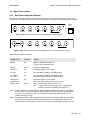
1
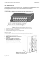
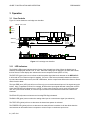
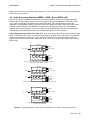
GUIDE TO INSTALLATION AND OPERATION
PRELIMINARY
Safety Compliance Information
Safety Compliance
This equipment complies with:
-
CSA C22.2 No. 60950-1-03 / Safety of Information Technology Equipment, Including Electrical Business Equipment.
st
UL 60950-1 (1 Edition) / Safety of Information Technology Equipment, Including Electrical Business Equipment.
st
IEC 60950-1 (1 Edition) Incorporating A1, A2, A3, A4, and A11/ Safety of Information Technology Equipment,
Including Electrical Business Equipment.
CAUTION
These servicing instructions are for use by qualified service personnel only. To reduce the risk of electric shock, do not
perform any servicing other than that contained in the operating instructions unless you are qualified to do so. Refer all
servicing to qualified service personnel. Servicing should be done in a static-free environment.
Electromagnetic Compatibility
-
This equipment has been tested for verification of compliance with FCC Part 15, Subpart B, class A requirements for
Digital Devices.
This equipment complies with the requirements of:
EN 55022 Class A, Electromagnetic Emissions,
EN 61000-3-2 & -3-3, Disturbance in Supply Systems
EN 61000-4-2, -3, -4, -5, -6, -8 & -11 Electromagnetic Immunity
CONTACT MIRANDA
For technical assistance, please contact the Miranda Technical support centre nearest you:
Americas
Telephone:
+1-800-224-7882
e-mail:
techsupp@miranda.com
Asia
Telephone:
+81-3-5730-2987
e-mail:
asiatech@miranda.com
Visit our web site at www.miranda.com
i
| UVP-101i
Europe, Middle East,
Africa, UK
Telephone:
+44 (0) 1491 820222
e-mail:
eurotech@miranda.com
France (only)
Telephone:
+33 (0) 1 55 86 87 88
e-mail:
francetech@miranda.com
PRELIMINARY
GUIDE TO INSTALLATION AND OPERATION
Table of Contents
1 UVP-101i Universal Video Processor/Synchronizer................................................... 1
1.1 Introduction ...............................................................................................................................................1
1.2 Features ...................................................................................................................................................1
2 Installation ..................................................................................................................... 2
2.1 Unpacking.................................................................................................................................................2
2.2 UVP-101i Mechanical Installation.............................................................................................................2
2.2.1 Quartet-M Frame ...............................................................................................................................2
2.2.2 Symphonie Frame..............................................................................................................................2
2.2.3 Rear Panel Label ...............................................................................................................................4
2.3 Signal Connections...................................................................................................................................5
2.3.1 Rear Panel Inputs and Outputs .........................................................................................................5
2.3.2 RJ-45 Connector ................................................................................................................................6
2.3.3 Audio Bus Connector Layout .............................................................................................................6
2.4 Genlock ....................................................................................................................................................6
2.4.1 External Reference ............................................................................................................................6
2.4.2 Analog Composite Video Input ..........................................................................................................7
2.4.3 Digital Video Input ..............................................................................................................................7
2.5 Video Tracking Delay ...............................................................................................................................7
3 Operation ....................................................................................................................... 8
3.1 User Controls............................................................................................................................................8
3.1.1 LED Indicators ...................................................................................................................................8
3.1.2 Push Buttons......................................................................................................................................9
3.1.3 Display ...............................................................................................................................................9
3.1.4 Parameter Adjustment using the Menu .............................................................................................9
3.1.5 Card Edge Menu Interface.................................................................................................................9
4 Description of Operating Functions .......................................................................... 12
4.1 Video Input Selection [MENU: INP]......................................................................................................12
4.2 Composite Input Processing Functions [MENU: ICMP] .......................................................................12
4.2.1 Input Format Detection [MENU: ICMP→FRMT] ............................................................................12
4.2.2 Analog Video Source Types [MENU: ICMP→SRC] ......................................................................12
4.2.3 Composite Input Decoding Mode [MENU: ICMP→DECD] ............................................................13
4.2.4 Composite Input Setup (NTSC only) [MENU: ICMP→SETP].........................................................13
4.3 Digital ProcAmp Functions [MENU: PROC] ...........................................................................................13
4.3.1 Y Gain [MENU: PROC→Y] ............................................................................................................13
4.3.2 Cb Gain [MENU: PROC→Cb].......................................................................................................13
4.3.3 Cr Gain [MENU: PROC→Cr] .........................................................................................................13
4.3.4 Chroma Gain (saturation) [MENU: PROC→SAT]...........................................................................13
4.3.5 Overall Video Gain [MENU: PROC→ALL].....................................................................................13
4.3.6 Black Level [MENU: PROC→BLAK]..............................................................................................13
4.3.7 Hue Adjustments (NTSC/525 only) [MENU: PROC→HUE] ...........................................................14
4.3.8 Horizontal Position (COMP IN only) [MENU: PROC→HPOS] .......................................................14
4.4 Timing Adjustments [MENU: TIMG] .....................................................................................................14
4.4.1 Timing mode [MENU: TIMG→MODE] ............................................................................................14
4.4.2 Frame phasing [MENU: TIMG→FRAM] ........................................................................................14
4.4.3 Vertical phasing [MENU: TIMG→VERT] .......................................................................................14
4.4.4 Horizontal phasing [MENU: TIMG→HORZ]...................................................................................14
4.4.5 Horizontal Fine phasing [MENU: TIMG→FINE].............................................................................14
UVP-101i |
ii
GUIDE TO INSTALLATION AND OPERATION
PRELIMINARY
4.5 Audio Processing Functions [MENU: ABUS→#1 and ABUS→#2] .......................................................15
4.5.1 Audio De-Embedding [MENU: ABUS→#1 (or #2)→DMUX]..........................................................16
4.5.2 Audio Embedding [MENU: ABUS→#1 (or #2)→MUX] ...................................................................16
4.5.3 VBIT Processing [MENU: ABUS→#1 (or #2)→VBIT].....................................................................16
4.6 Blanking Interval Processing [MENU: BLNK].......................................................................................16
4.6.1 Horizontal Interval Functions [MENU: BLNK→HANC] ..................................................................16
4.6.2 Vertical Interval Functions [MENU: BLNK→VANC].......................................................................16
4.7 Freeze Mode [MENU: FRZE] ...............................................................................................................16
4.7.1 Manual Freeze [MENU: FRZE→MAN] ..........................................................................................16
4.7.2 Automatic Freeze [MENU: FRZE→AUTO] .....................................................................................17
4.8 Composite Video Outputs [MENU: COMP] ..........................................................................................17
4.8.1 Setup Level [MENU: COMP→SETP] ............................................................................................17
4.8.2 Color Framing [MENU: COMP→CFRM]........................................................................................17
4.8.3 Horizontal Blanking/Edge Control [MENU: COMP→HBLK] ..........................................................18
4.8.4 Closed Captioning [MENU: COMP→CC] ......................................................................................18
4.8.5 Gain [MENU: COMP→GAIN].........................................................................................................18
4.9 Configurations [MENU: CONF] ............................................................................................................18
4.9.1 Load a Configuration [MENU: CONF→LOAD] ..............................................................................18
4.9.2 Save a Configuration [MENU: CONF→SAVE] ..............................................................................18
4.10 Factory Preset [MENU: FACT] .............................................................................................................18
4.11 Other functions .......................................................................................................................................18
4.11.1 Test Patterns....................................................................................................................................18
4.11.2 EDH Detection and Reporting..........................................................................................................18
5 Specifications .............................................................................................................. 19
iii
| UVP-101i
PRELIMINARY
GUIDE TO INSTALLATION AND OPERATION
1 UVP-101i Universal Video Processor/Synchronizer
1.1 Introduction
The UVP-101i is a universal video incoming feed processor supporting both digital and analog input
standards, 20-bit AES embedded audio handling and both digital and analog standards available at the
outputs. The analog input's adaptive decoder can handle a variety of decoding modes including Adaptive 2D,
Adaptive 3D and Super Adaptive. The built-in frame synchronizer can be used to lock remote feeds to a local
reference or to delay video signals by up to 4 frames. A built-in proc-amp provides a wide range of video
level and phase adjustments. The UVP-101i incorporates Automatic Gain Control (AGC) to handle the signal
amplitude instability typical of satellite sources, and Time Base Correction (TBC) to handle the timing
instability present on many feeds originating from video cassette (VCR). The UVP-101i is designed to work in
conjunction with the UAP-712i, the AAP-702i, or the DAP-712i audio processor. The UVP-101i can extract
embedded audio, pass it to the audio processor module for processing and re-embed the audio at the output.
A delay tracking output allows the audio processor to match the delay introduced by the UVP-101i. The
UVP-101i includes complete control of VANC allowing each line of the VANC to be passed, blanked or
processed. The UVP-101i’s flexible i/o and complete feature set make it ideal for in-studio and incoming feed
processing applications.
Digitally
Corrected
Oscillator
REF IN
NTSC/PAL
IN
Genlock
3D
Adaptive
Decoder
AGC
Proc
Amp
4:2:2
IN
EDH
NTSC/PAL
OUT
12Bit
Encoder
TBC
Audio
Demux
Frame
Sync
Audio
MUX
4:2:2
OUT
EDH
Test
Generator
Delay Out
GPI Out
Microcontroller
REMOTE
CONTROL
Digital Audio To/From
Audio Processor
Figure 1 UVP-101i Functional Block Diagram
1.2 Features
•
•
•
•
•
•
•
•
•
2D and 3D Adaptive decoder, including a Super Adaptive Decoding mode
SDI and NTSC/PAL video input (selectable)
SDI input can have up to 2 AES groups embedded
Automatic 525/625 input format detection
Reference input
Built-in frame synchronizer
Built-in TBC and AGC
Digital proc-amp adjustments
Flexible VANC/VBI processing
UVP-101i | 1
GUIDE TO INSTALLATION AND OPERATION
•
•
•
•
•
PRELIMINARY
12-bit video signal processing and 20-bit audio embedding / de-embedding
EDH monitoring and insertion
SDI outputs with embedding of up to 2 AES groups (8 channels)
Composite outputs
True PAL decoding
2 Installation
2.1 Unpacking
Make sure the following items have been shipped with your UVP-101i. If any of the following items are
missing, contact your distributor or Miranda Technologies Inc.
•
•
•
•
UVP-101i Universal Video Processor / Synchronizer
Rear panel for frame
Rear panel labels
This manual
2.2 UVP-101i Mechanical Installation
The UVP-101i must be mounted within a Quartet-M or a Symphonie frame in order to provide power to the
module. The installation in a Symphonie frame also requires a Symphonie-R-M Rear Module. This section
describes how to install the UVP-101i in these frames. It is not necessary to switch off the power to these
frames when installing or removing the UVP-101i. Note: installation is also possible in Quartet, Quartet-C,
Solo, or Symphonie R-C frames, but the GPI / Delay connection will not be available in these cases. See
section 2.3.1 for more details.
2.2.1 Quartet-M Frame
To install this module into a Quartet-M frame follow these steps. For a closer look at module installation and
removal, refer to the Quartet Imaging Frame Guide to Installation and Operation.
1- Remove the frame’s front panel by rotating the thumb screws counter-clockwise. Pull on the handles.
2- Select an empty slot.
3- Carefully place the UVP-101i between a set of module guides and gently push the module towards the
rear of the frame until the module’s edge connector is secured to the backplane. Pull lightly on the
module, verifying that it does not move.
4- Replace the frame’s front panel. Make sure to rotate the thumb screws clockwise in order to secure it to
the chassis.
2.2.2 Symphonie Frame
Installing the Symphonie-R-M Rear Module
Before installing the UVP-101i module, you must first set and install the Symphonie-R-M Rear Module. To
install this module into the frame follow these steps. For a closer look at rear module installation and
removal, refer to the Symphonie Imaging Frame Guide to Installation and Operation.
2 | UVP-101i
PRELIMINARY
GUIDE TO INSTALLATION AND OPERATION
Rear module switch settings:
The switch locations on the Symphonie-R-M rear module are shown in Figure 2.1.
- The reference switch LK1 is used to select the reference source for the imaging module. Selecting local
(LK1 position 2-3) drives the reference signal, connected to the rear module, to the imaging module.
- The reference signal selected by LK1 must be terminated by selecting ON (switch LK2 to position 2-3).
Fig. 2.1 Symphonie-R-M Rear Module Switch Location
Rear module physical installation:
In order to maintain the inter-rear module spacing, make sure to remove and replace one rear module at a
time. That is, at all times, there must be at least 15 rear modules installed.
To install a module, follow these steps.
1. Locate an empty compartment.
2. Carefully place the rear module between the rear module guides and slowly push the module towards
the front until it rests against the rear panel. It may require a light pressure to compress the EMI gaskets
on both sides.
3. Using a flat-edge screwdriver, secure the top and bottom screws to the frame.
Installing the UVP-101i
To install this module into a Symphonie frame follow these steps. For a closer look at module installation
and removal, refer to the Symphonie imaging housing frame Guide to Installation and Operation.
1. Remove the front panel door by pulling on the door handles and gently lowering it.
2. Select the compartment corresponding to the previously installed Symphonie-R-M rear module.
3. Carefully place the module between the module guides and slowly push the module towards the rear of
the frame until the module’s edge connector is secured to the rear module. A light pressure to mate the
connectors may be required. Pull lightly on the module, verifying that it does not move.
4. Replace the front panel door.
UVP-101i | 3
GUIDE TO INSTALLATION AND OPERATION
PRELIMINARY
2.2.3 Rear Panel Label
Connector labels have been shipped with the UVP-101i. These labels are to be installed on the rear panel of
the Quartet-M or Symphonie frame in order to identify the module’s external connectors.
Quartet-M Frame
To install the label on a Quartet-M frame, follow these steps while referring to Figure 2.2.
Figure 2.2 Rear panel label installation on Quartet-M frame
1. On Quartet’s rear panel, locate the appropriate connectors and remove the screws.
2. Carefully apply the label to the connectors.
3. Replace the screws making sure not to damage the label.
Symphonie Frame
To install the label on a Symphonie frame, follow these steps while referring to Figure 2.3.
1. On Symphonie’s rear panel, locate the
appropriate connectors.
2. Remove the rear label mounting screws from the
rear module.
3. Carefully apply the label to the connectors
making sure the label’s text is read from top to
bottom (refer to the Module Label Orientation
sticker on each side of the rear module bay).
4. Replace the screws, making sure not to damage
the label.
Figure 2.3 Rear panel label
installation on a Symphonie frame
4 | UVP-101i
PRELIMINARY
GUIDE TO INSTALLATION AND OPERATION
2.3 Signal Connections
2.3.1 Rear Panel Inputs and Outputs
The UVP-101i has eight connectors on the rear panel of the frame. Seven of these are common to all
installations. The other two differ according to the installation, as shown in the following figures and table.
UVP-101i UNIVERSAL VIDEO PROCESSOR / SYNCHRONIZER
1
4:2:2 ININ
COMP
REF IN
COMP
IN
4:2:2 IN
2
DELAY/GPI
1
Delay
GPI
2
COMP OUT
4:2:2 OUT
Figure 2.4 (a) UVP-101i rear connectors (Symphonie R-M, Quartet-M)
UVP-101i Back (Symphonie-R-M, Quartet-M)
UVP-101i UNIVERSAL VIDEO PROCESSOR / SYNCHRONIZER
1
4:2:2 ININ
COMP
REF IN
COMP
IN
4:2:2 IN
2
4:2:2 OUT
1
2
COMP OUT
Figure 2.4 (b) UVP-101i rear connectors (Symphonie R-C, Quartet, Quartet-C, Solo))
UVP-101i Back (Symphonie-R-C, Quartet-C, Quartet, Solo)
Table 2.1 Rear panel connections
CONNECTOR
CONFIG
SIGNAL
REF IN
All
SMPTE 170M/PAL ITU 624-4 or
2 Vp-p/ 4 Vp-p Composite Sync
REF IN
Note 1
Reference loop-through
COMP IN
All
Composite (NTSC or PAL) input
4:2:2 IN
All
4:2:2 per SMPTE 259M-C (270 Mbps) input
4:2:2 OUT 1
4:2:2 OUT 2
All
4:2:2 per SMPTE 259M-C (270 Mbps) output
(the same signal appears on both connectors)
COMP OUT 1
COMP OUT 2
All
Composite (NTSC or PAL) output
(the same signal appears on both connectors)
DELAY / GPI
Note 2
Delay: Video tracking delay (see sect. 2.5)
GPI: A single GPI contact closure on pin 2, triggered by a
manual or automatic FREEZE (see section 4.7)
Note 1: Quartet, Quartet C and Solo frames, and the Symphonie frame with the R-C rear module,
do not include an RJ-45 connector on the rear panel. Instead, they provide an eighth BNC
connector. That connector is used for a Reference loop-through when the UVP-101i is
installed. See figure 2.4 (b).
Note 2: The Quartet-M frame, and the Symphonie frame with the R-M rear module, provide 7 BNC
connectors and an RJ-45 connector on the rear panel. In this configuration, the RJ-45 is
used for Delay and GPI outputs, and there is no reference loop-through. See figure 2.4 (a).
UVP-101i | 5
GUIDE TO INSTALLATION AND OPERATION
PRELIMINARY
2.3.2 RJ-45 Connector
The pinout of the RJ-45 connector on the rear panel is shown in figure 2.5.
Pin
1
2
3
4
5
Signal
Pin
Signal
GND
GPI Error
GND
Tracking delay (+)
Tracking delay (-)
6
7
8
9
10
Not connected (NC)
NC
NC
NC
NC
Figure 2.5 RJ-45 connector pinout
2.3.3 Audio Bus Connector Layout
Figure 2-1
The UVP-101i incorporates two audio bus connectors, located on the front card edge (see figure 3.1). These
interconnect with outboard audio processors, which must be located in the same frame. The pin-out on the
HE-10 connectors is shown in table 2.2:
Table 2.2 Audio bus connector pin-out
Contact
Signal
Type
Description
1
GND
-
Ground
2
AES1
Output
Audio signal (bi-phase mark)
3
AES2
Output
Audio signal (bi-phase mark)
4
AUDIO DATA1 IN
Input
Audio data (not bi-phase mark)
5
AUDIO DATA2 IN
Input
Audio data (not bi-phase mark)
6
DATA clock
Input
Audio clock (3.072 MHz)
7
FRAME clock
Input
Frame clock at 48 KHz for L & R audio data
8
Tracking
Output
Video Processing Delay
9
27 MHz
Output
Output clock from UAP-101i to synchronize the audio
10
GND
-
Ground
2.4 Genlock
The UVP-101i can lock its output timing to one of four sources: the external reference, the analog composite
video input, the digital video input or an internal digitally-corrected oscillator. The source used to lock the
UVP-101i depends on the presence of a reference, the analog input, the digital input and the source type
(Satellite, Studio or VCR; see section 4.2.2).
2.4.1 External Reference
The external reference is usually a black burst composite signal or any composite video signal with burst
according to SMPTE-170M or ITU-624-4. It may also be any analog composite video signals (non-black
signal).
6 | UVP-101i
PRELIMINARY
GUIDE TO INSTALLATION AND OPERATION
The UVP-101i detects the line format of the reference. A valid analog composite reference signal will turn on
the REF indicator located on the module’s front end. The reference signal must be NTSC for 60 Hz sources
(NTSC, 525) and PAL for 50 Hz sources (PAL, 625). If there exists a line format mismatch between the
reference input and the composite input, the REF indicator flashes, but the output format is forced to black
and set according to the reference.
When the external reference is present, the digital or the analog input can be asynchronous and will be
frame synchronized with the reference.
2.4.2 Analog Composite Video Input
When the reference is not present and the analog video input is selected, the UVP-101i locks its timing
according to the analog composite video input. The input video can be any composite video signal (SMTPE170M or ITU-624-4) or a B&W composite sync (no burst).
2.4.3 Digital Video Input
When the reference is not present and the digital video input is selected, the UVP-101i locks its timing
according to the digital video input.
2.5 Video Tracking Delay
The video tracking delay is a signal that specifies the current processing delay of the card. It indicates to the
audio processor card the amount of delay that must be added in the audio path to compensate for the video
processing delay and frame sync function to avoid lip sync problems. The signal value is calculated by the
UVP-101i, and is not user-adjustable.
The video tracking delay signal is sent from the UVP-101i to external audio processors via the two ABUS
connectors. A differential signal using the RS-422A transport protocol is also available on the RJ-45
connector on the back of the frame (see sect. 2.3.2). Detailed specifications for this signal are available in
Miranda’s “Video Processing Delay Signal” document number 212-02S00-110.
UVP-101i | 7
GUIDE TO INSTALLATION AND OPERATION
PRELIMINARY
3 Operation
3.1 User Controls
Figure 3.1 below shows the card-edge user interface.
FRONT-TOP VIEW
Red
Green
Yellow
Black
Display
ABUS #2
525 ERR REF
625 EDH B&W
ABUS #1
ESC
-
FREEZE
+ TEST
SELECT
INPUT
UVP-101i UNIVERSAL VIDEO PROCESSOR/SYNCHRONIZER
1
2
3
4
AUDIO IN
DETECTED
UVP-101i
Figure 3.1 Card-edge user interface
3.1.1 LED Indicators
The 525/625 LEDs (green) indicate the line format of the selected input video. When the digital input is
selected, the display will indicate “525” or “625”. When the analog input is displayed, the LEDs still indicate
the line format, but the display also indicates the current composite format (NTSC or PAL).
The REF LED (green) turns on to indicate a valid composite signal has been detected on the REF IN BNC.
It will remain off if no reference signal is installed. If there is a line format mismatch between the reference
input and the selected video source, the REF LED flashes, but the output format follows the reference format
and is forced to black.
The input ERR (error) LED (red) will turn on if there is an error at the selected input or if the signal cannot be
locked. Also, if a standard is forced, for example, NTSC and the input signal detected is other than a NTSC
signal, the ERR LED will indicate an error. NOTE: in some cases, when the card is set to VCR mode (see
sect. 4.2.2) and forced standard, an incorrect input format will not be detected and the ERR LED will not
illuminate.
The EDH LED (red) turns on whenever an incoming EDH flag is detected.
The B&W LED (green) turns on when the analog video input is a monochrome signal (no subcarrier).
The TEST LED (yellow) will turn on whenever the internal test pattern is activated.
The FREEZE LED (yellow) will turn on whenever the manual freeze is enabled. It will also blink when the
card executes an automatic freeze in response to a loss of input or continuous input errors.
8 | UVP-101i
PRELIMINARY
GUIDE TO INSTALLATION AND OPERATION
3.1.2 Push Buttons
The following functions are accessible from the card-edge-mounted push buttons:
TEST
Enables and Disables the internal test signal on both analog and digital outputs. Toggles
between 100% white bar and 75% Color Bars, black, and normal mode. When it is activated,
the EDH error codes (flags) are blanked as well as the HANC and VANC intervals on the
input side.
FREEZE
Enables and Disables the manual freeze mode (see section 4.7.1).
The TEST and FREEZE LEDs will turn on when the indicated function is selected.
3.1.3 Display
The functionality of the four-character card-edge display is as follows:
•
•
In Normal operating mode, it shows the currently-selected input format, and the display is dimmed.
In Menu Adjustment mode, the display shows the current menu selection, and the display is at full
brightness.
3.1.4 Parameter Adjustment using the Menu
Most UVP-101i parameters are accessed and changed via an easy-to-use menu. The menu tree of figure 3.2
outlines the entire UVP-101i menu path. Each item in the menu is discussed in detail in sections 4.1 to 4.10.
Navigating Through the Menu
The front panel push-buttons are used to navigate the menu of Figure 3.2. The following describes the
function of each push-button when navigating through the menu.
To access the menu, the user must first press the SELECT push-button. Once in the menu, the four pushbuttons have the following functionality:
+:
Press + to move down in the menu or to increase the parameter value. Holding down + during
an adjustment will increase the parameter value at a faster rate.
-:
Press - to move up in the menu or to decrease the parameter value. Holding down - during an
adjustment will decrease the parameter value at a faster rate.
SELECT: Use SELECT to move to the right in the menu. Once you have moved to a parameter which
has a set of associated values, press SELECT to display the current value. After choosing a
new value using the + and – buttons, push SELECT. The new value is stored immediately in
non-volatile memory, and the display once again shows the parameter name.
ESC:
Use ESC to move to the left in the menu. If ESC is pressed after making changes to a
parameter, the parameter is reset to the value it had prior to the change (but not if SELECT
was pressed). For example, after changing the brightness, press ESC. The menu is returned
to BRI and the previous brightness value is reloaded.
Automatic Exit From Menu After 1-Minute Interval
If the menu is currently being accessed and no push button has been pressed for 1 minute, the UVP-101i
automatically exits from the menu, and returns to normal mode. When this happens, changes made to the
current parameter will be stored.
3.1.5 Card Edge Menu Interface
The chart on the following two pages shows a detailed menu tree for the UVP-101i.
UVP-101i | 9
GUIDE TO INSTALLATION AND OPERATION
PRELIMINARY
Figure 3.2 UVP-101i Menu Tree
DISPLAY
VALUES
INP
[ANA, SDI]
ICMP
(INP = ANA only)
PROC
TIMG
FRMT
SEL
[AUTO, NTSC, PAL, B&W5, B&W6]
SRC
SEL
[SAT, STUD, VCR]
DECD
SEL
[SADP, A-3D, A-2D]
(SRC = STUD or SAT only)
SETP
SEL
[-10, ..., -0.1, 0, 0.1, .., 7.5, …, 10]
IRE (NTSC only)
Y
SEL
[-800, …, -1, 0, 1, …, 800]
Cb
SEL
[-800, …, -1, 0, 1, …, 800]
Cr
SEL
[-800, …, -1, 0, 1, …, 800]
SAT
SEL
[-800, …, -1, 0, 1, …, 800]
ALL
SEL
[-800, …, -1, 0, 1, …, 800]
BLAK
SEL
[-100, …, -1, 0, 1, …, 100]
HUE
SEL
[-180, …, -1, 0, 1, …, 180]
DEG (NTSC/525 only)
HPOS
SEL
[-7, …, -0.5, 0, 0.5, …, 7]
PIX (Analog input only)
MODE
SEL
[4FLD, 2FLD]
Analog NTSC input only
Forced to 2 FLD when no REF IN
FRAM
SEL
[NOM, +1, +2, +3]
FRM (with REF IN) (MODE = 2FLD only)
VERT
SEL
[0, 1, …, 524]
LINE (NTSC/525)
[0, 1, …, 624]
LINE (PAL/625)
[0, 0.04, ..., 63.5]
us (NTSC/525)
[0, 0.04, ..., 64.0]
us (PAL/625)
HORZ
ABUS
#1
#2
BLNK
(continued)
10 | UVP-101i
NOTES
SEL
FINE
SEL
[-40, …, -1, 0, 1, …, +40]
with REF IN only
DMUX
SEL
[OFF, GRP1, GRP2, GRP3, GRP4]
(1) (INP = SDI only)
MUX
SEL
[OFF, GRP1, GRP2, GRP3, GRP4]
VBIT
SEL
[MUTE, PASS]
DMUX
SEL
[OFF, GRP1, GRP2, GRP3, GRP4]
MUX
SEL
[OFF, GRP1, GRP2, GRP3, GRP4]
VBIT
SEL
[MUTE, PASS]
HANC
SEL
[PASS, BLNK]
VANC
SEL
[PASS, BLNK, PROC, DECD, USER]
(Analog input)
[PASS, BLNK, PROC, USER]
(SDI input)
(1) (INP = SDI only)
PRELIMINARY
GUIDE TO INSTALLATION AND OPERATION
DISPLAY
VALUES
FRZE
COMP
NOTES
MAN
SEL
[FLD1, FLD2, FRM]
AUTO
SEL
[OFF, FLD, BLAK, BLK3]
(not available with SRC = VCR or no REF IN)
SETP
SEL
[0, 7.5]
IRE (NTSC/525 only)
CFRM
SEL
[NEAR, +1]
FRM (NTSC/525)
[NEAR, +1, +2, +3]
FRM (PAL/625)
(output)
CONF
FACT
SEL
HBLK
SEL
[NAR, WIDE]
CC
SEL
[OFF, ON]
GAIN
SEL
[-100,…,-1, 0, +1, …+100]]
LOAD
SEL
[USR1, USR2, USR3, USR4, USR5]
SAVE
SEL
[USR1, USR2, USR3, USR4, USR5]
(NTSC/525 only)
[NO, YES]
(1): If the user does not use a UAP-712i or a DAP-712I, the audio mux and demux selection should be set to OFF for proper operation.
Underlined values are factory reset values. All parameters will be reset to these values when YES is selected
in the FACT menu.
UVP-101i | 11
GUIDE TO INSTALLATION AND OPERATION
PRELIMINARY
4 Description of Operating Functions
The operating functions of the UVP-101i are described in the following paragraphs. In all cases reference is
made to the location in the menu where the described function can be controlled. The functions are
presented in the order of their appearance in the menu tree.
4.1 Video Input Selection [MENU: INP]
The UVP-101i supports two types of video input: composite analog (ANA) and serial digital (SDI). Since both
types of video input can be present and valid at the same time, a manual selection (via the menu or remote
control) allows the user to select the desired input.
Format detection for the incoming SDI signal is automatic, and no user controls are provided. There are a
number of options available to the user for the analog input; these are found in the ICMP menu (section 4.2).
4.2 Composite Input Processing Functions [MENU: ICMP]
Several processing options are available for the composite analog input, as follows:
4.2.1 Input Format Detection [MENU: ICMP→FRMT]
The UVP-101i supports two modes of analog input format detection: automatic and forced. These modes can
be set at the card edge or by remote control.
Automatic Format Detection
The analog input module is able to automatically detect the input format (NTSC or PAL) and report it (card
edge LED and remote control). It also detects black and white signals (B&W) and configures the decoder
accordingly. When B&W signals are detected, the card-edge B&W LED will turn ON. Select AUTO to enable
the automatic format detection mode.
Forced Input Format Selection
This mode allows the user to select one of the supported input formats. The available options are NTSC,
PAL, B&W5 (525-line monochrome) and B&W6 (625-line monochrome). While in this mode of operation, the
UVP-101i remains configured for that format at all times regardless of the actual input signal’s format. If the
input signal’s format does not match the forced selection, the ERR LED will turn on. NOTE: in VCR mode, a
format mismatch is not always detected.
4.2.2 Analog Video Source Types [MENU: ICMP→SRC]
To simplify the controls for the users when the analog video input is used, the UVP-101i is pre-programmed
for 3 operational modes corresponding to the the most common source types. The STUDIO source type is
used for high quality sources, SATELLITE for satellite sources, and VCR for unstable sources.
Selecting a source type affects the Automatic Gain Control (AGC), the Time Base Correction (TBC) and the
output phasing adjustments, as follows:
Satellite
In this mode, the TBC is OFF and the AGC is ON. If there is a valid external reference, the output phasing
(V, H and fine H) is set with respect to the reference timing. If there is no reference, the output is free
running with respect to the input and there are no output phasing adjustments.
The automatic gain control accepts a –10 dB to +3 dB input level on the analog input based on 75%
modulation. The AGC is based on the sync level and affects the overall gain.
12 | UVP-101i
PRELIMINARY
GUIDE TO INSTALLATION AND OPERATION
Studio
In this mode, the TBC is OFF and the AGC is OFF. If there is a valid external reference, the output phasing
(V, H and fine H) is set with respect to the reference timing. If there is no reference, the output phasing is
set with respect to the analog video input (frame buffer mode).
VCR
In this mode, the TBC is ON and the AGC is OFF. If there is a valid external reference, the output phasing
(V, H and fine H) is set with respect to the reference timing. If there is no reference, the output is free
running with respect to the input and there is no output phasing adjustment. NOTE: in this mode,
mismatches between a forced input standard and the actual input are not always detected and flagged,
due to the TBC’s acceptance of a wide range of unstable sources.
4.2.3 Composite Input Decoding Mode [MENU: ICMP→DECD]
The UVP-101i offers the following decoding modes for the active picture:
• 2D adaptive (bandsplit/line based)
• 3D adaptive (bandsplit/field/frame based)
• Super Adaptive (smoothly adapts between all modes on a pixel by pixel basis)
4.2.4 Composite Input Setup (NTSC only) [MENU: ICMP→SETP]
The UVP-101i handles a wide range of setup levels on the composite input (from –10 IRE to +10 IRE). In the
user interface, the setup level is expressed in IRE for NTSC sources. PAL inputs are assumed to have 0 mV
input setup, and no selection is provided.
4.3 Digital ProcAmp Functions [MENU: PROC]
The functions described below apply to both the analog and digital video inputs.
4.3.1 Y Gain [MENU: PROC→Y]
Range from –800 to +800. Unity gain at 0. Multiply by 2 gain at +800. Zero gain at –800.
4.3.2 Cb Gain [MENU: PROC→Cb]
Range from –800 to +800. Unity gain at 0. Multiply by 2 gain at +800. Zero gain at –800.
4.3.3 Cr Gain [MENU: PROC→Cr]
Range from –800 to +800. Unity gain at 0. Multiply by 2 gain at +800. Zero gain at –800.
4.3.4 Chroma Gain (saturation) [MENU: PROC→SAT]
The chroma gain applies to the Cb and Cr gains at the same time. Range from –800 to +800. Unity gain at 0.
Multiply by 2 gain at +800. Zero gain at –800.
4.3.5 Overall Video Gain [MENU: PROC→ALL]
The overall gain applies to the Y, Cb and Cr gains at the same time. Range from –800 to +800. Unity gain at
0. Multiply by 2 gain at +800. Zero gain at –800.
4.3.6 Black Level [MENU: PROC→BLAK]
The black level (Y only) may be changed within a range of –100 to +100 in the digital domain.
UVP-101i | 13
GUIDE TO INSTALLATION AND OPERATION
PRELIMINARY
4.3.7 Hue Adjustments (NTSC/525 only) [MENU: PROC→HUE]
The hue can be adjusted from –180 to +180 degrees in steps of 1 degree in 525 and 1.4 degrees in NTSC.
The default value is zero.
4.3.8 Horizontal Position (COMP IN only) [MENU: PROC→HPOS]
Picture position may be adjusted by +/- 7 pixels (a total range of 518 ns) in steps of ½ pixel (37 ns).
4.4 Timing Adjustments [MENU: TIMG]
When a valid external reference is present, the video output is phased with respect to the reference input
(frame sync mode). Otherwise, it is phased according to the video input (frame buffer mode). In this section,
we will assume that the analog composite output and the digital video output are phased together. Hence,
the term “output” refers to both the digital and the analog outputs. However, the digital output is slightly in
advance (~ 3 us) compared to the analog output.
4.4.1 Timing mode [MENU: TIMG→MODE]
When the studio reference and the analog composite inputs are asynchronous, and in order to time the
output video with the reference, the built-in frame synchronizer continuously changes the processing delay of
the video input with respect to the outputs. Due to this inherent operation, aligning re-encoded video data
with the same color frame as the input video is not always guaranteed. Misalignment results in encoding
artifacts at the composite outputs.
In order to overcome this drawback, the UVP-101i provides a special timing mode to reduce the encoding
artifacts derived from a color frame mismatch between the composite outputs and the decoded composite
input during genlock mode. Setting the timing mode menu to 4FLD reduces encoding artifacts. This
parameter is only available when a studio reference is installed and an NTSC composite signal is detected.
Frame phasing is not possible in 4FLD mode.
4.4.2 Frame phasing [MENU: TIMG→FRAM]
Frame phasing allows a super coarse adjustment in frame increments. In the user interface, this adjustment
is from 0 to 3 in steps of 1 frame. When a reference is present (frame sync mode), the frame adjustment
allows additional frames to be added after the frame sync. Frame phasing is not possible in 4FLD mode.
4.4.3 Vertical phasing [MENU: TIMG→VERT]
The vertical phasing allows coarse adjustments in line increments. In the user interface, this adjustment is
from 0 to 524 (or 624) in steps of 1 line. When the V phasing is zero (0) and the H phasing is zero (0), it
means the output is vertically and horizontally phased with the reference. When the reference is not present
and the UVP-101i is locked to the input, the minimum processing delay of the card is 3 lines. NOTE: vertical
phasing is not possible when there is no reference input, and the UVP-101i is in Satellite or VCR mode.
4.4.4 Horizontal phasing [MENU: TIMG→HORZ]
The horizontal phasing allows a less coarse adjustment in 37 ns increments. In the user interface, this
adjustment is from 0 to 63.6us (or 64.0 us). When the V phasing is zero (0) and the H phasing is zero (0), it
means the output is vertically and horizontally phased with the reference. When the reference is not present
and the UVP-101i is locked to the input, the minimum processing delay of the card is 3 lines. NOTE:
horizontal phasing is not possible when there is no reference input, and the UVP-101i is in Satellite or VCR
mode.
4.4.5 Horizontal Fine phasing [MENU: TIMG→FINE]
The horizontal fine phasing allows a fine adjustment in steps of 0.5 ns. In the user interface, this adjustment
is from –40 to +40 in steps of one (1). When the V, H and fine phasing are set to zero (0), the output is
14 | UVP-101i
PRELIMINARY
GUIDE TO INSTALLATION AND OPERATION
phased with the reference or the input within less than +/- 18.5 ns. NOTE: fine phasing is only available when
a reference input is detected.
4.5 Audio Processing Functions [MENU: ABUS→#1 and ABUS→#2]
The UVP-101i does not possess on-board audio processing capability. However, it can disembed audio
carried in the SDI input signal, and pass it to an external processor (such as Miranda’s UAP-712i or DAP712i). It then re-embeds the processed audio into the SDI output. Up to two external processors are
supported. Communications with the external processors are handled through the audio bus via two 10-pin
connectors called “ABUS #1” and “ABUS #2” located on the card edge (see section 2.2). This interface
supports 20-bit audio processing. The source audio group (for disembedding at the input) and destination
audio group (for embedding at the output) are selectable through the menu for each bus.
Typical Applications with UAP-712i or DAP-712i: Only one audio group can be processed by these audio
cards. To mux/demux two groups, two outboard cards must be used. All other audio groups not processed
by the audio card are lost in frame sync mode. When used alone, the UVP-101i will pass the audio but a
couple of audio frames could be lost in frame sync mode. The audio is not affected in delay mode (or frame
buffer mode).
UVP-101i
Encoder
4:2:2 + AES
DEMUX
Frame
Sync
Delay
Proc
Amp
MUX
Proc
Audio
NTSC
4:2:2 + AES
AES
Analog
Audio
UAP-712i or DAP-712i
Case A: AES is extracted on UVP-101i, processed on UAP-712i or
DAP-712i, and re-inserted on UVP-101i
UVP-101i
Encoder
NTSC
Decoder
AES
Frame
Sync
Delay
Proc
Amp
MUX
Proc
Audio
NTSC
4:2:2 + AES
AES
Analog
Audio
UAP-712i or DAP-712i
Case B: Audio from the UAP-712i or DAP-712i is inserted into the UVP-101i
UVP-101i
Encoder
4:2:2 + AES
DEMUX
Frame
Sync
Delay
Proc
Amp
Proc
Audio
UAP-712i or DAP-712i
MUX
NTSC
4:2:2 + AES
AES
Analog
Audio
Case C: AES is extracted on the UVP-101i and processed
on the UAP-712i or DAP-712i
Figure 4.1 Typical applications of the UVP-101i with UAP-712i or DAP-712i audio processors
UVP-101i | 15
GUIDE TO INSTALLATION AND OPERATION
PRELIMINARY
4.5.1 Audio De-Embedding [MENU: ABUS→#1 (or #2)→DMUX]
Audio De-Embedding from the digital input. Up to 2 Groups / 8 Channels are extracted and passed to a
companion audio delay/processor card via the header connectors on the front of the module.
4.5.2 Audio Embedding [MENU: ABUS→#1 (or #2)→MUX]
Audio embedding of up to 8 Channels (2 Groups) audio. Audio obtained from header connector linked to
companion audio card. When an audio group is inserted in the ancillary data, it overwrites only the previous
audio group (if present) that was present in the video. It does not affect any other ancillary data. This means
that if there are 4 groups of audio present in the video and we insert a new group 2, the previous group 2 is
replaced by the new one.
4.5.3 VBIT Processing [MENU: ABUS→#1 (or #2)→VBIT]
The user can choose to MUTE or PASS the VBIT in the selected audio bus.
4.6 Blanking Interval Processing [MENU: BLNK]
4.6.1 Horizontal Interval Functions [MENU: BLNK→HANC]
The user can select whether to PASS or BLANK the horizontal blanking interval for the digital video input.
When the HANC is blanked, the audio can still be de-embedded and re-embedded using the ABUS
connectors. The blanking function is performed between these two functions.
4.6.2 Vertical Interval Functions [MENU: BLNK→VANC]
Incoming vertical ancillary data can be manipulated on a block or line-by-line basis for the decoder setup and
proc-amp functions. This affects lines 10 to 23 for 525-line formats and line 6 to 23 for 625-line formats.
Block Basis :
PASS
BLNK
PROC
DECD
USER
The line is unprocessed and buffered to the luminance channel only. Chroma data is set
to 0. Setup OFF, unity gain.
The line is blanked (black). Setup OFF.
The line is processed by the Proc-Amp, adaptive decoding
The interval is decoded (adaptive decoding, setup OFF, unity gain)
This setting allows the user to select the above settings on a line-by-line basis. This is
possible via iControl only.
4.7 Freeze Mode [MENU: FRZE]
The UVP-101i has a freeze mode that may be triggered manually or automatically. All the current Proc-Amp
functions are applied to the frozen image. When a freeze condition occurs (manual or automatic), the
horizontal (HANC) and vertical blanking interval (lines 1 to 9) are blanked. Only the active picture (including
lines 10 to 20) is displayed.
A GPI output is triggered when the freeze function is activated, provided that the freeze trigger has been
continuously present for more than one second.
4.7.1 Manual Freeze [MENU: FRZE→MAN]
A manual freeze may be triggered from from the card edge Freeze pushbutton or from a remote controller.
The image displayed when a manual freeze is triggered is shown in table 4.1.
16 | UVP-101i
PRELIMINARY
GUIDE TO INSTALLATION AND OPERATION
Table 4.1 Output when Manual Freeze is activated.
Menu Option
Output Display
Field 1 (FLD1)
Displays field 1 of the current frame.
Field 2 (FLD2)
Displays field 2 of the current frame
Frame (FRM)
Displays the current frame
4.7.2 Automatic Freeze [MENU: FRZE→AUTO]
The conditions which generate an automatic freeze are shown in table 4.2. The input error or loss of
lock/sync conditions enable the UVP-101i to handle a hot switch or temporary loss in the video. The
response of the UVP-101i to an Automatic Freeze trigger condition is shown in table 4.3.
Automatic Freeze is disabled if the source type selected at [ICMP→SRC] is VTR, or if there is no reference
input.
Table 4.2 Conditions which will trigger an Automatic Freeze
Freeze Conditions
Description
Loss of input
When the input module detects a loss of carrier on the analog or digital input.
Input error
For a digital input, an input error condition is detected when there is a missing
or misplaced EAV/SAV code in the video. This error condition is also reported
by a LED on the card edge.
Loss of lock/sync
For an analog input, an input error condition is detected by a loss of lock or a
misplaced sync pulse or too much noise in the video. This error condition is also
reported by a LED on the card edge.
.
Table 4.3 Output when Automatic Freeze is activated
Menu Option
Output Display
OFF
Disables Auto-Freeze
Field (FLD)
Displays the last good field
Black (BLAK)
Displays a black frame at the output.
Field then Black (BLK3)
Displays the last good field for 3 seconds, then black.
4.8 Composite Video Outputs [MENU: COMP]
The following adjustments are available for the composite (NTSC or PAL) video output:
4.8.1
Setup Level [MENU: COMP→SETP]
The setup level for the composite output can be 0 IRE or 7.5 IRE in NTSC. There is no setup in PAL.
4.8.2 Color Framing [MENU: COMP→CFRM]
The color framing is adjusted according to the analog input reference or the composite video input (if there is
no reference). For digital video input when there is no reference input, the color framing is randomly
determined but can be adjusted by the user.
The color framing is adjustable on the composite output. In 525-line format, there are 2 possible color
framing choices (NEAR or +1). In 625-line, there are 4 possible choices (NEAR, +1, +2, +3).
UVP-101i | 17
GUIDE TO INSTALLATION AND OPERATION
PRELIMINARY
4.8.3 Horizontal Blanking/Edge Control [MENU: COMP→HBLK]
For the analog output only, the blanking interval can be NAR (narrow, as per SMPTE 259M : all pixels are
passed) or WIDE (as per SMPTE-170M).
4.8.4 Closed Captioning [MENU: COMP→CC]
The user can select whether closed captioning data from the incoming signal is inserted into the analog
output (NTSC only).
4.8.5 Gain [MENU: COMP→GAIN]
The overall level of the composite output signals can be adjusted.
4.9
Configurations [MENU: CONF]
There are five user configuration registers in on-board non-volatile memory. All card parameters are saved to
these registers, and may be recalled from them.
4.9.1 Load a Configuration [MENU: CONF→LOAD]
Select one of the five available user preset registers and load the UVP-101i with the parameter values stored
there.
4.9.2 Save a Configuration [MENU: CONF→SAVE]
Select one of the five available user preset registers and save the current parameter values of the UVP101i’s operating system into that configuration register..
4.10 Factory Preset [MENU: FACT]
Selecting YES loads the UVP-101i’s operating system with a factory-selected set of parameter values. The
values in this read-only factory set are underlined in the menu tree of figure 3.2.
The five user preset registers are not affected by this function.
4.11 Other functions
There are other aspects of UVP-101i operations which are not adjustable through the menu, but which are of
interest to the user. They are discussed in the following sections.
4.11.1 Test Patterns
There are two (2) test patterns available: color bars and black. They are accessed by the card-edge TEST
pushbutton. First push on this button activates COLOR BARS; second push activates BLACK; third push
turns the test pattern OFF.
The built-in test pattern is standard color bars with 75% color modulation and 100% white bar. It is enabled
by a direct access on the card edge.
The test pattern appears on both the digital and analog outputs. When it is activated, the EDH error codes
(flags) are blanked as well as the HANC and VANC intervals on the input side. Hence, no EDH errors can be
transmitted downstream when the test mode is enabled.
4.11.2 EDH Detection and Reporting
The input module supports error detection and handling (EDH) according to SMPTE RP-165. All error types
are reported (card edge LED or remote control).
All EDH error codes are inserted into the digital video output according to RP-165.
18 | UVP-101i
PRELIMINARY
GUIDE TO INSTALLATION AND OPERATION
5 Specifications
ANALOG INPUT
Signal:
NTSC (525/60) SMPTE 170M
PAL (625/50) ITU-R BT.740-6
Return loss:
> 35 dB up to 5.75 MHz
DIGITAL INPUT
Signal:
4:2:2 SMPTE 259M-C (270 Mbps)
Cable length:
250 m (850') Belden 8281
Return loss:
> 15 dB up to 270 MHz
REFERENCE INPUT
External reference:
SMPTE 170M/PAL ITU 624-4 or
2 Vp-p/ 4 Vp-p Composite Sync
Return loss:
> 35 dB up to 5.75 MHz
DIGITAL OUTPUT
Signal (2):
4:2:2 SMPTE 259M-C (270 Mbps)
Return loss:
> 15 dB up to 270 MHz
Jitter (wideband):
< 0.2 UI (0.74ns) p-p
Delay tracking:
Miranda video-audio tracking signal
Audio bus I/O (2):
10 pin connector to audio processor
COMPOSITE ANALOG OUTPUT
Signal (2):
NTSC (525/60) SMPTE 170M
PAL (625/50) ITU 624-4
Return loss:
> 35 dB up to 5.75 MHz
PROCESSING PERFORMANCE (DIGITAL)
Signal path:
10 bits (12-bit processing)
Processing delay:
Minimum 3 lines, maximum 4 frames
Decode type:
Adaptive 2D, Adaptive 3D, and Super Adaptive
Quantization:
12 bits
Sampling:
27 MHz (2X Oversampling)
Req response:
+/- 0.1 dB to 5.5 MHz
Noise (unweighted):
<-63 dB to 5.75 MHz
Differential gain:
< 1%
Differential phase:
< 1 degree
Linearity:
<1%
UVP-101i | 19
GUIDE TO INSTALLATION AND OPERATION
MISCELLANEOUS
Audio embedding:
SMPTE 272M, ABD
Test signals:
75% color bars with 100% white bar;
black
Power:
12 W maximum
20 | UVP-101i
PRELIMINARY