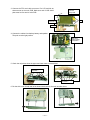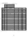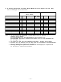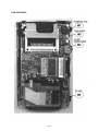
1
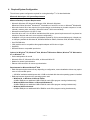
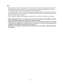
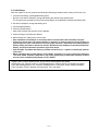
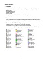
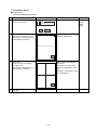
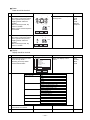
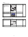
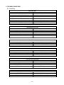
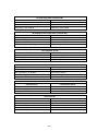
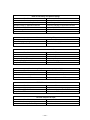
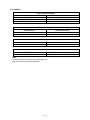
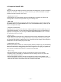
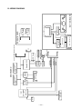
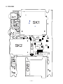
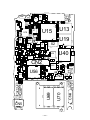
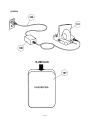
(without price)
Pocket PC
E-200
DEC. 2001
E-200
INDEX
R
Ver.1
MARCH/ 2002
CONTENTS
1. SPECIFICATIONS ------------------------------------------------------------------------------------- 1
2. OPTION --------------------------------------------------------------------------------------------------- 2
3. OPTION COMBINATION ----------------------------------------------------------------------------- 4
4. Required System Configuration ----------------------------------------------------------------- 5
5. GENERAL GUIDE ------------------------------------------------------------------------------------- 7
5-1. Guidance of each functions ------------------------------------------------------------------- 7
5-2. Initial Setup ----------------------------------------------------------------------------------------- 8
5-3. Opelation -------------------------------------------------------------------------------------------- 9
5-4. Software Applications ------------------------------------------------------------------------- 14
6. BATTERY & RESET --------------------------------------------------------------------------------6-1. Batteries ------------------------------------------------------------------------------------------6-2. Reset -----------------------------------------------------------------------------------------------6-3. Full Reset (Memory Initialize) ---------------------------------------------------------------
15
15
15
16
7. OPERATION CHECK ------------------------------------------------------------------------------7-1. Preparation --------------------------------------------------------------------------------------7-2. How to make a CF CARD for the diagnostic program -----------------------------7-3. How to boot the diagnostic program ----------------------------------------------------7-4. Operation Check --------------------------------------------------------------------------------
17
17
17
18
19
8. ADJUSTMENT ---------------------------------------------------------------------------------------- 27
9. TROUBLE SHOOTING ----------------------------------------------------------------------------9-1. Hardware -----------------------------------------------------------------------------------------9-2. Software-------------------------------------------------------------------------------------------9-3. Support PocketPC 2002 ----------------------------------------------------------------------
28
28
31
32
10. WIRING DIAGRAM ---------------------------------------------------------------------------------- 33
11. PCB VIEW ---------------------------------------------------------------------------------------------- 34
12. DISASSEMBLY/ASSEMBLY PROCEDURE -------------------------------------------------- 36
12-1. DISASSEMBLY ----------------------------------------------------------------------------------- 36
12-2. ASSEMBLY ---------------------------------------------------------------------------------------- 40
13. PARTS LIST ------------------------------------------------------------------------------------------- 42
14. EXPLODED VIEW ----------------------------------------------------------------------------------- 45
1. SPECIFICATIONS
Model:
Display:
E-200
240 × 320 dots
TFT Color LCD (65,536 colors)
CPU:
Intel® StrongARM Processor (206 MHz)
Memory:
ROM 32 MB Flash ROM
RAM 64 MB
Interfaces:
Serial:
RS-232C, 115.2 kbps max.
Infrared: IrDA Ver. 1.2
Range: 20 cm max.
USB (Host/Client)
Card Slot:
CompactFlash card, 3.3 V Type I / Type II
SD memory card/MultiMediaCard
Headphone jack:
ø 3.5 mm stereo output
Accepts monaural earphone, stereo earphones/headphones.
Power Supply:
Main:
Rechargeable battery pack JK-214LT (Lithium-Ion battery)
AC adapter (AD-C54240E)
Backup: One CR2032 lithium battery
Power Consumption:
4.5 W
Approximate Battery Life (Normal Temperature)
Main:
(Actual time may be shorter due to conditions when charging.)
12 hours: Continuous input and data display at a ratio of 1:10, front
light off.
• Even when the unit is turned off, small amounts of power are
required to retain memory contents, etc. This can cause batteries to
go dead even when you do not use the unit.
• The actual amount of operation time that can be expected from
batteries depends on operating conditions, settings, and other
variables.
Backup: 5 years: Main battery is charged or replaced immediately after
appearance of message to replace main battery.
1 week: No battery replacement after appearance of message to
replace main battery.
Approximate Charge Time (Normal Temperature)
4 hours: Charge time is longer for the first charges after purchasing
the unit or installing a new battery pack.
Operating Temperature: 0 °C to 40 °C (32 °F to 104 °F)
Charging Temperature:
10 °C to 35 °C (50 °F to 95 °F)
Dimensions:
17.5H × 82W × 130D mm (0.69 × 3.2 × 5.1 inch)
Weight:
Approximately 190 g (6.7 oz)
• The TFT color LCD is a product of the latest color LCD manufacturing technology.
However, virtually all TFT color LCDs have a very small number of pixels (about 0.01 % of the total
number of pixels) that do not turn on or always remain turned on.
This is normal and does not indicate malfunction.
• Playing back movies, digital camera images, and audio files consumes large amounts of power and may
cause the unit to become warm to the touch. This is normal and does not indicate malfunction.
• Inserting or removing a Storage card while the unit is off causes power to turn on automatically. This is
done so the unit can detect the card slot status.
—1—
2. OPTION
For Pocket PC 2002 CASSIOPEIA E-200
■ Battery & Power Adapter
AC Adapter
Attach it directly to the E-200 or to the E-200 cradle to provide power and recharge
the batteries.
• AD-C54240E
Lithium Ion Rechargeable Battery
Keeps your E-200 colour screen powered for an extended period.
Adapts for both E-200 and PC Card Unit.
• JK-214LT
■ Communication
USB Cradle
Keep a spare in the office or home for convenient transfer of data.
• JK-514CR
USB Cable
Connecting CASSIOPEIA to PCs
• JK-584CA
RS 232C Cable (20pin to serial)
(JK-744CV is needed)
Connecting CASSIOPEIA to PCs
• JK-580CA
■ Others
20PIN/USB host Converter
Convert 32pin connector to 20pin and add USB host client.
• JK-744CV
Stylus
For your replacement, 2 styluses are included.
• JK-824ST2
—2—
Screen Protectors
Helps protect your screen from pen and pencil damage. 5 sheets are included.
• JK-834PS5
PC Card Unit
Accepts PCMCIA TYPE II Cards.
• JK-864PU
Stereo Earphone with Remote Control
For use with music, while reading E-mail and E-book with the remote control.
• JK-840HE
MultiMediaCard (MMC)
For your storage.
• MMMB-32 (32MB)
• MMMB-16 (16MB)
—3—
3. OPTION COMBINATION
32pin→20pin/USB
Attachment (Option)
CASIO 20pin
233C Serial Cable
USB TypeA
32pin
USB Cable(Option)
DOS/V
PC
USB Cradle
(Included)
USB TypeA
USB TypeA
Expansion Unit
(Option)
USB Cradle/Cable
32pin
PCMCIA type II CARD
USB TypeA
USB Mach.
Wireless CARD
FLASH CARD
GPS CARD
MICRO DRIVE
CF Type II
Connector
SD Connector
SD CARD/MMC CARD
(Memory Card)
AC Jack
• AC adapter(Included) 5.4V 2.4A
(100-240 V Inn let Type)
With Remote Control
Audio Jack
IrDA
Stereo
Stereo Headphone
SIR (IrDA ver.1.2Conforming (:115.2 kbps max))
—4—
• PC/Printer/etc
4. Required System Configuration
The minimum system configuration required for running ActiveSync® 3.5 is described below.
Microsoft® ActiveSync® 3.5 System Requirements
Minimum Desktop Computer Requirements
• Microsoft® Windows® XP, Microsoft® Windows® 2000, Microsoft® Windows®
Millennium Edition, Microsoft® Windows NT® Workstation 4.0 with SP 6 or later, or Microsoft® Windows 98
• Microsoft Outlook® 98 or later required for synchronization to the desktop or portable computer of e-mail,
calendar, contacts, tasks, and notes. (Microsoft Outlook® 2002 recommended)
• Microsoft Internet Explorer 4.01 SP1 or later
• Hard disk drive with 12 to 65 MB of available hard disk space (actual requirements will vary based on
selection of features and user’s current system configuration)
• Available 9 or 25-pin communications port (adapter required for 25-pin communications port), infrared port,
or USB port (available for Windows 98, Windows Millennium Edition, Windows 2000, Windows® XP only)
• One CD-ROM drive
• VGA graphics card or compatible video graphics adapter at 256 color or higher
• Keyboard
• Microsoft Mouse or compatible input device
Options for Windows® XP, Windows® 2000, Windows® Millennium Edition, Windows® NT Workstation
4.0, or Windows® 98
•
•
•
•
Audio card/speakers for sound
Microsoft Office 97, Microsoft Office 2000, or Microsoft Office XP
Modem for remote synchronization
Ethernet LAN connection for remote synchronization
Requirements for Microsoft Outlook® 2002
• Hard disk space requirements will vary depending on configuration; custom installation choices may require
more or less hard disk space.
• 245 MB of available hard disk space with 115 MB on the hard disk where the operating system is installed
• RAM requirements depend on the operating system used:
• Windows 98, or Windows 98 Second Edition
24 MB of RAM plus an additional 8 MB of RAM for each Office program running simultaneously
• Windows Millennium Edition, or Microsoft Windows NT
32 MB of RAM plus an additional 8 MB of RAM for each Office program running simultaneously
• Windows 2000 Professional
64 MB of RAM plus an additonal 8 MB of RAM for each Office program running simultaneously
—5—
Note
• Different minimum system requirements are required when using the applications included on the
CASSIOPEIA Applications CD-ROM. See the documentation contained on the CD-ROM for full details.
• The cradle that comes with the unit is designed for USB connection only.
If your computer does not have a USB port, necessary to purchase the separate 20Pin/USB host Converter
(JK-744CV) and the serial connection cable (JK-580CA), which allow direct connection between the unit
and connected computer’s serial port.
• Certain computer hardware and/or software configurations may not allow PC Connect to run properly.
• When installing ActiveSync on a computer, check to make sure that the specified COM port number
correctly indicates the serial port to which the cradle is connected.
• Some laptop and sub-compact computers with built-in infrared ports and modems are initially
configured so the COM port is not always used as a serial port. In such a case, the setting must be
changed so the COM port is always used as a serial port.
See the documentation that comes with connected computer for full details on COM port numbers
and settings.
—6—
5. GENERAL GUIDE
(Quotation from E-200 Hardware Manual)
5-1. Guidance of each functions
CompactFlash Card slot
Charge indicator (Amber/Green)
Indicator lamp (Red)
Infrared port
Stylus
Microphone
Stereo headphone jack
Power button
Touch screen
Reset button
Cursor button
Action control
SD Memory/
MMC Card slot
Speaker
• Menu
(Launcher)
• Contacts
• Calendar
• Voice
Recorder
AC adapter terminal
32 pin connector
—7—
Program buttons
5-2. Initial Setup
After first unpack of the unit, perform the following initial setup procedure before using it for the first time.
1. Load the main battery (rechargeable battery pack).
• Be sure to use the AC Adapter to charge the battery pack before doing anything else.
The unit will not be operated correctly if the backup battery is loaded before charging the battery pack.
2. Use the AC Adapter to charge the battery pack.
3. Load the backup battery.
4. Press the [Power] button.
• After a few moments the welcome screen appears.
5. Follow the steps in the Welcome Wizard.
6. When finished, the Today screen can be seen.
• Also installation of ActiveSync is necessary before communication with a desktop computer.
• If the touch panel does not respond when it is tapped or if nothing appears on the display, try
performing a full reset. If this does not restore proper operation, remove the main battery and the
backup battery and wait for about five minutes. Reload the main battery first and then the backup
battery, and perform the above procedure again from step 4.
• If the message "A problem with memory contents has been found..." appears on the display, perform
a full reset.
• While prrforming above Initial Setup or FULL RESET operations, be sure to perform the following
"Cut" and "Paste" operation. Otherwise, it can not be continued to perform these operation, and the
unit can not be completed Initial Setup or FULL RESET.
Tapping "Next" in Stylus Wizard screen, pop-up menus Wizard display will appear.
Holding down "Dr. Johnson’s office" or "Dental appointment" using the stylus, "Cut" display will appear.
Then, after holding down its "Cut" character, hold down item 11. After that, "Paste" display will appear.
Then, hold down "Paste" character using the stylus. Then, tap "Next".
—8—
5-3. Operation
Using the Stylus
Data input and virtually all other operations are performed using a stylus, which is housed inside the stylus
holder in the right corner of the unit.
• Use only the stylus that comes with the unit, or some other stylus type instrument with a soft, blunt
point to perform touch screen operations. Never use a pen, pencil, or other sharp writing implement.
Recalibrating the Touch Screen
Recalibrate the touch screen whenever touch screen response is bad, or when the operation performed is
different from the operation you expected when tapping on the touch screen.
To recalibrate the touch screen, press the [Action] control while holding down the [Power] button (or tap
,
Settings, the System tab, and then the Align Screen). Next, follow the instructions that appear on the screen.
Adjusting Display Brightness
Use the following operations to adjust display brightness to make it easier to read.
• Tap
and then Settings. On the System tab, tap Brightness. On the dialog box that appears, tap the
Brightness tab.
• While holding down the [Action] button, press the right side of the cursor button to make the screen brighter,
or the left side of the cursor button to make it dimmer.
Adjusting Auto Dimming Settings
1. Tap
and then Settings. On the System tab, tap Brightness.
2. On the dialog box that appears, tap the Auto Dim tab.
3. Follow the instructions that appear on the screen to make auto dimming settings.
• The separate auto dimming settings for battery power and AC adapter power can be done by selecting the
appropriate check box.
• The front light turns back on whenever the unit is pressed a button or tap the screen while the unit is turned
off.
Changing Applications Assigned to the Program Button
• Tap
and then Settings. On the Personal tab, tap Button, and then follow the instructions that appear on
the display.
Using the Cradle
The cradle provides quick and easy connection between the unit and a computer.
• The unit can be powered by AC power when it is placed on the cradle.
• The battery pack charges while the unit is on the cradle.
• The cradle is equipped with a USB-A connector to connect another USB device.
• Before connecting the unit to a computer, make sure first installation of the ActiveSync on connected
computer.
—9—
Connecting the Cradle to a Computer
The cradle has a USB cable for connection to a computer. Connect the end of the cable to a USB port of the
connected computer.
• See "Required System Configuration" on page 5 for details on the type of computer system required
for use with the cradle.
• The above illustration is one example of possible connection configurations. The locations and
layouts of USB ports vary from computer to computer. See the documentation that comes with
connected computer for full details on connecting cables to it.
• Note that after connecting the cradle to connected computer, it is neccessary to make certain
ActiveSync settings on connected computer to enable data transfers. See the ActiveSync Help for
details about setting up and using ActiveSync.
To place the CASSIOPEIA onto the cradle
Make sure that unit power is turned off before it is placed it onto or remove it from the cradle.
Use the following procedure to place the unit onto the cradle.
1. Place the cradle on a desk or other flat, level surface.
2. Turn off the unit.
3. Orient the unit in relation to the cradle as shown in the illustration below.
Make sure the raised part of the cradle enters into the recess on the back of the unit.
1
2
— 10 —
4. Taking care to align the serial connector on the bottom of the unit with the connector on the cradle, lower the
unit into the cradle as shown in the illustration below.
Make sure the unit lowers securely into the cradle as far as it can go.
To remove the CASSIOPEIA from the cradle
Pull up on the unit so the recess on its back disengages from the raised part of the cradle, and then lift the unit
straight up from the cradle.
2
1
To connect another USB device to the cradle
The cradle is equipped with a USB-A connector that can be used to connect another USB device, as shown
below.
CASSIOPEIA
Computer
USB device
Cradle
USB-A connector
• When using any USB device, make sure the applicable USB driver on the unit.
— 11 —
Using the USB Cable
The USB cable to connect the unit directly to a computer.
• See "Required System Configuration" on page 5 for the computer system that is required for direct
USB connection.
• The illustration below is just one possible connection configuration. The location and layout of USB
ports vary from computer to computer. See the documentation that comes with connected computer
for full details on connecting cables to it.
• Make sure ActiveSync installed on connected computer in order to exchange data with the unit over
a USB connection. See the ActiveSync Help for details about setting up and using ActiveSync.
To connect to a computer using the USB cable
Before connecting the unit to a computer, make sure to first install the ActiveSync on connected computer. Use
the steps below to connect the unit to connected computer when prompted to do so during the software
installation procedure.
1. Plug the USB cable into the USB port of your computer.
2. Turn off the unit.
3. Connect the other end of the USB cable to the unit.
USB port
USB cable
• To disconnect the USB cable, squeeze in on the buttons on either side of the plug to unlock it, and then pull.
— 12 —
Infrared Communication
The infrared port of this unit can be used to exchange data with another unit, or with another device equipped
with infrared communication capabilities. Remember that the two infrared ports must be pointed directly at
each other when performing communication. The distance between the two infrared ports must be less than
20 cm.
See the Pocket PC User’s Guide for full details on performing infrared communication.
For infrared data communication with another device, the other device must conform with IrDA 1.2 standards,
and it must specifically support infrared data communication with a unit.
• Take care so either of the units does not move while infrared data communication are in progress.
• Infrared data communication may be impossible under strong sunlight or inverter type fluorescent
lighting.
• Infrared data communication problems can be caused by the distance between the two ports, the
angle between the two ports, outdoor sunlight, and low batteries.
• Dirt and dust on the infrared port surface can cause communication errors and other problems.
Using a CompactFlash Card
The unit supports Type I and Type II CompactFlash Cards (3.3 V).
The following describes the types of CompactFlash which card can be used.
Storage Card
A storage card functions the same as the unit’s data storage memory.
Modem Card
A modem card can be connected to a telephone line (standard household modular jack, public telephone with
modular jack, etc.) for modem data communications.
Wireless Modem Card
With a wireless modem card, it can be performed mobile data communication without a wire connection to a
telephone circuit.
• Gently but firmly slide the card into place as far as it will go, but do not force it. Forcing a card can damage
connectors. If there are problems inserting a card, pull it out and check to make sure it is oriented correctly.
• Sometimes, the unit may not be able to detect a CompactFlash card. This is indicated when a program on
the card does not start up normally. When this happens, remove the card, reinsert it, and then press the unit
reset button.
• The unit supports 3.3 V CompactFlash cards only. 5.0 V cards are not supported.
Using a SD Memory Card or Multimedia Card
The unit supports SD memory cards and Multimedia cards.
• The card slot cover will not close when certain types of cards are in the slot.
• Gently but firmly slide the card into place as far as it will go, but do not force it.
Forcing a card can damage connectors. If there are problems inserting a card, pull it out and check
to make sure it is oriented correctly.
Built-in Storage
The unit comes with two types of user memory built-in: RAM and flash memory. Flash memory appears on File
Explorer under My Device → Built-in Storage, and operates just like a storage card. To find out how much
flash memory capacity is still available, tap Start → Settings → Memory → Storage Card.
— 13 —
Using a PC Card Unit (Option)
The PC Card Unit makes it possible to use PCMCIA type cards with the unit. An optionally available battery
pack can also be installed on the PC Card Unit and used as an external power supply for the unit. See the user
documentation that comes with the PC Card Unit for details about using it.
About the 20Pin/USB host Converter (Option)
The 20Pin/USB host Converter (JK-744CV) converts the unit’s 32-pin serial connector to a 20-pin connector,
which is able to accept connection of a 20-pin serial cable. See the user documentation that comes with the
20Pin/USB host Converter for details about using it.
About the Modem Adapter and Modem Card (U.S. and Canada Only)
The Modem Adapter (JK-720MA) and CompactFlash type Modem Card (JK-711MC56) make it possible to use
the unit to access the Internet over an analog dial-up connection. See the documentation that comes with the
modem card for information about how to use it.
Check to make sure that the battery pack is charged before using the modem adapter and modem card.
Low battery power can cause sudden interruption of communication, unstable communication, and
loss of data.
5-4. Software Applications
Software applications are available for purchase from Microsoft and third parties who support Windows CE.
For details on commercially available software applications, visit the Microsoft Web site at http://
www.microsoft.com.
The unit also comes with a CASSIOPEIA Applications CD-ROM that contains a number of useful applications.
The necessary applications must be installed from the CD-ROM before they are used. See the documentation
contained on the CD-ROM for details on using the software applications.
• Whenever purchasing software applications, always double-check to make sure that it is compatible
with the CASSIOPEIA.
• Some applications written for a Palm-size PC (Windows CE 2.11) may not run on a Pocket PC. Contact
the producer of the application for information about an upgrade to the Pocket PC version.
— 14 —
6. BATTERY & RESET
(Quotation from E-200 Hardware Manual)
6-1. Batteries
The unit is powered by a dual power supply that consists of a main battery (rechargeable battery pack) and a
backup battery (CR2032 lithium battery).
Main (Backup) Battery
Recharge (Replace) the battery pack (backup battery) as soon as possible after the following message appears.
"Main (Backup) Batteries Very Low
To prevent possible data loss, replace or recharge the main batteries according to the owner’s manual."
If unit power turns off due to insufficient power or sudden power drain by a Storage card, the following warning
message appears on the display the next time it is turned on unit power.
"Warning
Due to high current demand by the hardware, the system powered down in order to protect memory
contents..."
Be sure to observe the following important battery handling precautions. Failure to do so can cause
batteries to leak, resulting in damage to surrounding items and create the danger of fire and electrical
shock.
• Use only the types of batteries specified for use with this unit.
• Charge the battery pack in an area where the temperature is between 10 °C (50 °F) and 35 °C (95 °F).
Charging in areas that are very cold or exposed to direct sunlight can cause deterioration and leaking
of the battery pack.
• To avoid deterioration and leaking, the battery pack is designed to discharge even when it is not
used. Be sure to recharge the battery pack at least once every three months, regardless of how
much it is used the unit during that time.
6-2. Reset
"Reset" is similar to a computer reboot. Performing a reset deletes any data that is in the process of being input
or edited, without yet being saved. Data stored in memory and all settings, however, are retained.
Perform the reset operation whenever the unit fails to operate correctly due to operational error or some other
abnormality. Any of the following symptoms indicate that reset is required.
• If the unit does not respond when the screen is tapped or pressed a button
• If the icon that indicates a procedure is in progress remains on the display for a long time
Normally the reboot-type reset does not delete data in internal memory. If corrupted data is discovered,
however, all data stored in memory will be deleted.
Performing a Reset
1. Use the stylus to press the reset button.
• The unit performs a reset followed by a memory check operation.
If no data error is found, the following two screens appear on the display in succession.
• Startup screen
• Today screen
2. Normal unit operation is possible after the desktop appears.
• Memory data and settings are retained when the Pocket PC is reset.
If the above operation does not solve the problem, perform a full reset (Memory Initialize, page 16).
— 15 —
Memory Error Message
If the memory check operation that the unit performs when the reset button is pressed detects a data error, the
following message appears on the screen instead of the startup screen.
"A problem with memory contents has been found. Press [Action] to continue with the reset procedure,
which restores normal system operation.
Note that if the system determines that user memory cannot be repaired, it will delete all user data
currently in memory.
See the User’s Guide for details about initializing memory."
This message indicates that the memory error is fatal and so recovery is impossible.
Press the [Action] control to execute a full reset (memory initialize), which deletes all data stored in memory.
• Pressing the [Action] control should display the Startup screen followed by the touch screen calibration
screen. The remainder of this procedure is identical to the Initial Setup described in the Quick Start Guide.
Perform the steps of the Initial Setup procedure.
• If pressing the [Action] control returns to the desktop without displaying the startup screen first, see the
following explanation for the procedure you need to follow.
What to do if the startup screen does not appear when you press the [Action] control
Even though the desktop appears when the [Action] control is pressed, there is still a data error in memory and
a full reset (memory initialize) must be performed. Before it is done, however, there is the chance that some of
the data in memory can be recalled and even transferred to a computer. Try recalling the necessary data
before performing the procedure described on the next page to perform a full reset.
Do not use the ActiveSync backup function to back up data to a computer when it is suspected a data
error. Doing so may also include the corrupted data that is causing, which means the problem will
reappear when the deta are restored.
6-3. Full Reset (Memory Initialize)
Full reset (memory initialize) deletes all data, and resets all unit parameters to their initial defaults.
The following are conditions when a full reset should be performed.
• When all memory data are wanted to delete and returned unit settings to factory defaults
• When the password is forgotten and needed to clear it
• When a data error causes operational problems
• Appearance of the message: "A problem with memory contents has been found..."
Performing a Full Reset
1. Make sure that unit power is turned on.
2. While holding down the power button, use the stylus to hold down the reset button for about two seconds.
3. Press the [Action] control.
4. Press the [Action] control again.
• This starts the full reset operation, which deletes all data in memory.
• Pressing the [Action] control should display the Startup screen followed by the touch screen calibration
screen. The remainder of this procedure is identical to the Initial Setup described in the Quick Start Guide.
Perform the steps of the Initial Setup procedure.
Errors Following a Full Reset
Either of the following two conditions can cause errors to continue, even after a full reset is performed.
• Hardware defect
• System problem caused by failure to correctly perform the reset procedure before using the unit for the first
time
Perform the procedure on page 16 when the full reset (memory initialize) does not correct the problem.
— 16 —
7. OPERATION CHECK
7-1. Preparation
1. E-200(Prepare another units to perform IrDA communication check except the checking unit.)
2. Compact Flash Memory Card (recommended more than 32MB type, at least 8MB type required)
3. SD Memory Card
4. Rechargeable Battery Pack
5. AC Adapter (AD-C54240E)
6. Cradle (JK-514CR)
7. Diagnostic Program File 2577 for E-200 with compact Flash Memory Card
8. Stereo Earphone (JK-840HE)
NOTES:
* Be sure to make back-up copies of all data in the unit before repair using BACKUP/ RESTORE function in
ActiveSync 3.5 software or Card Backup Tool in Utilities Program because FULL RESET must be performed
to finish or abort this operation check.
7-2 How to make a CF CARD for the diagnostic program
The diagnostic program is contained as 2577 file in CD-ROM of Service disc.
There are 45 files in the 2577 folder of the diagnostic program as shown below.
Transfer the files to the CF CARD using ActiveSync 3.5 or make copy of them using the CF CARD adaptor.
Do not transfer any other file except for diagnostic program 2577 in the CF card.
— 17 —
7-3. How to boot the diagnostic program
< HOW BOOT AND CHECK THE PROGRAM >
Seq.
Operation
Display
1
Perform full reset
Initial display (welcome) comes up after
full reset
2
Peform initial set up
(Refer to 5-2. Initial Setup of page 8)
Today Screen (Microsoft mobile) comes
up
3
The test menu is booted automatically
after the CF card with the diagnostic
program is inserted.
PQAP
2:24 ok
TouchPanel /I:2 /A /O...
Flow Saved Config
Start
IW
PPI
IW
Test Config About
4
5
Tap "Flow" and select "Component"
Tapping "Start" carries out the test items
whose boxes have been checked.
Note: The check box of "Power" and
"Break" test should be blank.
PQAP
TouchPanel
Botton
Display
Audio
RTC
Power
IrDA
LED
Memory
FlashCard
CPU
Flow Component
Test Config About
— 18 —
2:24 ok
Start
IW
PPI
IW
7-4. Operation Check
■ Touch Panel
Touch Panel should be checked.
No.
1
Operation
Check the item which you want
to test and tap "Start".
Display
Exit
Corners Test
Tap on the four points at corners.
After the test, "Test Passed!" or
"Test Failed!" is indicated.
If the four marks do not
disappear, tapping if NG.
Tap 4 corners to perform testing !
Exit
3
Cross Test
Trace the cross top to bottom,
and right to left.
After the test, "Test Passed!" or
"Test Failed!" is indicated.
Make sure the cross disappear
after tracing.
Note: Some small area of the
cross may not disappear at the
end.
At that time, "Test Failed!" comes
up, but disregard it.
X:0
Y:0
Exit
4
If NG
Touch
Panel,
Main
PCB
Test Items
Corners Test
Cross Test
Start
2
Check
Tap "Exit".
— 19 —
■ Button
Button should be checked.
No.
Operation
1
Check if the unit correctly counts
the number of times the buttons
in the right fiture are pressed.
Tapping "Reset" clears the
number.
After confirming the test, tap
"Pass" or "Failed."
Note: Connect remote earphone
if it is tested.
Check if the unit correctly counts
the number of times the buttons
in the right fiture are pressed.
Tapping "Reset" clears the
number.
After confirming the test, tap
"Pass" or "Failed."
Confirm the number every
pressing button
4
1
1
4
3
2
1
1
0
0
If NG
Button
PCB,
Main
PCB,
Remote
earphone
Stop
0
Pass
2
Check
Display
0
Failed Reset
0
0
Pause
0
0
Pass
0
Failed Reset
■ Display
Display should be checked.
Operation
No.
1
Check the item which you want
to test and tap "Start".
Selecting "Auto Tap" makes
screen feed automatic.
Check
Display
Test Items
Solid Colors Test
Solid Lines Test
Flickers Test
Color Bars Test
Checker Boards Test
Ghosts Test
Check if the display color is
normal.
Config Settings
Auto Tap
Start
2
Test Items
Solid Colors Test
Solid Lines Test
Flickers Test
Color Bars Test
Checker Boards Test
Ghosts Test
3
After the test, "Test Passed!" or
"Test Failed!" is indicated.
4
Tap "Exit".
Exit
Display
RED
GREEN
BLUE
BLACK
WHITE
Horizontal lines 1 dot
Reverse of horizontal lines 1 dot
Vertical line 1 dot
Reverse of vertical lines 1 dot
Vertical gradation 1
Vertical gradation 2
Horizontal gradation 1
Horizontal gradation 2
Color bars and gradation 1
Color bars and gradation 2
Checks
Reverse checks
Monochrome bar 1
Monochrome bar 2
— 20 —
If NG
LCD
module,
Main
PCB
■ Audio
Audio should be checked.
No.
1
Operation
Check the item which you want
to test and tap "Start".
Note: L-ch and R-ch sound can
be test if remote earphone is
inserted.
Check
Display
Check if the sounds are normal.
Play Test
500 Hz
1 KHz
If NG
Speaker,
Main
PCB
2 KHz
Record Playback Test
Record Test
Test...
Lenght (sec): 5
Sample
Channels: Mono
Bits: 8
8 KHz
Auto start
System Volume
Quiet
Play test R Record & Playback
test will be done automatically.
3
After the test, "Test Passed?" is
indicated. And tap "Yes" or "No".
Loud
Exit
Start
2
Beep
4
"Testing" is indicated next to
the test items.
Audio
Test Passed?
Yes
4
Yes
Tap "Exit"
■ RTC
RTC (Real Time Counter) should be checked.
No.
1
Operation
Tapping "Start" starts the test.
Check
Display
System Date/Time range test
Merlin Specication
Year Range
1980
~
2050
Testing status
Begin Year
End Year
Start
Exit
Auto Start
2
After confirming the test, tap
"Exit."
— 21 —
Check if the test finishes normal.
If NG
Main
PCB
■ Power
Not used.
■ IrDA
IrDA should be checked.
No.
Operation
Check
Display
If NG
TEST UNIT
1a
Check the item which you want
to test and set local mode
"client".
Main
PCB
Test Items
Connect Test
Transfer Test
Config Settings
Local Mode
Client
Run until stop
Start
Tap "Start".
Exit
Test Items
Client Mode
Connect Test
Transfer Test
States
Pass : 1
Fail : 0
Test Result
Start to locat socket ...... done!
Connecting ......
Exit
2a
3a
Tap "Stop".
4a
Tap "Exit".
MASTER UNIT
1b
Check the item which you want
to test and set local mode "Server".
Test Items
Connect Test
Transfer Test
Config Settings
Local Mode
Client
Run until stop
Start
2b
Tap "Start".
Exit
Test Items
Server Mode
Connect Test
Transfer Test
States
Pass : 1
Fail : 0
Test Result
Connect ...... listening
Exit
3b
Tap "Stop".
4b
Tap "Exit".
— 22 —
Check of the communication
condition,
■ LED
LED should be checked.
Operation
No.
1
Tap "Start."
Display
Check
Main
PCB
Action
Start
If NG
Stop
Click "Start" to flashing LED.
Click "Stop" to stop flashing LED.
Test Result
Click "PASS" if LED is work properly.
Otherwise, click "FAILED".
PASS
2
FAILED
Indicator lamp flashes.
Red light
Check if the LED flashing is
normal.
Action
Start
Stop
Click "Start" to flashing LED.
Click "Stop" to stop flashing LED.
3
After confirming the test, tap
"Pass" or "Failed."
■ Memory
Memory should be checked.
No.
1
Operation
Check the item which you want
to test and tap "Start".
Check
Display
Information
Memory RAM
Storage RAM
Total :
Free :
Total :
Free :
31.35 M
xx.xx M
31.34 M
xx.xx M
Test Item
Memory RAM
Storage RAM
Start
QUICK
Stop
Test Progress
2
Tap "ok."
3
Tap "ok." at status bar.
"OK" or "Failed" is indicated.
— 23 —
Check on Memory Test Result
"Pass".
If NG
Main
PCB,
RAM
PCB
■ FlashCard
FlashCard should be checked.
Operation
No.
1
Check the item which you want
to test and tap "Start".
Display
Check
Test Items
Check on test result "Pass".
CF Card Write/Read Test
SD Card Write/Read Test
If NG
Relevant
card
PC Card Write/Read Test
Bulit-in Storage Write/
Read Test
Options
Auto-Start and Exit
Allow to Retry if Card no found.
Start
2
Exit
"Pass" or "Failed" is
indicated in the item.
3
Tap "Exit."
No.
Operation
1
Information on CPU is indicated.
2
Tap "ok."
Display
Check
If NG
Check
If NG
Processor Vendor : Intel
Processor Core : ARM
Processor Name : SA1110
■ Break
Break the test procedure. should be blank the check box.
■ UsbHost
USB cable should be checked.
No.
Operation
1
Set the test unit on the cradle
with USB cable.
Note: USB cable should be
connected to PC which installs
ActiveSync.
2
Type "Q", "W", "E", "R", "T" and
"Y" in sequence.
Note: Use input panel of the unit.
Display
USB Power ON = = > OK
Connect USB keyboard on PDA's
cradle, and then typing Q, W, E, R, T
and Y keys in sequence.
Q
W
E
R
T
Failed
3
If the above procedure is
finished, automatically move to
next step.
— 24 —
Y
Check if PC screen shows
"Connected" and "Synchronized".
Cradle
Check if the typing is OK.
Button
PCB,
Main
PCB
■ OsVer
OS version should be checked.
Operation
No.
1
Information on OS version is
indicated.
Display
Check
If NG
Check
If NG
Version Testing
OS version
Checksum
Expect
1087
76240
Result :
Failed
Curent
1070
71073
Auto exit after checking.
Messages:
E-Boot version=1.51
Exit
2
Tap "Exit."
■ Panel Sign
Panel sign shouldbe checked.
No.
1
Operation
Display
Confirming frame of panel size
on display.
Check it the all frame inside of
display.
Pass
2
LCD
module
Fail
After confirming the test, tap
"Pass" or "Fail."
■ PCMCIA
PCMCIA setting should be checked.
No.
1
Operation
Set PC jacket with PCMCIA.
Display
PCMCIA SETTING
Check
ok
PCNCIA Set to 6.0Mhz !!
2
After confirming the test, tap "ok."
— 25 —
Check it the PCMCIA setting is
normal.
If NG
PC
jacket
■ SD_Detect
SD card detection should be checked.
No.
1
Operation
Insert SD card.
Display
Check
If NG
Main
PCB
SD Card is removed,
Please INSERT SD Card now.
SD
Auto exit after tested.
Failed & Exit
2
Remove SD card.
Check it the test is PASS.
PASS
SD
Auto exit after tested.
Pass
3
Failed & Exit
After the test, tap "Pass" or
"Failed."
■ CF Wake-on-Ring
CF wake-on-Ring should be checked.
No.
Operation
1
Testing CF card of wake on ring.
Display
Check
Testing...
Main
PCB
CF Wake on ring test
Test Again
Pass
2
Insert CF card.
Failed
Check it the test is PASS.
PASS
CF Wake on ring test
Test Again
Pass
3
After the test, tap "Pass" or
"Failed."
4
Return to test menu.
If NG
Failed
— 26 —
8. ADJUSTMENT
■ Display quality adjustment
When flickers and vertical stripes appear in the screen, perform this adjustment according to the following
procedure.
1. Disassemble side panel and upper case in accordance with DISSASSEMBLY PROCEDURE of this
manual.
2. Put the main PCB as shown below finger, and confirm the position of adjustment volume.
3. Turn on the power switch.
4. Insert a CF card with diagnosis program.
5. Test menu comes up automatically. (Refer to OPERATION CHECK)
6. Check the box only "Display test" in the test menu, and tap "Start".
7. Check the only "Flickers Test", and tap "Start".
8. Confirm the Flickers Test Display.
9. Adjust the volume to minimize flicking.
— 27 —
9. TROUBLE SHOOTING
9-1. Hardware
No power at all
Possible cause
Main battery discharged
Internal data corruption (F-ROM/RAM)
Wrong position of battery cover switch
AC adaptor fault
No main battery is set with AC adaptor
Terminals of main battery are dirty
Open circuit of internal PCB
Recommend action
Recharge the battery
Perform full reset
Set proper position
Replace AC adapotor
Set main battery during any operation
Clean the terminals
Replace main PCB assy
Intermittently no power
Possible cause
Low main battery
Poor contact adaptor jack
Poor contact of battery cover switch
Terminals of main battery are dirty
Poor contact of internal connector
Recommend action
Recharge the battery
Change the jack
Change the switch
Clean the terminals
Check and reconnect
Lock at initial display
Possible cause
Poor contact of RAM PCB connector
Faulty main or RAM PCB
Recommend action
Reconnect RAM PCB connector
Replace the main or RAM PCB
Poor playback sound
Possible cause
Recorded high pressure sound
Low sampling frequency when recording
Faulty speaker
Recommend action
Leave the microphone from speaker or voice
Chose hjgh sampling frequency
Replace the speaker
Lock up during operation
Possible cause
Data is full in memory
Data corruption in RAM
Performed improper application software
Faulty internal PCB
Recommend action
Perform reset or full reset operation
Perform reset or full reset operation
Delete the improper application software
Replace main PCB assy
Lock up at initial display
Possible cause
Poor contact of RAM PCB or connector
Faulty internal PCB
Recommend action
Resolder RAM PCB or check the contact
Replace RAM PCB or main PCB
— 28 —
No front light (Other fanctions OK)
Possible cause
Recommend action
Poor contact of inverter connector
Reconnect inverter connector CN1 and CN2
Faulty inverter PCB
Replace the inverter PCB
Faulty lamp in LCD module
Replace the LCD module
No display/No front light (other functions OK)
Possible cause
Recommend action
Poor soldering of connector at main PCB
Resolder connector pins
Poor contact of inverter cable/connector
Check and reconnect
Faulty Internal PCB
Replace inverter PCB
LCD (of front light lamp) fault
Replace LCD module
Poor playback sound
Possible cause
High pressure sound is recorded
Low sampling frequency when recording
Faulty speaker
Recommend action
Leave the microphone from sound source
Set hjgh sampling frequency rate
Replace the speaker
Erratic display
Possible cause
Faulty LCD
Poor connection of LCD cable
Poor flikers adjustmet
Faulty internal PCB
Recommend action
Replace LCD module
Check and reconnect
Readjust VR of flicking
Replace main PCB assy
No audio sound
Possible cause
Faulty speaker
Poor contact of speaker connector
Faulty internal PCB
Recommend action
Replace the speaker
Check and reconnect
Replace main PCB assy
No input at all
Possible cause
Out of calibration of touch panel
Scratch (damage) on touch panel
Poor contact of connector
Internal data malfunction
Short circuit of key
Recommend action
Recalibrate the touch panel
Replace the LCD unit
Reconnect the touch panel cable
Reset (or full reset) the unit
Replace short switch
— 29 —
Data error/memory corruption message
Possible cause
Recommend action
Internal data malfunction (corruption)
Reset (or full reset) the unit
Weak of main and sub battery
Check voltage of main and sub battery
Improper pocket TV application software
Check the matching of application software
Faulty internal PCB
Replace RAM PCB
Poor soldering of RAM
Resolder RAM
Poor contact of connector
Check the connection and reconnect
No communication by IrDA
Possible cause
Other IrDA is improper type
Faulty main PCB
Recommend action
Check the IrDA with other unit
Replace the main PCB
No communication with PC
Possible cause
Recommend action
Poor contact of serial connector
Check and repair the connector
Open circuit (damage) of serial connector
Check and replace the connector
Wrong set up of parameter
Reset the parameter
No ActiveSync installed in PC
Install the ActiveSync
Faulty internal PCB
Replace main PCB assy
Short battery life (current consumption too high)
Possible cause
Recommend action
Faulty or end of life main battery
Replace new main battery
Short circuit of connector pins
Check and resolder
Short circuit of internal PCB
Check and replace main PCB assy
CF/SD/MM card cannot read
Possible cause
Recommend action
Not designated (improper) card
Swap to recommended (proper) card
Broken (or bend) pins of card slot
Replace card slot or card/main PCB
Faulty internal PCB
Replace main PCB assy
Too slow response of input
Possible cause
Recommend action
Low available of memory capacity
Reset the unit
Poor contact of touch panel and keys
Check the switch and connection
— 30 —
9-2. Software
Lock and data corruption
Possible cause
Improper pocket TV application software
No service patch software installed
Faulty main PCB
Recommend action
Check the matching of application software
Install the service patch software from Web
Replace the faulty main PCB
Backup data cannot be reloaded by Card Backup Tool or ActiveSync
Possible cause
Recommend action
No Card Bacup Tool installed
Install the application from Casio CD-ROM
No service patch software installed
Install the service patch software from Web
Error at Built-in strage access after dial up
Possible cause
Recommend action
No service patch software installed
Install the service patch software from Web
No Menu
Possible cause
No Menu application installed
Recommend action
Install the application from Casio CD-ROM
Note:
Up dated program can be taken by the following URL
http://world.casio.com/euro/ce/download/
— 31 —
9-3. Support for PocketPC 2002
1. IMAP4
When you are using an IMAP4 mail server, note that the mail messages on your server cannot be
deleted from the Inbox. In this case, you need to connect to your server with another computer
and delete the mail messages on the server.
2. Attachment of e-mail
A file attached to an e-mail message cannot be saved directly to a storage card. Receive the
message and file in main memory, and then copy it to a Storage card.
3. DNS value
After checking the DNS value you input for a dial up connection setup, be sure to exit by tapping
the Finish button. Do not tap the Cancel button. If you tap the Cancel button by mistake, you will
need to reconfigure the setup.
4. Application install/uninstall
Depending on the memory location where you install an application and the method that you use
to uninstall an application, you may experience problems when later trying to re-install the same
application. If this happens, use Active Sync’s Remove from both location function to uninstall
the application and then re-install it.
5. Memory area
Certain applications may not be able to recognize non-main memory storage areas (storage card
or flash memory) correctly. Error messages and failure to store data in non-main memory areas
are symptoms that indicate the application you are using falls into this category. When using such
an application, use main memory only to store data.
6. Insert/remove of CF card
Whenever you insert or remove a CF card, the system checks the status of the card, automatically
sets up the required driver, and performs other tasks. Turning off your PocketPC or removing the
card while these tasks are being performed can cause the system to lock up. If your system locks
up or freezes, try resetting your PocketPC to restore normal operation.
7. Built-in strage
• After the using dial-up connection, the error occurs when you use the built-in storage.
And when you try to write data to or read data from built-in storage, the error may occur also.
In this case, reset your Pocket PC.
• After the using dial-up connection, the error occurs when you use the built-in storage. If you
install some application software in the built-in storage, please remove all application software in
connection with a dial-up in connection from built-in storage to RAM area.
— 32 —
— 33 —
SPI
Touch Screen
Controller
SIR
SA-1110
StrongARM
Intel
Parallel to Serial
CPLD
CF Type II
Xceiver
8Mx16 Intel Page
Mode Strata
Flash
60 Pin
B2B Connector
Ear Phone
Microphone
LCD Panel
Serial Signal
RS232C
Buttons
USB Host
USB Client
Amplifier
Audio
Codec
12S
SD
32 Pin Connector
BUS Switch
8M X 16
SDRAM
8M X 16
SDRAM
BUS Switch
Buttons
BUTTON BOARD
60 Pins B2B Connector
80 Pin Connector
SDRAM BOARD
Buffer for RS232C
Input Signal
80 Pin SDRAM Board Connector
MediaQ 1132
8Mx16 Intel Page
Mode Strata
Flash
MAIN BOARD
10. WIRING DIAGRAM
R158
BC138 R151
TC8
U72
R159
DT2
R197
U73
BC14
U93
R196
U74
TC9
BC142
SK1
U92
BC140
R155 R156
U71
R157
DT1
TC7
BC139 R152
R150
JK1
BC137
R149
R147 BC17
R148
BC136
R145
BC141
BC135
R146
11. PCB VIEW
U75
R160 R161
L6
TP17
BC143
BC145
H3
R165
U81
BC150
U80
R169
BC146
D10
BC157
R202
U86
R172
R176
BC158
R177
U85
L7
CN7
U91
R188
BC165
— 34 —
R185
CN9
R183
R187
RN6
U84
TC11
R182
U90
BC160
BC152
R173
SW1
R179
R178
R180
R181
CN8
BC163
D9
Q4
R171
U83
H4
U88
BC164
R186 R184 R183
U87
Q2
R170
Q3
R174
SK2
BC151
CN6
U82
L5
U77
BC149
U76
U78
R168
BC147 BC148
TP16
R167
R195
TP15
R164
H2
U79
TC10
R166
R162
BC144
R163
BT3
R189
R191
R193
R4
BC13
R16
R14
R15
R59
R72
BC102
R113 R106
R115
R114
U58
U63
R135 R136
CN3
H5
BC123
BC26
TC4
TP8
BC116
R127
U62
U61
R137
H11
D7
BC125
BC126
BC127
VR1
R144
BC124
U69
CN4
C1
D8
TP7
TC5
R134
D6
R122
BC122
BC121
U57
R131
BC115
BC153
BC156
R117 R112
R118
U55
U70
U65
BC36
BC46
BC47
BC82
R97
R95
R102
BC63
BC66
R78
R201
R101
BC48
BC49
T3
U60
U51
BC155
BC117
U59
U53
BC90 BC91
R140
R138
T2
PAD2
U89
T1
R13
R19
R18
BC16
BC15
R17
BC12
BC11
BC62
BC101
R130
RN5
R143
R142
R141 R139
R133
TC6
U52
R129
R203
BC115
U94
U50
BC154
U67
U68
U66
U49
R120
R126
R132
Q1
RN4
R120
R124
R110
R123
R113
U56
MARK1
R105 BC89
BC111
BC108
BC114
TP5
U40
MARK4
BC110
R121
BC119
OSC1
MARK2
BC106
BC120
R120
R119
BC104
BC109
BC105
BC107
X3
BC97
BC99
BC103
BC95
BC98
U25
U45 U46
BC93 BC94
BC92
U54
BC84
CN2
U48
R107
R108 R109
U64
U44
BC96
R111
BC88
R103
BC87
BC86
R100
L4
R104
U47
D4
R98
R99
R93
R83
U39
R88
R90
R87
R89
BC74
R94
D3
D5
U43
U37
BC77
U19
BC52 BC53 BC54
R86
BC78
BC85
BC76
R96 BC75
BC81
R92
U42
R74
R59
R60
R84
U41
BC73
R80
U34
U36
BC55
BC71 BC72
R91
TC3
BC79
U38
BC47
X2
BC80
U35
R199
R198
BC55
R45
R52
TP4
BC50 BC51
L2
U24
U31
U32
R79
R37
BC33
BC43
BC57
BC59
D2
U15
U23
R76
R77
U30
R75
U13
R32
BC30
RN2
R73
BC24
BC27
R85
L3
BC21
TP3
R204
U22
U8
BC116
R49
BC44
D1
U28
R81 BC64
BC65
R82
TC2
BC42
U27
U33
BC55 BC45
U21
BC69
R65
R66
R67
R68
R56
PAD1 H1
U7
R24
R42
R45
R47
R51
R53
R54
R43 R44
R50
BC41
U20
U18
U29 U26
R62
R63
R64
R57
R58
R61
BC2
BC3
R41
R55
U6
TP2
BC35
U17
RN1
R21
BC37
R70
R71 BC58
BC61 BC60
U14
BC38
U16
H10
U4
TP1
R23
R25
R29
R33
R35
R36
R38
L1
BC34
U1
BC18
R22
BC22
BC26
R31
BC32
R39
BC40
PAD3
U10 U11
BC38
R46
RN3
U5
BC31
BC30
R40
R28
R34
BC29
BC20
R5
R7
BC6
MARK3
BC23
U12
BC19
R194
R26
CN1
BC9
U9
R27
R12
R30
R154
R9
BC10
BC7
BC8
TC1
R10
R11
R8
BC5
R153
R20
BC4
U3
R2
BC1
U2
R1
R3
R6
MIC1
CN5
BC129
BC130
BC131
BC132
BC133
BC134
H9
H6
— 35 —
12. DISASSEMBLY/ASSEMBLY PROCEDURE
12-1. DISASSEMBLY
Disassembly the unit according to the following procedure.
1. Remove CF dummy card, Stylus pen. After sliding the battery
cover switch to left and right, remove the battery covers, lithium
battery and rechargeable battery in order.
2. By inserting the stylus pen into the hole on the side cover, open
SD cover. Then take the SD cover as shown figure, and remove
it.
2
1
3. Unhook and lift up the cover (panel) as shown figure carefully by using case opener. But do not remove at
once, unhook the other side as well. (Refer to other figure) Be careful the double adhesive tape at oposite
side of the side cover.
As these covers may be damaged during disasembling. It is recommended to prepare the replace side
covers beforehand.
Hook
Hook
Adhesive tape at
oposite side
Adhesive tape at
oposite side
4. By sliding the side cover as shown arrow, remove the side cover carefully.
— 36 —
5. Disassemble other side cover as same as 4.
Adhesive tape at
this side
6. Remove 6 screws from the case.
7. Unhook and separate the upper and lower cases by using case opner as shown figure.
Hook
Hook
8. Separete the upper and lower case, and main PCB, LCD module and button PCB must be the upper case
side.
Obstructing
battery springs
Obstructing
mainPCB on the
hooks
— 37 —
Obstructing
mainPCB on the
hooks and jog dial
9. Put the upper and lower case as shown figure. And disconnect
the backup battery, speaker and button PCB cable.
Disconnect
10. Remove main PCB and LCD module from upper case as shown
figure.
1
11. Remove LCD module from main PCB as shown figure.
Unscrew
Disconnect
2
12. Disconnect FPC and LCD cable as shown figure.
— 38 —
13. Separate the shield plate from LCD module carefully by using
case opener. Spare parts of LCD module dose not include the
shield plate, and shild paper and insullation seal on LCD cable.
14. The repair is available as set of Main PCB + Inverter PCB + RAM PCB. The details will be informed by
Service Bulletine separately.
Main PCB
Main PCB
Serial No. seal of
Main PCB
Inverter PCB
RAM PCB
Remove from
Main PCB
15. The inverter PCB is fixed by connector and hot melt glue which
can be remover by heat blower. However do not touch as long
as inverter fault.
Hot melt gule to fix
connector, can be
remove by heat
blower
16. RAM PCB is fixed by screws and double side adhesive tape.
However do not touch as long as RAM PCB fault.
Screws
Adhesive tape
— 39 —
17. Remove 4 screws, and separete the button PCB.
Screws
18. Remove Speaker and the cover as shown figure.
12-2. ASSEMBLY
Assembly the unit according to the following procedure.
1. Assemble speaker and the cover, then put them as shown figure.
Be careful the position of speaker wires. Insulation seal on the
button PCB is not included in the button PCB of spare parts.
Speaker wires
2. Connect the FPC of LCD and touchpanel tightly in order.
2
1
— 40 —
3. Connect the FPC and cable connector. Put LCD moldule as
shown arrow on the main PCB. Make sure end of LCD shield
plate must be fit at end of main PCB.
FPC between
main and
button PCB
Fit
Inverter
connector
Put cap
4. Connect the cables from backup battery and spaeker.
The pole must be right position.
Cable from
backup battery
and speaker
+
-
5. Check the onjectives when the upper and lower case are assembled.
Obstructing when
assemble
Obstructing when
assemble
6. Put the side cover of right and left as shown black arrows, then pull as white arrow.
— 41 —
15. PARTS PRICE LIST
* Refer to the lower table concerning Applicable in Parts LIst.
Applicable
Shipment
U
USA and Canada
B
UK
E
Europe
D
Others
N
Price Code
R
1
1
1
1
AA
AA
AA
AA
C
C
C
C
Common
Common
Common
Common
Common
Common
1
1
1
1
1
1
C
C
B
B
6M.30S02.001
42.30S08.001
60.30S05.001
Common
Common
Common
1
1
1
CG
AT
CR
BQ
AB
DE
CO
AR
AT
CH
CX
EH
CJ
EP
AA
AL
AA
AA
AA
AA
AT
BP
BP
BC
AB
AB
AA
N
N
N
N
Item Code No.
PCB ASSY/MAIN
M1
9481 1128
M2
9481 1129
M3
9481 1130
M4
9481 1131
Parts Name
Specification
Applicable
JACK/HEADPHONE
JACK/DC
BUTTON/POWER
SWITCH/JOG
22.10088.281
22.10133.381
62.40007.061
62.40010.031
Common
Common
Common
Common
N
N
N
N
N
N
COMPONENTS
1
1007 5943
2
1008 2764
3
1008 2765
4
1008 2767
4-1
1009 9820
5
1008 2772
BATTERY
PCB ASSY/BACKUP BATTERY
PCB ASSY/SDRAM
PCB ASSY/INVERTER
MAYLAR/INVERTER
PCB ASSY/BUTTON
23.20066.001
55.30S05.001
55.30S03.001
55.30S02.001
40.30S27.001
6M.30S04.001
1008 2775 CABLE/FPC
1007 5951 COVER/SD CARD
1007 5953 FRAME/LCD
Q
N
N
N
6
8
10
N
N
N
N
N
N
11
12
13
13-1
14
15
1008 2777
1008 2779
1008 2813
1009 8502
1008 2814
1007 5957
CASE/LOWER
CASE/UPPER
LCD MODULE
TOUCH PANEL
PCB ASSY/MAIN
RUBBER/MIC
6M.30S06.001
6M.30S05.001
6M.30S03.001
S8Z-06-4F
6M.30S01.001
47.30S03.001
Common
Common
Common
Common
Common
Common
1
1
1
1
1
1
N
N
N
N
16
17
18
19
1007 5958
1007 5974
1007 5975
1007 5976
PEN SUB ASSY
SCREW
SCREW
SCREW
60.30S03.001
86.XA52P.4R0
86.5A32P.3R0
86.00098.3Q0
Common
Common
Common
Common
1
8
4
2
N
N
N
N
N
N
N
N
20
21
22
23
24
25
26
27
1007 9873
1007 5978
1008 2782
1008 2783
1007 7744
1008 2816
1008 2817
1007 7743
SCREW
SPEAKER
COVER/SIDE(L)
COVER/SIDE(R)
CARD/DUMMY
LABEL/UNIT ID
LABEL/RATING
SHEET/BATTERY
86.5A53P.4R0
60.30S04.001
60.30S20.001
60.30S21.001
42.30S14.001
45.30S02.001
40.30S11.001
40.30S04.001
Common
Common
Common
Common
Common
Common
Common
Common
4
1
1
1
1
1
1
1
- 42 -
C
B
C
C
C
X
X
B
B
B
C
B
C
C
C
C
C
C
C
C
C
C
C
N
N
N
N
N
N
N
N
N
N
N
N
N
Item Code No.
Parts Name
Specification
OTHERS
101 1007 9259 CRADLE/USB
91.30S27.001
102 1007 0981 SOFTWARE/CD-ROM (MS)
CDJ710AA01A
*MS CD-ROM/ Language: English
103 1008 2785 KIT/CD-ROM
6K.30S01.001
*CD-ROM for North America is enclosed in this kit. Language: English
104 1008 2787 KIT/CD-ROM
6K.30S01.002
*CD-ROM for Asia and Others is enclosed in this kit. Language: English
105 1008 2789 KIT/CD-ROM
6K.30S01.003
*CD-ROM for Europe is enclosed in this kit. Language: English
106 1008 2791 KIT/CD-ROM
6K.30S01.004
*CD-ROM for UK is enclosed in this kit. Language: English
107 1007 9260 CASE/SOFT
90.30S28.007
Applicable
Q
Price Code
R
Common
Common
1
1
CV
BC
C
C
U
1
CP
C
D
1
CP
C
E
1
CP
C
B
1
CP
C
Common
1
BS
BX
C
AN
C
AT
C
AW
C
AT
C
108 1007 5942 ADAPTER/AC
25.10015.001
Common
1
* Connecting this adapter to one of the lower AC cords (Item 109), supply the power to the unit.
109 1008 2803 CORD/AC
27.01618.071
1
* USA & Canada Type (attached the Rectangular 2 Pin Plug)
27.01618.081
1
109 1008 2810 CORD/AC
* German Type (attached Round 2 Pin Plug)
109 1008 2807 CORD/AC
27.01618.091
1
* UK Type (attached the Rectangular 3 Pin Plug)
109 1008 2811 CORD/AC
27.01618.111
1
* Australian Type
Parts prices will be informed separately by Parts Price List.
Notes:N-New parts
Q-Quantity used per unit
R-Rank
R- A:Essential
B:Stock recommended
C:Others
X:No stock recommended
1. The following described in Tentative Service Manual can not be supplied.
N Item Code No.
Parts Name
Specification
N
7
1007 5949 COVER/BACKUP BATTERY
42.30S11.001
N
9
1007 5952 COVER/MAIN BATTERY
42.30S09.001
N
20
1007 5977 SCREW
86.00099.3Q0
N
103
SOFTWARE/CD-ROM(CASIO)
CDJ710AA02A
N
104
SOFTWARE/CD-ROM(CASIO)
CDJ710AA03A
N
105
SOFTWARE/CD-ROM(CASIO)
CDJ710AA04A
- 43 -
Applicable
Common
Common
Common
Common
Common
Common
Q
1
1
1
1
1
1
R
C
C
C
C
C
C
C
2. The following parts decribed in Tentative Service Manual will not be supplied in the near future,
and are interchanged now as shown below.
Parts described in Tentative
Interchanged Parts
Service Manual
Parts Name
PCB ASSY/BACKUP BATTERY
PCB ASSY/SDRAM
PCB ASSY/INVERTER
PCB ASSY/BUTTON
CABLE/FPC
CASE/LOWER
CASE/UPPER
LCD MODULE
PCB ASSY/MAIN
COVER/SIDE(L)
COVER/SIDE(R)
CORD/AC
I t e m Code No. Specification
2
3
4
5
6
11
12
13
14
22
23
108
1007 5944
1007 5945
1007 5946
1007 5947
1007 5948
1007 5954
1007 5955
1007 6207
1007 5956
1007 7745
1007 7746
1002 5818
55.30S05.D01
55.30S03.D01
55.30S02.D01
55.30S04.D01
50.30S03.001
60.30S02.001
60.30S01.001
56.07061.001
55.30S01.D01
42.30S15.001
42.30S16.001
27.01618.001
Stock (in
Item
JAN. 2002)
Stocked
2
Stocked
3
Stocked
4
Stocked
5
Not stocked
6
Not stocked
11
Stocked
12
Stocked
13
Stocked
14
Not stocked
22
Not stocked
23
Stocked
109
Code No. Specification
1008 2764
1008 2765
1008 2767
1008 2772
1008 2775
1008 2777
1008 2779
1008 2813
1008 2814
1008 2782
1008 2783
1008 2803
55.30S05.001
55.30S03.001
55.30S02.001
6M.30S04.001
6M.30S02.001
6M.30S06.001
6M.30S05.001
6M.30S03.001
6M.30S01.001
60.30S20.001
60.30S21.001
27.01618.071
Note: 1. The interchanged PCB ASSY/MAIN is wholly different from one described in
Tentative Service Manual.
PCB ASSY/INVERTER and PCB ASSY/SDRAM are NOT assembled onto
PCB ASSY/MAIN described in Tentative Service Manual, but are surely assembled onto
the interchaged one.
2 . Two spacers are NOT stuck onto CABLE/FPC described in Tentative Service Manual.
3 . Insulation sheet and Aluminum sheet are NOT stuck onto LCD MODULE, PCB ASSY/BUTTON
and so on described in Tentative Service Manual.
4 . Generally speaking, some parts will be added to the interchanged parts compared with
one described in Tentative Service Manual.
— 44 —
14. EXPLODED VIEW
(COMPONENTS)
16
Note: Refer to the descriptions in Parts (Price) List.
A
B
15
6
Spacers
M1
M2
12
21
M4
3
5
18
18
17
∗ Refer to the next page
concerning M1~M4.
18
4
17
B
A
14
13
17
Insulation
sheet
24
23
20
10
2
11 ∗ Only battery
Aluminium
sheet
compartment covers
can not be supplied.
20
8
22
25
20 ∗ Rating Label is stuck
on the lower case.
26
27
— 45 —
19
1
(PCB ASSY/MAIN)
— 46 —
(OTHERS)
— 47 —
Ver.1 : • "7. DATA BACKUP" has been deleted
• Deletion of spare part (Item28) in PARTS LIST (page 42) and EXPLODED VIEW (page 45)
CASIO TECHNO CO.,LTD.
Overseas Service Division
Nishi-Shinjuku Kimuraya Bldg. 1F
5-25, Nishi-Shinjuku 7-Chome
Shinjuku-ku, Tokyo 160-0023, Japan