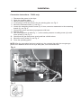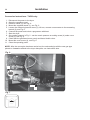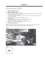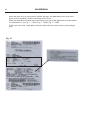
1
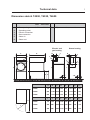
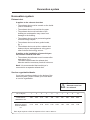
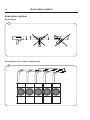
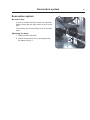
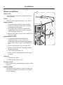
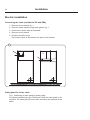
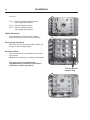
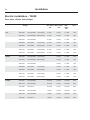
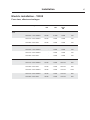
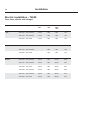
Installation manual T4290, T4530, T4650 Selecta Control 487 05 44 61/EN 08.38 Contents Contents Safety precautions......................................................................................5 Dimension sketch........................................................................................7 Technical data.............................................................................................8 Setup.........................................................................................................11 Door .........................................................................................................14 Special installation....................................................................................16 Exhaust system.........................................................................................17 Installation Steam installation.................................................................................22 Gas installation . ..................................................................................23 Electric installation...............................................................................31 Function check..........................................................................................39 Option: Adaptor for direct fresh-air intake................................................40 The manufacturer reserves the right to make changes to design and component specifications. Safety Precautions Safety Precautions Do not dry unwashed items in the machine The machine is not to be used if industrial chemicals have been used for cleaning. Do not allow minors to use the machine. Do not hose down the machine with water. The machine's door lock must under no circumstances be bypassed. Items that have been soiled with substances such as cooking oil, acetone, alcohol, petrol, kerosene, spot removers, turpentine, waxes and wax removers should be washed in hot water with an extra amount of detergent before being dried in the machine. Items such as foam rubber (latex foam), shower caps, waterproof textiles, rubber backed articles and clothes or pillows fitted with foam rubber pads should not be dried in the machine. Fabric softeners or similar products should be used as specified by the fabric softener instructions. The machine may not be used to dry floor mops that contain polypropylene. The final part of a drying cycle occurs without heat (cool down cycle) to ensure that the items are left at a temperature that ensures that the items will not be damaged. WARNING. Never stop the machine before the end of the drying cycle unless all items are quickly removed and spread out so that the heat is dissipiated. Remove garments from the machine as soon as they are dried. This prevents them from becoming creased and reduces the risk of spontaneous ignition. If the machine develops a fault, this must be reported to the person in charge as soon as possible. This is important both for your safety and that of others. The machine must not be located where a door, sliding door, etc., can block the machine's door The machine is not intended to be used by people (including minors) with reduced physical or mental capacity or lack of experience and knowledge. Such people must be instructed in the use of the machine by a person who has responsibility for their safety. Minors must be supervised to ensure that they do not play with the machine. Adequate ventilation has to be provided to avoid the back flow of gases into the room for appliances burning other fuels, including open fires. Gas heated tumble dryer: The machine is not to be installed in rooms containing cleaning machines with perchloroethylene, TRICHLOROETHYLENE or CHLOROFLUOROCONTAINING HYDROCARBONS as cleaning agents. If you can smell gas, • Do not switch on any equipment • Do not use electrical switches • Do not use telephones in the building • Evacuate the room, building or area • Contact the person responsible for the machine 7 Technical data Dimension sketch T4290, T4530, T4650 T4290 1 2 3 4 5 6 Door opening Operating panel Electric connection Gas connection Steam in Steam out Ø 580 T4530/T4650 Ø 810 7 Pipe connection, evacuation Steam heating Electric and gas heating B A M O 4 G P 5 3 2 3 1 6 N F C L E D H H 7 I A B C I D E F G H T4290 710 1120 1880 780 725 1610 470 135 T4530 960 1180 1995 720 650 1725 595 155 T4650 960 1370 1995 720 650 1725 595 155 I J L M N O P T4290 170 700 1810 1395 250 500 70 190 T4530 225 950 2120 1510 270 595 140 170 T4650 225 950 2300 1510 270 595 140 170 K K J 8 Technical data Technical data, T4290 Heating Electric Drum volume: Weight: Net Drum: Diameter Depth Revolutions per minute G-factor Load: Motor: Heat effect: Effect without reverse Effect with reverse Revolutions per minute: Motor 50 Hz Motor 60 Hz Electric heating Electric heating Gas heating Air consumption: Electric 13.5 kW Electric 18.0 kW Steam Gas Pipe connection: Evacuation Steam Condensate outlet Steam: 286 litres 286 litres 220 kg 220 kg 220 kg 680 mm 790 mm 44 rpm 0.8 680 mm 790 mm 44 rpm 0.8 680 mm 790 mm 44 rpm 0.8 13.5 kg 13.5 kg 13.5 kg 0.37 kW 2 x 0.37 kW 0.37 kW 2 x 0.37 kW 0.37 kW 2 x 0.37 kW 1400 rpm 1680 rpm 1400 rpm 1680 rpm 1400 rpm 1680 rpm 13.5 kW 18.0 kW Variable, depending on steam pressure 21.0 kW 430 m3/h 690 m3/h 925 m3/h 690 m3/h Ø 200 Ø 200 ISO 7/1-Rp1/2 ISO 7/1-Rp1/2 Noise level: Ø 200 100-1000 kPa 1000 kPa max. 80 Pa max. 80 Pa Gas pipe connection: Gas pressure: Gas 286 litres Recommended pressure (absolute) Max. allowable pressure Drop in pressure:Evacuation Steam max. 80 Pa ISO 7/1-R1/2 See page regarding pressure < 70 dB (A) < 70 dB (A) < 70 dB (A) 9 Technical data Technical data, T4530 Heating Electric Drum volume: Weight: Net Drum: Diameter Depth Revolutions per minute G-factor Load: Motor: Heat effect: Effect Revolutions per minute: Motor 50 Hz Motor 60 Hz Electric heating Electric heating Gas heating Air consumption:Electric 24.0 kW Electric 30.0 kW Steam Gas Pipe connection: Evacuation Steam: Condensate outlet: Steam: 528 litres 528 litres 300 kg 340 kg 300 kg 913 mm 812 mm 40 rpm 0.8 913 mm 812 mm 40 rpm 0.8 913 mm 812 mm 40 rpm 0.8 27 kg 27 kg 27 kg 2 x 0.37 kW 2 x 0.37 kW 2 x 0.37 kW 1400 rpm 1680 rpm 1400 rpm 1680 rpm 1400 rpm 1680 rpm 24.0 kW 30.0 kW Variable, depending on steam pressure 40.0 kW 840 m3/h 1060 m3/h 1380 m3/h 1160 m3/h Ø 200 Ø 200 ISO 7/1-Rp 3/4 ISO 7/1-Rp 3/4 Noise level: Ø 200 100-1000 kPa 1000 kPa max. 200 Pa max. 200 Pa Gas pipe connection: Gas pressure: Gas 528 litres Recommended pressure (absolute) Max. allowable pressure Drop in pressure: Evacuation Steam max. 60 Pa ISO 7/1 - R1/2 See page regarding pressure < 70 dB (A) < 70 dB (A) < 70 dB (A) 10 Technical data Technical data, T4650 Heating Electric Drum volume: Weight: Net Drum: Diameter Depth Revolutions per minute G-factor Load: Motor: Heat effect: Effect of drum motor Effect of fan motor Revolutions per minute: Motor 50 Hz, drum Motor 60 Hz, drum Motor 50 Hz, fan Motor 60 Hz, fan Electric heating Electric heating Gas heating Air consumption: Electric 30.0 kW Electric 36.0 kW Steam Gas Pipe connection: Evacuation Steam: Condensate outlet: Steam: Gas 650 litres 650 litres 650 litres 340 kg 345 kg 325 kg 913 mm 998 mm 44 rpm 0.9 913 mm 998 mm 44 rpm 0.9 913 mm 998 mm 44 rpm 0.9 35 kg 35 kg 35 kg 0.37 kW 0.80 kW 0.37 kW 0.80 kW 0.37 kW 0.80 kW 1400 rpm 1680 rpm 2800 rpm 3300 rpm 1400 rpm 1680 rpm 2800 rpm 3300 rpm 1400 rpm 1680 rpm 2800 rpm 3300 rpm 30.0 kW 36.0 kW Variable, depending on steam pressure 57.0 kW 1500 m3/h 1500 m3/h 1500 m3/h 1500 m3/h Ø 200 Ø 200 ISO 7/1-Rp 3/4 ISO 7/1-Rp 3/4 Ø 200 100-1000 kPa 1000 kPa Recommended pressure (absolute) Max. allowable pressure Drop in pressure: Evacuation Steam max. 340 Pa max. 340 Pa Gas pipe connection: max. 340 ISO 7/1-R3/4 Gas pressure: See page regarding pressure Noise level: < 70 dB (A) < 70 dB (A) < 70 dB (A) 11 Setup Setup T4290, T4530 1 When unpacking the machine, handle it with care. There are no transport clamps. A 500 Unpacking 10 10 Positioning Fig. 1 Position the tumble dryer so there is plenty of working room, both for the user and for the service technician. The distance from the wall or other equipment behind the tumble dryer should be at least 500 mm and the space at the sides at least 10 mm. Note that for servicing purposes access to the rear of the tumble dryer is required. A Mechanical installation The max. height adjustment of the feet is 15 mm. Min.150 mm A-A 2 Min. 45 mm Max. 50 mm Fig. 2 Adjust the machine to make it stand horizontally and stably on all four feet. 12 Setup Setup T4650 1 Unpacking A When unpacking the machine, handle it with care. There are no transportation brackets to remove. Fig. 1 From factory the dryer is equipped with 4 supporting feet A. Remove the dryer from the pallet At least two people are required to remove the dryer from the pallet. The tumble dryer is fastened to the pallet by 3 transportation screws. 2 1. Open filter door. Remove the 2 transportation screws by the front. 2. Remove the bottom back plate. Remove transportation screw by the back plate. Mount back plate. 3. Place a 1 1/2” steel pipe at the back of the dryer as shown in fig. 2. 4. Stand behind the dryer and tilt it forward. When the dryer rises from the pallet push the pipe under the dryer, fig. 3. 5. Push the dryer from the front so that it hangs off of the back edge of the pallet, fig. 4. 3 6. Remove the steel pipe by tilting the dryer forward while removing the pipe. 7. Install the 2 back feet (supplied the dryer). 8. Push the dryer backwards on the pallet until it leans on the 2 back feet. 9. Mount the 2 front feet. 10. Remove the pallet. 11. The dryer is now on the floor. If necessary, adjust the feet after the dryer is in its final position. See next page. 4 13 Setup Setup T4650 1 Fig. 1 Position the tumble dryer so that there is plenty of room for working, both for the user and for the service technician. The distance from the wall or other equipment behind the tumble dryer should be at least 500 mm and the space at the sides at least 10 mm. Note that for servicing purposes, access to the rear of the tumble dryer is required. A 500 Positioning 10 10 A Mechanical installation Fig. 2 Adjust the machine to make it stand horizontally and stably on all four feet. The max. height adjustment of the feet is 15 mm. Min.150 mm A-A 2 Min. 45 mm Max. 50 mm 14 Door Reversing the door 1 The dryer is usually delivered with a right hinged door but the door can be changed to left hinged position, as illustrated below, or vice versa. Door reversal instructions 1. Disconnect the power supply to the dryer. 2. Dismount the door. 3. Dismount locking unit A, fig. 1. 4. Remove the screws that secure the centre front panel to the dryer and remove the entire panel. A 2 5. Disconnect the door switch wires B and move them to the opposite side of the dryer, fig. 2. B Pull the wires through opening C and down through opening D. Also remember to move the bushing and mount it in opening D, fig. 3 & 4. 6. Dismount the bracket with switch and turn it 180°. Note! When turning the bracket the wires are facing downwards. Lead them upwards towards the operating panel and fasten them with cable strips. 3 7. Mount the bracket with switch on the left side and connect the wires as before. D To be continued on the following page. C 4 D 15 Door Continued 5 8. In order to prevent false air to enter, attatch the sealing strip around the drum casing edge on the same side as the door is to be hinged, fig. 5 & 6 - see how it is done by looking at the tape attatched on the opposite side. Note! The sealing strip is enclosed in the drum. 9. Make sure that the 4 guard strips on the casing are intact before mounting the front panel, fig. 7. 10. T4530/4650 only Remove the small cover plate on the centre front panel and mount it in the opposite corner. 6 11. Turn the front panel upside down and remount it. 12. Turn the door upside down and re-mount it. Test run Check for proper operation of the door switch, as follows: 1. Re-connect the power supply to the dryer 2. Attempt to start the dryer with the door open. It must not start. 3. Close the door and start the machine. Open the door. The dryer must stop. If the dryer starts with the door open, or fails to stop when the door is opened during operation, repair or replace the door switch, as necessary. 7 Ship installation 16 Installation on board a ship The four accompanying fittings are fastened to the foundation by means of 4 x M10 set screws (supplied with marine models). Fastening to the base If the dryer needs fastening to the base a kit containing 4 fittings can be ordered. Kit no. 472 77 77 01. The four fittings are fastened to the base by means of 4 x M10 expander bolts. Drilling plan 904 26 45 Type 4530 / 50 Type 4650 / 75 M10 706 A M10 A 1000 1253 = Type 4650 / 75 1067 = Type 4530 / 50 A A-A 45 A 45 45 26 Type 4290 / 30 M10 Evacuation system Evacuation system Air principle Fig. 1 The blower creates low pressure in the dryer, drawing air into the cylinder via the heating unit. The heated air passes through the garments and the cylinder vents. The air then flows out through a lint filter positioned straight below the drum. After this, the air is evacuated through the blower and exhaust system. It is very important that the dryer gets enough fresh air, see next section. 1 17 18 Evacuation system Evacuation system 1 Fresh-air A For maximum efficiency and the shortest possible drying time, it is important to ensure that fresh air is able to enter the room from the outside in the same volume as that blown out of the room. 5xA Fig. 1 To avoid a draught in the room, it is advisable to place the air inlet behind the dryer. Fig. 2 The area of the air inlet opening must be 5 times the size of the exhaust pipe area. The area of the inlet opening is the area through which the air can flow without resistance from the grating/slatted cover. See table on the following page. Note! Gratings/slatted covers often block half of the total fresh air vent area. Remember to take this into account The resistance in the grating/slats on the air inlet cover plate should not exceed 10 Pa (0.1 mbar). T4290: The air consumption is approximately 430 - 925 m3/h. T4530: The air consumption is approximately 840 - 1380 m3/h. T4650: The air consumption is approximately 1500 m3/h. 2 5xA 19 Evacuation system Evacuation system Exhaust duct It applies to the exhaust duct that: • The exhaust duct must be smooth on the inside (low air resistance). • The exhaust duct must lead into the open. • The exhaust duct must lead clear of the building as condensation may cause frost damage to the building. • The exhaust duct must be protected against rain and foreign objects. • The exhaust duct must have gentle bends, fig. 1. • The exhaust duct must not be a shared duct between dryers and appliances using gas or other fuels as their energy source. It applies to the installation of several dryers on a shared exhaust duct that: • The exhaust duct diameter must increase after each dryer, fig. 2. The table below shows the exhaust duct diameter and the necessary fresh-air inlet area. Note! It is recommended that each dryer is connected to a separate exhaust duct. Service organization/dealer If you have questions relating to the design of the exhaust system, please contact your local dealer or service organization. The exhaust duct diameter must not be reduced. No. of dryers 1 2 3 4 5 6 7 8 9 10 Exhaust duct diameter in mm 200 280 315 355 400 450 475 500 535 560 Minimum area of fresh-air intake in m2 0.15 0.30 0.45 0.60 0.75 0.90 1.05 1.20 1.35 1.50 Each dryer requires a fresh-air aperture of min. 400 x 400 mm. 20 Evacuation system Evacuation system Gentle bends 1 Several dryers on a shared exhaust duct 2 21 Evacuation system Evacuation system 1 Nonreturn flap In order to achieve the best result it is important that the dryer has the right volume of air to work with. From factory the nonreturn flap is set to be wide open. Adjusting the dryer 1. Dismount the back plate. 2. Adjust the amount of air by opening/closing the damper A, fig. 1. A 22 Installation Steam installation 1 Before start The steam pipe must be cut off and must not be under pressure. C Steam Steam 3-10 bar absolute pressure (130- 180°C). A Steam forward 1. The branch pipe’s branch must be located at the top of the main steam pipe to prevent condensation in the steam. 2. The branch pipe must have a descending gradient and must end at a height above the inlet connecting branch (A). D B E 3. Mount a plug valve (C) and a dirt collector (D) in the branch pipe. Condensation return 1. It is important that the branch pipe for condensed water on return to the main condensation pipe has a descending gradient and is lower than the outlet connecting branch (B). 2. Mount a dirt collector (D) in the return pipe. 3. Mount a mechanical water discharger behind the dirt collector (E). 4. Then mount a plug valve (C). 5. Mount pressure hoses between branch pipes and dryer. Leak test 1. Leak test the system. 2. Clean the dirt collectors (D). Function check The function check is described in the back of this manual. Pipe insulation All pipes must be insulated in order to reduce risk of burning. Insulation also reduces loss of heat to the surroundings. C D Installation Gas installation general To be carried out by qualified personnel Mount a shut-off valve upstream from the dryer. The gas connection to the dryer should be dimensioned to an output depending on the kW-rating of the dryer. The factory nozzle pressure setting corresponds to the fuel value given on the data label. Check that the nozzle pressure and fuel value correspond with the values in the gas tables on the following pages. If not, contact the supplier. Bleed the pipe system before connecting the dryer. After connection, test all joints for leaks. 23 24 Installation Converting instructions to another gas type Before installing the dryer affix the label "Read the user instructions" to the inside of the door, see pictures below. The label must have the correct country code - choose the correct label from the kit. GB, IE Read the technical instructions before installing the appliance. GB, IE Read the technical instructions before installing the appliance. Read the user instructions before lighting the appliance. Read the user instructions before lighting the appliance. This appliance may only be installed in a room if the room meets the appropriate ventilation requirements specified in the national installation regulations. This appliance may only be installed in a room if the room meets the appropriate ventilation requirements specified in the national installation regulations. 487229348.00. 487229348.00. GB, IE Read the technical instructions before installing the appliance. Read the user instructions before lighting the appliance. This appliance may only be installed in a room if the room meets the appropriate ventilation requirements specified in the national installation regulations. 487229348.00. 25 Installation Gas installation - table of pressure and adjustment This gas appliance has been build to run on natural gas group I2H and I2E(LL), commonly identified by GNH. The data label shows the injector size and the injector pressure and the countries that use this gas quality: DK, NO, SE, FI, CH, CZ, EE, LT, SL, TR, BG, RO, GB, ES, GR, IE, IT, PT, AT, LV, HU, IS, SK, DE, PL, LU and non-European countries. Before connecting the appliance please make sure that the supplied gas type is correct. Following gas conversions are possible: 1. Appliances to be installed to run on GNH or GNL in FR, BE: I2E+ 2. Appliances to be installed in NL, parts of DE and Non-European contries: I2L. 3. Appliances to be installed to run on LPG in: DK, NO, SE, FI, EE, LT, SL, TR, DE, NL, CH, CZ, HU, GR, MT, CY, LV, SK, LU, BG and Non-European contries: I3B/P . 4. Appliances to be installed to run on LPG in: GB, ES, GR, IE, IT, PT, CH, CZ, BE, FR, CY, EE, LV, LT, LU, RO: I3+ . 5. Appliances to be installed to run on LPG in: AT: I3B/P (50 mbar) inlet pressure. 6. Appliances to be installed to run on LPG in: PL: I3B/P (36 mbar) inlet pressure. Fig. 1 - T4290 only Gas group Injector size Ø mm (1) Air reducing plate (fig. 5) Inlet pressure (mbar) Injector pressure (mbar) Label no. (fig. 10 ) I2H, I2E(LL) 3.8 Ø38 20 10.5 DEFAULT I2E+ 3.3 Ø38 20/25 20/25 487266723 I2L (LL) 3.8 Ø38 20/25 15, 2 487266723 I3B/P, I3+ 2.2 NONE 30, 28/37 30, 28/37 487266721 I3B/P (36) 2.1 NONE 36 36 487266722 I3B/P (50) 2.2 NONE 50 50 487266722 Injector size Ø mm (1) Air reducing plate (fig. 7) Inlet pressure (mbar) I2H, I2E(LL) 5.6 Ø40 20 8 DEFAULT I2E+ 4.7 Ø40 20/25 20/25 487266733 I2L (LL) 6.2 Ø40 20,25 8 487266733 I3B/P, I3+ 3.2 Ø40 30, 28/37 30, 28/37 487266731 I3B/P (36) 3.05 Ø40 36 36 487266732 I3B/P (50) 3.2 Ø40 50 30 487266732 Fig. 2 - T4530 only Gas group Injector pressure (mbar) Label no. (fig 10) 26 Installation Fig. 3 - T4650 only Gas group Injector size Ø mm (1) Air reducing plate (fig. 9) Inlet pressure (mbar) Injector pressure (mbar) Label no. (fig. 10) I2H, I2E(LL) 6.5 Ø32 20 9.5 DEFAULT I2E+ 5.4 Ø32 20/25 20/25 487266738 I2L (LL) 6.5 Ø32 20,25 14 487266738 I3B/P, I3+ 3.8 Ø40 30, 28/37 30, 28/37 487266736 I3B/P (36) 3.5 Ø40 36 36 487266737 I3B/P (50) 3.8 Ø40 50 50 487266737 Installation Conversion instructions - T4290 only: 1. 2. 3. 4. 5. 6. 7. 8. 9. 10. 11. 12. Disconnect the power to the dryer. Open the operating panel. Remove nozzle (1), see Fig. 4. If converting to LPG also remove the air reducing plate, see Fig. 5. Mount the enclosed nozzle (1), see Fig. 1. Loosen the measuring branch screw (2) 1/4 turn; connect a manometer to the measuring branch (2), see Fig. 4. Connect the power and select a programme with heat. Start the dryer. See nozzle pressure in table Fig. 1 - set the nozzle pressure on setting screw (4) under cover screw (3), see Fig. 4. Check that the gas flame burns evenly and has a bluish colour. Mount the cover screw (3), see Fig. 4. Close the operating panel. NOTE: After the conversion has been carried out, the enclosed sign with the new gas type printed on it must be affixed to the dryer data plate, see instructions later. Fig. 4 1 4+3 2 Fig. 5 ø 27 28 Installation Conversion instructions - T4530 only: 1. 2. 3. 4. 5. Disconnect the power to the dryer. Open the operating panel. Remove nozzle (1), see Fig. 6. Mount the supplied nozzle (1), see Fig. 2. Loosen the measuring branch screw (2) 1/4 turn; connect a manometer to the measuring branch (2), see Fig. 6. Connect the power and select a programme with heat. Start the dryer. See nozzle pressure in Fig. 2 - set the nozzle pressure on setting screw (4) under cover screw (3), see Fig. 6. Check that the gas flame burns evenly and has a bluish colour. Mount the cover screw (3), see Fig. 6. Close the operating panel. 6. 7. 8. 9. 10. 11. NOTE: After the conversion has been carried out, the enclosed sign with the new gas type printed on it must be affixed to the dryer data plate, see instructions later. Fig. 6 1 4+3 2 Fig. 7 ø 29 Installation Conversion instructions - T4650 only: 1. 2. 3. 4. 5. 6. 7. 8. 9. 10. 11. 12. Disconnect the power to the dryer. Open the operating panel. Remove nozzle 1, see Fig. 8. Mount the supplied nozzle (1), see Fig. 3. If converting to LPG remove the air reducing plate with opening Ø32 and mount the one with opening Ø40 instead, see Fig. 3 & 9. Loosen the measuring branch screw (2) 1/4 turn; connect a manometer to the measuring branch (2), see Fig. 8. Connect the power and select a programme with heat. Start the dryer. See nozzle pressure in table Fig. 3 - set the nozzle pressure on setting screw (4) under cover screw (3), see Fig. 8. Check that the gas flame burns evenly and has a bluish colour. Mount the cover screw (3), see Fig. 8. Close the operating panel. NOTE: After the conversion has been carried out, the enclosed sign with the new gas type printed on it must be affixed to the dryer data plate, see instructions later. Fig. 8 1 4+3 2 Fig. 9 ø 30 Installation When the dryer is to be converted to another gas type, the data label on the rear of the dryer must be updated in order for the data to be correct. Place the data label enclosed in the conversion kit on top of the data label as shown below. For data label no. see Fig. 1 - T4290, Fig. 2 - T4530, Fig. 3 - T4650. If there are more than 1 data label, select the label with the correct country code and gas type. Fig. 10 Installation Electric installation To be carried out by qualified personnel The tumble dryer must be connected to its own fuse group and multi-pole main switch according to IEC 60947. The sizes of the fuse group and the effect are shown on the following page. The tumble dryer must be equipped with supplementary protection in accordance with heavy current regulations. For calculation of the connection cable dimension, please refer to local guidelines. Connecting the cable (within the EU and EEA) 1. Demount cover plate A, fig. 1 on the following page. 2. Pass the feeder cable through cable gland**, fig. 1 on the following page. 3. Turn knob* to ‘O’/‘OFF’ 4. Connect the feeder cable as illustrated on the following page. 5. Remount cover plate A . 6. Function check the dryer The function check is described in the back of this manual. * Lockable knob is fitted on machines type 4530 and 4650 for countries within the EU and EEA (the machine directive standard for disconnecting the electrical supply during servicing). 31 32 Installation Electric installation Connecting the cable (outside the EU and EEA) 1. Demount cover plate A, fig. 1. 2. Pass the feeder cable through cable gland**, fig. 1. 3. Connect the feeder cable as illustrated. 4. Remount cover plate A. 5. Function check the dryer. The function check is described in the back of this manual. 1 A A Cable gland for feeder cable Fig 1 Positioning of cable gland for feeder cable. On electric heated dryers type T4530 and T4650 the cable gland is not mounted. The cable gland is in the drum and has to be mounted on the beam. 33 Installation Electric installation - electric, gas, steam heated To be carried out by qualified personnel The tumble dryer must be connected to its own fuse group and pulti-pole main switch according to IEC 60947. 1 Connecting the cable Demount the cover plate from the supply unit. The cable is led through the cable gland to the terminal block and connected as illustrated. If there is a neutral conductor in the power supply line this must be connected to terminal N: Fig. 1 Gas and steam heated 1-phase Fig. 2 Gas and steam heated 1-phase with supply disconnector Fig. 3 Gas and steam heated 3-phase 2 To be continued on the following page 3 34 Installation Continued 4 Fig. 4 Gas and steam heated 3-phase with supply disconnector Fig. 5 Electric heated 3-phase Fig. 6 Electric heated 3-phase with supply disconnector Cable dimension For calculation of the connection cable dimension, please refer to local guidelines. 5 L1 Fuse group and effect L2 The sizes of the fuse group and the effect are shown on the following pages. L3 Function check The function check is described in the back of this manual. Note! Correct direction of rotation is important! N The dryer must be equipped with supplementary protection in accordance with heavy current regulations. 1.25 A external control only 6 35 Installation Electric installation - options 1 External connection - 100 mA A special connection terminal is located on the connection console fig. 1. This connection can be used as external control of a fan. X1 X2 Gnd. The terminal for external control is equipped with 110V/ max.100mA and is intended solely for the operation of a contactor Ext. connection Max. 100mA Max. connection 100mA. Gnd. must not be used for earthing of external board. 2 External connection - 1.25 A A special connection for an external fan can be chosen on the connection console. This connection is only available on 400V-3N machines. Mount cable for external connection on contactor K7 in K7-2 and K7-4, fig.2. Connect earth conductor to earth terminal for external connection, fig. 1. Max. connection 1.25A. N 230V K7-2 K7-4 K7-6 K7-14 K7 External connection Max. 1.25A 487 19 69 48.01 36 Installation Electric installation - T4290 Fuse sizes, effects and voltages Voltage Gas Steam Electric Heat effect Motor effect kW kW Max. effect kW Fuse 230-240V 3AC 50/60Hz w/reversing 21 kW 1.5 kW 1.5 kW 10A 230-240V 3AC 50/60Hz wo/reversing 21 kW 1.0 kW 1.0 kW 10A 230-240V 1AC 50/60Hz 21 kW 1.5 kW 1.5 kW 10A 400-480V 3AC 60HZ w/reversing 21 kW 1.5 kW 1.5 kW 10A 400-480V 3AC 60HZ wo/reversing 21 kW 1.0 kW 1.0 kW 10A 400-415V 3AC 50Hz w/reversing 21 kW 1.5 kW 1.5 kW 10A 400-415V 3AC 50Hz wo/reversing 21 kW 1.0 kW 1.0 kW 10A 230-240V 3AC 50/60Hz w/reversing 1.5 kW 1.5 kW 10A 230-240V 3AC 50/60Hz wo/reversing 1.0 kW 1.0 kW 10A 230-240V 1AC 50/60Hz 1.5 kW 1.5 kW 10A 400-480V 3AC 60HZ w/reversing 1.5 kW 1.5 kW 10A 400-480V 3AC 60HZ wo/reversing 1.0 kW 1.0 kW 10A 400-415V 3AC 50Hz w/reversing 1.5 kW 1.5 kW 10A 400-415V 3AC 50Hz wo/reversing 1.0 kW 1.0 kW 10A 230-240V 3AC 50/60Hz 13,5 kW 1.5 kW 15.0 kW 50A 400-415V 3AC 50/60Hz 13,5 kW 1.5 kW 15.0 kW 25A 440-480V 3AC 60 Hz 13,5 kW 1.5 kW 15.0 kW 20A 230-240V 3AC 50/60Hz 18 kW 1.5 kW 19.5 kW 50A 400-415V 3AC 50/60HZ 18 kW 1.5 kW 19.5 kW 35A 440-480V 3AC 60 Hz 18 kW 1.5 kW 19.5 kW 25A 37 Installation Electric installation - T4530 Fuse sizes, effects and voltages Voltage Gas Steam Electric Heat effect Motor effect kW kW Max. effect kW Fuse 230-240V 3AC 50/60 Hz 40 kW 1.5 kW 1.5 kW 10A 230-240V 1AC 50/60Hz 40 kW 1.5 KW 1.5 kW 10A 400-415V 3AC 50/60Hz 40 kW 1.5 kW 1.5 kW 10A 440-480V 3AC 60Hz 40 kW 1.5 kW 1.5 kW 10A 230-240V 3AC 50/60 Hz - 1.5 kW 1.5 kW 10A 230-240V 1AC 50/60Hz - 1.5 kW 1.5 kW 10A 400-415V 3AC 50/60Hz - 1.5 kW 1.5 kW 10A 440-480V 3AC 60Hz - 1.5 kW 1.5 kW 10A 230-240V 3AC 50/60Hz 24 kW 1.5 kW 25.5 kW 80A 400-415V 3AC 50/60Hz 24 kW 1.5 kW 25.5 kW 50A 440-480V 3AC 60Hz 24 kW 1.5 kW 25.5 kW 50A 230-240V 3AC 50/60Hz 30 kW 1.5 kW 31.5 kW 100A 400-415V 3AC 50/60Hz 30 kW 1.5 kW 31.5 kW 50A 440-480V 3AC 60Hz 30 kW 1.5 kW 31.5 kW 50A 38 Installation Electric installation - T4650 Fuse sizes, effects and voltages Voltage Gas Steam Electric Heat effect kW Motor effect kW Max. effect kW Fuse 230-240V 3AC 50/60 Hz 57 kW 2 kW 2 kW 10A 400-415V 3AC 50/60Hz 57 kW 2 kW 2 kW 10A 440-480V 3AC 60HZ 57 kW 2 kW 2 kW 10A 230-240V 3AC 50/60 Hz - 2 kW 2 kW 10A 400-415V 3AC 50/60HZ - 2 kW 2 kW 10A 440-480V 3AC 60Hz - 2 kW 2 kW 10A 230-240V 3AC 50/60Hz 30 kW 2 kW 32 kW 100A 400-415V 3AC 50/60Hz 30 kW 2 kW 32 kW 50A 440-480V 3AC 60Hz 30 kW 2 kW 32 kW 50A 230-240V 3AC 50/60Hz 36 kW 2 kW 38 kW 100A 400-415V 3AC 50/60Hz 36 kW 2 kW 38 kW 63A 440-480V 3AC 60Hz 36 kW 2 kW 38 kW 63A 39 Function check To be carried out by qualified personnel Function check 1 Check whether the drum is empty and the door has been closed. Start the dryer Check if the micro switches are working properly: The dryer must stop if the loading door is opened. The dryer must stop if the filter door is opened. Correct direction of rotation Fig. 1 Correct direction of rotation on fan wheel: clockwise. For dryers with a 3-phase motor the direction of rotation must be checked. If the direction of rotation is not correct, swop two phases on the connection terminal. Final test Let the dryer work for 5 minutes on a program that requires heat. Then check whether the heating is working by opening the front door and feel the heat. If the above tests-points are in order, the dryer is ready for use. Safety screws Fig. 2 Remember to fit the screws on the sides of the front panel. Service organisation/dealer If deficiencies or errors are detected, please contact your local service organisation / dealer. 2 40 Fresh-air intake Option: Adaptor for direct fresh-air intake - dimension sketch Gas- and electric heated dryers 1 Adaptor: T4290 T4530, T4650 no. 988 80 20 41 no. 988 80 20 42 2 Diameter: T4290 T4530, T4650 Ø 315 Ø 400 T4290 = 240 T4530 = 310 T4650 = 310 T4290 = 1195 T4530 = 1255 T4650 = 1445 2 1440 1 www.electrolux.com/laundrysystems Share more of our thinking at www.electrolux.com