1
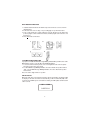
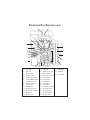
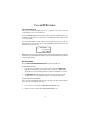
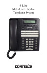
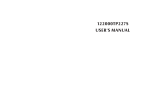
OWNER’S
INSTRUCTION MANUAL
CALLER ID TYPE II
LINE POWERED TELEPHONE
2211
THANK YOU
FOR PURCHASING THE
COLLEAGUE CALLER ID TYPE II
LINE POWERED TELEPHONE
We want you to know all about your new Colleague Telephone,
how to install it, the features it provides, and the services you can
expect from its use. We have included this information in your Owner’s
Instruction Manual.
PLEASE READ BEFORE INSTALLING
AND USING YOUR NEW TELEPHONE EQUIPMENT.
TABLE OF CONTENTS
IMPORTANT SAFETY INSTRUCTIONS ............................................................. 2
TELEPHONE USAGE ............................................................................................
SETUP/INSTALLATION ................................................................................
WALL MOUNT INSTRUCTIONS ...................................................................
24V/90V MESSAGE WAITING SWITCH ......................................................
INITIAL DISPLAY ........................................................................................
4
4
5
5
5
TELEPHONE PART IDENTIFICATION ................................................................ 6
TELEPHONE FEATURES ..................................................................................... 7
TONE DIALING ............................................................................................ 7
RECEIVING A PHONE CALL ........................................................................ 7
PLACING A PHONE CALL ........................................................................... 7
SPEAKERPHONE BUTTON .......................................................................... 7
AUTOMATIC MEMORY ................................................................................ 8
TO STORE A PHONE NUMBER IN MEMORY ........................................... 8
TO DIAL A PHONE NUMBER IN MEMORY ............................................... 8
VOLUME BUTTON ....................................................................................... 9
REDIAL BUTTON ......................................................................................... 9
PAUSE BUTTON .......................................................................................... 9
HOLD BUTTON ............................................................................................ 9
FLASH BUTTON .......................................................................................... 9
DATA PORT ................................................................................................ 10
MUTE BUTTON ........................................................................................... 10
RELEASE BUTTON ..................................................................................... 10
VOICE MAIL BUTTON ................................................................................ 10
HEADSET COMPATIBLE ............................................................................. 10
CALLER ID FEATURES ..................................................................................... 11
CALL WAITING DISPLAY .......................................................................... 11
MESSAGE WAITING ................................................................................... 11
RECEIVING CALLS .................................................................................... 12
REVIEWING CALLS ................................................................................... 12
DELETING CALLS .....................................................................................
MESSAGE ERROR .....................................................................................
PRIVATE CALLS ........................................................................................
UNKNOWN CALLS ....................................................................................
13
13
14
14
TELEPHONE SERVICE PROBLEMS ................................................................. 15
MAINTENANCE INFORMATION ....................................................................... 16
TELEPHONE REPAIR ......................................................................................... 17
FCC INFORMATION .......................................................................................... 18
IMPORTANT SAFETY INSTRUCTIONS
Always follow basic safety precautions when using your telephone equipment to reduce the risk of fire, electrical shock, and injury.
1.
Read and understand all instructions in the Owner’s Instruction Manual.
2.
Read all warnings and follow all instructions marked on the product.
3.
Unplug this product from the wall outlet before cleaning. Use a damp
cloth for cleaning. Do not use liquid or aerosol cleaners.
4.
Do not use the telephone near water. For example, do not use near a
bathtub, wash bowl, kitchen sink, laundry tub, swimming pool, or in a wet
basement.
5.
Do not place this product on an unstable cart or stand. The product may
fall causing serious damage to the product.
6.
Use only the type power source indicated on the label. If you are not sure
of the type power supply to your home, consult your dealer or local power
company.
7.
Do not place any objects on the telephone line cord. Do not locate the
telephone where the line cord will be walked on.
8.
Do not block or cover ventilation slots and openings in the bottom of
the telephone. The openings should never be blocked by placing the
telephone on a bed, sofa, rug, or other similar surfaces. The telephone
should never be placed near or over a radiator or heat register. The
telephone should never be placed in a built-in installation unless proper
ventilation is provided.
9.
Never spill liquid on the telephone or push objects of any kind through
ventilation slots. Liquid or objects may touch dangerous voltage points
or short out parts that could result in a risk of fire or electrical shock.
2
10.
Do not disassemble this product. Opening or removing covers may
expose you to dangerous voltages or other risks. Incorrect reassembly
can cause electrical shock when the product is subsequently used.
11.
Do not overload outlets and extension cords. Some telephones
require AC power from an outlet. Overloading the outlets can result in
the risk of fire or electric shock.
12.
Avoid using a telephone during a local thunderstorm. There may be a
remote risk of electrical shock from lightning.
13.
Do not use a telephone to report a gas leak in the vicinity of the leak.
14.
Unplug the telephone from the wall outlet and refer servicing to
qualified service personnel under the following conditions:
•
When the line cord is frayed or plugs damaged.
•
If liquid has been spilled into the telephone.
•
If the telephone has been exposed to rain or water.
•
If the telephone does not operate properly by following the operating
instructions. (Adjust only those controls covered by the operating
instructions. Improper adjustment of other controls may result in
damage and will often require extensive work by a qualified
technician to restore the product to normal operation.)
•
If the telephone has been dropped or the housing damaged.
•
If the telephone exhibits distinct change in performance.
SAVE THESE INSTRUCTIONS
15-101-613
3
TELEPHONE USAGE
SET UP/INSTALLATION
1. Connect the telephone line cord.
a. To connect without an answering machine.
•
Use the new line cord to connect the PHONE jack of your new caller ID phone
to the modular wall jack.
b. To connect with an existing answering machine.
•
Use the existing line cord supplied to connect the LINE jack of your answering
machine to the wall modular line jack.
•
Use the new line cord supplied to connect the telephone’s jack of your new
Caller ID phone to the PHONE jack of your answering machine.
•
Set your answering machine to answer the phone after 2 or more rings.
2. Place the unit on a flat table or mount it on a wall. If you desire to place it on a wall,
use the wall mount bracket and short line cord supplied to accomplish the wall
mounting.
4
WALL MOUNT INSTRUCTIONS
1. Install the wall mount bracket in wall mount position and route cords as shown in
diagram below.
2. Connect the line cord. See Step 1 on preceding page for specific instructions.
3. Push out the handset hook and reattach in opposite direction for the wall mount
position, plug the coiled cord into the handset, and then plug the other end of the cord
into the base.
4. Place the handset on the base.
24/90V MESSAGE WAITING LAMP
If your phone is installed behind a Message Waiting enabled PBX, you will need to set the
MW switch in order to receive the Message Waiting indication.
1. Locate the switch under the plastic cover on the right hand side of the faceplate
where the memory keys are located.
2. For 90V PBX Message Waiting Indication, move the switch to the position marked
“90V”. For 24V PBX Message Waiting Indication, move the switch to the position
marked “24V”.
Note: The unit is shipped in the off position.
INITIAL DISPLAY
When the unit is first connected to the telephone line, the information shown below will
be displayed. The time and date are automatically set when a Caller ID (CID) call is
received. The unit will keep the current time accurately, and will update each time a CID
call is received.
1/01
AM
12:00
CORTELCO
5
TELEPHONE PART IDENTIFICATION
2
1
23
24
25
26 27 28
29
30
22
3
21
31
20
19
4
18
5
17
6
16
15
14 13 12 11 10 9
7
8
LCD Display
1
Line Jack
15
Hold LED
29
2
Data Jack
16
Handset Cord Jack
30
VM Button
3
Ringer Switch
17
Mem Dial Button
31
Flash Button
4
Speaker Volume
18
Mute Button w/ LED
5
2.5mm Headset Jack
19
Volume Button
6
Headset Off/On Switch
20
Delete Button
7
RJ45 Headset Jack
21
Handset Hook
8
One-Touch Memory
22
Hook Switch
9
Pause Button
23
Store Button
10
Redial Button
24
Review Down Button
11 Speakerphone LED
25
Customized Logo
12
Speakerphone Button
26
Release Button
13
Hold Button
27
Review Up Button
14
Memory Index
28
Message LED
6
TELEPHONE FEATURES
TONE DIALING
This unit is capable of only DTMF dialing. This phone is not compatible with pulse dialing.
RECEIVING A PHONE CALL
1. Be sure the RINGER switch is set to the HI or LOW position.
2.
When the phone rings and the caller’s information shows on the display window
(refer to Using the Caller ID Function), lift the handset or press the SPEAKERPHONE button and begin your conversation.
3.
Set the Ringer switch to the OFF position when you do not want to be interrupted
by the phone ringing. Remember to set the ringer switch back to Hi or Low when
you want to receive calls again.
PLACING A PHONE CALL
1. Lift the handset or press the SPEAKERPHONE button and wait for a dial tone.
2.
Dial the telephone number you wish to call. The number will appear on the display
window.
SPEAKERPHONE BUTTON
1. Receiving Incoming Calls
a. When the phone rings and the caller’s information shows on the display
window (refer to Using the Caller ID Function), press and release the
Speakerphone button and talk normally into the built-in microphone from a
distance of 5-6 inches.
b. You can adjust the volume of the caller’s voice by sliding the VOLUME
CONTROL on the right side of the phone.
c. After the conversation has finished, press the SPEAKERPHONE button to
hang up.
2.
To Make A Call
a. Press and release the SPEAKERPHONE button.
b. When you hear a dial tone, dial the number or press the auto memory
button just as you would on any other push-button telephone. The number
will appear on the display window.
7
c.
d.
When your party answers, adjust the sound level of his or her voice by sliding
the VOLUME CONTROL located on the right side of the phone.
After the conversation has finished, press SPEAKERPHONE to hang up.
Note:
1. If you wish to switch from speakerphone to handset, simply lift the handset.
2. If you wish to switch from handset to speakerphone, press and release
Speakerphone and then hang up the handset.
MEMORY
To Store A Number In Memory:
Note: Must be off-hook to store a number in memory
1. Press the STORE button, [SAVE TO?] appears on the display
window.
2.
Press the desired memory location.
•
To store in an auto memory button (located on right-hand side of base) - Press
1, 2, 3, or 11).
•
To store in a keypad memory location - Press one of the keypad buttons (l,
2, 3, or 0).
3.
[ENTER NUM >] appears in the display. Dial the telephone number (24 digits
maximum) to store in memory.
Note: The memory locations can be chained together to store numbers of
longer length.
4.
Press STORE again.
5.
Use pull out memory index to write in name and the memory button where it is
stored.
To Dial A Phone Number In Memory
1. Lift the handset and wait for a dial tone.
2.
3.
Press any memory location.
•
To dial an auto memory button (located on right-band side of base) - Press
the desired auto memory button (1, 2, 3.... or 11).
•
To dial a keypad memory location - press the MEM DIAL button first, and then
the desired keypad button (1, 2, 3.... or 0).
The number will be displayed and dialed automatically.
8
VOLUME BUTTON
A built-in amplifier feature allows you to increase the listening volume in the receiver of
the handset when speaking with your party. When needed, press the VOLUME button
to achieve four different levels. The volume remains the same between calls. It does
not return to a nominal level.
REDIAL BUTTON
1. If the number you dialed is busy, or you want to call the last number dialed again,
lift the handset, or press and release the hookswitch for a new dial tone.
2.
Press REDIAL. The number will appear on the display window.
3.
The last number called (32 digits maximum) will automatically be redialed.
PAUSE BUTTON
The PAUSE button allows you to insert a 3.6-second pause in the dialing sequence. This
is particularly useful if you are connected to a PABX system where you must dial an
access code (usually the number 9) to obtain an outside line.
1. Press the PAUSE button once and release at any point in the dialing sequence
where a pause is desired.
2. The PAUSE button can be pressed more than once to create a longer pause.
HOLD BUTTON
1. To place a call on hold, press the HOLD button and hang up the handset. The HOLD
Indicator will light up and remain lighted until you resume your conversation.
2.
To resume your conversation, lift the handset or that of any extension phone on the
same line or press and release SPEAKERPHONE. The HOLD indicator will go out
and your call can continue.
FLASH BUTTON
This telephone provides a line break signal for accessing PABX service or for convenient use of Call Waiting from your local telephone company. If you have Call Waiting
service, you can alternate the Call Waiting function per the following instructions.
1.
While having a conversation, another party calls and you hear a tone.
2.
Press the FLASH button once and release. The first conversation is placed on hold
and the second call can be answered.
3.
To return to the original conversation, press the FLASH button again and
release.The first caller can be spoken to again and the second call is placed on
hold.
9
DATA PORT
This is a connection which is in parallel with the telephone line. It allows the connection
of a device such as a modem, caller ID, or an answering machine.
MUTE BUTTON
Press MUTE to speak without the person on the phone hearing your conversation. The
MUTE Indicator will light up and remain lighted until you resume your conversation. To
resume your conversation, press MUTE. The MUTE indicator will go out and your call
can continue.
RELEASE BUTTON
To end a conversation, press the RELEASE button once.
VOICEMAIL BUTTON
Press the VOICE MAIL button to dial the voicemail access number.
Note: To store the Voice Mail Number, press STORE. Then press the VOICE MAIL button.
Enter the desired Voice Mail Number (max of 24 digits). Press store again to save the
number into memory.
HEADSET COMPATIBLE
The slide switch must be located in the proper position for this feature to work. The
headset can be turned on and off by using the handsfree button. Compatible with 2.5mm
and RJ45 headsets.
Note: Use the Slide Switch located on the right side of the phone base to set On or Off.
10
CALLER ID FEATURES
CALL WAITING DISPLAY
In the past, if you had call-waiting service, a tone alerted you there was a new call
coming while you were on an existing call.
Now our Call Waiting Caller ID not only tells you there is another call waiting, but lets you
know who the caller is before you answer it. The call waiting information will be shown
on the unit’s display.
Press the FLASH button to put the existing call on hold and answer the new call. No
matter whether you answer the call or not, the Call Waiting Caller ID will store the call
information for future reference.
4/15 01:45
Å
123-456-7891
PM
CALL #
01
JOHN SMITH
Note: Make sure you have subscribed to both Call Waiting Caller ID and Caller ID
service from your local telephone company. If you only have Caller ID service, the unit
works for Caller ID only.
MESSAGE WAITING
This unit’s MESSAGE WAITING DETECTION is for FSK, 24 and 90 Volt.
IF YOUR SERVICE IS FSK:
1. If you have a voice mailbox service from the phone company, the MESSAGE
light indicator will flash (green) and the message envelope icon will blink in the
display when a message waiting signal (on) from the Central Office is received.
2.
The MESSAGE light indicator will go off and the message envelope icon will
disappear if the message waiting off signal is sent from the Central office.
IF YOUR SERVICE IS 24V OR 90V:
Note: The Message Waiting switch must be in the proper position under the plastic
memory insert on the right side of the base.
1.
If you receive a voice mail, the red MESSAGE LED will flash (red).
2.
After the message is retrieved, the MESSAGE LED will go off.
11
This unit may not be activated or deactivated under certain conditions. For example,
when you retrieve your message from an outside phone (not your own telephone
number), the MESSAGE indicator may not be canceled when you return home. If you
experience this situation, pick up the receiver and hang up. The MESSAGE indicator will
cancel.
RECEIVING CALLS
1. When the telephone is not in use and a new call is received, the display will show
the phone number, the caller’s name, and time and date of the call.
4/15 01:45
123-456-7891
PM
CALL #
01
JOHN SMITH
2.
After 16 seconds with no activity, the display will default to the Stand-By screen
and remain on until another call is received or a button is pressed. This will show
you the total number of calls stored and the number of new calls that have not been
reviewed.
4/15 01:45
60
60
NEW TOTAL
PM
REVIEWING CALLS
1.
Press the REVIEW UP (
the incoming stored calls.
) or REVIEW DOWN (
) button to review
2.
When you have reached the end of the call records, the display will start at the
beginning of the call list again.
NOTE: A MAXIMUM OF 60 CALLER ID RECORDS CAN BE STORED.
12
DELETING CALLS
1. To delete an individual call: When reviewing calls, you can delete an individual
call by pressing the DELETE button once. The display will show DELETE?.
Press Delete again to confirm the deletion. The display will be erased and the
rest of the records will be renumbered.
4/15 01:45
123-456-7891
PM
CALL #
01
DELETE?
2.
To delete all calls: When reviewing calls, you can delete all calls by pressing and
holding DELETE for more than 3 seconds. Then [DELETE ALL]’ will appear. Press
DELETE to confirm you really want to erase all records. [-EMPTY LIST-] appears
on the display to show there are no calls stored in memory.
4/15 01:45
123-456-7891
PM
CALL #
01
DELETE ALL?
- EMPTY LIST -
MESSAGE ERROR
•
The display indicates [-ERROR-]” if your unit receives a call that has an
error in the transmission or reception.
- DATA ERROR -
13
PRIVATE CALLS
•
If the caller has exercised the option to block his number from being sent,
only his name will display on the screen when this information is received.
4/15 01:45
PM
CALL #
01
JOHN SMITH
•
If the caller has exercised the option to block his name from being sent, [PRIVATE
CALLER] and his telephone number will be displayed on the screen.
4/15 01:45
123-456-7891
PM
CALL #
01
- PRIVATE CALLER -
•
If the caller has exercised the option to block his name and number from being sent,
then [PRIVATE CALLER] will be displayed on the screen.
4/15 01:45
PM
CALL #
01
- PRIVATE CALLER UNKNOWN CALLS
•
When the telephone company is unable to provide information of the caller’s
telephone number, only his name will display on the screen when this informa
tion is received.
4/15 01:45
PM
CALL #
01
JOHN SMITH
•
When the telephone company is unable to provide information of the caller s name,
[UNAVAILABLE] and his telephone number will be displayed on the screen.
4/15 01:45
123-456-7891
PM
CALL #
01
- UNAVAILABLE -
•
When the telephone company is unable to provide information of the caller s name
and number, [UNAVAILABLE] will be displayed on the screen.
4/15 01:45
PM
CALL #
01
- UNAVAILABLE -
14
TELEPHONE SERVICE PROBLEMS
If you have any problems with your telephone equipment service, determine
if the problem is with your unit or the telephone company lines. BEFORE CALLING THE
TELEPHONE COMPANY, be aware that they may charge you for a service call if the
problem is caused by your telephone equipment.
TROUBLESHOOTING
PHONE DOES NOT RING
1. HI/LOW/OFF ringer switch is set to OFF position
2. Line cord is disconnected at telephone outlet or at telephone end.
3. Phone is OFF HOOK. Make certain the hookswitch is depressed when the handset
is in the cradle.
4. SPEAKERPHONE indicator is on. Turn off speakerphone.
NO DIAL TONE
Wire is disconnected at telephone jack or at wall jack. Test the telephone in a different
wall jack. If it works, the first jack may be defective.
HAVE DIAL TONE BUT CANNOT DIAL OUT
Check if the PULSE/TONE switch is at the correct position.
REDIAL BUTTON DOES NOT FUNCTION
The telephone may have been momentarily disconnected from the telephone jack.
CALLERS ARE NOT DISPLAYED ON THE SCREEN
1. Verify that you have subscribed to the appropriate service (Caller ID and Call
Waiting Caller ID) from your telephone company. If you only subscribed to the Caller
ID service this unit will not display the call waiting caller ID information.
2.
Check if your answering machine is set to answer the call before 2 rings.
NO CALLER INFORMATION IS DISPLAYED WHEN HEARING THE CALL WAITING
AUDIO SOUND
1. Verify that you have subscribed to the Call Waiting Caller ID service from your
telephone company.
15
MESSAGE ERROR HAPPENS FREQUENTLY
1. Caller information was not transmitted properly. Check with your telephone
company to see if there is a problem with your phone line.
Since our special design will always retain your stored call records, we
encourage you to disconnect all the telephone cords and adapter; and then
reinstall the unit step by step per this instruction manual before you ask for service.
MAINTENANCE INFORMATION
Treat your telephone equipment with care for trouble-free performance. Avoid
dropping the handset. Carefully place the handset on-hook after use.
Avoid putting near heating appliances and devices that generate electrical noise (for
example, motors and florescent lamps).
Clean your telephone equipment with a damp cloth. Stains may be removed with
a mild soap. Do not use liquid or aerosol detergents or cleaning agents.
Do not expose to direct sunlight or moisture
Retain the original package in case you need to ship it at a later date.
16
TELEPHONE REPAIR
DO NOT ATTEMPT TO REPAIR THIS PRODUCT YOURSELF. Call Waiting Caller ID
Telephones manufactured by CORTELCO must be returned to us for repair.
You can return your telephone to CORTELCO for repair or replacement in
accordance with our LIMITED WARRANTY.
CORTELCO warrants THIS PRODUCT against defects in material and workmanship
in accordance with our LIMITED WARRANTY. If your telephone is returned for
repair, include a copy of your sales receipt containing the date-of-purchase. DO NOT
INCLUDE THE ORIGINAL SALES RECEIPT.
If date-of-purchase is not included, the factory date printed on the label on the
bottom of your telephone will be used as the date-of-purchase. The factory date
allows six months for distribution and sale of this product.
If you return your telephone for repair, the warranty period is not extended. The
original date-of-purchase continues to apply to your warranty.
OUT-OF-WARRANTY REPAIR We will repair this product for a nominal fee after the
LIMITED WARRANTY has expired if you send it to us in a complete and undamaged
condition. The repaired Call Waiting ID will be shipped to you C.O.D., freight collect.
RETURN-FOR-REPAIR PACKAGING If you are returning a unit to us for repair, package
it carefully, preferably in the original carton. Be sure to include your return address, a
copy of the sales receipt showing date-of-purchase, and a note describing the problem
you have with your Call Waiting Caller ID Telephone. Shipping must be prepaid. If the
telephone is in warranty, it will be repaired or replaced, at our option, at no cost to you,
and it will be returned shipping prepaid.
Ship your Call Waiting Caller ID (shipping prepaid) to:
CORTELCO REPAIR CENTER
1703 SAWYER ROAD
CORINTH, MS 38834
17
FCC INFORMATION
DESIGN COMPLIANCE Your telephone is designed to comply with FCC Rules and
Regulations, Part 68. It can be connected to the telephone network as FCC-registered
terminal equipment. The registration number is printed on the label on the bottom of your
telephone.
NOTIFICATION TO THE TELEPHONE COMPANY As a customer of the local Telephone
company, you must, if they ask, tell them before connecting your telephone to the
telephone company lines. The telephone company may need the FCC registration
number and the ringer equivalence of the telephone. This information is printed on a label
on the bottom of your telephone.
RINGER EQUIVALENCE The ringer equivalence indicates the amount of power that
your telephone draws from the telephone company line during ringing. The number is
printed on the label on the bottom of your telephone.
If you have more than one telephone (or other terminal device) connected to the
telephone company line, you should total the ringer equivalence numbers (REN s), and
be sure that the total is not more than five. Your telephones may not ring if the total is
more than five. Also, in some rural locations, your telephone may not ring if the REN total
is more than three.
RESTRICTIONS You must not connect your telephone to coin-operated lines or party
lines.
INTERFERENCE POTENTIAL Your telephone has a push-button dial that generates
radio frequency energy. If not properly used, it may interfere with radio and television
reception. If the telephone does cause interference with reception, move the radio or
television to another electrical circuit or another location. If necessary, you may need to
seek advice from an experienced technician.
INSTALLATION This model telephone must be connected to the telephone company
lines through a modular jack. The required USOC for the modular jack is RJ11C for desk
mounting and RJ11W for wall mounting. The USOC number is printed on the label on the
bottom of your telephone.
TYPE OF DIALING Your telephone has a push-button TONE dial. You must have TONE
service from your telephone company to use your telephone for dialing. Note that you
will usually be charged extra for TONE service.
HEARING-AID COMPATIBILITY The handset on your telephone will work with magnetically-coupled hearing aids. You can use a hearing aid equipped with a T (Telephone)
switch.
IN CASE OF TROUBLE If your telephone should cause problems on the telephone line,
the telephone company can temporarily disconnect your service. The telephone company must then notify and allow you to correct the problem.
The telephone company may from time to time change its lines or equipment. They
must notify you if planned changes will affect your telephone service, to allow you to
take steps to prevent interruptions.
18
LIMITED WARRANTY
If you purchased this product new in the U.S. or Puerto Rico, CORTELCO
warrants it against defects in material and workmanship for a period of two
(2) years from the date of original purchase. This warranty is in lieu of all
other express warranties. During the warranty period, CORTELCO agrees to
repair or, at its option, replace the defective product, or any part of it without
charge for parts or labor. This is your exclusive remedy. This warranty does
not cover damage resulting from accident, misuse, abuse, improper installation
or operation, lack of reasonable care, the affixing of any attachment not
provided by CORTELCO with the product and loss of parts. The warranty is
voided in the event any unauthorized person alters or repairs the unit.
Telephone companies use different types of equipment and offer various types
of services to customers. CORTELCO does not warrant that this product
is compatible with the type of equipment of any particular phone company or the services provided by it.
CORTELCO DISCLAIMSANY IMPLIED WARRANTY, INCLUDING THE WARRANTY
OF MERCHANTABILITYAND THE WARRANTY OF FITNESS FOR A PARTICULAR
PURPOSE, AS OF THE DATE ONE YEAR FROM THE ORIGINAL PURCHASE OF
THE PRODUCT. CORTELCOASSUMES NO RESPONSIBILITY FOR ANY SPECIAL,
INCIDENTAL OR CONSEQUENTIAL DAMAGES.
THIS WARRANTY GIVES YOU SPECIFIC LEGAL RIGHTS, AND YOU MAY HAVE
OTHER RIGHTS WHICH VARY FROM STATE TO STATE. SOME STATES DO NOT
ALLOW THE EXCLUSION OR LIMITATION OF SPECIAL, INCIDENTAL OR CONSEQUENTIAL DAMAGES OR LIMITATIONS ON HOW LONG AN IMPLIED WARRANTY
LASTS, SO THE ABOVE EXCLUSION AND LIMITATION MAY NOTAPPLY TO YOU.
If failure occurs and your Call Waiting ID is in warranty, service shall be provided
by returning it to CORTELCO - Repair Center, 1703 Sawyer Road, Corinth,
Mississippi 38834, shipping prepaid. The product will be repaired or replaced if examination by us determines the product to be defective. Call Waiting
IDs received damaged as a result of shipping will require you to file a claim with
the carrier.
2211 - REV. 5
COLLEAGUE