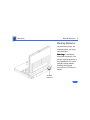
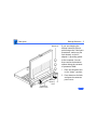
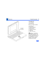
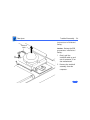
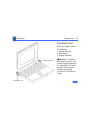
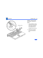
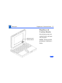
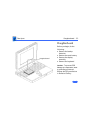
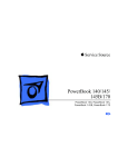
1
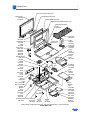
K Service Source
PowerBook 100
K Service Source
Specifications
PowerBook 100
Specifications
Processor - 1
Processor
CPU
Addressing
Motorola 68HC000, 16-bit CMOS microprocessor
15.6672 MHz
32-bit internal registers
24-bit address bus
16-bit data bus
Specifications
Memory - 2
Memory
RAM
2 MB of 100 ns pseudostatic RAM (PSRAM) standard, expandable
to 8 MB
ROM
256K (two 128K by 8-bit devices); 150 ns access time;
addressing supports up to 4 MB
PRAM
128 bytes of parameter memory
VRAM
32K of pseudostatic video display memory
Clock/Calendar
CMOS custom chip with long-life lithium battery
Specifications
Disk Storage - 3
Disk Storage
Floppy Drive
(Optional)
20 MB Hard Drive
40 MB Hard Drive
External Macintosh HDI-20 1.4 MB drive
4.5 W startup power; 1.25 W random operation; 50 mW idle
20 MB formatted capacity
Apple SCSI interface; 2.5 in. mechanism
23 msec average access time (maximum)
5.0 W startup power; 2.7 W random operation
40 MB formatted capacity
Apple SCSI interface; 2.5 in. mechanism
<19 msec average access time (maximum)
5.0 W startup power; 2.25–2.5 W random operation; 1.3–1.5 W
idle
Specifications
I/O Interfaces - 4
I/O Interfaces
Floppy Drive
One HDI-20 floppy drive port for external 1.4 MB drive
SCSI
One HDI-30 SCSI port; 1.5 MB/sec. transfer rate
Supports five devices maximum
Apple Desktop Bus
One Apple Desktop Bus (ADB) port; low-speed serial interface
Serial
Two RS-422 ports, one external and one internal 230.4 Kbaud
minimum
Asynchronous, synchronous, and AppleTalk protocols supported
Internal connector supports Macintosh PowerBook Fax/Data
modem
Specifications
Sound
I/O Interfaces - 5
One sound output port for external audio amplifier
Specifications
I/O Devices - 6
I/O Devices
Keyboard
Built-in keyboard; ADB interface
Dimensions: 10.6 in. length, 3.5 in. width, .5 in. depth
Pitch: .73 in. horizontal; .71 in. vertical
Trackball
Dual-button trackball; 25 mm diameter; ADB interface
Mouse (Optional)
Low-power mouse; ADB interface
Floppy Drive
(Optional)
External Macintosh HDI-20 1.4 MB floppy drive
Specifications
Sound and Video - 7
Sound and Video
Sound
Video Display
Apple Sound Chip; one- or four-voice mono (one or two voices in
stereo) with 4-bit digital-to-analog conversion using 22-kHz
sampling rate
9 in. (229 mm) diagonal screen
Film-compensated Super Twist Nematic (FSTN), backlit flatpanel display
640 by 400 pixels; 75 dpi
Specifications
Electrical - 8
Electrical
Main Battery
Backup Batteries
Sealed lead-acid battery (7 V)
2.5 hrs. maximum capacity
Three 3.5 V lithium cells
Industry-standard CR-2430 batteries
110–220 V
Frequency
50–60 Hz
ADB Power
Requirements
Maximum current draw for all ADB devices is 50 mA (maximum
of three ADB devices recommended)
Specifications
Power Adapter
Sound
Electrical - 9
Input voltage: 85–270 VAC (100/240 nominal); 48–62 Hz (50/
60 nominal)
Output voltage: 7.0–7.6 V (7.5 nominal); 5 mA–2 A (1.5
nominal)
One sound output port for external audio amplifier
K Service Source
Troubleshooting
PowerBook 100
Troubleshooting
General/ - 1
General
The Symptom Charts included in this chapter will help you
diagnose specific symptoms related to your product. Because cures
are listed on the charts in the order of most likely solution, try
the first cure first. Verify whether or not the product continues to
exhibit the symptom. If the symptom persists, try the next cure.
(Note: If you have replaced a module, reinstall the original module
before you proceed to the next cure.)
If you are not sure what the problem is, or if the Symptom Charts
do not resolve the problem, refer to the Flowchart for the product
family.
For additional assistance, contact Apple Technical Support.
Troubleshooting
Power Manager Reset/ - 2
Power Manager Reset
Reset the power manager if the battery and power adapter are
proven good, but the computer will not power on. The computer
will not reset after a system crash.
To reset the power manager in the PowerBook 100,
• Remove the AC adapter and the battery.
• Let the unit sit without power hooked up for 3-5 minutes.
• Simultaneously hold down the Control, Command, Option, and
Power On keys for 5-10 seconds.
• Reinstall the battery and, if necessary, reconnect the AC
adapter.
• Turn on the computer.
Troubleshooting
Symptom Charts/Startup - 3
Symptom Charts
Startup
Error chord sounds
during startup
sequence
Screen displays
checkerboard pattern;
no startup chime
1
3
4
Connect AC adapter and restart computer in three or four
minutes.
Replace memory expansion board (if installed). Refer to
“Memory Expansion Card” in Upgrades.
Replace motherboard.
Replace daughterboard.
1
2
3
4
Reseat RAM expansion card.
Replace RAM expansion card.
Replace daughterboard.
Reseat display cable.
2
Troubleshooting
Symptom Charts/Power - 4
Power
Screen is blank;
computer does not
respond
1
2
3
4
5
6
7
8
9
Verify storage switch is in “on” position.
Reset computer.
Connect AC adapter and restart computer in three or four
minutes.
Install known–good, charged main battery. If computer
works, replace main battery.
Verify that keyboard cable is securely connected.
Reset the power manager.
Replace keyboard.
Replace daughterboard.
Replace motherboard.
Troubleshooting
Symptom Charts/Power (Continued) - 5
Power (Continued)
After main battery is
changed, some
Control Panel
settings are different
Replace backup batteries.
After all power
sources are removed,
some Control Panel
settings are different
Condition is normal. Removing all power affects some Control
Panel settings (such as time) that are stored in parameter RAM.
Troubleshooting
Symptom Charts/Power (Continued) - 6
Power (Continued)
AC adapter is plugged
in and connected, but
battery DA does not
indicate charger is
connected
1
2
Low-power warning
appears soon after
computer starts
1
2
3
3
4
5
Verify that AC adapter is connected properly.
Try different main battery. If battery charges, replace main
battery.
Verify that adapter is good.
Replace AC adapter.
Replace motherboard.
Attach AC adapter. Battery needs recharging.
Verify that peripherals display low-power icon.
Reduce use of floppy or hard drives, modem, sound,
backlight, or other power-consuming devices or connect AC
adapter.
Troubleshooting
Symptom Charts/Video - 7
Video
Screen suddenly goes
blank
Condition is normal; computer has gone into sleep to conserve
battery power.
Screen goes blank and
computer shuts down
every few minutes
Adjust sleep delays in Control Panel or connect AC adapter.
Pixel never comes on
Replace display.
Row of pixels never
comes on
1
2
3
4
5
6
Replace interconnect cable.
Replace display.
Replace interconnect board.
Replace daughterboard.
Replace motherboard.
Return computer to Apple.
Troubleshooting
Symptom Charts/Video (Continued) - 8
Video (Continued)
Pixel is always on
Replace display.
Partial or complete
row of pixels is
always on
1
2
3
4
5
6
Replace interconnect cable.
Replace display.
Replace interconnect board.
Replace daughterboard.
Replace motherboard.
Return computer to Apple.
Troubleshooting
Symptom Charts/Video (Continued) - 9
Video (Continued)
Display is very light
or totally white
1
2
3
4
5
6
7
8
9
Adjust screen contrast and brightness settings.
Verify interconnect-cable-to-motherboard connection.
Replace inverter board.
Replace interconnect cable.
Replace interconnect board.
Replace display.
Replace daughterboard.
Replace motherboard.
Return computer to Apple.
Troubleshooting
Symptom Charts/Video (Continued) - 10
Video (Continued)
No display but
computer appears to
operate correctly
1
2
3
4
5
6
7
8
9
Display shows
rainbow colors when
viewed from extreme
side angles
Condition is normal for PowerBook 100 screen.
Adjust screen contrast and brightness settings.
Verify interconnect-cable-to-motherboard connection.
Replace inverter board.
Replace interconnect cable.
Replace interconnect board.
Replace display.
Replace daughterboard.
Replace motherboard.
Return computer to Apple.
Troubleshooting
Symptom Charts/Video (Continued) - 11
Video (Continued)
Image on display is
not uniform
Condition is normal for PowerBook 100 screen.
Display stopped
working (or
dimmed) but shows no
problems now
If temperature (under 5° C or over 45° C) or light was extreme
when problem occurred, condition is normal for PowerBook 100
screen.
Troubleshooting
Symptom Charts/Video (Continued) - 12
Video (Continued)
Backlight doesn’t
operate
1
2
3
4
5
6
7
8
Adjust screen brightness setting.
Verify interconnect-cable-to-motherboard connection.
Replace inverter board.
Replace interconnect cable.
Replace interconnect board.
Replace display.
Replace daughterboard.
Replace motherboard.
Slight white line is
always in middle of
screen.
Condition is normal for PowerBook 100 screen.
Troubleshooting
Symptom Charts/Hard Drive - 13
Hard Drive
Internal hard drive
does not operate
1
2
3
4
5
6
7
8
Verify that all external SCSI devices connected to computer
are switched on.
Verify that hard drive flex cable is securely connected at
both ends.
Use “HD SC Setup” to see if drive is visible to program. If it
is visible, update SCSI driver.
Reinstall system software.
Replace hard drive flex cable.
Replace hard drive.
Replace motherboard.
Replace daughterboard.
Troubleshooting
Symptom Charts/Hard Drive (Continued) - 14
Hard Drive (Continued)
Hard drive is slow to
respond or screen
goes blank too often
Adjust sleep delays in Control Panel or connect AC adapter.
Troubleshooting
Symptom Charts/Peripheral - 15
Peripheral
After you connect
external SCSI device,
computer no longer
boots
1
2
3
4
5
6
Switch on external SCSI device before starting up computer.
Verify that Apple HDI-30 SCSI system cable is connected to
computer and external SCSI device(s).
Verify that cable termination is correct.
Verify that no SCSI devices have same device address.
Replace motherboard.
Replace daughterboard.
Cursor does not move
when you move
trackball
1
2
3
4
5
Reset computer.
Verify trackball-assembly-to-motherboard connection.
Replace trackball assembly.
Replace daughterboard.
Replace motherboard.
Troubleshooting
Symptom Charts/Peripheral (Continued) - 16
Peripheral (Continued)
Cursor intermittently
does not move or
moves erratically
1
2
Clean trackball ball and internal rollers.
Replace trackball assembly.
Cursor does not move
when you move mouse
1
2
3
4
5
6
Verify that mouse is connected to ADB port.
Reset computer.
Clean mouse ball and inside of mouse.
Replace mouse.
Replace motherboard.
Replace daughterboard.
Troubleshooting
Symptom Charts/Peripheral (Continued) - 17
Peripheral (Continued)
Cursor moves, but
clicking button has no
effect
1
2
3
4
Verify trackball-assembly-to-motherboard connection.
Replace trackball assembly.
Replace daughterboard.
Replace motherboard.
No response to any
key on keyboard
1
2
Reset computer.
Connect AC adapter and restart computer in three or four
minutes.
Install known-good, charged main battery. If computer
works, replace main battery.
Verify that keyboard cable is securely connected to
motherboard.
Replace keyboard.
Replace daughterboard.
Replace motherboard.
3
4
5
6
7
Troubleshooting
Symptom Charts/Peripheral (Continued) - 18
Peripheral (Continued)
Known-good
ImageWriter,
ImageWriter II, or
LQ does not print
1
2
3
4
5
6
Verify that system software is 7.0.1 or later.
Verify that Chooser setting is correct.
Verify that printer cable is securely attached.
Replace printer cable.
Replace motherboard.
Replace daughterboard.
Known-good
LaserWriter does not
print
1
2
3
4
Verify that system software is 7.0.1 or later.
Verify that Chooser setting is correct.
Verify that all printer cables are securely attached.
Connect computer to another printer. If printer works,
refer to Networks and Communications manual.
Replace motherboard.
Replace daughterboard.
5
6
Troubleshooting
Symptom Charts/Peripheral (Continued) - 19
Peripheral (Continued)
PowerBook doesn’t
recognize serial
devices, or garbage is
transmitted and/or
received
1
2
3
4
5
Verify that system software is 7.0.1 or later.
Verify that all cables are correct and securely attached.
Attach device(s) in chain to known-good computer.
Replace motherboard.
Replace daughterboard.
Troubleshooting
Symptom Charts/Internal Modem - 20
Internal Modem
Internal modem
options do not appear
in Control Panel
window when modem
is installed
1
2
Modem does not
respond properly to
AT command set
instructions
1
3
4
2
3
4
Reseat modem card.
Replace modem card. Refer to “Fax/Data Modem” in
Upgrades.
Replace motherboard.
Replace daughterboard.
Verify that baud rate and data format settings of
communications application are compatible with internal
modem and remote modem.
Verify that telephone cord is securely attached and working
properly.
Verify that phone line produces dial tone. (Attach phone to
line and listen.)
Replace modem card. Refer to “Fax/Data Modem” in
Upgrades.
Troubleshooting
Symptom Charts/Internal Modem (Continued) - 21
Internal Modem (Continued)
Strange mix of
characters appears
on screen
1
2
3
Modem interferes
with system sound
1
2
3
Verify that baud rate and data format settings of
communications application are compatible with internal
modem and remote modem.
Verify that telephone cord is securely attached and working
properly.
Replace modem card. Refer to “Fax/Data Modem” in
Upgrades.
Replace modem card. Refer to “Fax/Data Modem” in
Upgrades.
Replace motherboard.
Replace daughterboard.
Troubleshooting
Symptom Charts/Internal Modem (Continued) - 22
Internal Modem (Continued)
Modem does not
respond to incoming
call
1
2
3
4
5
Modem has no sound
output
If system doesn’t respond during sleep mode, verify that
“Wake on Ring” option in CDEV is selected.
Verify that telephone cord is securely attached and working
properly.
Replace modem card. Refer to “Fax/Data Modem” in
Upgrades.
Replace motherboard.
Replace daughterboard.
Replace modem card. Refer to “Fax/Data Modem” in Upgrades.
Troubleshooting
Symptom Charts/Internal Modem (Continued) - 23
Internal Modem (Continued)
Modem connects but
does not communicate
with remote modem
1
2
Verify that remote modem needs error correction.
If remote modem does not need error correction, disable
error correction by typing “&Q0” (see “Macintosh
PowerBook Fax/Data Modem User’s Guide”).
Troubleshooting
Symptom Charts/Miscellaneous - 24
Miscellaneous
Some applications
seem to run slower
after few seconds of
operation
Computer is switching to system rest. If system rest is
interfering with operation of application, connect computer to AC
adapter.
No sound from
speaker
1
2
3
Verify that volume setting in Control Panel is 1 or above.
Verify that speaker is connected to motherboard.
Replace motherboard.
K Service Source
Take Apart
PowerBook 100
Take Apart
Guidelines - 1
Guidelines
Caution: Use the Macintosh
Shut Down command to shut
down the PowerBook 100
before you begin Take Apart
procedures. Otherwise, all
RAM contents will be lost.
Caution: Review the ESD
precautions in Bulletins/
Safety.
Take Apart
Backup Batteries - 2
Backup Batteries
No preliminary steps are
required before you begin
this procedure.
If handled or
discarded improperly, the
lithium backup batteries in
the PowerBook 100 could
explode. Review battery
handling and disposal
instructions in Bulletins/
Safety.
Warning:
Backup
Batteries
Take Apart
Backup Batteries - 3
Batteries
If you are changing the
backup batteries without
performing other Take Apart
procedures, make sure the
main battery or the AC
adapter is providing power
to the computer. You can
then remove the batteries
without losing the contents
of parameter RAM.
1
2
Connector
Panel Cover
Backup
Battery
Door
Place the elevation feet
in the “down” position.
Press down on the latch
and open the connector
panel cover.
Take Apart
Backup Batteries - 4
3
Pry open the backup
battery door and ease
out the batteries.
Replacement Note: Make
sure the positive side of each
replacement battery faces
up.
Take Apart
Backup Battery Door - 5
Backup Battery
Door
Before you begin, remove
the backup batteries.
If handled or
discarded improperly, the
lithium backup batteries in
the PowerBook 100 could
explode. Review battery
handling and disposal
instructions in Bulletins/
Safety.
±Warning:
Backup
Battery
Door
Take Apart
Backup Battery Door - 6
Caution: To prevent ESD
damage to components, wear
a grounding wriststrap.
Review the ESD precautions
in Bulletins/Safety.
1
2
Open the backup battery
door so that it is parallel
to the right side of the
bottom case.
Firmly pull the door
until it unsnaps from the
hinge posts in the bottom
cover.
Take Apart
Main Battery - 7
Main Battery
Before you begin,
disconnect power adapter.
Do not expose
the main battery to an open
flame, attempt to open the
plastic case, or dispose of
the battery with other trash.
If you touch a damaged
battery, immediately wash
your hands and affected skin
with water for at least five
minutes. If you are
replacing the battery, send
the old one to Apple for
proper disposal. Review
±Warning:
Main
Battery
Take Apart
Main Battery - 8
battery-handling and
disposal instructions in
Bulletins/Safety.
Caution: To prevent ESD
damage to components, wear
a grounding wriststrap.
Review the ESD precautions
in Bulletins/Safety.
1
2
3
Place the elevation feet
in the “up” position.
Slide the main battery
cover to the right.
Pull on the right side of
the cover and remove the
battery.
Take Apart
Main Battery Cover - 9
Main Battery
Cover
Before you begin, remove
the main battery.
Do not expose
the main battery to an open
flame, attempt to open the
plastic case, or dispose of
the battery with other trash.
If you touch a damaged
battery, immediately wash
your hands and affected skin
with water for at least five
minutes. If you are
replacing the battery, send
the old one to Apple for
±Warning:
Main Battery
Cover
Take Apart
Main Battery Cover - 10
proper disposal. Review
battery-handling and
disposal instructions in
Bulletins/Safety.
Locking Tab
Locking Tab
Caution: To prevent ESD
damage to components, wear
a grounding wriststrap.
Review the ESD precautions
in Bulletins/Safety.
Using needlenose pliers, pry
the battery cover locking
tabs apart and slide the
cover off the main battery.
Take Apart
Connector Panel Cover - 11
Connector Panel
Cover
No preliminary steps are
required before you begin
this procedure.
Caution: To prevent ESD
damage to components, wear
a grounding wriststrap.
Review the ESD precautions
in Bulletins/Safety.
Connector
Panel Cover
Take Apart
Connector Panel Cover - 12
1
Right Cover
Peg
2
3
4
Place the elevation feet
in the “down” position.
Open the connector
panel cover.
Hold the cover against
the left cover peg, gently
bend the center of the
cover away from the
computer, and free the
right cover peg.
Remove the panel cover
from the computer.
Take Apart
Display Assembly - 13
Display Assembly
Display Assembly
Before you begin, remove
the following:
• Backup batteries
• Main battery
If handled or
discarded improperly, the
lithium backup batteries in
the PowerBook 100 could
explode. Review battery
handling and disposal
instructions in Bulletins/
Safety.
±Warning:
Caution: Review the ESD
Take Apart
Display Assembly - 14
precautions in Bulletins/
Safety.
1
2
Close the computer so
that it locks.
Using a Phillips
screwdriver or pen,
move the power switch
to the “off” position.
Take Apart
Display Assembly - 15
Caution: Do not proceed if
the backup batteries, main
battery, or AC adapter are
still connected to the
computer.
3
With the computer
upside down, pry off the
three rubber covers and
remove the three case
screws.
Take Apart
Display Assembly - 16
4
With the computer
right-side up, place the
elevation feet in the
“down” position.
Note: Keep a firm grip on
the display assembly while
you complete the following
steps.
5
Interconnect Cable
6
Unlatch the display
assembly and open the
computer.
Disconnect the
interconnect cable from
the motherboard and
remove the display
assembly.
Take Apart
Keyboard - 17
Keyboard
Keyboard
Before you begin, remove
the following:
• Backup batteries
• Main battery
• Display assembly
Warning: If handled or
discarded improperly, the
lithium backup batteries in
the PowerBook 100 could
explode. Review battery
handling and disposal
instructions in Bulletins/
Safety.
±
Take Apart
Keyboard - 18
Caution: Review the ESD
precautions in Bulletins/
Safety.
1
2
Palm Rest
Cover
3
Caution: Be careful not
to stress the keyboard
cables or the connectors
on the motherboard.
Lift the back side of the
keyboard as high as the
keyboard cables will
allow.
Slide the keyboard
toward the rear of the
computer until the front
edge of the keyboard
clears the palm rest
cover.
Take Apart
Keyboard - 19
4
Keyboard
Cables
Note: You may have to
pry up one side of the
connector at a time.
Holding the keyboard
vertically, gently unlock
the connectors and
remove the two keyboard
cables.
Take Apart
Palm Rest Cover - 20
Palm Rest Cover
Palm Rest
Cover
Before you begin, remove
the following:
• Backup batteries
• Main battery
• Display assembly
• Keyboard
If handled or
discarded improperly, the
lithium backup batteries in
the PowerBook 100 could
explode. Review battery
handling and disposal
instructions in Bulletins/
Safety.
±Warning:
Take Apart
Palm Rest Cover - 21
Caution: Review the ESD
precautions in Bulletins/
Safety.
1
2
Using both hands, grasp
the two back corners of
the palm rest cover and
lift.
Remove the palm rest
cover from the
computer.
Take Apart
Palm Rest Cover - 22
Replacement Note: To
replace the cover, hold it
vertically with the front
edge slightly in front of the
front edge of the computer.
Rotate the back of the palm
rest cover down and back
until the cover locks into
position.
Take Apart
Trackball Assembly - 23
Trackball
Assembly
Trackball
Assembly
Before you begin, remove
the following:
• Backup batteries
• Main battery
• Display assembly
• Keyboard
• Palm rest cover
Warning: If handled or
discarded improperly, the
lithium backup batteries in
the PowerBook 100 could
explode. Review battery
handling and disposal
±
Take Apart
Trackball
Cable
J5
Connector
Trackball Assembly - 24
instructions in Bulletins/
Safety.
Caution: Review the ESD
precautions in Bulletins/
Safety.
1
2
Gently pull the
trackball cable up and
out of connector J5 on
the motherboard.
Remove the trackball
assembly from the
computer.
Take Apart
Hard Drive - 25
Hard Drive
Before you begin, remove
the following:
• Backup batteries
• Main battery
• Display assembly
• Keyboard
• Palm rest cover
Warning: If handled or
discarded improperly, the
lithium backup batteries in
the PowerBook 100 could
explode. Review battery
handling and disposal
instructions in Bulletins/
Safety.
±
Hard Drive
Take Apart
Hard
Drive
Flex
Cable
Tab
Hard Drive - 26
Caution: Review the ESD
precautions in Bulletins/
Safety.
Hard Drive Flex
Cable Connector
1
2
Hard Drive
Shield
Fold back the hard drive
shield and pull up the
tabs to unlock the hard
drive flex cable
connector.
Disconnect the hard
drive flex cable from the
motherboard.
Take Apart
Hard Drive - 27
3
4
5
Using a flat-blade
screwdriver, unlock one
of the two latches on the
side of the hard drive
nearest the
motherboard.
While applying upward
pressure on the first
latch, unlock the second
latch on the same side.
Lift up the motherboard
side of the hard drive and
remove the drive from
the computer.
Take Apart
Hard Drive - 28
Replacement Note: If the
replacement drive is too
high to fit in the PowerBook
100, remove the four
spacers on the bottom of the
drive. For information on
returning drives, cables,
and carriers to Apple, refer
to the Hard Drives manual.
Take Apart
Elevation Foot - 29
Elevation Foot
Before you begin, remove
the following:
• Backup batteries
• Main battery
• Display assembly
Elevation Foot
Elevation Foot
Warning: If handled or
discarded improperly, the
lithium backup batteries in
the PowerBook 100 could
explode. Review battery
handling and disposal
instructions in Bulletins/
Safety.
±
Take Apart
Elevation Foot - 30
Caution: Review the ESD
precautions in Bulletins/
Safety.
1
Elevation Foot
Locking Tabs
2
Using needlenose pliers,
squeeze the locking tabs
on the right elevation
foot and pull the foot
assembly from the case.
Repeat the procedure
for the left elevation
foot.
Take Apart
Brightness & Contrast Knobs - 31
Brightness &
Contrast Knobs
Brightness and
Contrast Knobs
No preliminary steps are
required before you begin
this procedure.
Caution: Review the ESD
precautions in Bulletins/
Safety.
Take Apart
Brightness & Contrast Knobs - 32
Brightness
Contrast
Using your fingers, pry the
contrast and brightness
knobs off the control shafts.
Take Apart
Daughterboard - 33
Daughterboard
Daughterboard
Before you begin, do the
following:
• Remove the backup
batteries
• Remove the main battery
• Remove the display
assembly
• Remove the keyboard
Caution: To prevent ESD
damage to components, wear
a grounding wriststrap.
Review the ESD precautions
in Bulletins/Safety.
Take Apart
Daughterboard - 34
Daughterboard
J318
J319
Note: To disconnect
connector J318, rock it
gently from end to end as
you lift.
Grip the daughterboard
near connectors J318
and J319 and lift the
daughterboard off the
motherboard.
Take Apart
Motherboard - 35
Motherboard
Motherboard
Before you begin, remove
the following:
• Backup batteries
• Backup batteries door
• Main battery
• Display assembly
• Keyboard
• Palm rest cover
• Trackball assembly
• Hard drive
• Memory expansion card
• Modem shield and modem
• Daughterboard
Take Apart
Motherboard - 36
Motherboard
Caution: Review the ESD
precautions in Bulletins/
Safety.
1
2
Hard Drive
Connector
Remove the five
motherboard mounting
screws.
Lift the motherboard
near the hard drive
connector and remove
the board from the
bottom cover.
Take Apart
Top Cover - 37
Top Cover
Before you begin, remove
the display assembly.
Top Cover
Caution: To prevent ESD
damage to components, wear
a grounding wriststrap.
Review the ESD precautions
in Bulletins/Safety.
Take Apart
Top Cover - 38
1
Clutch Plate
2
Cover Screw
3
Locking Tabs
4
Clutch Cover
Soldered Terminals
Speaker
Remove the four top
cover mounting screws.
Lift off the two clutch
plates.
Note: You may need to
lift the top cover before
the clutch covers slide
freely.
Slide off the two clutch
covers.
Pry back the speaker
locking tabs and lift out
the speaker.
Take Apart
Top Cover - 39
Replacement Note: Position
the speaker so that the
soldered wire terminals are
closest to the cable cover.
5
6
Interconnect
Cable Cover
Squeeze the outside of the
interconnect cable cover
near the tabs and
release the tabs.
Remove the cable cover.
Take Apart
Top Cover - 40
7
Top Cover
Interconnect Cable
and Speaker
Slip the interconnect
cable and speaker
through the top cover
and remove the top
cover.
Replacement Note: The
interconnect cable and the
speaker are separate parts.
If you replace the speaker or
interconnect cable, you must
solder the interconnect cable
onto the speaker.
Take Apart
Display Bezel - 41
Display Bezel
Display Bezel
Before you begin, remove
the following:
• Display assembly
• Top cover
• Brightness and contrast
knobs
Caution: Review the ESD
precautions in Bulletins/
Safety.
Take Apart
Display Bezel - 42
1
Display Bezel
Rubber Plugs
Bezel Screw
2
3
Clutch Assembly
Using a small, flat-blade
screwdriver, pry out the
two rubber plugs.
Remove the two display
bezel screws.
Note: Pry the display
bezel until the locking
tab closest to the clutch
assembly releases.
Using the flat-blade
screwdriver, pry the
display bezel from the
metal clutch assembly on
each side of the display.
Take Apart
Display Bezel - 43
4
5
Using your thumb and
index finger, pull the
display bezel toward you
and up until the top
locking tabs release.
Lift off the bezel.
Take Apart
Display - 44
Display
Display
Before you begin, remove
the following:
• Display assembly
• Top cover
• Brightness and contrast
knobs
• Display bezel
Caution: To prevent ESD
damage to components, wear
a grounding wriststrap.
Review the ESD precautions
in Bulletins/Safety.
Take Apart
Display - 45
1
2
Display Shield
Inverter
Board
Interconnect Board
Remove the display
shield mounting screw
and lift off the display
shield.
Remove the remaining
inverter board screw,
interconnect board
screw, and the four
display mounting
screws.
Take Apart
Display - 46
3
4
Display
Brightness/
Contrast
Flex Cable
Interconnect Board
Display Flex
Cable
Interconnect Cable
and Speaker
Move the interconnect
cable and speaker away
from the display.
Note: When you rotate
the display, the
interconnect board,
inverter board, and
related cables also rotate
forward. Move the
display carefully to
avoid stressing these
components.
Gently rotate the display
forward so that it rests
face-down.
Take Apart
Display - 47
5
6
Inverter Board
Display Lamp
Cable Connector
Disconnect the
brightness/ contrast
flex cable and the display
flex cable from the
interconnect board.
Release the locking tab
on the display lamp cable
connector and disconnect
the cable from the
inverter board.
Replacement Note:
Carefully press the display
lamp cable wires into the
channels in the display
housing.
Take Apart
Display - 48
Replacement Note: Make
sure the blue insulator end
of the brightness/contrast
cable faces the interconnect
board.
K Service Source
Upgrades
PowerBook 100
Upgrades
Fax/Data Modem - 1
Fax/Data Modem
Fax/Data Modem
Before you begin, remove
the following:
• Backup batteries
• Main battery
• Display assembly
• Keyboard
If handled or
discarded improperly, the
lithium backup batteries in
the PowerBook 100 could
explode. Review battery
handling and disposal
instructions in Bulletins/
Safety.
±Warning:
Upgrades
Fax/Data Modem - 2
Caution: Review the ESD
precautions in Bulletins/
Safety.
Modem
Shield
Metal Prongs
Metal Prongs
To install a fax/data modem,
1
Push the metal prongs
toward the back of the
computer and lift the
modem shield up and out
of the bottom cover.
Upgrades
Fax/Data Modem - 3
2
Modem
Connector
Cover
Modem
J1 Connector
Standoff
J9 Connector
Standoff
3
Lift the modem connector
cover out of the bottom
cover.
Position the modem so
that connector J1 on the
modem faces down and
directly above connector
J9 on the motherboard.
Press down on the
modem until the board
locks in place on the two
standoffs.
Upgrades
Fax/Data Modem - 4
Caution: Make sure the
modem shield does not extend
into the battery cavity.
Modem
Shield
4
Metal Prongs
Metal Prongs
Replace the modem
shield and modem
connector cover.
Upgrades
Fax/Data Modem - 5
5
DOC
Label
Modem Connector
FCC
Label
Apply the DOC and FCC
labels to the left of the
modem connector.
Upgrades
Fax/Data Modem - 6
Modem
Standoff
Standoff
Needlenose
Pliers
Replacement Note: To
remove the fax/data modem,
use needlenose pliers to
release the locking tabs of
the two standoffs and lift the
modem from the
motherboard.
Upgrades
Memory Expansion Card - 7
Memory
Expansion Card
Before you begin, remove
the following:
• Backup batteries
• Main battery
• Display assembly
• Keyboard
• Palm rest cover
Memory
Expansion
Upgrades
Memory Expansion Card - 8
If handled or
discarded improperly, the
lithium backup batteries in
the PowerBook 100 could
explode. Review battery
handling and disposal
instructions in Bulletins/
Safety.
±Warning:
Caution: Review the ESD
precautions in Bulletins/
Safety.
Install the memory
expansion card on the
motherboard.
To
verify correct installation
Verification Note:
Upgrades
Memory Expansion Card - 9
of the memory expansion
card, switch on the
computer by pressing any
key except <Caps Lock>.
Pull down the Apple menu
and select “About the
Finder.” Verify that the
amount of RAM (Total
Memory) is 4096K (for a 2
MB RAM expansion card) or
6144K (for a 4 MB RAM
expansion card). If the
amount of RAM is not
correct, replace the
expansion card. If this
procedure does not correct
the problem, return the
computer to Apple.
K Service Source
Additional Procedures
PowerBook 100
Additional Procedures
Fuse - 1
Fuse
Fuse
Before you begin, remove
the following:
• Backup batteries
• Main battery
• Display assembly
• Modem shield and modem
If handled or
discarded improperly, the
lithium backup batteries in
the PowerBook 100 could
explode. Review battery
handling and disposal
instructions in Bulletins/
Safety.
±Warning:
Additional Procedures
Fuse - 2
Caution: Review the ESD
precautions in Bulletins/
Safety.
Note: Some PowerBook 100
motherboards contain fuses
that are not removable. To
replace a fuse that is
soldered to the board, you
must replace the
motherboard. (All new
motherboards ordered from
Apple contain removable
fuses.)
Additional Procedures
Fuse - 3
Caution: Be careful not to
stress the keyboard cables
or the connectors on the
motherboard.
1
2
Palm Rest
Cover
Lift the back side of the
keyboard as high as the
keyboard cables will
allow.
Slide the keyboard
toward the rear of the
computer until the front
edge of the keyboard
clears the palm rest
cover.
Additional Procedures
Fuse - 4
3
Fuse
4
Fuse Holder
Place the keyboard on
top of the palm rest
cover.
Remove the fuse from
the fuse holders.
Additional Procedures
Battery Recharger - 5
Main Battery
Battery Recharger
No preliminary steps are
required before you begin
this procedure.
1
Battery
Recharger
Using the PowerBook
power adapter, plug the
battery recharger into a
power outlet and insert
the main battery into the
recharger.
Additional Procedures
Battery Recharger - 6
2
Track the status of the
battery. If the LED is
• Yellow, the battery is
charging
• Green, the battery is
ready to use
• Off, the charger is
unplugged, the
battery is bad, the
power adapter is
defective, or the
charger is defective
Additional Procedures
SCSI Termination - 7
SCSI Termination
SCSI Terminator
No preliminary steps are
required before you begin
this procedure.
Note: Because the
PowerBook 100 does not
provide SCSI termination at
the logic board, remember
to terminate at the beginning
and end of the SCSI chain.
Use the standard Apple
terminator (not the
Macintosh IIfx terminator).
External SCSI Device
Additional Procedures
SCSI Termination - 8
When terminating a SCSI
chain, follow these
guidelines:
• Add one terminator to a
single external SCSI
device, or
• Add one terminator to the
first device and another
to the last when there are
multiple devices.
Additional Procedures
Battery Handling - 9
Battery Handling
Main Battery
No preliminary steps are
required before you begin
this procedure.
Warning: The main
battery contains toxic
materials. If you touch a
damaged battery,
immediately wash your
hands and affected skin with
water for at least five
minutes. Send undamaged,
dead batteries to Apple for
recycling—do not discard
dead batteries with other
waste. If the battery is
±
Additional Procedures
Battery Case
Battery Handling - 10
damaged, do not return it to
Apple. Review battery
handling and disposal
instructions in Bulletins/
Safety.
Follow these guidelines for
properly handling the
battery:
• Handle the battery
carefully. Do not drop,
puncture, disassemble,
or incinerate the battery.
• Do not leave the battery
in the computer for
longer than one week
without plugging in the
power adaptor.
Additional Procedures
Battery Handling - 11
• Store the battery in its
protective battery
case.Do not store the
battery longer than six
months without
recharging.
• Do not short-circuit the
battery terminals.
Additional Procedures
Battery Verification - 12
Battery
Verification
Before you begin, remove
the main battery.
Main
Battery
If handled or
discarded improperly, the
lithium backup batteries in
the PowerBook 100 could
explode. Review batteryhandling and disposal
instructions in Bulletins/
Safety.
±Warning:
Review the ESD precautions
in Bulletins/Safety.
Additional Procedures
Battery Verification - 13
Negative
Probe
Positive
Probe
1
2
3
Set the voltmeter to the
10 volts DC scale.
Hold the positive probe
of the voltmeter to the
positive position on the
battery and the negative
probe to the negative
position on the battery.
If the battery voltage is
below 5.7 volts,
recharge or replace the
battery.
Additional Procedures
AC Adapter Verification - 14
AC Adapter
Verification
Negative
Probe
No preliminary steps are
required before you begin
this procedure.
1
2
Adapter
Plug
Positive
Probe
Set the voltmeter to the
10 volts DC scale.
Hold the positive probe
of the voltmeter to the
inside of the AC adapter
plug and the negative
probe to the outside of
the plug.
Additional Procedures
AC Adapter Verification - 15
3
If the voltage is not
between 7.5 and 7.9
volts, replace the
adapter.
Additional Procedures
Display Bulb - 16
Display Bulb
Display Bulb
Before you begin, remove
the following:
• Display assembly
• Top cover
• Brightness and contrast
knobs
• Display bezel
• Display
CCFL bulbs are
thin and break easily. Handle
them with care, especially
at the delicate solder joints
at the ends of the bulbs.
±Warning:
Additional Procedures
Display Bulb - 17
Caution: Review the ESD
precautions in Bulletins/
Safety.
Bulb Cover
1
2
Place the display facedown on a soft
workbench pad.
Using a #0 cross-tip
screwdriver, remove
the two self-threading
screws.
Replacement Caution:
Improperly installed selfthreading screws could
damage the display. Do not
overtighten them.
Additional Procedures
Display Bulb - 18
3
Display Bulb
4
Lift the metal display
bulb cover and back it
off the display.
Remove the display bulb.
Replacement Note: When
replacing the display bulb,
position the pink cable
along the bottom of the
display and make sure the
display bulb cover is under
the tabs at each end of the
case.
K Service Source
Exploded View
PowerBook 100
Exploded View
1
Interconnect Board 981-0016
Inverter Board 982-0105
Rear Display
Housing
949-0333
Display Bezel 076-0416
Brightness/Contrast Board 981-0017
Brightness/Contrast
Knob
956-0029
Keyboard*
661-0713
Display
661-0675
Brightness/
Contrast
Cable
936-0060
Interconnect
Cable and
Speaker
Assembly
936-0059
982-0106
Daughterboard
661-0674
Modem
Shield
949-0364
Modem
Connector
Cover
949-0337
Rear
Connector
Panel
Cover
076-0412
Top Cover
076-0413
External
Floppy
Drive
661-1651
Modem
661-1621
Trackball
Assembly
661-0676
Main
Battery
w/Case
661-0782
Memory
Expansion
Card
661-1103 (4 MB)
661-0715 (2 MB)
Main
Battery
Door
949-0365
Backup
Battery
Door
949-0336
Elevation
Foot
Assembly
076-0411
Motherboard
661-0673
Power
Adapter*
922-0043
Palm Rest
Assembly
076-0414
Phone
Cable
590-0590
Hard Drive
Flex Cable
076-0445
Hard Drive*
661-1298
Screw
Kit
076-0557
Bottom Housing
Assembly
076-0410
Screw
Cover
956-0030
Rubber
Foot
956-0039
Hard Drive
Mounting
Bracket*
922-0008
Product family configurations may vary. For parts with asterisk (*), refer to parts list.
Power Book 100