1
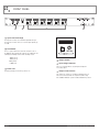
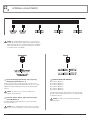
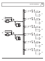
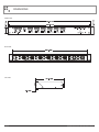
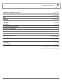
INSTALLATION AND OPERATION MANUAL
AMIS26
2 INPUT, 6 OUTPUT DISTRIBUTION AMPLIFIER
IMPORTANT SAFETY INFORMATION
PRÉCAUTIONS DURANT UTILISATION
1. Read these instructions.
1. LISEZ ces instructions.
2. Keep these instructions.
2. Tenez ces instructions.
3. Heed all warnings.
3. Notez tous les avertissements.
4. Follow all instructions.
4. Suivez toutes les avertissements.
5. Do not use this apparatus near water.
5. N’utilisez pas ce produit près de l’eau (la piscine, la plage, le lac, etc.).
6. Clean only with dry cloth.
6. Nettoyez seulement avec une étoffe sèche.
7. Do not block any ventilation openings. Install in accordance with the
manufacturer’s instructions.
7. Ne bloquez aucuns troux de ventilation. Installez en accord avec les
instructions du manufacturier.
8. Do not install near any heat sources such as radiators, heat registers,
stoves, or other apparatus (including amplifiers) that produce heat.
8. N’installez près aucunes sources de chaleur comme radiateurs, registres
de chaleur, fours ou les autres équipements (y compris amplificateurs) qui
produisent la chaleur.
9. Do not defeat the safety purpose of the polarized or grounding-type
plug. A polarized plug has two blades with one wider than the other. A
grounding type plug has two blades and a third grounding prong. The wide
blade or the third prong are provided for your safety. If the provided plug
does not fit into your outlet, consult an electrician for replacement of the
obsolete outlet.
10. Protect the power cord from being walked on or pinched particularly
at plugs, convenience receptacles, and the point where they exit from
the apparatus.
11. Only use attachments/accessories specified by the manufacturer.
12. Use only with the cart, stand, tripod, bracket, or table specified by the
manufacturer, or sold with the apparatus. When a cart is used, use caution
when moving the cart/apparatus combination to avoid injury from tip-over.
13. Unplug this apparatus during lightning storms or when unused for long
periods of time.
14. Refer all servicing to qualified service personnel.
Servicing is required when the apparatus has been
damaged in any way, such as power-supply cord or plug
is damaged, liquid has been spilled or objects have fallen
into the apparatus, the apparatus has been exposed to
rain or moisture, does not operate normally, or has been dropped.
15. This appliance shall not be exposed to dripping or splashing water and
that no object filled with liquid such as vases shall be placed on the
apparatus.
16. Plug this apparatus to the proper wall outlet and make the plug to be
disconnected readily operable.
17. Mains plug is used as disconnected device and it should remain readily
operable during intended use. In order to disconnect the apparatus from
the mains completely, the mains plug should be disconnected from the
mains socket outlet completely.
18. WARNING: To reduce the risk of fire or electric shock, do not expose this
apparatus to rain or moisture.
19. An appliance with a protective earth terminal should be connected to a
mains outlet with a protective earth connection.
20. The apparatus should be disconnected from the mains completely before
speaker wiring. The speaker output should be proper protected from
direct contact and pay attention to speaker connections, terminals and
speaker wiring during normal operation.
PAGE 2
9. Ne défaites pas le but de sécurité de la fiche polarisée ou base-type. Une
fiche polarisée a deux tranchants avec un plus large que l’autre. Une fiche
de base type a deux a deux tranchants et une troisième pointe de base,
le tranchant large ou la troisième pointe est fourni pour votre sécurité. Si
la fiche donnée ne conforme pas votre prise de contact, consultez un
électricien pour remplacement de la prise de contact obsolète.
10. Protegez le cordon de secteur contre être marchée dessus ou pincez en
particulier aux fiches, aux douilles de convenance, et au point où ils
sortent de l’appareil.
11. Seulement utilisez attachements/accessoires spécifiés par le manufacturier.
12. Utilisez seulement avec un chariot, un stand, un trépied, un support ou
une table indiquée par le manufacturier, ou vendue avec l’appareil. Quand
un chariot est utilisé, faites attention en déplaçant la combinaison
d’appareil/chariot pour éviter de se déséquilibrer.
13. Arrachez la fiche du dispositif durant éclair et orage ou quand pas utilisé
pour longues périodes de temps.
14. Référez au personnel qualifié de service pour toutes
réparations. La réparation est donnée quand le système
a été endommagé à n’importe façon, par exemple un fil
ou une fiche endommagé(e) de la source d’alimentation.
Avoir été exposé à pluie ou humidité, n’opère pas
normalement, ou avoir été tombé.
15. L’appareil ne doit pas être exposé aux écoulements ou aux éclaboussures
et aucun objet ne contenant de liquide, tel qu’un vase, ne doit être placé
sur l’objet.
16. Branchez l’appareil à une source appropriée et faire que la prise à
débrancher soit facilement accessible.
17. La prise du secteur ne doit pas être obstruée ou doit être facilement
accessible pendant son utilisation. Pour être complètement déconnecté
de l’alimentation d’entrée, la prise doit être débranchée du secteur.
18. AVERTISSEMENT: Pour éviter le risque d’incendie ou de chocs électriques,
ne pas exposer cet appareil à la pluie ou à l’humidité.
19. Un appareil avec la borne de terre de protection doit être connecté au
secteur avec la connexiion de terre de protection.
20. Assurez-vous que l’appareil est hors tension avant de connecter les hauts
parleurs. Verifiez que la sortie des enceintes soit protégées contre un
contact physique. Respecter les polarités des terminaux ainsi que le
câblage des enceintes pendant le fonctionnement afin d’assurer une
utilisation sécurisee.
AMIS26 INSTALLATION AND OPERATION MANUAL
INTRODUCTION AND CONTENTS
AMIS26
INTRODUCTION3
The Australian Monitor Installation Series AMIS26 is a high quality
2 input, 6 output distribution amplifier.
FRONT PANEL
4
REAR PANEL
5
The AMIS26’s 2 inputs can be balanced or unbalanced and each
input’s sensitivity can be switched between Mic and Line level.
15VDC Phantom power is individually switchable per input and for
ease of setup, a four segment LED level meter is provided per input.
INSTALLATION6
TROUBLESHOOTING AND BLOCK DIAGRAM
Each of the AMIS26’s inputs is individually assignable to any of the
6 outputs via front panel DIP switches. Outputs can be balanced
or unbalanced and feature up to 30dB of attenuation, so they can
be run as any combination of line level or mic level outputs. Ample
label space is provided for both inputs and outputs and the AMIS26
is powered via a supplied 20VAC power supply.
7
FUNCTIONAL NOTES AND INTERNAL ADJUSTMENTS 8
DIMENSIONS9
SPECIFICATIONS10
The AMIS26 provides a low noise, feature packed, signal routing
solution to cover a wide range of installation needs at a contractor
friendly price.
NOTES11
AUS, EUR, USA
Rev E: Oct 2014
WARNING!
TO PREVENT FIRE OR SHOCK HAZARD, DO NOT USE THE PLUG WITH
AN EXTENSION CORD, RECEPTACLE OR OTHER OUTLET UNLESS THE BLADES
CAN BE FULLY INSERTED TO PREVENT BLADE EXPOSURE.
TO REDUCE THE RISK OF FIRE OR ELECTRIC SHOCK, DO NOT EXPOSE
THIS APPLIANCE TO RAIN OR MOISTURE.
TO PREVENT ELECTRICAL SHOCK, MATCH WIDE BLADE PLUG TO WIDE SLOT & FULLY INSERT.
CAUTION
THESE SERVICING INSTRUCTIONS ARE FOR USE BY QUALIFIED SERVICE PERSONNEL ONLY.
TO REDUCE THE RISK OF ELECTRIC SHOCK DO NOT PERFORM ANY SERVICING OTHER THAN THAT
CONTAINED IN THE OPERATING INSTRUCTIONS UNLESS YOU ARE QUALIFIED TO DO SO.
CAUTION
RISK OF ELECTRIC SHOCK
DO NOT OPEN
The lightning flash with
arrowhead symbol, within an
equilateral triangle, is intended to
alert the user to the presence of
uninsulated “dangerous voltage”
within the product’s enclosure
that may be of sufficient
magnitude to constitute a risk
of electric shock to persons.
WARNING:
TO REDUCE THE RISK OF
ELECTRIC SHOCK, DO NOT
REMOVE COVER (OR BACK).
NO USER SERVICEABLE PARTS
INSIDE. REFER SERVICING
TO QUALIFIED SERVICE
PERSONNEL.
The exclamation point within
an equilateral triangle is
intended to alert the user to
the presence of important
operating and maintenance
(servicing) instructions in the
literature accompanying the
appliance.
For European Union countries: This symbol on
the product or its packaging indicates that this
product must not be disposed of with other waste.
Instead, it is your responsibility to dispose of your
waste equipment by handing it over to a designated
collection point for the recycling of waste electrical
and electronic equipment.
Please contact your local authority for further details
of your nearest designated collection point.
Rating plate and caution marking are marked on the back enclosure of the apparatus
AMIS26 INSTALLATION AND OPERATION MANUAL
PAGE 3
FRONT PANEL
1
2
3
4
1 Input Level Control(S)
The input level controls are screwdriver adjustable trim pots.
The input level controls can boost or cut the input signal by up
to 15dB.
2 Level Meter
These 4 segment LED meters show the strength of each of
the AMIS26’s input signals. LED segments are calibrated to the
following level markings and show the following colours:
-20dBu (green)
-10dBu (green)
0dBu (yellow)
+10dBu (red)
4 Power Led
This blue LED indicates the unit is powered “on”.
3 Output Section
3a Input Assign Switches
These recessed DIP switches assign input A and input B
to a desired output.
3b Output Level Controls
The output level controls are screwdriver adjustable trim pots.
These level controls attenuate the output level, with a range
from -60dB at ‘Minimum” position to 0dB at “Maximum” position.
PAGE 4
AMIS26 INSTALLATION AND OPERATION MANUAL
REAR PANEL
4
3
2
1
1 Input A/B Connectors
The balanced XLR inputs can be used as Mic or Line level inputs
and are switched between input sensitivities via internal DIP switches
accessed through the lid (see internal adjustments section page 6).
The dual RCA inputs are Line level inputs only and are internally
summed to mono.
2 Output Connectors
The AMIS26’s outputs can be either balanced XLR or unbalanced
dual RCA’s. Both these outputs can be switched between Mic level
& Line level via internal DIP switches accessed through the lid
(see internal adjustments section page 6).
3 20VAC/24VDC Power Connector
This 2.1mm x 5.5mm power socket accepts 20VAC or 24VDC.
For DC, tip is positive.
4 Earth Stud
In some circumstances it may be necessary to ground the unit to
eliminate noise in the system. This can be done by using this earth
stud.
NOTE: This stud provides a connection to chassis ground.
Audio ground is internally tied to chassis ground.
AMIS26 INSTALLATION AND OPERATION MANUAL
PAGE 5
INTERNAL ADJUSTMENT
NOTE: The following adjustments involve access to the inside of
the AMIS26 and should only be attempted by a qualified technician.
All internal adjustments are accessible through the lid of the AMIS26.
Always turn off the AC power and remove the AC power cord before
accessing the inside of the AMIS26.
1
2
1 Input Sensitivity Dip Switches. Dip1 (Input A),
Dip3 (Input B) Switches 1, 2
Switches 1 and 2 on this 3 pole DIP switch when selected to the “on”
position will switch the balanced XLR input to Mic level. The “off” position
will switch the balanced XLR input to Line level. The Default setting is
Line level.
NOTE: This switch does not effect the sensitivity of the
unbalanced dual RCA input.
2 Phantom Power Switch. Dip1 (Input A), Dip3
(Input B) Switch 3
This switch will enable 15VDC phantom power to the desired input.
The default setting is “off”.
3
3 OUTPUT LEVEL DIP SWITCH.
DIP 2 Switch 1 (OUTPUT 1)
DIP 2 Switch 2 (OUTPUT 2)
DIP 4 Switch 1 (OUTPUT 3)
DIP 4 Switch 2 (OUTPUT 4)
DIP 5 Switch 1 (OUTPUT 5)
DIP 5 Switch 2 (OUTPUT 6)
This switch will change the output sensitivity of the desired output
from Mic to Line level. When the switch is “on” the output level will
be switched to Mic level.
NOTE: This switch effects both balanced XLR & dual
RCA outputs.
NOTE: Before switching Phantom power on please ensure that
no line level source equipment is connected to the effected input.
PAGE 6
AMIS26 INSTALLATION AND OPERATION MANUAL
BLOCK DIAGRAM
AMIS26 INSTALLATION AND OPERATION MANUAL
PAGE 7
DIMENSIONS
FRONT PANEL
REAR PANEL
SIDE PANEL
PAGE 8
AMIS26 INSTALLATION AND OPERATION MANUAL
SPECIFICATIONS
FREQUENCY RESPONSE (0dB/-3dB)
THD
NOISE
CROSSTALK
SENSITIVITY (For 0dBu Out)
Line (XLR)
Mic (XLR)
Line (RCA)
10Hz - 50kHz
Line In (XLR/RCA) 0.02%
Mic In (XLR) 0.1%
-89dB
Better than 80dB
180mV (0dB)
2.3mV (-37dB)
150mV (0dB)
OUTPUT MIC/LINE GAIN SWITCH
30dB
MAX IN/OUT (HEADROOM)
15dB
POWER INPUT
POWER CONSUMPTION (Max)
PHANTOM POWER
20VAC or 24VCD
12VA
15VDC
DIMENSIONS (W x D x H)
482mm x 168mm x 44mm
(19” x 6.61” x 1.73”)
SHIPPING DIMENSIONS (W x D x H)
506mm x 294mm x 94mm
(19.9” x 11.5” x 3.7”)
WEIGHT
Net Weight
Shipping Weight
2.5kg (5.5lb)
3.5kg (7.7lb)
All measurements referenced to 0dBu (0.775mV)
All measurements done with levels set In/Out at 0dB
AMIS26 INSTALLATION AND OPERATION MANUAL
PAGE 9
NOTES
PAGE 10
AMIS26 INSTALLATION AND OPERATION MANUAL
NOTES
AMIS26 INSTALLATION AND OPERATION MANUAL
PAGE 11
ENGINEERED BY AUSTRALIAN MONITOR
Address: Level 7, 130 Pitt Street, Sydney NSW 2000 Australia.
Website: www.australianmonitor.com.au International enquiries email: international@australianmonitor.com.au