1
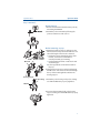
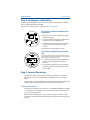
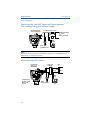
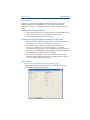
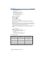
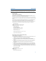
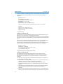
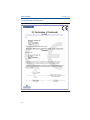
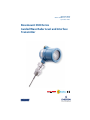
Quick Start Guide 00825-0100-4811, Rev HA September 2013 Rosemount 3300 Series Guided Wave Radar Level and Interface Transmitter Quick Start Guide September 2013 About this guide This start guide provides basic guidelines for the Rosemount 3300 Series. Refer to Rosemount 3300 Series Reference Manual (Document No. 00809-0100-4811) for more instructions. The manual and this Quick Start Guide (QSG) are also available electronically on www.rosemount.com. Any substitution of non-authorized parts or repair, other than exchanging the complete transmitter head or probe assembly, may jeopardize safety and is prohibited. Unauthorized changes to the product are strictly prohibited as they may unintentionally and unpredictably alter performance and jeopardize safety. Unauthorized changes that interfere with the integrity of the welds or flanges, such as making additional perforations, compromise product integrity and safety. Equipment ratings and certifications are no longer valid on any products that have been damaged or modified without the prior written permission of Emerson Process Management. Any continued use of product that has been damaged or modified without prior written authorization is at the customer's sole risk and expense. 2 September 2013 Quick Start Guide Failure to follow safe installation and service guidelines could result in death or serious injury Make sure only qualified personnel perform installation or service. Use the equipment only as specified in this QSG and the Reference Manual. Failure to do so may impair the protection provided by the equipment. Do not perform any services other than those contained in this manual unless you are qualified. Explosions could result in death or serious injury Verify that the operating environment of the transmitter is consistent with the appropriate hazardous locations specifications. See Product Certifications on page 17 in this Quick Start Guide. In an Explosion-proof/Flameproof installation, do not remove the transmitter covers when power is applied to the unit. ® Before connecting a HART -based Communicator in an explosive atmosphere, make sure the instruments in the loop are installed in accordance with intrinsically safe or non-incendive field wiring practices. To avoid process leaks, only use o-rings designed to seal with the corresponding flange adapter. Electrical shock can result in death or serious injury Avoid contact with the leads and terminals. High voltage that may be present on leads can cause electrical shock. Make sure the main power to the Rosemount 3300 Series transmitter is off and the lines to any other external power source are disconnected or not powered while wiring the transmitter. Temperature restrictions apply for Explosion-proof versions. For limits, see certificate-specific information in the Product Certification chapter in this document. Contents Step 1 Mount the transmitter head/probe . . . 5 Step 4 Configure. . . . . . . . . . . . . . . . . . . . . . . . . 12 Step 2 Set Jumpers and Switches. . . . . . . . . . . . 8 Environmental conditions. . . . . . . . . . . . . . . . . 16 Step 3 Connect the wiring . . . . . . . . . . . . . . . . . 8 Product certifications . . . . . . . . . . . . . . . . . . . . 17 3 September 2013 Quick Start Guide The electronics enclosures are category 2G or 2D equipment. The probes not covered with plastic and not made of titanium, are category 1G or 1D. The plastic covered probes or probes made of titanium, are only category 1G equipment. Probes with non-conducting surfaces and light metals Probes covered with plastic and/or with plastic discs may generate an ignition- capable level of electrostatic charge under certain extreme conditions. Therefore, when the probe is used in a potentially explosive atmosphere, appropriate measures must be taken to prevent electrostatic discharge. These probes are not allowed in dust classified areas. The following probes do not contain plastic or PTFE material, and are allowed to be placed in a Dust classified area: Code Material of Construction: Process Connection/Probe 1 316L SST (EN 1.4404) 2 Alloy C-276 (UNS N10276) plate design if flanged version 3 Alloy 400 (UNS N04400) plate design if flanged version 5 Titanium Gr-1 and Gr-2 9 Duplex 2205 (plate design if flanged version) L Alloy 625 (UNS N06625) M Alloy 400 (UNS N04400), flange design H Alloy C-276 (UNS N10276) D Duplex process connection Table 1. The Material of Construction Code in the above table can be found in the following position in the Rosemount 3300 Series model code: 330xxxxxN... Category 2G or 2D Category 2G or 2D Category 1G or 1D Category 1G Probes according to table 1 Applicable Marking: II 1/2 G Ex d [ia Ga] IIC T6…T1 Ga/Gb II 1/2 D Ex tb [ia Da] IIIC T85 ºC…T450 ºC Da/Db All probes possible II 1/2 G Ex d [ia Ga] IIC T6…T1 Ga/Gb II -/2 D Ex tb IIIC T85 ºC…T135 °C -/Db Probes and flanges containing >7.5% Magnesium or Zirconium are not allowed in explosive dust atmosphere. Please contact Rosemount Tank Radar for additional information. Probes and flanges containing light metals When used in category 1/2G installations, probes and flanges containing Titanium or Zirconium must be mounted in such a way that sparks from impact or friction between these parts and steel cannot occur. 4 Quick Start Guide September 2013 Step 1: Mount the transmitter head/probe Tank Connection with flange 1. Place a gasket on top of the tank flange. Transmitter 2. With the transmitter still attached, lower the Housing Nut Bolt Flange Probe Gasket probe into tank. 3. Tighten the bolts. 4. Loosen the nut that connects the housing to the probe and rotate the housing to the desired direction. 5. Tighten the nut. Tank Flange Threaded tank connection Nut Adapter Probe Sealant on threads (NPT) or Gasket (BSP/G) Tank Flange/ Process Connection 1. For adapters with BSP/G threads, place a gasket on top of the tank flange. 2. With the transmitter still attached, lower the probe into the tank. 3. Mount the adapter into the process connection. 4. Loosen the nut that connects the housing to the probe and rotate the housing to the desired direction. 5.Tighten the nut. Note For adapters with NPT threads, pressure-tight joints require a sealant. Tri-Clamp tank connection Tri-Clamp Probe Tank Clamp Gasket 1. Place a gasket on top of the tank flange. 2. With the transmitter still attached, lower the probe into the tank. 3. Fasten the Tri-Clamp connection to the tank with a clamp. 4. Loosen the nut that connects the housing to the probe and rotate the housing to the desired direction. 5.Tighten the nut. Refer to Rosemount 3300 Series Reference Manual (Document No. 00809-0100-4811) for details regarding the mounting of transmitter head/probe. 5 September 2013 Quick Start Guide Step 1 continued... Bracket mounting, on wall 1. Mount the bracket directly to the wall with screws suitable for the purpose. Transmitter housing 2. Mount the transmitter with probe to the bracket and secure the installation with the three supplied screws. Bracket Probe U-bolts Clamping Bracket brackets Transmitter housing Bracket mounting, on pipe 1. Put the two U-bolts through the holes of the bracket. Holes are available for both vertical and horizontal pipe mounting. 2. Put the clamping brackets on the U-bolts and around the pipe. Probe 3. Fasten the bracket to the pipe using the four supplied nuts. 4. Mount the transmitter with probe to the bracket and secure with the three supplied screws. Vertical mounting Transmitter housing Probe Horizontal mounting 6 See the Rosemount 3300 Series Reference Manual (Document No. 00809-0100-4811) for more installation details. Quick Start Guide September 2013 Step 1 continued... Remote housing 1. Remove the transmitter head from the probe by unscrewing the M50 nut M50 nut 2. Mount the probe in the tank by following the previous instructions in this section Bracket mounting, on pipe U-bolt M6 screw 3. Mount the bracket to the pole, making sure the distance between the probe and bracket does not exceed the length of the remote connection. Put the two U-bolts through the holes of the bracket. Several holes are available for Clamping vertical/horizontal pipe mounting. Bracket brackets Put the clamping brackets on the U-bolts and around the pipe. Use the supplied nuts to fasten the bracket to the pipe. 4. Fasten the housing support to the bracket using the M6 screws. The screws are threaded through the top of the mounting bracket and into the housing support. Housing support Probe housing 5. Mount the probe housing on the probe, making sure that the M50 nut is properly tightened. M50 nut 6. Connect the transmitter head on the housing support, making sure that the M50 nut is properly tightened. 7 September 2013 Quick Start Guide Step 2: Set Jumpers and Switches If alarm and security jumpers are not set, the transmitter operates with the default alarm condition HIGH and Security OFF. Write Protection must be set after configuration (Step 4 Configure). To set Alarm and Write Protection on the circuit board: 1. Remove the cover on the circuit side (see label marked circuit side). 2. To set the 4-20 mA alarm output to LOW, move the alarm switch to the LOW position. 3.To enable the security write protection feature, move the write protect switch to the ON position. 4. Replace the cover and tighten securely. To set Alarm and Write Protection on the LCD: To have the LCD override the circuit board settings, the write protection switch needs to be in the OFF position and the alarm switch needs to be in the HIGH position. 1. To set the 4-20 mA alarm output to LOW, place jumper between the right and center hole position. 2.To enable the security write protection feature, place jumper between the left and center hole position - ON. Step 3: Connect the wiring For HART, the input voltage is 11-42 V (11-30 V in IS applications, 16-42 V in Explosion-proof / Flameproof applications). For Modbus, the input voltage is 8-30 V. The transmitter requires shielded twisted pair wiring (18-12 AWG) suitable for the supply voltage and, if applicable, approved for use in hazardous areas. Cable/conduit entries The electronics housing has two entries for ½ - 14 NPT. Optional M20×1.5 and PG 13.5 adapters are also available. The connections are made in accordance with local or plant electrical codes. Make sure that unused ports are properly sealed to prevent moisture or other contamination from entering the terminal block compartment of the electronics housing. 8 Quick Start Guide September 2013 Note Use the enclosed metal plug to seal the unused port. Dual Compartment Housing Cable Entry: ½" NPT. Optional adapters: M20, PG13.5 Radar Electronics Flanged Process Connections Threaded Process Connections To connect the transmitter 1. Make sure the housing is grounded according to Hazardous Locations Certifications, national and local electrical codes. 2. Verify that the power supply is disconnected. 3. Remove the cover on the terminal side (see label marked field terminals). 4. Pull the cable(s) through the cable gland / conduit. For Explosion-proof / Flameproof installations, only use cable glands or conduit entry devices certified Explosion-proof or Flameproof (Ex d llC (gas) or Ex t lllC (dust)). 5. To connect the wires see the illustrations below. 6. If applicable, use the enclosed metal plug to seal any unused port. 7. Replace the cover and tighten. 8. Tighten the cable gland. 9. Connect the power supply. 9 September 2013 Quick Start Guide Step 3 continued... Non-Intrinsically Safe HART Output and Type n Approvals: Non-Sparking/ Energy Limited Power Supply Load Resistance = 250 Ω Rosemount 3300 Series Transmitter Maximum voltage: Um=250 V HART: Un=42.4 V Power Supply HART Modem Field Communicator PC NOTE Rosemount 3300 Series Transmitters with Flameproof/Explosion-proof HART Output have a built-in barrier; no external barrier needed. Intrinsically Safe HART Output Rosemount 3300 Series Transmitter Approved IS Barrier DCS Power Supply HART Mode IS Parameters: Ui=30 V, Ii= 130 mA, Pi=1 W, Li=Ci=0 10 Field Communicator PC RL = 250 Ω Quick Start Guide September 2013 Step 3 continued... Non-intrinsically Safe Modbus Output 120 Ω RS485 Bus B A 120 Ω Power Supply HART + HART 120 If the unit is the last transmitter on the bus, a 120 Ω termination resistor is required. NOTE Rosemount 3300 Series Transmitters with Flameproof/Explosion-proof Modbus Output have a built-in barrier; no external barrier needed. The Field Communicator requires a minimum load resistance of 250 Ω within the loop in order to function properly, see below. Load Limitations Non-Hazardous Installations, and Type n Approvals: Non-Sparking / Energy Limited Power Supply Explosion-proof/Flameproof (Ex d and tb) Installations Operating region Operating region Intrinsically Safe Installations NOTE For the Ex d and tb installations the diagram is only valid if the HART load resistance is at the + side, otherwise the load resistance value is limited to 300 Ω. Operating region 11 Quick Start Guide September 2013 Step 4: Configure If the transmitter is pre-configured at the factory, step 4 is only necessary to change or verify the settings. Configuration of the Rosemount 3300 Series transmitter can be done either with a Field Communicator, Asset Management Solutions (AMS), or Radar Configuration Tools (RCT). If using the Radar Configuration Tools, a HART modem is required, and the procedure is described below, together with the corresponding Field Communicator Fast Key sequence. Installing the Radar Configuration Tools (RCT) Software To install the RCT software: 1. Insert the installation CD into your CD-ROM drive. 2. Follow the instructions. If the installation program does not automatically start, run Setup.exe from the CD. Starting RCT Click Programs > Rosemount > RCT, and the following window appears1 The Help function of the RCT can be reached from the menu or by pressing the F1 key. Wizard Setup 1. For optimum performance set COM Port Buffers to 1. You might receive a pop-up reminder of this before the RCT window appears. See Chapter 4 “Start-up” in the Reference Manual (Document No. 00809-0100-4811) 12 September 2013 Quick Start Guide Step 4 continued... Configuration of a Rosemount 3300 Series transmitter can be done using the installation Wizard for detailed guidance. If you are already familiar with the configuration procedure, or if you want to change settings, you may use the setup function. Configuration Using the Wizard 1. Make sure that the Tools Bar is open (Project Bar is ticked within View). Then click the Wizard icon or choose the View>Wizard menu option. 2. Click the start button and follow the instructions. Configuration Using the Setup Function & Fast Key Code 1. Make sure that the Tools Bar is open (Project Bar is ticked within View). Then click the Setup icon or choose the View>Setup menu option. 2. Choose the appropriate tab: Info (information about the device), Basics (page 13), Output (page 14), Tank Config (page 15), Volume (specification of tank geometry for volume calculations), LCD (display panel settings), or Signal Quality Metrics (for activating/de-activating and display of signal quality metrics, available with the DA1 option). 3. Press the Receive Page button to load the parameters configured in the transmitter into the dialog window. Press the Send Page button to load any parameter changes back to the transmitter. Setup - Basics Set Units, Field Communicator Fast Key sequence [1,3,1] Length, volume, and temperature units can be set. Units are used wherever measurement and configuration data occur. 13 Quick Start Guide September 2013 Setup - Output Set Range Values, Field Communicator Fast Key sequence [1,3,4,3] The Lower Range value = 4 mA value. The Upper Range value = 20 mA value. The 4-20 mA range must not include the upper or lower Transition Zone.1 Set Variable Assignment, Field Communicator Fast Key sequence [1,1,1] Model 3301 available measuring parameters: Level, Distance to Level, Total Volume. For fully immersed probe: Interface Level and Interface Distance. Model 3302 available measuring parameters: Level, Distance to level, Total Volume, Interface Level, Interface Distance, and Upper Product Layer Thickness. In the Primary Variable field, the measuring parameter is entered for the analog signal. More variables can be assigned if the superimposed digital HART signal or a HART Tri-loop is used. Setup - Modbus Communication Parameters If the transmitter has the Modbus option, configuration of the communication parameters can be set. 1. See the Reference Manual (Document No. 00809-0100-4811) for details. 14 September 2013 Quick Start Guide Setup - Tank Config Geometry See tank picture in window. Set Reference Gauge Height, Field Communicator Fast Key sequence [1, 3, 2, 3] Set Upper Null Zone, if needed, Field Communicator Fast Key sequence [1, 3, 2, 5, 1] Set Mounting Type, Field Communicator Fast Key sequence [1, 3, 2, 4] Set Diameter if Mounting Type is Nozzle or Pipe/Chamber Set Nozzle Height if Mounting Type is Nozzle Probe Set Probe Type, Field Communicator Fast Key sequence [1, 3, 2, 1]: This is configured in factory Set Probe Length, Field Communicator Fast Key sequence [1, 3, 2, 2]: This is configured in factory, but needs to be changed if the probe is cut in field Set Probe Angle, Field Communicator Fast Key sequence [1, 3, 2, 5, 3] Set Remote Housing length if Remote Housing is mounted (setting not available in DD/DTM) Misc. Settings Set Vapor Dielectric value, if needed, Field Communicator Fast Key sequence [1, 3, 3, 2] Set Upper Product Dielectric value, Interface measurements only, Field Communicator Fast Key sequence [1, 3, 3, 3] Additional Configuration to Fine-Tune Performance To fine-tune the transmitter’s performance, it is recommended the Trim Near Zone function be executed after configuration is finished. For detailed information on how to trim the near zone, see the Rosemount 3300 Series Reference Manual (Document No. 00809-0100-4811). 15 September 2013 Quick Start Guide Environmental conditions Ambient temperature limits (for use in explosive atmospheres) Explosion-proof/Flame-proof version: -58 °F (-50 °C) ≤ Ta ≤ +167 °F (+75 °C) Intrinsically safe version: -58 °F (-50 °C) ≤ Ta ≤ +158 °F (+70 °C) National deviations may apply, see Product certifications on page 17. Process temperature restrictions When the Rosemount 3300 is installed in high temperature applications, it is important that the maximum ambient temperature is considered. Tank insulation should not exceed 4 in. (10 cm). The diagram below shows the maximum ambient temperature vs. process temperature: Ambient Temperature Process Temperature Pressure limits For pressure limits, see the Rosemount 3300 Series Reference Manual (Document No. 00809-0100-4811). 16 September 2013 Quick Start Guide Product certifications EU Conformity The EC declaration of conformity can be found on page 24. The most recent revision can be found at www.rosemount.com. Safety Note: A safety isolator, such as a zener barrier is always needed for intrinsic safety. Probes covered with plastic and/or with plastic discs may generate an ignition-capable level of electrostatic charge under certain extreme conditions. Therefore, when the probe is used in a potentially explosive atmosphere, appropriate measures must be taken to prevent electrostatic discharge. Hazardous Locations certifications North-American certifications Factory Mutual (FM) Approval Project ID: 3013394 E5 Explosion-proof for use in Class I, Div. 1, Groups B, C, and D; Dust-ignition-proof for use in Class II/III, Div. 1, Groups E, F, and G; With Intrinsically Safe connections to Class I, II, III, Div. 1, Groups A, B, C, D, E, F, and G. Temperature Class T5 @ +85 °C. Ambient temperature limits -50 °C to +85 °C. Approval valid for Modbus and HART option. I5 Intrinsically Safe for Class I, II, III, Div. 1, Groups A, B, C, D, E, F, and G, Class I, Zone 0, AEx ia IIC T4 Ta=70 °C. Temp code T4 at 70 °C max ambient. Installation Drawing: 9150077-944. Non-Incendive Class I, Div. 2, Groups A, B, C, and D; Suitable for Class II, III, Div. 2, Groups F and G. Non-incendive maximum operating parameters: 42 V, 25 mA. Temp code T4A at 70 °C max ambient. Approval valid for HART option. Canadian Standards Association (CSA) Approval Cert. no 1250250. E6 Explosion-proof: Class I, Div. 1, Groups C and D. Dust-ignition-proof: Class II, Div. 1 and 2, Groups G and coal dust. Class III, Div. 1, Haz. Loc. [Ex ia IIC T6]. Ambient temperature limits -50 °C to +85 °C. Approval valid for Modbus and HART option. 17 September 2013 Quick Start Guide I6 Intrinsically Safe: Ex ia IIC T4, Class I, Div. 1, Groups A, B, C, and D. Temp code T4. Installation Drawing: 9150077-945. Non-Incendive: Class III, Div. 1, Haz. Loc. Class I, Div 2, Groups A, B, C, and D. Ambient temperature limits -50 °C to +70 °C. Approval valid for HART option. European certifications ATEX Approval E1 Flameproof: Special conditions for safe use (x): On application of the transmitter with plastic covered probes1, in an explosive gas atmosphere, precaution shall be taken to avoid danger of ignition due to electrostatic charges on the probe. On application of the transmitter in an explosive dust atmosphere, the transmitter shall be installed in such a way that the risk from electrostatic discharges and propagating brush discharges caused by rapid flow of dust at the label is avoided. For probes and flanges containing light metals, an ignition hazard due to impact or friction needs to be avoided according to IEC 60079-0 clause 8.3, when used as EPL Ga/Gb equipment. KEMA 01ATEX2220X II 1/2 G Ex d [ia Ga] IIC T6...T1 Ga/Gb II 1/2 D Ex tb [ia Da] IIIC T85 ºC...T450 ºC Da/Db1 or II -/2 D Ex tb IIIC T85 ºC...T135 °C -/Db Um=250Vac Ambient temperature range: -50 ºC2 to +75 ºC Approval valid for HART and MODBUS options. Process temperature limits Maximum ambient temperature [°C] Maximum process temperature [°C] Temperature class / maximum surface temperature +75 +75 T6 / T 85 °C +75 +90 T5 / T 100 °C +75 +125 T4 / T 135 °C +75 +190 T3 / T 200 °C +65 +285 T2 / T 300 °C +55 +400 T1 / T 450 °C 1. Non-plastic covered probes only (see Table 1 on page 4) 2. -40 °C for process temperature range -196 °C to -50 °C 18 September 2013 Quick Start Guide Note: Maximum process temperature is limited by type of probe, see Product Data Sheet for details. I1 Intrinsic Safety: Special conditions for safe use (x): The apparatus is not capable of withstanding the 500V test as defined in Clause 6.3.13 of EN60079-11:2012. This must be considered in any installation. The Series 3300 enclosure is made of aluminium alloy and given a protective polyurethane paint finish; however, care should be taken to protect it from impact or abrasion if located in zone 0. The probes may contain plastic materials greater than 4cm² or be coated with plastic and these can present an electrostatic risk if rubbed or placed in a fast moving air flow. The probes may contain light alloys which can present a risk from frictional ignitions. Care should be taken to protect them from mechanical impact during use or installation. BAS02ATEX1163X II 1 G Ex ia IIC T4 Ga (-50 °C ≤ Ta ≤ +70 °C). Ui=30 V, Ii=130 mA, Pi=1.0 W, Li=Ci=0. Input Voltage range Loop-powered (2-wire): Functional voltage range: 11-42 Vdc Intrinsically safe version: 11-30 Vdc Max Power rating: 1.0 W Ambient temperature limit: -50 °C ≤ Ta ≤ +70 °C Approval valid for HART option. N1 Type N Approvals: Non-Sparking / Intrinsic safety Special conditions for safe use (x): 1. The apparatus is not capable of withstanding the 500V test as defined in Clause 6.3.13 of EN60079-11:2012. This must be considered in any installation. 2. The Series 3300 enclosure is made of aluminium alloy and given a protective polyurethane paint finish; however, care should be taken to protect it from impact or abrasion. 3. The Probes may contain light alloys which can present a risk from frictional ignitions. Care should be taken to protect them from mechanical impact during use or installation. 4. The Probes may contain plastic materials greater than 4cm² or be coated with plastic and these can present an electrostatic risk if rubbed or placed in a fast moving air flow. 5. The cable entry must use a suitable Certified Cable Gland which provides strain relief and any unused openings to the equipment must be blanked off to maintain a degree of protection of at least IP66. Baseefa12ATEX0089X ic nA IIC T4 Gc (-50 °C ≤ Ta ≤ +70 °C) UN=42.4 V Approval valid for HART option. 19 Quick Start Guide September 2013 Brazilian certifications INMETRO Approvals E2 Explosion-proof: Special conditions for safe use (x): On application of the Rosemount 3300 Series Guided Wave Radar Level and Interface Transmitters equipped with plastic materials in an explosive gas atmosphere, precaution shall be taken to avoid danger of ignition due to electrostatic charges on the enclosure. For probes and flanges containing light metals when used on EPL Ga or Gb areas, risk of impact and frictions must be avoided according to item 8.1 of ABNT NBR IEC 60079-0:2008. Ex db [ia] llC T6/T5/T4 Ga/Gb (-50 °C ≤ Ta ≤ +75 °C) Power supply: 16 - 42 Vcc Current/Output: 4-20 mA HART Protocol Vmax = 250 V (maximum voltage) Certificate no. NCC 11.0237X Standards: ABNT NBR IEC 60079-0:2008, ABNT NBR IEC 60079-1:2009, ABNT NBR IEC 60079-11:2009, ABNT NBR IEC 60079-26:2008 Approval valid for HART option. I2 Intrinsically safe: Special conditions for safe use (x): If the equipment is used in a hazardous area, the programming port should not be used. The metallic housing must be electrically connected to a ground terminal. The cable used should be equivalent to a copper cable with a cross-sectional area of at least 4 mm2. Intrinsically safe parameters for the +/- Terminals Ex ia llC T4 Ga (+70 °C) Ui = 30 V Ii = 130 mA Pi = 1 W Ci = 0 (negligible) Li = 0 (negligible) Certificate no. NCC 11.0201X Standards: ABNT NBR IEC 60079-0:2008, ABNT NBR IEC 60079-11:2009, ABNT NBR IEC 60079-26:2008, ABNT NBR IEC 60529:2005 Approval valid for HART option. 20 September 2013 Quick Start Guide Chinese certifications National Supervision and Inspection Center for Explosion Protection and Safety of Instrumentation (NEPSI) Approvals Special conditions for safe use (x): The enclosure contains light metal, attention should be taken to avoid ignition hazards due to impact or friction. This apparatus is not capable of withstanding the 500 V r.m.s insulation test required byClause 6.3.12 of GB3836.4-2010. E3 Flameproof: GYJ12.1037X Ex d ia llC T6~T4 Gb, DIP A21 TA85 °C~ TA135 °C IP66 Um=250 V Approval valid for HART and Modbus options. I3 Intrinsically Safe: GYJ11.1537X Ex ia IIC T4 (-50 °C ≤TA≤ +70 °C) Ui=30 Vdc, Ii=130 mA, Pi=1.0 W, Ci=0 nF, Li=0 H. Approval valid for HART option. Japanese certifications Technology Institution of Industrial Safety (TIIS) Approval Special conditions for safe use (x): See certificate for details. E4 Flameproof with Intrinsically Safe probe: TC18544, TC18545 Transmitter: Ex d [ia] IIB T6 (Ta, max = 60 °C) Um=250 V Probe: Ex ia IIB T6 Uo=25.2 V, Io=159 mA, Po=1.0 W Approval valid for HART option. Installation drawing: 03300-00408. IECEx certifications IECEx Approval E7 Flameproof: Conditions of Certification (X) On application of the transmitter with plastic covered probes1, in an explosive gas atmosphere, precaution shall be taken to avoid danger of ignition due to electrostatic charges on the probe. On application of the transmitter in an explosive dust atmosphere, the transmitter shall be installed in such a way that the risk from electrostatic discharges and propagating brush discharges caused by rapid flow of dust at the label is avoided. 1. Non-plastic covered probes only (see Table 1 on page 4) 21 Quick Start Guide September 2013 For probes and flanges containing light metals, an ignition hazard due to impact or friction needs to be avoided according to IEC 60079-0 clause 8.3, when used as EPL Ga/Gb equipment. IECEx DEK 12.0015X Ex d [ia Ga] IIC T6…T1 Ga/Gb Ex tb [ia Da] IIIC T85 ºC…T450 ºC Da/Db 1 or Ex tb IIIC T85 ºC…T135 °C -/Db Um=250Vac Approval valid for HART and MODBUS option. The process temperature effects shall be taken into account, see E1 approval. Standards: IEC 60079-0:2011, IEC 60079 -1:2007, IEC 60079-11:2011, IEC 60079-26:2006, IEC 60079-31:2008 I7 Intrinsic Safety: Conditions of Certification (X) The apparatus is not capable of withstanding the 500V test as defined in Clause 6.3.13 of EN60079-11:2012. This must be considered in any installation. The Series 3300 enclosure is made of aluminium alloy and given a protective polyurethane paint finish; however, care should be taken to protect it from impact or abrasion if located in zone 0. The probes may contain plastic materials greater than 4cm² or be coated with plastic and these can present an electrostatic risk if rubbed or placed in a fast moving air flow. The probes may contain light alloys which can present a risk from frictional ignitions. Care should be taken to protect them from mechanical impact during use or installation. IECEx BAS 12.0062X Ex ia IIC T4 (Ta = 60 °C) IP66 Ui= 30 V, Ii= 130 mA, Pi= 1 W, Ci= 0 nF, Li= 0 mH Approval valid for HART option. N7 Type N Approvals: Non-Sparking / Intrinsic Safety Conditions of Certification (X) The external supply must be provided with transient and over voltage protection. The apparatus is not capable of withstanding the 500 V test to earth for one minute as defined in Clause 34.2 of EN 60079-15. This must be taken into consideration during installation. The cable entry to the equipment must use ATEX Certified Cable glands or be blanked to maintain a degree of protection of IP54. 1. The apparatus is not capable of withstanding the 500V test as defined in Clause 6.3.13 of EN60079-11:2012. This must be considered in any installation. 2. The Series 3300 enclosure is made of aluminium alloy and given a protective polyurethane paint finish; however, care should be taken to protect it from impact or abrasion. 3. The Probes may contain light alloys which can present a risk from frictional ignitions. Care should be taken to protect them from mechanical impact during use or installation. 4. The Probes may contain plastic materials greater than 4cm² or be coated with plastic1 and these can present an electrostatic risk if rubbed or placed in a fast moving air flow. 22 September 2013 Quick Start Guide 5. The cable entry must use a suitable Certified Cable Gland which provides strain relief and any unused openings to the equipment must be blanked off to maintain a degree of protection of at least IP66. Ex ic nA IIC T4 Gc ( -50 °C ≤ Ta ≤ +70 °C) IECEx BAS 12.0061X Standards: IEC 60079-0:2011, IEC 60079-11:2001, IEC 60079-31:2008,IEC 60079 -1:2007, IEC 60079-26:2006 For information on hazardous locations installations, refer to Rosemount 3300 Series Reference Manual (Document No. 00809-0100-4811). Other certifications Overfill Protection U1 WHG Overfill Approval: TÜV-tested and approved by DIBt for overfill protection according to the German WHG regulations. Cert no: Z-65.16-416 Available for HART option. 1. Non-plastic covered probes only (see Table 1 on page 4) 23 Quick Start Guide EC Declaration of Conformity Figure 1. EC Declaration of Conformity - page 1 24 September 2013 September 2013 Quick Start Guide Figure 2. EC Declaration of Conformity - page 2 25 Quick Start Guide Figure 3. EC Declaration of Conformity - page 3 26 September 2013 September 2013 Quick Start Guide 27 00825-0100-4811 Quick Start Guide 00825-0100-4811, Rev HA September 2013 Emerson Process Management Rosemount Measurement 8200 Market Boulevard Chanhassen, MN 55317 USA Tel (USA) 1 800 999 9307 Tel (International) +1 952 906 8888 Fax +1 952 906 8889 Emerson Process Management Asia Pacific Private Limited 1 Pandan Crescent Singapore 128461 Tel +65 6777 8211 Fax +65 6777 0947 Service Support Hotline: +65 6770 8711 E-mail: Enquiries@AP.EmersonProcess.com Emerson Process Management Management Blegistrasse 23 P.O. Box 1046 CH 6341 Baar Switzerland Tel +41 (0) 41 768 6111 Fax +41 (0) 41 768 6300 Emerson FZE Jebel Ali Free Zone Dubai UAE Tel +971 4 811 8100 Fax +971 4 886 5465 Emerson Process Management Latin America 1300 Concord Terrace, Suite 400 Sunrise Florida 33323 USA Tel +1 954 846 5030 Emerson Beijing Instrument Co No.6 North Street, Hepingli Dongcheng District, Beijing 100013 China Tel +8610 64282233 Fax +8610 642 87640 © 2013 Rosemount Inc. All rights reserved. All marks property of owner. The Emerson logo is a trade mark and service mark of Emerson Electric Co Rosemount and the Rosemount logotype are registered trademarks of Rosemount Inc.