1
DIGITAL RECORDING CONSOLE
E
FCC INFORMATION (U.S.A.)
1. IMPORTANT NOTICE: DO NOT MODIFY THIS UNIT!
This product, when installed as indicated in the instructions contained in this manual, meets FCC requirements. Modifications not expressly approved by Yamaha
may void your authority, granted by the FCC, to use the product.
2. IMPORTANT: When connecting this product to accessories and/or another product use only high quality shielded cables. Cable/s supplied with this product MUST
be used. Follow all installation instructions. Failure to follow instructions could void your FCC authorization to use this product in the USA.
3. NOTE: This product has been tested and found to comply with the requirements listed in FCC Regulations, Part 15 for Class “B” digital devices. Compliance with
these requirements provides a reasonable level of assurance that your use of this product in a residential environment will not result in harmful interference with
other electronic devices. This equipment generates/uses radio frequencies and, if not installed and used according to the instructions found in the users manual, may
cause interference harmful to the operation of other electronic devices. Compliance with FCC regulations does not guarantee that interference will not occur in all
installations. If this product is found to be the source of interference, which can be determined by turning the unit “OFF” and “ON”, please try to eliminate the
problem by using one of the following measures:
Relocate either this product or the device that is being affected by the interference.
Utilize power outlets that are on different branch (circuit breaker or fuse) circuits or install AC line filter/s.
In the case of radio or TV interference, relocate/reorient the antenna. If the antenna lead-in is 300 ohm ribbon lead, change the lead-in to coaxial type cable.
If these corrective measures do not produce satisfactory results, please contact the local retailer authorized to distribute this type of product. If you can not locate the
appropriate retailer, please contact Yamaha Corporation of America, Electronic Service Division, 6600 Orangethorpe Ave, Buena Park, CA 90620
* This applies only to products distributed by YAMAHA CORPORATION OF AMERICA.
IMPORTANT NOTICE FOR
THE UNITED KINGDOM
Connecting the Plug and Cord
WARNING: THIS APPARATUS MUST BE EARTHED
IMPORTANT: The wires in this mains lead are coloured in accordance with
the following code:
GREEN-AND-YELLOW
BLUE
BROWN
: EARTH
: NEUTRAL
: LIVE
As the colours of the wires in the mains lead of this apparatus may not
correspond with the coloured markings identifying the terminals in your
plug, proceed as follows:
The wire which is coloured GREEN and YELLOW must be connected to
the terminal in the plug which is marked by the letter E or by the safety earth
symbol or coloured GREEN and YELLOW.
The wire which is coloured BLUE must be connected to the terminal which
is marked with the letter N or coloured BLACK.
The wire which is coloured BROWN must be connected to the terminal
which is marked with the letter L or coloured RED.
* This applies only to products distributed by YAMAHA KEMBLE
MUSIC (U.K.) LTD.
ADVARSEL!
Lithiumbatteri—Eksplosionsfare ved fejlagtig
håndtering. Udskiftning må kun ske med batteri
af samme fabrikat og type. Levér det brugte
batteri tilbage til leverandoren.
VARNING
Explosionsfara vid felaktigt batteribyte. Använd
samma batterityp eller en ekvivalent typ som
rekommenderas av apparattillverkaren.
Kassera använt batteri enligt fabrikantens
instruktion.
VAROITUS
Paristo voi räjähtää, jos se on virheellisesti
asennettu. Vaihda paristo ainoastaan
laitevalmistajan suosittelemaan tyyppiin. Hävitä
käytetty paristo valmistajan ohjeiden
mukaisesti.
Important Information
i
Important Information
Please read the following before operating your Digital Recording
Console 02R.
Precautions
Installing the 02R
•
The unit should be connected only to an AC receptacle of the type
described in the owner’s manual or as marked on the unit.
•
Be careful to prevent the 02R from getting wet; do not allow water to
enter the 02R, especially when raining or snowing, or near a body of a
water. Otherwise, fire or electrical shock may result.
•
Do not block the ventilation holes on the 02R. The 02R has ventilation
holes on the top, rear, front and bottom panel to prevent the inside
temperature from rising. If the ventilation holes are blocked, the heat
will remain inside, resulting in fire. In particular, avoid the following
situations:
Do not orient the 02R upside down, face down, or sideways.
Do not place the 02R in a narrow, non-ventilated space, such as in a
bookcase or closet. Use a dedicated rack.
•
Do not place a table cloth on top of the 02R; do not place the 02R on a
carpet or mattress.
•
Do not place heavy objects on the power cord. If the cord is damaged,
fire or electrical shock may result. In particular, it is possible that one
might accidentally place a heavy object on the carpet that covers the
cord, or place the 02R on top of a power cord; avoid these situations.
•
To allow for the efficient release of heat, maintain a gap of 10cm or
more between the rear of the 02R and the wall. Locate the 02R away
from other equipment. If the release of heat is insufficient, the heat
will remain inside the device, and result in a fire.
•
Do not install the 02R in a place where it may be exposed to oil,
smoke, or steam (for example, near a cooking table or humidifier).
Otherwise, fire or electrical shock may result.
•
Do not place the 02R on an unstable surface, such as an unstable
bench or slanted surface. Otherwise, the equipment may fall or drop,
resulting in injury.
•
Do not place the power cord near a heating device. Otherwise, the
cord sheath may melt, resulting in fire or electrical shock.
•
Do not locate the 02R in a place subject to excessive heat, such as
inside a car with all the windows closed, or in direct sunlight.
Otherwise, fire may result.
•
Do not place the 02R in a place subject to excessive humidity or dust.
Otherwise, fire or electrical shock may result.
Digital Recording Console 02R
Owner’s Manual
ii
Important Information
•
Do not handle the power plug with wet hands. Otherwise, you may
receive an electrical shock.
•
When you remove the power plug, be sure to hold the plug. Never
pull on the cord. Otherwise, the power cord will become damaged,
resulting in fire or electrical shock.
•
When relocating the 02R, since the 02R is heavy, make sure that two
or more people carry it.
•
When you are moving the 02R to another location, first turn off the
power switch, remove the power plug from the AC outlet, and
remove all cables connected to external devices. Otherwise, the cables
may become damaged, resulting in fire or electrical shock.
•
The Digital Recording Console 02R offers superb sonic quality. To
ensure the best possible results, you should use the best quality
connecting cables that you can afford. Regular maintenance involves
keeping all connections clean using a quality contact cleaner.
Using the 02R
Do not touch the 02R under the following circumstances:
•
If you hear thunder, turn off the power switch and remove the power
plug from the AC outlet as soon as possible.
If you fear a lightning hit, and the 02R has been connected to an AC
outlet, do not touch the power plug. Otherwise, you may receive an
electrical shock.
•
Do not attempt to modify this equipment. Otherwise, fire or electrical
shock may result.
•
Do not remove the case of the 02R. Otherwise, electrical shock may
result.
If you think the 02R needs to be checked for maintenance or repair,
consult your dealer.
Digital Recording Console 02R
•
Do not place a container of water, or any small metal object on top of
the 02R. If water is spilled or if the metal object falls inside, fire or
electrical shock may result. This applies to vases, potted plants,
glasses, cosmetic bottles, medicine, etc.
•
Do not damage, process, bend, twist, stretch, or heat the power cord.
Otherwise, the cord may be damaged, resulting in fire or electrical
shock.
•
When you are connecting audio devices or speakers to the 02R, make
sure that first you turn off the power to all devices to be connected.
Refer to the user's guide for each device, and use the specified cable
for connection.
•
Set the volume level on all the devices to the minimum before turning
on the power. Otherwise, an extremely loud noise could damage your
hearing.
•
If you plan not to use the 02R for a long period of time (such as when
you are on vacation), remove the power plug from the AC outlet.
Otherwise, a fire could possibly result.
Owner’s Manual
Important Information
iii
If an abnormality occurs while operating the 02, remove the plug from
the AC outlet
•
If you notice any abnormality--such as smoke, odor, noise, etc.--turn
off the power to the 02R immediately, and remove the power plug
from the AC outlet. Confirm that the abnormality is no longer
present, then consult your dealer for repair. If you continue using the
02R under abnormal conditions, fire or electrical shock may result.
•
If a foreign object or water enters inside the equipment, turn off the
power to the 02R immediately, remove the power plug from the AC
outlet, and consult your dealer for repair. If you continue using the
02R under this condition, fire or electrical shock may result.
•
If the power cord is damaged (for example, the it is cut or if the core
wire is exposed), ask your dealer for a replacement. If you continue
using the 02R under this condition, fire or electrical shock may result.
•
If the 02R is dropped, or the cabinet is damaged, turn off the power
switch, remove the power plug from the AC outlet, and consult your
dealer. If you continue using the 02R under this condition, fire or
electrical shock may result.
Maintenance
•
Before cleaning the 02R, remove the power plug from the AC outlet
for safety. Otherwise, an electrical shock may result.
•
An authorized dealer should clean the internal parts of the 02R on a
regular basis. If you do not clean them for a long period of time,
allowing dust to accumulate inside the equipment, fire or
malfunction may result.
Consult your dealer about cleaning and its cost.
The optimum frequency for cleaning is once a year. It is especially
effective to clean before a rainy or humid season starts.
•
The performance of contact parts--such as switches, the volume
encoder, and connectors--deteriorates with use. The degree of
deterioration may differ depending on the environment, but the
deterioration itself cannot be avoided. To replace the contact parts,
consult your dealer.
•
Do not apply oil, grease, or a contact repair agent to the faders.
Otherwise, the conductivity of the electrical contact point may be
affected.
If you think the faders' movement is awkward, refer to
"User’s Guide" on page 170 for calibration information.
Data backup
Data stored inside the equipment may be destroyed by malfunction
or incorrect operation of the equipment. Be sure to save important
data to an external MIDI device for backup.
Digital Recording Console 02R
Owner’s Manual
iv
Important Information
Influences on other electrical devices
This equipment uses many digital circuits, which may cause noise to
occur on nearby radio or TV. In this case, relocate the 02R away from
those devices.
Exclusion of Certain Damages
Manufacturer, importer or dealer shall not be liable for any incidental or
consequential damages for other than injury to the person and/or any
other damages that caused by not proper use or operate the instrument.
Please, watch also our instructions in this manual.
Copyright
© 1995 Yamaha Corporation. All rights reserved.
No part of the Digital Recording Console 02R software or its user
manuals may be reproduced or distributed in any form or by any means
without the prior written authorization of Yamaha Corporation.
Trademarks
ADAT and Alesis are registered trademarks of Alesis Corporation.
ADAT Multichannel Optical Digital Interface is a trademark of Alesis
Corporation.
TEAC® is a registered trademark of TEAC CORPORATION.
Tascam Digital Audio Interface (TDIF-1™) is a trademark of TEAC
CORPORATION.
All other trademarks and registered trademarks are the property of their
respective holders.
Package Contents
Your Digital Recording Console 02R package contains the following
items. If you do not have them all, please contact your Yamaha dealer.
•
Digital Recording Console 02R
•
This Getting Started Guide
This Owner’s Manual consists of:
Digital Recording Console 02R
•
A Getting Started Guide section and
•
A User’s Guide section.
Owner’s Manual
User’s Guide
DIGITAL RECORDING CONSOLE
User’s Guide
Contents
i
Contents
1
Introduction to the 02R. . . . . . . . . . . . . . . . . . . . . . 1
Digital Recording Console 02R . . . . . . . . . . . . . . . . . . . . . . . . . . . . . 2
User Guides . . . . . . . . . . . . . . . . . . . . . . . . . . . . . . . . . . . . . . . . . . . . . 3
Installation . . . . . . . . . . . . . . . . . . . . . . . . . . . . . . . . . . . . . . . . . . . . . . 3
Top and Rear Panels . . . . . . . . . . . . . . . . . . . . . . . . . . . . . . . . . . . . . . 4
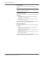
Features. . . . . . . . . . . . . . . . . . . . . . . . . . . . . . . . . . . . . . . . . . . . . . . . . 5
Key Features. . . . . . . . . . . . . . . . . . . . . . . . . . . . . . . . . . . . . . . . . . . . . 7
2
Getting Started . . . . . . . . . . . . . . . . . . . . . . . . . . . 13
Basic Assumptions . . . . . . . . . . . . . . . . . . . . . . . . . . . . . . . . . . . . . . 14
Making the Connections . . . . . . . . . . . . . . . . . . . . . . . . . . . . . . . . . 14
Basic Setup . . . . . . . . . . . . . . . . . . . . . . . . . . . . . . . . . . . . . . . . . . . . . 15
Power ON/OFF. . . . . . . . . . . . . . . . . . . . . . . . . . . . . . . . . . . . . . . . . 16
Setting the Synchronization. . . . . . . . . . . . . . . . . . . . . . . . . . . . . . . 16
Recall Scene Memory 0. . . . . . . . . . . . . . . . . . . . . . . . . . . . . . . . . . . 17
3
Introductory Recording Tutorial . . . . . . . . . . . . . 19
Setting the Input Level . . . . . . . . . . . . . . . . . . . . . . . . . . . . . . . . . . . 20
Applying EQ . . . . . . . . . . . . . . . . . . . . . . . . . . . . . . . . . . . . . . . . . . . 24
Using the EQUALIZER Library . . . . . . . . . . . . . . . . . . . . . . . . . . . 30
Routing . . . . . . . . . . . . . . . . . . . . . . . . . . . . . . . . . . . . . . . . . . . . . . . . 35
Panning . . . . . . . . . . . . . . . . . . . . . . . . . . . . . . . . . . . . . . . . . . . . . . . . 38
4
Secondary Recording Tutorial. . . . . . . . . . . . . . . 41
Auxiliary Send Channels . . . . . . . . . . . . . . . . . . . . . . . . . . . . . . . . . 42
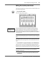
Setting the Auxiliary Send Level . . . . . . . . . . . . . . . . . . . . . . . . . . 43
Creating a Monitor Mix . . . . . . . . . . . . . . . . . . . . . . . . . . . . . . . . . . 45
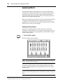
Applying Effects . . . . . . . . . . . . . . . . . . . . . . . . . . . . . . . . . . . . . . . . 46
Recalling and Editing Effects. . . . . . . . . . . . . . . . . . . . . . . . . . . . . . 49
Patching in a Dynamics Processor . . . . . . . . . . . . . . . . . . . . . . . . . 54
Using the Dynamics Library . . . . . . . . . . . . . . . . . . . . . . . . . . . . . . 57
Scene Memories . . . . . . . . . . . . . . . . . . . . . . . . . . . . . . . . . . . . . . . . . 62
Digital Recording Console 02R
Getting Started Guide
ii
Contents
5
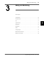
Mixing and Automation . . . . . . . . . . . . . . . . . . . . 67
What is 02R Automation? . . . . . . . . . . . . . . . . . . . . . . . . . . . . . . . . 68
Real-Time Automation . . . . . . . . . . . . . . . . . . . . . . . . . . . . . . . . . . . 69
Editing Automation Events . . . . . . . . . . . . . . . . . . . . . . . . . . . . . . . 76
Off-Line Automix Editing . . . . . . . . . . . . . . . . . . . . . . . . . . . . . . . . 81
Using the AUTOMIX Library . . . . . . . . . . . . . . . . . . . . . . . . . . . . . 86
Index . . . . . . . . . . . . . . . . . . . . . . . . . . . . . . . . . . . . . . . . 90
Digital Recording Console 02R
Getting Started Guide
Introduction to the 02R
1
1
Introduction to the 02R
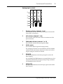
1
In this chapter...
Digital Recording Console 02R . . . . . . . . . . . . . . . . . . . . . . . . . . . . . . . . . . . . 2
User Guides . . . . . . . . . . . . . . . . . . . . . . . . . . . . . . . . . . . . . . . . . . . . . . . . . . . . 3
Installation . . . . . . . . . . . . . . . . . . . . . . . . . . . . . . . . . . . . . . . . . . . . . . . . . . . . . 3
Top and Rear Panels . . . . . . . . . . . . . . . . . . . . . . . . . . . . . . . . . . . . . . . . . . . . . 4
Features . . . . . . . . . . . . . . . . . . . . . . . . . . . . . . . . . . . . . . . . . . . . . . . . . . . . . . . . 5
Key Features . . . . . . . . . . . . . . . . . . . . . . . . . . . . . . . . . . . . . . . . . . . . . . . . . . . . 7
Digital Recording Console 02R
Getting Started Guide
2
Introduction to the 02R
Digital Recording Console 02R
From the company that pioneered digital mixing consoles and leads the
industry with its acclaimed DSP technology comes the Digital Recording
Console 02R – the most advanced digital mixing console in the world. All
of YAMAHA’s experience and innovation has been applied to the 02R, to
create a perfect mixer for use with the current generation of modular digital
multitrack tape and disk recorders.
Inputs and Outputs – I/O Cards and Digital Cascade
With the YAMAHA Digital Recording Console 02R you can record and mix
directly to your modular digital multitrack recorder without ever leaving
the sonic purity of the digital domain. It is a 40 input channel mixer, each
with full dynamic processing and 4-band parametric EQ, plus two stereo
internal effects returns. It comes with 24 analog inputs, featuring 20-bit
64-times oversampling analog-to-digital conversion. By adding one of the
optional digital I/O cards, you can also have 8 channels of direct digital
input. Depending on configuration, up to four cards can be inserted into
the 02R. The cards allow you to select from any of the currently used
formats (ADAT®, TDIF™, YAMAHA, or AES/EBU). The optional cards
allow you to route up to 16 outputs directly to your modular digital
multitrack recorder. In addition, you can insert a Digital Cascade card into
one of the I/O slots, allowing you to connect multiple 02Rs together to
create a larger digital mixing system.
Dynamic Automation with Total and Instant Recall
The Digital Recording Console 02R is a fully dynamic automated mixing
console – all referenced to time code. Its onboard automation system
memorizes not just the faders, but a myriad of parameters. Switch
individual channels on or off, adjust the equalization or the pan position,
change the auxiliary send, and recall any scene memory – automatically.
There are 64 internal scene memories which can store every digital mix
parameter in a “snapshot” providing instant recall and reset.
Crystal Clarity and Unsurpassed Audio Quality
The 02R contains YAMAHA’s latest generation 32-bit proprietary audio
DSP. All of your mix data is processed internally with 32-bit precision.
Using the power of the latest generation effects processor chip, it also has a
startling range of effects available: shimmering reverbs, clean, precise
delays, flanging and chorus, and other effects are built into this mixer. It
also features dynamics processors on all the inputs, allowing you to
compress, limit, or gate the signals, giving you unparalleled sonic quality
and flexibility. The 02R samples audio at 44.1 kHz and 48 kHz using its
internal clock, and can sample at any frequency from 28 kHz to 53 kHz
when an external word clock is applied.
Digital Recording Console 02R
Getting Started Guide
Introduction to the 02R
3
RISC Technology
To provide powerful system control and full dynamic automation, the 02R
is driven by a RISC technology CPU. With all this power and sonic quality,
the 02R will become the heart of your digital recording studio.
User Guides
The Digital Recording Console 02R is supplied with an Owner’s Manual
which consists of two sections – a Getting Started Guide and a User’s Guide.
You should keep this manual handy for future reference.
Getting Started Guide
The Getting Started Guide sections contain a simple description and a couple
of tutorials about digital recording with the 02R to get you started. It also
has a tutorial on the automation system.
User’s Guide
The User’s Guide sections explain each 02R function in full detail. Use its
table of contents to search for general topics and the index to search for
specifics. A glossary of related terms is also provided.
Where to Start
If you are unfamiliar with the 02R, you should start with the Getting Started
Guide. Read through the section and follow the steps outlined in the
tutorials. Refer to the User’s Guide when you are more familiar with the 02R
and just need the details of how a particular function works. You may also
want to refer to the User’s Guide for more detailed information while using
the Getting Started Guide.
Automation System
Regardless of your level of experience, you should read through the section
“Mixing and Automation” on page 67 of the Getting Started Guide. The
automation system built into the 02R is unique to this product. Even
experienced recording engineers will want to refer to this section to
discover how to record and playback entire mixing sessions. You should
also refer to the section entitled “Automation” on page 123 of the User’s
Guide.
Installation
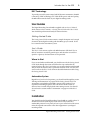
You should locate the Digital Recording Console 02R on a stable surface. It
should be sited so that the display screen can be easily read from a
comfortable position. Leave plenty of access space at the back of the unit to
make the required connections to the other equipment in your digital
recording studio.
Digital Recording Console 02R
Getting Started Guide
4
Introduction to the 02R
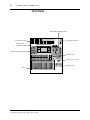
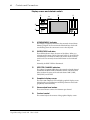
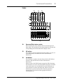
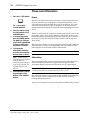
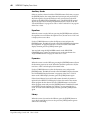
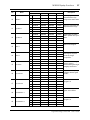
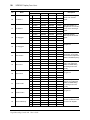
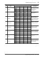
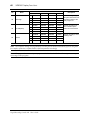
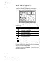
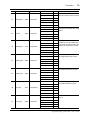
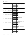
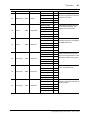
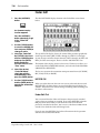
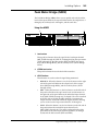
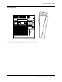
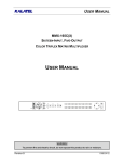
Top and Rear Panels
+48V
+48V
+48V
+48V
+48V
+48V
+48V
ON
ON
ON
ON
ON
ON
OFF
OFF
OFF
OFF
OFF
OFF
OFF
A
B
A
B
20dB
+4
-16
+48V
ON
A
B
20dB
GAIN
-40
-60
+4
-16
A
B
20dB
-40
-60
GAIN
+4
-16
A
B
20dB
-40
-60
GAIN
+4
-16
A
B
20dB
GAIN
-40
-60
+4
-16
-40
-60
+4
-16
OFF
A
B
20dB
GAIN
ON
A
B
20dB
GAIN
-40
-60
+4
-16
0
-40
-60
GAIN
+4
-16
20dB
-40
-60
GAIN
+4
-16
PEAK
PEAK
PEAK
PEAK
PEAK
PEAK
PEAK
PEAK
SIGNAL
SIGNAL
SIGNAL
SIGNAL
SIGNAL
SIGNAL
SIGNAL
SIGNAL
2
3
4
5
6
7
20dB
GAIN
PEAK
SIGNAL
1
10
T/B LEVEL
20dB
8
-40
-60
+4
-16
GAIN
20dB
-40
-60
+4
-16
GAIN
20dB
-40
-60
+4
-16
GAIN
20dB
-40
-60
+4
-16
GAIN
20dB
-40
-60
+4
-16
GAIN
20dB
-40
-60
+4
-16
20dB
GAIN
-40
-60
+4
-16
GAIN
+4
-40
-60
-40
+4
-40
GAIN
GAIN
+4
-40
+4
GAIN
-40
GAIN
PEAK
PEAK
PEAK
PEAK
PEAK
PEAK
PEAK
PEAK
PEAK
PEAK
PEAK
SIGNAL
SIGNAL
SIGNAL
SIGNAL
SIGNAL
SIGNAL
SIGNAL
SIGNAL
SIGNAL
SIGNAL
SIGNAL
9
10
11
12
13
14
15
16
17/18
19/20
21/22
0
23/24
0
10
10
PHONES
LEVEL
STUDIO
LEVEL
DIGITAL RECORDING CONSOLE
SELECTED CHANNEL
SCENE MEMORY
DISPLAY ACCESS
CLIP
-2
-4
SCENE
MEMORY
DIGITAL
I/O
SETUP
UTILITY
AUTOMIX
MIDI
GROUP
PAIR
-6
FADER STATUS
-12
1
2
AUX 1
AUX 2
C-R
3
4
AUX 3
AUX 4
AUX 5
ST
-15
INPUT
-24
AUX
-35
-48
1 2 3 4
5 6 7 8
CONFIGURATION
-60
AUX 6
STUDIO
-72
SELECTED CHANNEL
L STEREO R
Ø/ATT
PAN
DELAY
5
6
AUX 5
AUX 6
7
8
AUX 7
EFF1
AUX 8
EFF2
ROUTING
MIC/LINE
2TR-D1
2TR-A1
2TR-D2
2TR-A2
CONTRAST
TAPE/RTN
OUTPUT
METER
VIEW
AUX 1
AUX 2
EQ
DYNAMICS
MIXING
ST
AUX 3
DIRECT
SEND LEVEL
ROUTING
AUX 5
AUX 7
EFF1
AUX 6
2TR-D3
ST
AUX 5
AUX 6
MONO
DIM
AUX 4
ON
AUX
AUX 8
EFF2
AUX
L/MONO
L
ODD
R
R
EVEN
CONTROL ROOM
PAN
Q
SLATE
T/B
TALKBACK
LOW/HPF
SEL
SEL
SEL
SEL
SEL
SEL
SEL
SEL
SEL
SEL
SEL
SEL
SEL
SEL
SEL
SEL
SEL
L-MID
H-MID
HIGH/LPF
F
SEL
Hz
ON
ON
ON
ON
ON
ON
ON
ON
ON
ON
ON
ON
ON
ON
ON
ON
TAPE
TAPE
TAPE
TAPE
TAPE
TAPE
TAPE
TAPE
TAPE
TAPE
TAPE
TAPE
TAPE
TAPE
TAPE
TAPE
1
2
3
4
5
6
7
8
9
10
11
12
13
14
15
16
FLIP
ON
ON
EFF1
RTN
EFF2
RTN
SOLO
kHz
G
0
dB
EQ ON
10
C-R
LEVEL
EQUALIZER
SEL
SEL
SEL
SEL
SEL
SEL
SEL
SEL
SEL
SEL
SEL
SEL
SEL
SEL
SEL
SEL
SEL
SEL
SEL
SEL
SEL
ON
ON
ON
ON
ON
ON
ON
ON
ON
ON
ON
ON
ON
ON
ON
ON
ON
ON
ON
ON
ON
STORE
RECALL
SCENE MEMORY
10
10
10
10
10
10
10
10
10
10
10
10
10
10
10
10
10
10
10
10
5
5
5
5
5
5
5
5
5
5
5
5
5
5
5
5
5
5
5
5
5
0
0
0
0
0
0
0
0
0
0
0
0
0
0
0
0
0
0
0
0
10
0
5
5
5
5
5
5
5
5
5
5
5
5
5
5
5
5
5
5
5
5
10
10
10
10
10
10
10
10
10
10
10
10
10
10
10
10
10
10
10
10
20
15
15
15
15
15
15
15
15
15
15
15
15
15
15
15
15
15
15
15
15
30
20
20
20
20
20
20
20
20
20
20
20
20
20
20
20
20
20
20
20
20
30
30
30
30
30
30
30
30
30
30
30
30
30
30
30
30
30
30
30
30
40
40
40
40
40
40
40
40
40
40
40
40
40
40
40
40
40
40
40
40
15
CURSOR
ENTER
40
50
50
50
∞
50
∞
1
50
∞
2
50
∞
3
5
3
6
4
50
∞
4
50
∞
5
50
∞
6
50
∞
8
50
∞
50
∞
50
∞
9
10
11
INPUT
INPUT
INPUT
19
17
50
∞
12
50
∞
13
50
∞
50
∞
14
15
50
∞
16
50
∞
17/18
50
∞
19/20
∞
21/22
∞
23/24
STEREO
1
L
L
1
+4dB
2
R
AUX SEND
L
L
23
R
21
INPUT A
R
INPUT
B
L
-10dBV
R
STUDIO C- R
MONITOR MONITOR
OUT +4dB OUT +4dB
INPUT
+4dB
L
R
50
∞
7
60
70
INPUT A
INPUT
B
INPUT A
INPUT
B
INPUT A
INPUT
B
INPUT A
INPUT A
INPUT
B
INPUT
B
INSERT
I/O
INSERT
I/O
INPUT A
INPUT A
INPUT
B
INPUT
B
INSERT
I/O
INSERT
I/O
2
R
2 -10dBV
1 +4dB
2TR IN
STEREO OUT ANALOG ANALOG
INPUT
INPUT
INPUT
INPUT
INPUT
INPUT
INPUT
INPUT
INPUT
INPUT
INPUT
INPUT
24
22
20
18
16
15
14
13
12
11
10
9
COAXIAL
POWER
AES/EBU
OUT
IN
ON/ OFF
TIME CODE INPUT
Digital Recording Console 02R
STEREO OUT
DIGITAL
THRU
OFF
MIDI
INSERT
I/O
0dB
7
INSERT
I/O
0dB
6
INSERT
I/O
0dB
5
0dB
4
0dB
3
0dB
2
SLOT 4
SLOT 3
SLOT 2
SLOT 1
1
3
WORD CLOCK
OUT
8
AES/EBU
2
75Ω
ON
METER
SMPTE
MTC
COAXIAL
INSERT
I/O
0dB
2TR IN DIGITAL
IN
TO HOST
Getting Started Guide
0dB
1
Introduction to the 02R
5
Features
Sonic Specifications
•
Linear 20-bit 64-times oversampling A/D convertors
•
Linear 20-bit 8-times oversampling D/A convertors
•
105 dB dynamic range (typical)
•
32-bit precision internal processing with a dynamic range of over
190 dB using YAMAHA’s 32-bit proprietary audio DSP
General Features
•
40 input channel mixer, with full dynamic processing and 4-band
parametric equalization
•
Dynamic automation – all referenced to time code
•
64 internal scene memories for storing all digital mixer settings
•
4-band Parametric EQ with sweepable center-frequency from 20 Hz to
20kHz and adjustable bandwidth (Q)
•
Extensive EQ library
•
Comprehensive dynamics processors on each input channel, tape
return, and buss and stereo output:
•
Compressor
•
Expander
•
Gate/Ducking
•
Soft and Hard Compander
•
Dynamics library
•
Fully programmable channel settings: phase and attenuation, delay,
pan, routing, meters, EQ, and dynamics
•
Channel library
•
Two internal stereo effects using proprietary processor chip
•
Effects library
•
8 output busses, 8 auxiliary send busses, and main stereo mix buss
•
24 balanced analog inputs (8 channels with either XLR-type or phone
connectors)
•
Continuously variable gain control
•
20 dB input pad
•
8 XLR-type inputs with 48V phantom power for condenser
microphones
•
8 analog insert input/output connections
•
2 analog 2TR IN inputs
Digital Recording Console 02R
Getting Started Guide
6
Introduction to the 02R
•
2 analog stereo outputs
•
6 analog auxiliary send outputs
•
Stereo studio and control room outputs
•
3 digital 2TR IN inputs
•
2 digital stereo outputs
•
Industry standard AES/EBU or IEC958 Part2 (Consumer) digital
inputs and outputs
•
100mm motorized faders
•
Fader and mute groups for single fader or button control over several
faders or channel ON buttons
•
Adjacent channel pair function for stereo operation on inputs, tape
returns, and auxiliary channels
•
Dedicated buttons and controls of the Selected Channel module
•
Large 320 × 240 pixel, FL-backlit, user-friendly graphical display screen
•
RISC technology CPU
•
SMPTE and MTC synchronization plus full MIDI implementation
Optional Features
•
Digital Recording Console 02R
Optional digital I/O cards:
•
Alesis ADAT
•
TASCAM TDIF-1
•
YAMAHA
•
AES/EBU
•
Digital Cascade
•
Optional analog input/output card
•
Optional 1MB memory expansion kit
•
Optional meter bridge
•
Optional wooden side panels
Getting Started Guide
Introduction to the 02R
7
Key Features
This section looks at some of the key features of the Digital Recording
Console 02R, what they mean to you, and some hints about how you can
use them.
Dynamic Automation
One of the most demanding jobs of the recording engineer is taking all the
raw material produced during a multitrack recording session and mixing it
all together into an artistically satisfying master recording. The ability to
setup portions of the mix and then have them playback automatically as
you work on other portions is probably the most important feature of the
Digital Recording Console 02R.
It has an on-board automation system that memorizes fader positions,
switches individual channels on or off, adjusts the equalization or pan
positions, and changes the auxiliary sends – all based on time code. It can
also record and execute scene memory changes, also determined by time
code. This allows you to perform an entire mixing session, and then edit
individual channel settings until you have achieved the perfect mix.
The 02R allows you to record a mixdown in real-time and then edit the
results, either in real-time or by using one of the event editors. You can
select single parameters of the mixer to edit – for example, just enable the
faders for one pass as you create your mixdown.
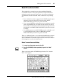
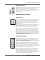
Scene Memories
The 02R has 64 internal scene memories each of which is a snapshot of all
the digital settings of the mixer (a mix scene). Each can be named for easy
identification. They can be stored and later recalled instantly.
If you work on several projects at one time, you can store the current mixer
settings in a scene memory so when you return to that project, you can start
immediately from where you left off. When you are working on a
mixdown, the ability to recall mixer scenes can speed the process and
allows for accurate repetition of the various parts of the mix. When you use
the 02R for sound reinforcement applications, the ability to recall mix
scenes can make light work of night-after-night sound checks.
Storing the mixer settings to a scene memory is a simple matter of pressing
the [STORE] button and confirming the request.
Note: You can customize your 02R to perform the storage operation without
confirmation. See “Preferences” on page 162 of the User’s Guide for more details.
Digital Recording Console 02R
Getting Started Guide
8
Introduction to the 02R
Recalling the scene is even easier – just press the [RECALL] button. You
should be careful that your scene memories flow into each other smoothly.
The instant recall means that you can have very abrupt level changes or the
unexpected intrusion of a very loud channel.
Note: The 02R allows you to have programmable fades between scene memories.
The only thing you need to watch is the sudden sound of a channel being switched
on. Even then, if the original channel level was set to –∞ dB, you should have no
problems. See “Fade Time” on page 121 of the User’s Guide.
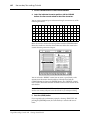
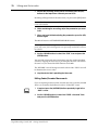
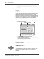
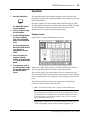
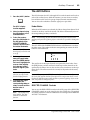
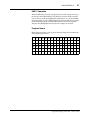
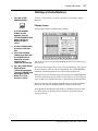
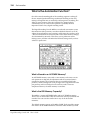
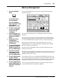
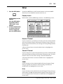
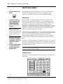
Large Graphical Display
The heart of the 02R user interface is the large graphical display located in
the center of the console. Using the Display Access controls, you can gain
immediate access to the features of the mixer – clearly displayed on the 320
× 240 pixel, FL-backlit, user-friendly graphical display screen. Virtual
control modules are shown on the screen, allowing you to adjust almost
any digital parameter anywhere in the system.
As well as displaying parameter values numerically, faders, rotary controls,
and push buttons are represented graphically, so you can actually see
button status, pan positions, and fader levels.
In addition the equalization curves are displayed graphically as are the
dynamics processor parameters.
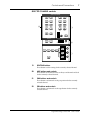
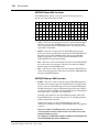
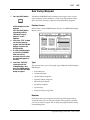
User Interface
The Digital Recording Console 02R user interface is powerful but very
intuitive. There are two main methods of working with the 02R:
•
Use the DISPLAY ACCESS controls to modify one parameter at a time
across the entire recording console.
•
Use the SELECTED CHANNEL controls to modify all of the
parameters of the currently selected channel.
The DISPLAY ACCESS controls consist of a block of 24 function buttons
divided into three groups – the CONFIGURATION group, the MIXING
group, and the AUX group – plus the large backlit graphical display screen,
four cursor buttons, a detented encoder wheel, and the [ENTER] button.
There is also a related block of four SCENE MEMORY buttons – to
increment, decrement, store, and recall the scene memories.
The SELECTED CHANNEL controls consist of four main blocks of controls
– each block was designed to be as familiar as the equivalent controls on a
standard analog mixer, but with the power of digital precision and instant
recall. The ROUTING block selects the buss onto which to route the current
channel signal. The AUX block selects the auxiliary buss to send the
channel signal to and sets the send level. The PAN block sets the pan
position of the channel signal. The EQ block sets the equalization curve for
Digital Recording Console 02R
Getting Started Guide
Introduction to the 02R
9
the current channel. You can customize your 02R to automatically select the
corresponding display function when you adjust a control in these blocks.
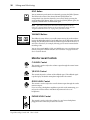
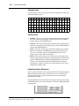
Motorized Faders
In addition to the DISPLAY ACCESS and SELECTED CHANNEL controls,
each input channel and the stereo master channel utilizes a 100mm
motorized fader. When a scene memory is recalled, the faders position
themselves automatically to the levels stored. Fader movements are
replayed automatically in synchronization with time code during playback
of a dynamic automation memory.
The faders allow you to quickly and accurately set the levels for the
selected channels. By pressing the [FLIP] button, you can transfer fader
control over your tape returns as well. Faders can be grouped into one of
four fader groups for control of multiple faders from a single control.
(There are also four mute groups which allow you to toggle a group of
channels on or off.) You can also control two adjacent channels in stereo
with the pair operation using only one fader.
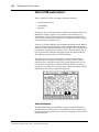
Internal Stereo Effects
The Digital Recording Console 02R features eight auxiliary sends, two of
which are routed to the internal multi-effects stereo processors: Effect1 and
Effect2. Using the power of YAMAHA’s proprietary effects processor chip,
the 02R has a startling range of special effects available to apply to your
mix. Shimmering reverbs, clean and precise delays, flanging and chorus,
and a myriad of other effects are available built right into this mixer. The
effects are processed entirely within the digital domain, ensuring the signal
quality is the finest that a digital system can provide.
The 02R features a simple and convenient analog interface to outboard
signal processing and effects units. When you use the six auxiliary sends,
the signal from those channels is converted to analog at 18-bits linear,
8-times oversampling.
Effects can be applied to input channels or the tape return channels, and the
auxiliary sends can be configured pre-fader or post-fader. There are 40
preset effects programs and 88 user effects programs for you to store your
own settings.
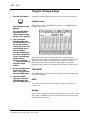
Dynamics Processors
Dynamics processors are generally used to correct or control signal levels.
However, you can also use them creatively to shape the volume envelope
of a sound. The 02R features comprehensive dynamics processors for all
the input, return, buss, and stereo output channels – a total of 50
processors. These processors allow you to compress, expand, limit, gate, or
duck the signals passing through the mixer, giving you unparalleled sonic
quality and flexibility.
Digital Recording Console 02R
Getting Started Guide
10
Introduction to the 02R
Similar to the internal stereo effects, the dynamics processors are patched
directly into the signal path while the audio data remains in the digital
domain. Signal quality is unaffected by conversion to and from digital as
would be the case if you used an external dynamics processor. The
dynamics program settings are stored in the dynamics library as well as the
scene memory. There are 40 preset programs for you to recall and 88 user
programs for you to store your own dynamics programs
Parametric EQ with Library
The Digital Recording Console 02R contains a high-performance
four-band, fully parametric equalizer. Each input channel, tape and effect
return, and the stereo output channel features an equalizer. You can tailor
the equalization curve with a high degree of precision, covering the entire
dynamic spectrum from 21 Hz to 20.1 kHz. Select the center-frequency (F)
and adjust the bandwidth (Q) and the gain (G) until you have achieved the
perfect sound.
The EQ setting for each channel is stored in the scene memory and can be
adjusted in real-time with the dynamic automation system. The 02R also
has an extensive EQ library which allows you to store frequently used
equalizer settings for instant recall. An equalization program stored in the
EQ library is a good starting point and reference when making adjustments
to the equalization.
Digital Benefits
You’re probably already familiar with the many benefits of digital audio,
but what exactly are the benefits for digital audio mixing?
An audio mixer has the job of combining audio signals from various
sources, at differing levels and impedances, usually into a stereo signal. It
must do this without introducing any new distortions and noise. Most
analog mixers do a pretty good job, but even with the best designs,
nonlinear effects caused by circuit components are unavoidable.
In the digital realm, audio mixing consists of adding and multiplying the
binary numbers that represent audio signals. The 02R uses a 32-bit DSP
(Digital Signal Processor) chip for these calculations, ensuring a very high
degree of precision. Once past the analog-to-digital conversion, audio
signals are essentially immune from standard signal degradation. With the
02R, noise, distortion, and crosstalk are virtually eliminated. You’ll hear a
new clarity in your mixes.
Once in the digital realm, there’s little point converting back to analog. The
02R features stereo digital outputs for direct mixdown to DAT and other
digital recorders. It uses the industry standards AES/EBU or IEC958 Part2
(Consumer) for its digital inputs and outputs. With one of the optional
digital I/O cards installed in your 02R, you can record direct-to-digital to
your modular digital multitrack recorder.
Digital Recording Console 02R
Getting Started Guide
Introduction to the 02R
11
Digital Recording Console 02R Sonic Performance
The Digital Recording Console 02R uses linear 20-bit 64-times
oversampling analog-to-digital converters to provide a typical dynamic
range of 105 dB. This means that an audio program’s dynamic range, from
low to high levels, is processed intact. The 02R samples audio at 44.1kHz,
the commercial sampling rate for compact discs, and at 48kHz, the
professional sampling rate. It provides a full spectrum frequency response
of 20 Hz to 20 kHz +1, –3 dB.
For digital-to-analog conversion, the 02R features 20-bit 8-times
oversampling for its main stereo outputs, including the control room
monitor outputs, and 18-bit 8-times oversampling for the studio and
auxiliary send outputs. Oversampling and bitstream techniques effectively
increase the internal sampling rate, so side effects caused by steep low-pass
filters, which are used to filter out undesirable sampling frequency
components during digital-to-analog conversion, are virtually eliminated.
Consequently, audio signal integrity is maintained from input through to
output.
Digital Recording Console 02R
Getting Started Guide
12
Introduction to the 02R
Digital Recording Console 02R
Getting Started Guide
Getting Started
2
13
Getting Started
In this chapter...
Basic Assumptions. . . . . . . . . . . . . . . . . . . . . . . . . . . . . . . . . . . . . . . . . . . . . . 14
Making the Connections. . . . . . . . . . . . . . . . . . . . . . . . . . . . . . . . . . . . . . . . . 14
Basic Setup . . . . . . . . . . . . . . . . . . . . . . . . . . . . . . . . . . . . . . . . . . . . . . . . . . . . 15
Power ON/OFF . . . . . . . . . . . . . . . . . . . . . . . . . . . . . . . . . . . . . . . . . . . . . . . . 16
Setting the Synchronization . . . . . . . . . . . . . . . . . . . . . . . . . . . . . . . . . . . . . . 16
Recall Scene Memory 0 . . . . . . . . . . . . . . . . . . . . . . . . . . . . . . . . . . . . . . . . . . 17
Digital Recording Console 02R
Getting Started Guide
2
14
Getting Started
Basic Assumptions
The Digital Recording Console 02R was designed to be the perfect digital
mixing console for a studio using the current generation of modular
digital multitrack tape and disk recorders. Although the 02R can also be
used as a sound-reinforcement mixer, the typical user will own a project
recording or post-production studio with some form of multitrack
recorder. Therefore, your 02R will probably be equipped with one or
more of the optional input/output cards. For the purposes of these
tutorials, it does not matter if you are working with an analog or digital
multitrack.
What You Will Need
To perform the following tutorials, you will need:
•
The 02R.
•
A sound source: CD player, drum machine, synthesizer/sequencer
with demo song.
•
Amplifiers and speakers, or headphones.
•
A multitrack recorder and a stereo master recorder.
•
Audio connecting cables.
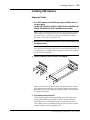
Making the Connections
WARNING! Before
making any connections,
make sure that all your
equipment is powered OFF.
1. Connect your sound source to input channel 1.
If you are using a stereo sound source, connect it to input channel 2 as well.
A stereo source is not essential, and for most of the tutorials it will probably
be easier to work with just one channel. If your sound source has XLR-type
connectors, connect it to the XLR-type connectors on the 02R. Otherwise,
use the phone jacks and select INPUT B with the [A/B] switch.
2. Connect the C-R MONITOR OUT connectors to the inputs on your
power amplifier.
If you are using headphones, connect them to the PHONES jack.
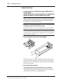
3. Connect your multitrack recorder to the appropriate optional
input/output card.
WARNING! The Digital
Recording Console 02R
should be connected only to
an AC receptacle of the
voltage type marked on its
rear panel.
Digital Recording Console 02R
You can also connect your stereo master recorder to either the digital or
analog STEREO OUT connectors.
4. Plug the 02R into a suitable AC receptacle.
Getting Started Guide
Getting Started
15
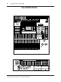
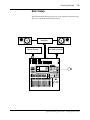
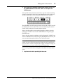
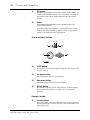
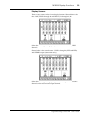
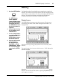
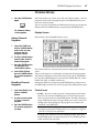
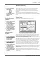
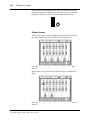
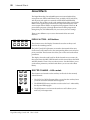
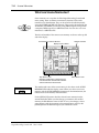
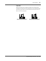
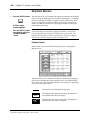
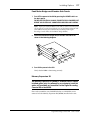
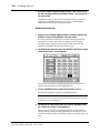
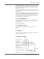
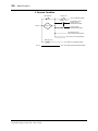
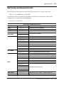
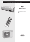
Basic Setup
The following illustration shows how to set up a minimal system that will
allow you to perform the following tutorials.
Amplifier
Sound Source
Multi-track recorder
Digital Recording Console 02R
Getting Started Guide
16
Getting Started
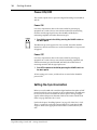
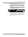
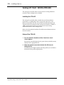
Power ON/OFF
This section explains how to power the Digital Recording Console 02R on
and off.
Power ON
It is always important to observe the correct order for powering up
equipment in a studio. Always start with the multitrack and mastering
recorders and the signal processors, then the 02R, and finally the
monitoring amplifiers and other downstream gear.
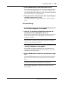
POWER
ON/ OFF
1. Turn ON the power to the 02R by pressing the POWER switch on
the back panel.
The 02R start-up screen appears for a few seconds, the faders initialize
themselves, then the screen that was used when the 02R was last powered
off appears.
Power OFF
It is always important to observe the correct order for powering up
equipment in a studio. Always start with the monitoring amplifiers and
other downstream gear, then the 02R, and finally the multitrack and
mastering recorders and the signal processors.
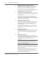
1. Turn OFF the power to the 02R by pressing the POWER switch on
the back panel.
All mix settings, mix scenes, and other data are stored when the 02R is
powered off.
Setting the Synchronization
Before you use the 02R with a modular digital multitrack recorder or DAT
master recorder, be sure to correctly set the synchronization. The 02R must
be slaved to an external wordclock in order to process the input digital
signals without drop-out or distortion. Refer to the section “Word Clock
Select” on page 154 of the User’s Guide.
Look in the chapter “Installing Options” on page 171 of the User’s Guide.
There is a section for each of the optional digital I/O cards that the 02R
supports. Refer to the appropriate section for the card installed in your
unit.
Digital Recording Console 02R
Getting Started Guide
Getting Started
17
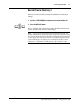
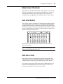
Recall Scene Memory 0
Before you start the tutorials, you should set the 02R to its initial mixer
settings.
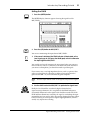
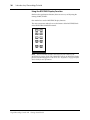
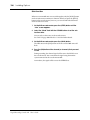
2. Use the SCENE MEMORY increment or decrement buttons to
select scene memory 0 “0 Initial Data”.
3. Press the [RECALL] button.
STORE
RECALL
SCENE MEMORY
This is a read-only scene memory that contains the default settings for the
system. The 02R will be reset to its initial settings.
Note: It is best to start at the beginning of each tutorial and work your way
through, taking breaks as required. If you deviate too far from the tutorial, or jump
into a tutorial halfway through, you may find that subsequent tutorial steps do not
work as expected. Also note that the tutorials do not explain all Digital Recording
Console 02R functions, nor do they serve as a substitute for the User’s Guide
explanations. For full details on all 02R functions, refer to the User’s Guide.
Digital Recording Console 02R
Getting Started Guide
18
Getting Started
Digital Recording Console 02R
Getting Started Guide
Introductory Recording Tutorial
3
19
Introductory Recording Tutorial
In this chapter...
Setting the Input Level . . . . . . . . . . . . . . . . . . . . . . . . . . . . . . . . . . . . . . . . . . 20
Applying EQ . . . . . . . . . . . . . . . . . . . . . . . . . . . . . . . . . . . . . . . . . . . . . . . . . . 24
Using the EQUALIZER Library . . . . . . . . . . . . . . . . . . . . . . . . . . . . . . . . . . 30
Routing . . . . . . . . . . . . . . . . . . . . . . . . . . . . . . . . . . . . . . . . . . . . . . . . . . . . . . . 35
Panning . . . . . . . . . . . . . . . . . . . . . . . . . . . . . . . . . . . . . . . . . . . . . . . . . . . . . . . 38
Digital Recording Console 02R
Getting Started Guide
3
20
Introductory Recording Tutorial
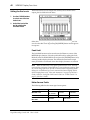
Setting the Input Level
Assuming that Digital Recording Console 02R is powered ON and your
music source is playing, the very first thing you need to do is set up a basic
control room monitor mix. When you recall Scene Memory 0 “0 Initial
Data”, all the channel faders are set to the 0 dB mark.
Setting Fader Levels
0
If the faders are not set to 0 dB, you should perform the following steps to
optimize the input signal level for the best performance:
10
5
5
10
0
1. Set the fader for MIC/LINE 1 to the 0 dB mark.
15
5
20
10
The 0 dB fader position is a good place to start when setting fader levels. It
is a good setting with regard to signal level and noise performance and it
leaves room for you to raise the level later, if necessary.
30
15
40
20
50
30
2. Set the STEREO fader to the 0 dB mark.
60
70
40
∞
50
∞
STEREO
1
The stereo output meters are indicating the stereo output level. The stereo
mix signal is now being output to the digital and analog STEREO OUT
connectors.
Selecting a Monitor Source
2TR-D2
2TR-A2
2TR-D3
ST
AUX 5
AUX 6
Before you can hear anything through your monitor amplifier and
speakers, you have to select a Control Room source:
1. Press the [ST] button of the CONTROL ROOM buttons group.
This selects the stereo bus for monitoring in the control room.
MONO
DIM
2. Adjust the volume with the C-R LEVEL control.
CONTROL ROOM
0
10
You should be able to hear the sound source through your monitor
speakers. If you are using stereo headphones, you will need to adjust the
PHONES LEVEL control to set a comfortable listening level.
C-R
LEVEL
Note: Be very careful with the level settings, especially if you are using stereo
headphones. When you are adjusting a unit as complex as the Digital Recording
Console 02R, it is possible for you to inadvertently switch on a very loud signal
source. Damaged loudspeakers or amplifiers can be very expensive. Damage to
your hearing can be much worse. Your ears are for life!
Digital Recording Console 02R
Getting Started Guide
Introductory Recording Tutorial
21
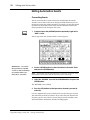
Setting the GAIN
1. Press the [METER] button.
METER
The METER Display function appears showing the signal level for
MIC/LINE 1.
2. Press the [SEL] button for MIC/LINE 1.
You are now monitoring the input channel MIC/LINE 1.
SEL
20dB
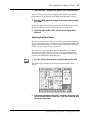
3. If the sound is distorted, the PEAK indicator is illuminated, or the
level is going up to CLIP, press the 20dB (pad) switch to attenuate
the input signal for MIC/LINE 1.
You usually need to pad (attenuate) the input signal when you connect a
line level device, such as a synthesizer or an effects unit to the channel. If
you connect a microphone, you should not need to pad the signal.
If you want to use a very high impedance device, such as a guitar or bass
guitar, you should insert a direct box or effects processor between the
guitar and the 02R – or you should mike the guitar amplifier.
Note: The stereo input channels (LINE 17 through 24) accept line level signals
only.
4. Use the GAIN control for MIC/LINE 1 to optimize the signal level.
+4
-16
GAIN
-40
-60
Ideally the level should be set relatively high to obtain the best
signal-to-noise performance. It is acceptable for the PEAK indicator to
occasionally illuminate but the signal levels should not reach CLIP. If the
PEAK indicator illuminates constantly, the signal is overloading the input
preamplifier and you may be able to hear analog clipping distortion. When
CLIP is reached, you will experience digital clipping distortion, which is
usually very unpleasant sounding.
Digital Recording Console 02R
Getting Started Guide
22
Introductory Recording Tutorial
Back off the GAIN control a little until the PEAK indicator illuminates very
occasionally. The GAIN control should be set with some care. If it is set too
low, the signal-to-noise performance will suffer, and if it is set too high,
signal clipping and distortion may occur.
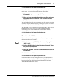
∅/ATT Display Function
The signal level may be too high in the digital domain. If CLIP is reached,
but the corresponding PEAK indicator is not illuminated, you need to
attenuate the channel slightly with the ∅/ATT display function.
1. Press the [∅/ATT] button.
Ø/ATT
2. Use the CURSOR buttons to select the attenuator icon for
MIC/LINE 1 and rotate the encoder wheel to adjust the
attenuation level.
The ∅/ATT display function allows you to attenuate (and invert the phase)
of a signal after it has been converted to digital data.
Note: You should rarely find it necessary to use the ∅/ATT function on an input
signal after the gain level has been correctly set, but you may need to attenuate
after you apply equalization, effects, or dynamics to the signal.
Peak Hold
1. If you used the ∅/ATT display function, press the [METER] button
again.
METER
The 02R will return to the METER display function.
2. You may find the Peak Hold function useful at this point. To turn it
on, use the CURSOR buttons to select the PEAK HOLD control icon
and press [ENTER]. When the Peak Hold function is active, the
control icon is displayed in reverse video.
Digital Recording Console 02R
Getting Started Guide
Introductory Recording Tutorial
23
The peak level is indicated by an empty square box. Peak Hold is very
useful for level checking before recording. You can leave a mix to play
through unattended while Peak Hold watches out for signal peaks. If any
levels reach CLIP, back off the relevant GAIN control or use the ∅/ATT
display function to attenuate the signal and run through the mix again.
Note: The Peak Hold function also works on the stereo output meters and
controls the optional meter bridge (MB02).
3. To clear the Peak Hold levels, select the PEAK HOLD control icon
with the CURSOR buttons and press [ENTER].
When you clear the Peak Hold levels, it also clears the peaks from the
stereo output meters.
Typically, you will be using more than just one input channel, so you will
need to set the input signal level for each channel individually. Since it is
relatively easy to set them at this point, take time and care. If you have to
adjust them later in the mixing process, you may need to adjust the faders,
auxiliary sends, and other levels, as well.
Channel ON/OFF
The channel [ON] buttons are used to turn channels ON or OFF. This
function is sometimes called MUTE. When you recall Scene Memory 0 “0
Initial Data”, all the channels are turned ON.
1. Press the channel [ON] button for MIC/LINE 1.
ON
The sound is cut and the LED inset in the [ON] button switches off.
Note: Even though you can no longer hear the sound source, the meter for
MIC/LINE 1 continues to be displayed on the screen. This is because the meter
signal is sourced before the [ON] button.
2. Press the [ON] button again to turn the channel back ON.
The LED inset in the [ON] button illuminates again and you will be able to
hear the sound source again.
SCENE MEMORY
Edit Indicator
SCENE MEMORY LED
The 2-digit (7-segment) LED shows the currently selected SCENE
MEMORY program. It also contains the Edit Indicator, which will start
flashing when you adjust the first digital parameter of the current scene
memory. See “Scene Memories” on page 62 of the Getting Started Guide.
Digital Recording Console 02R
Getting Started Guide
24
Introductory Recording Tutorial
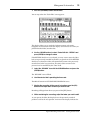
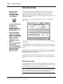
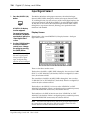
Applying EQ
The next step is to apply equalization to MIC/LINE 1.
The Digital Recording Console 02R has a four-band fully parametric
equalizer, with variable bandwidth (Q), frequency (F), and gain (G). The
power of the 02R user interface means that there are two ways of adjusting
the equalization for MIC/LINE 1.
One method is to use the EQUALIZER display function.
The more convenient method is to use the buttons and controls of the
EQUALIZER block of the SELECTED CHANNEL controls.
Q
LOW/HPF
L-MID
H-MID
HIGH/LPF
F
Hz
kHz
G
dB
EQ ON
EQUALIZER
Note: You can customize your 02R so that when you adjust a control of the
EQUALIZER block of the SELECTED CHANNEL controls, the EQUALIZER
display function automatically appears on the screen. See “Preferences” on page
162 of the User’s Guide for more information. The default setting is to
automatically display the EQUALIZER screen.
This tutorial will describe the operation of the EQUALIZER display
function, even though it will be immediately obvious to you that using the
dedicated buttons and controls of the EQUALIZER block of the SELECTED
CHANNEL group is the more convenient method. The purpose of this
tutorial is to show you how to use the 02R.
For consistency, the tutorials will focus on the display functions, but you
should use the dedicated controls of the SELECTED CHANNEL group as
much as you can.
Turning the Equalizer ON/OFF
1. Press the [SEL] button for MIC/LINE 1.
SEL
Digital Recording Console 02R
When you press the [SEL] button for a channel, the LED and numeric
indicators of the SELECTED CHANNEL controls change to reflect the
status of the channel you pressed.
Getting Started Guide
Introductory Recording Tutorial
25
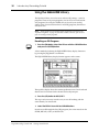
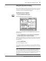
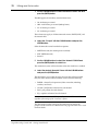
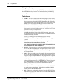
2. Press the [EQ] button.
EQ
The EQUALIZER display function appears showing the equalization curve
and settings for MIC/LINE 1.
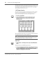
3. Use the CURSOR buttons to select the EQ ON icon.
If the equalizer is ON, the icon will be highlighted in reverse video. The
LED inset in the [EQ ON] button of the SELECTED CHANNEL –
EQUALIZER block controls will also be illuminated.
4. To switch the status of the EQ, either press the [ENTER] button or
the [EQ ON] button.
The ON icon will change to OFF and will no longer be displayed in reverse
video.The LED inset in the [EQ ON] button will no longer be illuminated.
If you turned the equalizer OFF, switch it ON again.
Setting the Gain
1. Select the gain (G) icon for the LOW band using the CURSOR
buttons.
The icon will be surrounded by a flashing grey box, indicating that this is
the active element on the screen. Alternatively, you can press the
[LOW/HPF] button of the SELECTED CHANNEL – EQUALIZER
controls.
2. Rotate the encoder wheel clockwise to boost the gain.
You can also adjust the “G” rotary encoder of the EQUALIZER controls to
achieve the same effect.
Digital Recording Console 02R
Getting Started Guide
26
Introductory Recording Tutorial
The gain increases in 0.5 dB steps and the EQ curve on the display changes
to reflect this.
3. Rotate the encoder wheel counterclockwise to reduce the gain.
You can also adjust the “G” rotary encoder to reduce the gain. The gain
decreases in 0.5 dB steps.
4. Use the CURSOR buttons to select the gain (G) icon for the L-MID
band and adjust its level with the encoder wheel. Select the
other bands as well.
You can also select the different bands using the [L-MID], [H-MID], and
[HIGH/LPF] buttons of the SELECTED CHANNEL – EQUALIZER
controls.
Note: Applying a lot of EQ boost may increase the signal level sufficiently to
cause distortion. If this does occur, reduce the amount of EQ boost or adjust the
attenuation level to compensate (the ATT control icon). You can switch back to the
METER display function and select POST EQ to monitor the signal levels.
Note: You can reset the gain of each band to 0.0 dB by double-clicking the
corresponding [LOW/HPF], [L-MID], [H-MID], or [HIGH/LPF] buttons of the
SELECTED CHANNEL – EQUALIZER controls.
Digital Recording Console 02R
Getting Started Guide
Introductory Recording Tutorial
27
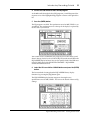
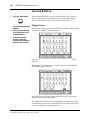
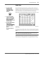
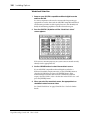
Setting the Frequency
1. Select the frequency (F) icon for the LOW band using the CURSOR
buttons.
2. Use the encoder wheel to sweep through the frequency range.
You can also adjust the “F” rotary encoder of the EQUALIZER controls to
achieve the same effect.
All four bands of the 02R parametric equalizer cover virtually the entire
audio spectrum, from 21 Hz to 20.1 kHz. Although they are labelled LOW,
L-MID, H-MID, and HIGH, the frequency of the bands can actually be in
any order.
Note: If your 02R is busy processing some complex data, it may take a little
while to draw the equalization curve. However, the internal EQ circuits reflect
your adjustments immediately.
Note: As well as the frequency value in Hz displayed under the icon and on the
numeric LED in the SELECTED CHANNEL – EQUALIZER controls, the dotted
vertical line on the EQ graph indicates the current frequency position.
3. Use the CURSOR buttons to select the frequency (F) icon for the
L-MID band and adjust its position with the encoder wheel. Select
the other bands and adjust their frequency.
You can also select the different bands using the [L-MID], [H-MID], and
[HIGH/LPF] buttons of the SELECTED CHANNEL – EQUALIZER
controls. Adjust the “F” rotary encoder for each band.
Digital Recording Console 02R
Getting Started Guide
28
Introductory Recording Tutorial
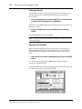
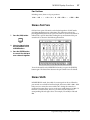
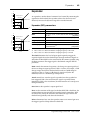
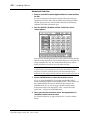
Setting the Bandwidth
The L-MID and H-MID bands are peaking type equalizers. The LOW and
HIGH bands are initially configured as shelving type equalizers, however,
they can also be configured as peaking type equalizers. The LOW band can
also be configured as a HPF (high-pass filter) and the HIGH band as a LPF
(low-pass filter).
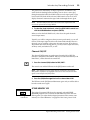
1. Select the bandwidth (Q) icon for the LOW band using the
CURSOR buttons.
2. Use the encoder wheel to sweep through the bandwidth.
You can also adjust the “Q” rotary encoder of the EQUALIZER controls to
achieve the same effect.
The LOW band changes from low-shelving to peaking to high-pass filter as
you continue to rotate the encoder wheel.
3. As you rotate the encoder wheel counterclockwise, it effectively
increases the Q – narrowing the bandwidth, as shown on the EQ
graph.
A narrow curve is useful for boosting or cutting specific frequencies.
4. Use the CURSOR buttons to select the bandwidth (Q) icon for the
L-MID band and adjust its position with the encoder wheel. Select
and adjust the bandwidth of the other bands.
You can also select the different bands using the [L-MID], [H-MID], and
[HIGH/LPF] buttons of the SELECTED CHANNEL – EQUALIZER
controls. Adjust the “Q” rotary encoder for each band.
The HIGH band changes from high-shelving to peaking to low-pass filter
as you adjust its value.
Digital Recording Console 02R
Getting Started Guide
Introductory Recording Tutorial
29
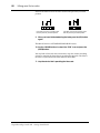
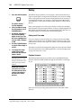
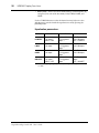
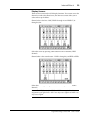
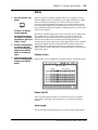
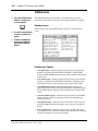
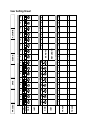
Resetting the Equalizer
1. Press and hold the [LOW/HPF] button and then press the
[HIGH/LPF] button of the SELECTED CHANNEL – EQUALIZER
controls.
All equalizer values will be reset to their defaults.
LOW/HPF
L-MID
H-MID
HIGH/LPF
Q
LOW SHELF
Peak – 0.7
Peak – 0.7
HIGH SHELF
F
125 Hz
1.00 kHz
4.00 kHz
10.0 kHz
G
0 dB
0 dB
0 dB
0 dB
Digital Recording Console 02R
Getting Started Guide
30
Introductory Recording Tutorial
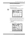
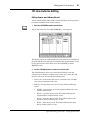
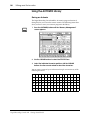
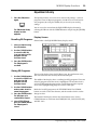
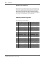
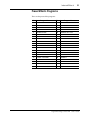
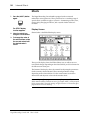
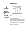
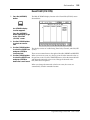
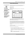
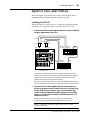
Using the EQUALIZER Library
The Equalizer Library is used to access and store EQ settings – stored as
programs. There are 32 preset programs (1 to 32) for you to recall and 96
user programs (33 to 128 plus UNDO) for you to store your own EQ
settings. First you need to know how to recall EQ programs, then how to
store your own.
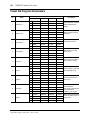
Note: The programs 33 to 40 contain preset programs and are listed in the
“Equalizer Programs” on page 52 of the User’s Guide. However, you can store
your own setting to these programs.
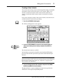
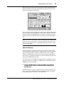
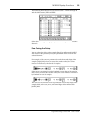
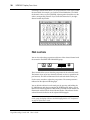
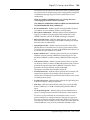
Recalling an EQ Program
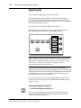
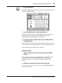
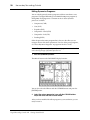
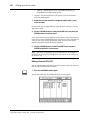
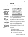
1. Press the [EQ] button. Select the LIB icon with the CURSOR buttons
and press the [ENTER] button.
EQ
A faster method of selecting the EQUALIZER Library display function is
by pressing the [EQ] button a second time.
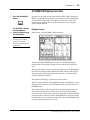
The EQUALIZER Library display function appears on the screen.
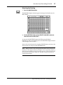
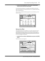
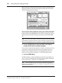
The top of the display shows the current equalization curve for the selected
channel and a level meter for the channel and its adjacent pair.
2. Press the [SEL] button for MIC/LINE 1.
This step is only necessary to make sure you are still working with the
same channel you started with.
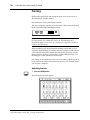
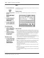
3. Select the RECALL icon with the CURSOR buttons.
In order to scroll through the list of EQ programs, the cursor must be on the
STORE, RECALL, COPY, or PASTE icons.
Digital Recording Console 02R
Getting Started Guide
Introductory Recording Tutorial
31
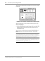
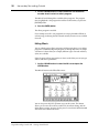
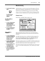
4. Use the encoder wheel to select an EQ program.
As the 02R scrolls through the list of EQ programs, a small diagram of the
response curve of the highlighted EQ program is shown to the right of the
list.
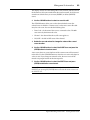
5. Press the [ENTER] button.
The EQ program is recalled. The equalization curve for MIC/LINE 1 is set
accordingly. The equalization curve at the top of the display is replaced by
the new curve you selected.
Your sound source is modified by the program you recalled. If the sound
doesn’t change, check if you have left the EQ ON switch turned OFF in the
EQUALIZER display function. You can also quickly check if the LED inset
in the EQ ON button of the SELECTED CHANNEL – EQUALIZER
controls is illuminated or not.
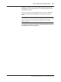
6. Select the LIB icon with the CURSOR buttons and press the [ENTER]
button.
The faster method of exiting from the EQUALIZER Library display
function is by pressing the [EQ] button again.
The EQUALIZER display function reappears showing the new
equalization curve for MIC/LINE 1. You can see the details of the new EQ
settings.
Digital Recording Console 02R
Getting Started Guide
32
Introductory Recording Tutorial
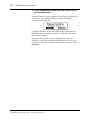
Undoing a Recall
If you decided you did not want to replace the current equalization curve
with the program you selected from the EQ library, you can recall the
previous curve.
1. Use the CURSOR buttons to select the RECALL icon and rotate the
encoder wheel until program “U” is highlighted.
Program “U” is the UNDO buffer. It always contains the last curve that was
applied to a channel.
2. Use the CURSOR buttons to select the RECALL icon and press
[ENTER].
The original equalization curve is recalled.
Note: The curve you first recalled and then used UNDO to replace is now itself
in the UNDO buffer.
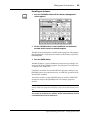
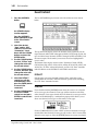
Storing an EQ Program
Before you store an equalization curve, you need to create it using the
EQUALIZER display function. Set the EQ parameters as detailed in the
steps starting from “Setting the Gain” on page 25 of the Getting Started
Guide.
1. Select the LIB icon with the CURSOR buttons and press the [ENTER]
button.
It is still faster to select the EQUALIZER Library display function by
pressing the [EQ] button again.
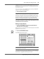
The EQUALIZER Library display function appears on the screen with your
new equalization curve at the top of the display.
Digital Recording Console 02R
Getting Started Guide
Introductory Recording Tutorial
33
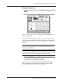
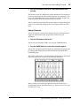
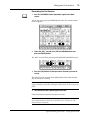
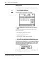
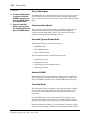
2. Select the STORE icon with the CURSOR buttons.
In order to scroll through the list of EQ programs, the cursor must be on the
STORE, RECALL, COPY, or PASTE icons.
3. Use the encoder wheel to select an EQ program.
If you select one of the preset programs (1 to 32), an error message will flash
on the screen when you attempt to store your program. Select a program
from the 96 user programs (33 to 128).
You cannot store your settings to program “U” (the UNDO buffer) either.
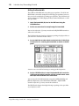
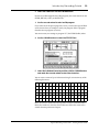
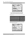
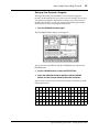
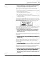
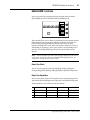
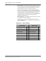
4. Use the CURSOR buttons to select the TITLE EDIT box.
5. Select the individual character positions with the CURSOR buttons
and rotate the encoder wheel to select the characters.
You can create a name of up to 16 characters long. It can contain any of the
following characters:
!
“
#
$
%
&
'
(
)
*
+
,
-
.
/
0
1
2
3
4
5
6
7
8
9
:
;
<
=
>
?
@
A
B
C
D
E
F
G
H
I
J
K
L
M
N
O
P
Q
R
S
T
U
V
W
X
Y
Z
[
\
]
^
_
`
a
b
c
d
e
f
g
h
i
j
k
l
m
n
o
p
q
r
s
t
u
v
w
x
y
z
{
|
}
~
Move the cursor to the first character position with the CURSOR buttons.
Rotate the encoder to select the desired character. Move the cursor to the
second character position and repeat.
Digital Recording Console 02R
Getting Started Guide
34
Introductory Recording Tutorial
You can select the “INS.” control icon to insert a space (blank) at the current
cursor location in the TITLE EDIT box. Select the icon with the CURSOR
buttons and press the [ENTER] button. The “DEL.” control icon is used to
delete the character under the current cursor location in the TITLE EDIT
box.
Note: The “COPY” and “PASTE” control icons allow you to select the title from
another EQ program and paste it into your program. These icons only copy the
title. See “Control Icons” on page 54 of the User’s Guide.
6. Use the CURSOR buttons to select the STORE icon and press the
[ENTER] button.
The 02R will display a popup confirmation request message asking if you
want to store your settings in the selected EQ program. The popup has two
control icons: “CANCEL” and “EXECUTE”.
Note: You can customize your 02R to prevent the confirmation popup from
appearing during STORE operations. In this case, the program is stored without
confirmation. See “Preferences” on page 162 of the User’s Guide for more
information.
CANCEL is the default. To cancel the STORE operation, either press the
[ENTER] button or wait about 10 seconds – the STORE operation will be
automatically cancelled.
To store your settings, use the CURSOR buttons to select the “EXECUTE”
control icon and press the [ENTER] button. The EQ program is stored.
Note: If you decide you don’t like an EQ program after you have stored it, it is
very easy to overwrite it by creating new settings and storing them to the same
location. Conversely, it is also very easy to accidentally overwrite a valued EQ
program.
YOU SHOULD ALWAYS BE CAREFUL WHEN THE 02R DISPLAYS ITS
CONFIRMATION POPUP MESSAGE!
Digital Recording Console 02R
Getting Started Guide
Introductory Recording Tutorial
35
Routing
This tutorial assumes you have a multitrack recorder and you have
connected it to your Digital Recording Console 02R – after having one or
more of the optional input/output cards installed:
•
Alesis ADAT (CD8-AT) – This single slot card supports an 8-channel
ADAT compatible modular digital multitrack recorder. It provides
eight input channels and eight output channels. You can insert as many
as four of these cards in the 02R.
•
TASCAM TDIF-1 (CD8-TDII) – This single slot card supports an
8-channel TASCAM modular digital multitrack recorder. It provides
eight input channels and eight output channels. You can insert as many
as four of these cards in the 02R.
•
YAMAHA (CD8-Y) – This single slot card supports an 8-channel
YAMAHA modular digital multitrack recorder. It provides eight input
channels and eight output channels. You can insert as many as four of
these cards in the 02R.
•
AES/EBU (CD8-AE double slot card, CD8-AE-S single solt card) –
These cards support an 8-channel AES/EBU compatible modular
digital multitrack recorder (such as the Akai DD1500 series). They
provide eight input channels and eight output channels.
•
Analog AD/DA (CD8-AD) – This double slot card supports any
8-channel analog multitrack recorder. It provides eight input channels
and eight output channels. You can only insert two of these cards in the
02R.
The 02R allows you to route the first 16 MIC/LINE channels directly to an
output. If you have the correct configuration, this means you can send
direct outputs to a 16-track recorder (for example, two paired ADAT
compatible modular digital multitrack recorders).
You can route any channel to one of the eight output buses. The buses feed
to each of the four 8-track I/O slots in the back of the 02R. You can also
route any channel to the stereo bus.
When you recall Scene Memory 0 “0 Initial Data”, all the channels are
routed to the stereo bus.
Digital Recording Console 02R
Getting Started Guide
36
Introductory Recording Tutorial
Using the ROUTING Display Function
Similar to the equalization function, there are two ways of adjusting the
routing for MIC/LINE 1.
One method is to use the ROUTING display function.
The more convenient method is to use the buttons of the ROUTING block
of the SELECTED CHANNEL controls.
1
2
3
4
5
6
7
8
ST
DIRECT
ROUTING
Note: You can customize the 02R so that when you press a button in the
ROUTING block of the SELECTED CHANNEL controls, the ROUTING display
function automatically appears on the screen. See “Preferences” on page 162 of the
User’s Guide for more information.
Digital Recording Console 02R
Getting Started Guide
Introductory Recording Tutorial
37
Selecting the Routing
1. Press the [ROUTING] button.
ROUTING
The ROUTING display function appears showing the selected routes for
MIC/LINE 1.
2. Use the ROUTING buttons of the SELECTED CHANNEL controls to
select the routes for MIC/LINE 1.
As you press the ROUTING buttons, the LED inset in the button
illuminates and the corresponding icon on the ROUTING display function
screen changes to reverse video.
You can also select the routes by using the CURSOR buttons to move to the
desired route icon and pressing the [ENTER] button.
Note: When you select a route, the signal from the channel will be routed to the
selected bus. The output from that bus will appear at the corresponding outputs of
all the I/O cards installed in the 02R. The only exception is when you are using I/O
cards in slots 1 and 2 for direct output. See “Routing” on page 39 of the User’s
Guide for further details.
Digital Recording Console 02R
Getting Started Guide
38
Introductory Recording Tutorial
Panning
Similar to the equalization and routing functions, there are two ways of
adjusting the pan for MIC/LINE 1.
One method is to use the PAN display function.
The more convenient method is to use the buttons and controls of the PAN
block of the SELECTED CHANNEL controls.
L/ODD
L
ODD
R/EVEN
R
EVEN
PAN
Note: You can customize your 02R so that when you adjust a control of the PAN
block of the SELECTED CHANNEL controls, the PAN display function
automatically appears on the screen. See “Preferences” on page 162 of the User’s
Guide for more information.
With a recording mixer like the Digital Recording Console 02R, you can
send more effort building your monitor mix than would be worthwhile on
a conventional analog mixer. Rather than labouriously having to reset all
those parameters again for your mixdown, with the 02R you simply save
the settings in a scene memory for instant recall.
Pan settings are also important when you are recording a signal to a pair of
buses and want to create a balance between the buses – for example, when
you close-mic a drum kit.
Adjusting the Pan
1. Press the [PAN] button.
PAN
Digital Recording Console 02R
The PAN display function appears.
Getting Started Guide
Introductory Recording Tutorial
39
2. Press the [SEL] button for MIC/LINE 1 and rotate the pan rotary
encoder.
The LED inset in the [L/ODD] button will be illuminated. The current pan
position is indicated on the adjacent LED bargraph. As an alternative, you
can use the CURSOR buttons to select the PAN icon for MIC/LINE 1 and
rotate the encoder wheel until the desired value is shown.
You can adjust the pan position from extreme right/even (R16) through the
centre (C) to extreme left/odd (L16). There are 33 pan positions to choose
from.
Pairing Channels
You can pair the pan controls of two adjacent channels. Linking channels
together is called GANG mode, and provides simultaneous pan
adjustment
1. Press the [SEL] button for MIC/LINE 1.
You can also select the MIC/LINE 1 icon using the CURSOR buttons.
2. Press the [ENTER] button to connect the channels together.
You can also connect the channels together by simultaneously pressing the
[L/ODD] and [R/EVEN] buttons of the PAN block of the SELECTED
CHANNEL group.
The GANG is indicated by a pair of dotted lines linking the top and bottom
of the pan control icons as shown in the following illustration:
When you adjust one channel, the linked channel will also move by a
corresponding amount. For further details, see “Stereo-Pair Pans” on page
37 of the User’s Guide.
Digital Recording Console 02R
Getting Started Guide
40
Introductory Recording Tutorial
Digital Recording Console 02R
Getting Started Guide
Secondary Recording Tutorial
4
41
Secondary Recording Tutorial
In this chapter...
Auxiliary Send Channels . . . . . . . . . . . . . . . . . . . . . . . . . . . . . . . . . . . . . . . . 42
Setting the Auxiliary Send Level . . . . . . . . . . . . . . . . . . . . . . . . . . . . . . . . . . 43
Creating a Monitor Mix . . . . . . . . . . . . . . . . . . . . . . . . . . . . . . . . . . . . . . . . . 45
Applying Effects . . . . . . . . . . . . . . . . . . . . . . . . . . . . . . . . . . . . . . . . . . . . . . . 46
Recalling and Editing Effects . . . . . . . . . . . . . . . . . . . . . . . . . . . . . . . . . . . . . 49
Patching in a Dynamics Processor . . . . . . . . . . . . . . . . . . . . . . . . . . . . . . . . 54
Using the Dynamics Library . . . . . . . . . . . . . . . . . . . . . . . . . . . . . . . . . . . . . 57
Scene Memories . . . . . . . . . . . . . . . . . . . . . . . . . . . . . . . . . . . . . . . . . . . . . . . . 62
Digital Recording Console 02R
Getting Started Guide
4
42
Secondary Recording Tutorial
Auxiliary Send Channels
The Digital Recording Console 02R has eight auxiliary send channels.
AUX7 and AUX8 are used to feed the internal effects processors, with the
signal remaining entirely in the digital domain.
The other auxiliary sends – AUX1 through AUX6 – can be used to feed
external signal processors and effects units, foldback amplifiers, or
multitrack recording equipment. AUX5 and AUX6 can also be used to
construct a monitor mix and routed directly to either the studio or control
room monitors. When a send is used to feed an external effects processor,
the processed signal can be returned via one of the stereo input channels or
an unused input channel.
There are two different ways to access the auxiliary send channels:
DISPLAY ACCESS – AUX buttons
AUX 1
AUX 2
AUX 3
AUX 4
AUX 5
AUX 6
AUX 7
EFF1
AUX 8
EFF2
These buttons access the Display Functions that set the auxiliary send
levels for the recording console.
AUX
•
The [AUX 1] to [AUX 6] buttons set the auxiliary send levels to the
corresponding auxiliary bus. You can also select whether to send the
signal pre or post fader.
•
The [AUX 7] and [AUX 8] buttons also set the send levels to the
corresponding auxiliary bus and can be sent pre or post fader. These
two sends are routed to the internal effects unit. Therefore, the buttons
also allow you to select and set the effects parameters.
When you press any one of these buttons, the faders switch from
controlling the input levels to controlling the auxiliary send levels.
SELECTED CHANNEL – AUX controls
AUX 1
AUX 2
AUX 3
AUX 4
AUX 5
AUX 6
AUX 7
EFF1
AUX 8
EFF2
SEND LEVEL
These buttons and controls set the auxiliary send levels for the currently
selected channel.
•
The [AUX 1] to [AUX 8] buttons allow you to select the auxiliary buses
you want to send the selected channel signal to.
•
The SEND LEVEL rotary encoder is used to set the level – indicated by
the adjacent LED bargraph.
•
The [ON] button is used to turn the send on or off.
ON
AUX
Digital Recording Console 02R
Getting Started Guide
Secondary Recording Tutorial
43
Setting the Auxiliary Send Level
The following example shows setting the send level for MIC/LINE 1 to the
first auxiliary channel, AUX1.
1. Press the [AUX 1] button.
AUX 1
FADER STATUS
INPUT
AUX
1 2 3 4
5 6 7 8
The AUX1 display function appears:
The faders change from channel level controls to auxiliary send level
controls. To indicate the change , the AUX LED of the FADER STATUS
indicator will illuminate. The number indicator corresponding to the
current AUX button (in this case, AUX1) is also illuminated. The faders will
automatically relocate from their channel level positions to the auxiliary
send level positions.
Note: Avoid blocking the fader movements when the faders relocate to their
auxiliary send positions by placing objects on the 02R. It is possible to damage the
faders.
Although the faders have moved to the auxiliary send level positions, the
02R remembers the channel signal levels. You will still be able to hear the
signal.
2. Select MIC/LINE 1 using the [SEL] buttons or the CURSOR buttons.
Turn the auxiliary send on by pressing the [AUX 1] button and then the
[ON] button in the AUX group of the SELECTED CHANNEL controls. The
default is for the send to be ON, therefore this step is not usually required.
Note: In order to change the auxiliary send status from on to off, you must first
select the send channel with the corresponding button of the SELECTED
CHANNEL – AUX controls
3. To change the auxiliary send from post to pre fader, press the
[ENTER] button.
Digital Recording Console 02R
Getting Started Guide
44
Secondary Recording Tutorial
The PRE icon becomes the POST icon and is highlighted in reverse video
when the signal is pre-fader.
4. To change the signal level, adjust the fader for MIC/LINE 1 until
the desired value is obtained.
You can use the rotary encoders for the tape returns or press the [FLIP]
button. Then the tape return channels can be operated by the faders. The
effect returns can only be adjusted with the rotary encoders.
You can also use the SEND LEVEL encoder in the AUX group of the
SELECTED CHANNEL controls. You must press the corresponding
[AUX 1] button to make certain you are adjusting the signal level for the
correct auxiliary channel.
SEND LEVEL
Note: In order to adjust the auxiliary send level with the SEND LEVEL encoder,
you must first select the send channel with the corresponding button of the
SELECTED CHANNEL – AUX controls
Digital Recording Console 02R
Getting Started Guide
Secondary Recording Tutorial
45
Creating a Monitor Mix
The Digital Recording Console 02R has two different monitoring outputs –
the control room outputs and the studio outputs – plus, of course, the
PHONES output (which are a duplicate of the control room output).
C-R
ST
AUX 5
AUX 6
STUDIO
2TR-D1
2TR-A1
2TR-D2
2TR-A2
2TR-D3
ST
AUX 5
AUX 6
MONO
DIM
During a multitrack recording session, what you want to listen to in the
control room is often very different from what the musicians need in the
studio. For example, while recording a rhythm section, the bass player and
the drummer may want to hear the kick drum at a much higher volume
than you need in the control room.
To cater to this requirement, the 02R allows you to create a monaural
monitor mix using either AUX5 or AUX6 or a stereo mix using both AUX5
and AUX6.
Monitor Mix Process
The process for creating the monitor mix is similar to the steps as detailed
starting from “Setting the Auxiliary Send Level” on page 43 of the Getting
Started Guide
1. Press the [AUX 5] button.
CONTROL ROOM
2. Select MIC/LINE 1 using the [SEL] buttons or the CURSOR buttons.
Turn the auxiliary send on by pressing the [AUX 5] button and then the
[ON] button in the AUX group of the SELECTED CHANNEL controls.
You should leave the send pre-fader. This will allow the musicians to
continue to hear each other independently of anything you may be doing
in the control room.
3. Press the [AUX 5] button of the STUDIO buttons group.
You should also press the [AUX 5] button of the CONTROL ROOM
buttons group so you can hear the results of adjusting the levels.
4. Adjust the fader for MIC/LINE 1 until the desired signal level is
obtained.
Use the Talkback system to check with your musicians, to see if they are
content with the signal levels you have set. When you finish setting the
studio monitor levels, press the [ST] button of the CONTROL ROOM
buttons group for monitoring in the control room.
Digital Recording Console 02R
Getting Started Guide
46
Secondary Recording Tutorial
Applying Effects
The Digital Recording Console 02R features two internal multi-effects
stereo processors: Effect1 and Effect2. These are fed by AUX7 and AUX8,
and the processed signals are returned via EFF1 RTN and EFF2 RTN,
respectively. When you use the internal effects, the signal gets processed
without ever leaving the digital domain.
Effects can be applied to input channels or the tape return channels. Effects
are organized into programs. There are 40 preset effects programs (1
through 40) and 88 user effects programs (41 through 128 plus an UNDO
buffer) for you to store your own settings.
Setting the Send Levels
The process for applying effects is similar to the steps as detailed in
“Setting the Auxiliary Send Level” on page 43 of the Getting Started Guide.
The following example shows applying effects to MIC/LINE 1 using the
auxiliary channel, AUX7.
1. Press the [AUX 7] button.
AUX 7
EFF1
The AUX7 display function appears:
Note: If one of the effects edit screens appears, press the [AUX 7] button again
until the channel levels screen appears.
The faders will automatically relocate from the channel level positions to
the auxiliary send level positions. Even though the fader has changed
positions, the 02R remembers the channel signal levels and you can still
hear the sound.
Note: Avoid blocking the fader movements when the faders relocate to their
auxiliary send positions by placing objects on the 02R. It is possible to damage the
faders.
Digital Recording Console 02R
Getting Started Guide
Secondary Recording Tutorial
47
2. Select MIC/LINE 1 using the [SEL] buttons or the CURSOR buttons.
Turn the auxiliary send on by pressing the [AUX 7] button and then the
[ON] button in the AUX group of the SELECTED CHANNEL controls.
3. Press the [ENTER] button to change the auxiliary send from pre to
post fader.
Sends to the effects are usually post fader. This means the the signal level
feed into the effects processor to follow the “dry” channel level.
4. Adjust the fader for MIC/LINE 1 until the desired signal level is
obtained.
Adjusting the Effect Return
The effect return channel is similar to one of the input channels except that
it has no analog component, and therefore no gain or input pad need to be
applied. Otherwise the steps are similar to those starting with “Setting the
GAIN” on page 21 of the Getting Started Guide.
The easiest way of applying all the required adjustments is to select the
View display function. This allows you to see all the parameters of the
channel on one screen, while you can still use the dedicated buttons and
controls of the SELECTED CHANNEL group.
1. Press the [VIEW] button and press the [SEL] button for EFF 1 RTN.
VIEW
The VIEW display function for the effect return channel EFF 1 RTN
appears:
2. If the sound is distorted or the level is constantly going up to CLIP,
use the CURSOR buttons to select the ∅/ATT icon. Adjust the level
with the encoder wheel.
Digital Recording Console 02R
Getting Started Guide
48
Secondary Recording Tutorial
As the effect return signal is entirely digital, if CLIP is reached, you will
experience digital clipping distortion.
Note: In many cases, clipping in the effect return channel is caused by the send
level being too high. You may need to adjust the send levels as well as the
attenuation if you experience clipping.
3. Select the PAN icon with the CURSOR buttons and set the pan
position using the encoder wheel.
Note: Setting the pan position, routing and equalization can all be done quickly
and easily with the dedicated controls of the SELECTED CHANNEL block.
4. Use the CURSOR buttons to select the ROUTING icons. Press the
[ENTER] button to select routes for the effect return signal.
By default (assuming you are still working with Scene Memory 0 “0 Initial
Data”) the effect return channel is routed to the stereo bus.
Note: Although you cannot route the effect return channel to the direct outputs,
you can route it to the same bus that the input channel is routed to, allowing you to
record the effect together with the input signal.
Many engineers prefer to add effects only during the final mix. It is very easy to
apply effects, but difficult to remove it once it has been recorded. You may want to
send the effect to the monitor mix, however, especially when recording a vocalist –
many vocalists dislike hearing their voice “dry” in the monitors.
5. Select the EQ graph with the CURSOR buttons and press the
[ENTER] button.
The 02R will automatically switch to the EQUALIZER display function.
Follow the steps detailed in “Applying EQ” on page 24 of the Getting
Started Guide to set the equalization for the effect return channel EFF 1 RTN.
Note: Many engineers prefer to hold off applying EQ to a recording until they
are ready to mixdown. Again, it is much easier to apply EQ than to subsequently
remove it.
Digital Recording Console 02R
Getting Started Guide
Secondary Recording Tutorial
49
Recalling and Editing Effects
Once you have applied effects to MIC/LINE 1, you need to know how to
recall effects programs from the effects library and to adjust their
parameters in order to create your own effect programs.
Recalling Effects Programs
1. Press the [AUX 7] button until the Effect Edit screen appears:
AUX 7
EFF1
The parameters of the currently selected effects program are displayed on
this screen. You will see the library (LIB) icon, an effects curve or icon
(depending on the selected effect), and a level meter for the effects return
stereo pair, as well as control icons for adjusting the parameters.
2. Use the CURSOR buttons to select the LIB icon and press the
[ENTER] button.
The Effect Library screen appears:
(You can also press the [AUX 7] button again to get to this screen.)
Digital Recording Console 02R
Getting Started Guide
50
Secondary Recording Tutorial
3. Use the CURSOR buttons to select the RECALL icon. Rotate the
encoder wheel to select an effects program.
The 02R will scroll through the available effects programs. The program
that is highlighted is the program that will be recalled when you press the
[ENTER] button.
4. Press the [ENTER] button.
The effects program is recalled.
If you attempt to recall a user program that is empty, the 02R will flash an
error message, indicating that the selected memory location is not available
for recall.
Editing Effects
You can edit the preset effects programs and then store them as user effects
programs. The 02R has 40 preset programs (1 through 40). Some are simple
variations of a basic effect, for example, different types of reverb and delay
(echo) are available.
Select the preset effects program that is closest to the effect you are trying to
achieve and edit its parameters.
1. Use the CURSOR buttons to select the LIB icon and press the
[ENTER] button.
The 02R will return to the Effect Edit screen:
You can also press the [AUX 7] button to get to this screen. This button
allows you to access the auxiliary send levels, the effects editing, and the
effects library screens. You may need to press it several times before the 02R
will return to the Effect Edit screen.
Digital Recording Console 02R
Getting Started Guide
Secondary Recording Tutorial
51
2. Select the various parameter icons with the CURSOR buttons.
Adjust the value with the encoder wheel.
As you adjust the parameters, you should listen carefully to the results.
Some of the parameters of some of the effects are very subtle in their effect,
others are quite obvious.
After you have modified the effects program to your satisfaction, you are
ready to store it:
Storing a User Effect
The Digital Recording Console 02R has 88 user effects program locations
(41 through 128) for you to store your own settings. You can store your
effects program in the Effect Library, or you can just rely on the 02R scene
memory to recall your settings. The following instructions show you how
to store your program in the library.
1. Select the LIB icon with the CURSOR buttons and press the [ENTER]
button.
The Effect Library screen appears:
Digital Recording Console 02R
Getting Started Guide
52
Secondary Recording Tutorial
2. Use the CURSOR buttons to select the TITLE EDIT box:
3. Select the individual character positions with the CURSOR
buttons. Use the encoder wheel to select the characters.
You can create a name of up to 16 characters long. It can contain any of the
following characters:
!
“
#
$
%
&
'
(
)
*
+
,
-
.
/
0
1
2
3
4
5
6
7
8
9
:
;
<
=
>
?
@
A
B
C
D
E
F
G
H
I
J
K
L
M
N
O
P
Q
R
S
T
U
V
W
X
Y
Z
[
\
]
^
_
`
a
b
c
d
e
f
g
h
i
j
k
l
m
n
o
p
q
r
s
t
u
v
w
x
y
z
{
|
}
~
Move the cursor to the first character position with the CURSOR buttons.
Rotate the encoder to select the desired character. Move the cursor to the
second character position and repeat:
Digital Recording Console 02R
Getting Started Guide
Secondary Recording Tutorial
53
You can select the “INS.” control icon to insert a space (blank) at the current
cursor location in the TITLE EDIT box. Select the icon with the CURSOR
buttons and press the [ENTER] button. The “DEL.” control icon is used to
delete the character under the current cursor location in the TITLE EDIT
box.
Note: The “COPY” and “PASTE” control icons allow you to select the title from
another effects program and paste it into your program for subsequent editing.
These icons only copy the title. See “Control Icons” on page 96 of the User’s Guide.
4. Use the CURSOR buttons to select the STORE icon. Rotate the
encoder wheel to select an effects program.
If you select one of the preset programs (1 to 40), an error message, “Preset
is read only!”, will flash on the screen when you attempt to store your
program. Select a program from the 88 user programs (41 to 128).
You cannot store your settings to program “U” (the UNDO buffer) either.
5. Press the [ENTER] button.
The 02R will display a popup confirmation request message asking if you
want to store your settings in the selected effects program. The popup has
two control icons: “CANCEL” and “EXECUTE”.
Note: You can customize your 02R to prevent the confirmation popup from
appearing during STORE operations. See “Preferences” on page 162 of the User’s
Guide for more information.
CANCEL is the default. To cancel the STORE operation, either press the
[ENTER] button or wait about 10 seconds – the STORE operation will be
automatically cancelled.
To store your settings, use the CURSOR buttons to select the “EXECUTE”
control icon and press the [ENTER] button. The effects program is stored.
Note: If you decide you do not like an effects program after you have stored it, it
is very easy to overwrite it by creating new settings and storing them to the same
location. Conversely, it is also very easy to accidentally overwrite a valued effects
program.
YOU SHOULD ALWAYS BE CAREFUL WHEN THE 02R DISPLAYS ITS
CONFIRMATION POPUP MESSAGE!
Digital Recording Console 02R
Getting Started Guide
54
Secondary Recording Tutorial
Patching in a Dynamics Processor
The Digital Recording Console 02R features comprehensive dynamics
processors for all the channel inputs, tape returns, and stereo and bus
outputs. These processors allow you to compress, expand,
compress/expand (compand), gate, or duck the signals passing through
the mixer.
The dynamics processors are generally used to correct or control signal
levels, giving you unparalleled sonic quality and flexibility. You can also
use them creatively to shape the volume envelope of a sound.
Compressor
A compressor provides a form of automatic level control. It attenuates high
levels, thus effectively reducing the dynamic range, making it much easier
to control signals and set appropriate fader levels. Reducing the dynamic
range also means that recording levels can be set higher, therefore
improving the signal-to-noise performance.
Limiting is an extreme form of compression, where the output signal is
sharply attenuated so that it cannot exceed a particular level.
Expander
An expander is another form of automatic level control. By attenuating the
signal below the threshold, the expander reduces low-level noise or
expands the dynamic range of the recorded material.
Compander
A compander is a compressor/expander – a combination of signal
compression and expansion. The compander attenuates the input signal
above the threshold as well as the level below the width. For very dynamic
material, this program allows you to retain the dynamic range without
having to be concerned with excessive output signal levels and clipping.
Gate and Ducking
A gate, or noise gate is an audio switch used to mute signals below a set
threshold level. It can be used to suppress background noise and hiss from
valve (tube) amps, effects pedals, and microphones.
Ducking is used to automatically reduce signal levels when the level of a
source signal exceeds a specified threshold. It is used for voice-over
applications where, for example, level of background music is
automatically reduced, allowing an announcer to be heard clearly.
Digital Recording Console 02R
Getting Started Guide
Secondary Recording Tutorial
55
Compressing the Stereo Output
You can apply dynamics to the input channels, for example, the channel
you have used throughout these tutorials – MIC/LINE 1. The selection of
dynamics program would depend on the input material: a gate for a noisy
guitar amp, a compressor for an unpredictable vocalist, and so on.
In this case, apply a compressor to the stereo bus to add punch to the
output signal. You can hear the effect by monitoring the stereo bus with the
control room buttons.
1. Press the [DYNAMICS] button.
DYNAMICS
The DYNAMICS display function appears:
2. Press the [SEL] button for STEREO.
Note: If one of the icons B1 through B8 in the KEY IN section of the display is
highlighted in reverse video, it means the corresponding output bus is selected. To
select the stereo bus, move the cursor to the STEREO icon using the CURSOR
buttons and press the [ENTER] button.
By default (assuming you are still working with Scene Memory 0 “0 Initial
Data”) the dynamics processor is set to a compression program with all
parameters set to the default value as shown in the table below:
Threshold
0 dB
Knee
hard
Ratio
1:1
Attack
0 ms
Out Gain
0 dB
Release
5 ms *1
*1
This value is obtained when the sampling frequency is 48 kHz.
The processor is OFF.
Digital Recording Console 02R
Getting Started Guide
56
Secondary Recording Tutorial
3. Use the CURSOR buttons to select the DYNAMICS OFF icon and
press the [ENTER] button to turn the processor on.
The icon is highlighted in reverse video with the text changed to ON. Being
able to easily turn the dynamics processor on and off allows you to perform
quick A-B listening tests.
4. Select the KEY IN prompt with the CURSOR buttons. Rotate the
encoder wheel or press the [ENTER] button to select the trigger
source for the processor.
By default, the STEREO channel is triggered by itself, pre-equalization
(SELF – PRE-EQ). You can select post-equalization or the signal on the
auxiliary buses, AUX1 or AUX2.
Note: As you change the KEY IN parameter, the icons in the KEY IN block on
the display also change.
You should select either SELF – PRE-EQ or SELF – POST-EQ.
5. Use the CURSOR buttons to select the compressor control icons.
The control icons are in the box entitled “Comp”. The title of this box
changes depending on the program you select from the dynamics library.
6. Adjust the value of each control icon by rotating the encoder
wheel.
To compress the stereo output signal, try settings similar to the table below:
Threshold
–10 dB
Knee
2
Ratio
2:1
Attack
60 ms
Out Gain
0 dB
Release
1.02 sec *1
*1
This value is obtained when the sampling frequency is 44.1 kHz or 48 kHz.
The above settings provide a 2:1 compression above –10 dB. This means for
every 1 dB change in input signal level above –10 dB there will be a 0.5 dB
change in the output level. You can increase the output level without as
much risk of clipping. The overall effect is the output signal sounds louder,
essentially because you have limited – or compressed – the dynamic range.
Experiment with the settings until you get an effect that you like.
Digital Recording Console 02R
Getting Started Guide
Secondary Recording Tutorial
57
Using the Dynamics Library
Once you have applied a dynamics processor to the stereo bus, you need to
know how to recall dynamics programs from the library and to adjust the
parameters to create your own dynamics programs.
Recalling Dynamics Programs
1. Press the [DYNAMICS] button again.
DYNAMICS
The DYNAMICS Library display screen appears:
You can also select the LIB icon with the CURSOR buttons and press the
[ENTER] button.
2. Use the CURSOR buttons to select the RECALL icon. Rotate the
encoder wheel to select a dynamics program.
The 02R will scroll through the available dynamics programs. The program
that is highlighted is the program that will be recalled when you press the
[ENTER] button.
3. Press the [ENTER] button.
The dynamics program is recalled.
If you attempt to recall a user program that is empty, the 02R will flash an
error message, indicating that the selected memory location is not available
for recall.
Note: Unlike EQ and effects, it is sometimes essential to apply a dynamics
processor to an input signal as you are recording multitrack sources. Some signals
are too unpredictable or noisy to record without some form of compression or
gating. However, you should be very selective about the dynamics you apply, as the
same rule holds: it is easy to add the effect, but very difficult to remove it
afterwards.
Digital Recording Console 02R
Getting Started Guide
58
Secondary Recording Tutorial
Editing Dynamics Programs
You can edit the preset dynamics programs and then store them as user
programs. The Digital Recording Console 02R has 40 preset programs (1
through 40). Each program is a variation on the six basic dynamics
processors available:
•
Compressor (CMP)
•
Gate (GAT)
•
Expander (EXP)
•
Compander – Hard (CPH)
•
Compander – Soft (CPS)
•
Ducking (DUK)
Select the preset dynamics program that is closest to the effect you are
trying to achieve and edit its parameters. For a list of the preset programs,
see “Preset Dynamics Programs” on page 62 of the User’s Guide.
Note: The program name of each preset dynamics program contains a three letter
code indicating the type of dynamics processor it is.
1. Press the [DYNAMICS] button.
The 02R will return to the DYNAMICS display function:
You can also select the LIB icon with the CURSOR buttons and press the
[ENTER] button.
2. Select the various parameter icons with the CURSOR buttons.
Adjust the value with the encoder wheel.
After you have modified the effects program to your satisfaction, you are
ready to store it.
Digital Recording Console 02R
Getting Started Guide
Secondary Recording Tutorial
59
Storing a User Dynamics Program
The Digital Recording Console 02R has 88 user dynamics program
locations (41 through 128) for you to store your own settings. You can store
your dynamics program in the Dynamics Library, or you can just rely on
the 02R scene memory to recall your settings. The following instructions
show you how to store your program in the library.
1. Press the [DYNAMICS] button again.
The DYNAMICS Library display screen appears:
You can also select the LIB icon with the CURSOR buttons and press the
[ENTER] button.
2. Use the CURSOR buttons to select the TITLE EDIT box.
3. Select the individual character positions with the CURSOR
buttons. Use the encoder wheel to select the characters.
You can create a name of up to 16 characters long. It can contain any of the
following characters:
!
“
#
$
%
&
'
(
)
*
+
,
-
.
/
0
1
2
3
4
5
6
7
8
9
:
;
<
=
>
?
@
A
B
C
D
E
F
G
H
I
J
K
L
M
N
O
P
Q
R
S
T
U
V
W
X
Y
Z
[
\
]
^
_
`
a
b
c
d
e
f
g
h
i
j
k
l
m
n
o
p
q
r
s
t
u
v
w
x
y
z
{
|
}
~
Digital Recording Console 02R
Getting Started Guide
60
Secondary Recording Tutorial
Move the cursor to the first character position with the CURSOR buttons.
Rotate the encoder to select the desired character. Move the cursor to the
second character position and repeat:
You can select the “INS.” control icon to insert a space (blank) at the current
cursor location in the TITLE EDIT box. Select the icon with the CURSOR
buttons and press the [ENTER] button. The “DEL.” control icon is used to
delete the character under the current cursor location in the TITLE EDIT
box.
Note: The “COPY” and “PASTE” control icons allow you to select the title from
another dynamics program and paste it into your program for subsequent editing.
These icons only copy the title. See “Control Icons” on page 74 of the User’s Guide.
4. Use the CURSOR buttons to select the STORE icon. Rotate the
encoder wheel to select a dynamics program.
If you select one of the preset programs (1 to 40), an error message, “Preset
is read only!”, will flash on the screen when you attempt to store your
program. Select a program from the 88 user programs (41 to 128). You
cannot store your settings to program “U” (the UNDO buffer) either.
5. Press the [ENTER] button.
The 02R will display a popup confirmation request message asking if you
want to store your settings in the selected dynamics program. The popup
has two control icons: “CANCEL” and “EXECUTE”.
Note: You can customize your 02R to prevent the confirmation popup from
appearing during STORE operations. See “Preferences” on page 162 of the User’s
Guide for more information.
Digital Recording Console 02R
Getting Started Guide
Secondary Recording Tutorial
61
CANCEL is the default. To cancel the STORE operation, either press the
[ENTER] button or wait about 10 seconds – the STORE operation will be
automatically cancelled.
To store your settings, use the CURSOR buttons to select the “EXECUTE”
control icon and press the [ENTER] button. The dynamics program is
stored.
Note: If you decide you do not like a dynamics program after you have stored it,
it is very easy to overwrite it by creating new settings and storing them to the same
location. Conversely, it is also very easy to accidentally overwrite a valued
dynamics program.
YOU SHOULD ALWAYS BE CAREFUL WHEN THE 02R DISPLAYS ITS
CONFIRMATION POPUP MESSAGE!
Digital Recording Console 02R
Getting Started Guide
62
Secondary Recording Tutorial
Scene Memories
The Digital Recording Console 02R scene memories are a snapshot of all
the digital parameters of the mixer. The 02R has 64 mix scene memory
locations. Each can be named for easy identification.
There are two special scene memories. “0 Initial Data” is a read-only scene
memory that resets the 02R to its default settings. The other is an undo
buffer entitled “U”. Recalling the undo buffer restores the last state of the
02R.
STORE
RECALL
Scene memories can be stored and recalled using the [STORE] and
[RECALL] buttons. Scene memories are selected using the SCENE
MEMORY increment or decrement buttons.
SCENE MEMORY
They can also be recalled by the automation system or by using MIDI
Program Changes from a computer, MIDI sequencer, or MIDI footswitch.
You can save scene memories to a MIDI data filer.
Storing a Scene Memory
When you store a scene memory, you should check that all the mixer
settings in the Edit Buffer are correct. Some settings may have been
adjusted accidentally, or by someone else. If you are not sure about the
exact contents of the mixer and do not want to labouriously check each
setting, recall the initial mixer settings (Scene Memory 0 “0 Initial Data”),
make the adjustments that you really want, and then store.
Note: You may want to store the current mix settings to an unused scene
memory, just in case.
1. Use the SCENE MEMORY increment or decrement buttons to
select a scene memory.
You cannot store your settings to either of the special scene memories: “U”
(the UNDO buffer) or “0 Initial Data”. If you select these scene memories,
an error message will flash on the screen when you attempt to store your
scene memory.
SCENE MEMORY
When you select a new scene memory, the number displayed in the SCENE
MEMORY LED indicator flashes.
2. Press the [STORE] button.
The 02R will display a popup confirmation request message asking if you
want to store your settings in the selected scene memory. The popup has
two control icons: “CANCEL” and “EXECUTE”.
Note: You can customize your 02R to prevent the confirmation popup from
appearing during STORE operations. See “Preferences” on page 162 of the User’s
Guide for more information.
Digital Recording Console 02R
Getting Started Guide
Secondary Recording Tutorial
63
CANCEL is the default. To cancel the STORE operation, either press the
[ENTER] button or wait about 10 seconds – the STORE operation will be
automatically cancelled.
To store your settings, use the CURSOR buttons to select the “EXECUTE”
control icon and press the [ENTER] button.
3. The scene memory is stored.
Note: If you decide you do not like a scene memory after you have stored it, it is
very easy to overwrite it by adjusting the mixer settings and storing them to the
same location. Conversely, it is also very easy to accidentally overwrite a valued
scene memory. The 02R has a “Memory Protect” feature to help prevent this, but
this feature can interfere with your work, plus it is very easy to turn off the
protection. See “Protecting Scene Memories” on page 118 of the User’s Guide
YOU SHOULD ALWAYS BE CAREFUL WHEN THE 02R DISPLAYS ITS
CONFIRMATION POPUP MESSAGE!
Naming a Scene Memory
1. Use the SCENE MEMORY increment or decrement buttons to
select the correct scene memory.
When you select a new scene memory, the number displayed in the SCENE
MEMORY LED indicator flashes.
2. Press the [SCENE MEMORY] button.
SCENE
MEMORY
The SCENE display function appears:
Note: You may have to press the [SCENE MEMORY] button several times to
get to the main screen as shown above.
To ensure the scene memory you are attempting to edit is the correct one,
you should recall it before proceeding with the next step. See “Recalling a
Scene Memory” on page 65 of the Getting Started Guide.
Digital Recording Console 02R
Getting Started Guide
64
Secondary Recording Tutorial
3. Use the CURSOR buttons to select the title edit box.
4. Select the individual character positions with the CURSOR
buttons. Use the encoder wheel to select the characters.
You can create a name of up to 16 characters long. It can contain any of the
following characters:
!
“
#
$
%
&
'
(
)
*
+
,
-
.
/
0
1
2
3
4
5
6
7
8
9
:
;
<
=
>
?
@
A
B
C
D
E
F
G
H
I
J
K
L
M
N
O
P
Q
R
S
T
U
V
W
X
Y
Z
[
\
]
^
_
`
a
b
c
d
e
f
g
h
i
j
k
l
m
n
o
p
q
r
s
t
u
v
w
x
y
z
{
|
}
~
Move the cursor to the first character position with the CURSOR buttons.
Rotate the encoder to select the desired character. Move the cursor to the
second character position and repeat:
You can select the “INSERT” control icon to insert a space (blank) at the
current cursor location in the title edit box. Select the icon with the
CURSOR buttons and press the [ENTER] button. The “DELETE” control
icon is used to delete the character under the current cursor location in the
title edit box.
Note: The “COPY” and “PASTE” control icons allow you to select the title from
another scene memory and paste it into the title edit box for subsequent editing.
5. Press the [STORE] button.
If you respond to the confirmation popup by selecting “EXECUTE” and
pressing the [ENTER] button, the scene memory is stored with its new
name.
Digital Recording Console 02R
Getting Started Guide
Secondary Recording Tutorial
65
Recalling a Scene Memory
Scene memories are recalled using the [RECALL] button. They can also be
recalled by the automation system or by using MIDI Program Change
Messages.
1. Use the SCENE MEMORY increment or decrement buttons to
select the desired scene memory.
STORE
RECALL
SCENE MEMORY
When you select a new scene memory, the number displayed in the SCENE
MEMORY LED indicator flashes.
2. Press the [RECALL] button.
The selected scene memory is recalled.
Note: When recalling mix scenes, be aware that volume levels may change
suddenly as channels are switched ON and faders moved. The 02R has a feature
that allows you to fade the levels as a scene memory is loaded, but it cannot
compensate for the sudden burst of a channel suddenly being switched on. See
“Fade Time” on page 121 of the User’s Guide for further information.
When the scene memory is recalled, the number displayed in the SCENE
MEMORY LED indicator stops flashing.
If you attempt to recall a scene memory that is empty, the 02R will flash an
error message, indicating that the selected memory location is not available
for recall.
Digital Recording Console 02R
Getting Started Guide
66
Secondary Recording Tutorial
Digital Recording Console 02R
Getting Started Guide
Mixing and Automation
5
67
Mixing and Automation
In this chapter...
What is 02R Automation?. . . . . . . . . . . . . . . . . . . . . . . . . . . . . . . . . . . . . . . . 68
Real-Time Automation . . . . . . . . . . . . . . . . . . . . . . . . . . . . . . . . . . . . . . . . . . 69
Editing Automation Events . . . . . . . . . . . . . . . . . . . . . . . . . . . . . . . . . . . . . . 76
Off-Line Automix Editing. . . . . . . . . . . . . . . . . . . . . . . . . . . . . . . . . . . . . . . . 81
Using the AUTOMIX Library . . . . . . . . . . . . . . . . . . . . . . . . . . . . . . . . . . . . 86
5
Digital Recording Console 02R
Getting Started Guide
68
Mixing and Automation
What is 02R Automation?
There are three basic steps to making a multitrack recording:
•
Setup and initial tracks
•
Overdubbing
•
Mixdown
Each step is vital in order to produce a satisfactory recording, but the most
difficult one for most engineers is the mixdown. The musicians have
finished their work. They have played their instruments and sung their
vocals. All that raw material is stored on your multitrack recorder, waiting
to be turned into a perfect final mix.
To assist you with this difficult task, the Digital Recording Console 02R has
a fully-featured on-board automation system. It memorizes fader position
changes, switches individual channels on or off, adjusts the equalization or
pan positions, and changes the auxiliary sends – all based on timecode. It
can also recall scene memories and programs from the equalizer library,
effects library, dynamics library, and channel library.
This allows you to record an entire mixing session, and then edit the
individual channel settings in multiple passes until you have achieved
perfection. You can punch-in to fine tune a specific parameter or you can
use one of the event editors to adjust the timecode position of a channel
setting or scene change. You can easily create a mix that would be virtually
impossible to achieve on a standard analog mixer.
Automix Memory
The Digital Recording Console 02R has a current automix buffer and 16
automix memories. There is also an undo buffer. Only the current mix can
be played back and recorded. You can store the current mix in any of the 16
automix memories.
Digital Recording Console 02R
Getting Started Guide
Mixing and Automation
69
Real-Time Automation
These tutorials have assumed you are using your Digital Recording
Console 02R with one or more of the optional I/O cards installed and a
multitrack recorder connected. In this section, you will be synchronizing
your multitrack recorder to the 02R. There are three basic ways of doing
this:
•
If your multitrack recorder is equipped with a SMPTE timecode output
connector, you use an audio cable to connect it to the SMPTE
TIME CODE INPUT jack on the rear panel of the 02R.
•
Use an external SMPTE timecode generator if your multitrack recorder
cannot output SMPTE time. You need to record timecode onto one of
the tracks of your multitrack recorder and connect the output from that
track directly to the SMPTE TIME CODE INPUT jack on the rear panel
of the 02R.
•
Use a MIDI sequencer to send MTC (MIDI timecode) to the 02R as well
as your multitrack recorder. Connect a MIDI cable to the MTC
TIME CODE INPUT jack on the rear panel of the 02R.
There is an additional option – you can automate the 02R using its internal
timecode generator. However, you cannot synchronize with an external
device as the 02R has no timecode output connectors. This mode is effective
for learning how to use the automation system.
Basic Connections and Setup
1. Connect your timecode source to the 02R.
2. Press the [AUTOMIX] button repeatedly to get to the “Main”
screen.
AUTOMIX
There are six screens in the AUTOMIX display function. The “Automix
Main” screen appears:
Digital Recording Console 02R
Getting Started Guide
70
Mixing and Automation
3. Use the CURSOR buttons to select the desired “Frame” rate and
press the [ENTER] button.
The 02R supports four industry standard frame rates:
•
30 – 30 frames per second.
•
30D – 29.97 frames per second (30 drop frame).
•
25 – 25 frames per second.
•
24 – 24 frames per second.
These frame rates apply to all three timecode sources: SMPTE, MTC, and
the internal clock.
4. Select the “TC Input” with the CURSOR buttons and press the
[ENTER] button.
Select the timecode source from the three options:
•
SMPTE timecode (the motion picture standard).
•
MTC (MIDI timecode).
•
Internal.
5. Use the CURSOR buttons to select the “Automix” ENABLE and
press the [ENTER] button to switch it on.
The automation system will not function unless this check box is enabled.
6. Select the desired “Overwrite” items with the CURSOR buttons
and press the [ENTER] button.
This field allows you to select the types of events that will be recorded.
Only the items selected will be recorded. Choose from the following:
•
FADER – channel level operations (fader or encoder) including
auxiliary send levels.
•
CH ON – [ON] button selections for each channel.
•
PAN – pan position for each channel.
•
EQ – equalizer selections for each channel.
Note: Scene memories and all library recall operations will be recorded
regardless of the settings of the “Overwrite” options.
The other options on this screen are also important, but not for the
purposes of this tutorial. See “Main Screen” on page 129 of the User’s Guide
for more details.
Digital Recording Console 02R
Getting Started Guide
Mixing and Automation
71
Creating a New Automix
To record an entire mixing session with the Digital Recording Console 02R
automation system, you must first create a new automix. When a new
automix is created, the contents of the current automix (referred to as
“events”) are deleted and the current automix is returned to its default
settings.
If you want to keep the contents of the current automix, store them into an
available memory location before proceeding.
1. Press the [AUTOMIX] button again.
AUTOMIX
STORE
RECALL
The “Memory Management” screen appears:
2. Use the SCENE MEMORY increment or decrement buttons to
select your starting scene memory and press the [RECALL]
button.
SCENE MEMORY
The selected scene memory is recalled.
Your mixdown scene memory should be stored with the [FLIP] button
pressed so that the faders operate the tape returns rather than the input
channels.
Note: You can customize your 02R so that the [FLIP] button status is ignored
during scene memory recalls. In this case, you may need to press the [FLIP] button
before you start recording your automix. See “Preferences” on page 162 of the
User’s Guide for more information.
3. Set your starting levels for the mixdown and press the [STORE]
button to update the scene memory.
The 02R will display a popup confirmation request message. Select the
“EXECUTE” icon and press the [ENTER] button.
Digital Recording Console 02R
Getting Started Guide
72
Mixing and Automation
4. Use the CURSOR buttons to select the “NEW” control icon and
press the [ENTER] button.
The 02R will display a popup confirmation request message asking if you
want to make a new automix. The popup has two control icons:
“CANCEL” and “EXECUTE”:
CANCEL is the default. To cancel the NEW operation, either press the
[ENTER] button or wait about 10 seconds – the NEW operation will be
automatically cancelled.
To create the new automix, use the CURSOR buttons to select the
“EXECUTE” control icon and press the [ENTER] button. The last scene
memory that was stored or recalled will be inserted at timecode location
00:00:00.00.
Digital Recording Console 02R
Getting Started Guide
Mixing and Automation
73
Recording the First Session
1. Press the [AUTOMIX] button repeatedly to get to the “Main”
screen.
AUTOMIX
You can stop pressing the [AUTOMIX] button when the “Automix Main”
screen reappears:
2. Select the “REC” (record) icon with the CURSOR buttons and
press the [ENTER] button.
The “REC” icon will flash, indicating AUTOMIX RECORD READY status:
3. Press the [SEL] buttons for the tape return channels you want to
record.
The LED inset in the selected channel [SEL] buttons flash indicating that
they are armed for recording.
Note: Remember the scene memory you recalled has the [FLIP] function
engaged. Therefore you should be selecting the [SEL] buttons in the row above the
faders.
4. Start the device that is providing the timecode.
It should start from a location before the music starts.
Note: The 02R automix function will not respond correctly in cases where the
source timecode starts at “23:59:30.00” and rolls over to “00:00:00.00”. The
timecode must be continuous.
Digital Recording Console 02R
Getting Started Guide
74
Mixing and Automation
When timecode is received when the 02R is in AUTOMIX RECORD
READY status, the “RECORD” icon will change to steady illumination
(reverse video) and automix recording will begin. The timecode will be
displayed in real-time in the “Time Code” field of the “Automix Main”
screen.
Note: If the timecode is not being displayed correctly in the “Time Code” field,
check the following:
•
Are your cables connected between the timecode source device and the 02R
correctly?
•
Is the timecode source device setup correctly to output timecode?
5. While monitoring the recording, operate the faders and other
controls for the selected channels.
When you are recording the automix events, you can only operate the
controls, specifically the faders, of the selected channels.
Note: The 02R tries to prevent accidental level changes by “freezing” the faders
that have not been selected. To avoid damaging the unit, do not attempt to operate
the faders of channels that have not been selected.
Automix Recording Notes
Digital Recording Console 02R
•
When you are recording pan or equalizer changes you may find it
more convenient to use the buttons and controls of the SELECTED
CHANNEL block.
•
If you have selected more than one channel with the [SEL] buttons, the
SELECTED CHANNEL controls can only adjust the channel that was
selected last. The same applies for equalizer and dynamics processor
operations. Because of these restrictions, you may find it more
convenient to work on your automix recording one channel at a time
when editing equalizer and pan data.
•
While you are recording automix events, you can select other 02R
display functions, allowing you to adjust the parameters for multiple
channels.
•
To record a recall operation from equalizer, dynamics, or channel
libraries, press the [SEL] button for the channel to be changed, then use
the corresponding display function to perform the recall operation. To
record a recall operation from the effect libraries, use the [AUX7] or
[AUX8] button to access the effect libraries.
Getting Started Guide
Mixing and Automation
75
6. When you have completed recording the automix session, use
the CURSOR buttons to select the “STOP” icon and press the
[ENTER] button.
You may find it faster and more convenient to stop the automix recording
session by stopping the device that is providing the timecode. In this case,
the effect is the same as if you selected the STOP function on the 02R:
The “RECORD” icon will change to normal video and the “STOP” icon will
be illuminated in reverse video. The events recorded during the automix
session will be written to the current automix memory.
You can also discard the events recorded during the automix session by
selecting the “UNDO” icon with the CURSOR buttons and pressing the
[ENTER] button.
You can stop the automix recording session by selecting the “ABORT” icon
with the CURSOR buttons and pressing the [ENTER] button. However, the
events recorded during the automix session will be discarded.
Note: The ABORT function must be used before an automix recording has
stopped. Once the recording has stopped, the automix data will be updated and a
new current mix is created. At this point after stopping an automix recording, the
UNDO function can be used to retrieve the previous automix data.
In most cases, punch-in edits or using the event editors can correct minor
errors.
7. Stop the device that is providing the timecode.
Digital Recording Console 02R
Getting Started Guide
76
Mixing and Automation
Editing Automation Events
Overwriting Events
You can overwrite the events that have been recorded into the current
automix. You can alter events on an already recorded channel or you can
record new events onto another channel. For example, you may first record
the faders for the rhythm section to the automix and then overwrite the
fader operations for the lead parts and vocals.
1. If required, press the [AUTOMIX] button repeatedly to get to the
“Main” screen.
AUTOMIX
You can stop when the “Automix Main” screen reappears:
WARNING! Be careful
that previously recorded
events are not accidentally
overwritten when you
make these selections.
2. Use the CURSOR buttons to select the desired “Overwrite” items
and press the [ENTER] button.
Note: If you double-click the [ENTER] button on a selected “Overwrite” item,
only that item will be selected and the other items will be switched off.
3. Select the “RECORD” icon with the CURSOR buttons and press the
[ENTER] button.
The “RECORD” icon will flash.
4. Press the [SEL] buttons for the tape return channels you want to
overwrite.
It is very important that you be careful when you select the type of events
and channels that will be overwritten. If you select the same channel and
the same type of event as the last session, the previously recorded events
will be deleted the moment the automix recording begins.
Digital Recording Console 02R
Getting Started Guide
Mixing and Automation
77
5. Start the device that is providing the timecode.
It should have been rewound and again start from a location before the
music starts. The previously recorded automix will playback.
6. While monitoring the recording, adjust the parameters you want
to overwrite.
7. When you have completed the automix overwriting session, use
the CURSOR buttons to select the “STOP” icon and press the
[ENTER] button.
You may find it faster and more convenient to stop the automix recording
session by stopping the device that is providing the timecode. The effect is
the same as if you selected the STOP function on the 02R.
The “RECORD” icon will change to normal video and the “STOP” icon will
be illuminated in reverse video. The events recorded during the
overwriting session will be added to the current automix memory.
8. Stop the device that is providing the timecode.
Punch-in Automix Data
If you made a mistake in just one portion of the automix, you can replace
the erroneous data with a punch-in.
1. If required, press the [AUTOMIX] button repeatedly to get to the
“Main” screen.
AUTOMIX
2. Use the CURSOR buttons to select the desired “Overwrite” items
and press the [ENTER] button.
3. Select the “RECORD” icon with the CURSOR buttons and press the
[ENTER] button.
The “RECORD” icon will flash.
4. Start the device that is providing the timecode.
It should have been rewound and again start from a location before the
music starts. The previously recorded automix will playback, however,
because you have not selected any channels, the 02R will remain in
AUTOMIX RECORD READY status.
Digital Recording Console 02R
Getting Started Guide
78
Mixing and Automation
5. Monitor the recording. At the punch-in location, press the [SEL]
buttons for the tape return channels you want to fix.
Recording will begin from the location where you pressed the [SEL] button.
Note: From this point, new events will be recorded and previously existing
events will be deleted.
6. While monitoring the recording, adjust the parameters you want
to fix.
7. When you have finished adjusting the parameters, press the [SEL]
buttons again.
The 02R will return to AUTOMIX RECORD READY status.
Note: If you do not adjust any parameters between the punch-in and punch-out
points, any events of the selected type that were previously recorded there will have
been deleted.
8. Use the CURSOR buttons to select the “STOP” icon and press the
[ENTER] button.
You may find it faster and more convenient to stop the automix recording
session by stopping the device that is providing the timecode. The effect is
the same as if you selected the STOP function on the 02R.
The “RECORD” icon will change to normal video and the “STOP” icon will
be illuminated in reverse video.
9. Stop the device that is providing the timecode.
Editing Fader/Encoder Movements
If you are replacing erroneous fader/encoder data with a punch-in, the 02R
allows you to monitor the differences with its “Fader Edit” screen.
1. If required, press the [AUTOMIX] button repeatedly to get to the
“Main” screen.
AUTOMIX
2. Use the CURSOR buttons to select the “FADER – Overwrite” item
and press the [ENTER] button.
Digital Recording Console 02R
Getting Started Guide
Mixing and Automation
79
3. Press the [AUTOMIX] button several times.
You can stop when the “Fader Edit” screen appears:
This display allows you to watch the fader movements as dynamic
bargraphs. Several features make this display convenient to use while you
perform detailed fader/encoder edits.
4. Use the CURSOR buttons to select “Fader Edit Out – RETURN” and
press [ENTER] to change its value.
If the RETURN check box is not selected, you may want to move the fader
back to its previously recorded level before you punch-out. If the RETURN
check box is selected, the fader will automatically return to the previously
recorded level when you punch out. The time it takes to return to the
previous level is controlled by the “Time” field.
5. Select the “RECORD” icon with the CURSOR buttons and press the
[ENTER] button.
The “RECORD” icon will flash.
6. Start the device that is providing the timecode.
The 02R will remain in AUTOMIX RECORD READY status.
7. Monitor the recording. At the punch-in location, press the [SEL]
button for the tape return channel you want to edit.
Recording will begin from where you pressed the [SEL] button.
8. While monitoring the recording, adjust the fader you want to edit.
As you operate the fader, the display shows the previously recorded
position as well as the new position. An arrow in the display indicates the
Digital Recording Console 02R
Getting Started Guide
80
Mixing and Automation
direction the fader has to be moved to return to the previously recorded
position:
If the fader is moved to a position lower
than the previously recorded position
If the fader is moved to a position higher
than the previously recorded position
9. When you have finished adjusting the fader, press the [SEL] button
again.
The 02R will return to AUTOMIX RECORD READY status.
10. Use the CURSOR buttons to select the “STOP” icon and press the
[ENTER] button.
You may find it faster and more convenient to stop the automix recording
session by stopping the device that is providing the timecode. The effect is
the same as if you selected the STOP function on the 02R.
11. Stop the device that is providing the timecode.
Digital Recording Console 02R
Getting Started Guide
Mixing and Automation
81
Off-Line Automix Editing
Editing Scene and Library Recall
You can edit the timing and contents of scene and library recall events that
have been recorded into the current automix.
1. Press the [AUTOMIX] button several times.
AUTOMIX
You can stop when the “Event Edit (MEMORY)” screen appears:
This display consists of a table listing Time Code, Memory, and Channel of
the scene and library recall events recorded into the current automix. It also
has two control icons which allow you to insert (INSERT) or delete
(DELETE) events.
2. Use the CURSOR buttons to select an event to edit.
The CURSOR buttons allow you to select the individual events (the
selected event is called the “current event”) and to move across the table
entry for each event. You can edit the following data:
•
Time Code – the location of the event as a timecode value. The 02R
sorts events by their timecode value.
•
Memory – the type of the event. You can select from the following
events:
•
SCENE – scene memory recall. The number indicates the scene
number (from 0 to 64).
•
EQ.Lib. – equalizer library recall. The number indicates the
equalizer library number (from 1 to 128).
•
DY.Lib. – dynamics library recall. The number indicates the
dynamics library number (from 1 to 128).
•
EF.Lib. – effect library recall. The number indicates the effect
library number (from 1 to 128).
Digital Recording Console 02R
Getting Started Guide
82
Mixing and Automation
•
•
CH.Lib. – channel library recall. The number indicates the
channel library number (from 1 to 64).
Channel – the channel that the recall applies to. For scene memory
recall, this field is blank.
3. Rotate the encoder wheel to change the value at the current
cursor location.
For timecode, you can independently adjust the hours, minutes, seconds,
and frames values.
4. Use the CURSOR buttons to select the INSERT icon and press the
[ENTER] button to insert an event.
A new event that is an exact duplicate of the current event will be inserted
in the table. Use the CURSOR buttons to select the new event and adjust its
values to suit. If you change its timecode value, the new event will be
moved to its proper location in the time sequence.
5. Use the CURSOR buttons to select the DELETE icon and press
[ENTER] to delete the current event.
Note: If the cursor is anywhere on the screen other than over the INSERT or
DELETE icons, pressing the [ENTER] button will cause the cursor to move over
the DELETE icon.
Editing Channel ON/OFF
You can edit the timing and contents of the channel on/off events that have
been recorded into the current automix.
1. Press the [AUTOMIX] button again.
AUTOMIX
Digital Recording Console 02R
You can stop when the “Event Edit (CH ON)” screen appears:
Getting Started Guide
Mixing and Automation
83
This display consists of a table listing Time Code, Channel, and ON/OFF of
the channel on/off events recorded into the current automix. It also has two
control icons which allow you to insert (INSERT) or delete (DELETE)
events.
2. Use the CURSOR buttons to select an event to edit.
The CURSOR buttons allow you to select the individual events (the
selected event is called the “current event”) and to move across the table
entry for each event. You can edit the following data:
•
Time Code – the location of the event as a timecode value. The 02R
sorts events by their timecode value.
•
Channel – the channel that the on/off event applies to.
•
ON/OFF – the ON or OFF status of the channel.
3. Rotate the encoder wheel to change the value at the current
cursor location.
4. Use the CURSOR buttons to select the INSERT icon and press the
[ENTER] button to insert an event.
A new event that is an exact duplicate of the current event will be inserted
in the table. Use the CURSOR buttons to select the new event and adjust its
values to suit. If you change its timecode value, the new event will be
moved to its proper location in the time sequence.
5. Use the CURSOR buttons to select the DELETE icon and press
[ENTER] to delete the current event.
Note: If the cursor is anywhere on the screen other than over the INSERT or
DELETE icons, pressing the [ENTER] button will cause the cursor to move over
the DELETE icon.
Digital Recording Console 02R
Getting Started Guide
84
Mixing and Automation
Deleting Events
You can delete specific events that have been recorded into the current
automix. You can select a timecode range, the channels desired, and the
specific events you want to delete.
1. Press the [AUTOMIX] button again.
AUTOMIX
You can stop when the “Event Extract” screen appears:
2. Use the CURSOR buttons to select the channel or channels to
delete.
You can also use the [SEL] buttons to select channels. The following
channels may be selected:
•
Tape 1 through 16 – the tape return channels.
•
E1 and E2 – the effect return channels.
•
STEREO – the stereo bus.
•
Mic 1 through 16 – the MIC/LINE input channels.
•
17/18 through 23/24 – the stereo pair line input channels.
3. You must press the [ENTER] button to switch a channel on or off.
If you double-click the [ENTER] button on a selected channel, that channel
will be turned on and all the other channels turned off, or all the channels
will be turned on. The 02R displays a confirmation popup which allows
you to select one channel or all channels:
Use the CURSOR buttons to select “ONE” to turn one channel on and all
the other channels turned off, or select “ALL” to turn all the channels on.
Press the [ENTER] button to execute your choice.
Digital Recording Console 02R
Getting Started Guide
Mixing and Automation
85
4. Select the “Parameters” to delete with the CURSOR buttons and
press the [ENTER] button to switch a parameter on or off.
You can select one or more parameters to delete from the following:
•
LEVEL – fader/encoder events, controlling the input level of a channel.
•
CH ON – channel on/off events.
•
PAN – pan operation events of a channel.
•
EQ – equalization operation events of a channel.
•
AUX1 through AUX8 – fader/encoder events, controlling the auxiliary
send level of a channel.
If you double-click the [ENTER] button on an event type, that event type
will be turned on and all the other types turned off,or all event types will be
turned on.The 02R displays a confirmation popup which allows you to
select one channel or all channels:
Use the CURSOR buttons to select “ONE” to turn one event type on and all
the other types turned off, or select “ALL” to turn all the event types on.
Press the [ENTER] button to execute your choice.
5. Use the CURSOR buttons to select the “In Time” and rotate the
encoder wheel to specify the timecode location at which to
begin deleting events.
You can independently adjust the timecode hours, minutes, seconds, and
frames values.
6. Select the “Out Time” with the CURSOR buttons and rotate the
encoder wheel to specify the timecode location at which to stop
deleting events.
The 02R will delete all the specified events starting from the “In Time”
timecode location up to, but not including, events at the “Out Time”
timecode location.
7. Use the CURSOR buttons to select the “EXTRACT” control icon and
press the [ENTER] button.
The specified events will be removed from the current automix from the
starting timecode location up to the stopping timecode location.
8. If you decide you did not want to delete the events just removed
from the current automix, you can use the CURSOR buttons to
select the “UNDO” control icon and press the [ENTER] button.
Be aware that you can only UNDO the last delete operation you
performed!
Digital Recording Console 02R
Getting Started Guide
86
Mixing and Automation
Using the AUTOMIX Library
Storing an Automix
The Digital Recording Console 02R has 16 automix program locations (1
through 16) for you to store the current automix. The following instructions
show you how to store your automix program in the library.
1. Press the [AUTOMIX] button until the “Memory Management”
screen appears:
AUTOMIX
2. Use the CURSOR buttons to select the TITLE EDIT box.
3. Select the individual character positions with the CURSOR
buttons. Use the encoder wheel to select the characters.
You can create a name of up to 16 characters long. It can contain any of the
following characters:
Digital Recording Console 02R
!
“
#
$
%
&
'
(
)
*
+
,
-
.
/
0
1
2
3
4
5
6
7
8
9
:
;
<
=
>
?
@
A
B
C
D
E
F
G
H
I
J
K
L
M
N
O
P
Q
R
S
T
U
V
W
X
Y
Z
[
\
]
^
_
`
a
b
c
d
e
f
g
h
i
j
k
l
m
n
o
p
q
r
s
t
u
v
w
x
y
z
{
|
}
~
Getting Started Guide
Mixing and Automation
87
Move the cursor to the first character position with the CURSOR buttons.
Rotate the encoder to select the desired character. Move the cursor to the
second character position and repeat:
You can select the “INS.” control icon to insert a space (blank) at the current
cursor location in the TITLE EDIT box. Select the icon with the CURSOR
buttons and press the [ENTER] button. The “DEL.” control icon is used to
delete the character under the current cursor location in the TITLE EDIT
box.
Note: The “COPY” and “PASTE” control icons allow you to select the title from
another automix program and paste it into your program for subsequent editing.
These icons only copy the title. See “AUTOMIX Name Edit Functions” on page
134 of the User’s Guide.
Automix Memory
Automix memory is shared between the current automix and the stored
automix programs. This means that a “Memory Full” error message could
appear even though there are empty automix locations left. A complex
automix, containing many events, may exceed the capacity of the 02R to
store. If this occurs, backup and delete any unused automix programs and
attempt the STORE operation again.
The default capacity of the 02R automation function is 512Kbytes. You can
expand the memory to 1.5Mbytes or 2.5Mbytes by installing the optional
ME4M memory expansion kits.
4. Use the CURSOR buttons to select the STORE icon. Rotate the
encoder wheel to select an automix program and press the
[ENTER] button.
The 02R will display a popup confirmation request message asking if you
want to store your settings in the selected automix program. The popup
has two control icons: “CANCEL” and “EXECUTE”.
Digital Recording Console 02R
Getting Started Guide
88
Mixing and Automation
CANCEL is the default. To cancel the STORE operation, either press the
[ENTER] button or wait about 10 seconds – the STORE operation will be
automatically cancelled.
To store your settings, use the CURSOR buttons to select the “EXECUTE”
control icon and press the [ENTER] button. The automix program is stored.
Note: If you decide you do not like an automix program after you have stored it,
it is very easy to overwrite it by creating a new automix and storing it to the same
location. Conversely, it is also very easy to accidentally overwrite a valued automix
program.
YOU SHOULD ALWAYS BE CAREFUL WHEN THE 02R DISPLAYS ITS
CONFIRMATION POPUP MESSAGE!
Digital Recording Console 02R
Getting Started Guide
Mixing and Automation
89
Recalling an Automix
1. Press the [AUTOMIX] button until the “Memory Management”
screen appears:
AUTOMIX
2. Use the CURSOR buttons to select the RECALL icon. Rotate the
encoder wheel to select an automix program.
The 02R will scroll through the available automix programs. The program
that is highlighted is the program that will be recalled when you press the
[ENTER] button.
3. Press the [ENTER] button.
The 02R will display a popup confirmation request message asking if you
want to recall selected automix program. The popup has two control icons:
“CANCEL” and “EXECUTE”.
CANCEL is the default. To cancel the RECALL operation, either press the
[ENTER] button or wait about 10 seconds – the RECALL operation will be
automatically cancelled.
To recall the automix, use the CURSOR buttons to select the “EXECUTE”
control icon and press the [ENTER] button. The automix program is
recalled.
Note: When you recall an automix program, you are overwriting the current
automix. Make sure that you have backed up or stored the current automix just in
case.
YOU SHOULD ALWAYS BE CAREFUL WHEN THE 02R DISPLAYS ITS
CONFIRMATION POPUP MESSAGE!
Digital Recording Console 02R
Getting Started Guide
90
Index
Index
A
automation system
automix memory.........................................................68
AUTOMIX RECORD READY ...................................73
connections and setup ................................................69
create a new automix..................................................71
deleting events.............................................................84
description....................................................................68
editing channel ON/OFF...........................................82
editing fader/encoder movements ..........................78
editing scene and library recall .................................81
naming an automix .....................................................86
overwriting events ......................................................76
punch-in recording .....................................................77
recalling an automix ...................................................89
recording ......................................................................73
storing an automix ......................................................86
timecode
internal clock........................................................69
MTC (MIDI timecode) ........................................69
SMPTE ..................................................................69
timecode errors............................................................74
AUTOMIX button ...............................................................69
AUTOMIX display function
ABORT icon .................................................................75
Automix Main screen
“Automix” ENABLE check box ........................70
“Frame” rate box .................................................70
“Overwrite” check boxes ...................................70
“TC Input” box ....................................................70
Event Edit(CH ON) screen
Channel field........................................................83
DELETE icon........................................................83
INSERT icon.........................................................83
ON/OFF field ......................................................83
Time Code field ...................................................83
Event Edit(Memory) screen
Channel field........................................................82
DELETE icon........................................................82
INSERT icon.........................................................82
Memory field .......................................................81
Time Code field ...................................................81
Event Extract screen
channel icons........................................................84
EXTRACT icon ....................................................85
“In Time” field.....................................................85
Digital Recording Console 02R
Getting Started Guide
ONE/ALL – confirmation popup ....................84
“Out Time” field..................................................85
“Parameters” check boxes .................................85
popup – ALL icon ...............................................84
popup – ONE icon ..............................................84
UNDO icon ..........................................................85
Fader Edit screen
Fader Edit Out – RETURN check box ..............79
Fader Edit Out – Time field ...............................79
Memory Management screen
COPY icon ............................................................87
DEL. (delete) icon................................................87
INS. (insert) icon..................................................87
NEW icon .............................................................72
NEW – confirmation popup ..............................72
PASTE icon...........................................................87
popup – CANCEL icon ......................................72
popup – EXECUTE icon.....................................72
RECALL icon .......................................................89
RECALL – confirmation popup........................89
STORE icon ..........................................................87
STORE – confirmation popup ...........................87
TITLE EDIT box...................................................86
UNDO icon ..........................................................75
REC (record) icon ........................................................73
STOP icon .....................................................................75
auxiliary send
description....................................................................42
fader status...................................................................43
pre or post fader status...............................................43
send level......................................................................44
send status....................................................................43
AUX 1 display function
PRE/POST icon ...........................................................44
AUX 7 display function
Effect Edit screen
LIB icon.................................................................49
parameter icons ...................................................51
Effect Library screen
COPY icon ............................................................53
DEL. icon ..............................................................53
INS. icon ...............................................................53
PASTE icon...........................................................53
popup – CANCEL icon ......................................53
popup – EXECUTE icon.....................................53
RECALL icon .......................................................50
STORE icon ..........................................................53
Index
STORE – confirmation popup ...........................53
TITLE EDIT box...................................................52
A/B switch ...........................................................................14
C
channel
ON button ....................................................................23
SEL button....................................................................21
C-R LEVEL control .............................................................20
CONTROL ROOM group
AUX 5 button...............................................................45
ST button ......................................................................20
C-R MONITOR OUT connectors ......................................14
CURSOR buttons.................................................................22
D
DISPLAY ACCESS – AUX
AUX 1 button...............................................................43
AUX 5 button...............................................................45
AUX 7/EFF1 button....................................................46
DISPLAY ACCESS – MIXING
AUTOMIX button .......................................................69
DYNAMICS button ....................................................55
EQ button .....................................................................25
METER button .............................................................21
PAN button ..................................................................38
∅/ATT button .............................................................22
ROUTING button........................................................37
VIEW button ................................................................47
display controls
CURSOR buttons.........................................................22
ENTER button .............................................................25
display functions
AUTOMIX....................................................................69
AUX 1............................................................................43
AUX 7............................................................................46
DYNAMICS .................................................................55
DYNAMICS Library ...................................................57
EQUALIZER ................................................................24
EQUALIZER Library ..................................................30
METER..........................................................................21
PAN...............................................................................38
∅/ATT..........................................................................22
ROUTING ....................................................................37
SCENE ..........................................................................63
VIEW.............................................................................47
DYNAMICS button ............................................................55
DYNAMICS display function
91
DYNAMICS OFF icon ................................................56
KEY IN icons................................................................56
KEY IN prompt ...........................................................56
LIB icon.........................................................................57
parameter icons ...........................................................56
DYNAMICS Library display function
COPY icon ....................................................................60
DEL. (delete) icon........................................................60
INS. (insert) icon..........................................................60
PASTE icon...................................................................60
popup – CANCEL icon ..............................................61
popup – EXECUTE icon.............................................61
RECALL icon ...............................................................57
STORE icon ..................................................................60
STORE – confirmation popup ...................................60
TITLE EDIT box...........................................................59
dynamics processor
compressing the stereo output..................................55
compressor default values .........................................55
description....................................................................54
dynamics programs
Compander – Hard (CPH).................................58
Compander – Soft (CPS) ....................................58
Compressor (CMP) .............................................58
Ducking (DUK)....................................................58
Expander (EXP) ...................................................58
Gate (GAT) ...........................................................58
editing dynamics programs.......................................58
editing the program name .........................................59
recalling dynamics programs....................................57
storing dynamics programs.......................................59
E
edit indicator........................................................................23
ENTER button .....................................................................25
EQ button .............................................................................25
equalizer
attenuation ...................................................................26
bandwidth type ...........................................................28
bandwidth, setting ......................................................28
description....................................................................24
editing the program name .........................................33
frequency indicators ...................................................27
frequency, setting........................................................27
gain, resetting ..............................................................26
gain, setting..................................................................25
resetting ........................................................................29
turning on/off .............................................................24
EQUALIZER controls .........................................................24
Digital Recording Console 02R
Getting Started Guide
92
Index
EQUALIZER display function
ATT (attenuation) icon ...............................................26
EQ ON icon ..................................................................25
F (frequency) icon .......................................................27
G (gain) icon.................................................................25
Q (bandwidth) icon.....................................................28
equalizer library
description....................................................................30
recalling an EQ program............................................30
storing an EQ program...............................................32
undoing a recall...........................................................32
EQUALIZER Library display function
COPY icon ....................................................................34
DEL. (delete) icon........................................................34
INS. (insert) icon..........................................................34
LIB icon.........................................................................31
PASTE icon...................................................................34
popup – CANCEL icon ..............................................34
popup – EXECUTE icon.............................................34
program list..................................................................31
program "U" (UNDO buffer).....................................32
RECALL icon ...............................................................30
STORE icon ..................................................................33
STORE – confirmation popup ...................................34
TITLE EDIT box...........................................................33
F
fader levels, setting .............................................................20
fader status...........................................................................43
FADER STATUS indicator
AUX LED......................................................................43
AUX number................................................................43
FLIP button ..........................................................................44
G
gain
GAIN control ...............................................................21
20dB (pad) switch........................................................21
setting............................................................................21
GAIN control .......................................................................21
I
input connectors 1 through 8 ............................................14
internal effects
adjusting the effect return..........................................47
description....................................................................46
Digital Recording Console 02R
Getting Started Guide
editing effects...............................................................50
editing the program name .........................................52
effect return clipping ..................................................48
pre or post fader status...............................................47
recalling effects programs..........................................49
send levels, setting ......................................................46
storing effects programs.............................................51
M
manuals
Getting Started Guide......................................................3
User’s Guide ....................................................................3
METER button .....................................................................21
METER display function....................................................21
monitor mix, creating .........................................................45
monitor source, selecting ...................................................20
multi-effects stereo processors ..........................................46
O
ON button (mute) ...............................................................23
optional input/output cards
AES/EBU (CD8-AE/CD8-AE-S) ..............................35
Alesis ADAT (CD8-AT)..............................................35
Analog AD/DA (CD8-AD)........................................35
TASCAM TDIF-1 (CD8-TDII) ...................................35
YAMAHA (CD8-Y).....................................................35
P
20dB (pad) switch................................................................21
pan
adjusting the pan.........................................................38
GANG mode................................................................39
pairing channels ..........................................................39
pan positions................................................................39
PAN button ..........................................................................38
PAN controls .......................................................................38
PAN display function
GANG indicator ..........................................................39
PAN icon ......................................................................39
peak hold function ..............................................................22
∅/ATT button .....................................................................22
∅/ATT display function....................................................22
PHONES jack.......................................................................14
PHONES LEVEL control....................................................20
POWER switch ....................................................................16
Index
R
routing
direct outputs...............................................................35
eight output buses.......................................................35
selecting the routes .....................................................37
ROUTING button................................................................37
ROUTING display function
ROUTE icons................................................................37
S
SCENE display function
COPY icon ....................................................................64
DELETE icon................................................................64
INSERT icon.................................................................64
PASTE icon...................................................................64
title edit box .................................................................64
scene memories
description....................................................................62
edit buffer.....................................................................62
naming a scene memory ............................................63
popup – CANCEL icon ..............................................63
popup – EXECUTE icon.............................................63
recalling a scene memory...........................................65
Scene Memory 0 (0 Initial Data)................................62
store – confirmation popup .......................................62
storing a scene memory .............................................62
undo buffer ..................................................................62
SCENE MEMORY buttons ................................................17
decrement (▼)..............................................................62
increment (▲) ..............................................................62
RECALL........................................................................65
STORE...........................................................................62
SCENE MEMORY LED......................................................23
edit indicator................................................................23
SEL button............................................................................21
SELECTED CHANNEL – AUX
AUX 1 button...............................................................43
AUX 5 button...............................................................45
AUX 7 button...............................................................47
LED bargraph ..............................................................44
ON button ....................................................................43
SEND LEVEL rotary encoder....................................44
SELECTED CHANNEL – EQUALIZER
EQ ON button..............................................................25
F (frequency) rotary encoder.....................................27
G (gain) rotary encoder ..............................................25
HIGH/LPF button ......................................................26
93
H-MID button..............................................................26
L-MID button...............................................................26
LOW/HPF button.......................................................25
Q (bandwidth) rotary encoder ..................................28
SELECTED CHANNEL – PAN
LED bargraph ..............................................................39
L/ODD button.............................................................39
pan rotary encoder......................................................39
R/EVEN button...........................................................39
SELECTED CHANNEL – ROUTING
ROUTING buttons ......................................................37
STEREO OUT connectors ..................................................14
STUDIO group
AUX 5 button...............................................................45
synchronization ...................................................................16
T
talkback system ...................................................................45
V
VIEW button ........................................................................47
VIEW display function
EQ graph ......................................................................48
PAN icon ......................................................................48
∅/ATT controls...........................................................47
ROUTING icons ..........................................................48
Digital Recording Console 02R
Getting Started Guide
94
Index
Digital Recording Console 02R
Getting Started Guide
Getting Started
Guide
DIGITAL RECORDING CONSOLE
Getting Started Guide
Sections
i
Sections
1
Controls and Connections. . . . . . . . . . . . . . . . . . . 1
2
User Interface . . . . . . . . . . . . . . . . . . . . . . . . . . . . 17
3
Mixing and Monitoring. . . . . . . . . . . . . . . . . . . . . 25
4
MIXING Display Functions . . . . . . . . . . . . . . . . . . 31
5
Dynamics . . . . . . . . . . . . . . . . . . . . . . . . . . . . . . . 61
6
Auxiliary Channels . . . . . . . . . . . . . . . . . . . . . . . . 83
7
Internal Effects . . . . . . . . . . . . . . . . . . . . . . . . . . . 89
8
Scene Memories. . . . . . . . . . . . . . . . . . . . . . . . . 113
9
Automation . . . . . . . . . . . . . . . . . . . . . . . . . . . . . 123
10
MIDI . . . . . . . . . . . . . . . . . . . . . . . . . . . . . . . . . . . 141
11
Groups and Pairs . . . . . . . . . . . . . . . . . . . . . . . . 147
12
Digital I/O, Setup, and Utilities. . . . . . . . . . . . . . 153
13
Installing Options . . . . . . . . . . . . . . . . . . . . . . . . 171
14
Specifications . . . . . . . . . . . . . . . . . . . . . . . . . . . 191
15
Glossary. . . . . . . . . . . . . . . . . . . . . . . . . . . . . . . . 225
Index . . . . . . . . . . . . . . . . . . . . . . . . . . . . . . . . . . . . . . . 233
Digital Recording Console 02R
User’s Guide
ii
Sections
Digital Recording Console 02R
User’s Guide
Contents
iii
Contents
1
Controls and Connections. . . . . . . . . . . . . . . . . . . 1
Front Panel . . . . . . . . . . . . . . . . . . . . . . . . . . . . . . . . . . . . . . . . . . . . . . 2
Rear Panel. . . . . . . . . . . . . . . . . . . . . . . . . . . . . . . . . . . . . . . . . . . . . . 11
Block Diagram . . . . . . . . . . . . . . . . . . . . . . . . . . . . . . . . . . . . . . . . . . 15
2
User Interface . . . . . . . . . . . . . . . . . . . . . . . . . . . . 17
About the User Interface . . . . . . . . . . . . . . . . . . . . . . . . . . . . . . . . . 18
DISPLAY ACCESS Buttons . . . . . . . . . . . . . . . . . . . . . . . . . . . . . . . 18
Display . . . . . . . . . . . . . . . . . . . . . . . . . . . . . . . . . . . . . . . . . . . . . . . . 20
CURSOR Buttons . . . . . . . . . . . . . . . . . . . . . . . . . . . . . . . . . . . . . . . 20
Encoder Wheel. . . . . . . . . . . . . . . . . . . . . . . . . . . . . . . . . . . . . . . . . . 21
ENTER Button . . . . . . . . . . . . . . . . . . . . . . . . . . . . . . . . . . . . . . . . . . 21
SCENE MEMORY Buttons . . . . . . . . . . . . . . . . . . . . . . . . . . . . . . . 21
Display Functions . . . . . . . . . . . . . . . . . . . . . . . . . . . . . . . . . . . . . . . 22
SELECTED CHANNEL Controls . . . . . . . . . . . . . . . . . . . . . . . . . . 23
3
Mixing and Monitoring. . . . . . . . . . . . . . . . . . . . . 25
Analog Inputs . . . . . . . . . . . . . . . . . . . . . . . . . . . . . . . . . . . . . . . . . . 26
Phantom Power . . . . . . . . . . . . . . . . . . . . . . . . . . . . . . . . . . . . . . . . . 26
Pad. . . . . . . . . . . . . . . . . . . . . . . . . . . . . . . . . . . . . . . . . . . . . . . . . . . . 27
GAIN Controls. . . . . . . . . . . . . . . . . . . . . . . . . . . . . . . . . . . . . . . . . . 27
SEL Buttons . . . . . . . . . . . . . . . . . . . . . . . . . . . . . . . . . . . . . . . . . . . . 27
ON Buttons. . . . . . . . . . . . . . . . . . . . . . . . . . . . . . . . . . . . . . . . . . . . . 28
Faders . . . . . . . . . . . . . . . . . . . . . . . . . . . . . . . . . . . . . . . . . . . . . . . . . 28
Analog Outputs . . . . . . . . . . . . . . . . . . . . . . . . . . . . . . . . . . . . . . . . . 29
Monitor Selector Switches . . . . . . . . . . . . . . . . . . . . . . . . . . . . . . . . 29
Monitor Level Controls . . . . . . . . . . . . . . . . . . . . . . . . . . . . . . . . . . 30
4
MIXING Display Functions . . . . . . . . . . . . . . . . . . 31
Phase and Attenuation . . . . . . . . . . . . . . . . . . . . . . . . . . . . . . . . . . . 32
Delay . . . . . . . . . . . . . . . . . . . . . . . . . . . . . . . . . . . . . . . . . . . . . . . . . . 34
Pan and Balance. . . . . . . . . . . . . . . . . . . . . . . . . . . . . . . . . . . . . . . . . 36
Stereo-Pair Pans. . . . . . . . . . . . . . . . . . . . . . . . . . . . . . . . . . . . . . . . . 37
Stereo Width . . . . . . . . . . . . . . . . . . . . . . . . . . . . . . . . . . . . . . . . . . . 37
PAN controls . . . . . . . . . . . . . . . . . . . . . . . . . . . . . . . . . . . . . . . . . . . 38
Routing . . . . . . . . . . . . . . . . . . . . . . . . . . . . . . . . . . . . . . . . . . . . . . . . 39
ROUTING buttons . . . . . . . . . . . . . . . . . . . . . . . . . . . . . . . . . . . . . . 40
Digital Recording Console 02R
User’s Guide
iv
Contents
Metering . . . . . . . . . . . . . . . . . . . . . . . . . . . . . . . . . . . . . . . . . . . . . . . 41
View . . . . . . . . . . . . . . . . . . . . . . . . . . . . . . . . . . . . . . . . . . . . . . . . . . 44
Channel Library. . . . . . . . . . . . . . . . . . . . . . . . . . . . . . . . . . . . . . . . . 47
Equalizer. . . . . . . . . . . . . . . . . . . . . . . . . . . . . . . . . . . . . . . . . . . . . . . 49
EQUALIZER controls . . . . . . . . . . . . . . . . . . . . . . . . . . . . . . . . . . . . 51
Equalizer Programs. . . . . . . . . . . . . . . . . . . . . . . . . . . . . . . . . . . . . . 52
Equalizer Library. . . . . . . . . . . . . . . . . . . . . . . . . . . . . . . . . . . . . . . . 53
Preset EQ Program Parameters. . . . . . . . . . . . . . . . . . . . . . . . . . . . 56
5
Dynamics . . . . . . . . . . . . . . . . . . . . . . . . . . . . . . . 61
Dynamics Processors . . . . . . . . . . . . . . . . . . . . . . . . . . . . . . . . . . . . 62
Preset Dynamics Programs . . . . . . . . . . . . . . . . . . . . . . . . . . . . . . . 62
Compressor . . . . . . . . . . . . . . . . . . . . . . . . . . . . . . . . . . . . . . . . . . . . 63
Expander. . . . . . . . . . . . . . . . . . . . . . . . . . . . . . . . . . . . . . . . . . . . . . . 65
Compander . . . . . . . . . . . . . . . . . . . . . . . . . . . . . . . . . . . . . . . . . . . . 66
Gate and Ducking . . . . . . . . . . . . . . . . . . . . . . . . . . . . . . . . . . . . . . . 67
DYNAMICS Display Function . . . . . . . . . . . . . . . . . . . . . . . . . . . . 69
Patching in a Processor. . . . . . . . . . . . . . . . . . . . . . . . . . . . . . . . . . . 70
Dynamics Processor Meters. . . . . . . . . . . . . . . . . . . . . . . . . . . . . . . 71
KEY IN and LINK Indicators . . . . . . . . . . . . . . . . . . . . . . . . . . . . . 72
Dynamics Library . . . . . . . . . . . . . . . . . . . . . . . . . . . . . . . . . . . . . . . 73
Preset Dynamics Program Parameters. . . . . . . . . . . . . . . . . . . . . . 76
6
Auxiliary Channels . . . . . . . . . . . . . . . . . . . . . . . . 83
About the 02R Auxiliaries . . . . . . . . . . . . . . . . . . . . . . . . . . . . . . . . 84
The AUX Buttons . . . . . . . . . . . . . . . . . . . . . . . . . . . . . . . . . . . . . . . 85
Stereo Input Channels . . . . . . . . . . . . . . . . . . . . . . . . . . . . . . . . . . . 87
AUX [ON] Button . . . . . . . . . . . . . . . . . . . . . . . . . . . . . . . . . . . . . . . 87
AUX Pre or Post. . . . . . . . . . . . . . . . . . . . . . . . . . . . . . . . . . . . . . . . . 87
Monitor Mix . . . . . . . . . . . . . . . . . . . . . . . . . . . . . . . . . . . . . . . . . . . . 88
7
Internal Effects . . . . . . . . . . . . . . . . . . . . . . . . . . . 89
About Effects . . . . . . . . . . . . . . . . . . . . . . . . . . . . . . . . . . . . . . . . . . . 90
Preset Effects Programs . . . . . . . . . . . . . . . . . . . . . . . . . . . . . . . . . . 91
AUX 7 and AUX 8 . . . . . . . . . . . . . . . . . . . . . . . . . . . . . . . . . . . . . . . 92
Effects . . . . . . . . . . . . . . . . . . . . . . . . . . . . . . . . . . . . . . . . . . . . . . . . . 94
Effects Library . . . . . . . . . . . . . . . . . . . . . . . . . . . . . . . . . . . . . . . . . . 95
Preset Effects Program Parameters. . . . . . . . . . . . . . . . . . . . . . . . . 98
Digital Recording Console 02R
User’s Guide
Contents
8
v
Scene Memories. . . . . . . . . . . . . . . . . . . . . . . . . 113
What are Scene Memories? . . . . . . . . . . . . . . . . . . . . . . . . . . . . . . 114
What is Stored in a Scene Memory? . . . . . . . . . . . . . . . . . . . . . . . 115
What is the Edit Buffer? . . . . . . . . . . . . . . . . . . . . . . . . . . . . . . . . . 115
Initial Data and UNDO Memory . . . . . . . . . . . . . . . . . . . . . . . . . 115
Storing Mix Scenes . . . . . . . . . . . . . . . . . . . . . . . . . . . . . . . . . . . . . 116
Naming a Scene Memory. . . . . . . . . . . . . . . . . . . . . . . . . . . . . . . . 117
Recalling Scene Memories . . . . . . . . . . . . . . . . . . . . . . . . . . . . . . . 119
Fader Recall Safe . . . . . . . . . . . . . . . . . . . . . . . . . . . . . . . . . . . . . . . 120
Fade Time . . . . . . . . . . . . . . . . . . . . . . . . . . . . . . . . . . . . . . . . . . . . . 121
9
Automation . . . . . . . . . . . . . . . . . . . . . . . . . . . . . 123
What is the Automation Function?. . . . . . . . . . . . . . . . . . . . . . . . 124
What is Timecode? . . . . . . . . . . . . . . . . . . . . . . . . . . . . . . . . . . . . . 126
Automation Function . . . . . . . . . . . . . . . . . . . . . . . . . . . . . . . . . . . 128
Main Screen . . . . . . . . . . . . . . . . . . . . . . . . . . . . . . . . . . . . . . . . . . . 129
Memory Management . . . . . . . . . . . . . . . . . . . . . . . . . . . . . . . . . . 133
Fader Edit . . . . . . . . . . . . . . . . . . . . . . . . . . . . . . . . . . . . . . . . . . . . . 136
Event Edit (MEMORY) . . . . . . . . . . . . . . . . . . . . . . . . . . . . . . . . . . 138
Event Edit (CH ON) . . . . . . . . . . . . . . . . . . . . . . . . . . . . . . . . . . . . 139
Event Extract . . . . . . . . . . . . . . . . . . . . . . . . . . . . . . . . . . . . . . . . . . 140
10
MIDI . . . . . . . . . . . . . . . . . . . . . . . . . . . . . . . . . . . 141
MIDI and the 02R . . . . . . . . . . . . . . . . . . . . . . . . . . . . . . . . . . . . . . 142
Setup . . . . . . . . . . . . . . . . . . . . . . . . . . . . . . . . . . . . . . . . . . . . . . . . . 143
Program Change Assign . . . . . . . . . . . . . . . . . . . . . . . . . . . . . . . . 144
Bulk Dump/Request . . . . . . . . . . . . . . . . . . . . . . . . . . . . . . . . . . . 145
11
Groups and Pairs . . . . . . . . . . . . . . . . . . . . . . . . 147
Grouping Faders . . . . . . . . . . . . . . . . . . . . . . . . . . . . . . . . . . . . . . . 148
Grouping Mutes . . . . . . . . . . . . . . . . . . . . . . . . . . . . . . . . . . . . . . . 149
Pairing Channels . . . . . . . . . . . . . . . . . . . . . . . . . . . . . . . . . . . . . . . 150
12
Digital I/O, Setup, and Utilities. . . . . . . . . . . . . . 153
Word Clock Select . . . . . . . . . . . . . . . . . . . . . . . . . . . . . . . . . . . . . . 154
Input Signal Select. . . . . . . . . . . . . . . . . . . . . . . . . . . . . . . . . . . . . . 156
Cascade Configuration . . . . . . . . . . . . . . . . . . . . . . . . . . . . . . . . . . 157
Dither . . . . . . . . . . . . . . . . . . . . . . . . . . . . . . . . . . . . . . . . . . . . . . . . 159
Solo . . . . . . . . . . . . . . . . . . . . . . . . . . . . . . . . . . . . . . . . . . . . . . . . . . 160
Preferences . . . . . . . . . . . . . . . . . . . . . . . . . . . . . . . . . . . . . . . . . . . . 162
Digital Recording Console 02R
User’s Guide
vi
Contents
Oscillator. . . . . . . . . . . . . . . . . . . . . . . . . . . . . . . . . . . . . . . . . . . . . . 165
Emphasis Monitor . . . . . . . . . . . . . . . . . . . . . . . . . . . . . . . . . . . . . . 166
Channel Status Monitor . . . . . . . . . . . . . . . . . . . . . . . . . . . . . . . . . 167
Battery Check. . . . . . . . . . . . . . . . . . . . . . . . . . . . . . . . . . . . . . . . . . 169
02R System Initialization . . . . . . . . . . . . . . . . . . . . . . . . . . . . . . . . 170
13
Installing Options . . . . . . . . . . . . . . . . . . . . . . . . 171
Digital Recording Console 02R Options . . . . . . . . . . . . . . . . . . . 172
Installing 02R Options . . . . . . . . . . . . . . . . . . . . . . . . . . . . . . . . . . 175
Analog I/O Card – AD/DA (CD8-AD) . . . . . . . . . . . . . . . . . . . . 178
Digital I/O Card – AES/EBU (CD8-AE/CD8-AE-S). . . . . . . . . 179
Digital I/O Card – ADAT (CD8-AT) . . . . . . . . . . . . . . . . . . . . . . 181
Digital Cascade Kit (CD8-CS) . . . . . . . . . . . . . . . . . . . . . . . . . . . . 183
Digital I/O Card – TDIF-1 (CD8-TDII) . . . . . . . . . . . . . . . . . . . . 187
Peak Meter Bridge (MB02) . . . . . . . . . . . . . . . . . . . . . . . . . . . . . . . 189
14
Specifications . . . . . . . . . . . . . . . . . . . . . . . . . . . 191
General Specifications . . . . . . . . . . . . . . . . . . . . . . . . . . . . . . . . . . 192
Input Specifications. . . . . . . . . . . . . . . . . . . . . . . . . . . . . . . . . . . . . 198
Output Specifications . . . . . . . . . . . . . . . . . . . . . . . . . . . . . . . . . . . 199
Digital Input and Output Specifications . . . . . . . . . . . . . . . . . . . 199
Dimensions. . . . . . . . . . . . . . . . . . . . . . . . . . . . . . . . . . . . . . . . . . . . 200
Options . . . . . . . . . . . . . . . . . . . . . . . . . . . . . . . . . . . . . . . . . . . . . . . 201
Troubleshooting . . . . . . . . . . . . . . . . . . . . . . . . . . . . . . . . . . . . . . . 202
Error Messages . . . . . . . . . . . . . . . . . . . . . . . . . . . . . . . . . . . . . . . . 203
MIDI Data Format . . . . . . . . . . . . . . . . . . . . . . . . . . . . . . . . . . . . . . 206
Parameter Change and Request Format . . . . . . . . . . . . . . . . . . . 209
Bulk Dump and Request Format . . . . . . . . . . . . . . . . . . . . . . . . . 213
15
Glossary. . . . . . . . . . . . . . . . . . . . . . . . . . . . . . . . 225
References and Further Reading. . . . . . . . . . . . . . . . . . . . . . . . . . 231
Index . . . . . . . . . . . . . . . . . . . . . . . . . . . . . . . . . . . . . . . 233
MIDI implimentation chart . . . . . . . . . . . . . . . . . . . . . . . . . . . . . . 241
User Setting Sheet . . . . . . . . . . . . . . . . . . . . . . . . . . . . . . . . . . . . . . 242
Digital Recording Console 02R
User’s Guide
Controls and Connections
1
1
Controls and Connections
1
In this chapter...
Front Panel . . . . . . . . . . . . . . . . . . . . . . . . . . . . . . . . . . . . . . . . . . . . . . . . . . . . . 2
Rear Panel . . . . . . . . . . . . . . . . . . . . . . . . . . . . . . . . . . . . . . . . . . . . . . . . . . . . . 11
Block Diagram . . . . . . . . . . . . . . . . . . . . . . . . . . . . . . . . . . . . . . . . . . . . . . . . . 15
Digital Recording Console 02R
User’s Guide
2
Controls and Connections
Front Panel
SELECTED CHANNEL controls
Analog output controls
Analog input controls
Display screen
and related controls
DISPLAY ACCESS controls
Monitor controls
Scene memory controls
Display controls
Faders
Digital Recording Console 02R
User’s Guide
Controls and Connections
3
Analog input controls
+48V
+48V
1
2
+48V
ON
ON
ON
OFF
OFF
OFF
A
B
A
B
A
B
3
20dB
20dB
20dB
4
5
6
1.
+4
-16
-40
GAIN -60
+4
-16
-40
GAIN -60
+4
-16
-40
GAIN -60
PEAK
PEAK
PEAK
SIGNAL
SIGNAL
SIGNAL
1
2
3
Phantom switches (channels 1 to 8)
These switches turn the +48 V DC phantom power ON and OFF
for the XLR-3-31 connectors.
2.
A/B switches (channels 1 to 8)
These switches select between the XLR-3-31 connectors and the
phone connectors.
3.
20dB (pad) switches (channels 1 to 16)
These switches attenuate the input signal by 20 dB.
4.
GAIN controls
These controls adjust the gain of the input preamp.
The analog input controls are not controlled or stored by the 02R
automation and scene memory functions. To allow easy recall of
the gain setting, the controls are detented.
5.
PEAK LED
This red LED illuminates when the input signal exceeds 3 dB
below clipping.
It is acceptable if this LED illuminates occasionally. However, if it is
continuously illuminated, the input preamp is being overloaded
and clipping distortion will result.
6.
SIGNAL LED
This green LED illuminates when the input signal exceeds 10 dB
below nominal.
Digital Recording Console 02R
User’s Guide
4
Controls and Connections
Analog output controls
0
10
T/B LEVEL
7
7.
This control sets the volume level of the built-in talkback
microphone.
8.
10
STUDIO
LEVEL
0
STUDIO LEVEL control
This control sets the level of the signal sent to the STUDIO
MONITOR OUTPUT connectors.
8
0
T/B LEVEL control and microphone
10
9.
PHONES
LEVEL
PHONES LEVEL control and connector
This control sets the level of signal output to a pair of stereo
headphones plugged into the connector.
9
DISPLAY ACCESS controls
DISPLAY ACCESS
SCENE
MEMORY
DIGITAL
I/O
SETUP
UTILITY
AUTOMIX
MIDI
GROUP
PAIR
0
CONFIGURATION
Ø/ATT
DELAY
PAN
ROUTING
METER
VIEW
EQ
DYNAMICS
A
MIXING
AUX 1
AUX 2
AUX 3
AUX 4
AUX 5
AUX 6
AUX 7
EFF1
AUX 8
EFF2
B
AUX
10.
CONFIGURATION buttons
These buttons access the corresponding Display function.
Button
Digital Recording Console 02R
Description
SCENE MEMORY
Store and recall mix scenes.
DIGITAL I/O
Define the digital interconnections and word
clock source, cascade parameters, and dither characteristics.
SETUP
Set SOLO status and preferences
UTILITY
Define oscillator, check battery status.
AUTOMIX
Store and recall automation programs.
MIDI
Set the MIDI channels and tables. Control
bulk data transfers.
GROUP
Set up the fader groups.
PAIR
Set up channel pairs.
User’s Guide
Controls and Connections
11.
5
MIXING buttons
These buttons access the corresponding Display function.
Button
12.
Description
∅/ATT
Set phase and attenuation.
DELAY
Set the channel delay.
PAN
Set the pan position.
ROUTING
Set the channel routing.
METER
Meter the levels from the individual input
channels, the tape and effect return channels, the 8 main busses, and the 8 auxiliary
busses.
VIEW
View and set all the parameters for the selected channel and access the channel library.
EQ
Set the equalization and access the EQ library.
DYNAMICS
Set the dynamics and access the dynamics
library.
AUX buttons
These buttons access the corresponding Display function.
Button
Description
AUX 1 to 6
Set the channel levels to the auxiliary busses.
AUX 7 and 8
Set the channel levels to the auxiliary busses and set the effect parameters.
Digital Recording Console 02R
User’s Guide
6
Controls and Connections
Display screen and related controls
C
Edit
Indicator
F
G
SCENE MEMORY
CLIP
-2
-4
-6
FADER STATUS
-12
-15
INPUT
-24
D
AUX
-35
-48
1 2 3 4
5 6 7 8
-60
-72
SELECTED CHANNEL
L STEREO R
E
MIC/LINE
CONTRAST
TAPE/RTN
OUTPUT
H
13.
SCENE MEMORY indicator
This 2-digit (7-segment) LED shows the currently selected Scene
Memory program. It also contains the Edit Indicator, which will
start flashing when the current mix scene is first adjusted.
14.
FADER STATUS indicators
These LED indicators show the status of the faders. When you
select the AUX buttons ([AUX 1] through [AUX 8]), the AUX LED
will illuminate to indicate the faders are used to set the auxiliary
send levels. The currently selected AUX button is also indicated
here.
Normally, the INPUT LED is illuminated.
15.
SELECTED CHANNEL indicators
The 2-digit (7-segment) LED shows the currently selected channel
number for the SELECTED CHANNEL controls. The three LEDs
below indicate the status of the selected channel: MIC/LINE,
TAPE/RTN, or OUTPUT.
16.
Graphical display screen
This is the 320 × 240 pixel, CFL-backlight, graphical display screen.
It displays the system functions and their parameter values both
graphically and numerically.
17.
Stereo output level meters
These stereo meters consist of 21-elements per channel.
18.
Contrast control
This control adjusts the contrast of the graphical display screen.
Digital Recording Console 02R
User’s Guide
Controls and Connections
7
SELECTED CHANNEL controls
SELECTED CHANNEL
I
1
2
AUX 1
AUX 2
3
4
AUX 3
AUX 4
5
6
AUX 5
AUX 6
7
8
AUX 7
EFF1
AUX 8
EFF2
ST
DIRECT
SEND LEVEL
ROUTING
L/ODD
J
ON
AUX
L
ODD
R/EVEN
K
R
EVEN
PAN
Q
LOW/HPF
L-MID
H-MID
HIGH/LPF
F
Hz
kHz
L
G
dB
EQ ON
EQUALIZER
19.
ROUTING buttons
These buttons set the routing for the currently selected channel.
20.
AUX buttons and controls
These buttons and controls set the auxiliary send channel and level
for the currently selected channel.
21.
PAN buttons and controls
These buttons and controls set the pan position for the currently
selected channel.
22.
EQ buttons and controls
These buttons and controls set the equalization for the currently
selected channel.
Digital Recording Console 02R
User’s Guide
8
Controls and Connections
Monitor controls
23.
C-R
ST
AUX 5
AUX 6
STUDIO buttons
These buttons select the monitor signal sent to the
STUDIO MONITOR OUTPUT connectors.
M
24.
STUDIO
2TR-D1
2TR-A1
2TR-D2
2TR-A2
2TR-D3
ST
AUX 5
AUX 6
MONO
DIM
These buttons select the monitor signal sent to the
C-R MONITOR OUT connectors.
25.
26.
SOLO button
This button activates the SOLO bus. Use the ON buttons to select a
channel to monitor.
CONTROL ROOM
O
T/B
TALKBACK buttons
These buttons allow the control room to talk to the studio and to
SLATE control room information to the output busses.
N
SLATE
CONTROL ROOM buttons
TALKBACK
27.
C-R LEVEL
This control sets the level of the C-R MONITOR OUT connectors.
P
SOLO
Q
0
10
C-R
LEVEL
Digital Recording Console 02R
User’s Guide
Controls and Connections
9
Faders
U
R
R
S
SEL
T
SEL
SEL
SEL
SEL
ON
ON
ON
TAPE
TAPE
TAPE
14
15
16
SEL
SEL
SEL
SEL
SEL
SEL
SEL
SEL
ON
ON
ON
ON
ON
ON
ON
ON
FLIP
ON
ON
EFF1
RTN
EFF2
RTN
S
T
10
10
10
10
10
10
10
0
15
15
15
15
15
15
15
30
20
20
20
20
20
20
20
30
30
30
30
30
30
30
40
40
40
40
40
40
40
50
50
50
50
50
50
50
∞
∞
∞
∞
∞
∞
∞
40
50
14
15
16
17/18
19/20
21/22
60
70
∞
23/24
STEREO
V
28.
Tape and Effect return controls
These continuously rotary controls set the level of the tape and
effect returns. The current level of a return channel is shown by the
corresponding icon on the bottom of the display screen.
29.
SEL buttons
These buttons select the individual channels. When you press on
of the SEL buttons, the LED in the centre of the button is
illuminated.
30.
ON buttons
These buttons switch the selected channel ON or OFF. When a
channel is ON, the LED in the centre of the button is
illuminated.
When you press the SOLO button (engage the SOLO function),
these buttons are used to select the monitor channels. The LEDs
inset in the buttons are switched off. Press the ON buttons to
select channels to send to the SOLO bus. When you press the
SOLO button again (cancel the SOLO function), the prior
channel status is restored and the appropriate LEDs are
switched back on.
Digital Recording Console 02R
User’s Guide
10
Controls and Connections
31.
FLIP button
This button interchanges the functions of MIC/LINE channels 1 to
16 and TAPE RETURN channels 1 to 16. This allows you to set the
tape return levels with the Faders rather than the Tape Return
controls.
32.
Faders
These 100mm motorized faders set the channel level for the
corresponding channel.
The faders will position themselves automatically when a scene
memory snapshot is recalled, a number of faders are grouped or
paired, or an automation mix is played back.
Scene memory controls
XY
W
Z
STORE
RECALL
SCENE MEMORY
\
[
CURSOR
]
ENTER
33.
STORE button
This button stores the current mixer settings into the current scene
memory location.
34.
Increment button
This button selects the next scene memory.
35.
Decrement button
This button selects the previous scene memory.
36.
RECALL button
This button recalls the current scene memory. All mixer settings
are restored to the positions recorded in the scene memory
snapshot.
Display controls
37.
Encoder wheel
This control adjusts the value of the currently selected parameter.
Rotate it clockwise to increase the value, and counterclockwise to
decrease the value.
Digital Recording Console 02R
User’s Guide
Controls and Connections
38.
11
CURSOR buttons
These buttons select the parameters and options on the display
screen.
39.
ENTER button
This button either confirms a parameter setting made with the
Encoder wheel or it sets a parameter that only has two possible
values.
Rear Panel
1
2
4 5
5
3
1
6
4
2
6
1
+4dB
R
INPUT
23
+4dB
21
INPUT
INPUT
19
17
R
INPUT A
INPUT
B
INPUT A
INPUT
B
INPUT A
INPUT
B
INPUT A
INPUT A
INPUT
B
INPUT
B
INSERT
I/O
INSERT
I/O
INPUT A
INPUT A
INPUT
B
INPUT
B
INSERT
I/O
INSERT
I/O
2
R
2 -10dBV
1 +4dB
STUDIO C- R
2TR IN
MONITOR MONITOR
OUT +4dB OUT +4dB STEREO OUT ANALOG ANALOG
INPUT
INPUT
INPUT
INPUT
INPUT
INPUT
INPUT
INPUT
INPUT
INPUT
INPUT
INPUT
24
22
20
18
16
15
14
13
12
11
10
9
COAXIAL
POWER
AES/EBU
OUT
IN
ON/ OFF
COAXIAL
METER
SMPTE
MTC
STEREO OUT
DIGITAL
TIME CODE INPUT
0 A B
Phantom Power Warning
To prevent hazard or damage,
connect only microphones and
cables that conform to the
IEC268-15A standard.
THRU
OFF
MIDI
C
1.
8
INSERT
I/O
0dB
7
INSERT
I/O
0dB
6
INSERT
I/O
0dB
5
0dB
4
0dB
3
0dB
2
SLOT 4
SLOT 3
SLOT 2
SLOT 1
0dB
1
1
3
WORD CLOCK
OUT
INSERT
I/O
0dB
AES/EBU
2
75Ω
ON
3 9
INPUT A
INPUT
B
L
-10dBV
R
INPUT
R
L
R
8
L
L
AUX SEND
L
L
7
2TR IN DIGITAL
IN
TO HOST
DE
G
F
STUDIO MONITOR OUT connectors
These are balanced 1/4" phone jacks with a +4 dB nominal output
level. They output the monitor signals for the studio, and can be
connected to the inputs on a monitor or headphone amplifier.
The monitor signal source is determined by the STUDIO buttons.
The output level is set using the STUDIO LEVEL control.
2.
AUX SEND connectors
These are unbalanced 1/4" phone jacks with a +4 dB nominal
output level. They output the signals from AUX busses 1 to 6, and
can be used to feed external effects processors, foldback amplifiers,
or multitrack recording equipment.
3.
C-R MONITOR OUT connectors
These are balanced 1/4” phone connectors with a +4 dB nominal
output level. They are wired TRS. They output the signal selected
by the CONTROL ROOM buttons.
Digital Recording Console 02R
User’s Guide
12
Controls and Connections
4.
STEREO OUT ANALOG (1 and 2) connectors
STEREO OUT (1) are balanced XLR-3-32 type connectors with a
+4 dB nominal output level. STEREO OUT (2) are unbalanced
RCA/phono jacks with a –10 dBV nominal output level.
These connectors output the main stereo signals for recording, and
can be connected to cassette and other analog recorders.
5.
2TR IN ANALOG (1 and 2) connectors
2TR IN (1) are balanced phone jacks with a +4 dB nominal input
level. 2TR IN (2) are unbalanced RCA/phono jacks with a –10 dBV
nominal input level.
Signals input here are fed through to the CONTROL ROOM
buttons (24) and are monitored in the control room or the studio.
The outputs of a 2-track master recorder can be connected here for
confidence monitoring and playback.
6.
Stereo input channels (17 to 24)
These are pairs of balanced 1/4" phone jacks with a –40 to +4 dB
nominal input level. You can connect the return from a stereo
effects unit (for example the YAMAHA D5000 digital delay) to
these input channels.
The signals from 2TR IN DIGITAL (1) can be routed to channels
17/18 and the signals from2TR IN DIGITAL (2) can be routed to
channels 19/20.
7.
Input channels (9 to 16)
These are balanced phone jack connectors. The nominal input level
is –60 dB to +4 dB. Wiring is sleeve–ground, tip–hot (+), and
ring–cold (–). They can be used with balanced or unbalanced
plugs.
8.
Input channels (1 to 8)
INPUT A (1 to 8) are balanced XLR-3-31 type connectors. The
nominal input level is –60 dB to +4 dB. They are wired according to
the IEC 268 standard: Pin 1–ground, pin 2–hot (+), and pin 3–cold
(–). Phantom powering is available for condenser type
microphones.
Note: Make sure that the balanced devices you plug into the input
connectors also use pin 2–hot, pin 3–cold wiring. If they are wired
differently, undesirable phase shifts may occur. However, you can invert
the phase of an input signal with the 02R.
INPUT B (1 to 8) are balanced phone jack connectors. The nominal
input level is –60 dB to +4 dB. Wiring is sleeve–ground, tip–hot (+),
and ring–cold (–). They can be used with balanced or unbalanced
plugs. See the note above.
INSERT I/O (1 to 8) are unbalanced phone jack connectors. Both
the nominal output and input levels are +0 dB. Wiring is
sleeve–ground, tip–out, and ring–in. Connect external dynamic
processors and other analog devices here.
Digital Recording Console 02R
User’s Guide
Controls and Connections
9.
13
POWER switch
This is a push-type power switch. It is recessed to prevent
accidental operation. Press once to power ON; press again to
power OFF.
10.
METER connector
This 15-pin Dsub connector sends the meter information from each
of the input channels, tape and effect return channels, auxiliary
channels, etc., to the optional meter bridge (MB02).
11.
TIME CODE IN
SMPTE connector
This RCA/phone jack is a nominal –10 dB/10kΩ connector. It
accepts standard SMPTE time code to synchronize the 02R to an
external time code generator.
MTC connector
This is a standard 5-pin DIN-type MIDI connector. It is used to
connect the 02R to a MIDI time code source for external
synchronization.
12.
STEREO OUT DIGITAL connectors
The COAXIAL output is an RCA/phono jack. It outputs the main
stereo signals for recording, and can be connected to DAT, MD,
and DCC digital recorders via a 75Ω coaxial cable. The output
format is IEC958 Part 2 (S/PDIF - Consumer).
The AES/EBU output is an XLR-3-32 type connector. It also
outputs the main stereo signals for recording. The output format is
IEC958 Part 3 (AES/EBU - Professional).
13.
MIDI connectors
These are standard 5-pin DIN-type MIDI THRU, OUT, and IN
connections. They are used to connect the 02R to external MIDI
devices for sequencer synchronization and control.
14.
WORD CLOCK connectors
These are TTL/75Ω BNC connectors for transmitting (OUT) and
receiving (IN) word clock signals. A switch is provided to apply a
75Ω terminator to the signal if the 02R is the last device in the
chain.
15.
TO HOST connector
This 8-pin MiniDIN connector is to plug a Macintosh or PC into
the 02R for dedicated external system control.
16.
2TR IN DIGITAL (1 to 3) connectors
2TR IN DIGITAL (1) is an XLR-3-32 type connector. The input
format is IEC958 Part 3 (AES/EBU - Professional).
2TR IN DIGITAL (2 and 3 ) are RCA/phono jacks. The input
format is IEC958 Part 2 (S/PDIF - Consumer).
Digital Recording Console 02R
User’s Guide
14
Controls and Connections
Signals input here are fed through to the CONTROL ROOM
buttons (24) and are monitored in the control room or the studio.
The outputs of a 2-track master recorder can be connected here for
confidence monitoring and playback.
Note: Digital signals routed through the control room selector switch
do not have to be synchronized with the system word clock.
The signals from 2TR IN DIGITAL (1) can also be routed to stereo
input channels 17/18.
The signals from 2TR IN DIGITAL (2) can be routed to stereo input
channels 19/20 or directly to the stereo buss.
Note: Digital signals that are routed to the stereo input channels or
directly to the stereo buss must be synchronized with the system word
clock to prevent dropout and/or other noise.
17.
Option slots (1 to 4)
These slots accept one of the optional I/O cards.
List of Cards
Card
Format
Product
AES/EBU CD8-AE
Digital I/O
Analog I/O
Cascade Kit
Size
Slot
Double
1 or 2 (max 2
cards - 16 ch)
CD8-AE-S
Single
1 ~ 4 (max 4
cards - 32 ch)
ADAT
CD8-AT
Single
1 ~ 4 (max 4
cards - 32 ch)
TDIF-1
CD8-TDΙΙ
Single
1 ~ 4 (max 4
cards - 32 ch)
YAMAHA CD8-Y
Single
1 ~ 4 (max 4
cards - 32 ch)
AD/DA
CD8-AD
Double
1 or 2 (max 2
cards - 16 ch)
CD8-CS KIT
Single × 2 Any (normally 3
or 4)
Use slots 1 and 2 for direct output lines to your multi-track
recorder. See Section 13, “Installing Options” on page 171 of the
User’s Guide for further details.
Digital Recording Console 02R
User’s Guide
INSERT
I/O
+0dB
INPUT 18,20
22,24
INPUT 17,19
21,23
INPUT 9-16
1-8
INPUT B
INPUT A
B
A
ON
+48V
OFF
HA
GAIN
HA
GAIN
HA
HA
GAIN
20dB
PAD
20dB
PAD
(+48V)
DC CUT
DC CUT
SIGNAL
PEAK
DC CUT
A/D
EFF1,2
DC CUT
SIGNAL
PEAK
A/D
A/D
A/D
SIGNAL
PEAK
PHASE
4BAND
EQ
4BAND
EQ
4BAND
EQ
4BAND
EQ
4BAND
EQ
2TR IN
ANALOG
R
L
3
2
L
2
–10dBV R
1
+4dB
COAXIAL
AES/EBU 1
PHASE
PHASE
PHASE
2TR IN
DIGITAL
ATT
ATT
PHASE
Same as 1-8
ATT
DYNAMICS
OSC
Meter
DELAY
HA
T/B LEVEL
DELAY
DELAY
Meter
DELAY
Gain
Reduction
DYNAMICS
Meter
DELAY
Gain Reduction
DYNAMICS
ON
ON
ON
ON
ON
ON
Meter
Meter
ON
DIRECT
Line17/18
A/D
Line19/20
Meter
De-EMP
SLATE
Same as ST IN
EFF1 can not be assigned to AUX7
EFF2 can not be assigned to AUX8
C-R
Digital
Audio
Interface
Format
Receiver
ON
Meter
ON
Meter
BUS
1234 56 78
ST
LR
AUX
1234 56 78
ATT
ATT
ST
AUX 6
AUX 5
4BAND
EQ
4BAND
EQ
Meter
D/A
2TR-D1
2TR-D2
2TR-D3
AUX 5
DYNAMICS
Meter
Gain
Reduction
DYNAMICS
Meter
Selector
De-EMP
T/B
ON
2TR-A1
2TR-A2
ST
AUX 6
T/B
MONO
D/A
Meter
Meter
Meter
Meter
C-R
DIM
RTN1,2
Digital
Audio
Interface
Format
Transmitter
PHONES
LEVEL
C-R
LEVEL
STUDIO
LEVEL
EFFECTOR
D/A
Dither
Dither
D/A
L
[Phones]
C-R
MONITOR
OUT
+4dB
R
L
STUDIO
MONITOR
OUT
R +4dB
L
AUX SEND
+4dB
1-6
AES/EBU
STEREO
OUT
DIGITAL
COAXIAL
1
+4dB
R
STEREO
OUT
ANALOG
L
2
–10dBV
R
Block Diagram
16
Controls and Connections
Digital Recording Console 02R
User’s Guide
User Interface
2
17
User Interface
In this chapter...
About the User Interface. . . . . . . . . . . . . . . . . . . . . . . . . . . . . . . . . . . . . . . . . 18
DISPLAY ACCESS Buttons . . . . . . . . . . . . . . . . . . . . . . . . . . . . . . . . . . . . . . 18
Display . . . . . . . . . . . . . . . . . . . . . . . . . . . . . . . . . . . . . . . . . . . . . . . . . . . . . . . 20
CURSOR Buttons. . . . . . . . . . . . . . . . . . . . . . . . . . . . . . . . . . . . . . . . . . . . . . . 20
Encoder Wheel . . . . . . . . . . . . . . . . . . . . . . . . . . . . . . . . . . . . . . . . . . . . . . . . . 21
ENTER Button . . . . . . . . . . . . . . . . . . . . . . . . . . . . . . . . . . . . . . . . . . . . . . . . . 21
SCENE MEMORY Buttons . . . . . . . . . . . . . . . . . . . . . . . . . . . . . . . . . . . . . . . 21
Display Functions . . . . . . . . . . . . . . . . . . . . . . . . . . . . . . . . . . . . . . . . . . . . . . 22
SELECTED CHANNEL Controls . . . . . . . . . . . . . . . . . . . . . . . . . . . . . . . . . 23
Digital Recording Console 02R
User’s Guide
2
18
User Interface
About the User Interface
Digital Recording Console 02R user interface is powerful but very intuitive.
There are two main methods of working with the 02R:
•
Use the DISPLAY ACCESS controls to modify one parameter at a time
across the entire recording console.
•
Use the SELECTED CHANNEL controls to modify all of the
parameters of the currently selected channel. You will find these
controls similar to the setup of an analog mixer.
Use whichever method is most convenient to you. You will probably find
you use a combination of both methods, dependent on what you are trying
to do with the 02R.
The DISPLAY ACCESS controls consist of a block of twelve function
buttons divided into three groups: the CONFIGURATION group, the
MIXING group, and the AUX group, plus the large backlit graphical
display screen, four CURSOR buttons, a detented encoder wheel, and the
[ENTER] button. There is also a related block of four SCENE MEMORY
buttons.
The SELECTED CHANNEL controls consist of four main blocks of
controls, each block corresponding to the equivalent controls on an analog
mixer. The ROUTING block selects the buss onto which to route the current
channel signal. The AUX block selects the auxiliary buss to send the
channel signal to and sets the send level. The PAN block sets the pan
position of the channel signal. The EQ block sets the equalization curve for
the current channel.
The biggest difference between the two methods is that the DISPLAY
ACCESS functions are directly associated with one or more displays on the
display screen. The following section will briefly explain each of the
controls of the two main blocks. Later sections will give more details about
how to use these controls.
DISPLAY ACCESS Buttons
CONFIGURATION group
DISPLAY ACCESS
SCENE
MEMORY
AUTOMIX
DIGITAL
I/O
SETUP
UTILITY
MIDI
GROUP
PAIR
CONFIGURATION
Digital Recording Console 02R
These buttons access the Display Functions that control the system
configuration of the 02R.
•
The [SCENE MEMORY] button is used to examine and edit the scene
memories. You can also set channels to “recall safe”, which means they
will not change levels when the scene is recalled, and you can set recall
fade time.
User’s Guide
User Interface
19
•
The [DIGITAL I/O] button is used to select the word clock source,
define the digital input/output connectors, control the cascade
configuration, and set the word dither.
•
The [SETUP] button is used to control the solo function and defines
system preferences.
•
The [UTILITY] button is used to set the oscillator function and check
the battery, emphasis, and channel status monitors.
•
The [AUTOMIX] button is used to set and control the automation
parameters.
•
The [MIDI] button is used to select the MIDI channels and MIDI
functions.
•
The [GROUP] and [PAIR] buttons are used to create fader and mute
groups and pair faders together.
MIXING group
Ø/ATT
DELAY
PAN
ROUTING
METER
VIEW
EQ
DYNAMICS
These buttons access the Display Functions that set mixer parameters for
the entire recording console.
MIXING
•
The [∅/ATT] button is used to invert the phase and attenuate the
signals after they have been converted to digital.
•
The [DELAY] key is used to apply a small delay to the input signal, for
example, to compensate for the gap between the record and playback
heads of your multitrack recorder.
•
The [PAN] button is used to adjust the pan position for a group of
channels.
•
The [ROUTING] button selects the routing page – a large visual patch
bay.
•
The [METER] button is used to meter the individual channels.
•
The [VIEW] button is used to adjust all the parameters for the selected
channel. It also accesses the Channel library.
•
The [EQ] button is used to view the equalization curve and parameters
of each individual channel. It also accesses the EQ library.
•
The [DYNAMICS] button is used to adjust the dynamics of each
individual channel. It also accesses the Dynamics library.
AUX group
AUX 1
AUX 2
AUX 3
AUX 4
AUX 5
AUX 6
AUX 7
EFF1
AUX 8
EFF2
These buttons access the Display Functions that set the auxiliary send
levels for the recording console.
AUX
•
The [AUX 1] to [AUX 6] buttons set the auxiliary send levels to the
corresponding auxiliary buss. You can also select whether to send the
signal pre or post fader.
•
The [AUX 7] and [AUX 8] buttons also set the send levels to the
corresponding auxiliary buss and can select pre or post fader.
Digital Recording Console 02R
User’s Guide
20
User Interface
However, these two sends are routed to the internal effects unit.
Therefore, the buttons also allow you to select and set the effects
parameters.
Display
The large backlit 320 × 240 pixel graphical display screen provides clear
indication of mix settings and operating status. As well as showing
parameter values numerically, faders and rotary controls are represented
graphically, so you can actually see pan positions and fader positions. In
addition, EQ curves are displayed graphically and signal levels are
metered. The following illustration shows information that is always
displayed and explains what it means:
Scene Memory Title and Number
Selected Channel
Display Function Name
Tape Return Level
When the [FLIP] button is pressed, these
icons become the channel level indicators and
are switched to reverse video.
Effect Return Level
The CONTRAST control allows you to adjust the brightness of the screen
for different environments.
CURSOR Buttons
CURSOR
Digital Recording Console 02R
The CURSOR buttons are used to select parameters and options on the
display screen. The selected parameter or option usually appears
highlighted.
User’s Guide
User Interface
21
The CURSOR buttons are also used to position the cursor in a name when
naming automation mixes, scene memories, equalizer programs, effects
programs, dynamics programs, and channel library programs.
When a display left or right icon appears at the left or right side of the
display, indicating that another display page is available, the CURSOR
buttons are used to select that display.
Encoder Wheel
The encoder wheel is used to adjust the parameter selected using the
CURSOR buttons. Its detented action gives it a positive feel, allowing quick
and accurate parameter adjustments. Turning it clockwise increases the
selected parameter value. Turning it counterclockwise decreases the
selected parameter value. The faster you turn it, the faster the parameter
value changes.
The encoder wheel is also used to scroll through the automation programs,
mix scenes, effects programs, EQ programs, and dynamics processor
programs. When naming automation programs, mix scenes, user effects
programs, user EQ programs, and user dynamics programs, the encoder
wheel is used to scroll through the available characters.
ENTER Button
ENTER
The [ENTER] button is used to confirm settings made using the encoder
wheel and to toggle two-option parameters such as EQ ON/OFF.
SCENE MEMORY Buttons
STORE
RECALL
SCENE MEMORY
These buttons allow you to select, store and recall scene memories. The
current scene memory is indicated on the SCENE MEMORY LED.
Digital Recording Console 02R
User’s Guide
22
User Interface
Display Functions
The following table lists all the Digital Recording Console 02R display
functions and briefly explains what they do.
Display Function
Digital Recording Console 02R
Description
SCENE
Store and recall mix scenes.
DIGITAL I/O
Sets digital I/O parameters and selects word
clock.
SETUP
Sets the solo parameters and system preferences.
UTILITY
Controls the oscillator parameters and accesses
the emphasis monitor, the channel status monitor, and the battery level check.
MIDI
Set the MIDI channels, build the program
change table, and control MIDI bulk data transfers.
AUTOMIX
Create, store, recall, and play automation programs.
GROUP
Set up the fader and mute groups.
PAIR
Set up channel pairs.
∅/ATT
Set phase and attenuation.
DELAY
Set the channel delay.
PAN
Set the pan position.
ROUTING
Set the channel routing.
METER
Meter the levels from the individual input channels, the tape and effect return channels, the 8
main busses, and the 8 auxiliary busses.
VIEW
Set all parameters for the selected channel and
access the channel library.
EQUALIZER
Set the equalization and access the EQ library.
DYNAMICS
Set the dynamics processor and access the dynamics library.
AUX 1 to 6
Set the channel levels to the auxiliary busses.
AUX 7 and 8
Set the channel levels to the auxiliary busses
and set the internal effect parameters.
User’s Guide
User Interface
23
SELECTED CHANNEL Controls
These controls are very similar in setup to the controls of an analog mixer.
You may find working with the buttons and controls of this section of the
02R is much faster and more intuitive than working through the screens of
the DISPLAY ACCESS functions.
ROUTING buttons
1
2
3
4
5
6
7
8
ST
DIRECT
ROUTING
The routing buttons allow you to directly select the destination for the
selected channel. The LEDs in the buttons illuminate to indicate the status
of the channel.
Note: You can customize your 02R so that when you adjust any of the controls
in this group, the display switches to the ROUTING display function. See
“Preferences” on page 162 of the User’s Guide.
AUX controls
AUX 1
AUX 2
AUX 3
AUX 4
AUX 5
AUX 6
AUX 7
EFF1
AUX 8
EFF2
SEND LEVEL
ON
AUX
The AUX buttons allow you to select the auxiliary busses you want to send
the selected channel signal to. The SEND LEVEL rotary encoder is used to
set the level – indicated by the adjacent LED bargraph. The [ON] button is
used to turn the send on or off. This allows you to make quick A-B
comparisons.
Digital Recording Console 02R
User’s Guide
24
User Interface
PAN controls
L/ODD
L
ODD
R/EVEN
R
EVEN
PAN
These controls allow you to select the pan position of the selected channel.
The buttons select one of two channels (channels are always paired for the
pan function). Use the rotary encoder to adjust the pan position. The
current position is indicated on the adjacent LED bargraph.
Note: You can customize your 02R so that when you adjust any of the controls
in this group, the display switches to the PAN display function. See “Preferences”
on page 162 of the User’s Guide.
EQUALIZER controls
Q
LOW/HPF
L-MID
H-MID
HIGH/LPF
F
Hz
kHz
G
dB
EQ ON
EQUALIZER
These controls allow you to adjust the equalization of the selected channel.
Select the band you want to adjust with one the buttons in the top row:
[LOW/HPF], [L-MID], [H-MID], or [HIGH/LPF]. The three LED
indicators will reflect the status of the selected band. Adjust the values (Q,
F, and G) with the adjacent rotary encoders. Use the [EQ ON] button to
insert the equalization into the channel.
Note: You can customize your 02R so that when you adjust any of the controls
in this group, the display switches to the EQUALIZER display function. See
“Preferences” on page 162 of the User’s Guide.
Digital Recording Console 02R
User’s Guide
Mixing and Monitoring
3
25
Mixing and Monitoring
In this chapter...
Analog Inputs. . . . . . . . . . . . . . . . . . . . . . . . . . . . . . . . . . . . . . . . . . . . . . . . . . 26
Phantom Power . . . . . . . . . . . . . . . . . . . . . . . . . . . . . . . . . . . . . . . . . . . . . . . . 26
Pad . . . . . . . . . . . . . . . . . . . . . . . . . . . . . . . . . . . . . . . . . . . . . . . . . . . . . . . . . . . 27
GAIN Controls . . . . . . . . . . . . . . . . . . . . . . . . . . . . . . . . . . . . . . . . . . . . . . . . . 27
SEL Buttons. . . . . . . . . . . . . . . . . . . . . . . . . . . . . . . . . . . . . . . . . . . . . . . . . . . . 27
ON Buttons . . . . . . . . . . . . . . . . . . . . . . . . . . . . . . . . . . . . . . . . . . . . . . . . . . . . 28
Faders . . . . . . . . . . . . . . . . . . . . . . . . . . . . . . . . . . . . . . . . . . . . . . . . . . . . . . . . 28
Analog Outputs . . . . . . . . . . . . . . . . . . . . . . . . . . . . . . . . . . . . . . . . . . . . . . . . 29
Monitor Selector Switches . . . . . . . . . . . . . . . . . . . . . . . . . . . . . . . . . . . . . . . 29
Monitor Level Controls. . . . . . . . . . . . . . . . . . . . . . . . . . . . . . . . . . . . . . . . . . 30
Digital Recording Console 02R
User’s Guide
3
26
Mixing and Monitoring
Analog Inputs
The Digital Recording Console 02R is equipped with 24 individual analog
input connectors. The first sixteen channels, 1 through 16, are monophonic
input channels designed for microphone to line level signal inputs. The last
eight channels, 17 through 24, are stereo pairs designed for line level
signals only.
INPUT
23
INPUT
21
INPUT
INPUT
19
17
INPUT A
INPUT
B
INPUT
INPUT
INPUT
INPUT
INPUT
INPUT
INPUT
INPUT
INPUT
INPUT
INPUT
INPUT
24
22
20
18
16
15
14
13
12
11
10
9
INSERT
I/O
0dB
8
INPUT A
INPUT
B
INSERT
I/O
0dB
7
INPUT A
INPUT
B
INSERT
I/O
0dB
6
INPUT A
INPUT
B
INSERT
I/O
0dB
5
INPUT A
INPUT A
INPUT
B
INPUT
B
INSERT
I/O
INSERT
I/O
0dB
4
0dB
3
INPUT A
INPUT A
INPUT
B
INPUT
B
INSERT
I/O
INSERT
I/O
0dB
2
0dB
1
In addition, the first eight channels not only have selectable input
connectors, XLR-type or phone, but they also have an insert connector,
allowing you to patch external signal processors before the input signal is
converted to digital.
For monitoring the output of a stereo tape recorder or another similar
analog device, the 02R also has two pairs of 2TR IN phone connectors.
Phantom Power
+48V
ON
OFF
A
B
Phantom power provides a +48 V DC power source for condenser type
microphones. It is applied to the XLR-type connectors (INPUT A) for input
channels 1 through 8. The phantom power switch for each channel is used
to turn it ON and OFF. Phantom power is applied to each individual input.
Phantom power can only be applied to the XLR-type connectors
(INPUT A) for input channels 1 through 8. Select those connectors with the
A/B switch: up for A, down for B.
With phantom power set to ON, non-phantom powered microphones,
dynamic microphones, and balanced line-level sources can still be
connected to INPUT A connectors for input channels 1 through 8.
However, be careful with unbalanced sources.
Digital Recording Console 02R
User’s Guide
Mixing and Monitoring
27
Pad
20dB
The Pad function attenuates input signals by 20 dB. This is useful when
inputting high level signals that would otherwise overload the input
preamplifier. By increasing the effective range of the GAIN control,
high-level signals can be adjusted accurately. Pad can be set individually
for the mono input channels 1 through 16. The [20dB] (pad) switch at the
top of each channel is used to turn it ON and OFF: up for OFF, down for
ON.
GAIN Controls
+4
-16
GAIN
PEAK
SIGNAL
-40
-60
The GAIN controls are used to optimize the input channel signal levels.
Use them with the PEAK indicators. This red LED illuminates when the
input signal exceeds 3 dB below clipping. Ideally the level should be set
relatively high. It is acceptable if this LED illuminates occasionally. If it is
continuously illuminated, however, back off the GAIN control a little,
otherwise the input preamplifier is being overloaded and clipping
distortion will result.
The GAIN control should be set with some care. If it is set too low, the
signal-to-noise performance will suffer, and if it is set too high, unpleasant
signal clipping and distortion may occur.
The SIGNAL indicator is a green LED which illuminates when the input
signal exceeds 10 dB below nominal.
The analog input controls are not controlled or stored by the 02R
automation and scene memory functions. To assist in easy recall of the gain
setting, the GAIN controls are detented. You should note the analog
settings on a copy of the User Settings Sheet at the back of the manual.
SEL Buttons
SEL
The [SEL] buttons are used to select a channel in order to perform some
action on it. When a channel is selected, the LED set in the corresponding
button lights up and its name appears in the Selected Channel area of the
display screen. Stereo-pair channels are selected together.
Note: You can use the [SEL] buttons to create stereo-pair channels. Refer to
“Pairing Channels” on page 150 of the User’s Guide.
The SELECTED CHANNEL controls are set to the current status of the
selected channel. Depending on which display function is active, the
selected channel may be highlighted, or the entire display may be
dedicated to its parameters.
Digital Recording Console 02R
User’s Guide
28
Mixing and Monitoring
ON Buttons
ON
The [ON] buttons are used to turn channels on and off. The input channel,
tape return channel, effect return channel, and stereo output [ON] buttons
turn their respective channels on and off. When a channel is turned on, the
LED set in the corresponding button lights up. When it is turned off, the
LED goes off. Stereo-pair channels are turned on and off together.
Faders
10
0
5
5
0
5
10
15
The 02R’s faders are motorized. This means that they can be positioned
automatically. You can group or pair faders together so all faders in a group
or pair move automatically when you move any fader in that group or
stereo pair.
10
15
20
30
Fader positions are stored in scene memories. When a scene memory is
recalled the faders automatically move to their stored positions.
20
40
50
30
40
60
70
50
∞
∞
STEREO
Fader positions are stored when the 02R is powered OFF. Even if faders are
subsequently moved, they return automatically to their last positions when
the 02R is powered ON again.
Note: You should avoid placing objects on the 02R that may block fader
movements. There are several operations, such as recalling a scene memory,
selecting the auxiliary buses, and automation playback, that automatically move
the faders. If a fader is blocked, it could be damaged as it attempts to move.
Rotary Encoders
To adjust the levels of the tape and effect return channels, the 02R provides
a continuously rotary encoder for each channel. The channel levels are
indicated by the Tape Return Level and Effect Return Level icons on the
bottom of the display screen.
FLIP Button
FLIP
Although the rotary encoders are reasonably accurate, there will be times,
for example during a mixdown, when you want the increased accuracy
and feel of a fader to adjust the tape return levels.
The faders for input channels 1 through 16 are multi-function controls.
When you press the [FLIP] button, the faders switch to adjusting the tape
returns. The Tape Return icons change to reverse video to indicate the input
channels have moved up to the TAPE controls, and the LED in the [FLIP]
button is illuminated.
Digital Recording Console 02R
User’s Guide
Mixing and Monitoring
29
Analog Outputs
L
R
L
R
The Digital Recording Console 02R is equipped with a pair of analog stereo
out connectors, one pair XLR-type for connecting to professional
equipment, the other phono (RCA) jacks. There are also two pairs of phone
jacks to provide a stereo output to your control room and studio
monitoring systems.
2 -10dBV
1 +4dB
STEREO OUT ANALOG
Monitor Selector Switches
STUDIO Buttons
C-R
ST
AUX 5
AUX 6
These buttons select the monitor signal sent to the studio monitor system.
In many studios, this would be a headphone amplifier, typically one that
could drive several sets of headphones. This system provides the
monitoring that your musicians need in order to successfully work on a
multitrack recording.
STUDIO
You can select the same signal that is being monitored in the control room
with the [C-R] button. When you press this button, it cancels the current
settings. When you press it again, it restores the previous settings.
You can send the signal from the stereo bus by pressing the [ST] button.
The most flexible approach is to set up a separate mix using one of the
auxiliary channels (press either the [AUX5] or [AUX6] button), and send
that to the studio monitors. This allows you, for example, to apply reverb
and equalization to the monitor signal you send to your vocalist, while you
record the performance dry. You can select any combination of the [ST],
[AUX5], and [AUX6] buttons – including none.
CONTROL ROOM Buttons
2TR-D1
2TR-A1
2TR-D2
2TR-A2
2TR-D3
ST
AUX 5
AUX 6
MONO
DIM
The buttons select the monitor signal sent to the control room monitor
system. This is usually a large pair of near-field loudspeakers. Many
studios also use a smaller speaker system, such as the YAMAHA NS-10M,
to monitor a “typical” listening environment.
You can select one of five 2TR IN inputs, three of which are digital (the
2TR-D1 to 2TR-D3 buttons). These inputs are used for monitoring two
track source signals, for example, the return of your master recorder. When
you press any of these buttons, the current setting is cancelled. When you
press the button again, the previous setting is restored.
CONTROL ROOM
You can also monitor the signal on the stereo bus with the [ST] button or
select the auxiliary channels (AUX5 or AUX6). You can select any
combination of the [ST], [AUX5], and [AUX6] buttons – including none.
Convert the monitor signal to monaural by pressing the [MONO] button or
mute the output by 20 dB by pressing the [DIM] button.
Digital Recording Console 02R
User’s Guide
30
Mixing and Monitoring
SOLO Button
You can monitor input channels in isolation by pressing the [SOLO] button.
The LEDs in the centre of the selected channel [ON] buttons are
extinguished. You select the channel(s) you want to solo by pressing the
corresponding [ON] button. When you press the [SOLO] button again, the
originally selected LEDs are illuminated again.
SOLO
Note: If the 02R is connected to other units with the digital cascade kit
(CD8-CS), only the [SOLO] button on the cascade master unit is valid. See
“Digital Cascade Kit (CD8-CS)” on page 183 of the User’s Guide
TALKBACK Buttons
SLATE
The talkback system allows you to talk to musicians in the studio without
leaving the Digital Recording Console 02R. Press the [T/B] button and start
talking. The [SLATE] button sends the talkback signal to the main buses as
well as the stereo bus, for example, allowing you to record a memo before
recording a take.
T/B
TALKBACK
You can also record 100 Hz, 1 kHz, and 10 kHz sine waves and white noise
tones by using the oscillator function. See “Oscillator” on page 165 of the
User’s Guide for details.
Monitor Level Controls
C-R LEVEL Control
0
10
C-R
LEVEL
This control is used to adjust the volume output through the control room
monitor outputs.
T/B LEVEL Control
0
10
T/B LEVEL
This control adjusts the volume of the talkback signal. The talkback signal
is picked up by the built-in microphone right below the control.
STUDIO LEVEL Control
0
10
STUDIO
LEVEL
This control is used to adjust the overall volume output through the studio
monitor outputs.
If you are using a headphone amplifier to provide studio monitoring, you
may need a unit that allows individual adjustment of each set of
headphones.
PHONES LEVEL Control
This control is used to adjust the volume of a set of stereo headphones
plugged into the connector just above the control.
0
10
PHONES
LEVEL
Digital Recording Console 02R
User’s Guide
MIXING Display Functions
4
31
MIXING Display Functions
In this chapter...
Phase and Attenuation . . . . . . . . . . . . . . . . . . . . . . . . . . . . . . . . . . . . . . . . . . 32
Delay . . . . . . . . . . . . . . . . . . . . . . . . . . . . . . . . . . . . . . . . . . . . . . . . . . . . . . . . . 34
Pan and Balance . . . . . . . . . . . . . . . . . . . . . . . . . . . . . . . . . . . . . . . . . . . . . . . . 36
Stereo-Pair Pans . . . . . . . . . . . . . . . . . . . . . . . . . . . . . . . . . . . . . . . . . . . . . . . . 37
Stereo Width . . . . . . . . . . . . . . . . . . . . . . . . . . . . . . . . . . . . . . . . . . . . . . . . . . . 37
PAN controls . . . . . . . . . . . . . . . . . . . . . . . . . . . . . . . . . . . . . . . . . . . . . . . . . . 38
Routing . . . . . . . . . . . . . . . . . . . . . . . . . . . . . . . . . . . . . . . . . . . . . . . . . . . . . . . 39
ROUTING buttons. . . . . . . . . . . . . . . . . . . . . . . . . . . . . . . . . . . . . . . . . . . . . . 40
Metering . . . . . . . . . . . . . . . . . . . . . . . . . . . . . . . . . . . . . . . . . . . . . . . . . . . . . . 41
View . . . . . . . . . . . . . . . . . . . . . . . . . . . . . . . . . . . . . . . . . . . . . . . . . . . . . . . . . . 44
Channel Library . . . . . . . . . . . . . . . . . . . . . . . . . . . . . . . . . . . . . . . . . . . . . . . . 47
Equalizer . . . . . . . . . . . . . . . . . . . . . . . . . . . . . . . . . . . . . . . . . . . . . . . . . . . . . . 49
EQUALIZER controls . . . . . . . . . . . . . . . . . . . . . . . . . . . . . . . . . . . . . . . . . . . 51
Equalizer Programs . . . . . . . . . . . . . . . . . . . . . . . . . . . . . . . . . . . . . . . . . . . . . 52
Equalizer Library . . . . . . . . . . . . . . . . . . . . . . . . . . . . . . . . . . . . . . . . . . . . . . . 53
Preset EQ Program Parameters . . . . . . . . . . . . . . . . . . . . . . . . . . . . . . . . . . . 56
Digital Recording Console 02R
User’s Guide
4
32
MIXING Display Functions
Phase and Attenuation
1. Press the [∅/ATT] button.
Ø/ATT
The ∅/ATT display
function appears.
2. Select a channel using
the [SEL] buttons or the
CURSOR buttons.
3. To change the phase,
press the [ENTER] button.
The NOR icon changes
to REV and is highlighted
in reverse video when
the phase is inverted.
4. To change the
attenuation, rotate the
encoder wheel until the
desired value is shown.
Note: Double-click the
[ENTER] button to set all the
channels phase and
attenuation to the same level
as the selected channel. The
STEREO channel is not
affected.
5. Select another channel
by pressing the [SEL]
buttons of the CURSOR
buttons.
Phase
The Phase (∅) function inverts the phase of the selected signal. When the
phase of an channel is inverted against a corresponding channel, it can
cause attenuation of both channels due to phase-cancellation. This can be
caused by incorrectly wired cables or connectors. It can also be caused
improper microphone placement, especially when attempting to record in
stereo.
The Phase (∅) function can compensate for these problems. It is also useful,
for example, when a snare drum is miked top and bottom. In this case the
bottom microphone signal should be phase inverted. The phase can be set
to normal or reverse (inverted) for the input channels and the tape and
effect returns.
The stereo input channels are always ganged together. The MIC/LINE and
TAPE channels are always set independently even when they have been
linked together in GANG mode with the PAN function.
Note: You cannot invert the phase of the STEREO output channel.
Attenuation
The Attenuation function is used to cut the level of the selected signal by as
much as 96 dB. This attenuation is applied after the signal has been
converted to digital (or format converted in the case of a digital input).
Note: The STEREO output channel attenuation is in the range of +12 dB to
–96 dB. The attenuation for all other channels is 0 dB to –96 dB.
The attenuation function is repeated in the EQUALIZER display functions,
where it can be used to compensate for the gain increases caused by
boosting different frequencies.
You can also set the phase and attenuation with the VIEW display function.
Digital Recording Console 02R
User’s Guide
MIXING Display Functions
33
Display Screens
There are two screens in the ∅/ΑΤΤ display function. Shown below is the
first – MIC/LINE 1 through 16 and LINE 17/18 through 23/24:
Select this screen by pressing a [SEL] button for one of the MIC/LINE
channels.
Shown below is the second screen – TAPE 1 through 16, EFF1 and EFF2,
and STEREO output (attenuation only):
Select this screen by pressing a [SEL] button for the tape or effect returns
channels or the master stereo output channel.
Digital Recording Console 02R
User’s Guide
34
MIXING Display Functions
Delay
1. Press the [DELAY] button.
DELAY
The DELAY display
function appears.
2. Select a channel using
the [SEL] buttons or the
CURSOR buttons.
3. By default, the delay is
off. Press the [ENTER]
button to turn it on. The
OFF icon, highlighted in
reverse video, changes
to ON.
4. Use the CURSOR buttons
to select either [Smpl] or
[mSEC].
5. To change the delay,
rotate the encoder
wheel until the desired
value is shown.
Note: Double-click the
[ENTER] button to set the
delay for all channels to the
same value as the selected
channel.
The DELAY display function is used to apply a small amount of delay to
input or return signals to compensate for situations such as line or cabling
delays or the gap between the record and playback heads (or circuitry) of
your multitrack recorder. You can delay a signal from 0 to 2,600 samples –
at 44.1 kHz this is a delay of 0 to 59.0 ms and at 48 kHz it is a delay of 0 to
54.2 ms.
Delay can be applied to any of the input channels and the tape and effect
return channels. The stereo input channels are always ganged together. The
MIC/LINE and TAPE channels are set independently only when they are
not linked together in GANG mode with the PAN function
Delay and Cascade
If you use a digital cascade kit (CD8-CS) to connect more than four 02Rs
together, you will need to use the DELAY display function to apply delay
to the machines closest to the output. Set a delay value of 10 to 20 samples
for each unit.
The digital cascade kit will automatically apply the correct amount of delay
when you connect four or less 02Rs together. See “Cascade Configuration”
on page 157 of the User’s Guide.
Display Screens
The following illustration shows the first screen of the DELAY display
function. It shows the MIC/LINE 1 through 16 and LINE 17/18 through
23/24:
Rotate the encoder
clockwise to increase
the delay amount and
counter-clockwise to
decrease the delay
amount.
Select this screen by pressing a [SEL] button for one of the MIC/LINE
channels.
Digital Recording Console 02R
User’s Guide
MIXING Display Functions
35
The following illustration shows the second screen – TAPE 1 through 16
and the effect returns, EFF1 and EFF2:
Select this screen by pressing a [SEL] button for the tape or effect returns
channels.
Fine-Tuning the Delay
You can adjust the delay, either samples [Smpl] or milliseconds [mSEC]
with coarse or fine precision just by the placement of the cursor on the
selected channel.
For example, if the cursor is positioned over the thousands digit of the
samples [Smpl] field, when you rotate the encoder wheel, the values
increase or decrease by thousands of samples.
If the cursor is positioned over the hundreds or tens digit of the samples
field, when you rotate the encoder wheel, the values increase or decrease
by hundreds or tens of samples.
The same is true when the cursor is positioned over the ones digit of the
samples field, or the tens, ones, or decimal digits of the milliseconds
[mSEC] field.
Digital Recording Console 02R
User’s Guide
36
MIXING Display Functions
Pan and Balance
1. Press the [PAN] button.
The PAN display function is used to pan and balance signals. The input
channels, including the stereo input channels, and the tape and effect
returns can be panned, and the stereo output can be balanced.
PAN
The PAN display function
appears.
2. Select a channel using
the [SEL] buttons or the
CURSOR buttons.
Display Screens
Shown below is the first screen of the PAN display function – MIC/LINE 1
through 16 and LINE 17/18 through 23/24:
3. To change the pan
position, rotate the
encoder wheel until the
desired value is shown.
Select this screen by pressing a [SEL] button for one of the MIC/LINE
channels.
Shown below is the second screen – TAPE 1 through 16, EFF1 and EFF2,
and STEREO output (balance):
Select this screen by pressing a [SEL] button for the tape or effect return
channels or the master stereo output.
The number of the selected channel is highlighted. Channel pan positions
are indicated by marker lines, just like the ones on real knobs. The current
pan value is displayed under the panpot icon.
Digital Recording Console 02R
User’s Guide
MIXING Display Functions
37
Pan Positions
Including center, there are 33 pan positions:
L16 ← L15 ← ... ← L2 ← L1 ← C → R1 → R2 → ... → R15 → R16
Stereo-Pair Pans
1. Press the [PAN] button.
Odd and even pairs of channels can be linked together in GANG mode
providing simultaneous pan adjustment. This function can be set by
pressing [ENTER] when one of a pair of channels is selected. The GANG is
indicated by a pair of dotted lines linking the top and bottom of the pan
control icons as shown in the following illustration:
PAN
2. Select a channel using
the [SEL] buttons or the
CURSOR buttons.
3. Press the [ENTER] button
to connect the odd and
even channels together.
To set the channels back to INDIVIDUAL mode, just press the [ENTER]
button again. The dotted lines between the pan control icons are deleted.
Stereo Width
In INDIVIDUAL mode, the width of a stereo signal can be set. When the
pan controls are set hard-left and hard-right, the stereo width is 100%. With
both pans set to center the stereo width is 0%. Setting the controls to a
position in between allows you to set the stereo width from 0% to 100%. To
maintain a central balance, however, you must set both controls to a
corresponding left and right values. For example, L5 and R5, or L10 and
R10.
Digital Recording Console 02R
User’s Guide
38
MIXING Display Functions
Switching to GANG mode allows you to reposition the stereo signal within
the stereo field. For example, you could set L5 and R10 before you GANG
the channels. After you press [ENTER], adjusting either channel moves the
other a corresponding amount. If you set the left channel to L7, the right
channel would adjust to R8.
PAN controls
You can also adjust the pan position or balance of the selected channel with
the controls in the SELECTED CHANNEL group.
L/ODD
L
ODD
R/EVEN
R
EVEN
PAN
These controls allow you to select the pan position of the selected channel.
The buttons select one of two channels (channels are always paired for the
pan function). The LED is illuminated in the selected channel of the pair.
Use the rotary encoder to adjust the pan position. The current position is
indicated on the adjacent LED bargraph.
You can link the odd and even channel pairs by pressing and holding the
[L/ODD] button and then pressing the [R/EVEN] button. When a pair of
channels are linked together in GANG mode, The LEDs in both buttons are
illuminated and the LED of selected channel flashes. The indicator for the
selected channel also flashes in the adjacent LED bargraph.
Note: You can customize your 02R so that when you adjust any of the controls
in this group, the display switches to the PAN display function. See “Preferences”
on page 162 of the User’s Guide.
Digital Recording Console 02R
User’s Guide
MIXING Display Functions
39
Routing
1. Press the [ROUTING]
button.
ROUTING
The ROUTING display
function appears.
2. Select a channel using
the [SEL] buttons or the
CURSOR buttons.
The ROUTING display function is used to select the bus routing of the
input channels and tape and effect return signals. The first sixteen input
channels, 1 through 16, can also be routed to the direct outputs.
By default, all channels are routed to the stereo bus.
Direct Outputs
All the input channels and tape and effect return signals can be routed to
the output buses and the stereo bus. You can only route the first sixteen
input channels, MIC/LINE 1 through 16, to the direct outputs.
3. Use the CURSOR buttons The outputs for the optional boards are as follows:
to select the routing
destinations and press
Slot
Direct Out all OFF
Direct Out all ON
the [ENTER] button to
Bus 1 to 8
Direct 1 to 8
switch a route ON or OFF. Slot 1
Slot 2
Bus 1 to 8
Direct 9 to 16
Slot 3
Bus 1 to 8
Bus 1 to 8
Slot 4
Bus 1 to 8
Bus 1 to 8
If you select both direct out and an output bus for a channel, the direct
output will take priority.
Display Screens
Shown below is the first page of the ROUTING display function –
MIC/LINE 1 through 16 and LINE 17/18 through 23/24:
Select this screen by pressing a [SEL] button for one of the MIC/LINE
channels.
Digital Recording Console 02R
User’s Guide
40
MIXING Display Functions
Shown below is the second screen – TAPE 1 through 16, EFF1 and EFF2,
and STEREO output (balance):
Select this screen by pressing a [SEL] button for the tape or effect returns
channels or the master stereo output.
ROUTING buttons
1
2
3
4
5
6
7
8
ST
DIRECT
ROUTING
Digital Recording Console 02R
You can also adjust the routing for the selected channel with the ROUTING
buttons in the SELECTED CHANNEL group. A route is selected ON when
its icon is highlighted on the display in reverse video.
The routing buttons allow you to directly select the destination for the
selected channel. The LED inset each the button illuminates to indicate the
status of the channel.
Note: You can customize your 02R so that when you adjust any of the buttons in
this group, the display switches to the ROUTING display function. See
“Preferences” on page 162 of the User’s Guide.
User’s Guide
MIXING Display Functions
41
Metering
1. Press the [METER] button.
METER
The METER display
function appears.
To select the first screen,
press the [METER] button.
Subsequent presses of
the [METER] button select
the next two screens in
sequence.
The Digital Recording Console 02R features comprehensive signal level
metering. The mono and stereo input channels, the tape and effect returns,
and the auxiliary sends and buses are all metered using the METER display
function. The control room output is metered using the dedicated
21-segment LED meters. Peak hold is available for all meters.
Display Screens
The METER display function consists of three screens. The first screen
shows the input channels – MIC/LINE 1 through 16 and LINE 17/18
through 23/24:
2. Select a channel using
the [SEL] buttons or the
CURSOR buttons.
3. Use the CURSOR buttons
to select the PEAK HOLD
icon and press the
[ENTER] button to switch
the function on or off.
4. Select one of the meter
source point icons –
PRE EQ, POST EQ, or
POST FADER – with the
CURSOR buttons. Make it
the current meter point
by pressing the [ENTER]
button.
Select this screen by pressing a [SEL] button for one of the MIC/LINE
channels.
The second screen shows the tape and effect returns – TAPE 1 through 16
and EFF1 and EFF2:
Select this screen by pressing a [SEL] button for the tape or effect returns
channels. You can also select this screen by pressing the [METER] button
until it appears in sequence.
Digital Recording Console 02R
User’s Guide
42
MIXING Display Functions
Setting the Bus Levels
The third screen shows the output and auxiliary buses and the stereo
output, plus level faders for the buses:
1. Use the CURSOR buttons
to select one of the bus
fader icons.
2. Adjust the level of the
bus by rotating the
encoder wheel.
Select this screen by pressing the [SEL] button for the stereo output. You
can also select this screen by pressing the [METER] button until it appears
in sequence.
Peak Hold
The Peak Hold function can be turned on and off from any screen of the
METER display function. Clear the peak hold levels by turning the Peak
Hold off (select the PEAK HOLD icon and press the [ENTER] button) or by
selecting another display function. The dedicated control room output
meter peak hold is not affected when other display functions are selected.
Note: When the 02R reaches CLIP, digital signal distortion occurs. You must
ensure this does not happen. Digital distortion is very unpleasant sounding. There
are a several things you can do. If CLIP is reached, but the corresponding PEAK
indicator is not illuminated, you need to attenuate the channel slightly with the
∅/ATT display function (see “Phase and Attenuation” on page 32 of the User’s
Guide). Otherwise, back off the GAIN control a little (see “GAIN Controls” on
page 27 of the User’s Guide).
Meter Source Points
The following table lists the meter signal source points:
Signal
Source Points
MIC/LINE 1~24
Post GAIN and
A/D, Pre EQ
Post EQ
Post Fader
TAPE 1~16, EFF1, EFF2
Pre EQ
Post EQ
Post Fader
BUS 1~8, AUX 1~8, STEPre Fader
REO OUT
Digital Recording Console 02R
User’s Guide
Post Fader
MIXING Display Functions
43
By changing the meter source points, you can easily observe the effect of
changing the EQ or channel fader levels on the signal.
Note: Switching the meter source point for the input channels switches it for the
tape and effect returns as well. Switching it for the tape and effect return changes
the input channels.
Optional Meter Bridge – MB02
L STEREO R
PEAK METER BRIDGE MB02 FOR
MIC·LINE·TAPE
TAPE
MIC
CLIP
–3
–6
–9
–12
–15
–18
–24
–30
–36
–42
–48
PRE EQ
POST EQ
POST FADER
1
2
3
4
5
6
7
8
9
10
11
12
13
14
15
16
1
2
3
4
5
6
7
8
9
10
11
12
13
14
15
16
CLIP
–3
–6
–9
–12
–15
–18
–24
–30
–36
–42
–48
CLIP
–2
–4
–6
–8
–10
–12
–14
–18
–24
–30
–36
–42
–48
-60
-72
STEREO·BUS·AUX
PRE FADER
POST FADER
SELECT
AUX
BUS
1
2
3
4
5
6
7
8
1
2
3
4
5
6
7
8
BUS·AUX
1
2
3
4
5
6
7
8
9
10
11
12
13
14
15
16
MIC
17
18
19
20
21
22
23
24
1
L EFF
R
RTN
2
L EFF
R
RTN
CLIP
–3
–6
–9
–12
–15
–18
–24
–30
–36
–42
–48
LINE
CLIP
–3
–6
–9
–12
–15
–18
–24
–30
–36
–42
–48
PEAK HOLD
If your Digital Recording Console 02R is equipped with the optional Meter
Bridge – MB02, the METER display function controls both the selection of
the meter points for each channel as well as switching the Peak Hold
function ON or OFF. The levels displayed on the optional meter bridge will
be identical to the levels shown on the display screen when the METER
display function is selected.
Digital Recording Console 02R
User’s Guide
44
MIXING Display Functions
View
1. Press the [VIEW] button.
VIEW
The VIEW display
function appears.
2. Select a channel by
pressing one of the [SEL]
buttons.
The VIEW display function allows you to see all the parameters of an
individual channel at a glance and adjust any parameter that you feel
requires a change. You can view the input channels (MIC/LINE 1 through
16, LINE 17/18 through 23/24) and the tape and effect return channels
(TAPE 1 through 16, EFF1 and EFF2).
Display Screen
Shown below is the VIEW display function:
3. Use the CURSOR buttons
to select an item.
4. Adjust the value of the
item using the encoder
wheel and/or the
[ENTER] button.
5. To set the EQ, use the
CURSOR buttons to
select the EQ curve and
press the [ENTER] button.
The 02R will switch to the
EQUALIZER display
function.
6. To set the dynamics,
select the dynamics
curve with the CURSOR
buttons and press the
[ENTER] button. The 02R
will switch to the
DYNAMICS display
function.
Unlike the previous display functions in this section, the VIEW display
function shows the currently selected channel only.
Phase/Attenuation
Each time you press the [ENTER] button, the phase will alternate between
NOR (normal) and REV (inverted). Rotate the encoder wheel to adjust the
attenuation.
These controls duplicate the phase/attenuation function. See “Phase and
Attenuation” on page 32 of the User’s Guide.
Pan
Rotate the encoder wheel to set the pan position. You may find the PAN
controls in the SELECTED CHANNEL group more convenient for setting
the pan position.
When you press the [ENTER] button, the channel will be linked with its
adjacent channel in GANG mode. Dotted lines will indicate the connection
to the corresponding channel. Press the [ENTER] button again to switch
back to INDIVIDUAL mode.
See “Pan and Balance” on page 36 and “Stereo-Pair Pans” on page 37 of the
User’s Guide.
Digital Recording Console 02R
User’s Guide
MIXING Display Functions
45
Pair
Each time you press the [ENTER] button, PAIR will alternately be set or
cancelled. Pair only applies to the individual input and tape return
channels. See “Pairing Channels” on page 150 of the User’s Guide.
If the selected channel is one of the stereo input channels or the effect return
channels, the PAIR function does not apply. Instead the pan control icon for
the opposite channel will be displayed here.
Routing
Use the CURSOR buttons to select the routing assignment. Each time you
press the [ENTER] button, the selected route will alternately switch on or
off. You may find using the ROUTING buttons in the SELECTED
CHANNEL group a more convenient way to select the routes. See
“Routing” on page 39 of the User’s Guide.
Delay
Rotate the encoder wheel clockwise to increase the delay,
counter-clockwise to decrease the delay. You can select “Smpl” (samples) or
“mSEC” (milliseconds) with the CURSOR buttons. Press the [ENTER]
button to turn the delay on or off. See “Delay” on page 34 of the User’s
Guide.
Note: The fine-tuning procedure is not available from this display function. See
“Fine-Tuning the Delay” on page 35 of the User’s Guide.
Meter Source Point
When the cursor is located at this part of the display, as you press the
[ENTER] button, you can cycle through the meter source points – PRE EQ,
POST EQ, or POST FADER. There are also level meters for the channel pair
(selected and its corresponding even or odd mate). See “Metering” on page
41 of the User’s Guide.
Groups and Channel ON
Use the CURSOR buttons to select the fader and mute group icons. Each
time you press the [ENTER] button, the selected group will alternately be
set or cancelled. Remember that a channel can only belong to one fader
group and one mute group. See “Grouping Faders” on page 148 and
“Grouping Mutes” on page 149 of the User’s Guide.
Press the [ON] button to turn the channel on or off. See “ON Buttons” on
page 28 of the User’s Guide.
Beside the fader and mute group icons is the fader position icon. You
cannot adjust this from the display, but it accurately reflects the current
position of the channel fader. Displayed below the icon is the fader position
in dB. See “Faders” on page 28 of the User’s Guide.
Digital Recording Console 02R
User’s Guide
46
MIXING Display Functions
Auxiliary Sends
Select an auxiliary channel with the CURSOR buttons. Each time you press
the [ENTER] button, the setting alternates between pre and post-fader. To
adjust the signal or to turn the send on or off, you need to use the AUX
controls in the SELECTED CHANNEL group. The SEND LEVEL control
adjusts the signal level and the [ON] button turns the send on or off. See
“The AUX Buttons” on page 85 as well as “AUX 7 and AUX 8” on page 92
of the User’s Guide.
Equalizer
When the cursor is on the ON icon, pressing the [ENTER] button will turn
the equalizer on or off. When the equalizer is on, the icon text is “ON” and
is displayed in reverse video.
Use the CURSOR buttons to select the EQ curve icon and press the
[ENTER] button. The 02R will switch to the EQUALIZER display function.
See “Equalizer” on page 49 of the User’s Guide. To return to the VIEW
display function, press the [VIEW] button again.
You may find using the EQUALIZER controls in the SELECTED
CHANNEL group a more convenient way to set the equalization. See
“EQUALIZER controls” on page 51 of the User’s Guide.
Dynamics
When the cursor is on the OFF icon, pressing the [ENTER] button will turn
the dynamics processor on or off. When the dynamics processor is off, the
icon text is “OFF” and is displayed in normal video.
Use the CURSOR buttons to select the dynamics curve and press the
[ENTER] button. The 02R will switch to the DYNAMICS display function.
See “DYNAMICS Display Function” on page 69 of the User’s Guide. To
return to the VIEW display function, press the [VIEW] button again.
If the selected channel is one of the effect return channels, dynamics is
replaced by the EFFECT TYPE display. It shows the name of the current
effects program for the channel. Use the CURSOR buttons to select the
effects program name and press the [ENTER] button. The 02R will switch
to the EFFECT display function. See “Effects” on page 94 of the User’s
Guide. To return to the VIEW display function, press the [VIEW] button
again.
Library
When the cursor is located on the LIB icon, press the [ENTER] button to
access the channel library. You can also press the [VIEW] button again to
achieve the same thing.
Digital Recording Console 02R
User’s Guide
MIXING Display Functions
47
Channel Library
1. Press the [VIEW] button
again.
VIEW
The CHANNEL Library
screen appears.
Storing Channel
Programs
The Channel Library is used to access and store channel settings – stored as
programs. There are 64 user programs (plus an UNDO buffer) for you to
store your channel settings.
You can access this screen from the VIEW display function by selecting the
LIB icon with the CURSOR buttons and pressing the [ENTER] button.
Display Screen
Shown below is the CHANNEL Library screen.
1. Select the STORE icon
with the CURSOR button
and use the encoder
wheel to select a
program number.
2. Use the CURSOR buttons
and encoder wheel to
name the program.
3. Press the [ENTER] button.
The 02R pops up a
confirmation request.
4. Select EXECUTE and
press the [ENTER] button.
The channel program is
stored.
The Channel Library is overlaid on the previous VIEW display function
screen.
The top of the display is a scrolling box containing the channel programs.
The bottom of the display contains the control icons and the TITLE EDIT
box. Use the CURSOR buttons to select from the STORE, RECALL, COPY,
PASTE, INS., DEL., and EXIT control icons.
Recalling Channel
Programs
Selecting the EXIT icon and pressing the [ENTER] button switches back to
the VIEW display function. You can also just press the [VIEW] button again.
1. Select the RECALL icon
with the CURSOR
buttons.
Control Icons
2. Use the encoder wheel
to select a channel
program.
3. Press the [ENTER] button.
The channel program is
recalled.
•
STORE – This icon is used to store the current program to the library.
Select the icon with the CURSOR buttons. Use the encoder wheel to
select a program and press the [ENTER] button. The 02R will display a
popup confirmation request message asking if you want to store your
settings in the selected program. The popup has two control icons:
“CANCEL” and “EXECUTE”.
Note: You can customize your 02R to prevent the confirmation popup
from appearing during the STORE operation. See “Preferences” on page 162
of the User’s Guide for more information.
CANCEL is the default. To cancel the STORE operation, either press
the [ENTER] button or wait about 10 seconds – the STORE operation
will be automatically cancelled.
Digital Recording Console 02R
User’s Guide
48
MIXING Display Functions
To store your settings, use the CURSOR buttons to select the
“EXECUTE” control icon and press the [ENTER] button. The program
is stored.
When you confirm a STORE operation, any existing data in the
selected program location will be overwritten.
YOU SHOULD ALWAYS BE CAREFUL WHEN THE 02R DISPLAYS
ITS CONFIRMATION POPUP MESSAGE!
•
RECALL – This icon is used to recall a program from the library. Select
the icon with the CURSOR buttons. Use the encoder wheel to select a
program and press the [ENTER] button. The recalled program is now
the current program.
•
COPY – This icon is used to copy the name of a library program. Select
the icon with the CURSOR buttons. Use the encoder wheel to select a
program and press the [ENTER] button. The program name is copied
into an edit buffer.
•
PASTE – This icon is used to paste a program name previously selected
with the COPY operation into the TITLE EDIT box. Select the icon with
the CURSOR buttons and press the [ENTER] button. The program
name is pasted from the edit buffer into the TITLE EDIT box for
subsequent editing.
•
INS. – This icon is used to insert blank characters into the TITLE EDIT
box at the current cursor location. Select the icon with the CURSOR
buttons and press the [ENTER] button.
•
DEL. – This icon is used to delete characters from the TITLE EDIT box
at the current cursor location. Select the icon with the CURSOR buttons
and press the [ENTER] button.
UNDO Operation
When the 02R stores or recalls a program, the previous settings are always
preserved in the UNDO buffer. If you discover you have made a mistake,
you can always recall the UNDO buffer (displayed as “U:” in the scrolling
list of programs). Use the CURSOR buttons to select the RECALL icon, then
rotate the encoder wheel until the UNDO buffer is the current program,
and press the [ENTER] button. The previous settings are restored.
Program Name
Channel program names can be up to 16 characters long and can contain
any of the following characters:
Digital Recording Console 02R
!
“
#
$
%
&
'
(
)
*
+
,
-
.
/
0
1
2
3
4
5
6
7
8
9
:
;
<
=
>
?
@
A
B
C
D
E
F
G
H
I
J
K
L
M
N
O
P
Q
R
S
T
U
V
W
X
Y
Z
[
\
]
^
_
`
a
b
c
d
e
f
g
h
i
j
k
l
m
n
o
p
q
r
s
t
u
v
w
x
y
z
{
|
}
~
User’s Guide
MIXING Display Functions
49
Equalizer
1. Press the [EQ] button.
EQ
The EQUALIZER display
function appears.
The Digital Recording Console 02R is equipped with a four-band, fully
parametric equalizer, with variable bandwidth, center frequency, gain, and
ON/OFF parameters.
EQ can be applied to the input channels (MIC/LINE 1 through 16, LINE
17/18 through 23/24), the tape and effect return channels (TAPE 1 through
16, EFF1 and EFF2), and the stereo output. For stereo channels, the
equalization curve is applied equally to both channels.
2. Select a channel using
the [SEL] buttons.
3. Use the CURSOR buttons
to select the EQ ON
icon. Press the [ENTER]
button to turn the EQ on
or off.
Display Screen
Shown below is the EQUALIZER display function:
The icon changes from
ON to OFF. When the EQ
is on, the icon is
highlighted in reverse
video.
4. Select a control icon
using the CURSOR
buttons, for example the
“F” control for the H-MID
band.
5. To change the value of
the selected item, rotate
the encoder wheel until
the desired value is
shown.
Similar to the VIEW display function, the EQUALIZER display function
shows the equalization for the currently selected channel only.
The top of the display shows the EQ library icon, the equalization curve,
and a level meter for the currently selected channel pair. The vertical dotted
line in the equalization curve indicates the center frequency of the selected
band.
The bottom of the display contains the control icons for adjusting the
parameters for the currently selected channel:
•
ATT – The attenuator rotary icon is used to set the channel level.
Note: The attenuator rotary icon is adjusting the same parameter as in the
∅/ATT display function. When you boost the gain of the equalization curve,
you may cause the overall signal level to reach CLIP. Watch the level meters
for the selected pair as you adjust the equalizer values. If CLIP is reached,
digital signal distortion will occur.
•
EQ ON icon – Indicates the status of the equalizer, on or off. The text
“ON” is highlighted in reverse video when the equalizer is on.
Digital Recording Console 02R
User’s Guide
50
MIXING Display Functions
•
Rotary icons – There is an icon for bandwidth (Q), center frequency (F),
and gain (G) for each of the four bands, LOW, L-MID, H-MID, and
HIGH.
Use the CURSOR buttons to select the desired icon and adjust its value
with the rotary encoder. Switch the equalizer on or off by pressing the
[ENTER] button.
Equalization parameters:
Q
G
Peak 10 to 0.1
in 41 steps /
SHELF / HPF
21 Hz to 20.1 kHz
in 1/12 octave
steps *1
±18 dB
in 0.5 dB steps
HPF = ON/OFF
L-MID
Peak 10 to 0.1
in 41 steps
21 Hz to 20.1 kHz
in 1/12 octave
steps *1
±18 dB
in 0.5 dB steps
H-MID
Peak 10 to 0.1
in 41 steps
21 Hz to 20.1 kHz
in 1/12 octave
steps *1
±18 dB
in 0.5 dB steps
Peak 10 to 0.1
in 41 steps /
SHELF / LPF
21 Hz to 20.1 kHz
in 1/12 octave
steps *1
±18 dB in 0.5 dB
steps
LPF = ON/OFF
LOW/HPF
HIGH/LPF
*1
Digital Recording Console 02R
F
When the sampling frequency is 32 kHz, the frequency range (F) is 21 Hz to
15.1 kHz
User’s Guide
MIXING Display Functions
51
EQUALIZER controls
You can also adjust the equalization for the selected channel with the
EQUALIZER controls in the SELECTED CHANNEL group.
Q
LOW/HPF
L-MID
H-MID
HIGH/LPF
F
Hz
kHz
G
dB
EQ ON
EQUALIZER
These controls allow you to adjust the equalization of the selected channel.
Select the band you want to adjust with one the buttons in the top row:
[LOW/HPF], [L-MID], [H-MID], or [HIGH/LPF]. The three LED
indicators will reflect the status of the selected band. Adjust the values, Q
(bandwidth), F (frequency), and G (gain), with the corresponding rotary
encoders. Use the [EQ ON] button to insert the equalization into the
channel.
Note: You can customize your 02R so that when you adjust any of the controls
in this group, the display switches to the EQUALIZER display function. See
“Preferences” on page 162 of the User’s Guide.
Reset the Gain
You can reset the gain of each band to 0.0 dB by double-clicking the
corresponding [LOW/HPF], [L-MID], [H-MID], or [HIGH/LPF] buttons.
Reset the Equalizer
You can reset all the values of the equalizer for the selected channel. Press
and hold the [LOW/HPF] button and then press the [HIGH/LPF] button.
All the equalizer values will be reset to their default.
LOW/HPF
L-MID
H-MID
HIGH/LPF
Q
LOW SHELF
Peak – 0.7
Peak – 0.7
HIGH SHELF
F
125 Hz
1.00 kHz
4.00 kHz
10.0 kHz
G
0dB
0dB
0dB
0dB
Digital Recording Console 02R
User’s Guide
52
MIXING Display Functions
Equalizer Programs
These are the preset equalizer programs.
No
Program Name
No
Program Name
1
Bass Drum 1
21
A.G.Stroke 2
2
Bass Drum 2
22
A.G.Arpeggio 1
3
Snare Drum 1
23
A.G.Arpeggio 2
4
Snare Drum 2
24
Brass Section
5
Tom-tom 1
25
Male Vocal 1
6
Cymbal
26
Male Vocal 2
7
High Hat
27
Female Vocal 1
8
Percussion
28
Female Vocal 2
9
E.Bass 1
29
Chorus & Harmony
10
E.Bass 2
30
Total EQ 1
11
Syn.Bass 1
31
Total EQ 2
12
Syn.Bass 2
32
Total EQ 3
13
Piano 1
33
Bass Drum 3
14
Piano 2
34
Snare Drum 3
15
E.G.Clean
35
Tom-tom 2
16
E.G.Crunch 1
36
Piano 3
17
E.G.Crunch 2
37
Piano Low
18
E.G.Distortion 1
38
Piano High
19
E.G.Distortion 2
39
Fine-EQ(Cass)
20
A.G.Stroke 1
40
Narrator
Note: The programs 33 to 40 contain preset programs and are listed in the table
above. However, you can store your own settings to these programs.
Digital Recording Console 02R
User’s Guide
MIXING Display Functions
53
Equalizer Library
1. Press the [EQ] button
again.
EQ
The EQUALIZER Library
display function
appears.
The Equalizer Library is used to access and store EQ settings – stored as
programs. There are 40 preset programs (1 to 40) for you to recall and 88
user programs (41 to 128 plus UNDO) for you to store your own EQ
settings.
You can access this screen from the EQUALIZER display function by
selecting the LIB icon with the CURSOR buttons and pressing the [ENTER]
button.
Display Screen
Recalling EQ Programs
Shown below is the EQUALIZER Library display screen.
1. Select a channel using
the [SEL] buttons.
2. Use the CURSOR buttons
to select the RECALL
icon and select an EQ
program with the
encoder wheel.
3. Press the [ENTER] button.
The EQ program is
recalled.
Storing EQ Programs
1. Use the CURSOR buttons
to select the STORE icon
and select an EQ
program with the
encoder wheel.
2. Use the CURSOR buttons
and encoder wheel to
name the program.
3. Press the [ENTER] button.
The 02R pops up a
confirmation request.
4. Select EXECUTE and
press the [ENTER] button.
The EQ program is
stored.
The top of the display shows the EQ library icon, the equalization curve,
and a level meter for the currently selected channel pair.
The middle of the display shows a scrolling list of EQ programs. The name
of the EQ program under the cursor is highlighted. The encoder wheel is
used to scroll through the program list. A small diagram of the response
curve of the highlighted EQ program is shown to the right.
Beside the list of EQ programs is the TITLE EDIT field. The CURSOR
buttons are used to select the character, and the encoder wheel is used to
change its value.
The bottom of the display contains the control button icons. Use the
CURSOR buttons to select from the STORE, RECALL, COPY, PASTE, INS.,
and DEL. icons.
Digital Recording Console 02R
User’s Guide
54
MIXING Display Functions
Exiting the Library
Selecting the LIB icon and pressing the [ENTER] button switches back to
the EQUALIZER display function. You can also press the [EQ] button
again.
Control Icons
•
STORE – This icon is used to store the current program to the library.
Select the icon with the CURSOR buttons. Use the encoder wheel to
select a program and press the [ENTER] button. The 02R will display a
popup confirmation request message asking if you want to store your
settings in the selected program. The popup has two control icons:
“CANCEL” and “EXECUTE”.
Note: You can customize your 02R to prevent the confirmation popup
from appearing during the STORE operation. See “Preferences” on page 162
of the User’s Guide for more information.
CANCEL is the default. To cancel the STORE operation, either press
the [ENTER] button or wait about 10 seconds – the STORE operation
will be automatically cancelled.
To store your settings, use the CURSOR buttons to select the
“EXECUTE” control icon and press the [ENTER] button. The program
is stored.
When you confirm a STORE operation, any existing data in the
selected program location will be overwritten.
YOU SHOULD ALWAYS BE CAREFUL WHEN THE 02R DISPLAYS
ITS CONFIRMATION POPUP MESSAGE!
Digital Recording Console 02R
•
RECALL – This icon is used to recall a program from the library. Select
the icon with the CURSOR buttons. Use the encoder wheel to select a
program and press the [ENTER] button. The recalled program is now
the current program.
•
COPY – This icon is used to copy the name of a library program. Select
the icon with the CURSOR buttons. Use the encoder wheel to select a
program and press the [ENTER] button. The program name is copied
into an edit buffer.
•
PASTE – This icon is used to paste a program name previously selected
with the COPY operation into the TITLE EDIT box. Select the icon with
the CURSOR buttons and press the [ENTER] button. The program
name is pasted from the edit buffer into the TITLE EDIT box for
subsequent editing.
•
INS. – This icon is used to insert blank characters into the TITLE EDIT
box at the current cursor location. Select the icon with the CURSOR
buttons and press the [ENTER] button.
•
DEL. – This icon is used to delete characters from the TITLE EDIT box
at the current cursor location. Select the icon with the CURSOR buttons
and press the [ENTER] button.
User’s Guide
MIXING Display Functions
55
UNDO Operation
When the 02R stores or recalls a program, the previous settings are always
preserved in the UNDO buffer. If you discover you have made a mistake,
you can always recall the UNDO buffer (displayed as “U:” in the scrolling
list of programs). Use the CURSOR buttons to select the RECALL icon, then
rotate the encoder wheel until the UNDO buffer is the current program,
and press the [ENTER] button. The previous settings are restored.
Program Name
Equalizer program names can be up to 16 characters long and can contain
any of the following characters:
!
“
#
$
%
&
'
(
)
*
+
,
-
.
/
0
1
2
3
4
5
6
7
8
9
:
;
<
=
>
?
@
A
B
C
D
E
F
G
H
I
J
K
L
M
N
O
P
Q
R
S
T
U
V
W
X
Y
Z
[
\
]
^
_
`
a
b
c
d
e
f
g
h
i
j
k
l
m
n
o
p
q
r
s
t
u
v
w
x
y
z
{
|
}
~
Digital Recording Console 02R
User’s Guide
56
MIXING Display Functions
Preset EQ Program Parameters
MIXING Display Functions
No
1
2
3
4
5
6
7
8
9
Parameter
Name
Bass Drum 1
Bass Drum 2
Snare Drum 1
Snare Drum 2
Tom-tom 1
Cymbal
High Hat
Percussion
E.Bass 1
Digital Recording Console 02R
LOW
L-MID
H-MID
HIGH
PEAKING
PEAKING
PEAKING
Q
1.2
10
0.9
F
99Hz
265Hz
1.05kHz
5.33kHz
G
+3.5dB
–3.5dB
0.0dB
+4.0dB
PEAKING
PEAKING
PEAKING
LPF
Q
1.4
4.5
2.2
F
79Hz
397Hz
2.52kHz
12.6kHz
G
+8.0dB
–7.0dB
+6.0dB
ON
PEAKING
PEAKING
PEAKING
H.SHELF
Q
1.2
4.5
0.11
F
132Hz
1.00kHz
3.17kHz
5.04kHz
G
–0.5dB
0.0dB
+3.0dB
+4.5dB
L.SHELF
PEAKING
PEAKING
PEAKING
10
0.7
0.1
Q
H.SHELF
F
177Hz
334Hz
2.37kHz
4.00kHz
G
+1.5dB
–8.5dB
+2.5dB
+4.0dB
PEAKING
PEAKING
PEAKING
PEAKING
Q
1.4
10
1.2
0.28
F
210Hz
667Hz
4.49kHz
6.35kHz
G
+2.0dB
–7.5dB
+2.0dB
+1.0dB
L.SHELF
PEAKING
PEAKING
H.SHELF
8
0.9
Q
F
105Hz
420Hz
1.05kHz
13.4kHz
G
–2.0dB
0.0dB
0.0dB
+3.0dB
L.SHELF
PEAKING
PEAKING
H.SHELF
0.5
1
Q
F
94Hz
420Hz
2.82kHz
7.55kHz
G
–4.0dB
–2.5dB
+1.0dB
+0.5dB
L.SHELF
PEAKING
PEAKING
H.SHELF
4.5
0.56
Q
F
99Hz
397Hz
2.82kHz
16.9kHz
G
–4.5dB
0.0dB
+2.0dB
0.0dB
L.SHELF
PEAKING
PEAKING
H.SHELF
5
4.5
Q
F
35Hz
111Hz
2.00kHz
4.00kHz
G
–7.5dB
+4.5dB
+2.5dB
0.0dB
User’s Guide
Description
Emphasizes the low range
of the bass drum and the
attack created by the
beater.
Creates a peak around
80Hz, producing a tight,
stiff sound.
Emphasizes snapping
and rimshot sounds.
Emphasizes the ranges of
that classic rock snare
drum sound.
Emphasizes the attack of
tom-toms, and creates a
long, “leathery” decay.
Emphasizes the attack of
crash cymbals, extending
the “sparkling” decay.
Use on a tight high-hat,
emphasizing the mid to
high range.
Emphasizes the attack
and clarifies the
high-range of instruments,
such as shakers,
cabanas, and congas.
Makes a tight electric bass
sound by cutting very low
frequencies.
MIXING Display Functions
No
10
11
12
Parameter
Name
E.Bass 2
Syn.Bass 1
Syn.Bass 2
LOW
14
15
16
17
Piano 1
Piano 2
E.G.Clean
E.G.Crunch 1
E.G.Crunch 2
E.G.Distortion 1
PEAKING
PEAKING
PEAKING
5
6.3
F
111Hz
111Hz
2.24kHz
4.00kHz
G
+3.0dB
0.0dB
+2.5dB
+0.5dB
PEAKING
PEAKING
PEAKING
H.SHELF
Q
0.1
8
4.5
F
83Hz
944Hz
4.00kHz
12.6kHz
G
+3.5dB
+8.5dB
0.0dB
0.0dB
PEAKING
PEAKING
PEAKING
H.SHELF
Q
1.6
8
2.2
F
125Hz
177Hz
1.12kHz
12.6kHz
G
+2.5dB
0.0dB
+1.5dB
0.0dB
H.SHELF
Q
E.G.Distortion 2
PEAKING
PEAKING
8
0.9
H.SHELF
F
94Hz
944Hz
3.17kHz
7.55kHz
G
–6.0dB
0.0dB
+2.0dB
+4.0dB
PEAKING
PEAKING
PEAKING
H.SHELF
Q
5.6
10
0.7
F
223Hz
595Hz
3.17kHz
5.33kHz
G
+3.5dB
–8.5dB
+1.5dB
+3.0dB
PEAKING
PEAKING
PEAKING
H.SHELF
Q
0.18
10
6.3
F
265Hz
397Hz
1.33kHz
4.49kHz
G
+2.0dB
–5.5dB
+0.5dB
+2.5dB
PEAKING
PEAKING
PEAKING
PEAKING
Q
8
4.5
0.63
9
F
140Hz
1.00kHz
1.88kHz
5.65kHz
G
+4.5dB
0.0dB
+4.0dB
+2.0dB
PEAKING
PEAKING
PEAKING
H.SHELF
Q
8
0.4
0.16
F
125Hz
445Hz
3.36kHz
19.0kHz
G
+2.5dB
+1.5dB
+2.5dB
0.0dB
H.SHELF
Q
PEAKING
PEAKING
9
10
F
354Hz
944Hz
3.36kHz
12.6kHz
G
+5.0dB
0.0dB
+3.5dB
0.0dB
H.SHELF
L.SHELF
19
HIGH
0.1
L.SHELF
18
H-MID
Q
L.SHELF
13
L-MID
Q
PEAKING
PEAKING
10
4
F
315Hz
1.05kHz
4.23kHz
12.6kHz
G
+6.0dB
–8.5dB
+4.5dB
+4.0dB
57
Description
Unlike program 9, this
emphasizes the high
range of the electric bass.
Use on a synth bass with
emphasized low range.
Emphasizes the attack
that is peculiar to a synth
bass.
This is used to make a
piano sound brighter.
Emphasize the attack and
low range of the piano
sound by using a
compressor.
Use for line-recording an
electric guitar or
semi-acoustic guitar to get
a slightly hard sound.
Adjusts the tonal quality of
a slightly distorted guitar
sound.
This is a variation on
program 16.
Makes a heavily distorted
guitar sound clearer.
This is a variation on
program 18.
Digital Recording Console 02R
User’s Guide
58
No
20
MIXING Display Functions
Parameter
Name
A.G.Stroke 1
LOW
A.G.Stroke 2
A.G.Arpeggio 1
PEAKING
PEAKING
PEAKING
4.5
3.5
F
105Hz
1.00kHz
1.88kHz
5.33kHz
G
–2.0dB
0.0dB
+1.0dB
+4.0dB
H.SHELF
Q
24
25
26
27
A.G.Arpeggio 2
Brass Section
Male Vocal 1
Male Vocal 2
Female Vocal 1
29
Female Vocal 2
Chorus & Harmony
Digital Recording Console 02R
PEAKING
4.5
297Hz
749Hz
2.00kHz
3.56kHz
G
–3.5dB
–2.0dB
0.0dB
+2.0dB
Q
PEAKING
PEAKING
PEAKING
4.5
4.5
0.12
F
223Hz
1.00kHz
4.00kHz
6.72kHz
G
–0.5dB
0.0dB
0.0dB
+2.0dB
H.SHELF
Q
PEAKING
PEAKING
7
4.5
F
177Hz
354Hz
4.00kHz
4.23kHz
G
0.0dB
–5.5dB
0.0dB
+4.0dB
PEAKING
PEAKING
PEAKING
PEAKING
Q
2.8
2
0.7
7
F
88Hz
841Hz
2.11kHz
4.49kHz
G
–2.0dB
+1.0dB
+1.5dB
+3.0dB
PEAKING
PEAKING
PEAKING
PEAKING
Q
0.11
4.5
0.56
0.11
F
187Hz
1.00kHz
2.00kHz
6.72kHz
G
–0.5dB
0.0dB
+2.0dB
+3.5dB
H.SHELF
PEAKING
PEAKING
PEAKING
Q
0.11
10
5.6
F
167Hz
236Hz
2.67kHz
6.72kHz
G
+2.0dB
–5.0dB
+2.5dB
+4.0dB
PEAKING
PEAKING
PEAKING
PEAKING
Q
0.18
0.45
0.56
0.14
F
118Hz
397Hz
2.67kHz
5.99kHz
G
–1.0dB
+1.0dB
+1.5dB
+2.0dB
H.SHELF
L.SHELF
28
PEAKING
9
H.SHELF
F
L.SHELF
23
HIGH
0.9
L.SHELF
22
H-MID
Q
L.SHELF
21
L-MID
Q
PEAKING
PEAKING
0.16
0.2
F
111Hz
334Hz
2.00kHz
6.72kHz
G
–7.0dB
+1.5dB
+1.5dB
+2.5dB
PEAKING
PEAKING
PEAKING
PEAKING
Q
2.8
2
0.7
7
F
88Hz
841Hz
2.11kHz
4.49kHz
G
–2.0dB
+1.0dB
+1.5dB
+3.0dB
User’s Guide
Description
Emphasizes the bright
tones of an acoustic
guitar.
This is a variation on
program 20. You can also
use it for the electric gut
guitar.
Corrects arpeggio
technique of an acoustic
guitar.
This is a variation on
program 22.
Use with trumpets,
trombones, or sax. With
one instrument, adjust the
HIGH or H-MID frequency.
Use as a template for
male vocal. Adjust the
HIGH or H-MID setting
according to the voice
quality.
This is a variation on
program 25.
Use as a template for
female vocal. Adjust the
HIGH or H-MID setting
according to the voice
quality.
This is a variation on
program 27
Use as a template for a
chorus. It makes the entire
chorus much brighter.
MIXING Display Functions
No
30
31
Parameter
Name
Total EQ 1
Total EQ 2
LOW
33
Total EQ 3
Bass Drum 3
Snare Drum 3
PEAKING
PEAKING
PEAKING
2.2
5.6
F
94Hz
944Hz
2.11kHz
16.0kHz
G
–0.5dB
0.0dB
+3.0dB
+6.5dB
PEAKING
PEAKING
PEAKING
H.SHELF
Q
7
2.8
5.6
F
94Hz
749Hz
1.78kHz
17.9kHz
G
+4.0dB
+1.5dB
+2.0dB
+6.0dB
H.SHELF
Q
36
37
Tom-tom 2
Piano 3
Piano Low
PEAKING
PEAKING
0.28
0.7
H.SHELF
F
66Hz
841Hz
1.88kHz
15.1kHz
G
+1.5dB
+0.5dB
+2.0dB
+4.0dB
PEAKING
PEAKING
PEAKING
PEAKING
Q
2
10
0.4
0.4
F
118Hz
315Hz
4.23kHz
20.1kHz
G
+3.5dB
–10.0dB
+3.5dB
0.0dB
Q
PEAKING
PEAKING
PEAKING
4.5
2.8
0.1
F
223Hz
561Hz
4.23kHz
4.00kHz
G
0.0dB
+2.0dB
+3.5dB
0.0dB
H.SHELF
L.SHELF
35
HIGH
7
L.SHELF
34
H-MID
Q
L.SHELF
32
L-MID
Q
PEAKING
PEAKING
4.5
1.2
F
88Hz
210Hz
5.33kHz
16.9kHz
G
–9.0dB
+1.5dB
+2.0dB
0.0dB
PEAKING
PEAKING
PEAKING
H.SHELF
Q
8
10
9
F
99Hz
472Hz
2.37kHz
10.0kHz
G
+4.5dB
–13.0dB
+4.5dB
+2.5dB
PEAKING
PEAKING
PEAKING
H.SHELF
Q
10
6.3
2.2
F
187Hz
397Hz
6.72kHz
12.6kHz
G
–5.5dB
+1.5dB
+6.0dB
0.0dB
59
Description
Use on the STEREO bus
during mixdown. For more
effect, try it with a
compressor.
This is a variation on
program 30.
This is a variation on
program 30. Also use
these programs for stereo
inputs or external effect
returns.
This is a variation on
program 1. The low and
mid range is removed.
This is a variation on
program 3. It creates
rather thick sound.
This is a variation on
program 5. Emphasizes
the mid and high range.
This is a variation on
program 13.
Use for the low range of
the piano sound when it is
recorded in stereo. Use
with program 38.
Digital Recording Console 02R
User’s Guide
60
MIXING Display Functions
No
38
Parameter
Name
Piano High
LOW
40
Fine-EQ(Cass)
Narrator
H-MID
HIGH
PEAKING
PEAKING
PEAKING
PEAKING
Q
10
6.3
2.2
0.1
F
187Hz
397Hz
6.72kHz
5.65kHz
G
–5.5dB
+1.5dB
+5.0dB
+3.0dB
H.SHELF
L.SHELF
39
L-MID
Q
PEAKING
PEAKING
4.5
1.8
F
74Hz
1.00kHz
4.00kHz
12.6kHz
G
–1.5dB
0.0dB
+1.0dB
+3.0dB
PEAKING
PEAKING
PEAKING
H.SHELF
Q
4
7
0.63
F
105Hz
707Hz
2.52kHz
10.0kHz
G
–4.0dB
–1.0dB
+2.0dB
0.0dB
Description
Use for the high range of
the piano sound when it is
recorded in stereo. Use
with program 37.
Use for recording to or
from cassette tape to
make the sound clearer.
Use for recording a voice
reading a text.
Note: These equalizer settings were programmed for recording acoustic musical instruments. If you are using them
for a sampler, synthesizer, or rhythm machine, adjust the parameters accordingly.
Note: The programs 33 to 40 contain preset programs and are listed in the table above. However, you can store your
own settings to these programs.
Digital Recording Console 02R
User’s Guide
Dynamics
5
61
Dynamics
In this chapter...
Dynamics Processors. . . . . . . . . . . . . . . . . . . . . . . . . . . . . . . . . . . . . . . . . . . . 62
Preset Dynamics Programs . . . . . . . . . . . . . . . . . . . . . . . . . . . . . . . . . . . . . . 62
Compressor. . . . . . . . . . . . . . . . . . . . . . . . . . . . . . . . . . . . . . . . . . . . . . . . . . . . 63
Expander . . . . . . . . . . . . . . . . . . . . . . . . . . . . . . . . . . . . . . . . . . . . . . . . . . . . . . 65
Compander. . . . . . . . . . . . . . . . . . . . . . . . . . . . . . . . . . . . . . . . . . . . . . . . . . . . 66
Gate and Ducking . . . . . . . . . . . . . . . . . . . . . . . . . . . . . . . . . . . . . . . . . . . . . . 67
DYNAMICS Display Function . . . . . . . . . . . . . . . . . . . . . . . . . . . . . . . . . . . 69
Patching in a Processor . . . . . . . . . . . . . . . . . . . . . . . . . . . . . . . . . . . . . . . . . . 70
Dynamics Processor Meters . . . . . . . . . . . . . . . . . . . . . . . . . . . . . . . . . . . . . . 71
KEY IN and LINK Indicators. . . . . . . . . . . . . . . . . . . . . . . . . . . . . . . . . . . . . 72
Dynamics Library . . . . . . . . . . . . . . . . . . . . . . . . . . . . . . . . . . . . . . . . . . . . . . 73
Preset Dynamics Program Parameters . . . . . . . . . . . . . . . . . . . . . . . . . . . . . 76
Digital Recording Console 02R
User’s Guide
5
62
Dynamics
Dynamics Processors
Dynamics processors are generally used to correct or control signal levels.
However, you can also use them creatively to shape the volume envelope
of a sound. The Digital Recording Console 02R features comprehensive
dynamics processors for all the input channels, tape returns, and the bus
and stereo outputs. These processors allow you to compress, expand,
compress-expand (compand), gate, or duck the signals passing through the
mixer, giving you unparalleled sonic quality and flexibility.
Preset Dynamics Programs
These are the preset dynamics programs.
No
Digital Recording Console 02R
Program Name
No
Program Name
1
A.Dr.BD
"CMP
21
BrassSection
"CMP
2
A.Dr.BD
"EXP
22
Syn.Pad
"CMP
3
A.Dr.BD
"GAT
23
SamplingPerc
"CPS
4
A.Dr.BD
"CPH
24
Sampling BD
"CMP
5
A.Dr.SN
"CMP
25
Sampling SN
"CMP
6
A.Dr.SN
"EXP
26
Hip Comp
"CPS
7
A.Dr.SN
"GAT
27
Solo Vocal1
"CMP
8
A.Dr.SN
"CPS
28
Solo Vocal2
"CMP
9
A.Dr.Tom
"EXP
29
Chorus
"CMP
10
A.Dr.OverTop
"CPS
30
Compander(H)
"CPH
11
E.B.finger
"CMP
31
Compander(S)
"CPS
12
E.B.slap
"CMP
32
Click Erase
"EXP
13
Syn.Bass
"CMP
33
Announcer
"CPH
14
Piano1
"CMP
34
Easy Gate
"GAT
15
Piano2
"CMP
35
BGM Ducking
"DUK
16
E.Guitar
"CMP
36
Limiter1
"CPS
17
A.Guitar
"CMP
37
Limiter2
"CMP
18
Strings1
"CMP
38
Total Comp1
"CMP
19
Strings2
"CMP
39
Total Comp2
"CMP
20
Strings3
"CMP
40
Total Comp3
"CMP
User’s Guide
Dynamics
63
Compressor
dB
+20
Compression ratio = 2:1
+10
A compressor provides a form of automatic level control. By attenuating
high levels, thus effectively reducing the dynamic range, the compressor
makes it much easier to control signals and set appropriate fader levels.
Reducing the dynamic range also means that recording levels can be set
higher, therefore improving the signal-to-noise performance.
0
Output Level
-10
Threshold = -20dB
-20
Knee = hard
-30
-40
-50
-60
-70
dB
-70
-60
-50
-40
-30 -20 -10
Input Level
0
+10
+20
Compressor (CMP) parameters:
Parameter
Value
Threshold (dB)
–54 to 0
Ratio
1.0, 1.1, 1.3, 1.5, 1.7, 2.0, 2.5, 3.0, 3.5, 4.0, 5.0, 6.0, 8.0,
10, 20, ∞
(16 points)
Attack (ms)
0 to 120
(121 points)
Outgain (dB)
0 to +18
(36 points)
Knee
hard,1,2,3,4,5
Release (ms)
*1
*2
*3
(55 points)
sec *1,
6 ms to 46.0
5 ms to 42.3
8 ms to 63.4 sec *3
(6 points)
sec *2,
(160 points)
These values are obtained when the sampling frequency is 48 kHz.
These values are obtained when the sampling frequency is 44.1 kHz.
These values are obtained when the sampling frequency is 32 kHz
Threshold determines the level of input signal required to trigger the
compressor. Signals at a level below the threshold pass through unaffected.
Signals at and above the threshold level are compressed by the amount
specified using the Ratio parameter. The trigger signal is determined using
the KEY IN parameter.
Note: See “KEY IN” on page 70 of the User’s Guide for an explanation of the
KEY IN parameter.
Ratio controls the amount of compression - the change in output signal
level relative to change in input signal level. With a 2:1 ratio, for example, a
10 dB change in input level (above the threshold) results in a 5 dB change in
output level. For a 5:1 ratio, a 10 dB change in input level (above the
threshold) results in a 2 dB change in output level.
Attack controls how soon the signal is compressed once the compressor
has been triggered. With a fast attack time, the signal is compressed almost
immediately. With a slow attack time, the initial transient of a sound passes
through unaffected.
Out Gain sets the compressor’s output signal level. Compression tends to
reduce the average signal level. Out Gain can be used to counter this level
reduction and set an appropriate level for the next stage in the audio path.
Digital Recording Console 02R
User’s Guide
64
Dynamics
Knee sets the transition of the signal at the threshold. With a hard knee, the
transition between uncompressed and compressed signal is immediate.
With the softest knee, knee5, the transition starts before the signal reaches
the threshold and gradually ends above the threshold.
Release determines how soon the compressor returns to its normal gain
once the trigger signal level drops below the threshold. If the release time is
too short, the gain will recover too quickly causing level pumping noticeable gain fluctuations. If it is set too long, the compressor may not
have time to recover before the next high level signal appears, and it will be
compressed incorrectly.
Digital Recording Console 02R
User’s Guide
Dynamics
65
Expander
dB
+20
Expansion ratio = 2:1
+10
0
Knee = hard
Output Level
-10
Threshold = -10dB
-20
-30
An expander is another form of automatic level control. By attenuating the
signal below the threshold, the expander reduces low-level noise and
effectively increases the dynamic range of the recorded material.
-40
-50
Expander (EXP) parameters:
-60
-70
dB
-70
-60
-50
-40
-30 -20 -10
Input Level
0
+10
Parameter
+20
dB
Threshold (dB)
–54 to 0
Ratio
1.0, 1.1, 1.3, 1.5, 1.7, 2.0, 2.5, 3.0, 3.5, 4.0, 5.0, 6.0, 8.0,
10, 20, ∞
(16 points)
Attack (ms)
0 to 120
(121 points)
Outgain (dB)
0 to +18
(36 points)
Knee
hard,1,2,3,4,5
+20
Expansion ratio = 2:1
+10
Knee = knee5
0
Output Level
-10
Value
(55 points)
Threshold = -20dB
-20
-30
Release (ms)
-40
-50
sec *1,
6 ms to 46.0
5 ms to 42.3
8 ms to 63.4 sec *3
(6 points)
sec *2,
(160 points)
-60
-70
dB
-70
-60
-50
-40
-30 -20 -10
Input Level
0
+10
+20
*1
*2
*3
These values are obtained when the sampling frequency is 48kHz.
These values are obtained when the sampling frequency is 44.1 kHz.
These values are obtained when the sampling frequency is 32 kHz
Threshold determines the level of input signal required to trigger the
expander. Signals above the threshold pass through unaffected. Signals at
and below the threshold level are attenuated by the amount specified using
the Ratio parameter. The trigger signal is determined using the KEY IN
parameter.
Ratio controls the amount of expansion - the change in output signal level
relative to change in input signal level. With a 1:2 ratio, for example, a 5 dB
change in input level (below the threshold) results in a 10 dB change in
output level. For a 1:5 ratio, a 2 dB change in input level (below the
threshold) results in a 10 dB change in output level.
Attack controls how soon the signal is expanded once the expander has
been triggered. With a fast attack time, the signal is expanded almost
immediately. With a slow attack time, the initial transient of a sound passes
through unaffected.
Out Gain sets the expander’s output signal level.
Knee sets the transition of the signal at the threshold. With a hard knee, the
transition between unexpanded and expanded signal is immediate. With
the softest knee, knee5, the transition starts before the signal reaches the
threshold and gradually ends above the threshold.
Release determines how soon the expander returns to its normal gain once
the trigger signal level drops below the threshold.
Digital Recording Console 02R
User’s Guide
66
Dynamics
Compander
dB
+20
A compander is a compressor-expander - a combination of signal
compression and expansion. The compander attenuates the input signal
above the threshold as well as the level below the width. For very dynamic
material, this program allows you to retain the dynamic range without
having to be concerned with excessive output signal levels and clipping.
+10
Width
0
Output Level
-10
-20
Threshold
-30
-40
-50
-60
-70
dB
-70
-60
-50
-40
-30 -20 -10
Input Level
0
+10
+20
CompanderH (CPH) and CompanderS (CPS)
parameters:
Parameter
Value
Threshold (dB)
–54 to 0
Ratio
1.0, 1.1, 1.3, 1.5, 1.7, 2.0, 2.5, 3.0, 3.5, 4.0, 5.0, 6.0, 8.0,
10, 20
(15 points)
Attack (ms)
0 to 120
(121 points)
Outgain (dB)
–18 to 0
(36 points)
Width (dB)
1 to 90
Release (ms)
*1
*2
*3
(55 points)
(90 points)
*1,
6 ms to 46.0 sec
5 ms to 42.3 sec
8 ms to 63.4 sec *3
*2,
(160 points)
These values are obtained when the sampling frequency is 48kHz.
These values are obtained when the sampling frequency is 44.1 kHz.
These values are obtained when the sampling frequency is 32 kHz
Threshold determines the level of input signal required to trigger the
compander. Signals above the threshold pass through unaffected. Signals at
and below the threshold level are attenuated by the amount specified using
the Ratio parameter. The trigger signal is determined using the KEY IN
parameter.
Ratio controls the amount of companding - the change in output signal
level relative to change in input signal level. With a 2:1 ratio, for example, a
10 dB change in input level (above the threshold) results in a 5 dB change in
output level. The hard compander (CPH) has a fixed ratio of 5:1 for
expansion and the soft compander (CPS) has a fixed ratio of 1.5:1 for
expansion.
Attack controls how soon the signal is companded once the compander has
been triggered. With a fast attack time, the signal is companded almost
immediately. With a slow attack time, the initial transient of a sound passes
through unaffected.
Out Gain sets the compander’s output signal level.
Width is used to determine the distance, in decibels, between the expander
and the compressor. With a width of 90dB, the expander is effectively
switched off and the compander is simply a compressor-limiter. With a
smaller width (30dB) and a high threshold (0dB), the compander is an
expander-compressor-limiter.
Release determines how soon the compander returns to its normal gain
once the trigger signal level drops below the threshold.
Digital Recording Console 02R
User’s Guide
Dynamics
67
Gate and Ducking
dB
+20
+10
0
A gate, or noise gate is an audio switch used to mute signals below a set
threshold level. It can be used to suppress background noise and hiss from
valve (tube) amps, effects pedals, and microphones.
Threshold = -10dB
Output Level
-10
-20
-30
Range = -30dB
-40
-50
-60
Range = -70dB
-70
dB
-70
-60
-50
-40
-30 -20 -10
Input Level
0
+10
+20
Ducking is used to automatically reduce the levels of one signal when the
level of a source signal exceeds a specified threshold. It is used for
voice-over applications where, for example, level of background music is
automatically reduced, allowing an announcer to be heard clearly.
dB
Gate (GAT) and Ducking (DUK) parameters:
+20
+10
Parameter
0
Output Level
-10
Threshold = -20dB
-20
-30
-40
-50
Range = -30dB
-60
Threshold (dB)
–54 to 0
(55 points)
Range (dB)
–70 to 0
(71 points)
Attack (ms)
0 to 120
-50
-40
-30 -20 -10
Input Level
0
+10
+20
0.02 ms to 2.13
0.02 ms to
2.94 sec *3
Decay (ms)
5ms to 42.3s *1, 6 ms to 46.0 sec*2,
8 ms to 63.4 sec *3
dB
-60
(121 points)
1.96s *1,
Hold (ms)
-70
-70
Value
*1
*2
*3
sec *2,
0.03 ms to
(216 points)
(160 points)
These values are obtained when the sampling frequency is 48kHz.
These values are obtained when the sampling frequency is 44.1 kHz.
These values are obtained when the sampling frequency is 32 kHz
Threshold sets the level at which the gate closes, cutting off the signal.
Signals above the threshold level pass through unaffected. Signals at or
below the threshold cause the gate to close.
For ducking, trigger signal levels at and above the threshold level activate
ducking, and the signal level is reduced to a level set by the Range
parameter.
The trigger signal is determined using the KEY IN parameter.
Range controls the level to which the gate closes. It can be used to reduce
the signal level rather than cut it completely. At a setting of –70 dB, the gate
closes completely when the input signal falls below the threshold. At a
setting of –30 dB, the gate only closes so far allowing an attenuated signal
through. At a setting of 0 dB, the gate has no effect. When signals are gated
abruptly, the sudden cut-off can sound odd.
For ducking, a setting of –70 dB causes the signal to be virtually cutoff. At a
setting of –30 dB the signal is ducked by 30 dB. At a setting of 0 dB, the
duck has no effect.
Attack determines how fast the gate opens when the signal exceeds the
threshold level. Slow attack times can be used to remove the initial
transient edge of percussive sounds. Too slow an attack time makes some
signals sound backwards.
Digital Recording Console 02R
User’s Guide
68
Dynamics
For ducking, this controls how soon the signal is ducked once the duck has
been triggered. With a fast attack time, the signal is ducked almost
immediately. With a slow attack time, ducking fades the signal. Too fast an
attack time may sound abrupt.
Hold sets how long the gate stays open or the ducking remains active once
the trigger signal has fallen below the threshold level.
Decay controls how fast the gate closes once the hold time has expired. A
longer decay time produces a more natural gating effect, allowing the
natural decay of an instrument to pass through.
For ducking, this determines how soon the ducker returns to its normal
gain after the hold time has expired.
Digital Recording Console 02R
User’s Guide
Dynamics
69
DYNAMICS Display Function
1. Press the [DYNAMICS]
button.
DYNAMICS
The DYNAMICS display
function appears.
2. Select a channel using
the [SEL] buttons.
Dynamics can be applied to the input channels (MIC/LINE 1 through 16,
LINE 17/18 through 23/24), the tape return channels (TAPE 1 through 16),
the internal bus outputs (BUS 1 through 8), and the stereo output. For
stereo channels when the link is on, the dynamics processor is applied
equally to both channels.
Display Screen
Shown below is the DYNAMICS display function:
Note: Press the [SEL]
button for the STEREO
channel to access the
dynamics processors for the
output buses.
Similar to the EQUALIZER display function, the DYNAMICS display
function shows the dynamics settings for the currently selected channel
only.
The top of the display contains the Dynamics library icon, the DYNAMICS
icon, the main control prompts (KEY IN, ST.LINK, and optionally IN), the
dynamics graph, and the gain reduction meter plus a level meter for the
currently selected channel pair.
The bottom of the display is split into two main sections:
The first section shows the channel KEY IN settings and LINK icons. These
settings can be changed by the CURSOR buttons, the encoder wheel, and
[ENTER] button.
The second section contains the controls for adjusting the parameters for
the currently selected channel. There are rotary icons for the threshold,
ratio, output gain, attack, release, and so on, depending on which dynamics
program you have selected. Use the CURSOR buttons to select the desired
icon and adjust its value with the encoder wheel. Press the [ENTER] button
to turn the dynamics processor on or off.
Digital Recording Console 02R
User’s Guide
70
Dynamics
Patching in a Processor
1. To turn the dynamics
processor on, use the
CURSOR buttons to
select the DYNAMICS
icon and press the
[ENTER] button.
The icon changes from
OFF to ON and is
highlighted in reverse
video.
2. Use the CURSOR buttons
to select the KEY IN
prompt and rotate the
encoder wheel or press
the [ENTER] button to
select a trigger source.
3. Use the CURSOR buttons
to select the ST.LINK
prompt and rotate the
encoder wheel or press
the [ENTER] button to turn
the stereo link on or off.
4. If the stereo link is on,
use the CURSOR buttons
to select the IN prompt
and rotate the encoder
wheel or press the
[ENTER] button to select
the channels to patch
the dynamics processor
into.
DYNAMICS Icon
The DYNAMICS ON/OFF icon is used to turn the dynamics processor on
or off for the selected channel.
Control Prompts
The main control prompts are used to patch a dynamics processor into a
channel or stereo pair:
Prompt
Value
KEY IN
SELF - POST EQ, SELF - PRE EQ, LEFT - POST EQ,
LEFT - PRE EQ, AUX 1, AUX 2
ST.LINK
ON, OFF
IN
BOTH, L (left/odd), R (right/even)
KEY IN selects the processor trigger source - the signal that triggers, or
activates the processor. You can select the current channel either before or
after equalization, the left channel (again either before or after
equalization), or either AUX 1 or AUX 2.
You cannot select the left channel (before or after equalization) for the first
input channel, MIC/LINE 1, the first tape return channel, TAPE 1, the first
bus channel, or the stereo output channel.
ST.LINK determines if a channel pair is to be linked together. You cannot
turn it off when the channel pair has been linked together with the PAIR
display function.
IN appears only when ST.LINK is set to ON. It determines whether a
dynamics processor is patched into just the left/odd channel (L),
right/even channel (R), or both (BOTH).
Note: The DYNAMICS, KEY IN, ST.LINK, and IN parameters are not stored
in the dynamics programs. These are individual channel (or stereo pair) parameters
and are stored in the scene memories.
Digital Recording Console 02R
User’s Guide
Dynamics
71
Dynamics Processor Meters
The amount of processor gain reduction (GR) and the output signal levels
are metered on the DYNAMICS display function, as shown below:
Gain reduction is the amount by which a signal’s level is reduced. The
output signal levels are conventional level meters which work from
bottom-to-top. The GR level meter is inverted and works from
top-to-bottom.
For compression, expansion, companding, and ducking, the GR meter
operates when the processor is active, that is when it has been triggered by
the KEY IN signal, and it shows the amount of signal level reduction.
For a gate, the processor is active when the input signal is below the
threshold. So the GR meter operates when the input signal is below the
threshold and also when there is no input signal.
Dynamics Graph
The dynamics graph gives you a visual indication of how the parameters of
the dynamics processor will effect the signal as it passes through. The
horizontal axis of the graph indicates the input signal. The vertical axis
indicates the output signal:
When the dynamics graph is a straight line at 45° from the bottom left
corner of the graph, it indicates that the dynamics processor will have no
effect on the input signal.
Digital Recording Console 02R
User’s Guide
72
Dynamics
KEY IN and LINK Indicators
The channel KEY IN settings and LINK settings are shown below.
The settings can be changed with the CURSOR buttons, and the encoder
wheel, or the [ENTER] button. The following table shows the meaning of
the KEY IN icons:
Icon
Meaning
SELF - POST EQ - the trigger is taken from the current
channel after the equalization.
SELF - PRE EQ - the trigger is taken from the current
channel before equalization.
LEFT - POST EQ - the trigger is taken from the left
channel after the equalization.
LEFT - PRE EQ - the trigger is taken from the left
channel before equalization.
A1
AUX 1 - the trigger is taken from the first auxiliary
channel.
A2
AUX 2 - the trigger is taken from the second auxiliary
channel.
The KEY IN icons duplicate the KEY IN prompt, giving you a faster visual
indication of the channel status. When the cursor is on a KEY IN icon, press
the [ENTER] button to select that channel. The only way you can select the
output buses 1 through 8 is with this method.
The LINK icons duplicate the ST.LINK prompt, giving you a faster visual
indication of the channel status.
Digital Recording Console 02R
User’s Guide
Dynamics
73
Dynamics Library
1. Press the [DYNAMICS]
button again.
DYNAMICS
The DYNAMICS Library
display function
appears.
The Dynamics Library is used to access and store dynamics programs.
There are 40 preset programs (1 to 40) for you to recall and 88 user
programs (41 to 128 plus UNDO) for you to store your own dynamics
programs.
You can access this screen from the DYNAMICS display function by
selecting the LIB icon with the CURSOR buttons and pressing the [ENTER]
button.
Display Screen
Recalling Dynamics
Programs
Shown below is the DYNAMICS Library display screen:
1. Select a channel using
the [SEL] buttons.
2. Use the CURSOR buttons
to select the RECALL
icon and rotate the
encoder wheel to select
a dynamics program .
3. Press the [ENTER] button.
The dynamics program
is recalled.
Storing Dynamics
Programs
1. Use the CURSOR buttons
to select the STORE icon
and select a dynamics
program with the
encoder wheel.
2. Use the CURSOR buttons
and encoder wheel to
name the program.
3. Press the [ENTER] button.
The 02R pops up a
confirmation request.
4. Select EXECUTE and
press the [ENTER] button.
The dynamics program
is stored.
The top of the display shows the Dynamics library icon, the main control
prompts, the dynamics graph, and the gain reduction meter plus a level
meter for the currently selected channel pair. This will be the curve that was
seen in the previous DYNAMICS display screen.
The middle of the display shows a scrolling list of dynamics programs. The
name of the dynamics program under the cursor is highlighted. When the
cursor is on the STORE, RECALL, COPY, or PASTE control icons, the
encoder wheel is used to scroll through the program list. A small diagram
of the dynamics graph of the highlighted program is shown to the right
along with its vital statistics, such as Attack, Hold, Decay, and so forth.
Beside the list of dynamics programs is the TITLE EDIT field. The CURSOR
buttons are used to select the character, and the encoder wheel is used to
change its value.
The bottom of the display contains the control button icons. Use the
CURSOR buttons to select from the STORE, RECALL, COPY, PASTE, INS.,
and DEL. icons.
Digital Recording Console 02R
User’s Guide
74
Dynamics
Exiting the Library
Selecting the LIB icon and pressing the [ENTER] button switches back to
the DYNAMICS display function. You can also press the [DYNAMICS]
button again.
Control Icons
•
STORE – This icon is used to store the current program to the library.
Select the icon with the CURSOR buttons. Use the encoder wheel to
select a program and press the [ENTER] button. The 02R will display a
popup confirmation request message asking if you want to store your
settings in the selected program. The popup has two control icons:
“CANCEL” and “EXECUTE”.
Note: You can customize your 02R to prevent the confirmation popup
from appearing during the STORE operation. See “Preferences” on page 162
of the User’s Guide for more information.
CANCEL is the default. To cancel the STORE operation, either press
the [ENTER] button or wait about 10 seconds – the STORE operation
will be automatically cancelled.
To store your settings, use the CURSOR buttons to select the
“EXECUTE” control icon and press the [ENTER] button. The program
is stored.
When you confirm a STORE operation, any existing data in the
selected program location will be overwritten.
YOU SHOULD ALWAYS BE CAREFUL WHEN THE 02R DISPLAYS
ITS CONFIRMATION POPUP MESSAGE!
Digital Recording Console 02R
•
RECALL – This icon is used to recall a program from the library. Select
the icon with the CURSOR buttons. Use the encoder wheel to select a
program and press the [ENTER] button. The recalled program is now
the current program.
•
COPY – This icon is used to copy the name of a library program. Select
the icon with the CURSOR buttons. Use the encoder wheel to select a
program and press the [ENTER] button. The program name is copied
into an edit buffer.
•
PASTE – This icon is used to paste a program name previously selected
with the COPY operation into the TITLE EDIT box. Select the icon with
the CURSOR buttons and press the [ENTER] button. The program
name is pasted from the edit buffer into the TITLE EDIT box for
subsequent editing.
•
INS. – This icon is used to insert blank characters into the TITLE EDIT
box at the current cursor location. Select the icon with the CURSOR
buttons and press the [ENTER] button.
•
DEL. – This icon is used to delete characters from the TITLE EDIT box
at the current cursor location. Select the icon with the CURSOR buttons
and press the [ENTER] button.
User’s Guide
Dynamics
75
UNDO Operation
When the 02R stores or recalls a program, the previous settings are always
preserved in the UNDO buffer. If you discover you have made a mistake,
you can always recall the UNDO buffer (displayed as “U:” in the scrolling
list of programs). Use the CURSOR buttons to select the RECALL icon, then
rotate the encoder wheel until the UNDO buffer is the current program,
and press the [ENTER] button. The previous settings are restored.
Program Name
Dynamics program names can be up to 16 characters in length and can
contain any of the following characters:
!
“
#
$
%
&
'
(
)
*
+
,
-
.
/
0
1
2
3
4
5
6
7
8
9
:
;
<
=
>
?
@
A
B
C
D
E
F
G
H
I
J
K
L
M
N
O
P
Q
R
S
T
U
V
W
X
Y
Z
[
\
]
^
_
`
a
b
c
d
e
f
g
h
i
j
k
l
m
n
o
p
q
r
s
t
u
v
w
x
y
z
{
|
}
~
Digital Recording Console 02R
User’s Guide
76
Dynamics
Dynamics
Preset Dynamics Program Parameters
The “Release”, “Hold”, and “Decay” values shown in the following table are valid when the 02R is set at a
sampling frequency of 44.1kHz.
No.
1
2
3
4
5
6
Name
A.Dr.BD
A.Dr.BD
A.Dr.BD
A.Dr.BD
A.Dr.SN
A.Dr.SN
Type
"CMP
"EXP
"GAT
"CPH
"CMP
"EXP
Digital Recording Console 02R
Compressor
Expander
Gate
CompanderH
Compressor
Expander
User’s Guide
Parameter
Value
Threshold (dB)
–24
Ratio ( :1)
3
Attack (ms)
9
Outgain (dB)
5.5
Knee
2
Release (ms)
58
Threshold (dB)
–23
Ratio ( :1)
1.7
Attack (ms)
1
Outgain (dB)
3.5
Knee
2
Release (ms)
70
Threshold (dB)
–11
Range (dB)
–53
Attack (ms)
0
Hold (ms)
1.93
Decay (ms)
400
Threshold (dB)
–11
Ratio ( :1)
3.5
Attack (ms)
1
Outgain (dB)
–1.5
Width (dB)
7
Release (ms)
192
Threshold (dB)
–17
Ratio ( :1)
2.5
Attack (ms)
8
Outgain (dB)
3.5
Knee
2
Release (ms)
12
Threshold (dB)
–23
Ratio ( :1)
2
Attack (ms)
0
Outgain (dB)
0.5
Knee
2
Release (ms)
151
Description
Compressor that gives the best
results with an acoustic bass drum.
Expander for the same purpose as
program 1.
Gate for the same purpose as
program 1.
Hard compander for the same
purpose as program 1.
Compressor that gives the best
results with an acoustic snare
drum.
Expander for the same purpose as
program 5.
Dynamics
No.
7
8
9
10
11
12
13
Name
A.Dr.SN
A.Dr.SN
A.Dr.Tom
A.Dr.OverTop
E.B.finger
E.B.slap
Syn.Bass
Type
"GAT
"CPS
"EXP
"CPS
"CMP
"CMP
"CMP
Gate
CompanderS
Expander
CompanderS
Compressor
Compressor
Compressor
Parameter
Value
Threshold (dB)
–8
Range (dB)
–23
Attack (ms)
1
Hold (ms)
0.63
Decay (ms)
238
Threshold (dB)
–8
Ratio ( :1)
1.7
Attack (ms)
11
Outgain (dB)
0.0
Width (dB)
10
Release (ms)
128
Threshold (dB)
–20
Ratio ( :1)
2
Attack (ms)
2
Outgain (dB)
5.0
Knee
2
Release (ms)
749
Threshold (dB)
–24
Ratio ( :1)
2
Attack (ms)
38
Outgain (dB)
–3.5
Width (dB)
54
Release (ms)
842
Threshold (dB)
–12
Ratio ( :1)
2
Attack (ms)
15
Outgain (dB)
4.5
Knee
2
Release (ms)
470
Threshold (dB)
–12
Ratio ( :1)
1.7
Attack (ms)
6
Outgain (dB)
4.0
Knee
hard
Release (ms)
133
Threshold (dB)
–10
Ratio ( :1)
3.5
Attack (ms)
9
Outgain (dB)
3.0
Knee
hard
Release (ms)
250
77
Description
Gate for the same purpose as
program 5.
Soft compander for the same
purpose as program 5.
Expander for acoustic toms
automatically reduces the volume
when the toms are not played,
helping to differentiate the bass and
snare drums clearly.
Soft compander to emphasize the
attack and ambience of
cymbals using overhead
microphones. It automatically
reduces the volume when the
cymbals are not played, helping
differentiate the bass and snare
drums clearly.
Compressor to equalize the attack
and volume level of a finger-picked
electric bass guitar.
Compressor to equalize the attack
and volume level of a slap electric
bass guitar
Compressor to adjust and/or
emphasize the level of a synth
bass.
Digital Recording Console 02R
User’s Guide
78
Dynamics
No.
14
15
16
17
18
19
20
Name
Piano1
Piano2
E.Guitar
A.Guitar
Strings1
Strings2
Strings3
Type
"CMP
"CMP
"CMP
"CMP
"CMP
"CMP
"CMP
Digital Recording Console 02R
Compressor
Compressor
Compressor
Compressor
Compressor
Compressor
Compressor
User’s Guide
Parameter
Value
Threshold (dB)
–9
Ratio ( :1)
2.5
Attack (ms)
17
Outgain (dB)
1.0
Knee
hard
Release (ms)
238
Threshold (dB)
–18
Ratio ( :1)
3.5
Attack (ms)
7
Outgain (dB)
6.0
Knee
2
Release (ms)
174
Threshold (dB)
–8
Ratio ( :1)
3.5
Attack (ms)
7
Outgain (dB)
2.5
Knee
4
Release (ms)
261
Threshold (dB)
–10
Ratio ( :1)
2.5
Attack (ms)
5
Outgain (dB)
1.5
Knee
2
Release (ms)
238
Threshold (dB)
–11
Ratio ( :1)
2
Attack (ms)
33
Outgain (dB)
1.5
Knee
2
Release (ms)
749
Threshold (dB)
–12
Ratio ( :1)
1.5
Attack (ms)
93
Outgain (dB)
1.5
Knee
4
Release (ms)
1.35 S
Threshold (dB)
–17
Ratio ( :1)
1.5
Attack (ms)
76
Outgain (dB)
2.5
Knee
2
Release (ms)
186
Description
Compressor to brighten the tonal
color of a piano.
A variation on program 14,
adjusting the attack and entire level
using a deeper threshold.
Compressor for backing
performances, such as electric
rhythm guitar playing chords or
arpeggios.
A variation on program 16,
intended for acoustic guitar
playing rhythm chords or
arpeggios.
Compressor for string instruments.
This program was intended for
violins.
A variation on program 18, intended
for violas or cellos.
A variation on program 18, intended
for string instruments with a very
low range, such as cellos or
contrabass.
Dynamics
No.
21
22
23
24
25
26
27
Name
BrassSection
Syn.Pad
Type
"CMP
"CMP
SamplingPerc "CPS
Sampling BD
Sampling SN
Hip Comp
Solo Vocal1
"CMP
"CMP
"CPS
"CMP
Compressor
Compressor
CompanderS
Compressor
Compressor
CompanderS
Compressor
Parameter
Value
Threshold (dB)
–18
Ratio ( :1)
1.7
Attack (ms)
18
Outgain (dB)
4.0
Knee
1
Release (ms)
226
Threshold (dB)
–13
Ratio ( :1)
2
Attack (ms)
58
Outgain (dB)
2.0
Knee
1
Release (ms)
238
Threshold (dB)
–18
Ratio ( :1)
1.7
Attack (ms)
8
Outgain (dB)
–2.5
Width (dB)
18
Release (ms)
238
Threshold (dB)
–14
Ratio ( :1)
2
Attack (ms)
2
Outgain (dB)
3.5
Knee
4
Release (ms)
35
Threshold (dB)
–18
Ratio ( :1)
4
Attack (ms)
8
Outgain (dB)
8.0
Knee
hard
Release (ms)
354
Threshold (dB)
–23
Ratio ( :1)
20
Attack (ms)
15
Outgain (dB)
0.0
Width (dB)
15
Release (ms)
163
Threshold (dB)
–20
Ratio ( :1)
2.5
Attack (ms)
31
Outgain (dB)
2.0
Knee
1
Release (ms)
342
79
Description
Compressor intended for brass
sounds with fast and strong attack.
Compressor for synth pad,
intended to prevent diffusion of the
sound.
Compressor for sampled sounds to
boost them to be as powerful and
clear as the acoustic sounds. This
program is for percussion sounds.
A variation on program 23, intended
for sampled bass drum sounds.
A variation on program 23, intended
for sampled snare drum sounds.
A variation on program 23, intended
for sampled sounds for loops.
Compressor suited for a solo vocal
source.
Digital Recording Console 02R
User’s Guide
80
Dynamics
No.
28
29
30
31
32
33
34
Name
Solo Vocal2
Chorus
Type
"CMP
"CMP
Compander(H) "CPH
Compander(S) "CPS
Click Erase
Announcer
Easy Gate
"EXP
"CPH
"GAT
Digital Recording Console 02R
Compressor
Compressor
CompanderH
CompanderS
Expander
CompanderH
Gate
User’s Guide
Parameter
Value
Threshold (dB)
–8
Ratio ( :1)
2.5
Attack (ms)
26
Outgain (dB)
1.5
Knee
3
Release (ms)
331
Threshold (dB)
–9
Ratio ( :1)
1.7
Attack (ms)
39
Outgain (dB)
2.5
Knee
2
Release (ms)
226
Threshold (dB)
–10
Ratio ( :1)
3.5
Attack (ms)
1
Outgain (dB)
0.0
Width (dB)
6
Release (ms)
250
Threshold (dB)
–8
Ratio ( :1)
4
Attack (ms)
25
Outgain (dB)
0.0
Width (dB)
24
Release (ms)
180
Threshold (dB)
–33
Ratio ( :1)
2
Attack (ms)
1
Outgain (dB)
2.0
Knee
2
Release (ms)
284
Threshold (dB)
–14
Ratio ( :1)
2.5
Attack (ms)
1
Outgain (dB)
–2.5
Width (dB)
18
Release (ms)
180
Threshold (dB)
–26
Range (dB)
–56
Attack (ms)
0
Hold (ms)
2.56
Decay (ms)
331
Description
A variation on program 27.
A variation on program 27, intended
for chorus vocals.
A template for the hard knee
compander program.
A template for the soft knee
compander program.
Expander to remove click track
sounds that may bleed out of the
monitor headphones the musicians
are using.
Hard compander reduces the level
during the interval between the
words, making the voice sound
even.
A template for the gate program.
Dynamics
No.
35
36
37
38
39
40
Name
BGM Ducking
Limiter1
Limiter2
Total Comp1
Total Comp2
Total Comp3
Type
"DUK
"CMP
"CMP
"CMP
"CMP
"CMP
Ducking
CompanderS
Compressor
Compressor
Compressor
Compressor
Parameter
Value
Threshold (dB)
–19
Range (dB)
–22
Attack (ms)
93
Hold (ms)
1.20 S
Decay (ms)
6.32 S
Threshold (dB)
–8
Ratio ( :1)
4
Attack (ms)
25
Outgain (dB)
0.0
Width (dB)
24
Release (ms)
180
Threshold (dB)
0
Ratio ( :1)
∞
Attack (ms)
0
Outgain (dB)
0.0
Knee
hard
Release (ms)
319
Threshold (dB)
–8
Ratio ( :1)
2.5
Attack (ms)
60
Outgain (dB)
0.0
Knee
2
Release (ms)
1.12 S
Threshold (dB)
–18
Ratio ( :1)
3.5
Attack (ms)
94
Outgain (dB)
2.5
Knee
hard
Release (ms)
447
Threshold (dB)
–16
Ratio ( :1)
6
Attack (ms)
11
Outgain (dB)
6.0
Knee
1
Release (ms)
180
81
Description
Ducking background music for
voiceovers, typically keyed from the
announcer’s channel.
A template for a limiter using the
soft compander program. This
program has a slow release.
A template for a limiter using the
compressor program. This program
is a PEAK STOP type.
Compressor intended to reduce the
overall volume level. Use for the
stereo out during mixdown. It is also
interesting on stereo input signals.
A variation of program 38. It has a
harder compression ratio.
A variation of program 38. It has an
extreme compression ratio, almost
a limiter in effect.
Digital Recording Console 02R
User’s Guide
82
Dynamics
Digital Recording Console 02R
User’s Guide
Auxiliary Channels
6
83
Auxiliary Channels
In this chapter...
About the 02R Auxiliaries . . . . . . . . . . . . . . . . . . . . . . . . . . . . . . . . . . . . . . . 84
The AUX Buttons . . . . . . . . . . . . . . . . . . . . . . . . . . . . . . . . . . . . . . . . . . . . . . . 85
Stereo Input Channels. . . . . . . . . . . . . . . . . . . . . . . . . . . . . . . . . . . . . . . . . . . 87
AUX [ON] Button . . . . . . . . . . . . . . . . . . . . . . . . . . . . . . . . . . . . . . . . . . . . . . 87
AUX Pre or Post . . . . . . . . . . . . . . . . . . . . . . . . . . . . . . . . . . . . . . . . . . . . . . . . 87
Monitor Mix . . . . . . . . . . . . . . . . . . . . . . . . . . . . . . . . . . . . . . . . . . . . . . . . . . . 88
6
Digital Recording Console 02R
User’s Guide
84
Auxiliary Channels
About the 02R Auxiliaries
The Digital Recording Console 02R has eight auxiliary send channels:
AUX1, AUX2, AUX3, AUX4, AUX5, AUX6, AUX7, and AUX8. The
auxiliary sends can be configured pre-fader or post-fader.
AUX7 and AUX8 are used to feed the internal effects processors: Effect1
and Effect2. EFF1 RTN and EFF2 RTN are used to return the processed
signals. Refer to “Internal Effects” on page 89 of the User’s Guide for further
details.
The other auxiliary sends can be used to feed external effects processors,
foldback amplifiers, or multitrack recording equipment. When a send is
used to feed an external effects processor, the processed signal can be
returned via one of the stereo input channels or an unused monophonic
input channel.
There are two different ways to access the auxiliary send channels:
DISPLAY ACCESS – AUX buttons
AUX 1
AUX 2
AUX 5
AUX 6
AUX 3
AUX 4
AUX 7
EFF1
AUX 8
EFF2
AUX
These buttons access the Display Functions that set the auxiliary send
levels for the recording console.
•
The [AUX 1] to [AUX 6] buttons set the auxiliary send levels to the
corresponding auxiliary bus. You can also select whether to send the
signal pre or post fader.
•
The [AUX 7] and [AUX 8] buttons also set the send levels to the
corresponding auxiliary bus and can select pre or post fader. However,
these two sends are routed to the internal effects unit. Therefore, the
buttons also allow you to select and set the effects parameters.
The display shows the levels for all the channels in two screens: the first
screen shows the MIC/LINE channels, and the second shows the TAPE
and EFF channels.
SELECTED CHANNEL – AUX controls
AUX 1
AUX 2
AUX 3
AUX 4
AUX 5
AUX 6
AUX 7
EFF1
AUX 8
EFF2
SEND LEVEL
These buttons and controls set the auxiliary send levels for the currently
selected channel.
•
The [AUX 1] to [AUX 8] buttons allow you to select the auxiliary buses
you want to send the selected channel signal to.
•
The SEND LEVEL rotary encoder is used to set the level – indicated by
the adjacent LED bargraph.
•
The [ON] button is used to turn the send on or off. It allows you to
make easy A-B comparisons.
ON
AUX
Digital Recording Console 02R
User’s Guide
Auxiliary Channels
85
The AUX Buttons
1. Press the [AUX 1] button.
The AUX functions for AUX 1 through AUX 6 set the channel send levels to
each of the auxiliary buses. With this function, you can select an auxiliary
bus and then set the levels of a group of input channels simultaneously.
You can also select whether to send the signal pre or post fader.
AUX 1
The AUX 1 display
function appears.
2. Select a channel using
the [SEL] buttons or the
CURSOR buttons.
3. To turn the send on,
press the [ON] button in
the AUX group of the
SELECTED CHANNEL
controls. The LED inset in
the button illuminates.
Note: The [ON] button is
the only way to turn the send
on or off.
4. To change the aux send
from pre to post-fader,
press the [ENTER] button.
The icon is highlighted in
reverse video and the
text changes to POST
when the signal is post
fader.
Note: Pre or post fader
selection can only be made
from the display function.
5. To change the signal
level, adjust the
corresponding fader or
rotary encoder until the
desired value is
obtained.
Note: This example only
shows AUX 1. The other
channels are identical in
function.
Fader Status
When the AUX functions are selected, the faders change from channel level
controls to auxiliary send level controls. The faders automatically move to
the corresponding auxiliary send levels.
Note: Avoid blocking the fader movements when the faders relocate to their
auxiliary send positions by placing objects on the 02R. It is possible to damage the
faders.
The AUX LED of the FADER STATUS indicator will illuminate to indicate
the fader status. The number indicator corresponding to current the AUX
button is also illuminated:
FADER STATUS
INPUT
AUX
1 2 3 4
5 6 7 8
The send levels for the input channels are operated by their faders. Press
the [FLIP] button, and the send levels for the tape return channels can be
operated by the faders. You can also use the rotary encoders to set the tape
return levels. The effect return levels can only be adjusted with the rotary
encoders.
Note: When you press the [FLIP] button, the faders will automatically move to
the levels of the opposite channels (from input levels to tape return levels). Avoid
blocking the fader movements when the faders reposition by placing objects on the
02R. It is possible to damage the faders.
SELECTED CHANNEL Controls
You can use the SEND LEVEL encoder in the AUX group of the SELECTED
CHANNEL controls to set the signal level to the auxiliary bus. The method
of working with these controls is different than working with the DISPLAY
ACCESS – AUX buttons.
Digital Recording Console 02R
User’s Guide
86
Auxiliary Channels
Select a channel with the [SEL] buttons. Select the auxiliary bus with the
[AUX1] through [AUX8/EFF2] buttons. Turn the send on or off with the
[ON] button. Adjust the send level with the SEND LEVEL encoder.
SEND LEVEL
Display Screens
There are two screens in the AUX display functions. Shown below is the
first – MIC/LINE 1 through 16 and LINE 17/18 through 23/24:
Select this screen by pressing a SEL button for one of the MIC/LINE
channels.
Shown below is the second screen – TAPE 1 through 16, and EFF1 and
EFF2:
Select this screen by pressing a SEL button for the tape or effect returns
channels.
Digital Recording Console 02R
User’s Guide
Auxiliary Channels
87
Stereo Input Channels
Input channels 1 through 16 handle only a single signal. The stereo input
channels 17 through 24, are paired together and handle two signals: left
and right. Before feeding a stereo input signal to the auxiliary level
controls, the left and right signals are summed to form a mono L+R mix.
AUX [ON] Button
The auxiliary sends can be turned on or off for quick A-B comparisons by
using the [ON] button in the AUX group of the SELECTED CHANNEL
controls. When the send for a channel is turned off, the send level icon for
that channel continues to show the current level setting for the channel, but
the text underneath the icon switches to “OFF” giving you a quick visual
indicator of the channel send status:
The LED inset in the [ON] button is illuminated when the send for a
channel is turned on.
Note: The [ON] button of the SELECTED CHANNEL – AUX controls is the
only way to turn the channel send on or off.
AUX Pre or Post
The auxiliary sends can be configured as pre-fader or post-fader. This
setting can be changed by selecting a channel with a [SEL] button or the
CURSOR buttons and pressing the [ENTER] button for that channel.
If you select a channel with a [SEL] button or the CURSOR buttons and
double-click the [ENTER] button, all channels will be set to the same
pre-fader or post-fader status as the selected channel.
Digital Recording Console 02R
User’s Guide
88
Auxiliary Channels
POST – the auxiliary send signal is sourced after the channel fader. This
means that the signal is controlled by the channel fader as well as the send
level. In order to send a signal to the auxiliary bus, you must have that
fader raised as well. This enables the channel-to-mix and channel-to-effects
signal levels to be controlled together, with the former supplying the dry,
unaffected signal and the latter supplying the wet, affected signal. This is
useful when, for example, you fade-out a channel, since the channel-to-mix
and channel-to-effects signals are reduced together.
PRE – the auxiliary send signal is sourced before the channel fader. The
send signal is unaffected by the channel fader and its level can be set
independently.
Note: Pre or post-fader selection can only be made from the corresponding
display function.
Monitor Mix
1. Press the [AUX 5] button.
The Digital Recording Console 02R has two different monitoring outputs –
the control room outputs (including the PHONES output) and the studio
outputs.
AUX 5
The AUX 5 display
function appears.
2. Select a channel using
the [SEL] buttons or the
CURSOR buttons.
3. Set the send on and set it
to pre/post fader as
detailed previously.
4. Press the [AUX 5] button
of the STUDIO buttons
group.
Often during a multitrack recording session, what you want to listen to in
the control room is very different from what the musicians need in the
studio. For example, while recording a rhythm section, the bass player and
the drummer may want to hear the kick drum at a much higher volume
than you need in the control room.
To cater to this requirement, the 02R allows you to create a monitor mix
using either AUX5 or AUX6.
Use the STUDIO buttons to select the monitor signal sent to the studio
monitor system. You can monitor the signal on the stereo bus with the [ST]
button or select the auxiliary channels (AUX5 or AUX6). You can select any
combination of the [ST], [AUX5], and [AUX6] buttons:
5. Adjust the STUDIO LEVEL
control, then adjust the
channel level using the
appropriate faders or
rotary encoders.
C-R
ST
AUX 5
AUX 6
STUDIO
You can also use the [C-R] button to send the signal being monitored in the
control room to the studio outputs.
Use the CONTROL ROOM buttons to select the monitor signal sent to the
control room monitor system. See “Monitor Selector Switches” on page 29
and “Monitor Level Controls” on page 30 of the User’s Guide for more
details.
Digital Recording Console 02R
User’s Guide
Internal Effects
7
89
Internal Effects
In this chapter...
About Effects . . . . . . . . . . . . . . . . . . . . . . . . . . . . . . . . . . . . . . . . . . . . . . . . . . 90
Preset Effects Programs . . . . . . . . . . . . . . . . . . . . . . . . . . . . . . . . . . . . . . . . . 91
AUX 7 and AUX 8 . . . . . . . . . . . . . . . . . . . . . . . . . . . . . . . . . . . . . . . . . . . . . . 92
Effects . . . . . . . . . . . . . . . . . . . . . . . . . . . . . . . . . . . . . . . . . . . . . . . . . . . . . . . . 94
Effects Library . . . . . . . . . . . . . . . . . . . . . . . . . . . . . . . . . . . . . . . . . . . . . . . . . 95
Preset Effects Program Parameters . . . . . . . . . . . . . . . . . . . . . . . . . . . . . . . . 98
7
Digital Recording Console 02R
User’s Guide
90
Internal Effects
About Effects
The Digital Recording Console 02R features two internal multi-effects
stereo processors: Effect1 and Effect2. These are fed by AUX7 and AUX8,
and the processed signals are returned via EFF1 RTN and EFF2 RTN,
respectively. The auxiliary sends can be configured pre-fader or post-fader.
Effects can be applied to input channels, the tape return channels, or the
stereo output channel. Effects are organized into programs. There are 40
preset effects programs (1 through 40) and 88user effects programs (41
through 128 plus an UNDO buffer) for you to store your own settings.
There are two different ways to access the internal effects unit send
channels:
DISPLAY ACCESS – AUX buttons
AUX 1
AUX 2
AUX 3
AUX 4
AUX 5
AUX 6
AUX 7
EFF1
AUX 8
EFF2
These buttons access the Display Functions that set the auxiliary send
levels for the recording console.
AUX
The [AUX 7] and [AUX 8] buttons are routed to the internal effects unit.
Use them to set the send levels to the corresponding effects unit and select
pre or post fader. These buttons also allow you to select and set the effects
parameters.
The display shows the send levels for all the channels in two screens: the
first screen shows the MIC/LINE channels and the second shows the TAPE
and EFF channels. There is also two other screens – the third allows you to
set the effects parameters, and the fourth allows you to access the effects
library.
SELECTED CHANNEL – AUX controls
AUX 1
AUX 2
AUX 3
AUX 4
AUX 5
AUX 6
AUX 7
EFF1
AUX 8
EFF2
SEND LEVEL
ON
These buttons and controls set the auxiliary send levels for the currently
selected channel.
•
The [AUX 1] to [AUX 8] buttons allow you to select the auxiliary buses
you want to send the selected channel signal to.
•
The SEND LEVEL rotary encoder is used to set the level – indicated by
the adjacent LED bargraph.
•
The [ON] button is used to turn the send on or off. It allows you to
make easy A-B comparisons.
AUX
Digital Recording Console 02R
User’s Guide
Internal Effects
91
Preset Effects Programs
These are the preset effects programs:
No
Program Name
No
Program Name
1
REVERB HALL1
21
REVERSE GATE
2
REVERB HALL2
22
DELAY->EARLY REF
3
REVERB ROOM1
23
DELAY L-C-R 1
4
REVERB ROOM2
24
DELAY L-C-R 2
5
REVERB STAGE
25
CHORUS->DLY LCR
6
REVERB PLATE
26
MONODLY->CHORUS
7
REV AMBIENCE1
27
STEREO INI.DLY ECHO
8
REV AMBIENCE2
28
ECHO
9
REV LIVE ROOM1
29
CROSS ECHO
10
REV LIVE ROOM2
30
CROSS DELAY
11
REVERB VOCAL1
31
CHORUS1
12
REVERB VOCAL2
32
CHORUS2
13
REV SN.ROOM
33
BROAD CHORUS
14
REV SN.PLATE
34
FLANGE
15
CHORUS->REVERB
35
SYMPHONIC
16
FLANGE->REVERB1
36
TREMOLO
17
FLANGE->REVERB2
37
AUTO PAN
18
EARLY REF.1
38
PHASING
19
EARLY REF.2
39
ST.PITCH CHANGE
20
GATE REVERB
40
VOCAL DOUBLER
Digital Recording Console 02R
User’s Guide
92
Internal Effects
AUX 7 and AUX 8
1. Press the [AUX 7] button.
The AUX functions for AUX 7 and AUX 8 set the channel send levels to
either of these effects buses. Similar to the functions for AUX 1 through
AUX 6, you select an effect bus and then set the levels of a group of input
channels. You can also select whether to send the signals pre or post fader.
AUX 7
EFF1
The AUX 7 display
function appears.
2. Select a channel using
the [SEL] buttons or the
cursor buttons.
3. To turn the send on,
press the [ON] button in
the AUX group of the
SELECTED CHANNEL
controls. The LED inset in
the button illuminates.
Fader Status
When the AUX functions are selected, the faders change from channel level
controls to auxiliary send level controls. The faders automatically move to
the corresponding auxiliary send levels.
Note: Avoid blocking the fader movements when the faders relocate to their
auxiliary send positions by placing objects on the 02R. It is possible to damage the
faders.
The AUX LED of the FADER STATUS indicator will illuminate to indicate
the fader status. The number indicator corresponding to current the AUX
button is also illuminated:
Note: The [ON] button is
the only way to turn the send
on or off.
4. To change the aux send
from pre to post-fader,
press the [ENTER] button.
The icon is highlighted in
reverse video and the
text changes to POST
when the signal is post
fader.
Note: Pre or post fader
selection can only be made
from the display function.
5. To change the signal
level, adjust the fader or
rotary encoder until the
desired value is
obtained.
Note: AUX 7 and AUX 8
are identical.
FADER STATUS
INPUT
AUX
1 2 3 4
5 6 7 8
The send levels for the input channels are operated by their faders. Press
the [FLIP] button, and the send levels for the tape return channels can be
operated by the faders. You can also use the rotary encoders to set the tape
return levels. The effect return levels can only be adjusted with the rotary
encoders.
Note: When you press the [FLIP] button, the faders will automatically move to
the levels of the opposite channels (from input levels to tape return levels). Avoid
blocking the fader movements when the faders reposition by placing objects on the
02R. It is possible to damage the faders.
SELECTED CHANNEL Controls
You can use the SEND LEVEL encoder in the AUX group of the SELECTED
CHANNEL controls to set the signal level to the auxiliary bus. The method
of working with these controls is different than working with the DISPLAY
ACCESS – AUX buttons.
Select a channel with the [SEL] buttons. Select the auxiliary bus with the
[AUX1] through [AUX8/EFF2] buttons. Turn the send on or off with the
[ON] button. Adjust the send level with the SEND LEVEL encoder.
SEND LEVEL
Digital Recording Console 02R
User’s Guide
Internal Effects
93
Display Screens
There are four screens in the AUX display functions. Two screens access the
channels to send to the effects buses, the other two screens allow you to
select and set-up the effects.
Shown below is the first – MIC/LINE 1 through 16 and LINE 17/18
through 23/24:
Select this screen by pressing a SEL button for one of the MIC/LINE
channels.
Shown below is the second screen – TAPE 1 through 16, and EFF1 or EFF2:
Select this screen by pressing a SEL button for the tape or effect returns
channels.
Note: The AUX functions for AUX 7 and AUX 8 are restricted in their
assignments to the effects buses. AUX 7 can only route to Effect2 and AUX 8 can
only route to Effect1.
Digital Recording Console 02R
User’s Guide
94
Internal Effects
Effects
1. Press the [AUX 7] button
again.
AUX 7
EFF1
The EFFECT display
function appears.
2. Select a control icon
using the cursor buttons.
The Digital Recording Console 02R is equipped with two internal
multi-effects stereo processors. These processors have a startling range of
special effects available to apply to your mix – shimmering reverbs, clean,
precise delays, flanging and chorus, and a myriad of other effects are
available.
Display Screen
Shown below is the Effect Edit display screen:
3. To change the value of
the selected item, rotate
the encoder wheel until
the desired value is
shown.
The top of the display shows the Effects library icon, an effects curve or
icon (which changes depending on the selected effect), and a level meter for
the effects return stereo pair.
The bottom of the display shows the controls for adjusting the parameters
for the currently selected channel. These control parameters change
depending on the selected effects. Use the cursor buttons to select the
desired icon and adjust its value with the encoder wheel.
Note: Only one effects program can run on an effects processor. This means that
all the channel auxiliary sends that are set to, for example, AUX 7 will be processed
by the program that is currently running on Effect Processor 1. The current effect
program is stored in scene memory.
Digital Recording Console 02R
User’s Guide
Internal Effects
95
Effects Library
1. Press the [AUX 7] button
again.
AUX 7
EFF1
The EFFECT Library
display function
appears.
The Effects Library is used to access and store effects programs. There are
40 preset effects programs (1 through 40) and 88 user effects programs (41
through 128 plus an UNDO buffer) for you to store your own settings.
You can access this screen from the EFFECT display function by selecting
the LIB icon with the CURSOR buttons and pressing the [ENTER] button.
Display Screen
Shown below is the EFFECT Library display screen:
Recalling Effects
Programs
1. Use the CURSOR buttons
to select the RECALL
icon and select an
effects program with the
encoder wheel.
2. Press the [ENTER] button.
The effects program is
recalled.
Storing Effects
Programs
The top of the display shows an effects curve or icon (which changes
depending on the selected effect), and a level meter for the effects return
stereo pair.
1. Use the CURSOR buttons
to select the STORE icon
and select an effects
program with the
encoder wheel.
The middle of the display shows a scrolling list of effects programs. The
name of the effects program under the cursor is highlighted. When the
cursor is on the STORE, RECALL, COPY, or PASTE control icons, the
encoder wheel is used to scroll through the program list.
2. Use the CURSOR buttons
and encoder wheel to
name the program.
Beside the list of effects programs is the EFFECT TYPE field and below that
is the TITLE EDIT field. The cursor buttons are used to select the characters
in the title, and the encoder wheel is used to change the value.
3. Press the [ENTER] button.
The 02R pops up a
confirmation request.
4. Select EXECUTE and
press the [ENTER] button.
The effects program is
stored.
The bottom of the display contains the control button icons. Use the cursor
buttons to select fromthe STORE, RECALL, COPY, PASTE, INS., and DEL.
icons.
Digital Recording Console 02R
User’s Guide
96
Internal Effects
Exiting the Library
Selecting the LIB icon and pressing the [ENTER] button switches back to
the EFFECT display function.
You can also press the [AUX 7] button again. You may have to press it
several times to get to the EFFECT display function.
Control Icons
•
STORE – This icon is used to store the current program to the library.
Select the icon with the CURSOR buttons. Use the encoder wheel to
select a program and press the [ENTER] button. The 02R will display a
popup confirmation request message asking if you want to store your
settings in the selected program. The popup has two control icons:
“CANCEL” and “EXECUTE”.
Note: You can customize your 02R to prevent the confirmation popup
from appearing during the STORE operation. See “Preferences” on page 162
of the User’s Guide for more information.
CANCEL is the default. To cancel the STORE operation, either press
the [ENTER] button or wait about 10 seconds – the STORE operation
will be automatically cancelled.
To store your settings, use the CURSOR buttons to select the
“EXECUTE” control icon and press the [ENTER] button. The program
is stored.
When you confirm a STORE operation, any existing data in the
selected program location will be overwritten.
YOU SHOULD ALWAYS BE CAREFUL WHEN THE 02R DISPLAYS
ITS CONFIRMATION POPUP MESSAGE!
Digital Recording Console 02R
•
RECALL – This icon is used to recall a program from the library. Select
the icon with the CURSOR buttons. Use the encoder wheel to select a
program and press the [ENTER] button. The recalled program is now
the current program.
•
COPY – This icon is used to copy the name of a library program. Select
the icon with the CURSOR buttons. Use the encoder wheel to select a
program and press the [ENTER] button. The program name is copied
into an edit buffer.
•
PASTE – This icon is used to paste a program name previously selected
with the COPY operation into the TITLE EDIT box. Select the icon with
the CURSOR buttons and press the [ENTER] button. The program
name is pasted from the edit buffer into the TITLE EDIT box for
subsequent editing.
•
INS. – This icon is used to insert blank characters into the TITLE EDIT
box at the current cursor location. Select the icon with the CURSOR
buttons and press the [ENTER] button.
•
DEL. – This icon is used to delete characters from the TITLE EDIT box
at the current cursor location. Select the icon with the CURSOR buttons
and press the [ENTER] button.
User’s Guide
Internal Effects
97
UNDO Operation
When the 02R stores or recalls a program, the previous settings are always
preserved in the UNDO buffer. If you discover you have made a mistake,
you can always recall the UNDO buffer (displayed as “U:” in the scrolling
list of programs). Use the CURSOR buttons to select the RECALL icon, then
rotate the encoder wheel until the UNDO buffer is the current program,
and press the [ENTER] button. The previous settings are restored.
Program Name
Effects program names can be up to 16 characters long and can contain any
of the following characters:
!
“
#
$
%
&
'
(
)
*
+
,
-
.
/
0
1
2
3
4
5
6
7
8
9
:
;
<
=
>
?
@
A
B
C
D
E
F
G
H
I
J
K
L
M
N
O
P
Q
R
S
T
U
V
W
X
Y
Z
[
\
]
^
_
`
a
b
c
d
e
f
g
h
i
j
k
l
m
n
o
p
q
r
s
t
u
v
w
x
y
z
{
|
}
~
Digital Recording Console 02R
User’s Guide
98
Internal Effects
Preset Effects Program Parameters
Internal Effects
Program 1 — REVERB HALL1
This simulates the reverberation in a larger concert hall, and adds spread to sounds such as strings and brass.
Parameter
Setting
Range
Description
Rev.Time
2.8s
0.3~30.0s
Reverb time.
Hi.Ratio
0.8
0.1~1.0
High frequency decay ratio.
Diff.
6
0~10
Reverb diffusion.
Ini.Dly
40.0ms
0.1~200.0ms
Initial delay between the direct sound and early reflections.
Density
3
0~3
Average time between reflections.
LPF
7.0kHz
1.0kHz~THRU
Low pass filter cutoff frequency.
HPF
THRU
THRU~8.0kHz
High pass filter cutoff frequency.
Rev.Dly
18.0ms
0.1~85.0ms
Delay between early reflections and reverb.
Rev.Bal
50%
0~100%
Reverb balance. The amount of reverb.
Program 2 — REVERB HALL2
This is a variation of program 1. It emphasizes longer reverberation and spaciousness.
Parameter
Setting
Rev.Time
3.2s
Hi.Ratio
0.7
Diff.
8
Ini.Dly
38.0ms
Density
3
LPF
6.3kHz
HPF
THRU
Rev.Dly
17.0ms
Rev.Bal
50%
Range
Same as program 1
Description
Same as program 1
Program 3 — REVERB ROOM1
This simulates reverberation of a room with many reflective wall aspects. It gives a live acoustic feel to drums.
Parameter
Setting
Rev.Time
1.4s
Hi.Ratio
0.8
Diff.
7
Ini.Dly
5.0ms
Density
3
LPF
THRU
HPF
280Hz
Rev.Dly
1.0ms
Rev.Bal
50%
Digital Recording Console 02R
Range
Same as program 1
User’s Guide
Description
Same as program 1
Internal Effects
99
Program 4 — REVERB ROOM2
This is a variation on program 3.
Parameter
Setting
Rev.Time
1.8s
Hi.Ratio
0.6
Diff.
6
Ini.Dly
17.0ms
Density
3
LPF
9.0kHz
HPF
80Hz
Rev.Dly
4.0ms
Rev.Bal
50%
Range
Same as program 1
Description
Same as program 1
Program 5 — REVERB STAGE
This has a slightly brighter effect than the REVERB HALL programs. Applying a small amount of this effect to an
entire mix will create the feel of live acoustic environment.
Parameter
Setting
Rev.Time
3.4s
Hi.Ratio
0.9
Diff.
8
Ini.Dly
45.0ms
Density
3
LPF
THRU
HPF
70Hz
Rev.Dly
9.0ms
Rev.Bal
50%
Range
Same as program 1
Description
Same as program 1
Program 6 — REVERB PLATE
This simulates an old "steel plate reverb" and is effective on vocals or musical instruments, especially percussion.
Parameter
Setting
Rev.Time
2.4s
Hi.Ratio
0.7
Diff.
8
Ini.Dly
16.0ms
Density
3
LPF
8.0kHz
HPF
THRU
Rev.Dly
2.0ms
Rev.Bal
50%
Range
Same as program 1
Description
Same as program 1
Digital Recording Console 02R
User’s Guide
100
Internal Effects
Program 7 — REV AMBIENCE1
This creates space (a smaller space than created by the REVERB ROOM programs) around instruments. A small
amount of these effects is effective on vocal and chorus, as well as percussion instruments.
Parameter
Setting
Rev.Time
1.2s
Hi.Ratio
1.0
Diff.
8
Ini.Dly
19.0ms
Density
3
LPF
9.0kHz
HPF
45Hz
Rev.Dly
4.0ms
Rev.Bal
50%
Range
Same as program 1
Description
Same as program 1
Program 8 — REV AMBIENCE2
This is a variation on program 7.
Parameter
Setting
Rev.Time
0.8s
Hi.Ratio
0.6
Diff.
8
Ini.Dly
0.1ms
Density
3
LPF
THRU
HPF
56Hz
Rev.Dly
0.1ms
Rev.Bal
50%
Range
Same as program 1
Description
Same as program 1
Program 9 — REV LIVE ROOM1
This simulates reverberation in much larger rooms.
Parameter
Setting
Rev.Time
2.4s
Hi.Ratio
0.8
Diff.
7
Ini.Dly
0.1ms
Density
3
LPF
7.0kHz
HPF
THRU
Rev.Dly
0.1ms
Rev.Bal
50%
Digital Recording Console 02R
Range
Same as program 1
User’s Guide
Description
Same as program 1
Internal Effects
101
Program 10 — REV LIVE ROOM2
This is a variation on program 9.
Parameter
Setting
Rev.Time
2.2s
Hi.Ratio
0.5
Diff.
6
Ini.Dly
12.0ms
Density
3
LPF
4.0kHz
HPF
THRU
Rev.Dly
3.0ms
Rev.Bal
50%
Range
Same as program 1
Description
Same as program 1
Program 11 — REVERB VOCAL1
This is useful for vocal and chorus.
Parameter
Setting
Rev.Time
1.8s
Hi.Ratio
0.4
Diff.
3
Ini.Dly
19.0ms
Density
3
LPF
6.3kHz
HPF
110Hz
Rev.Dly
10.0ms
Rev.Bal
100%
Range
Same as program 1
Description
Same as program 1
Program 12 — REVERB VOCAL2
This has longer reverberation than program 11. This could be suitable for ballads.
Parameter
Setting
Rev.Time
2.8s
Hi.Ratio
0.3
Diff.
6
Ini.Dly
35.0ms
Density
2
LPF
6.3KHz
HPF
80Hz
Rev.Dly
30.0ms
Rev.Bal
100%
Range
Same as program 1
Description
Same as program 1
Digital Recording Console 02R
User’s Guide
102
Internal Effects
Program 13 — REV SN.ROOM
This is a reverb variation to enhance the sound of a snare drum.
Parameter
Setting
Rev.Time
1.3s
Hi.Ratio
0.9
Diff.
8
Ini.Dly
26.0ms
Density
1
LPF
10.0KHz
HPF
180Hz
Rev.Dly
4.0ms
Rev.Bal
90%
Range
Same as program 1
Description
Same as program 1
Program 14 — REV SN.PLATE
This is also for snare drums, similar to program 13.
Parameter
Setting
Rev.Time
1.7s
Hi.Ratio
0.9
Diff.
2
Ini.Dly
20.0ms
Density
1
LPF
11.0KHz
HPF
140Hz
Rev.Dly
6.0ms
Rev.Bal
90%
Range
Same as program 1
Description
Same as program 1
Program 15 — CHORUS–>REVERB
Stereo chorus followed by reverb. This program will change a dry sound into a warm sound with spread. Use the
reverb Depth parameter to adjust the amount of reverberation.
Parameter
Setting
Range
Description
Freq.
4.5Hz
0.1~40.0Hz
Modulation frequency.
Depth
14%
0~100%
Modulation depth. The amount of modulation.
Mod.Dly
7.3ms
0.0~255.0ms
Modulation delay. The delay time before modulation begins.
Rev.Time
1.7s
0.3~30.0s
Reverb time.
Hi.Ratio
0.8
0.1~1.0
High frequency decay ratio.
Diff.
8
0~10
Reverb diffusion.
Ini.Dly
30.0ms
0.1~200.0ms
Initial delay between the direct sound and early reflections.
LPF
12.0KHz
1.0kHz~THRU
Low pass filter cutoff frequency.
HPF
40Hz
THRU~8.0kHz
High pass filter cutoff frequency.
Depth
60%
0~100%
Reverb depth. The amount of reverb.
Digital Recording Console 02R
User’s Guide
Internal Effects
103
Program 16 — FLANGE–>REVERB1
Flange effect followed by reverb. This effect is more appropriate to emphasize modulation effects than the
CHORUS–>REVERB program. Use the reverb Depth parameter to adjust the amount of reverberation.
Parameter
Setting
Range
Description
Freq.
2.4Hz
0.1~40.0Hz
Flange modulation frequency.
Depth
68%
0~100%
Flange depth. The amount of modulation.
FB.Gain
+37%
–99 ~ +99%
Feedback gain. The amount of signal returned to the flanger.
Mod.Dly
254.4ms
0.0~255.0ms
Flange delay. The delay time before modulation begins.
Rev.Time
2.6s
0.3~30.0s
Reverb time.
Diff.
8
0~10
Reverb diffusion.
Ini.Dly
10.0ms
0.1~200.0ms
Initial delay between the direct sound and early reflections.
LPF
9.0KHz
1.0kHz~THRU
Low pass filter cutoff frequency.
HPF
45Hz
THRU~8.0kHz
High pass filter cutoff frequency.
Depth
61%
0~100%
Reverb depth. The amount of reverb.
Program 17 — FLANGE–>REVERB2
This is a variation of program 16.
Parameter
Setting
Freq.
3.3Hz
Depth
9%
FB.Gain
–63%
Mod.Dly
0.4ms
Rev.Time
1.4s
Diff.
8
Ini.Dly
9.1ms
LPF
9.0KHz
HPF
45Hz
Depth
56%
Range
Description
Same as program 16 Same as program 16
Program 18 — EARLY REF.1
Simulates early reflections only. It can create a wide range of effects , from gate-reverb to ambience effects.
Parameter
Setting
Range
Description
Type
L-Hall
ER type
Choose S-Hall, L-Hall, Random, Reverse, Plate, or Spring.
RoomSize
2.5
0.1~20.0
Time interval between the early reflections.
Liveness
2
0~10
Rate at which reflected sounds fade or decay.
Diff.
8
0~10
Reverb diffusion.
Ini.Dly
23.7ms
0.1~200.0ms
Initial delay between the direct sound and early reflections.
ER Num.
15
1~15
Number of early reflections.
Hi.Ratio
0.8
0.1~1.0
High frequency decay ratio.
FB.Gain
0%
–99 ~ +99%
Feedback gain. The amount of signal returned to the effect.
LPF
10.0kHz
1.0kHz~THRU
Low pass filter cutoff frequency.
HPF
THRU
THRU~8.0kHz
High pass filter cutoff frequency.
Digital Recording Console 02R
User’s Guide
104
Internal Effects
Program 19 — EARLY REF.2
This is a variation on program 18. It produces a thicker sound.
Parameter
Setting
Type
S-Hall
RoomSize
2.0
Liveness
7
Diff.
7
Ini.Dly
4.8ms
ER Num.
15
Hi.Ratio
0.8
FB.Gain
0%
LPF
11.0kHz
HPF
THRU
Range
Description
Same as program 18 Same as program 18
Program 20 — GATE REVERB
Simulates a gate reverb effect by using the EARLY REFLECTION program.
Parameter
Setting
Range
Description
Type
Type-B
Type-A, Type-B
Type of reflections
RoomSize
1.9
0.1~20.0
Time interval between the early reflections.
Liveness
8
0~10
Rate at which reflected sounds fade or decay.
Diff.
7
0~10
Reverb diffusion.
Ini.Dly
0.1ms
0.1~200.0ms
Initial delay between the direct sound and early reflections.
ER Num.
15
1~15
Number of early reflections.
Hi.Ratio
0.8
0.1~1.0
High frequency decay ratio.
FB.Gain
0%
–99 ~ +99%
Feedback gain. The amount of signal returned to the effect.
LPF
12.0kHz
1.0kHz~THRU
Low pass filter cutoff frequency.
HPF
THRU
THRU~8.0kHz
High pass filter cutoff frequency.
Program 21 — REVERSE GATE
This is a variation on program 20. It creates somewhat strange, reversed gate reverb sound.
Parameter
Setting
Type
Type-A
RoomSize
2.8
Liveness
8
Diff.
5
Ini.Dly
0.1ms
ER Num.
15
Hi.Ratio
0.8
FB.Gain
0%
LPF
12.0kHz
HPF
THRU
Digital Recording Console 02R
Range
Same as program 20 Same as program 20
User’s Guide
Description
Internal Effects
105
Program 22 — DELAY–>EARLY REF
This effect creates early reflection sound after a delay.
Parameter
Setting
Range
Description
Delay
256.0ms
0.1~320.0ms
Delay time.
FB.Gain
+43%
–99 ~ +99%
Feedback gain. The amount of signal returned to the effect.
Hi.Ratio
0.3
0.1~1.0
High frequency decay ratio.
Type
Random
ER type
Choose S-Hall, L-Hall, Random, Reverse, Plate, or Spring.
RoomSize
6.8
0.1~20
Time interval between the early reflections.
Liveness
4
0~10
Rate at which reflected sounds fade or decay.
Diff.
3
0~10
Reverb diffusion.
Ini.Dly
8.0ms
0.1~200.0ms
Initial delay between the direct sound and early reflections.
ER Num.
12
1~15
Number of early reflections.
Depth
47%
0~100%
Reverb depth. The amount of reverb.
Program 23 — DELAY L-C-R 1
A three-part delay with independent delay time parameters for left, right, and center.
Parameter
Setting
Range
Description
Dly(L)
125.0ms
0.1~1000.0ms
Left channel delay time.
Dly(R)
250.0ms
0.1~1000.0ms
Right channel delay time.
Dly(C)
500.0ms
0.1~1000.0ms
Centre channel delay time.
Level(C)
+57
–100 ~ +100
Centre delay volume level.
FB.Dly
125.0ms
0.1~1000.0ms
Feedback delay. The delay time before feedback starts.
FB.Gain
+20%
–99 ~ +99%
Feedback gain. The amount of signal returned to the effect.
Hi.Ratio
0.8
0.1~1.0
High frequency decay ratio.
LPF
THRU
1.0kHz~THRU
Low pass filter cutoff frequency.
HPF
THRU
THRU~8.0kHz
High pass filter cutoff frequency.
Ini.Dly
0.1ms
0.1~320.0ms
Initial delay between the direct sound and early reflections.
Program 24 — DELAY L-C-R 2
This is a variation on program 23.
Parameter
Setting
Dly(L)
250.0ms
Dly(R)
500.0ms
Dly(C)
1000.0ms
Level(C)
+57
FB.Dly
1000.0ms
FB.Gain
+17%
Hi.Ratio
0.8
LPF
THRU
HPF
THRU
Ini.Dly
0.1ms
Range
Description
Same as program 23 Same as program 23
Digital Recording Console 02R
User’s Guide
106
Internal Effects
Program 25 — CHORUS–>DLY LCR
Chorus effect is followed by a three-part delay (L-C-R) with feedback.
Parameter
Setting
Range
Description
Freq.
0.8Hz
0.1~40.0Hz
Chorus modulation frequency.
Depth
24%
0~100%
Chorus depth. The amount of modulation.
Mod.Dly
5.9ms
0.0~255.0ms
Chorus delay. The delay time before modulation starts.
Dly(L)
26.4ms
0.1~1000.0ms
Left channel delay time.
Dly(R)
33.2ms
0.1~1000.0ms
Right channel delay time.
Dly(C)
13.1ms
0.1~1000.0ms
Centre channel delay time.
Level(C)
+60
–100 ~ +100
Centre delay volume level.
FB.Dly
40.5ms
0.1~1000.0ms
Feedback delay. The delay time before feedback starts.
FB.Gain
–48%
–99 ~ +99%
Feedback gain. The amount of signal returned to the effect.
Hi.Ratio
0.1
0.1~1.0
High frequency decay ratio.
Program 26 — MONODLY–>CHORUS
Mono feedback delay followed by stereo chorus.
Parameter
Setting
Range
Description
Delay
400.0ms
0.1~1000.0ms
Delay time.
FB.Gain
+32%
–99 ~ +99%
Feedback gain. The amount of signal returned to the effect.
LPF
THRU
1.0kHz~THRU
Low pass filter cutoff frequency.
HPF
THRU
THRU~8.0kHz
High pass filter cutoff frequency.
Freq.
0.4Hz
0.1~40.0Hz
Chorus modulation frequency.
Mod.Dly
0.1ms
0.0~255.0ms
Chorus delay. The delay time before modulation starts.
EQ F
315Hz
160Hz~8.0kHz
Equalizer frequency.
EQ G
0dB
–12 ~ +12dB
Equalizer signal gain.
AM Depth
10%
0~100%
Amplitude modulation depth.
PM Depth
40%
0~100%
Pitch modulation depth.
Program 27 — STEREO INI.DLY ECHO
Stereo feedback delay followed by stereo echo.
Parameter
Setting
Range
Description
FB.D(L)
220.0ms
0.1~360.0ms
Left channel feedback delay time.
FB.G(L)
+40%
–99 ~ +99%
Left channel feedback gain.
FB.D(R)
220.0ms
0.1~360.0ms
Right channel feedback delay time.
FB.G(R)
+40%
–99 ~ +99%
Right channel feedback gain.
Hi.Ratio
0.4
0.1~1.0
High frequency decay ratio.
LPF
THRU
1.0kHz~THRU
Low pass filter cutoff frequency.
HPF
THRU
THRU~8.0kHz
High pass filter cutoff frequency.
Dly(L)
220.0ms
0.1~320.0ms
Left channel delay time.
Dly(R)
110.0ms
0.1~320.0ms
Right channel delay time.
Digital Recording Console 02R
User’s Guide
Internal Effects
107
Program 28 — ECHO
This is a common echo effect.
Parameter
Setting
Range
Description
Dly(L)
220.0ms
0.1~500.0ms
Left channel delay time.
FB.G(L)
+44%
–99 ~ +99%
Left channel feedback gain.
Dly(R)
180.0ms
0.1~500.0ms
Right channel delay time.
FB.G(R)
–55%
–99 ~ +99%
Right channel feedback gain.
Hi.Ratio
0.2
0.1~1.0
High frequency decay ratio.
LPF
THRU
1.0kHz~THRU
Low pass filter cutoff frequency.
HPF
THRU
THRU~8.0kHz
High pass filter cutoff frequency.
Ini.Dly
0.1ms
0.1~320.0ms
Initial delay between the direct sound and early reflections.
L->R Bal
0%
0~100%
Feeds left channel signal back to the right channel.
R->L Bal
0%
0~100%
Feeds right channel signal back to the left channel.
Program 29 — CROSS ECHO
The echo feedback signal crosses from left to right and from right to left.
Parameter
Setting
Dly(L)
200.0ms
FB.G(L)
+40%
Dly(R)
350.0ms
FB.G(R)
+40%
Hi.Ratio
0.4
LPF
THRU
HPF
THRU
Ini.Dly
0.1ms
L->R Bal
34%
R->L Bal
34%
Range
Description
Same as program 28 Same as program 28
Program 30 — CROSS DELAY
The echo feedback signal crosses completely.
Parameter
Setting
Dly(L)
220.0ms
FB.G(L)
+44%
Dly(R)
180.0ms
FB.G(R)
–55%
Hi.Ratio
0.2
LPF
THRU
HPF
THRU
Ini.Dly
0.1ms
L->R Bal
100%
R->L Bal
100%
Range
Description
Same as program 28 Same as program 28
Digital Recording Console 02R
User’s Guide
108
Internal Effects
Program 31 — CHORUS1
A stereo chorus. Creates a rich, thickening effect.
Parameter
Setting
Range
Description
Freq.
0.6Hz
0.1~40.0Hz
Modulation frequency.
AM Depth
49%
0~100%
Amplitude modulation depth.
PM Depth
35%
0~100%
Pitch modulation depth.
LSF F
220Hz
32Hz~1.0kHz
Low shelving filter frequency.
LSF G
+3dB
–12 ~ +12dB
Low shelving filter gain.
Mod.Dly
12.1ms
0.0~255.0ms
Chorus delay. The delay time before modulation starts.
EQ F
560Hz
160Hz~8.0kHz
Equalizer frequency.
EQ G
–1dB
–12 ~ +12dB
Equalizer signal gain.
HSF F
4.0kHz
1.0~10.0kHz
High shelving filter frequency.
HSF G
+1dB
–12 ~ +12dB
High shelving filter gain.
Program 32 — CHORUS2
This is a variation on program 31. The modulation is much thicker and shimmering.
Parameter
Setting
Freq.
0.6Hz
AM Depth
49%
PM Depth
35%
LSF F
220Hz
LSF G
0dB
Mod.Dly
12.1ms
EQ F
560Hz
EQ G
0dB
HSF F
4.0kHz
HSF G
0dB
Range
Description
Same as program 31 Same as program 31
Program 33 — BROAD CHORUS
This is a variation on program 31, with more spread and spaciousness.
Parameter
Setting
Freq.
0.5Hz
AM Depth
64%
PM Depth
90%
LSF F
180Hz
LSF G
+2dB
Mod.Dly
38.0ms
EQ F
560Hz
EQ G
0dB
HSF F
3.2kHz
HSF G
+2dB
Digital Recording Console 02R
Range
Same as program 31 Same as program 31
User’s Guide
Description
Internal Effects
109
Program 34 — FLANGE
Stereo flanger. Creates a rich, swirling effect, full of harmonics.
Parameter
Setting
Range
Description
Freq.
1.2Hz
0.1~40.0Hz
Modulation frequency.
Depth
25%
0~100%
Modulation depth.
FB.Gain
+45%
–99 ~ +99%
Feedback gain. The amount of signal returned to the effect.
LSF F
63Hz
32Hz~1.0kHz
Low shelving filter frequency.
LSF G
0dB
–12 ~ +12dB
Low shelving filter gain.
Mod.Dly
14.6ms
0.0~255.0ms
Flange delay. The delay time before modulation starts.
EQ F
630Hz
160Hz~8.0kHz
Equalizer frequency.
EQ G
+2dB
–12 ~ +12dB
Equalizer signal gain.
HSF F
3.2kHz
1.0~10.0kHz
High shelving filter frequency.
HSF G
0dB
–12 ~ +12dB
High shelving filter gain.
Program 35 — SYMPHONIC
This program creates a rich and grand chorus effect, bigger than chorus alone.
Parameter
Setting
Range
Description
Freq.
0.6Hz
0.1~40.0Hz
Modulation frequency.
Depth
8%
0~100%
Modulation depth.
Mod.Dly
2.4ms
0.0~255.0ms
Modulation delay. The delay time before modulation starts.
LSF F
63Hz
32Hz~1.0kHz
Low shelving filter frequency.
LSF G
0dB
–12 ~ +12dB
Low shelving filter gain.
EQ F
500Hz
160Hz~8.0kHz
Equalizer frequency.
EQ G
0dB
–12 ~ +12dB
Equalizer signal gain.
HSF F
6.3kHz
1.0~10.0kHz
High shelving filter frequency.
HSF G
–2dB
–12 ~ +12dB
High shelving filter gain.
Program 36 — TREMOLO
A stereo tremolo, just like on a classic guitar amplifier. It creates a fat sound that is great with guitars.
Parameter
Setting
Range
Description
Freq.
3.1Hz
0.1~40.0Hz
Modulation frequency.
AM Depth
84%
0~100%
Amplitude modulation depth.
PM Depth
6%
0~100%
Pitch modulation depth.
LSF F
250Hz
32Hz~1.0kHz
Low shelving filter frequency.
LSF G
+2dB
–12 ~ +12dB
Low shelving filter gain.
EQ F
630Hz
160Hz~8.0kHz
Equalizer frequency.
EQ G
+1dB
–12 ~ +12dB
Equalizer signal gain.
HSF F
2.8KHz
1.0~10.0kHz
High shelving filter frequency.
HSF G
+1dB
–12 ~ +12dB
High shelving filter gain.
Digital Recording Console 02R
User’s Guide
110
Internal Effects
Program 37 — AUTO PAN
This effect performs automatic panning across the stereo image.
Parameter
Setting
Range
Description
Freq.
0.5Hz
0.1~40.0Hz
Modulation frequency.
LR Depth
98%
0~100%
Left to right pan depth.
FR Depth
15%
0~100%
Front to rear pan depth.
LSF F
140Hz
32Hz~1.0kHz
Low shelving filter frequency.
LSF G
+4dB
–12 ~ +12dB
Low shelving filter gain.
Dir.
L<–>R
Pan direction
Choose from L<–>R, L-->R, L<--R, Turn L, or Turn R.
EQ F
630Hz
160Hz~8.0kHz
Equalizer frequency.
EQ G
+3dB
–12 ~ +12dB
Equalizer signal gain.
HSF F
3.2kHz
1.0~10.0kHz
High shelving filter frequency.
HSF G
0dB
–12 ~ +12dB
High shelving filter gain.
Program 38 — PHASING
Stereo phaser. This effect simulates old phase shifter effects.
Parameter
Setting
Range
Description
Freq.
1.3Hz
0.1~40.0Hz
Modulation frequency.
Depth
52%
0~100%
Modulation depth.
FB.Gain
+68%
–99 ~ +99%
Feedback gain. The amount of signal returned to the effect.
Offset
32
0 ~ 100
Phase offset. The amount that the signal phase is offset.
Stage
4
4, 6, 8
Stage of phase.
LSF F
250Hz
32Hz~1.0kHz
Low shelving filter frequency.
LSF G
+2dB
–12 ~ +12dB
Low shelving filter gain.
HSF F
3.6KHz
1.0~10.0kHz
High shelving filter frequency.
HSF G
+1dB
–12 ~ +12dB
High shelving filter gain.
Program 39 — ST.PITCH CHANGE
Two-part stereo pitch shifter. This stereo effect changes the pitch of the left and right channels independently of each
other.
Parameter
Setting
Range
Description
Pitch
0
–12 ~ +12
Coarse pitch change for pitch changers 1 and 2.
Fine(1)
+20
–50 ~ +50
Fine pitch for pitch changer 1.
Fine(2)
–20
–50 ~ +50
Fine pitch for pitch changer 2.
Out(1)
+100
–100 ~ +100
Output volume level for pitch changer 1.
Out(2)
+100
–100 ~ +100
Output volume level for pitch changer 2.
Pan(1)
L100
L100~R100
Pan control for pitch changer 1.
Pan(2)
R100
L100~R100
Pan control for pitch changer 2.
FB.G(1)
+28%
–99 ~ +99%
Feedback gain for pitch changer 1.
FB.G(2)
–28%
–99 ~ +99%
Feedback gain for pitch changer 2.
Delay
25.0ms
0.1~255.0ms
Delay time before the feedback starts.
Digital Recording Console 02R
User’s Guide
Internal Effects
111
Program 40 — VOCAL DOUBLER
This is a thin harmonizing effect obtained by setting a longer delay.
Parameter
Setting
Pitch
0
Fine(1)
+5
Fine(2)
–10
Out(1)
+100
Out(2)
+100
Pan(1)
L6
Pan(2)
R6
FB.G(1)
+10%
FB.G(2)
–10%
Delay
60.0ms
Range
Description
Same as program 39 Same as program 39
Digital Recording Console 02R
User’s Guide
112
Internal Effects
Digital Recording Console 02R
User’s Guide
Scene Memories
8
113
Scene Memories
In this chapter...
What are Scene Memories? . . . . . . . . . . . . . . . . . . . . . . . . . . . . . . . . . . . . . 114
What is Stored in a Scene Memory? . . . . . . . . . . . . . . . . . . . . . . . . . . . . . . 115
What is the Edit Buffer? . . . . . . . . . . . . . . . . . . . . . . . . . . . . . . . . . . . . . . . . 115
Initial Data and UNDO Memory. . . . . . . . . . . . . . . . . . . . . . . . . . . . . . . . . 115
Storing Mix Scenes . . . . . . . . . . . . . . . . . . . . . . . . . . . . . . . . . . . . . . . . . . . . 116
Naming a Scene Memory . . . . . . . . . . . . . . . . . . . . . . . . . . . . . . . . . . . . . . . 117
Recalling Scene Memories . . . . . . . . . . . . . . . . . . . . . . . . . . . . . . . . . . . . . . 119
Fader Recall Safe . . . . . . . . . . . . . . . . . . . . . . . . . . . . . . . . . . . . . . . . . . . . . . 120
Fade Time . . . . . . . . . . . . . . . . . . . . . . . . . . . . . . . . . . . . . . . . . . . . . . . . . . . . 121
8
Digital Recording Console 02R
User’s Guide
114
Scene Memories
What are Scene Memories?
STORE
RECALL
SCENE MEMORY
Scene memories are a snapshot of all the Digital Recording Console 02R
mixer setting. There are 64 mix scene memory locations. Each can be
named for easy identification. They can be stored and recalled manually
using the [STORE] and [RECALL] buttons. They can also be recalled by the
automation (AUTOMIX) system or by using MIDI Program Changes from
a computer, MIDI sequencer, or MIDI footswitch. You can also save scene
memories to a MIDI data filer.
The title and number of the current scene memory are shown at the top left
side of the display.
Scene Memory Title and Number
Selected Channel
Display Function Name
Tape Return Level
When the [FLIP] button is pressed, these
icons become the channel level indicators
and are switched to reverse video.
SCENE MEMORY
Effect Return Level
The number and status of the scene memory is also shown in the SCENE
MEMORY LED beside the display screen. When you select a new scene
memory with the SCENE MEMORY increment or decrement buttons, the
number in the scene memory indicator flashes.
Use the [RECALL] button to load the selected scene memory into the
current edit buffer. When you first change a parameter in the recalled
memory, the Edit Indicator starts to flash. To save your changes, select a
scene memory with the increment or decrement buttons and press the
[STORE] button. The 02R will request you confirm the action.
Digital Recording Console 02R
User’s Guide
Scene Memories
115
What is Stored in a Scene Memory?
Virtually all Digital Recording Console 02R mix settings are stored in a
scene memory. Settings that are not stored consist mainly of analog controls
and switches. They are: +48V phantom switches, A/B input switches, 20dB
(pad) switches, GAIN controls, T/B LEVEL control, STUDIO LEVEL
control, PHONES LEVEL control, C-R LEVEL control, and the display
CONTRAST control.
MIDI setup and assignment table data are also not stored in the scene
memory.
What is the Edit Buffer?
The Edit Buffer is the current mix settings. When a scene memory is
recalled, the mix settings of the selected scene memory are written to the
Edit Buffer. When a scene memory is stored, the mix settings in the Edit
Buffer are written to the selected scene memory.
SCENE MEMORY
The first time you adjust a parameter in the current mix settings, the Edit
Indicator of the SCENE MEMORY indicator on the display panel will start
to flash. This indicates that the current mix settings – those in the Edit
Buffer – do not match those of the scene memory previously recalled.
Edit Indicator
Initial Data and UNDO Memory
The Digital Recording Console 02R has two special scene memory
locations. Scene number ”0“ (zero) and scene number “U” are read-only
memory locations.
Scene number “0 – Initial Data” contains the initial mix settings for the 02R.
When you want to reset all the mixer settings to their initial values, recall
this scene memory.
Scene number “U” is the UNDO memory. It always contains a copy of the
last scene memory. Even if you have pressed the [STORE] button and
confirmed the operation, you can still recall the contents of the overwritten
scene memory by recalling scene number “U”.
Digital Recording Console 02R
User’s Guide
116
Scene Memories
Storing Mix Scenes
1. Use the increment or
decrement buttons to
select a scene memory.
STORE
RECALL
SCENE MEMORY
2. Press the [STORE] button.
3. The confirmation popup
appears on the display.
By default “CANCEL” is
selected.
4. Use the CURSOR buttons
to select “EXECUTE” and
press the [ENTER] button.
The Digital Recording Console 02R has 64 scene memory locations. You can
save additional scenes to a MIDI data filer. Scene memories can be named
for easy identification.
When you are about to store a scene memory, make sure there are no
settings in the Edit Buffer that you do not want to store. Maybe some
settings have been adjusted accidentally, or by someone else. If you are not
sure about the Edit Buffer’s exact contents, first recall the last scene
memory, make the adjustments that you really want, and then store. You
may want to store the current mix settings to an unused scene memory, just
in case.
Storage Confirmation
When you save the mixer settings to a scene memory location, the 02R will
display a popup confirmation request message. The popup has two control
icons: “CANCEL” and “EXECUTE”, as shown below:
5. The mix scene is stored.
Note: You can customize your 02R to prevent the confirmation popup from
appearing during the STORE operation. See “Preferences” on page 162 of the
User’s Guide for more information.
CANCEL is the default. To cancel the STORE operation, either press the
[ENTER] button or wait about 10 seconds – the STORE operation will be
automatically cancelled. A prompt indicating the operation has been
cancelled will flash momentarily on the display.
To store your settings, use the CURSOR buttons to select the “EXECUTE”
control icon and press the [ENTER] button. The program is stored.
Note: When a scene memory is stored, all the previous data in the selected scene
memory is overwritten. The 02R has an UNDO function, but you should still be
careful not to overwrite an important scene memory.
YOU SHOULD ALWAYS BE CAREFUL WHEN THE 02R DISPLAYS ITS
CONFIRMATION POPUP MESSAGE!
Reorganizing Scene Memories
By recalling a scene memory and then storing it to another location, you
can copy and reorganize your scene memories.
Digital Recording Console 02R
User’s Guide
Scene Memories
117
Naming a Scene Memory
1. Press the [SCENE
MEMORY] button.
SCENE
MEMORY
To name a scene memory, you need to select the scene memory display
functions.
Display Screen
Shown below is the first SCENE display function:
A SCENE MEMORY
display function
appears. Press the
[SCENE MEMORY] button
again until the first
display function is
shown.
2. Use the CURSOR buttons
to select the title edit
box.
3. Select the individual
character positions with
the CURSOR buttons.
Rotate the encoder
wheel to select
characters for your title.
4. Press the [STORE] button.
Respond to the
confirmation popup by
selecting “EXECUTE” and
pressing the [ENTER]
button. The scene
memory is stored.
You may have to press the [SCENE MEMORY] button several times to get
to this screen.
The left side of the display shows a list of the scene memories. The name of
the scene memory under the cursor is highlighted. The SCENE MEMORY
increment or decrement buttons are used to scroll through the list.
Beside the list of scene memories is the title edit field. The CURSOR buttons
are used to select the character, and the encoder wheel is used to change its
value. A table of the available characters is shown below the title edit field.
Below the character table are four control button icons. Use the CURSOR
buttons to select from the INSERT, DELETE, COPY, or PASTE icons.
At the bottom of the right side of the display is the Memory Protect check
box. When this box is checked, all scene memory is protected from the
storage operations.
Digital Recording Console 02R
User’s Guide
118
Scene Memories
Character Set
A scene memory name can be up to 16 characters long and can contain any
of the following characters:
!
“
#
$
%
&
'
(
)
*
+
,
-
.
/
0
1
2
3
4
5
6
7
8
9
:
;
<
=
>
?
@
A
B
C
D
E
F
G
H
I
J
K
L
M
N
O
P
Q
R
S
T
U
V
W
X
Y
Z
[
\
]
^
_
`
a
b
c
d
e
f
g
h
i
j
k
l
m
n
o
p
q
r
s
t
u
v
w
x
y
z
{
|
}
~
Control Icons
•
INSERT – This icon is used to insert blank characters into the title edit
box at the current cursor location. Select the icon with the CURSOR
buttons and press the [ENTER] button.
•
DELETE – This icon is used to delete characters from the title edit box
at the current cursor location. Select the icon with the CURSOR buttons
and press the [ENTER] button.
•
COPY – This icon is used to copy the name of another scene memory.
Select the icon with the CURSOR buttons. Use the encoder wheel to
select a scene memory and press the [ENTER] button. The scene
memory name is copied into an edit buffer.
•
PASTE – This icon is used to paste a scene memory name previously
selected with the COPY operation into the title edit box. Select the icon
with the CURSOR buttons and press the [ENTER] button. The scene
memory name is pasted from the edit buffer into the title edit box,
replacing any text that was there. You can then edit the text to create a
unique scene memory name.
Protecting Scene Memories
You can protect stored mix scenes against accidental overwriting using this
Memory Protect function. This is useful when you’ve set up many mix
scenes for repeated use, or when inexperienced users operate Digital
Recording Console 02R.
When the Memory Protect is checked, mix settings cannot be stored using
the [STORE] button. Any scene memory data received as MIDI Bulk Dump
is also ignored.
Digital Recording Console 02R
User’s Guide
Scene Memories
119
Recalling Scene Memories
Scene memories are recalled using the [RECALL] button. They can also be
recalled using MIDI Program Changes.
STORE
RECALL
SCENE MEMORY
Note: When you recall a scene memory, all mix settings in the Edit Buffer
(current mix scene) are overwritten. You may want to store the Edit Buffer to an
unused scene memory before recalling, just in case.
Note: When recalling mix scenes, be aware that volume levels may change
suddenly as channels are switched ON and faders moved. The 02R has a feature
that allows you to fade the levels as a scene memory is loaded, but it cannot
compensate for the sudden burst of a channel suddenly being switched on. See
“Fade Time” on page 121 of the User’s Guide
Digital Recording Console 02R
User’s Guide
120
Scene Memories
Fader Recall Safe
1. Press the [SCENE
MEMORY] button
repeatedly until the
“Fader Recall Safe”
screen appears.
SCENE
MEMORY
The Digital Recording Console 02R has two methods of protecting the
system from sudden volume level changes when a scene memory is
recalled. You can select individual channels to safety. When the scene
memory is recalled, the fader level will not change from the level it was set
to in the previous mix.
Shown below is the second SCENE display function, the “Fader Recall
Safe” screen:
2. Use the CURSOR buttons
to select the
“Enable/Disable”
options and use the
[ENTER] button to ENABLE
the safe function.
3. Select the individual
channels with the [SEL]
buttons or the CURSOR
buttons. Press the [ENTER]
button to enable a
channel. Its icon is
highlighted in reverse
video.
4. Press the [STORE] button.
Respond to the
confirmation popup by
selecting “EXECUTE” and
pressing the [ENTER]
button. The scene
memory is stored.
You may have to press the [SCENE MEMORY] button several times to get
to this screen.
The “Enable/Disable” controls are in the top left corner of the display. Use
the CURSOR buttons to select ENABLE check box and press the [ENTER]
button.
The remainder of the screen contains control icons for each of the input and
return channels plus the stereo master fader. Select an icon and press the
[ENTER] button to safety a channel.
In order for the “Fader Recall Safe” function to have any effect, you must
store the scene memory (see “Storing Mix Scenes” on page 116 of the User’s
Guide).
Restoring the Faders
To restore the fader movements, select the “DISABLE” option and press the
[ENTER] button. Reset the fader levels. Then store the scene memory again
(see “Storing Mix Scenes” on page 116 of the User’s Guide).
Note: If you DISABLE the fader recall safe or switch off the individual channels
and then store the scene memory, be aware that the current fader levels will be
stored in the memory, not the levels that were previously stored there.
Digital Recording Console 02R
User’s Guide
Scene Memories
121
Fade Time
1. Press the [SCENE
MEMORY] button
repeatedly until the
“Fade Time” screen
appears.
The second method of protecting the system from sudden volume level
changes is to set the fade time for each channel. When the scene memory is
recalled, the fader level will change from its previous level to the new level
of the recalled memory. You can control the duration of the change.
Shown below is the third SCENE display function, the “Fade Time” screen:
SCENE
MEMORY
2. Select the individual
channels with the [SEL]
buttons or the CURSOR
buttons. Rotate the
encoder wheel to set the
fade time value.
3. Press the [STORE] button.
Respond to the
confirmation popup by
selecting “EXECUTE” and
pressing the [ENTER]
button.
The scene memory is
stored.
You may have to press the [SCENE MEMORY] button several times to get
to this screen.
The display consists of all the “Mic”, “Tape” and “Line/Rtn/ST” channels
with a fade time value beside each. You can set the fade time from 0.0sec to
10.0sec.
Note: If you double-click the [ENTER] button on a selected channel, all the
channels will be set to the same fade time as that channel.
In order for the fade time you set to have any effect, you must store the
scene memory (see “Storing Mix Scenes” on page 116 of the User’s Guide).
Digital Recording Console 02R
User’s Guide
122
Scene Memories
Digital Recording Console 02R
User’s Guide
Automation
9
123
Automation
In this chapter...
What is the Automation Function? . . . . . . . . . . . . . . . . . . . . . . . . . . . . . . . 124
What is Timecode?. . . . . . . . . . . . . . . . . . . . . . . . . . . . . . . . . . . . . . . . . . . . . 126
Automation Function . . . . . . . . . . . . . . . . . . . . . . . . . . . . . . . . . . . . . . . . . . 128
Main Screen . . . . . . . . . . . . . . . . . . . . . . . . . . . . . . . . . . . . . . . . . . . . . . . . . . 129
Memory Management. . . . . . . . . . . . . . . . . . . . . . . . . . . . . . . . . . . . . . . . . . 133
Fader Edit . . . . . . . . . . . . . . . . . . . . . . . . . . . . . . . . . . . . . . . . . . . . . . . . . . . . 136
Event Edit (MEMORY) . . . . . . . . . . . . . . . . . . . . . . . . . . . . . . . . . . . . . . . . . 138
Event Edit (CH ON) . . . . . . . . . . . . . . . . . . . . . . . . . . . . . . . . . . . . . . . . . . . 139
Event Extract . . . . . . . . . . . . . . . . . . . . . . . . . . . . . . . . . . . . . . . . . . . . . . . . . 140
9
Digital Recording Console 02R
User’s Guide
124
Automation
What is the Automation Function?
One of the most demanding jobs of the recording engineer is taking all
the raw material produced during a multitrack recording session and
mixing it all together into an artistically satisfying master recording. The
ability to setup portions of the mix and then have them playback
automatically as you work on other portions is probably the most
important feature of any digital recording studio.
The Digital Recording Console 02R has an on-board automation system
that memorizes fader positions, switches individual channels on or off,
adjusts the equalization or pan positions, and changes the auxiliary sends
– all based on timecode. It can record and execute scene memory changes,
also determined by timecode. This allows you to perform an entire
mixing session, and then edit individual channel settings until you have
achieved a perfect mix.
What is Stored in an AUTOMIX Memory?
An AUTOMIX memory starts with a scene memory and a time start. As
each parameter is adjusted, the adjustment and the associated time is
recorded in memory. The parameters that are recorded include fader
positions, channel settings (on or off), changes to the equalization and the
pan position, and level changes for the auxiliary sends. The more
complicated the mix, the more memory it consumes.
What is the 02R Memory Capacity?
The 02R has a current AUTOMIX buffer and 16 AUTOMIX memories.
There is also an undo buffer. Only the current mix can be played back and
recorded. You can store the current mix in any of the 16 automix
memories.
The default memory capacity of the 02R is 512kB. Total size of the current
mix and the 16 AUTOMIX memories should be under 512kB. If you find
Digital Recording Console 02R
User’s Guide
Automation
125
yourself running out of memory, you can download unused AUTOMIX
memories to a storage device, such as a MIDI data filer, then clear the
memories. You can also expand the available memory with 1Mbyte
expansion kits (ME4M). You can install up to two of these kits in the 02R,
resulting in a maximum memory size of 2.5Mbytes.
What is the Current Buffer?
The only automix program that can be recorded or played back is the
current AUTOMIX buffer. When you perform edits to the current buffer,
its previous state is saved in an undo buffer. You can always undo the last
edit operation.
Note: You cannot undo a STORE operation. Once you have confirmed the
operation, the previous AUTOMIX memory contents have been overwritten.
Digital Recording Console 02R
User’s Guide
126
Automation
What is Timecode?
Timecode is a signal that contains a chronological record of the absolute
time in a recording. It is used for synchronizing different recorders. It can
be used for electronic editing. Timecode was initially invented for the
motion picture business, as a method of synchronizing the pictures
recorded in the frames of a camera to the sound recorded on tape
recorder.
The 02R supports three types of timecode:
•
SMPTE timecode
•
MTC (MIDI timecode)
•
Internal timecode
When you synchronize the 02R to an external device such as a multitrack
recorder or MIDI sequencer, the external device will provide SMPTE or
MTC timecode to allow the automix to synchronize with the data on the
recorder or sequencer.
Using SMPTE Timecode
SMPTE timecode is a synchronization signal developed for the film and
television industries (Society of Motion Picture and Television Engineers).
It is normally implemented as timing pulses converted into an audio
signal and recorded onto tape or film. Some devices are able to transmit
SMPTE timecode directly.
SMPTE indicates an absolute time in hours:minutes:seconds:frames.
There are four basic formats, depending on the number of frames that a
second is divided into:
•
24 frames per second.
•
25 frames per second.
•
29.97 frames per second (30 drop frame).
•
30 frames per second.
Use SMPTE timecode when you want to synchronize the 02R automation
system with video recorders, a multitrack recorder, or other film and
video post-production recorders.
Connections
If the connected device can directly output SMPTE timecode, use an
audio cable to connect the output to the TIME CODE INPUT – SMPTE
connector on the back of the 02R.
Digital Recording Console 02R
User’s Guide
Automation
127
If the connected device does not have a dedicated SMPTE output
connector, record the timecode onto a spare track (in the case of a
multitrack recorder) or a special track (in the case of a video recorder or
film post-production recorder) and connect the output from that track to
the timecode input connector on the 02R.
SMPTE Time code
SMPTE Time code
TIME CODE INPUT (SMPTE)
TIME CODE INPUT (SMPTE)
Analog tape
output connector
SMPTE
output connector
Digital MTR
Digital MTR
The connected device has
a dedicated SMPTE output connector
The connected divice does not have
a dedicated SMPTE output connector
Using MIDI Timecode (MTC)
MTC is a MIDI System message that indicates absolute time in
hours:minutes:seconds:frames, in the same fashion as SMPTE. MTC is an
alternate method of transferring the timecode data from one device to
another.
Use MTC when you want to synchronize the 02R automation system with
MIDI sequencers or a multitrack recorder that has MTC output jacks. Use
a MIDI cable to plug the MTC output connector of the controlling device
into the TIME CODE INPUT – MTC connector on the back of the 02R.
MIDI Time code
TIME CODE INPUT (MTC)
MIDI OUT (MTC OUT)
MIDI sequencer
Note: When transmitting MTC to the 02R, you should use a dedicated output
on the connected device. Otherwise the 02R has to discard MIDI playback data and
other extraneous information, decreasing the accuracy of the timecode data.
Digital Recording Console 02R
User’s Guide
128
Automation
Automation Function
1. Press the [AUTOMIX]
button.
The AUTOMIX display function is divided into six screens:
Main
AUTOMIX
One of the AUTOMIX
display function screens
will appear.
Note: The 02R always
remembers the last function
visited (and the last screen of
that function) even after you
turn the power off and back
on again.
The Main screen controls the record and playback operations. Select the
frame-per-second rate, and the timecode input. Set the initial start time
and enable the editing operations.
Memory Management
The Memory Management screen is used to name the AUTOMIX and
perform store and recall operations. You can also control the record and
playback operations from this screen.
Fader Edit
2. Press the [AUTOMIX]
button repeatedly to get
to the desired screen.
The Fader Edit screen is used to edit the fader positions and set motor
parameters. You can also control the record and playback operations from
this screen.
Event Edit (Memory)
The Event Edit (MEMORY) screen is used to edit memory events. Events
can be inserted or deleted using the timecode as a reference point.
Event Edit (CH ON)
The Event Edit (CH ON) screen is used to edit channel on/off events.
Events can be inserted or deleted using the timecode as a reference point.
Event Extract
The Event Extract screen allows you to select the channels and types of
event parameters that you want to delete over a particular time duration.
Note: You should also refer to the section “Mixing and Automation” on page 67
of the Getting Started Guide for additional tips on the operation of the 02R
automation system.
Digital Recording Console 02R
User’s Guide
Automation
129
Main Screen
1. Press the [AUTOMIX]
button repeatedly to get
to the “Main” screen.
The first AUTOMIX display function screen is shown below. This is the
Main screen. From the first three screens – this screen, the Memory
Management screen, or the Fader Edit screen – you can operate the
automation transport controls:
AUTOMIX
2. Use the CURSOR buttons
to select a
“Communication
Speed” check box and
press the [ENTER] button.
3. Select the “INT Start
Time” with the CURSOR
buttons and set the
desired value by
rotating the encoder
wheel.
4. Use the CURSOR buttons
to select the desired
“Frame” rate check box
and press the [ENTER]
button.
5. Select a “TC Input”
check box with the
CURSOR buttons and
press the [ENTER] button.
6. Use the CURSOR buttons
to select the “Automix”
ENABLE check box and
press the [ENTER] button
to change its value.
7. Select the “Overwrite”
status check boxes with
the CURSOR buttons and
press the [ENTER] button.
continued...
The top row of the display consists of the Time Code read-out, the current
free memory size, shown in a bargraph, kilobytes, and percentage, and
the size of the current memory buffer and the undo buffer.
The second row allows you to select the Communication Speed to a
computer plugged into the TO HOST connector (clock÷2, clock×1,
clock×2, or clock×4 – the default is 38.4kbps: clock×1) and set the INT
(initial) Start Time.
In the third row, you set the number of Frames per second (30, 30drop, 25,
or 24) and select the Time Code Input (SMPTE, MTC, or internal).
The fourth row allows you to set the Automix ENABLE and select the
real-time edit Overwrite status (FADER, CH ON, PAN, or EQ).
In the fifth row, you set the Edit Out RETURN and select the Fader Edit
Mode (ABSOLUTE or RELATIVE). At the end of the row is the UNDO
icon, which allows you to undo the last edit operation.
The bottom row contains the automation transport control icons. Select
from the following:
•
AUTOREC – recording starts when the 02R receives timecode.
•
REC – places the 02R in record ready mode.
•
PLAY – starts playback of the automation program when timecode is
received.
•
STOP – stops recording or playback.
•
ABORT – stops recording and discards any data recorded.
Digital Recording Console 02R
User’s Guide
130
Automation
...continued
Time Code Display
8. Use the CURSOR buttons
to select the “Edit Out”
RETURN check box and
press the [ENTER] button
to change its value.
The 02R displays the received timecode in this large area on the screen. If
you select INT (internal) timecode, the timecode display immediately
starts to count the time. You can reset this value with the “INT Start Time”
field.
9. Select a “Fader Edit
Mode” check box with
the CURSOR buttons and
press the [ENTER] button.
Communication Speed
You can set the communication speed to a computer plugged into the
TO HOST connector on the back of the 02R. The default speed is
38.4 kbps (kbaud), indicated by clock×1. This connector is used by a
computer running the Project Manager software.
Timecode Type and Frame Rate
Select the timecode type from the following list:
•
SMPTE timecode
•
MTC (MIDI timecode)
•
Internal (INT) timecode
Select the timecode frame rate from the following list:
•
24 frames per second.
•
25 frames per second.
•
29.97 frames per second (30 drop frame).
•
30 frames per second.
Automix ENABLE
When the 02R receives timecode during enable status (box checked), it
will start playback of the AUTOMIX (or recording if it is in REC ready
mode). If the 02R is in disable status, the AUTOMIX will not function.
Overwrite Mode
The automation system can record the following parameters: FADER,
CH ON, PAN, or EQ. The FADER parameter includes the AUX send
level. You can select whether or not to overwrite one of these four
parameters.
Use the [SEL] button to select which channel the parameter is to be
recorded from. The parameter will be overwritten during the record
operation. During the overwrite operation, the [SEL] button will flash.
During automation recording, you cannot change a parameter settings
unless the corresponding parameter has been selected and the channel
Digital Recording Console 02R
User’s Guide
Automation
131
[SEL] button (edit key) has been pressed. If the parameter has been
selected and the channel [SEL] button has been pressed, automation
playback for that parameter will be stopped, and you can record new
data.
Note: It is possible to change a parameter during automation playback, but
automation playback has priority.
Edit Out Mode
This mode is effective only for the faders. It controls how to connect the
current fader AUTOMIX with the previous fader data after editing the
faders, disabling the parameter, or stopping the recording.
If RETURN is off (default setting – the box has not been checked), the
fader will stay at the position it reached at the Edit Out time. When the
first fader AUTOMIX event is found, the fader will follow the event.
If RETURN is on ( box has been checked). the fader will return to the
previous AUTOMIX position at the Edit Out time.
Fader Edit Mode
This mode is effective only for the faders. When it is set to ABSOLUTE,
recording fader movement data overwrites the previously recorded data.
When it is set to RELATIVE, the previous fader movement data is added
to the fader movements during recording.
UNDO
This operation allows you to undo the following conditions: updating the
automix (after recording has been stopped via the stop key or due to the
interrupted timecode), recalling the data from the automix memory into
the current mix, creating a new mix, or aborting the automix. It returns
the current automix to its previous state.
Using the Transport
Controls
1. Use the CURSOR buttons
to select a transport
control icon.
2. Press the [ENTER] button
to operate the selected
automation control.
Transport Controls
The following five operations have been made as control icons:
AUTOREC, REC, PLAY, STOP, ABORT. Use the CURSOR buttons to
select the desired operation and press the [ENTER] button.
AUTOREC – Selecting this icon will start AUTOMIX recording when the
02R receives timecode, even if it is not in REC ready mode. You can use
this key when you do not want to press the REC ready key many times.
Note: A channel must be selected with its [SEL] button in order for any
automation events to be recorded.
Digital Recording Console 02R
User’s Guide
132
Automation
REC – Selecting this icon will cause the unit to enter REC ready mode.
The icon will flash. The 02R starts recording when it receives timecode
during REC ready mode. The icon will be highlighted in reverse video.
Selecting this icon during AUTOMIX playback will cause the 02R to enter
REC ready mode. Selecting the PLAY icon will start a punch-in recording.
Note: A channel must be selected with its [SEL] button in order for any
automation events to be recorded.
PLAY – Selecting this icon when timecode is being received and the
AUTOMIX is stopped will play back the automix. Selecting this icon
while the 02R is in record ready mode will start a punch-in recording.
Note: A channel must be selected with its [SEL] button in order for any
automation events to be recorded.
STOP – Selecting this icon will stop the playback and/or recording of the
AUTOMIX. When recording is stopped, the data will be stored as the new
current mix.
ABORT – Selecting this icon will stop the playback or recording of the
AUTOMIX. When the recording is stopped, the data will be discarded.
(Internally, the data is stored in memory for the undo operation.)
Digital Recording Console 02R
User’s Guide
Automation
133
Memory Management
1. Press the [AUTOMIX]
button.
The second AUTOMIX display function is the Memory Management
screen shown below:
AUTOMIX
An AUTOMIX display
function appears.
Press the [AUTOMIX ]
button repeatedly to get
to the “Memory
Management” screen.
2. Use the encoder wheel
to select an AUTOMIX
memory from the
scrolling list.
3. Select the RECALL icon
with the CURSOR buttons
and press the [ENTER]
button.
4. Edit the title with the
CURSOR buttons,
encoder wheel, and
[ENTER] button.
5. Use the CURSOR buttons
to select the “Automix”
ENABLE check box and
press the [ENTER] button.
The top left of the display shows a scrolling list of the 16 AUTOMIX
memories.
The top right of the display is the Title Edit field. The CURSOR buttons
are used to select the character, and the encoder wheel is used to change
its value. AUTOMIX memory names can be up to 16 characters long.
Below the Title Edit field are the edit control button icons. Use the
CURSOR buttons to select from the PASTE, COPY, INS., DEL., STORE,
RECALL, CLEAR, and A.CLR icons.
Between the list of AUTOMIX memories and the Title Edit field is the
memory Size indicator.
6. Select the “Overwrite”
check boxes with the
CURSOR buttons and
press the [ENTER] button.
The bottom of the display consists of three rows. The first row allows you
to set the Automix ENABLE and select the real-time edit Overwrite status
(FADER, CH ON, PAN, or EQ).
7. Use the CURSOR buttons
to select “Edit Out”
RETURN check box and
press the [ENTER] button.
The second row allows you set the Edit Out RETURN. Beside that is the
current Time Code read-out and the Free memory indicator. At the end of
the row are the UNDO (which allows you to undo the last edit operation)
and NEW (which creates a new automix in the current buffer) icons.
8. Use the CURSOR buttons
and the [ENTER] button to
operate the automation
transport.
The last row on the bottom contains the automation transport control
icons (AUTOREC, REC, PLAY, STOP, or ABORT).
Digital Recording Console 02R
User’s Guide
134
Automation
AUTOMIX Name Edit Functions
AUTOMIX memory names can be up to 16 characters long and can
contain any of the following characters:
!
“
#
$
%
&
'
(
)
*
+
,
-
.
/
0
1
2
3
4
5
6
7
8
9
:
;
<
=
>
?
@
A
B
C
D
E
F
G
H
I
J
K
L
M
N
O
P
Q
R
S
T
U
V
W
X
Y
Z
[
\
]
^
_
`
a
b
c
d
e
f
g
h
i
j
k
l
m
n
o
p
q
r
s
t
u
v
w
x
y
z
{
|
}
~
•
COPY – This icon is used to copy the name of an AUTOMIX program.
Select the icon with the CURSOR buttons. Use the encoder wheel to
select a program and press the [ENTER] button. The program name is
copied into an edit buffer.
•
PASTE – This icon is used to paste the AUTOMIX program name
previously selected with the COPY operation into the TITLE EDIT box.
Select the icon with the CURSOR buttons and press the [ENTER]
button. The program name is pasted from the edit buffer into the
TITLE EDIT box for subsequent editing.
•
INS. – This icon is used to insert blank characters into the TITLE EDIT
box at the current cursor location. Select the icon with the CURSOR
buttons and press the [ENTER] button.
•
DEL. – This icon is used to delete characters from the TITLE EDIT box
at the current cursor location. Select the icon with the CURSOR buttons
and press the [ENTER] button.
AUTOMIX Memory Edit Functions
•
STORE – This icon is used to store the current AUTOMIX program to
the library. Select the icon with the CURSOR buttons. Use the encoder
wheel to select an AUTOMIX program and press the [ENTER] button.
The 02R will display a popup confirmation request message asking if
you want to store your settings in the selected program. The popup has
two control icons: “CANCEL” and “EXECUTE”.
CANCEL is the default. To cancel the STORE operation, either press
the [ENTER] button or wait about 10 seconds – the STORE operation
will be automatically cancelled.
To store your settings, use the CURSOR buttons to select the
“EXECUTE” control icon and press the [ENTER] button. The program
is stored.
When you confirm a STORE operation, any existing data in the
selected automix memory location will be overwritten. You cannot
undo the STORE operation.
YOU SHOULD ALWAYS BE CAREFUL WHEN THE 02R DISPLAYS
ITS CONFIRMATION POPUP MESSAGE!
Digital Recording Console 02R
User’s Guide
Automation
•
135
RECALL – This icon is used to recall an AUTOMIX program from the
library. Select the icon with the CURSOR buttons. Use the encoder
wheel to select an AUTOMIX program and press the [ENTER] button.
The 02R will display a popup confirmation request message asking if
you want to recall the selected program. The popup has two control
icons: “CANCEL” and “EXECUTE”.
CANCEL is the default. To cancel the RECALL operation, either press
the [ENTER] button or wait about 10 seconds – the RECALL operation
will be automatically cancelled.
To store your settings, use the CURSOR buttons to select the
“EXECUTE” control icon and press the [ENTER] button. The recalled
program is now the current program. You can undo or redo the recall
operation.
•
CLEAR – delete the data located in the currently selected AUTOMIX
memory location. You cannot undo the CLEAR function.
•
A.CLR – delete all the data from all AUTOMIX memory locations. You
cannot undo the ALL CLEAR function.
UNDO
This operation allows you to undo the following conditions: updating the
automix (after recording has been stopped via the STOP transport
function or due to the interrupted timecode), recalling the data from the
automix memory into the current mix, creating a new mix, or aborting the
automix. It returns the current automix to its previous state.
NEW
Before you can record an automix session, you must create a new
automix. This operation allows you to create a new mix. As a default new
mix, the current scene memory (the last scene memory to be stored or
recalled) will be inserted at timecode location 00:00:00.00. Later, you can
edit the timecode location using the AUTOMIX event edit operations.
Digital Recording Console 02R
User’s Guide
136
Automation
Fader Edit
1. Press the [AUTOMIX]
button.
The third AUTOMIX display function is the Fader Edit screen shown
below:
AUTOMIX
An AUTOMIX display
function appears.
Press the [AUTOMIX ]
button repeatedly to get
to the “Fader Edit”
screen.
2. Use the CURSOR buttons
to select the MOTOR ON
icon and press [ENTER] to
change its value.
3. Select the “Fader Edit
Out” RETURN check box
with the CURSOR buttons
and press the [ENTER]
button. Rotate the
encoder wheel to set a
“Time” value.
4. Select the desired
“Fader Edit Mode”
check box with the
CURSOR buttons and
press the [ENTER] button.
5. Use the CURSOR buttons
and the [ENTER] button to
operate the automation
transport.
The top half of the display shows the current fader positions graphically
for the input channels (MIC/LINE 1 through 16, LINE 17/18 through
23/24), the tape and effect return channels (TAPE 1 through 16, EFF1 and
EFF2), and the stereo output. There is also the “MOTOR ON” icon.
The bottom of the display consists of two rows. The first row allows you
set the Fader Edit Out RETURN and time, and select the Fader Edit Mode
(ABSOLUTE or RELATIVE).
The last row contains the automation transport control icons (AUTOREC,
REC, PLAY, STOP, or ABORT).
MOTOR ON
When you select this icon (the icon is in reverse video and the text reads
MOTOR OFF), the fader motors are switched off during playback of an
automix. The fader levels will still change according to the recording, but
the faders will not move.
Fader Edit Out
You can control how the faders will return to the previously recorded
values when you perform an overdub. If you select RETURN, when the
02R plays back the overdub, it will return the fader to the location
previously recorded in the data. You can set a value between 0.0 and 3.0
seconds over which the fader will change levels.
If you do not select RETURN, the fader will remain in the last position
until the next recorded movement.
Digital Recording Console 02R
User’s Guide
Automation
137
Fader Edit
When you record a fader overdub, this display shows the previously
recorded level and the new fader setting, plus an arrow indicating which
direction the fader will have to be moved to return to the previous level.
Refer to the following diagram:
If the fader is moved to a position lower
than the previously recorded position
If the fader is moved to a position higher
than the previously recorded position
Digital Recording Console 02R
User’s Guide
138
Automation
Event Edit (MEMORY)
1. Press the [AUTOMIX]
button.
The fourth AUTOMIX display function is the Event Edit (MEMORY)
screen shown below:
AUTOMIX
An AUTOMIX display
function appears.
Press the [AUTOMIX ]
button repeatedly to get
to the the “Event Edit
(MEMORY)” screen.
2. Use the CURSOR buttons
to select an event to
edit.
3. Use the CURSOR buttons
to select the INSERT icon
and press [ENTER] to
insert an event.
The display consists of a table listing Time Code, Memory (event), and
Channel.
To the right of the table are two control icons; INSERT and DELETE. You
4. Use the CURSOR buttons
can insert scene memory changes (no corresponding channel) and recall
to select the DELETE icon
libraries (channel library, dynamics library, effect library, and equalizer
and press [ENTER] to
library each with a corresponding channel).
delete the current event.
When you insert an event, it is always given the same timecode value as
the previous event. Use the CURSOR buttons to select the timecode field
and adjust the timecode value to suit. Use the CURSOR buttons to select
the event field and use the encoder wheel to select the desired event. Use
the CURSOR buttons to select the channel field (not applicable if the
event is a scene memory recall) and use the encoder wheel to select the
desired channel.
When you change the timecode value for an event, the events are
automatically sorted in timecode location.
Digital Recording Console 02R
User’s Guide
Automation
139
Event Edit (CH ON)
1. Press the [AUTOMIX]
button.
The fifth AUTOMIX display function is the Event Edit (CH ON) screen
shown below:
AUTOMIX
An AUTOMIX display
function appears.
Press the [AUTOMIX ]
button repeatedly to get
to the “Event Edit
(CH ON)” screen.
2. Use the CURSOR buttons
to select an event to
edit.
3. Use the CURSOR buttons
to select the INSERT icon
and press [ENTER] to
insert an event.
4. Use the CURSOR buttons
to select the DELETE icon
and press [ENTER] to
delete the current event.
The display consists of a table listing Time Code, Channel, and ON/OFF
(event).
There are two control icons to the right of the table; INSERT and DELETE.
When you insert an event, it is always given the same timecode value as
the previous event. Use the CURSOR buttons to select the timecode field
and adjust the timecode value to suit. Change the channel or the
ON/OFF values if required.
When you change the timecode value for an event, the events are
automatically sorted in timecode location.
Digital Recording Console 02R
User’s Guide
140
Automation
Event Extract
1. Press the [AUTOMIX]
button.
The last AUTOMIX display function is the Event Extract screen shown
below:
AUTOMIX
An AUTOMIX display
function appears.
Press the [AUTOMIX ]
button repeatedly to get
to the “Event Extract”
screen.
2. Select the desired
“Tape” and/or “MIC”
channel icons and the
“Parameters” check
boxes with the CURSOR
buttons and press the
[ENTER] button.
3. Use the CURSOR buttons
to select “IN Time” and
change the value with
the encoder wheel.
4. Use the CURSOR buttons
to select “Out Time” and
change the value with
the encoder wheel.
The top half of the display shows the channel status graphically for the
input channels (MIC/LINE 1 through 16, LINE 17/18 through 23/24), the
tape and effect return channels (TAPE 1 through 16, EFF1 and EFF2), and
the stereo output. The channels you want to extract are highlighted in
reverse video.
The bottom of the display consists of the “Parameter” block (LEVEL,
CH ON, PAN, EQ, AUX1, AUX2, AUX3, AUX4, AUX5, AUX6, AUX7, and
AUX8), the “In Time” timecode indicator, and the “Out Time” timecode
indicator. Below are the EXTRACT and UNDO control icons.
EXTRACT
5. Select the EXTRACT
control icon with the
CURSOR buttons and
press the [ENTER] button
to execute the
command.
Selecting this icon causes the 02R to delete all the applicable events
starting from the “In Time” timecode location up to, but not including,
the “Out Time” timecode location.
6. Use the CURSOR buttons
to select the UNDO
control icon and press
[ENTER] to undo the last
command.
If you double-click the [ENTER] button when the cursor is on a channel
or an event type, that channel/event type will be turned on and all the
other channels/event types turned off,or all channels/event types will be
turned on.The 02R displays a confirmation popup which allows you to
chose one channel/event type or all channels/event types:
ONE/ALL
Use the CURSOR buttons to select “ONE” to turn one channel/event type
on and all the other channels/event types off, or select “ALL” to turn all the
channels/event types on. Press the [ENTER] button to execute your choice.
Digital Recording Console 02R
User’s Guide
MIDI
10
141
MIDI
In this chapter...
MIDI and the 02R. . . . . . . . . . . . . . . . . . . . . . . . . . . . . . . . . . . . . . . . . . . . . . 142
Setup . . . . . . . . . . . . . . . . . . . . . . . . . . . . . . . . . . . . . . . . . . . . . . . . . . . . . . . . 143
Program Change Assign . . . . . . . . . . . . . . . . . . . . . . . . . . . . . . . . . . . . . . . . 144
Bulk Dump/Request. . . . . . . . . . . . . . . . . . . . . . . . . . . . . . . . . . . . . . . . . . . 145
Digital Recording Console 02R
User’s Guide
10
142
MIDI
MIDI and the 02R
THRU
OUT
IN
MIDI
The Digital Recording Console 02R is equipped with SMPTE and MTC
synchronization plus a MIDI implementation. You will find that for most
operations, MIDI is not required – indeed, because of the complexity of the
02R and the number of parameters available for adjustment, it is not
possible to operate the unit by sending MIDI control change messages.
Instead, parameter changes are implemented using MIDI system exclusive
messages.
MIDI can be used to request or send bulk data, system exclusive parameter
changes, and program change messages. The 02R uses the following MIDI
messages:
•
Program Change – to send or receive scene memory changes.
•
System Exclusive – to send or receive parameter changes or bulk data
transfers.
The 02R ignores any control change messages it receives.
Bulk Data Transfers
The 02R can send or receive the following types of bulk data:
•
Scene Memories.
•
Automix Memories.
•
Effect Library Programs.
•
Dynamics Library Programs.
•
EQ Library Programs.
•
Channel Library Programs.
•
System Setup.
•
Program Change Assign Table.
MIDI Display Function
The 02R MIDI display function consists of three screens:
•
MIDI Setup
•
MIDI Program Change Assign
•
MIDI Bulk Dump & Request
See “MIDI Data Format” on page 206 of the User’s Guide for details of the
02R MIDI specifications.
Digital Recording Console 02R
User’s Guide
MIDI
143
Setup
1. Press the [MIDI] button.
MIDI
A MIDI display function
appears.
Set the basic MIDI Receive and Transmit functions and select the MIDI
channels you want the 02R to transmit and receive on.
Display Screen
Shown below is the first MIDI display function – the MIDI Setup screen:
Press the [MIDI] button
repeatedly until the
“MIDI Setup” screen
appears.
2. Use the CURSOR buttons
to select the item you
want to change and
press the [ENTER] button.
Receive Channel
Use these functions to set the Receive Channel, and select whether the 02R
will receive Program Change and Parameter Change messages. When you
change a Receive Channel item, it also changes the corresponding Transmit
Channel item.
A Receive Channel item is selected/enabled when it is highlighted in
reverse video.
Transmit Channel
Use these functions to set the Transmit Channel, and select whether the 02R
will transmit Program Change and Parameter Change messages. Use these
functions when you only want to change a Transmit Channel item
A Transmit Channel item is selected/enabled when it is highlighted in
reverse video.
OMNI
Use this function to select whether the 02R will receive Program Change
messages regardless of the Receive Channel setting. The function is
enabled when it is highlighted in reverse video.
Echo
Use this function to select whether the received Program Change messages
will be output. The 02R will retransmit the Program Change messages even
if it is set to ignore them. The function is enabled when it is highlighted in
reverse video.
Digital Recording Console 02R
User’s Guide
144
MIDI
Program Change Assign
1. Press the [MIDI] button.
The 02R uses MIDI Program Change messages to recall scene memories.
Display Screen
MIDI
A MIDI display function
appears.
Shown below is the second MIDI display function – the MIDI Program
Change Assign screen:
Press the [MIDI] button
repeatedly until the
“MIDI Program Change
Assign” screen appears.
2. Select a Program
Change number with
the CURSOR buttons. Use
the encoder wheel to
change the value of the
corresponding Scene
Memory number.
Press the [ENTER] button
to enable or disable the
current Scene Memory
number. When a
memory is disabled,
“---” appears beside the
Program Change
number.
3. Use the CURSOR buttons
to select the “TABLE
RESET” control icon and
press the [ENTER] button.
4. Select the “UNDO”
control icon using the
CURSOR buttons and
press the [ENTER] button.
The default Program Change Assign table consists of a mapping of
Program Change numbers 1 through 64 to Scene Memories 1 through 64.
Program Change numbers 65 through 127 are mapped to nothing.
Messages containing those Program Change numbers are ignored.
Program Change number 128 is mapped to Scene Memory 0 (initial data).
TABLE RESET
The TABLE RESET command sets the Program Change Assign table back
to its default mapping.
UNDO
The UNDO command restores the Program Change Assign table to its
previous state.
Backup
You can create a Program Change Assign table and save it to a data storage
device such as a MIDI data filer by executing the Program Change Assign
table Bulk Dump command.
Digital Recording Console 02R
User’s Guide
MIDI
145
Bulk Dump/Request
1. Press the [MIDI] button.
The 02R uses MIDI Bulk Dump and Request messages to store or recall
scene memories, automix memories, system setup and program change
tables, and effect, dynamics, equalizer, and channel library programs.
MIDI
A MIDI display function
appears.
Press the [MIDI] button
repeatedly until the
“MIDI Bulk Dump &
Request” screen
appears.
Display Screen
Shown below is the third MIDI display function – the MIDI Bulk Dump &
Request screen:
2. Select the “TYPE” of data
you want to dump or
request with the CURSOR
buttons and press the
[ENTER] button.
3. Use the CURSOR buttons
to select the “NUMBER”
field and use the
encoder wheel to select
the desired program or
memory.
4. Select the “EXECUTE”
command with the
CURSOR buttons and
press the [ENTER] button
to execute the MIDI bulk
dump or request.
Type
This function allows you to select eight types of 02R data to Bulk Dump or
Bulk Request:
•
Scene Memories
•
Automix Memories
•
Channel Library Programs
•
Dynamics Library Programs
•
Effect Library Programs
•
EQ Library Programs
•
System Setup
•
Program Change Assign Table
Number
For all of the data types except the System Setup and Program Change
Assign Table data, you can select the number of the program or memory
you want to dump or request. The list shows the program number and its
corresponding name.
Digital Recording Console 02R
User’s Guide
146
MIDI
Execute
There are four commands you can execute:
•
BULK DUMP – the data of the selected type and number will be
output to the connected MIDI device.
•
BULK REQUEST – the 02R will request the selected type and number
from the connected MIDI device.
•
DUMP ALL – all the programs or memories of the selected data type
will be transmitted to the connected MIDI device.
•
REQUEST ALL – the 02R will request all the programs or memories of
the selected data type from the connected MIDI device.
When you execute one of the above commands, the 02R displays its current
status in the STATUS field at the bottom of the display.
You can abort a bulk data transmission by moving the cursor with the
CURSOR buttons.
Digital Recording Console 02R
User’s Guide
Groups and Pairs
11
147
Groups and Pairs
In this chapter...
Grouping Faders . . . . . . . . . . . . . . . . . . . . . . . . . . . . . . . . . . . . . . . . . . . . . . 148
Grouping Mutes. . . . . . . . . . . . . . . . . . . . . . . . . . . . . . . . . . . . . . . . . . . . . . . 149
Pairing Channels . . . . . . . . . . . . . . . . . . . . . . . . . . . . . . . . . . . . . . . . . . . . . . 150
Digital Recording Console 02R
User’s Guide
11
148
Groups and Pairs
Grouping Faders
1. Press the [GROUP]
button.
The Digital Recording Console 02R allows you to group the faders for
multiple fader control using only one fader. This makes it easy to control
several faders simultaneously. The input channel and the tape and effect
returns can be grouped. There are four groups available: A, B, C, and D.
GROUP
A GROUP display
function appears. Press
the [GROUP] button
again if the “Fader
Group” screen is not
shown.
Display screen
Shown below is the first GROUP display function - the Fader Group screen.
You can group the input channels – MIC/LINE 1 through 16 and LINE
17/18 through 23/24 – and the tape and effect returns – TAPE 1 through 16,
EFF1 and EFF2:
2. Use the CURSOR buttons
to select from group A
through D.
3. Use the [SEL] buttons to
add or remove faders to
and from the selected
group.
Another method is to use
the CURSOR buttons to
select the faders and
press the [ENTER] button.
Note: Stereo-pair channels
are added or removed
together.
4. Select a “Enable” group
icon and turn it on or off
by pressing the [ENTER]
button.
When a group is off, the
LEDs of the faders flash.
The individual levels can
be adjusted.
Select this screen by pressing the [GROUP] button. You may have to press
more than once to get this screen - there are two screens in the GROUP
display function.
The faders are listed in two main rows with the four group icons below
each channel number.
On the right side of the display are the “Enable” group select icons. You can
adjust the level balance within a group by turning the group on or off by
selecting the corresponding icon (a group is ON when its icon is
highlighted in reverse video) and pressing the [ENTER] button. The LEDs
inset in the [SEL] buttons of the faders in the group will flash and they will
be ungrouped temporarily, allowing you to adjust the individual fader
levels.
If you try to operate multiple faders, the first fader you select will have
priority. It is possible to upset the relative positions of the faders if you
attempt to operate more than one at a time.
Note: A fader can only be assigned to one group. If you attempt to assign a fader
to more than one group, the error message “Duplicate Grouping!” will flash on the
display.
Digital Recording Console 02R
User’s Guide
Groups and Pairs
149
Grouping Mutes
1. Press the [GROUP]
button.
GROUP
A GROUP display
function appears. Press
the [GROUP] button until
the “Mute Group”
screen.
2. Use the CURSOR buttons
to select from group E
through H.
The 02R also allows you to group channel status controls for multiple
channel control using only one channel ON button. The channels in a
group can be on or off depending on their status when they were grouped.
Pressing a channel ON button toggles the status of all the channels in the
group. There are four groups available: E, F, G, and H.
Display Screen
Shown below is the second GROUP display function - the Mute Group
screen. You can group the input channels – MIC/LINE 1 through 16 and
LINE 17/18 through 23/24 – and the tape and effect returns – TAPE 1
through 16, EFF1 and EFF2:
3. Use the [SEL] buttons to
add or remove channels
to and from the selected
group.
Another method is to use
the CURSOR buttons to
select the channels and
press the [ENTER] button.
Note: Stereo-pair channels
are added or removed
together.
4. Select a “Enable” group
icon and turn it on or off
by pressing the [ENTER]
button.
When a group is off, the
LEDs of the channels
flash. You can change
the channel status of
any channel in the
group.
Select this screen by pressing the [GROUP] button. You may have to press
more than once to get this screen.
The channels are listed in two main rows with the four group icons below
each channel number.
On the right side of the display are the “Enable” group select icons. You can
change the status of the channels within a group by disabling the group by
selecting the corresponding icon (a group is enabled when its icon is
highlighted in reverse video) and pressing the [ENTER] button. The LEDs
inset in the [SEL] buttons of the channels in the group will flash and they
will be ungrouped temporarily, allowing you to adjust the individual
channel status of the group members.
Note: A channel can only be assigned to one group. If you attempt to assign a
channel to more than one group, the error message “Duplicate Grouping!” will
flash on the display.
Digital Recording Console 02R
User’s Guide
150
Groups and Pairs
Pairing Channels
1. Press the [PAIR] button.
PAIR
The PAIR display function
appears.
There are two screens in
this function. You may
have to press the [PAIR]
button again to get to
the “Pair” screen.
Adjacent channels can be paired for stereo operation. This makes it easy to
work with stereo signals, because you only have to adjust one channel to
control both left and right signals. The 02R allows you to link the input
channels – MIC/LINE 1 through 16 – the tape return channels – TAPE 1
through 16 – and the auxiliary send channels AUX 1 through AUX 6.
Channel Pair Display Screen
Shown below is the first PAIR display function - the channel Pair screen.
You can pair the input channels – MIC/LINE 1 through 16 – and the tape
returns – TAPE 1 through 16:
2. Use the CURSOR buttons
to select a pair of
adjacent channels and
press the [ENTER] button
to pair them.
1. Press the [PAIR] button
again to select the “Aux
Pair” screen.
2. Select a pair of adjacent
auxiliary channels and
press the [ENTER] button
to pair them.
Use the CURSOR buttons to select a channel pair and press the [ENTER]
button to pair or separate them.
Another method of pairing channels is to press and hold the [SEL] button
of the first channel and then press the [SEL] button for the adjacent channel.
The 02R will request you confirm the operation as shown below:
Note: When you create a channel pair, all the parameters from the odd channel
are copied to the even channel, overwriting the existing even channel settings.
Digital Recording Console 02R
User’s Guide
Groups and Pairs
151
Auxiliary Pair Display Screen
Shown below is the second PAIR display function - the Aux Pair screen.
You can pair the auxiliary send channels – AUX 1 through AUX 6:
Use the CURSOR buttons to select a channel pair and press the [ENTER]
button to pair or separate them.
Digital Recording Console 02R
User’s Guide
152
Groups and Pairs
Digital Recording Console 02R
User’s Guide
Digital I/O, Setup, and Utilities
12
153
Digital I/O, Setup, and Utilities
12
In this chapter...
Word Clock Select . . . . . . . . . . . . . . . . . . . . . . . . . . . . . . . . . . . . . . . . . . . . . 154
Input Signal Select . . . . . . . . . . . . . . . . . . . . . . . . . . . . . . . . . . . . . . . . . . . . . 156
Cascade Configuration . . . . . . . . . . . . . . . . . . . . . . . . . . . . . . . . . . . . . . . . . 157
Dither. . . . . . . . . . . . . . . . . . . . . . . . . . . . . . . . . . . . . . . . . . . . . . . . . . . . . . . . 159
Solo . . . . . . . . . . . . . . . . . . . . . . . . . . . . . . . . . . . . . . . . . . . . . . . . . . . . . . . . . 160
Preferences . . . . . . . . . . . . . . . . . . . . . . . . . . . . . . . . . . . . . . . . . . . . . . . . . . . 162
Oscillator . . . . . . . . . . . . . . . . . . . . . . . . . . . . . . . . . . . . . . . . . . . . . . . . . . . . . 165
Emphasis Monitor . . . . . . . . . . . . . . . . . . . . . . . . . . . . . . . . . . . . . . . . . . . . . 166
Channel Status Monitor . . . . . . . . . . . . . . . . . . . . . . . . . . . . . . . . . . . . . . . . 167
Battery Check . . . . . . . . . . . . . . . . . . . . . . . . . . . . . . . . . . . . . . . . . . . . . . . . . 169
02R System Initialization . . . . . . . . . . . . . . . . . . . . . . . . . . . . . . . . . . . . . . . 170
Digital Recording Console 02R
User’s Guide
154
Digital I/O, Setup, and Utilities
Word Clock Select
1. Press the [DIGITAL I/O]
button.
DIGITAL
I/O
A DIGITAL I/O display
function appears. The
“Word Clock Select”
screen is the first of
many screens in this
function.
Note: The 02R always
recalls the last function
visited (and the screen of that
function) even after you turn
the power off and back on
again.
You may have to press
the [DIGITAL I/O] button
repeatedly to get to the
“Word Clock Select”
screen.
2. Use the CURSOR buttons
to select a wordclock
source and press the
[ENTER] button.
The Digital Recording Console 02R processes audio data at 44.1 kHz or
48 kHz using its internal clock, and can run at any frequency from
32 kHz –6% to 48 kHz +6% when an external wordclock is applied.
Wordclock
When you connect a number of digital audio devices together, all the
devices should synchronize to one device – the wordclock master. The
wordclock master generates a sync pulse which allows the other devices
connected to it to determine where the start of each digital word is.
Although most digital interconnect protocols are self-clocking, it is more
reliable to use a dedicated line for your wordclock signal. This is especially
important in a multitrack environment where up to eight channels of
digital data may be multiplexed on one cable.
When you are using a digital device – such as a DAT mastering recorder or
a modular digital multitrack recorder – connected to the 02R, all the digital
devices in the system, including the 02R, should synchronize the
wordclock being supplied by one master device. If any device does not
synchronize to the system wordclock, dropout and/or other noise may
occur.
In Section 13, “Installing Options” on page 171 of the User’s Guide, there are
examples of connecting external digital devices to the 02R and setting the
appropriate wordclock selection. Refer to this section for details for each of
the optional digital I/O cards.
Note: Wordclock is not required if you use the analog I/O card (CD8-AD) to
connect to an analog multitrack recorder.
Display Screen
Shown below is the first DIGITAL I/O display function – the Word Clock
Select screen:
Digital Recording Console 02R
User’s Guide
Digital I/O, Setup, and Utilities
155
The left side of the display is a list of the cards in the four option slots of the
02R. The indication varies depending on the type of optional card being
used:
•
Cascade (CD8-CS)
•
ADAT (CD8-AT)
•
TDIF-1 (CD8-TDII)
•
AES/EBU (CD8-AE/CD8-AE-S)
•
YAMAHA (CD8-Y)
•
Analog AD/DA (CD8-AD)
•
No Connection
Beside each optional slot indicator is a row of four boxes defining the
connections to the card inserted in the corresponding slot.
Note: When a cascade card is inserted in any slot, the boxes defining the
connections remain on the screen. However, you cannot select any of these items.
Across the bottom of the display are boxes for the external wordclock
(W.CLK IN), the digital inputs (2TR D1 and 2TR D2), and the internal
wordclock (INT 48k and INT 44.1k). To the left of the boxes are the
wordclock indicators.
There is also an indicator – inside the “Fs” box – that shows the current
wordclock frequency or status.
Wordclock indicators
W.CLK
IN
No wordclock input.
W.CLK
IN
Wordclock input. However, the input wordclock
frequency is different from that of the selected wordclock.
W.CLK
IN
Wordclock input. No discrepancy between the input and
selected wordclock frequencies.
W.CLK
IN
Wordclock input is selected. The 02R is synchronized to
the input wordclock frequency.
W.CLK
IN
The wordclock input is selected, but the wordclock signal
is inappropriate.
W.CLK
IN
Digital Recording Console 02R
User’s Guide
156
Digital I/O, Setup, and Utilities
Input Signal Select
1. Press the [DIGITAL I/O]
button.
DIGITAL
I/O
A DIGITAL I/O display
function appears.
You may have to press
the [DIGITAL I/O] button
repeatedly to get to the
“Input Signal Select”
screen.
The 02R has 24 built-in analog input connectors; the individual input
channels (MIC/LINE 1 through 16) and the stereo input channels (LINE
17/18 through 23/24). You can route two of the 2-track digital inputs to the
stereo input channels (2TR IN D1 to LINE 17/18 and 2TR IN D2 to LINE
19/20). You can also convert the individual input channels (MIC/LINE 1
through 16) to tape return channels, allowing you to perform 32-track
mixdowns with the 02R.
Display Screen
Shown below is the second DIGITAL I/O display function – the Input
Signal Select screen:
2. Use the CURSOR buttons
to select the desired
control icons. Change
the setting by pressing
the [ENTER] button.
Note: If there is no digital
I/O card or signal present
when you select a digital
input, the default analog
selection will not be changed.
There are four boxes on this screen:
The first box is for MIC 1-8 (MIC/LINE 1 through 8). You can select “CARD
SLOT 3” or “INT ANALOG” (the default). If there is no digital I/O card in
slot 3, the selection will fail.
The second box is for MIC 9-16 (MIC/LINE 9 through 16). You can select
“CARD SLOT 4” or “INT ANALOG” (the default). If there is no digital I/O
card in slot 4, the selection will fail.
The third box is for LINE 17/18. You can select “2TR-IN D1” or “INT
ANALOG” (the default). If there is no digital signal (no wordclock present)
at the 2TR IN DIGITAL connector #1, the selection will fail.
The fourth box is for LINE 19/20. You can select “2TR-IN D2” or “INT
ANALOG” (the default). If there is no digital signal (no wordclock present)
at the 2TR IN DIGITAL connector #2, the selection will fail.
Note: You cannot select 2TR-IN D1 or 2TR-IN D2 for digital input/output if
the corresponding switch (2TR-D1 or 2TR-D2) for either connector has been
selected with the CONTROL ROOM monitor switches.
Digital Recording Console 02R
User’s Guide
Digital I/O, Setup, and Utilities
157
Cascade Configuration
1. Press the [DIGITAL I/O]
button.
Just like the modular digital multitrack recorders it is intended to work
with, the 02R was designed to be easily expandable from a basic 16-track
(40 input) system up to a 64-track (160 input) system. It uses Cascade
Digital I/O card kits (CD8-CS) to accomplish this.
DIGITAL
I/O
A DIGITAL I/O display
function appears.
You may have to press
the [DIGITAL I/O] button
repeatedly to get to the
“Cascade
Configuration” screen.
2. Use the CURSOR buttons
to specify which of the
internal auxiliary buses
the cascade AUX A and
AUX B buses will be
assigned to.
Press the [ENTER] button
to make the selection.
3. Select the “ID” option
with the CURSOR buttons
and rotate the encoder
wheel to specify the
cascade ID number.
For installation details, see Section 13, “Installing Options” on page 171 of
the User’s Guide, specifically “Digital Cascade Kit (CD8-CS)” on page 183.
Display Screen
Shown below is the third DIGITAL I/O display function – the Cascade
Configuration screen:
4. Use the CURSOR buttons
to select the cascade
input attenuator icons.
Rotate the encoder
wheel to change the
attenuation level.
5. Select the “2TR-D2 to
Stereo Bus” option with
the CURSOR buttons and
press the [ENTER] button
to ENABLE.
Rotate the encoder
wheel to change the
attenuation level.
Digital Recording Console 02R
User’s Guide
158
Digital I/O, Setup, and Utilities
Cascade Aux Bus Assign
The Cascade Digital I/O card kit (CD8-CS) has two paired auxiliary buses:
AUX A and AUX B. You can assign these buses to any pair of the 02R’s
internal auxiliary buses – but not to the same pairs.
If a cascade card is not inserted in the 02R, this display is greyed-out.
ID
The ID value specifies the order in the cascade of this 02R. The first slave
unit is assigned 0 (zero). The cascade master is assigned the highest ID
value (maximum 3). You can select from 0 to 3 as the unit ID.
You can only set this item when a cascade card is inserted in the 02R and set
to IN. When the screen is greyed-out, the ID is automatically set to 0.
Cascade Input Attenuator
These control icons allow you to set the input level of each bus line that is
being input into the 02R. You can set the levels for the internal buses 1
through 8, the cascade auxiliary buses (AUX A and AUX B), the stereo bus,
and the solo bus.
You can only set this item when a cascade card is inserted in the 02R and set
to IN.
2TR-D2 to Stereo Bus
This option allows you to route the 2TR-D2 digital input connector to the
stereo bus. You also can set the attenuation level.
Note: The device plugged into the 2TR-D2 digital input connector must be
synchronized to the system wordclock to prevent dropout and/or other noise. You
cannot assign the 2TR-D2 to the stereo bus if the corresponding switch (2TR-D2)
has been selected with the CONTROL ROOM monitor switches. Select another
monitor source before you try to assign this signal to the stereo bus.
Custom Cascade
The cascade system was designed to be able to connect four 02R’s together,
but in fact you can actually add even more units if you want. The cascade
digital I/O cards were designed to compensate for the signal delay of
connecting up to four units together. If you add more units, you will have
to compensate for the signal delay with the DELAY display function. See
“Delay and Cascade” on page 34 of the User’s Guide for more details.
Digital Recording Console 02R
User’s Guide
Digital I/O, Setup, and Utilities
159
Dither
1. Press the [DIGITAL I/O]
button.
DIGITAL
I/O
A DIGITAL I/O display
function appears.
You may have to press
the [DIGITAL I/O] button
repeatedly to get to the
“Dither” screen.
2. Use the CURSOR buttons
to select the ON/OFF
icon for the desired bus
and press the [ENTER]
button to change the
value.
3. Select the Word Length
with the CURSOR buttons
and press the [ENTER]
button.
When you connect a number of digital audio devices together, you may
find their digital word size is different. For example, the 02R uses a 20-bit
word size for input and output and a 32-bit word size for internal
processing. Professional digital equipment uses a 24-bit wordsize, while
consumer digital equipment uses a 20-bit wordsize. In order to obtain the
best possible signal quality, the 02R has a dither function for its internal bus
and stereo bus outputs.
Dithering is a mathematical process where a random noise is added to the
least significant bit of a digital word. With very low level signals, the
quantization error becomes correlated to the signal level. This creates a
small but measurable amount of distortion. By adding dither, the
correlation between the signal level and the quantization error is cancelled,
allowing the digital system to encode amplitudes smaller than the least
significant bit. If you change the word size as a signal passes from one
digital system to another, being able to add dither allows you to maintain a
high quality signal.
Display Screen
Shown below is the last DIGITAL I/O display function – the Dither screen:
Dither ON/OFF
You can turn the dither function on or off for the stereo bus and for the
internal buses 1 through 8. The internal buses are paired for the dither
function.
Word Length
You can add dither to compensate for any word size from 16-bit to 24-bit.
Digital Recording Console 02R
User’s Guide
160
Digital I/O, Setup, and Utilities
Solo
1. Press the [SETUP] button.
SETUP
A SETUP display function
appears.
The SETUP display function consists of two screens: the “Solo” screen and
the “Preferences” screen.
Display Screen
Shown below is the first SETUP display function – the Solo screen:
Press the [SETUP ] button
until the “Solo” screen
appears.
2. Use the CURSOR buttons
to select the desired
“Mode” and press the
[ENTER] button.
3. Use the CURSOR buttons
to select a “Status” and
press the [ENTER] button.
Recording mode:
4. Select a “Listen” point
with the CURSOR buttons
and press the [ENTER]
button.
5. Select the “Solo Level”
control icon and adjust
the level with the
encoder wheel.
Solo Functions
•
Status – This command determines which bus will be used when you
press the [SOLO] button. If you select “Recording”, the Solo bus will be
used. If you select “Mixdown”, the signals selected by the combination
of the [SOLO] button and the [ON] buttons will be sent to the Stereo
bus, and all other channels will be off.
•
Listen – This command is only functional in “Recording Mode”. It
selects the point the Solo monitoring signal will be taken from. You can
select “Pre Fader” or “After Pan” as the monitoring points.
Mixdown mode:
6. Use the CURSOR buttons
to select the “Solo Safe”
channels and press the
[ENTER] button to
enable/disable the
selected channel.
In “Mixdown Mode” the signal is always taken from after the pan and
this function is greyed-out.
•
Mode – This command controls which channels are added to the Solo.
If you select “Mix Solo”, all channels that are selected ON will be
added to output. If you select “Last Solo”, the channel that was last
selected ON will be output.
If you only want to listen to one channel at a time in solo mode, select
“Last Solo”.
•
Solo Level – This rotary icon controls the output level sent to the Solo
bus in “Recording Mode”.
In “Mixdown Mode” the signal is sent to the stereo bus and this icon is
greyed-out.
Digital Recording Console 02R
User’s Guide
Digital I/O, Setup, and Utilities
•
161
Solo Safe – Tape, Mic, Line, and Effects – These functions disable solo
On/Off selection. If you set a channel to Solo Safe while it was set to
Solo ON, the channel remains unconditionally ON in “Mixdown
Mode” when you select Solo.
This function has no effect in “Recording Mode”.
How to use Solo
1. Press the [SOLO] button.
The LEDs inset in all the [ON] buttons start flashing.
2. Press the [ON] buttons for the channels you want to solo.
The LED inset in the [ON] button you select is illuminated steadily. If you
selected “Last Solo” in the Status command, only the last channel you
select will be soloed.
3. Press the [SOLO] button again to cancel the solo function.
Digital Recording Console 02R
User’s Guide
162
Digital I/O, Setup, and Utilities
Preferences
1. Press the [SETUP] button
until the “Preferences”
screen appears.
The Digital Recording Console 02R is a very flexible mixer. You can
customize its behaviour to suit your needs using the preferences options.
Display Screen
SETUP
2. Use the CURSOR buttons
to select a preference
option.
Shown below is the second SETUP display function – the Preferences
screen:
3. Enable or disable the
preference option by
pressing the [ENTER]
button.
Preferences Options
Digital Recording Console 02R
•
Auto EQ Display – With this option selected, when you operate the
buttons or controls in the SELECTED CHANNEL – EQUALIZER
group, the EQUALIZER display function will be automatically recalled
on the screen.
•
Auto PAN Display – With this option selected, when you operate the
buttons or controls in the SELECTED CHANNEL – PAN group, the
PAN display function will be automatically recalled on the screen.
•
Auto ROUTING Display – With this option selected, when you
operate the buttons in the SELECTED CHANNEL – ROUTING group,
the ROUTING display function will be automatically recalled on the
screen.
•
Auto AUTOMIX Display – With this option selected, the AUTOMIX
display function will be automatically recalled when the 02R stops
automix recording.
•
Auto SOLO Display – With this option selected, the “Solo” screen of
the SETUP display function will appear when you press the [SOLO]
button.
•
Store Confirmation – With this option selected, the 02R will request
you confirm any scene memory or library store operation. It is selected
ON when the 02R is set to its factory defaults.
User’s Guide
Digital I/O, Setup, and Utilities
163
You should leave this option in its default state when your 02R is going
to be operated by an inexperienced person. Forcing them to respond to
a confirmation message may prevent the accidental loss of your
valuable data.
When you confirm a STORE operation, any existing data in the
selected program location will be overwritten.
YOU SHOULD ALWAYS BE CAREFUL WHEN THE 02R DISPLAYS
ITS CONFIRMATION POPUP MESSAGE!
•
Recall Confirmation – With this option selected, the 02R will request
you confirm any scene memory or library recall operation.
•
Mix Update Confirmation – With this option selected, the 02R will
request you confirm saving the update of the current data, or the
ABORT command, when an AUTOMIX recording is completed.
•
REC Recall Safe Fader – With this option selected, you can record
fader movement events during an AUTOMIX recording even though
the faders were set to Recall Safe.
•
Fader Flip Recall Safe – With this option selected, the status of the
[FLIP] button is not recalled when you recall a scene memory. When
you recall a scene memory, the status of the [FLIP] button remains as it
was before the scene memory was recalled.
•
Remote Talkback (C3) – With this option selected, you can enable the
Talkback system by sending a MIDI Note On message for C3. You
disable the Talkback system by sending a MIDI Note Off message for
C3.
•
Transmit Key Remote – With this option selected, when you operate
any buttons, controls, or faders, the 02R will transmit system exclusive
parameter change messages from its MIDI OUT connector. This is
intended to be used to remotely control another 02R.
This option is cancelled when the 02R is turned off.
•
Fast Meter Fall Time – With this option selected, the level meters will
respond more quickly to level changes. When the option is not
selected, the level meters delay their fall in order to allow you to see the
level changes more clearly.
•
Pre Fader Direct Out – With this option selected, the signal being sent
to the direct outputs will bypass the faders.
•
Slate Tone – With this option selected, when you press the [SLATE]
button, a 50 Hz tone at –34 dB is recorded along with the talkback
input.
•
TC Drop Warning OFF – With this option selected, the 02R will not
report a warning when the timecode reader detects a frame dropout.
If you have a noisy connection to your timecode source, or it was
poorly recorded on an analog recorder, this message may appear on
the screen so often that it becomes distracting. However, if you know
your timecode source is reliable, you may want to leave this option off
so that the 02R can warn you of any undesirable timecode events.
Digital Recording Console 02R
User’s Guide
164
Digital I/O, Setup, and Utilities
•
DIO Warning OFF – With this option selected, the 02R will not report a
warning when an error is detected in the digital signals being input
from one of the digital I/O cards. When the 02R detects an error, the
message “DIGITAL I/O Error!” is flashed on the display.
If you have a poor connection to your modular digital multitrack
recorder or any other digital audio devices, this message may appear
on the screen so often that it becomes distracting. You should be aware
that if the 02R detects an error in the digital input or output, your
recorded data may be compromised. However, some modular digital
multitrack recorders will cause this error while performing
synchronization during start-up.
•
MIDI Warning OFF – With this option selected, the 02R will not report
a warning when it receives a MIDI error.
The following error conditions will not be reported: “Byte Count
Error!”, “Check Sum Error!”, “Code Mismatch!”, “ID Mismatch”, and
“MIDI Ch Mismatch”.
Preferences – Factory Settings
Option / Setting
Digital Recording Console 02R
Option / Setting
Auto EQ Display
ON
Transmit Key Remote
OFF
Auto PAN Display
ON
Fast Meter Fall Time
OFF
Auto ROUTING Display
ON
Pre Fader Direct Out
OFF
Auto AUTOMIX Display
OFF Slate Tone
OFF
Auto SOLO Display
OFF TC Drop Warning OFF
OFF
Store Confirmation
ON
OFF
Recall Confirmation
OFF MIDI Warning OFF
Mix Update Confirmation
OFF
REC Recall Safe Fader
OFF
Fader Flip Recall Safe
OFF
Remote Talk Back (C3)
OFF
User’s Guide
DIO Warning OFF
OFF
Digital I/O, Setup, and Utilities
165
Oscillator
1. Press the [UTILITY] button. Before starting a recording session, many engineers like to record a few
seconds of sine wave tones. These tones are used to compare the
performance of multitrack recorders when you take the master tapes from
one studio to another. This is especially important when the multitrack
UTILITY
recorder is analog. The 02R has an oscillator function that allows you to
send 100 Hz, 1 kHz, and 10 kHz sine waves and white noise to the
A UTILITY display
auxiliary and output buses and the stereo bus.
function appears.
Press the [UTILITY ] button
repeatedly to get to the
“Oscillator” screen.
2. Use the CURSOR buttons
to select the ON or OFF
icon and press the
[ENTER] button.
Display Screen
Shown below is the first UTILITY display function – the Oscillator screen:
3. Select the “Level”
control icon with the
CURSOR buttons. Rotate
the encoder wheel to set
the oscillator output
level.
4. Use the CURSOR buttons
to select the “Wave
Form” and press the
[ENTER] button.
5. Select the output
assignment icons with
the CURSOR buttons and
press the [ENTER] button
for each output.
Oscillator Functions
•
ON/OFF – This icon is selected to turn the oscillator on or off. When
the oscillator is on, the Control Room DIM (mute) function is
automatically turned on.
•
Level – This rotary icon allows you to set the oscillator output level. Set
the level from –96 dB to 0 dB. Watch the level meters to ensure you are
not driving the 02R into digital clipping.
•
Wave Form – These icons allow you to select the wave form you want
output. The 02R can generate four different wave forms: “Sine 100Hz”,
“Sine 1kHz”, “Sine 10kHz”, and “Noise”.
•
BUS Assign – Select the output buses 1 through 8.
•
Stereo Assign – Select the stereo bus.
•
Aux Assign – Select the auxiliary buses 1 through 8.
Digital Recording Console 02R
User’s Guide
166
Digital I/O, Setup, and Utilities
Emphasis Monitor
1. Press the [UTILITY] button. This function allows you to monitor the emphasis information of the digital
inputs. If an input digital signal was recorded with emphasis – a technique
used in early digital recordings to compensate for the deficiencies of the
hardware of the period, similar to Dolby® or dbx® noise reduction for
UTILITY
analog – the 02R can compensate by applying de-emphasis to the signal
A UTILITY display
before further processing.
function appears.
Press the [UTILITY ] button
repeatedly to get to the
“Emphasis Monitor”
screen.
Note: When the 02R receives data that has been processed with emphasis ON, it
will automatically process the data by applying de-emphasis. It will continue
processing the signal internally and will subsequently out put the data with
emphasis OFF. Regardless of whether a signal has been received with emphasis
ON, the 02R will always output the signal with emphasis OFF.
Display Screen
Shown below is the second UTILITY display function – the Emphasis
Monitor screen:
This screen allows you to monitor the emphasis information of the signal
input from each digital input jack of optional slots 1-4 and 2TR DIGITAL
IN 1-3 connectors. One of the following three icons will appear depending
on the status of the input signal:
No signal or an invalid signal is being input.
Digital Recording Console 02R
OFF
Valid digital audio signal is being input. De-emphasis is
not required and is off for the signal.
ON
Valid digital audio signal is being input. De-emphasis is
required and is set to on for the signal.
User’s Guide
Digital I/O, Setup, and Utilities
167
Channel Status Monitor
1. Press the [UTILITY] button. This function shows the channel status information of digital audio signal.
Channel status information is only present in IEC958 digital audio
interconnect signals.
UTILITY
A UTILITY display
function appears.
Press the [UTILITY ] button
repeatedly to get to the
“Channel Status
Monitor” screen.
Display Screen
Shown below is the third UTILITY display function – the Channel Status
Monitor screen:
2. Use the CURSOR buttons
to select an input signal
– “SLOT1”, “SLOT2”,
“SLOT3”, “SLOT4”, or
“2TR” – and press the
[ENTER] button.
If applicable, the 02R will
show the channel status
information for the
selected input.
This screen allows you to monitor the channel status information from a
digital audio signal using the IEC958 Part3 (AES/EBU – Professional)
format or IEC958 Part2 (Consumer) format.
Check one of the [SLOT1], [SLOT2], [SLOT3], [SLOT4], and [2TR] check
boxes shown in the upper part of the screen to select the information you
wish to monitor. If you select one of SLOTs 1-4 and any card other than the
CD8-AE (AES/EBU card) has been installed in the corresponding slot (or
no card is installed), the screen becomes grey and you cannot monitor the
information.
The table in the center of the screen shows the contents of the channel
status of the selected signal.
Each indication has the following meaning:
•
Fs – This is the sampling frequency information. One of “32k”, “44.1k”,
“48k”, “None” (unknown), and “(UNLOCK)” will appear.
“(UNLOCK)” means that no signal is being input or the input signal is
invalid. In this case, the Emphasis, Category, and Copy columns will
show “---”.
•
Emphasis – This shows the status of emphasis of the control bit. “ON”,
“OFF” or “???” (unknown) will be shown.
Digital Recording Console 02R
User’s Guide
168
Digital I/O, Setup, and Utilities
•
Category – This shows the status of the “category bit” which is
implemented only for the IEC958 Part2 (Consumer) format. The
following items are included:
General – Used temporarily.
Laser Optical – Laser optical device
D/D Conv – Digital-to-digital converter and signal processor
Magnetic – Magnetic tape device and magnetic disk device
D. Broadcast – Digital broadcast reception
Instruments – Musical instruments, microphones and the sources that
generate the original signal
A/D Conv – A/D Converter (Without copyright information)
A/D Conv with (C) – A/D Converter (With copyright information)
Solid Memory – Solid memory device
Experimental – Experimental device
Unknown – Unknown
Note: If you monitor a signal in the IEC958 Part3 (AES/EBU –
Professional) format (which does not have a category code bit), the Category
column will show “AES/EBU”.
•
Copy – This shows the status of “C bit” (Copyright information) that
has been implemented in only the IEC958 Part 2 (Consumer) format.
The following items will be shown:
Ok – Copy allowed.
Prohibit – Copy prohibited.
Note: If you monitor a signal in the IEC958 Part3 (AES/EBU –
Professional) format (which does not have a “C” bit), the Copy column will
show “---”.
Digital Recording Console 02R
User’s Guide
Digital I/O, Setup, and Utilities
169
Battery Check
1. Press the [UTILITY] button. This function allows you to check the status of the memory back-up
lithium battery inside the 02R.
UTILITY
A UTILITY display
function appears.
Display Screen
Shown below is the fourth UTILITY display function – the Battery Check
screen:
Press the [UTILITY ] button
repeatedly to get to the
“Battery Check” screen.
If there is enough battery capacity, the screen shown above will appear.
If the battery needs to be changed, the screen shown below will appear:
Note: If this screen appears, your important data in memory, such as scene
memories, automix memories, and libraries, may be lost. Ask your nearest Yamaha
dealer or Yamaha Service Center to replace the battery as soon as possible.
Digital Recording Console 02R
User’s Guide
170
Digital I/O, Setup, and Utilities
02R System Initialization
1. Turn the 02R power off.
2. Press and hold the left
CURSOR button.
This operation allows you to reset the Digital Recording Console 02R to its
factory default settings. This operation deletes all scene memories, automix
programs, and clears all user library programs from the channel, dynamics,
effect, and equalizer libraries.
Note: If you just want to reset the current mix settings, recall Scene Memory 0.
See “Initial Data and UNDO Memory” on page 115 of the User’s Guide.
CURSOR
Initialization consists of:
3. Turn the 02R power back
on.
•
Clearing all user RAM settings: all scene memories (except Scene
Memory 0), automix programs, and user library programs from the
channel, dynamics, effect, and equalizer libraries.
•
Initializing the Edit Buffer. See “What is the Edit Buffer?” on page 115
of the User’s Guide.
•
Initializing the Program Change table (list of scene memories to MIDI
Program Change numbers). See “Program Change Assign” on page
144 of the User’s Guide.
•
Coping Scene Memory 0 to the Edit Buffer.
•
Initializing the input and output ports.
•
Calibrating the faders.
A confirmation popup
message appears.
4. Select the EXECUTE icon
by with the CURSOR
buttons and press the
[ENTER] button.
The 02R will initialize itself
back to its factory
default settings. When it
has completed the
initialization operation,
the SCENE MEMORY
display function will
appear on the screen.
Note: Avoid blocking the fader movements by placing objects on the 02R
while the faders are calibrating themselves. It is possible to damage the faders.
•
Refreshing the display screen.
The SCENE MEMORY display function will appear on the screen.
Fader Calibration
This operation allows you to calibrate the faders.
1. Turn the 02R power off.
2. Press and hold the [ENTER] button, then turn the 02R power back
on.
The faders will calibrate themselves.
Note: Avoid blocking the fader movements by placing objects on the 02R while
the faders are calibrating themselves. It is possible to damage the faders.
Digital Recording Console 02R
User’s Guide
Installing Options
13
171
Installing Options
13
In this chapter...
Digital Recording Console 02R Options. . . . . . . . . . . . . . . . . . . . . . . . . . . 172
Installing 02R Options . . . . . . . . . . . . . . . . . . . . . . . . . . . . . . . . . . . . . . . . . 175
Analog I/O Card – AD/DA (CD8-AD) . . . . . . . . . . . . . . . . . . . . . . . . . . . 178
Digital I/O Card – AES/EBU (CD8-AE/CD8-AE-S) . . . . . . . . . . . . . . . . 179
Digital I/O Card – ADAT (CD8-AT). . . . . . . . . . . . . . . . . . . . . . . . . . . . . . 181
Digital Cascade Kit (CD8-CS) . . . . . . . . . . . . . . . . . . . . . . . . . . . . . . . . . . . 183
Digital I/O Card – TDIF-1 (CD8-TDII). . . . . . . . . . . . . . . . . . . . . . . . . . . . 187
Peak Meter Bridge (MB02) . . . . . . . . . . . . . . . . . . . . . . . . . . . . . . . . . . . . . . 189
Digital Recording Console 02R
User’s Guide
172
Installing Options
Digital Recording Console 02R Options
There are a number of options you can add to your Digital Recording
Console 02R. Some of these options add to the convenience and appearance
of the 02R, such as the peak meter bridge (MB02) or the wooden side panels
(W02SP). There is also a memory expansion kit (ME4M) which allows you
to add up to 2 MB of additional memory for the automation system.
The most important options are the I/O cards.
These cards support direct digital interconnection to the latest generation of
modular digital multitrack recorders. Alesis ADAT, TASCAM TDIF-1,
YAMAHA, and AES/EBU cards are available.
In addition, you can insert a Digital Cascade card into one of the I/O slots,
allowing you to cascade multiple 02Rs together to create a larger digital
mixing system.
An analog card is also available to allow you to connect to an analog
multitrack recorder.
02R Options
Type
Analog I/O Card
Digital I/O Card
Product
Format
CD8-AD
AD/DA
CD8-AE
AES/EBU
CD8-AE-S
AES/EBU
CD8-AT
ADAT
CD8-TDΙΙ
TDIF-1
CD8-Y
YAMAHA
Digital Cascade Kit
CD8-CS
Peak Meter Bridge
MB02
Memory Expansion Kit
ME4M
Wooden Side Panels
W02SP
I/O Cards
The I/O cards transmit and receive signals between your 02R and external
devices, such as modular digital multitrack recorders, hard disk recorders,
analog multitrack recorders, or other 02R’s. The cards come in two sizes
(form factors), single slot and double slot:
Digital Recording Console 02R
•
Single slot I/O cards can be installed in any slot from 1 through 4.
•
Double slot I/O cards can only be installed in slots 1 or 2.
User’s Guide
Installing Options
173
The I/O cards fall into three groups:
•
Digital I/O Cards – These cards provide 8 tracks of digital input and
output. They are used to connect the 02R to a digital multitrack
recorder – either tape or disk based. Cards supporting ADAT, TDIF-1,
YAMAHA, and AES/EBU formats are available. Except for the
CD8-AE card, these cards are single slot, allowing you to insert up to
four cards giving you a maximum 32 tracks of digital mixdown.
•
Analog I/O Card – This card provides 8 tracks of analog input and
output. It can be used to connect the 02R to an analog multitrack
recorder or to expand the analog inputs and outputs of the mixer.
Conversion is performed in 20-bit linear. The sampling frequency is the
same as the current wordclock master on the 02R.
•
Cascade I/O Card – This card allows you to connect the bus lines 1
through 8, two pairs of the auxiliary buses 1 through 8 to the cascade
card’s AUX A and AUX B buses, the STEREO bus, and the SOLO bus
of two or more 02R’s. One 02R is the cascade master, the others are
slaves.
The following table lists the I/O cards available:
Card
Format
Product
CD8-AE
double – slots 1 or 2
(max 2 cards – 16 ch)
CD8-AE-S
single – all slots 1 through 4
(max 4 cards – 32 ch)
ADAT
CD8-AT
single – all slots 1 through 4
(max 4 cards – 32 ch)
TDIF-1
CD8-TDΙΙ
single – all slots 1 through 4
(max 4 cards – 32 ch)
YAMAHA
CD8-Y
single – all slots 1 through 4
(max 4 cards – 32 ch)
AD/DA
CD8-AD
double – slots 1 or 2
(max 2 cards – 16 ch)
CD8-CS
single – kit incl. 2 cards & connecting cable. slots 1 through 4
(normally 3 or 4)
AES/EBU
Digital I/O
Analog I/O
Size & Location
Cascade Kit
Peak Meter Bridge
The Peak Meter Bridge (MB02) displays the levels for all the input, output,
and bus channels of the 02R, plus it duplicates the stereo output signal
levels. The meter bridge duplicates the information shown in the METER
display function in a much more convenient form.
Digital Recording Console 02R
User’s Guide
174
Installing Options
Memory Expansion Kit
The memory expansion kit (ME4M) expands the 02R automation system
memory from the standard 512 Kbytes to either 1.5 Mbytes or 2.5 Mbytes.
Note: You cannot install the Memory Expansion Kit ME4M without
invalidating the warranty. Take your 02R to your YAMAHA dealer or authorized
service centre for installation of the ME4M kit.
Wooden Side Panels
These Wooden Side Panels (W02SP) attach to either side of the 02R to give
it an attractive appearance.
Digital Recording Console 02R
User’s Guide
Installing Options
175
Installing 02R Options
Single Slot Cards
1. Turn OFF the power to the 02R by pressing the POWER switch on
the back panel.
TO PREVENT ELECTRICAL SHOCK, ENSURE THE 02R IS POWERED OFF
BEFORE YOU OPEN ANY OF THE OPTIONAL SLOT COVERS!
Note: Before you install a card in the 02R, be certain to turn the power off.
Not only do you risk electrical shock, you can also damage either the 02R or
the optional card. You will also invalidate any warranties for the Digital
Recording Console 02R or the optional cards.
2. Remove the cover plate from the slot in which you intend to insert
the optional card.
Note: You should save the cover plates for possible later use. You should also
never operate the 02R with one of the slots uncovered. This disrupts the flow of
air through the power supply and other components and can cause premature
failure of internal components.
3. Insert the optional card as shown in the diagram:
When you insert the card, press it firmly into the slot to make certain
the connector on the card edge seats firmly on the bus slot inside the
02R. Make sure the card is properly secured with the screws that held
the cover plate in place.
4. Turn ON the power to the 02R.
Verify that the card has been recognized by the system software by
pressing the [DIGITAL I/O] button until the “Word Clock Select”
screen appears (see “Word Clock Select” on page 154 of the User’s
Guide). If the card was installed properly, the system software should
correctly identify it in the appropriate slot.
Digital Recording Console 02R
User’s Guide
176
Installing Options
Double Slot Cards
1. Turn OFF the power to the 02R by pressing the POWER switch on
the back panel.
TO PREVENT ELECTRICAL SHOCK, ENSURE THE 02R IS POWERED OFF
BEFORE YOU OPEN ANY OF THE OPTIONAL SLOT COVERS!
Note: Before you install a card in the 02R, be certain to turn the power off.
Not only do you risk electrical shock, you can also damage either the 02R or
the optional card. You will also invalidate any warranties for the Digital
Recording Console 02R or the optional cards.
2. Remove the cover plate from the slot in which you intend to insert
the optional card as well as the slot over top
The double slot cards can only be installed in SLOT1 and/or SLOT2.
Note: You should save the cover plates for possible later use. You should also
never operate the 02R with one of the slots uncovered. This disrupts the flow of
air through the power supply and other components and can cause premature
failure of internal components.
3. Insert the optional card as shown in the diagram:
When you insert the card, press it firmly into the slot to make certain
the connector on the card edge seats firmly on the bus slot inside the
02R. Make sure the card is properly secured with the screws that held
the cover plate in place.
4. Turn ON the power to the 02R.
Verify that the card has been recognized by the system software by
pressing the [DIGITAL I/O] button until the “Word Clock Select”
screen appears. If the card was installed properly, the system software
should correctly identify it in the appropriate slot.
Digital Recording Console 02R
User’s Guide
Installing Options
177
Peak Meter Bridge and Wooden Side Panels
1. Turn OFF the power to the 02R by pressing the POWER switch on
the back panel.
TO PREVENT ELECTRICAL SHOCK, ENSURE THE 02R IS POWERED OFF
BEFORE YOU FASTEN ANY CONNECTORS OR UNDO ANY SCREWS!
Note: Before you install the MB02 on the 02R, be certain to turn the power
off. Not only do you risk electrical shock, you can also damage either the 02R
or the MB02. You may also invalidate any warranties for the Digital
Recording Console 02R or the Peak Meter Bridge (MB02).
2. Install the Peak Meter Bridge and/or Wooden Side Panels as
shown in the following diagram:
3. Turn ON the power to the 02R.
Verify that the MB02 is functioning correctly.
Memory Expansion Kit
The Memory Expansion Kit (ME4M) is a dealer/service center
installed option only. Any attempt by a customer to install this
option will invalidate any warranties for the Digital Recording
Console 02R or the ME4M.
Please take your 02R to your YAMAHA dealer or a YAMAHA service
centre to have the Memory Expansion Kit (ME4M) installed in the unit.
Digital Recording Console 02R
User’s Guide
178
Installing Options
Analog I/O Card – AD/DA (CD8-AD)
The analog I/O card (CD8-AD) is used to connect an analog multitrack
recorder or other analog devices to the 02R.
Installing the CD8-AD
The analog I/O card (CD8-AD) is a double slot card. For installation
instructions, see “Double Slot Cards” on page 176 of the User’s Guide.
Before you install the CD8-AD, you need to set the individual input and
output levels for the connectors in the card. Set the switches to –10dBv or
+4dB as appropriate for the input or output levels of your analog
multitrack recorder or other analog devices.
Refer to the sheet included with the CD8-AD for more information about
the level switches.
Setup of the CD8-AD
1. Press the [DIGITAL I/O] button until the “Word Clock Select”
screen appears.
If the card was installed properly, the system software should correctly
identify it in the appropriate slot.
2. Make the required connections between the 02R and your
analog devices.
You should use the highest quality connecting cables you can afford to
maintain the best possible signal quality.
Digital Recording Console 02R
User’s Guide
Installing Options
179
Digital I/O Card – AES/EBU
(CD8-AE/CD8-AE-S)
The AES/EBU digital I/O cards (CD8-AE/CD8-AE-S) are used to connect
AES/EBU compatible multitrack digital recorders or other similar digital
devices to the 02R.
Installing the CD8-AE/CD8-AE-S
The CD8-AE card is a double slot card (see “Double Slot Cards” on page
176). The CD8-AE-S card is a single slot card (see “Single Slot Cards” on
page 175).
1. Connect the AES/EBU compatible multitrack digital recorder to
the 02R using the appropriate connectors.
XLR cable x 4
XLR cable x 4
AES/EBU
OUT
CD8-AE
SLOT 1
AES/EBU
IN
WORD
CLOCK
IN
BNC 75
cable
WORD
CLOCK
OUT
AES/EBU
OUT
AES/EBU
IN
Digital MTR
This illustration shows how to
connect to a CD8-AE card.
For the CD8-AE-S card, 25-pin
D-SUB cables are used instead
of the XLR cables.
Use high quality 110Ω digital connecting cables to connect to the
CD8-AE card. Use 25-pin D-SUB cables that are suitable for digital
audio use to connect to the CD8-AE-S card.
2. If your AES/EBU compatible multitrack digital recorder has a
dedicated wordclock output connector, plug it into the WORD
CLOCK – IN connector on the back of the 02R and turn the 75Ω
terminator switch on.
If there is no dedicated wordclock output, you can obtain the
wordclock signal required from one of the digital interconnect lines.
Note: A dedicated wordclock line will give you the best wordclock
synchronization results.
Digital Recording Console 02R
User’s Guide
180
Installing Options
Wordclock Selection
1. Power on your AES/EBU compatible multitrack digital recorder
and then the 02R.
It is always important to observe the correct order for powering up
equipment in a studio. Start with the AES/EBU compatible multitrack
and mastering recorders and the signal processors, then the 02R, and
finally the monitoring amplifiers and other downstream gear.
2. Press the [DIGITAL I/O] button until the “Word Clock Select”
screen appears.
If the card was installed properly, the system software should correctly
identify it in the appropriate slot.
3. Use the CURSOR buttons to select the wordclock source.
If your AES/EBU compatible multitrack digital recorder has a
dedicated wordclock output connector, use the CURSOR buttons to
select the W.CLK IN box and press the [ENTER] button. If the
multitrack digital recorder does not have a dedicated wordclock
output, select the TAPE 1/2 box – the first box in the SLOT1 row – and
press the [ENTER] button.
4. When you select the wordclock source, the appropriate icon
should be inverted in reverse video.
See “Word Clock Select” on page 154 of the User’s Guide for further
details.
Digital Recording Console 02R
User’s Guide
Installing Options
181
Digital I/O Card – ADAT (CD8-AT)
The ADAT digital I/O card (CD8-AT) is used to connect Alesis ADAT
compatible modular digital multitrack recorders to the 02R.
Installing the CD8-AT
The ADAT digital I/O card (CD8-AT) is a single slot card. For installation
instructions, see “Single Slot Cards” on page 175 of the User’s Guide.
1. Connect the ADAT modular digital multitrack recorder to the 02R
using the appropriate connectors.
OUTPUT
INPUT
OUTPUT
CD8-AT
SLOT 1
INPUT
CD8-AT
OPTICAL
OUTPUT
SLOT 2
OPTICAL
INPUT
SYNC
OUT
ALESIS ADAT
(Word clock master)
OPTICAL
OUTPUT
02R (Word clock slave)
75Ω Switch=ON
OPTICAL
INPUT
SYNC
IN
ALESIS ADAT
(Word clock slave)
Use the special ADAT optical cables to plug the IN connector of the
CD8-AT to the OPTICAL OUT connector of the ADAT modular digital
multitrack recorder. Plug the OUT connector of the CD8-AT to the
OPTICAL IN connector of the ADAT recorder.
If you have installed more than one CD8-AT in the 02R and have more
than one ADAT recorder, connect it in the same manner as the first unit.
2. The Alesis ADAT modular digital multitrack recorder does not
have a dedicated wordclock output connector. If you are using
the BRC ADAT remote controller, you can use the 48kHZ OUT
connector and an appropriate cable to plug it into the WORD
CLOCK – IN connector on the back of the 02R and turn the 75Ω
terminator switch on.
If there is no dedicated wordclock output, you can obtain the
wordclock signal required from the digital interconnect line.
Note: A dedicated wordclock line will give you the best wordclock
synchronization results.
Digital Recording Console 02R
User’s Guide
182
Installing Options
Wordclock Selection
1. Power on your ADAT modular digital multitrack recorder and then
the 02R.
It is always important to observe the correct order for powering up
equipment in a studio. Start with the ADAT and mastering recorders
and the signal processors, then the 02R, and finally the monitoring
amplifiers and other downstream gear.
2. Press the [DIGITAL I/O] button until the “Word Clock Select”
screen appears.
If the card was installed properly, the system software should correctly
identify it in the appropriate slot. The ADAT digital I/O card (CD8-AT)
can be installed in any slot. You should install the first two cards in
SLOT1 and SLOT2 in order to access the direct out lines.
Note: If the W.CLK IN box or the TAPE1/2 box is not showing a proper
wordclock input (no discrepancy between the input and selected wordclock
frequencies), check the connections between the ADAT modular digital
multitrack recorder and the 02R.Check that the ADAT recorder is powered on.
3. Use the CURSOR buttons to select the wordclock source.
If you are using the 48kHZ OUT connector from the BRC ADAT
remote controller plugged into the WORD CLOCK – IN connector, use
the CURSOR buttons to select the W.CLK IN box and press the
[ENTER] button. If you are just using an ADAT modular digital
multitrack recorder, select the TAPE 1/2 box – the first box in the
SLOT1 row – and press the [ENTER] button.
4. When you select the wordclock source, the appropriate icon
should be inverted in reverse video.
See “Word Clock Select” on page 154 of the User’s Guide for further
details.
Digital Recording Console 02R
User’s Guide
Installing Options
183
Digital Cascade Kit (CD8-CS)
The digital cascade kit (CD8-CS) is used to connect two or more Digital
Recording Console 02R units together. The kit consists of two cascade I/O
cards and a special cable. When two or more 02R units are connected
together, they share the output buses 1 through 8, four auxiliary buses (two
paired buses, AUX A and AUX B), the stereo bus, and the solo bus.
WORD CLOCK OUT
SYNC
SYNC
Digital MTR
(Word clock master)
Digital MTR
(Word click
slave)
SLOT 1
WORD
CLOCK
SLOT 2 IN
Digital MTR
(Word clock slave)
SYNC
Digital MTR
(Word clock slave)
IN
OUT
WORD
CLOCK
OUT
CD8-CS
WORD
CLOCK
IN
SLOT 4 SLOT 4
02R cascade slave (Word clock slave)
75Ωswitch=ON
SLOT 2
SLOT 1
02R cascade slave (Word clock slave)
75Ωswitch=ON
Installing the CD8-CS
The cascade I/O card (CD8-CS) is a single slot card. At least one cascade
I/O card should be installed in each 02R. If you are connecting more than
two units, the middle units should have two cards. The cascade I/O cards
should be installed in SLOT3 or SLOT4. You should reserve SLOT1 and
SLOT2 for digital I/O cards.
For installation instructions, see “Single Slot Cards” on page 175 of the
User’s Guide.
1. Set the IN/OUT switch of the cascade I/O card installed in the first
02R to the IN position.
This unit will be the cascade master.
2. Set the IN/OUT switch of the cascade I/O card installed in the
second 02R to the OUT position.
This unit will be the cascade slave.
Digital Recording Console 02R
User’s Guide
184
Installing Options
3. Use a BNC cable to plug the WORD CLOCK – OUT connector on
the back of the first 02R into the WORD CLOCK – IN connector on
the second 02R.
The 02R that is the cascade master should be receiving a wordclock
signal from a wordclock master device, such as a modular digital
multitrack recorder or other appropriate device.
Wordclock Selection
1. Power on your modular digital multitrack recorder and then the
02R units in order, starting with the cascade master.
It is always important to observe the correct order for powering up
equipment in a studio. Start with the multitrack and mastering
recorders and the signal processors, then the 02R, and finally the
monitoring amplifiers and other downstream gear.
2. On the 02R cascade slave, press the [DIGITAL I/O] button until the
“Word Clock Select” screen appears.
If the cascade I/O card was installed properly, the system software
should correctly identify it in the appropriate slot.
3. Use the CURSOR buttons to select the wordclock source.
Select the W.CLK IN box and press the [ENTER] button.
Note: If the W.CLK IN box is not showing a proper wordclock input (no
discrepancy between the input and selected wordclock frequencies), check the
connections between the 02R units.
4. On the 02R cascade master, press the [DIGITAL I/O] button until
the “Word Clock Select” screen appears.
If the cascade I/O card was installed properly, the system software
should correctly identify it in the appropriate slot. A digital I/O card
should be installed in SLOT1 or SLOT2 in order to access the direct out
lines.
Digital Recording Console 02R
User’s Guide
Installing Options
185
5. Use the CURSOR buttons to select the wordclock source.
If your multitrack digital recorder has a dedicated wordclock output
connector, use the CURSOR buttons to select the W.CLK IN box and
press the [ENTER] button. Otherwise, select a box from the appropriate
I/O slot row and press the [ENTER] button.
6. When you select the wordclock source, the corresponding icon
should be inverted in reverse video.
See “Word Clock Select” on page 154 of the User’s Guide for further
details.
Cascade Settings
1. On the 02R cascade master, press the [DIGITAL I/O] button until
the “Cascade Configuration” screen appears.
2. Select the “ID” field with the CURSOR buttons and rotate the
encoder wheel until the appropriate value is set.
The cascade master should have the highest ID number in the system.
If you have four 02R units cascaded together, the cascade master
should be set to ID=3.
Note: If you connect more than four 02R units together, you will have to
adjust the delay to compensate for signal processing time. See “Delay and
Cascade” on page 34 of the User’s Guide.
3. On the 02R cascade slave, press the [DIGITAL I/O] button until the
“Cascade Configuration” screen appears.
If the cascade slave and cascade master units are powered on and
connected correctly, the ID number for the cascade slave is set to the
appropriate value automatically.
4. Use the CURSOR buttons to select the “Cascade Aux Bus Assign”
field.
Use the CURSOR buttons to select two pairs of auxiliary buses from
the cascade slave to send to the cascade master AUX A and AUX B
buses.
Note: It is not possible to send the same pair of auxiliary buses from the
cascade slave to both AUX A and AUX B on the cascade master.
See “Cascade Configuration” on page 157 of the User’s Guide for
further details.
Digital Recording Console 02R
User’s Guide
186
Installing Options
Solo function
When two or more 02R units are cascaded together, only the [SOLO] button
on the cascade master continues to function. When you press the [SOLO]
button on the cascade master, however, you can solo individual channels
on the cascade slave units.
1. On the 02R cascade master, press the [SETUP] button until the
“Solo” screen appears.
2. Select the “Mode” field with the CURSOR buttons to set the solo
function status.
You can only set this status on the cascade master.
See “Solo” on page 160 of the User’s Guide for further details.
3. On the 02R cascade master, press the [SOLO] button.
The LEDs inset in the [ON] buttons of all the cascaded 02R units will
flash.
4. Press the [ON] button of the channel (or channels) that you want
to solo.
During recording, the channel signal will be sent to the SOLO bus on
the cascade master. You can monitor the signal using the monitor
system connected to the cascade master 02R.
At mixdown, the signal will be sent to the STEREO bus.
Digital Recording Console 02R
User’s Guide
Installing Options
187
Digital I/O Card – TDIF-1 (CD8-TDII)
The TDFI-1 digital I/O card (CD8-TDII) is used to connect TASCAM
TDFI-1 modular digital multitrack recorders such as the DA-88 to the 02R.
Installing the CD8-TDII
The TDFI-1 digital I/O card (CD8-TDII) is a single slot card. For installation
instructions, see “Single Slot Cards” on page 175 of the User’s Guide.
1. Connect the TASCAM DA-88 modular digital multitrack recorder
to the 02R using the appropriate connectors.
CD8-TD
SLOT 1
CD8-TD
SLOT 2
WORD
CLOCK IN
WORD
SYNC OUT
DIGITAL
I/O
SYNC
OUT
TASCAM DA-88
(Word clock Master)
DIGITAL
I/O
02R (Word clock slave)
75 switch=ON
SYNC
IN
TASCAM DA-88/DA-38
(Word clock slave)
Use the special cable to plug the connector of the CD8-AT to the
DIGITAL I/O connector of the TASCAM DA-88 recorder.
If you have installed more than one CD8-TDII in the 02R and have
more than one TASCAM DA-88 recorder, connect it in the same
manner as the first unit.
2. The TASCAM DA-88 recorder is equipped with a WORD SYNC OUT
connector. Use a BNC cable to plug it into the WORD CLOCK – IN
connector on the back of the 02R.
If you are using more than one TASCAM DA-88 recorder, make the
first unit the wordclock master. There are SYNC IN/SYNC OUT
connectors on the DA-88 recorders that allow them to run together.
DA-38s can not be used as wordclock master, because they do not have
a SYNC OUT connector.
Digital Recording Console 02R
User’s Guide
188
Installing Options
Wordclock Selection
1. Power on your DA-88 modular digital multitrack recorder and
then the 02R.
It is always important to observe the correct order for powering up
equipment in a studio. Start with the DA-88 and mastering recorders
and the signal processors, then the 02R, and finally the monitoring
amplifiers and other downstream gear.
2. Press the [DIGITAL I/O] button until the “Word Clock Select”
screen appears.
If the card was installed properly, the system software should correctly
identify it in the appropriate slot. The TDFI-1 digital I/O card
(CD8-TDII) can be installed in any slot. You should install the first two
cards in SLOT1 and SLOT2 in order to access the direct out lines.
Note: If the W.CLK IN box is not showing a proper wordclock input (no
discrepancy between the input and selected wordclock frequencies), check the
BNC cable between the WORD SYNC OUT connector on the DA-88 and the
WORD CLOCK IN connector on the 02R.Check that the DA-88 is powered
on.
3. Use the CURSOR buttons to select the wordclock source.
Use the CURSOR buttons to select the W.CLK IN box and press the
[ENTER] button.
4. When you select the wordclock source, the appropriate icon
should be inverted in reverse video.
See “Word Clock Select” on page 154 of the User’s Guide for further
details.
Digital Recording Console 02R
User’s Guide
Installing Options
189
Peak Meter Bridge (MB02)
The Peak Meter Bridge (MB02) allows you to quickly and easily check the
levels of the input channels, the tape and effect returns, the output buses 1
through 8, the auxiliary buses 1 through 8, and the stereo bus.
Using the MB02
6
5
L STEREO R
PEAK METER BRIDGE MB02 FOR
MIC·LINE·TAPE
TAPE
MIC
PRE EQ
POST EQ
POST FADER
1
2
3
4
5
6
7
8
9
10
11
12
13
14
15
16
1
2
3
4
5
6
7
8
9
10
11
12
13
14
15
16
CLIP
–3
–6
–9
–12
–15
–18
–24
–30
–36
–42
–48
CLIP
–3
–6
–9
–12
–15
–18
–24
–30
–36
–42
–48
1
CLIP
–2
–4
–6
–8
–10
–12
–14
–18
–24
–30
–36
–42
–48
-60
-72
2
STEREO·BUS·AUX
PRE FADER
3
POST FADER
SELECT
AUX
BUS
1
2
3
4
5
6
7
8
1
2
3
4
5
6
7
8
BUS·AUX
1
2
3
4
5
6
7
8
9
10
11
12
13
14
15
16
MIC
17
18
19
20
21
22
23
24
1
L EFF
R
RTN
2
L EFF
R
RTN
LINE
CLIP
–3
–6
–9
–12
–15
–18
–24
–30
–36
–42
–48
CLIP
–3
–6
–9
–12
–15
–18
–24
–30
–36
–42
–48
1
PEAK HOLD
4
1. Level meters
These peak level meters show the signal level of each input channel
(MIC/LINE 1 through 16, LINE 17/18 through 23/24), the tape returns
(TAPE 1 through 16), the effect returns (EFF1 and EFF2), the output
buses (BUS1 through BUS8), and the auxiliary buses (AUX1 through
AUX8).
2. STEREO level meter
This peak level meter shows the level of the stereo bus.
3. SELECT buttons
These buttons are used to select the signal being monitored.
•
BUS/AUX – When this button is on, the level meters on the right
side of the panel will indicate the output levels of the output
buses (BUS1 through BUS8), and the auxiliary buses (AUX1
through AUX8).
•
MIC – When this button is on, the level meters on the left side of
the panel will indicate the tape return levels and the meters on
the right side of the panel indicate the individual input channel
levels (MIC/LINE 1 through 16). If a digital I/O card is installed
in SLOT3 and/or SLOT4, the MIC channels can monitor the
output from the connected multitrack digital recorder, allowing
you to see the levels of tape return channels 17 through 32.
•
LINE – When this button is on, the level meters on the left side of
the panel indicate the individual input channel levels
(MIC/LINE 1 through 16). The meters on the right side of the
panel indicate the stereo input channels (LINE 17/18 through
23/24) and the effect returns (EFF1 and EFF2).
Digital Recording Console 02R
User’s Guide
190
Installing Options
4. PEAK HOLD button
This button used to enable or cancel the peak hold function of the
meters.
Note: The operation of this button duplicates the function of the PEAK
HOLD icon in the METER display function. See “Metering” on page 41 and
“Peak Hold” on page 42 of the User’s Guide.
5. STEREO-BUS-AUX Indicators
These indicators show the meter source points for the channels being
monitored.
•
PRE FADER – When this LED is illuminated, the bus signal
before the fader is being displayed.
•
POST FADER – When this LED is illuminated, the bus signal
after the fader is being displayed.
The meter source points are set with the METER display function. See
“Meter Source Points” on page 42 of the User’s Guide.
6. MIC-LINE-TAPE Indicators
These indicators show the meter source points for the channels being
monitored.
•
PRE EQ – When this LED is illuminated, the signal before the
equalizer signal is being displayed.
•
POST EQ – When this LED is illuminated, the signal after the
equalizer is being displayed.
•
POST FADER – When this LED is illuminated, the signal after
the fader is being displayed.
The meter source points are set with the METER display function. See
“Meter Source Points” on page 42 of the User’s Guide.
Digital Recording Console 02R
User’s Guide
Specifications
14
191
Specifications
In this chapter...
General Specifications . . . . . . . . . . . . . . . . . . . . . . . . . . . . . . . . . . . . . . . . . . 192
Input Specifications . . . . . . . . . . . . . . . . . . . . . . . . . . . . . . . . . . . . . . . . . . . . 198
Output Specifications . . . . . . . . . . . . . . . . . . . . . . . . . . . . . . . . . . . . . . . . . . 200
Digital Input and Output Specifications . . . . . . . . . . . . . . . . . . . . . . . . . . 200
Dimensions . . . . . . . . . . . . . . . . . . . . . . . . . . . . . . . . . . . . . . . . . . . . . . . . . . . 201
Options . . . . . . . . . . . . . . . . . . . . . . . . . . . . . . . . . . . . . . . . . . . . . . . . . . . . . . 202
Troubleshooting . . . . . . . . . . . . . . . . . . . . . . . . . . . . . . . . . . . . . . . . . . . . . . . 203
Error Messages. . . . . . . . . . . . . . . . . . . . . . . . . . . . . . . . . . . . . . . . . . . . . . . . 204
MIDI Data Format . . . . . . . . . . . . . . . . . . . . . . . . . . . . . . . . . . . . . . . . . . . . . 206
Parameter Change and Request Format . . . . . . . . . . . . . . . . . . . . . . . . . . 209
Bulk Dump and Request Format. . . . . . . . . . . . . . . . . . . . . . . . . . . . . . . . . 213
Digital Recording Console 02R
User’s Guide
14
192
Specifications
Specifications
Specifications
General Specifications
Number of scene memories
64
Sampling frequency
Signal delay
Internal
44.1 kHz, 48 kHz
External
(32 kHz –6%) to (48 kHz +6%)
Less than 2.5 ms. MIC/LINE input to STEREO output.
+10 to –90, –∞ dB (128 steps/100 mm ) input faders.
Fader resolution
0 to –120, –∞ dB (128 steps/100 mm ) stereo fader.
Total harmonic distortion (THD)
Less then 0.2%, 20 Hz to 20 kHz (analog output) @+14 dB into
600Ω.
Frequency response
+1, –3 dB, 20 Hz to 20 kHz @+4 dB into 600Ω .
110 dB typical D/A Converter (STEREO OUT). *
Dynamic range
105 dB typical A/D to D/A (MIC/LINE IN to STEREO OUT). *
–128 dB Equivalent input noise.
Hum & Noise (20 Hz to 20 kHz) *,
Rs = 150Ω, Input gain max.
Input pad = 0 dB
Input sensitivity = –60 dBv
–88 dB residual output noise. STEREO OUTPUT. STEREO OUTPUT off.
–88 dB (92 dB S/N) STEREO OUTPUT. Master fader at nominal level and all channel faders at minimum level.
–64 dB (68 dB S/N) STEREO OUTPUT. Master fader at nominal level and all channel faders at nominal level.
74 dB MIC/LINE (1 through 16) IN to STEREO OUT
Maximum Voltage Gain
74 dB MIC/LINE (1 through 16) IN to AUX SEND 1, 2, 3, 4, 5, 6 (via
PRE INPUT FADER)
74 dB MIC/LINE (1 through 16) IN to MONITOR OUT (via STEREO
bus)
54 dB LINE (17 through 24) IN to STEREO OUT
Crosstalk(@1kHZ)
70 dB adjacent input channels.
70 dB input to output.
* Hum & Noise are measured with a 6 dB/octave filter @12.7 kHz; equivalent to a 20 kHz filter with an infinite dB/octave attenuation.
* Sampling Frequency: Internal 48 kHz
Digital Recording Console 02R
User’s Guide
Specifications
193
Inputs
Input channel (MIC/LINE 1 through 24)
Phantom switch
MIC/LINE 1 to 8
Select switch
A (XLR) / B (phone)
MIC/LINE 1 through 8
44 dB (–60 to –16)
MIC/LINE 1 through 16
44 dB (–40 to +4)
LINE 17/18 through 23/24
Gain trim
Peak indicator
LED (red) illuminates when post HA level reaches 3 dB below clipping.
Signal indicator
LED (green) illuminates when post HA level reaches 10 dB below nominal.
Insert
MIC/LINE 1 through 8 (pre A/D)
Pad switch
0/20 dB attenuation
AD converter
20 bit linear / 64 times oversampling
I/O option
ADAT / TASCAM / YAMAHA
Attenuator
0 to 96 dB (1 dB step)
Filter
DC cut filter / de-emphasis
MIC/LINE 1 through 16
MIC/LINE 1 through 16
ON/OFF
LOW/HPF
L-MID
H-MID
HIGH/LPF
10 to 0.1 (Peaking)
(41 steps)
Q Low shelving
4 band parametric
equalizer
High shelving
HPF
(slope = 12 dB/oct)
LPF
(slope = 12 dB/oct)
21 Hz to 20.1 kHz (@ 48 kHz and 44.1 kHz)
F 21 Hz to 15.1 kHz (@ 32 kHz)
(1/12 octave steps)
±18 dB
G (0.5 dB steps)
HPF = ON/OFF
LPF = ON/OFF
Digital Recording Console 02R
User’s Guide
194
Specifications
Input channel (MIC/LINE 1 through 24)
Compressor / Expander
Threshold
–54 dB to 0 dB
(1 dB steps)
Ratio
1, 1.1, 1.3, 1.5, 1.7, 2, 2.5, 3, 3.5, 4, 5, 6, 8, 10, 20, ∞
points)
Out gain
0 dB to +18 dB
Knee
hard , 1 , 2 , 3 , 4 , 5
Attack
0 ms to 120 ms
Release
5 ms to 42.3 sec (@48 kHz), 6 ms to 46.0 sec (@44.1 kHz),
8 ms to 63.4 sec (@32 kHz)
(160 points)
(16
(0.5 dB steps)
(6 steps)
(1 ms steps)
Gate / Ducking
Dynamics
Threshold
–54 dB to 0 dB
(1 dB steps)
Range
–70 dB to 0 dB
(1 dB steps)
Attack
0 ms to 120 ms
(1 ms steps)
Hold
0.02 ms to 1.96 sec (@ 48 kHz), 0.02 ms to 2.13 sec
(@ 44.1 kHz), 0.03 ms to 2.94 sec (@ 32 kHz) (216 points)
Decay
5 ms to 42.3 sec (@ 48 kHz), 6 ms to 46.0 sec (@ 44.1 kHz),
8 ms to 63.4 sec (@32 kHz)
(160 points)
CompanderH / CompanderS
Threshold
–54 dB to 0 dB
Ratio
1, 1.1, 1.3, 1.5, 1.7, 2, 2.5, 3, 3.5, 4, 5, 6, 8, 10, 20 (15 points)
Out gain
–18 dB to 0 dB
Width
1 dB to 90 dB
(1 dB steps)
Attack
0 ms to 120 ms
(1 ms steps)
Release
5 ms to 42.3 sec (@48 kHz), 6 ms to 46.0 sec (@44.1 kHz),
8 ms to 63.4 sec (@32 kHz)
(160 points)
Delay
0 to 2600 samples
Phase
NORMAL / REVERSE
(1 dB steps)
(0.5 dB steps)
Channel ON/OFF ( 1 to 20)
Channel SEL ( 1 to 20)
Fader (1 to 20)
100 mm motorized
INPUT FADER / AUX1 / AUX2 / AUX3 / AUX4 / AUX5 / AUX6 / AUX7 / AUX8
ON/OFF
Aux send
AUX 1
PRE / POST FADER (external effects )
AUX 2
PRE / POST FADER (external effects )
AUX 3
PRE / POST FADER (external effects )
AUX 4
PRE / POST FADER (external effects )
AUX 5
PRE / POST FADER (external effects )
AUX 6
PRE / POST FADER (external effects )
AUX 7
PRE / POST FADER (internal effects )
AUX 8
PRE / POST FADER (internal effects )
Digital Recording Console 02R
User’s Guide
Specifications
195
Input channel (MIC/LINE 1 through 24)
Pan
33 positions (L = 16 to 1, C, R = 16 to 1 )
Routing
BUS 1 through 8. ST. DIRECT
Solo
ON/OFF
Pre fader / After pan
Peakhold: ON/OFF
Meter
12 points displays of the pre-EQ / post-EQ / post-fader levels of all channel input
are displayed on the screen.
Tape Input channel (TAPE 1 through 16)
I/O option
ANALOG, ADAT, TASCAM, AES/EBU, YAMAHA
Filter
DC cut filter / de-emphasis
Attenuator
4 band parametric
equalizer
Dynamics
0 to 96 dB (1 dB step)
Delay
0 to 2600 sample
Phase
NORMAL / REVERSE
(Parameters are as same as MIC/LINE input equalizer.)
(Parameters are as same as MIC/LINE input dynamics.)
ON/OFF
Fader
Rotary encoder
INPUT / AUX1 / AUX2 / AUX3 / AUX4 / AUX5 / AUX6 / AUX7 / AUX8
Aux send
(Parameters are as same as MIC/LINE input aux send.)
Pan
33 positions ( L = 16 to 1, C, R = 16 to 1)
Routing
BUS 1 through 8. ST
Solo
ON/OFF
Pre fader / After pan
Peakhold: ON/OFF
Meter
12 points displays of the pre-EQ / post-EQ / post-fader levels of all channel input
are displayed on the screen.
Effect Return (EFF 1 through 2)
Attenuator
0 to 96 dB (1 dB step)
4 band parametric
equalizer
(Parameters are as same as MIC/LINE input equalizer.)
Delay
0 to 2600 sample
Phase
NORMAL / REVERSE
ON/OFF
Fader
Rotary encoder
INPUT / AUX1 / AUX2 / AUX3 / AUX4 / AUX5 / AUX6 / AUX7 / AUX8
Aux send
(Parameters are as same as MIC/LINE input aux send. EFF1 can only send to
AUX8. EFF2 can only send to AUX7.)
Pan
33 positions (L = 16 to 1, C, R = 16 to 1)
Digital Recording Console 02R
User’s Guide
196
Specifications
Effect Return (EFF 1 through 2)
Routing
Solo
BUS 1 through 8. ST
ON/OFF
Pre fader / After pan
Peakhold: ON/OFF
Meter
12 points displays of the pre-EQ / post-EQ / post-fader levels of all channel input
are displayed on the screen.
Digital Recording Console 02R
User’s Guide
Specifications
197
Outputs
STEREO OUT
Dynamics
(parameters are as same as MIC/LINE input dynamics.)
4 band parametric
equalizer
(parameters are as same as MIC/LINE input equalizer.)
Fader
100 mm motorized
ON/OFF
Meter
21-elements x 2 LED meter. (pre fader / post fader)
D/A converter
20bit linear / 8 times oversampling
BUS OUT (BUS1 through BUS8)
Dynamics
(parameters are as same as MIC/LINE input dynamics.)
Level
rotary encoder
Meter
12 points displays of the pre/post fader levels of all channel input are displayed on
the screen.
I/O option
ANALOG, ADAT, TASCAM, AES/EBU, YAMAHA
AUX OUT (AUX1 through AUX8)
Level
rotary encoder
Meter
12 points displays of the pre/post fader levels of all channel input are displayed on
the screen.
D/A converter
18bit linear / 8 times oversampling (AUX1 through AUX6)
CONTROL ROOM MONITOR OUT
Select switch
2TR-A1 / 2TR-A2 / 2TR-D1 / 2TR-D2 / 2TR-D3 / AUX5 /AUX6 / ST
Mono
ON/OFF
DIM
ON/OFF
D/A converter
20bit linear / 8 times oversampling
Emphasis
Auto ON/OFF
Level control
Phone level
STUDIO MONITOR OUT
Select switch
AUX5 / AUX6 / C-R / ST_
D/A converter
18bit linear / 8 times oversampling
Level control
TALKBACK
Talkback
ON/OFF
Slate
ON/OFF
Level control
A/D converter
16 bit linear / 64 times oversampling
Digital Recording Console 02R
User’s Guide
198
Specifications
Libraries
Internal Digital Effector (EFFECT 1, 2)
Number of factory presets
40
Number of user library
88
Dynamics
Number of factory presets
40
Number of user library
88
Equalizer Library
Number of factory presets
32
Number of user library
96
Channel Library
Number of user library
Power Requirement
64
USA/Canada
120V
60 Hz
UK
240V
50 Hz
General
230V
50 Hz
Power Consumption
180W
Dimensions (H × D × W)
221.5 mm × 685 mm × 672 mm
Net Weight
31kg
Free-air operating
temperature range
10 to 35°C
Options
DIGITAL I/O CARD (adat)
CD8-AT
DIGITAL CASCADE KIT
CD8-CS
AD/DA CARD
CD8-AD
PEAK METER BRIDGE
MB02
DIGITAL I/O CARD (TDIF-1)
CD8-TDII
MEMORY EXPANSION KIT
ME4M
DIGITAL I/O CARD (YAMAHA)
CD8-Y
WOODEN SIDE PANEL
W02SP
DIGITAL I/O CARD (AES/EBU)
CD8-AE,
CD8-AE-S
Input Specifications
Input
connection
Actual
PAD GAIN
load
impedance
For use
with
nominal
–60
CH INPUT
MIC/LINE 1
through16
0
–16
3kΩ (XLR) 50 to 600Ω
4kΩ (Phone mics and
jack)
600Ω lines
20
Digital Recording Console 02R
User’s Guide
Input level
Sensitivity*1
Mixer
Max.
connector
Nominal
before clip
–70 dB
(245µV)
–60 dB
(775µV)
–26 dB
(38.8mV)
–16 dB
(123mV)
– 6 dB
(388mV)
+ 4 dB
(1.23V)
–40 dB
(7.75mV) XLR-3-31
+ 4 dB
type*2 or
(1.23V) Phone Jack
*3
+24 dB (TRS)
(12.3V)
Specifications
Input
connection
Actual
PAD GAIN
load
impedance
CH INPUT
LINE 17 through 24
For use
with
nominal
–40
Input level
Sensitivity*1
Mixer
Max.
connector
Nominal
before clip
–50 dB
(2.45mV)
–40 dB
(7.75mV)
– 6 dB
(388mV)
+ 4 dB
(1.23V)
–20 dB
(77.5mV) Phone Jack
*3
+24 dB (TRS)
(12.3V)
4kΩ
600Ω lines
10kΩ
600Ω lines
–10 dB
(245mV)
+ 0 dB
(775mV)
+20 dB
(7.75V)
Phone
Jack*4
10kΩ
600Ω lines
+ 4 dB
(1.23V)
+ 4 dB
(1.23V)
+24 dB
(12.3V)
Phone
Jack*5
10kΩ
600Ω lines
–10 dBV
(316mV)
–10 dBV
(316mV)
+10 dBV
(3.16V)
RCA/phono
+4
INSERT IN MIC/LINE 1
through 8
199
2 TRACK INPUT [ L,R ]
*6
*1 Sensitivity is the lowest level that will produce an output of +4 dB (1.23V) or the nominal output level when the unit
is set to maximum gain. (All faders and level controls are maximum position.)
*2 XLR type connectors are balanced. (1=GND, 2=HOT, 3=COLD)
*3 MIC/LINE INPUT and LINE INPUT phone jacks are balanced. (Tip=HOT, Ring=COLD, Sleeve=GND)
*4 INSERT INPUT phone jacks are unbalanced. (Tip=OUT, Ring=IN, Sleeve=GND)
*5 2 TRACK INPUT phone jacks are balanced.
*6 2 TRACK INPUT RCA/phone jacks are unbalanced.
✳ In these specifications, when dB represents are specific voltage, 0 dB is referenced to 0.775 volts RMS.
✳ In these specifications, when dBV represents are specific voltage, 0 dBV is referenced to 1 volts RMS.
Digital Recording Console 02R
User’s Guide
200
Specifications
Output Specifications
Output connection
Actual
source
impedance
For use
with
nominal
Output level
Nominal
Max before clip
Mixer connector
150Ω
600Ω lines
+ 4 dB
(1.23V)
+24 dB
(12.3V)
XLR-3-32 type
600Ω
10kΩ lines
–10 dBV
(316mV)
+10 dBV
(3.16V)
RCA/phono
(Unbalanced)
STUDIO MONITOR OUT (L, R) 150Ω
10kΩ lines
+ 4 dB
(1.23V)
+24 dB
(12.3V)
Phone Jack
(Balanced)
CONTROL ROOM MONITOR
OUT (L, R)
150Ω
10kΩ lines
+ 4 dB
(1.23V)
+24 dB
(12.3V)
Phone Jack
(Balanced)
AUX (1, 2, 3, 4, 5, 6)
600Ω
10kΩ lines
+ 4 dB
(1.23V)
+20 dB
(7.75V)
Phone Jack
(Unbalanced)
INSERT OUT
MIC/LINE 1 through 8
600Ω
10kΩ lines
+ 0 dB
(0.775V)
+20 dB
(7.75V)
Phone Jack
(Unbalanced)*1
PHONES
100Ω
8Ω phones
1 mW
25 mW
Stereo Phone Jack
(Unbalanced)
STEREO OUT (L, R)
40Ω phones 3 mW
110 mW
*1 INSERT OUTPUT phone jacks are balanced. (Tip=OUT, Ring=IN, Sleeve=GND)
✳ In these specifications, when dB represents are specific voltage, 0 dB is referenced to 0.775 volts RMS.
✳ In these specifications, when dBV represents are specific voltage, 0 dBV is referenced to 1 volts RMS.
Digital Input and Output Specifications
Input/Output
Format
Level
Mixer connector
DIGITAL IN (COAXIAL)
(2TRK IN 2, 3)
IEC958 Consumer
(S/PDIF)
0.5Vpp/75Ω
RCA/phono jack
DIGITAL OUT (COAXIAL)
(STEREO OUT)
IEC958 Consumer
(S/PDIF)
0.5Vpp/75Ω
RCA/phono jack
DIGITAL IN (AES/EBU)
(2TRK IN 1)
IEC958 Professional
RS422
(AES/EBU)
XLR-3-32 type
DIGITAL OUT (AES/EBU)
(STEREO OUT)
IEC958 Professional
RS422
(AES/EBU)
XLR-3-31 type
WORD CLOCK IN
–
TTL / 75Ω
BNC
WORD CLOCK OUT
–
TTL / 75Ω
BNC
MIDI IN
MIDI
–
DIN Connector 5P
MIDI OUT
MIDI
–
DIN Connector 5P
MIDI THRU
MIDI
–
DIN Connector 5P
TO HOST
–
–
MiniDIN Connector 8P
METER
–
RS422
Dsub Connector 15p
MTC IN
MIDI
–
DIN Connector 5P
TC IN
SMPTE
Nominal –10 dBV/10kΩ RCA/phono jack
Digital Recording Console 02R
User’s Guide
Specifications
201
Dimensions
15
D : 68
5
H : 21
1.5
196.5
183.8
W : 672
Specifications and external appearance are subject to change without notice.
Digital Recording Console 02R
User’s Guide
202
Specifications
Options
AD/DA I/O Card Specifications
Analog Input
Input
connections
GAIN
Input level
For use
Actual load
with nomimpedance
Sensitivity*1 Nominal
inal
+4
INPUT 1
through 8
10kΩ
600Ω lines
–10
Max.
before clip
–6 dB
(388mV)
+4 dB
(1.23mV)
+24 dB
(12.3mV)
–20 dBV
(100mV)
–10 dBV
(316mV)
+10 dBV
(3.16V)
Mixer
connector
Phone Jack
(TRS)*2
*1 Sensitivity is the lowest level that will produce an output of +4 dB (1.23V) or the nominal output level when the unit
is set to maximum gain. (All faders and level controls are maximum position.)
*2 CH INPUT phone jacks are balanced. (Tip=HOT, Ring=COLD, Sleeve=GND)
✳ In these specifications, when dB represents are specific voltage, 0 dB is referenced to 0.775 volts RMS.
✳ In these specifications, when dBV represents are specific voltage, 0 dBV is referenced to 1 volts RMS.
Analog Output
Output connections
For use
Actual source
GAIN
with nomimpedance
inal
+4
OUTPUT 1 through 8
150Ω
10kΩ lines
–10
Output level
Nominal
Max before clip
+4 dB
(1.23mV)
+24 dB
(12.3mV)
–10 dBV
(316mV)
+10 dBV
(3.16V)
Mixer connector
Phone Jack
(TRS)*1
*1 CH OUTPUT phone jacks are balanced. (Tip=HOT, Ring=COLD, Sleeve=GND)
✳ In these specifications, when dB represents are specific voltage, 0 dB is referenced to 0.775 volts RMS.
✳ In these specifications, when dBV represents are specific voltage, 0 dBV is referenced to 1 volts RMS.
Digital I/O Card Specifications
Digital Input/Output
Input/Output
Format
Level
DA88/DA38 (BUS/DIRECT OUT, TAPE IN) TDIF-1
C-MOS
ADAT (BUS/DIRECT OUT, TAPE IN)
OPTICAL
ADAT
Mixer connector
D-SUB 25PIN
XLR-3-31 type (INPUT)
AES/EBU (BUS/DIRECT OUT, TAPE IN)
AES/EBU
RS422
XLR-3-32 type (OUTPUT)
D-SUB 25PIN
YAMAHA (BUS/DIRECT OUT, TAPE IN)
YAMAHA
RS422
D-SUB 25PIN
CASCADE (BUS/DIRECT OUT, TAPE IN)
YAMAHA
RS422
D-SUB 25PIN
Digital Recording Console 02R
User’s Guide
Specifications
203
Troubleshooting
If there is any trouble, check the situation and follow the corrective actions described below.
The power is not turned on.
• Did you plug the power cord to a correct AC outlet?
• Is the POWER switch ON?
No sound is produced.
• Is the signal coming in from the external device?
• Is the input "ON" indicator lit?
• Is the input fader raised?
• Is the stereo output "ON" indicator lit?
• Is the stereo output fader raised?
• Is the option board securely inserted?
• Is the output bus assigned correctly?
• Is the word clock set correctly?
• Is the output in the C-R monitor section selected?
The volume level is very low.
• Are the PAD switch and GAIN volume control set correctly?
• Is the input fader raised?
• Is the gain set too low in the equalizer section?
• Are the threshold and ratio settings for the dynamics processor set correctly?
• Is the [DIM] key in the C-R monitor section OFF?
Sound is distorted.
• Are the PAD switch and GAIN volume control set correctly?
• Is the input fader raised too high?
• Is the stereo output fader raised too high?
• Is the gain set too high in the equalizer section?
A pair of stereo channels does not sound in stereo.
• Is the pan setting correct?
Abnormal phase
• Is the phase on the input device set correctly?
The volume level of certain channels goes up and down.
• Is the dynamics processor ducking set for those channels?
Scene data cannot be stored.
• Is memory protect ON?
• You cannot store scene data to Scene “0.”
MIDI data cannot be transmitted or received.
• Does the MIDI transmit channel match the receive channel?
• Is the switch for the item to be transmitted/received (Program Change, Parameter Change) turned
on?
The fader movement is not consistent.
• Calibrate the faders. See “Fader Calibration” on page 170 of the User’s Guide.
Digital Recording Console 02R
User’s Guide
204
Specifications
Error Messages
Follow the corrective actions described below when the error messages are shown on the display:
Error Message
Corrective Action
2TR-D1 No Input!
Correct digital signal is not input to 2TR-D1.
(C-R monitoring is not available.)
2TR-D2 Cascade Disabled
2TR-D2 cannot be routed to STEREO BUS.
(Incorrect word clock setting)
2TR-D2 No Input!
Correct digital signal is not input to 2TR-D2.
(C-R monitoring is not available.)
2TR-D3 No Input!
Correct digital signal is not input to 2TR-D3.
(C-R monitoring is not available.)
Automix Aborted!
Automix data was aborted.
(You can undo the operation.)
Automix Disabled!
Time code was input, but automix is disabled.
Automix REC Ready!
Ready for recording automix.
Automix Recording!
Recording automix now.
Automix Running!
Automix is now running.
Automix Updated!
Automix has been updated.
(You can undo the operation.)
Byte Count Error!
Byte count for the received bulk data is not correct.
Can't assign 2TR-D1!
2TR-D1 cannot be routed to line 17/18. (The signal at 2TR-D1 is not
syncing with the 02R, or 2TR-D1 has been selected in the C-R monitor
section.)
Can't assign 2TR-D2!
2TR-D2 cannot be routed to line 19/20. (The signal at 2TR-D2 is not
syncing with the 02R, or 2TR-D2 has been selected in the C-R monitor
section.)
Can't select SLOT3!
SLOT3 cannot be selected for digital input.
(The I/O card is not in SLOT3.)
Can't select SLOT4!
SLOT4 cannot be selected for digital input.
(The I/O card is not in SLOT4.)
Can't select WORD CLOCK!
Not available as a word clock source.
Cannot Copy Title!
You cannot copy the title from the memory that has no data.
Cannot Paste Title!
You cannot paste the title to the memory that has no data.
Check Sum Error!
Check sum of the received bulk data is not correct.
Code Mismatch!
Product code for the received bulk data is not correct.
DIGITAL I/O Error!
Incoming signal from SLOT DIO is not syncing with the 02R. The synchronization system has not been configured successfully. Or, if the
sync system has been configured, this message may still appear if the
clock sent from the MTR is unstable until the digital MTR enters CHASE
status. You can select whether this message will be shown or not. (see
“Preferences” on page 162 of the User’s Guide)
Duplicate Grouping!
You cannot duplicate the group.
Digital Recording Console 02R
User’s Guide
Specifications
Error Message
205
Corrective Action
Fixed Fragmentation!
The automix memory has been corrected. Abnormal data may be generated in the memory if you turn off the power during recording or if incomplete bulk data is received.
Frame Drop Out!(#)
Time code frame is dropping out.
(The count in the parenthesis shows the number of dropping frames.)
Frame Jump!
Time code frame is dropping out.
ID Mismatch!
Model ID for parameter change is not correct.
Illegal Time Range!
In/out time setting is incorrect.
Low Battery!
The internal battery voltage is getting very low. Back-up the setup data
stored in the 02R (see “Bulk Dump/Request” on page 145 of the User’s
Guide), and ask your dealer to replace the battery.
MAIN SCI0 Framing Err.
Consult the nearest YAMAHA service center.
MAIN SCI0 OverRun Err.
Consult the nearest YAMAHA service center.
MAIN SCI0 Party Err.
Consult the nearest YAMAHA service center.
MAIN SCI0 RxBuf. Full
MIDI data being transmitted is too large.
MAIN SCI0 TxBuf. Full
MIDI data being received is too large.
MAIN SCI1 Framing Err.
Check the connection at the TO HOST connector.
MAIN SCI1 OverRun Err.
Check the connection at the TO HOST connector.
MAIN SCI1 Party Err.
Check the connection at the TO HOST connector.
MAIN SCI1 RxBuf. Full
Check the connection at the TO HOST connector.
MAIN SCI1 TxBuf. Full
Check the connection at the TO HOST connector.
MAIN->SUB Disconnected!
Consult the nearest YAMAHA service center.
Make New Mix!
First make a New Mix.
Memory Full!
Automix memory is full.
MIDI Ch Mismatch (#)
The device number of the received bulk data is not correct.
No Aux Send!
There is no AUX send from EFF1 to AUX7 or EFF2 to AUX8.
No Time Code!
Time code is not being input.
Preset is read only!
You cannot store data to the preset memory.
Redone.
The previous operation was redone.
Scene 0 is read only!
You cannot store data to Scene “0.”
Scene Memory Protected!
Scene memory is write-protected.
Select Channel!
A channel for extract has not been assigned.
Select Parameter!
The parameter for extract has not been assigned.
Set Overwrite!
Set the overwrite parameter.
SOLO Ready!
The track is ready for solo.
SOLO Slave!
You cannot change the solo status and the Solo key is disabled if the
unit is a cascade slave.
SUB->MAIN Disconnected!
Consult the nearest YAMAHA service center.
SUB SCI0 Framing Err.
Consult the nearest YAMAHA service center.
SUB SCI0 OverRun Err.
Consult the nearest YAMAHA service center.
SUB SCI0 Party Err.
Consult the nearest YAMAHA service center.
Digital Recording Console 02R
User’s Guide
206
Specifications
Error Message
Corrective Action
SUB SCI0 RxBuf. Full
MIDI data being transmitted is too large.
SUB SCI0 TxBuf. Full
MIDI data being received is too large.
SUB SCI1 Framing Err.
Check the MIDI connection.
SUB SCI1 OverRun Err.
Check the MIDI connection.
SUB SCI1 Party Err.
Check the MIDI connection.
SUB SCI1 RxBuf. Full
MIDI data being transmitted is too large.
SUB SCI1 TxBuf. Full
MIDI data being received is too large.
TC RxBuf. Full
Buffer for time code reception is full.
TC TxBuf. Full
Buffer for time code transmission is full.
Too Large Bulk!
MIDI bulk data size is too large.
Undo Buf. is Empty!
The previous operation cannot be undone because no d
undo buffer.
Undo Buf. is Full!
The store operation cannot be done because the data e
buffer.
Undone Recall.
The recall operation was undone.
Undone Store.
The store operation was undone.
Wrong WORD CLOCK!
The device for synchronization (selected from the 02R
correct word clock. Re-configure the synchronization s
Too many cascade in/out cards. There are more than two cascade cards or too many ca
Shut off the power and check
or “out” setting. Check the slot condition, and turn the p
slot, please.
02R again.
Digital Recording Console 02R
User’s Guide
206
Specifications
MIDI Data Format
Specifications
1. General remarks
1-1
This section describes the MIDI functionality of the 02R.
1-2
Electrical characteristics and message formats are in compliance with MIDI standard 1.0.
2. Messages transmitted and received
2-1. Program change
Transmission/reception can be turned ON or OFF using the “MIDI Setup” display function (see “Setup” on
page 143 of the User’s Guide).
When a memory recall occurs, the program change corresponding to that memory number will be
transmitted on the specified MIDI channel.
When a program change is received on the specified MIDI channel or in OMNI mode, the memory
corresponding to that program number will be recalled.
The user can create a customized program change assign table (see “Program Change Assign” on page 144 of
the User’s Guide).
2-2. System exclusive messages
System exclusive messages include Bulk Dump/Request and Parameter Change/Request. For these
messages, the device number will be the same as the MIDI channel.
BULK DUMP/REQUEST
Transmission and reception is always ON.
Bulk Request is transmitted using the “MIDI Bulk Dump & Request” display function (see “Bulk
Dump/Request” on page 145 of the User’s Guide) on the specified MIDI channel.
Bulk Dump transmits the contents of the corresponding memory on the specified MIDI channel, and is
transmitted either by operations in the “MIDI Bulk Dump & Request” display function, or when a Bulk
Request is received on the specified MIDI channel.
When a Bulk Dump is received, the contents of the corresponding memory will change.
PARAMETER CHANGE/REQUEST
Transmission/reception can be turned ON or OFF using the “MIDI Setup” display function (see “Setup” on
page 143 of the User’s Guide).
If parameter change transmission is ON, a message will be transmitted on the specified MIDI channel when
the parameters of the 02R are modified.
Digital Recording Console 02R
User’s Guide
Specifications
207
If parameter change reception is ON and a parameter request is received on
the specified MIDI channel, the contents of the corresponding parameter
will be transmitted on the specified MIDI channel regardless of whether
transmission is ON or OFF.
If parameter change reception is ON and a parameter change is received on
the specified MIDI channel, the contents of the corresponding parameter
will be modified.
Transmission of KEY REMOTE parameter changes can be turned ON or
OFF using the “Preferences” display function (see “Preferences” on page
162 of the User’s Guide) independently of other parameters. This is used
only in special circumstances such as when externally monitoring key
operations. Normally, it should be left OFF.
2-3. Active sensing, MIDI reset
If, after receiving Active Sensing, no messages are received for an interval
longer than 300 ms, or when MIDI Reset is received, only the running
status will be cleared.
Active Sensing is transmitted.
2-4. Quarter-frame messages
MIDI Time Code Quarter-frame messages are received at the MTC
connector.
3. ECHO BACK
If ECHO is turned ON, the Program Change messages will be transmitted
immediately after being received.
4. Transmission Condition
PGM T × ON
PROGRAM CHANGE $CnH
SYSTEM EXCLUSIVE
PARAMETER CHANGE
$F0H, $43H, $1nH
PARAM T × ON
KEY REMOTE T × ON
MIDI CH?
(KEY REMOTE)
(RESPONSE FOR
PARAMETER REQUEST)
SYSTEM EXCLUSIVE
BULK DUMP $F0H, $43H, $0nH
MIDI OUT
BULK REQUEST $F0H, $43H, $2nH
PBM ECHO ON
MIDI IN PROGRAM CHANGE $CnH
ACTIVE SENSE $FEH
Digital Recording Console 02R
User’s Guide
208
Specifications
5. Receive Condition
PGM OMNI ON
PGM R × ON
$CnH PROGRAM CHANGE
PARAM R × ON
MIDI IN
SYSTEM EXCLUSIVE
$F0H,$43H,$1nH
PARAMETER CHANGE
MIDI CH?
$F0H,$43H,$3nH
PARAMETER REQUEST
SYSTEM EXCLUSIVE
$F0H, $43H, $0nH BULK DUMP
$F0H, $43H, $2nH BULK REQUEST
PGM ECHO ON
$CnH MIDI OUT PROGRAM CHANGE
MTC IN
Digital Recording Console 02R
User’s Guide
∗∗H, MIDI QUARTER FRAME MESSAGE
$F1H, $
Specifications
209
Parameter Change and Request Format
Specifications
PARAMETER CHANGE (basic format)
STATUS
11110000 F0
System Exclusive Message
ID No.
01000011 43
Manufacturer's ID No.(YAMAHA)
SUB STATUS
0001nnnn 1n
n=0-15(Tx/Rx Channel No.1-16)
MODEL ID
00111101 3d
MODEL ID (02R)
PARAM TYPE
0ttttttt tt
(type number, bit6:0=byte 1=bit operation)
0ddddddd dd0
data 0-n
:
:
DATA
0ddddddd ddn
EOX
11110111 F7
End Of Exclusive
PARAMETER CHANGE REQUEST
STATUS
11110000 F0
System Exclusive Message
ID No.
01000011 43
Manufacturer's ID No.(YAMAHA)
SUB STATUS
0011nnnn 3n
n=0-15(Tx/Rx Channel No.1-16)
MODEL ID
00111101 3d
MODEL ID (02R)
PARAM TYPE
0ttttttt tt
(type number, bit6:0=byte)
0ddddddd dd0
address( H) high 7 bits of 14 bits address
0ddddddd dd1
address( L) low 7 bits of 14 bits address
0ddddddd dd2
count
11110111 F7
End Of Exclusive
DATA
EOX
type number:
0
edit buffer( used byte or bit operation format)
1
setup( used byte operation format, request and response for request only)
2
backup( used byte operation format, request and response for request only)
24 recall/store( parameter change only)
25 key remote( parameter change only)
26 fader/encoder Remote( parameter change only)
PARAMETER CHANGE (byte operation for type number 0:edit buffer, 1:setup, 2:backup)
STATUS
11110000 F0
System Exclusive Message
ID No.
01000011 43
Manufacturer's ID No.(YAMAHA)
SUB STATUS
0001nnnn 1n
n=0-15(Tx/Rx Channel No.1-16)
MODEL ID
00111101 3d
MODEL ID (02R)
PARAM TYPE
00tttttt tt
(type number, bit6 = 0( byte operation))
Digital Recording Console 02R
User’s Guide
210
Specifications
PARAMETER CHANGE (byte operation for type number 0:edit buffer, 1:setup, 2:backup)
DATA
EOX
0ddddddd dd0
address( H) high 7 bits of 14 bits address
0ddddddd dd1
address( L) low 7 bits of 14 bits address
0ddddddd dd2
data( H) high 4 bits of 8 bits data( 0000dddd)
0ddddddd dd3
data( L) low 4 bits of 8 bits data( 0000dddd)
:
:
11110111 F7
End Of Exclusive
You can modify two or more continuous bytes by increasing pairs of "data( H)" and "data(L)".
PARAMETER CHANGE (bit operation for type number 0:edit buffer)
STATUS
11110000 F0
System Exclusive Message
ID No.
01000011 43
Manufacturer's ID No.(YAMAHA)
SUB STATUS
0001nnnn 1n
n=0-15(Tx/Rx Channel No.1-16)
MODEL ID
00111101 3d
MODEL ID (02R)
PARAM TYPE
01tttttt tt
(type number, bit6 = 1( bit operation))
0ddddddd dd0
address( H) high 7 bits of 14 bits address
0ddddddd dd1
address( L) low 7 bits of 14 bits address
0ddddddd dd2
data( bit0-3:change bit0-7 bit4:0=reset 1=set)
:
:
11110111 F7
End Of Exclusive
DATA
EOX
You can modify two or more bits in same address data.
PARAMETER CHANGE (recall/store)
STATUS
11110000 F0
System Exclusive Message
ID No.
01000011 43
Manufacturer's ID No.(YAMAHA)
SUB STATUS
0001nnnn 1n
n=0-15(Tx/Rx Channel No.1-16)
MODEL ID
00111101 3d
MODEL ID (02R)
PARAM TYPE
00011000 18
recall/store (type number)
0ddddddd dd0
instruction
0ddddddd dd1
number
0ddddddd dd2
channel
11110111 F7
End Of Exclusive
DATA
EOX
Digital Recording Console 02R
User’s Guide
Specifications
instruction
number
channel
0x00 scene recall
0-64 (memory 0-64)
0x7e (undo)
0
0
Tx only
Tx only
0x01 eq lib recall
0-127 (library 1-128)
0-15(mic1-16)
16-31(tape1-16)
32-35(line)
36,37(eff1,eff2)
38(st mas)
64-79(undo mic)
80-95(undo tape)
96-99(undo line)
100,101(undo eff)
102(undo st mas)
Tx only
Tx only
Tx only
Tx only
Tx only
0-127 (library 1-128)
0
0-35,38,39-46(bus,aux)
64-95,102
103-110(undo bus,aux)
Tx only
Tx only
0-127 (library 1-128)
0
36,37
100,101
Tx only
0-63 (library 1-64)
0
0-37
64-101
Tx only
0x10 scene store
1-64 (memory 1-64)
0x7e (undo)
0, 62(from host)
0
Tx only
Tx only
0x11 eq lib store
32-127 (library 33-128)
0
0-38,62
64-102
Tx only
Tx only
0x12 dynamics lib str
40-127 (library 41-128)
0
0-35,38,39-46,62
64-95,102,103-110
Tx only
Tx only
0x13 eff lib store
40-127 (library 41-128)
0
36,37,62
100,101
Tx only
Tx only
0x14 channel lib str
0-63 (library 1-64)
0
0-37,62
64-101
Tx only
Tx only
0
0x02 dynamics lib rcl
0x03 eff lib recall
0x04 channel lib rcl
211
PARAMETER CHANGE (key remote)
STATUS
11110000 F0
System Exclusive Message
ID No.
01000011 43
Manufacturer's ID No.(YAMAHA)
SUB STATUS
0001nnnn 1n
n=0-15(Tx/Rx Channel No.1-16)
MODEL ID
00111101 3d
MODEL ID (02R)
PARAM TYPE
00011001 19
key remote (type number)
DATA
0ddddddd dd0
key No.( H) high 7 bits
0ddddddd dd1
key No.( L) low 7 bits
0ddddddd dd2
key on( 1)/off( 0)
11110111 F7
End Of Exclusive
EOX
Digital Recording Console 02R
User’s Guide
212
Specifications
PARAMETER CHANGE (fader remote)
STATUS
11110000 F0
System Exclusive Message
ID No.
01000011 43
Manufacturer's ID No.(YAMAHA)
SUB STATUS
0001nnnn 1n
n=0-15(Tx/Rx Channel No.1-16)
MODEL ID
00111101 3d
MODEL ID (02R)
PARAM TYPE
00011001 1A
fader remote (type number)
DATA
0ddddddd dd0
No. (0-20:fader 1-21(st mas)
64-87:encoder tape1-16,rtn1-2,aux,pan,q,f,g,entry)
0ddddddd dd1
data(fader 0~127/ encoder -64~+63)
11110111 F7
End Of Exclusive
EOX
Digital Recording Console 02R
User’s Guide
Specifications
213
Bulk Dump and Request Format
Specifications
The data format is as following. For example, Internal data: ds,d1,d2,...dx,...de( dx is 1byte data).
dxH = (dx / 16) AND 0Fh, dxL = dx AND 0Fh
To calculate the check sum: add the data from BYTE COUNT(LOW) to just before the CHECK SUM,
multiplying -1( 2's complement), resetting MSB( bit7).
check sum = ( -sum) & 0x7F
Scene Memory Bulk Dump Format
STATUS
11110000 F0
System Exclusive Message
ID No.
01000011 43
Manufacturer's ID No.(YAMAHA)
SUB STATUS
0000nnnn 0n
n=0-15(Tx/Rx Channel No.1-16)
FORMAT No.
01111110 7E
Universal Bulk Dump
BYTE COUNT
(HIGH/LOW)
00011111 1F
DATA NAME
01101010 6A
01001100 4C
'L'
01001101 4D
'M'
00100000 20
''
00100000 20
''
00111000 38
'8'
01000001 41
'A'
00110110 36
'6'
00110111 37
'7'
01001101 4D
'M'
0mmmmmmm mm
m=0-64,127(Scene Memory No.0-64,current)
0iiiiiii ii
id 1
:
:
:
0iiiiiii ii
id 16
0ttttttt tt
title1
:
DATA
4074(2016x2+32+10)bytes
:
0ttttttt tt
:
title16
0ddddddd dsH
0ddddddd dsL
:
:
Scene Memory(2016x2bytes)
0ddddddd deH
0ddddddd deL
CHECK SUM
0eeeeeee ee
ee=(INVERT('L'+'M'+...+dsH+...+deL)+1) AND 7Fh
EOX
11110111 F7
End Of Exclusive
Scene memory receive is effective for programs 1-64 only.
Digital Recording Console 02R
User’s Guide
214
Specifications
Scene Memory Bulk Dump Request Format
STATUS
11110000 F0
System Exclusive Message
ID No.
01000011 43
Manufacturer's ID (YAMAHA)
SUB STATUS
0010nnnn 2n
n=0-15(Tx/Rx Channel No.1-16)
FORMAT No.
01111110 7E
Universal Bulk Dump
01001100 4C
'L'
01001101 4D
'M'
00100000 20
''
00100000 20
''
00111000 38
'8'
01000001 41
'A'
00110110 36
'6'
00110111 37
'7'
01001101 4D
'M'
0mmmmmmm mm
m=0-64,127(Scene Memory No.0-64,current)
11110111 F7
End Of Exclusive
DATA NAME
EOX
Scene memory transmission from the 02R is possible for programs 1-64 only.
Program Change Assignment Table Bulk Dump Format
STATUS
11110000 F0
System Exclusive Message
ID No.
01000011 43
Manufacturer's ID No.(YAMAHA)
SUB STATUS
0000nnnn 0n
n=0-15(Tx/Rx Channel No.1-16)
FORMAT No.
01111110 7E
Universal Bulk Dump
BYTE COUNT
(HIGH/LOW)
00000010 02
DATA NAME
00001010 0A
266(128x2+10)bytes
01001100 4C
'L'
01001101 4D
'M'
00100000 20
''
00100000 20
''
00111000 38
'8'
01000001 41
'A'
00110110 36
'6'
00110111 37
'7'
01010000 50
'P'
00100000 20
''
Digital Recording Console 02R
User’s Guide
Specifications
215
Program Change Assignment Table Bulk Dump Format
0ddddddd dsH
0ddddddd dsL
DATA
:
:
Program Change Table(128x2bytes)
0ddddddd deH
0ddddddd deL
CHECK SUM
0eeeeeee ee
ee=(INVERT('L'+'M'+...+dsH+...+deL)+1) AND 7Fh
EOX
11110111 F7
End Of Exclusive
Program Change Assignment Table Bulk Dump Request Format
STATUS
11110000 F0
System Exclusive Message
ID No.
01000011 43
Manufacturer's ID (YAMAHA)
SUB STATUS
0010nnnn 2n
n=0-15(Tx/Rx Channel No.1-16)
FORMAT No.
01111110 7E
Universal Bulk Dump
01001100 4C
'L'
01001101 4D
'M'
00100000 20
''
00100000 20
''
00111000 38
'8'
01000001 41
'A'
00110110 36
'6'
00110111 37
'7'
01010000 50
'P'
00100000 20
''
11110111 F7
End Of Exclusive
DATA NAME
EOX
Setup Memory Bulk Dump Format
STATUS
11110000 F0
System Exclusive Message
ID No.
01000011 43
Manufacturer's ID No.(YAMAHA)
SUB STATUS
0000nnnn 0n
n=0-15(Tx/Rx Channel No.1-16)
FORMAT No.
01111110 7E
Universal Bulk Dump
BYTE COUNT
(HIGH/LOW)
00000000 00
01101010 6A
266(128x2+10)bytes
Digital Recording Console 02R
User’s Guide
216
Specifications
Setup Memory Bulk Dump Format
DATA NAME
01001100 4C
'L'
01001101 4D
'M'
00100000 20
''
00100000 20
''
00111000 38
'8'
01000001 41
'A'
00110110 36
'6'
00110111 37
'7'
01010011 53
'S'
00100000 20
''
0ddddddd dsH
0ddddddd dsL
DATA
:
:
Setup Memory(128x2bytes)
0ddddddd deH
0ddddddd deL
CHECK SUM
0eeeeeee ee
ee=(INVERT('L'+'M'+...+dsH+...+deL)+1) AND 7Fh
EOX
11110111 F7
End Of Exclusive
Setup Memory Bulk Dump Request Format
STATUS
11110000 F0
System Exclusive Message
ID No.
01000011 43
Manufacturer's ID (YAMAHA)
SUB STATUS
0010nnnn 2n
n=0-15(Tx/Rx Channel No.1-16)
FORMAT No.
01111110 7E
Universal Bulk Dump
01001100 4C
'L'
01001101 4D
'M'
00100000 20
''
00100000 20
''
00111000 38
'8'
01000001 41
'A'
00110110 36
'6'
00110111 37
'7'
01010011 53
'S'
00100000 20
''
11110111 F7
End Of Exclusive
DATA NAME
EOX
Digital Recording Console 02R
User’s Guide
Specifications
217
Effect Library Bulk Dump Format
STATUS
11110000 F0
System Exclusive Message
ID No.
01000011 43
Manufacturer's ID No.(YAMAHA)
SUB STATUS
0000nnnn 0n
n=0-15(Tx/Rx Channel No.1-16)
FORMAT No.
01111110 7E
Universal Bulk Dump
BYTE COUNT
(HIGH/LOW)
00000000 00
DATA NAME
01001000 48
01001100 4C
'L'
01001101 4D
'M'
00100000 20
''
00100000 20
''
00111000 38
'8'
01000001 41
'A'
00110110 36
'6'
00110111 37
'7'
01000101 45
'E'
0mmmmmmm mm
m=0-127(Effect Library No.1-128)
0ttttttt tt
title1
:
:
0ttttttt tt
DATA
72(23x2+16+10)bytes
title16
0ddddddd dsH
0ddddddd dsL
:
:
Effect Library Memory(23x2bytes)
0ddddddd deH
0ddddddd deL
CHECK SUM
0eeeeeee ee
ee=(INVERT('L'+'M'+...+dsH+...+deL)+1) AND 7Fh
EOX
11110111 F7
End Of Exclusive
Effect library receive is effective for programs 41-128 only.
Effect Library Bulk Dump Request Format
STATUS
11110000 F0
System Exclusive Message
ID No.
01000011 43
Manufacturer's ID (YAMAHA)
SUB STATUS
0010nnnn 2n
n=0-15(Tx/Rx Channel No.1-16)
FORMAT No.
01111110 7E
Universal Bulk Dump
Digital Recording Console 02R
User’s Guide
218
Specifications
Effect Library Bulk Dump Request Format
DATA NAME
EOX
01001100 4C
'L'
01001101 4D
'M'
00100000 20
''
00100000 20
''
00111000 38
'8'
01000001 41
'A'
00110110 36
'6'
00110111 37
'7'
01000101 45
'E'
0mmmmmmm mm
m=0-127(Effect Library No.1-128)
11110111 F7
End Of Exclusive
Effect library transmission from the 02R is possible for programs 41-128 only.
Equalizer Library Bulk Dump Format
STATUS
11110000 F0
System Exclusive Message
ID No.
01000011 43
Manufacturer's ID No.(YAMAHA)
SUB STATUS
0000nnnn 0n
n=0-15(Tx/Rx Channel No.1-16)
FORMAT No.
01111110 7E
Universal Bulk Dump
BYTE COUNT
(HIGH/LOW)
00000000 00
DATA NAME
00111110 3e
01001100 4C
'L'
01001101 4D
'M'
00100000 20
''
00100000 20
''
00111000 38
'8'
01000001 41
'A'
00110110 36
'6'
00110111 37
'7'
01010001 51
'Q'
0mmmmmmm mm
m=0-127(Equalizer Library No.1-128)
0ttttttt tt
title1
:
:
0ttttttt tt
DATA
62(18x2+16+10)bytes
title16
0ddddddd dsH
0ddddddd dsL
:
:
0ddddddd deH
0ddddddd deL
Digital Recording Console 02R
User’s Guide
Equalizer Library Memory(18x2bytes)
Specifications
219
Equalizer Library Bulk Dump Format
CHECK SUM
0eeeeeee ee
ee=(INVERT('L'+'M'+...+dsH+...+deL)+1) AND 7Fh
EOX
11110111 F7
End Of Exclusive
Equalizer library receive is effective for programs 33-128 only.
Equalizer Library Bulk Dump Request Format
STATUS
11110000 F0
System Exclusive Message
ID No.
01000011 43
Manufacturer's ID (YAMAHA)
SUB STATUS
0010nnnn 2n
n=0-15(Tx/Rx Channel No.1-16)
FORMAT No.
01111110 7E
Universal Bulk Dump
01001100 4C
'L'
01001101 4D
'M'
00100000 20
''
00100000 20
''
00111000 38
'8'
01000001 41
'A'
00110110 36
'6'
00110111 37
'7'
01010001 51
'Q'
0mmmmmmm mm
m=0-127(Equalizer Library No.1-128)
11110111 F7
End Of Exclusive
DATA NAME
EOX
Equalizer library transmission from the 02R is possible for programs 33-128 only.
Dynamics Library Bulk Dump Format
STATUS
11110000 F0
System Exclusive Message
ID No.
01000011 43
Manufacturer's ID No.(YAMAHA)
SUB STATUS
0000nnnn 0n
n=0-15(Tx/Rx Channel No.1-16)
FORMAT No.
01111110 7E
Universal Bulk Dump
BYTE COUNT
(HIGH/LOW)
00000000 00
00101100 2c
44(9x2+16+10)bytes
01001100 4C
'L'
01001101 4D
'M'
00100000 20
''
00100000 20
''
00111000 38
'8'
01000001 41
'A'
00110110 36
'6'
00110111 37
'7'
Digital Recording Console 02R
User’s Guide
220
Specifications
Dynamics Library Bulk Dump Format
DATA NAME
01011001 59
'Y'
0mmmmmmm mm
m=0-127(Dynamics Library No.1-128)
0ttttttt tt
title1
:
:
0ttttttt tt
DATA
title16
0ddddddd dsH
0ddddddd dsL
:
:
Dynamics Library Memory(9x2bytes)
0ddddddd deH
0ddddddd deL
CHECK SUM
0eeeeeee ee
ee=(INVERT('L'+'M'+...+dsH+...+deL)+1) AND 7Fh
EOX
11110111 F7
End Of Exclusive
Dynamics library receive is effective for programs 41-128 only.
Dynamics Library Bulk Dump Request Format
STATUS
11110000 F0
System Exclusive Message
ID No.
01000011 43
Manufacturer's ID (YAMAHA)
SUB STATUS
0010nnnn 2n
n=0-15(Tx/Rx Channel No.1-16)
FORMAT No.
01111110 7E
Universal Bulk Dump
01001100 4C
'L'
01001101 4D
'M'
00100000 20
''
00100000 20
''
00111000 38
'8'
01000001 41
'A'
00110110 36
'6'
00110111 37
'7'
01011001 59
'Y'
0mmmmmmm mm
m=0-127(Dynamics Library No.1-128)
11110111 F7
End Of Exclusive
DATA NAME
EOX
Dynamics library transmission from the 02R is possible for programs 41-128 only.
Channel Library Bulk Dump Format
STATUS
11110000 F0
System Exclusive Message
ID No.
01000011 43
Manufacturer's ID No.(YAMAHA)
SUB STATUS
0000nnnn 0n
n=0-15(Tx/Rx Channel No.1-16)
FORMAT No.
01111110 7E
Universal Bulk Dump
Digital Recording Console 02R
User’s Guide
Specifications
221
Channel Library Bulk Dump Format
BYTE COUNT
(HIGH/LOW)
DATA NAME
00000000 00
01111010 7A
01001100 4C
'L'
01001101 4D
'M'
00100000 20
''
00100000 20
''
00111000 38
'8'
01000001 41
'A'
00110110 36
'6'
00110111 37
'7'
01001000 48
'H'
0mmmmmmm mm
m=0-63(Channel Library No.1-64)
0ttttttt tt
title1
:
:
0ttttttt tt
DATA
122(48x2+16+10)bytes
:
title16
0ddddddd dsH
0ddddddd dsL
:
:
Channel Library Memory(48x2bytes)
0ddddddd deH
0ddddddd deL
CHECK SUM
0eeeeeee ee
ee=(INVERT('L'+'M'+...+dsH+...+deL)+1) AND 7Fh
EOX
11110111 F7
End Of Exclusive
Channel Library Bulk Dump Request Format
STATUS
11110000 F0
System Exclusive Message
ID No.
01000011 43
Manufacturer's ID (YAMAHA)
SUB STATUS
0010nnnn 2n
n=0-15(Tx/Rx Channel No.1-16)
FORMAT No.
01111110 7E
Universal Bulk Dump
01001100 4C
'L'
01001101 4D
'M'
00100000 20
''
00100000 20
''
00111000 38
'8'
01000001 41
'A'
00110110 36
'6'
00110111 37
'7'
01001000 48
'H'
0mmmmmmm mm
m=0-63(Channel Library No.1-64)
DATA NAME
Digital Recording Console 02R
User’s Guide
222
Specifications
Channel Library Bulk Dump Request Format
EOX
End Of Exclusive
11110111 F7
Automix Bulk Dump Format
STATUS
11110000 F0
System Exclusive Message
ID No.
01000011 43
Manufacturer's ID No.(YAMAHA)
SUB STATUS
0000nnnn 0n
n=0-15(Tx/Rx Channel No.1-16)
FORMAT No.
01111110 7E
Universal Bulk Dump
BYTE COUNT
(HIGH/LOW)
00010000 10
DATA NAME
DATA
00011110 1e
2078(1024x2+20+10)bytes
01001100 4C
'L'
01001101 4D
'M'
00100000 20
''
00100000 20
''
00111000 38
'8'
01000001 41
'A'
00110110 36
'6'
00110111 37
'7'
01000001 41
'A'
0000mmmm 0m
m=0-15(Automix No.1-16)
0xxxxxxx xx
block count( High)
0xxxxxxx xx
block count( Low) [ 0~size]
0yyyyyyy yy
total size( High)
0yyyyyyy yy
total size( Low)[ size-1]
0ttttttt tt
title1
:
:
0ttttttt tt
:
title16
0ddddddd dsH
0ddddddd dsL
:
:
Automix Memory(1024x2bytes)
0ddddddd deH
0ddddddd deL
CHECK SUM
0eeeeeee ee
ee=(INVERT('L'+'M'+...+dsH+...+deL)+1) AND 7Fh
EOX
11110111 F7
End Of Exclusive
Digital Recording Console 02R
User’s Guide
Specifications
223
Automix Bulk Dump Request Format
STATUS
11110000 F0
System Exclusive Message
ID No.
01000011 43
Manufacturer's ID (YAMAHA)
SUB STATUS
0010nnnn 2n
n=0-15(Tx/Rx Channel No.1-16)
FORMAT No.
01111110 7E
Universal Bulk Dump
01001100 4C
'L'
01001101 4D
'M'
00100000 20
''
00100000 20
''
00111000 38
'8'
01000001 41
'A'
00110110 36
'6'
00110111 37
'7'
01000001 41
'A'
0000mmmm 0m
m=0-15(Automix No.1-16)
11110111 F7
End Of Exclusive
DATA NAME
EOX
Digital Recording Console 02R
User’s Guide
224
Specifications
Digital Recording Console 02R
User’s Guide
Glossary
15
225
Glossary
A/D converter – The conversion of analog signals into digital signals. The
analog signal is sampled every few milliseconds and its level is quantized
into a digital word. The larger the digital word, the more accurate the
representation of the analog value. See Quantization and Sampling frequency.
The 02R uses 20-bit linear analog-to-digital converters for most of its analog
inputs.
Aliasing – A form of distortion which can occur during the conversion of
analog signals into digital. If the input signal is more than one half the
sampling rate, only portions of the signal will be present when the system
samples the waveform. A false image of the waveform, based on the
components that were actually sampled, is created.
A system which samples at 48 kHz can correctly process signals of up to
24 kHz. To remove signals above the Nyquist frequency (see Nyquist
Sampling Theorem), all A/D converters employ anti-aliasing filters. The 02R
employs over-sampling A/D converters to allow the anti-aliasing filter to
be performed in the digital domain. See over-sampling.
Attenuation – After the signal has been converted to digital, the 02R can
apply numerous forms of signal processing, such as equalization or effects.
Some of these processes may boost the signal to digital clipping. The 02R
allows you to attenuate the digital signal to reduce the chances of clipping.
Automation system – The 02R has an on-board automation system that
memorizes fader positions, switches individual channels on or off, adjusts
the equalization or pan positions, and changes the auxiliary sends – all
based on timecode. It can recall scene memories and programs from the
equalizer, effects, dynamics, and channel libraries, also determined by the
recorded timecode. You can record an entire mixing session, and then edit
the individual channel settings in multiple passes. You can punch-in to fine
tune a specific parameter or you can use one of the event editors to adjust
the timecode position of channel settings or scene and library changes.
Automix Memory – The automation system records each parameter
change and the associated time as an event. The parameters that are
recorded include fader movements, channel status and equalizer changes,
and library recalls. The more complicated the mix, the more memory it
consumes. The 02R has a default of 512 kbytes of automation memory.
Auxiliary send – The auxiliary sends are used to feed signals from the
input or tape return channels to external effects processors, amplifiers, or
multitrack recording equipment. The 02R has eight auxiliary sends. Two of
the sends feed the internal effects processors. See Internal Effects.
Digital Recording Console 02R
User’s Guide
15
226
Glossary
Bit – A single unit of digital data. It can have a value of 1 or 0.
Bulk Dump – A MIDI function that allow the transfer of system specific
data, such as sample files or mixer settings, between MIDI capable devices.
The data are transmitted as MIDI System Exclusive messages.
Bus – A circuit that connects the input or tape and effect return signals with
the output connectors. The 02R has eight output buses plus the stereo
output.
Channel Library – An area in 02R memory used to access and store
channel settings – stored as programs. There are 64 user programs for you
to store your channel settings.
Compander – A compander is a compressor/expander – a combination of
signal compression and expansion. The compander attenuates the input
signal above the threshold as well as the level below the width. For very
dynamic material, this program allows you to retain the dynamic range
without having to be concerned with excessive output signal levels and
clipping. See Dynamics Processor.
Compressor – A compressor provides a form of automatic level control. It
attenuates high levels, thus effectively reducing the dynamic range,
making it much easier to control signals and set appropriate fader levels.
Reducing the dynamic range also means that recording levels can be set
higher, therefore improving the signal-to-noise performance. Limiting is an
extreme form of compression, where the output signal is sharply
attenuated so that it cannot exceed a particular level. See Dynamics
Processor.
Confidence monitoring – Listening directly from a recording medium to
ensure the program material is being recorded correctly. Most analog
recorders have a playback head trailing the record head, allowing you to
hear the material directly after it has been recorded. Professional DAT
recorders usually have four heads for confidence monitoring, as do a
number of the modular digital multitrack recorders. Hard disk recorders
offer their own form of confidence monitoring.
D/A converter – The conversion of a digital data stream into analog signals.
The digital word is buffered and then converted into an analog signal. After
conversion, the analog signal is usually processed through a smoothing
filter which removes the step transitions between the digital words. The
02R uses 20-bit linear digital-to-analog converters for most of its analog
outputs
DAT cassette – Metal chrome cassette tape (thickness 13µm, width 8.8mm).
Delay – A delay applied to the input signals processed by the 02R to
compensate for signal processing delays, for example caused by the gap
between the record and playback heads of a multitrack recorder.
Digital Recording Console 02R
User’s Guide
Glossary
227
Dither – Dithering is a mathematical process where a random noise is
added to the least significant bit of a digital word. With very low level
signals, the quantization error becomes correlated to the signal level. This
creates a measurable amount of distortion. By adding dither, the correlation
between the signal level and the quantization error is cancelled, allowing
the digital system to encode amplitudes smaller than the least significant
bit. If you change the word size as a signal passes from one digital system
to another, being able to add dither allows you to maintain a high quality
signal.
Digital Signal Processor (DSP) – A specialized circuit, usually a chip, that
is designed to manipulate large quantities of data in real-time. YAMAHA
has developed world renowned expertise in proprietary musical
application specific digital signal processing.
Ducking – Ducking is used to automatically reduce signal levels when the
level of a source signal exceeds a specified threshold. It is used for
voice-over applications where, for example, level of background music is
automatically reduced, allowing an announcer to be heard clearly. See
Dynamics Processor.
Dynamic range – The difference between the loudest (maximum output
level) and quietest (residual noise floor) sounds produced in an audio
system. The dynamic range in a digital system is determined by the data
resolution, about 6dB per digital bit. A 20-bit system has a theoretical
dynamic range of 120 dB. The 02R has a specified dynamic range of 105 dB.
Dynamics Library – An area in 02R memory used to access and store
dynamics settings – stored as programs. There are 40 preset programs (1 to
40) for you to recall and 88 user programs (41 to 128) for you to store your
own dynamics settings.
Dynamics Processor – Dynamics processors are used to correct or control
signal levels. The 02R features comprehensive dynamics processors for all
the input channels, tape returns, and the bus and stereo outputs. These
processors allow you to compress, expand, compress-expand (compand),
gate, or duck the signals passing through the mixer. See Compander,
Compressor, Ducking, Expander, and Gate.
Edit Buffer – The Edit Buffer is the current mix settings. When a scene
memory is recalled, the mix settings of the selected scene memory are
written to the Edit Buffer. When a scene memory is stored, the mix settings
in the Edit Buffer are written to the selected scene memory.
Equalizer – The 02R is equipped with a four-band, fully parametric
equalizer, with variable bandwidth (Q), center frequency (F), gain (G), and
ON/OFF parameters. equalization can be applied to the input channels,
the tape and effect return channels, and the stereo output. For stereo
channels, the equalization curve is applied equally to both channels.
Equalizer Library – An area in 02R memory used to access and store
equalizer settings – stored as programs. There are 40 preset programs (1 to
40) for you to recall and 88 user programs (41 to 128) for you to store your
own equalizer settings.
Digital Recording Console 02R
User’s Guide
228
Glossary
Expander – An expander is another form of automatic level control. By
attenuating the signal below the threshold, the expander reduces low-level
noise or expands the dynamic range of the recorded material. See Dynamics
Processor
F (frequency) – The center frequency of an equalizer band. See Equalizer.
Fader calibration – The motorized faders occasionally require
re-calibration in order to maintain the highest performance possible.
G (gain) – The signal gain of an equalizer band. See Equalizer.
Gain and 20dB (pad) – The analog input pre-amplifier controls. These
controls are used to optimize the signal from the input connectors. The pad
switch is used to reduce the channel gain for line level signals.
Gate – A gate, or noise gate is an audio switch used to mute signals below a
set threshold level. It can be used to suppress background noise and hiss
from valve (tube) amps, effects pedals, and microphones. See Dynamics
Processor.
IEC958 Part-2 (Consumer) – A digital interface protocol that is used to
transfer digital audio data between consumer-type digital audio
equipment such as CD players and DAT , DCC, and Mini Disc recorders.
Two channels of digital audio (left/right) are carried on a single line. A
coaxial phono/RCA jack connection is typical, but some systems use
optical interconnects.
IEC958 Part-3 (AES/EBU - Professional) – A digital interface protocol that
is used to transfer digital audio data between professional digital audio
equipment such as PCM and DAT mastering recorders, modular
multitrack recorders and other equipment. Two channels of digital audio
are carried on a single line. An XLR-type connector and a shielded cable is
typically used.
Internal Effects – The 02R is equipped with two internal multi-effects
stereo processors. These processors have a startling range of special effects
available to apply to your mix – shimmering reverbs, clean, precise delays,
flanging and chorus, and a myriad of other effects are available.
Metering – The 02R features comprehensive signal level metering. The
mono and stereo input channels, the tape and effect returns, and the
auxiliary sends and buses are all metered using the METER display
function. The control room output is metered using the dedicated
21-segment LED meters. Peak hold is available for all meters.
MIDI implementation – MIDI is an acronym for Musical Instrument
Digital Interface. It is an international standard that allows electronic
musical instruments to communicate with each other. Because of the
complexity of the 02R, it only recognizes MIDI Program Change, Parameter
Change, and System Exclusive messages. It uses System Exclusive
messages to provide bulk data transfers as well as controller changes. It
also reads MTC (MIDI timecode). See Timecode.
Digital Recording Console 02R
User’s Guide
Glossary
229
Modulation – Using a low frequency oscillator (LFO) to control a signal’s
frequency (pitch) or amplitude (level). The internal effects programs use
modulation for a number of their programs. See Internal Effects.
Nyquist Sampling Theorem – This theorem defines the process of
sampling audio with a digital system. Amongst other things, it states that
the sampling frequency of a digital audio system must be at least twice that
of the highest audio frequency, otherwise aliasing will occur. The Nyquist
theorem was developed at Bell Labs by C. Shannon and H. Nyquist. See
Aliasing.
over-sampling – The input analog signal is sampled at a much higher rate
than the normal sampling rate. Using the high sample rate, the digital data
may be processed with a very steep slope digital filter. As the filter is in the
digital domain, unpleasant side-effects, such as phase effects are
eliminated. The 02R uses 64-times over-sampling for most of its analog
inputs and 8-times over-sampling for most of its analog outputs.
PCM – Pulse Code Modulation. A scheme for encoding audio data as a
series of pulses. Each pulse defines a transition from binary one to binary
zero.
Peaking – An equalizer circuit that is used to cut and boost a signal,
centered about a specific frequency. Using the bandwidth (Q) parameter,
you can widen or narrow the effect of the circuit.
Phase – Phase is the frequency coherence of a signal. If two signals are out
of phase, the trough of the first waveform corresponds with the peak of the
second, resulting in cancellation. The 02R can invert the phase of the input
signals, which allows you to compensate for incorrectly wired conductors
and so forth.
Program Change – A MIDI message that is used to recall programs. On the
02R they recall scene memories.
Q (bandwidth) – The bandwidth of an equalizer band. For high values the
bandwidth is narrow. For low values, it is wide. See Equalizer .
Quantization – The encoding process when the analog input is
approximated (quantized) to the nearest binary value available. In the
20-bit system of the 02R, pulses are approximated to one of 1,048,576 binary
values. These approximations are not an exact duplication of the analog
waveform and are therefore contain quantization errors (noise). However,
this noise is reduced by over-sampling.
RAM (Random Access Memory) – A memory chip that stores data that
can be edited and changed. It requires a continuous electrical charge. The
02R scenes memories and other libraries are stored in RAM. An internal
backup battery provides the continuous charge. Contrast with ROM.
ROM (Read Only Memory) – A memory chip that stores data that cannot
be edited. The 02R operating system is stored in ROM. Contrast with RAM.
Digital Recording Console 02R
User’s Guide
230
Glossary
Routing – The process of assigning input or tape and effect returns to the
output buses or the stereo bus.
Sampling frequency – The rate at which measurements of an audio signal
are taken during A/D and D/A conversion. Once in the digital domain, the
data usually remains at the same sampling frequency. The measure is
samples per second.
Scene Memory – The 02R scene memories are a memory location used to
store a snapshot of virtually all the digital parameters of the mixer. Settings
that are not stored consist mainly of monitor controls, analog controls, and
switches. The 02R has 64 mix scene memory locations. Each can be named
for easy identification.
Shelving – An equalizer circuit that is used to cut and boost a signal above
or below a specified frequency. High and low band equalizers are usually
shelving type. The 02R equalizer can be configured as shelving or peaking.
Signal to Noise ratio (S/N) – The difference between the nominal signal
level and the residual noise floor, usually expressed in decibels.
System Exclusive – A MIDI message that is used to transmit data between
MIDI devices that is exclusive to those devices. Bulk dump data can be sent
from any device to a MIDI data filer. Controller events are transmitted
between 02Rs using System Exclusive messages. See also Bulk Dump.
Talkback System – A system that allows the engineer in the control room
to talk to the musicians in the studio.
Timecode –Timecode is a signal that contains a chronological record of the
absolute time in a recording. It is used for synchronizing different
recorders. It can be used for electronic editing. Timecode was initially
invented for the motion picture business, as a method of synchronizing the
pictures recorded in the frames of a camera to the sound recorded on tape
recorder.
The 02R supports three types of timecode, SMPTE timecode, MTC (MIDI
timecode), and Internal timecode
White noise – A random noise that contains an equal amount of energy per
frequency band. That is, 100–200, 800–900, and 3000–3100. Pink noise has
an equal amount of energy per octave. The bands 100–200, 800–1600, and
3000–6000 all contain the same amount of energy.
Word – One sample of audio data. In the 02R, a word is 20-bits.
Wordclock – Wordclock is a sync pulse which allows devices to determine
where the start of each digital word is. When multiple digital devices are
connected together, it is vital that each device knows where a digital word
starts and stops. Otherwise dropout or distortion may result. Although
most digital interconnect protocols are self-clocking, it is more reliable to
use a dedicated line for your wordclock signal. This is especially important
in a multitrack environment where up to eight channels of digital data may
be multiplexed on one cable.
Digital Recording Console 02R
User’s Guide
Glossary
231
References and Further Reading
•
Introducing Digital Audio, Ian R Sinclair, second edition, PC Publishing,
1992.
•
Practical Recording Techniques, Bruce and Jenny Bartlett, Sams, 1992.
•
Principles of Digital Audio, Ken C. Pohlmann, Howard W.Sams & Co,
1989.
•
The Art of Digital Audio, John Watkinson, Focal Press (Butterworth
Group), 1990.
•
The MIDI Ins, Outs & Thrus, Jeff Rona, Hal Leonard Publishing, 1992.
•
Yamaha Sound Reinforcement Handbook, Gary Davis and Ralph Jones,
second edition, Hal Leonard Publishing Corporation, 1990.
Digital Recording Console 02R
User’s Guide
232
Glossary
Digital Recording Console 02R
User’s Guide
Index
233
Index
A
analog input connectors .....................................................26
attenuation, digital..............................................................32
automation system
current buffer.............................................................125
description..................................................................124
fader edit ....................................................................137
memory capacity.......................................................124
memory contents.......................................................124
naming an automix ...................................................134
recall operation..........................................................135
store operation...........................................................134
timecode
internal timecode ..............................................126
MTC connections ..............................................127
MTC (MIDI) timecode ......................................127
SMPTE connections ..........................................126
SMPTE timecode ...............................................126
using the transport controls.....................................131
AUTOMIX button .............................................................128
AUTOMIX display function
ABORT icon ...............................................................132
Automix Main screen
“Communication Speed” check boxes ...........130
ENABLE (Automix) check box .......................130
“Fader Edit Mode” check boxes......................131
“Frame” check boxes ........................................130
“INT Start Time” field ......................................130
“Overwrite” check boxes .................................130
RETURN (Edit Out) check box .......................131
“TC Input” check boxes ...................................130
Time Code display ............................................130
UNDO icon ........................................................131
AUTOREC icon .........................................................131
Event Edit(CH ON) screen
Channel column ................................................139
DELETE icon......................................................139
INSERT icon.......................................................139
ON/OFF column...............................................139
Time Code column............................................139
Event Edit(MEMORY) screen
Channel column ................................................138
DELETE icon......................................................138
INSERT icon.......................................................138
Memory column................................................138
Time Code column............................................138
Event Extract screen
channel icons......................................................140
EXTRACT icon ..................................................140
“IN Time” field..................................................140
ONE/ALL – confirmation popup ..................140
“Out Time” field................................................140
“Parameters” check boxes ...............................140
popup – ALL icon .............................................140
popup – ONE icon ............................................140
Fader Edit screen
“Fader Edit Mode” check boxes......................136
Fader Edit Out – Time field .............................136
MOTOR ON icon ..............................................136
RETURN check box ..........................................136
Memory Management screen
A.CLR (all clear) icon........................................135
CLEAR icon........................................................135
COPY icon ..........................................................134
DEL. (delete) icon..............................................134
INS. (insert) icon................................................134
NEW icon ...........................................................135
PASTE icon.........................................................134
popup – CANCEL icon ....................................134
popup – EXECUTE icon...................................134
RECALL – confirmation popup......................135
RECALL icon .....................................................135
STORE – confirmation popup .........................134
STORE icon ........................................................134
UNDO icon ........................................................135
PLAY icon ..................................................................132
REC (record) icon ......................................................132
STOP icon ...................................................................132
also see Getting Started Guide
auxiliary send
monitor mix .................................................................88
auxiliary sends
A-B comparisons .........................................................87
description....................................................................84
effects return ................................................................84
fader status...................................................................85
pre-fader or post-fader configuration ......................87
send level control ........................................................85
stereo input channels..................................................87
AUX 1 button.......................................................................85
AUX 1 display function
Mic/Line screen ..........................................................86
PRE/POST icon ...........................................................85
Digital Recording Console 02R
User’s Guide
234
Index
send level icon .............................................................87
send OFF indicator......................................................87
Tape/Effect screen ......................................................86
AUX 5 button.......................................................................88
AUX 7 button.......................................................................92
AUX 7 display function
Effect Edit screen
level meters ..........................................................94
LIB icon.................................................................94
parameter icons ...................................................94
Effect Library screen
COPY icon ............................................................96
DEL. icon ..............................................................96
INS. icon ...............................................................96
level meters ..........................................................95
LIB icon.................................................................96
PASTE icon...........................................................96
popup – CANCEL icon ......................................96
popup – EXECUTE icon.....................................96
program "U" (UNDO buffer).............................97
RECALL icon .......................................................96
STORE icon ..........................................................96
STORE – confirmation popup ...........................96
TITLE EDIT box...................................................95
Mic/Line screen ..........................................................93
PRE/POST icon ...........................................................92
send level icon .............................................................92
send OFF indicator......................................................92
Tape/Effect screen ......................................................93
also see Getting Started Guide
C
channel controls
fader ..............................................................................28
FLIP button ..................................................................28
ON button ....................................................................28
rotary encoder .............................................................28
SEL button....................................................................27
channel library
description....................................................................47
program name .............................................................48
recalling channel programs .......................................47
storing channel programs ..........................................47
UNDO operation.........................................................48
CHANNEL library display function
channel library store
confirmation popup............................................47
popup – CANCEL icon ......................................47
popup – EXECUTE icon.....................................48
Digital Recording Console 02R
User’s Guide
COPY icon ....................................................................48
DEL. (delete) icon........................................................48
EXIT icon ......................................................................47
INS. (insert) icon..........................................................48
PASTE icon...................................................................48
program "U" (UNDO buffer).....................................48
RECALL icon ...............................................................48
STORE icon ..................................................................47
TITLE EDIT box...........................................................47
also see VIEW display function
CONTROL ROOM group
AUX5 button................................................................29
AUX6 button................................................................29
DIM button...................................................................29
MONO button .............................................................29
ST button ......................................................................29
2TR IN analog
2TR-A1 button .....................................................29
2TR-A2 button .....................................................29
2TR IN digital
2TR-D1 button .....................................................29
2TR-D2 button .....................................................29
2TR-D3 button .....................................................29
also see Monitor Mix ...................................................88
controls
analog input controls....................................................3
analog output controls .................................................4
DISPLAY ACCESS controls.........................................4
display controls ...........................................................10
display screen and related controls ............................6
faders...............................................................................9
monitor controls ............................................................8
scene memory controls...............................................10
SELECTED CHANNEL controls ................................7
C-R LEVEL control .............................................................30
CURSOR buttons.................................................................20
D
delay
cascade, and .................................................................34
description....................................................................34
fine-tuning....................................................................35
DELAY button .....................................................................34
DELAY display function
mSEC (milliseconds) field..........................................34
OFF/ON (delay) icon .................................................34
Smpl (sample) field .....................................................34
DIGITAL I/O button ........................................................154
DIGITAL I/O display function
Index
Cascade Configuration screen
Attenuator icon..................................................158
Cascade Aux Bus Assign check boxes ...........158
Cascade Input Attenuator icons .....................158
ENABLE check box...........................................158
ID field ................................................................158
2TR-D2 to Stereo Bus controls.........................158
Dither screen
ON/OFF icon.....................................................159
Word Length icons............................................159
Input Signal Select screen
LINE17/18 icons ...............................................156
LINE19/20 icons ...............................................156
MIC1–8 icons .....................................................156
MIC9–16 icons ...................................................156
Word Clock Select screen
connection icons ................................................155
“Fs” box ..............................................................155
option slot icons ................................................155
wordclock select icons ......................................155
DIM button (20 dB mute)...................................................29
DISPLAY ACCESS – AUX
AUX 1 button...............................................................85
AUX 5 button...............................................................88
AUX 7 button...............................................................92
DISPLAY ACCESS – CONFIGURATION
AUTOMIX button .....................................................128
DIGITAL I/O button ................................................154
GROUP button ..........................................................148
MIDI button ...............................................................143
PAIR button ...............................................................150
SCENE MEMORY button ........................................117
SETUP button ............................................................160
UTILITY button .........................................................165
DISPLAY ACCESS – MIXING
DELAY button .............................................................34
DYNAMICS button ....................................................69
EQ button .....................................................................49
METER button .............................................................41
PAN button ..................................................................36
∅/ATT button .............................................................32
ROUTING button........................................................39
VIEW button ................................................................44
display functions
AUTOMIX..................................................................128
AUX 1 to 6 ....................................................................86
AUX 7 and 8.................................................................93
CHANNEL library......................................................47
DELAY..........................................................................34
DIGITAL I/O.............................................................154
235
DYNAMICS .................................................................69
DYNAMICS Library ...................................................73
EQUALIZER ................................................................49
EQUALIZER Library ..................................................53
GROUP .......................................................................148
METER..........................................................................41
MIDI ............................................................................142
PAIR ............................................................................150
PAN...............................................................................36
∅/ATT..........................................................................33
ROUTING ....................................................................39
SCENE ........................................................................117
SETUP .........................................................................160
UTILITY......................................................................165
VIEW.............................................................................44
dither...................................................................................159
DYNAMICS button ............................................................69
DYNAMICS display function
dynamics graph...........................................................71
GR (gain reduction) meter .........................................71
IN prompt ....................................................................70
KEY IN icons................................................................72
KEY IN prompt ...........................................................70
level meters ..................................................................71
LINK icon .....................................................................72
ON/OFF icon...............................................................70
ST.LINK prompt..........................................................70
also see Getting Started Guide
DYNAMICS Library display function
COPY icon ....................................................................74
DEL. icon ......................................................................74
dynamics library store
confirmation popup............................................74
popup – CANCEL icon ......................................74
popup – EXECUTE icon.....................................74
INS. icon .......................................................................74
LIB icon.........................................................................74
PASTE icon...................................................................74
program "U" (UNDO buffer).....................................75
RECALL icon ...............................................................74
STORE icon ..................................................................74
TITLE EDIT box...........................................................73
also see Getting Started Guide
dynamics processor
compander
description............................................................66
parameters............................................................66
compressor
description............................................................63
parameters............................................................63
Digital Recording Console 02R
User’s Guide
236
Index
description....................................................................62
ducking
description............................................................67
parameters............................................................67
dynamics library .........................................................73
dynamics programs
Compander – Hard (CPH).................................66
Compander – Soft (CPS) ....................................66
Compressor (CMP) .............................................63
Ducking (DUK)....................................................67
Expander (EXP) ...................................................65
Gate (GAT) ...........................................................67
exiting the library........................................................74
expander
description............................................................65
parameters............................................................65
gate
description............................................................67
parameters............................................................67
program name .............................................................75
recalling dynamics programs....................................73
storing dynamics programs.......................................73
UNDO operation.........................................................75
E
edit indicator......................................................................115
effect return rotary encoder...............................................28
effects
see internal effects
also see AUX 7 display function
encoder wheel......................................................................21
ENTER button .....................................................................21
EQ button .............................................................................49
equalizer
default values ..............................................................51
description....................................................................49
equalizer, resetting......................................................51
gain, resetting ..............................................................51
parameters....................................................................50
EQUALIZER display function
ATT control icon..........................................................49
equalization curve.......................................................49
EQ ON icon ..................................................................49
F (frequency) icon .......................................................50
G (gain) icon.................................................................50
HIGH box .....................................................................50
H-MID box ...................................................................50
level meters ..................................................................49
LIB icon.........................................................................49
Digital Recording Console 02R
User’s Guide
L-MID box ....................................................................50
LOW box ......................................................................50
Q (bandwidth) icon.....................................................50
also see Getting Started Guide
equalizer library
description....................................................................53
exiting the library........................................................54
program name .............................................................55
recalling EQ programs ...............................................53
storing EQ programs ..................................................53
UNDO operation.........................................................55
EQUALIZER Library display function
COPY icon ....................................................................54
DEL. icon ......................................................................54
equalizer library store
confirmation popup............................................54
popup – CANCEL icon ......................................54
popup – EXECUTE icon.....................................54
INS. icon .......................................................................54
LIB icon.........................................................................54
PASTE icon...................................................................54
program "U" (UNDO buffer).....................................55
RECALL icon ...............................................................54
STORE icon ..................................................................54
TITLE EDIT box...........................................................53
F
factory default settings .....................................................170
fader calibration ................................................................170
faders.....................................................................................28
faders, grouping ................................................................148
FADER STATUS indicator
AUX LED......................................................................85
AUX number................................................................85
FLIP button ..........................................................................28
G
gain
GAIN control ...............................................................27
20dB (pad) switch........................................................27
GAIN control .......................................................................27
graphical display screen.....................................................20
GROUP button ..................................................................148
GROUP display function
Fader Group screen
channel group icons..........................................148
“Enable” group select icons.............................148
Mute Group screen
Index
channel group icons..........................................149
“Enable” group select icons.............................149
I
input controls
gain................................................................................27
pad.................................................................................27
phantom power ...........................................................26
installing 02R options
double slot cards .......................................................176
memory expansion kit..............................................177
peak meter bridge .....................................................177
single slot cards .........................................................175
wooden side panels ..................................................177
internal effects
auxiliary sends.............................................................92
description....................................................................90
exiting the library........................................................96
program name .............................................................97
recalling effects programs..........................................95
storing effects programs.............................................95
UNDO operation.........................................................97
M
METER button .....................................................................41
METER display function
PEAK HOLD icon .......................................................41
POST EQ icon ..............................................................41
POST FADER icon ......................................................41
PRE EQ icon .................................................................41
also see Getting Started Guide
metering
description....................................................................41
optional meter bridge – MB02...................................43
peak hold......................................................................42
source points................................................................42
MIDI button .......................................................................143
MIDI data format ......................................................206–223
MIDI display function
MIDI Bulk Dump & Request screen
AUTOMIX icon .................................................145
BULK DUMP icon.............................................146
BULK REQUEST icon.......................................146
CH LIB icon........................................................145
DUMP ALL icon................................................146
DY. LIB icon .......................................................145
EFF LIB icon .......................................................145
EQ LIB icon ........................................................145
237
EXECUTE icons .................................................146
NUMBER field...................................................145
PGM TABLE icon ..............................................145
REQUEST ALL icon..........................................146
SCENE MEM icon.............................................145
SETUP icon.........................................................145
STATUS field .....................................................146
TYPE icons .........................................................145
MIDI Program Change Assign screen
Program Change Assign table.........................144
TABLE RESET icon ...........................................144
UNDO icon ........................................................144
MIDI Setup screen
Echo – “Program Change” icon ......................143
Omni – “Program Change” icon.....................143
“Parameter Chg.” icon .....................................143
“Program Change” icon ...................................143
Receive Channel icons......................................143
Transmit Channel icons ...................................143
MIDI implementation
aborting a bulk dump...............................................146
bulk dump/request ..................................................145
description..................................................................142
Program Change messages......................................142
recalling scene memories .........................................144
set-up ..........................................................................143
System Exclusive messages .....................................142
monitor mix .........................................................................88
MONO button .....................................................................29
MTC (MIDI) timecode
see automation system
O
ON button ............................................................................28
ON button, grouping........................................................149
options
Analog I/O Card
AD/DA (CD8-AD)............................................173
Analog I/O Card – AD/DA (CD8-AD)
installing .............................................................178
setup....................................................................178
Digital Cascade Kit (CD8-CS) .................................173
cascade settings .................................................185
installing .............................................................183
solo function ......................................................186
wordclock selection ..........................................184
Digital I/O Card
ADAT (CD8-AT) ...............................................173
AES/EBU (CD8-AE/CD8-AE-S) ....................173
Digital Recording Console 02R
User’s Guide
238
Index
TDIF-1 (CD8-TDII)............................................173
YAMAHA (CD8-Y)...........................................173
Digital I/O Card – ADAT (CD8-AT)
installing .............................................................181
workclock selection...........................................182
Digital I/O Card – AES/EBU (CD8-AE/CD8-AE-S)
installing .............................................................179
wordclock selection ..........................................180
Digital I/O Card – TDIF-1 (CD8-TDII)
installing .............................................................187
wordclock selection ..........................................188
Memory Expansion Kit (ME4M).............................174
Peak Meter Bridge (MB02).......................................173
level meters ........................................................189
MIC-LINE-TAPE indicators ............................190
PEAK HOLD button.........................................190
SELECT buttons ................................................189
STEREO-BUS-AUX indicators ........................190
Wooden Side Panels (W02SP) .................................174
P
20db (pad) switch................................................................27
PAIR button .......................................................................150
PAIR display function
Aux Pair screen..........................................................151
channel pair icons .....................................................150
Pair screen ..................................................................150
pan
description....................................................................36
GANG mode................................................................37
indicators......................................................................36
INDIVIDUAL mode ...................................................37
positions .......................................................................37
PAN button ..........................................................................36
PAN display function
GANG indicator ..........................................................37
panpot icon ..................................................................36
also see Getting Started Guide
+48V (phantom) switch......................................................26
∅/ATT button .....................................................................32
∅/ATT display function
attenuator control icon ...............................................32
NOR/REV (phase) icon .............................................32
also see Getting Started Guide
phase, inverting...................................................................32
PHONES LEVEL control....................................................30
Digital Recording Console 02R
User’s Guide
R
rotary encoder (tape and effect return)............................28
routing
description....................................................................39
direct outputs...............................................................39
priority ..........................................................................39
ROUTING button................................................................39
ROUTING display function
ROUTE icons................................................................39
also see Getting Started Guide
S
SCENE display function
character table............................................................118
COPY icon ..................................................................118
DELETE icon..............................................................118
Fader Recall Safe screen
Eff. Recall Safe icons .........................................120
ENABLE check box...........................................120
“Enable/Disable” box ......................................120
Line Recall Safe icons .......................................120
Mic Recall Safe icons.........................................120
STEREO Safe icon .............................................120
Tape Recall Safe icons.......................................120
Fade Time screen
channel icons......................................................121
fade time field....................................................121
INSERT icon...............................................................118
Memory Protect check box ......................................118
PASTE icon.................................................................118
title edit box ...............................................................117
also see Getting Started Guide
scene memories
channel safety ............................................................120
description..................................................................114
edit buffer...................................................................115
edit indicator..............................................................115
fade time.....................................................................121
memory contents.......................................................115
naming a scene memory ..........................................117
popup – CANCEL icon ............................................116
popup – EXECUTE icon...........................................116
protecting scene memories ......................................118
reorganizing...............................................................116
restoring the faders ...................................................120
SCENE MEMORY LED............................................114
Scene Memory “U” (UNDO)...................................115
Index
Scene Memory 0 (0 – Initial Data)...........................115
store – confirmation popup .....................................116
SCENE MEMORY button ................................................117
SCENE MEMORY buttons ................................................21
decrement (▼)............................................................116
increment (▲) ............................................................116
RECALL......................................................................119
STORE.........................................................................116
SCENE MEMORY LED....................................................114
edit indicator..............................................................115
SELECTED CHANNEL – AUX
AUX 1 button...............................................................86
AUX 2 button...............................................................86
AUX 3 button...............................................................86
AUX 4 button...............................................................86
AUX 5 button...............................................................86
AUX 6 button...............................................................86
AUX 7/EFF1 button....................................................86
AUX 8/EFF2 button....................................................86
LED bargraph ..............................................................86
ON button ....................................................................87
SEND LEVEL rotary encoder....................................86
SELECTED CHANNEL – EQUALIZER
EQ ON button..............................................................51
F (frequency) rotary encoder.....................................51
G (gain) rotary encoder ..............................................51
HIGH/LPF button ......................................................51
H-MID button..............................................................51
L-MID button...............................................................51
LOW/HPF button.......................................................51
Q (bandwidth) rotary encoder ..................................51
SELECTED CHANNEL – PAN
LED bargraph ..............................................................38
L/ODD button.............................................................38
pan rotary encoder......................................................38
R/EVEN button...........................................................38
SELECTED CHANNEL – ROUTING
ROUTING buttons ......................................................40
SEL (select) button ..............................................................27
SETUP button ....................................................................160
SETUP display function
Preferences screen
Auto AUTOMIX Display check box...............162
Auto EQ Display check box.............................162
Auto PAN Display check box .........................162
Auto ROUTING Display check box ...............162
Auto SOLO Display check box .......................162
DIO Warning OFF check box ..........................164
Fader Flip Recall Safe check box.....................163
Fast Meter Fall Time check box.......................163
239
MIDI Warning OFF check box ........................164
Mix Update Confirmation check box .............163
Pre Fader Direct Out check box ......................163
Recall Confirmation check box .......................163
REC Recall Safe Fader check box....................163
Remote Talkback (C3) check box ....................163
Slate Tone check box.........................................163
Store Confirmation check box .........................162
TC Drop Warning OFF check box ..................163
Transmit Key Remote check box ....................163
Solo screen
Listen check boxes.............................................160
Mode check boxes .............................................160
Solo Level rotary icon.......................................160
Solo Safe – Tape, Mic, Line, and Effects icons ....
161
Status check boxes.............................................160
SMPTE timecode
see automation system
SOLO button ........................................................................30
solo, how to use .................................................................161
stereo channel pairs ..........................................................150
STUDIO group
AUX5 button................................................................29
AUX6 button................................................................29
C-R button ....................................................................29
ST button ......................................................................29
also see Monitor Mix ...................................................88
STUDIO LEVEL control .....................................................30
T
talkback system
microphone ..................................................................30
SLATE button ..............................................................30
T/B button ...................................................................30
T/B LEVEL control .....................................................30
tape return rotary encoder.................................................28
timecode
see automation system
T/B LEVEL control .............................................................30
U
UTILITY button .................................................................165
UTILITY display function
Battery Check screen ................................................169
Channel Status Monitor screen
Category indicator ............................................168
Copy indicator ...................................................168
Digital Recording Console 02R
User’s Guide
240
Index
Emphasis indicator ...........................................167
Fs indicator.........................................................167
SLOT1 icon .........................................................167
SLOT2 icon .........................................................167
SLOT3 icon .........................................................167
SLOT4 icon .........................................................167
2TR icon ..............................................................167
Emphasis Monitor screen.........................................166
Oscillator screen
Aux Assign icons...............................................165
BUS Assign icons ..............................................165
Level rotary icon ...............................................165
ON/OFF icon.....................................................165
Stereo Assign icon.............................................165
Wave Form icons...............................................165
V
VIEW button ........................................................................44
VIEW display function
auxiliary send icons
AUX1 to 8 icons ...................................................46
PRE/POST icon ...................................................46
channel library
also see CHANNEL Library display function
DELAY controls
mSEC (milliseconds) field..................................45
OFF/ON (delay) icon .........................................45
Smpl (sample) field .............................................45
DYNAMICS controls
dynamics curve icon ...........................................46
ON/OFF (DYNAMICS) icon.............................46
EFFECT TYPE icon .....................................................46
EQ controls
equalizer curve icon............................................46
ON/OFF (EQ) icon .............................................46
fader position icon ......................................................45
F (fader group) icons ..................................................45
level meters ..................................................................45
LIB (library) icon .........................................................46
M (mute group) icons .................................................45
ON (channel) icon .......................................................45
PAIR icon......................................................................45
PAN control icon.........................................................44
∅/ATT controls
ATT control icon..................................................44
NOR/REV (phase) icon .....................................44
PRE EQ/POST EQ/POST FADER icon...................45
ROUTING icons ..........................................................45
also see Getting Started Guide
Digital Recording Console 02R
User’s Guide
W
wordclock
definition of................................................................154
indicators....................................................................155
YAMAHA
[Digital Recording Console]
Model: 02R
MIDI Implementation Chart
MIDI Implementation
Chart
Function...
Transmitted
Recognized
Basic
Channel
Default
Changed
Mode
Default
Messages
Altered
x
OMNI off/OMNI on
x
x
**************
x
Note
Number
: True voice
x
**************
x
x
Velocity
Note ON
Note OFF
x
x
x
x
After
Touch
Key’s
Ch’s
x
x
x
x
Pitch Bend
x
x
Control
Change
x
x
Prog
Change
: True #
System Exclusive
1-16
1-16
o
0 - 127
**************
1-16
1-16
o
o
0 - 127
0 - 647
o
o
Common
: Song Pos
: Song Sel
: Tune
x
x
x
x
x
x
System
Real Time
: Clock
: Commands
x
x
x
x
Aux
Messages
: Local ON/OFF
: All Notes OFF
: Active Sense
: Reset
x
x
o
x
x
x
x
x
Notes
Date:22-Aug-1995
Version:1.0
Remarks
Memorized
Memorized
*1
*2
MTC quarter frame message is recognized (MTC IN)
*1 : For program 1 - 128, memory #0 - #64 is selected.
*2 : Bulk Dump/Request and Parameter Change/Request
Mode 1:OMNI ON,POLY
Mode 3:OMNI OFF,POLY
Mode 2:OMNI ON,MONO
Mode 4:OMNI OFF,MONO
o:Yes
x:No
TRACK
TRACK
INST.
GAIN
INST.
GAIN
A/B
20dB
PROJECT
ON
OFF
1
1
17
B
1
A
2
2
2
18
OFF
A
ON
B
3
3
3
19
OFF
A
ON
B
4
4
4
20
OFF
A
5
OFF
A
5
5
LINE
21
ON
B
DATE
ON
B
6
6
6
22
OFF
A
ON
B
7
7
7
23
OFF
A
ON
B
8
8
ON
ON
OFF
ON
9
10
10
RETURN TO
SEND TO
OFF
TAPE
9
24
OFF
10
11
11
1
OFF
11
ON
12
12
2
OFF
12
ON
13
13
3
OFF
14
14
4
OFF
AUX
ON
14
13
B
MIC/LINE
8
9
A
AUTOMIX
SCENE
ON
15
15
5
OFF
15
ON
16
16
6
OFF
16
ON
User Setting Sheet
YAMAHA CORPORATION
98 10 300 AP Printed in Japan
Pro Audio Division, #18/3
P.O. Box 3, Hamamatsu, 430-8651, Japan