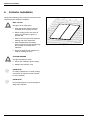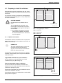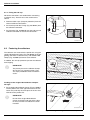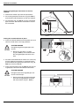
1
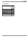
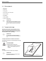
FKT SERIES FLAT PANEL
SOLAR COLLECTORS
ROOF MOUNTING FOR WORCESTER SOLAR HEATING SYSTEMS
63043966.01-1.SD
GB
Installation instructions
About this manual
This installation manual contains important
information for the safe and appropriate installation of
the roof mounted solar panels.
Notes are included with important information for
situations in which there is no danger for persons or
equipment.
These technical documents should be retained in a
safe place. These may also be inspected at the
manufacturer's premises.
The activities described in the installation manual
assume expertise based on completed vocational
training in gas or water-related installation. Only carry
out these installation steps, if you possess these
skills.
B Hand these installation instructions to the
customer.
B Explain to the customer the function and operation
of the related devices.
2
6 720 613 055 (2006/04)
1
General information
2
Specifications .
3
Safety
. . . . . . . . . . . . . . . . . . . . . . . . . . . . . . . . . . . . . . . . . .4
. . . . . . . . . . . . . . . . . . . . . . . . . . . . . . . . . . . . . . . . . . . . . .5
. . . . . . . . . . . . . . . . . . . . . . . . . . . . . . . . . . . . . . . . . . . . . . . . . . . . .6
3.1 Correct use . . . . . . . . . . . . . . . . . . . . . . . . . . . . . . . . . . . . . . . . . . . . . . .6
3.2 Notes structure . . . . . . . . . . . . . . . . . . . . . . . . . . . . . . . . . . . . . . . . . . . . .7
3.3 Please observe these safety instructions . . . . . . . . . . . . . . . . . . . . . . . . . . . . .8
4
Before installation .
4.1
4.2
4.3
4.4
4.5
4.6
5
General notes . . . . . . . . . . . . . .
Component description . . . . . . . .
Other equipment . . . . . . . . . . . .
Transport and storage . . . . . . . . .
Technical documentation . . . . . . .
Determining space required on roof
. . . . . . . . . . . . . . . . . . . . . . . . . . . . . . . .9
. . . . . . . . . . . . . . . . . . . . . . . . . . . . . . . 10
. . . . . . . . . . . . . . . . . . . . . . . . . . . . . . . 12
. . . . . . . . . . . . . . . . . . . . . . . . . . . . . . . 12
. . . . . . . . . . . . . . . . . . . . . . . . . . . . . . . 13
. . . . . . . . . . . . . . . . . . . . . . . . . . . . . . . 14
Fitting the roof connection and profile rails
5.1
5.2
5.3
5.4
5.5
5.6
5.7
5.8
6
. . . . . . . . . . . . . . . . . . . . . . . . . . . . . . . . . . . . . . . . . . .9
Setting clearances . . . . . . . . . .
Pan tile roofs. . . . . . . . . . . . . .
Crown tile roofs . . . . . . . . . . . .
Corrugated sheet steel roofs . . . .
Slate/shingle roofs . . . . . . . . . .
Sheet roofs . . . . . . . . . . . . . . .
Fitting additional rails (accessory) .
Installing profile rails . . . . . . . . .
Collector installation .
. . . . . . . . . . . . . . . . . . . . . . . 15
. . . . . . . . . . . . . . . . . . . . . . . . . . . . . . . . 15
. . . . . . . . . . . . . . . . . . . . . . . . . . . . . . . . 16
. . . . . . . . . . . . . . . . . . . . . . . . . . . . . . . . 18
. . . . . . . . . . . . . . . . . . . . . . . . . . . . . . . . 21
. . . . . . . . . . . . . . . . . . . . . . . . . . . . . . . . 24
. . . . . . . . . . . . . . . . . . . . . . . . . . . . . . . . 24
. . . . . . . . . . . . . . . . . . . . . . . . . . . . . . . . 25
. . . . . . . . . . . . . . . . . . . . . . . . . . . . . . . . 26
. . . . . . . . . . . . . . . . . . . . . . . . . . . . . . . . . . . . . . . . 28
6.1 Preparing to install the collectors . . . . . . . . . . . . . . . . . . . . . . . . . . . . . . . . . 29
6.2 Fastening the collectors . . . . . . . . . . . . . . . . . . . . . . . . . . . . . . . . . . . . . . . 30
7
Collector sensor connection .
8
Header connection
. . . . . . . . . . . . . . . . . . . . . . . . . . . . . . . . . . 34
. . . . . . . . . . . . . . . . . . . . . . . . . . . . . . . . . . . . . . . . . . 35
8.1 De-airing through pressure filling . . . . . . . . . . . . . . . . . . . . . . . . . . . . . . . . . 35
8.2 De-airing through air vent (accessory) on roof . . . . . . . . . . . . . . . . . . . . . . . . . 36
9
Fitting the connection set for two rows (accessory) .
10 Final activities .
. . . . . . . . . . . . . . . . 39
. . . . . . . . . . . . . . . . . . . . . . . . . . . . . . . . . . . . . . . . . . . . . 40
10.1 Checking the installation . . . . . . . . . . . . . . . . . . . . . . . . . . . . . . . . . . . . . . 40
10.2 Insulating the connection and header pipes . . . . . . . . . . . . . . . . . . . . . . . . . . 41
11 Quick reference guide for pan tile roof and pressure filling .
6 720 613 055 (2006/04)
. . . . . . . . . . 42
3
General information
1
General information
This chapter details which technical rules and regulations apply to this installation.
i
USER NOTE
Observe all standards and guidelines
applicable to the installation and
operation of this system in your country.
UK
Installation work on roofs
The Health and Safety at Work etc
Act 1974
Connection of thermal solar heating
systems
EN 12976: Thermal solar heating
system and their components (prefabricated systems).
The Management of Health and Safety
at Work Regulations 1999
ENV 12977: Thermal solar heating
system and their components
The Construction (Health Safety and
(bespoke systems).
Welfare) Regulations 1996
BS 6795: Code of practice for solar
The Construction (Design and
heating systems for swimming pools.
Management) Regulations 1994
Installation and equipment of DHW
cylinders
BS5546: 2000 Specification for
installation of hot water supplies for
domestic purposes, using gas-fired
appliances of rated input not
exceeding 70 kW.
BS6700:1997 Specification for
design, installation, testing and
maintenance, of servicing supplying
water for domestic use within
buildings and their curtilages.
The Lifting Operations and Lifting
Equipment Regulations 1998
Tab. 1
Technical rules for the installation of thermal solar heating systems (selection) in UK
Lightning protection
If the building height (installation height) exceeds 20 m,
and there is no lightning conductor installed, ask your local electrical contractor to connect the components on
the roof which conduct electricity with an electrical earth
cable of at least 16 mm2 to the earth bonding.
Special measures regarding lightning protection are not
required for building heights (installation heights) of less
than 20 m.
Where there is a lightning conductor system installed,
ask your local electrical contractor to check the inclusion
of the solar heating system into the lightning protection
system.
4
i
USER NOTE
The installation of the Worcester Solar
System must be carried out in accordance
with the relevant requirements for safety,
current IEE wiring regulations, local
building regulations, building standards
(Scotland) (Consolidation) regulations and
by-laws of the local water company and
health and safety document No 635
(Electricity at Work Regulations 1989).
BS 6795: Latest version
6 720 613 055 (2006/04)
Specifications
2
Specifications
FKT Solar Panels
Certificates
0036
DIN
Length
Width
Height
Clearance between collectors
Fluid content, portrait version
Fluid content, landscape version
Gross absorber surface area
Net absorber surface area
Net weight, portrait version
Net weight, landscape version
Permissible operating pressure of the
collector
Tab. 2
Vf
Vf
AG
m
m
pmax
2,070 mm
1,145 mm
90 mm
25 mm
1.43 l
1.76 l
2.37 m²
2.23 m²
46 kg
47 kg
10 bar
Specifications
6 720 613 055 (2006/04)
5
Safety
3
Safety
This chapter details how the notes for the installation
instructions, as well as the general safety instructions,
necessary for safe and trouble-free operation, are
arranged in this manual.
Safety and user notes, which specifically refer to the
installation, in the installation manual immediately
following the individual installation steps, are found here.
Carefully read the safety instructions before
commencing the installation.
Severe injury and even death, as well as material losses
and environmental damage, may follow if you ignore
safety instructions.
3.1
Correct use
This installation set holds the thermal solar collectors
(portrait and landscape), which are installed on sloping
roofs with a slope of 25° to 65°. The collectors can be
installed on corrugated and sheet steel roofs with slopes
of between 5° and 65°.
Operating conditions
Only erect the installation set on roofs whose
construction can support the weight. If necessary,
consult a structural engineer or a roofer.
The installation set is suitable for a max. standard snow
load of 2.0 kN/m² and an installation height of
max. 20 m. Using appropriate accessories, the
installation set can be used for a max. standard snow
load of 3.1 kN/m² and a max. installation height of
100 m. See Chapter 5.7 "Fitting additional rails
(accessory)".
The roof installation set must not be used for fixing any
other objects to the roof. The kit is intended exclusively
for the safe fixing of solar collectors.
6
6 720 613 055 (2006/04)
Safety
3.2
Notes structure
Two levels are identified by signal terms:
RISK TO LIFE
WARNING!
Identifies possible dangers emanating
from a product, which might lead to
serious injury or death if appropriate care
is not taken.
RISK OF INJURY/
SYSTEM DAMAGE/
BUILDING DAMAGE
CAUTION!
Identifies potentially hazardous situations,
which could lead to medium or slight
injuries or to material losses.
Additional symbol for designating user notes:
i
USER NOTE
Tip for the optimum utilisation and setting
of the control(s) plus other useful
information.
6 720 613 055 (2006/04)
7
Safety
3.3
Please observe these safety instructions
RISK TO LIFE
through a fall or falling parts.
WARNING!
B Ensure you have the correct safety
equipment for working on roofs.
B Take appropriate action to prevent
accidents when working on roofs.
B Whilst working on the roof, take all
necessary precautions against a
possible fall.
B Always wear your personal protective
clothing and safety equipment.
B After completing the installation,
always check the secure positioning of
the installed set and that of the
collectors.
RISK OF INJURY
CAUTION!
Injury and operating faults can result from
making changes to the system
construction.
B Never change the system
construction.
RISK OF INJURY
CAUTION!
Some parts may cause burns, if the
collector and installation materials are
exposed to solar radiation for longer
periods of time.
B Always wear your personal protective
clothing and safety equipment.
B Cover the collector (e.g. with
a covering sheet – available as an
accessory 7739 300 399) and the
installation material during the
installation as protection against high
temperatures resulting from solar
irradiation.
8
6 720 613 055 (2006/04)
Before installation
4
Before installation
4.1
General notes
i
USER NOTE
It is recommended that the services of a
roofing company, who are experienced in
working on roofs and will be fully aware of
the risks of working at height are considered.
Make yourself familiar with the on-site conditions and local regulations before commencing the installation.
RISK OF INJURY
CAUTION!
If the collector and its installation material
is left exposed to the sunlight for a long
period, the parts will become hot and may
cause burns.
B Wear protective clothing.
B Cover the collector (e.g. with
a covering sheet – available as an accessory 7739 300 399) and the installation material during the installation
as protection against high temperatures resulting from solar irradiation.
63043966.02-1.SD
Fig. 1
General overview of collector pair – roof mounting
Check
B the delivery for completeness and perfect condition.
B the optimum arrangement of the solar collectors.
Take account of the direction of the sunlight (angle
of inclination, southerly direction). Avoid the shade
of high trees or structures and match the collector array to the shape of the building (e.g. flush with windows, doors, etc.).
i
USER NOTE
i
USER NOTE
Only use OEM components and replace
any faulty parts immediately.
Remove broken pan tiles, shingles or
plates in the area of the collectors and replace them.
6 720 613 055 (2006/04)
9
Before installation
4.2
Component description
4.2.1 Installation set for the collectors
i
USER NOTE
The installation sets are for mounting and
fixing the collectors in place.
8
3
2
1
4
3
5
7
6
63043965.03-1.SD
Fig. 2
Installation set for 2 collectors – 1 basic installation set, 1 extended installation set and 2 roof connection installation sets
Basic installation set for each collector array and
for the first collector (Fig. 2):
Item 1:
Item 3:
Item 7:
Item 8:
Profile rail
Single-sided collector clamp
Anti-slip protection
M8 screw
2×
4×
2×
4×
Extended installation set for each additional collector
(Fig. 2):
Item 1:
Item 2:
Item 7:
Item 6:
Item 8:
Profile rail
Double-sided collector clamp
Anti-slip protection
Rail connector with threaded studs
M8 screw
2×
2×
2×
2×
4×
Roof connection, pan tile roofs, per collector
(Fig. 2):
Item 4
Item 5
10
Roof hook, adjustable
Sliding nut
4×
4×
6 720 613 055 (2006/04)
Before installation
4.2.2 Hydraulic connection
i
USER NOTE
One connection kit for each collector array will be required. The collectors are
connected together by a connection set.
2
1
3
7
6
Fig. 3
5
4
63043966.03-1.SD
Connection kit and connection set (illustration shows 2 portrait collectors)
Connection kit, per collector array (Fig. 3)
Item 2:
Item 3:
Item 4:
Item 5:
Connector clip
Connecting pipe (insulation not shown)
Insulation for corrugated pipe connector 710 mm
Clamped joint for collector sensor
2×
2×
1×
1×
Item 6:
Item 7:
Item 8:
1×
2×
1×
Size 5 Allen key
End cap
Sensor bush plug, not shown
Connection set between the collectors,
for each collector (in two corner protectors, Fig. 4)
Item 1: Corrugated pipe connector
Item 2: Connector clip
2×
4×
2
1
63043966.04-1.SD
Fig. 4
6 720 613 055 (2006/04)
Corner protectors with one connection set
11
Before installation
4.3
Other equipment
– Spirit level
– Plumb line
– Filling pump
– Vest harness with safety rope
– Pipe insulation
– Scaffolding
– Roofing ladder
– Crane or mobile hoist
i
4.4
USER NOTE
When fitting the roof installation set and
water connection, the only tool reqiured is
the size 5 allen key from the connection
kit.
Transport and storage
Please ensure that the corner protectors are retained. They contain pipework connection pieces
which are required for installation. All components
are protected by transport packaging.
i
USER NOTE
Dispose of the transport packaging in
an environmentally friendly recycling system.
Transport protection for collector connections
The collector connections are protected against damage
by rubber caps.
SYSTEM DAMAGE
through damaged sealing faces.
CAUTION!
B Do not remove the rubber caps (Fig. 5,
Item 1) until immediately prior to installation.
1
Storage
The collectors must be stored in dry conditions.
i
USER NOTE
Do not store collectors outside without
protection from the rain.
63043966.05-1.SD
Fig. 5
12
Plastic caps on collector connections
6 720 613 055 (2006/04)
Before installation
4.5
Technical documentation
The solar heating system consists of various components (Fig. 6). Installation, operation and maintenance
documentation is provided for each component. Accessories may be accompanied by a separate document.
Item 1:
Collector: instructions for roof installation
are enclosed with the connection kit
Item 2:
Pump station: instructions enclosed with the
complete station
Item 3:
Solar Controller: instructions are enclosed
with the controller.
Item 4:
DHW Cylinder: instructions enclosed with the
DHW cylinder.
4
1
3
2
6720613577.00-1.SD
Fig. 6
6 720 613 055 (2006/04)
Solar heating system components and technical
documentation
13
Before installation
4.6
Determining space required on roof
Please note the following minimum space requirements.
Dimension A and B
Area required for the collector array.
H
Dimension C
At least two tiles to the roof or chimney. Otherwise there
is a risk of damaging the tiles, particularly if the tiles are
laid in mortar.
Dimension D
G
Roof overhang including gable wall thickness.
Dimension E
Minimum 30 cm for fitting the connection cables in
the attic.
63043965.09-1.SD
Fig. 7
Clearances to be observed
Dimension F
Minimum 40 cm for installing the connection cables in
the attic (if installing a vent, sufficient space must also be
allowed for in the vicinity of the flow outlet).
Please note that the air vent must be the highest point of
the system.
Dimension G
Minimum 50 cm left and right of the collector array for
the pipework under the roof.
Dimension H
Dimension H is 1.900 mm (1.000 mm for landscape collectors) and is the minimum distance from the upper
edge of the collector to the lower profile rail, which is installed first.
Space requirements for portrait collectors:
Space requirements for landscape collectors:
Number of collectors
Dimension A
Dim. B
Number of collectors
Dimension A
Dim. B
2
2.32 m
2.07 m
2
4.17 m
1.15 m
Tab. 3
14
3
3.49 m
2.07 m
3
6.26 m
1.15 m
4
4.66 m
2.07 m
4
8.36 m
1.15 m
5
5.83 m
2.07 m
5
10.45 m
1.15 m
6
7.06 m
2.07 m
6
12.55 m
1.15 m
7
8.17 m
2.07 m
7
14.64 m
1.15 m
8
9.34 m
2.07 m
8
16.74 m
1.15 m
9
10.51 m
2.07 m
9
18.61 m
1.15 m
10
11.68 m
2.07 m
10
20.93 m
1.15 m
Space requirement for portrait collectors
Tab. 4
Space requirement for landscape collectors
6 720 613 055 (2006/04)
Fitting the roof connection and profile rails
5
Fitting the roof connection and profile rails
5.1
Setting clearances
The dimensions given are guide values that should be
approximately maintained.
i
USER NOTE
On pan tile roofs the tile troughs determine the true distance between the roof
hooks.
Distances of roof hooks
Every profile rail is fastened using two roof hooks
(Fig. 8). See the table for the approximate distance between the roof hooks.
Installation
type
portrait
Distance w
Distance x
z
x
Distance z
approx.
1170 mm
landscape approx. 2090 mm
Tab. 5
610 –
170 – 540 mm
1030 mm
1520 –
170 – 540 mm
1950 mm
Distance of the roof hooks from one another
i
63043965.11-1.SD
Fig. 8
Distance of the roof hooks from one another
USER NOTE
Distances x and z should always be approximately equal to distance w.
Distances of profile rails
Set the distance between the top and bottom profile rails
(Fig. 9). Use the table values.
Installation
type
Distance y
from
to
portrait
1320 mm
1710 mm
landscape
600 mm
820 mm
Tab. 6
i
y
Distance (centre-centre) between bottom and
top profile rail
USER NOTE
Landscape installation is only possible
if roof battens are max. 420 mm apart.
63043965.12-1.SD
Fig. 9
6 720 613 055 (2006/04)
Distance between the profile rails
15
Fitting the roof connection and profile rails
5.2
Pan tile roofs
Fit all roof hooks according to the guide values shown in
tables 5 and 6 on page 15.
i
i
USER NOTE
Do not modify the roof construction and
avoid damaging the roof covering. In the
case of roof tiles laid in mortar, lift the tiles
starting with the 3rd row under the roof.
USER NOTE
Carefully cut away the base of the tile if
necessary to ensure the tile lies correctly
over the roof hook.
63043965.13-1.SD
Fig. 10
Fitted roof hooks for two collectors
SYSTEM DAMAGE
CAUTION!
1
2
through subsequent loosening of the long
hexagon nut on the roof hook. When the
nut is tightened, adhesive is activated
which bonds the joint securely after one
hour.
B If the nut becomes loose after this
time, it must be tightened on-site
(e.g. lock washer).
5.2.1 Attaching the roof hooks over the roof batten
63043965.14-1.SD
In its packaged state, the lower part of the roof hook is
folded.
B Loosen the long hexagon nut (Fig. 11, Item 2) on the
roof hook and move the lower part of the roof hook
(Fig. 11, Item 1) to the correct position.
Fig. 11
Turning the lower part of the roof hook
B Push the tile upwards according to the roof hook positions shown in (Tab. 5 and Tab. 6, page 15).
1
B Attach in the roof hook in such a way that the front
brace lies in a tile trough (Fig. 12, Item 4).
5
B Push the lower part of roof hook (Fig. 12, Item 3) upwards until it touches the roof batten (Fig. 12,
Item 2).
4
B Tighten the long hexagon nut (Fig. 12, Item 1). To do
this, insert the size 5 Allen key into one of the holes
in the hexagon nut and turn.
2
4
3
i
16
USER NOTE
The serated washer (Fig. 12, Item 5)
must grip the teeth on the lower part of the
roof hook.
63043965.15-1.SD
Fig. 12
Roof hook located in place (some tiles have been
removed to show the example in more detail)
6 720 613 055 (2006/04)
Fitting the roof connection and profile rails
5.2.2 Fastening roof hooks to joists
1
Alternatively, the roof hook can also be used for fastening to the joist.
2
3
According to the roof hook positions shown in (Tab. 5
and Tab. 6, page 15), sufficiently strong boards must be
attached to the joists so that the roof hook can be fitted
between the joists.
i
USER NOTE
With some roof coverings it may be necessary to underlay the lower part of the
roof hook (Fig. 13, Item 4) with boards so
that the upper part of the roof hook lies on
top of the tile.
B Loosen the long hexagon nut (Fig. 13, Item 2).
B Insert bolt into upper hole (Fig. 13, Item 3).
B Loosely fasten lower part of roof hook (Fig. 13,
Item 1). Do not tighten the connection yet.
4
5
63043965.16-1.SD
Fig. 13
Fastening roof hooks to joists
Item 1: Lower part of roof hook
Item 2: Long hexagon nut
Item 3: Upper hole for fastening the lower part
Item 4: Underlay if necessary
Item 5: Cut off if necessary
SYSTEM DAMAGE
CAUTION!
through breakage of the roof hook if the
bolt is not positioned in the upper hole, resulting in uneven load distribution.
B Lay front brace onto the tile so that when subjected
to a load it lies in a tile trough (Fig. 14, Item 3).
1
5
The roof hook must have some clearance along the upper edge of the tile (Fig. 14, Item 4). Adjust the top of the
tile if necessary.
6
4
B Push the lower part of the roof hook down until it lies
on the joist or on the boards (Fig. 14, Item 6).
i
USER NOTE
3
The serated washer (Fig. 14, Item 5)
must grip the teeth on the lower part of the
roof hook.
B Tighten the long hexagon nut (Fig. 14, Item 1). To do
this, insert the size 5 Allen key into the hole in the
hexagon nut and turn.
B Using suitable screws, fasten the lower part of the
roof hook into the first (Fig. 14, Item 2) and second
holes (at least) of the joist.
3
2
63043965.17-1.SD
Fig. 14
Roof hook fitted (some tiles have been removed for
a better view)
Item 1: Long hexagon nut
Item 2: Screw for fastening roof hook
Item 3: Front brace
Item 4: Adjust the tile as necessary to fit the roof hook
Item 5: Serated washer
Item 6: Board
6 720 613 055 (2006/04)
17
Fitting the roof connection and profile rails
5.3
Crown tile roofs
i
USER NOTE
1
Consult a roofer when installing on a roof
with crown tiles.
During installation, please maintain the required distances (w, x and y) between the roof hooks as detailed in
(Tab. 5 and Tab. 6, page 15).
According to the roof hook positions shown in (Tab. 5
and Tab. 6, page 15), sufficiently strong boards (Fig. 15,
Item 1) must be attached to the joists (cut out counterbattens) so that the roof hook can be fitted between the
joists.
i
1
63043965.18-1.SD
Fig. 15
Fit boards/planks if necessary
USER NOTE
If the roof has been fitted with boards, the
same roof hook as with pan tile roofs can
be used (page 16).
It may be possible to fit the roof hooks
over battens.
Preparing roof hook
1
Before installing, the lower part must be moved to the
correct position.
2
B Loosen the long hexagon nut (Fig. 16, Item 2).
3
B Insert bolt into upper hole (Fig. 16, Item 3).
B Loosely fasten lower part of roof hook (Fig. 16,
Item 1). Do not tighten the connection yet.
SYSTEM DAMAGE
CAUTION!
4
through breakage of the roof hook if the
bolt is not positioned in the upper hole, resulting in uneven load distribution.
63043965.16-1.SD
Fig. 16
Repositioning lower part of roof hook
Item 1: Lower part of roof hook
Item 2: Long hexagon nut
Item 3: Upper hole for fastening the lower part
Item 4: Cut off if necessary
18
6 720 613 055 (2006/04)
Fitting the roof connection and profile rails
RISK TO LIFE
WARNING!
Whilst working on the roof, take all necessary precautions against a possible fall.
RISK OF INJURY
through a fall or falling parts.
WARNING!
B Take appropriate action to prevent accidents when working on roofs.
B Always wear personal protective clothing and safety equipment.
i
63043965.10-1.SD
USER NOTE
Fig. 17
Fitted profile rails for two collectors
For better access to the roof use a roofing
ladder or slide the tiles at the edge of the
collector array up.
6 720 613 055 (2006/04)
19
Fitting the roof connection and profile rails
Fitting the roof hook
BUILDING DAMAGE
caused by leaks.
CAUTION!
i
B Fit each roof hook centrally on a crown
tile.
1
USER NOTE
If the roof battens are too close together,
remove the lower part of the roof hook between the second and third holes.
B Push the lower part of the hook down until it lies on
the joist or on the board (Fig. 18, Item 1).
63043965.20-1.SD
i
USER NOTE
Fig. 18
The serated washer (Fig. 19, Item 2)
must grip the teeth on the lower part of the
roof hook.
Fitted roof hook
5
1
2
B Tighten the long hexagon nut (Fig. 19, Item 1). To do
this, insert the size 5 Allen key into the hole in the
hexagon nut and turn.
B Using suitable screws, fasten the lower part of the
roof hook into the first (Fig. 19, Item 3) and second
holes (at least) of the joist or board.
3
4
63043965.21-1.SD
Fig. 19
Fitted roof hook – cross section showing shortened
lower part of roof hook
Item 1: Long hexagon nut
Item 2: Serated washer
Item 1: Screw for fastening roof hook
B Cut the adjacent crown tiles (Fig. 20, Item 1) to size
(dashed line, Fig. 20, Item 2).
2
1
63043965.65-1.SD
Fig. 20
20
Roof hook with covered roof
6 720 613 055 (2006/04)
Fitting the roof connection and profile rails
5.4
Corrugated sheet steel roofs
Carriage bolts must be used instead of roof hooks for
fastening the profile rails.
1
Standard delivery (Fig. 21):
Item 1:
Item 2:
Item 3:
Item 4:
Item 5:
Item 6:
M8 screw
Holding bracket
M12 nut
Washer
Sealing disc
M12 carriage bolt
2
4×
4×
4×
4×
4×
4×
3
4
5
6
On corrugated roofs, the peaks determine the true distance between the carriage bolts. During installation,
please maintain the required distances (w, x and y) between carriage bolts as detailed in (Tab. 5 and Tab. 6,
page 15).
63043965.22-1.SD
Fig. 21
SYSTEM DAMAGE
due to an insufficiently strong subframe.
CAUTION!
B Check that the subframe is strong
enough. To fasten the carriage bolts,
timber supports of at least 40 × 40 mm
thickness are required.
B If necessary, fit additional timber supports to maintain the measurements
shown in Tab. 5 and Tab. 6.
6 720 613 055 (2006/04)
Roof connector for corrugated steel sheets
Additional tools required
– Cordless screwdriver
– Tape measure
– Wood drill, Ø 6 mm (drill bit length see
Chapter "Fitting the carriage bolts", page 22)
– Metal drill, Ø 13 mm
– Spanner size 15 and 19
21
Fitting the roof connection and profile rails
Fitting the carriage bolts
i
USER NOTE
Using the wood drill, drill precisely at a
90° angle through the roof subframe to
obtain a flat, level surface between the
holding bracket and profile rail.
BUILDING DAMAGE
caused by leaks.
CAUTION!
B Never drill into a tile trough.
B Drill through the corrugated metal roof using a metal
drill (Ø 13 mm) taking note of the positions of the carriage bolt (see Tab. 5 and Tab. 6). Do not drill into the
wood beneath!
63043965.23-1.SD
Fig. 22
Creating a drilling template
B Feed wood drill (Ø 6 mm) through the hole and drill
vertically into the subframe (timber support).
1
B When fitting the carriage bolts, note the sequence of
the individual parts (Fig. 23).
2
3
4
B Turn holding bracket (Fig. 23, Item 1) until it touches
the carriage bolt (Fig. 23, Item 5).
B Screw the pre-assembled carriage bolt into the roof
using a size 15 spanner until distance B is reached.
i
5
USER NOTE
When screwing in Carriage bolts, ensure
that the distance B (Fig. 24) is the same
for all carriage bolts.
63043965.24-1.SD
Fig. 23
Fitting the carriage bolts – sequence
Item 1: Holding bracket
Item 2: M12 nut
Item 3: Washer
Item 4: Sealing disc
Item 5: M12 carriage bolt
22
6 720 613 055 (2006/04)
Fitting the roof connection and profile rails
B Tighten the nuts (Fig. 24, Item 2) until the sealing
disc (Fig. 24, Item 3) is lying completely flush on the
roof.
i
1
USER NOTE
2
3
B The holding bracket must be screwed
fully onto the carriage bolt.
Height of peak, dim. A
35 mm
40 mm
45 mm
50 mm
55 mm
60 mm
Dim. B
70 mm
65 mm
60 mm
55 mm
50 mm
45 mm
63043965.25-1.SD
Fig. 24
Carriage bolt fitted to corrugated roof
Item 1: Holding bracket
Item 2: Nut, M12
Item 3: Sealing disc
Fastening the profile rail
1
Please also note Chapter 5.8.1 "Connecting profile
rails".
2
B Fasten each profile rail (Fig. 25, Item 2) with two
bolts (Fig. 25, Item 1).
i
3
USER NOTE
The profile rails must not sag due to differences in level of the joists.
B Use a plumb line to check. If necessary, pack the profile rails at the holding bracket.
63043965.26-1.SD
Fig. 25
Fastening the profile rail to the holding bracket
Item 1: Screw
Item 2: Profile rail
Item 3: Holding bracket
6 720 613 055 (2006/04)
23
Fitting the roof connection and profile rails
5.5
i
Slate/shingle roofs
USER NOTE
1
A roofer must carry out the installation
on slates or shingles.
6
Here is an example of the installation of the special roof
hooks and the watertight seal with custom flashing
(Fig. 26, Item 1 and 2) with a shingle/slate roof.
4
5
4
3
During installation, please maintain the required distances (w, x and y) between the special roof hooks as detailed in (Tab. 5 and Tab. 6, page 15).
2
B Fit special roof hook (Fig. 26, Item 5) and gasket
(Fig. 26, Item 4) to the slate/shingle roofs using
screw (Fig. 26, Item 6).
B To ensure that the installation is watertight, flashing
(Fig. 26, Item 1, 2) must be installed on the building
above and below the special roof hooks.
i
5.6
i
User note:
63043965.27-1.SD
Fig. 26
Mounting on slate/shingle roof
Item 1: Flashing (on building)
Item 2: Flashing (on building)
Item 3: Multiple tites
Item 4: Gasket (on building)
The special roof hooks must be positioned on the front of a multiple roof
(Fig. 26, Item 3).
Item 5: Special roof hooks
Item 6: Screw
Sheet roofs
USER NOTE
1
2
3
4
A roofer must carry out the installation on
a sheet steel roof.
1
5
Carriage bolts (Fig. 27, Item 5) must be used instead of
roof hooks for fastening the profile rails. During installation, please observe the distances (w, x and y) between
Carriage bolts as detailed in (Tab. 5 and Tab. 6,
page 15).
6
4
To ensure the roof is water tight, sleeves for the carriage
bolts (Fig. 27, Item 5) must be soldered onto the sheet
steel roof.
i
2
3
5
USER NOTE
For the fitting sequence for carriage bolts
and profile rails, and the relevant instructions, see Chapter 5.4 "Corrugated sheet
steel roofs".
63043965.29-1.SD
Fig. 27
Mounting on sheet steel roof
Item 1: Holding bracket
Item 2: M12 nut
Item 3: Washer
Item 4: Sealing disc
Item 5: M12 carriage bolt
Item 6: Sleeve (not supplied)
24
6 720 613 055 (2006/04)
Fitting the roof connection and profile rails
5.7
Fitting additional rails (accessory)
Additional measures are needed for installation heights
of 20 to 100 m and/or with standard snow loads of 2.0 to
3.1 kN/m2.
i
USER NOTE
The example here shows an installation
on pan tile roofs. The additional rails can
also be installed on other types of roof described in this manual.
1
Fitting additional roof hooks
Additional roof hooks must be fitted for attaching the
snow load profiles.
B Fasten additional roof hooks (Fig. 28, Item 1) as centrally as possible between the upper and lower roof
hooks already fitted.
i
63043965.30-1.SD
Fig. 28
Additional roof hooks for the snow load profile
(here: for two collectors)
USER NOTE
1
There must be at least one free row of
tiles between the upper, middle and lower
roof hooks.
Fastening the snow load profile to the roof hooks
B Push sliding nut (Fig. 29, Item 1) onto the roof hook
in the direction of the arrow.
3
2
B Place the snow load profile (Fig. 29, Item 2) onto
the roof hooks and tighten using an M8 bolt (Fig. 29,
Item 3).
B Make sure snow load profiles are level and flush
(use string line).
63043965.31-1.SD
Fig. 29
Fastening the snow load profile
Installing the profile rails
The profile rails must be joined before they are fastened.
Please see Chapter 5.8.1 "Connecting profile rails".
B Place the profile rails (Fig. 30, Item 1) into the indentations (Fig. 30, Item 2) on the snow load profiles
and loosely fasten using bolt and sliding nut (Fig. 30,
Item 3) so that the profile rails can still be aligned.
1
2
3
B Carry out the same procedure for the other profile
rails.
To continue with the installation, see Chapter 5.8.3
"Aligning the profile rails".
63043965.32-1.SD
Fig. 30
6 720 613 055 (2006/04)
Fitting landscape profile rails
25
Fitting the roof connection and profile rails
5.8
Installing profile rails
The profile rails must be joined together using rail connectors. Each collector has been provided with an upper
and lower profile rail.
5.8.1 Connecting profile rails
1
B Push rail connector (Fig. 31, Item 1) as far as it will
go into both profile rails (Fig. 31, Item 2).
2
B To lock, tighten both fitted M10 threaded studs
(Fig. 31, Item 3) in the rail connector using a
size 5 Allen key.
3
63043965.33-1.SD
Fig. 31
Connecting profile rails
Item 1: Rail connector
Item 2: Profile rail
Item 3: M10 threaded stud
5.8.2 Installing profile rails
B Push sliding nut (Fig. 32, Item 1) onto the roof hook
in the direction of the arrow.
3
B Place the lower profile rails (Fig. 32, Item 2) onto the
roof hooks and loosely fasten M8 bolt (Fig. 32,
Item 3) so that the profile rails can still be aligned.
1
B Carry out the same procedure for the upper profile
rails.
i
USER NOTE
Care should be taken not to over-tighten
the stud in the rail connector to avoid
deforming the material.
2
63043965.34-1.SD
Fig. 32
Fastening profile rails to the roof hook
Item 1: Sliding nut
Item 2: Profile rail
Item 3: Bolt
26
6 720 613 055 (2006/04)
Fitting the roof connection and profile rails
5.8.3 Aligning the profile rails
B Align the upper and lower profile rails to the side flush
with each other and level them (Fig. 33, use a spirit
level)..
i
1
USER NOTE
90°
Measure the diagonals or place a roof
batten (Fig. 33, Item 1), for example, at
the ends of the profile rails. The angle between roof batten and profile rail must be
90°. Align the profile rails over the slotted
holes.
90°
1
B Tighten the screws.
i
USER NOTE
63043965.35-1.SD
Fig. 33
Aligning the profile rails
The profile rails must not sag due to differences in level of the joists.
Check using a plumb line.
5.8.4 Installation of anti-slip protection
To prevent the collectors from slipping, you must fasten
two anti-slip protectors to the lower profile rails for each
collector.
1
3
B Push each anti-slip protector (Fig. 34, Item 3) into
the innermost slotted holes (Fig. 34, Item 1) over the
profile rails until it clicks into place (Fig. 34, Item 2).
2
Fig. 34
Attaching anti-slip protection
Item 1: Fixing holes for the anti-slip protection
Item 2: Clicking the anti-slip protection into place
Item 3: Anti-slip protection
6 720 613 055 (2006/04)
27
Collector installation
6
Collector installation
Observe the following safety and user instructions when
commencing the collector installation.
RISK TO LIFE
through a fall or falling parts.
WARNING!
B Take appropriate action to prevent
accidents when working on roofs.
B Whilst working on the roof, take all
necessary precautions against a
possible fall.
B Always wear your personal protective
clothing and safety equipment.
B After completing the installation,
always check the secure positioning of
the installed set and that of the
collectors.
63043965.37-1.SD
Fig. 35
View of roof mounting with collectors
B Ensure that the correct equipment is
used for working on roofs.
SYSTEM DAMAGE
through interruption of work.
CAUTION!
B Secure the collectors against falling.
B Stabilise the collector array.
28
i
USER NOTE
i
USER NOTE
Use lifting equipment as used by roofing
contractors or sufficient suction handles
for the installation.
Unsecured collectors may fall during handling and installation.
6 720 613 055 (2006/04)
Collector installation
6.1
1
Preparing to install the collectors
Before beginning actual installation on the roof, preassemble the end caps on the ground to make work on the
roof easier.
4
To secure the end caps (and later the corrugated pipe
connectors and connecting pipes as well), attach brackets to the connections.
SYSTEM DAMAGE
CAUTION!
through leaks in the collector connections.
The corrugated pipe connectors, connecting pipes and collector connections
must not display any signs of damage or
contamination.
B The collector connections have had
special grease applied in the factory
to make installation easier. Do not use
any other grease.
4
1
2
3
63043966.09-1.SD
Fig. 36
Water connection (right) up to max. 5 collectors
Item 1: Corrugated pipe connector
Item 2: Flow line
Item 3: Return line
Item 4: End cap
1
6.1.1 Pipework connections
The collectors must be installed in such a way that the
sensor bushs that receive the collector sensor (Fig. 37,
Item 1) are at the top.
i
USER NOTE
The water connection pipes can be connected on the right (Fig. 36) or left
(Fig. 37). In this manual, the connection
pipes are shown on the right.
The pipework in the collector is designed as a double
meander, which enables you to carry out two different
water connections:
63043966.10-1.SD
Fig. 37
Water connection (left) up to max. 5 collectors
Fig. 38
Two-way pipework connections
single-sided connection of up to 5 collectors
Up to 5 collectors can be connected one side of
a collector array (Fig. 36 and Fig. 37).
Two-way connection of up to 9 collectors
If there are more than 5 collectors installed in one
collector array, the water connection must be two-way
(Tichelmann principle, Fig. 38).
The two-way connection can also be made if there are
fewer than 6 collectors (Fig. 38).
If more than 9 collectors are required then a further AGS
pump station is required.
6 720 613 055 (2006/04)
63043966.08-1.SD
29
Collector installation
6.1.2 Fitting the end cap
Not all the connections are needed when connecting
a collector array. Those that are not used must be
closed.
1
B Remove rubber caps (transport protection) from the
relevant collector connections.
B Push end cap with the O-rings (Fig. 39, Item 1) onto
the collector connection.
2
B Push bracket (Fig. 39, Item 2) over the end cap and
collector connection to secure the connection.
63043966.12-1.SD
Fig. 39
6.2
Securing end cap with bracket
Fastening the collectors
The collectors are fastened to the profile rails using the
single-sided collector clamps (Fig. 40, Item 2) at the beginning and end of a collector array, and double-sided
clamps (Fig. 40, Item 1) between each collector.
In addition, the anti-slip protectors prevent the collector
from slipping.
i
1
2
USER NOTE
The plastic parts on the collector clamps
do not have any support function. They
are simply intended to make installation
easier.
63043965.42-1.SD
Fig. 40
Fasteners for the collector
Pushing on the single-sided collector clamp on
the right
B Push single-sided collector clamps (Fig. 41, Item 1)
into the profile rails at the right-hand end of the collector array until they click into place in the first slotted hole on the profile rails.
i
1
1
2
USER NOTE
Do not fit the single-sided collector
clamps to the left-hand side of the collector array until the last collector has been
installed.
63043965.43-1.SD
Fig. 41
30
Pushing on the single-sided collector clamp
6 720 613 055 (2006/04)
Collector installation
Putting the first collector in place
Lay the collector on the profile rails in such a way that
the sensor bush is at the top to receive the collector sensor. Begin by laying the collectors on the right-hand side
of the profile rails.
1
2
RISK OF INJURY
CAUTION!
11
Install collectors with at least one assistant.
B Place the first collector onto the profile rails and allow
it to slide into the anti-slip protectors (Fig. 42).
The lower collector edge must lie in the opening of the
anti-slip protector (Fig. 42, Item 1).
63043966.13-1.SD
Fig. 42
Laying the first collector on the profile rails
B Carefully push collector (Fig. 43, Item 1) up against
the single-sided collector clamp and align horizontally.
1
B Screw in single-sided collector clamp (Fig. 43,
Item 2) using size 5 Allen key.
i
USER NOTE
2
When the screw is tightened, the plastic
lugs at the pre-determined cut-off points
break away and can be discarded.
The grip on the collector clamp (Fig. 43, Item 2) now
grips the lower collector edge.
63043965.45-1.SD
Fig. 43
single-sided collector clamp screwed in place
Inserting a double-sided collector clamp
B Insert the double-sided collector clamp, nut first, into
the opening made by the profile rail and plug connector so that the plastic spacer (Fig. 44, Item 1) surrounds the profile rail.
B Push double-sided collector clamp up against the
collector frame.
i
1
2
1
USER NOTE
1
Do not tighten the screw until the second
collector has been pushed up against the
double-sided collector clamp.
63043966.14-1.SD
Fig. 44
6 720 613 055 (2006/04)
Fitting a double-sided collector clamp
31
Collector installation
Fitting corrugated pipe connectors to the first
collector
B Remove the rubber caps from the connections.
B Push corrugated pipe connectors (Fig. 45, Item 1)
onto the left-hand connections on the first collector.
B Push bracket (Fig. 45, Item 2) over the corrugated
pipe connector and collector connection to secure
the connection.
1
2
63043966.11-1.SD
Fig. 45
Fitting corrugated pipe connectors to the first
collector
Putting the second collector in place
B Place the second collector onto the profile rails and
allow it to slide into the anti-slip protectors.
SYSTEM DAMAGE
CAUTION!
2
1
through damaged corrugated pipe connectors.
B Do not use any tools, e.g. pliers
(Fig. 46, Item 2). These could render
the corrugated pipe connector unusable.
B Push the second collector on to the first in such a way
that the collector connections are pushed into the
preassembled corrugated pipe connectors (Fig. 46,
Item 1) on the first collector.
3
2
63043966.15-1.SD
Fig. 46
Pushing second collector towards the first
B Place second bracket (Fig. 46, Item 3) over the corrugated pipe connector and collector connection.
SYSTEM DAMAGE
CAUTION!
through unsecured corrugated pipe connectors and end caps.
B Secure each end cap with one bracket
and each corrugated pipe connector
with two brackets (Fig. 47, Item 1).
1
63043966.16-1.SD
Fig. 47
32
Corrugated pipe connector secured with brackets
6 720 613 055 (2006/04)
Collector installation
B Tighten the screw on the double-sided collector
clamp using the size 5 Allen key.
i
USER NOTE
When the screw is tightened, the plastic
lugs at the pre-determined cut-off points
break away.
1
The grip (Fig. 48, Item 1) on the collector clamp now
grips the lower collector edges.
Repeat the procedure for all the other collectors.
63043965.48-1.SD
Fig. 48
Double-sided collector clamp between two collectors
Fitting the single-sided collector clamp on the left
Once all collectors are fitted, the two remaining singlesided collector clamps can be attached.
2
B Push single-sided collector clamp (Fig. 49, Item 1)
into upper and lower profile rails.
B Push collector clamp up against the collector frame
and screw in place using size 5 Allen key (Fig. 49,
Item 2).
i
USER NOTE
1
When the screw is tightened, the plastic
lugs at the pre-determined cut-off points
break away and can be discarded.
63043966.17-1.SD
Fig. 49
6 720 613 055 (2006/04)
single-sided collector clamp (left)
33
Collector sensor connection
7
Collector sensor connection
i
USER NOTE
B
The collector sensor is supplied with the
solar controller.
A
Observe the installation location for single
or dual row collector systems (Fig. 50).
SYSTEM DAMAGE
through faulty sensor cable.
CAUTION!
1 2
B Protect the cable from possible damage.
Insertion point
The collector sensor must be fitted in the collector nearest to the flow connection (Fig. 50, Item 2).
– Insertion point (Fig. 50, Item A) for single row collector systems.
1 2
63043966.25-1.SD
Fig. 50
Collector sensor installation location (schematic)
Item 1: Return line
Item 2: Flow line
– Insertion point (Fig. 50, Item B) for dual row collector
systems.
Installing the collector sensor
For perfect functioning of the solar heating system,
the collector sensor (Fig. 51, Item 1) needs to be inserted into the sensor guide tube as far as it will go (approx.
250 mm).
B Using the collector sensor or screwdriver, push
through the sealing membrane on the sensor bush
(Fig. 51, Item 3).
3
B Insert collector sensor approx. 250 mm into the sensor guide tube (as far as it will go).
B Tighten clamped joint (Fig. 51, Item 2), counterhold if
necessary.
i
34
USER NOTE
1
2
B Screw clamped joint (Fig. 51, Item 2) into sensor
bush.
250 mm
Kollektor
63043966.26-1.SD
Fig. 51
Pushing the collector sensor into the collector
Item 1: Collector sensor
Item 2: Clamped joint
If you accidentally push through the sensor bush (Fig. 51, Item 3) on the wrong
collector, it can be resealed using the plug
from the connection kit. You must first remove the nut in the sensor bush using the
cable gland (Fig. 51, Item 2).
Item 3: Sensor bush
6 720 613 055 (2006/04)
Header connection
8
Header connection
Information on laying the header pipes can be found in
the complete station installation instructions.
1
The pipework connection to the header pipes is made
using the long flexible connection pipes. It is not permitted to connect a fixed header pipe directly to the collector.
i
USER NOTE
Use standard ventilation tiles or lead
flashing when laying the connection pipes
under the roof.
2
Use a specialist company to route
the connection pipes under the roof.
3
63043966.18-1.SD
i
i
8.1
USER NOTE
Feed the sensor cable together with the
flow line through the ventilation tile under
the roof.
Fig. 52
Routing connection pipes under the roof
Item 1: Flow line (shown without insulation)
Item 2: Return line (shown without insulation)
Item 3: Sensor cable
USER NOTE
If you intend to vent the solar heating system with an automatic air-vent valve (accessory) at the highest point of the
system, run the flow line rising to the airvent valve and the return line rising to the
collector array.
De-airing through pressure filling
If venting of the solar heating system is carried out using
a pressure filling pump, no vent is required on the roof.
1
B Push connection pipe (1.000 mm, Fig. 53, Item 1)
onto the flow connection on the collector array and fix
in place using bracket (Fig. 53, Item 4).
4
B Feed connection pipe together with the sensor cable
through the ventilation tile (Fig. 53, Item 3) and
through the roof insulation.
2
B Connect header pipe to the compression fitting
(Fig. 53, Item 2).
Perform the same procedure with the return connection.
3
63043966.19-1.SD
Fig. 53
6 720 613 055 (2006/04)
Fitting flow line (with no vent at highest point in the
system)
35
Header connection
8.2
De-airing through air vent (accessory) on roof
If you intend to vent the solar heating system with an automatic air-vent valve (accessory) at the highest point of
the system, run the flow line rising to the air-vent valve
(Fig. 54, Item 2) and the return line rising to the collector
array (Fig. 54).
2
1
Avoid frequent changes in direction.
i
User note:
For each change of direction downwards
and each new rise, install an additional
with air vent.
If you cannot provide an automatic air vent valve due to
space restrictions, install a manual air vent valve.
63043966.20-1.SD
Fig. 54
View – with vent valve for flow connection
Item 1: Collector sensor
Item 2: Automatic air vent valve on roof
Function of the weather protection cap and weather
protection cap on the automatic air vent valve
The solar heating system is vented through the opened
weather protection cap. When in operation, the weather
protection cap (Fig. 55, Item 1) must always be positioned over the weather protection cap to prevent moisture entering through the opened weather protection cap
into the solar heating system).
11
1
10
2
9
3
8
Open the air vent valve by unscrewing the weather protection cap one full revolution.
4
7
Universal air vent set (Fig. 55):
Item 1:
Item 2:
Item 3:
Item 4:
Item 5:
Item 6:
Item 7:
Item 8:
Item 9:
Item 10:
Item 11:
36
Weather protection cap
Automatic air vent
Ball valve
Gasket
Vent pot
Double threaded fitting with O-ring
Threaded fitting R¾
Union nut
Gasket
Large diameter washer
Clamping disc
5
1×
1×
1×
1×
1×
1×
1×
2×
1×
1×
1×
6
63043966.21-1.SD
Fig. 55
Universal air vent set
6 720 613 055 (2006/04)
Header connection
8.2.1 Fitting the air vent valve under the roof
B Push connection pipe (Fig. 56, Item 3) onto the flow
connection on the collector array and fix in place using bracket (Fig. 56, Item 5).
B Feed connection pipe together with the sensor cable
through the ventilation tile (Fig. 56, Item 4) and
through the roof insulation.
5
Perform the same procedure with the return connection.
B Remove nut and compression fitting from connection
pipe.
B Firmly screw connection pipe (Fig. 56, Item 3) and
double threaded fitting (Fig. 56, Item 1) into air pot
(O-ring gasket).
B Connect header pipe to double threaded fitting with
compression fitting (Fig. 56, Item 1).
4
3
1
2
63043966.22-1.SD
Fig. 56
Fitting the air vent valve under the roof
Item 1: Double threaded fitting with O-ring
Item 2: Air pot
Item 3: Connection pipe
Item 4: Ventilation tile
Item 5: Bracket
6 720 613 055 (2006/04)
37
Header connection
8.2.2 Fitting the air vent valve on the roof
1
To connect the connection pipe to the air vent
(flow connection), the elbow must be removed from the
connection pipe and the double threaded fitting fitted.
2
B Cut elbow (Fig. 57, Item 1) from connection pipe using pipe cutter.
3
B Push union nut over the connection pipe.
3.
4
Making the sealing face:
B Place clamping disc (Fig. 57, Item 2) behind the first
rib and press together. The clamping disc must lie
evenly on the collar of the nut.
B Put large diameter washer (Fig. 57, Item 3) into the
union nut in front of the cut surface of the connection
pipe.
B Firmly screw double threaded fitting (Fig. 57, Item 4)
into union nut, so that a flat sealing surface is created
on the connection pipe.
B Remove double threaded fitting and large diameter
washer and check that a flat sealing surface has
been created.
B Remove any burrs as required.
5
4.
63043966.24-1.SD
Fig. 57
Preparing the connection pipe
Item 1: Bracket
Item 2: Clamping disc
Item 3: Large diameter washer (for making sealing face)
Item 4: Double threaded fitting
Item 5: Gasket
6
B Insert gasket (Fig. 57, Item 5) and screw in double
threaded fitting.
1
Connection to the collector:
5
B Firmly screw threaded fitting (Fig. 58, Item 5) and
connection pipe (Fig. 58, Item 2) into air pot (O-ring
gasket).
2
B Push air pot (Fig. 58, Item 1) and threaded fitting
onto collector connection and secure with bracket
(Fig. 58, Item 6).
B Feed connection pipe together with the sensor cable
through the ventilation tile (Fig. 58, Item 4) and
through the roof insulation.
B Connect header pipe to the compression fitting
(Fig. 58, Item 3).
i
38
4
3
63043966.23-1.SD
Fig. 58
Fitting the air vent
Item 1: Air pot
Item 2: Connection pipe
Item 3: Compression fitting 22 mm
USER NOTE
Install return connection as described in
Chapter 8.1 "De-airing through pressure
filling".
Item 4: Ventilation tile
Item 5: Threaded fitting R¾
Item 6: Bracket
6 720 613 055 (2006/04)
Fitting the connection set for two rows (accessory)
9
Fitting the connection set for two rows (accessory)
The connection set (Fig. 59, Item 9) is available as an
accessory, and connects two rows of collectors.
i
8
7
USER NOTE
6
Fit as many connection parts as possible
to the collectors on the ground. This
makes installation on the roof easier.
1
5
4
1
Scope of supply (Fig. 59)
Item 1:
Item 2:
Item 3:
Item 4:
Item 5:
Item 6:
Item 7:
Item 8:
End cap
Connection pipe
Bracket
Gasket
Large diameter washer
Clamping disc
Olive
Nut
2×
1×
1×
1×
1×
1×
2×
1×
1
3
9
2
63043966.27-1.SD
Fig. 59
Schematic diagram and scope of supply
Fitting additional end caps
Use the end caps to close up any collector connections
not in use (Fig. 59, Item 1, see Chapter 6.1.2 "Fitting the
end cap", page 30).
1
Installing the connection set
4
B Remove double threaded fitting and compression fitting from connection pipe.
i
USER NOTE
2
If you need to shorten the connection pipe
(Fig. 60, Item 1), observe the installation
steps described in "Making the sealing
face:", page 38.
3
63043966.29-1.SD
Fig. 60
Connection set between two collector rows
B Insert gasket (Fig. 60, Item 2) into nut.
B Insert bracket (Fig. 60, Item 3) into nut, align and
screw tight.
B Push connection pipe (Fig. 60, Item 1) onto the collector connections and fix in place using brackets
(Fig. 60, Item 4) from the connection kit.
1
Extending the connection set
B Fit olive (Fig. 61, Item 2) and nut to bracket (Fig. 61,
Item 3).
2
B Push copper pipe (cut to appropriate length) (22 mm,
Fig. 61, Item 1) into compression fittings.
3
B Tighten the fittings.
63043966.32-1.SD
Fig. 61
6 720 613 055 (2006/04)
Lengthening the connection pipe
39
Final activities
10 Final activities
10.1 Checking the installation
SYSTEM DAMAGE
CAUTION!
through corrosion if water remains in
the solar heating system for an extended
period after it has been flushed or after
a pressure test.
B Start up the solar heating system immediately after flushing/pressure test
with solar fluid (for instructions on
flushing/pressure test see pump
station instructions). Otherwise, carry
out flushing/pressure test later.
i
USER NOTE
Carry out the final insulating work only
once the appropriate checks have been
performed.
Checks
1.
Corrugated pipe connector, end caps and
connection pipes secured with clips?
2.
Profile rails connected to roof hook and sliding nut?
3.
Anti-slip protection installed and clicked into
place in profile rails?
4.
Sensor inserted as far as it will go and secured with clamped joint?
5.
Pressure test carried out and all connections
leak-proof (see pump station instructions)?
i
40
USER NOTE
If you are venting the solar heating system with an automatic air vent valve (accessory), you must close the ball valve
after the venting procedure (see pump
station installation instructions).
6 720 613 055 (2006/04)
Final activities
10.2 Insulating the connection and header pipes
B Cut enclosed insulation (710 mm long) into 88 mm
lengths and place around the corrugated pipe connectors between the collectors.
Insulation of the manifolds in internal or external
installations
– For the insulation of external pipework, use only UV
and high temperature resistant insulating materials,
rated to 150 °C.
– For the insulation of internal pipework, use only high
temperature resistant insulating materials, rated
to 150 °C.
– Make the insulation bird-proof.
6 720 613 055 (2006/04)
41
Quick reference guide for pan tile roof and pressure filling
11 Quick reference guide for pan tile roof and pressure filling
These instructions are only intended as an overview of
the work to be carried out. You MUST follow the detailed
descriptions for the work on the pages mentioned, and
all safety and user instructions.
11, 14
6
4
5
8, 10
Fitting roof hooks and profile rails
1.
2.
3.
4.
5.
6.
p. 16
Turn lower part of roof hook and hook complete roof
hook into a tile trough, observing the distances given
in (Chapter 5.1 "Setting clearances", page 15).
Lift lower part of roof hook and tighten fitting.
p. 16
Connect profile rails together using plug connectors.
p. 26
Fasten profile rails to roof hook
p. 26
Align profile rails horizontally and laterally flush with
each other.
Install anti-slip protectors into the two inner slotted
holes on the lower profile rails.
p. 27
3
p. 27
1, 2
63043965.62-1.SD
Fig. 62
Preparing to install the collectors
7.
Push end caps onto those connections that are not required and secure using brackets.
Roof mounting
p. 30
12
17
9
18
Fastening the collectors
8.
9.
Push single-sided collector clamp (right) into profile
rails.
Place first collector (right) onto profile rails and push
onto collector clamp.
Screw up collector clamp on the right.
10.
11. Place double-sided collector clamp into profile rail and
12.
13.
push onto first collector.
Push corrugated pipe connectors onto the connections on the first collector and secure with brackets.
Push second collector towards the first and fit second
bracket.
Tighten screws on the double-sided collector clamp.
14.
15. Repeat the procedure for all other collectors.
16. Fit single-sided collector clamps on the left
p. 30
p. 31
7
p. 31
12
p. 31
p. 32
p. 32
7
p. 33
p. 33
p. 33
63043966.31-1.SD
Fig. 63
Header connection
17.
18.
19.
Insert collector sensor as far as it will go into
the collector with the flow line to be connected, and
screw tight.
Push connection pipes onto flow and return connections and secure with brackets.
Feed flow connection pipe together with sensor cable
through ventilation tile or lead flashing and roof insulation.
Perform installation checks.
20.
21. Insulate header pipes and corrugated pipe connectors
Water connections
13
7
17
p. 34
p. 35
12
p. 35
p. 40
18,19
p. 41
12
with UV and high temperature resistant material.
18
13
Fig. 64
42
63043966.30-1.SD
Fitting the collector sensor and header pipes
6 720 613 055 (2006/04)
6 720 613 055 (2006/04)
43
CONTACT INFORMATION
WORCESTER, BOSCH GROUP:
TECHNICAL:
08705 266241
SERVICE:
08457 256206
SPARES:
01905 752571
LITERATURE:
01905 752556
TRAINING:
01905 752526
SALES:
01905 752640
WEBSITE: www.worcester-bosch.co.uk
EXCELLENCE COMES AS STANDARD
Worcester, Bosch Group
Cotswold Way, Warndon, Worcester WR4 9SW.
Tel. 01905 754624 Fax. 01905 754619
Worcester, Bosch Group is a brand name of BBT
Thermotechnology UK Ltd.
www.worcester-bosch.co.uk
6 720 613 055a (2006/04)