1
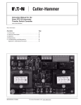
Instruction Booklet IB 70-8698 Effective December 2009 Instruction Manual for the Eaton RTC-100 Automatic Transfer Switch Controller Contents Description Page 1. Introduction. . . . . . . . . . . . . . . . . . . . . . . . . . . . . . . . . . . . . . . . . . . . . . . . . . . . . . . . . . . . . . . . . . . . . . . 2 2. Hardware Description. . . . . . . . . . . . . . . . . . . . . . . . . . . . . . . . . . . . . . . . . . . . . . . . . . . . . . . . . . . . . . . 5 3. Operation.. . . . . . . . . . . . . . . . . . . . . . . . . . . . . . . . . . . . . . . . . . . . . . . . . . . . . . . . . . . . . . . . . . . . . . . . 6 4. Programming. . . . . . . . . . . . . . . . . . . . . . . . . . . . . . . . . . . . . . . . . . . . . . . . . . . . . . . . . . . . . . . . . . . . . . 7 5. Maintenance, Troubleshooting, and Replacement. . . . . . . . . . . . . . . . . . . . . . . . . . . . . . . . . . . . . . . . . 18 Instruction Booklet IB 70-8698 Effective December 2009 Section 1: Introduction Caution All possible contingencies that may arise during installation, operation, or maintenance, and all details and variations of this equipment do no purport to be covered by these instructions. If further information is desired by the purchaser regarding a particular installation, operation, or maintenance of particular equipment, please contact an authorized Eaton Electrical Sales Representative or the installing contractor. 1.1 Preliminary Comments and Safety Precautions This technical document is intended to cover all aspects associated with the installation, application, operation, and maintenance of the Automatic Transfer Switch Controller (RTC-100). It is provided as a guide for authorized and qualified personnel only in the selection and application of the RTC-100 controller. Please refer to the specific WARNING and CAUTION in Section 1.1.2 before proceeding. If further information is required by the purchaser regarding a particular installation, application, or maintenance activity, please contact an authorized Eaton Electrical Sales Representative or the installing contractor. 1.1.1 Warranty and Liability Information No warranties, expressed or implied, including warranties of fitness for a particular purpose of merchantability, or warranties arising from course of dealing or usage of trade, are made regarding the information, recommendations and descriptions contained herein. In no event will Eaton be responsible to the purchaser or user in contract, in tort (including negligence), strict liability or otherwise for any special, indirect, incidental or consequential damage or loss whatsoever, including but not limited to damage or loss of use of equipment, plant or power system, cost of capital, loss of power, additional expenses in the use of existing power facilities, or claims against the purchaser or user by its customers resulting from the use of the information and descriptions contained herein. 1.1.2 Safety Precautions All safety codes, safety standards, and/or regulations must be strictly observed in the installation, operation, and maintenance of this device. warning THE WARNINGS AND CAUTIONS INCLUDED AS PART OF THE PROCEDURAL STEPS IN THIS DOCUMENT ARE FOR PERSONNEL SAFETY AND PROTECTION OF EQUIPMENT FROM DAMAGE. AN EXAMPLE OF A TYPICAL WARNING LABEL HEADING IS SHOWN ABOVE TO FAMILIARIZE PERSONNEL WITH THE STYLE OF PRESENTATION. THIS WILL HELP TO INSURE THAT PERSONNEL ARE ALERT TO WARNINGS, WHICH APPEAR THROUGHOUT THE DOCUMENT. IN ADDITION, WARNINGS AND CAUTIONS ARE ALL UPPER CASE AND BOLDFACE. 2 eaton corporation www.eaton.com Instruction Manual for the Eaton RTC-100 Automatic Transfer Switch Controller warning COMPLETELY READ AND UNDERSTAND THE MATERIAL PRESENTED IN THIS DOCUMENT BEFORE ATTEMPTING INSTALLATION, OPERATION, OR APPLICATION OF THE EQUIPMENT. IN ADDITION, ONLY QUALIFIED PERSONS SHOULD BE PERMITTED TO PERFORM ANY WORK ASSOCIATED WITH THIS EQUIPMENT. ANY WIRING INSTRUCTIONS PRESENTED IN THIS DOCUMENT MUST BE FOLLOWED PRECISELY. FAILURE TO DO SO COULD CAUSE PERMANENT EQUIPMENT DAMAGE. 1.2 General Information Automatic Transfer Switches (ATS) are used to protect critical electrical loads against loss of power. The load’s Utility power source is backed up by an alternate power source such as a Generator. An ATS is connected to both the Utility and Generator power sources and supplies the load with power from one of the two sources. In the event that power is lost from Utility, the ATS transfers the load to the Generator power source. Once Utility power is restored, the load is automatically transferred back to the Utility power source. An intelligence system initiates the transfer when the Utility power fails or falls below a preset voltage. An engine start is then initiated by the Generator and the ATS transfers to the Generator power source when sufficient Generator voltage is available. When the Utility power is restored, the ATS automatically transfers back to the Utility and the Generator will shut down after a time delay. ATSs automatically perform the transfer function, and include three basic elements: 1.Main contacts to connect and disconnect the load to and from the power sources. 2.Solenoids to make the transfer of the main contacts from source to source. 3.Intelligence/supervisory circuits to constantly monitor the condition of the power sources and thus provide the intelligence necessary for the switch and related circuit operation. This manual deals with the third basic element of the ATS, the required intelligence/supervisory circuits. The RTC-100 controller advances the application of intelligence, supervisory, and programming capabilities for ATS equipment. Instruction Manual for the Eaton RTC-100 Automatic Transfer Switch Controller Instruction Booklet IB 70-8698 Effective December 2009 1.3 Product Overview 1.4 Glossary The RTC-100 controller is a comprehensive, multi-function, microprocessor-based ATS controller. Designed to meet the needs of markets worldwide, the RTC-100 controller: With respect to their use within this document and as they relate to transfer switch and controller operation, the following terminology is defined. • Is a UL Listed Component • Complies with UL 1008/ CSA 22.2-178 • Complies with UL 991 humidity tests • Complies with IEC 61000-4-2, 61000-4-3, 61000-4-4, 61000-4-5, 61000-4-6, 61000-4-11, 61000-3-2, and 61000-3-3 Available A source is defined as “available” when it is within its undervoltage setpoint range. Connected • Complies with CISPR 11, Class B Connected is defined as when the input is shorted by an external contact or connection. • Complies with FCC Part 15, Class B Failed or Fails • Meets European Standards Conformance (CE mark) A source is defined as “failed” when it is outside of the applicable voltage ranges for the nominal voltage and for a time exceeding 0.5 seconds after the time delay emergency fail (TDEF) time delays expires. The RTC-100 controller provides an unmatched degree of programmed flexibility to address the needs of any system. It operates on 240 VAC, single-phase at 50 or 60 Hz. The RTC-100 controller monitors the condition of the line voltage of both the Utility and Generator power sources. The RTC-100 controller provides the necessary intelligence to insure that the transfer switch operates properly through a series of programmed sensing and timing functions. A standard RTC-100 controller will: • Monitor Utility and Generator power source voltages • Provide undervoltage protection of the Utility and Generator power sources • Permit easy customer set-up • Provide source status indications • Monitor and actively control two loads to ensure that the generator does not become overload by those loads. • • Actively control, with external RLC-100 load control boards, an infinite number of loads to ensure that overloading of the generator does not occur Provide start signals for all makes and models of generators (Utility sensing, 2 wire start, etc.) Failsafe Failsafe is a feature that prevents disconnection from the only available power source and also forces a transfer or re-transfer operation to the only available power source. Re-Transfer Re-transfer is defined as a change of the load connection from the Generator to the Utility. Utility Utility is the primary source (normal source, normal power source, or normal). Generator Generator is the secondary source (emergency source, emergency power source, emergency, standby, or backup source). Utility: Failed or Fails Utility is defined as “failed” when it is outside of its undervoltage setpoint range. Generator: Failed or Fails Generator is defined as “failed” when it is outside of its undervoltage setpoint range for a time exceeding 0.5 seconds after the TDEF time delay expires. Transfer Transfer is defined as a change of the load connection from the Utility to the Generator power source. Unconnected Unconnected is defined as when the input is not shorted by an external contact or connection. eaton corporation www.eaton.com 3 Instruction Manual for the Eaton RTC-100 Automatic Transfer Switch Controller Instruction Booklet IB 70-8698 Effective December 2009 1.5 Functions/Features The primary function of RTC-100 controller is to accurately monitor the Utility and Generator power sources and provide the necessary intelligence to operate the ATS in an appropriate and timely manner. In addition, the RTC-100 controller provides status information through on-board and remote indicators. 12. Power Source Annunciation This feature provides LEDs to indicate power source availability. 12C. Utility - Connected - EGSU Only The following is a list of the features of the RTC-100 controller. 1. Time Delay Normal to Emergency (TDNE) This feature provides a time delay when transferring from the Utility to the Generator power source. Timing begins when the Generator becomes available. It permits controlled transfer of the load circuit to the Generator. This feature provides a white LED that when lit, indicates the utility is connected. 12D. Generator - Connected - EGSU Only This feature provides a yellow LED that when lit, indicates the generator is connected. 12G. Utility - Available This feature provides a green LED that, when lit, indicates that the Utility is available. Jumper selectable at 20 or 50 seconds. Default is 20 seconds. 2. Time Delay on Engine Starting (TDES) This feature provides a time delay of the signal to initiate the engine/generator start cycle in order to override momentary power outages or voltage fluctuations of the utility source. 15N. Load Shed (Active) Fixed setting of six seconds (For 2 wire start only) Some generators have their own time delay start. 3. Time Delay Emergency to Normal (TDEN) This feature provides a time delay of the re-transfer operation to permit stabilization of Utility source. Timing begins when the Utility becomes available. If the Generator fails during timing, then re-transfer is delayed for up to 6 seconds to allow the generator to recover. 12H. Generator - Available Time Delay for Engine Cool-down (TDEC) This feature provides a time delay of the signal to initiate the engine/generator stop cycle after the re-transfer operation. This allows the engine/generator to cool down by running unloaded. Timing begins on completion of the re-transfer operation. Fixed setting of five minutes. 5. Generator Monitoring and Protection This feature provides monitoring and protection based on the Generator voltage setpoints. All feature 5 functions are failsafe operations. 5J. All Phase Undervoltage Protection Dropout: 168 Vac (70% of 240 Vac nominal) Pickup: 192 Vac (80% of 240 Vac nominal) 7. Time Delay Emergency Fail (TDEF) This feature provides a time delay that prevents a connected Generator source from being declared “failed” in order to override momentary generator fluctuations. If the Generator remains in the failed state then, after the TDEF timer expires, the transfer switch will proceed with the programmed sequence for re-transfer (if the utility source is available). Fixed setting of 6 Seconds 4 eaton corporation www.eaton.com Two sets of contacts are available and can be used to control large connected loads on the generator (i.e. air conditioners, hot tubs, etc.). The contacts are rated for 250 Vac, 5 amps. See section 4.1.4 for connection and operation. 23K. Generator Test Selectable - Off / 7 14 / 28 Day Interval This feature provides for automatic test operation of the generator. Available test cycles are 7, 14, or 28 days with a 15-minute duration. Programmable jumpers allow for selection of three test cycles: Fixed at 10 Seconds. 4. This feature provides a red LED that, when lit, indicates that the Generator is available. • Generator Start/Run Only (No Load); • Generator Test with Load Transfer; or • Disabled This is a “Failsafe” operation. 26. Utility - Monitoring and Protection This feature provides Utility monitoring and protection functions. If the Utility power source fails, then the RTC-100 will begin the sequence of operations necessary to transfer the load circuit to the Generator power source. All Feature 26 monitoring and protection functions are failsafe operations. 26D. Transfer to Generator This feature provides the capability for an external contact closure to initiate a transfer from Utility to Generator. After the Generator becomes available, TDNE will time out before the transfer to Generator takes place. Re-transfer will occur when the external contact is opened or under a failsafe condition. A connection point for the connection of an external contact is provided. 26P. All Phase Undervoltage Protection Dropout: 168 Vac (70% of 240 Vac nominal) Pickup: 192 Vac (80% of 240 Vac nominal) Instruction Manual for the Eaton RTC-100 Automatic Transfer Switch Controller Instruction Booklet IB 70-8698 Effective December 2009 Section 2: Hardware Description 2.4 Input/Output Connectors 2.1 General Located along the bottom of the RTC-100 are connectors J1, J2, and J3. J1 provides board control power and voltage monitoring for both the Utility and Generator sources. J2 and J3 provide load current information that is used for the active load control portion of the RTC-100. Along the side of the controller is connector J5. This connector is currently reserved for future use. Connectors J6, J7, J8 and J9 are located along the top of the controller. J6 is used for communication to the RLC-100 load control board. J7 provides a form C relay with dry contacts that is used for 2 wire engine start schemes. Connector J8 contains 2 contacts for the active load control portion of the controller. These contacts are discussed in section 4.1.4. J9 provides connection for the control input and the transfer switch control outputs. The purpose of this section is to familiarize the reader with the RTC-100 controller hardware, its nomenclature, and to list the unit’s specifications. 2.2 LED Indicators • Utility Available The green Utility Available LED illuminates if the utility power source meets the criteria to be considered “available”. That is, when it is within its undervoltage range. • Generator Available The red Generator Available LED illuminates if the generator power source meets the criteria to be considered “available”. That is, when it is within its undervoltage range. • • Utility Connected The White Utility connected LED illuminates when the power switching device is in a position such that when utility power is available, it is connected to the load. Generator Connected The Yellow Generator Connected LED illuminates when the power switching device is in a position such that when generator power is available, it is connected to the load. 2.3 Programming Jumpers The RTC-100 controller is programmable via five jumpers on the PC board. The jumper selections are discussed in Section 4, Programming. 2.5 Transfer to Generator Input The RTC-100 has a control input signal that will initiate a transfer from Utility to Generator. The input requires an external contact closure to the Transfer to Generator input (J9, pins 1 and 2). The Control Input “State” definitions are as follows. Connected - When the input is shorted by an external contact or connection. Unconnected - When the input is NOT shorted by an external contact or connection. The Transfer to Generator Input operations are defined as follows. When this input (J9, pins 1 and 2) is in the “Connected” state, the RTC-100 will initiate a transfer from Utility to Generator. The Generator will be automatically started. After the Generator becomes available, TDNE will time out before the transfer to Generator takes place. Re-transfer will occur when the external contact is opened or under a failsafe condition. 2.6 Output Connections The RTC-100 output connections are divided into two categories: • Customer Connections • Transfer Operation Connections. 2.6.1 Customer Connections Load Shed Contacts There are two sets of load shed contacts for customer use on connector J8, Load Shed Contacts #1 and Load Shed Contacts #2. Both sets of contacts are closed when the transfer switch is in the Utility position and both sets are automatically controlled when the transfer switch is in the Generator position. The output contacts are rated for 5 amps @ 250 VAC. The DC rating is 5 amps @ 30 VDC. See Section 4.1.4 for more information 2.6.2 Transfer Operation Connections The Utility Close and Gen Close outputs are factory wired to operate the transfer switch. The relay contacts for each output are rated for 5 amps @ 250 VAC. The DC rating is 5 amps @ 30 VDC. Utility Close Outputs This output is used to transfer to Utility. The Utility Close Outputs are on J9, pins 5 and 6. Generator Close Outputs Figure 1. RTC-100 Connectors and Programming Jumpers. This output is used to transfer to Generator. The Generator Close Outputs are on J9, pins 3 and 4. eaton corporation www.eaton.com 5 Instruction Manual for the Eaton RTC-100 Automatic Transfer Switch Controller Instruction Booklet IB 70-8698 Effective December 2009 Section 3: Operation 2.7 Specification Summary Table 1. RTC-100 Controller Specifications 3.1 General Input Voltage 240 Vac 50/60 Hz Voltage Measurements of Utility Generator Voltage Measurement Range 0 to 300 Vac RMS (50/60 Hz) Voltage Measurement Accuracy ± 6 Vac Undervoltage Dropout 70% of the Nominal 240 Vac Input Voltage This section specifically describes the operation and functional use of the RTC-100 controller. The practical use of and operation within each category will be discussed. In this section, it is assumed that prior sections of this manual were reviewed and that the operator has a basic understanding of the hardware. The RTC-100 controller provides for automatic transfer and re-transfer from source to source. It provides a summary of the RTC-100 controller intelligence and supervisory circuits that constantly monitor the condition of both the Utility and Generator power sources, thus providing the required intelligence for transfer operations. These circuits, for example, automatically initiate an immediate transfer of power when the power fails or the voltage level drops below a preset value and an alternate source of power is available. Undervoltage Pickup 80% of the Nominal 240 Vac Input Voltage Operating Temperature Range -20 to +70°C (-4 to +158°F) Storage Temperature Range -30 to +85°C (-22 to +185°F) Operating Humidity 0 to 95% Relative Humidity (Non-condensing) Operating Environment Resistant to Ammonia, Methane, Nitrogen, Hydrogen, and Hydrocarbons Utility Close and Gen Close Outputs 5 amps @ 250 Vac 5 amps @ 30 Vdc The RTC-100 controller operates on an input voltage of 240 Vac with selectable frequency settings of 50 or 60 Hz. Load Shed Contacts #1 and #2 5 amps @ 250 Vac 5 amps @ 30 Vdc1 The RTC-100 controller operates directly from the line sensing inputs of the Utility and Generator power sources. Applicable Testing UL Recognized Component UL 991 Humidity IEC 61000-4-2, 61000-4-3, 61000-4-4, 61000-4-5, 61000-4-6, 61000-4-11, 61000-3-2, 61000-3-3 CISPR 11, Class B FCC Part 15, Class B All voltage monitoring and measurements are true RMS measurements. Engine Start Contacts 5 amps @ 250 Vac 5 amps @ 30 Vdc 3.2 Operating Voltage and Measurements 3.3 Typical Transfer Operation A typical transfer request will begin with a Utility outage (Utility voltage falls below the 70% dropout level). When the Generator source meets the requirements to be considered available, the TDNE (Time Delay Normal to Emergency) timer will start timing. TDNE is jumper-programmable at either 20 seconds or 50 seconds. The 50 second setting may be used to allow for a longer warm-up period of the Generator. After TDNE times out, the Utility Close Outputs will open, the Gen Close Outputs will close, and the Load Shed Contacts will open. This will connect the load to the Generator source but any loads wired to the Load Shed Contacts will be disconnected. When the Utility becomes available (Utility voltage is above the 80% pickup level), the TDEN (Time Delay Emergency to Normal) timer will start timing. TDEN is a fixed delay of 10 seconds. After TDEN times out, the Gen Close Outputs will open, the Utility Close Outputs will close, and the Load Shed Contacts will be closed. This will connect all loads to the Utility source. If used with two wire start generators, a time delay engine start (TDES) will time down when utility voltage is below the 70% dropout. This time delay of 6 seconds allows the utility to return to normal before the generator is started. A time delay engine cool (TDEC) timer will time out after the transfer switch transfers load back to the utility This timer allows the generator to properly cool down before it is shut down. The timer allows the generator to run unloaded for 5 minutes. 6 eaton corporation www.eaton.com Instruction Manual for the Eaton RTC-100 Automatic Transfer Switch Controller Instruction Booklet IB 70-8698 Effective December 2009 Section 4: Programming 4.1.1 Load Control Jumper 4.1 Introduction Aside from the built in Active Load Control relays, the RTC-100 has the ability to extend the loads that it can actively control. An external load control board, RLC-100, can be utilized so that the RTC-100 can ensure that more loads have power available while at the same time ensuring that the generator does NOT become overloaded. This jumper controls the RTC-100’s ability to communicate with the RLC-100 load control board. If an RLC-100 load control board is used, the Load Control jumper MUST be placed in the “ON” state. See Figure 2. The RTC-100 controller is programmable via the five programming jumpers shown in Figure 2. The TDNE jumper enables the end-user to select a Time Delay Normal to Emergency setting of either 20 seconds or 50 seconds. TDNE is a time delay that starts timing when the Generator source becomes available either after the Utility becomes unavailable, after the Transfer to Generator input is activated, or the Gentest is programed. The 50 second setting may be used to allow for a longer warm-up period of the Generator. The FREQ jumper enables the end-user to program the RTC-100 for an operating frequency of either 50 or 60 hertz. Figure 2. Load Control Jumper – shown in the “OFF” position. eaton corporation www.eaton.com 7 Instruction Booklet IB 70-8698 Effective December 2009 Instruction Manual for the Eaton RTC-100 Automatic Transfer Switch Controller Table 2 is a summary of the Fixed and Jumper-selectable settings that are available in the RTC-100 Table 2. Fixed and Jumper-Selectable Settings Description Range Factory Default Fixed/Jumper Time Delay Normal to Emergency 20 or 50 seconds 20 Seconds Jumper-selectable Time Delay Emergency to Normal 10 seconds 10 Seconds Fixed Setting Time Delay Emergency Fail Timer 6 seconds 6 Seconds Fixed Setting Nominal Frequency 50 or 60 Hz 60 Hz Jumper-selectable Nominal Voltage 240 Vac 240 Vac Fixed Setting Utility Undervoltage Dropout 70% of 240 Vac Nominal Voltage 70% of 240 Vac Nominal Voltage Fixed Setting Generator Undervoltage Dropout 70% of 240 Vac Nominal Voltage 70% of 240 Vac Nominal Voltage Fixed Setting Utility Undervoltage Pickup 80% of 240 Vac Nominal Voltage 80% of 240 Vac Nominal Voltage Fixed Setting Generator Undervoltage Pickup 80% of 240 Vac Nominal Voltage 80% of 240 Vac Nominal Voltage Fixed Setting Time Delay Engine Start 6 Seconds 6 Seconds Fixed Setting Time Delay Engine Cool Down 5 Minutes 5 Minutes Load Control On/Off Off Jumper Selectable Gen Test Off/No Lead/Load No Load Jumper Selectable Gen Test 7 Day / 14 Day / 28 Day 7 Day Jumper Selectable Running kw 0 -99 kw 0 kw Potentiometer Starting kw 0 -99 kw 0 kw Potentiometer 4.1.2 Generator test (Plant Exercise) Jumpers The RTC-100 has the ability to perform a variety of generator tests. These tests can be completed both Automatically and/or manually. The jumpers allow the end user to select the Gen Test (see Figure 3) to the “OFF”, “NO LOAD”, or “LOAD” positions. This jumper is utilized when the test occurs manually or automatically. “OFF” - No test can be performed “NO LOAD” – An engine run ONLY test is performed. No load is transferred to the generator “LOAD” – A fully loaded generator test is completed. The ATS load is transferred to the generator. To perform a manual test the “GEN TEST” push button (See Figure 3) needs to be momentarily (NO LONGER THAN 2 SECONDS) pressed and released. The TDES (Time Delay Engine Start) timer will start before the generator is signaled to start. Once the generator has started and is producing rated voltage and frequency, the ATS will 1) If the jumper is set to “NO LOAD” the generator will run unloaded for 15 minutes or 2) if the jumper is set to the “LOAD” position the ATS will transfer the load to the generator and it will run loaded for 15 minutes before transferring the load back to the primary source and cooling down the generator. If at anytime during the test the “GEN TEST” button is pressed momentarily, the test will be aborted and the load will be transferred to the utility, if applicable, and the generator will be cooled and shut down. 8 eaton corporation www.eaton.com To perform an automatic test or Plant Exercise, the end user must determine which cycle (number of days) they would like the test to be run. The RTC-100 can run the exercise test every 7 calendar days, every 14 calendar days, or every 28 calendar days. Once this is chosen, the end user must perform a manual test on the time and day that they would like the test to occur. The “GEN TEST” switch must be depressed and held at least 5 seconds to program the time and day. Once the program is accepted, the “AVAILABLE” (RED and GREEN) LEDS on the board will flash 2 times to acknowledge the programming. The test will occur at that time and every subsequent period of time as programmed via the jumper. The test will be either a “LOAD” or “NO LOAD” test as set on by the jumper. If the LOAD jumper is set to “OFF”, no test can be performed. If the programmed test is to be cleared, the “GEN TEST” pushbutton can be depressed, again, for 5 seconds. The “AVAILABLE” (RED and GREEN) LEDs will flash FOUR times to acknowledge and clear the scheduled test. Some generators have built in testing and this function of the ATS may not be needed for those generators. Refer to the generator manufacturers instructions to see if the generator that you have has a built in test. If that is the case, the ATS testing may still be utilized but may not be necessary. Instruction Manual for the Eaton RTC-100 Automatic Transfer Switch Controller Instruction Booklet IB 70-8698 Effective December 2009 Jumpers shown in the “NO LOAD” test position and “7 DAY” position Figure 3. Generator Test (Plant Exercise) Jumpers and Generator Test Pushbutton. eaton corporation www.eaton.com 9 Instruction Booklet IB 70-8698 Effective December 2009 Instruction Manual for the Eaton RTC-100 Automatic Transfer Switch Controller 4.1.3 Reset Pushbutton If, during normal operation, a transfer (from utility to generator or from generator to utility) does NOT occur when it should, the “CONNECTED” LED’s (WHITE or YELLOW depending on which source should be connected) will flash (see Figure 4). Once the root cause of the failure to transfer has been corrected, the “RESET” pushbutton (see Figure 4) needs to be momentarily depressed (about 1 second) to reset the board. “Connected“ LED’s Figure 4. Reset Pushbutton and Connected LED’s. 10 eaton corporation www.eaton.com Instruction Manual for the Eaton RTC-100 Automatic Transfer Switch Controller Active Load Control. 4.1.4 RTC-100 on board Active Load Control 4.1.4.1 Connections There are 2 relays on the RTC-100 that can be used to actively control up to 2 loads while connected to the generator source. The connections are on J8 located on the top of the board. Pins 1 and 2 are the primary load and pins 3 and 4 are the secondary load (see Figure 5). The primary load has priority over the secondary load. Priority 2 Controlled Load Instruction Booklet IB 70-8698 Effective December 2009 The loads can be any load that provides a voltage to turn on (i.e. Air Conditioner, hot tub, etc). The relays will function with a voltage input as little as 12 Vac/Vdc up to 120 Vac/Vdc. Typical connection scheme is shown in Figures 6 and 7. The connections must be such that the grounded side of the voltage source MUST be connected to pins 2 or 4. The “HIGH” or “HOT” side of the voltage source MUST be connected to pins 1 or 3. If these connections are reversed, the load will cycle rapidly rather than remain on. Pin Locations: 4 3 2 1 Priority 1 Controlled Load Figure 5. Connections of Controlled Loads to J8 on RTC-100. eaton corporation www.eaton.com 11 Instruction Booklet IB 70-8698 Effective December 2009 Instruction Manual for the Eaton RTC-100 Automatic Transfer Switch Controller Note that the Ground/ Neutral Side of the Circuits MUST Be Connected to Pins 2 and 4 Figure 6. Typical Connections of Controlled Loads – Non Thermostatically Controlled. 12 eaton corporation www.eaton.com Instruction Manual for the Eaton RTC-100 Automatic Transfer Switch Controller Instruction Booklet IB 70-8698 Effective December 2009 Note that the Ground/Neutral Side of the Circuits MUST Be Connected to Pins 2 and 4 Figure 7. Typical Connections of Controlled Loads – Thermostatically Controlled. eaton corporation www.eaton.com 13 Instruction Booklet IB 70-8698 Effective December 2009 Instruction Manual for the Eaton RTC-100 Automatic Transfer Switch Controller 4.1.4.2 Adjustments – Required for Automatic Load Control There are 4 potentiometers on the RTC-100 that allow the user to program the board with required information about the generator (see Figure 8). Both the RUNNING watts and the STARTING watts are required for the RTC-100 active load control to function properly. It the STARTING watts are not know, then enter the RUNNING watts as the both the RUNNING and STARTING watts on the potentiometers. The RTC-100 utilizes this information to determine if enough KW is available to turn on the controlled loads when the generator is connected to those loads. Starting KW Input Here. Example for 20 KW Generator with 37 KW Starting Watts. The Left Hand Pot Would Be Set to 3 and the Right Hand Pot Would be Set to 7 Running KW input here. Example for 20 KW generator with 37 KW starting watts. The left hand pot would be set to 2 and the right hand pot would be set to 0 Figure 8. Generator KW Setting Potentiometers. 14 eaton corporation www.eaton.com Instruction Manual for the Eaton RTC-100 Automatic Transfer Switch Controller Instruction Booklet IB 70-8698 Effective December 2009 4.1.4.3 Operation While the ATS is connected to the Utility (Primary) source, the J8 contacts on the RTC-100 will close and monitor the loads that are being controlled. The starting KW that is measured when those loads are initiated is kept in memory on the controller. Each time each of those loads is initiated, that starting KW is recorded and the oldest starting KW that was in memory is now removed. When the controller is first energized, these memory locations are empty. The very first time a load is recorded, that value will populate the 4 memory locations for that load. This allows the RTC-100 to maintain a running average of the power required to start the 2 controlled loads that are connected to J8. This method allows for the controller to track the load throughout its life time and to actively adjust as the load power requirements change due to age, use, etc. This ensures that the loads are never applied to the generator if the generator does not have enough usable KW to start/run these loads. During a power outage, the generator is initiated and the customer load is connected to the generator power. The contacts on J8 are held in the OPEN position for the first 10 minutes that the load is connected to the generator. This allows the generator to stabilize. After the 10 minutes is over, the contacts will then begin to monitor if the controllable load is being called for. If it is, the controller will verify how much KW is currently available from the generator and compare that to the amount of KW that is programmed into the 4 potentiometers discussed above. If the amount of KW is less than the amount of KW available from the generator, the RTC-100 will now close the contact and allow the controlled load to be energized. In the event that the controlled load is an inductive load (i.e. Air conditioner, pool pump, etc) both the starting KW and running KW will be monitored and compared prior to energizing that load. If there is enough running KW but NOT enough starting KW available from the generator, the load will not be allowed to energize. Both the starting and running KW setting must be met before the load will be allowed to be started. If the load on contacts 3 and 4 of J8 are initialized and the load on contacts 1 and 2 of J8 are being called to start, and the KW is not sufficient to start the priority load, the secondary load will be turned OFF in order to allow the primary load to start. After the primary load is started, the secondary load will be restarted, if enough KW is available, after 10 minutes. If there is not enough KW to start the primary load, the secondary load will be restarted after 10 minutes and the controller will monitor the KW and attempt to restart the primary load once it senses the KW has changed. Anytime a transfer occurs to generator with both sources available (i.e. load test, utility load shed input, etc.), the loads will be turned off prior to the transfer to decrease the amount of inrush current placed on the generator during initial loading. The controlled loads will then be restarted after a 10 minute delay and verification of KW availability. Anytime there is a transfer from generator to utility, the controlled loads will remain ON during the transfer. At anytime while connected to the generator source and the controlled loads are energized, if the running KW of the generator is reached or surpassed, the controlled loads will be immediately turned OFF to ensure that the generator has enough KW to supply the uncontrolled loads. After a 10 minute delay, the RTC-100 will begin to monitor the J8 contacts to check if it can apply the controlled loads once again. This same scenario will occur if the voltage output of the generator drops below 80% of nominal will the controlled loads are connected. This is done to protect the uncontrolled loads from low voltage and also to prevent the generator from shutting down due to under voltage or under frequency. If, for any reason, a controlled load is changed or replaced, the RTC-100 memory for the loads may need to be reset (as the power requirements may differ). This can be done by pressing and holding the reset button for 5 seconds. If this is not accomplished, the memory can also easily be changed by energizing the load at least 4 times while the controllable load is connected to the utility source. eaton corporation www.eaton.com 15 Instruction Manual for the Eaton RTC-100 Automatic Transfer Switch Controller Instruction Booklet IB 70-8698 Effective December 2009 RTC-100 Active Load Control A Measure Load kW Are controlled load energize signal(s) present? N Y Is this the first measurement with Load on? N Y Is Relay #2 Closed? B Is the Generator powering the Load? N Is Current kW < 80% of Run kW? C Y Y Close relay #1 to allow load #1 to energize Figure 9. Active Load Control Flowchart. 16 Close relay #1 and relay #2 Y Close relay #2 to allow load #2 to energize C N eaton corporation www.eaton.com Is Relay #1 Closed? N N Is Active Load Control for RLC-100 enabled? Y Shed RLC-100 Load N Instruction Manual for the Eaton RTC-100 Automatic Transfer Switch Controller Instruction Booklet IB 70-8698 Effective December 2009 B C Measure Load kW N Is the Generator powering the Load? Y Time 3 Seconds Y Open Relays. Time 10 Min Is Load kW < 90% of Running kW? Open Relay (#1 has priority over #2) N Calculate kW for Load Is Run kW less than (Generator Max – Current kW)? N A Is Active Load Control –RLC100 enabled? Y Close relay #1 if called for Y Measure Load kW Is load kW < 90% of Running kW? N Shed Load Y C N Calculate kW for Load Close relay #2 if called for Measure Load kW Is load kW < 90% of Running kW? Y C N Calculate kW for Load A Figure 10. Active Load Control Flowchart. eaton corporation www.eaton.com 17 Instruction Manual for the Eaton RTC-100 Automatic Transfer Switch Controller Instruction Booklet IB 70-8698 Effective December 2009 Section 5: Maintenance, Troubleshooting, and Replacement 5.1 Maintenance and Care The RTC-100 is designed to be a self-contained and maintenancefree unit. The printed circuit board is conformally coated at the factory. The RTC-100 is intended for service by factory-trained personnel only. 5.2 RTC-100 Controller Troubleshooting The Troubleshooting Guide (Table 3) is intended for service personnel to identify whether a problem being observed is external or internal to the unit. For assistance with this determination, contact Eaton Electrical. If a problem is identified to be internal, the unit should be returned to the factory for replacement. Table 3. Troubleshooting Guide. Symptom Probable Cause Possible Solution(s) “Util Avail” and “Gen Avail” LEDs are not lit. Power is deficient or absent. Verify that power is connected at J1 – J4 and that it is within specifications. . RTC-100 is malfunctioning Replace the unit. Utility source or Generator source is not available when it should be. Voltage is not within setpoint values. Verify voltage with multimeter. Check the programmed setpoint values. 5.3 Level of Repair This manual is written with the assumption that only ATS troubleshooting will be performed. If the cause of malfunction is traced to an RTC-100, the unit should be replaced with a new unit. The malfunctioning unit should then be returned to Eaton Electrical for factory repairs. 18 eaton corporation www.eaton.com 5.4 RTC-100 Replacement warning HIGH VOLTAGES ARE PRESENT IN AND AROUND TRANSFER SWITCH EQUIPMENT. BEFORE ATTEMPTING TO REPLACE ANY COMPONENT, DISCONNECT THE LINE POWER FROM THE EQUIPMENT BEING SERVICED BY OPENING AND LOCKING OUT, IF POSSIBLE, THE NEXT HIGHEST DISCONNECT DEVICE. FAILURE TO FOLLOW THIS PROCEDURE COULD CAUSE SEVERE PERSONAL INJURY AND/OR DEATH. ALWAYS TURN THE UTILITY POWER OFF AND TURN THE GENERATOR CONTROL SELECTOR SWITCH TO THE “OFF” POSITION BEFORE ATTEMPTING TO REPLACE ANY COMPONENTS. Step 1: Turn the Generator Start select to “OFF” before attempting to replace the RTC-100 controller. Ensure all sources of power are removed. Step 2: Disconnect the J1, J2, J3, J4, J5, J6, J7, and J9 plugs from the controller Step 3: Disconnect the customer wires connected to J7, J8, and J9. Step 4: Remove the four (4) screws located at the corners of the controller that secure it to the power panel. Remove the controller. (The center support will have to be removed also.) Step 5: Align the new controller with the mounting holes. Secure the new controller board using the existing hardware. Tighten the screws. Step 6: Connect the J1, J2, J3, J4, J5, J6, J7, and J9 plugs to their original receptacles. Step 7: Reconnect the customer wires to J7, J8, and J9. Step 8: Reapply power to the transfer switch. Step 9: Place the generator control selector switch in the “AUTO” position after the controller has been replaced. (The Generator may start but will shut down within 5 minutes.) Test the system for proper functionality. Instruction Manual for the Eaton RTC-100 Automatic Transfer Switch Controller Instruction Booklet IB 70-8698 Effective December 2009 Notes: eaton corporation www.eaton.com 19 Instruction Booklet IB 70-8698 Instruction Manual for the Eaton RTC-100 Automatic Transfer Switch Controller This instruction booklet is published solely for information purposes and should not be considered all-inclusive. If further information is required, you should consult Eaton. Sale of product shown in this literature is subject to terms and conditions outlined in appropriate Eaton selling policies or other contractual agreement between the parties. This literature is not intended to and does not enlarge or add to any such contract. The sole source governing the rights and remedies of any purchaser of this equipment is the contract between the purchaser and Eaton. NO WARRANTIES, EXPRESSED OR IMPLIED, INCLUDING WARRANTIES OF FITNESS FOR A PARTICULAR PURPOSE OR MERCHANTABILITY, OR WARRANTIES ARISING FROM COURSE OF DEALING OR USAGE OF TRADE, ARE MADE REGARDING THE INFORMATION, RECOMMENDATIONS AND DESCRIPTIONS CONTAINED HEREIN. In no event will Eaton be responsible to the purchaser or user in contract, in tort (including negligence), strict liability or otherwise for any special, indirect, incidental or consequential damage or loss whatsoever, including but not limited to damage or loss of use of equipment, plant or power system, cost of capital, loss of power, additional expenses in the use of existing power facilities, or claims against the purchaser or user by its customers resulting from the use of the information, recommendations and description contained herein. Eaton Corporation Electrical Group 1000 Cherrington Parkway Moon Township, PA 15108 United States 877-ETN-CARE (877-386-2273) Eaton.com © 2009 Eaton Corporation All Rights Reserved Printed in USA Publication No. IB 70-8698 / TBG000263 December 2009 PowerChain Management is a registered trademark of Eaton Corporation. All other trademarks are property of their respective owners.