1
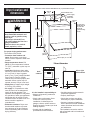
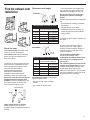
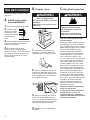
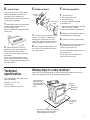
Installation Instructions
for models:
3RLER5437
3RLEQ8000
3RLEC8646
Electric Dryer
IMPORTANT:
Read and save these
instructions.
Introduction
Installer: Leave Installation Instructions with
homeowner.
Homeowner: Keep Installation Instructions
for future reference. For best
performance, install dryer according to
Installation Instructions. Failure to
complete installation as instructed
could void warranty.
Save Installation Instructions for local
inspector’s use.
Have questions about your dryer?
Call your dealer or local authorised service company.
When you call, you will need the dryer model number and serial
number. Both numbers are on the model/serial
rating plate located in the door well behind the
dryer door and on front of opening.
Record the numbers here for handy reference:
This appliance must be installed in accordance with the rules in force,
and used only in a sufficiently ventilated space. Consult instructions
before installation and use of this appliance.
Model No.
Serial No.
8528094
Before you start...
Your safety and the safety of
others are very important.
We have provided many important
safety messages in this manual
and on your appliance. Always
read and obey all safety
messages.
This is the safety alert
symbol.
This symbol alerts you to
potential hazards that can kill or
hurt you and others.
All safety messages will follow the
safety alert symbol and either the
word “DANGER” or “WARNING”.
These words mean:
DANGER
You can be killed or seriously
injured if you don’t immediately
follow instructions.
WARNING
You can be killed or seriously
injured if you don’t follow
instructions.
All safety messages will tell you
what the potential hazard is, tell you
how to reduce the chance of injury,
and tell you what can happen if the
instructions are not followed.
WARNING: If the information in this
manual is not followed exactly, a
fire or explosion may result causing
property damage, personal injury or
death.
Do Not store or use gasoline, or
other flammable vapours and
liquids in the vicinity of this or any
other appliance.
2
Tools and materials
needed for
installation...
• level
• gloves
• 20 to 30 cm (8" or l0") adjustable
wrench that opens to 2.5 cm (1")
• flat-blade screwdriver
• safety glasses
• 1/4" nut driver or socket wrench
• caulking gun and compound
• knife
• duct tape
• 1" hex-head socket wrench
• tin snips
Parts supplied for
installation...
Remove parts
package from dryer
drum. Check that all
parts were included.
Venting
Vent system
100 mm (4") metal exhaust vent must
be used.
WARNING
Fire Hazard
Use a heavy metal vent.
Do not use a plastic vent.
Do not use a metal foil vent.
Failure to follow these instructions
can result in death or fire.
Exhaust hood
Do Not use exhaust hoods with
magnetic latches.
Preferred
Acceptable
4 leveling legs
Parts needed for
installation...
Check local codes, and read electrical
and venting requirements before
purchasing parts.
10,2 cm
(4")
10,2 cm
(4")
6,4 cm
(2-1/2")
Floors sloped greater than 2.5 cm
(1 inch):
Require Extended Dryer Feet Kit, Part
No. 279810 available for purchase
from your dealer.
Dryer location and
dimensions
Dimensions shown with feet extended 2.5 cm (1") from bottom of dryer.
27.9 cm
(11")
terminal block cover
power supply
cord/cable
strain relief
WARNING
35.6 cm
(14")
The dryer door
extends 35.6 cm
(14") from the
front of the
dryer when fully
opened.
109.5 cm
(43-1/8")
Explosion Hazard
Keep flammable materials and
vapors, such as gasoline, away
from dryer.
Place dryer at least 45.7 cm
(18 inches) above the floor for a
garage installation.
Failure to do so can result in
death, explosion, or fire.
For proper drying performance:
The location must provide:
• Protection from weather and
water: Do not store or use dryer
where it will be exposed to water and
weather.
• Room temperature above 7°C
(45°F): If room temperature is below
7°C (45°F), automatic cycles may not
shut off.
• Level floor: Maximum slope under
entire dryer should not be more than
2.5 cm (I inch). If slope is greater
than 2.5 cm (1 inch), install Extended
Dryer Feet Kit, Part No. 2798l0.
Clothes may not tumble properly and
automatic sensor cycles may not
operate correctly if dryer is not level.
• Sturdy floor to support dryer weight
of 79.4 kg (175 pounds).
• Air supply: It is important to make
sure the room has an adequate air
supply for drying operation. The
operation of this appliance may affect
the operation of other gas appliances
which take their air supply for safe
combustion from the same room. If in
doubt consult the appliance
manufacturers.
• Exhaust to outdoors: Dryer must
be exhausted outdoors to prevent
large amounts of lint and moisture
from accumulating and to maintain
drying efficiency.
97.2 cm
(38-1/4")
74.3 cm
(29-1/4")
68.6 cm (27")
Exhaust dimensions
left or right
side exhaust
back
exhaust
10.2 cm
(4")
35.9 cm
(14-1/8")
It is the installer's responsibility to:
• Observe all governing codes and
ordinances.
• Check code requirements: Some
codes limit or do not permit
installation of clothes dryers in
garages, closets, mobile homes or
sleeping quarters. Contact your local
building inspector.
• Comply with the installation
specifications and dimensions.
10.8 cm
(4-1/4")
26 cm
(10-1/4")
• Consider spacing requirements for
companion appliances.
• Properly install dryer.
• Check that you have everything
necessary; for proper installation.
• Contact a competent installer to
ensure that the electrical installation
meets all national and local codes
and ordinances.
This installation must also conform
with all national and local codes and
ordinances.
3
Door clearance
57.8 cm
(22-3/4")
Exhaust requirements
9.8 cm (3-7/8")
WARNING
48.9 cm
(19-1/8")
57.8 cm
(22-3/4")
Location must be large enough to fully
open dryer door.
Electrical
requirements
Important: Observe all governing
codes and ordinances.
This dryer is supplied without an
electric cord and plug. It must be
connected by a competent electrician
to a single-phase electricity supply at
the voltage shown on the dataplate,
using a suitable fixed wiring
installation in accordance with local
and national wiring regulations. A
3-wire circular cord of minimum
conductor size 2.5mm 2 cross-section
area should be used. A 30A supply
fuse should be used, and a switch with
a minimum contact separation of 3mm
in both poles must be incorporated
into the fixed wiring for dryer
disconnection. A cord clamp bush is
provided on the dryer, and should be
tightened on completion of wiring. The
electrical mains terminals are located
behind the small rear access panel
(terminal block cover), and
connections should be made in
accordance with the terminal
markings. Remember to replace the
terminal access panel (terminal block
cover).
If codes permit and an additional
earth bond wire is used, it is
recommended that a competent
electrician determine that the earth
bond path is adequate.
4
Fire Hazard
Use a heavy metal vent.
Do not use a plastic vent.
Do not use a metal foil vent.
Failure to follow these instructions
can result in death or fire.
• Do Not use non-metal flexible vent,
metal vent that is smaller than
100 mm (4") in diameter or exhaust
hoods with magnetic latches.
• Do Not exhaust dryer into a chimney,
furnace, cold air vent, attic or crawl
space, or any other vent used for
venting.
• Do Not install flexible vent in
enclosed walls, ceilings or floors.
Important: Observe all governing
codes and ordinances.
Exhaust your dryer to the outside.
Moisture and lint indoors may cause:
• Lint to gather around the dryer where
it can be fuel for a fire.
• Moisture damage to woodwork,
furniture, paint, wallpaper, carpet etc.
• Housecleaning problems and health
problems.
10 cm (four-inch) diameter vent is
required for best performance.
Rigid or flexible metal exhaust vent
must be used. Do Not use a plastic or
a foil vent.
Rigid metal vent is recommended to
prevent crushing and kinking.
Flexible metal vent must be fully
extended and supported when the
dryer is in its final position. Remove
excess flexible vent to avoid sagging
and kinking that may result in reduced
air flow.
An exhaust hood should cap the
exhaust vent to prevent exhausted air
from returning to the dryer.
Exhaust outlet hood
must be at least 30.5
30.5 cm
(12") min.
cm (12 inches) from
the ground or any
object that may be in
the path of the exhaust
(such as flowers, rocks
or bushes, etc.).
If using an existing exhaust system
clean lint from entire length of system
and make sure exhaust hood is not
plugged with lint. Replace any plastic
or foil vent with rigid metal or flexible
metal vent.
Use 100 mm (4") clamps to seal all
joints. Do Not use screws to secure
vent.
Service check: Back pressure in any
exhaust system used must not exceed
15.2 mm (0.6 inches) in water column
measured with an incline manometer
at the point that exhaust vent connects
to dryer.
Plan the exhaust vent
installation
Determine vent length
Preferred —
10.2 cm
(4")
10.2 cm
(4")
When you have a 10.2 cm (4") hood
Maximum length of
10.2 cm (4") diameter metal vent
Number of
Rigid
90° elbows
0
15.8 m (52 ft.)
1
13.4 m (44 ft.)
2
11.0 m (36 ft.)
3
8.2 m (27 ft.)
4
6.1 m (20 ft.)
Flexible
(fully extended)
9.4 m (31 ft.)
7.9 m (26 ft.)
6.7 m (22 ft.)
6.1 m (20 ft.)
5.5 m (18 ft.)
Acceptable —
Route the vent
The exhaust outlet is located at the
centre of the rear of the dryer.
The exhaust vent can be routed up
down, left, right or straight out the
back of the dryer.
6.4 cm
(2-1/2")
When you have a 6.4 cm (2-1/2") hood
Maximum length of 6.4 cm
(2-1/2") diameter metal vent
The design of the flue system should
ensure that any condensate formed
when operating the appliance from
cold, is either retained and
subsequently evaporated or
discharged. Following these
installation instructions should
adequately meet this requirement.
Select the route that will provide the
straightest and most direct path
outdoors. Plan the installation to use
the fewest number of elbows and
turns. Avoid making 90° turns.
Number of
Rigid
90° elbows
0
13.4 m (44 ft.)
1
11.0 m (36 ft.)
2
8.5 m (28 ft.)
3
6.4 m (21 ft.)
4
4.3 m (14 ft.)
Flexible
(fully extended)
7.0 m (23 ft.)
5.5 m (18 ft.)
4.3 m (14 ft.)
3.7 m (12 ft.)
3.0 m (10 ft.)
1. See the exhaust vent length chart
that matches your type hood for the
maximum vent lengths you can use.
Do not use vent runs longer than
specified in exhaust vent length
charts.
Exhaust Systems longer than specified
will:
– Accumulate lint creating a potential
fire hazard.
– Shorten the life of the dryer.
– Reduce performance, resulting in
longer drying times and increased
energy usage.
2. Determine the number of elbows you
will need.
3. In the column listing the type of
metal vent you are using (rigid or
flexible), find the maximum length of
metal vent on the same line as the
number of elbows.
The maximum length using a
5.1 cm x 15.2 cm (2" x 6")
rectangular vent with 2 elbows and
a 6.4 cm (2-1/2") exhaust hood is
2.4 m (8 ft.).
For exhaust systems not covered by
exhaust vent length charts (such as
multiple unit hookups, plenums, and
power-assist fans), see Service
Manual. Part No. 603197. (To purchase
the Service Manual, contact your local
authorised service company)
The maximum length of the exhaust
system depends upon:
• the type of vent (rigid or flexible
metal).
• the number of elbows used.
exhaust air flow
better
good
When using elbows or making
turns, allow as much room as
possible. Bend vent gradually to avoid
kinking.
5
Now start installation
B. Prepare
If installing washer and dryer, install
dryer first.
A. Install vent system
(new installation)
1. Put on safety glasses and gloves.
2. Install exhaust
dryer
WARNING
Excessive Weight Hazard
Use two or more people to move and
install dryer.
Failure to do so can result in back or
other injury.
hood. Use caulking
compound to seal
exterior wall opening
around exhaust
hood.
3.
Connect exhaust vent to hood with
100 mm (4”) clamp. (Exhaust vent
MUST fit inside hood.)
4.
Run exhaust vent to dryer
location. Use the straightest path
possible. Avoid 90° turns. Use 100 mm
(4") clamps to secure vent pieces. Tin
snips may be needed to cut vent to
required length.
1.
Open dryer door and remove
drying rack, if included. Wipe drum
with damp cloth to remove any dust.
2.
Take two cardboard corners from
dryer carton and place them on floor
in back of dryer. Firmly grasp body of
dryer and gently lay it on its back on
the cardboard corners.
diamond
marking
3.
Start to screw legs into holes by
hand. Use an adjustable wrench or
2.5 cm (1") hex-head socket wrench to
finish turning legs until you reach the
ridge with the diamond marking.
4.
Stand dryer up on cardboard or
hardboard.
6
C. Electrical connection
WARNING
Fire Hazard
This dryer must be earthed.
Securely tighten all electrical
connections.
Failure to do so can result in
death, fire, or electrical shock.
This is a 3-wire appliance which
must be earthed.
For dryers supplied without an electric
cord and plug, it must be connected
by a competent electrician to a singlephase electricity supply at the voltage
shown on the dataplate, using a
suitable fixed wiring installation in
accordance with local and national
wiring regulations. A 3-wire circular
cord of minimum conductor size
2.5 mm 2 cross-section area should be
used. A 30A supply fuse should be
used, and a switch with a minimum
contact separation of 3 mm in both
poles must be incorporated into the
fixed wiring for dryer disconnection.
A cord clamp bush is provided on the
dryer, and should be tightened on
completion of wiring. The electrical
mains terminals are located behind
the small rear access panel (terminal
block cover), and connections should
be made in accordance with the
terminal markings. Remember to
replace the terminal access panel
(terminal block cover).
Important: Observe all governing
codes and ordinances.
If codes permit and an additional
earth bond wire is used, it is
recommended that a competent
electrician determine that the earth
bond path is adequate.
D. Level dryer
Dryer must be level to reduce noise
and assure proper performance.
Slide dryer onto cardboard or
hardboard before moving across floor
to prevent floor damage.
E. Exhaust dryer
F. Check operation
10.2 cm (4")
clamp
1. Check that you:
10.2 cm (4")
clamp
1.
Move dryer close to its permanent
location. Leave enough room to
connect exhaust vent.
Remove cardboard or hardboard from
under dryer.
with 100 mm (4") clamps.
✔ have all the tools you started with.
1. Connect vent to dryer outlet using
100 mm (4") clamp. If connecting to
existing vent, make sure the vent is
clean. The vent must fit over the dryer
outlet and inside the exhaust hood.
2. Check levelness of dryer by
placing a level on top of dryer, first
side to side, then front to back.
If dryer is not level, adjust dryer legs
up or down.
If legs are not long enough to level
dryer, order Extended Dryer Feet Kit,
Part No. 2798I0 (sold two legs per kit),
from your dealer.
Technical
specification
(see rating plate in door opening for
full model details)
220-240V ~ 50 Hz, 1ph
4575W, IPX4
Clothes capacity: 9.1 kg max.
✔ did not skip any steps.
✔ installed all parts.
✔ properly installed dryer legs.
✔ levelled dryer.
✔ have secured all exhaust vent joints
2.
Move dryer into final position. Do
not crush or kink exhaust vent. Make
sure dryer is level.
2.
Read the Use and Care Guide to
fully understand your new dryer.
3. Connect electricity power supply.
4.
Select a full heat cycle (not the air
cycle) and start dryer. After five
minutes, open dryer door.
You should feel heat inside dryer or on
the exhaust vent.
If dryer makes an unusual noise,
check that dryer is level.
Moving dryer to a new location?
Check with a licensed electrician to confirm that supply voltage at new home
matches voltage specified on the model/serial rating plate.
Shut off electrical
supply to dryer.
Disconnect power
supply cable from
dryer.
Tape top
to cabinet.
Tape door to
front panel.
Turn leveling
legs all the
way in.
Slide dryer onto cardboard or hardboard
before moving it across the floor to
prevent damaging floor covering.
7
Part No. 8528094
© 2000 Whirlpool Corporation
Benton Harbor, Michigan 49022, U.S.A.
Printed in U.S.A.