1
PA-MC-2T3+ Multi-Channel T3 Port
Adapter Installation and Configuration
Product Number: PA-MC-2T3+(=)
Platforms Supported: Cisco 7200 Series, Cisco 7301 Routers, Cisco 7304 PCI
Port Adapter Carrier Card in the Cisco 7304 Router, Cisco 7401ASR Routers,
and VIP in the Cisco 7000 Series and Cisco 7500 Series
Corporate Headquarters
Cisco Systems, Inc.
170 West Tasman Drive
San Jose, CA 95134-1706
USA
http://www.cisco.com
Tel: 408 526-4000
800 553-NETS (6387)
Fax: 408 526-4100
Text Part Number: OL-3526-05
THE SPECIFICATIONS AND INFORMATION REGARDING THE PRODUCTS IN THIS MANUAL ARE SUBJECT TO CHANGE WITHOUT NOTICE. ALL
STATEMENTS, INFORMATION, AND RECOMMENDATIONS IN THIS MANUAL ARE BELIEVED TO BE ACCURATE BUT ARE PRESENTED WITHOUT
WARRANTY OF ANY KIND, EXPRESS OR IMPLIED. USERS MUST TAKE FULL RESPONSIBILITY FOR THEIR APPLICATION OF ANY PRODUCTS.
THE SOFTWARE LICENSE AND LIMITED WARRANTY FOR THE ACCOMPANYING PRODUCT ARE SET FORTH IN THE INFORMATION PACKET THAT
SHIPPED WITH THE PRODUCT AND ARE INCORPORATED HEREIN BY THIS REFERENCE. IF YOU ARE UNABLE TO LOCATE THE SOFTWARE LICENSE
OR LIMITED WARRANTY, CONTACT YOUR CISCO REPRESENTATIVE FOR A COPY.
The following information is for FCC compliance of Class A devices: This equipment has been tested and found to comply with the limits for a Class A digital device, pursuant
to part 15 of the FCC rules. These limits are designed to provide reasonable protection against harmful interference when the equipment is operated in a commercial
environment. This equipment generates, uses, and can radiate radio-frequency energy and, if not installed and used in accordance with the instruction manual, may cause
harmful interference to radio communications. Operation of this equipment in a residential area is likely to cause harmful interference, in which case users will be required
to correct the interference at their own expense.
The following information is for FCC compliance of Class B devices: The equipment described in this manual generates and may radiate radio-frequency energy. If it is not
installed in accordance with Cisco’s installation instructions, it may cause interference with radio and television reception. This equipment has been tested and found to
comply with the limits for a Class B digital device in accordance with the specifications in part 15 of the FCC rules. These specifications are designed to provide reasonable
protection against such interference in a residential installation. However, there is no guarantee that interference will not occur in a particular installation.
Modifying the equipment without Cisco’s written authorization may result in the equipment no longer complying with FCC requirements for Class A or Class B digital
devices. In that event, your right to use the equipment may be limited by FCC regulations, and you may be required to correct any interference to radio or television
communications at your own expense.
You can determine whether your equipment is causing interference by turning it off. If the interference stops, it was probably caused by the Cisco equipment or one of its
peripheral devices. If the equipment causes interference to radio or television reception, try to correct the interference by using one or more of the following measures:
• Turn the television or radio antenna until the interference stops.
• Move the equipment to one side or the other of the television or radio.
• Move the equipment farther away from the television or radio.
• Plug the equipment into an outlet that is on a different circuit from the television or radio. (That is, make certain the equipment and the television or radio are on circuits
controlled by different circuit breakers or fuses.)
Modifications to this product not authorized by Cisco Systems, Inc. could void the FCC approval and negate your authority to operate the product.
The Cisco implementation of TCP header compression is an adaptation of a program developed by the University of California, Berkeley (UCB) as part of UCB’s public
domain version of the UNIX operating system. All rights reserved. Copyright © 1981, Regents of the University of California.
NOTWITHSTANDING ANY OTHER WARRANTY HEREIN, ALL DOCUMENT FILES AND SOFTWARE OF THESE SUPPLIERS ARE PROVIDED “AS IS” WITH
ALL FAULTS. CISCO AND THE ABOVE-NAMED SUPPLIERS DISCLAIM ALL WARRANTIES, EXPRESSED OR IMPLIED, INCLUDING, WITHOUT
LIMITATION, THOSE OF MERCHANTABILITY, FITNESS FOR A PARTICULAR PURPOSE AND NONINFRINGEMENT OR ARISING FROM A COURSE OF
DEALING, USAGE, OR TRADE PRACTICE.
IN NO EVENT SHALL CISCO OR ITS SUPPLIERS BE LIABLE FOR ANY INDIRECT, SPECIAL, CONSEQUENTIAL, OR INCIDENTAL DAMAGES, INCLUDING,
WITHOUT LIMITATION, LOST PROFITS OR LOSS OR DAMAGE TO DATA ARISING OUT OF THE USE OR INABILITY TO USE THIS MANUAL, EVEN IF CISCO
OR ITS SUPPLIERS HAVE BEEN ADVISED OF THE POSSIBILITY OF SUCH DAMAGES.
CCSP, CCVP, the Cisco Square Bridge logo, Follow Me Browsing, and StackWise are trademarks of Cisco Systems, Inc.; Changing the Way We Work, Live, Play, and Learn, and
iQuick Study are service marks of Cisco Systems, Inc.; and Access Registrar, Aironet, BPX, Catalyst, CCDA, CCDP, CCIE, CCIP, CCNA, CCNP, Cisco, the Cisco Certified
Internetwork Expert logo, Cisco IOS, Cisco Press, Cisco Systems, Cisco Systems Capital, the Cisco Systems logo, Cisco Unity, Enterprise/Solver, EtherChannel, EtherFast,
EtherSwitch, Fast Step, FormShare, GigaDrive, GigaStack, HomeLink, Internet Quotient, IOS, IP/TV, iQ Expertise, the iQ logo, iQ Net Readiness Scorecard, LightStream,
Linksys, MeetingPlace, MGX, the Networkers logo, Networking Academy, Network Registrar, Packet, PIX, Post-Routing, Pre-Routing, ProConnect, RateMUX, ScriptShare,
SlideCast, SMARTnet, The Fastest Way to Increase Your Internet Quotient, and TransPath are registered trademarks of Cisco Systems, Inc. and/or its affiliates in the United States
and certain other countries.
All other trademarks mentioned in this document or Website are the property of their respective owners. The use of the word partner does not imply a partnership relationship
between Cisco and any other company. (0601R)
PA-MC-2T3+ Multi-Channel T3 Port Adapter Installation and Configuration
Copyright © 1997–2003, Cisco Systems, Inc.
All rights reserved.
CONTENTS
Preface
vii
Document Revision History
Objectives
Organization
vii
viii
viii
Related Documentation
viii
Obtaining Documentation x
Cisco.com x
Product Documentation DVD
Ordering Documentation x
Documentation Feedback
x
xi
Cisco Product Security Overview xi
Reporting Security Problems in Cisco Products
Product Alerts and Field Notices
xi
xii
Obtaining Technical Assistance xii
Cisco Technical Support & Documentation Website
Submitting a Service Request xiii
Definitions of Service Request Severity xiv
Obtaining Additional Publications and Information
CHAPTER
1
Overview
xiv
1-1
Port Adapter Overview
1-1
Channelized T3 Overview
Unchannelized T3 Overview
1-2
1-2
T3 Specifications 1-3
Unchannelized Interoperability Guidelines for DSUs
LEDs
xii
1-3
1-4
Port Adapter Slot Locations on the Supported Platforms 1-5
Cisco 7200 Series Routers Slot Numbering 1-5
Cisco 7200 VXR Router with the Port Adapter Jacket Card Slot Numbering
Cisco 7301 Router Slot Numbering 1-7
Cisco 7304 PCI Port Adapter Carrier Card Slot Numbering 1-7
Cisco 7401ASR Router Slot Numbering 1-8
VIP Slot Numbering 1-9
1-6
PA-MC-2T3+ Multi-Channel T3 Port Adapter Installation and Configuration
OL-3526-05
iii
Contents
Identifying Interface Addresses 1-11
Cisco 7200 Series Routers Interface Addresses 1-12
Cisco 7301 Router Interface Addresses 1-12
Cisco 7304 PCI Port Adapter Carrier Card Interface Addresses
Cisco 7401ASR Router Interface Addresses 1-12
VIP Interface Addresses 1-13
CHAPTER
2
Preparing for Installation
2-1
Required Tools and Equipment
2-1
Software and Hardware Requirements
2-2
Checking Hardware and Software Compatibility
75-Ohm In-Line Coaxial Attenuator
CHAPTER
3
3-1
3-1
Online Insertion and Removal
Warnings and Cautions
2-9
2-9
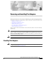
Removing and Installing Port Adapters
Handling Port Adapters
2-3
2-3
Safety Guidelines 2-3
Safety Warnings 2-3
Electrical Equipment Guidelines 2-8
Preventing Electrostatic Discharge Damage
FCC Class A Compliance
1-12
3-2
3-3
Port Adapter Removal and Installation 3-4
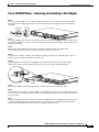
Cisco 7200 Series—Removing and Installing a Port Adapter 3-5
Cisco 7200 VXR Routers Port Adapter Jacket Card 3-6
Cisco 7301 Router—Removing and Installing a Port Adapter 3-8
Cisco 7304 PCI Port Adapter Carrier Card—Removing and Installing a Port Adapter
Cisco 7401ASR Router—Removing and Installing a Port Adapter 3-11
VIP—Removing and Installing a Port Adapter 3-12
3-9
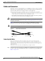
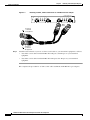
Cables and Connectors 3-13
Connecting the Cables 3-13
CHAPTER
4
Configuring Unchannelized mode for the Cisco PA-MC-2T3+
4-1
Using the EXEC Command Interpreter 4-1
Replacing an Existing Port Adapter 4-2
Shutting Down the T3 Controller 4-2
Configuring an Unchannelized T3 Link 4-3
Configuring the T3 Controller 4-4
PA-MC-2T3+ Multi-Channel T3 Port Adapter Installation and Configuration
iv
OL-3526-05
Contents
Selecting a T3 Controller 4-4
Setting Unchannelized Mode for the T3 Controller 4-5
Setting the Framing Type for the Serial Interface 4-6
Specifying the Cable Length for the Serial Interface 4-6
Setting the Clock Source for the Serial Interface 4-6
Configuring MDL Messages for the Serial Interface 4-7
Examples of MDL Message Configuration 4-8
Setting the DSU Mode for the Serial Interface 4-9
Setting the Bandwidth for the Serial Interface 4-10
Setting Scrambling for the Serial Interface 4-10
Configuring Loopback Mode for the Serial Interface 4-10
Configuring the T3 controller to Enable Loopbacks 4-11
Shutting Down the T3 Controller 4-12
Configuring a BER Test on the T3 Controller 4-12
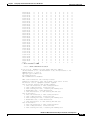
Sending a BER Test Pattern on the T3 Line 4-13
Viewing the Results of a BER Test 4-14
Terminating a BER Test 4-16
Performing a Basic Serial Interface Configuration 4-17
Checking the Configuration 4-18
Using show Commands to Verify the New Interface Status 4-18
Using the show version or show hardware Commands 4-19
Using the show diag Command 4-22
Using the show interfaces Command 4-24
Using the show controllers Command 4-27
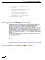
Using the ping Command to Verify Network Connectivity 4-30
Using loopback Commands to Troubleshoot Network Problems 4-30
CHAPTER
5
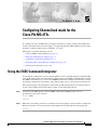
Configuring Channelized mode for the Cisco PA-MC-2T3+
5-1
Using the EXEC Command Interpreter 5-1
Replacing an Existing Port Adapter 5-2
Shutting Down the T3 Controller 5-2
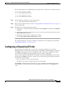
Configuring a Channelized T3 Link 5-3
Configuring the T3 Controller 5-4
Selecting a T3 Controller 5-4
Setting Channelized Mode for the T3 Controller 5-4
Setting the Framing Type for the T3 Controller 5-5
Specifying the Cable Length for the T3 Controller 5-6
Setting the Clock Source for the T3 Controller 5-6
Configuring MDL Messages for the T3 Controller 5-7
PA-MC-2T3+ Multi-Channel T3 Port Adapter Installation and Configuration
OL-3526-05
v
Contents
Examples of MDL Message Configuration 5-7
Configuring the Loopback Mode for the T3 Controller 5-8
Configuring the T3 controller to Enable Remote Loopback 5-9
Shutting Down the T3 Controller 5-9
Configuring T1 Lines 5-10
Creating a Logical Channel Group on a T1 Line 5-10
Removing a Logical Channel Group from a T1 Line 5-11
Setting the Framing Format on a T1 Line 5-11
Setting the Yellow Alarm Configuration for a T1 Line 5-12
Setting the Clock Source on a T1 Line 5-12
Setting the FDL Configuration for a T1 Line 5-13
Setting Loopbacks on a T1 Line 5-13
Configuring a BER Test on a T1 Line 5-16
Sending a BER Test Pattern on a T1 Line 5-17
Viewing the Results of a BER Test 5-18
Terminating a BER Test 5-23
Performing a Basic Serial Interface Configuration 5-24
Checking the Configuration 5-26
Using show Commands to Verify the New Interface Status 5-26
Using the show version or show hardware Commands 5-27
Using the show diag Command 5-31
Using the show interfaces Command 5-33
Using the show controllers Command 5-35
Displaying Remote Performance Reports 5-42
Using the ping Command to Verify Network Connectivity 5-44
PA-MC-2T3+ Multi-Channel T3 Port Adapter Installation and Configuration
vi
OL-3526-05
Preface
This preface describes the objectives and organization of this document and explains how to find
additional information on related products and services. This preface contains the following sections:
•
Document Revision History, page vii
•
Objectives, page viii
•
Organization, page viii
•
Related Documentation, page viii
•
Obtaining Documentation, page x
•
Documentation Feedback, page xi
•
Cisco Product Security Overview, page xi
•
Product Alerts and Field Notices, page xii
•
Obtaining Technical Assistance, page xii
•
Obtaining Additional Publications and Information, page xiv
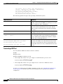
Document Revision History
The Document Revision History table below records technical changes to this document.
Document Version
Date
Change Summary
OL-3536-04
September, 2006
This version of the document adds support for the
NPE-G2 and the Port Adapter Jacket Card for
Cisco 7200 VXR routers.
OL-3536-05
May, 2006
This version of this document adds Port Adapter Jacket
Card installation information for the Cisco 7200 VXR
with NPE-G1 and NPE-G2.
PA-MC-2T3+ Multi-Channel T3 Port Adapter Installation and Configuration
OL-3526-05
vii
Preface
Objectives
Objectives
This document describes how to install and configure the PA-MC-2T3+ Multi-Channel T3 port adapter
PA-MC-2T3+ (=), hereafter referred to as the PA-MC-2T3+, which is used in the following platforms:
•
Cisco 7200 series routers, consisting of the two-slot Cisco 7202, four-slot Cisco 7204 and
Cisco 7204VXR, and the six-slot Cisco 7206 and Cisco 7206VXR
•
Cisco 7301 router
•
Cisco 7304 PCI Port Adapter Carrier Card in the Cisco 7304 router
•
Cisco 7401ASR router
•
VIP in Cisco 7500 series and Cisco 7000 series routers with the 7000 Series Route Switch Processor
(RSP7000) and 7000 Series Chassis Interface (RSP7000CI)
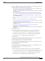
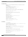
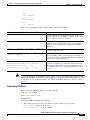
Organization
This document contains the following chapters:
Section
Title
Description
Chapter 1
Overview
Describes the PA-MC-2T3+ and its LED
displays, cables, and receptacles.
Chapter 2
Preparing for Installation
Describes safety considerations, tools required,
and procedures you should perform before the
actual installation.
Chapter 3
Removing and Installing
Port Adapters
Describes the procedures for installing and
removing PA-MC-2T3+ port adapters and cables
in the supported platforms.
Chapter 4
Configuring Unchannelized mode for Provides instructions for configuring the
the Cisco PA-MC-2T3+
channelized mode for the PA-MC-2T3+.
Chapter 5
Configuring Channelized mode for
the Cisco PA-MC-2T3+
Provides instructions for configuring the
unchannelized mode for the PA-MC-2T3+.
Related Documentation
Your router or switch and the Cisco IOS software running on it contain extensive features and
functionality, which are documented in the following resources:
•
Cisco IOS software:
For configuration information and support, refer to the modular configuration and modular
command reference publications in the Cisco IOS software configuration documentation set that
corresponds to the software release installed on your Cisco hardware.
Note
You can access Cisco IOS software configuration and hardware installation and maintenance
documentation on the World Wide Web at http://www.cisco.com,
http://www-china.cisco.com, or http://www-europe.cisco.com.
PA-MC-2T3+ Multi-Channel T3 Port Adapter Installation and Configuration
viii
OL-3526-05
Preface
Related Documentation
•
Your Cisco 7200 routers and the Cisco IOS software running on it contain extensive features and
functionality, which are documented in the following resources:
– Cisco 7200 Series Routers Documentation Roadmap for a list of all Cisco 7200 series routers
documentation and troubleshooting tools and information. See
http://www.cisco.com/en/US/products/hw/routers/ps341/products_documentation_roadmap09
186a00801c0915.html
– For port adapter hardware installation and memory configuration information, refer to the
Cisco 7200 Series Port Adapter Hardware Configuration Guidelines at the following URL:
http://www.cisco.com/en/US/products/hw/modules/ps2033/products_configuration_guide_bo
ok09186a00801056ef.html
– Regulatory Compliance and Safety Information for Cisco 7200 Series Routers at the following
URL:
http://www.cisco.com/univercd/cc/td/doc/product/core/7206/3419pnc6.htm
– Cisco 7200 Series Routers Port Adapter Documentation Roadmap for a list of all Cisco 7200
series routers-supported port adapter documentation. See
http://www.cisco.com/en/US/products/hw/routers/ps341/products_documentation_roadmap09
186a00801c0a32.html
– Cisco 7200 Series Routers Troubleshooting Documentation Roadmap for links to
troubleshooting tools, utilities, and Tech Notes. See
http://www.cisco.com/en/US/products/hw/routers/ps341/prod_troubleshooting_guide09186a0
0801c0f65.html
•
Cisco 7000 series routers:
For hardware installation and maintenance information, refer to the following publications:
– Cisco 7000 Hardware Installation and Maintenance that shipped with your router.
– Second-Generation Versatile Interface Processor (VIP2) Installation and Configuration
– Fourth-Generation Versatile Interface Processor (VIP4) Installation and Configuration
– Versatile Interface Processor (VIP6-80) Installation and Configuration
•
Cisco 7301 router:
For hardware installation and maintenance information, refer to the Cisco 7301 Installation and
Configuration Guide or the Cisco 7301 Router Quick Start Guide.
•
Cisco 7304 PCI Port Adapter Carrier Card in Cisco 7304 routers:
For hardware installation and maintenance information, refer to the Cisco 7304 PCI Port Adapter
Carrier Card Installation and Configuration Guide.
•
Cisco 7401ASR routers:
For hardware installation and maintenance information, refer to Cisco 7401ASR Installation and
Configuration Guide or the Cisco 7401ASR Quick Start Guide.
•
Cisco 7500 series routers:
For hardware installation and maintenance information, refer to the following publications:
– Cisco 7500 Installation and Configuration or the quick start guide that shipped with your router
– Second-Generation Versatile Interface Processor (VIP2) Installation and Configuration
– Fourth-Generation Versatile Interface Processor (VIP4) Installation and Configuration
– Versatile Interface Processor (VIP6-80) Installation and Configuration
PA-MC-2T3+ Multi-Channel T3 Port Adapter Installation and Configuration
OL-3526-05
ix
Preface
Obtaining Documentation
•
For international agency compliance, safety, and statutory information for WAN interfaces:
– Regulatory Compliance and Safety Information for the Cisco 7200 Series Routers
– Regulatory Compliance and Safety Information for the Cisco 7301 Router
– Regulatory Compliance and Safety Information for the Cisco 7304 Internet Router
– Regulatory Compliance and Safety Information for the Cisco 7401ASR Router
– Regulatory Compliance and Safety Information for the Cisco 7500 Series Routers
– Cisco Information Packet that shipped with your router or switch.
Obtaining Documentation
Cisco documentation and additional literature are available on Cisco.com. This section explains the
product documentation resources that Cisco offers.
Cisco.com
You can access the most current Cisco documentation at this URL:
http://www.cisco.com/techsupport
You can access the Cisco website at this URL:
http://www.cisco.com
You can access international Cisco websites at this URL:
http://www.cisco.com/public/countries_languages.shtml
Product Documentation DVD
The Product Documentation DVD is a library of technical product documentation on a portable medium.
The DVD enables you to access installation, configuration, and command guides for Cisco hardware and
software products. With the DVD, you have access to the HTML documentation and some of the
PDF files found on the Cisco website at this URL:
http://www.cisco.com/univercd/home/home.htm
The Product Documentation DVD is created monthly and is released in the middle of the month. DVDs
are available singly or by subscription. Registered Cisco.com users can order a Product Documentation
DVD (product number DOC-DOCDVD= or DOC-DOCDVD=SUB) from Cisco Marketplace at the
Product Documentation Store at this URL:
http://www.cisco.com/go/marketplace/docstore
Ordering Documentation
You must be a registered Cisco.com user to access Cisco Marketplace. Registered users may order
Cisco documentation at the Product Documentation Store at this URL:
http://www.cisco.com/go/marketplace/docstore
PA-MC-2T3+ Multi-Channel T3 Port Adapter Installation and Configuration
x
OL-3526-05
Preface
Documentation Feedback
If you do not have a user ID or password, you can register at this URL:
http://tools.cisco.com/RPF/register/register.do
Documentation Feedback
You can provide feedback about Cisco technical documentation on the Cisco Technical Support &
Documentation site area by entering your comments in the feedback form available in every online
document.
Cisco Product Security Overview
Cisco provides a free online Security Vulnerability Policy portal at this URL:
http://www.cisco.com/en/US/products/products_security_vulnerability_policy.html
From this site, you will find information about how to do the following:
•
Report security vulnerabilities in Cisco products
•
Obtain assistance with security incidents that involve Cisco products
•
Register to receive security information from Cisco
A current list of security advisories, security notices, and security responses for Cisco products is
available at this URL:
http://www.cisco.com/go/psirt
To see security advisories, security notices, and security responses as they are updated in real time, you
can subscribe to the Product Security Incident Response Team Really Simple Syndication (PSIRT RSS)
feed. Information about how to subscribe to the PSIRT RSS feed is found at this URL:
http://www.cisco.com/en/US/products/products_psirt_rss_feed.html
Reporting Security Problems in Cisco Products
Cisco is committed to delivering secure products. We test our products internally before we release them,
and we strive to correct all vulnerabilities quickly. If you think that you have identified a vulnerability
in a Cisco product, contact PSIRT:
•
For emergencies only — security-alert@cisco.com
An emergency is either a condition in which a system is under active attack or a condition for which
a severe and urgent security vulnerability should be reported. All other conditions are considered
nonemergencies.
•
For nonemergencies — psirt@cisco.com
In an emergency, you can also reach PSIRT by telephone:
•
1 877 228-7302
•
1 408 525-6532
PA-MC-2T3+ Multi-Channel T3 Port Adapter Installation and Configuration
OL-3526-05
xi
Preface
Product Alerts and Field Notices
Tip
We encourage you to use Pretty Good Privacy (PGP) or a compatible product (for example, GnuPG) to
encrypt any sensitive information that you send to Cisco. PSIRT can work with information that has been
encrypted with PGP versions 2.x through 9.x.
Never use a revoked encryption key or an expired encryption key. The correct public key to use in your
correspondence with PSIRT is the one linked in the Contact Summary section of the Security
Vulnerability Policy page at this URL:
http://www.cisco.com/en/US/products/products_security_vulnerability_policy.html
The link on this page has the current PGP key ID in use.
If you do not have or use PGP, contact PSIRT to find other means of encrypting the data before sending
any sensitive material.
Product Alerts and Field Notices
Modifications to or updates about Cisco products are announced in Cisco Product Alerts and Cisco Field
Notices. You can receive Cisco Product Alerts and Cisco Field Notices by using the Product Alert Tool
on Cisco.com. This tool enables you to create a profile and choose those products for which you want to
receive information.
To access the Product Alert Tool, you must be a registered Cisco.com user. (To register as a Cisco.com
user, go to this URL: http://tools.cisco.com/RPF/register/register.do) Registered users can access the
tool at this URL: http://tools.cisco.com/Support/PAT/do/ViewMyProfiles.do?local=en
Obtaining Technical Assistance
Cisco Technical Support provides 24-hour-a-day award-winning technical assistance. The
Cisco Technical Support & Documentation website on Cisco.com features extensive online support
resources. In addition, if you have a valid Cisco service contract, Cisco Technical Assistance Center
(TAC) engineers provide telephone support. If you do not have a valid Cisco service contract, contact
your reseller.
Cisco Technical Support & Documentation Website
The Cisco Technical Support & Documentation website provides online documents and tools for
troubleshooting and resolving technical issues with Cisco products and technologies. The website is
available 24 hours a day at this URL:
http://www.cisco.com/techsupport
Access to all tools on the Cisco Technical Support & Documentation website requires a Cisco.com
user ID and password. If you have a valid service contract but do not have a user ID or password, you
can register at this URL:
http://tools.cisco.com/RPF/register/register.do
PA-MC-2T3+ Multi-Channel T3 Port Adapter Installation and Configuration
xii
OL-3526-05
Preface
Obtaining Technical Assistance
Note
Use the Cisco Product Identification Tool to locate your product serial number before submitting a
request for service online or by phone. You can access this tool from the Cisco Technical Support &
Documentation website by clicking the Tools & Resources link, clicking the All Tools (A-Z) tab, and
then choosing Cisco Product Identification Tool from the alphabetical list. This tool offers three search
options: by product ID or model name; by tree view; or, for certain products, by copying and pasting
show command output. Search results show an illustration of your product with the serial number label
location highlighted. Locate the serial number label on your product and record the information before
placing a service call.
Tip
Displaying and Searching on Cisco.com
If you suspect that the browser is not refreshing a web page, force the browser to update the web page
by holding down the Ctrl key while pressing F5.
To find technical information, narrow your search to look in technical documentation, not the entire
Cisco.com website. On the Cisco.com home page, click the Advanced Search link under the Search box
and then click the Technical Support & Documentation.radio button.
To provide feedback about the Cisco.com website or a particular technical document, click Contacts &
Feedback at the top of any Cisco.com web page.
Submitting a Service Request
Using the online TAC Service Request Tool is the fastest way to open S3 and S4 service requests. (S3 and
S4 service requests are those in which your network is minimally impaired or for which you require
product information.) After you describe your situation, the TAC Service Request Tool provides
recommended solutions. If your issue is not resolved using the recommended resources, your service
request is assigned to a Cisco engineer. The TAC Service Request Tool is located at this URL:
http://www.cisco.com/techsupport/servicerequest
For S1 or S2 service requests, or if you do not have Internet access, contact the Cisco TAC by telephone.
(S1 or S2 service requests are those in which your production network is down or severely degraded.)
Cisco engineers are assigned immediately to S1 and S2 service requests to help keep your business
operations running smoothly.
To open a service request by telephone, use one of the following numbers:
Asia-Pacific: +61 2 8446 7411
Australia: 1 800 805 227
EMEA: +32 2 704 55 55
USA: 1 800 553 2447
For a complete list of Cisco TAC contacts, go to this URL:
http://www.cisco.com/techsupport/contacts
PA-MC-2T3+ Multi-Channel T3 Port Adapter Installation and Configuration
OL-3526-05
xiii
Preface
Obtaining Additional Publications and Information
Definitions of Service Request Severity
To ensure that all service requests are reported in a standard format, Cisco has established severity
definitions.
Severity 1 (S1)—An existing network is “down” or there is a critical impact to your business operations.
You and Cisco will commit all necessary resources around the clock to resolve the situation.
Severity 2 (S2)—Operation of an existing network is severely degraded, or significant aspects of your
business operations are negatively affected by inadequate performance of Cisco products. You and
Cisco will commit full-time resources during normal business hours to resolve the situation.
Severity 3 (S3)—Operational performance of the network is impaired while most business operations
remain functional. You and Cisco will commit resources during normal business hours to restore service
to satisfactory levels.
Severity 4 (S4)—You require information or assistance with Cisco product capabilities, installation, or
configuration. There is little or no effect on your business operations.
Obtaining Additional Publications and Information
Information about Cisco products, technologies, and network solutions is available from various online
and printed sources.
•
The Cisco Product Quick Reference Guide is a handy, compact reference tool that includes brief
product overviews, key features, sample part numbers, and abbreviated technical specifications for
many Cisco products that are sold through channel partners. It is updated twice a year and includes
the latest Cisco channel product offerings. To order and find out more about the Cisco Product Quick
Reference Guide, go to this URL:
http://www.cisco.com/go/guide
•
Cisco Marketplace provides a variety of Cisco books, reference guides, documentation, and logo
merchandise. Visit Cisco Marketplace, the company store, at this URL:
http://www.cisco.com/go/marketplace/
•
Cisco Press publishes a wide range of general networking, training, and certification titles. Both new
and experienced users will benefit from these publications. For current Cisco Press titles and other
information, go to Cisco Press at this URL:
http://www.ciscopress.com
•
Packet magazine is the magazine for Cisco networking professionals. Each quarter, Packet delivers
coverage of the latest industry trends, technology breakthroughs, and Cisco products and solutions,
as well as network deployment and troubleshooting tips, configuration examples, customer case
studies, certification and training information, and links to scores of in-depth online resources. You
can subscribe to Packet magazine at this URL:
http://www.cisco.com/packet
•
Internet Protocol Journal is a quarterly journal published by Cisco Systems for engineering
professionals involved in designing, developing, and operating public and private internets and
intranets. You can access the Internet Protocol Journal at this URL:
http://www.cisco.com/ipj
PA-MC-2T3+ Multi-Channel T3 Port Adapter Installation and Configuration
xiv
OL-3526-05
Preface
Obtaining Additional Publications and Information
•
Networking products offered by Cisco Systems, as well as customer support services, can be
obtained at this URL:
http://www.cisco.com/en/US/products/index.html
•
Networking Professionals Connection is an interactive website where networking professionals
share questions, suggestions, and information about networking products and technologies with
Cisco experts and other networking professionals. Join a discussion at this URL:
http://www.cisco.com/discuss/networking
•
“What’s New in Cisco Documentation” is an online publication that provides information about the
latest documentation releases for Cisco products. Updated monthly, this online publication is
organized by product category to direct you quickly to the documentation for your products. You
can view the latest release of “What’s New in Cisco Documentation” at this URL:
http://www.cisco.com/univercd/cc/td/doc/abtunicd/136957.htm
•
World-class networking training is available from Cisco. You can view current offerings at
this URL:
http://www.cisco.com/en/US/learning/index.html
PA-MC-2T3+ Multi-Channel T3 Port Adapter Installation and Configuration
OL-3526-05
xv
Preface
Obtaining Additional Publications and Information
PA-MC-2T3+ Multi-Channel T3 Port Adapter Installation and Configuration
xvi
OL-3526-05
C H A P T E R
1
Overview
This chapter describes the Cisco PA-MC-2T3+ port adapter and contains the following sections:
•
Port Adapter Overview, page 1-1
•
Channelized T3 Overview, page 1-2
•
Unchannelized T3 Overview, page 1-2
•
T3 Specifications, page 1-3
•
LEDs, page 1-4
•
Port Adapter Slot Locations on the Supported Platforms, page 1-5
•
Identifying Interface Addresses, page 1-11
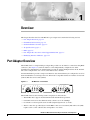
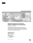
Port Adapter Overview
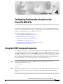
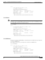
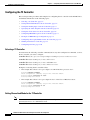
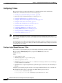
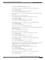
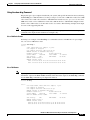
The PA-MC-2T3+ is a single-width port adapter that provides two T3 interface connections using BNC
connectors. (See Figure 1-1.) Each T3 interface can be independently configured to be either
channelized or unchannelized. A channelized T3 provides 28 T1 lines multiplexed into the T3. Each T1
line can be configured into one or more serial interface data channels.
An unchannelized T3 provides a single serial interface data channel that may be configured to use all of
the T3 bandwidth or a fractional portion of it. This mode is compatible with several vendors of fractional
(subrate) DS3 data service units (DSUs).
PA-MC-2T3+—Front Panel
FE
RF
AI
S
LO
S
1
AL
RM
AI
S
LO
S
AL
RM
0
22648
RX
OO
F
TX
LO
OP
FE
RF
RX
OO
F
LO
OP
MULTI-CHANNEL 2T3+
TX
EN
AB
LE
D
Figure 1-1
The PA-MC-2T3+ has the following features and physical characteristics:
•
The PA-MC-2T3+ supports both channelized and unchannelized operations.
•
It transmits and receives data bidirectionally at the T3 rate of 44.736 Mbps.
•
It conforms to relevant specifications for DS3 (Digital Signal Level 3) circuits.
•
The T3 connection, provided by two female BNC connectors for transmit (TX) and receive (RX),
requires 734A coaxial cable that has an impedance of 75 ohms.
PA-MC-2T3+ Multi-Channel T3 Port Adapter Installation and Configuration
OL-3526-05
1-1
Chapter 1
Overview
Channelized T3 Overview
•
It supports RFC 1406 and RFC 1407 (CISCO-RFC-1407-CAPABILITY.my). For RFC 1406, Cisco
supports all tables except the FarEnd table. For RFC 1407, Cisco does not support FarEnd or
Fractional tables. (For information on accessing Cisco MIB files, refer to the Cisco MIB User Quick
Reference publication.)
•
PA-MC-2T3+ microcode is loaded at initialization and is bundled into IOS software.
Channelized T3 Overview
In the channelized mode of operation, a PA-MC-2T3+ T3 link is channelized into 28 DS1 data lines in
an industry standard multiplexing format.
Each of the T1 lines contains 24 timeslots of 64 or 56 kbps each. The T1 lines can support one or more
user data channels which appear to the system as serial interfaces. Each serial interface is assigned one
or more of the timeslots giving the serial interface a bandwidth of n x 56 kbps or n x 64 kbps, where n
is the number of timeslots assigned. Any unused timeslots of the T1 are filled with an idle channel
pattern.
The following restrictions apply: A timeslot can only be used by one serial interface. A serial interface
cannot use timeslots from more than one T1 line. Each T3 can have a maximum of 128 serial interfaces.
Unused serial interfaces on one T3 cannot be used by the other T3.
The PA-MC-2T3+ supports Cisco High-Level Data Link Control (HDLC), Frame Relay, PPP, and
Switched Multimegabit Data Service (SMDS) Data Exchange Interface (DXI) encapsulations over each
serial interface.
Note
T1 lines on the PA-MC-2T3+ are numbered 1–28, rather than the more traditional zero-based scheme
(0–27) used with other Cisco products. This is to ensure consistency with telco numbering schemes for
T1 lines within channelized T3 equipment.
Note
The PA-MC-2T3+ does not support the aggregation of multiple T1 lines (called inverse multiplexing or
bonding) in hardware for higher bandwidth data rates. MLPPP may be used for this purpose in software.
The T3 section of the PA-MC-2T3+ supports the maintenance data-link channel (MDL) when using c-bit
parity framing as well as local and network loopbacks. The T1 section of the PA-MC-2T3+ supports
facilities data link (FDL) in Extended Superframe (ESF) framing, as well as various loopbacks. Bit error
rate testing (BERT) is supported on each of the T1 lines although a test may not be active on more than
one T1 at a time. BER testing may be done over a framed or unframed T1 signal.
Unchannelized T3 Overview
In the unchannelized mode of operation, a T3 link provides a single high speed user data channel, rather
than being multiplexed into 28 T1 lines. The data channel appears to the system as a serial interface that
may be configured to use the full T3 bandwidth or a smaller portion of the T3 bandwidth. No industry
standard exists for subdividing the T3 bandwidth but the PA-MC-2T3+ is compatible with the
proprietary formats of five vendors of T3 DSUs, when used at the far end of the T3 link.
PA-MC-2T3+ Multi-Channel T3 Port Adapter Installation and Configuration
1-2
OL-3526-05
Chapter 1
Overview
T3 Specifications
In unchannelized T3 mode, the T3 section supports the maintenance data link (MDL) channel when
using c-bit parity framing as well as local and network loopbacks. Bit error rate testing (BERT) is
supported on the T3 link. The PA-MC-2T3+ supports Cisco High-Level Data Link Control (HDLC),
Frame Relay, PPP, and Switched Multimegabit Data Service (SMDS) Data Exchange Interface (DXI)
encapsulations over the serial interface.
T3 Specifications
The PA-MC-2T3+ T3 port is designed to receive and transmit at the DSX-3 level while driving and
receiving from 75-ohm coaxial cables (ATT 734A or equivalent quality coax). The T3 port connects
directly to any equipment with DSX-3 level BNC connectors.
Table 1-1 lists the specifications that the T3 front end is designed to meet.
Table 1-1
Note
Specifications for the T3 Front End
Parameter
Specification
Line rate
44.736 Mbps (±20 ppm)
Line code
B3ZS (bipolar with three-zero substitution)
Impedance
75 ohms
Output Pulse shape
ANSI T1.102, pulse amplitude is between 0.36 and 0.85 volts peak
Input signal
0.035-1.1 volts peak
Output signal
Able to drive 450 feet (135 meters) of 75-ohm coaxial cable (734A
or equivalent) and meet pulse shape template
The coax shield side of the T3 BNC connectors is connected to the router chassis ground.
Unchannelized Interoperability Guidelines for DSUs
The PA-MC-2T3+ supports several types of integrated data service units (DSUs). Table 1-2 lists the
feature compatibilities of PA-MC-2T3+ DSUs.
Table 1-2
Feature Compatibilities of PA-MC-2T3+ DSUs
Vendor
DSU Model
Full Rate
Support
Scrambling
Support
Subrate
Support
Digital Link
DL3100
Yes
Yes
Yes
ADC Kentrox
T3/E3 IDSU
Yes
Yes
Yes
Larscom
Access T45
Yes
Yes
Yes
Adtran
T3SU 300
Yes
Yes
Yes
Verilink
HDM2182
Yes
Yes
Yes
PA-MC-2T3+ Multi-Channel T3 Port Adapter Installation and Configuration
OL-3526-05
1-3
Chapter 1
Overview
LEDs
Note
The PA-MC-2T3+ does not support configuration of the far end T3 DSU using the maintenance data link
channel in c-bit parity framing.
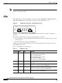
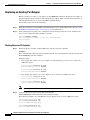
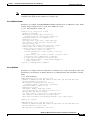
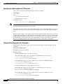
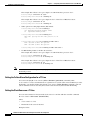
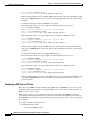
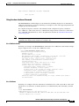
LEDs
The PA-MC-2T3+ has seven status LEDs located on its faceplate: ENABLED, ALARM, LOOP, LOS,
OOF, AIS, and FERF. (These status LEDs are shown from left to right in Figure 1-2.)
AI
S
S
LO
AL
RM
0
22649
FE
RX
F
P
OO
LO
O
TX
EN
AB
RF
PA-MC-2T3+ Status LEDs—Partial Horizontal View
LE
D
Figure 1-2
After system initialization, the green ENABLED LED indicates that the port adapter is enabled for
operation.
The following conditions must be met before the PA-MC-2T3+ is enabled:
•
The port adapter is correctly installed in the VIP motherboard or Cisco 7200 series router slot and
is receiving power.
•
The system software recognizes the PA-MC-2T3+
If either one of the preceding conditions is not met, or if the initialization fails for other reasons, the
enabled LED does not go on.
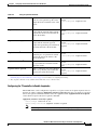
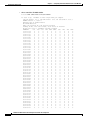
Table 1-3 lists LED colors and indications.
Table 1-3
PA-MC-2T3+ LEDs
LED Label Color
State
Meaning
ALARM
Yellow
On
T1 loss of frame (LOF)
T1 alarm indication signal (AIS)
T3 loss of signal (LOS)
T3 alarm indication signal (AIS)
T3 out of frame (OOF)
T3 far-end received failure (FERF)
LOOP
Yellow
On
T1 line or T3 link in a loopback state; not enabled for normal
data traffic
LOS
Yellow
On
T3 link loss of the received signal.
Operates in conjunction with ALARM LED.
AIS
Yellow
On
T3 link receives alarm indication signal.
Operates in conjunction with the ALARM LED.
OOF
Yellow
On
Indicates a DS3 out-of-frame (OOF) condition. Operates in
conjunction with the ALARM LED.
PA-MC-2T3+ Multi-Channel T3 Port Adapter Installation and Configuration
1-4
OL-3526-05
Chapter 1
Overview
Port Adapter Slot Locations on the Supported Platforms
Table 1-3
PA-MC-2T3+ LEDs (continued)
LED Label Color
State
Meaning
FERF
On
Receiver detects a far end receive failure (FERF) signal from
the far end. Operates in conjunction with the ALARM LED.
Yellow
In addition to the interface status information provided by the LEDs, you can also retrieve detailed
interface status information either through the router console port or through Telnet or Simple Network
Management Protocol (SNMP).
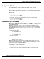
Port Adapter Slot Locations on the Supported Platforms
This section discusses port adapter slot locations on the supported platforms. The illustrations that
follow summarize slot location conventions on each platform:
•
Cisco 7200 Series Routers Slot Numbering, page 1-5
•
•
Cisco 7301 Router Slot Numbering, page 1-7
•
Cisco 7304 PCI Port Adapter Carrier Card Slot Numbering, page 1-7
•
Cisco 7401ASR Router Slot Numbering, page 1-8
•
VIP Slot Numbering, page 1-9
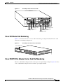
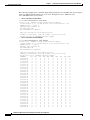
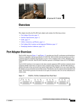
Cisco 7200 Series Routers Slot Numbering
Figure 1-4 shows a Cisco 7206 with port adapters installed. In the Cisco 7206 (including the Cisco 7206
and Cisco 7206VXR as router shelves in a Cisco AS5800 Universal Access Server), port adapter slot 1
is in the lower left position, and port adapter slot 6 is in the upper right position. (The Cisco 7202 and
Cisco 7204 are not shown; however, the PA-MC-2T3+ can be installed in any available port adapter slot
1 through 6.)
PA-MC-2T3+ Multi-Channel T3 Port Adapter Installation and Configuration
OL-3526-05
1-5
Chapter 1
Overview
Port Adapter Slot Locations on the Supported Platforms
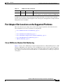
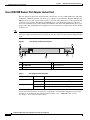
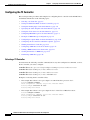
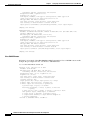
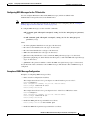
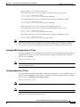
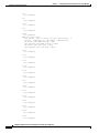
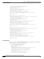
Cisco 7200 VXR Router with the Port Adapter Jacket Card Slot Numbering
Figure 1-3
Port Adapter Slots in Cisco 7206 VXR Router with the Port Adapter Jacket Card
5
6
1
7
3
2
1
0
6
TOKEN RING
5
FAST ETHERNET
4
RJ4
5
MII
0
LIN
K
D
LE
AB
EN
2
TX
RX
4
TX
RX
3
TX
RX
2
TX
RX
1
TX
EN
0
CD
LB
RC
RD
TC
TD
CD
LB
RC
RD
TC
TD
CD
LB
RC
RD
TC
TD
CD
LB
RC
ETHERNET-10BFL
1
2
RD
TD
TC
EN
FAST SERIAL
RX
3
3
2
2
1
LINK
1
0
3
EN
AB
LE
0
D
ETHERNET 10BT
149560
D
BLE
EN
A
PW
R
3
SA-VAM2+
ENCRYPTION/COMPRESSION
0
PORT ADAPTER JACKET CARD
Cisco 7200
Series VXR
4
1
Slot 5
5
Slot 6
2
Slot 3
6
Slot 4
3
Slot 1
7
Slot 2
4
Slot 7–port adapter (slot 0–Jacket Card)
Table 1-3 shows the slot number of port adapters in a Cisco 7200 VXR router with the Port Adapter
Jacket Card installed. Port adapter slots in the Cisco 7200 VXR routers are numbered from left to right.
With an NPE-G1 or NPE-G2 installed, port adapter slot 0 can accept the Port Adapter Jacket Card. The
Port Adapter Jacket Card resides in port adapter slot 0. The port adapter in the Port Adapter jacket card
resides in port adapter slot 5 on the Cisco 7204 VXR router, or port adapter slot 7 on the
Cisco 7206 VXR router.
PA-MC-2T3+ Multi-Channel T3 Port Adapter Installation and Configuration
1-6
OL-3526-05
Chapter 1
Overview
Port Adapter Slot Locations on the Supported Platforms
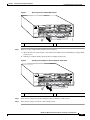
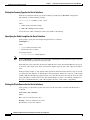
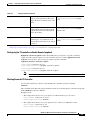
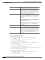
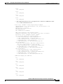
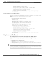
Figure 1-4
Port Adapter Slots in the Cisco 7206
3
2
1
0
6
TOKEN RING
5
FAST ETHERNET
4
5
RJ4
MII
0
LIN
K
D
LE
AB
EN
J-4
2
TX
RX
4
TX
RX
3
TX
RX
5
0
T
O
T
EJ
EC
M
C
PC
AB
EN
II
M N
E
SL
IA
LE
D
0
R
Port adapter slot 5
Port adapter slot 3
Port adapter slot 1
5
J-4
R EN
R
R
5
PW
J-4 K
O K
LIN 1 O
28329
M
II
FE
O
T
SL
2
FAST ETHERNET INPUT/OUTPUT CONTROLLER
1
Cisco 7200
Series
TX
RX
1
TX
RX
1
0
7
6
5
4
3
2
1
0
ETHERNET-10BFL
EN
3
2
3
LINK
1
0
2
1
SERIAL-V.35
EN
3
EN
AB
LE
0
D
ETHERNET 10BT
Port adapter slot 6
Port adapter slot 4
Port adapter slot 2
Port adapter slot 0
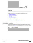
Cisco 7301 Router Slot Numbering
Figure 1-5 shows the front view of a Cisco 7301 router with a port adapter installed. The Cisco 7301
router has one standard port adapter slot.
Figure 1-5
Port Adapter Slot in the Cisco 7301 Router
Port adapter slot
D
LE
AB
EN
S IER
LL R RM
CE CAR LA
RX RX RX A
ATM
GIGABIT ETHER
NET
RJ45 EN
CISCO 7400
CISCO 7411SERIES
0/0
LINK
TX GBIC
GIGABIT ETHER
NET
RX
RJ45 EN
0/1
LINK
TX GBIC
GIGABIT ETHER
NET
RX
RJ45 EN
0/2
LINK
TX GBIC
AUX
RX
CONSOLE
ALARM
COMPACT
FLASH
100-24 0V,
2A, 50/60
Hz
24V=9 A,
48 - 60V=5
A
STATUS
84988
SLOT 1
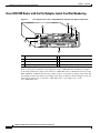
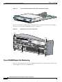
Cisco 7304 PCI Port Adapter Carrier Card Slot Numbering
The Cisco 7304 PCI Port Adapter Carrier Card accepts one single-width port adapter. Figure 1-6 shows
a Cisco 7304 PCI Port Adapter Carrier Card with a port adapter installed.
PA-MC-2T3+ Multi-Channel T3 Port Adapter Installation and Configuration
OL-3526-05
1-7
Chapter 1
Overview
Port Adapter Slot Locations on the Supported Platforms
Figure 1-6
7300-C
Cisco 7304 PCI Port Adapter Carrier Card—Port Adapter Installed
C-PA
84653
D
R
LE LS RIE M
AB EL AR AR
EN RX C RX C X AL
R
OIR
STATUS
7300 PA
ATM
CARRIE
R
The Cisco 7304 PCI Port Adapter Carrier Card installs in Cisco 7304 router module slots 2 through 5.
See Figure 1-7 for module slot numbering on a Cisco 7304 router.
Figure 1-7
Module Slots on the Cisco 7304 Router
Slot 4
7300-2
OC3AT
M-MM
TX
OIR
0
Slot 5
RX
STATUS
2-PORT
OC3 ATM
TX
1
RX
MM
CARRIER
ALARM/
9K-10C
48
ACTIVE/
LOOPBAC
K
CARRIER
ALARM/
ACTIVE/
LOOPBAC
K
TX
OIR
RX
STATUS
1-PORT
OC48 POS
9K-40C
w/ SMS
3/POS
-MM
R
OIR
STATUS
4-POR
T OC3
0
1
POS w/
2
3
MM
CARRIER
ALARM/
70550
ACTIVE/
LOOPBA
CK
Slot 0
Slot 2
Slot 3
Slot 1
Cisco 7401ASR Router Slot Numbering
Figure 1-8 shows the front view of a Cisco 7401ASR router with a port adapter installed. There is only
one port adapter slot in a Cisco 7401ASR router.
PA-MC-2T3+ Multi-Channel T3 Port Adapter Installation and Configuration
1-8
OL-3526-05
Chapter 1
Overview
Port Adapter Slot Locations on the Supported Platforms
Figure 1-8
D
R
LE LS RIE M
AB EL AR AR
EN RX C RX C X AL
Port Adapter Slot in the Cisco 7401ASR Router
TX
R
RX
ATM
57680
ENHANCED
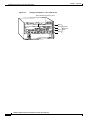
VIP Slot Numbering
Figure 1-9 on page 1-9 shows a partial view of a VIP motherboard with installed port adapters. With the
motherboard oriented as shown in Figure 1-9 on page 1-9, the left port adapter is in port adapter slot 0,
and the right port adapter is in port adapter slot 1.
Figure 1-9
VIP Motherboard with Two Port Adapters Installed—Horizontal Orientation
Port adapter slot 0
29328
Port adapter slot 1
Port adapter
handles not
shown
Note
In the Cisco 7000, Cisco 7507, and Cisco 7513 chassis, the VIP motherboard is installed vertically. In
the Cisco 7010 and Cisco 7505 chassis, the VIP motherboard is installed horizontally.
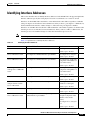
Interface processor slots are numbered as shown in Figure 1-10.
PA-MC-2T3+ Multi-Channel T3 Port Adapter Installation and Configuration
OL-3526-05
1-9
Chapter 1
Overview
Port Adapter Slot Locations on the Supported Platforms
Figure 1-10
Interface Slot Numbers—Cisco 7505 Shown
VIP in interface processor slot 3
T
SE
E
OL
NS
CO
U
RE
CP
EC
EJ
AL
RM
NO
S L SLO
OT T
0 1
T
HA
LT
ROUTE SWITCH PROCESSOR
Slot 3
Slot 2 Interface
processor
Slot 1 slots
29619
Slot 0
PA-MC-2T3+ Multi-Channel T3 Port Adapter Installation and Configuration
1-10
OL-3526-05
Chapter 1
Overview
Identifying Interface Addresses
Identifying Interface Addresses
This section describes how to identify interface addresses for the PA-MC-2T3+ in supported platforms.
Interface addresses specify the actual physical location of each interface on a router or switch.
Interfaces on the PA-MC-2T3+ installed in a router maintain the same address regardless of whether
other port adapters are installed or removed. However, when you move a port adapter to a different slot,
the first number in the interface address changes to reflect the new port adapter slot number.
Interfaces on a PA-MC-2T3+ installed in a VIP maintain the same address regardless of whether other
interface processors are installed or removed. However, when you move a VIP to a different slot, the
interface processor slot number changes to reflect the new interface processor slot.
Note
Interface ports are numbered from left to right starting with 0.
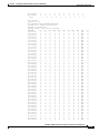
Table 1-4 explains how to identify interface addresses.
Table 1-4
Identifying Interface Addresses
Platform
Interface Address Format
Numbers
Syntax
Cisco 7120 series routers
Port-adapter-slot-number/interface-port-number
Port adapter slot—always 3
3/1
Interface port—0 and 1
Cisco 7140 series routers
Port-adapter-slot-number/interface-port-number
Port adapter slot—always 4
4/0
Interface port—0 and 1
Cisco 7200 series routers
Port-adapter-slot-number/interface-port-number
Port adapter slot—0 through 1/0
6 (depends on the number of
slots in the router)1
Interface port—0 and 1
Port Adapter Jacket Card
with the Cisco 7200 VXR
router2
Port-adapter-slot-number/interface-port-number
Port adapter slot—0 through 1/0
7 (depends on the number of
slots in the router)3
Interface port—0 and 1
Cisco 7301 routers
Port-adapter-slot-number/interface-port-number
Port adapter slot—always 1
1/0
Interface port—0 and 1
Cisco 7304 PCI Port
Adapter Carrier Card in
Cisco 7304 routers
Port-adapter-slot-number/interface-port-number
Cisco 7401ASR routers
Port-adapter-slot-number/interface-port-number
Port adapter slot—router
module slot 2 through 5
3/0
Interface port—0 and 1
Port adapter slot—always 1
1/0
Interface port—0 and 1
VIP in Cisco 7000 series or
Cisco 7500 series routers
Interface-processor-slot-number/port-adapter-slotnumber/interface-port-number
Interface processor slot—0
through 12 (depends on the
number of slots in the
router)
3/1/0
Port adapter slot—always 0
or 1
Interface port—0 and 1
PA-MC-2T3+ Multi-Channel T3 Port Adapter Installation and Configuration
OL-3526-05
1-11
Chapter 1
Overview
Identifying Interface Addresses
1. Port adapter slot 0 is reserved for the Fast Ethernet port on the I/O controller (if present).
2. Port adapter slot 0 can accept the Port Adapter Jacket Card if an NPE-G1 or NPE-G2 are installed.
3. Port adapter slot 0 is reserved for the Fast Ethernet port on the I/O controller (if present).
Cisco 7200 Series Routers Interface Addresses
This section describes how to identify the interface addresses used for the PA-MC-2T3+ in Cisco 7200
series routers. The interface address is composed of a two-part number in the format
port-adapter-slot-number/interface-port-number. See Table 1-4 for the interface address format.
In Cisco 7200 series routers, port adapter slots are numbered from the lower left to the upper right,
beginning with port adapter slot 1 and continuing through port adapter slot 2 for the Cisco 7202, slot 4
for the Cisco 7204 and Cisco 7204VXR, and slot 6 for the Cisco 7206 and Cisco 7206VXR. (Port
adapter slot 0 is reserved for the optional Fast Ethernet port on the I/O controller—if present.)
The interface addresses of the interfaces on the PA-MC-2T3+ in port adapter slot 1 are 1/0 through 1/1
(port adapter slot 1 and interfaces 0 and 1). If the PA-MC-2T3+ was in port adapter slot 4, these same
interfaces would be numbered 4/0 through 4/1 (port adapter slot 4 and interfaces 0 and 1).
Cisco 7301 Router Interface Addresses
This section describes how to identify addresses used for the PA-MC-2T3+ in the Cisco 7301 router. In
the Cisco 7301 router, slot 1 is the port adapter slot you use for the PA-MC-2T3+. (See Figure 1-5.)
The interface address is composed of a two-part number in the format
port-adapter-slot-number/interface-port-number. See Table 1-4 on page 1-11 for the interface address
format.
Cisco 7304 PCI Port Adapter Carrier Card Interface Addresses
This section describes how to identify the interface addresses used for the PA-MC-2T3+ in the Cisco
7304 PCI Port Adapter Carrier Card in Cisco 7304 routers. The interface address is made of a two-part
number in the format port-adapter-slot-number/interface-port-number.
The Cisco 7304 PCI Port Adapter Carrier Card installs into Cisco 7304 router module slots 2 through 5
(See Figure 1-7.) The port-adapter-slot-number is the Cisco 7304 router module slot number. For
example, the interface address of port 0 on a PA-MC-2T3+, in which the Cisco 7304 PCI Port Adapter
Carrier Card is installed in Cisco 7304 router module slot 3, would be numbered 3/0.
Cisco 7401ASR Router Interface Addresses
This section describes how to identify addresses used for the PA-MC-2T3+ in the Cisco 7401ASR router.
In the Cisco 7401ASR router, slot 1 is the port adapter slot you use for the PA-MC-2T3+.
(See Figure 1-8.) The interface address is composed of a two-part number in the format
port-adapter-slot-number/interface-port-number. See Table 1-4 on page 1-11 for the interface address
format.
PA-MC-2T3+ Multi-Channel T3 Port Adapter Installation and Configuration
1-12
OL-3526-05
Chapter 1
Overview
Identifying Interface Addresses
VIP Interface Addresses
This section describes how to identify the interface addresses used for the PA-MC-2T3+ on a VIP in
Cisco 7000 series and Cisco 7500 series routers.
Note
Although the processor slots in the 7-slot Cisco 7000 and Cisco 7507 and the 13-slot Cisco 7513 and
Cisco 7576 are vertically oriented and those in the 5-slot Cisco 7010 and Cisco 7505 are horizontally
oriented, all Cisco 7000 series and Cisco 7500 series routers use the same method for slot and port
numbering.
See Table 1-4 on page 1-11 for the interface address format. The interface address is composed of a
three-part number in the format
interface-processor-slot-number/port-adapter-slot-number/interface-port-number.
If the VIP is inserted in interface processor slot 3, then the interface addresses of the PA-MC-2T3+ are
3/1/0 through 3/1/1 (interface processor slot 3, port adapter slot 1, and interfaces 0 and 1). If the
port adapter was in port adapter slot 0 on the VIP, these same interface addresses would be numbered
3/0/0 through 3/0/1.
Note
If you remove the VIP with the PA-MC-2T3+ (shown in Figure 1-9 on page 1-9) from interface
processor slot 3 and install it in interface processor slot 2, the interface addresses become 2/1/0 through
2/1/1.
PA-MC-2T3+ Multi-Channel T3 Port Adapter Installation and Configuration
OL-3526-05
1-13
Chapter 1
Overview
Identifying Interface Addresses
PA-MC-2T3+ Multi-Channel T3 Port Adapter Installation and Configuration
1-14
OL-3526-05
C H A P T E R
2
Preparing for Installation
This chapter describes the general equipment, safety, and site preparation requirements for installing the
Cisco PA-MC-2T3+ port adapter. This chapter contains the following sections:
•
Required Tools and Equipment, page 2-1
•
Software and Hardware Requirements, page 2-2
•
Checking Hardware and Software Compatibility, page 2-3
•
75-Ohm In-Line Coaxial Attenuator, page 2-3
•
Safety Guidelines, page 2-3
•
FCC Class A Compliance, page 2-9
Required Tools and Equipment
You need the following tools and parts to install a port adapter. If you need additional equipment, contact
a service representative for ordering information.
•
PA-MC-2T3+(=) port adapter.
•
Cisco 7200 VXR routers Port Adapter Jacket Card for installation of a port adapter in the I/O
controller slot (requires an NPE-G1 or NPE-G2
•
VIP (for installation in Cisco 7000 series or Cisco 7500 series chassis only). Two 75-ohm 734A
coaxial cables (one for transmit and one for receive) per T3 port.
•
Cisco 7304 PCI Port Adapter Carrier Card (for installation in a Cisco 7304 router).
•
Number 1 Phillips and a 3/16-inch flat-blade screwdriver (for VIP installation only).
•
Number 2 Phillips screwdriver.
•
Your own electrostatic discharge (ESD)-prevention equipment or the disposable grounding wrist
strap included with all upgrade kits, field-replaceable units (FRUs), and spares.
•
Antistatic mat.
•
Antistatic container.
•
Attenuator kit (optional).
PA-MC-2T3+ Multi-Channel T3 Port Adapter Installation and Configuration
OL-3526-05
2-1
Chapter 2
Preparing for Installation
Software and Hardware Requirements
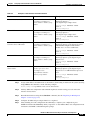
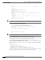
Software and Hardware Requirements
Table 2-1 lists the minimum Cisco IOS software release required to use the PA-MC-2T3+ in supported
router or switch platforms.
Table 2-1
PA-MC-2T3+ Software Requirements
Platform
Recommended Minimum Cisco IOS Release
Cisco 7200 series
1, 2,
Channelized T3 functionality
•
Cisco 7202, 7204 and 7206
•
Cisco IOS Release 12.0(6)S or a later release of Cisco IOS Release 12.0 S
•
Cisco 7204VXR and 7206VXR
•
Cisco IOS Release 12.1(1)E or a later release of Cisco IOS Release 12.1 E
•
Cisco IOS Release 12.1(4)T or a later release of Cisco IOS Release 12.1 T
•
Cisco IOS Release 12.2(4)B or a later release of Cisco IOS Release 12.2 B
Channelized and unchannelized T3 functionality
•
•
Port Adapter Jacket Card for the
Cisco 7200 VXR router with an
NPE-G1
Port Adapter Jacket Card for the
Cisco 7200 VXR router with an
NPE-G2
Cisco 7301 router
•
Cisco IOS Release 12.0(14)S or a later release of Cisco IOS Release 12.0 S
•
Cisco IOS Release 12.1(1)E or a later release of Cisco IOS Release 12.1 E
Cisco IOS Release 12.4(7) or later releases of Cisco IOS Release 12.4
Cisco IOS Release 12.4(6)T1 or later releases of Cisco IOS Release 12.4T
Cisco IOS Release 12.4(4)XD2 or later releases of Cisco IOS Release 12.4
Cisco IOS Release 12.2(11)YZ or a later release of Cisco IOS Release 12.2
Cisco 7304 routers
•
With Cisco 7304 PCI Port Adapter
Carrier Card
Cisco IOS Release 12.2(14)SZ or a later release of Cisco IOS Release 12.2SZ
Cisco 7401ASR routers
Cisco IOS Release 12.2(1)DX or a later release of Cisco IOS Release 12.2 DX
Cisco IOS Release 12.2(4)B or a later release of Cisco IOS Release 12.2 B
VIP in the Cisco 7000 series and Cisco 7500
series 3, 4,
Channelized T3 functionality
•
Cisco IOS Release 12.0(6)S or a later release of Cisco IOS Release 12.0 S
•
Cisco IOS Release 12.1(1)E or a later release of Cisco IOS Release 12.1 E
•
Cisco IOS Release 12.1(4)T or a later release of Cisco IOS Release 12.1 T
Channelized and unchannelized T3 functionality
•
Cisco IOS Release 12.0(14)S or a later release of Cisco IOS Release 12.0 S
•
Cisco IOS Release 12.1(1)E or a later release of Cisco IOS Release 12.1 E
1. The PA-MC-2T3+ is not supported on a Cisco 7200 series routers with an NPE-100 or NPE-150.
2. For Cisco 7200 series routers running 12.0 S, it is recommended that you have a minimum of 64 MB of DRAM. For Cisco 7200 series routers running
12.1x, it is recommended that you have a minimum of 128 MB of DRAM.
3. The specific VIP2 models recommended for the PA-MC-2T3+ in all Cisco 7500 series routers, and in Cisco 7000 series routers using the RSP7000 and
RSP7000CI, are VIP2-40(=), which has 2 MB of SRAM and 32 MB of DRAM, and VIP2-50(=), which has 4 to 8 MB of SRAM and 32 to 128 MB of
SDRAM.
4. Only one PA-MC-2T3+ may be used in a VIP2-40 in Cisco 7500 series routers.
PA-MC-2T3+ Multi-Channel T3 Port Adapter Installation and Configuration
2-2
OL-3526-05
Chapter 2
Preparing for Installation
Checking Hardware and Software Compatibility
For configuration guidelines on port adapters in the Cisco 7200 series, refer to the Cisco 7200 Series
Port Adapter Hardware Configuration Guidelines.
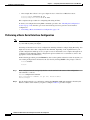
Checking Hardware and Software Compatibility
To check the minimum software requirements of Cisco IOS software with the hardware installed on your
router, Cisco maintains the Software Advisor tool on Cisco.com. This tool does not verify whether
modules within a system are compatible, but it does provide the minimum IOS requirements for
individual hardware modules or components.
Note
Access to this tool is limited to users with Cisco.com login accounts.
To access Software Advisor, click Login at Cisco.com and go to Technical Support Help—Cisco TAC:
Tool Index: Software Advisor. You can also access the tool by pointing your browser directly to
http://www.cisco.com/cgi-bin/support/CompNav/Index.pl.
Choose a product family or enter a specific product number to search for the minimum supported
software release needed for your hardware.
75-Ohm In-Line Coaxial Attenuator
A 75-ohm in-line coaxial attenuator may be required to tune the signal between the PA-MC-2T3+ and
the far-end equipment, if the port adapter is experiencing line code violations (LCVs). LCVs occur when
the far end equipment transmit signal saturates the front end receiver of the PA-MC-2T3+.
Cisco offers an attenuator kit (ATTEN-KIT-PA=) that contains five attenuators with fixed values ranging
from 3-dB to 20-dB. For more information on the attenuator kit go to the following website:
http://www.cisco.com/univercd/cc/td/doc/product/core/7206/fru/12884att.htm
Safety Guidelines
This section provides safety guidelines that you should follow when working with any equipment that
connects to electrical power or telephone wiring.
Safety Warnings
Safety warnings appear throughout this publication in procedures that, if performed incorrectly, may
harm you. A warning symbol precedes each warning statement.
PA-MC-2T3+ Multi-Channel T3 Port Adapter Installation and Configuration
OL-3526-05
2-3
Chapter 2
Preparing for Installation
Safety Guidelines
Warning
IMPORTANT SAFETY INSTRUCTIONS
This warning symbol means danger. You are in a situation that could cause bodily injury. Before you
work on any equipment, be aware of the hazards involved with electrical circuitry and be familiar
with standard practices for preventing accidents. To see translations of the warnings that appear in
this publication, refer to the translated safety warnings that accompanied this device.
Statement 1071
Note: SAVE THESE INSTRUCTIONS
Note: This documentation is to be used in conjunction with the specific product installation guide
that shipped with the product. Please refer to the Installation Guide, Configuration Guide, or other
enclosed additional documentation for further details.
Waarschuwing
BELANGRIJKE VEILIGHEIDSINSTRUCTIES
Dit waarschuwingssymbool betekent gevaar. U verkeert in een situatie die lichamelijk letsel kan
veroorzaken. Voordat u aan enige apparatuur gaat werken, dient u zich bewust te zijn van de bij
elektrische schakelingen betrokken risico's en dient u op de hoogte te zijn van de standaard
praktijken om ongelukken te voorkomen. Voor een vertaling van de waarschuwingen die in deze
publicatie verschijnen, dient u de vertaalde veiligheidswaarschuwingen te raadplegen die bij dit
apparaat worden geleverd.
Opmerking BEWAAR DEZE INSTRUCTIES.
Opmerking Deze documentatie dient gebruikt te worden in combinatie met de
installatiehandleiding voor het specifieke product die bij het product wordt geleverd. Raadpleeg de
installatiehandleiding, configuratiehandleiding of andere verdere ingesloten documentatie voor
meer informatie.
Varoitus
TÄRKEITÄ TURVALLISUUTEEN LIITTYVIÄ OHJEITA
Tämä varoitusmerkki merkitsee vaaraa. Olet tilanteessa, joka voi johtaa ruumiinvammaan. Ennen
kuin työskentelet minkään laitteiston parissa, ota selvää sähkökytkentöihin liittyvistä vaaroista ja
tavanomaisista onnettomuuksien ehkäisykeinoista. Tässä asiakirjassa esitettyjen varoitusten
käännökset löydät laitteen mukana toimitetuista ohjeista.
Huomautus SÄILYTÄ NÄMÄ OHJEET
Huomautus Tämä asiakirja on tarkoitettu käytettäväksi yhdessä tuotteen mukana tulleen
asennusoppaan kanssa. Katso lisätietoja asennusoppaasta, kokoonpano-oppaasta ja muista
mukana toimitetuista asiakirjoista.
PA-MC-2T3+ Multi-Channel T3 Port Adapter Installation and Configuration
2-4
OL-3526-05
Chapter 2
Preparing for Installation
Safety Guidelines
Attention
IMPORTANTES INFORMATIONS DE SÉCURITÉ
Ce symbole d'avertissement indique un danger. Vous vous trouvez dans une situation pouvant causer
des blessures ou des dommages corporels. Avant de travailler sur un équipement, soyez conscient
des dangers posés par les circuits électriques et familiarisez-vous avec les procédures couramment
utilisées pour éviter les accidents. Pour prendre connaissance des traductions d'avertissements
figurant dans cette publication, consultez les consignes de sécurité traduites qui accompagnent cet
appareil.
Remarque CONSERVEZ CES INFORMATIONS
Remarque Cette documentation doit être utilisée avec le guide spécifique d'installation du produit
qui accompagne ce dernier. Veuillez vous reporter au Guide d'installation, au Guide de
configuration, ou à toute autre documentation jointe pour de plus amples renseignements.
Warnung
WICHTIGE SICHERHEITSANWEISUNGEN
Dieses Warnsymbol bedeutet Gefahr. Sie befinden sich in einer Situation, die zu einer
Körperverletzung führen könnte. Bevor Sie mit der Arbeit an irgendeinem Gerät beginnen, seien Sie
sich der mit elektrischen Stromkreisen verbundenen Gefahren und der Standardpraktiken zur
Vermeidung von Unfällen bewusst. Übersetzungen der in dieser Veröffentlichung enthaltenen
Warnhinweise sind im Lieferumfang des Geräts enthalten.
Hinweis BEWAHREN SIE DIESE SICHERHEITSANWEISUNGEN AUF
Hinweis Dieses Handbuch ist zum Gebrauch in Verbindung mit dem Installationshandbuch für Ihr
Gerät bestimmt, das dem Gerät beiliegt. Entnehmen Sie bitte alle weiteren Informationen dem
Handbuch (Installations- oder Konfigurationshandbuch o. Ä.) für Ihr spezifisches Gerät.
Figyelem!
FONTOS BIZTONSÁGI ELÕÍRÁSOK
Ez a figyelmezetõ jel veszélyre utal. Sérülésveszélyt rejtõ helyzetben van. Mielõtt bármely
berendezésen munkát végezte, legyen figyelemmel az elektromos áramkörök okozta kockázatokra,
és ismerkedjen meg a szokásos balesetvédelmi eljárásokkal. A kiadványban szereplõ
figyelmeztetések fordítása a készülékhez mellékelt biztonsági figyelmeztetések között található.
Megjegyzés ÕRIZZE MEG EZEKET AZ UTASÍTÁSOKAT!
Megjegyzés Ezt a dokumentációt a készülékhez mellékelt üzembe helyezési útmutatóval együtt kell
használni. További tudnivalók a mellékelt Üzembe helyezési útmutatóban (Installation Guide),
Konfigurációs útmutatóban (Configuration Guide) vagy más dokumentumban találhatók.
Avvertenza
IMPORTANTI ISTRUZIONI SULLA SICUREZZA
Questo simbolo di avvertenza indica un pericolo. La situazione potrebbe causare infortuni alle
persone. Prima di intervenire su qualsiasi apparecchiatura, occorre essere al corrente dei pericoli
relativi ai circuiti elettrici e conoscere le procedure standard per la prevenzione di incidenti. Per le
traduzioni delle avvertenze riportate in questo documento, vedere le avvertenze di sicurezza che
accompagnano questo dispositivo.
Nota CONSERVARE QUESTE ISTRUZIONI
Nota La presente documentazione va usata congiuntamente alla guida di installazione specifica
spedita con il prodotto. Per maggiori informazioni, consultare la Guida all'installazione, la Guida
alla configurazione o altra documentazione acclusa.
PA-MC-2T3+ Multi-Channel T3 Port Adapter Installation and Configuration
OL-3526-05
2-5
Chapter 2
Preparing for Installation
Safety Guidelines
Advarsel
VIKTIGE SIKKERHETSINSTRUKSJONER
Dette varselssymbolet betyr fare. Du befinner deg i en situasjon som kan forårsake personskade.
Før du utfører arbeid med utstyret, bør du være oppmerksom på farene som er forbundet med
elektriske kretssystemer, og du bør være kjent med vanlig praksis for å unngå ulykker. For å se
oversettelser av advarslene i denne publikasjonen, se de oversatte sikkerhetsvarslene som følger
med denne enheten.
Merk TA VARE PÅ DISSE INSTRUKSJONENE
Merk Denne dokumentasjonen skal brukes i forbindelse med den spesifikke
installasjonsveiledningen som fulgte med produktet. Vennligst se installasjonsveiledningen,
konfigureringsveiledningen eller annen vedlagt tilleggsdokumentasjon for detaljer.
Aviso
INSTRUÇÕES IMPORTANTES DE SEGURANÇA
Este símbolo de aviso significa perigo. O utilizador encontra-se numa situação que poderá ser
causadora de lesões corporais. Antes de iniciar a utilização de qualquer equipamento, tenha em
atenção os perigos envolvidos no manuseamento de circuitos eléctricos e familiarize-se com as
práticas habituais de prevenção de acidentes. Para ver traduções dos avisos incluídos nesta
publicação, consulte os avisos de segurança traduzidos que acompanham este dispositivo.
Nota GUARDE ESTAS INSTRUÇÕES
Nota Esta documentação destina-se a ser utilizada em conjunto com o manual de instalação
incluído com o produto específico. Consulte o manual de instalação, o manual de configuração ou
outra documentação adicional inclusa, para obter mais informações.
¡Advertencia!
INSTRUCCIONES IMPORTANTES DE SEGURIDAD
Este símbolo de aviso indica peligro. Existe riesgo para su integridad física. Antes de manipular
cualquier equipo, considere los riesgos de la corriente eléctrica y familiarícese con los
procedimientos estándar de prevención de accidentes. Vea las traducciones de las advertencias
que acompañan a este dispositivo.
Nota GUARDE ESTAS INSTRUCCIONES
Nota Esta documentación está pensada para ser utilizada con la guía de instalación del producto
que lo acompaña. Si necesita más detalles, consulte la Guía de instalación, la Guía de
configuración o cualquier documentación adicional adjunta.
Varning!
VIKTIGA SÄKERHETSANVISNINGAR
Denna varningssignal signalerar fara. Du befinner dig i en situation som kan leda till personskada.
Innan du utför arbete på någon utrustning måste du vara medveten om farorna med elkretsar och
känna till vanliga förfaranden för att förebygga olyckor. Se översättningarna av de
varningsmeddelanden som finns i denna publikation, och se de översatta säkerhetsvarningarna som
medföljer denna anordning.
OBS! SPARA DESSA ANVISNINGAR
OBS! Denna dokumentation ska användas i samband med den specifika
produktinstallationshandbok som medföljde produkten. Se installationshandboken,
konfigurationshandboken eller annan bifogad ytterligare dokumentation för närmare detaljer.
PA-MC-2T3+ Multi-Channel T3 Port Adapter Installation and Configuration
2-6
OL-3526-05
Chapter 2
Preparing for Installation
Safety Guidelines
PA-MC-2T3+ Multi-Channel T3 Port Adapter Installation and Configuration
OL-3526-05
2-7
Chapter 2
Preparing for Installation
Safety Guidelines
Electrical Equipment Guidelines
Follow these basic guidelines when working with any electrical equipment:
•
Before beginning any procedures requiring access to the chassis interior, locate the emergency
power-off switch for the room in which you are working.
•
Disconnect all power and external cables before moving a chassis; do not work alone when
potentially hazardous conditions exist.
PA-MC-2T3+ Multi-Channel T3 Port Adapter Installation and Configuration
2-8
OL-3526-05
Chapter 2
Preparing for Installation
FCC Class A Compliance
•
Never assume that power has been disconnected from a circuit; always check.
•
Do not perform any action that creates a potential hazard to people or makes the equipment unsafe;
carefully examine your work area for possible hazards such as moist floors, ungrounded power
extension cables, and missing safety grounds.
Preventing Electrostatic Discharge Damage
Electrostatic discharge (ESD) damage, which can occur when electronic cards or components are
improperly handled, results in complete or intermittent failures. Port adapters and processor modules
comprise printed circuit boards that are fixed in metal carriers. Electromagnetic interference (EMI)
shielding and connectors are integral components of the carrier. Although the metal carrier helps to
protect the board from ESD, use a preventive antistatic strap during handling.
Following are guidelines for preventing ESD damage:
Caution
•
Always use an ESD wrist or ankle strap and ensure that it makes good skin contact.
•
Connect the equipment end of the strap to an unfinished chassis surface.
•
When installing a component, use any available ejector levers or captive installation screws to
properly seat the bus connectors in the backplane or midplane. These devices prevent accidental
removal, provide proper grounding for the system, and help to ensure that bus connectors are
properly seated.
•
When removing a component, use any available ejector levers or captive installation screws to
release the bus connectors from the backplane or midplane.
•
Handle carriers by available handles or edges only; avoid touching the printed circuit boards or
connectors.
•
Place a removed board component-side-up on an antistatic surface or in a static shielding container.
If you plan to return the component to the factory, immediately place it in a static shielding
container.
•
Avoid contact between the printed circuit boards and clothing. The wrist strap only protects
components from ESD voltages on the body; ESD voltages on clothing can still cause damage.
•
Never attempt to remove the printed circuit board from the metal carrier.
For safety, periodically check the resistance value of the antistatic strap. The measurement should be
between 1 and 10 megohms (Mohm).
FCC Class A Compliance
This equipment has been tested and found to comply with the limits for a Class A digital device, pursuant
to part 15 of the FCC rules. These limits are designed to provide reasonable protection against harmful
interference when the equipment is operated in a commercial environment. This equipment generates,
uses, and can radiate radio-frequency energy and, if not installed and used in accordance with the
instruction manual, may cause harmful interference to radio communications. Operation of this
equipment in a residential area is likely to cause harmful interference, in which case users will be
required to correct the interference at their own expense.
PA-MC-2T3+ Multi-Channel T3 Port Adapter Installation and Configuration
OL-3526-05
2-9
Chapter 2
Preparing for Installation
FCC Class A Compliance
You can determine whether your equipment is causing interference by turning it off. If the interference
stops, it was probably caused by the Cisco equipment or one of its peripheral devices. If the equipment
causes interference to radio or television reception, try to correct the interference by using one or more
of the following measures:
Note
•
Turn the television or radio antenna until the interference stops.
•
Move the equipment to one side or the other of the television or radio.
•
Move the equipment farther away from the television or radio.
•
Plug the equipment into an outlet that is on a different circuit from the television or radio. (That is,
make certain the equipment and the television or radio are on circuits controlled by different circuit
breakers or fuses.)
The Cisco PA-MC-2T3+ port adapter has been designed to meet these requirements. Modifications to
this product that are not authorized by Cisco Systems, Inc., could void the various approvals and negate
your authority to operate the product.
PA-MC-2T3+ Multi-Channel T3 Port Adapter Installation and Configuration
2-10
OL-3526-05
C H A P T E R
3
Removing and Installing Port Adapters
This chapter describes how to remove the Cisco PA-MC-2T3+ port adapter from supported platforms
and also how to install a new or replacement port adapter. This chapter contains the following sections:
•
Handling Port Adapters, page 3-1
•
Online Insertion and Removal, page 3-2
•
Warnings and Cautions, page 3-3
•
Port Adapter Removal and Installation, page 3-4
•
Cables and Connectors, page 3-13
Each port adapter circuit board is mounted to a metal carrier and is sensitive to electrostatic discharge
(ESD) damage.
Note
Caution
When a port adapter slot is not in use, a blank port adapter must fill the empty slot to allow the router or
switch to conform to electromagnetic interference (EMI) emissions requirements and to allow proper
airflow across the port adapters. If you plan to install a new port adapter in a slot that is not in use, you
must first remove the blank port adapter.
When powering off the router, wait a minimum of 30 seconds before powering it on again.
Handling Port Adapters
Caution
Always handle the port adapter by the carrier edges and handle; never touch the port adapter components
or connector pins. (See Figure 3-1 on page 3-2.)
PA-MC-2T3+ Multi-Channel T3 Port Adapter Installation and Configuration
OL-3526-05
3-1
Chapter 3
Removing and Installing Port Adapters
Online Insertion and Removal
Figure 3-1
Handling a Port Adapter
Metal carrier
H6420
Printed circuit board
Online Insertion and Removal
Several platforms support online insertion and removal (OIR) of port adapters; therefore, you do not
have to power down routers when removing and replacing a PA-MC-2T3+ on Cisco 7100 series routers,
Cisco 7200 series routers, Cisco uBR7200 series routers, Cisco 7301 routers, or Cisco 7401ASR routers.
Although the VIP and the Cisco 7304 PCI Port Adapter Carrier Card support online insertion and
removal, individual port adapters do not. To replace port adapters, you must first remove the VIP or the
Cisco 7304 PCI Port Adapter Carrier Card from the chassis and then install or replace port adapters as
required. If a blank port adapter is installed on the VIP or the Cisco 7304 PCI Port Adapter Carrier Card
on which you want to install a new port adapter, you must first remove the VIP or the Cisco 7304 PCI
Port Adapter Carrier Card from the chassis and then remove the blank port adapter.
Caution
To prevent system problems, do not remove port adapters from the VIP or the Cisco 7304 PCI Port
Adapter Carrier Card motherboard or attempt to install other port adapters on the motherboard when the
system is operating. To install or replace port adapters, first remove the VIP or the Cisco 7304 PCI Port
Adapter Carrier Card from its interface processor slot.
It is wise to gracefully shut down the system before removing a port adapter that has active traffic moving
through it. Removing a module while traffic is flowing through the ports can cause system disruption.
Once the module is inserted, the ports can be brought back up.
Note
Online insertion and removal (OIR) is not supported on the Port Adapter Jacket Card. OIR is supported
on the port adapter. You must have the chassis powered off to install or remove the Port Adapter Jacket
Card.
Note
As you disengage the module from the router or switch, online insertion and removal (OIR)
administratively shuts down all active interfaces in the module.
OIR allows you to install and replace modules while the router is operating; you do not need to notify
the software or shut down the system power, although you should not run traffic through the module you
are removing while it is being removed. OIR is a method that is seamless to end users on the network,
maintains all routing information, and preserves sessions.
PA-MC-2T3+ Multi-Channel T3 Port Adapter Installation and Configuration
3-2
OL-3526-05
Chapter 3
Removing and Installing Port Adapters
Warnings and Cautions
The following is a functional description of OIR for background information only; for specific
procedures for installing and replacing a module in a supported platform, refer to the “Port Adapter
Removal and Installation” section on page 3-4.
Each module has a bus connector that connects it to the router. The connector has a set of tiered pins in
three lengths that send specific signals to the system as they make contact with the module. The system
assesses the signals it receives and the order in which it receives them to determine if a module is being
removed from or introduced to the system. From these signals, the system determines whether to
reinitialize a new interface or to shut down a disconnected interface.
Specifically, when you insert a module, the longest pins make contact with the module first, and the
shortest pins make contact last. The system recognizes the signals and the sequence in which it receives
them.
When you remove or insert a module, the pins send signals to notify the system of changes. The router
then performs the following procedure:
Note
1.
Rapidly scans the system for configuration changes.
2.
Initializes newly inserted port adapters or administratively shuts down any vacant interfaces.
3.
Brings all previously configured interfaces on the module back to their previously installed state.
Any newly inserted interface is put in the administratively shutdown state, as if it was present (but
not configured) at boot time. If a similar module type is reinserted into a slot, its ports are configured
and brought online up to the port count of the originally installed module of that type.
Before you begin installation, read Chapter 2, “Preparing for Installation,” for a list of parts and tools
required for installation.
Warnings and Cautions
Observe the following warnings and cautions when installing or removing port adapters.
Note
If a port adapter lever or other retaining mechanism does not move to the locked position, the port
adapter is not completely seated in the midplane. Carefully pull the port adapter halfway out of the slot,
reinsert it, and move the port adapter lever or other mechanism to the locked position.
Caution
To prevent jamming the carrier between the upper and the lower edges of the port adapter slot, and to
ensure that the edge connector at the rear of the port adapter mates with the connection at the rear of the
port adapter slot, make certain that the carrier is positioned correctly, as shown in the cutaway in the
following illustrations.
Caution
When performing the following procedures, wear a grounding wrist strap to avoid ESD damage to the
card. Some platforms have an ESD connector for attaching the wrist strap.
Warning
Hazardous voltage or energy is present on the backplane when the system is operating. Use caution
when servicing.
PA-MC-2T3+ Multi-Channel T3 Port Adapter Installation and Configuration
OL-3526-05
3-3
Chapter 3
Removing and Installing Port Adapters
Port Adapter Removal and Installation
Port Adapter Removal and Installation
In this section, the illustrations that follow give step-by-step instructions on how to remove and install
port adapters. This section contains the following illustrations:
•
Cisco 7200 Series—Removing and Installing a Port Adapter, page 3-5
•
Cisco 7200 VXR Routers Port Adapter Jacket Card, page 3-6
•
Cisco 7301 Router—Removing and Installing a Port Adapter, page 3-8
•
Cisco 7304 PCI Port Adapter Carrier Card—Removing and Installing a Port Adapter, page 3-9
•
Cisco 7401ASR Router—Removing and Installing a Port Adapter, page 3-11
•
VIP—Removing and Installing a Port Adapter, page 3-12
PA-MC-2T3+ Multi-Channel T3 Port Adapter Installation and Configuration
3-4
OL-3526-05
Chapter 3
Removing and Installing Port Adapters
Port Adapter Removal and Installation
Cisco 7200 Series—Removing and Installing a Port Adapter
Step 1
Port adapter lever
(locked position)
To remove the port adapter, place
the port adapter lever in the
unlocked position. (See A.) The
port adapter lever remains in the
unlocked position.
Step 2
3
2
1
0
6
TOKEN RING
5
LI
0
4
NK
RJ
45
EN
AB
LE
D
K
3
3
2
2
1
LIN
1
0
3
EN
AB
LE
0
D
ETHERNET 10BT
A
MII
Grasp the handle of the port adapter
and pull the port adapter from the
router, about halfway out of its slot.
If you are removing a blank port
adapter, pull the blank port adapter
completely out of the chassis slot.
FAST ETHERNET
2
CD
LB
RC
RD
TC
TD
CD
LB
RC
RD
TC
TD
CD
LB
RC
RD
TC
TD
CD
LB
RC
RD
TC
TD
EN
FAST SERIAL
1
FAST ETHERNET INPUT/OUTPUT CONTROLLER
RE
U
CP
5
-4
With the port adapter halfway out of
the slot, disconnect all cables from
the port adapter. After disconnecting
the cables, pull the port adapter
from its chassis slot.
PW
K R
O
1O
R
LI J4
N 5
K
M
EN II
0
SLO
T
T
EJE
C
IA
C
M
PC
Note: This adapter
removal applies to any
port or service adapter.
Step 3
R
EN J4
5
EN
AB
LE
D
0
RJ
FE
SLO
M
II
T
1
SE
T
Cisco 7200
Series
Port adapter lever
(unlocked position)
Step 4
To insert the port adapter, carefully
align the port adapter carrier
between the upper and the lower
edges of the port adapter slot.
(See B.)
6
3
2
4
45
RJ
LI
2
0
3
2
MII
EN
AB
LE
D
K
3
2
LIN
1
0
D
1
0
LE
AB
3
EN
NK
FAST ETHERNET
ETHERNET 10BT
Carefully slide the new port adapter
halfway into the port adapter slot.
(See B.)
SE
U
CP
RJ
-4
5
FE
M
RE
II
1
T
SLO
D
LE
AB
27996
PW
O
K R
1O
R
LI J4
N 5
K
5
R
EN J4
T
M
EN II
0
T
C
EJE
SLO
IA
C
M
PC
B
FAST ETHERNET INPUT/OUTPUT CONTROLLER
EN
Cisco 7200
Series
T
1
Step 6
1
0
5
Step 5
TOKEN RING
Slot
guide
With the port adapter halfway into
the slot, connect all required cables
to the port adapter. After connecting
all required cables, carefully slide
the port adapter all the way into the
slot until the port adapter is seated
in the router midplane.
Step 7
After the port adapter is properly
seated, lock the port adapter lever.
(See A.)
PA-MC-2T3+ Multi-Channel T3 Port Adapter Installation and Configuration
OL-3526-05
3-5
Chapter 3
Removing and Installing Port Adapters
Port Adapter Removal and Installation
Cisco 7200 VXR Routers Port Adapter Jacket Card
The Port Adapter Jacket Card is used in the I/O controller slot of a Cisco 7200 VXR router with either
an NPE-G1 or NPE-G2 installed, and allows a port adapter to be installed in it. Both the NPE-G1 and
NPE-G2 incorporate I/O controller functionality, so that with either network processing engine the I/O
controller slot is available. The NPE-G1 and NPE-G2 have a third dedicated peripheral component
interconnect (PCI) bus that provides additional bandwidth to the chassis. The third PCI bus allows a port
adapter with a high bandwidth point requirement to be used with the Port Adapter Jacket Card in the I/O
controller slot.
Note
Online insertion and removal (OIR) is not supported on the Port Adapter Jacket Card. OIR is supported
on the port adapter. You must have the chassis powered off to install or remove the Port Adapter Jacket
Card.
Figure 2
Port Adapter Jacket Card Faceplate
1
1
2
4
4
3
5
1
Captive installation screw
4
Handle
2
ENABLE LED
5
Port adapter slot
3
PWR (power) LED
Table 1
138883
PW
R
EN
AB
LE
D
PORT ADAPTER JACKET CARD
Port Adapter Jacket Card LEDs
LED
Color
Indicates
ENABLE
Green
Port Adapter Jacket Card is enabled for operation.
Off
Port Adapter Jacket Card is not enabled for operation.
Green
Port Adapter Jacket Card is receiving power.
Off
Port Adapter Jacket Card is not receiving power.
PWR (power)
Use the following information to install a port adapter into an installed Port Adapter Jacket Card. For
information on installing the Port Adapter Jacket Card into a Cisco 7200 VXR router, see the
Port Adapter Jacket Card Installation Guide.
PA-MC-2T3+ Multi-Channel T3 Port Adapter Installation and Configuration
3-6
OL-3526-05
Chapter 3
Removing and Installing Port Adapters
Port Adapter Removal and Installation
Figure 3
Removing the Port Adapter Blank Panel
3
2
1
0
6
TOKEN RING
5
FAST ETHERNET
4
0
LIN
K
MII
RJ4
5
D
1
0
3
4
2
TX
RX
TX
RX
TX
RX
1
2
RX
TX
EN
CD
RX
LB
RC
RD
TC
TD
CD
LB
RC
RD
TC
TD
CD
LB
RC
RD
TC
TD
CD
LB
RC
EN
RD
TC
TD
LE
AB
EN
ETHERNET-10BFL
FAST SERIAL
TX
3
3
2
2
1
LINK
1
0
3
EN
AB
LE
0
D
ETHERNET 10BT
PORT ADAPTER JACKET CARD
138891
PW
R
EN
AB
LE
D
0
Cisco 7200
Series VXR
1
1
Step 1
Port adapter lock lever
Remove any port adapter blank panel that may be in place.
a.
Move the lock lever on the top left corner of the Port Adapter Jacket Card until the port adapter blank
panel releases.
b.
Pull the port adapter blank panel from the Port Adapter Jacket Card.
Figure 4
Installing a Port Adapter in the Port Adapter Jacket Card
3
2
1
0
6
TOKEN RING
5
FAST ETHERNET
4
RJ4
5
MII
0
LIN
K
D
LE
AB
1
2
TX
RX
4
TX
RX
3
RX
2
TX
RX
1
TX
RX
0
TX
ETHERNET-10BFL
CD
LB
RC
RD
TC
TD
CD
LB
RC
RD
TC
TD
CD
LB
RC
RD
TC
TD
CD
LB
RC
RD
TD
TC
EN
FAST SERIAL
EN
3
2
EN
LINK
1
1
2
3
0
3
EN
AB
LE
0
D
ETHERNET 10BT
0
D
LE
AB
EN
PW
R
SA-VAM2+
ENCRYPTION/COMPRESSION
138885
PORT ADAPTER JACKET CARD
Cisco 7200
Series VXR
1
1
Port adapter lock lever
Step 2
Insert the port adapter into the Port Adapter Jacket Card until it is fully seated.
Step 3
Move the port adapter lock lever to the locked position.
PA-MC-2T3+ Multi-Channel T3 Port Adapter Installation and Configuration
OL-3526-05
3-7
Chapter 3
Removing and Installing Port Adapters
Port Adapter Removal and Installation
Cisco 7301 Router—Removing and Installing a Port Adapter
Step 1
Use an ESD wrist strap to ground yourself to the router.
Step 2
To remove a port adapter, use a Phillips screwdriver to turn the screw holding the port adapter latch. The screw
should be loose enough to allow the latch to rotate to an unlocked position. (See A.) The latch can rotate 360˚.
Step 3
Grasp the handle and pull the port adapter from the router, about halfway out of its slot. (See B.) If you are
removing a blank port adapter, pull the blank port adapter completely out of the chassis slot.
Step 4
With the port adapter halfway out of the slot, diconnect all cables from the port adapter. After disconnecting
the cables, pull the port adapter from its chassis slot.
Caution
The port adapter must slide into the slot guides close to the chassis lid. (See C.) Do not allow the port
adapter components to come in contact with the system board or the port adapter could be damaged.
GIGABIT ETHERNE
T 0/0
RJ45 EN
R
ATM
LINK
TX GBIC
GIGABIT ETHERNE
T 0/1
RX
RJ45 EN
LINK
TX GBIC
GIGABIT ETHERNE
T 0/2
RX
RJ45 EN
LINK
TX GBIC
AUX
CONSOLE
RX
ALARM
COMPACT
FLASH
100-240V
, 2A, 50/60
Hz
24V=9A ,
48 - 60V=5A
STATUS
A
B
CISCO 7411
A
84129
SLOT 1
D
R
LE LS RIE M
AB EL AR AR
EN RX C RX C X AL
B
C
Step 5
To insert the port adapter, carefully align the port adapter carrier in the slot guides. (See C.) Slide the new
port adapter halfway into the chassis.
Step 6
Connect all required cables to the port adapter. After connecting all required cables, carefully slide the port
adapter all the way into the slot until the port adapter is seated in the midplane.
Step 7
After the port adapter is properly seated, turn and secure the port adapter latch in the upright, locked
position. (See A.) Tighten the screw to ensure the port adapter remains firmly in place.
PA-MC-2T3+ Multi-Channel T3 Port Adapter Installation and Configuration
3-8
OL-3526-05
Chapter 3
Removing and Installing Port Adapters
Port Adapter Removal and Installation
Cisco 7304 PCI Port Adapter Carrier Card—Removing and Installing a Port
Adapter
You can install one single-width port adapter in a Cisco 7304 PCI Port Adapter Carrier Card. This
section provides step-by-step instructions for removing and installing a port adapter in a Cisco 7304 PCI
Port Adapter Carrier Card.
Warning
When performing the following procedures, wear a grounding wrist strap to avoid ESD damage to the
Cisco 7304 PCI Port Adapter Carrier Card. Some platforms have an ESD connector for attaching the wrist
strap. Do not directly touch the midplane or backplane with your hand or any metal tool, or you could
shock yourself.
To remove and install a port adapter in a Cisco 7304 PCI Port Adapter Carrier Card, refer to Figure 3-5
and do the following:
Step 1
If the Cisco 7304 PCI Port Adapter Carrier Card is still in the router, you must remove the Cisco 7304
PCI Port Adapter Carrier Card before removing a port adapter.
Step 2
To remove the port adapter from the Cisco 7304 PCI Port Adapter Carrier Card, turn the port adapter
lock from its locked and horizontal position shown in A of Figure 3-5 to its unlocked and vertical
position shown in B of Figure 3-5.
Step 3
Grasp the handle of the port adapter and pull the port adapter from the Cisco 7304 PCI Port Adapter
Carrier Card. (You have already disconnected the cables from the port adapter when removing the
Cisco 7304 PCI Port Adapter Carrier Card).
Step 4
To insert the port adapter in the Cisco 7304 PCI Port Adapter Carrier Card, locate the guide rails inside
the Cisco 7304 PCI Port Adapter Carrier Card that hold the port adapter in place. They are at the top
left and top right of the port adapter slot and are recessed about an inch, as shown in C of Figure 3-5.
Step 5
Carefully slide the port adapter in theCisco 7304 PCI Port Adapter Carrier Card until the port adapter
makes contact with the port adapter interface connector. When fully seated, the port adapter front panel
should be flush with the face of the Cisco 7304 PCI Port Adapter Carrier Card.
Step 6
After the port adapter is properly seated, turn the port adapter lock to its locked and horizontal position,
as shown in A of Figure 3-5.
PA-MC-2T3+ Multi-Channel T3 Port Adapter Installation and Configuration
OL-3526-05
3-9
Chapter 3
Removing and Installing Port Adapters
Port Adapter Removal and Installation
Figure 3-5 illustrates how to remove and install a port adapter in a Cisco 7304 PCI Port Adapter Carrier
Card.
Figure 3-5
Cisco 7304 PCI Port Adapter Carrier Card—Port Adapter Removal and Installation
A
73 00 -CC
B
-PA
EN
AB
LE
D
S IER
LL RR RM
CE CA LA
RX RX RX A
OIR
STATUS
7300 PA
ATM
CARRIE
R
C
C -P A
7300-C
C-PA
OIR
STATUS
7300 PA
A
EN
BL
CARRIER
ED L S R I E R M
L R R
CE A A
84657
7 3 0 0 -C
C L
RX RX RX A
ATM
PA-MC-2T3+ Multi-Channel T3 Port Adapter Installation and Configuration
3-10
OL-3526-05
Chapter 3
Removing and Installing Port Adapters
Port Adapter Removal and Installation
Cisco 7401ASR Router—Removing and Installing a Port Adapter
Step 1
To remove the port adapter, use a number 2 Phillips screwdriver to loosen the screw on the port adapter
latch. Rotate the port adapter latch until it clears the faceplate of the port adapter. (See A.) The latch can
rotate 360˚.
Unlocked
Locked
D
R
LE S RIE M
AB ELL AR R
EN RX C RX C X ALA
A
R
TX
RX
ENHANCED
ATM
Step 2
Pull the port adapter from the router, about halfway out of its slot. (If you remove a blank port adapter, keep
the blank port adapter for use in the router if you should ever remove the port adapter. The port adapter slot
must always be filled.)
Step 3
With the port adapter halfway out of the slot, disconnect all cables from the port adapter. After
disconnecting the cables, pull the port adapter completely out of the chassis slot.
Step 4
To insert the port adapter, locate the port adapter slot guides inside the Cisco 7401ASR router. They are
near the top, and are recessed about 1/2 inch. (See B.)
Caution
The port adapter must slide into the slot guides under the chassis lid. Do not allow the port adapter
components to come in contact with the system board, or the port adapter could be damaged.
B
AB
LE
D
R
LS RIE M
CEL CAR AR
RX RX RX AL
TX
RX
ENHANCED
ATM
57643
EN
Step 5
Insert the port adapter in the slot guides halfway, and then reconnect the port adapter cables.
Step 6
After the cables are connected, carefully slide the port adpater all the way into the slot until the port adapter
is seated in the router midplane. When installed, the port adapter input/output panel should be flush with the
face of the router.
Step 7
After the port adapter is properly seated, rotate the port adapter latch to the upright locked position and use
a number 2 Phillips screwdriver to tighten the latch screw. If needed, loosen the latch screw to rotate the
latch over the port adapter. Finish the installation by tightening the latch screw.
PA-MC-2T3+ Multi-Channel T3 Port Adapter Installation and Configuration
OL-3526-05
3-11
Chapter 3
Removing and Installing Port Adapters
Port Adapter Removal and Installation
VIP—Removing and Installing a Port Adapter
Note: You must first remove the VIP
from the chassis before removing a port
adapter from the VIP.
Step 1
To remove the port adapter, remove
the screw that secures the port
adapter (or blank port adapter).
(See A.)
A
Step 2
Screw
With the screw removed, grasp the
handle on the front of the port adapter
(or blank port adapter) and carefully pull
it out of its slot, away from the edge
connector at the rear of the slot. (See A.)
Step 3
To insert the port adapter, carefully align
the port adapter carrier between the
upper and the lower edges of the port
adapter slot. (See B.)
B
Step 4
Carrier
Carefully slide the new port adapter into
the port adapter slot until the connector
on the port adapter is completely seated
in the connector at the rear of the port
adapter slot. (See B.)
NS
26520
CO
AU
X.
OL
E
SE
U
T
LT
ROUTE SWITCH PROCESSOR
RE
HA
C
CP
CT
EJE
SL SLO
OT T
0 1
AL
Step 6
Carefully slide the VIP motherboard into
the interface processor slot until the
connectors at the rear of the VIP are
completely seated in the connectors at
the rear of the interface processor slot.
Use the ejector levers to seat the VIP in
the interface processor slot. Tighten the
captive installation screws on the VIP.
(See C.)
Captive
installation
screw
RM
Install the screw in the rear of the port
adapter slot on the VIP. Do not
overtighten the screw. (See A.)
NO
Step 5
Upper edge
Lower edge
PA-MC-2T3+ Multi-Channel T3 Port Adapter Installation and Configuration
3-12
OL-3526-05
Chapter 3
Removing and Installing Port Adapters
Cables and Connectors
Cables and Connectors
The interface connectors on the PA-MC-2T3+ are coaxial BNC types, with one connector for transmit
(TX) and one for receive (RX). The BNC connectors are transformer-coupled to the PA-MC-2T3+ line
interface unit (LIU), which is the analog physical interface on the PA-MC-2T3+.
The pinout and signal descriptions for the BNC connectors on the PA-MC-2T3+ are as follows:
Caution
•
Transmit (TX)—Transmitted signals appear on the center contact, and the outer shield is grounded
for the 75-ohm 734A coaxial cable you attach to the TX BNC connector.
•
Receive (RX)—Received signals appear on the center contact, and the outer shield is grounded for
the 75-ohm 734A coaxial cable you attach to the RX BNC connector.
To prevent problems when long cable lengths are required, you must ensure that your 75-ohm coaxial
cables meet or exceed 734A specifications. See Table 1-1 in the “T3 Specifications” section on page 1-3
for supported cable lengths.
Figure 3-6 shows the typical 75-ohm 734A coaxial cable pair recommended for use with the
PA-MC-2T3+. Use one 75-ohm coaxial cable for each PA-MC-2T3+ connection: RX and TX.
Note
Cisco Systems does not supply cables with the PA-MC-2T3+. You must supply your own cables.
Figure 3-6
75-Ohm 734A Coaxial Cable Pair
Tx
Rx (In)
Rx
To PA-MC-2T3+
To DS3 equipment
22650
Tx (Out)
Connecting the Cables
This section describes the procedure for attaching 75-ohm, 734A coaxial cables between the
PA-MC-2T3+ port adapter and your external DS3 equipment. To continue your PA-MC-2T3+ port
adapter installation, you must install the port adapter cables. The instructions that follow apply to all
supported platforms.
Connect the 75-ohm coaxial cables to the PA-MC-2T3+ port adapter as follows:
Step 1
Attach the 75-ohm coaxial cables directly to the BNC ports on the PA-MC-2T3+ port adapter. Attach
one end of a cable to the port labeled TX and one end of a second cable to the port labeled RX. (See
Figure 3-7 on page 3-14.)
PA-MC-2T3+ Multi-Channel T3 Port Adapter Installation and Configuration
OL-3526-05
3-13
Chapter 3
Removing and Installing Port Adapters
Cables and Connectors
Attaching 75-Ohm, 734A Coaxial Cables to a PA-MC-2T3+ Port Adapter
22654
S
AI
S
LO
RM
1
AL
S
AI
S
LO
AL
RM
0
RX
F
RF
FE
OO
LO
TX
FE
RX
F
RF
OP
TX
LO
OO
LE
AB
EN
OP
MULTI-CHANNEL 2T3+
D
Figure 3-7
BNC
cables
To RX port
on external
T3 equipment
To TX port
on external
T3 equipment
Step 2
Attach the network ends of your two 75-ohm coaxial cables to your external T3 equipment as follows:
•
Attach the coaxial cable from the PA-MC-2T3+ TX port to the RX port on your external T3
equipment.
•
Attach the coaxial cable from the PA-MC-2T3+ RX port to the TX port on your external T3
equipment.
This completes the procedure for 75-ohm coaxial cable attachment on PA-MC-2T3+ port adapters.
PA-MC-2T3+ Multi-Channel T3 Port Adapter Installation and Configuration
3-14
OL-3526-05
C H A P T E R
4
Configuring Unchannelized mode for the
Cisco PA-MC-2T3+
To continue your Cisco PA-MC-2T3+ port adapter installation, you must configure the PA-MC-2T3+
interface. The instructions that follow apply to all supported platforms. Minor differences between the
platforms—with Cisco IOS software commands—are noted.
This chapter contains the following sections:
•
Using the EXEC Command Interpreter, page 4-1
•
Replacing an Existing Port Adapter, page 4-2
•
Configuring an Unchannelized T3 Link, page 4-3
•
Configuring the T3 Controller, page 4-4
•
Performing a Basic Serial Interface Configuration, page 4-17
•
Checking the Configuration, page 4-18
Using the EXEC Command Interpreter
You modify the configuration of your router through the software command interpreter called the EXEC
(also called enable mode). You must enter the privileged level of the EXEC command interpreter with
the enable command before you can use the configure command to configure a new interface or change
the existing configuration of an interface. The system prompts you for a password if one has been set.
The system prompt for the privileged level ends with a pound sign (#) instead of an angle bracket (>).
At the console terminal, use the following procedure to enter the privileged level:
Step 1
At the user-level EXEC prompt, enter the enable command. The EXEC prompts you for a
privileged-level password as follows:
Router> enable
Password:
Step 2
Enter the password (the password is case sensitive). For security purposes, the password is not displayed.
When you enter the correct password, the system displays the privileged-level system prompt (#):
Router#
PA-MC-2T3+ Multi-Channel T3 Port Adapter Installation and Configuration
OL-3526-05
4-1
Chapter 4
Configuring Unchannelized mode for the Cisco PA-MC-2T3+
Using the EXEC Command Interpreter
Replacing an Existing Port Adapter
Before you remove or replace a port adapter, use the shutdown command to disable the port adapter to
prevent anomalies when you remove and reinstall the port adapter. When you shut down an interface, it
is designated administratively down in the show command displays.
Follow these steps to shut down an interface:
Step 1
Enter the privileged level of the EXEC command interpreter (also called enable mode). (See the “Using
the EXEC Command Interpreter” section on page 4-1 for instructions.)
Step 2
At the privileged-level prompt, enter configuration mode and specify that the console terminal is the
source of the configuration subcommands, as follows:
Router# configure terminal
Enter configuration commands, one per line. End with CNTL/Z.
Router(config)#
Shutting Down the T3 Controller
Step 3
Shut down the T3 controller on the PA-MC-2T3+ with the controller command:
shutdown
This command sends a DS3 idle signal toward the network. You can bring the T3 controller back up with
the no shutdown controller command.
Examples follow:
•
The example that follows is for a port adapter on a VIP in interface processor slot 1 of the Cisco
7500 series router:
Router(config)# controller T3 1/0/0
Router(config-controller)# shutdown
Router(config)# controller T3 1/0/1
Router(config-controller)# shutdown
•
The example that follows is for a port adapter in slot 1 of the Cisco 7200 series routers:
Router(config)# controller T3 1/0
Router(config-controller)# shutdown
Router(config)# controller T3 1/1
Router(config-controller)# shutdown
Note
Step 4
Both T3 ports of the PA-MC-2T3+ should be shut down before removing the port adapter.
Verify that the two T3 ports are now shut down using the
show controller T3 command shown in the following examples:
The following example is for a PA-MC-2T3+ in port adapter slot 6 of a Cisco 7200 series router.
Router(config-controller)# end
Router# show controller T3 6/0
T3 6/0 is administratively down.
Router# show controller T3 6/1
T3 6/1 is administratively down.
PA-MC-2T3+ Multi-Channel T3 Port Adapter Installation and Configuration
4-2
OL-3526-05
Chapter 4
Configuring Unchannelized mode for the Cisco PA-MC-2T3+
Configuring an Unchannelized T3 Link
The following example is for a PA-MC-2T3+ in port adapter slot 1 of a VIP in a Cisco 7500 series router.
Router(config-controller)# end
Router# show controller T3 1/1/0
T3 1/1/0 is administratively down.
Router# show controller T3 1/1/1
T3 1/1/1 is administratively down.
Step 5
Save the shutdown configuration to nonvolatile memory.
Router# copy running-config startup-config
Step 6
Replace the port adapter in the slot. See the “Port Adapter Removal and Installation” section on page 3-4
for more information.
Step 7
Re enable the port adapter by doing the following:
a.
Repeat Step 3 to renewable an interface but substitute the no shutdown command for the shutdown
command.
b.
Repeat Step 4 to verify that the interfaces are in the correct state and no longer shut down. Use the
show controller T3 command.
c.
Repeat Step 5 to write the new configuration to memory.
Use the copy running-config startup-config command.
For complete descriptions of software configuration commands, refer to the publications listed in the
“Related Documentation” section on page viii.
Configuring an Unchannelized T3 Link
If you installed a new PA-MC-2T3+ or if you want to change the configuration of an existing
PA-MC-2T3+ link, you must enter the privileged level of the EXEC command interpreter and then use
the configure command. If you replace a PA-MC-2T3+ that was previously configured, the system
recognizes the new PA-MC-2T3+ link and brings it up in its existing configuration.
After you verify that the new PA-MC-2T3+ is installed correctly (the enabled LED goes on), use the
privileged-level configure command to configure the new interface. Be prepared with the information
you need, such as the following:
•
Protocols you plan to route on each new interface
•
IP addresses, if you plan to configure the interfaces for IP routing
The configure command requires privileged-level access to the EXEC command interpreter, which
usually requires a password. Contact your system administrator if necessary to obtain EXEC-level
access.
PA-MC-2T3+ Multi-Channel T3 Port Adapter Installation and Configuration
OL-3526-05
4-3
Chapter 4
Configuring Unchannelized mode for the Cisco PA-MC-2T3+
Configuring an Unchannelized T3 Link
Configuring the T3 Controller
This section provides procedures and examples for configuring the T3 controller on the PA-MC-2T3+,
and includes information on the following topics:
•
Selecting a T3 Controller, page 4-4
•
Setting Unchannelized Mode for the T3 Controller, page 4-5
•
Setting the Framing Type for the Serial Interface, page 4-6
•
Specifying the Cable Length for the Serial Interface, page 4-6
•
Setting the Clock Source for the Serial Interface, page 4-6
•
Configuring MDL Messages for the Serial Interface, page 4-7
•
Examples of MDL Message Configuration, page 4-8
•
Configuring Loopback Mode for the Serial Interface, page 4-10
•
Configuring the T3 controller to Enable Loopbacks, page 4-11
•
Shutting Down the T3 Controller, page 4-12
•
Configuring a BER Test on the T3 Controller, page 4-12
•
Sending a BER Test Pattern on the T3 Line, page 4-13
•
Viewing the Results of a BER Test, page 4-14
•
Terminating a BER Test, page 4-16
Selecting a T3 Controller
You must enter the following controller command, before any other configuration commands, to select
the T3 controller you want to configure:
controller T3 interface-processor-slot/port-adapter-slot/T3-port for Cisco 7500 series router
controller T3 chassis-slot/T3-port for Cisco 7200 series router
controller T3 chassis-slot/T3-port for Cisco 7301 series router
controller T3 chassis-slot/T3-port for Cisco 7401ASR router
Examples of selecting the T3 controller follow:
•
The example that follows is for a port adapter on a VIP in interface processor slot 1:
Router# configure terminal
Enter configuration commands, one per line. End with CNTL/Z.
Router(config)# controller T3 1/0/0
Router(config-controller)#
•
The example that follows is for a port adapter in slot 1 of the Cisco 7200 series routers:
Router# configure terminal
Enter configuration commands, one per line. End with CNTL/Z.
Router(config)# controller t3 1/0
Router(config-controller)#
PA-MC-2T3+ Multi-Channel T3 Port Adapter Installation and Configuration
4-4
OL-3526-05
Chapter 4
Configuring Unchannelized mode for the Cisco PA-MC-2T3+
Configuring an Unchannelized T3 Link
Setting Unchannelized Mode for the T3 Controller
To configure the T3 for unchannelized mode, use the no channelized command. After the full-rate T3
interface is configured, use the dsu bandwidth command to create a subrate T3 interface. The
following example configures a subrate T3 interface on a PA-MC-2T3+ in port adapter slot 1 of a Cisco
7200 series router.
Router# configure terminal
Enter configuration commands, one per line. End with CNTL/Z.
Router(config)# controller t3 1/0
Router (config)# no channelized
Router (config-controller)# exit
Router (config)# interface serial 1/0
Router (config-if)# dsu bandwidth 16000
Router (config-if)# encapsulation frame-relay
Router (config-if)# ip address 10.10.10.10 255.255.255.255
Router (config-if)# no shutdown
The following example is for a PA-MC-2T3+ in port adapter slot 1 of a VIP in a Cisco 7500 series router.
Router# configure terminal
Enter configuration commands, one per line. End with CNTL/Z.
Router(config)# controller T3 1/1/0
Router (config)# no channelized
Change to subrate mode will cause cbus complex reset. Proceed? [yes/no]: Y
Router(config)# interface serial 1/1/0
Router(config-if)# encapsulation ppp
Router(config-if)# ip address 10.10.10.10.10 255.255.255.255
Router(config)# no shutdown
When the PA-MC-2T3+ is configured for unchannelized T3 mode, its default MTU size is set to 4470
for compatibility with other T3 equipment and port adapters.
Caution
The change in MTU sizes will cause a memory recarve and cbus complex to occur, disrupting all traffic
on the router for several minutes. (This occurs only on Cisco 7500 series routers.)
The following message will be displayed when switching from channelized to unchannelized mode on
Cisco 7500 series routers:
Change to subrate mode will cause cbus complex reset. Proceed? [yes/no]: Y
Type Y for ‘yes’ at the end of the warning. At the prompt, type ^Z to exit. This will allow you to exit
configuration mode and enter unchannelized mode.
Setting the T3 port to unchannelized mode creates a serial interface which the following commands may
be used to configure. Use the interface serial command to select the serial interface.
router# configure terminal
router# interface serial 1/0/1
router(config-if)#
PA-MC-2T3+ Multi-Channel T3 Port Adapter Installation and Configuration
OL-3526-05
4-5
Chapter 4
Configuring Unchannelized mode for the Cisco PA-MC-2T3+
Configuring an Unchannelized T3 Link
Setting the Framing Type for the Serial Interface
In interface configuration mode, specify T3 framing by entering the {c-bit | m13} configuration
subcommand, as in the following example:
router(config-if)# framing {c-bit | m13}
where:
•
c-bit—C-bit parity DS3 framing
•
m13—M13 Multiplex DS3 framing
Use the no form of this command to return to the default, C-bit framing.
Specifying the Cable Length for the Serial Interface
At the prompt, specify the cable length using the interface command:
cablelength feet
where:
•
feet is a numeral from 0 to 450.
•
The default value is 10 feet.
An example follows:
Router(config-if)# cablelength 40
Note
For the cablelength feet command, user-specified T3 cable lengths are structured into ranges as follows:
0–49 and 50–450 to represent short and long cables.
If the numerical value entered by the user falls within the lower range, then the PA-MC-2T3+ T3 port is
set for short cable output levels. If the value falls into higher range, the long cable output levels will be
used.
In the preceding example, a cable length of 40 is specified, which means that the 0–49 range is used. If
you change the cable length to 45, then the 0–49 range still applies. Further, if you specify a cable length
of 100 or 200, the 50–450 range applies in both cases. Only moving from one range (0–49) to the other
range (50–450) has an effect. The actual cable-length number you enter is stored in the configuration
file. It is recommended that the actual cable length be entered to ensure future compatibility.
Setting the Clock Source for the Serial Interface
At the prompt, set the internal or line clock source for the selected T3 controller with the interface
command:
clock source {line | internal}
Where:
line—selects a network clock source
internal—selects an internal clock source
The default is clock source internal.
PA-MC-2T3+ Multi-Channel T3 Port Adapter Installation and Configuration
4-6
OL-3526-05
Chapter 4
Configuring Unchannelized mode for the Cisco PA-MC-2T3+
Configuring an Unchannelized T3 Link
Examples follow:
•
Instruct the PA-MC-2T3+ to use a line clock source.
The example that follows is for a port adapter on a VIP in interface processor slot 1:
Router(config)# interface serial 1/0/0
Router(config-if)# clock source line
The example that follows is for a port adapter in slot 1 of the Cisco 7200 series routers:
Router(config)# interface serial 1/0
Router(config-if)# clock source line
•
Instruct the PA-MC-2T3+ to use an internal clock source.
The example that follows is for a port adapter on a VIP in interface processor slot 1:
Router(config)# interface serial 1/0/0
Router(config-if)# clock source internal
The example that follows is for a port adapter in slot 1 of the Cisco 7200 series routers:
Router(config)# interface serial 1/0
Router(config-if)# clock source internal
Configuring MDL Messages for the Serial Interface
You can configure Maintenance Data Link (MDL) messages (which are defined in the ANSI
T1.107a-1990 specification) on the PA-MC-2T3+.
Note
MDL messages are only supported when the T3 framing is set for c-bit parity. (See the “Setting the
Framing Type for the Serial Interface” section on page 4-6.)
To configure MDL messages, use the interface commands:
mdl {transmit {path | idle-signal | test-signal} | string {eic | lic | fic | unit | pfi | port | generator}
string}
no mdl {transmit {path | idle-signal | test-signal} | string {eic | lic | fic | unit | pfi | port |
generator} string}
where:
•
eic is the equipment identification code (up to 10 characters).
•
lic is the location identification code (up to 11 characters).
•
fic is the frame identification code (up to 10 characters).
•
unit is the unit identification code (up to 6 characters).
•
pfi is the facility identification code to send in the MDL path message (up to 38 characters).
•
port is the equipment port, which initiates the idle signal, to send in the MDL idle signal message
(up to 38 characters).
•
generator is the generator number to send in the MDL test signal message (up to 38 characters).
Use the no form of this command to remove MDL messages. The default is that no MDL message is
configured.
PA-MC-2T3+ Multi-Channel T3 Port Adapter Installation and Configuration
OL-3526-05
4-7
Chapter 4
Configuring Unchannelized mode for the Cisco PA-MC-2T3+
Configuring an Unchannelized T3 Link
Examples of MDL Message Configuration
Examples of configuring MDL messages follow:
•
Enter interface configuration mode first.
The example that follows is for a port adapter on a VIP in interface processor slot 1:
Router# configure terminal
Enter configuration commands, one per line. End with CNTL/Z.
Router(config)# interface serial 1/0/0
Router(config-if)#
The example that follows is for a port adapter in slot 1 of the Cisco 7200 series routers:
Router# configure terminal
Enter configuration commands, one per line. End with CNTL/Z.
Router(config)# interface serial 1/0
Router(config-if)#
•
Enable the MDL path message transmission as follows:
Router(config-controller)# mdl transmit path
•
Enable the MDL idle signal message transmission as follows:
Router(config-if)# mdl transmit idle-signal
•
Enable the MDL test signal message transmission as follows:
Router(config-if)# mdl transmit test-signal
•
Enter the equipment identification code as follows:
Router(config-if)# mdl string eic router A
•
Enter the location identification code as follows:
Router(config-if)# mdl string lic tst network
•
Enter the frame identification code as follows:
Router(config-if)# mdl string fic building b
•
Enter the unit identification code as follows:
Router(config-if)# mdl string unit abc
•
Enter the facility identification code to send in the MDL path message as follows:
Router(config-if)# mdl string pfi string
•
Enter the port number to send in the MDL idle signal message as follows:
Router(config-if)# mdl string port string
•
Enter the generator number to send in the MDL test signal message as follows:
Router(config-if)# mdl string generator string
PA-MC-2T3+ Multi-Channel T3 Port Adapter Installation and Configuration
4-8
OL-3526-05
Chapter 4
Configuring Unchannelized mode for the Cisco PA-MC-2T3+
Configuring an Unchannelized T3 Link
Setting the DSU Mode for the Serial Interface
In interface configuration mode, define the DSU interoperability mode by entering the
dsu mode [0 | 1 | 2 | 3 | 4] configuration subcommand, as in the following example:
router(config-if)# dsu mode 1
Use the no form of this command to return to the default, 0.
The local DSU mode must match the remote DSU or T3 port configuration. For example, if an ADC
Kentrox DSU is at the remote end of the T3 link, then the local T3 port must be configured for mode 1.
You need to know what type of DSU is at the remote T3 end to find out if it interoperates with the
PA-MC-2T3+. Specify mode 0 for connection from a PA-MC-2T3+ to another PA-MC-2T3+ or a Digital
Link DSU (DL3100). Specify mode 1 for connection from a PA-MC-2T3+ to a Kentrox DSU. Specify
mode 2 for connection from a PA-MC-2T3+ to a Larscom DSU. See Table 4-1 for a list of DSUs and
their corresponding bandwidth range.
Also see the “T3 Specifications” section on page 1-3 for information regarding DSU feature
compatibilities.
Table 4-1
DSU Mode Bandwidth Ranges
Mode
DSU
Bandwidth Range
0
PA-MC-2T3+, PA-2T3+
22-44210 kbps
Other Cisco subrate T3 equipment
Note
0
Digital Link 3100
300-44210 kbps
1
ADC Kentrox T3/E3 IDSU
1500-35000, 44210 kbps
2
Larscom Access T45
3100-44210 kbps
3
Adtran T3SU 300
75-44210 kbps
4
Verilink HDM 2182
1500-44210 kbps
If the far end DSU has more than one DTE (HSSI) port, connect to and configure only DTE#1. See
Caution below for Verilink DSUs.
Caution
Always connect to and configure HSSI port B on the Verilink HDM2182. Port A is not supported by the
PA-MC-2T3+.
Caution
The PA-MC-2T3+ does not support the Kentrox DSU bandwidth setting of 1.0 mbps. The Kentrox DSU
speed must be set to 1.5 mbps or greater.
Caution
For all DSU modes, the DSU must be configured for the same transmit and receive speeds. Asymmetrical
transmit and receive speeds are not supported.
PA-MC-2T3+ Multi-Channel T3 Port Adapter Installation and Configuration
OL-3526-05
4-9
Chapter 4
Configuring Unchannelized mode for the Cisco PA-MC-2T3+
Configuring an Unchannelized T3 Link
Setting the Bandwidth for the Serial Interface
In interface configuration mode, set the bandwidth to be used by the serial interface on the T3 link by
entering the dsu bandwidth bandwidth configuration subcommand, as in the following example:
Router(config-if)# dsu bandwidth 16000
The allowable bandwidth range is 1 to 44210 kbps. Use the no form of this command to return to the
default, 44210.
The local DSU bandwidth value must match the remote DSU or T3 port bandwidth exactly. For example,
if you set the DSU bandwidth to 16000 on the local port, you must do the same on the remote DSU or
T3 port.
Setting Scrambling for the Serial Interface
In interface configuration mode, enable serial interface scrambling by entering the scramble
configuration subcommand, as in the following example:
router(config-if)# scramble
Use the no form of this command to restore the default value, disabled.
The local port configuration must match the remote DSU or T3 port configuration. For example, if you
enable scrambling on the local port, you must do the same on the remote DSU or T3 port.
Configuring Loopback Mode for the Serial Interface
With loopbacks, you can detect and isolate equipment malfunctions by testing the connection between
the PA-MC-2T3+ interface and a remote device such as a CSU/DSU. Remote loopback sends a command
to loop the T3 line at the far end. It can be used to diagnose problems with cables from the port adapter
to the switching office. Network loopback loops the PA-MC-2T3+ T3 port back to the network, allowing
the remote end to test the connection to the PA-MC-2T3+.
Local loopback loops the PA-MC-2T3+ T3 port back to itself allowing it to be tested in isolation from
the T3 cables and remote T3 equipment.
The loopback subcommand places an interface in loopback mode, which enables test packets that are
generated from the ping command to loop through a remote device and cables. If the packets complete
the loop, the connection is good.
Table 4-2 provides examples of the loopback {local | network {line | payload} | remote {line | payload}2
command. You can configure the serial interface for loopback modes using the interface command:
loopback [local | network | remote]
The default is no loopback.
To return the serial interface to its default unlooped condition, use the no form of the command.
PA-MC-2T3+ Multi-Channel T3 Port Adapter Installation and Configuration
4-10
OL-3526-05
Chapter 4
Configuring Unchannelized mode for the Cisco PA-MC-2T3+
Configuring an Unchannelized T3 Link
Table 4-2
Using loopback Commands
loopback local
Sets the interface into local loopback
mode. Local loopback loops the router
output data back toward the router at the
framer.
Router(config)# interface serial
10/0/0
router(config-if)# loopback local
loopback network line
Sets the interface into network line
loopback mode. Network line loopback
loops the data back toward the network
(before the framer).
Router(config)# interface serial
10/0/0
router(config-if)# loopback network
line
loopback network payload
Sets the interface into network payload
loopback mode. Network payload
loopback loops just the payload data back
toward the network at the T3 framer.
Router(config)# interface serial
10/0/0
router(config-if)# loopback network
payload
loopback remote1
Sends a command to the remote T3 device Router(config)# interface serial
10/0/0
instructing it to loop itself back toward
router(config-if)# loopback remote
the network (before the framer at the
remote T3 device).
loopback remote line2
Sends a command to the remote Kentrox
to loop itself back toward the network
before the framer.
Router(config)# interface serial
10/0/0
router(config-if)# loopback remote
line
loopback remote payload2
Sends a command to the remote Kentrox
DSU to loop only the payload after the
framer back toward the network.
Router(config)# interface serial
10/0/0
router(config-if)# loopback remote
payload
1. Remote loopback mode works with C-bit framing only. The other loopback modes listed above work with C-bit and M13 framing. Refer to the “Setting
the Framing Type for the Serial Interface” section on page 4-6 for information on configuring C-bit framing.
2. These loopback commands are only available when the DSU mode is set to 1, Kentrox mode.
Configuring the T3 controller to Enable Loopbacks
The PA-MC-2T3+ can be configured to respond to or to ignore remote T3 loopback requests sent to it
from the far end T3 equipment. Equipment customer loopback enables the port adapter to respond to
remote T3 loopback commands from the remote T3 equipment while equipment network loopback
causes the PA to ignore remote T3 loopback commands.
equipment [customer | network] loopback
Router(config)# controller T3 1/0
Router(config-controller)# equipment customer loopback
Note
Remote loopbacks are only available when you use c-bit parity framing.
PA-MC-2T3+ Multi-Channel T3 Port Adapter Installation and Configuration
OL-3526-05
4-11
Chapter 4
Configuring Unchannelized mode for the Cisco PA-MC-2T3+
Configuring an Unchannelized T3 Link
Shutting Down the T3 Controller
You can shut down the T3 controller on the PA-MC-2T3+ with the controller command:
shutdown
This command sends a DS3 idle signal toward the network. You can bring the T3 controller back up with
the no shutdown controller command.
Examples follow:
•
The example that follows is for a port adapter on a VIP in interface processor slot 1:
Router(config)# controller T3 1/0/0
Router(config-controller)# shutdown
•
The example that follows is for a port adapter in slot 1 of the Cisco 7200 series routers:
Router(config)# controller T3 1/0
Router(config-controller)# shutdown
Configuring a BER Test on the T3 Controller
Bit error rate test (BERT) circuitry is built into the PA-MC-2T3+. With BER tests, you can test cable and
signal problems in the field.
There are two categories of test patterns that can be generated by the onboard BER test circuitry:
pseudorandom and repetitive. The former test patterns are polynomial based numbers and conform to
the CCITT/ITU O.151 and O.153 specifications; the latter test patterns are zeros or ones, or alternating
zeros and ones.
A list of the available test patterns follows:
•
Pseudorandom test patterns:
– 2^15 (per CCITT/ITU O.151)
– 2^20 (per CCITT/ITU O.151 non-QRSS)
– 2^23 (per CCITT/ITU O.151)
•
Repetitive test patterns:
– All zeros (0s)
– All ones (1s)
– Alternating zeros (0s) and ones (1s)
Both the total number of error bits received and the total number of bits received are available for
analysis. You can set the testing period from 1 minute to 14,400 minutes (240 hours), and you can also
retrieve the error statistics anytime during the BER test.
When running a BER test, your system expects to receive the same pattern that it is transmitting. To
accomplish this, two common options are available:
•
Use a loopback somewhere in the link or network.
•
Configure remote testing equipment to transmit the same BER test pattern at the same time.
PA-MC-2T3+ Multi-Channel T3 Port Adapter Installation and Configuration
4-12
OL-3526-05
Chapter 4
Configuring Unchannelized mode for the Cisco PA-MC-2T3+
Configuring an Unchannelized T3 Link
Sending a BER Test Pattern on the T3 Line
You can send a BERT pattern on the T3 line with the bert command in controller configuration mode.
bert pattern pattern interval time
where:
•
pattern is:
– 0s, repetitive test pattern of all zeros (as 00000...)
– 1s, repetitive test pattern of all ones (as 11111...)
– 2^15, pseudorandom O.151 test pattern (32,768 bits long)
– 2^20, pseudorandom O.151 non-QRSS test pattern (1,048,575 bits long)
– 2^23, pseudorandom O.151 test pattern (8,388,607 bits long)
– alt-0-1, repetitive alternating test pattern of zeros (0s) and ones (1s), (as 01010101)
•
time is 1–14400 minutes.
Examples follow:
•
Send a BERT pseudorandom pattern of 2^23 for 5 minutes.
The example that follows is for a port adapter on a VIP in interface processor slot 1:
Router(config)# controller T3 1/0/0
Router(config-controller)# bert pattern 2^23 interval 5
The example that follows is for a port adapter in slot 1 of the Cisco 7200 series routers:
Router(config)# controller T3 1/0
Router(config-controller)# bert pattern 2^23 interval 5
•
Send a repetitive pattern of all ones for 14400 minutes (240 hours).
The example that follows is for a port adapter on a VIP in interface processor slot 1:
Router(config)# controller T3 1/0/0
Router(config-controller)# bert pattern 1s interval 14400
The example that follows is for a port adapter in slot 1 of the Cisco 7200 series routers:
Router(config)# controller T3 1/0
Router(config-controller)# bert pattern 1s interval 14400
Note
You can terminate a BER test during the specified test period with the no bert command.
PA-MC-2T3+ Multi-Channel T3 Port Adapter Installation and Configuration
OL-3526-05
4-13
Chapter 4
Configuring Unchannelized mode for the Cisco PA-MC-2T3+
Configuring an Unchannelized T3 Link
Viewing the Results of a BER Test
You can view the results of a BER test using the controller command:
show controllers T3 slot/port-adapter/t3-port for Cisco 7500 series routers
show controllers T3 slot/t3-port for Cisco 7200 series routers
show controllers T3 slot/t3-port for Cisco 7401ASR routers
You can view the results of a BER test at the following times:
•
After you terminate the test using the no bert command
•
After the test runs completely
•
Anytime during the test (in real time)
Examples follow:
•
The example that follows is for a port adapter on a VIP in interface processor slot 1:
Router# show controller T3 1/0/0
T3 1/0/0 is up. Hardware is 2CT3+ single wide port adapter
CT3 H/W Version: 0.1.1, CT3 ROM Version: 0.95, CT3 F/W Version: 1.4.4
FREEDM version: 1, reset 0
Applique type is Subrate T3
No alarms detected.
MDL transmission is disabled
FEAC code received: No code is being received
Framing is C-BIT Parity, Line Code is B3ZS, Clock Source is Internal
Rx throttle total 0, equipment customer loopback
Data in current interval (9 seconds elapsed):
0 Line Code Violations, 0 P-bit Coding Violation
0 C-bit Coding Violation, 0 P-bit Err Secs
0 P-bit Severely Err Secs, 0 Severely Err Framing Secs
9 Unavailable Secs, 0 Line Errored Secs
0 C-bit Errored Secs, 0 C-bit Severely Errored Secs
Data in Interval 1:
0 Line Code Violations, 0 P-bit Coding Violation
0 C-bit Coding Violation, 0 P-bit Err Secs
0 P-bit Severely Err Secs, 0 Severely Err Framing Secs
0 Unavailable Secs, 0 Line Errored Secs
0 C-bit Errored Secs, 0 C-bit Severely Errored Secs
Data in Interval 2:
0 Line Code Violations, 0 P-bit Coding Violation
0 C-bit Coding Violation, 0 P-bit Err Secs
0 P-bit Severely Err Secs, 0 Severely Err Framing Secs
0 Unavailable Secs, 0 Line Errored Secs
0 C-bit Errored Secs, 0 C-bit Severely Errored Secs
Data in Interval 3:
0 Line Code Violations, 0 P-bit Coding Violation
0 C-bit Coding Violation, 0 P-bit Err Secs
0 P-bit Severely Err Secs, 0 Severely Err Framing Secs
0 Unavailable Secs, 0 Line Errored Secs
0 C-bit Errored Secs, 0 C-bit Severely Errored Secs
Data in Interval 4:
0 Line Code Violations, 0 P-bit Coding Violation
0 C-bit Coding Violation, 0 P-bit Err Secs
0 P-bit Severely Err Secs, 0 Severely Err Framing Secs
0 Unavailable Secs, 0 Line Errored Secs
0 C-bit Errored Secs, 0 C-bit Severely Errored Secs
Data in Interval 5:
0 Line Code Violations, 0 P-bit Coding Violation
PA-MC-2T3+ Multi-Channel T3 Port Adapter Installation and Configuration
4-14
OL-3526-05
Chapter 4
Configuring Unchannelized mode for the Cisco PA-MC-2T3+
Configuring an Unchannelized T3 Link
0 C-bit Coding Violation, 0 P-bit Err Secs
0 P-bit Severely Err Secs, 0 Severely Err Framing Secs
0 Unavailable Secs, 0 Line Errored Secs
0 C-bit Errored Secs, 0 C-bit Severely Errored Secs
Data in Interval 6:
0 Line Code Violations, 0 P-bit Coding Violation
0 C-bit Coding Violation, 0 P-bit Err Secs
0 P-bit Severely Err Secs, 0 Severely Err Framing Secs
0 Unavailable Secs, 0 Line Errored Secs
0 C-bit Errored Secs, 0 C-bit Severely Errored Secs
Data in Interval 7:
1 Line Code Violations, 0 P-bit Coding Violation
0 C-bit Coding Violation, 0 P-bit Err Secs
0 P-bit Severely Err Secs, 1 Severely Err Framing Secs
0 Unavailable Secs, 1 Line Errored Secs
0 C-bit Errored Secs, 0 C-bit Severely Errored Secs
Total Data (last 7 15 minute intervals):
1 Line Code Violations, 0 P-bit Coding Violation,
0 C-bit Coding Violation, 0 P-bit Err Secs,
0 P-bit Severely Err Secs, 1 Severely Err Framing Secs,
0 Unavailable Secs, 1 Line Errored Secs,
0 C-bit Errored Secs, 0 C-bit Severely Errored Secs
BERT test result (done)
Test Pattern : All 1's, Status : Not Sync, Sync Detected : 0
Interval : 14400 minute(s), Time Remain : 14400 minute(s)
Bit Errors (since BERT started): 0 bits,
Bits Received (since BERT started): 0 Kbits
Bit Errors (since last sync): 0 bits
Bits Received (since last sync): 0 Kbits
•
The example that follows is for a port adapter in slot 5 of the Cisco 7200 series routers:
Router# show controllers T3 5/0
T3 5/0 is up. Hardware is 2CT3+ single wide port adapter
CT3 H/W Version : 0.1.1, CT3 ROM Version : 0.95, CT3 F/W Version : 1.4.4
FREEDM version: 1, reset 0
Applique type is Subrate T3
No alarms detected.
MDL transmission is disabled
FEAC code received: No code is being received
Framing is C-BIT Parity, Line Code is B3ZS, Clock Source is Internal
Rx throttle total 0, equipment customer loopback
Data in current interval (63 seconds elapsed):
0 Line Code Violations, 0 P-bit Coding Violation
0 C-bit Coding Violation, 0 P-bit Err Secs
0 P-bit Severely Err Secs, 0 Severely Err Framing Secs
0 Unavailable Secs, 0 Line Errored Secs
0 C-bit Errored Secs, 0 C-bit Severely Errored Secs
Data in Interval 1:
4905 Line Code Violations, 4562 P-bit Coding Violation
5167 C-bit Coding Violation, 2 P-bit Err Secs
1 P-bit Severely Err Secs, 3 Severely Err Framing Secs
58 Unavailable Secs, 1 Line Errored Secs
3 C-bit Errored Secs, 3 C-bit Severely Errored Secs
Data in Interval 2:
0 Line Code Violations, 0 P-bit Coding Violation
0 C-bit Coding Violation, 0 P-bit Err Secs
0 P-bit Severely Err Secs, 0 Severely Err Framing Secs
0 Unavailable Secs, 0 Line Errored Secs
0 C-bit Errored Secs, 0 C-bit Severely Errored Secs
(additional display text ommitted)
BERT test result (running)
PA-MC-2T3+ Multi-Channel T3 Port Adapter Installation and Configuration
OL-3526-05
4-15
Chapter 4
Configuring Unchannelized mode for the Cisco PA-MC-2T3+
Configuring an Unchannelized T3 Link
Test Pattern : All 1's, Status : Sync, Sync Detected : 1
Interval : 14400 minute(s), Time Remain : 14400 minute(s)
Bit Errors (since BERT started): 0 bits,
Bits Received (since BERT started): 92 Mbits
Bit Errors (since last sync): 0 bits
Bits Received (since last sync): 92 Mbits
The following explains the output of the preceding command, line by line:
Output Display Line
Explanation
BERT test result (running)
This line indicates the current state of the test. In this case,
“running” indicates that the BER test is still in process. After
a test is completed, “done” is displayed.
Test Pattern : 2^15, Status : Sync, Sync Detected : 1
This line indicates the test pattern you selected for the test
(2^15), the current synchronization state (sync), and the
number of times synchronization has been detected during
this test (1).
Interval : 5 minute(s), Time Remain : 5 minute(s)
This line indicates the time the test takes to run and the time
remaining for the test to run.
Interval : 5 minute(s), Time Remain : 2 minute(s)
(unable to complete)
For a BER test that you terminate, this line indicates the time
the test would have taken to run and the time remaining for
the test to run had you not terminated it; “unable to complete”
signifies that you interrupted the test.
Bit Errors(Since BERT Started): 6 bits,
These four lines show the bit errors that have been detected
versus the total number of test bits that have been received
since the test started and since the last synchronization was
detected. Bits and errors are only counted when the test status
is “sync”.
Bits Received(Since BERT start): 8113 Kbits
Bit Errors(Since last sync): 6 bits
Bits Received(Since last sync): 8113 Kbits
Terminating a BER Test
You can terminate a BER test with the controller command:
no bert
Examples follow:
Terminate the BER test running on T3 0.
•
The example that follows is for a port adapter on a VIP in interface processor slot 1:
Router(config)# controller T3 1/0/0
Router(config-controller)# no bert
•
The example that follows is for a port adapter in slot 1 of the Cisco 7200 series routers:
Router(config)# controller T3 1/0
Router(config-controller)# no bert
To check your configurations using show commands, proceed to the “Checking the Configuration”
section on page 4-18; otherwise, proceed to the following section to perform a basic interface
configuration.
PA-MC-2T3+ Multi-Channel T3 Port Adapter Installation and Configuration
4-16
OL-3526-05
Chapter 4
Configuring Unchannelized mode for the Cisco PA-MC-2T3+
Configuring an Unchannelized T3 Link
Performing a Basic Serial Interface Configuration
Following are instructions for a basic configuration: enabling an interface and specifying IP routing. You
might also need to enter other configuration subcommands, depending on the requirements for your
system configuration and the protocols you plan to route on the interface. For complete descriptions of
configuration subcommands and the configuration options available for serial interfaces, refer to the
appropriate software documentation.
In the following procedure, press the Return key after each step unless otherwise noted. At any time you
can exit the privileged level and return to the user level by entering disable at the prompt as follows:
Router# disable
Router>
Step 1
Enter configuration mode and specify that the console terminal is the source of the configuration
subcommands, as follows:
Router# configuration terminal
Enter configuration commands, one per line. End with CNTL/Z.
Router(config)#
Step 2
Specify the first interface to configure by entering the interface serial subcommand, followed by the
interface address of the interface you plan to configure. See “Port Adapter Slot Locations on the
Supported Platforms” section on page 1-5 and “Identifying Interface Addresses” section on page 1-11.
This example is for the serial interface of T3 port 0 in port adapter slot 6.
Router(config)# interface serial 6/0
Router(config-if)#
This example is for the serial interface of T3 port 0 of a port adapter in port adapter slot 1 of a VIP in
interface processor slot 2.
Router(config)# interface serial 2/1/0
Router(config-if)#
Step 3
Assign an IP address and subnet mask to the interface (if IP routing is enabled on the system) by using
the ip address subcommand, as in the following example:
Router(config-if)# ip address 10.0.0.0 10.255.255.255
Step 4
Add any additional configuration subcommands required to enable routing protocols and set the
interface characteristics.
Step 5
Re enable the interfaces using the no shutdown command. (See the “Replacing an Existing Port
Adapter” section on page 4-2.)
Step 6
Configure all additional port adapter interfaces as required.
Step 7
After including all of the configuration subcommands to complete your configuration, press
Ctrl-Z—hold down the Control key while you press Z—or enter end or exit to exit configuration mode
and return to the EXEC command interpreter prompt.
Step 8
Write the new configuration to NVRAM as follows:
Router# copy running-config startup-config
[OK]
Router#
PA-MC-2T3+ Multi-Channel T3 Port Adapter Installation and Configuration
OL-3526-05
4-17
Chapter 4
Configuring Unchannelized mode for the Cisco PA-MC-2T3+
Checking the Configuration
This completes the procedure for creating a basic configuration.
Checking the Configuration
After configuring the new interface, use the show commands to display the status of the new interface
or all interfaces, and use the ping and loopback commands to check connectivity. This section includes
the following subsections:
•
Using show Commands to Verify the New Interface Status, page 4-18
•
Using the ping Command to Verify Network Connectivity, page 4-30
•
Using loopback Commands to Troubleshoot Network Problems, page 4-30
Using show Commands to Verify the New Interface Status
Table 4-3 demonstrates how you can use the show commands to verify that new interfaces are configured
and operating correctly and that the PA-MC-2T3+ appears in them correctly. Sample displays of the
output of selected show commands appear in the sections that follow. For complete command
descriptions and examples, refer to the publications listed in the “Related Documentation” section on
page viii.
Note
Table 4-3
The outputs that appear in this document may not match the output you receive when running these
commands. The outputs in this document are examples only.
Using show Commands
Command
Function
Example
show version or
show hardware
Router# show version
Displays system hardware
configuration, the number of
each interface type installed,
Cisco IOS software version,
names and sources of
configuration files, and boot
images
show controllers
Displays all the current
interface processors and
their interfaces
show diag slot
Router# show diag 2
Displays types of port
adapters installed in your
system and information
about a specific port adapter
slot, interface processor slot,
or chassis slot
For Cisco 7200 series routers:
show interfaces serial port-adapter/t3-port
Displays status information
about a specific type of
interface
Router# show controllers
Router# show interfaces serial 3/1/
PA-MC-2T3+ Multi-Channel T3 Port Adapter Installation and Configuration
4-18
OL-3526-05
Chapter 4
Configuring Unchannelized mode for the Cisco PA-MC-2T3+
Checking the Configuration
Table 4-3
Using show Commands (continued)
Command
Function
Example
For a Cisco 7304 PCI Port Adapter Carrier Card in Displays status information
a Cisco 7304 router:
about a specific type of
show interfaces serial port-adapter/t3-port
interface
Router# show interfaces serial 3/1
For Cisco 7301 routers:
show interfaces serial port-adapter/t3-port
Displays status information
about a specific type of
interface
Router# show interfaces serial 3/1
For Cisco 7401ASR routers:
show interfaces serial port-adapter/t3-port
Displays status information
about a specific type of
interface
Router# show interfaces serial 3/1
For Cisco 7500 series routers:
show interfaces serial slot/port-adapter/t3-port
Displays status information
about a specific type of
interface (for example,
serial) on a VIP in a Cisco
7000 series or Cisco 7500
series router
Router# show interfaces serial 3/1/0
show protocols
Displays protocols
configured for the entire
system and for specific
interfaces
Router# show protocols
show running-config
Displays the running
configuration file
Router# show running-config
show startup-config
Displays the configuration
stored in NVRAM
Router# show startup-config
If an interface is shut down and you configured it as up, or if the display indicates that the hardware is
not functioning properly, ensure that the interface is properly connected and terminated. If you still have
problems bringing up the interface, contact a service representative for assistance. This section includes
the following subsections:
•
Using the show version or show hardware Commands, page 4-19
•
Using the show diag Command, page 4-22
•
Using the show interfaces Command, page 4-24
•
Using the show controllers Command, page 4-27
Choose the subsection appropriate for your system. Proceed to the “Using the ping Command to Verify
Network Connectivity” section on page 4-30 when you have finished using the show commands.
Using the show version or show hardware Commands
Display the configuration of the system hardware, the number of each interface type installed, the Cisco
IOS software version, the names and sources of configuration files, and the boot images, using the show
version (or show hardware) command. Following are examples for some of the platforms.
Note
The outputs that appear in this document may not match the output you receive when running these
commands. The outputs in this document are examples only.
PA-MC-2T3+ Multi-Channel T3 Port Adapter Installation and Configuration
OL-3526-05
4-19
Chapter 4
Configuring Unchannelized mode for the Cisco PA-MC-2T3+
Checking the Configuration
Cisco 7200 Series Routers
Following is an example of the show version command from a Cisco 7200 series router with the
PA-MC-2T3+:
Router# show version
Cisco Internetwork Operating System Software
IOS (tm) 7200 Software (C7200-JS-M), Released Version 12.0
Copyright (c) 1986-2000 by cisco Systems, Inc.
Compiled Fri 02-Jun-00 04:19 by biff
Image text-base: 0x600088F8, data-base: 0x61274000
ROM: System Bootstrap, Version 11.1(10) [dschwart 10], RELEASE SOFTWARE (fc1)
BOOTFLASH: 7200 Software (C7200-BOOT-M), Version 11.1(25.1)CC, EARLY DEPLOYMENT
ranger uptime is 5 weeks, 14 hours, 32 minutes
System returned to ROM by reload
cisco 7206 (NPE150) processor with 90112K/8192K bytes of memory.
R4700 CPU at 150Mhz, Implementation 33, Rev 1.0, 512KB L2 Cache
6 slot midplane, Version 1.3
Last reset from power-on
Bridging software.
X.25 software, Version 3.0.0.
SuperLAT software (copyright 1990 by Meridian Technology Corp).
TN3270 Emulation software.
4 Ethernet/IEEE 802.3 interface(s)
1 Serial network interface(s)
1 FDDI network interface(s)
2 Channelized T3 port(s)
125K bytes of non-volatile configuration memory.
1024K bytes of packet SRAM memory.
4096K bytes of Flash internal SIMM (Sector size 256K).
Configuration register is 0x0
Cisco 7301 Routers
Router# show version
Cisco Internetwork Operating System Software
IOS (tm) 7301 Software (C7300-JS-M), Experimental Version 12.2(20020904:004736) [biff 107]
Copyright (c) 1986-2002 by cisco Systems, Inc.
Compiled Mon 09-Sep-02 18:02 by biff
Image text-base:0x600088F8, data-base:0x61A94000
ROM:System Bootstrap, Version 12.2(20020730:200705) [biff-TAZ2_QA_RELEASE_16B 101],
DEVELOPMENT SOFTWARE
BOOTLDR:7301 Software (C7301-BOOT-M), Experimental Version 12.2(20020813:014224)
[biff-TAZ2_QA_RELEASE_17B 101]
7301p2b uptime is 0 minutes
System returned to ROM by reload at 00:01:51 UTC Sat Jan 1 2000
System image file is "tftp://10.1.8.11/tazii/images/c7301-js-mz"
cisco 7301 (NPE-G1) processor (revision A) with 491520K/32768K bytes of memory.
Processor board ID 0
BCM1250 CPU at 700Mhz, Implementation 1, Rev 0.2, 512KB L2 Cache
1 slot midplane, Version 2.0
Last reset from power-on
Bridging software.
PA-MC-2T3+ Multi-Channel T3 Port Adapter Installation and Configuration
4-20
OL-3526-05
Chapter 4
Configuring Unchannelized mode for the Cisco PA-MC-2T3+
Checking the Configuration
X.25 software, Version 3.0.0.
SuperLAT software (copyright 1990 by Meridian Technology Corp).
TN3270 Emulation software.
3 Gigabit Ethernet/IEEE 802.3 interface(s)
509K bytes of non-volatile configuration memory.
62976K bytes of ATA PCMCIA card at slot 0 (Sector size 512 bytes).
32768K bytes of Flash internal SIMM (Sector size 256K).
Configuration register is 0x102
Cisco 7401ASR Routers
Following is an example of the show version command from a Cisco 7401ASR router with the
PA-MC-2T3+:
Router# show version
Cisco Internetwork Operating System Software
IOS (tm) 7401ASR Software (C7401ASR)0
Copyright (c) 1986-2000 by cisco Systems, Inc.
Compiled Fri 02-Jun-00 04:19 by biff
Image text-base: 0x600088F8, data-base: 0x61274000
ROM: System Bootstrap, Version 11.1(10) [dschwart 10], RELEASE SOFTWARE (fc1)
BOOTFLASH: 7401ASR Software (C7401ASR-BOOT-M)
ranger uptime is 5 weeks, 14 hours, 32 minutes
System returned to ROM by reload
cisco 7401ASR processor with 90112K/8192K bytes of memory.
R4700 CPU at 150Mhz, Implementation 33, Rev 1.0, 512KB L2 Cache
6 slot midplane, Version 1.3
Last reset from power-on
Bridging software.
X.25 software, Version 3.0.0.
SuperLAT software (copyright 1990 by Meridian Technology Corp).
TN3270 Emulation software.
4 Ethernet/IEEE 802.3 interface(s)
1 Serial network interface(s)
1 FDDI network interface(s)
2 Channelized T3 port(s)
125K bytes of non-volatile configuration memory.
1024K bytes of packet SRAM memory.
4096K bytes of Flash internal SIMM (Sector size 256K).
Configuration register is 0x0
VIP in Cisco 7000 Series and Cisco 7500 Series Routers
Following is an example of the show version command from a Cisco 7500 series router with the
PA-MC-2T3+:
Router# show version
Cisco Internetwork Operating System Software
IOS (tm) RSP Software (RSP-JSV-M), Version 12.0(5.6)S2 [soma-v120_6
_s_throttle.build2 108]
Copyright (c) 1986-1999 by cisco Systems, Inc.
Compiled Tue 17-Aug-99 23:39 by biff
Image text-base: 0x60010908, data-base: 0x61030000
ROM: System Bootstrap, Version 11.1(2) [nitin 2], RELEASE SOFTWARE (fc1)
BOOTFLASH: RSP Software (RSP-BOOT-M), Version 12.0(19990624:041614)
PA-MC-2T3+ Multi-Channel T3 Port Adapter Installation and Configuration
OL-3526-05
4-21
Chapter 4
Configuring Unchannelized mode for the Cisco PA-MC-2T3+
Checking the Configuration
[biff-mc2t3h 293]
7513_1 uptime is 4 days, 6 hours, 11 minutes
System returned to ROM by reload
cisco RSP2 (R4700) processor with 131072K/2072K bytes of memory.
R4700 CPU at 100Mhz, Implementation 33, Rev 1.0
Last reset from power-on
G.703/E1 software, Version 1.0.
G.703/JT2 software, Version 1.0.
Channelized E1, Version 1.0.
X.25 software, Version 3.0.0.
SuperLAT software (copyright 1990 by Meridian Technology Corp).
Bridging software.
TN3270 Emulation software.
Primary Rate ISDN software, Version 1.1.
Chassis Interface.
1 EIP controller (4 Ethernet).
1 HIP controller (1 HSSI).
1 FSIP controller (8 Serial).
1 AIP controller (1 ATM).
1 TRIP controller (4 Token Ring).
1 FIP controller (1 FDDI).
2 VIP2 R5K controllers (2 E1)(2 Channelized T3).
4 Ethernet/IEEE 802.3 interface(s)
4 Token Ring/IEEE 802.5 interface(s)
66 Serial network interface(s)
1 HSSI network interface(s)
1 FDDI network interface(s)
1 ATM network interface(s)
2 Channelized T3 port(s)
123K bytes of non-volatile configuration memory.
16384K bytes of Flash PCMCIA card at slot 0 (Sector size 128K).
16384K bytes of Flash PCMCIA card at slot 1 (Sector size 128K).
8192K bytes of Flash internal SIMM (Sector size 256K).
No slave installed in slot 7.
Configuration register is 0x0
Using the show diag Command
Display the types of port adapters installed in your system (and specific information about each) using
the show diag slot command, where slot is the port adapter slot in a Cisco 7100 series router, Cisco 7200
series router, Cisco 7301 router, and Cisco 7401ASR router and the interface processor slot in a Cisco
7000 series router or Cisco 7500 series router with a VIP. In the Cisco 7304 PCI Port Adapter Carrier
Card in a Cisco 7304 router, slot is the router module-slot-number. The following examples show output
for some of the supported platforms.
Note
The outputs that appear in this document may not match the output you receive when running these
commands. The outputs in this document are examples only.
Cisco 7200 Series Routers
Following is an example of the show diag slot command that shows a PA-MC-2T3+ in port adapter slot
5 of a Cisco 7200 series router:
The example that follows is for a port adapter in slot 5 of the Cisco 7200 router series:
Router# show diag 5
PA-MC-2T3+ Multi-Channel T3 Port Adapter Installation and Configuration
4-22
OL-3526-05
Chapter 4
Configuring Unchannelized mode for the Cisco PA-MC-2T3+
Checking the Configuration
Slot 5:
2CT3+ single wide Port adapter, 2 ports
Port adapter is analyzed
Port adapter insertion time 16:03:05 ago
EEPROM contents at hardware discovery:
Hardware revision 1.00
Board revision
Serial number
14338549
Part number
Test history
0x0
RMA number
EEPROM format version 1
EEPROM contents (hex):
0x20: 01 B7 00 00 00 DA C9 F5 00 00 00 00 00
0x30: 00 00 00 00 00 00 00 00 00 00 00 00 00
A0
73-3388-03
00-00-00
00 00 00
00 00 00
Cisco 7301 Routers
Note
Input/output data for the console port, auxiliary port, Gigabit Ethernet ports, and CompactFlash Disk are
listed in the output of the show c7300 command, rather than in the output of the show diag command.
Use the show diag command for port adapter information.
Router# sh diag
Slot 1:
POS Single Width, Multi Mode Port adapter, 1 port
Port adapter is analyzed
Port adapter insertion time 01:38:29 ago
EEPROM contents at hardware discovery:
Hardware revision 2.2
Board revision A0
Serial number
28672741
Part number
73-3192-06
FRU Part Number:PA-POS-OC3MM=
Test history
0x0
RMA number
00-00-00
EEPROM format version 1
EEPROM contents (hex):
0x20:01 96 02 02 01 B5 82 E5 49 0C 78 06 00 00 00 00
0x30:50 00 00 00 02 08 19 00 00 00 FF FF FF FF FF FF
Cisco 7401ASR Routers
Following is an example of the show diag slot command that shows a PA-MC-2T3+ in port adapter slot
5 of a Cisco 7401ASR router:
The example that follows is for a port adapter in slot 1of the Cisco 7401ASR router:
Router# show diag 5
Slot 1:
2CT3+ single wide Port adapter, 2 ports
Port adapter is analyzed
Port adapter insertion time 16:03:05 ago
EEPROM contents at hardware discovery:
Hardware revision 1.00
Board revision
Serial number
14338549
Part number
Test history
0x0
RMA number
EEPROM format version 1
EEPROM contents (hex):
0x20: 01 B7 00 00 00 DA C9 F5 00 00 00 00 00
0x30: 00 00 00 00 00 00 00 00 00 00 00 00 00
A0
73-3388-03
00-00-00
00 00 00
00 00 00
PA-MC-2T3+ Multi-Channel T3 Port Adapter Installation and Configuration
OL-3526-05
4-23
Chapter 4
Configuring Unchannelized mode for the Cisco PA-MC-2T3+
Checking the Configuration
VIP in Cisco 7000 Series and Cisco 7500 Series Routers
Following is an example of the show diag slot command that shows a PA-MC-2T3+ in port adapter
slot 0 on a VIP in interface processor slot 1:
Router# show diag 1
Slot 1:
Physical slot 1, ~physical slot 0xE, logical slot 1, CBus 0
Microcode Status 0x4
Master Enable, LED, WCS Loaded
Board is analyzed
Pending I/O Status: None
EEPROM format version 1
VIP2 R5K controller, HW rev 2.02, board revision C0
Serial number: 12720200 Part number: 73-2167-05
Test history: 0x00
RMA number: 00-00-00
Flags: cisco 7000 board; 7500 compatible
EEPROM contents (hex):
0x20: 01 1E 02 02 00 C2 18 48 49 08 77 05 00 00 00 00
0x30: 60 00 00 01 00 00 00 00 00 00 00 00 00 00 00 00
Slot database information:
Flags: 0x4
Insertion time: 0x165C (16:04:59 ago)
Controller Memory Size: 32 MBytes DRAM, 4096 KBytes SRAM
PA Bay 0 Information:
2CT3+ single wide PA, 2 ports
EEPROM format version 1
HW rev 1.00, Board revision A0
Serial number: 14062933 Part number: 73-3388-03
PA Bay 1 Information:
Fast-Ethernet PA, 1 ports, 100BaseTX-ISL
EEPROM format version 1
HW rev 1.00, Board revision A0
Serial number: 06641389 Part number: 73-1688-04
--Boot log begin-Cisco Internetwork Operating System Software
IOS (tm) VIP Software (SVIP-DW-M), Experimental Version 12.1(20000630:023314) []
Copyright (c) 1986-2000 by cisco Systems, Inc.
Compiled Tue 11-Jul-00 13:15 by biff
Image text-base: 0x60010910, data-base: 0x60320000
--Boot log end--
Using the show interfaces Command
The show interfaces serial command displays status information (including the physical slot and
interface address) for the interfaces you specify. Following are examples for some of the supported
platforms; the examples specify serial interfaces.
For complete descriptions of interface subcommands and the configuration options available for
Cisco 7200, Cisco 7401ASR and VIP interfaces, refer to the publications listed in the “Related
Documentation” section on page viii.
PA-MC-2T3+ Multi-Channel T3 Port Adapter Installation and Configuration
4-24
OL-3526-05
Chapter 4
Configuring Unchannelized mode for the Cisco PA-MC-2T3+
Checking the Configuration
Note
The outputs that appear in this document may not match the output you receive when running these
commands. The outputs in this document are examples only.
Cisco 7200 Series Routers
Following is an example of the show interfaces serial command for Cisco 7200 series routers. In this
example, the port adapter is in slot 5 of the Cisco 7200 series router:
Router# show interfaces serial 5/0
Serial5/0 is up, line protocol is down
Hardware is PA-MC-2T3+
MTU 4470 bytes, BW 44210 Kbit, DLY 200 usec,
reliability 128/255, txload 1/255, rxload 1/255
Encapsulation HDLC, crc 16, loopback not set
Keepalive set (10 sec)
Last input never, output never, output hang never
Last clearing of "show interface" counters never
Queueing strategy: fifo
Output queue 0/40, 0 drops; input queue 0/75, 0 drops
5 minute input rate 0 bits/sec, 0 packets/sec
5 minute output rate 0 bits/sec, 0 packets/sec
0 packets input, 0 bytes, 0 no buffer
Received 0 broadcasts, 0 runts, 0 giants, 0 throttles
0 parity
0 input errors, 0 CRC, 0 frame, 0 overrun, 0 ignored, 0 abort
5823 packets output, 140669 bytes, 0 underruns
0 output errors, 0 applique, 0 interface resets
0 output buffer failures, 0 output buffers swapped out
1 carrier transitions
DSU mode 0, bandwidth 44210, scramble 0
Cisco 7301 Router
Following is an example of the show interfaces command for Cisco 7301 routers. Most of the status
information for each interface is omitted. (Interfaces are administratively shut down until you enable
them.)
outer# show interfaces
GigabitEthernet0/0 is up, line protocol is up
Hardware is BCM1250 Internal MAC, address is 0005.dd2c.7c1b (bia 0005.dd2c.7c1b)
Internet address is 10.1.3.153/16
MTU 1500 bytes, BW 100000 Kbit, DLY 100 usec,
reliability 255/255, txload 1/255, rxload 1/255
Encapsulation ARPA, loopback not set
Keepalive set (10 sec)
Half-duplex, 100Mb/s, media type is RJ45
output flow-control is off, input flow-control is off
ARP type:ARPA, ARP Timeout 04:00:00
Last input 00:00:01, output 00:00:07, output hang never
Last clearing of "show interface" counters 19:00:50
Input queue:0/75/63658/0 (size/max/drops/flushes); Total output drops:0
(display text omitted)
GigabitEthernet0/1 is up, line protocol is up
Hardware is BCM1250 Internal MAC, address is 0005.dd2c.7c1a (bia 0005.dd2c.7c1a)
Internet address is 192.18.1.1/24
MTU 1500 bytes, BW 1000000 Kbit, DLY 10 usec,
PA-MC-2T3+ Multi-Channel T3 Port Adapter Installation and Configuration
OL-3526-05
4-25
Chapter 4
Configuring Unchannelized mode for the Cisco PA-MC-2T3+
Checking the Configuration
reliability 255/255, txload 5/255, rxload 6/255
Encapsulation ARPA, loopback not set
Keepalive set (10 sec)
Full-duplex, 1000Mb/s, link type is autonegotiation, media type is SX
output flow-control is off, input flow-control is off
ARP type:ARPA, ARP Timeout 04:00:00
Last input 18:56:46, output 00:00:09, output hang never
Last clearing of "show interface" counters 19:00:52
Input queue:0/75/16176489/0 (size/max/drops/flushes); Total output drops:0
(display text omitted)
GigabitEthernet0/2 is up, line protocol is up
Hardware is BCM1250 Internal MAC, address is 0005.dd2c.7c19 (bia 0005.dd2c.7c19)
Internet address is 1.1.1.1/24
MTU 1500 bytes, BW 1000000 Kbit, DLY 10 usec,
reliability 255/255, txload 1/255, rxload 5/255
Encapsulation ARPA, loopback not set
Keepalive set (10 sec)
Full-duplex, 1000Mb/s, link type is autonegotiation, media type is SX
output flow-control is off, input flow-control is off
ARP type:ARPA, ARP Timeout 04:00:00
Last input 00:04:42, output 00:00:01, output hang never
Last clearing of "show interface" counters 19:00:54
Input queue:0/75/22087/0 (size/max/drops/flushes); Total output drops:0
(display text omitted)
Cisco 7401ASR Routers
Following is an example of the show interfaces serial command for Cisco 7401ASR routers. In this
example, the port adapter is in slot 1 of the Cisco 7401ASR router:
Router# show interfaces serial 1/0
Serial1/0 is up, line protocol is down
Hardware is PA-MC-2T3+
MTU 4470 bytes, BW 44210 Kbit, DLY 200 usec,
reliability 128/255, txload 1/255, rxload 1/255
Encapsulation HDLC, crc 16, loopback not set
Keepalive set (10 sec)
Last input never, output never, output hang never
Last clearing of "show interface" counters never
Queueing strategy: fifo
Output queue 0/40, 0 drops; input queue 0/75, 0 drops
5 minute input rate 0 bits/sec, 0 packets/sec
5 minute output rate 0 bits/sec, 0 packets/sec
0 packets input, 0 bytes, 0 no buffer
Received 0 broadcasts, 0 runts, 0 giants, 0 throttles
0 parity
0 input errors, 0 CRC, 0 frame, 0 overrun, 0 ignored, 0 abort
5823 packets output, 140669 bytes, 0 underruns
0 output errors, 0 applique, 0 interface resets
0 output buffer failures, 0 output buffers swapped out
1 carrier transitions
DSU mode 0, bandwidth 44210, scramble 0
PA-MC-2T3+ Multi-Channel T3 Port Adapter Installation and Configuration
4-26
OL-3526-05
Chapter 4
Configuring Unchannelized mode for the Cisco PA-MC-2T3+
Checking the Configuration
VIP in Cisco 7000 Series or Cisco 7500 Series Routers
Following is an example of the show interfaces serial command used with a VIP in interface processor
slot 1 and a PA-MC-2T3+ in port adapter slot 0.
Router# show interfaces serial 1/0/0
Serial1/0/0 is up, line protocol is up
Hardware is cyBus 2CT3+ Serial
MTU 4470 bytes, BW 44210 Kbit, DLY 200 usec,
reliability 255/255, txload 1/255, rxload 1/255
Encapsulation HDLC, crc 16, loopback not set
Keepalive set (10 sec)
Last input 00:00:09, output 00:00:07, output hang never
Last clearing of "show interface" counters never
Queueing strategy: fifo
Output queue 0/40, 4 drops; input queue 0/75, 0 drops
5 minute input rate 0 bits/sec, 0 packets/sec
5 minute output rate 0 bits/sec, 0 packets/sec
4 packets input, 402 bytes, 0 no buffer
Received 0 broadcasts, 0 runts, 0 giants, 0 throttles
0 parity
0 input errors, 0 CRC, 0 frame, 0 overrun, 0 ignored, 1 abort
5 packets output, 1008 bytes, 0 underruns
0 output errors, 0 applique, 1 interface resets
0 output buffer failures, 0 output buffers swapped out
0 carrier transitions
DSU mode 0, bandwidth 44210, scramble 0
Using the show controllers Command
You can display information for the T3 controller within a PA-MC-2T3+ in Cisco 7200 series,
Cisco 7301 routers, and Cisco 7401ASR routers with the command:
show controllers t3 port-adapter/t3-port [brief | tabular]
where:
•
brief displays a list of configurations only.
•
tabular displays a list of configurations and MIB data in a tabular format.
Note
If you use the show controllers t3 port-adapter/port command without either of the optional arguments
(brief or tabular), all information is displayed for the T3 controller you specified; therefore, the
resulting display output can be extensive.
Note
You can use these show controllers t3 commands for Cisco 7500 series routers in which the
PA-MC-2T3+ is supported. The syntax is as follows:
— show controllers t3 slot/port-adapter/t3-port brief
— show controllers t3 slot/port-adapter/t3-port tabular
PA-MC-2T3+ Multi-Channel T3 Port Adapter Installation and Configuration
OL-3526-05
4-27
Chapter 4
Configuring Unchannelized mode for the Cisco PA-MC-2T3+
Checking the Configuration
The following examples show command output display information for a PA-MC-2T3+ in port adapter
slot 0 on a VIP installed in interface processor slot 1. Examples for Cisco 7200 series and
Cisco 7401ASR routers are not shown.
•
show controllers t3 1/0/0 brief
router# show controllers t3 1/0/0 brief
T3 1/0/0 is up. Hardware is 2CT3+ single wide port adapter
CT3 H/W Version: 0.1.1, CT3 ROM Version: 0.95, CT3 F/W Version: 1.4.4
FREEDM version: 1, reset 0
Applique type is Subrate T3
No alarms detected.
MDL transmission is disabled
FEAC code received: No code is being received
Framing is C-BIT Parity, Line Code is B3ZS, Clock Source is Line
Rx throttle total 0, equipment customer loopback
•
show controllers t3 1/0/0 tabular
router# show controllers t3 1/0/0 tabular
T3 1/0/0 is up. Hardware is 2CT3+ single wide port adapter
CT3 H/W Version: 0.1.1, CT3 ROM Version: 0.95, CT3 F/W Version: 1.4.4
FREEDM version: 1, reset 0
Applique type is Subrate T3
No alarms detected.
MDL transmission is disabled
FEAC code received: No code is being received
Framing is C-BIT Parity, Line Code is B3ZS, Clock Source is Line
Rx throttle total 0, equipment customer loopback
INTERVAL
LCV
PCV
CCV
PES PSES SEFS
UAS
LES
CES
08:23-08:26
1
0
0
0
0
1
0
1
0
08:08-08:23
0
0
0
0
0
0
0
0
0
07:53-08:08
0
0
0
0
0
0
0
0
0
07:38-07:53
0
0
0
0
0
0
0
0
0
07:23-07:38
0
0
0
0
0
0
0
0
0
07:08-07:23
0
0
0
0
0
0
0
0
0
06:53-07:08
0
0
0
0
0
0
0
0
0
06:38-06:53
0
0
0
0
0
0
0
0
0
06:23-06:38
0
0
0
0
0
0
0
0
0
06:08-06:23
0
0
0
0
0
0
0
0
0
05:53-06:08
0
0
0
0
0
0
0
0
0
05:38-05:53
0
0
0
0
0
0
0
0
0
05:23-05:38
0
0
0
0
0
0
0
0
0
05:08-05:23
0
0
0
0
0
0
0
0
0
04:53-05:08
0
0
0
0
0
0
0
0
0
04:38-04:53
0
0
0
0
0
0
0
0
0
04:23-04:38
0
0
0
0
0
0
0
0
0
04:08-04:23
0
0
0
0
0
0
0
0
0
03:53-04:08
0
0
0
0
0
0
0
0
0
03:38-03:53
0
0
0
0
0
0
0
0
0
03:23-03:38
0
0
0
0
0
0
0
0
0
03:08-03:23
0
0
0
0
0
0
0
0
0
02:53-03:08
0
0
0
0
0
0
0
0
0
02:38-02:53
0
0
0
0
0
0
0
0
0
02:23-02:38
0
0
0
0
0
0
0
0
0
02:08-02:23
0
0
0
0
0
0
0
0
0
01:53-02:08
0
0
0
0
0
0
0
0
0
01:38-01:53
0
0
0
0
0
0
0
0
0
01:23-01:38
0
0
0
0
0
0
0
0
0
01:08-01:23
0
0
0
0
0
0
0
0
0
00:53-01:08
0
0
0
0
0
0
0
0
0
00:38-00:53
0
0
0
0
0
0
0
0
0
00:23-00:38
0
0
0
0
0
0
0
0
0
CSES
0
0
0
0
0
0
0
0
0
0
0
0
0
0
0
0
0
0
0
0
0
0
0
0
0
0
0
0
0
0
0
0
0
PA-MC-2T3+ Multi-Channel T3 Port Adapter Installation and Configuration
4-28
OL-3526-05
Chapter 4
Configuring Unchannelized mode for the Cisco PA-MC-2T3+
Checking the Configuration
00:08-00:23
23:53-00:08
23:38-23:53
23:23-23:38
23:08-23:23
22:53-23:08
22:38-22:53
22:23-22:38
22:08-22:23
21:53-22:08
21:38-21:53
21:23-21:38
21:08-21:23
20:53-21:08
20:38-20:53
20:23-20:38
20:08-20:23
19:53-20:08
19:38-19:53
19:23-19:38
19:08-19:23
18:53-19:08
18:38-18:53
18:23-18:38
18:08-18:23
17:53-18:08
17:38-17:53
17:23-17:38
17:08-17:23
16:53-17:08
16:38-16:53
16:23-16:38
16:08-16:23
Total
•
0
0
0
0
0
0
0
0
0
0
0
0
0
0
0
0
0
0
0
0
0
0
0
0
0
0
0
0
0
0
0
0
1
2
0
0
0
0
0
0
0
0
0
0
0
0
0
0
0
0
0
0
0
0
0
0
0
0
0
0
0
0
0
0
0
0
0
0
0
0
0
0
0
0
0
0
0
0
0
0
0
0
0
0
0
0
0
0
0
0
0
0
0
0
0
0
0
0
0
0
0
0
0
0
0
0
0
0
0
0
0
0
0
0
0
0
0
0
0
0
0
0
0
0
0
0
0
0
0
0
0
0
0
0
0
0
0
0
0
0
0
0
0
0
0
0
0
0
0
0
0
0
0
0
0
0
0
0
0
0
0
0
0
0
0
0
0
0
0
0
0
0
0
0
0
0
0
0
0
0
0
0
0
0
0
0
0
0
0
0
0
0
0
0
0
0
0
0
0
0
0
0
1
2
0
0
0
0
0
0
0
0
0
0
0
0
0
0
0
0
0
0
0
0
0
0
0
0
0
0
0
0
0
0
0
0
0
0
0
0
0
0
0
0
0
0
0
0
0
0
0
0
0
0
0
0
0
0
0
0
0
0
0
0
0
0
0
0
0
0
1
2
0
0
0
0
0
0
0
0
0
0
0
0
0
0
0
0
0
0
0
0
0
0
0
0
0
0
0
0
0
0
0
0
0
0
0
0
0
0
0
0
0
0
0
0
0
0
0
0
0
0
0
0
0
0
0
0
0
0
0
0
0
0
0
0
0
0
0
0
show controllers t3 1/0/0
router # show controllers t3 1/0/0
T3 1/0/0 is up. Hardware is 2CT3+ single wide port adapter
CT3 H/W Version: 0.1.1, CT3 ROM Version: 0.95, CT3 F/W Version: 1.4.4
FREEDM version: 1, reset 0
Applique type is Subrate T3
No alarms detected.
MDL transmission is disabled
FEAC code received: No code is being received
Framing is C-BIT Parity, Line Code is B3ZS, Clock Source is Line
Rx throttle total 0, equipment customer loopback
Data in current interval (364 seconds elapsed):
1 Line Code Violations, 0 P-bit Coding Violation
0 C-bit Coding Violation, 0 P-bit Err Secs
0 P-bit Severely Err Secs, 1 Severely Err Framing Secs
0 Unavailable Secs, 1 Line Errored Secs
0 C-bit Errored Secs, 0 C-bit Severely Errored Secs
Data in Interval 1:
0 Line Code Violations, 0 P-bit Coding Violation
0 C-bit Coding Violation, 0 P-bit Err Secs
0 P-bit Severely Err Secs, 0 Severely Err Framing Secs
0 Unavailable Secs, 0 Line Errored Secs
0 C-bit Errored Secs, 0 C-bit Severely Errored Secs
Data in Interval 2:
0 Line Code Violations, 0 P-bit Coding Violation
0 C-bit Coding Violation, 0 P-bit Err Secs
0 P-bit Severely Err Secs, 0 Severely Err Framing Secs
PA-MC-2T3+ Multi-Channel T3 Port Adapter Installation and Configuration
OL-3526-05
4-29
Chapter 4
Configuring Unchannelized mode for the Cisco PA-MC-2T3+
Checking the Configuration
0 Unavailable Secs, 0 Line Errored Secs
0 C-bit Errored Secs, 0 C-bit Severely Errored Secs
Data in Interval 3:
0 Line Code Violations, 0 P-bit Coding Violation
0 C-bit Coding Violation, 0 P-bit Err Secs
0 P-bit Severely Err Secs, 0 Severely Err Framing Secs
0 Unavailable Secs, 0 Line Errored Secs
0 C-bit Errored Secs, 0 C-bit Severely Errored Secs
Data in Interval 4:
0 Line Code Violations, 0 P-bit Coding Violation
0 C-bit Coding Violation, 0 P-bit Err Secs
0 P-bit Severely Err Secs, 0 Severely Err Framing Secs
0 Unavailable Secs, 0 Line Errored Secs
0 C-bit Errored Secs, 0 C-bit Severely Errored Secs
(additional displayed text not shown)
If you use the show controllers T3 command without specifying a port address (slot/port-adapter/port),
all information is displayed for all T3 port adapters in the router; therefore, the resulting display output
can be extensive.
Using the ping Command to Verify Network Connectivity
Using the ping command, you can verify that an interface port is functioning properly. This section
provides a brief description of this command. Refer to the publications listed in the “Related
Documentation” section on page viii for detailed command descriptions and examples.
The ping command sends echo request packets out to a remote device at an IP address that you specify.
After sending an echo request, the system waits a specified time for the remote device to reply. Each
echo reply is displayed as an exclamation point (!) on the console terminal; each request that is not
returned before the specified timeout is displayed as a period (.). A series of exclamation points (!!!!!)
indicates a good connection; a series of periods (.....) or the messages [timed out] or [failed] indicate a
bad connection.
Following is an example of a successful ping command to a remote server with the address 10.0.0.10:
Router# ping 10.0.0.10 <Return>
Type escape sequence to abort.
Sending 5, 100-byte ICMP Echoes to 10.0.0.10, timeout is 2 seconds:
!!!!!
Success rate is 100 percent (5/5), round-trip min/avg/max = 1/15/64 ms
Router#
If the connection fails, verify that you have the correct IP address for the destination and that the device
is active (powered on), and repeat the ping command.
Proceed to the next section, “Using loopback Commands to Troubleshoot Network Problems,” to finish
checking network connectivity.
Using loopback Commands to Troubleshoot Network Problems
If you have difficulty with the PA-MC-2T3+ configuration or installation, you can troubleshoot the port
adapter using the loopback command. Refer to the “Configuring Loopback Mode for the Serial
Interface” section on page 4-10 for instructions on setting loopbacks.
PA-MC-2T3+ Multi-Channel T3 Port Adapter Installation and Configuration
4-30
OL-3526-05
Chapter 4
Configuring Unchannelized mode for the Cisco PA-MC-2T3+
Checking the Configuration
If the ping command to the remote IP address failed, then use loopbacks to troubleshoot the T3
connection using the following steps:
Step 1
Use the show controller T3 and show interface serial commands to confirm that the T3 controller,
serial interface, and line protocol are up.
Step 2
Place the serial interface of the PA-MC-2T3+ in local loopback using the loop local command.
Step 3
Repeat the ping command using the IP address of the local serial interface. Using the previous example
where the remote server’s IP address was 10.0.0.10, if the local IP address is 10.0.0.5, then use the
command:
ping 10.0.0.5
If the ping is successful, proceed to Step 4. A failure indicates a configuration problem or a hardware
problem with the PA-MC-2T3+.
Step 4
Remove the local loop with the no loopback command and place the remote server or DSU in network
loopback with the loopback remote command.
Note
The loopback remote command is only available when the framing is set to c-bit parity. If the framing
is not set to c-bit parity, the remote server will have to be placed into network loopback by someone at
the remote site.
Step 5
Repeat Step 3. If the ping is successful then the PA-MC-2T3+ and the T3 link to the remote site is
functioning correctly. The problem is probably in the remote DSU or server configuration or hardware.
If the ping fails then either the T3 link to the remote site or the remote server or DSU configuration or
hardware has a problem.
PA-MC-2T3+ Multi-Channel T3 Port Adapter Installation and Configuration
OL-3526-05
4-31
Chapter 4
Configuring Unchannelized mode for the Cisco PA-MC-2T3+
Checking the Configuration
PA-MC-2T3+ Multi-Channel T3 Port Adapter Installation and Configuration
4-32
OL-3526-05
C H A P T E R
5
Configuring Channelized mode for the
Cisco PA-MC-2T3+
To continue your Cisco PA-MC-2T3+ port adapter installation, you must configure the PA-MC-2T3+
interface. The instructions that follow apply to all supported platforms. Minor differences between the
platforms—with Cisco IOS software commands—are noted.
This chapter contains the following sections:
•
Using the EXEC Command Interpreter, page 5-1
•
Replacing an Existing Port Adapter, page 5-2
•
Configuring a Channelized T3 Link, page 5-3
•
Performing a Basic Serial Interface Configuration, page 5-24
•
Checking the Configuration, page 5-26
Using the EXEC Command Interpreter
You modify the configuration of your router through the software command interpreter called the EXEC
(also called enable mode). You must enter the privileged level of the EXEC command interpreter with
the enable command before you can use the configure command to configure a new interface or change
the existing configuration of an interface. The system prompts you for a password if one has been set.
The system prompt for the privileged level ends with a pound sign (#) instead of an angle bracket (>).
At the console terminal, use the following procedure to enter the privileged level:
Step 1
At the user-level EXEC prompt, enter the enable command. The EXEC prompts you for a
privileged-level password as follows:
Router> enable
Password:
Step 2
Enter the password (the password is case sensitive). For security purposes, the password is not displayed.
When you enter the correct password, the system displays the privileged-level system prompt (#):
Router#
PA-MC-2T3+ Multi-Channel T3 Port Adapter Installation and Configuration
OL-3526-05
5-1
Chapter 5
Configuring Channelized mode for the Cisco PA-MC-2T3+
Using the EXEC Command Interpreter
Replacing an Existing Port Adapter
Before you remove or replace a port adapter, use the shutdown command to disable the port adapter to
prevent anomalies when you remove and reinstall the port adapter. When you shut down an interface, it
is designated administratively down in the show command displays.
Follow these steps to shut down an interface:
Step 1
Enter the privileged level of the EXEC command interpreter (also called enable mode). (See the “Using
the EXEC Command Interpreter” section on page 5-1 for instructions.)
Step 2
At the privileged-level prompt, enter configuration mode and specify that the console terminal is the
source of the configuration subcommands, as follows:
Router# configure terminal
Enter configuration commands, one per line. End with CNTL/Z.
Router(config)#
Shutting Down the T3 Controller
Step 3
Shut down the T3 controller on the PA-MC-2T3+ with the controller command:
shutdown
This command sends a DS3 idle signal toward the network. You can bring the T3 controller back up with
the no shutdown controller command.
Examples follow:
•
The example that follows is for a port adapter on a VIP in interface processor slot 1 of the Cisco
7500 series router:
Router(config)# controller T3 1/0/0
Router(config-controller)# shutdown
Router(config)# controller T3 1/0/1
Router(config-controller)# shutdown
•
The example that follows is for a port adapter in slot 1 of the Cisco 7200 series routers:
Router(config)# controller T3 1/0
Router(config-controller)# shutdown
Router(config)# controller T3 1/1
Router(config-controller)# shutdown
Note
Step 4
Both T3 ports of the PA-MC-2T3+ should be shut down before removing the port adapter.
Verify that the two T3 ports are now shut down using the
show controller T3 command shown in the following examples:
The following example is for a PA-MC-2T3+ in port adapter slot 6 of a Cisco 7200 series router.
Router(config-controller)# end
Router# show controller T3 6/0
T3 6/0 is administratively down.
Router# show controller T3 6/1
T3 6/1 is administratively down.
PA-MC-2T3+ Multi-Channel T3 Port Adapter Installation and Configuration
5-2
OL-3526-05
Chapter 5
Configuring Channelized mode for the Cisco PA-MC-2T3+
Configuring a Channelized T3 Link
The following example is for a PA-MC-2T3+ in port adapter slot 1 of a VIP in a Cisco 7500 series router.
Router(config-controller)# end
Router# show controller T3 1/1/0
T3 1/1/0 is administratively down.
Router# show controller T3 1/1/1
T3 1/1/1 is administratively down.
Step 5
Save the shutdown configuration to nonvolatile memory.
Router# copy running-config startup-config
Step 6
Replace the port adapter in the slot. See the “Port Adapter Removal and Installation” section on page 3-4
for more information.
Step 7
Reenable the port adapter by doing the following:
a.
Repeat Step 3 to reenable an interface but substitute the no shutdown command for the shutdown
command.
b.
Repeat Step 4 to verify that the interfaces are in the correct state and no longer shut down. Use the
show controller T3 command.
c.
Repeat Step 5 to write the new configuration to memory.
Use the copy running-config startup-config command.
For complete descriptions of software configuration commands, refer to the publications listed in the
“Related Documentation” section on page viii.
Configuring a Channelized T3 Link
If you installed a new PA-MC-2T3+ or if you want to change the configuration of an existing
PA-MC-2T3+ link, you must enter the privileged level of the EXEC command interpreter and then use
the configure command. If you replace a PA-MC-2T3+ that was previously configured, the system
recognizes the new PA-MC-2T3+ link and brings it up in its existing configuration.
After you verify that the new PA-MC-2T3+ is installed correctly (the enabled LED goes on), use the
privileged-level configure command to configure the new interface. Be prepared with the information
you need, such as the following:
•
Protocols you plan to route on each new interface
•
IP addresses, if you plan to configure the interfaces for IP routing
The configure command requires privileged-level access to the EXEC command interpreter, which
usually requires a password. Contact your system administrator if necessary to obtain EXEC-level
access.
PA-MC-2T3+ Multi-Channel T3 Port Adapter Installation and Configuration
OL-3526-05
5-3
Chapter 5
Configuring Channelized mode for the Cisco PA-MC-2T3+
Configuring a Channelized T3 Link
Configuring the T3 Controller
This section provides procedures and examples for configuring the T3 controller on the PA-MC-2T3+,
and includes information on the following topics:
•
Selecting a T3 Controller, page 5-4
•
Setting Channelized Mode for the T3 Controller, page 5-4
•
Setting the Framing Type for the T3 Controller, page 5-5
•
Specifying the Cable Length for the T3 Controller, page 5-6
•
Setting the Clock Source for the T3 Controller, page 5-6
•
Configuring MDL Messages for the T3 Controller, page 5-7
•
Examples of MDL Message Configuration, page 5-7
•
Configuring the Loopback Mode for the T3 Controller, page 5-8
•
Shutting Down the T3 Controller, page 5-9
•
Configuring T1 Lines, page 5-10
Selecting a T3 Controller
You must enter the following controller command, before any other configuration commands, to select
the T3 controller you want to configure:
controller T3 interface-processor-slot/port-adapter-slot/T3-port for Cisco 7500 series router
controller T3 chassis-slot/T3-port for Cisco 7301 router\
controller T3 chassis-slot/T3-port for Cisco 7401ASR router
controller T3 chassis-slot/T3-port for Cisco 7200 series router
Examples of selecting the T3 controller follow:
•
The example that follows is for a port adapter on a VIP in interface processor slot 1:
Router# configure terminal
Enter configuration commands, one per line. End with CNTL/Z.
Router(config)# controller t3 1/0/0
Router(config-controller)#
•
The example that follows is for a port adapter in slot 1 of the Cisco 7200 series routers:
Router# configure terminal
Enter configuration commands, one per line. End with CNTL/Z.
Router(config)# controller t3 1/0
Router(config-controller)#
Setting Channelized Mode for the T3 Controller
Note
Channelized mode is the default, so you only need to configure the T3 for channelized mode if it had
previously been set to ‘no channelized’ mode.
PA-MC-2T3+ Multi-Channel T3 Port Adapter Installation and Configuration
5-4
OL-3526-05
Chapter 5
Configuring Channelized mode for the Cisco PA-MC-2T3+
Configuring a Channelized T3 Link
To configure the T3 for channelized mode, use the channelized command. The following example is
for a PA-MC-2T3+ in port adapter slot 1 of a Cisco 7200 series router.
Router# configure terminal
Enter configuration commands, one per line. End with CNTL/Z.
Router(config)# controller T3 1/0
Router (config)# channelized
The following example is for a PA-MC-2T3+ in port adapter slot 1 of a VIP in a Cisco 7500 series router.
Router# configure terminal
Enter configuration commands, one per line. End with CNTL/Z.
Router(config)# controller T3 1/1/0
Router (config)# channelized
Change to channelized mode will cause cbus complex reset. Proceed? [yes/no]:
When the PA-MC-2T3+ is configured for channelized T3 mode, its default MTU size is set to 1500 for
compatibility with other T3 equipment and port adapters.
When the T3 controller is configured to be channelized, 28 T1 lines are created. To configure the T1
lines, refer to the “Configuring T1 Lines” section on page 5-10.
Caution
The change in MTU sizes will cause a memory recarve and cbus complex to occur, disrupting all traffic
on the router for several minutes. (This occurs only on Cisco 7500 series routers.)
The following message will be displayed when switching from unchannelized to channelized mode on
Cisco 7500 series routers:
Change to channelized mode will cause cbus complex reset. Proceed? [yes/no]:
Type Y for ‘yes’ at the end of the warning. At the prompt, type ^Z to exit. This will allow you to exit
configuration mode and enter channelized mode.
Setting the Framing Type for the T3 Controller
At the prompt, specify the framing type using the controller command:
framing [c-bit | m23 | auto-detect]
You can set c-bit framing format as follows:
Router(config-controller)# framing c-bit
You can set m23 framing format as follows:
Router(config-controller)# framing m23
You can request the PA-MC-2T3+ to detect the framing type it is receiving from the far end and transmit
that same framing type as follows:
Router(config-controller)# framing auto-detect
PA-MC-2T3+ Multi-Channel T3 Port Adapter Installation and Configuration
OL-3526-05
5-5
Chapter 5
Configuring Channelized mode for the Cisco PA-MC-2T3+
Configuring a Channelized T3 Link
Specifying the Cable Length for the T3 Controller
At the prompt, specify the cable length using the controller command:
cablelength feet
where:
•
feet is a numeral from 0 to 450.
•
The default value is 49 feet.
An example follows:
Router(config-controller)# cablelength 40
Note
For the cablelength feet command, user-specified T3 cable lengths are structured into ranges as follows:
0–49 and 50–450 to represent short and long cables.
If the numerical value entered by the user falls within the lower range, then the PA-MC-2T3+ T3 port is
set for short cable output levels. If the value falls into higher range, the long cable output levels will be
used.
In the preceding example, a cable length of 40 is specified, which means that the 0–49 range is used. If
you change the cable length to 45, then the 0–49 range still applies. Further, if you specify a cable length
of 100 or 200, the 50–450 range applies in both cases. Only moving from one range (0–49) to the other
range (50–450) has an effect. The actual cable-length number you enter is stored in the configuration
file. It is recommended that the actual cable length be entered to ensure future compatibility.
Setting the Clock Source for the T3 Controller
At the prompt, set the internal or line clock source for the selected T3 controller with the controller
command:
clock source {internal | line}
The default is clock source internal.
Examples follow:
•
Instruct the PA-MC-2T3+ to use a line clock source.
The example that follows is for a port adapter on a VIP in interface processor slot 1:
Router(config)# controller T3 1/0/0
Router(config-controller)# clock source line
The example that follows is for a port adapter in slot 1 of the Cisco 7200 series routers:
Router(config)# controller T3 1/0
Router(config-controller)# clock source line
•
Instruct the PA-MC-2T3+ to use an internal clock source.
The example that follows is for a port adapter on a VIP in interface processor slot 1:
Router(config)# controller T3 1/0/0
Router(config-controller)# clock source internal
The example that follows is for a port adapter in slot 1 of the Cisco 7200 series routers:
Router(config)# controller T3 1/0
Router(config-controller)# clock source internal
PA-MC-2T3+ Multi-Channel T3 Port Adapter Installation and Configuration
5-6
OL-3526-05
Chapter 5
Configuring Channelized mode for the Cisco PA-MC-2T3+
Configuring a Channelized T3 Link
Configuring MDL Messages for the T3 Controller
You can configure Maintenance Data Link (MDL) messages (which are defined in the
ANSI T1.107a-1990 specification) on the PA-MC-2T3+.
Note
MDL messages are only supported when the T3 framing is set for c-bit parity. (See the “Setting the
Framing Type for the T3 Controller” section on page 5-5.)
To configure MDL messages, use the controller commands:
mdl {transmit {path | idle-signal | test-signal} | string {eic | lic | fic | unit | pfi | port | generator}
string}
no mdl {transmit {path | idle-signal | test-signal} | string {eic | lic | fic | unit | pfi | port |
generator} string}
where:
•
eic is the equipment identification code (up to 10 characters).
•
lic is the location identification code (up to 11 characters).
•
fic is the frame identification code (up to 10 characters).
•
unit is the unit identification code (up to 6 characters).
•
pfi is the facility identification code to send in the MDL path message (up to 38 characters).
•
port is the equipment port, which initiates the idle signal, to send in the MDL idle signal message
(up to 38 characters).
•
generator is the generator number to send in the MDL test signal message (up to 38 characters).
Use the no form of this command to remove MDL messages. The default is that no MDL message is
configured.
Examples of MDL Message Configuration
Examples of configuring MDL messages follow:
•
Enter controller configuration mode first.
The example that follows is for a port adapter on a VIP in interface processor slot 1:
Router# configure t
Enter configuration commands, one per line. End with CNTL/Z.
Router(config)# controller T3 1/0/0
Router(config-controller)#
The example that follows is for a port adapter in slot 1 of the Cisco 7200 series routers:
Router# configure t
Enter configuration commands, one per line. End with CNTL/Z.
Router(config)# controller T3 1/0
Router(config-controller)#
•
Enable the MDL path message transmission as follows:
Router(config-controller)# mdl transmit path
•
Enable the MDL idle signal message transmission as follows:
PA-MC-2T3+ Multi-Channel T3 Port Adapter Installation and Configuration
OL-3526-05
5-7
Chapter 5
Configuring Channelized mode for the Cisco PA-MC-2T3+
Configuring a Channelized T3 Link
Router(config-controller)# mdl transmit idle-signal
•
Enable the MDL test signal message transmission as follows:
Router(config-controller)# mdl transmit test-signal
•
Enter the equipment identification code as follows:
Router(config-controller)# mdl string eic router A
•
Enter the location identification code as follows:
Router(config-controller)# mdl string lic tst network
•
Enter the frame identification code as follows:
Router(config-controller)# mdl string fic building b
•
Enter the unit identification code as follows:
Router(config-controller)# mdl string unit abc
•
Enter the facility identification code to send in the MDL path message as follows:
Router(config-controller)# mdl string pfi string
•
Enter the port number to send in the MDL idle signal message as follows:
Router(config-controller)# mdl string port string
•
Enter the generator number to send in the MDL test signal message as follows:
Router(config-controller)# mdl string generator string
Configuring the Loopback Mode for the T3 Controller
With loopbacks, you can detect and isolate equipment malfunctions by testing the connection between
the PA-T3+ interface and the remote T3 device such as a DS3 MUX. Remote loopback sends a command
to loop the T3 line at the far end (central office). It can be used to diagnose problems with cables from
the port adapter to the switching office. Network loopback loops the PA-MC-2T3+ T3 port back to the
network allowing the remote end to test the connection to the PA-MC-2T3+. Local loopback loops the
PA-MC-2T3+ T3 port output back to itself allowing it to be tested in isolation from the T3 cables and
remote T3 equipment.
The loopback subcommand places an interface in loopback mode, which enables test packets that are
generated from the ping command to loop through a remote device and cables. If the packets complete
the loop, the connection is good. If not, you can isolate a fault to the remote device or cables in the path
of the loopback test.
You can configure the T3 controller for loopback modes using the controller command:
loopback [local | network | remote]
The default is no loopback.
To return the T3 controller to its default unlooped condition, use the no form of the command.
Table 5-1 provides examples of the loopback {local | network | remote} command.
PA-MC-2T3+ Multi-Channel T3 Port Adapter Installation and Configuration
5-8
OL-3526-05
Chapter 5
Configuring Channelized mode for the Cisco PA-MC-2T3+
Configuring a Channelized T3 Link
Table 5-1
Using loopback commands
loopback local
Sets the T3 port into local loopback
mode. Local loopback loops the router
output data back toward the router at the
framer.
Router(config)# controller T3 10/0/0
router(config-controller)# loopback
local
loopback network
Sets the T3 port into network line
loopback mode. Network line loopback
loops the data back toward the network
(before the framer).
Router(config)# controller t3 10/0/0
router(config-controller)# loopback
network line
loopback remote1
Sends a command to the remote T3 device Router(config)# controller T310/0/0
router(config-controller)# loopback
instructing it to loop itself back to the
remote
network (before the framer at the remote
T3 device).
1. Remote loopback mode works with C-bit framing only. The other loopback modes listed above work with C-bit, and M23. Refer to the “Setting the
Framing Type for the T3 Controller” section on page 5-5 for information on configuring C-bit framing.
Configuring the T3 controller to Enable Remote Loopback
Equipment customer loopback enables the PA-MC-2T3+ port adapter to respond to remote T3
loopback and T1 loopback requests it receives from the remote site, while equipment network
loopback causes the PA to ignore remote T3 and T1 loopback commands.
equipment [customer | network] loopback
router(config)# controller T3 3/0
router(config-controller)# equipment customer loopback
router(config)# controller T3 3/0
router(config-controller)# equipment network loopback
Note
T3 remote loopbacks are only available when you use c-bit parity framing.
Shutting Down the T3 Controller
You can shut down the T3 controller on the PA-MC-2T3+ with the controller command:
shutdown
This command sends a DS3 idle signal toward the network. You can bring the T3 controller back up with
the no shutdown controller command.
Examples follow:
•
The example that follows is for a port adapter on a VIP in interface processor slot 1:
Router(config)# controller t3 1/0/0
Router(config-controller)# shutdown
•
The example that follows is for a port adapter in slot 1 of the Cisco 7200 series routers:
Router(config)# controller t3 1/0
Router(config-controller)# shutdown
PA-MC-2T3+ Multi-Channel T3 Port Adapter Installation and Configuration
OL-3526-05
5-9
Chapter 5
Configuring Channelized mode for the Cisco PA-MC-2T3+
Configuring a Channelized T3 Link
Configuring T1 Lines
This section provides procedures and examples for configuring T1 lines on the T3 link of the
PA-MC-2T3+, and includes information on the following topics:
Note
•
Creating a Logical Channel Group on a T1 Line, page 5-10
•
Removing a Logical Channel Group from a T1 Line, page -11
•
Setting the Framing Format on a T1 Line, page 5-11
•
Setting the Yellow Alarm Configuration for a T1 Line, page 5-12
•
Setting the Clock Source on a T1 Line, page 5-12
•
Setting the FDL Configuration for a T1 Line, page 5-13
•
Setting Loopbacks on a T1 Line, page 5-13
•
Configuring a BER Test on a T1 Line, page 5-16
•
Sending a BER Test Pattern on a T1 Line, page 5-17
•
Viewing the Results of a BER Test, page 5-18
•
Terminating a BER Test, page 5-23
For consistency throughout the following configuration examples and whenever possible, the port
addresses 1/0/0 and 1/0/0/1:1 are used for Cisco 7500 series routers and 1/0 and 1/0/1:1 for Cisco 7200
series routers.
Your PA-MC-2T3+ port addressing might be different depending on the Cisco 7200 series router chassis
slot or the interface processor slot in which your VIP is installed and the VIP port adapter slot in which
your PA-MC-2T3+ is installed.
Creating a Logical Channel Group on a T1 Line
You can create a logical channel group on a T1 line using the following controller command:
t1 t1-line-number channel-group channel-group-number timeslots list-of-timeslots
[speed {56 | 64}]
where:
•
t1-line-number is 1–28.
•
channel-group defines a logical channel group.
•
channel-group-number is 0–23.
•
timeslots list-of-timeslots can be 1–24 or a combination of subranges within 1–24 (each subrange
is a list of timeslots of the T1 line).
•
speed{56 | 64} is an optional argument that specifies the speed of a time slot to be either 56 kbps or
64 kbps.
Configure logical channel group 20 on T1 line 1 and assign channelized timeslots 1 to 5 and 20 to 23.
The example that follows is for a port adapter on a VIP in interface processor slot 1:
Router(config)# controller T3 1/0/0
Router(config-controller)# t1 1 channel-group 20 timeslots 1-5, 20-23
PA-MC-2T3+ Multi-Channel T3 Port Adapter Installation and Configuration
5-10
OL-3526-05
Chapter 5
Configuring Channelized mode for the Cisco PA-MC-2T3+
Configuring a Channelized T3 Link
The example that follows is for a port adapter in slot 1 of the Cisco 7200 series routers:
Router(config)# controller T3 1/0
Router(config-controller)# t1 1 channel-group 20 timeslots 1-5, 20-23
Note
Each T1 link may have up to 24 channel groups with an overall limit of 128 for the 28 T1 links on each
T3 port. Unused channel groups in one T3 port may not be used by the other T3 port.
Note
Each channel group defined with this command causes a serial interface to be created. Refer to the
“Performing a Basic Serial Interface Configuration” section on page 5-24 for instructions on configuring
these interfaces.
Note
All the encapsulation formats, such as PPP, HDLC, SMDS, Frame Relay, and switching types are
applicable to the serial interface and can be set using the serial interface configuration commands.
Removing a Logical Channel Group from a T1 Line
You can remove a logical channel group from a T1 line with the following controller command:
no t1 t1-line-number channel-group channel-group-number
where:
•
t1-line-number is 1–28.
•
channel-group-number is 0–23.
Remove logical channel group 10 from channelized T1 line 1.
The example that follows is for a port adapter on a VIP in interface processor slot 1:
Router(config)# controller T3 1/0/0
Router(config-controller)# no t1 1 channel-group 10
The example that follows is for a port adapter in slot 1 of the Cisco 7200 series routers:
Router(config)# controller T3 1/0
Router(config-controller)# no t1 1 channel-group 10
Note
If logical channel groups had previously been configured on a port, and you switch to ‘no channelized’
mode, first remove all channel groups before invoking the ‘no channelized’ command.
Setting the Framing Format on a T1 Line
You can specify the T1 framing format using the controller command:
t1 t1-line-number framing {esf | sf}
where:
•
The default framing format is extended super frame (ESF).
•
t1-line-number is 1–28.
Examples follow:
•
Set Super Frame (SF) framing format for T1 line 6.
PA-MC-2T3+ Multi-Channel T3 Port Adapter Installation and Configuration
OL-3526-05
5-11
Chapter 5
Configuring Channelized mode for the Cisco PA-MC-2T3+
Configuring a Channelized T3 Link
The example that follows is for a port adapter on a VIP in interface processor slot 1:
Router(config)# controller T3 1/0/0
Router(config-controller)# t1 6 framing sf
The example that follows is for a port adapter in slot 1 of the Cisco 7200 series routers:
Router(config)# controller T3 1/0
Router(config-controller)# t1 6 framing sf
•
Other options for setting Super Frame (SF) include:
router(config-controller)#t1 6 framing ?
esf Extended Superframe Framing format
sf
Superframe Framing Format
router(config-controller)#t1 6 framing sf ?
hdlc-idle Specify the HDLC idle pattern on a T1
<cr>
router(config-controller)#t1 6 framing sf hdlc-idle ?
0x7E Use 0x7E as HDLC idle pattern
0xFF Use 0xFF as HDLC idle pattern
router(config-controller)#t1 6 framing sf hdlc-idle 0x7e ?
•
Set ESF framing format for T1 line 16 as follows:
The example that follows is for a port adapter on a VIP in interface processor slot 1:
Router(config)# controller T3 1/0/0
Router(config-controller)# t1 16 framing esf
The example that follows is for a port adapter in slot 1 of the Cisco 7200 series routers:
Router(config)# controller T3 1/0
Router(config-controller)# t1 16 framing esf
Note
Use of the 0xFF HDLC idle pattern may help prevent false yellow alarms in the remote T1 device when
SF framing is used.
Setting the Yellow Alarm Configuration for a T1 Line
You can use the [no] t1 t1-line-number yellow {detection | generation} command (where
t1-line-number is 1–28) to turn the detection or generation of a yellow alarm on and off. When you select
SF framing, you should consider using the no t1-line-number yellow detection command to turn off
yellow alarm detection, because the yellow alarm can be incorrectly detected with SF framing.
Setting the Clock Source on a T1 Line
You can set the internal or line (network) clock source for a T1 line with the controller command:
t1 t1-line-number clock source {internal | line}
where:
•
t1-line-number is 1–28.
•
The default clock source is internal.
Examples follow:
PA-MC-2T3+ Multi-Channel T3 Port Adapter Installation and Configuration
5-12
OL-3526-05
Chapter 5
Configuring Channelized mode for the Cisco PA-MC-2T3+
Configuring a Channelized T3 Link
•
Instruct T1 line 1 to use an internal clock source.
The example that follows is for a port adapter on a VIP in interface processor slot 1:
Router(config)# controller T3 1/0/0
Router(config-controller)# t1 1 clock source internal
The example that follows is for a port adapter in slot 1 of the Cisco 7200 series routers:
Router(config)# controller T3 1/0
Router(config-controller)# t1 1 clock source internal
•
Instruct T1 line 16 to use a line clock source received from the network.
The example that follows is for a port adapter on a VIP in interface processor slot 1:
Router(config)# controller T3 1/0/0
Router(config-controller)# t1 16 clock source line
The example that follows is for a port adapter in slot 1 of the Cisco 7200 series routers:
Router(config)# controller T3 1/0
Router(config-controller)# t1 16 clock source line
Note
Normally the T1 link should be configured to use the line clock recovered from the network. In cases
where the network does not provide the clock, such as two PA-MC-2T3+ port adapters connected
back-to-back, one end of the T1 link must be set to internal clock and the other end to line clock.
Setting the FDL Configuration for a T1 Line
To enable and disable 1-second transmissions of performance reports through the facility data link (per
ANSI T1.403 specification), you must use the following command on both ends of the connection:
t1 t1-line-number fdl ansi
where: t1-line-number is 1–28.
Note
You can use this command only when the T1 framing is ESF. Use the no form of the command to disable
remote performance reports.
Setting Loopbacks on a T1 Line
If you have difficulty with the PA-MC-2T3+ configuration or installation, you can troubleshoot the port
adapter using the loopback command. Specify loopback for a T1 line using the following command:
t1 t1-line-number loopback [local | network | remote]
where: t1-line-number is 1–28.
Note
This command requires that you are in T3 controller mode.
Note
fdl loopback commands are available only for T1 lines configured for ESF framing.
Explanations of specific loopback modes follow:
PA-MC-2T3+ Multi-Channel T3 Port Adapter Installation and Configuration
OL-3526-05
5-13
Chapter 5
Configuring Channelized mode for the Cisco PA-MC-2T3+
Configuring a Channelized T3 Link
local
Loops the router output data back toward the router at the T1
framer and sends an AIS signal out toward the network.
network {line | payload}
Loops the data back toward the network before the T1 framer
and automatically sets a local loopback at the HDLC
controllers (line), or loops the payload data back toward the
network at the T1 framer and automatically sets a local
loopback at the HDLC controllers (payload).
remote line fdl {ansi | bellcore}
Sends a repeating, 16-bit ESF data link code word (00001110
11111111 for ANSI; 00010010 11111111 for Bellcore) to the
remote end, requesting that it enter into a network line
loopback.
Specify the ansi keyword to enable the remote line facility
data link (FDL) ANSI loopback on the T1 channel, per the
ANSI T1.403 specification.
Specify the bellcore keyword to enable the remote SmartJack
loopback on the T1 channel, per the TR-TSY-000312
specification.
remote line inband
Sends a repeating, 5-bit inband pattern (00001) to the remote
end, requesting that it enter into a network line loopback.
remote payload [fdl] [ansi]
Sends a repeating, 16-bit ESF data link code word (00010100
11111111) to the remote end, requesting that it enter into a
network payload loopback. Enables the remote payload
Facility Data Link (FDL) ANSI loopback on the T1 channel.
You can optionally specify fdl and ansi, but it is not
necessary.
Examples of the loopback commands follow:
•
Set the first T1 line into local loopback.
The example that follows is for a port adapter on a VIP in interface processor slot 1:
Router# configure terminal
Enter configuration commands, one per line. End with CNTL/Z.
Router(config)# controller T3 1/0/0
Router(config-controller)# t1 1 loopback local
The example that follows is for a port adapter in slot 1 of the Cisco 7200 series routers:
Router# configure terminal
Enter configuration commands, one per line. End with CNTL/Z.
Router(config)# controller T3 1/0
Router(config-controller)# t1 1 loopback local
In the preceding examples, local loopback loops the router output data back toward the router at the
T1 framer and sends an AIS out toward the network.
•
Set the first T1 line into network line loopback.
The example that follows is for a port adapter on a VIP in interface processor slot 1:
Router# configure terminal
Enter configuration commands, one per line. End with CNTL/Z.
PA-MC-2T3+ Multi-Channel T3 Port Adapter Installation and Configuration
5-14
OL-3526-05
Chapter 5
Configuring Channelized mode for the Cisco PA-MC-2T3+
Configuring a Channelized T3 Link
Router(config)# controller T3 1/0/0
Router(config-controller)# t1 1 loopback network line
The example that follows is for a port adapter in slot 1 of the Cisco 7200 series routers:
Router# configure terminal
Enter configuration commands, one per line. End with CNTL/Z.
Router(config)# controller T3 1/0
Router(config-controller)# t1 1 loopback network line
In the preceding examples, network line loopback loops the data back toward the network (before
the T1 framer).
•
Set the first T1 line into network payload loopback.
The example that follows is for a port adapter on a VIP in interface processor slot 1:
Router# configure terminal
Enter configuration commands, one per line. End with CNTL/Z.
Router(config)# controller T3 1/0/0
Router(config-controller)# t1 1 loopback network payload
The example that follows is for a port adapter in slot 1 of the Cisco 7200 series routers:
Router# configure terminal
Enter configuration commands, one per line. End with CNTL/Z.
Router(config)# controller T3 1/0
Router(config-controller)# t1 1 loopback network payload
In the preceding examples, network payload loopback loops just the payload data back toward the
network at the T1 framer.
Examples of the loopback remote command follow:
•
Set the first T1 line into remote line inband loopback.
The example that follows is for a port adapter on a VIP in interface processor slot 1:
Router# configure terminal
Enter configuration commands, one per line. End with CNTL/Z.
Router(config)# controller T3 1/0/0
Router(config-controller)# t1 1 loop remote line inband
The example that follows is for a port adapter in slot 1 of the Cisco 7200 series routers:
Router# configure terminal
Enter configuration commands, one per line. End with CNTL/Z.
Router(config)# controller T3 1/0
Router(config-controller)# t1 1 loop remote line inband
In the preceding examples, remote line inband loopback sends a repeating five-bit in-band pattern
(of 00001) to the remote end, requesting that it enter into a network line loopback.
•
Set the first T1 line into remote line FDL ANSI loopback.
The example that follows is for a port adapter on a VIP in interface processor slot 1:
Router# configure terminal
Enter configuration commands, one per line. End with CNTL/Z.
Router(config)# controller T3 1/0/0
Router(config-controller)# t1 1 loop remote line fdl ansi
The example that follows is for a port adapter in slot 1 of the Cisco 7200 series routers:
Router# configure terminal
Enter configuration commands, one per line.
End with CNTL/Z.
PA-MC-2T3+ Multi-Channel T3 Port Adapter Installation and Configuration
OL-3526-05
5-15
Chapter 5
Configuring Channelized mode for the Cisco PA-MC-2T3+
Configuring a Channelized T3 Link
Router(config)# controller T3 1/0
Router(config-controller)# t1 1 loop remote line fdl ansi
In the preceding examples, remote line FDL ANSI loopback sends a repeating 16-bit ESF data link
code word (of 00001110 11111111) to the remote end, requesting that it enter into a network line
loopback.
•
Set the first T1 line into remote line FDL bellcore loopback
The example that follows is for a port adapter on a VIP in interface processor slot 1:
Router# configure terminal
Enter configuration commands, one per line. End with CNTL/Z.
Router (config)#controller t3 1/0/0
Router (config-controller)#t1 1 loop remote line fdl bellcore
The example that follows is for a port adapter in slot 1 of the Cisco 7200 series routers:
Router# configure terminal
Enter configuration commands, one per line. End with CNTL/Z.
Router (config)#controller t3 1/0
Router (config-controller)#t1 1 loop remote line fdl bellcore
In the preceding examples, remote line FDL bellcore loopback sends a repeating 16-bit ESF data
link code word (00010010 11111111) to the remote end, requesting that it enter into a network line
loopbacks.
•
Set the first T1 line into remote payload FDL ANSI loopback.
The example that follows is for a port adapter on a VIP in interface processor slot 1:
Router# configure terminal
Enter configuration commands, one per line. End with CNTL/Z.
Router(config)# controller T3 1/0/0
Router(config-controller)# t1 1 loop remote payload fdl ansi
The example that follows is for a port adapter in slot 1 of the Cisco 7200 series routers:
Router# configure terminal
Enter configuration commands, one per line. End with CNTL/Z.
Router(config)# controller T3 1/0
Router(config-controller)# t1 1 loop remote payload fdl ansi
In the preceding examples, remote payload ANSI loopback sends a repeating 16-bit ESF data link
code word (of 00010100 11111111) to the remote end, requesting that it enter into a network
payload loopback.
Configuring a BER Test on a T1 Line
Bit error rate test (BERT) circuitry is built into the PA-MC-2T3+. With BER tests, you can test cables
and signal problems in the field. You can configure BER tests on each of the 28 T1 lines but only one
BER test can be active at a time.
There are two categories of test patterns that can be generated by the onboard BER test circuitry:
pseudorandom and repetitive. The former test patterns are polynomial based numbers and conform to
the CCITT/ITU O.151 and O.153 specifications; the latter test patterns are zeros or ones, or alternating
zeros and ones.
A list of the available test patterns follows:
•
Pseudorandom test patterns:
– 2^11 (per CCITT/ITU O.151)
PA-MC-2T3+ Multi-Channel T3 Port Adapter Installation and Configuration
5-16
OL-3526-05
Chapter 5
Configuring Channelized mode for the Cisco PA-MC-2T3+
Configuring a Channelized T3 Link
– 2^15 (per CCITT/ITU O.151)
– 2^20 (per CCITT/ITU O.153)
– 2^20 QRSS (per CCITT/ITU O.151)
– 2^23 (per CCITT/ITU O.151)
•
Repetitive test patterns:
– All zeros (0s)
– All ones (1s)
– Alternating zeros (0s) and ones (1s)
Both the total number of error bits received and the total number of bits received are available for
analysis. You can set the testing period from 1 minute to 14,400 minutes (240 hours), and you can also
retrieve the error statistics anytime during the BER test.
Note
BER testing for the T3 link is not supported in channelized T3 mode. It is only supported for
unchannelized T3 ports.
When running a BER test, your system expects to receive the same pattern that it is transmitting. To
accomplish this, two common options are available:
•
Use a loopback somewhere in the link or network.
•
Configure remote testing equipment to transmit the same BER test pattern at the same time.
Sending a BER Test Pattern on a T1 Line
You can send a BERT pattern on a T1 line with the controller command. The unframed option causes the
BERT pattern to use the entire T1 bandwidth including the T1 framing as well as payload bits. If
“unframed” is omitted, then the T1 will be either SF or ESF framed as configured by the “T1 n framing”
command and the BERT pattern will occupy only the T1 payload bits.
t1 t1-line-number bert pattern pattern interval time [unframed]
where:
•
t1-line-number is 1–28.
•
time is 1–14400 minutes.
•
pattern is:
– 0s, repetitive test pattern of all zeros (as 00000...)
– 1s, repetitive test pattern of all ones (as 11111...)
– 2^11, pseudorandom test pattern (2,048 bits long)
– 2^15, pseudorandom O.151 test pattern (32,768 bits long).
– 2^20-O153, pseudorandom O.153 test pattern (1,048,575 bits long)
– 2^20-QRSS, pseudorandom QRSS O.151 test pattern (1,048,575 bits long)
– 2^23, pseudorandom O.151 test pattern (8,388,607 bits long)
– alt-0-1, repetitive alternating test pattern of zeros (0s) and ones (1s), as 01010101
Examples follow:
•
Send a BERT pseudorandom pattern of 2^23 through T1 line 10 for 5 minutes.
PA-MC-2T3+ Multi-Channel T3 Port Adapter Installation and Configuration
OL-3526-05
5-17
Chapter 5
Configuring Channelized mode for the Cisco PA-MC-2T3+
Configuring a Channelized T3 Link
The example that follows is for a port adapter on a VIP in interface processor slot 1:
Router(config)# controller T3 1/0/0
Router(config-controller)# t1 10 bert pattern 2^23 interval 5 unframed
The example that follows is for a port adapter in slot 1 of the Cisco 7200 series routers:
Router(config)# controller T3 1/0
Router(config-controller)# t1 10 bert pattern 2^23 interval 5 unframed
•
Send a repetitive pattern of all ones through T1 line 10 for 14400 minutes (240 hours).
The example that follows is for a port adapter on a VIP in interface processor slot 1:
Router(config)# controller T3 1/0/0
Router(config-controller)# t1 10 bert pattern 1s interval 14400 unframed
The example that follows is for a port adapter in slot 1 of the Cisco 7200 series routers:
Router(config)# controller T3 1/0
Router(config-controller)# t1 10 bert pattern 1s interval 14400 unframed
Note
You can terminate a BER test during the specified test period with the no t1 bert command.
Viewing the Results of a BER Test
You can view the results of a BER test using the controller command:
show controllers T3 slot/port-adapter/t3-port for Cisco 7500 series router
show controllers T3 chassis-slot/t3-port/t1-line-number for Cisco 7401ASR router
show controllers T3 chassis-slot/t3-port/t1-line-number for Cisco 7200 series router
where: t1-line-number is 1–28.
You can view the results of a BER test at the following times:
•
After you terminate the test using the no t1 bert command
•
After the test runs completely
•
Anytime during the test (in real time)
Examples follow:
•
The example that follows is for a port adapter on a VIP in interface processor slot 1:
Router# show cont T3 1/0/0
T3 1/0/0 is up. Hardware is 2CT3+ single wide port adapter
CT3 H/W Version: 0.1.1, CT3 ROM Version: 0.95, CT3 F/W Version: 1.4.4
FREEDM version: 1, reset 0
Applique type is Channelized T3
No alarms detected.
MDL transmission is disabled
FEAC code received: No code is being received
Framing is C-BIT Parity, Line Code is B3ZS, Clock Source is Internal
Rx throttle total 0, equipment customer loopback
Data in current interval (9 seconds elapsed):
0 Line Code Violations, 0 P-bit Coding Violation
0 C-bit Coding Violation, 0 P-bit Err Secs
0 P-bit Severely Err Secs, 0 Severely Err Framing Secs
9 Unavailable Secs, 0 Line Errored Secs
0 C-bit Errored Secs, 0 C-bit Severely Errored Secs
PA-MC-2T3+ Multi-Channel T3 Port Adapter Installation and Configuration
5-18
OL-3526-05
Chapter 5
Configuring Channelized mode for the Cisco PA-MC-2T3+
Configuring a Channelized T3 Link
Data in Interval 1:
0 Line Code Violations, 0 P-bit Coding Violation
0 C-bit Coding Violation, 0 P-bit Err Secs
0 P-bit Severely Err Secs, 0 Severely Err Framing Secs
0 Unavailable Secs, 0 Line Errored Secs
0 C-bit Errored Secs, 0 C-bit Severely Errored Secs
Data in Interval 2:
0 Line Code Violations, 0 P-bit Coding Violation
0 C-bit Coding Violation, 0 P-bit Err Secs
0 P-bit Severely Err Secs, 0 Severely Err Framing Secs
0 Unavailable Secs, 0 Line Errored Secs
0 C-bit Errored Secs, 0 C-bit Severely Errored Secs
Data in Interval 3:
0 Line Code Violations, 0 P-bit Coding Violation
0 C-bit Coding Violation, 0 P-bit Err Secs
0 P-bit Severely Err Secs, 0 Severely Err Framing Secs
0 Unavailable Secs, 0 Line Errored Secs
0 C-bit Errored Secs, 0 C-bit Severely Errored Secs
Data in Interval 4:
0 Line Code Violations, 0 P-bit Coding Violation
0 C-bit Coding Violation, 0 P-bit Err Secs
0 P-bit Severely Err Secs, 0 Severely Err Framing Secs
0 Unavailable Secs, 0 Line Errored Secs
0 C-bit Errored Secs, 0 C-bit Severely Errored Secs
Data in Interval 5:
0 Line Code Violations, 0 P-bit Coding Violation
0 C-bit Coding Violation, 0 P-bit Err Secs
0 P-bit Severely Err Secs, 0 Severely Err Framing Secs
0 Unavailable Secs, 0 Line Errored Secs
0 C-bit Errored Secs, 0 C-bit Severely Errored Secs
Data in Interval 6:
0 Line Code Violations, 0 P-bit Coding Violation
0 C-bit Coding Violation, 0 P-bit Err Secs
0 P-bit Severely Err Secs, 0 Severely Err Framing Secs
0 Unavailable Secs, 0 Line Errored Secs
0 C-bit Errored Secs, 0 C-bit Severely Errored Secs
Data in Interval 7:
1 Line Code Violations, 0 P-bit Coding Violation
0 C-bit Coding Violation, 0 P-bit Err Secs
0 P-bit Severely Err Secs, 1 Severely Err Framing Secs
0 Unavailable Secs, 1 Line Errored Secs
0 C-bit Errored Secs, 0 C-bit Severely Errored Secs
Total Data (last 7 15 minute intervals):
1 Line Code Violations, 0 P-bit Coding Violation,
0 C-bit Coding Violation, 0 P-bit Err Secs,
0 P-bit Severely Err Secs, 1 Severely Err Framing Secs,
0 Unavailable Secs, 1 Line Errored Secs,
0 C-bit Errored Secs, 0 C-bit Severely Errored Secs
T1 1
Not configured.
T1 2
Not configured.
T1 3
Not configured.
T1 4
Not configured.
T1 5
Not configured.
PA-MC-2T3+ Multi-Channel T3 Port Adapter Installation and Configuration
OL-3526-05
5-19
Chapter 5
Configuring Channelized mode for the Cisco PA-MC-2T3+
Configuring a Channelized T3 Link
T1 6
Not configured.
T1 7
Not configured.
T1 8
Not configured.
T1 9
Not configured.
T1 10
Not configured.
BERT test result (done)
Test Pattern : All 1's, Status : Not Sync, Sync Detected : 0
Interval : 14400 minute(s), Time Remain : 14400 minute(s)
Bit Errors (since BERT started): 0 bits,
Bits Received (since BERT started): 0 Kbits
Bit Errors (since last sync): 0 bits
Bits Received (since last sync): 0 Kbits
T1 11
Not configured.
T1 12
Not configured.
T1 13
Not configured.
T1 14
Not configured.
T1 15
Not configured.
T1 16
Not configured.
T1 17
Not configured.
T1 18
Not configured.
T1 19
Not configured.
T1 20
Not configured.
T1 21
Not configured.
T1 22
Not configured.
T1 23
Not configured.
T1 24
Not configured.
PA-MC-2T3+ Multi-Channel T3 Port Adapter Installation and Configuration
5-20
OL-3526-05
Chapter 5
Configuring Channelized mode for the Cisco PA-MC-2T3+
Configuring a Channelized T3 Link
T1 25
Not configured.
T1 26
Not configured.
T1 27
Not configured.
T1 28
Not configured.
•
The example that follows is for a port adapter in slot 5 of the Cisco 7200 series routers:
Router# show controllers T3 5/0
T3 5/0 is up. Hardware is 2CT3+ single wide port adapter
CT3 H/W Version: 0.1.1, CT3 ROM Version: 0.95, CT3 F/W Version: 1.4.4
FREEDM version: 1, reset 0
Applique type is Channelized T3
No alarms detected.
MDL transmission is disabled
FEAC code received: No code is being received
Framing is C-BIT Parity, Line Code is B3ZS, Clock Source is Internal
Rx throttle total 0, equipment customer loopback
Data in current interval (63 seconds elapsed):
0 Line Code Violations, 0 P-bit Coding Violation
0 C-bit Coding Violation, 0 P-bit Err Secs
0 P-bit Severely Err Secs, 0 Severely Err Framing Secs
0 Unavailable Secs, 0 Line Errored Secs
0 C-bit Errored Secs, 0 C-bit Severely Errored Secs
Data in Interval 1:
4905 Line Code Violations, 4562 P-bit Coding Violation
5167 C-bit Coding Violation, 2 P-bit Err Secs
1 P-bit Severely Err Secs, 3 Severely Err Framing Secs
58 Unavailable Secs, 1 Line Errored Secs
3 C-bit Errored Secs, 3 C-bit Severely Errored Secs
Data in Interval 2:
0 Line Code Violations, 0 P-bit Coding Violation
0 C-bit Coding Violation, 0 P-bit Err Secs
0 P-bit Severely Err Secs, 0 Severely Err Framing Secs
0 Unavailable Secs, 0 Line Errored Secs
0 C-bit Errored Secs, 0 C-bit Severely Errored Secs
(additional display text ommitted)
T1 1
Not configured.
T1 2
Not configured.
T1 3
Not configured.
T1 4
Not configured.
T1 5
Not configured.
T1 6
Not configured.
PA-MC-2T3+ Multi-Channel T3 Port Adapter Installation and Configuration
OL-3526-05
5-21
Chapter 5
Configuring Channelized mode for the Cisco PA-MC-2T3+
Configuring a Channelized T3 Link
T1 7
Not configured.
T1 8
Not configured.
T1 9
Not configured.
T1 10
Not configured.
BERT test result (running)
Test Pattern : All 1's, Status : Sync, Sync Detected : 1
Interval : 14400 minute(s), Time Remain : 14400 minute(s)
Bit Errors (since BERT started): 0 bits,
Bits Received (since BERT started): 92 Mbits
Bit Errors (since last sync): 0 bits
Bits Received (since last sync): 92 Mbits
T1 11
Not configured.
T1 12
Not configured.
T1 13
Not configured.
T1 14
Not configured.
T1 15
Not configured.
T1 16
Not configured.
T1 17
Not configured.
T1 18
Not configured.
T1 19
Not configured.
T1 20
Not configured.
T1 21
Not configured.
T1 22
Not configured.
T1 23
Not configured.
T1 24
Not configured.
T1 25
Not configured.
PA-MC-2T3+ Multi-Channel T3 Port Adapter Installation and Configuration
5-22
OL-3526-05
Chapter 5
Configuring Channelized mode for the Cisco PA-MC-2T3+
Configuring a Channelized T3 Link
T1 26
Not configured.
T1 27
Not configured.
T1 28
Not configured.
The following explains the output of the preceding command, line by line:
Output Display Line
Explanation
BERT test result (running)
This line indicates the current state of the test. In this case,
“running” indicates that the BER test is still in process. After
a test is completed, “done” is displayed.
Test Pattern : 2^11, Status : Sync, Sync Detected : 1
This line indicates the test pattern you selected for the test
(2^11), the current synchronization state (sync), and the
number of times synchronization has been detected during
this test (1).
Interval : 5 minute(s), Time Remain : 5 minute(s)
This line indicates the time the test takes to run and the time
remaining for the test to run.
Interval : 5 minute(s), Time Remain : 2 minute(s)
(unable to complete)
For a BER test that you terminate, this line indicates the time
the test would have taken to run and the time remaining for
the test to run had you not terminated it; “unable to complete”
signifies that you interrupted the test.
Bit Errors(Since BERT Started): 6 bits,
These four lines show the bit errors that have been detected
versus the total number of test bits that have been received
since the test started and since the last synchronization was
detected. Bits and errors are only counted when the test status
is “sync”.
Bits Received(Since BERT start): 8113 Kbits
Bit Errors(Since last sync): 6 bits
Bits Received(Since last sync): 8113 Kbits
Note
Unless unframed is selected, the BER test runs over the currently configured framing option for the
specified T1 line (ESF or SF). Before running a BER test, you should configure the framing option that
is appropriate to your application. (Refer to the “Setting the Framing Format on a T1 Line” section on
page 5-11.)
Terminating a BER Test
You can terminate a BER test with the controller command:
no t1 t1-line-number bert
where: t1-line-number is 1–28.
Examples follow:
Terminate the BER test running on T1 line 10.
•
The example that follows is for a port adapter on a VIP in interface processor slot 1:
Router(config)# controller T3 1/0/0
Router(config-controller)# no t1 10 bert
PA-MC-2T3+ Multi-Channel T3 Port Adapter Installation and Configuration
OL-3526-05
5-23
Chapter 5
Configuring Channelized mode for the Cisco PA-MC-2T3+
Configuring a Channelized T3 Link
•
The example that follows is for a port adapter in slot 1 of the Cisco 7200 series routers:
Router(config)# controller T3 1/0
Router(config-controller)# no t1 10 bert
This completes the procedures for configuring and testing T1 lines.
To check your configurations using show commands, proceed to the “Checking the Configuration”
section on page 5-26; otherwise, proceed to the following sections to perform a basic interface
configuration:
•
Performing a Basic Serial Interface Configuration, page 5-24
Performing a Basic Serial Interface Configuration
Note
The Cisco 7200 VXR Port Adapter Jacket Card requires no configuration. Configure a port adapter in it
as you would any other port adapter.
Following are instructions for a basic configuration: enabling an interface and specifying IP routing. You
might also need to enter other configuration subcommands, depending on the requirements for your
system configuration and the protocols you plan to route on the interface. For complete descriptions of
configuration subcommands and the configuration options available for serial interfaces, refer to the
appropriate software documentation.
In the following procedure, press the Return key after each step unless otherwise noted. At any time you
can exit the privileged level and return to the user level by entering disable at the prompt as follows:
Router# disable
Router>
Step 1
Enter configuration mode and specify that the console terminal is the source of the configuration
subcommands, as follows:
Router# configuration terminal
Enter configuration commands, one per line. End with CNTL/Z.
Router(config)#
Step 2
Specify the first interface to configure by entering the interface serial subcommand, followed by the
interface address of the interface you plan to configure. Table 5-2 provides examples.
PA-MC-2T3+ Multi-Channel T3 Port Adapter Installation and Configuration
5-24
OL-3526-05
Chapter 5
Configuring Channelized mode for the Cisco PA-MC-2T3+
Configuring a Channelized T3 Link
Table 5-2
Examples of the interface serial Subcommand
Platform
Command
Example
Cisco 7200 series routers
interface serial, followed by
port-adapter-slot/T3-port/
T1-line-number:channel-group
number
The example is for T3 port 0, T1 1,
channel group 0 of a
port adapter in port adapter slot 6.
interface serial, followed by
port-adapter-slot/T3-port/
T1-line-number:channel-group
number
The example is for T3 port 0, T1 1,
channel group 0 of a
port adapter in port adapter slot 1.
interface serial, followed by
port-adapter-slot/T3-port/
T1-line-number:channel-group
number
The example is for T3 port 0, T1 1,
channel group 0 of a port adapter in a Cisco
7304 PCI Port Adapter Carrier Card in
module slot 3 of a Cisco 7304 router.
Cisco 7301 routers
Cisco 7304 PCI Port Adapter Carrier
Card in a Cisco 7304 router
Router(config)# interface serial
6/0/1:0
Router(config-if)#
Router(config)# interface serial
1/0/1:0
Router(config-if)#
Router(config)# interface serial
1/0/1:0
Router(config-if)#
Cisco 7401ASR routers
interface serial, followed by
port-adapter-slot/T3-port/
T1-line-number:channel-group
number
VIP in Cisco 7000 series or Cisco 7500 interface serial, followed by
series routers
interface-processor-slot/
port-adapter-slot/
T3-port/T1-line-number:
channel-group number
Step 3
The example is for T3 port 0, T1 1,
channel group 0 of a port adapter in port
adapter slot 1.
Router(config)# interface serial
1/0/1:0
Router(config-if)#
The example is for T3 port 0, T1 1,
channel group 0 of a port adapter in port
adapter slot 1 of a VIP in interface processor
slot 4.
Router(config)# interface serial
4/1/0/1:0
Router(config-if)#
Assign an IP address and subnet mask to the interface (if IP routing is enabled on the system) by using
the ip address subcommand, as in the following example:
Router(config-if)# ip address 10.0.0.0 10.255.255.255
Step 4
Add any additional configuration subcommands required to enable routing protocols and set the
interface characteristics.
Step 5
Reenable the interfaces using the no shutdown command. (See the “Replacing an Existing Port
Adapter” section on page 5-2.)
Step 6
Configure all additional port adapter interfaces as required.
Step 7
After including all of the configuration subcommands to complete your configuration, press
Ctrl-Z—hold down the Control key while you press Z—or enter end or exit to exit configuration mode
and return to the EXEC command interpreter prompt.
PA-MC-2T3+ Multi-Channel T3 Port Adapter Installation and Configuration
OL-3526-05
5-25
Chapter 5
Configuring Channelized mode for the Cisco PA-MC-2T3+
Checking the Configuration
Step 8
Write the new configuration to NVRAM as follows:
Router# copy running-config startup-config
[OK]
Router#
This completes the procedure for creating a basic configuration.
Checking the Configuration
After configuring the new interface, use the show commands to display the status of the new interface
or all interfaces, and use the ping and loopback commands to check connectivity. This section includes
the following subsections:
•
Using show Commands to Verify the New Interface Status, page 5-26
•
Displaying Remote Performance Reports, page 5-42
•
Using the ping Command to Verify Network Connectivity, page 5-44
Using show Commands to Verify the New Interface Status
Table 5-3 demonstrates how you can use the show commands to verify that new interfaces are configured
and operating correctly and that the PA-MC-2T3+ appears in them correctly. Sample displays of the
output of selected show commands appear in the sections that follow. For complete command
descriptions and examples, refer to the publications listed in the “Related Documentation” section on
page viii.
Note
Table 5-3
The outputs that appear in this document may not match the output you receive when running these
commands. The outputs in this document are examples only.
Using show Commands
Command
Function
Example
show version or
show hardware
Displays system hardware
configuration, the number of
each interface type installed,
Cisco IOS software version,
names and sources of
configuration files, and boot
images
Router# show version
show controllers
Displays all the current interface Router# show controllers
processors and their interfaces
show diag slot
Displays types of port adapters
installed in your system and
information about a specific
port adapter slot, interface
processor slot, or chassis slot
Router# show diag 2
PA-MC-2T3+ Multi-Channel T3 Port Adapter Installation and Configuration
5-26
OL-3526-05
Chapter 5
Configuring Channelized mode for the Cisco PA-MC-2T3+
Checking the Configuration
Table 5-3
Using show Commands (continued)
Command
Function
Example
show interfaces type
port-adapter-slot-number/
T3-port-number/T1-line-number:
channel-group number
Router# show interfaces serial
Displays status information
about a specific type of interface 1/0/2:0
(for example, serial) in a
Cisco 7200 series, Cisco 7301
router, or Cisco 7401ASR router
show interfaces type module-slot-number/
T3-port-number/T1-line-number:
channel-group number
Router# show interfaces serial
Displays status information
about a specific type of interface 1/0/2:0
(for example, serial) on a Cisco
7304 PCI Port Adapter Carrier
Card in a Cisco 7304 router
show interfaces type interface-processorslot-number/port-adapter-slot-number/
T3-port-number/T1-line-number:channel-g
roup number
Router# show interfaces serial
Displays status information
3/1/0/10:5
about a specific type of interface
(for example, serial) on a VIP in
a Cisco 7000 series or Cisco
7500 series router
show protocols
Displays protocols configured
for the entire system and for
specific interfaces
Router# show protocols
show running-config
Displays the running
configuration file
Router# show running-config
show startup-config
Displays the configuration
stored in NVRAM
Router# show startup-config
If an interface is shut down and you configured it as up, or if the display indicates that the hardware is
not functioning properly, ensure that the interface is properly connected and terminated. If you still have
problems bringing up the interface, contact a service representative for assistance. This section includes
the following subsections:
•
Using the show version or show hardware Commands, page 5-27
•
Using the show diag Command, page 5-31
•
Using the show interfaces Command, page 5-33
•
Using the show controllers Command, page 5-35
Choose the subsection appropriate for your system. Proceed to the “Using the ping Command to Verify
Network Connectivity” section on page 5-44 when you have finished using the show commands.
Using the show version or show hardware Commands
Display the configuration of the system hardware, the number of each interface type installed, the Cisco
IOS software version, the names and sources of configuration files, and the boot images, using the show
version (or show hardware) command. Following are examples for some of the supported platforms.
Note
The outputs that appear in this document may not match the output you receive when running these
commands. The outputs in this document are examples only.
PA-MC-2T3+ Multi-Channel T3 Port Adapter Installation and Configuration
OL-3526-05
5-27
Chapter 5
Configuring Channelized mode for the Cisco PA-MC-2T3+
Checking the Configuration
Cisco 7200 Series Routers
Following is an example of the show version command from a Cisco 7200 series router with the
PA-MC-2T3+:
Router# show version
Cisco Internetwork Operating System Software
IOS (tm) 7200 Software (C7200-JS-M), Released Version 12.0
Copyright (c) 1986-2000 by cisco Systems, Inc.
Compiled Fri 02-Jun-00 04:19 by biff
Image text-base: 0x600088F8, data-base: 0x61274000
ROM: System Bootstrap, Version 11.1(10) [dschwart 10], RELEASE SOFTWARE (fc1)
BOOTFLASH: 7200 Software (C7200-BOOT-M), Version 11.1(25.1)CC, EARLY DEPLOYMENT
ranger uptime is 5 weeks, 14 hours, 32 minutes
System returned to ROM by reload
cisco 7206 (NPE150) processor with 90112K/8192K bytes of memory.
R4700 CPU at 150Mhz, Implementation 33, Rev 1.0, 512KB L2 Cache
6 slot midplane, Version 1.3
Last reset from power-on
Bridging software.
X.25 software, Version 3.0.0.
SuperLAT software (copyright 1990 by Meridian Technology Corp).
TN3270 Emulation software.
4 Ethernet/IEEE 802.3 interface(s)
1 Serial network interface(s)
1 FDDI network interface(s)
2 Channelized T3 port(s)
125K bytes of non-volatile configuration memory.
1024K bytes of packet SRAM memory.
4096K bytes of Flash internal SIMM (Sector size 256K).
Configuration register is 0x0
Cisco 7301 Routers
Router# show version
Cisco Internetwork Operating System Software
IOS (tm) 7301 Software (C7300-JS-M), Experimental Version 12.2(20020904:004736) [biff 107]
Copyright (c) 1986-2002 by cisco Systems, Inc.
Compiled Mon 09-Sep-02 18:02 by biff
Image text-base:0x600088F8, data-base:0x61A94000
ROM:System Bootstrap, Version 12.2(20020730:200705) [biff-TAZ2_QA_RELEASE_16B 101],
DEVELOPMENT SOFTWARE
BOOTLDR:7301 Software (C7301-BOOT-M), Experimental Version 12.2(20020813:014224)
[biff-TAZ2_QA_RELEASE_17B 101]
7301p2b uptime is 0 minutes
System returned to ROM by reload at 00:01:51 UTC Sat Jan 1 2000
System image file is "tftp://10.1.8.11/tazii/images/c7301-js-mz"
cisco 7301 (NPE-G1) processor (revision A) with 491520K/32768K bytes of memory.
Processor board ID 0
BCM1250 CPU at 700Mhz, Implementation 1, Rev 0.2, 512KB L2 Cache
1 slot midplane, Version 2.0
Last reset from power-on
Bridging software.
PA-MC-2T3+ Multi-Channel T3 Port Adapter Installation and Configuration
5-28
OL-3526-05
Chapter 5
Configuring Channelized mode for the Cisco PA-MC-2T3+
Checking the Configuration
X.25 software, Version 3.0.0.
SuperLAT software (copyright 1990 by Meridian Technology Corp).
TN3270 Emulation software.
3 Gigabit Ethernet/IEEE 802.3 interface(s)
509K bytes of non-volatile configuration memory.
62976K bytes of ATA PCMCIA card at slot 0 (Sector size 512 bytes).
32768K bytes of Flash internal SIMM (Sector size 256K).
Configuration register is 0x102
Cisco 7301 Routers
Note
Input/output data for the console port, auxiliary port, Gigabit Ethernet ports, and CompactFlash Disk are
listed in the output of the show c7300 command, rather than in the output of the show diag command.
Use the show diag command for port adapter information.
Router# sh diag
Slot 1:
POS Single Width, Multi Mode Port adapter, 1 port
Port adapter is analyzed
Port adapter insertion time 01:38:29 ago
EEPROM contents at hardware discovery:
Hardware revision 2.2
Board revision A0
Serial number
28672741
Part number
73-3192-06
FRU Part Number:PA-POS-OC3MM=
Test history
0x0
RMA number
00-00-00
EEPROM format version 1
EEPROM contents (hex):
0x20:01 96 02 02 01 B5 82 E5 49 0C 78 06 00 00 00 00
0x30:50 00 00 00 02 08 19 00 00 00 FF FF FF FF FF FF
Cisco 7401ASR Routers
Following is an example of the show version command from a Cisco 7401ASR router with the
PA-MC-2T3+:
Router# show version
Cisco Internetwork Operating System Software
IOS (tm) 7401ASR Software (C7401ASR)
Copyright (c) 1986-2000 by cisco Systems, Inc.
Compiled Fri 02-Jun-00 04:19 by biff
Image text-base: 0x600088F8, data-base: 0x61274000
ROM: System Bootstrap, Version 11.1(10) [dschwart 10], RELEASE SOFTWARE (fc1)
BOOTFLASH: 7401ASR Software (C7401ASR-BOOT-M)
ranger uptime is 5 weeks, 14 hours, 32 minutes
System returned to ROM by reload
Last reset from power-on
Bridging software.
X.25 software, Version 3.0.0.
SuperLAT software (copyright 1990 by Meridian Technology Corp).
TN3270 Emulation software.
4 Ethernet/IEEE 802.3 interface(s)
1 Serial network interface(s)
PA-MC-2T3+ Multi-Channel T3 Port Adapter Installation and Configuration
OL-3526-05
5-29
Chapter 5
Configuring Channelized mode for the Cisco PA-MC-2T3+
Checking the Configuration
1 FDDI network interface(s)
2 Channelized T3 port(s)
125K bytes of non-volatile configuration memory.
1024K bytes of packet SRAM memory.
4096K bytes of Flash internal SIMM (Sector size 256K).
Configuration register is 0x0
VIP in Cisco 7000 Series and Cisco 7500 Series Routers
Following is an example of the show version command from a Cisco 7500 series router with a
PA-MC-2T3+:
Router# show version
Cisco Internetwork Operating System Software
IOS (tm) RSP Software (RSP-JSV-M), Version 12.0(5.6)S2 [soma-v120_6
_s_throttle.build2 108]
Copyright (c) 1986-1999 by cisco Systems, Inc.
Compiled Tue 17-Aug-99 23:39 by biff
Image text-base: 0x60010908, data-base: 0x61030000
ROM: System Bootstrap, Version 11.1(2) [nitin 2], RELEASE SOFTWARE (fc1)
BOOTFLASH: RSP Software (RSP-BOOT-M), Version 12.0(19990624:041614)
[biff-mc2t3h 293]
7513_1 uptime is 4 days, 6 hours, 11 minutes
System returned to ROM by reload
cisco RSP2 (R4700) processor with 131072K/2072K bytes of memory.
R4700 CPU at 100Mhz, Implementation 33, Rev 1.0
Last reset from power-on
G.703/E1 software, Version 1.0.
G.703/JT2 software, Version 1.0.
Channelized E1, Version 1.0.
X.25 software, Version 3.0.0.
SuperLAT software (copyright 1990 by Meridian Technology Corp).
Bridging software.
TN3270 Emulation software.
Primary Rate ISDN software, Version 1.1.
Chassis Interface.
1 EIP controller (4 Ethernet).
1 HIP controller (1 HSSI).
1 FSIP controller (8 Serial).
1 AIP controller (1 ATM).
1 TRIP controller (4 Token Ring).
1 FIP controller (1 FDDI).
2 VIP2 R5K controllers (2 E1)(2 Channelized T3).
4 Ethernet/IEEE 802.3 interface(s)
4 Token Ring/IEEE 802.5 interface(s)
66 Serial network interface(s)
1 HSSI network interface(s)
1 FDDI network interface(s)
1 ATM network interface(s)
2 Channelized T3 port(s)
123K bytes of non-volatile configuration memory.
16384K bytes of Flash PCMCIA card at slot 0 (Sector size 128K).
16384K bytes of Flash PCMCIA card at slot 1 (Sector size 128K).
8192K bytes of Flash internal SIMM (Sector size 256K).
No slave installed in slot 7.
Configuration register is 0x0
PA-MC-2T3+ Multi-Channel T3 Port Adapter Installation and Configuration
5-30
OL-3526-05
Chapter 5
Configuring Channelized mode for the Cisco PA-MC-2T3+
Checking the Configuration
Using the show diag Command
Display the types of port adapters installed in your system (and specific information about each) using
the show diag slot command, where slot is the port adapter slot in a Cisco 7100 series router, Cisco 7200
series router, Cisco 7301 router, and Cisco 7401ASR router and the interface processor slot in a Cisco
7000 series router or Cisco 7500 series router with a VIP. In the Cisco 7304 PCI Port Adapter Carrier
Card in a Cisco 7304 router, slot is the router module-slot-number. The following examples show output
for some of the supported platforms.
Note
The outputs that appear in this document may not match the output you receive when running these
commands. The outputs in this document are examples only.
Cisco 7200 Series Routers
Following is an example of the show diag slot command that shows a PA-MC-2T3+ in port adapter
slot 5 of a Cisco 7200 series router:
router# show diag 5
Slot 5:
2CT3+ single wide Port adapter, 2 ports
Port adapter is analyzed
Port adapter insertion time 18:34:20 ago
EEPROM contents at hardware discovery:
Hardware revision 1.00
Board revision
Serial number
14338549
Part number
Test history
0x0
RMA number
EEPROM format version 1
EEPROM contents (hex):
0x20: 01 B7 00 00 00 DA C9 F5 00 00 00 00 00
0x30: 00 00 00 00 00 00 00 00 00 00 00 00 00
A0
73-3388-03
00-00-00
00 00 00
00 00 00
Cisco 7301 Routers
Note
Input/output data for the console port, auxiliary port, Gigabit Ethernet ports, and CompactFlash Disk are
listed in the output of the show c7300 command, rather than in the output of the show diag command.
Use the show diag command for port adapter information.
Router# sh diag
Slot 1:
POS Single Width, Multi Mode Port adapter, 1 port
Port adapter is analyzed
Port adapter insertion time 01:38:29 ago
EEPROM contents at hardware discovery:
Hardware revision 2.2
Board revision A0
Serial number
28672741
Part number
73-3192-06
FRU Part Number:PA-POS-OC3MM=
Test history
0x0
RMA number
00-00-00
EEPROM format version 1
EEPROM contents (hex):
0x20:01 96 02 02 01 B5 82 E5 49 0C 78 06 00 00 00 00
0x30:50 00 00 00 02 08 19 00 00 00 FF FF FF FF FF FF
PA-MC-2T3+ Multi-Channel T3 Port Adapter Installation and Configuration
OL-3526-05
5-31
Chapter 5
Configuring Channelized mode for the Cisco PA-MC-2T3+
Checking the Configuration
Cisco 7401ASR Routers
Following is an example of the show diag slot command that shows a PA-MC-2T3+ in port adapter slot
1of a Cisco 7401ASR router:
router# show diag 5
Slot 1:
2CT3+ single wide Port adapter, 2 ports
Port adapter is analyzed
Port adapter insertion time 18:34:20 ago
EEPROM contents at hardware discovery:
Hardware revision 1.00
Board revision
Serial number
14338549
Part number
Test history
0x0
RMA number
EEPROM format version 1
EEPROM contents (hex):
0x20: 01 B7 00 00 00 DA C9 F5 00 00 00 00 00
0x30: 00 00 00 00 00 00 00 00 00 00 00 00 00
A0
73-3388-03
00-00-00
00 00 00
00 00 00
VIP in Cisco 7000 Series and Cisco 7500 Series Routers
Following is an example of the show diag slot command that shows a PA-MC-2T3+ in port adapter
slot 0 on a VIP in interface processor slot 1:
Router# show diag 1
Slot 1:
Physical slot 1, ~physical slot 0xE, logical slot 1, CBus 0
Microcode Status 0x4
Master Enable, LED, WCS Loaded
Board is analyzed
Pending I/O Status: None
EEPROM format version 1
VIP2 R5K controller, HW rev 2.02, board revision C0
Serial number: 12720200 Part number: 73-2167-05
Test history: 0x00
RMA number: 00-00-00
Flags: cisco 7000 board; 7500 compatible
EEPROM contents (hex):
0x20: 01 1E 02 02 00 C2 18 48 49 08 77 05 00 00 00 00
0x30: 60 00 00 01 00 00 00 00 00 00 00 00 00 00 00 00
Slot database information:
Flags: 0x4
Insertion time: 0x165C (18:47:18 ago)
Controller Memory Size: 32 MBytes DRAM, 4096 KBytes SRAM
PA Bay 0 Information:
2CT3+ single wide PA, 2 ports
EEPROM format version 1
HW rev 1.00, Board revision A0
Serial number: 14062933 Part number: 73-3388-03
PA Bay 1 Information:
Fast-Ethernet PA, 1 ports, 100BaseTX-ISL
EEPROM format version 1
HW rev 1.00, Board revision A0
Serial number: 06641389 Part number: 73-1688-04
--Boot log begin-Cisco Internetwork Operating System Software
IOS (tm) VIP Software (SVIP-DW-M), Experimental Version 12.1(20000630:023314) []
Copyright (c) 1986-2000 by cisco Systems, Inc.
Compiled Tue 11-Jul-00 13:15 by biff
PA-MC-2T3+ Multi-Channel T3 Port Adapter Installation and Configuration
5-32
OL-3526-05
Chapter 5
Configuring Channelized mode for the Cisco PA-MC-2T3+
Checking the Configuration
Image text-base: 0x60010910, data-base: 0x60320000
--Boot log end--
Using the show interfaces Command
The show interfaces command displays status information (including the physical slot and interface
address) for the interfaces you specify. Following are examples for some of the supported platforms; the
examples specify serial interfaces.
For complete descriptions of interface subcommands and the configuration options available for
Cisco 7200, Cisco 7301 routers, the Cisco 7304 PCI Port Adapter Carrier Card in Cisco 7304 routers,
Cisco 7401ASR, and VIP interfaces, refer to the publications listed in the “Related Documentation”
section on page viii.
Note
The outputs that appear in this document may not match the output you receive when running these
commands. The outputs in this document are examples only.
Cisco 7200 Series Routers
Following is an example of the show interfaces command for Cisco 7200 series routers. In this example,
the port adapter is in slot 1 of the Cisco 7200 series router:
Router# show interfaces serial 1/0/1:0
Serial1/0/1:0 is up, line protocol is up
Hardware is 2CT3+
Internet address is 1.1.1.1/24
MTU 1500 bytes, BW 1536 Kbit, DLY 20000 usec, rely 255/255, load 1/255
Encapsulation HDLC, loopback not set, keepalive not set
Last input 19:04:01, output 12:49:52, output hang never
Last clearing of “show interface” counters 13:09:09
Queueing strategy: fifo
Output queue 0/40, 0 drops; input queue 0/75, 0 drops
5 minute input rate 0 bits/sec, 0 packets/sec
5 minute output rate 0 bits/sec, 0 packets/sec
18722 packets input, 2134308 bytes, 0 no buffer
Received 0 broadcasts, 0 runts, 0 giants
82 input errors, 0 CRC, 0 frame, 82 overrun, 0 ignored, 0 abort
18722 packets output, 2134308 bytes, 0 underruns
0 output errors, 0 collisions, 0 interface resets
0 output buffers copied, 0 interrupts, 0 failures
8 carrier transitions no alarm present
Timeslot(s) Used: 1-24, Transmitter delay is 0 flags, transmit queue length 5
non-inverted data
Cisco 7301 Router
Following is an example of the show interfaces command for Cisco 7301 routers. Most of the status
information for each interface is omitted. (Interfaces are administratively shut down until you enable
them.)
outer# show interfaces
GigabitEthernet0/0 is up, line protocol is up
Hardware is BCM1250 Internal MAC, address is 0005.dd2c.7c1b (bia 0005.dd2c.7c1b)
Internet address is 10.1.3.153/16
PA-MC-2T3+ Multi-Channel T3 Port Adapter Installation and Configuration
OL-3526-05
5-33
Chapter 5
Configuring Channelized mode for the Cisco PA-MC-2T3+
Checking the Configuration
MTU 1500 bytes, BW 100000 Kbit, DLY 100 usec,
reliability 255/255, txload 1/255, rxload 1/255
Encapsulation ARPA, loopback not set
Keepalive set (10 sec)
Half-duplex, 100Mb/s, media type is RJ45
output flow-control is off, input flow-control is off
ARP type:ARPA, ARP Timeout 04:00:00
Last input 00:00:01, output 00:00:07, output hang never
Last clearing of "show interface" counters 19:00:50
Input queue:0/75/63658/0 (size/max/drops/flushes); Total output drops:0
(display text omitted)
GigabitEthernet0/1 is up, line protocol is up
Hardware is BCM1250 Internal MAC, address is 0005.dd2c.7c1a (bia 0005.dd2c.7c1a)
Internet address is 192.18.1.1/24
MTU 1500 bytes, BW 1000000 Kbit, DLY 10 usec,
reliability 255/255, txload 5/255, rxload 6/255
Encapsulation ARPA, loopback not set
Keepalive set (10 sec)
Full-duplex, 1000Mb/s, link type is autonegotiation, media type is SX
output flow-control is off, input flow-control is off
ARP type:ARPA, ARP Timeout 04:00:00
Last input 18:56:46, output 00:00:09, output hang never
Last clearing of "show interface" counters 19:00:52
Input queue:0/75/16176489/0 (size/max/drops/flushes); Total output drops:0
(display text omitted)
GigabitEthernet0/2 is up, line protocol is up
Hardware is BCM1250 Internal MAC, address is 0005.dd2c.7c19 (bia 0005.dd2c.7c19)
Internet address is 1.1.1.1/24
MTU 1500 bytes, BW 1000000 Kbit, DLY 10 usec,
reliability 255/255, txload 1/255, rxload 5/255
Encapsulation ARPA, loopback not set
Keepalive set (10 sec)
Full-duplex, 1000Mb/s, link type is autonegotiation, media type is SX
output flow-control is off, input flow-control is off
ARP type:ARPA, ARP Timeout 04:00:00
Last input 00:04:42, output 00:00:01, output hang never
Last clearing of "show interface" counters 19:00:54
Input queue:0/75/22087/0 (size/max/drops/flushes); Total output drops:0
(display text omitted)
Cisco 7401ASR Routers
Following is an example of the show interfaces command for Cisco 7401ASR routers. In this example,
the port adapter is in slot 1 of the Cisco 7401ASR router:
Router# show interfaces serial 1/0/1:0
Serial1/0/1:0 is up, line protocol is up
Hardware is 2CT3+
Internet address is 1.1.1.1/24
MTU 1500 bytes, BW 1536 Kbit, DLY 20000 usec, rely 255/255, load 1/255
Encapsulation HDLC, loopback not set, keepalive not set
Last input 19:04:01, output 12:49:52, output hang never
Last clearing of “show interface” counters 13:09:09
Queueing strategy: fifo
Output queue 0/40, 0 drops; input queue 0/75, 0 drops
5 minute input rate 0 bits/sec, 0 packets/sec
5 minute output rate 0 bits/sec, 0 packets/sec
PA-MC-2T3+ Multi-Channel T3 Port Adapter Installation and Configuration
5-34
OL-3526-05
Chapter 5
Configuring Channelized mode for the Cisco PA-MC-2T3+
Checking the Configuration
18722 packets input, 2134308 bytes, 0 no buffer
Received 0 broadcasts, 0 runts, 0 giants
82 input errors, 0 CRC, 0 frame, 82 overrun, 0 ignored, 0 abort
18722 packets output, 2134308 bytes, 0 underruns
0 output errors, 0 collisions, 0 interface resets
0 output buffers copied, 0 interrupts, 0 failures
8 carrier transitions no alarm present
Timeslot(s) Used: 1-24, Transmitter delay is 0 flags, transmit queue length 5
non-inverted data
VIP in Cisco 7000 Series or Cisco 7500 Series Routers
Following is an example of the show interfaces command used with the VIP. In this example, a VIP is
in interface processor slot 1, and the PA-MC-2T3+ is in port adapter
slot 0.
Router# show interfaces serial 1/0/0/1:0
Serial1/0/0/1:0 is up, line protocol is up
Hardware is 2CT3+
Internet address is 1.1.1.1/24
MTU 1500 bytes, BW 1536 Kbit, DLY 20000 usec, rely 255/255, load 1/255
Encapsulation HDLC, loopback not set, keepalive not set
Last input 19:04:01, output 12:49:52, output hang never
Last clearing of “show interface” counters 13:09:09
Queueing strategy: fifo
Output queue 0/40, 0 drops; input queue 0/75, 0 drops
5 minute input rate 0 bits/sec, 0 packets/sec
5 minute output rate 0 bits/sec, 0 packets/sec
18722 packets input, 2134308 bytes, 0 no buffer
Received 0 broadcasts, 0 runts, 0 giants
82 input errors, 0 CRC, 0 frame, 82 overrun, 0 ignored, 0 abort
18722 packets output, 2134308 bytes, 0 underruns
0 output errors, 0 collisions, 0 interface resets
0 output buffers copied, 0 interrupts, 0 failures
8 carrier transitions no alarm present
Timeslot(s) Used: 1-24, Transmitter delay is 0 flags, transmit queue length 5
non-inverted data
Using the show controllers Command
You can display information for all T1 lines within a PA-MC-2T3+ with the command:
show controllers T3 slot/port-adapter/port [brief | tabular | remote performance]
where:
Note
•
brief displays a list of configurations only.
•
tabular displays a list of configurations and MIB data in a tabular format.
•
remote performance displays a list of performance data from the remote end of a T1 connection.
If you use the show controllers T3 slot/port-adapter/port command without either of the three optional
arguments (brief, tabular, or remote performance), all information is displayed for the T3 controller
you specified; therefore, the resulting display output can be extensive.
PA-MC-2T3+ Multi-Channel T3 Port Adapter Installation and Configuration
OL-3526-05
5-35
Chapter 5
Configuring Channelized mode for the Cisco PA-MC-2T3+
Checking the Configuration
Note
You can use these three show controllers T3 commands for Cisco 7200 series, Cisco 7301 routers, and
Cisco 7401ASR routers in which the PA-MC-2T3+ is supported. The syntax is as follows:
— show controllers T3 chassis-slot/T3-port brief
— show controllers T3 chassis-slot/T3-port tabular
— show controllers T3 chassis-slot/T3-port remote performance
Examples of these show controllers T3 commands for Cisco 7200 series and Cisco 7401ASR routers
are not shown.
The show controllers command with no arguments displays information about every controller and
interface in the router.
The following example is for a Cisco 7500 series router:
•
show controllers
Router# show controllers
Serial0/1/0 Framing is c-bit, Clock Source is Line
Bandwidth limit is 44210, DSU mode 0, Cable length is 10
Data in current interval (1 seconds elapsed):
0 Line Code Violations, 0 P-bit Coding Violation
0 C-bit Coding Violation
0 P-bit Err Secs, 0 P-bit Sev Err Secs
0 Sev Err Framing Secs, 0 Unavailable Secs
0 Line Errored Secs, 0 C-bit Errored Secs, 0 C-bit Sev Err Secs
No alarms detected.
Fddi1/0 - hardware version 2.9, microcode version 20.4
Phy-A registers:
cr0 4, cr1 0, cr2 0, status 6, cr3 0
Phy-B registers:
cr0 4, cr1 4, cr2 0, status 3, cr3 0
FORMAC registers:
irdtlb 70DA, irdtneg F85E, irdthtt 6F8D, irdmir FFFF0BDC
irdtrth F85F, irdtmax FBC5, irdtvxt 8585, irdstmc 0810
irdmode 6A21, irdimsk E000, irdstat 8060, irdtpri 0000
FIP registers
ccbptr:
7F98 event_ptr:
0088 cmdreg:
0006 argreg:
0003
memdptr:
0000 memdpage:
0000 memaptr:
0000 afaddr:
0602
frptr:
000F apptr:
0004 tx_channel:
0000 tx_claim: F002
tx_claim_bc:
8011 tx_beacon:
F016 tx_beacon_bc: 8011 tx_clbn: 0000
tx_pend:
0000 local_freeptr:00C8 hold_ctl:
0003 unused:
B000
tx_active_cnt: 0000 txq_ptr:
00CC tx_accptr:
0045 raw_ptr: 0080
tx_state:
0003 rx_channel:
0000 rx_eof_channel:0000 rx_error: 00A0
rx_pool:
00B8 rx_buf0:
7CB0 rx_buf1:
7CA0 rx_next0: 7C98
rx_next1:
7C90 rx_limit_lo: 0004 rx_limit_hi:
00AD rx_offset:0028
enabled:
0001 return:
0000 phya_ls_flag: 0001 unused:
0002
phya_tmin:
0000 phya_tmax:
1388 unused:
0000 txq_fill: 0018
lovenote:
0000 not_rcv_pkt: 0000 phyb_tmin:
0000 phyb_tmax:1388
t0:
0030 t1:
FE60 t2:
002E t3:
0049
txq_fill_txEof:0018 unused:
0288 cur:
7F30 cnt:
0000
fop:
9070 phyb_ls_flag: 0001 lst_fint:
9070 rx_count: 0004
unused:
0000 bogus_claim: 0000 robin:
0000 park:
0000
Total LEM: phy-a 0, phy-b 0
T3 0/1/0 is down. Hardware is 2CT3+ single wide port adapter
CT3 H/W Version: 0.1.1, CT3 ROM Version: 0.95, CT3 F/W Version: 1.3.2
PA-MC-2T3+ Multi-Channel T3 Port Adapter Installation and Configuration
5-36
OL-3526-05
Chapter 5
Configuring Channelized mode for the Cisco PA-MC-2T3+
Checking the Configuration
FREEDM version: 1, reset 0
Applique type is Subrate T3
Receiver has idle signal.
MDL transmission is disabled
FEAC code received: No code is being received
Framing is C-BIT Parity, Line Code is B3ZS, Clock Source is Line
Rx throttle total 0, equipment customer loopback
Data in current interval (287 seconds elapsed):
0 Line Code Violations, 0 P-bit Coding Violation
25152 C-bit Coding Violation, 0 P-bit Err Secs
0 P-bit Severely Err Secs, 0 Severely Err Framing Secs
0 Unavailable Secs, 0 Line Errored Secs
287 C-bit Errored Secs, 287 C-bit Severely Errored Secs
Total Data (last 24 hours)
0 Line Code Violations, 0 P-bit Coding Violation,
7571467 C-bit Coding Violation, 0 P-bit Err Secs,
0 P-bit Severely Err Secs, 0 Severely Err Framing Secs,
0 Unavailable Secs, 0 Line Errored Secs,
86400 C-bit Errored Secs, 86400 C-bit Severely Errored Secs
T3 0/1/1 is down. Hardware is 2CT3+ single wide port adapter
CT3 H/W Version: 0.1.1, CT3 ROM Version: 0.95, CT3 F/W Version: 1.3.2
FREEDM version: 1, reset 0
Applique type is Channelized T3
Receiver has loss of signal.
Framing is M23, Line Code is B3ZS, Clock Source is Internal
Rx throttle total 0, equipment customer loopback
Data in current interval (293 seconds elapsed):
0 Line Code Violations, 0 P-bit Coding Violation
0 C-bit Coding Violation, 0 P-bit Err Secs
0 P-bit Severely Err Secs, 0 Severely Err Framing Secs
293 Unavailable Secs, 0 Line Errored Secs
0 C-bit Errored Secs, 0 C-bit Severely Errored Secs
Total Data (last 24 hours)
0 Line Code Violations, 0 P-bit Coding Violation,
0 C-bit Coding Violation, 0 P-bit Err Secs,
0 P-bit Severely Err Secs, 0 Severely Err Framing Secs,
86400 Unavailable Secs, 0 Line Errored Secs,
0 C-bit Errored Secs, 0 C-bit Severely Errored Secs
(additional displayed text not shown)
The following examples show command output display information for a PA-MC-2T3+ in port adapter
slot 0 on a VIP installed in interface processor slot 4.
•
show controllers T3 4/0/0 brief
Router# show controllers T3 4/0/0 brief
T3 4/0/0 is up. Hardware is 2CT3+ single wide port adapter
CT3 H/W Version: 0.1.1, CT3 ROM Version: 0.95, CT3 F/W Version: 0.15.3
FREEDM version: 1, reset 0
Applique type is Channelized T3
No alarms detected.
FEAC code received: No code is being received
Framing is M23, Line Code is B3ZS, Clock Source is Internal
Rx throttle total 0, equipment customer loopback
(additional displayed text not shown)
PA-MC-2T3+ Multi-Channel T3 Port Adapter Installation and Configuration
OL-3526-05
5-37
Chapter 5
Configuring Channelized mode for the Cisco PA-MC-2T3+
Checking the Configuration
•
show controllers T3 4/0/0 tabular
Router# show controllers t3 4/0/0 tabular
T3 4/0/0 is up. Hardware is 2CT3+ single wide port adapter
CT3 H/W Version: 0.1.1, CT3 ROM Version: 0.95, CT3 F/W Version: 0.15.3
FREEDM version: 1, reset 0
Applique type is Channelized T3
No alarms detected.
FEAC code received: No code is being received
Framing is M23, Line Code is B3ZS, Clock Source is Internal
Rx throttle total 0, equipment customer loopback
INTERVAL
LCV
PCV
CCV
PES PSES SEFS
UAS
LES
CES CSES
13:32-13:38
0
0
0
0
0
0
0
0
0
0
13:17-13:32
0
0
0
0
0
0
0
0
0
0
13:02-13:17
0
0
0
0
0
0
0
0
0
0
12:47-13:02
0
0
0
0
0
0
0
0
0
0
12:32-12:47
0
0
0
0
0
0
0
0
0
0
12:17-12:32
0
0
0
0
0
0
0
0
0
0
12:02-12:17
0
0
0
0
0
0
0
0
0
0
11:47-12:02
0
0
0
0
0
0
0
0
0
0
11:32-11:47
0
0
0
0
0
0
0
0
0
0
11:17-11:32
0
0
0
0
0
0
0
0
0
0
11:02-11:17
0
0
0
0
0
0
0
0
0
0
10:47-11:02
0
0
0
0
0
0
0
0
0
0
10:32-10:47
0
0
0
0
0
0
0
0
0
0
10:17-10:32
0
0
0
0
0
0
0
0
0
0
10:02-10:17
0
0
0
0
0
0
0
0
0
0
09:47-10:02
0
0
0
0
0
0
0
0
0
0
09:32-09:47
0
0
0
0
0
0
0
0
0
0
09:17-09:32
0
0
0
0
0
0
0
0
0
0
09:02-09:17
0
0
0
0
0
0
0
0
0
0
08:47-09:02
0
0
0
0
0
0
0
0
0
0
08:32-08:47
0
0
0
0
0
0
0
0
0
0
08:17-08:32
0
0
0
0
0
0
0
0
0
0
08:02-08:17
0
0
0
0
0
0
0
0
0
0
07:47-08:02
0
0
0
0
0
0
0
0
0
0
07:32-07:47
0
0
0
0
0
0
0
0
0
0
07:17-07:32
0
0
0
0
0
0
0
0
0
0
07:02-07:17
0
0
0
0
0
0
0
0
0
0
06:47-07:02
0
0
0
0
0
0
0
0
0
0
06:32-06:47
0
0
0
0
0
0
0
0
0
0
06:17-06:32
0
0
0
0
0
0
0
0
0
0
06:02-06:17
0
0
0
0
0
0
0
0
0
0
05:47-06:02
0
0
0
0
0
0
0
0
0
0
05:32-05:47
0
0
0
0
0
0
0
0
0
0
05:17-05:32
0
0
0
0
0
0
0
0
0
0
05:02-05:17
0
0
0
0
0
0
0
0
0
0
04:47-05:02
0
0
0
0
0
0
0
0
0
0
04:32-04:47
0
0
0
0
0
0
0
0
0
0
04:17-04:32
0
0
0
0
0
0
0
0
0
0
04:02-04:17
0
0
0
0
0
0
0
0
0
0
03:47-04:02
0
0
0
0
0
0
0
0
0
0
03:32-03:47
0
0
0
0
0
0
0
0
0
0
03:17-03:32
0
0
0
0
0
0
0
0
0
0
03:02-03:17
0
0
0
0
0
0
0
0
0
0
02:47-03:02
0
0
0
0
0
0
0
0
0
0
02:32-02:47
0
0
0
0
0
0
0
0
0
0
02:17-02:32
0
0
0
0
0
0
0
0
0
0
02:02-02:17
0
0
0
0
0
0
0
0
0
0
01:47-02:02
0
0
0
0
0
0
0
0
0
0
01:32-01:47
0
0
0
0
0
0
0
0
0
0
01:17-01:32
0
0
0
0
0
0
0
0
0
0
01:02-01:17
0
0
0
0
0
0
0
0
0
0
PA-MC-2T3+ Multi-Channel T3 Port Adapter Installation and Configuration
5-38
OL-3526-05
Chapter 5
Configuring Channelized mode for the Cisco PA-MC-2T3+
Checking the Configuration
00:47-01:02
00:32-00:47
Total
0
0
0
0
0
0
0
0
0
0
0
0
0
0
T1 1 is down
timeslots: 1-24
FDL per ANSI T1.403 and AT&T 54016 spec.
Transmitter is sending LOF Indication.
Receiver is getting AIS.
Framing is ESF, Clock Source is Internal
INTERVAL
LCV
PCV
CSS SELS
LES
13:32-13:39
0
0
0
0
0
13:17-13:32
0
0
0
0
0
13:02-13:17
0
0
0
0
0
12:47-13:02
0
0
0
0
0
12:32-12:47
0
0
0
0
0
12:17-12:32
0
0
0
0
0
12:02-12:17
0
0
0
0
0
11:47-12:02
0
0
0
0
0
11:32-11:47
0
0
0
0
0
11:17-11:32
0
0
0
0
0
11:02-11:17
0
0
0
0
0
10:47-11:02
0
0
0
0
0
10:32-10:47
0
0
0
0
0
10:17-10:32
0
0
0
0
0
10:02-10:17
0
0
0
0
0
09:47-10:02
0
0
0
0
0
09:32-09:47
0
0
0
0
0
09:17-09:32
0
0
0
0
0
09:02-09:17
0
0
0
0
0
08:47-09:02
0
0
0
0
0
08:32-08:47
0
0
0
0
0
08:17-08:32
0
0
0
0
0
08:02-08:17
0
0
0
0
0
07:47-08:02
0
0
0
0
0
07:32-07:47
0
0
0
0
0
07:17-07:32
0
0
0
0
0
07:02-07:17
0
0
0
0
0
06:47-07:02
0
0
0
0
0
06:32-06:47
0
0
0
0
0
06:17-06:32
0
0
0
0
0
06:02-06:17
0
0
0
0
0
05:47-06:02
0
0
0
0
0
05:32-05:47
0
0
0
0
0
05:17-05:32
0
0
0
0
0
05:02-05:17
0
0
0
0
0
04:47-05:02
0
0
0
0
0
04:32-04:47
0
0
0
0
0
04:17-04:32
0
0
0
0
0
04:02-04:17
0
0
0
0
0
03:47-04:02
0
0
0
0
0
03:32-03:47
0
0
0
0
0
03:17-03:32
0
0
0
0
0
03:02-03:17
0
0
0
0
0
02:47-03:02
0
0
0
0
0
02:32-02:47
0
0
0
0
0
02:17-02:32
0
0
0
0
0
02:02-02:17
0
0
0
0
0
01:47-02:02
0
0
0
0
0
01:32-01:47
0
0
0
0
0
01:17-01:32
0
0
0
0
0
01:02-01:17
0
0
0
0
0
00:47-01:02
0
0
0
0
0
00:32-00:47
0
0
0
0
0
0
0
0
0
0
0
DM
0
0
0
0
0
0
0
0
0
0
0
0
0
0
0
0
0
0
0
0
0
0
0
0
0
0
0
0
0
0
0
0
0
0
0
0
0
0
0
0
0
0
0
0
0
0
0
0
0
0
0
0
0
0
0
0
ES
0
0
0
0
0
0
0
0
0
0
0
0
0
0
0
0
0
0
0
0
0
0
0
0
0
0
0
0
0
0
0
0
0
0
0
0
0
0
0
0
0
0
0
0
0
0
0
0
0
0
0
0
0
0
0
0
BES
0
0
0
0
0
0
0
0
0
0
0
0
0
0
0
0
0
0
0
0
0
0
0
0
0
0
0
0
0
0
0
0
0
0
0
0
0
0
0
0
0
0
0
0
0
0
0
0
0
0
0
0
0
0
0
0
SES
0
0
0
0
0
0
0
0
0
0
0
0
0
0
0
0
0
0
0
0
0
0
0
0
0
0
0
0
0
0
0
0
0
0
0
0
0
0
0
0
0
0
0
0
0
0
0
0
0
0
0
0
0
0
UAS
396
900
900
900
900
900
900
900
900
900
900
900
900
900
900
900
900
900
900
900
900
900
900
900
900
900
900
900
900
900
900
900
900
900
900
900
900
900
900
900
900
900
900
900
900
900
900
900
900
900
900
900
900
SS
0
0
0
0
0
0
0
0
0
0
0
0
0
0
0
0
0
0
0
0
0
0
0
0
0
0
0
0
0
0
0
0
0
0
0
0
0
0
0
0
0
0
0
0
0
0
0
0
0
0
0
0
0
PA-MC-2T3+ Multi-Channel T3 Port Adapter Installation and Configuration
OL-3526-05
5-39
Chapter 5
Configuring Channelized mode for the Cisco PA-MC-2T3+
Checking the Configuration
00:17-00:32
Total
0
0
0
0
0
0
0
0
0
0
T1 2 is up
timeslots: 1-24
FDL per ANSI T1.403 and AT&T 54016 spec.
No alarms detected.
Framing is ESF, Clock Source is Internal
INTERVAL
LCV
PCV
CSS SELS
LES
13:32-13:39
0
0
0
0
0
13:17-13:32
0
0
0
0
0
13:02-13:17
0
0
0
0
0
12:47-13:02
0
0
0
0
0
12:32-12:47
0
0
0
0
0
12:17-12:32
0
0
0
0
0
12:02-12:17
0
0
0
0
0
(additional displayed text not shown)
Note
0
0
0
0
0
0
DM
0
0
0
0
0
0
0
ES
0
0
0
0
0
0
0
BES
0
0
0
0
0
0
0
0
900
0 47700
SES
0
0
0
0
0
0
0
UAS
0
0
0
0
0
0
0
0
0
SS
0
0
0
0
0
0
0
The PA-MC-2T3+ does not support slip buffers and always reports local controlled slip seconds (CSS)
as 0.
•
show controllers t3 4/0/0 remote performance
router # show controllers t3 4/0/0 remote performance
T3 4/0/0 is up. Hardware is 2CT+ single wide port adapter
CT3 H/W Version: 0.1.0, CT3 ROM Version: 0.95, CT3 F/W Version: 0.3.9
FREEDM version: 1, reset 0
T1 1 - Remote Performance Data (Not available)
.
.
.
(additional displayed text not shown)
Note
In the preceding example, remote performance data is unavailable.
If you use the show controllers T3 command without specifying a port address
(slot/port-adapter/port/t1-line-number), all information is displayed for all 28 T1 lines within every T3
port adapter in the router; therefore, the resulting display output can be extensive.
You can also display brief configuration information or tabular configuration and MIB information about
a specific T1 line within a PA-MC-2T3+ with the command:
show controllers T3 slot/port-adapter/t3-port/t1-line-number [brief | tabular | remote performance]
where:
•
t1-line-number is 1–28.
•
brief displays a list of configurations only.
•
tabular displays a list of configurations and MIB data in a tabular format.
The following examples show command output display information for a PA-MC-2T3+ in port adapter
slot 0 on a VIP installed in interface processor slot 1, using the following commands.
PA-MC-2T3+ Multi-Channel T3 Port Adapter Installation and Configuration
5-40
OL-3526-05
Chapter 5
Configuring Channelized mode for the Cisco PA-MC-2T3+
Checking the Configuration
Note
You can use these show controllers T3 commands in Cisco 7200 series, Cisco 7301 routers, and Cisco
7401ASR routers in which the PA-MC-2T3+ is supported. The syntax is as follows:
— show controllers T3 chassis-slot/t3-port/t1-line-number brief
— show controllers T3 chassis-slot/t3-port/t1-line-number tabular
— show controllers T3 chassis-slot/t3-port/t1-line-number remote performance
Examples of these show controllers T3 commands for Cisco 7200 series and Cisco 7401ASR routers
are not shown.
•
show controllers t3 4/0/0/1 brief
T3 4/0/0 is up. Hardware is 2CT3+ single wide port adapter
CT3 H/W Version: 0.1.1, CT3 ROM Version: 0.95, CT3 F/W Version: 0.15.3
FREEDM version: 1, reset 0
Applique type is Channelized T3
No alarms detected.
FEAC code received: No code is being received
Framing is M23, Line Code is B3ZS, Clock Source is Internal
Rx throttle total 0, equipment customer loopback
T1 1 is down
timeslots: 1-24
FDL per ANSI T1.403 and AT&T 54016 spec.
Transmitter is sending LOF Indication.
Receiver is getting AIS.
Framing is ESF, Clock Source is Internal
•
show controllers T3 4/0/0/1 tabular
Router# show controllers t3 4/0/0 tabular
T3 4/0/0 is down. Hardware is 2CT3+ single wide port adapter
CT3 H/W Version : 0.1.1, CT3 ROM Version : 0.95, CT3 F/W Version : 1.3.2
FREEDM version: 1, reset 0
Applique type is Channelized T3
Receiver has loss of signal.
Framing is M23, Line Code is B3ZS, Clock Source is Internal
Rx throttle total 0, equipment network loopback
INTERVAL
LCV
PCV
CCV
PES PSES SEFS
UAS
LES
CES CSES
14:53-15:05
0
0
0
0
0
0
716
0
0
0
14:38-14:53
0
0
0
0
0
0
900
0
0
0
14:23-14:38
0
0
0
0
0
0
900
0
0
0
14:08-14:23
0
0
0
0
0
0
900
0
0
0
13:53-14:08
0
0
0
0
0
0
900
0
0
0
13:38-13:53
0
0
0
0
0
0
900
0
0
0
13:23-13:38
0
0
0
0
0
0
900
0
0
0
13:08-13:23
0
0
0
0
0
0
900
0
0
0
12:53-13:08
0
0
0
0
0
0
900
0
0
0
12:38-12:53
0
0
0
0
0
0
900
0
0
0
12:23-12:38
0
0
0
0
0
0
900
0
0
0
12:08-12:23
0
0
0
0
0
0
900
0
0
0
11:53-12:08
0
0
0
0
0
0
900
0
0
0
11:38-11:53
0
0
0
0
0
0
900
0
0
0
11:23-11:38
0
0
0
0
0
0
900
0
0
0
11:08-11:23
0
0
0
0
0
0
900
0
0
0
10:53-11:08
0
0
0
0
0
0
900
0
0
0
10:38-10:53
50
2
2
0
0
0
112
0
0
0
(additional displayed text not shown)
PA-MC-2T3+ Multi-Channel T3 Port Adapter Installation and Configuration
OL-3526-05
5-41
Chapter 5
Configuring Channelized mode for the Cisco PA-MC-2T3+
Checking the Configuration
Note
To enable and display remote performance reports, see the “Setting the FDL Configuration for a T1
Line” section on page 5-13, and the “Displaying Remote Performance Reports” section on page 5-42.
Displaying Remote Performance Reports
To display performance data from the remote T1 equipment, use the following command:
show controllers T3 0/1/0 remote performance.
Examples follow:
•
The example that follows is for a port adapter on a VIP in interface processor slot 1:
Router# show controllers T3 1/1/0 remote performance
T3 1/1/0 is up. Hardware is 2CT3+ single wide port adapter
CT3 H/W Version : 1.0.0, CT3 ROM Version: 1.1, CT3 F/W Version: 0.23.0
FREEDM version: 1
T1 1 - Remote Performance Data
Data in current interval (356 seconds elapsed):
0 Line Code Violations, 0 Path Code Violations
0 Slip Secs, 0 Fr Loss Secs, 0 Line Err Secs, 0 Degraded
0 Errored Secs, 0 Bursty Err Secs, 0 Severely Err Secs
0 Unavail Secs
Data in Interval 1:
0 Slip Secs, 0 Fr Loss Secs, 0 Line Err Secs, 0 Degraded
2 Errored Secs, 0 Bursty Err Secs, 0 Severely Err Secs
0 Unavail Secs
Data in Interval 2:
0 Line Code Violations, 0 Path Code Violations
0 Slip Secs, 0 Fr Loss Secs, 0 Line Err Secs, 0 Degraded
0 Errored Secs, 0 Bursty Err Secs, 0 Severely Err Secs
0 Unavail Secs
Total Data (last 2 15 minute intervals):
1 Path Code Violations
0 Slip Secs, 0 Fr Loss Secs, 0 Line Err Secs, 0 Degraded
2 Errored Secs, 0 Bursty Err Secs, 0 Severely Err Secs
0 Unavail Secs
T1 2 - Remote Performance Data
.
.
.
(additional displayed text not shown)
•
Mins
Mins
Mins
Mins,
The example that follows is for a port adapter in slot 3 of a Cisco 7200 series router:
router# show controllers t3 3/0 remote performance tabular
T3 3/0 is down. Hardware is 2CT3+ single wide port adapter
CT3 H/W Version : 0.1.1, CT3 ROM Version : 0.95, CT3 F/W Version : 1.3.2
FREEDM version: 1, reset 0
T1 1 - Remote Performance Data (Not available)
T1 2 - Remote Performance Data (Not available)
T1 3 - Remote Performance Data (Not available)
T1 4 - Remote Performance Data (Not available)
PA-MC-2T3+ Multi-Channel T3 Port Adapter Installation and Configuration
5-42
OL-3526-05
Chapter 5
Configuring Channelized mode for the Cisco PA-MC-2T3+
Checking the Configuration
T1 5 - Remote Performance Data (Not available)
T1 6 - Remote Performance Data (Not available)
•
The example that follows is for a port adapter in slot 1 of a Cisco 7200 series router:
Router# show controllers T3 1/0 remote performance
T3 1/0 is up. Hardware is 2CT3+ single wide port adapter
CT3 H/W Version :1.0.1, CT3 ROM Version :1.1, CT3 F/W Version :2.0.1
FREEDM version:1, reset 0
T1 1
Data
0
0
0
0
- Remote Performance Data
in current interval (640 seconds elapsed):
Line Code Violations, 0 Path Code Violations
Slip Secs, 0 Fr Loss Secs, 0 Line Err Secs, 0 Degraded Mins
Errored Secs, 0 Bursty Err Secs, 0 Severely Err Secs
Unavail Secs
T1 2
Data
0
0
0
0
T1 3
Data
0
0
0
0
- Remote Performance Data
in current interval (640 seconds elapsed):
Line Code Violations, 0 Path Code Violations
Slip Secs, 0 Fr Loss Secs, 0 Line Err Secs, 0 Degraded Mins
Errored Secs, 0 Bursty Err Secs, 0 Severely Err Secs
Unavail Secs
- Remote Performance Data
in current interval (7 seconds elapsed):
Line Code Violations, 0 Path Code Violations
Slip Secs, 0 Fr Loss Secs, 0 Line Err Secs, 0 Degraded Mins
Errored Secs, 0 Bursty Err Secs, 0 Severely Err Secs
Unavail Secs
T1 4 - Remote Performance Data (Not available)
T1 5 - Remote Performance Data (Not available)
T1 6 - Remote Performance Data (Not available)
.
.
.
(additional displayed text not shown)
Note
If you do not first enable remote performance data with the t1 t1-line-number fdl ansi command, the
following is displayed:
T1 1 - Remote Performance Data (Not available)
Note
Although the PA-MC-2T3+ does not support local controlled slip seconds (CSS), remote T1 equipment
may report CSS values and they will be shown in the remote performance reports.
PA-MC-2T3+ Multi-Channel T3 Port Adapter Installation and Configuration
OL-3526-05
5-43
Chapter 5
Configuring Channelized mode for the Cisco PA-MC-2T3+
Checking the Configuration
Using the ping Command to Verify Network Connectivity
Using the ping command, you can verify that an interface port is functioning properly. This section
provides a brief description of this command. Refer to the publications listed in the “Related
Documentation” section on page viii for detailed command descriptions and examples.
The ping command sends echo request packets out to a remote device at an IP address that you specify.
After sending an echo request, the system waits a specified time for the remote device to reply. Each
echo reply is displayed as an exclamation point (!) on the console terminal; each request that is not
returned before the specified timeout is displayed as a period (.). A series of exclamation points (!!!!!)
indicates a good connection; a series of periods (.....) or the messages [timed out] or [failed] indicate a
bad connection.
Following is an example of a successful ping command to a remote server with the address 10.0.0.10:
Router# ping 10.0.0.10 <Return>
Type escape sequence to abort.
Sending 5, 100-byte ICMP Echoes to 10.0.0.10, timeout is 2 seconds:
!!!!!
Success rate is 100 percent (5/5), round-trip min/avg/max = 1/15/64 ms
Router#
If the connection fails, verify that you have the correct IP address for the destination and that the device
is active (powered on), and repeat the ping command.
PA-MC-2T3+ Multi-Channel T3 Port Adapter Installation and Configuration
5-44
OL-3526-05