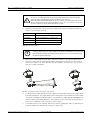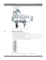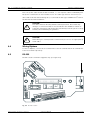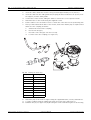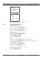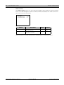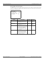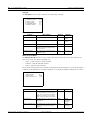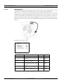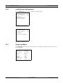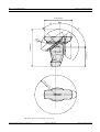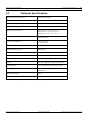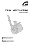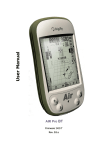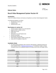
1
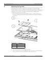
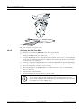
High Speed Pan/Tilt System
UPH-2D, UPH-3D, UPH-Z Series
en
Instruction Manual
High Speed Pan/Tilt System
Table of Contents | en
3
Table of Contents
1
Safety
5
1.1
Important safety instructions
5
1.2
Safety precautions
6
1.3
Important notices
7
2
Unpacking
9
2.1
Parts List
9
2.2
Tools Required
9
2.3
Safety Rules
10
3
Description
10
4
Installing the High Speed Pan/Tilt
11
4.1
Mounting the High Speed Pan/Tilt
11
4.2
Wiring the Video Cable
14
4.3
Connecting the Power Supply
15
4.4
Wiring Biphase
16
4.5
RS-232
16
5
Connecting the Washer Pump (optional)
17
5.1
Connecting the Peripherals
21
6
Attaching the Top Unit
22
7
Configuring the Device
25
7.1
Baud Rate Switches
25
7.2
Protocol Switches
26
7.3
Setting the Address
26
7.3.1
Address Combinations
27
7.4
Connections
28
8
Switching On and Off
31
8.1
Configuring the Device
31
9
On-screen Display (OSD)
32
9.1
Using the Joystick
32
10
Moving Around the Menus
32
10.1
Keyboard Commands List
33
10.2
Changing the Settings
34
10.3
Changing the Numeric Fields
34
Bosch Security Systems
Instruction Manual
F01U.073.990 | Version 1.0 | 2007.07
4
en | Table of Contents
High Speed Pan/Tilt System
11
Configuring the System
34
11.1
Language Menu
35
11.2
Display Setup Menu
35
11.2.1
Area Parameters Menu
37
11.2.2
Changing the Edit Text Menu
38
11.2.3
Display Parameters
39
11.3
Motion Parameters Menu
40
11.3.1
Speed Menu
40
11.3.2
Limits
42
11.3.3
Preset/Patrol/Autopan
43
11.3.4
Wiper-Washer
49
11.3.5
Alarms
50
11.4
Camera Parameters
50
(DinionXF
11.4.1
UPH-2D and UPH-3D Series
11.4.2
UPH-Z Series (camera module)
52
11.5
Creating a New Dynamic Mask
56
11.6
Load Default Configuration
58
11.7
Setup Info Menu
58
12
Maintenance
59
12.1
Cleaning
59
12.2
Replacing the Fuses
59
13
Troubleshooting
60
13.1
Dimensions and Range of Movement
61
14
Technical Specifications
63
F01U.073.990 | Version 1.0 | 2007.07
Cameras)
Instruction Manual
51
Bosch Security Systems
High Speed Pan/Tilt System
Safety | en
1
Safety
1.1
Important safety instructions
5
Read, follow, and retain for future reference all of the following safety instructions. Heed all
warnings on the unit and in the operating instructions before operating the unit.
1.
Cleaning - Unplug the unit from the outlet before cleaning. Follow any instructions
provided with the unit. Generally, using a dry cloth for cleaning is sufficient, but a moist
fluff-free cloth or leather shammy may also be used. Do not use liquid cleaners or aerosol
cleaners.
2.
Heat Sources - Do not install the unit near any heat sources such as radiators, heaters,
stoves, or other equipment (including amplifiers) that produce heat.
3.
Object and liquid entry - Never push objects of any kind into this unit through openings
as they may touch dangerous voltage points or short-out parts that could result in a fire
or electrical shock. Never spill liquid of any kind on the unit. Do not place objects filled
with liquids, such as vases or cups, on the unit.
4.
Lightning - For added protection during a lightning storm, or when leaving this unit
unattended and unused for long periods, unplug the unit from the supplied voltage and
disconnect the cable system. This will prevent damage to the unit from lightning and
power line surges.
5.
Controls adjustment - Adjust only those controls specified in the operating instructions.
Improper adjustment of other controls may cause damage to the unit. Use of controls or
adjustments, or performance of procedures other than those specified, may result in
hazardous radiation exposure.
6.
Overloading - Do not overload outlets and extension cords. This can cause fire or
electrical shock.
7.
Power sources - Operate the unit only from the type of power source indicated on the
label. Before proceeding, be sure to disconnect the power from the cable to be installed
into the unit.
–
For 24 VAC units, voltage applied to the unit's power input should not exceed
±10% VAC. User-supplied wiring must comply with local electrical codes (Class 2
power levels). Do not ground the supply at the terminals or at the unit's power
supply terminals.
–
If unsure of the type of power supply to use, contact your dealer or local power
company.
8.
Servicing - Do not attempt to service this unit yourself. Opening or removing covers may
expose you to dangerous voltage or other hazards. Refer all servicing to qualified service
personnel.
9.
Damage requiring service - Unplug the unit from the power source and refer servicing to
qualified service personnel when any damage to the equipment has occurred, such as:
–
the power supply cord or plug is damaged;
–
liquid has been spilled in or on the equipment;
–
an object has fallen into the unit;
–
unit has been dropped or the unit cabinet is damaged;
–
unit exhibits a distinct change in performance;
–
unit does not operate normally when the user correctly follows the operating
instructions.
10. Replacement parts - Be sure the service technician uses replacement parts specified by
the manufacturer, or that have the same characteristics as the original parts.
Unauthorized substitutions may cause fire, electrical shock, or other hazards.
Bosch Security Systems
Instruction Manual
F01U.073.990 | Version 1.0 | 2007.07
6
en | Safety
High Speed Pan/Tilt System
11. Safety check - Safety checks should be performed upon completion of service or repairs
to the unit to ensure proper operating condition.
12. Installation - Install in accordance with the manufacturer's instructions and in
accordance with applicable local codes.
13. Attachments, changes or modifications - Only use attachments/accessories specified by
the manufacturer. Any change or modification of the equipment, not expressly approved
by Bosch, could void the warrantee or, in the case of an authorization agreement,
authority to operate the equipment.
1.2
Safety precautions
DANGER! High risk:
This symbol indicates an imminently hazardous situation such
as "Dangerous Voltage" inside the product.
If not avoided, this will result in an electrical shock, serious
bodily injury, or death.
WARNING! Medium risk:
!
Indicates a potentially hazardous situation.
If not avoided, this could result in serious bodily injury or death.
CAUTION! Medium risk:
!
Indicates a potentially hazardous situation.
If not avoided, this may result in minor or moderate injury.
Alerts the user to important instructions accompanying the
unit.
CAUTION! Low risk:
Indicates a potentially hazardous situation.
if not avoided, this may result in property damage or risk of
damage to the unit.
i
F01U.073.990 | Version 1.0 | 2007.07
NOTICE!
This symbol indicates information or a company policy that
relates directly or indirectly to the safety of personnel or
protection of property.
Instruction Manual
Bosch Security Systems
High Speed Pan/Tilt System
1.3
Safety | en
7
Important notices
Accessories - Do not place this unit on an unstable stand, tripod, bracket, or mount. The unit
may fall, causing serious injury and/or serious damage to the unit. Use only with the cart,
stand, tripod, bracket, or table specified by the manufacturer. When a cart is used, use
caution and care when moving the cart/apparatus combination to avoid injury from tip-over.
Quick stops, excessive force, or uneven surfaces may cause the cart/unit combination to
overturn. Mount the unit per the manufacturer's instructions.
CAUTION!
!
Incorporate an all-pole magnetic and residual current power
switch, with a contact separation of at least 3 mm in each pole,
into the electrical installation of the building. If it is needed to
open the housing for servicing and/or other activities, use this
all-pole switch as the main disconnect device for switching off
the voltage to the unit.
Camera signal - Protect the cable with a primary protector if the camera signal is beyond 140
feet, in accordance with NEC800 (CEC Section 60).
Coax grounding:
–
Ground the cable system if connecting an outside cable system to the unit.
–
Connect outdoor equipment to the unit's inputs only after this unit has had its grounding
plug connected to a grounded outlet or its ground terminal is properly connected to a
ground source.
–
Disconnect the unit's input connectors from outdoor equipment before disconnecting the
grounding plug or grounding terminal.
–
Follow proper safety precautions such as grounding for any outdoor device connected to
this unit.
Disposal - Your Bosch product was developed and manufactured with high-quality material
and components that can be recycled and reused. This symbol means that electronic and
electrical appliances, which have reached the end of their working life, must be collected and
disposed of separately from household waste material. Separate collecting systems are
usually in place for disused electronic and electrical products. Please dispose of these units at
an environmentally compatible recycling facility, per European Directive 2002/96/EC.
Environmental statement - Bosch has a strong commitment towards the environment. This
unit has been designed to respect the environment as much as possible.
Electrostatic-sensitive device - Use proper ESD handling precautions to avoid electrostatic
discharge.
NOTE: Wear required grounded wrist straps and observe proper ESD precautions when
handling the electrostatic-sensitive printed circuit boards.
Grounding and polarization - This unit may be equipped with a 3-wire grounding connector
for earth grounding.
Moving - Disconnect the power before moving the unit. Move the unit with care. Excessive
force or shock may damage the unit.
Outdoor signals - The installation for outdoor signals, especially regarding clearance from
power and lightning conductors and transient protection.
Permanently connected equipment - Incorporate a readily accessible disconnect device in
the building installation wiring.
Video loss - Video loss is inherent to digital video recording; therefore, Bosch Security
Systems cannot be held liable for any damage that results from missing video information. To
minimize the risk of lost digital information, Bosch Security Systems recommends multiple,
Bosch Security Systems
Instruction Manual
F01U.073.990 | Version 1.0 | 2007.07
8
en | Safety
High Speed Pan/Tilt System
redundant recording systems, and a procedure to back up all analog and digital information.
Copyright
This user guide is the intellectual property of Bosch Security Systems and is protected by
copyright.
All rights reserved.
Trademarks
All hardware and software product names used in this document are likely to be registered
trademarks and must be treated accordingly.
NOTICE!
i
F01U.073.990 | Version 1.0 | 2007.07
This user guide has been compiled with great care and the
information it contains has been thoroughly verified. The text
was complete and correct at the time of printing. The ongoing
development of the products may mean that the content of the
user guide can change without notice. Bosch Security Systems
accepts no liability for damage resulting directly or indirectly
from faults, incompleteness or discrepancies between the user
guide and the product described.
Instruction Manual
Bosch Security Systems
High Speed Pan/Tilt System
2
Unpacking | en
9
Unpacking
This equipment should be unpacked and handled with care. If an item appears to have been
damaged in shipment, notify the shipper immediately.
Verify that all the parts listed in Section 2.1 Parts List are included. If any items are missing,
notify your Bosch Security Systems Sales or Customer Service Representative.
The original packing carton is the safest container in which to transport the unit and must be
used if returning the unit for service. Save it for possible future use.
2.1
Parts List
The High Speed Pan/Tilt System includes the following components:
–
–
–
One (1) Unitized Pan Head (UPH) device
One (1) small box of accessories:
–
One (1) 4 mm allen wrench
–
One (1) moisture bag with salt, metal fixing accessory and two (2) fixing screws
–
One (1) serial extension cable
–
One (1) serial adapter
–
One (1) safety label
–
One (1) instruction manual
–
Two (2) tie thread
–
One (1) plastic tube
One (1) box containing:
–
2.2
Bosch Security Systems
One (1) base with power supply box
Tools Required
–
Small, straight-blade screwdriver - 2.5 mm (0.1 in.)
–
3 mm Allen wrench
Instruction Manual
F01U.073.990 | Version 1.0 | 2007.07
10
2.3
en | Description
High Speed Pan/Tilt System
Safety Rules
To ensure safety, the following warnings are specified:
–
–
The device must be installed and maintained by skilled technical personnel.
Connect the device to a power source corresponding to the indications given on the
marking label.
–
The device has been designed for permanent installation in a building or other suitable
structure.
–
Moving parts may result in risk of injury, therefore, the device should be mounted so that
–
Place the safety label near the UPH. See Figure 6.4 for illustration of safety label.
it is accessible only to the technician/installer.
–
Before carrying out any technical work on the UPH, tilt the UPH all the way up or all the
way down, then disconnect the power supply and cables from all other devices.
–
Do not use power cables with signs of wear or aging.
–
Do not use the device in the presence of inflammable substances.
–
Do not allow children or unauthorized personnel to use the device.
–
The device should be switched OFF when the power supply has been disconnected and
the connecting cables to other devices have been removed.
–
Keep this manual for future reference.
!
3
CAUTION! Before disconnecting the power supply to the UPH, tilt the device
either all the way up or all the way down. When the UPH loses power,
depending on how it is positioned, the unit may drop slightly forward or
backward. Therefore, failure in correctly positioning the UPH before
disconnecting the power supply may result in personal injury or possible
damage to the device.
Description
The Bosch High-Speed Positioning System is a complete, high-performance, high quality solution that can pan 360 degrees continuously at speeds of up to 100 degrees per second. An
extensive range of options lets you tailor the system to your specific requirements. For example, a wide variety of video cameras and lenses, including the optimized DinionXF camera and
zoom combinations, are available.
F01U.073.990 | Version 1.0 | 2007.07
Instruction Manual
Bosch Security Systems
High Speed Pan/Tilt System
4
Installing the High Speed Pan/Tilt | en
11
Installing the High Speed Pan/Tilt
This chapter outlines the procedures needed to install the High Speed Pan/Tilt. Installation
should only be done by qualified service personnel in conformance to all local codes.
i
4.1
NOTICE!
The High Speed Pan/Tilt unit cannot be mounted upside down! This will stress
bearings and mechanical components; no liabilities are accepted and all
warranties are void.
Mounting the High Speed Pan/Tilt
The High Speed Pan/Tilt System can be mounted with either a wall mount (MTC-WUPH, sold
separately) or pole mount (MTC-PUPH, sold seperately).
To install the device, proceed as follows:
1.
Determine the location to install the device.
–
When selecting a location, a minimum clearance of 300 mm (12 in.) in front of the
unit and 300 mm (12 in.) in back of the unit is required to facilitate component
removal and installation.
–
The device should be installed vertically. Any other position could impair the performance of the device.
–
2.
Do not attach the device upside down.
Insert the cables into the optional wall or pole mount so they protrude approximately
.5 m (19.7 in.) (see Figure 4.1).
.5 m
19.7 in.
2
1
.5 m
19.7 in.
MTC-PUPH
MTC-WUPH
Fig. 4.1
Optional Wall Mount (1) or Pole Mount (2)
WARNING! Medium Risk:
!
Bosch Security Systems
The cables should not be accessible by unauthorized personnel; cables should be
secured to fixed locations at appropriate intervals to bare the weight of the
cables, e.g. cables running inside a tall camera pole.
Instruction Manual
F01U.073.990 | Version 1.0 | 2007.07
12
en | Installing the High Speed Pan/Tilt
High Speed Pan/Tilt System
CAUTION! Medium Risk:
Be sure to use appropriately strong and load bearing bolts and other fixing
materials when installing any UPH mountings to any surface.
When the MTC-WUPH Wall Mount is fixed to a wall, each fixing dowel must be
able to support a traction load of 300daN or more. It is necessary to use 8 mm
(0.315 in.) diameter bolts with appropriate length.
!
3.
Attach the optional wall or pole mount according to the specific mounting manual (see
Table 4.1 for mounting options).
Part #
Description
MTC-PUPH
Outdoor Pole Mount for UPH Series
MTC-WUPH
Outdoor Wall Mount for UPH Series
MTC-POLE-W
Pole Adapter for MTC-WUPH
MTC-CORN-W
Corner Adapter for MTC-WUPH
Table 4.1 Mounting Options
NOTICE!
If using a washer kit, the spray support should be installed before positioning
and wiring the pan/tilt. For additional information, see Section 5 Connecting
the Washer Pump (optional).
i
4.
Remove the cable glands from the base and fit the gasket / seal ring (see Figure 4.3).
5.
Insert the cables into the cable glands while holding the base approx. 20 cm from the
bracket (see Figure 4.2). Note that there are three glands; one for power, one for video,
and one for data / IO cables.
7
Fig. 4.2
6.
Inserting the Cables through the Cable Glands
Securely lock the cable glands into place (gland closing torque 5 Nm); they accept cables
5-10 mm in diameter. The cable glands can be changed to accept smaller 3-7 mm in diameter cables, available from www.cembre.com and browse "Cable glands IP68 MAXIblock"
(model number: 1910.M16 M16x1.5 ). The gland (5-10 mm or 3-7 mm) closing torque is
5 Nm; use a calibrated torque wrench to ensure closure.
7.
Position the base on the optional wall or pole mount, guiding the cables so that they are
positioned inside the wall or pole mount (see Figure 4.3).
F01U.073.990 | Version 1.0 | 2007.07
Instruction Manual
Bosch Security Systems
High Speed Pan/Tilt System
Installing the High Speed Pan/Tilt | en
8.
13
Fasten the base to the wall or pole mount with the supplied screws and washers (use a
calibrated torque wrench setting of 2.1 Nm).
1
6
1
7
2
2
3
3
4
4
5
5
Fig. 4.3
Wiring the Device
Reference #
Description
1
Base
2
Gasket
3
Screw Ring
4
Washer
5
Screw
6
Bracket
7
Support
Fig. 4.4
9.
Preparing the Cables for Wiring
Cut the cables to approximately 152.4 mm (6 in) (see Figure 4.4). The earth cable must
be longer then the power wires approximately 10 mm or more to prevent the stretch disconnecting.
10. Cover the cable with a plastic tube and fix it with the tie thread.
Bosch Security Systems
Instruction Manual
F01U.073.990 | Version 1.0 | 2007.07
14
en | Installing the High Speed Pan/Tilt
High Speed Pan/Tilt System
11. Make a group with all signal cables and fix them with the tie thread. Figure 4.5 indicates a
proper cable connection.
Fig. 4.5
4.2
Tie Threads used to Group and Secure Signal Cables
Wiring the Video Cable
To wire the video cable, proceed as follows:
1.
Strip the video cable with a pair of wire strippers.
2.
Cut the length of the center conductor and the braid to approximatley 30 mm (1.2 in.).
3.
Twist the braid into a single conductor.
4.
Use a small screwdriver to press down on the GND push latch (see Figure 4.6) and attach
the single braid to the GND terminal.
5.
Use a small screwdriver to press down on the VIDEO push latch (see Figure 4.6) and
attach the center conductor to the VIDEO terminal.
Fig. 4.6
Wiring the Terminal
Note: The above terminals support AWG 20 (0.5 mm2) to AWG 28 (0.08 mm2).
F01U.073.990 | Version 1.0 | 2007.07
Instruction Manual
Bosch Security Systems
High Speed Pan/Tilt System
4.3
Installing the High Speed Pan/Tilt | en
15
Connecting the Power Supply
The base with power supply box is available in two (2) power supply voltages (24 VAC or
230 VAC). Before proceeding with the installation, check the identification label of the product to verify that the device coincides with the power supply requirements.
CAUTION!
!
When connecting the base, make sure the power supply is disconnected and
that the disconnecting switch is open.
When the base is opened, the power supply board appears as shown below. To connect the
power supply, make the connections as seen in Figure 4.7.
Power Supply and Bi-polar Disconnecting Switch
Fig. 4.7
Connecting the Power Supply
To wire the power cable (not supplied), use Table 4.2 to attach the appropriate colored wire
to the appropriate terminal.
Wire Color
Per local Installer
Neutral
Per local Installer
Live/Active
Green/Yellow
Earth
Wire Color
230 VAC Terminal Connection
Blue
Neutral
Brown
Live/Active
Green/Yellow
Earth
Table 4.2
Bosch Security Systems
24 VAC Terminal Connection
Terminal Connections
Instruction Manual
F01U.073.990 | Version 1.0 | 2007.07
16
en | Installing the High Speed Pan/Tilt
High Speed Pan/Tilt System
Note: The power cable must be double insulated, i.e. each separate cable is individually insulated, then contained in an outer insulated cover. The cable type must be chosen in accordance with local and national wiring rules; recommended cable type H05RN-F 1mm2 both for
24 VAC and 230 VAC installations.
CAUTION!
The device must be wired by skilled technical personnel. Never make any
changes or connections that are not described in this handbook. Failure to
follow the instructions indicated in this manual may result in system or safety
hazards, thus invalidating the guarantee.
!
CAUTION!
!
4.4
When wiring for external/outdoor environments, be sure to use appropriately
rated cables.
Wiring Biphase
To wire for Biphase, connect the C+ terminal wire to the B+ terminal and the C- terminal wire
to the B- terminal respectively.
4.5
RS-232
RS-232 is used for firmware upgrades only (see Figure 4.8).
Fig. 4.8
RS-232 Location
F01U.073.990 | Version 1.0 | 2007.07
Instruction Manual
Bosch Security Systems
High Speed Pan/Tilt System
5
Connecting the Washer Pump (optional) | en
17
Connecting the Washer Pump (optional)
The device must be wired by skilled technical personnel. Never make any
changes or connections that are not described in this handbook. Failure to follow the instructions indicated in this manual may result in system or safety
hazards, thus invalidating the guarantee.
!
The High Speed Pan/Tilt System may have an optional washer pump. To connect the washer
pump for the HAC-WAS05-20, HAC-WAS05-50, and HAC-WAS30-50, proceed as follows:
1.
Attach the mount, (optional wall or pole mount) by positioning the washer pipe support
in the desired position (see Figure 5.1).
1
2
3
4
5
6
7
8
Fig. 5.1
Installing the Washer Cables
Reference #
Bosch Security Systems
Description
1
Base
2
Cable Glands
3
Washer Pipe Support
4
Gasket
5
Screw Seals
6
Bracket or Pole Support
7
Washers
8
Screws
Instruction Manual
F01U.073.990 | Version 1.0 | 2007.07
18
en | Connecting the Washer Pump (optional)
High Speed Pan/Tilt System
2.
Insert the cables inside the mount so they protrude approximately 0.5 m (19.7 in.).
3.
Insert the cable into the cable glands and, keeping the base at about 20 cm (7.9 in.) from
4.
Set the base on the mount, aiding the cables to achieve the correct position inside.
5.
Attach the base to the mount using the supplied screws.
the support, lock the cable glands.
6.
Cut the cables to size and either restore or make the connections to the positioning unit.
7.
After you have attached the base to the mount, shorten the washer pipe as required and
attach it to the coupling as follows:
a.
unfasten the nut from the coupling,
b.
insert it into the pipe,
c.
insert the end of the pipe onto the nosecap.
d.
Lock the nut to the coupling (see Figure 5.2).
1
5
3
2
6
7
4
8
9
Fig. 5.2
Installing the Washer Pipe
Reference #
Description
1
Washer Pipe
2
Nut
3
Nosecap
4
Coupling
5
Bracket
6
Noseclip
7
Screws
8
Washers
9
Delivery Hose
8.
Attach the pipe to the washer support using the supplied bracket, screws, and washers.
9.
Lock the coupling using the supplied hoseclip and connect the delivery hose.
10. Calibrate the jet (see Figure 5.3) by directing the nozzle towards the glass of the housing.
F01U.073.990 | Version 1.0 | 2007.07
Instruction Manual
Bosch Security Systems
High Speed Pan/Tilt System
Connecting the Washer Pump (optional) | en
19
1
Fig. 5.3
Calibrating the Nozzle
The diagram below refers to the 19-pin connector on the base board of the pan/tilt.
Fig. 5.4
Bosch Security Systems
Connecting the Washer Pump
Instruction Manual
F01U.073.990 | Version 1.0 | 2007.07
20
en | Connecting the Washer Pump (optional)
Reference
High Speed Pan/Tilt System
Description
AL1
Alarm input, voltage-controlled (10-35 V), to
monitor the presence of water in the tank.
For devices with level sensors (HAC-WAS05-50,
HAC-WAS30-50), closure of the contact, if
enabled, generates an on-screen alarm (see
Figure 11.3.5 to configure the alarm).
O1-C1
Clean contact for starting the water pump.
K1
Power relay (external), able to start the water
pump.
F1-F2
Wiper power supply (max 24 Vac – 0.75 A from
TR3 and TR4), from safety transformer housed
in the base of the device (factory fitted with
wiper option).
Note: Only required for UPH-Z Series; not
required for UPH-2D or UPH-3D Series.
Fig. 5.5
Connecting the Washer System with Level Sensor Capabilities
i
F01U.073.990 | Version 1.0 | 2007.07
NOTICE!
The HAC-WAS05-10 washer system does not have a level sensor. Therefore, it is
not necessary to connect the alarm input.
Instruction Manual
Bosch Security Systems
High Speed Pan/Tilt System
5.1
Connecting the Washer Pump (optional) | en
21
Connecting the Peripherals
The base has a 19-pin connector for which the following connections are illustrated:
Fig. 5.6
Base with 19-pin Connector for Connecting Peripherals
Reference
RS-485-2
Dedicated communication port for Pelco D
(2400 baud, 8N1)
Video
Composite video out 1 Vpp
O1-C1 and
O2-C2
Clean output contacts that can be activated by
alarm or by user (50 VDC or 30 VAC @ 1A)
A1, A2, A3,
and A4
Alarm in, voltage-controlled (10-35 VDC),
referred to common COM
B+ and B-
Biphase communication lines
!
Bosch Security Systems
Description
CAUTION! The system is TNV-1 type, do not connect to SELV circuits.
Instruction Manual
F01U.073.990 | Version 1.0 | 2007.07
22
6
en | Attaching the Top Unit
High Speed Pan/Tilt System
Attaching the Top Unit
Each time the top unit requires re-assembling, the screw seals should be replaced (use a calibrated torque wrench setting of 2.1 Nm) to ensure the appliance remains water tight.
Inside the bottom cover there is a small bag containing mineral salts that are used to prevent
moisture formation in the base and near the connector boards. This salt does not require any
maintenance; however, remove the salt bag from the base before installing the unit.
To attach the top unit, proceed as follows:
1.
Place the salt bag inside the housing as shown in Figure 6.1, with the salt bag secured
into position by the metal fixing accessory and two fixing screws (supplied in small box of
accessories).
Fig. 6.1
Salt Bag Placement
Reference #
Description
1
Salt Bag
2
Metal Fixing Accessory
3
Fixing Screws
2.
Remove the camera packaging material.
3.
Make sure the gasket is present and in good condition.
4.
Place the unit on the base. Align the tabs on the sides (see Figure 6.2) and verify that the
parts are positioned correctly. Be careful not to pinch any of the wires.
F01U.073.990 | Version 1.0 | 2007.07
Instruction Manual
Bosch Security Systems
High Speed Pan/Tilt System
Attaching the Top Unit | en
Fig. 6.2
5.
6.
23
Aligning the Tabs
Push down to snap into place.
Attach the top unit to the base using the supplied attachment screws and corresponding
seals (see Figure 6.3).
7.
Bosch Security Systems
Tighten the base with a 4 mm Allen wrench.
Instruction Manual
F01U.073.990 | Version 1.0 | 2007.07
24
en | Attaching the Top Unit
High Speed Pan/Tilt System
Fig. 6.3
Attaching the Top Unit
Reference #
Description
1
Configuration Window
2
Base
3
Screw
4
Screw Seal
5
Gasket
CAUTION! Medium Risk:
Place safety label near unit that warns of moving parts.
!
Fig. 6.4
Safety Label
F01U.073.990 | Version 1.0 | 2007.07
Instruction Manual
Bosch Security Systems
High Speed Pan/Tilt System
7
Configuring the Device | en
25
Configuring the Device
Before powering the High Speed Pan/Tilt, it must be properly configured. To configure the DIP
switches inside the configuration window, proceed as follows:
1.
Open the configuration window by unscrewing the screws with a 3 mm Allen wrench. See
Figure 6.3 for the location of the configuration window.
2.
Verify that the position of the DIP switches are the same as in Figure 7.1. Starting from
the left, we see the baud rate, protocol, and the peripheral address selectors, respectively.
Baud
Rate
Protocol
Rs485
Terminations
Fig. 7.1
Address +
Serial
Biphase +
Bilinx
Positioning the DIP Switches
For all DIP switches, when the rocker is down the switch is OFF, or represents the logical
value “0”; when the rocker is up, the switch is ON, with logical value “1”. The white rectangle
represents the position of the rocker.
7.1
Baud Rate Switches
DIP switches 4, 3, and 2 are not used; the unit has fixed baud rates. DIP switch No. 1 is used
to update the firmware: PROGRAM. ON and PROGRAM. OFF. During normal use, make sure
the rocker for DIP switch No. 1 is OFF (PROGRAM. OFF).
DIP-SWITCH 1
(for updating the firmware)
Program ON
Table 7.1
Bosch Security Systems
Program OFF
Updating the Firmware
Instruction Manual
F01U.073.990 | Version 1.0 | 2007.07
26
7.2
en | Configuring the Device
High Speed Pan/Tilt System
Protocol Switches
There is no need to set any particular protocol, the UPH is auto-sensing. The protocols supported are:
Protocol
Pelco D
Biphase and
Bilinx
Baud Rate
2400
(8N 1)
Menu setup (OSD)
Preset 95
Auto
AUX-On 200
Table 7.2 Supported Protocols
7.3
Setting the Address
The UPH address can have a setting from 1 to 255. Binary code is used to select the address,
using the 8 DIP switches on the far right. The up position represents binary value “1”, while
the down position represents binary value “0”.
See Figure 7.2 for all possible combinations (the white rectangle represents the position of
the switch).
Serial Lines
Address
Table 7.3 All Possible Settings for Setting the UPH Address
Serial Lines Switches:
Dip-switches 10 and 9 are not used; the unit has fixed serial line mode.
Serial Lines Termination Switches:
Dip-switch 1 is not used (the RS485-1 line is not available).
Dip-switch 2 is used to enable the line termination of RS485-2 serial line.
Bilinx and Biphase Switches:
Dip-switch 1 is used to enable the line termination of Biphase serial line.
Dip-switch 2 is used to select the video format (ON = PAL, OFF = NTSC).
F01U.073.990 | Version 1.0 | 2007.07
Instruction Manual
Bosch Security Systems
High Speed Pan/Tilt System
7.3.1
27
Address Combinations
Fig. 7.2
Bosch Security Systems
Configuring the Device | en
Address table
Instruction Manual
F01U.073.990 | Version 1.0 | 2007.07
28
7.4
en | Configuring the Device
High Speed Pan/Tilt System
Connections
Please take note of the particular UPH model that you have installed. All three versions, UPHZ, UPH-2D, and UPH-3D Series, support Bilinx and Biphase telemetry control, i.e.: PTZ.
The camera menu setup of UPH-Z Series is done via the OSD, i.e.: AUX ON - 200 - Enter. The
camera menu setup of UPH-2D and UPH-3D Series is done via two different AUX commands,
i.e.: AUX ON - 46 - Enter (DinionXF main menu) and AUX ON - 801 - Enter (DinionXF installation menu). See Figure 10.1 for more information about keyboard commands.
Bilinx is a Bosch two-way communication protocol that allows remote control, configuration,
and updates over a video coax cable. Bilinx is available on all UPH models.
Biphase is used for communicating telemetry (control) and set up information with the UPHSeries units. Biphase does not pass the video signal from the UPH-Series units, so a separate
video coax cable is required. Biphase should be wired with Belden 8760 or equivalent.
Biphase is available on all UPH models.
Note: If the UPH is the only unit connected, or the last unit in a daisy chain configuration, then
turn ON dip-switch 1 of Biphase + Bilinx to terminate the data line. Turn OFF dip-switch 1 of
Biphase + Bilinx for each UPH in a daisy chain (i.e. unterminated). A maximum of four (4) UPH
units can be daisy chained together.
LTC5136 or
equivalent
RS-232
Interface
Biphase
unitized pan/
Box
CCTV Monitor
F01U.073.990 | Version 1.0 | 2007.07
Instruction Manual
UPH Series:
tilt head
Video
Bosch Security Systems
High Speed Pan/Tilt System
Configuring the Device | en
29
Intuikeyboard
BOSCH
Prod
Mon
Shot
Clr
1
2
3
4
5
6
7
8
9
Divar
0
RS-485
Biphase
Divar
Bilinx/Video
UPH Series: unitized
pan/tilt head
Intuikeyboard
BOSCH
Prod
Mon
Shot
Clr
1
2
3
4
5
6
7
8
9
Allegiant
0
RS-485
Biphase
Bilinx/Video
Intuikeyboard
Intuikeyboard
Allegiant +
BOSCH
BOSCH
ProdProd
Mon Mon
ShotShot
Clr Clr
1 1 2 2 3 3
LTC 8016
Divar
- Bilinx
4 4 5 5 6 6
7 7 8 8 9 9
0 0
RS-485
RS485
- orDivar
Divar
Bilinx/Video
Video
UPH Series: unitized
pan/tilt head
Intuikeyboard
BOSCH
BOSCH
Prod
Mon
Prod
RS485
Mon
Shot
Clr
7
0
Allegiant
8016
Divar+ -LTC
Bilinx
Shot
Clr
1
4
3
2
1
4
7
5
8
2
5
8
6
9
3
6
9
0
RS-485
Bilinx/Video
Bosch Security Systems
Instruction Manual
F01U.073.990 | Version 1.0 | 2007.07
30
en | Configuring the Device
High Speed Pan/Tilt System
Bilinx/Video
DiBos 8
Biphase
DiBos 8
Video
UPH Series: unitized
pan/tilt head
Video
DiBos 8
LTC 8786
RS-232
Biphase
Vidos, IE, DiBos 8, Bosch
VMS or equivalent
RS485-2
LAN
Ethernet
VIPX1
Ethernet
Video
Fig. 7.3
Connection Diagrams
F01U.073.990 | Version 1.0 | 2007.07
Instruction Manual
Bosch Security Systems
High Speed Pan/Tilt System
8
Switching On and Off | en
31
Switching On and Off
Systems in the UPH line are switched on by simply connecting the power supply, and
switched off by disconnecting the power supply. When the UPH is powered up in an environment below 0 °C, the device checks it’s internal components to make sure that they are warm
enough to start without damage. If the internal components’ temperatures are too low, the
OSD displays a warning message and the UPH automatically enters its de-icing mode. In deicing mode the UPH is powered in an attempt to raise its internal temperature. A timer
appears on the screen and counts down showing how much time remains for de-icing to complete.
i
8.1
NOTICE!
De-icing can take between 30 and 105 minutes, after which time it is ready for
use, assuming that a safe internal temperature is reached; otherwise, it is too
cold to safely operate the UPH and it remains off.
Configuring the Device
The first time the UPH is switched on, make sure it is configured correctly.
To configure the UPH, proceed as follows:
1.
Disconnect the power supply by first tilting the device either all the way up or all the way
down. When the UPH loses power, depending on how it is positioned, the unit may automatically tilt forward or backward. Therefore, failure in correctly positioning the UPH
before disconnecting the power supply may result in personal injury or possible damage
to the device.
2.
3.
Remove the DIP switch configuration window (see Figure 6.2).
Set the firmware update DIP switch rocker to the up position (PROGRAM. ON). See
Figure 7.1.
4.
Connect a monitor to the video output and power the device. After a few seconds, it is
possible to check the settings on the monitor screen. Check these settings to verify that
the unit is configured correctly.
5.
After completing the check, switch off the device and re-toggle the firmware update DIP
switch rocker to the down position (PROGRAM. OFF).
6.
Close the c window and re-connect the power supply.
WARNING!
!
!
Bosch Security Systems
1.
2.
3.
Make sure the UPH system and other components of the installation are
closed so it is impossible to come into contact with live parts.
Make sure all parts are fastened down firmly and safely.
Make sure the power source and connecting cables are suitable for the
power consumption of the system.
CAUTION!
Do not stay in the vicinity of the device when it is powered. There is a risk of
crushing.
Instruction Manual
F01U.073.990 | Version 1.0 | 2007.07
32
en | On-screen Display (OSD)
High Speed Pan/Tilt System
NOTICE! High temperatures can also have a negative effect on camera image. If
the ambient (outside) air temperature exceeds 40 deg Celsius (104 deg
Fahrenheit), the HSPT will continue to operate, however some unusual effects
may appear on the video signal. These are blemishes that appear as very small
white dots on the video picture. They are usually only noticeable during and few a
few hours after dusk, when the overall scene becomes darker, and the housing is
i
still cooling down as the sun goes down.
Continued exposure of the HSPT to excessive ambient (outside) air temperatures
will effect the long-term reliability of the HSPT, cause blemished to become more
severe, and may introduce fixed pattern noise (FPN) on the video signal.
Solution: via Bilinx change the SensUp setting in the camera to OFF; this reduces
the number and intensity of the blemishes.
9
On-screen Display (OSD)
During normal UPH operation, it is possible to activate the on-screen menu in order to set the
advanced functions using the corresponding key/s.
When using a Bosch keyboard, control the OSD with the Iris and Focus buttons. For dynamic
masking, the SET - 1 - Enter and SET - 2 - Enter keys are used.
Consult the user’s manual for other keyboard brands.
9.1
Using the Joystick
In order to move through the OSD, move the joystick up or down through the menus.
To enter a menu, press the Focus Near or Focus Far button. To exit a menu, press the Iris
Open or Iris Close button.
10
Moving Around the Menus
Each on-screen display (OSD) shows a list of parameters or submenus that can be selected by
the operator. For example, to access the main menu in the High Speed Pan/Tilt (see
Figure 10.1), click AUX - ON - 200, then Enter. If the camera is a DinionXF option, then the DinionXF’s main menu (see Figure 10.2) can be accessed by clicking AUX - ON - 46, followed by
Enter. The DinionXF’s Installer menu can be accessed by clicking AUX - ON - 801, followed by
Enter.
1.
To scroll through the parameters, move the cursor by operating the joystick up and down.
–
To scroll through the parameters, move the cursor by operating the joystick up or
down.
–
The cursor is indicated by the “” symbol at the beginning of a line, i.e. on the left
side of the screen/monitor.
2.
The “” symbol at the end of a line, i.e. on the on the right of the screen/monitor, indicates the presence of a submenu. To enter the submenu, confirm the menu item by
pressing the Focus Near or Far key.
3.
To exit the submenu, press Iris Open or Iris Close button.
F01U.073.990 | Version 1.0 | 2007.07
Instruction Manual
Bosch Security Systems
High Speed Pan/Tilt System
Moving Around the Menus | en
MAIN MENU
1 - LANGUAGE
2 - DISPLAY SETUP
3 - MOTION PARAMETERS
4 - CAMERA PARAMETERS
5 - LOAD DEFAULT CONFIG
6 - SETUP INFO
Fig. 10.1
33
Accessing the Main Menu - AUX On 200
MODE
ALC
ENHANCE
COLOR
BLC
VMD
MODE ID
DEFAULTS
2
OFF
OSD
TRAFFIC
EXIT
Fig. 10.2 Accessing the DinionXF camera Setup Menu - AUX On 46
(screen may differ depending on the camera type)
10.1
Keyboard Commands List
Setup and Configuration
Open OSD configuration: AUX ON - 200 - Enter
DinionXF main menu on: AUX ON - 46 - Enter
DinionXF installation menu on: AUX ON - 801 - Enter
Receiver reset/home: AUX ON - 911 - Enter
Receiver offset re-calibration: AUX ON - 204 - Enter
Auxiliary Connections
Relay number 2 activation: AUX ON - 65 - Enter
Relay number 2 de-activiation: AUX OFF - 65 - Enter
Wiper start: AUX ON - 202 - Enter
Wiper stop: AUX OFF - 202 - Enter
Washer start: AUX ON - 201 - Enter
Presets
Store preset position: Show Shot - n - Enter (n = 01 - 99, i.e. 99 presets)
Move to a preset position: Show Shot - n - Enter (n = 01 - 99, i.e. 99 presets)
Erase preset position: Show Shot - 9n - Enter (n = 01 - 99, e.g. to erase preset position #31,
then push Show Shot - 931 - Enter)
Standard preset patrol start: AUX ON - 8 - Enter
Standard preset patrol stop: AUX OFF - 8 - Enter
Recalibrate presets: AUX ON - 204 - Enter
Autopan (requires left and right limits to be set in OSD)
Autopan start: AUX ON - 1 - Enter
Autopan stop: AUX OFF - 1 - Enter
Bosch Security Systems
Instruction Manual
F01U.073.990 | Version 1.0 | 2007.07
34
en | Configuring the System
10.2
High Speed Pan/Tilt System
Changing the Settings
To change a setting, proceed as follows:
1.
AUX ON - 200 - Enter to enable the OSD.
2.
Move the cursor to the parameter to be changed.
3.
Press the confirmation (Focus) button. The field starts flashing, indicating that it is in
change mode. Operating the joystick (up and down) shows the alternative choices.
4.
After identifying the desired selection, press the confirmation (Focus) button; the parameter stops flashing.
Note: For UPH-2D and UPH-3D Series (DinionXF) models, use up and down to scroll through
the menus, Focus to enter a submenu, and left and right to change values.
10.3
Changing the Numeric Fields
To change a numeric field, proceed as follows:
1.
2.
Use the joystick to scroll to the parameter you would like to edit.
Press the confirmation (Focus) button. The cursor starts flashing for the character to be
changed, indicating it is in edit mode.
–
The minimum and maximum values allowed are displayed at the bottom of the
screen. If you try to insert a value outside the limits, the field is forced to the minimum or maximum allowed value.
–
Operating the joystick (up and down) shows the alternative choices. If there is more
than one field on the same line, it is necessary to select the field by moving the joystick (left and right).
3.
After making the change, press the confirmation (Focus) button.
–
The first digit in the numeric field to be changed flashes and the last line of the dis-
–
Move within the field (left and right) and change the sign or the numeric value (up
play shows the accepted limits for the field.
and down).
Note: For UPH-2D and UPH-3D Series (DinionXF) models, use up and down to scroll through
the menus, Focus to enter a submenu, and left and right to change values.
11
Configuring the System
The UPH High Speed Pan/Tilt can be configured through the on-screen display (OSD). Open
the main menu by pressing AUX ON - 200 - Enter.
MAIN MENU
1 - LANGUAGE
2 - DISPLAY SETUP
3 - MOTION PARAMETERS
4 - CAMERA PARAMETERS
5 - LOAD DEFAULT CONFIGUR.
6 - SETUP INFO
Fig. 11.1 OSD (On-screen Display) Main Menu
F01U.073.990 | Version 1.0 | 2007.07
Instruction Manual
Bosch Security Systems
High Speed Pan/Tilt System
11.1
Configuring the System | en
35
Language Menu
This menu is used to select and set the desired language. The default setting is English.
LANGUAGE MENU
1 - ITALIANO
2 - ENGLISH
3 - FRANCAIS
4 - DEUTSCH
Fig. 11.2
OK
Language Menu with English Selected.
OK is displayed next to your choice, and the language is changed immediately.
11.2
Display Setup Menu
The Display Setup menu is used to define settings for the information that is permanently displayed on the screen.
DISPLAY SETUP MENU
1 - PAN/TILT POSITION
2 - PRESET TITLE
3 - PRESET POSITION
4 - TILT LIMIT TITLE
5 - VIDEO SIGNAL
6 - INTERLACED VIDEO
7 - AREA PARAMETERS
8 - DISPLAY PARAMETERS
Fig. 11.3
Bosch Security Systems
:
:
:
:
:
:
YES
YES
YES
YES
PAL
YES
Display Setup Menu
Instruction Manual
F01U.073.990 | Version 1.0 | 2007.07
36
en | Configuring the System
High Speed Pan/Tilt System
Feature
Description
Default
Options
PAN/TILT POSITION
Shows the current position of the device (in
degrees) with reference to the home position.
YES
YES, NO
PRESET TITLE
Enables or disables the preset title on the display.
YES
YES, NO
PRESET POSITION
Enables or disables the preset number reached
YES
on the display.
YES, NO
TILT LIMIT TITLE
Enables or disables displaying if the tilt limit is
YES
reached.
YES, NO
VIDEO SIGNAL
Type of video signal.
PAL
PAL, NTSC
INTERLACED VIDEO
Enables or disables the display for interlaced
video.
YES
YES, NO
AREA PARAMETERS
Information about area (or sector) that the unit
is pointing towards.
DISPLAY
PARAMETERS
Setup of location of text position/type on the
display.
NOTICE! Over time, due to environmental factors such as wind and vibration,
preset positions may not always align with what they were at installation. Use
i
AUX ON - 204 - Enter to correct this. It takes 30-45 seconds to cycle through this
process, during which time there is no user control. Once it has finished the
process and corrected for the effect of any environmental factors, the user regains full
control.
F01U.073.990 | Version 1.0 | 2007.07
Instruction Manual
Bosch Security Systems
High Speed Pan/Tilt System
11.2.1
Configuring the System | en
37
Area Parameters Menu
The Area Parameters menu enables the user to show a message on the screen, depending on
the horizontal position reached by the device; this is sometimes known as sector information.
From this menu, it is possible to enter two (2) lower menus that are used to set the text for
each area, and the start and end positions (in degrees) of these areas. It is possible to set up
to eight (8) areas with their own title, start, and end positions.
For example, to activate the first title and obtain a message when the device is between +80 °
and +120 ° in the horizontal (pan) direction, proceed as follows:
1.
2.
Enter the Position Area menu.
Select Area 1 by pressing Focus; an arrow starts blinking next to the start position. Press
Focus again, use the joystick to enter the value +080.00 in the left column (start position
of text coming on screen), then press Focus to store that value. Repeat the process, but
put +120.00 in the right column (stop position of text removed from the screen).
3.
In the Text (String) Area menu, select the first line and enter the desired text.
Note: If the area position start and end values are set to +0.00, this disables the text display.
AREA PARAMETERS MENU
1 - AREA TITLE
: NO
2 - STRING AREA MENU
3 - POSITION AREA MENU 8 - OFFSET PAN :
TEXT AREA MENU
1 - AREA 1
2 - AREA 2
3 - AREA 3
4 - AREA 4
5 - AREA 5
6 - AREA 6
7 - AREA 7
8 - AREA 8
Test area 1
+ 0.0
EDIT TEXT MENU
1 - STRING EDIT
-----------------------------------------Test area 1
-----------------------------------------2 - DELETE STRING
AREA POSITION MENU
1 - AREA 1 + 0.0 + 0.0
2 - AREA 2 + 0.0 + 0.0
3 - AREA 3 + 0.0 + 0.0
4 - AREA 4 + 0.0 + 0.0
5 - AREA 5 + 0.0 + 0.0
6 - AREA 6 + 0.0 + 0.0
7 - AREA 7 + 0.0 + 0.0
8 - AREA 8 + 0.0 + 0.0
Test area 1
Fig. 11.4
Area Parameters Menu
Feature
Default
AREA TITLE
Enables / disables the on-screen message
depending on the horizontal position reached NO
by the device.
STRING AREA MENU
Enables the user to edit a customized, onscreen text message that is activated when the
device reaches a defined, horizontal position.
POSITION AREA
MENU
OFFSET PAN
Bosch Security Systems
Description
Options
YES, NO
The horizontal position reached by the device
that prompts a customized on-screen text
message.
Adds a corresponding value (offset) in degrees
to the pan references used for displaying the
area text. For example, if this value is set to
+0.00
+45.0 ° then all references will be shifted in
PAN by +45 ° with respect to the system’s
physical reference.
Instruction Manual
-180.00
to
+180.00
F01U.073.990 | Version 1.0 | 2007.07
38
en | Configuring the System
High Speed Pan/Tilt System
+/-180°
0°
120°
80°
Fig. 11.5 Setting the Area Position Values
11.2.2
Changing the Edit Text Menu
To change the text within the Edit Text menu, proceed as follows:
1.
Upon accessing the Edit Text menu, select String Edit. The first field flashes a "v", indicating it is in Edit mode (see Figure 11.6).
2.
Press the Focus button. The cursor flashes at the bottom of the screen, corresponding to
the groups of alpha/numeric characters. Operate the joystick (up, down, left, and right)
to select a group of characters.
3.
Press the confirmation (Focus) button to confirm the alpha/numeric group containing the
character to be added. The first value in the sequence you selected starts flashing.
4.
Move the joystick up or down to choose a value.
5.
When finished, press the Focus button to confirm your choice. The "v" automatically
moves to the right.
6.
Repeat steps 2-5 until finished.
7.
When finished, press the Iris button to exit the menu.
i
F01U.073.990 | Version 1.0 | 2007.07
NOTICE!
To skip a space while in edit mode, press the Iris button, then move the
joystick to the right past the number spaces you would like to skip. Press the
Focus button to resume adding values.
Instruction Manual
Bosch Security Systems
High Speed Pan/Tilt System
Configuring the System | en
39
The character being edited flashes and the joystick (up and down) can be used to change it.
After making the change, confirm and continue to edit the text, or else exit with the Iris button.
EDIT TEXT MENU
v____________________
> 1ABC
5MNO
9YZ
Fig. 11.6
2DEF
6PQR
0()x
3GHI 4JKL
7STU 8VWX
+,-.
Edit Text Menu
Offset Pan
By default, the offset pan is +0.00. The value can be changed to move the default pan position
of the unit to wherever is convenient. For example, if the installation requires that the NORTH
position should be at 0.00 ° (pan), then an offset pan can be entered to compensate for any
deviation from NORTH. After mounting, the NORTH position was found to be +41.37 ° (pan
position); therefore, the offset pan should be set to - 41.37 ° to make the pan +0.00 ° position
point to NORTH.
This has an effect on the Area Titles as defined in the Area Position menu. In the above example, after the offset pan has been set to -41.37 °, the Area Text Menu "1 - Area" could be
changed to "1 - NORTH" to display NORTH on the screen at pan +0.00 ° position.
11.2.3
Display Parameters
The Display Parameters menu is used to enter the settings menus for the device movement
parameters.
DISPLAY PARAMETERS
1 - OSD VIDEO ENABLING
2 - VIDEO CHARACTER TYPE
3 - HORIZONTAL DELTA
4 - VERTICAL DELTA
5 - ADDRSS NUMBER
Fig. 11.7
Bosch Security Systems
:
:
:
:
YES
000
000
000
YES
Display Parameters Menu
OSD Video Enabling
Set to YES to superimpose the menu text over the video signal
from the camera. Set to NO to have a blue screen behind the
menu TEXT.
Video Character Type
Set to 0 to make the background of the text to transparent; set to
1 to make it black.
Horizontal Delta/Vertical
Delta
These set the position of reference to the titler so that the text
can be centralized.
Address Number
If enabled, the address number of the unit is shown at the top left
of the screen during normal operation.
Instruction Manual
F01U.073.990 | Version 1.0 | 2007.07
40
en | Configuring the System
11.3
High Speed Pan/Tilt System
Motion Parameters Menu
The Motion Parameters menu is used to control the speed, limits, preset/patrol/autopan,
wiper-washer, and the alarm settings of the UPH.
MOTION PARAMETERS MENU
1 - SPEEDS
2
3
4
5
-
LIMITS
PRESET/PATROL/AUTOPAN
WIPER-WASHER
ALARMS
Fig. 11.8 Motion Parameters Menu
11.3.1
Speed Menu
The Speed menu is used to control the pan and tilt movement of the UPH in manual control
mode using the joystick. See Figure 11.3.3 for setting pan & tilt speeds for the presets,
patrols, and scans.
.
PAN SPEED MENU
SPEED MENU
1 - PAN SPEED
2 - TILT SPEED
3 - ZOOM DEPENDENT
SPEED
1 - SPEED 1...
NO
2 - SPEED 2...
3 - SPEED 3...
4 - SPEED 4...
5
6
7
8
-
SPEED 5...
SPEED 6...
SPEED 7...
DEFAULT
0.6
1.0
6.0
10.0
gr./s
gr./s
gr./s
gr./s
20.0
30.0
40.0
gr./s
gr./s
gr./s
0.6
1.0
6.0
10.0
20.0
30.0
40.0
gr./s
gr./s
gr./s
gr./s
gr./s
gr./s
gr./s
TILT SPEED MENU
1 - SPEED 1...
2 - SPEED
3 - SPEED
4 - SPEED
5 - SPEED
6 - SPEED
7 - SPEED
DEFAULT
2...
3...
4...
5...
6...
7...
Fig. 11.9 Speed Menu
F01U.073.990 | Version 1.0 | 2007.07
Instruction Manual
Bosch Security Systems
High Speed Pan/Tilt System
Configuring the System | en
Feature
Description
Default
41
Options
PAN SPEED 1
Correspondance between joystick 1.0
0.1-100.0
PAN SPEED 2
position and UPHspeed. Joystick
2.0
0.1-100.0
PAN SPEED 3
positions have been divided into 7 5.0
0.1-100.0
PAN SPEED 4
levels for both axis (pan & tilt);
10.0
0.1-100.0
PAN SPEED 5
each level corresponds to a
20.0
0.1-100.0
PAN SPEED 6
defined speed which can be modi- 30.0
0.1-100.0
PAN SPEED 7
fied by the user.
40.0
0.1-100.0
The data is expressed as degrees per second.
Feature
Description
Default
Options
TILT SPEED 1
Correspondance between joystick 1.0
0.1-40.0
TILT SPEED 2
position and UPHspeed. Joystick
2.0
0.1-40.0
TILT SPEED 3
positions have been divided into 7 3.0
0.1-40.0
TILT SPEED 4
levels for both axis (pan & tilt);
5.0
0.1-40.0
TILT SPEED 5
each level corresponds to a
8.0
0.1-40.0
TILT SPEED 6
defined speed which can be modi- 10.0
0.1-40.0
TILT SPEED 7
fied by the user.
20.0
0.1-40.0
The data is expressed as degrees per second.
Zoom dependent speed by default is turned off. When the zoom-dependent function is turned
off, then the pan and tilt speeds of the UPH are unaffected by the zoom measurement of the
camera/lens combination. If the zoom-dependent function is turned on, the zoom measurement of the camera/lens combination affects the pan and tilt speeds. This is useful when the
zoom is in telephoto (i.e. zoomed in); it slows down the pan and tilt speeds so that very fine
adjustments can be made to follow moving subjects.
Bosch Security Systems
Instruction Manual
F01U.073.990 | Version 1.0 | 2007.07
42
en | Configuring the System
11.3.2
High Speed Pan/Tilt System
Limits
The Limits menu sets the movement limits for the UPH. These limits apply to all presets, autopan and patrols, including manual operation of the UPH using the joystick. After the limits are
set in the OSD and the UPH moves into the "limited pan and tilt zone", it will not move outside
of those limits until they are altered in the OSD or the UPH is reset. On reset, the UPH returns
to within the limited pan and tilt zone.
LIMITS MENU
1 - ENABLE PAN LIM.
2 - START PAN
3 - END PAN
4 - ENABLE TILT LIM.
5 - START TILT
6 - END TILT
7 - COMPL. ROTATION
8 - RAMP TYPE
:
:
:
:
:
:
:
:
NO
+ 0.00
+ 0.00
NO
+ 0.00
+ 0.00
YES
012
Fig. 11.10 Limits Menu
.
Feature
Description
Default
Options
ENABLE PAN LIM.
NO
Enables limits and values in
degrees taken by the device in
pan.
Enables or disables complete rotation for scan/patrol/autopan movements (this function is useful when
using accessories with external
cables, such as infrared spotlights,
where continuous rotation of the
UPH could break the accessories
themselves).
YES, NO
START PAN
Enables the location that the UPH +0.00
begins to pan.
-180.00° -
Enables the location that the UPH +0.00
stops panning.
-180.00° -
ENABLE TILT LIM.
Enables limits and values in
NO
degrees taken by the device in tilt.
YES, NO
START TILT
Enables the location that the UPH +0.00
begins to tilt.
-40.00° -
END TILT
Enables the location that the UPH +0.00
stops tilting.
END PAN
+180.00°
+180.00°
+90.00°
-40.00° +90.00°
COMPL. ROTATION
Enables the search for the shortest YES
route during scan, patrol, and
autopan movements.
YES, NO
RAMP TYPE
Changes start and stop times for 012
the UPH. The higher the number,
the greater the acceleration/deceleration during starting/stopping.
000 - 012
F01U.073.990 | Version 1.0 | 2007.07
Instruction Manual
Bosch Security Systems
High Speed Pan/Tilt System
11.3.3
Configuring the System | en
43
Preset/Patrol/Autopan
The Preset/Patrol/Autopan menu sets the movement limits related to the UPH.
MOTION PARAMETERS MENU
1 - PRESET
2
3
4
5
-
SPECIAL PRESET PARAM.
HOME POSITION
PATROL
AUTOPAN
8 - MOTIONS RECALL
Fig. 11.11
Preset/Patrol/Autopan Menu
Feature
Description
PRESET
A pre-selected and stored combination of pan, tilt and zoom positions
that allow a set view to be recalled.
SPECIAL PRESET
Allows change to the default values for preset speeds and forces it
into all presets.
PARAMETER
Bosch Security Systems
HOME POSITION
A special preset that is automatically recalled after an interval of
time (see other config. menu).
PATROL
Manually change the path of the
automatic cycle between preset
positions.
AUTOPAN
The camera pans continuously
between right and left limit settings.
MOTIONS RECALL
Allows definition of action after an
interval of inactivity (it can recall a
patrol, autopan, home position,
etc).
Instruction Manual
F01U.073.990 | Version 1.0 | 2007.07
44
en | Configuring the System
High Speed Pan/Tilt System
Preset Menu
The Preset menu displays and allows changes to all parameters for the available preset positions in the UPH. Use the up and down function of the joystick to move between the presets in
units, i.e.: PRST 01 to PRST 02 to PRST 03. Use the left and right function of the joystick to
move between the presets in tens, i.e.: PRST 01 to PRST 11 to PRST 21. Press Focus to edit
the chosen preset, using the joystick and Focus button to fine tune these parameters. Use the
Iris button to exit.
PRESET EDIT MENU
PRST PAN
:
01
TILT
:
ENABLE
:
ZOOM
:
FOCUS
:
IRIS
:
SPEED
:
DWELL
:
TXT: PRESET NR. 1
+ 0.0
+ 0.0
NO
00000
00000
00000
040.0
00001
Fig. 11.12 Preset Menu
Feature
Description
Default
PAN
Moves a camera on a horizontal
axis.
0.0
TILT
Moves a camera on a vertical axis. 0.0
Options
-180.00° +180.00°
-40.00° +90.00°
ENABLE
Enables preset.
ZOOM
Changing the effective focal length 00000
to allow different fields of view to
fill the picture area. Zoom can be
optical, where the lens is adjusted,
or digital, where a portion of the
view selected is magnified electronically.
65535
FOCUS
Positions
00000
65535
IRIS
Positions
00000
65535
SPEED
Speed for reaching the position
040.0
when the preset position is loaded
by the patrol function.
.1 - 100.0°
DWELL
Dwell time during patrol and auto- 00001
pan movements.
00000 01000 sec.
TXT: PRESET NR. 1
Message displayed when the preset position is reached.
F01U.073.990 | Version 1.0 | 2007.07
Instruction Manual
NO
YES, NO
Bosch Security Systems
High Speed Pan/Tilt System
Configuring the System | en
45
Special Preset Parameters
The Special Preset Parameters menu can be used to make parameter settings. Increase the
default value to increase the speed between presets or the scan speed.
SPECIAL PRESET PARAMETER MENU
1 - PRESET SPEED REF.
2 - SCAN SPEED
3 - TILT SPEED
REDUCTION
6 - FIRST DWELL
TIME
7 - FORCE PRST
DW.TIME
8 - FORCE PRST
SPEED
Feature
Bosch Security Systems
: 20.0
: 20.0
: 100
00005
NO
NO
Description
Default
Options
PRESET SPEED REF.
Default value whenever a preset
position is stored.
20.0
0.1 - 100.0
SCAN SPEED
Reference speed used when a pre- 20.0
set position is recalled by the scan
function.
0.1 - 100.0
TILT SPEED REDUCTION
Tilt speed reducing factor with
respect to pan speed.
0.1 - 100.0
FIRST DWELL TIME
Time in seconds to dwell at preset 00005
position.
00001 - 01000
FORCE PRST DW.TIME
Forces the default dwell time value NO
for all presets.
YES, NO
FORCE PRST SPEED
Forces the default speed value for NO
all presets.
YES, NO
Instruction Manual
100.0
F01U.073.990 | Version 1.0 | 2007.07
46
en | Configuring the System
High Speed Pan/Tilt System
Home Position
The Home Position menu is one of the 250 presets which can be defined as a preset position.
Please note that through the normal Set Shot Command, only 99 presets can be stored. Use
this menu for presets 100 to 250.
HOME MENU
1 - HOME POSITION :
2 - REACHED SPEED :
00001
20.0
Fig. 11.13 Home Menu
Feature
Description
Default
HOME POSITION
Preset position associated with
the home function.
00001
REACHED SPEED
Speed for reaching the home posi- 20.0
tion when it is loaded.
Options
00001 00250
.1 - 100.0
Note: Increase the reached speed from the default value to reach presets faster.
F01U.073.990 | Version 1.0 | 2007.07
Instruction Manual
Bosch Security Systems
High Speed Pan/Tilt System
Configuring the System | en
47
Patrol (loading of preset positions)
The Patrol menu is a defined path from preset to preset. This can be from two (2) presets up
to 250. For example, the random option allows various presets such as preset 4, then preset
1, then preset 8, then preset 3.
PATROL MENU
1 - START POSITION
:
2 - END POSITION
:
3 - FIRST PRST SPEED :
4 - RANDOM
:
Fig. 11.14
Patrol Menu
Feature
Bosch Security Systems
00001
00250
20.0
NO
Description
Default
Options
START POSITION
The first preset position considered valid for carrying out the
patrol function.
00001
00001 00250
END POSITION
The last preset position considered valid for carrying out the
patrol function.
00250
00001 00250
FIRST PRST SPEED
Speed at which the UPH reachs
the first preset position when the
patrol function is activated.
Increase the First PRST Speed
from the default value to reach
presets faster.
20.0
01 - 100.0°
RANDOM
Enables execution of the Patrol
function by passing through the
defined positions in a random
manner. The random sequence is
continually recalculated.
NO
YES, NO
Instruction Manual
F01U.073.990 | Version 1.0 | 2007.07
48
en | Configuring the System
High Speed Pan/Tilt System
Autopan
The Autopan menu is used to indicate preset position settings.
AUTOPAN MENU
1 - START POSITION :
2
3
4
5
-
END POSITION
REACH SPEED
FORWARD SPEED
REVERSE SPEED
00002
00001
10.0
10.0
20.0
:
:
:
:
Fig. 11.15 Autopan Menu
Feature
Description
Default
Options
START POSITION
First preset position.
00002
00001 00250
END POSITION
Second preset position.
00001
00001 00250
REACH POSITION
Preset position to be reached.
010.0
.1 - 100.0
FORWARD SPEED
Speed for reaching the first preset 010.0
position when the autopan function is loaded.
.1 - 100.0
REVERSE SPEED
The return speed going from 2-1
(autopan only).
.1 - 100.0
020.0
Motions Recall Menu
The Motions Recall menu is used to activate the camera after a period of time that the joystick is not used. The options available are:
–
Home - return camera to Home position
–
Autopan - start the Autopan feature
–
Patrol - start the Patrol feature
The period of time between the joystick not being used and activating one of the motion types
is based on the dwell before activity setting (in seconds); by default the dwell is 50 seconds.
123-
MOTIONS RECALL MENU
TIME ENABLING
: NO
MOTION TYPE
: HOME
DWELL BEFORE ACT. : 00050
Table 11.1 Motions Recall Menu
Feature
Description
Default
Options
TIME ENABLING
When set to YES, the functionality NO
is enabled and the action will be
done after the dwell of inactivity.
When set to NO, no action takes
place after the dwell of inactivity.
YES, NO
MOTION TYPE
Enables the type of movement to
be loaded.
HOME
HOME,
AUTOPAN,
PATROL
DWELL BEFORE ACT.
Interval that the joystick is inactive 00050
before the movement setting is
loaded.
00005 01000 sec.
F01U.073.990 | Version 1.0 | 2007.07
Instruction Manual
Bosch Security Systems
High Speed Pan/Tilt System
11.3.4
Configuring the System | en
49
Wiper-Washer
Select UPH Pan/Tilt models have a wiper option used to operate an (external) pump for cleaning the glass. The spray for cleaning the glass is on the outside of the pan/tilt (see
Figure 11.16). For cleaning, the UPH must be positioned with the glass facing the spray. Start
the pump for the glass cleaning liquid and then start the wiper. It is necessary to set a preset
position corresponding to the spray which is loaded when the “wiper” function is started. For
washer models with a level sensor, the UPH displays an on-screen message when the level of
liquid in the tank is too low (only if using a pump with high discharge head from the UPTWASA
Series).
Fig. 11.16
Wiper-washer Function
WIPER-WASHER MENU
1 - ENABLED
2
3
4
5
6
-
PRESET POSITION
RELAYS NR.
PUMP DELAY
WIPER DURATION
DELAY WIPER OFF
Fig. 11.17
NO
00001
00002
00003
00005
00002
Wiper-washer Menu
Feature
Bosch Security Systems
:
:
:
:
:
:
Description
Default
Options
ENABLED
Enables the wiper function.
NO
YES, NO
PRESET POSITION
Enables the preset position to be
reached.
00001
00001 00250
RELAYS NR.
Enables the relay to activate for
water pump control.
00002
00001 00002
PUMP DELAY
The delay between the pump com- 00003
mand and when the wiper starts
moving.
00001 00050
WIPER DURATION
The amount of time that the wiper 00005
wipes.
00001 00050
DELAY WIPER OFF
The amount of time that the wiper 00002
wipes without water.
00001 00050
Instruction Manual
F01U.073.990 | Version 1.0 | 2007.07
50
en | Configuring the System
11.3.5
High Speed Pan/Tilt System
Alarms
The Alarms menu is used to set up the action and duration of the alarm when it is activated.
MOTION PARAMETERS MENU
1 - SPEED
2 - LIMITS
3 - PRESET/PATROL/AUTOPAN
4 - WIPER-WASHER
5 - ALARMS
ALARM MENU
1 - ACTION:
ALARMS MENU
1 - ALARM 1
2
3
4
5
-
ALARM 2
ALARM 3
ALARM 4
ALARMS TEST
: IR FILT
234 - SHOW MESSAGE
5 - DURATION
6 - TXT: Test Alarm 1
:
: NO
: 00000
:
TEST ALARMS MENU
1 - ALARM 1
2 - ALARM 2
3 - ALARM 3
4 - ALARM 4
:
:
:
:
OFF
OFF
OFF
OFF
Fig. 11.18 Alarms Menu
Feature
11.4
Description
Default
Options
ACTION
Enables the action to take place
when the alarm is activated.
DISABLE
DISABLE,
SCAN,
RELAY,
AUTOPAN,
PATROL,
IR FILT
SHOW MESSAGE
Enables the display of an alarm
message.
NO
YES, NO
DURATION
Length (in seconds) of alarm mes- 00000
sage display (0 means for the complete duration of the alarm).
TXT: Test Alarm 1
Text associated with the alarm.
ALARMS TEST
Displays the status of Alarm Inputs
1, 2, 3, and 4; either ON or OFF
status (not user selectable).
00000 01000
Camera Parameters
There are some differences between the UPH-Z Series, and the UPH-2D and UPH-3D Series.
Figure 11.4.1 refers to the camera parameters of the UPH-2D and UPH-3D Series, i.e. units
with DinionXF cameras and motorized zoom lenses. Figure 11.4.2 refers to the camera module
parameters of the UPH-Z Series.
F01U.073.990 | Version 1.0 | 2007.07
Instruction Manual
Bosch Security Systems
High Speed Pan/Tilt System
11.4.1
Configuring the System | en
51
UPH-2D and UPH-3D Series (DinionXF Cameras)
MODULE PARAMETERS
MODULE PARAMETER
1 - ZOOM/FOCUS/IRIS
2 - AREAS MASKING
1 - ENABLED ZOOM :
YES
: 003
: YES
: 003
: YES
: 003
:
8 - DEFAULT VALUES LOADING
2
3
4
5
6
MASKING MANAGEMENT MENU
1 - MASK TEXT
2 - MASK POSITION
-
WINDOW ZOOM
ENABLED FOCUS
WINDOW FOCUS
ENABLED IRIS
WINDOW IRIS
AREAS MASKING TEXT MENU
1 - MASK. 1
2 - MASK. 2
3 - MASK. 3
4 - MASK. 4
5 - MASK. 5
6 - MASK. 6
7 - MASK. 7
8 - MASK. 8
TEST MASK 1
EDIT TEXT MENU
1 - STRING EDIT
--------------------------------TEST MASK 1
--------------------------------2 - DELETE STRING
AREA MASKING MENU
1 - AREA 1 + 0.00 + 0.00
2 - AREA 1 + 0.00 + 0.00
3 - AREA 1 + 0.00 + 0.00
4 - AREA 1 + 0.00 + 0.00
5 - AREA 1 + 0.00 + 0.00
6 - AREA 1 + 0.00 + 0.00
7 - AREA 1 + 0.00 + 0.00
8 - AREA 1 + 0.00 + 0.00
TEST MASK 1
Fig. 11.19
Bosch Security Systems
Camera Parameters Menu
Instruction Manual
F01U.073.990 | Version 1.0 | 2007.07
52
en | Configuring the System
11.4.2
High Speed Pan/Tilt System
UPH-Z Series (camera module)
1
2
3
4
5
-
7-
LENS MODULE PARAMETERS
ZOOM
FOCUS
AUT EXPOSURE
INFRARED
DYNAMIC MASKING
VARIOUS
Fig. 11.20 Camera Module Parameters Menu
Feature
Description
ZOOM
Electronically or optically enlarging
or reducing the size of an image.
FOCUS
To adjust a lens so that it produces
the sharpest visual image.
AUT EXPOSURE
To select the exposure mode:
AUTOMATIC or MANUAL.
INFRARED
Electromagnetic radiation with
wavelengths between 700 nm and
1 mm, that is longer than visible
light but shorter than radio waves.
DYNAMIC MASKING
Create and modify the Dynamic
Masks with the menu (for Sony
module only).
VARIOUS
Manages various features, such as
back light compensation or digital
image stabilization.
Default
Options
Zoom Parameters Menu
The Zoom Parameters menu is used to enable digital zoom and speed.
12-
ZOOM PARAMETERS MENU
MANUAL SPEED
007
OPTICAL AND DIGIT NO
Fig. 11.21 Zoom Parameters Menu
Feature
Description
Default
Options
MANUAL SPEED
The speed can take values
between 0 (minimum speed) and
7, maximum speed.
007
000 - 007
OPTICAL AND DIGIT
Enables digital zoom.
NO
YES, NO
F01U.073.990 | Version 1.0 | 2007.07
Instruction Manual
Bosch Security Systems
High Speed Pan/Tilt System
Configuring the System | en
53
Focus Parameters Menu
The Focus Parameters menu is used to enable focus settings.
1
2
3
4
5
-
FOCUS PARAMETERS
MANUAL SPEED
AUTOFOCUS TYPE
SENSIBILITY
AUTOFOCUS
FOCUS MIN. LIMIT
Fig. 11.22
Focus Parameters Menu
Feature
Bosch Security Systems
MENU
005
TRIG
HIGH
YES
150
Description
Default
MANUAL SPEED
The speed can take values
between zero (0) minimum speed
and seven (7) maximum speed.
AUTOFOCUS TYPE
Normal: standard operating mode TRIG
for auto focus.
Interval: load the auto focus function at intervals. Loading is set at
every five (5) seconds.
Trigger: load auto focus whenever
the zoom or pan and tilt movements move and return to manual
focus.
NORM,
INTER, TRIG
SENSIBILITY
High: focusing at the higher speed. LOW
Low: slower focusing. This is useful when the lighting is poor
because it makes the image more
stable.
AUTOMATIC
or MANUAL
AUTOFOCUS
MANUAL MODE: the user always manually adjusts the exposure
via the iris buttons.
AUTOMATIC MODE: the exposure normally stays in automatic
mode. Moreover, the user can override the exposure manually
via Iris.
FOCUS MIN LIMIT
Set the minimum object distance
for focus (cm).
Instruction Manual
005
Options
150
0-7
016 - 192
F01U.073.990 | Version 1.0 | 2007.07
54
en | Configuring the System
High Speed Pan/Tilt System
Auto Exposure Parameters Menu
The Auto Exposure Parameters menu is used to control the iris of the UPH-Z Series. In Automatic mode the iris of the camera/lens combination automatically reacts to light level
changes. In Manual mode the user has full control of the iris.
1-
AE PARAMETERS
MODE:
AUTOMATIC
Fig. 11.23 AE Parameters Menu
Feature
MODE
Description
Default
Type of exposure control
AUTOMATIC
Options
Parameters Mode - Infrared Menu
The Parameters Mode - Infrared Menu controls how the IR-cut filter of the camera/lens combination reacts to light changes.
1
2
3
4
-
PARAMETERS MODE - INFRARED
INFRARED MODE ENABLING
NO
AUTOM. INFRARED MODE
YES
INFRARED DELAY TIME
025
ICR OFF AE LEVEL
16
Fig. 11.24 Parameters Mode Menu
Feature
Description
Default
Options
INFRARED MODE
ENABLING
Continuous activation of infrared
mode.
NO
YES, NO
AUTOM. INFRARED
MODE
Enables the automatic function
with automatic switching to infrared mode.
YES
YES, NO
25
005 - 255
INFRARED DELAY TIME Delayed recognition of daylight
(color) mode; the parameter is
shown in seconds.
ICR OFF AE LEVEL
Changes the point of switching the 16
IR-cut filter (ICR) between day and
night time. The lower the value,
the earlier the ICR changes (i.e.
more sensitive to low light).
1, 10, 16, 18,
20, 22, 24, 26
Dynamic Masking (UPH-Z Series only)
With dynamic masking, it is possible to create up to 24 masks so as to hide specific areas
defined by the user. The masks are defined in the space and take into account the horizontal,
vertical, and depth position of the zoom at the time of the setting.
The UPH automatically holds the position and the size of the masking, according to the area
displayed.
F01U.073.990 | Version 1.0 | 2007.07
Instruction Manual
Bosch Security Systems
High Speed Pan/Tilt System
Configuring the System | en
55
It is possible to set up a maximum of eight (8) simultaneous masks. If the device is used at the
maximum speed, video signal update times become critical and it is necessary to create masks
that are larger than the object to be hidden to be sure it will not be seen.
Fig. 11.25
Dynamic Masking
PARAMETERS MODE - MASKING
1 - MASK NR
001
2 - MASK CHANGING
3 - POSITION RECALL
4 - CHANGING COLOR YELLOW
5 - MASK COLOR
BLUE
001
1..................2....
123456789012345678901234
---------------------------------------
PARAMETERS MODE - MASKING
1 - MASKS CHANGING
2 - MASKS DELETING
Fig. 11.26
PARAMETERS MODE -MASKING
1 - DELETE ALL
2 - DELETE MASK 001
Parameters mode - Masking Menu
Feature
Bosch Security Systems
PTZ MODE: MASKING
Description
Default
Options
MASK NR
Enables the mask to be worked 001
on.
MASK CHANGING
Enables the menu for creating/
editing the mask.
POSITION RECALL
Enables the position where the
mask was defined.
CHANGING COLOUR
Enables the color of the mask
being modified.
YELLOW
VARIOUS
MASK COLOR
Enables the color of the mask.
BLUE
VARIOUS
Instruction Manual
001 - 024
F01U.073.990 | Version 1.0 | 2007.07
56
en | Configuring the System
11.5
High Speed Pan/Tilt System
Creating a New Dynamic Mask
Select "Mask Changing" and an 8 x 6 grid is displayed on the screen. In the top right corner is
the Mask Number, and in the bottom left corner is the text "PTZ Mode: Masking". Then proceed as follows:
Press Set Shot - 1 - Enter to change
from masking mode to move camera
mode.
PTZ MODE: MASKING
Operate the joystick on the keyboard
to move the UPH and, if necessary,
operate the zoom to center the object
that will be masked. In this example,
we are going to mask a flower.
PTZ MODE: MOVE CAMERA
When the object is centered, press the
Set Shot - 2 - Enter and press Iris Open
or Close.
PTZ MODE: MOVE CAMERA
A small yellow rectangle is displayed.
Operate the joystick (left, right, up &
down) to enlarge the rectangle until it
covers the whole flower.
PTZ MODE: MASK CHANGING
When the desired result is obtained,
confirm by pressing the Iris Open or
Close button. A message indicates that
the mask has been saved.
PTZ MODE: MASKING
Fig. 11.27 Creating new dynamic masks
An "x" is displayed at the bottom of the parameters mode masking screen, indicating a mask
has been set.
Note: The tilt angle at which you can set the mask is between -40 to +70 degrees. It is recommended that you set the mask size to larger than the object size (height and width) - this is to
ensure masking even during pan, tilt and zoom.
F01U.073.990 | Version 1.0 | 2007.07
Instruction Manual
Bosch Security Systems
High Speed Pan/Tilt System
Configuring the System | en
Parameters Mode - Various
1 - BACK LIGHT COMPENSAT
2 - IMAGE STABILIZATION
Fig. 11.28
NO
NO
Parameters Mode - Various
Feature
Bosch Security Systems
57
Description
Default
Options
BACK LIGHT COMPEN- Reduces negative effects from NO
SAT
bight backlights. This feature is
scene dependent, therefore, it
is recommended to test this feature on site.
YES, NO
IMAGE STABILIZATION Turn on this feature when the
NO
image is affected by vibration
that causes the picture to move.
YES, NO
Instruction Manual
F01U.073.990 | Version 1.0 | 2007.07
58
en | Configuring the System
11.6
High Speed Pan/Tilt System
Load Default Configuration
The Load Default menu is used to load the default settings.
DEFAULT VALUES MENU
1 - LOAD DEF. VALUES?
2 - DELETE ALL PRST?
YES
NO
ATTENTION!!!
RELOAD ALL SETTINGS
EXCEPT FOR PRESETS
Fig. 11.29 Load Default Menu
DEFAULT VALUES MENU
1 - LOAD DEF. VALUES?
2 - DELETE ALL PRST?
NO
YES
ATTENTION!!!
CLEARS ONLY THE PRESETS
Fig. 11.30 Clear All Presets
11.7
Setup Info Menu
The Setup Info menu is used to check the device configuration and the software versions of
the UPH boards.
SETUP INFO MENU
NET board
:
ver. BOSCH 1.7
Apr. 27 2007
HD r.2
MPP board:
ver. BOSCH 1.7
Apr. 27 2007
HD r.2
Protocol
Baudrate
Address
Enabled RS485
BOSCH
38400
00001
TX-RX
FWInt 01.03
:
:
:
:
FWCam: 01.00
Fig. 11.31 Setup Info Menu
F01U.073.990 | Version 1.0 | 2007.07
Instruction Manual
Bosch Security Systems
High Speed Pan/Tilt System
12
Maintenance | en
59
Maintenance
UPH pan/tilt devices require no particular maintenance.
12.1
Cleaning
To clean the device, use neutral detergent and a non-abrasive cloth.
12.2
Replacing the Fuses
There are two (2) preset fuses on the connection board. Sizes are related to the power supply
voltage, as shown in Table 12.1..
Fig. 12.1
Fuses on the Connection Board
Voltage
Fuse F2
24 VAC 50/60 Hz
T 4A L 250 V
T 6.3A H 250 V
230 VAC 50/60 Hz
T 4A L 250 V
T 2A H 250 V
Table 12.1
Bosch Security Systems
Fuse F1
Fuse Values for Replacement
Instruction Manual
F01U.073.990 | Version 1.0 | 2007.07
60
13
en | Troubleshooting
High Speed Pan/Tilt System
Troubleshooting
Problem
Possible Cause
The device is switched off
and shows no signs of life.
Solution
Incorrect wiring, fuses Make sure all the connections are corblown.
rect, check the continuity of the fuses
and, if there is a failure, replace them
according to the values shown in the
table.
NOTE: if the fuses blow repeatedly,
contact the authorized service centre.
There is no image on the
Incorrect camera or
Make sure all connections are correct
screen, just a blue screen
module wiring, camera for the camera version and motorised
with the message NO VIDEO failure.
lenses.
SIGNAL!!!
Presets are not as accurate Wind, vibration, and
as they were during installa- other environmental
tion.
conditions.
AUX On - 204 - Enter command recalibrates presets; takes 30-45 seconds to
complete.
Under particular zoom con- The camera is too far
ditions, the housing or sun- behind the glass.
shield interferes with the
image (only for versions with
motorised lens).
Adjust the camera position by adjusting
the slide until the correct position is
found.
De-icing counter appears on It is too cold for the
Wait for de-icing procedure to comthe screen and user has no UPH to safely be used. plete (30-105 minutes).
control.
Data transfer stops.
Power spike/fluctuation or spurious noise
on video/data line.
Reset power on UPH and the unit
recovers, although some OSD changes
may be lost and need to be re-entered.
The monitor does NOT show Programming dip
the image photographed by switch on (up posithe UPH, but shows a distion).
play similar to Figure .
Switch off the pan & tilt, switch off
(down position) the “PROGRAM.” dip
switch (dip-switch number 1 in the
baud rate section) and then switch the
device on again.
There is no video.
Wire(s) may be
installed incorrectly.
Re-check all wires and cables to ensure
that they are properly secure.
Monitor input may be
on incorrect setting.
Verify that monitor is displaying the
correct input setting.
The motor may be
working improperly.
Remove power to the unit, re-apply
power, and allow the device to go
through its homing phase.
NET board
MPP board
ver. Bosch 1.7
Apr 27 2007
HD r.2
ver. Bosch 1.7
Apr 27 2007
HD r.2
Protocol
:BOSCH
Baudrate
:38400
Address
:00001
Enabled RS485 TX-RX
Dip-switch upgrade ON
Troubleshooting Error
F01U.073.990 | Version 1.0 | 2007.07
Instruction Manual
Bosch Security Systems
High Speed Pan/Tilt System
13.1
Troubleshooting | en
61
Dimensions and Range of Movement
258 (10.16)
584 (22.99)
514 (20.24)
Bosch Security Systems
Instruction Manual
F01U.073.990 | Version 1.0 | 2007.07
62
en | Troubleshooting
High Speed Pan/Tilt System
514 (20.24)
-40º
º
90
73
(2.87)
R
38
5
(1
5.
16
374 (14.72)
724 (28.50)
R35
(13. 0
78)
)
Fig. 13.1 Dimensions and Range of Movement
F01U.073.990 | Version 1.0 | 2007.07
Instruction Manual
Bosch Security Systems
High Speed Pan/Tilt System
14
Technical Specifications | en
63
Technical Specifications
Horizontal movement (Pan)
Continuous rotation
Vertical movement (Tilt)
+90 ° / -40 °
Horizontal pan speed
Variable from 0.1 °/s to 100 °/s
Vertical tilt speed
Variable from 0.1 °/s to 40 °/s
Operating temperature
UPH-Z Series: -20 °C to +40 °C
UPH-2D Series: -20 °C to +40 °C
UHP-3D Series: -20 °C to +40 °C
Power supply
230 VAC 50/60 Hz
24 VAC 50/60 Hz
Current consumption
0.5 A (230 VAC)
4.0 A (24 VAC)
Input line cable dimension
AWG: 16-30
Signal cable dimension
AWG: 20-28
Alarm input (voltage-controlled)
10-35 VDC
Clean contact
Maximum 50 VDC or 30 VAC @ 1A
Video line type
Coaxial cable (1 Vpp, 75 Ohm)
Paint
RAL 7035 (light grey) with epoxy powder
Construction
Die-cast aluminum, outer body in ABS
Protection
IP66
IEC 60529
Weight (unit only)
14 kg
Dimensions
258 x 584 x 514 mm (W x H x D)
Table 14.1 Technical Specifications for the High Speed Pan/Tilt System
Bosch Security Systems
Instruction Manual
F01U.073.990 | Version 1.0 | 2007.07
Bosch Security Systems
Robert-Koch-Straße 100
D-85521 Ottobrunn
Germany
www.boschsecuritysystems.com
© Bosch Security Systems, 2007