1
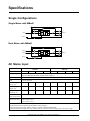
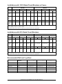
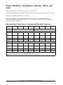
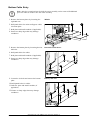
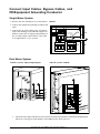
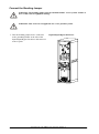
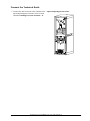
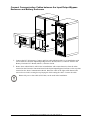
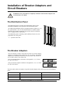
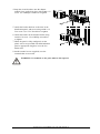
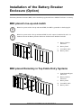
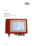
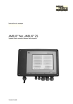
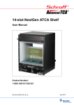
Symmetra PX with MBwD
250–500 kW 400/480 V
Installation
Table of Contents
IMPORTANT SAFETY INSTRUCTIONS – SAVE THESE
INSTRUCTIONS................................................................................................................ 1
Symbols used ............................................................................................................... 1
Specifications ................................................................................................................... 2
Single Configurations ................................................................................................. 2
Single Mains with MBwD ........................................................................................... 2
Dual Mains with MBwD .............................................................................................. 2
AC Mains Input.............................................................................................................. 2
AC Bypass Input........................................................................................................... 3
AC Output....................................................................................................................... 3
Battery Input.................................................................................................................. 3
Fuses, Breakers, and Cables in the US.................................................................. 4
Single Systems .......................................................................................................... 4
Recommended Fuses, Breakers, and Cable Sizes ..................................................... 4
Fuses, Breakers, and Cables in Europe, Africa, and Asia ................................ 6
Required Breaker Settings for Input Overload and Short-Circuit
Protection for Breakers with Electronic Trip Units ............................................. 7
Single Mains Installation (Common Mains and Bypass Input Breaker)...................... 7
Dual Mains Installation (Separate Mains and Bypass Breaker) .................................. 7
Torque Specifications ................................................................................................. 8
Connect the Power Cables ........................................................................................ 9
Overview of Cables...................................................................................................... 9
Single Mains .............................................................................................................. 9
Dual Mains .................................................................................................................10
Remote Batteries .......................................................................................................12
Prepare for cables........................................................................................................13
Top Cable Entry .........................................................................................................13
Bottom Cable Entry ...................................................................................................14
Remove NEMA 2 Hole Pattern ..................................................................................15
Install the Terminal Blocks (Optional) ....................................................................15
Connect Input Cables, Bypass Cables, and PE/Equipment Grounding
Conductor ......................................................................................................................16
Single Mains System .................................................................................................16
Dual Mains System ....................................................................................................16
990–2746G-001
Symmetra PX with MBwD 250–500 kW 400/480 V
i
Connection of Bonding Jumper and Technical/System Earth.........................17
Systems in the US .....................................................................................................17
Systems in Europe, Africa, and Asia .........................................................................17
Connect the Bonding Jumper ....................................................................................18
Connect the Technical Earth ......................................................................................19
Connect Battery Cables in Systems with Remote Batteries ............................20
Connect Battery Cables in Top Cable Entry Systems ................................................20
Connect Battery Cables in Bottom Cable Entry Systems ..........................................21
Communication Cables ..............................................................................................22
EPO switch wiring......................................................................................................22
For installations in the US and Canada......................................................................22
For installations in Europe.........................................................................................22
Connect Communication Cables between Power Module and
Input/Output/Bypass Enclosure in 250 kW systems .................................................23
Connect Communication Cables between Power Module and
Input/Output/Bypass Enclosures in 500 kW Systems ................................................24
Run the Communication Cables ................................................................................25
Connect the EPO and Output Disconnect Switch ......................................................26
Connect Communication Cables between the Input/Output/Bypass Enclosure
and Battery Enclosure ...............................................................................................27
Connect Communication Cables between Battery Enclosures ..................................28
Connect Communication Cables between Input/Output/Bypass and Battery
Breaker Enclosure .....................................................................................................29
Relay Inputs/Outputs .................................................................................................30
Installation of Breaker Adapters and Circuit Breakers .............................31
The Distribution Panel ................................................................................................31
The Breaker Adaptors.................................................................................................31
Install the Breaker Adaptors and Circuit Breakers in the MBwD ....................32
Connect the Load to the Distribution Panel..........................................................34
Installation of the Battery Breaker Enclosure (Option).............................35
BBE placed Line-up-and-match ...............................................................................35
BBE placed Remotely in Top Cable Entry Systems............................................35
BBE placed Remotely in Bottom Cable Entry Systems.....................................36
Prepare BBE for Cables in Top Cable Entry Systems........................................36
Prepare BBE for Cables in Bottom Cable Entry Systems.................................36
Connect Cables in Systems with Line-Up-and-Match BBE ..............................37
Connect Cables in Systems with Remote BBE....................................................38
Connect BBE Communication Cables....................................................................39
Install Seismic Option ..................................................................................................40
ii
Symmetra PX with MBwD 250–500 kW 400/480 V
990–2746G-001
Replace the Side Panel Lock ....................................................................................40
Install the Rear Anchoring Brackets.......................................................................43
Install the Front Anchoring Bracket........................................................................44
Install the Top Assembly Bracket ............................................................................44
Install the Assembly Bracket between Input/Output/Bypass and
MBwD ..............................................................................................................................45
Install the Door Hinge Lock.......................................................................................46
Install the Battery Locks ............................................................................................47
Install the Bypass Static Switch Lock ....................................................................47
Install the Filter Option in the Power Module Enclosure .........................48
990–2746G-001
Symmetra PX with MBwD 250–500 kW 400/480 V
iii
iv
Symmetra PX with MBwD 250–500 kW 400/480 V
990–2746G-001
IMPORTANT SAFETY INSTRUCTIONS –
SAVE THESE INSTRUCTIONS
WARNING: ALL safety instructions in the Safety Sheet (990-2984) must be read,
understood and followed when installing the UPS system. Failure to do so could result
in equipment damage, serious injury, or death.
Caution: All electrical power and power control wiring must be installed by a qualified
electrician, and must comply with local and national regulations.
This unit contains components that are sensitive to electrostatic discharge (ESD). Follow
proper ESD procedures to avoid severe damage to electronic components.
Symbols used
WARNING: Indicates an electrical hazard, which, if not avoided, could result in injury
or death.
Caution: Indicates a hazard, which, if not avoided, could result in injury or death.
Note: Indicates important information.
See: Indicates that more information is available on this subject.
990–2746G-001
Symmetra PX with MBwD 250–500 kW 400/480 V
1
Specifications
Single Configurations
Single Mains with MBwD
Q3
Q5
Mains
SB1
Q1
Q2
SB2
Outputs
SB3
Battery
Battery Breaker
Dual Mains with MBwD
Q3
Bypass
Q5
Mains
SB1
Q1
Q2
SB2
Outputs
SB3
Battery
Battery Breaker
AC Mains Input
250 kW
380 V1
400 V
415 V
500 kW
480 V
380 V1
400 V
415 V
480 V
Voltage range
+/-15% for full performance (340 - 460V at 400V, 408 - 552V at 480V)
-50% for reduced load (200V at 400V, 240V at 480V)
Input frequency
40–70 with 10 Hz/sec slewrate
I thd
< 5% at full load
Nom input
current (A)2
398
378
364
315
795
756
728
630
Max input
current (A)3
437
416
401
346
875
831
801
693
Input current
limitation (A)4
447
447
431
372
894
894
861
745
Max. input
short-circuit level
65 kA/3 cycles (50 kA with standard MBwD)
Input power
factor correction
0.995 @ load = 100 %
0.99 @ load > 50 %
0.97 @ load > 25 %
1
380 V has reduced mains input voltage window (-10% at 100% load).
Input current based on rated load and batteries fully charged.
3 Input current based in fully battery recharge, nominal voltage and rated load.
4 Current limitation through electronic current limiting is based on fully recharge and -15% input voltage.
2
2
Symmetra PX with MBwD 250–500 kW 400/480 V
990–2746G-001
AC Bypass Input
250 kW
380 V
Input frequency
(Hz)
50/60
Nom input
current (A)
380
500 kW
400 V
415 V
480 V
380 V
400 V
415 V
480 V
361
348
301
760
722
696
601
AC Output
250 kW
380 V
400 V
415 V
500 kW
480 V
380 V
400 V
415 V
Output capacity
150% for 30 seconds (normal operation)
125% for 10 minutes (normal operation)
150% for 30 seconds (battery operation)
125% for 10 minutes (battery operation)
125% Continuous at 480 V/110% Continuous at 400 V (bypass operation)1
1000% for 100 ms (bypass operation)
Voltage tolerance
Sym. load (0-100%): +/-1% static, +/-5% after 2 ms and +/-1% after 50 ms dynamic
Asym. load (0-100%): +/-3% static
Nom output
current (A)
380
Output frequency
(sync to mains)
50 Hz/60 Hz
Slew rate
(Hz/Sec)
0.25 - 6
Total Harmonic
Distortion (THD)
< 2% linear load
< 3% non-linear load
Output power
factor
1
Dynamic load
response
+/- 5%
361
348
301
760
722
696
480 V
601
1
This is a UPS thermal performance rating. The continuous overload is not supported by the recommended
input protection in this document.
Battery Input
250 kW
500 kW
Nom. voltage
2 x +/- 288 Vdc
INom discharge1
452
904
IMax discharge2
565
1130
End Voltage
1.6–1.75/cell (automatic, depending on load)
1
Nominal battery discharge current based on rated load and nominal battery voltage
Maximum battery discharge current based on rated load at the end of the discharge
3 Maximum available fault current: 40 kA
2
The UPS supports customer-specific battery solutions with 144 cells +/- 6 cells (138 - 150 cells) for
runtime optimization. Display settings allow programmable settings for number of cells and all DC
voltage levels where voltage is typed in as V/cell.
990–2746G-001
Symmetra PX with MBwD 250–500 kW 400/480 V
3
Adjustable window
Battery type
Sealed lead acid/wet cells
Nom voltage (Vdc)
+/- 276 — +/- 300
Float voltage (Vdc)
+/- 308 — +/- 345
Boost charge voltage (Vdc)
+/- 308 — +/- 345
Equalize charge voltage
+/- 308 — +/- 345
End of discharge voltage at full load (Vdc)
+/- 221 — +/- 263
Charging power
20 % of nominal power at 0–90 % load
10 % of nominal power at 100 % load
Typical recharge time
3.5 hours
Fuses, Breakers, and Cables in the US
Single Systems
In single utility/mains systems, supply the UPS from a grounded 4–wire WYE service.
In dual utility/mains systems, use a 4–wire supply for the bypass and a 3–wire supply for the mains input.
APC also supports 3–wire installations if the utility transformer is a grounded WYE transformer located
in the same room. In this installation, the UPS system must be installed as a separately derived system.
Please refer to section “Connection of Bonding Jumper and Technical/System Earth“. Leakage currents
will occur in the bonding jumper and the technical/system earth.
Caution: 3–wire installation using bonding wire will result in a higher leakage current.
Leakage current for typical installation are usually within UL and industry standard limits.
Recommended Fuses, Breakers, and Cable Sizes
Caution: All wiring must comply with all applicable national and/or local electrical codes.
Temperature rating of conductors: 90◦C/194◦F. Refer to table 310-16 of NEC, 75◦C column for maximum
ampacity. Use only copper conductors.
Equipment grounding conductors are sized in accordance with NEC Article 250-122 and Table 250-122.
The cable sizes are recommendations for maximum configurations with three current carrying conductors.
For other configurations see the label inside the front door of the Input/Output/Bypass Enclosure.
Note: A separate 800 A protection device for bypass input (similar to dual mains) is required
for single mains systems from 450 kW 400 V or 475 kW 415 V.
4
Symmetra PX with MBwD 250–500 kW 400/480 V
990–2746G-001
Installations with 100% Rated Circuit Breakers or Fuses2
250 kW
500 kW
400 V
415 V
480 V
400 V
415 V
480 V
OCPD Cable
OCPD Cable
OCPD Cable
OCPD Cable
OCPD Cable
OCPD Cable
Mains
input
Q1
450A
2x4/0
450A
2x4/0
400A
1x500
1000A 3x400
1000A 3x400
800A
2x500
Bypass
input
Q51
400A
2x2/0
350A
2x2/0
350A
2x2/0
800A
700A
700A
3x4/0
Battery
500A
2x4/0
500A
2x4/0
500A
2x4/0
1000A 3x400
1000A 3x400
1000A 3x400
AC
output
Q2
400A
1x500
350A
1x500
350A
1x350
800A
700A
700A
3x250
2x500
3x250
2x500
2x350
1
Max. input protection: 800 A and the maximum cable size is 250 kcmil
Use breaker or class J or class L fuses.
Appropriate disconnect devices shall be provided external to the equipment.
2
Installations with 80% Rated Circuit Breakers
250 kW
400 V
415 V
500 kW
480 V
400 V
OCPD
Cable
415 V
OCPD
480 V
OCPD
Cable
OCPD
Cable
OCPD
Cable
Cable
OCPD
Cable
Mains
input
Q1
600A
2x300
600A
2x250
450A
2x4/0
Not allowed
Not allowed
1000A 3x400
Bypass
input
Q51
500A
2x4/0
450A
2x4/0
400A
2x3/0
Not allowed
Not allowed
800A
Battery
500A
2x4/0
500A
2x4/0
500A
2x4/0
1000A 3x400
1000A 3x400
AC
output
Q2
500A
2x4/0
450A
2x4/0
400A
1x500
Not allowed
Not allowed
3x250
1000A 3x400
800A
2x500
1
Max. input protection is 800 A and the maximum cable size is 250 kcmil.
Appropriate disconnect devices shall be provided external to the equipment.
Recommended Bolt and Lug Sizes
Cable size
Terminal bolt
diameter
Single Hole lug
NEMA 2 Lug
Crimping tool/die
4/0 AWG
M10
LCA 4/0-12-X
LCD 4/0-12-X
CT-720/CD-720-3
250 kcmil
M10
LCA250-12-X
LCD250-12-X
CT-720/CD-720-3
300 kcmil
M10
LCA300-12-X
LCD300-12-X
CT-720/CD-720-4
350 kcmil
M10
LCA350-12-X
LCD350-12-X
CT-720/CD-720-5
400 kcmil
M10
LCA400-12-6
LCD400-12-6
CT-720/CD-720-6
500 kcmil
M10
LCA500-12-6
LCD500-12-6
CT-720/CD-720-7
990–2746G-001
Symmetra PX with MBwD 250–500 kW 400/480 V
5
Fuses, Breakers, and Cables in Europe, Africa, and
Asia
Supply the UPS from a 5–wire TN-S system (L1, L2, L3, N, PE).
The recommended cable sizes are based on an environment with an ambient temperature of 40◦C (104◦F).
Temperature ratings of conductors: 90◦C (194◦F).
Refer to IEC 60364-5-52 for installation methods. The cable sizes are recommendations for
maximum configurations and copper cables. For other system size configurations see label inside of
Input/Output/Bypass front door.
Recommended Cable Sizes in Systems with Breaker Protection1
Installation
Method
OCPD
B1
(mm2)
B2
(mm2)
C
(mm2)
OCPD
B1
(mm2)
400 V
B2
(mm2)
C
(mm2)
415 V
250 kW
Mains
input
400A1
2 x 95
2 x 120
2 x 95
400A1
2 x 95
2 x 120
2 x 95
Bypass
input
400A
2 x 95
2 x 120
2 x 95
355A
2 x 95
2 x 120
2 x 95
Battery
500A
1 x 120
3 x 95
2 x 95
500A
1 x 120
3 x 95
2 x 95
Output
400A
2 x 95
2 x 120
2 x 95
355A
2 x 95
2 x 120
2 x 95
500 kW
Mains
input
800A
4 x 120
-
3 x 150
800A1
4 x 120
-
3 x 150
Bypass
input
800A
4 x 120
-
3 x 150
800A
4 x 120
-
3 x 150
Battery
1000A
-
-
3 x 240
1000A
-
-
3 x 240
Output
800A
4 x 120
-
3 x 150
800A
4 x 120
-
3 x 150
1
Breaker must comply with IEC 60947-2 which garantee a non-tripping current of 1,05 times current setting for 2
hours. Alternative breaker size must be higher than stated current.
Appropriate disconnect devices shall be provided external to the equipment.
6
Symmetra PX with MBwD 250–500 kW 400/480 V
990–2746G-001
Recommended Cable Sizes in Systems with Fuse Protection
Installation
Method
OCPD
B1
(mm2)
B2
(mm2)
C
(mm2)
OCPD
B1
(mm2)
400 V
B2
(mm2)
C
(mm2)
415 V
250 kW
Mains
input
500A
2 x 95
2 x 120
2 x 150
400A1
2 x 95
2 x 120
2 x 95
Bypass
input
400A
2 x 95
2 x 120
2 x 95
355A
2 x 95
2 x 95
1 x 185
Battery
500A
1 x 120
3 x 95
2 x 95
500A
1 x 120
3 x 95
2 x 95
Output
400A
2 x 95
2 x 120
2 x 95
355A
2 x 95
2 x 95
1 x 185
500 kW
Mains
input
1000A
-
-
4 x 150
1000A
-
-
4 x 150
Bypass
input1
800A
4 x 120
-
3 x 150
800A
4 x 120
-
3 x 150
Battery
1000A
-
-
3 x 240
1000A
-
-
3 x 240
Output
800A
4 x 120
-
3 x 150
800A
4 x 120
-
3 x 150
1
Max. input protection: 800 A
Required Breaker Settings for Input Overload and
Short-Circuit Protection for Breakers with Electronic
Trip Units
Single Mains Installation (Common Mains and Bypass Input Breaker)
Mains input breaker
In
= Maximum input current
STPU
In x A ( 3 < A < 4)
STD
Max. 100 ms
LTD
Max. 3 x In in 5s
Iinst
In x 5
Dual Mains Installation (Separate Mains and Bypass Breaker)
Mains input breaker
Bypass input breaker
In
= Maximum input current
= Maximum input current
STPU
In x A ( 3 < A < 4)
In x B (10 < B <12)
STD
Max. 100 ms
Max. 100 ms
LTD
Max. 3 x In in 5s
Max. 3 x In in 5s
Iinst
In x 5
In x 15
990–2746G-001
Symmetra PX with MBwD 250–500 kW 400/480 V
7
Torque Specifications
Bolt size M8
Bolt size M10
13.5 Nm
30 Nm
8
Symmetra PX with MBwD 250–500 kW 400/480 V
990–2746G-001
Connect the Power Cables
Overview of Cables
APC recommends to run the output cables out of the top of the Maintenance Bypass Panel with
Distribution but it is also possible to run the cables out of the bottom. The running of the output cable does
not impact the routing of the mains and bypass cables.
Single Mains
Top Entry Systems with Line-Up and Match Batteries
E
A.
FI
Maintenance Bypass Panel with Distribution
(MBwD)
B. Input/Output/Bypass
C. Power Module Enclosure
D.
Battery Enclosure
E. Output Cables
F.
A
B
Input Cables
C
D
D
E
990–2746G-001
Symmetra PX with MBwD 250–500 kW 400/480 V
9
Bottom Entry Systems with Line-Up and Match Batteries
A.
E
A
B
Maintenance Bypass Panel with Distribution
(MBwD)
B. Input/Output/Bypass
C
D
D
C. Power Module Enclosure
D.
Battery Enclosure
E. Output Cables
F. Input Cables
F
Dual Mains
Top Entry Systems with Line-up and Match Batteries
A.
E
F
F G
Maintenance Bypass with Distribution
(MBwD)
B. Input/Output/Bypass
C. Power Module Enclosure
D.
Battery Enclosure
E. Bypass Input Cables
F. Output Cables
G.
A
B
Mains Input Cables
C
D
D
E
10
Symmetra PX with MBwD 250–500 kW 400/480 V
990–2746G-001
Bottom Entry Systems <250 kW with Line-up and Match Batteries
A.
E
A
Maintenance Bypass with Distribution
(MBwD)
B. Input/Output/Bypass
B
C. Power Module Enclosure
C
D
D
D.
Battery Enclosure
E. Output Cables
F.
Bypass Input Cables
G.
Mains Input Cables
F
G
Bottom Entry Systems >250 kW with Line-up and Match Batteries
A.
F
A
B
C
D
Maintenance Bypass with Distribution
(MBwD)
B. Input/Output/Bypass
D
E
E
C. Bottom Feed Enclosure
D.
Power Module Enclosure
E. Battery Enclosure
F.
Output Cables
G.
Bypass Input Cables
H.
Mains Input Cables
G
H
990–2746G-001
Symmetra PX with MBwD 250–500 kW 400/480 V
11
Remote Batteries
Top Cable Entry
A.
D
Input/Output/Bypass
B. Battery Side Car
C. Battery Enclosure
D.
Battery Cables
A.
Bottom Feed
Enclosure
C
C
B
A
Bottom Cable Entry
C
C
B
B. Battery Side Car
A
C. Battery Enclosure
D.
Battery Cables
D
12
Symmetra PX with MBwD 250–500 kW 400/480 V
990–2746G-001
Prepare for cables
Caution: Drilling or cutting must not take place over the top or inside the UPS.
Top Cable Entry
1. From the inside of the Input/Output/Bypass
Input/Output/Bypass Enclosure
Enclosure, loosen the four screws.
1
2. Lift up the front of top cover and slide it out.
1
2
3. Drill/punch holes for cables.
4. Refit the cover and install conduits (if
applicable).
5. Ensure no sharp edges that may damage
conductors.
6. Remove the top cover of the MBwD by
MBwD
loosening the eight M5 screws.
7. Drill/punch holes for cables.
8. Refit the cover and install conduits (if
5
5
5
applicable).
5
5
5
5
5
9. Ensure no sharp edges that may damage
conductors.
10.From the inside of the Battery Side Car, loosen
Battery Side Car
the six nuts.
11.Lift off the top cover.
12.Drill/punch holes for cables.
13.Refit the cover and install conduits (if
applicable).
10
14.Ensure no sharp edges that may damage
10
conductors.
10
10
10
10
990–2746G-001
Symmetra PX with MBwD 250–500 kW 400/480 V
13
Bottom Cable Entry
Note: After the system has been leveled, the caster assembly can be removed if additional
space for cables is needed. Save the caster assembly.
1. Remove the bottom plates by loosening the
MBwD
eight M8 nuts.
1
1
2. Drill/punch holes for mains and bypass cables
in bottom plate.
3. Refit plate and install conduits (if applicable).
4. Ensure no sharp edges that may damage
conductors.
5. Remove the bottom plate by loosening the four
Bottom Feed Enclosure
M8 bolts.
6. Drill/punch holes for cables.
5
7. Refit plate and install conduits (if applicable).
5
8. Ensure no sharp edges that may damage
conductors.
5
9. Loosen the six bolts and remove the bottom
5
Battery Side Car
plate.
10.Drill/punch holes for cables.
9
11.Refit the plate and install conduits (if
9
12.Ensure no sharp edges that may damage
conductors.
9
9
applicable).
9
9
14
Symmetra PX with MBwD 250–500 kW 400/480 V
990–2746G-001
Remove NEMA 2 Hole Pattern
Note: The NEMA 2 hole plates can be installed upside down to gain additional wiring
clearances.
The NEMA 2 hole pattern plate is only used in some installations in the US. In other installations, the
NEMA 2 plate must be removed.
Use cable lugs with a mutual distance of 44.5 mm. In other installations, follow the below procedure to
remove the NEMA 2 hole pattern plates from the busbars.
1. Loosen the four 10 mm nuts connecting the
NEMA 2 hole pattern plate to the busbar.
1
2
3
2. Loosen the 8 mm nut on the back of the busbar.
3. Slide the NEMA 2 hole pattern plate off the
busbar.
Install the Terminal Blocks (Optional)
1. Slide the plate with the terminal blocks onto the
busbar.
1
2
3
2. Tighten the 8 mm nut on the back of busbar.
3. Tighten the four 10 mm nuts below the terminal
blocks.
990–2746G-001
Symmetra PX with MBwD 250–500 kW 400/480 V
15
Connect Input Cables, Bypass Cables, and
PE/Equipment Grounding Conductor
Single Mains System
1. Remove the clear shield that covers the busbars. MBwD
2. Connect the equipment grounding conductor/PE
2
cable.
3. Connect the AC input cables to the AC Bypass
Input cable landings in the MBwD (single feed
busbars connect the AC Bypass Input busbars to
the AC Mains Input cable busbars). The N-bus
is not applicable to 3-wire systems.
L3
L2
3
N
L1
Dual Mains System
250 kW systems: Input/Output/Bypass
500 kW systems: MBwD
2
2
1
N
L3
L2
L1
N
L3
L2
L1
1. Ensure that the single feed busbars, that connect the mains input busbars in the Input/Output/Bypass
Enclosure to the bypass input busbars in the MBwD, have been removed.
16
Symmetra PX with MBwD 250–500 kW 400/480 V
990–2746G-001
2. Connect the AC input cables to the AC Mains Input cable landings in the Input/Output/Bypass
Enclosure. In systems over 250 kW with bottom cable entry, a Bottom Feed Enclosure is required
for mains connection. The N-bus is not applicable to 3-wire systems.
3. Install plastic covers over the terminals L1, L2, L3, N.
4. Connect the AC bypass input cables to the AC Bypass Input cable landings in MBwD. The N-bus
is not applicable to 3-wire systems.
5. Connect the grounding conductor/PE cable.
5
L3
L2
4
L1
N
Connection of Bonding Jumper and Technical/System
Earth
Connect the bonding jumper and the technical/system earth according to the guidelines below:
Systems in the US
• 4–wire systems
– Bonding jumper: Not connected
– Technical/system earth: No Local Grounding Electrode connected
• 3–wire systems
– Bonding jumper: Must be connected
– Technical/system earth: A Grounding Electrode must be connected via the Grounding Electrode
Conductor
Systems in Europe, Africa, and Asia
• 5–wire systems
– Bonding jumper: Not connected
– Technical/system earth: A Local Earth Electrode must be connected
990–2746G-001
Symmetra PX with MBwD 250–500 kW 400/480 V
17
Connect the Bonding Jumper
WARNING: The bonding jumper must be installed in 480 V 3-wire systems. Failure to
do so could result in equipment damage.
WARNING: This section is not applicable for 4–wire parallel systems.
1. Take the bonding jumper that is connected
Input/Output/Bypass Enclosure
to the grounding busbar in the side of the
Input/Output/Bypass Enclosure and connect it
to the N-point.
1
18
N
Symmetra PX with MBwD 250–500 kW 400/480 V
990–2746G-001
Connect the Technical Earth
1. Connect the earth electrode to the N busbar in the Input/Output/Bypass Enclosure
Input/Output/Bypass Enclosure in the location
labeled Grounding Electrode Terminal – E.
1N
990–2746G-001
Symmetra PX with MBwD 250–500 kW 400/480 V
19
Connect Battery Cables in Systems with Remote
Batteries
Connect Battery Cables in Top Cable Entry Systems
1. Connect one end of the battery cables to the
Battery Side Car
BAT+, BAT-, and CT (Midpoint) cable landings
in the Battery Side Car.
2. Connect the ground/PE cable.
BAT+
BAT1
2
CT
CT
3. Connect the other end of the battery cables to
Input/Output/Bypass Enclosure
BAT+, BAT-, and CT (Midpoint) cable landings
in the Input/Output/Bypass Enclosure.
3
CT
BAT-
20
Symmetra PX with MBwD 250–500 kW 400/480 V
CT
BAT+
990–2746G-001
Connect Battery Cables in Bottom Cable Entry Systems
1. Connect one end of the battery cables to the
Battery Side Car
BAT+, BAT-, and CT (Midpoint) cable landings
in the Battery Side Car.
2. Connect the ground/PE cable.
BAT+
2
BAT1
CT
CT
3. Connect the other end of the battery cables to
Bottom Feed Enclosure
BAT+, BAT-, and CT (Midpoint) cable landings
in the Bottom Feed Enclosure.
BATCT
3
CT
BAT+
990–2746G-001
Symmetra PX with MBwD 250–500 kW 400/480 V
21
Communication Cables
EPO switch wiring
In installations with EPO, the UPS must be connected to either a dry contact or an external 24 Vdc
Emergency Power Off (EPO) switch.
For installations in the US and Canada
The EPO circuit is considered Class 2 and SELV (Safety Extra Low voltage). A SELV circuit is isolated
from primary circuitry through an isolating transformer and designed so that under normal conditions,
the voltage is limited to 42.4 Vac peak or 60 Vdc. SELV and Class 2 circuits must be isolated from all
primary circuitry. Do not connect any circuit to the EPO terminal block unless it can be confirmed that
the circuit is SELV or Class 2.
Installations in the US
• CL2 Class 2 cable for general purpose use
• CL2 Plenum cable for use in a vertical shaft or from floor to floor
• CL2 R Racer cable for use in dwellings and raceways
• CL2 XLimited use cable for dwellings and raceways
Installations in Canada
• CL2 RCertified, type ELC (Extra-Low-Voltage Control Cable)
• CL2 XCertified, type ELC (Extra-Low-Voltage Control Cable)
For installations in Europe
The EPO can be achieved with either a contact closure or application of an external 24 Vac or 24 Vdc
from a SELV (Safety Extra Low voltage). It is important to note that the hazardous voltage from the
mains voltage must be isolated from the contact closure or 24 Vac/24 Vdc circuit. The EPO circuit
contact closure, the Vac or Vdc circuit is considered a SELV circuit as defined in EN60950 “Safety of
Information Technology Equipment”.
22
Symmetra PX with MBwD 250–500 kW 400/480 V
990–2746G-001
Connect Communication Cables between Power Module and
Input/Output/Bypass Enclosure in 250 kW systems
2
2
Power Module
Enclosure
Input/Output/Bypass
Enclosure
J9901 on
p/n 640-4733
1
J4300 on
p/n 640-4706
1
1. Take the MIM/RIM cables that are placed in the bottom of the Power Module Enclosure and
connect them in the bottom of the Input/Output/Bypass Enclosure (left to left and right to right).
2. Verify that terminators are installed.
990–2746G-001
Symmetra PX with MBwD 250–500 kW 400/480 V
23
Connect Communication Cables between Power Module and
Input/Output/Bypass Enclosures in 500 kW Systems
3
3
Power Module
Enclosure
Power Module
Enclosure
Input/Output/
Bypass Enclosure
2
2
J9901 on
p/n 640-4733
2
1
1
1
2
J4300 on
p/n 640-4706
1
1. Take the MIM/RIM cables that are placed in the bottom of Power Module Enclosure next to the
Input/Output/Bypass Enclosure and connect them in the bottom of the the Input/Output/Bypass
Enclosure (left to left and right to right).
2. Take the MIM/RIM cables that are placed in the bottom of the other Power Module Enclosure.
Connect one end in the top of this Power Module Enclosure and the other end in the bottom of the
second Power Module Enclosure (left to left and right to right).
3. Verify that terminators are installed.
24
Symmetra PX with MBwD 250–500 kW 400/480 V
990–2746G-001
Run the Communication Cables
1. Run the cables through the openings in the top
1
cover.
2. Guide the cables through the cable channel in
the side.
3. Guide the cables through the hole from the cable
tray to the board assembly.
2
3
990–2746G-001
Symmetra PX with MBwD 250–500 kW 400/480 V
25
Connect the EPO and Output Disconnect Switch
1. Run the cables through the openings in the front Input/Output/Bypass Enclosure
left corner of the enclosure.
1
2. Connect the cable from the EPO to the ECT
J6504
J6505
board. A normally open installation is shown.
1
2
3
1
2
3
2
EPO
Switch
26
Symmetra PX with MBwD 250–500 kW 400/480 V
990–2746G-001
Connect Communication Cables between the Input/Output/Bypass
Enclosure and Battery Enclosure
1
2
1
2
1. Connect the ECT (Emergency Connect and Trip) cable 0W4528 (0W3759 in installations with
remote batteries) from the Input/Output/Bypass ECT Board (0P4711) connector J6500 to the
Battery Enclosure ECT Board (0P4711) connector J6500.
2. Route Abus cable 0W4527 (0W3758A in installations with remote batteries) from the Abus
terminal on the External Connection Board in the Input/Output/Bypass Enclosure to the top Abus
terminal on the Abus Communication Board. Route the cable in the right cable channel and
remove the two bolts securing the top baying kit while routing the cable. Connect the cable.
Note: Only one A–bus cable (0W3758A) can be used in the installation.
990–2746G-001
Symmetra PX with MBwD 250–500 kW 400/480 V
27
Connect Communication Cables between Battery Enclosures
WARNING: Harzadous electric voltages are present if batteries are installed. Do not
stick fingers behind the ECT board.
5
4
1
6
3
4
5
2
1
1. Remove the terminator from the bottom Abus terminal on the Battery Enclosure that is connected
to the UPS and connect 0W4527 Abus terminal to the top Abus terminal on the next Battery
Enclosure in the system.
2. Route the Abus cables (0W4527) between all Battery Enclosures in the system from the bottom
Abus slot to the top Abus slot in the next Battery Enclosure. Route the cable in the right cable
channel and remove the two bolts securing the top baying kit while routing the cable. Connect
the cable to the slots.
3. Install the terminator in the bottom Abus terminal on the last Battery Enclosure.
4. Set the number of each Battery Enclosure using the selector.
5. Connect the ECT cable (0W4528) from the connector J6501 on the ECT Board of the Battery
Enclosure connected to the Input/Output/Bypass Enclosure to connector J6500 on the next Battery
Enclosure in the system.
6. Connect ECT cables (0W4528) between all Battery Enclosures in the system as in step 5.
28
Symmetra PX with MBwD 250–500 kW 400/480 V
990–2746G-001
Connect Communication Cables between Input/Output/Bypass and
Battery Breaker Enclosure
1
3
2
1
2
1. Connect ECT cable (0W3759) from the Input/Output/Bypass ECT Board (0P4711) connector
J6500 to the Battery Breaker Enclosure ECT Board (0P4711) connector J6500. In the Battery
Breaker Enclosure, secure the ECT cable (0W3759) to the cable relief in the lower left corner.
2. Connect the Abus cable (0W3758A) from the Abus terminal on the External Connection Board
in the Input/Output/Bypass Enclosure to the top Abus terminal J2 on the Ancillary Monitor
Board. In the Battery Breaker Enclosure, secure the Abus cable (0W3758A) to the cable relief in
the upper right corner.
3. Verify that terminator 0W03913 is installed in the J4 terminal on the Ancillary Monitor Board
in the Battery Breaker Enclosure.
990–2746G-001
Symmetra PX with MBwD 250–500 kW 400/480 V
29
Relay Inputs/Outputs
The relay board informs the user of the operation mode, status, and alarm conditions and has eight ports on
the input side and 16 output terminals.
All input voltages must have the same ground and 0 V reference.
All wiring to the relay board should be considered as field wiring rated minimum 480 Vac, and must
use copper conductors only.
Note: Communication cables to the relay board should be run through the openings in the
front right corner of the enclosure.
Note: Option 1 to 4 can be configured via the display.
30
Symmetra PX with MBwD 250–500 kW 400/480 V
990–2746G-001
Installation of Breaker Adapters and
Circuit Breakers
WARNING: The system must be completely shut down when breaker adaptors and
circuit breakers are added.
The Distribution Panel
The distribution panel is located in the Maintenance Bypass with
Distribution (MBwD) of the Symmetra PX 250/500 kW system.
As standard the distribution panel is equipped with three phases (L1-L3)
for 3-pole breakers. For use with 4-pole breakers in countries where
isolation of the neutral is required, a neutral bar must be installed by
APC to supply breakers with neutral.
A
N L1 L2
L3
The distribution panel’s flexibility enables different frame sizes to be
populated in the same panel.
A.
Optional neutral bar.
N
N
The Breaker Adaptors
The circuit breakers connect to the panels by means of a breaker adaptor,
and they are available in three frame sizes: T1, T3, and T5. The breaker
adaptors have terminals to attach two circuit breakers, and contacts in
the rear that connect to the output rails.
The 3-pole breaker adaptor terminals are designated L1, L2, L3 from
the top to the bottom.
The 4-pole breaker adaptor terminals are designated L1, L2, L3, N from
the top to the bottom.
3-pole
distribution
breaker
L1
L2
L3
3-pole
distribution
breaker
4-pole
distribution
breaker
L1
L2
L3
N
4-pole
distribution
breaker
The below table outlines the number of possible breaker adaptors that can be inserted in the distribution
panel:
Breaker frame size
Max. number of 3-pole devices
Max. number of 4-pole devices
T1
16
12
T3
12
8
T5
8
990–2746G-001
Symmetra PX with MBwD 250–500 kW 400/480 V
31
Install the Breaker Adaptors and Circuit Breakers in
the MBwD
Note: All parts needed for the installation procedures are included with the circuit breaker kit.
Note: A breaker schedule should be maintained and kept in the breaker schedule on the
front of the inner door.
Both the input and output sides of the T3 and T5 breakers require preparation before they are installed on
the panel. Follow the instructions below for each pole.
Steps 3–9 below show the installation of the T1 3-pole breaker assembly. The steps are identical for
the other breaker assemblies.
1. On the input side, place an M8 square nut into
1
2
a square nut retainer, and insert the nut retainer
into the pole position. Slide an M8 washer onto
an M8 bolt and insert the bolt into the pole
position by loosely attaching the bolt to the M8
square nut.
2. On the output side, slide a saddle lug into the
pole position. You may need to loosen the bolt
in the lug. Insert a saddle lug retainer into the
pole position.
1
2
3. Attach the breaker adaptor to the distribution
panel, and secure it by turning the module locks
using and allen key.
1
2
pg0065a
2
32
Symmetra PX with MBwD 250–500 kW 400/480 V
990–2746G-001
4. Snap the circuit breakers onto the adapter
module’s bus, and lock in place with an M4 x 70
screw. Use a Phillips screwdriver to tighten.
pg0066b
1
2
5. Attach the breaker brackets to the slots in the
1
distribution panel, and secure using an M6 x 12
Torx screw. Use a T25 Torx driver to tighten.
6. Attach the breaker to the breaker bracket using
an M4 x 70 screw. Use a Phillips screwdriver
to tighten.
plastic rail covers provided with the distribution
panel to appropriate length to cover the live
busbar rails.
3
pg0067b
2
7. When the panel is fully configured, cut the
8. Install terminal covers (supplied) over the
terminals that are not used.
WARNING: No terminals or live parts must be left exposed.
990–2746G-001
Symmetra PX with MBwD 250–500 kW 400/480 V
33
Connect the Load to the Distribution Panel
1. Route the cables through either the top or
MBwD
the bottom of the MBwD to the distribution
breakers.
2. Secure the cables to the brackets in the right or
left panel.
3. Connect the cables to the breakers according to
the distribution breaker documentation.
4. Connect neutral (if applicable) and ground/PE
conductor. Attach the connectors provided to
the Neutral and PE busbars located at both sides
of the distribution panel. Place sleeves over the
conductors, insert conductors with sleeves into
the connectors, and apply the appropriate torque.
4
3
2
1
34
Symmetra PX with MBwD 250–500 kW 400/480 V
990–2746G-001
Installation of the Battery Breaker
Enclosure (Option)
The Battery Breaker Enclosure (BBE) can be installed up against the Power Module Enclosure or remotely.
BBE placed Line-up-and-match
Note: In systems with a line-up-and-match BBE, the BBE is grounded via the baying kit.
Note: In systems with a line-up-and-match BBE, the DC output is hardwired by APC via
busbars between the Battery Breaker Enclosure and the Power Module Enclosure.
A.
C
D
Battery Breaker
Enclosure
B. Battery Bank
D
C. Ground/PE cable
D.
A
Battery cables
B
BBE placed Remotely in Top Cable Entry Systems
A.
D
E
D
E
Input/Output/Bypass
Enclosure
B. Battery Breaker
Enclosure
E
E
F
C. Battery Bank
D.
A
Ground/PE cable
E. Battery cables
B
C
990–2746G-001
Symmetra PX with MBwD 250–500 kW 400/480 V
35
BBE placed Remotely in Bottom Cable Entry Systems
A.
Bottom Feed
Enclosure
B. Battery Breaker
Enclosure
A
C. Battery Bank
B
C
D
E
D.
Ground/PE cable
E.
Battery cables
E
D
E
E
Prepare BBE for Cables in Top Cable Entry Systems
1. From the inside of the BBE, loosen the four screws.
2. Lift up the front of the top cover and slide out the cover.
3. Drill/punch holes for the cables.
4. Refit the cover and install conduits (if applicable). Ensure no sharp edges that may damage the
conductors.
5. Run the cables through the top of the BBE to the cable landing area.
Prepare BBE for Cables in Bottom Cable Entry Systems
1. From the inside of the BBE, loosen the 4 screws of the rear bottom cover and remove.
2. Drill/punch holes for cables.
3. Refit cover and install conduits (if applicable).
4. Ensure no sharp edges that may damage conductors.
36
Symmetra PX with MBwD 250–500 kW 400/480 V
990–2746G-001
Connect Cables in Systems with Line-Up-and-Match
BBE
The battery breaker supports two strings of 144 VLA batteries (equal 2 x 288 V). The two strings are
divided into a positive (+) and a negative (-) string. For runtime optimization, the number of cells can be
adjusted to +/- 6 cells (138-150 cells).
1. Route the DC input cables from the battery bank Battery Breaker Enclosure
and through the top or bottom of the BBE and
guide them to the DC input terminals in the top
of the enclosure.
2. Connect the DC input cables to the Bat 1 and
Bat 2 busbars.
2
Bat 2-
Bat 2+
(CT)
990–2746G-001
Symmetra PX with MBwD 250–500 kW 400/480 V
Bat 1+
Bat 1(CT)
37
Connect Cables in Systems with Remote BBE
1. Route the DC input cables from the battery bank Battery Breaker Enclosure
and through the top or bottom of the BBE and
guide them to the DC input terminals in the top
of the enclosure.
2. Connect the ground/PE cable to the equipment
2 Ground/PE
grounding terminal in the upper left corner of
the enclosure.
Bat 1+
Bat 2-
3. Connect the DC input cables to the Bat 1 and
3
Bat 2 busbars.
Bat 2+
(CT)
4. Route the DC output cables from the UPS and
Bat 1(CT)
Battery Breaker Enclosure
through the top or bottom of the BBE and guide
them to the DC output terminals in the bottom
of the enclosure.
5. Connect the DC output cables to the DC output
busbars.
5
DC
DC
output- output+
CT
38
Symmetra PX with MBwD 250–500 kW 400/480 V
CT
990–2746G-001
Connect BBE Communication Cables
1. Connect cables from fuse indicators from the fuses in the battery bank to J14-J21. If not used,
jump the inputs as they are configured as normally closed (NC).
2. Install the battery temperature sensors in the battery bank as described in the documentation
supplied with the battery temperature sensors, and connect cables from the battery temperature
sensors to J25 and J26.
3. Connect cable from the DC ground fault detection to the J24. If not used, jump the inputs as
they are configured as normally closed (NC).
4. Connect cables from the gas detector to J13. If not used, jump the inputs as they are configured
as normally closed (NC).
5. Connect cable from gas alarm relay to J11.
990–2746G-001
Symmetra PX with MBwD 250–500 kW 400/480 V
39
Install Seismic Option
Replace the Side Panel Lock
1. Remove the side panel from the end of row
enclosures.
1
2. Use a screwdriver to press on the tap that secures
the lock to the side panel.
3. Pull the lock out and up and remove it from the
3
side panel.
2
40
Symmetra PX with MBwD 250–500 kW 400/480 V
990–2746G-001
4. Put the two lock parts together.
5. Loosely tighten the screws.
5
4
6. Place the side panel at an angle at the bottom
of the frame.
6
7. Push the top of the side panel in place.
7
990–2746G-001
Symmetra PX with MBwD 250–500 kW 400/480 V
41
8. Hold the side panel with one hand.
9. Take the lock assembly and guide the top
10
through the hole in the side panel.
10.Lift the lock assembly in place.
11.Ensure that the upper and lower taps are hidden
behind the side panel.
11
9
8
12.Secure the two screws in the lock assembly.
13.Install the lock cover using the provided screw.
13
12
42
Symmetra PX with MBwD 250–500 kW 400/480 V
990–2746G-001
Install the Rear Anchoring Brackets
1. Secure the floor anchoring bracket to the floor
using floor anchoring bolts (not supplied). Use
M12 strength class 8.8 or 1/2 in grade 5 steel
bolts.
1
2. Secure the other part of the rear anchoring to the
back of the enclosure.
2
3. Push the enclosure backwards so the enclosure
slides under the floor anchoring bracket.
3
990–2746G-001
Symmetra PX with MBwD 250–500 kW 400/480 V
43
Install the Front Anchoring Bracket
1. Secure the front anchoring bracket to the
enclosure.
1
2. Secure the front anchoring bracket to the floor
using floor anchoring bolts (not supplied). Use
M12 strength class 8.8 or 1/2 in grade 5 steel
bolts.
2
Install the Top Assembly Bracket
Required parts for each assembly:
• Two top assembly brackets
• Four screws
1. Only applicable for Symmetra PX 100 kW
systems: Dispose of the top assembly brackets
supplied with the battery enclosure.
2
2
2. Place the top assembly bracket over two adjacent
enclosures and secure using two screws.
44
2
Symmetra PX with MBwD 250–500 kW 400/480 V
2
990–2746G-001
Install the Assembly Bracket between
Input/Output/Bypass and MBwD
Required parts:
• Four top assembly brackets
• Six screws
1. Place the two narrow top assembly brackets
2
over the corners of the Input/Output/Bypass
enclosures and secure using the provided four
screws.
2. Place the two wide top assembly brackets over
1
2
the Input/Output/Bypass enclosure and the
adjacent Power Module enclosure and secure
using the provided two screws.
990–2746G-001
Symmetra PX with MBwD 250–500 kW 400/480 V
1
45
Install the Door Hinge Lock
Note: This procedure is only applicable for 600 mm and 750 mm wide enclosures.
Required parts:
• Two door hinge locks
• Four screws
1. With one hand slide the lock into the hole below
the hinge.
2. With the other hand turn the lock 90◦ holding
the bottom of the lock.
5
3. Push the lock upwards to the bottom of the
hinge.
4. Secure it with the two provided screws.
5. Use the same procedure to install the upper door
hinge lock.
3
4
2
1
46
Symmetra PX with MBwD 250–500 kW 400/480 V
990–2746G-001
Install the Battery Locks
Required parts:
• Eight battery locks
• 56 screws
1. Place the battery lock below the battery row.
2. Secure the lock by the seven provided screws.
2
1
Install the Bypass Static Switch Lock
Required parts:
• Four M5 bolts
1. Secure the bypass static switch using the four
provided bolts.
1
1
1
1
990–2746G-001
Symmetra PX with MBwD 250–500 kW 400/480 V
47
Install the Filter Option in the Power
Module Enclosure
The filters are used for extra protection of systems installed in environment with conductive dust. Check
the filters once a month. If the air filters show visible dust or other impurities, the filters must be replaced.
1. Open the front door.
2. Loosen the screws and disconnect the ground
wire between the front door and the Power
Module Enclosure.
3. Press the bottom filter plate against the bottom
half of the front door.
6
4. Remove the bottom right perforated area of the
filter to get access to the bottom hinge.
5
5. Remove the three perforated corners marked in
the drawing.
6. Install the logo plate.
3
4
5
5
48
Symmetra PX with MBwD 250–500 kW 400/480 V
990–2746G-001
7. Press the top filter plate against the top half of
the front door.
9
8. Remove the top right perforated area of the filter
9
to get access to the top hinge.
9. Remove the three perforated corners marked on
the drawing.
8
10.Reconnect the ground wire disconnected in step
1.
7
9
990–2746G-001
Symmetra PX with MBwD 250–500 kW 400/480 V
49
Worldwide Customer Support
Customer support for this or any other product is available at no charge:
• Contact the Customer Support Center by telephone or e-mail. For local, country-specific centers:
go to www.apc.com/support/contact for contact information.
© APC by Schneider Electric. APC and the APC logo are owned by Schneider Electric Industries
S.A.S., American Power Conversion Corporation, or their affiliated companies. All other trademarks
are property of their respective owners.
990–2746G-001
08/2011