1
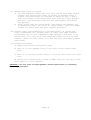
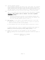
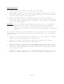
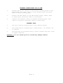
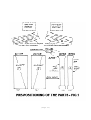
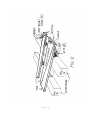
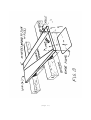
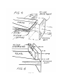
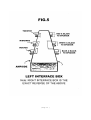
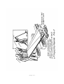
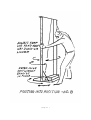
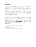
APOGEE ACOUSTICS INC.
APOGEE FULL RANGE RIBBON SPEAKER SYSTEM
OWNER'S MANUAL
AND
ASSEMBLY INSTRUCTIONS
Full Range Ribbon Speaker System
Apogee Acoustics has resolved fundamental problems inherent to ribbon acoustical
transducer design. For the first time clarity, speed and power are provided over the
entire music spectrum with a full range ribbon speaker system. The combined tweeter,
midrange and woofer ribbon coupled with APOGEE's own seamless crossover provide:
vanishing low distortion virtually flat frequency response no spurious coloration over
entire music spectrum
•
rise time consistent with the fastest
amplifiers
•
dynamic impact of 115 db SPL @ 4 meters on axis.
FEATURES:
A virtually resonant free structural steel framework. A trapezoidal thousand square inch
woofer panel designed to provide a broad non-resonant frequency response. Half inch
wide tweeter ribbon and two inch wide mid-range ribbon are both eighty inches long
utilizing patent filed magnetic and electromagnetic constraints that hold the ribbon
within its magnetic field. This technique affords a combination of unprecedented power
and clarity along with transient response and imaging. Extremely low ribbon mass
permits almost instantaneous acceleration for unexcelled transient response. The FULL
RANGE RIBBON SPEAKER SYSTEM is now available in a handsome architectural design.
SPECIFICATIONS:
Three element system: tweeter, midrange and woofer ribbon.
Frequency response: below 25 Hz to over 30 KHz.
Sound Pressure level: 115dB @ 4 meters listening position* using biamped 100 watt
amplifiers.
*(14 x 27 foot room, geometry dependent)
Nominal Impedance: 4 ohms.
Dimensions: 801/2" x 35" x 4"
Weight: 300 pounds for each speaker.
Warranty: 5 year limited warranty.
APOGEE ACOUSTICS' FULL RANGE RIBBON SPEAKER SYSTEM
APOGEE ACOUSTICS takes great pride in announcing a revolutionary
development in loudspeaker design; the first full range ribbon speaker
system. Previous sound system's have employed ribbon-technology to
provide outstanding performance in the high frequency, tweeter range.
Now, with the addition of APOGEE'S midrange and woofer ribbon drivers,
the excellence of the ribbon is made available from deep bass, through
midrange and beyond the upper frequency limits of the acoustical range.
The integration of the tweeter, midrange and woofer ribbons combined
with seamless crossovers provides an outstanding clarity, resolution,
spectral dispersion, depth, and dynamic range. Further, the tweeter
operation as a line source reproduces the uncanny ambience of live
music into your listening room.
The full range ribbon system reproduces classical music at Concert Hall
sound levels but also has the dynamic range for ear splitting hard
rock. The APOGEE ribbons play at a massive 115db acoustical power level
at a 4 meter listening position in a 14x27 foot room using 100 watt per
channel amplifiers in bi-amp configuration.
The system's three drivers are mounted in an architectural structure
that readily fits into most living room environments The speakers are
sculptural in their appearance with dimensions of 80 inches in height,
35 inches width, and a depth of under 4 inches.
The geometry of the three ribbons has been scaled to provide a
combination of good power handling capacity, dispersion and a balanced
tonal quality over the bass, midrange and upper frequencies. The woofer
averages 12 inches in width covering a frequency band of below
25-400Hz, the midrange ribbon is two inches in width and covers the
band from 400-3,500Hz while the tweeter covers the 3,500 to well over
the 30,000Hz region.
The clarity, resolution, and wide dispersion of the midrange and
tweeter are provided by the use of a ribbon element, free over its
entire length except for the top and bottom mechanical support. This is
the theoretically perfect-approach to sound reproduction; a limp
conductor placed in a magnetic field. A force is generated uniformly
across the area of the ribbon when the amplifier drives current through
the ribbon. Hence, sound is reproduced without the normal structural
coloration’s of speakers that do not have a pure force over area
mechanization.
The midrange dipole driver consists of a two inch wide ribbon. The line
source tweeter driver consists of a pair of one half inch ribbons
radiating in phase acoustical power in both the forward and rear
cylinders. The lime source acoustical power radiation provides
impressive imaging, depth, sound stage, and live music ambience. The
horizontal dispersion is essentially 360 degrees. Vertical dispersion
is not an issue due to the tall line source geometry.
TABLE OF CONTENTS
Pages
PREPARATION (Steps 1-6) ---------------------------1-3
ASSEMBLY (Steps 7-11) -----------------------------3-5
PLACEMENT (Steps 12-14) ---------------------------5
BIAMP OPERATION -----------------------------------6
SPEAKER CONNECTION FOR BI-AMP ---------------------7
APOGEE PASSIVE CROSSOVER --------------------------8
AMPLIFIER IMPEDENCE LOADING TABLE CX-1 ------------9
SPEAKER ADJUSTMENTS -------------------------------10
SPECIFICATIONS ------------------------------------11
LOW IMPEDENCE DIRECT DRIVE ------------------------12
DIRECT DRIVE CONNECTIONS --------------------------13
DIRECT DRIVE RETROFIT PROCEDURE -------------------14
FIGURE
FIGURE
FIGURE
FIGURE
FIGURE
FIGURE
FIGURE
FIGURE
1
2
3
4
5
6
7
8
–
-
Preassembly positioning ----------------15
Connection of midrange and woofer ------16
Position speaker and baseplate ---------17
Attachment baseplate to speaker --------18
Interface box --------------------------19
Attachment interface box to plate ------18
Lifting and positioning ----------------20
Pivoting into position -----------------21
SPEAKER SET-UP
The APOGEE speakers' performance is affected by the quality and
compatibility of the front end equipment, turntable, cartridge,
electronics, connections, room acoustics and the placement within the
room. Care in selection of compatible equipment and placement of the
speakers within the room will be very rewarding in terms of the sonic
quality of your music system.
ASSEMBLY
The APOGEE Speaker System is packaged in five cartons. Before opening
the cartons be sure there is no visible sign of damage and the boxes
are placed with the "THIS SIDE UP" marking facing up.
(1)
Check for the five boxes
2 Midrange-Tweeter Boxes (9"x9"x87")
(designation is MRT-L and MRT-R)
2 Woofer Boxes (9"x34"x87")
(designation W-L and W-R)
1 Interface Box (21"x21"x13")
(designation INT B)
(2)
Clear a 12'x12' area near the final speaker location to permit
assembly of the speakers. (see FIG. 1)
(Page 1)
CAUTION - USE CARE - DO
(3)
NOT allow any object to touch the ribbons!!
Unpack outer midrange tweeter-left, MRT-L, and MRT-R and place
the outer boxes in position A and B as shown in FIG. 1. During
the removal of the inner containers do not rotate the container
(lift straight out). The inner containers for MRT-L and MRT-R
should be placed on the floor as shown in FIG. 1, position G and
H. Please note the top and bottom orientations of the
containers.
The rear bottom of MRT inner box should be up.
The outer MRT boxes will be used as a work surface for the
assembly
of the speakers. Clean boxes to prevent soiling the speaker
grill and suede.
(4) a) Turn right woofer, W-R, outer box upside down.
b) Cut strapping and remove outer box.
c) Turn inner box so that rear bottom printing is in up position
and toward right speaker position.
CAUTION -Keep fingers away from ribbon.
d) Lift W-R by holding at top and bottom and place on boxes A and
B as shown in FIG. 2.
e) Remove the white foam end caps.
f) Carefully cut tape holding inner box together.
g) Remove top and bottom corrugation piece and place in outer
woofer box.
h) Please note the bottom of the woofer is toward the right speaker
position with the ribbon down and cable visible.
i) Loosen the screws nearest to the MRT to make the MRT/woofer
assembly easier.
(Page 2)
(5)
Place the right midrange tweeter, MRT-R on boxes A and B. (see
FIG. 2). The bottom of the MRT-R should be toward speaker position.
a) Remove the white foam end caps.
b) Remove top and bottom corrugations.
c) Do not rotate MRT during this procedure.
(6)
Carefully move the midrange tweeter toward the woofer until they
butt. Two people should be involved in this process.
Do not slide the midrange tweeter but lift gently for this
process.
(7) Assembly of woofer and MRT.
a) Align the 2 holes in the Top and Bottom steel plates. Use
the Drift Punch located between the two holes for the alignment.
b) Screw MRT and Woofer together with 3/4" long 1/4-20 flat head
Cap Screws. A "T" handle wrench is provided for this purpose.
c) Insert and turn screws 3-4 turns until all 4 screws are started
Then evenly tighten all 4 screws.
d) Tighten the screws loosened under item 4 to facilitate the
MRT and Woofer assembly:
(8) Open the Interface Box.
a) Remove the transformer boxes and place aside.
b) Remove Base Plates from interface box
Note Base Plates have a protective plastic coating - peel off
coating.
c) Place right Base Plate on floor between Box A and the right
speaker position.
(Page 3)
(9)
Attach base plate to woofer.
a) Use the T-Handle wrench and 1/2" long 1/4-20 Flat Head Socket
Screws, and secure base plate to woofer of speaker using 8
screws. The base plate is oriented as shown in FIG. 3 and 4
with the bottom of the base plate seen from the right speaker
position. The mounting holes for the transformer are behind
the speaker.
b) Align holes with the Drift Punch. Two people are needed, one
to hold base plate, the other to start screws. Start all eight
screws 2-3 turns each and then tighten uniformly.
(10) Attach right transformer box to the base plate. a) Orient the
right transformer box (woofer plate on lower left when viewing
transformer box so that nameplate reads upright.) See FIG. 6. b)
Secure with 1/2" long 10-32 flat head cap screws at each of four
corners. Start all the screws 2-3 turns and then uniformly tighten
each screw.
(11) Attach back brace.
a) Remove back brace from plastic bag.
b) Bolt it to the speaker using a 2¼" long 1/4-20 socket head
bolt.
c) Bolt it to the base plate using a 1/4-20 by half inch flat head
bolt.
d) Attach the leveler bolt to base of MRT. Turn all the way in and
then adjust to level speaker.
CAUTION!! Do not lift or move speaker unless back brace is securely
bolted in position.
(Page 4)
(12)
Placing speaker upright.
This procedure requires two people with clean hands. The stronger
person should be positioned to lift the top section of the mid
range tweeter while the other person should be positioned to lift
the top section of the suede covered ear. A rubber mat should be
placed between the floor and the front edge of the base plate
(see
FIG. 7) to protect the floor and base plate and prevent slippage.
CAUTION!! Keep fingers clear of ribbons. Use care as speaker
weighs 300 pounds.
a)
Securely holding the top half of the midrange tweeter and
the top half of the suede ear slowly rotate the speaker into
the final upright speaker position (FIG. 7).
(13) Move speaker to the nominal right speaker position in the room
(see FIG. 8)
a) Speaker may be readily moved by use of a series of rotations
about the vertical axis of the speaker.
b) Hold speaker with left and right hands at positions a and b.
c) Rotate about left corner of speaker by holding left corner of
speaker and pushing on right corner. (Hands should be held
relatively low to minimize the overturning forces).
(14) REPEAT the procedure for the Assembly of the left speaker.
Start by moving the A and B boxes to position C and D as shown in
FIG. 1.
ELECTRICAL CONNECTION TO SPEAKER
(See FIG. 5 )
(Page 5)
BIAMP Operation
1. CONNECT crossover between Pre Amp and Power Amps.
2. For APOGEE crossover go to Step 3. For other manufacturers follow
instruction with unit. Note the woofer/midrange crossover frequency
is 400 Hz and the slope is 6db/octave.
3. Connect Preamp Output to crossover input. Connect Lo output to
woofer Amp input and Hi output to MRT Amp input. Make sure that the
crossover loading resistors are installed. - See passive crossover
section of this manual.
CAUTION!! Prior to making power amplifier connections to the speaker
insure that all front end connections have been properly
made in full accordance with manufacturers instructions.
Pre Amp gain should be set low and then adjusted to listening
level.
Do not make front end system changes while the power is on and speaker
connected. All such changes should be made with power off and speaker
disconnected.
4. Connect the Left channel woofer amplifier to the terminals labeled
"Woofer" of the Left speaker transformer box.
5. Connect the Right channel woofer Amp to the terminals labeled
"Woofer" of the Right speaker transformer box.
6. Connect the Left channel of the Midrange/Tweeter Amplifier to the
terminals labeled "Midrange" DO NO CONNECT anything to the Tweeter
terminals. The midrange and tweeter crossover are contoured within
the transformer box.
7. Connect the Right channel of the Midrange/Tweeter Amplifier to the
terminals labeled "Midrange" of the right speaker transformer box.
(Page 6)
SPEAKER CONNECTIONS FOR BI AMP
1.
Connect the woofer cables to the woofer binding posts of the
transformer box. Blue cable to blue binding post and black
cable to black binding post.
2.
Connect the MR cables to the MR binding posts. White cable
to white post and black cable to black post.
3.
Connect the Tweeter cables to Tweeter binding posts. Red
cable to red post and black cable to black post.
GENERAL CARE
1.
The grill may be cleaned with a soft dusting brush.
2.
The suede may be cleaned with a suede brush - be careful not
to abraid.
3.
The base may be polished using a glass cleaner and soft cloth
or paper toweling.
CAUTION!!! Do not vacuum grill as vacuum may damage ribbons.
(Page 7)
APOGEE PASSIVE CROSSOVER
INTRODUCTION
The Apogee passive crossover is designed to provide the electrical
separation of woofer and midrange-tweeter signals. This is accomplished
at signal levels between the pre-amplifier and power amplifiers in a
manner to provide the most coherent and musically accurate result. This
passive approach requires selection of loading resistors to provide the
ultimate performance.
LOADING RESISTORS
These resistors are chosen according to table CX-1 depending upon
amplifier listed in the table for convenience. If your amplifier is not
listed, consult your Owner's Manual, or your local dealer.
The load resistors may be changed by removing the bottom panel of the
crossover. They are soldered to gold plated pins/sockets for easy
removal. All crossovers are shipped standard with 20K OHM input
impedences. Others should be changed according to table CX-1. Resistors
presoldered to gold pins are available form your local dealer. These
resistors are shown as RHI & RLO in figure CX-1. RHI is chosen
according to the input impedence of the midrange-tweeter amplifier
while RLO is selected according to the input impedence of the bass
amplifier.
ADJUSTMENTS
The system balance between bass and midrange-tweeter is adjustable via
the front panel controls. These attenuators provide 11 dB of
attenuation in 1 dB steps. When the attenuators are set to "0", the
crossover will provide 6 dB more gain to the midrange-tweeter than the
woofer amp. This will be modified by any gain change between the bass
amp and midrange tweeter amps. For amplifiers of equal gain, position
"7" or "8" is expected to provide proper balance.
INPUT IMPEDENCE
The crossover input impedence is 10K OHMS. This is expected to function
properly with most modern pre-amps. Some pre-amps may function properly
into a 50 K OHM load. Apogee also offers such a unit. Consult your local
dealer if you have questions.
(Page 8)
TABLE CX -1
Amplifier
Amplifier
Impedence
Load
Resistor
RHI & RLO
Spectral DMA - 100
10K
NONE
Perreau 2150
10K
NONE
ML-3
20K
20K
22K
18.2K
Bryston 4B
50K
12.4K
ML-9
50K
12.4K
D-90
50K
12.4K
Threshold
75K
11.5K
ML-2
100K
11.0K
Quicksilver
200K
10.5K
Krell
(ALL MODELS)
(Page 9)
SPEAKER ADJUSTMENTS
The performance of the Apogee Ribbon Speaker will respond to
adjustments that can be made in three separate ways. The first way that
adjustments may be made is by speaker position within the room. This is
room dependant and primarily affects the openness and correctness of
the sound image. Large changes in the speaker position will affect the
frequency balance. The second adjustment is the crossover gain controlled by a rotary position switch. The third adjustment is the
tweeter balance which is controlled by a toggle switch on the rear of
the transformer boxes. These three adjustments should allow the user to
obtain an accurate image field recreating the original music with
proper bass - midrange - and tweeter frequency balance under most
conditions.
NATURE OF THE CONTROLS
The exact nature of the adjustments is as follows: The crossover gain
rotary switch operates to attenuate the gain of the midrange/tweeter.
Unity gain occurs with the rotary switch in the #6 position. Each
counterclockwise detent represents 1 dB of attenuation from 400 HZ to
above 200 kHz. It should be noted that this control attenuates both the
midrange and tweeter relative to the bass.
The tweeter control is operated by a toggle switch on the rear of the
transformer box. The normal position is with the switch DOWN. With the
switch UP, a 1½ dB response gain is added from 10 kHz to above
audibility. With the switch in the MID position, a 1 ½ dB response
attenuation is implemented.
ADJUSTMENT PROCEDURE
Start with the speakers positioned as follows:
(0.85m) 41" from rear wall to back of tweeter
(1.07m) 42" from rear wall to back of ear (baffle)
(2m) 6 ½ feet apart - between inside edges
Start with the tweeter switch down:
Start with the crossover gain six clicks down (CCW) from maximum
(-6db) for amps of identical gain. For others, adjust as necessary.
Play your favorite source material with full frequency content. Adjust
the crossover gain until the bass and midrange balance is correct. This
is best determined by listening for the proper amount of bass. As the
midrange is attenuated the bass will increase relative to the midrange.
When satisfied with the bass/midrange balance, move on to the tweeter
balance.
Again, while playing your favorite source material, adjust the tweeter
to full maximum (switch up) or minimum (switch in middle) to achieve
the proper "Air" to the music.
(Page 10)
SPECIFICATIONS
FULL RANGE RIBBON SPEAKER
Three element system -
Woofer - Midrange – Tweeter
Frequency response -
below 25 - 30 kHz
Sound Pressure Level:
115 dB at 4 meter listening position in a
14 by 27 foot room utilizing 100 watt
amplifiers, bi-amped.
Nominal Impedance:
Dimensions:
4 ohms
80 ½” x 35” x 4”
Weight:
300 lbs. (Net weight for one speaker with
interface box)
Warranty:
5 yr. limited warranty, see statement for
details.
(Page 11)
LOW IMPEDANCE DIRECT DRIVE
Introduction & Description
The APOGEE Acoustics Direct Drive is an alternate embodiment of the speaker.
It is intended to take advantage of certain low power Class A Amplifiers with
exceptional sonic merits, and still provide adequate dynamic range for most
music. These amplifiers are capable of driving a 1 ohm load with no problem.
If you have questions as to the adequacy of a particular product, consult your
dealer or amplifier manufacturer.
The characteristics of the APOGEE Direct Drive are summarized as follows:
1.
Typical Peak SPL's of 110 dB with 25 watt Class A amplifiers into 8 ohms.
2.
Speaker has a nominal impedance of 1.6 ohms.
3.
Woofer and Tweeter are transformerless.
4.
All speaker connections are with Fisher Speaker Connectors.
5.
The Passive Crossover supplied must be used for proper contouring.
6.
Midrange / Tweeter adjustment resolution is ⅓ dB.
HOOK-UP
Connection of the Direct Drive is as follows:
1. All connections to the Interface Box follow the convention:
Red Right / Black Left
2. Connect the Woofer directly to the bass Amp using the Fisher Connector
3. Connect the tweeter to the Interface Box using the Fisher Connectors.
NOTE: Black Left / Red Right.
4. Connect the Midrange to the Interface Box using the Fisher Connector.
5. Connect the Interface Box to the MRT power Amp using the Fisher Connectors
provided.
6. Check the phasing & Hook-up according to the accompanying figure.
7. Recheck the connections.
NOTE: For tri-amp direct drive, connect MR/TW power Amps per designation on
the Interface Box.
All APOGEE Full Range Ribbon Speakers may be retrofitted with direct drive
technology. See your dealer for details.
(Page 12)
(page13)
DIRECT DRIVE RETROFIT PROCEDURE
The following assembly steps are to be done prior to hookup of the
direct drive on those systems being retrofitted from the standard 4 OHM
speaker:
1.
Measure each midrange cable and mark at 10½” with a black
magic marker. (Black and white lugs)
2.
Check to make sure that you have selected the midrange.
3.
Cut the white wire at the mark. Do not cut the black lead at
this time.
4.
Strip 3/8" of insulation off the wire and separate the cables
by cutting the web for 3"
5.
Place the red Fisher cap on the cable. It may be necessary to
open the nylon bushing with an exacto knife.
6.
Solder the Fisher speaker connector to the speaker wire. Clean
with flux remover.
7.
Cut the black wire at the mark.
8.
Repeat steps 4, 5, and 6 for the black wire using the black
Fisher cap.
9.
Repeat steps 1-8 for both midrange speakers.
10.
Measure each tweeter cable and mark at 6½" with a magic
marker.
11.
Cut the red lead. Do not cut the black lead.
12.
Strip 3/8" of insulation from the red lead and separate the
cables by cutting the web for 3"
13.
Place the red Fisher cap on the cable. It may be necessary to
open the nylon bushing with an exacto knife.
14.
Solder the Fisher speaker connector the speaker wire. Clean
with flux remover.
15.
Cut the black wire at the mark.
16.
Repeat steps 12, 13, and 14 for the black lead using the black
Fisher cap.
17.
Repeat steps 10-16 for both tweeter speakers.
18.
Proceed to the hookup instructions under the low impedance
direct drive section.
(Page 14)
(Page 15)
(Page 16)
(Page 17)
(Page 18)
(Page 19 )
(Page 20)
(Page 21 )