1
HN-IOM-1
3382-0331
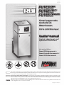
Finned copper tube
Gas boilers &
Water heaters
500 to 4,000 Btuh Input
HeatNet®manual
Control adjustment and
operation instructions
Also read and follow:
Futera III Boiler manual or
Futera Fusion Boiler manual or
Futera XLF Boiler manual
This manual is intended only for use by a qualified heating installer/technician. Read and follow this manual, all supplements and related instructional
information provided with the boiler. Install, start and service the boiler only in the sequence and methods given in these instructions. Failure to do
so can result in severe personal injury, death or substantial property damage.
Do not use the boiler during construction. Construction dust and particulate, particularly drywall dust, will cause contamination of the
burner, resulting in possible severe personal injury, death or substantial property damage. The boiler can only be operated with a dust-free air supply.
Follow the instruction manual procedures to duct air to the boiler air intake. If the boiler has been contaminated by operation with contaminated air,
follow the instruction manual guidelines to clean, repair or replace the boiler if necessary.
Affix these instructions near to the boiler. Instruct the building owner to retain the instructions for future use by a qualified service technician, and
to follow all guidelines in the User’s Information Manual.
Copyright 2009 Mestek, Inc.
Finned copper tube gas boilers & water heaters – Control manual
RBI Futera III/XLF/FUSION-Series boilers — HeatNet control
TM
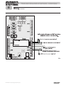
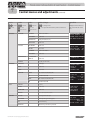
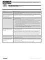
Control overview
The HeatNet control monitors boiler temperature and limit circuit inputs, modulating boiler firing rate
to meet demand. The control uses microprocessor electronics, watching time-average response from the
system to anticipate how much heat the system needs. Coupled with the five-to-one turndown of the boiler, this results in maximum operating efficiency. The boiler will provide unmatched seasonal efficiency.
The HeatNet platform
HeatNet controls are designed to provide an integrated boiler management system on every boiler. The
platform provides multiple levels of selectivity. HeatNet electronics can be operated as a simple singleboiler control, while still providing intelligent regulation of boiler firing rate to match system demand.
With a few key strokes on the key pad, the HeatNet control can operate as a sophisticated multiple-boiler controller, using simple RJ45 cable interfacing between units. The control can even accept external
control commands from building managements systems (Modbus standard, with optional bridge for
BACnet or LonWorks) or 20-milliamp analog input from an external controller.
The control method used by the HeatNet control is based on digital communications, which eliminates
the need for analog control signals. Analog signal inputs are supported, but a higher level of control precision, repeatability and feedback is gained with digital communications.
The HeatNet control can be versatile, providing for operation in multiple ways:
• As a stand-alone boiler, either modulating, two-stage or ON/OFF.
• As a boiler in a boiler network, using the on-board HeatNet protocol.
• As a member boiler in a boiler management system (either directly managed by BMS or managed by
a MASTER HeatNet boiler that communicates with the BMS).
• As a member of a remotely-controlled boiler network (4 – 20-milliamp regulation).
• Setpoint can be determined by the HeatNet control or by a 4 – 20-milliamp input signal.
• Network boilers can be operated by override commands for increased versatility.
This manual is arranged so the instructions for each of the methods above is self-contained. See the Table
of contents for selection and location.
PID response
The HeatNet control uses proportional-integral-derivative calculations to determine the response to
boiler water temperature changes. This means it not only looks at how far away the water temperature is
from the setpoint temperature, but how fast the temperature is changing and how it has responded over
time. This ensures the boiler won’t make sudden unnecessary changes in firing rate.
External limit monitoring & annunciation
In addition to controlling the boiler, the HeatNet control monitors external limits wired into the limit circuit connections. The control shuts down the boiler if a limit opens, and the digital display shows which
limit failed. Monitored limits include high limit aquastat, low water cutoff, flow, ignition control fault, gas
valve alarm and other optional or user-selectable limits.
Futera
HeatNet
Electrical enclosure
Multiple boiler operation
The HeatNet control easily interfaces with other HeatNet controls. Multiple boiler operation using HeatNet protocol only requires RJ45 cables daisy-chained from boiler to boiler and a few key strokes setting
up control behavior. The master boiler is automatically selected by connecting a sensor lead to its SYSTEM HEADER sensor terminals. The HeatNet control recognizes the sensor and configures the boiler
as the master. Other boilers only need to have an address assigned.
Among the advanced design features of the HeatNet control is the MOD-MAX setting. This limits the
firing rate of all boilers to a pre-set maximum (70% by default). This means all of the boilers will be run
at a very efficient level until all boilers are on. Only then can firing rate increase above this setting. Boiler
rotation can be first-on/first-off, first-on/last-off, or true rotation (the HeatNet control monitors the total
on time of all boilers, and rotates their usage so the total on time is the same for all).
2
P/N HN-IOM-1 82-0331 Copyright 2009 Mestek, Inc.
Finned copper tube gas boilers & water heaters – Control manual
RBI Futera III/XLF/FUSION-Series boilers — HeatNet control
TM
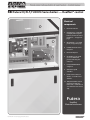
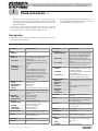
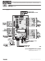
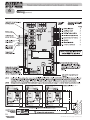
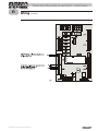
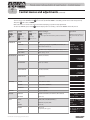
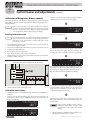
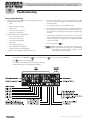
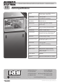
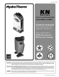
Electrical
components
6
7
1.
Electrical enclosure
2.
Control panel — 4-line digital display and navigation
buttons (on front of control
panel door — see opposite
page)
3.
On/off switch — on control
panel (see opposite page)
4.
HeatNet electrical connection panel
5.
Electrical subpanel
6.
Air chamber access panel
(access to differential
pressure switches, pilot
valve, etc.)
7.
Honeywell R7800 flame
safeguard
8.
VFD blower speed
controller
9.
Power entrance box (not
shown) — located on rear
of boiler
10
8
4
5
1
10. Temperature limit controls
(manual reset and automatic reset) — FuteraIII uses
one automatic reset control
only
Futera
HeatNet
Electrical enclosure
P/N HN-IOM-1 82-0331 Copyright 2009 Mestek, Inc.
3
Finned copper tube gas boilers & water heaters – Control manual
RBI Futera III/XLF/FUSION-Series boilers — HeatNet control
TM
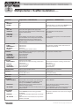
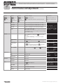
1 Stand-alone boiler . . . . . . . . . . . . . . . . . . . . . . page 6
• Provide an external contact connected across J12A HEAT DEMAND terminals
to start the boiler. (A MEMBER boiler in a network can also be activated by closing
the circuit across HEAT DEMAND.)
• The boiler can operate based on its SUPPLY temperature, or can be operated by remote control from a 4-20mA source. And setpoint temperature can be controlled
locally or by 4-20mA signal from a remote source.
• The boiler’s T1/T2 terminals can be used to operate the boiler as two-stage (fired
at minimum input or maximum input).
• The AA terminals can be used to fire the boiler as ON/OFF at maximum input.
2 Multiple boilers: HeatNet modulation . . . . page 8
• The HeatNet control can control up to (16) boilers using built-in software and
hardware.
• Boilers come standard with HeatNet communications capability, and require only
RJ45 HeatNet cables (or shielded wires) to connect between them.
• The header water temperature setpoint can be set by the master boiler or by a
4-20ma input from an external controller.
• Member boilers can override master boiler control if they receive a contact closure
on the HEAT DEMAND terminals or the AA high fire terminals. In addition, the
controls can be set up to allow priority override by a remote 4-20mA source.
3 Multiple boilers: BMS operation . . . . . . . . page 13
• PREFERRED — Combined BMS/HeatNet operation — This method uses
the HeatNet control’s built-in communications capabilities to accept MODBUS
protocol inputs from a building management system. The master boiler control
sequences and modulates the boiler network to accomplish the demands from the
building management system.
• ALTERNATE — Direct BMS control of all boilers — Each boiler can be operated directly by the BMS (each boiler will require an optional plug-in protocessor if using BACnet or LonWorks).
• Boiler setup is essentially the same as for method 2, with the exception that each
boiler must be assigned both a HeatNet network address and an address for the
MODBUS interface.
Futera
HeatNet
Electrical enclosure
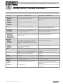
• An optional plug-in protocessor is required to interface with systems using BACnet
or LonWorks protocol.
• The master boiler will take control and regulate the boiler network if signal from
the BMS is lost or times out.
4 External 4-20ma control . . . . . . . . . . . . . . . . page 15
• 4-20mA/HeatNet combined operation — The master boiler can receive the
4-20mA modulation signal and control the other boilers.
4
P/N HN-IOM-1 82-0331 Copyright 2009 Mestek, Inc.
Finned copper tube gas boilers & water heaters – Control manual
Contents
• 4-20mA direct operation — Up to 5 boilers can be controlled by an external control that provides a 4-20ma input signal. The external controls must also activate
each boiler by closing a contact across the boiler’s 4-20ma Remote Enable contacts.
• Member boilers can override external boiler control if they receive a contact closure on the Heat Demand or any terminal higher priority than the 4-20mA (controls can be set up to make 4-20mA the highest priority if desired).
5 Configuring for DHW applications . . . . . . . page 16
• The HeatNet control can control provides multiple options for DHW heating,
either for dedicated DHW or combined space heating/DHW. This section discusses four alternatives, referred to as Method 1 through Method 4.
6 Control menus and adjustments . . . . . . . . . page 29
• Operating parameters and control behaviors are set using the HeatNetv control’s
display/keypad interface.
• Refer to this section for the menu structure and explanations of the setup options.
• Table 7 — SETUP menus . . . . . . . . . . . . . . . . . . . . . . . . . . . . . . . . . . . . . . . . . . . . . . . . . page 30
• Table 8 — ADVANCED SETUP menus . . . . . . . . . . . . . . . . . . . . . . . . . . . . . . . . . page 33
• Table 9 — Setup menus — parameter explanations . . . . . . . . . . . . . . . . . . . . . page 35
7 Wiring . . . . . . . . . . . . . . . . . . . . . . . . . . . . . . . . . page 29
• Wire the boilers as described in this section.
8 Boiler operation and status display . . . . . . page 29
• This section describes control start-up and operation.
9 Troubleshooting . . . . . . . . . . . . . . . . . . . . . . . page 51
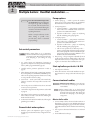
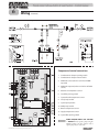
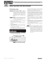
Futera
HeatNet
Electrical connection
panel & subpanel
• Table 11 — Status screen fault displays . . . . . . . . . . . . . . . . . . . . . . . . . . . . . . . . . . . . . . . . . . . . . page 49
• Table 12 — Troubleshooting suggestions . . . . . . . . . . . . . . . . . . . . . . . . . . . . . . . . . . . . . . . . . . page 52
10Setup worksheet . . . . . . . . . . . . . . . . . . . . . . . page 55
• Use this section to enter setup information.
P/N HN-IOM-1 82-0331 Copyright 2009 Mestek, Inc.
5
Finned copper tube gas boilers & water heaters – Control manual
1
Stand-alone boiler
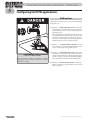
Electrical shock hazard — Disconnect all electrical power
sources to the boiler before making any electrical connections.
Label all wires prior to disconnection when servicing controls.
Wiring errors can cause improper and dangerous operation!
Verify proper operation after servicing.
Failure to comply with the above could result in severe personal
injury, death or substantial property damage.
Close the external manual gas valve on every boiler before
proceeding. DO NOT open any gas valve, or attempt to fire the
boiler, until the boilers has been set up and verified following the
instructions in the Boiler Installation & Operating Instructions.
Failure to comply could cause a boiler failure, leading to possible
severe personal injury, death or substantial property damage.
The electrical connections to this boiler must be made in
accordance with all applicable local codes and the latest revision
of the National Electrical Code, ANSI /NFPA-70. Installation
should also conform to CSA C22.1 Canadian Electrical Code
Part I if installed in Canada. Install a separate 120 volt 15 amp
circuit for the boiler. A properly rated shut-off switch should be
located at the boiler. The boiler must be grounded in accordance
with the authority having jurisdiction, or if none, the latest
revision of the National Electrical Code, ANSI/NFPA-70.
Line voltage field wiring of any controls or other devices must
use copper conductors with a minimum size of #14 awg. Use
appropriate wiring materials for units installed outdoors.
Control setup sequence
Install the boilers according to the Boiler Installation & Operating
Instructions before attempting to set up the control system.
• Two-stage fired by using the T1 and T2 terminals. Closing one of these brings the boiler on at MIN firing rate.
Closing the other brings the boiler to MAX input.
Set control parameters
Before turning boilers on to set parameters,
disconnect all call for heat wiring at the electrical
connection boards. This will prevent the boiler
from attempting to cycle during the setup
process.
1. See Table 1 for a list of parameters that should be set for a
stand-alone boiler.
2. See “Control menus and adjustments,” beginning on
page 29 for a complete list of control parameters and explanations (Table 7, page 30 and Table 8, page 33).
3. Carefully read the parameter explanations in Table 9,
page 35.
4. When adjusting the limit band, operating limit (OP LIMIT), local setpoint (LOC SETPOINT), system header or
DHW setpoint, make sure the operating temperature bands
do not overlap or cause potential for nuisance cycling.
5. System clock — Set the system clock to ensure the time
stamps will be accurate in the data logs.
6. Turn on the power to the boiler and set the on/off switch to
ON as you set its parameters.
7. Use the boiler’s keypad to enter the parameters as described
on page 29.
8. After setting a boiler’s parameters, turn off the power to the
boiler until you are ready to start the boiler up following the
Boiler manual instructions.
Domestic hot water options
1. Close the external gas valve.
2. Wire the boiler following the guidelines in this manual.
3. Attach sensors as required, including a HEADER sensor if needed for primary/
secondary circuits or DHW tank heating.
4. Set the boiler control parameters using its display/keypad.
1. Read the options and explanations given on page 16
through page 19 to determine the best configuration for the
system.
Wiring
1. Summer pump jog — enable to operate the circulator
pump once per week (at 12:01 AM on any specified day)
when the heater is shut down for summer shutdown.
2. System pump options:
a. Constant circulation — pump remains on at all times
unless outdoor reset is enabled and the outdoor temperature is above WWS SETPOINT.
b. Operation on call for heat — pump is on only during
heat calls and during pump postpurge time.
3. Local pump options:
a. Constant circulation — pump remains on at all times
unless outdoor reset is enabled and the outdoor temperature is above WWS SETPOINT.
b. Operation on call for heat — pump is on only during
heat calls and during pump postpurge time.
PUMPS REQUIRE RELAYS OR STARTERS — DO NOT directly
operate a pump using the HeatNet contacts. Use these contacts only to
operate pump relay or starter coils.
1. See page 20 for wiring information and wiring diagrams.
2. Note that the boiler can be wired for override operation. The wiring section provides information on override priorities and options.
3. The boiler can be activated by the HEAT DEMAND input, and allowed to modulate based on the HeatNet control. It can also be activated by either:
• ON/OFF full input operation by closing the AA terminals.
• Operation via remote 4-20mA signal by closing the 4-20mA ENABLE terminals and providing the 4-20mA signal.
6
Pump options
P/N HN-IOM-1 82-0331 Copyright 2009 Mestek, Inc.
Finned copper tube gas boilers & water heaters – Control manual
1
Stand-alone boiler (cont.)
c. Call for heat operation PLUS delta temp mode — pump is on during heat
calls, during pump postpurge time, and the pump will continue to run after
the postpurge timing until the temperature difference across the boiler is less
than DELTA TEMP.
4. Flow proving — Flow proving time is adjustable (from 10 to 240 seconds), with
factory default setting of 10 seconds. Adjust this time if necessary to compensate
for slow-opening valves or other factors that would delay flow start.
2. After setting up the boiler per the I & OM Instructions, you
can set MIN, MAX and IGNITION firing rates using the
CALIBRATION procedure in this manual.
Start up boiler
1. Follow all instructions in the Boiler Installation & Operating Instructions to start
up the boiler and verify operation.
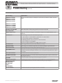
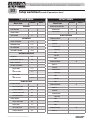
Table 1
Control parameters — stand-alone boiler
Parameter
Requirement
Parameter
BOILERS
HEAT BAND . . . . . . . . . . . . . . .
Set
AUX FUNCTIONS
COMBUST AIR DAMPER . . . . .
SETPOINTS
LOCAL SETPT . . . . . . . . . . . . .
SYSTEM SETPT . . . . . . . . . . . .
OPERATE LIMIT . . . . . . . . . . . .
OP LIMIT BAND . . . . . . . . . . .
SETPT SOURCE . . . . . . . . . . . .
OUTDOOR RESET, IF USED
OA RESET . . . . . . . . . . . . . . . .
WARM WEATHER SD . . . . . . .
WWS SETPOINT . . . . . . . . . . .
OA SETPTS . . . . . . . . . . . . . . .
Set if control will regulate boiler
supply temp
Set if control will regulate header
or DHW tank temp (requires header
sensor)
Set
Set
Specify AUTO or 4-20mA remote
control (AUTO uses the HeatNet
control setup values for setpoint
temperature; 4-20mA uses a 4-20mA
signal to determine setpoint
temperature as described in the
parameters tables)
Enable if used
Enable if used
Set if used
Set if used (requires outdoor sensor)
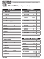
SYSTEM PUMP
Applies ONLY if the control will cycle
a system pump as well as the boiler
pump
POST PRG TIME . . . . . . . . . . . . . . . Set or keep default
ALWAYS ENABLE . . . . . . . . . . Enable if desired
SUMMER PUMP JOG . . . . . . . . Enable if desired
Settings for boiler pump
LOCAL PUMP
DELTA TEMP ENABLE . . . . . . . Enable if desired (requires installing a
return water temp sensor)
DELTA TEMP . . . . . . . . . . . . . . Set value if enabled
POST PRG TIME . . . . . . . . . . . Set or keep default
ALWAYS ENABLED . . . . . . . . . Enable if desired
PUMP/VALVE OPTION
Enable constant pump if desired
FLOW PROVE
Enable if used
(connect flow switch)
NIGHT SETBACK
Set if desired
OPTIONS (all)
Set
P/N HN-IOM-1 82-0331 Copyright 2009 Mestek, Inc.
ALARM SILENCE . . . . . . . . . . .
FAILSAFE MODES . . . . . . . . . .
HEAT EXCHANGER
ALARM TYPE . . . . . . . . . . . . . .
EXCHR DELTA T . . . . . . . . . . . .
LIM->HALF RATE . . . . . . . . . .
DOMESTIC HOT WATER
DHW BOILER? . . . . . . . . . . . . .
DHW SETPOINT . . . . . . . . . . .
DHW DIFF . . . . . . . . . . . . . . . .
USE SENSOR? . . . . . . . . . . . . .
Requirement
Select IN USE = YES to enable; select
proof time or keep default (connect
wires to damper and end switch)
Enable remote alarm silence if
desired (connect terminals to remote
switch)
Enable LOW TEMP if desired for freeze
protection; set temp as desired
Select WARNING (continue running)
or FAULT (shutdown)
Set maximum allowable temperature
rise through boiler
Enable if boiler is to be limited to 50%
input when DELTA T is exceeded
PASSWORD
Select YES if boiler/system is for DHW
Set
Set
YES for sensor in DHW tank; NO for
tank aquastat
Set
Set
Set
Set to ensure accuracy of time
stamping
Select type or accept defaults; make
sure installed sensors are listed and
are the correct type
Set values for 4-20mA parameters if
using either as primary control source
or as an override
Set if desired
COMMUNICATIONS
Set if desired
LOAD DEFAULTS
Restore defaults if desired
DHW PRIORITY . . . . . . . . . . . .
POST PURGE . . . . . . . . . . . . . .
DEMAND STARTS? . . . . . . . . .
SYSTEM CLOCK
SENSORS
4-20mA INPUT
SYSTEM
FIRMWARE . . . . . . . . . . . . . . .
OPTION: . . . . . . . . . . . . . . . . .
APPLICATION . . . . . . . . . . . . .
Load firmware if necessary to bring
up to date
Set
Select HEAT or DHW
7
Finned copper tube gas boilers & water heaters – Control manual
2
Multiple boilers: HeatNet modulation
Set termination DIP switches
Electrical shock hazard — Disconnect all electrical power
sources to the boiler before making any electrical connections.
Label all wires prior to disconnection when servicing controls.
Wiring errors can cause improper and dangerous operation!
Verify proper operation after servicing.
Failure to comply with the above could result in severe personal
injury, death or substantial property damage.
The electrical connections to this boiler must be made in
accordance with all applicable local codes and the latest revision
of the National Electrical Code, ANSI /NFPA-70. Installation
should also conform to CSA C22.1 Canadian Electrical Code
Part I if installed in Canada. Install power supplies to the
boiler as indicated on the boiler wiring diagram, making sure
to provide the correct voltage, phase and amperage capacity
specified. A properly rated shut-off switch should be located at
the boiler. The boiler must be grounded in accordance with the
authority having jurisdiction, or if none, the latest revision of
the National Electrical Code, ANSI/NFPA-70.
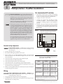
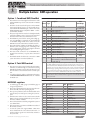
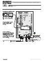
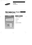
1. The HeatNet network needs to recognize the beginning
and end of the network. This requires setting the four DIP
switches on each boiler’s electrical connection board.
2. See Figure 1 for location of the switches.
3. See Table 2 for required settings. The table gives settings
for HeatNet modulation — local control and for remote
control from a building management system (MODBUS
protocol).
4. DO NOT connect the communications cables (or shielded
wires) between boilers until all boilers have had parameters
set and then been started up following all instructions in the
Boiler manual.
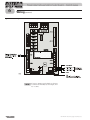
Figure 1
Termination DIP switches (located at lower
left corner of control board) (component
details are omitted for clarity)
Line voltage field wiring of any controls or other devices must
use copper conductors with a minimum size of #14 awg. Use
appropriate wiring materials for units installed outdoors.
Control setup sequence
Follow the Boiler manual — Install the boilers according to the Boiler
Installation & Operating Instructions manual before attempting to set up
the control system.
1. Close the external gas valve on every boiler.
2. Wire all boilers following the guidelines in this manual.
3. Attach a header sensor (SYSTEM HEADER terminals) to the master boiler
ONLY. The HeatNet control automatically configures the boiler with a header
sensor as the master.
4. Set the master boiler control parameters using its display/keypad.
5. Set the master boiler’s termination DIP switches.
6. Set the termination DIP switches on the member boilers.
7. Set the member boilers’ control parameters using their display/keypads.
8. Follow the instructions in the Boiler Installation & Operating Instructions to start
up each boiler before proceeding further.
9. Finish by connecting cables between the communications boards of all of the boilers and verifying network operation.
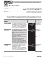
Table 2
Termination DIP switch settings (HeatNet
switches are on left, MODBUS switches are on
right) (DOWN = ON; UP = OFF)
Boiler
1. See page page 20 for wiring information and wiring diagrams.
2. Note that the boilers can be wired for override operation. The wiring section provides information on override priorities.
8
MODBUS
(see note)
Master
Switch 1: ON
Switch 2: ON
Switch 1: ON
Switch 2: ON
Last member
Switch 1: ON
Switch 2: ON
Switch 1: ON
Switch 2: ON
Other members
Switch 1: OFF
Switch 2: OFF
Switch 1: OFF
Switch 2: OFF
Wiring
PUMPS REQUIRE RELAYS OR STARTERS — DO NOT directly
operate a pump using the HeatNet contacts. Use these contacts only to
operate pump relay or starter coils.
HeatNet
Note: MODBUS setup is for applications controlled by a building
management system. For systems using BACnet or LonWorks, a bridge
board is used to interface with the HeatNet control. If each boiler is directly
controlled by the BMS, set the DIP switches for each boiler the same as for a
master boiler (both switches on).
P/N HN-IOM-1 82-0331 Copyright 2009 Mestek, Inc.
Finned copper tube gas boilers & water heaters – Control manual
2
Multiple boilers: HeatNet modulation (cont.)
Pump options
Close the external manual gas valve
on every boiler before proceeding. DO
NOT open any gas valve, or attempt to
fire any boiler, until the boilers have
been set up and verified following the
instructions in the Boiler Installation &
Operating Instructions.
Failure to comply could cause a boiler
failure, leading to possible severe
personal injury, death or substantial
property damage.
Set control parameters
Before turning boilers on to set parameters,
disconnect all call for heat wiring at the electrical
connection boards. This will prevent the boiler
from attempting to cycle during the setup
process.
1. See “Control menus and adjustments,” beginning on
page 29 for a complete list of control parameters and explanations (Table 7, page 30 and Table 8, page 33).
2. Carefully read the parameter explanations in Table 9,
page 35.
3. When adjusting the limit band, operating limit (OP LIMIT), local setpoint (LOC SETPOINT) and DHW setpoint,
make sure the operating temperature bands do not overlap
or cause potential for nuisance cycling.
4. System clock — Set the system clock on the master boiler
ONLY, to ensure the time stamps will be accurate in the
data logs.
5. Turn on the power to each boiler and set the on/off switch
to ON as you set its parameters.
6. Use the boiler’s keypad to enter the parameters as described
on page 29.
7. After setting a boiler’s parameters, turn off the power to the
boiler until you are ready to start the boiler, following the
Boiler manual instructions.
8. Set the master boiler and each member boiler, following the
guidelines given in Table 3.
Domestic hot water options
1. Read the options and explanations given on page 16
through page 19 to determine the best configuration for the
system.
P/N HN-IOM-1 82-0331 Copyright 2009 Mestek, Inc.
1. Summer pump jog — enable to operate the circulator
pump once per week (at 12:01 AM on any specified day)
when the heater is shut down for summer shutdown.
2. System pump options:
a. Constant circulation — pump remains on at all times
unless outdoor reset is enabled and the outdoor temperature is above WWS SETPOINT.
b. Operation on call for heat — pump is on only during
heat calls and during pump postpurge time.
3. Local pump options:
a. Constant circulation — pump remains on at all times
unless outdoor reset is enabled and the outdoor temperature is above WWS SETPOINT.
b. Operation on call for heat — pump is on only during
heat calls and during pump postpurge time.
c. Call for heat operation PLUS delta temp mode —
pump is on during heat calls, during pump postpurge
time, and the pump will continue to run after the postpurge timing until the temperature difference across
the boiler is less than DELTA TEMP.
4. Flow proving — Flow proving time is adjustable (from 10
to 240 seconds), with factory default setting of 10 seconds.
Adjust this time if necessary to compensate for slow-opening valves or other factors that would delay flow start.
Start up boilers per boiler I & OM
1. Turn off power to all boilers.
2. Follow all instructions in the Boiler Installation & Operating Instructions to start up each boiler and verify operation.
Connect network cables
Electrical shock hazard — Turn off power
to each boiler before attempting to connect the
network cables.
Before turning boilers on to check network
operation, disconnect all call for heat wiring at the
electrical connection boards. This will prevent
the boiler from attempting to cycle during the
setup process.
Master boiler cable
1. Connect an RJ45 cable to the master boiler H-Link OUT
block (Figure 3, page 22) or 3-wire shielded cable to the HLink terminal strip (Figure 3, page 22). The other end of this
cable will be attached to the first member boiler in following
steps.
2. Turn on power to the master boiler and set its on/off switch
to ON.
3. You should hear at least 2 beeps.
9
Finned copper tube gas boilers & water heaters – Control manual
2
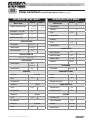
Table 3
Multiple boilers: HeatNet modulation (cont.)
Control parameters for HeatNet networks
Parameter
Requirement — MASTER boiler
BOILERS
LEAD STAGE # . . . . . . . . . . . . .
HEAT BAND . . . . . . . . . . . . . . .
Set
Set
SETPOINTS
LOCAL SETPT . . . . . . . . . . . . .
SYSTEM SETPT . . . . . . . . . . . .
OPERATE LIMIT . . . . . . . . . . . .
OP LIMIT BAND . . . . . . . . . . .
SETPT SOURCE . . . . . . . . . . . .
OUTDOOR RESET, IF USED
OA RESET . . . . . . . . . . . . . . . .
WARM WEATHER SD . . . . . . .
WWS SETPOINT . . . . . . . . . . .
OA SETPTS . . . . . . . . . . . . . . .
SYSTEM PUMP
POST PRG TIME . . . . . . . . . . .
ALWAYS ENABLE . . . . . . . . . .
SUMMER PUMP JOG . . . . . . . .
OVR ENAB IN WWS . . . . . . . . .
LOCAL PUMP
DELTA TEMP ENABLE . . . . . . .
Requirement — MEMBER boiler
Heat band setting is not applicable to MEMBER boiler
unless boiler will operate in override mode
Set if control will regulate boiler supply temp
Set if control will regulate header or DHW tank temp
(requires header sensor)
Set
Set
Specify AUTO or 4-20mA remote control (AUTO
uses the HeatNet control setup values for setpoint
temperature; 4-20mA uses a 4-20mA signal to
determine setpoint temperature as described in
Table 9, page 35)
Set
Set if needed for override operation
Not needed
Set
Set
Set only if boiler will operate in override mode with
4-20mA input
Enable if used
Enable if used
Set if used
Set if used (requires outdoor sensor)
Not applicable to member boiler unless boiler is to
operate in override mode
Applies ONLY if the control will cycle a system pump
as well as the boiler pump
Set or keep default
Enable if desired
Enable if desired
Enable if desired
Not applicable to member boiler
Settings for boiler pump
Enable if desired (requires installing a return water
temp sensor)
Set value if enabled
Set or keep default
Enable if desired
Enable if desired (requires installing a return water
temp sensor)
Set value if enabled
Set or keep default
Enable if desired
PUMP/VALVE OPTION
Enable constant pump if desired
Enable constant pump if desired
FLOW PROVE
Enable if used
(connect flow switch)
Enable if used
(connect flow switch)
NIGHT SETBACK
Set if desired
Not applicable to member boiler
OPTIONS (all)
Set
Set
Select IN USE = YES to enable; select proof time or
keep default (connect wires to damper and end
switch); select COMMON or INDEPENDENT
Enable remote alarm silence if desired (connect
terminals to remote switch)
Enable LOW TEMP if desired for freeze protection; set
temp as desired
Same as MASTER
Select WARNING (continue running) or FAULT
(shutdown)
Set maximum allowable temperature rise through
boiler
Enable if boiler is to be limited to 50% input when
DELTA T is exceeded
Set if boiler is enabled to run on local on loss of signal
from MASTER
DELTA TEMP . . . . . . . . . . . . . .
POST PRG TIME . . . . . . . . . . .
ALWAYS ENABLED . . . . . . . . .
AUX FUNCTIONS
COMBUST AIR DAMPER . . . . .
ALARM SILENCE . . . . . . . . . . .
FAILSAFE MODES . . . . . . . . . .
HEAT EXCHANGER
ALARM TYPE . . . . . . . . . . . . . .
EXCHR DELTA T . . . . . . . . . . . .
LIM->HALF RATE . . . . . . . . . .
10
Enable remote alarm silence if desired (connect
terminals to remote switch)
Enable LOW TEMP if desired for freeze protection; set
temp as desired; enable run in local if desired
P/N HN-IOM-1 82-0331 Copyright 2009 Mestek, Inc.
Finned copper tube gas boilers & water heaters – Control manual
2
Table 3
Multiple boilers: HeatNet modulation (cont.)
Control parameters for HeatNet networks (continued)
Parameter
Requirement — MASTER boiler
Requirement — MEMBER boiler
DOMESTIC HOT WATER
DHW BOILER? . . . . . . . . . . . . .
DHW SETPOINT . . . . . . . . . . .
DHW DIFF . . . . . . . . . . . . . . . .
USE SENSOR? . . . . . . . . . . . . .
DHW PRIORITY . . . . . . . . . . . .
POST PURGE . . . . . . . . . . . . . .
DEMAND STARTS? . . . . . . . . .
Select YES if boiler/system is for DHW
Set
Set
YES for sensor in DHW tank; NO for tank aquastat
Set
Set
Set
Set if boiler is enabled to run on local on loss of signal
from MASTER
SYSTEM CLOCK
Set to ensure accuracy of time stamping
NO — set only on master boiler (master
automatically updates all member boilers
DISTRIBUTED CTRL
H-NET ADDRESS . . . . . . . . . . .
MODBUS ADDRESS . . . . . . . . .
HeatNet address is automatic for MASTER = 255
Set only if using BMS operation
Set from 2 to 16; unique address for each boiler
Set only if using BMS operation
MODULAR BOILER SET
ADD DELAY TIME . . . . . . . . . .
SHED DELAY TIME . . . . . . . . .
MODULATE DELAY TIME . . . . .
MOD MAX-LAST FIRE . . . . . . .
ADAPTIVE MODE
MOD MODE . . . . . . . . . . . . . . .
DROP DOWN . . . . . . . . . . . . . .
DELAY RELEASE . . . . . . . . . . .
FIRING MODE
FIRING MODE . . . . . . . . . . . . .
MASTER FIRST . . . . . . . . . . . .
Adjust timings as needed to match control operation Not applicable to member boilers
to system response
Select ADAPTIVE if the Master boiler is to lower the
Not applicable to member boilers
modulating rate of running boilers when a new
boiler starts. Set DROP DOWN and DELAY RELEASE as
needed.
Select rotation method preferred
Enable if desired
Not applicable to member boilers
SENSORS
Select type or accept defaults; make sure installed
sensors are listed and are the correct type; make sure
HEADER sensor is connected to MASTER boiler only
ONLY return sensor would apply with member boiler,
and ONLY if using DELTA TEMP or HEAT EXCHGER
parameters
4-20mA INPUT
Set values for 4-20mA parameters if using either as
primary control source or as an override
Set values for 4-20mA parameters if using as an
override
PASSWORD
Set if desired
Set if desired
COMMUNICATIONS
Set if desired
Set if desired
LOAD DEFAULTS
Restore defaults if desired
Restore defaults if desired
SYSTEM
FIRMWARE . . . . . . . . . . . . . . .
OPTION: . . . . . . . . . . . . . . . . .
Load firmware if necessary to bring up to date
Set
Select HEAT or DHW
Load firmware if necessary to bring up to date
Set if boiler is enabled to run on local on loss of signal
from MASTER
Set if boiler is enabled to run on local on loss of signal
from MASTER
APPLICATION . . . . . . . . . . . . .
P/N HN-IOM-1 82-0331 Copyright 2009 Mestek, Inc.
11
Finned copper tube gas boilers & water heaters – Control manual
2
Multiple boilers: HeatNet modulation (cont.)
4. The control’s firmware version number will display. Make sure the
firmware of all boilers is compatible. All boilers in a multiple boiler application should preferably have the same firmware version to ensure
consistency. If versions are different, all versions must be either version
2.0 or greater, or version 1.x.
3. After about 30 seconds, the master boiler should recognize the member boilers.
5. After the control’s timer finishes, the display will show STANDBY and
SYSTEM. This verifies that the master boiler is setup correctly as the
master. The same display will show on member boilers when there is a
call for heat from the master boiler. When there is no call for heat at a
member boiler, the display will show LOCAL instead.
5. If the display shows a blank space, such as “123_56789,” the control
does not detect the missing boiler (boiler 4). Check the yellow LED
on the communication port of the missing boiler.
6. If the master is functioning correctly, the yellow LED’s on the H-Link
jack ports will blink. The blinking indicates that the master is trying to
communicate with member boilers.
7. TERMINATION incorrect — LED will flash rapidly and stay on.
7. If a FAULT message is displayed, clear the faults until the STANDBY
message is displayed. Refer to troubleshooting suggestions in this
manual if you cannot resolve the issue.
Member boiler cables
1. Begin with the first member boiler.
4. Navigate to the BOILERS menu, then to HEATNET BOILERS display. The master control will show the boilers it recognizes.
6. NORMAL connection — LED should flash steadily, about twice per
second.
8. OPEN connection — LED does not flash at all.
9. If a FAULT message is displayed, clear the faults until the STANDBY
message is displayed. Refer to troubleshooting suggestions at the end
of this manual if you cannot resolve the issue.
Start the system
2. Plug one end of the RJ45 or shielded cable into the master boiler’s output port. Plug the other end of the master boiler’s communications cable to a member boiler’s input port, using either RJ45 cable or shielded
cable (Figure 3, page 22).
1. Turn off power to all boilers.
3. Connect cables to all of the member boilers by cabling from one to the
next.
4. The boilers should now operate normally, as described in the Boiler
manual.
Check the network
5. The master boiler will sequence and modulate boilers as necessary to
control the water temperature.
1. Turn the power on and the on/off switch to ON for all of the member
boilers.
2. Allow time for each boiler to initialize.
12
2. Connect all call for heat wiring to the boilers.
3. Turn on power to all boilers and turn the on/off switches to ON.
6. The master boiler will show the number of boilers firing as well as the
temperature and heat band display. Use the UP/DOWN keys to scroll
through the displays to watch the process of starting and stopping boilers.
P/N HN-IOM-1 82-0331 Copyright 2009 Mestek, Inc.
Finned copper tube gas boilers & water heaters – Control manual
3
Multiple boilers: BMS operation
Option 1: Combined BMS/HeatNet
1. This method uses an RS485 digital communications cable
with the MODBUS protocol to control a boiler or HeatNet
network.
2. The boiler or boiler network will operate as in the HeatNet
local control method (Section 1 of this manual). But, instead of the HEAT DEMAND input, a software form of the
HEAT DEMAND input is used (address 40001 — Boiler/
System Enable/Disable).
3. The System Setpoint Timer needs to be loaded periodically
to allow the HeatNet system to revert to local control from
the master boiler in the event communications is lost.
4. The MODBUS protocol allows writing and reading registers using MODBUS commands. An optional BACNet
or LONWorks bridge module can be used to connect the
MODBUS network to a BACNet or LonWorks network.
5. This method allows enabling and disabling the boiler or
HeatNet system; changing setpoints; and reading boiler
status or temperatures remotely, using digital commands
from a Building Management System.
6. The master boiler assumes the role of MEMBER, RTU,
19.2Kb, 8 bits, Even Parity, 1 stop bit, when connected to
a BMS.
7. The Member Boilers should not be connected to a BMS
system other than to view read-only addresses.
Option 2: Total MBS control
1. This option uses direct control of each boiler (and requires
a BACnet or LonWorks bridge on each boiler if not using
MODBUS). The BMS controls each boiler directly, except
when the boiler is wired and activated for override operation.
2. Consult the website for address configuration information,
at info.www.rbiwaterheaters.com. Click the “HeatNet
On Board” icon.
MODBUS registers
1. See Table 4, page 13; Table 5, page 13; and Table 6, page 14
for register requirements.
2. The system setpoint timer and system setpoint work in tandem to externally control the operating setpoint.
3. The setpoint (countdown) timer should be loaded with a
timeout value (in seconds) prior to writing the system setpoint.
4. When the timer reaches zero, the control assumes that the
BMS is no longer operating and the local setpoint (saved on
the master control) is reloaded.
5. This is a fail-safe feature used to help safeguard the system in
case of BMS failure.
6. If the setpoint timer is not written, a default timeout value of
60 seconds is assumed.
7. To write the system clock, registers 40009 – 40015 must
first be loaded with the correct date and time. Then, a 1
must be written to register 16 to write the date and time to
the system clock.
P/N HN-IOM-1 82-0331 Copyright 2009 Mestek, Inc.
Table 4
MODBUS holding (read/write) registers
Address
Data
Type
Description
Valid
Values/Range
40001 Unsigned Boiler/System Enable/Disable
40002 Unsigned
40003 Unsigned
40004 Unsigned
40005
40006
40007
40008
40009
40010
40011
40012
40013
40014
40015
40016
Unsigned
Unsigned
Unsigned
Unsigned
Signed
Unsigned
Unsigned
Unsigned
Unsigned
Unsigned
Unsigned
Unsigned
40017 Unsigned
0 = Disabled/Off
1 = Enabled/On
System Setpoint Timer (1)
0 – 65535 seconds
System Setpoint (1)
40°F – 220 °F
Outdoor Air Reset Enable/Disable
0 = Disabled/Off
1 = Enabled/On
Outdoor Air Setpoint
40°F -100 °F
Water Temperature at High Outside Air
60°F -150 °F
High Outside Air Temperature
50°F -90 °F
Water Temperature at Low Outside Air
70°F -220 °F
Low Outside Air Temperature
-35°F -40 °F
Set Clock – Month (2)
0 – 11
Set Clock – Day of Month (2)
1 – 31
Set Clock – Year (2)
0 – 99
Set Clock – Hours (2)
0 – 23
Set Clock – Minutes (2)
0 – 59
Set Clock – Seconds (2)
0 – 59
Set Clock – Day of Week (2)
1 – Monday 7 –
Sunday
Set Clock – After the Set Clock Registers listed above
1
have been written, a 1 must be written to this location
to set the clock. (2)
Note (1) The system setpoint timer and system setpoint work in tandem to externally control
(i.e. a BMS - building management system) the operating setpoint. The System Setpoint (countdown) timer should be loaded with a timeout value (in seconds) prior to
writing the system setpoint. When the timer reaches zero, the control assumes that the
BMS is no longer operating and the local setpoint (saved on the control) is reloaded.
This is a failsafe feature used to help safeguard the system in case of BMS failure. If the
setpoint timer is not written, a default timeout value of 60 seconds is assumed.
Note (2) To write the system clock, registers 40010 – 40015 must first be loaded with the correct date and time. Then, a 1 must be written to register 17 to write the date and time
to the system clock.
Table 5
Bit
0
1
2
3
4
5
6
7
8
9
10
11
12
13
14
15
Boiler status flags
Description
Disabled
Local Override
Alarm
Failed
Member Error
Boiler Running
Pump Running
Spare 3 Interlock
LWCO Interlock
VFD Interlock
Gas Prove
Spare 4
Operator Interlock
Water Prove (Flow) Interlock
Air Prove UV Sensor Interlock
Main Valve
Bit
16
17
18
19
20
21
22
23
24
25
26
27
28
29
30
31
Description
Pilot Valve
Blower
Ignition Alarm
Valve Alarm
High Limit
Air Prove Switch
XS Factory
Software Operator
Header (SYS/DHW) Sensor not Present
Supply Sensor not Present
Return Sensor not Present
Outside Air Sensor not Present
——
——
Master Boiler
Present (Boiler Detected)
13
Finned copper tube gas boilers & water heaters – Control manual
Multiple boilers: BMS operation (cont.)
BACnet or LonWorks protocols
1. Install the correct protocessor to adapt to building management systems using BACnet or LonWorks protocols. Each
boiler must have a protocessor if the BMS is to operate with
direct control of each boiler (option 2, page 13).
2. The protocessor translates the BACnet or LonWorks input
to the MODBUS protocol for compatibility with the HeatNet controls.
Wiring and set-up
PUMPS REQUIRE RELAYS OR STARTERS
— DO NOT directly operate a pump using the
HeatNet contacts. Use these contacts only to
operate pump relay or starter coils.
1. Wire and set up the master boiler and member boilers exactly as for HeatNet modulation — local control applications. See section beginning on page 8.
2. ALL control parameters must be set up just as for the local
control method.
3. The ONLY difference in setup is the termination DIP
switch settings. Use the settings for MODBUS communications given in Table 2, page 8.
4. Connect communications cables (RJ45 or shield-wire
cables) between the control communications boards as for
the local control method.
5. Verify network operation BEFORE connecting the building management system.
Connect the BMS cable
1. DO NOT connect the building management system cable
until the boiler network has been proven to operate independently. The system is designed to revert to local control by the master boiler should communications with the
building management system be lost.
2. Turn off power to the master boiler.
3. See Figure 9, page 28. Connect an RJ45 cable or shielded
cable to the corresponding input port on the MASTER
boiler HeatNet board.
Verify BMS/HeatNet operation
1. Turn on power to the master boiler.
2. Allow the master boiler to initialize.
3. Verify operation with the building management system.
14
Table 6
Address
3
MODBUS input (read-only) registers
Data
Type
Description
Valid Values/Range
30001 Unsigned Boilers Running
0 – 16
30002 Unsigned Modulation (% BTU Load)
0 – 100
30003
Signed Header / System Temperature
32 – 250 °F
30004
Signed Supply Temperature
32 – 250 °F
30005
Signed Return Temperature
32 – 250 °F
30006
Signed Outside Air Temperature
-40 – 250 °F
30007
Signed Spare Input 1
-32768 to 32767
30008
Signed Spare Input 2
-32768 to 32767
30009 Unsigned Clock – Month
0 – 11
30010 Unsigned Clock – Day
1 – 31
30011 Unsigned Clock – Year
0 – 99
30012 Unsigned Clock – Hours
0 – 23
30013 Unsigned Clock – Minutes
0 – 59
30014 Unsigned Clock – Seconds
0 – 59
30015 Unsigned Clock – Day of Week
1 – Monday 7 –
Sunday
30016 – Unsigned Boilers 1 – 16 status flag (32-bit) registers. The
30047
upper 16-bits of each 32-bit register is stored at
odd numbered addresses 30016 –30046. The
lower 16-bits of each 32-bit register is stored at
even numbered addresses 30017 – 30047.
See the Boiler Status
Flags Table Below
30048 – Unsigned Boilers 1 – 16 runtime (32-bit) registers. The up30079
per 16-bits of each 32-bit register is stored at odd
numbered addresses 30048 – 30078. The lower
16-bits of each 32-bit register is stored at even
numbered addresses 30049 – 30079.
When the upper and lower registers are combined they form a 32-bit unsigned integer that is
the number of seconds that the boiler has been
running. For instance: (((Register 29) * 65536) +
Register 30) = Boiler 1 runtime in seconds.
Boiler 1 is the master boiler. Boilers 2 – 16 are
member boilers.
0 – 4294967295
seconds
P/N HN-IOM-1 82-0331 Copyright 2009 Mestek, Inc.
Finned copper tube gas boilers & water heaters – Control manual
4
External 4-20ma control
Electrical shock hazard — Disconnect all electrical power
sources to the boiler before making any electrical connections.
Label all wires prior to disconnection when servicing controls.
Wiring errors can cause improper and dangerous operation!
Verify proper operation after servicing.
Failure to comply with the above could result in severe personal
injury, death or substantial property damage.
The electrical connections to this boiler must be made in
accordance with all applicable local codes and the latest revision
of the National Electrical Code, ANSI /NFPA-70. Installation
should also conform to CSA C22.1 Canadian Electrical Code
Part I if installed in Canada. Install power supplies to the
boiler as indicated on the boiler wiring diagram, making sure
to provide the correct voltage, phase and amperage capacity
specified. A properly rated shut-off switch should be located at
the boiler. The boiler must be grounded in accordance with the
authority having jurisdiction, or if none, the latest revision of
the National Electrical Code, ANSI/NFPA-70.
Line voltage field wiring of any controls or other devices must
use copper conductors with a minimum size of #14 awg. Use
appropriate wiring materials for units installed outdoors.
Follow the Boiler manual — Install the boilers according to the Boiler
Installation & Operating Instructions manual before attempting to set up
the control system.
If using a 0-10 VDC signal multiply any references to current in the
manual by 0.5. Example: 5ma / 0.5 = 2.5 VDC.
Option 1:
Modulation using HeatNet control
1. Set up the boilers following the instructions for a HeatNet modulated system, beginning on page 8.
2. See Figure 7, page 26 for wiring from the 4-20mA external controller. The controller must provide the 4-20mA signal and a contact for each boiler to enable its
operation by closing across the Remote Enable contact.
3. Set parameters as for the HeatNet modulated system.
4. Closing the 4-20mA enable contact will cause the master boiler to modulate all
boilers at a level proportional to the 4-20mA signal.
5. Make sure to set the 4-20mA parameters for compatible boiler start current.
P/N HN-IOM-1 82-0331 Copyright 2009 Mestek, Inc.
Option 2:
Direct modulation, up to 5 boilers
1. Set up parameters as for a stand-alone boiler, beginning on
page 6.
2. The 4-20mA input is daisy-chained (connected in series)
from boiler to boiler. Connect the 4-20mA input signal
with its “+” input on boiler 1, and its “-” input on the last
boiler. Then connect the 4-20mA input terminals from
boiler to boiler in series; i.e., the - from boiler 1 goes to + on
boiler 2, etc.
3. Close the external gas valve on every boiler.
4. Wire all boilers following the guidelines in this manual.
5. DO NOT install a system header sensor or DHW sensor
on any of the boilers.
6. Disconnect the wires to the boilers’ Remote Enable terminals (and any override wiring to Heat Demand or DHW
Demand terminals) to ensure there will be no call for heat
while proceeding.
7. Set the boilers’ control parameters using their display/keypads.
8. Follow the instructions in the Boiler manual to start up each
boiler before proceeding further.
9. Finish by reconnecting call-for-heat wiring, then operating
the complete system to verify operation in all modes.
Option 3:
Remote setpoint operation
1. A HeatNet system or an individual boiler can be operated
using remote setpoint by providing a 4-20mA input and enable. Set the 4-20mA parameters for compatible boiler start
current and correct temperature range.
2. See Figure 7, page 26 for wiring from the 4-20mA controller.
Wiring
1. See page 20 for wiring information and wiring diagrams.
2. Note that the boilers can be wired for override operation.
The wiring section provides information on override priorities.
15
Finned copper tube gas boilers & water heaters – Control manual
5
Configuring for DHW applications
DHW options
The HeatNet control allows four options for providing DHW
heating. These are:
❑❑ Method 1 — A tank-temperature sensor, connected to
the DHW Sensor input allows direct control of tank temperature. Method 1 can be used for combined space heating/DHW systems.
This control method is designed to limit tank temperature
to a specified maximum. It can cause short cycling in some
cases. If the tank temperature can be allowed to vary above
and below a setpoint temperature and the application is
DHW heating only, you can use method 3 instead.
❑❑ Method 2 — A tank temperature aquastat in the tank
turns one boiler on and off on demand. Method 2 can be
used on combined space heating/DHW systems.
SCALD HAZARD — Water over 125°F can
cause severe burns or death.
Provide temperature regulating, anti-scald devices in DHW
supply piping to fixtures to prevent possibility of severe injury
or death due to scalding.
16
❑❑ Method 3 — A tank-temperature sensor, connected to
the Header sensor input of the master boiler allows direct
control of the tank temperature. The firing and sequencing
of boilers operates just as when used space heating applications. This method is limited to dedicated DHW systems.
❑❑ Method 4 — 4–20 ma remote controller. This can be applied for a single boiler (or single member boilers) or for all
boilers of a network.
P/N HN-IOM-1 82-0331 Copyright 2009 Mestek, Inc.
Finned copper tube gas boilers & water heaters – Control manual
5
Configuring for DHW applications (continued)
Post purge will increase tank temperature
above SETPOINT — Adding additional heat to
the DHW tank after the setpoint temperature is
reached will increase tank temperature ABOVE
setpoint. Ensure that this is acceptable. IF NOT,
then the pump post purge must be disabled (set
to zero).
DHW Method 1 —
DHW tank sensor (on DHW Sensor terminals)
❑❑ DHW tank temperature controlled directly — tank
temperature sensor (10k thermistor) in tank connected to
DHW TEMPERATURE SENSOR input (J10B 1/2) —
see Figure 4, page 23 for location.
❑❑ Single or multiple boiler application.
❑❑ Dedicated water heating or combined space heating and DHW.
Limiting maximum boiler temperature when
applying for DHW applications — When the
boiler is to be used for domestic water heating,
jumper JPS1 must be clipped. This limits the
maximum water outlet temperature. Failure to
comply could result in overly hot water being
delivered to the system. See Figure 3, page 22 for
location of JPS1.
Method 1 operation
Method 1 regulates 1 or more boilers using three parameters
that are set in the DHW Setup menus — DHW SETPOINT
and DHW DIFF, and ADD BOILER DELAY.
DHW SETPOINT — This is the target tank water temperature
(usually the maximum allowable temperature in the tank).
DHW DIFF — This is the control range for firing the boiler or
boilers (typically set at 5 °F for this method). NOTE that a narrow differential setting may cause frequent cycling.
OFF TEMP (= SETPOINT)
❑❑ All boilers are off when tank temperature is at or above SETPOINT temperature.
ON TEMP (= SETPOINT minus DIFF)
❑❑ Boilers are brought on one at a time, and only when the tank
temperature is below ON TEMP.
❑❑ Boilers are added if temperature remains below ON TEMP.
The HeatNet control waits for the ADD BOILER DELAY
time between each boiler.
❑❑ When temperature reaches ON TEMP or above, no more
boilers are added.
OPERATING BAND
❑❑ Active boilers remain on until the temperature reaches the
SETPOINT.
Method 1 post purge option
When tank temperature reaches OFF TEMP, all active boilers
turn off. The master boiler DHW relay will remain on for the
POST PURGE time set in the DHW Setup menu.
DHW post purge allows dumping the residual heat in the boiler
to the DHW tank.
P/N HN-IOM-1 82-0331 Copyright 2009 Mestek, Inc.
Method 1 setup procedure
❑❑ Tank sensor — Install a 10k tank temperature sensor in
the tank. Wire the sensor to master boiler DHW SENSOR
terminals, J10B terminals 1/2 (Figure 4, page 23).
❑❑ Clip jumper JPS1(see Figure 3, page 22 for location) on
all boilers that will be used for DHW.
❑❑ Header sensor — For combined space heating/water
heating — Install a header sensor and wire it to the master
boiler HEADER SENSOR terminals, J10A terminals 7/8
(Figure 4, page 23).
❑❑ DHW pump — Wire the DHW pump relay or valve to the
normally-open contact, DHW PUMP/AUX. STATUS terminals, J13 terminals 9/10 (Figure 3, page 22).
❑❑ Master boiler setup — Navigate to the SETUP / DOMESTIC HOT WATER menu.
a. For DHW BOILER? enter NO (will be changed to
YES only after other parameters are set).
b. Set the desired values for DHW SETPOINT, DHW
DIFF and ADD BOILER DELAY.
c. Enter YES for USE SENSOR?
d. For DHW PRIORITY?, select YES if the space heating
system pump is to be turned off during DHW heating.
Select NO if the space heating pump is to continue running during DHW.
e. Select the desired POST PURGE time (how long the
DHW pump or valve will remain open after the boilers
have shut down). See previous WARNING regarding
pump post purge operation.
f. DHW MASTER?
Dedicated DHW — select YES so the master boiler will
Combined space heating/DHW — Select NO for
combined space heating/DHW systems. The master
boiler for a combined system will have a header sensor
connected for space heating. This will automatically
make it the master for both space heating and DHW.
control itself plus HeatNet member boilers.
g. Go to DHW BOILER? and select YES. Note that, if
jumper JPS1 has not been cut, the display will show a
message to do so.
If DHW operation is to be handled by a single
member boiler of a multiple boiler system, install
necessary piping, including diverting valve if
needed, and set up the boiler’s control settings to
switch to DHW on call from the tank sensor.
17
Finned copper tube gas boilers & water heaters – Control manual
5
Configuring for DHW applications (continued)
DHW Method 2 —
Tank thermostat control
❑❑ Tank thermostat located in tank.
❑❑ One boiler, master or member if in a network, operated
by thermostat closure (across boiler’s OA OVR terminals,
J12A terminals 7/8 — see Figure 4, page 23 for location).
❑❑ Dedicated water heating or combined space heating and
DHW.
❑❑ For multiple-boiler applications, it is preferable to use a
member boiler for this purpose. If the master boiler is used,
the system cannot operate both space heating and DHW
concurrently.
Limiting maximum boiler temperature when
applying for DHW applications — When the
boiler is to be used for domestic water heating,
jumper JPS1 must be clipped. This limits the
maximum water outlet temperature. Failure to
comply could result in overly hot water being
delivered to the system. See Figure 3, page 22 for
location of JPS1.
Method 2 operation
When the tank thermostat calls for heat, closing its contact
across J12A terminals 7/8, the boiler enters DHW heating
mode.
❑❑ The boiler fires to 100% of maximum input.
❑❑ The HeatNet control senses boiler temperature, shutting
the boiler off if temperature reaches the OPERATE LIM
setting (in setup menus, SETUP / SETPOINTS). (See
Table 7, page 30 and Table 9, page 35 for information.)
❑❑ While boiler temperature is below OPERATE LIM minus
OP LIM BAND, the boiler is at 100% of input. (See Table 7,
page 30 and Table 9, page 35 for information.)
❑❑ While boiler temperature is in the OP LIM BAND, the
maximum firing rate decreases as the temperature rises, until it reaches minimum input at OPERATE LIM temperature, where the boiler shuts off.
❑❑ Set the OP LIM BAND as wide as possible to reduce likelihood of short cycling.
18
Method 2 post purge option
When the tank thermostat opens, the boiler stops firing, but the
DHW relay will remain on for the POST PURGE time set in the
DHW Setup menu.
DHW post purge allows dumping the residual heat in the boiler
to the DHW tank.
Post purge will increase tank temperature
above SETPOINT — Adding additional heat
to the DHW tank after the tank thermostat
setpoint temperature is reached will increase
tank temperature ABOVE setpoint. Ensure that
this is acceptable. IF NOT, then the pump post
purge must be disabled (set to zero).
Method 2 setup procedure
❑❑ Wire the tank thermostat DRY CONTACT across the input on J12A terminals 7/8 (Figure 4, page 23).
❑❑ Clip jumper JPS1(see Figure 3, page 22 for location) on the
boiler that will be used for DHW.
❑❑ Wire the DHW pump relay or valve to the normally-open
contact, DHW PUMP/AUX. STATUS terminals, J13 terminals 9/10 (Figure 3, page 22).
❑❑ On the DHW boiler, navigate to the SETUP / DOMESTIC HOT WATER menu.
a. For DHW BOILER? enter NO (will be changed to
YES only after other parameters are set).
b. Skip the values for DHW SETPOINT, DHW DIFF
and ADD BOILER DELAY. Just leave set at defaults.
c. Enter NO for USE SENSOR?
d. For DHW PRIORITY?, select YES.
e. Select the desired POST PURGE time (how long the
DHW pump or valve will remain open after the boilers
have shut down). See previous WARNING regarding
pump post purge operation.
f. For DHW MASTER?, select NO.
g. Go to DHW BOILER? and select YES. Note that, if
jumper JPS1 has not been cut, the display will show a
message to do so.
P/N HN-IOM-1 82-0331 Copyright 2009 Mestek, Inc.
Finned copper tube gas boilers & water heaters – Control manual
5
Configuring for DHW applications (continued)
DHW Method 3 —
DHW tank sensor (on HEADER Sensor terminals)
DHW tank temperature controlled directly — tank temperature sensor (10k
thermistor) in tank connected to DHW TEMPERATURE SENSOR input (J10B
1/2) — see Figure 4, page 23 for location.
❑❑ Single or multiple boiler application.
❑❑ Dedicated water heating ONLY if using HeatNet (boilers could be operated
for space heating by BMS, 4-20 ma remote controller or relay mode for space heating, though piping and valves will have to be designed to isolate from the DHW
tank).
Limiting maximum boiler temperature when applying for DHW
applications — When the boiler is to be used for domestic water
heating, jumper JPS1 must be clipped. This limits the maximum water
outlet temperature. Failure to comply could result in overly hot water
being delivered to the system. See Figure 3, page 22 for location of JPS1.
Method 3 operation
Set up the HeatNet control as for space heating, with the tank temperature sensor
connected to the master boiler Header sensor terminals. See Table 7, page 30, Table 8,
page 33 and Table 9, page 35 for set up and explanation of parameters.
HEAT BAND
The HeatNet control will regulated boilers and firing rates to control temperature within one half of the Heat Band above and below the Setpoint temperature.
SHED BOILER DELAY
Set Shed Boiler Delay to 0 to prevent tank temperature from going above Setpoint +
½ HeatBand. With this parameter set to 0, all boilers will shut off at Setpoint + ½ HeatBand. If temperature excursions above Setpoint + ½ HeatBand are acceptable, Shed
Boiler Delay can be adjusted to reduce cycling if necessary.
SETPOINT (LOCAL SETPT)
Method 3 setup procedure
❑❑ Tank sensor — Install a 10k tank temperature sensor in
the tank. Wire it to the master boiler HEADER SENSOR
terminals, J10A terminals 7/8 (Figure 4, page 23).
❑❑ Clip jumper JPS1(see Figure 3, page 22 for location) on
all boilers that will be used for DHW.
❑❑ DHW pump — Wire the DHW pump relay or valve to the
normally-open contact, LOCAL PUMP terminals, J13 terminals 5/6 (Figure 3, page 22).
❑❑ Master boiler setup — Set up the boilers as for space
heating, but with the setpoint and heat band set as needed
for the DHW tank.
DHW Method 4 —
4–20 ma control (by remote controller)
❑❑ DHW tank temperature controlled directly — tank
temperature sensor (10k thermistor) in tank connected to
DHW TEMPERATURE SENSOR input (J10B 1/2) —
see Figure 4, page 23 for location.
❑❑ Single or multiple boiler application.
❑❑ Dedicated water heating or combined space heating/DHW.
Limiting maximum boiler temperature when
applying for DHW applications — When the
boiler is to be used for domestic water heating, jumper
JPS1 must be clipped. This limits the maximum water
outlet temperature. Failure to comply could result in
overly hot water being delivered to the system. See
Figure 3, page 22 for location of JPS1.
Setpoint is the design temperature for controlling the tank. The HeatNet control will
regulated boilers on and off, adjusting firing rates as necessary, to control the tank temperature within the range of Setpoint – ½ HeatBand to Setpoint + ½ HeatBand.
Method 4 setup — controlling master
boiler
Example
❑❑ Set the master boiler’s HeatNet control with 4–20 ma set to
HIGH PRIORITY in the ADVANCED Setup menu.
❑❑ This will allow the remote controller to take over operation
of the boilers when DHW is required.
❑❑ Tank temperature setpoint = 135 °F | Heat band = 10 °F | Shed Boiler Delay = 0.
❑❑ This means the operating range is (135 – 5) to (135 + 5), or from 130 °F to 140 °F.
All boilers will be on below 130 °F and all boilers off above 140 °F, and boilers
cycled on/off and modulating in between, based on the HeatNet control’s PID
methodology.
Method 3 post purge option
When tank temperature reaches OFF TEMP, all active boilers turn off. The pump relay
will remain on for the POST PURGE time set in the Setup menu.
Post purge allows dumping the residual heat in the boilers to the DHW tank.
Post purge will increase tank temperature above SETPOINT —
Adding additional heat to the DHW tank after boilers are shut off will
increase tank temperature. Ensure that this is acceptable. IF NOT, then
the pump post purge must be disabled (set to zero).
P/N HN-IOM-1 82-0331 Copyright 2009 Mestek, Inc.
Method 4 setup — controlling individual boiler
❑❑ Set the member boiler’s HeatNet control with 4–20 ma set
to HIGH PRIORITY in the ADVANCED Setup menu.
❑❑ When the remote DHW controller calls for DHW, this
boiler will be taken offline and controlled by the remote
4–20 ma signal.
❑❑ Piping and valves must provide for automatic switching
from space heating to DHW.
19
Finned copper tube gas boilers & water heaters – Control manual
6
Wiring
Power supply
1. Refer to the Boiler Manual/wiring diagram and rating plate
for required voltage and amperage.
2. Connect minimum 14 awg copper wire to the power connection. See Figure 3, page 22.
3. Install a fused service switch, mounted and installed in accordance with all applicable codes.
Circulator wiring
All circulators operated by the HeatNet control
require a motor starter or relay to handle the
power load of the circulator. Use the output
terminals of the HeatNet control ONLY to
operate the starter or relay coil.
Boiler circulator
• If the boiler circulator is to be controlled by the boiler’s
HeatNet control, power the boiler circulator starter or relay
coil through the local pump or valve terminals provided on
J13 (see Figure 3, page 22).
System circulator
• If the system circulator is operated by one of the HeatNet
controls (by the MASTER boiler control for HeatNet multiple boiler systems), power the boiler circulator starter or
relay coil through the system pump terminals provided on
J13 (see Figure 3, page 22).
Sensor wiring
• Factory-installed sensors — boilers are provided with a
factory-installed supply sensor (boiler outlet water temperature) and return sensor (boiler return water temperature),
connected to the terminals on J10.
• Parameters that require the supply water temperature
sensor are OP LIMIT and LOCAL SETPOINT.
• Parameters that require the return water temperature
sensor are DELTA TEMP (under PUMP OPTIONS)
and EXCHGR DELTA (under AUX FUNCTIONS).
20
• Header (SYSTEM HEADER) sensor is required — A header sensor (SYSTEM HEADER) must be installed in the system supply piping for HeatNet controlled systems.
• Connect the header sensor ONLY to the master boiler.
• Install the header sensor in an immersion well.
• Locate the sensor where it will accurately sense the system water supply temperature.
• Connect the sensor leads to the MASTER boiler electrical connection board
terminals on J10 as shown in Figure 4, page 23.
• The header sensor can be used with a stand-alone boiler to allow regulation of
a primary/secondary system.
• Domestic hot water (DHW) sensor —
• A DHW sensor must be installed in the tank for HeatNet-controlled systems
if providing domestic hot water.
• Connect the DHW sensor ONLY to the master boiler.
• Install the DHW sensor in an immersion well.
• Locate the sensor where it will properly control tank temperature, in accordance with tank manufacturer’s instructions.
• Connect the sensor leads to the MASTER boiler electrical connection board
terminals on J10 as shown in Figure 4, page 23.
• The DHW sensor can also be connected to a stand-alone boiler connection
board.
• The DHW sensor can be connected to a MASTER boiler control, in addition
to a space heating SYSTEM HEADER sensor, for combined space heating/
domestic water heating applications.
• Outdoor reset application — To operate with outdoor reset, purchase and
install an optional outdoor sensor.
• Mount the sensor such that it is shielded from direct sunlight if possible and
not likely to be covered by snow drifts or debris.
• Connect the outdoor air sensor leads to the electrical connection board terminals on J10 as shown in Figure 4, page 23.
• The sensor must be connected to the MASTER boiler for a HeatNet system.
• A member boiler could have its own outdoor sensor if it is to be activated in
override mode by closing the Heat Demand terminals.
• The outdoor sensor can also be connected to a stand-alone boiler connection
board.
P/N HN-IOM-1 82-0331 Copyright 2009 Mestek, Inc.
Finned copper tube gas boilers & water heaters – Control manual
6
Wiring (continued)
DHW wiring
• To operate the boiler for domestic water heating with a
storage tank, install and pipe the tank according to the tank
manufacturer’s instructions and the recommended piping
diagrams in the Boiler Installation & Operating Instructions
manual. Consult the factory for applications not covered.
• Read the options and explanations given on page 16
through page 19 to determine the best configuration for the
system.
External interlocks
1. If used, wire external limits and flow switch, as shown in Figure 5, page 24.
2. If wiring to and from a motorized combustion air damper
(or dampers), follow the guidelines given in Figure 5,
page 24. Connect only to the master boiler. Make sure the
AUX FUNCTION options are set correctly.
If any of the member boilers is to operate in
override mode, and the system is equipped with
a single, master combustion air damper, you
must provide special wiring in order to ensure
the damper opens and proves when the boiler
fires. This must be done without compromising
the wiring between the master boiler and the
damper.
Override operation control setup — MEMBER boilers must be set
up with operating parameters necessary during their override (local)
operation.
2. A HeatNet boiler will respond to overrides in the following order. The modes
listed will override any other activation function listed below it.
Figure 2
Boiler input priorities
MASTER BOILER
MEMBER BOILER
Priority 1
AA terminals
ON/OFF operation
Priority 1
AA terminals
ON/OFF operation
Master boiler operates in ON/OFF
and fires all member boilers ON/OFF
together based on system settings.
See Figure 8, page 27 for wiring connections.
Member boiler switches to local control
in ON/OFF operation, using the
boiler’s settings.
See Figure 8, page 27 for wiring connections.
Priority 2
HEAT DEMAND
Priority 2
HEAT DEMAND
Master boiler operates in full modulation and fires/modulates member
boilers based on system settings.
Member boiler switches to local control,
using the boiler’s settings for operation
and modulation.
Priority 3
HeatNet input
Overrides — Control priorities
Member boiler receives operating commands from the master boiler through
the cable or shielded wires between
HeatNet boilers.
1. The HeatNet control can provide override operation for
any or all boilers in a HeatNet network. This requires the
boilers be piped with appropriate isolation piping and controls as needed for isolation.
Do not wire boilers for override operation unless
the piping design provides automatic isolation of
the overriding boilers. The master boiler would
be unable to properly control system water
temperature if member boilers were to input heat
to the system without control from the master.
DHW operation, in particular, would raise the
supply temperature from overriding boilers to
the DHW Setpoint.
Priority 3
4-20mA/0-10VDC input
Priority 4
4-20mA/0-10VDC input
Requires closure across the 4-20mA
ENABLE terminals.
Master boiler operates and controls
member boilers based on 4-20mA
signal received at master.
Requires closure across the 4-20mA
ENABLE terminals.
Member boiler operates on local control based on 4-20mA signal received
at member.
Setting the 4-20mA parameter to HIGHEST in the ADVANCED
SETUP menu will cause 4-20mA ENABLE to move to priority 1.
P/N HN-IOM-1 82-0331 Copyright 2009 Mestek, Inc.
Priority 4
T1/T2 stage control
Priority 4
T1/T2 stage control
Master boiler operates based on closure
of T1 and T2 terminals on master, firing member boilers at the same rate.
See Figure 8, page 27 for wiring connections.
Member boiler operates on local control based on closure of T1 and T2 on
member boiler.
See Figure 8, page 27 for wiring connections.
21
Finned copper tube gas boilers & water heaters – Control manual
6
Figure 3
Wiring (continued)
HeatNet control field wiring (also see Boiler Installation & Operation Instructions) — Verify against wiring diagram supplied
with boiler
PUMPS REQUIRE RELAYS OR STARTERS
— DO NOT directly operate a pump using the
HeatNet contacts. Use these contacts only to
operate pump relay or starter coils.
22
P/N HN-IOM-1 82-0331 Copyright 2009 Mestek, Inc.
Finned copper tube gas boilers & water heaters – Control manual
6
Figure 4
Wiring (continued)
HeatNet temperature sensors
P/N HN-IOM-1 82-0331 Copyright 2009 Mestek, Inc.
23
Finned copper tube gas boilers & water heaters – Control manual
6
Figure 5
24
Wiring (continued)
Field wiring — relays, interlocks and boiler status
P/N HN-IOM-1 82-0331 Copyright 2009 Mestek, Inc.
Finned copper tube gas boilers & water heaters – Control manual
6
Figure 6
Wiring (continued)
Primary/secondary piping — component electrical connections
Component electrical connections
1. Combustion air damper proving switch
2. Combustion air damper motor enable
3. DHW tank sensor (when used in lieu of DHW
aquastat)
4. DHW tank aquastat (when used in lieu of DHW
sensor)
5. Outdoor air temperature sensor
6. Local flow proving switch
7. System/header temperature sensor
8. Local pump enable
9. System pump enable
10. DHW pump enable
11. Return temperature sensor
12. Supply temperature sensor
13. System flow proving switch
PUMPS REQUIRE RELAYS OR STARTERS
— DO NOT directly operate a pump using the
HeatNet contacts. Use these contacts only to
operate pump relay or starter coils.
P/N HN-IOM-1 82-0331 Copyright 2009 Mestek, Inc.
25
Finned copper tube gas boilers & water heaters – Control manual
6
Figure 7
Wiring (continued)
Field wiring connections for 4-20mA remote operation
If using a 0–10VDC signal, multiply any references
to current in the manual by 0.5. For example: 5ma x
0.5 = 2.5 VDC.
26
P/N HN-IOM-1 82-0331 Copyright 2009 Mestek, Inc.
Finned copper tube gas boilers & water heaters – Control manual
6
Wiring (continued)
Figure 8
Field wiring connections for on/off and two-stage firing options
P/N HN-IOM-1 82-0331 Copyright 2009 Mestek, Inc.
27
Finned copper tube gas boilers & water heaters – Control manual
6
Figure 9
28
Wiring (continued)
Installation of optional BACnet or LonWorks bridge — Protocessor (for MODBUS operation)
P/N HN-IOM-1 82-0331 Copyright 2009 Mestek, Inc.
Finned copper tube gas boilers & water heaters – Control manual
7
Control menus and adjustments
The HEATNET control display
Starting the display
1.
2.
3.
4.
5.
Check all wiring to make sure it is complete and all wires are securely connected.
Verify that the HEAT DEMAND and DHW DEMAND wires are removed.
Close the external gas valve on every boiler.
Turn on power to the boiler and then turn the boiler on/off switch ON.
The control will beep at least twice and the display will show the first STANDBY
display in Figure 10. Note that pushing the DOWN button on the keypad will
change the right side of the display as shown, providing information on various
setpoints and parameters.
6. The display, LOCAL SET, means the setpoint temperature for a single boiler application. Figure 10 shows the factory default values.
Adjusting setpoint temperature while in Standby
1. The local setpoint temperature (LOCAL SET) or system setpoint temperature
(SYSTEM SET) can be adjusted using the SETUP menus or by pressing down the
SELECT key for one second while in Standby.
2. The setpoint will begin to flash. Use the arrow keys to increase or decrease the setpoint.
3. When satisfied, press SELECT to keep the new number. To cancel and return to
Standby, press the BACK button.
Figure 10
HeatNet display during Standby (no call
for heat) — pressing the DOWN key on the
keypad changes the display as shown.
LOCAL SET or SYSTEM SET can be adjusted
while in Standby as described in this section.
S T A N D B Y
The above display occurs on single-boiler
installations only (no header sensor installed).
— OR —
S T A N D B Y
T
L
P
D
E
E
O
O
R
R
I
O
A S E R
S
N T S
R A I R
V
The above display occurs when boilers are
connected to a HeatNet network.
S T A N D B Y
S T A N D B Y
S T A N D B Y
R E S E T
R
R
I
O
A S E R
S
N T S
R A I R
V
3 . X
R E S E T
6. The cursor moves to the second line, indicating this option could now be selected
with the SELECT key.
7. Continuing to press the DOWN key will access the menu options listed on the
following pages. Table 7, page 30 lists the sequence of menu items found under the
SETUP menu. Table 8, page 33 lists the sequence of menu items found under the
ADVANCED SETUP menu. For an explanation of the parameters, see Table 9,
page 35.
P/N HN-IOM-1 82-0331 Copyright 2009 Mestek, Inc.
0
0
R E T U R N
O U T S I D E
1 80 o F
S T A N D B Y
S U P P L Y
1 80 o F
S T A N D B Y
H E A D E R
NA
5. Press the DOWN key to access additional menu options. Pressing the DOWN
button once will change the display to:
E
E
O
O
* S T A T U S
1 80 o F
3 . X
All boilers on a network must have firmware revisions of 2.0 or above,
or all can have revision 1.x. Do not mix 2.x firmware boilers with
1.x firmware boilers. Follow the procedure in this manual (Table 9,
page 35) to install a firmware update on each boiler as necessary. To
ensure consistent setup, all boilers should preferably have the SAME
firmware edition.
F U T
B O I L
S E T P
O U T D
S E T
1 80 o F
S E T U P
3. Press the SELECT key to select setup. (Note that pressing the DOWN key would
change the selection to ADVANCED SETUP or VIEW LOG.)
4. The display will now show the first options in the setup menus:
U
I
T
T
S Y S T E M
S T A R T
S T O P
1. With the display in STANDBY, press and hold the BACK key for 5 seconds.
2. The display will change to:
F
B O
S E
O U
S E T
1 80 o F
Accessing setup menus
S E T U P
A D V A N C E D
V I E W L O G
L O C A L
The “NA” appears if a sensor is not connected to
the SYSTEM HEADER sensor terminals. The
master boiler (where the SYSTEM HEADER
sensor is attached) will show the SYSTEM
HEADER temperature in lieu of NA.
S T A N D B Y
L O C A L
S E T
1 80 o F
29
Finned copper tube gas boilers & water heaters – Control manual
7
Control menus and adjustments (continued)
SETUP menus (see Table 9, page 35 for explanations)
To enter Setup: From STANDBY, hold
for 5 seconds. (If SKIP PASSWORD is set to OFF, you will have to enter the password.)
Then press
with cursor on SETUP.
Make sure there is no call for heat at the boiler before attempting to perform setup adjustments.
To return to STANDBY, press/release
until the display returns to standby, or turn boiler ON/OFF switch off, then on.
Table 7
Level 1
Level 2
next item
to select
next item
Level 3
next item
to select
to select
back one level
back one level
FUTERA V X.X
BOILERS
SETPOINTS
OUTDOOR AIR
Typical line
to change value
to accept value and return to previous menu level
# OF BOILERS
1 {1 to 16} — display only — gives the number of boilers on a HeatNet network
LEAD STAGE #
Select the boiler that is to start first in multiple boiler operation.
HEAT BAND
30 °F {10 to 50°F}
HEATNET BOILERS
123 . . .
Display only, on MASTER boiler only — shows the H-NET ADDRESS of each boiler
detected on the HeatNet network (from 1 to 16)
NOTE that the MASTER address, actually 255, is shown as 1 in this display
LOCAL SETPT or
SYSTEM SETPT
160°F {40 to 220°F}
SYSTEM SETPT will appear if a sensor is connected to the SYS/DHW HEADER
terminals. Otherwise, the display will show LOCAL SETPT.
OPERATE LIMIT
215°F {45 to 230°F}
OP LIM BAND
20°F {1 to 50°F}
SETPT SOURCE
AUTO {AUTO, 4-20MA} (NOTE: If 4-20MA is selected, the control setup menu will
automatically open the ADVANCED SETUP | 4-20MA INPUT menu to allow setting
the operating levels to match the 4-20MA remote signal controller requirements.)
OA RESET
OFF {ON or OFF}
WARM WEATHER SD
NO {YES or NO}
WWS SETPOINT
68°F {40 to 100°F}
If the OA OVR input is closed, outdoor reset and warm weather shutdown are
overridden. The boiler will run at LOCAL/SYSTEM SETPOINT.
WATER TEMP
AT
HIGH OA TEMP
140°F {60 to 150°F}
WATER TEMP
AT
LOW OA TEMP
180°F {70 to 220°F}
70°F {50 to 90°F}
10°F {-35 to +40°F}
(Display shows four lines at a
time; cursor indicates active
line)
FUTERA SER V3.xx
Shows firmware version number
SET OA SETPOINTS
30
Default {Range}
# OF BOILERS
1
LEAD BOILER #
1
HEAT BAND
30°F
HNT 123456789Z/ZzZxZcZvZbZn
LOCAL SETPT
180°F
OPERATE LIM
10°F
OP LIM BAND 215°F
SETPT SOURCE
AUTO
OA RESET
OFF
WARMWEATHER SD NO
OA SETPOINT
68°F
SET OA SETPOINTS
WATER TEMP
140°F
AT
HIGH OA TEMP 70°F
NEXT
WATER TEMP
AT
LOW OA TEMP
BACK
180°F
10°F
P/N HN-IOM-1 82-0331 Copyright 2009 Mestek, Inc.
Finned copper tube gas boilers & water heaters – Control manual
7
Control menus and adjustments (continued)
SETUP menus (continued) (see Table 9, page 35 for explanations)
Table 7
Level 1
Level 2
next item
next item
to select
PUMP OPTIONS
to select
back one level
back one level
SYSTEM PUMP
(Display shows four lines at a
time; cursor indicates active
line)
POST PRG TIME
2M
ALWAYS ENABLED OFF
SUMMER PUMP JOG:OFF
OVR ENAB IN WWS:OFF
2 minutes {1 to 60 minutes}
ALWAYS ENABLED
OFF {ON or OFF}
SUMMER PUMP JOG:
OFF {Day of week, MON , TUE, etc.}
OVR ENAB IN WWS
OFF {ON or OFF}
DELTA TEMP ENAB
OFF {ON or OFF}
DELTA TEMP
10°F {0 to 50°F}
POST PRGE TIME
2 minutes {1 to 60 minutes}
ALWAYS ENABLED
OFF {ON or OFF}
MASTER PUMP/VALVE
REMAINS ON:
OFF {ON or OFF}
MASTER PUMP/VALVE
REMAINS ON:
OFF
FLOW PROVE:
10 seconds {10 to 240 seconds)
FLOW PROVE:
SETBACK ENTRY
1 {1 through 4}
ENTRY IS
OFF {ON of OFF}
SETBACK
20 °F {0 to 50°F}
SETBACK TIME
LOG/RUNTIME
to change value
to accept value and return to previous menu level
Typical line
POST PRG TIME
PUMP/VALVE OPTION
OPTIONS
Default {Range}
next item
to select
LOCAL PUMP
NIGHT SETBACK
Level 3
START DAY
MON {SUN, MON, TUE, WED, THU, FRI, SAT}
TIME
12:00 AM {Time, AM or PM}
END DAY
MON {SUN, MON, TUE, WED, THU, FRI, SAT}
TIME
12:00 AM {Time, AM or PM}
TEMP SCALE
°F {°F or °C}
KEY CLICK
ON {ON or OFF}
SKIP PASSWORD
ON {ON or OFF}
BRIGHTNESS
50% {12, 25, 37, 50, 62, 75, 87, 100%}
RUN HOURS
Total time gas valve has been open
DATA LOG ENTRY
Current entry in the log (see Table 9, page 35)
SIZE
The size of the data log
BOILER CYCLES
Number of times gas valve has been cycled on/off
P/N HN-IOM-1 82-0331 Copyright 2009 Mestek, Inc.
DELTA TEMP ENAB OFF
DELTA TEMP
10°
POST PRG TIME
2M
ALWAYS ENABLED OFF
10S
SETBACK ENTRY
1
ENTRY IS
OFF
SETBACK
20°F
SETBACK TIME
START DAY
MON
TIME
10:00 PM
END DAY
FRI
TIME
9:00 PM
TEMP SCALE
KEY CLICK
SKIP PASSW
BRIGHTNESS
°F
ON
ON
50%
RUN HOURS
1240
DATA LOG ENTRY 327
SIZE 1000
BOILER CYCLES 5021
31
Finned copper tube gas boilers & water heaters – Control manual
7
Control menus and adjustments (continued)
SETUP menus (continued) (see Table 9, page 35 for explanations)
Table 7
Level 1
Level 2
next item
next item
to select
AUX FUNCTIONS
to select
back one level
back one level
COMBUST AIR DAMPER
FAILSAFE MODES
HEAT EXCHANGER
SYSTEM CLOCK
Default {Range}
to change value
TYPE
LINKED/COMMON {LINKED/COMMON or INDEPENDENT}
IN USE?
NO {YES or NO}
INPUT:
J10B “DAMPER” {J10B DAMPER or J12B terminal 7} Change only when required to
maintain existing wiring on boilers with an older edition of the firmware that used
J10 B instead of J12 for this interlock.
PROOF TIME
2:00 minutes {0 to 4 minutes}
IN USE?
YES {YES or NO}
INPUT=
J10B SPARE 2 {see explanation, Table 9, page 35}
RUN IN LOCAL IF:
H-NET COMM LOST:
LOW TEMP:
TEMP < 40F
ON {ON or OFF}
OFF {SUPPLY, SYS/DHW HEADER, RETURN, N/A, or OFF}
40°F {35 to 200°F}
ALARM TYPE:
WARNING {WARNING or FAULT}
EXCHGR DELTA T
40°F {1 to 120°F} (Not selectable — preset based on boiler size)
LIM->HALF RATE
NO {YES or NO}
NO {YES or NO}
DHW SETPOINT
160°F {10 to 200°F}
DHW DIFF
5°F {1 to 30°F}
USER SENSOR?
NO {YES or NO}
DHW PRIORITY
NO {YES or NO}
POST PURGE
120 seconds {0 to 600 seconds}
DEMAND STARTS?
YES {YES or NO}
TIME
See explanation, Table 9, page 35
MONTH
DAY
YEAR
Typical line
to accept value and return to previous menu level
DHW BOILER?
DAY OF WEEK
32
next item
to select
ALARM SILENCE
DOMESTIC HOT WATER
Level 3
(Display shows four lines at a
time; cursor indicates active
line)
TYPE: LINKED/COMMON
IN USE?
NO
INPUT: J12B DAMPER
PROOF TIME
2:00
ALARM SILENCE SWITCH
IN USE?
YES
INPUT=J10B SPARE 2
RUN IN LOCAL IF:
H-NET COMM LOST:OFF
LOW TEMP:
OFF
TEMP< 40°F
ADAPTIVE INPUT
EXCHGR DELTA
40°F
LIM->HALF RATE
NO
{YES or NO}
TIME
11:20AM
DAY OF WEEK
MON
MONTH
JAN
NEXT
DAY
FRI
YEAR
2008
PRESS SEL TO SAVE
P/N HN-IOM-1 82-0331 Copyright 2009 Mestek, Inc.
Finned copper tube gas boilers & water heaters – Control manual
7
Control menus and adjustments (continued)
ADVANCED SETUP menus (see Table 9, page 35 for explanations)
To enter Setup: From STANDBY, hold
for 5 seconds. (If SKIP PASSWORD is set to OFF, you will have to enter the password.)
Then press
with cursor on SETUP.
Make sure there is no call for heat at the boiler before attempting to perform setup adjustments.
To return to STANDBY, press/release
until the display returns to standby, or turn boiler ON/OFF switch off, then on.
Table 8
Level 1
Level 2
next item
to select
DISTRIBUTED CTRL
MODULAR BOILER SET
Level 3
next item
Default {Range}
to change value
next item
to select
to select
back one level
back one level
to accept value and return to previous menu level
CONTROL
HNET
H-NET MASTER
YES (Display only, not changeable here) (MEMBER boilers will show NO, and
addresses must be set from 2 to 16.)
H-NET ADDRESS
Master default = 255 (not changeable); Member default = 2 (Range = 2 to 16)
MODBUS ADDRESS
Default = 1; Range = 1 to 247
ADD BOILER DELAY
10 minutes {0 to 15 minutes}
Typical line
(Display shows four lines at a
time; cursor indicates active
line)
CONTROL
H-NET
H-NET MASTER
YES
LOCAL ADDRESS
255
MODBUS ADDRESS
1
ADD DELAY TIME
10 MINUTES
0 SECONDS
SHED BOILER DELAY
2 minutes {0 to 15 minutes}
SHED DELAY TIME
2 MINUTES
0 SECONDS
MODULATE DELAY TIME
10 seconds {0 to 60 minutes}
MODULATE DELAY TIME
0 MINUTES
10 SECONDS
MOD MAX - LAST FIRE
50% {25 to 100%}
STOP MOD MAX
% 50
ADAPTIVE MOD
MOD MODE
ADAPTIVE {ADAPTIVE or ORIG KN}
DROP DOWN
ON PILOT {ON PILOT or IMMEDIATELY}
DELAY RELEASE
0 seconds {0 to 600 seconds}
Factory set, not adjustable
PID (FACTORY)
FIRING MODE
TRUE ROTATION {TRUE ROTATION, LAST ON FIRST OFF, FIRST ON FIRST OFF}
MASTER FIRST
OFF {ON or OFF}
FIRING MODE
TRUE ROTATION
MASTER FIRST
OFF
SENSOR #
OUTSIDE {OUTSIDE, SUPPLY, RETURN, HEADER, 5, 6}
TYPE
CALIBRATE
TYPE Z {TYPE Z (10K), ON/OFF, NONE}
NO {YES or NO}
CALIBRATE
If YES is selected:
(See explanation, Table 9, page 35)
PID (FACTORY)
FIRING MODE
SENSORS
P/N HN-IOM-1 82-0331 Copyright 2009 Mestek, Inc.
SENSOR ASSIGNMENTS
SENSOR #
OUTSIDE
TYPE
TYPEZ
CALIBRATE?
NO
PLACE A PRECISION
1K OR 10K RESISTOR
ON CHANNEL # 1
TRIM OHMS =
120
33
Finned copper tube gas boilers & water heaters – Control manual
7
Control menus and adjustments (continued)
ADVANCED SETUP menus (continued) (see Table 9, page 35 for explanations)
Table 8
Level 1
Level 2
next item
next item
to select
4-20MA INPUT
LOAD DEFAULTS
SYSTEM
34
Default {Range}
to select
back one level
back one level
Typical line
to change value
next item
to select
to accept value and return to previous menu level
4MA SETPOINT
50°F {50 to 220°F} (Not applied unless SETPOINT SOURCE is set to 4-20MA)
20MA SETPOINT
220°F {50 to 220°F} (Not applied unless SETPOINT SOURCE is set to 4-20MA)
BOILER START
4.11 MA {3.7 to 4.3 MA} (Applies to either 4-20ma setpoint or modulation)
PRIORITY
Default = NORMAL {NORMAL or HIGH}
NOTE: HIGH will cause the 4-20MA input to take control when a contact closes across
the 4-20MA ENABLE terminals (J12A). To set to HIGH, make sure SETUP | SETPOINTS |
SETPOINT SOURCE is set to AUTO.
PASSWORD
COMMUNICATIONS
Level 3
(Display shows four lines at a
time; cursor indicates active
line)
4MA SETPOINT
50°F
20MA SETPOINT 220°F
BOILER START 4.11MA
PRIORITY
NORMAL
Default = AAAAAA (Restore to default by pressing
while turning ON/OFF
switch to ON.)
Password must be 6 characters long — the control will not accept blank
characters.
CHANGE PASSWORD
OLD:>?______
Enter current password
Press
, enter old password using arrow keys and
CHANGE PASSWORD
NEW:>?______
Enter new password
Press
, enter new password using arrow keys and
for each character.
Once all six places are filled, the display changes as shown below.
ACCEPT PASSWORD
Once new password is entered, press
BAUD
19200
PARITY
EVEN {EVEN or ODD}
MODEM INSTALLED
NO {YES or NO}
FACTORY CAL?
NO {YES or NO}
FACTORY RESET?
NO {YES or NO}
FACTORY TEST
Press
LOAD FIRMWARE
NO {YES or NO}
OPTION:
NO OPTION {DUAL FUEL or NO OPTION}
APPLICATION
HEAT {HEAT or DHW}
and the test will proceed.
to save or press
for each character.
to cancel.
CHANGE PASSWORD
OLD:
>?_____
CHANGE PASSWORD
OLD:
AAAAAA
NEW:
>?_____
CHANGE PASSWORD
OLD:
AAAAAA
NEW:
XXXXXX
ACCEPT PASSWORD?
COMMUNICATIONS
BAUD
19200
PARITY
EVEN
MODEM
NO
FACTORY CAL?
FACTORY RESET?
NO
NO
FACTORY TEST
LOAD FIRMWARE
NO
P/N HN-IOM-1 82-0331 Copyright 2009 Mestek, Inc.
Finned copper tube gas boilers & water heaters – Control manual
7
Table 9
Control menus and adjustments (continued)
Setup menus — parameter explanations
Menu item
Under . . .
Explanation
FIRMWARE VERSION
V X.XX
All boilers in a multiple boiler application should preferably have the same firmware version
to ensure consistency. If versions are different, they must all have the same first digit in the
version number (i.e., 3.x).
# OF BOILERS
BOILERS
Display only — shows the number of boilers detected on the network for a HeatNet network
only; displays the total number only on the Master boiler; displays “1” for MEMBER boilers or
for any boiler not on a HeatNet network.
The maximum number of boilers on a HeatNet network is 16.
LEAD BOILER #
BOILERS
Sets the boiler that starts first in multiple-boiler systems.
HEAT BAND
BOILERS
HEATNET BOILERS
BOILERS
This line appears on the display only for a HeatNet Master boiler (boiler with a sensor
connected to the SYSTEM HEADER sensor input terminals). The line is blank on MEMBER
boilers.
If the number of boilers shown is less than the number of boilers on the HeatNet network,
check the yellow light on the HeatNet connection port of each boiler. The yellow light will be
ON if the communications port is successfully connected to the Master.
The address of each recognized MEMBER boilers (addresses 2 up to 16), and begins with “1,”
the address of the Master boiler.
LOCAL SETPT OR
SETPOINTS
Setpoint temperature controlled by the HeatNet control.
Local setpoint refers to boiler supply temperature. System setpoint appears if there is a sensor
connected to the SYSTEM HEADER sensor terminals. System setpoint refers to the header
temperature.
NOTE: If the boiler is operated by a Master control or by a remote control (building
management system, 4-20ma control, etc.), this setpoint temperature only comes into play
when the HeatNet control is in override mode (such as by closing its Heat Demand, AA or T1,
T2 terminals; or by the 4-20mA Enable if 4-20mA is set to Highest Priority).
SETPOINTS
This is for boilers regulating header temperature instead of boiler supply temperature, or
boilers operated by an external source, such as by a Master boiler on a HeatNet network or
by external 4-20mA signal or closure on T1,T2 or AA. OPERATE LIMIT is the temperature at
the boiler outlet that will cause the boiler control to shut down on high temperature limit. It
must be high enough above the upper end of the heat band to avoid nuisance cycling. For
boilers operating as stand-alone and regulating boiler supply temperature, this setting is not
necessary, because the boiler shuts off when the SUPPLY temperature exceeds the top of the
HEAT BAND.
The maximum setting is 220°F.
Example: If the boiler setpoint is 180°F, and the heat band is 30°F, the upper end of the heat
band is 180 + 30/2 = 195°F. The limit band (see below) must be set at 10°F so the OP LIMIT
setting can be: 195 + 10 = 205°F. The OP LIMIT cannot be higher than 220°F.
The operating limit setting (OPERATE LIMIT) always limits boiler outlet water temperature,
regardless of how the boiler is controlled (HeatNet member, 4-20ma control, stand-alone or
other).
The OP LIMIT BAND (see below) determines when the boiler begins to be forced to reduce
input as the outlet temperature rises toward the limit setting.
SYSTEM SETPT
OPERATE LIMIT
P/N HN-IOM-1 82-0331 Copyright 2009 Mestek, Inc.
The heat band is the height of the modulating
band. When the water temperature is between
½ the heat band above or below the setpoint
temperature, boiler firing rate modulates.
Boilers are at minimum input at the upper end
of the band and maximum input at the lower
end of the band. Boilers come on only if the
water temperature is below the band. Boilers
stage off when the water temperature is above
the band.
35
Finned copper tube gas boilers & water heaters – Control manual
7
Table 9
Control menus and adjustments (continued)
Setup menus — parameter explanations (continued)
Menu item
Under . . .
Explanation
OP LIM BAND
SETPOINTS
If the boiler outlet water temperature rises
toward the OPERATE LIMIT setting, the
HeatNet control will begin to reduce the
boiler’s firing rate when the temperature gets
within the limit band degrees F below the
operating limit setting. At the lower end of the
limit band, the boiler can fire up to maximum
input (100%). By the time the temperature
reaches the upper end of the band (the OP
LIMIT setting), the boiler is limited to minimum
input (20%). Example: If OPERATE LIMIT is set to 220°F and OP LIM BAND is set to 30°F, the
boiler will begin to reduce firing rate when the SUPPLY temperature in the boiler exceeds
220° – 30° = 190°F. The boiler firing rate will be reduced to minimum when SUPPLY
temperature reaches 220°F. The boiler will shut off if the SUPPLY temperature rises above
220°F.
Restart — The boiler will not fire again until the SUPPLY temperature drops below the bottom
of the OP LIM BAND. For the example above, the boiler will be allowed to come on again
below 190°F.
The limit band reduces the likelihood of short cycling on boilers controlled by a master
control or a remote control by reducing boiler maximum allowable firing rate as the
temperature rises toward the limit setting. Make sure the lower end of the limit band is above
the upper end of the heat band.
SETPOINT SOURCE
SETPOINTS
Specifies where the space heating setpoint temperature comes from:
AUTO:
With AUTO selected, the HeatNet control determines the setpoint (using local setpoint,
outdoor reset or SYS/DHW HEADER temperature setpoint).
4-20mA:
If 4-20mA is selected, the HeatNet control determines setpoint based on the signal it receives
at the 4-20ma terminals on the connection board.
There must be a contact closure across the 4-20mA ENABLE terminals (J12A) for the boiler to
respond to the 4-20mA signal.
The temperature and boiler start settings are set in the ADVANCED SETUP | 4-20mA INPUT
menus. (The menu will automatically transfer to the 4-20mA INPUT menus if 4-20mA is
selected for SETPOINT SOURCE.)
If the HEAT DEMAND input is closed, the H-NET control will use the SYSTEM SETPT or LOCAL
SETPT temperature to control the boiler(s) if the 4-20ma signal is below 5ma. Once the
current exceeds 5ma, the setpoint is determined from the ma signal value. (This method may
be thought of as a backup in the event the 4-20ma signal is lost.)
If the HEAT DEMAND input is open, the 4-20ma signal will start the H-NET system once the
current exceeds 5ma. Temperature is controlled to the setpoint determined by the milliamp
signal value.
OA RESET
OUTDOOR AIR
Set to “ON” to enable resetting the SUPPLY temperature (or SYSTEM HEADER temperature)
based on outside air temperature. This requires an outdoor sensor when enabled.
Set to “OFF” to disable outdoor reset.
WARM WEATHER SD
OUTDOOR AIR
When this setting is YES, the boiler will shut down when outdoor temperature is at or above
WWS SETPOINT. The outside temperature must drop at least 2°F below the WWS SETPOINT
for the boiler to come on again.
Set to NO to disable.
36
P/N HN-IOM-1 82-0331 Copyright 2009 Mestek, Inc.
Finned copper tube gas boilers & water heaters – Control manual
7
Table 9
Control menus and adjustments (continued)
Setup menus — parameter explanations (continued)
Menu item
Under . . .
Explanation
WWS SETPOINT
OUTDOOR AIR
The boiler and its circulator shut down when the outside air temperature is above WWS
SETPOINT if outdoor air reset is enabled (ON). This requires an outdoor sensor when enabled.
The differential is 2°F; i.e., the boiler will shut off if the outdoor temperature is equal to
or greater than OUTDOOR AIR setting. The outdoor temperature must drop 2°F below
OUTDOOR AIR setting for the boiler to turn back on.
If the OA OVR input is closed, outdoor reset and warm weather shutdown are overridden. The
boiler will run at LOCAL/SYSTEM SETPOINT. This function can be used to operate the HeatNet
system at a fixed temperature (equal to the LOCAL SETPT or SYSTEM SETPT), for applications
such as DHW heating.
LOW WATER
AT
OUTDOOR AIR
SET OA SETPTS
These temperatures determine the reset curve
for supply water temperature. High water at
low outside air means the design water
temperature for maximum load (at ODT, or
outside design temperature for the
installation). The other end of the reset curve is
the low water temperature at high outside air
temperature. The low water temperature is
generally equal to room temperature, meaning
no heat input to the space would occur below
this outside air temperature.
HIGH OA TEMP
HI WATER
AT
LOW OA TEMP
POST PRG TIME
PUMP OPTIONS
SYSTEM PUMP
ALWAYS ENABLED
PUMP OPTIONS
SYSTEM PUMP
SUMMER PUMP JOG:
PUMP OPTIONS
SYSTEM PUMP
DELTA TEMP ENAB
PUMP OPTIONS
LOCAL PUMP
DELTA TEMP
PUMP OPTIONS
LOCAL PUMP
P/N HN-IOM-1 82-0331 Copyright 2009 Mestek, Inc.
SYSTEM PUMP settings apply to a system pump if it is to be cycled by the HeatNet control.
Connect a relay or starter for the system pump to the SYSTEM PUMP terminals (J13). DO NOT
directly connect the pump motor with these terminals. They are for pilot duty only.
To prove system flow before boiler operation, install a flow proving switch across SYSTEM
WTR FLOW terminals (J11A). Place a jumper on these terminals if system flow proving is not
used.
POST PRG TIME keeps the pump running for the specified time after call for heat is
completed, allowing distribution of residual heat to the system.
WARNING — The system must be equipped with a bypass pressure regulator or other means
to prevent dead-heading if system valves close when call for heat is completed.
If enabled, the system pump remains on constantly. If pump is constant, DELTA TEMP and
POST PRG TIME have not effect.
NOTE: If the option is enabled, the system pump will shut down if outdoor air reset is
enabled and the outside temperature is above OA SETPOINT (summer mode operation).
WARNING — The system must be equipped with a bypass pressure regulator or other means
to prevent dead-heading if system valves close when call for heat is completed.
This option is available to prevent the pump from seizing during long idle periods. Enable
the option to have the system pump operated once per week (specify the day in setup). The
pump will cycle on at 12:00 AM on the day specified. It will operate for a time equal to the
time set for POST PRG TIME.
WARNING — The system must be equipped with a bypass pressure regulator or other means
to prevent dead-heading if system valves close when call for heat is completed or during
summer or outdoor air shutdown.
The boiler pump can be set to run after boiler shutdown to distribute residual heat to the
heating system. Delta enable causes the boiler pump to run until the temperature difference
between boiler inlet and outlet is less than DELTA TEMP (see below). The pump will continue
to run an additional period after this for the amount of time specified in PURGE TIME (below).
When DELTA ENABLE (above) is set to “ON,” the boiler pump will run until the temperature
difference across the boiler is less than DELTA TEMP. (The pump will run an additional time
equal to the PURGE TIME.) An inlet temperature sensor is required.
37
Finned copper tube gas boilers & water heaters – Control manual
7
Table 9
Control menus and adjustments (continued)
Setup menus — parameter explanations (continued)
Menu item
Under . . .
Explanation
POST PRGE TIME
PUMP OPTIONS
LOCAL PUMP
The boiler pump can run after boiler shutdown to distribute heat remaining in the boiler
water. POST PRGE TIME sets how long the boiler pump will run. (Also see DELTA TEMP, above.)
NOTICE: For systems that shut off flow valves (such as zone valve systems) when the call for
heat is satisfied, this option must be set to “0” to prevent dead-heading the pump.
PUMP OPTIONS
If ALWAYS ENABLED is set to “YES,” the boiler circulator never turns off.
ALWAYS ENABLED
LOCAL PUMP
MASTER PUMP/VALVE
REMAINS ON:
PUMP OPTIONS
FLOW PROVE
PUMP OPTIONS
PUMP/VALVE
OPTION
FLOW PROVE
If set to “ON,” the master control in the network will keep its pump contacts closed (running
its pump and/or control valve) if no other boilers are operating. This is used to prevent deadheading system flow.
This is the time allowed for flow to prove (closure across the J11B “WTR FLW” terminals. It can
be increased to allow time for slow-opening valves to open. The flow proving switch must
remain closed for at least 2 seconds for the control to accept the proving signal to prevent
nuisance problems caused by fluttering flow switches.
SETBACK ENTRY
NIGHT SETBACK
Setback entry is the designator for the setback operation. Up to four (4) setback operations
can be programmed.
ENTRY IS
NIGHT SETBACK
Select “ON” to enable a setback operation. Then program the times, days and setpoint. The
setpoint assigned will override the HeatNet control’s setpoint when setpoint is controlled
locally. It will not override 4-20ma control or building management control.
SETBACK
NIGHT SETBACK
This is the reduction in local (or system) setpoint temperature during the specified period.
SETBACK TIME
NIGHT SETBACK
Enter the start and end days and the times for start/end.
TEMP SCALE
OPTIONS
Select Fahrenheit or Centigrade.
KEY CLICK
OPTIONS
If activated, the control beeps when a key is pressed.
SKIP PASSWORD
OPTIONS
The control can be programmed such that a password is required to change settings.
Setting this to “ON” disables the password. If SKIP PASSWORD is OFF, then a password is
required to enter the setup menus.
while turning ON/OFF
Default password = AAAAAA (Restore to default by pressing
switch to ON.)
Password must be 6 characters long — the control will not accept blank characters.
BRIGHTNESS
OPTIONS
Adjust the brightness of the display.
RUN HRS
LOG/RUNTIME
Displays the total time the boiler gas valve has been open.
DATA LOG ENTRY
LOG/RUNTIME
Displays the current entry in the data log (see Figure 12, page 46).
SIZE
LOG/RUNTIME
Displays the current number of entries in the data log.
BOILER CYCLES
LOG/RUNTIME
Displays the number of times the boiler gas valve has been cycled on, then off. It does not
include failed ignition attempts.
TYPE
AUX FNCTIONS
This option allows selecting either a single, master combustion air damper or an individual,
independent damper for each boiler.
Select LINKED/COMMON if only one damper is present. If the damper fails to prove, all boilers
in the system are disabled. The control will re-attempt to prove the damper every 10 minutes.
Select INDEPENDENT to operate an independent damper with each boiler. If a boiler’s
damper fails to prove, the control will shut down only that boiler, and will retry proving every
10 minutes.
COMBUSTION AIR
DAMPER
IN USE?
INPUT
COMBUSTION AIR
DAMPER
Enter YES to enable the combustion air damper interlock. If not using the combustion
air damper, make sure the damper proving terminals on the HeatNet control board are
jumpered.
NOTE: If the damper is not proven, the HeatHet control will retry proving every 10 minutes.
AUX FNCTIONS
This indicates which terminals are connected to the combustion air damper proving switch.
AUX FNCTIONS
COMBUSTION AIR
DAMPER
38
P/N HN-IOM-1 82-0331 Copyright 2009 Mestek, Inc.
Finned copper tube gas boilers & water heaters – Control manual
7
Table 9
Control menus and adjustments (continued)
Setup menus — parameter explanations (continued)
Menu item
Under . . .
Explanation
PROOF TIME
AUX FUNCTIONS
Set proof time long enough to be sure the combustion air damper can open and activate its
end switch.
COMBUSTION AIR
DAMPER
RUN IN LOCAL IF:
H-NET COMM LOST
AUX FUNCTIONS
RUN IN LOCAL IF:
AUX FUNCTIONS
LOW TEMP:
FAILSAFE MODES
RUN IN LOCAL IF:
AUX FUNCTIONS
TEMP LESS THAN
FAILSAFE MODES
ALARM TYPE
AUX FUNCTIONS
FAILSAFE MODES
HEAT EXCHANGER
EXCHGR DELTA
AUX FUNCTIONS
HEAT EXCHANGER
LIM->HALF RATE
AUX FUNCTIONS
HEAT EXCHANGER
When set to NO, the boiler will only operate if activated by an override input (AA, 4-20mA
enable, or T1/T2).
When set to YES, the boiler will revert to LOCAL operation, controlling its outlet water
temperature to the LOCAL SETPOINT setting. The LOCAL PUMP relay will be set to always ON
during failsafe operation.
NOTE: The control will wait 10 minutes after losing communications with the HeatNet master
before switching to local operation.
This function can automatically start the boiler (or boilers, via the Master) if water
temperature drops below the value set for TEMP LESS THAN. This function can be used to
provide automatic freeze protection. The LOCAL PUMP relay will be set to always ON during
failsafe operation.
Once the temperature (TEMP LESS THAN value) is reached, the boiler (or boilers) will shut off.
Select which sensor to monitor: SUPPLY, RETURN or HEADER.
Set the minimum allowable temperature for the location selected in LOW TEMP, above. The
LOCAL PUMP relay will be set to always ON during failsafe operation.
This setting determines the way in which the control reacts when the differential temperature
across the heat exchanger exceed the specified maximum differential temperature. The
default alarm condition is a WARNING. The WARNING state will allow the boiler to keep
functioning and display a warning message a a timestamp in the status screen when the
maximum differential temperature is exceeded. If FAULT is selected, the boiler will shut down
and act as if an interlock has tripped. After the Delta T has dropped by 10°F, the boiler will
restart if the demand is still present.
This feature is active if LIM->HALF RATE is set to YES (see following explanation). When the
temperature rise through the boiler (SUPPLY minus RETURN temperatures) rises higher than
the value of EXCHGR DELTA, the control immediately begins limiting the boiler firing rate to
one half of the called for rate. This quickly reduces the boiler output to avoid short cycling on
limit. The control will return to normal operation once the boiler temperature rise reduces to
10°F less than the value set for EXCHGR DELTA.
Set this feature to YES to cause the control to automatically reduce the boiler firing rate to
one half the called for value if the temperature rise through the boiler exceeds the maximum
value desired. This maximum temperature rise is EXCHGR DELTA. NOTE: This function can be
used to prevent short cycling if the header temperature can drop quickly, causing the boiler
to try increasing boiler supply temperature to meet the apparent demand increase. Quick
header temperature drop can occur, for example, when boilers are equipped with slowopening valves — the valve begin to allow flow as they open, but the boiler can’t fire until
they are fully open and make their end switches.
NOTE: DISPLAY — When this feature is enabled, the display will be differently from normal.
In RUN mode, the display will show “1/2 INPUT *” instead of RUN %. The “*STATUS” screen will
show “ADAPTIVE IN” over the START and STOP times.
DHW BOILER?
DOMESTIC HOT WATER
Setting this value to YES enables the boiler/system for DHW operation. DHW settings are only
looked at if this is set to YES.
DHW SETPOINT
DOMESTIC HOT WATER
The setpoint that the boiler/system will target. The boiler shuts off when this temperature is
reached.
DHW DIFF
DOMESTIC HOT WATER
This is the amount the temperature must drop below the DHW SETPOINT to start the boiler.
USE SENSOR?
DOMESTIC HOT WATER
If this entry is set to YES, the HeatNet control monitors the DHW 10k sensor and regulates the
boiler to achieve the DHW SETPOINT.
DHW PRIORITY?
DOMESTIC HOT WATER
If the DHW PRIORITY is set to YES, then when there is a call for DHW, the system pump shuts
off. If set to NO, the system pump stays on.
P/N HN-IOM-1 82-0331 Copyright 2009 Mestek, Inc.
39
Finned copper tube gas boilers & water heaters – Control manual
7
Table 9
Control menus and adjustments (continued)
Setup menus — parameter explanations (continued)
Menu item
Under . . .
Explanation
POST PURGE
DOMESTIC HOT WATER
This is the time that the DHW relay remains on after the DHW call ends.
DHW MASTER?
DOMESTIC HOT WATER
If set to YES, this boiler becomes the MASTER boiler and will use HeatNet to control MEMBER
boilers without the use of a header sensor.
If set to NO, only this boiler will run in DHW mode. This setting is only for stand-alone boilers,
NOT for a boiler in a HeatNet network.
Set the system clock (time, day of week, month, day and year) on start-up and after any
power outage to ensure the data log time stamp information will be accurate.
On HeatNet multiple boiler systems, you only have to set the MASTER boiler clock. The
MASTER boiler will automatically update all MEMBER boiler clocks.
SYSTEM CLOCK
CONTROL
ADVANCED SETUP
DISTRIBUTED CTRL
This is not adjustable. It only displays that the control is a HeatNet (H-Net) control.
H-NET Master
ADVANCED SETUP
DISTRIBUTED CTRL
This is not adjustable. It will automatically say YES for the Master boiler and NO for a MEMBER
boiler. (The Master boiler is the boiler with a sensor connected to the SYS/DHW HEADER
terminals.)
H-NET ADDRESS
ADVANCED SETUP
DISTRIBUTED CTRL
Assign each MEMBER boiler a unique address, any value from 2 through 16.
The Master boiler H-NET address is automatically set to 255. (The master boiler is
automatically recognized because it is the one with a sensor wired to its SYS/DHW HEADER
terminals.)
MODBUS ADDRESS
ADVANCED SETUP
DISTRIBUTED CTRL
This is used only when the boilers are regulated by a building management system, using
MODBUS, BACNET or LonWorks. Assign each member boiler AND the HEATNET master boiler
a unique address, any value from 1 to 247.
ADD BOILER DELAY
ADVANCED SETUP
MODULAR BOILER
This is the minimum wait time before an additional boiler can fire when called on by the
master boiler control.
MODULATE DELAY TIME
ADVANCED SETUP
MODULAR BOILER
The boiler will remain at minimum fire when first starting until this amount of time has
elapsed.
MOD MAX - LAST FIRE
ADVANCED SETUP
MODULAR BOILER
This sets the maximum firing percentage for boilers during times that some boilers are not
firing. It limits input of the boilers to keep them as efficient as possible. Once all boilers are
started (during high heat demand periods), this restriction is removed, and all boilers can fire
up to maximum input. Once any boiler is dropped offline, the restriction is applied again.
MOD MODE
ADVANCED SETUP
ADAPTIVE MOD
ADAPTIVE — the Master boiler lowers the modulation rate of all currently-operating boilers
before a newly-added boiler enters “main valve” state. After the new boiler main valve starts,
the Master boiler waits the DELAY RELEASE time (see below) before allowing return to normal
modulation.
ORIG KN — the Master boiler allows the HeatNet system to modulate normally as additional
boilers start.
DROP DOWN
ADVANCED SETUP
ADAPTIVE MOD
ON PILOT — the Master boiler (if MOD MODE is set to ADAPTIVE) waits until the newly-added
boiler reaches its PILOT state before lowering the modulation rate of running boilers.
IMMEDIATE — the Master boiler (if MOD MODE is set to ADAPTIVE) drops the modulating rate
of running boilers immediately when an additional boiler is started.
DELAY RELEASE
ADVANCED SETUP
ADAPTIVE MOD
When MOD MODE is set to ADAPTIVE, the Master boiler waits this amount of time before
allowing the system to return to normal modulation. This delay allows time for the newlyadded heat to impact the system.
ROTATION
ADVANCED SETUP
FIRING MODE
Select the rotation method. NOTE: The boiler setup as LEAD BOILER under
[SETUP/BOILERS/LEAD STAGE #] will always start first, regardless of rotation method selected.
For boilers on a common vent system, this allows specifying the boiler closest to the vertical
vent to start first to establish draft in the vent system.
True rotation (or TRUE RUNTIME ROTATION) attempts to fire all boilers an equal amount of
time.
First on first off jogs between boilers to balance usage.
LAST ON FIRST OFF maintains the same rotation sequence at all times.
40
P/N HN-IOM-1 82-0331 Copyright 2009 Mestek, Inc.
Finned copper tube gas boilers & water heaters – Control manual
7
Table 9
Control menus and adjustments (continued)
Setup menus — parameter explanations (continued)
Menu item
Under . . .
Explanation
Master FIRST
ADVANCED SETUP
FIRING MODE
Set this to “ON” to always start the master boiler first, regardless of the rotation scheme
selected.
SENSOR#
ADVANCED SETUP
SENSORS
The HeatNet control can be connected to up to six sensors: OUTSIDE, SUPPLY, RETURN
HEADER, and two user-selectable inputs (number 5 or number 6).
TYPE
ADVANCED SETUP
SENSORS
For each sensor, select either TYPE Z (10K), ON/OFF, or NONE.
Type Z is a thermistors sensor (as supplied by RBI). Type Z sensors are NTC thermistors,
10Kohms at 77 °F, 335.67 Kohms at -40 °F, 185 Kohms at 150 °F, +/- 1 °F,
-40 to 140 °F.
ON/OFF looks for an external dry contact closure.
NONE means no sensor is connected to the terminals.
CALIBRATE ?
ADVANCED SETUP
SENSORS
Use this function only if the response to a sensor indicates the control calibration may be off.
Calibrate Type Z sensors inputs by attaching a 10Kohm precision resistor across the sensor
terminals.
Select “YES” after “CALIBRATE.”
The control will measure the resistance and establish a trim value (in ohms) for the sensor
input.
The control display will show the trim value setting.
The trim value must not exceed +/- 200 ohms. If it does, verify that the resistor is correctly
connected. If so, the sensor input is bad. Contact RBI for recommended action.
If the trim setting is acceptable, press the SELECT key to accept.
The display will show, “TRIM VALUE SET!”
After a slight delay, the display will return to the sensors menu.
4mA SETPOINT
ADVANCED SETUP
20mA SETPOINT
4-20mA INPUT
The 4mA SETPOINT and 20mA SETPOINT establish the temperature range when the boiler/
system is operated with a remote 4-20mA setpoint.
Set the 4mA SETPOINT to the starting temperature.
Set the 20mA SETPOINT to the maximum desired temperature (at max signal of 20 mA).
Any signal between 4 and 20 mA will change the setpoint proportionally between the upper
and lower temperature values.
Example: 4mA SETPOINT = 140 °F / 20mA SETPOINT = 200 °F — If the signal is at 4 mA, the
setpoint temperature will be 140 °F; at 20 mA, the setpoint temperate will be 200 °F.
At 12 mA, the setpoint temperature will be:
140° + (200° – 140°) x (12mA – 4 mA)/16mA = 140° + (60° x 8/16) = 140° + 30° = 170 °F.
At 15 mA, the setpoint temperature will be:
140° + (200° – 140°) x (15mA – 4 mA)/16mA = 140° + (60° x 11/16) = 140° + 41° = 181 °F.
NOTE: Under SETUP | SETPOINTS, the SETPT SOURCE must be set to 4-20mA. The current
must be above the BOILER START value, the 4-20mA ENABLE contact must be closed for
remote setpoint operation to function.
ADVANCED SETUP
4-20mA INPUT
BOILER START
ADVANCED SETUP
4-20mA INPUT
P/N HN-IOM-1 82-0331 Copyright 2009 Mestek, Inc.
This sets the signal current at which the boiler will start/shut off. The boiler will start when the
current is approximately 0.10 mA above the setting. The boiler will shut off if the current falls
below the setting. Example: 4mA SETPOINT = 3.8 mA — the boiler will start at 3.9 mA and
shut at or below 3.7 mA.
41
Finned copper tube gas boilers & water heaters – Control manual
7
Table 9
Control menus and adjustments (continued)
Setup menus — parameter explanations (continued)
Menu item
Under . . .
Explanation
PRIORITY
ADVANCED SETUP
When this is set to NORMAL, the priority of a 4-20mA input (when enabled by closure across
the 4-20mA enable terminals) is in the normal order: AA (high fire), HEAT DEMAND, HeatNet,
4-20mA, T1/T2.
When set to HIGHEST, the priority sequence is changed to give 4-20mA the highest priority
(above AA).
NOTE: The SETPOINT SOURCE (under SETUP | SETPOINTS) must be set to AUTO for HIGHEST
priority to work. The control cannot be placed in LOCAL mode if this PRIORITY is enabled and
active.
4-20mA INPUT
CHANGE PASSWORD
ADVANCED SETUP
PASSWORD
Use to set/change a password.
NOTE: You can reset the password to the default value (AAAAAA) by turning the ON/OFF
switch to OFF. Then hold down the BACK key as you turn the ON/OFF switch to ON.
The password is only required if the control is setup with SKIP PASSWORD set to NO, found
under: SETUP | OPTIONS | SKIP PASSWORD.
BAUD
ADVANCED SETUP
COMMUNICATIONS
9600
PARITY
ADVANCED SETUP
COMMUNICATIONS
Select even or odd as required by communications port used.
MODEM
ADVANCED SETUP
COMMUNICATIONS
Select “YES” only if a modem is installed.
LOAD DEFAULTS
ADVANCED SETUP
Load the factory defaults when you want to be sure nothing has been changed or after you
have loaded new firmware.
1. Disconnect wires to the Heat Demand terminals and any other remote operation wiring.
There must be no call for heat during the process.
2. Navigate the control display to “LOAD DEFAULTS.”
3. To restore factory calibration settings or factory settings, section either of the options and
select “YES” for the prompt, “ARE YOUR SURE?”
FIRMWARE VERSION
(UPDATE CONTROL?)
ADVANCED SETUP
SYSTEM
The firmware version in the control must match the version in this manual in order to ensure
accuracy of the installation/operation information. The control displays the firmware version
number when SETUP is accessed. To update the control’s firmware, obtain a disk from RBI or
download the current file from the RBI website.
See instructions on the following page for the procedure to load firmware to the
HeatNet control, either from a PC or from a flash drive, as explained.
APPLICATION
42
This is the type of heating application that the boiler will perform. Select HEAT if the boiler
is to be used for building heating. Select DHW if the boiler is to heat domestic hot water.
This setting makes sure the HeatNet control display displays the correct terms on its status
screens.
P/N HN-IOM-1 82-0331 Copyright 2009 Mestek, Inc.
Finned copper tube gas boilers & water heaters – Control manual
7
Control menus and adjustments (continued)
Downloading HeatNet firmware
Firmware can be downloaded to the control through the USB port (J6)
on the HeatNet control board. You can use either a PC or a flash drive, as
explained below.
If power is lost (or cycled) while downloading from a flash
drive, the download will be corrupted. Should this happen,
the control can only be operated by using a PC and HeatNet
software to download the firmware correctly.
Downloading firmware using a PC
1. Disconnect wires to the Heat Demand terminals and any other remote
operation wiring. There must be no call for heat during the process.
2. Record all setup information for the application before proceeding
(use SETUP WORKSHEET, page 55).
3. Insert the Firmware Update Program disk (or download executable
file) into the computer. The program will auto-start if on disk (manually execute the program if working from a file on the computer).
4. Follow the instructions as the program progresses. (If a separate option
is provided to install USB drivers, do so before running the firmware
update program.)
5. Plug a USB cable into the control connection board, with the other
connected to the computer. THE CABLE MUST BE CONNECTED
BEFORE STARTING THE FIRMWARE UPDATE PROGRAM.
6. Follow the program instructions for selecting the correct com port and
firmware file.
7. Navigate to the HeatNet control ADVANCED SETUP menu, to “SYSTEM.”
8. Move the cursor to “LOAD FIRMWARE.”
9. NOTICE: The firmware must be downloaded now for the HeatNet
control to function again.
10. Return to the computer. Follow the firmware program instructions to
begin downloading the firmware to the HeatNet control.
11. If the download is interrupted or fails, turn the boiler ON/OFF switch
OFF, then ON. Restart the firmware download program to start the
download. (The boiler will appear unresponsive during this time because it is waiting for the download to take place.)
12. When the download is complete, the boiler will power cycle. The display should show STANDBY.
13. If the firmware does not load correctly, the display will remain blank.
Try running the firmware program again.
14. Check that the boiler performs properly.
b. Navigate to ADVANCED SETUP / SYSTEM: LOAD FIRMWARE.
c. Select YES using the arrow keys.
d. Press the SELECT key to proceed.
e. Select YES when prompted, “ARE YOU SURE?”
f. When SOURCE is displayed, select USB DRIVE.
5. Downloading procedure
a. After SOURCE is selected, the HeatNet control will display REMOVE USB CABLE.
b. Remove any cable connected to the USB port (J6) on the HeatNet control board.
c. The control will display PLEASE WAIT while checking to ensure
there is no cable connected.
d. The control will next display INSERT USB DRIVE.
e. Plug the flash drive into the USB port (J6).
f. Press the SELECT key.
g. The control will display PLEASE WAIT.
h. The file names in the flash drive FIRMWARE directory will display on the first line of the HeatNet control display.
i. Use the arrow keys to cycle through the files until the correct file
name is listed on the HeatNet control display.
j. Press the SELECT key to select the firmware file.
k. LOADING: xxxxxx will appear on the display, and the number
will increase as the file is loaded.
l. Once the file download is complete, the control will emit a series
of beeps to acknowledge the download is finished.
m. The control will no begin burning the new firmware code, indicated by a chirping sound.
n. DO NOT interrupt power during this time or the firmware will
be corrupted. Should this happen, you will have to use a PC and
HeatNet software to download the firmware.
If power is lost (or cycled) while downloading from a flash
drive, the download will be corrupted. Should this happen,
the control can only be operated by using a PC and HeatNet
software to download the firmware correctly.
Downloading firmware from a flash drive
1. Disconnect wires to the Heat Demand terminals and any other remote
operation wiring. There must be no call for heat during the process.
2. Record all setup information for the application before proceeding
(use SETUP WORKSHEET, page 55).
3. Directory
a. Create a directory in the root directory of the flash drive. Name the
directory, “Firmware.”
b. Copy the firmware file to the flash drive under this directory.
4. Enter setup mode on HeatNet control:
a. Press and hold the BACK key for 5 seconds.
P/N HN-IOM-1 82-0331 Copyright 2009 Mestek, Inc.
43
Finned copper tube gas boilers & water heaters – Control manual
7
Control menus and adjustments (continued)
Calibration of firing rates (blower speeds)
This section describes use of the HeatNet control to set blower speeds for minimum
input (MIN OUTPUT), maximum input (MAX OUTPUT) and pilot ignition period (IGNITION).
Follow all of the instructions in the Boiler Installation and Operation
Instructions manual to install and adjust the boiler before proceeding
with any of the procedures below. Failure to comply could result in
severe personal injury, death or substantial property damage.
S T A N D B Y
P I D
C A L I B R A T E
1 80 o F
This screen is for display only.
Entering calibration mode
Electrical shock hazard — Use caution when working around electrical
components in the boiler. Exposed line voltage electrical connections
could cause a severe shock. Failure to comply could result in severe
personal injury or death.
1. Turn off all call for heat inputs or disconnect wires, if necessary, to ensure there are
not heat calls during the procedures.
2. Disconnect the HeatNet cable from the boiler if necessary to ensure there is no call
for heat from the MASTER boiler.
3. Turn the boiler ON/OFF switch to ON.
4. Open the boiler front door and locate the control board.
5. Find the calibration switch, located on the lower left corner of the control board. It
is labeled, “NORM” and “CAL.”
Figure 11
This screen is for display only, and shows the setting for DELTA
TEMP (see SETUP instructions on previous pages).
Calibration switch (on lower left corner of control board) —
shown with reduced board component detail for clarity
S T A N D B Y
M A X O U T P U T
C A L I B R A T E
1 00%
Press SELECT to change the value. The number will begin flashing. Use the arrow keys to change. Then press SELECT to save
the setting. The value is saved when the number stops flashing.
S T A N D B Y
I G N I T I O N
C A L I B R A T E
30%
Press SELECT to change the value (IGNITION rate must be
between 20% and 40%.). The number will begin flashing. Use
the arrow keys to change. Then press SELECT to save the setting. The value is saved when the number stops flashing.
S T A N D B Y
M I N O U T P U T
C A L I B R A T E
20%
6. Slide the calibration switch to the right to “CAL.”
Calibration mode display
1. The HeatNet control is now in calibration mode, and will show “CALIBRATE” on
the display.
2. The first screen will show the following. The value shown for temperature is the
SYSTEM (or LOCAL) setpoint. MEMBER boilers will show LOCAL SET instead of SYSTEM SET.
S T A N D B Y
S Y S T E M S E T
C A L I B R A T E
1 80 o F
3. Press the DOWN key to navigate through the following displays.
S T A N D B Y
D E L T A T E M P
C A L I B R A T E
1 80 o F
44
Press SELECT to change the value. (Minimum must be at least
20%.) The number will begin flashing. Use the arrow keys to
change. Then press SELECT to save the setting. The value is
saved when the number stops flashing.
Additional screens follow, and show information only for: SUPPLY (supply temperature value) and HEADER (header temperature value).
When a setting is blinking, you have 5 minutes
to change the value with the arrow keys, or the
control will restore the original value and stop
blinking.
4. Slide the calibration to NORM to return the boiler to normal operation. Reconnect wires as needed.
P/N HN-IOM-1 82-0331 Copyright 2009 Mestek, Inc.
Finned copper tube gas boilers & water heaters – Control manual
8
Boiler operation and status display
Starting the system
Follow the Boiler manual — Install the
boilers according to the Boiler Installation &
Operating Instructions manual before attempting
to set up the control system. Perform the start-up
and adjustment procedures in the manual before
proceeding. Failure to comply could result in severe
personal injury, death or substantial property
damage.
FAULTS — Clear any faults that appear on the
display and make sure to correct the cause before
proceeding. You can silence the alarm by applying
a jumper across J10B SPARE terminals.
1. Place the LOCAL/REMOTE switch on the MASTER
boiler (or stand-alone boiler) to LOCAL.
2. Place MEMBER boiler LOCAL/REMOTE switches to
REMOTE.
3. Start the MASTER boiler first. Turn the MASTER boiler
ON/OFF switch to ON.
4. The HeatNet control will initialize and show the standby
screen unless there is a call for heat.
5. Start a call for heat. As soon as the control receives a call for
heat, it will show the setpoint temperature bar, as below:
R U N
%
5 0
| | | | | | | | |
B L R S
F I R I N G
1 - - - - - - - - - - - - - 6. The graphic below explains the temperature bar. You will
see the header or supply temperature change as boilers add
heat to the system or demand changes.
P/N HN-IOM-1 82-0331 Copyright 2009 Mestek, Inc.
7. The upper left of the display will show boiler condition
(prepurge, etc.) as the boiler begins its cycle. After the boiler
begins firing, the screen will show RUN % as above.
8. After the ADD BOILER DELAY time has elapsed, the next
boiler will fire. The MASTER boiler display will show the
START and STOP times. The START time counts down
on the display. When the next boiler starts, a 2 will shown
in the BLRS FIRING list. If this doesn’t happen, the water
temperature may have entered the HEAT BAND, so no additional heat is needed.
9. Watch the temperature response as boilers are added. The
HeatNet control will attempt to bring the controlled temperature to the setpoint by modulating boilers to meet the
demand.
10. If temperature tends to overshoot too much, adjust the
ADD BOILER DELAY, STOP BOILER DELAY, and
MODULATE DELAY settings in the ADVANCED SETUP menu to adapt behavior to the system.
11. Member boiler displays will show RUN % in the upper left
of the display.
The AA terminals are the high fire override. If
closed on a MEMBER boiler, the boiler runs
independently of the MASTER, because AA takes
priority. If AA is closed on the MASTER boiler, the
HeatNet network shuts down, and only the master
boiler fires (at high fire). If using a diverter valve
for a DHW tank, it is recommended that you use
a MEMBER boiler, activated with its AA terminals.
This way, the HeatNet and heating loop will still be
under control.
45
Finned copper tube gas boilers & water heaters – Control manual
9
Troubleshooting
Accessing the data log
1. The log stores major events that have occurred during the operation of
the boiler. These events include:
• Faults
• Boilers starting and stopping
• Pump activity
• Valve activity (main and pilot)
• Input (Type of call for heat)
2. Additional information recorded includes:
• Time of event (Time stamp)
• The # of the event in the log
• The supply water temperature
• The setpoint
• The outside air temperature
• The actual PWM % of modulation
• All of the boilers that are firing (Master)
3. See Figure 12 for an explanation of the data on the screen.
Figure 12
4. Notice the snapshot #. This is a log entry, of which there are up to 1,000.
As soon as you enter the view log screen, it displays the last log entry
the boiler recorded.
5. To view previous entries, press the DOWN arrow key.
6. If you pressed the UP arrow key instead, you would have been taken to
the very first entry. The log entries form a continuous ring of entries.
You can verify this by observing the time stamp as you cycle through
the entries.
7. Once the log is full (1,000 entries), pressing the UP arrow key will
show the oldest entry and no longer take you to the first entry. The log
cannot be cleared and is a continuous record of 1000 entries. Older
entries are overwritten.
8. To exit the log, press the
key.
Boiler (x) on display — The display can only show up to 7
boilers, and this information only appears on the MASTER
boiler display. To view boilers above number 7, you will
need the Boiler Control Pro software.
Accessing and using the Log
Enter Setup: From STANDBY, hold
Press
for 5 seconds. Then press
until the cursor points to VIEW LOG.
with the cursor on VIEW LOG.
The screen will now show the most recent entry in the log.
Use the arrow keys to scroll through the log entries.
46
P/N HN-IOM-1 82-0331 Copyright 2009 Mestek, Inc.
Finned copper tube gas boilers & water heaters – Control manual
9
Troubleshooting (continued)
Table 10 Line #4 log entries
Line #4 entry
Explanation
SETBACK#1 IS ACTIVE
SETBACK#2 IS ACTIVE
SETBACK#3 IS ACTIVE
SETBACK#4 IS ACTIVE
If one or more of the setbacks is enabled, these entries will occur when the setback is started or
ended.
SETBACK#1 IS EXPIRED
SETBACK#2 IS EXPIRED
SETBACK#3 IS EXPIRED
SETBACK#4 IS EXPIRED
NO LOCAL SYSTEM FLOW
NO SYSTEM FLOW
This indicates failure of flow proving (switches wired to J11A and J11B).
COMBUSTION AIR FAIL
Logs if the combustion air damper is used and does not prove across J10B DAMPER or J12B
DAMPER
SYSTEM RESET -- ---
Records the type of reset the control board experienced —
O: stack overflow; U: stack underflow; (both of these are software faults)
R: reset instruction (firmware or default load)
W: Watchdog (firmware code ran erroneous code and rebooted)
P: Power-ON (Power switch toggled)
B: Brown-out (Microcontroller saw a voltagle less than 4.5 VDC)
OUTDOOR RESET
This message indicates that warm weather shutdown is in effect.
HIGH DELTA TEMP
This message occurs when the temperature across the heat exchanger is greater than 40 °F.
LOW RETURN TEMP
If the return temperature is less than 130 °F, condensation may occur.
SHUTDOWN UV TEST
After 24 hours of continuous operation, the ignition control module must check its UV detector. The boiler
will shutdown and restart, allowing the self-check to occur on start-up. This message indicates this sequence
has occurred.
HIGH LIMIT EXCEEDED
This indicates the limit control has exceeded it limit.
IGNITION CTRL ALARM
This indicates the ignition control module faulted while performing an ignition sequence or while monitoring during flame operation.
IRI ALARM
This indicates the gas valve proving circuit detected a gas pressure problem.
DOMESTIC HOT WATER
This indicates the occurrence of a DHW call for heat from a DHW sensor or external DHW aquastat.
LOW WATER CUT-OFF
VAR FREQ DRIVE
GAS PRESSURE
SPARE 4
OP LIMIT MECH
These are faults due to interlocks connected to 24VAC interlock inputs on J11A and J11B.
OP LIMIT REMOTE
This indicates the software operating temperature limit was exceeded.
P/N HN-IOM-1 82-0331 Copyright 2009 Mestek, Inc.
47
Finned copper tube gas boilers & water heaters – Control manual
9
Troubleshooting (continued)
Table 10 Status screen fault displays (continued)
Line #4 entry
Explanation
OPEN OUTSIDE SENSOR,
SUPPLY SENSOR,
RETURN SENSOR,
HEADER SENSOR,
DHW SENSOR
This indicates a sensor was detected open or not connected.
SHORT OUTSIDE SENSOR,
SUPPLY SENSOR,
RETURN SENSOR,
HEADER SENSOR,
DHW SENSOR
This indicates a sensor was detected to be shorted.
AIR SWITCH BLOWER
If the ignition control is called to start and the HeatNet control detects blower operation, but no pilot within
two minutes, the boiler locks out. This condition indicates the boiler was stuck on with no flame in the boiler.
Causing a lockout provides freeze-up protection.
LOST BOILER #
FOUND BOILER #
This indicates the HeatNet control has discovered a boiler or lost a boiler during its auto-detection process.
FAIL SAFE H-NET LOST
FAIL SAFE LOW TEMP
This occurs if Failsafe mode is activated and a failsafe condition occurs.
48
P/N HN-IOM-1 82-0331 Copyright 2009 Mestek, Inc.
Finned copper tube gas boilers & water heaters – Control manual
9
Troubleshooting (continued)
Fault indications
The HeatNet control monitors both boiler and external interlocks, and will
shut down the boiler and display a fault code when a problem occurs. See
Table 11 for details.
Some faults will cause the control to shut down the boiler or
system and display the message. CALL FACTORY. Should
this message appear, immediately contact RBI for assistance.
DO NOT attempt to correct the condition without
discussing the issue with the factory. Failure to comply could
result in severe personal injury, death or substantial property
damage.
Table 11 Status screen fault displays — when fault is tripped, display will show fault message, beep and close the alarm contact (for
remote alarm); the fault displays for a second, then is followed by the time the fault occurred. The fault and time toggle once per
second until the condition is corrected. NOTE: Momentary closure across J10B terminals ALARM SILENCE will silence the alarm.
FAULT EVENT &
INTERLOCK
TERMINALS
CAUSE/Discussion
AIR SWITCH (BLOWER)
FAULT
SUPPLY
Occurs if the blower remains in prepurge longer than two
minutes. The boiler is shut down until the fault is corrected. AIR SWITCH (BLOWER)
The display continues showing the SUPPLY, HEADER or
other temperature, whichever had been selected for display.
The temperature shown is the value detected at the sensor
listed.
DISPLAY
Action required to
reset from fault
168°F
Automatically resets
control after external
limit closes
SUPPLY
MASTER boiler —
COMBUST AIR DAMPER Occurs if closure isn’t detected across J12B terminals 7 and FAULT
8 within the allowable time after the damper is activated via COMBUSTION AIR DAMPER Automatically resets
the J13 BOILER3/DAMPER contact.
control after external
limit closes
LINKED/COMMON damper operation (single, common
MEMBER boiler or
damper):
stand-alone boiler —
The system is shut down until the fault is corrected, but
Requires cycling of
attempts a restart every 10 minutes.
the boiler ON/OFF
INDEPENDENT damper operation (a damper for each
switch
boiler):
(J12B, terminals 7 & 8)
168°F
The individual boiler is shut down until the fault is
corrected and the ON/OFF switch is cycled.
The display continues showing the SUPPLY, HEADER or
other temperature, whichever had been selected for display.
The temperature shown is the value detected at the sensor
listed.
FLOW SWITCH ERROR
(J11B, WTR FLW)
Occurs on failure to close of a flow switch connected to
J11B WTR FLW terminals. The boiler will restart every 10
minutes, attempting to prove flow.
The display continues showing the SUPPLY, HEADER or
other temperature, whichever had been selected for display.
The temperature shown is the value detected at the sensor
listed.
P/N HN-IOM-1 82-0331 Copyright 2009 Mestek, Inc.
FAULT
SUPPLY
WATER FLOW SWITCH
168°F
Automatically corrects
if flow is proven
49
Finned copper tube gas boilers & water heaters – Control manual
9
Troubleshooting (continued)
Table 11 Status screen fault displays (continued)
FAULT EVENT &
INTERLOCK
TERMINALS
GAS PRESSURE
(J11A, GAS PR)
CAUSE/Discussion
Occurs on opening of gas pressure switches connected to
J11A GAS PR terminals. The high and low gas pressure
switches are wired in series. Opening of either switch will
cause this fault.
DISPLAY
Action required to
reset from fault
FAULT
GAS PRESSURE
SUPPLY
FAULT
HIGH LIMIT
SUPPLY
168°F
The boiler is shut down until the fault is corrected.
Automatically resets
control after condition
is corrected
The display continues showing the SUPPLY, HEADER or
other temperature, whichever had been selected for display.
The temperature shown is the value detected at the sensor
listed.
HIGH LIMIT
(J5, HIGH LIMIT)
Occurs on opening of an external limit connected to J5
HIGH LIMIT terminals. The boiler is shut down until the
fault is corrected.
168°F
The display continues showing the SUPPLY, HEADER or
other temperature, whichever had been selected for display.
The temperature shown is the value detected at the sensor
listed.
IGNITION CTRL ALARM
Occurs when the HeatNet control receives an alarm signal
from the ignition control. This could occur on ignition
failure, air proving switch error, or any other fault that
triggers the ignition control’s alarm circuit. The boiler is
shut down until the fault is corrected.
FAULT
SUPPLY
IGNITION CTRL ALARM
168°F
Automatically resets
control after external
limit closes
Automatically resets
control after external
signal ends
The display continues showing the SUPPLY, HEADER or
other temperature, whichever had been selected for display.
The temperature shown is the value detected at the sensor
listed.
INTERLOCK SPARE 3
(J11A, SPARE 3)
Occurs on opening of an external device connected to J11A FAULT
SUPPLY
SPARE 3 terminals. The boiler is shut down until the fault
INTERLOCK SPARE 3
is corrected.
The display continues showing the SUPPLY, HEADER or
other temperature, whichever had been selected for display.
The temperature shown is the value detected at the sensor
listed.
INTERLOCK SPARE 4
(J11B, SPARE 4)
Occurs on opening of an external device connected to J11B FAULT
SUPPLY
SPARE 4 terminals. The boiler is shut down until the fault
INTERLOCK SPARE 4
is corrected.
The display continues showing the SUPPLY, HEADER or
other temperature, whichever had been selected for display.
The temperature shown is the value detected at the sensor
listed.
IRI ALARM
168°F
Occurs when the HeatNet control receives an alarm signal FAULT
from the gas valve. The boiler is shut down. If the condition IRI ALARM
isn’t corrected within one minute, CALL FACTORY
appears on the display.
Check the gas valve if this fault appears.
168°F
SUPPLY
168°F
Automatically resets
control after condition
is corrected
Automatically resets
control after condition
is corrected
Requires cycling
the boiler ON/OFF
switch to reset after
condition is corrected
The display continues showing the SUPPLY, HEADER or
other temperature, whichever had been selected for display.
The temperature shown is the value detected at the sensor
listed.
50
P/N HN-IOM-1 82-0331 Copyright 2009 Mestek, Inc.
Finned copper tube gas boilers & water heaters – Control manual
9
Troubleshooting (continued)
Table 11 Status screen fault displays (continued)
FAULT EVENT &
INTERLOCK
TERMINALS
LOW WATER CUTOFF
(J1, LWCO)
CAUSE/Discussion
DISPLAY
Action required to
reset from fault
Occurs on opening of a low water cutoff switch connected
to J11 LWCO terminals. The boiler is shut down until the
fault is corrected.
FAULT
SUPPLY
LOW WATER CUTOFF
Automatically
resets control after
temperature drops
The display continues showing the SUPPLY, HEADER or
other temperature, whichever had been selected for display.
The temperature shown is the value detected at the sensor
listed.
OPEN ____ SENSOR
(ANY SENSOR)
168°F
Occurs when the HeatNet control detects an open circuit
FAULT
SUPPLY
on any sensor that should be in operation. The boiler
OPEN ________ SENSOR
will shut down on the failure of any sensor except the
OUTDOOR sensor. If the OUTDOOR circuit is open,
and the boiler is set for outdoor reset operation, the control
(The name of the sensor
reverts to fixed setpoint operation, controlling to either
appears where the _____
the LOCAL or SYSTEM setpoint, until the condition is
is above)
corrected.
168°F
Automatically resets
control after external
limit closes
The display continues showing the SUPPLY, HEADER or
other temperature, whichever had been selected for display.
The temperature shown is the value detected at the sensor
listed.
SHORTED ____ SENSOR
(ANY SENSOR)
Occurs when the HeatNet control detects a short circuit on FAULT
SUPPLY
any sensor that should be in operation. The boiler will shut SHORTED _____ SENSOR
down on the failure of any sensor except the OUTDOOR
sensor. If the OUTDOOR circuit is open, and the boiler is
set for outdoor reset operation, the control reverts to fixed
(The name of the sensor
setpoint operation, controlling to either the LOCAL or
appears where the _____
SYSTEM setpoint, until the condition is corrected.
is above)
168°F
Automatically resets
control after external
limit closes
The display continues showing the SUPPLY, HEADER or
other temperature, whichever had been selected for display.
The temperature shown is the value detected at the sensor
listed.
VAR FREQ DRIVE
(J11A, VFD)
Occurs when the variable frequency drive sends a fault
signal to the HeatNet control VFD terminals on J11A.
The display continues showing the SUPPLY, HEADER or
other temperature, whichever had been selected for display.
The temperature shown is the value detected at the sensor
listed.
P/N HN-IOM-1 82-0331 Copyright 2009 Mestek, Inc.
FAULT
SUPPLY
VAR FREQ DRIVE
168°F
Automatically
resets control after
temperature drops
51
Finned copper tube gas boilers & water heaters – Control manual
9
Troubleshooting (continued)
Table 12 Troubleshooting suggestions
Situation
Suggested procedure
Nothing happens when the power
switch is turned on.
❑❑ Check 120VAC power on the service connector, J1. Verify power is connected per wiring diagrams.
❑❑ The Power switch light (ON -Position) should illuminate if power is wired correctly. If the light does not
illuminate on the power switch, ensure that J7 is connected to the main board and the power switch.
❑❑ If the Ignition Control is active, but the front panel display is inactive check:
1. Cable and cable polarity from the control board to the display.
2. J14 on the control board. 120VAC is routed from here to the transformer. The transformer returns
24VAC to power the control.
3. Check for 120vac on the primary of the transformer and 24vac on the secondary. If one of the 24vac
interlocks has been shorted to ground or the 24vac output is low, the transformer may be damaged or
a 24vac circuit may be miswired.
❑❑ The HeatNet control is equipped with resettable fuses on the power input circuit. Wiring power incorrectly to the unit will cause these fuses to open. Once the incorrect wiring is corrected, the fuses should
reset themselves in less than 5 minutes.
The display shows combustion air
damper failure.
❑❑ If you are not using the combustion air damper then it needs to be disabled in the AUX FUNCTIONS
menu.
❑❑ The prove switch for the combustion air damper is not closing. Check to make sure the dampers are being
controlled by the output relay you specified when programming for the damper. Also check to make sure
the prove switch is working properly.
❑❑ If you are using SPARE 1 and you continue to get the error message after the steps above, check the sensor
TYPE specified in the SENSORS menu for sensor 5. If it is set to NONE, the controller will not recognize
the closed circuit. Set the Sensor type to ON/OFF.
The display is displaying random
characters or the control keeps
resetting.
❑❑ There may exist a grounding problem with the controller or one of the boilers, pumps, contactors or other
devices connected to it.
❑❑ If all grounding is correct, there may be an issue with radiated or induced electrical noise (interference).
This may be caused by arcing across a contactor’s contacts when starting a pump motor or a large electrical
load. It may also be caused by the ignition transformer being improperly grounded or the spark gap being
out of adjustment.
❑❑ Attempt to identify the noise source:
a. What is the boiler/controller trying to do at the time of the failure?
b. Is the boiler on the same circuit as the noise source? (The boiler should have isolated power.)
c. Are shielded sensor wires used? (Ensure the shields are grounded only at the boiler control end.)
d. Are any sensors or sensor wires located near a transmitting antenna? (Move sensor)
There are no heating boilers on.
❑❑ Check the settings for WWS SETPOINT and WARM WEATHER SHUTDOWN.
a. If the outdoor air temperature is above the WWS SETPOINT and WARM WEATHER SHUTDOWN is set to YES, the circulator pump relay will be locked out and the heating boilers will not
fire.
b. If the water temperature is within the heating band around the setpoint, boilers will not come on.
c. The water temperature must fall below the lower band limit to begin firing boilers.
52
P/N HN-IOM-1 82-0331 Copyright 2009 Mestek, Inc.
Finned copper tube gas boilers & water heaters – Control manual
9
Troubleshooting (continued)
Table 12 Troubleshooting suggestions (continued)
Situation
Suggested procedure
Unable to change the # of Boilers
in the BOILERS menu.
❑❑ In H-Net method, the control auto-detects the boilers in the system and adjusts the number of boilers
accordingly.
❑❑ Using H-NET, if the number of boilers is not being detected properly as the actual number of boilers in the
system, check each boiler. There can only be (1) master boiler, but there can be up to 15 member boilers.
❑❑ Make sure only the master boiler has a Header Sensor (SYSTEM HEADER) connected.
❑❑ Verify that each boiler’s HeatNet cable is in place.
❑❑ Verify that each boiler has a unique address assigned (ADVANCED SETUP | DISTRIBUTED CTRL |
H-NET ADDRESS).
The BOILERS menu only indicates
one boiler, but there are member
boilers connected. The amber
light blinks on all of the boilers’
communications jacks.
❑❑ Verify that the latest version of firmware is installed on all boilers.
❑❑ All boilers in a system must have the same firmware revision (version).
❑❑ Verify the proper termination is set on the Master and the last Member boiler.
H-Net boilers are detected but
then lost and then detected again.
❑❑ The H-Net communications cable may be receiving interference from the blower, ignition, or other form
of radiated electrical noise. The communications cable must be run separate from other wires.
❑❑ Termination of the jumpers may not be correct or there is more than one master.
a. Ensure that the termination dip switches are set on the MASTER boiler and only the LAST MEMBER boiler. All of the other member boilers should have their termination dip switches OFF.
b. There may be two or more MASTER boilers. Ensure that only one header sensor is present and connected to the SYSTEM HEADER input. There should be no wires or sensors connected to the SYSTEM HEADER input if the boiler is operating as a member.
c. Verify that the HNet cables are of a shielded or twisted pair type. Shielding of the cable is required.
d. Minimize possible electrical interference by routing the communications cables away from electrical
noise sources, such as motors, ignition controls, contactors, etc.
Only the MASTER boiler Fires, but
the system has many boilers and is
using H-Net.
❑❑ In order for the MASTER boiler to act as a MASTER, the header sensor must be set to TYPEZ, and there
must be a header sensor present.
❑❑ At power-up, the header sensor is auto detected. If the temperature of the header sensor at power-up is
greater than –25 °F and less than 240 °F it is considered a valid sensor. The boiler will default to the MEMBER mode if the temperature is not in this range, and can only be run locally or by external inputs.
❑❑ If the LOAD FACTORY DEFAULTS has been used to restore all the default settings, the header sensor
has been set to NONE. This needs to be set as stated above (TYPEZ). The header sensor will need to be
replaced or the temperature brought into a valid range. Power cycle the boiler and the HeatNet control will
detect the sensor (if temperature is in the range listed above).
❑❑ The HNet needs a communications cable daisy-chained between boilers. Ensure that a good connection
is made on the communications board and that the lights on the dual RJ45 jacks flash (roughly twice a
second). The MASTER is the only one that should flash with no communications cables plugged in.
You get the error message –
WATER FLOW SWITCH or WAITING
FOR FLOW.
❑❑ If the control does not sense a closed circuit at input connection, FLOW SWITCH, check to make sure
the circuit for the circulator pump is correct, that the pump is being energized, and that the flow prove
switch is working properly.
❑❑ If there is no flow prove switch, check to make sure that a jumper wire has been connected across J11B,
WTR FLW interlock.
P/N HN-IOM-1 82-0331 Copyright 2009 Mestek, Inc.
53
Finned copper tube gas boilers & water heaters – Control manual
9
Troubleshooting (continued)
Table 12 Troubleshooting suggestions (continued)
Situation
Suggested procedure
You have forgotten the password.
❑❑ Turn the ON/OFF switch off. Then depress and hold the ESC key while turning it back on. This will load
the default password “AAAAAA”.
Firmware update program starts
to load, but then stops.
❑❑ Ensure that the USB driver for your PC/Laptop computer is properly installed.
H-Net boilers are detected but
then lost and then detected again.
❑❑ The H-Net communications cable may be receiving interference from the blower, ignition, or other forms
of radiated electrical noise.
❑❑ Termination of the jumpers may not be correct or there is more than one master.
a. Ensure that the termination dip switches are set on the MASTER boiler and only the LAST MEMBER boiler. All of the other member boilers should have their termination dip switches OFF.
b. There may be two or more MASTER boilers. Ensure that only one header sensor is present and connected to the HEADER input. There should be no wires or sensors connected to the HEADER input
if the boiler is operating as a member.
c. Verify that the HNet cables are of a shielded or twisted pair type. Shielding of the cable is required.
d. Minimize possible electrical interference by routing the communications cables away from electrical
noise sources, such as motors, ignition controls, contactors, etc.
Only the MASTER boiler Fires, but
the system has many boilers and is
using H-Net.
❑❑ In order for the MASTER boiler to act as a MASTER, the header sensor must be set to TYPEZ, and there
must be a header sensor present.
❑❑ At power-up, the header sensor is auto detected. If the temperature of the header sensor at power-up is
greater than –25 °F and less than 240 °F it is considered a valid sensor. The boiler will default to the MEMBER mode if the temperature is not in this range, and can only be run locally or by external inputs.
❑❑ The HNet needs a communications cable daisy-chained between boilers. Ensure that a good connection
is made on the communications board and that the lights on the dual RJ45 jacks flash (roughly twice a
second). The MASTER is the only one that should flash with no communications cables plugged in.
You have forgotten the password.
❑❑ Turn the ON/OFF switch off. Then depress and hold the ESC key while turning it back on. This will load
the default password “AAAAAA”.
Firmware update program starts
to load, but then stops, or does
not load at all.
❑❑ Check that the termination switches, J3 and J6, are not in the termination position. If they are, switch them
back temporarily while updating. Restore the switch positions afterwards for proper communication with
a building management system.
❑❑ Ensure that the USB driver for your PC/Laptop computer is properly installed.
54
P/N HN-IOM-1 82-0331 Copyright 2009 Mestek, Inc.
Finned copper tube gas boilers & water heaters – Control manual
10
Setup worksheet (record all parameters here)
SETUP MENU
Menu item
Default
SETUP MENU
Value
Menu item
# OF BOILERS
LEAD STAGE #
1
HEAT BAND
REMAINS ON:
OFF
FLOW PROVE
10 seconds
NIGHT SETBACK
30°F
SETBACK ENTRY
SETPOINTS
LOCAL SETPOINT
180°F
ENTRY IS
OPERATE LIMIT
205°F
SETBACK
OP LIM BAND
10°F
SETBACK TIME
SETPOINT SOURCE
AUTO
OUTDOOR AIR RESET
OA RESET
OFF
WARM WEATHER SD
NO
WWS SETPOINT
68°F
WATER TEMP
AT
HIGH OA TEMP
140°F
WATER TEMP
AT
LOW OA TEMP
180°F
70°F
10°F
PUMP OPTIONS
SYSTEM PUMP
START DAY
TIME
END DAY
TIME
SETBACK ENTRY
2
SETBACK
SETBACK TIME
START DAY
TIME
END DAY
TIME
SETBACK ENTRY
POST PURGE TIME
2 minutes
ENTRY IS
ALWAYS ENABLED
OFF
SETBACK
SUMMER PUMP JOG
OFF
SETBACK TIME
OVR ENAB IN WWS
OFF
START DAY
LOCAL PUMP
3
TIME
DELTA TEMP ENAB
OFF
END DAY
DELTA TEMP
10°F
TIME
2 minutes
SETBACK ENTRY
P/N HN-IOM-1 82-0331 Copyright 2009 Mestek, Inc.
1
ENTRY IS
SET OA SETPOINTS
ALWAYS ENABLED
Value
PUMP/VALVE OPTION
BOILERS
POST PRGE TIME
Default
OFF
4
ENTRY IS
55
Finned copper tube gas boilers & water heaters – Control manual
10
Setup worksheet (record all parameters here) (continued)
SETUP MENU
Menu item
Default
SETUP MENU
Value
Menu item
Default
SETBACK
LOW TEMP:
OFF
SETBACK TIME
TEMP LESS THAN
40°F
START DAY
HEAT EXCHANGER
TIME
ALARM TYPE
END DAY
EXCHR DELTA T
40°F
TIME
LIM->HALF RATE
YES
OPTIONS
Value
WARNING
DOMESTIC HOT WATER
TEMP SCALE
°F
DHW BOILER
KEY CLICK
ON
DHW SETPOINT
SKIP PASSWORD
ON
DHW DIFF
5°F
BRIGHTNESS
50%
USE SENSOR?
NO
DHW PRIORITY
NO
POST PURGE
120s
DEMAND STARTS?
YES
LOG/ RUNTIME
RUN HOURS
DATA LOG ENTRY
SYSTEM CLOCK
SIZE
NO
160°F
Verified/updated? _______
BOILER CYCLES
AUX FUNCTIONS
COMBUST AIR DAMPER
Menu item
TYPE
IN USE?
OUTPUT RELAY #
J10B DAMPER
ALARM SILENCE
INPUT=
YES
J10B SPARE 2
RUN IN LOCAL IF:
H-NET COMM LOST:
56
CONTROL
H-NET MASTER
YES
H-NET ADDRESS
255
MODBUS ADDRESS
1
MODULAR BOILER SET
SHED BOILER DELAY
ON
Value
H-NET
ADD BOILER DELAY
FAILSAFE MODES
Default
DISTRIBUTED CTRL
NO
PROOF TIME
ALARM SILENCE IN USE?
ADVANCED SETUP MENU
10 MINUTES
0 SECONDS
2 MINUTES
0 SECONDS
MINUTES
SECONDS
MINUTES
SECONDS
P/N HN-IOM-1 82-0331 Copyright 2009 Mestek, Inc.
Finned copper tube gas boilers & water heaters – Control manual
10
Setup worksheet (record all parameters here) (continued)
ADVANCED SETUP MENU
Menu item
Default
MODULATE DELAY TIME
50%
STOP BAND OFFSET
5°F
BOILER START TIME
50 SECONDS
Menu item
Value
0 MINUTES
10 SECONDS
MOD MAX – LAST FIRE
ADVANCED SETUP MENU
MINUTES
CALIBRATED?
SENSOR #
DROP DOWN
DELAY RELEASE
0 SECONDS
TYPE Z
CALIBRATED?
4-20MA INPUT
MODULATION PID
Factory set — not adjustable
FIRING MODE
FIRING MODE
TRUE
ROTATION
MASTER FIRST
OFF
4MA SETPOINT
50°F
20MA SETPOINT
220°F
BOILER START
4.11 MA
PRIORITY
NORMAL
PASSWORD
PASSWORD
AAAAAA
COMMUNICATIONS
SENSORS
SENSOR #
OUTSIDE
TYPE Z
BAUD
19200
PARITY
EVEN
MODEM INSTALLED
CALIBRATED?
SENSOR #
TYPE Z
SENSOR #
FACTORY CAL?
NO
FACTORY RESET?
NO
SYSTEM
RETURN
TYPE Z
FACTORY TEST
CALIBRATED?
LOAD FIRMWARE
SENSOR #
HEADER
TYPE Z
NO
LOAD DEFAULTS
SUPPLY
CALIBRATED?
P/N HN-IOM-1 82-0331 Copyright 2009 Mestek, Inc.
6
TYPE
ON PILOT
TYPE
TYPE Z
SENSOR #
ADAPTIVE
TYPE
5
CALIBRATED?
ADD MODE
TYPE
Value
SECONDS
TYPE
ADAPTIVE MOD
TYPE
Default
OPTION:
APPLICATION
NO
NO OPTION
HEAT
57
Finned copper tube gas boilers & water heaters – Control manual
Notes
58
P/N HN-IOM-1 82-0331 Copyright 2009 Mestek, Inc.
Finned copper tube gas boilers & water heaters – Control manual
Notes
P/N HN-IOM-1 82-0331 Copyright 2009 Mestek, Inc.
59
Finned copper tube gas boilers & water heaters – Control manual
11
Control specifications
A MESTEK COMPANY
60
Control
Microprocessor based PID modulating
control ( NOT a safety limit )
Environment
–40 °F to 140 °F
< 90% RH non-condensing
Input Power
24 VAC, 250 ma
Switched Line
120 VAC single phase (120 VAC
models only)
Relays
Stage, Circulator, Alarm 8A 250 VAC
AC Interlocks
24 VAC – 120 VAC input
Control Inputs
AA, Heat Demand, 4-20ma Enable, OA
override, T1-T2 (dry contact inputs)
Dimensions
9” wide: 6” high : 2” deep
Temperature Sensors
NTC thermistor, 10K @ 77 °F, 335.67K
@ -40 F, 185 @ 150 °F ,+/- 1 °F
Environment
–40 °F to 140 °F
< 90% RH non-condensing
USB
1.0
RS485 Console
Modbus RTU, 19200 baud default
(9600 baud selectable), 8 bits, Even
Parity, 1 Stop Bit
Boiler-to-Boiler
HEATNET
Network
Optional LonWorks, BACnet available
260 North Elm Street
Tel: (413) 564-5515
Westfield, MA 01085
Fax: (413) 568-9613
7555 Tranmere Drive
Tel: (905) 672-2991
Mississauga, ONT. L5S IL4 Canada
Fax: (905) 672-2883
—
www.rbiwaterheaters.com
—
P/N HN-IOM-1 82-0331 Copyright 2009 Mestek, Inc.