1
High-Density Layer 3 Stackable Gigabit Ethernet Switch
AT-9724TS
Command Line Interface
Reference Manual
PN D617/10032CLI Rev B
Copyright. 2003 Allied Telesyn, Inc.
960 Stewart Drive Suite B, Sunnyvale, CA 94085 USA
All rights reserved. No part of this publication may be reproduced without prior written permission from Allied Telesyn,
Inc. All product names, company names, logos or other designations mentioned herein are trademarks or registered trademarks
of their respective owners.Allied Telesyn, Inc. reserves the right to make changes in specifications and other information
contained in this document without prior written notice.The information provided herein is subject to change
without notice. In no event shall Allied Telesyn, Inc. be liable for any incidental, special, indirect, or consequential damages
whatsoever, including but not limited to lost profits, arising out of or related to this manual or the information contained
herein, even if Allied Telesyn, Inc. has been advised of, known, or should have known, the possibility of such damages.
Electrical Safety and Emission Statement
Standards:This product meets the following standards.
CE Marking Warning: This is a Class A product. In a domestic environment this product may cause radio interference in which case the user may be required to take adequate
measures.
Important: Appendix B contains translated safety statements for installing this equipment.When you see the go to Appendix A for the translated safety statement in your language.
Wichtig: Anhang B enthält übersetzte Sicherheitshinweise für die Installation dieses Geräts.Wenn Sie sehen, schlagen Sie in Anhang A den übersetzten Sicherheitshinweis in Ihrer
Sprache nach.
Vigtigt: Tillæg B indeholder oversatte sikkerhedsadvarsler, der vedrører installation af dette udstyr. Når De ser symbolet, skal De slå op i tillæg A og finde de oversatte
sikkerhedsadvarsler i Deres eget sprog.
Belangrijk: Appendix B bevat vertaalde veiligheidsopmerkingen voor het installeren van deze apparatuur.Wanneer u de ziet, raadpleeg Appendix A voor vertaalde v
eiligheidsinstructies in uw taal.
Important: L'annexe B contient les instructions de sécurité relatives à l'installation de cet équipement. Lorsque vous voyez le symbole , reportez-vous à l'annexe A pour consulter la
traduction de ces instructions dans votre langue.
Tärkeää: Liite B sisältää tämän laitteen asentamiseen liittyvät käännetyt turvaohjeet. Kun näet -symbolin, katso käännettyä turvaohjetta liitteestä A.
Importante: l’Appendice B contiene avvisi di sicurezza tradotti per l’installazione di questa apparecchiatura. Il simbolo, indica di consultare l’Appendice A per l’avviso di sicurezza nella
propria lingua.
Viktig: Tillegg B inneholder oversatt sikkerhetsinformasjon for installering av dette utstyret. Når du ser , åpner du til Tillegg A for å finne den oversatte sikkerhetsinformasjonen på
ønsket språk.
Importante: O Anexo B contém advertências de segurança traduzidas para instalar este equipamento. Quando vir o símbolo , leia a advertência de segurança traduzida no seu idioma
no Anexo A.
Importante: El Apéndice B contiene mensajes de seguridad traducidos para la instalación de este equipo. Cuando vea el símbolo , vaya al Apéndice A para ver el mensaje de seguridad
traducido a su idioma.
Obs! Bilaga B innehåller översatta säkerhetsmeddelanden avseende installationen av denna utrustning. När du ser, skall du gå till Bilaga A för att läsa det översatta säkerhetsmeddelandet
på ditt språk.
Allied Telesyn AT-9724TS High-Density Layer 3 Stackable Gigabit Ethernet Switch • Command Line Interface Reference Manual
1
Table of Contents
Electrical Safety and Emission Statement . . . . . . . . . . . . . . . . . . . . . . . . . . . . . . . . . . . . . . . . . . . . . . . . . . . . . . . . . . . . . . . . . . . . . . . . . . . . . . . . . . . . . . . . . . . . . . . . . . . . . . . . . . . . . . . . 1
Preface . . . . . . . . . . . . . . . . . . . . . . . . . . . . . . . . . . . . . . . . . . . . . . . . . . . . . . . . . . . . . . . . . . . . . . . . . . . . . . . . . . . . . . . . . . . . . . . . . . . . . . . . . . . . . . . . . . . . . . . . . . . . . . . . . . . . . . . . . . . 3
Purpose of This Guide . . . . . . . . . . . . . . . . . . . . . . . . . . . . . . . . . . . . . . . . . . . . . . . . . . . . . . . . . . . . . . . . . . . . . . . . . . . . . . . . . . . . . . . . . . . . . . . . . . . . . . . . . . . . . . . . . . . . . . . . . . . . . . . 3
How This Guide is Organized . . . . . . . . . . . . . . . . . . . . . . . . . . . . . . . . . . . . . . . . . . . . . . . . . . . . . . . . . . . . . . . . . . . . . . . . . . . . . . . . . . . . . . . . . . . . . . . . . . . . . . . . . . . . . . . . . . . . . . . . . 3
Document Conventions. . . . . . . . . . . . . . . . . . . . . . . . . . . . . . . . . . . . . . . . . . . . . . . . . . . . . . . . . . . . . . . . . . . . . . . . . . . . . . . . . . . . . . . . . . . . . . . . . . . . . . . . . . . . . . . . . . . . . . . . . . . . . . 4
Where to Find Related Guides . . . . . . . . . . . . . . . . . . . . . . . . . . . . . . . . . . . . . . . . . . . . . . . . . . . . . . . . . . . . . . . . . . . . . . . . . . . . . . . . . . . . . . . . . . . . . . . . . . . . . . . . . . . . . . . . . . . . . . . . 5
Contacting Allied Telesyn Technical Support . . . . . . . . . . . . . . . . . . . . . . . . . . . . . . . . . . . . . . . . . . . . . . . . . . . . . . . . . . . . . . . . . . . . . . . . . . . . . . . . . . . . . . . . . . . . . . . . . . . . . . . . . . . . . . 5
Returning Products . . . . . . . . . . . . . . . . . . . . . . . . . . . . . . . . . . . . . . . . . . . . . . . . . . . . . . . . . . . . . . . . . . . . . . . . . . . . . . . . . . . . . . . . . . . . . . . . . . . . . . . . . . . . . . . . . . . . . . . . . . . . . . . . . 6
FTP Server . . . . . . . . . . . . . . . . . . . . . . . . . . . . . . . . . . . . . . . . . . . . . . . . . . . . . . . . . . . . . . . . . . . . . . . . . . . . . . . . . . . . . . . . . . . . . . . . . . . . . . . . . . . . . . . . . . . . . . . . . . . . . . . . . . . . . . . . 6
For Sales or Corporate Information . . . . . . . . . . . . . . . . . . . . . . . . . . . . . . . . . . . . . . . . . . . . . . . . . . . . . . . . . . . . . . . . . . . . . . . . . . . . . . . . . . . . . . . . . . . . . . . . . . . . . . . . . . . . . . . . . . . . 6
Tell Us What You Think . . . . . . . . . . . . . . . . . . . . . . . . . . . . . . . . . . . . . . . . . . . . . . . . . . . . . . . . . . . . . . . . . . . . . . . . . . . . . . . . . . . . . . . . . . . . . . . . . . . . . . . . . . . . . . . . . . . . . . . . . . . . . . 7
Chapter 1 - Introduction . . . . . . . . . . . . . . . . . . . . . . . . . . . . . . . . . . . . . . . . . . . . . . . . . . . . . . . . . . . . . . . . . . . . . . . . . . . . . . . . . . . . . . . . . . . . . . . . . . . . . . . . . . . . . . . . . . . . . . . . . . . . . 8
Chapter 2 - Using the Console CLI. . . . . . . . . . . . . . . . . . . . . . . . . . . . . . . . . . . . . . . . . . . . . . . . . . . . . . . . . . . . . . . . . . . . . . . . . . . . . . . . . . . . . . . . . . . . . . . . . . . . . . . . . . . . . . . . . . . . 10
Chapter 3 - Command Syntax. . . . . . . . . . . . . . . . . . . . . . . . . . . . . . . . . . . . . . . . . . . . . . . . . . . . . . . . . . . . . . . . . . . . . . . . . . . . . . . . . . . . . . . . . . . . . . . . . . . . . . . . . . . . . . . . . . . . . . . . 14
Chapter 4 - Basic Switch Commands . . . . . . . . . . . . . . . . . . . . . . . . . . . . . . . . . . . . . . . . . . . . . . . . . . . . . . . . . . . . . . . . . . . . . . . . . . . . . . . . . . . . . . . . . . . . . . . . . . . . . . . . . . . . . . . . . . 16
Chapter 5 - Switch Port Commands. . . . . . . . . . . . . . . . . . . . . . . . . . . . . . . . . . . . . . . . . . . . . . . . . . . . . . . . . . . . . . . . . . . . . . . . . . . . . . . . . . . . . . . . . . . . . . . . . . . . . . . . . . . . . . . . . . . 28
Chapter 6 - Port Security Commands. . . . . . . . . . . . . . . . . . . . . . . . . . . . . . . . . . . . . . . . . . . . . . . . . . . . . . . . . . . . . . . . . . . . . . . . . . . . . . . . . . . . . . . . . . . . . . . . . . . . . . . . . . . . . . . . . . 30
Chapter 7 - Network Management (SNMP) Commands . . . . . . . . . . . . . . . . . . . . . . . . . . . . . . . . . . . . . . . . . . . . . . . . . . . . . . . . . . . . . . . . . . . . . . . . . . . . . . . . . . . . . . . . . . . . . . . . . . . 33
Chapter 8 - Switch Utility Commands . . . . . . . . . . . . . . . . . . . . . . . . . . . . . . . . . . . . . . . . . . . . . . . . . . . . . . . . . . . . . . . . . . . . . . . . . . . . . . . . . . . . . . . . . . . . . . . . . . . . . . . . . . . . . . . . . 50
Chapter 9 - Network Monitoring Commands . . . . . . . . . . . . . . . . . . . . . . . . . . . . . . . . . . . . . . . . . . . . . . . . . . . . . . . . . . . . . . . . . . . . . . . . . . . . . . . . . . . . . . . . . . . . . . . . . . . . . . . . . . . 55
Chapter 10 - Multiple Spanning Tree Protocol (MSTP) Commands . . . . . . . . . . . . . . . . . . . . . . . . . . . . . . . . . . . . . . . . . . . . . . . . . . . . . . . . . . . . . . . . . . . . . . . . . . . . . . . . . . . . . . . . . . . 68
Chapter 11 - Forwarding Database Commands . . . . . . . . . . . . . . . . . . . . . . . . . . . . . . . . . . . . . . . . . . . . . . . . . . . . . . . . . . . . . . . . . . . . . . . . . . . . . . . . . . . . . . . . . . . . . . . . . . . . . . . . . . 79
Chapter 12 - Broadcast Storm Control Commands . . . . . . . . . . . . . . . . . . . . . . . . . . . . . . . . . . . . . . . . . . . . . . . . . . . . . . . . . . . . . . . . . . . . . . . . . . . . . . . . . . . . . . . . . . . . . . . . . . . . . . 88
Chapter 13 - QoS Commands. . . . . . . . . . . . . . . . . . . . . . . . . . . . . . . . . . . . . . . . . . . . . . . . . . . . . . . . . . . . . . . . . . . . . . . . . . . . . . . . . . . . . . . . . . . . . . . . . . . . . . . . . . . . . . . . . . . . . . . . 90
Chapter 14 - Port Mirroring Commands . . . . . . . . . . . . . . . . . . . . . . . . . . . . . . . . . . . . . . . . . . . . . . . . . . . . . . . . . . . . . . . . . . . . . . . . . . . . . . . . . . . . . . . . . . . . . . . . . . . . . . . . . . . . . . 100
Chapter 15 - VLAN Commands. . . . . . . . . . . . . . . . . . . . . . . . . . . . . . . . . . . . . . . . . . . . . . . . . . . . . . . . . . . . . . . . . . . . . . . . . . . . . . . . . . . . . . . . . . . . . . . . . . . . . . . . . . . . . . . . . . . . . . 103
Chapter 16 - Link Aggregation Commands . . . . . . . . . . . . . . . . . . . . . . . . . . . . . . . . . . . . . . . . . . . . . . . . . . . . . . . . . . . . . . . . . . . . . . . . . . . . . . . . . . . . . . . . . . . . . . . . . . . . . . . . . . . . . 111
Chapter 17 - IP Commands (including IP Multinetting). . . . . . . . . . . . . . . . . . . . . . . . . . . . . . . . . . . . . . . . . . . . . . . . . . . . . . . . . . . . . . . . . . . . . . . . . . . . . . . . . . . . . . . . . . . . . . . . . . . . 116
Chapter 18 - IGMP Commands . . . . . . . . . . . . . . . . . . . . . . . . . . . . . . . . . . . . . . . . . . . . . . . . . . . . . . . . . . . . . . . . . . . . . . . . . . . . . . . . . . . . . . . . . . . . . . . . . . . . . . . . . . . . . . . . . . . . . . 121
Chapter 19 - IGMP Snooping Commands . . . . . . . . . . . . . . . . . . . . . . . . . . . . . . . . . . . . . . . . . . . . . . . . . . . . . . . . . . . . . . . . . . . . . . . . . . . . . . . . . . . . . . . . . . . . . . . . . . . . . . . . . . . . . . 123
Chapter 20 - MAC Notification Commands . . . . . . . . . . . . . . . . . . . . . . . . . . . . . . . . . . . . . . . . . . . . . . . . . . . . . . . . . . . . . . . . . . . . . . . . . . . . . . . . . . . . . . . . . . . . . . . . . . . . . . . . . . . . 131
Chapter 21 - Access Authentication Control Commands . . . . . . . . . . . . . . . . . . . . . . . . . . . . . . . . . . . . . . . . . . . . . . . . . . . . . . . . . . . . . . . . . . . . . . . . . . . . . . . . . . . . . . . . . . . . . . . . . 135
Chapter 22 - SSH Commands . . . . . . . . . . . . . . . . . . . . . . . . . . . . . . . . . . . . . . . . . . . . . . . . . . . . . . . . . . . . . . . . . . . . . . . . . . . . . . . . . . . . . . . . . . . . . . . . . . . . . . . . . . . . . . . . . . . . . . . 154
Chapter 23 - SSL Commands. . . . . . . . . . . . . . . . . . . . . . . . . . . . . . . . . . . . . . . . . . . . . . . . . . . . . . . . . . . . . . . . . . . . . . . . . . . . . . . . . . . . . . . . . . . . . . . . . . . . . . . . . . . . . . . . . . . . . . . . 161
Chapter 24 - 802.1X Commands . . . . . . . . . . . . . . . . . . . . . . . . . . . . . . . . . . . . . . . . . . . . . . . . . . . . . . . . . . . . . . . . . . . . . . . . . . . . . . . . . . . . . . . . . . . . . . . . . . . . . . . . . . . . . . . . . . . . 167
Chapter 25 - Access Control List (ACL) Commands . . . . . . . . . . . . . . . . . . . . . . . . . . . . . . . . . . . . . . . . . . . . . . . . . . . . . . . . . . . . . . . . . . . . . . . . . . . . . . . . . . . . . . . . . . . . . . . . . . . . . 185
Chapter 26 - Traffic Segmentation Commands . . . . . . . . . . . . . . . . . . . . . . . . . . . . . . . . . . . . . . . . . . . . . . . . . . . . . . . . . . . . . . . . . . . . . . . . . . . . . . . . . . . . . . . . . . . . . . . . . . . . . . . . . . 191
Chapter 27 - Stacking Commands. . . . . . . . . . . . . . . . . . . . . . . . . . . . . . . . . . . . . . . . . . . . . . . . . . . . . . . . . . . . . . . . . . . . . . . . . . . . . . . . . . . . . . . . . . . . . . . . . . . . . . . . . . . . . . . . . . . . 193
Chapter 28 - Allied Telesyn Single IP Management Commands . . . . . . . . . . . . . . . . . . . . . . . . . . . . . . . . . . . . . . . . . . . . . . . . . . . . . . . . . . . . . . . . . . . . . . . . . . . . . . . . . . . . . . . . . . . . . 196
Chapter 29 - Time and SNTP Commands. . . . . . . . . . . . . . . . . . . . . . . . . . . . . . . . . . . . . . . . . . . . . . . . . . . . . . . . . . . . . . . . . . . . . . . . . . . . . . . . . . . . . . . . . . . . . . . . . . . . . . . . . . . . . . 205
Chapter 30 - ARP Commands . . . . . . . . . . . . . . . . . . . . . . . . . . . . . . . . . . . . . . . . . . . . . . . . . . . . . . . . . . . . . . . . . . . . . . . . . . . . . . . . . . . . . . . . . . . . . . . . . . . . . . . . . . . . . . . . . . . . . . . 210
Chapter 31 - VRRP Commands . . . . . . . . . . . . . . . . . . . . . . . . . . . . . . . . . . . . . . . . . . . . . . . . . . . . . . . . . . . . . . . . . . . . . . . . . . . . . . . . . . . . . . . . . . . . . . . . . . . . . . . . . . . . . . . . . . . . . . 214
Chapter 32 - Routing Table Commands . . . . . . . . . . . . . . . . . . . . . . . . . . . . . . . . . . . . . . . . . . . . . . . . . . . . . . . . . . . . . . . . . . . . . . . . . . . . . . . . . . . . . . . . . . . . . . . . . . . . . . . . . . . . . . . 220
Chapter 33 - Route Redistribution Commands . . . . . . . . . . . . . . . . . . . . . . . . . . . . . . . . . . . . . . . . . . . . . . . . . . . . . . . . . . . . . . . . . . . . . . . . . . . . . . . . . . . . . . . . . . . . . . . . . . . . . . . . . 223
Chapter 34 - BOOTP Relay Commands . . . . . . . . . . . . . . . . . . . . . . . . . . . . . . . . . . . . . . . . . . . . . . . . . . . . . . . . . . . . . . . . . . . . . . . . . . . . . . . . . . . . . . . . . . . . . . . . . . . . . . . . . . . . . . . 229
Chapter 35 - DNS Relay Commands . . . . . . . . . . . . . . . . . . . . . . . . . . . . . . . . . . . . . . . . . . . . . . . . . . . . . . . . . . . . . . . . . . . . . . . . . . . . . . . . . . . . . . . . . . . . . . . . . . . . . . . . . . . . . . . . . 232
Chapter 36 - RIP Commands. . . . . . . . . . . . . . . . . . . . . . . . . . . . . . . . . . . . . . . . . . . . . . . . . . . . . . . . . . . . . . . . . . . . . . . . . . . . . . . . . . . . . . . . . . . . . . . . . . . . . . . . . . . . . . . . . . . . . . . . 236
Chapter 37 - DVMRP Commands . . . . . . . . . . . . . . . . . . . . . . . . . . . . . . . . . . . . . . . . . . . . . . . . . . . . . . . . . . . . . . . . . . . . . . . . . . . . . . . . . . . . . . . . . . . . . . . . . . . . . . . . . . . . . . . . . . . . 239
Chapter 38 - PIM Commands . . . . . . . . . . . . . . . . . . . . . . . . . . . . . . . . . . . . . . . . . . . . . . . . . . . . . . . . . . . . . . . . . . . . . . . . . . . . . . . . . . . . . . . . . . . . . . . . . . . . . . . . . . . . . . . . . . . . . . . 243
Chapter 39 - IP Multicasting Commands. . . . . . . . . . . . . . . . . . . . . . . . . . . . . . . . . . . . . . . . . . . . . . . . . . . . . . . . . . . . . . . . . . . . . . . . . . . . . . . . . . . . . . . . . . . . . . . . . . . . . . . . . . . . . . . 246
Chapter 40 - MD5 Configuration Commands . . . . . . . . . . . . . . . . . . . . . . . . . . . . . . . . . . . . . . . . . . . . . . . . . . . . . . . . . . . . . . . . . . . . . . . . . . . . . . . . . . . . . . . . . . . . . . . . . . . . . . . . . . 248
Chapter 41 - OSPF Configuration Commands . . . . . . . . . . . . . . . . . . . . . . . . . . . . . . . . . . . . . . . . . . . . . . . . . . . . . . . . . . . . . . . . . . . . . . . . . . . . . . . . . . . . . . . . . . . . . . . . . . . . . . . . . . 250
Chapter 42 - Route Preference Commands . . . . . . . . . . . . . . . . . . . . . . . . . . . . . . . . . . . . . . . . . . . . . . . . . . . . . . . . . . . . . . . . . . . . . . . . . . . . . . . . . . . . . . . . . . . . . . . . . . . . . . . . . . . . 268
Chapter 43 - Jumbo Frame Commands . . . . . . . . . . . . . . . . . . . . . . . . . . . . . . . . . . . . . . . . . . . . . . . . . . . . . . . . . . . . . . . . . . . . . . . . . . . . . . . . . . . . . . . . . . . . . . . . . . . . . . . . . . . . . . . 271
Chapter 44 - Command History List . . . . . . . . . . . . . . . . . . . . . . . . . . . . . . . . . . . . . . . . . . . . . . . . . . . . . . . . . . . . . . . . . . . . . . . . . . . . . . . . . . . . . . . . . . . . . . . . . . . . . . . . . . . . . . . . . 273
Appendix A - Technical Specifications . . . . . . . . . . . . . . . . . . . . . . . . . . . . . . . . . . . . . . . . . . . . . . . . . . . . . . . . . . . . . . . . . . . . . . . . . . . . . . . . . . . . . . . . . . . . . . . . . . . . . . . . . . . . . . . . . 275
Appendix B - Translated Electrical Safety and Emission Information . . . . . . . . . . . . . . . . . . . . . . . . . . . . . . . . . . . . . . . . . . . . . . . . . . . . . . . . . . . . . . . . . . . . . . . . . . . . . . . . . . . . . . . . . 277
Allied Telesyn AT-9724TS High-Density Layer 3 Stackable Gigabit Ethernet Switch • Command Line Interface Reference Manual
2
Preface
Purpose of This Guide
This guide is intended for network administrators who are responsible for installing and maintaining the AT-9724TS Gigabit Switch.
How This Guide is Organized
This guide contains the following chapters and appendices:
Chapter 1 - Introduction
Chapter 2 - Using the Console CLI
Chapter 3 - Command Syntax
Chapter 4 - Basic Switch Commands
Chapter 5 - Switch Port Commands
Chapter 6 - Port Security Commands
Chapter 7 - Network Management (SNMP) Commands
Chapter 8 - Switch Utility Commands
Chapter 9 - Network Monitoring Commands
Chapter 10 - Multiple Spanning Tree Protocol (MSTP) Commands
Chapter 11 - Forwarding Database Commands
Chapter 12 - Broadcast Storm Control Commands
Chapter 13 - QoS Commands
Chapter 14 - Port Mirroring Commands
Chapter 15 - VLAN Commands
Chapter 16 - Link Aggregation Commands
Chapter 17 - IP Commands (including IP Multinetting)
Chapter 18 - IGMP Commands
Chapter 19 - IGMP Snooping Commands
Chapter 20 - MAC Notification Commands
Chapter 21 - Access Authentication Control Commands
Chapter 22 - SSH Commands
Chapter 23 - SSL Commands
Chapter 24 - 802.1X Commands
Chapter 25 - Access Control List (ACL) Commands
Chapter 26 - Traffic Segmentation Commands
Chapter 27 - Stacking Commands
Chapter 28 - Allied Telesyn Single IP Management Commands
Chapter 29 - Time and SNTP Commands
Chapter 30 - ARP Commands
Chapter 31 - VRRP Commands
Chapter 32 - Routing Table Commands
Chapter 33 - Route Redistribution Commands
Chapter 34 - BOOTP Relay Commands
Chapter 35 - DNS Relay Commands
Chapter 36 - RIP Commands
Chapter 37 - DVMRP Commands
Chapter 38 - PIM Commands
Chapter 39 - IP Multicasting Commands
Chapter 40 - MD5 Configuration Commands
Chapter 41 - OSPF Configuration Commands
Chapter 42 - Route Preference Commands
Chapter 43 - Jumbo Frame Commands
Chapter 44 - Command History List
Appendix A - Technical Specifications
Appendix B - Translated Electrical Safety and Emission Information
Allied Telesyn AT-9724TS High-Density Layer 3 Stackable Gigabit Ethernet Switch • Command Line Interface Reference Manual
3
Document Conventions
This guide uses several conventions that you should become familiar with before you begin to install the product:
Note
A note provides additional information.
c
Warning
A warning indicates that performing or omitting a specific action may result in bodily injury.
m
Caution
A caution indicates that performing or omitting a specific action may result in equipment damage or loss of data.
[]
In a command line, square brackets indicate an optional entry. For example: [copy filename] means that optionally you can type copy
followed by the name of the file. Do not type the brackets.
Bold font
Indicates a button, a toolbar icon, menu, or menu item. For example: Open the File menu and choose Cancel. Used for emphasis. May
also indicate system messages or prompts appearing on your screen. For example:You have mail. Bold font is also used to represent
filenames, program names and commands. For example: use the copy command.
Typewriter
Font
Indicates commands and responses to prompts that must be typed exactly as printed in the manual.
Italics
Indicates a window name or a field. Also can indicate a variables or parameter that is replaced with an appropriate word or string.
For example: type filename means that you should type the actual filename instead of the word shown in italic.
Menu Name >
Menu Option
Indicates the menu structure. Device > Port > Port Properties means the Port Properties menu option under the
Port menu option that is located under the Device menu.
Allied Telesyn AT-9724TS High-Density Layer 3 Stackable Gigabit Ethernet Switch • Command Line Interface Reference Manual
4
Where to Find Related Guides
The Allied Telesyn web site at www.alliedtelesyn.com under the support section contains the most recent documentation for all of our products.All webbased documents relating to this product and other Allied Telesyn products can be downloaded from the web site.
Contacting Allied Telesyn Technical Support
You can contact Allied Telesyn technical support through the company’s web site www.alliedtelesyn.com under the support section or by telephone or fax.
EUROPEAN SUPPORT NUMBERS
Telephone support is available Monday through Friday between 0900 and 1730 local time (excluding national holidays).
Austria, Belgium, Finland, France, Germany, Ireland, Italy, Luxembourg, The Netherlands, Norway, Sweden, Switzerland
and the United Kingdom
Free phone 00 800 287 877 678 or +31 20 711 4333
europe_support@alliedtelesyn.com
Spain:
Free phone 00 800 287 877 67 or +31 20 711 4333
europe_support@alliedtelesyn.com
Finland:
Free phone: 990 800 287 877 67 or +31 20 711 4333
europe_support@alliedtelesyn.com
Croatia and Slovenia:
Support Telephone number: +385 1 382 1341
Support Fax Number: + 385 1 382 1340
Support e-mail Address:ATIhelpdesk_Croatia@alliedtelesyn.com
Czech Republic:
Support Telephone number: +420 296 538 888
Support Fax Number: +420 296 538 889
Support e-mail Address: Czech_support@alliedtelesyn.com
Hungary:
Support Telephone number: +36 1 382 6385
Support Fax number: +36 1 382 6398
Support e-mail Address: Hungary_Helpdesk@alliedtelesyn.com
Poland:
Support Telephone number: +48 22 535 9670
Support Fax number: +48 22 535 9671
Support e-mail Address: Polska_pomoc@alliedtelesyn.com
Serbia, Montenegro, Macedonia, Bosnia and Herzegovina and Bulgaria:
Support Telephone number: +381 11 32 35 639
Support Fax Number: +381 11 3235 992
Support e-mail Address:Yug.Servis@alliedtelesyn.com
Russia and former Soviet Union Countries:
Support Telephone number: +7-095-935 8585
Support Fax Number: +7-095-935 8586
Support e-mail Address : support_CIS@alliedtelesyn.ru
Ukraine:
Support Telephone number: +7-095-935 8585
Support Fax Number: +7-095-935 8586
Support e-mail Address : Ukraine support@alliedtelesyn.com
All other countries not listed above should refer their technical support request to:
Support Telephone number: +31 20 711 4333
Support e-mail Address: europe_support@alliedtelesyn.com
Americas:
Technical Support by Phone or Fax (8-5 PST M-F)
Toll-free: 1 800 428 4835
Fax: 1 425 481 3790
*Support for Puerto Rico and the US Virgin Islands is provided through our Technical Support Center in Latin America.
México
e-mail soporte_mexico@alliedtelesyn.com
Teléfono +52 55 5559 0611
Allied Telesyn AT-9724TS High-Density Layer 3 Stackable Gigabit Ethernet Switch • Command Line Interface Reference Manual
5
Returning Products
Products for return or repair must first be assigned a Return Materials Authorization (RMA) number. RMA policy varies from country to country. Please check
the applicable RMA policy at www.alliedtelesyn.com. For Europe, you can also contact our European Customer Service centre by e-mail at
rma_europe@alliedtelesyn.com.
FTP Server
If you need management software for an Allied Telesyn managed device, you can download the software by connecting directly to our FTP server at
ftp.alliedtelesyn.com.At login, enter “anonymous” as the user name and your e-mail address as the password.
European & Latin America Headquarters
Allied Telesis International SA
Via Motta 24
6830 Chiasso
Switzerland
Tel: +41 91 6976900
Fax: +41 91 6976911
Allied Telesis International Services
Piazza Tirana n.24/4 B
20147 Milano
Italy
Tel: +39 02 4141121
Fax: +39 02 41411261
REGIONAL LOCATIONS
Austria & Eastern Europe
Allied Telesyn Vertriebsgesellschaft m.b.H.
Lainzer Strasse 16/5-6
1130,Vienna
Tel: +43-1-876 24 41
Fax: +43-1-876 25 72
Poland
Allied Telesyn Vertriebsgesellschaft m.b.H.
Sp. z o.o. Oddzial w Polsce
ul. Elektoralna 13
00-137 Warszawa
Tel: +48 22 620 82 96
Fax: +48 22 654 48 56
Italy – North
Allied Telesyn International S.r.l.
Via Anna Kuliscioff, 37
20152 Milano
Tel: +39 02 41304.1
Fax: +39 02 41304.200
Italy – East
Tel: +39 348 1522583
Tel & Fax: +39 049 8868175
Italy – South
Allied Telesyn International S.r.l.
Via Troilo il Grande 3
00131 Roma
Tel: +39 06 41294507
Fax: +39 06 41404801
Turkey
Allied Telesyn International
6. Cadde 61/2 Öveçler
06460 Ankara
Tel: +90 312 472 1054/55
Fax: +90 312 472 1056
Germany – South
Allied Telesyn International GmbH
Zeppelinstr. 1
85399 Hallbergmoos
Tel: +49-811-999 37-0
Fax: +49-811-999 37-22
Romania
Allied Telesyn Vertriebsgesellschaft m.b.H.
str.Thomas Masaryk 23
Sector 2, Bucharest 0209
Tel: +40-21-211-1817/8245
Fax: +40-21-210-5610
Germany - Koln
Allied Telesyn GmbH West
Edmund Rumpler-Str. 6b
51149 Koln
Deutschand
Tel.: +49 02203 1019685
Fax: +49 02203 1019678
Russia
Allied Telesyn International
Ul. Korovij Vall
Dom 7 Str. 1 Office 190
119049 Moscow
Tel: +7095 9358585
Fax: +7095 9358586
Denmark
Allied Telesyn Internationa
Jyllinge ErhvervsCenter
Møllehaven 8
DK-4040 Jyllinge
Tel: +45 46734835
Fax: +45 46734837
Serbia & Montenegro
Allied Telesyn Vertriebsgesellschaft m.b.H.
Krunska 6
11000 Belgrade
Tel & Fax: +381 11 3033 208
+381 11 3033 209
+381 11 3235 639
Finland
Allied Telesyn International Ltd.
Metsänneidonkuja 10
02130 ESPOO
Tel: +358 9 7255 5290
Fax: +358 9 7255 5299
Iceland +47 22 70 04 70
France
Allied Telesyn International SAS
12, avenue de Scandinavie
Parc Victoria, Immeuble “Le Toronto”
91953 Courtaboeuf Cédex - Les Ulis
Tel: +33 1 60 92 15 25
Fax: +33 1 69 28 37 49
Ireland (Freephone) 1 800 409 127
Greece
Allied Telesyn International S.r.l
Kiriazi 14-16
145 62 Kifisia
Tel: +30 210 6234 200
Fax: +30 210 6234 209
Norway
Allied Telesyn International
Ole Deviksvei 4
0666 Oslo
Tel: +47 22 70 04 70
Fax: +47 22 70 04 01
The Netherlands
Allied Telesyn International BV
Hoeksteen 26
2132 MS Hoofddorp
Tel: +31 20 6540 246
Fax: +31 20 6540 249
Allied Telesyn AT-9724TS High-Density Layer 3 Stackable Gigabit Ethernet Switch • Command Line Interface Reference Manual
Sweden
Allied Telesyn International
Isafjordsgatan 22, B5tr
164 40 Kista
Sweden
Tel.: +46 (0) 8131414
Fax: +46 (0) 87506004
United Kingdom
Allied Telesyn International Ltd.
100 Longwater Avenue
GreenPark
Reading, RG2 6GP
Tel: +44 118 920 9800
Fax: +44 118 975 2456
Latin America – Support Office
Allied Telesyn International
19800 North Creek Parkway, Suite 200
Bothell,WA 98011 USA
Tel: +1 425 481 3852
Fax: +1 425 489 9191
Toll Free (Mexico & Puerto Rico): (95-800) 424 5012 ext.
3852
Latin America – Mexico
Allied Telesyn International
AV. Insurgentes Sur # 800, Piso 8
Col. Del Valle
México, DF, 03100
Tel: +52 55 5448 4989
Fax: +52 55 5448 4910
Portugal
Allied Telesyn International
Centro de Escritórios das Laranjeiras
Praça Nuno Rodrigues dos Santos, Nº 7 Sala 211
1600-171 Lisbon
Tel: +351 21 721 74 00
Fax: +351 21 727 91 26
Spain
Allied Telesyn International S.L.U
Plaza de España
18-4ª Ofic. 3, 28008 Madrid
Tel: +34 91 559 1055
Fax: +34 91 559 2644
Allied Telesyn International, Corp.
19800 North Creek Parkway, Suite 200
Bothell,WA 98011
Tel: 1 (425) 487-8880
Fax: 1 (425) 489-9191
Allied Telesyn International, Corp.
960 Stewart Drive, Suite B
Sunnyvale, CA 94085
Tel: 1 (800) 424-4284 (USA and Canada)
Fax: 1 (408) 736-0100
For current information, please visit our web site
www.alliedtelesyn.com
6
Tell Us What You Think
If you have any comments or suggestions on how we might improve this or other Allied Telesyn documents, please contact us at www.alliedtelesyn.com.
Allied Telesyn AT-9724TS High-Density Layer 3 Stackable Gigabit Ethernet Switch • Command Line Interface Reference Manual
7
Chapter 1 - Introduction
The Switch can be managed through the Switch’s serial port,Telnet, or the Web-based management agent.The Command Line Interface (CLI) can be used to
configure and manage the Switch via the serial port or Telnet interfaces.
This manual provides a reference for all of the commands contained in the CLI. Configuration and management of the Switch via the Web-based management
agent is discussed in the User’s Guide.
1-1 Accessing the Switch via the Serial Port
The Switch’s serial port’s default settings are as follows:
•
115200 baud
•
no parity
•
8 data bits
•
1 stop bit
A computer running a terminal emulation program capable of emulating a VT-100 terminal and a serial port configured as above is then connected to the Switch’s
serial port via an RS-232 DB-9 cable.
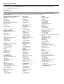
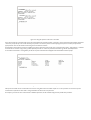
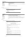
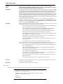
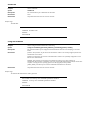
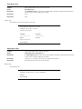
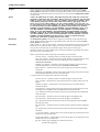
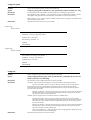
With the serial port properly connected to a management computer, the following screen should be visible. If this screen does not appear, try pressing Ctrl+r to
refresh the console screen.
AT-9724TS
Allied Telesyn Intl
Figure 1- 1. Initial CLI screen
The default username and password is Username: manager Password: friend
1-2 Setting the Switch’s IP Address
Each switch must be assigned its own IP Address, which is used for communication with an SNMP network manager or other TCP/IP application (for example
BOOTP,TFTP).The switch’s default IP address is 10.0.0.1 You can change the default switch IP address to meet the specification of your networking address
scheme.
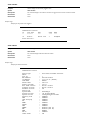
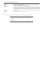
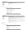
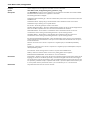
The Switch is also assigned a unique MAC address by the factory.This MAC address cannot be changed, and can be found on the initial boot console screen –
shown below.
Allied Telesyn AT-9724TS High-Density Layer 3 Stackable Gigabit Ethernet Switch • Command Line Interface Reference Manual
8
Figure 1-2. Boot Screen
The Switch’s MAC address can also be found in the Web management program on the Switch Information (Basic Settings) window on the Configuration menu.
The IP address for the Switch must be set before it can be managed with the Web-based manager.The Switch IP address can be automatically set using BOOTP
or DHCP protocols, in which case the actual address assigned to the Switch must be known.
The IP address may be set using the Command Line Interface (CLI) over the console serial port as follows:
1.
Starting at the command line prompt, enter the commands config ipif System ipaddress xxx.xxx.xxx.xxx/yyy.yyy.yyy.yyy.Where the
x’s represent the IP address to be assigned to the IP interface named System and the y’s represent the corresponding subnet mask.
2.
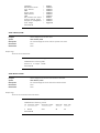
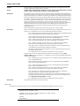
Alternatively, you can enter config ipif System ipaddress xxx.xxx.xxx.xxx/z.Where the x’s represent the IP address to be assigned to the
IP interface named System and the z represents the corresponding number of subnets in CIDR notation.
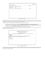
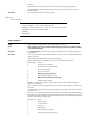
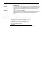
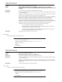
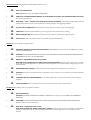
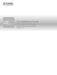
The IP interface named System on the Switch can be assigned an IP address and subnet mask which can then be used to connect a management station to the
Switch’s Telnet or Web-based management agent.
AT-9724TS
Allied Telesyn Intl.
AT-9724TS
AT-9724TS
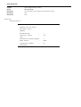
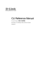
Figure 1-3. Assigning an IP Address
In the above example, the Switch was assigned an IP address of 10.53.13.144/8 with a subnet mask of 255.0.0.0.The system message Success indicates that the
command was executed successfully.The Switch can now be configured and managed via Telnet and the CLI or via the Web-based management agent using the
above IP address to connect to the Switch.
Allied Telesyn AT-9724TS High-Density Layer 3 Stackable Gigabit Ethernet Switch • Command Line Interface Reference Manual
9
Chapter 2 - Using The Console CLI
The AT-9724TS supports a console management interface that allows the user to connect to the Switch’s management agent via a serial port and a terminal or a
computer running a terminal emulation program.The console can also be used over the network using the TCP/IP Telnet protocol.The console program can be
used to configure the Switch to use an SNMP-based network management software over the network.
This chapter describes how to use the console interface to access the Switch, change its settings, and monitor its operation.
Note:
Switch configuration settings are saved to non-volatile RAM using the save command.The current configuration will then be retained in the
Switch’s NV-RAM, and reloaded when the Switch is rebooted. If the Switch is rebooted without using the save command, the last configuration saved
to NV-RAM will be loaded.
2 -1 Connecting to the Switch
The console interface is used by connecting the Switch to a VT100-compatible terminal or a computer running an ordinary terminal emulator program (e.g., the
HyperTerminal program included with the Windows operating system) using an RS-232C serial cable.Your terminal parameters will need to be set to:
•
VT-100 compatible
•
115200 baud
•
8 data bits
•
No parity
•
1 stop bit
•
No flow control
You can also access the same functions over a Telnet interface. Once you have set an IP address for your Switch, you can use a Telnet program (in VT-100
compatible terminal mode) to access and control the Switch.All of the screens are identical, whether accessed from the console port or from a Telnet interface.
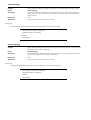
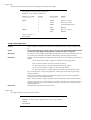
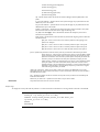
After the Switch reboots and you have logged in, the console looks like this:
AT-9724TS
Allied Telesyn Intl.
Figure 2-1. Initial Console Screen
Allied Telesyn AT-9724TS High-Density Layer 3 Stackable Gigabit Ethernet Switch • Command Line Interface Reference Manual
10
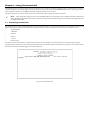
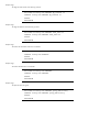
Commands are entered at the command prompt,AT-9724TS:4#.
There are a number of helpful features included in the CLI. Entering the ? command will display a list of all of the top-level commands.
Figure 2-2. The ? Command
When you enter a command without its required parameters, the CLI will prompt you with a Next possible completions: message.
AT-9724TS
AT-9724TS
Figure 2-3. Example Command Parameter Help
In this case, the command config account was entered with the parameter <username>.The CLI will then prompt you to enter the <username> with the
message, Next possible completions:. Every command in the CLI has this feature, and complex commands have several layers of parameter prompting.
In addition, after typing any given command plus one space, you can see all of the next possible sub-commands, in sequential order, by repeatedly pressing the Tab
key.
To re-enter the previous command at the command prompt, press the up arrow cursor key.The previous command will appear at the command prompt.
Allied Telesyn AT-9724TS High-Density Layer 3 Stackable Gigabit Ethernet Switch • Command Line Interface Reference Manual
11
AT-9724TS
AT-9724TS
AT-9724TS
Figure 2-4. Using the Up Arrow to Re-enter a Command
In the above example, the command config account was entered without the required parameter <username>, the CLI returned the Next possible completions:
<username> prompt.The up arrow cursor control key was pressed to re-enter the previous command (config account) at the command prompt. Now the
appropriate User name can be entered and the config account command re-executed.
All commands in the CLI function in this way. In addition, the syntax of the help prompts are the same as presented in this manual – angle brackets < > indicate a
numerical value or character string, braces { } indicate optional parameters or a choice of parameters, and brackets [ ] indicate required parameters.
If a command is entered that is unrecognized by the CLI, the top-level commands will be displayed under the Available commands: prompt.
AT-9724TS
AT-9724TS
Figure 2-5. The Next Available Commands Prompt
The top-level commands consist of commands such as show or config. Most of these commands require one or more parameters to narrow the top-level
command.This is equivalent to show what? or config what? Where the what? is the next parameter.
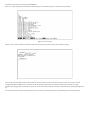
For example, if you enter the show command with no additional parameters, the CLI will then display all of the possible next parameters.
Allied Telesyn AT-9724TS High-Density Layer 3 Stackable Gigabit Ethernet Switch • Command Line Interface Reference Manual
12
AT-9724TS
AT-9724TS
Figure 2-6. Next possible completions: Show Command
In the above example, all of the possible next parameters for the show command are displayed.At the next command prompt, the up arrow was used to re-enter
the show command, followed by the account parameter.The CLI then displays the user accounts configured on the Switch.
Allied Telesyn AT-9724TS High-Density Layer 3 Stackable Gigabit Ethernet Switch • Command Line Interface Reference Manual
13
Chapter 3 - Command Syntax
The following symbols are used to describe how command entries are made and values and arguments are specified in this manual.The online help contained in
the CLI and available through the console interface uses the same syntax.
Note:
All commands are case-sensitive. Be sure to disable Caps Lock or any other unwanted function that changes text case.
<angle brackets>
Purpose
Encloses a variable or value that must be specified.
Syntax
create ipif <ipif_name> vlan <vlan_name 32> ipaddress <network_address>
Description
In the above syntax example, you must supply an IP interface name in the <ipif_name> space, a VLAN name in
the <vlan_name 32> space, and the network address in the <network_address> space. Do not type the angle
brackets.
Example Command
create ipif Engineering vlan Design ipaddress 10.24.22.5/255.0.0.0
[square brackets]
Purpose
Encloses a required value or set of required arguments. One value or argument can be specified.
Syntax
create account [admin | user]
Description
In the above syntax example, you must specify either an admin or a user level account to be created. Do not
type the square brackets.
Example Command
create account admin
| vertical bar
Purpose
Separates two or more mutually exclusive items in a list, one of which must be entered.
Syntax
show snmp [community | detail]
Description
In the above syntax example, you must specify either community, or detail. Do not type the backslash.
Example Command
show snmp community
{braces}
Purpose
Encloses an optional value or set of optional arguments.
Syntax
reset {[config | system]}
Description
In the above syntax example, you have the option to specify config or system. It is not necessary to specify
either optional value, however the effect of the system reset is dependent on which, if any, value is specified.
Therefore, with this example there are three possible outcomes of performing a system reset. See the following
chapter, Basic Commands for more details about the reset command.
Example Command
reset config
Line Editing Key Usage
Delete
Deletes the character under the cursor and then shifts the remaining characters in the line to the left.
Backspace
Deletes the character to the left of the cursor and shifts the remaining characters in the line to the left.
Left Arrow
Moves the cursor to the left.
Right Arrow
Moves the cursor to the right.
Up Arrow
Repeat the previously entered command. Each time the up arrow is pressed, the command previous to that
displayed appears.This way it is possible to review the command history for the current session. Use the down
arrow to progress sequentially forward through the command history list.
Down Arrow
The down arrow will display the next command in the command history entered in the current session.This
displays each command sequentially as it was entered. Use the up arrow to review previous commands.
Tab
Shifts the cursor to the next field to the left.
Allied Telesyn AT-9724TS High-Density Layer 3 Stackable Gigabit Ethernet Switch • Command Line Interface Reference Manual
14
Multiple Page Display Control Keys
Space
Displays the next page.
CTRL+c
Stops the display of remaining pages when multiple pages are to be displayed.
ESC
Stops the display of remaining pages when multiple pages are to be displayed.
n
Displays the next page.
p
Displays the previous page.
q
Stops the display of remaining pages when multiple pages are to be displayed.
r
Refreshes the pages currently displayed.
a
Displays the remaining pages without pausing between pages.
Enter
Displays the next line or table entry.
Allied Telesyn AT-9724TS High-Density Layer 3 Stackable Gigabit Ethernet Switch • Command Line Interface Reference Manual
15
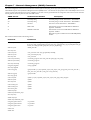
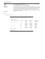
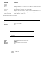
Chapter 4 - Basic Switch Commands
The basic switch commands in the Command Line Interface (CLI) are listed (along with the appropriate parameters) in the following table.
Command
Parameters
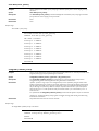
create account
[admin | user] <username 15>
config account
<username 15>
show account
delete account
<username 15>
show config
[current_config | config_in_NVRAM]
show session
show switch
show switch_mode
show device status
show serial_port
config serial_port
{baud_rate [115200] auto_logout [never | 2_minutes | 5_minutes | 10_minutes | 15_minutes]}
enable clipaging
disable clipaging
enable telnet
<tcp_port_number 1-65535>
disable telnet
enable web
<tcp_port_number 1-65535>
disable web
save
[log | all]
reboot
reset
{[config | system]}
login
logout
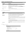
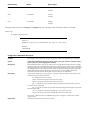
Each command is listed, in detail, in the following sections:
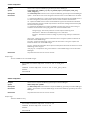
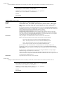
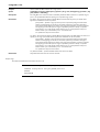
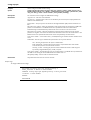
create account
Purpose
Used to create user accounts
Syntax
create [admin | user] <username>
Description
The create account command is used to create user accounts that consist of a username of 1 to 15
characters and a password of 0 to 15 characters. Up to 8 user accounts can be created.
Parameters
Admin <username>
User <username>
Restrictions
Only Administrator-level users can issue this command.
Usernames can be between 1 and 15 characters.
Passwords can be between 0 and 15 characters.
Example usage:
To create an administrator-level user account with the username “Allied Telesyn”.
AT-9724TS:4# create account admin Allied Telesyn
Command: create account admin Allied Telesyn
Enter a case-sensitive new password:****
Enter the new password again for confirmation:****
Success.
AT-9724TS:4#
Allied Telesyn AT-9724TS High-Density Layer 3 Stackable Gigabit Ethernet Switch • Command Line Interface Reference Manual
16
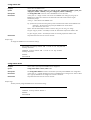
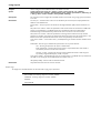
config account
Purpose
Used to configure user accounts
Syntax
config account <username>
Description
The config account command configures a user account that has been created using the create account
command.
Parameters
<username>
Restrictions
Only Administrator-level users can issue this command.
Usernames can be between 1 and 15 characters.
Passwords can be between 0 15 characters.
Example usage:
To configure the user password of “Allied Telesyn” account:
AT-9724TS:4# config account Allied Telesyn
Command: config account Allied Telesyn
Enter a old password:****
Enter a case-sensitive new password: ****
Enter the new password again for confirmation:****
Success.
AT-9724TS:4#
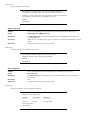
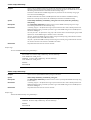
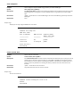
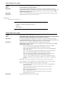
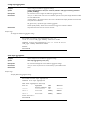
show account
Purpose
Used to display user accounts
Syntax
show account
Description
Displays all user accounts created on the Switch. Up to 8 user accounts can exist on the Switch at one time.
Parameters
None
Restrictions
None
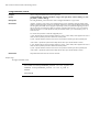
Example usage:
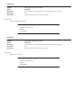
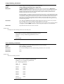
To display the accounts that have been created:
AT-9724TS:4# show account
Command: show account
Current Accounts:
User Name
---------
Access Level
------------
Allied Telesyn
Admin
AT-9724TS:4#
Allied Telesyn AT-9724TS High-Density Layer 3 Stackable Gigabit Ethernet Switch • Command Line Interface Reference Manual
17
delete account
Purpose
Used to delete an existing user account
Syntax
delete account <username>
Description
The delete account command deletes a user account that has been created using the create account
command.
Parameters
<username>
Restrictions
Only Administrator-level users can issue this command.
Example usage:
To delete the user account “System”:
AT-9724TS:4# delete account System
Command:delete account System
Success.
AT-9724TS:4#
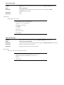
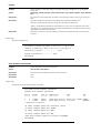
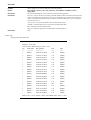
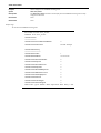
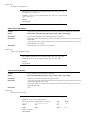
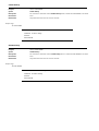
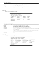
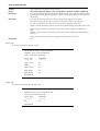
show config
Purpose
Used to display a list of configuration commands entered into the Switch.
Syntax
show config [current_config | config_in_NVRAM]
Description
This command displays a list of configuration commands entered into the Switch.
Parameters
current_config – Entering this parameter will display configurations entered without being saved to NVRAM.
config_in_NVRAM - Entering this parameter will display configurations entered and saved to NVRAM.
Restrictions
None.
Example usage:
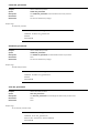
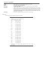
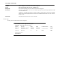
To view configurations entered on the Switch that were saved to NVRAM:
Command: show config config_in_NVRAM
#------------------------------------------------------#
AT-9724TS Configuration
#
Firmware: Build 3.00-B13
# Copyright(C) 2004-2007 Allied Telesyn Corporation. All
rights reserved.
#------------------------------------------------------# BASIC
config serial_port baud_rate 115200 auto_logout never
enable telnet 23
enable web 80
enable clipaging
# STORM
config traffic control 1:1-1:26 broadcast disable multicast
disable dlf disable
threshold 128
config traffic control 2:1-2:24 broadcast disable multicast
disable dlf disable
CTRL+C ESC q Quit SPACE n Next Page ENTER Next Entry a All
Allied Telesyn AT-9724TS High-Density Layer 3 Stackable Gigabit Ethernet Switch • Command Line Interface Reference Manual
18
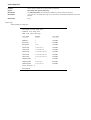
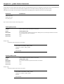
show session
Purpose
Used to display a list of currently logged-in users.
Syntax
show session
Description
This command displays a list of all the users that are logged-in at the time the command is issued.
Parameters
None.
Restrictions
None.
Example usage:
To display the way that the users logged in:
AT-9724TS:4# show session
Command:show session
ID
--
Live Time
---------
From
----
Level
-----
Name
----
*8
03:36:27
Serial Port
4
Anonymous
Total Entries: 1
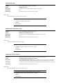
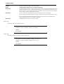
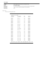
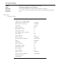
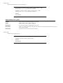
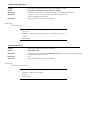
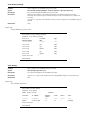
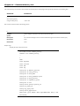
show switch
Purpose
Used to display information about the Switch.
Syntax
show switch
Description
This command displays information about the Switch.
Parameters
None.
Restrictions
None.
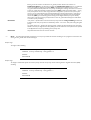
Example usage:
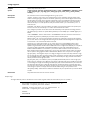
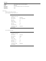
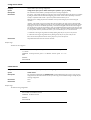
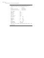
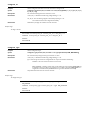
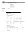
To display the Switch information:
AT-9724TS:4# show switch
Command:show switch
Device Type
Switch
Unit ID
MAC Address
IP Address
VLAN Name
Subnet Mask
Default Gateway
Boot PROM Version
Firmware Version
Hardware Version
Device S/N
System Name
System Location
System Contact
Spanning Tree
GVRP
IGMP Snooping
RIP
DVMRP
PIM-DM
OSPF
TELNET
WEB
RMON
802.1x
Jumbo Frame
:
AT-9724TS Stackable Ethernet
:
:
:
:
:
:
:
:
:
:
:
:
:
:
:
:
:
:
:
:
:
:
:
:
:
1
DA-10-21-00-00-01
10.41.44.22 (Manual)
default
255.0.0.0
0.0.0.0
Build 2.00-B04
Build 3.00-B16
2A1
AT-9724TS_#3
7th_flr_east_cabinet
Julius_Erving_212-555-6666
Disabled
Disabled
Disabled
Disabled
Disabled
Disabled
Disabled
Enabled (TCP 23)
Enabled (TCP 80)
Enabled
Disabled
Off
Allied Telesyn AT-9724TS High-Density Layer 3 Stackable Gigabit Ethernet Switch • Command Line Interface Reference Manual
19
Clipaging
MAC Notification
Port Mirror
SNTP
Bootp Relay
DNSR Status
VRRP
HOL Prevention State
Syslog Global State
Single IP Management
Dual Image
:
:
:
:
:
:
:
:
:
:
:
Enabled
Disabled
Disabled
Disabled
Disabled
Disabled
Disabled
Enabled
Disabled
Disabled
Supported
AT-9724TS:4#
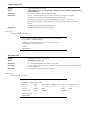
show switch_mode
Purpose
Used to display the current switch mode.
Syntax
show switch_mode
Description
This command displays the current mode of operation of the switch.
Parameters
None.
Restrictions
None.
Example usage:
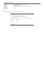
To view the current switch mode:
AT-9724TS:4# show switch_mode
Command:show switch_mode
Switch is in Layer 3 mode
AT-9724TS:4#
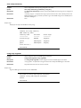
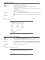
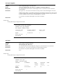
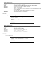
show device status
Purpose
Used to display the current status of the hardware of the Switch.
Syntax
show device_status
Description
This command displays the current status of the Switch’s elements.
Parameters
None.
Restrictions
None.
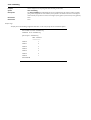
Example usage:
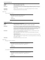
To view the current hardware status of the Switch:
AT-9724TS:4# show device_status
Command:show device_status
ID Internal Power
-- --------------
External Power
--------------
Side Fan
--------
Back Fan
--------
2
Fail
OK
OK
Active
AT-9724TS:4#
Allied Telesyn AT-9724TS High-Density Layer 3 Stackable Gigabit Ethernet Switch • Command Line Interface Reference Manual
20
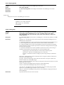
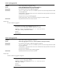
show serial_port
Purpose
Used to display the current serial port settings.
Syntax
show serial_port
Description
This command displays the current serial port settings.
Parameters
None.
Restrictions
None.
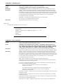
Example usage:
To display the serial port setting:
AT-9724TS:4# show serial_port
Command:show serial_port
Baud Rate
:
115200
Data Bits
:
8
Parity Bits
:
None
Stop Bits
:
1
Auto-Logout
:
10 mins
AT-9724TS:4#
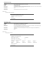
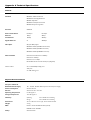
config serial_port
Purpose
Used to configure the serial port.
Syntax
config serial_port {baud_rate [115200] | auto_logout [never | 2_minutes | 5_minutes |
10_minutes | 15_minutes]}
Description
This command is used to configure the serial port’s baud rate and auto logout settings.
Parameters
baud_rate [115200] – The serial bit rate that will be used to communicate with the management host.This
parameter is fixed at 115200.
never – No time limit on the length of time the console can be open with no user input.
2_minutes – The console will log out the current user if there is no user input for 2 minutes.
5_minutes – The console will log out the current user if there is no user input for 5 minutes.
10_minutes – The console will log out the current user if there is no user input for 10 minutes.
15_minutes – The console will log out the current user if there is no user input for 15 minutes.
Restrictions
Only administrator-level users can issue this command.
Example usage:
To configure baud rate:
AT-9724TS:4# config serial_port baud_rate 115200
Command:config serial_port baud_rate 115200
Success
AT-9724TS:4#
Allied Telesyn AT-9724TS High-Density Layer 3 Stackable Gigabit Ethernet Switch
21
enable clipaging
Purpose
Used to pause the scrolling of the console screen when the show command displays more than one page.
Syntax
enable clipaging
Description
This command is used when issuing the show command which causes the console screen to rapidly scroll
through several pages.This command will cause the console to pause at the end of each page.The default
setting is enabled.
Parameters
None.
Restrictions
Only administrator-level users can issue this command.
Example usage:
To enable pausing of the screen display when the show command output reaches the end of the page:
AT-9724TS:4# enable clipaging
Command:enable clipaging
Success
AT-9724TS:4#
disable clipaging
Purpose
Used to disable the pausing of the console screen scrolling at the end of each page when the show command
displays more than one screen of information.
Syntax
disable clipaging
Description
This command is used to disable the pausing of the console screen at the end of each page when the show
command would display more than one screen of information.
Parameters
None.
Restrictions
Only administrator-level users can issue this command.
Example usage:
To disable pausing of the screen display when the show command output reaches the end of the page:
AT-9724TS:4# disable clipaging
Command:disable clipaging
Success
AT-9724TS:4#
Allied Telesyn AT-9724TS High-Density Layer 3 Stackable Gigabit Ethernet Switch • Command Line Interface Reference Manual
22
enable telnet
Purpose
Used to enable communication with and management of the Switch using the Telnet protocol.
Syntax
enable telnet <tcp_port_number 1-65535>
Description
This command is used to enable the Telnet protocol on the Switch.The user can specify the TCP or UDP port
number the Switch will use to listen for Telnet requests.
Parameters
<tcp_port_number 1-65535> – The TCP port number.TCP ports are numbered between 1 and 65535.The
“well-known” TCP port for the Telnet protocol is 23.
Restrictions
Only administrator-level users can issue this command.
Example usage:
To enable Telnet and configure port number:
AT-9724TS:4# enable telnet 23
Command:enable telnet 23
Success
AT-9724TS:4#
disable telnet
Purpose
Used to disable the Telnet protocol on the Switch.
Syntax
enable telnet
Description
This command is used to disable the Telnet protocol on the Switch.
Parameters
None.
Restrictions
Only administrator-level users can issue this command.
Example usage:
To disable Telnet protocol on the Switch:
AT-9724TS:4# disable telnet
Command:disable telnet
Success
AT-9724TS:4#
Allied Telesyn AT-9724TS High-Density Layer 3 Stackable Gigabit Ethernet Switch • Command Line Interface Reference Manual
23
enable web
Purpose
Used to enable the HTTP-based management software on the Switch.
Syntax
enable web <tcp_port_number 1-65535
Description
This command is used to enable the Web-based management software on the Switch.The user can specify the
TCP port number the Switch will use to listen for Telnet requests.
Parameters
<tcp_port_number 1-65535> – The TCP port number.TCP ports are numbered between 1 and 65535.The
“well-known” port for the Web-based management software is 80.
Restrictions
Only administrator-level users can issue this command.
Example usage:
To enable HTTP and configure port number:
AT-9724TS:4# enable web 80
Command:enable web 80
Note: SSL will be disabled if web is enabled.
Success.
AT-9724TS:4#
disable web
Purpose
Used to disable the HTTP-based management software on the Switch.
Syntax
disable web
Description
This command disables the Web-based management software on the Switch.
Parameters
None.
Restrictions
Only administrator-level users can issue this command.
Example usage:
To disable HTTP:
AT-9724TS:4# disable web
Command:disable web
Success.
AT-9724TS:4#
Allied Telesyn AT-9724TS High-Density Layer 3 Stackable Gigabit Ethernet Switch • Command Line Interface Reference Manual
24
save
Purpose
Used to save changes in the Switch’s configuration to non-volatile RAM.
Syntax
save [log | all]
Description
This command is used to enter the current switch configuration into non-volatile RAM.The saved switch
configuration will be loaded into the Switch’s memory each time the Switch is restarted.
Parameters
Entering just the save command will save only the Switch configuration to NV-RAM.
log – Entering the log parameter will save only the log file to NV-RAM.
all - Entering the all command will save both the log file and the Switch configuration to NV-RAM.
Restrictions
Only administrator-level users can issue this command.
Example usage:
To save the Switch’s current configuration to non-volatile RAM:
AT-9724TS:4# save
Command:save
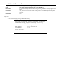
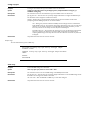
Do you want to change current box id from AUTO mode to
STATIC mode? (y/n) n
Saving all configurations to NV-RAM. Done.
AT-9724TS:4#
reboot
Purpose
Used to restart the Switch.
Syntax
reboot
Description
This command is used to restart the Switch.
Parameters
None.
Restrictions
None.
Example usage:
To restart the Switch:
AT-9724TS:4# reboot
Command:reboot
Are you sure want to proceed with the system
reboot? (y/n)
Please wait, the Switch is rebooting...
AT-9724TS:4#
Allied Telesyn AT-9724TS High-Density Layer 3 Stackable Gigabit Ethernet Switch • Command Line Interface Reference Manual
25
reset
Purpose
Used to reset the Switch to the factory default settings.
Syntax
reset {[config | system]}
Description
This command is used to restore the Switch’s configuration to the default settings
assigned from the factory.
Parameters
config – If the keyword ‘config’ is specified, all of the factory default settings are restored on the Switch including
the IP address, user accounts, and the Switch history log.The Switch will not save or reboot.
system – If the keyword ‘system’ is specified all of the factory default settings are restored on the Switch.The
Switch will save and reboot after the settings are changed to default. Rebooting will clear all entries in the
Forwarding Data Base.
If no parameter is specified, the Switch’s current IP address, user accounts, and the Switch history log are not
changed.All other parameters are restored to the factory default settings.The Switch will not save or reboot.
Restrictions
Only administrator-level users can issue this command.
Example usage:
To restore all of the Switch’s parameters to their default values:
AT-9724TS:4# reset config
Command:reset config
Success.
AT-9724TS:4#
login
Purpose
Used to log in a user to the Switch’s console.
Syntax
login
Description
This command is used to initiate the login procedure.The user will be prompted for his Username and
Password.
Parameters
None.
Restrictions
None.
Example usage:
To initiate the login procedure:
AT-9724TS:4# login
Command:login
UserName:
AT-9724TS:4#
Allied Telesyn AT-9724TS High-Density Layer 3 Stackable Gigabit Ethernet Switch • Command Line Interface Reference Manual
26
logout
Purpose
Used to log out a user from the Switch’s console.
Syntax
logout
Description
This command terminates the current user’s session on the Switch’s console.
Parameters
None.
Restrictions
None.
Example usage:
To terminate the current user’s console session:
AT-9724TS:4# logout
Allied Telesyn AT-9724TS High-Density Layer 3 Stackable Gigabit Ethernet Switch • Command Line Interface Reference Manual
27
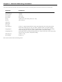
Chapter 5 - Switch Port Commands
The switch port commands in the Command Line Interface (CLI) are listed (along with the appropriate parameters) in the following table.
Command
Parameters
config ports
[<portlist | all {speed [auto | 10_half | 10_full | 100_half | 100_full | 1000_full [master | slave]} | flow_control
[enable | disable] | learning [enable | disable] state [enable | disable] description <desc 32> | clear]
show ports
<portlist>
Each command is listed, in detail, in the following sections:
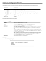
config ports
Purpose
Used to configure the Switch’s Ethernet port settings.
Syntax
[<portlist> | all {speed [auto | 10_half | 10_full | 100_half | 100_full | 1000_full [master
|slave]} | flow_control [enable | disable] | learning [enable | disable] state [enable |
disable] description <desc 32> | clear]
Description
This command allows for the configuration of the Switch’s Ethernet ports. Only the ports listed in the
<portlist> will be affected.
Parameters
all – Configure all ports on the Switch.
<portlist> – Specifies a range of ports to be configured.The port list is specified by listing the lowest switch
number and the beginning port number on that switch, separated by a colon.Then the highest switch number,
and the highest port number of the range (also separated by a colon) are specified.The beginning and end of
the port list range are separated by a dash. For example, 1:3 specifies switch number 1, port 3. 2:4 specifies
switch number 2, port 4. 1:3-2:4 specifies all of the ports between switch 1, port 3 and switch 2, port 4 – in
numerical order.
auto – Enables auto-negotiation for the specified range of ports.
[10 | 100 | 1000] – Configures the speed in Mbps for the specified range of ports.
[half | full] – Configures the specified range of ports as either full- or half-duplex.
[master | slave] – The master and slave parameters refer to connections running a 1000T cable for connection
between the Switch port and other device capable of a gigabit connection.The master setting will allow the
port to advertise capabilities related to duplex, speed and physical layer type.The master setting will also
determine the master and slave relationship between the two connected physical layers.This relationship is
necessary for establishing the timing control between the two physical layers.The timing control is set on a
master physical layer by a local source.The slave setting uses loop timing, where the timing comes form a data
stream received from the master. If one connection is set for 1000 master, the other side of the connection
must be set for 1000 slave.Any other configuration will result in a link down status for both ports.
flow_control [enable | disable] – Enable or disable flow control for the specified ports.
learning [enable | disable] – Enables or disables the MAC address learning on the specified range of ports.
state [enable | disable] – Enables or disables the specified range of ports.
description <desc 32> - Enter an alphanumeric string of no more than 32 characters to describe a selected port
interface.
clear – Enter this command to clear the port description of the selected port(s).
Restrictions
Only administrator-level users can issue this command.
Example usage:
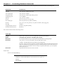
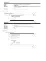
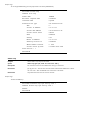
To configure the speed of port 3 to be 10 Mbps, full duplex, learning and state enable:
AT-9724TS:4# config ports 1:1-1:3 speed 10_full learning
enable state enable
Command:config ports 1:1-1:3 speed 10_full learning
enable state enable
Success.
AT-9724TS:4#
Allied Telesyn AT-9724TS High-Density Layer 3 Stackable Gigabit Ethernet Switch • Command Line Interface Reference Manual
28
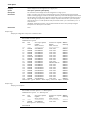
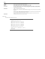
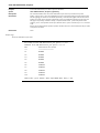
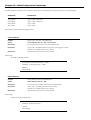
show ports
Purpose
Used to display the current configuration of a range of ports.
Syntax
show ports <portlist> {description}
Description
This command is used to display the current configuration of a range of ports
Parameters
portlist> – Specifies a range of ports to be displayed.The port list is specified by listing the lowest switch
number and the beginning port number on that switch, separated by a colon.Then the highest switch number,
and the highest port number of the range (also separated by a colon) are specified.The beginning and end of
the port list range are separated by a dash. For example, 1:3 specifies switch number 1, port 3. 2:4 specifies
switch number 2, port 4. 1:3-2:4 specifies all of the ports between switch 1, port 3 and switch 2, port 4 – in
numerical order.
{description} – Adding this parameter to the command will allow the user to view previously configured
description set on various ports on the Switch.
Restrictions
None.
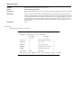
Example usage:
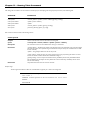
To display the configuration of all ports on a standalone switch:
AT-9724TS:4# show ports
Command:show ports
Port
Port
State
Settings Speed/
Connection Speed/ Address
Duplex/
Duplex/
Learning
Flow Control
Flow Control
------------------------------------------1:1
Enabled
Auto/Enabled
Link Down
Enabled
1:2
Enabled
Auto/Enabled
Link Down
Enabled
1:3
Enabled
Auto/Enabled
Link Down
Enabled
1:4
Enabled
Auto/Enabled
Link Down
Enabled
1:5
Enabled
Auto/Enabled
Link Down
Enabled
1:6
Enabled Auto/Enabled
Link Down
Enabled
1:7
Enabled
Auto/Enabled
Link Down
Enabled
1:8
Enabled
Auto/Enabled
Link Down
Enabled
1:9
Enabled
Auto/Enabled
Link Down
Enabled
1:10
Enabled
Auto/Enabled
100M/Full/802.3x
Enabled
1:11
Enabled
Auto/Enabled
Link Down
Enabled
1:12
Enabled
Auto/Enabled
Link Down
Enabled
1:13
Enabled
Auto/Disabled
Link Down
Enabled
1:14
Enabled
Auto/Disabled
Link Down
Enabled
1:15
Enabled
Auto/Disabled
Link Down
Enabled
1:16
Enabled
Auto/Disabled
Link Down
Enabled
1:17
Enabled
Auto/Disabled
Link Down
Enabled
1:18
Enabled
Auto/Disabled
Link Down
Enabled
1:19
Enabled
Auto/Disabled
Link Down
Enabled
1:20
Enabled
Auto/Disabled
Link Down
Enabled
CTRL+C ESC q Quit SPACE n Next Page p Previous Page r Refresh
Example usage:
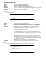
To display port descriptions:
AT-9724TS:4# show ports 1:1 description
Command:show ports 1:1 description
Port
---1:1
Port
State
Settings Speed/
Duplex/
Flow Control
-----------------Enabled
Auto/Enabled
Description: Accounting
Connection Speed/
Duplex/
Flow Control
---------------Link Down
Address
Learning
-------Enabled
AT-9724TS:4#
Allied Telesyn AT-9724TS High-Density Layer 3 Stackable Gigabit Ethernet Switch • Command Line Interface Reference Manual
29
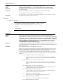
Chapter 6 - Port Security Commands
The port security commands in the Command Line Interface (CLI) are listed (along with the appropriate parameters) in the following table.
Command
Parameters
config ports
[<portlist>| all ] {admin_state [enable | disable] | max_learning_addr <max_lock_no 0-64> |
lock_address_mode [Permanent | DeleteOnTimeout | DeleteOnReset]}
show port_security
{ports <portlist>}
delete port_security_entry_
vlan_name
<vlan_name 32> port <port> mac_address <macaddr>
Each command is listed, in detail, in the following sections:
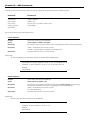
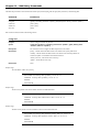
config port_security ports
Purpose
Used to configure port security settings.
Syntax
[<portlist>| all ] {admin_state [enable | disable] | max_learning_addr <max_lock_no 064> | lock_address_mode [Permanent | DeleteOnTimeout | DeleteOnReset]}
Description
This command allows for the configuration of the port security feature. Only the ports listed in the <portlist>
are effected.
Parameters
<portlist> – Specifies a range of ports to be configured.The port list is specified by listing the lowest switch
number and the beginning port number on that switch, separated by a colon.Then the highest switch number,
and the highest port number of the range (also separated by a colon) are specified.The beginning and end of
the port list range are separated by a dash. For example, 1:3 specifies switch number 1, port 3. 2:4 specifies
switch number 2, port 4. 1:3-2:4 specifies all of the ports between switch 1, port 3 and switch 2, port 4 – in
numerical order.
all – Configure port security for all ports on the Switch.
admin_state [enable | disable] – Enable or disable port security for the listed ports.
max_learning_addr <max_lock_no 0-64> - Use this to limit the number of MAC addresses dynamically listed in
the FDB for the ports.
lock_address_mode [Permanent | DeleteOnTimeout | DeleteOnReset] – Indicates the method of locking addresses.
The user has three choices:
Permanent – The locked addresses will not age out after the aging timer expires.
DeleteOnTimeout – The locked addresses will age out after the aging timer expires.
DeleteOnReset – The locked addresses will not age out until the Switch has been reset.
Restrictions
Only administrator-level users can issue this command.
Example usage:
To configure the port security:
AT-9724TS:4# config port_security ports 5:1-5:5 admin_state
enable max_learning_addr 5 lock_address_mode DeleteOnReset
Command:config port_security ports 5:1-5:5 admin_state
enable max_learning_addr 5 lock_address_mode DeleteOnReset
Success.
AT-9724TS:4#
Allied Telesyn AT-9724TS High-Density Layer 3 Stackable Gigabit Ethernet Switch • Command Line Interface Reference Manual
30
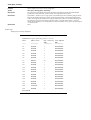
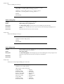
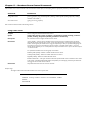
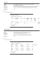
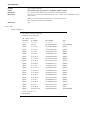
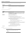
show port_security
Purpose
Used to display the current port security configuration.
Syntax
show port_security {ports <portlist>}
Description
This command is used to display port security information of the Switch ports.The information displayed
includes port security admin state, maximum number of learning address and lock mode.
Parameters
ports <portlist> – Specifies a port or range of ports to be viewed.The port list is specified by listing the lowest
switch number and the beginning port number on that switch, separated by a colon.Then the highest switch
number, and the highest port number of the range (also separated by a colon) are specified.The beginning and
end of the port list range are separated by a dash. For example, 1:3 specifies switch number 1, port 3. 2:4
specifies switch number 2, port 4. 1:3-2:4 specifies all of the ports between switch 1, port 3 and switch 2, port 4
– in numerical order.
Restrictions
None.
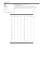
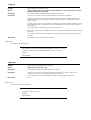
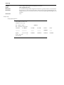
Example usage:
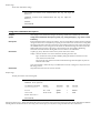
To display the port security configuration:
AT-9724TS:4# show port_security ports 1:1-1:19
Command:show port_security ports 1:1-1:19
Port#
Admin State
-----
-----------
Max. Learning Lock Address
Addr.
Mode
------------------------
1:1
Disabled
1
DeleteOnReset
1:2
Disabled
1
DeleteOnReset
1:3
Disabled
1
DeleteOnReset
1:4
Disabled
1
DeleteOnReset
1:5
Disabled
1
DeleteOnReset
1:6
Disabled
1
DeleteOnReset
1:7
Enabled
10
DeleteOnReset
1:8
Disabled
1
DeleteOnReset
1:9
Disabled
1
DeleteOnReset
1:10
Disabled
1
DeleteOnReset
1:11
Disabled
1
DeleteOnReset
1:12
Disabled
1
DeleteOnReset
1:13
Disabled
1
DeleteOnReset
1:14
Disabled
1
DeleteOnReset
1:15
Disabled
1
DeleteOnReset
1:16
Disabled
1
DeleteOnReset
1:17
Disabled
1
DeleteOnReset
1:18
Disabled
1
DeleteOnReset
1:19
Disabled
1
DeleteOnReset
AT-9724TS:4#
Allied Telesyn AT-9724TS High-Density Layer 3 Stackable Gigabit Ethernet Switch • Command Line Interface Reference Manual
31
delete port_security_entry_vlan_name
Purpose
Used to delete an entry from the Switch’s port security settings.
Syntax
delete port_security_entry_vlan_name <vlan_name 32> port <port> mac_address
<macaddr>
Description
This command is used to remove an entry from the port security entries learned by the Switch and entered
into the forwarding database.
Parameters
<vlan_name 32> - Enter the corresponding VLAN of the entry the user wishes to delete.
port <port> - Enter the corresponding port of the entry to delete.The port is specified by listing the lowest
switch number and the beginning port number on that switch, separated by a colon. For example, 1:3 specifies
switch number 1, port 3. 2:4 specifies switch number 2, port 4.
mac_address <macaddr> - Enter the corresponding MAC address of the entry the user wishes to delete.
Restrictions
Only administrator-level users can issue this command.
Example usage:
To delete an entry from the port security list:
AT-9724TS:4# delete port_security_entry_vlan_name
default port 1:1 mac_address 00-0C-6E-73-2B-C9
Command: delete port_security_entry_vlan_name
default port 1:1 mac_address 00-0C-6E-73-2B-C9
Success.
AT-9724TS:4#
Allied Telesyn AT-9724TS High-Density Layer 3 Stackable Gigabit Ethernet Switch • Command Line Interface Reference Manual
32
Chapter 7 - Network Management (SNMP) Commands
The network management commands in the Command Line Interface (CLI) are listed (along with the appropriate parameters) in the following table.
The AT-9724TS supports the Simple Network Management Protocol (SNMP) versions 1, 2c, and 3.You can specify which version of the SNMP you want to use to
monitor and control the Switch.The three versions of SNMP vary in the level of security provided between the management station and the network device.The
following table lists the security features of the three SNMP versions:
SNMP Version
Authentication Method
Description
v1
Community String
Community String is used for authentication – NoAuthNoPriv
v2c
Community String
Community String is used for authentication – NoAuthNoPriv
v3
Username
Username is used for authentication – NoAuthNoPriv
v3
MD5 or SHA
Authentication is based on the HMAC-MD5 or HMAC-SHA
algorithms – AuthNoPriv
v3
MD5 DES or SHA DES
Authentication is based on the HMAC-MD5 or HMAC-SHA
algorithms – AuthPriv.
DES 56-bit encryption is added based on the CBC-DES (DES-56)
standard
Each command is listed, in detail, in the following sections.
Command
Parameters
create snmp user
create snmp user <SNMP_name 32> <groupname 32> {encrypted [by_password auth [md5 <auth_password
8-16> | sha <auth_password 8-20>] priv [none | des <priv_password 8-16>] | by_key auth [md5 <auth_key
32-32> | sha <auth_key 40-40>] priv [none | des <priv_key 32-32>]]}
delete snmp user
<SNMP_name 32>
show snmp user
create snmp view
<view_name 32> <oid> view_type [included | excluded]
delete snmp view
<view_name 32> [all | oid]
show snmp view
<view_name 32>
create snmp community
<community_string 32> view <view_name 32> [read_only | read_write]
delete snmp community
<community_string 32>
show snmp community
<community_string 32>
config snmp engineID
<snmp_engineID>
show snmp engineID
create snmp group
<groupname 32> {v1 | v2c |v3 [noauth_nopriv | auth_nopriv | auth_priv ]} {read_view <view_name 32> |
write_view <view_name 32> | notify_view <view_name 32>}
delete snmp group
<groupname 32>
show snmp groups
create snmp host
<ipaddr> {v1 |v2c | v3 [noauth_nopriv | auth_nopriv | auth_priv]} <auth_string 32>
delete snmp host
<ipaddr>
show snmp host
<ipaddr>
create trusted_host
<ipaddr>
delete trusted_host
<ipaddr>
show trusted_host
<ipaddr>
enable snmp traps
enable snmp authenticate_traps
show snmp traps
disable snmp traps
disable snmp authenticate_traps
config snmp system contact
<sw_contact>
config snmp system location
<sw_location>
config snmp system name
<sw_name>
enable rmon
disable rmon
Allied Telesyn AT-9724TS High-Density Layer 3 Stackable Gigabit Ethernet Switch • Command Line Interface Reference Manual
33
Each command is listed, in detail, in the following sections.
create snmp user
Purpose
Used to create a new SNMP user and adds the user to an SNMP group that is also created by this command.
Syntax
create snmp user <SNMP_name 32> <groupname 32> {encrypted [by_password auth
[md5 <auth_password 8-16> | sha <auth_password 8-20>] priv [none | des
<priv_password 8-16>] | by_key auth [md5 <auth_key 32-32> | sha <auth_key 40-40>]
priv [none | des <priv_key 32-32>]]}
Description
The create snmp user command creates a new SNMP user and adds the user to an SNMP group that is
also created by this command. SNMP ensures:
Message integrity – Ensures that packets have not been tampered with during transit.
Authentication – Determines if an SNMP message is from a valid source.
Encryption – Scrambles the contents of messages to prevent it from being viewed by an unauthorized source.
create snmp view
Parameters
<view_name 32> <oid> view
<username 32> – An alphanumeric name of up to 32 characters that will identify the new SNMP user.
<groupname 32> – An alphanumeric name of up to 32 characters that will identify the SNMP group the new
SNMP user will be associated with.
encrypted – Allows the user to choose a type of authorization for authentication using SNMP.The user may
choose:
by_password – Requires the SNMP user to enter a password for authentication and privacy.The password is
defined by specifying the auth_password below.This method is recommended.
by_key – Requires the SNMP user to enter a encryption key for authentication and privacy.The key is defined
by specifying the key in hex form below.This method is not recommended.
auth – The user may also choose the type of authentication algorithms used to authenticate the snmp user.The
choices are:
md5 – Specifies that the HMAC-MD5-96 authentication level will be used. md5 may be utilized by entering one
of the following:
<auth password 8-16> – An alphanumeric sting of between 8 and 16 characters that will be used to authorize
the agent to receive packets for the host.
<auth_key 32-32> – Enter an alphanumeric sting of exactly 32 characters, in hex form, to define the key that
will be used to authorize the agent to receive packets for the host.
sha – Specifies that the HMAC-SHA-96 authentication level will be used.
<auth password 8-20> – An alphanumeric sting of between 8 and 20 characters that will be used to authorize
the agent to receive packets for the host.
<auth_key 40-40> – Enter an alphanumeric sting of exactly 40 characters, in hex form, to define the key that
will be used to authorize the agent to receive packets for the host.
priv – Adding the priv (privacy) parameter will allow for encryption in addition to the authentication algorithm
for higher security.The user may choose:
des – Adding this parameter will allow for a 56-bit encryption to be added using the DES-56 standard using:
<priv_password 8-16> – An alphanumeric string of between 8 and 16 characters that will be used to encrypt
the contents of messages the host sends to the agent.
<priv_key 32-32> – Enter an alphanumeric key string of exactly 32 characters, in hex form, that will be used to
encrypt the contents of messages the host sends to the agent.
none – Adding this parameter will add no encryption.
Restrictions
Only administrator-level users can issue this command.
Allied Telesyn AT-9724TS High-Density Layer 3 Stackable Gigabit Ethernet Switch • Command Line Interface Reference Manual
34
Example usage:
To create an SNMP user on the Switch:
AT-9724TS:4# create snmp user Allied Telesyn default
encrypted by_password auth md5 auth_password priv none
Command: create snmp user Allied Telesyn default encrypted
by_password auth md5 auth_password priv none
Success.
AT-9724TS:4#
delete snmp user
Purpose
Used to remove an SNMP user from an SNMP group and also to delete the associated SNMP group.
Syntax
delete snmp user <SNMP_name 32>
Description
The delete snmp user command removes an SNMP user from its SNMP group and then deletes the
associated SNMP group.
Parameters
<SNMP_name 32> – An alphanumeric string of up to 32 characters that identifies the SNMP user that will be
deleted.
Restrictions
Only administrator-level users can issue this command.
Example usage:
To delete a previously entered SNMP user on the Switch:
AT-9724TS:4# delete snmp user Allied Telesyn
Command: delete snmp user Allied Telesyn
Success.
AT-9724TS:4#
show snmp user
Purpose
Used to display information about each SNMP username in the SNMP group username table.
Syntax
show snmp user
Description
The show snmp user command displays information about each SNMP username in the SNMP group
username table.
Parameters
None.
Restrictions
Only administrator-level users can issue this command.
Example usage:
To display the SNMP users currently configured on the Switch:
AT-9724TS:4# show snmp user
Command: show snmp user
Username
--------
Group Name
----------
VerAuthPriv
-----------
initial
initial
V3 None None
Total Entries: 1
AT-9724TS:4#
Allied Telesyn AT-9724TS High-Density Layer 3 Stackable Gigabit Ethernet Switch • Command Line Interface Reference Manual
35
create snmp view
Purpose
Used to assign views to community strings to limit which MIB objects and SNMP manager can access. .
Syntax
create snmp view <view_name 32> <oid> view_type [included | excluded]
Description
The create snmp view command assigns views to community strings to limit which MIB objects an SNMP
manager can access.
Parameters
<view_name 32> – An alphanumeric string of up to 32 characters that identifies the SNMP view that will be
created.
<oid> – The object ID that identifies an object tree (MIB tree) that will be included or excluded from access by
an SNMP manager.
included – Include this object in the list of objects that an SNMP manager can access.
excluded – Exclude this object from the list of objects that an SNMP manager can access.
Restrictions
Only administrator-level users can issue this command.
Example usage:
To create an SNMP view:
AT-9724TS:4# create snmp view Allied Telesynview
1.3.6 view_type included
Command: create snmp view Allied Telesynview
1.3.6 view_type included
Success.
AT-9724TS:4#
delete snmp view
Purpose
Used to remove an SNMP view entry previously created on the Switch.
Syntax
delete snmp view <view_name 32> [all | <oid>]
Description
The delete snmp view command is used to remove an SNMP view previously created on the Switch.
Parameters
<view_name 32> – An alphanumeric string of up to 32 characters that identifies the SNMP view to be deleted.
all – Specifies that all of the SNMP views on the Switch will be deleted.
<oid> – The object ID that identifies an object tree (MIB tree) that will be deleted from the Switch.
Restrictions
Only administrator-level users can issue this command.
Example usage:
To delete a previously configured SNMP view from the Switch:
AT-9724TS:4# delete snmp view Allied Telesynview all
Command: delete snmp view Allied Telesynview all
Success.
AT-9724TS:4#
Allied Telesyn AT-9724TS High-Density Layer 3 Stackable Gigabit Ethernet Switch • Command Line Interface Reference Manual
36
show snmp view
Purpose
Used to display an SNMP view previously created on the Switch.
Syntax
show snmp view {<view_name 32>}
Description
The show snmp view command displays an SNMP view previously created on the Switch.
Parameters
<view_name 32> – An alphanumeric string of up to 32 characters that identifies the SNMP view that will be
displayed.
Restrictions
None.
Example usage:
To display SNMP view configuration:
AT-9724TS:4# show snmp view
Command: show snmp view
VACM View Table Settings
View Name
---------
Subtree
-------
View Type
---------
ReadView
1
Included
WriteView
1
Included
NotifyView
1.3.6
Included
restricted
1.3.6.1.2.1.1
Included
restricted
1.3.6.1.2.1.11
Included
restricted
1.3.6.1.6.3.10.2.1
Included
restricted
1.3.6.1.6.3.11.2.1
Included
restricted
1.3.6.1.6.3.15.1.1
Included
CommunityView
1
Included
CommunityView
1.3.6.1.6.3
Excluded
CommunityView
1.3.6.1.6.3.1
Included
Total Entries: 11
AT-9724TS:4#
Allied Telesyn AT-9724TS High-Density Layer 3 Stackable Gigabit Ethernet Switch • Command Line Interface Reference Manual
37
create snmp community
Purpose
Used to create an SNMP community string to define the relationship between the SNMP manager and an
agent.The community string acts like a password to permit access to the agent on the Switch. One or more of
the following characteristics can be associated with the community string:
An Access List of IP addresses of SNMP managers that are permitted to use the community string to gain
access to the Switch’s SNMP agent.
An MIB view that defines the subset of all MIB objects that will be accessible to the SNMP community.
Read-write or read-only level permission for the MIB objects accessible to the SNMP community.
Syntax
create snmp community <community_string 32> view <view_name 32> [read_only |
read_write]
Description
The create snmp community command is used to create an SNMP community string and to assign
access-limiting characteristics to this community string.
Parameters
<community_string 32> – An alphanumeric string of up to 32 characters that is used to identify members of an
SNMP community.This string is used like a password to give remote SNMP managers access to MIB objects in
the Switch’s SNMP agent.
view <view_name 32> – An alphanumeric string of up to 32 characters that is used to identify the group of MIB
objects that a remote SNMP manager is allowed to access on the Switch.
read_only – Specifies that SNMP community members using the community string created with this command
can only read the contents of the MIBs on the Switch.
read_write – Specifies that SNMP community members using the community string created with this command
can read from and write to the contents of the MIBs on the Switch.
Restrictions
Only administrator-level users can issue this command.
Example usage:
To create the SNMP community string “Allied Telesyn”:
AT-9724TS:4# create snmp community Allied Telesyn
view ReadView read_write
Command: create snmp community Allied Telesyn
view ReadView read_write
Success.
AT-9724TS:4#
delete snmp community
Purpose
Used to remove a specific SNMP community string from the Switch.
Syntax
delete snmp community <community_string 32>
Description
The delete snmp community command is used to remove a previously defined SNMP community string
from the Switch.
Parameters
<community_string 32> – An alphanumeric string of up to 32 characters that is used to identify members of an
SNMP community.This string is used like a password to give remote SNMP managers access to MIB objects in
the Switch’s SNMP agent.
Restrictions
Only administrator-level users can issue this command.
Example usage:
To delete the SNMP community string “Allied Telesyn”:
AT-9724TS:4# delete snmp community Allied Telesyn
Command: delete snmp community Allied Telesyn
Success.
AT-9724TS:4#
Allied Telesyn AT-9724TS High-Density Layer 3 Stackable Gigabit Ethernet Switch • Command Line Interface Reference Manual
38
show snmp community
Purpose
Used to display SNMP community strings configured on the Switch.
Syntax
show snmp community {<community_string 32>}
Description
The show snmp community command is used to display SNMP community strings that are configured on
the Switch.
Parameters
<community_string 32> – An alphanumeric string of up to 32 characters that is used to identify members of an
SNMP community.This string is used like a password to give remote SNMP managers access to MIB objects in
the Switch’s SNMP agent.
Restrictions
None.
Example usage:
To display the currently entered SNMP community strings:
AT-9724TS:4# show snmp community
Command: show snmp community
SNMP Community Table
Community Name
--------------
View Name
----------
Access Right
------------
Allied Telesyn
ReadView
read_write
private
CommunityView
read_write
public
CommunityView
read_only
Total Entries: 3
AT-9724TS:4#
config snmp engineID
Purpose
Used to configure a name for the SNMP engine on the Switch.
Syntax
config snmp engineID <snmp_engineID>
Description
The config snmp engineID command configures a name for the SNMP engine on the Switch.
Parameters
<snmp_engineID> – An alphanumeric string that will be used to identify the SNMP engine on the Switch.
Restrictions
Only administrator-level users can issue this command.
Example usage:
To give the SNMP agent on the Switch the name “0035636666”:
AT-9724TS:4# config snmp engineID 0035636666
Command: config snmp engineID 0035636666
Success.
AT-9724TS:4#
Allied Telesyn AT-9724TS High-Density Layer 3 Stackable Gigabit Ethernet Switch • Command Line Interface Reference Manual
39
show snmp engineID
Purpose
Used to display the identification of the SNMP engine on the Switch.
Syntax
show snmp engineID
Description
The show snmp engineID command displays the identification of the SNMP engine on the Switch.
Parameters
None.
Restrictions
None.
Example usage:
To display the current name of the SNMP engine on the Switch:
AT-9724TS:4# show snmp engineID
Command: show snmp engineID
SNMP Engine ID 0035636666
AT-9724TS:4#
create snmp group
Purpose
Used to create a new SNMP group, or a table that maps SNMP users to SNMP views users to SNMP views.
Syntax
create snmp group <groupname 32> [v1 | v2c | v3 [noauth_nopriv | auth_nopriv |
auth_priv]] {read_view <view_name 32> | write_view <view_name 32> | notify_view
<view_name 32>}
Description
The create snmp group command creates a new SNMP group, or a table that maps SNMP users to SNMP
views.
Parameters
<groupname 32> – An alphanumeric name of up to 32 characters that will identify the SNMP group the new
SNMP user will be associated with.
v1 – Specifies that SNMP version 1 will be used.The Simple Network Management Protocol (SNMP), version 1,
is a network management protocol that provides a means to monitor and control network devices.
v2c – Specifies that SNMP version 2c will be used.The SNMP v2c supports both centralized and distributed
network management strategies. It includes improvements in the Structure of Management Information (SMI)
and adds some security features.
v3 – Specifies that the SNMP version 3 will be used. SNMP v3 provides secure access to devices through a
combination of authentication and encrypting packets over the network. SNMP v3 adds:
Message integrity – Ensures that packets have not been tampered with during transit.
Authentication – Determines if an SNMP message is from a valid source.
Encryption – Scrambles the contents of messages to prevent it being viewed by an unauthorized
source.
noauth_nopriv – Specifies that there will be no authorization and no encryption of packets sent between the
Switch and a remote SNMP manager.
auth_nopriv – Specifies that authorization will be required, but there will be no encryption of packets sent
between the Switch and a remote SNMP manager.
auth_priv – Specifies that authorization will be required, and that packets sent between the Switch and a remote
SNMP manger will be encrypted.
read_view – Specifies that the SNMP group being created can request SNMP messages.
write_view – Specifies that the SNMP group being created has write privileges.
<view_name 32> – An alphanumeric string of up to 32 characters that is used to identify the group of MIB
objects that a remote SNMP manager is allowed to access on the Switch.
notify_view – Specifies that the SNMP group being created can receive SNMP trap messages generated by the
Switch’s SNMP agent.
Restrictions
Only administrator-level users can issue this command.
Allied Telesyn AT-9724TS High-Density Layer 3 Stackable Gigabit Ethernet Switch • Command Line Interface Reference Manual
40
Example usage:
To create an SNMP group named “sg1”:
AT-9724TS:4# create snmp group sg1 v3 noauth_nopriv
read_view v1 write_view v1 notify_view v1
Command: create snmp group sg1 v3 noauth_nopriv
read_view v1 write_view v1 notify_view v1
Success.
AT-9724TS:4#
delete snmp group
Purpose
Used to remove an SNMP group from the Switch.
Syntax
delete snmp group <groupname 32>
Description
The delete snmp group command is used to remove an SNMP group from the Switch.
Parameters
<groupname 32> – An alphanumeric name of up to 32 characters that will identify the SNMP group to be
deleted.
Restrictions
Only administrator-level users can issue this command.
Example usage:
To delete the SNMP group named “sg1”:
AT-9724TS:4# delete snmp group sg1
Command: delete snmp group
Success.
AT-9724TS:4#
show snmp groups
Purpose
Used to display the group-names of SNMP groups currently configured on the Switch.The security model, level,
and status of each group are also displayed.
Syntax
show snmp groups
Description
The show snmp groups command displays the group-names of SNMP groups currently configured on the
Switch.The security model, level, and status of each group are also displayed.
Parameters
None.
Restrictions
None.
Example usage:
To display the currently configured SNMP groups on the Switch:
AT-9724TS:4# show snmp groups
Command: show snmp groups
VACM Access Table Settings
Group Name
ReadView Name
WriteView Name
Notify View Name
Security Model
Security Level
:
:
:
:
:
:
Group3
ReadView
WriteView
NotifyView
SNMPv3
NoAuthNoPriv
Group Name
ReadView Name
WriteView Name
: Group4
: ReadView
: WriteView
Allied Telesyn AT-9724TS High-Density Layer 3 Stackable Gigabit Ethernet Switch • Command Line Interface Reference Manual
41
Notify View Name
Security Model
Security Level
: NotifyView
: SNMPv3
: authNoPriv
Group Name
ReadView Name
WriteView Name
Notify View Name
Security Model
Security Level
:
:
:
:
:
:
Group5
ReadView
WriteView
NotifyView
SNMPv3
authNoPriv
Group Name
ReadView Name
WriteView Name
Notify View Name
Security Model
Security Level
:
:
:
:
:
:
Group6
ReadView
WriteView
NotifyView
SNMPv3
authPriv
Group Name
ReadView Name
WriteView Name
Notify View Name
Security Model
Security Level
:
:
:
:
:
:
Group7
ReadView
WriteView
NotifyView
SNMPv3
authPriv
Group Name
ReadView Name
WriteView Name
Notify View Name
Security Model
Security Level
:
:
:
:
:
:
initial
restricted
Group Name
ReadView Name
WriteView Name
Notify View Name
Security Model
Security Level
:
:
:
:
:
:
ReadGroup
CommunityView
Group Name
ReadView Name
WriteView Name
Notify View Name
Security Model
Security Level
:
:
:
:
:
:
ReadGroup
CommunityView
Group Name
ReadView Name
WriteView Name
Notify View Name
Security Model
Security Level
:
:
:
:
:
:
WriteGroup
CommunityView
CommunityView
CommunityView
SNMPv1
NoAuthNoPriv
Group Name
ReadView Name
WriteView Name
Notify View Name
Security Model
Security Level
:
:
:
:
:
:
WriteGroup
CommunityView
CommunityView
CommunityView
SNMPv2
NoAuthNoPriv
restricted
SNMPv3
NoAuthNoPriv
CommunityView
SNMPv1
NoAuthNoPriv
CommunityView
SNMPv2
NoAuthNoPriv
Total Entries: 10
AT-9724TS:4#
Allied Telesyn AT-9724TS High-Density Layer 3 Stackable Gigabit Ethernet Switch • Command Line Interface Reference Manual
42
create snmp host
Purpose
Used to create a recipient of SNMP traps generated by the Switch’s SNMP agent.
Syntax
create snmp host <ipaddr> [v1 | v2c | v3 [noauth_nopriv | auth_nopriv | auth_priv]
<auth_string 32>]
Description
The create snmp host command creates a recipient of SNMP traps generated by the Switch’s SNMP agent.
Parameters
<ipaddr> – The IP address of the remote management station that will serve as the SNMP host for the Switch.
v1 – Specifies that SNMP version 1 will be used.The Simple Network Management Protocol (SNMP), version 1,
is a network management protocol that provides a means to monitor and control network devices.
v2c – Specifies that SNMP version 2c will be used.The SNMP v2c supports both centralized and distributed
network management strategies. It includes improvements in the Structure of Management Information (SMI)
and adds some security features.
v3 – Specifies that the SNMP version 3 will be used. SNMP v3 provides secure access to devices through a
combination of authentication and encrypting packets over the network. SNMP v3 adds:
Message integrity – Ensures that packets have not been tampered with during transit.
Authentication – Determines if an SNMP message is from a valid source.
Encryption – Scrambles the contents of messages to prevent it being viewed by an unauthorized
source.
noauth_nopriv – Specifies that there will be no authorization and no encryption of packets sent between the
Switch and a remote SNMP manager.
auth_nopriv – Specifies that authorization will be required, but there will be no encryption of packets sent
between the Switch and a remote SNMP manager.
auth_priv – Specifies that authorization will be required, and that packets sent between the Switch and a remote
SNMP manger will be encrypted.
<auth_sting 32> – An alphanumeric string used to authorize a remote SNMP manager to access the Switch’s
SNMP agent.
Restrictions
Only administrator-level users can issue this command.
Example usage:
To create an SNMP host to receive SNMP messages:
AT-9724TS:4# create snmp host 10.48.74.100 v3 auth_priv
public
Command: create snmp host 10.48.74.100 v3 auth_priv public
Success.
AT-9724TS:4#
delete snmp host
Purpose
Used to remove a recipient of SNMP traps generated by the Switch’s SNMP agent.
Syntax
delete snmp host <ipaddr>
Description
The delete snmp host command deletes a recipient of SNMP traps generated by the Switch’s SNMP agent.
Parameters
<ipaddr> – The IP address of a remote SNMP manager that will receive SNMP traps generated by the Switch’s
SNMP agent.
Restrictions
Only administrator-level users can issue this command.
Example usage:
To delete an SNMP host entry:
AT-9724TS:4# delete snmp host 10.48.74.100
Command: delete snmp host 10.48.74.100
Success.
AT-9724TS:4#
Allied Telesyn AT-9724TS High-Density Layer 3 Stackable Gigabit Ethernet Switch • Command Line Interface Reference Manual
43
show snmp host
Purpose
Used to display the recipient of SNMP traps generated by the Switch’s SNMP agent.
Syntax
show snmp host {<ipaddr>}
Description
The show snmp host command is used to display the IP addresses and configuration information of remote
SNMP managers that are designated as recipients of SNMP traps that are generated by the Switch’s SNMP
agent
Parameters
<ipaddr> – The IP address of a remote SNMP manager that will receive SNMP traps generated by the Switch’s
SNMP agent.
Restrictions
None.
Example usage:
To display the currently configured SNMP hosts on the Switch:
AT-9724TS:4# show snmp host
Command: show snmp host
SNMP Host Table
Host IP Address
SNMP Version
---------------
------------
Community Name/
SNMPv3 User Name
----------------
10.48.76.23
V2c
private
10.48.74.100
V3 authpriv
public
Total Entries: 2
AT-9724TS:4#
create trusted_host
Purpose
Used to create the trusted host.
Syntax
create trusted_host <ipaddr>
Description
The create trusted_host command creates the trusted host.The Switch allows you to specify up to four IP
addresses that are allowed to manage the Switch via in-band SNMP or TELNET based management software.
These IP addresses must be members of the Management VLAN. If no IP addresses are specified, then there is
nothing to prevent any IP address from accessing the Switch, provided the user knows the Username and
Password.
Parameters
<ipaddr> – The IP address of the trusted host.
Restrictions
Only administrator-level users can issue this command.
Example usage:
To create the trusted host:
AT-9724TS:4# create trusted_host 10.48.74.121
Command: create trusted_host 10.48.74.121
Success.
AT-9724TS:4#
Allied Telesyn AT-9724TS High-Density Layer 3 Stackable Gigabit Ethernet Switch • Command Line Interface Reference Manual
44
show trusted_host
Purpose
Used to display a list of trusted hosts entered on the Switch using the create trusted_host command
above.
Syntax
show trusted_host
Description
This command is used to display a list of trusted hosts entered on the Switch using the create
trusted_host command above.
Parameters
None.
Restrictions
None.
Example usage:
To display the list of trusted hosts:
AT-9724TS:4# show trusted_host
Command: show trusted_host
Management Stations
IP Address
---------10.53.13.94
Total Entries: 1
AT-9724TS:4#
delete trusted_host
Purpose
Used to delete a trusted host entry made using the create trusted_host command above.
Syntax
delete trusted _host <ipaddr>
Description
This command is used to delete a trusted host entry made using the create trusted_host command above.
Parameters
<ipaddr> – The IP address of the trusted host.
Restrictions
Only administrator-level users can issue this command.
Example usage:
To delete a trusted host with an IP address 10.48.74.121:
AT-9724TS:4# delete trusted_host 10.48.74.121
Command: delete trusted_host 10.48.74.121
Success.
AT-9724TS:4#
Allied Telesyn AT-9724TS High-Density Layer 3 Stackable Gigabit Ethernet Switch • Command Line Interface Reference Manual
45
enable snmp traps
Purpose
Used to enable SNMP trap support.
Syntax
enable snmp traps
Description
The enable snmp traps command is used to enable SNMP trap support on the Switch.
Parameters
None.
Restrictions
Only administrator-level users can issue this command.
Example usage:
To enable SNMP trap support on the Switch:
AT-9724TS:4# enable snmp traps
Command: enable snmp traps
Success.
AT-9724TS:4#
enable snmp authenticate_traps
Purpose
Used to enable SNMP authentication trap support.
Syntax
enable snmp authenticate_traps
Description
This command is used to enable SNMP authentication trap support on the Switch.
Parameters
None.
Restrictions
Only administrator-level users can issue this command.
Example usage:
To turn on SNMP authentication trap support:
AT-9724TS:4# enable snmp authenticate_traps
Command: enable snmp authenticate_traps
Success.
AT-9724TS:4#
show snmp traps
Purpose
Used to show SNMP trap support on the Switch.
Syntax
show snmp traps
Description
This command is used to view the SNMP trap support status currently configured on the Switch.
Parameters
None.
Restrictions
Only administrator-level users can issue this command.
Example usage:
To view the current SNMP trap support:
AT-9724TS:4# show snmp traps
Command: show snmp traps
SNMP Traps
: Enabled
Authenticate Traps
: Enabled
AT-9724TS:4#
Allied Telesyn AT-9724TS High-Density Layer 3 Stackable Gigabit Ethernet Switch • Command Line Interface Reference Manual
46
disable snmp traps
Purpose
Used to disable SNMP trap support on the Switch.
Syntax
disable snmp traps
Description
This command is used to disable SNMP trap support on the Switch.
Parameters
None.
Restrictions
Only administrator-level users can issue this command.
Example usage:
To prevent SNMP traps from being sent from the Switch:
AT-9724TS:4# disable snmp traps
Command: disable snmp traps
Success.
AT-9724TS:4#
disable snmp authenticate_traps
Purpose
Used to disable SNMP authentication trap support.
Syntax
disable snmp authenticate_traps
Description
This command is used to disable SNMP authentication support on the Switch.
Parameters
None.
Restrictions
Only administrator-level users can issue this command.
Example usage:
To disable the SNMP authentication trap support::
AT-9724TS:4# disable snmp authenticate_traps
Command: disable snmp authenticate_traps
Success.
AT-9724TS:4#
config snmp system_contact
Purpose
Used to enter the name of a contact person who is responsible for the Switch.
Syntax
config snmp system_contact{<sw_contact>}
Description
The config snmp system_contact command is used to enter the name and/or other information to
identify a contact person who is responsible for the Switch.A maximum of 255 character can be used.
Parameters
<sw_contact> – A maximum of 255 characters is allowed.A NULL string is accepted if there is no contact.
Restrictions
Only administrator-level users can issue this command.
Example usage:
To configure the Switch contact to “MIS Department II”:
AT-9724TS:4# config snmp system_contact richard
Command:config snmp system_contact richard
Success.
AT-9724TS:4#
Allied Telesyn AT-9724TS High-Density Layer 3 Stackable Gigabit Ethernet Switch • Command Line Interface Reference Manual
47
config snmp system_location
Purpose
Used to enter a description of the location of the Switch.
Syntax
config snmp system_location {<sw_location>}
Description
The config snmp system_location command is used to enter a description of the location of the Switch.
A maximum of 255 characters can be used.
Parameters
<sw_location> – A maximum of 255 characters is allowed.A NULL string is accepted if there is no location
desired.
Restrictions
Only administrator-level users can issue this command.
Example usage:
To configure the Switch contact to “HQ 5F”:
AT-9724TS:4# config snmp system_location HQ 5F
Command: config snmp system_location HQ 5F
Success.
AT-9724TS:4#
config snmp system_name
Purpose
Used to configure the name for the Switch.
Syntax
config snmp system_name {<sw_name>}
Description
The config snmp system_name command configures the name of the Switch.
Parameters
<sw_name> – A maximum of 255 characters is allowed.A NULL string is accepted if no name is desired.
Restrictions
Only administrator-level users can issue this command.
Example usage:
To configure the Switch name for “AT-9724TS Stackable Switch”:
AT-9724TS:4# config snmp system_name AT-9724TS Stackable
Switch
Command: config snmp system_name AT-9724TS Stackable Switch
Success.
AT-9724TS:4#
Allied Telesyn AT-9724TS High-Density Layer 3 Stackable Gigabit Ethernet Switch • Command Line Interface Reference Manual
48
enable rmon
Purpose
Used to enable RMON on the Switch.
Syntax
enable rmon
Description
This command is used, in conjunction with the disable rmon command below, to enable and disable remote
monitoring (RMON) on the Switch.
Parameters
None.
Restrictions
Only administrator-level users can issue this command.
Example usage:
To enable RMON:
AT-9724TS:4# enable rmon
Command: enable rmon
Success.
AT-9724TS:4#
disable rmon
Purpose
Used to disable RMON on the Switch.
Syntax
disable rmon
Description
To view the HOL prevention status. This command is used, in conjunction with the enable rmon command
above, to enable and disable remote monitoring (RMON) on the Switch. AT-9724TS:4# show
hol_prevention.
Parameters
None. Device HOL Prevention State Enabled.
Restrictions
Only administrator-level users can issue this command.
Example usage:
To disable RMON:
AT-9724TS:4# disable rmon
Command: disable rmon
Success.
AT-9724TS:4#
Allied Telesyn AT-9724TS High-Density Layer 3 Stackable Gigabit Ethernet Switch • Command Line Interface Reference Manual
49
Chapter 8 - Switch Utility Commands
The switch utility commands in the Command Line Interface (CLI) are listed (along with the appropriate parameters) in the following table.
Command
Parameters
download
[firmware_fromTFTP <ipaddr> <path_filename 64> image_id <int 1-2> {unit [all | <unitid 1-12>]} |
cfg_fromTFTP <ipaddr> <path_filename 64> {increment}]
upload
[cfg_toTFTP <ipaddr> <path_filename 64> | log_toTFTP <ipaddr> <path_filename 64>]
show firmware_information
To view the HOL prevention status. This command is used, in conjunction with the enable rmon command
above, to enable and disable remote monitoring (RMON) on the Switch. AT-9724TS:4# show
hol_prevention.
config firmware image_id
<int 1-2> [delete | boot_up]
ping
<ipaddr> {times <value 1-255>} {timeout <sec 1-99>}
traceroute
<ipaddr> {ttl <value 1-60> | port <value 30000-64900> | timeout <sec 1-65535> | probe <value <1-9>
Each command is listed, in detail, in the following sections.
download
Purpose
Used to download and install new firmware or a switch configuration file from a TFTP server.
Syntax
download [firmware_fromTFTP <ipaddr> <path_filename 64> image_id <int 1-2> {unit
[all | <unitid 1-12>]} | cfg_fromTFTP <ipaddr> <path_filename 64> {increment}]
Description
This command is used to download a new firmware or a switch configuration file from a TFTP server.
Parameters
firmware_fromTFTP – Download and install new firmware on the Switch from a TFTP server.
cfg_fromTFTP – Download a switch configuration file from a TFTP server.
image_id <int 1-2> – This Switch holds two places for storing firmware so the user may store an extra firmware
file on the Switch. image_id 1 will hold the current firmware in use on the Switch, unless otherwise configured.
unit [all | <unitid>] – all specifies all units (switches), <unitid> is the unit ID of the Switch that will receive the
download.
<ipaddr> – The IP address of the TFTP server.
<path_filename 64> – The DOS path and filename of the firmware or switch configuration file on the TFTP
server or CompactFlash card. For example, C:\3226S.had.
increment – Allows the download of a partial switch configuration file.This allows a file to be downloaded that
will change only the Switch parameters explicitly stated in the configuration file.All other switch parameters
will remain unchanged.
Restrictions
The TFTP server must be on the same IP subnet as the Switch. Only administrator-level users can issue this
command.
Example usage:
To download a configuration file:
AT-9724TS:4# download cfg_to TFTP 10.48.74.121
c:\cfg\setting.txt
Command: download cfg_to TFTP 10.48.74.121
c:\cfg\setting.txt
Connecting to server................... Done.
Download configuration............. Done.
AT-9724TS:4#
Allied Telesyn AT-9724TS High-Density Layer 3 Stackable Gigabit Ethernet Switch • Command Line Interface Reference Manual
50
upload
Purpose
Used to upload the current switch settings or the switch history log to a TFTP server or a CompactFlash
memory card.
Syntax
upload [cfg_toTFTP <ipaddr> <path_filename 64> | log_toTFTP <ipaddr> <path_filename
64>]
Description
This command is used to upload either the Switch’s current settings, the Switch’s history log or firmware to a
TFTP.
Parameters
cfg_toTFTP – Specifies that the Switch’s current settings will be uploaded to the TFTP server.
log_toTFTP – Specifies that the Switch’s current log will be uploaded to the TFTP server.
<ipaddr> – The IP address of the TFTP server.The TFTP server must be on the same IP subnet as the Switch.
<path_filename 64> – Specifies the location of the Switch configuration file on the TFTP server.This file will be
replaced by the uploaded file from the Switch.
Restrictions
The TFTP server must be on the same IP subnet as the Switch. Only administrator-level users can issue this
command.
Example usage:
To upload a configuration file:
AT-9724TS:4# upload cfg_toTFTP 10.48.74.121 c:\cfg\log.txt
Command: upload cfg_to TFTP 10.48.74.121 c:\cfg\log.txt
Connecting to server................... Done.
Upload configuration............. Done.
AT-9724TS:4#
show firmware information
Purpose
Used to display the firmware section information.
Syntax
show firmware information
Description
This command is used to display the firmware section information.
Parameters
None.
Restrictions
None.
Example usage:
To display the current firmware information on the Switch:
AT-9724TS:4# show firmware information
Command: show firmware information
Box ID
-------
Version
-------
Size (B) Update Time
------------------
From
----
1
1
3.00-B14
3.00-B13
2360471
1052372
Serial Port (PROM) Unknown
10.53.13.94
Anonymous
*1
2
00000 days 00:00:00
00000 days 00:00:00
User
----
* means boot up section
(R) means firmware update thru SerialPort (RS232)
(T) means firmware update thru TELNET
(S) means firmware update thru SNMP
(W) means firmware update thru WEB
(SIM) means firmware update thru Single IP Management
AT-9724TS:4#
Allied Telesyn AT-9724TS High-Density Layer 3 Stackable Gigabit Ethernet Switch • Command Line Interface Reference Manual
51
config firmware
Purpose
To configure firmware currently in the Switch’s NV-RAM.
Syntax
config firmware image_id <int 1-2> {delete | boot_up]
Description
This command allows the user to configure the dual image firmware on the Switch.This Switch allows the user
to hold two firmware versions in its memory, labeled as image_id 1 and 2. Using this command, the user may
delete a firmware or set it as the boot up firmware for the Switch. If the boot up firmware is not specified by
the user, image_id 1 will be the default boot up firmware.
Parameters
<int 1-2> – Select the ID number of the firmware in the Switch’s memory to be configured.
delete – Selecting this parameter, along with the image_id will delete this firmware from the Switch’s memory.
boot_up – Selecting this parameter, along with the image_id will set this firmware as the default boot up
runtime image firmware upon the next reboot of the Switch.
Restrictions
Only administrator-level users can issue this command.
Example usage:
To delete a firmware from the Switch’s memory:
AT-9724TS:4# config firmware image_id 2 delete
Command: config firmware image_id 2 delete
Success.
AT-9724TS:4#
Example usage:
To configure a firmware as the boot up runtime image firmware:
AT-9724TS:4# config firmware image_id 2 boot_up
Command: config firmware image_id 2 boot_up
Success.
AT-9724TS:4#
Allied Telesyn AT-9724TS High-Density Layer 3 Stackable Gigabit Ethernet Switch • Command Line Interface Reference Manual
52
ping
Purpose
Used to test the connectivity between network devices.
Syntax
ping <ipaddr> {times <value 1-255>} {timeout <sec 1-99>}
Description
The ping command sends Internet Control Message Protocol (ICMP) echo messages to a remote IP address.
The remote IP address will then “echo” or return the message.This is used to confirm connectivity between
the Switch and the remote device.
Parameters
<ipaddr> – Specifies the IP address of the host.
times <value 1-255> – The number of individual ICMP echo messages to be sent.The maximum value is 255.The
default is 0.
timeout <sec 1-99> – Defines the time-out period while waiting for a response from the remote device.A value
of 1 to 99 seconds can be specified.The default is 1 second.
Pinging an IP address without the times parameter will ping the target device an infinite amount of times.
Restrictions
Only administrator-level users can issue this command.
Example usage:
To ping the IP address 10.48.74.121 four times:
AT-9724TS:4# ping 10.48.74.121 times 4
Command: ping 10.48.74.121
Reply from 10.48.74.121, time<10ms
Reply from 10.48.74.121, time<10ms
Reply from 10.48.74.121, time<10ms
Reply from 10.48.74.121, time<10ms
Ping statistics for 10.48.74.121
Packets: Sent =4, Received =4, Lost =0
AT-9724TS:4#
Allied Telesyn AT-9724TS High-Density Layer 3 Stackable Gigabit Ethernet Switch • Command Line Interface Reference Manual
53
traceroute
Purpose
Used to trace the routed path between the Switch and a destination endstation.
Syntax
traceroute <ipaddr> {ttl <value 1-60> | port <value 30000-64900> | timeout <sec 165535> | probe <value <1-9>
Description
The traceroute command allows you to trace a route between the Switch and a give host on the network.
Parameters
<ipaddr> – Specifies the IP address of the host.
ttl <value 1-60> – The time to live value of the trace route request.This is the maximum number of routers the
traceroute command will cross while seeking the network path between two devices.
port <value 30000-64900> – The port number. Must be above 1024.The value range is from 30000 to 64900 .
timeout <sec 1-65535> – Defines the time-out period while waiting for a response from the remote device.The
user may choose an entry between 1 and 65535 seconds.
probe <value 1-9> – The probe value is the number of times the Switch will send probe packets to the next hop
on the intended traceroute path.The default is 1.
Restrictions
None.
Example usage:
To trace the routed path between the Switch and 10.48.74.121:
AT-9724TS:4# traceroute 10.48.74.121 probe 3
Command: traceroute 10.48.74.121 probe 3
1
<10ms 10.254.254.251
2
<10ms 10.55.25.35
3
<10ms 10.22.35.1
AT-9724TS:4#
Allied Telesyn AT-9724TS High-Density Layer 3 Stackable Gigabit Ethernet Switch • Command Line Interface Reference Manual
54
Chapter 9 - Network Monitoring Commands
The network monitoring commands in the Command Line Interface (CLI) are listed (along with the appropriate parameters) in the following table.
Command
Parameters
show packet ports
<portlist>
show error ports
<portlist>
show utilization
[ports | cpu]
clear counters
ports <portlist>
clear log
<ipaddr> {times <value 1-255>} {timeout <sec 1-99>}
show log
index <value_list>
enable syslog
disable syslog
show syslog
create syslog host
[<index 1-4> | all] {severity [informational | warning | all] | facility [local0 | local1 | local2 | local3 | local4 |
local5 | local6 | local7] | udp_port <udp_port_number> | ipaddress <ipaddr> | state [enable | disable]}
config syslog host
<index 1-4> {severity [informational | warning | all] | facility [local0 | local1 | local2 | local3 | local4 | local5 |
local6 | local7] | udp_port <udp_port_number> | ipaddress <ipaddr> | state [enable | disable]}
config syslog host all
{severity [informational | warning | all] | facility [local0 | local1 | local2 | local3 | local4 | local5 | local6 | local7] |
udp_port <udp_port_number> | state [enable | disable]}
delete syslog host
[<index 1-4> | all]
show syslog host
[<index 1-4>]
Each command is listed, in detail, in the following sections.
Allied Telesyn AT-9724TS High-Density Layer 3 Stackable Gigabit Ethernet Switch • Command Line Interface Reference Manual
55
show packet ports
Purpose
Used to display statistics about the packets sent and received by the Switch.
Syntax
show packet ports <portlist>
Description
This command is used to display statistics about packets sent and received by ports specified in the port list.
Parameters
<portlist> – Specifies a range of ports to be displayed.The port list is specified by listing the lowest switch
number and the beginning port number on that switch, separated by a colon.Then the highest switch number,
and the highest port number of the range (also separated by a colon) are specified.The beginning and end of
the port list range are separated by a dash. For example, 1:3 specifies switch number 1, port 3. 2:4 specifies
switch number 2, port 4. 1:3-2:4 specifies all of the ports between switch 1, port 3 and switch 2, port 4 – in
numerical order.
Restrictions
None.
Example usage:
To display the packets analysis for port 7 of module 2:
AT-9724TS:4# show packet port 2:7
Port number : 2:7
Frame Size
----------
Frame Counts
------------
Frames/sec
----------
Frame Type
----------
64
3275
10
RX Bytes
408973
1657
65-127
755
10
RX Frames
4395
19
128-255
316
1
256-511
145
0
TX Bytes
7918
178
512-1023
15
0
TX Frames
111
2
1024-1518
0
0
Unicast RX
152
1
Multicast RX 557
2
Broadcast RX 3686
16
Total
-----
Total/sec
---------
CTRL+C ESC q Quit SPACE n Next Page p Previous Page r Refresh
Allied Telesyn AT-9724TS High-Density Layer 3 Stackable Gigabit Ethernet Switch • Command Line Interface Reference Manual
56
show error ports
Purpose
Used to display the error statistics for a range of ports.
Syntax
show error ports <portlist>
Description
This command will display all of the packet error statistics collected and logged by the Switch for a given port
list.
Parameters
<portlist> – Specifies a range of ports to be displayed.The port list is specified by listing the lowest switch
number and the beginning port number on that switch, separated by a colon.Then the highest switch number,
and the highest port number of the range (also separated by a colon) are specified.The beginning and end of
the port list range are separated by a dash. For example, 1:3 specifies switch number 1, port 3. 2:4 specifies
switch number 2, port 4. 1:3-2:4 specifies all of the ports between switch 1, port 3 and switch 2, port 4 – in
numerical order.
Restrictions
None.
Example usage:
To display the errors of the port 3 of module 1:
AT-9724TS:4# show errors ports 1:3
Command: traceroute 10.48.74.121 probe 3
RX Frames
---------
TX Frames
---------
CRC Error
19
Excessive Deferral
0
Undersize
0
CRC Error
0
Oversize
0
Late Collision
0
Fragment
0
Excessive Collision
0
Jabber
11
Single Collision
0
Drop Pkts
20837
Collision
0
CTRL+C ESC q Quit SPACE n Next Page p Previous Page r Refresh
Allied Telesyn AT-9724TS High-Density Layer 3 Stackable Gigabit Ethernet Switch • Command Line Interface Reference Manual
57
show utilization
Purpose
Used to display real-time port and cpu utilization statistics.
Syntax
show utilization [ports | cpu]
Description
This command will display the real-time port and cpu utilization statistics for the Switch.
Parameters
cpu – Entering this parameter will display the current cpu utilization of the Switch, as a percentage.
ports – Entering this parameter will display the current utilization of all ports on the Switch.
Restrictions
None.
Example usage:
To display the port utilization statistics:
AT-9724TS:4# show utilization ports
Port
----
TX/sec
------
RX/sec
------
Util
----
Port
----
TX/sec
------
RX/sec
------
Util
----
1:1
0
0
0
1:22
0
0
0
1:2
0
0
0
1:23
0
0
0
1:3
0
0
0
1:24
0
0
0
1:4
0
0
0
2:1
0
0
0
1:5
0
0
0
2:2
0
0
0
1:6
0
0
0
2:3
0
0
0
1:7
0
0
0
2:4
0
0
0
1:8
0
0
0
2:5
0
0
0
1:9
0
0
0
2:6
0
0
0
1:10
0
0
0
2:7
0
30
1
1:11
0
0
0
2:8
0
0
0
1:12
0
0
0
2:9
30
0
1
1:13
0
0
0
2:10
0
0
0
1:14
0
0
0
2:11
0
0
0
1:15
0
0
0
2:12
0
0
0
1:16
0
0
0
2:13
0
0
0
1:17
0
0
0
2:14
0
0
0
1:18
0
0
0
2:15
0
0
0
1:19
0
0
0
2:16
0
0
0
1:20
0
0
0
2:17
0
0
0
1:21
0
0
0
2:18
0
0
0
CTRL+C ESC q Quit SPACE n Next Page p Previous Page r Refresh
Allied Telesyn AT-9724TS High-Density Layer 3 Stackable Gigabit Ethernet Switch • Command Line Interface Reference Manual
58
To display the current cpu utilization:
AT-9724TS:4# show utilization cpu
Command: show utilization cpu
CPU utilization :
------------------------------------------------------Five seconds - 15%
One minute - 25%
Five minutes - 14%
CTRL+C ESC q Quit SPACE n Next Page p Previous Page r Refresh
AT-9724TS:4#
clear counters
Purpose
Used to clear the Switch’s statistics counters.
Syntax
clear counters {ports <portlist>}
Description
This command will clear the counters used by the Switch to compile statistics.
Parameters
<portlist> – Specifies a range of ports to be configured.The port list is specified by listing the lowest switch
number and the beginning port number on that switch, separated by a colon.Then the highest switch number,
and the highest port number of the range (also separated by a colon) are specified.The beginning and end of
the port list range are separated by a dash. For example, 1:3 specifies switch number 1, port 3. 2:4 specifies
switch number 2, port 4. 1:3-2:4 specifies all of the ports between switch 1, port 3 and switch 2, port 4 – in
numerical order.
Restrictions
Only administrator-level users can issue this command.
Example usage:
To clear the counters:
AT-9724TS:4# clear counters ports 2:7-2:9
Command: clear counters ports 2:7-2:9
Success.
AT-9724TS:4#
clear log
Purpose
Used to clear the Switch’s history log.
Syntax
clear log
Description
This command will clear the Switch’s history log.
Parameters
None.
Restrictions
Only administrator-level users can issue this command.
Example usage:
To clear the log information:
AT-9724TS:4# clear counters ports 2:7-2:9
Command: clear counters ports 2:7-2:9
Success.
AT-9724TS:4#
Allied Telesyn AT-9724TS High-Density Layer 3 Stackable Gigabit Ethernet Switch • Command Line Interface Reference Manual
59
show log
Purpose
Used to display the Switch’s history log.
Syntax
show log {index <value_list>}
Description
This command will display the contents of the Switch’s history log.
Parameters
index <value_list> – Enter a value that corresponds to an entry made in the log. Multiple entries may be made in
the form of x-x where x is the number of an entry in the log.The smallest number (and therefore the earlier
entry) will be first.
Restrictions
None.
Example usage:
To display the Switch history log:
AT-9724TS:4# show log index 1-4
Command: show log index 1-4
Index
Date
Time
Log Text
-----
----
----
--------
4
2000-03-02
01:54:53
Port 1:13 link up, 100Mbps FULL duplex
3
2000-03-02
01:54:53
Spanning Tree Protocol is enabled
2
2000-03-02
01:54:53
Unit 1, System started up
1
2000-02-28
06:06:09
Spanning Tree Protocol is disabled
AT-9724TS:4#
enable syslog
Purpose
Used to enable the system log to be sent to a remote host.
Syntax
enable syslog
Description
The enable syslog command enables the system log to be sent to a remote host.
Parameters
None.
Restrictions
Only administrator-level users can issue this command.
Example usage:
To enable the syslog function on the Switch:
AT-9724TS:4# enable syslog
Command: enable syslog
Success.
AT-9724TS:4#
Allied Telesyn AT-9724TS High-Density Layer 3 Stackable Gigabit Ethernet Switch • Command Line Interface Reference Manual
60
disable syslog
Purpose
Used to disable the system log function on the Switch.
Syntax
disable syslog
Description
The disable syslog command disables the system log function on the Switch.After disabling, Syslog entries
will no longer be sent to a remote host.
Parameters
None.
Restrictions
Only administrator-level users can issue this command.
Example usage:
To disable the syslog function on the Switch:
AT-9724TS:4# disable syslog
Command: disable syslog
Success.
AT-9724TS:4#
show syslog
Purpose
Used to display the syslog protocol status as enabled or disabled.
Syntax
show syslog
Description
The show syslog command displays the syslog status as enabled or disabled.
Parameters
None.
Restrictions
None.
Example usage:
To display the current status of the syslog function:
AT-9724TS:4# show syslog
Command: show syslog
Syslog Global State:
Enabled.
AT-9724TS:4#
create syslog host
Purpose
Used to create a new syslog host.
Syntax
show create syslog host [<index 1-4>] {severity [informational | warning | all] facility
[local0 | local1 | local2 | local3 | local4 | local5 | local6 | local7] | udp_port<int> | ipaddress
<ipaddr> | state [enable | disable]
Description
The create syslog host command is used to create a new syslog host.
Parameters
<index 1-4> – Specifies that the command will be applied to an index of hosts.There are four available indexes,
numbered 1 through 4.
severity – Severity level indicator.These are described in the following:
Bold font indicates that the corresponding severity level is currently supported on the Switch.
Numerical Code
Severity
0
Emergency: system is unusable
1
Alert: action must be taken immediately
2
Critical: critical conditions
3
Error: error conditions
Allied Telesyn AT-9724TS High-Density Layer 3 Stackable Gigabit Ethernet Switch • Command Line Interface Reference Manual
61
4
Warning: warning conditions
5
Notice: normal but significant condition
6
Informational: informational messages
7
Debug: debug-level messages
informational – Specifies that informational messages will be sent to the remote host.This corresponds to
number 6 from the list above.
warning – Specifies that warning messages will be sent to the remote host.This corresponds to number 4 from
the list above.
all – Specifies that all of the currently supported syslog messages that are generated by the Switch will be sent
to the remote host.
facility – Some of the operating system daemons and processes have been assigned Facility values. Processes and
daemons that have not been explicitly assigned a Facility may use any of the "local use" facilities or they may use
the "user-level" Facility.Those Facilities that have been designated are shown in the following: Bold font indicates
the facility values that the Switch currently supports.
Numerical Code
Facility
0
kernel messages
1
user-level messages
2
mail system
3
system daemons
4
security/authorization messages
5
messages generated internally by syslog
6
line printer subsystem
7
network news subsystem
8
UUCP subsystem
9
clock daemon
10
security/authorization messages
11
FTP daemon
12
NTP subsystem
13
log audit
14
log alert
15
clock daemon
16
local use 0 (local0)
17
local use 1 (local1)
18
local use 2 (local2)
19
local use 3 (local3)
20
local use 4 (local4)
21
local use 5 (local5)
22
local use 6 (local6)
23
local use 7 (local7)
local0 – Specifies that local use 0 messages will be sent to the remote host.This corresponds to number 16
from the list above.
local1 – Specifies that local use 1 messages will be sent to the remote host.This corresponds to number 17
from the list above.
local2 – Specifies that local use 2 messages will be sent to the remote host.This corresponds to number 18
from the list above.
local3 – Specifies that local use 3 messages will be sent to the remote host.This corresponds to number 19
from the list above.
local4 – Specifies that local use 4 messages will be sent to the remote host.This corresponds to number 20
from the list above.
local5 – Specifies that local use 5 messages will be sent to the remote host.This corresponds to number 21
from the list above.
local6 – Specifies that local use 6 messages will be sent to the remote host.This corresponds to number 22
from the list above.
local7 – Specifies that local use 7 messages will be sent to the remote host.This corresponds to number 23
from the list above.
udp_port <int> – Specifies the UDP port number that the syslog protocol will use to send messages to the
Allied Telesyn AT-9724TS High-Density Layer 3 Stackable Gigabit Ethernet Switch • Command Line Interface Reference Manual
62
remote host.
ipaddress <ipaddr> – Specifies the IP address of the remote host where syslog messages will be sent.
state [enable | disable] – Allows the sending of syslog messages to the remote host, specified above, to be
enabled and disabled.
Restrictions
Only administrator-level users can issue this command.
Example usage:
To create syslog host:
AT-9724TS:4# create syslog host 1 severity all facility
local0 ipaddress 10.53.13.94 state enable
Command: create syslog host 1 severity all facility local0
ipaddress 10.53.13.94 state enable
Success.
AT-9724TS:4#
config syslog host
Purpose
Used to configure the syslog protocol to send system log data to a remote host.
Syntax
config syslog host <index 1-4> [severity [informational | warning | all] | facility [local0 |
local1 | local2 | local3 | local4 | local5 | local6 | local7] | udp_port<int> | ipaddress <ipaddr>
| state [enable | disable]]
Description
The config syslog host command is used to configure the syslog protocol to send system log information
to a remote host.
Parameters
<index 1-4> – Specifies that the command will be applied to an index of hosts.There are four available indexes,
numbered 1 through 4.
severity – Severity level indicator.These are described in the following:
Bold font indicates that the corresponding severity level is currently supported on the Switch.
Numerical Code
Severity
0
Emergency: system is unusable
1
Alert: action must be taken immediately
2
Critical: critical conditions
3
Error: error conditions
4
Warning: warning conditions
5
Notice: normal but significant condition
6
Informational: informational messages
7
Debug: debug-level messages
informational – Specifies that informational messages will be sent to the remote host.This corresponds to
number 6 from the list above.
warning – Specifies that warning messages will be sent to the remote host.This corresponds to number 4 from
the list above.
all – Specifies that all of the currently supported syslog messages that are generated by the Switch will be sent
to the remote host.
facility – Some of the operating system daemons and processes have been assigned Facility values. Processes and
daemons that have not been explicitly assigned a Facility may use any of the "local use" facilities or they may use
the "user-level" Facility.Those Facilities that have been designated are shown in the following: Bold font indicates
the facility values the Switch currently supports.
Numerical Code
Facility
0
kernel messages
1
user-level messages
2
mail system
3
system daemons
4
security/authorization messages
5
messages generated internally by syslog
Allied Telesyn AT-9724TS High-Density Layer 3 Stackable Gigabit Ethernet Switch • Command Line Interface Reference Manual
63
6
line printer subsystem
7
network news subsystem
8
UUCP subsystem
9
clock daemon
10
security/authorization messages
11
FTP daemon
12
NTP subsystem
13
log audit
14
log alert
15
clock daemon
16
local use 0 (local0)
17
local use 1 (local1)
18
local use 2 (local2)
19
local use 3 (local3)
20
local use 4 (local4)
21
local use 5 (local5)
22
local use 6 (local6)
23
local use 7 (local7)
local0 – Specifies that local use 0 messages will be sent to the remote host.This corresponds to number 16
from the list above.
local1 – Specifies that local use 1 messages will be sent to the remote host.This corresponds to number 17
from the list above.
local2 – Specifies that local use 2 messages will be sent to the remote host.This corresponds to number 18
from the list above.
local3 – Specifies that local use 3 messages will be sent to the remote host.This corresponds to number 19
from the list above.
local4 – Specifies that local use 4 messages will be sent to the remote host.This corresponds to number 20
from the list above.
local5 – Specifies that local use 5 messages will be sent to the remote host.This corresponds to number 21
from the list above.
local6 – Specifies that local use 6 messages will be sent to the remote host.This corresponds to number 22
from the list above.
local7 – Specifies that local use 7 messages will be sent to the remote host.This corresponds to number 23
from the list above.
udp_port <int> – Specifies the UDP port number that the syslog protocol will use to send messages to the
remote host.
ipaddress <ipaddr> – Specifies the IP address of the remote host where syslog messages will be sent.
state [enable | disable] – Allows the sending of syslog messages to the remote host, specified above, to be
enabled and disabled.
Restrictions
Only administrator-level users can issue this command.
Example usage:
To configure a syslog host:
AT-9724TS:4# config syslog host 1 severity all facility
local0 ipaddress 10.1.1.24
Command: config syslog host 1 severity all facility
local0 ipaddress 10.1.1.24
Success.
AT-9724TS:4#
Allied Telesyn AT-9724TS High-Density Layer 3 Stackable Gigabit Ethernet Switch • Command Line Interface Reference Manual
64
config syslog host all
Purpose
Used to configure the syslog protocol to send system log data to a remote host.
Syntax
show config syslog host all [severity [informational | warning | all] | facility [local0 | local1
| local2 | local3 | local4 | local5 | local6 | local7] | udp_port <int> | state [enable | disable]]
Description
The config syslog host all command is used to configure the syslog protocol to send system log
information to a remote host.
Parameters
all – Specifies that the command will be applied to all hosts.
severity – Severity level indicator.These are described in the following:
Bold font indicates that the corresponding severity level is currently supported on the Switch.
Numerical Code
Severity
0
Emergency: system is unusable
1
Alert: action must be taken immediately
2
Critical: critical conditions
3
Error: error conditions
4
Warning: warning conditions
5
Notice: normal but significant condition
6
Informational: informational messages
7
Debug: debug-level messages
informational – Specifies that informational messages will be sent to the remote host.This corresponds to
number 6 from the list above.
warning – Specifies that warning messages will be sent to the remote host.This corresponds to number 4 from
the list above.
all – Specifies that all of the currently supported syslog messages that are generated by the Switch will be sent
to the remote host.
facility – Some of the operating system daemons and processes have been assigned Facility values. Processes and
daemons that have not been explicitly assigned a Facility may use any of the "local use" facilities or they may use
the "user-level" Facility.Those Facilities that have been designated are shown in the following:
Bold font indicates the facility values the Switch currently supports.
Numerical Code
Facility
0
kernel messages
1
user-level messages
2
mail system
3
system daemons
4
security/authorization messages
5
messages generated internally by syslog
6
line printer subsystem
7
network news subsystem
8
UUCP subsystem
9
clock daemon
10
security/authorization messages
11
FTP daemon
12
NTP subsystem
13
log audit
14
log alert
15
clock daemon
16
local use 0 (local0)
17
local use 1 (local1)
18
local use 2 (local2)
19
local use 3 (local3)
20
local use 4 (local4)
21
local use 5 (local5)
22
local use 6 (local6)
23
local use 7 (local7)
Allied Telesyn AT-9724TS High-Density Layer 3 Stackable Gigabit Ethernet Switch • Command Line Interface Reference Manual
65
local0 – Specifies that local use 0 messages will be sent to the remote host.This corresponds to number 16
from the list above.
local1 – Specifies that local use 1 messages will be sent to the remote host.This corresponds to number 17
from the list above.
local2 – Specifies that local use 2 messages will be sent to the remote host.This corresponds to number 18
from the list above.
local3 – Specifies that local use 3 messages will be sent to the remote host.This corresponds to number 19
from the list above.
local4 – Specifies that local use 4 messages will be sent to the remote host.This corresponds to number 20
from the list above.
local5 – Specifies that local use 5 messages will be sent to the remote host.This corresponds to number 21
from the list above.
local6 – Specifies that local use 6 messages will be sent to the remote host.This corresponds to number 22
from the list above.
local7 – Specifies that local use 7 messages will be sent to the remote host.This corresponds to number 23
from the list above.
udp_port <int> – Specifies the UDP port number that the syslog protocol will use to send messages to the
remote host.
state [enable | disable] – Allows the sending of syslog messages to the remote host, specified above, to be
enabled and disabled.
Restrictions
Only administrator-level users can issue this command.
Example usage:
To configure all syslog hosts:
AT-9724TS:4# config syslog host all severity all facility
local0
Command: config syslog host all severity all facility
local0
Success.
AT-9724TS:4#
delete syslog host
Purpose
Used to remove a syslog host, that has been previously configured, from the Switch.
Syntax
delete syslog host [<index 1-4> | all]
Description
The delete syslog host command is used to remove a syslog host that has been previously configured from
the Switch.
Parameters
<index 1-4> – Specifies that the command will be applied to an index of hosts.There are four available indexes,
numbered 1 through 4.
all – Specifies that all syslog hosts will be deleted.
Restrictions
Only administrator-level users can issue this command.
Example usage:
To delete a previously configured syslog host:
AT-9724TS:4# delete syslog host
Command: delete syslog host 4
Success.
AT-9724TS:4#
Allied Telesyn AT-9724TS High-Density Layer 3 Stackable Gigabit Ethernet Switch • Command Line Interface Reference Manual
66
show syslog host
Purpose
Used to display the syslog hosts currently configured on the Switch.
Syntax
show syslog host {<index 1-4>}
Description
The show syslog host command is used to display the syslog hosts that are currently configured on the
Switch.
Parameters
<index 1-4> – Specifies that the command will be applied to an index of hosts.There are four available indexes,
numbered 1 through 4.
Restrictions
None.
Example usage:
To show syslog host information:
AT-9724TS:4# show syslog host
Command: show syslog host 4
Syslog Global State: Disabled
Host Id
-------
Host IP Address
---------------
Severity
--------
Facility
--------
UDP port
--------
Status
------
1
10.1.1.2
All
Local0
514
Disabled
2
10.40.2.3
All
Local0
514
Disabled
3
10.21.13.1
All
Local0
514
Disabled
Total Entries : 3
AT-9724TS:4#
Allied Telesyn AT-9724TS High-Density Layer 3 Stackable Gigabit Ethernet Switch • Command Line Interface Reference Manual
67
Chapter 10 - Multiple Spanning Tree Protocol (MSTP) Commands
This switch supports three versions of the Spanning Tree Protocol; 802.1d STP, 802.1w Rapid STP and 802.1s MSTP. Multiple Spanning Tree Protocol, or MSTP, is a
standard defined by the IEEE community that allows multiple VLANs to be mapped to a single spanning tree instance, which will provide multiple pathways across
the network.Therefore, these MSTP configurations will balance the traffic load, preventing wide scale disruptions when a single spanning tree instance fails.This
will allow for faster convergences of new topologies for the failed instance. Frames designated for these VLANs will be processed quickly and completely
throughout interconnected bridges utilizing either of the three spanning tree protocols (STP, RSTP or MSTP).This protocol will also tag BDPU packets so
receiving devices can distinguish spanning tree instances, spanning tree regions and the VLANs associated with them.These instances will be classified by an
instance_id. MSTP will connect multiple spanning trees with a Common and Internal Spanning Tree (CIST).The CIST will automatically determine each MSTP
region, its maximum possible extent and will appear as one virtual bridge that runs a single spanning tree. Consequentially, frames assigned to different VLANs will
follow different data routes within administratively established regions on the network, continuing to allow simple and full processing of frames, regardless of
administrative errors in defining VLANs and their respective spanning trees. Each switch utilizing the MSTP on a network will have a single MSTP configuration
that will have the following three attributes:
a)
A configuration name defined by an alphanumeric string of up to 32 characters (defined in the config stp mst_config_id command as name <string>).
b)
A configuration revision number (named here as a revision_level) and;
c)
A 4096 element table (defined here as a vid_range) which will associate each of the possible 4096 VLANs supported by the Switch for a given
instance.
To utilize the MSTP function on the Switch, three steps need to be taken:
a)
The switch must be set to the MSTP setting (config stp version)
b)
The correct spanning tree priority for the MSTP instance must be entered (config stp priority).
c)
VLANs that will be shared must be added to the MSTP Instance ID (config stp instance_id).
The Multiple Spanning Tree Protocol commands in the Command Line Interface (CLI) are listed (along with the appropriate parameters) in the following table.
Command
Parameters
enable stp
disable stp
config stp version
[mstp | rstp | stp]
config stp
{maxage <value 6-40> | maxhops <value 1-20> | hellotime <value 1-10> | forwarddelay <value 4-30>|
txholdcount <value 1-10> | fbpdu [enable | disable]}
config stp ports
<portlist> {externalCost [auto | <value 1-200000000>] | hellotime <value 1-10> | migrate [yes | no] edge [true
| false] | p2p [true | false | auto ] | state [enable | disable]
create stp instance_id
<value 1-15>
config stp instance _id
<value 1-15> [add_vlan | remove_vlan] <vidlist>
delete stp instance_id
<value 1-15>
config stp priority
<value 0-61440> instance_id <value 0-15>
config stp mst_config_id
{revision_level <int 0-65535> | name <string>}
config stp mst_ports
<portlist> instance_id <value 0-15> {internalCost [auto | value 1-200000000] | priority <value 0-240>}
show stp
show stp ports
{<portlist>}
show stp instance_id
{<value 0-15>}
show stp mst_config id
Each command is listed, in detail, in the following sections.
Allied Telesyn AT-9724TS High-Density Layer 3 Stackable Gigabit Ethernet Switch • Command Line Interface Reference Manual
68
enable stp
Purpose
Used to globally enable STP on the Switch.
Syntax
enable stp
Description
This command allows the Spanning Tree Protocol to be globally enabled on the Switch.
Parameters
None.
Restrictions
Only administrator-level users can issue this command.
Example usage:
To enable STP, globally, on the Switch:
AT-9724TS:4# enable stp
Command: enable stp
Success.
AT-9724TS:4#
disable stp
Purpose
Used to globally disable STP on the Switch.
Syntax
disable stp
Description
This command allows the Spanning Tree Protocol to be globally disabled on the Switch.
Parameters
None.
Restrictions
Only administrator-level users can issue this command.
Example usage:
To disable STP on the Switch:
AT-9724TS:4# disable stp
Command: disable stp
Success.
AT-9724TS:4#
Allied Telesyn AT-9724TS High-Density Layer 3 Stackable Gigabit Ethernet Switch • Command Line Interface Reference Manual
69
config stp version
Purpose
Used to globally set the version of STP on the Switch.
Syntax
config stp version [mstp | rstp | stp]
Description
This command allows the user to choose the version of the spanning tree to be implemented on the Switch.
Parameters
mstp – Selecting this parameter will set the Multiple Spanning Tree Protocol (MSTP) globally on the Switch.
rstp - Selecting this parameter will set the Rapid Spanning Tree Protocol (RSTP) globally on the Switch.
stp - Selecting this parameter will set the Spanning Tree Protocol (STP) globally on the Switch.
Restrictions
Only administrator-level users can issue this command.
Example usage:
To set the Switch globally for the Multiple Spanning Tree Protocol(MSTP):
AT-9724TS:4# config stp version mstp
Command: config stp version mstp
Success.
AT-9724TS:4#
config stp
Purpose
Used to setup STP, RSTP and MSTP on the Switch.
Syntax
config stp {maxage <value 6-40> | maxhops <value 1-20> | hellotime <1-10> |
forwarddelay <value 4-30> | txholdcount <value 1-10> | fbpdu [enable | disable]}
Description
This command is used to setup the Spanning Tree Protocol (STP) for the entire switch.All commands here will
be implemented for the STP version that is currently set on the Switch.
Parameters
maxage <value 6-40> – This value may be set to ensure that old information does not endlessly circulate
through redundant paths in the network, preventing the effective propagation of the new information. Set by
the Root Bridge, this value will aid in determining that the Switch has spanning tree configuration values
consistent with other devices on the bridged LAN. If the value ages out and a BPDU has still not been received
from the Root Bridge, the Switch will start sending its own BPDU to all other switches for permission to
become the Root Bridge. If it turns out that your switch has the lowest Bridge Identifier, it will become the
Root Bridge.The user may choose a time between 6 and 40 seconds.The default value is 20.
maxhops <value 1-20> - The number of hops between devices in a spanning tree region before the BPDU
(bridge protocol data unit) packet sent by the Switch will be discarded. Each switch on the hop count will
reduce the hop count by one until the value reaches zero.The Switch will then discard the BDPU packet and
the information held for the port will age out.The user may set a hop count from 1 to 20.The default is 20.
hellotime <value 1-10> – The user may set the time interval between transmission of configuration messages by
the root device in STP, or by the designated router in RSTP, thus stating that the Switch is still functioning.A
time between 1 and 10 seconds may be chosen, with a default setting of 2 seconds.
In MSTP, the spanning tree is configured by port and therefore, the hellotime must be set using the configure
stp ports command for switches utilizing the Multiple Spanning Tree Protocol.
forwarddelay <value 4-30> – The maximum amount of time (in seconds) that the root device will wait before
changing states.The user may choose a time between 4 and 30 seconds.The default is 15 seconds.
txholdcount <value 1-10> - The maximum number of BDPU Hello packets transmitted per interval. Default value
= 3.
fbpdu [enable | disable] – Allows the forwarding of STP BPDU packets from other network devices when STP is
disabled on the Switch.The default is enable.
Restrictions
Only administrator-level users can issue this command.
Example usage:
To configure STP with maxage 18 and maxhops of 15:
AT-9724TS:4# config stp maxage 18 maxhops 15
Command: config stp maxage 18 maxhops 15
Success.
AT-9724TS:4#
Allied Telesyn AT-9724TS High-Density Layer 3 Stackable Gigabit Ethernet Switch • Command Line Interface Reference Manual
70
config stp ports
Purpose
Used to setup STP on the port level.
Syntax
config stp ports <portlist> {externalCost [auto | <value 1-200000000>] | hellotime <value
1-10> | migrate [yes | no] edge [true | false] | p2p [true | false | auto ] | state [enable |
disable]
Description
This command is used to create and configure STP for a group of ports.
Parameters
<portlist> – Specifies a range of ports to be configured.The port list is specified by listing the lowest switch
number and the beginning port number on that switch, separated by a colon.Then the highest switch number,
and the highest port number of the range (also separated by a colon) are specified.The beginning and end of
the port list range are separated by a dash. For example, 1:3 specifies switch number 1, port 3. 2:4 specifies
switch number 2, port 4. 1:3-2:4 specifies all of the ports between switch 1, port 3 and switch 2, port 4 – in
numerical order.
externalCost – This defines a metric that indicates the relative cost of forwarding packets to the specified port
list. Port cost can be set automatically or as a metric value.The default value is auto.
auto – Setting this parameter for the external cost will automatically set the speed for forwarding packets to
the specified port(s) in the list for optimal efficiency. Default port cost: 100Mbps port = 200000. Gigabit port =
20000.
<value 1-200000000> - Define a value between 1 and 200000000 to determine the external cost.The lower
the number, the greater the probability the port will be chosen to forward packets.
hellotime <value 1-10> – The time interval between transmission of configuration messages by the designated
port, to other devices on the bridged LAN, thus stating that the Switch is still functioning.The user may choose
a time between 1 and 10 seconds.The default is 2 seconds.
migrate [yes | no] – Setting this parameter as “yes” will set the ports to send out BDPU packets to other
bridges, requesting information on their STP setting If the Switch is configured for RSTP, the port will be
capable to migrate from 802.1d STP to 802.1w RSTP. If the Switch is configured for MSTP, the port is capable of
migrating from 802.1d STP to 802.1s MSTP. RSTP and MSTP can coexist with standard STP, however the
benefits of RSTP and MSTP are not realized on a port where an 802.1d network connects to an 802.1w or
802.1s enabled network. Migration should be set as yes on ports connected to network stations or segments
that are capable of being upgraded to 802.1w RSTP or 802.1s MSTP on all or some portion of the segment.
edge [true | false] – true designates the port as an edge port. Edge ports cannot create loops, however an edge
port can lose edge port status if a topology change creates a potential for a loop.An edge port normally should
not receive BPDU packets. If a BPDU packet is received it automatically loses edge port status. false indicates
that the port does not have edge port status.
p2p [true | false | auto] – true indicates a point-to-point (P2P) shared link. P2P ports are similar to edge ports
however they are restricted in that a P2P port must operate in full-duplex. Like edge ports, P2P ports transition
to a forwarding state rapidly thus benefiting from RSTP.A p2p value of false indicates that the port cannot have
p2p status.Auto allows the port to have p2p status whenever possible and operate as if the p2p status were
true. If the port cannot maintain this status (for example if the port is forced to half-duplex operation) the p2p
status changes to operate as if the p2p value were false.The default setting for this parameter is auto.
state [enable | disable] – Allows STP to be enabled or disabled for the ports specified in the port list.The default
is enable.
Restrictions
Only administrator-level users can issue this command.
Example usage:
To configure STP with path cost 19, hellotime set to 5 seconds, migration enable, and state enable for ports 1-5 of module 1:
AT-9724TS:4# config stp ports 1:1-1:5 externalCost 19
hellotime 5 migrate yes state enable
Command: config stp ports 1:1-1:5 externalCost 19
hellotime 5 migrate yes state enable
Success.
AT-9724TS:4#
Allied Telesyn AT-9724TS High-Density Layer 3 Stackable Gigabit Ethernet Switch • Command Line Interface Reference Manual
71
create stp instance_id
Purpose
Used to create a STP instance ID for MSTP.
Syntax
create stp instance_id <value 1-15>
Description
This command allows the user to create a STP instance ID for the Multiple Spanning Tree Protocol.There are
16 STP instances on the Switch (one internal CIST, unchangeable) and the user may create up to 15 instance
IDs for the Switch.
Parameters
<value 1-15> – Enter a value between 1 and 15 to identify the Spanning Tree instance on the Switch.
Restrictions
Only administrator-level users can issue this command.
Example usage:
To create a spanning tree instance 2:
AT-9724TS:4# create stp instance_id 2
Command: create stp instance_id 2
Success.
AT-9724TS:4#
config stp instance_id
Purpose
Used to add or delete an STP instance ID.
Syntax
config stp instance_id <value 1-15> [add_vlan | remove_vlan] <vidlist>
Description
This command is used to map VIDs (VLAN IDs) to previously configured STP instances on the Switch by
creating an instance_id.A STP instance may have multiple members with the same MSTP configuration.There is
no limit to the number of STP regions in a network but each region only supports a maximum of 16 spanning
tree instances (one unchangeable default entry).VIDs can belong to only one spanning tree instance at a time.
Note that switches in the same spanning tree region having the same STP instance_id must be mapped
identically, and have the same configuration revision_level number and the same name.
Parameters
<value 1-15> – Enter a number between 1 and 15 to define the instance_id.The Switch supports 16 STP
regions with one unchangeable default instance ID set as 0.
add_vlan – Along with the vid_range <vidlist> parameter, this command will add VIDs to the previously
configured STP instance_id.
remove_vlan – Along with the vid_range <vidlist> parameter, this command will remove VIDs to the previously
configured STP instance_id.
<vidlist> – Specify the VID range from configured VLANs set on the Switch. Supported VIDs on the Switch range
from ID number 1 to 4094.
Restrictions
Only administrator-level users can issue this command.
Example usage:
To configure instance id 2 to add VID 10:
AT-9724TS:4# config stp instance_id 2 add_vlan 10
Command: config stp instance_id 2 add_vlan 10
Success.
AT-9724TS:4#
To remove VID 10 from instance id:
AT-9724TS:4# config stp instance_id 2 remove_vlan 10
Command: config stp instance_id 2 remove_vlan 10
Success.
AT-9724TS:4#
Allied Telesyn AT-9724TS High-Density Layer 3 Stackable Gigabit Ethernet Switch • Command Line Interface Reference Manual
72
delete stp instance_id
Purpose
Used to delete a STP instance ID from the Switch.
Syntax
delete stp instance_id <value 1-15>
Description
This command allows the user to delete a previously configured STP instance ID from the Switch.
Parameters
<value 1-15> – Enter a value between 1 and 15 to identify the Spanning Tree instance on the Switch.
Restrictions
Only administrator-level users can issue this command.
Example usage:
To delete instance id 2 from the Switch:
AT-9724TS:4# delete stp instance_id 2
Command: delete stp instance_id 2
Success.
AT-9724TS:4#
config stp mst_config_id
Purpose
Used to update the MSTP configuration identification.
Syntax
config stp mst_config_id {revision_level <int 0-65535> | name <string 32>
Description
This command will uniquely identify the MSTP configuration currently configured on the Switch. Information
entered here will be attached to BDPU packets as an identifier for the MSTP region to which it belongs.
Switches having the same revision_level and name will be considered as part of the same MSTP region.
Parameters
revision_level <int 0-65535> – Enter a number between 0 and 65535 to identify the MSTP region.This value,
along with the name will identify the MSTP region configured on the Switch.The default setting is 0.
name <string> – Enter an alphanumeric string of up to 32 characters to uniquely identify the MSTP region on
the Switch.This name, along with the revision_level value will identify the MSTP region configured on the Switch.
If no name is entered, the default name will be the MAC address of the device.
Restrictions
Only administrator-level users can issue this command.
Example usage:
To configure the MSTP region of the Switch with revision_level 10 and the name “Trinity”:
AT-9724TS:4# config stp mst_config_id revision_level 10
name Trinity
Command: config stp mst_config_id revision_level 10 name
Trinity
Success.
AT-9724TS:4#
Allied Telesyn AT-9724TS High-Density Layer 3 Stackable Gigabit Ethernet Switch • Command Line Interface Reference Manual
73
config stp mst_ports
Purpose
Used to update the port configuration for a MSTP instance.
Syntax
config stp mst_ports <portlist> instance_id <value 0-15> {internalCost [auto | <value 120000000>] `priority <value 0-240>}
Description
This command will update the port configuration for a STP instance_id. If a loop occurs, the MSTP function will
use the port priority to select an interface to put into the forwarding state. Set a higher priority value for
interfaces to be selected for forwarding first. In instances where the priority value is identical, the MSTP
function will implement the lowest port number into the forwarding state and other interfaces will be blocked.
Remember that lower priority values mean higher priorities for forwarding packets.
Parameters
<portlist> – Specifies a port or range of ports to be configured.The port list is specified by listing the lowest
switch number and the beginning port number on that switch, separated by a colon.Then the highest switch
number, and the highest port number of the range (also separated by a colon) are specified.The beginning and
end of the port list range are separated by a dash. For example, 1:3 specifies switch number 1, port 3. 2:4
specifies switch number 2, port 4. 1:3-2:4 specifies all of the ports between switch 1, port 3 and switch 2, port 4
– in numerical order.
instance_id <value 0-15> - Enter a numerical value between 0 and 15 to identify the instance_id previously
configured on the Switch.An entry of 0 will denote the CIST (Common and Internal Spanning Tree.
internalCost – This parameter is set to represent the relative cost of forwarding packets to specified ports when
an interface is selected within a STP instance.The default setting is auto.There are two options:
auto – Selecting this parameter for the internalCost will set quickest route automatically and optimally for an
interface.The default value is derived from the media speed of the interface.
value 1-2000000 – Selecting this parameter with a value in the range of 1-2000000 will set the quickest route
when a loop occurs.A lower internalCost represents a quicker transmission.
priority <value 0-240> – Enter a value between 0 and 240 to set the priority for the port interface.A higher
priority will designate the interface to forward packets first.A lower number denotes a higher priority.
Restrictions
Only administrator-level users can issue this command.
Example usage:
To designate ports 1 through 5 on module one, with instance ID 2, to have an auto internalCost and a priority of 16:
AT-9724TS:4# config stp mst_config_id ports 1:1-1:5
instance_id 2 internalCost auto priority 16
Command: config stp mst_config_id ports 1:1-1:5
instance_id 2 internalCost auto priority 16
Success.
AT-9724TS:4#
Allied Telesyn AT-9724TS High-Density Layer 3 Stackable Gigabit Ethernet Switch • Command Line Interface Reference Manual
74
show stp
Purpose
Used to display the Switch’s current STP configuration.
Syntax
show stp
Description
This command displays the Switch’s current STP configuration.
Parameters
None.
Restrictions
None.
Example usage:
To display the status of STP on the Switch:
Status 1: STP enabled with STP compatible version:
AT-9724TS:4# show stp
Command: show stp
STP Status
: Enabled
STP Version
: STP Compatible
Max Age
: 20
Hello Time
: 2
Forward Delay
: 15
Max Age
: 20
TX Hold Count
: 3
Forwarding BPDU
: Enabled
AT-9724TS:4#
Status 2: STP enabled with STP:
AT-9724TS:4# show stp
Command: show stp
STP Status
: Enabled
STP Version
: RSTP
Max Age
: 20
Hello Time
: 2
Forward Delay
: 15
Max Age
: 20
TX Hold Count
: 3
Forwarding BPDU
: Enabled
AT-9724TS:4#
Allied Telesyn AT-9724TS High-Density Layer 3 Stackable Gigabit Ethernet Switch • Command Line Interface Reference Manual
75
Status 3: STP enabled for MSTP:
AT-9724TS:4# show stp
Command: show stp
STP Status
: Enabled
STP Version
: MSTP
Max Age
: 20
Forward Delay
: 15
Max Age
: 20
TX Hold Count
: 3
Forwarding BPDU
: Enabled
AT-9724TS:4#
show stp ports
Purpose
Used to display the Switch’s current instance_id configuration.
Syntax
show stp ports <portlist>
Description
This command displays the STP Instance Settings and STP Instance Operational Status currently implemented
on the Switch.
Parameters
<portlist> – Specifies a range of ports to be viewed.The port list is specified by listing the lowest switch number
and the beginning port number on that switch, separated by a colon.Then the highest switch number, and the
highest port number of the range (also separated by a colon) are specified.The beginning and end of the port
list range are separated by a dash. For example, 1:3 specifies switch number 1, port 3. 2:4 specifies switch
number 2, port 4. 1:3-2:4 specifies all of the ports between switch 1, port 3 and switch 2, port 4 – in numerical
order.
Restrictions
None.
Example usage:
To show stp ports 1 through 9 on switch one:
AT-9724TS:4# show stp ports 1:1-1:9
Command: show stp ports 1:1-1:9
MSTP Port Information
Port Index
: 1:1, Hello Time:
External PathCost
2 /2,
Port STP enabled
: Auto/200000, Edge Port : No /No,
P2P : Auto /Yes
Msti
---0
Designated Bridge
----------------8000/0050BA7120D6
Internal PathCost
----------------200000
Prio
---128
Status
-----Forwarding
Role
---Root
1
8001/0053131A3324
200000
128
Forwarding
Master
CTRL+C ESC q Quit SPACE n Next Page p Previous Page r Refresh
Allied Telesyn AT-9724TS High-Density Layer 3 Stackable Gigabit Ethernet Switch • Command Line Interface Reference Manual
76
show stp instance_id
Purpose
Used to display the Switch’s STP instance configuration.
Syntax
show stp instance_id <value 0-15>
Description
This command displays the Switch’s current STP Instance Settings and the STP Instance Operational Status.
Parameters
<value 0-15> – Enter a value defining the previously configured instance_id on the Switch.An entry of 0 will
display the STP configuration for the CIST internally set on the Switch.
Restrictions
None.
Example usage:
To display the STP instance configuration for instance 0 (the internal CIST) on the Switch:
AT-9724TS:4# show stp instance 0
Command: show stp instance 0
STP Instance Settings
--------------------Instance Type
: CIST
Instance Status
: Enabled
Instance Priority
: 32768(bridge priority : 32768, sys ID ext : 0 )
STP Instance Operational Status
--------------------Designated Root Bridge
External Root Cost
: 32766/00-90-27-39-78-E2
: 200012
Regional Root Bridge : 32768/00-53-13-1A-33-24
Internal Root Cost
: 0
Designated Bridge
: 32768/00-50-BA-71-20-D6
Root Port
: 1:1
Max Age
: 20
Forward Delay : 15
Last Topology Change : 856
Topology Changes Count
: 2987
CTRL+C ESC q Quit SPACE n Next Page p Previous Page r Refresh
Allied Telesyn AT-9724TS High-Density Layer 3 Stackable Gigabit Ethernet Switch • Command Line Interface Reference Manual
77
show stp mst_config_id
Purpose
Used to display the MSTP configuration identification.
Syntax
show stp mst_config_id
Description
This command displays the Switch’s current MSTP configuration identification.
Parameters
None.
Restrictions
None.
Example usage:
To show the MSTP configuration identification currently set on the Switch:
AT-9724TS:4# show stp mst_config_id
Command: show stp mst_config_id
Current MST Configuration Identification
---------------------------------------Configuration Name
: 00:53:13:1A:33:24
MSTI ID
-------
Vid list
--------
CIST
2-4094
1
1
Revision Level :0
AT-9724TS:4#
Allied Telesyn AT-9724TS High-Density Layer 3 Stackable Gigabit Ethernet Switch • Command Line Interface Reference Manual
78
Chapter 11 - Forwarding Database Commands
The forwarding database commands in the Command Line Interface (CLI) are listed (along with the appropriate parameters) in the following table.
Command
Parameters
create fdb
<vlan_name 32> <macaddr> port <port>
create multicast_fdb
<vlan_name 32> <macaddr>
config multicast_fdb
<vlan_name 32> <macaddr> [add | delete] <portlist>
config fdb aging_time
<sec 10-1000000>
delete fdb
<vlan_name 32> <macaddr>
clear fdb
[vlan <vlan_name 32> | port <port>| all]
show multicast_fdb
{vlan <vlan_name 32> | mac_address <macaddr>}
show fdb
{port <port> | vlan <vlan_name 32> | mac_address <macaddr> | static | aging_time}
show ipfdb
{<ipaddr>}
config fdb destination_hit ports
[<portlist> | all ] {enable | disable]
show fdb destination_hit ports
{<portlist>}
Each command is listed, in detail, in the following sections.
create fdb
Purpose
Used to create a static entry to the unicast MAC address forwarding table (database).
Syntax
create fdb <vlan_name 32> <macaddr> [port <port>]
Description
This command will make an entry into the Switch’s unicast MAC address forwarding database.
Parameters
<vlan_name 32> – The name of the VLAN on which the MAC address resides.
<macaddr> – The MAC address that will be added to the forwarding table.
port <port> – The port number corresponding to the MAC destination address.The Switch will always forward
traffic to the specified device through this port.The port is specified by listing the switch number and the port
number on that switch, separated by a colon. For example, 1:3 specifies switch number 1, port 3. 2:4 specifies
switch number 2, port 4.
Restrictions
Only administrator-level users can issue this command.
Example usage:
To create a unicast MAC FDB entry:
AT-9724TS:4# create fdb default 00-00-00-00-01-02 port 2:5
Command: create fdb default 00-00-00-00-01-02 port 2:5
Success.
AT-9724TS:4#
Allied Telesyn AT-9724TS High-Density Layer 3 Stackable Gigabit Ethernet Switch • Command Line Interface Reference Manual
79
create multicast_fdb
Purpose
Used to create a static entry to the multicast MAC address forwarding table (database).
Syntax
create multicast_fdb <vlan_name 32> <macaddr>
Description
This command will make an entry into the Switch’s multicast MAC address forwarding database.
Parameters
<vlan_name 32> – The name of the VLAN on which the MAC address resides.
<macaddr> – The MAC address that will be added to the forwarding table.
Restrictions
Only administrator-level users can issue this command.
Example usage:
To create multicast MAC forwarding
AT-9724TS:4# create multicast_fdb default 01-00-00-00-00-01
Command: create multicast_fdb default 01-00-00-00-00-01
Success.
AT-9724TS:4#
config multicast_fdb
Purpose
Used to configure the Switch’s multicast MAC address forwarding database.
Syntax
config multicast_fdb <vlan_name 32> <macaddr> [add | delete] <portlist>
Description
This command configures the multicast MAC address forwarding table.
Parameters
<vlan_name 32> – The name of the VLAN on which the MAC address resides.
<macaddr> – The MAC address that will be added to the multicast forwarding table.
[add | delete] – Add will add ports to the forwarding table. Delete will remove ports from the multicast
forwarding table.
<portlist> – Specifies a range of ports to be configured.The port list is specified by listing the lowest switch
number and the beginning port number on that switch, separated by a colon.Then the highest switch number,
and the highest port number of the range (also separated by a colon) are specified.The beginning and end of
the port list range are separated by a dash. For example, 1:3 specifies switch number 1, port 3. 2:4 specifies
switch number 2, port 4. 1:3-2:4 specifies all of the ports between switch 1, port 3 and switch 2, port 4 – in
numerical order.
Restrictions
Only administrator-level users can issue this command.
Example usage:
To add multicast MAC forwarding:
AT-9724TS:4# config multicast_fdb default 01-00-00-00-00-01
add 1:1-1:5
Command: config multicast_fdb default 01-00-00-00-00-01 add
1:1-1:5
Success.
AT-9724TS:4#
Allied Telesyn AT-9724TS High-Density Layer 3 Stackable Gigabit Ethernet Switch • Command Line Interface Reference Manual
80
config fdb aging_time
Purpose
Used to set the aging time of the forwarding database.
Syntax
config fdb aging_time <sec 10-1000000>
Description
The aging time affects the learning process of the Switch. Dynamic forwarding table entries, which are made up
of the source MAC addresses and their associated port numbers, are deleted from the table if they are not
accessed within the aging time.The aging time can be from 10 to 1000000 seconds with a default value of 300
seconds.A very long aging time can result in dynamic forwarding table entries that are out-of-date or no longer
exist.This may cause incorrect packet forwarding decisions by the Switch. If the aging time is too short
however, many entries may be aged out too soon.This will result in a high percentage of received packets
whose source addresses cannot be found in the forwarding table, in which case the Switch will broadcast the
packet to all ports, negating many of the benefits of having a switch.
Parameters
<sec 10-1000000> – The aging time for the MAC address forwarding database value.The value in seconds may
be between 10 and 1000000 seconds.The default is 300 seconds.
<macaddr> – The MAC address that will be added to the multicast forwarding table.
Restrictions
Only administrator-level users can issue this command.
Example usage:
To set the fdb aging time:
AT-9724TS:4# config fdb aging_time 300
Command: config fdb aging_time 300
Success.
AT-9724TS:4#
delete fdb
Purpose
Used to delete an entry to the Switch’s forwarding database.
Syntax
delete fdb <vlan_name 32> <macaddr>
Description
This command is used to delete a previous entry to the Switch’s MAC address forwarding database.
Parameters
<vlan_name 32> – The name of the VLAN on which the MAC address resides.
<macaddr> – The MAC address that will be deleted from the forwarding table.
Restrictions
Only administrator-level users can issue this command.
Example usage:
To delete a permanent FDB entry:
AT-9724TS:4# delete fdb default 00-00-00-00-01-02
Command: delete fdb default 00-00-00-00-01-02
Success.
AT-9724TS:4#
Example usage:
To delete a multicast fdb entry:
AT-9724TS:4# delete fdb default 01-00-00-00-01-02
Command: delete fdb default 01-00-00-00-01-02
Success.
AT-9724TS:4#
Allied Telesyn AT-9724TS High-Density Layer 3 Stackable Gigabit Ethernet Switch • Command Line Interface Reference Manual
81
clear fdb
Purpose
Used to clear the Switch’s forwarding database of all dynamically learned MAC addresses.
Syntax
clear fdb [vlan <vlan_name 32> | port <port> | all]
Description
This command is used to clear dynamically learned entries to the Switch’s forwarding database.
Parameters
vlan<vlan_name 32> – The name of the VLAN on which the MAC address resides.
port <port> – The port number corresponding to the MAC destination address.The Switch will always forward
traffic to the specified device through this port.The port is specified by listing the switch number and the port
number on that switch, separated by a colon. For example, 1:3 specifies switch number 1, port 3. 2:4 specifies
switch number 2, port 4.
all – Clears all dynamic entries to the Switch’s forwarding database.
Restrictions
Only administrator-level users can issue this command.
Example usage:
To delete a permanent FDB entry:
AT-9724TS:4# clear fdb all
Command: clear fdb all
Success.
AT-9724TS:4#
show multicast_fdb
Purpose
Used to display the contents of the Switch’s multicast forwarding database.
Syntax
show multicast_fdb [vlan <vlan_name 32> | mac_address <macaddr>]
Description
This command is used to display the current contents of the Switch’s multicast MAC address forwarding
database.
Parameters
<vlan_name 32> – The name of the VLAN on which the MAC address resides.
<macaddr> – The MAC address that is present in the forwarding database table.
Restrictions
None.
Example usage:
To delete a permanent FDB entry:
AT-9724TS:4# show multicast_fdb
Command: show multicast_fdb
VLAN Name
: default
MAC Address
: 01-00-5E-00-00-00
Egress Ports : 1:1-1:5,1:26,2:26
Mode
: Static
Total Entries : 1
AT-9724TS:4#
Allied Telesyn AT-9724TS High-Density Layer 3 Stackable Gigabit Ethernet Switch • Command Line Interface Reference Manual
82
show fdb
Purpose
Used to display the current unicast MAC address forwarding database.
Syntax
show fdb {port <port> | vlan <vlan_name 32> | mac_address <macaddr> | static |
aging_time}
Description
This command will display the current contents of the Switch’s forwarding database.
Parameters
port <port> – The port number corresponding to the MAC destination address.The Switch will always forward
traffic to the specified device through this port.The port is specified by listing the switch number and the port
number on that switch, separated by a colon. For example, 1:3 specifies switch number 1, port 3. 2:4 specifies
switch number 2, port 4.
<vlan_name 32> – The name of the VLAN on which the MAC address resides.
<macaddr> – The MAC address that is present in the forwarding database table.
static – Displays the static MAC address entries.
aging_time – Displays the aging time for the MAC address forwarding database.
Restrictions
None.
Example usage:
To display unicast MAC address table:
AT-9724TS:4# show fdb
Command: show fdb
Unicast MAC Address Aging Time = 300
VID
---
VLAN Name
---------
MAC Address
-----------
Port
----
Type
----
1
default
00-00-39-34-66-9A
1:12
Dynamic
1
default
00-00-51-43-70-00
1:12
Dynamic
1
default
00-00-5E-00-01-01
1:12
Dynamic
1
default
00-00-74-60-72-2D
1:12
Dynamic
1
default
00-00-81-05-00-80
1:12
Dynamic
1
default
00-00-81-05-02-00
1:12
Dynamic
1
default
00-00-81-48-70-01
1:12
Dynamic
1
default
00-00-E2-4F-57-03
1:12
Dynamic
1
default
00-00-E2-61-53-18
1:12
Dynamic
1
default
00-00-E2-6B-BC-F6
1:12
Dynamic
1
default
00-00-E2-7F-6B-53
1:12
Dynamic
1
default
00-00-E2-82-7D-90
1:12
Dynamic
1
default
00-00-F8-7C-1C-29
1:12
Dynamic
1
default
00-01-02-03-04-00
CPU
Self
1
default
00-01-02-03-04-05
1:12
Dynamic
1
default
00-01-30-10-2C-C7
1:12
Dynamic
1
default
00-01-30-FA-5F-00
1:12
Dynamic
1
default
00-02-3F-63-DD-68
1:12
Dynamic
CTRL+C ESC q Quit SPACE n Next Page ENTER Next Entry a All
Allied Telesyn AT-9724TS High-Density Layer 3 Stackable Gigabit Ethernet Switch • Command Line Interface Reference Manual
83
show ipfdb
Purpose
Used to display the current IP address forwarding database table.
Syntax
show ipfdb <ipaddr>
Description
This command will display the current contents of the Switch’s IP forwarding database.
Parameters
<ipaddr> – The user may enter an IP address to view the table by.
Restrictions
None.
Example usage:
To view the IP forwarding database table:
AT-9724TS:4#show ipfdb
Command: show ipfdb
Interface
---------
IP Address
----------
Port
----
Learned
-------
System
10.0.0.1
1:13
Dynamic
System
10.0.0.2
1:13
Dynamic
System
10.0.0.3
1:13
Dynamic
System
10.0.0.4
1:13
Dynamic
System
10.0.0.7
1:13
Dynamic
System
10.0.0.30
1:13
Dynamic
System
10.0.34.1
1:13
Dynamic
System
10.0.51.1
1:13
Dynamic
System
10.0.58.4
1:13
Dynamic
System
10.0.85.168
1:13
Dynamic
System
10.1.1.1
1:13
Dynamic
System
10.1.1.99
1:13
Dynamic
System
10.1.1.101
1:13
Dynamic
System
10.1.1.102
1:13
Dynamic
System
10.1.1.103
1:13
Dynamic
System
10.1.1.152
1:13
Dynamic
System
10.1.1.157
1:13
Dynamic
System
10.1.1.161
1:13
Dynamic
System
10.1.1.162
1:13
Dynamic
System
10.1.1.163
1:13
Dynamic
CTRL+C ESC q Quit SPACE n Next Page ENTER Next Entry a All
Allied Telesyn AT-9724TS High-Density Layer 3 Stackable Gigabit Ethernet Switch • Command Line Interface Reference Manual
84
config fdb destination_hit ports
Purpose
To set specified ports as destination hit ports for the forwarding database table.
Syntax
config fdb destination_hit ports [<portlist> | all] [enable | disable]
Description
This command will allow the user to define certain ports on the Switch as destination hit ports.These
destination hit ports will keep FDB entries learned in the forwarding database table from aging out.When a
packet with a destination MAC address is received by one of these ports, the packet will refresh the MAC
address in the forwarding database table, once a match has been made, so that it will not age out.
Parameters
portlist> - Specify a port or ports to be enabled or disabled as destination hit ports on the Switch.The port list
is specified by listing the lowest switch number and the beginning port number on that switch, separated by a
colon.Then the highest switch number, and the highest port number of the range (also separated by a colon)
are specified.The beginning and end of the port list range are separated by a dash. For example, 1:3 specifies
switch number 1, port 3. 2:4 specifies switch number 2, port 4. 1:3-2:4 specifies all of the ports between switch
1, port 3 and switch 2, port 4 – in numerical order.
<all> - Specifies that all ports on the Switch will be enabled or disabled as destination hit ports.
[enable | disable] – Used to enable or disable the ports listed in the <portlist> above to be destination hit ports.
Restrictions
Only administrator-level users can issue this command.
Example usage:
To configure ports 1 to 5 as destination hit ports:
AT-9724TS:4# config fdb destination_hit ports 1:1-1:5
enable
Command: config fdb destination_hit ports 1:1-1:5 enable
Success.
AT-9724TS:4#
Allied Telesyn AT-9724TS High-Density Layer 3 Stackable Gigabit Ethernet Switch • Command Line Interface Reference Manual
85
show fdb destination_hit ports
Purpose
To view the destination hit port status of ports on the Switch.
Syntax
show fdb destination_hit ports {<portlist>}
Description
This command will allow users to view the destination hit port status of ports listed in the portlist.
Parameters
portlist> - Specify a port or ports to be displayed.The port list is specified by listing the lowest switch number
and the beginning port number on that switch, separated by a colon.Then the highest switch number, and the
highest port number of the range (also separated by a colon) are specified.The beginning and end of the port
list range are separated by a dash. For example, 1:3 specifies switch number 1, port 3. 2:4 specifies switch
number 2, port 4. 1:3-2:4 specifies all of the ports between switch 1, port 3 and switch 2, port 4 – in numerical
order.
Entering this command without a specified <portlist> will allow the user to view the destination hit port status
of all ports on the Switch.
Restrictions
None.
Example usage:
To view the destination hit port status:
AT-9724TS:4# show fdb destination_hit ports 1:1-1:10
Command: show fdb destination_hit ports 1:1-1:10
Port
----
Destination Hit State
---------------------
1:1
Enabled
1:2
Enabled
1:3
Enabled
1:4
Enabled
1:5
Enabled
1:6
Disabled
1:7
Disabled
1:8
Disabled
1:9
Disabled
1:10
Disabled
CTRL+C ESC q Quit SPACE n Next Page ENTER Next Entry a All
Allied Telesyn AT-9724TS High-Density Layer 3 Stackable Gigabit Ethernet Switch • Command Line Interface Reference Manual
86
config fdb destination_hit ports
Purpose
To set specified ports as destination hit ports for the forwarding database table.
Syntax
config fdb destination_hit ports [<portlist> | all] [enable | disable]
Description
This command will allow the user to define certain ports on the Switch as destination hit ports.These
destination hit ports will keep FDB entries learned in the forwarding database table from aging out.When a
packet with a destination MAC address is received by one of these ports, the packet will refresh the MAC
address in the forwarding database table, once a match has been made, so that it will not age out.
Parameters
portlist> - Specify a port or ports to be enabled or disabled as destination hit ports on the Switch.The port list
is specified by listing the lowest switch number and the beginning port number on that switch, separated by a
colon.Then the highest switch number, and the highest port number of the range (also separated by a colon)
are specified.The beginning and end of the port list range are separated by a dash. For example, 1:3 specifies
switch number 1, port 3. 2:4 specifies switch number 2, port 4. 1:3-2:4 specifies all of the ports between switch
1, port 3 and switch 2, port 4 – in numerical order.
<all> - Specifies that all ports on the Switch will be enabled or disabled as destination hit ports.
[enable | disable] – Used to enable or disable the ports listed in the <portlist> above to be destination hit ports.
Restrictions
Only administrator-level users can issue this command.
Example usage:
To configure ports 1 to 5 as destination hit ports:
AT-9724TS:4# config fdb destination_hit ports 1:1-1:5
enable
Command: config fdb destination_hit ports 1:1-1:5 enable
Success.
AT-9724TS:4#
Allied Telesyn AT-9724TS High-Density Layer 3 Stackable Gigabit Ethernet Switch • Command Line Interface Reference Manual
87
Chapter 12 - Broadcast Storm Control Commands
The broadcast storm control commands in the Command Line Interface (CLI) are listed (along with the appropriate parameters) in the following table.
Command
Parameters
config traffic control
[<storm_grouplist> | all ] { broadcast [enable | disable] | multicast [enable | disable] | dlf [enable | disable] |
threshold <value 0-255> }
show traffic control
{group_list <storm_grouplist>}
Each command is listed, in detail, in the following sections:
config traffic control
Purpose
Used to configure broadcast/multicast traffic control.
Syntax
config traffic control [<storm_grouplist> | all] {broadcast [enable | disable] | multicast
[enable | disable] | dlf [enable | disable] | threshold <value 0-255>}
Description
This command is used to configure broadcast storm control.
Parameters
<storm_grouplist> – Used to specify a broadcast storm control group.This is specified by listing the lowest
switch number and the beginning port number on that switch, separated by a colon.Then the highest switch
number, and the highest port number of the range (also separated by a colon) are specified.The beginning and
end of the port list range are separated by a dash. For example, 1:3 specifies switch number 1, port 3. 2:4
specifies switch number 2, port 4. 1:3-2:4 specifies all of the ports between switch 1, port 3 and switch 2, port 4
– in numerical order.
all – Specifies all broadcast storm control groups on the Switch.
broadcast [enable | disable] – Enables or disables broadcast storm control.
multicast [enable | disable] – Enables or disables multicast storm control.
dlf [enable | disable] – Enables or disables dlf traffic control.
threshold <value 0-255> – The upper threshold at which the specified traffic control is switched on.The <value>
is the number of broadcast/multicast/dlf packets, in kilopackets per second (Kpps), received by the Switch that
will trigger the storm traffic control measures.
Restrictions
Only administrator-level users can issue this command.
Example usage:
To configure traffic control and enable broadcast storm control system wide:
AT-9724TS:4# config traffic control all broadcast enable
Command: config traffic control all broadcast enable
Success.
AT-9724TS:4#
Allied Telesyn AT-9724TS High-Density Layer 3 Stackable Gigabit Ethernet Switch • Command Line Interface Reference Manual
88
show traffic control
Purpose
Used to display current traffic control settings.
Syntax
show traffic control {group_list <storm_grouplist>}
Description
This command displays the current storm traffic control configuration on the Switch.
Parameters
group_list <storm_grouplist> – Used to specify a broadcast storm control group.This is specified by listing the
lowest switch number and the beginning port number on that switch, separated by a colon.Then the highest
switch number, and the highest port number of the range (also separated by a colon) are specified.The
beginning and end of the port list range are separated by a dash. For example, 1:3 specifies switch number 1,
port 3. 2:4 specifies switch number 2, port 4. 1:3-2:4 specifies all of the ports between switch 1, port 3 and
switch 2, port 4 – in numerical order.
Restrictions
None.
Example usage:
To display traffic control setting:
AT-9724TS:4# show traffic control group_list 1:1-1:5
Command: show traffic control group_list 1:1-1:5
Traffic Control
Module
Group (ports)
Threshold
---------
Broadcast
Storm
---------
Multicast
Storm
---------
Destination
Lookup Fail
-----------
------
-------------
1
1
128
Disabled
Disabled
Disabled
1
2
128
Disabled
Disabled
Disabled
1
3
128
Disabled
Disabled
Disabled
1
4
128
Disabled
Disabled
Disabled
1
5
128
Disabled
Disabled
Disabled
Total Entries:
5
AT-9724TS:4#
Allied Telesyn AT-9724TS High-Density Layer 3 Stackable Gigabit Ethernet Switch • Command Line Interface Reference Manual
89
Chapter 13 - QoS Commands
The AT-9724TS switch supports 802.1p priority queuing.The Switch has eight classes of service for each port on the Switch, one of which is internal and
unconfigurable to the user.These hardware classes of service are numbered from 6 (Class 6) – the highest hardware class of service – to 0 (Class 0) – the lowest
hardware class of service.The eight priority tags specified in IEEE 802.1p (p0 to p7) are mapped to the Switch’s hardware classes of service as follows:
•
Priority 0 is assigned to the Switch’s Q2 class.
•
Priority 1 is assigned to the Switch’s Q0 class.
•
Priority 2 is assigned to the Switch’s Q1 class.
•
Priority 3 is assigned to the Switch’s Q3 class.
•
Priority 4 is assigned to the Switch’s Q4 class.
•
Priority 5 is assigned to the Switch’s Q5 class.
•
Priority 6 is assigned to the Switch’s Q6 class.
•
Priority 7 is assigned to the Switch’s Q6 class.
Priority scheduling is implemented using two types of methods, strict priority and weight fair priority. If no changes are made to the QoS priority scheduling
settings the method used is strict priority.
Note:
The Switch contains eight classes of service for each port on the Switch. One of these classes is reserved for internal use on the Switch
and is therefore unconfigurable.All references in the following section regarding classes of service will refer to only the seven classes of service that
may be used and configured by the Switch’s Administrator. (ex. port 21 of the SFP and port 21 of the 1000T), the SFP ports will take priority over the
combo ports and render the 1000T ports inoperable.
For strict priority-based scheduling, packets residing in the higher hardware classes of service are transmitted first. Only when these classes are empty, are
packets of lower hardware class allowed to be transmitted. Higher priority tagged packets always receive precedence regardless of the amount of lower priority
tagged packets in the buffer and regardless of the time elapsed since any lower priority tagged packets have been transmitted. By default, the Switch is configured
to empty the buffer using strict priority.
Note:
The default QoS scheduling arrangement is a strict priority schedule.To customize scheduling to set up weight fair queue clearing, the
MAX. Packets values need to be changed using the config scheduling command. See config scheduling below.
To use implement weight fair priority, the Switch’s seven hardware classes of service can be configured to reduce the buffer in a weighted round-robin (WRR)
fashion - beginning with the highest hardware class of service, and proceeding to the lowest hardware class of service before returning to the highest hardware
class of service.
The weighted-priority based scheduling alleviates the main disadvantage of strict priority-based scheduling – in that lower priority classes of service get starved
of bandwidth – by providing a minimum bandwidth to all queues for transmission.This is accomplished by configuring the maximum number of packets allowed to
be transmitted from a given priority class of service before being allowed to transmit its accumulated packets.This establishes a Class of Service (CoS) for each
of the Switch’s seven hardware classes.
The possible range for maximum packets is: 0 to 15 packets.
The commands in the Command Line Interface (CLI) are listed (along with the appropriate parameters) in the following table.
Command
Parameters
config bandwidth_control
[<portlist> | all] {rx_rate [no_limit | <value 1-999>] | tx_rate [no_limit <value 1-999>]}
show bandwidth_control
{<portlist>}
config scheduling
<class_id 0-6> {max_packet <value 0-15>}
show scheduling
config 802.1p user_priority
{<priority 0-7> <class_id 0-6>}
show 802.1p user_priority
config 802.1p default_priority
[<portlist> | all] | <priority 0-7>
show 802.1p default_priority
{<portlist>}
config scheduling_mechanism
[strict | weight_fair]
show scheduling_mechanism
enable hol_prevention
disable hol_prevention
show hol_prevention
Allied Telesyn AT-9724TS High-Density Layer 3 Stackable Gigabit Ethernet Switch • Command Line Interface Reference Manual
90
Each command is listed, in detail, in the following sections.
config bandwidth_control
Purpose
Used to configure bandwidth control on a by-port basis.
Syntax
config bandwidth_control [<portlist> | all] {rx_rate [no_limit | <value 1-999>] | tx_rate
[no_limit | <value 1-999>]}
Description
The config bandwidth_control command is used to configure bandwidth on a by-port basis.
Parameters
<portlist> – Specifies a range of ports to be configured.The port list is specified by listing the lowest switch
number and the beginning port number on that switch, separated by a colon.Then the highest switch number,
and the highest port number of the range (also separated by a colon) are specified.The beginning and end of
the port list range are separated by a dash. For example, 1:3 specifies switch number 1, port 3. 2:4 specifies
switch number 2, port 4. 1:3-2:4 specifies all of the ports between switch 1, port 3 and switch 2, port 4 – in
numerical order.
all – Choose this parameter to select all configurable ports.
rx_rate – Specifies that one of the parameters below (no_limit or <value 1-999>) will be applied to the rate at
which the above specified ports will be allowed to receive packets
no_limit – Specifies that there will be no limit on the rate of packets received by the above specified ports.
<value 1-999> – Specifies the packet limit, in Mbps, that the above ports will be allowed to receive.
tx_rate – Specifies that one of the parameters below (no_limit or <value 1-999>) will be applied to the rate at
which the above specified ports will be allowed to transmit packets.
no_limit – Specifies that there will be no limit on the rate of packets received by the above specified ports.
<value 1-999> – Specifies the packet limit, in Mbps, that the above ports will be allowed to receive.
Restrictions
Only administrator-level users can issue this command.
Example usage:
To configure bandwidth control:
AT-9724TS:4# config bandwidth_control 1:1-1:10 tx_rate 10
Command: config bandwidth_control 1:1-1:10 tx_rate 10
Success.
AT-9724TS:4#
Allied Telesyn AT-9724TS High-Density Layer 3 Stackable Gigabit Ethernet Switch • Command Line Interface Reference Manual
91
show bandwidth_control
Purpose
Used to display the bandwidth control configuration on the Switch.
Syntax
show bandwidth_control {<portlist>}
Description
The show bandwidth_control command displays the current bandwidth control configuration on the Switch, on
a port-by-port basis.
Parameters
<portlist> – Specifies a range of ports to be configured.The port list is specified by listing the lowest switch
number and the beginning port number on that switch, separated by a colon.Then the highest switch number,
and the highest port number of the range (also separated by a colon) are specified.The beginning and end of
the port list range are separated by a dash. For example, 1:3 specifies switch number 1, port 3. 2:4 specifies
switch number 2, port 4. 1:3-2:4 specifies all of the ports between switch 1, port 3 and switch 2, port 4 – in
numerical order.
Using this command without adding a portlist entry will show the bandwidth control for all ports in the Switch
stack.
Restrictions
None.
Example usage:
To display bandwidth control settings:
AT-9724TS:4# show bandwidth_control 1:1-1:10
Command: show bandwidth_control 1:1-1:10
Bandwidth Control Table
Port
----
RX Rate (Mbit/sec)
------------------
TX_Rate (Mbit/sec)
------------------
1:1
no_limit
10
1:2
no_limit
10
1:3
no_limit
10
1:4
no_limit
10
1:5
no_limit
10
1:6
no_limit
10
1:7
no_limit
10
1:8
no_limit
10
1:9
no_limit
10
1:10
no_limit
10
AT-9724TS:4#
config scheduling
Purpose
Used to configure traffic scheduling for each of the Switch’s hardware priority classes.
Syntax
config scheduling <class_id 0-6> {max_packet <value 0-15>}
Description
The Switch contains seven hardware classes of service per device.The Switch’s default settings draw down
seven hardware classes of service in order, from the highest priority class (Class 6) to the lowest priority class
(Class 0). Starting with the highest priority class (Class 6), the highest priority class will transmit all of the
packets and empty its buffer before allowing the next lower priority class to transmit its packets.The next
highest priority class will empty before proceeding to the next class and so on. Lower priority classes are
allowed to transmit only if the higher priority classes in the buffer are completely emptied. Packets in the higher
priority classes are always emptied before any in the lower priority classes.
The default settings for QoS scheduling employ this strict priority scheme to empty priority classes.
The config scheduling command can be used to specify the weighted round-robin (WRR) rotation by
which these seven hardware priority classes of service are reduced.To use a weighted round-robin (WRR)
scheme, the max_packets parameters must not have a value of zero (0). (See Combination Queue below.)
The max_packet parameter allows you to specify the maximum number of packets a given priority class can
transmit per weighted round-robin (WRR) scheduling cycle.This provides for a controllable CoS behavior
while allowing for other classes to empty as well.A value between 0 and 15 packets can be specified per
priority queue.
Allied Telesyn AT-9724TS High-Density Layer 3 Stackable Gigabit Ethernet Switch • Command Line Interface Reference Manual
92
Entering a 0 into the <value 0-15> field of the max_packet parameter allows for the creation of a
Combination Queue for the forwarding of packets.This Combination Queue allows for a combination
of strict and weight-fair (weighted round-robin “WRR”) scheduling. Priority classes that have a 0 in the
max_packet field will forward packets with strict priority scheduling.The remaining classes, that do not have a 0
in their max_packet field, will follow a weighted round-robin (WRR) method of forwarding packets — as long
as the priority classes with a 0 in their max_packet field are empty.When a packet arrives in a priority class
with a 0 in its max_packet field, this class will automatically begin forwarding packets until it is empty. Once a
priority class with a 0 in its max_packet field is empty, the remaining priority classes will reset the weighted
round-robin (WRR) cycle of forwarding packets, starting with the highest available priority class. Priority
classes with an equal level of priority and equal entries in their max_packet field will empty their fields based
on hardware priority scheduling.
Parameters
<class_id 0-6> – Specifies which of the seven hardware priority classes the config scheduling command will
be applied to.The seven priority classes are identified by number – from 0 to 6– with queue 6 being the highest
priority.
max_packet <value 0-15> – Specifies the maximum number of packets the above specified priority class will be
allowed to transmit per weighted round-robin (WRR) cycle.A value between 0 and 15 packets can be specified.
A zero (0) denotes strict priority scheduling for that priority class.
Restrictions
Only administrator-level users can issue this command.
Note:
The default QoS scheduling arrangement is a strict priority schedule.To customize scheduling to set up weighted or round-robin class
clearing, the max_packets values need to be changed.
Example usage:
To configure traffic scheduling:
AT-9724TS:4# config scheduling 0 max_packet 15
Command: config scheduling 0 max_packet 15
Success.
AT-9724TS:4#
Example usage:
To configure a Combination Queue with a Class 6 priority class with strict priority and the remaining classes as weighted round robin (WRR)
scheduling:
AT-9724TS:4# config scheduling 6 max_packet 0
Command: config scheduling 6 max_packet 0
Success.
AT-9724TS:4#
Allied Telesyn AT-9724TS High-Density Layer 3 Stackable Gigabit Ethernet Switch • Command Line Interface Reference Manual
93
show scheduling
Purpose
Used to display the currently configured traffic scheduling on the Switch.
Syntax
show scheduling
Description
The show scheduling command displays the current configuration for the maximum number of packets
(max_packets) assigned to the seven hardware priority classes on the Switch.At this value, it will empty the
seven hardware priority classes in order, from the highest priority (queue 6) to the lowest priority (queue 0).
Parameters
None.
Restrictions
None.
Example usage:
To display the current scheduling configuration with Class 1 as the strict priority class of a Combination Queue:
AT-9724TS:4# show scheduling
Command: show scheduling
QOS Output Scheduling
MAX. Packets
-----------Class-0
1
Class-1
0
Class-2
3
Class-3
4
Class-4
5
Class-5
6
Class-6
7
AT-9724TS:4#
Allied Telesyn AT-9724TS High-Density Layer 3 Stackable Gigabit Ethernet Switch • Command Line Interface Reference Manual
94
config 802.1p user_priority
Purpose
Used to map the 802.1p user priority tags of an incoming packet to one of the seven hardware priority classes
of service available on the Switch.
Syntax
config 802.1p user_priority <priority 0-7> <class_id 0-6>
Description
The config 802.1p user_priority command is used to configure the way the Switch will map an incoming packet,
based on its 802.1p user priority tag, to one of the seven hardware classes of service queues available on the
Switch.The Switch’s default is to map the incoming 802.1p priority values to the seven hardware priority
classes of service according to the following chart:
802.1p
Value
--------0
Parameters
Switch Hardware
Priority Queue
---------------------2
1
0
2
1
3
3
4
4
5
5
6
6
7
6
<priority 0-7> – Specifies which of the eight 802.1p priority tags (0 through 7) you want to map to one of the
Switch’s hardware priority classes of service (<class_id>, 0 through 6).
<class_id 0-6> – Specifies which of the Switch’s hardware priority classes of service the 802.1p priority tags
(specified above) will be mapped to.
Restrictions
Only administrator-level users can issue this command.
Example usage:
To configure 802.1 user priority on the Switch:
AT-9724TS:4# config 802.1p user_priority 1 3
Command: config 802.1p user_priority 1 3
Success.
AT-9724TS:4#
Allied Telesyn AT-9724TS High-Density Layer 3 Stackable Gigabit Ethernet Switch • Command Line Interface Reference Manual
95
show 802.1p user_priority
Purpose
Used to display the current 802.1p user priority tags to hardware priority class of service mapping in use by
the Switch.
Syntax
show 802.1p user_priority
Description
The show 802.1p user_priority command will display the current 802.1p user priority tags to hardware
priority classes of service mapping in use by the Switch.
Parameters
None.
Restrictions
None.
Example usage:
To show 802.1p user priority:
AT-9724TS:4# show 802.1p user_priority
Command: show 802.1p user_priority
COS Class of Traffic
Priority-0 -> <Class-2>
Priority-1 -> <Class-0>
Priority-2 -> <Class-1>
Priority-3 -> <Class-3>
Priority-4 -> <Class-4>
Priority-5 -> <Class-5>
Priority-6 -> <Class-6>
Priority-7 -> <Class-6>
AT-9724TS:4#
config 802.1p default_priority
Purpose
Used to specify default priority settings on the Switch. Untagged packets that are received by the Switch will be
assigned a priority tag in its priority field using this command.
Syntax
config 802.1p default_priority [<portlist> | all] <priority 0-7>
Description
The config 802.1p default_priority command allows you to specify the 802.1p priority value an
untagged, incoming packet will be assigned before being forwarded to its destination.
Parameters
<portlist> – Specifies a range of ports to be configured.The port list is specified by listing the lowest switch
number and the beginning port number on that switch, separated by a colon.Then the highest switch number,
and the highest port number of the range (also separated by a colon) are specified.The beginning and end of
the port list range are separated by a dash. For example, 1:3 specifies switch number 1, port 3. 2:4 specifies
switch number 2, port 4. 1:3-2:4 specifies all of the ports between switch 1, port 3 and switch 2, port 4 – in
numerical order.
all – Specifies that the config 802.1p default_priority command will be applied to all ports on the Switch.
<priority 0-7> – Specifies the 802.1p priority tag that an untagged, incoming packet will be given before being
forwarded to its destination.
Restrictions
Only administrator-level users can issue this command.
Example usage:
To configure 802.1p default priority on the Switch:
AT-9724TS:4# config 802.1p default_priority all 5
Command: config 802.1p default_priority all 5
Success.
AT-9724TS:4#
Allied Telesyn AT-9724TS High-Density Layer 3 Stackable Gigabit Ethernet Switch • Command Line Interface Reference Manual
96
show 802.1p default_priority
Purpose
Used to display the currently configured 802.1p priority tags that will be assigned to incoming, untagged packets
before being forwarded to its destination.
Syntax
show 802.1p default_priority {<portlist>}
Description
The show 802.1p default_priority command displays the currently configured 802.1p priority tag that
will be assigned to an incoming, untagged packet before being forwarded to its destination.
Parameters
<portlist> – Specifies a port or range of ports to be viewed.The port list is specified by listing the lowest switch
number and the beginning port number on that switch, separated by a colon.Then the highest switch number,
and the highest port number of the range (also separated by a colon) are specified.The beginning and end of
the port list range are separated by a dash. For example, 1:3 specifies switch number 1, port 3. 2:4 specifies
switch number 2, port 4. 1:3-2:4 specifies all of the ports between switch 1, port 3 and switch 2, port 4 – in
numerical order.
Restrictions
None.
Example usage:
To display the current 802.1p default priority configuration on the Switch:
AT-9724TS:4# show 802.1p default_priority
Command: show 802.1p default_priority
Port
-----
Priority
--------
1:1
0
1:2
0
1:3
0
1:4
0
1:5
0
1:6
0
1:7
0
1:8
0
1:9
0
1:10
0
1:11
0
1:12
0
1:13
0
1:14
0
1:15
0
1:16
0
1:17
0
1:18
0
1:19
0
1:20
0
1:21
0
1:22
0
1:23
0
1:24
0
AT-9724TS:4#
Allied Telesyn AT-9724TS High-Density Layer 3 Stackable Gigabit Ethernet Switch • Command Line Interface Reference Manual
97
config scheduling_mechanism
Purpose
Used to configure the scheduling mechanism for the QoS function
Syntax
config scheduling mechanism [strict | weight_fair]
Description
The config scheduling_mechanism command allows the user to select between a Weight Fair
(WRR) and a Strict mechanism for emptying the priority classes of service of the QoS function.The Switch
contains 7 hardware priority classes of service. Incoming packets must be mapped to one of these seven
hardware priority classes of service.This command is used to specify the rotation by which these seven
hardware priority classes of service are emptied.
The Switch’s default is to empty the seven priority classes of service in order – from the highest priority class
of service (queue 6) to the lowest priority class of service (queue 0). Each queue will transmit all of the packets
in its buffer before allowing the next lower priority class of service to transmit its packets. Lower classes of
service will be pre-empted from emptying its queue if a packet is received on a higher class of service.The
packet that was received on the higher class of service will transmit its packet before allowing the lower class
to resume clearing its queue.
Parameters
strict – Entering the strict parameter indicates that the highest class of service is the first to be processed.
That is, the highest class of service should finish emptying before the others begin.
weight_fair – Entering the weight fair parameter indicates that the priority classes of service will empty packets
in a weighted round-robin (WRR) order.That is to say that they will be emptied in an even distribution.
Restrictions
Only administrator-level users can issue this command.
Example usage:
To configure the traffic scheduling mechanism for each COS queue:
AT-9724TS:4# config scheduling_mechanism strict
Command: config scheduling_mechanism strict
Success.
AT-9724TS:4#
show scheduling_mechanism
Purpose
Used to display the current traffic scheduling mechanisms in use on the Switch.
Syntax
show scheduling_mechanism
Description
This command will display the current traffic scheduling mechanisms in use on the Switch.
Parameters
None.
Restrictions
None.
Example usage:
To show the scheduling mechanism:
AT-9724TS:4# show scheduling_mechanism
Command: show scheduling_mechanism
QOS scheduling_mechanism
CLASS ID
--------
Mechanism
---------
Class-0
strict
Class-1
strict
Class-2
strict
Class-3
strict
Class-4
strict
Class-5
strict
Class-6
strict
AT-9724TS:4#
Allied Telesyn AT-9724TS High-Density Layer 3 Stackable Gigabit Ethernet Switch • Command Line Interface Reference Manual
98
enable hol_prevention
Purpose
Used to enable HOL prevention.
Syntax
enable hol_prevention
Description
The enable hol_prevention command enables Head of Line prevention.
Parameters
None.
Restrictions
You must have administrator privileges.
Example usage:
To enable HOL prevention:
AT-9724TS:4# enable hol_prevention
Command: enable hol_prevention
Success.
AT-9724TS:4#
disable hol_prevention
Purpose
Used to disable HOL prevention.
Syntax
disable hol_prevention
Description
The disable hol_prevention command disables Head of Line prevention.
Parameters
None.
Restrictions
You must have administrator privileges.
Example usage:
To disable HOL prevention:
AT-9724TS:4# disable hol_prevention
Command: disable hol_prevention
Success.
AT-9724TS:4#
show hol_prevention
Purpose
Used to show HOL prevention.
Syntax
show hol_prevention
Description
The show hol_prevention command displays the Head of Line prevention state.
Parameters
None.
Restrictions
None.
Example usage:
To view the HOL prevention status:
AT-9724TS:4# show hol_prevention
Command: show hol_prevention
Device HOL Prevention State Enabled
AT-9724TS:4#
Allied Telesyn AT-9724TS High-Density Layer 3 Stackable Gigabit Ethernet Switch • Command Line Interface Reference Manual
99
Chapter 14 - Port Mirroring commands
The port mirroring commands in the Command Line Interface (CLI) are listed (along with the appropriate parameters) in the following table.
Commands
Parameters
config mirror port
<port> [add] | delete] source ports <portlist> [rx | tx | both]
enable mirror
disable mirror
show mirror
Each command is listed, in detail, in the following sections.
config mirror port
Purpose
Used to configure a mirror port – source port pair on the Switch.
Syntax
config mirror port <port> add source ports <portlist> [rx | tx | both]
Description
This command allows a range of ports to have all of their traffic also sent to a designated port, where a
network sniffer or other device can monitor the network traffic. In addition, you can specify that only traffic
received by or sent by one or both is mirrored to the Target port.
Parameters
port <port> – This specifies the Target port (the port where mirrored packets will be sent).The port is specified
by listing the lowest switch number and the beginning port number on that switch, separated by a colon. For
example, 1:3 specifies switch number 1, port 3. 2:4 specifies switch number 2, port 4.
add source ports – The port or ports being mirrored.This cannot include the Target port.
<portlist> – This specifies a range of ports that will be mirrored.That is, the range of ports in which all traffic
will be copied and sent to the Target port.The port list is specified by listing the lowest switch number and the
beginning port number on that switch, separated by a colon.Then the highest switch number, and the highest
port number of the range (also separated by a colon) are specified.The beginning and end of the port list range
are separated by a dash. For example, 1:3 specifies switch number 1, port 3. 2:4 specifies switch number 2, port
4. 1:3-2:4 specifies all of the ports between switch 1, port 3 and switch 2, port 4 – in numerical order.
rx – Allows the mirroring of only packets received by (flowing into) the port or ports in the port list.
tx – Allows the mirroring of only packets sent to (flowing out of) the port or ports in the port list.
both – Mirrors all the packets received or sent by the port or ports in the port list.
Restrictions
The Target port cannot be listed as a source port. Only administrator-level users can issue this command.
Example usage:
To add the mirroring ports:
AT-9724TS:4# config mirror port 1:10 add source ports 1:11:5 both
Command: config mirror port 1:10 add source ports 1:1-1:5
both
Success.
AT-9724TS:4#
Allied Telesyn AT-9724TS High-Density Layer 3 Stackable Gigabit Ethernet Switch • Command Line Interface Reference Manual
100
config mirror delete
Purpose
Used to delete a port mirroring configuration.
Syntax
config mirror port <port> delete source port <portlist> [rx | tx | both]
Description
This command is used to delete a previously entered port mirroring configuration.
Parameters
port <port> – This specifies the Target port (the port where mirrored packets will be sent).The port is specified
by listing the lowest switch number and the beginning port number on that switch, separated by a colon. For
example, 1:3 specifies switch number 1, port 3. 2:4 specifies switch number 2, port 4.
delete source port – Adding this parameter will delete source ports according to ports entered using the
<portlist>.
<portlist> – This specifies a range of ports that will be mirrored.That is, the range of ports in which all traffic
will be copied and sent to the Target port.The port list is specified by listing the lowest switch number and the
beginning port number on that switch, separated by a colon.Then the highest switch number, and the highest
port number of the range (also separated by a colon) are specified.The beginning and end of the port list range
are separated by a dash. For example, 1:3 specifies switch number 1, port 3. 2:4 specifies switch number 2, port
4. 1:3-2:4 specifies all of the ports between switch 1, port 3 and switch 2, port 4 – in numerical order.
rx – Allows the mirroring of only packets received by (flowing into) the port or ports in the port list.
tx – Allows the mirroring of only packets sent to (flowing out of) the port or ports in the port list.
both – Mirrors all the packets received or sent by the port or ports in the port list.
Restrictions
Only administrator-level users can issue this command.
Example usage:
To delete the mirroring ports:
AT-9724TS:4# config mirror port 1:5 delete source port 1:11:5 both
Command: config mirror port 1:5 delete source port 1:1-1:5
both
Success.
AT-9724TS:4#
enable mirror
Purpose
Used to enable a previously entered port mirroring configuration.
Syntax
enable mirror
Description
This command, combined with the disable mirror command below, allows you to enter a port mirroring
configuration into the Switch, and then turn the port mirroring on and off without having to modify the port
mirroring configuration.
Parameters
None.
Restrictions
None.
Example usage:
To enable mirroring configurations:
AT-9724TS:4# enable mirror
Command: enable mirror
Success.
AT-9724TS:4#
Allied Telesyn AT-9724TS High-Density Layer 3 Stackable Gigabit Ethernet Switch • Command Line Interface Reference Manual
101
disable mirror
Purpose
Used to disable a previously entered port mirroring configuration.
Syntax
disable mirror
Description
This command, combined with the enable mirror command above, allows you to enter a port mirroring
configuration into the Switch, and then turn the port mirroring on and off without having to modify the port
mirroring configuration
Parameters
None.
Restrictions
Only administrator-level users can issue this command.
Example usage:
To disable mirroring configurations:
AT-9724TS:4# disable mirror
Command: disable mirror
Success.
AT-9724TS:4#
show mirror
Purpose
Used to show the current port mirroring configuration on the Switch.
Syntax
show mirror
Description
This command displays the current port mirroring configuration on the Switch.
Parameters
None.
Restrictions
None.
Example usage:
To display mirroring configuration:
AT-9724TS:4# show mirror
Command: show mirror
Current Settings
Mirror Status: Enabled
Target Port: 9
Mirrored Port
RX:
TX:
1:1 - 1:5
AT-9724TS:4#
Allied Telesyn AT-9724TS High-Density Layer 3 Stackable Gigabit Ethernet Switch • Command Line Interface Reference Manual
102
Chapter 15 - VLAN Commands
The AT-9724TS incorporates the idea of protocol-based VLANs.This standard, defined by the IEEE 802.1v standard maps packets to protocol-defined VLANs by
examining the type octet within the packet header to discover the type of protocol associated with it.After assessing the protocol, the Switch will forward the
packets to all ports within the protocol-assigned VLAN.This feature will benefit the administrator by better balancing load sharing and enhancing traffic
classification.The switch supports fifteen (15) pre-defined protocols for configuring protocol-based VLANs.The user may also choose a protocol that is not one
of the fifteen defined protocols by properly configuring the user defined protocol VLAN.The supported protocols for the protocol VLAN function on this Switch
include IP, IPX, DEC, DEC LAT, SNAP, NetBIOS,AppleTalk, XNS, SNA, IPv6, RARP and VINES.
The VLAN commands in the Command Line Interface (CLI) are listed (along with the appropriate parameters) in the following table.
Command
Parameters
create vlan
<vlan_name 32> {tag <vlanid 2-4094> | {type {1q_vlan {advertisement} | [protocol-ip | protocol-ipx802dot3 |
protocol-ipx802dot2 | protocol-ipxSnap | protocol-ipxEthernet2 | protocol-appleTalk | protocol-decLat |
protocol-decOther | protocol-sna802dot2 | protocol-snaEthernet2 | protocol-netBios | protocol-xns |
protocol-vines | protocol-ipV6 | protocol-user defined <hex0x0-0xffff> encap [ethernet | llc | snap | all] |
protocol-rarp]}}
delete vlan
<vlan_name 32>
config vlan
<vlan_name 32> {[add [tagged | untagged | forbidden] <portlist> | advertisement [enable | disable]}
config vlan
<vlan_name 32> delete <portlist>
config gvrp
[<portlist> | all] {state [enable | disable] | ingress_checking [enable | disable] | acceptable_frame [tagged_only |
admit_all] | pvid <vlanid 1-4094>}
enable gvrp
disable gvrp
show vlan
{<vlan_name 32>}
show gvrp
{<portlist>}
Each command is listed, in detail, in the following sections:
create vlan
Purpose
Used to create a VLAN on the Switch.
Syntax
create vlan <vlan_name 32> {tag <vlanid 2-4094> | {type {1q_vlan {advertisement} |
[protocol-ip | protocol-ipx802dot3 | protocol-ipx802dot2 | protocol-ipxSnap | protocolipxEthernet2 | protocol-appleTalk | protocol-decLat | protocol-decOther | protocolsna802dot2 | protocol-snaEthernet2 | protocol-netBios | protocol-xns | protocol-vines |
protocol-ipV6 | protocol-user defined <hex0x0-0xffff> encap [ethernet | llc | snap | all] |
protocol-rarp]}}
Description
This command allows you to create a VLAN on the Switch.The user may choose between an 802.1Q VLAN or
a protocol-based VLAN.
Parameters
<vlan_name 32> – The name of the VLAN to be created.
tag <vlanid 2-4094> – The VLAN ID of the VLAN to be created.Allowed values = 2-4094
type – This parameter uses the type field of the packet header to determine the packet protocol and
destination VLAN.There are two main choices of types for VLANs created on the Switch:
1q_vlan – Allows the creation of a normal 802.1Q VLAN on the Switch.
advertisement – Specifies that the VLAN is able to join GVRP. If this parameter is not set, the VLAN cannot be
configured to have forbidden ports.
The following parameters allow for the creation of protocol-based VLANs.The Switch supports 15 preconfigured protocol-based VLANs plus one user defined protocol based VLAN where the administrator may
configure the settings for the appropriate protocol and forwarding of packets (16 total). Selecting a specific
protocol will indicate which protocol will be utilized in determining the VLAN ownership of a tagged packet.
Pre-set protocol-based VLANs on the Switch include:
protocol-ip – Using this parameter will instruct the Switch to forward packets to this VLAN if the tag in the
packet header is concurrent with this protocol.This packet header information is based on the Ethernet
protocol.
protocol-ipx802dot3 – Using this parameter will instruct the Switch to forward packets to this VLAN if the tag in
the packet header is concurrent with this protocol.This packet header information is defined by Novell
NetWare 802.3 (IPX - Internet Packet Exchange).
Allied Telesyn AT-9724TS High-Density Layer 3 Stackable Gigabit Ethernet Switch • Command Line Interface Reference Manual
103
protocol-ipx802dot2 – Using this parameter will instruct the Switch to forward packets to this VLAN if the tag in
the packet header is concurrent with this protocol.This packet header information is defined by Novell
NetWare 802.2 (IPX - Internet Packet Exchange).
protocol-ipxSnap – Using this parameter will instruct the Switch to forward packets to this VLAN if the tag in the
packet header is concurrent with this protocol.This packet header information is defined by Novell and the Sub
Network Access Protocol (SNAP).
protocol-ipxEthernet2 – Using this parameter will instruct the Switch to forward packets to this VLAN if the tag
in the packet header is concurrent with this protocol.This packet header information is defined by the Ethernet
Protocol.
protocol-appleTalk – Using this parameter will instruct the Switch to forward packets to this VLAN if the tag in
the packet header is concurrent with this protocol.This packet header information is defined by the AppleTalk
protocol.
protocol-decLAT – Using this parameter will instruct the Switch to forward packets to this VLAN if the tag in the
packet header is concurrent with this protocol.This packet header information is defined by the Digital
Equipment Corporation (DEC) Local Area Transport (LAT) protocol.
protocol–decOther – Using this parameter will instruct the Switch to forward packets to this VLAN if the tag in
the packet header is concurrent with this protocol.This packet header information is defined by the Digital
Equipment Corporation (DEC) Protocol.
protocol–sna802dot2 – Using this parameter will instruct the Switch to forward packets to this VLAN if the tag
in the packet header is concurrent with this protocol.This packet header information is defined by the Systems
Network Architecture(SNA) 802.2 Protocol.
protocol-netBios – Using this parameter will instruct the Switch to forward packets to this VLAN if the tag in the
packet header is concurrent with this protocol.This packet header information is defined by the NetBIOS
Protocol.
protocol-xns – Using this parameter will instruct the Switch to forward packets to this VLAN if the tag in the
packet header is concurrent with this protocol.This packet header information is defined by the Xerox
Network Systems (XNS) Protocol.
protocol-vines – Using this parameter will instruct the Switch to forward packets to this VLAN if the tag in the
packet header is concurrent with this protocol.This packet header information is defined by the Banyan Virtual
Integrated Network Service (VINES) Protocol.
protocol-ipV6 – Using this parameter will instruct the Switch to forward packets to this VLAN if the tag in the
packet header is concurrent with this protocol.This packet header information is defined by the Internet
Protocol Version 6 (IPv6) Protocol.
protocol–user defined – Using this parameter will instruct the Switch to forward packets to this VLAN if the tag
in the packet header is concurrent with this protocol defined by the user.This packet header information is
defined by entering the following information:
<hex 0x0-0xffff> – Specifies that the VLAN will only accept packets with this hexadecimal 802.1Q Ethernet type
value in the packet header.
encap [ethernet | llc | snap | all] – Specifies that the Switch will examine the octet of the packet header referring
to one of the protocols listed (Ethernet, LLC or SNAP), looking for a match of the hexadecimal value
previously entered . all will instruct the Switch to examine the total packet header.After a match is found, the
Switch will forward the packet to this VLAN.
protocol-rarp – Using this parameter will instruct the Switch to forward packets to this VLAN if the tag in the
packet header is concurrent with this protocol.This packet header information is defined by the Reverse
Address Resolution (RARP) Protocol.
Restrictions
Each VLAN name can be up to 32 characters. If the VLAN is not given a tag, it will be a port-based VLAN. Only
administrator-level users can issue this command.
Note:
A specific protocol VLAN and a user defined protocol VLAN with the same encapsulation protocol cannot coexist and will result in a Fail!
Message. (For example, if a user creates an Ethernet2 protocol VLAN, the user can not create a user defined protocol VLAN with an Ethernet
encapsulation).
Example usage:
To create a protocol VLAN:
AT-9724TS:4# create vlan v5 tag 2 protocol-ipxSnap
Command: create vlan v5 tag 2 protocol-ipxSnap
Success.
AT-9724TS:4#
Allied Telesyn AT-9724TS High-Density Layer 3 Stackable Gigabit Ethernet Switch • Command Line Interface Reference Manual
104
Example usage:
To create a VLAN v1, tag 2:
AT-9724TS:4# create vlan v1 tag 2
Command: create vlan v1 tag 2
Success.
AT-9724TS:4#
delete vlan
Purpose
Used to delete a previously configured VLAN on the Switch.
Syntax
delete vlan <vlan_name 32>
Description
This command will delete a previously configured VLAN on the Switch.
Parameters
<vlan_name 32> – The VLAN name of the VLAN you want to delete.
Restrictions
Only administrator-level users can issue this command.
Example usage:
To remove the vlan “V1”:
AT-9724TS:4# delete vlan v1
Command: delete vlan v1
Success.
AT-9724TS:4#
Allied Telesyn AT-9724TS High-Density Layer 3 Stackable Gigabit Ethernet Switch • Command Line Interface Reference Manual
105
config vlan add
Purpose
Used to add additional ports to a previously configured VLAN.
Syntax
config vlan <vlan_name 32> { [ add [ tagged | untagged | forbidden ] <portlist> |
advertisement [ enable | disable]}
Description
This command allows you to add ports to the port list of a previously configured VLAN.You can specify the
additional ports as tagging, untagging, or forbidden.The default is to assign the ports as untagging.
Parameters
<vlan_name 32> – The name of the VLAN you want to add or delete ports to.
add – Specifies which ports the user wishes to add.The user may also specify if the ports are:
tagged – Specifies the additional ports as tagged.
untagged – Specifies the additional ports as untagged.
forbidden – Specifies the additional ports as forbidden.
<portlist> – A range of ports to add to the VLAN.The port list is specified by listing the lowest switch number
and the beginning port number on that switch, separated by a colon.Then the highest switch number, and the
highest port number of the range (also separated by a colon) are specified.The beginning and end of the port
list range are separated by a dash. For example, 1:3 specifies switch number 1, port 3. 2:4 specifies switch
number 2, port 4. 1:3-2:4 specifies all of the ports between switch 1, port 3 and switch 2, port 4 – in
numerical order.
advertisement [enable | disable] – Enables or disables GVRP on the specified VLAN.
Restrictions
Only administrator-level users can issue this command.
Example usage:
To add 4 through 8 of module 2 as tagged ports to the VLAN v1:
AT-9724TS:4# config vlan v1 add tagged 2:4-2:8
Command: config vlan v1 add tagged 2:4-2:8
Success.
AT-9724TS:4#
config vlan delete
Purpose
Used to delete ports from a previously configured VLAN.
Syntax
config vlan <vlan_name 32> delete <portlist>
Description
This command allows you to delete ports from the port list of a previously configured VLAN.
Parameters
<vlan_name 32> – The name of the VLAN to delete ports from.
<portlist> – A range of ports to delete from the VLAN.The port list is specified by listing the lowest switch
number and the beginning port number on that switch, separated by a colon.Then the highest switch number,
and the highest port number of the range (also separated by a colon) are specified.The beginning and end of
the port list range are separated by a dash. For example, 1:3 specifies switch number 1, port 3. 2:4 specifies
switch number 2, port 4. 1:3-2:4 specifies all of the ports between switch 1, port 3 and switch 2, port 4 – in
numerical order.
Restrictions
Only administrator-level users can issue this command.
Example usage:
To delete ports 5-7 of module 2 of the VLAN v1:
AT-9724TS:4# config config vlan v1 delete 2:5-2:7
Command: config config vlan v1 delete 2:5-2:7
Success.
AT-9724TS:4#
Allied Telesyn AT-9724TS High-Density Layer 3 Stackable Gigabit Ethernet Switch • Command Line Interface Reference Manual
106
config gvrp
Purpose
Used to configure GVRP on the Switch.
Syntax
config gvrp [<portlist> | all] {state [enable | disable] | ingress_checking [enable | disable] |
acceptable_frame [tagged_only | admit_all] | pvid <vlanid 1-4094>}
Description
This command is used to configure the Group VLAN Registration Protocol on the Switch.You can configure
ingress checking, the sending and receiving of GVRP information, and the Port VLAN ID (PVID).
Parameters
<portlist> – A range of ports to configure GVRP for.The port list is specified by listing the lowest switch
number and the beginning port number on that switch, separated by a colon.Then the highest switch number,
and the highest port number of the range (also separated by a colon) are specified.The beginning and end of
the port list range are separated by a dash. For example, 1:3 specifies switch number 1, port 3. 2:4 specifies
switch number 2, port 4. 1:3-2:4 specifies all of the ports between switch 1, port 3 and switch 2, port 4 – in
numerical order.
all – Specifies all of the ports on the Switch.
state [enable | disable] – Enables or disables GVRP for the ports specified in the port list.
ingress_checking [enable | disable] – Enables or disables ingress checking for the specified port list.
acceptable_frame [tagged_only | admit_all] – This parameter states the frame type that will be accepted by the
Switch for this function. tagged_only implies that only VLAN tagged frames will be accepted, while admit_all
implies tagged and untagged frames will be accepted by the Switch.
pvid – Specifies the default VLAN ID associated with the port.
Restrictions
Only administrator-level users can issue this command.
Example usage:
To set the ingress checking status, the sending and receiving GVRP information:
AT-9724TS:4# config gvrp 1:1-1:4 state enable
ingress_checking enable acceptable_frame tagged_only pvid 2
Command: config gvrp 1:1-1:4 state enable ingress_checking
enable acceptable_frame tagged_only pvid 2
Success.
AT-9724TS:4#
enable gvrp
Purpose
Used to enable GVRP on the Switch.
Syntax
enable gvrp
Description
This command, along with disable gvrp below, is used to enable and disable GVRP globally on the Switch,
without changing the GVRP configuration on the Switch.
Parameters
None.
Restrictions
Only administrator-level users can issue this command.
Example usage:
To enable the generic VLAN Registration Protocol (GVRP):
AT-9724TS:4# enable gvrp
Command: enable gvrp
Success.
AT-9724TS:4#
Allied Telesyn AT-9724TS High-Density Layer 3 Stackable Gigabit Ethernet Switch • Command Line Interface Reference Manual
107
disable gvrp
Purpose
Used to disable GVRP on the Switch.
Syntax
disable gvrp
Description
This command, along with enable gvrp above, is used to enable and disable GVRP globally on the Switch,
without changing the GVRP configuration on the Switch.
Parameters
None.
Restrictions
Only administrator-level users can issue this command.
Example usage:
To disable the generic VLAN Registration Protocol (GVRP):
AT-9724TS:4# disable gvrp
Command: disable gvrp
Success.
AT-9724TS:4#
Allied Telesyn AT-9724TS High-Density Layer 3 Stackable Gigabit Ethernet Switch • Command Line Interface Reference Manual
108
show vlan
Purpose
Used to display the current VLAN configuration on the Switch.
Syntax
show vlan {<vlan_name 32>}
Description
This command displays summary information about each VLAN including the VLAN ID,VLAN name, the
Tagging/Untagging status, and the Member/Non-member/Forbidden status of each port that is a member of the
VLAN.
Parameters
<vlan_name 32> – The VLAN name of the VLAN for which you want to display a summary of settings.
Restrictions
None.
Example usage:
To display the Switch’s current VLAN settings:
AT-9724TS:4# show vlan
Command: show vlan
VID
: 1
VLAN Name
: default
VLAN TYPE
: 1QVLAN
Protocol ID
:
UserDefinedPid
:
Advertisement
: Enabled
Encap
:
Member ports
: 1:1-1:24,2:1-2:24
Static ports
: 1:1-1:24,2:1-2:24
Untagged ports
: 1:1-1:24,2:1-2:24
Forbidden ports
:
VID
: 2
VLAN Name
: v1
VLAN TYPE
: PROTOCOL
Protocol ID
: ip
UserDefinedPid
:
Advertisement
: Enabled
Encap :
Member ports
: 1:1-1:24,2:1-2:24
Static ports
: 1:24,2:24
Untagged ports
:
Forbidden ports
:
Total Entries : 2
AT-9724TS:4#
Allied Telesyn AT-9724TS High-Density Layer 3 Stackable Gigabit Ethernet Switch • Command Line Interface Reference Manual
109
show gvrp
Purpose
Used to display the GVRP status for a port list on the Switch.
Syntax
show gvrp {<portlist>}
Description
This command displays the GVRP status for a port list on the Switch.
Parameters
<portlist> – Specifies a range of ports for which the GVRP status is to be displayed.The port list is specified by
listing the lowest switch number and the beginning port number on that switch, separated by a colon.Then the
highest switch number, and the highest port number of the range (also separated by a colon) are specified.The
beginning and end of the port list range are separated by a dash. For example, 1:3 specifies switch number 1,
port 3. 2:4 specifies switch number 2, port 4. 1:3-2:4 specifies all of the ports between switch 1, port 3 and
switch 2, port 4 – in numerical order.
Restrictions
None.
Example usage:
To display GVRP port status:
AT-9724TS:4# show gvrp
Command: show gvrp
Global GVRP
:
Disabled
Port Frame
PVID Type
GVRP
----
Ingress
Checking
--------
Acceptable
Frame Type
----------
----------
----------
1:1
1
Disabled
Enabled
All Frames
1:2
1
Disabled
Enabled
All Frames
1:3
1
Disabled
Enabled
All Frames
1:4
1
Disabled
Enabled
All Frames
1:5
1
Disabled
Enabled
All Frames
1:6
1
Disabled
Enabled
All Frames
1:7
1
Disabled
Enabled
All Frames
1:8
1
Disabled
Enabled
All Frames
1:9
1
Disabled
Enabled
All Frames
1:10
1
Disabled
Enabled
All Frames
1:11
1
Disabled
Enabled
All Frames
1:12
1
Disabled
Enabled
All Frames
1:13
1
Disabled
Enabled
All Frames
1:14
1
Disabled
Enabled
All Frames
1:15
1
Disabled
Enabled
All Frames
1:16
1
Disabled
Enabled
All Frames
1:17
1
Disabled
Enabled
All Frames
1:18
1
Disabled
Enabled
All Frames
CTRL+C ESC q Quit SPACE n Next Page p Previous Page r Refresh
Allied Telesyn AT-9724TS High-Density Layer 3 Stackable Gigabit Ethernet Switch • Command Line Interface Reference Manual
110
Chapter 16 - Link Aggregation Commands
The link aggregation commands in the Command Line Interface (CLI) are listed (along with the appropriate parameters) in the following table.
Command
Parameters
create link_aggregation
group_id <value 1-32> {type [lacp | static]}
delete link_aggregation
group_id <value 1-32>
config link_aggregation
group_id <value1-32> {master_port <port> | ports <portlist> state [enable | disable]}
config link_aggregation algorithm
[mac_source | mac_destination | mac_source_dest | ip_source | ip_destination | ip_source_dest]
show link_aggregation
{group_id <value 1-32> | algorithm}
config lacp_port
<portlist> mode [active | passive]
show lacp_port
{<portlist>}
Each command is listed, in detail, in the following sections:
create link_aggregation
Purpose
Used to create a link aggregation group on the Switch.
Syntax
create link_aggregation group_id <value 1-32> {type [lacp | static]}
Description
This command will create a link aggregation group with a unique identifier.
Parameters
<value 1-32> – Specifies the group ID.The Switch allows up to 32 link aggregation groups to be configured.The
group number identifies each of the groups.
type – Specify the type of link aggregation used for the group. If the type is not specified the default type is
static.
lacp – This designates the port group as LACP compliant. LACP allows dynamic adjustment to the aggregated
port group. LACP compliant ports may be further configured (see config lacp_ports). LACP compliant must
be connected to LACP compliant devices.
static – This designates the aggregated port group as static. Static port groups can not be changed as easily as
LACP compliant port groups since both linked devices must be manually configured if the configuration of the
trunked group is changed. If static link aggregation is used, be sure that both ends of the connection are
properly configured and that all ports have the same speed/duplex settings.
Restrictions
Only administrator-level users can issue this command.
Example usage:
To create a link aggregation group:
AT-9724TS:4# create link_aggregation group_id 1
Command: create link_aggregation group_id 1
Success.
AT-9724TS:4#
Allied Telesyn AT-9724TS High-Density Layer 3 Stackable Gigabit Ethernet Switch • Command Line Interface Reference Manual
111
delete link_aggregation group_id
Purpose
Used to delete a previously configured link aggregation group.
Syntax
delete link_aggregation group_id <value 1-32>
Description
This command is used to delete a previously configured link aggregation group.
Parameters
<value 1-32> – Specifies the group ID.The Switch allows up to 32 link aggregation groups to be configured.The
group number identifies each of the groups.
Restrictions
Only administrator-level users can issue this command.
Example usage:
To delete link aggregation group:
AT-9724TS:4# delete link_aggregation group_id 6
Command: delete link_aggregation group_id 6
Success.
AT-9724TS:4#
config link_aggregation
Purpose
Used to configure a previously created link aggregation group.
Syntax
config link_aggregation group_id <value 1-32> {master_port <port> | ports <portlist> |
state [enable | disable]
Description
This command allows you to configure a link aggregation group that was created with the create
link_aggregation command above.The AT-9724TS supports link aggregation cross box which specifies that
link aggregation groups may be spread over multiple switches in the Switching stack.
Parameters
group_id <value 1-32> – Specifies the group ID.The Switch allows up to 32 link aggregation groups to be
configured.The group number identifies each of the groups.
master_port <port> – Master port ID. Specifies which port (by port number) of the link aggregation group will
be the master port.All of the ports in a link aggregation group will share the port configuration with the
master port.The port is specified by listing the switch number and the port number on that switch, separated
by a colon. For example, 1:3 specifies switch number 1, port 3. 2:4 specifies switch number 2, port 4.
ports <portlist> – Specifies a range of ports that will belong to the link aggregation group.The port list is
specified by listing the lowest switch number and the beginning port number on that switch, separated by a
colon.Then the highest switch number, and the highest port number of the range (also separated by a colon)
are specified.The beginning and end of the port list range are separated by a dash. For example, 1:3 specifies
switch number 1, port 3. 2:4 specifies switch number 2, port 4. 1:3-2:4 specifies all of the ports between switch
1, port 3 and switch 2, port 4 – in numerical order. Ports may be listed in only one port aggregation group, that
is, link aggregation groups may not overlap.
state [enable | disable] – Allows you to enable or disable the specified link aggregation group
Restrictions
Only administrator-level users can issue this command. Link aggregation groups may not overlap.
Example usage:
To define a load-sharing group of ports, group-id 1,master port 5 of module 1 with group members ports 5-7 plus port 9:
AT-9724TS:4# config link_aggregation group_id 1 master_port
1:5 ports 1:5-1:7, 1:9
Command: config link_aggregation group_id 1 master_port
1:5 ports 1:5-1:7, 1:9
Success.
AT-9724TS:4#
Allied Telesyn AT-9724TS High-Density Layer 3 Stackable Gigabit Ethernet Switch • Command Line Interface Reference Manual
112
config link_aggregation algorithm
Purpose
Used to configure the link aggregation algorithm.
Syntax
config link_aggregation algorithm [mac_source | mac_destination | mac_source_dest |
ip_source | ip_destination | ip_source_dest]
Description
This command configures to part of the packet examined by the Switch when selecting the egress port for
transmitting load-sharing data.This feature is only available using the address-based load-sharing algorithm.
Parameters
mac_source – Indicates that the Switch should examine the MAC source address.
mac_destination – Indicates that the Switch should examine the MAC destination address.
mac_source_dest – Indicates that the Switch should examine the MAC source and destination addresses
ip_source – Indicates that the Switch should examine the IP source address.
ip_destination – Indicates that the Switch should examine the IP destination address.
ip_source_dest – Indicates that the Switch should examine the IP source address and the destination address.
Restrictions
Only administrator-level users can issue this command.
Example usage:
To configure link aggregation algorithm for mac-source-dest:
AT-9724TS:4# config link_aggregation algorithm
mac_source_dest
Command: config link_aggregation algorithm mac_source_dest
Success.
AT-9724TS:4#
show link_aggregation
Purpose
Used to display the current link aggregation configuration on the Switch.
Syntax
show link_aggregation {group_id <value> | algorithm}
Description
This command will display the current link aggregation configuration of the Switch.
Parameters
<value 1-32> – Specifies the group ID.The Switch allows up to 32 link aggregation groups to be configured.The
group number identifies each of the groups.
algorithm – Allows you to specify the display of link aggregation by the algorithm in use.
Restrictions
None.
Example usage:
To display Link Aggregation configuration:
AT-9724TS:4# show link_aggregation
Command: show link_aggregation
Link Aggregation Algorithm = MAC-source-dest
Group ID
: 1
Master Port
: 2:17
Member Port
: 1:5-1:10,2:17
Active Port:
Status
: Disabled
Flooding Port
: 1:5
AT-9724TS:4#
Allied Telesyn AT-9724TS High-Density Layer 3 Stackable Gigabit Ethernet Switch • Command Line Interface Reference Manual
113
config lacp_port
Purpose
Used to configure settings for LACP compliant ports.
Syntax
config lacp_port <portlist> mode [active | passive]
Description
This command is used to configure ports that have been previously designated as LACP ports (see create
link_aggregation).
Parameters
<portlist> – Specifies a range of ports to be configured.The port list is specified by listing the lowest switch
number and the beginning port number on that switch, separated by a colon.Then the highest switch number,
and the highest port number of the range (also separated by a colon) are specified.The beginning and end of
the port list range are separated by a dash. For example, 1:3 specifies switch number 1, port 3. 2:4 specifies
switch number 2, port 4. 1:3-2:4 specifies all of the ports between switch 1, port 3 and switch 2, port 4 – in
numerical order.
mode – Select the mode to determine if LACP ports will initially send LACP control frames.
active – Active LACP ports are capable of processing and sending LACP control frames.This allows LACP
compliant devices to negotiate the aggregated link so the group may be changed dynamically as needs require.
In order to utilize the ability to change an aggregated port group, that is, to add or subtract ports from the
group, at least one of the participating devices must designate LACP ports as active. Both devices must support
LACP.
passive – LACP ports that are designated as passive cannot initially send LACP control frames. In order to allow
the linked port group to negotiate adjustments and make changes dynamically, at one end of the connection
must have “active” LACP ports (see above).
Restrictions
Only administrator-level users can issue this command.
Example usage:
To configure LACP port mode settings:
AT-9724TS:4# config lacp_port 1:1-1:12 mode active
Command: config lacp_port 1:1-1:12 mode active
Success.
AT-9724TS:4#
Allied Telesyn AT-9724TS High-Density Layer 3 Stackable Gigabit Ethernet Switch • Command Line Interface Reference Manual
114
show lacp_port
Purpose
Used to display current LACP port mode settings.
Syntax
show lacp_port {<portlist>}
Description
This command will display the LACP mode settings as they are currently configured.
Parameters
<portlist> – Specifies a range of ports that will be viewed.The port list is specified by listing the lowest switch
number and the beginning port number on that switch, separated by a colon.Then the highest switch number,
and the highest port number of the range (also separated by a colon) are specified.The beginning and end of
the port list range are separated by a dash. For example, 1:3 specifies switch number 1, port 3. 2:4 specifies
switch number 2, port 4. 1:3-2:4 specifies all of the ports between switch 1, port 3 and switch 2, port 4 – in
numerical order.
Restrictions
Only administrator-level users can issue this command.
Example usage:
To display LACP port mode settings:
AT-9724TS:4# show lacp_port 1:1-1:8
Command: show lacp_port 1:1-1:8
Port
-----1:1
Activity
-------Active
1:2
Active
1:3
Active
1:4
Active
1:5
Active
1:6
Active
1:7
Active
1:8
Active
AT-9724TS:4#
Allied Telesyn AT-9724TS High-Density Layer 3 Stackable Gigabit Ethernet Switch • Command Line Interface Reference Manual
115
Chapter 17 - IP Commands (including IP Multinetting)
IP Multinetting is a function that allows multiple IP interfaces to be assigned to the same VLAN.This is beneficial to the administrator when the number of IPs on
the original interface is insufficient and the network administrator wishes not to resize the interface. IP Multinetting is capable of assigning another IP interface on
the same VLAN without affecting the original stations or settings of the original interface.
Two types of interfaces are configured for IP multinetting, primary and secondary, and every IP interface must be classified as one of these.A primary interface
refers to the first interface created on a VLAN, with no exceptions.All other interfaces created will be regarded as secondary only, and can only be created once a
primary interface has been configured.There may be five interfaces per VLAN (one primary, and up to four secondary) and they are, in most cases, independent of
each other. Primary interfaces cannot be deleted if the VLAN contains a secondary interface. Once the user creates multiple interfaces for a specified VLAN
(primary and secondary), that set IP interface cannot be changed to another VLAN.
m
Application Limitation:
Note:
A multicast router cannot be connected to IP interfaces that are utilizing the IP Multinetting function.
Only the primary IP interface will support the BOOTP relay agent.
IP Multinetting is a valuable tool for network administrators requiring a multitude of IP addresses, but configuring the Switch for IP multinetting may cause
troubleshooting and bandwidth problems, and should not be used as a long term solution. Problems may include:
The Switch may use extra resources to process packets for multiple IP interfaces.
The amount of broadcast data, such as RIP update packets and PIM hello packets, will be increased.
The IP interface commands in the Command Line Interface (CLI) are listed (along with the appropriate parameters) in the following table.
Command
Parameters
create ipif
<ipif_name 12> <network_address> <vlan_name 32> {secondary | state [enable | disable]}
config ipif
<ipif_name 12> [{ ipaddress <network_address> | vlan <vlan_name 32> state [enable | disable]} | bootp |
dhcp}]
enable ipif
<ipif_name 12> | all
disable ipif
<ipif_name 12> | all
delete ipif
<ipif_name 12> | all
show ipif
<ipif_name 12>
Each command is listed, in detail, in the following sections.
Allied Telesyn AT-9724TS High-Density Layer 3 Stackable Gigabit Ethernet Switch • Command Line Interface Reference Manual
116
create ipif
Purpose
Used to create an IP interface on the Switch.
Syntax
create ipif <ipif_name 12> <network_address> <vlan_name 32> {secondary | {state
[enable | disable]}
Description
This command will create an IP interface.
Parameters
<ipif_name 12> – The name for the IP interface to be created.The user may enter an alphanumeric string of up
to 12 characters to define the IP interface.
<network_address> – IP address and netmask of the IP interface to be created.The address and mask
information can be specified using the traditional format (for example, 10.1.2.3/255.0.0.0 or in CIDR format,
10.1.2.3/8).
<vlan_name 32> – The name of the VLAN that will be associated with the above IP interface.
secondary – Enter this parameter if this configured IP interface is to be a secondary IP interface of the VLAN
previously specified. secondary interfaces can only be configured if a primary interface is first configured.
state [enable | disable] – Allows you to enable or disable the IP interface.
Restrictions
Only administrator-level users can issue this command.
Example usage:
To create the primary IP interface, p1 on VLAN Trinity:
AT-9724TS:4# create ipif p1 ipaddress 10.1.1.1 Trinity
state enable
Command: create ipif p1 ipaddress 10.1.1.1 Trinity state
enable
Success.
AT-9724TS:4#
To create the secondary IP interface, s1 on VLAN Trinity:
AT-9724TS:4# create ipif p1 ipaddress 12.1.1.1 Trinity
secondary state enable
Command: create ipif p1 ipaddress 12.1.1.1 Trinity
secondary state enable
Success.
AT-9724TS:4#
Allied Telesyn AT-9724TS High-Density Layer 3 Stackable Gigabit Ethernet Switch • Command Line Interface Reference Manual
117
config ipif
Purpose
Used to configure the System IP interface.
Syntax
config ipif <ipif_name 12> [ ipaddress <network_address> | vlan <vlan_name 32> | state
[enable | disable] | bootp | dhcp}]
Description
This command is used to configure the System IP interface on the Switch.
Parameters
<ipif_name 12> - Enter the previously created IP interface name desired to be configured.
ipaddress <network_address> – IP address and netmask of the IP interface to be configured.The address and
mask information can be specified using the traditional format (for example, 10.1.2.3/255.0.0.0 or in CIDR
format, 10.1.2.3/8).
vlan <vlan_name 32> – The name of the VLAN corresponding to the previously created IP interface. If a primary
and secondary IP interface are configured for the same VLAN (subnet), the user cannot change the VLAN of
the IP interface.
state [enable | disable] – Allows you to enable or disable the IP interface.
bootp – Allows the selection of the BOOTP protocol for the assignment of an IP address to the Switch’s System
IP interface.
dhcp – Allows the selection of the DHCP protocol for the assignment of an IP address to the Switch’s System
IP interface.
Restrictions
Only administrator-level users can issue this command.
Example usage:
To configure the IP interface System:
AT-9724TS:4# config ipif System ipaddress 10.48.74.122/8
Command: config ipif System ipaddress 10.48.74.122/8
Success.
AT-9724TS:4#
enable ipif
Purpose
Used to enable an System IP interface on the Switch.
Syntax
enable ipif {<ipif_name 12> | all}
Description
This command will enable the IP interface function on the Switch.
Parameters
<ipif_name 12> – The name of a previously configured IP interface the user wishes to enable. Enter an
alphanumeric entry of up to twelve characters to define the IP interface.
all – Entering this parameter will enable all the IP interfaces currently configured on the Switch.
Restrictions
None.
Example usage:
To enable the ipif function on the Switch:
AT-9724TS:4# enable ipif s2
Command: enable ipif s2
Success.
AT-9724TS:4#
Allied Telesyn AT-9724TS High-Density Layer 3 Stackable Gigabit Ethernet Switch • Command Line Interface Reference Manual
118
disable ipif
Purpose
Used to disable the configuration of an IP interface on the Switch.
Syntax
disable ipif <ipif_name 12> | all
Description
This command will disable an IP interface on the Switch, without altering its configuration values.
Parameters
<ipif_name 12> – The name previously created to define the IP interface.
all – Entering this parameter will enable all the IP interfaces currently configured on the Switch.
Restrictions
None.
Example usage:
To disable the IP interface named “s2”:
AT-9724TS:4# disable ipif s2
Command: disable ipif s2
Success.
AT-9724TS:4#
delete ipif
Purpose
Used to delete the configuration of an IP interface on the Switch.
Syntax
delete ipif <ipif_name 12> | all
Description
This command will delete the configuration of an IP interface on the Switch.
Parameters
<ipif_name 12> – The name of the IP interface to delete.
all – Entering this parameter will delete all the IP interfaces currently configured on the Switch.
Restrictions
None.
Example usage:
To delete the IP interface named “s2”:
AT-9724TS:4# delete ipif s2
Command: delete ipif s2
Success.
AT-9724TS:4#
Allied Telesyn AT-9724TS High-Density Layer 3 Stackable Gigabit Ethernet Switch • Command Line Interface Reference Manual
119
show ipif
Purpose
Used to display the configuration of an IP interface on the Switch.
Syntax
show ipif <ipif_name 12>
Description
This command will display the configuration of an IP interface on the Switch.
Parameters
<ipif_name 12> – The name created for the IP interface to be viewed.
Restrictions
None.
Example usage:
To display the IP interface settings:
AT-9724TS:4# show ipif System
Command: show ipif System
IP Interface Settings
Interface Name
: System
Secondary
: FALSE
IP Address
: 10.48.74.122
Subnet Mask
: 255.0.0.0
VLAN Name
: default
Admin. State
: Disabled
Link Status
: Link UP
Member Ports
: 1:1-1:24
(MANUAL)
AT-9724TS:4#
Note:
In the IP Interface Settings table shown above, the Secondary field will have two displays. FALSE denotes that the IP interface is a primary IP
interface while TRUE denotes a secondary IP interface.
Allied Telesyn AT-9724TS High-Density Layer 3 Stackable Gigabit Ethernet Switch • Command Line Interface Reference Manual
120
Chapter 18 - IGMP Commands
The IGMP commands in the Command Line Interface (CLI) are listed (along with the appropriate parameters) in the following table.
Command
Parameters
config igmp
[ipif <ipif_name 12> | all] {version <value 1-2> | query_interval <sec 1-65535> | max_response_time <sec 125> | robustness_variable <value 1-255> | last_member_query_interval <sec 1-25> | state [enable | disable]}
show igmp
{ipif <ipif_name 12>}
show igmp group
{group <group>} {ipif <ipif_name 12>}
Each command is listed, in detail, in the following sections.
config igmp
Purpose
Used to configure IGMP on the Switch.
Syntax
config igmp [ipif <ipif_name 12> | all] {version <value 1-2> | query_interval <sec 165535> | max_response_time <sec 1-25> | robustness_variable <value 1-255> |
last_member_query_interval <sec 1-25> | state [enable | disable]}
Description
This command allows you to configure IGMP on the Switch.
Parameters
<ipif_name 12> – The name of the IP interface for which you want to configure IGMP.
version <value 1-2> – The IGMP version number.
query_interval <sec 1-65535> – The time in seconds between general query transmissions, in seconds.
max_response_time <sec 1-25> – Enter the maximum time in seconds that the Switch will wait for reports from
members.
robustness_variable <value 1-255> – This value states the permitted packet loss that guarantees IGMP.
last_member_query_interval <value 1-25> – The Max Response Time inserted into Group-Specific Queries sent
in response to Leave Group messages, and is also the amount of time between Group-Specific Query messages.
The default is 1 second
state [enable | disable] – Enables or disables IGMP for the specified IP interface.
Restrictions
Only administrator-level users can issue this command.
Example usage:
To configure the IGMP for the IP interface System:
AT-9724TS:4# config igmp all version 1 state enable
Command: config igmp all version 1 state enable
Success.
AT-9724TS:4#
Allied Telesyn AT-9724TS High-Density Layer 3 Stackable Gigabit Ethernet Switch • Command Line Interface Reference Manual
121
show igmp
Purpose
Used to display the IGMP configuration for the Switch of for a specified IP interface.
Syntax
show igmp {ipif <ipif_name 12>}
Description
This command will display the IGMP configuration for the Switch if no IP interface name is specified. If an IP
interface name is specified, the command will display the IGMP configuration for that IP interface.
Parameters
<ipif_name 12> – The name of the IP interface for which the IGMP configuration will be displayed.
Restrictions
None.
Example usage:
To display IGMP configurations:
AT-9724TS:4# show igmp
Command: show igmp
IGMP Interface Configurations
Interface
IP Address
/Netmask
Version-
Query
Maximum
Response
Time
Robustness
Value
State
------
Last
Member
Query
Interval
--------
---------
----------
-------
-----
--------
System
10.90.90.90/8
1
125
10
2
1
Enabled
p1
20.1.1.1/8
1
125
10
2
1
Enabled
-----
Total Entries: 2
AT-9724TS:4#
show igmp group
Purpose
Used to display the Switch’s IGMP group table.
Syntax
show igmp group {group <group>} {ipif <ipif_name 12>}
Description
This command will display the IGMP group configuration.
Parameters
group <group> – The multicast group ID which the user wishes to display.
<ipif_name 12> – The name of the IP interface the IGMP group is part of.
Restrictions
None.
Example usage:
To display IGMP group table:
AT-9724TS:4# show igmp group
Command: show igmp group
Interface
Name
---------
Multicast
Group
---------
LastReporter
--------
IP Querier
IP Expire Time
----------
--------------
System
224.0.0.2
10.42.73.111
10.48.74.122
260
System
224.0.0.9
10.20.53.1
10.48.74.122
260
System
224.0.1.24
10.18.1.3
10.48.74.122
259
System
224.0.1.41
10.1.43.252
10.48.74.122
259
Total Entries: 5
AT-9724TS:4#
Allied Telesyn AT-9724TS High-Density Layer 3 Stackable Gigabit Ethernet Switch • Command Line Interface Reference Manual
122
Chapter 19 - IGMP Snooping Commands
The IGMP snooping commands in the Command Line Interface (CLI) are listed (along with the appropriate parameters) in the following table.
Command
Parameters
config igmp_snooping
[<vlan_name 32> | all] {host_timeout <sec 1-16711450> | router_timeout <sec 1-16711450> | leave_timer
<sec 1-6711450> | state [enable | disable]}
config igmp_snooping querier
[<vlan_name 32> | all] {query_interval <sec 1-65535> | max_response_time <sec 1-25> | robustness_variable
<value 1-255> | last_member_query_interval <sec 1-25> | state [enable | disable]}
enable igmp snooping
{forward_mcrouter_only}
disable igmp snooping
{forward_mcrouter_only}
config router_ports
{vlan <vlan_name 32>} [add | delete] <portlist>
config router_ports_forbidden
<vlan_name 32> [add | delete] <portlist>
show router_ports
{<vlan_name 32>} {static | dynamic | forbidden}
show igmp_snooping
{vlan <vlan_name 32>}
show igmp_snooping group
{vlan <vlan_name 32>}
show igmp_snooping forwarding
{vlan <vlan_name 32>}
config igmp_snooping
Purpose
Used to configure IGMP snooping on the Switch.
Syntax
config igmp_snooping [<vlan_name 32> | all] {host_timeout <sec 1-16711450> |
router_timeout <sec 1-16711450> | leave_timer <sec 1-16711450> | state [enable |
disable]}
Description
This command allows you to configure IGMP snooping on the Switch.
Parameters
<vlan_name 32>– The name of the VLAN for which IGMP snooping is to be configured.
all – Selecting this parameter will configure IGMP snooping for all VLANs on the Switch.
host_timeout <sec 1-16711450> – Specifies the maximum amount of time a host can be a member of a
multicast group without the Switch receiving a host membership report.The default is 260 seconds.
router_timeout <sec 1-16711450> – Specifies the maximum amount of time a route can be a member of a
multicast group without the Switch receiving a host membership report.The default is 260 seconds.
leave_timer <sec 1-16711450> – Leave timer.The default is 2 seconds.
state [enable | disable] – Allows you to enable or disable IGMP snooping for the specified VLAN.
Restrictions
Only administrator-level users can issue this command.
Example usage:
To configure the igmp snooping:
AT-9724TS:4# config igmp_snooping default host_timeout 250
state enable
Command: config igmp_snooping default host_timeout 250
state enable
Success.
AT-9724TS:4#
Allied Telesyn AT-9724TS High-Density Layer 3 Stackable Gigabit Ethernet Switch • Command Line Interface Reference Manual
123
config igmp_snooping querier
Purpose
Used command configures IGMP snooping querier.
Syntax
config igmp_snooping querier [<vlan_name 32> | all] {query_interval <sec 1-65535> |
max_response_time <sec 1-25> | robustness_variable <value 1-255> |
last_member_query_interval <sec 1-25> | state [enable | disable]
Description
Used to configure the time in seconds between general query transmissions, the maximum time in seconds to
wait for reports from members and the permitted packet loss that guarantees IGMP snooping.
Parameters
<vlan_name 32> – The name of the VLAN for which IGMP snooping querier is to be configured.
all – Selecting this parameter will configure the IGMP snooping querier for all VLANs on the Switch.
query_interval <sec 1-65535> – Specifies the amount of time in seconds between general query transmissions.
The default setting is 125 seconds.
max_response_time <sec 1-25> – Specifies the maximum time in seconds to wait for reports from members.
The default setting is 10 seconds.
robustness_variable <value 1-255> – Provides fine-tuning to allow for expected packet loss on a subnet.The
value of the robustness variable is used in calculating the following IGMP message intervals:
last_member_query_interval <sec 1-25> – The maximum amount of time between group-specific query
messages, including those sent in response to leave-group messages.You might lower this interval to reduce the
amount of time it takes a router to detect the loss of the last member of a group.
state [enable | disable] – Allows the Switch to be specified as an IGMP Querier or Non-querier.
Restrictions
Only administrator-level users can issue this command.
•
Group member interval—Amount of time that must pass before a multicast router decides there are no more members of a group on a network.
This interval is calculated as follows: (robustness variable x query interval) + (1 x query response interval).
•
Other querier present interval—Amount of time that must pass before a multicast router decides that there is no longer another multicast router
that is the querier.This interval is calculated as follows: (robustness variable x query interval) + (0.5 x query response interval).
•
Last member query count—Number of group-specific queries sent before the router assumes there are no local members of a group.The default
number is the value of the robustness variable.
•
By default, the robustness variable is set to 2.You might want to increase this value if you expect a subnet to be lossy.
Example usage:
To configure the igmp snooping querier:
AT-9724TS:4# config igmp_snooping querier default
query_interval
125 state enable
Command: config igmp_snooping querier default query_interval
125 state enable
Success.
AT-9724TS:4#
Allied Telesyn AT-9724TS High-Density Layer 3 Stackable Gigabit Ethernet Switch • Command Line Interface Reference Manual
124
enable igmp_snooping
Purpose
Used to enable IGMP snooping on the Switch.
Syntax
enable igmp_snooping {forward_mcrouter_only}
Description
This command allows you to enable IGMP snooping on the Switch. If forward_mcrouter_only is specified,
the Switch will only forward all multicast traffic to the multicast router, only. Otherwise, the Switch forwards all
multicast traffic to any IP router.
Parameters
forward_mcrouter_only – Specifies that the Switch should only forward all multicast traffic to a multicast-enabled
router. Otherwise, the Switch will forward all multicast traffic to any IP router.
Restrictions
Only administrator-level users can issue this command.
Example usage:
To enable IGMP snooping on the Switch:
AT-9724TS:4# enable igmp_snooping
Command: enable igmp_snooping
Success.
AT-9724TS:4#
disable igmp_snooping
Purpose
Used to disable IGMP snooping on the Switch.
Syntax
disable igmp_snooping {forward_mcrouter_only}
Description
This command disables IGMP snooping on the Switch. IGMP snooping can be disabled only if IP multicast
routing is not being used. Disabling IGMP snooping allows all IGMP and IP multicast traffic to flood within a
given IP interface. If forward_mcrouter_only is specified, the Switch will forward all multicast traffic to any
IP router.
Parameters
forward_mcrouter_only – Specifies that the Switch will forward all multicast traffic to any IP router.
Restrictions
Only administrator-level users can issue this command.
Example usage:
To enable IGMP snooping on the Switch:
AT-9724TS:4# disable igmp_snooping
Command: disable igmp_snooping
Success.
AT-9724TS:4#
Allied Telesyn AT-9724TS High-Density Layer 3 Stackable Gigabit Ethernet Switch • Command Line Interface Reference Manual
125
config router_ports
Purpose
Used to configure ports as router ports.
Syntax
config router_ports <vlan_name 32> [add | delete] <portlist>
Description
This command allows you to designate a range of ports as being connected to multicast-enabled routers.This
will ensure that all packets with such a router as its destination will reach the multicast-enabled router –
regardless of protocol, etc.
Parameters
[add | delete] – Specify if you wish to add or delete the following ports as router ports.
<portlist> – Specifies a range of ports that will be configured as router ports.The port list is specified by listing
the lowest switch number and the beginning port number on that switch, separated by a colon.Then the
highest switch number, and the highest port number of the range (also separated by a colon) are specified.The
beginning and end of the port list range are separated by a dash. For example, 1:3 specifies switch number 1,
port 3. 2:4 specifies switch number 2, port 4. 1:3-2:4 specifies all of the ports between switch 1, port 3 and
switch 2, port 4 – in numerical order.
Restrictions
Only administrator-level users can issue this command.
Example usage:
To set up static router ports:
AT-9724TS:4# config router_ports default add 2:1-2:10
Command: config router_ports default add 2:1-2:10
Success.
AT-9724TS:4#
config router_ports_forbidden
Purpose
Used to configure ports as forbidden multicast router ports.
Syntax
config router_ports_forbidden <vlan_name 32> [add | delete] <portlist>
Description
This command allows you to designate a port or range of ports as being forbidden to multicast-enabled
routers.This will ensure that multicast packets will not be forwarded to this port – regardless of protocol, etc.
Parameters
[add | delete] – Specify if you wish to add or delete the following ports as router ports.
<vlan_name 32> – The name of the VLAN on which the router port resides.
[add | delete] – Specifies whether to add or delete forbidden ports of the specified VLAN.
<portlist> – Specifies a range of ports that will be configured as forbidden router ports.The port list is specified
by listing the lowest switch number and the beginning port number on that switch, separated by a colon.Then
the highest switch number, and the highest port number of the range (also separated by a colon) are specified.
The beginning and end of the port list range are separated by a dash. For example, 1:3 specifies switch number
1, port 3. 2:4 specifies switch number 2, port 4. 1:3-2:4 specifies all of the ports between switch 1, port 3 and
switch 2, port 4 – in numerical order.
Restrictions
Only administrator-level users can issue this command.
Example usage:
To set up static router ports:
AT-9724TS:4# config router_ports_forbidden default add 2:12:10
Command: config router_ports_forbidden default add 2:1-2:10
Success.
AT-9724TS:4#
Allied Telesyn AT-9724TS High-Density Layer 3 Stackable Gigabit Ethernet Switch • Command Line Interface Reference Manual
126
show router_ports
Purpose
Used to display the currently configured router ports on the Switch.
Syntax
show router_ports {vlan <vlan_name 32>} {static | dynamic | forbidden}
Description
This command will display the router ports currently configured on the Switch.
Parameters
<vlan_name 32> – The name of the VLAN on which the router port resides.
static – Displays router ports that have been statically configured.
dynamic – Displays router ports that have been dynamically configured.
forbidden – Displays router ports that have been labeled as forbidden.
Restrictions
None.
Example usage:
To display the router ports:
AT-9724TS:4# show router_ports
Command: show router_ports
VLAN Name
: default
Static router port
: 2:1-2:10
Dynamic router port
:
Forbidden Router Port
:
Static router port
:
Dynamic router port
:
Forbidden Router Port
:
Total Entries: 2
AT-9724TS:4#
Allied Telesyn AT-9724TS High-Density Layer 3 Stackable Gigabit Ethernet Switch • Command Line Interface Reference Manual
127
show igmp_snooping
Purpose
Used to show the current status of IGMP snooping on the Switch.
Syntax
show igmp_snooping {vlan <vlan_name 32>}
Description
This command will display the current IGMP snooping configuration on the Switch.
Parameters
<vlan_name 32> – The name of the VLAN for which you want to view the IGMP snooping configuration.
Restrictions
None.
Example usage:
To show igmp snooping:
AT-9724TS:4# show igmp_snooping
Command: show igmp_snooping
IGMP Snooping Global State
: Disabled
Multicast router Only
: Disabled
VLAN Name
: default
Query Interval
: 125
Max Response Time
: 10
Robustness Value
: 2
Last Member Query Interval
: 1
Host Timeout
: 260
Route Timeout
: 260
Querier State
: Disabled
Querier Router Behavior
: Non-Querier
State
: Disabled
VLAN Name
: vlan2
Query Interval
: 125
Max Response Time
: 10
Robustness Value
: 2
Host Timeout
: 260
Route Timeout
: 260
Querier State
: Disabled
Querier Router Behavior
: Non-Querier
Total Entries: 2
AT-9724TS:4#
Allied Telesyn AT-9724TS High-Density Layer 3 Stackable Gigabit Ethernet Switch • Command Line Interface Reference Manual
128
show igmp_snooping group
Purpose
Used to display the current IGMP snooping group configuration on the Switch.
Syntax
show igmp_snooping group {vlan <vlan_name 32>}
Description
This command will display the current IGMP snooping group configuration on the Switch.
Parameters
vlan <vlan_name 32> – The name of the VLAN for which you want to view IGMP snooping group configuration
information.
Restrictions
None.
Example usage:
To show igmp snooping group:
AT-9724TS:4# show igmp_snooping group
Command: show igmp_snooping group
VLAN Name
: default
Multicast group
: 224.0.0.2
MAC address
: 01-00-5E-00-00-02
Reports
: 1
VLAN Name
: default
MAC address
: 01-00-5E-00-00-09
Reports
: 1
VLAN Name
: default
MAC address
: 01-00-5E-05-06-07
Reports
: 1
VLAN Name
: default
MAC address
: 01-00-5E-36-3F-4B
Reports
: 1
VLAN Name
: default
MAC address
: 01-00-5E-7F-FF-FA
Reports
: 2
VLAN Name
: default
MAC address
: 01-00-5E-7F-FF-FE
Reports
: 1
Total Entries : 6
AT-9724TS:4#
Allied Telesyn AT-9724TS High-Density Layer 3 Stackable Gigabit Ethernet Switch • Command Line Interface Reference Manual
129
show igmp_snooping forwarding
Purpose
Used to display the IGMP snooping forwarding table entries on the Switch.
Syntax
show igmp_snooping forwarding {vlan <vlan_name 32>}
Description
This command will display the current IGMP snooping forwarding table entries currently configured on the
Switch.
Parameters
<vlan_name 32> – The name of the VLAN for which you want to view IGMP snooping forwarding table
information.
Restrictions
None.
Example usage:
To view the IGMP snooping forwarding table for VLAN “Trinity”:
AT-9724TS:4# show igmp_snooping forwarding vlan Trinity
Command: show igmp_snooping forwarding vlan Trinity
VLAN Name
: Trinity
MAC address
: 01-00-5E-00-00-02
Port Member
: 1:17
Total Entries: 1
AT-9724TS:4#
Allied Telesyn AT-9724TS High-Density Layer 3 Stackable Gigabit Ethernet Switch • Command Line Interface Reference Manual
130
Chapter 20 - MAC Notification Commands
The MAC notification commands in the Command Line Interface (CLI) are listed, in the following table, along with their appropriate parameters.
Command
Parameters
enable mac_notification
disable mac_notification
config mac_notification
{interval <int 1-2147483647> | historysize <int 1-500>}
[<portlist> | all] [enable | disable]
show mac_notification
show mac_notification ports
<portlist>
Each command is listed, in detail, in the following sections.
enable mac_notification
Purpose
Used to enable global MAC address table notification on the Switch.
Syntax
enable mac_notification
Description
This command is used to enable MAC Address Notification without changing configuration.
Parameters
None.
Restrictions
Only administrator-level users can issue this command.
Example usage:
To enable MAC notification without changing basic configuration:
AT-9724TS:4# enable mac_notification
Command: enable mac_notification
Success.
AT-9724TS:4#
disable mac_notification
Purpose
Used to disable global MAC address table notification on the Switch.
Syntax
disable mac_notification
Description
This command is used to disable MAC Address Notification without changing configuration.
Parameters
None.
Restrictions
Only administrator-level users can issue this command.
Example usage:
To disable MAC notification without changing basic configuration:
AT-9724TS:4# disable mac_notification
Command: disable mac_notification
Success.
AT-9724TS:4#
Allied Telesyn AT-9724TS High-Density Layer 3 Stackable Gigabit Ethernet Switch • Command Line Interface Reference Manual
131
config mac_notification
Purpose
Used to configure MAC address notification.
Syntax
config mac_notification {interval <int 1-2147483647> | historysize <int 1-500>
Description
MAC address notification is used to monitor MAC addresses learned and entered into the FDB.
Parameters
interval <int 1-2147483647> – The time in seconds between notifications.The user may choose an interval
between 1 and 2,147,483,647 seconds.
historysize <1-500> – The maximum number of entries listed in the history log used for notification.
Restrictions
Only administrator-level users can issue this command.
Example usage:
To configure the Switch’s MAC address table notification global settings:
AT-9724TS:4# config mac_notification interval 1 historysize
500
Command: config mac_notification interval 1 historysize 500
Success.
AT-9724TS:4#
config mac_notification ports
Purpose
Used to configure MAC address notification status settings.
Syntax
config mac_notification ports [<portlist> | all] [enable | disable]
Description
MAC address notification is used to monitor MAC addresses learned and entered into the FDB.
Parameters
<portlist> - Specify a port or range of ports to be configured.The port list is specified by listing the lowest
switch number and the beginning port number on that switch, separated by a colon.Then the highest switch
number, and the highest port number of the range (also separated by a colon) are specified.The beginning and
end of the port list range are separated by a dash. For example, 1:3 specifies switch number 1, port 3. 2:4
specifies switch number 2, port 4. 1:3-2:4 specifies all of the ports between switch 1, port 3 and switch 2, port 4
– in numerical order. Ports may be listed in only one port aggregation group, that is, link aggregation groups may
not overlap.
all – Entering this command will set all ports on the system.
[enable | disable] – These commands will enable or disable MAC address table notification on the Switch.
Restrictions
Only administrator-level users can issue this command.
Example usage:
To enable port 7 for MAC address table notification:
AT-9724TS:4# config mac_notification ports 7 enable
Command: config mac_notification ports 7 enable
Success.
AT-9724TS:4#
Allied Telesyn AT-9724TS High-Density Layer 3 Stackable Gigabit Ethernet Switch • Command Line Interface Reference Manual
132
show mac_notification
Purpose
Used to display the Switch’s MAC address table notification global settings.
Syntax
show mac_notification
Description
This command is used to display the Switch’s MAC address table notification global settings.
Parameters
None.
Restrictions
Only administrator-level users can issue this command.
Example usage:
To view the Switch’s MAC address table notification global settings:
AT-9724TS:4# show mac_notification
Command: show mac_notification
State
: Enabled
Interval
: 1
History Size : 1
AT-9724TS:4#
show mac_notification ports
Purpose
Used to display the Switch’s MAC address table notification status settings.
Syntax
show mac_notification ports <portlist>
Description
This command is used to display the Switch’s MAC address table notification status settings.
Parameters
<portlist> – Specify a port or group of ports to be viewed.The port list is specified by listing the lowest switch
number and the beginning port number on that switch, separated by a colon.Then the highest switch number,
and the highest port number of the range (also separated by a colon) are specified.The beginning and end of
the port list range are separated by a dash. For example, 1:3 specifies switch number 1, port 3. 2:4 specifies
switch number 2, port 4. 1:3-2:4 specifies all of the ports between switch 1, port 3 and switch 2, port 4 – in
numerical order. Ports may be listed in only one port aggregation group, that is, link aggregation groups may not
overlap.
Entering this command without the parameter will display the MAC notification table for all ports.
Restrictions
None.
Allied Telesyn AT-9724TS High-Density Layer 3 Stackable Gigabit Ethernet Switch • Command Line Interface Reference Manual
133
Example usage:
To display all port’s MAC address table notification status settings:
AT-9724TS:4#show mac_notification ports
Command: show mac_notification ports
Port #
-----1:1
MAC Address Table Notification State
-----------------------------------Disabled
1:2
Disabled
1:4
Disabled
1:5
Disabled
1:6
Disabled
1:7
Disabled
1:8
Disabled
1:9
Disabled
1:10
Disabled
1:11
Disabled
1:12
Disabled
1:13
Disabled
1:14
Disabled
1:15
Disabled
1:16
Disabled
1:17
Disabled
1:18
Disabled
1:19
Disabled
1:20
Disabled
CTRL+C ESC q Quit SPACE n Next Page p Previous Page r Refresh
Allied Telesyn AT-9724TS High-Density Layer 3 Stackable Gigabit Ethernet Switch • Command Line Interface Reference Manual
134
Chapter 21 - Access Authentication Control Commands
The Access Authentication Control commands let you secure access to the Switch using the TACACS / XTACACS / TACACS+ and RADIUS protocols.When a
user logs in to the Switch or tries to access the administrator level privilege, he or she is prompted for a password. If TACACS / XTACACS / TACACS+ /
RADIUS authentication is enabled on the Switch, it will contact a TACACS / XTACACS / TACACS+ / RADIUS server to verify the user. If the user is verified, he
or she is granted access to the Switch.
There are currently three versions of the TACACS security protocol, each a separate entity.The Switch’s software supports the following versions of TACACS:
•
TACACS (Terminal Access Controller Access Control System) —Provides password checking and authentication, and notification of user actions for
security purposes utilizing via one or more centralized TACACS servers, utilizing the UDP protocol for packet transmission.
•
Extended TACACS (XTACACS) — An extension of the TACACS protocol with the ability to provide more types of authentication requests and more
types of response codes than TACACS.This protocol also uses UDP to transmit packets.
•
TACACS+ (Terminal Access Controller Access Control System plus) — Provides detailed access control for authentication for network devices.
TACACS+ is facilitated through Authentication commands via one or more centralized servers.The TACACS+ protocol encrypts all traffic between
the Switch and the TACACS+ daemon, using the TCP protocol to ensure reliable delivery.
The Switch also supports the RADIUS protocol for authentication using the Access Authentication Control commands. RADIUS or Remote Authentication Dial
In User Server also uses a remote server for authentication and can be responsible for receiving user connection requests, authenticating the user and returning
all configuration information necessary for the client to deliver service through the user. RADIUS may be facilitated on this Switch using the commands listed in
this section.
In order for the TACACS / XTACACS / TACACS+ security function to work properly, a TACACS / XTACACS / TACACS+ server must be configured on a device
other than the Switch, called a server host and it must include usernames and passwords for authentication.When the user is prompted by the Switch to enter
usernames and passwords for authentication, the Switch contacts the TACACS / XTACACS / TACACS+ server to verify, and the server will respond with one of
three messages:
A)
The server verifies the username and password, and the user is granted normal user privileges on the Switch.
B)
The server will not accept the username and password and the user is denied access to the Switch.
C)
The server doesn’t respond to the verification query.At this point, the Switch receives the timeout from the server and then moves to the next
method of verification configured in the method list.
The switch has four built-in server groups, one for each of the TACACS, XTACACS,TACACS+ and RADIUS protocols.These built-in server groups are used to
authenticate users trying to access the Switch.The users will set server hosts in a preferable order in the built-in server group and when a user tries to gain
access to the Switch, the Switch will ask the first server host for authentication. If no authentication is made, the second server host in the list will be queried,
and so on.The built-in server group can only have hosts that are running the specified protocol. For example, the TACACS server group can only have TACACS
server hosts.
The administrator for the Switch may set up 6 different authentication techniques per user-defined method list (TACACS / XTACACS / TACACS+ / RADIUS /
local / none) for authentication.These techniques will be listed in an order preferable, and defined by the user for normal user authentication on the Switch, and
may contain up to eight authentication techniques.When a user attempts to access the Switch, the Switch will select the first technique listed for authentication.
If the first technique goes through its server hosts and no authentication is returned, the Switch will then go to the next technique listed in the server group for
authentication, until the authentication has been verified or denied, or the list is exhausted.
Please note that user granted access to the Switch will be granted normal user privileges on the Switch.To gain access to admin level privileges, the user must
enter the enable admin command and then enter a password, which was previously configured by the administrator of the Switch.
Note:
TACACS, XTACACS and TACACS+ are separate entities and are not compatible.The switch and the server must be configured exactly the
same, using the same protocol. (For example, if the Switch is set up for TACACS authentication, so must be the host server.).
The Access Authentication Control commands in the Command Line Interface (CLI) are listed (along with the appropriate parameters) in the following table.
Allied Telesyn AT-9724TS High-Density Layer 3 Stackable Gigabit Ethernet Switch • Command Line Interface Reference Manual
135
Command
Parameters
enable authen_policy
disable authen_policy
show authen_policy
create authen_login
method_list_name
config authen_login
<string 15>
[default | method_list_name <string 15>] method {tacacs | xtacacs | tacacs+ | radius | server_group <string
15> | local | none}
delete authen_login
method_list_name
<string 15>
show authen_login
{default | method_list_name <string 15> | all}
create authen_enable
method_list_name
<string 15>
config authen_enable
[default | method_list_name <string 15>] method {tacacs | xtacacs | tacacs+ | radius | server_group <string
15> | local_enable | none}
delete authen_enable
method_list_name
<string 15>
show authen_enable
[default | method_list_name <string 15> | all]
config authen application
{console | telnet | ssh | http | all] [login | enable] [default | method_list_name <string 15>]
show authen application
create authen server_group
<string 15>
config authen server_group
[tacacs | xtacacs | tacacs+ | radius | <string 15>] [add | delete] server_host <ipaddr> protocol [tacacs | xtacacs
| tacacs+ | radius]
delete authen server_group
<string 15>
show authen server_group
{<string 15>}
create authen server_host
<ipaddr> protocol [tacacs | xtacacs | tacacs+ | radius] {port <int 1-65535> | key [<key_string 254> | none] |
timeout <int 1-255> | retransmit <int 1-255>}
config authen server_host
<ipaddr> protocol [tacacs | xtacacs | tacacs+ | radius] {port <int 1-65535> | key [<key_string 254> | none] |
timeout <int 1-255> | retransmit <int 1-255>}
delete authen server_host
<ipaddr> protocol [tacacs | xtacacs | tacacs+ | radius]
show authen server_host
config authen parameter
response_timeout
<int 1-255>
config authen parameter attempt
<int 1-255>
show authen parameter
enable admin
config admin local_enable
<password 15>
Each command is listed, in detail, in the following sections:
Allied Telesyn AT-9724TS High-Density Layer 3 Stackable Gigabit Ethernet Switch • Command Line Interface Reference Manual
136
enable authen_policy
Purpose
Used to enable system access authentication policy.
Syntax
enable authen_policy
Description
This command will enable an administrator-defined authentication policy for users trying to access the Switch.
When enabled, the device will check the method list and choose a technique for user authentication upon
login.
Parameters
None.
Restrictions
Only administrator-level users can issue this command.
Example usage:
To enable the system access authentication policy:
AT-9724TS:4# enable authen_policy
Command: enable authen_policy
Success.
AT-9724TS:4#
disable authen_policy
Purpose
Used to disable system access authentication policy.
Syntax
disable authen_policy
Description
This command will disable the administrator-defined authentication policy for users trying to access the Switch.
When disabled, the Switch will access the local user account database for username and password verification.
In addition, the Switch will now accept the local enable password as the authentication for normal users
attempting to access administrator level privileges.
Parameters
None.
Restrictions
Only administrator-level users can issue this command.
Example usage:
To enable the system access authentication policy:
AT-9724TS:4# disable authen_policy
Command: disable authen_policy
Success.
AT-9724TS:4#
Allied Telesyn AT-9724TS High-Density Layer 3 Stackable Gigabit Ethernet Switch • Command Line Interface Reference Manual
137
show authen_policy
Purpose
Used to display the system access authentication policy status on the Switch.
Syntax
show authen_policy
Description
This command will disable the administrator-defined authentication policy for users trying to access the Switch.
When disabled, the Switch will access the local user account database for username and password verification.
In addition, the Switch will now accept the local enable password as the authentication for normal users
attempting to access administrator level privileges.
Parameters
None.
Restrictions
None.
Example usage:
To enable the system access authentication policy:
AT-9724TS:4# show authen_policy
Command: show authen_policy
Authentication Policy:
Enabled.
AT-9724TS:4#
create authen_login method_list_name
Purpose
Used to create a user defined method list of authentication methods for users logging on to the Switch.
Syntax
create authen_login method_list_name <string 15>
Description
This command is used to create a list for authentication techniques for user login.The Switch can support up
to eight method lists, but one is reserved as a default and cannot be deleted. Multiple method lists must be
created and configured separately.
Parameters
<string 15> – Enter an alphanumeric string of up to 15 characters to define the given method list.
Restrictions
Only administrator-level users can issue this command.
Example usage:
To create the method list “Trinity.”:
AT-9724TS:4# create authen_login method_list_name Trinity
Command: create authen_login method_list_name Trinity
Success.
AT-9724TS:4#
Allied Telesyn AT-9724TS High-Density Layer 3 Stackable Gigabit Ethernet Switch • Command Line Interface Reference Manual
138
config authen_login
Purpose
Used to configure a user-defined or default method list of authentication methods for user login.
Syntax
config authen_login [default | method_list_name <string 15>] method {tacacs | xtacacs |
tacacs+ | radius | server_group <string 15> | local | none}
Description
This command will configure a user-defined or default method list of authentication methods for users logging
on to the Switch.The sequence of methods implemented in this command will affect the authentication result.
For example, if a user enters a sequence of methods like tacacs – xtacacs – local, the Switch will send an
authentication request to the first tacacs host in the server group. If no response comes from the server host,
the Switch will send an authentication request to the second tacacs host in the server group and so on, until
the list is exhausted.At that point, the Switch will restart the same sequence with the following protocol listed,
xtacacs. If no authentication takes place using the xtacacs list, the local account database set in the Switch is
used to authenticate the user.When the local method is used, the privilege level will be dependant on the local
account privilege configured on the Switch.
Successful login using any of these methods will give the user a “user” privilege only. If the user wishes to
upgrade his or her status to the administrator level, the user must implement the enable admin command,
followed by a previously configured password. (See the enable admin part of this section for more detailed
information, concerning the enable admin command.)
Parameters
default – The default method list for access authentication, as defined by the user.The user may choose one or a
combination of up to four (4) of the following authentication methods:
tacacs – Adding this parameter will require the user to be authenticated using the TACACS protocol
from the remote TACACS server hosts of the TACACS server group list.
xtacacs – Adding this parameter will require the user to be authenticated using the XTACACS
protocol from the remote XTACACS server hosts of the XTACACS server group list.
tacacs+ – Adding this parameter will require the user to be authenticated using the TACACS+
protocol from the remote TACACS+ server hosts of the TACACS+ server group list.
radius - Adding this parameter will require the user to be authenticated using the RADIUS protocol
from the RADIUS server listed in the server group list.
server_group <string 15> - Adding this parameter will require the user to be authenticated using a
user-defined server group previously configured on the Switch.
local - Adding this parameter will require the user to be authenticated using the local user account
database on the Switch.
none – Adding this parameter will require no authentication to access the Switch.
method_list_name – Enter a previously implemented method list name defined by the user.The user may add
one, or a combination of up to four (4) of the following authentication methods to this method list:.
tacacs – Adding this parameter will require the user to be authenticated using the TACACS protocol
from a remote TACACS server.
xtacacs – Adding this parameter will require the user to be authenticated using the XTACACS
protocol from a remote XTACACS server.
radius - Adding this parameter will require the user to be authenticated using the RADIUS protocol
from a previously configured RADIUS server.
server_group <string 15> - Adding this parameter will require the user to be authenticated using a
user-defined server group previously configured on the Switch.
local - Adding this parameter will require the user to be authenticated using the local user account
database on the Switch.
none – Adding this parameter will require no authentication to access the Switch.
Note:
Restrictions
Entering none or local as an authentication protocol will override any other authentication that follows it on a
method list or on thedefault method list.
Only administrator-level users can issue this command.
Example usage:
To configure the user defined method list “Trinity” with authentication methods TACACS, XTACACS and local, in that order.
AT-9724TS:4# config authen_login method_list_name Trinity
method tacacs xtacacs local
Command: config authen_login method_list_name Trinity
method tacacs xtacacs local
Success.
AT-9724TS:4#
Allied Telesyn AT-9724TS High-Density Layer 3 Stackable Gigabit Ethernet Switch • Command Line Interface Reference Manual
139
Example usage:
To configure the default method list with authentication methods XTACACS,TACACS+ and local, in that order:
AT-9724TS:4# config authen_login default method xtacacs
tacacs+ local
Command: config authen_login default method xtacacs
tacacs+ local
Success.
AT-9724TS:4#
delete authen_login method_list_name
Purpose
Used to delete a previously configured user defined method list of authentication methods for users logging on
to the Switch.
Syntax
delete authen_login method_list_name <string 15>
Description
This command is used to delete a list for authentication methods for user login.
Parameters
string 15> – Enter an alphanumeric string of up to 15 characters to define the given method list the user wishes
to delete.
Restrictions
Only administrator-level users can issue this command.
Example usage:
To delete the method list name “Trinity.”:
AT-9724TS:4# delete authen_login method_list_name Trinity
Command: delete authen_login method_list_name Trinity
Success.
AT-9724TS:4#
Allied Telesyn AT-9724TS High-Density Layer 3 Stackable Gigabit Ethernet Switch • Command Line Interface Reference Manual
140
show authen_login
Purpose
Used to display a previously configured user defined method list of authentication methods for users logging on
to the Switch.
Syntax
show authen_login [default | method_list_name <string 15> | all]
Description
This command is used to show a list of authentication methods for user login.The window will display the
following parameters:
Method List Name – The name of a previously configured method list name.
Priority – Defines which order the method list protocols will be queried for authentication when a
user attempts to log on to the Switch. Priority ranges from 1 (highest) to 4 (lowest).
Method Name – Defines which security protocols are implemented, per method list name.
Comment – Defines the type of Method. User-defined Group refers to server group defined by the
user. Built-in Group refers to the TACACS, XTACACS,TACACS+ and RADIUS security protocols
which are permanently set in the Switch. Keyword refers to authentication using a technique
instead of TACACS/XTACACS/TACACS+ and RADIUS, which are local (authentication through
the user account on the Switch) and none (no authentication necessary to access any function
on the Switch).
Parameters
default – Entering this parameter will display the default method list for users logging on to the Switch.
method_list_name <string 15> –Enter an alphanumeric string of up to 15 characters to define the given method
list the user wishes to view.
all – Entering this parameter will display all the authentication login methods currently configured on the
Switch.
Restrictions
Only administrator-level users can issue this command.
Example usage:
To view all method list configurations:
AT-9724TS:4# show authen_login method_list_name Trinity all
Command: show authen_login method_list_name Trinity all
Method List Name
----------------
Priority
--------
Method Name
-----------
Comment
-------
Darren
1
tacacs+
Built-in Group
default
1
radius
Built-in Group
GoHabs!
1
Newfie
User-defined Group
AT-9724TS:4#
Allied Telesyn AT-9724TS High-Density Layer 3 Stackable Gigabit Ethernet Switch • Command Line Interface Reference Manual
141
create authen_enable method_list_name
Purpose
Used to create a user-defined method list of authentication methods for promoting normal user level privileges
to Administrator level privileges on the Switch.
Syntax
create authen_enable method_list_name <string 15>
Description
This command is used to promote users with normal level privileges to Administrator level privileges using
authentication methods on the Switch. Once a user acquires normal user level privileges on the Switch, he or
she must be authenticated by a method on the Switch to gain administrator privileges on the Switch, which is
defined by the Administrator.A maximum of eight (8) enable method lists can be implemented on the Switch.
Parameters
<string 15 – Enter an alphanumeric string of up to 15 characters to define the given enable method list the user
wishes to create.
Restrictions
Only administrator-level users can issue this command.
Example usage:
To create a user-defined method list, named “Permit” for promoting user privileges to Administrator privileges:
AT-9724TS:4# create authen_login method_list_name Permit
Command: create authen_login method_list_name Permit
Success.
AT-9724TS:4#
Allied Telesyn AT-9724TS High-Density Layer 3 Stackable Gigabit Ethernet Switch • Command Line Interface Reference Manual
142
config authen_enable
Purpose
Used to configure a user-defined method list of authentication methods for promoting normal user level
privileges to Administrator level privileges on the Switch.
Syntax
config authen_enable [default | method_list_name <string 15>] method {tacacs | xtacacs |
tacacs+ | radius | server_group <string 15> | local_enable | none}
Description
This command is used to promote users with normal level privileges to Administrator level privileges using
authentication methods on the Switch. Once a user acquires normal user level privileges on the Switch, he or
she must be authenticated by a method on the Switch to gain administrator privileges on the Switch, which is
defined by the Administrator.A maximum of eight (8) enable method lists can be implemented on the Switch.
The sequence of methods implemented in this command will affect the authentication result. For example, if a
user enters a sequence of methods like tacacs – xtacacs – local_enable, the Switch will send an authentication
request to the first tacacs host in the server group. If no verification is found, the Switch will send an
authentication request to the second tacacs host in the server group and so on, until the list is exhausted.At
that point, the Switch will restart the same sequence with the following protocol listed, xtacacs. If no
authentication takes place using the xtacacs list, the local_enable password set in the Switch is used to
authenticate the user.
Successful authentication using any of these methods will give the user a “Admin” privilege.
Parameters
default – The default method list for administration rights authentication, as defined by the user.The user may
choose one or a combination of up to four (4) of the following authentication methods:
tacacs – Adding this parameter will require the user to be authenticated using the TACACS protocol
from the remote TACACS server hosts of the TACACS server group list.
xtacacs – Adding this parameter will require the user to be authenticated using the XTACACS
protocol from the remote XTACACS server hosts of the XTACACS group list.
tacacs+ – Adding this parameter will require the user to be authenticated using the TACACS+
protocol from the remote TACACS+ server hosts of the TACACS+ server group list.
radius –- Adding this parameter will require the user to be authenticated using the RADIUS
protocol from a remote RADIUS server previously implemented on the Switch.
server_group <string 15> – Adding this parameter will require the user to be authenticated using
a user-defined server group previously configured on the Switch.
local_enable – Adding this parameter will require the user to be authenticated using the local user
account database on the Switch.
none – Adding this parameter will require no authentication to access the Switch.
method_list_name – Enter a previously implemented method list name defined by the user (create
authen_enable).The user may add one, or a combination of up to four (4) of the following authentication
methods to this method list:
tacacs – Adding this parameter will require the user to be authenticated using the TACACS protocol
from a remote TACACS server.
xtacacs – Adding this parameter will require the user to be authenticated using the XTACACS
protocol from a remote XTACACS server.
tacacs+ – Adding this parameter will require the user to be authenticated using the TACACS+
protocol from a remote TACACS+ server
radius –- Adding this parameter will require the user to be authenticated using the RADIUS
protocol from a remote RADIUS server previously implemented on the Switch.
server_group <string 15> – Adding this parameter will require the user to be authenticated
using a user-defined server group previously configured on the Switch.
local_enable – Adding this parameter will require the user to be authenticated using the local user
account database on the Switch.The local enable password of the device can be configured using
the “config admin local_password” command.
none – Adding this parameter will require no authentication to access the Switch.
Restrictions
Only administrator-level users can issue this command.
Example usage:
To configure the user defined method list “Trinity” with authentication methods TACACS, XTACACS and local, in that order:
AT-9724TS:4# config authen_enable method_list_name Trinity
method tacacs xtacacs local
Command: config authen_enable method_list_name Trinity
method tacacs xtacacs local
Success.
AT-9724TS:4#
Allied Telesyn AT-9724TS High-Density Layer 3 Stackable Gigabit Ethernet Switch • Command Line Interface Reference Manual
143
Example usage:
To configure the default method list with authentication methods XTACACS,TACACS+ and local, in that order:
AT-9724TS:4# config authen_enable default method xtacacs
tacacs+ local
Command: config authen_enable default method xtacacs
tacacs+ local
Success.
AT-9724TS:4#
delete authen_enable method_list_name
Purpose
Used to delete a user-defined method list of authentication methods for promoting normal user level privileges
to Administrator level privileges on the Switch.
Syntax
delete authen_enable method_list_name <string 15>
Description
This command is used to delete a user-defined method list of authentication methods for promoting user level
privileges to Administrator level privileges.
Parameters
<string 15 – Enter an alphanumeric string of up to 15 characters to define the given enable method list the user
wishes to delete.
Restrictions
Only administrator-level users can issue this command.
Example usage:
To delete the user-defined method list “Permit”:
AT-9724TS:4# delete authen_login method_list_name Permit
Command: delete authen_login method_list_name Permit
Success.
AT-9724TS:4#
show authen_enable
Purpose
Used to display the method list of authentication methods for promoting normal user level privileges to
Administrator level privileges on the Switch.
Syntax
show authen_enable [default | method_list_name <string 15> | all]
Description
This command is used to delete a user-defined method list of authentication methods for promoting user level
privileges to Administrator level privileges.The window will display the following parameters:
Method List Name – The name of a previously configured method list name.
Priority – Defines which order the method list protocols will be queried for authentication when
a user attempts to log on to the Switch. Priority ranges from 1 (highest) to 4 (lowest).
Method Name – Defines which security protocols are implemented, per method list name.
Comment – Defines the type of Method. User-defined Group refers to server groups defined by
the user. Built-in Group refers to the TACACS/XTACACS/TACACS+ and RADIUS security protocols
which are permanently set in the Switch. Keyword refers to authentication using a technique
INSTEAD of TACACS/XTACACS/TACACS+ and RADIUS which are local (authentication through
the local_enable password on the Switch) and none (no authentication necessary to access any
function on the Switch).
Parameters
default – Entering this parameter will display the default method list for users attempting to gain access to
Administrator level privileges on the Switch.
method_list_name <string 15> – Enter an alphanumeric string of up to 15 characters to define the given method
list the user wishes to view.
all – Entering this parameter will display all the authentication login methods currently configured on the
Switch.
Restrictions
Only administrator-level users can issue this command.
Allied Telesyn AT-9724TS High-Density Layer 3 Stackable Gigabit Ethernet Switch • Command Line Interface Reference Manual
144
Example usage:
To display all method lists for promoting user level privileges to administrator level privileges:
AT-9724TS:4# show authen_enable all
Command: show authen_enable all
Method List Name
----------------
Priority
--------
Method Name
-----------
Comment
-------
Permit
1
tacacs+
Built-in Group
2
tacacs
Built-in Group
3
Darren
User-defined Group
4
local
Keyword
1
tacacs+
Built-in Group
2
local
Keyword
default
Total Entries:
2
AT-9724TS:4#
config authen application
Purpose
Used to configure various applications on the Switch for authentication using a previously configured method
list.
Syntax
config authen application [console | telnet | ssh | http | all] [login|enable][default|method
list name<string15>][login | enable] [default | method_list_name <string 15>]
Description
This command is used to configure switch configuration applications (console, telnet, ssh, web) for login at the
user level and at the administration level (authen_enable) utilizing a previously configured method list.
Parameters
application – Choose the application to configure.The user may choose one of the following four applications to
configure:
console – Choose this parameter to configure the command line interface login method.
telnet – Choose this parameter to configure the telnet login method.
ssh - Choose this parameter to configure the SSH (Secure Shell) login method.
http – Choose this parameter to configure the web interface login method.
all – Choose this parameter to configure all applications (console, telnet, web, ssh) login method.
login – Use this parameter to configure an application for normal login on the user level, using a previously
configured method list.
enable – Use this parameter to configure an application for upgrading a normal user level to administrator
privileges, using a previously configured method list.
default – Use this parameter to configure an application for user authentication using the default method list.
method_list_name <string 15> -– Use this parameter to configure an application for user authentication using a
previously configured method list. Enter a alphanumeric string of up to 15 characters to define a previously
configured method list.
Restrictions
Only administrator-level users can issue this command.
Example usage:
To configure the default method list for the web interface:
AT-9724TS:4# config authen application http login default
Command: config authen application http login default
Success.
AT-9724TS:4#
Allied Telesyn AT-9724TS High-Density Layer 3 Stackable Gigabit Ethernet Switch • Command Line Interface Reference Manual
145
show authen application
Purpose
Used to display authentication methods for the various applications on the Switch.
Syntax
show authen application
Description
This command will display all of the authentication method lists (login, enable administrator privileges) for
switch configuration applications (console, telnet, SSH, web) currently configured on the Switch.
Parameters
None.
Restrictions
None.
Example usage:
To display the login and enable method list for all applications on the Switch:
AT-9724TS:4# show authen application
Command: show authen application
Application
-----------
Login Method List
-----------------
Enable Method List
------------------
Console
default
default
Telnet
Trinity
default
SSH
default
default
HTTP
default
default
AT-9724TS:4#
create authen server_host
Purpose
Used to create an authentication server host.
Syntax
create authen server_host <ipaddr> protocol [tacacs | xtacacs | tacacs+ | radius] {port
<int 1-65535> | key [<key_string 254> | none] | timeout <int 1-255> | retransmit < 1255>}
Description
This command will create an authentication server host for the TACACS/XTACACS/TACACS+ and RADIUS
security protocols on the Switch.When a user attempts to access the Switch with authentication protocol
enabled, the Switch will send authentication packets to a remote TACACS/XTACACS/TACACS+ or RADIUS
server host on a remote host.The TACACS/XTACACS/TACACS+ or RADIUS server host will then verify or
deny the request and return the appropriate message to the Switch. More than one authentication protocol can
be run on the same physical server host but, remember that TACACS/XTACACS/TACACS+ and RADIUS are
separate entities and are not compatible with each other.The maximum supported number of server hosts is
16.
Parameters
server_host <ipaddr> - The IP address of the remote server host the user wishes to add the user wishes to add.
protocol – The protocol used by the server host.The user may choose one of the following:
tacacs – Enter this parameter if the server host utilizes the TACACS protocol.
xtacacs – Enter this parameter if the server host utilizes the XTACACS protocol.
tacacs+ – Enter this parameter if the server host utilizes the TACACS+ protocol.
radius – Enter this parameter if the server host utilizes the RADIUS protocol.
port <int 1-65535> - Enter a number between 1 and 65535 to define the virtual port number of the
authentication protocol on a server host.The default port number is 49 for TACACS/XTACACS/TACACS+
servers but the user may set a unique port number for higher security.The default port number of the
authentication protocol on the RADIUS server is 1812
key <key_string 254> - Authentication key to be shared with a configured TACACS+ server only. Specify an
alphanumeric string up to 254 characters.
timeout <int 1-255> - Enter the time in seconds the Switch will wait for the server host to reply to an
authentication request.The default value is 5 seconds.
retransmit <int 1-255> - Enter the value in the retransmit field to change how many times the device will resend
an authentication request when the TACACS/XTACACS/TACACS+ or RADIUS server does not respond.
Restrictions
Only administrator-level users can issue this command.
Allied Telesyn AT-9724TS High-Density Layer 3 Stackable Gigabit Ethernet Switch • Command Line Interface Reference Manual
146
Example usage:
To create a TACACS+ authentication server host, with port number 1234, a timeout value of 10 seconds and a retransmit count of 5:
AT-9724TS:4# create authen server_host 10.1.1.121 protocol
tacacs+ port 1234 timeout 10 retransmit 5
Command: create authen server_host 10.1.1.121 protocol
tacacs+ port 1234 timeout 10 retransmit 5
Success.
AT-9724TS:4#
config authen server_host
Purpose
Used to configure a user-defined authentication server host.
Syntax
create authen server_host <ipaddr> protocol [tacacs | xtacacs | tacacs+ | radius] {port
<int 1-65535> | key [<key_string 254> | none] | timeout <int 1-255> | retransmit < 1255>}
Description
This command will configure a user-defined authentication server host for the TACACS/XTACACS/TACACS+
and RADIUS security protocols on the Switch.When a user attempts to access the Switch with authentication
protocol enabled, the Switch will send authentication packets to a remote
TACACS/XTACACS/TACACS+/RADIUS server host on a remote host.The
TACACS/XTACACS/TACACS+/RADIUS server host will then verify or deny the request and return the
appropriate message to the Switch. More than one authentication protocol can be run on the same physical
server host but, remember that TACACS/XTACACS/TACACS+ are separate entities and are not compatible
with each other.The maximum supported number of server hosts is 16.
Parameters
server_host <ipaddr> - The IP address of the remote server host the user wishes to alter.
protocol – The protocol used by the server host.The user may choose one of the following::
tacacs – Enter this parameter if the server host utilizes the TACACS protocol.
xtacacs – Enter this parameter if the server host utilizes the XTACACS protocol.
tacacs+ – Enter this parameter if the server host utilizes the TACACS+ protocol.
radius – Enter this parameter if the server host utilizes the RADIUS protocol.
port <int 1-65535> – Enter a number between 1 and 65535 to define the virtual port number of the
authentication protocol on a server host.The default port number is 49 for TACACS/XTACACS/TACACS+
servers but the user may set a unique port number for higher security.The default port number for RADIUS
servers is 1812.
key <key_string 254> – Authentication key to be shared with a configured TACACS+ server only. Specify an
alphanumeric string up to 254 characters or choose none.
retransmit <int 1-255> – Enter the value in the retransmit field to change how many times the device will
resend an authentication request when the TACACS, XTACACS or RADIUS server does not respond.This field
is inoperable for the TACACS+ protocol.
Restrictions
Only administrator-level users can issue this command.
Example usage:
To configure a TACACS authentication server host, with port number 4321, a timeout value of 12 seconds and a retransmit count of 4.
AT-9724TS:4# config authen server_host 10.1.1.121 protocol
tacacs port 4321 timeout 12 retransmit 4
Command: config authen server_host 10.1.1.121 protocol
tacacs port 4321 timeout 12 retransmit 4
Success.
AT-9724TS:4#
Allied Telesyn AT-9724TS High-Density Layer 3 Stackable Gigabit Ethernet Switch • Command Line Interface Reference Manual
147
delete authen server_host
Purpose
Used to delete a user-defined authentication server host.
Syntax
delete authen server_host <ipaddr> protocol [tacacs | xtacacs | tacacs+ | radius]
Description
This command is used to delete a user-defined authentication server host previously created on the Switch.
Parameters
server_host <ipaddr> - The IP address of the remote server host the user wishes to delete.
protocol – The protocol used by the server host the user wishes to delete.The user may choose one of the
following:
tacacs – Enter this parameter if the server host utilizes the TACACS protocol.
xtacacs – Enter this parameter if the server host utilizes the XTACACS protocol.
tacacs+ – Enter this parameter if the server host utilizes the TACACS+ protocol.
radius – Enter this parameter if the server host utilizes the RADIUS protocol.
Restrictions
Only administrator-level users can issue this command.
Example usage:
To delete a user-defined TACACS+ authentication server host.
AT-9724TS:4# delete authen server_host 10.1.1.121 protocol
tacacs+
Command: delete authen server_host 10.1.1.121 protocol
tacacs+
Success.
AT-9724TS:4#
show authen server_host
Purpose
Used to view a user-defined authentication server host.
Syntax
show authen server_host
Description
This command is used to view user-defined authentication server hosts previously created on the Switch.
The following parameters are displayed:
IP address – The IP address of the authentication server host.
Protocol – The protocol used by the server host. Possible results will include tacacs, xtacacs, tacacs+ and
radius.
Port – The virtual port number on the server host.The default value is 49.
Timeout – The time in seconds the Switch will wait for the server host to reply to an authentication request.
Key – Authentication key to be shared with a configured TACACS+ server only.
Parameters
None.
Restrictions
Only administrator-level users can issue this command.
Example usage:
To view authentication server hosts currently set on the Switch:
AT-9724TS:4# show authen server_host
Command: show authen server_host
IP Address
----------
Protocol
--------
Port
----
Timeout
-------
Retransmit
----------
Key
---
10.53.13.94
TACACS
49
5
2
---
Total Entries : 1
AT-9724TS:4#
Allied Telesyn AT-9724TS High-Density Layer 3 Stackable Gigabit Ethernet Switch • Command Line Interface Reference Manual
148
create authen server_group
Purpose
Used to create a user-defined authentication server group.
Syntax
create authen server_group <string 15>
Description
This command will create an authentication server group.A server group is a technique used to group
TACACS/XTACACS/TACACS+ and RADIUS server hosts into user defined categories for authentication using
method lists.The user may add up to eight (8) authentication server hosts to this group using the config
authen server_group command.
Parameters
<string 15> – Enter an alphanumeric string of up to 15 characters to define the newly created server group.
Restrictions
Only administrator-level users can issue this command.
Example usage:
To create the server group “group_1”:
AT-9724TS:4# create server_group group_1
Command: create server_group group_1
Success.
AT-9724TS:4#
config authen server_group
Purpose
Used to create a user-defined authentication server group.
Syntax
config authen server_group [tacacs | xtacacs | tacacs+ | radius | <string 15>] [add | delete]
server_host <ipaddr> protocol [tacacs | xtacacs | tacacs+ | radius]
Description
This command will configure an authentication server group.A server group is a technique used to group
TACACS/XTACACS/TACACS+ and RADIUS server hosts into user defined categories for authentication using
method lists.The user may add up to eight (8) authentication server hosts to this group.
Parameters
server_group – The user may define the group by protocol groups built into the Switch
(TACACS/XTACACS/TACACS+/RADIUS), or by a user-defined group previously created using the create
authen server_group command.
tacacs – Use this parameter to utilize the built-in TACACS server protocol on the Switch.
Only server hosts utilizing the TACACS protocol may be added to this group.
xtacacs – Use this parameter to define the protocol if the server host is using the XTACACS
authentication protocol.
tacacs+ – Use this parameter to utilize the built-in TACACS+ server protocol on the Switch.
Only server hosts utilizing the TACACS+ protocol may be added to this group.
radius – Use this parameter to utilize the built-in RADIUS server protocol on the Switch.
Only server hosts utilizing the RADIUS protocol may be added to this group.
<string 15> – Enter an alphanumeric string of up to 15 characters to define the previously
created server group.This group may add any combination of server hosts to it, regardless of
protocol.
[add | delete] – Enter the correct parameter to add or delete a server host from a server group.
server_host <ipaddr> – Enter the IP address of the previously configured server host to add or delete.
protocol - Enter the protocol utilized by the server host.There are four options:
tacas – Use this parameter to define the protocol if the server host is using the TACACS
authentication protocol.
xtacacs – Use this parameter to define the protocol if the server host is using the
XTACACS authentication protocol.
tacacs+ – Use this parameter to define the protocol if the server host is using the
TACACS+ authentication protocol.
radius – Use this parameter to define the protocol if the server host is using the
RADIUS authentication protocol.
Restrictions
Only administrator-level users can issue this command.
Allied Telesyn AT-9724TS High-Density Layer 3 Stackable Gigabit Ethernet Switch • Command Line Interface Reference Manual
149
Example usage:
To add an authentication host to server group “group_1”:
AT-9724TS:4# config authen server_group group_1 add
server_host 10.1.1.121 protocol tacacs+
Command: config authen server_group group_1 add
server_host 10.1.1.121 protocol tacacs+
Success.
AT-9724TS:4#
delete authen server_group
Purpose
Used to delete a user-defined authentication server group.
Syntax
delete authen server_group <string 15>
Description
This command will delete an authentication server group.
Parameters
<string 15> – Enter an alphanumeric string of up to 15 characters to define the previously created server group
the user wishes to delete.
Restrictions
Only administrator-level users can issue this command.
Example usage:
To delete the server group “group_1”:
AT-9724TS:4# delete server_group group_1
Command: delete server_group group_1
Success.
AT-9724TS:4#
Allied Telesyn AT-9724TS High-Density Layer 3 Stackable Gigabit Ethernet Switch • Command Line Interface Reference Manual
150
show authen server_group
Purpose
Used to view authentication server groups on the Switch.
Syntax
show authen server_group <string 15>
Description
This command will display authentication server groups currently configured on the Switch.
This command will display the following fields:
Group Name:– The name of the server group currently configured on the Switch, including built in groups and
user defined groups.
IP Address – The IP address of the server host.
Protocol – The authentication protocol used by the server host.
Parameters
<string 15> – Enter an alphanumeric string of up to 15 characters to define the previously created server group
to view.
Entering this command without the <string> parameter will display all authentication server groups on the
Switch.
Restrictions
None.
Example usage:
To show authentication server groups:
AT-9724TS:4# show authen server_group
Command: show authen server_group
Group Name
----------
IP Address
----------
Protocol
--------
radius
----------------
Darren
10.53.13.2
TACACS
tacacs
10.53.13.94
TACACS
tacacs+
----------------
xtacacs
----------------
Total Entries : 4
AT-9724TS:4#
config authen parameter response_timeout
Purpose
Used to configure the amount of time the Switch will wait for a user to enter authentication before timing out.
Syntax
config authen parameter response_timeout <int 0-255>
Description
This command will set the time the Switch will wait for a response of authentication from the user.
Parameters
response_timeout <int 0-255> – Set the time, in seconds, the Switch will wait for a response of authentication
from the user attempting to log in from the command line interface or telnet interface.An entry of 0 will
denote that the Switch will never time out while waiting for a response of authentication.The default setting is
30 seconds.
Restrictions
Only administrator-level users can issue this command.
Example usage:
To configure the response timeout for 60 seconds:
AT-9724TS:4# config authen parameter response_timeout 60
Command: config authen parameter response_timeout 60
Success.
AT-9724TS:4#
Allied Telesyn AT-9724TS High-Density Layer 3 Stackable Gigabit Ethernet Switch • Command Line Interface Reference Manual
151
Example usage:
To configure the response timeout to never time out:
AT-9724TS:4# config authen parameter response_timeout 0
Command: config authen parameter response_timeout 0
Success.
AT-9724TS:4#
config authen parameter attempt
Purpose
Used to configure the maximum number of times the Switch will accept authentication attempts.
Syntax
config authen parameter attempt <int 1-255>
Description
This command will configure the maximum number of times the Switch will accept authentication attempts.
Users failing to be authenticated after the set amount of attempts will be denied access to the Switch and will
be locked out of further authentication attempts. Command line interface users will have to wait 60 seconds
before another authentication attempt.Telnet users will be disconnected from the Switch.
Parameters
parameter attempt <int 1-255> – Set the maximum number of attempts the user may try to become
authenticated by the Switch, before being locked out.The default setting is 3 attempts.
Restrictions
Only administrator-level users can issue this command.
Example usage:
To set the maximum number of authentication attempts at 5:
AT-9724TS:4# config authen parameter attempt 5
Command: config authen parameter attempt 5
Success.
AT-9724TS:4#
show authen parameter
Purpose
Used to display the authentication parameters currently configured on the Switch.
Syntax
show authen parameter
Description
This command will display the authentication parameters currently configured on the Switch, including the
response timeout and user authentication attempts.
This command will display the following fields:
Response timeout – The configured time allotted for the Switch to wait for a response of authentication from
the user attempting to log in from the command line interface or telnet interface.
User attempts – The maximum number of attempts the user may try to become authenticated by the Switch,
before being locked out.
Parameters
None.
Restrictions
None.
Example usage:
To show authentication parameters:
AT-9724TS:4# show authen parameter
Command: show authen parameter
Response timeout:
60 seconds
User attempts:
5
AT-9724TS:4#
Allied Telesyn AT-9724TS High-Density Layer 3 Stackable Gigabit Ethernet Switch • Command Line Interface Reference Manual
152
enable admin
Purpose
Used to promote user level privileges to administrator level privileges.
Syntax
enable admin
Description
This command is for users who have logged on to the Switch on the normal user level, to become promoted
to the administrator level.After logging on to the Switch users, will have only user level privileges.To gain access
to administrator level privileges, the user will enter this command and will have to enter an authentication
password. Possible authentication methods for this function include TACACS/XTACACS/TACACS+, RADIUS,
user defined server groups, local enable (local account on the Switch), or no authentication (none). Because
XTACACS and TACACS do not support the enable function, the user must create a special account on the
server host which has the username “enable”, and a password configured by the administrator that will support
the “enable” function.This function becomes inoperable when the authentication policy is disabled.
Parameters
None.
Restrictions
Only administrator-level users can issue this command.
Example usage:
To enable administrator privileges on the Switch:
AT-9724TS:4# enable admin
Password:
******
AT-9724TS:4#
config admin local_enable
Purpose
Used to configure the local enable password for administrator level privileges.
Syntax
config admin local_enable
Description
This command will configure the locally enabled password for the enable admin command.When a user
chooses the “local_enable” method to promote user level privileges to administrator privileges, he or she will
be prompted to enter the password configured here, that is set locally on the Switch.
Parameters
<password 15> – After entering this command, the user will be prompted to enter the old password, then a
new password in an alphanumeric string of no more than 15 characters, and finally prompted to enter the new
password again to confirm. See the example below.
Restrictions
Only administrator-level users can issue this command.
Example usage:
To configure the password for the “local_enable” authentication method:
AT-9724TS:4# config admin local_enable
Command: config admin local_enable
Enter the old password: ******
Enter the case-sensitive new password:******
Enter the new password again for confirmation:******
Success.
AT-9724TS:4#
Allied Telesyn AT-9724TS High-Density Layer 3 Stackable Gigabit Ethernet Switch • Command Line Interface Reference Manual
153
Chapter 22 - SSH Commands
The steps required to use the SSH protocol for secure communication between a remote PC (the SSH Client) and the Switch (the SSH Server), are as follows:
Create a user account with admin-level access using the create account admin <username> <password> command.This is identical to
creating any other admin-lever User account on the Switch, including specifying a password.This password is used to login to the Switch, once secure
communication has been established using the SSH protocol.
Configure the user account to use a specified authorization method to identify users that are allowed to establish SSH connections with the Switch
using the config ssh user authmode command.There are three choices as to the method SSH will use to authorize the user, and they are
password, publickey and hostbased.
Configure the encryption algorithm that SSH will use to encrypt and decrypt messages sent between the SSH Client and the SSH Server.
Finally, enable SSH on the Switch using the enable ssh command.
After following the above steps, you can configure an SSH Client on the remote PC and manage the Switch using secure, in-band communication.
The Secure Shell (SSH) commands in the Command Line Interface (CLI) are listed (along with the appropriate parameters) in the following table.
Command
Parameters
enable ssh
disable ssh
config ssh authmode
[password | publickey | hostbased] [enable | disable]
show ssh authmode
config ssh server
{maxsession <int 1-3> | contimeout <sec 120-600> | authfail <int 2-20> | rekey [10min | 30min | 60min |
never]
show ssh server
config ssh user
<username> authmode {hostbased [hostname <string 32> | hostname_IP <string 32> <ipaddr>} | password |
publickey | none]
show ssh user authmode
config ssh algorithm
[3DES | AES128 | AES192 | AES256 | arcfour | blowfish | cast128 | twofish128 | twofish192 | twofish256 | MD5 |
SHA1 | DSA | RSA] [enable | disable]
show ssh algorithm
Each command is listed, in detail, in the following sections:
enable shh
Purpose
Used to enable SSH.
Syntax
enable ssh
Description
This command allows you to enable SSH on the Switch.
Parameters
None.
Restrictions
Only administrator-level users can issue this command.
Example usage:
To enable SSH:
AT-9724TS:4# enable ssh
Command: enable ssh
Success.
AT-9724TS:4#
Allied Telesyn AT-9724TS High-Density Layer 3 Stackable Gigabit Ethernet Switch • Command Line Interface Reference Manual
154
disable shh
Purpose
Used to enable SSH.
Syntax
disable ssh
Description
This command allows you to disable SSH on the Switch.
Parameters
None.
Restrictions
Only administrator-level users can issue this command.
Example usage:
To disable SSH:
AT-9724TS:4# disable ssh
Command: disable ssh
Success.
AT-9724TS:4#
config shh authmode
Purpose
Used to configure the SSH authentication mode setting.
Syntax
config ssh authmode [password | publickey | hostbased] [enable | disable]
Description
This command will allow you to configure the SSH authentication mode for users attempting to access the
Switch.
Parameters
password – This parameter may be chosen if the administrator wishes to use a locally configured password for
authentication on the Switch.
publickey - This parameter may be chosen if the administrator wishes to use a publickey configuration set on a
SSH server, for authentication.
hostbased - This parameter may be chosen if the administrator wishes to use a host computer for
authentication.This parameter is intended for Linux users requiring SSH authentication techniques and the host
computer is running the Linux operating system with a SSH program previously installed.
[enable | disable] - This allows you to enable or disable SSH authentication on the Switch.
Restrictions
Only administrator-level users can issue this command.
Example usage:
To enable the SSH authentication mode by password:
AT-9724TS:4# config ssh authmode password enable
Command: config ssh authmode password enable
Success.
AT-9724TS:4#
Allied Telesyn AT-9724TS High-Density Layer 3 Stackable Gigabit Ethernet Switch • Command Line Interface Reference Manual
155
show shh authmode
Purpose
Used to display the SSH authentication mode setting.
Syntax
show ssh authmode
Description
This command will allow you to display the current SSH authentication set on the Switch.
Parameters
None.
Restrictions
None.
Example usage:
To view the current authentication mode set on the Switch:
AT-9724TS:4# show ssh authmode
Command: show ssh authmode
The SSH User Authentication Support
----------------------------------Password:
Enabled
Publickey:
Enabled
Hostbased:
Enabled
AT-9724TS:4#
config shh server
Purpose
Used to configure the SSH server.
Syntax
config ssh server {maxsession <int 1-3> | contimeout <sec 120-600> | authfail <int 2-20>
| rekey [10min | 30min | 60min | never] | port <tcp_port_number 1-65535>}
Description
This command allows you to configure the SSH server.
Parameters
maxsession <int 1-3> – Allows the user to set the number of users that may simultaneously access the Switch.
The default is 3.
contimeout <sec 120-600> – Allows the user to set the connection timeout.The user may set a time between
120 and 600 seconds.The default is 120 seconds.
rekey [10min | 30min | 60min | never] – Sets the time period that the Switch will change the security shell
encryptions.
Restrictions
Only administrator-level users can issue this command.
Example usage:
To configure the SSH server:
AT-9724TS:4# config ssh server maxsession 2 timeout 300
authfail 2
Command: config ssh server maxsession 2 timeout 300
authfail 2
Success.
AT-9724TS:4#
Allied Telesyn AT-9724TS High-Density Layer 3 Stackable Gigabit Ethernet Switch • Command Line Interface Reference Manual
156
show shh server
Purpose
Used to display the SSH server setting.
Syntax
show ssh server
Description
This command allows you to display the current SSH server setting.
Parameters
None.
Restrictions
None.
Example usage:
To display the SSH server:
AT-9724TS:4# show ssh server
Command: show ssh server
SSH Server Status
:
Disabled
SSH Max Session
:
3
Connection timeout
(sec)
:
120
Authenticate failed attempts:
2
Rekey timeout
:
Never
Listened Port Number
:
22
AT-9724TS:4#
Allied Telesyn AT-9724TS High-Density Layer 3 Stackable Gigabit Ethernet Switch • Command Line Interface Reference Manual
157
config shh user
Purpose
Used to configure the SSH user.
Syntax
config ssh user <username 15> | authmode {hostbased [hostname <string 32> |
hostname_ip <string 32> | password | publickey | none}
Description
This command allows you to configure the SSH user authentication method.
Parameters
<username 15> – Enter a username of no more than 15 characters to identify the SSH user.
authmode – Specifies the authentication mode of the SSH user wishing to log on to the Switch.The
administrator may choose between:
hostbased – This parameter should be chosen if the user wishes to use a remote SSH server for
authentication purposes. Choosing this parameter requires the user to input the following
information to identify the SSH user.
hostname <string 32> - Enter an alphanumeric string of up to 31 characters identifying the
remote SSH user.
hostname_IP <string 32> <ipaddr> - Enter the hostname and the corresponding IP address
of the SSH user.
password – This parameter should be chosen if the user wishes to use an administrator defined password for
authentication. Upon entry of this command, the Switch will prompt the user for a password, and then to
retype the password for confirmation.
publickey – This parameter should be chosen if the user wishes to use the publickey on a SSH server for
authentication.
none – Choose this parameter if no authentication is desired.
Restrictions
Only administrator-level users can issue this command.
Example usage:
To configure the SSH user:
AT-9724TS:4# config ssh user Trinity authmode Password
Command: config ssh user Trinity authmode Password
Success.
AT-9724TS:4#
show shh user mode
Purpose
Used to display the SSH user setting.
Syntax
show ssh user authmode
Description
This command allows you to display the current SSH user setting.
Parameters
None.
Restrictions
None.
Example usage:
To display the SSH user:
AT-9724TS:4# show ssh user authmode
Command: show ssh user authmode
Current Accounts:
UserName
----------------
Authentication
Trinity
Publickey
--------------
AT-9724TS:4#
Note:
To configure the SSH user, the administrator must create a user account on the Switch. For information concerning configuring a user
account, please see the section of this manual entitled Basic Switch Commands and then the command, create user account.
Allied Telesyn AT-9724TS High-Density Layer 3 Stackable Gigabit Ethernet Switch • Command Line Interface Reference Manual
158
config ssh algorithm
Purpose
Used to configure the SSH algorithm.
Syntax
config ssh algorithm [3DES | AES128 | AES192 | AES256 | arcfour | blowfish | cast128 |
twofish128 | twofish192 | twofish256 | MD5 | SHA1 | DSA | RSA] [enable | disable]
Description
This command allows you to configure the desired type of SSH algorithm used for authentication encryption.
Parameters
3DES – This parameter will enable or disable the Triple_Data Encryption Standard encryption algorithm.
AES128 – This parameter will enable or disable the Advanced Encryption Standard AES128 encryption
algorithm.
AES192 – This parameter will enable or disable the Advanced Encryption Standard AES192 encryption
algorithm.
AES256 – This parameter will enable or disable the Advanced Encryption Standard AES256 encryption
algorithm.
arcfour - This parameter will enable or disable the Arcfour encryption algorithm.
blowfish – This parameter will enable or disable the Blowfish encryption algorithm.
cast128 – This parameter will enable or disable the Cast128 encryption algorithm.
twofish128 – This parameter will enable or disable the twofish128 encryption algorithm.
twofish192 – This parameter will enable or disable the twofish192 encryption algorithm.
MD5 – This parameter will enable or disable the MD5 Message Digest encryption algorithm.
SHA1 – This parameter will enable or disable the Secure Hash Algorithm encryption.
DSA – This parameter will enable or disable the Digital Signature Algorithm encryption.
RSA – This parameter will enable or disable the RSA encryption algorithm.
[enable | disable] – This allows you to enable or disable algorithms entered in this command, on the Switch.
Restrictions
Only administrator-level users can issue this command.
Example usage:
To configure the SSH algorithm:
AT-9724TS:4# config ssh algorithm Blowfish enable
Command: config ssh algorithm Blowfish enable
Success.
AT-9724TS:4#
Allied Telesyn AT-9724TS High-Density Layer 3 Stackable Gigabit Ethernet Switch • Command Line Interface Reference Manual
159
show shh algorithm
Purpose
Used to display the SSH algorithm setting.
Syntax
show ssh algorithm
Description
This command will display the current SSH algorithm setting status.
Parameters
None.
Restrictions
None.
Example usage:
To display SSH algorithms currently set on the Switch:
AT-9724TS:4# show ssh user algorithm
Command: show ssh algorithm
Encryption Algorithm
-------------------3DES
:Enabled
AES128
:Enabled
AES192
:Enabled
AES256
:Enabled
ARC4
:Enabled
Blowfish
:Enabled
Cast128
:Enabled
Twofish128
:Enabled
Twofish192
:Enabled
Twofish256
:Enabled
Data Integrity Algorithm
-----------------------MD5
:Enabled
SHA1
:Enabled
Public Key Algorithm
-------------------RSA
:Enabled
DSA
:Enabled
AT-9724TS:4#
Allied Telesyn AT-9724TS High-Density Layer 3 Stackable Gigabit Ethernet Switch • Command Line Interface Reference Manual
160
Chapter 23 - SSL Commands
Secure Sockets Layer or SSL is a security feature that will provide a secure communication path between a host and client through the use of authentication,
digital signatures and encryption.These security functions are implemented through the use of a ciphersuite, which is a security string that determines the exact
cryptographic parameters, specific encryption algorithms and key sizes to be used for an authentication session and consists of three levels:
1.
Key Exchange:The first part of the ciphersuite string specifies the public key algorithm to be used.This switch utilizes the Rivest Shamir Adleman
(RSA) public key algorithm and the Digital Signature Algorithm (DSA), specified here as the DHE_DSS Diffie-Hellman (DHE) public key algorithm.This
is the first authentication process between client and host as they “exchange keys” in looking for a match and therefore authentication to be accepted
to negotiate encryptions on the following level.
2.
Encryption:The second part of the ciphersuite that includes the encryption used for encrypting the messages sent between client and host.The
Switch supports two types of cryptology algorithms:
Stream Ciphers – There are two types of stream ciphers on the Switch, RC4 with 40-bit keys and RC4 with 128-bit keys.These keys are used to
encrypt messages and need to be consistent between client and host for optimal use.
CBC Block Ciphers – CBC refers to Cipher Block Chaining, which means that a portion of the previously encrypted block of encrypted text is
used in the encryption of the current block.The switch supports the 3DES_EDE encryption code defined by the Data Encryption Standard (DES)
to create the encrypted text.
3.
Hash Algorithm:This part of the ciphersuite allows the user to choose a message digest function which will determine a Message Authentication
Code.This Message Authentication Code will be encrypted with a sent message to provide integrity and prevent against replay attacks.The Switch
supports two hash algorithms, MD5 (Message Digest 5) and SHA (Secure Hash Algorithm).
These three parameters are uniquely assembled in four choices on the Switch to create a three layered encryption code for secure communication between the
server and the host.The user may implement any one or combination of the ciphersuites available, yet different ciphersuites will affect the security level and the
performance of the secured connection.The information included in the ciphersuites is not included with the Switch and requires downloading from a third
source in a file form called a certificate.This function of the Switch cannot be executed without the presence and implementation of the certificate file and can be
downloaded to the Switch by utilizing a TFTP server.The Switch supports SSLv3 and TLSv1. Other versions of SSL may not be compatible with this switch and
may cause problems upon authentication and transfer of messages from client to host.
Command
Parameters
enable ssl
{ciphersuite {RSA_with_RC4_128_MD5 | RSA_with_3DES_EDE_CBC_SHA |
DHE_DSS_with_3DES_EDE_CBC_SHA | RSA_EXPORT_with_RC4_40_MD5}}
disable ssl
{ciphersuite {RSA_with_RC4_128_MD5 | RSA_with_3DES_EDE_CBC_SHA |
DHE_DSS_with_3DES_EDE_CBC_SHA | RSA_EXPORT_with_RC4_40_MD5}}
config ssl cachetimeout
<value 60-86400>
show ssl
{certificate}
show ssl cachetimeout
download certificate_fromTFTP
<ipaddr> certfilename <path_filename 64> keyfilename <path_filename 64>
Each command is listed, in detail, in the following sections.
Allied Telesyn AT-9724TS High-Density Layer 3 Stackable Gigabit Ethernet Switch • Command Line Interface Reference Manual
161
enable ssl
Purpose
To enable the SSL function on the Switch.
Syntax
enable ssl {ciphersuite {RSA_with_RC4_128_MD5 | RSA_with_3DES_EDE_CBC_SHA |
DHE_DSS_with_3DES_EDE_CBC_SHA | RSA_EXPORT_with_RC4_40_MD5}}
Description
This command will enable SSL on the Switch by implementing any one or combination of listed ciphersuites on
the Switch. Entering this command without a parameter will enable the SSL status on the Switch. Enabling SSL
will disable the web-manager on the Switch.
Parameters
ciphersuite – A security string that determines the exact cryptographic parameters, specific encryption
algorithms and key sizes to be used for an authentication session.The user may choose any combination of the
following:
RSA_with_RC4_128_MD5 – This ciphersuite combines the RSA key exchange, stream cipher
RC4 encryption with 128-bit keys and the MD5 Hash Algorithm.
RSA_with_3DES_EDE_CBC_SHA – This ciphersuite combines the RSA key exchange,
CBC Block Cipher 3DES_EDE encryption and the SHA Hash Algorithm.
DHE_DSS_with_3DES_EDE_CBC_SHA – This ciphersuite combines the DSA Diffie Hellman
key exchange, CBC Block Cipher 3DES_EDE encryption and SHA Hash Algorithm.
RSA_EXPORT_with_RC4_40_MD5 – This ciphersuite combines the RSA Export key exchange,
stream cipher RC4 encryption with 40-bit keys.
The ciphersuites are enabled by default on the Switch, yet the SSL status is disabled by default. Enabling SSL
with a ciphersuite will not enable the SSL status on the Switch.
Restrictions
Only administrator-level users can issue this command.
Example usage:
To enable SSL on the Switch for all ciphersuites:
AT-9724TS:4# enable ssl
Command: enable SSL
Note: Web will be disabled if SSL is enabled.
Success.
AT-9724TS:4#
Note: Enabling SSL on the Switch will enable all ciphersuites, upon initial configuration.To utilize a particular ciphersuite, the user must eliminate
other ciphersuites by using the disable ssl command along with the appropriate ciphersuites.
Note: Enabling the SSL function on the Switch will disable the port for the web manager (port 80).To log on to the web based manager, the
entry of your URL must begin with https://. (ex. https://10.90.90.90).
Allied Telesyn AT-9724TS High-Density Layer 3 Stackable Gigabit Ethernet Switch • Command Line Interface Reference Manual
162
disable ssl
Purpose
To disable the SSL function on the Switch.
Syntax
disable ssl {ciphersuite {RSA_with_RC4_128_MD5 | RSA_with_3DES_EDE_CBC_SHA |
DHE_DSS_with_3DES_EDE_CBC_SHA | RSA_EXPORT_with_RC4_40_MD5}}
Description
This command will disable SSL on the Switch and can be used to disable any one or combination of listed
ciphersuites on the Switch.
Parameters
ciphersuite – A security string that determines the exact cryptographic parameters, specific encryption
algorithms and key sizes to be used for an authentication session.The user may choose any combination of the
following:
RSA_with_RC4_128_MD5 – This ciphersuite combines the RSA key exchange, stream cipher RC4
encryption with 128-bit keys and the MD5 Hash Algorithm.
RSA_with_3DES_EDE_CBC_SHA – This ciphersuite combines the RSA key exchange,
CBC Block Cipher 3DES_EDE encryption and the SHA Hash Algorithm.
DHE_DSS_with_3DES_EDE_CBC_SHA – This ciphersuite combines the DSA Diffie Hellman
key exchange, CBC Block Cipher 3DES_EDE encryption and SHA Hash Algorithm.
RSA_EXPORT_with_RC4_40_MD5 – This ciphersuite combines the RSA Export key exchange,
stream cipher RC4 encryption with 40-bit keys.
Restrictions
Only administrator-level users can issue this command.
Example usage:
To disable the SSL status on the Switch:
AT-9724TS:4# disable ssl
Command: disable ssl
Success.
AT-9724TS:4#
Example usage:
To disable ciphersuite RSA_EXPORT_with_RC4_40_MD5 only:
AT-9724TS:4# disable ssl ciphersuite
RSA_EXPORT_with_RC4_40_MD5
Command: disable ssl ciphersuite RSA_EXPORT_with_RC4_40_MD5
Success.
AT-9724TS:4#
Allied Telesyn AT-9724TS High-Density Layer 3 Stackable Gigabit Ethernet Switch • Command Line Interface Reference Manual
163
config ssl cachetimeout timeout
Purpose
Used to configure the SSL cache timeout.
Syntax
config ssl cachetimeout timeout <value 60-86400>
Description
This command will set the time between a new key exchange between a client and a host using the SSL
function.A new SSL session is established every time the client and host go through a key exchange. Specifying a
longer timeout will allow the SSL session to reuse the master key on future connections with that particular
host, therefore speeding up the negotiation process.
Parameters
timeout <value 60-86400> – Enter a timeout value between 60 and 86400 seconds to specify the total time an
SSL key exchange ID stays valid before the SSL module will require a new, full SSL negotiation for connection.
The default cache timeout is 600 seconds.
Restrictions
Only administrator-level users can issue this command.
Example usage:
To set the SSL cachetimeout for 7200 seconds:
AT-9724TS:4# config ssl cachetimeout timeout 7200
Command: config ssl cachetimeout timeout 7200
Success.
AT-9724TS:4#
show ssl cachetimeout
Purpose
Used to show the SSL cache timeout.
Syntax
show ssl cachetimeout
Description
Entering this command will allow the user to view the SSL cache timeout currently implemented on the Switch.
Parameters
None.
Restrictions
None.
Example usage:
To view the SSL cache timeout on the Switch:
AT-9724TS:4# show ssl cachetimeout
Command: show ssl cachetimeout
Cache timeout is 600 second(s).
AT-9724TS:4#
Allied Telesyn AT-9724TS High-Density Layer 3 Stackable Gigabit Ethernet Switch • Command Line Interface Reference Manual
164
show ssl
Purpose
Used to view the SSL status and the certificate file status on the Switch.
Syntax
show ssl {certificate}
Description
This command is used to view the SSL status on the Switch.Adding the certificate parameter will allow the
user to view the certificate file information currently set on the Switch.
Parameters
{certificate} – Adding this parameter will allow the user to view certificate file information currently
implemented on the Switch.
Restrictions
None.
Example usage:
To view the SSL status on the Switch:
AT-9724TS:4# show ssl
Command: show ssl
SSL status
Disabled
RSA_WITH_RC4_128_MD5
0x0004
Enabled
RSA_WITH_3DES_EDE_CBC_SHA
0x000A
Enabled
DHE_DSS_WITH_3DES_EDE_CBC_SHA
0x0013
Enabled
RSA_EXPORT_WITH_RC4_40_MD5
0x0003
Enabled
AT-9724TS:4#
Example usage:
To view certificate file information on the Switch:
AT-9724TS:4# show ssl certificate
Command: show ssl certificate
Loaded with RSA Certificate!
AT-9724TS:4#
Allied Telesyn AT-9724TS High-Density Layer 3 Stackable Gigabit Ethernet Switch • Command Line Interface Reference Manual
165
download certificate_fromTFTP
Purpose
Used to download a certificate file for the SSL function on the Switch.
Syntax
download certificate_fromTFTP <ipaddr> certfilename <path_filename 64> keyfilename
<path_filename 64>
Description
This command is used to download a certificate file for the SSL function on the Switch from a TFTP server.The
certificate file is a data record used for authenticating devices on the network. It contains information on the
owner, keys for authentication and digital signatures. Both the server and the client must have consistent
certificate files for optimal use of the SSL function.The Switch only supports certificate files with .der file
extensions.
Parameters
<ipaddr> – Enter the IP address of the TFTP server.
certfilename <path_filename 64> – Enter the path and the filename of the certificate file you wish to download.
keyfilename <path_filename 64> – Enter the path and the filename of the key exchange file you wish to
download.
Restrictions
Only administrator-level users can issue this command.
Example usage:
To download a certificate file and key file to the Switch:
AT-9724TS:4# download certificate_fromTFTP 10.53.13.94
certfilename c:/cert.der keyfilename c:/pkey.der
Command: download certificate_fromTFTP 10.53.13.94
certfilename c:/cert.der keyfilename c:/pkey.der
Certificate Loaded Successfully!
AT-9724TS:4#
Allied Telesyn AT-9724TS High-Density Layer 3 Stackable Gigabit Ethernet Switch • Command Line Interface Reference Manual
166
Chapter 24 - 802.1X Commands
The AT-9724TS implements the server-side of the IEEE 802.1x Port-based and MAC-based Network Access Control.This mechanism is intended to allow only
authorized users, or other network devices, access to network resources by establishing criteria for each port on the Switch that a user or network device must
meet before allowing that port to forward or receive frames.
Command
Parameters
enable 802.1x
disable 802.1x
create 802.1x user
<username 15>
show 802.1x user
delete 802.1x user
show 802.1x auth_state
ports [<portlist> | all]
show 802.1x auth_configuration
ports [<portlist> | all]
config 802.1x auth_mode
[port_based | mac_based]
config 802.1x capability
[ports <portlist> | all] [authenticator | none]
config 802.1x auth_parameter ports
[<portlist> | all] [default | {direction [both | in] | port_control [force_unauth | auto | force_auth] |
quiet_period <sec 0-65535> | tx_period <sec 1-65535> | supp_timeout <sec 1-65535> | server_timeout <sec
1-65535> | max_req <value 1-10> | reauth_period <sec 1-65535> | enable_reauth [enable | disable]}]
config 802.1x auth_protocol
[local | radius eap]
config 802.1x init
{port_based ports [<portlist> | all]} | mac_based [ports] [<portlist> | all] {mac_address <macaddr>}]
config 802.1x reauth
{port_based ports [<portlist> | all]} [<portlist> | all] {mac_address <macaddr>}]
config radius add
<server_index 1-3> <server_ip> key <passwd 32> [default {auth_port <udp_port_number 1-65535> |
acct_port <udp_port_number 1-65535>}]
<server_index 1-3>
<server_index 1-3> {ipaddress <server_ip> | key <passwd 32> [auth_port <udp_port_number 1-65535> acct_port <udp_port_number 1-65535>]}
show radius
show acct_client
show auth_client
show auth_diagnostics
{ports [<portlist> | all]}
show auth_session statistics
{ports [<portlist> | all]}
show auth_statistics
{ports [<portlist> | all]}
Each command is listed, in detail, in the following sections.
enable 802.1x
Purpose
Used to enable the 802.1x server on the Switch.
Syntax
enable 802.1x
Description
The enable 802.1x command enables the 802.1x Network Access control server application on the Switch.
To select between port-based or MAC-based, use the config 802.1x auth_mode command.
Parameters
None.
Restrictions
Only administrator-level users can issue this command.
Example usage:
To enable 802.1x switch wide:
AT-9724TS:4# enable 802.1x
Command: enable 802.1x
Success.
AT-9724TS:4#
Allied Telesyn AT-9724TS High-Density Layer 3 Stackable Gigabit Ethernet Switch • Command Line Interface Reference Manual
167
disable 802.1x
Purpose
Used to disable the 802.1x server on the Switch.
Syntax
disable 802.1x
Description
The disable 802.1x command is used to disable the 802.1x Network Access control server application on
the Switch.To select between port-based or MAC-based, use the config 802.1x auth_mode command.
Parameters
None.
Restrictions
Only administrator-level users can issue this command.
Example usage:
To disable 802.1x on the switch:
AT-9724TS:4# disable 802.1x
Command: disable 802.1x
Success.
AT-9724TS:4#
create 802.1x user
Purpose
Used to create a new 802.1x user.
Syntax
create 802.1x user <username 15>
Description
The create 802.1x user command is used to create new 802.1x users.
Parameters
<username 15> – A username can be as many as 15 alphanumeric characters.
Restrictions
Only administrator-level users can issue this command.
Example usage:
To create an 802.1x user:
AT-9724TS:4# create 802.1x user dtremblett
Command: create 802.1x user dtremblett
Enter a case sensitive new password: ******
Success.
AT-9724TS:4#
Allied Telesyn AT-9724TS High-Density Layer 3 Stackable Gigabit Ethernet Switch • Command Line Interface Reference Manual
168
show 802.1x user
Purpose
Used to display the 802.1x user accounts on the Switch.
Syntax
show 802.1x user
Description
The show 802.1x user command is used to display the 802.1x Port-based or MAC-based Network Access
control local users currently configured on the Switch.
Parameters
None.
Restrictions
None.
Example usage:
To view 802.1X users currently configured on the Switch:
AT-9724TS:4# show 802.1x user
Command: show 802.1x user
Current Accounts:
UserName
--------------
Password
--------------
Darren
Trinity
Total entries: 1
AT-9724TS:4#
delete 802.1x user
Purpose
Used to delete an 802.1x user account on the Switch.
Syntax
delete 802.1x user <username 15>
Description
The delete 802.1x user command is used to display the 802.1x Port-based or MAC-based Network Access
control local users currently configured on the Switch.
Parameters
<username 15> – A username can be as many as 15 alphanumeric characters.
Restrictions
Only administrator-level users can issue this command.
Example usage:
To delete 802.1x users:
AT-9724TS:4# delete 802.1x user dtremblett
Command: delete 802.1x user dtremblett
Success.
AT-9724TS:4#
Allied Telesyn AT-9724TS High-Density Layer 3 Stackable Gigabit Ethernet Switch • Command Line Interface Reference Manual
169
show 802.1x auth_configuration
Purpose
Used to display the current configuration of the 802.1x server on the Switch.
Syntax
show 802.1x auth_configuration {ports [<portlist> | all]}
Description
The show 802.1x command is used to display the current configuration of the 802.1x Port-based and MACbased Network Access Control server application on the Switch.
The following details what is displayed:
Authentication Protocol: Radius_Eap – Shows the authentication protocol suite in use between the Switch and
a RADIUS server.
Authentication Mode – Displays the type of authentication mode of the 802.1x function on the Switch.
Authentication may be made by port or by MAC address.
Port number – Shows the physical port number on the Switch.
Capability:Authenticator/None – Shows the capability of 802.1x functions on the port number displayed above.
There are two 802.1x capabilities that can be set on the Switch:Authenticator and None.
AdminCtlDir: Both/In – Shows whether a controlled Port that is unauthorized will exert control over
communication in both receiving and transmitting directions, or just the receiving direction.
OpenCtlDir: Both/In – Shows whether a controlled Port that is unauthorized will exert control over
communication in both receiving and transmitting directions, or just the receiving direction.
Port Control: ForceAuth/ForceUnauth/Auto – Shows the administrative control over the port’s authorization
status. ForceAuth forces the Authenticator of the port to become Authorized. ForceUnauth forces the port to
become Unauthorized.
TxPeriod – Shows the time to wait for a response from a supplicant (user) to send EAP Request/Identity
packets.
SuppTimeout – Shows the time to wait for a response from a supplicant (user) for all EAP packets, except for
the Request/Identity packets.
ServerTimeout – Shows the length of time to wait for a response from a RADIUS server.
MaxReq – Shows the maximum number of times to retry sending packets to the supplicant.
ReAuthenticate: Enabled/Disabled – Shows whether or not to re-authenticate.
Parameters
ports <portlist> – Specifies a range of ports.The port list is specified by listing the lowest switch number and the
beginning port number on that switch, separated by a colon.Then the highest switch number, and the highest
port number of the range (also separated by a colon) are specified.The beginning and end of the port list range
are separated by a dash. For example, 1:3 specifies switch number 1, port 3. 2:4 specifies switch number 2, port
4. 1:3-2:4 specifies all of the ports between switch 1, port 3 and switch 2, port 4 – in numerical order.
Restrictions
Only administrator-level users can issue this command.
Allied Telesyn AT-9724TS High-Density Layer 3 Stackable Gigabit Ethernet Switch • Command Line Interface Reference Manual
170
Example usage:
To display the 802.1x rustication states (stacking disabled):
AT-9724TS:4# show 802.1x auth_configuration ports 1:1
Command: show 802.1x auth_configuration ports 1:1
802.1X
: Enabled
Authentication Mode
: Port_based
Authentication Protocol
: Radius_EAP
Port number
: 1:1
Capability
: None
AdminCrlDir
: Both
OpenCrlDir
: Both
Port Control
: Auto
QuietPeriod
: 60
sec
TxPeriod
: 30
sec
SuppTimeout
: 30
sec
MaxReq
: 2
times
ReAuthPeriod
: 3600
sec
ReAuthenticate
: Disabled
CTRL+C ESC q Quit SPACE n Next Page Enter Next Entry a All
AT-9724TS:4#
Allied Telesyn AT-9724TS High-Density Layer 3 Stackable Gigabit Ethernet Switch • Command Line Interface Reference Manual
171
show 802.1x auth_state
Purpose
Used to display the current authentication state of the 802.1x server on the Switch.
Syntax
show 802.1x auth_state {ports [<portlist | all>]}
Description
The show 802.1x auth_state command is used to display the current authentication state of the 802.1x Portbased or MAC-based Network Access Control server application on the Switch.
The following details what is displayed:
Port number – Shows the physical port number on the Switch.
Auth PAE State: Initialize / Disconnected / Connecting / Authenticating / Authenticated / Held / ForceAuth /
ForceUnauth – Shows the current state of the Authenticator PAE.
Backend State: Request / Response / Fail / Idle / Initialize / Success / Timeout – Shows the current state of the
Backend Authenticator.
Port Status: Authorized / Unauthorized – Shows the result of the authentication process.Authorized means
that the user was authenticated, and can access the network. Unauthorized means that the user was not
authenticated, and cannot access the network.
Parameters
ports <portlist> – Specifies a range of ports.The port list is specified by listing the lowest switch number and the
beginning port number on that switch, separated by a colon.Then highest switch number, and the highest port
number of the range (also separated by a colon) are specified.The beginning and end of the port list range are
separated by a dash. For example, 3 would specify port 3. 4 specifies port 4. 3-4 specifies all of the ports
between port 3 and port 4 – in numerical order.
all – Denotes all ports on the Switch
Restrictions
Only administrator-level users can issue this command.
Example usage:
To display the 802.1x auth state for port-based 802.1x:
AT-9724TS:4# show 802.1x auth_state
Command: show 802.1x auth_state
1:1
ForceAuth
Success
Authorized
1:2
ForceAuth
Success
Authorized
1:3
ForceAuth
Success
Authorized
1:4
ForceAuth
Success
Authorized
1:5
ForceAuth
Success
Authorized
1:6
ForceAuth
Success
Authorized
1:7
ForceAuth
Success
Authorized
1:8
ForceAuth
Success
Authorized
1:9
ForceAuth
Success
Authorized
1:10
ForceAuth
Success
Authorized
1:11
ForceAuth
Success
Authorized
1:12
ForceAuth
Success
Authorized
1:13
ForceAuth
Success
Authorized
1:14
ForceAuth
Success
Authorized
1:15
ForceAuth
Success
Authorized
1:16
ForceAuth
Success
Authorized
1:17
ForceAuth
Success
Authorized
1:18
ForceAuth
Success
Authorized
1:19
ForceAuth
Success
Authorized
1:20
ForceAuth
Success
Authorized
CTRL+C ESC q Quit SPACE n Next Page Enter Next Entry a All
Allied Telesyn AT-9724TS High-Density Layer 3 Stackable Gigabit Ethernet Switch • Command Line Interface Reference Manual
172
Example usage:
To display the 802.1x auth state for MAC-based 802.1x::
AT-9724TS:4#show 802.1x auth_state
Command: show 802.1x auth_state
Port number
Index
-----
:
1:1
MAC Address
-----------
1
00-08-02-4E-DA-FA
Auth PAE State
--------------
Backend State
-------------
Port Status
-----------
Authenticated
Idle
Authorized
2
3
4
6
7
9
10
12
13
14
15
16
CTRL+C ESC q Quit SPACE n Next Page Enter Next Entry a All
config 802.1x auth_mode
Purpose
Used to configure the 802.1x authentication mode on the Switch.
Syntax
config 802.1x auth_mode {port_based | mac_based]
Description
The config 802.1x authentication mode command is used to enable either the port-based or MAC-based
802.1x authentication feature on the Switch.
Parameters
[port_based | mac_based ports] – The Switch allows you to authenticate 802.1x by either port or MAC address.
Restrictions
Only administrator-level users can issue this command.
Example usage:
To configure 802.1x authentication by MAC address:
AT-9724TS:4# config 802.1x auth_mode mac_based
Command: config 802.1x auth_mode mac_based
Success.
AT-9724TS:4#
Allied Telesyn AT-9724TS High-Density Layer 3 Stackable Gigabit Ethernet Switch • Command Line Interface Reference Manual
173
config 802.1x capability ports
Purpose
Used to configure the 802.1x capability of a range of ports on the Switch.
Syntax
config 802.1x capability ports [<portlist> | all] [authenticator | none]
Description
The config 802.1x command has two capabilities that can be set for each port, authenticator and none.
Parameters
<portlist> – Specifies a range of ports.The port list is specified by listing the lowest switch number and the
beginning port number on that switch, separated by a colon.Then the highest switch number, and the highest
port number of the range (also separated by a colon) are specified.The beginning and end of the port list range
are separated by a dash. For example, 1:3 specifies switch number 1, port 3. 2:4 specifies switch number 2, port
4. 1:3-2:4 specifies all of the ports between switch 1, port 3 and switch 2, port 4 – in numerical order.
all – Specifies all of the ports on the Switch.
authenticator – A user must pass the authentication process to gain access to the network.
none – The port is not controlled by the 802.1x functions.
Restrictions
Only administrator-level users can issue this command.
Example usage:
To configure 802.1x capability on ports 1-10 on switch 1:
AT-9724TS:4# config 802.1x capability ports 1:1 – 1:10
authenticator
Command: config 802.1x capability ports 1:1 – 1:10
authenticator
Success.
AT-9724TS:4#
config 802.1x auth_parameter
Purpose
Used to configure the 802.1x Authentication parameters on a range of ports.The default parameter will return
all ports in the specified range to their default 802.1x settings.
Syntax
config 802.1x auth_parameter ports [<portlist> | all] [default | {direction [both | in] |
port_control [force_unauth | auto | force_auth] | quiet_period <sec 0-65535>| tx_period
<sec 1-65535> | supp_timeout <sec 1-65535> | server_timeout <sec 1-65535> | max_req
<value 1-10> | reauth_period <sec 1-65535> | enable_reauth [enable | disable]}]
Description
The config 802.1x auth_parameter command is used to configure the 8021x Authentication parameters on a
range of ports.The default parameter will return all ports in the specified range to their default 802.1x settings.
Parameters
<portlist> – Specifies a range of ports.The port list is specified by listing the lowest switch number and the
beginning port number on that switch, separated by a colon.Then the highest switch number, and the highest
port number of the range (also separated by a colon) are specified.The beginning and end of the port list range
are separated by a dash. For example, 1:3 specifies switch number 1, port 3. 2:4 specifies switch number 2, port
4. 1:3-2:4 specifies all of the ports between switch 1, port 3 and switch 2, port 4 – in numerical order.
all – Specifies all of the ports on the Switch.
default – Returns all of the ports in the specified range to their 802.1x default settings.
direction [both | in] – Determines whether a controlled port blocks communication in both the receiving and
transmitting directions, or just the receiving direction.
port_control – Configures the administrative control over the authentication process for the range of ports.
The user has the following authentication options:
force_auth – Forces the Authenticator for the port to become authorized.
Network access is allowed.
auto – Allows the port’s status to reflect the outcome of the authentication process.
force_unauth – Forces the Authenticator for the port to become unauthorized.
Network access will be blocked.
quiet_period <sec 0-65535> – Configures the time interval between authentication failure and the start of a new
authentication attempt.
tx_period <sec 1-65535> – Configures the time to wait for a response from a supplicant (user) to send EAP
Request/Identity packets.
supp_timeout <sec 1-65535> –Configures the time to wait for a response from a supplicant (user) for all EAP
packets, except for the Request/Identity packets.
server_timeout <sec 1-65535> – Configure the length of time to wait for a response from a RADIUS server.
Allied Telesyn AT-9724TS High-Density Layer 3 Stackable Gigabit Ethernet Switch • Command Line Interface Reference Manual
174
max_req <value 1-10> – Configures the number of times to retry sending packets to a supplicant (user).
reauth_period <sec 1-65535> – Configures the time interval between successive re-authentications.
enable_reauth [enable | disable] – Determines whether or not the Switch will re-authenticate. Enabled causes reauthentication of users at the time interval specified in the Re-authentication Period field, above.
Restrictions
Only administrator-level users can issue this command.
Example usage:
To configure 802.1x authentication parameters for ports 1 – 20 of switch 1:
AT-9724TS:4# config 802.1x auth_parameter ports 1:1–1:20
direction both
Command: config 802.1x auth_parameter ports 1:1–1:20
direction both
Success.
AT-9724TS:4#
config 802.1x auth_protocol
Purpose
Used to configure the 802.1x authentication protocol on the Switch.
Syntax
config 802.1x auth_protocol [local | radius_eap]
Description
The config 802.1x auth_protocol command enables you to configure the authentication protocol.
Parameters
[local | radius_eap] – Specify the type of authentication protocol desired.
Restrictions
Only administrator-level users can issue this command.
Example usage:
To configure the authentication protocol on the Switch:
AT-9724TS:4# config 802.1x auth_protocol local
Command: config 802.1x auth_protocol local
Success.
AT-9724TS:4#
Allied Telesyn AT-9724TS High-Density Layer 3 Stackable Gigabit Ethernet Switch • Command Line Interface Reference Manual
175
config 802.1x init
Purpose
Used to initialize the 802.1x function on a range of ports.
Syntax
config 802.1x init [port_based ports [<portlist | all>] | mac_based [ports] [<portlist> | all]
{mac_address <macaddr}]
Description
The config 802.1x init command is used to immediately initialize the 802.1x functions on a specified range of
ports or for specified MAC addresses operating from a specified range of ports.
Parameters
port_based – This instructs the Switch to initialize 802.1x functions based only on the port number. Ports
approved for initialization can then be specified.
ports <portlist> – Specifies a range of ports.The port list is specified by listing the lowest switch
number and the beginning port number on that switch, separated by a colon.Then the highest
switch number, and the highest port number of the range (also separated by a colon) are specified.
The beginning and end of the port list range are separated by a dash. For example, 1:3 specifies
switch number 1, port 3. 2:4 specifies switch number 2, port 4. 1:3-2:4 specifies all of the ports
between switch 1, port 3 and switch 2, port 4 – in numerical order.
all – Specifies all of the ports on the Switch
mac_based – This instructs the Switch to initialize 802.1x functions based on the MAC address of a device on a
specific port or range of ports. MAC address approved for initialization can then be specified.
ports <portlist> – Specifies a range of ports.The port list is specified by listing the lowest switch
number and the beginning port number on that switch, separated by a colon.Then the highest
switch number, and the highest port number of the range (also separated by a colon) are specified.
The beginning and end of the port list range are separated by a dash. For example, 1:3 specifies
switch number 1, port 3. 2:4 specifies switch number 2, port 4. 1:3-2:4 specifies all of the ports
between switch 1, port 3 and switch 2, port 4 – in numerical order.
all – Specifies all of the ports on the Switch
mac_address<macaddr> – Specifies the MAC address of the client to be added.
Restrictions
Only administrator-level users can issue this command.
Example usage:
To initialize the authentication state machine of some or all:
AT-9724TS:4# config 802.1x init port_based ports all
Command: config 802.1x init port_based ports all
Success.
AT-9724TS:4#
Allied Telesyn AT-9724TS High-Density Layer 3 Stackable Gigabit Ethernet Switch • Command Line Interface Reference Manual
176
config 802.1x reauth ports
Purpose
Used to configure the 802.1x re-authentication feature of the Switch.
Syntax
config 802.1x reauth [port_based ports [<portlist | all>] | mac_based [ports] [<portlist> |
all] {mac_address <macaddr}]
Description
The config 802.1x reauth command is used to re-authenticate a previously authenticated device based on
port number or MAC address.
Parameters
port_based – This instructs the Switch to initialize 802.1x functions based only on the port number. Ports
approved for re-authorization can then be specified.
ports <portlist> – Specifies a range of ports.The port list is specified by listing the lowest switch
number and the beginning port number on that switch, separated by a colon.Then the highest
switch number, and the highest port number of the range (also separated by a colon) are specified.
The beginning and end of the port list range are separated by a dash. For example, 1:3 specifies
switch number 1, port 3. 2:4 specifies switch number 2, port 4. 1:3-2:4 specifies all of the ports
between switch 1, port 3 and switch 2, port 4 – in numerical order.
all – Specifies all of the ports on the Switch
mac_based – This instructs the Switch to re-authorize 802.1x functions based on a specific MAC address. Ports
approved for re-authorization can then be specified.
<portlist> – Specifies a range of ports.The port list is specified by listing the lowest switch
number and the beginning port number on that switch, separated by a colon.Then the highest
switch number, and the highest port number of the range (also separated by a colon) are specified.
The beginning and end of the port list range are separated by a dash. For example, 1:3 specifies
switch number 1, port 3. 2:4 specifies switch number 2, port 4. 1:3-2:4 specifies all of the ports
between switch 1, port 3 and switch 2, port 4 – in numerical order.
all – Specifies all of the ports on the Switch
mac_address<macaddr> – Specifies the MAC address of the client the user wishes to add.
Restrictions
Only administrator-level users can issue this command.
Example usage:
To configure 802.1x reauthentication for ports 1-18:
AT-9724TS:4# config 802.1x reauth port_based ports 1:1-1:18
Command: config 802.1x reauth port_based ports 1:1-1:18
Success.
AT-9724TS:4#
Allied Telesyn AT-9724TS High-Density Layer 3 Stackable Gigabit Ethernet Switch • Command Line Interface Reference Manual
177
config radius add
Purpose
Used to add a new RADIUS server.
Syntax
config radius add <server_index 1-3> <server_ip> key <passwd 32> [default | {auth_port
<udp_port_number 1-65535> | acct_port <udp_port_number 1-65535>}]
Description
The config radius add command is used to add RADIUS servers to the Switch.
Parameters
<server_index 1-3> – Assigns a number to the current set of RADIUS server settings. Up to 3 groups of
RADIUS server settings can be entered on the Switch.The lowest index number will have a higher
authenticative priority.
<server_ip> – The IP address of the RADIUS server.
key – Specifies that a password and encryption key will be used between the Switch and the RADIUS server.
<passwd 32> – The shared-secret key used by the RADIUS server and the Switch.
Up to 32 characters can be used.
default – Uses the default UDP port number in both the “auth_port” and “acct_port” settings.
auth_port <udp_port_number> – The UDP port number for authentication requests.The default is 1812.
acct_port <udp_port_number> – The UDP port number for accounting requests.The default is 1813.
Restrictions
Only administrator-level users can issue this command.
Example usage:
To configure the RADIUS server communication settings:
AT-9724TS:4# config radius add 1 10.48.74.121 key Allied
Telesyn default
Command: config radius add 1 10.48.74.121 key Allied
Telesyn default
Success.
AT-9724TS:4#
config radius delete
Purpose
Used to delete a previously entered RADIUS server configuration.
Syntax
config radius delete <server_index 1-3>
Description
The config radius delete command is used to delete a previously entered RADIUS server configuration.
Parameters
<server_index 1-3> – A number identifying the current set of RADIUS server settings the user wishes to delete.
Up to 3 groups of RADIUS server settings can be entered on the Switch.
Restrictions
Only administrator-level users can issue this command.
Example usage:
To delete previously configured RADIUS server communication settings:
AT-9724TS:4# config radius delete 1
Command: config radius delete 1
Success.
AT-9724TS:4#
Allied Telesyn AT-9724TS High-Density Layer 3 Stackable Gigabit Ethernet Switch • Command Line Interface Reference Manual
178
config radius
Purpose
Used to configure the Switch’s RADIUS settings.
Syntax
config radius <server_index 1-3> {ipaddress <server_ip> | key <passwd 32> | auth_port
<udp_port_number 1-65535> | acct_port <udp_port_number 1-65535>}
Description
The config radius command is used to configure the Switch’s RADIUS server settings.
Parameters
<server_index 1-3> – Assigns a number to the current set of RADIUS server settings. Up to 3 groups of
RADIUS server settings can be entered on the Switch.
ipaddress <server_ip> – The IP address of the RADIUS server.
key – Specifies that a password and encryption key will be used between the Switch and the RADIUS server.
<passwd 32> – The shared-secret key used by the RADIUS server and the Switch. Up to 32 characters can be
used.
auth_port <udp_port_number> – The UDP port number for authentication requests.The default is 1812.
acct_port <udp_port_number> – The UDP port number for accounting requests.The default is 1813.
Restrictions
Only administrator-level users can issue this command.
Example usage:
To delete previously configured RADIUS server communication settings:
AT-9724TS:4# config radius 1 10.48.74.121 key Allied
Telesyn default
Command: config radius 1 10.48.74.121 key Allied Telesyn
default
Success.
AT-9724TS:4#
show radius
Purpose
Used to display the current RADIUS configurations on the Switch.
Syntax
show radius
Description
The show radius command is used to display the current RADIUS configurations on the Switch.
Parameters
None.
Restrictions
None.
Example usage:
To display RADIUS settings on the Switch:
AT-9724TS:4# show radius
Command: show radius
Idx
IP Address
Acct-Port
Number
---------
Status
Key
----------
Auth-Port
Number
---------
----
------
---
1
10.1.1.1
1812
1813
Active
switch
2
20.1.1.1
1800
1813
Active
des3226
3
30.1.1.1
1812
1813
Active
alliedtelesyn
Total Entries:
3
AT-9724TS:4#
Allied Telesyn AT-9724TS High-Density Layer 3 Stackable Gigabit Ethernet Switch • Command Line Interface Reference Manual
179
show acct client
Purpose
Used to display the current RADIUS accounting client.
Syntax
show acct_client
Description
The show acct_client command is used to display the current RADIUS accounting client currently
configured on the Switch.
Parameters
None.
Restrictions
None.
Example usage:
To view the current RADIUS accounting client:
AT-9724TS:4# show acct_client
Command: show acct_client
radiusAcctClient
---------------radiusAcctClientInvalidServerAddresses
0
radiusAcctClientIdentifier
Allied Telesyn
radiusAuthServerEntry
---------------------radiusAccServerIndex
1
radiusAccServerAddress
10.53.13.199
radiusAccClientServerPortNumber
0
radiusAccClientRequests
0
radiusAccClientRetransmissions
0
radiusAccClientResponses
0
radiusAccClientMalformedResponses
0
radiusAccClientBadAuthenticators
0
radiusAccClientPendingRequests
0
radiusAccClientTimeouts
0
radiusAccClientUnknownTypes
0
radiusAccClientPacketsDropped
0
CTRL+C ESC q Quit SPACE n Next Page Enter Next Entry a All
Allied Telesyn AT-9724TS High-Density Layer 3 Stackable Gigabit Ethernet Switch • Command Line Interface Reference Manual
180
show auth client
Purpose
Used to display the current RADIUS authentication client.
Syntax
show auth_client
Description
The show auth_client command is used to display the current RADIUS authentication client currently
configured on the Switch.
Parameters
None.
Restrictions
None.
Example usage:
To view the current RADIUS accounting client::
AT-9724TS:4# show auth_client
Command: show auth_client
radiusAuthClient_client
----------------------radiusAuthClientInvalidServerAddresses
0
radiusAuthClientIdentifier
Allied Telesyn
radiusAuthServerEntry
---------------------radiusAuthServerIndex
1
radiusAuthServerAddress
0.0.0.0
radiusAuthClientServerPortNumber
0
radiusAuthClientRoundTripTime
0
radiusAuthClientAccessRequests
0
radiusAuthClientAccessRetransmissions
0
radiusAuthClientAccessAccepts
0
radiusAuthClientAccessRejects
0
radiusAuthClientAccessChallenges
0
radiusAuthClientMalformedAccessResponses
0
radiusAuthClientBadAuthenticators
0
radiusAuthClientPendingRequests
0
radiusAuthClientTimeouts
0
radiusAuthClientUnknownTypes
0
radiusAuthClientPacketsDropped
0
CTRL+C ESC q Quit SPACE n Next Page Enter Next Entry a All
Allied Telesyn AT-9724TS High-Density Layer 3 Stackable Gigabit Ethernet Switch • Command Line Interface Reference Manual
181
show auth_diagnostics
Purpose
Used to display the current authentication diagnostics.
Syntax
show auth_diagnostics {ports [<portlist> | all]}
Description
The show auth_diagnostics command is used to display the current authentication diagnostics of the
Switch on a per port basis.
Parameters
ports <portlist> – Specifies a range of ports.The port list is specified by listing the lowest switch number and the
beginning port number on that switch, separated by a colon.Then the highest switch number, and the highest
port number of the range (also separated by a colon) are specified.The beginning and end of the port list range
are separated by a dash. For example, 1:3 specifies switch number 1, port 3. 2:4 specifies switch number 2, port
4. 1:3-2:4 specifies all of the ports between switch 1, port 3 and switch 2, port 4 – in numerical order.
all – Specifies that all ports will be viewed.
Restrictions
None.
Example usage:
To display the current authentication diagnostics for port 16:
AT-9724TS:4# show auth_diagnostics ports 1:16
Command: show auth_diagnostics ports 1:16
Port number:
1:16
EntersConnecting
0
EapLogoffsWhileConnecting
0
EntersAuthenticating
0
SuccessWhileAuthenticating
0
TimeoutsWhileAuthenticating
0
FailWhileAuthenticating
0
ReauthsWhileAuthenticating
0
EapLogoffWhileAuthenticating
0
ReauthsWhileAuthenticated
0
EapStartsWhileAuthenticated
0
EapLogoffWhileAuthenticated
0
BackendResponses
0
BackendAccessChallenges
0
BackendOtherRequestsToSupplicant
0
BackendNonNakResponsesFromSupplicant
0
BackendAuthSuccesses
0
BackendAuthFails
0
CTRL+C ESC q Quit SPACE n Next Page Enter Next Entry a All
Allied Telesyn AT-9724TS High-Density Layer 3 Stackable Gigabit Ethernet Switch • Command Line Interface Reference Manual
182
show auth_session_statistics
Purpose
Used to display the current authentication session statistics.
Syntax
show auth_session_statistics {ports [<portlist> | all]}
Description
The show auth_session statistics command is used to display the current authentication session
statistics of the Switch on a per port basis.
Parameters
ports <portlist> – Specifies a range of ports.The port list is specified by listing the lowest switch number and the
beginning port number on that switch, separated by a colon.Then the highest switch number, and the highest
port number of the range (also separated by a colon) are specified.The beginning and end of the port list range
are separated by a dash. For example, 1:3 specifies switch number 1, port 3. 2:4 specifies switch number 2, port
4. 1:3-2:4 specifies all of the ports between switch 1, port 3 and switch 2, port 4 – in numerical order.
all – Specifies that all ports will be viewed.
Restrictions
None.
Example usage:
To display the current authentication session statistics for port 16:
AT-9724TS:4# show auth_session_statistics ports 1:16
Command: show auth_session_statistics ports 1:16
Port number:
1:16
SessionOctetsRx
0
SessionOctetsTx
0
SessionFramesRx
0
SessionFramesTx
0
SessionId
SessionAuthenticMethod
Remote Authentication Server
SessionTime
0
SessionTerminateCause
SupplicantLogOff
SessionUserName
Trinity
CTRL+C ESC q Quit SPACE n Next Page Enter Next Entry a All
Allied Telesyn AT-9724TS High-Density Layer 3 Stackable Gigabit Ethernet Switch • Command Line Interface Reference Manual
183
show auth_statistics
Purpose
Used to display the current authentication statistics.
Syntax
show auth_statistics {ports [<portlist>}
Description
The show auth_statistics command is used to display the current authentication statistics of the Switch on
a per port basis.
Parameters
ports <portlist> – Specifies a range of ports.The port list is specified by listing the lowest switch number and the
beginning port number on that switch, separated by a colon.Then the highest switch number, and the highest
port number of the range (also separated by a colon) are specified.The beginning and end of the port list range
are separated by a dash. For example, 1:3 specifies switch number 1, port 3. 2:4 specifies switch number 2, port
4. 1:3-2:4 specifies all of the ports between switch 1, port 3 and switch 2, port 4 – in numerical order.
all – Specifies that all ports will be viewed.
Restrictions
None.
Example usage:
To display the current authentication statistics for port 16:
AT-9724TS:4# show auth_statistics ports 1:16
Command: show auth_statistics ports 1:16
Port number:
1:16
EapolFramesRx
0
EapolFramesTx
0
EapolStartFramesRx
0
EapolReqldFramesTx
0
EapolLogOffFramesRx
0
EapolReqFramesTx
0
EapolRespldFramesRx
0
EapolRespFramesTx
0
InvalidEapolFramesRx
0
EapolLengthErrorFramesRx
0
LastEapolFrameVersion
0
LastEapolFrameSource
00-00-00-00-00-00
CTRL+C ESC q Quit SPACE n Next Page Enter Next Entry a All
Allied Telesyn AT-9724TS High-Density Layer 3 Stackable Gigabit Ethernet Switch • Command Line Interface Reference Manual
184
Chapter 25 - Access Control List (ACL) Commands
The AT-9724TS implements Access Control Lists that enable the Switch to deny network access to specific devices or device groups based on IP settings or MAC
address.
Command
Parameters
create access_profile
[ethernet {vlan | source_mac <macmask> | destination_mac <macmask> | 802.1p | ethernet_type} | ip {vlan |
source_ip_mask <netmask> | destination_ip_mask <netmask> | dscp | [icmp {type | code} | igmp {type} | tcp
{src_port_mask <hex 0x0-0xffff> | dst_port_mask <hex 0x0-0xffff> | flag_mask [all | {urg | ack | psh | rst | syn
| fin}]} | udp {src_port_mask <hex 0x0-0xffff> | dst_port_mask <hex 0x0-xffff>} | protocol_id {user _mask
<hex 0x0-0xffffffff>}]} | packet_content_mask {offset_0-15 <hex 0x0-0xffffffff> <hex 0x0-0xffffffff> <hex 0x00xffffffff> <hex 0x0-0xffffffff> | offset_16-31 <hex 0x0-0xffffffff> <hex 0x0-0xffffffff> <hex 0x0-0xffffffff> <hex
0x0-0xffffffff> | offset_32-47 <hex 0x0-0xffffffff> <hex 0x0-0xffffffff> <hex 0x0-0xffffffff> <hex 0x0-0xffffffff> |
offset_48-63 <hex 0x0-0xffffffff> <hex 0x0-0xffffffff> <hex 0x0-0xffffffff> <hex 0x0-0xffffffff> | offset_64-79
<hex 0x0-0xffffffff> <hex 0x0-0xffffffff> <hex 0x0-0xffffffff> <hex 0x0-0xffffffff>}] {port [<portlist> | all] |
profile_id <value 1-8>}
delete access_profile profile_id
<value 1-8>
config access_profile profile_id
<value 1-8> [add access_id <value 1-50> [ethernet {vlan <vlan_name 32> | source_mac <macaddr> |
destination_mac <macaddr> | 802.1p <value 0-7> | ethernet_type <hex 0x0-0xffff> } | ip {vlan <vlan_name
32> | source_ip <ipaddr> | destination_ip <ipaddr> | dscp <value 0-63> | [icmp {type <value 0-255> code
<value 0-255>} | igmp {type <value 0-255>} | tcp {src_port <value 0-65535> | dst_port <value 0-65535> | {urg
| ack | psh | rst | syn | fin} | udp {src_port <value 0-65535> | dst_port <value 0-65535>} | protocol_id <value 0
- 255> {user_define <hex 0x0-0xffffffff> }]} | packet_content {offset_0-15 <hex0x0-0xffffffff> <hex 0x00xffffffff> <hex 0x0-0xffffffff> <hex 0x0-0xffffffff> | offset_16-31 <hex 0x0-0xffffffff> <hex 0x0-0xffffffff> <hex
0x0-0xffffffff> <hex 0x0-0xffffffff> | offset_32-47 <hex 0x0-0xffffffff> <hex 0x0-0xffffffff><hex 0x0-0xffffffff>
<hex 0x0-0xffffffff> | offset_48-63 <hex 0x0-0xffffffff> <hex 0x0-0xffffffff> <hex 0x0-0xffffffff> <hex 0x00xffffffff> | offset_64-79 <hex 0x0-0xffffffff> <hex 0x0-0xffffffff> <hex 0x0-0xffffffff> <hex0x0-0xffffffff>}]
[permit { priority <value 0-7> {replace_priority} | replace_dscp <value 0-63> } | deny] | delete <value 1-50>]
show access_profile
{profile_id <value 1-8>}
Due to a chipset limitation, the Switch currently supports a maximum of 8 access profiles, each containing a maximum of 50 rules – with the additional limitation
of 50 rules total for all 8 access profiles.
Access profiles allow you to establish criteria to determine whether or not the Switch will forward packets based on the information contained in each packet’s
header.These criteria can be specified on a VLAN-by-VLAN basis.
Creating an access profile is divided into two basic parts. First, an access profile must be created using the create access_profile command. For example, if
you want to deny all traffic to the subnet 10.42.73.0 to 10.42.73.255, you must first create an access profile that instructs the Switch to examine all of the
relevant fields of each frame:
Here we have created an access profile that will examine the IP field of each frame received by the Switch. Each source IP address the Switch finds will be
combined with the source_ip_mask with a logical AND operation.The profile_id parameter is used to give the access profile an identifying number – in this
case, 1.The deny parameter instructs the Switch to filter any frames that meet the criteria – in this case, when a logical AND operation between an IP address
specified in the next step and the ip_source_mask match.
The default for an access profile on the Switch is to permit traffic flow. If you want to restrict traffic, you must use the deny parameter.
Now that an access profile has been created, you must add the criteria the Switch will use to decide if a given frame should be forwarded or filtered. Here, we
want to filter any packets that have an IP source address between 10.42.73.0 and 10.42.73.255:
config access_profile profile_id 1 add access_id 1 ip source_ip 10.42.73.1 deny
Here we use the profile_id 1 which was specified when the access profile was created.The add parameter instructs the Switch to add the criteria that follows
to the list of rules that are associated with access profile 1. For each rule entered into the access profile, you can assign an access_id that both identifies the
rule and establishes a priority within the list of rules.A lower access_id gives the rule a higher priority. In case of a conflict in the rules entered for an access
profile, the rule with the highest priority (lowest access_id) will take precedence.
The ip parameter instructs the Switch that this new rule will be applied to the IP addresses contained within each frame’s header. source_ip tells the Switch
that this rule will apply to the source IP addresses in each frame’s header. Finally, the IP address 10.42.73.1 will be combined with the source_ip_mask
255.255.255.0 to give the IP address 10.42.73.0 for any source IP address between 10.42.73.0 to 10.42.73.255.
Allied Telesyn AT-9724TS High-Density Layer 3 Stackable Gigabit Ethernet Switch • Command Line Interface Reference Manual
185
create access_profile
Purpose
Used to create an access profile on the Switch and to define which parts of each incoming frame’s header the
Switch will examine. Masks can be entered that will be combined with the values the Switch finds in the
specified frame header fields. Specific values for the rules are entered using the config access_profile
command, below.
Syntax
[ethernet {vlan | source_mac <macmask> | destination_mac <macmask> | 802.1p |
ethernet_type} | ip {vlan | source_ip_mask <netmask> | destination_ip_mask <netmask> |
dscp | [ icmp {type | code} | igmp {type} | tcp {src_port_mask <hex 0x0-0xffff> |
dst_port_mask <hex 0x0-0xffff> | flag_mask [all | {urg | ack | psh | rst | syn | fin}]} | udp
{src_port_mask <hex 0x0-0xffff> | dst_port_mask <hex 0x0-xffff>} | protocol_id {user
_mask <hex 0x0-0xffffffff> }]} | packet_content_mask {offset_0-15 <hex 0x0-0xffffffff>
<hex 0x0-0xffffffff> <hex 0x0-0xffffffff> <hex 0x0-0xffffffff> | offset_16-31 <hex 0x00xffffffff> <hex 0x0-0xffffffff> <hex 0x0-0xffffffff> <hex 0x0-0xffffffff> | offset_32-47
<hex 0x0-0xffffffff> <hex 0x0-0xffffffff> <hex 0x0-0xffffffff> <hex 0x0-0xffffffff> |
offset_48-63 <hex 0x0-0xffffffff> <hex 0x0-0xffffffff> <hex 0x0-0xffffffff> <hex 0x00xffffffff> | offset_64-79 <hex 0x0-0xffffffff> <hex 0x0-0xffffffff> <hex 0x0-0xffffffff>
<hex 0x0-0xffffffff>}] {port [<portlist> | all] | profile_id <value 1-8>}
Description
The create access_profile command is used to create an access profile on the Switch and to define which
parts of each incoming profile on the Switch and to define which parts of each incoming frame’s header the
Switch will examine. Masks can be entered that will be combined with the values the Switch finds in the
specified frame header fields. Specific values for the rules are entered using the config access_profile
command, below.
Parameters
ethernet – Specifies that the Switch will examine the layer 2 part of each packet header.
vlan – Specifies that the Switch will examine the VLAN part of each packet header.
source_mac <macmask> – Specifies a MAC address mask for the source MAC address.This mask is
entered in the following hexadecimal format: 000000000000-FFFFFFFFFFFF
destination_mac <macmask> – Specifies a MAC address mask for the destination MAC address in the
following format: 000000000000-FFFFFFFFFFFF
802.1p – Specifies that the Switch will examine the 802.1p priority value in the frame’s header.
ethernet_type – Specifies that the Switch will examine the Ethernet type value in each frame’s header.
ip – Specifies that the Switch will examine the IP address in each frame’s header.
vlan – Specifies a VLAN mask.
source_ip_mask <netmask> – Specifies an IP address mask for the source IP address.
destination_ip_mask <netmask> – Specifies an IP address mask for the destination IP address.
dscp – Specifies that the Switch will examine the DiffServ Code Point (DSCP) field in each
frame’s header.
icmp – Specifies that the Switch will examine the Internet Control Message Protocol (ICMP) field
in each frame’s header.
type – Specifies that the Switch will examine each frame’s ICMP Type field.
code – Specifies that the Switch will examine each frame’s ICMP Code field.
igmp – Specifies that the Switch will examine each frame’s Internet Group Management
Protocol (IGMP) field.
type – Specifies that the Switch will examine each frame’s IGMP Type field.
tcp – Specifies that the Switch will examine each frames Transport Control Protocol (TCP) field.
src_port_mask <hex 0x0-0xffff> – Specifies a TCP port mask for the source port.
dst_port_mask <hex 0x0-0xffff> – Specifies a TCP port mask for the destination port.
flag_mask [ all | {urg | ack | psh | rst | syn | fin}] – Enter the appropriate flag_mask parameter.All
incoming packets have TCP port numbers contained in them as the forwarding criterion.
These numbers have flag bits associated with them which are parts of a packet that determine
what to do with the packet.The user may deny packets by denying certain flag bits within the
packets.The user may choose between all, urg (urgent), ack (acknowledgement), psh (push), rst
(reset), syn (synchronize) and fin (finish).
udp – Specifies that the Switch will examine each frame’s Universal Datagram Protocol (UDP) field.
src_port_mask <hex 0x0-0xffff> – Specifies a UDP port mask for the source port.
dst_port_mask <hex 0x0-0xffff> – Specifies a UDP port mask for the destination port.
protocol_id – Specifies that the Switch will examine each frame’s Protocol ID field.
user_define <hex 0x0-0xfffffff> – Enter a hexadecimal value that will identify the protocol to
be discovered in the packet header.
packet_content_mask – Specifies that the Switch will mask the packet header beginning with the offset
value specified as follows:
offset_0-15 – Enter a value in hex form to mask the packet from the beginning of
Allied Telesyn AT-9724TS High-Density Layer 3 Stackable Gigabit Ethernet Switch • Command Line Interface Reference Manual
186
the packet to the 15th byte.
offset_16-31 – Enter a value in hex form to mask the packet from byte 16 to byte 31.
offset_32-47 – Enter a value in hex form to mask the packet from byte 32 to byte 47.
offset_48-63 – Enter a value in hex form to mask the packet from byte 48 to byte 63.
offset_64-79 – Enter a value in hex form to mask the packet from byte 64 to byte 79.
port <portlist> – Specifies a port or range of ports to be configured.The port list is specified by listing the
lowest switch number and the beginning port number on that switch, separated by a colon.Then the highest
switch number, and the highest port number of the range (also separated by a colon) are specified.The
beginning and end of the port list range are separated by a dash. For example, 1:3 specifies switch number 1,
port 3. 2:4 specifies switch number 2, port 4. 1:3-2:4 specifies all of the ports between switch 1, port 3 and
switch 2, port 4 – in numerical order.
all – denotes all ports on the Switch.
profile_id <value 1-8> – Specifies an index number that will identify the access profile being created with this
command.
Restrictions
Only administrator-level users can issue this command.
Example usage:
To create an access list rules:
AT-9724TS:4# create access_profile ip vlan source_ip_mask
20.0.0.0 destination_ip_mask 10.0.0.0 dscp icmp type
code permit profile_id 101
Command: create access_profile ip vlan source_ip_mask
20.0.0.0 destination_ip_mask 10.0.0.0 dscp icmp type
code permit profile_id 101
Success.
AT-9724TS:4#
delete access_profile
Purpose
Used to delete a previously created access profile.
Syntax
delete access_profile [profile_id <value 1-8>]
Description
The delete access_profile command is used to delete a previously created access profile on the Switch.
Parameters
profile_id <value 1-8> – Enter an integer between 1 and 8 that is used to identify the access profile that will be
deleted with this command.This value is assigned to the access profile when it is created with the create
access_profile command.
Restrictions
Only administrator-level users can issue this command.
Example usage:
To delete the access profile with a profile ID of 1:
AT-9724TS:4# delete access_profile profile_id 1
Command: delete access_profile profile_id 1
Success.
AT-9724TS:4#
Allied Telesyn AT-9724TS High-Density Layer 3 Stackable Gigabit Ethernet Switch • Command Line Interface Reference Manual
187
config access_profile
Purpose
Used to configure an access profile on the Switch and to define specific values that will be used to by the
Switch to determine if a given packet should be forwarded or filtered. Masks entered using the create
access_profile command will be combined, using a logical AND operation, with the values the Switch finds in
the specified frame header fields. Specific values for the rules are entered using the config access_profile
command, below.
Syntax
<value 1-8> [add access_id <value 1-50> [ethernet {vlan <vlan_name 32> | source_mac
<macaddr> | destination_mac <macaddr> | 802.1p <value 0-7> | ethernet_type <hex 0x00xffff> } | ip {vlan <vlan_name 32> | source_ip <ipaddr> | destination_ip <ipaddr> | dscp
<value 0-63> | [icmp {type <value 0-255> code <value 0-255>} | igmp {type <value 0255>} | tcp {src_port <value 0-65535> | dst_port <value 0-65535> | {urg | ack | psh | rst |
syn | fin} | udp {src_port <value 0-65535> | dst_port <value 0-65535>} | protocol_id <value
0 - 255> {user_define <hex 0x0-0xffffffff> }]} | packet_content {offset_0-15 <hex0x00xffffffff> <hex 0x0-0xffffffff> <hex 0x0-0xffffffff> <hex 0x0-0xffffffff> | offset_16-31
<hex 0x0-0xffffffff> <hex 0x0-0xffffffff> <hex 0x0-0xffffffff> <hex 0x0-0xffffffff> |
offset_32-47 <hex 0x0-0xffffffff> <hex 0x0-0xffffffff><hex 0x0-0xffffffff> <hex 0x00xffffffff> | offset_48-63 <hex 0x0-0xffffffff> <hex 0x0-0xffffffff> <hex 0x0-0xffffffff>
<hex 0x0-0xffffffff> | offset_64-79 <hex 0x0-0xffffffff> <hex 0x0-0xffffffff> <hex 0x00xffffffff> <hex0x0-0xffffffff>}] [permit { priority <value 0-7> {replace_priority} |
replace_dscp <value 0-63> } | deny] | delete <value 1-50>]
Description
The config access_profile command is used to configure an access profile on the Switch and to enter
specific values that will be combined, using a logical AND operation, with masks entered with the create
access_profile command, above.
Parameters
profile_id <value 1-8> – Enter an integer between 1 and 8 that is used to identify the access profile that will be
deleted with this command.This value is assigned to the access profile when it is created with the create
access_profile command.The lower the profile ID, the higher the priority the rule will be given.
add access_id <value 1-50> – Adds an additional rule to the above specified access profile.The value specifies
the relative priority of the additional rule.
ethernet – Specifies that the Switch will look only into the layer 2 part of each packet.
vlan <vlan_name 32> – Specifies that the access profile will apply to only to this VLAN.
source_mac <macaddr> – Specifies that the access profile will apply to only packets with this source
MAC address. MAC entries may be made in the following form: in the following format:
000000000000-FFFFFFFFFFFF.
destination_mac <macaddr> – Specifies that the access profile will apply to only packets with this
destination MAC address in the following format: 000000000000-FFFFFFFFFFFF.
802.1p <value 0-7> – Specifies that the access profile will apply only to packets with this 802.1p
priority value.
ethernet_type <hex 0x0-0xffff> – Specifies that the access profile will apply only to packets with this
hexadecimal 802.1Q Ethernet type value in the packet header.
ip – Specifies that the Switch will look into the IP fields in each packet.
vlan <vlan_name 32> – Specifies that the access profile will apply to only to this VLAN.
source_ip <ipaddr> – Specifies that the access profile will apply to only packets with this source IP
address.
destination_ip <ipaddr> – Specifies that the access profile will apply to only packets with this
destination IP address.
dscp <value 0-63> – Specifies that the access profile will apply only to packets that have this value
in their Type-of-Service (DiffServ code point, DSCP) field in their IP packet header.
icmp – Specifies that the Switch will examine the Internet Control Message Protocol (ICMP) field
within each packet.
type <value 0-255> – Specifies that the access profile will apply to this ICMP type value.
code <value 0-255> – Specifies that the access profile will apply to this ICMP code.
gmp – Specifies that the Switch will examine the Internet Group Management Protocol (IGMP)
field within each packet.
type <value 0-255> – Specifies that the access profile will apply to packets that have this IGMP type
value.
tcp – Specifies that the Switch will examine the Transmission Control Protocol (TCP) field within
each packet.
src_port <value 0-65535> – Specifies that the access profile will apply only to packets that have this
TCP source port in their TCP header.
dst_port <value 0-65535> – Specifies that the access profile will apply only to packets that have this
TCP destination port in their TCP header.
flag_mask – Enter the type of TCP flag to be masked.The choices are:
urg:TCP control flag (urgent)
Allied Telesyn AT-9724TS High-Density Layer 3 Stackable Gigabit Ethernet Switch • Command Line Interface Reference Manual
188
ack:TCP control flag (acknowledgement)
psh:TCP control flag (push)
rst:TCP control flag (reset)
syn:TCP control flag (synchronize)
fin:TCP control flag (finish)
udp – Specifies that the Switch will examine the Universal Datagram Protocol (UDP) field in each
packet.
src_port <value 0-65535> – Specifies that the access profile will apply only to packets that have this
UDP source port in their header.
dst_port <value 0-65535> – Specifies that the access profile will apply only to packets that have this
UDP destination port in their header.
protocol_id <value 0-255> – Specifies that the Switch will examine the Protocol field in each packet
and if this field contains the value entered here, apply the following rules.
user_define <hex 0x0-0xfffffff> – Enter a hexadecimal value that will identify the protocol to be
discovered in the packet header.
packet_content – Specifies that the Switch will mask the packet header beginning with the offset value
specified as follows:
offset_0-15 – Enter a value in hex form to mask the packet from the beginning of the
packet to the 15th byte.
offset_16-31 - Enter a value in hex form to mask the packet from byte 16 to byte 32.
offset_32-47 - Enter a value in hex form to mask the packet from byte 32 to byte 47.
offset_64-79- Enter a value in hex form to mask the packet from byte 64 to byte 79.
permit – Specifies that packets that match the access profile are permitted to be forwarded by the Switch.
priority <value 0-7> – This parameter is specified if you want to re-write the 802.1p default
priority previously set in the Switch, which is used to determine the CoS queue to which
packets are forwarded to. Once this field is specified, packets accepted by the Switch that
match this priority are forwarded to the CoS queue specified previously by the user.
{replace_priority} – Click the corresponding box if you want to re-write the 802.1p default
priority of a packet to the value entered in the Priority field, which meets the criteria
specified previously in this command, before forwarding it on to the specified CoS queue.
Otherwise, a packet will have its incoming 802.1p user priority re-written to its original
value before being forwarded by the Switch.
replace_dscp <value 0-63> – Allows you to specify a value to be written to the DSCP field of an incoming
packet that meets the criteria specified in the first part of the command.This value will over-write the value in
the DSCP field of the packet.
deny – Specifies that packets that do not match the access profile are not permitted to be forwarded by the
Switch and will be filtered.
delete access_id <value 1-50> – Specifies the access ID of a rule you want to delete.
Restrictions
Only administrator-level users can issue this command.
Example usage:
To configure the access profile with the profile ID of 1 to filter frames that have IP addresses in the range between 10.42.73.0 to 10.42.73.255:
AT-9724TS:4# config access_profile profile_id 2 add
access_id 1 ip source_ip 10.42.73.1 deny
Command: config access_profile profile_id 2 add access_id 1
ip source_ip 10.42.73.1 deny
Success.
AT-9724TS:4#
Allied Telesyn AT-9724TS High-Density Layer 3 Stackable Gigabit Ethernet Switch • Command Line Interface Reference Manual
189
show access_profile
Purpose
Used to display the currently configured access profiles on the Switch.
Syntax
show access_profile
Description
The show access_profile command is used to display the currently configured access profiles.
Parameters
None.
Restrictions
Only administrator-level users can issue this command.
Example usage:
To display all of the currently configured access profiles on the Switch:
AT-9724TS:4# show access_profile
Command: show access_profile
Access Profile Table
Access Profile ID:
1
TYPE:
Ethernet
Ports: 1:1
===========================================================
MASK Option:
VLAN
-----------Access ID: 1 Mode:
Deny
-----------0
===========================================================
Access Profile ID: 2 TYPE:
IP
Ports: 1:1-1:24, 2:1-2:24
MASK Option:
Source IP MASK
255.255.255.0
-----------
-----------
===========================================================
Total Entries:
1
AT-9724TS:4#
Allied Telesyn AT-9724TS High-Density Layer 3 Stackable Gigabit Ethernet Switch • Command Line Interface Reference Manual
190
Chapter 26 - Traffic Segmentation Commands
Traffic segmentation allows you to further sub-divide VLANs into smaller groups of ports that will help to reduce traffic on the VLAN.The VLAN rules take
precedence, and then the traffic segmentation rules are applied.The traffic segmentation commands in the Command Line Interface (CLI) are listed (along with
the appropriate parameters) in the following table.
Command
Parameters
config traffic_segmentation
[<portlist> | all] forward_list [null | all | <portlist>]
show traffic_segmentation
{<portlist>}
Each command is listed, in detail, in the following sections.
config traffic_segmentation
Purpose
Used to configure traffic segmentation on the Switch.
Syntax
config traffic_segmentation [<portlist> | all] forward_list [null | all | <portlist>]
Description
The config traffic_segmentation command is used to configure traffic segmentation on the Switch.
Parameters
<portlist> – Specifies a range of ports that will be configured for traffic segmentation.The port list is specified
by listing the lowest switch number and the beginning port number on that switch, separated by a colon.Then
the highest switch number, and the highest port number of the range (also separated by a colon) are specified.
The beginning and end of the port list range are separated by a dash. For example, 1:3 specifies switch number
1, port 3. 2:4 specifies switch number 2, port 4. 1:3-2:4 specifies all of the ports between switch 1, port 3 and
switch 2, port 4 – in numerical order.
all – Specifies all ports on the Switch.
forward_list – Specifies a range of ports that will receive forwarded frames from the ports specified in the
portlist, above.
null – no ports are specified
<portlist> – Specifies a range of ports for the forwarding list.This list must be on the same switch previously
specified for traffic segmentation (i.e. following the <portlist> specified above for config
traffic_segmentation).The port list is specified by listing the lowest switch number and the beginning port
number on that switch, separated by a colon.Then the highest switch number, and the highest port number of
the range (also separated by a colon) are specified.The beginning and end of the port list range are separated
by a dash. For example, 1:3 specifies switch number 1, port 3. 2:4 specifies switch number 2, port 4. 1:3-2:4
specifies all of the ports between switch 1, port 3 and switch 2, port 4 – in numerical order.
Restrictions
Only administrator-level users can issue this command.
Example usage:
To configure ports 1 through 10 to be able to forward frames to port 11 through 15:
AT-9724TS:4# config traffic_segmentation 1:1-1:10
forward_list 1:11-1:15
Command: config traffic_segmentation 1:1-1:10
forward_list 1:11-1:15
Success.
AT-9724TS:4#
Allied Telesyn AT-9724TS High-Density Layer 3 Stackable Gigabit Ethernet Switch • Command Line Interface Reference Manual
191
show traffic_segmentation
Purpose
Used to display the current traffic segmentation configuration on the Switch.
Syntax
show traffic_segmentation <portlist>
Description
The show traffic_segmentation command is used to display the current traffic segmentation
configuration on the Switch.
Parameters
<portlist> – Specifies a range of ports that will be configured for traffic segmentation.The port list is specified
by listing the lowest switch number and the beginning port number on that switch, separated by a colon.Then
the highest switch number, and the highest port number of the range (also separated by a colon) are specified.
The beginning and end of the port list range are separated by a dash. For example, 1:3 specifies switch number
1, port 3. 2:4 specifies switch number 2, port 4. 1:3-2:4 specifies all of the ports between switch 1, port 3 and
switch 2, port 4 – in numerical order.
Restrictions
The port lists for segmentation and the forward list must be on the same Switch.
Example usage:
To display the current traffic segmentation configuration on the Switch:
AT-9724TS:4# show traffic_segmentation
Command: show traffic_segmentation
Traffic Segmentation Table
Port
----
Forward Portlist
----------------
1:1
1:1-1:24,2:1-2:24
1:2
1:1-1:24,2:1-2:24
1:3
1:1-1:24,2:1-2:24
1:4
1:1-1:24,2:1-2:24
1:5
1:1-1:24,2:1-2:24
1:6
1:1-1:24,2:1-2:24
1:7
1:1-1:24,2:1-2:24
1:8
1:1-1:24,2:1-2:24
1:9
1:1-1:24,2:1-2:24
1:10
1:1-1:24,2:1-2:24
1:11
1:1-1:24,2:1-2:24
1:12
1:1-1:24,2:1-2:24
1:13
1:1-1:24,2:1-2:24
1:14
1:1-1:24,2:1-2:24
1:15
1:1-1:24,2:1-2:24
1:16
1:1-1:24,2:1-2:24
1:17
1:1-1:24,2:1-2:24
1:18
1:1-1:24,2:1-2:24
CTRL+C ESC q Quit SPACE n Next Page Enter Next Entry a All
AT-9724TS:4#
Allied Telesyn AT-9724TS High-Density Layer 3 Stackable Gigabit Ethernet Switch • Command Line Interface Reference Manual
192
Chapter 27 - Stacking Commands
The stacking configuration commands in the Command Line Interface (CLI) are listed (along with the appropriate parameters) in the following table.
Commands
Parameters
config box_priority
current_box_id <value 1-12> priority <value 1-16>
config box_id
current_box_id <value 1-12> new_box_id [AUTO | 1 | 2 | 3 | 4 | 5 | 6 | 7 | 8 | 9 | 10 | 11 | 12]
config box_type
current_box_id <value 1-12> type [AT-9724TS | BOX_NOTEXIST]
config all_boxes_id
[static_mode | auto_mode]
show stack_information
Each command is listed, in detail, in the following sections.
config box_priority
Purpose
Used to configure box priority, which determines which box becomes master. Lower numbers have higher
priority.
Syntax
config box_priority {current_box_id <value 1-12> priority <value 1-16>}
Description
This command configures box (switch) priority.
Parameters
current_box_id <value 1-12> – Identifies the Switch being configured. Range is 1-12.
priority <value 1-16> – Assigns a priority value to the box, with lower numbers having higher priority.
Range is 1-16.
Restrictions
Only administrator-level users can issue this command.
Example usage:
To configure box priority:
AT-9724TS:4# config box_priority current_box_id 1 priority
1
Command: config box_priority current_box_id 1 priority 1
Success.
AT-9724TS:4#
Allied Telesyn AT-9724TS High-Density Layer 3 Stackable Gigabit Ethernet Switch • Command Line Interface Reference Manual
193
config box_id
Purpose
Used to configure box ID. Users can use this command to reassign box Ids.
Syntax
config box_id {current_box_id <value 1-12> new_box_id [AUTO | 1 | 2 | 3 | 4 | 5 | 6 | 7 | 8 |
9 | 10 | 11 | 12]}
Description
This command will assign box IDs to switches in a stack.
Parameters
current_box_id – Identifies the Switch being configured. Range is 1-12.
new_box_id – The new ID being assigned to the Switch (box). Range is 1-12.
auto – Allows the box ID to be assigned automatically.
Restrictions
Administrator privileges are needed to issue this command.
Example usage:
To change a box ID:
AT-9724TS:4# config box_id current_box_id 1 new_box_id 2
Command: config box_id current_box_id 1 new_box_id 2
Success.
AT-9724TS:4#
config box_type
Purpose
Used to configure box type.
Syntax
config box_type {current_box_id <value 1-12> type [AT-9724TS | BOX_NOTEXIST]}
Description
This command will pre-assign the box type of switches in a stack.
Parameters
current_box_id – Identifies the Switch being configured. Range is 1-12.
type – Enter the type of switch to be configured.The user may choose between the following:
AT-9724TS – Name of a switch that can be set in the stack.
BOX_NOTEXIST – Identifies a switch which may be added to the stack in future.A box_type may
be assigned to this box, in effect to pre-configure it, as it is added to the stack. If box_type is not
assigned, box is identified as BOX_NOTEXIST and box type will be identified automatically.
Restrictions
Only administrator-level users can issue this command.
Example usage:
To configure box type:
AT-9724TS:4# config box_type current_box_id 3 type
BOX_NOTEXIST
Command: config box_type current_box_id 3 type BOX_NOTEXIST
Success.
AT-9724TS:4#
Allied Telesyn AT-9724TS High-Density Layer 3 Stackable Gigabit Ethernet Switch • Command Line Interface Reference Manual
194
config all_boxes_id
Purpose
Used to configure box IDs for switches in a stack.
Syntax
config all_boxes_id [static_mode | auto_mode]
Description
This command will determine the mode of assigning box IDs.
Parameters
static_mode– Box IDs assigned by the user.
auto_mode – Box IDs are assigned automatically.
Restrictions
Only administrator-level users can issue this command.
Example usage:
To configure box type:
AT-9724TS:4# config all_boxes_id auto_mode
Command: config all_boxes_id auto_mode
Success.
AT-9724TS:4#
show stack_information
Purpose
Used to display the stack information table.
Syntax
config all_boxes_id [static_mode | auto_mode]
Description
This command displays stack information.
Parameters
None.
Restrictions
None.
Example usage:
To display stack information:
AT-9724TS:4# show stack_information
Command: show stack_information
Box
ID
--1
User
Set
---AUTO
Type
Exist
---AT-9724TS
----exist
2
-
USR-NOT-CFG
no
3
-
USR-NOT-CFG
no
4
-
USR-NOT-CFG
no
5
-
USR-NOT-CFG
no
6
-
USR-NOT-CFG
no
7
-
USR-NOT-CFG
no
8
-
USR-NOT-CFG
no
10
-
USR-NOT-CFG
no
11
-
USR-NOT-CFG
no
Priority
---16
Prom
version
------2.00-B04
Runtime
version
------3.00-B16
H/W
version
------4A1
12
USR-NOT-CFG
no
----------------------------------------------------------Topology
My Box ID
Current state
Box Count
:DUPLEX_CHAIN
:1
:MASTER
:1
AT-9724TS:4#
Allied Telesyn AT-9724TS High-Density Layer 3 Stackable Gigabit Ethernet Switch • Command Line Interface Reference Manual
195
Chapter 28 - Allied Telesyn Single IP Management Commands
Simply put,Allied Telesyn Single IP Management is a concept that will stack switches together over Ethernet instead of using stacking ports or modules. Switches
using Single IP Management (labeled here as SIM) must conform to the following rules:
•
SIM is an optional feature on the Switch and can easily be enabled or disabled. SIM grouping has no effect on the normal operation of the Switch in
the user’s network.
•
There are three classifications for switches using SIM.The Commander Switch (CS), which is the master switch of the group, Member Switch (MS),
which is a switch that is recognized by the CS a member of a SIM group, and a Candidate Switch (CaS), which is a switch that has a physical link to the
SIM group but has not been recognized by the CS as a member of the SIM group.
•
A SIM group can only have one Commander Switch (CS).
•
All switches in a particular SIM group must be in the same IP subnet (broadcast domain). Members of a SIM group cannot cross a router.
•
A SIM group accepts up to 32 switches (numbered 0-31), including the Commander Switch (numbered 0).
•
There is no limit to the number of SIM groups in the same IP subnet (broadcast domain), however a single switch can only belong to one group.
•
If multiple VLANs are configured, the SIM group will only utilize the default VLAN on any switch.
•
SIM allows intermediate devices that do not support SIM.This enables the user to manage a switch that are more than one hop away from the CS.
The SIM group is a group of switches that are managed as a single entity.The switch may take on three different roles:
Commander Switch (CS) – This is a switch that has been manually configured as the controlling device for a group, and takes on the following
characteristics:
•
It has an IP Address.
•
It is not a command switch or member switch of another Single IP group.
Member Switch (MS) – This is a switch that has joined a single IP group and is accessible from the CS, and it takes on the following characteristics:
•
It is not a CS or MS of another IP group.
•
It is connected to the CS through the CS management VLAN.
Candidate Switch (CaS) – This is a switch that is ready to join a SIM group but is not yet a member of the SIM group.The Candidate Switch may join the
SIM group through an automatic function of the Switch, or by manually configuring it to be a MS of a SIM group.A switch configured as a CaS is not a member of
a SIM group and will take on the following characteristics:
•
It is not a CS or MS of another Single IP group.
•
It is connected to the CS through the CS management VLAN
The following rules also apply to the above roles:
1.
Each device begins in a Commander state.
2.
CS’s must change their role to CaS and then to MS, to become a MS of a SIM group.Thus the CS cannot directly be converted to a MS.
3.
The user can manually configure a CS to become a CaS.
4.
A MS can become a CaS by:
a
Being configured as a CaS through the CS.
b
If report packets from the CS to the MS time out.
5.The user can manually configure a CaS to become a CS.
After configuring one switch to operate as the CS of a SIM group, additional switches may join the group by either an automatic method or by manually
configuring the Switch to be a MS.The CS will then serve as the in band entry point for access to the MS.The CS’s IP address will become the path to all MS’s of
the group and the CS’s Administrator’s password, and/or authentication will control access to all MS’s of the SIM group.
With SIM enabled, the applications in the CS will redirect the packet instead of executing the packets.The applications will decode the packet from the
administrator, modify some data, then send it to the MS.After execution, the CS may receive a response packet from the MS, which it will encode and send it
back to the administrator.
When a CaS becomes a MS, it automatically becomes a member of first SNMP community (include read/write and read only) to which the CS belongs. However
if a MS has its own IP address, it can belong to SNMP communities to which other switches in the group, including the CS, do not belong.
The Allied Telesyn Single IP Management commands in the Command Line Interface (CLI) are listed (along with the appropriate parameters) in the following
table.
Allied Telesyn AT-9724TS High-Density Layer 3 Stackable Gigabit Ethernet Switch • Command Line Interface Reference Manual
196
Commands
Parameters
enable sim
disable sim
show sim
{[candidates {<candidate_id 1-100>} | members { <member_id 1-32> } | group {commander_mac <macaddr>}
| neighbor]}
reconfig
{member_id <value 1-32> | exit}
config sim_group
[add <candidate_id 1-100> {<password>} | delete <member_id 1-32> ]
config sim
[{[commander { group_name <groupname 64> | candidate] | dp_interval <sec 30-90> | hold_time <sec 100255>}
download sim_ms
[firmware | configuration] <ipaddr> <path_filename> [members <mslist 1-32> | all}
upload sim_ms configuration
<ipaddr> <path_filename> <member_id 1-32>
Each command is listed, in detail, in the following sections.
enable sim
Purpose
Used to enable Single IP Management (SIM) on the Switch.
Syntax
enable sim
Description
This command will enable SIM globally on the Switch. SIM features and functions will not function properly
unless this function is enabled.
Parameters
None.
Restrictions
Only administrator-level users can issue this command.
Example usage:
To enable SIM on the Switch:
AT-9724TS:4# enable sim
Command: enable sim
Success.
AT-9724TS:4#
disable sim
Purpose
Used to disable Single IP Management (SIM) on the Switch.
Syntax
disable sim
Description
This command will disable SIM globally on the Switch.
Parameters
None.
Restrictions
Only administrator-level users can issue this command.
Example usage:
To enable SIM on the Switch:
AT-9724TS:4# disable sim
Command: disable sim
Success.
AT-9724TS:4#
Allied Telesyn AT-9724TS High-Density Layer 3 Stackable Gigabit Ethernet Switch • Command Line Interface Reference Manual
197
show sim
Purpose
Used to view the current information regarding the SIM group on the Switch.
Syntax
show sim {[candidates {<candidate_id 1-100>} | members {<member_id 1-32>} | group
{commander_mac <macaddr>} neighbor]}
Description
This command will display the current information regarding the SIM group on the Switch, including the
following:
SIM Version – Displays the current Single IP Management version on the Switch.
Firmware Version – Displays the current Firmware version on the Switch.
Device Name - Displays the user-defined device name on the Switch.
MAC Address - Displays the MAC Address of the Switch.
Capabilities – Displays the type of switch, be it Layer 2 (L2) or Layer 3 (L3).
Platform – Switch Description including name and model number.
SIM State –Displays the current Single IP Management State of the Switch, whether it be enabled or disabled.
Role State – Displays the current role the Switch is taking, including Commander, Member or Candidate.A
stand-alone switch will always have the candidate role.
Discovery Interval – Time in seconds the Switch will send discovery packets out over the network.
Hold time – Displays the time in seconds the Switch will hold discovery results before dropping it or utilizing it.
Parameters
candidates <candidate_id 1-100> – Entering this parameter will display information concerning candidates of the
SIM group.To view a specific candidate, include that candidate’s ID number, listed from 1 to 100.
members <members_id 1-32> – Entering this parameter will display information concerning members of the SIM
group.To view a specific member, include that member’s ID number, listed from 1 to 32.
group commander_mac <macaddr> – Entering this parameter will display information concerning the SIM group
of a commander device,.identified by its MAC address.
neighbor – Entering this parameter will display neighboring devices of the Switch.A SIM neighbour is defined as
a switch that is physically connected to the Switch but is not part of the SIM group.This screen will produce the
following results:
Port – Displays the physical port number of the commander switch where the uplink to the
neighbor switch is located.
MAC Address – Displays the MAC Address of the neighbor switch.
Role – Displays the role (CS, CaS, MS) of the neighbor switch.
Restrictions
Only administrator-level users can issue this command.
Example usage:
To show the SIM information in detail:
AT-9724TS:4# show sim
Command: show sim
SIM Version
: VER-1
Firmware Version
: Build 3.00-B16
Device Name
:
MAC Address
: 00-35-26-11-11-00
Capabilities
: L3
Platform
: AT-9724TS L3 Switch
SIM State
: Enabled
Role State
: Commander
Discovery Interval
: 30 sec
Hold Time
: 100 sec
AT-9724TS:4#
Allied Telesyn AT-9724TS High-Density Layer 3 Stackable Gigabit Ethernet Switch • Command Line Interface Reference Manual
198
Example usage:
To show the candidate information in summary, if the candidate id is specified:
AT-9724TS:4# show sim candidates
Command: show sim candidates
ID
MAC Address
Platform/
Capability
Hold
Time
Firmware
Version
Device
Name
--
-----------
----------
-----
--------
------
1
00-01-02-03-04-00
AT-9724TS L3 Switch
40
3.00-B16
The Man
2
00-55-55-00-55-00
AT-9724TS L3 Switch
140
3.00-B16
default master
Hold
Time
-----
Firmware
Version
--------
Device
Name
------
Total Entries: 2
AT-9724TS:4#
Example usage:
To show the member information in summary, if the member ID is specified:
AT-9724TS:4# show sim members
Command: show sim members
ID
MAC Address
--
-----------
Platform/
Capability
----------
1
00-01-04-03-04-00
AT-9724TS L3 Switch
40
3.00-B16
The Man
2
00-55-35-00-55-00
AT-9724TS L3 Switch
140
3.00-B16
default master
Hold
Time
-----
Firmware
Version
--------
Device
Name
------
40
3.00-B16
Trinity
Hold
Time
-----
Firmware
Version
--------
Device
Name
------
Total Entries: 2
AT-9724TS:4#
Example usage:
To show other groups information in summary, if the group is specified:
AT-9724TS:4# show sim group
Command: show sim group
SIM Group Name:
default
ID
MAC Address
--
-----------
Platform/
Capability
----------
*1
00-01-02-03-04-00
AT-9724TS L3 Switch
SIM Group Name:
default
ID
MAC Address
--
-----------
Platform/
Capability
----------
2
00-55-55-00-55-00
AT- xxxxx L2 Switch
140
3.00-B08
Enrico
Hold
Time
-----
Firmware
Version
--------
Device
Name
------
SIM Group Name:
SIM2
ID
MAC Address
--
-----------
Platform/
Capability
----------
*1
00-01-02-03-04-00
AT- xxxxx L2 Switch
40
3.00-B08
Neo
2
00-55-55-00-55-00
AT- xxxxx L2 Switch
140
3.00-B08
default master
‘*’ means commander switch.
AT-9724TS:4#
Allied Telesyn AT-9724TS High-Density Layer 3 Stackable Gigabit Ethernet Switch • Command Line Interface Reference Manual
199
Example usage:
To view SIM neighbors:
AT-9724TS:4# show sim neighbor
Command: show sim neighbor
Neighbor Info Table
Port
----
MAC Address
-----------
Role
----
23
00-35-26-00-11-99
Commander
23
00-35-26-00-11-91
Member
24
00-35-26-00-11-90
Candidate
Total Entries:
3
AT-9724TS:4#
reconfig
Purpose
Used to connect to a member switch, through the commander switch using telnet.
Syntax
reconfig [member_id <value 1-32 | exit]
Description
This command is used to reconnect to a member switch using telnet
Parameters
member_id <value 1-32> – Select the ID number of the member switch the user desires to configure.
exit – This command is used to exit from managing the member switch and will return to managing the
commander switch.
Restrictions
Only administrator-level users can issue this command.
Example usage:
To connect to the MS, with member id 2, through the CS, using the command line interface:
AT-9724TS:4# reconfig member_id 2
Command: reconfig member_id 2
Success.
AT-9724TS:4#
Allied Telesyn AT-9724TS High-Density Layer 3 Stackable Gigabit Ethernet Switch • Command Line Interface Reference Manual
200
config sim_group
Purpose
Used to add candidates and delete members from the SIM group.
Syntax
config sim_group [add <candidate_id 1-100> {<password>} | delete <member_id 1-32>]
Description
This command is used to add candidates and delete members from the SIM group by ID number.
Parameters
add <candidate_id 1-100> <password> – Use this parameter to change a candidate switch (CaS) to a member
switch (MS) of a SIM group.The CaS may be defined by its ID number and a password (if necessary).
delete <member_id 1-32> – Use this parameter to delete a member switch of a SIM group.The member switch
should be defined by it ID number.
Restrictions
Only administrator-level users can issue this command.
Example usage:
To add a member:
AT-9724TS:4# config sim_group add 2
Command: config sim_group add 2
Please wait for ACK...
SIM Config Success !!!
Success.
AT-9724TS:4#
Example usage:
To delete a member:
AT-9724TS:4# config sim delete 1
Command: config sim delete 1
Please wait for ACK...
Success.
AT-9724TS:4#
config sim
Purpose
Used to configure role parameters for the SIM protocol on the Switch.
Syntax
config sim [{[commander {group_name <groupname 64> | candidate] | dp_interval <sec
30-90> | hold_time <sec 100-255>}]
Description
This command is used to configure parameters of switches of the SIM.
Parameters
commander – Use this parameter to configure the commander switch for the following parameters:
dp_interval <sec 30-90> – The user may set the discovery protocol interval, in seconds that the
Switch will send out discovery packets. Returning information to the commander switch will include
information about other switches connected to it. (Ex. MS, CaS).The user may set the discovery protocol
interval from 30 to 90 seconds.
hold time <sec 100-255> – Using this parameter, the user may set the time, in seconds, the Switch will
hold information sent to it from other switches, utilizing the discovery interval protocol.The user
may set the hold time from 100 to 255 seconds.
candidate – Used to change the role of a commander switch to a candidate switch.
dp_interval <sec 30-90> – The user may set the discovery protocol interval, in seconds that the
Switch will send out discovery packets. Returning information to the commander switch will include
information about other switches connected to it. (Ex. MS, CaS).The user may set the dp_interval
from 30 to 90 seconds.
hold time <sec 100-255> – Using this parameter, the user may set the time, in seconds, the Switch will
hold information sent to it from other switches, utilizing the discovery interval protocol.The user
may set the hold time from 100 to 255 seconds.
group_name <groupname 64> – Used to update the name of the group. Enter an alphanumeric string
of up to 64 characters to rename the SIM group.
Restrictions
Only administrator-level users can issue this command.
Allied Telesyn AT-9724TS High-Density Layer 3 Stackable Gigabit Ethernet Switch • Command Line Interface Reference Manual
201
Example usage:
To change the time interval of the discovery protocol:
AT-9724TS:4# config sim commander dp_interval 30
Command: config sim commander dp_interval 30
Success.
AT-9724TS:4#
Example usage:
To change the hold time of the discovery protocol:
AT-9724TS:4# config sim commander hold_time 120
Command: config sim commander hold_time 120
Success.
AT-9724TS:4#
Example usage:
To transfer the commander switch to be a candidate:
AT-9724TS:4# config sim candidate
Command: config sim candidate
Success.
AT-9724TS:4#
Example usage:
To transfer the Switch to be a commander:
AT-9724TS:4# config sim commander
Command: config sim commander
Success.
AT-9724TS:4#
Example usage:
To update the name of a group:
AT-9724TS:4# config sim commander group_name Trinity
Command: config sim commander group_name Trinity
Success.
AT-9724TS:4#
Allied Telesyn AT-9724TS High-Density Layer 3 Stackable Gigabit Ethernet Switch • Command Line Interface Reference Manual
202
download sim_ms
Purpose
Used to download firmware or configuration file to an indicated device.
Syntax
download sim_ms [ firmware | configuration] <ipaddr> <path_filename> {members
<mslist 1-32> | all}
Description
This command will download a firmware file or configuration file to a specified device from a TFTP server.
Parameters
firmware – Specify this parameter if the user wishes to download firmware to members of a SIM group.
configuration – Specify this parameter if the user wishes to download a switch configuration to members of a
SIM group.
ipaddr – Enter the IP address of the TFTP server.
path_filename – Enter the path and the filename of the firmware or switch on the TFTP server.
members – Enter this parameter to specify the members the user prefers to download firmware or switch
configuration files to.The user may specify a member or members by adding one of the following:
<mslist 1-32> – Enter a value, or values to specify which members of the SIM group will receive the
firmware or switch configuration.
all – Add this parameter to specify all members of the SIM group will receive the firmware or switch
configuration.
Restrictions
Only administrator-level users can issue this command.
Example usage:
To download firmware:
AT-9724TS:4# download sim_ms firmware 10.53.13.94
c:/dgssri.had members all
Command: download sim_ms firmware 10.53.13.94 c:/dgssri.had
members all
This device is updating firmware. Please wait...
Download Status:
ID
--
MAC Address
-----------
Result
--------
1
00-01-02-03-04-00
Success
2
00-07-06-05-04-03
Success
3
00-07-06-05-04-03
Success
AT-9724TS:4#
Example usage:
To download configuration files:
AT-9724TS:4# download sim_ms configuration 10.53.13.94
c:/dgssri.txt members all
Command: download sim_ms configuration 10.53.13.94
c:/dgssri.had members all
This device is updating configuration. Please wait...
Download Status:
ID
--
MAC Address
-----------
Result
--------
1
00-01-02-03-04-00
Success
2
00-07-06-05-04-03
Success
3
00-07-06-05-04-03
Success
AT-9724TS:4#
Allied Telesyn AT-9724TS High-Density Layer 3 Stackable Gigabit Ethernet Switch • Command Line Interface Reference Manual
203
upload sim_ms configuration
Purpose
User to upload a configuration file to a TFTP server from a specified member of a SIM group.
Syntax
upload sim_ms configuration <ipaddr> <path_filename> <member_id 1-32>
Description
This command will upload a configuration file to a TFTP server from a specified member of a SIM group.
Parameters
<ipaddr> – Enter the IP address of the TFTP server to upload a configuration file to.
<path_filename> – Enter a user-defined path and file name on the TFTP server the user wishes to upload
configuration files to.
<member_id 1-32> – Enter this parameter to specify the member the user prefers to upload a switch
configuration file to.The user may specify a member or members by adding the ID number of the specified
member.
Restrictions
Only administrator-level users can issue this command.
Example usage:
To upload configuration files to a TFTP server:
AT-9724TS:4# upload sim_ms configuration 10.55.47.1
D:\configuration.txt 1
Command: upload sim_ms configuration 10.55.47.1
D:\configuration.txt 1
Success.
AT-9724TS:4#
Allied Telesyn AT-9724TS High-Density Layer 3 Stackable Gigabit Ethernet Switch • Command Line Interface Reference Manual
204
Chapter 29 - Time and SNTP Commands
The Simple Network Time Protocol (SNTP) {an adaptation of the Network Time Protocol (NPT)} commands in the Command Line Interface (CLI) are listed
(along with the appropriate parameters) in the following table.
Command
Parameters
config sntp
{primary <ipaddr> | secondary <ipaddr> | poll-interval <int 30-99999>}
show sntp
enable sntp
disable sntp
config time
<date ddmthyyyy > <time hh:mm:ss>
config time_zone
{operator [+ | -] | hour <gmt_hour 0-13> | min <minute 0-59>}
config dst
[disable | repeating {s_week <start_week 1-4,last> | s_day <start_day sun-sat>| s_mth <start_mth 1-12> |
s_time <start_time hh:mm> | e_week <end_week 1-4,last> | e-day <end_day sun-sat> | e_mth <end_mth 112> | e_time <end_time hh:mm> | offset [30 | 60 | 90 | 120]} | annual {s_date <start_date 1-31> | s_mth
<start_mth 1-12> | s_time <start_time hh:mm> | e_date <end_date 1-31> | e_mth <end_mth 1-12> | e_time
<end_time hh:mm> | offset [30 | 60 | 90 | 120]}]
show time
Each command is listed, in detail, in the following sections:
config sntp
Purpose
Used to setup SNTP service.
Syntax
config sntp {primary <ipaddr> | secondary <ipaddr> | poll-interval <int 30-99999>}
Description
Use this command to configure SNTP service from an NTP server. SNTP must be enabled for this command to
function (See enable sntp).
Parameters
primary – This is the primary server the SNTP information will be taken from.
<ipaddr> – The IP address of the primary server.
secondary – This is the secondary server the SNTP information will be taken from in the event the primary
server is unavailable.
<ipaddr> – The IP address for the secondary server.
poll-interval <int 30-99999> – This is the interval between requests for updated SNTP information.The polling
interval ranges from 30 to 99,999 seconds.
Restrictions
Only administrator-level users can issue this command. SNTP service must be enabled for this command to
function (enable service must be enabled for this command to function (enable sntp).
Example usage:
To configure SNTP settings:
AT-9724TS:4# config sntp primary 10.1.1.1 secondary
10.1.1.2 poll-interval 30
Command: config sntp primary 10.1.1.1 secondary
10.1.1.2 poll-interval 30
Success.
AT-9724TS:4#
Allied Telesyn AT-9724TS High-Density Layer 3 Stackable Gigabit Ethernet Switch • Command Line Interface Reference Manual
205
show sntp
Purpose
Used to display the SNTP information.
Syntax
show sntp
Description
This command will display SNTP settings information including the source IP address, time and poll interval.
Parameters
None.
Restrictions
Only administrator-level users can issue this command.
Example usage:
To display SNTP configuration information:
AT-9724TS:4# show sntp
Command: show sntp
Current Time Source
: System Clock
SNTP
: Disabled
SNTP Primary Server
: 10.1.1.1
SNTP Secondary Server
: 10.1.1.2
SNTP Poll Interval
: 720 sec
AT-9724TS:4#
enable sntp
Purpose
Enables SNTP server support.
Syntax
enable sntp
Description
This will enable SNTP support. SNTP service must be separately configured (see config sntp). Enabling and
configuring SNTP support will override any manually configured system time settings.
Parameters
None.
Restrictions
Only administrator-level users can issue this command. SNTP settings must be configured for SNTP to function
(config sntp).
Example usage:
To enable the SNTP function:
AT-9724TS:4# enable sntp
Command: enable sntp
Success.
AT-9724TS:4#
Allied Telesyn AT-9724TS High-Density Layer 3 Stackable Gigabit Ethernet Switch • Command Line Interface Reference Manual
206
disable sntp
Purpose
Disables SNTP server support.
Syntax
disable sntp
Description
This will disable SNTP support. SNTP service must be separately configured (see config sntp).
Parameters
None.
Restrictions
Only administrator-level users can issue this command.
Example usage:
To enable the SNTP function:
AT-9724TS:4# disable sntp
Command: disable sntp
Success.
AT-9724TS:4#
config time
Purpose
Used to manually configure system time and date settings.
Syntax
config time date <date ddmthyyyy> <time hh:mm:ss>
Description
This will configure the system time and date settings.These will be overridden if SNTP is configured and
enabled.
Parameters
date – Express the date using two numerical characters for the day of the month, three alphabetical characters
for the name of the month, and four numerical characters for the year. For example: 03aug2003.
time – Express the system time using the format hh:mm:ss, that is, two numerical characters each for the hour
using a 24-hour clock, the minute and second. For example: 19:42:30.
Restrictions
Only administrator-level users can issue this command. Manually configured system time and date settings are
overridden if SNTP support is enabled.
Example usage:
To manually set system time and date settings:
AT-9724TS:4# config time 30jun2003 16:30:30
Command: config time 30jun2003 16:30:30
Success.
AT-9724TS:4#
Allied Telesyn AT-9724TS High-Density Layer 3 Stackable Gigabit Ethernet Switch • Command Line Interface Reference Manual
207
config time zone
Purpose
Used to determine the time zone used in order to adjust the system clock.
Syntax
config time_zone {operator [+ | -] | hour <gmt_hour 0-13> | min <minute 0-59>}
Description
This will adjust system clock settings according to the time zone. Time zone settings will adjust SNTP
information accordingly.
Parameters
operator – Choose to add (+) or subtract (-) time to adjust for time zone relative to GMT.
hour <gmt_hour 0-13> – Select the number hours different from GMT.
min <minute 0-59> – Select the number of minutes difference added or subtracted to adjust the time zone.
Restrictions
Only administrator-level users can issue this command.
Example usage:
To configure time zone settings:
AT-9724TS:4# config time_zone operator + hour 2 min 30
Command: config time_zone operator + hour 2 min 30
Success.
AT-9724TS:4#
config dst
Purpose
Used to enable and configure time adjustments to allow for the use of Daylight Savings Time (DST).
Syntax
config dst [disable | repeating {s_week <start_week 1-4,last> | s_day <start_day sun-sat>|
s_mth <start_mth 1-12> | s_time <start_time hh:mm> | e_week <end_week 1-4,last> | eday <end_day sun-sat> | e_mth <end_mth 1-12> | e_time <end_time hh:mm> | offset [30
| 60 | 90 | 120]} | annual {s_date <start_date 1-31> | s_mth <start_mth 1-12> | s_time
<start_time hh:mm> | e_date <end_date 1-31> | e_mth <end_mth 1-12> | e_time
<end_time hh:mm> | offset [30 | 60 | 90 | 120]}]
Description
DST can be enabled and configured using this command.When enabled this will adjust the system clock to
comply with any DST requirement. DST adjustment effects system time for both manually configured time and
time set using SNTP service.
Parameters
disable – Disable the DST seasonal time adjustment for the Switch.
repeating – Using repeating mode will enable DST seasonal time adjustment. Repeating mode requires that the
DST beginning and ending date be specified using a formula. For example, specify to begin DST on Saturday
during the second week of April and end DST on Sunday during the last week of October.
annual - Using annual mode will enable DST seasonal time adjustment.Annual mode requires that the DST
beginning and ending date be specified concisely. For example, specify to begin DST on April 3 and end DST on
October 14.
s_week – Configure the week of the month in which DST begins.
<start_week 1-4,last> – The number of the week during the month in which DST begins
where 1 is the first week, 2 is the second week and so on, last is the last week of the
month.
e_week – Configure the week of the month in which DST ends.
<end_week 1-4,last> – The number of the week during the month in which DST ends
where 1 is the first week, 2 is the second week and so on, last is the last week of the
month.
s_day – Configure the day of the week in which DST begins.
<start_day sun-sat> – The day of the week in which DST begins expressed using a three
character abbreviation (sun, mon, tue, wed, thu, fri, sat).
e_day – Configure the day of the week in which DST ends.
<end_day sun-sat> – The day of the week in which DST ends expressed using a three
character abbreviation (sun, mon, tue, wed, thu, fri, sat).
s_mth – Configure the month in which DST begins.
<start_mth 1-12> – The month to begin DST expressed as a number.
s_time – Configure the time of day to begin DST.
<end_mth 1-12> – The month to end DST expressed as a number.
e_time – Configure the time of day to end DST.
Allied Telesyn AT-9724TS High-Density Layer 3 Stackable Gigabit Ethernet Switch • Command Line Interface Reference Manual
208
<start_time hh:mm> – Time is expressed using a 24-hour clock, in hours and minutes.
s_date – Configure the specific date (day of the month) to begin DST.
<end_time hh:mm> – Time is expressed using a 24-hour clock, in hours and minutes.
e_date – Configure the specific date (day of the month) to begin DST.
<start_date 1-31> – The start date is expressed numerically.
offset [30 | 60 | 90 | 120] – Indicates number of minutes to add or to subtract during the summertime.The
possible offset times are 30, 60, 90, 120.The default value is 60.
Restrictions
Only administrator-level users can issue this command.
Example usage:
To configure daylight savings time on the Switch:
AT-9724TS:4# config dst repeating s_week 2 s_day tue
s_mth 4 s_time 15:00 e_week 2 e_day wed e_mth 10 e_time
15:30 offset 30
Command: config dst repeating s_week 2 s_day tue
s_mth 4 s_time 15:00 e_week 2 e_day wed e_mth 10 e_time
15:30 offset 30
Success.
AT-9724TS:4#
show time
Purpose
Used to display the current time settings and status.
Syntax
show time
Description
This will display system time and date configuration as well as display current system time.
Parameters
None.
Restrictions
Only administrator-level users can issue this command.
Example usage:
To show the time currently set on the Switch’s System clock:
AT-9724TS:4# show time
Command: show time
Boot Time
: 2 Jul 2003 10:59:59
Current Time
: 10 Jul 2003 01:43:41
Time Zone
: GMT +02:30
Daylight Saving Time : Repeating
Offset in Minutes
: 60
Repeating From : Apr 2nd Tue 15:00
To
Annual
: Oct 2nd Wed 15:30
From
: 29 Apr 00:00
To
: 12 Oct 00:00
AT-9724TS:4#
Allied Telesyn AT-9724TS High-Density Layer 3 Stackable Gigabit Ethernet Switch • Command Line Interface Reference Manual
209
Chapter 30 - ARP Commands
The ARP commands in the Command Line Interface (CLI) are listed (along with the appropriate parameters) in the following table.
Command
Parameters
create arpentry
<ipaddr> <macaddr>
delete arpentry
[<ipaddr> | all]
show arpentry
{ipif <ipif_name 12> | ipaddress <ipaddr> | static}
config arp_aging time
<value 0-65535>
clear arptable
Each command is listed, in detail, in the following sections.
create arpentry
Purpose
Used to make a static entry into the ARP table.
Syntax
create arpentry <ipaddr> <macaddr>
Description
This command is used to enter an IP address and the corresponding MAC address into the Switch’s ARP table.
Parameters
<ipaddr> – The IP address of the end node or station.
<macaddr> – The MAC address corresponding to the IP address above.
Restrictions
Only administrator-level users can issue this command.
Example usage:
To create a static ARP entry for the IP address 10.48.74.121 and MAC address 00:50:BA:00:07:36:
AT-9724TS:4# create arpentry 10.48.74.121 00-50-BA-00-07-36
Command: create arpentry 10.48.74.121 00-50-BA-00-07-36
Success.
AT-9724TS:4#
delete arpentry
Purpose
Used to delete a static entry into the ARP table.
Syntax
delete arpentry {<ipaddr> | all}
Description
This command is used to delete a static ARP entry, made using the create arpentry command above, by
specifying either the IP address of the entry or all. Specifying all clears the Switch’s ARP table.
Parameters
<ipaddr> – The IP address of the end node or station.
all – Deletes all ARP entries.
Restrictions
Only administrator-level users can issue this command.
Example usage:
To delete an entry of IP address 10.48.74.121 from the ARP table:
AT-9724TS:4# delete arpentry 10.48.74.121
Command: delete arpentry 10.48.74.121
Success.
AT-9724TS:4#
Allied Telesyn AT-9724TS High-Density Layer 3 Stackable Gigabit Ethernet Switch • Command Line Interface Reference Manual
210
config arp_aging
Purpose
Used to configure the age-out timer for ARP table entries on the Switch.
Syntax
config arp_aging time <value 0-65535 >
Description
This command sets the maximum amount of time, in minutes, that an ARP entry can remain in the Switch’s ARP
table, without being accessed, before it is dropped from the table.
Parameters
time <value 0-65535> – The ARP age-out time, in minutes.The value may be set in the range of 0-65535 minutes
with a default setting of 20 minutes.
Restrictions
Only administrator-level users can issue this command.
Example usage:
To configure ARP aging time:
AT-9724TS:4# config arp_aging time 30
Command: config arp_aging time 30
Success.
AT-9724TS:4#
Allied Telesyn AT-9724TS High-Density Layer 3 Stackable Gigabit Ethernet Switch • Command Line Interface Reference Manual
211
show arpentry
Purpose
Used to display the ARP table.
Syntax
show arpentry {ipif <ipif_name 12> | ipaddress <ipaddr> | static}
Description
This command is used to display the current contents of the Switch’s ARP table.
Parameters
<ipif_name 12> – The name of the IP interface the end node or station for which the ARP table entry was
made, resides on.
<ipaddr> – The network address corresponding to the IP interface name above.
static – Displays the static entries to the ARP table.
Restrictions
None.
Example usage:
To display the ARP table:
AT-9724TS:4# show arpentry
Command: show arpentry
ARP Aging Time 30
Interface
---------
IP Address
----------
MAC Address
-----------
Type
----
System
10.0.0.0
FF-FF-FF-FF-FF-FF
Local/Broadcast
System
10.1.1.169
00-50-BA-70-E4-4E
Dynamic
System
10.1.1.254
00-01-30-FA-5F-00
Dynamic
System
10.9.68.1
00-A0-C9-A4-22-5B
Dynamic
System
10.9.68.4
00-80-C8-2E-C7-45
Dynamic
System
10.10.27.51
00-80-C8-48-DF-AB
Dynamic
System
10.11.22.145
00-80-C8-93-05-6B
Dynamic
System
10.11.94.10
00-10-83-F9-37-6E
Dynamic
System
10.14.82.24
00-50-BA-90-37-10
Dynamic
System
10.15.1.60
00-80-C8-17-42-55
Dynamic
System
10.17.42.153
00-80-C8-4D-4E-0A
Dynamic
System
10.19.72.100
00-50-BA-38-7D-5E
Dynamic
System
10.21.32.203
00-80-C8-40-C1-06
Dynamic
System
10.40.44.60
00-50-BA-6B-2A-1E
Dynamic
System
10.42.73.221
00-01-02-03-04-00
Dynamic
System
10.44.67.1
00-50-BA-DA-02-51
Dynamic
System
10.47.65.25
00-50-BA-DA-03-2B
Dynamic
System
10.50.8.7
00-E0-18-45-C7-28
Dynamic
System
10.90.90.90
00-01-02-03-04-00
Local
System
10.255.255.255
FF-FF-FF-FF-FF-FF
Local/Broadcast
Total Entries = 20
AT-9724TS:4#
Allied Telesyn AT-9724TS High-Density Layer 3 Stackable Gigabit Ethernet Switch • Command Line Interface Reference Manual
212
clear arptable
Purpose
Used to remove all dynamic ARP table entries.
Syntax
clear arptable
Description
This command is used to remove dynamic ARP table entries from the Switch’s ARP table. Static ARP table
entries are not affected.
Parameters
None.
Restrictions
Only administrator-level users can issue this command.
Example usage:
To remove dynamic entries in the ARP table:
AT-9724TS:4# clear arptable
Command: clear arptable
Success.
AT-9724TS:4#
Allied Telesyn AT-9724TS High-Density Layer 3 Stackable Gigabit Ethernet Switch • Command Line Interface Reference Manual
213
Chapter 31 - VRRP Commands
VRRP or Virtual Routing Redundancy Protocol is a function on the Switch that dynamically assigns responsibility for a virtual router to one of the VRRP routers
on a LAN.The VRRP router that controls the IP address associated with a virtual router is called the Master, and will forward packets sent to this IP address.This
will allow any Virtual Router IP address on the LAN to be used as the default first hop router by end hosts. Utilizing VRRP, the administrator can achieve a higher
available default path cost without needing to configure every end host for dynamic routing or routing discovery protocols.
Statically configured default routes on the LAN are prone to a single point of failure.VRRP is designed to eliminate these failures by setting an election protocol
that will assign a responsibility for a virtual router to one of the VRRP routers on the LAN.When a virtual router fails, the election protocol will select a virtual
router with the highest priority to be the Master router on the LAN.This retains the link and the connection is kept alive, regardless of the point of failure.
To configure VRRP for virtual routers on the Switch, an IP interface must be present on the system and it must be a part of a VLAN.VRRP IP interfaces may be
assigned to every VLAN, and therefore IP interface, on the Switch.VRRP routers within the same VRRP group must be consistent in configuration settings for this
protocol to function optimally.
The VRRP commands in the Command Line Interface (CLI) are listed, along with the appropriate parameters, in the following table.
Command
Parameters
enable vrrp
{ping}
disable vrrp
{ping}
create vrrp vrid
<vrid 1-255> <ipif_name 12> ipaddress <ipaddr> {state [enable | disable] | priority <int 1-254> |
advertisement_interval <int 1-255> | preempt [true | false] | critical_ip <ipaddr> | critical_ip_state [enable |
disable]}
config vrrp vrid
<vrid 1-255> {state [enable | disable] | priority <int 1-254> | ipaddress <ipaddr> | advertisement_interval <int
1-255> | preempt [true | false] | critical_ip <ipaddr> | critical_ip_state [enable | disable]}
config vrrp ipif
<ipif_name 12> [authtype [none | simple authdata <string 8> | ip authdata <string 16>]]
show vrrp
{ipif <ipif_name 12> {vrid <vrid 1-255>}
delete vrrp
{ipif <ipif_name 12> vrid <vrid 1-255>}
Each command is listed, in detail, in the following sections:
enable vrrp
Purpose
To enable a VRRP interface configuration.
Syntax
enable vrrp {ping}
Description
This command will enable the VRRP interface configuration on the Switch.
Parameters
{ping} – Adding this parameter to the command will allow the virtual IP address to be pinged from other host
end nodes to verify connectivity.This will only enable the ping connectivity check function.To enable the VRRP
protocol on the Switch, omit this parameter.This command is disabled by default.
Restrictions
Only administrator-level users can issue this command.
Example usage:
To enable VRRP globally on the Switch:
AT-9724TS:4# enable vrrp
Command: enable vrrp
Success.
AT-9724TS:4#
Allied Telesyn AT-9724TS High-Density Layer 3 Stackable Gigabit Ethernet Switch • Command Line Interface Reference Manual
214
Example usage:
To enable the virtual IP address to be pinged:
AT-9724TS:4# enable vrrp
Command: enable vrrp ping
Success.
AT-9724TS:4#
disable vrrp
Purpose
To disable a VRRP interface configuration.
Syntax
disable vrrp {ping}
Description
This command will disable the VRRP interface configuration on the Switch.
Parameters
{ping} – Adding this parameter to the command will allow the virtual IP address to be pinged from other host
end nodes to verify connectivity.This will only enable the ping connectivity check function.To enable the VRRP
protocol on the Switch, omit this parameter.This command is disabled by default.
Restrictions
Only administrator-level users can issue this command.
Example usage:
To disable the VRRP function globally on the Switch:
AT-9724TS:4# disable vrrp
Command: disable vrrp
Success.
AT-9724TS:4#
Example usage:
To disable the virtual IP address from being pinged:
AT-9724TS:4# disable vrrp ping
Command: disable vrrp ping
Success.
AT-9724TS:4#
Allied Telesyn AT-9724TS High-Density Layer 3 Stackable Gigabit Ethernet Switch • Command Line Interface Reference Manual
215
create vrrp vrid
Purpose
To create a VRRP router on the Switch.
Syntax
vrid <vrid 1-255> <ipif_name 12> ipaddress <ipaddr> {state [enable | disable] | priority
<int 1-254> | advertisement_interval <int 1-255> | preempt [true | false] | critical_ip
<ipaddr> | critical_ip_state [enable | disable]}
Description
This command is used to create a VRRP interface on the Switch.
Parameters
vrid <vrid 1-255> – Enter a value between 1 and 255 to uniquely identify this VRRP group on the Switch.All
routers participating in this group must be assigned the same vrid value.This value MUST be different from
other VRRP groups set on the Switch.
<ipif_name 12> – Enter the name of a previously configured IP interface that you wish to create a VRRP entry
for.This IP interface must be assigned to a VLAN on the Switch.
ipaddress <ipaddr> – Enter the IP address that will be assigned to the VRRP router.This IP address is also the
default gateway that will be statically assigned to end hosts and must be set for all routers that participate in
this group.
state [enable | disable] – Used to enable and disable the VRRP IP interface on the Switch.
priority <int 1-254> – Enter a value between 1 and 254 to indicate the router priority.The VRRP Priority value
may determine if a higher priority VRRP router overrides a lower priority VRRP router.A higher priority will
increase the probability that this router will become the Master router of the group.A lower priority will
increase the probability that this router will become the backup router.VRRP routers that are assigned the
same priority value will elect the highest physical IP address as the Master router.The default value is 100. (The
value of 255 is reserved for the router that owns the IP address associated with the virtual router and is
therefore set automatically.)
advertisement_interval <int 1-255> – Enter a time interval value, in seconds, for sending VRRP message packets.
This value must be consistent with all routers participating within the same VRRP group.The default is 1
second.
preempt [true | false] – This entry will determine the behavior of backup routers within the VRRP group by
controlling whether a higher priority backup router will preempt a lower priority Master router.A true entry,
along with having the backup router’s priority set higher than the masters priority, will set the backup router as
the Master router.A false entry will disable the backup router from becoming the Master router.This setting
must be consistent with all routers participating within the same VRRP group.The default setting is true.
critical_ip <ipaddr> – Enter the IP address of the physical device that will provide the most direct route to the
Internet or other critical network connections from this virtual router.This must be a real IP address of a real
device on the network. If the connection from the virtual router to this IP address fails, the virtual router will
be disabled automatically.A new master will be elected from the backup routers participating in the VRRP
group. Different critical IP addresses may be assigned to different routers participating in the VRRP group, and
can therefore define multiple routes to the Internet or other critical network connections.
critical_ip_state [enable | disable] – This parameter is used to enable or disable the critical IP address entered
above.The default is disable.
Restrictions
Only administrator-level users can issue this command.
Example usage:
To create a VRRP entry:
AT-9724TS:4# create vrrp vrid 1 ipif Darren ipaddress
11.1.1.1 state enable priority 200 advertisement_interval 1
preempt true critical_ip 10.53.13.224 critical_ip_state
enable
Command: create vrrp vrid 1 ipif Darren ipaddress 11.1.1.1
state enable priority 200 advertisement_interval 1 preempt
true critical_ip 10.53.13.224 critical_ip_state enable
Success.
AT-9724TS:4#
Allied Telesyn AT-9724TS High-Density Layer 3 Stackable Gigabit Ethernet Switch • Command Line Interface Reference Manual
216
config vrrp vrid
Purpose
To configure a VRRP router set on the Switch.
Syntax
vrid <vrid 1-255> {state [enable | disable] | priority <int 1-254> | ipaddress <ipaddr> |
advertisement_interval <int 1-255> | preempt [true | false] | critical_ip <ipaddr> |
critical_ip_state [enable | disable]}
Description
This command is used to configure a previously configured VRRP interface on the Switch.
Parameters
vrid <vrid 1-255> – Enter a value between 1 and 255 that uniquely identifies the VRRP group you wish to
configure.All routers participating in this group must be assigned the same vrid value.This value MUST be
different from other VRRP groups set on the Switch.
state [enable | disable] – Used to enable and disable the VRRP IP interface on the Switch.
priority <int 1-254> – Enter a value between 1 and 254 to indicate the router priority.The VRRP Priority value
may determine if a higher priority VRRP router overrides a lower priority VRRP router.A higher priority will
increase the probability that this router will become the Master router of the group.A lower priority will
increase the probability that this router will become the backup router.VRRP routers that are assigned the
same priority value will elect the highest physical IP address as the Master router.The default value is 100. (The
value of 255 is reserved for the router that owns the IP address associated with the virtual router and is
therefore set automatically.)
ipaddress <ipaddr> – Enter the virtual IP address that will be assigned to the VRRP entry.This IP address is also
the default gateway that will be statically assigned to end hosts and must be set for all routers that participate
in this group.
advertisement_interval <int 1-255> – Enter a time interval value, in seconds, for sending VRRP message packets.
This value must be consistent with all routers participating within the same VRRP group.The default is 1
second.
preempt [true | false] – This entry will determine the behavior of backup routers within the VRRP group by
controlling whether a higher priority backup router will preempt a lower priority Master router.A true entry,
along with having the backup router’s priority set higher than the masters priority, will set the backup router as
the Master router.A false entry will disable the backup router from becoming the Master router.This setting
must be consistent with all routers participating within the same VRRP group.The default setting is true.
critical_ip <ipaddr> – Enter the IP address of the physical device that will provide the most direct route to the
Internet or other critical network connections from this virtual router.This must be a real IP address of a real
device on the network. If the connection from the virtual router to this IP address fails, the virtual router will
be disabled automatically.A new master will be elected from the backup routers participating in the VRRP
group. Different critical IP addresses may be assigned to different routers participating in the VRRP group, and
can therefore define multiple routes to the Internet or other critical network connections.
critical_ip_state [enable | disable] – This parameter is used to enable or disable the critical IP address entered
above.The default is disable.
Restrictions
Only administrator-level users can issue this command.
Example usage:
To configure a VRRP entry:
AT-9724TS:4# config vrrp vrid 1 state enable priority 100
advertisement_interval 2
Command: config vrrp vrid 1 state enable priority
100 advertisement_interval 2
Success.
AT-9724TS:4#
Allied Telesyn AT-9724TS High-Density Layer 3 Stackable Gigabit Ethernet Switch • Command Line Interface Reference Manual
217
config vrrp ipif
Purpose
To configure the authentication type for the VRRP routers of an IP interface.
Syntax
config vrrp ipif <ipif_name 12> [authtype [none | simple authdata <string 8> | ip
authdata <string 16>]
Description
This command is used to set the authentication type for the VRRP routers of an IP interface.
Parameters
ipif <ipif_name 12> – Enter the name of a previously configured IP interface to configure the VRRP entry for.
This IP interface must be assigned to a VLAN on the Switch.
authtype – Specifies the type of authentication used.The authtype must be consistent with all routers
participating within the VRRP group.The user can choose between:
none – Entering this parameter indicates that VRRP protocol exchanges will not be authenticated.
simple authdata <string 8> – This parameter, along with an alphanumeric string of no more than eight
characters, to set a simple password for comparing VRRP message packets received by a router.
If the two passwords are not exactly the same, the packet will be dropped.
ip authdata <string 16> – This parameter will require the user to set an alphanumeric authentication
string of no more than 16 characters to generate a MD5 message digest for authentication in
comparing VRRP messages received by the router. If the two values are inconsistent, the packet will
be dropped.
Restrictions
Only administrator-level users can issue this command.
Example usage:
To set the authentication type for a VRRP entry:
AT-9724TS:4# config vrrp ipif Trinity authtype simple
authdata tomato
Command: config vrrp ipif Trinity authtype simple authdata
tomato
Success.
AT-9724TS:4#
show vrrp
Purpose
To view the VRRP settings set on the Switch.
Syntax
show vrrp ipif <ipif_name 12> vrid <vrid 1-255>
Description
This command is used to view current VRRP settings of the VRRP Operations table.
Parameters
ipif <ipif_name 12> – Enter the name of a previously configured IP interface to view the VRRP settings for.This
IP interface must be assigned to a VLAN on the Switch.
vrid <vrid 1-255> – Enter the VRRP ID of a VRRP entry to view these settings for.
Restrictions
Only administrator-level users can issue this command.
Allied Telesyn AT-9724TS High-Density Layer 3 Stackable Gigabit Ethernet Switch • Command Line Interface Reference Manual
218
Example usage:
To view the global VRRP settings currently implemented on the Switch (VRRP Enabled):
AT-9724TS:4# show vrrp
Command: show vrrp
Global VRRP
:Enabled
Non-owner response PING
: Disabled
Interface Name
: System
Authentication type
: No Authentication
VRID
: 2
Virtual IP Address
: 10.53.13.3
Virtual MAC Address
: 00-00-5E-00-01-02
Virtual Router State
: Master
State
: Enabled
Priority
: 255
Master IP Address
: 10.53.13.3
Checking Critical IP
: Disabled
Advertisement Interval
: 1 secs
Virtual Router Up Time
: 2754089 centi-secs
Total Entries :
1
AT-9724TS:4#
delete vrrp
Purpose
Used to delete a vrrp entry from the switch.
Syntax
delete vrrp {ipif <ipif_name 12> vrid <vrid 1-255>}
Description
This command is used to remove a VRRP router running on a local device.
Parameters
ipif <ipif_name 12> – Enter the name of the IP interface which holds the VRRP router to delete.
vrid <vrid 1-255> – Enter the VRRP ID of the virtual router to be deleted.
Restrictions
Only administrator-level users can issue this command.
Example usage:
To delete the VRRP entry:
AT-9724TS:4# delete vrrp ipif Trinity vrid 2
Command: delete vrrp ipif Trinity vrid 2
Success.
AT-9724TS:4#
Allied Telesyn AT-9724TS High-Density Layer 3 Stackable Gigabit Ethernet Switch • Command Line Interface Reference Manual
219
Chapter 32 - Routing Table Commands
The routing table commands in the Command Line Interface (CLI) are listed (along with the appropriate parameters) in the following table.
Command
Parameters
create iproute
<network_address> <ipaddr> {<metric 1-65535>} {[primary | backup]}
create iproute default
<ipaddr> {metric 1-63335>}
delete iproute default
<ipaddr>
delete iproute
<network_address> <ipaddr> {[primary | backup]}
show iproute
{<network_address>} {[static | rip | ospf]}
Each command is listed, in detail, in the following sections.
create iproute
Purpose
Used to create IP route entries to the Switch’s IP routing table.
Syntax
create iproute <network_address> <ipaddr> {<metric 1-65535>}
Description
This command is used to remove a VRRP router running on a local device.
Parameters
<network_address> – IP address and netmask of the IP interface that is the destination of the route.The address
and mask information can be specified using the traditional format (for example, 10.1.2.3/255.0.0.0 or in CIDR
format, 10.1.2.3/8).
<ipaddr> – The gateway IP address for the next hop router.
<metric 1-65535> – Allows the entry of a routing protocol metric entry, representing the number of routers
between the Switch and the IP address above.The default setting is 1.
[primary | backup] – The user may choose between Primary and Backup. If the Primary Static/Default Route
fails, the Backup Route will support the entry. Please take note that the Primary and Backup entries cannot
have the same Gateway.
Restrictions
Only administrator-level users can issue this command.
Example usage:
To add a single static address 10.48.74.121, mask 255.0.0.0 and gateway 10.1.1.254 to the routing table:
AT-9724TS:4# create iproute 10.48.74.121/255.0.0.0
10.1.1.254 1
Command: create iproute 10.48.74.121/255.0.0.0 10.1.1.254 1
Success.
AT-9724TS:4#
Allied Telesyn AT-9724TS High-Density Layer 3 Stackable Gigabit Ethernet Switch • Command Line Interface Reference Manual
220
create iproute default
Purpose
Used to create IP route entries to the Switch’s IP routing table.
Syntax
create iproute default <ipaddr> {<metric>}
Description
This command is used to remove a VRRP router running on a local device.
Parameters
<metric> – Allows the entry of a routing protocol metric entry representing the number of routers between
the Switch and the IP address above.The default setting is 1.
Restrictions
Only administrator-level users can issue this command.
Example usage:
To add the default static address 10.48.74.121, with a metric setting of 1, to the routing table:
AT-9724TS:4# create iproute default 10.48.74.121 1
Command: create iproute default 10.48.74.121 1
Success.
AT-9724TS:4#
delete iproute
Purpose
Used to delete an IP route entry from the Switch’s IP routing table.
Syntax
delete iproute default <network_address> <ipaddr> [primary | backup]
Description
This command will delete an existing entry from the Switch’s IP routing table.
Parameters
<network_address> – IP address and netmask of the IP interface that is the destination of the route.The address
and mask information can be specified using the traditional format (for example, 10.1.2.3/255.0.0.0 or in CIDR
format, 10.1.2.3/8).
<ipaddr> – The gateway IP address for the next hop router.
Restrictions
Only administrator-level users can issue this command.
Example usage:
To delete a backup static address 10.48.75.121, mask 255.0.0.0 and gateway (ipaddr) entry of 10.1.1.254 from the routing table:
AT-9724TS:4# delete iproute 10.48.74.121/8 10.1.1.254
Command: delete iproute 10.48.74.121/8 10.1.1.254
Success.
AT-9724TS:4#
Allied Telesyn AT-9724TS High-Density Layer 3 Stackable Gigabit Ethernet Switch • Command Line Interface Reference Manual
221
delete iproute default
Purpose
Used to delete a default IP route entry from the Switch’s IP routing table.
Syntax
delete iproute default <ipaddr>
Description
This command will delete an existing default entry from the Switch’s IP routing table.
Parameters
<ipaddr> – The gateway IP address for the next hop router.
Restrictions
Only administrator-level users can issue this command.
Example usage:
To delete the default IP route 10.53.13.254:
AT-9724TS:4# delete iproute 10.48.74.121/8 10.1.1.254
Command: delete iproute 10.48.74.121/8 10.1.1.254
Success.
AT-9724TS:4#
show iproute
Purpose
Used to display the Switch’s current IP routing table.
Syntax
show iproute {<network_address>} {[static | rip | ospf]}
Description
This command will display the Switch’s current IP routing table.
Parameters
<network_address> – IP address and netmask of the IP interface that is the destination of the route.The address
and mask information can be specified using the traditional format (for example, 10.1.2.3/255.0.0.0 or in CIDR
format, 10.1.2.3/8.
static – Use this parameter to display static iproute entries.
rip – Use this parameter to display RIP iproute entries.
ospf – Use this parameter to display OSPF iproute entries.
Restrictions
None.
Example usage:
To display the contents of the IP routing table:
AT-9724TS:4# show iproute
Command: show iproute
IP Address/Netmask
------------------
Gateway
--------
Interface
---------
Cost
----
Protocol
--------
0.0.0.0
10.1.1.254
System
1
Default
10.0.0.0/8
10.48.74.122
System
1
Local
Total Entries: 2
AT-9724TS:4#
Allied Telesyn AT-9724TS High-Density Layer 3 Stackable Gigabit Ethernet Switch • Command Line Interface Reference Manual
222
Chapter 33 - Route Redistribution Commands
The route redistribution commands in the Command Line Interface (CLI) are listed (along with the appropriate parameters) in the following table.
Command
Parameters
create route redistribute dst ospf src
[static | rip | local] {mettype [1 | 2] |metric <value 0-65535>}
create route redistribute dst rip src
[local | static | ospf {all | internal | external | type_1 | type_2 | inter+e1 | inter+e2}] {metric <value 0-65535>}
config route redistribute dst ospf src
[static | rip | local] {mettype [1 | 2] | metric <value 0-65535>}
config route redistribute dst rip src
[local | static | ospf {all | internal | external | type_1 | type_2 | inter+e1 | inter+e2}] {metric <value 0-65535>}
delete route redistribute
{dst [rip | ospf] src [rip | local | static | ospf]}
show route redistribute
{dst [rip | ospf] | src [rip | static | local | ospf]
Each command is listed, in detail, in the following sections.
create route redistribute dst ospf src
Purpose
Used to add route redistribution settings for the exchange of RIP routes to OSPF routes on the Switch.
Syntax
create route redistribute dst ospf src [static | rip | local] {mettype [1 | 2] | metric <value
0-65535>}
Description
This command will redistribute routing information between the OSPF and RIP routing protocols to all routers
on the network that are running OSPF or RIP. Routing information entered into the Static Routing Table on the
local AT-9724TS switch is also redistributed.
Parameters
src [static | rip | local] – Allows for the selection of the protocol for the source device.
mettype [1 | 2] – Allows for the selection of one of two methods of calculating the metric value.
Type-1 calculates (for RIP to OSPF) by adding the destination’s interface cost to the metric entered in
the Metric field.
Type-2 uses the metric entered in the Metric field without change.This field applies only when the
destination field is OSPF.
metric <value 0-65535> – Allows the entry of an OSPF interface cost.This is analogous to a Hop Count in the
RIP routing protocol.
Restrictions
Only administrator-level users can issue this command.
Example usage:
To display the contents of the IP routing table:
AT-9724TS:4# show iproute
Command: show iproute
IP Address/Netmask
------------------
Gateway
--------
Interface
---------
Cost
----
Protocol
--------
0.0.0.0
10.1.1.254
System
1
Default
10.0.0.0/8
10.48.74.122
System
1
Local
Total Entries: 2
AT-9724TS:4#
Allied Telesyn AT-9724TS High-Density Layer 3 Stackable Gigabit Ethernet Switch • Command Line Interface Reference Manual
223
Routing information source — RIP, the Static Route table, and the Local interface routing information. Routing information will be redistributed to OSPF.
Route Source
Metric
Metric Type
RIP
0 to 16777214
mettype 1
mettype 2
Static
0 to 16777214
mettype 1
mettype 2
Local
0 to 16777214
mettype 1
mettype 2
Allowed Metric Type combinations are mettype 1 or mettype 2.The metric value 0 above will be redistributed in OSPF as the metric 20.
Example usage:
To add route redistribution settings:
AT-9724TS:4# create route redistribute dst ospf src rip
Command: create route redistribute dst ospf src rip
Success.
AT-9724TS:4#
Allied Telesyn AT-9724TS High-Density Layer 3 Stackable Gigabit Ethernet Switch • Command Line Interface Reference Manual
224
create route redistribute dst rip src
Purpose
Used to add route redistribution settings for the exchange of OSPF routes to RIP routes on the Switch.
Syntax
create route redistribute dst rip src {all | internal | external | type_1 | type_2 | inter+e1 |
inter+e2}] {metric <value>}
Description
This command will redistribute routing information between the OSPF and RIP routing protocols to all routers
on the network that are running OSPF or RIP. Routing information entered into the Static Routing Table on the
local AT-9724TS switch is also redistributed.
Parameters
src {all | internal | external | type_1 | type_2 | inter+e1 | inter+e2} – Allows the selection of the protocol of the
source device.The user may choose between:
all – Specifies both internal an external.
internal – Specifies the internal protocol of the source device.
external – Specifies the external protocol of the source device.
type_1 – Calculates the metric (for RIP to OSPF) by adding the destination’s interface cost to the
metric entered in the Metric field.
type_2 – Uses the metric entered in the Metric field without change.This field applies only when the
destination field is OSPF.
inter+e1 – Specifies the internal protocol AND type 1 of the external protocol.
inter+e2 – Specifies the internal protocol AND type 2 of the external protocol.
mettype [1 | 2] – Allows for the selection of one of two methods of calculating the metric value.
metric <value > – Allows the entry of an OSPF interface cost.This is analogous to a Hop Count in the RIP
routing protocol.
Restrictions
Only administrator-level users can issue this command.
Example usage:
To display the contents of the IP routing table:
AT-9724TS:4# show iproute
Command: show iproute
IP Address/Netmask
------------------
Gateway
--------
Interface
---------
Cost
----
Protocol
--------
0.0.0.0
10.1.1.254
System
1
Default
10.0.0.0/8
10.48.74.122
System
1
Local
Total Entries: 2
AT-9724TS:4#
Routing information source – OSPF and the Static Route table. Routing information will be redistributed to RIP.The following table lists the allowed values for the
routing metrics and the types (or forms) of the routing information that will be redistributed.
Route Source
Metric
Metric Type
OSPF
0 to 16
all
type_1
inter+e1
inter+e2
internal
Static
0 to 16
not applicable
Entering the Type combination – internal type_1 type_2 is functionally equivalent to all. Entering the combination type_1 type_2 is functionally
equivalent to external. Entering the combination internal external is functionally equivalent to all.
Entering the metric 0 specifies transparency.
Allied Telesyn AT-9724TS High-Density Layer 3 Stackable Gigabit Ethernet Switch • Command Line Interface Reference Manual
225
Example usage:
To add route redistribution settings:
AT-9724TS:4# create route redistribute dst rip src ospf all
metric 2
Command: create route redistribute dst rip src ospf all
metric 2
Success.
AT-9724TS:4#
config route redistribute dst ospf src
Purpose
Used configure route redistribution settings for the exchange of RIP routes to OSPF routes on the Switch.
Syntax
config route redistribute dst ospf src [static | rip | local] {mettype [1 | 2] | metric <value
0-65535>}
Description
Route redistribution allows routers on the network – that are running different routing protocols to exchange
routing information.This is accomplished by comparing the routes stored in the various router’s routing tables
and assigning appropriate metrics.This information is then exchanged among the various routers according to
the individual routers current routing protocol.The Switch can redistribute routing information between the
OSPF and RIP routing protocols to all routers on the network that are running OSPF or RIP. Routing
information entered into the Static Routing Table on the local switch is also redistributed.
Parameters
src [static | rip | local] – Allows the selection of the protocol of the source device.
mettype – allows the selection of one of the methods for calculating the metric value.
Type-1 calculates the metric (for RIP to OSPF) by adding the destination’s interface cost to the
metric entered in the Metric field.
Type-2 uses the metric entered in the Metric field without change.This field applies only when the
destination field is OSPF.
metric <value 0-65535>– Allows the entry of an OSPF interface cost.This is analogous to a Hop Count in the
RIP routing protocol.
Restrictions
Only administrator-level users can issue this command.
Example usage:
To display the contents of the IP routing table:
AT-9724TS:4# show iproute
Command: show iproute
IP Address/Netmask
------------------
Gateway
--------
Interface
---------
Cost
----
Protocol
--------
0.0.0.0
10.1.1.254
System
1
Default
10.0.0.0/8
10.48.74.122
System
1
Local
Total Entries: 2
AT-9724TS:4#
Routing information source – RIP: the Static Route table, and the Local interface routing information. Routing information will be redistributed to OSPF.The
following table lists the allowed values for the routing metrics and the types (or forms) of the routing information that will be redistributed.
Allied Telesyn AT-9724TS High-Density Layer 3 Stackable Gigabit Ethernet Switch • Command Line Interface Reference Manual
226
Route Source
Metric
Metric Type
RIP
0 to 16777214
mettype 1
mettype 2
Static
0 to 16777214
mettype 1
mettype 2
Local
0 to 16777214
mettype 1
mettype 2
Allowed Metric Type combinations are mettype 1 or mettype 2.The metric value 0 above will be redistributed in OSPF as the metric 20.
Example usage:
To configure route redistributions:
AT-9724TS:4# config route redistribute dst ospf src all
metric 2
Command: config route redistribute dst ospf src all metric
2
Success.
AT-9724TS:4#
config route redistribute dst rip src
Purpose
Used configure route redistribution settings for the exchange of RIP routes to OSPF routes on the Switch.
Syntax
config route redistribute dst rip src [local | static | ospf | [all | internal | external | type_1 |
type_2 | inter+e1 | inter+e2]] {metric <value>}
Description
Route redistribution allows routers on the network that are running different routing protocols to exchange
routing information.This is accomplished by comparing the routes stored in the various router’s routing tables
and assigning appropriate metrics.This information is then exchanged among the various routers according to
the individual routers current routing protocol.The Switch can redistribute routing information between the
OSPF and RIP routing protocols to all routers on the network that are running OSPF or RIP. Routing
information entered into the Static Routing Table on the local switch is also redistributed.
Parameters
src {all | internal | external | type_1 | type_2 | inter+e1 | inter+e2} – Allows the selection of the protocol of the
source device.The user may choose between:
all – Specifies both internal an external.
internal – Specifies the internal protocol of the source device.
external – Specifies the external protocol of the source device.
type_1 – Calculates the metric (for RIP to OSPF) by adding the destination’s interface cost to the
metric entered in the Metric field.
type_2 – Uses the metric entered in the Metric field without change.This field applies only when the
destination field is OSPF.
inter+e1 – Specifies the internal protocol AND type 1 of the external protocol.
inter+e2 – Specifies the internal protocol AND type 2 of the external protocol.
metric <value> – Allows the entry of an OSPF interface cost.This is analogous to a Hop Count in the RIP
routing protocol.
Restrictions
Only administrator-level users can issue this command.
Allied Telesyn AT-9724TS High-Density Layer 3 Stackable Gigabit Ethernet Switch • Command Line Interface Reference Manual
227
Example usage:
To configure route redistributions:
AT-9724TS:4# config route redistribute dst ospf src rip
mettype type_1 metric 2
Command: config route redistribute dst ospf src rip mettype
type_1 metric 2
Success.
AT-9724TS:4#
delete route redistribute
Purpose
Used configure route redistribution settings for the exchange of RIP routes to OSPF routes on the Switch.
Syntax
delete route redistribute {dst [rip | ospf] src [rip | static | local | ospf]}
Description
This command will delete the route redistribution settings on this switch.
Parameters
dst [rip | ospf] – Allows the selection of the protocol on the destination device.The user may choose between
RIP and OSPF.
src [rip | static | local | ospf] – Allows the selection of the protocol on the source device.The user may choose
between RIP, static, local or OSPF.
Restrictions
Only administrator-level users can issue this command.
Example usage:
To delete route redistribution settings:
AT-9724TS:4# delete route redistribute dst rip src ospf
Command: delete route redistribute dst rip src ospf
Success.
AT-9724TS:4#
show route redistribute
Purpose
Used to display the route redistribution on the Switch.
Syntax
show route redistribute {dst [rip | ospf] | src [rip | static | local | ospf]}
Description
Displays the current route redistribution settings on the Switch.
Parameters
src [rip | static | local | ospf] – Allows the selection of the routing protocol on the source device.The user may
choose between RIP, static, local or OSPF.
dst [rip | ospf] – Allows the selection of the routing protocol on the destination device.The user may choose
between RIP and OSPF.
Restrictions
None.
Example usage:
To display route redistributions:
AT-9724TS:4# show route redistribute
Command: show route redistribute
Source Protocol
-------STATIC
Destination Protocol
-------------------RIP
Type
---All 1
Metric
------
LOCAL
OSPF
Type-2
20
Total Entries:
2
AT-9724TS:4#
Allied Telesyn AT-9724TS High-Density Layer 3 Stackable Gigabit Ethernet Switch • Command Line Interface Reference Manual
228
Chapter 34 - BOOTP Relay Commands
The BOOTP relay commands in the Command Line Interface (CLI) are listed (along with the appropriate parameters) in the following table.
Command
Parameters
config bootp_relay
{hops <value 1-16> | time <sec 0-65535>}
config bootp_relay add ipif
config bootp_relay delete ipif
<ipif_name 12> <ipaddr>
enable bootp_relay
disable bootp_relay
show bootp_relay
{ipif <ipif_name 12>}
Each command is listed, in detail, in the following sections:
config bootp_relay
Purpose
Used to configure the BOOTP relay feature of the Switch.
Syntax
config bootp_relay {hops <value 1-16>} {time <sec 0-65535>}
Description
This command is used to configure the BOOTP relay feature.
Parameters
hops <value 1-16> – Specifies the maximum number of relay agent hops that the BOOTP packets can cross.
time <sec 0-65535> – If this time is exceeded, the Switch will relay the BOOTP packet.
Restrictions
Only administrator-level users can issue this command.
Example usage:
To configure bootp relay status:
AT-9724TS:4# config bootp_relay hops 4 time 2
Command: config bootp_relay hops 4 time 2
Success.
AT-9724TS:4#
config bootp_relay add
Purpose
Used to add an IP destination address to the Switch’s BOOTP relay table.
Syntax
config bootp_relay add ipif <ipif_name 12> <ipaddr>
Description
This command adds an IP address as a destination to forward (relay) BOOTP packets to.
Parameters
<ipif_name 12> – The name of the IP interface in which BOOTP relay is to be enabled.
<ipaddr> – The BOOTP server IP address.
Restrictions
Only administrator-level users can issue this command.
Example usage:
To add a bootp relay:
AT-9724TS:4# config bootp_relay add ipif System 10.43.21.12
Command: config bootp_relay add ipif System 10.43.21.12
Success.
AT-9724TS:4#
Allied Telesyn AT-9724TS High-Density Layer 3 Stackable Gigabit Ethernet Switch • Command Line Interface Reference Manual
229
config bootp_relay delete
Purpose
Used to delete an IP destination address from the Switch’s BOOTP relay table.
Syntax
config bootp_relay delete ipif <ipif_name 12> <ipaddr>
Description
This command is used to delete an IP destination addresses in the Switch’s BOOTP relay table.
Parameters
<ipif_name 12> – The name of the IP interface that contains the IP address below.
<ipaddr> – The BOOTP server IP address.
Restrictions
Only administrator-level users can issue this command.
Example usage:
To delete a bootp relay:
AT-9724TS:4# config bootp_relay delete ipif System
10.43.21.12
Command: config bootp_relay delete ipif System 10.43.21.12
Success.
AT-9724TS:4#
enable bootp_relay
Purpose
Used to enable the BOOTP relay function on the Switch.
Syntax
enable bootp_relay
Description
This command, in combination with the disable bootp_relay command below, is used to enable and disable
the BOOTP relay function on the Switch.
Parameters
None.
Restrictions
Only administrator-level users can issue this command.
Example usage:
To enable the bootp relay function:
AT-9724TS:4# enable bootp_relay
Command: enable bootp_relay
Success.
AT-9724TS:4#
Allied Telesyn AT-9724TS High-Density Layer 3 Stackable Gigabit Ethernet Switch • Command Line Interface Reference Manual
230
disable bootp_relay
Purpose
Used to disable the BOOTP relay function on the Switch.
Syntax
disable bootp_relay
Description
This command, in combination with the enable bootp_relay command above, is used to enable and disable
the BOOTP relay function on the Switch.
Parameters
None.
Restrictions
Only administrator-level users can issue this command.
Example usage:
To disable the bootp relay function:
AT-9724TS:4# disable bootp_relay
Command: disable bootp_relay
Success.
AT-9724TS:4#
show bootp_relay
Purpose
Used to display the current BOOTP relay configuration.
Syntax
show bootp_relay {ipif <ipif_name 12>}
Description
This command will display the current BOOTP relay configuration for the Switch, or if an IP interface name is
specified, the BOOTP relay configuration for that IP interface.
Parameters
<ipif_name 12> – The name of the IP interface for which you what to display the current BOOTP relay
configuration.
Restrictions
None.
Example usage:
To display bootp relay status:
AT-9724TS:4# show bootp_relay
Command: show bootp_relay
Bootp Relay Status
: Disabled
Bootp Hops Count Limit
: 4
Bootp Relay Time Threshold
: 0
Interface
--------System
Server 1
-------10.48.74.122
Server 2
-------10.23.12.34
Server 3
-------10.12.34.12
Server 4
-------10.48.75.121
Total Entries: 1
AT-9724TS:4#
Allied Telesyn AT-9724TS High-Density Layer 3 Stackable Gigabit Ethernet Switch • Command Line Interface Reference Manual
231
Chapter 35 - DNS Relay Commands
The DNS relay commands in the Command Line Interface (CLI) are listed (along with the appropriate parameters) in the following table.
Command
Parameters
config dnsr
{[primary | secondary] nameserver <ipaddr> | [add | delete] static <domain_name 32> <ipaddr>}
enable dnsr
{cache | static}
disable dnsr
{cache | static}
show dnsr
{static}
Each command is listed, in detail, in the following sections.
config dnsr
Purpose
Used to configure the DNS relay function.
Syntax
config dnsr {[primary | secondary] nameserver <ipaddr> | [add | delete] static
<domain_name 32> <ipaddr>}
Description
This command is used to configure the DNS relay function on the Switch.
Parameters
primary – Indicates that the IP address below is the address of the primary DNS server.
secondary – Indicates that the IP address below is the address of the secondary DNS server.
nameserver <ipaddr> – The IP address of the DNS nameserver.
<domain_name 32> – The domain name of the entry.
<ipaddr> – The IP address of the entry.
Restrictions
None.
Example usage:
To set IP address 10.43.21.12 of primary.
AT-9724TS:4# config dnsr primary 10.43.21.12
Command: config dnsr primary 10.43.21.12
Success.
AT-9724TS:4#
Example usage:
To add an entry domain name dns1, IP address 10.43.21.12 to DNS static table:
AT-9724TS:4# config dnsr add static dns1 10.43.21.12
Command: config dnsr add static dns1 10.43.21.12
Success.
AT-9724TS:4#
Example usage:
To delete an entry domain name dns1, IP address 10.43.21.12 from DNS static table:
AT-9724TS:4# config dnsr delete static dns1 10.43.21.12
Command: config dnsr delete static dns1 10.43.21.12
Success.
AT-9724TS:4#
Allied Telesyn AT-9724TS High-Density Layer 3 Stackable Gigabit Ethernet Switch • Command Line Interface Reference Manual
232
enable dnsr
Purpose
Used to enable the DNS relay.
Syntax
enable dnsr {cache | static}
Description
This command is used, in combination with the disable dnsr command below, to enable and disable DNS
Relay on the Switch.
Parameters
cache – This parameter will allow the user to enable the cache lookup for the DNS rely on the Switch.
static – This parameter will allow the user to enable the static table lookup for the DNS rely on the Switch.
Restrictions
Only administrator-level users can issue this command.
Example usage:
To enable status of DNS relay.
AT-9724TS:4# enable dnsr
Command: enable dnsr
Success.
AT-9724TS:4#
Example usage:
To enable cache lookup for DNS relay.
AT-9724TS:4# enable dnsr cache
Command: enable dnsr cache
Success.
AT-9724TS:4#
Example usage:
To enable static table lookup for DNS relay.
AT-9724TS:4# enable dnsr static
Command: enable dnsr static
Success.
AT-9724TS:4#
Allied Telesyn AT-9724TS High-Density Layer 3 Stackable Gigabit Ethernet Switch • Command Line Interface Reference Manual
233
disable dnsr
Purpose
Used to disable DNS relay on the Switch.
Syntax
disable dnsr {cache | static}
Description
This command is used, in combination with the enable dnsr command above, to enable and disable DNS
Relay on the Switch.
Parameters
cache – This parameter will allow the user to enable the cache lookup for the DNS rely on the Switch.
static – This parameter will allow the user to enable the static table lookup for the DNS rely on the Switch.
Restrictions
Only administrator-level users can issue this command.
Example usage:
To disable status of DNS relay.
AT-9724TS:4# disable dnsr
Command: disable dnsr
Success.
AT-9724TS:4#
Example usage:
To disable status of DNS relay.
AT-9724TS:4# disable dnsr
Command: disable dnsr
Success.
AT-9724TS:4#
Example usage:
To disable cache lookup for DNS relay.
AT-9724TS:4# disable dnsr cache
Command: disable dnsr cache
Success.
AT-9724TS:4#
Example usage:
To disable static table lookup for DNS relay.
AT-9724TS:4# disable dnsr static
Command: disable dnsr static
Success.
AT-9724TS:4#
Allied Telesyn AT-9724TS High-Density Layer 3 Stackable Gigabit Ethernet Switch • Command Line Interface Reference Manual
234
show dnsr
Purpose
Used to display the current DNS relay status.
Syntax
show dnsr {static}
Description
This command is used to display the current DNS relay status.
Parameters
static – Allows the display of only the static entries into the DNS relay table. If this parameter is omitted, the
entire DNS relay table will be displayed.
Restrictions
None.
Example usage:
To display DNS relay status.
AT-9724TS:4# show dnsr
Command: show dnsr
DNSR Status
: Disabled
Primary Name Server
: 0.0.0.0
Secondary Name Server
: 0.0.0.0
DNSR Cache Status
: Disabled
DNSR Static Cache Table Status
: Disabled
DNS Relay Static Table
Domain Name
-----------
IP Address
----------
www.123.com.tw
10.12.12.123
Total Entries : 2
AT-9724TS:4#
Allied Telesyn AT-9724TS High-Density Layer 3 Stackable Gigabit Ethernet Switch • Command Line Interface Reference Manual
235
Chapter 36 - RIP Commands
The RIP commands in the Command Line Interface (CLI) are listed (along with the appropriate parameters) in the following table.
Command
Parameters
config rip
[ipif <ipif_name 12> | all] {authentication [enable <password 16> | disable] | tx_mode [disable | v1_only |
v1_compatible | v2_only] | rx_mode [v1_only | v2_only | v1_or_v2 | disable] state [enable | disable]}
enable rip
disable rip
show rip
ipif <ipif_name 12>
Each command is listed, in detail, in the following sections.
config rip
Purpose
Used to configure RIP on the Switch.
Syntax
config rip [ipif <ipif_name 12> | all] {authentication [enable <password 16> | disable] |
tx_mode [disable | v1_only | v1_compatible | v2_only] | rx_mode [v1_only | v2_only |
v1_or_v2 | disable] state [enable | disable]}
Description
This command is used to configure RIP on the Switch.
Parameters
<ipif_name 12> – The name of the IP interface.
all – To configure all RIP receiving mode for all IP interfaces.
authentication [enable | disable] – Enables or disables authentication for RIP on the Switch.
<password 16> – Allows the specification of a case-sensitive password.
tx_mode – Determines how received RIP packets will be interpreted – as RIP version V1 only,V2 Only, or V1
Compatible (V1 and V2).This entry specifies which version of the RIP protocol will be used to transfer RIP
packets.The disabled entry prevents the reception of RIP packets.
disable – Prevents the transmission of RIP packets.
v1_only – Specifies that only RIP v1 packets will be transmitted.
v1_compatible – Specifies that only RIP v1 compatible packets will be transmitted.
v2_only – Specifies that only RIP v2 packets will be transmitted.
rx_mode – Determines how received RIP packets will be interpreted – as RIP version V1 only,V2 Only, or V1 or
V2.This entry specifies which version of the RIP protocol will be used to receive RIP packets.The Disabled
entry prevents the reception of RIP packets.
v1_only – Specifies that only RIP v1 packets will be transmitted.
v2_only – Specifies that only RIP v2 packets will be transmitted.
v1_or_v2 – Specifies that only RIP v1 or v2 packets will be transmitted.
state [enable | disable] – Allows RIP to be enabled and disabled on the Switch.
Restrictions
Only administrator-level users can issue this command.
Example usage:
To change the RIP receive mode for the IP interface System:
AT-9724TS:4# config rip ipif System rx_mode v1_only
Command: config rip ipif System rx_mode v1_only
Success.
AT-9724TS:4#
Allied Telesyn AT-9724TS High-Density Layer 3 Stackable Gigabit Ethernet Switch • Command Line Interface Reference Manual
236
enable rip
Purpose
Used to enable RIP.
Syntax
enable rip
Description
This command is used to enable RIP on the Switch.
Parameters
None.
Restrictions
Only administrator-level users can issue this command.
Example usage:
To enable RIP:
AT-9724TS:4# config rip ipif System rx_mode v1_only
Command: config rip ipif System rx_mode v1_only
Success.
AT-9724TS:4#
disable rip
Purpose
Used to disable RIP.
Syntax
disable rip
Description
This command is used to disable RIP on the Switch.
Parameters
None.
Restrictions
Only administrator-level users can issue this command.
Example usage:
To disable RIP:
AT-9724TS:4# disable rip
Command: disable rip
Success.
AT-9724TS:4#
Allied Telesyn AT-9724TS High-Density Layer 3 Stackable Gigabit Ethernet Switch • Command Line Interface Reference Manual
237
show rip
Purpose
Used to display the RIP configuration and statistics for the Switch.
Syntax
show rip {ipif_name 12>}
Description
This command will display the RIP configuration and statistics for a given IP interface or for all IP interfaces.
Parameters
ipif <ipif_name 12> – The name of the IP interface for which you want to display the RIP configuration and
settings. If this parameter is not specified, the show rip command will display the global RIP configuration for
the Switch.
Restrictions
None.
Example usage:
To display RIP configuration:
AT-9724TS:4# show rip
Command: show rip
RIP Global State :
Disabled
RIP Interface Settings
Interface
IP Address
TX Mode
RX Mode
Authen-
State
---------
----------
-------
-------
tication
--------
-----
System
10.41.44.33/8
Disabled
Disabled
Disabled
Disabled
Total Entries:
1
AT-9724TS:4#
Allied Telesyn AT-9724TS High-Density Layer 3 Stackable Gigabit Ethernet Switch • Command Line Interface Reference Manual
238
Chapter 37 - DVMRP Commands
The DVMRP commands in the Command Line Interface (CLI) are listed (along with the appropriate parameters) in the following table.
Command
Parameters
config dvmrp
[ipif <ipif_name 12> | all] {metric <value 1-31> | probe <sec 1-65535> | neighbor_timeout <sec 1-65535> |
state [enable | disable]}
enable dvmrp
disable dvmrp
show dvmrp neighbor
{ipif <ipif_name 12> | ipaddress <network_address>}
show dvmrp nexthop
show dvmrp routing_table
{ipaddress <network_address>}
show dvmrp
{ipif <ipif_name 12>}
Each command is listed, in detail, in the following sections:
config dvmrp
Purpose
Used to configure DVMRP on the Switch.
Syntax
config dvmrp [ipif <ipif_name 12> | all] {metric <value 1-31> | probe <sec 1-65535> |
neighbor_timeout <sec 1-65535> | state [enable | disable]}
Description
This command is used to configure DVMRP on the Switch.
Parameters
<ipif_name 12> – The name of the IP interface for which DVMRP is to be configured.
all – Specifies that DVMRP is to be configured for all IP interfaces on the Switch.
metric <value 1-31> – Allows the assignment of a DVMRP route cost to the above IP interface.A DVMRP route
cost is a relative number that represents the real cost of using this route in the construction of a multicast
delivery tree. It is similar to, but not defined as, the hop count in RIP.The default is 1.
probe <second 1-65525> – DVMRP defined an extension to IGMP that allows routers to query other routers to
determine if a DVMRP neighbor is present on a given subnetwork or not.This is referred to as a ‘probe’.This
entry will set an intermittent probe (in seconds) on the device that will transmit dvmrp messages, depending on
the time specified.This probe is also used to “keep alive” the connection between DVMRP enabled devices.The
default value is 10 seconds.
neighbor_timeout <second 1-65535> – The time period for which DVMRP will hold Neighbor Router reports
before issuing poison route messages.The default value is 35 seconds.
state [enable | disable] – Allows DVMRP to be enabled or disabled.
Restrictions
Only administrator-level users can issue this command.
Example usage:
To configure DVMRP configurations of the IP interface System:
AT-9724TS:4# config dvmrp ipif System neighbor_timeout 30
metric 1 probe 5
Command: config dvmrp ipif System neighbor_timeout 30
metric 1 probe 5
Success.
AT-9724TS:4#
Allied Telesyn AT-9724TS High-Density Layer 3 Stackable Gigabit Ethernet Switch • Command Line Interface Reference Manual
239
enable dvmrp
Purpose
Used to enable DVMRP.
Syntax
enable dvmrp
Description
This command, in combination with the disable dvmrp below, to enable and disable DVMRP on the Switch.
Parameters
None.
Restrictions
Only administrator-level users can issue this command.
Example usage:
To enable DVMRP:
AT-9724TS:4# enable dvmrp
Command: enable dvmrp
Success.
AT-9724TS:4#
disable dvmrp
Purpose
Used to disable DVMRP.
Syntax
disable dvmrp
Description
This command, in combination with the enable dvmrp above, to enable and disable DVMRP on the Switch.
Parameters
None.
Restrictions
Only administrator-level users can issue this command.
Example usage:
To disable DVMRP:
AT-9724TS:4# disable dvmrp
Command: disable dvmrp
Success.
AT-9724TS:4#
Allied Telesyn AT-9724TS High-Density Layer 3 Stackable Gigabit Ethernet Switch • Command Line Interface Reference Manual
240
show dvmrp routing_table
Purpose
Used to display the current DVMRP routing table.
Syntax
show dvmrp routing table [ipaddress <network_address>]
Description
The command is used to display the current DVMRP routing table.
Parameters
ipaddress <network_address> – The IP address and netmask of the destination.The address and mask
information can be specified using the traditional format (for example, 10.1.2.3/255.0.0.0 or in CIDR format,
10.1.2.3/8).
Restrictions
None.
Example usage:
To display DVMRP routing table:
AT-9724TS:4# show dvmrp routing_table
Command: show dvmrp routing_table
DVMRP Routing Table
Source Address/
Netmask
--------------
Upstream
Neighbor
--------
Metric
Learned
Interface
Expire
------
-------
---------
------
10.0.0.0/8
10.90.90.90
2
Local
System
-
20.0.0.0/8
20.1.1.1
2
Local
ip2
117
30.0.0.0/8
30.1.1.1
2
Dynamic
ip3
106
AT-9724TS:4#
show dvmrp neighbor
Purpose
Used to display the DVMRP neighbor table.
Syntax
show dvmrp neighbor {ipif <ipif_name 12> | ipaddress <network_address>}
Description
This command will display the current DVMRP neighbor table.
Parameters
<ipif_name 12> – The name of the IP interface for which you want to display the DVMRP neighbor table.
Restrictions
None.
Example usage:
To display DVMRP neighbor table:
AT-9724TS:4# show dvmrp neighbor
Command: show dvmrp neighbor
DVMRP Neighbor Address Table
Interface
Time
----------
Neighbor
Address
--------
Generation ID
Expire
-------------
---------
System
10.2.1.123
2
250
Total Entries:
1
AT-9724TS:4#
Allied Telesyn AT-9724TS High-Density Layer 3 Stackable Gigabit Ethernet Switch • Command Line Interface Reference Manual
241
show dvmrp nexthop
Purpose
Used to display the current DVMRP routing next hop table.
Syntax
show dvmrp nexthop {ipaddress <network_address> | ipif <ipif_name 12>}
Description
This command will display the DVMRP routing next hop table.
Parameters
ipaddress <network_address> – The IP address and netmask of the destination.The address and mask
information can be specified using the traditional format (for example, 10.1.2.3/255.0.0.0 or in CIDR format,
10.1.2.3/8).
<ipif_name 12> – The name of the IP interface for which you want to display the current DVMRP routing next
hop table.
Restrictions
None.
Example usage:
To display DVMRP routing next hop table:
AT-9724TS:4# show dvmrp nexthop
Command: show dvmrp nexthop
Source IP
Address/Netmask
---------------
Interface
Name
--------
Type
10.0.0.0/8
ip2
Leaf
10.0.0.0/8
ip3
Leaf
20.0.0.0/8
System
Leaf
20.0.0.0/8
ip3
Leaf
30.0.0.0/8
System
Leaf
Total Entries:
----
1
AT-9724TS:4#
show dvmrp
Purpose
Used to display the current DVMRP settings on the Switch.
Syntax
show dvmrp {<ipif_name 12>}
Description
This command will display the current DVMRP routing table.
Parameters
<ipif_name 12> – This parameter will allow the user to display DVMRP settings for a specific IP interface.
Restrictions
None.
Example usage:
To show DVMRP configurations:
AT-9724TS:4# show dvmrp
Command: show dvmrp
DVMRP Global State:
Disabled
Interface
IP Address
Probe
Metric
State
----------
Neighbor
Timeout
----
---------
-----
------
-----
System
10.90.90.90/8
35
10
1
Disabled
Total Entries:
1
AT-9724TS:4#
Allied Telesyn AT-9724TS High-Density Layer 3 Stackable Gigabit Ethernet Switch • Command Line Interface Reference Manual
242
Chapter 38 - PIM Commands
Command
Parameters
config pim
[ipif <ipif_name 12> | all ] { hello <sec 1-18724> | jp_interval <sec 1-18724> | state [ enable | disable ]}
enable pim
disable pim
show pim neighbor
{ipif <ipif_name 12> | ipaddress <network_address>}
show pim
{ipif <ipif_name 12>}
Each command is listed, in detail, in the following sections:
config pim
Purpose
Used to configure PIM settings for the Switch or for specified IP interfaces.
Syntax
config pim [ipif <ipif_name 12> | all ] { hello <sec 1-18724> | jp_interval <sec 1-18724> |
state [enable | disable]}
Description
The config pim command is used to configure PIM settings and enable or disable PIM settings for specified IP
interfaces. PIM must also be globally enabled to function (see enable pim).
Parameters
ipif <ipif_name 12> – Name assigned to the specific IP interface being configured for PIM settings.
all – Used to configure PIM settings for all IP interfaces.
hello <sec 1-18724> – The time, in seconds, between issuing hello packets to find neighboring routers.
jp_interval <sec 1-18724> – The join/prune interval is the time value (seconds) between transmitting (flooding
to all interfaces) multicast messages to downstream routers, and automatically ‘pruning’ a branch from the
multicast delivery tree.The jp_interval is also the interval used by the router to automatically remove prune
information from a branch of a multicast delivery tree and begin to flood multicast messages to all branches of
that delivery tree.These two actions are equivalent.The range is between 1 and 18724 seconds.The default is
60 seconds.
state [enable | disable] – This can enable or disable PIM for the specified IP interface.The default is disabled.
Note that PIM settings must also be enabled globally for the Switch with the enable pim described below for
PIM to operate on any configured IP interfaces.
Restrictions
Only administrator-level users can issue this command.
Example usage:
To configure PIM settings for IP interface “System”:
AT-9724TS:4# config pim ipif System hello 35 jp_interval 70
state enable
Command: config pim ipif System hello 35 jp_interval 70
state enable
Success.
AT-9724TS:4#
Allied Telesyn AT-9724TS High-Density Layer 3 Stackable Gigabit Ethernet Switch • Command Line Interface Reference Manual
243
enable pim
Purpose
Used to enable PIM function on the Switch.
Syntax
enable pim
Description
This command will enable PIM for the Switch. PIM settings must first be configured for specific IP interfaces
using the config pim command.
Parameters
None.
Restrictions
Only administrator-level users can issue this command.
Example usage:
To enable PIM as previously configured on the Switch:
AT-9724TS:4# enable pim
Command: enable pim
Success.
AT-9724TS:4#
disable pim
Purpose
Used to disable PIM function on the Switch.
Syntax
disable pim
Description
This command will disable PIM for the Switch.Any previously configured PIM settings will remain unchanged
and may be enabled at a later date with the enable pim command.
Parameters
None.
Restrictions
Only administrator-level users can issue this command.
Example usage:
To disable PIM on the Switch:
AT-9724TS:4# disable pim
Command: disable pim
Success.
AT-9724TS:4#
Allied Telesyn AT-9724TS High-Density Layer 3 Stackable Gigabit Ethernet Switch • Command Line Interface Reference Manual
244
show pim neighbor
Purpose
Used to display PIM neighbor router table entries.
Syntax
show pim neighbor {ipif <ipif_name 12> | ipaddress <network_address>}
Description
This command will list current entries in the PIM neighbor table for a specified IP interface or destination
router IP address.
Parameters
ipif <ipif_name 12> – The name of an IP interface for which you want to view the PIM neighbor router table.
ipaddress <network_address> – The IP address and netmask of the destination routing device for which you want
to view the neighbor router table.You can specify the IP address and netmask information using the traditional
format or the CIDR format. For example, 10.1.2.3/255.255.0.0 or 10.2.3.4/16.
If no parameters are specified, all PIM neighbor router tables are displayed.
Restrictions
None.
Example usage:
To display PIM settings as configured on the Switch:
AT-9724TS:4# show pim neighbor
Command: show pim neighbor
PIM Neighbor Address Table
Interface Name
--------------
Neighbor Address
----------------
Expire Time
-----------
System
10.48.74.122
5
Total Entries:
1
AT-9724TS:4#
show pim
Purpose
Used to display current PIM configuration.
Syntax
show pim {ipif <ipif_name 12>}
Description
This command will list current PIM configuration settings for a specified IP interface or all IP interfaces.
Parameters
ipif <ipif_name 12> – The name of an IP interface for which PIM settings are listed.
If no parameters are specified, all PIM neighbor router tables are displayed.
Restrictions
None.
Example usage:
To display PIM settings as configured on the Switch:
AT-9724TS:4# show pim
Command: show pim
PIM-DM Interface Table
Interface
IP Address
--------System
Enabled
Total Entries:
----------
Hello
Interval
--------
Join/Prune
Interval
----------
10.90.90.90/8
35
60
State
-----
1
AT-9724TS:4#
Allied Telesyn AT-9724TS High-Density Layer 3 Stackable Gigabit Ethernet Switch • Command Line Interface Reference Manual
245
Chapter 39 - IP Multicasting Commands
The IP multicasting commands in the Command Line Interface (CLI) are listed (along with the appropriate parameters) in the following table.
Command
Parameters
show ipmc cache
{group <group>} {ipaddress <network_address>}
show ipmc
{ipif <ipif_name 12> | protocol [inactive | dvmrp | pim}
Each command is listed, in detail, in the following sections:
show ipmc cache
Purpose
Used to display the current IP multicast forwarding cache.
Syntax
show ipmc cache {group <group>} {ipaddress <network_address>}
Description
This command will display the current IP multicast forwarding cache.
Parameters
group <group> – The multicast group IP address.
ipaddress <network_address> – The IP address and netmask of the source.The address and mask information can
be specified using the traditional format (for example, 10.1.2.3/255.0.0.0 or in CIDR format, 10.1.2.3/8).
Restrictions
None.
Example usage:
To display the current IP multicast forwarding cache:
AT-9724TS:4# show ipmc cache
Command: show ipmc cache
Multicast
Group
---------
Source Address/
Netmask
--------------
Upstream
Neighbor
--------
Expire
Time
------
224.1.1.1
10.48.74.121/32
10.48.75.63
30
dvmrp
224.1.1.1
20.48.74.25 /32
20.48.75.25
20
dvmrp
Routing
Protocol
--------
Total Entries: 3
AT-9724TS:4#
Allied Telesyn AT-9724TS High-Density Layer 3 Stackable Gigabit Ethernet Switch • Command Line Interface Reference Manual
246
show ipmc
Purpose
Used to display the IP multicast interface table.
Syntax
show ipmc {ipif <ipif_name 12> | protocol [inactive | dvmrp | pim}
Description
This command will display the current IP multicast interface table.
Parameters
<ipif_name 12> – The name of the IP interface for which you want to display the IP multicast interface table for.
protocol – Allows the user to specify whether or not to use one of the available protocols to display the IP
multicast interface table. For example, if DVMRP is specified, the table will display only those entries that are
related to the DVMRP protocol.
inactive – Specifying this parameter will display entries that are currently inactive.
dvmrp – Specifying this parameter will display only those entries that are related to the DVMRP
protocol.
pim – Specifying this parameter will display only those entries that are related to the PIM protocol.
Restrictions
None.
Example usage:
To display the current IP multicast interface table by DVMRP entry:
AT-9724TS:4# show ipmc protocol dvmrp
Command: show ipmc protocol dvmrp
Interface Name
--------------
IP Address
----------
Multicast Routing
-----------------
System
10.90.90.90
DVMRP
Total Entries:
1
AT-9724TS:4#
Allied Telesyn AT-9724TS High-Density Layer 3 Stackable Gigabit Ethernet Switch • Command Line Interface Reference Manual
247
Chapter 40 - MD5 Configuration Commands
The MD5 configuration commands in the Command Line Interface (CLI) are listed (along with the appropriate parameters) in the following table.
Command
Parameters
create md5 key
<key_id 1-255> <password 16>
config md5 key
<key_id 1-255> <password 16>
delete md5 key
<key_id 1-255>
show md5 key
<key_id 1-255>
Each command is listed, in detail, in the following sections:
create md5 key
Purpose
Used to create a new entry in the MD5 key table.
Syntax
create md5 key <key_id 1-255> <password 16>
Description
This command is used to create an entry for the MD5 key table.
Parameters
<key_id 1-255> – The MD5 key ID.The user may enter a key ranging from 1 to 255.
<password 16> – An MD5 password of up to 16 bytes.
Restrictions
Only administrator-level users can issue this command.
Example usage:
To configure an MD5 Key password:
AT-9724TS:4# config md5 key 1 taboo
Command: config md5 key 1 taboo
Success.
AT-9724TS:4#
delete md5 key
Purpose
Used to delete a new entry in the MD5 key table.
Syntax
delete md5 key <key_id 1-255>
Description
This command is used to delete a specific entry in the MD5 key table.
Parameters
<key_id 1-255> – The MD5 key ID the user wishes to delete.
<password 16> – An MD5 password of up to 16 bytes.
Restrictions
Only administrator-level users can issue this command.
Example usage:
To delete an entry in the MD5 key table:
AT-9724TS:4# delete md5 key 1
Command: delete md5 key 1
Success.
AT-9724TS:4#
Allied Telesyn AT-9724TS High-Density Layer 3 Stackable Gigabit Ethernet Switch • Command Line Interface Reference Manual
248
show md5
Purpose
Used to display an MD5 key table.
Syntax
show md5 {key <key_id 1-255>}
Description
This command will display the current MD5 key table.
Parameters
<key_id 1-255> – The MD5 key ID to be displayed.
Restrictions
None.
Example usage:
To display the current MD5 key:
AT-9724TS:4# show md5
Command: show md5
MD5 Key Table Configurations
Key-ID
------
Key
---
1
Allied Telesyn
2
develop
3
fireball
4
intelligent
Total Entries:
4
AT-9724TS:4#
Allied Telesyn AT-9724TS High-Density Layer 3 Stackable Gigabit Ethernet Switch • Command Line Interface Reference Manual
249
Chapter 41 - OSPF Configuration Commands
The OSPF configuration commands in the Command Line Interface (CLI) are listed (along with the appropriate parameters) in the following table.
Command
Parameters
config ospf router_id
<ipaddr>
enable ospf
disable ospf
show ospf
create ospf area
<area_id> type [normal | stub {stub_summary [enable | disable] | metric <value 0-65535>}]
delete ospf area
<area_id>
config ospf area
<area_id> type [normal | stub {stub_summary [enable | disable] | metric <value 0-65535>}]
show ospf area
{<area_id>}
create ospf host_route
<ipaddr> {area <area_id> | metric <value 1-65535>}
delete ospf host_route
<ipaddr>
config ospf host_route
<ipaddr> {area <area_id> | metric <value 1-65535>}
show ospf host_route
<ipaddr>
create ospf aggregation
<area_id> <network_address> lsdb_type summary {advertise [enable | disable]}
delete ospf aggregation
<area_id> <network_address> lsdb_type summary
config ospf aggregation
<area_id> <network_address> lsdb_type summary {advertise [enable | disable]}
show ospf aggregation
<area_id>
show ospf lsdb
{area <area_id> | advertise_router <ipaddr> | type [rtrlink | netlink | summary | assummary | asextlink]}
show ospf neighbor
<ipaddr>
show ospf virtual_neighbor
{<area_id> <neighbor_id>}
config ospf ipif
<ipif_name 12> {area <area_id> | priority <value> | hello_interval <sec 1-65535 > | dead_interval <sec 165535> | authentication [none | simple <password 8> | md5 <key_id 1-255>] | metric <value 1-65535> state
[enable | disable]
config ospf all
{area <area_id> | priority <value> | hello_interval <1-65535 sec> | dead_interval <1-65535 sec> |
authentication [none | simple <password 8> | md5 <key_id 1-255>] | metric <value 1-65535> state [enable |
disable]
show ospf ipif
<ipif_name 12>
show ospf all
create ospf virtual_link
<area_id> <neighbor_id> {hello_interval <sec 1-65535> | dead_interval <sec 1-65535> | authentication [none
| simple <password 8> | md5 <key_id 1-255>]}
config ospf virtual_link
<area_id> <neighbor_id> {hello_interval <sec 1-65535> | dead_interval <sec 1-65535> | authentication [none
| simple <password 8> | md5 <key_id 1-255>]}
delete ospf virtual_link
<area_id> <neighbor_id>
show ospf virtual_link
<area_id> <neighbor_id>
Each command is listed, in detail, in the following sections.
Allied Telesyn AT-9724TS High-Density Layer 3 Stackable Gigabit Ethernet Switch • Command Line Interface Reference Manual
250
config ospf router_id
Purpose
Used to configure the OSPF router ID.
Syntax
config ospf router_id <ipaddr>
Description
This command is used to configure the OSPF router ID.
Parameters
<ipaddr> – The IP address of the OSPF router.
Restrictions
Only administrator-level users can issue this command.
Example usage:
To configure the OSPF router ID:
AT-9724TS:4# config ospf router_id 10.48.74.122
Command: config ospf router_id 10.48.74.122
Success.
AT-9724TS:4#
enable ospf
Purpose
Used to enable OSPF on the Switch.
Syntax
enable ospf
Description
This command, in combination with the disable ospf command below, is used to enable and disable OSPF on
the Switch.
Parameters
None.
Restrictions
Only administrator-level users can issue this command.
Example usage:
To enable OSPF on the Switch:
AT-9724TS:4# enable ospf
Command: enable ospf
Success.
AT-9724TS:4#
disable ospf
Purpose
Used to disable OSPF on the Switch.
Syntax
disable ospf
Description
This command, in combination with the enable ospf command above, is used to enable and disable OSPF on
the Switch.
Parameters
None.
Restrictions
Only administrator-level users can issue this command.
Example usage:
To disable OSPF on the Switch:
AT-9724TS:4# enable ospf
Command: disable ospf
Success.
AT-9724TS:4#
Allied Telesyn AT-9724TS High-Density Layer 3 Stackable Gigabit Ethernet Switch • Command Line Interface Reference Manual
251
show ospf
Purpose
Used to display the current OSPF state on the Switch.
Syntax
show ospf
Description
This command will display the current state of OSPF on the Switch, divided into the following categories:
General OSPF settings
OSPF Interface settingså
OSPF Area settings
OSPF Virtual Interface settings
OSPF Area Aggregation settings
OSPF Host Route settings
Parameters
None.
Restrictions
None.
Example usage:
To show OSPF state:
AT-9724TS:4# show ospf
Command: show ospf
OSPF Router ID
: 10.1.1.2
State
: Enabled
OSPF Interface Settings
Interface
IP Address
Area ID
State
Metric
-----
Link
Status
-----
---------
-----------
-------
System
10.90.90.90/8
0.0.0.0
Disabled
Link DOWN
1
ip2
20.1.1.1/8
0.0.0.0
Disabled
Link DOWN
1
ip3
30.1.1.1/8
0.0.0.0
Disabled
Link DOWN
1
------
Total Entries : 3
OSPF Area Settings
Area ID
-------
Type
-----
Stub Import Summary LSA
-----------------------
Stub Default Cost
-----------------
0.0.0.0
Normal
None
None
10.0.0.0
Normal
None
None
10.1.1.1
Normal
None
None
20.1.1.1
Stub
Enabled
1
Total Entries : 4
Virtual Interface Configuration
Transit
Area ID
Virtual
Neighbor Router
Hello
Interval
Dead
Interval
Authentication
Link
Status
-------
---------------
--------
--------
--------------
------
10.0.0.0
20.0.0.0
10
60
None
DOWN
10.1.1.1
20.1.1.1
10
60
None
DOWN
Total Entries : 2
table continued/...
Allied Telesyn AT-9724TS High-Density Layer 3 Stackable Gigabit Ethernet Switch • Command Line Interface Reference Manual
252
OSPF Area Aggregation Settings
Area ID
Aggregated
LSDB
Advertise
-------
Network Address
---------------
Type
----
---------
Total Entries : 0
OSPF Host Route Settings
Host Address
---------------
Metric
------
Area ID
---------------
10.3.3.3
1
10.1.1.1
Total Entries : 1
AT-9724TS:4#
create ospf area
Purpose
Used to configure OSPF area settings.
Syntax
create ospf area <area_id> type [normal | stub {stub_summary [enable | disable] | metric
<value 0-65535>}]
Description
This command is used to create an OSPF area and configure its settings.
Parameters
<area_id> – The OSPF area ID.The user may enter a 32-bit number in the form of an IP address
(xxx.xxx.xxx.xxx) that uniquely identifies the OSPF area in the OSPF domain.
type [normal | stub] – The OSPF area mode of operation – stub or normal.
stub_summary [enable | disable] – Enables or disables the OSPF area to import summary LSA advertisements.
Restrictions
Only administrator-level users can issue this command.
Example usage:
To create an OSPF area:
AT-9724TS:4# create ospf area 10.48.74.122 type normal
Command: create ospf area 10.48.74.122 type normal
Success.
AT-9724TS:4#
delete ospf area
Purpose
Used to delete an OSPF area.
Syntax
delete ospf area <area_id>
Description
This command is used to delete an OSPF area.
Parameters
<area_id> – A 32-bit number in the form of an IP address (xxx.xxx.xxx.xxx) that uniquely identifies the OSPF
area in the OSPF domain.
Restrictions
Only administrator-level users can issue this command.
Example usage:
To delete an OSPF area:
AT-9724TS:4# delete ospf area 10.48.74.122
Command: delete ospf area 10.48.74.122
Success.
AT-9724TS:4#
Allied Telesyn AT-9724TS High-Density Layer 3 Stackable Gigabit Ethernet Switch • Command Line Interface Reference Manual
253
configure ospf area
Purpose
Used to configure OSPF’s area settings.
Syntax
config ospf area <area_id> type [normal | stub {stub_summary [enable | disable] | metric
<value 0-65535>}]
Description
This command is used to configure an OSPF area’s settings.
Parameters
<area_id> – The OSPF area ID.The user may enter a 32-bit number in the form of an IP address
(xxx.xxx.xxx.xxx) that uniquely identifies the OSPF area in the OSPF domain.
type [normal | stub] – Allows the specification of the OSPF mode of operation – stub or normal.
stub_summary [enable | disable] – Allows the OSPF area import of LSA advertisements to be enabled or
disabled.
metric <value 0-65535> – The OSPF area stub default cost.
Restrictions
Only administrator-level users can issue this command.
Example usage:
To configure an OSPF area’s settings:
AT-9724TS:4# config ospf area 10.48.74.122 type stub
stub_summary enable metric 1
Command: config ospf area 10.48.74.122 type stub
stub_summary enable metric 1
Success.
AT-9724TS:4#
show ospf area
Purpose
Used to display an OSPF area’s configuration.
Syntax
show ospf area {<area_id>}
Description
This command will display the current OSPF area configuration.
Parameters
<area_id> – A 32-bit number in the form of an IP address (xxx.xxx.xxx.xxx) that uniquely identifies the OSPF
area in the OSPF domain.
Restrictions
Only administrator-level users can issue this command.
Example usage:
To display an OSPF area’s settings:
AT-9724TS:4# display ospf area
Command: display ospf area
Area Id
--------
Type
-----
Stub Import Summary LSA
-----------------------
Stub
----
Default Cost
------------
0.0.0.0
Normal
None
None
None
10.48.74.122
Stub
Enabled
Enabled
1
Total Entries : 2
AT-9724TS:4#
Allied Telesyn AT-9724TS High-Density Layer 3 Stackable Gigabit Ethernet Switch • Command Line Interface Reference Manual
254
create ospf host_route
Purpose
Used to configure OSPF host route settings.
Syntax
create ospf host_route <ipaddr> {area <area_id> | metric <value 1-65535>}
Description
This command is used to configure the OSPF host route settings.
Parameters
<ipaddr> – The host’s IP address.
<area_id> – A 32-bit number in the form of an IP address (xxx.xxx.xxx.xxx) that uniquely identifies the OSPF
area in the OSPF domain.
metric <value 1-65535> – A metric between 1 and 65535, which will be advertised.
Restrictions
Only administrator-level users can issue this command.
Example usage:
To configure the OSPF host route settings:
AT-9724TS:4# create ospf host_route 10.48.74.122 area
10.1.1.1 metric 2
Command: create ospf host_route 10.48.74.122 area 10.1.1.1
metric 2
Success.
AT-9724TS:4#
delete ospf host_route
Purpose
Used to delete an OSPF host route.
Syntax
delete ospf host_route <ipaddr>
Description
This command is used to delete an OSPF host route.
Parameters
<ipaddr> – The address of the OSPF host.
Restrictions
Only administrator-level users can issue this command.
Example usage:
To delete an OSPF host route:
AT-9724TS:4# delete ospf host_route 10.48.74.122
Command: delete ospf host_route 10.48.74.122
Success.
AT-9724TS:4#
Allied Telesyn AT-9724TS High-Density Layer 3 Stackable Gigabit Ethernet Switch • Command Line Interface Reference Manual
255
config ospf host_route
Purpose
Used to configure OSPF host route settings.
Syntax
config ospf host_route <ipaddr> {area <area_id> | metric <value>}
Description
This command is used to delete OSPF host route settings.
Parameters
<ipaddr> – The address of the OSPF host.
<value> – A metric between 1 and 65535 that will be advertised for the route.
Restrictions
Only administrator-level users can issue this command.
Example usage:
To configure an OSPF host route:
AT-9724TS:4# config ospf host_route 10.48.74.122
area 10.1.1.1 metric 2
Command: config ospf host_route 10.48.74.122
area 10.1.1.1 metric 2
Success.
AT-9724TS:4#
show ospf host_route
Purpose
Used to display the current OSPF host route table.
Syntax
show ospf host_route <ipaddr>
Description
This command will display the current OSPF host route table.
Parameters
<ipaddr> – The address of the OSPF host.
Restrictions
None.
Example usage:
To display the current OSPF host route table:
AT-9724TS:4# show ospf host_route
Command: show ospf host_route
Host Address
------------
Metric
-------
Area_ID
-------
10.48.73.21
2
10.1.1.1
10.48.74.122
1
10.1.1.1
Total Entries : 2
AT-9724TS:4#
Allied Telesyn AT-9724TS High-Density Layer 3 Stackable Gigabit Ethernet Switch • Command Line Interface Reference Manual
256
create ospf aggregation
Purpose
Used to configure OSPF area aggregation settings.
Syntax
create ospf aggregation <area_id> <network_address>
lsdb_type summary {advertise [enable | disable]}
Description
This command is used to create an OSPF area aggregation.
Parameters
<area_id> – A 32-bit number in the form of an IP address (xxx.xxx.xxx.xxx) that uniquely identifies the OSPF
area in the OSPF domain.
<network_address> – The 32-bit number in the form of an IP address that uniquely identifies the network that
corresponds to the OSPF Area.
lsdb_type summary – The type of address aggregation.
advertise [enable | disable] – Allows for the advertisement trigger to be enabled or disabled.
Restrictions
Only administrator-level users can issue this command.
Example usage:
To create an OSPF area aggregation:
AT-9724TS:4# create ospf aggregation 10.1.1.1
10.48.76.122/16 lsdb_type summary advertise enable
Command: create ospf aggregation 10.1.1.1 10.48.76.122/16
lsdb_type summary advertise enable
Success.
AT-9724TS:4#
delete ospf aggregation
Purpose
Used to delete an OSPF area aggregation configuration.
Syntax
delete ospf aggregation <area_id> <network_address> lsdb_type summary
Description
This command is used to delete an OSPF area aggregation configuration.
Parameters
<area_id> – A 32-bit number in the form of an IP address (xxx.xxx.xxx.xxx) that uniquely identifies the OSPF
area in the OSPF domain.
<network_address> – The 32-bit number in the form of an IP address that uniquely identifies the network that
corresponds to the OSPF Area.
lsdb_type summary – Specifies the type of address aggregation.
Restrictions
Only administrator-level users can issue this command.
Example usage:
To delete an OSPF area aggregation configuration:
AT-9724TS:4# delete ospf aggregation 10.1.1.1
10.48.76.122/16 lsdb_type summary
Command: delete ospf aggregation 10.1.1.1 10.48.76.122/16
lsdb_type summary
Success.
AT-9724TS:4#
Allied Telesyn AT-9724TS High-Density Layer 3 Stackable Gigabit Ethernet Switch • Command Line Interface Reference Manual
257
config ospf aggregation
Purpose
Used to configure the OSPF area aggregation settings.
Syntax
config ospf aggregation <area_id> <network_address> lsdb_type summary {advertise
[enable | disable]}
Description
This command is used to configure the OSPF area aggregation settings.
Parameters
<area_id> – A 32-bit number in the form of an IP address (xxx.xxx.xxx.xxx) that uniquely identifies the OSPF
area in the OSPF domain.
<network_address> – The 32-bit number in the form of an IP address that uniquely identifies the network that
corresponds to the OSPF Area.
lsdb_type summary – Specifies the type of address aggregation.
advertise {enable | disable} – Allows for the advertisement trigger to be enabled or disabled.
Restrictions
Only administrator-level users can issue this command.
Example usage:
To configure the OSPF area aggregation settings:
AT-9724TS:4# config ospf aggregation 10.1.1.1
10.48.76.122/16 lsdb_type summary advertise enable
Command: config ospf aggregation 10.1.1.1 10.48.76.122/16
lsdb_type summary advertise enable
Success.
AT-9724TS:4#
show ospf aggregation
Purpose
Used to display the current OSPF area aggregation settings.
Syntax
show ospf aggregation {<area_id>}
Description
This command will display the current OSPF area aggregation settings.
Parameters
<area_id> – Enter this parameter to view this table by a specific OSPF area ID.
Restrictions
None.
Example usage:
To display OSPF area aggregation settings:
AT-9724TS:4# show ospf aggregation
Command: show ospf aggregation
OSPF Area Aggregation Settings
Area ID
LSDB
Type
----
Advertise
--------
Aggregated
Network Address
---------------
10.1.1.1
10.0.0.0/8
Summary
Enabled
10.1.1.1
20.2.0.0/16
Summary
Enabled
---------
Total Entries: 2
AT-9724TS:4#
Allied Telesyn AT-9724TS High-Density Layer 3 Stackable Gigabit Ethernet Switch • Command Line Interface Reference Manual
258
show ospf lsdb
Purpose
Used to display the OSPF Link State Database (LSDB).
Syntax
show ospf lsdb {area_id <area_id> | advertise_router
<ipaddr> | type [rtrlink | netlink | summary | assummary | asextlink]}
Description
This command will display the current OSPF Link State Database (LSDB).
Parameters
area_id <area_id> – A 32-bit number in the form of an IP address (xxx.xxx.xxx.xxx) that uniquely identifies the
OSPF area in the OSPF domain.
advertise_router <ipaddr> – The router ID of the advertising router.
type [rtrlink | netlink | summary | assummary | asextlink] – The type of link.
Restrictions
None.
Example usage:
To display OSPF area aggregation settings:
AT-9724TS:4# show ospf aggregation
Command: show ospf aggregation
OSPF Area Aggregation Settings
Area ID
LSDB
Type
----
Advertise
--------
Aggregated
Network Address
---------------
10.1.1.1
10.0.0.0/8
Summary
Enabled
10.1.1.1
20.2.0.0/16
Summary
Enabled
---------
Total Entries: 2
AT-9724TS:4#
Note:
When this command displays a “*” (a star symbol) in the OSPF LSDB table for the area_id or the Cost, this is interpreted as “no area ID”
for external LSAs, and as “no cost given” for the advertised link.
Example usage:
To display the link state database of OSPF:
AT-9724TS:4# show ospf lsdb
Command: show ospf lsdb
Area
ID
-----
LSDB
Type
-----
Advertising
Router ID
-----------
Link State
ID
----------
Cost
------
Sequence
Number
--------
0.0.0.0
RTRLink
50.48.75.73
50.48.75.73
*
0x80000002
0.0.0.0
Summary
50.48.75.73
10.0.0.0/8
1
0x80000001
1.0.0.0
RTRLink
50.48.75.73
50.48.75.73
*
0x80000001
1.0.0.0
Summary
50.48.75.73
40.0.0.0/8
1
0x80000001
1.0.0.0
Summary
50.48.75.73
50.0.0.0/8
1
0x80000001
*
ASExtLink
50.48.75.73
1.2.0.0/16
20
0x80000001
Total Entries: 5
AT-9724TS:4#
Allied Telesyn AT-9724TS High-Density Layer 3 Stackable Gigabit Ethernet Switch • Command Line Interface Reference Manual
259
show ospf neighbor
Purpose
Used to display the current OSPF neighbor router table.
Syntax
show ospf neighbor {<ipaddr>}
Description
This command will display the current OSPF neighbor router table.
Parameters
<ip_addr> – The IP address of the neighbor router.
Restrictions
None.
Example usage:
To display the current OSPF neighbor router table:
AT-9724TS:4# show ospf neighbor
Command: show ospf neighbor
OSPF Area Aggregation Settings
IP Address of
Neighbor
--------
Router ID of
Neighbor
---------------
Neighbor
Priority
----
Neighbor
State
---------
10.48.74.122
10.2.2.2
1
Initial
AT-9724TS:4#
show ospf virtual neighbor
Purpose
Used to display the current OSPF virtual neighbor router table.
Syntax
show ospf virtual_neighbor {<area_ID> <neighbor id>}
Description
This command will display the current OSPF virtual neighbor router table.
Parameters
<area_id> – A 32-bit number in the form of an IP address (xxx.xxx.xxx.xxx) that uniquely identifies the OSPF
area in the OSPF domain.
<neighbor_id> – The OSPF router ID for the neighbor.This is a 32-bit number in the form of an IP address
(xxx.xxx.xxx.xxx) that uniquely identifies the remote area’s Area Border Router.
Restrictions
None.
Example usage:
To display the current OSPF virtual neighbor table:
AT-9724TS:4# show ospf virtual_neighbor
Command: show ospf virtual_neighbor
Transit
Area ID
-------
Router ID of
Virtual Neighbor
----------------
IP Address of
Virtual Neighbor
---------------
Virtual Neighbor
State
----------------
10.1.1.1
10.2.3.4
10.48.74.111
Exchange
Total Entries : 1
AT-9724TS:4
Allied Telesyn AT-9724TS High-Density Layer 3 Stackable Gigabit Ethernet Switch • Command Line Interface Reference Manual
260
config ospf ipif
Purpose
Used to configure the OSPF interface settings.
Syntax
config ospf ipif <ipif_name 12> {area <area_id> | priority <value> | hello_interval <sec 165535>| dead_interval <sec 1-65535> | authentication [none | simple <password 8> | md5
<key_id 1-255>] | metric <value 1-65535> | state [enable | disable]}
Description
This command is used to configure the OSPF interface settings.
Parameters
<ipif_name 12> – The name of the IP interface.
area <area_id> – A 32-bit number in the form of an IP address (xxx.xxx.xxx.xxx) that uniquely identifies the
OSPF area in the OSPF domain.
priority <value> – The priority used in the election of the Designated Router (DR).A number between 0 and
255.
hello_interval <sec 1-65535> – Allows the specification of the interval between the transmission of OSPF Hello
packets, in seconds. Between 1 and 65535 seconds can be specified.The Hello Interval, Dead Interval,
Authorization Type, and Authorization Key should be the same for all routers on the same network.
dead_interval <sec 1-65535> – Allows the specification of the length of time between the receipt of Hello
packets from a neighbor router before the selected area declares that router down.An interval between 1 and
65535 seconds can be specified.The Dead Interval must be evenly divisible by the Hello Interval.
metric <value 1-65535 > – The interface metric (1 to 65535). Entering a 0 will allow automatic calculation of the
metric.
authentication – Enter the type of authentication preferred.The user may choose between:
none – Choosing this parameter will require no authentication.
simple <password 8> – Choosing this parameter will set a simple authentication which includes
a case-sensitive password of no more than 8 characters.
md5 <key_id 1-255> – Choosing this parameter will set authentication based on md5 encryption.
A previously configured MD5 key ID (1 to 255) is required.
metric <value 1-65535> – This field allows the entry of a number between 1 and 65,535 that is representative of
the OSPF cost of reaching the selected OSPF interface.The default metric is 1.
state [enable | disable] – Used to enable or disable this function.
Restrictions
Only administrator-level users can issue this command.
Example usage:
To configure OSPF interface settings:
AT-9724TS:4# config ospf ipif System priority 2
hello_interval 15 metric 2 state enable
Command: config ospf ipif System priority 2 hello_interval
15 metric 2 state enable
Success.
AT-9724TS:4#
Allied Telesyn AT-9724TS High-Density Layer 3 Stackable Gigabit Ethernet Switch • Command Line Interface Reference Manual
261
config ospf all
Purpose
Used to configure all of the OSPF interfaces on the Switch at one time.
Syntax
config ospf all {area <area_id> | priority <value> | hello_interval <sec 1-65535> |
dead_interval <sec 1-65535> | authentication [none | simple <password 8> | md5 <key_id
1-255>] | metric <value 1-65535> | state [enable | disable]}
Description
This command is used to configure all of the OSPF interfaces on the Switch, using a single group of parameters,
at one time.
Parameters
area <area_id> – A 32-bit number in the form of an IP address (xxx.xxx.xxx.xxx) that uniquely identifies the
OSPF area in the OSPF domain.
priority <value> – The priority used in the election of the Designated Router (DR).A number between 0 and
255.
hello_interval <sec 1-65535> – Allows the specification of the interval between the transmission of OSPF Hello
packets, in seconds. Between 1 and 65535 seconds can be specified.The Hello Interval, Dead Interval,
Authorization Type, and Authorization Key should be the same for all routers on the same network.
dead_interval <sec 1-65535> – Allows the specification of the length of time between the receipt of Hello
packets from a neighbor router before the selected area declares that router down.An interval between 1 and
65535 seconds can be specified.The Dead Interval must be evenly divisible by the Hello Interval.
metric <value 1-65535 > – The interface metric (1 to 65535). Entering a 0 will allow automatic calculation of the
metric.
authentication – Enter the type of authentication preferred.The user may choose between:
none – Choosing this parameter will require no authentication.
simple <password 8> – Choosing this parameter will set a simple authentication which includes a
case-sensitive password of no more than 8 characters.
md5 <key_id 1-255> – Choosing this parameter will set authentication based on md5 encryption.
A previously configured MD5 key ID (1 to 255) is required.
metric <value 1-65535> – This field allows the entry of a number between 1 and 65,535 that is representative of
the OSPF cost of reaching the selected OSPF interface.The default metric is 1.
state [enable | disable] – Used to enable or disable this function.
Restrictions
Only administrator-level users can issue this command.
Example usage:
To configure all of the OSPF interfaces on the Switch with a single group of parameters:
AT-9724TS:4# config ospf all state enable
Command: config ospf all state enable
Success.
AT-9724TS:4#
Allied Telesyn AT-9724TS High-Density Layer 3 Stackable Gigabit Ethernet Switch • Command Line Interface Reference Manual
262
show ospf ipif
Purpose
Used to display the current OSPF interface settings for the specified interface name.
Syntax
show ospf ipif {<ipif_name 12>}
Description
This command will display the current OSPF interface settings for the specified interface name.
Parameters
<ipif_name 12> – The IP interface name for which you want to display the current OSPF interface settings.
Restrictions
None.
Example usage:
To display the current OSPF interface settings, for a specific OSPF interface:
AT-9724TS:4# show ospf ipif ipif2
Command: show ospf ipif ipif2
Interface Name:
ipif2
IP Address: 123.234.12.34/24 (Link Up)
Network Medium Type: BROADCAST
Metric:
1
Priority:
1
DR State:
DR
DR Address:
123.234.12.34
Backup DR Address:
None
Transmit Delay:
1
Retransmit Time:
5
Authentication:
None
Total Entries: 1
AT-9724TS:4#
Allied Telesyn AT-9724TS High-Density Layer 3 Stackable Gigabit Ethernet Switch • Command Line Interface Reference Manual
263
show ospf all
Purpose
Used to display the current OSPF settings of all the OSPF interfaces on the Switch.
Syntax
show ospf all
Description
This command will display the current OSPF interface settings for all OSPF interfaces on the Switch interfaces
on the Switch.
Parameters
None.
Restrictions
None.
Example usage:
To display the current OSPF interface settings, for all OSPF interfaces on the Switch:
AT-9724TS:4# show ospf all
Command: show ospf all
Interface Name:
System
IP Address: 10.42.73.10/8 (Link Up)
Network Medium Type: BROADCAST
Metric:
1
Area ID:
0.0.0.0
Administrative State: Enabled
Priority:
1
DR State:
DR Address:
10.42.73.10
Backup DR Address:
None
Transmit Delay:
1
Retransmit Time:
5
Authentication:
None
Interface Name:
ipif2
DR
IP Address: 123.234.12.34/24 ((Link Up)
Network Medium Type: BROADCAST
Metric:
1
Priority:
1
DR State:
DR
DR Address:
123.234.12.34
Backup DR Address:
None
Transmit Delay:
1
Retransmit Time:
5
Authentication:
None
Total Entries: 2
AT-9724TS:4#
Allied Telesyn AT-9724TS High-Density Layer 3 Stackable Gigabit Ethernet Switch • Command Line Interface Reference Manual
264
create ospf virtual_link
Purpose
Used to create an OSPF virtual interface.
Syntax
create ospf virtual_link <area_id> <neighbor_id> {hello_interval <sec 1-65535> |
dead_interval <sec 1-65535> | authentication [none | simple <password 8> | md5 <key_id
1-255>]}
Description
This command is used to create an OSPF virtual interface.
Parameters
<area_id> – A 32-bit number in the form of an IP address (xxx.xxx.xxx.xxx) that uniquely identifies the OSPF
area in the OSPF domain.
<neighbor_id> – The OSPF router ID for the remote area.This is a 32-bit number in the form of an IP address
(xxx.xxx.xxx.xxx) that uniquely identifies the OSPF area in the OSPF domain.This is the router ID of the
neighbor router.
hello_interval <sec 1-65535> – Allows the specification of the interval between the transmission of OSPF Hello
packets, in seconds. Between 1 and 65535 seconds can be specified.The Hello Interval, Dead Interval,
Authorization Type, and Authorization Key should be the same for all routers on the same network.
dead_interval <sec 1-65535> – Allows the specification of the interval between the receipt of Hello packets
from a neighbor router before the selected area declares that router down.An interval between 1 and 65535
seconds can be specified.The Dead Interval must be evenly divisible by the Hello Interval.
authentication – Enter the type of authentication preferred.The user may choose between:
none – Choosing this parameter will require no authentication.
simple <password 8> – Choosing this parameter will set a simple authentication which includes
a case-sensitive password of no more than 8 characters.
md5 <key_id 1-255> – Choosing this parameter will set authentication based on md5 encryption.A previously
configured MD5 key ID (1 to 255) is required.
Restrictions
Only administrator-level users can issue this command.
Example usage:
To create an OSPF virtual interface:
AT-9724TS:4# create ospf virtual_link 10.1.12 20.1.1.1
hello_interval 10
Command: create ospf virtual_link 10.1.12 20.1.1.1
hello_interval 10
Success.
AT-9724TS:4#
Allied Telesyn AT-9724TS High-Density Layer 3 Stackable Gigabit Ethernet Switch • Command Line Interface Reference Manual
265
config ospf virtual_link
Purpose
Used to configure the OSPF virtual interface settings.
Syntax
config ospf virtual_link <area_id> <neighbor_id> {hello_interval <sec 1-65535> |
dead_interval <sec 1-65535> | authentication [none | simple <password 8> | md5 <key_id
1-255>]}
Description
This command is used to configure the OSPF virtual interface settings.
Parameters
<area_id> – A 32-bit number in the form of an IP address (xxx.xxx.xxx.xxx) that uniquely identifies the OSPF
area in the OSPF domain.
<neighbor_id> – The OSPF router ID for the remote area.This is a 32-bit number in the form of an IP address
(xxx.xxx.xxx.xxx) that uniquely identifies the remote area’s Area Border Router.
hello_interval <sec 1-65535> – Allows the specification of the interval between the transmission of OSPF Hello
packets, in seconds. Between 1 and 65535 seconds can be specified.The Hello Interval, Dead Interval,
Authorization Type, and Authorization Key should be the same for all routers on the same network.
dead_interval <sec 1-65535> – Allows the specification of the length of time between the receipt of Hello
packets from a neighbor router before the selected area declares that router down.An interval between 1 and
65535 seconds can be specified.The Dead Interval must be evenly divisible by the Hello Interval.
authentication – Enter the type of authentication preferred.The user may choose between:
none – Choosing this parameter will require no authentication.
simple <password 8> – Choosing this parameter will set a simple authentication which includes a
case-sensitive password of no more than 8 characters.
md5 <key_id 1-255> – Choosing this parameter will set authentication based on md5 encryption.
A previously configured MD5 key ID (1 to 255) is required.
Restrictions
Only administrator-level users can issue this command.
Example usage:
To configure the OSPF virtual interface settings:
AT-9724TS:4# config ospf virtual_link 10.1.1.2
20.1.1.1hello_interval 10
Command: config ospf virtual_link 10.1.1.2 20.1.1.1
hello_interval 10
Success.
AT-9724TS:4#
delete ospf virtual_link
Purpose
Used to delete an OSPF virtual interface.
Syntax
delete ospf virtual_link <area_id> <neighbor_id>
Description
This command will delete an OSPF virtual interface from the Switch.
Parameters
<area_id> – A 32-bit number in the form of an IP address (xxx.xxx.xxx.xxx) that uniquely identifies the OSPF
area in the OSPF domain.
<neighbor_id> – The OSPF router ID for the remote area.This is a 32-bit number in the form of an IP address
(xxx.xxx.xxx.xxx) that uniquely identifies the remote area’s Area Border Router.This is the router ID of the
neighbor router.
Restrictions
Only administrator-level users can issue this command.
Example usage:
To delete an OSPF virtual interface from the Switch:
AT-9724TS:4# delete ospf virtual_link 10.1.12 20.1.1.1
Command: delete ospf virtual_link 10.1.12 20.1.1.1
Success.
AT-9724TS:4#
Allied Telesyn AT-9724TS High-Density Layer 3 Stackable Gigabit Ethernet Switch • Command Line Interface Reference Manual
266
show ospf virtual_link
Purpose
Used to display the current OSPF virtual interface configuration.
Syntax
show ospf virtual_link <area_id> <neighbor_id>
Description
This command will display the current OSPF virtual interface configuration.
Parameters
<area_id> – A 32-bit number in the form of an IP address (xxx.xxx.xxx.xxx) that uniquely identifies the OSPF
area in the OSPF domain.
<neighbor_id> – The OSPF router ID for the remote area.This is a 32-bit number in the form of an IP address
(xxx.xxx.xxx.xxx) that uniquely identifies the remote area’s Area Border Router.This is the router ID of the
neighbor router.
Restrictions
Only administrator-level users can issue this command.
Example usage:
To display the current OSPF virtual interface configuration:
AT-9724TS:4# show ospf virtual_link
Command: show ospf virtual_link
Transit
Area ID
-------
Virtual
Neighbor Router
---------------
Hello
Interval
--------
Dead
Interval
--------
Authentication
--------------
Link
Status
----
10.0.0.0
20.0.0.0
10
60
None
DOWN
Total Entries: 1
AT-9724TS:4#
Allied Telesyn AT-9724TS High-Density Layer 3 Stackable Gigabit Ethernet Switch • Command Line Interface Reference Manual
267
Chapter 42 - Route Preference Commands
Route Preference is a way for routers to select the best path when there are two or more different routes to the same destination from two different routing
protocols.The majority of routing protocols are not compatible when used in conjunction with each other.This Switch supports and may be configured for many
routing protocols, as a stand alone switch or more importantly, in utilizing the stacking function and Single IP Management of the Switch.Therefore the ability to
exchange route information and select the best path is essential to optimal use of the Switch and its capabilities.
The first decision the Switch will make in selecting the best path is to consult the Route Preference Settings table of the Switch.This table can be viewed using
the show route preference command, and it holds the list of possible routing protocols currently implemented in the Switch, along with a reliability value
which determines which routing protocol will be the most dependable to route packets. Below is a list of the default route preferences set on the Switch.
Route Type
Validity Range
Default Value
Local
0 – Permanently set on the Switch and unconfigurable.
0
Static
1 – 999
60
OSPF Intra
1 – 999
80
OSPF Inter
1 – 999
90
RIP
1 – 999
100
OSPF ExtT1
1 – 999
110
OSPF ExtT2
1 – 999
115
As shown above, Local will always be the first choice for routing purposes and the next most reliable path is Static due to the fact that its has the next lowest
value.To set a higher reliability for a route, change its value to a number less than the value of a route preference that has a greater reliability value using the
config route preference command. For example, if the user wishes to make RIP the most reliable route, the user can change its value to one that is less than
the lowest value (Static – 60) or the user could change the other route values to more than 100.
The user should be aware of three points before configuring the route preference.
1.
No two route preference values can be the same. Entering the same route preference may cause the Switch to crash due to indecision by the Switch.
2.
If the user is not fully aware of all the features and functions of the routing protocols on the Switch, a change in the default route preference value
may cause routing loops or black holes.
3.
After changing the route preference value for a specific routing protocol, that protocol needs to be restarted because the previously learned routes
have been dropped from the Switch.The switch must learn the routes again before the new settings can take effect.
The route preference commands in the Command Line Interface (CLI) are listed (along with the appropriate parameters) in the following table:
Command
Parameters
config route preference
[static | rip | ospfIntra | ospfInter | ospfExt1 | ospfExt2] <value 1-999>
show route preference
{[local | static | rip | ospfIntra | ospfInter | ospfExt1 | ospfExt2]}
Each command is listed, in detail, in the following sections.
Allied Telesyn AT-9724TS High-Density Layer 3 Stackable Gigabit Ethernet Switch • Command Line Interface Reference Manual
268
config route preference
Purpose
Used to configure the route preference of each route type.
Syntax
config route preference [static | rip | ospfIntra | ospfInter | ospfExt1 | ospfExt2] <value 1999>
Description
This command is used to set the route preference value for each routing protocol listed.A lower value will
denote a better chance that the specified protocol is the best path for routing packets.
Parameters
The user may set a preference value for a specific route by first choosing one of the following and then adding
an alternate preference value:
static – Choose this parameter if you wish to configure the preference value for the static route.
rip – Choose this parameter if you wish to configure the preference value for the RIP route.
ospfIntra – Choose this parameter if you wish to configure the preference value for the OSPF
Intra-area route.
ospfInter – Choose this parameter if you wish to configure the preference value for the OSPF
Inter-area route.
ospfExtT1 – Choose this parameter if you wish to configure the preference value for the
OSPF AS External route type-1.
ospfExtT2 – Choose this parameter if you wish to configure the preference value for the
AS External route type-2 route.
<value 1-999> – Enter a value between 1 and 999 to set the route preference for a particular route.The lower
the value, the higher the chance the specified protocol will be chosen as the best path for routing packets.
Restrictions
Only administrator-level users can issue this command.
Example usage:
To configure the route preference value for RIP as 50:
AT-9724TS:4# config route preference rip 50
Command: config route preference rip 50
Success.
AT-9724TS:4#
Allied Telesyn AT-9724TS High-Density Layer 3 Stackable Gigabit Ethernet Switch • Command Line Interface Reference Manual
269
show route preference
Purpose
Used to display the route preference of each route type.
Syntax
show route preference {[local | static | rip | ospfIntra | ospfInter | ospfExt1 | ospfExt2]}
Description
This command will display the Route Preference Settings table.The user may view all route preference settings
by entering the command without any parameters or choose a specific type by adding the route parameter to
the command.
Parameters
local – Enter this parameter if you wish to view the route preference settings for the local route.
static – Enter this parameter if you wish to view the route preference settings for the static route.
rip – Enter this parameter if you wish to view the route preference settings for the RIP route.
ospfIntra – Enter this parameter if you wish to view the route preference settings for the Ospf Intra-area route.
ospfInter – Enter this parameter if you wish to view the route preference settings for the OSPF Inter-area
route.
ospfExtT1 – Enter this parameter if you wish to view the route preference settings for the OSPF AS External
route type-1.
Entering this command with no parameters will display the route preference for all routes.
Restrictions
None.
Example usage:
To view the route preference values for all routes:
AT-9724TS:4# show route preference
Command: show route preference
Route Preference Settings
Route Type
----------
Preference
----------
OSPF Intra
80
STATIC
60
OSPF Inter
90
OSPF ExtT1
110
OSPF ExtT2
115
AT-9724TS:4#
Example usage:
To view the route preference values for the RIP route:
AT-9724TS:4# show route preference rip
Command: show route preference rip
Route Preference Settings
Route Type
----------
Preference
----------
RIP
100
AT-9724TS:4#
Allied Telesyn AT-9724TS High-Density Layer 3 Stackable Gigabit Ethernet Switch • Command Line Interface Reference Manual
270
Chapter 43 - Jumbo Frame Commands
Certain switches can support jumbo frames (frames larger than the standard Ethernet frame size of 1518 bytes).To transmit frames of up to 9K (and 9004 bytes
tagged), the user can increase the maximum transmission unit (MTU) size from the default of 1522 by enabling the Jumbo Frame command.
The jumbo frame commands in the Command Line Interface (CLI) are listed (along with the appropriate parameters) in the following table.
Command
Parameters
enable jumbo_frame
disable jumbo_frame
show jumbo_frame
Each command is listed, in detail, in the following sections.
enable jumbo_frame
Purpose
Used to enable the jumbo frame function on the Switch.
Syntax
enable jumbo_frame
Description
This command will allow ethernet frames larger than 1536 bytes to be processed by the Switch.The maximum
size of the jumbo frame may not exceed 9k
Parameters
None.
Restrictions
None.
Example usage:
To enable the jumbo frame function on the Switch:
AT-9724TS:4# enable jumbo_frame
Command: enable jumbo_frame
Success.
AT-9724TS:4#
disable jumbo_frame
Purpose
Used to disable the jumbo frame function on the Switch.
Syntax
disable jumbo_frame
Description
This command will disable the jumbo frame function on the Switch.
Parameters
None.
Restrictions
None.
Example usage:
To disable the jumbo frame function on the Switch:
AT-9724TS:4# disable jumbo_frame
Command: disable jumbo_frame
Success.
AT-9724TS:4#
Allied Telesyn AT-9724TS High-Density Layer 3 Stackable Gigabit Ethernet Switch • Command Line Interface Reference Manual
271
show jumbo_frame
Purpose
Used to show the status of the jumbo frame function on the Switch.
Syntax
show jumbo_frame
Description
This command will show the status of the jumbo frame function on the Switch.
Parameters
None.
Restrictions
None.
Example usage:
To show the jumbo frame status currently configured on the Switch:
AT-9724TS:4# show jumbo_frame
Command: show jumbo_frame
Off.
AT-9724TS:4#
Allied Telesyn AT-9724TS High-Density Layer 3 Stackable Gigabit Ethernet Switch • Command Line Interface Reference Manual
272
Chapter 44 - Command History List
The command history list commands in the Command Line Interface (CLI) are listed (along with the appropriate parameters) in the following table.
Command
Parameters
?
show command_history
config command_history
<value 1-40>
Each command is listed, in detail, in the following sections.
?
Purpose
Used to display all commands in the Command Line Interface (CLI).
Syntax
?
Description
This command will display all of the commands available through the Command Line Interface (CLI).
Parameters
None.
Restrictions
None.
Example usage:
To display all of the commands in the CLI:
AT-9724TS:4# show command_history
Command: show command_history
..
?
clear
clear arptable
clear counters
clear fdb
clear log
config 802.1p default_priority
config 802.1p user_priority
config 802.1x auth_mode
config 802.1x auth_parameter ports
config 802.1x auth_protocol
config 802.1x capability ports
config 802.1x init
config access profile profile_id
config all_boxes_id
config arp_aging time
config authen_application
CTRL+C ESC q Quit SPACE n Next Page ENTER Next Entry a All
AT-9724TS:4#
Allied Telesyn AT-9724TS High-Density Layer 3 Stackable Gigabit Ethernet Switch • Command Line Interface Reference Manual
273
show command_history
Purpose
Used to display the command history.
Syntax
show command_history
Description
This command will display the command history.
Parameters
None.
Restrictions
None.
Example usage:
To display the command history:
AT-9724TS:4# show command_history
?
clear show vlan
config router_ports vlan2 add 1:1-1:10
config router_ports vlan2
config router_ports
create vlan vlan2 tag 3
create vlan vlan2 tag 2
show router ports
login
AT-9724TS:4#
config command_history
Purpose
Used to configure the command history.
Syntax
config command_history <value 1-40>
Description
This command is used to configure the command history.
Parameters
<value 1-40> – The number of previously executed commands maintained in the buffer. Up to 40 of the latest
executed commands may be viewed.
Restrictions
None.
Example usage:
To configure the command history:
AT-9724TS:4# config command_history 20
Command: config command_history 20
Success.
AT-9724TS:4#
Allied Telesyn AT-9724TS High-Density Layer 3 Stackable Gigabit Ethernet Switch • Command Line Interface Reference Manual
274
Appendix A Technical Specifications
General
Standard
IEEE 802.3u 100TX Fast Ethernet
IEEE 802.3ab 1000T Gigabit Ethernet
IEEE 802.1 P/Q VLAN
IEEE 802.3x Full-duplex Flow Control
IEEE 802.3 Nway auto-negotiation
Protocols
CSMA/CD
Data Transfer Rates:
Half-duplex
Full-duplex
Ethernet
10Mbps
20Mbps
Fast Ethernet
100Mbps
200Mbps
Gigabit Ethernet
n/a
2000Mbps
Fibre Optic
SFP (mini GBIC) Support
IEEE 802.3z 1000LX (AT-MG8LX10 transceiver)
IEEE 802.3z 1000SX (AT-MG8SX transceiver)
IEEE 802.3z 1000ZX (AT-MG8ZX transceiver)
Network Cables
UTP Cat.5, Cat 5 Enhanced for 1000Mbps
UTP Cat.5 for 100Mbps
UTP Cat 3, 4, 5 for 10Mbps
EIA/TIA-568 100-ohm screened twisted-pair (STP)(100m)
Number of Ports
24 x 10/100/1000Mbps NWay ports
4 SFP ports
2 x 10GB stacking ports
Physical & Environmental
AC inputs & External
Redundant Power Supply
100 – 120; 200 - 240 VAC, 50/60 Hz (internal universal power supply)
Power Consumption:
90 watts maximum
DC fans:
2 built-in 40 x 40 x 10 mm fans
Operating Temperature:
0 to 40 degrees C
Storage Temperature:
-25 to 55 degrees C
Humidity:
Operating:
5% to 95% RH non-condensing
Storage:
0% to 95% RH non-condensing
Dimensions:
441 mm x 207 mm x 44 mm (1U), 19 inch rackmount width
Weight:
3.15 kg
EMC:
FCC Part 15 Class A/ IECES-003 Class (Canada)
EN55022 Class A / EN55024
Safety:
CSA International
Allied Telesyn AT-9724TS High-Density Layer 3 Stackable Gigabit Ethernet Switch • Command Line Interface Reference Manual
275
Performance
Transmission Method:
Store-and-forward
RAM Buffer:
2MB per device
Filtering Address Table:
16K MAC address per device
Packet Filtering/
Forwarding Rate:
Full-wire speed for all connections.
148,810 pps per port (for 100Mbps)
1,488,100 pps per port (for 1000Mbps)
MAC Address Learning:
Automatic update.
Forwarding Table Age Time:
Max age: 10 – 1000000 seconds.
Default = 300.
Allied Telesyn AT-9724TS High-Density Layer 3 Stackable Gigabit Ethernet Switch • Command Line Interface Reference Manual
276
Appendix B - Translated Electrical Safety and Emission Information
Important:This appendix contains multiple-language translations for the safety statements in this guide.
Wichtig: Dieser Anhang enthält Übersetzungen der in diesem Handbuch enthaltenen Sicherheitshinweise in mehreren Sprachen.
Vigtigt: Dette tillæg indeholder oversættelser i flere sprog af sikkerhedsadvarslerne i denne håndbog.
Belangrijk: Deze appendix bevat vertalingen in meerdere talen van de veiligheidsopmerkingen in deze gids.
Important: Cette annexe contient la traduction en plusieurs langues des instructions de sécurité figurant dans ce guide.
Tärkeää:Tämä liite sisältää tässä oppaassa esiintyvät turvaohjeet usealla kielellä.
Importante: questa appendice contiene traduzioni in più lingue degli avvisi di sicurezza di questa guida.
Viktig: Dette tillegget inneholder oversettelser til flere språk av sikkerhetsinformasjonen i denne veiledningen.
Importante: Este anexo contém traduções em vários idiomas das advertências de segurança neste guia.
Importante: Este apéndice contiene traducciones en múltiples idiomas de los mensajes de seguridad incluidos en esta guía.
Obs! Denna bilaga innehåller flerspråkiga översättningar av säkerhetsmeddelandena i denna handledning.
Standards: This product meets the following safety standards.
1
m
LIGHTNING DANGER
DANGER: DO NOT WORK on equipment or CABLES during periods of LIGHTNING ACTIVITY.
2
c
CAUTION: POWER CORD IS USED AS A DISCONNECTION DEVICE.TO DE-ENERGIZE EQUIPMENT, disconnect the power cord.
3
c
ELECTRICAL – TYPE CLASS 1 EQUIPMENT
THIS EQUIPMENT MUST BE EARTHED. Power plug must be connected to a properly wired earth ground socket outlet.An
improperly wired socket outlet could place hazardous voltages on accessible metal parts.
4
m
PLUGGABLE EQUIPMENT, the socket outlet shall be installed near the equipment and shall be easily accessible.
5
m
CAUTION: Air vents must not be blocked and must have free access to the room ambient air for cooling.
6
m
OPERATING TEMPERATURE: This product is designed for a maximum ambient temperature of 40° degrees C.
7
m
ALL COUNTRIES: Install product in accordance with local and National Electrical Codes.
Normen: Dieses Produkt erfüllt die Anforderungen der nachfolgenden Normen.
1
c
GEFAHR DURCH BLITZSCHLAG
GEFAHR: Keine Arbeiten am Gerät oder an den Kabeln während eines Gewitters ausführen.
2
c
3
c
VORSICHT: DAS NETZKABEL DIENT ZUM TRENNEN DER STROMVERSORGUNG. ZUR TRENNUNG VOM NETZ, KABEL AUS
DER STECKDOSE ZIEHEN.
GERÄTE DER KLASSE 1
DIESE GERÄTE MÜSSEN GEERDET SEIN. Der Netzstecker darf nur mit einer vorschriftsmäßig geerdeten Steckdose verbunden
werden. Ein unvorschriftsmäßiger Anschluß kann die Metallteile des Gehauses unter gefährliche elektrische Spannungen setzen.
4
m
STECKBARES GERÄT: Die Anschlußbuchse sollte in der Nähe der Einrichtung angebrachtwerden und leicht zugänglich sein.
5
m
VORSICHT
Die Entlüftungsöffnungen dürfen nicht versperrt sein und müssen zum Kühlen freien Zugang zur Raumluft haben.
Allied Telesyn AT-9724TS High-Density Layer 3 Stackable Gigabit Ethernet Switch • Command Line Interface Reference Manual
277
6
m
7
m
BETRIEBSTEMPERATUR: Dieses Produkt wurde für den Betrieb in einer Umgebungstemperatur von nicht mehr als 40° C
entworfen.
ALLE LÄNDER: Installation muß örtlichen und nationalen elektrischen Vorschriften entsprechen.
Standarder: Dette produkt tilfredsstiller de følgende standarder.
1
c
FARE UNDER UVEJR
FARE: UNDLAD at arbejde på udstyr eller KABLER i perioder med LYNAKTIVITET.
2
c
ADVARSEL: DEN STRØMFØRENDE LEDNING BRUGES TIL AT AFBRYDE STRØMMEN.
SKAL STRØMMEN TIL APPARATET AFBRYDES, tages ledningen ud af stikket.
3
c
ELEKTRISK – KLASSE 1-UDSTYR
DETTE UDSTYR KRÆVER JORDFORBINDELSE. Stikket skal være forbundet med en korrekt installeret jordforbunden
stikkontakt. En ukorrekt installeret stikkontakt kan sætte livsfarlig spænding til tilgængelige metaldele.
4
m
UDSTYR TIL STIKKONTAKT, stikkontakten bør installeres nær ved udstyret og skal være let tilgængelig.
5
m
ADVARSEL: Ventilationsåbninger må ikke blokeres og skal have fri adgang til den omgivende luft i rummet for afkøling.
6
m
BETJENINGSTEMPERATUR: Dette apparat er konstrueret til en omgivende temperatur på maksimum 40 grader C.
7
m
ALLE LANDE: Installation af produktet skal ske i overensstemmelse med lokal og national lov givning for elektriske installationer.
Eisen: Dit product voldoet aan de volgende eisen.
1
c
2
c
3
c
GEVAAR VOOR BLIKSEMINSLAG GEVAAR: NIET aan toestellen of KABELS WERKEN bij BLIKSEM.
WAARSCHUWING: HET TOESTEL WORDT UITGESCHAKELD DOOR DE STROOMKABEL TE ONTKOPPELEN. OM HET
TOESTEL STROOMLOOS TE MAKEN: de stroomkabel ontkoppelen.
ELEKTRISCHE TOESTELLEN VAN KLASSE 1
DIT TOESTEL MOET GEAARD WORDEN. De stekker moet aangesloten zijn op een juist geaarde contactdoos. Een onjuist
geaarde contactdoos kan de metalen onderdelen waarmee de gebruiker eventueel in aanraking komt onder gevaarlijke spanning stellen.
4
m
5
m
OPGELET: De ventilatiegaten mogen niet worden gesperd en moeten de omgevingslucht onge hinderd toelaten voor afkoeling.
6
m
BEDRIJFSTEMPERATUUR: De omgevingstemperatuur voor dit produkt mag niet meer bedra gen dan 40 graden Celsius.
7
m
ALLE LANDEN: het toestel installeren overeenkomstig de lokale en nationale elektrische voorschriften.
AAN TE SLUITEN APPARATUUR, de contactdoos wordt in de nabijheid van de apparatu ur geïnstalleerd en is gemakkelijk te
bereiken."
Normes: ce produit est conforme aux normes de suivantes:
1
c
DANGER DE FOUDRE
DANGER: NE PAS MANIER le matériel ou les CÂBLES lors d’activité orageuse.
2
c
ATTENTION: LE CORDON D’ALIMENTATION SERT DE MISE HORS CIRCUIT. POUR COUPER L’ALIMENTATION DU MATÉRIEL,
débrancher le cordon.
Allied Telesyn AT-9724TS High-Density Layer 3 Stackable Gigabit Ethernet Switch • Command Line Interface Reference Manual
278
3
c
4
m
5
m
6
m
7
m
ÉQUIPEMENT DE CLASSE 1 ÉLECTRIQUE CE MATÉRIEL DOIT ÊTRE MIS A LA TERRE. La prise de courant doit
être branchée dans une prise femelle correctement mise à la terre car des tensions dangereuses risqueraient d’atteindre les pièces
métalliques accessibles à l’utilisateur.
EQUIPEMENT POUR BRANCHEMENT ELECTRIQUE, la prise de sortie doit être placée près de l’équipement et facilement
accessible".
ATTENTION: Ne pas bloquer les fentes d’aération, ceci empêcherait l’air ambiant de circuler l librement pour le refroidissement.
TEMPÉRATURE DE FONCTIONNEMENT: Ce matériel est capable de tolérer une température ambiante maximum de ou 40
degrés Celsius
POUR TOUS PAYS: Installer le matériel conformément aux normes électriques nationales et locales.
Standardit: Tämä tuote on seuraavien standardien mukainen.
1
c
SALAMANISKUVAARA
HENGENVAARA: ÄLÄ TYÖSKENTELE laitteiden tai KAAPELEIDEN KANSSA SALAMOIN NIN AIKANA.
2
c
3
c
4
m
PISTORASIAAN KYTKETTÄVÄ LAITE; pistorasia on asennettava laitteen lähelle ja siihen on oltava esteetön pääsy."
5
m
HUOMAUTUS: Ilmavaihtoreikiä ei pidä tukkia ja niillä täytyy olla vapaa yhteys ympäröivään huoneilmaan, jotta ilmanvaihto tapahtuisi.
6
m
KÄYTTÖLÄMPÖTILA: Tämä tuote on suunniteltu ympäröivän ilman maksimilämpötilalle 40°C.
7
m
KAIKKI MAAT: Asenna tuote paikallisten ja kansallisten sähköturvallisuusmääräysten mukaisesti.
HUOMAUTUS: VIRTAJOHTOA KÄYTETÄÄN VIRRANKATKAISULAITTEENA.VIRTA KATKAISTAAN irrottamalla virtajohto.
SÄHKÖ – TYYPPILUOKAN 1 LAITTEET TÄMÄ LAITE TÄYTYY MAADOITTAA. Pistoke täytyy liittää kunnollisesti
maadoitettuun pistorasiaan.Virheellisesti johdotettu pistorasia voi altistaa met alliosat vaarallisille jännitteille.
Standard: Questo prodotto è conforme ai seguenti standard.
1
c
PERICOLO DI FULMINI
PERICOLO: NON LAVORARE sul dispositivo o sui CAVI durante PRECIPITAZIONI TEMPORALESCHE.
2
c
3
c
ATTENZIONE: IL CAVO DI ALIMENTAZIONE È USATO COME DISPOSITIVO DI DISATTIVAZIONE. PER TOGLIERE LA COR
RENTE AL DISPOSITIVO staccare il cavo di alimentazione.
ELETTRICITÀ – DISPOSITIVI DI CLASSE 1
QUESTO DISPOSITIVO DEVE AVERE LA MESSA A TERRA. La spina deve essere inserita in una presa di corrente specifi
camente dotata di messa a terra. Una presa non cablata in maniera corretta rischia di scaricare una tensione pericolosa su parti metalliche
accessibili.
4
m
APPARECCHIATURA COLLEGABILE, la presa va installata vicino all’apparecchio per risultare facilmente accessibile.
5
m
ATTENZIONE: le prese d’aria non vanno ostruite e devono consentire il libero ricircolo dell’aria ambiente per il raffreddamento.
6
m
7
m
TEMPERATURA DI FUNZIONAMENTO: Questo prodotto è concepito per una temperatura ambientale massima di 40 gradi
centigradi.
TUTTI I PAESI: installare il prodotto in conformità delle vigenti normative elettriche nazionali.
Allied Telesyn AT-9724TS High-Density Layer 3 Stackable Gigabit Ethernet Switch • Command Line Interface Reference Manual
279
Sikkerhetsnormer: Dette produktet tilfredsstiller følgende sikkerhetsnormer.
1
c
FARE FOR LYNNEDSLAG
FARE: ARBEID IKKE på utstyr eller KABLER i TORDENVÆR.
2
c
3
c
4
m
UTSTYR FOR STIKKONTAKT. Stikkontakten skal monteres i nærheten av utstyret og skal være lett tilgjengelig."
5
m
FORSIKTIG: Lufteventilene må ikke blokkeres, og må ha fri tilgang til luft med romtemperatur for avkjøling.
6
m
DRIFTSTEMPERATUR: Dette produktet er konstruert for bruk i maksimum romtemperatur på 40 grader celsius.
7
m
ALLE LAND: Produktet må installeres i samsvar med de lokale og nasjonale elektriske koder.
FORSIKTIG: STRØMLEDNINGEN BRUKES TIL Å FRAKOBLE UTSTYRET. FOR Å DEAKTIVISERE UTSTYRET,
må strømforsyningen kobles fra.
ELEKTRISK – TYPE 1- KLASSE UTSTYR DETTE UTSTYRET MÅ JORDES. Strømkontakten må være tilkoplet en korrekt
jordet kontakt. En kontakt som ikke er korrekt jordet kan føre til farlig spenninger i lett t ilgjengelige metalldeler.
Padrões: Este produto atende aos seguintes padrões.
1
c
2
c
3
c
PERIGO DE CHOQUE CAUSADO POR RAIO PERIGO: NÃO TRABALHE no equipamento ou nos CABOS durante períodos
suscetíveis a QUEDAS DE RAIO.
CUIDADO: O CABO DE ALIMENTAÇÃO É UTILIZADO COMO UM DISPOSITIVO DE DESCONEXÃO. PARA DESELETRIFICAR O
EQUIPAMENTO, desconecte o cabo de ALIMENTAÇÃO.
ELÉTRICO – EQUIPAMENTOS DO TIPO CLASSE 1
DEVE SER FEITA LIGAÇÃO DE FIO TERRA PARA ESTE EQUIPAMENTO. O plugue de alimen tação deve ser conectado a
uma tomada com adequada ligação de fio terra.Tomadas sem adequa da ligação de fio terra podem transmitir voltagens perigosas a peças
metálicas expostas.
4
m
5
m
6
m
7
m
EQUIPAMENTO DE LIGAÇÃO, a tomada eléctrica deve estar instalada perto do equipamento e ser de fácil acesso."
CUIDADO: As aberturas de ventilação não devem ser bloqueadas e devem ter acesso livre ao ar ambiente para arrefecimento adequado
do aparelho.
TEMPERATURA DE FUNCIONAMENTO: Este produto foi projetado para uma temperatura ambiente máxima de 40 graus
centígrados.
TODOS OS PAÍSES: Instale o produto de acordo com as normas nacionais e locais para instalações elétricas.
Estándares: Este producto cumple con los siguientes estándares.
1
c
PELIGRO DE RAYOS
PELIGRO: NO REALICE NINGUN TIPO DE TRABAJO O CONEXION en los equipos o en LOS CABLES durante TORMENTAS
ELECTRICAS.
2
c
3
c
ATENCION: EL CABLE DE ALIMENTACION SE USA COMO UN DISPOSITIVO DE DESCONEXION. PARA DESACTIVAR EL
EQUIPO, desconecte el cable de alimentación.
ELECTRICO – EQUIPO DEL TIPO CLASE 1
ESTE EQUIPO TIENE QUE TENER CONEXION A TIERRA. El cable tiene que conectarse a un enchufe a tierra debidamente
instalado. Un enchufe que no está correctamente instalado podría ocasionar tensiones peligrosas en las partes metálicas que están
expuestas.
Allied Telesyn AT-9724TS High-Density Layer 3 Stackable Gigabit Ethernet Switch • Command Line Interface Reference Manual
280
4
m
5
m
6
m
7
m
EQUIPO CONECTABLE, el tomacorriente se debe instalar cerca del equipo, en un lugar con acceso fácil".
ATENCION: Las aberturas para ventilación no deberán bloquearse y deberán tener acceso libre al aire ambiental de la sala para su
enfriamiento.
TEMPERATURA REQUERIDA PARA LA OPERACIÓN: Este producto está diseñado para una temperatura ambiental máxima
de 40 grados C.
PARA TODOS LOS PAÍSES: Monte el producto de acuerdo con los Códigos Eléctricos locales y nacionales.
Standarder: Denna produkt uppfyller följande standarder.
1
c
FARA FÖR BLIXTNEDSLAG
FARA: ARBETA EJ på utrustningen eller kablarna vid ÅSKVÄDER.
2
c
VARNING: NÄTKABELN ANVÄNDS SOM STRÖMBRYTARE FÖR ATT KOPPLA FRÅN STRÖMMEN, dra ur nätkabeln.
3
c
ELEKTRISKT – TYP KLASS 1 UTRUSTNING
DENNA UTRUSTNING MÅSTE VARA JORDAD. Nätkabeln måste vara ansluten till ett ordentligt jordat uttag. Ett felaktigt uttag
kan göra att närliggande metalldelar utsätts för högspänning.Apparaten skall anslutas till jordat uttag, när den ansluts till ett nätverk.
4
m
UTRUSTNING MED PLUGG. Uttaget skall installeras i utrustningens närhet och vara lättåtkomligt".
5
m
VARNING: Luftventilerna får ej blockeras och måste ha fri tillgång till omgivande rumsluft för avsvalning.
6
m
DRIFTSTEMPERATUR: Denna produkt är konstruerad för rumstemperatur ej överstigande 40 grader Celsius.
7
m
ALLA LÄNDER: Installera produkten i enlighet med lokala och statliga bestämmelser för elektrisk utrustning.
Allied Telesyn AT-9724TS High-Density Layer 3 Stackable Gigabit Ethernet Switch • Command Line Interface Reference Manual
281