1
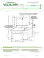
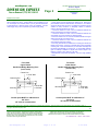
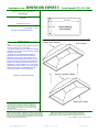
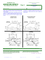
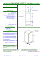
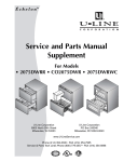
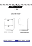
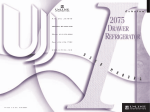
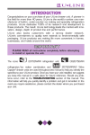
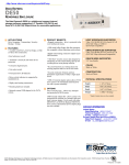
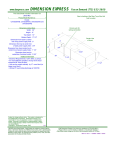
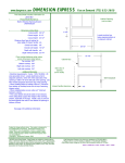
Dimension Express Booklet
Prepared On: 5/18/2005
.
Prepared By:
Job Information:
From:
Company:
Address:
Phone:
Fax:
Email:
Job Name:
Number:
Contact:
Address:
Phone:
Cell:
Fax:
Email:
Jim Builder
Construction ABC
123 Front St.
555.555.1212
555.555.1313
info@dexpress.com
Model No
Type
2075DWRR
VGIC3074B
DD602I
KSSS42FKT
VBCV3038
CT227NPRS
REF
RNG
DSH
REF
HOD
OVN
Please Distribute to all
Tim Haraol
85745
Bayville home
123 J St
555.1236
555.8956
555.8745
tim@xysd.com
Manufacturer
Doc Type
U-Line
Viking
Fisher & Paykel
Kitchen Aid
Viking
Thermador
Mfr Guide
Data Sheet
Data Sheet
Mfr Guide
Data Sheet
Data Sheet
Page
2
4
7
10
11
13
Sub Contractors
- Thank you for using our NEW PDF Booklet Feature!! We hope this
feature will save you time when working on your project.
- Dimension Express is now offering FREE model listings for
manufacturers. All information listed with Dimension Express MUST be
approved by the manufacturer. Please check back regularly as we are
adding manufacturers and industries.
To access over 14,000 appliance specification sheets, visit:
http://www.dexpress.com
www.dexpress.com
Page 1 of 14
5/18/2005
Model 2075DWRR
Drawer Refrigerator
A 5.5 cubic foot built-in under the counter
refrigerated drawer unit.
3/4" WOOD OVERLAY
SUPPLIED BY CUSTOMER
24
(61) WITH 3/4"
OVERLAY FRAME
23-15/16
(60.8)
23-1/4
(59.1)
21
(53.3)
34-1/8
(86.7)
FULL
RETRACT
HEIGHT
2-7/8
(7.3)
* POWER CORD
* ON BACK OF UNIT
5-7/8
(14.9)
35-1/8
(89.2)
FULL
EXTEND
HEIGHT
3-3/8
(8.6)
INCHES (CENTIMETERS)
S U P E R I O R F E AT U R E S O F É C H E L O N ™
1. Easy to set, adjustable, LED temperature
controller
BENEFIT: Digital readout of temperature setting
and actual drawer temperatures. Easy ability to see
and adjust to desired temperature.
2. Black units come standard to accept a full
overlay drawer panel
BENEFIT: Provides a fully integrated appearance
with surrounding cabinetry. Overlay panels are
easily attached to drawers.
4. Stainless steel units have a seamless full wrap
stainless steel cabinet and drawers with
sculpted, contoured handles
BENEFIT: The seamless full wrap stainless steel
drawers with sculpted handles distinguish this unit
from heavier, “commercial” looks.
5. Stainless steel drawer interiors
BENEFIT: Corrosion resistant, sleek professional
appearance.
3. Full overlay capability allows the customer to
choose the size of the gap between drawer
panels (either 1/2 or 1/4 inch gap)
BENEFIT: This provides the customer greater
flexibility in matching surrounding cabinetry.
www.dexpress.com
Page 2 of 14
5/18/2005
S U P E R I O R F E AT U R E S O F É C H E L O N ™
6. Multiple organizing features
a. Adjustable Slide & Divide organizer comes
standard in the top drawer and can be used in
either drawer. Consumer can adjust the
organizer from front to back, and side to side.
b. Clear organizing bin for top drawer can
accommodate wine bottles, two-liter bottles, or
other items. The bin is designed to slide from the
front to rear of the drawer allowing easy access
to items in or beneath the bin.
c. Bottom drawer crisper can be removed from
either side of the drawer to easily bring fruit or
vegetables to a sink, counter top, or bar.
d. Glass crisper shelf allows customer to easily see
contents of the crisper. Crisper shelf can easily
be fully removed to accommodate storage of
taller items.
BENEFIT: Use of all organizing features allow
consumers to customize their refrigeration space.
7. Heavy duty, full extension drawer slides
BENEFIT: Allows easy accessibility to contents in
the back of drawers.
8. Lighting in each drawer
BENEFIT: Automatically illuminates when either
drawer is opened.
www.dexpress.com
9. Consumer friendly, self diagnosing controller
BENEFIT: In the rare event of a problem, a
flashing LED indicator light explains if there is a
need to call for service.
10. Black units come with flush mounted black
drawer panel and will accept a custom 1/4 inch
thick panel
BENEFIT: Allows customer to achieve a custom,
built-in look by matching surrounding cabinetry.
Drawers come standard from the factory equipped
to be used with full overlay panels. For 1/4 inch
custom panel applications, replacement drawer
handles are required. Part number 11926-4-BLK.
11. Black units have black vinyl clad steel cabinet
BENEFIT: A textured, rich look that is more
resistant to scratching, peeling and flaking.
12. Adjustable leveling legs – durable, factory
installed
BENEFIT: More precise under the counter fit.
13. Automatic defrost
BENEFIT: Maintenance free defrosting.
14. Anchoring device is included with the unit
BENEFIT: This unit must be installed under a
counter and must be anchored to prevent tipping if
both drawers are opened when full.
Page 3 of 14
5/18/2005
2075DWRR
www.dexpress.com
•
DIMENSION EXPRESS
This Data Sheet Includes Information On
Viking Range
Product Model Number (s):
Professional Ranges :
VGIC307-4B
Fax on Demand (775) 833-3600
•
11"
2"
•
Dimensions (Actual Size)
Depth to end of side panel:
Depth to end of control panel:
Depth to end of knobs:
Door swing:
Control panel height:
Unit width:
Recommended opening width:
Minimum height to top of grate support:
Maximum height to top of grate support:
Recommended countertop height:
High-Shelf height:
6" Backguard height:
Island trim height :
Spider grate height
Distance from bottom of side panel (NOT
from floor) to centerline of gas inlet :
•
24 5/16"
26 1/4"
27 3/4"
18"
6"
29 7/8"
30"
35 7/8"
37 5/8"
36"
23 1/2"
6"
1 1/4"
1 1/8"
High-Shelf
23 1/2"
10" Backguard
10"
1 1/8"
6" Backguard
6"
Island trim
27 3/4"
1 1/4"
26 1/4"
6"
Top of
grate
support
27 1/2"
(to gas inlet)
35 7/8" Min.
37 5/8" Max.
27 1/2"
5 1/4"
•
Additional Information
•
• WARNING: The use of cabinets for storage above the
appliance may result in a potential burn hazard.
Combustible items may ignite, metallic items may
become hot and cause burns.
• All openings in the wall behind the appliance and in the
floor under the appliance shall be sealed.
• Do not obstruct the flow of combustion and ventilation
air.
• Countertop edge must be finished unless you are
using countertop side trim.
• Gas Service : Shipped natural gas standard; field
convert to LP/Propane with standard convertible
regulator; accepts standard residential 1/2" ID gas
service line or larger.
3 1/2"
3 3/8" Min.
5 1/8" Max.
24 5/16"
18"
30" Opening
Wall View
(not to scale)
See page 2-3 for additional information
11"
3"
5"
Subject to change without notice. This system is designed to
be updated daily if necessary. Dimension Express is not
responsible for use of superseded, voided, or outdated data
sheets. Because of the difficulty or impracticability of determining actual damages, liability of Dimension Express shall
not exceed $50.00.
Copyright © Dimension Express, 2005.
328
Locate gas shutoff valve
within light shaded area
• NEVER reuse Data Sheets. Data Sheets are subject to change without
notice. Dimension Express is a FREE service bureau and is updated daily,
it makes far more sense to spend the time necessary to request new Data
Sheets for each project, as opposed to the problems, time, costs, and risks
associated with reusing old Data Sheets.
www.dexpress.com
12"
6"
Floor line
Locate electrical outlet
within dark shaded area
• Call Dimension Express if you have any questions at (775) 833-3633 •
• Always refer to a current Code at a Glance or manufacturer directory •
• Data Sheet codes change on the first of odd numbered months at 12:01am •
BN • A328B149C150 • • 051101 • 83324 • 23174
Page 4 of 14
5/18/2005
www.dexpress.com
DIMENSION EXPRESS
Fax on Demand (775) 833-3600
This Data Sheet Includes Information On
Viking Range
Page 2
•
Product Model Number (s):
•
Professional Ranges :
VGIC307-4B
Additional Information:
• An agency-approved, properly-sized manual shut-off valve should be
installed no higher than 3" above the floor and within 6" from the left
side (facing product). To connect gas between shut-off valve and
regulator, use agency-approved, properly sized flexible conduit or
rigid pipe. Check all local code requirements.
• Natural requires 5.0"WC and LP gas requires 10.0"WC. Incoming line
pressure upstream from the regulator must be 1"WC higher than the
manifold pressure in order to check the regulator. The regulator used
on this range can withstand a maximum input pressure of 1/2PSI
(14.0"WC). If the line pressure is in excess of that amount, a
step-down regulator will be required.
• An installer supplied shut-off valve must be installed in the gas
service line ahead of the appliance and regulator in the gas stream and
in a position where it can be reached quickly in the event of an
emergency.
• Electrical requirements : 120V, 60Hz. 15 amp grounded circuit. 48"
cord with grounded 3 prong plug is included.
• A properly-grounded, adequately-powered, horizontally-mounted
electrical receptacle should be installed no higher than 3" above the
floor and not less than 6" from the right side (facing product). Check
all local code requirements.
• A backguard, high-shelf or island trim MUST be used for all
installations.
• The unit may be installed directly adjacent to existing 36" high base
cabinets. IMPORTANT - the top grate support MUST be 3/8" above the
adjacent base cabinet countertop. This may be accomplished by
raising the unit using the adjustment spindles on the legs.
• The unit CANNOT be installed directly adjacent to sidewalls, tall
cabinets, tall appliances, or other side vertical surfaces above 36"
high. There must be a minimum of 6" side clearance from the range to
such combustible surfaces above the 36" counter height.
• Within the 6" side clearance to combustible vertical surfaces above
36", the maximum wall cabinet depth must be 13" and wall cabinets
within this 6" side clearance must be 18" above the 36" high
countertop.
• Wall cabinets above the range must be a minimum of 36" above the
range cooking surface for the full width of the range.
• Use of island trim against non-combustible wall: Normal installation
for an island trim is in an island or where there is a minimum clearance
of 6" to any type of wall at the rear of the unit. However, agency
authorization has been received for "island trim" installations where a
unit can be installed at zero clearance to the rear wall AS LONG AS
THE WALL IS NON-COMBUSTIBLE.
• The responsibility for ensuring that the rear wall is non-combustible
and heat resistant lies with the individual owner and/or end user. Only
in those cases where the island trim is installed with six (6) inches of
minimum clearance to a rear wall, or when a truly non-combustible
material is used, will the warranty apply.
• In no case will Viking Range Corporation accept responsibility for
any claims which may result from heat damage against rear wall,
including cosmetic damage. It is the total responsibility of the owner
and/or end user to ensure that the material utilized in such
applications is not only non-combustible, but is also truly heat
resistant.
• Units available in Stainless Steel (SS), Black (BK), White (WH),
Almond (AL), Biscuit (BT), Stone Gray (SG), Graphite Gray (GG),
Burgundy (BU), Lemonade (LE), Mint Julep (MJ), Forest Green (FG),
Viking Blue (VB), Cobalt Blue (CB) and Eggplant (EP).
• All finishes can be ordered with Brass Trim Option (VGSC models
only).
• VGIC307-4B and VGIC305-4B: 30" wide with 4 burners. Approximate
shipping weight is 395 pounds.
Kits/Accessories:
• B30BG6 : 6" high, stainless steel backguard, included with unit.
• RS30CBF4 : Curb base front in stainless steel or can be used as
custom curb base.
• B30HS24 : Stainless steel high-shelf.
• B30TII : Stainless steel island trim.
• RE24CST : Stainless steel countertop side trim.
• RS30CBF4-SS : Curb base front in stainless steel or can be used as
custom curb base.
• UWRG : Stainless steel Wok Ring.
• SB-CCH : Hardwood cover that fits over standard surface grates,
griddle or grill, and may also be used as a cutting board.
Subject to change without notice. This system is designed to be updated daily if necessary. Dimension Express is not responsible for use of superseded, voided, or
outdated data sheets. Because of the difficulty or impracticability of determining actual damages, liability of Dimension Express shall not exceed $50.00.
Copyright © Dimension Express, 2005.
149
• NEVER reuse Data Sheets. Data Sheets are subject to change without
notice. Dimension Express is a FREE service bureau and is updated daily,
it makes far more sense to spend the time necessary to request new Data
Sheets for each project, as opposed to the problems, time, costs, and risks
associated with reusing old Data Sheets.
www.dexpress.com
• Call Dimension Express if you have any questions at (775) 833-3633 •
• Always refer to a current Code at a Glance or manufacturer directory •
• Data Sheet codes change on the first of odd numbered months at 12:01am •
BN • A328B149C150 • • 051101 • 83324 • 23174
Page 5 of 14
5/18/2005
www.dexpress.com
This Data Sheet Includes Information On
Viking Range
DIMENSION EXPRESS
•
Page 3
Fax on Demand (775) 833-3600
Product Model Number (s):
•
Professional Ranges :
VGIC307-4B
Additional Information:
36" Minimum from cooking surface to combustible
surface above/ 30"-36" to bottom of rangehood.
Cabinet depth
CANNOT exceed
13" from back wall
30" Minimum
(upper opening)
18"
Minimum
6" Minimum cooking
surface to sidewall or tall
cabinets (both sides)
3/8" Minimum
From countertop to
top of grate support
0" Side
clearance
30" Minimum
(lower opening)
36"
Recommended
counter top
height
4" from side of unit to
center of leg (each side)
Subject to change without notice. This system is designed to be updated daily if necessary. Dimension Express is not responsible for use of superseded, voided, or
outdated data sheets. Because of the difficulty or impracticability of determining actual damages, liability of Dimension Express shall not exceed $50.00.
Copyright © Dimension Express, 2005.
150
• NEVER reuse Data Sheets. Data Sheets are subject to change without
notice. Dimension Express is a FREE service bureau and is updated daily,
it makes far more sense to spend the time necessary to request new Data
Sheets for each project, as opposed to the problems, time, costs, and risks
associated with reusing old Data Sheets.
www.dexpress.com
• Call Dimension Express if you have any questions at (775) 833-3633 •
• Always refer to a current Code at a Glance or manufacturer directory •
• Data Sheet codes change on the first of odd numbered months at 12:01am •
BN • A328B149C150 • • 051101 • 83324 • 23174
Page 6 of 14
5/18/2005
www.dexpress.com
•
DIMENSION EXPRESS
This Data Sheet Includes Information On
Fisher & Paykel
Product Model Number (s):
Dishwashers:
DD602I
Fax on Demand (775) 833-3600
Top View
(not to scale)
22 7/16"
•
23 7/16"
•
Dimensions (Actual Size)
Body width:
Minimum height:
Maximum height:
Body depth:
Distance from unit body and front of
open drawer:
Minimum cabinet opening width:
Maximum cabinet opening width:
Minimum cabinet opening height:
Maximum cabinet opening height:
Minimum cabinet opening depth:
Total drawer panel height:
Toe kick depth:
Toe kick height (min.-max.)
•
Drawer Front
23 7/16"
32 3/16"
34 9/16"
22 7/16"
Body
20 1/2"
20 1/2"
23 5/8"
24"
32 5/16"
34 11/16"
22 7/8"
29 29/32"
2"
4" - 6"
•
Additional Information
•
• Custom panels must be supplied for this unit.
• Custom kickstrips are optional for this unit.
• It is recommended that bare wood surrounding the
DishDrawer is sealed with an oil based paint or
polyurethane to prevent steam damage.
• Ensure the cavity sides are plumb (vertical) as this
will assist with leveling the DishDrawer.
• Ensure the 1 1/2" dia. Services hole is located as
close to the rear corner of the cabinet opening. The
hole can be located on either side depending on the
location of the services.
• Flexible extrusions are supplied for 24" wide cabinet
opening installations.
• Electrical: 110-120VAC., 15 amp, 3 pin socket outlet
positioned in the adjacent cabinet between 6" and 18"
from the DishDrawer cabinet opening.
• Drain : The drain hose support must be at least 30"
above the floor to prevent siphoning of the water during
the wash cycle.
See page 2-3 for additional information
1 3/16"
22 7/16"
29 29/32"
45° angle is
imparative
Body
2"
Upper Kickstrip (attached to lower
drawer, will come forward when lower
drawer is opened)
2" min. from cabinet opening to
adjacent cabinet or wall (both sides)
Cabinet Opening
Wall View
(not to scale)
32 5/16" Min.
34 11/16" Max.
1 1/2" dia. Service Hole
(either side)
• NEVER reuse Data Sheets. Data Sheets are subject to change without
notice. Dimension Express is a FREE service bureau and is updated daily,
it makes far more sense to spend the time necessary to request new Data
Sheets for each project, as opposed to the problems, time, costs, and risks
associated with reusing old Data Sheets.
www.dexpress.com
32 3/16" Min.
34 9/16" Max.
Lower Kickstrip
23 5/8" Min.
24" Max.
Subject to change without notice. This system is designed to
be updated daily if necessary. Dimension Express is not
responsible for use of superseded, voided, or outdated data
sheets. Because of the difficulty or impracticability of determining actual damages, liability of Dimension Express shall
not exceed $50.00.
Copyright © Dimension Express, 2000.
280
Side View
(not to scale)
22 7/8" Min.
• Call Dimension Express if you have any questions at (775) 833-3633 •
• Always refer to a current Code at a Glance or manufacturer directory •
• Data Sheet codes change on the first of odd numbered months at 12:01am •
BN • A280B149C150 • • 000211 • 19443 • 41869
Page 7 of 14
5/18/2005
www.dexpress.com
DIMENSION EXPRESS
Fax on Demand (775) 833-3600
This Data Sheet Includes Information On
Fisher & Paykel
•
Page 2
Product Model Number (s):
•
Dishwashers:
DD602I
Additional Information:
• Water Supply : Hot or cold water supply. Water temperature must
NOT be greater than 140°F. Water pressure is to be between 4.3 psi
min. and 139psi max. Pressure below 7 psi may need the electronics
re-programmed by a Service Person at time of installation. Connect
water supply using a 3/8" compression type water supply fitting.
Custom Panels:
• Custom panels must be supplied for the drawer fronts. Drawer front
panel material and finish measurements are based on 3/4" material
and cannot be less than 5/8" thick. The drawer front material must be
suitable for damp conditions or adequately sealed to withstand
moisture. Kickstrip should be 3/8" thick.
• A minimum clearance of 3/32" must be maintained between the
drawer front/Kickstrip and adjacent cabinetry.
• A minimum clearance of 3/32" must be maintained between the
upper drawer front and countertop or cabinetry above.
• A minimum clearance of 1/4" must be maintained between the Upper
drawer front and the Lower drawer front.
• A minimum clearance of 3/32" must be maintained between the
upper Kickstrip and lower Kickstrip.
• A mounting zone MUST be maintained for mounting the handle and
badge (control panel). Accuracy is essential when cutting the badge
mounting hole, it is recommended that you have both the badge and
the drawer front BEFORE you cut the hole. A control badge template
(part no. 526253) is available on request from Fisher & Paykel. The
badge is an ellipse 2 7/32" wide and 1 1/8" high.
• All DishDrawer cavity areas are different. This is a rough guideline
to follow.
Front View
Lower Drawer
Handle and Badge Mounting Zone
(not to scale)
Front View
Upper Drawer
Handle and Badge Mounting Zone
(not to scale)
Center Line
7 13/32" Max
Center Line
7 13/32" Max
Custom Panel
Custom Panel
Mounting Zone
1 11/16" Min
4 3/4" Max
Mounting Zone
1 15/32" Min
4 17/32" Max
Custom panel MUST be a Minimum of
5/8" thick
3/4" thick is recommended
Custom panel MUST be a Minimum of
5/8" thick
3/4" thick is recommended
Subject to change without notice. This system is designed to be updated daily if necessary. Dimension Express is not responsible for use of superseded, voided, or
outdated data sheets. Because of the difficulty or impracticability of determining actual damages, liability of Dimension Express shall not exceed $50.00.
Copyright © Dimension Express, 2000.
149
• NEVER reuse Data Sheets. Data Sheets are subject to change without
notice. Dimension Express is a FREE service bureau and is updated daily,
it makes far more sense to spend the time necessary to request new Data
Sheets for each project, as opposed to the problems, time, costs, and risks
associated with reusing old Data Sheets.
www.dexpress.com
• Call Dimension Express if you have any questions at (775) 833-3633 •
• Always refer to a current Code at a Glance or manufacturer directory •
• Data Sheet codes change on the first of odd numbered months at 12:01am •
BN • A280B149C150 • • 000211 • 19443 • 41869
Page 8 of 14
5/18/2005
www.dexpress.com
DIMENSION EXPRESS
Fax on Demand (775) 833-3600
This Data Sheet Includes Information On
Fisher & Paykel
Page 3
•
Product Model Number (s):
•
Dishwashers:
DD602I
Additional Information:
Front View
Custom Panels
(not to scale)
3/32"
Surrounding Cabinet
Door/Drawer Front
Dimension
Countertop
Upper Panel Height:
15 3/4" Fixed
Custom Panel
1/4"
3/32"
Bottom Panel Height
=
Surrounding Cabinet
Door/Drawer
Front Dimension
Upper Panel Height
1/4"
3/32"
Custom Panel
Panel Width (all panels):
23 7/16" Min. for 23 5/8" opening
23 13/16" Min for 24" opening
6" Max. Toe Kick
3/32"
Upper Kickstrip 3/8" thick X 3" tall
X Same width as drawer panels
Upper Kickstrip attaches to lower drawer and
moves forward when lower drawer is opened
Lower Kickstrip 3/8" thick X 3" tall Max. - 1" tall Min.
X Same width as drawer panels
LowerKickstrip is fixed to the unit
Subject to change without notice. This system is designed to be updated daily if necessary. Dimension Express is not responsible for use of superseded, voided, or
outdated data sheets. Because of the difficulty or impracticability of determining actual damages, liability of Dimension Express shall not exceed $50.00.
Copyright © Dimension Express, 2000.
150
• NEVER reuse Data Sheets. Data Sheets are subject to change without
notice. Dimension Express is a FREE service bureau and is updated daily,
it makes far more sense to spend the time necessary to request new Data
Sheets for each project, as opposed to the problems, time, costs, and risks
associated with reusing old Data Sheets.
www.dexpress.com
• Call Dimension Express if you have any questions at (775) 833-3633 •
• Always refer to a current Code at a Glance or manufacturer directory •
• Data Sheet codes change on the first of odd numbered months at 12:01am •
BN • A280B149C150 • • 000211 • 19443 • 41869
Page 9 of 14
5/18/2005
®
Built-in Refrigerators, Side by Side and Bottom Mount
PRODUCT MODEL NUMBERS
KBLC36FK
KBLP36FK
KBLS36FK
KBRC36FK
KBRP36FK
KBRS36FK
KSSC36FK
KSSC36QK
KSSC42FK
KSSC42QK
KSSC48FK
KSSC48QK
KSSP36QK
KSSP42QK
OVERALL DIMENSIONS
Front view
KSSP48QK
KSSS36FK
KSSS36QK
KSSS42FK
KSSS42QK
KSSS48FK
KSSS48QK
Side by Side
Side view
(all models)
251/8"
(64 cm)
1
Bottom Mount
231/2"
(60 cm)
24"
(61 cm)
2
831/8"
(211 cm)
Electrical: A 115-volt, 60-Hz, AC-only, 15- or 20ampere, fused, electrical supply is required. A
time-delay fuse or circuit breaker is recommended.
It is recommended that a separate circuit serving
only this appliance be provided.
Water Supply: Use only 1/4" copper tubing for
water line. Water line to refrigerator must provide
15-100 psi water pressure.
831/8"
(211 cm)*
831/8"
(211 cm)
3
31/2" (9 cm)*
A
(see chart following)
361/4" (92 cm)
1. 25-1/8" (64 cm) dimension is to front of top grille.
2. Power cord (24 in. [61 cm])
3. 5 ft. (1.5 m) water line tubing taped to back
Width of Refrigerator:
Model
A
Width A (above)
36 in. (91 cm)
42 in. (106 cm)
48 in. (122 cm)
Top
view
36-1/4 in. (92 cm)
42-1/4 in. (107 cm)
48-1/4 in. (123 cm)
Model
251/8"
(64 cm)
Width A
36 in. (91 cm) 35 in. (89 cm)
42 in. (106 cm) 41 in. (104 cm)
48 in. (122 cm) 47 in. (119 cm)
DOOR SWING DIMENSIONS
Side by Side
A
CABINET OPENING DIMENSIONS
C
E
F
B
D
51"
(130 cm)
130˚
80" - 90"
(203-229 cm)
90˚
110˚
130˚
4"
(10.2 cm)
36"
A
B
C
D
E
F
831/4" (211.5 cm) min.
843/4" (215 cm) max.
to bottom of solid soffit.*
42"
48"
36-1/16" (92 cm) 38" (97 cm)
40" (102 cm)
38-1/2" (98 cm)
41" (104 cm)
43-1/2" (110 cm)
40" (102 cm)
42-9/16" (108 cm) 45-1/4" (115 cm)
43-1/2" (110 cm) 47" (119 cm)
50-1/2" (128 cm)
19-3/4" (50 cm)
23-1/4" (59 cm)
26-3/4" (68 cm)
14-1/2" (37 cm)
17-1/2" (44 cm)
19-3/4" (50 cm)
77"
(196 cm)
Model
Width A (above)
36 in. (91.4 cm)
42 in. (106.7 cm)
48 in. (121.9 cm)
35-1/2 in. (90.2 cm)
41-1/2 in. (105.4 cm)
47-1/2 in. (120.7 cm)
1
6"
(15.2 cm)
231/2"
(60 cm) min.
3
11"
(28 cm)
90˚
130˚
2
3
2" (5 cm)
3" (7.6 cm)
59"
(150 cm)
Location must
permit doors to
open to 90° min.
Allow 4-1/2 inch
min. space
between
refrigerator side
and corner wall.
ANTI-TIP REQUIREMENTS
Width of Opening:
A
Width
(see chart following)
23"
(58 cm)
90˚
110˚
2
1
Bottom Mount
4
6"
6"
(15.2 cm) (15.2 cm)
1. Stud location
2. Grounded electrical outlet location
3. Recommended water shutoff valve location
4. Plumbing hole and water line location (wall or floor)
Because Whirlpool
Corporation policy includes a continuous commitment to improve
www.dexpress.com
our products, we reserve the right to change materials and specifications without notice.
4
The solid soffit must be within 1 in.
(2.5 cm) maximum above the
refrigerator. If the solid soffit is higher
than 1 in. (2.5 cm) or one is not
available, prevent the refrigerator from
tipping during use as shown.
Locate the board(s) so the bottom
surface of the board(s) are 84 in.
(213 cm) from the floor.
Securely attach one or two 2 in. x 4 in. x
32 in. (5 cm x 10 cm x 81 cm) wood
boards to wall studs behind refrigerator.
Use 6 - #8 x 3 in. (7.6 mm) (or longer)
wood screws. The wood screws must
be screwed into the studs at least
1-1/2 in. (3.8 cm). The board(s) must
overlap the compressor cover.
1. Center board 1/4 in. (6 mm) max. above refrigerator
2. Two, 2 in. x 4 in. x 32 in. (5 cm x 10 cm x 81 cm) boards
3. Attach to studs with 6 -#8 x 3 in. (7.6 cm) screws
4. Compressor cover
For complete details, see Installation
5/18/2005 Ref. 2266877
04-17-03
Instructions packed with product. Specifications subject to change without notice.
Dimensions
are for14
planning purposes only.
Page
10 of
www.dexpress.com
•
•
DIMENSION EXPRESS
This Data Sheet Includes Information On
Viking Range
Product Model Number (s):
Custom Wall Ventilator:
VBCV3038
•
Dimensions (Actual Size)
•
Fax on Demand (775) 833-3600
27 7/16"
Cutout width: 27 7/16"
Cutout depth: 21 71/6"
See page 2 for additional dimensions
•
Additional Information
•
• IMPORTANT: Do NOT obstruct motor cooling vent
area.
• Always vent this product outside. DO NOT vent to an
attic, wall, garage, room or crawl space.
• The external blowers must be vented and connected
separately. Do not restrict ducting anywhere, including
roof jacks or wall louvers.
• If possible, the vent pipe should be installed in a
straight line from the rangehood through the roof,
eliminating or reducing the number of elbow joints
(elbows reduce the efficiency of the blower). If elbow
joints are necessary, they should make gradual turns.
Elbows of 90° should be avoided. Each 90° elbow is
equivalent to increasing distance by 5-10 feet. Make
gradual turns or use 45° elbows. In runs of longer than
20 feet, the duct size can be enlarged by at least 1"
after the first 10 feet to improve performance.
21 7/16"
Cutout Opening
(not to scale)
Custom Hood Canopy
(not to scale)
Built-In Ventilator System
See page 2 for additional information
Flange (all 4 sides)
Subject to change without notice. This system is designed to
be updated daily if necessary. Dimension Express is not
responsible for use of superseded, voided, or outdated data
sheets. Because of the difficulty or impracticability of determining actual damages, liability of Dimension Express shall
not exceed $50.00.
Copyright © Dimension Express, 2005.
234
• NEVER reuse Data Sheets. Data Sheets are subject to change without
notice. Dimension Express is a FREE service bureau and is updated daily,
it makes far more sense to spend the time necessary to request new Data
Sheets for each project, as opposed to the problems, time, costs, and risks
associated with reusing old Data Sheets.
www.dexpress.com
• Call Dimension Express if you have any questions at (775) 833-3633 •
• Always refer to a current Code at a Glance or manufacturer directory •
• Data Sheet codes change on the first of odd numbered months at 12:01am •
BN • A234B276 • • 051101 • 83324 • 91703
Page 11 of 14
5/18/2005
www.dexpress.com
DIMENSION EXPRESS
•
Page 2
Fax on Demand (775) 833-3600
This Data Sheet Includes Information On
Viking Range
Product Model Number (s):
•
Custom Wall Ventilator:
VBCV3038
Additional Information:
• Ventilators recommended for this unit are VIV300 (interior, 300 CFM),
VIV600 (interior, 600CFM), VIV1200 (interior, 1200CFM), VEV900
(exterior, 900CFM) or VEV1200 (exterior, 1200CFM). Ventilators are
ordered separately.
• Interior ventilators: 120VAC, 60Hz. Unit requires a minimum round
duct size of 7" or equivalent, this should never be reduced. Never use
flexible duct. Maximum equivalent duct length is 50 feet; for longer
duct runs, increase duct size and contact a qualified and trained
installer.
• Exterior ventilators: 120VAC, 60Hz. Unit requires a minimum round
duct size of 10" or equivalent, this should never be reduced. Never
use flexible duct. Maximum equivalent duct length is 50 feet; for
longer duct runs, increase duct size and contact a qualified and
trained installer.
VEV900/VEV1200
Ventilator cutouts
VIV300/VIV600/VIV1200
Ventilator cutouts
11 1/2"
Side View
(not to scale)
11 1/2"
Side View
(not to scale)
17 1/4"
17 1/4"
18 1/4"
6"
18 1/8"
6"
21 7/16"
21 7/8"
21 7/16"
21 7/8"
Flange
Top View
(not to scale)
Top View
(not to scale)
28 1/4"
27 7/16"
14 1/8"
5 1/2"
Flange
28 1/4"
27 7/16"
CL
8 1/4"
14 1/8"
4 5/8"
7 1/2"
11 1/2"
C
L
10" Dia.
duct cutout
C
L 8 1/8"
7 3/4" 11 1/2"
C
L
7" Dia.
duct cutout
21 7/16"
21 7/16"
21 7/8"
Flange Edge (4 sides)
21 7/8"
120V
electrical
supply
Flange Edge (4 sides)
120V
electrical
supply
Subject to change without notice. This system is designed to be updated daily if necessary. Dimension Express is not responsible for use of superseded, voided, or
outdated data sheets. Because of the difficulty or impracticability of determining actual damages, liability of Dimension Express shall not exceed $50.00.
Copyright © Dimension Express, 2005.
276
• NEVER reuse Data Sheets. Data Sheets are subject to change without
notice. Dimension Express is a FREE service bureau and is updated daily,
it makes far more sense to spend the time necessary to request new Data
Sheets for each project, as opposed to the problems, time, costs, and risks
associated with reusing old Data Sheets.
www.dexpress.com
• Call Dimension Express if you have any questions at (775) 833-3633 •
• Always refer to a current Code at a Glance or manufacturer directory •
• Data Sheet codes change on the first of odd numbered months at 12:01am •
BN • A234B276 • • 051101 • 83324 • 91703
Page 12 of 14
5/18/2005
www.dexpress.com
•
DIMENSION EXPRESS
This Data Sheet Includes Information On
Thermador
Product Model Number (s):
Convection-Self-Cleaning-Thermal-Ovens:
CT227NPRS
Fax on Demand (775) 833-3600
26 7/8"
•
25 1/2"
12 3/4"
•
Dimensions (Actual Size)
Cutout width: 25 1/2"
•
24"
Locate electrical
connection in this area.
4 1/2"
Cutout height: 48 3/8"
Minimum cabinet width: 26 7/8"
Minimum cabinet depth: 24"
Recommended cutout location from floor : 10"
Distance from face of cabinet to
outer edge of open door(s): 23 1/4"
Cabinet Cutout Opening
(not to scale)
48 3/8"
Distance from face of cabinet to
front of closed door handle: 4"
Overall unit width: 26 7/8"
Overall unit height: 48 3/4"
Penetration into cabinet: 24"
Distance from opening (top) to centerline
of electrical: 4 1/2"
10"
Distance from opening (right side) to
centerline of electrical: 12 3/4"
Oven overlap distances when using
cutout dimensions listed above:
Top overlap: 3/8"
Bottom overlap: 0"
Right side overlap: 11/16"
Left side overlap: 11/16"
Overall Dimensions
(not to scale)
•
Additional Information
•
• Power Supply: 120/240 volts, 3 wire, single phase,
60Hz., A.C. or 120/208 volts, 3 wire, single phase,
60Hz., A.C. Requires 40 Ampere circuit.
• IMPORTANT: Mandatory access to the top of the unit
is required for both horizontal and vertical duct
conections. Mandatory access to the back of the unit
is required for horizontal ducting.
• The unit is installed at any height preferred by the
user. Recommended height is 10" above the floor.
• Install a suitable conduit box (not furnished) flush in
the back of the cabinet. For best results, locate the
conduit box above the oven.
• 48" flexible metallic conduit is supplied and should be
routed to permit temporary removal of oven.
48 3/4"
24"
See page 2 for more additional information.
26 7/8"
Subject to change without notice. This system is designed to
be updated daily if necessary. Dimension Express is not
responsible for use of superseded, voided, or outdated data
sheets. Because of the difficulty or impracticability of determining actual damages, liability of Dimension Express shall
not exceed $50.00.
Copyright © Dimension Express, 2000.
324
• NEVER reuse Data Sheets. Data Sheets are subject to change without
notice. Dimension Express is a FREE service bureau and is updated daily,
it makes far more sense to spend the time necessary to request new Data
Sheets for each project, as opposed to the problems, time, costs, and risks
associated with reusing old Data Sheets.
www.dexpress.com
• Call Dimension Express if you have any questions at (775) 833-3633 •
• Always refer to a current Code at a Glance or manufacturer directory •
• Data Sheet codes change on the first of odd numbered months at 12:01am •
BN9.11 • A324B149 • 11215 • 001006 • 20045 • 70385
Page 13 of 14
5/18/2005
www.dexpress.com
DIMENSION EXPRESS
Fax on Demand (775) 833-3600
This Data Sheet Includes Information On
Thermador
Page 2
•
Product Model Number (s):
•
Convection-Self-Cleaning-Thermal-Ovens:
CT227NPRS
Additional Information:
• Install two 2" x 4"'s extending from front to back flush with the bottom
and sides of the opening. These are for supporting the oven, they
should be level and well blocked at the rear wall.
• The oven may be vented indoors or outdoors according to customer
preference. The unit is shipped from the factory ready to vent indoors.
• When venting outdoors, you must use 4" diameter conductor pipe.
This connector pipe can be connected to either the top (vertical
discharge) or back (horizontal discharge) of the oven. The oven
requires its own separate metal conductor pipe to the outdoors. Do
NOT connect into any other exhaust system, wall, ceiling or other
concealed space of a building.
• Collar and Slip Joint are furnished with unit to connect unit to 4" pipe.
• Maximum length of 4" diameter conductor pipe that can be used with
this oven: 47' (not counting 90° elbows). This data is based on the
installer using a wall or roof cap with not more than 0.07 inches static
pressure. In general, a cap with an opening at least equal to the area
of the 4" pipe (approximately 13 square inches) will meet this
requirement. For each 90° elbow in the run, subtract 3' of pipe from the
47' maximum. Like all "rules of thumb," this one should be used with
judgement (example: when using one 90° elbow the maximum length
of 4" pipe is 44'). For unusual installations, a competent ventillating
expert should calculate the static pressure from friction charts and
verify the actual static pressure of the installation. The maximum
static pressure is 0.27" of water column.
• The bottom edge of the oven opening must be a finished-Cut. It is
exposed because the unit has zero overlap at the bottom.
• When installing unit in existing construction, the cutout opening
width must be 25 1/2". The cutout opening height can be 48 3/8"
minimum to 50" maximum. If the cutout opening height is greater than
48 3/8" the use of the included extension trim is necessary (the trim is
added to the bottom of the unit), the trim adds 1 5/8", making the
overall unit height 50 3/8" . IMPORTANT: the oven supports must be
located 48 3/8" down from the top edge of the opening. The top trim
overlap will be 3/8".
Discharge locations
Centerline of unit and opening
Centerline of unit and opening
7" diameter hole for 4"
horizontal discharge
7" diameter hole for
4" vertical discharge
4 5/8"
4 5/8"
20 1/8"
from face
of cabinet
44 1/4"
Front view of opening
(not to scale)
Top view
(not ot scale)
Vertical
Horizontal
Subject to change without notice. This system is designed to be updated daily if necessary. Dimension Express is not responsible for use of superseded, voided, or
outdated data sheets. Because of the difficulty or impracticability of determining actual damages, liability of Dimension Express shall not exceed $50.00.
Copyright © Dimension Express, 2000.
149
• NEVER reuse Data Sheets. Data Sheets are subject to change without
notice. Dimension Express is a FREE service bureau and is updated daily,
it makes far more sense to spend the time necessary to request new Data
Sheets for each project, as opposed to the problems, time, costs, and risks
associated with reusing old Data Sheets.
www.dexpress.com
• Call Dimension Express if you have any questions at (775) 833-3633 •
• Always refer to a current Code at a Glance or manufacturer directory •
• Data Sheet codes change on the first of odd numbered months at 12:01am •
BN9.11 • A324B149 • 11215 • 001006 • 20045 • 70385
Page 14 of 14
5/18/2005