1
SGI 1450 Server User’s Guide
007-4274-001
Cover design by Sarah Bolles, Sarah Bolles Design, and Dany Galgani, SGI Technical Publications.
© 2000, Silicon Graphics, Inc.— All Rights Reserved
The contents of this document may not be copied or duplicated in any form, in whole or in part, without the prior written permission of Silicon
Graphics, Inc.
This equipment has been tested and found to comply with the limits for a Class A digital device, pursuant to Part 15 of the FCC Rules. This
equipment generates, uses, and can radiate radio frequency energy and, if not installed and used in accordance with the instructions, may cause
harmful interference to radio communications.
LIMITED AND RESTRICTED RIGHTS LEGEND
Use, duplication, or disclosure by the Government is subject to restrictions as set forth in the Rights in Data clause at FAR 52.227-14 and/or in
similar or successor clauses in the FAR, or in the DOD, DOE, or NASA FAR Supplements. Unpublished rights reserved under the Copyright
Laws of the United States. Contractor/manufacturer is Silicon Graphics, Inc., 1600 Amphitheatre Pkwy., Mountain View, CA 94043-1351.
Silicon Graphics is a registered trademark and SGI and the SGI logo are trademarks of Silicon Graphics, Inc.
Compaq is a trademark of Compaq Computer Corporation. IBM and OS/2 are registered trademarks of International Business Machines. Intel,
LANDesk, and Pentium are registered trademarks and Server Set and Xeon are trademarks of Intel Corporation. Linux is a registered trademark
of Linus Torvalds. Microsoft, MS-DOS, Windows, and WIndows 2000 are registered trademarks of Microsoft Corporation. UNIX is a registered
trademark in the United States and other countries, licensed exclusively through X/Open Company, Ltd.
Record of Revision
Version
Description
001
June 2000
Initial Rev
007-4274-001
iii
Contents
1.
2.
007-4274-001
Figures .
.
.
.
.
.
.
.
.
.
.
.
.
.
.
.
.
.
.
.
.
.
.
.
.
. ix
Tables .
.
.
.
.
.
.
.
.
.
.
.
.
.
.
.
.
.
.
.
.
.
.
.
.
. xi
About This Guide.
.
.
.
.
.
.
.
.
.
.
.
.
.
.
.
.
.
.
.
.
.
. xiii
Obtaining Publications
.
.
.
.
.
.
.
.
.
.
.
.
.
.
.
.
.
.
.
.
. xiii
Reader Comments .
.
.
.
.
.
.
.
.
.
.
.
.
.
.
.
.
.
.
.
.
.
. xiii
Chassis Description .
.
.
.
.
.
.
.
.
.
.
.
.
.
.
.
.
.
.
.
.
.
1
Chassis Features
.
.
.
.
.
.
.
.
.
.
.
.
.
.
.
.
.
.
.
.
.
.
.
2
Peripherals .
.
.
.
.
.
.
.
.
.
.
.
.
.
.
.
.
.
.
.
.
.
.
.
7
.
Peripheral Bay.
.
.
.
.
.
.
.
.
.
.
.
.
.
.
.
.
.
.
.
.
.
.
7
Hard Drive Bay
.
.
.
.
.
.
.
.
.
.
.
.
.
.
.
.
.
.
.
.
.
.
8
Power Subsystem .
.
.
.
.
.
.
.
.
.
.
.
.
.
.
.
.
.
.
.
.
.
.
9
System Cooling
.
.
.
.
.
.
.
.
.
.
.
.
.
.
.
.
.
.
.
.
.
. 10
Chassis Front Controls and Indicators .
.
.
.
.
.
.
.
.
.
.
.
.
.
.
.
. 12
Rear Panel I/O Ports and Features .
.
.
.
.
.
.
.
.
.
.
.
.
.
.
.
.
. 13
Baseboard Description .
.
.
.
.
.
.
.
.
.
.
.
.
.
.
.
.
.
.
.
. 15
Baseboard Features
.
.
.
.
.
.
.
.
.
.
.
.
.
.
.
.
.
.
.
. 16
Baseboard Connector and Component Locations .
.
.
.
.
.
.
.
.
.
.
.
.
. 18
Processor
.
.
.
.
.
.
.
.
.
.
.
.
.
.
.
.
.
.
.
.
.
.
.
.
. 19
Memory.
.
.
.
.
.
.
.
.
.
.
.
.
.
.
.
.
.
.
.
.
.
.
.
.
. 20
Peripherals .
.
.
.
.
.
.
.
.
.
.
.
.
.
.
.
.
.
.
.
.
.
.
.
. 22
Super I/O Chip (SIO).
.
.
.
.
.
.
.
.
.
.
.
.
.
.
.
.
.
.
.
. 22
Serial Ports.
.
.
.
.
.
.
.
.
.
.
.
.
.
.
.
.
.
.
.
.
.
.
. 22
Parallel Port
.
.
.
.
.
.
.
.
.
.
.
.
.
.
.
.
.
.
.
.
.
.
. 22
Add-in Board Slots
.
.
.
.
.
.
.
.
.
.
.
.
.
.
.
.
.
.
.
.
.
. 23
DesotoE2 Hot-Plug PCI Controller .
.
.
.
.
.
.
.
.
.
.
.
.
.
.
.
.
. 24
IDE Interface
.
.
.
.
.
.
.
.
.
.
.
.
.
.
.
.
. 25
.
.
.
.
.
.
.
.
.
.
v
Contents
USB Interface
3.
vi
.
.
.
.
.
.
.
.
.
.
.
.
.
.
.
.
.
. 25
Network Interface Controller (NIC) .
.
.
.
.
.
.
.
.
.
.
.
.
.
.
.
.
. 25
Video.
.
. 26
.
.
.
.
.
.
.
.
.
.
.
.
.
.
.
.
.
.
.
.
.
.
.
.
.
.
.
.
.
.
SCSI Controller .
.
.
.
.
.
.
.
.
.
.
.
.
.
.
.
.
.
.
.
.
.
.
. 26
IDE Controller .
.
.
.
.
.
.
.
.
.
.
.
.
.
.
.
.
.
.
.
.
.
.
. 28
Keyboard and Mouse .
.
.
.
.
.
.
.
.
.
.
.
.
.
.
.
.
.
.
.
.
. 28
Server Management
.
.
.
.
.
.
.
.
.
.
.
.
.
.
.
.
.
.
.
.
. 29
Software Locks via the SSU or BIOS Setup .
.
.
.
.
.
.
.
.
.
.
.
.
.
.
.
. 30
Using Passwords .
.
.
.
.
.
.
.
.
.
.
.
.
.
.
.
.
.
.
.
.
. 31
Secure Mode
.
.
.
.
.
.
.
.
.
.
.
.
.
.
.
.
.
.
.
.
. 31
Summary of Software Security Features
.
.
.
.
.
.
.
.
.
.
.
.
.
.
. 31
.
.
Configuring Software and Utilities .
.
.
.
.
.
.
.
.
.
.
.
.
.
.
.
.
. 35
Hot Keys.
.
.
.
.
.
.
.
.
.
.
.
.
.
.
.
.
.
.
.
.
. 36
Power-On Self Test (POST)
.
.
.
.
.
.
.
.
.
.
.
.
.
.
.
.
.
.
.
.
.
.
.
. 37
Using BIOS Setup .
.
.
.
.
.
.
.
.
.
.
.
.
.
.
.
.
.
.
.
.
.
. 38
Starting Setup .
.
.
.
.
.
.
.
.
.
.
.
.
.
.
.
.
.
.
.
.
.
. 38
Setup Menus
.
.
.
.
.
.
.
.
.
.
.
.
.
.
.
.
.
.
.
.
.
.
. 39
Main Menu .
.
.
.
.
.
.
.
.
.
.
.
.
.
.
.
.
.
.
.
.
.
.
. 41
Advanced Menu .
.
.
.
.
.
.
.
.
.
.
.
.
.
.
.
.
.
.
.
.
. 45
Security Menu .
.
.
.
.
.
.
.
.
.
.
.
.
.
.
.
.
.
.
.
.
.
. 56
Server Menu
.
.
.
.
.
.
.
.
.
.
.
.
.
.
.
.
.
.
.
.
.
.
. 57
Boot Menu .
.
.
.
.
.
.
.
.
.
.
.
.
.
.
.
.
.
.
.
.
.
.
. 61
Exit Menu .
.
.
.
.
.
.
.
.
.
.
.
.
.
.
.
.
.
.
.
.
.
.
. 63
Changing the Boot Device Priority Temporarily
.
.
.
.
.
.
.
.
.
.
.
.
.
. 63
Changing the Boot Device Priority Permanently
Running the SCSISelect Utility
.
.
.
.
.
.
.
.
.
.
.
.
.
. 64
.
.
.
.
.
.
.
.
.
.
.
.
.
.
.
.
. 64
When to Run the SCSISelect Utility .
.
.
.
.
.
.
.
.
.
.
.
.
.
.
.
. 65
Starting the SCSISelect Utility
.
.
.
.
.
.
.
.
.
.
.
.
.
.
.
. 65
Configuring the Adaptec AIC-7880 SCSI Adapter .
.
.
.
.
.
.
.
.
.
.
.
. 66
Configuring the Adaptec AIC-7899 SCSI Adapter .
.
.
.
.
.
.
.
.
.
.
.
. 67
.
.
.
.
007-4274-001
Contents
Using the System Setup Utility (SSU)
.
.
.
.
.
.
.
.
.
.
.
.
.
.
.
. 68
When to Run the SSU.
.
.
.
.
.
.
.
.
.
.
.
.
.
.
.
.
.
.
.
. 68
What You Need to Do
.
.
.
.
.
.
.
.
.
.
.
.
.
.
.
.
.
.
.
. 69
Running the SSU Remotely .
.
.
.
.
.
.
.
.
.
.
.
.
.
.
.
.
.
. 69
Creating SSU Diskettes .
.
.
.
.
.
.
.
.
.
.
.
.
.
.
.
.
.
.
. 70
Running the SSU .
.
.
.
.
.
.
.
.
.
.
.
.
.
.
.
.
.
.
.
.
. 70
FRU and SDR Load Utility
.
.
.
.
.
.
.
.
.
.
.
.
.
.
.
.
.
.
.
. 71
What You Need to Do
.
.
.
.
.
.
.
.
.
.
.
.
.
.
.
.
.
.
.
. 71
How You Use the FRUSDR Load Utility .
.
.
.
.
.
.
.
.
.
.
.
.
.
. 72
Cleaning Up and Exiting .
.
.
.
.
.
.
.
.
.
.
.
.
.
.
.
.
.
.
. 74
.
.
.
.
.
.
.
.
.
.
.
.
.
.
.
.
.
.
. 75
Preparing for the Upgrade .
.
.
.
.
.
.
.
.
.
.
.
.
.
.
.
.
.
. 75
Upgrading the BIOS .
.
.
.
.
.
.
.
.
.
.
.
.
.
.
.
.
.
.
.
. 76
Recovering the BIOS .
.
.
.
.
.
.
.
.
.
.
.
.
.
.
.
.
.
.
.
. 77
Changing the BIOS Language .
.
.
.
.
.
.
.
.
.
.
.
.
.
.
.
.
. 78
Using the Firmware Update Utility .
.
.
.
.
.
.
.
.
.
.
.
.
.
.
.
.
. 78
Running the Firmware Update Utility .
.
.
.
.
.
.
.
.
.
.
.
.
.
.
. 78
Removing and Installing User Serviceable Components
.
.
.
.
.
.
.
.
.
.
. 79
SCSI Hard drives .
Upgrading the BIOS .
4.
.
.
.
.
.
.
.
.
.
.
.
.
.
.
.
.
.
.
.
.
. 80
Mounting a SCSI Hard Drive in a Carrier .
.
.
.
.
.
.
.
.
.
.
.
.
.
. 80
Removing a SCSI Hard drive
.
.
.
.
.
.
.
.
.
.
.
.
.
.
.
.
.
. 81
Installing a SCSI Hard Drive
.
.
.
.
.
.
.
.
.
.
.
.
.
.
.
.
.
. 83
.
.
.
.
.
.
.
.
.
.
.
.
.
.
.
.
.
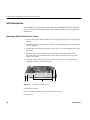
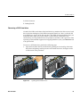
. 83
Removing a Hot-Plug PCI Add-in Board .
.
.
.
.
.
.
.
.
.
.
.
.
.
. 85
Hot-Plug PCI Add-In Boards.
.
.
.
.
.
Installing a Hot-Plug PCI Add-in Board
.
.
.
.
.
.
.
.
.
.
.
.
.
.
. 87
.
.
.
.
.
.
.
.
.
.
.
.
.
.
.
.
.
.
.
.
. 90
Regulatory Specifications
.
.
.
.
.
.
.
.
.
.
.
.
.
.
.
.
.
.
.
. 93
Manufacturer’s Regulatory Declarations
.
.
.
.
.
.
.
.
.
.
.
.
.
.
.
. 93
Server Model Number
.
.
.
.
.
.
.
.
.
.
.
.
.
.
.
.
.
.
.
.
. 93
Class A Compliance .
.
.
.
.
.
.
.
.
.
.
.
.
.
.
.
.
.
.
.
.
. 94
Electromagnetic Emissions
.
.
.
.
.
.
.
.
.
.
.
.
.
.
.
.
.
.
.
. 95
VCCI Notice Class A (Japan Only) .
.
.
.
.
.
.
.
.
.
.
.
.
.
.
.
.
. 95
Equipment Log
A.
007-4274-001
.
.
vii
Contents
Chinese Class A Regulatory Notice .
.
.
.
.
.
.
.
.
.
.
.
.
.
.
.
.
. 95
Industry Canada Notice (Canada Only) .
.
.
.
.
.
.
.
.
.
.
.
.
.
.
.
. 95
CE Notice
.
.
.
.
.
.
.
.
.
.
.
.
.
.
.
. 96
.
.
.
Shielded Cables .
.
.
.
.
.
.
.
.
.
.
.
.
.
.
.
.
.
.
.
.
.
.
. 96
Electrostatic Discharge.
.
.
.
.
.
.
.
.
.
.
.
.
.
.
.
.
.
.
.
.
. 96
B.
Physical Environment Specifications .
.
.
.
.
.
.
.
.
.
.
.
.
.
.
.
. 97
C.
Safety Precautions .
.
.
.
.
.
.
.
.
.
.
.
.
.
.
.
.
.
.
.
.
.
. 99
.
.
.
.
.
.
.
.
.
.
.
.
.
.
.
.
.
.
.
.
.
.
101
Index.
viii
.
.
.
.
.
.
.
.
.
007-4274-001
Figures
007-4274-001
Figure 1-1
Server in Rack-Mountable Configuration
.
.
.
.
.
.
.
.
3
Figure 1-2
Top Cover Thumbscrew .
.
.
.
.
.
.
.
.
.
.
.
4
Figure 1-3
Server without Covers and Bezel .
.
.
.
.
.
.
.
.
.
.
5
Figure 1-4
Hard Drive in Drive Carrier .
.
.
.
.
.
.
.
.
.
.
.
8
Figure 1-5
Fan Board Assembly .
.
.
.
.
.
.
.
.
.
.
. 11
Figure 1-6
Front Panel Controls and Indicators .
.
.
.
.
.
.
.
.
. 12
Figure 1-7
Rear Panel I/O Ports and Features .
.
.
.
.
.
.
.
.
. 13
Figure 2-1
Baseboard Connector and Component Locations .
.
.
.
.
. 18
Figure 2-2
Memory Module DIMM Installation Sequence .
.
.
.
.
.
. 21
Figure 4-1
Hard Drive in Drive Carrier .
.
.
.
.
.
.
.
.
.
.
. 80
Figure 4-2
Opening the Front Bezel Door
.
.
.
.
.
.
.
.
.
.
. 81
Figure 4-3
Disengaging Drive Carrier from Chassis
.
.
.
.
.
.
.
. 82
Figure 4-4
PCI Hot-Plug Retention Mechanism .
.
.
.
.
.
.
.
.
. 84
Figure 4-5
Rear Retention Latch .
.
.
.
.
.
.
.
.
.
.
.
.
. 85
Figure 4-6
Top Cover Thumbscrew .
.
.
.
.
.
.
.
.
.
.
.
. 86
.
.
.
ix
Tables
007-4274-001
Table 1-1
SGI 1450 Server Physical Specifications .
.
.
.
.
.
.
.
.
2
Table 1-2
Chassis Feature Summary .
.
.
.
.
.
.
.
.
.
.
.
.
6
Table 1-3
Hard Drive LED State Status .
.
.
.
.
.
.
.
.
.
.
.
9
Table 2-1
Baseboard Features.
.
.
.
.
.
.
.
.
.
.
.
.
.
. 16
Table 2-2
Slot State Indicators
.
.
.
.
.
.
.
.
.
.
.
.
.
. 23
Table 2-3
Software Security Features
.
.
.
.
.
.
.
.
.
.
.
. 32
Table 3-1
Configuration Utilities .
.
.
.
.
.
.
.
.
.
.
.
.
. 35
Table 3-2
Hot Keys.
.
.
.
.
.
.
.
.
.
.
.
.
.
.
.
. 36
Table 3-3
Navigation Keys
.
.
.
.
.
.
.
.
.
.
.
.
.
.
. 40
Table 3-4
Selecting Options .
.
.
.
.
.
.
.
.
.
.
.
.
.
. 41
Table 3-5
Main Menu .
.
.
.
.
.
.
.
.
.
.
.
.
.
. 41
Table 3-6
Primary IDE Master and Slave Submenu
.
.
.
.
.
.
.
. 42
Table 3-7
Processor Settings Submenu .
.
.
.
.
.
.
.
.
.
.
. 44
Table 3-8
Advanced Menu
.
.
.
.
.
.
.
.
.
.
. 45
Table 3-9
Embedded Video Controller Submenu .
.
.
.
.
.
.
.
. 46
Table 3-10
Embedded Legacy SCSI Submenu
.
.
.
.
.
.
.
. 46
Table 3-11
Embedded Dual Ultra 160 SCSI Submenu .
.
.
.
.
.
.
. 47
Table 3-12
Embedded NIC Submenu .
.
.
.
.
.
.
.
.
.
.
.
. 47
Table 3-13
PCI Device, Slot 1 Submenu .
.
.
.
.
.
.
.
.
.
.
. 48
Table 3-14
PCI Device, Slot 2 Submenu .
.
.
.
.
.
.
.
.
.
.
. 48
Table 3-15
PCI Device, Slot 3 Submenu .
.
.
.
.
.
.
.
.
.
.
. 49
Table 3-16
PCI Device, Slot 4 Submenu .
.
.
.
.
.
.
.
.
.
.
. 50
Table 3-17
PCI Device, Slot 5 Submenu .
.
.
.
.
.
.
.
.
.
.
. 50
Table 3-18
PCI Device, Slot 6 Submenu .
.
.
.
.
.
.
.
.
.
.
. 51
Table 3-19
PCI Device, Slot 7 Submenu .
.
.
.
.
.
.
.
.
.
.
. 52
Table 3-20
PCI Device, Slot 8 Submenu .
.
.
.
.
.
.
.
.
.
.
. 52
Table 3-21
Hot-Plug PCI Control Submenu .
.
.
.
.
.
.
.
.
.
. 53
.
.
.
.
.
.
.
.
.
xi
Tables
xii
Table 3-22
Integrated Peripheral Configuration Submenu .
.
.
.
.
.
. 54
Table 3-23
Advanced Chipset Control Submenu .
.
.
.
.
.
.
.
.
. 55
Table 3-24
Security Menu
.
.
.
.
.
.
.
.
.
.
.
.
.
. 56
Table 3-25
Server Menu .
.
.
.
.
.
.
.
.
.
.
.
.
.
.
.
. 57
Table 3-26
System Management Submenu
.
.
.
.
.
.
.
.
.
.
. 58
Table 3-27
Console Redirection Submenu.
.
.
.
.
.
.
.
.
.
.
. 59
Table 3-28
EMP Configuration Submenu .
.
.
.
.
.
.
.
.
.
.
. 60
Table 3-29
PEP Management Submenu
.
.
.
.
.
.
.
.
.
.
.
. 60
Table 3-30
Boot Menu
.
.
.
.
.
.
.
.
.
.
.
. 61
Table 3-31
Boot Device Priority Submenu.
.
.
.
.
.
.
.
.
.
.
. 61
Table 3-32
Hard Drive Submenu .
.
.
.
.
.
.
.
.
.
.
. 62
Table 3-33
Removable Devices Selection Submenu .
.
.
.
.
.
.
.
. 62
Table 3-34
Exit Menu
.
.
.
.
.
.
.
.
.
.
.
.
.
.
.
. 63
Table 3-35
Navigation Keys.
.
.
.
.
.
.
.
.
.
.
.
.
.
.
. 65
Table 3-36
Main Menu .
.
.
.
.
.
.
.
.
.
.
.
.
.
.
. 66
Table 3-37
Exit Menu
.
.
.
.
.
.
.
.
.
.
.
.
.
.
.
.
. 66
Table 3-38
Main Menu .
.
.
.
.
.
.
.
.
.
.
.
.
.
.
.
. 67
Table 3-39
Menu for each SCSI Channel .
.
.
.
.
.
.
.
.
.
.
. 67
Table 3-40
Exit Menu
.
.
.
.
.
.
.
.
.
.
.
.
.
. 67
Table 3-41
Command Line Format .
.
.
.
.
.
.
.
.
.
.
.
.
. 72
Table 4-1
Hard Drive LED State Status .
.
.
.
.
.
.
.
.
.
.
. 82
Table 4-2
Equipment Log .
.
.
.
.
.
.
.
.
.
.
.
. 90
Table B-1
Environmental Specifications .
.
.
.
.
.
.
.
.
.
.
. 97
.
.
.
.
.
.
.
.
.
.
.
.
.
.
.
.
.
007-4274-001
About This Guide
This guide describes the features of the SGI 1450 server and provides information on
installing customer-replaceable components and on configuring software and utilities.
The following topics are covered:
•
Chassis Description
•
Baseboard Description
•
Configuring Software and Utilities
•
Removing and Installing User Serviceable Components
Qualified and trained service personnel should refer to the 1450 Sever Maintenance Guide
for a more detailed chassis description and information on removing and installing field
replaceable components.
Refer to the SGI 1450 Server Quick Start Guide for information on setting up your system.
Obtaining Publications
To obtain SGI documentation, go to the SGI Technical Publications Library at
http://techpubs.sgi.com.
Reader Comments
If you have comments about the technical accuracy, content, or organization of this
document, please tell us. Be sure to include the title and document number of the manual
with your comments. (Online, the document number is located in the front matter of the
manual. In printed manuals, the document number can be found on the back cover.)
You can contact us in any of the following ways:
007-4274-001
xiii
About This Guide
•
Send e-mail to the following address:
techpubs@sgi.com
•
Use the Feedback option on the Technical Publications Library World Wide Web
page:
http://techpubs.sgi.com
•
Contact your customer service representative and ask that an incident be filed in the
SGI incident tracking system.
•
Send mail to the following address:
Technical Publications
SGI
1600 Amphitheatre Pkwy., M/S 535
Mountain View, California 94043-1351
•
Send a fax to the attention of “Technical Publications” at +1 650 932 0801.
We value your comments and will respond to them promptly.
xiv
007-4274-001
Chapter 1
1. Chassis Description
This chapter provides a description of the external and internal structure of the SGI 1450
server.
The following sections are covered:
007-4274-001
•
Chassis Features
•
Peripherals
•
Power Subsystem
•
System Cooling
•
Chassis Front Controls and Indicators
•
Rear Panel I/O Ports and Features
1
1: Chassis Description
Chassis Features
The SGI 1450 server is designed to be either mounted in a standard 19-inch rack (rack
mode) or standing upright (pedestal mode). Table 1-1 shows the physical specifications
for the SGI 1450 server in rack mode.
For instructions on mounting the SGI 1450 server in a 19-inch rack, see the SGI 1450
Server Mounting Instructions.
Table 1-1
SGI 1450 Server Physical Specifications
Specification
Rack Mode
Height
4u (7 inches)
Width
17.5 inches (44.5 cm)
Depth
26.5 inches (67.3 cm)
Weight
57 lbs. (26 kg), minimum configuration
88 lbs. (40 kg), maximum configuration
2
Required front clearance
3 inches (inlet air temperature <35 °C / 95 °F)
Required rear clearance
6 inches (no airflow restriction allowed)
Required side clearance
1 inch
007-4274-001
Chassis Features
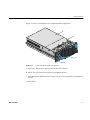
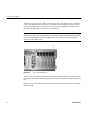
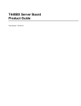
Figure 1-1 shows a SGI 1450 server in rack-mountable configuration.
A
B
C
D
Figure 1-1
Server in Rack-Mountable Configuration
A. Top Cover. The top cover protects the contents of the chassis.
B. Front Cover. The front cover protects the peripheral devices.
C. Front Bezel Door. When this door is open, you can access hard drives and peripheral
devices.
D. Front Bezel.
007-4274-001
3
1: Chassis Description
The chassis has two covers: a front cover and a top cover. The front cover is secured by
screws and should be removed only by a qualified service technician. The top cover is
secured by thumbscrews and provides user access to hot-pluggable PCI components.
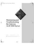
One of two thumbscrews is noted by “A” in Figure 1-2.
Note: At this time, the Linux operating system does not support use of the PCI Hot-Plug
(PHP) feature. If you are running Linux, your system must be turned off before installing
or removing PCI boards. Windows 2000 requires drivers that are PHP compatible in
order to use the PHP feature.
A
Figure 1-2
Top Cover Thumbscrew
A bezel snaps on to the front of the chassis and allows adequate airflow to cool the system
components. The door in the bezel provides user access to hard drives and the peripheral
bay.
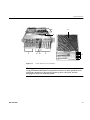
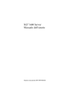
Figure 1-3 gives an overhead view of the system with the top cover, front cover, and front
bezel removed.
4
007-4274-001
Chassis Features
E
E1
D
C
Figure 1-3
A1
A2
B
E2
Server without Covers and Bezel
Warning: The total power requirement for the SGI 1450 server exceeds the 240 VA
energy hazard limit that defines an operator-accessible area. Only qualified service
technicians should access the processor, memory, power subsystem, and non
hot-plug/hot-swap areas of the baseboard.
007-4274-001
5
1: Chassis Description
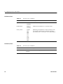
Table 1-2 summarizes the SGI 1450 server chassis features, using the labels provided in
Figure 1-3.
Table 1-2
Chassis Feature Summary
Feature
Description
A. Peripheral Bay
[A1 and A2]
A peripheral bay in the front of the system has a 5.25-inch device bay and
a media bay.
A1. Peripheral Bay:
Device Bay
The device bay can hold a 5.25-inch CD-ROM or DAT device.
A2. Peripheral Bay:
Media Bay
The media bay holds a 0.5-inch slim-line floppy drive and a 0.5-inch
slim-line CD-ROM drive.
B. Hard Drives
The hard drive bay supports up to five 1.0-inch hot-swap Ultra 160 SCSI
hard drives.
If the operating system supports hot-swapping of hard drives, these
drives can be changed without shutting down the server.
C. Power Subsystem Installed:
A power subsystem bay that supports up to three 350-watt power supply
modules in a (2+1) redundant configuration.
The power subsystem can only be accessed by qualified service
technicians.
D. Cooling
Installed:
Fan board assembly and six fans in a redundant (5+1) fan array. The fans
cool the baseboard and other components.
In a 5+1 configuration, a failed fan may be removed and replaced without
shutting down the server. This process is called hot-swapping.
Hot-swapping fans should only be performed by a qualified service
technician.
6
007-4274-001
Peripherals
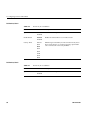
Table 1-2
Chassis Feature Summary
Feature
Description
E. Electronics Bay
(E-Bay)
The E-Bay contains the baseboard. The baseboard has the following major
components:
Up to four Intel Pentium III Xeon processors
Server Set III HE chipset
Up to sixteen PC/100-compliant Registered ECC SDRAM memory
modules, allowing up to 16 gigabytes of Error Checking and Correcting
(ECC) Synchronous Dynamic RAM
32-bit, 33 MHz, 5V PCI slots and several embedded devices
64-bit, 66/33 MHz, 3.3V hot-plug PCI slots and one embedded device
64-bit, 33 MHz, 5V hot-plug PCI slots and three embedded devices
ISA bus segment with three embedded devices
Two externally accessible USB ports
One IDE connector, supporting up to two ATA33 compatible devices
With the exception of the hot-plug PCI cards, the E-Bay can only be
accessed by qualified service technicians.
E1. E-Bay (Overhead An overhead view of the E-Bay
View)
E2. Hot-plug PCI
Slots
Six hot-plug PCI slots located within the E-Bay
NOTE: At this time, the Linux operating system does not support use of
the PCI Hot-Plug (PHP) feature. If you are running Linux, your system
must be turned off before installing or removing PCI boards. Windows
2000 requires drivers that are PHP compatible in order to use the PHP
feature.
Peripherals
Peripheral Bay
The chassis contains one peripheral bay for CD-ROM, DAT, and floppy drives. The
peripheral bay contains two smaller bays: a device bay and a media bay.
007-4274-001
7
1: Chassis Description
Device Bay
The device bay accommodates either a 5.25-inch CD-ROM or a DAT drive. Only
qualified service technicians should remove and install components in the device bay.
Media Bay
The media bay accommodates a 0.5-inch slim line floppy drive and 0.5-inch slim line
CD-ROM drive. Only qualified service technicians should remove and install
components in the media bay.
Hard Drive Bay
The chassis contains one hard drive bay. The hard drive bay can accommodate up to five
3.5-inch by 1.0-inch hot-swap Ultra 160 SCSI SCA hard disk drives
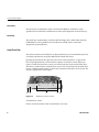
Opening the front bezel door provides user access to the hard drives. As part of the
hot-swap implementation, each hard drive requires a hard drive carrier. When you
remove a hard drive from the system, you remove both the carrier and the hard drive.
The drive is attached to the carrier by four screws. The carrier locks into the hard drive
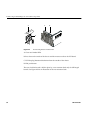
bay by a locking handle. Figure 1-4 shows the orientation of the drive in the carrier. The
carrier is upside down in this figure.
E
B
A
Figure 1-4
C
D
Hard Drive in Drive Carrier
A. Hard Drive Carrier
B. Two (of four) Fasteners Used to Attach Drive to Carrier
8
007-4274-001
Power Subsystem
C. Hard Drive
D. Connector
E. Locking Handle
Each hard drive is connected to an Ultra 160 SCSI hot-swap backplane. The backplane
provides industry-standard 80-pin SCA-2 connectors for each hard drive and accepts
10,000 RPM or slower drives that consume up to 23 watts of power. If another type or a
slower Ultra 160 SCSI SCA drive is installed, make sure that the drive meets these
backplane and carrier requirements.
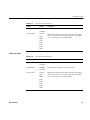
An LED above each hard drive displays the status of that hard drive. Table 1-3 shows the
hard drive LED state status.
Table 1-3
Hard Drive LED State Status
LED State
Status
Solid green
The hard drive is present and powered on.
Flashing green
The hard drive is active.
Solid yellow
There is an asserted fault status on the hard drive.
Flashing yellow
A rebuild of the hard drive is in progress.
Off
The hard drive is not powered on.
Power Subsystem
The SGI 1450 server uses a universal input-switching power subsystem (PSBS). This
subsystem provides up to 630 watts DC. The subsystem also minimizes the RMS current
drawn from each AC line by providing power-factor corrected AC input. The chassis can
be configured with one, two, or three 350-watt power supply modules, where each is
designed to minimize electromagnetic interference (EMI) and radio frequency
interference (RFI).
007-4274-001
9
1: Chassis Description
Warning: The total power requirement for the SGI 1450 server exceeds the 240 VA
energy hazard limit that defines an operator-accessible area. Only qualified service
technicians should access the processor, memory, power subsystem, and non
hot-plug/hot-swap areas of the baseboard.
The power subsystem consists of a power subsystem bay, with up to three power supply
modules. The power subsystem bay contains a power distribution board, which
manages the power delivered by all functional power supplies.
The power subsystem can operate in either a nonredundant or redundant manner.
Nonredundant operation means that you are using only one or two power supply
modules. If a power supply module ceases to function normally, the server system
cannot function properly, if at all. A minimal configuration supported by one power
supply module is one processor, four memory DIMMs, one hard drive slower than 10,000
RPM, one floppy drive, and one CD-ROM.
The SGI 1450 server uses a redundant (2+1) power subsystem. To form a (2+1) redundant
power subsystem, the subsystem parallels the DC output of one power supply module
with one or two other modules. If one module ceases to function normally, the remaining
modules provide power to the server system and the system continues to function
properly. Two power supply modules are required to provide power to a fully configured
SGI 1450 server. The third module provides redundancy. A fully configured system
includes four processors, 8 GB of memory, one floppy drive, one CD-ROM, five hard
drives, and eight PCI add-in boards.
System Cooling
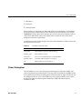
The SGI 1450 server uses up to six fans mounted in a fan board assembly in the middle
of the chassis between the E-Bay and peripheral device bays. The six fans are noted by
“A” in Figure 1-5.
Warning: The total power requirement for the SGI 1450 server exceeds the 240 VA
energy hazard limit that defines an operator-accessible area. Only qualified service
technicians should access the processor, memory, power subsystem, and non
hot-plug/hot-swap areas of the baseboard.
10
007-4274-001
System Cooling
A
Figure 1-5
Fan Board Assembly
The cooling system can operate in either a non redundant configuration or a redundant
configuration. A non redundant configuration includes just three fans. If any one of these
three fans ceases to function normally, environmental conditions within the chassis may
exceed the environmental regulations in this guide and the chassis may not function
normally. Three fans support any system configuration but without fan redundancy.
The SGI 1450 server uses all six fans to form a redundant cooling system. If one of the six
fans ceases to function normally, the remaining five fans adequately cool the system.
Using six fans supports any configuration up to the maximum configuration.
Air flows in through the front bezel over the power subsystem bay, the peripheral bay,
and the hard drive bay. The air then passes through the fan board assembly and to the
baseboard. Finally, the air exhausts through the rear and left side of the chassis.
Individual fan status indicators are located on the fan board mounted in the fan board
assembly. Fan failure is also indicated by the general fault LED located at the front of the
chassis.
Caution: The top cover must be on the system for proper cooling.
007-4274-001
11
1: Chassis Description
Chassis Front Controls and Indicators
Figure 1-6 shows the front panel controls and indicators.
A
B
D0
Figure 1-6
D1
D2
C
D3
Front Panel Controls and Indicators
The following front controls and indicators are shown in Figure 1-6.
A. Power on/off button: If you press this button when the system is off, you turn on the
power subsystem. If you press this button when the system is in sleep state, you activate
it. If you hold down the button for more than 4 seconds, you override the ACPI mode
and the power is turned off.
B. Reset button: If you press this button, you reset the system. If you hold down this
button for 4 seconds or more, push on the power button, and then release both the reset
and power buttons within one second of each other, the CMOS will be cleared.
Caution: The CMOS should be cleared only if it has been corrupted.
C. Sleep button: If the operating system supports ACPI and you press this button, the
operating system goes into sleep state (S1). If you press this button during sleep state, the
operating system becomes active. This system does not have a service mode.
D. Front panel LEDs from left to right:
D0. General System Fault LED: Yellow indicates a system failure.
D1. NIC activity LED: Green indicates NIC activity.
D2. HDD activity LED: Green indicates any system hard drive activity.
D3. Main Power LED: Solid green indicates the presence of DC power in the server.
Flashing green indicates that the system is in ACPI sleep mode.
12
007-4274-001
Rear Panel I/O Ports and Features
Rear Panel I/O Ports and Features
Figure 1-7 shows a detailed view of the rear panel I/O ports and features.
O
B
A
N
M
L K
Figure 1-7
G F
I
J
E
D
C
H
Rear Panel I/O Ports and Features
A. AC input power connector
B. External SCSI connector ports
C. Hot-plug 64-bit, 33 MHz PCI add-in board slots
D. Hot-plug 64-bit, 66/33 MHz PCI add-in board slots
E. Non-hot-plug 32-bit, 33 MHz PCI add-in board slots
These slots can also accept an Intelligent Chassis Management Bus (ICMB) SEMCONN
6-pin connector in/out
F. Video connector
G. USB ports 0 (upper) and 1 (lower), 4-pin connectors
H. NIC RJ45 connector
I. Serial port 2 (COM1), 9-pin RS-232 connector
J. IEEE 1284 compliant, 25-pin bi-directional parallel connector
K. Serial port 1 (COM1), 9-pin RS-232 connector
L. PS/2-compatible keyboard connector
M. PS/2-compatible mouse connector
N. HW push button
O. PCI green and amber LEDs inside the chassis
007-4274-001
13
Chapter 2
2. Baseboard Description
This chapter provides a description of the SGI 1450 server baseboard.
The topics covered in this chapter include:
007-4274-001
•
Baseboard Features
•
Baseboard Connector and Component Locations
•
Processor
•
Memory
•
Peripherals
•
Add-in Board Slots
•
DesotoE2 Hot-Plug PCI Controller
•
IDE Interface
•
USB Interface
•
SCSI Controller
•
IDE Controller
•
Server Management
15
2: Baseboard Description
Baseboard Features
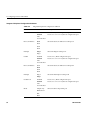
Table 2-1 provides a summary of the baseboard features.
Table 2-1
Baseboard Features
Feature
Description
Processor
Up to four Intel Pentium III Xeon processors, packaged in single edge
contact (S.E.C.) cartridges and installed in 330-pin SC330.1 compliant
edge connectors, operating at 1.8 V to 3.5 V. The baseboard's voltage
regulator is automatically programmed by the processor's VID pins to
provide the required voltage. The baseboard includes connectors for
three 8.3-compliant plug-in voltage-regulator modules (VRM).
Memory, dynamic
random access (DRAM)
Single plug-in module containing a 64- or 72-bit four-way-interleaved
pathway to main memory supporting SDRAM.
256 MB to 16 GB of error correcting code (ECC) memory. A minimum
of four DIMMs must be installed.
Video memory (DRAM)
Installed: 2 MB of video memory.
PCI Segment A bus
Two 184-pin, 3.3 V keyed, 64-bit PCI full-length expansion connectors
(66/33 MHz).
One DesotoE2 Hot-Plug PCI controller.
PCI Segment B bus
Four 184-pin, 5 V keyed, 64-bit PCI full-length expansion connectors
(33 MHz).
One Adaptec AIC-7899 dual channel SCSI-3 Ultra 160 SCSI controller.
One DesotoE2 Hot-Plug PCI controller.
PCI Segment C bus
Two 120-pin, 32-bit PCI half-length expansion connectors (33 MHz).
OSB4 I/O APIC.
PCI network interface controller.
ATI Rage IIc video controller.
PCI narrow/wide Adaptec AIC-7880 Ultra SCSI controller.
PCI Bus Master IDE
Interface
The baseboard supports Ultra DMA33 Synchronous Direct Memory
Access (DMA) mode transfers.
USB Interface
The baseboard provides a dual external USB connector.
Server Management
Thermal/voltage monitoring and error handling.
Front panel controls and indicators (LEDs).
16
007-4274-001
Baseboard Features
Table 2-1
Baseboard Features
Feature
Description
Graphics
ATI Rage IIc VGA Graphics Accelerator, along with video SGRAM
and support circuitry for an embedded SVGA video subsystem.
SCSI
Two embedded SCSI controllers:
Adaptec AIC-7899 SCSI controller-dual channel wide Ultra II/Ultra
160 SCSI controller.
Adaptec AIC-7880 SCSI controller-PCI narrow/wide Ultra SCSI
controller.
System I/O
PS/2-compatible keyboard and mouse ports, 6-pin DIN.
Advanced parallel port, supporting Enhanced Parallel Port (EPP)
levels 1.7 and 1.9, ECP, compatible 25-pin.
VGA video port, 15-pin.
Two serial ports, 9-pin (serial port A is the top connector).
Form Factor
007-4274-001
16 x 13 inches, ATX-style backpanel I/O.
17
2: Baseboard Description
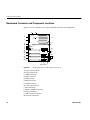
Baseboard Connector and Component Locations
Figure 2-1 shows a detailed view of the baseboard connectors and components.
A
B
Z
JJ
C
Y
X
W
V
U
T
AA
S
BB
R
CC
Q
DD
II
J
D
E
HH
F
K
L
M
G
H
O
N
P
EE FF GG I
Figure 2-1
Baseboard Connector and Component Locations
A. Legacy Narrow SCSI
B. Legacy Wide SCSI
C. SMM Connector
D. IMB Connector
E. HDD Activity
F. HPIB Connector
G. ICMB Connector
H. Connector not Used
I. Lithium Battery
J. Memory Module Connector
K. Video Connector
L. USB, External Connector
M. Network Connector
18
007-4274-001
Processor
N. Parallel Connector
O. COM1, COM2 Connector
P. Keyboard/Mouse
Q. Main Power 1
R. Auxiliary Power
S. Main Power 2
T. SMBus
U. Front Panel
V. IDE Connector
W. Floppy Connector
X. Configuration Jumpers
Y. Ultra 160 SCSI A
Z. Ultra 160 SCSI B
AA. Processor #1
BB. Processor #2
CC. Processor #3
DD. Processor #4
EE. Voltage Regulator Module (VRM) Connector #2
FF. Voltage Regulator Module (VRM) Connector #3
GG. Voltage Regulator Module (VRM) Connector #4
HH. 32-bit, 33 MHz Half-length PCI Slots
II. 64-bit, 66/33 MHz Hot-Plug PCI Slots
JJ. 64-bit, 33 MHz Hot-Plug PCI Slots
Processor
Each Intel Pentium III Xeon processor is packaged in a single edge contact (S.E.C.)
cartridge. The cartridge includes the processor core with an integrated 32 KB primary
(L1) cache, the secondary (L2) cache, a thermal plate, and a plastic cover.
The processor core and L2 cache components are on a pre-assembled printed circuit
board, approximately 5 inches by 6 inches. The L2 cache and processor core L1 cache
interface use a private bus isolated from the processor host bus. The L2 cache bus
operates at the processor core frequency.
007-4274-001
19
2: Baseboard Description
Each S.E.C. cartridge connects to the baseboard through a 330-pin SC330.1 compliant
edge connector. A retention module attached to the baseboard secures the cartridge.
Depending on configuration, the system supports one to four processors.
The processor external interface is multiprocessor (MP) ready and operates at 100 MHz.
The processor contains a local Advanced Configuration and Power Interface (APIC) unit
for interrupt handling in multiprocessor (MP) and uniprocessor (UP) environments.
The L2 cache is located on the substrate of the S.E.C. cartridge. The cache:
•
Is offered in 1 MB and 2 MB configurations
•
Has Error Correcting Code (ECC)
•
Operates at the full core clock rate
Memory
Main memory resides on an add-in board, called a memory module. The memory
module contains slots for 16 DIMMs, each of which must be at least 64 MB, and is
attached to the baseboard through a 330-pin connector, called the Memory Expansion
Card Connector (MECC). The memory module supports PC-100 compliant registered
ECC SDRAM memory modules. The ECC used for the memory module is capable of
correcting single-bit errors (SBEs) and detecting 100 percent of double-bit errors over one
code word. Nibble error detection is also provided.
System memory begins at address 0 and is continuous (flat addressing) up to the
maximum amount of DRAM installed (exception: system memory is non contiguous in
the ranges defined as memory holes using configuration registers). The system supports
both base (conventional) and extended memory.
•
Base memory is located at addresses 00000h to 9FFFFh (the first 1 MB).
•
Extended memory begins at address 0100000h (1 MB) and extends to 3FFFFFFFFh
(16 GB), which is the limit of supported addressable memory. The top of physical
memory is a maximum of 16 GB (to 3FFFFFFFFh).
Memory amounts from 256 MB to 16 GB of DIMM are supported, with a 64/72-bit
four-way-interleaved pathway to main memory, which is also located on the module.
Therefore, data transfers between MADPs and DIMMs is in four-way interleave fashion.
Each of the four DIMMs must be populated in a bank. The 16 slots are divided into four
banks of four slots each. They are labeled A through D. Bank A contains DIMM sockets
20
007-4274-001
Memory
A1, A2, A3, and A4. Banks B, C, and D each contain 4 DIMM sockets and are named in
the same fashion. There are silk screens on the module next to each DIMM socket to label
its bank number. For the best thermal results, populate the banks from A to D. For
example, populate bank A and then bank B. For best performance results, populate
adjacent banks. For example, populate bank A and then bank C.
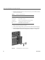
Figure 2-2 shows a detailed view of the memory module slots.
A3
C3
B3
D3
A1
C1
B1
D1
A4
C4
B4
D4
A2
C2
B2
D2
X
Figure 2-2
Y
Z
Memory Module DIMM Installation Sequence
X. One of sixteen DIMM sockets
Y. One of four Memory Address Data Paths (MADPs)
Z. Memory Expansion Card Connector (MECC)
Each slot is identified by another notation. Sockets A1 through A4 are identified as J1
through J4 respectively. Sockets B1 through B4 are identified as J5 through J8. Sockets C1
through C4 are identified as J9 through J12. Sockets D1 through D4 are identified as J13
through J16.
Some operating systems and application programs use base memory while others use
both conventional and extended memory. Examples are:
•
007-4274-001
Base memory: Microsoft MS-DOS, IBM OS/2, Microsoft Windows NT, and various
UNIX systems
21
2: Baseboard Description
•
Conventional and extended memory: IBM OS/2, Microsoft Windows NT, and
various UNIX systems
MS-DOS does not use extended memory; however, some MS-DOS utility programs like
RAM disks, disk caches, print spoolers, and windowing environments use extended
memory for better performance.
The BIOS automatically detects, sizes, and initializes the memory array, depending on
the type, size, and speed of the installed DIMMs, and reports memory size and allocation
to the system via configuration registers.
Peripherals
Super I/O Chip (SIO)
The National PC97317VUL Super I/O Plug and Play Compatible with ACPI Compliant
Controller/Extender device supports two serial ports, one parallel port, a diskette drive,
and a PS/2-compatible keyboard and mouse. The system provides the connector
interface for each port.
Serial Ports
Both serial ports can be relocated. Each serial port can be set to one of four different
COMx ports, and each can be enabled separately. When disabled, serial port interrupts
are available to add-in boards.
Parallel Port
The baseboard provides a 25-pin Parallel Port connector. The SIO chip provides an IEEE
1284-compliant, 25-pin, bi-directional parallel port. BIOS programming of the SIO
registers enable the parallel port and determine the port address and interrupt. When
disabled, the interrupt is available to add-in cards.
22
007-4274-001
Add-in Board Slots
Add-in Board Slots
The baseboard has eight slots for PCI add-in boards supported by three PCI bus
segments called PCI-A, PCI-B, and PCI-C. There are two slots on PCI-A, four slots on
PCI-B, and two slots on PCI-C. PCI-C supports half-length boards (5.6 inches to 6.3
inches) only; the other slots support full-length boards.
The two slots for the PCI bus segment PCI-C consume a maximum of 375 mA of standby
current on a 3.3 V Aux power line. The remaining six slots do not have any 3.3 V Aux
capabilities.
Both PCI segments A and B allow you to add, remove, or replace PCI add-in boards
installed in their slots without interrupting normal operation or powering down the
system. To use this PCI Hot-Plug (PHP) feature, a server system requires PCI Hot-Plug
software and PCI Hot-Plug capable add-in boards. PCI Hot-Plug software usually is a
driver loaded for a specific operating system.
Note: At this time, the Linux operating system does not support use of the PCI Hot-Plug
(PHP) feature. If you are running Linux, your system must be turned off before installing
or removing PCI boards. Windows 2000 requires drivers that are PHP compatible in
order to use the PHP feature.
Each Hot-Plug PCI slot has two LEDs. The green LED indicates the state of power on for
each slot. The amber LED indicates an error condition with that slot.
The table below summarizes typical LED states that you may encounter during a
system's operation.
Table 2-2
007-4274-001
Slot State Indicators
LED State
Status
Green On
Amber Off
The slot is on and functioning normally.
Green On
Amber On
The slot is on and the card requires attention.
Green Off
Amber On
The slot is off and the card in the slot requires
attention.
23
2: Baseboard Description
Table 2-2
Slot State Indicators
LED State
Status
Green blinking
Amber Off
Slot power is transitioning from either ON to
OFF or OFF to ON.
Off
The slot is powered off.
PCI features include:
•
33 or 66 MHz bus speed
•
32-bit or 64-bit memory addressing
•
3.3 V or 5 V signaling environment
•
Independent bus structure supports transfers up to 1.2 GB/sec.
•
8-, 16-, 32-, or 64-bit data transfers
•
Plug-and-Play ready
•
Parity enabled
DesotoE2 Hot-Plug PCI Controller
Note: At this time, the Linux operating system does not support use of the PCI Hot-Plug
(PHP) feature. If you are running Linux, your system must be turned off before installing
or removing PCI boards. Windows 2000 requires drivers that are PHP compatible in
order to use the PHP feature.
The DesotoE2 Hot-Plug PCI controller is a 32-bit PCI bus agent that operates at either 33
or 66 MHz. The PCI controller manages PHP functionality for the PCI segment it resides
on. There is a DesotoE2 controller on PCI segments A and B. The DesotoE2 PHP
controller is:
24
•
ACPI compliant
•
Compatible with Compaq's PHP controller design
•
Supports either a 3.3 V or 5 V PCI bus
007-4274-001
IDE Interface
The DesotoE2 is responsible for:
•
Managing power application and removal to individual slots
•
Properly resetting newly added PCI boards prior to bringing the board online
•
Managing connection and disconnection of the PCI signals between the PCI bus
and the add-in board
•
Managing seamless addition and removal of individual PCI add-in boards without
impacting bus functionality
IDE Interface
The Open South Bridge (OSB4) acts as a PCI-based fast IDE controller. The controller
supports programmed I/O and bus master transfers. While the OSB4 supports two IDE
channels, the baseboard uses only the primary IDE channel and provides a single 40-pin
IDE connector.
USB Interface
The baseboard provides a dual external USB connector for the back panel of a server
system. The connector is defined by the USB Specification, Revision 1.0. Both ports
function identically with the same bandwidth.
Network Interface Controller (NIC)
The baseboard supports a 10BASE-T/100BASE-TX network subsystem based on the
Intel 82559 Fast Ethernet Multifunction PCI/CARDBus controller. The Intel 82559
controller is a highly integrated PCI LAN controller in a 196-pin Ball Grid Array (BGA)
supporting 10 or 100 Mbps fast Ethernet networks.
Supported network features include:
007-4274-001
•
Glueless 32-bit PCI Bus Master Interface compatible with the PCI Local bus
Specification
•
82596-like chained memory structure with improved dynamic transmit chaining for
enhanced performance
25
2: Baseboard Description
•
Programmable transmit threshold for improved bus utilization
•
Early receive interrupt for concurrent processing of receive data
•
On-chip counters for network management
•
Auto-detect and auto-switching for 10 or 100 Mbps network speeds
•
Support for both 10 and 100 Mbps networks
•
Integrated physical interface to TX magnetics
•
The magnetics component terminates the 100BASE-TX connector interface and a
flash device stores the network ID
Video
The baseboard provides an ATI Rage IIc VGA Graphics Accelerator, along with video
Synchronous Graphics RAM (SGRAM) and support circuitry for an embedded Super
VGA (SVGA) video subsystem. The ATI Rage IIc chip contains an SVGA video controller,
clock generator, BitBLT engine, and a RAM digital-to-analog Converter (RAMDAC) in a
208-pin PQFP. One 256K x 32 SGRAM chip provides 2 MB of 10-ns video memory. The
baseboard does not support adding video memory to the system. The SVGA subsystem
supports a variety of modes, up to 1600 x 1200 resolution, or up to 16.7 M colors.
The SVGA subsystem also supports analog VGA monitors, single- and multi-frequency,
interlaced and non-interlaced, up to 100 Hz vertical retrace frequency. The baseboard
provides a standard 15-pin VGA connector and video blanking logic for server
management console redirection support.
Depending on the environment, the controller displays up to 16.7 M colors in some video
resolutions.
SCSI Controller
The baseboard includes two SCSI controllers. A dual function SCSI controller (Adaptec
AIC-7899) is on the PCI-B bus, and a PCI wide SCSI controller (Adaptec AIC-7880) is on
the PCI-C bus.
26
007-4274-001
SCSI Controller
The Adaptec AIC-7899 SCSI controller contains two independent SCSI channels that
share a single PCI bus master interface as a multifunction device, packaged in a 352-pin
ball grid array (BGA). Internally, each channel is identical, capable of operations using
either 16-bit Single-Ended (SE) or Low Voltage Differential (LVD) SCSI providing 40
MBps (Ultra-wide SE), 80 MBps (Ultra 2), or 160 MBps (Ultra 160).
Both channels attach to 68-pin 16-bit differential SCSI connector LVD interfaces. Each
channel has its own set of PCI configuration registers and SCSI I/O registers. As a PCI
bus master, the AIC-7899 controller supports burst data transfers on PCI up to the
maximum rate of 266 MBps using on-chip buffers.
The Adaptec AIC-7880 controller contains a single SCSI channel with full-featured PCI
bus master interface in a 160-pin Plastic Quad Flat Pack (PQFP). The controller supports
either 8- or 16-bit Fast SCSI providing 10 MBps or 20 MBps (Fast-10) throughput, or
Fast-20 SCSI that can burst data at 20 MBps or 40 MBps. As a PCI 2.1 bus master, the
AIC-7880 controller supports burst data transfers on PCI up to the maximum rate of 133
MBps using the on-chip 256-byte FIFO.
The AIC-7880 implementation offers 8-bit or 16-bit SCSI connectors and operation at data
transfer rates of 10, 20, or 40 MBps. The AIC-7880 controller also offers active negation
outputs, controls for external differential transceivers, a disk activity output, and a SCSI
terminator power-down control. Active negation outputs reduce the chance of data
errors by actively driving both polarities of the SCSI bus, avoiding indeterminate voltage
levels and common-mode noise on long cable runs. The SCSI output drivers can directly
drive a 48-mA single-ended SCSI bus with no additional drivers. The SCSI segment can
support up to 15 devices.
The AIC-7880 controller can be used as an 8-bit controller via the narrow, 50-pin
connector and as a 16-bit controller via the wide, 68-pin connector. As a result, the
AIC-7880 controller is not always at one end of the SCSI bus, and termination is
controlled through some simple circuitry. The circuitry senses whether there is a device
attached through the narrow 50-pin connector or the wide 68-pin connector. When there
are devices attached to both connectors, the termination is on for the upper 8 bits of data
and the parity bit associated with these data lines. All other signals are not terminated on
board and are terminated by the devices attached through the connector. When there is
a device attached to only one connector (either wide or narrow), all on-board termination
is on.
007-4274-001
27
2: Baseboard Description
IDE Controller
IDE is a 16-bit interface for intelligent disk drives with AT disk controller electronics
onboard. The Open South Bridge (OSB4) acts as a PCI-based fast IDE controller. The
device controls:
•
PIO and IDE DMA/bus master operations
•
Mode 4 timings
•
Transfer rates up to 33 MBbs.
•
Ultra DMA 33 capacity
•
Buffering for PCI/IDE burst transfers
•
Master/slave IDE mode
•
Up to two drives for one IDE channel
Note: An IDE signal cable can be connected up to the IDE connector on the baseboard.
However, the maximum length of the cable is 18 inches. The cable supports up to two
devices, one at the end of the cable and the other six inches from the end.
Keyboard and Mouse
The PS/2-compatible keyboard and mouse connectors are mounted in a single-stacked
housing with the mouse connector over the keyboard. Externally, they appear as two
connectors.
The user can plug in the keyboard and mouse to either connector before powering up the
system. The BIOS detects these and configures the keyboard controller accordingly.
The keyboard controller is functionally compatible with the Intel 8042A micro controller.
The system can be locked automatically if no keyboard or mouse activity occurs for a
predefined length of time, if specified through the SSU. Once the inactivity (lockout)
timer has expired, the keyboard and mouse do not respond until the previously stored
password is entered.
28
007-4274-001
Server Management
Server Management
Server management features are implemented using one micro controller called the
Baseboard Management Controller (BMC).
The BMC and associated circuitry are powered from 5 V standby, which remains active
when system power is switched off. The BMC is IPMI 1.0 compliant.
The primary function of the BMC is to autonomously monitor system platform
management events and log their occurrence in the nonvolatile System Event Log (SEL).
The BMC is compliant to the Intelligent Platform Management Interface Specification,
Version 1.0. These events include over-temperature and over-voltage conditions, fan
failure, or chassis intrusion. While monitoring, the BMC maintains the nonvolatile
Sensor Data Record Repository (SDRR), from which run-time information can be
retrieved. The BMC provides an interface to SDRR information, so software running on
the server can poll and retrieve the current status of the platform. A shared register
interface is defined for this purpose.
Field service personnel can retrieve SEL contents after system failure for analysis by
using system management tools like Intel LANDesk Server Manager, Intel Server
Control (ISC), or Direct Platform control (DPC). Because 5 V standby provides power the
BMC, SEL (and SDRR) information is also available via the interperipheral management
bus (IPMB). During monitoring, the BMC performs the following functions:
007-4274-001
•
Baseboard temperature and voltage monitoring
•
Processor presence monitoring and FRB control
•
Baseboard fan failure detection and indicator control
•
SEL interface management
•
Sensor Data Record Repository (SDRR) interface management
•
SDR/SEL timestamp clock
•
Baseboard Field Replaceable Unit (FRU) information interface
•
System management watchdog timer
•
SMI/NMI Status Monitor
•
Front panel NMI handling
•
Event receiver
•
IPMB Management Controller Initialization Agent
29
2: Baseboard Description
•
Secure mode control, front panel lock/unlock initiation, and video blank and
diskette write protect monitoring and control
•
ACPI Support
•
Direct Platform Control (DPC) support
•
Platform Event Paging (PEP) / Platform Event Filtering (PEF)
•
Power distribution board monitoring
•
Speaker beep capability. When the system is powered up, this capability is used to
indicate conditions such as “empty processor slot”
•
Pentium III Xeon processor SEEPROM interface for Processor Information ROM
(PIROM) and Scratch EEPROM access
•
Processor temperature monitoring
•
Hot-Plug PCI slot status reporting
•
Processor bus speed setting
•
Chassis fan failure light control
•
Chassis power fault light control
•
Chassis power light control
Software Locks via the SSU or BIOS Setup
The SSU provides a number of security features to prevent unauthorized or accidental
access to the system. Once the security measures are enabled, access to the system is
allowed only after the user enters the correct password(s). For example, the SSU allows
you to:
30
•
Enable the keyboard lockout timer so the server requires a password to reactivate
the keyboard and mouse after a specified time-out period of 1 to 120 minutes
•
Set and enable administrator and user passwords
•
Set secure mode to prevent keyboard or mouse input and to prevent use of the front
panel reset and power switches
•
Activate a hot key combination to enter secure mode quickly
•
Disable writing to the diskette drive when secure mode is set
007-4274-001
Software Locks via the SSU or BIOS Setup
Using Passwords
If a user password is set and enabled, but an administrator password is not set, a user
password must be entered to boot the system and run the SSU.
If both a user and administrator password are set:
•
Enter either one to boot the server and enable the keyboard and mouse
•
Enter the administrator password to access the SSU or BIOS Setup to change the
system configuration
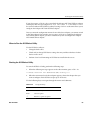
Secure Mode
Configure and enable the secure boot mode by using the SSU. When secure mode is in
effect:
•
The system can boot and the operating system runs, but the user password must be
entered for a user to use the keyboard or mouse
•
The system cannot be turned off or reset from the front panel switches
Secure mode has no effect on functions enabled via the Server Manager Module or power
control via the real-time clock (RTC).
Taking the system out of secure mode does not change the state of system power. That is,
if you press and release the power switch while secure mode is in effect, the system will
not power off when secure mode is later removed. However, if the front panel power
switch remains depressed when secure mode is removed, the system will power off.
Summary of Software Security Features
Table 2-3 lists the software security features and describes what protection each offers. In
general, to enable or set the features listed here, the SSU must be run and configured with
the Security Menu (described in this manual in “Security Menu” on page 56.) The table
also refers to other SSU menus and to the Setup utility. For greater detail, see Chapter 3.
007-4274-001
31
2: Baseboard Description
Table 2-3
Software Security Features
Feature
Description
Secure mode
How to enter secure mode:
Setting and enabling passwords automatically places the system in
secure mode.
If a hot key combination is set (through the SSU or Setup), the
system can be secured simply by pressing the key combination.
This means that the user does not have to wait for the inactivity
time-out period.
When the system is in secure mode:
The server can boot and run the operating system, but mouse and
keyboard input is not accepted until the user password is entered.
At boot time, if a CD is detected in the CD-ROM drive or a diskette
in drive A, the system prompts for a password. When the
password is entered, the server boots from CD or diskette and
disables the secure mode.
If there is no CD in the CD-ROM drive or diskette in drive A, the
server boots from drive C and automatically goes into secure
mode. All enabled secure mode features go into effect at boot time.
To leave secure mode, enter the correct password(s).
Disable writing to diskette
In secure mode, the server will not boot from or write to a diskette
unless a password is entered. To set this feature, use the SSU
Security Subsystem Group.
To write protect access to diskette whether the server is in secure
mode or not, use the Setup main menu, Floppy Options, and
specify Floppy Access as read only.
Disable the power and reset
buttons
32
Power and reset buttons are always disabled when the server is in
secure mode.
007-4274-001
Software Locks via the SSU or BIOS Setup
Table 2-3
Software Security Features
Feature
Description
Set a time out period so that Specify and enable an inactivity time-out period of from 1 to 120
keyboard and mouse input minutes.
are not accepted.
If no keyboard or mouse action occurs for the specified period,
attempted keyboard and mouse input will not be accepted.
Also, screen can be blanked, The monitor display will go blank, and the diskette drive will be
and writes to diskette can be write protected (if these security features are enabled through
inhibited
Setup or the SSU and using onboard video).
To resume activity, enter the user password.
Control access to using the
SSU: set administrative
password
To control access to setting or changing the system configuration,
set an administrative password and enable it through Setup or the
SSU.
If both the administrative and user passwords are enabled, either
can be used to boot the server or enable the keyboard and/or
mouse, but only the administrative password will allow Setup and
the SSU to be changed.
To disable a password, change it to a blank entry or press Ctrl-D in
the Change Password menu of the Administrative Password
Option menu found in the Security Subsystem Group.
If you cannot access Setup or the SSU to clear the password,
change the Clear Password jumper. See “CMOS Clear Jumper” in
the SGI 1450 Server Maintenance Guide.
Control access to the system To control access to using the system, set a user password and
other than SSU: set user
enable it through Setup or the SSU.
password
To disable a password, change it to a blank entry or press Ctrl-D in
the Change Password menu of the User Password Option menu
found in the Security Subsystem Group.
If you cannot access Setup or the SSU to clear the password,
change the Clear Password jumper. See “CMOS Clear Jumper” in
the SGI 1450 Server Maintenance Guide.
007-4274-001
33
2: Baseboard Description
Table 2-3
34
Software Security Features
Feature
Description
Boot without keyboard
The system can boot with or without a keyboard. During POST,
before the system completes the boot sequence, the BIOS
automatically detects and tests the keyboard if it is present and
displays a message. There is no entry in the SSU to enable or
disable a keyboard.
Specify the boot sequence
The sequence specified on the menu in the SSU MultiBoot Group
will determine the boot order. If secure mode is enabled (a user
password is set), then the user is prompted for a password before
the server fully boots. If secure mode is enabled and the Secure
Boot Mode option is also enabled, the server fully boots but
requires a password before accepting any keyboard or mouse
input.
007-4274-001
Chapter 3
3. Configuring Software and Utilities
This chapter describes the Power-On Self Test (POST) and system configuration utilities.
Table 3-1 briefly describes the utilities and refers to the page where the information can
be found.
Table 3-1
Configuration Utilities
Utility
Description and brief procedure
Page
BIOS Setup
If the system does not have a diskette drive, or the drive “Using BIOS Setup” on
is disabled or misconfigured, use Setup to enable it.
page 38
Or, you can move the CMOS jumper on the system
board from the default setting (Protect CMOS memory)
to the Clear setting; this will allow most system
configurations to boot. For the procedure to do this, see
the 1450 Server Maintenance Guide.
007-4274-001
Changing Boot Use to change the boot device priority temporarily or
Device Priority permanently.
“Changing the Boot
Device Priority
Temporarily” on
page 63
SCSISelect
Utility
Use to configure the SCSI controllers in the system.
“Running the
SCSISelect Utility” on
page 64
Adaptec SCSI
Utility
Use to configure or view the settings of the SCSI host
adapters and onboard SCSI devices in the system.
“Configuring the
Adaptec AIC-7880 SCSI
Adapter” on page 66
35
3: Configuring Software and Utilities
Table 3-1
Configuration Utilities
Utility
Description and brief procedure
Page
Server Setup
Utility (SSU)
Use for extended system configuration of onboard
“Using the System
resources and add-in boards, viewing the system event Setup Utility (SSU)” on
log (SEL), setting boot device priority, or setting system page 68
security options.
The SSU can be run from either the configuration
software CD or from a set of bootable diskettes. You can
create the diskettes from the CD.
Information entered via the SSU overrides information
entered via Setup.
FRUSDR Load Use to update the Field Replacement Unit (FRU),
Utility
Sensor Data Record (SDR), and Desktop Management
Interface (DMI) flash components.
“FRU and SDR Load
Utility” on page 71
BIOS Update
Utility
“Upgrading the BIOS”
on page 75
Use to update the BIOS or recover from a corrupted
BIOS update.
Firmware
Use to update BMC flash ROM.
Update Utility
“Using the Firmware
Update Utility” on
page 78
Hot Keys
Table 3-2 shows the key combinations used to perform certain operations.
Table 3-2
Hot Keys
To do this:
Press these keys
Clear memory and reload the operating system—this is <Ctrl+Alt+Del>
a system reset.
36
Secure your system immediately.
<Ctrl+Alt>+hot key (Set your hot key
combination using the SSU or Setup.)
Enter the Adaptec SCSI Utility during BIOS POST.
<Ctrl+A>
007-4274-001
Power-On Self Test (POST)
Table 3-2
Hot Keys
To do this:
Press these keys
Enter BIOS Setup during BIOS POST.
F2
Abort memory test during BIOS POST.
Esc (Press while BIOS is updating
memory size on screen.)
Power-On Self Test (POST)
Each time you turn on the system, the BIOS begins execution of the Power-On Self Test
(POST). POST discovers, configures, and tests the processors, memory, keyboard, and
most installed peripheral devices. The length of time needed to test memory depends on
the amount of memory installed. POST is stored in flash memory.
1.
Turn on your video monitor and system. After a few seconds, POST begins to run
and a splash screen is displayed.
2. While the splash screen is displayed, you can either:
•
Press <F2> to enter the BIOS Setup (see “Using BIOS Setup” on page 38)
OR
•
press <Esc> to change the boot device priority for this boot only (see “Changing
the Boot Device Priority Temporarily” on page 63).
3. After pressing <F2> or <Esc> during POST, you can press <Ctrl+A> to run the
SCSISelect Utility. For more information, see “Running the SCSISelect Utility” on
page 64.
4. If you do not press <F2> or <Esc> and do not have a device with an operating
system loaded, the boot process continues and the system beeps once. The
following message is displayed:
Operating System not found
5. At this time, pressing any key causes the system to attempt a reboot. The system
searches all removable devices in the order defined by the boot priority.
6. If you want to boot from a hard drive loaded with an operating system, make sure
that the hard drive is installed and push the Reset button on the front panel.
007-4274-001
37
3: Configuring Software and Utilities
Using BIOS Setup
This section describes the BIOS Setup options. Use Setup to change the system
configuration defaults. You can run Setup with or without an operating system being
present. Setup stores most of the configuration values in battery-backed CMOS; the rest
of the values are stored in flash memory. The values take effect when the system is
booted. POST uses these values to configure the hardware; if the values and the actual
hardware do not agree, POST generates an error message. You must then run Setup to
specify the correct configuration.
Run Setup: Run Setup to modify any standard PC-AT baseboard feature such as:
•
Select diskette drive
•
Select parallel port
•
Select serial port
•
Set time/date (to be stored in RTC)
•
Configure hard drive(s)
•
Specify boot device sequence
•
Enable SCSI BIOS
Run SSU, not Setup: Run the SSU instead of Setup to do the following:
•
Enter or change information about a board
•
Alter system resources (for example, interrupts, memory addresses, I/O
assignments) to user-selected choices instead of choices selected by the BIOS
resource manager
Starting Setup
Setup can be entered under several conditions:
38
•
When you turn on the system, after POST completes the memory test.
•
When you reboot the system by pressing <Ctrl+Alt+Del> while at the DOS
operating system prompt.
007-4274-001
Using BIOS Setup
•
When you have moved the CMOS jumper on the baseboard to the “Clear CMOS”
position (enabled); for a step-by-step procedure, see the 1450 Server Maintenance
Guide.
In the preceding three conditions, the following prompt is displayed:
Press <F2> to enter SETUP
In a fourth condition, when CMOS/NVRAM has been corrupted, the following prompts
are displayed, but not the <F2> prompt:
Warning: cmos checksum invalid
Warning: cmos time and date not set
In this condition, the BIOS loads default values for CMOS and attempts to boot.
Setup Menus
Setup has six major menus and several submenus:
1.
Main Menu
•
Primary IDE Master and Slave Adapters
•
Processor Settings Information
2. Advanced Menu
007-4274-001
•
PCI Configuration
–
Embedded Video Controller
–
Embedded Legacy SCSI
–
Embedded Dual Ultra 160 SCSI
–
Embedded NIC
–
PCI Devices, Slots 1 - 8
–
Hot-Plug PCI Control
•
Integrated Peripheral Configuration
•
Advanced Chipset Control
39
3: Configuring Software and Utilities
3. Security Menu
•
Passwords
•
Lockout Features
4. Server Menu
•
System Management
•
Console Redirection
•
EMP Configuration
•
PEP Management
5. Boot Menu
•
Boot Device Priority
•
Hard Drive
•
Removable Devices Selections
6. Exit Menu
Table 3-3 shows the keys used to navigate through the Setup menus and submenus.
Table 3-3
40
Navigation Keys
To:
Press:
Get general help
<F1> or <Alt+H>
Move between menus
←→
Go to the previous item
¦¦↑
Go to the next Item
↓
Change the value of an item
+ or -
Select an item or display a submenu
<Enter>
Leave a submenu or exit Setup
<Esc>
Reset to Setup defaults
<F9>
Save and exit Setup
<F10>
007-4274-001
Using BIOS Setup
See Table 3-4 if an option is shown but you cannot select or move the option.
Table 3-4
Selecting Options
When you see this:
What it means:
On screen, an option is shown but you
cannot select it or move to that field.
You cannot change or configure the option in that
menu screen for one of the following reasons:
The option is auto-configured or auto-detected.
You must use a different Setup screen to change it.
You must use the SSU.
On screen, the phrase Press Enter appears Press <Enter> to display a submenu that is either
next to the option.
a separate full-screen menu or a pop-up menu
with one or more choices.
The rest of this section lists the features that display on screen after you press <F2> to
enter Setup. Not all of the option choices are described, because (1) a few are not
user-selectable but are displayed for your information, and (2) many of the choices are
relatively self-explanatory.
Main Menu
Table 3-5 lists the selections you can make on the Main Menu itself. Use the submenus
for other selections. Default values are in bold.
Table 3-5
Main Menu
Feature
Choices
Description
System Time
HH:MM:SS
Sets the system time.
System Date
MM/DD/YYYY
Sets the system date.
Legacy Diskette A:
Disabled
Selects the diskette type.
1.44/1.25 MB 3.5 in.
2.88 MB 3.5 in.
Legacy Diskette B:
Disabled
Selects the diskette type.
1.44/1.25 MB 3.5 in.
2.88 MB 3.5 in.
007-4274-001
41
3: Configuring Software and Utilities
Main Menu
Table 3-5
Feature
Choices
Description
Primary IDE Master
N/A
Enters submenu.
Primary IDE Slave
N/A
Enters submenu.
Processor Settings
N/A
Enters submenu.
Language
English (US)
Selects which language BIOS displays.
French Spanish
German
Italian
Japanese (Kanji)
NOTE: Serial redirection does not work
with Kanji.
Primary IDE Master and Slave Submenu
In the following table, the features other than “Type” appear only for Type Auto if a drive
is detected.
Table 3-6
Primary IDE Master and Slave Submenu
Feature
Choices
Description
Type
User
User allows the manual entry of all fields described below.
Auto
Auto allows the system to attempt auto-detection of the
drive type.
CD-ROM
ATAPI Removable CD-ROM allows the manual entry of fields described below.
42
Multi-Sector
Transfers
Disabled
Determines the number of sectors per block for multisector
2, 4, 8, or 16 sectors transfers.
For Type Auto, this field is informational only.
LBA Mode
Control
Disabled
32 Bit I/O
Disabled
Enabling allows 32-bit IDE data transfers.
Enabled
For Type Auto, this field is informational only.
For Type Auto, this field is informational only.
Enabled
007-4274-001
Using BIOS Setup
Table 3-6
Primary IDE Master and Slave Submenu
Feature
Choices
Description
Transfer
Mode
Standard
Selects the method for moving data to and from the drive.
Fast PIO 1
For Type Auto, this field is informational only.
Fast PIO 2
Fast PIO 3/DMA 1
Fast PIO 4/DMA 2
Ultra DMA
Mode
Disabled
Enabled
For use with Ultra DMA drives. Ultra DMA is disabled by
default to work around a chipset erratum.
For Type Auto, this field is informational only.
007-4274-001
43
3: Configuring Software and Utilities
Processor Settings Submenu
Table 3-7
Processor Settings Submenu
Feature
Choices
Description
Processor Retest
No
Select yes for the BIOS to clear historical processor
status and retest all processors on the next boot.
Yes
Processor Serial Number
Memory Cache
Disabled
If enabled, the system records the serial number of
each processor.
Enabled
Controls cacheability. For debugging purposes only.
Enabled
Disabled
44
Measured Processor Speed
N/A
Reports the speed of Processor 1.
Processor 1 CPU ID
N/A
Reports Stepping for Processor 1.
Processor 1 L2 Cache Size
N/A
Reports L2 Cache Size for Processor 1. This feature is
hidden if processor 1 is absent or disabled.
Processor 2 CPU ID
N/A
Reports Stepping for Processor 2.
Processor 2 L2 Cache Size
N/A
Reports L2 Cache Size for Processor 2. This feature is
hidden if processor 2 is absent or disabled.
Processor 3 CPU ID
N/A
Reports Stepping for Processor 3.
Processor 3 L2 Cache Size
N/A
Reports L2 Cache Size for Processor 3. This feature is
hidden if processor 3 is absent or disabled.
Processor 4 CPU ID
N/A
Reports Stepping for Processor 4.
Processor 4 L2 Cache Size
N/A
Reports L2 Cache Size for Processor 4. This feature is
hidden if processor 4 is absent or disabled.
007-4274-001
Using BIOS Setup
Advanced Menu
You can make the following selections on the Advanced Menu itself. See the following
submenu tables for information on a particular submenu.
Table 3-8
Advanced Menu
Feature
Choices
Description
PCI Configuration
N/A
Enters submenu.
Integrated Peripheral
Configuration
N/A
Enters submenu.
Advanced Chipset Control
N/A
Enters submenu.
Reset Configuration Data
No
Yes
Select Yes to clear the system configuration data
during next boot. System automatically resets to No
in next boot.
Yes
If Yes, the ACPI sleep button is activated.
Enable Sleep Button
No
System Wake-up Feature
Delay on Option ROMs
Disabled
Enabled
If enabled, the system will be powered up upon
receiving a LAN wake-up event, ring on
COM1/COM2, or PME interrupt from a PCI board.
Enabled
Enables a short delay after an Option ROM scan.
Disabled
PCI Configuration Submenu
The PCI Configuration submenu contains selections that access other submenus.
007-4274-001
45
3: Configuring Software and Utilities
Embedded Video Controller Submenu
Table 3-9
Embedded Video Controller Submenu
Feature
Choices
Description
Embedded Video Controller
Enabled
Enables the embedded video controller.
Disabled
Embedded Legacy SCSI Submenu
Table 3-10
Embedded Legacy SCSI Submenu
Feature
Choices
Description
Embedded Legacy SCSI
Enabled
Enables or disables embedded legacy SCSI
controller hardware.
Disabled
Option ROM Scan
Enabled
Disabled
Latency Timer
Default
020h
040h
060h
Initializes the device expansion ROM on the
device.
Minimum guaranteed time, in units of PCI bus
clocks, that a device can be master on a PCI bus.
Typically, option ROM code overwrites the value
set by the BIOS.
080h
0A0h
0C0h
0E0h
46
007-4274-001
Using BIOS Setup
Embedded Dual Ultra 160 SCSI Submenu
Table 3-11
Embedded Dual Ultra 160 SCSI Submenu
Feature
Choices
Description
Embedded Legacy SCSI
Enabled
Disabled
Enables or disables embedded legacy SCSI
controller hardware.
Enabled
Initializes the device expansion ROM on the device.
Option ROM Scan
Disabled
Latency Timer
Default
Minimum guaranteed time, in units of PCI bus
clocks, that a device can be master on a PCI bus.
Typically, option ROM code overwrites the value set
by the BIOS.
020h
040h
060h
080h
0A0h
0C0h
0E0h
Embedded NIC Submenu
Table 3-12
Embedded NIC Submenu
Feature
Choices
Description
Embedded NIC
Enabled
If enabled, the system uses the embedded NIC.
Disabled
007-4274-001
47
3: Configuring Software and Utilities
PCI Device, Slot 1
Table 3-13
PCI Device, Slot 1 Submenu
Feature
Choices
Description
Option ROM Scan
Enabled
Initializes device expansion ROM.
Disabled
Enable Master
Enabled
Enables the selected device as a PCI bus master.
Disabled
Latency Timer
Default
020h
040h
Minimum guaranteed time, in units of PCI bus clocks,
that a device can be master on a PCI bus. Typically,
option ROM code overwrites the value set by the BIOS.
060h
080h
0A0h
0C0h
0E0h
PCI Device, Slot 2
Table 3-14
PCI Device, Slot 2 Submenu
Feature
Choices
Description
Option ROM Scan
Enabled
Initializes device expansion ROM.
Disabled
48
007-4274-001
Using BIOS Setup
Table 3-14
PCI Device, Slot 2 Submenu
Feature
Choices
Description
Enable Master
Enabled
Enables the selected device as a PCI bus master.
Disabled
Latency Timer
Default
020h
040h
Minimum guaranteed time, in units of PCI bus clocks, that a
device can be master on a PCI bus. Typically, option ROM
code overwrites the value set by the BIOS.
060h
080h
0A0h
0C0h
0E0h
PCI Device, Slot 3
Table 3-15
PCI Device, Slot 3 Submenu
Feature
Choices
Description
Option ROM Scan
Enabled
Initializes device expansion ROM.
Disabled
Enable Master
Enabled
Enables the selected device as a PCI bus master.
Disabled
Latency Timer
Default
020h
040h
Minimum guaranteed time, in units of PCI bus clocks, that
a device can be master on a PCI bus. Typically, option
ROM code overwrites the value set by the BIOS.
060h
080h
0A0h
0C0h
0E0h
007-4274-001
49
3: Configuring Software and Utilities
PCI Device, Slot 4
Table 3-16
PCI Device, Slot 4 Submenu
Feature
Choices
Description
Option ROM Scan
Enabled
Initializes device expansion ROM.
Disabled
Enable Master
Enabled
Enables the selected device as a PCI bus master.
Disabled
Latency Timer
Default
020h
040h
Minimum guaranteed time, in units of PCI bus clocks, that a
device can be master on a PCI bus. Typically, option ROM
code overwrites the value set by the BIOS.
060h
080h
0A0h
0C0h
0E0h
PCI Device, Slot 5
Table 3-17
PCI Device, Slot 5 Submenu
Feature
Choices
Description
Option ROM Scan
Enabled
Initializes device expansion ROM.
Disabled
50
007-4274-001
Using BIOS Setup
Table 3-17
PCI Device, Slot 5 Submenu
Feature
Choices
Description
Enable Master
Enabled
Enables the selected device as a PCI bus master.
Disabled
Latency Timer
Default
020h
040h
Minimum guaranteed time, in units of PCI bus clocks, that a
device can be master on a PCI bus. Typically, option ROM
code overwrites the value set by the BIOS.
060h
080h
0A0h
0C0h
0E0h
PCI Device, Slot 6
Table 3-18
PCI Device, Slot 6 Submenu
Feature
Choices
Description
Option ROM Scan
Enabled
Initializes device expansion ROM.
Disabled
Enable Master
Enabled
Enables the selected device as a PCI bus master.
Disabled
Latency Timer
Default
020h
040h
Minimum guaranteed time, in units of PCI bus clocks, that a
device can be master on a PCI bus. Typically, option ROM
code overwrites the value set by the BIOS.
060h
080h
0A0h
0C0h
0E0h
007-4274-001
51
3: Configuring Software and Utilities
PCI Device, Slot 7
Table 3-19
PCI Device, Slot 7 Submenu
Feature
Choices
Description
Option ROM Scan
Enabled
Initializes device expansion ROM.
Disabled
Enable Master
Enabled
Enables the selected device as a PCI bus master.
Disabled
Latency Timer
Default
020h
040h
Minimum guaranteed time, in units of PCI bus clocks, that
a device can be master on a PCI bus. Typically, option
ROM code overwrites the value set by the BIOS.
060h
080h
0A0h
0C0h
0E0h
PCI Device, Slot 8
Table 3-20
PCI Device, Slot 8 Submenu
Feature
Choices
Description
Option ROM Scan
Enabled
Initializes device expansion ROM.
Disabled
52
007-4274-001
Using BIOS Setup
Table 3-20
PCI Device, Slot 8 Submenu
Feature
Choices
Description
Enable Master
Enabled
Enables the selected device as a PCI bus master.
Disabled
Latency Timer
Default
020h
040h
Minimum guaranteed time, in units of PCI bus clocks, that
a device can be master on a PCI bus. Typically, option
ROM code overwrites the value set by the BIOS.
060h
080h
0A0h
0C0h
0E0h
Hot-Plug PCI Control Submenu
Note: At this time, the Linux operating system does not support use of the PCI Hot-Plug
(PHP) feature. If you are running Linux, your system must be turned off before installing
or removing PCI boards. Windows 2000 requires drivers that are PHP compatible in
order to use the PHP feature.
Table 3-21
Hot-Plug PCI Control Submenu
Feature
Choices
Description
Hot-Plug PCI BIOS
Support
Enabled
If enabled, the system uses resource padding and the
Hot-Plug resource table.
Resource Padding
Level
Disabled
Disabled
Minimum
Determines amount of resources used by each Hot-Plug
PCI slot.
Maximum
Empty Bus Default
Speed
007-4274-001
33 MHz
Unoccupied bus default speed.
66 MHz
53
3: Configuring Software and Utilities
Integrated Peripheral Configuration Submenu
Table 3-22
Integrated Peripheral Configuration Submenu
Feature
COM1:
Choices
Description
Disabled
If set to Auto, BIOS configures the port.
Enabled
If set to OS Controlled, the OS configures the port.
Auto
OS Controlled
Base I/O Address
3F8h
Selects the base I/O address for COM port A.
2F8h
3E8h
2E8h
Interrupt
IRQ 4
Selects the IRQ for COM port A.
IRQ 3
COM2:
Disabled
If set to Auto, BIOS configures the port.
Enabled
If set to OS Controlled, the OS configures the port.
Auto
OS Controlled
Base I/O Address
3F8h
Selects the base I/O address for COM port B.
2F8h
3E8h
2E8h
Interrupt
IRQ 4
Selects the interrupt for COM port B.
IRQ 3
Parallel Port
Disabled
If set to Auto, BIOS configures the port.
Enabled
If set to OS Controlled, the OS configures the port.
Auto
OS Controlled
Mode
Output only
Selects mode for the parallel port.
Bidirectional
EPP
ECP
54
007-4274-001
Using BIOS Setup
Table 3-22
Integrated Peripheral Configuration Submenu
Feature
Choices
Description
Base I/O Address
378
Selects the base I/O address for parallel port.
278
Interrupt
IRQ 5
Selects the interrupt for the parallel port.
IRQ 7
DMA Channel
DMA 1
Selects the DMA channel for the parallel port.
DMA 3
Floppy Disk
Controller
Enabled
Disabled
If enabled, the system enables the floppy disk
controller.
Advanced Chipset Control Submenu
Table 3-23
Advanced Chipset Control Submenu
Feature
Choices
Description
Base RAM Step
1 MB
Selects the size of step to use during Base RAM tests.
1 KB
Every location
Extended RAM Step 1 MB
1 KB
Selects the size of step to use during Extended RAM
tests.
Every location
No Memory Test
Remap Memory
Enable
Disable
007-4274-001
Enables or disables remapping some amount of
memory lost to PCI devices. This is an advanced
feature. Consult the technical product specification
before changing this option.
55
3: Configuring Software and Utilities
Security Menu
You can make the following selections on the Security Menu. Enabling the Supervisor
Password field requires a password for entering Setup. The passwords are not case
sensitive.
Table 3-24
Security Menu
Feature
Choices
Description
User Password is
Clear
Status only; user cannot modify. Once set, this can
be disabled by setting it to a null string or by
clearing the password jumper on the baseboard
(see the 1450 Server Maintenance Guide).
Set
Administrator Password is
Clear
Set
Set User Password
Press Enter
When the Enter key is pressed, the user is
prompted for a password; press Esc key to abort.
Once set, this can be disabled by setting it to a null
string or by clearing the password jumper on the
baseboard (see the 1450 Server Maintenance Guide).
Set Administrative
Password
Press Enter
When the Enter key is pressed, the user is
prompted for a password; press the Esc key to
abort. Once set, this can be disabled by setting it to
a null string or by clearing the password jumper on
the baseboard (see the 1450 Server Maintenance
Guide).
Password on Boot
Disabled
If enabled and the user password is set, the system
prompts the user for a password before the system
boots.
Enabled
Fixed Disk Boot Sector
Normal
Write Protect
Secure Mode Timer
Disabled
1, 2, 5, 10,
or 20 min.
1 or 2 hr.
56
Status only; user cannot modify. Once set, this can
be disabled by setting it to a null string or by
clearing the password jumper on the baseboard
(see the 1450 Server Maintenance Guide).
Write-protects the boot sector on the hard disk to
protect against viruses.
Period of keyboard or PS/2 mouse inactivity
specified for secure mode to activate. A password
is required for secure mode to function. Cannot be
enabled unless at least one password is enabled.
007-4274-001
Using BIOS Setup
Table 3-24
Security Menu
Feature
Choices
Description
Secure Mode Hot Key
(Ctrl+Alt+)
[]
Key assigned to invoke the secure mode feature.
Cannot be enabled unless at least one password is
enabled. Can be disabled by entering a new key
followed by a backspace or by pressing the delete
key.
[A, B, ..., Z]
[0 - 9]
Secure Mode Boot
Disabled
Enabled
Video Blanking
Disabled
Enabled
Floppy Write Protect
Disabled
Enabled
System boots in secure mode. The user must enter
a password to unlock the system. Cannot be
enabled unless at least one password is enabled.
Blank video when secure mode is activated. The
user must enter a password to unlock the system.
Cannot be enabled unless at least one password is
enabled.
When secure mode is activated, the diskette drive
is write protected. The user must enter a password
to re-enable diskette writes. Cannot be enabled
unless at least one password is enabled.
Server Menu
You can make the following selections on the Server Menu itself. See the following
submenu tables for information on a particular submenu.
Table 3-25
Server Menu
Feature
Choices
Description
System Management
N/A
Enters submenu.
Console Redirection
N/A
Enters submenu.
EMP Configuration
N/A
Enters submenu.
PEP Management
N/A
Enters submenu.
Service Boot
Enable
Disable
Service Partition Type
007-4274-001
[0 - 999]
57
3: Configuring Software and Utilities
Table 3-25
Server Menu
Feature
Choices
Description
System Event Logging
Disabled
Enabled
Enabled forces BIOS and BMC to log system
events.
No
If Yes, the System Event log is cleared.
Clear Event Log
Yes
Assert NMI on PERR
Disabled
Enabled
Assert NMI on SERR
FRB-2 CPU Policy
Disabled
If enabled, PCI bus parity error (PERR) is enabled
and is routed to NMI.
Enabled
If enabled, PCI bus system error (SERR) is enabled
and is routed to NMI.
Disable BSP
What action to take when FRB-2 occurs.
Do not disable
BSP
System Management Submenu
Table 3-26
58
System Management Submenu
Feature
Choices
Description
Board Part Number
N/A
Information field only
Board Serial Number
N/A
Information field only
System Part Number
N/A
Information field only
System Serial Number
N/A
Information field only
Chassis Part Number
N/A
Information field only
Chassis Serial Number
N/A
Information field only
BMC Revision
N/A
Information field only
Primary HSBP Revision
N/A
Information field only
007-4274-001
Using BIOS Setup
Console Redirection Submenu
Table 3-27
Feature
Console Redirection Submenu
Choices
COM Port Address: Disabled
Redirection disabled 3F8
2F8
3E8
Description
When enabled, Console Redirection uses the I/O port
specified.
When disabled, Console Redirection is completely
disabled.
IRQ #
3 or 4
When Console Redirection is enabled, this displays
the IRQ assigned per the address chosen in the COM
Port Address field.
Baud Rate
9600
When Console Redirection is enabled, use the baud
rate specified.
19.2k
115.2k
When the Direct Platform Control (DPC) shares the
COM port as console redirection, the baud rate must
be set to 19.2k to match DPC baud rate, unless the
autobaud feature is used.
38.4k
Flow Control
No flow control
Disallows flow control.
CTS/RTS
CTS/RTS is hardware-based flow control.
XON/XOFF
XON/XOFF is software flow control.
CTS/RTS + CD
CTS/RTS +CD is hardware-based plus carrier-detect
flow control.
When DPC is sharing the Com port as Console
Redirection, the flow control must be set to
XON/XOFF or CTS/RTS+CD depending on whether
a modem is used.
007-4274-001
59
3: Configuring Software and Utilities
EMP Configuration Submenu
Table 3-28
EMP Configuration Submenu
Feature
Choices
Description
EMP Password
Switch
Disabled
Disables EMP password.
EMP ESC Sequence
+++ or other text
Escape string for the modem EMP port.
EMP Hang-up Line
String
ATH or other text
Hang-up string for the modem EMP port.
Modem Init String
ATE1Q0V1X4&D 20 characters to set up the modem.
0S0=0 or other text
EMP Access Mode
Pre-Boot Only
Enabled
Establishes EMP access mode.
Always
Active
Disabled
EMP Restricted
Mode Access
Disabled
EMP Direct
Connect/Modem
Mode
Direct Connect
System Phone
Number
[Phone number]
Enables/Disables EMP Restricted Mode Access.
Enabled
Establishes connection for EMP port.
Modem Mode
Phone number of system you are dialing into.
PEP Management Submenu
Table 3-29
PEP Management Submenu
Feature
Choices
Description
PEP Filter Events
N/A
Enters Submenu with a single feature listed. If the
feature is enabled, all triggers for PEP are enabled.
PEP Enable
Enable
Enables PEP.
Disable
60
007-4274-001
Using BIOS Setup
Table 3-29
PEP Management Submenu
Feature
Choices
Description
PEP Blackout Period [0 - 255]
Time in minutes between consecutive pages.
Entering 0 disables paging.
PEP Page String
[Phone number]
Send Test Page
<Enter>
Press <Enter> to send a test page.
Boot Menu
You can make the following selections on the Boot Menu itself.
Table 3-30
Boot Menu
Feature
Choices
Description
Boot-Time Diagnostic Screen
Disabled
Enabled
If enabled, the system displays the diagnostic
screen during the boot process.
Boot Device Priority
N/A
Enters submenu.
Hard Drive
N/A
Enters submenu.
Removable Devices
N/A
Enters submenu.
Maximum umber of I2O
Drives
1
Selects the maximum number of I2O drives
assigned a DOS drive letter.
4
Boot Device Priority Submenu
Use the up or down arrow keys to select a device. Press the <+> or <-> keys to move the
device higher or lower in the boot priority list.
Table 3-31
007-4274-001
Boot Device Priority Submenu
Boot
Priority
Device
Description
1.
Removable Devices
Attempts to boot from a removable media device.
2.
Hard Drive
Attempts to boot from a hard drive device.
61
3: Configuring Software and Utilities
Table 3-31
Boot Device Priority Submenu
Boot
Priority
Device
Description
3.
ATAPI CD-ROM Drive
Attempts to boot from an ATAPI CD-ROM drive.
4.
UND1, PXE-2.0
Wired for Management WFM 2.0 Specification.
Hard Drive Submenu
For options on this menu, use the up or down arrow keys to select a device. Press the <+>
or <-> keys to move the device higher or lower in the boot priority list.
Table 3-32
Hard Drive Submenu
Option
Description
1. Drive #1 (or actual drive string)
Other bootable cards cover all the boot devices
that are not reported to the system BIOS
through BIOS Boot Specification mechanisms.
It may or may not be bootable, and may not
correspond to any device.
2. Other bootable cards (additional entries for
each drive that has a PnP header)
Removable Devices Selection Submenu
For options on this menu, use the up or down arrow keys to select a device.
Table 3-33
62
Removable Devices Selection Submenu
Feature
Option
Description
Lists bootable removable
devices in the system.
+/-
This list includes legacy 1.44 MB floppy drives and
120 MB floppy drives.
007-4274-001
Changing the Boot Device Priority Temporarily
Exit Menu
You can make the following selections on the Exit Menu. Select an option using the up or
down arrow keys. Press <Enter> to run the option. Pressing <Esc> does not exit this
menu. You must select one of the items from the menu or menu bar to exit.
Table 3-34
Exit Menu
Choices
Description
Exit Saving Changes
Exits and saves changes to CMOS.
Exit Discarding Changes
Exits without saving changes to CMOS. User is prompted if any
of the Setup fields were modified.
Load Setup Defaults
Loads default values for all Setup data.
Save Custom Defaults
Loads settings from custom defaults.
Discard Changes
Reads previous values of all Setup data from CMOS.
Save Changes
Saves Setup data to CMOS.
Changing the Boot Device Priority Temporarily
During POST, you can use the following procedure to change the boot device priority for
the current boot process. The changes made during this instruction set are not retained
for the next boot process.
1.
Boot the server.
2. At any time during POST, press <Esc>. When POST completes, a pop-up Boot menu
is displayed.
3. Use the arrow keys to highlight the device you want the server system to boot from
first. For example, if you want the server system to boot from the CD-ROM first,
you select CD-ROM Drive.
Note: One of the selections on the pop-up Boot menu is Enter Setup. Selecting this
option brings you into the BIOS setup. For more information about the BIOS setup,
see “Using BIOS Setup” on page 38.
4. Press <Enter>.
007-4274-001
63
3: Configuring Software and Utilities
5. The bootup process continues. When finished, a system prompt is displayed.
Changing the Boot Device Priority Permanently
You can use the following procedure to change the boot device permanently. Until you
change the boot device priority again using this same procedure, the boot device priority
does not change.
1.
Quickly press the <F2> key. A prompt may or may not appear. After a few bootup
tests complete, the main BIOS Setup screen appears.
2. From the Setup screen, select Boot Menu. Press <Enter>.
3. Select Boot Device Priority and press <Enter>.
4. In the Boot Device Priority screen, use the up or down arrow keys to select ATAPI
CD-ROM Drive, or the appropriate SCSI CD-ROM drive, then press the <+> key to
move it to the top of the list.
5. Now set the second boot device to Diskette Drive and the third boot device to Hard
Drive.
6. Press the <F10> key to save your changes and exit Setup.
7. When the Exit prompt appears, press <Enter> again.
8. The bootup process continues. When finished, an operating system prompt is
displayed.
9. Make sure the CD is in the drive, and boot the server.
Running the SCSISelect Utility
Each host adapter includes an onboard SCSISelect configuration utility that allows you to
configure, and view the settings of the host adapters and devices in the server.
After pressing <F2> or <Esc> during POST, the splash screen is replaced by text.
The system first finds the Adaptec AIC-7880 SCSI host adapter and displays the message
Adaptec AIC-7880 SCSI BIOS V x.xxx, where x.xxx is the version number of
the SCSISelect utility. Pressing <Ctrl+A> at this time allows you to configure the Adaptec
AIC-7880 SCSI host adapter.
64
007-4274-001
Running the SCSISelect Utility
If you do not press <Ctrl+A>, the system finds the Adaptec AIC-7899 SCSI host adapter
and displays the message Adaptec AIC-7899 SCSI BIOS V x.xxx where x.xxx is
the version number of the SCSISelect utility. Pressing <Ctrl+A> at this time allows you to
configure the Adaptec AIC-7899 SCSI host adapter.
Once you enter the configuration menus for one of the host adapters, you cannot switch
to the other adapter. For example, once you press <Ctrl+A> to configure the Adaptec
AIC-7899 SCSI host adapter, you have to reboot the system to configure the Adaptec
AIC-7880 SCSI host adapter.
When to Run the SCSISelect Utility
Use the SCSISelect utility to:
•
Change default values.
•
Check and/or change SCSI device settings that may conflict with those of other
devices in the server.
•
Perform a low-level formatting on SCSI devices installed in the server.
Starting the SCSISelect Utility
To start the SCSISelect Utility, perform the following steps:
1.
When the following message appears on the video monitor, press <Ctrl + A>.
<<<Press <Ctrl><A> for SCSISelect(TM) Utility!>>>
2. When the main menu for the host adapter appears, choose the adapter that you
want to configure. Each SCSI bus accepts up to 15 devices.
Use the following keys to navigate through the menus and submenus.
Table 3-35
007-4274-001
Navigation Keys
Press
To
Esc
Exit the utility
Enter
Select an option
¦↑
Return to a previous option
65
3: Configuring Software and Utilities
Table 3-35
Navigation Keys
Press
To
↓
Move to the next option
F5
Switch between color and monochrome
F6
Reset to host adapter defaults
Configuring the Adaptec AIC-7880 SCSI Adapter
The following menu is displayed when you configure the Adaptec AIC-7880 SCSI
adapter.
Table 3-36
Main Menu
Host Adapter
Option
AIC-7880 Ultra/Ultra W at
Bus:Device 00:01h
Configure/View Host Press <Enter> to view the
Adapter Settings
Configuration Menu.
SCSI Disk Utilities
Comment
Press <Enter> to view the SCSI Disk
Utilities Menu.
Make a selection and press <Enter>.
When you are finished, press <Esc> and make your selection from the following menu.
Table 3-37
Exit Menu
Feature
Option
Comment
Exit Utility?
Yes
When you finish configuring your SCSI devices, select Yes and
press <Enter>.
No
When this message appears:
Please press any key to reboot
Press any key, and your server will reboot.
66
007-4274-001
Running the SCSISelect Utility
Configuring the Adaptec AIC-7899 SCSI Adapter
The Adaptec AIC-7880 SCSI adapter has two busses. Select the bus from the following
menu.
Table 3-38
Main Menu
Menu Item
Options
You have an AIC-7899 adapter in your system. Move the
cursor to the bus:device:channel of the one to be
configured and press <Enter>.
Bus:Device:Channel
01:06:A
01:06:B
<F5> - Toggle color/monochrome
After selecting the bus, the following menu is displayed.
Table 3-39
Menu for each SCSI Channel
Host Adapter
Option
Comment
AIC-7899 at
Bus:Device:Channel
01:06:A (or 01:06:B)
Configure/View Host
Adapter Settings
Press <Enter> to view the Configuration
Menu.
SCSI Disk Utilities
Press <Enter> to view the SCSI Disk
Utilities Menu. This menu allows you to
format hard disks and/or verify disk
media.
When you are finished, press <Esc> and make your selection from the following menu.
Table 3-40
Exit Menu
Feature
Option
Comment
Exit Utility?
Yes
When you finish configuring your SCSI devices, press <Esc>. Then
select Yes and press <Enter>. When this message appears:
No
Please press any key to reboot
Press any key, and the server reboots.
007-4274-001
67
3: Configuring Software and Utilities
Using the System Setup Utility (SSU)
The SSU is on the configuration software CD shipped with the server. The SSU provides
a graphical user interface (GUI) over an extensible framework for server configuration.
The SSU framework supports the following functions and capabilities:
•
Assigns resources to baseboard devices and add-in boards before loading the
operating system
•
Specifies the boot device order and system security options
•
Permits viewing and clearing of the system event log (SEL)
•
Permits viewing of the system Field Replaceable Unit (FRU) and Sensor Data
Record (SDR)
•
Allows troubleshooting of the server when the operating system is not operational
•
Provides a system-level view of the server's I/O devices
When to Run the SSU
The SSU is a DOS-based utility that supports extended system configuration operations
for onboard resources and add-in boards. Use the SSU to:
•
Add and remove boards affecting the assignment of resources (ports, memory,
IRQs, DMA)
•
Modify the server's boot device order or security settings
•
Change the server configuration settings
•
Save the server configuration
•
View or clear the SEL
•
View FRU information
•
View the SDR table
The SSU is PCI 2.1 compliant and uses the information entered and provided by
configuration registers and flash memory to specify a system configuration. The SSU
then writes the configuration information to flash memory.
The SSU stores configuration values in flash memory. These values take effect when the
server is booted. POST checks the values against the actual hardware configuration; if the
68
007-4274-001
Using the System Setup Utility (SSU)
values do not agree, POST generates an error message. You must then run the SSU to
specify the correct configuration before the server boots.
The SSU always includes a checksum with the configuration data so the BIOS can detect
any potential data corruption before the actual hardware configuration takes place.
What You Need to Do
You can run the SSU directly from the configuration software CD after you have installed
a CD-ROM drive, or from a set of diskettes.
If you choose to run the SSU from diskettes, create the SSU diskettes from the CD by
following the instructions in “Creating SSU Diskettes” on page 70.
If the diskette drive is disabled or improperly configured, use the flash-resident Setup
utility to enable it to use the SSU. If necessary, disable the drive after exiting the SSU.
Information entered using the SSU overrides any entered using Setup.
Running the SSU Remotely
Running the SSU remotely requires a remote server with a LAN Desk Server Monitor
Module 2 (SMM2) card and a local system with Remote Control software available.
When running the SSU remotely, the client SSU (CSSU) runs on the remote server. The
CSSU controls the local server and uses the local server's SSU software.
The SMM2 card provides video memory, keyboard, and mouse redirection support for
the remote server. The Remote Control console of the local system displays and sends
video memory and user input to the remote server through either a modem or an
Ethernet link. Because the CSSU runs exclusively on the remote server, any files required
for the CSSU to run must be available on the remote server (on removable or non
removable media).
If the local system is connected to the remote server through a network or modem, you
can see the console of the local system, control the mouse, and control the keyboard from
the remote server.
For more information, see the documentation accompanying your SMM2 card.
007-4274-001
69
3: Configuring Software and Utilities
Creating SSU Diskettes
When creating SSU diskettes, the system copies the SSU from the CD to the diskettes.
To copy the SSU from the CD to diskettes, perform the following steps:
1.
Make sure that the CD-ROM is the first bootable device for the system.
2. Place the CD in the CD-ROM drive and boot the system.
3. Use the arrow keys to highlight “Create Diskettes” and press <Enter>.
4. Make sure “Create Disk Sets by Device/Function” is highlighted and press <Enter>.
5. Make sure “System Setup Utility” is highlighted and press <Enter>.
6. The software prompts you to insert a blank diskette. Insert the diskette into the
floppy drive.
7. After the system creates the diskette, remove it from the drive and label it “SSU Disk
1".
8. The software prompts you to insert another blank diskette. Insert the diskette into
the floppy drive.
9. After the system creates the diskette, remove it from the drive and label it “SSU Disk
2".
Running the SSU
You can run the SSU from diskettes, a CD-ROM drive, or a hard drive.
Running the SSU from Diskettes
For best results, however, it is recommended that you execute the SSU from diskettes.
Place the bootable diskette in the floppy drive. Typically, the floppy drive is recognized
by the system as drive A. If the system is not set to boot from the floppy drive, change
the boot priority. For more information, see“Changing the Boot Device Priority
Temporarily” on page 63. After making sure that the system boots from the floppy drive,
restart the system.
Once the system boots, a virtual drive is created. The System Setup Utility files are copied
to the virtual drive and invoked.
70
007-4274-001
FRU and SDR Load Utility
Running the SSU from a CD
You can also run the SSU from a CD. Place the CD in the CD-ROM drive. If the system is
not set to boot from the CD-ROM drive, change the boot priority. For more information,
see “Changing the Boot Device Priority Temporarily” on page 63. After making sure that
the system boots from the CD-ROM drive, restart the system. Run the file SSU.BAT.
Running the SSU from a Hard Drive
To run the SSU from a hard drive, first install the SSU software on the hard drive. To
install the SSU software on the hard drive, insert either the diskette or CD into the floppy
drive or CD-ROM drive respectively. Run the executable file called SSIOMAGE.EXE. If
you are using diskettes, the executable file is on disk 1. When prompted, insert disk 2.
Lastly, run the file SSU.BAT on the hard disk. Note that the SSU does not function
properly in a DOS window under another operating system.
FRU and SDR Load Utility
The Field Replaceable Unit (FRU) and Sensor Data Record (SDR) load utility is a
DOS-based program used to update the server management subsystem's product level
FRU, SDR, and the Desktop Management Interface (DMI) nonvolatile storage
components (EEPROMs). The utility does the following:
•
Discovers the product configuration based on instructions in a master configuration
file
•
Displays the FRU information
•
Updates the EEPROM associated with the Baseboard Management Controller
(BMC) that holds the SDR and FRU area
•
Updates the DMI FRU area located in the BIOS nonvolatile storage device
•
Generically handles FRU devices that might not be associated with the BMC
What You Need to Do
Run the utility either directly from the configuration software CD or from diskettes
created from the CD.
007-4274-001
71
3: Configuring Software and Utilities
If you run the FRUSDR Load Utility from a diskette, copy the utility from the CD. Follow
the instructions in the included README.TXT file.
If the diskette drive is disabled, or improperly configured, use BIOS Setup to enable it. If
necessary, disable the drive after you are done with the FRUSDR utility.
How You Use the FRUSDR Load Utility
The FRUSDR Load utility:
•
Is compatible with ROM-DOS Ver. 6.22, MS-DOS Ver. 6.22, and later versions
•
Accepts CFG, SDR, and FRU load files (the executable file for the utility is
frusdr.exe)
•
Requires the following supporting files
–
One or more .fru files describing the system's field replaceable units
–
A.cfg file describing the system configuration
–
An .sdr file describing the sensors in the system
Command Line Format
The basic command line format is
frusdr [-?] [-h] [-d {dmi, fru, sdr}] [-cfg filename.cfg] [-fru
filename.fru]
Table 3-41
72
Command Line Format
Command
Description
-? or -h
Displays usage information
-d {dmi, fru, sdr}
Displays requested area only
-cfg filename.cfg
Uses custom CFG file
-p
Pause between blocks of data
007-4274-001
FRU and SDR Load Utility
Parsing the Command Line
The FRUSDR load utility allows only one command line function at a time. A command
line function can consist of two parameters. Example: -cfg filename.cfg. Invalid
parameters cause an error message and the program to exit. You can use either a slash (/)
or a minus sign (-) to specify command line options. The -p and flags can be used in
conjunction with any of the other options.
Displaying a Given Area
When the utility is run with the -d DMI, -d FRU, or -d SDR command line flag,
information about each area is read from memory and printed on the screen. Each area
represents one sensor for each instrumented device in the server. If the given display
function fails because of an inability to parse the data present or a hardware failure, the
utility displays an error message and exits.
Using a Specified CFG File
The utility can be run with the command line parameter of -cfg filename.cfg. The
filename variable can be any DOS-accepted, 8-character filename string. The utility loads
the specified CFG file and uses the entries in that file to probe the hardware and to select
the proper SDRs to load into nonvolatile storage.
Displaying Utility Title and Version
The utility displays its title:
FRU & SDR Load Utility, Version Y.Y, Revision X.XX
Y.Y is the version number and X.XX is the revision number for the utility.
Configuration File
The configuration file is in ASCII text. The utility executes commands formed by the
strings present in the configuration file. These commands cause the utility to run tasks
needed to load the proper SDRs into the nonvolatile storage of the BMC and possibly
generic FRU devices. Some of the commands may be interactive and require you to make
a choice.
007-4274-001
73
3: Configuring Software and Utilities
Prompting for Product Level FRU Information
Through the use of a configuration file, the utility might prompt you for FRU
information.
Filtering Records from the SDR File
The MASTER.SDR file has all the possible SDRs for the system. These records might need
to be filtered based on the current product configuration. The configuration file directs
the filtering of the SDRs.
Updating the SDR Nonvolatile Storage Area
After the utility validates the header area of the supplied SDR file, it updates the SDR
repository area. Before programming, the utility clears the SDR repository area. The
utility filters all tagged SDRs depending on the product configuration set in the
configuration file. Non-tagged SDRs are automatically programmed. The utility also
copies all written SDRs to the SDR.TMP file; it contains an image of what was loaded. The
TMP file is also useful for debugging the server.
Updating FRU Nonvolatile Storage Area
After the configuration is determined, the utility updates the FRU nonvolatile storage
area. First it verifies the common header area and checksum from the specified FRU file.
The internal use area is read out of the specified .FRU file and is programmed into the
nonvolatile storage. The chassis area is read out of the specified .FRU file. Finally, it reads
the product area out of the specified FRU file, then the area is programmed into the FRU
nonvolatile storage. All areas are also written to the FRU.TMP file.
Updating DMI FRU Nonvolatile Storage Area
After programming the BMC FRU area, the utility programs chassis, board, and product
FRU information to the DMI fields, if the DMI flag follows each FRUAREA command in
the configuration file.
Cleaning Up and Exiting
If an update was successfully performed, the utility displays a single message and then
exits.
74
007-4274-001
Upgrading the BIOS
If the utility fails, it immediately exits with an error message and exit code.
Upgrading the BIOS
Preparing for the Upgrade
Before upgrading the BIOS, prepare for the upgrade by recording the current BIOS
settings, obtaining the upgrade utility, and making a copy of the current BIOS.
Recording the Current BIOS Settings
Follow these steps to record the current BIOS settings:
1.
Boot the computer and press <F2> when you see the splash screen.
2. Write down the current settings in the BIOS Setup program.
Note: If you are not familiar with BIOS settings for the system, make sure you complete
step two. You need these settings to configure your computer at the end of the procedure.
Creating a Bootable Diskette
To create a bootable diskette, do the following:
1.
Use a DOS system to create the diskette.
2. Insert a diskette in drive A.
3. At the C:\ prompt, for an unformatted diskette, type:
format a:/s
or, for a formatted diskette, type:
sys a:
4. Press <Enter>
007-4274-001
75
3: Configuring Software and Utilities
Creating the BIOS Upgrade Diskette
The BIOS upgrade file is a compressed self-extracting archive that contains the files you
need to upgrade the BIOS.
1.
Copy the BIOS upgrade file to a temporary directory on the hard disk.
2. From the C:\ prompt, change to the temporary directory.
3. To extract the file, type the name of the BIOS upgrade file, for example:
10006BI1.EXE
4. Press <Enter>. The extracted file contains the following files:
LICENSE.TXT
README.TXT
BIOS.EXE
5. Read the LICENSE.TXT file, which contains the software license agreement, and the
README.TXT file, which contains the instructions for the BIOS upgrade.
6. Insert the bootable diskette into drive A.
7. To extract the BIOS.EXE file to the diskette, change to the temporary directory that
holds the BIOS.EXE file and type:
BIOS A:
8. Press <Enter>.
9. The diskette now holds the BIOS upgrade and recovery files.
Upgrading the BIOS
1.
Boot the computer with the floppy disk in drive A.
2. Type <1> and then press <Enter>.
3. When the utility is done updating the BIOS, the system reboots automatically.
Remove the floppy from the floppy drive.
4. Press <F2> while the splash screen is displayed to enter the BIOS Setup program.
5. Load the Setup program defaults. To load the defaults, press <F9>. To accept the
defaults, press <Enter>.
6. Clear the CMOS. See the 1450 Server Maintenance Guide.
76
007-4274-001
Upgrading the BIOS
7. Turn off the computer and reboot.
8. If you need to change the BIOS settings, press <F2> while the splash screen is
displayed to enter the Setup program.
Recovering the BIOS
It is unlikely that anything will interrupt the BIOS upgrade; however, if an interruption
occurs, the BIOS could be damaged. The following steps explain how to recover the BIOS
if an upgrade fails. The following procedure use recovery mode for the Setup program.
Note: Because of the small amount of code available in the nonerasable boot block area,
there is no video support. You will not see anything on the screen during the procedure.
Monitor the procedure by listening to the speaker and looking at the floppy drive LED.
1.
Turn off all peripheral devices connected to the computer. Turn off the computer.
2. Remove the computer cover.
3. Locate jumper block J9F2.
4. Move the Recovery Boot jumper from pins 9-10 to pins 10-11. See the 1450 Server
Maintenance Guide.
5. Insert the bootable BIOS upgrade floppy disk into floppy drive A.
6. Replace the cover, turn on the computer, and allow it to boot. The recovery process
will take a few minutes.
7. Listen to the speaker.
8. Two beeps indicate successful BIOS recovery.
9. A series of continuous beeps indicates failed BIOS recovery.
10. If recovery fails, return to step 1 and repeat the recovery process.
11. If recovery is successful, turn off the computer. Remove the computer cover and
continue with the following steps.
12. Move the Recovery Boot jumper back to pins 9-10.
13. Replace the computer cover.
14. Follow the instructions for “Upgrading the BIOS” on page 75.
007-4274-001
77
3: Configuring Software and Utilities
Changing the BIOS Language
You can use the BIOS upgrade utility to change the language BIOS displays. Use a
bootable diskette containing the flash utility and language files (see “Creating a Bootable
Diskette” on page 75).
Using the Firmware Update Utility
The Firmware Update Utility is a DOS-based program used to update the BMC's
firmware code. You need to run the utility only if new firmware code is necessary.
Running the Firmware Update Utility
1.
Create a DOS-bootable diskette. The version of DOS must be 6.0 or higher.
2. Place the firmware update utility (FWUPDATE.EXE) and the *.hex file on the
diskette. Make a note of the *.hex file name, because you will need it later.
3. Insert the diskette into the drive and boot to it.
4. At the DOS prompt, run the executable file (FWUPDATE.EXE).
5. The utility displays a menu screen. Select “Upload Flash.”
6. The utility asks for a file name. Enter the name of the *.hex file.
7. The program will load the file and then ask if it should upload boot code. Press “N”
to continue.
8. The program next asks if it should upload operational code. Press “Y” to continue.
The process of uploading operational code takes a few minutes.
9. Once the operational code has been updated and verified, press any key to continue.
Then press <Esc> to exit the program.
10. Shut down the system and remove any diskettes in the system.
11. Disconnect the AC power cord from the system and wait 60 seconds.
12. Reconnect the AC power cord and power up the system.
78
007-4274-001
Chapter 4
4. Removing and Installing User Serviceable
Components
This chapter describes how to remove and install user-serviceable components.
A user can remove and install hot-swappable SCSI hard drives and hot-pluggable PCI
add-in boards. The term hot-swap describes the process of removing and installing a
system component without shutting down the server. The term hot-plug describes the
same process for PCI components only.
Note: At this time, the Linux operating system does not support use of the PCI Hot-Plug
(PHP) feature. If you are running Linux, your system must be turned off before installing
or removing PCI boards. Windows 2000 requires drivers that are PHP compatible in
order to use the PHP feature.
Warning: The total power requirement for the SGI 1450 server exceeds the 240 VA
energy hazard limit that defines an operator-accessible area. Only qualified service
technicians should access the processor, memory, power subsystem, and non
hot-plug/hot-swap areas of the baseboard.
Caution: Electrostatic discharge (ESD) and ESD protection: ESD can damage hard
drives, add-in boards, and other components. This server can withstand normal levels of
environmental ESD while you are hot-swapping SCSI hard drives. However, we
recommend doing all procedures in this manual only at an ESD-protected workstation.
If one is not available, provide some ESD protection by wearing an antistatic wrist strap
attached to chassis ground of the server—any unpainted metal surface—when handling
components.
007-4274-001
79
4: Removing and Installing User Serviceable Components
SCSI Hard drives
The SGI 1450 server supports Ultra 160 SCSI SCA type 10K RPM or slower hard drives
that are 3.5 inches wide. Contact a sales representative or dealer for a list of approved
SCSI devices.
Mounting a SCSI Hard Drive in a Carrier
1.
Remove the 3.5-inch wide hard drive from its wrapper and place it on an antistatic
surface.
2. Record the drive model and serial number in your equipment log (see “Equipment
Log” on page 90).
3. Remove the carrier filler panel and save the screws. You will need them later in this
procedure.
4. Orient the drive so the connector is near the top and rear of the drive carrier.
Figure 4-1 shows the orientation of the drive in the carrier. The carrier is upside
down in this figure.
5. Using the screws from step 3 or other screws of the correct size and length (not
supplied), attach the carrier to the drive.
E
B
A
Figure 4-1
C
D
Hard Drive in Drive Carrier
A. Hard Drive Carrier
B. Two (of Four) Fasteners Used to Attach Drive to Carrier
C. Hard Drive
80
007-4274-001
SCSI Hard drives
D. SCA2 Connector
E. Locking Handle
Removing a SCSI Hard drive
A bank of five LEDs on the front of the hard drive bays monitors the drive status of each
drive in the hot-docking bay. Each LED corresponds directly to a drive, so that the left
most LED shows activity in the left most drive. The LEDs and corresponding drives are
numbered (left to right) zero to four. When a yellow LED for a hard drive is on
continuously, you are permitted to hot-swap (replace) a bad drive with a good one. If the
operating system installed supports hot-swapping hard drives, the system does not need
to be powered off.
To remove a SCSI hard drive, perform the following steps:
1.
Open the front bezel door by simultaneously pulling on the raised lip of the front
bezel door and putting counter pressure on the bezel latch area. See Figure 4-2 for
an illustration of the procedure.
Figure 4-2
007-4274-001
Opening the Front Bezel Door
81
4: Removing and Installing User Serviceable Components
2. Determine which drive needs to be removed. If necessary, use the LED states below
to make this determination.
Table 4-1
Hard Drive LED State Status
LED State
Status
Solid green
The hard drive is present and powered on.
Flashing green
The hard drive is active.
Solid yellow
There is an asserted fault status on the hard drive.
Flashing yellow
A rebuild of the hard drive is in progress.
Off
The hard drive is not powered on.
3. Depress the handle lock with your thumb.
4. Gently pull the locking handle away from the chassis until the handle disengages.
5. Grasp the locking handle and pull it toward you to disengage the drive connector
from the backplane connector. The locking handle is noted by “A” in Figure 4-3.
A
Figure 4-3
82
Disengaging Drive Carrier from Chassis
007-4274-001
Hot-Plug PCI Add-In Boards
6. Carefully slide the drive out of the bay. Place the drive on an antistatic surface.
Installing a SCSI Hard Drive
A bank of five LEDs on the front of the hard drive bays monitors the drive status of each
drive in the hot-docking bay. Each LED corresponds directly to a drive, so that the right
most LED shows activity in the right most drive. The LEDs and corresponding drives are
numbered (left to right) zero to four. When a yellow LED for a hard drive is on
continuously, you are permitted to hot-swap (replace) a bad drive with a good one. If the
operating system installed supports hot-swapping hard drives, the system does not need
to be powered off.
To install a SCSI hard drive, perform the following steps:
1.
Open the front bezel door by simultaneously pulling on the raised lip of the front
bezel door and putting counter pressure on the bezel latch area. See Figure 4-2 on
page 81 for an illustration of the procedure.
2. Position the new carrier and drive assembly so that it engages the bay guide rails.
3. Gently push the drive into the bay. Swing the locking handle towards the chassis.
The locking handle engages the latch.
4. Close the front bezel door by pressing the door gently into the chassis.
Hot-Plug PCI Add-In Boards
The SGI 1450 server supports six hot-plug PCI add-in boards. The six slot openings (seen
from the back of the system) are shown in Figure 1-7 on page 13.
Each hot-plug PCI add-in board is held in place by a PCI Hot-Plug (PHP) Retention
mechanism (see Figure 4-4).
Note: At this time, the Linux operating system does not support use of the PCI Hot-Plug
(PHP) feature. If you are running Linux, your system must be turned off before installing
or removing PCI boards. Windows 2000 requires drivers that are PHP compatible in
order to use the PHP feature.
007-4274-001
83
4: Removing and Installing User Serviceable Components
A
C
D
B
Figure 4-4
PCI Hot-Plug Retention Mechanism
A. Green and Amber LEDs
B. Press here on the inside of the chassis and then rotate to release the PCI board.
C. PCI Hot-plug Retention Mechanism from the outside of the chassis
D. HW push button
The rear of add-in boards is held in place by a rear retention latch only for full-length
boards. See Figure 4-5 for an illustration of the rear retention latch.
84
007-4274-001
Hot-Plug PCI Add-In Boards
C
B
A
Figure 4-5
Rear Retention Latch
A. Hot-plug PCI add-in board
B. Close up of rear retention latch in the closed position
C. Rear retention latch in the closed position
Removing a Hot-Plug PCI Add-in Board
Warning: If the system has been running, any installed PCI add-in board on the
baseboard will be hot. To avoid the possibility of a burn, be careful when removing or
installing baseboard components, especially those that are located near processors.
Caution: Slot covers must be installed on all vacant expansion slots. This maintains the
electromagnetic emissions characteristics of the system and ensures proper cooling of
system components.
007-4274-001
85
4: Removing and Installing User Serviceable Components
Note: At this time, the Linux operating system does not support use of the PCI Hot-Plug
(PHP) feature. If you are running Linux, your system must be turned off before installing
or removing PCI boards. Windows 2000 requires drivers that are PHP compatible in
order to use the PHP feature.
1.
Observe the safety and ESD precautions at the beginning of this chapter.
2. Release the two thumbscrews located on the top rear of the chassis. One of two
thumbscrews is noted by “A” in Figure 4-6.
A
Figure 4-6
Top Cover Thumbscrew
3. Using an even pull, press lightly on the top cover and slide it back until it stops.
4. Lift the entire top cover upward away from the chassis.
5. Make sure that the slot is powered off. If the slot is powered on, turn the power to
the slot off through the PCI Hot-Plug application on your system or through the
HW push button.
6. Disconnect any cables attached to the board you are removing.
7. Press down on the PCI Hot-Plug (PHP) retention mechanism from inside the
chassis. Rotate the mechanism outside the chassis and towards the bottom of the
chassis. This action frees the card's faceplate. See Figure 4-4 on page 84.
86
007-4274-001
Hot-Plug PCI Add-In Boards
8. If you are removing a full-length board, release the rear retention latch. See
Figure 4-5 on page 85.
9. Remove the PCI board by pulling straight up.
10. Store board in an antistatic protective wrapper.
11. If you are not reinstalling a board in the same slot, install a slot cover over the
vacant slot. The tapered foot of the cover must fit into the mating slot in the
expansion slot frame.
12. Before replacing the top cover, check that no loose tools or parts were left inside the
system.
13. Position the cover over the chassis so that the rows of tabs align with slots in the
chassis. Slide the cover toward the front of the system until the tabs on the cover
firmly engage in the chassis.
14. Attach the top cover to the chassis with the two thumbscrews released earlier and
tighten them firmly.
15. Connect any external cables.
16. Running the SSU is optional after you remove a PCI add-in board.
Installing a Hot-Plug PCI Add-in Board
Warning: If the system has been running, any installed PCI add-in board on the
baseboard will be hot. To avoid the possibility of a burn, be careful when removing or
installing baseboard components, especially those that are located near processors.
Caution: Do not overload baseboard: Do not draw too much current from the baseboard
by installing add-in boards that draw excessive current.
Caution: ESD and handling boards: Add-in boards can be extremely sensitive to ESD
and always require careful handling. After removing the board from its protective
wrapper or from the baseboard, place it component-side up on a grounded, static-free
surface or conductive foam pad, if available. Do not slide the board over any surface.
007-4274-001
87
4: Removing and Installing User Serviceable Components
Note: At this time, the Linux operating system does not support use of the PCI Hot-Plug
(PHP) feature. If you are running Linux, your system must be turned off before installing
or removing PCI boards. Windows 2000 requires drivers that are PHP compatible in
order to use the PHP feature.
1.
Observe the safety and ESD precautions at the beginning of this chapter and this
procedure.
2. Release the two thumbscrews located on the top rear of the chassis. One of two
thumbscrews is noted by “A” in Figure 4-6 on page 86.
3. Using an even pull, press lightly on the top cover and slide it back until it stops.
4. Lift the entire top cover upward away from the chassis.
5. Remove add-in board from its protective wrapper. Be careful not to touch the
components or gold edge connectors. Place board component-side up on an
antistatic surface.
6. Record the serial number of the add-in board in your equipment log (see
“Equipment Log” on page 90).
7. Make sure that the slot is powered off. If the slot is powered on, turn the power to
the slot off through the PCI Hot-Plug application on your system or through the
HW push button.
8. Set jumpers or switches on the board according to the manufacturer's instructions.
9. Remove and save the expansion slot cover, if one was present.
10. Hold the add-in board by its top edge or upper corners. Firmly press it into an
expansion slot on the baseboard. The tapered foot of the board-retaining bracket
must fit into the mating slot in the expansion slot frame.
11. Press in the PCI Hot-plug (PHP) retention mechanism toward the back panel. This
action locks the add-in board into place. See Figure 4-4 on page 84.
12. If you are installing a full-length board, lock the rear retention latch. See Figure 4-5
on page 85.
13. Use the screw removed earlier to fasten the new board to the chassis. Tighten the
screw firmly (6.0 inch-pounds).
14. Attach cables if necessary.
15. Power on the add-in board through the PCI Hot-Plug application on your system or
through the HW push button.
88
007-4274-001
Hot-Plug PCI Add-In Boards
16. Check that no loose tools or parts were left inside the system.
17. Position the top cover over the chassis so that the rows of tabs align with slots in the
chassis. Slide the cover toward the front of the system until the tabs on the cover
firmly engage in the chassis.
18. Attach the top cover to the chassis with the two thumbscrews released earlier and
tighten them firmly.
19. Connect any external cables.
007-4274-001
89
4: Removing and Installing User Serviceable Components
Equipment Log
Use the blank equipment log provided here to record information about the system.
Some of this information may be required when running the System Setup Utility (SSU).
Table 4-2
Equipment Log
Item
Manufacturer
Name
Model Number
Serial Number
Date Installed
System
Baseboard
Processor speed
and cache
Processor speed
and cache
Processor speed
and cache
Processor speed
and cache
Video display
Keyboard
Mouse
Diskette drive A
Diskette drive B
Tape drive
CD-ROM drive
Hard drive 1
Hard drive 2
Hard drive 3
Hard drive 4
Hard drive 5
90
007-4274-001
Equipment Log
Table 4-2
Item
007-4274-001
Equipment Log
Manufacturer
Name
Model Number
Serial Number
Date Installed
91
Appendix A
A. Regulatory Specifications
This appendix presents information that may be important to the operation of your SGI
server.
Manufacturer’s Regulatory Declarations
The SGI 1450 server products conform to several national and international
specifications and European Directives listed on the “Manufacturer’s Declaration of
Conformity.” The CE insignia displayed on each device is an indication of conformity to
the European requirements.
Caution: Each SGI server system has several governmental and third-party approvals,
licenses, and permits. Do not modify this product in any way that is not expressly
approved by Silicon Graphics. If you do, you may lose these approvals and your
governmental agency authority to operate this device.
For a copy of the Manufacture’s Declaration of Conformity, or questions related to
regulatory matters, contact:
SGI
Product compliance Group
1600 Amphitheater Pkwy
Mountain View, CA 94043
(650) 933 1594
Server Model Number
The CMN (model) number for each server is shown on the system label on the unit.
007-4274-001
93
A: Regulatory Specifications
Class A Compliance
This equipment complies with Part 15 of the FCC Rules. Operation is subject to the
following two conditions: (1) This device may not cause harmful interference, and (2) this
device must accept any interference received, including interference that may cause
undesired operation.
Note: This equipment has been tested and found to comply with the limits for a Class A
digital device, pursuant to Part 15 of the FCC Rules. These limits are designed to provide
reasonable protection against harmful interference when the equipment is operated in a
commercial environment. This equipment generates, uses, and can radiate radio
frequency energy and, if not installed and used in accordance with the instruction
manual, may cause harmful interference to radio communications. Operation of this
equipment in a residential area is likely to cause harmful interference in which case the
user will be required to correct the interference at his own expense.
If this equipment does cause harmful interference to radio or television reception, which
can be determined by turning the equipment off and on, the user is encouraged to try to
correct the interference by one or more of the following measures:
•
Reorient or relocate the receiving antenna.
•
Increase the separation between the equipment and receiver.
•
Connect the equipment into an outlet on a circuit different from that to which the
receiver is connected.
•
Consult the dealer or an experienced radio/TV technician for help.
Caution: Users should note that changes or modifications to the equipment not
expressly approved by the party responsible for compliance could void the user’s
authority to operate the equipment.
94
007-4274-001
Electromagnetic Emissions
Electromagnetic Emissions
This device complies with Class A electromagnetic emissions limits of C.I.S.P.R.
Publication 22, Limits and Methods of Measurement of Radio Interference
Characteristics of Information Technology Equipment.
VCCI Notice Class A (Japan Only)
Chinese Class A Regulatory Notice
Industry Canada Notice (Canada Only)
This Class A digital apparatus meets all requirements of the Canadian
Interference-Causing Equipment Regulations.
Cet appareil numérique német pas de perturbations radioélectriques dépassant les
normes applicables aux appareils numériques de Classe A préscrites dans le Règlement
sur les interferences radioélectriques établi par le Ministère des Communications du
Canada.
007-4274-001
95
A: Regulatory Specifications
CE Notice
Marking by the “CE” symbol indicates compliance of the device to directives of the
European Community. A “Declaration of Conformity” in accordance with the standards
has been made and is available from Silicon Graphics upon request.
Shielded Cables
The SGI 1450 server is FCC-compliant under test conditions that include the use of
shielded cables between the server and its peripherals. Your server and any peripherals
you purchase from Silicon Graphics have shielded cables. Shielded cables reduce the
possibility of interference with radio, television, and other devices. If you use any cables
that are not from Silicon Graphics, make sure they are shielded. Telephone cables do not
need to be shielded.
Optional monitor cables supplied with your server system use additional filtering
molded into the cable jacket to reduce radio frequency interference. Always use the cable
supplied with your system. If your monitor cable becomes damaged, a replacement cable
should be obtained from Silicon Graphics.
Electrostatic Discharge
Silicon Graphics designs and tests its products to be immune to the effects of electrostatic
discharge (ESD). ESD is a source of electromagnetic interference and can cause problems
ranging from data errors and lockups to permanent component damage.
It is important that while you are operating the server system you keep all the covers and
doors, including the plastics, in place. The shielded cables that came with the server and
its peripherals should be installed correctly, with all thumbscrews fastened securely.
An ESD wrist strap may be included with some products, such as memory or PCI
upgrades. The wrist strap is used when installing these upgrades to prevent the flow of
static electricity, and it should protect your system from ESD damage.
96
007-4274-001
Appendix B
B. Physical Environment Specifications
Table B-1 details the environmental specifications for the SGI 1450 server.
Table B-1
Environmental Specifications
Temperature:
Non-operating
-40° to 70 °C (-104° to 158 °F)
Operating
5° to 35 °C (41° to 95 °F)
Altitude
5,000 ft. max
Humidity
95% relative humidity (non condensing) at 25 °C (77 °F) to
30 °C (86 °F)
Shock:
Operating
2.0 g, 11 msec, 1/2 sine, 100 pulses in each direction
Packaged
Trapezoidal, 30 g, 170 inches/sec. delta V, 3 drops in each
direction on each of the three axes
Acoustic noise
< 55 dBA with three power supplies at 28 °C +/- 2 °C
Electrostatic discharge
(ESD)
Tested to 15 kilovolts (kV) air discharge and up to 8 kV
contact discharge
System AC Input Power:
007-4274-001
100-120 V~
6 A, 50/60 Hz
200-240 V~
4 A, 50/60 Hz
97
Appendix C
C. Safety Precautions
The power supply in this product contains no user-serviceable parts. There may be more
than one supply in this product. Refer servicing only to qualified personnel.
Do not attempt to modify or use the supplied AC power cord if it is not the exact type
required.
The DC push button on/off switch on the system does not turn off system AC power. To
remove AC power from the system, you must unplug each AC power cord from the wall
outlet or power supply.
SAFETY STEPS: Whenever you remove the top and front covers in a non hot-swap or
non hot-plug operation, follow these steps:
1.
Turn off all peripheral devices connected to the system.
2. Turn off the system by using the push button on/off power switch on the system.
3. Unplug the AC power cord from the system or from wall outlets.
4. Label and disconnect all cables connected to I/O connectors or ports on the back of
the system.
5. Provide some electrostatic discharge (ESD) protection by wearing an antistatic wrist
strap attached to chassis ground of the system-any unpainted metal surface-when
handling components.
6. Do not operate the system with the covers removed.
After you have completed the preceding six safety steps, any user can remove the top
cover. However, only qualified service personnel can remove the front cover.
For proper cooling and airflow, always reinstall the chassis covers before turning on the
system. Operating the system without the covers in place can damage system parts. To
install the covers:
007-4274-001
99
C: Safety Precautions
1.
Check first to make sure you have not left loose tools or parts inside the system.
2. Check that cables, add-in boards, and other components are properly installed.
3. Attach the covers to the chassis with the screws removed earlier and tighten them
firmly.
4. Connect all external cables and the AC power cord to the system.
A microprocessor and heat sink may be hot if the system has been running. Also, there
may be sharp pins and edges on some board and chassis parts. Contact should be made
with care. Consider wearing protective gloves.
There is a danger of explosion if the battery is incorrectly replaced. Replace only with the
same or equivalent type recommended by the equipment manufacturer. Discard used
batteries according to manufacturer's instructions.
The system is designed to operate in a typical office environment. Choose a site that is:
100
•
Clean and free of airborne particles (other than normal room dust).
•
Well ventilated and away from sources of heat including direct sunlight.
•
Away from sources of vibration or physical shock.
•
Isolated from strong electromagnetic fields produced by electrical devices.
•
In regions that are susceptible to electrical storms, we recommend you plug your
system into a surge suppressor and disconnect telecommunication lines to your
modem during an electrical storm.
•
Provided with a properly grounded wall outlet.
007-4274-001
Index
A
E
Advanced menu, configuring in Setup, 45
Embedded Dual Ultra 160 SCSI submenu,
configuring in Setup, 47
Embedded Legacy SCSI submenu, configuring in
Setup, 46
Embedded NIC submenu, configuring in Setup, 47
Embedded Video Controller submenu, configuring
in Setup, 46
EMP Configuration submenu, configuring in Setup,
60
Exit menu, configuring in Setup, 63
B
baseboard management controller, 29
BIOS
creating upgrade diskette, 76
recording settings, 75
BMC, 29
Boot Device Priority submenu, configuring in Setup,
61
Boot menu, configuring in Setup, 61
C
configurable media bay, 8
Console Redirection submenu, configuring in Setup,
59
cooling
description, 10
fans, 10
D
DesotoE2 controller, 24
device bay, 8
007-4274-001
F
FRU, 71
FRUSDR
command line format, 72
load utility, 71
H
hard disk drive configuration, 8
hard drive bay
backplane, 9
description, 8
Hard Drive submenu, configuring in Setup, 62
hard drives LED state status, 82
Hot-Plug PCI Control submenu, configuring in
101
Index
Setup, 53
I
IDE interface, 25
IDE, primary, master and slave, configuring in Setup,
42
Integrated Peripherals submenu, configuring in
Setup, 54
M
Main menu, configuring in Setup, 41
memory
addresses, 20
supported amounts, 20
peripheral bay, 7
PHP, 23
POST, 37
power subsystem
description, 9
redundancy, 10
Primary IDE Master and Slave submenu, configuring
in Setup, 42
Processor Settings submenu, configuring in Setup,
44
R
Removable Devices Selection submenu, configuring
in Setup, 62
S
N
network interface controller, 25
NIC, 25
P
PCI
bus segments, 23
features, 24
Hot-Plug feature (PHP), 23
Hot-plug retention mechanism, 83
LED states, 23
slots, 23
PCI Configuration submenu, configuring in Setup,
45
PCI device, slots 1 through 8, configuring in Setup,
48-52
PEP Management submenu, configuring in Setup, 60
102
SCSI controllers, 26
SDR, 71
Security menu, configuring in Setup, 56
Server menu, configuring in Setup, 57
Setup
Advanced menu, 45
Boot Device Priority submenu, 61
Boot menu, 61
Console Redirection submenu, 59
Embedded Dual Ultra 160 SCSI submenu, 47
Embedded Legacy SCSI submenu, 46
Embedded NIC submenu, 47
Embedded Video Controller submenu, 46
EMP Configuration submenu, 60
Exit menu, 63
Hard Drive submenu, 62
Hot-Plug PCI Control submenu, 53
Integrated Peripherals submenu, 54
Main menu, 41
007-4274-001
Index
menus, 39
navigating through, 40
PCI Configuration menu, 45
PCI device, slots 1 through 8, 48-52
PEP Management submenu, 60
Primary IDE Master and Slave submenu, 42
Processor Settings submenu, 44
Removable Devices Selection submenu, 62
Security menu, 56
Server menu, 57
System Management submenu, 58
SSU, see system setup utility
System Management submenu, configuring in Setup,
58
system setup utility (SSU)
configuration software, 69
creating diskettes, 70
description, 68
running from a CD, 71
running from a hard drive, 71
running from diskettes, 70
running remotely, 69
U
USB interface, 25
V
video
supported resolutions, 26
007-4274-001
103