1
Notification
Notification is hereby given that TransTel Communications Inc. reserves the right to modify, change, update or
revise this document from time to time as required without the prior obligation to notify any person, company or
organization. Further, TransTel makes no warranty or representation, either expressed or implied, with respect to
merchantability, or fitness of its products for a particular purpose.
© 2001-2006 TransTel Communications Incorporated
This document or any parts thereof are not to be reproduced or transmitted in any form or by any means, electronic
or mechanical, including photocopying, recording, or information storage and retrieval systems for any purpose
whatsoever without the express written permission of TransTel Communications Inc.
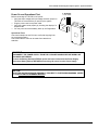
IMPORTANT SAFETY INSTRUCTIONS
Installation Safety Precautions:
1. Never install telephone wiring during a lightning storm.
2. Never install telephone jacks in wet locations unless the jack is specifically designed for wet
locations.
3. Never touch un-insulated telephone wires or terminals unless the telephone line has been
disconnected at the network interface.
4. Use caution when installing or modifying telephone lines.
The TransTel TD-824-I utilizes a 3-prong grounding power supply cord. This cord is not to be
attached to any building surfaces. When using your telephone equipment, basic safety precautions should always be followed to
reduce the risk of fire, electric shock and injury to persons, including the following:
1. Read and understand all instructions.
2. Follow all warnings and instruction marked on the
product.
3. Unplug this product from the wall outlet before
cleaning. Do not use liquid cleaners or aerosol
cleaners. Use a damp cloth for cleaning.
4. Do not use this product near water, for example, near
a bath tub, wash bowl, kitchen sink, or laundry tub,
in a wet basement, or near a swimming pool.
5. Do not place this product on an unstable cart, stand,
or table. The product may fall, causing serious
damage to the product.
6. Slots and openings in the cabinet and the back or
bottom are provided for ventilation, to protect it
from overheating. These openings must not be
blocked or covered. The openings should never
be blocked by placing the product on a bed, sofa,
rug, or other similar surface. This product should
never be placed near or over a radiator or heat
register. This product should not be placed in a
built in installation unless proper ventilation is
provided.
7. This product should be operated only from the type
of power source indicated on the marking label. If
you are not sure of the type of power supply to
your home or office, consult your dealer or local
Power Company.
8. This product is equipped with a three-wire grounding
type plug. A plug will only fit into a grounding type
power outlet. This is a safety feature. If you are
unable to insert the plug into the outlet, contact
your electrician to replace your obsolete outlet. Do
not defeat the safety purpose of the grounding type
plug.
9. Do not allow anything to rest on the power cord or place it
where it will be abused by persons walking on it.
10. Do not overload wall outlets and extension cords as this can
result in the risk of fire or electric shock.
11. Never push objects of any kind into this product through
cabinet slots as they may touch dangerous voltage points or
short out parts that could result in a risk of fire or electric
shock. Never spill liquid of any kind on the product.
12. To reduce the risk of electric shock, do not disassemble this
product, but take it to qualified service personnel when
service or repair work is required. Opening or removing
covers may expose you to dangerous voltages or other
risks. Incorrect re-assembly can cause electric shock when
the appliance is subsequently used.
13. Unplug this product from the wall outlet and refer servicing to
qualified service personnel under the following conditions:
A. When the power supply cord or plug is damaged or frayed.
B. If liquid has been spilled into the product.
C. If the product has been exposed to rain or water.
D. If the product does not operate normally by following the
operating instructions. Adjust only those control, that are
covered by the operating instructions because improper
adjustment of other controls may result in damage and will
often require extensive work by a qualified technician to
restore the product to normal operation.
E. If the product has been dropped or the cabinet has been
damaged.
F. If the product exhibits a distinct change in performance.
14. Avoid using a telephone (other than a cordless type) during
an electrical storm. There may be a remote risk of electric
shock from lightning.,
15. Do not use the telephone to report a gas leak in the vicinity of
the leak.
SAVE THESE INSTRUCTIONS
Page 2
Version 1.3b October 2005
Includes all versions through G1-a20x
TransTel Model TD-824-I
Digital Telephone System
General Description - Installation - Programming Forms Manual
Table of Contents
Notification..........................................................................................................................................................................1
General Description - Introduction ..................................................................................................................................10
FCC Rules and Regulation..............................................................................................................................................10
FCC Registration Number ...........................................................................................................................................10
Ringer Equivalence Number .......................................................................................................................................10
Notification of the Telephone Company......................................................................................................................10
Incidence of Harm to the Telephone Lines.................................................................................................................10
Compatibility of the Telephone Network and Terminal Equipment. ..........................................................................11
Radio Frequency Interference .....................................................................................................................................11
Description........................................................................................................................................................................12
Economy and Efficiency...............................................................................................................................................12
Easy Installation ...........................................................................................................................................................12
Easy Maintenance ........................................................................................................................................................13
Flexibility of System Applications.................................................................................................................................13
Varied Extension Alternatives ......................................................................................................................................13
Digital Twin Port ...........................................................................................................................................................13
Liquid Crystal Display...................................................................................................................................................13
System Specifications ..................................................................................................................................................15
System Capacities / Maximum .................................................................................................................................15
Electrical Specifications ...............................................................................................................................................15
Mechanical Specifications (Key Service Unit) .............................................................................................................16
Mechanical Specifications (Battery Back Up Housing)...............................................................................................16
Environmental Specifications.......................................................................................................................................16
Features ...........................................................................................................................................................................17
System Features ..........................................................................................................................................................17
Station Features ...........................................................................................................................................................18
Optional Features.........................................................................................................................................................18
Parts & Peripherals ..........................................................................................................................................................19
System Modules...........................................................................................................................................................19
Type of Phones ............................................................................................................................................................19
Peripheral Devices .......................................................................................................................................................19
Optional Interface Cards..............................................................................................................................................20
Associated Software ....................................................................................................................................................20
System Installation - Introduction ....................................................................................................................................21
Site Requirements ...........................................................................................................................................................22
Location ........................................................................................................................................................................22
Choosing The Right Environment............................................................................................................................22
Installation Checklist ....................................................................................................................................................22
Equipment Requirements................................................................................................................................................22
Installation ........................................................................................................................................................................23
Page 4
Version 1.3b October 2005
Includes all versions through G1-a20x
TransTel Model TD-824-I Digital Telephone System – Table Of Contents
Installing expansion and optional cards...................................................................................................................... 23
TD-CFC - Conference Card.................................................................................................................................... 24
TD-MSC - Multi Service Card .................................................................................................................................. 24
G1-VSC - Voice Service Card ................................................................................................................................. 24
TD-TKU - 4 Port CO Line Card ............................................................................................................................... 25
TD-STC - Digital Station Expansion Card.............................................................................................................. 26
TD-SLC - Single Line Station Adapter Card ........................................................................................................... 27
TD-RGU - Ring Generator Unit............................................................................................................................... 27
Voltage Selection Check ......................................................................................................................................... 28
Backboard ................................................................................................................................................................ 28
Key Service Unit....................................................................................................................................................... 28
Power Supply............................................................................................................................................................... 28
Preparing The External Battery Backup ..................................................................................................................... 29
Charging the Battery.................................................................................................................................................... 29
Installing or Replacing Batteries ................................................................................................................................. 29
System Ground............................................................................................................................................................ 30
KSU Connecting (Main) Panel Layout........................................................................................................................ 30
Connecting Stations .................................................................................................................................................... 30
Digital Key Telephone – DK-1D, DK-1S, DK-1B, DK2, DK3-D, DK3-B .................................................................... 30
Access Control Phone (ACP) and Digital Doorphone Unit (DDU) ............................................................................ 32
Single Line Telephone ................................................................................................................................................ 33
Analog Door Phone Connection ................................................................................................................................. 34
CO/PABX Connections ............................................................................................................................................... 35
Optional Cabling.............................................................................................................................................................. 35
Door Switch (Relay) Connection................................................................................................................................. 35
Sensor Connection ...................................................................................................................................................... 35
Paging Connection ...................................................................................................................................................... 35
Music on Hold Connection .......................................................................................................................................... 36
RS232 Port Connection .............................................................................................................................................. 36
Power On and Operational Test ..................................................................................................................................... 37
Operational Tests ........................................................................................................................................................ 37
Series Model TD-824i - Programming Forms Manual .................................................................................................. 38
Programming Information ........................................................................................................................................... 38
New Systems ........................................................................................................................................................... 38
Lost Programming Key............................................................................................................................................ 38
Alphanumeric Entry: ................................................................................................................................................ 40
Form 01 - Day Ringing and Ringing Line Preference Assignment ........................................................................... 41
Form 02 - Night Ringing and Ringing Line Preference Assignment ......................................................................... 42
Form 03 - Door Phone Ringing Assignment Form .................................................................................................... 43
Form 04 - Console Assignment Form ........................................................................................................................ 44
G1-a20m G1-a20t
Form 05-01 - System Parameters Form - Timers-1
............................................................................. 45
Form 05-02 - System Parameters Form - Timers-2 .................................................................................................. 47
Form 05-03 - System Parameters Form - Codes-1................................................................................................... 49
G1-a20u
Form 05-04 - System Parameters Form - Codes-2
........................................................................................ 51
Form 05-05 - System Parameters Form - Codes-3................................................................................................... 53
Form 05-06 - System Parameters Form - Timer/Codes ........................................................................................... 55
G1-a20u
Form 05-07 - System Parameters Form - Timer/Codes
................................................................................. 57
Form 05-08 - System Parameters Form - Timer/Codes ........................................................................................... 59
G1-a10ax
Form 05-09 - System Parameters Form - Misc.
............................................................................................. 61
G1-A10n G1-A20o
Form 05-10 - Voice Mail Leading Digits
................................................................................................ 63
Enhanced Protocol ...................................................................................................................................................... 63
Answering Machine Operation .................................................................................................................................... 64
Record Function .......................................................................................................................................................... 64
Direct To Voice Mail .................................................................................................................................................... 64
Message Waiting Digits ............................................................................................................................................... 64
More About Voice Mail ................................................................................................................................................ 64
G1-a10ao
Form 05-11 - System Parameters Form – Supplemental
.............................................................................. 65
G1-a10h G1-a20u
Form 05-12 - System Parameters Form - Miscellaneous
.................................................................... 67
G1-a10aw
Form 05-13 - System Parameters Form - Miscellaneous
............................................................................. 69
Page 5
TransTel Model TD-824-I Digital Telephone System - General Description - Installation - Programming Forms Manual
Form 05-14 - System Parameters Form – Miscellaneous .........................................................................................70
G1-10a6
Form 06-01 - Relay Assignment Form:
.............................................................................................................71
G1-10a6
Form 06-st – ACP/Doorphone Relay Assignment Form:
.................................................................................71
DK-2 Key Layout.......................................................................................................................................................73
DK-3 Key Layout.......................................................................................................................................................74
Form 07 - Flexible Key Group Assignment: ................................................................................................................75
Form 07 - Key Assignment Parameters:.....................................................................................................................77
Form 08-01-IP - DSS Key Group Assignment: ..........................................................................................................78
Form 09 - System Speed Dial Assignment:................................................................................................................79
Form 10 - Single Digit Dialing Assignment : ...............................................................................................................81
Form 11 - Date and Time Settings: .............................................................................................................................82
Form 12 - System Alarm Schedule:...........................................................................................................................83
Form 13 - System Passwords: ....................................................................................................................................84
Form 14 - Station Message Detail Recording:............................................................................................................85
Form 17 - Forced Account Code Assignment: ...........................................................................................................89
G1-a10aw
Form 18 - Toll Plan Assignment:
....................................................................................................................90
Form 19 - Voice Service Unit Channel Assignment: ..................................................................................................92
Form 20 - Day/Lunch/Night Service Switching Schedule:..........................................................................................94
Form 25 - Reset Data to System Default:...................................................................................................................95
Form 29 - CO Line Specifications #1: ........................................................................................................................96
Form 35 - CO Line Specifications: ..............................................................................................................................98
Form 36 - CO Line Groups (Dial 9 Groups):............................................................................................................100
Form 37 - Busy Out CO Trunk: .................................................................................................................................100
Form 38 - Alternate CO Line Groups (Dial 87 Groups):..........................................................................................101
Form 39-00 - Sensor Assignment Form – KSU Sensor only:..................................................................................102
G1-a10aq
Form 39-st Sensor Assignment Form – ACP and Doorphone Units:
...........................................................103
Form 40 - Station Class of Service (Part 1): ............................................................................................................104
Form 41 - Station Specifications................................................................................................................................106
Form 42 - Personal Speed Dial Table Assignment:.................................................................................................108
Form 43 - Port Assignments:.....................................................................................................................................110
G1-a10as
Form 44 - Station Class of Service (Part 2):
................................................................................................112
Form 45 - Station Class of Service (Part 3): ............................................................................................................114
G1-a10av
Form 46 - Station Class of Service (Part 4):
................................................................................................116
Form 47 - Hot Line Table:..........................................................................................................................................119
Form 50 - Station Class of Service (Part 5): ............................................................................................................120
Prog. Form .................................................................................................................................................................122
Form 51 - Exception (Allow) Tables:.........................................................................................................................123
Form 61 - Deny Tables:.............................................................................................................................................123
Form 52 - Exception (Allow) Tables:.........................................................................................................................124
Form 62 - Deny Tables:.............................................................................................................................................124
Form 53 - Exception (Allow) Tables:.........................................................................................................................125
Form 63 - Deny Tables:.............................................................................................................................................125
Form 54 - Exception (Allow) Tables:.........................................................................................................................126
Form 64 - Deny Tables:.............................................................................................................................................126
Form 55 - Exception (Allow) Tables:.........................................................................................................................127
Form 65 - Deny Tables:.............................................................................................................................................127
Form 56 - Exception (Allow) Tables:.........................................................................................................................128
Form 66 - Deny Tables:.............................................................................................................................................128
Form 57 - Exception (Allow) Tables:.........................................................................................................................129
Form 58 - Exception (Allow) Tables:.........................................................................................................................129
Form 59 - Exception (Allow) Tables:.........................................................................................................................130
Toll Control Examples ...............................................................................................................................................130
Form 67 - Hunt Group Pilot Assignment:..................................................................................................................131
Form 68 - Day Hunt group assignments:..................................................................................................................132
Form 69 - Night Hunt group assignments:................................................................................................................133
Form 70-Cd - ISDN Interface Specifications Program: ............................................................................................134
Form 71-tk - ISDN Line Number Assignment Program: ..........................................................................................135
Form 72 - ISDN Called Party Extension Number Assignment:................................................................................135
Form 73-st - ISDN Extension Sub Address Assignment: .........................................................................................135
Page 6
Version 1.3b October 2005
Includes all versions through G1-a20x
TransTel Model TD-824-I Digital Telephone System – Table Of Contents
Form 74 - Least Cost Routing - Digit String Analysis Table: ................................................................................... 136
Form 74 - Least Cost Routing - Digit String Analysis Table: ................................................................................... 137
Form 76 - Least Cost Routing - Routing Table Normal Operation: ....................................................................... 138
Form 76 - Least Cost Routing - Routing Table Special Day Rate: ........................................................................ 139
Form 76 - Least Cost Routing - Routing Table Second Special Rate Day Operation: ......................................... 140
Form 77-num - Least Cost Routing - Modify Digits Table: ...................................................................................... 141
Form 77-num – Least Cost Routing – Modify Digits Table (continued): ................................................................. 142
G1-a20u
Form 78 - Station Class of Service (Part 6):
................................................................................................. 144
Caller ID and Redial Patterns ....................................................................................................................................... 147
U.S. Caller ID Overview ................................................................................................................................................ 147
Various North American Dialing sequences............................................................................................................. 147
1. Local Call (7 digit)............................................................................................................................................. 147
2. Local Toll (7 digit) ............................................................................................................................................. 148
3. Local Call (10 digit)........................................................................................................................................... 148
4. Local Toll (1 + 7 digit) ....................................................................................................................................... 148
5. Local Toll (1 + 10 digit)..................................................................................................................................... 149
6. Outside of Area Toll (1 + 10 digit) .................................................................................................................... 149
Form 83 - Caller ID Block Assignment:.................................................................................................................... 150
Form 84-01 – Home Area Code:.............................................................................................................................. 151
Form 85-nn – Overlay Area Code: ........................................................................................................................... 151
Form 86-nnn – Office Code Pattern: ........................................................................................................................ 151
Form 86-nnn – Office Code Pattern 300—399:...................................................................................................... 152
Form 86-nnn – Office Code Pattern 400—499:...................................................................................................... 153
Form 86-nnn – Office Code Pattern 500—599:...................................................................................................... 154
Form 86-nnn – Office Code Pattern 600—699:...................................................................................................... 155
Form 86-nnn – Office Code Pattern 700—799:...................................................................................................... 156
Form 86-nnn – Office Code Pattern 800—899:...................................................................................................... 157
Form 86-nnn – Office Code Pattern 900—999:...................................................................................................... 158
Programming Cross Reference.................................................................................................................................... 159
By Application: ........................................................................................................................................................... 159
Incoming Calls: ...................................................................................................................................................... 159
Outgoing Calls: ...................................................................................................................................................... 159
Intercom Calls:....................................................................................................................................................... 160
Busy/During Conversation: .................................................................................................................................... 161
DISA: ...................................................................................................................................................................... 161
Night Service: ......................................................................................................................................................... 162
Group Assignments: .............................................................................................................................................. 162
Call Control: ........................................................................................................................................................... 162
System Clock: ........................................................................................................................................................ 163
Station Numbering: ................................................................................................................................................ 163
Single Line Telephone:.......................................................................................................................................... 163
Miscellaneous: ....................................................................................................................................................... 163
Optional Services:.................................................................................................................................................. 164
Voice Mail Integration: ........................................................................................................................................... 164
Caller ID: ................................................................................................................................................................ 164
SMDR: .................................................................................................................................................................... 164
Voice Mail:.............................................................................................................................................................. 165
Hunt Groups:.......................................................................................................................................................... 165
Trunk Assignment:................................................................................................................................................. 165
Toll Control: ........................................................................................................................................................... 165
Least Cost Routing: ............................................................................................................................................... 165
By Program Type in Alphabetical Order:.................................................................................................................. 166
System Parameters: .............................................................................................................................................. 166
TransTel Key Telephone Operation Manual................................................................................................................ 169
Introduction ................................................................................................................................................................ 169
1A2 Emulation / Privacy Release.......................................................................................................................... 169
Account Codes – Client......................................................................................................................................... 169
Advisory Messages ................................................................................................................................................ 169
Alternate Trunk Group Access (Dial 87)............................................................................................................... 169
Page 7
TransTel Model TD-824-I Digital Telephone System - General Description - Installation - Programming Forms Manual
Answering Calls......................................................................................................................................................170
Answering a Doorphone.........................................................................................................................................171
Answer Paging (Meet Me Page) ............................................................................................................................171
Automatic Callback ................................................................................................................................................171
Automatic Last Number Redial..............................................................................................................................172
Automatic Line Access...........................................................................................................................................172
Automatic Redial ....................................................................................................................................................172
Automatic Saved Number Redial ..........................................................................................................................172
Background Music ..................................................................................................................................................173
Barge-In (Override).................................................................................................................................................173
Caller ID Features ..................................................................................................................................................173
Call Forwarding ......................................................................................................................................................174
G1-a10e
Call Forward All stations (Operator Function)
............................................................................................175
G1-a10e
Clear All Call Forwarding (Operator Function)
...........................................................................................175
Call Hold .................................................................................................................................................................175
Calling the Doorphone ...........................................................................................................................................175
Call Pickup..............................................................................................................................................................175
Call Swap................................................................................................................................................................176
Call Transfer...........................................................................................................................................................176
Call Waiting (Camp On).........................................................................................................................................177
Conference .............................................................................................................................................................177
Conversation monitor .............................................................................................................................................178
Date and Time Setting (Operator Function)..........................................................................................................178
Day / Night Service Switching Setup (Operator function) .....................................................................................178
Dialing Operator .....................................................................................................................................................179
Direct Trunk Access ...............................................................................................................................................179
Do Not Disturb ........................................................................................................................................................179
Environment Monitor ..............................................................................................................................................179
Exclusive Hold ........................................................................................................................................................179
Feature Menu .........................................................................................................................................................180
Flash (To an outside telephone line) .....................................................................................................................180
Forced Account Codes ..........................................................................................................................................180
Group Listen ...........................................................................................................................................................181
Handsfree Operation..............................................................................................................................................181
Immediate CO Line Access ...................................................................................................................................182
Intercom dialing ......................................................................................................................................................182
Last Number Redial ...............................................................................................................................................182
Lock / Unlock SMDR from Console ......................................................................................................................182
Macro Keys .............................................................................................................................................................182
Mute ........................................................................................................................................................................183
Operator Set Timed Reminder or Wakeup (Remote Setup) ...............................................................................183
Operator Timed Reminder or Wake Up ................................................................................................................183
Paging .....................................................................................................................................................................183
Pulse To Tone Conversion ....................................................................................................................................184
Room Monitor .........................................................................................................................................................184
Saved Number Redial ............................................................................................................................................184
Saved Number Redial (SuperSave) ......................................................................................................................185
Shift Key..................................................................................................................................................................185
Speed Dialing .........................................................................................................................................................185
Speed Dial Programming.......................................................................................................................................185
Speed Dial Programming (Operator). ...................................................................................................................186
Station Lock / Unlock .............................................................................................................................................187
Switching between Handsfree and Handset mode...............................................................................................187
Timed Reminder or Wake Up................................................................................................................................188
Trunk Queuing........................................................................................................................................................188
Trunk Group Access (Dial 9) .................................................................................................................................188
Voice Service Unit (Operator Function).................................................................................................................189
Voice Mail Access...................................................................................................................................................189
Voice Mail Live Call Recording ..............................................................................................................................190
Page 8
Version 1.3b October 2005
Includes all versions through G1-a20x
TransTel Model TD-824-I Digital Telephone System – Table Of Contents
Voice Mail Message Retrieval ............................................................................................................................... 190
Voice Mail Transfer Key......................................................................................................................................... 190
Volume Control...................................................................................................................................................... 190
Volume Levels Programming (Permanent).......................................................................................................... 191
Access Control Phone Operation Manual ................................................................................................................ 192
Intercom (as doorphone)....................................................................................................................................... 192
G1-a10b
Intercom (as Hotline, to external telephone number)
............................................................................... 192
Outgoing call (as wall mount phone) .................................................................................................................... 192
Access via password ............................................................................................................................................. 192
Access via proximity card(Touch-N-Go) ............................................................................................................... 192
Access via password and proximity card .............................................................................................................. 192
Check out (lock) ACP (as wall mount phone) ...................................................................................................... 193
Burglary Report...................................................................................................................................................... 194
Time Display .......................................................................................................................................................... 194
As a wall mount phone .......................................................................................................................................... 194
ACP Related Programming ...................................................................................................................................... 194
Extension Number length for ACP ........................................................................................................................ 194
’Voice’ announce or ‘ring’ announce for ACP....................................................................................................... 194
Hunt group for ACP .............................................................................................................................................. 194
Hunt Group Pilot Number...................................................................................................................................... 194
Hunt Group Members............................................................................................................................................ 194
Station Hunt Group Ringing Method ..................................................................................................................... 194
Station Function Form 46-st-08............................................................................................................................. 195
Dial 9 Access (System Option).............................................................................................................................. 195
Forced Account Code for ACP (as wall mount phone)........................................................................................ 195
Password for ACP (as doorphone) ....................................................................................................................... 195
Page 9
TransTel Model TD-824-I Digital Telephone System - General Description - Installation - Programming Forms Manual
General Description - Introduction
®
The General Description section contains an easy to understand overview of the TransTel TD-824i Digital
Telephone System. It is the intent of this document to provide both technical and non-technical readers with
information pertaining to the system building blocks, capabilities, key highlights, electrical, physical and
environmental characteristics of the TransTel TD-824i Digital Telephone System.
FCC Rules and Regulation
In compliance with the requirements of Part 68 of the Federal Communications Commission Rules and Regulations
for connection of terminal system equipment to the telephone network and for your convenience, the following
information is presented.
FCC Registration Number
The TransTel TD-824i is registered with the as a key system. The FCC Registration Number is 3A7TAI-35152-KFE for key systems registration.
Ringer Equivalence Number
Ringer Equivalence 0.3B.
Notification of the Telephone Company
Customers connecting terminal equipment to the telephone network shall, upon request of the
Telephone Company, inform the Telephone Company of the particular line(s) to which such
connection is made, the FCC registration number and ringer equivalence number (REN) of the
registered terminal equipment.
The REN is useful to determine the quantity of devices you may connect to your telephone line
and still have all of those devices ring when your telephone number is called. In most, but not all
areas, the sum of the REN's of all devices connected to one line should not exceed five (5.0). To
be certain of the number of devices you may connect to your line, as determined by the REN,
you should contact your local telephone company to determine the maximum REN for your
calling area.
Direct Connection to a Party-Line or Coin Operated Telephone Line is Prohibited.
Incidence of Harm to the Telephone Lines
Should terminal equipment cause harm to the Telephone Network, the Telephone Company shall, where practical,
notify the customer that service may be temporarily discontinued. However, where prior notice is not practical, the
Telephone Company may temporarily discontinue service, if such action is reasonable in the circumstances. In
case of such un-notified temporary discontinuance of service, the Telephone Company shall:
(a)
Promptly notify the customer of such temporary discontinuance of service.
(b)
Afford the customer the opportunity to correct the situation which gave rise to the temporary
discontinuance.
(c)
Inform the customer of the right to bring a complaint to the FCC pursuant to the procedures set
out in Subpart E of Part 68 of FCC Telephone Equipment Rules.
Page 10
Version 1.3b October 2005
Includes all versions through G1-a20x
TransTel Model TD-824-I Digital Telephone System – General Description
Compatibility of the Telephone Network and Terminal Equipment.
(a)
Availability of telephone interface information.
Technical information concerning interface parameters and specifications not specified in FCC
Rules, including the number of Ringers which may be connected to a particular line, which is
needed to permit Terminal Equipment to operate in a manner compatible with Telephone
Company communications facilities shall be provided by the Telephone Company upon
customer's request.
(b)
Changes in Telephone Company Communications Facilities, Equipment, Operations and
Procedures.
The Telephone Company may make changes in its communications facilities, equipment, operations or procedures
where such action is reasonably required in the operation of its business and is not inconsistent with the rules and
regulations in FCC Part 68 of the FCC Rules and Regulations. If such changes can be reasonably expected to
render any customer Terminal Equipment incompatible with Telephone Company Communications Facilities, or
require modification or alteration of such Terminal Equipment, or otherwise materially affect its use or performance,
the customer shall be given adequate notice in writing to allow the customer an opportunity to maintain
uninterrupted service.
Radio Frequency Interference
This equipment generates and uses radio frequency energy and if not installed and used properly and in strict
accordance with the manufacturer's instructions, may cause interference to radio and television reception. It has
been type-tested and found to comply with the limits for a Class A computing device in accordance with the
specification in Subpart J of Part 15 of FCC Rules, which are designed to provide reasonable protection against
such interference in a residential installation. However, this is no guarantee that interference will not occur in a
particular installation. If this equipment does cause interference to radio or television reception, which can be
determined by turning the equipment off and on, the user is encouraged to try to correct the interference by one or
more of the following measures:
Re-orient the receiving antenna.
Relocate the equipment with respect to the receiver.
Move the equipment away from the receiver.
Plug the equipment into a different outlet so that equipment and receiver are on different branch
circuits.
Page 11
TransTel Model TD-824-I Digital Telephone System - General Description - Installation - Programming Forms Manual
Description
The TD-824i is an advanced digital telephone system employing a microprocessor stored program and digitally
controlled solid state time-division switching. The TD-824i system is specifically designed for small business as well
as residential applications. At the forefront of the system’s design is a universal concept to adapting and connecting
with a variety of communications devices. Productive TransTel Digital Key Telephones offer thoughtfully designed
feature access to keep you connected with one another and with customers. TransTel technology leads the
industry in providing for compatibility with devices such as fax machines, answering machines, cordless phones,
computer modems and other office/home equipment.
Key highlights of the TD-824i includes:
Economy and Efficiency
The base system is equipped to support four (4) CO lines and eight (8) digital stations. The system may be
expanded to a maximum of eight (8) CO lines / or four (4) CO lines and three (3) ISDN Basic Rate Interfaces.
Station cards may be selected to allow practically any combination ranging from all TransTel Digital Key Sets to all
industry standard Single Line Telephone sets, with almost any combination of the two types. In addition to being cost
effective at the initial phase and for expanding to it's maximum capacity, the TD-824i system also is economical to
operate, as it consumes about the same amount of electricity at full configuration as a 60 watt light bulb. A
maximum of 8 CO lines (or 3 ISDN BRIs) and 24 Extensions can be accommodated. This allows a wide variety of
applications for the system to work effectively
Easy Installation
•
•
“Factory Ready” - All TD-824i Telephone systems are "ready to go" right out of the box. A default database is
factory installed on each system, which meets the needs for most installations. In most cases, this alleviates
hours of on site time, reducing installation costs for both dealer and customer.
“Small & Compact” - The Key Service Unit's small size takes little space for installation and is about the size of
a piece of legal paper.
Page 12
Version 1.3b October 2005
Includes all versions through G1-a20x
TransTel Model TD-824-I Digital Telephone System – General Description
Easy Maintenance
•
Solid-state design minimizes trouble and eliminates periodic maintenance.
•
Easy Expansion. Various Interface Cards for simple, modular expansion.
•
Versatile programming and options for ease of selection.
•
Database Battery Back Up - Customer data is backed up when the power is turned off and back on. Batteries
can periodically be replaced with power on using commercially available replacements.
•
Battery Back Up (System Operation) - TD-824i systems can be equipped with an optional battery back up
which keeps the system operational for up to 4 hours in the case of a commercial power failure.
•
Customer Care Programming - Customers and service personnel can easily communicate and perform
programming right over the telephone. TransTel telephone systems allow programming and voice
conversations to co-exist at the same time.
•
Advanced software upgrades – Through the RS232 connection, system software can be upgraded easily
without firmware “chip” replacements.
Flexibility of System Applications
Unlike other conventional systems in the TD-824i size range, the installer will find an unprecedented range of
customer database programmability. In "system parameters" there are extensive options for various timing settings
related to features. An array of parameters is programmable for signaling options on outside lines and internal
single line telephone sets. The installer may Enable/Disable many system wide features. And in class of service,
there are over 20 options for each station providing maximum flexibility for nearly any application.
Varied Extension Alternatives
You can connect Transtel DK series Key telephones, TransTel Access Control Phones (ACP), Digital Door Phones
and conventional industry standard single line sets, Modems, Answering Machines, Cordless phones, etc. directly to
the KSU. This feature provides you with the choice to select different extension equipment to suit individual
applications.
Digital Twin Port
Install two Digital Key telephones on a single two-wire cable. No Master and Slave difference. Any key telephone
can be plugged in and unplugged with no interference to the other. This feature allows easy cabling, easy
expansion and easy maintenance.
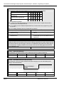
Liquid Crystal Display
The TD-824i Series Model DK-1/D and TransTel’s DK-3D telephones are equipped with a large, easy to read LCD
display. The LCD is 32 characters total, comprised of 2 rows by 16 characters each. This LCD provides an
invaluable tool for simplifying the use of the telephone by identifying the calling extension by name, outside lines by
name and self prompting displays for feature access. Station feature usage is made simple with the help of the
LCD display. Continuous prompting information is displayed during calls so that users know what to do and when to
do it.
32-character LCD Display shows:
•
Time
•
Last number dialed
•
Dialed telephone number
•
The status of operation/function
•
Voice Mail Messages
•
Absent messages
•
CO Line Names
•
Speed Dial Directory
•
Last Number Redial
•
Calling Party Name
•
Speed dial number
•
Input data during system data entry
Page 13
TransTel Model TD-824-I Digital Telephone System - General Description - Installation - Programming Forms Manual
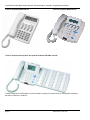
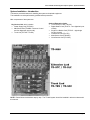
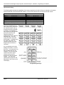
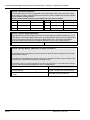
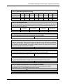
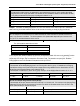
TransTel Telephone Model DK-1/D
TransTel Telephone Model DK-3/D
TransTel Telephone DK-2 (shown with optional 66 button DK-2DSS console)
The DK-2 expands the LCD display to a 4 line indication, providing an enhanced view ot call progress and adding
the ability to utilize the 4 “Softkeys”
Page 14
Version 1.3b October 2005
Includes all versions through G1-a20x
TransTel Model TD-824-I Digital Telephone System – General Description
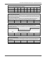
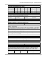
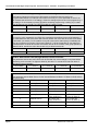
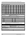
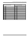
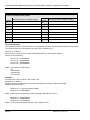
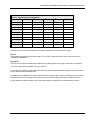
System Specifications
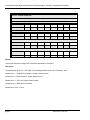
System Capacities / Maximum
CO/PABX Lines
Key Telephones / ACP / Digital Doorphones (Maximum)
Single Line Phones(Maximum)
Control Relay
8
24
8
1 per cabinet
1 per ACP or Digital
Doorphone
1 per cabinet
1 per ACP or Digital
Doorphone
External Input Sensor
Intercom Paths (Local)
Doorphone
1 analog (requires single line
card)
< 24 Digital doorphones
1
Total 600 sets for
Private/System Speed Dial.
20 sets per station(Max.)
600 sets (Max.)
External Music
Speed dial
Private Speed Dial
System Speed Dial
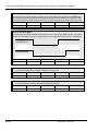
Electrical Specifications
CONTROL SYSTEM
CPU
SWITCHING METHOD
POWER REQUIREMENTS
Stored Program
8 /16 bit CPU
TDM (Time Division Multiplex)
100 - 120 V AC, (50/60Hz) 0.9 AMPS
210 - 230 V AC, (50/60Hz) 0.45 AMPS
Dedicated AC line and a good earth ground for power supply
POWER FAILURE
System operation for 180 minutes (full load) or for 4 hours (normal load) by installing
batteries (with two 12 V DC batteries 6.5 AH for each)
POWER DISSIPATION
Common Equipment Unit
Each Telephone
Electronic Sets
Single Line Telephone
DIALING
Outward
Internal
(idle) 21 W (full) 56 Watts
2.8 Watts, maximum
1.25 Watts
Dial Pulse - 10 pps (Pulses Per Second), DTMF
Dial Pulse - 10 pps (Pulses Per Second) / DTMF /
Digital
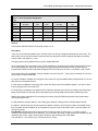
Page 15
TransTel Model TD-824-I Digital Telephone System - General Description - Installation - Programming Forms Manual
MAXIMUM LOOP RESISTANCE/IMPEDANCE
Digital Key Telephone
Less than 40 ohms 26 AWG / 650 feet (200 meters)
Single Line telephone
Less than 800 ohms 22 AWG / 2,620 feet (800 meters)
Doorphone
Less than 40 ohms
Music Source Input Impedance
600 ohms
Maximum Input
0.775 VRMS
INTERNAL RELAY CONTACTS
Type
SPST
Rating
3 AMP, 110VAC/220VAC
Function
Door Switch, Music on Hold, etc
CABLE REQUIREMENTS
CO/PABX Line
Twisted 1 Pair (2 wires)
Key Telephone
Twisted 1 Pair (2 wires)
Doorphone
Twisted 1 Pair (2 wires)
Door Switch
Twisted 1 Pair (2 wires)
External Music Source
Twisted 1 Pair (2 wires)
Single Line Telephone
Twisted 1 Pair (2 wires)
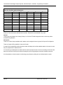
Mechanical Specifications (Key Service Unit)
CABINET DIMENSIONS
233mm W
9.17”
WEIGHT
76mm D
2.99"
2.3 Kg (Configuration: 2 x 8)
5.0 lbs
290mm H
11.4"
Mechanical Specifications (Battery Back Up Housing)
CABINET DIMENSIONS
15.5” W
WEIGHT
Mounting Screws
3.0” D
5.75” H
With Batteries -16 lbs Without Batteries- 4 lbs.
12.25” center to center
Environmental Specifications
OPERATING CONDITIONS
Temperature
Humidity
Page 16
0º to 45º C
(32º to 113º F)
10 to 95% relative
non-condensing
STORAGE
CONDITIONS
-40º to 66º C
(-40º to 150º F)
10 to 95% relative
non-condensing
Version 1.3b October 2005
Includes all versions through G1-a20x
TransTel Model TD-824-I Digital Telephone System – General Description
Features
System Features
1A2 Emulation
Attendant Console Assigment (4) Consoles
Account Code Capability
Attendant Overflow
Automatic Line Access
Automatic Line Search
Automatic Ring-down
Automatic Wake-up
Battery Charger
Behind PABX Operation
Centrex Operation
Class Of Service (10) Classes
CO Line Groups
CO Line Hunting
CO Line Name Programming
CO Line Ring Types
Linear
Common Audible
Circular
Add on Ring
Day/Night Service
Manual/Automatic Switch
Dial 9 Group (8) Groups
Direct In Line
Dial By Name
Dial Mode Selection (DP/DTMF)
Dial Pulse to DTMF Conversion
allowing switch to DTMF during call
Distinctive Ringing
DTMF Signaling
Dual Port Capability
End to End Signaling
Easy Installation and Operation
Flash (Programmable)
Flash Memory Backup Memory
Flexible Expansion
Flexible Ringing Assignment
Flexible Key Group Assignment (8) Templates
Flexible Number Plan 2,3 or 4 Digit
Flexible Time Format 12/24 Hour
Forced Account Code Assignment
Intercom
Intercom Single Digit Assignment
Intercom Ring / Voice Select
Intercom Dialing Restriction
Host PABX Access
Hot line
Line Group Assignment
Loud Bell Assignment
Multiple Attendant Consoles
Multiple Trunk Groups
Night Transfer
On Call Programming
Paging
Internal
Zone
Meet Me
Password Assignment
DISA
System programming
Toll Override
Pause
Pick Up Groups
Power Fail Transfer
Security Code
Single Digit Dialing
Station Group Assignment
Station Hunting
Station Lock
System Speed Dial and Personal Speed Dial
System Date & Time Setting
System Time-Reminder Service
Telephone Directory
Toll Control
Day / Night
Tone to pulse dialing
Trunk Queuing
Trunk to trunk connections
Uniform Call Distribution
Voice Mail Compatibility
Page 17
Station Features
Advisory Messages
System
Personal
Access to System Programming from any station
Account Code Capability
Auto Hold
Auto Hold Recall
Automatic Call Back
Automatic Answer-Intercom
Automatic Line Access
Automatic Redial
Automatic Volume Increase
Brokers Call (Split/Swap)
Call Duration Timer (LCD Phones)
Call Waiting
Call Forwarding
All Calls
Busy
No Answer
Busy / No Answer
External
Call Pickup
Call Split
Call Transfer
Calling Name Display (LCD Phones)
Calling Number Display (LCD Phones)
Camp On
Chain Dialing
Conference
Dial By Name (LCD Phones)
Dial Access to Attendant
Direct Station Selection
Doorphone Access
Do Not Disturb (DND)
Dual Color LED
Duration Time Display (LCD Phones)
Executive Override (Barge-In)
External Call Forwarding
Flash (Open Loop Timed Flash)
Group Listen
Hands-free Answer Back
Hearing Aid Compatibility
Headset Compatibility
Hold (Exclusive / System)
Hold Recall
I Hold Indication
I Use Indication
Intercom
Intercom ring / voice interchange
Intercom Step Call
Intercom Voice Announce
Last Number Redial
Message Waiting
On Hook Dialing
Prime Line Select
Privacy
Privacy Release
Private Line
Pulse/Tone Conversion
Ring Frequency Selection
Ringing Line Preference
Saved Number Redial
Speed Dialing
Station Lock / Unlock
Station Monitor
Store Speed Dial/DSS Number
Timed Reminder Service
System
Station
Toll Restriction Override by Account Code
Trunk Queuing
Volume Control
Handset
Speaker
Ringer
Optional Features
Automated Attendant
Battery Backup (System)
Direct Inward System Access (DISA)
Doorphone / Door Latch
External Music Source
Page 18
Music On Hold
Relay Control
RS232
Security Sensor/Door Open Indication
Station Message Detail Record (SMDR)
Voice Mail using in band signaling
Version 1.3b October 2005
Includes all versions through G1-a20x
TransTel Model TD-824-I Digital Telephone System – General Description
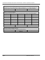
Parts & Peripherals
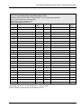
System Modules
Model
TD-824i
TD-TKU-4
TD-CID/FSK
TD-SIU-2
TD-SIU-3
TD-DKC-8
TD-SLC-8
TD-SLC-2
TD-RGU
Description
KSU with 4 CO lines, 4 Digital twin ports
Trunk Card : 4 CO lines
Caller ID daughterboard. Installs on TD-TKU-4. Converts 4 lines for
Caller ID Features. FSK Format (U.S.)
ISDN S/T interface with 2 circuits
ISDN S/T interface with 3 circuits
Station Card : 4 Digital Twin-port (Supports 8 key telephones)
Single Line Card : 8 SLT ports (maximum 1 per system)
Single Line Card : 2 SLT ports (maximum 1 per system)
Ring Generator Unit
Type of Phones
Model
DK1-D/I
DK1-D/G
DK1-S/I
DK1-S/G
DK1-B/I
DK1-B/G
DK2-D/I
DK2-D/G
DK2-BT/I
DK2-BT/G
DK3-D/I
DK3-D/G
DK3-B/I
DK3-B/G
DK-ACP
DK-DPU1
DK-WMK/I
DK-WMK/G
Description
Multifunction Key Telephone. Includes 32 character LCD display,
speakerphone, handsfree, headset jack, 20 dual color keys and 14 function
keys for feature access, DSS, CO Lines and speed dial. (Ivory or Gray)
Multifunction Key Telephone. Includes speakerphone, handsfree, headset
jack, 20 dual color keys and 14 function keys for feature access, DSS, CO
Lines and speed dial. (Ivory or Gray)
Multifunction Key Telephone. Includes 8 dual color keys and 14 function
keys for feature access, DSS, CO Lines and speed dial. (Ivory or Gray)
Multifunction Key Telephone. Includes 4 line LCD display, blue message
waiting LED, top mounted speaker, headset jack, speakerphone and
handsfree intercom. (Ivory or Gray)
Same as listed for DK2 above, but with wireless Bluetooth adapter installed
in telephone set. Note: Bluetooth compatible wireless headset not
included. (Ivory or Gray)
Includes 2 line LCD display and styled similar to the DK2 telephone. For
smaller applications and where fewer buttons are required. 10
programmable buttons for lines, stations, features or speed dial.
Speakerphone, top mounted speaker, headset jack and handsfree intercom.
(Ivory or gray)
Basic telephone set. 10 Programmable buttons for lines stations or buttons.
Styled similar to DK3-D, but without LCD display. On-hook dialing. (Ivory
or gray)
DK1-ACP Access Control Phone – Doorphone or Speakerphone (Ivory
only)
DK-DPU1 Digital Doorphone Unit. Includes 1 relay for door/gate release
and 1 sensor for intrusion or other use.
Wall Mount Kit for DK1 Series Telephones
(Ivory or Gray)
Peripheral Devices
Model
BBOX0
BBOX1
Description
Battery Box without Batteries
Battery Box with Batteries
Page 19
TransTel Model TD-824-I Digital Telephone System - General Description - Installation - Programming Forms Manual
Optional Interface Cards
Model
TD-VSC
TD-MSC
TD-CFC
Description
Voice Service Card (60 sec. / 8 voice segments)- Auto Attendant, Wake-up,
Message Waiting
RS232/Relay/Sensor/External Paging Interface
Conference / Expansion Card – 32 parties conference / Expand system from 6
x 16 to 8 x 24
Associated Software
Model
TD-RPS
Page 20
Description
Remote Programming Software
Version 1.3b October 2005
Includes all versions through G1-a20x
TransTel Model TD-824-I Digital Telephone System – System Installation
System Installation - Introduction
This section provides directions for installing the system and optional equipment.
The installation must be performed by qualified service personnel.
Main components of the system are:
Key Service Unit, which includes:
• Power Supply Unit (TD-PWU)
• Main Board Unit (TD-MBU / Common Control
and four digital twin port circuits)
• Trunk Unit (TD-TKU / TD-SIU)
Optional Expansion Cards:
• Trunk Card (TD-TKU / TD-SIU)
• Digital Station Card (TD-STC – four digital twin port
circuits)
• Single Line Station Card (TD-SLC – eight single
line port circuits)
• Conference Card (TD-CFC)
• Multi-Service Card (TD-MSC)
• Voice Service Card (TD-VSC)
NOTE: Please follow the directions step by step. The TD-824i system should be installed in strict accordance with
this manual.
Page 21
TransTel Model TD-824-I Digital Telephone System - General Description - Installation - Programming Forms Manual
Site Requirements
Location
Choosing The Right Environment
•
System should be installed in a clean, dry, secure location. This location must have adequate ventilation, and a
temperature from 0ºC to 45ºC (32ºF to 113ºF), with 10% to 95% non-condensing relative humidity. DO NOT
install the equipment near sources of static electricity, excessive vibration, or water. Avoid direct sunlight.
Installation Checklist
INSTALLATION REQUIREMENTS
VERIFICATION
MOUNTING SURFACE
Flat surface with adequate space for main cabinet,
power supply, wiring and optional Battery Backup
cabinet.
AC LINE
AC line should be dedicated exclusively to the system.
POWER OUTLET
Power Outlet must be a
3-wire grounded outlet plug, having parallel blades
and ground pin.
Input power Line capacity requirements - 10 amperes.
SURGE PROTECTION
A Surge Protector is recommended on the dedicated AC
line.
VENTILATION AND TEMPERATURE
Humidity: 10% to 95% relative non-condensing
Temperature:32ºF to 113ºF
(0ºC to 45ºC).
EARTH GROUND
A proper ground connection. (14 AWG)
SERVICEABILITY
Lighting conditions and working space adequate for
future service.
Equipment Requirements
•
•
•
Unpack, Check and Verify Equipment - Unpack the telephone equipment boxes and verify the contents in
accordance with the packing list provided. If any discrepancies are noticed, please contact TransTel
Communications.
Damaged Boxes - If you notice any damage to the packages, please notify both the shipper and TransTel at
once.
List of parts included in basic KSU box:
• KSU Main Cabinet
• Power Supply
• Mounting Template
• Mounting Screws
• Station Connectors
• Spare Fuses
• Cable Cover
Page 22
Version 1.3b October 2005
Includes all versions through G1-a20x
TransTel Model TD-824-I Digital Telephone System – System Installation
Installation
Caution
1. This system should be installed only by qualified service personnel.
2. Do not install the Power Supply unless you have read the following instructions and
completed all the installation and wiring.
3. STATIC SENSITIVE DEVICES! Please handle with care.
Installing expansion and optional cards
In this step you will be installing printed circuit cards on to header pins of the main board in the basic cabinet. Take
your time and extra care to assure the printed circuit cards are properly aligned. After installing each option and
expansion card, perform a visual inspection to assure the printed circuit card is installed properly.
1. Position the cabinet on a flat surface like a table or countertop. Avoid doing this on carpet.
2. Remove the 4 screws located at the corners of the cabinet and lift the front cover off.
1. Locate the expansion and option cards and unpack them at this time.
Page 23
TransTel Model TD-824-I Digital Telephone System - General Description - Installation - Programming Forms Manual
Installing expansion and option cards (continued)
TD-CFC - Conference Card
Install this card on CN6 of the TD-MBU.
Be sure that the component side of the TD-CFC is facing in towards right of KSU.
CFC card is necessary to expand the system from 6 x16 to 8x 24.
TD-MSC - Multi Service Card
Align CN1 of the MSC card with CN4 of the TD-MBU.
Align the hole on the right side of the MSC with the standoff.
Once aligned push the MSC on the connector.
Place the screw into the standoff securing the MSC card.
When installed correctly the connectors should be easily
accessible through the main panel.
G1-VSC - Voice Service Card
Align CN1 of the G1-VSC card with CN5 of the TD-MBU.
Align the hole on the left side of the VSC with the standoff.
Once aligned push the VSC on the connector.
Place the screw into the standoff securing the VSC card.
Page 24
Version 1.3b October 2005
Includes all versions through G1-a20x
TransTel Model TD-824-I Digital Telephone System – System Installation
TD-TKU - 4 Port CO Line Card
Align four holes of TD-TKU with the standoffs on top of the existing TD-TKU or TD-SIU card provided for in the
basic key service unit. Once aligned, place the four screws into the standoff securing the TD-TKU card.
Verify that the TD-TKU that was installed in the basic KSU has JP1 set to the ‘TKU1’ position..
Set JP1 on the new installed TD-TKU to ‘TKU2’.
Connect an attached cable between CN1 of TD-TKU to CN3 of TD-MBU.
Connect an attached cable between CN4 of TD-TKU to CN3 of TD-SLC for power failure transfer.
TD-TKU 4 Circuit CO Trunk Card
TD-TKU Jumper JP1 – Basic Card is strapped for TKU1
Expansion Card is strapped for TDK2 (Basic Card shown)
Page 25
TransTel Model TD-824-I Digital Telephone System - General Description - Installation - Programming Forms Manual
TD-STC - Digital Station Expansion Card
TD-STC – Digital Station Expansion Card
st
For the 1 TD-STC card:
This expands KSU from 8 to 16 stations.
Set JP1 on TD-STC to ‘STC1’ position.
Align CN2 of the TD1-STC card with CN2 f the TD-MBU.
Align four screw holes on TD-STC with the standoff.
Once aligned push the TD-STC on the connector.
Place the screw into the standoff securing the TD-STC card.
TD-STC Jumper JP1 – Shown set for first card position (stations 9-16)
nd
For the 2 TD-STC card:
This expands KSU from 16 to 24 stations.
Install TD-CFC card.
st
Use the attached three standoffs to replace the original screws on the 1 TD-STC card.
nd
Set JP1 on the 2 TD-STC to ‘STC2’ position.
Align CN2 of the two TD-STC cards together.
Align four screw holes on TD-STC with the standoff.
Once aligned push the TD-STC on the connector.
Place the screw into the standoff securing the G1-STC card.
Page 26
Version 1.3b October 2005
Includes all versions through G1-a20x
TransTel Model TD-824-I Digital Telephone System – System Installation
TD-SLC - Single Line Station Adapter Card
Install G1-SLC on TD-MBU:
Connect the attached cable between CN1
of TD-SLC card to CN7 of the TD-MBU.
Align four screw holes on the TD-SLC with
the standoffs.
Place the screws into the standoffs
securing the TD-SLC card.
Connect the attached cable between CN3
of TD-SLC to CN4 of TD-TKU for power
fail transfer. (Power fail Transfer will
transfer the CO lines to the first 4 stations
of TD-SLC card.)
Install TD-SLC on the top of TD-STC:
Install TD-CFC card.
Use the attached three standoffs to replace
st
the original screws on the 1 TD-STC card.
Connect the attached cable between CN1
of TD-SLC card to CN7 of the TD-MBU.
Align four screw holes on the TD-SLC with
the standoffs.
Place the screws into the standoffs
securing the TD-SLC card.
Connect the attached cable between CN3
of TD-SLC to CN4 of TD-TKU for power
fail transfer. (Power fail Transfer will
transfer the CO lines to the first 4 stations
of TD-SLC card.)
Note: Only one TD-SLC Card may be installed in a
TD-824i system. It will always be configured as
station equipment ports 31 through 38.
TD-RGU - Ring Generator Unit
The ring generator installs inside the power supply
unit.
Remove the cover of the power supply by taking
out the 4 screws located on each corner.
Inside the TD-RGU are 4 screws and a
connecting cable.
Align the TD-RGU with the 4 holes and secure by
installing the screws provided.
Install the cable from the TD-RGU to the 4 pin header connector located on the TD-PWU board.
Page 27
TransTel Model TD-824-I Digital Telephone System - General Description - Installation - Programming Forms Manual
Voltage Selection Check
Make a check to assure the power supply jumper setting
is for the proper voltage.
When complete, place the power supply cover back on the
power supply.
Replace Cover
With the expansion and option cards installed and the battery
insulator removed, replace the cover and install the 4 screws
removed earlier.
This concludes the installation of expansion and option
cards!
Backboard
Be sure to plan and allow enough space to mount and connect the
key service unit, power supply and system battery back up if
applicable.
Key Service Unit
Use the enclosed paper template to locate the mounting position for
the Key Service Unit. Drill appropriately spaced holes and mount the
KSU on the wall. When mounting the KSU, make certain that there
is adequate room for the system power supply and that the
connecting cable between the Power Supply and the KSU will reach
the KSU. The same applies for the battery back up unit.
Mounting Tabs
Key Service Unit
Wall or backboard
Power Supply
Dedicated Power Source - The power supply must be connected to a dedicated AC outlet.
Be sure that the third wire earth ground of the AC circuit is connected to a good electrical ground. If a music source
is installed, it must be connected to a separate AC circuit, rather than the system's dedicated AC line cord.
Check Your Voltage Selection Jumper
Verify that the input voltage and input voltage jumper are correct before you power on the system. The input
voltage is set according to the Customer's requirement before shipping. However it is important to verify that the
setting is correct prior to initial system power up.
Power Supply voltage options for the unit:
100-VAC: 100 to 120 V AC (50/60Hz) or 220-VAC: 210 to 230 V AC (50/60Hz).
Mount Power Supply
Using screws provided with the system, mount the power supply close to the KSU so that the connector reaches
from the Power Supply to the KSU.
Page 28
Version 1.3b October 2005
Includes all versions through G1-a20x
TransTel Model TD-824-I Digital Telephone System – System Installation
Preparing The External Battery Backup
The Key Service Unit can have two external
backup batteries in series (12 volts each) for
emergency power and when a power failure
takes place.
If you are installing an optional Battery Backup
(SK-BCAB/B), make certain that there is
adequate room for its installation. Make certain
that the Battery Backup is mounted close
enough to the Power Supply that the
interconnecting cable between the Battery
Backup and the Power Supply can connect.
Do Not Connect the Battery Backup at this time!
Do Not Connect the Battery Backup at this time! Battery Backup should not be connected to the
System power supply until all power up testing has been completed!
Charging the Battery
The rechargeable batteries are automatically charged when the KSU is plugged in.
When System is in a full-load condition (eight CO trunks and twenty four extensions all in use), the batteries provide
a minimum of 1 hour's continuous use. Change the batteries every two years.
Installing or Replacing Batteries
Caution
To Reduce the Risk of Fire or Injury to persons, Read and Follow these Instructions.
1. Use only the following type and size batteries:
12 Volt 6.5 Amp/Hour "Gel-Cell" sealed batteries (2).
Dimensions, approximately 3 1/4" (H), 5 15/16" (W), 2 1/2" (D).
PowerSonic model PS660 or equivalent.
2. Do not dispose of the batteries in a fire. The cell may explode. Check with local codes
for possible special disposal instructions.
3. Do not open or mutilate the batteries. Released electrolyte is corrosive and may cause
damage to the eyes or skin. It may be toxic if swallowed.
4. Exercise care in handling batteries in order not to short the battery with conducting
materials such as rings, bracelets, and keys. The battery or conductor may overheat and cause burns.
This product is defined as a secondary battery operated device. As such, the following instructions should
also be read and followed:
1.
Charge the batteries provided with or identified for use with this product only in accordance with the instructions
and limitations specified in this manual.
2. Observe proper polarity orientation between the batteries and battery charger.
3. Do not mix old and new batteries in this product.
5. Do not mix batteries of different sizes or from different manufacturers in this product.
Before installing or replacing batteries, disconnect the battery supply unit to the KSU by removing the polarized
battery connector at the KSU. Due to the weight of the batteries, it is advised that the battery cabinet be removed
from the wall before working on it.
Page 29
TransTel Model TD-824-I Digital Telephone System - General Description - Installation - Programming Forms Manual
System Ground
It is strongly recommended that the system be grounded by connecting a heavy, insulated copper wire (e.g.,
14AWG or larger) between the grounding bolt on the right-lower side of the cabinet and an earth ground.
Do not connect the grounding wire of the KSU to a computer, telex, or any other external device.
KSU Connecting (Main) Panel Layout
The following illustration should be used as a reference when connecting equipment to the TD-824i KSU.
Refer to the wiring diagram located on the inside of the cable cover for all connections
Connecting Stations
The station cabling for the TD-824i should be a home run from the jack to the telephone room. The termination
should be at conventional 66 type connecting blocks or directly to the provided station connectors. One pair twisted
wiring is required for each station location. Attention to proper cabling will help ensure a successful installation and
minimize service calls after installation. Some guidelines for running station cable are as follows:
•
•
•
•
Avoid running cable parallel to fluorescent light fixtures or electrical lines not in conduit. If these obstacles are
unavoidable, run the cable at right angles across them.
Do Not run station cable inside conduit already occupied by electrical wiring.
Do Not run station cable near equipment with electric motors or strong magnetic fields.
Do not place station cable on the ground where it can be stepped on or rolled over by office furniture or office
equipment.
Digital Key Telephone – DK-1D, DK-1S, DK-1B, DK2, DK3-D, DK3-B
A cable cover is provided with the KSU. Station cables can enter from either the top or bottom as desired.
Remove one or both ends of the cover as required and route the station cable through the hole. Terminate the
station wires with the connectors that are provided. The stations will connect to the KSU as shown on the main
panel (above) on connector locations.
Connect Tip terminal with GRN terminal (screws) of the modular jack, Ring with RED.
There is no polarity requirement on Tip and Ring.
Single Pair (2-conductor) wiring is required for all DK series Digital Key Telephones.
Page 30
Version 1.3b October 2005
Includes all versions through G1-a20x
TransTel Model TD-824-I Digital Telephone System – System Installation
CAUTION!: Avoid shorting Tip and Ring together. It may damage the TD-MBU or TD-STC board.
• Connections to telephones are made pins
2 & 3 and pins 1 & 4.
• A cable cover is provided with the KSU.
Station cables can enter from either the top
or bottom as desired. Remove one or both
ends of the cover as required and route the
station cable through the hole. Terminate
the station wires with the connectors that are
provided. The stations will connect to the
KSU as shown on the main panel (above) on
connector locations 1 ~ 4 of each station
card.
• Connect Tip terminal with GRN
terminal(screws) of the modular jack, Ring
with RED
• 2-conductor wiring is required for Key
Telephones.
• 2-conductor wiring is required for Single Line
Telephones.
• Incorrect connections may cause a system
malfunction or equipment failure.
DK-1 A-B Switch
st
nd
Open the overlay of the function key on the DK telephone and select the 1 or 2 station. Dip switch to the right for
st
nd
the A or 1 station. Dip switch to the left for the B or 2 station. DK2 and DK3 telephone sets change from A to B
by depressing a recessed pushbutton with a paper clip or toothpick.
Page 31
TransTel Model TD-824-I Digital Telephone System - General Description - Installation - Programming Forms Manual
Access Control Phone (ACP) and Digital Doorphone Unit (DDU)
•
•
•
Page 32
Single Pair Wiring is required for connection to ACP/DDU phone.
ACP/DDU Phone can be used on a digital pair with another ACP/DDU or a DK-1 telephone set.
st
nd
ACP/DDU can be either 1 or 2 station on circuit.
Version 1.3b October 2005
Includes all versions through G1-a20x
TransTel Model TD-824-I Digital Telephone System – System Installation
Single Line Telephone
Connections to telephones are made pins 2 & 3
(odd ports) and pins 1 & 4 (even ports).
A cable cover is provided with the KSU. Station
cables can enter from either the top or bottom as
desired. Remove one or both ends of the cover as
required and route the station cable through the hole.
Terminate the station wires with the connectors that
are provided. The stations will connect to the KSU as
shown on the main panel (above) on connector
locations 27 – 34 (Need TD-SLC installed).
Connect Tip terminal with GRN terminal (screws) of
the modular jack, Ring with RED.
There is no polarity requirement on Tip and Ring.
2-conductor wiring is required for Single Line
Telephones.
SLC-1 Cards have only two circuits and will be on
equipment positions 31 and 32.
SLC-4 Cards have 4 circuits and will be found on
equipment positions 31, 32, 33 and 34.
Page 33
TransTel Model TD-824-I Digital Telephone System - General Description - Installation - Programming Forms Manual
Analog Door Phone Connection
One Door phone may be connected to the
TD-824 system and only with SLC-8 cards..
A cable cover is provided with the KSU. Door
phone cable can enter from either the top or
bottom as desired. Remove one or both ends
of the cover as required and route the door
phone cable through the hole. Terminate the
door phone wires with the connectors that are
provided. The Door phone will connect to the
KSU as shown on the main panel (above) on
connector locations 34 (Needs TD-SLC
installed).
Connect Tip terminal with GRN terminal
(screws) of the modular jack, Ring with RED.
No polarity on Tip and Ring.
2-conductor wiring is required for Door phone.
Doorphone wiring is on pin 1 and pin 4 of
the connector.
Adjust the DIP selector on the main panel to
Door Phone.
Page 34
Version 1.3b October 2005
Includes all versions through G1-a20x
TransTel Model TD-824-I Digital Telephone System – System Installation
CO/PABX Connections
Make your CO line connection to the telephone company on this
connector. Pins 3 and 4 of the connector are for the CO line.
RJ-11C (2 wire) modular connector is required.
2-conductor wiring is required.
Optional Cabling
Connect a 6 conductor mounting cord from the KSU to a RJ-25
modular block.
Door Switch (Relay) Connection
One Door Switch (24+-12VDC) may be
used on the G1-824 system.
2-conductor wiring is required.
Connect the door switch to pins 1 and 6 of
the RJ-11 connector.
Sensor Connection
The Sensor connector on G1-824 may be
used for the External Sensor input.
The sensor may be configured for
normally open or normally closed
operation.
2-conductor wiring is required.
Connect the sensor to pins 2 and 5 of the
RJ-11 connector.
Refer to System Programming Form 39 -Sensor Assignment.
Paging Connection
The Paging connector on G1-824 may be
used for an External Paging input.
2-conductor wiring is required.
Connect the amplifier to pins 3 and 4 of
the RJ-11 connector.
Page 35
TransTel Model TD-824-I Digital Telephone System - General Description - Installation - Programming Forms Manual
Music on Hold Connection
•
•
Connect the (optional) external music source to the external Music" input labeled on the KSU.
Use a 1/8” mini plug to connect the music source to the KSU.
RS232 Port Connection
Use the RJ-11 connector to terminate the RS232 cable. Then connect the RJ-11 to the KSU with a 6 conductor line
cord. Insert the line cord into the connector labeled RS-232.
Page 36
Version 1.3b October 2005
Includes all versions through G1-a20x
TransTel Model TD-824-I Digital Telephone System – System Installation
Power On and Operational Test
Before connecting the TD-PWU to AC power:
• Verify that input voltage and input voltage selection jumper on
TD-PWU are correct before you power up the system.
• Plug the power cord into a power outlet.
• Verify the system boots properly by checking the display of a
telephone set.
• You may now connect the battery back up unit if applicable.
Operational Tests
Check each telephone and CO line to verify that outgoing lines
are connected properly.
Check that intercom calls can be made from extension to
extension.
WARNING:
DISCONNECT THE POWER SUPPLY FROM THE AC POWER SOURCE BEFORE WIRING OR
CHANGING ANY WIRING.
Connect the Battery Backup AFTER AC power has been connected to the Power Supply.
Disconnect Battery Backup BEFORE disconnecting AC power from the Power Supply.
NOTICE:
ONCE THE SYSTEM OPERATES PROPERLY, PROCEED TO SYSTEM PROGRAMMING. (REFER
TO THE SYSTEM PROGRAMMING MANUAL.)
Page 37
TransTel Model TD-824-I Digital Telephone System - General Description - Installation - Programming Forms Manual
Series Model TD-824i - Programming Forms Manual
Programming Information
This document contains the system forms required to program the TD-824i and an explanation of the parameters.
New Systems
We recommend that all new systems have the system memory reset before system programming takes place.
This ensures that any extraneous information that may be present in system memory is erased and that the system
database will not be corrupt.
To Reset System Memory.
Enter System Programming :
From an LCD equipped Superkey DK Telephone Set:
1.
2.
3.
4.
5.
6.
7.
8.
Press [PROG]. Press [2].
Enter Password if programmed. (New systems will not have a system password).
Press [SAVE].
LCD display will show:
PROGRAM MODE: __
(01 - 93)
Enter [2][5]. Press [SAVE]. Display will show:
25- Reset Data
0-9 Default
Enter [2].
System Database is now reset. LCD will display:
PROGRAM MODE: __
(01 - 93)
You may commence database entry at this point, or exit system programming by pressing SPK key
or by lifting and replacing the handset.
To Enter System Programming:
1.
2.
3.
4.
Press [PROG]. Press [2].
Enter Password if programmed. (New systems will not have a system password).
Press [SAVE].
LCD display will show:
PROGRAM MODE: __
(01 - 93)
5.
You may begin system programming at this point.
Lost Programming Key
If programming personnel accidentally delete or change the programming key (07-gp-29=FN:01), you can enter
programming from DK1-D, DK-2, or a DK-3 set connected to the first port (11) of the system. To enter
programming when the key has been removed:
1. Press [SPK].
2. Dial [7] [0] [2].
3. Press [SAVE]. You will be in system programming (only if password has not been set).
4. Immediately go to Form 07-01-29 and program the key to be FN:01 to restore your programming
capabilities.
Page 38
Version 1.3b October 2005
Includes all versions through G1-a20x
TransTel Model TD-824-I Digital Telephone System – Programming Forms Manual
Basic Programming Commands:
For the first time or infrequent installer, a programming overlay is provided with each Key Service Unit. This overlay,
when placed on a TransTel LCD telephone set indicates keys used during programming for easy reference.
Experienced installers may program without the overlay. Both key designations are listed below.
Note:
Keys listed between [ ] indicate the default keys shown on a telephone set. Keys listed between
{ } indicate keys displayed by the programming overlay. See illustration Programming Overlay on
the next page.
These commands are active while in the system programming mode
[F4]{PRG} Moves to the Top Level Programming Mode Display (does not save information entered
into any field unless [SAVE] is pressed first).
[F3]{SAVE} Commits the data that is showing on the LCD display into the system database.
[DSS 1]{PREV} Moves to the previous section of any multiple part form.
[DSS 2]{NEXT} Moves to the next section in any multiple part form.
[DSS 3]{LEFT} Moves the programming cursor to the left.
[DSS 4]{RIGHT} Moves the programming cursor to the right.
[DND/CN]{DON’T CARE} Enters a Wild Card (don't care) into Account Codes or Toll control
entries. LCD will display d (lower case letter "d") to indicate don't care entry.
[HOLD]{PAUSE} Inserts a Pause when programming a Speed Dial Entry or for Voice Mail
Programming. LCD will display p (lower case "p") to indicate a Pause entry.
[TRF/FL]{FLASH} Enters a FLASH command as part of a Speed Dial Entry. LCD will display F
(upper case "F") to indicate a Flash command. Clears a digit during other entries (Passwords, etc).
[MSG]{Pϕ T} Enters a command to convert from pulse dialing to DTMF dialing into a Speed Dial
Entry. LCD will display T (upper case "T") to indicate a tone conversion command.
[MIC/AT]{CHANGE} CHANGE key. Depending on form, it will cycle through available
Programming parameters.
[TRF/FL]{CLR DIGIT} Enters a FLASH command as part of a speed dial number. Clears a digit
during other entries (Passwords, etc).
[SPK]{EXIT} Exits Programming. Returns telephone to normal idle mode.
[REDIAL]{CLR ALL} Clears all digits on an entry such as speed dial or account codes.
Page 39
TransTel Model TD-824-I Digital Telephone System - General Description - Installation - Programming Forms Manual
Alphanumeric Entry:
The following table indicates the capabilities of the name programming functions if they are selected on the system.
System Speed Dial, Personal Speed Dial, Stations, CO Lines and Sensors may be programmed with names.
Key 1 =
Key 3 =
Key 5 =
Key 7 =
Key 9 =
Key # =
DSS Key 1 =
(Blank Space) - 1
D-E-F-3
J-K-L-5
P–Q-R-S-7
W-X-Y–Z-9
(
) $
#
Backspace Cursor (Left)
Key 2 =
Key 4 =
Key 6 =
Key 8 =
Key 0 =
Key * = (Dash)
DSS Key 2 =
A-B-C-2
G-H-I-4
M-N-O-6
T-U-V-8
(Period). : & 0
/ ! *
Cursor Forward
If an entry is made that is not
within valid system parameters,
the Superkey system will not
accept the entry when [SAVE]
is pressed. The Speaker on
the programming set will return
a busy tone and the LCD
Display will place the
programming cursor under the
offending entry. You may
make corrections and press
[SAVE] again. If multiple errors
are made, the system will
continue to return you to the
illegal entries as others are
corrected.
It is not necessary to re-enter
existing information on a multiitem form. You need enter only
the information that is to be
changed. You may move the
cursor to the left or right in
order to access only the
specific entry that you want to
change. You may press
{SAVE} without regard for the
placement of the cursor on the
LCD display.
Programming Overlays
Page 40
Version 1.3b October 2005
Includes all versions through G1-a20x
TransTel Model TD-824-I Digital Telephone System – Programming Forms Manual
Form 01 - Day Ringing and Ringing Line Preference Assignment
Ring Type : Linear / Circular / Hunt / Private / Common (See Form 35-CO-07)
(Line 1) 01-01- 01
02
03
04
05
06
07
08
09
10
11
12
13
14
15
16
Extension
(Line 2) 01-02-
01
02
03
04
05
06
07
08
09
10
11
12
13
14
15
16
01
02
03
04
05
06
07
08
09
10
11
12
13
14
15
16
01
02
03
04
05
06
07
08
09
10
11
12
13
14
15
16
01
02
03
04
05
06
07
08
09
10
11
12
13
14
15
16
01
02
03
04
05
06
07
08
09
10
11
12
13
14
15
16
01
02
03
04
05
06
07
08
09
10
11
12
13
14
15
16
01
02
03
04
05
06
07
08
09
10
11
12
13
14
15
16
Extension
(Line 3) 01-03Extension
(Line 4) 01-04Extension
(Line 5) 01-05Extension
(Line 6) 01-06Extension
(Line 7) 01-07Extension
(Line 8) 01-08Extension
General:
This program assigns each incoming line to ring the programmed stations. The ringing methods can be LINEAR,
(ring the first available station), CIRCULAR (Ring the next station following the last station who just answered an
incoming call), HUNT (Ring the first assigned station for a set period of time (program mode 05-08-01) then if no
answer ring the next ring assigned station then the next etc.) or COMMON AUDIBLE (All stations will ring
simultaneously). See Program Mode: 35-tk-07 to assign.
Description:
1. This program sets Day Time ringing.
2. The station number can be 2,3,4 digits.
3. A total of 16 stations can be assigned to ring for each trunk.
4. If the location is to be assigned to no station, the location value is set to " 0 ".
5. To clear all entries press [REDIAL].
Any station programmed on a line will immediately be connected to it when the handset is lifted or the speaker
button is pressed. It also controls ringing assignments as per form 35-CO-07 (Linear, Circular, Private, Common).
The total number of stations that will ring is determined by Form 29-CO-05.
Example:
IF stations 11 through 18 are programmed on Form 01-01,
AND Form 35-CO-07 is programmed as 0,
AND Form 29-CO-05 is programmed as 2,
THEN Incoming calls on line 1 will ring ON Extensions 11 and 12 only, but any station
will be directly connected to an incoming call if they lift the handset or press the speaker button.
Page 41
TransTel Model TD-824-I Digital Telephone System - General Description - Installation - Programming Forms Manual
Form 02 - Night Ringing and Ringing Line Preference Assignment
Ring Type : Linear / Circular / Hunt / Private / Common (See Form 35-CO-08)
(Line 1) 02-01- 01
02
03
04
05
06
07
08
09
10
11
12
13
14
15
16
Extension
(Line 2) 02-02-
01
02
03
04
05
06
07
08
09
10
11
12
13
14
15
16
01
02
03
04
05
06
07
08
09
10
11
12
13
14
15
16
01
02
03
04
05
06
07
08
09
10
11
12
13
14
15
16
01
02
03
04
05
06
07
08
09
10
11
12
13
14
15
16
01
02
03
04
05
06
07
08
09
10
11
12
13
14
15
16
01
02
03
04
05
06
07
08
09
10
11
12
13
14
15
16
01
02
03
04
05
06
07
08
09
10
11
12
13
14
15
16
Extension
(Line 3) 02-03Extension
(Line 4) 02-04Extension
(Line 5) 02-05Extension
(Line 6) 02-06Extension
(Line 7) 02-07Extension
(Line 8) 02-08Extension
General:
This program assigns each incoming line to ring the programmed stations at night. The ringing methods can be
LINEAR (ring the first available station), CIRCULAR (Ring the next station following the last station who answered
an incoming call), HUNT (Ring the first assigned station for a set period of time (program mode 05-08-01) then if no
answer ring the next ring assigned station then the next etc.) or COMMON AUDIBLE (All stations will ring
simultaneously). See Program Mode: 35-tk-08 to assign.
Description:
1. This program sets Night Time ringing.
2. The station number can be 2,3,4 digits.
3. A total of 16 stations can be assigned to ring for each trunk.
4. If the location is to be assigned to no station, the location value is set to 0.
5. To clear all entries press [REDIAL].
Any station programmed on a line will immediately be connected to it when the handset is lifted or the speaker
button is pressed. It also controls ringing assignments as per form 35-CO-08 (Linear, Circular, Private, or
Common). The total number of stations that will ring is determined by Form 29-CO-05.
Example:
IF station 11 is the only station programmed on Form 02-01,
AND Form 35-CO-08 is programmed as 0,
AND Form 29-CO-05 is programmed as 1,
THEN Incoming calls on line 1 will ring ON Extensions 11 only AND only extension 11 will be directly connected to
an incoming call when he lifts the handset or presses the speaker button.
Page 42
Version 1.3b October 2005
Includes all versions through G1-a20x
TransTel Model TD-824-I Digital Telephone System – Programming Forms Manual
Form 03 - Door Phone Ringing Assignment Form
03 – 01 -
01
02
03
04
05
06
07
08
Extension
General:
This program assigns the door phone to ring the programmed stations. If the only entry on form 03-01-01 is 99,
then all phones will ring.
Description:
1. There is one door phone port available in the TD-824i.
2. Eight stations can be assigned to ring for the door phone.
3. To clear all entries press [REDIAL].
4. Door phone ringing time is set in Mode 05-11-07.
5. Door Relay Unlock Time is set in Mode 05-12-04.
6. Door phone Ringing frequency is set in Mode 05-03-08.
A Door phone can be programmed to ring up to eight telephone sets. The first station to answer a call from a Door
phone is automatically connected to the Door phone and all other stations are excluded from the conversation.
Note:
Door phones may not be connected to outside telephone lines. They may not be involved in any station
conference. They may not be transferred.
Any station can contact the Door phone by dialing 88 for Door phone
Software versions G1-A10m and earlier
Single Line circuits cannot activate the open door relay on the MSC.
Page 43
TransTel Model TD-824-I Digital Telephone System - General Description - Installation - Programming Forms Manual
Form 04 - Console Assignment Form
Console Group 01
04 – 01 -
01
Console Group
02
03
04
04 – 02 -
Extension
Console Group
04 – 03 -
04 – 05 -
03
01
Console Group
02
03
04
04 – 04 -
04 – 07 -
02
03
04
02
03
04
02
03
04
02
03
04
04
01
Extension
05
01
Console Group
02
03
04
04 – 06 -
Extension
Console Group
01
Extension
Extension
Console Group
02
06
01
Extension
07
01
Console Group
02
03
04
Extension
04 – 08 -
08
01
Extension
General:
This program permits the selection of the consoles in each station group.
Description:
1. There are 8 console groups available.
2. A total of four stations can be set to be the console in each group.
3. The first assigned station is the master console.
4. To clear all entries press [REDIAL]. Do this in ALL unused groups.
5. It is recommended that only one console is used per group.
Extension numbers can be put in to determine what stations will be considered system Operators. Extension
numbers that appear in a group will ring when another station in the same group Dials 0. When a station dials 0,
the routing is controlled by the setting of Form 41-Station-01. Please see Form 41 for more information.
System Default has Group 01 programmed with Extensions 11, 12, 13, and 14 as system consoles.
Page 44
Version 1.3b October 2005
Includes all versions through G1-a20x
TransTel Model TD-824-I Digital Telephone System – Programming Forms Manual
Form 05-01 - System Parameters Form - Timers-1
G1-a20m G1-a20t
01
02
03
04
05
06
07
08
0-9
0-9
0-9
0-9
0-9
0-9
0-9
0-9
1
1
1
1
4
2
2
1
Form 05-01Range of Entries
Default Value
Item
05-01-01
05-01-02
05-01-03
05-01-04
05-01-05
05-01-06
05-01-07
05-01-08
Valid
Settings
0-9
0-9
0-9
0-9
0-9
0-9
0-9
0-9
Description
Default
Hold Recall Time
Exclusive Hold Recall Time
Hold Recall Timeout
G1-a20m
DISA Access Delay Day Service
G1-a20t
Busy Remind Cycle Time
Pause Time
DTMF Generation Time
Call Forward No Answer TRF. Time
1=60 Sec
1=60 Sec
1=60 Sec
1=2 Sec
4=8 Sec
2=800 Ms
2=83 Ms
1=20 Sec
05-01-01. Hold recall time:
This parameter sets the time duration from when Hold is initiated to when the held call starts to ring
(recall) the station.
After a pre-determined recall time (see 05-01-03: Hold Recall Timeout), if the station still does not
answer, the hold call will automatically transfer to the Console.
05-01-02. Exclusive Hold recall time:
This parameter sets the time duration from when Exclusive hold is initiated to when the held call starts to
recall the station.
After a pre-determined recall time (see 05-01-03: Hold Recall Timeout), if the station still does not
answer, the held call will recall to the Console in addition to the holding station.
05-01-03. Hold Recall Timeout:
This parameter sets the time between a call recalling to a holding or transferring station and then
recalling to the console if unanswered.
See Values below for these timers.
0=30 seconds
1=60 seconds
2=90 seconds
3=120 seconds
4=150 seconds
5=180 seconds
6=210 seconds
7=240 seconds
8=253 seconds
9=No recall
Page 45
TransTel Model TD-824-I Digital Telephone System - General Description - Installation - Programming Forms Manual
G1-a20m
05-01-04. DISA Access Delay Day Service:
This parameter sets the time duration that a DISA trunk will ring prior to connection to return dial tone or
VSC message. (Stations can answer during this time.)
0 = Automatic connection, no ring to the stations.
1-8 = Automatic connection after 2-254 seconds ringing as listed below.
Pre: G1-a20m this option controlled the DISA Delayed Answer Timer during both Day Service and Night
Service.
Version G1-a20m and newer: DISA delayed answer timer has day/night mode
The DISA answer delay reference 05-01-04 in day service.
The DISA answer delay reference 05-11-04 in night service.
0=0 second
1=2 seconds
2=4 seconds
3=6 seconds
4=8 seconds
5=15 seconds
6=30 seconds
7=60 seconds
8=120 seconds
9=254 seconds
G1-a20t
05-01-05. Busy Remind Cycle Time (Off-Hook Ringing):
This parameter selects the length of time an incoming trunk call rings the system before a busy ring
assigned station is reminded of the call. A muted, one-second ring will be given to the station through the
speaker to indicate the call. The tone will be repeated every busy remind time interval.
This parameter also sets the timing for the SLT Camp-On feature (see Mode 05-08-03 to extend timing
for SLT Camp on tone) and the camp on tone for key stations.
Added G1-a20u: This parameter also controls the frequency of Caller ID display for new incoming calls
while the caller is on an existing call.
0=0 seconds
1=2 seconds
2=4 seconds
3=6 seconds
4=8 seconds
5=15 seconds
6=30 seconds
7=60 seconds
8=120 seconds
9=254 seconds
05-01-06. Pause Time:
This parameter sets the system pause time duration for speed dial entry, trunk access time and voice
mail call forwarding tone delay..
0=400 ms.
1=600 ms.
2=800 ms.
3=1000 ms.
4=1200 ms.
5=1400 ms.
6=1600 ms.
7=1800 ms.
8=2000 ms.
9=2200 ms.
05-01-07. DTMF Generation Time:
This parameter permits the selection of DTMF Generation output time. The generation time may need to
be lengthened to access some Voice Mail or answering machines.
0=48 ms.
1=64 ms.
2=80 ms.
3=100 ms.
4=114 ms.
5=132 ms.
6=156 ms.
7=164 ms.
8=180 ms.
9=196 ms.
05-01-08. Call Forward No Answer Transfer Time:
This parameter sets the duration between calling a station which has set call forward no answer, and the
transfer of the call to the station to which it has been forwarded.
0=10 seconds
1=20 seconds
2=30 seconds
3=40 seconds
4=50 seconds
5=60 seconds
6=70 seconds
7=80 seconds
8=90 seconds
9=100 seconds
Page 46
Version 1.3b October 2005
Includes all versions through G1-a20x
TransTel Model TD-824-I Digital Telephone System – Programming Forms Manual
Form 05-02 - System Parameters Form - Timers-2
Form 05-02-
01
02
03
04
05
06
07
08
0-9
0-9
0-9
0-9
0-9
0-9
0-9
0-9
5
5
1
8
4
3
2
6
Item
Range Of Entries
Default
05-02-01. SLT Dial Tone Timeout:
This parameter is for Single Line Telephones. If a key is not pressed before the assigned time period
expires when Dial Tone is given, a Busy Tone will be heard and the DTMF receiver will be released.
05-02-02. SLT Inter-Digit Timeout:
This parameter is for Single Line Telephones. If the interval between digits dialed exceeds the
assigned time period, a Busy Tone will be given and the DTMF receiver will be released.
0=0 second
1=2 seconds
2=4 seconds
3=6 seconds
4=8 seconds
5=15 seconds
6=30 seconds
7=60 seconds
8=120 seconds
9=254 seconds
05-02-03. Auto Redial Ringing Time – CO lines:
This parameter is the time duration for which the system will redial the telephone number
automatically and then hang up during Auto Redial on CO lines. ISDN lines will hang up immediately
if the called number is busy.
Off Hook
Auto-Redial Pause Time
(Program 05-05-08), Y seconds
Auto-Redial Ringing
Timer
On Hook
Off Hook
Auto-Redial Ringing Timer
0=1 second
1=10 seconds
2=20 seconds
3=30 seconds
4=40 seconds
5=50 seconds
6=60 seconds
7=70 seconds
8=80 seconds
9=90 seconds
05-02-04. SLT Release Signal:
This parameter is the time duration of depressing the hook switch of an SLT that the system will see
as a hang up, the system will take it as a hold signal if less than this time but longer than the SLT
hook flash time.
0=40 ms.
1=80 ms.
2=120 ms.
3=400 ms.
4=600 ms.
5=800 ms.
6=1000 ms.
7=1200 ms.
8=1400 ms.
9=1600 ms.
Page 47
TransTel Model TD-824-I Digital Telephone System - General Description - Installation - Programming Forms Manual
Form 02-05 Continued
05-02 05 - Key Telephone Flash Timer (ms. = milliseconds):
This parameter permits the selection of Flash time for Key stations when pressing the [TRF/FL] key
or an analog phone which presses flash and then dials 800 while connected to an outside line. After
dialing 800 the flash signal will be sent to the CO line and the analog phone will reconnect to the line
0=80 ms.
1=120 ms.
2=200 ms.
3=280 ms.
4=440 ms.
5=640 ms.
6=840 ms.
7=1040 ms.
8=1240 ms.
9=1440 ms.
05-02-06. SLT Hold Signal:
This parameter permits the selection of the Flash time from a single line telephone that the system
will see as a Hold signal if the time is greater than the hold signal but less than the SLT release time.
DURING
CONVERSATION
DURING
CONVERSATION
HOOK PRESSED-Period B
HOOK RELEASED
Period B < SLT Release Time
Hold
HOOK PRESSED-Period B
HOOK RELEASED
Period B > SLT Release Time
Hang Up
0=64 ms.
1=80 ms.
2=104 ms.
3=200 ms.
4=304 ms.
5=400 ms.
6=512 ms.
7=600 ms.
8=704 ms.
9=800 ms.
05-02-07 - Minimum Ring Detection (Ring On) Timer (ms. = milliseconds): Minimum ring burst
that must be present for the system to detect an incoming call.
0=0 ms.
1=160 ms.
2=240 ms.
3=360 ms.
4=440 ms.
5=560 ms.
6=640 ms.
7=760 ms.
8=840 ms.
9=960 ms.
05-02-08 - Ring Cycle (Ring Off) Timer: Length of time that the system must have without a ring
signal for the system to stop internal ringing (abandoned calls).
Page 48
0=2 seconds
1=2 seconds
2=2 seconds
3=3 seconds
4=4 seconds
5=5 seconds
6=6 seconds
7=7 seconds
8=8 seconds
9=9 seconds
Version 1.3b October 2005
Includes all versions through G1-a20x
TransTel Model TD-824-I Digital Telephone System – Programming Forms Manual
Form 05-03 - System Parameters Form - Codes-1
Form 05-03-
01
02
03
04
05
06
07
08
0-1
0-1
0-1
0-9
0-9
2-4
0-1
0-9
1
0
0
9
0
2
0
9
Code
Range Of Entries
Default
05-03-01 - Pulse Dial - Make / Break Ratio Dial Pulse Ratio:
This permits the selection of a Make/Break Ratio for Dial Pulse signaling
0=33/67
1=40/60
05-03 02 - Automatic CO Line Search During Speed Dial, Auto Redial, Saved Redial, etc:
This allows the system to search for an available trunk according to the assigned dial 9 trunk group when
automatic dialing features are used; i.e., Speed Dial, Save Redial, Redial, etc.
0=Enabled (Allowed)
1=Disabled (Not Allowed)
05-03 03 -Intercom Call Signaling to Electronic Telephone Set:
This selects the Intercom calling method. The user can still override this selection by dialing 3 after
initiating an intercom call. Individual stations can be set to automatic microphone switch-on in mode 46-st03 and thus override the system wide ring method.
0=Voice Signaling
1=Ring Signaling
05-03-04 - PABX (Centrex) Outgoing Code (Reference Form 35-CO-01):
This parameter assigns the PABX outgoing call access code for Redial and Save Redial when the system
is installed behind a PABX.
It is used only when Trunk Lines are set to be PABX lines in Mode 35-TK-01.
This assignment also enables the system to identify whether the user's dialing is a PABX's Intercom call or
an Outgoing call for toll restrictions. (Refer to Program 35-TK-01)
0=0
1=1
2=2
3=3
4=4
5=5
6=6
7=7
8=8
9=9
05-03-05 - Toll Access Code:
The first digit that is checked for verification of a toll call. This has no effect on toll restriction within
the system. It is only used to notify SMDR that a particular call is a toll call. See Form 14-01-03.
In the United States, this parameter (if used) will generally be set to 1.
0=0
1=1
2=2
3=3
5=5
6=6
7=7
8=8
4=4
9=9
Page 49
TransTel Model TD-824-I Digital Telephone System - General Description - Installation - Programming Forms Manual
Form 05-03 Continued
05-03-06 - Station Number Digit Length:
This assigns the number of digits used for the station numbering plan. 2, 3, or 4 digits may be used. In the
TD-824i the system will set this parameter to 2 digits automatically at the time of system initialization
2=2 digit length
3=3 digit length
4=4 digit length
05-03-07 - SLT Dial Tone Options:
This parameter assigns the pattern of intercom dial tone and other “off hook” tones within the system.
Setting
ICM Tone
DND Tone
CFWD Tone
MSG Tone
0
Continuous
Special
Special
Continuous
1
Interrupted
Special
Special
Interrupted
2
Continuous
Continuous
Continuous
Continuous
3
Interrupted
Interrupted
Interrupted
Interrupted
4
Continuous
Special
Special
Interrupted
5
Interrupted
Special
Special
Continuousl
6
Continuous
Continuous
Continuous
Interrupted
7
Interrupted
Interrupted
Interrupted
Continuous
Continuous = Normal Dial tone
Interrupted = Normal Busy Tone
05-03-08 -Doorphone Ringing Frequency:
This parameter allows for different ring patterns for the Door Phone
0= continuous ringing
1~8 = ring frequency of the DK
telephone
Page 50
Special = Three Short Beeps
9= Background Music
Version 1.3b October 2005
Includes all versions through G1-a20x
TransTel Model TD-824-I Digital Telephone System – Programming Forms Manual
Form 05-04 - System Parameters Form - Codes-2
Form 05-04-
G1-a20u
01
02
03
04
05
06
07
08
Range of Entries
0
0-1
0-1
0
0-4
0-1
1-2
Default
1
1
0-2
5-7
0
0
0
1
0
1
Item
05-04-01 – RS-232 Baud rate:
This paramter controls the output speed of data from the system.
0=1200bps
1=2400bps
2=3600bps
3=4800bps
4=9600bps
5=19200bps
6=38400bps
7,8,9=56000bps
05-04-02 - Dial 9 (Hybrid) Activation Turns on Dial 9 (pooled CO lines):
This parameter sets if a station can access an outgoing line by dialing 9. If this parameter is disabled
the station can still access an outgoing line by pressing a line key
0=Dial 9 access Disabled
1=Dial 9 access Enable
05-04-03 – Call Limit Type:
This parameter decides what action will be taken if a station has limit call duration enabled in Mode
40-nnnn-03. Settings 0 to 3 are for outgoing calls only. The outside party will also hear the warning
tone.
0=Continuous Warning After Timeout (Outgoing).
1=1 Second Warning at Duration Limit (Outgoing).
2=1 Second Tone 10 seconds Prior to Timeout. Continuous Tone 5 seconds prior.
Line is released at Timeout (Outgoing).
3 =1 Second Tone 60 seconds Prior to Timeout. Continuous Tone 30 seconds prior.
G1-a10an
4= immediate disconnect
5=Same as 0 above, except affects both Incoming and Outgoing.
6=Same as 1 above, except affects both Incoming and Outgoing.
8=Same as 3 above, except affects both Incoming and Outgoing.
7=Same as 2 above, except affects both Incoming and Outgoing.
05-04-04 - Time Format Display:
0=12 Hour Clock (AM/PM)
1=24 Hour Clock 00:00-23:59
05-04-05- SLT Ignore Flash Timer:
This parameter is used for certain single line telephones that need to be “debounced” when the
station goes off hook. When a station goes off hook, the system will ignore any flash from the
telephone until this timer expires. This option generally will not be used in North America.
0=No delay
1=1 second delay
2=2 second delay
3=3 second delay
4=4 second delay
5=5 second delay
6=6 second delay
7=7second delay
8=8second delay
9=9second delay
Page 51
TransTel Model TD-824-I Digital Telephone System - General Description - Installation - Programming Forms Manual
05-04-06 - Speed Dial Distribution:
This parameter sets the number of speed dial numbers allocated to the system speed dial. Adding
extra numbers to system Speed Dial reduces the number of personal Speed Dial numbers available
to share between individual stations
Numbers after backslash indicate sets available with name feature enabled.
System
Personal
System
Personal
0
100 Sets
500/200 Sets
3
400/300 Sets
200/000 Sets
1
200 Sets
400/100 Sets
4
500/300 Sets
100/000 Sets
2
300 Sets
300/000 Sets
05-04-07 - Intercom Single Digit Dialing:
Single digit intercom allows the stations to call up to 5 other stations by dialing one digit only (1 to 5).
This feature is for the Hotel / Motel Environment. Up to eight different groups may be programmed. If
a group is not programmed with any entries then stations which are in the same number station
group will be able to make intercom calls without dialing the room to room dialing prefix (6).
0=Disabled
1=Enabled
05-04-08 - Message Waiting (MW) Status for Single Line Phones:
G1-a20u
If the setting is Ring, the single line phone will receive 30 seconds intercom ringing every 5 minutes
until the station answers.
If the setting is Voice Message, the station which is left a message will hear the voice message which
is stored by the console after answering the message waiting.
If the setting is 250 ms. ring the analogue phone will receive two 250 ms. ring burst every 5 minutes.
This is for use with the special telephones to turn on message lamp.
G1-a20u
0= 90V Message Waiting Lamp
1=MW Ring - Route recipient to message originator.
2=MW - Route to VSU. (Day and Night)
(Day and Night)
3=250 millisecond ring every 5 minutes. (Day and
4=No MW during Night Service
Night)
Page 52
Version 1.3b October 2005
Includes all versions through G1-a20x
TransTel Model TD-824-I Digital Telephone System – Programming Forms Manual
Form 05-05 - System Parameters Form - Codes-3
Form 05-05-
01
02
03
04
05
06
07
08
0-1
0
0-6
0-9
0
1
0-9
0-9
1
0
0
0
0
1
1
0
Item
Range of Entries
Default
05-05-01 – Wake Up Call Signaling:
This parameter is for the Hotel/Motel environment to decide what an extension will hear upon
receiving a wake up call.
Each station can be set in Mode 44-st-08 to decide whether to hear Background Music or DND tone
0=VSU (requires Voice Service Unit)
1 = Back-ground music or DND tone.
2 = VSC + Record Wake Up Call History via
SMDR
3 = Back-ground music or DND tone + Record
Wake Up Call History via SMDR
05-05-02 – Reserved:
05-05-03 – Speed Dial Unrestricted (Hundreds Group):
If 05-05-03, 05-05-04 settings are A, B, then the speed dial codes from 100 to AB0 are not toll
restricted. For example if the settings are 1 and 1 then Speed dials up to 110 can be used by
stations whether they conflict with toll restrictions or not. Individual stations can be restricted from
using this feature in Mode 45-st-07.
If 05-05-03, 05-05-04 settings are set to 0, 0, then all speed dial codes are toll restricted if the
station using the speed dial is restricted.
0=000
1=100
2=200
3=300
4=400
5=500
6=600
05-05-04 - Speed Dial Unrestricted (Tens Group):
See 05-05-03 above
2=20
3=30
4-=40
5=50
6=60
7=70
0=00
1=10
8=80
9=90
Page 53
TransTel Model TD-824-I Digital Telephone System - General Description - Installation - Programming Forms Manual
Form 05-05 Continued
05-05-05 - Name Function:
This parameter enables the naming feature for trunks, extensions and speed dials.
Features \ Values
0
Display Name instead of number
for Extension
1
2
X
Directory Dial for Speed Dial
X
Directory Dial for Extension
3
5
7
X
X
X
X
X
X
X
X: The feature is enabled.
Note 1: When any of the above features are enabled the total number of speed dial sets will be
reduced by 300. See Mode 05-04-06.
Note 2: For setting name for Extension/Speed dial/Trunk, Please refer to the programming mode
43 / 09 /35.
Note 3: For setting “Directory Dial” key, Please refer to mode 07.
0=No Names Used
1=Display Names for Extensions
2=Name Speed Dial. (Allow Dial by Name
Speed Dial only)
3=Name Extensions & Speed Dial (Dial by
Name)
5=Name Display and Dial by name for
Extensions only
7=Enable Name display and speed Dial.
Enabled Dial by name for Extensions and
Speed Dial
05-05-06 – Dial Tone Detector:
If setting is enable, then the system will send out the dialing signals after the system detects the Dial
Tone which is sent from the exchange, if dial tone is not detected by the system then dialing signals
will not be sent out. If setting is disable, then the system will send out dialing signals whether Dial
Tone is detected or not.
0 = Enable
1 = Disable
05-05-07 – Auto Redial Attempts:
This parameter is to set the number of auto redial times which the system will attempt.
0=Disabled
1=3 Attempts
2=6 attempts
3=10 attempts
4=20 attempts
5=30 attempts
6=40 attempts
7=50 attempts
8=60 attempts
9=70 attempts
05-05-08 - Auto Redial Inter-Call Timer (seconds):
This parameter is the time duration between the system hanging up an auto redial attempt and
starting to redial automatically
.
Off Hook
Auto-Redial Pause Time
Off Hook
(Program 05-05-08), Y
seconds
Auto-Redial Ringing Timer
On Hook
Auto-Redial Ringing Timer
Page 54
0=10
1=20
2=30
3=40
4=50
5=60
6=70
7=80
8=90
9=100
Version 1.3b October 2005
Includes all versions through G1-a20x
TransTel Model TD-824-I Digital Telephone System – Programming Forms Manual
Form 05-06 - System Parameters Form - Timer/Codes
Form 05-06-
01
02
03
04
05
06
07
08
0-9
0-9
0
0-1
0-1
0-9
0, 1, 3
0
4
4
0
1
0
3
0
0
Item
Range Of Entries
Default
05-06-01 - Transfer Recall Timeout-Busy (seconds):
This parameter sets the time duration between transferring a call to a busy party and automatic
transfer back to the transferring party when the called party remains busy
0=5
1=10
2=15
3=20
4=30
5=40
6=50
7=60
8=70
9=No Recall
05-06-02 - Transfer Recall Timeout-No Answer (seconds):
This parameter sets the time duration between transferring a call to a station and automatic transfer
back to the transferring party when the called party does not answer.
0=5
1=10
2=15
3=20
4=30
5=40
6=50
05-06-03. ISDN Audio:
This parameter sets ISDN Audio type.
0 = a law
7=60
8=70
9=No Recall
1 = u law
05-06-04 - Polarity Reverse Detection:
This parameter is to enable the Polarity Reversal detection feature for incoming caller hang up
detection in Australia and some European countries. See Mode 14-01-08 for SMDR setting. Telecom
will need to enable polarity reversal at the exchange. When reversal is enabled the system will hang
up the exchange line when the incoming caller hangs up and the exchange sends a reversal to the
system.
0 = Disable
1 = Enable for 1 polarity reverse signal
2-9 = Delay for 1-8 Seconds and then detect Polarity Reverse Signal
0=Enable
1=Disable
05-06-05 - Operator Access Code:
This parameter is to set whether to dial "0" or "9" for the operator or for accessing a CO. line.
0 = 0 Operator - 9 Outside Line
1= 9 Operator - 0 Outside Line
Page 55
TransTel Model TD-824-I Digital Telephone System - General Description - Installation - Programming Forms Manual
Form 05-06 Continued
05-06-06 -CO Disconnect Timer for ECF, Unsupervised Conference, and DISA:
This parameter sets the time that the system will allow an Unsupervised Conference or External Call
Forward to continue before sending a warning tone to the parties and then disconnecting the call.
If either party sends a DTMF digit (0-9) to the system the timer will reset and allow the call to
continue for the time setting. If reversal supervision is used it will override this setting.
0=Disable
1=1 minute
2=2 minutes
3=3 minutes
4-9=4 minutes
05-06-07 - Single Line Telephone Hold Procedure:
This parameter is to set whether Single Line Telephones use [FLASH] (or [Hook-switch]) or [FLASH,
7] (or [Hook-switch, 7]) to place a call on Hold.
3=Flash +[7] (System returns
0=Flash only
1 +[7=Flash]
tone after Flash)
05-06-08 - Station Hunting Group Ring Method:
This parameter sets the ring method used in the station hunting groups. Pilot numbers for hunt
groups are set in Mode 67 and Day/Night ring stations are set in Mode 68 & 69. This system wide
parameter can be overridden by programming in Form 67-GP.
0 = Common
Page 56
1 = Linear
2 = Circular
Version 1.3b October 2005
Includes all versions through G1-a20x
TransTel Model TD-824-I Digital Telephone System – Programming Forms Manual
Form 05-07 - System Parameters Form - Timer/Codes
Form 05-07-
G1-a20u
01
02
03
04
05
06
07
08
0-1
0-1
0
0-1
0-7
0-9
0
0
0
0
0
0
0
0
0
0
Item
Range of Entries
Default
05-07-01 - Intercom Step Call:
If setting is enable, when calling an internal station which is busy or does not answer, pressing [4] will
call the station on the next port which is in the same station group as the called station. If setting is
disable then there will be no transfer.
0=Disable
1=Enable on Busy
2=Enable on No Answer
3=Enable on Busy and No Answer
05-07-02 - SLT Calling Proof:
In areas where dial tone from the CO is delayed, this option will disallow dialing before dial tone is
available. If dial tone is delayed, SLT users may attempt to bypass toll control by dialing a DTMF
digit before dial tone is available. Enabling this option causes toll checking to not occur until dial tone
is heard on the CO trunk. If digits are dialed before dial tone is available, they are disregarded by the
TD-824i.
0=Disable
1=Enable
G1-a20u
05-07-03 – Splash Tone On Page:
This option enables or disables the splash tone that is heard at the beginning of a page. Please
note, this option only affects key telephones. Single line sets will always cause a splash tone prior to
paging. Default is 0 = enabled
0= Splash Tone Enabled
1=Splash tone Disabled
Page 57
TransTel Model TD-824-I Digital Telephone System - General Description - Installation - Programming Forms Manual
05-07- 04 - DISA Operator Recall Capability (No Digits Dialed):
Setting
No dialing after the first
voice announcement
from the VSU.
0=
1=
2=
3=
4=
5=
6=
7=
*
T
The VSU has already
announced the invalid number
or a dialed number that has not
been received completely.
*
*
*
T
T
*
*
*
T
*
*
*
*
*
T
T
T
T
T
T
“*” = Transfer the incoming
call to console
“T”=System will announce
VSU function 06 (if
programmed) to the
incoming call if no digits
dialed timer has expired.
System releases call (hangs
up).
“*”=See Form 46-ST-04
“T”=See Form 46-ST-04.
If 46-ST-04 is no recall to
operator, VSU function 06
will be played to the caller
(if programmed). System
will release call (hang up).
“*”= System will transfer incoming
caller to system operator if 05-08-07
has expired.
“T”=System will play VSU function 06
(if programmed) to the caller if 05-0807 has expired. System will release
the call (hang up).
T
T
Note
Situation
The VSU has
announced that the
called station is busy
or no answer
05-07-05 - DK Calling Proof
If the setting is enabled, then no audio will be sent from the handset until 3 digits are received by the
KSU from the key station dial pad. The intent of this option is to prevent the use of external dialing
devices in order to bypass existing toll restrictions. This parameter will be automatically disabled on
any lines which are set to Pulse dial.
0=Disable
1=Enable
05-07-06 - SMDR Dialed Number Print
If setting is "0", then the full length of the telephone number will be output
to the SMDR. If setting is n, then the length of the telephone number will
be n digits long.
0=Print All Digits
1=Print 1st digit
2=Print First 2 digits
3=Print First 3 digits
4=Print First 4 digits
5=Print First 5 digits
6=Print First 6 digits
7=Print First 7 digits
8=Print First 8 digits
9=Print First 9 digits
05-07-07 CO Trunk Guard Timer
This parameter is used to insert a pause between a line being
released and being able to be re-selected for outward dialing.
1=1 second
2=2 seconds
0=No delay
3=3 seconds
4=4 seconds
5=5 seconds
6=6 seconds
7=7 seconds
8=8 seconds
9=9 seconds
05-07-08 - Reserved
Page 58
Version 1.3b October 2005
Includes all versions through G1-a20x
TransTel Model TD-824-I Digital Telephone System – Programming Forms Manual
Form 05-08 - System Parameters Form - Timer/Codes
Form 05-08-T
01
02
03
04
05
06
07
08
0-9
0-1
0-9
0-1
0-8
0-9
0-9
0
5
0
0
0
7
1
7
0
Item
Range of Entries
Default
05-08-01 – Ring Hunt Interval (seconds):
If setting is n, Then when an incoming call rings the first ring assigned extension and that extension is
nd
busy, after n seconds the call will ring the second of the ring assigned extensions. If the 2 extension
rd
is busy the call will go to the 3 extension immediately. All stations which have been passed by the
ring assignment will receive off hook busy remind. Up to 16 stations can be in the ring hunt group. If
the setting is 0 then only the first ring assigned station will ring.
0=0
1=2
2=4
3=6
4=8
5=15
6=30
7=60
05-08-02 - Direct CO Access:
This feature enables or disables the ability of stations to
use a DSS key to access CO lines not in their own dial 9
group.
8=120
9=250
0=Disable
1=Enable
05-08-03 – SLT Busy Remind Tone Timer:
This feature enables a tone to indicate call waiting for a busy single line telephone and sets the
interval between tones. The interval between tones will be the Off Hook Busy Remind Interval (t) x by
the setting in this parameter. Off Hook Busy Remind Time is set in Mode 05-01-05.
0=Disable
1=1 X Value of Form 05-01-05
2=2 X Value of Form 05-01-05
3=3 X Value of Form 05-01-05
4=4 X Value of Form 05-01-05
5=5 X Value of Form 05-01-05
6=6 X Value of Form 05-01-05
7=7 X Value of Form 05-01-05
8=8 X Value of Form 05-01-05
9=9 X Value of Form 05-01-05
05-08-04 - DISA Operator Recall Location (No Answer):
This parameter decides to which Console group an unsuccessful DISA call will be transferred if the
called station has transfer enabled in 46-st-04.
0=Console for the Called Station's group (41-st-01)
1=Console for the Incoming Trunk's group (36-gp)
Page 59
TransTel Model TD-824-I Digital Telephone System - General Description - Installation - Programming Forms Manual
Form 05-08 Continued
05-08-05 - SLT Feature Programming Access Code First Digit:
This feature changes the programming digit used by an Analogue phone to perform its
programmable features. For example call forward is normally 701, If this parameter is set to 3 the
call forward code will be 301. If the setting is 0 then the analogue phones cannot do programming. If
the setting is 8 it is necessary to press [*][#] before accessing programming or dialing any 8 codes.
This will allow the use of digits 1 to 8 as the first digit of a station number
0=Disabled
1=1
2=2
3=3
4=4
5=5
6=6
7=7
8=[*][#][7]
05-08-06 – DISA No Answer Recall Timer (seconds):
An incoming call is answered by the DISA voice message and transferred to the called extension. If
the called extension does not answer after this time duration the voice card will announce the status
of the station (no answer). Or if the station is busy will announce the status (busy) immediately and
then retry the station the number of times set in Mode 05-11-06 and depending on the settings for
individual stations in Mode 46-st-03 will also transfer the call to the console of the group specified in
Mode 05-08-04, transfer the call to the console only or disconnect the call.
0=8
1=16
2=24
3=32
4=40
5=48
6=56
7=64
8=72
9=80
05-08-07 -DISA Transfer Time (No Digits Dialed) Transfer to Console:
This parameter sets the time that a DISA call will wait after the voice message is completed before
transferring to the console if no digits are dialed by the caller. Do not set this to less than about 3
seconds for normal operation
0=Immediate
1 = 1 second
2 = 2 seconds
3 = 3 seconds
4 = 4 seconds
5 = 5 seconds
6 = 6 seconds
7 = 7 seconds
8 = 8 seconds
9 = 9 seconds
05-08-08. Music source selection:
This parameter sets the Music Source for the Internal Background Music, CO Music on Hold and the
Doorphone Ring.
Set Data
B.G.M
M.O.H
Door Phone Bell
Page 60
0
Melody IC
Melody IC
Melody IC
1
External Source
Melody IC
Melody IC
2
Melody IC
External Source
External Source
3
External Source
External Source
External Source
4
Melody IC
5
External Source
6
Melody IC
SLT music port
(Form 43-st-02=7)
SLT Music port
(Form 43-st-02=7)
DND tone
SLT music port
(Form 43-st-02=7)
SLT music port
(Form 43-st-02=7)
External Source
7
External Source
DND tone
External Source
Version 1.3b October 2005
Includes all versions through G1-a20x
TransTel Model TD-824-I Digital Telephone System – Programming Forms Manual
Form 05-09 - System Parameters Form - Misc.
Form 05-09-T
G1-a10ax
01
02
03
04
05
06
07
08
Range of Entries
0
0-1
0-9
0
0
0
0
0
Default
0
1
0
0
0
0
0
0
ITem
05-09-01 Reserved:
05-09-02 – Console Automatic Queuing:
This feature enables the busy console(s) to have an intercom call(s) queued to it(them). If the station
dials the operator (by 0 or 9) and all the consoles are busy, the system will put this call in the queue to
wait for the operators to be free. The calling station will hear ring back tone instead of busy tone and
the first operator in the group will receive the Busy Remind Signal. The first operator to go on-hook will
receive the call.
0=Disable
1=Enable
05-09-03 - CO Loop Disconnect (Calling Party Control):
This option enables Calling Party Control so that held calls that are abandoned are dropped by the
system and callers who abandon while listening to voice mail do not continue processing. Calling
Party Control is sent from the telco Central Office as an open loop (loop current dropped). Open loop
interval is listed below in milliseconds
0=Disabled
1=80 ms
2=160 ms
3=240 ms
4=320 ms
5=400 ms
6=480 ms
7=560 ms
8=640 ms
9=720 ms
05-09-04 - DISA Busy Tone Detection:
This feature allows the system to recognize busy tone from the CO line during DISA operation for
clearing down the call.
Type 1 = busy tone is 250 ms. on, 250 ms. off.
Type 2 = 500 ms. on and 500 ms. off.
Type 3 = Continuous busy tone (>3.2 seconds).
Type 4 = 375 ms. on and 375 ms. Off.
0 = Disable
1 = Type 1
2 = Type 2
3 = Type 1 and 2
4 = Type 3
5 = Type 1 and 3
6 = Type 2 and 3
7 = Type 1, 2, 3
8 = Type 4
05-09-05 Reserved:
Page 61
TransTel Model TD-824-I Digital Telephone System - General Description - Installation - Programming Forms Manual
Form 05-09 Continued
05-09-06 - UCD Enable Time:
This parameter is to set the time duration before the system answers an incoming call when the ring
assigned station(s) are busy, if a VSC card is installed. The incoming call will show as a normal ring
signal on the DSS key and can be answered by the operator at any time even while the voice message
is playing to the caller.
0=5 seconds
1=10 seconds
2=15 seconds
3=20 seconds
4=25 seconds
5=30 seconds
6=35 seconds
7=40 seconds
8=45 seconds
9=50 seconds
05-09-07 - UCD Hold Recall Time:
After the assigned time duration, if a station in the hunt group or the system operator has not become
nd
free, the caller will recall the VSU and VSU 2 UCD recording will be played. This time sets the hold
value. The message will be played to the caller every time the recall time is reached until answered by
the operator or the caller hangs up.
0=disabled (Does 1=30 seconds
2=45 seconds
3=60 seconds
4=75 seconds
not recall)
5=90 seconds
6=105 seconds
7=120 seconds
8=135 seconds
9-150 seconds
Values changed in software version G1-a10ax (listed below)
0=disabled
1=5 seconds
2=10 seconds
3=15 seconds
4=20 seconds
5=25 seconds
6=30 seconds
7=40 seconds
8=50 seconds
9=60 seconds
05-09-08 - UCD Duration Time:
If a call has not been answered by a live person by the time this timer expires, the system will
disconnect the outside caller. The system will play a warning message to the caller before releasing
the call
0=No Disconnect
1=5 minutes
2=10 minutes
3=15 minutes
4=20 minutes
Timer
5=25 minutes
6=30 minutes
7=35 minutes
8=40 minutes
9=45 minutes
Page 62
Version 1.3b October 2005
Includes all versions through G1-a20x
TransTel Model TD-824-I Digital Telephone System – Programming Forms Manual
Form 05-10 - Voice Mail Leading Digits
Form 05-10-T
G1-A10n G1-A20o
01
02
03
04
05
06
07
08
d
d
d
d
d
d
d
d
Range of Entries
Default
Description
This parameter allows the system to insert digits before the call forwarded station number when the call forward is
received by the voice mail port if Standard Protocol is selected. If the station numbering is only 2 or 3 digits the
system will insert additional digits if the Voice Mail requires more. The last digits of the voice mail box number will
still have to be the same as the station numbering for correct recognition. The HOLD key can be used to insert a
pause in the DTMF tone sending and will display as a (p). The DND key is no digits sent and is shown as (d).
Example
The SYSTEM is set to 2 digit numbering but the voice mail requires 4 digits. The voice mail also requires a pause
between answering the call and the tones being sent. Set this parameter to the following
05-10-IP SYS PAR
p 1 1 d d d d d
When the call forwarded station 11 is answered by the voice mail port after the pause time the digits 1111 will be
sent to the port by the system. If station 11's voice mail box is 1111 then the mailbox number 1111 will be
automatically opened by the tones.
There are 2 different Voice Mail Protocols available in the TD-824i depending on the setting in Form 05-12-05. If this
mode is set to 0 then the Protocol will be the leading digits entered in this Form plus the Station Number of the
forwarded station. If Form 05-12-05 is set to 1 then the Enhanced Protocol that follows will be used.
Enhanced Protocol
Enhanced Protocol is a more sophisticated means of integration with most voice mails. Its use is preferable to that
of the integration of 05-10 in most cases. Within the enhanced protocol the TD-824i defines specific types of calls.
Depending on the application and the type of voice mail, this allows for the maximum flexibility in the processing of
calls. Each digit string will be unique to the type of call and the user.
The format is as follows:
1 + extension number = Call Forwarding All Calls
2 + extension number = Call Forward Busy
3 + extension number = Call Forward No Answer
4 + extension number = Direct Call to Voice Mail (Auto Login)
5 + extension number = Call Record
6 + extension number = Recall to Voice Mail
7 + CO Trunk Number = Incoming CO Call
9# + extension number = Direct to Mailbox (Take A Message)
Note: G1-A10n (& G1-a20o) updated system software so that all calls sent to a hunt group by voice mail will recall
to voice mail and send the integration digits for the hunt group. So if a call is transferred to a hunt group with the
pilot number of 65 by voice mail and the call returned to voice mail, the integration string will be 6+65. Previous
versions of software sent the last member of the hunt group for the integration information.
In the case of codes 1+ through 6+ and 9#+ the actual string will be the identifier digit plus the actual extension
number.
Systems using two digit numbering will send a total of three digits (identifier plus 2 digit extension number).
Systems using three digit numbering will send a total of four digits (identifier plus 3 digit extension number).
Systems using four digit numbering will send a total of five digits (identifier plus 4 digit extension number).
Page 63
TransTel Model TD-824-I Digital Telephone System - General Description - Installation - Programming Forms Manual
If the Incoming trunk indentifier is enabled in the TD-824i on Form 05-12-05 the dial string will be 7+ a two digit trunk
number, so an identifier for trunk 1 will be 701, trunk 2 is 702 and so on.
Answer Digit When a called station answers the System will play [DTMF A] to the voice mail port.
Busy Digit. When a called station is busy the system will play [DTMF B] to the voice mail port.
Disconnect Digit. The system will play [DTMF C] when an inside station disconnects or when a V/M is connected
to a CO trunk which receives polarity reversal or Loop Disconnect.
These 3 functions will considerably speed up the operation of the V/M as it will not have to wait to listen to tones to
see what is happening with calls.
Answering Machine Operation
When activated this function allows the caller to set call forward to the Voice Mail as usual but then monitor calls to
the Voice Mail from his key phone (on hook) and if they wish can lift the handset and take the call back from the
Voice Mail. To enable the user presses [SPK] [7][7][3][1] and to disable presses [SPK] [7][7][3][0]. You may have
a button on your telephone programmed for Answering Machine Emulation. If so, Press the Answering Machine
button. It will light up, indicating your telephone is in Answering Machine Mode. To remove from Answering
Machine Mode, press the Answering Machine button again. The light will extinguish, indicating your exit from
Answering Machine Mode.
Record Function
This function is dependent on the Recording Unit being capable of inserting the recording tone to alert the caller
they are being recorded. To record it is necessary for the Key phone to have a [RECORD] key which is FN 48 .
During a call the STN presses the [RECORD] button and the Voice Mail will answer if a port is available and the
system will send the Protocol 5 + STN NO.
Direct To Voice Mail
Direct to Voice Mail allows a station to place another caller directly in a user’s mailbox without the need to dial
special codes. A station user presses the “Transfer to Voice Mail Key” and then either dials the extension user’s
number or presses their DSS button. The call is immediately routed to their voice mail box and their greeting
without the need to transfer to a station and allow forwarding to take place. Assign FN:25 to a key (Form 07-groupkey) for the phones you want.
Message Waiting Digits
Message Waiting is a non-programmable string that is sent by the voice mail system to the TD-824i in order to
activate message waiting on telephones. The TD-824i accepts the following codes for Message Waiting utilization:
Message Waiting ON: 7071 + Extension Number
Message Waiting OFF: 7072 + Extension Number
More About Voice Mail
Voice Mail Ports are configured on Form 43-Port-02. Setting this parameter to a value of 8 identifies it as a voice
mail port. It will then receive the integration digits selected for the system. All voice mail ports in a system must be
set to type 8.
All Message Waiting levels for Voice Mail ports must be 9. Message Waiting level is set on Form 46-ext-02.
Voice mail ports must be assigned to Hunt Group 1 in the TD-824i. The Pilot number for Hunt Group 1 is
assigned on Form 67-01. Individual member of Hunt Group 1 are programmed on Form 68-01-01 for Day Service
and 69-01-01 for Night Service.
When a voice mail port sets a message waiting on an LCD display set, the callback number displayed will be the
first member of the hunt group. Message callbacks will call the station displayed. If it is busy, the system will hunt,
just as if you had dialed the pilot number of the hunt group.
Page 64
Version 1.3b October 2005
Includes all versions through G1-a20x
TransTel Model TD-824-I Digital Telephone System – Programming Forms Manual
G1-a10ao
Form 05-11 - System Parameters Form – Supplemental
Form 05-11-T
01
02
03
04
05
06
07
08
Range Of Entries
0
0
0
0
0-3
0-9
0-9
0-8
Default
0
0
0
0
0
0
1
0
Item
G1-a10a0
05-11-01 – Caller ID Ignore Header Digit:
This option is enabled for locations where a non-numeric character precedes the Caller ID
information. The non-mumeric character is not displayed on LCD displays. It is not normally
found in North America.
0=No Entry
1=Header “A”
2=Header “B”
4=Header “D”
5=Header “*”
6=Header “#”
3=Header “C”
05-11-02 - DISA Password:
This parameter when enabled will increase the number of DISA passwords from 1 to 24. At the
default setting of 0 the DISA password will be set in Form 13-02. If the parameter is set to 1, 24
passwords are available and they will be the same as the forced account codes numbers (25-48).
Forced account codes are set in Form 17-(00-48).
0=Disable
1=Enable
05-11-03 – Music On Hold/Ringback on Transfer:
This parameter selects what the incoming caller will hear during Ring Transfer and Hold Recall
conditions. The feature is designed for the U.S. to prevent the caller from hearing recognizing the
TD-824i International Ring Back Tone and mistake it as a disconnect or busy signal and hanging up
even though their call is still in progress.
0 = Ring Back Tone
1 = Music On Hold
2 = Silence
G1-a20m
05-11-04. DISA Access Delay NIght Service:
This parameter sets the time duration that a DISA trunk will ring prior to connection to return dial tone
or VSC message. (Stations can answer during this time.)
0 = Automatic connection, no ring to the stations.
1-8 = Automatic connection after 2-254 seconds ringing as listed below.
Pre: G1-a20m this option controlled the DISA Delayed Answer Timer during both Day Service and
Night Service.
Version G1-a20m and newer: DISA delayed answer timer has day/night mode
The DISA answer delay reference 05-01-04 in day service.
The DISA answer delay reference 05-11-04 in night service.
0=0 second
1=2 seconds
2=4 seconds
3=6 seconds
4=8 seconds
5=15 seconds
6=30 seconds
7=60 seconds
8=120 seconds
9=254 seconds
Page 65
TransTel Model TD-824-I Digital Telephone System - General Description - Installation - Programming Forms Manual
05-11-05 - DISA Digit Acceptance:
This parameter sets which of the system functions are accessible by DISA callers
0=All special digits allowed
1=[*],[#] Allowed - [8],[9] Disallowed
2=[8],[9] Allowed - [*],[#] Disallowed
3=No Special Digits Allowed
05-11-06 - DISA Transfer Count:
This function sets the number of times that an unsuccessful DISA call will attempt to retry a station
and or transfer to a console after the ringing time set in Mode 05-08-06. A setting of 9 may cause
trunks to lock up on systems that are completely unattended overnight. Please use care if you select
9 as the value for this parameter.
0=2
1=3
2=4
3=5
4=6
5=7
6=8
7=9
8=10
9=Infinite
05-11-07 - Door Phone Ring Timer:
This parameter sets the time that Door Phone ring assigned stations will ring for when the Door
Phone button is pressed.
0=5 seconds
1=10 seconds
2=15 seconds
3=20 seconds
4=25 seconds
5=30 seconds
6=35 seconds
7=40 seconds
8=45 seconds
9=50 seconds
05-11-08 - DISA Single Digit Dialing:
This feature allows a DISA caller to dial stations by 1 digit (1-5) using the settings in Form 10-gp-IP to
set which station will be dialed by each digit
0=No Single Digit Dialing
Page 66
1=Single Digit Group 1
2=Single Digit Group 2
3=Single Digit Group 3
4=Single Digit Group 4
5=Single Digit Group 5
6=Single Digit Group 6
7=Single Digit Group 7
8=Single Digit Group 8
Version 1.3b October 2005
Includes all versions through G1-a20x
TransTel Model TD-824-I Digital Telephone System – Programming Forms Manual
Form 05-12 - System Parameters Form - Miscellaneous
Form 05-12-T
G1-a10h G1-a20u
01
02
03
04
05
06
07
08
Range Of Entries
0
0
0-1
0-4
0-1
0
0
0
Default
0
0
0
4
0
0
0
0
Item
G1-a20u
05-12-01 – TRF/FL Key Operation:
If set to 0, transfer procedure requires that the TRF/FL
0=TRF/FL is pressed to transfer a call to a station. When talking to a trunk, will flash the trunk
1=Can transfer to an extension by hanging up. When talking to a trunk, press TRF/FL will flash the trunk.
G1-a20u
2=TRF/FL is pressed to transfer a call to a station.
When talking to a trunk, with a trunk on hold, will create unsupervised conference.
05-12-02 – Mute CO trunk on disconnect (open loop):
g1-a10h (discontinued g1-a10n)
0=Do not Mute
1=Mute Audio on CO on open loop
Note: 05-12-02 was eliminated in software version G1-a10n. It is now an automatic function that is applied
whenever 05-09-03 (CPC loop disconnect) is set to any value other than 0.
05-12-03 - Exclusive Hold:
A call on exclusive hold cannot be readily retrieved by any other station. On all TransTel digital telephone stations,
a call on exclusive hold will appear to other stations as a busy line (steady illuminated red pushbutton). The call
owner will see a slow flash, to differentiate the exclusive call from other calls in the system.
0=Enable
1=Disable
05-12-04 - Door Relay Activation Timer:
This parameter sets the time that the door unlock relay will remain activated after the Door Unlock function is
activated by the user. The Door unlock relay is programmed in Mode 06
0=1 second
1=2 seconds
2=3 seconds
3=4 seconds
4=5 seconds
5=6 seconds
6=7 seconds
7=8 seconds
8=9 seconds
9=10 seconds
05-12-05 - Voice Mail Integration Type:
This parameter selects between Standard Voice Mail Call Forward Protocol and the Digit+ Extension protocol. For
a full description of Voice Mail Protocol see Mode 05-10. This parameter will also enable or disable muting of the
leading digits to the outside caller.
0=Use Form 05-10 DTMF Not Muted
1=Use Digit + Extension spec. DTMF Not Muted
2=Use Form 05-10 DTMF Muted
3= Use Digit + Extension spec. DTMF Muted
4=Same as 0.
5= Use Digit + Extension spec. Not Muted. Does Not
send Direct CO Call Code
7= Use Digit + Extension spec. DTMF Muted. Does Not
send Direct CO Call Code.
6=Same As 2
Page 67
TransTel Model TD-824-I Digital Telephone System - General Description - Installation - Programming Forms Manual
05-12-06 Trunk Group Access Type:
If this parameter is set to 0 then line selection will be the first available trunk in the users dial (9-0) group. If the
parameter is set to 1 then the lines will be selected in a Circular fashion till all lines have been used and then the
selection will start again. Do NOT use Circular with CO lines unless there is a very good reason as call collision is
more likely to occur as a result.
0=Linear Hunt
1=Circular Hunt
05-12-07 - LED indication of Check in / Check out:
This parameter disables or enables the LED indication for Check in/Check out features for the DSS consoles and
DSS Keys
The LED indications are as follows:
Red and slow flash:
Green:
Red:
Off:
0 = Disable
If the Reception has checked out an extension, the LED for extension will
slow flash red.
When the checked out extension’s room has been cleaned by the
cleaner(maid), they can dial [776] from the phone and hang up. The LED for
that extension will go Green. This means the room is ready for a new guest
The room is checked in and the phone is in use.
The room is checked in and idle.
1= Enable
05-12-08 – Reserved:
Page 68
Version 1.3b October 2005
Includes all versions through G1-a20x
TransTel Model TD-824-I Digital Telephone System – Programming Forms Manual
Form 05-13 - System Parameters Form - Miscellaneous
Form 05-13-T
G1-a10aw
01
02
03
04
05
06
07
08
Range Of Entries
0
0
0-1
0-4
0-1
0
0
0
Default
1
0
0
1
0
0
0
0
Item
05-13-01. Intercom Hot Key Dialing:
This parameter when enabled allows stations to dial an intercom call On Hook without having to lift the handset
or press the SPK key.
0 = Disable
1= Enable
05-13-02 Immediate SMDR output:
This parameter when enabled, is for external software to know who is dialing out at this moment. When enabled,
if a station user dials out, system will send out the SMDR information immediately. The external software could
start to count the cost in the beginning of the call. If the credit is 1 hour and time is expired, the external software
could cut the connection by sending some commands back to KSU. Or any other applications are similar to this
example could use this feature.
0 = Disable
1= Enable
05-13-03 - Call ID Memory Block Size:
0 = 10 Records per Block
2 = 30 Records per Block
1 = 20 Records per Block
3 = 40 Records per Block
05-13-04 – Reserved:
05-13-05 – Caller ID Display Method:defines whether the system will display the incoming name or number
when new calls arrive at the system
0 = Display Number on LCD
5 = Display Name and number of incoming call
1 = Display Name on LCD
G1-a10aw
05-13-06. CTI-Trunk Status Report:
This parameter enables trunk status reports for CTI applications (Not currently available in North America).
0=Disable
1=Enable
st
05-13-07 - 1 Special Rate Day:
This parameter sets an exception day to the standard day schedule. Use when the scheduling information
changes on a specific day, such as the first day of the weekend.
0= No Special Rate Day
1 = Monday
2 = Tuesday
3 = Wednesday
4 = Thursday
5 = Friday
6 = Saturday
7 = Sunday
nd
05-13-08 – 2 Special Rate Day:
This parameter sets an exception day to the standard day schedule. Use when the scheduling information
changes on a specific day, such as the second day of the weekend.
0= No Special Rate Day
1 = Monday
2 = Tuesday
3 = Wednesday
4 = Thursday
5 = Friday
6 = Saturday
7 = Sunday
Page 69
TransTel Model TD-824-I Digital Telephone System - General Description - Installation - Programming Forms Manual
Form 05-14 - System Parameters Form – Miscellaneous
Form 05-14-T
01
02
03
04
05
06
07
08
0-8
0
0
0 -1
0-9
0
0
0
0
0
0
1
0
0
0
0
Item
Range Of Entries
Default
05-14-01 – ISDN PLL Maintenance:
This parameter controls the function of the internal phase locked loop, used for ISDN trunking.
If set to 0, the system relies on it’s internal clock to remain synchronized with ISDN lines.
0=Disable
1=Every hour search an active
ISDN Link for synchronization
2~8=Use the ISDN circuit specified
for synchronization (2-8)
05-14-02 – Reserved:
05-14-03 – Reserved:
05-14-04 – Trunk Metering Detection:
This parameter detemines which method of trunk metering will be used.
Note: This parameter is not used in North America.
0=Detect 16K meter pulses
1=Detect 12k meter pulses
05-14-05 – Caller ID Delay Ring Timer:
In applications using Caller ID, it may be necessary to delay the start of incoming ringing in order to allow Caller
ID be to sent to the telephone system. This timer will cause the system to delay ringing up to the time selected in
this timer or until a valid Caller ID record is received, whichever occurs first.
0=disable
1~9=Delay n seconds or until valid CID record received
05-14-06 – Reserved:
05-14-07 – Reserved:
05-14-08 – Reserved:
Page 70
Version 1.3b October 2005
Includes all versions through G1-a20x
TransTel Model TD-824-I Digital Telephone System – Programming Forms Manual
G1-10a6
Form 06-01 - Relay Assignment Form:
TD-MSC card has 1 dry contact relay.
No voltage is provided by the system, the installer will have to provide their own source to suit the
application. Only use the relays to switch 24V. They are only designed for low voltage control circuits.
All Relays are Normally Open contacts and will close on activation of the function for which they
have been programmed.
Note: This description applies to systems with software prior to version G1-A10a6 only!
For newer versions, the internal relay is controlled using entry 06-00
00-10
Valid Settings:
00=Non-Operational (Default)
04=CO Line Loud Bell
01=Music On Hold
05=Station Loud Bell
02=Door Latch Release
06=System Alarm
G1-10a6
Form 06-st – ACP/Doorphone Relay Assignment Form:
Each Digital doorphone and ACP contain a relay. The relay can be assigned as listed above
No voltage is provided by the system, the installer will have to provide their own source to suit the
application. Only use the relays to switch 24V. They are only designed for low voltage control circuits.
All Relays are Normally Open contacts and will close on activation of the function for which they
have been programmed.
Note: This description applies to systems with software prior to version G1-A10a6 only!
For newer versions, the internal relay is controlled using entry 06-00
00-10
Page 71
TransTel Model TD-824-I Digital Telephone System - General Description - Installation - Programming Forms Manual
Page 72
Version 1.3b October 2005
Includes all versions through G1-a20x
TransTel Model TD-824-I Digital Telephone System – Programming Forms Manual
DK-2 Key Layout
Note: Keys 1 through 29 are programmable. Keys 30 – 34 are not currently usable on the TD-824i
Page 73
TransTel Model TD-824-I Digital Telephone System - General Description - Installation - Programming Forms Manual
DK-3 Key Layout
Note: Keys 31 – 32 are not currently usable on the TD-824i.
Page 74
Version 1.3b October 2005
Includes all versions through G1-a20x
TransTel Model TD-824-I Digital Telephone System – Programming Forms Manual
Form 07 - Flexible Key Group Assignment:
07 - Group 01
Key
Function
07 - Group 02
Key
Function
Key
Function
Key
01
16
01
16
02
17
02
17
03
18
03
18
04
19
04
19
05
20
05
20
06
21
06
21
07
22
07
22
08
23
08
23
09
24
09
24
10
25
10
25
11
26
11
26
12
27
12
27
13
28
13
28
14
29
14
29
15
15
07 - Group 03
07 - Group 04
Key
Function
Key
Function
Key
Function
Key
01
16
01
16
02
17
02
17
03
18
03
18
04
19
04
19
05
20
05
20
06
21
06
21
07
22
07
22
08
23
08
23
09
24
09
24
10
25
10
25
11
26
11
26
12
27
12
27
13
28
13
28
14
29
14
29
15
Function
Function
15
Page 75
TransTel Model TD-824-I Digital Telephone System - General Description - Installation - Programming Forms Manual
Form 07 - Flexible Key Group Assignment:
07 - Group 05
Key
Key
Function
Key
Function
Key
01
16
01
16
02
17
02
17
03
18
03
18
04
19
04
19
05
20
05
20
06
21
06
21
07
22
07
22
08
23
08
23
09
24
09
24
10
25
10
25
11
26
11
26
12
27
12
27
13
28
13
28
14
29
14
29
15
15
07 - Group 07
07 - Group 08
Key
Function
Key
Function
Key
Function
Key
01
16
01
16
02
17
02
17
03
18
03
18
04
19
04
19
05
20
05
20
06
21
06
21
07
22
07
22
08
23
08
23
09
24
09
24
10
25
10
25
11
26
11
26
12
27
12
27
13
28
13
28
14
29
14
29
15
Page 76
Function
07 - Group 06
Function
Function
15
Version 1.3b October 2005
Includes all versions through G1-a20x
TransTel Model TD-824-I Digital Telephone System – Programming Forms Manual
Form 07 Continued
General:
This program assigns 8 groups of Flexible key plans for Key phones.
Each Key phone can be assigned to use two groups (Mode 41-st-(02 & 03)).
Database Entry is as follows: 07-Gp-Key.
For example: Form 07-01-01 Refers to Form 07 – Key Group 1 – Button 1.
Form 07-01-29 Refers to Form 07 – Key Group 1 – Button 29.
Description:
Each key can be assigned as either a Trunk, a Station or a Function.
To change the assignment from TK to Station or to Function or vice versa, press the {Change} key before setting.
nn = 01-10 - Trunk Key (1 to 10)
xx = 10-69 - Station Key (2 digits)
xxx= 100-699 - Station Key ( 3 digits )
xxxx = 1000-6999 - Station Key ( 4 digits )
fn = 00-65 - Function Key (0 to 65)
Form 07 - Key Assignment Parameters:
Description
Entry
Description
Entry
CO Lines 01-08
CO:XX
Any valid Station Number
XXXX
1A2 Emulation
FN:24
Microphone / Auto Answer
FN:04
Account Code (Forced)
FN:09
Paging All Internal
FN:20
Alarm Assign (Wakeup)
FN:47
Paging All External
FN:21
Caller ID History
FN:32
Paging All Internal/External
FN:22
Call Forward
FN:53
Paging Internal Zone
FN:23
Call Pickup Own Group
FN:35
Page Meet Me
FN:56
Call Pickup All Groups
FN:36
Program Key
FN:01
Call Pickup Group
FN:37
One Touch Speed Dial Key
FN:00
Date / Time Set up (Console)
FN:50
Redial
FN:07
Do Not Disturb/Conference
FN:02
Reminder Key (Operator only)
FN:48
Directory Key
FN:62
Save
FN:06
Day/Night Key
FN:52
Shift Key
FN:57
Door Phone
FN:60
Speed Dial
FN:05
Headset Operation
FN:29
Split/Swap Key
FN:26
Hotel/Motel
FN:59
Voice Mail Transfer Key
FN:25
Lock/Unlock Station
FN:14
Voice Mail Answer Machine Emulation
FN:27
Lock Override (One Call)
FN:16
Voice Mail Live Call Recording
FN:34
Message Waiting / P/T
FN:03
Volume Level Setup
FN:10
Page 77
TransTel Model TD-824-I Digital Telephone System - General Description - Installation - Programming Forms Manual
Form 08-01-IP - DSS Key Group Assignment:
General:
This program assigns 1 group of Flexible key plans for DSS Consoles. There is 1 key group available in the TD824i.
Form 08-01 = DSS Key Group 1
The DSS Key Group to which a particular DSS console belongs is assigned on Form 43-port-03.
Database Entry is as follows: 08 – 01 – Key Number.
For example: Form 08-01-01 Refers to Form 08 – Key Group 1 – Button (Key) 1.
Form 08-01-59 Refers to Form 08 – Key Group 1 – Button 59.
Assignment Values are the same as in Form 07 of this document.
Note: DSS Consoles are associated with individual stations.This is done through form 43-port-01. In order to make
this association, the DSS console is assigned the same extension number as the telephone to which it will be
associated. Please see Form 43 in this manual.
For example, If the DSS console connected to port 12 will operate in conjunction with extension 11, then 43-12-01
must be set to 11.
Form 08-01 – DSS Key Group Assignment:
Key
Page 78
Function
Key
Function
Key
Function
Key
01
16
31
46
02
17
32
47
03
18
33
48
04
19
34
49
05
20
35
50
06
21
36
51
07
22
37
52
08
23
38
53
09
24
39
54
10
25
40
55
11
26
41
56
12
27
42
57
13
28
43
58
14
29
44
59
15
30
45
60
Function
Version 1.3b October 2005
Includes all versions through G1-a20x
TransTel Model TD-824-I Digital Telephone System – Programming Forms Manual
Form 09 - System Speed Dial Assignment:
Special Characters
HOLD=Pause (p)
Bin # 09-
MSG=Tone (T)
TRF/FL=Flash(F)
MIC/AT = Change Key
Toggles between Line entry, telephone number entry and name entry.
TK: ##
Number
Name
____0
____1
____2
____3
____4
____5
____6
____7
____8
____9
General:
This program permits the assignment of up to 500 sets of system speed dialing codes.
Description:
nnn
DP
= 100-599
= 01-30
tt
= 01-10
= Speed dial code, up to 500 sets in total.
= Digit Pointer for telephone number.
30 digits per speed dial code.
= Pre-assigned CO line number.
Pre-Assigned CO Line:
Press the {Change} key to change or clear the Pre-assigned CO line number. This CO line is the dedicated
outgoing line for the speed dial code. If the user presses a speed dial code without selecting a CO line first, the
system will select this CO Line automatically. If no CO line is assigned, the system will select an available CO line
according to the assigned Dial 9 group (Program 41-nnnn-04). A line may also be selected directly by the user.
Telephone Number:
30 digits maximum may be entered in each memory.
In addition to the digits 1 to 0, *, # the following can also be stored: Pause, Flash, Pulse to DTMF. Each function
occupies one digit.
Page 79
TransTel Model TD-824-I Digital Telephone System - General Description - Installation - Programming Forms Manual
Form 09 Continued
i) Pause : During dial procedures, the dialing will wait for a programmable period
(Refer Program 05-01-06).
ii) Flash : This will make a loop disconnection of a pre-assigned duration.
(Refer program mode 05-02-05).
iii) Pulse to DTMF : If the dialed signal is "pulse", it will change to "DTMF".
Note:
Pressing {Don’t Care} will erase the digit which the cursor is on.
Pressing [REDIAL] will erase all the assigned digits.
Note:
An indication of TK:00 will cause the system to utilize the first free line in a station's dial 9 group.
An indication of 01-08 will cause the system to always select the same CO Line.
Note:
To enter a name, press the CHG (Volume Down) key until the letter "N" appears in the upper right
corner of the LCD display. Letters and numbers may be entered through the keypad. For Dial by
name to operate, 05-05-05 must be enabled.
Phone numbers may not exceed 30 digits in length (including special characters). Names may be entered up to 30
characters, but will only be displayed to 16 characters.
Page 80
Version 1.3b October 2005
Includes all versions through G1-a20x
TransTel Model TD-824-I Digital Telephone System – Programming Forms Manual
Form 10 - Single Digit Dialing Assignment :
Form 10 - Single Digit Group 01
Item
01
02
Form 10 - Single Digit Group 02
03
04
05
Item
01
02
03
Station
Station
Form 10- Single Digit Group 03
Form 10- Single Digit Group 04
Item
01
02
03
04
05
Item
01
02
03
Station
Station
Form 10- Single Digit Group 05
Form 10- Single Digit Group 06
Item
01
02
03
04
05
Item
01
02
03
Station
Station
Form 10- Single Digit Group 07
Form 10- Single Digit Group 08
Item
Station
01
02
03
04
05
Item
01
02
03
04
05
04
05
04
05
04
05
Station
General:
This program permits the stations in one or more station groups to call a specific station by dialing one digit only. To
enable station Single Digit Dialing, Form 05-04-07 must be set to 1 = Enabled.
The settings in this Form are also used by DISA Single Digit Dialing (Form 05-11-08 to enable for DISA use).
Description:
Single Digit Intercom.
When single digit dialing is enabled and a group (1-8) selected in Form 41-stn-01 then extensions will be able to dial
the stations in the group selected by dialing the digits 1 to 5. The digit 1 will call the first station in the group, 2 will
dial the second station in the group and so on up to digit 5. The caller can also dial 6 and then dial a full extension
number to call other extensions or dial (0 or 9) to call the operator.
If a particular group has no entries programmed, the stations in the same number station group will not have single
digit dialing and will not have to use the station to station prefix.
Note: Default programming places all stations in Single Digit Group 1.
Single Digit DISA.
When single digit dialing is enabled and a group (1-8) selected in Form 05-11-08 then DISA callers will be able to
dial the stations in the group selected by dialing the digits 1 to 5. The digit 1 will call the first station in the group, 2
will dial the second station in the group and so on up to digit 5. The caller can also dial 6 and then dial a full
extension number to call other extensions or dial (0 or 9) to call the operator.
If a position is left programmed to 0 then station numbers starting with the digit, which corresponds, to this position
can be dialed in full.
Page 81
TransTel Model TD-824-I Digital Telephone System - General Description - Installation - Programming Forms Manual
Form 10 Continued
Example
10-01-IP S.D.I.
11 13 22 00 55
In the above example an incoming DISA caller subject to Single Digit dialing group 01 who dials 1 will call station
11, dialing 2 will call station 13, 3 will call Station 22. Dialing 4 will allow the caller to dial the full extension number
of any extension, which starts with 4, e.g. 44. 55 has been assigned as a Hunt Group Pilot number so a DISA caller
dialing 5 will call the Station hunting group which has 55 as it's pilot Number. Pilot numbers are set in Mode 67 and
Hunt groups are programmed in Form 68 and 69.
A station with single digit dialing enabled will ring the station number programmed in Item 01 whenever that station
dials 1. It will ring the station number programmed in Item 02 whenever the station dials 2, etc.
Single Digit Dialing is enabled on the system by programming Form 05-04-07 as 1 (Enable).
Any station that is to utilize Single Digit Dialing must be assigned to a Single Digit Dialing Group
on Form 41-STN-01.
DISA Single Digit Dialing is enabled on Form 05-11-08. The group selected will correspond to the table entry on
this form. A setting on 05-11-08 of 0 disables DISA Single Digit Dialing.
Form 11 - Date and Time Settings:
Form 11 - Date and Time
Item
01
02
03
04
05
06
Input
01= Month
02=Date
03=Year
04=Hour
05=Minute
06=Day of Week
General:
This program permits the setting of system Date & Time.
Description:
The Date & Time will be held during a power failure on the TD-824I if G1-MSC is fitted, there is no need to reset the
Time after power is restored.
All entries are two digit, except 06 which begins with Sunday as 0, Monday as 1, Tuesday as 2, etc.
Page 82
Version 1.3b October 2005
Includes all versions through G1-a20x
TransTel Model TD-824-I Digital Telephone System – Programming Forms Manual
Form 12 - System Alarm Schedule:
Schedule:
Alarm Time
(24 Hour Format 00:00-23:59)
Duration
(01-98 minutes)
01
02
03
04
05
06
07
08
09
10
General:
This program permits the assignment of 10 time schedules for alarm clock purposes.
Description:
When the assigned time is reached, Background music will be broadcast over all Key telephones, which are idle.
The time duration for alarm clock music is programmable (00 to 99 minutes.).
Note:
A duration of 00 will deactivate a system alarm
Time entry format:
12 midnight until 11:59 AM = 00:00 to 11:59.
12 Noon until 11:59 PM = 12:00 to 23:59.
Page 83
TransTel Model TD-824-I Digital Telephone System - General Description - Installation - Programming Forms Manual
Form 13 - System Passwords:
d(on't care) = DSS Key 4. All other digits are entered from the station keypad.
13-01 System Programming Password
Password
Default
d
d
d
d
d
d
d
d
3
4
7
2
d
d
d`
d
6
5
5
d
d
d
d
d
d
d
d
d
d
d
13-02 DISA Password
Password
Default
13-03 Toll Override Password
Password
Default
8
13-04 Monitor Password
Password
Default
d
General:
This program permits the assignment of 9 different passwords in the system.
Description:
The password length is from 1 to 8 digits. All unused digit positions must have ’d’ entered in them.
Password No. 1 = Programming Password. System Default is None.
Password No. 2 = DISA Password. System Default is 3472.
Password No. 3 = Toll Free. System Default is 8655.
Password No. 4 = DISA Monitor Password.
Password No. 5 to 9 = Future.
Page 84
Version 1.3b October 2005
Includes all versions through G1-a20x
TransTel Model TD-824-I Digital Telephone System – Programming Forms Manual
Form 14 - Station Message Detail Recording:
Form 14 -01-
01
02
03
04
05
06
07
08
Options
0-9
0-1
0-1
0-1
0-1
00-99
0
0-1
Default
0
0
0
0
0
21
0
0
Item
14-01-01 - Recording Start Time:
This parameter determines a “grace period” before call costing begins. This allows for calls that are
made but unanswered. Calls that last less than the amount of time specified in this parameter will
not be reported via the SMDR port.
0=immediate
1=5 seconds
2=10 seconds
3=15 Seconds
4=20 Seconds
start
5=25 Seconds
6=30 Seconds
7=35 Seconds
8=40 Seconds
9=45 Seconds
14-01-02 – Record Incoming Calls:
This parameter determines if inbound calls generate a record via SMDR
0=Enable (Record Incoming Calls)
1=Disable (Do Not Record Incoming Calls)
14-01-03 – Record Calls Local Calls (No Toll Access Code):
Outbound calls that begin with the toll access code programmed on Form 05-03-05 are considered
toll calls in this parameter. If this option is enabled, calls that do not begin with the selected toll code,
they will still be recorded via SMDR. If this option is disabled, calls do not begin with the toll access
code in 05-03-05 will not be recorded via SMDR.
0=Enable (Record local calls)
1=Disable (Do Not Record local calls)
04-01-04 - Record Unanswered Incoming Calls:
This parameter determines if an unanswered incoming call is recorded via SMDR.
0=Enable
1=Disable
(Record Unanswered Incoming Calls)
(Does Not Record Unanswered Incoming Calls)
14-01-05 -Print Page Header:
This parameter decides whether the system will output the description of each column.
0=Enable
1=Disable
14-01-06 - Number of Call Records To be Printed Between Headers:
This parameter permits the assignment of the number of records between each Header.
If the Number = 00, The whole SMDR feature will be disabled.
01-99=Actual Number Of Call Records Between Headers
00=Disable SMDR
14-01-07 – RESERVED:
Page 85
TransTel Model TD-824-I Digital Telephone System - General Description - Installation - Programming Forms Manual
Form 14 Continued
14-01-08 - Detect Polarity Reversal:
If reversal is disabled, the system will start the call timer after accessing a CO line.
If reversal is enabled, the system will start the call timer after the called party answers.
0= Not Detect P.R. / Normal SMDR format
1= Detect P.R. / Normal SMDR format output
output
2= Not Detect P.R. / Simple SMDR format output 3= Detect P.R. / Simple SMDR format output
ST.
TK S TELEPHONE NUMBER
112
115
000
112
112
112
121
117
D3
D-03
112
01
02
03
04
03
05
01
01
05
D
02
03
05
05
111
SMDR OUTPUT DATA FORMAT
Account
MM/DD START DURATION
001188629645752
Incoming
Incoming no answer
001188629645752
X FAC or PSW error
X 001
# 0294150100
* 0294150100
0418220212
<< D I S A
OFF >>
DDI Num: 94150112
CLI NoAns:294176288
CLI Num: 294150100
DDI NoAns:94150112
12345678
87654321
FAC:01
10/02
10/02
10/02
10/02
10/02
10/02
10/02
10/02
10/02
10/02
10/02
10/02
10/02
10/02
08:35
08:45
12:00
12:10
12:30
12:35
14:15
14:15
21:01
21:00
08:45
12:00
12:35
12:37
00:02'35"
00:10'20"
RING
UNIT
00'10"
00'35"
00:02'00"
00:00'05"
00:00'55"
00:03'10"
00:02'30"
00:02'40"
00:10'20"
00:00'00"
00:00'05"
00:00'00"
00'10"
00'35"
00'05"
00'27"
TITLE DESCRIPTION:
ST = Station No.
TK = Trunk No.
S = Status
Telephone Number
Account
MM/DD
Begin_Time hh:mm
Duration_Tm hh:mm:ss
Ring_Tm mm:ss
Unit 00000
: 11 to 6999, D = DISA
: 01 to 10,
: # = Hold, * = Answered the hold, X = Cut off by toll restrictions.
: First 24 digits
: 8 digits in total
: Month/Day
: The start time of accessing the trunk line.
: Time duration of the call.
: Incoming ring time.
: Meter Pulse Count
CASE EXPLANATION:
CASE 1: October 2, 08:35 A.M., Station 112 made a call (telephone No. is 00116495256611) through line 1. The
call lasted 2 minutes and 35 seconds, Account code No. 12345678 was entered for the call and 12-meter pulses
were recorded.
CASE 2: October 2, 08:45 A.M., An incoming call on line 2, rang for 10 seconds, station 115 answered the call and
stored an Account No. 87654321.
CASE 3: October 2, 12:00 P.M., An incoming call through line 3, rang for 35 seconds, no one answered and the call
was abandoned.
CASE 4: October 2, 12:10 P.M., Station 112 made a Long Distance call through line 4 by Forced Account Code 1
and 23 meter pulses were recorded.
CASE 5: October 2, 12:30 P.M., Station 112 made a call by Forced Account Code but was denied because of a
wrong code.
Page 86
Version 1.3b October 2005
Includes all versions through G1-a20x
TransTel Model TD-824-I Digital Telephone System – Programming Forms Manual
CASE 6: October 2, 12:35 P.M., Station 116 made a call, which was restricted.
CASE 7: Line 1 was used by station 121 for 55 seconds then put on hold. One meter pulse was recorded against
this station for its section of the call.
CASE 8: The held line 1 was answered by station 117 and he occupied the line for 3 minutes and 10 seconds. Four
meter pulses were recorded against this station for its section of the call.
CASE 9: Incoming Line 3, using the DISA function, made an outside call 018220212 on line 5. The Duration time is
for line 5. 3 meter pulses were recorded for this call.
CASE 10: DISA is completed. The Duration time is for line 3.
CASE 11: Incoming call on an ISDN system. The number displayed is the Indial number dialed by the calling party.
The system can be programmed on a station by station basis to select whether calls to that station will display the
Indial number dialed or the CLI information of the incoming caller
CASE 12: An incoming call rang for 35 seconds and no one answered. The CLI number of the calling station is
displayed.
CASE 13: An incoming call on line 5 (ISDN) was answered by station 111. The SMDR displayed the CLI number
(294150100) of the calling party and the extension number (112) of the calling party. The extension number shown
is what the system will receive if the call is from another Hybrex with ISDN. The format may be different or nonexistent from other telephone systems or on PSTN lines. The system can be programmed on a station by station
basis to select whether calls to that station will display the Indial number dialed or the CLI information of the
incoming caller. The number 94150100 is the pilot number of the Indial group.
CASE 14: An incoming call rang for 27 seconds and no one answered. The Indial number the calling station dialed
is displayed.
Page 87
TransTel Model TD-824-I Digital Telephone System - General Description - Installation - Programming Forms Manual
SMDR OUTPUT DATA FORMAT - NEW With CLI Output
ST. TK S TELEPHONE NUMBER
Account
MM/DD
112 01
001188629645752
12345678 10/02
112 02
DDI Num:94150112
10/02
03
CLI NoAns:294176288
10/02
111 05
CLI Num:294150100*11
10/02
05
DDI NoAns:94150112
10/02
START DURATION
RING
UNIT
08:35 00:02'35"
00012
08:45 00:10'20" 00'10"
12:00 00:00'00" 00'35"
12:35 00:00'05" 00'05"
12:37 00:00'00" 00'27"
Case 1: Outgoing call. All information remains as before.
Case 2: Incoming call on an ISDN system. The number displayed is the Indial number dialed by the calling party.
The system can be programmed on a station by station basis to select whether calls to that station will display the
Indial number dialed or the CLI information of the incoming caller
Case 3: An incoming call rang for 35 seconds and no one answered. The CLI number of the calling station is
displayed.
Case 4: An incoming call on line 5 (ISDN) was answered by station 111. The SMDR displayed the CLI number
(294150100) of the calling party and the extension number (112) of the calling party. The extension number shown
is what the system will receive if the call is from another Hybrex with ISDN. The format may be different or non
existent from other telephone systems or on PSTN lines. The system can be programmed on a station by station
basis to select whether calls to that station will display the Indial number dialed or the CLI information of the
incoming caller. The number 94150100 is the pilot number of the Indial group.
Case 5: An incoming call rang for 27 seconds and no one answered. The Indial number the calling station dialed is
displayed.
Page 88
Version 1.3b October 2005
Includes all versions through G1-a20x
TransTel Model TD-824-I Digital Telephone System – Programming Forms Manual
Form 17 - Forced Account Code Assignment:
Entries less than eight digits should have "d" in all trailing locations, (e.g., 123245ddd).
##
Actual Code
## Actual Code
##
Actual Code
01
17
33
02
18
34
03
19
35
04
20
36
05
21
37
06
22
38
07
23
39
08
24
40
09
25
41
10
26
42
11
27
43
12
28
44
13
29
45
14
30
46
15
31
47
16
32
48
General:
This program creates 48 Forced Account codes.
Description:
The forced account code will temporarily override a station's toll restrictions.
48 codes of up to 8 digits maximum are allowed. If the system is equipped with a call accounting output, the entry
for a call made using a forced account code will display the code used in the account code column. The actual
numbers of the code will not be displayed for security reasons, the reading will show FAC:XX. XX is the forced
account code number 01 to 48.
The Forced Account Code will not be displayed on the screen of Executive phones when it is entered.
Digit "d" is keyed in by {Don’t care} button and means " Any digit " ("don't care").
Digit "_" is keyed in by [TRF/FL] button and means " No digit ".
Clear all digits by pressing [TRF/FL] to insert a line in place of the original entry.
Do not use Redial to clear forced account code entries as this will insert "don't care" which will allow any digit as a
forced account code.
The Forced Account Codes may also be used as DISA passwords to allow call accounting to show which user was
making an external call using DISA from outside the system. In the TD-824i, Forced Account Codes 25 to 48 can be
used for this purpose. This feature will need to be enabled in Form 05-11-02
Page 89
TransTel Model TD-824-I Digital Telephone System - General Description - Installation - Programming Forms Manual
Form 18 - Toll Plan Assignment:
G1-a10aw
18-00 - ITem
01
02
03
04
05
06
07
08
09
10
18-01 - ITem
01
02
03
04
05
06
07
0-8
09
10
18-02 - ITem
01
02
03
04
05
06
07
08
09
10
18-03 - ITem
01
02
03
04
05
06
07
08
09
10
18-04 - ITem
01
02
03
04
05
06
07
08
09
19
18-05 - ITem
01
02
03
04
05
06
07
08
09
10
18-06 - ITem
01
02
03
04
05
06
07
08
09
10
18-07 - ITem
01
02
03
04
05
06
07
08
09
10
18-08 - ITem
01
02
03
04
05
06
07
08
09
10
18-09 - ITem
01
02
03
04
05
06
07
08
09
10
General:
This Mode assigns Toll Plans to trunk lines. The Toll plans are to be written in Modes 51 to 59 and 61 to 66.
Description:
10 toll plans can be used.
Each Toll Plan assigns each trunk line a Toll Class. It is possible to allow a toll class to have different restriction
level on a line by line basis.
Example 1: Form 18-00 is set to 0000dddddd. Any station in the system which is set to toll class 0 will be
unrestricted on lines 1 to 4 but will be unable to dial out on lines 5 to 10.
Example 2: Form 18-01 is set to 111100dddd. Any station in the system which is set to toll class 1 will be restricted
by toll class 1 on lines 1 to 4, will be unrestricted on lines 5 and 6 but will be unable to dial out on lines 7 and 10.
To assign toll plans to stations, see Form 41-st-05, 41-st-06.
Page 90
Version 1.3b October 2005
Includes all versions through G1-a20x
TransTel Model TD-824-I Digital Telephone System – Programming Forms Manual
Form 18 continued
Toll Classes:
Class
0
1
2
3
4
5
6
7
8
9
*
d
Function
Unrestricted
Use Form 51 for the Unrestricted numbers. Use Form 61 for the Restricted numbers
Use Form 52 for the Unrestricted numbers. Use Form 62 for the Restricted numbers
Use Form 53 for the Unrestricted numbers. Use Form 63 for the Restricted numbers
Use Form 54 for the Unrestricted numbers. Use Form 64 for the Restricted numbers
Use Form 55 for the Unrestricted numbers. Use Form 65 for the Restricted numbers
Use Form 56 for the Unrestricted numbers. Use Form 66 for the Restricted numbers
Use Form 57 for the Unrestricted numbers.
Use Form 58 for the Unrestricted numbers.
Use Form 59 for the Unrestricted numbers.
Use Form 51-56 for unrestricted numbers. Use Form 61-66 for all restricted numbers
Cannot access the trunk line. (DND/CN button programs a “d” digit)
Prog. Form
Default
Form 51,61
Form 52,62
Form 53,63
Form 54,64
Form 55,65
Form 56,66
Form 57
Form 58
Form 59
G1-a10aw
G1-a10aw
If this form is used for Form 57, 58, or 59 there are no corresponding Restriction tables (i.e., Form 67, 68, or 69. If
not otherwise specified on Forms 57, 58 or 59, telephones that are subject to toll plans 7,8, and 9 are unable to
place any calls on CO lines.
Note:
Each Toll Plan defines the dialing characteristics of a telephone that is assigned the corresponding
Toll Plan number, (e.g., a Station that is programmed as Toll Plan 01 will be subject to the dialing
patterns defined for each of the CO lines in Plan 01. Toll Plan is assigned to a station on Form 41STN-05 for definition of Day Service Toll Plan and Form 41-STN-06 for definition of Night Service
Toll Plan.
Each Toll Plan carries a default value that is equal to the plan number. For example Toll Plan 00 carries all 4 CO
lines with a default value of 0. Toll Plan 01 is set by default with all values at 1, through Toll Plan 09, which carries
a default value of 9.
Page 91
TransTel Model TD-824-I Digital Telephone System - General Description - Installation - Programming Forms Manual
Form 19 - Voice Service Unit Channel Assignment:
Channel/Item
Function Number
Channel/Item
19-01
19-05
19-02
19-06
19-03
19-07
19-04
19-08
Function Number
19-01 - 19-08=Channel Assignments
00
01
02
03
04
05
06
07
08
09
10
11
12
13
14
15
18
Non-functional (Not Programmed)
DISA: Day Main Answer Greeting
DISA: Dialed Extension is Busy Message
DISA: Dialed Extension does Not Answer
DISA: Dialed number is invalid (doesn’t exist)
DISA: Console (Operator) is Busy, Please Hold
DISA: Timer has Expired
DISA: Insufficient Digits Dialed
DISA: Night Answer Main Greeting
External Call Forward Reroute - Tells callers that call is being routed outside.
UCD: Answer Greeting and all stations are busy.
UCD: second announcement all stations are busy.
UCD: All stations busy. Call timer has expired. Call will be dropped
Lunch Greeting (Note: For Disa Trunks only)
Wake Up Message
SLT Message Waiting Advisory
Music On Hold Greeting
During DISA operation if there is no VSC channel allocated to DISA Night Answer (type 08) then DISA calls will be
answered by the DISA Day message in both Day and Night mode.
RECORDING VOICE MESSAGES
VOICE MESSAGES MUST BE RECORDED FROM A MASTER CONSOLE ONLY.
There is a channel available in the TD-824i and this is accessed by dialing 86 from the console. Each channel can
be divided into 1 to 8 segments depending on requirements.
VOICE PORT (1) (1)
0=REC 7=PLAY
Dial 0 and after the tone has stopped, record the company greeting message,
VOICE PORT (1)
RECORDING..............
When completed Dial 1 and the screen display will be,
VOICE PORT (1) (2)
0=REC 7=PLAY
Page 92
Version 1.3b October 2005
Includes all versions through G1-a20x
TransTel Model TD-824-I Digital Telephone System – Programming Forms Manual
The 2 in brackets indicate that the second message segment is ready to record. Dial 0 and record the message to
apologize for the continuing delay,
VOICE PORT (1)
RECORDING..............
When the message is recorded dial 1. Continue using the same procedure until all the required segments are
recorded and then hang up.
To record and play voice prompts:
1. From the operators station, dial 86
3. LCD display shows:
The number in parenthesis indicates the voice channel number that is presently being programmed.
4. You must record your entire set of messages, one at a time. Press [0] to record. Press 1 to stop recording and
step to the next message section.
5. Repeat step 4 until you have completed all messages you wish to record.
6. To listen to your recording(s), press [7]. The selected message will play. You may step from message to
message by pressing [1].
7. The values entered must show what recording has been made first, second, etc.
Page 93
TransTel Model TD-824-I Digital Telephone System - General Description - Installation - Programming Forms Manual
Form 20 - Day/Lunch/Night Service Switching Schedule:
This program assigns daytime from Sunday to Saturday for automatic night switching and sets lunchtime to allow
the VSU to play a different message for this period. All times must be in 24 hour format.
Day Service
Lunch Service
Lunch Service
Schedule
Day
Day Service End
Start
Start
End
20-00
Sunday
20-01
Monday
20-02
Tuesday
20-03
Wednesday
20-04
Thursday
20-05
Friday
20-06
Saturday
The system is capable of switching automatically between day / lunch break / night settings using the time
parameters set in this Mode. To change from manual to automatic night switching the console presses [PRG]
/[TRF/FL] / *. Pressing * toggles between the 2 modes.
If a Function key has been set to function 52 then pressing this key will change from Day to night mode by one
touch but will not change between Automatic and Manual switching.
Example
20-01 Day Time
08 30 17 00 12 30 13 30
On Monday the system will switch from nighttime to daytime start at 8:30 in the morning, will switch to lunchtime
start at 12:30, switch back to daytime at 13:30 and switch to Nighttime at 17:00. To program no lunchtime leave the
entries for items on 00.
Page 94
Version 1.3b October 2005
Includes all versions through G1-a20x
TransTel Model TD-824-I Digital Telephone System – Programming Forms Manual
Form 25 - Reset Data to System Default:
This program resets all data to System Default. All new systems must be reset to default before any
programming in case corruption has been caused during handling or shipping. When using item 3 or 4
these must be done AFTER the system reset is performed.
General:
This program resets all data to System Default. All new systems must be reset to default before any programming
in case corruption has been caused during handling or shipping. It will also be necessary to reset to default after a
software upgrade is installed. When using item 3 or 4 these must be done AFTER the system reset is performed.
Description:
1 = System data will be reset to system default except System Speed Dial Programming.
2 = The system data will be totally reset to system default.
WARNING: All user-defined data will be lost.
3 = For all Stations set
44-st-02=1 (Hold Feature restricted)
44-st-03=1 (Call Split Feature restricted)
This feature is for Hotel/Motel operation. After setting this Mode it is necessary to reprogram the
Console and any Administration phones in Mode 44-st-02 to allow them to place calls on hold.
4 = For all stations set
40-st-01=0 (Barge In not allowed)
40-st-02=0 (Monitor not allowed)
It is strongly recommended that this parameter is used on ALL systems to prevent accidental
Barge In operations being misinterpreted as cross talk.
All other system programming information remains unchanged when using 3 or 4.
Page 95
TransTel Model TD-824-I Digital Telephone System - General Description - Installation - Programming Forms Manual
Form 29 - CO Line Specifications #1:
Line
Data
01
02
03
04
05
06
07
08
Range
0
0-1
0
0-8
0-8
0-1
0-9
0-9
Default
0
1
0
0
6
0
0
0
29-01 Line 01
29-02 Line 02
29-03 Line 03
29-04 Line 04
29-05 Line 05
29-06 Line 06
29-07 Line 07
29-08 Line 08
29-xx-01-– CO Line Loop Receive Gain:
This parameter allows adjustment of the system’s analog trunk interface to adapt to different CO loop resistance.
0 = 0 Km (default)
1 = 3 Km
2 = 5 Km
29-xx-02 – UCD Function Selection: This parameter enables or disables the UCD function for each trunk
individually and is able to select whether UCD operates in Day or Night or Both Modes.
1
0
Day Disable - Night Disable
1
Day Disable - Night Enable
2
2
Day Disable - Night Enable
4
Day Enable
1
6
Day Enable - Night Disable
8
Day Enable - Night Enable
- Night Enable
3
1
2
2
*1:
*2:
1
Day Disable
1
- Night Disable
5
Day Enable
- Night Enable
2
7
Day Enable - Night Enable
1
2
2
Enable ACD-1 function only when all ring assigned stations are busy.
Enable ACD-1 function when time set in mode 05-09-06 has elapsed even if the ring
assigned stations are idle.
29-xx-01-– CO Line Loop Transmit Gain:
This parameter allows adjustment of the system’s analog trunk interface to adapt to different CO loop resistance.
0 = 0 Km (default)
1 = 3 Km
2 = 5 Km
29-xx-04 - Set Ringing Tone:
This feature allows each trunk to ring at DK telephone sets with its own individual ring frequency and override the
frequency set by the user for all calls.
0=Use station’s default ring
1-8=Use assigned trunk ring cadence
Page 96
Version 1.3b October 2005
Includes all versions through G1-a20x
TransTel Model TD-824-I Digital Telephone System – Programming Forms Manual
29-xx-05 – Incoming Call Connect:
This feature allows either some or all stations which are ring assigned in Mode 01 or 02 to receive the audible
ring signal when a trunk rings at the station. If the audible signal is disabled the station will still be able to answer
a call by lifting the handset only, if they are ring assigned in Mode 01 or 02
0=Ring All
1=Ring first station
2=Ring first two stations
3=Ring first three stations
4=Ring first four stations
5=Ring first 5 stations
6=Ring first 6 stations
7=Ring first 7 stations
8=Ring 8 stations
9=Ring first 9 stations
Example: If there are 12 stations programmed on Form 01-01 and 29-01-05 is set to a value of 5, the first five
stations will ring, but all twelve stations will be able to access the incoming line simply by lifting the handset.
29-xx-06. 1A2 Emulation:
When an extension is connected to a trunk, another extension can make a conference by press the busy trunk
button if 1A2 Emulation is available. The actual operation of this parameter is dependant upon interaction with
Form 78-ST-03, described elsewhere in this manual.
0=No Trunk Access
1=Access Conditional upon 78-STN-03
The 1A2 Emulation status is shown below:
29-xx-06
78-St-03 Status
0
N/A
No access
1
0
No access
1
1
access with tone
1
2
access with no tone
Even if 1A2 Emulation status is enabled, the extension can temporarily disable 1A2 emuation by pressing Function
key: [1A2 Emulation Privacy] – (FN:24 for DSS key in Form 07). When the extension sets 1A2 Emulation Privacy
Key, the key LED will light, and other extensions can't enter the call. The extension can press [1A2- Emulation
Privacy] again to cancel 1A2 Emulation Privacy and turn the key LED off.
29-xx-07. CO Delayed Ring Timer to Hunting Group:
This parameter sets the delayed ringing time for an incoming call to the hunt group. If the stations in the Ringing
Line Preference Assignment (mode 01/02) do not answer the incoming call within the timer listed below, the call
will overflow to the pre-assigned hunt group (mode 29-TK-08).
This parameter is operational only when 35-tk-07 (Day Service) or 35-tk-08 (Night Service) is set to 0, 1, 2, or 3.
It does not function when 35-tk-07/08 is set to 4 (Private Line).
0=Overflow Disabled 1 = 8 sec
2 = 16 sec
3 = 24 sec
4 = 32 sec
5 = 40 sec
6 = 48 sec
7 = 56 sec
8 = 64 sec.
9 = 72 sec.
29-xx-08. CO Delayed Ring Overflow Hunting Group:
This parameter sets the pre-assigned overflow Hunt Group for an incoming call. If the stations in the Incoming Ring
Assignment Forms 01 and 02 do not answer the incoming call within the pre-assigned time (form 29-TK-07), the
call will overflow to the pre-assigned hunt group.
0 = Hunt Group 1
1 = Hunt Group 2
2 = Hunt Group 3
3 = Hunt Group 4
4 = Hunt Group 5
5 = Hunt Group 6
8 = Hunt Group 9
9 = Hunt Group 10
6 = Hunt Group 7
7 = Hunt Group 8
Page 97
TransTel Model TD-824-I Digital Telephone System - General Description - Installation - Programming Forms Manual
Form 35 - CO Line Specifications:
Line
Data
01
02
03
04
05
06
07
08
Range
0-1
0-1
0-8
0-8
0-3
0-2
0-3
0-3
Default
0
1
0
0
3
0
0
0
Line 01
Line 02
Line 03
Line 04
Line 05
Line 06
Line 07
Line 08
35-xx-01 - Line Type:
0=CO Line (Connected to Telco Lines)
1=Behind PABX (Connected to a PABX Extension or
Centrex line)
35-xx-02 - Dial Signaling Type:
0=Pulse Dialing
1=DTMF Dialing
35-xx-03 - External Call Forwarding Location:
(Only applicable if 35-CO-04 is programmed for External Call Forwarding)
0=Not Active
1=Speed Dial 101
2=Speed Dial 102
4=Speed Dial 104
5=Speed Dial 105
6=Speed Dial 106
3=Speed Dial 103
7=Speed Dial 107
8=Speed Dial 108
35-xx-04 – DISA / External Call Forward Status:
0=Day Disable/Night Disable
1=Day Disable/Night DISA
2=Day DISA/Night Disable
3=Day DISA/Night DISA
4=Day Disable/Night ECF
5=Day ECF/Night Disable
6=Day ECF/Night ECF
7=Day DISA/Night ECF
8=Day ECF/Night DISA
Page 98
Version 1.3b October 2005
Includes all versions through G1-a20x
TransTel Model TD-824-I Digital Telephone System – Programming Forms Manual
Form 35 Continued
35-xx-05 - Line Pick Up Enable (Allows a non-ringing station to answer an incoming call):
Enable = An incoming call on this line can be answered by non-ringing stations.
Disable = An incoming call on this line can not be answered by non-ringing stations.
This feature is to assign "Private Lines" in conjunction with the programming of dial 9 groups, or to prevent
incoming calls being answered by users other than the ring assigned stations
Value
Day Operation
Night Operation
0
Disable
Disable
1
Disable
Enable
2
Enable
Disable
3
Enable
Enable
35-xx-06 - Loud Bell Operation:
The system does not provide any voltage from the assigned relay. A separate ring voltage and ring device will
need to be provided by the installer
0=Inoperative
1=Relay #1
35-xx-07 - Day Ring Type
0=Common Audible
Rings all assigned Extensions simultaneously
1=Linear
Each incoming call rings the first available Extension in order of the Extensions assigned in Program 01-tk.
2=Circular
The first incoming call on each trunk rings the first assigned Extension, the 2nd incoming call rings the next
station, etc.
3=Hunt
If an incoming line rings an extension which is busy or does not answer, after the assigned Hunt Time (Program
05-08-01,) the call will ring the next available extension assigned in the same group. If the next ringing station is
busy the call will immediately move to the next ring assigned extension. If the station does not answer then the
call will wait for the Hunt time and then ring the next assigned extension. Once the ring assignment has passed a
station which is busy it will provide Off Hook Busy Remind signal and when the station is free if the call is still
unanswered the station will begin ringing for that call. Stations which do not answer a call will also continue to
ring until the call is answered.
4=Private Line
This is for an incoming private line. The station that owns this private line can set call forward (All, Busy, No
Answer) for this private line to the Voice Mail Port (See Program 43-ST-02).
08 - Night Ring Type:
Parameters for this option are the same as 35-xx-07 above, except they apply when the system is in Night
Service only.
0=Common Audible
1=Linear
2=Circular
3=Hunt
4=Private Line
Note: Private Line (35-CO-07/08) can be used when only one station is programmed as the ringing
station on Form 01 or 02. When Private Line is enabled, any call forwarding programmed on the
station will be honored by the incoming CO line.
Page 99
TransTel Model TD-824-I Digital Telephone System - General Description - Installation - Programming Forms Manual
Form 36 - CO Line Groups (Dial 9 Groups):
Line -
01
02
03
04
05
06
07
08
36 01
36-02
36-03
36-04
36-05
36-06
36-07
36-08
General:
This program permits each trunk line to be assigned to different Trunk groups. There are eight groups in total.
This parameter will work with the following features:
. Dial 9 (or 0) access to trunk group.
. Tenant service
Note: Each line group may contain up to eight CO lines.
A line may be programmed in any number of Groups.
Note: LCD Displays on TD-824i show 10 possible lines. Systems sold within North America currently
support only 8 CO lines.
Form 37 - Busy Out CO Trunk:
This program permits the trunk line to be locked (busy out) by a Technician. This feature is used when the user
does not want to use the trunk or to remove a problem line. When the trunk is set to BUSY OUT, the LCD display
on the phone will display " Access denied " when that line button is pressed.
37-tk Busy Out
0000000000
tk = 01-10
Busy out Type
0 = Line is unlocked
1 = Busy for Outgoing calls
2 = Busy for Incoming and Outgoing calls (set line LED off)
3 = Busy for Incoming and Outgoing calls (set line LED on)
Note: LCD Displays on TD-824i show 10 possible lines. Systems sold within North America currently
support only 8 CO lines.
Page 100
Version 1.3b October 2005
Includes all versions through G1-a20x
TransTel Model TD-824-I Digital Telephone System – Programming Forms Manual
Form 38 - Alternate CO Line Groups (Dial 87 Groups):
This program permits each line to be assigned to different Trunk groups which can be accessed by dialing
[87]. There are 8 groups in total. This group will be available to a station in addition to it's dial 9 group. Always
set outgoing calls to start from the highest installed trunk and program in descending order to the lowest
trunk equipped. This will reduce call collision particularly in systems with single line telephones.
Press [REDIAL] to clear all entries in the table before entering required trunks.
Line -
01
02
03
04
05
06
07
08
38 01
38-02
38-03
38-04
38-05
38-06
38-07
38-08
Page 101
TransTel Model TD-824-I Digital Telephone System - General Description - Installation - Programming Forms Manual
Form 39-00 - Sensor Assignment Form – KSU Sensor only:
The SENSOR type may be normally open or normally closed and can be set to be activated in Day
or Night switching or in both. Parameters 39-02 in the TD-824I set each sensor contact to be a
normally open or normally closed type and set whether to work in Day or Night Mode or both
Form 39-Item01
02
Name - (Reference Only – Not
programmed in system)
Form 39-
Valid Options for Sensor Item Settings 39-01:
00=Disabled
01=Latch operation (Fire Alarm)
Sensor detects activation, all idle extensions will be rung and all busy extensions will
Hear the alarm tone. The fire alarm will continue for 10 minutes.
Pressing [7][7][7] from the console will stop the fire alarm.
The LCD display will show FIRE ALARM !!!! when the alarm is activated.
02=Non-Latching Operation (Break Alarm)
.The Sensor detects the signal appears, all idle extensions will be rung.
.The Sensor detects the signal disappears, all extensions will stop ringing.
The LCD display will show BREAK ALARM !!!! when the alarm is activated.
03=Door Phone 1 Causes the door open command to activate the relay in the KSU instead of in the
ACP or TD-DPU1 Digital doorphone unit.
Valid Idle Options for Sensor Item Settings 39-02:
0 = Disable Sensor function
1 = Normally Open, Activated for Day Service only.
2 = Normally Closed, Activated for Day Service only.
3 = Normally Open, Activated for Night Service only.
4 = Normally Closed, Activated for Night Service only.
5 = Normally Open, Activated for Day Service and Night Service.
6 = Normally Closed, Activated for Day Service and Night Service
Note: Individual stations can be programmed to not receive the Break Alarm in Mode 45-st-06.
The ring cadence for the fire alarm will be as follows
a
B
a = 1.25 seconds On
c
b
A
b = 0.25 seconds off
b
C
b
a
b
c = 0.25 seconds on.
If door key has been set in mode 07 and mode 39, the Door key on DSS will get the following indications:
Names or labels may be programmed for each of the system sensors. This name will appear on all LCD displays
whenever the respective alarm is activated. To access the name programming function, press DSS key 3 (CO Line
3) while in Form 39-Sensor.
All stations to be alerted by sensor activation are programmed on Form 17.
Page 102
Version 1.3b October 2005
Includes all versions through G1-a20x
TransTel Model TD-824-I Digital Telephone System – Programming Forms Manual
G1-a10aq
Form 39-st Sensor Assignment Form – ACP and Doorphone Units:
The SENSOR type may be normally open or normally closed
Form 39-st01
02
Name - (Reference Only – Not programmed in
system)
Form 39-
Starting with software version G1-a10aq, the ability was added to the system to program the sensors that
accompany each Digital Doorphone Unit and ACP. Valid settings are:
00=Can provide two different methods of operation.
If 50-ACP-01 is set to 0, then the sensor is not programmed.
If 50-ACP-01 is set to 1, then the sensor is configured as a latching fire alarm.
Sensor detects activation, all idle extensions will be rung and all busy extensions will
Hear the alarm tone. The fire alarm will continue for 10 minutes.
Pressing [7][7][7] from the console will stop the fire alarm.
01=Non-Latching Operation (Break Alarm)
When activated, all idle extensions will be rung.
When deactivated, all extensions will stop ringing.
03=Non-Latching Operation with LED indication
When activated, all idle extensions will be rung. Any extensions with a DSS appearance of the Door Phone Unit
will see a flashing indication while the alarm is active.
When deactivated, the signal disappears, all extensions will stop ringing LED will extinguish.
Valid Idle Options for Sensor Item Settings 39-02:
0 = Disable Sensor function
1 = Normally Open, Activates on sensor close
2 = Normally Closed, Activates on sensor open
Page 103
TransTel Model TD-824-I Digital Telephone System - General Description - Installation - Programming Forms Manual
Form 40 - Station Class of Service (Part 1):
Item
40-st-01
40-st-02
40-st-03
40-st-04
40-st-05
40-st-06
40-st-07
40-st-08
Valid
Settings
0-9,d
0-9
0-9
0-1
0-1
0-1
0-1
00-48
Description
Override/OHCA Level
Monitor Level
Limit Call Duration
Station Loud Bell
Access Paging
Receive Paging
Security Code Status
Forced Account Code
Default
1=Low
1=Low
0=No
0=No
0=Yes
0=Yes
0=None
00=All
40-STN-01 – Override and OHCA Level:
Higher level stations can override lower level stations, equal levels may override each other.
0=Unable to Override
1-9=Can Override equal and lower numbered levels
40-STN-02 - Monitor Level:
Higher level stations can monitor lower level stations, equal levels can not monitor each other.
0=Unable to Monitor
1-9=Can Monitor lower numbered levels
40-STN-03 - Call Limit Duration:
Conversation will be interrupted by a BusyTone. A warning tone will be given 10 seconds before the end of the
timed duration. (see form 05-04-03 to set call limiting action)
0=No Duration Limit
1=3 minutes
2 = 5 minutes
3 = 10 min
4 = 15 minutes
5 = 20 minutes
6 = 30 minutes
7 = 40 minutes
8 = 50 minutes
9 = 60 minutes
40-STN-04 - Associated Loud Bell:
0=Disabled
1=Use Relay on MSC Card
The system does not provide any voltage from the assigned relay. A separate ring voltage and ring device will
need to be provided by the installer.
40-STN-05 - Paging Access:
Stations will be able to page only if this option is enabled.
0=Enable
1=Disable
40-STN-06 - Paging Over Speaker:
This feature is useful for someone who should not be disturbed by paging calls.
0="All Page" can be received by this station
1= "All Page" can not be received by this station
Page 104
Version 1.3b October 2005
Includes all versions through G1-a20x
TransTel Model TD-824-I Digital Telephone System – Programming Forms Manual
40-STN-07- Station Lock/Unlock Status:
If a phone becomes locked accidentally or the user forgets their lock code, this parameter will unlock the phone.
There is no way of finding what the lock code was.
0 = Station unlocked. (Can make outgoing calls.)
1 = Station locked. (Can not make outgoing calls.)
40-STN-08 - Forced Account Code:
There are 48 forced account codes which can be used on the system. Each user can be allocated use of one or
all of these. If a station has a Forced Account Code 01-48, the user can key [PRG][4] and the force account
code to override toll restrictions for one call only.
If the setting is from 01-48 then this Account Code ONLY can be used by the station. If the setting is 00 then the
station can use any one or all Account Codes.
Refer to Form 17, Create Forced Account Code
00=Any Valid Account Code
01-48=Only the corresponding Account Code (01-48) is Valid on this Set
Station Card #1
Form 40-STN40-_____
01
02
03
04
05
06
07
08
1
1
0
0
0
0
0
00
40-_____
40-_____
40-_____
40-_____
40-_____
40-_____
40-_____
40-_____
40-_____
40-_____
40-_____
40-_____
40-_____
40-_____
40-_____
40-_____
40-_____
40-_____
40-_____
40-_____
40-_____
40-_____
40-_____
Default
Page 105
TransTel Model TD-824-I Digital Telephone System - General Description - Installation - Programming Forms Manual
Form 41 - Station Specifications
Item
41-st-01
41-st-02
41-st-03
41-st-04
41-st-05
41-st-06
41-st-07
Valid
Settings
1-8
1-8
1-8
1-8
0-9
0-9
cn
Description
Station Group / Agent Group for UCD
Key Group For KeyPhone
Shift Key Group For KeyPhone
Dial 9 trunk group
Toll plan - Day
Toll plan - Night
c = Card number, n = Port number
Default
1=1
2=2
0=None
1=1
0=0
0=0
41-STN-01 – Group Assignment:
Zone Paging - Pick Up Group Station Group - Single Digit Dialing Group
41-STN-02 – Flexible Key Group (EKT):
(This parameter assigns stations to one of 8 flexible key pattern
groups.)
1-8 = Valid Group Entries
1-8 = Applicable Key Group From Form 07
41-STN-03 - SHIFT Key Group (EKT):
Each station can have access to a second soft key group accessed by the [SHIFT] key (refer to mode 07). The
shift key must be programmed in the first group assigned to the station. When the shift key is used to access the
second group then it will light red and override the function assigned to it in the second group.
0 = Disabled
1-8 = Applicable Key Group From Form 07.
41-STN-04 - Dial 9 Group:
When a station selects a trunk line by dialing 9, the system finds an available trunk according to the dial 9 group
assignment. If a trunk is not in a stations assigned dial 9 group then the station will not be able to make outgoing
calls on that trunk.
1-8 = Applicable Dial 9 Group From Form 36
41-STN-05 - Toll Plan (Day Service):
This parameter assigns the toll plan to be used by the station in day mode.
Refer to Form 18 for Toll plan details.
0-9 = Applicable Toll Plan
41-STN-06 - Toll Plan (Night Service):
This parameter assigns the toll plan to be used by the station in night mode.
Refer to Form 18 for Toll plan details
0-9 = Applicable Toll Plan
Page 106
Version 1.3b October 2005
Includes all versions through G1-a20x
TransTel Model TD-824-I Digital Telephone System – Programming Forms Manual
41-STN-07 - Port Number:
This is for checking only, the system will
automatically show the correct port number. It
is not possible for the user to change or remove
this parameter.
This parameter is not user programmable
In the TD-824i, the port number consists of 2 digits
11~18: station ports on the G1-MBU
st
21~28: station ports on the 1 G1-STC card.
nd
31~38: station ports on the 2 G1-STC or G1-SLC card.
Station Card #1
41-STN--
01
02
03
04
05
06
07
41-_____
11
41-_____
12
41-_____
13
41-_____
14
41-_____
15
41-_____
16
41-_____
17
41-_____
18
41-_____
21
41-_____
22
41-_____
23
41-_____
24
41-_____
25
41-_____
26
41-_____
27
41-_____
28
41-_____
31
41-_____
32
41-_____
33
41-_____
34
41-_____
35
41-_____
36
41-_____
37
41-_____
38
Page 107
TransTel Model TD-824-I Digital Telephone System - General Description - Installation - Programming Forms Manual
Form 42 - Personal Speed Dial Table Assignment:
Default
Numerical -01
DSS -02
Default
42-___-
42-___-
42-___-
42-___-
42-___-
42-___-
42-___-
42-___-
42-___-
42-___-
42-___-
42-___-
42-___-
42-___-
42-___-
42-___-
42-___-
42-___-
42-___-
42-___-
42-___-
42-___-
42-___-
42-___-
Numerical -01
DSS -02
General:
This program divides sets of Individual Speed Dial into blocks for use by Stations.
Description:
If in program 05-04-06, the Individual Speed Dial Codes are assigned:
500 sets, the maximum blocks in this program are 50 blocks.
400 sets, the maximum blocks in this program are 40 blocks.
300 sets, the maximum blocks in this program are 30 blocks.
Each block has 10 sets of Individual Speed Dial.
Each set has up to 30 digits.
Each Station can use up to 2 blocks (20 sets of Individual Speed Dial.)
Example:
42-553-IP SPD-T
01 02
13: Station No. ( 2-4 digits )
01 02: Station 553 can use block 01 and 02 for
Individual Speed Dial (20 sets)
42-15-IP SPD-T
04 00
15: Station No. ( 2-4 digits )
04 00: Station 15 can use block 04 (10 sets) for
Individual Speed Dial (00-09), 00 : for no block.
42-550-IP SPD-T
00 03
18: Station No. ( 2-4 digits )
00 03: Station 550 can use block 03 for Individual
Speed Dial (DSS 1-10)
*
*
Refer to Keyphone Operation, for the programming of Individual Speed Dial.
Be sure to program these parameters before programming speed dial on key phones.
Page 108
Version 1.3b October 2005
Includes all versions through G1-a20x
TransTel Model TD-824-I Digital Telephone System – Programming Forms Manual
If problems are encountered with stations not being able to program speed dial numbers, check this parameter to
be sure that speed dial locations are available to the station. If the station card was installed at the time of system
initialization then the blocks will have been allocated automatically.
Default Information provides the basic two digit default numbering plan for the system.
Numeric allows you to enter the storage Bin Group that you wish to assign for a station to have numeric keypad
speed dialing capability.
DSS permits you to enter a storage Bin Group that you wish to assign for a station to have DSS speed dialing
capability on DSS keys 1 through 10.
Note:
Entry of 00 at any location (numeric or DSS) disables speed dialing for that station of the selected
type.
It is possible to assign the same storage Bin Group to more than one station. If more than one station is assigned
the same Bin Group, the stations that share the Bin Group will be able to program the numbers and share the ability
to use them
Page 109
TransTel Model TD-824-I Digital Telephone System - General Description - Installation - Programming Forms Manual
Form 43 - Port Assignments:
Station Card #1 (Ports 11 – 18)
01
02
03
04
Name (Optional)
03
04
Name (Optional)
03
04
Name (Optional)
43-1143-1243-1343-1443-1543-1643-1743-18Station Card #2 (Ports 21 – 28)
01
02
43-2143-2243-2343-2443-2543-2643-2743-28Station Card #3 (Ports 31 – 38)
01
02
43-3143-3243-3343-3443-3543-3643-3743-38-
Form 43-port-01 – Station Extension Number:
Any valid entry: 10-69 (2 digit)
100-699 (3 digit)
1000-6999 (4 digit)
Page 110
Version 1.3b October 2005
Includes all versions through G1-a20x
TransTel Model TD-824-I Digital Telephone System – Programming Forms Manual
Form 43-port-02 – Equipment Type:
(Recognized by the system Automatically)
0=No Equipment Connected
1=Digital Telephone without LCD
2=Digital Telephone with LCD
3=Hybrid function for Digital Phone with SLT adapter installed
4=Single Line Telephone
5=DSS console
6=Reserved
7=SLT music port
8=Voice Mail Port
9=Reserved
D=Doorphone
Note: Equipment Type 8 (above) is the only item that can be programmed. All other entries are autodetected by the system. Program equipment type 8 only when a single line circuit is connected to a
voice mail port.
Form 43-port-03 – Reserved:
Form 43-port-04 – Associated Single Line Telephone:
This parameter is used on Display Digital Telephones that are equipped with an internal Single line
adapter. When equipped the SLT and digital telephone may operate in conjunction with one another.
0=SLT Device operates independently from the digital telephone. No association exists between the two
devices.
1=Auto call forward digital key telephone to single line telephone.
2=Enable pickup key, allowing digital telephone to capture an existing phone call from the single line
telephone port.
3= Enable 1 & 2 above.
Programming Station Name. Entries may be programmed on this form. Select the STN number that you
wish to program, press [CHANGE] (MIC/AT) key. During name entry, the numeric keypad keys will
operate as alphabetical character keys. Each key will enter the letters that appear on the keycaps.
The following table illustrates the entries that each key can make.
Note: While the keycaps on TransTel DK telephones show the letter “Q” on the 7 digit and “Z” on the 9
digit, they are in fact programmed as listed below.
Key 1
=
Q - Z - (Blank Space) – 1
Key 2 =
A-B–C-2
Key 3 =
D-E-F–3
Key 4 =
G-H-I-4
Key 5 =
J-K-L–5
Key 6 =
M-N–O-6
Key 7 =
P-R-S–7
Key 8 =
T-U–V-8
Key 9 =
W-X-Y–9
Key 0 =
(Period). - : - & - 0
Key # =
(-)-$-#
Key * = (Dash) - / - ! - *
DSS Key 23 =
Backspace
DSS Key 24 =
Forward
Each character is indicated in order. For instance, pressing 2 will display A. Pressing it again will display B.
Pressing it a third time will display C. Pressing it for the fourth time will display 2. The character that is being
programmed will be underscored. Movement from character to character (left to right) is through the use of the
DSS3 – (left) and DSS4 - (right) keys.
When the name is acceptable, press [SAVE] to store the name in system memory.
The Comments field is a forms only field and is for use by installation personnel.
Page 111
TransTel Model TD-824-I Digital Telephone System - General Description - Installation - Programming Forms Manual
Form 44 - Station Class of Service (Part 2):
Station Card #1
44-EXT--
G1-a10as
01
02
03
04
05
06
07
08
0
0
0
0
0
0
0
0
01
02
03
04
05
06
07
08
01
02
03
04
05
06
07
08
0
0
0
0
0
0
0
0
44-_____
44-_____
44-_____
44-_____
44-_____
44-_____
44-_____
44-_____
Default
Station Card #2
44-EXT-44-_____
44-_____
44-_____
44-_____
44-_____
44-_____
44-_____
44-_____
Station Card #3
44-EXT-44-_____
44-_____
44-_____
44-_____
44-_____
44-_____
44-_____
44-_____
Default
Page 112
Version 1.3b October 2005
Includes all versions through G1-a20x
TransTel Model TD-824-I Digital Telephone System – Programming Forms Manual
Form 44 continued
44-ext-01 – System Alarm Station:
If disabled, the station will not receive system alarm clock signals
0=Enable
1=Disable
44-ext-02 – Call Hold:
0=Hold is allowed
( SLT Internal Flash)
1=Hold is not allowed
(SLT devices can flash CO)
44-ext-03 – Call Split:
If the setting is disable, the station will not be able to activate call splitting function. When activated and the station
presses hook flash after placing a call on hold the call will not be retrieved. Dialing 9 (or 0) or 72 will retrieve the
held call
0=Call split allowed
1=Call split not allowed
44-ext-04 – Manual Line:
If enabled, this options will cause a station to ring the console group when it goes off-hook.
0=Disable
1=Enable
44-ext-05 – Headset Operation:
If disabled, the code [775] is disabled on the telephone and the headset button will not operate. If enabled, the
headset button will be operative and [775] will also activate and deactivate headset operation.
0=Headset Mode Disabled
1=Headset Mode Enabled
44-ext-06 – Default Password (System Programming Access):
If enabled, a station will have access to system programming. If not, the station will be unable to access system
programming.
0=Enable
1=Disable
44-ext-07 – DTMF Receiver Control for Voice mail Ports:
This program controls the operation of DTMF detectors for each Voice mail Port. The parameter is set to free
DTMF detectors quickly for systems with high Voice Mail traffic.
0=After the Voice Mail dials the extension number, The receiver remains online until the timeout of form 05-0202.
1=After the Voice Mail dials the extension number, The system releases the DTMF receiver immediately
44-ext-08 – Alarm Signaling Type (SLT and Keysets):
This parameter determines what a station will hear when a station alarm or Wake Up Call is answered.
0=Background Music
1=Busy Tone
G1-a10as
44-ext-08 – Transfer Indication Type (Voice Mail extensions only):
This parameter determines if a transferred call will display the outside caller information or Transfer from ST:xx
(where xx is the extension number of the voice mail port).
0=Display Transfer from ST:xx
1=Display Outside caller information
Page 113
TransTel Model TD-824-I Digital Telephone System - General Description - Installation - Programming Forms Manual
Form 45 - Station Class of Service (Part 3):
Station Card #1
45-STN--
01
02
03
04
05
06
07
08
0
0
0
0
0
0
0
0
01
02
03
04
05
06
07
08
01
02
03
04
05
06
07
08
45-_____
45-_____
45-_____
45-_____
45-_____
45-_____
45-_____
45-_____
Default
Station Card #2
45-STN-45-_____
45-_____
45-_____
45-_____
45-_____
45-_____
45-_____
45-_____
Station Card #3
45-STN-45-_____
45-_____
45-_____
45-_____
45-_____
45-_____
45-_____
45-_____
Page 114
Version 1.3b October 2005
Includes all versions through G1-a20x
TransTel Model TD-824-I Digital Telephone System – Programming Forms Manual
Form 45 Continued
45-ext-01 - Intercom Dialing Restriction:
If this setting is enabled, the station can not make an intercom call by dialing a station number. Under this
condition, the Key Phone still can press a Flexible Key to make an intercom call or the Key Station or Analogue
phones can call a station using the "Single Digit" feature.
0=Disable
1=Enable
45-ext-02 – Reserved:
45-ext-03 – Reserved:
45-ext-04-Trunk Access:
If this function is disabled then the station will be unable to access any trunks for incoming or outgoing calls.
0= Enabled - Trunk Access Allowed
1=Disabled - Trunk Access Disallowed
45-ext-05-Inter-Station Group Calling:
If this function is disabled then stations will not be able to make intercom calls outside their own station group
(Form 41-st-01). This parameter is for use in tenant arrangements where each company wishes to remain totally
separate although some stations can still be allowed this function, for instance a shared Receptionist.
0=Enable
1=Disable
45-ext-06. Receive Break Alarm:
If this parameter is disabled then the station will not receive the Break Alarm signal if one has been programmed
in Form 39.
0 = Enabled – Receive Alarm
1 = Disable – Do not Receive Alarm
45-ext-07 - System Speed Dial Access:
If this parameter is disabled then the station will not be able to access any of the Speed Dial numbers which have
been unrestricted in Mode 05-05-03/04 if they conflict with the stations toll restrictions
0= Enabled – Toll Control is bypassed for unrestricted
1=Disabled - Toll Control applies to unrestricted
numbers
stations.
45-ext-08 - Record Station's SMDR Data:
If this parameter is disabled then calls to and from this station will not recorded or output to the SMDR or the Mini
Accounting feature. When the Mini Accounting feature is enabled (see Mode 14-01-08) then all stations which
are used for administration should have this feature disabled to prevent using memory unnecessarily to record
their calls. If calls are allowed to accumulate against stations which are not checked in or out regularly then the
system memory buffer will become full and calls will not be recorded.
0 = Record
1 = Do not Record
Page 115
TransTel Model TD-824-I Digital Telephone System - General Description - Installation - Programming Forms Manual
Form 46 - Station Class of Service (Part 4):
Station Card #1
46-STN--
G1-a10av
01
02
03
04
05
06
07
08
0
1
0
0
0
1
2
0
01
02
03
04
05
06
07
08
01
02
03
04
05
06
07
08
46-_____
46-_____
46-_____
46-_____
46-_____
46-_____
46-_____
46-_____
Default
Station Card #2
46-STN-46-_____
46-_____
46-_____
46-_____
46-_____
46-_____
46-_____
46-_____
Station Card #3
46-STN-46-_____
46-_____
46-_____
46-_____
46-_____
46-_____
46-_____
46-_____
Page 116
Version 1.3b October 2005
Includes all versions through G1-a20x
TransTel Model TD-824-I Digital Telephone System – Programming Forms Manual
Form 46 continued
46-ext-01 - Dial 87 Line Group:
If this setting is from 1 to 8, after the station dials [87], the system will automatically search for a free line which is
assigned in group 1 to 8 in Program Form 38.
0=Disabled
1-8=Group Number
46-ext-02 - Message Waiting Level:
The Stations assigned higher levels can leave message for stations with the same or lower levels. Ten levels (09) are available (9=highest level, 0=lowest level cannot leave messages).
0=Cannot leave messages
1-9 -Able To leave messages for stations of equal or lesser Message Waiting Level
46-ext-03 - Automatic Answer Capability (Digital Telephone Sets):
This parameter if enabled will automatically switch on the microphone of the station if it receives an intercom call.
This setting is independent of whether the system is set to voice or ring signaling for intercom calls.
0 = No
1 = MIC permanently on
2 = MIC will switch on for Intercom calls
46-ext-03 – Caller ID to Single Line stations (Connected to TD-SLC1 card):
This enables system to send different internal CLIP(Caller ID) signals to the single line telephone
1 = Enable to send SDMF(number without name)
0 = Disable Caller ID
Caller ID to the single line telephone
2 = Enable to send MDMF(number with name) Caller
ID to the single line telephone
46-ext-04 - DISA Recall Capability To Operator (No Answer/Busy):
If this parameter is enabled then when a DISA call rings an extension but the station is busy or does not answer
(depending on setting) after the voice message announcing the status of the station is heard, the system will
recall the operator after the assigned DISA transfer time. Using settings 1 to 3 the called station will continue to
ring until the console answers the call. Using Settings 5 to 7 the call will ring the station for 1 cycle (Form 05-0806) and then camp on to the console only and cease to ring the called station. If the parameter is set to 0 then
the call will stay at the station until answered or terminated.
0=No Recall to Operator
1=Recall on No Answer
2=Recall on Busy
3= Recall on Busy and No Answer
5=Recall on No Answer (Forwarding station stops
6=Recall on Busy and Stop Busy Remind Tone at
ringing)
Forwarding Station
7= Recall to Operator on No Answer/Busy (Stop Notification at Forwarding Station)
Page 117
TransTel Model TD-824-I Digital Telephone System - General Description - Installation - Programming Forms Manual
46-ext-05 - Maximum Transfer Times:
This feature allows the user or the automatic attendant console to re-transfer the same call for the number of
times set in this parameter.
0 = No Limit
1 = Allow 6 times
2 = Allow 7 times
3 = Allow 8 times
4 = Allow 9 times
5 = Allow 10 times
8 = Allow 13 times
9 = Allow 14 times
6 = Allow 11 times
7 = Allow 12 time
46-ext-06 - Door Unlock/DND/CFWD Access:
Door
Unlock
DND
CFWD
0
Disallow
1
Allow
2
Disallow
3
Allow
4
Disallow
5
Allow
6
Disallow
7
Allow
Disallow
Disallow
Disallow
Disallow
Allow
Disallow
Allow
Disallow
Disallow
Allow
Disallow
Allow
Allow
Allow
Allow
Allow
46-ext-07 - Call Forward No-Answer to a Pre-assigned Hunting Group (Keysets and Single Line Sets):
This parameter allows Call forward no answer to the pre-assigned hunting group. This parameter will not be
disabled if the user enables or disables the “Personal Call Forward” function, but will be temporarily overridden. If
the user has set the Personal Call Forward to some specified number, system will use “Personal Call Forward”
rule first. When the user disables Personal Call Forward, this option will once again go into effect.
0=Disable
1-9=Forward to Hunt Group 1-9
46-ext-07 – ACP Ring to a Pre-assigned Hunting Group (ACP only):
This parameter determine what station(s) will ring when an ACP doorbell button is pressed. Please note the
difference in ringing assignments when an ACP is connected..
0=Hunt Group 1
1=Hunt Group 2
2=Hunt Group 3
3=Hunt Group 4
4=Hunt Group 5
5=Hunt Group 6
6=Hunt Group 7
7=Hunt Group 8
8=Hunt Group 9
9=Hunt Group 10
d=Use Form 03 (“d”=DND/CN key during system programming)
G1-a10aw
G1-a10-ar
46-ext-08 – Single Line Ringing Type:
Determines the ringing cadence on Single line phones
0 = Ring double ring for Intercom calls and single ring for external (trunk) calls
1 = Single ring – All calls
Page 118
2 = Double ring – All Calls
Version 1.3b October 2005
Includes all versions through G1-a20x
TransTel Model TD-824-I Digital Telephone System – Programming Forms Manual
Form 47 - Hot Line Table:
STN
SPD? (Y/N)
Location (Number)
STN
SPD? (Y/N)
Location (Number)
This feature allows a user to lift the handset and directly call a specific outside party through System Speed Dial or
an Intercom Extension without dialing any digits.
* Pressing [SPK] on a Keyphone allows the Hot line to be over-ridden.
Description:
1. Enter a System Speed Dial Number for an outgoing call or a Station Number for an Intercom call.
Example:
47-15 HOT LINE
SPD:101
15 = Station No. ( 3 digits )
7 Speed Dial 101 (for example: 9415010)
When the user lifts the handset, the System will automatically call 9415010 through System Speed Dial 101.
2. Press [Change] to select a hot line Intercom. (Press again 6 back to SPD assignment), the display shows:
47-15 HOT LINE
Enter an Extension number 18
00
47-550 HOT LINE
18
The system calls Extension 18 when the handset is lifted.
The Hot Line is the recommended method of connecting a Fax machine to the system. Use a spare analogue port
and make the Fax extension a Hot Line to an unused Speed Dial number and allocate the fax line to be used by that
Speed Dial. Do not program any number into the Speed Dial. When the fax goes off hook it will select the Fax line
and then wait for the Fax to dial the number required.
Page 119
TransTel Model TD-824-I Digital Telephone System - General Description - Installation - Programming Forms Manual
Form 50 - Station Class of Service (Part 5):
Station Card #1
50-STN--
01
02
03
04
05
06
07
08
0
1
0
0
0
1
2
0
01
02
03
04
05
06
07
08
01
02
03
04
05
06
07
08
50-_____
50-_____
50-_____
50-_____
50-_____
50-_____
50-_____
50-_____
Default
Station Card #2
50-STN-50-_____
50-_____
50-_____
50-_____
50-_____
50-_____
50-_____
50-_____
Station Card #3
50-STN-50-_____
50-_____
50-_____
50-_____
50-_____
50-_____
50-_____
50-_____
Page 120
Version 1.3b October 2005
Includes all versions through G1-a20x
TransTel Model TD-824-I Digital Telephone System – Programming Forms Manual
50-ext-01 – Digital Doorphone/ACP Intrusion Alarm:
G1-a10ar
When enabled, this parameter will cause an alarm condition on all stations if the ACP is disconnected or is opened.
Dial [777] from a system console to stop this alarm.
Note: This must be enabled on the DigitalDoorphone/ACP in order to provide the latch alarm. 39-ACP-01
must also be set to a value of 00.
0 = Intrusion Alarm Disabled
1 = Intrusion Alarm Enabled
50-ext-02 – Call Forward Indication:
This function enables or disables indication of call forwarding on the SPK button.
0 = Disable
1 = Enable
50-ext-03 - ISDN Incoming Call Display Type:
This parameter selects what will be displayed on the screen of an LCD phone when an incoming call is received,
either the Caller ID number or the ISDN Indial number. Caller ID on CO lines requires optional equipment to be
installed. This will also select what will be displayed on the SMDR output for incoming calls. This setting also allows
the naming of indials or Caller ID numbers using System Speed Dial Name / numbers. If this setting is a 1 then
when an incoming call with Caller ID or an Indial number rings the TD-824i will search the System Speed dials and
if this number is entered then the name associated with it will be displayed on the screen.
0 = Caller ID / Name
1 = ISDN Indial Number / Name
50-ext-04 CTI-Extension Status Report:
If enabled this parameter will output the extension status report for CTI application.
0 = Disable
1 = Enable
50-ext-05 – Voice Mail Auto Logon Function
0 = EnableVoice Mail Auto Log On String
1 = Disable Voice Mail Auto Log On String
50-ext-06 – ACP/TD-DPU1 Door Lock Relay:
This parameter selects either the ACP/DPU1 relay to be activated or the relay on the MSC card inside the KSU.
0 = Use ACP/DPU1 Relay
1 = Use G1-MSC Relay
(Form 06-00 needs to be set to 2)
50-ext-07 – ACP Door Control Security:
This parameter selects the type of security used for local door relay control.
0 = Use RF Proximity Card OR Password
1 = Use RF Proximity card AND Password
50-ext-08 – ACP Function
0 = Used as a doorphone
1 = Wall Mount Digital Phone
(dial 9 access, intercom calling allowed)
Page 121
TransTel Model TD-824-I Digital Telephone System - General Description - Installation - Programming Forms Manual
Toll Control Forms
Forms 51 through 56 set exceptions (allow) to rules defined in corresponding forms 61 through 66. Form 51 & 61
correspond to toll class setting 1 as per Form 18 of the Td-824i. Forms 52 & 62 correspond to toll class setting 2,
through forms 56 & 66, which correspond to a setting of 6 on form 18.
Forms 57 through 59 are allow tables which provide for exceptions to complete toll restriction. There are no
corresponding forms to 57 through 59. If nothing is programmed on form 57, any station subject to toll class 7 will
be restricted from placing any calls on a CO line. Forms 58 & 59 act in a like manner with respect to toll classes 8
& 9.
Description:
There are 16 codes for each Toll Class and each code contains up to 12 digits
In the table below, the Class column refers to the class programming done on Form 18 of the TD-824i.
Toll Classes:
Class Function
Prog. Form
0
Unrestricted
Default
1
Use Form 51 for the Unrestricted numbers. Use Form 61 for the Restricted numbers
Form 51,61
2
Use Form 52 for the Unrestricted numbers. Use Form 62 for the Restricted numbers
Form 52,62
3
Use Form 53 for the Unrestricted numbers. Use Form 63 for the Restricted numbers
Form 53,63
4
Use Form 54 for the Unrestricted numbers. Use Form 64 for the Restricted numbers
Form 54,64
5
Use Form 55 for the Unrestricted numbers. Use Form 65 for the Restricted numbers
Form 55,65
6
Use Form 56 for the Unrestricted numbers. Use Form 66 for the Restricted numbers
Form 56,66
7
Use Form 57 for the Unrestricted numbers.
Form 57
8
Use Form 58 for the Unrestricted numbers.
Form 58
9
Use Form 59 for the Unrestricted numbers.
Form 59
*
Use Form 51-56 for unrestricted numbers. Use Form 61-66 for all restricted numbers
D
Cannot access the trunk line.
000
Note 1: Default numbers in Form 61, 62, 63, 65, 66 are: dddddddd
Note 2: Default numbers in Form 51, 52, 53, 55, 56, 57, 58, 59 are:-----------Note 3: d: Don't care: any digit is allowed in this position.
Note 4: _: The system does not allow any digits dialed after this symbol.
Page 122
Version 1.3b October 2005
Includes all versions through G1-a20x
TransTel Model TD-824-I Digital Telephone System – Programming Forms Manual
Form 51 - Exception (Allow) Tables:
Form 61 - Deny Tables:
Entry
Number
01
Entry
Number
01
Actual Entry (Up to 12 digits in Length)
02
02
03
03
04
04
05
05
06
06
07
07
08
08
09
09
10
10
11
11
12
12
13
13
14
14
15
15
16
16
Actual Entry (Up to 12 digits in Length)
Form 51 - Notes
Entries on Form 51 provide exception (allowances) to a condition that is restricted on Form 61.
In default any station allocated to Toll Plan 1 will be able to dial unrestricted until the associated forms are
programmed.
Valid entries in this form are 0 to 9, d and _.
d = Don't care and means that any digit can be dialed in this position. _
= No digit is allowed to be dialed beyond this position.
If a digit is allowed as the beginning of a number then the entry should be filled with don't care's to the end of the
line or the caller will not be able to dial the full number.
Form 61 - Notes
Entries on this form provide dialing restrictions to a telephone subject to this toll plan. If an entry is not followed by
a “d”=don’t care digit. The system will not consult the corresponding exception (allow) table, Form 51. The call will
be restricted. An entry of “624" will cause a call beginning with the digits 624 to be disconnected.
If an entry is followed by a “d” digit, the system will check the exception (allow) table, Form 51 to see if a valid
exception exists.
An entry of “1d” will cause the system to check Form 52 for an exception of 1+additional digits. If an exception is
found on Form 52, the call will be allowed. If an exception is not found, the call will be restricted.
An entry of 1d on Form 62 will check Form 52 for any exceptions. If 1800dddddddd is found, all 1+ dialing will be
denied, except for 1-800 calls.
Page 123
TransTel Model TD-824-I Digital Telephone System - General Description - Installation - Programming Forms Manual
Form 52 - Exception (Allow) Tables:
Form 62 - Deny Tables:
Entry
Number
01
Entry
Number
01
Actual Entry (Up to 12 digits in Length)
02
02
03
03
04
04
05
05
06
06
07
07
08
08
09
09
10
10
11
11
12
12
13
13
14
14
15
15
16
16
Actual Entry (Up to 12 digits in Length)
Form 52 Notes
Entries on Form 52 provide exception (allowances) to a condition that is restricted on Form 62.
In default any station allocated to Toll Plan 2 will be able to dial unrestricted until the associated forms are
programmed.
Valid entries in this form are 0 to 9, d and _.
d = Don't care and means that any digit can be dialed in this position. _
= No digit is allowed to be dialed beyond this position.
If a digit is allowed as the beginning of a number then the entry should be filled with don't care's to the end of the
line or the caller will not be able to dial the full number.
Form 62 Notes
Entries on this form provide dialing restrictions to a telephone subject to this toll plan. If an entry is not followed by
a “d”=don’t care digit. The system will not consult the corresponding exception (allow) table, Form 52. The call will
be restricted. An entry of “624" will cause a call beginning with the digits 624 to be disconnected.
If an entry is followed by a “d” digit, the system will check the exception (allow) table, Form 52 to see if a valid
exception exists.
An entry of “1d” will cause the system to check Form 52 for an exception of 1+additional digits. If an exception is
found on Form 52, the call will be allowed. If an exception is not found, the call will be restricted.
An entry of 1d on Form 62 will check Form 52 for any exceptions. If 1800dddddddd is found, all 1+ dialing will be
denied, except for 1-800 calls.
Page 124
Version 1.3b October 2005
Includes all versions through G1-a20x
TransTel Model TD-824-I Digital Telephone System – Programming Forms Manual
Form 53 - Exception (Allow) Tables:
Form 63 - Deny Tables:
Entry
Number
01
Entry
Number
01
Actual Entry (Up to 12 digits in Length)
02
02
03
03
04
04
05
05
06
06
07
07
08
08
09
09
10
10
11
11
12
12
13
13
14
14
15
15
16
16
Actual Entry (Up to 12 digits in Length)
Form 53 Notes
Entries on Form 53 provide exception (allowances) to a condition that is restricted on Form 63.
In default any station allocated to Toll Plan 3 will be able to dial unrestricted until the associated forms are
programmed.
Valid entries in this form are 0 to 9, d and _.
d = Don't care and means that any digit can be dialed in this position. _
= No digit is allowed to be dialed beyond this position.
If a digit is allowed as the beginning of a number then the entry should be filled with don't care's to the end of the
line or the caller will not be able to dial the full number.
Form 63 Notes
Entries on this form provide dialing restrictions to a telephone subject to this toll plan. If an entry is not followed by
a “d”=don’t care digit. The system will not consult the corresponding exception (allow) table, Form 53. The call will
be restricted. An entry of “624" will cause a call beginning with the digits 624 to be disconnected.
If an entry is followed by a “d” digit, the system will check the exception (allow) table, Form 53 to see if a valid
exception exists.
An entry of “1d” will cause the system to check Form 53 for an exception of 1+additional digits. If an exception is
found on Form 53, the call will be allowed. If an exception is not found, the call will be restricted.
An entry of 1d on Form 63 will check Form 53 for any exceptions. If 1800dddddddd is found, all 1+ dialing will be
denied, except for 1-800 calls.
Page 125
TransTel Model TD-824-I Digital Telephone System - General Description - Installation - Programming Forms Manual
Form 54 - Exception (Allow) Tables:
Form 64 - Deny Tables:
Entry
Number
01
Entry
Number
01
Actual Entry (Up to 12 digits in Length)
02
02
03
03
04
04
05
05
06
06
07
07
08
08
09
09
10
10
11
11
12
12
13
13
14
14
15
15
16
16
Actual Entry (Up to 12 digits in Length)
Form 54 Notes
Entries on Form 54 provide exception (allowances) to a condition that is restricted on Form 64.
In default any station allocated to Toll Plan 4 will be able to dial unrestricted until the associated forms are
programmed.
Valid entries in this form are 0 to 9, d and _.
d = Don't care and means that any digit can be dialed in this position. _
= No digit is allowed to be dialed beyond this position.
If a digit is allowed as the beginning of a number then the entry should be filled with don't care's to the end of the
line or the caller will not be able to dial the full number.
Form 64 Notes
Entries on this form provide dialing restrictions to a telephone subject to this toll plan. If an entry is not followed by
a “d”=don’t care digit. The system will not consult the corresponding exception (allow) table, Form 54. The call will
be restricted. An entry of “624" will cause a call beginning with the digits 624 to be disconnected.
If an entry is followed by a “d” digit, the system will check the exception (allow) table, Form 54 to see if a valid
exception exists.
An entry of “1d” will cause the system to check Form 54 for an exception of 1+additional digits. If an exception is
found on Form 54, the call will be allowed. If an exception is not found, the call will be restricted.
An entry of 1d on Form 64 will check Form 54 for any exceptions. If 1800dddddddd is found, all 1+ dialing will be
denied, except for 1-800 calls.
Page 126
Version 1.3b October 2005
Includes all versions through G1-a20x
TransTel Model TD-824-I Digital Telephone System – Programming Forms Manual
Form 55 - Exception (Allow) Tables:
Form 65 - Deny Tables:
Entry
Number
01
Entry
Number
01
Actual Entry (Up to 12 digits in Length)
02
02
03
03
04
04
05
05
06
06
07
07
08
08
09
09
10
10
11
11
12
12
13
13
14
14
15
15
16
16
Actual Entry (Up to 12 digits in Length)
Form 55 Notes
Entries on Form 55 provide exception (allowances) to a condition that is restricted on Form 65
In default any station allocated to Toll Plan 5 will be able to dial unrestricted until the associated forms are
programmed.
Valid entries in this form are 0 to 9, d and _.
d = Don't care and means that any digit can be dialed in this position. _
= No digit is allowed to be dialed beyond this position.
If a digit is allowed as the beginning of a number then the entry should be filled with don't care's to the end of the
line or the caller will not be able to dial the full number.
Form 65 Notes
Entries on this form provide dialing restrictions to a telephone subject to this toll plan. If an entry is not followed by
a “d”=don’t care digit. The system will not consult the corresponding exception (allow) table, Form 55. The call will
be restricted. An entry of “624" will cause a call beginning with the digits 624 to be disconnected.
If an entry is followed by a “d” digit, the system will check the exception (allow) table, Form 55 to see if a valid
exception exists.
An entry of “1d” will cause the system to check Form 55 for an exception of 1+additional digits. If an exception is
found on Form 55, the call will be allowed. If an exception is not found, the call will be restricted.
An entry of 1d on Form 65 will check Form 55 for any exceptions. If 1800dddddddd is found, all 1+ dialing will be
denied, except for 1-800 calls.
Page 127
TransTel Model TD-824-I Digital Telephone System - General Description - Installation - Programming Forms Manual
Form 56 - Exception (Allow) Tables:
Form 66 - Deny Tables:
Entry
Number
01
Entry
Number
01
Actual Entry (Up to 12 digits in Length)
02
02
03
03
04
04
05
05
06
06
07
07
08
08
09
09
10
10
11
11
12
12
13
13
14
14
15
15
16
16
Actual Entry (Up to 12 digits in Length)
Form 56 Notes
Entries on Form 56 provide exception (allowances) to a condition that is restricted on Form 66
In default any station allocated to Toll Plan 6 will be able to dial unrestricted until the associated forms are
programmed.
Valid entries in this form are 0 to 9, d and _.
d = Don't care and means that any digit can be dialed in this position. _
= No digit is allowed to be dialed beyond this position.
If a digit is allowed as the beginning of a number then the entry should be filled with don't care's to the end of the
line or the caller will not be able to dial the full number.
Form 66 Notes
Entries on this form provide dialing restrictions to a telephone subject to this toll plan. If an entry is not followed by
a “d”=don’t care digit. The system will not consult the corresponding exception (allow) table, Form 56. The call will
be restricted. An entry of “624" will cause a call beginning with the digits 624 to be disconnected.
If an entry is followed by a “d” digit, the system will check the exception (allow) table, Form 56 to see if a valid
exception exists.
An entry of “1d” will cause the system to check Form 56 for an exception of 1+additional digits. If an exception is
found on Form 56, the call will be allowed. If an exception is not found, the call will be restricted.
An entry of 1d on Form 66 will check Form 56 for any exceptions. If 1800dddddddd is found, all 1+ dialing will be
denied, except for 1-800 calls.
Page 128
Version 1.3b October 2005
Includes all versions through G1-a20x
TransTel Model TD-824-I Digital Telephone System – Programming Forms Manual
Form 57 - Exception (Allow) Tables:
Form 58 - Exception (Allow) Tables:
Entry
Number
01
Entry
Number
01
Actual Entry (Up to 12 digits in Length)
02
02
03
03
04
04
05
05
06
06
07
07
08
08
09
09
10
10
11
11
12
12
13
13
14
14
15
15
16
16
Actual Entry (Up to 12 digits in Length)
Page 129
TransTel Model TD-824-I Digital Telephone System - General Description - Installation - Programming Forms Manual
Form 59 - Exception (Allow) Tables:
Entry
Number
01
Actual Entry (Up to 12 digits in Length)
Entry
Number
09
02
10
03
11
04
12
05
13
06
14
07
15
08
16
Actual Entry (Up to 12 digits in Length)
Toll Control Examples
This example is based on a location where 911 is enabled and all local calls are placed by dialing a 7 digit number.
The customer wants calls only allowed to 911 and 1-800, 1-888 and 1-877.
Set Form 41-11-05/06 = 7
When this form is set and Form 57 is still at default then station 11 will be totally restricted.
Set form 57 to the following,
Form
Form
Form
Form
57-01 = 911ddddddddd
57-02 = 1800dddddddd
57-03 = 1888dddddddd
57-04 = 1877dddddddd
Station 11 will now be only able to dial:
911
1-800-xxx-xxxx
1-888-xxx-xxxx
1-877-xxx-xxxx
Example 2
All except 0 and 1 plus, but allow 1-800, 1-888, 1-877.
Set Mode 41-11-05/06 = 1
When this mode is set and Mode 51 and 61are still at default then station 11 will be unrestricted.
Set Mode 61 to the following,
Mode 61-01 = 0 (remove all trailing d digits)
Mode 61-02 = 1ddddddddddd
Station 11 will now be only able to dial numbers beginning with digits 2 through 9.
Mode 52-01 = 1800dddddddd
Mode 52-02 = 1888dddddddd
Mode 52-03 = 1877dddddddd
Station 11 can now dial calls beginning with 1-800, 1-888 and 1-877.
Page 130
Version 1.3b October 2005
Includes all versions through G1-a20x
TransTel Model TD-824-I Digital Telephone System – Programming Forms Manual
Form 67 - Hunt Group Pilot Assignment:
67-grp
Group
Pilot
Hunt
Num.
Number
Type
01
Group
Num.
02
03
04
05
06
07
08
09
10
Pilot
Number
Hunt
Type
General:
This program sets Pilot Numbers for Hunting Groups 1 to 10.
Description:
There are 10 Hunt Groups available in the TD-824i. Each Hunt Group is assigned a Pilot Number in this form. The
pilot number can be any valid unused number and will have the same number of digits as the station-numbering
scheme used in the system (2, 3 or 4).
Hunt group pilots can be assigned to be rung from Single Digit DISA.
Once Hunting Ring Type is enabled in Form 67-GP (individual) or 05-06-08 (system wide) ringing this pilot number
will access the stations in the group according to the ringing method selected and the order in which they are
programmed in Mode 68 (Day) and Mode 69 (Night). Each Hunt Group can be from 1 to 5 stations in the TD-824i.
There are 3 types of Ring available, Common Audible, Linear and Circular. These can be controlled on a per hunt
group basis or a system wide basis.
If Common Audible is enabled, then calling the pilot number will ring all available stations programmed on Form 68
(Day Service) or 69 (Night Service).
If Linear Ring is enabled then calling the pilot number will always call the first available station in the order in which
they are programmed in Form 68 or 69.
If Circular Ring is enabled then the stations will be called one after the other for each succeeding call until all have
taken a call and then the Ring will revert to the beginning of the Ring assignment and then repeat the process.
Stations can remove themselves from receiving Hunt calls by using the DND key but this will also prevent them
from receiving direct calls.
It is still possible to call each station in the Hunting group directly by dialing it's own individual station number.
If a station in a Hunt Group has set call forward to a station or another Hunt Group (for instance Voice Mail Group)
then only direct calls to the station will be forwarded. If Hunt calls come to the station and it is call forwarded it will
still ring for the call.
Pilot Number Indicates the Access Code that must be dialed to reach the Hunt Group. It must be a unique
number (it cannot be the same as an extension). It must be within the range of valid numbers for extensions (2 digit
numbering plan 10-69, 3 digit numbering plan 100-699, 4 digit numbering plan 1000-6999).
The hunt type is 0 for common ring,1 for linear and 2 for circular
Page 131
TransTel Model TD-824-I Digital Telephone System - General Description - Installation - Programming Forms Manual
Form 68 - Day Hunt group assignments:
Group Number
1
st
Member
2
nd
Member
rd
3 Member
th
4 Member
th
5 Member
Group 01
Group 02
Group 03
Group 04
Group 05
Group 06
Group 07
Group 08
Group 09
Group 10
Entries on Form 68 must be valid extension numbers. Extensions can be entered in any order.
General:
This program sets Stations into Hunting Groups 1 to 10 for the TD-824I assigns the order in which they will be
accessed during Daytime.
Description:
There are 10 Hunt Groups available and 5 stations can be assigned into each group for Day and 5 for Nighttime.
There are 3 types of Ring available, Linear and Circular.
If Linear Ring is enabled then calling the pilot number will always call the first available station in the order in which
they are programmed in Mode 68 or 69.
If Circular Ring is enabled then the stations will be called one after the other for each succeeding call until all have
taken a call and then the Ring will revert to the beginning of the Ring assignment and then repeat the process.
It is still possible to call each station in the Hunting group directly by dialing its own individual station number.
Page 132
Version 1.3b October 2005
Includes all versions through G1-a20x
TransTel Model TD-824-I Digital Telephone System – Programming Forms Manual
Form 69 - Night Hunt group assignments:
Group Number
1
st
Member
2
nd
Member
rd
3 Member
th
4 Member
th
5 Member
Group 01
Group 02
Group 03
Group 04
Group 05
Group 06
Group 07
Group 08
Group 09
Group 10
Entries on Form 69 must be valid extension numbers. Extensions can be entered in any order.
General:
This program sets Stations into Hunting Groups 1 to 10 for the TD-824I assigns the order in which they will be
accessed during Nighttime.
Description:
There are 10 Hunt Groups available and 5 stations can be assigned into each group for Day and 5 for Nighttime.
There are 2 types of Ring available, Linear and Circular.
If Linear Ring is enabled then calling the pilot number will always call the first available station in the order in which
they are programmed in Mode 68 or 69.
If Circular Ring is enabled then the stations will be called one after the other for each succeeding call until all have
taken a call and then the Ring will revert to the beginning of the Ring assignment and then repeat the process.
It is still possible to call each station in the Hunting group directly by dialing its own individual station number.
Page 133
TransTel Model TD-824-I Digital Telephone System - General Description - Installation - Programming Forms Manual
Form 70-Cd - ISDN Interface Specifications Program:
IDSN=01
ISDN=02
ISDN=03
Cd=01 (Default=1)
Cd=02 (Default=0)
Cd=03 (Default=1)
Cd=04 (Default=0)
General:
Assigns the ISDN interface to either “S” interface or “T” interface.
Description:
Cd= 01 is to assign the “S” or “T” interface for the ISDN port on G1-SIU card.
0= “S” interface. It can connect two ISDN devices. Use Program 43-CN to set the Device
Station Number (Station Type is 9).
1= “T” interface. It can be connected to “NT” interface of ISDN line.
Cd= 02 is for the test purpose. Only for approval
0= Loopback disabled
1= Loopback enabled
Cd= 03 is for connection method
0= Point to Point
(recommend ‘0’ for internal ISDN S interface use if only one ISDN device connected)
1= Point to Multi-point
2= Point to Multi-point and ignore the unknown MSN or DDI number (not assigned in mode 72)
This application is normally for other ISDN devices (e.g. ISDN TA, ISDN video conference, ISDN card, …) that are
hooked on NT1 with TD-824I together.
Cd= 04 is for ISDN PLL (Phase Loop Lock)
0= Auto detect
1= Lock this ISDN line for PLL. Signal.
Page 134
Version 1.3b October 2005
Includes all versions through G1-a20x
TransTel Model TD-824-I Digital Telephone System – Programming Forms Manual
Form 71-tk - ISDN Line Number Assignment Program:
This form allows you to assign an identifying number to each B Channel of an ISDN line. Tk 01 and 02
correspond to ISDN circuit #1. Tk 03 and 04 correspond to ISDN circuit #2. Tk 05 and 06 correspond to
ISDN circuit #3. A maximum of 12 digits can be assigned.
01
02
03
04
05
06
Example:
71-04 SIU NUMBER
2961135ddddd
Assign an identifying number 2961135 to the
2nd B-channel of the 2nd ISDN S/T interface.
Form 72 - ISDN Called Party Extension Number Assignment:
This form is not currently implemented in the North American version of TD-824i.
Form 73-st - ISDN Extension Sub Address Assignment:
This form is not currently implemented in North American systems
Page 135
TransTel Model TD-824-I Digital Telephone System - General Description - Installation - Programming Forms Manual
Form 74 - Least Cost Routing - Digit String Analysis Table:
Numbers entered here are used for routing analysis. Up to 10 digits may be analyzed
Item numbers range from 001 through 500
Entries can be up to 10 digits in length
Route Tables Range from 01-20
Item
Entry
Route
Item
Entry
Table
74- __01
74- __26
74- __02
74- __27
74- __03
74- __28
74- __04
74- __29
74- __05
74- __30
74- __06
74- __31
74- __07
74- __32
74- __08
74- __33
74- __09
74- __34
74- __10
74- __35
74- __11
74- __36
74- __12
74- __37
74- __13
74- __38
74- __14
74- __39
74- __15
74- __40
74- __16
74- __41
74- __17
74- __42
74- __18
74- __43
74- __19
74- __44
74- __10
74- __45
74- __2
74- __46
74- __22
74- __47
74- __23
74- __48
74- __24
74- __49
74- __25
74- __50
Route
Table
Dialed digits can be 0~9, *, #. ‘d’ is the wildcards. ‘-‘ means no digit.
Routing Tables 01 through 20 are programmed on Form 76.
Page 136
Version 1.3b October 2005
Includes all versions through G1-a20x
TransTel Model TD-824-I Digital Telephone System – Programming Forms Manual
Form 74 - Least Cost Routing - Digit String Analysis Table:
Numbers entered here are used for routing analysis. Up to 10 digits may be analyzed
Item numbers range from 001 through 500
Entries can be up to 10 digits in length
Route Tables Range from 01-20
Item
Entry
Route
Item
Entry
Table
74- __51
74- __76
74- __52
74- __77
74- __53
74- __78
74- __54
74- __79
74- __55
74- __80
74- __56
74- __81
74- __57
74- __82
74- __58
74- __83
74- __59
74- __84
74- __60
74- __85
74- __61
74- __86
74- __62
74- __87
74- __63
74- __88
74- __64
74- __89
74- __65
74- __90
74- __66
74- __91
74- __67
74- __92
74- __68
74- __93
74- __69
74- __94
74- __70
74- __95
74- __71
74- __96
74- __72
74- __97
74- __73
74- __98
74- __74
74- __99
74- __75
74- __00
Route
Table
Dialed digits can be 0~9, *, #. ‘d’ is the wildcards. ‘-‘ means no digit.
Routing Tables 01 through 20 are programmed on Form 76.
Page 137
TransTel Model TD-824-I Digital Telephone System - General Description - Installation - Programming Forms Manual
Form 76 - Least Cost Routing - Routing Table Normal Operation:
This form determines the 20 Routing Tables that will be used during normal operation
Modify Second
Modify Third
Start
End
First Trunk Digits
Trunk
Digits
Trunk
Table
Time
Time Group
Table Group
Table Group
Numbe (2
(2
Preferenc
(2
Preferenc
(2
Preferenc
r
digits) digits) e (1 digit)
digits) e (1 digit)
digits) e (1 digit)
Modify
Digits
Table
(2
digits)
Fourth
Trunk
Group
Preferenc
e (1 digit)
Modify
Digits
Table
(2
digits)
01
02
03
04
05
06
07
08
09
10
11
12
13
14
15
16
17
18
19
20
Page 138
Version 1.3b October 2005
Includes all versions through G1-a20x
TransTel Model TD-824-I Digital Telephone System – Programming Forms Manual
Form 76 - Least Cost Routing - Routing Table Special Day Rate:
This form determines the 20 Routing Tables that will be used during Special Day Rate (05-13-07) Operation
Modify Second
Modify Third
Modify Fourth
Start
End
First Trunk Digits
Trunk
Digits
Trunk
Digits
Trunk
Table
Time
Time Group
Table Group
Table Group
Table Group
Numbe (2
(2
Preferenc
(2
Preferenc
(2
Preferenc
(2
Preferenc
r
digits) digits) e (1 digit)
digits) e (1 digit)
digits) e (1 digit)
digits) e (1 digit)
Modify
Digits
Table
(2
digits)
21
22
23
24
25
26
27
28
29
30
31
32
33
34
35
36
37
38
39
40
Page 139
TransTel Model TD-824-I Digital Telephone System - General Description - Installation - Programming Forms Manual
Form 76 - Least Cost Routing - Routing Table Second Special Rate Day Operation:
This form determines the 20 Routing Tables that will be used during normal operation
Modify Second
Modify Third
Modify
Start
End
First Trunk Digits
Trunk
Digits
Trunk
Digits
Table
Time
Time Group
Table Group
Table Group
Table
Numbe (2
(2
Preferenc
(2
Preferenc
(2
Preferenc
(2
r
digits) digits) e (1 digit)
digits) e (1 digit)
digits) e (1 digit)
digits)
Fourth
Trunk
Group
Preferenc
e (1 digit)
Modify
Digits
Table
(2
digits)
41
42
43
44
45
46
47
48
49
50
51
52
53
54
55
56
57
58
59
60
Description:
20 routing tables can be used for each rate period (Normal – Special Day – Second Special Day)
3 time schedules can be assigned for each routing table.
4 priority trunk groups can be assigned for each routing table.
4 modifying tables can be assigned for each routing table.
For weekly holiday, the system will refer to 76-(21~40).
For weekly weekend, the system will refer to 76-(41~60).
Start time and end time will occur on the hour.
If a route table is to run 24 hours a day, the start time will be 00 and the end time will be 00.
In each routing table, you may program up to 4 trunk groups to route the call. Each trunk group may have a modify
digits table associated with it if digits dialed into the TD-824i must be changed before they are sent over a trunk.
Page 140
Version 1.3b October 2005
Includes all versions through G1-a20x
TransTel Model TD-824-I Digital Telephone System – Programming Forms Manual
Form 77-num - Least Cost Routing - Modify Digits Table:
System will delete the first nn digits (from 01 – 10) and then added the assigned digits in the front of the dialed
numbers. Digits are deleted from the left most side of the dialing string.
The added digits could be 0~9, *, #, p, T.
‘d’ is the wildcard. ‘-‘ means no digit.
‘p’ is the pause character.
‘T‘ means to chain next modify digits table with current one for long digit string. For applications where more than
10 digits must be added to a targeted telephone number.
An entry will consist of two digits (which tells the TD-824i how many digits to delete). Valid range of entries is 00
~ 10 .
The remaining portion of the entry is the actual digit string that must be inserted into a dial string. Exmples follow
the programming tables.
Entry
Digits to
Digits to Insert
Entry
Digits to
Digits to Insert
num
delete
(Up to 10 digits)
num
delete
(Up to 10 digits)
01
26
02
27
03
28
04
29
05
30
06
31
07
32
08
33
09
34
10
35
11
36
12
37
13
38
14
39
15
40
16
41
17
42
18
43
19
44
20
45
21
46
22
47
23
48
24
49
25
50
Page 141
TransTel Model TD-824-I Digital Telephone System - General Description - Installation - Programming Forms Manual
Form 77-num – Least Cost Routing – Modify Digits Table (continued):
Entry
Digits to
Digits to Insert
Entry
Digits to
num
delete
(Up to 10 digits)
num
delete
51
76
52
77
53
78
54
79
55
80
56
81
57
82
58
83
59
84
60
85
61
86
62
87
63
88
64
89
65
90
66
91
67
92
68
93
69
94
70
95
71
96
72
97
73
98
74
99
Digits to Insert
(Up to 10 digits)
75
Example:
A user dials 1-919-345-6789. In this example, we want to route this call via 1010-220, an alternate carrier.
The LCR routes it to a trunk group and modify digits table 01. Table 01 will be programmed as follows:
77-01
01
Mod
Tab
00 1010220ddd
The modify digits table will not remove any digits (first two digits are 00) and it will add 1010220 before the entered
dial string, so the resulting digit
Page 142
Version 1.3b October 2005
Includes all versions through G1-a20x
TransTel Model TD-824-I Digital Telephone System – Programming Forms Manual
Example 2:
A customer has local lines and a Foreign Exchange (FX) into a town just across the state line (and in another area
code). He wants to make sure calls to the other town always go over the FX.
The telephone numbers for the next town use 5 different central office codes, 541 through 545. The area code for
the next town is 838. Most of his office staff is used to dialing the next town from home and they pick up the phone
and dial 1-838-541-1234 (for example).
The TD-824i is programmed to take this digit string and make sure it gets on the FX line, which is in trunk group 2.
Modify digits table 06 is to be used as a reference in this example.
To allow the call to go out over the FX, we will need to remove the 1 plus the area code, so the digits to delete field
will be programmed to remove 4 digits (1838). That leaves 541-1234 remaining. This digit string is what is required
to dial on the FX, so we do not add any digits to it.
77-06
01
Mod
Tab
04 dddddddddd
Example 3:
The system is installed in a branch office in the suburbs. The main headquarters downtown has provided an OPX
circuit that acts as a station off the headquarters’ telephone system. To reach anyone at headquarters, all someone
in the suburbs office has to do is access the OPX (which appears as a CO trunk on the TD-824i) and dial an
extension number. However a number of employees still access a CO line and dial the company’s main number
downtown. This ties up a CO line in the suburban office and another one at main headquarters. The company
wants any calls made to the main HQ office to instead go over the OPX circuit to HQ. The number is a local call.
The telephone number is 638-8923.
To make this work, we will tell the system in Form 75-01 to recognize 638-8923 and to use route table 11.
75-001 01 Dg Tab
6388923---
11
On Form 76-11, we will tell the system to use trunk group 3 and modify digits plan 2.
7 6 - 0 1
A
R o u
T a b
00 00 3 02 0 00 0 00 0 00
Note: Display will not show all this information onscreen at one time. As you enter information, display will scroll off
to the left, showing further entries on the right.
On Form 77-03, we will program the system to delete all 7 of the digits dialed (638-8923) and replace it with 0
(zero) to ring the operators’ station.
77-03 01
Mod Tab
07 0ddddddddd
Example 3A:
After the system has been in a while, the customer wants to be able to call HQ using the local lines if the OPX is
busy.
We will add to Form 76-01. On it we will make trunk group 1 the second choice. Since the digits need no
modification from the 7 that are dialed into the TD-824i, we do not need to assign a modify digits table.
7 6 - 0 1
A
R o u
T a b
00 00 3 02 1 00 0 00 0 00
Page 143
TransTel Model TD-824-I Digital Telephone System - General Description - Installation - Programming Forms Manual
Form 78 - Station Class of Service (Part 6):
Station Card #1
78-STN--
G1-a20u
01
02
03
04
05
06
07
08
0
1
0
0
0
1
2
0
01
02
03
04
05
06
07
08
01
02
03
04
05
06
07
08
78-_____
78-_____
78-_____
78-_____
78-_____
78-_____
78-_____
78-_____
Default
Station Card #2
78-STN-78-_____
78-_____
78-_____
78-_____
78-_____
78-_____
78-_____
78-_____
Station Card #3
78-STN-78-_____
78-_____
78-_____
78-_____
78-_____
78-_____
78-_____
78-_____
Page 144
Version 1.3b October 2005
Includes all versions through G1-a20x
TransTel Model TD-824-I Digital Telephone System – Programming Forms Manual
Form 78 - continued
Description:
Form 78-ext-01 - Least Cost Routing Access Level:
This parameter assigns the LCR routing level for each station.
st
1 = Allow this station to use the 1 priority trunk group
0 = Disable LCR
only
st
nd
st
rd
2 = Allow this station to use the 1 and the 2 priority
3 = Allow this station to use the 1 ~3 priority trunk
trunk groups only
groups only
st
th
5 = Allow this station to use the 1 ~4 priority trunk
st
th
st
th
4 = Allow this station to use the 1 ~4 priority trunk
groups. If there is not any available trunk in the 1 ~4
groups
priority trunk groups, system will allow this station to
use the normal assigned dial 9 group.
Form 78-ext-02 - LCR - Direct Access a Trunk:
This parameter allows a station to select a trunk directly under LCR environment.
If you wish to force users to use LCR, this option must be set to 0 (disable direct trunk access).
0 = Do not allow to access a trunk directly (need to dial 9 (or 0) first).
1 = Allow this station to access a trunk directly (by pressing line key button).
Form 78-ext-03 - 1A2 Emulation (Station Programming):
When extension talks with a trunk, the other extension can make a conference by pressing this Trunk's button if
the 1A2 Emulation is allowed.
0 = No Access
1 = Access with tone notification
2 = Access without tone notification
1A2 Emulation status is setting below:
29-Tk-06 78-St-03 Status
0
N/A
No access
1
0
No access
1
1
access with tone
1
2
access with no tone
Even if 1A2 Emulation status is programmed, an extension can temporarily disable it by pressing the Function key:
[1A2 Emulation Privacy] – (FN:24 for DSS key in mode 07). When an extension sets 1A2 Emulation Privacy, the
key LED will light, and other extensions will not be able to access the line in use. When the extension presses [1A2Emulation Privacy] again 1A2 Emulation Privacy is cancelled and the LED will extinguish.
Form 78-ext-04 - Call Forward Busy to a Pre-assigned Hunting Group (Keysets and Single Line Sets):
This parameter allows Call forward busy to the pre-assigned hunting group. This parameter will not be disabled
if the user enables or disables the “Personal Call Forward” function, but will be temporarily overridden. If the
user has set the Personal Call Forward to some specified number, system will use “Personal Call Forward”
rule first. When the user disables Personal Call Forward, this option will once again go into effect.
0=Disable
1-9=Forward to Hunt Group 1-9
Form 78-ext-05 – Reserved:
Page 145
TransTel Model TD-824-I Digital Telephone System - General Description - Installation - Programming Forms Manual
Form 78-ext-06 – Reserved:
Form 78-ext-07 – Auto Connect to Ringing Line:
G1-a20u
When set to 0 (Default) a station that is ringing on an incoming CO trunk is automatically connected to the
station when the handset is lifted or the SPKR button is pressed. When set to 1, Auto Answer is disabled and
the station will need to press the key associated with the ringing line in order to answer the call.
0=Auto Connect Enabled (Default)
1= Auto Connect Disabled
Form 78-ext-08 – Reserved:
Page 146
Version 1.3b October 2005
Includes all versions through G1-a20x
TransTel Model TD-824-I Digital Telephone System – Programming Forms Manual
Caller ID and Redial Patterns
The bulk of programming necessary for addition of the Caller ID device is to implement Redial capabilities on
identified calls. This is an issue that has kept most telephone manufacturers from incorporating redial on telephone
systems equipped with Caller ID. Software shipped with the TD-824i properly addresses what we believe to be all
the possible dialing situations in North America.
However, in order to properly program the Caller ID redial capabilities, you must understand what your local
telephone company (telco) expects for each call that you dial.
The information (digits that must be dialed) will vary depending on your local telco’s requirements. Unfortunately
there is no “one size fits all” configuration that will work. Each system must be custom tailored to the particular
dialing patterns at the site. The following section is designed to explain the possible variants you may encounter
during installation.
U.S. Caller ID Overview
Caller ID is delivered to telephone lines in the U.S. containing 10 digits (conforming to the North American
Numbering Plan) which consist of NXX-NXX-XXXX, where N is a digit from 2 through 9 and X is any digit from 0
through 9.
For reference through this section:
•
The (NXX)-NXX-XXXX of the number is referred to as the Area Code.
•
The NXX-(NXX)-XXXX is referred to as the Office Code.
•
The NXX-NXX-(XXXX) is referred to as the Subscriber Number.
This applies to both local and toll calls.
Caller ID delivers the entire NXX-NXX-XXXX to a Caller Id subscriber or it delivers a code indicating the
unavailability of Caller ID information. Caller ID is never abbreviated to less than 10 digits.
Various North American Dialing sequences
1. Local Call (7 digit)
In most areas, local calls are a 7 digit number, which consist of the 7 right-most digits. The Area Code (the first
NXX) is not used.
TransTel Communications, telephone number is Area Code 561, the Office Code is 747 and our Subscriber
Number is 4466.
Another telephone user within our local dialing area will dial only 747-4466. This is the only dialing string the local
telco will accept.
For example: If I receive a call from the business next door, my caller ID unit will display 561-555-3489. In order
to redial the call, I must dial 555 + 3489. It will be necessary to program the TD-824i to recognize that the
561-555 area code and office code combination is local and will disregard the area code and dial only the
office code and subscriber number (555+3489).
In order to make the TD-824i redial this number properly, set Form 84-01-01 with a value of 561 (Home Area
Code). You will also set Form 86-555 to a value of 0. This tells the TD-824i when it sees the area code of 561
AND the office code of 555, the redial function will be to dial only the office code and subscriber number
(555+3489).
Page 147
TransTel Model TD-824-I Digital Telephone System - General Description - Installation - Programming Forms Manual
2. Local Toll (7 digit)
Some localities (a good example is the state of Maine, in the northeastern U.S.) allows 7 digit dialing to the entire
state, even though some calls are billed at toll rates. So a caller ID report from a telephone in the state of Maine to
another telephone in the state of Maine will show 207 234 5678. However if a caller ID machine is going to provide
redial capabilities, it must remove the area code 207 and dial only 234 5678.
For example: If I receive a call from the company across the state, my caller ID unit will display 207-234-5678. In
order to redial the call, I must dial 234 + 5678.
In this example , set Program 84-01-01 with a value of 207 (Home Area Code). You will also set Program 86200 through 86-999 to a value of 0. With this programming, whenever a number begins with the area code 207
the redial function will only dial the office code and subscriber number (7 digits).
Note: The default database already has 86-200 through 86-999 set to 0.
3. Local Call (10 digit)
Some larger cities in the United States have exhausted an entire area code. Miami, Florida is a good example of
this. Instead of separating portions of Miami and assigning unique area codes to different geographic regions, the
telco has instead introduced an ”overlay” area code. There are two area codes that cover the same geographic
area. In this situation, all local calls must dial NXX-NXX-XXXX for all local calls.
For example: I receive a call from the business next door. My caller ID unit displays 305-471-9091. To redial the
number I dial 305 + 471 + 9091.
This situation requires that you set Program 85-01-01 to a value of 305. The TD-824i supports up to a total of 5
“overlay” codes, so other overlay codes will be programmed on 85-02-01, 85-03-01, 85-04-01 and 85-05-01.
When calls are received from within your overlay area, the TD-824i will redial the call using all 10 digits received
from the telephone company, Area Code – Office Code – Subscriber Number as listed in the example paragraph,
above.
4. Local Toll (1 + 7 digit)
Within a large part of North America area codes cover a large amount of land. In these situations, a call within your
own area code will require that you dial 1 + the rightmost 7 digits of the telephone number. So if we used this for
calls within the 561 area code (our area code in Jupiter), other callers that are beyond the range of a local call
would dial 1 + 747-4466 to call TransTel. In this situation the caller ID would have to strip off the area code.
This requires the use of some kind of table, because a basic caller ID box would not know which office codes within
the 561 area code are local (7 digits only) and which are local toll (1 + 7 digits). In order to make this operate
properly we must provide the caller ID box with a list of all office codes that are local or a list of all office codes that
are not local. This allows the Caller ID box to determine which office codes need to be dialed with only 7 digits and
which need to use 1 + 7 digits.
For Example: If I get a call from another caller within my area code, but not a local call, I will see a display on my
Caller ID unit of 561-344-5678. To redial that call, we need to send the digits
1 + 344 + 5678
To make this example operate, set Program 84-01-01 to the value 561 (home area code). Then, on
Program 86-nxx you will enter the office codes that are in your area code and are reached by dialing 1+ 7
digits with a value of 1:
86-221 = 1
86-222 = 1
86-223 = 1
86-224 = 1
86-225 = 1
86-226=1
86-227 = 1
86-228 = 1
86-229 = 1
86-220 = 1
86-321 = 1
86-344 = 1
86-348 = 1
86-349 = 1
86-440 = 1
86-441 = 1
86-442 = 1
86-443 = 1
86-444 = 1
86-445 = 1
When these values are set as shown, each call received from 561-and any of the office codes will result in
calls being redialed using 1+ Office Code + Subscriber Line. (1+221-1234, 1+222=1234…).
Page 148
Version 1.3b October 2005
Includes all versions through G1-a20x
TransTel Model TD-824-I Digital Telephone System – Programming Forms Manual
5. Local Toll (1 + 10 digit)
Some parts of the country require that in order to call a toll location within your own area code, you must dial 1 +
Area Code + Office Code + subscriber number.
In this application, we have to have the telephone system “know” which office codes are local and which are not
local within the area code. We have to know this in order to be able to properly return a call.
For example: If I receive a call at TransTel Communications and it has the Caller ID of 561-747-4567, and I want
to return the call, I must dial only the Office Code and subscriber number. 747 is a local office code within
the 561 Area Code. My telco provides me with a list of the office codes that are local and those that are toll
calls within the 561 area code.
However, if I receive a call at TransTel Communications and it has the Caller ID of 561-994-2345, to redial it, I must
dial 1 + 561 + 994 + 2345. It is not a local office code, but it is within the 561 area code.
Program 84-01-01 is set to 561. Office Codes within 561 that are not local calls and must be dialed using 1+Area
Code + Office Code + Subscriber Line will need to have Program 86-nxx programmed with the value 2:
86-361 = 2
86-362 = 2
86-363 = 2
86-364 = 2
86-365 = 2
86-366 = 2
86-367 = 2
86-368 = 2
86-369 = 2
86-991 = 2
86-992 = 2
86-994 = 2
With this programming, all calls that Caller ID receives as 561-361-xxxx will be redialed using the digit string
1+561+361+xxxx. Every office code programmed with the value 2 will be dialed using this method.
6. Outside of Area Toll (1 + 10 digit)
This is the “rest of North America.” This accounts for calling outside of my home area code. It will always include 1
+ Area Code + Office Code + subscriber number.
For example: If I receive a call from New York City, it will display 212-987-6543 on my Caller ID unit. If I want to
return the call, I must dial 1 + 212 + 987 + 6543 to call the number.
This is the default dialing for any examples not covered above. If the area code does not appear in the Home Area
Code Programming form 84 and it also does not appear in the Overlay Area Code Table Form 85 the call will be
placed using 1+Area code + Office Code + Subscriber Number.
These are the potential dialing patterns that are in use in the United States, Canada and many other parts of North
America. Obviously, they are not all in use at one place.
Some examples within the United States:
Miami, Florida uses patterns 3 and 6 as listed above.
West Palm Beach, Florida uses patterns 1, 5 and 6.
The entire state of Maine uses patterns 1, 2 and 6.
The state of Colorado uses patterns 1, 4 and 6.
Page 149
TransTel Model TD-824-I Digital Telephone System - General Description - Installation - Programming Forms Manual
Form 83 - Caller ID Block Assignment:
This program divides Caller ID blocks for use by Stations. The number of memory buffers per block are
assigned on Form 05-13-03. A Block of Caller ID memory may contain 10, 20, 30 or 40 records. The available
number of blocks decreases as the number of records per block increases. Default is 10 records per block and
24 blocks per system.
You may assign up to 2 blocks to an station.
The next assigned block must be null or continuous after the first assigned block number for each extension.
That means if the first assigned block number is “n” then the next assigned block must be “0 = null” or “n+1”.
Form 83-ext
Blocks 01-02
Form 83-ext
Blocks 01-02
Form 83-ext
Blocks 01-02
83-_____
83-_____
83-_____
83-_____
83-_____
83-_____
83-_____
83-_____
83-_____
83-_____
83-_____
83-_____
83-_____
83-_____
83-_____
83-_____
83-_____
83-_____
83-_____
83-_____
83-_____
83-_____
83-_____
83-_____
Form 05-13-03, the Individual Caller ID history buffers are assigned:
05-13-03 Memory Block Size
0
10 sets
1
20 sets
2
30 sets
3
40 sets
Example:
(Form 05-13-03=0)
83-13-IP CLI-T
01 02
Max. Memory blocks
24
12
8
6
13: Station No. ( 2-4 digits )
01 02: Station 13 can use block 01 and 02 for Caller ID history buffer and it
can store 20 records (10 records in block 01 + 10 records in block 02).
83-14-IP CLI-T
03 00
14: Station No. ( 2-4 digits )
03 00: Station 15 can use block 03 (10 sets) for Caller ID history buffer.
00: for no additional block.
83-15-IP CLI-T
00 00
15: Station No. ( 2-4 digits )
00 00: Station 15 has no allocation for a Caller ID history buffer.
83-16-IP CLI-T
04 05
16: Station No. ( 2-4 digits )
04 05: Station 15 Can use block 04 and 05 for Caller ID history buffer and it
can store 20 records (10 in block 4+10 in block 5).
Page 150
Version 1.3b October 2005
Includes all versions through G1-a20x
TransTel Model TD-824-I Digital Telephone System – Programming Forms Manual
Form 84-01 – Home Area Code:
This is the area code where your own telephone numbers terminate. It is the area code portion of your phone
number. It is 3 digits in length.
Home Area Code
Form 85-nn – Overlay Area Code:
Some larger cities in the United States have exhausted an entire area code. Instead of separating portions and
assigning unique area codes to different geographic regions, the telco has instead and introduced an overlay
area code. This program assigns up to 5 overlay area codes for Caller ID redial feature. Each overlay Area
Code is 3 digits in length.
85-01
85-02
85-03
85-04
85-05
Form 86-nnn – Office Code Pattern:
This form assigns proper redial pattern to each office code (only within your own area code). This is designed to
provide you with the ability to differentiate between 7 digit dialing (local calls) and other calls within your own
area code. There are three possible settings for calls within your own area code. You must define each type.
0 = Redial pattern is NXX-XXXX (Local call: 7 Digit)
1 = Redial pattern is 1-NXX-XXXX (Local Toll: 1 + 7 Digit)
2 = Redial pattern is 1-NXX-NXX-XXXX (Local Toll: 1 + 10 Digit)
86-200
86-220
86-240
86-260
86-280
86-201
86-221
86-241
86-261
86-281
86-202
86-222
86-242
86-262
86-282
86-203
86-223
86-243
86-263
86-283
86-204
86-224
86-244
86-264
86-284
86-205
86-225
86-245
86-265
86-285
86-206
86-226
86-246
86-266
86-286
86-207
86-227
86-247
86-267
86-287
86-208
86-228
86-248
86-268
86-288
86-209
86-229
86-249
86-269
86-289
86-210
86-230
86-250
86-270
86-290
86-211
86-231
86-251
86-271
86-291
86-212
86-232
86-252
86-272
86-292
86-213
86-233
86-253
86-273
86-293
86-214
86-234
86-254
86-274
86-294
86-215
86-235
86-255
86-275
86-295
86-216
86-236
86-256
86-276
86-296
86-217
86-237
86-257
86-277
86-297
86-218
86-238
86-258
86-278
86-298
86-219
86-239
86-259
86-279
86-299
Page 151
TransTel Model TD-824-I Digital Telephone System - General Description - Installation - Programming Forms Manual
Form 86-nnn – Office Code Pattern 300—399:
This form assigns proper redial pattern to each office code (only within your own area code). This is designed
to provide you with the ability to differentiate between 7 digit dialing (local calls) and other calls within your
own area code. There are three possible settings for calls within your own area code. You must define each
type.
0 = Redial pattern is NXX-XXXX (Local call: 7 Digit)
1 = Redial pattern is 1-NXX-XXXX (Local Toll: 1 + 7 Digit)
2 = Redial pattern is 1-NXX-NXX-XXXX (Local Toll: 1 + 10 Digit)
86-300
86-320
86-340
86-360
86-380
86-301
86-321
86-341
86-361
86-381
86-302
86-322
86-342
86-362
86-382
86-303
86-323
86-343
86-363
86-383
86-304
86-324
86-344
86-364
86-384
86-305
86-325
86-345
86-365
86-385
86-306
86-326
86-346
86-366
86-386
86-307
86-327
86-347
86-367
86-387
86-308
86-328
86-348
86-368
86-388
86-309
86-329
86-349
86-369
86-389
86-310
86-330
86-350
86-370
86-390
86-311
86-331
86-351
86-371
86-391
86-312
86-332
86-352
86-372
86-392
86-313
86-333
86-353
86-373
86-393
86-314
86-334
86-354
86-374
86-394
86-315
86-335
86-355
86-375
86-395
86-316
86-336
86-356
86-376
86-396
86-317
86-337
86-357
86-377
86-397
86-318
86-338
86-358
86-378
86-398
86-319
86-339
86-359
86-379
86-399
Page 152
Version 1.3b October 2005
Includes all versions through G1-a20x
TransTel Model TD-824-I Digital Telephone System – Programming Forms Manual
Form 86-nnn – Office Code Pattern 400—499:
This form assigns proper redial pattern to each office code (only within your own area code). This is designed
to provide you with the ability to differentiate between 7 digit dialing (local calls) and other calls within your
own area code. There are three possible settings for calls within your own area code. You must define each
type.
0 = Redial pattern is NXX-XXXX (Local call: 7 Digit)
1 = Redial pattern is 1-NXX-XXXX (Local Toll: 1 + 7 Digit)
2 = Redial pattern is 1-NXX-NXX-XXXX (Local Toll: 1 + 10 Digit)
86-400
86-420
86-440
86-460
86-480
86-401
86-421
86-441
86-461
86-481
86-402
86-422
86-442
86-462
86-482
86-403
86-423
86-443
86-463
86-483
86-404
86-424
86-444
86-464
86-484
86-405
86-425
86-445
86-465
86-485
86-406
86-426
86-446
86-466
86-486
86-407
86-427
86-447
86-467
86-487
86-408
86-428
86-448
86-468
86-488
86-409
86-429
86-449
86-469
86-489
86-410
86-430
86-450
86-470
86-490
86-411
86-431
86-451
86-471
86-491
86-412
86-432
86-452
86-472
86-492
86-413
86-433
86-453
86-473
86-493
86-414
86-434
86-454
86-474
86-494
86-415
86-435
86-455
86-475
86-495
86-416
86-436
86-456
86-476
86-496
86-417
86-437
86-457
86-477
86-497
86-418
86-438
86-458
86-478
86-498
86-419
86-439
86-459
86-479
86-499
Page 153
TransTel Model TD-824-I Digital Telephone System - General Description - Installation - Programming Forms Manual
Form 86-nnn – Office Code Pattern 500—599:
This form assigns proper redial pattern to each office code (only within your own area code). This is designed
to provide you with the ability to differentiate between 7 digit dialing (local calls) and other calls within your
own area code. There are three possible settings for calls within your own area code. You must define each
type.
0 = Redial pattern is NXX-XXXX (Local call: 7 Digit)
1 = Redial pattern is 1-NXX-XXXX (Local Toll: 1 + 7 Digit)
2 = Redial pattern is 1-NXX-NXX-XXXX (Local Toll: 1 + 10 Digit)
86-500
86-520
86-540
86-560
86-580
86-501
86-521
86-541
86-561
86-581
86-502
86-522
86-542
86-562
86-582
86-503
86-523
86-543
86-563
86-583
86-504
86-524
86-544
86-564
86-584
86-505
86-525
86-545
86-565
86-585
86-506
86-526
86-546
86-566
86-586
86-507
86-527
86-547
86-567
86-587
86-508
86-528
86-548
86-568
86-588
86-509
86-529
86-549
86-569
86-589
86-510
86-530
86-550
86-570
86-590
86-511
86-531
86-551
86-571
86-591
86-512
86-532
86-552
86-572
86-592
86-513
86-533
86-553
86-573
86-593
86-514
86-534
86-554
86-574
86-594
86-515
86-535
86-555
86-575
86-595
86-516
86-536
86-556
86-576
86-596
86-517
86-537
86-557
86-577
86-597
86-518
86-538
86-558
86-578
86-598
86-519
86-539
86-559
86-579
86-599
Page 154
Version 1.3b October 2005
Includes all versions through G1-a20x
TransTel Model TD-824-I Digital Telephone System – Programming Forms Manual
Form 86-nnn – Office Code Pattern 600—699:
This form assigns proper redial pattern to each office code (only within your own area code). This is designed
to provide you with the ability to differentiate between 7 digit dialing (local calls) and other calls within your
own area code. There are three possible settings for calls within your own area code. You must define each
type.
0 = Redial pattern is NXX-XXXX (Local call: 7 Digit)
1 = Redial pattern is 1-NXX-XXXX (Local Toll: 1 + 7 Digit)
2 = Redial pattern is 1-NXX-NXX-XXXX (Local Toll: 1 + 10 Digit)
86-600
86-620
86-640
86-660
86-680
86-601
86-621
86-641
86-661
86-681
86-602
86-622
86-642
86-662
86-682
86-603
86-623
86-643
86-663
86-683
86-604
86-624
86-644
86-664
86-684
86-605
86-625
86-645
86-665
86-685
86-606
86-626
86-646
86-666
86-686
86-607
86-627
86-647
86-667
86-687
86-608
86-628
86-648
86-668
86-688
86-609
86-629
86-649
86-669
86-689
86-610
86-630
86-650
86-670
86-690
86-611
86-631
86-651
86-671
86-691
86-612
86-632
86-652
86-672
86-692
86-613
86-633
86-653
86-673
86-693
86-614
86-634
86-654
86-674
86-694
86-615
86-635
86-655
86-675
86-695
86-616
86-636
86-656
86-676
86-696
86-617
86-637
86-657
86-677
86-697
86-618
86-638
86-658
86-678
86-698
86-619
86-639
86-659
86-679
86-699
Page 155
TransTel Model TD-824-I Digital Telephone System - General Description - Installation - Programming Forms Manual
Form 86-nnn – Office Code Pattern 700—799:
This form assigns proper redial pattern to each office code (only within your own area code). This is designed
to provide you with the ability to differentiate between 7 digit dialing (local calls) and other calls within your
own area code. There are three possible settings for calls within your own area code. You must define each
type.
0 = Redial pattern is NXX-XXXX (Local call: 7 Digit)
1 = Redial pattern is 1-NXX-XXXX (Local Toll: 1 + 7 Digit)
2 = Redial pattern is 1-NXX-NXX-XXXX (Local Toll: 1 + 10 Digit)
86-700
86-720
86-740
86-760
86-780
86-701
86-721
86-741
86-761
86-781
86-702
86-722
86-742
86-762
86-782
86-703
86-723
86-743
86-763
86-783
86-704
86-724
86-744
86-764
86-784
86-705
86-725
86-745
86-765
86-785
86-706
86-726
86-746
86-766
86-786
86-707
86-727
86-747
86-767
86-787
86-708
86-728
86-748
86-768
86-788
86-709
86-729
86-749
86-769
86-789
86-710
86-730
86-750
86-770
86-790
86-711
86-731
86-751
86-771
86-791
86-712
86-732
86-752
86-772
86-792
86-713
86-733
86-753
86-773
86-793
86-714
86-734
86-754
86-774
86-794
86-715
86-735
86-755
86-775
86-795
86-716
86-736
86-756
86-776
86-796
86-717
86-737
86-757
86-777
86-797
86-718
86-738
86-758
86-778
86-798
86-719
86-739
86-759
86-779
86-799
Page 156
Version 1.3b October 2005
Includes all versions through G1-a20x
TransTel Model TD-824-I Digital Telephone System – Programming Forms Manual
Form 86-nnn – Office Code Pattern 800—899:
This form assigns proper redial pattern to each office code (only within your own area code). This is designed
to provide you with the ability to differentiate between 7 digit dialing (local calls) and other calls within your
own area code. There are three possible settings for calls within your own area code. You must define each
type.
0 = Redial pattern is NXX-XXXX (Local call: 7 Digit)
1 = Redial pattern is 1-NXX-XXXX (Local Toll: 1 + 7 Digit)
2 = Redial pattern is 1-NXX-NXX-XXXX (Local Toll: 1 + 10 Digit)
86-800
86-820
86-840
86-860
86-880
86-801
86-821
86-841
86-861
86-881
86-802
86-822
86-842
86-862
86-882
86-803
86-823
86-843
86-863
86-883
86-804
86-824
86-844
86-864
86-884
86-805
86-825
86-845
86-865
86-885
86-806
86-826
86-846
86-866
86-886
86-807
86-827
86-847
86-867
86-887
86-808
86-828
86-848
86-868
86-888
86-809
86-829
86-849
86-869
86-889
86-810
86-830
86-850
86-870
86-890
86-811
86-831
86-851
86-871
86-891
86-812
86-832
86-852
86-872
86-892
86-813
86-833
86-853
86-873
86-893
86-814
86-834
86-854
86-874
86-894
86-815
86-835
86-855
86-875
86-895
86-816
86-836
86-856
86-876
86-896
86-817
86-837
86-857
86-877
86-897
86-818
86-838
86-858
86-878
86-898
86-819
86-839
86-859
86-879
86-899
Page 157
TransTel Model TD-824-I Digital Telephone System - General Description - Installation - Programming Forms Manual
Form 86-nnn – Office Code Pattern 900—999:
This form assigns proper redial pattern to each office code (only within your own area code). This is designed
to provide you with the ability to differentiate between 7 digit dialing (local calls) and other calls within your
own area code. There are three possible settings for calls within your own area code. You must define each
type.
0 = Redial pattern is NXX-XXXX (Local call: 7 Digit)
1 = Redial pattern is 1-NXX-XXXX (Local Toll: 1 + 7 Digit)
2 = Redial pattern is 1-NXX-NXX-XXXX (Local Toll: 1 + 10 Digit)
86-900
86-920
86-940
86-960
86-980
86-901
86-921
86-941
86-961
86-981
86-902
86-922
86-942
86-962
86-982
86-903
86-923
86-943
86-963
86-983
86-904
86-924
86-944
86-964
86-984
86-905
86-925
86-945
86-965
86-985
86-906
86-926
86-946
86-966
86-986
86-907
86-927
86-947
86-967
86-987
86-908
86-928
86-948
86-968
86-988
86-909
86-929
86-949
86-969
86-989
86-910
86-930
86-950
86-970
86-990
86-911
86-931
86-951
86-971
86-991
86-912
86-932
86-952
86-972
86-992
86-913
86-933
86-953
86-973
86-993
86-914
86-934
86-954
86-974
86-994
86-915
86-935
86-955
86-975
86-995
86-916
86-936
86-956
86-976
86-996
86-917
86-937
86-957
86-977
86-997
86-918
86-938
86-958
86-978
86-998
86-919
86-939
86-959
86-979
86-999
Page 158
Version 1.3b October 2005
Includes all versions through G1-a20x
TransTel Model TD-824-I Digital Telephone System – Programming Forms Manual
Programming Cross Reference
By Application:
Incoming Calls:
RINGING ASSIGNMENT
01-tk-stn
02-tk-stn
05-01-05
05-02-07
05-02-08
05-08-01
20-nn
35-tk-07
35-tk-08
29-tk-04
29-tk-05
35-tk-06
44-st-04
35-TK
Day Ringing And Ringing Line Preference Assignment
Night Ringing And Ringing Line Preference Assignment
Busy Reminder Tone Interval (Off-Hook Ringing/Camp-On)
Ring On Timer (Minimum ring to be detected)
Ring Off Timer (Time to hold signal during silent period)
CO Hunt Interval
Day/Night Service Schedule
Day Ring Type
Night Ring Type
Ringer tone for calls from this trunk
Number of stations in form 01 & 02 to ring on incoming call
Loud bell relay assignment
Allow Trunk Answer
Trunk Name
Outgoing Calls:
DIAL ‘9'
05-04-02
36-grp-tk
41-stn-04
Dial ‘9' Enable/Disable
Dial ‘9' Group Assignment
Stations Dial ‘9' Group Assignment
38-gp
46-stn-01
Dial ‘87’ Group Assignment
Stations Dial ‘87’ Group Assignment
DIAL ‘87’
PABX OUTGOING CODE
05-03-04 Code for outside line in PABX (If trunk/trunks are served by PABX
TRUNK SPECIFICATIONS
05-01-06 Pause Time Duration (For Speed Dial Pauses)
05-01-07 DTMF Generation Time
05-02-05 Flash Time to CO (For Special CO Features or Centrex)
05-02-07 Ring On Time (Minimum ring signal detected)
05-02-08 Ring Off Time (Time to hold signal during silent period)
05-03-01 Make/Break Ratio
29-trk-02 UCD function setting
29-trk-04 Set ringing tone
29-trk-05 Number of stations in form 01 & 02 to ring on incoming call
35-trk-01 Trunk Type (PABX/CO)
35-trk-02 Trunk Signaling Type (dial pulse/DTMF)
35-trk
Trunk Name
Page 159
TransTel Model TD-824-I Digital Telephone System - General Description - Installation - Programming Forms Manual
SPEED DIAL
05-01-06
05-03-02
05-04-06
05-05-03/04
09-spd-xx
42-stn-01/02
AUTO-REDIAL
05-02-03
05-03-02
05-05-07
05-05-08
Pause Duration for Speed Dial pauses
Automatic Trunk Search During Speed Dial, Auto Redial, Saved
Redial, etc.
Speed Dial Distribution
System Speed Dial Unrestricted block
System Speed Dial Locations
Register Memory Block for Personal Speed Dial
Auto-Redial Off Hook (wait for answer) Timer
Automatic Trunk Search
Auto-Redial Attempts (Quantity)
Auto-Redial Time (Inter-Call) between attempts
MISC.
05-05-06
Dial tone detection
Intercom Calls:
INTERCOM CALL SIGNALING
05-03-03 Intercom call signaling to electronic telephone sets
STEP CALL
05-07-01
41-stn-01
Intercom Step Call Type
Station Group Assignment
DIAL TONE PATTERN
05-03-07
05-04-07
10-grp-xx
41-stn-01
SLT Dial Tone Pattern Options
Intercom Single Digit Dialing
Single Digit Dialing Assignment
Station Group Assignment
DIRECT STATION SELECT
07-grp-key Flexible Key Group Assignment
41-stn-02 Keyphone Flexible Key Group Assignment
DIAL 0 (CALL OPERATOR)
05-06-05 Operator/CO access codes
44-stn-04 Manual Line
INTERCOM DIALING RESTRICTION
45-stn-01 Intercom Dialing Restriction
Page 160
Version 1.3b October 2005
Includes all versions through G1-a20x
TransTel Model TD-824-I Digital Telephone System – Programming Forms Manual
Busy/During Conversation:
HOLD AND HOLD RECALL
05-01-01 Hold Recall Timer (Time until station is warned of hold call)
05-01-02 Exclusive Hold Recall Timer (Same operation as hold recall)
05-01-03 Hold Recall Time out (Time before call is rerouted to Operator - After Hold
Recall Timer has expired.)
05-07-04 DISA Recall Capability
05-12-03 Station ability to place call on Exclusive Hold
44-stn-02 Station ability to hold a call
BUSY REMIND / CAMP-ON
05-01-05 Busy Reminder Interval (Time between notifications)
CALL SPLIT
44-stn-03
Call Split
TRANSFER
05-06-01
05-06-02
05-08-06
05-08-07
Transfer Recall Timer Blind transfer (Camp-On / Busy)
Transfer Recall Timer blind transfer (No Answer)
DISA No Answer Recall (To Message) Timer
DISA Transfer Time (No Digits Dialed)
MESSAGE WAITING LEVEL
46-stn-02 Message Waiting Level
OVERRIDE
40-stn-01
Override Level
DISA:
05-01-04
05-07-04
05-08-04
05-08-06
05-08-07
05-11-06
05-11-02
05-11-05
35-tk-04
Delayed DISA Access Time
DISA Recall Capability
DISA Operator Recall Location ( No Answer)
DISA No Answer Recall Timer
DISA Transfer Timer - No digits dialed
DISA Transfer Count - Console busy
DISA Password - Optional extra passwords
DISA Special Digit Acceptance
DISA / External Call Forward Status
DISA SINGLE DIGIT DIALING
05-04-07 Intercom Single Digit Dialing Enable
05-11-08 DISA Single Digit Dialing
10-grp-stn Single Digit Dialing Assignment
20-nn
Day/Night Service Schedule
AUTOMATED ATTENDANT - VOICE SERVICE UNIT
19-ch-fn
Voice Service Unit Channel Assignments
46-stn-04 DISA Recall Capability (No Answer/Busy)
Page 161
TransTel Model TD-824-I Digital Telephone System - General Description - Installation - Programming Forms Manual
Night Service:
02
09-spd-nn
20-nn
35-tk-03
35-tk-04
Night Ringing And Ringing Line Preference Assignment
System Speed Dial 101~109 for ECF
Day/Night Service Schedule
External Call Forward Location (Speed Dial Assignment)
DISA/ECF, Day/Night Status
Group Assignments:
CONSOLE ASSIGNMENT
04-grp-stn Assign Stations to be consoles by group
FLEXIBLE KEY GROUP ASSIGNMENTS
07-grp-key Key Group Layout Assignment
41-stn-02 Assign stations to Key Groups
DIAL ‘9' TRUNK GROUPS
36-grp-trk Assign trunks to groups for Dial ‘9'
41-stn-04 Assign stations a Dial ‘9' group
DIAL ‘87' TRUNK GROUPS
38-grp-trk Assign trunks to groups for Dial ‘87'
46-stn-01 Assign stations a Dial ‘87' group
GROUP ASSIGNMENT FOR STATIONS (PAGE ZONE, PICK UP, SINGLE DIGIT)
41-stn-01 Assign stations to station groups
Call Control:
TOLL RESTRICTION
05-05-03
05-05-04
05-03-05
18-pln-trk
41-stn-05
41-stn-06
51~59
61~66
Set a portion of system speed dial for no restriction (Hundreds)
Set a portion of system speed dial for no restriction (Tens)
Toll Access Code (Usually a ‘1') for SMDR only
Assigning Toll Class by Toll Plan/Trunk used
Station Day Toll Plan Assignment
Station Night Toll Plan Assignment
Allowed (Exception) Tables for Toll classes 1~9
Restrict (Deny) Tables for Toll classes 1~6
FORCED ACCOUNT CODES
17-nn
Creating Account Codes
40-stn-08 Assigning Account Codes to Stations
CALL LIMIT
05-04-03
40-stn-03
Call Limit Type
Call Limit Duration (Class of Service - per station)
PASSWORDS
13-01
13-02
13-03
System Programming Password (default=none)
DISA Password (for using a trunk on DISA call)
Toll Override Password
Page 162
Version 1.3b October 2005
Includes all versions through G1-a20x
TransTel Model TD-824-I Digital Telephone System – Programming Forms Manual
13-04
Password for Monitoring over DISA (defaulr=none)
STATION LOCK/UNLOCK
40-stn-07 Station Lock/Unlock Status
BUSY OUT A TRUNK
37-tk-x
Taking a trunk out of service
INTERCOM DIALING RESTRICTIONS
45-stn-01 Restrict station to station intercom dialing
System Clock:
DATE AND TIME SETUP
05-04-04 12/24 hour time format
11Set the system time
20-nn
Day/Night schedule Definition
SYSTEM ALARM
12-nn
44-stn-01
System Alarm Clock
Stations to include (notify) in system alarms
WAKE UP CALLS
05-05-01
19-ch-fn
Wake up signaling type
VSC channel Assignment
Station Numbering:
05-03-06 Digit length selection (2, 3, or 4 digits)
43-port-01 Station number (extension) Assignment
Single Line Telephone:
05-02-01 Dial Tone Timeout
05-02-02 Interdigit Timeout
05-02-04 Hook switch Disconnect Timer
05-02-06 Minimum Flash Timer (used to recognize a hook switch flash for hold)
05-04-08 Message Waiting Status Setup
05-06-07 Single Line Telephone Hold Procedure
05-07-02 Toll fraud Protection (Calling Proof)
05-08-03 SLT Busy Remind Tone Timer
05-08-05 SLT Feature Programming Access Code
45-stn-02 Setting Single line type (VM port, Dual Port)
Miscellaneous:
CALL FORWARD NO ANSWER TRANSFER TIME
05-01-08 Call Forward-No Answer Timer
HOT LINE
09-spd-nn System Speed dial number for Hot Line use
47-stn-xx Hot Line destination for a station
MONITOR
40-stn-02
Station Monitor Level
Page 163
TransTel Model TD-824-I Digital Telephone System - General Description - Installation - Programming Forms Manual
PAGING
07-grp-key
40-stn-05
40-stn-06
41-stn-01
Paging key
Station Paging Access Deny/Allow
Receive Page Over Speaker Deny/Allow
Station Page Group
Optional Services:
DOOR PHONE & DOOR SWITCH
03-01-ext Stations to ring upon Door Phone Activation
05-12-04 Door Relay Activation Timer
06-01-fn
Relay Assignment (for doorphone latch release)
ACCESS CONTROL PHONE
13-05
Pass word for entry from ACP
46-ST-08 Station type (ACP/ACP as wall phone, DK1
87-port
Specify key card for the doorphone
88
Register key card
89-ser
Delete key card
90
Encode key card
Voice Mail Integration:
01
02
05-02-04
05-02-06
05-06-07
05-10
05-12-05
43-port-02
Day Ringing Assignment
Night Ringing Assignment
Single Line Telephone Release (Disconnect) Timer
Single Line Telephone Minimum Flash Timer
Single Line Telephone Hold Procedure
Voice Mail Leading Digits
Voice Mail Integration Type
Equipment type for Voice Mail
Caller ID:
83-stn
05-13-03
46-stn-03
848568-
Set blocks for station CID
Set block size. 10, 20, 30, 40 records
Caller ID to Single Line Stations
Home Area Code (for auto redial)
Overlay Area Code (for auto redial)
Office Code Redial Pattern
14-01-01
14-01-02
14-01-03
14-01-04
14-01-05
14-01-06
14-01-07
14-01-08
Set recording start time
Record incoming calls?
Record local calls?
Record unanswered incoming calls?
Print Page header?
Set number of records between headers
Reserved
Detect Polarity Reversal
SMDR:
Page 164
Version 1.3b October 2005
Includes all versions through G1-a20x
TransTel Model TD-824-I Digital Telephone System – Programming Forms Manual
Voice Mail:
05-12-05
43-prt-02
35-trk-07
35-trk-08
67-grp
68-grp
69-grp
Set Voice Mail integration type
Set equipment type for Voice Mail Port
Set ring type (day)
Set ring type (night)
Set Hunt group Pilot number and hunt type for VM
Set Hunt group members for VM (day)
Set Hunt group members for VM (night)
Hunt Groups:
67-grp
68-grp
69-grp
Set Hunt group Pilot number and hunt type
Set hunt group members for (Day)
Set hunt group members for (Night)
Trunk Assignment:
05-04-02
36-grp-trk
38-grp-trk
41-stn-04
46-stn-01
Dial ‘9’ enable/disable
Dial ‘9’ Group assignment
Dial ‘87’ Group assignment
Assign Dial ‘9’ Group to Stations
Assign Dial ‘87’ Group to Stations
Toll Control:
05-03-05
05-05-03
05-05-04
05-07-02
05-07-05
18-toll plan
41-stn-05
41-stn-06
45-stn-07
51/59
61/66
Toll Access Code
Set System Speed dial unrestricted (hundreds)
Set System Speed dial unrestricted (tens)
Toll Override Prevention from Quick Dialing (analog phones)
Toll Override Prevention using DTMF gen. (key phones)
Toll Class by trunk used
Station Toll Plan (day time)
Station Toll Plan (night time)
Allow unrestricted Toll by System Speed Dial
Toll Class Exception tables for class 1~9
Toll Class Restriction tables for class 1~6
Least Cost Routing:
05-13-07
05-13-08
75-1/500
76-1/60
77-1/99
78-stn-01
78-stn-02
Special Rate day for LCR
nd
2 Special Rate day for LCR
LCR Dialed digit analysis table
LCR Routing table
LCR Modifying Table
Station Routing Level
Station Direct Access to Trunk (LCR Override)
Page 165
TransTel Model TD-824-I Digital Telephone System - General Description - Installation - Programming Forms Manual
By Program Type in Alphabetical Order:
System Parameters:
12/24 Hours Clock
ACD - 1 Enable Time
ACD - 1 Release Time
ACD - 1 Segment 2 Recall Time
Action For Call Duration Limiting
Auto Redial Pause Time
Auto Redial Ringing Time – PSTN Lines
Auto Redial Times
Automatic Trunk Search
Busy Remind Cycle Time (Off-Hook Ringing)
Call Cut Off Timer – No Polarity Reversal Received
Call Forward No Answer Transfer Time
Caller ID auto redial (home area code)
Caller ID auto redial (office code redial pattern)
Caller ID auto redial (overlay area code)
Clear Forward Signal Detection – Loop Disconnect
Console Queuing
CTI – Trunk Status Report
Dial 9 Flag
Dial Tone Detection
DISA Access Delay Time
DISA Busy Tone Detection
DISA Processing Way When VSU Is Busy Or Absent
DISA Recall To Console – No Dialing
DISA Re-Check Times To Station/Console
DISA Single Digit Dialing
DISA Special Function Access
DISA Transfer Group
DISA Transfer Time No Answer
DISA Transfer Time No Dialing
Door Phone Ring Pattern
Door Phone Ringing Time
Door Unlock Relay Activation Time
DSS Access To Other Trunk Group
DTMF Generation Time
Exchange Line Flash Time – Key Phone & Analogue
Exclusive Hold Capability
Exclusive Hold Recall Time
Fire Alarm Ringing Time
Hold Feature For SLT
Hold Recall Time
Hold Recall Timeout
Hot line table
Immediate SMDR Output
Intercom Call Signaling Method
Intercom Dial Tone Pattern
Intercom Hot Key Dialing
Intercom Searching
ISDN Audio
ISDN called party extension number assignment
ISDN extension sub-address assignment
Page 166
05-04-04
05-09-06
05-09-08
05-09-07
05-04-03
05-05-08
05-02-03
05-05-07
05-03-02
05-01-05
05-13-03
05-01-08
84
86
85
05-09-03
05-09-02
05-13-06
05-04-02
05-05-06
05-01-04
05-09-04
05-11-04
05-07-04
05-11-06
05-11-08
05-11-05
05-08-04
05-08-06
05-08-07
05-03-08
05-11-07
05-12-04
05-08-02
05-01-07
05-02-05
05-12-03
05-01-02
05-12-08
05-06-07
05-01-01
05-01-03
47
05-13-02
05-03-03
05-03-07
05-13-01
05-07-01
05-06-03
72-ST-NUM
73-ST
Version 1.3b October 2005
Includes all versions through G1-a20x
TransTel Model TD-824-I Digital Telephone System – Programming Forms Manual
ISDN interface specifications
70-CD
ISDN line number assignment
71-CH
Least cost routing (analysis table)
75-NUM
Least cost routing (modifying table)
77-NUM
Least cost routing (routing table)
76-NUM
Least cost Routing – Weekly Holiday
05-13-07
Least cost Routing – Weekly Weekend
05-13-08
LED Indication Of Check In/Check Out
05-12-07
Linear/Circular Trunk Group Access
05-12-06
Make/Break Ratio
05-03-01
Message Waiting Method For Analogue Phones
05-04-08
Meter Pulse Detect Delay Time
05-07-07
Metering Detector
05-05-02
Morning Call
05-05-01
Music Source Selection
05-08-08
Name Function
05-05-05
Number Of DISA Passwords
05-11-02
Operator Code
05-06-05
PABX (Centrex) Outgoing Code: (Refer to Program 35-TK-01)
05-03-04
Pause Time
05-01-06
Polarity Reversal
05-06-04
Ring Hunt Time Setting
05-08-01
Ring Off Time
05-02-08
Ring On Time
05-02-07
Save Redial Numbers – 1 Or 6
05-09-05
Select Music On Hold Or Ring Back Tone
05-11-03
Single Digit Intercom
05-04-07
SLT Camp On Tone
05-08-03
SLT Dial Tone Timeout
05-02-01
SLT Hold Signal
05-02-06
SLT Inter-Digit Timeout
05-02-02
SLT Programming Digit
05-08-05
SLT Release Signal
05-02-04
SMDR Digit Mask
05-07-06
Speed Dial Unrestricted 1, 2
05-05-03, 04
Speed Dialing Distribution
05-04-06
Station Hunt group assignment (pilot number/type)
67
Station hunt groups members (day)
68
Station hunt groups members (night)
69
Station Hunting Group Ring Method
05-06-08
Station Numbering Plan
05-03-06
Toll Access Code
05-03-05
Toll Override Prevention From Quick Dial
05-07-02
Toll plans exception codes
51/59
Toll plans restriction codes
61/66
Toll Restriction Override Prevention
05-07-05
Transfer Busy Recall Timeout
05-06-01
Transfer Idle Recall Timeout
05-06-02
Unsupervised Conference And ECF Time Setting
05-06-06
Voice Mail Call Forward Protocol Selection And Muting Leading Digits
05-12-05
Class Of Service/Station programming:
Access Paging
ACP Assign key card to door phone
ACP Delete key card
ACP Password
40-ST-05
87
89
13-05
Page 167
TransTel Model TD-824-I Digital Telephone System - General Description - Installation - Programming Forms Manual
ACP Encode key card
ACP Register key card
Alarm signaling type
Allow Trunk Access
Allow Unrestricted Speed Dial Access
Associated loud bell
Automatic Answer Capability
Be paged by others
Call duration limit
Call Hold
Call Split
CTI-Extension Status Report
Dial (87) Trunk Group
Dial 9 Trunk Group
Direct CO access
DISA Recall Capability
Disallow SLT Connection
Door Unlock/DND/CFWD Access
DTMF Receiver Control For Voice Mail Ports
Equipment Type
Flexible Key Pattern Group Assignments (Key Phone)
Forced Account Code
Headset Feature
Hold Feature
Intercom Call Limitation
Intercom Calls To Different Station Groups
Intercom dialing restriction
Intercom direct call to VM (send leading digits)
ISDN Incoming Call Display Type
Least cost routing level for station
Least cost routing override for station
Limit Call Duration
Manual Line
Maximum Re-Transferred Times
Message Waiting Level
Monitor Level
Override Level
Paging allowed
Port Number
Receive Break Alarm
Record Station’s SMDR Data
Ringing Volume Up Gradually Capability
Security Code Status
Shift Key Group For Keyphone
Station Alarm Signal
Station Group (pick up, page, single digit group
Station Key Group
Station lock/unlock
Station Loud Bell
Station Number
System Alarm
System speed dial access (all/only restricted area)
Telephone/ACP setting
Toll Plan – Day
Toll Plan – Night
Use Engineering Password
90
88
44-ST-08
45-ST-04
45-ST-07
40-ST-04
46-ST-03
40-ST-05
40-ST-03
44-ST-02
44-ST-03
50-ST-04
46-ST-01
41-ST-04
45-ST-08
46-ST-04
43-ST-04
46-ST-06
45-ST-06
43-ST-02
41-ST-02
40-ST-08
44-ST-05
44-ST-02
45-ST-01
45-ST-05
45-ST-01
50-ST-05
50-ST-03
78-ST-01
78-ST-02
40-ST-03
44-ST-04
46-ST-05
46-ST-02
40-ST-02
40-ST-01
40-ST-06
41-ST-07
45-ST-06
45-ST-08
45-ST-03
40-ST-07
41-ST-03
44-ST-08
41-ST-01
41-ST-02
40-ST-07
40-ST-04
43-ST-01
44-ST-01
45-ST-07
46-ST-08
41-ST-05
41-ST-06
44-ST-06
Page 168
Version 1.3b October 2005
Includes all versions through G1-a20x
TransTel Model TD-824-I Digital Telephone System – Key Telephone Operation Manual
TransTel Key Telephone Operation Manual.
Introduction
This section is devoted to an explanation of the implementation and operation of TransTel electronic telephones
(keysets). Included are normal functions that are available to most station users and functions that are available
only to console operators.
1A2 Emulation / Privacy Release
This feature allows station users to join a conversation in progress with outside lines and other station users. A
station user must have a class of service option enabled in order to join a call in progress. You may temporarily
invoke privacy to reject others attempts to join your conversation, if desired, through the use of a 1A2 (privacy
release) key. This feature may be activated on all lines, or only specific lines as required.
To join in on a conversation:
1. Dial desired party and hear busy tone
2. Press desired [CO] line key. Your telephone set will be connected to the call in progress on that line.
To invoke privacy:
1. If you are on a conversation and you would like the conversation to remain private, press the 1A2 key. The 1A2
key will light indicating the call’s status as private.
Note: In system programming individual lines may or may not be permitted 1A2 Emulation. Also, individual stations
may be allowed the ability to invoke the feature by pressing the line and entering into the conversation.
Certain station users may elect to invoke call privacy by pressing the 1A2 key.
Account Codes – Client
During a conversation you may enter an account code for billing purposes. The system will output a call record to
an external device for tracking purposes of billable time spent with a specific client.
During a conversation
1. Press [SAVE] followed by [MSG]
2. Enter Account Code (up to 8 digits)
3. Press [SPK] to end.
Advisory Messages
If your telephone is equipped with an LCD, you can put a message on your telephone when you are unavailable.
Any other station that is equipped with an LCD will see this message on their LCD when they call your station.
Press PGM.
Press MSG.
Enter the message number you wish to display.
To cancel an advisory message:
Press PGM.
Press MSG.
Press SPKR.
Alternate Trunk Group Access (Dial 87)
In some applications, you may have more than one type of outside line. If you do, you will probably use this method
to access your secondary lines.
Lift the handset or Press SPKR.
Dial 87.
You will be connected to an available line in your alternate trunk group.
Page 169
TransTel Model TD-824-I Digital Telephone System - General Description - Installation - Programming Forms Manual
Answering Calls
There are several ways that you may answer calls at Your telephone. Depending on the particular type of call and
the system programming, calls may require different actions in order to answer them.
Intercom Calls
Voice Announce Call:
If the system is programmed for Voice Announce calls, you will hear a quick tone. The calling party will then be
routed to your speaker. To answer the call and have the ability to talk back to the caller, press [MIC] (if your
telephone is equipped with a speakerphone) or lift the handset .
Note:
If your telephone is programmed for Auto Answer, your microphone will activate automatically upon a voice
announce call. It is not necessary to press any buttons to answer a call if your station is in the Auto Answer
mode.
Tone Signal Call:
If the system is programmed for Tone Signaling on Intercom calling, or if you are called by a Voice Mail Port, you
will hear a double ring that repeats until you answer the call. You may answer the call by pressing [SPK] if your
telephone is speakerphone equipped or answer by lifting the handset.
External Calls Ringing Your Telephone Set
For outside line calls that ring at your telephone, lift the handset or press [SPK]. You will be connected to the call.
Page 170
Version 1.3b October 2005
Includes all versions through G1-a20x
TransTel Model TD-824-I Digital Telephone System – Key Telephone Operation Manual
External Calls Not Ringing At Your Set
Calls With CO Line Appearance:
Incoming calls on a line that appears on your set may be picked up by pressing the flashing CO line key. You will
be connected to the call.
Note:
This feature depends on system programming. On some systems this option may be disabled. If that is the
case, this procedure will not work.
Calls That Do Not Appear on Your Telephone Set:
If an incoming call is not ringing on your telephone set and it does not appear on a line button on your telephone set,
you may answer the call by one of several methods, depending on the way the call is presented.
Please see Call Pickup for further explanation if necessary.
Line is ringing at a station within your pickup group:
Press the Group Pick Up key on your telephone set or
1. Press [*].
2. The LCD on your telephone (if equipped) will display:
3. Press [0]. You will be connected to the call.
Pick Up _
Line is ringing at a station in a pickup group other than your own:
Press the Group Pick Up key on your telephone set or
1. Press [*].
2. The LCD on your telephone (if equipped) will display:
Pick Up _
3. Press [8]. Display shows:
Enter GROUP #
4. Dial the group where the call is ringing (1-8). You will be connected to the call.
OR
Press [*] followed by [9] to pick up any ringing telephone assigned to any ringing group.
Answering a Doorphone
You can only answer a doorphone if your station is programmed to ring when the doorphone button is pressed.
When your telephone rings, lift the handset or press SPKR.
You will be connected to the doorphone.
If your system is equipped with a door strike relay:
Press 0 while talking to the doorphone. The strike release will activate, allowing security door (or other controlled
area) to be accessed.
Answer Paging (Meet Me Page)
Use this when you want to talk to the person who is making the page.
Lift the handset or press SPKR.
Dial # and *.
You will be connected to the person who is making the page.
If the person who made the page has hung up, you will hear busy tone.
Automatic Callback
When dialing another station that is busy, you may activate an automatic callback. When the busy station becomes
free, your telephone set will ring. When you answer the callback, the other station’s telephone will ring and you will
be connected.
To initiate a Callback:
1. Dial desired party and hear busy tone
2. Press [MSG]. Your telephone set will return to an idle condition.
Page 171
TransTel Model TD-824-I Digital Telephone System - General Description - Installation - Programming Forms Manual
To respond to a Callback:
1. If you are on a conversation and a callback has been left on your telephone and you have an LCD display it will
indicate in the lower portion of the LCD:
MSG ST:XX Also, your Message key will flash. This tells you
who is leaving the callback message.
2. You may place your existing call on hold and hang up or simply
hang up. The originator of the callback will be
called and upon answer, your telephone will ring. Answer and you will be connected.
Automatic Last Number Redial
Rather than pressing REDIAL over and over again, you can let the telephone system do it for you. This feature will
repeatedly re-dial a telephone number for you. But you must be near your telephone, because this feature doesn’t
listen to see if the other end answers. It only stays off hook for a certain period of time (determined by system
programming) and then it hangs up…..unless you lift your handset or turn on your microphone.
After you have dialed an outside call,
Hang up.
Press SPD.
Press REDIAL. Your telephone will redial the last number called and remain off hook for at least 10 seconds
(depending on system programming). And will continue to redial the number periodically for a number of times (the
number of times also depends on system programming).
When the number you dialed answers, lift the handset or press your MIC key to carry on a conversation and keep
the system from hanging up.
Automatic Line Access
Automatic Line Access allows a station to gain access to a telephone line without pressing a specific CO line
button. It is also known as Dial 9 access.
1. Dial [9].
2. Outside CO line dial tone will be returned from the first available CO line in your Dial 9 group. If no outside lines
in your group are available, you will hear a Busy signal.
Note:
In some systems, you must dial [0] instead of [9] depending on the country where you are located. Please
check with your system administrator for the applicable access code.
Automatic Redial
Automatic Redial allows you to save a telephone number for use at a later time. This feature is in addition to Last
Number Redial.
1.
2.
3.
4.
5.
6.
7.
8.
You have dialed an outside call. The number does not answer or is busy.
Press [SAVE].
The lower portion of the LCD (on display telephones) will display:
Auto Save
You may hang up.
You may make other calls if you wish.
While your telephone is idle, press [SAVE].
The telephone will access an available line, turn on your speaker and redial the saved number.
If you take no action, the system will monitor the call for a programmable period of time and then disconnect the
call and return your telephone to idle.
9. The telephone set will periodically access a CO line and continue to redial the saved number. Steps 7 and 8 will
continue for a programmed number of times or until you lift the handset while an attempt is in progress.
Note:
If you place another call while Auto Redial is active, your telephone will wait until you have finished the call
and resume the Auto Redial mode.
Automatic Saved Number Redial
This feature is similar to Automatic Last Number Redial, but it adds the ability for you to save a number, dial some
other calls and then come back to it later.
After you have dialed an outside call,
Page 172
Version 1.3b October 2005
Includes all versions through G1-a20x
TransTel Model TD-824-I Digital Telephone System – Key Telephone Operation Manual
Press SAVE. Your Display (if you have one) will show “Auto Save.”
Hang up.
You may make 1 or a hundred calls (or more if you need to…) in between.
Press SAVE. Your telephone will redial the number you previously saved and remain off hook for at least 10
seconds (depending on system programming). And will continue to redial the number periodically for a number of
times (the number of times also depends on system programming).
When the number you dialed answers, lift the handset or press your MIC key to carry on a conversation and keep
the system from hanging up.
Background Music
If your system is equipped with background music or music on hold capabilities, you may choose to have the music
play over your telephone's speaker when your set is idle. Background music will automatically be interrupted
whenever you initiate a telephone call or receive a call.
1. While your set is idle, press [#]. The [SPK] button will light. Background music will be heard through your
telephone speaker.
2. You may discontinue background music by pressing [#] or by pressing the lit [SPK] key.
Barge-In (Override)
If you need to join a conversation for any reason, this feature will let you drop in on an existing conversation.
Please be aware that this option is a level controlled option (from system programming), so you may be able to
override no phones, a few phones or all phones, depending on your telephone’s access level. Some stations may
not have access to this feature.
Dial a station. It is busy (or in Do Not Disturb)
Press 0. If you have access, you will hear a warning tone (so will everyone else in the call) and you will be allowed
into the conversation.
You may also use this feature on a CO line if you do not have an appearance of the station you want to override.
Lift the handset or press SPKR.
Press the busy CO line.
Press 0. If you have access, you will hear a warning tone (so will everyone else in the call) and you will be allowed
into the conversation.
Caller ID Features
The Caller ID feature on the TD-824i system allows you to identify incoming callers before you answer the call. This
feature is available only to digital telephone sets equipped with an LCD display.
While your telephone set is ringing with an incoming call:
1.
Your LCD will display: TK: XX
TransTel
Note: Caller ID information will appear on your LCD with incoming calls, held calls, transferred calls, and recalls
back to your station. You will also ger Caller ID information if you are talking on an outside line and another
calls rings in to your telephone set.
To review Caller ID records:
1. Press the lit Caller ID key on your telephone set.
Press [VOL ] or [VOL ] to scroll back and forth through the records.
To view Date and Time:
1. While reviewing a record you may also view the date and time by pressing the [MIC] key.
Redial Caller ID Number:
1. Press the [REDIAL] key. The system will place the call for you automatically. The current Caller ID record will
be dialed back.
Page 173
TransTel Model TD-824-I Digital Telephone System - General Description - Installation - Programming Forms Manual
Delete Caller ID Record:
1. While reviewing a Caller ID record, you may delete it by pressing the [TSF] key.
To exit Caller ID Review Mode:
1. Press the [SPK] key.
Call Forwarding
To forward All calls:
Press PGM.
Enter CFD
Dial the extension number where you want to forward your calls.
Press 1 for All Calls.
Your telephone will return to idle. Your telephone is now forwarded. All calls to your station number will now ring at
the forwarding location.
To forward busy calls:
Press PGM.
Enter CFD
Dial the extension number where you want to forward your calls.
Enter 2 for Busy Conditions.
Dial the extension number where you want to forward your calls.
Your telephone will return to idle. Your telephone is now forwarded. All calls to your station number will now ring at
the forwarding location, when your telephone is busy.
Page 174
Version 1.3b October 2005
Includes all versions through G1-a20x
TransTel Model TD-824-I Digital Telephone System – Key Telephone Operation Manual
To forward calls when you don’t answer or are busy:
Press PGM.
Enter CFD
Dial the extension number where you want to forward your calls.
Enter 3 for No Answer / Busy Conditions.
Dial the extension number where you want to forward your calls.
Your telephone will return to idle. Your telephone is now forwarded. All calls to your station number will now ring at
the forwarding location, if you do not answer your telephone or your telephone is busy.
Note: Prior to software version G1-a10e, stations were unable to forward to hunt groups in systems using 3 or 4
digit numbering plans.
Note: Prior to software version G1-a10e, stations were unable to forward to ACP phones.
G1-a10e
Call Forward All stations (Operator Function)
In some instances, an operator may need to program all stations into Call forwarding. This can be achieved as
follows:
1. From the operator station, press [PRG]
2. Press Call Fwd (FN:53).
3. Enter 00 (2 digit numbering plan) or 000 (3 digit numbering plan) or 0000 (4 digit numbering plan).
4. Enter forwarding type (1=All, 2 = Busy, 3 = Busy/No Answer)
5. Enter forwarding location extension number or hunt group pilot number.
G1-a10e
Clear All Call Forwarding (Operator Function)
To clear all call forwarding on the system:
1. From the operator station, press [PRG]
2. Press Call Fwd (FN:53).
3. Enter 00 (2 digit numbering plan) or 000 (3 digit numbering plan) or 0000 (4 digit numbering plan).
4. Press 4.
Note: This will not remove information programmed in Forms 46-st-07 and 78-st-04.
Call Hold
You can place outside callers and internal (intercom) calls on hold.
Press HOLD.
The caller is on hold.
To pick up an outside line call on Hold.
Lift the handset or press SPKR.
Press the Flashing CO line key
OR
Dial 80 plus the line number (1-4).
Calling the Doorphone
If your system is equipped with a doorphone, this is how you will call it.
Lift the handset or press SPKR.
Dial 88 to speak to the Doorphone.
(If the doorphone is programmed with a Relay, you may activate it
by dialing 0 while connected to the doorphone).
Call Pickup
You can use call pickup to answer calls that are ringing at other telephones. There are a variety of types that you
may choose.
Page 175
TransTel Model TD-824-I Digital Telephone System - General Description - Installation - Programming Forms Manual
DIRECT (EXTENSION) CALL PICKUP
This allows you to answer a specific station that is ringing.
Lift the handset or press SPKR.
Press the * key on the dial pad.
Dial the extension number of the station that is ringing.
You will be connected to the caller.
ALL GROUP PICKUP
You can pick up any ringing call in the system using this method. You will pick up the oldest ringing call.
Lift the handset or press SPKR.
Press the * key on the dial pad.
Press 9 on the dial pad.
You will be connected to the caller.
PICKUP WITHIN YOUR GROUP
This allows you to pick up telephones that are in your own station group.
Lift the handset or press SPKR.
Press the * key on the dial pad.
Press 0 on the dial pad.
You will be connected to the caller.
PICKUP A CALLER IN ANOTHER GROUP
This allows you to pick up telephones in another station group. You must know the group number that you want to
answer to use this. In the TD-824i, it is unlikely that you will use it, but it is available.
Lift the handset or press SPKR.
Press the * key on the dial pad.
Press 8 on the dial pad.
Press 1 - 8 for the group that you want to pick up.
You will be connected to the caller.
Call Swap
If you want to alternate between two callers, this feature allows you to do so quite easily.
You are speaking with the first caller.
Press HOLD.
The caller is on hold.
Make a second call.
Press SPD and then #. You will be connected to the first party. The second party will be on hold.
Press SPD and then #. You will be connected to the second party. The first party will be on hold.
If you have a Split/Swap Key programmed on your telephone set, you may use it instead of SPD #.
Call Transfer
Call transfer allows you to send a call to a specific station. Most of the time when you are using TransTel Electronic
sets, placing a station on hold and announcing the call to the station is all that is necessary, but instances where
you need to transfer a call to a FAX machine or a computer modem, you need to use the capability.
Unscreened Transfer:
Place the caller on hold by pressing the HOLD button.
Dial the station number where the call needs to go.
Press TRF/FL or hang up (depending on programming).
The call has been successfully transferred.
Screened Transfer:
Place the caller on hold by pressing the HOLD button.
Page 176
Version 1.3b October 2005
Includes all versions through G1-a20x
TransTel Model TD-824-I Digital Telephone System – Key Telephone Operation Manual
Dial the station number where the call needs to go.
Wait for the station to answer.
Press TRF/FL or hang up (depending on programming).
The call has been successfully transferred.
If you have a DSS button for the station where you transfer the call, you do not need to press the HOLD button first.
Just press the DSS button for the station where you want to transfer the call. Then you use either the Unscreened
or Screened method of transfer.
Call Waiting (Camp On)
If the station you call is busy, you can “mark” the station so that when the station becomes free, the called station
will ring back to your telephone.
When you hear busy tone, Press MSG key.
Hang up.
When the other station is free, your station will ring with a special ringing tone. When you answer, the other station
will begin ringing.
Check In – Check Out (Operator Function)
Check In - Check Out allow an operator station to change the dialing restriction of a telephone. This is commonly
used in Hotel applications where there is a need to “turn off” dialing capabilies of individual room telephones. This
function is only available to system operators.
Note: The use of Check In - Check Out requires that function keys are programmed on the telephone set.
Check In:
1.
Press [Hotel] and the digit 1.
2.
Dial the extension number to be unrestricted.
3.
Press [SAVE].
4.
Press [SPK] to return the set to idle.
Check Out:
1.
Press [Hotel] and the digit 2.
2.
Dial the extension number to be restricted.
3.
Press [SAVE].
4.
Press [SPK] to return the set to idle.
Conference
You can conference any two parties, internal or outside CO lines.
Establish your conversation with the first party.
Press HOLD to hold the first party.
Get the second party on the line.
Press DND/CN when you have the second party on the line.
You know have a three way conference.
You may continue this procedure to add additional parties to the conference.
You can leave the conference and allow the other two parties to continue the conversation. Just press the
DND/CN key before you hang up. If you don’t press the key and just hang up, the other parties will be
disconnected, if they are both outside lines.
To rejoin the conference, press either CO line button and then the DND/CN key.
If you cannot rejoin an unsupervised conference, you may not have the capability in your class of service. Check
with your system administrator or check system programming to see if your override capability is enabled.
Page 177
TransTel Model TD-824-I Digital Telephone System - General Description - Installation - Programming Forms Manual
Conversation monitor
If you need to monitor a conversation for any reason, this feature will let you observe an existing conversation.
Please be aware that this option is a level controlled option (from system programming), so you may be able to
override no phones, a few phones or all phones, depending on your telephone’s access level. Some stations may
not have access to this feature.
Dial a station. It is busy.
Press #. If you have access, you will be connected to the station.
Date and Time Setting (Operator Function)
You must be a system operator to set the date and time.
Press PGM.
Press HOLD
Press 7
Press SAVE
Enter the two digit month (01 - 12)
Enter the two digit date (01 - 31)
Enter the two digit year (97 - 99 or even further)
Enter the hour (00 - 24).
Enter the minute (00-59)
Enter the day of the week (0=Sunday - 7=Saturday)
Press MSG.
Day / Night Service Switching Setup (Operator function)
With this feature, you can make incoming calls ring in different places based on day time or night time. You should
have a LCD equipped telephone to use this feature. It also controls the dialing (toll restriction) capabilities of
telephones if your installer programmed it that way). Yes, you must be an operator to do this. The change from day
to night service may be either automatic, or it may be under manual control of the operator.
Selecting Manual or Automatic Switching:
Press PGM.
Press TRF/FL.
Your telephone will display the current mode (day or night) and status (automatic or manual).
By pressing the * key you will “toggle” between automatic and manual switching.
When you are finished, press SPKR.
Selecting Day or Night Mode When in Manual Switching Mode:
Press PGM.
Press TRF/FL.
You can alternate between Day Service and Night Service by pressing the TRF/FL key.
When finished, press SPKR.
OR
If you have a Day/Night button, you can achieve the same results simply by pressing the DAY/NIGHT key.
Note: Programming of Automatic schedules is done as a function of system programming. For more information
on Automatic scheduling, see Form 20 in the Programming Forms section of this manual.
Dial By Name
Dial by name allows you to use your TransTel DK1-D LCD equipped telephone set to dial intercom calls, personal
speed dial calls, and system speed dial calls by name rather than by number.
Note:
In order to utilize Dial By Name, your telephone must be equipped with LCD and a programmed Directory
button.
1.
2.
Press [DIR].
The LCD will display:
Page 178
1= Intercom
2= Speed Dial
Version 1.3b October 2005
Includes all versions through G1-a20x
TransTel Model TD-824-I Digital Telephone System – Key Telephone Operation Manual
3.
Select the directory that you want to utilize by pressing either [1], or [2].
Note: Depending on how your system is programmed, steps 2 and 3 may not appear.
4.
The LCD will display:
ENTER LETTER
5.
Using the numbers on the keypad, enter the first letter of the name that you want to dial.
6.
When the letter that you want is displayed in the lower left corner of the LCD, press [VOL ]. The lower
portion of the display will show the first matching name. If that is not the name you want, you may press [VOL ]
again to scroll through the names. When the end of the list is found, the system will "wrap around" and present
the first name on the list again.
7.
When you see the name that you want, lift the handset or press [SPK]. The call will be automatically dialed.
Note: System program 05-05-05 must be enabled beforehand in order for Dial By Name to operate.
Dialing Operator
Lift the handset or press SPKR. (Optional when dialing the operator).
Press 0.
Your telephone will ring the operator’s station.
Direct Trunk Access
Using this method, you can “punch in” to an outside line.
Lift the Handset or Press SPKR (Optional).
Press CO trunk button.
You will be connected to the CO line you pressed (if you have access to it).
Do Not Disturb
You can block incoming ringing from individual extensions, including paging announcements to them. If your
telephone is in Do Not Disturb, you can still place calls and use features of the telephone. Any station that calls you
and is equipped with an LCD will see “DND” in the upper left portion of the LCD. Please note that transferred CO
calls will not honor DND.
Added G1-a20u: DND is honored for all calls, including transferred CO trunk calls if 78-st-04 is forwarded to a
hunt group. In such cases, any transferred calls (internal or external) or directly dialed calls (internal) calls will be
forwarded to the hunt group specified in 78-st-04.
Press DND/CN key.
The DND/CN Light will flash. Your telephone is in Do Not disturb.
To cancel Do Not Disturb:
Press DND/CN key.
Environment Monitor
This feature is similar to the Room Monitor, except that this can be done to a telephone without a prior setup. You
can be “sneaky” about listening with this option.
Lift handset or press SPKR.
Dial 7, 7, 4.
Dial the extension number of the station you want to monitor.
You will be connected to the station you want to monitor.
Note: You can only use this feature to monitor either an DK-1D or DK-1S Electronic Set.
Exclusive Hold
Exclusive Hold allows you to place a call on hold without the worry of someone else picking it up from hold by
accident. Exclusive Hold only applies to outside calls. When a call is on exclusive hold at your station, the line
appears to be in use (not on hold) at all other stations.
While you are on a call.
Page 179
TransTel Model TD-824-I Digital Telephone System - General Description - Installation - Programming Forms Manual
Press HOLD HOLD (that’s pressing HOLD twice).
The call is placed on Exclusive Hold for your extension.
You can alternate between Exclusive Hold and System Hold with each press of the HOLD key.
As noted above, to place a call on Exclusive Hold, press HOLD twice.
Pressing HOLD again will return the call to regular system hold.
Another press of the HOLD key will return the call to Exclusive Hold.
To retrieve a caller from Exclusive Hold at your station.
Lift Handset or press SPKR.
Press the line button that you placed on Exclusive Hold
OR
Dial 80 plus the line number that you placed on hold
You will be connected to the caller.
To retrieve a caller from Exclusive Hold at another station. (Yes, you can get a call from another extension…but
you have to make an effort to pick it up. It’s difficult to pick this call up by accident).
Press CO line button. Press HOLD.
You will be connected to that caller.
Feature Menu
Digital LCD telephones allow you to select, activate and program most system features even if you do not have all
the keys that are required to program. This is called the feature menu.
1. Press [PGM],[0] . The LCD will begin scrolling through the feature menu. Each menu item will be displayed for
two seconds. The system will then scroll to the next menu item.
2. You may press [*] to step the display backwards or press [#] to move the display forward. At any time you may
press [0] to access the feature that is displayed on the LCD.
3. Feature programming or activation continues according to the individual descriptions in this features guide.
Note: The feature menu also lists the keystrokes required in order to invoke or program a function within
the Superkey system.
Flash (To an outside telephone line)
Use this feature to make use of telephone company services such as Call Waiting and Three way calling.
Or to access Centrex features like call transfer and call conferencing.
Press the TRF/FL key.
The outside line will receive a flash.
Note: This feature is dependent upon system programming. Some program settings will provide a disconnect
when the TRF/FL button is pressed.
Forced Account Codes
If telephones are restricted within the system, this feature can allow people to enter a code and place calls on a
telephone that otherwise would be restricted.
Press PGM.
Dial 4
Enter the forced account code.
If the forced account code you dialed is recognized by the system, you will be connected to a CO line. You can then
place an outgoing call.
If the system does not authorize your account code, you will hear busy tone.
Page 180
Version 1.3b October 2005
Includes all versions through G1-a20x
TransTel Model TD-824-I Digital Telephone System – Key Telephone Operation Manual
Group Listen
Added in G1-a20u. For DK2 sets (s/w version 22 and newer) and DK3 sets (s/w version 15 and newer), Group
Listen may be selected.
This function keeps the handset operational and also activates the speaker.
To use Group Listen, keep the handset off hook and press the SPK button. The conversation can now be heard
over the speaker as well as the handset. However, the microphone in the handset remains active.
From Group Listen mode, a station user can place the handset in the cradle and the telephone will enter
Speakerphone mode.
To exit Group Listen mode, the station user presses the SPK button and the telephone reverts to handset operation.
Handsfree Operation
All TransTel Digital Telephone sets may be used in the Handsfree mode for On Hook Dialing and receiving calls
handsfree. Models DK1-D and DK1-S offer conversation "Hands Free" on both internal and outside calls. The DK1B offers handsfree conversations on intercom calls only.
Note: Intercom Handsfree dialing is dependent upon system programming. Some systems may not have this
capability.
Placing Intercom Calls:
1. Dial the station number that you wish to reach or press the station's [DSS] button.
2. Your station will automatically enter the handsfree speakerphone mode. You will be able to hear call progress
tones through the telephone speaker.
3a. If the party answers, you may lift the handset to begin the conversation.
3b. You may begin the conversation or lift the handset and begin the conversation.
Handsfree Dialing (External):
1. Press a [CO] line button or dial [9]. The [SPK] follwed by the [MIC] button will light and you will be connected to
an outside line.
2. Dial the number that you wish to reach. You will hear all call progress over the telephone's internal speaker.
3a. If the party answers, you may lift the handset to begin the conversation.
3b. If you have a speakerphone, you may talk handsfree.
Alternating Between Handset and Handsfree:
1. While in the Handsfree mode, you may lift the handset to change to the handset mode of operation.
2. While in the handset mode, you may change to the handsfree mode by pressing [SPK]. This will allow you to
hang up the handset and utilize the built in speaker in the system.
3. These steps may be repeated as many times as you like.
Note:
All speed dial functions, including Dial by Name may be accessed in the Handsfree mode. For more
information, see System Speed Dialing, Personal Speed Dialing, and Dial by Name in this document.
Page 181
TransTel Model TD-824-I Digital Telephone System - General Description - Installation - Programming Forms Manual
Immediate CO Line Access
Immediate Line Access will connect you to the first available line in your Dial 9 Group when you lift the handset
while in an idle state.
To Enable/Disable:
1. Press [7], [7], [1].
2. If Auto Line Access was previously disabled, it is now enabled. If it was previously active, it is now disabled.
Note: Automatic Line Access is only applicable when the handset is lifted. Activation of the [SPK] button will still
provide intercom dial tone. You may still place intercom calls by pressing the DSS button of the desired
party.
Intercom dialing
An intercom call allows you to talk to another station within your telephone system.
Lift Handset or press SPKR.
Dial the extension number of the station you wish to reach.
You can reach another station by using a DSS button if you are equipped with one.
Lift Handset or press SPKR. (Optional)
Press the DSS button of the station you want to call.
Last Number Redial
This feature lets you redial the last number you just called. It’s great when you want to catch that busy number as
soon as it’s free!
Lift the handset or press SPKR. (Optional)
Press REDIAL.
The last (outside) number you called will be dialed again.
Lock / Unlock SMDR from Console
If your system is equipped with an RS-232 port and is using a printer to keep a telephone log, you can temporarily
suspend the output of the RS-232 port so you can change the paper on the printer or for any other reason where
the printer needs to go off line. If you lock the SMDR port, calls will be stored in the TD-824i until you re-enable the
port.
Press SPKR.
Dial 7, 7, 2.
This will toggle the RS-232 port on or off.
If you have an LCD equipped telephone, the display will show the current status of the SMDR port. If it is on, the
display will show “SMDR IS UNLOCK.” If it is off, the display will show “SMDR IS LOCK.”
Macro Keys
This feature will let you program your own “custom” function onto up to 4 keys on your telephone.
Press PGM.
Press one of the assigned Macro Keys (15-22).
Dial the exact keystrokes that you want to save. (Up to 5 keystrokes)
Press the assigned Macro Key again.
Page 182
Version 1.3b October 2005
Includes all versions through G1-a20x
TransTel Model TD-824-I Digital Telephone System – Key Telephone Operation Manual
Mute
Use the mute function any time you don’t want the outside party to hear what you are saying.
While you are on the handset:
Press MIC/AT key.
The microphone on the handset will be muted. The LED on the MIC/AT button will flash rapidly.
Press MIC/AT key.
The microphone on the handset will be enabled. The MIC/AT button will go dark.
While you are on the speakerphone:
Press MIC/AT key.
The microphone on the Speakerphone will be muted. The LED on the MIC/AT button will flash rapidly.
Press MIC key.
The microphone on the Speakerphone will be enabled. The LED on the MIC/AT button will remain lit.
Operator Set Timed Reminder or Wakeup (Remote Setup)
This allows the system operator to set a Timed Reminder or Wake Up call for another station within the system.
Press PGM
Press REDIAL
(Or Press Remind if your phone is equipped with a REMIND Key)
Enter the extension number of the station you where you want to set up a reminder or wake up call.
Enter the time for the reminder (24 hour clock, please).
Enter the type of call (01-98 for a reminder, 99 for a wakeup call).
Press SAVE.
Press SPKR
Operator Timed Reminder or Wake Up
Note: This sets a message only on your own station!
Press PGM.
Press HOLD.
Press 8.
Enter the time you want the reminder to occur (must be in 24 hour format).
Enter the duration (01 through 98). That is how long you want the reminder period to be. This type of reminder will
occur every day at the same time.
OR
Enter 99 for a Wake Up call. This call will occur only once, then never again.
Press SAVE.
Press SPKR to exit.
To cancel:
Press PGM.
Press HOLD
Press 8
Press HOLD.
Paging
Internal Zone
Lift the handset or press SPKR.
Press # and 2.
Then press the one digit Paging Zone Code. (1-8)
You will be connected to the telephones in that zone.
Page 183
TransTel Model TD-824-I Digital Telephone System - General Description - Installation - Programming Forms Manual
All Paging
Lift the handset or press SPKR.
Press # and 0.
Pulse To Tone Conversion
This feature is of use to you if you are located in an area where your telephone company does not accept DTMF
(Touch Tone),This feature lets you dial DTMF (Touch-Tone) for services such as remote voice mail, bank by
phone, etc.
Press MSG key.
Your telephone set will now dial DTMF digits instead of pulse dialing on a CO line.
Room Monitor
If you need to listen in on another room, such as a baby’s room or a secured room, you can set this function up so
that any telephone in the system can monitor the room by dialing the extension number.
At the telephone that you are going to monitor:
Press the SPKR key or take the handset off hook.
Dial 770.
The telephone is now in the room monitor mode. Any station can now dial the extension number of the station and
be placed in the Room Monitor mode. The calling station will hear room activitiy. This connection will stay in place
until the calling station hangs up or until the Monitored station is placed on Hook or the SPKR is turned off.
Only one station at a time can monitor a room, but the monitored station will stay in the room monitor mode until it is
reset. So you can set up a monitor from one telephone and if your activities take you to another room, when you
leave the first room, hang up. When you get to the next room, you can re-enter the monitor mode at the new
extension, so you can go all over a building and still be able to monitor an individual room.
Saved Number Redial
Saved Number Redial allows you to save a telephone number for use at a later time. This feature is in addition to
Last Number Redial.
Automatic Save:
1. You have dialed an outside call. The number does not answer or is busy.
2. Press [SAVE].
3. The lower portion of the LCD (on display telephones) will display:
Auto Save
4. You may hang up.
5. Make other calls if you wish.
6. While your telephone is idle, press [SAVE].
7. The telephone will access an available line, turn on your speaker and redial the saved number.
8. If you take no action, the system will monitor the call for a programmable period of time and then disconnect the
call and return your telephone to idle.
9. The telephone set will periodically access a CO line and continue to redial the saved number. Steps 7 and 8
will continue for a programmed number of times or until you lift the handset or press [SPK] while the system is
on the line or until you make another call.
Note:
Page 184
If you lift the handset or press [SPK] immediately before step 6 above, the system will dial the number
without the automatic redial functions taking effect.
Version 1.3b October 2005
Includes all versions through G1-a20x
TransTel Model TD-824-I Digital Telephone System – Key Telephone Operation Manual
Saved Number Redial (SuperSave)
You are on an outside call and you need to save a number for dialing later. Supersave provides a way for you to
save the number to your telephone set so that you can dial it later.
SuperSave:
1. You are on an outside call.
2. Press [SAVE].
3. Dial the new telephone number that you wish to save.
4. You may hang up.
5. Make other calls if you wish.
6. While your telephone is idle, press [SAVE].
7. The telephone will access an available line, turn on your speaker and redial the saved number.
8. If you take no action, the system will monitor the call for a programmable period of time and then disconnect the
call and return your telephone to idle.
9. The telephone set will periodically access a CO line and continue to redial the saved number. Steps 7 and 8 will
continue for a programmed number of times or until you lift the handset or press while the system is on the line
or until you make another call.
Shift Key
The shift key allows you to use an alternate key map. It is used primarily when you have a use for more keys than
your telephone is capable of displaying. This requires system programming to enable.
Press your SHIFT key (which has been programmed on one of the DSS buttons on your telephone. The SHIFT key
will light. While you are in SHIFT key mode, your telephone will operate as if it is in the SHIFT key group. To return
to your own group, press SHIFT key again and the SHIFT light will go out. You are now in your telephone’s regular
key group.
Speed Dialing
You can use this feature to access frequently dialed telephone numbers.
Lift the handset or press SPKR.
Press SPD key.
Dial 100 through xxx (for system speed dial).
OR Dial 00 through 09 (for personal speed dial).
OR press a DSS button (for personal speed dial).
Speed Dial Programming
There are three types of speed dial in the system, numeric personal speed dial, DSS personal speed dial and
system speed dial. This section shows you how to program and personal speed dial if you are a regular station. If
you are the system attendant (operator), your methods will be different - Please See Programming Speed Dial
(Operator).
Note: There are three special keys that you may need to use when programming speed dial numbers. They are:
HOLD - When entering a speed dial number, if you press this key, the speed dial will pause for approximately 2
seconds (this time is programmable, but 2 seconds is the standard length). You may press HOLD multiple times for
a longer pause.
TRF/FL - Pressing this button while you are entering a speed dial number will cause the system to perform a
hookswitch “flash” to the outside telephone line. This may be of use if your telephone system has Centrex or
special telephone company provided features.
MSG - This key will cause the telephone to stop using pulse (rotary) dialing and begin using DTMF (Touch tone).
This may be useful if your telephone company doesn’t recognize Touch Tone, but you need to access remote
banking, paging, or voice mail services that require Touch Tone digits.
Page 185
TransTel Model TD-824-I Digital Telephone System - General Description - Installation - Programming Forms Manual
Programming Personal Numeric Speed Dial
Press PGM
Press SPD.
Press the number that you want to program (0-9).
(If you want the speed dial number to access a specific telephone line every time it places the call, Press the MIC
button and dial 0 plus the line number. Otherwise skip this step.)
Enter the telephone number you want to dial.
Press SAVE.
Press SPKR.
Programming Personal DSS Speed Dial
Press PGM
Press SPD.
Press the DSS button that you want to enter (DSS button 1 through 10).
(If you want the speed dial number to access a specific telephone line every time it places the call, Press the MIC
button and dial 0 plus the line number. Otherwise skip this step.)
Enter the telephone number you want to dial.
Press SAVE.
Press SPKR.
Speed Dial Programming (Operator).
Programming (Operator) Personal Numeric Speed Dial
Press PGM
Press SPD 8.
Press the number that you want to program (0-9).
(If you want the speed dial number to access a specific telephone line every time it places the call, Press the MIC
button and dial 0 plus the line number. Otherwise skip this step.)
Enter the telephone number you want to dial.
Press SAVE.
Press SPKR.
Programming (Operator) Personal DSS Speed Dial
Press PGM
Press SPD 8.
Press the DSS button that you want to enter (DSS button 1 through 10).
(If you want the speed dial number to access a specific telephone line every time it places the call, Press the MIC
button and dial 0 plus the line number. Otherwise skip this step.)
Enter the telephone number you want to dial.
Press SAVE.
Press SPKR.
Programming (Operator) System Speed Dial Numbers
Press PGM
Press SPD 7.
Press the number that you want to program (100-xxx).
Press MSG.
(If you want the speed dial number to access a specific telephone line every time it places the call, Press the
VOLume Down button and dial 0 plus the line number. Otherwise skip this step.)
Enter the telephone number you want to dial.
Press MSG.
Press SPKR.
Page 186
Version 1.3b October 2005
Includes all versions through G1-a20x
TransTel Model TD-824-I Digital Telephone System – Key Telephone Operation Manual
Station Lock / Unlock
This feature lets you lock your telephone so that no one can make unauthorized telephone calls on it. In order to
unlock your telephone, you must remember the 3 digit long “password” that you enter when you lock it. You will
need this to unlock your telephone. You can create any 3 digit code to lock your station, but the code to unlock it
MUST be the one that you used to lock it!
To lock or unlock your station:
Press PGM.
Dial 9.
Enter your 3 digit “password.”
Press SAVE.
Your telephone is now locked.
To temporarily unlock your station (This will allow you to make one telephone call. Then it reverts back to a locked
state):
Press PGM.
Dial #.
Enter your 3 digit “password.”
You will be connected to the outside world. You may dial your call.
Your telephone will revert to the locked state when you hang up.
Switching between Handsfree and Handset mode
If you want to switch from the handset to speakerphone….or vice versa.
While on the handset:
Press SPKR.
Place the handset back in the cradle.
You are now in Speakerphone mode.
While on the Speakerphone:
Lift the handset.
You are now in the handset mode.
Added in G1-a20u: Group Listen. For DK2 sets (s/w version 22 and newer) and DK3 sets (s/w version 15 and
newer), Group Listen may be selected, which keeps the handset operational and also activates the speaker. To
use this function, keep the handset off hook and press the SPK button. The conversation can now be heard over
the speaker as well as the handset. However, the microphone in the handset remains active.
From Group Listen mode, a station user can place the handset in the cradle and the telephone will enter
Speakerphone mode.
To exit Group Listen mode, the station user presses the SPK button and the telephone reverts to handset operation.
Page 187
TransTel Model TD-824-I Digital Telephone System - General Description - Installation - Programming Forms Manual
Timed Reminder or Wake Up
With this feature, you can set an appointment reminder, that will alert you only once, or you can set a daily reminder
that will happen every day at the same time (like when it’s time to stop working and go home). Note: If you are a
system operator, the procedure you follow will be different. Please see Operator Timed Reminder or Wake
Up.
Press PGM.
Press HOLD.
Enter the time you want the reminder to occur (must be in 24 hour format).
Enter the duration (01 through 98). That is how long you want the reminder period to be. This type of reminder will
occur every day at the same time.
OR
Enter 99 for a Wake Up call. This call will occur only once, then never again.
Press SAVE.
Press SPKR to exit.
To cancel:
Press PGM.
Press HOLD HOLD (that’s Hold….two times).
Trunk Queuing
If you need an outside line and none are available, this feature will make sure you get one when it becomes
available.
Lift the handset or press SPKR. (Optional)
Select a CO line (either by dialing 9 or by pressing a CO line button)
Press MSG key.
Hang up.
When the CO line (or one of the lines in your Dial 9 group) is free, your telephone will ring. When you answer it,
you will be connected to the outside line.
Trunk Group Access (Dial 9)
This is one method of getting an outside line.
Lift the handset or press SPKR. (Optional for Dial 9)
Dial 9.
You will be connected to an available line in your dial 9 group
Page 188
Version 1.3b October 2005
Includes all versions through G1-a20x
TransTel Model TD-824-I Digital Telephone System – Key Telephone Operation Manual
Voice Service Unit (Operator Function)
The Voice Service Unit has up to 8 channels on which you can record up to 8 different messages. The actual
number of messages that you record will be determined by how your system is programmed. This section explains
how to record and playback the messages so that the system can use them. Remember, the Voice Service Unit
allows a maximum of 60 seconds total recording time.
To Record (Operator only):
Lift handset (we don’t recommend that you make the recordings using the Speakerphone).
Dial 86.
Dial 0
Record your message after the tone.
To stop the recording and select the next voice channel, press 1.
To record the next segment, dial 0 . Repeat as necessary.
Your LCD display will always show you which channel you are currently recording.
Please note that you cannot record one message and then record another message at another time. When you
record a message, you must record all messages, one after another. In the future, if you need to update a
message, it will be necessary that you re-record all messages.
To Playback (Operator only):
Lift handset or press SPKR.
Dial 86
Dial 7 to play the first message.
Press 1 to advance to the next message.
Continue the Dial 7 and Dial 1 sequence to hear all messages.
When you are finished, either put the handset back in it’s cradle or Press the SPKR button (which ever is
appropriate).
Voice Mail Access
A Voice Mail Access Key is typically programmed on each telephone set of each station user. This Voice Mail
Access Key represents the total number of voice mail ports in your system. The voice mail ports are assigned in
system programming into a hunt group. By pressing the Voice Mail Access Key, you are making a call in a hunting
or rollover fashion to the available voice mail ports in the system. The Voice Mail Pilot number for the voice mail
hunt group is programmed on a key by using Form 07.
To access voice mail ports
1. Press the voice mail access key and listen for the voice prompts. An available voice mail port will be accessed. If
the auto login feature is enabled, you will be asked for your security code.
2. Enter your security code.
3. You are logged in to the voice mail system and may use various features that are spoken to you by the voice mail
system.
Page 189
TransTel Model TD-824-I Digital Telephone System - General Description - Installation - Programming Forms Manual
Voice Mail Live Call Recording
Live Call Recording allows you to record a conversation directly into your mailbox for retrieval at a later time.
During a Conversation:
1. Press the Record key on your telephone set. The voice mail system will be notified of your request to record the
conversation automatically. At the end of your conversation, the voice mail system will light your MSG key,
indicating you have a new message.
To Stop a Recording without Ending the call:
1. Press the [HOLD], placing the caller on hold. Then retrieve the call from hold. Live call recording is terminated
when you place the caller on hold.
Voice Mail Message Retrieval
When messages have been left in your voice mailbox, you will notice a flashing MSG key on your telephone set.
LCD equipped digital telephones will also have an indication of xx Messages.
To retrieve your messages:
1. While the MSG key is flashing, press the [MSG] key.
2. Call XX (Voice Mail Port Name)
automatically call the Voice Mail System. If you have messages from other station users, you may scroll through
the messages by pressing [VOL
or [VOL
until you come to the Voice Mail Message, then press [SPK] or
lift the handset to make the connection.
3. If the auto login feature is enabled you will be prompted to enter your security code. After entering your security
code, proceed with the voice prompt instructions to retrieve your messages.
Voice Mail Transfer Key
The Voice Mail Transfer Key allows user’s the ability to transfer outside callers directly to the personal mailbox
greeting of the desried station user.
For example, a call comes into the system and the caller would like to leave a voice message for John Smith. The
Operator knows that John Smith is out of the office and can use the Voice Mail Transfer Key to send the caller
directly to his mailbox.
During a conversation with an outside party:
1. Press the Voice Mail Transfer Key. The line goes on hold automatically.
2. Press desired [DSS] key or enter the station number. Hang up.
Volume Control
If the person on the other end isn’t quite loud enough….or is too loud!
Press Vol UP to increase the volume level.
Press VOL DOWN to decrease the volume level.
Page 190
Version 1.3b October 2005
Includes all versions through G1-a20x
TransTel Model TD-824-I Digital Telephone System – Key Telephone Operation Manual
Volume Levels Programming (Permanent)
You can permanently set the volume levels on your telephone.
Press PGM.
Press 6.
Dial 1 to set Ringing Volume.
OR
Dial 2 to set Speaker Volume.
OR
Dial 3 to set Handset Volume
OR
Dial 4 to Set Ringing Volume Increase (Rings louder as the call ages)
OR
Dial 5 to set the Ringing Frequency (Pitch)
And adjust the pitch using your volume up and down keys on your telephone.
OR
Dial 6 to set Microphone Level
OR
Dial 7 to set Camp-On Tone Volume
Press the Volume UP or Volume DOWN to reach the desired volume level.
Press PGM when finished.
Page 191
TransTel Model TD-824-I Digital Telephone System - General Description - Installation - Programming Forms Manual
Access Control Phone Operation Manual
Intercom (as doorphone)
Operation:
1. Press
to call the associated hunt group and open the door; or
2. Dial extension number, then press
Note:
to call an individual extension to answer and open the door.
calls the hunt group according to TD-824i system settings:
ACP Hunt Group Routing - See Programming Form 46-st-07 (0-9 = Group 1 - Group 10 / “d”=Form 03)
Hunt Group Pilot Number - Form 67-GP (GP = 01-10)
Hunt Group Members - 68-GP-01-05 (GP=01-10)
Intercom (as Hotline, to external telephone number)
Operation:
1. Press
G1-a10b
to call the associated speed dial number and open the door.
Programming Required:
50-ACP-08=0
40-ACP-03=1 (3 minute call limit duration – required)
05-04-03=7 disconnect at timer expiration (also required)
47-ACP= SPD:100~354
This option only provides external forwarding in Night Service. During day service the doorphone always follows
ringing information as programmed on Form 46-st-07.
Outgoing call (as wall mount phone)
Operation:
1. Press [9] to access an outgoing trunk.
2. Press
to disconnect and return to idle.
Note: Auto-answer is available for both intercom and in-coming call.
Access via password
Operation:
Press
+[7]+[password]+[#] to open the door (Display will show ‘PASS’)
Note: On invalid password, ACP will play busy tone for 5 sec and display will show ‘ERR’.
Access via proximity card(Touch-N-Go)
Operation:
Use the registered and authorized card, touch and go (Display will show ‘PASS’)
Note: On invalid card, ACP will play busy tone for 5 sec and display will show ‘ERR’.
Access via password and proximity card
Operation:
[Touch the card]+[password]+[#] to open the door (Display will show ‘PASS’)
Page 192
Version 1.3b October 2005
Includes all versions through G1-a20x
TransTel Model TD-824-I Digital Telephone System – Key Telephone Operation Manual
Note: On invalid password or card, ACP will play busy tone for 5 sec and display will show ‘ERR’.
Check out (lock) ACP (as wall mount phone)
Operation:
1.
2.
+[8]+[password
(3-digit)] to lock up ACP (as wall mount phone) to prevent it from use by others.
+[#]+[password (3-digit)] to un-lock ACP (as wall mount phone) for temporary use (making a call)
by the owner. After the use, ACP is locked up again.
Page 193
TransTel Model TD-824-I Digital Telephone System - General Description - Installation - Programming Forms Manual
Burglary Report
When the sensor is opened, ACP will signal PC for application of warning or asking help. (Not currently available)
Time Display
When ACP is idle, display will show the time (’08.30’ for 8:30AM).
As a wall mount phone
When ACP is in use of as a wall mount phone, ‘auto answer’ is operational for both intercom call and incoming call.
ACP Related Programming
Extension Number length for ACP
Form 05-03-06
’Voice’ announce or ‘ring’ announce for ACP
Form 05-03-03. ‘0’ for Voice Announce; ‘1’ for Ring Announce.
Hunt group for ACP
To specify the groups associated with the ACP (as doorphone).
Form 46-st-07 (0-9 = Group 1 - Group 10)
Hunt Group Pilot Number
Form 67-GP (GP = 01~10)
Hunt Group Members
68-GP-01-05 (GP=01-10)
Station Hunt Group Ringing Method
Form 05-06-08 (0=common audible, 1=linear ringing 2=circular ringing)
Page 194
Version 1.3b October 2005
Includes all versions through G1-a20x
TransTel Model TD-824-I Digital Telephone System – Key Telephone Operation Manual
Station Function Form 46-st-08
There are three parameters under control of 46-st-08.
1. ACP Functions as:
a. Doorphone
b. Wall Mount Telephone
2. Door lock function activates the relay:
a. in the ACP
b. in the KSU.
3. Security Access is:
a. Via password OR Identification Card
b. Via password AND Identification Card.
Form 46-st-08 ACP Function (Applies only to stations equipped with ACP Device)
Value
Doorphone / Wall Mount Phone
Activate Relay
Security Access
0
Doorphone
Inside ACP
ID Card OR Password
1
Wall Mount Keyphone
Inside ACP
ID Card OR Password
2
Doorphone
Use TD-824i MSC Card
ID Card OR Password
3
Wall Mount Keyphone
Use TD-824i MSC Card
ID Card OR Password
4
Doorphone
Inside ACP
ID Card AND Password
5
Wall Mount Keyphone
Inside ACP
ID Card AND Password
6
Doorphone
Use TD-824i MSC Card
ID Card AND Password
7
Wall Mount Keyphone
Use TD-824i MSC Card
ID Card AND Password
Dial 9 Access (System Option)
Form 05-04-02 = 0
Forced Account Code for ACP (as wall mount phone)
Form 17 (01-48) (Program Forced Account Code)
Form 40-st-08 = 01-48 (specify the Account Code programmed given in Form 17 for a specific station)
Password for ACP (as doorphone)
There are two ways to assign a password for ACP
1. Use/share the same code given for FAC; Form 17 & Form 40-st-08
2. Use the password in Form 13-05.
This password will be available for all ACP in the system.
Note: Password given in Mode 13-05 will only be applied when FAC is not used or programmed.
Page 195