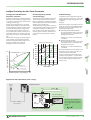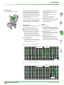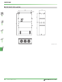
1
MITSUBISHI ELECTRIC
Frequency
Inverter
FR-F 540L EC
Technical Catalogue
AUDIN
Composants & systèmes d'automatisme
7 bis rue de Tinqueux - 51100 Reims - France
Tel. +33(0)326042021 • Fax +33(0)326042820
http://www.audin.fr • e-mail info@audin.fr
2003/2004
The New Frequency Inverter Series FR-F 540 EC
Saving
r
e
w
o
P
e
h
T
Inverter
The new FR-F 540L EC frequency inverters are available with outputs between 75 and 530 kW. They are ideal for high-load applications like pumps and ventilator fans.
These units use a 3-phase AC power supply and have an output
frequency range from 0.5 – 120 Hz.
Further Publications within the Factory Automation Range
Technical catalogues FR-E 500, FR-A 500 and FR-S 500
Technical
Catalogues
Product catalogue for frequency inverters and accessories
of the FR-E 500, FR-F 500 and FR-S 500 series
Technical catalogues MELSERVO and Motion Controllers
Product catalogues for MR-J2S series amplifiers, servo motors
and motion controllers with SSCNET connection
Technical catalogues PLC and HMI
Product catalogues for programmable logic controllers,
operator terminals, software, and accessories of the
MELSEC PLC series
Networks Technical Catalogue
Product catalogue for Master and Slave modules as well as accessories for the use of programmable logic controllers and frequency
inverters in open networks and MELSEC networks (art. no. 136730)
Additional services
You will find current information on updates, alterations, new items, and technical support on MITSUBISHI ELECTRIC's web pages
(www.mitsubishi-automation.com).
The products section of the MITSUBISHI home site includes various documentations of the whole product range by MITSUBISHI
ELECTRIC as well as the current version of this catalogue on hand. All manuals and catalogues can be downloaded.
The content is updated daily and to date is provided in German and English.
About this product catalogue
This catalogue is periodically updated due to product range enlargement, technical changes or new or changed features.
Texts, figures and diagrams shown in this product catalogue are intended exclusively for explanation and assistance in planning and ordering
the frequency inverter series FR-F 500L EC and the associated accessories. Only the manuals supplied with the devices are relevant for
installation, commissioning and handling of the devices and the accessories. The information given in these manuals must be read before
installation and commissioning of the devices or software.
Should questions arise with regard to the planning of devices described in this product catalogue, do not hesitate to contact MITSUBISHI
ELECTRIC EUROPE B.V. in Ratingen (Germany) or one of its distributors (see cover page).
© MITSUBISHI ELECTRIC EUROPE B.V. 08/2003 (1st edition - version A)
2
FR-F 540L EC
MITSUBISHI ELECTRIC
CONTENTS
FREQUENCY INVERTER FR-F 540L EC
SYSTEM DESCRIPTION
웇
웇
웇
웇
웇
Introduction to the FR-F series . . . . . . . . . . . . . . . . . . . . . . . . . . . . . . . . . . . . . . . . . . . . . . . . . . . . . . . . . . . . . . . . . . . . . . . . . . . . . 4
Energy conservation mode . . . . . . . . . . . . . . . . . . . . . . . . . . . . . . . . . . . . . . . . . . . . . . . . . . . . . . . . . . . . . . . . . . . . . . . . . . . . . . . . 5
Control functions, standards, communications and operation. . . . . . . . . . . . . . . . . . . . . . . . . . . . . . . . . . . . . . . . . . . . . . . 6
Specifications . . . . . . . . . . . . . . . . . . . . . . . . . . . . . . . . . . . . . . . . . . . . . . . . . . . . . . . . . . . . . . . . . . . . . . . . . . . . . . . . . . . . . . . . . . . . . 8
Terminal assignment. . . . . . . . . . . . . . . . . . . . . . . . . . . . . . . . . . . . . . . . . . . . . . . . . . . . . . . . . . . . . . . . . . . . . . . . . . . . . . . . . . . . . 10
OPERATION
N
MO
FWD
SET
PARAMETERS
웇 Overview . . . . . . . . . . . . . . . . . . . . . . . . . . . . . . . . . . . . . . . . . . . . . . . . . . . . . . . . . . . . . . . . . . . . . . . . . . . . . . . . . . . . . . . . . . . . . . . . 15
PROTECTIVE FUNCTIONS
웇 Overview of protective functions . . . . . . . . . . . . . . . . . . . . . . . . . . . . . . . . . . . . . . . . . . . . . . . . . . . . . . . . . . . . . . . . . . . . . . . . . 19
웇 Ressetting methods. . . . . . . . . . . . . . . . . . . . . . . . . . . . . . . . . . . . . . . . . . . . . . . . . . . . . . . . . . . . . . . . . . . . . . . . . . . . . . . . . . . . . . 21
APPLICATIONS
웇 Sample applications . . . . . . . . . . . . . . . . . . . . . . . . . . . . . . . . . . . . . . . . . . . . . . . . . . . . . . . . . . . . . . . . . . . . . . . . . . . . . . . . . . . . . 22
ACCESSORIES
Overview of internal and external options . . . . . . . . . . . . . . . . . . . . . . . . . . . . . . . . . . . . . . . . . . . . . . . . . . . . . . . . . . . . . . . . 24
Noise filters . . . . . . . . . . . . . . . . . . . . . . . . . . . . . . . . . . . . . . . . . . . . . . . . . . . . . . . . . . . . . . . . . . . . . . . . . . . . . . . . . . . . . . . . . . . . . . 26
DC reactors . . . . . . . . . . . . . . . . . . . . . . . . . . . . . . . . . . . . . . . . . . . . . . . . . . . . . . . . . . . . . . . . . . . . . . . . . . . . . . . . . . . . . . . . . . . . . . 26
Brake units . . . . . . . . . . . . . . . . . . . . . . . . . . . . . . . . . . . . . . . . . . . . . . . . . . . . . . . . . . . . . . . . . . . . . . . . . . . . . . . . . . . . . . . . . . . . . . 27
External brake resistors. . . . . . . . . . . . . . . . . . . . . . . . . . . . . . . . . . . . . . . . . . . . . . . . . . . . . . . . . . . . . . . . . . . . . . . . . . . . . . . . . . . 27
DIMENSIONS
웇
웇
웇
웇
웇
웇
Control panels . . . . . . . . . . . . . . . . . . . . . . . . . . . . . . . . . . . . . . . . . . . . . . . . . . . . . . . . . . . . . . . . . . . . . . . . . . . . . . . . . . . . . . . . . . . 28
Frequency inverters. . . . . . . . . . . . . . . . . . . . . . . . . . . . . . . . . . . . . . . . . . . . . . . . . . . . . . . . . . . . . . . . . . . . . . . . . . . . . . . . . . . . . . 29
Chokes . . . . . . . . . . . . . . . . . . . . . . . . . . . . . . . . . . . . . . . . . . . . . . . . . . . . . . . . . . . . . . . . . . . . . . . . . . . . . . . . . . . . . . . . . . . . . . . . . . 31
Filters . . . . . . . . . . . . . . . . . . . . . . . . . . . . . . . . . . . . . . . . . . . . . . . . . . . . . . . . . . . . . . . . . . . . . . . . . . . . . . . . . . . . . . . . . . . . . . . . . . . 32
Brake resistors . . . . . . . . . . . . . . . . . . . . . . . . . . . . . . . . . . . . . . . . . . . . . . . . . . . . . . . . . . . . . . . . . . . . . . . . . . . . . . . . . . . . . . . . . . . 33
Brake units . . . . . . . . . . . . . . . . . . . . . . . . . . . . . . . . . . . . . . . . . . . . . . . . . . . . . . . . . . . . . . . . . . . . . . . . . . . . . . . . . . . . . . . . . . . . . . 33
APPENDIX
웇 Order form . . . . . . . . . . . . . . . . . . . . . . . . . . . . . . . . . . . . . . . . . . . . . . . . . . . . . . . . . . . . . . . . . . . . . . . . . . . . . . . . . . . . . . . . . . . . . . 34
웇 Index . . . . . . . . . . . . . . . . . . . . . . . . . . . . . . . . . . . . . . . . . . . . . . . . . . . . . . . . . . . . . . . . . . . . . . . . . . . . . . . . . . . . . . . . . . . . . . . . . . . . 35
MITSUBISHI ELECTRIC
PU
D
FW
EXT
V
RE
REV
E
MOD
웇 Control panel FR-DU04. . . . . . . . . . . . . . . . . . . . . . . . . . . . . . . . . . . . . . . . . . . . . . . . . . . . . . . . . . . . . . . . . . . . . . . . . . . . . . . . . . . 12
웇 Control panel FR-PU04 . . . . . . . . . . . . . . . . . . . . . . . . . . . . . . . . . . . . . . . . . . . . . . . . . . . . . . . . . . . . . . . . . . . . . . . . . . . . . . . . . . . 13
웇
웇
웇
웇
웇
EL
L PAN
TRO
Hz
CON
A
V
U-04
FR-D
FR-F 540L EC
3
P
STO
ET
RES
SYSTEM DESCRIPTION
The Frequency Inverter FR-F 540L EC
N
MO
PU
D
FW
T
EX
V
RE
D
FW
REV
DE
MO
SET
P
STO
ET
RES
Hz
A
V
POWER
ALARM
MON
PU
EXT
REV
FWD
88
CHARGE
ALARM
MODE
SET
REV
FWD
STOP
RESET
DATA PORT
MITSUBISHI
F 500L
In addition to their outstanding performance and power delivery these units are
also very user-friendly.
The FR-F 540L EC inverters are available
with outputs from 75 – 530kW. All the
inverters are designed for connection to
3~ 380-480V (50/60Hz) power supplies.
The output frequency ranges from
0.5 to 120 Hz.
Hz
A
V
POWER
ALARM
MON
MODE
PU
EXT
REV
FWD
REV
FWD
STOP
RESET
SET
DATA PORT
MITSUBISHI
F 500
Proven Technology with New, Optimised Capabilities
High-tech processor technolgy
Optimum excitation control mode
The general design of the FR-F540 L EC family is based on the successful FR-A 540
(L-G). Just like the FR-A series, the FR-F 540
uses advanced ASIC components, state-of-the-art IGBT power semiconductors
and advanced signal processors.
The "optimum excitation control mode"
enables additional power savings that are
not possible with other types of inverters
designed for pump and fan systems.
The graph below shows a typical example
of the performance improvement that can
be achieved with this control mode.
Active current limiting
Tried and tested capabilities like the active
current limiting feature have been retained. However, the response characteristics
of the current limiting have been further
improved to prevent unwanted triggering
of the overcurrent protection. Transient
current surges like those generated when
a motor coasting in reverse is started or
when an input contactor is closed will no
longer trigger the current limiter.
100
90
Motor efficiency (percent)
EL
PAN
OL
Hz
CONTR
A
V
04
FR-DU-
The FR-F 540L EC is suitable for a very
broad spectrum of applications in the high
power range. With its excellent power-conservation capabilities it is ideal for pumps,
ventilation fans and applications with
reduced overload requirements, such as:
앬 Air conditioning systems, e.g. in
building services
앬 Air extraction systems
앬 Fans and blowers
앬 Hydraulics systems
앬 Compressors
앬 Sewage and drains systems
앬 Ground water pumps
앬 Heat pumps
앬 Drive systems with a high idling
percentage
80
70
60
50
40
30
20
10
0
5%
10%
25%
50%
75%
100%
Torque load (percentage of rated torque load)
Optimum excitation control mode
Standard inverter
No excitation control
4
FR-F 540L EC
120%
Innovative performance
optimisation
The drive characteristics of the FR-F540Lseries have been optimised for the special
needs of pump and fan applications. These
drive systems are characterised by a load
torque that increases by the cube of the
motor speed (variable curve). However, the
units can also be used to power other drive
types with reduced loads combined with
lower overload demands and no extreme
torque requirements at low frequencies –
the FR-F540L provides many benefits for
such applications. Of course, you can also
power standard applications with "constant" curves and maximum overloads of
150 %.
The inverters also include all the following
outstanding features:
앬 Power-saving mode
앬 Extended PID control
앬 PID control with multi-motor switching
function
앬 Disable defined frequency ranges
앬 2nd parameter set selectable for
different load characteristics
앬 Switch motor to direct mains operation
MITSUBISHI ELECTRIC
SYSTEM DESCRIPTION
Intelligent Technology that Cuts Power Consumption
Saving power with Mitsubishi
frequency converters
How do frequency inverters
conserve energy?
Reducing consumption and optimising the
utilisation of our valuable energy resources
is one of the greatest global environmental
challenges of our age.
Energy conservation mode is a standard
feature of the intelligent controller. It dynamically adjusts the voltage to motor requirements, eliminating unnecessary power
losses, which helps to further reduce power consumption. Frequency inverters are
particularly effective at conserving energy
when they are used to control pumps and
fans.
The amount of energy conservation (hysteresis) depends on the speed/torque fluctuations. The graph below provides an impressive example of the results of
intelligent control in a fan system.
The illustration at the bottom of the page
shows a blower system in which the air
flow is regulated by controlling the motor
with a frequency inverter instead of with a
damper on the exhaust side.
The graph below compares the motor power consumption of the frequency inverter
and damper solutions. At a flow rate of
60% the curve shows that the frequency
inverter system consumes a full 60% less
power than the motor with the damper
system.
Constant torque
pattern (Pr. no.14 = 0)
Frequency inverter
control
Power consumption (%)
Mechanical solution
0
Damper control (exhaust side)
80
70
60
50
40
30
20
In addition to the ecological benefits frequency inverters can also save a great deal
of money by radically cutting power consumption.
Example:
Based on the graph on the left and an electricity price of 14 cents per kWh, the following savings can be achieved with a system using a 75 kW motor:
앬 Conventional mechanical solution
At an air throughput of 60 % the power
consumption is 90 %, resulting in the
following annual costs:
75 kW x 0.9 x 0.14 € x 24 h x 365 days
= 82,782 €
앬 Frequency inverter solution
At an air throughput of 60 % the power
consumption is 30 %, resulting in the
following annual costs:
100
90
Power consumption (%)
100
Potential savings
Conserved
energy
Inverter control
75 kW x 0.3 x 0.14 € x 24 h x 365 days
= 27,594 €
This means that the inverter solution saves
€ 55,188 per year compared to the conventional mechanical system!
Clearly, a frequency inverter will pay for
itself in a very short time – and one must
also remember that the potential savings
increase with the power ratings of the
motors used.
10
0
0
Variable torque
pattern (Pr. no. 14 = 1)
40
60
80
100
Air quantity (%)
Energy conservation mode
(Pr. no. 14 = 1, Pr. no. 60 = 4)
Rotational speed (= air quantity) (%)
100
Application with potential for power savings
Power
supply
Frequency inverter
Hz
A
V
POWER
ALARM
MON
MODE
PU
EXT
REV
FWD
REV
FWD
STOP
RESET
SET
Duct
Exhaust
DATA PORT
MITSUBISHI
F 500
Belt
Blower
Cold source (chiller)
Heat source (heat pump)
Motor
Cold/hot
water
3-phase 400 V
Heat
exchanger
Air
The power PL required for a
fan or pump is proportional
to the cube of the rotational
speed n3
Air filter
Example of air handling unit
MITSUBISHI ELECTRIC
FR-F 540L EC
5
EL
PAN
OL
Hz
CONTR
A
V
04
FR-DU-
PU
N
MO
D
FW
T
EX
V
RE
D
FW
REV
DE
MO
SET
P
STO
ET
RES
SYSTEM DESCRIPTION
Intelligent Motor Control Functions
Extended PID control
EL
PAN
OL
Hz
CONTR
A
V
04
FR-DUN
MO
PU
D
FW
T
EX
V
RE
D
FW
REV
DE
MO
SET
P
STO
ET
RES
The FR-F500L supports extended PID
control. This feature makes it possible to
connect the process status signal to the
frequency inverter as a voltage signal
(0–10 V DC) or a current signal (0/4–20 mA
DC) and then use the analog input calibration function of the inverter to compensate
minor controller-related fluctuations.
In addition to this the frequency inverter
can also control up to four motors successively. This function is programmable; for
example, you can program it so that only
one motor is frequency-controlled and the
others are switched on and off under direct
mains power as required, or you can alternate between direct mains power and
frequency control for all four motors.
The graph on the right illustrates this multimotor switching function with a typical
example.
When implementing an application like
this you must plan the necessary number
of magnetic power contactors and the required number of output signal terminals
on the inverter. Care must also be taken to
ensure that the mains power is never switched to the inverter output.
Q max
Flow rate
Q3
Q2
Q1
Stop
Motor 1 (M1)
Motor 2 (M2)
Motor 3 (M3)
Motor 4 (M4)
Alternating mode *
Direct mode
Motor 1 (M1)
Motor 2 (M2)
Motor 3 (M3)
Motor 4 (M4)
VFD controlled operation
Conventional operation
Stop
World-standard specifications
The FR-F 540L EC conforms to the EMC
standards of the European Community. To
meet the requirements in your application
you must install an input EMC filter.
The EMC filters are available for inverters of
all performance ranges. Refer to page 24
for further details.
The frequency inverters of the FR-F 540L
EC series include a DC link reactor as standard equipment, and the reactor must be
used with these models.
The units of the FR-A 540(L-G) EC product
line are designed to be used world-wide
without further effort or certifications.
앬 World-wide CE, UL, cUL standard
compliant
앬 Selectable sink or source logic.
The logic for input and output signals
can be freely selected. The result is a
flexible and easy customisation of the
units to the needs of the world market.
앬 Extended rated input voltage
3~ 380–480 V; 50 Hz / 60 Hz
Tolerance: −15 %; +10 %
앬 Multiple language parameter unit
앬 Compatible to several world-wide
common communications standards
앬 MS-Windows compatible world-wide
standardised multi-language parameterising software
FR-F 540L EC
*
Motor 1 (M1)
Motor 2 (M2)
Motor 3 (M3)
Motor 4 (M4)
Electromagnetic compatibility
6
Time
Standard mode
* After switching the magnetic contactor the motor start
sequence switches from M1->M2->M3 to M2->M3->M1
The FR-F 540L EC therefore is a world product complying with all relevant standards
and easily adopting to the according needs
of a country.
Communications
For the integration in an automation plant a
serial interface RS485 is included as standard equipment. Through this interface up
to 32 inverters can be linked up. Open communications with standardised industrial
bus systems like Profibus/DP, CANopen
(Europe), DeviceNet (USA), and CC-Link
(Asia) can be realised easily via optional interface cards. This enables the integration of
the inverter in entire automation concepts.
MITSUBISHI ELECTRIC
SYSTEM DESCRIPTION
User-friendly Operation
Easy operation via control panel or
via software
The FR-DU04 control panel is included as
standard equipment of all inverters. It features a clear and easy operation of the inverter
and displays several operational and alarm
signals.. The integrated copy function
makes it possible to read out the entire
stored parameter set and transfer it to
another frequency inverter, or compare the
parameters with the settings in the other
inverter. The control panel can also be connected remotely via an extension cable.
The FR-PU04 control panel is optionally
available. It provides a long-life backlight LC-display. Operational data is
directly input on the numeric keypad.
Eight different selectable languages are
supported on the display. This control
panel too can be installed either directly
on the inverter or connected remotely with
a cable. You can define user groups with
which you can activate or change sets of
user-definable parameters for specific
applications.
CONTROL PANEL
Hz
A
V
FR-DU-04
MON
EXT
PU
REV
FWD
REV
MODE
50 0 0 Hz
- - - STOP EXT
MON
SET
EXT
HELP
SHIFT
ESC
7
8
9
PU
FWD
STOP
RESET
SET
PARAMETER UNIT
FR-PU-04
N
MO
D
FW
FR-DU04
4
5
6
1
2
3
SET
REV
STOP
0
The integrated copy function transfers the
entire parameter settings to other inverters
and thus shortens the initialisation time
significantly.
In addition to control panel operation the
frequency inverter can also be connected
to a standard PC via an RS-485 port and
operated from the PC with the optional
VFD setup software package. Version 2.4
and above of this package run under
Windows® 95, 98, Me and XP and also
WRITE
READ
RESET
FR-PU04
under Windows® NT and 2000. Using this
software you can configure, operate and
monitor multiple frequency inverters in a
network or directly from a single PC or
notebook computer.
Easy access to cooling fans
The easily accessable cooling fans can be
replaced quickly and easily if required.
The lifetime of the cooling fans can be
extended significantly through a selective
ON/OFF control specified by parameter 244.
Easy installation and maintenance
R
N
S
P1
Simple installation and removal of the control terminal block makes installation and
maintenance easier.
Easy transfer of parameter settings
via control panel
MITSUBISHI ELECTRIC
PU
D
FW
T
EX
V
RE
REV
DE
MO
FWD
User-friendly Maintenance and Handling
Once the parameter settings are specified,
they can be transferred from one inverter
to the other via the control panel.
EL
PAN
OL
Hz
CONTR
A
V
04
FR-DU-
Hz
A
V
POWER
ALARM
MON
PU
EXT
REV
FWD
88
CHARGE
ALARM
MODE
SET
REV
FWD
STOP
RESET
FR-F 540L EC
7
P
STO
ET
RES
SYSTEM DESCRIPTION
Specifications FR-F 540L EC
FR-F 540L
Product line
75 k
Rated motor
capacity �
[kW]
EL
PAN
OL
Hz
CONTR
A
V
N
MO
PU
D
FW
T
EX
V
RE
D
FW
REV
DE
MO
P
STO
ET
RES
SET
Input
160 k
185 k
220 k
280 k
375 k
450 k
530 k
185
220
250
315
400
530
530
90
110
132
160
185
220
280
375
450
530
260
302
360
432
477
610
750
1010
1010
150 % overlaod capacity � 144
180
216
260
302
360
432
547
722
866
1010
120 % overlaod capacity � 110
137
198
230
274
329
417
464
571
770
770
150 % overlaod capacity �
110
137
165
198
230
274
329
417
550
660
770
�
Overload
current rating � �
120 % of rated motor capacity for 0,5 s; 110 % for 1 min. (max. ambient temperature = 40 °C); typical e.g. for pumps and fans
Voltage �
3-phase, 0 V up to power supply voltage 햶
Frequency range
0,5–120 Hz
150 % of rated motor capacity for 0,5 s; 120 % for 1 min. (max. ambient temperature = 50 °C); typical e.g. for conveyor belts/centrifuges
Control method
High carrier frequency PWM control (V/F control), optimum excitation control
Modulation control
Sine evaluated PWM, Soft PWM
Carrier frequency
0.7 kHz / 1 kHz / 2.5 kHz (user adjustable)
Power supply voltage
3-phase, 380–480 V AC,15 % / +10 %
Input voltage range
323–528 V AC at 50 / 60 Hz
Power supply frequency
50 / 60 Hz ± 5 %
Frequency
setting values
120 % overload capacity � 110
137
198
230
274
329
364
464
571
770
770
150 % overload capacity �
110
137
165
198
230
274
329
417
550
660
770
Analog input
0.015 Hz / 50 Hz (connecting terminal 2: 12 bits / 0–10 V; 11 bits / 0–5 V, connecting terminal 1: 12 bits / -10–+10 V; 11 bits / -5–+5 V
Digital input
0.01 Hz
Frequency precision
±0.2 % of max. output frequency (temperature range 25 °C±10 °C) during analog input;
±0.01 % of max. output frequency during digital input
Voltage / frequency characteristics
Base frequency adjustable from 0 to 120 Hz;
constant torque or variable torque selectable; optional flexible 5-point V/f characteristics
Acceleration / deceleration time
0; 0.1 to 3600 s ndividual settings
Acceleration / deceleration characteristics
Linear or S-form course, user selectable
DC braking
Braking time and braking moment adjustable;
Operating frequency: 0–120 Hz, operating time: 0–10 s, voltage: 0–30 % (adjustable externally)
Torque boost
Manual and automatic torque boost
Stall prevention
Respones threshold 0–150 %, user adjustable, also via analog input
Motor protection
Electronic motor protection relay (rated current user adjustable)
Frequency
setting values
Control
signals for
operation Input
signals
8
132 k
160
180
Rated input
capacity �
[kVA]
Control
specifications
110 k
132
120 % overlaod capacity � 144
Rated output
capacity
[kVA]
Output
90k
90
150 % overlaod capacity � 75
Rated
current
[A]
04
FR-DU-
120 % overlaod capacity � 75
Analog input
0–5 V DC, 0–10 V DC, 0–±10 V DC, 0/4–20 mA
Digital input
From control panel or optional circuit board
Starting signal
Forward and reverse rotation, start signal automatic self-holding input (3-wire input) can be selected.
Multi-speed selection
Up to 7 speeds can be selected. (Each speed can be set between 0 and 120 Hz, running speed can be changed during operation from the control
unit (FR-DU04/FR-PU04)
2nd/3rd acceleration /
deceleration time
0 – 3600 seconds (acceleration and deceleration time can be set individually)
JOG operation
Jog operation via control panel or special JOG terminal
Current input selection
Frequency setting via current input signal 0/4 to 20 mA DC
Automatic restart
Selection of whether automatic restart is made or not after an instantaneous power failure
External thermal relay
Thermal relay contact input when the thermal relay provided externally is used to stop the inverter
MT-HC connection
Inverter operation enable input and instantaneous power failure detection input
External DC dynamic brake
External input for DC dynamic braking start
PID control valid
Selection for exercising PID control
PU<->external
operation
External selection between PU and external operation
PU operation external
interlock
External interlock switch-over of PU operation
Output stop
Instantaneous shut-off of inverter output (frequency, voltage)
Error message reset
Alarm retained at the activation of protective function is reset
FR-F 540L EC
MITSUBISHI ELECTRIC
SYSTEM DESCRIPTION
FR-F 540L
Product line
75 k
Control
Output
signals for signals
operation
Display
options
Protection
Displayed on
control panel
(FR-PU04/
FR-DU04)
Additional
displays on
control panel
FR-PU04
110 k
132 k
160 k
185 k
220 k
280 k
375 k
450 k
530 k
Operation state
Alarm functions
Relay output ... contactor (230 V AC / 0.3 A , 30 V DC/ 0.3 A)
Open collector output ... error message through alarm code (4 bits)
Analog signal
or
pulse train
One of the following output types can be selected:
Output frequency, motor current (constant or peak value), output voltage, frequency setting value, motor speed, converter output voltage
(constant or peak value), electronic thermal relay load rate, input power, output power, load meter, motor excitation current and reference
voltage output. Pulse train output (1440 Hz / full scale), or analog output (0 to 10 VDC).
Operatingstate
Output frequency, motor current (constant or peak value), output voltage, frequency setting value, motor speed, overload, converter output
voltage (constant or peak value), electronic thermal relay load rate, input power, output power, load meter, cumulative power ON time,
current operation time, cumulative power, regenerative brake duty, and motor load rate.
Alarm display
Error details are displayed after a protective function is activated. Up to 8 error codes can be stored.
Operating state
Signal status of input and output terminals, indication of installed options, indication of terminal assignment state.
Alarm display
Output voltage, output current, output frequency, cumulative power ON time before acivation of protective function.
Interactive
operating guide
Interactive guide for operation and troubleshooting via help function.
Functions
Overcurrent cutoff (during acceleration, deceleration, constant speed), regenerative overvoltage cutoff, undervoltage, instantaneous power
failure, overload cutoff (electronic thermal relay), ground fault overcurrent, output short circuit, overheating of main circuit, stall prevention,
overload warning, fin overheating, fan error, option error, parameter error, PU connection error, retry count exceeded, output phase error,
CPU error, 24 V DC power output short circuit, operation panel power supply short circuit;
output of group error message via relay contact (220 V AC / 0.3 A; 30 V DC / 0.3 A)
Protection
IP 00
Cooling
Others
90k
5 different signals can be selected from inverter running, up to frequency, instantaneous power failure (undervoltage), frequency detection, second frequency detection, during PU operation, overload alarm, electronic overcurrent protection pre-alarm, zero current detection, PID lower limit, PID upper limit, PID forward/reverse rotation, commercial power supply-inverter switch-over MC1, 2, 3, operation ready, fan fault and fin
overheat pre-alarm minor fault. Open collector output.
Power loss
[kW]
N
MO
2.75
4.12
4.80
5.55
6.75
7.50
9.45
12.0
10.6
10.6
150 % overload capacity � 2.25
2.75
3.375
4.12
4.80
5.55
6.75
8.59
11.25
9.0
10.6
Inverter weight [kg]
41
57
66
66
68
120
120
220
235
560
560
Choke weight [kg]
14
18
19
22
22
29
36
48
57
100
100
141045
141046
141047
141048
141049
141050
141051
141052
141053
142587
142588
Order information
Art. no.
D
FW
SET
햲 The performance values of the rated motor capacity are based on a 400 V motor voltage. At 120 % rating a maximum ambient temperature of 40 °C is allowed.
햳 The overload capacity indicated in % is the ratio of the overload current to the inverter’s rated current. For repeated duty, allow time for the inverter and motor to return to
or below the temperatures under 100% load.
햴 The maximum output voltage cannot exceed the power supply voltage. The maximum output voltage may be set as desired below the power supply voltage.
햵 The power supply capacity changes with the values of the power supply side inverter impedances (including those of the input reactor and cables).
햶 It is not possible to connect 1-phase motors.
General Operating Conditions
Item
Specifications
Ambient temperature in operation
-10 °C to +50 °C (non-freezing)
For selection of the load characteristics with a 120 % overload rating the max. temperature is 40 °C.
Storage temperature
-20 – +65 °C
Ambient humidity
Max. 90 % RH (non-condensing)
Altitude
Max. 1000 m above NN
Protection rating
Up to 22kW: IP 20 / from on 30 kW: IP00
Shock resistance
10 G (3 times each in 3 directions)
Vibration resistance
2 G: resistance to vibrations from 10 to 55 Hz for 2 hours along all 3 axes
Ambience conditions
For indoor use only, avoid environments containing corrosive gases, install in a dust-free location.
Certifications
UL / CSA / CE / EN
MITSUBISHI ELECTRIC
FR-F 540L EC
PU
D
FW
T
EX
V
RE
REV
DE
MO
Fan-cooling
120 % overload capacity � 2.25
EL
PAN
OL
Hz
CONTR
A
V
04
FR-DU-
9
P
STO
ET
RES
SYSTEM DESCRIPTION
Block Diagram
P1
P
N
Converter
Mains supply
L11
L21
EL
PAN
OL
Hz
CONTR
A
V
04
FR-DUN
MO
Motor
U
V
W
L1
L2
L3
Voltage
supply
PU
D
FW
T
EX
V
RE
D
FW
REV
DE
MO
P
STO
ET
RES
Input signal
circuits
SET
CHARGE
Protective
circuits
PC
STF
STR
STOP
RH
RM
RL
RT
JOG
MRS
AU
CS
SD
RES
Reset
ALARM
CPU
LSI
Control panel
Options
4–20 mA
±0–5 V
(10 V)
Error
output
AM
5
Analog
output
Hz
FM
SD
SE
RUN
SU
OL
IPF
FU
PU/DU
10E
10
2
5
4
1
A
B
C
Operating
state
and
error
output
LCD/LED display PU/DU
Terminal Assignment of Main Circuit Terminals
Function
Terminal
Designation
L1, L2, L3
Mains supply connection
Mains power supply of the inverter (380–480 V AC, 50/60 Hz)
External brake unit connection
An optional external brake resistor can be connected to the terminals P and N (up to 375 k) or you can connect the optional high
power factor converter (MT-HC) or the power regenerative converter (MT-RC).
P, N
Main circuit
connection
10
P1, P
(P0, P1)
Description
optional choke coil can be connected to the terminals P1 and P (up to 375 k) or P0 and P1 (450 k and 530 k).
Converter choke coil connection An
For all FR-F 540L inverters the supplied choke coil has to be installed to the mentioned terminals.
U, V, W
Motor connection
Voltage output of the inverter (3-phase, 0 V up to power supply voltage, 0.5–120 Hz)
L11, L21
Control circuit mains supply
connection
External power supply input for a separate supply of the control circuit
PE
Protective earth connection of inverter
FR-F 540L EC
MITSUBISHI ELECTRIC
SYSTEM DESCRIPTION
Terminal Asssignment of Signal Terminals
Function
Terminal
STF
Forward rotation start
The motor rotates forward, if a signal is applied to terminal STF
Reverse rotation start
The motor rotates reverse, if a signal is applied to terminal STR
STOP
Start self-retaining selection
The start signals are self-retaining, if a signal is applied to terminal STOP
Multi-speed selection
Preset of 7 different output frequencies
JOG
JOG mode selection
The JOG mode is selected, if a signal is applied to terminal JOG (factory setting). The inverters FR-A 540L-G 375 k and 450 k are not
equipped with a JOG terminal. The start signals STF and STR determine the rotation direction.
RT
Second parameter settings
A second set of parameter settings is selected, if a signal is applied to terminal RT.
Output stop
The inverter lock stops the output frequency without regard to the delay time. By changing a parameter the pulsed voltage of the
DC braking is output as long as the inverter lock is active.
MRS
RES
Interface
D
FW
Current input selection
Only, if the AU signal is ON, the inverter can be operated with the 4–20 mA frequency setting signal.
CS
Automatic restart after power
failure selection
The inverter restarts automatically after a power failure, if a signal is applied to the terminal CS.
SD
A determined control function is activated, if the corresponding terminal is connected to the terminal SD. The SD terminal is isolated
Common sink for contact input/ from the digital circuits via optocouplers.
reference potential
Reference potential for the pulse output FM. The terminal is isolated from the reference potential of the control circuit.
Common reference potential for 24 V DC/0.1 A output (PC terminal).
PC
24 V DC output
10
SET
24 V DC/0.1 A output.
Internal power supply source logic.
Output voltage 10 V DC.
Max. output current 10 mA.
Recommended potentiometer: 1 kΩ, 2 W linear
Output voltage 5 V DC.
Max. output current 10 mA.
Recommended potentiometer: 1 kΩ, 2 W linear
2
Input for frequency setting
value signal
The voltage setting value 0–5 (10) V is applied to this terminal. The voltage range is preset to 0–5 V.
The input resistance is 10 kΩ.
5
Reference point for frequency
setting value signal
Terminal 5 is the reference point for all analog setting values and for the analog output signal AM. The terminal is not isolated from
the reference potential of the control circuit and must not be earthed.
1
Auxiliary input for frequency
setting value signal
0–±5 (10) V DC
An additional voltage setting value signal of 0–±5 (10) V DC can be applied to terminal 1.
The voltage range is preset to 0–±10 V DC. The input resistance is 10 kΩ.
4
Input for current
setting value signal
DC 4–20 mA
The current setting value signal (DC 0/4–20 mA) is applied to this terminal. The input resistance is 250 Ω.
A, B, C
Potential free
alarm output
The alarm is output via relay contacts. The block diagram shows the normal operation and voltage free status. If the protective
function is activated, the relay picks up.The maximum contact load is 200 V AC / 0,3 A or 30 V DC / 0,3 A.
RUN
Signal output for
motor operation
The output is switched low, if the inverter output frequency is equal to or higher than the starting frequency.
The output is switched high, if no frequency is output or the DC brake is in operation.
SU
Signal output for frequency
setting value / current value
comparison
The SU output supports a monitoring of frequency setting value and frequency current value. The output is switched low, once the
frequency current value (output frequency of the inverter) approaches the frequency setting value (determined by the setting value
signal) within a preset range of tolerance.
IPF
Signal output for
instantaneous power failure
The output is switched low for a temporary power failure within a range of 15 ms ≤ tIPF ≤ 100 ms or for under voltage.
OL
Signal output for
overload alarm
The OL is switched low, if the output current of the inverter exceeds the current limit preset in parameter 22 and the stall prevention
is activated. If the output current of the inverter falls below the current limit preset in parameter 22, the signal at the OL output is
switched high.
FU
Signal output for
monitoring output frequency
The output is switched low once the output frequency exceeds a value preset in parameter 42 (or 43). Otherwise the FU output is
switched high.
SE
Reference potential for
signal outputs
Reference potential for the signals RUN, SU, OL, IPF, and FU. This terminal is isolated from the reference potential of the control
circuit P24.
FM
Pulse output
One of 16 monitoring functions can be selected, e.g. external frequency output. FM and AM output can be used simultaneously.
The functions are determined by parameters.
Either a moving coil gauge (measuring range: 1 mA) or a pulse counter with an initial setting of 1440 pulses/s at 60 Hz output
frequency (internal resistance of load min. 10 kΩ).
AM
Analog output
One of 16 monitoring functions can be selected, e.g. external frequency output. FM and AM output can be used simultaneously.
The functions are determined by parameters.
A DC voltmeter can be connected. The max. output voltage is 10 V.
—
Connection of
control panel (RS485)
Communications via RS485
I/O standard: RS485, Multi-Drop operation, max. 19200 Baud
MITSUBISHI ELECTRIC
FR-F 540L EC
PU
D
FW
T
EX
V
RE
REV
DE
MO
AU
Voltage output for
potentiometer
Signal
outputs
N
MO
An activated protective circuit is reset, if a signal is applied to the terminal RES (t > 0,1 s).
10 E
EL
PAN
OL
Hz
CONTR
A
V
04
FR-DU-
RESET input
Common
Setting value
specification
Description
STR
RH, RM, RL
Control
connection
Terminal name
11
P
STO
ET
RES
CONTROL PANELS
Control Panel FR-DU04 (Standard)
EL
PAN
OL
Hz
CONTR
A
V
04
FR-DUN
MO
PU
D
FW
T
EX
V
RE
D
FW
REV
DE
MO
SET
P
STO
ET
RES
The control panel FR-DU04 is the standard
control panel of the inverter FR-F 540L EC
and is included as standard equipment.
The control panel supports the input and
display of several control variables (parameters) and a monitoring and output of
current operational data. The data is displayed on a 4-digit LED display.
Besides a display and setting of parameters
all operating states of the inverter and motor can be monitored. Faults are indicated
by error codes.
The control panel can alternatively be attached directly on the inverter or via cable
connection mounted remotely, e.g. in a
control cabinet.
LED display
L
CONTROL PANE
Hz
A
V
FR-DU-04
PU
EXT
REV
MON
FWD
REV
MODE
4-digit 7-segment display for indication of
operational data, error codes, and several
functions.
Indication of unit
LED for indication of current unit:
앫 Frequency (Hz)
앫 Current (A)
앫 Voltage (V)
FWD
STOP
RESET
SET
Operating state indication
Indication of operating state and direction of
motor rotation:
앫 Monitor mode (MON)
앫 External operation (EXT)
앫 Operation via control panel (PU)
앫 Reverse rotation (REV)
앫 Forward rotation (FWD)
Menu Guide to the Control Panel FR-DU04
Frequency
setting
Monitor
FR-DU04
FR-DU04
CONTROL PANEL
Hz
A
V
MON
EXT
PU
REV
FWD
Hz
A
V
MON
SET
FR-DU04
CONTROL PANEL
MODE
● Frequency display
● Current display
● Voltage display
● Alarm display
Parameter
setting
EXT
PU
REV
FWD
Hz
A
V
MON
PU
REV
FWD
FR-F 540L EC
CONTROL PANEL
FWD
Hz
A
V
MON
2x
MON
EXT
PU
REV
FWD
MON
EXT
PU
REV
FWD
PU
REV
FWD
● Alarm history
● Alarm history clear
● Parameter clear
● Software version
FR-DU04
CONTROL PANEL
Hz
A
V
MON
EXT
PU
REV
FWD
CONTROL PANEL
Hz
A
V
SET
1,5 s
SET
햵 Press the ▲ key, then press and hold the
SET key for 1.5 s, to verify values
FR-DU04
CONTROL PANEL
Hz
A
V
EXT
SET
Hz
A
V
햳 Press and hold the SET key for 1.5 s, to read
all parameter values
SET
PU
REV
CONTROL PANEL
햴 Press the ▲ key, then press and hold the
SET key for 1.5 s, to write all values to the
destination inverter
FR-DU04
MODE
EXT
● External operation
● Operation via control panel
● JOG operation
햲 Press the MODE key twice
and the ▼ key twice
2x
FR-DU04
MODE
SET
● Parameter menu
● Parameter number
● Parameter value specification
● Parameter value storage
FR-DU04
12
Hz
A
V
MON
EXT
Help
CONTROL PANEL
MODE
SET
● Frequency display
● Frequency setting
● Frequency storage
Via the control panel parameters can be
transferred from one inverter to another.
For that purpose first read out the parameter settings from the source inverter,
then connect the control panel to the
destination inverter and transfer the parameters. Inititalising and setting times are
reduced significantly that way.
The example besides illustrates the
procedure of copying parameters via the
control panel FR-DU04.
FR-DU04
CONTROL PANEL
MODE
SET
Copying parameters
Operating mode
MON
EXT
PU
REV
FWD
SET
1,5 s
MITSUBISHI ELECTRIC
CONTROL PANELS
Control Panel FR-PU04 (Optional)
The control panel FR-PU04 with extended
functions is available as optional accessory.
This control panel provides a 10-key keypad for a direct entering of numerical
values. A 4-row LC display returns operational data, parameter names or status
and error messages in uncoded text.
The control panel displays text in the
following selectable languages:
English, German, French, Spanish,
Swedish, Italian, Finnish, and Japanese.
In addition to the functions of the
standard control panel the FR-PU04 displays and monitors 21 different values
and states in total.
The control unit FR-PU04 is used instead of
the standard control unit FR-DU04 and can
be replaced by this after use.
PARAMETER UNIT
FR-PU-04
LCD display
50 0 0EXHzT
4-row LCD display (backlit)
앫 Interactive parameter setting
앫 Help function
앫 Error indication
앫 21 different displays (frequency, current,
voltage, etc.)
- - - STOP
MON
SET
EXT
HELP
SHIFT
ESC
Buttons for operating mode selection
N
MO
8
9
4
5
6
1
2
3
WRITE
READ
FWD
REV
STOP
RESET
The desired operating mode is selected by
pressing the buttons MONITOR, SET, EXT OP or
PU OP.
SET
Function keys and numerical keys
Keys for the selection of specific functions via
the display and the entering of numerical
values.
Displaying the parameter list
Display of
output
MONITOR
0 0 0 Hz
- - - STOP EXT
Copying parameters
Press the SET key and then the ▲ key to
enter the copy mode. Now you find three
choices:
앬 Press the READ key to read out all
parameters from the inverter.
앬 Press the WRITE key to write
parameters to the inverter.
앬 Press the ▼ key to verify the values
stored in the control panel and the
inverter.
Display of
output current
SHIFT
SHIFT
0.00Hz
0.00A
0. 0V
- - - STOP EXT
0 00
A
- - - STOP EXT
Display of
output voltage
SHIFT
SHIFT
Others
0 00V
SHIFT
SHIFT
Al ar m Hi stor y
<READ>
MITSUBISHI ELECTRIC
HELP
<HELP>
- - - STOP EXT
Display of
alarm history
PU
D
FW
T
EX
V
RE
REV
DE
MO
Menu Guide to the Control Panel FR-PU04
Press the SET key to enter the parameter
setting menu. Then press the HELP key to
display the parameter lists. After pressing
the READ key, the according parameter
value will be read in.
EL
PAN
OL
Hz
CONTR
A
V
04
FR-DU-
D
FW
7
0
PU
READ
SHIFT
Monitor
selection
Display of
alarms
(up to 8)
1 UVT 5
2 UVT 6
7
3
8
4
FR-F 540L EC
13
P
STO
ET
RES
CONTROL PANELS
Operating Modes
N
MO
D
FW
REV
DE
MO
P
STO
ET
RES
SET
I
L1
L2
I
L2
V
L3
I
L3
W
U
PC
S1
Start
S2
Frequency
setting
R1
STR
STF
10
2
5
Operation from the control panel
The direction of rotation and frequency
setting of the inverter are controlled from
the control panel.
The setting of the output frequency is
increased or decreased via the ▲ and ▼
keys.
Motor
L1
These connections
are required for
combined
operation or
operation by
external signals.
PU
D
FW
T
EX
V
RE
FR-F 540 EC
Power
EL
PAN
OL
Hz
CONTR
A
V
04
FR-DU-
Q1
Sample connection
The inverter can alternatively be operated
via external signals or directly via the control panels FR-DU04 or FR-PU04.
The operating mode on the control panel
FR-DU04 is selected in the operating mode
menu or on the control panel FR-PU04 by
pressing the EXT OP key for external signal
operation and PU OP for control panel
operation.
Operation by external signals
The example below shows the operational
steps for a frequency setting with following motor start and motor stop.
The direction of rotation and frequency
setting of the inverter are controlled by external signals. The following figure shows
the display on the control panel FR-DU04
for forward rotation of the motor and a
frequency of 50 Hz.
FR-DU04
CONTROL PANEL
Hz
A
V
MON
FR-DU04
햲 Press the MODE key
CONTROL PANEL
EXT
PU
REV
FWD
Hz
A
V
MODE
MON
EXT
PU
REV
FWD
Combined operation
FR-DU04
CONTROL PANEL
Hz
A
V
햳 Set frequency with SET key
SET
MON
EXT
PU
REV
FWD
FR-DU04
햴 Start motor
In addition to the operation by external
signals and the operation from the control
panel (FR-DU04 / FR-PU04) the inverter can
be operated in combined operation mode.
앬 Setting value preset from the control
panel and external starting signal.
앬 External setting value signal and starting signal from the control panel.
CONTROL PANEL
Hz
A
V
FWD
REV
MON
EXT
PU
REV
FWD
or
FR-DU04
햵 Stop motor
14
FR-F 540L EC
STOP
RESET
CONTROL PANEL
Hz
A
V
MON
EXT
PU
REV
FWD
MITSUBISHI ELECTRIC
PARAMETERS
Parameter Overview
Function
Basic
parameters
Parameter
Setting range
Meaning
Default setting
0
Torque boost (manual)
0–30 %
1%
1
Maximum output frequency
0–120 Hz
60 Hz
2
Minimum output frequency
0–120 Hz
0 Hz
3
V/f characteristics (base frequency)
0–120 Hz
50 Hz
4
1. Multispeed (high) preset - RH 햳
0–120 Hz
60 Hz
5
2. Multispeed (high) preset - RM 햳
0–120 Hz
30 Hz
6
3. Multispeed (high) preset - RL 햳
0–120 Hz
10 Hz
7
Acceleration time
0–360 s / 0–3600 s
15 s
8
Deceleration time
0–360 s / 0–3600 s
30 s
9
Electronic thermal overload relay (motor protection)
0–3600 A
Rated current
10
DC injection brake (initial frequency)
0–120 Hz / 9999
3 Hz
11
DC injection brake (operation time)
0–10 s / 8888
0.5 s
12
DC injection brake (voltage)
0–30 %
1%
13
Starting frequency
0–60 Hz
0.5 Hz
14
Selection of load pattern
15
JOG frequency
16
JOG acceleration and deceleration time
17
MRS input selection
19
Maximum output voltage
20
Acceleration / deceleration reference frequency
EL
PAN
OL
Hz
CONTR
A
V
04
FR-DUN
MO
PU
D
FW
T
EX
V
RE
D
FW
REV
Parameters for
standard drive
operation
Settings of
control outputs
2nd parameter
settings
0/1
1
0–120 Hz
5 Hz
0–360 s / 0–3600 s
0.5 s
0, 2
0
0–1000 V / 8888 / 9999
8888
1–120 Hz
50 Hz
21
Acceleration / deceleration time increments
0/1
0
22
Stall prevention operation level 햸
0–150 % / 9999
120 %
23
Stall prevention operation at double speed
0–200 % / 9999
9999
24
Multispeed preset (speed 4)
햸
0–120 Hz / 9999
9999
25
Multispeed preset (speed 5) 햸
0–120 Hz / 9999
9999
26
Multispeed preset (speed 6) 햸
0–120 Hz / 9999
9999
27
Multispeed preset (speed 7) 햸
0–120 Hz / 9999
9999
28
Multi-speed input compensation
0/1
0
29
Acceleration / deceleration pattern
30
Regenerative function selection
0/1/2/3
0
0/2
0
31
32
Frequency jump 1A
0–120 Hz / 9999
9999
Frequency jump 1B
0–120 Hz / 9999
9999
33
Frequency jump 2A
0–120 Hz / 9999
9999
34
Frequency jump 2B
0–120 Hz / 9999
9999
35
Frequency jump 3A
0–120 Hz / 9999
9999
36
Frequency jump 3B
0–120 Hz / 9999
9999
37
Speed display
0 / 1–9998
0
38
Automatic torque boost
0–200 %
0
39
Automatic torque boost operation starting current
0–3600 A
0
10 %
41
Setting value / current value comparison (SU output)
0–100 %
42
Output frequency monitoring (FU output)
0–120 Hz
6 Hz
43
Output frequency monitoring / reverse rotation
0–120 Hz / 9999
9999
44
2. Acceleration / deceleration time
45
2. Deceleration time
0–360 s / 0–3600 s
5s
0–360 s / 0–3600 s / 9999
9999
46
2. Manual torque boost
0–30 % / 9999
9999
47
2. V/f characteristics (base frequency)
0–120 Hz / 9999
9999
0–150 %
120 %
48
2. Stall prevention operation current
49
2. Stall prevention operation frequency
50
2. Output frequency monitoring
MITSUBISHI ELECTRIC
0–120 Hz / 9999
0 Hz
0–120 Hz
30 Hz
FR-F 540L EC
DE
MO
SET
15
P
STO
ET
RES
PARAMETERS
Parameter
Function
52
Display
functions
Restart
EL
PAN
OL
Hz
CONTR
A
V
04
FR-DUN
MO
PU
D
FW
T
EX
V
RE
Aux. functions
D
FW
REV
DE
MO
P
STO
ET
RES
SET
Operation
settings
VF 5 points
adjustable
Communications
functions
PID control
16
Meaning
LCD main display on control panel
햳
Setting range
Default setting
0 / 5 / 6 / 8 / 10–14 / 17 / 20 / 23 /
24 / 25 / 100
0
53
Bar graph in LCD display 햳
54
FM terminal function selection 햳
55
Frequency monitoring reference 햳
0–120 Hz
50 Hz
56
External current monitoring reference 햳
0–3600 A
Rated current
57
Restart coasting time after power failure
0–30 s / 9999
9999
58
Restart cushion time before automatic synchronisation
0–60 s
1s
59
Selection of digital motor potentiometer
0/1/2
0
0–3 / 5 / 6 / 8 / 10–14 / 17
1
1–3 / 5 / 6 / 8 / 10–14 / 17 / 21
1
60
Intelligent mode selection
0/3/4/9
0
61
Rated current for intelligent mode
0–3600 A / 9999
9999
62
Current limit for intelligent mode (acceleration)
0–150 % / 9999
9999
63
Current limit for intelligent mode (deceleration)
0–150 % / 9999
9999
65
Selection of protective function for automatic restart
0–5
0
0–120 Hz
50 Hz
66
Starting frequency for stall prevention at boost frequency
67
Number of restart retries
68
Waiting time for automatic restart retry
0–10 / 101–110
0
0–10 s
1s
69
Counting of automatic restart retries
0
0
70
Special regenerative brake duty
0–100 %
0%
71
Applied motor
0/1/2
0
72
PWM frequency selection 햳
0/1/2
1
73
Specification of setting value input data
0–5 / 10–15
1
74
Setting value signal filter
75
Reset condition / connection error / stop 햳
76
77
0–8
1
0–3 / 14–17
14
Coded alarm output
0/1/2
0
Write protection for parameters 햳
0/1/2
0
78
Prevention of reverse rotation
0/1/2
0
79
Operation mode selection
100
V/f1 frequency 햲
101
V/f1 voltage 햲
102
V/f2 frequency 햲
103
V/f2 voltage 햲
104
V/f3 frequency 햲
105
V/f3 voltage 햲
햲
106
V/f4 frequency
107
V/f4 voltage 햲
108
V/f5 frequency 햲
109
0–4 / 6–8
0
0–120 Hz / 9999
9999
0–1000 V
0
0–120 Hz / 9999
9999
0–1000 V
0
0–120 Hz / 9999
9999
0–1000 V
0
0–120 Hz / 9999
9999
0–1000 V
0
0–120 Hz / 9999
9999
V/f5 voltage 햲
0–1000 V
0
117
Station number
0–31
0
118
Communication speed
48 / 96 / 192
192
119
Stop bit length/data length
120
Parity check presence/absence
0 / 1 data length 8; 10 / 11 data length 7
1
0/1/2
2
121
Number of communication retries
0–10 / 9999
1
122
Communication check time interval
0–999.8 s / 9999
9999
123
Wait time setting
0–150 ms / 9999
9999
124
CR / LF absence/presence selection
128
PID action selection
0/1/2
1
10 / 11 / 20 / 21
10
129
130
PID proportional band
0.1–1000 % / 9999
100 %
PID integral time
0.1–3600 s / 9999
131
1s
Upper limit for actual value
0–100 % / 9999
9999
132
Lower limit for actual value
0–100 % / 9999
9999
133
PID action set point via parameter
134
PID differential time
FR-F 540L EC
0–100 %
0%
0.01–10.00 s / 9999
9999
MITSUBISHI ELECTRIC
PARAMETERS
Function
Commercial
power supply
switch-over
Backlash
Parameter
Meaning
135
Switch-over sequence output terminal selection
136
Setting range
Default setting
0/1
0
MC switch-over interlock time at alarm occurrence
0–100 s
1s
137
Start waiting time
0–100 s
0.5 s
138
Selection of MCs at alarm occurrence
139
Response frequency of MCs
140
Backlash acceleration stopping frequency 햲
0–120 Hz
1 Hz
141
Backlash acceleration stopping time 햲
0–360 s
0.5 s
142
Backlash deceleration stopping frequency 햲
0–120 Hz
1 Hz
143
Backlash deceleration stopping time 햲
0–360 s
0.5 s
144
Speed setting switchover
0 / 2 / 4 / 6 / 8 / 10 / 102 / 104 / 106 / 108 / 110
4
0/1
0
0–60 Hz / 9999
9999
EL
PAN
OL
Hz
CONTR
A
V
04
FR-DUN
MO
PU
D
FW
T
EX
V
RE
D
FW
REV
Display
145
Language selection
0–7
1
Auxiliary
functions
148
Stall prevention level at 0 V input
0–150 %
120 %
149
Stall prevention level at 10 V input
0–150 %
150 %
Output current
detection
152
Zero current detection level
0–200 %
5%
153
Zero current detection period
0–1 s
0.5 s
Help functions
Aux. function
Restart
Aux. functions
Initial monitor
User functions
Terminal
functions
selection
Aux. function
Help functions
Aux. functions
154
Voltage reduction selection during stall prevention operation
0/1
1
155
RT activated condition
0 / 10
0
156
Stall prevention operation selection
0–31 / 100 / 101
0
157
OL signal waiting time
158
AM terminal function selection
160
User group read selection 햳
162
Automatic restart after instantaneous power failure selection
163
First cushion time for automatic restart
0–25 s
0
1–3 / 5 / 6 / 8 / 10–14 / 17 / 21
1
0 / 1 / 10 / 11 / 9999
9999
0 / 1 / 10 / 11
0
0–20 s
0s
164
First cushion voltage for automatic restart
0–100 %
0%
165
Restart stall prevention operation level
0–150 %
120 %
168
169
170
Parameters set by the manufacturer. Do not set!
Watt-hour meter clear
—
—
—
—
0
0
171
Current operation hour meter clear
0
0
173
User group 1 parameter registration
0–999
0
174
User group 1 parameter deletion
175
User group 2 parameter registration
176
User group 2 parameter deletion
180
RL terminal function selection
0
181
RM terminal function selection
1
182
RH terminal function selection
183
RT terminal function selection
184
AU terminal function selection
0–999 / 9999
0
0–999
0
0–999 / 9999
0
0–7 / 10–14 /
16 / 9999
SET
2
3
4
185
JOG terminal function selection
186
CS terminal function selection
6
190
RUN terminal function selection
0
191
SU terminal function selection
192
IPF terminal function selection
193
OL terminal function selection
194
FU terminal function selection
195
ABC terminal function selection
199
User's initial value setting
0–999 / 9999
0
240
Soft-PWM setting 햳
0/1
1
5
0
0–5 / 8 / 10 / 11 /
13–19 / 25 / 26 /
98–105 / 108 / 110 /
111 / 113–116 /
125 / 126 / 198 /
199 / 9999
1
2
3
4
99
244
Cooling fan operation selection
0/1
251
Output phase failure protection selection
0/1
1
252
Gain overlay for setting voltage
0–200 %
50 %
253
Offset overlay for setting voltage
0–200 %
150 %
MITSUBISHI ELECTRIC
DE
MO
FR-F 540L EC
17
P
STO
ET
RES
PARAMETERS
Function
Special
functions
N
MO
Default setting
Refer to the options instruction manual
for further details.
0/1
0
Operation command write
339
Speed command write
0/1
0
340
Link start mode selection
0/1/2
0
341
CR LF precense/absent selection
0/1/2
1
Aux. functions
342
E2PROM write selection
0/1
0
D
FW
REV
DE
MO
300 – 337
Setting range
Refer to the options instruction manual
for further details.
338
PU
D
FW
T
EX
V
RE
Meaning
Parameters for inboard options
(optional selectable if apropriate option board is installed)
Communications
functions
EL
PAN
OL
Hz
CONTR
A
V
04
FR-DU-
Parameter
P
STO
ET
RES
SET
Advanced
PID control
Calibration
functions
Auxiliary
functions
500
Auxiliary motor operation selection
0/1/2/3
0
501
Motor switch-over selection
0/1/2
0
502
MC switching interlock time
0–100 s
1s
503
Start waiting time
0–100 s
1s
504
Auxiliary motor connection-time deceleration time
0–3600 s
1s
505
Auxiliary motor disconnection-time acceleration time
0–3600 s / 9999
1s
506
Output stop detection time
0–3600 s / 9999
9999
507
Output stop detection level
0–120 Hz
0 Hz
508
Output stop cancel process value level
0–100 %
100 %
509
Auxiliary motor 1 starting frequency
0–120 Hz
50 Hz
510
Auxiliary motor 2 starting frequency
0–120 Hz
50 Hz
511
Auxiliary motor 3 starting frequency
0–120 Hz
50 Hz
512
Auxiliary motor 1 stopping frequency
0–120 Hz
0 Hz
513
Auxiliary motor 2 stopping frequency
0–120 Hz
0 Hz
514
Auxiliary motor 3 stopping frequency
0–120 Hz
0 Hz
515
Auxiliary motor start delay frequency
0–3600 s
5s
516
Auxiliary motor stop delay frequency
571
Starting frequency holding time
900
FM terminal calibration 햳
901
AM terminal calibration
902
Frequency setting voltage bias
903
904
905
햳
0–3600 s
5s
0–10 s / 9999
9999
Calibration range
—
Calibration range
—
0–60 Hz / [0–10 V]
0 Hz / [0 V]
Frequency setting voltage gain
1–120 Hz / [0–10 V]
50 Hz / [5 V]
Frequency setting current bias
0–60 Hz / [0–20 mA]
0Hz/[4mA]
Frequency setting current gain
1–120 Hz / [0–20 mA]
50 Hz / [20 mA]
990
Buzzer control for keyboard
0/1
1
991
Calibration for the LC display of the parameter unit
0–63
53
Remarks to the table:
햲
Can only be accessed, if parameter 29 is set to the value 3.
햳
These parameters allow their settings to be changed during operation if 0 (factorysetting) has been set in Pr. 77. (Note that the Pr. 72 and Pr. 240 settings cannot be changedduring external operation.).
Wether a parameter can be changed during operation depends also on the setting of paramter 160. This parameter is factory set to "9999" which means that a parameter setting is not possible before this
parameter 160 is changed. For more detailed informations please refer to the FR-F500 users manual.
18
FR-F 540L EC
MITSUBISHI ELECTRIC
PROTECTIVE FUNCTIONS
Protective Functions Overview
The frequency inverter FR-F 540L EC provides a large number of protective functions
that protect the drive and the inverter
against damage in case of any malfunction.
Display on
control panel
FR-DU04
E.OC1
E.OC2
Meaning
If an error occurs, the output of the inverter is suspended and the control panel
returns an error message.
Description
Remedy
A) The output current of the inverter has reached or exceeded 200 % of the rated current during
the acceleration, deceleration, or at constant speed.
The cause for the activation of the protective
function is a short circuit or a ground fault
across the main outputs, an exceeding moment
of inertia of the load (GD2), too short acceleration / deceleration time presets, restart during
a motor idling phase, operation of a motor with
an exceeding capacity.
Overcurrent 1
(acceleration)
Overcurrent 2
(const. speed)
B) The temperature of the main circuits of the inverter rises rapidly.
Overheating due to insufficient cooling (defective cooling fan or choked heat sink).
E.OC3
Overcurrent 3
(deceleration)
E.OV1
Overvoltage 1
(acceleration)
E.OV2
Overvoltage 2
(constant speed)
E.OV3
Overvoltage 3
(deceleration)
E.THM
Overload
(motor)
E.THT
Overload
(inverter)
E.IPF
Instantaneous
power failure protection
The output of the inverter is suspended and the alarm message returned, if the power supply fails
for more than 15 ms. If the power supply fails for more than 100 ms, the inverter shuts down com- Check the power supply.
pletely. In this case after restoring the power supply the inverter is in the power ON state. If the
power failure stays below 15 ms, the operation is proceeded normally.
E.UVT
Undervoltage
The input voltage of the inverter has fallen below the minimum value. The protective function is
activated, if the input voltage falls below the minimum value.
An undervoltage can occur, if the capacity of
the mains transformer is not sufficient or if a
high capacity motor is turned ON connected to
the same mains supply circuit.
E.FIN
Overheating of
heat sink
In case of an overheating of the heat sink the temperature sensor responds and the inverter is
stopped.
Check ambient temperature.
In most cases the protective function is activated due to a too short deceleration time
preset or a regenerative overload.
The converter voltage has increased highly due to regenerative energy. The overvoltage limit was
exceeded during acceleration, deceleration, or at constant speed.
Remedy by increasing the deceleration time of
connecting an external brake unit.
An overvoltage in the mains power supply
activates this protective function as well.
The electronic overload protection for the motor or inverter was activated.
The electronic motor protection switch continually detects the motor current and the output frequency of the inverter. If a self-cooling motor operates over a long period at low speed but high
torque, the motor is thermally overloaded and the protective function is activated.
If several motors are operated by one inverter the motor protection switch will not operate properly.
In this case deactivate the motor protection and replace it by external protection switches.
Decrease the motor load to avoid an activation.
Check whether the performance range of the
motor and inverter correspond.
E.GF
Ground failure
An overcurrent occured due to a ground failure upon the inverter output (load).
Check load connections (motor circuit).
E.OHT
Activation of an external
motor protection relay
(thermal contact)
An external motor protective switch was activated.
If an external motor protective switch for thermal monitoring is used, this switch can activate the
protective function of the inverter.
Check motor load and drive.
E.OLT
Stall prevention
overload
A long lasting excess of the current limit (OL display) shut down the inverter.
Reduce the load.
Check the preset values for the current limit
(parameter 22) and the stall prevention
selection (parameter 156).
E.OPT
Error in an optional unit
A dedicated inboard option does not operate properly.
The protective function is activated, if an internal option is improperly installed or connected.
Check connections and connectors of the
optional unit.
E.OP1
bis
E.OP3
Error in combination with The protective function is activated for a fault (e.g. transmission error) of an internal optional unit.
an option board
E.PE
Memory error
Erroronaccessofthedatamemoryoftheinverter.
Please contact your nearest MITSUBISHI
ELECTRIC representative if the error occurs
repeatedly.
E.PUE
Control panel connection
error
A connection error between inverter and control panel occurred during operation. This alarm is
only returned, if parameter 75 is set to “2", ”3", “16", or ”17".
Check the connection of control panel.
MITSUBISHI ELECTRIC
Check the function settings of the optional unit.
FR-F 540L EC
19
EL
PAN
OL
Hz
CONTR
A
V
04
FR-DUN
MO
PU
D
FW
T
EX
V
RE
D
FW
REV
DE
MO
SET
P
STO
ET
RES
PROTECTIVE FUNCTIONS
Display on
control panel
FR-DU04
Meaning
Description
Remedy
E.RET
Automatic restart retry
exceeded
After activation of a protective function the inverter failed to be restarted automatically within the
number of retries specified in parameter 67.
Remedy the actual cause of the originary
protective function.
E.CPU
CPU error
Scan time of CPU was exceeded.
Restart the inverter.
Contact the customer service if the error
occurs again.
E.E6
CPU error
E.E7
CPU error
Communication error with the built-in CPU
Restart the inverter. Contact the customer
service if the error occurs again.
Err
Error
CPU error
Please contact your nearest MITSUBISHI
ELECTRIC representative if the error occurs
repeatedly.
E.LF
Open output phase
protection
One of the phases (U, V, W) is not connected.
Check the connections.
E.P24
24 V DC power output
short circuit
The 24 V DC output at the PC terminal is short circuited.
Eliminate short circuit.
E.CTE
Short circuit in the
control panel
The power supply of the control unit is short circuited.
Eliminate short circuit. Check the control panel
and the connecting cable.
Inverter was stopped via
control panel
STOP key on the control panel was pressed during external operating mode.
Check the parameter 77.
Overcurrent during
acceleration
If a current of more than 120 % 햳 of the rated inverter current flows in the motor, this function
stops the increase in frequency until the overload current reduces to prevent the inverter from
resulting in overcurrent shut-off. When the overload current has reduced below 120 %, this
function increases the frequency again.
EL
PAN
OL
Hz
CONTR
A
V
04
FR-DUN
MO
PU
D
FW
T
EX
V
RE
D
FW
REV
DE
MO
P
STO
ET
RES
SET
PS
OL
oL
E.15 햳
If a current of more than 120 % 햳 o of the rated inverter current flows in the motor, this function
Overcurrent during
lowers the frequency until the overload current reduces to prevent overcurrent shut-off. When the
constant speed operation overload current has reduced below 120 %, this function increases the frequency up to the set
value.
Overcurrent during
deceleration
If a current of more than 120 % 햳 of the rated inverter current flows in the motor, this function
stops the decrease in frequency until the overload current reduces to prevent theinverter from
resulting in overcurrent shut-off. When the overload current has reduced below 120 %, this
function decreases the frequency again.
Overvoltage during
deceleration
If the regenerative energy of the motor increases too much to exceed the brake capability, this
function stops the decrease in frequency to prevent overvoltage shut-off. As soon as the
regenerative energy has reduced, deceleration resumes.
Increase the deceleration time with Pr. 8
"deceleration time".
The heat sink of brake unit is overheated.
Reduce the load moment or brake frequency;
clean the heat sink; replace the cooling fan
DC fuse is blown.
Eliminate the short-circuit and replace the fuse
The control board is overheated.
Replace the cooling fan; check the ambient
temperature
An overcurrent on the output has occured.
Eliminate the short-circut or short to ground;
replace the motor; increase the brake time;
reduce the load fluctuations, increase the
acceleration time; check the brake operation
Power supply for cooling fan fails.
Eliminate the short-circuit; replace the power
supply for cooling fan; replace the fuse
General overcurrent
Eliminate the short-circuit and replace the fuse;
eliminate the short-circuit on output or short to
ground; replace the motor and reduce the load
The heat sink is overheated.
Clean or replace the heat sink; check the
ambient temperature
A gate power supply failure has occured.
Eliminate the short-circuit; replace the gate
power supply
Main circuit failure
햲
Please refer to the FR-F500 user's manual for a detailed description of the error message E.15.
햳
The stall prevention operation current may be set as desired (Pr. 22). It is factory-set to 120%
20
Increase the stall prevention operation level
with Pr. 22 "stall prevention operation level"
or disable stall prevention with Pr. 156 "stall
prevention operation selection".
FR-F 540L EC
MITSUBISHI ELECTRIC
PROTECTIVE FUNCTIONS
Resetting Methodes
When a protective function is activated,
the output of the inverter is switched off.
The motor coasts to a halt. The output
remains switched off until the error cause
is eliminated and the inverter reset.
The inverter can be reset following three
different methods:
If on occurrence of an error the input protection contactor is toggled the error message cannot be retained, since there is no
power supply for the control circuit.
If the error message is intended to be
retained in spite of an activation of the protectve contactor, the control circuit has to
be supplied by a separate power supply.
앬 Switch the power supply OFF and ON
again.
앬 Switch the reset signal ON for at least
0.1 s.
앬 Press the RESET key on the control
panel.
If the reset signal is ON continuously, the
control panel FR-DU04 returns an error
message while the control unit FR-PU04
indicates that the reset procedure is in
progress.
When a protective function is activated,
the control panel FR-DU04 returns an error
code as listed in the table above. The control panel FR-PU04 returns error messages
in clear.
MITSUBISHI ELECTRIC
Separate power supply for the
control circuit
The figure on the right shows the
connection of the separate 380-480 V AC
(-15%/+10%) power supply for the control
circuit. The current consumption is 2 A.
Prior to the connection remove the two
short bars upon L11 and L21 on the
inverter.
Please refer to the according manual for a
precise description of the connection.
Q1
Netz
FR-F 500
L1
I
L1
L2
I
L2
V
L3
I
L3
W
U
EL
PAN
OL
Hz
CONTR
A
V
04
FR-DUN
MO
PU
D
FW
T
EX
V
RE
D
FW
REV
DE
MO
SET
Separate
mains supply
of control circuit
L11
L21
FR-F 540L EC
21
P
STO
ET
RES
APPLICATIONS
Application Examples
Moulding machine
EL
PAN
OL
Hz
CONTR
A
V
04
FR-DUN
MO
PU
D
FW
T
EX
V
RE
D
FW
REV
DE
MO
P
STO
ET
RES
SET
Hydraulic injection moulding machines
are used in many factories for producing
plastic components. The hydraulic pumps
are powered by electric motors – usually
asynchronous 3-phase AC motors – which
are frequently very powerful.
In some steps of the manufacturing
process the power consumption of the
injection moulding machines is
considerably lower than the peak value.
Frequency inverters make it possible to
save power in the periods when loads are
low, and they can easily be retrofitted at
any time.
Benefits
앬 Energy savings
앬
앬
앬
Specifications
앬 Injection moulding machine with
200 tons injection pressure
Drive system with 6-pole motor, 75 kW
Frequency inverter: FR-F 540L
Acceleration/braking times setting: 2 s
Control with 2 preset frequencies
Operation modes: 60 Hz during the
injection sequence, 20 Hz the rest of
the time
앬 Injection moulding machine power
consumption per cycle in normal
mode: 8.5 kWh
앬 Injection moulding machine power
consumption per cycle with frequency
inverter control: 3.2 kWh
앬
앬
앬
앬
앬
앬
Reducing the hydraulic pump motor
frequency by 20 – 30 Hz during the
cooling sequence brings energy savings
of 20 – 40 %.
Simple installation
Frequency inverters can be retrofitted
to existing systems quickly and easily.
No time-consuming modifications are
required.
Less wear
Installing a frequency inverter reduces
the oil temperature and extends the
service life of the system.
Improved environmental conditions
Reducing motor speed in low-load
phases cuts noise levels and the
vibration caused by the machine.
Flux optimisation mode
The FR-F 540L frequency inverter can
also dynamically optimise the voltage to
motor requirements, thus maximising
motor efficiency.
The dark gray areas show
where energy is conserved
by using the inverter.
Power
Die
clamping
Die
clamping
Injection
Measurement
Die
opening
Ejection
Time
22
FR-F 540L EC
MITSUBISHI ELECTRIC
APPLICATIONS
Stamping press
(small metal parts production)
Retrofitting this stamping press with the
FR-F 540L frequency inverter brought
significant energy savings. The secret is the
FR-F 540L’s intelligent Flux Optimisation
mode. During the phase of the stamping
sequence with low overload requirements
Flux Optimisation mode quickly reduces
the motor voltage.
The rapid Flux Optimisation response time
is the key to success – after the low-load
phase the voltage is increased again just as
quickly for the next stamping sequence.
However, the low load cycle power
consumption (magnetic clutch
disengaged) drops when a frequency
inverter is used:
Normal operation of the stamping
press: 7.8 kW
Stamping press operated with
frequency inverter: 5.3 kW
앬 Depending on the design of the drive
system used it may also be necessary to
use an (optional) brake resistor in
applications like this.
EL
PAN
OL
Hz
CONTR
A
V
04
FR-DUN
MO
PU
D
FW
T
EX
V
RE
D
FW
REV
DE
MO
SET
Benefits
Specifications
앬 Manually-operated stamping press with
400 tons stamping pressure
앬 Powered by a 4-pole motor (55 kW)
앬 Frequency inverter: FR-F 540L-75k
앬 Operation: The press is operated with
the motor running at constant speed.
During the stamping sequence the
power required for punching out the
metal components is transferred briefly
to the punch by engaging a magnetic
clutch coupling.
앬 Power consumption:
As the graphs below show, the power
consumption of the press is identical for
both pressing operations.
앬 Energy savings
Flux optimisation mode prevents unnecessary power consumption. Energy
is conserved in every phase of the cycle
when the motor load is less than 100 %.
앬 Simple installation
Retrofitting applications like this stamping press with a frequency inverter is
very quick and trouble-free.
앬 Enhanced precision
The option of variable motor speed
provides better control over your
application and thus improves manufacturing precision and product quality.
Normal operation without Flux Optimisation
kW
Magnetic clutch
coupling
Press stroke
operation
60
40
20
0
7.8 kW
Operation of the press with Flux Optimisation
kW
Magnetic clutch
coupling
Press stroke
operation
60
40
20
0
MITSUBISHI ELECTRIC
5.3 kW
FR-F 540L EC
23
P
STO
ET
RES
ACCESSORIES
Internal and External Options
A large number of options allows an
individual adoption of the inverter to
the according task. The options can be
installed quickly and easily. Detailed information on installation and functions
is included in the manual of the options.
The options can be divided into two major
categories:
앬 internal options
앬 external options
Internal options
PIN
P0
5V
SG
PCR
PB2 PBR PC1 PC2
PA1 PA2 PAR PB1
FR-A5AP
The internal options comprise input and
output extensions as well as communications options supporting the operation of
the inverter within a network or connected
to a personal computer or PLC. The optional connection of a PLG supports a
position control and via a feedback loop a
precise speed control.
EL
PAN
OL
Hz
CONTR
A
V
04
FR-DUN
MO
PU
D
FW
T
EX
V
RE
D
FW
REV
DE
MO
P
STO
ET
RES
SET
Type
Option
12-bit digital input
FR-A5AX
Remarks / specifications
Input: 24 V DC; 5 mA; open collector
or switching signal,
sink or source logic
Art. no.
68039
Selectable 7 of 27 standard output signals of the inverter can be out- Output load: 24V DC; 0,1 A,
put at the open collector.
sink or source logic
Digital output
FR-A5AY
Selectable 2 of 16 additional signals (e.g. output frequency,
output voltage, output current) can be output and indicated at the
FM / AM output.
Display on measuring gauge: 20 mA DC or 5 V (10 V) DC
Relay output
FR-A5AR
Selectable 3 of 27 standard output signals of the inverter can be out- Switching load: 230 V AC/0.3 A,
put through relay terminals.
30 V DC/0.3 A
68038
PTC monitor
OI-FR-APTC
The PTC board is a device that is capable to give an overtemperature Connection of PTC resistors series KTY
alarm by detecting the ohmic value of one PTC resistance.
147224
Expansion analog output
Internal
options
Communications
Output: max. 0 – 10 V DC; 0 – 20 mA;
Resolution: 3 mV at voltage output,
1 µA at current output,
accuracy: ±10 %
EIA RS485 and RS422,
Multi-Drop operation,
max. 19.200 Baud; max. 500 m,
connection of up to 32 inverters
supported
68040
Computer
link
FR-A5NR
Via this additional RS422 or RS485 compatible interface the
operation, display functions, and parameter settings can be
controlled by a computer (PC etc.).
For minimum noise use twisted pair cables for the connection.
Profibus/DP
FR-A5NPA
Option board for the integration of a frequency inverter into a
Connection of up to 126 inverters
Profibus/DP network. The operation, display functions, and parame- supported. Maximum transfer rate:
ter settings can be controlled by a computer (PC etc.) or a PLC.
12 MBaud
141680
DeviceNet TM
FR-A5ND
Option board for the integration of a frequency inverter into a
DeviceNet. The operation, display functions, and parameter settings Maximum transfer rate: 10 MBaud
can be controlled by a computer (PC etc.) or a PLC.
68043
CC-Link
FR-A5NC
Option board for the integration of a frequency inverter into a
CC-Link network. The operation, display functions, and parameter
settings can be controlled by a PLC.
Maximum transfer distance:
1200 m (at 156 x 10 kBaud)
68042
Modbus Plus
FR-A5NM
The operation, display functions, and parameter settings can be
controlled by a computer (PC etc.) or a PLC.
Maximum transfer distance:
100 m (at 10 kBaud)
68044
CANopen
FR-A5NCO
Option board for the integration of a frequency inverter into a
CANopen network. The operation, display functions, and parameter
settings can be controlled by a computer (PC etc.) or a PLC.
Maximum transfer rate: 1 MBaud
139377
Length 3 m; for parametrization and programming of the frequency inverter;
it can be used for example with the VFD
setup software
69946
PCMCIA communications card
SioCard
Connection between mobile PC (PCMCIA) and frequency inverter
RS485 (RJ45); no external power supply neccessary
Conection cable
SC-FR PC
Connection between PC (RS232) and frequency inverte RS485
(RJ45); no external power supply neccessary
Accessories
24
Description
Interface for the input of the frequency setting via 3-digit BCD or
12-bit binary code,
setting of gain and bias supported.
FR-F 540L EC
68046
88426
MITSUBISHI ELECTRIC
ACCESSORIES
External Options
Besides the control panel FR-PU04 that
provides an interactive control of the inverter the external options comprise noise
filters complying with the EMC directives,
Type
Option
Control panel (8 languages)
External
options
FR-PU04
Remarks/Specifications
Interactive control panel with LCD display.
Refer to p.13 for detailed descriptio
Connecting cable for control panel
FR-A5 CBL
Cable for a remote connection of the control panel FR-DU04 or
FR-PU04.
Connection cable
SC-FR PC
Communications cable for RS232 or RS485 interface to connect an
external personal computer
EMC noise filter
FN 3359-첸 첸 첸
67735
1 m: 70727
2,5 m: 70728
5 m: 70729
Length 3 m; can be used for example
with the VFD setup software
88426
English / German
149718
Noise filter for compliance with EMC directives.
Refer to p.26 for detailed description
see p. 26
Refer to p.26 for detailed description
—
DC converter circuit choke coil
MT-BEL 햲
For an increased efficiency and compensation of voltage
fluctuations.
Brake units
MT-BU 5,
BU-UFS
For an improvement of the brake capacity. For loads with high
moment of inertia or negative loads. Used in combination with
a resistor unit.
Refer to p.27 for detailed description
see p. 27
External brake resistors
MT-BR 5,
RUFC
To improve the brake capacity of the inverter;
is used in combination with a brake unit
Refer to p.27 for detailed description
see p. 27
The DC converter circuit choke coil is standard equipment of the FR-F 540L EC type inverters. This choke coil is required for the operation of the inverter.
Mounting examples for
internal and external options
Hz
A
V
POWER
ALARM
MON
PU
EXT
REV
FWD
88
CHARGE
ALARM
MODE
SET
REV
FWD
STOP
RESET
PIN
P0
5V
SG
PCR
PB2 PBR PC1 PC2
PA1 PA2 PAR PB1
FR-A5AP
DATA PORT
MITSUBISHI
FR-A5NPA
A 500L
1 2
C2C186A002H02
ALARM
MON
F 012
3456
BCDE
Hz
A
V
POWER
F 012
3456
BCDE
HP 7101
9806
HP 7101
9806
PU
EXT
REV
FWD
88
CHARGE
ALARM
NMV2412DA
789A
SERIAL
MODE
SET
REV
FWD
STOP
RESET
DATA PORT
MITSUBISHI
A 500L
Installation of an
option board into the
inverter (up to 3 option boards can be installed.)
Filter mounting
at the side of the
FR-F 540L EC
MITSUBISHI ELECTRIC
FR-F 540L EC
EL
PAN
OL
Hz
CONTR
A
V
04
FR-DU-
Available length: 1; 2.5 and 5 m
and setup software for the whole FR-F 500 series
FR-SW0-SETUP-W첸 Parameterization
as well as all other Mitsubishi inverter series.
VFD setup software
Art. no.
Description
789A
햲
power chokes improving the efficiency as
well as brake units and brake resistors.
25
N
MO
PU
D
FW
T
EX
V
RE
D
FW
REV
DE
MO
SET
P
STO
ET
RES
ACCESSORIES
왎 Noise Filters
Noise filters for high capacities
The extremely compact line of FN 3359
filters provides the user with an efficient
noise suppression at low room requirements.
The FN 3359 filters are suitable for noise
suppression conforming to EN 61800-3.
EL
PAN
OL
Hz
CONTR
A
V
04
FR-DUN
MO
PU
D
FW
T
EX
V
RE
Filter
D
FW
REV
DE
MO
P
STO
ET
RES
SET
Inverter
FR-F 540 L EC
These filters make it possible to stay within
the Environment 2 interference limits for
variable-speed electrical power drive systems (corresponds to EN 5011 Class A) with
motor power cables up to 100 m long
(shielded).
Power loss [W]
Class
Leakage
current [mA]
Weight
[kg]
Art. no.
34
A
<6
6.5
141097
FN 3359-180-28
75 k–90 k
FN 3359-250-28
110 k
38
A
<6
7
104663
FN 3359-400-99
132 k–185 k
51
A
<6
10.5
104664
FN 3359-600-99
220 k–280 k
65
A
<6
11
104665
FN3359-1000-99
375 k–450 k
84
A
<6
18
104666
FN3359-1600-99
530 k
130
A
<6
27
130229
왎 DC Reactors
DC link reactors
A DC link reactor is included as standard
equipment with the FR-F540L EC frequency inverters. This reactor is essential for the
operation of the inverter and must be installed.
Application
(inverter)
Power loss [W]
The function of these reactors corresponds
to that of the three-phase mains supply
chokes described above.
Weight [kg]
at 120 %*
at 150 %*
FR-F 540L-75 k
133
133
14
FR-F 540L-90 k
146
146
18
FR-F 540L-110 k
192
166
19
FR-F 540L-132 k
202
192
22
FR-F 540L-160 k
214
202
22
FR-F 540L-185 k
253
214
29
FR-F 540L-220 k
260
253
36
FR-F 540L-280 k
312
276
48
FR-F 540L-375 k
396
372
57
FR-F 540L-450 k
530
450
100
FR-F 540L-530 k
530
530
100
Art. no.
A DC link reactor is included as
standard equipment with the respective frequency inverter.
*Overload capacity
26
FR-F 540L EC
MITSUBISHI ELECTRIC
ACCESSORIES
왎 Brake Units
The capacitors in the converter circuit provide a braking torque of approx. 20 % of
the rated motor torque. If a higher braking
torque or is required, an external brake
unit is required.
400V series
Brake resistors (see below) are to be provided application related. Regarding the selection of a suitable brake resistor you
should contact MITSUBISHI ELECTRIC. The
brake unit and brake resistor are connected according to the connecting diagram
on the left.
RESET
BRAKE OPTION
BU - H15K
BRAKE
Inverter
U
L2
V
L3
W
PR
+
P/+
PX
-
N/-
Braking torque
N
MO
Art. no.
MT-BU5-H75 k
1 x MT-BR5-H75 k
100 %, 10 % ED
125700
2 x MT-BR5-H75 k
100 %, 10 % ED
125701
MT-BU5-H220 k
3 x MT-BR5-H75 k
100 %, 10 % ED
125702
MT-BU5-H280 k
4 x MT-BR5-H75 k
100 %, 10 % ED
125703
MT-BU5-H375 k
5 x MT-BR5-H75 k
100 %, 10 % ED
125705
Inverter
Brake unit
Max. peak
current [W]
Max. instantaneous power [kW]
D
FW
FR-F 540L
BU-UFS110
140
105
PR
Brake unit
Max. duty cycle
Art. no.
5%
127950
왎 External Brake Resistor MT-BR for Brake Unit MT-BU
The brake resistor MT-BR5 for the frequency inverters FR-F 540L EC is used exclusively in combination with a brake unit
(see above).
앬 Prior to the connection of the external
brake resistor remove the short bar
across terminals PR and PX, then
connect it to terminals PR and +.
Brake resistor
앬 The regenerative brake duty should
be set at levels below the permissible
brake duty specified in the table.
앬 Since the temperature of the brake resistor may exceed 300 °C take care to provide a sufficient heat dissipation.
Regenerative brake duty
Resistance [Ω]
Art. no.
6%
6.5
125699
MT-BR5-H75 k
왎 Brake Resistors RUFC for Brake Unit BU-UFS
The brake resistors RUFC for the frequency
inverters FR-F 540L EC are designed for the
exclusive use in combination with a brake
unit BU-UFS.
MITSUBISHI ELECTRIC
Type
Application
RUFC110 (Set)
BU-UFS 110
Please, note the specifications for the
allowed duty cycle (ED max.) included in
the instruction manual for the brake unit!
Regenerative
brake duty
Resistance
[Ω]
Capacity
[W]
Art. no.
10 %
4 x 6.8
2000
129631
FR-F 540L EC
PU
D
FW
T
EX
V
RE
REV
DE
MO
SET
MT-BU5-H150 k
FR-F 540L
FR-F 540L EC
L1
Brake unit
EL
PAN
OL
Hz
CONTR
A
V
04
FR-DU-
Number of required units for inverter
27
P
STO
ET
RES
DIMENSIONS
왎 Control Panel FR-DU04
16,5
16,5
24
23,75
2x ∅ 4mm
3,5
17
2x ∅ 4mm
EL
PAN
OL
Hz
CONTR
A
V
04
FR-DUN
MO
46,5
46,5
81,5
20
9,7
19,75
15
72
PU
D
FW
T
EX
V
RE
D
FW
REV
P
STO
ET
RES
54
SET
3,25
54
All dimensions in mm
왎 Control Panel FR-PU04
16,5
24
43,75
40
81,5
5x ∅ 4mm
15
1,5
1,25
13
21,5
80
125
5x ∅ 4mm
11,75
46,5
13
13
45
17
9,7
18,5
15
72
20
DE
MO
3,75
40
All dimensions in mm
Connection of the control panel
햹
1
2
3
4
햲
28
FR-F 540L EC
SG
P5S
RDA
SDB
5
6
7
8
SDA
RDB
SG
P5S
The control panel can be attached on the
inverter after removing the protective
cover. The control panel can be connected
to the inverter remotely via the connecting
cable type FR-A5-CBL (1m; 2.5m; 5m). You
must only use the original MITSUBISHI
ELECTRIC cable. This cable is available as
optional accessory. Plug the cable in the
according connectors on the control panel
and the inverter.
The figure besides shows the pin assignment of the connector plugs.
Never connect fax modems or modular
telephone plugs with the connectors.
Otherwise, the inverter might be damaged.
The connection of the control panel can be
done with the communications cable
SC-FR PC. A connection of the control
panel to a personal computer is possible
too.
MITSUBISHI ELECTRIC
DIMENSIONS
왎 FR-F 540L EC 75 k to 160 k
Type
FR-F 540L-75 k
A
A1
A2
B
B1
C
A
C
3,2
2 - ø10 mm
4 - ø16 mm
D
360 260 336 610 584 360 160
B
B1
FR-F 540L-90 k– 480 400 456 740 714 360 160
FR-F 540L-160 k
EL
PAN
OL
Hz
CONTR
A
V
04
FR-DUN
MO
PU
D
FW
T
EX
V
RE
D
FW
REV
DE
MO
SET
10
D
A1
A2
A
왎 FR-F 540L EC 185 k to 375 k
Type
A
A1 A2
B
B1
C
D
All dimensions in mm
C
3 - øC mm
3,2
4 - ø16 mm
E
FR-F 540L-185 k 498 200 474 1010 984 380 185 10
FR-F 540L-220 k 498 200 474 1010 984 380 185 10
FR-F 540L-280 k 680 300 656 1010 984 380 185 10
B1
B
FR-F 540L-375 k 790 316 766 1330 1300 440 196 12
E
A1
D
A1
A2
MITSUBISHI ELECTRIC
All dimensions in mm
FR-F 540L EC
29
P
STO
ET
RES
DIMENSIONS
왎 FR-F 540L EC 450 k and 530 k
500
1100
4 - ø30
825
35
30
949
EL
PAN
OL
Hz
CONTR
A
V
04
FR-DUN
MO
PU
D
FW
T
EX
V
RE
D
FW
REV
DE
MO
P
STO
ET
RES
1075
1900
SET
All dimensions in mm
30
FR-F 540L EC
MITSUBISHI ELECTRIC
DIMENSIONS
왎 Converter Chokes for Frequency Inverters FR-F 540L-75 k–110 k
M12-Bolt
X
Z1 ±5
H ±5
Z ±5
Inverter
Y
Z
Z1
B
H
G
S
S1
∅
Weight
[kg]
FR-F 540L 75 k
140 170 320 230 130 295
25
M6
M6 M10
FR-F 540L 90 k
150 175 337 265 130 310
25
M6
M6 M12
14
18
FR-F 540L 110 k
150 180 337 255 130 310
25
M6
M6 M12
19
G
All dimensions in mm
4xS
B
X
Y ±5
N
MO
S1
2 x S2
D
FW
SET
H ±5
Z ±5
Z1 ±5
Inverter
X
Y
Z
Z1
B
H
G
S
S1
S2
∅
Weight
[kg]
FR-F 540L 132 k
175 185 400 300 150 365 32
M8 M6 — M12
22
FR-F 540L 160 k
175 190 400 315 150 365 32
M8 M6
– M12
22
FR-F 540L 185 k
175 225 400 285 150 365 32
M8 M6
– M12
29
FR-F 540L 220 k
190 225 438 305 165 400 38
M8 M8 M8 M12
36
G
All dimensions in mm
2 x S2
B
X
Y ±5
4xS
왎 Converter Chokes for Frequency Inverters FR-F 540L-280 k–375 k
2 x S2
Inverter
X
Y
Z
Z1
B
H
G
S
S1
S2
∅
Weight
[kg]
FR-F 540L 280 k
210 235 495 380 185 450 44 M10 M8 M8 M16
48
FR-F 540L 375 k
220 250 495 380 195 450 44 M10 M8 M8 M16
57
All dimensions in mm
G
Z1 ±5
H ±5
Z ±5
∅-Bolt
Y ±5
B
MITSUBISHI ELECTRIC
B
X
PU
D
FW
T
EX
V
RE
REV
DE
MO
왎 Converter Chokes for Frequency Inverters FR-F 540L-132 k–220 k
∅-Bolt
EL
PAN
OL
Hz
CONTR
A
V
04
FR-DU-
4xS
S1
FR-F 540L EC
31
P
STO
ET
RES
DIMENSIONS
왎 Converter Choke for Frequency Inverters FR-A 540L-G 375 k und 450 k
2 - M12
4 - ø15
X
U
X
330
U
EL
PAN
OL
Hz
CONTR
A
V
04
FR-DUN
MO
150
PU
D
FW
T
EX
V
RE
45
215
410±5
240
450±10
D
FW
REV
DE
MO
P
STO
ET
RES
SET
4 - M10
Weight: 100 kg
U
X
D
D
B
B
D
D
왎 Noise Filters
F
E
C
A
Inverter
Filter
FR-F 540 L
F
E
C
A
A
B
C
D
E
F
Weight
[kg]
Filter
Inverter
FR-F 540 L
A
B
C
D
E
F
Weight
[kg]
FN 3359-180-28
75 k –90 k
210
300
185
120
160
120
6.5
FN 3359-400-99
132 k–185 k
260
306
235
120
210
115
10.5
FN 3359-250-28
110 k
230
300
205
120
180
125
7
FN 3359-600-99
All dimensions in mm
220 k–280 k
260
306
235
120
210
135
11
FN 3359-1000-99 375 k–450 k
280
356
255
145
230
170
18
FN3359-1600-99 530 k
300
406
275
170
250
160
27
All dimensions in mm
32
FR-F 540L EC
MITSUBISHI ELECTRIC
DIMENSIONS
왎 Brake Units MT-BU5
A
P & PR
n x M6
B
B’
A’
NP
Brake unit
A
A’
B
B’
C
Weight [kg]
MT-BU5-H75K
118
90
200
100
256.5
1.5
MT-BU5-H150K
188
160
200
100
256.5
3.0
MT-BU5-H220K
258
230
200
100
256.5
4.5
MT-BU5-H280K
328
300
200
100
256.5
6.0
MT-BU5-H375K
398
370
200
100
256.5
7.5
All dimensions in mm
TM
EL
PAN
OL
Hz
CONTR
A
V
04
FR-DUN
MO
PU
D
FW
T
EX
V
RE
D
FW
4 - 7 x 10
C
REV
DE
MO
SET
왎 Brake Units BU-UFS
C
A
A'
Brake unit
A
A’
B
B’
C
Weight [kg]
BU-UFS110
107
50
250
240
195
3.9
B
B'
220
All dimensions in mm
M5 x 15
왎 External Brake Resistor MT-BR5
Brake resistor
MT-BR5-H75 k
NP
A
A’
B
B’
C
C'
Weight [kg]
510
480
885
800
465
300
70
B'
B
All dimensions in mm
A'
C'
A
C
왎 External Brake Resistor RUFC
Brake resistor
A
A’
B
Weight [kg]
365
350
75
18.8
B
RUFC110
All dimensions in mm
A’
A
MITSUBISHI ELECTRIC
70
100
FR-F 540L EC
33
P
STO
ET
RES
ORDER FORM
Company:
AUDIN
Composants & systèmes d'automatisme
7 bis rue de Tinqueux - 51100 Reims - France
Tel. +33(0)326042021 • Fax +33(0)326042820
http://www.audin.fr • e-mail info@audin.fr
. . . . . . . . . . . . . . . . . . . . .
Department: . . . . . . . . . . . . . . . . . . . . .
Street:
. . . . . . . . . . . . . . . . . . . . .
Address:
. . . . . . . . . . . . . . . . . . . . .
Phone:
. . . . . . . . . . . . . . . . . . . . .
Fax:
. . . . . . . . . . . . . . . . . . . . .
Order declaration
Pos.
Number
Item (type)
Article number
Description
Remarks
Notes when ordering:
When ordering, please use only the type designations and order numbers shown in this catalogue.
34
MITSUBISHI ELECTRIC
INDEX
A
Ambient conditions . . . . . . . . . . . . . . . . . . . . . . . . . . . . . 9
Application examples. . . . . . . . . . . . . . . . . . . . . . . . . . . 22
Application range . . . . . . . . . . . . . . . . . . . . . . . . . . . . . . 4
B
Block diagram . . . . . . . . . . . . . . . . . . . . . . . . . . . . . . . .
Brake units
Dimensions . . . . . . . . . . . . . . . . . . . . . . . . . . . . . .
Description . . . . . . . . . . . . . . . . . . . . . . . . . . . . . .
Brake resistors
Dimensions . . . . . . . . . . . . . . . . . . . . . . . . . . . . . .
Description . . . . . . . . . . . . . . . . . . . . . . . . . . . . . .
10
33
27
33
27
C
Communications possibilities . . . . . . . . . . . . . . . . . . . . . . 6
Converter chokes
Description . . . . . . . . . . . . . . . . . . . . . . . . . . . . . . 26
Dimensions . . . . . . . . . . . . . . . . . . . . . . . . . . . . . . 31
Connection
Control units. . . . . . . . . . . . . . . . . . . . . . . . . . . . . . 28
Frequency inverter . . . . . . . . . . . . . . . . . . . . . . . . . . 10
Control unit
Dimensions . . . . . . . . . . . . . . . . . . . . . . . . . . . . . . 28
FR-DU04 description . . . . . . . . . . . . . . . . . . . . . . . . 12
FR-PU04 description . . . . . . . . . . . . . . . . . . . . . . . . 13
D
Dimensions
Brake units/brake resistors .
Chokes . . . . . . . . . . . . .
Control units. . . . . . . . . .
Frequency inverter . . . . .
Noise filter . . . . . . . . . . .
.
.
.
.
.
.
.
.
.
.
.
.
.
.
.
.
.
.
.
.
.
.
.
.
.
.
.
.
.
.
.
.
.
.
.
.
.
.
.
.
.
.
.
.
.
.
.
.
.
.
.
.
.
.
.
.
.
.
.
.
.
.
.
.
.
.
.
.
.
.
.
.
.
.
.
.
.
.
.
.
.
.
.
.
.
.
.
.
.
.
.
.
.
.
.
.
.
.
.
.
33
31
28
29
32
E
Error messages . . . . . . . . . . . . . . . . . . . . . . . . . . . . . . . 19
EMC compliance . . . . . . . . . . . . . . . . . . . . . . . . . . . . . . . 6
Energy conservation . . . . . . . . . . . . . . . . . . . . . . . . . . . . 5
Example applications . . . . . . . . . . . . . . . . . . . . . . . . . . . 22
External brake resistors
Description . . . . . . . . . . . . . . . . . . . . . . . . . . . . . . 27
Dimensions . . . . . . . . . . . . . . . . . . . . . . . . . . . . . . 33
External options . . . . . . . . . . . . . . . . . . . . . . . . . . . . . . 25
F
FR-DU04 . . . . . . . . . . . . . . . . . . . . . . . . . . . . . . . . . . . 12
FR-PU04 . . . . . . . . . . . . . . . . . . . . . . . . . . . . . . . . . . . 13
Frequency inverter
Dimensions . . . . . . . . . . . . . . . . . . . . . . . . . . . . . . 29
Specifications . . . . . . . . . . . . . . . . . . . . . . . . . . . . . 8
Functions
Inverter . . . . . . . . . . . . . . . . . . . . . . . . . . . . . . . . . . 8
Parameter . . . . . . . . . . . . . . . . . . . . . . . . . . . . . . . 15
I
Internal options. . . . . . . . . . . . . . . . . . . . . . . . . . . . . . . 24
M
Maintenance . . . . . . . . . . . . . . . . . . . . . . . . . . . . . . . . . 7
Mains supply
Frequency inverter . . . . . . . . . . . . . . . . . . . . . . . . . . 10
Control circuit . . . . . . . . . . . . . . . . . . . . . . . . . . . . . 21
Menu guide
FR-DU04 standard parameter unit. . . . . . . . . . . . . . . . 12
FR-PU04 optional parameter unit . . . . . . . . . . . . . . . . 13
Motor control functions . . . . . . . . . . . . . . . . . . . . . . . . . . 6
N
Noise filter
Dimensions . . . . . . . . . . . . . . . . . . . . . . . . . . . . . . 32
Description . . . . . . . . . . . . . . . . . . . . . . . . . . . . . . 26
O
Operation . . . . . . . . . . . . . . . . . . . . . . . . . . . . . . . . . . . 7
Operating conditions . . . . . . . . . . . . . . . . . . . . . . . . . . . . 9
Operating modes. . . . . . . . . . . . . . . . . . . . . . . . . . . . . . 14
Option boards. . . . . . . . . . . . . . . . . . . . . . . . . . . . . . . . 24
P
Parameter . . . . . . . . . . . . . . . . . . . . . . . . . . . . . . . . . . 15
PID control. . . . . . . . . . . . . . . . . . . . . . . . . . . . . . . . . . . 6
Protective functions . . . . . . . . . . . . . . . . . . . . . . . . . . . . 19
R
RESET function . . . . . . . . . . . . . . . . . . . . . . . . . . . . . . . 21
Resetting methodes. . . . . . . . . . . . . . . . . . . . . . . . . . . . 21
S
Separate power supply. . . . . . . . . . . . . . . . . . . . . . . . . . 21
Signal terminals. . . . . . . . . . . . . . . . . . . . . . . . . . . . . . . 11
Specifications
Brake resistors/brake units . . . . . . . . . . . . . . . . . . . . . 27
Frequency inverter . . . . . . . . . . . . . . . . . . . . . . . . . . 8
Noise filter . . . . . . . . . . . . . . . . . . . . . . . . . . . . . . . 26
Options . . . . . . . . . . . . . . . . . . . . . . . . . . . . . . . . . 24
System description . . . . . . . . . . . . . . . . . . . . . . . . . . . . . 4
T
Terminal designation . . . . . . . . . . . . . . . . . . . . . . . . . . . 10
H
Handling
Control units. . . . . . . . . . . . . . . . . . . . . . . . . . . . . . 12
Frequency inverter . . . . . . . . . . . . . . . . . . . . . . . . . . 7
MITSUBISHI ELECTRIC
FR-F 540L EC
35
HEADQUARTERS
EUROPEAN REPRESENTATIVES
EUROPEAN REPRESENTATIVES
EUROPEAN REPRESENTATIVES
MITSUBISHI ELECTRIC
EUROPE
EUROPE B.V.
German Branch
Gothaer Straße 8
D-40880 Ratingen
Phone: +49 (0)2102 486-0
Fax: +49 (0)2102 486-1120
e mail: megfamail@meg.mee.com
MITSUBISHI ELECTRIC
FRANCE
EUROPE B.V.
French Branch
25, Boulevard des Bouvets
F-92741 Nanterre Cedex
Phone: +33 1 55 68 55 68
Fax: +33 1 55 68 56 85
e mail: factory.automation@fra.mee.com
MITSUBISHI ELECTRIC
IRELAND
EUROPE B.V.
Irish Branch
Westgate Business Park, Ballymount
IRL-Dublin 24
Phone: +353 (0) 1 / 419 88 00
Fax: +353 (0) 1 / 419 88 90
e mail: sales.info@meir.mee.com
MITSUBISHI ELECTRIC .
ITALY
EUROPE B.V
Italian Branch
Via Paracelso 12
I-20041 Agrate Brianza (MI)
Phone: +39 039 60 53 1
Fax: +39 039 60 53 312
e mail: factory.automation@it.mee.com
MITSUBISHI ELECTRIC
SPAIN
EUROPE B.V.
Spanish Branch
Carretera de Rubí 76-80
E-08190 Sant Cugat del Vallés
Phone: +34 9 3 565 3131
Fax: +34 9 3 589 2948
e mail: industrial@sp.mee.com
MITSUBISHI ELECTRIC
UK
EUROPE B.V.
UK Branch
Travellers Lane
GB-Hatfield Herts. AL10 8 XB
Phone: +44 (0) 1707 / 27 61 00
Fax: +44 (0) 1707 / 27 86 95
e mail: automation@meuk.mee.com
MITSUBISHI ELECTRIC
JAPAN
CORPORATION
Office Tower “Z” 14 F
8-12,1 chome, Harumi Chuo-Ku
Tokyo 104-6212
Phone: +81 3 622 160 60
Fax: +81 3 622 160 75
MITSUBISHI ELECTRIC
USA
AUTOMATION
500 Corporate Woods Parkway
Vernon Hills, IL 60061
Phone: +1 847 478 21 00
Fax: +1 847 478 22 83
GEVA
AUSTRIA
Wiener Straße 89
A-2500 Baden
Phone: +43 (0)2252 / 85 55 20
Fax: +43 (0)2252 / 488 60
e mail: office@geva.at
TEHNIKON
BELARUS
Oktjabrskaya 16/5, Ap 704
BY-220030 Minsk
Phone: +375 (0)17 / 2275704
Fax: +375 (0)17 / 2276669
e mail: tehnikon@belsonet.net
Getronics b.v.
BELGIUM
Control Systems
Pontbeeklaan 43
B-1731 Asse-Zellik
Phone: +32 (0)2 / 467 17 51
Fax: +32 (0)2 / 467 17 45
e mail: infoautomation@getronics.com
TELECON CO.
BULGARIA
4, A. Ljapchev Blvd.
BG-1756 Sofia
Phone: +359 (0)2 / 97 44 058
Fax: +359 (0)2 / 97 44 061
e mail: —
INEA CR d.o.o.
CROATIA
Drvinje 63
HR-10000 Zagreb
Phone: +385 (0)1 / 3667140
Fax: +385 (0)1 / 3667140
e mail: —
AutoCont
CZECH REPUBLIC
Control Systems s.r.o.
Nemocnicni 12
CZ-70200 Ostrava 2
Phone: +420 59 / 6152 111
Fax: +420 59 / 6152 562
e mail: consys@autocont.cz
louis poulsen
DENMARK
industri & automation
Geminivej 32
DK-2670 Greve
Phone: +45 (0)43 / 95 95 95
Fax: +45 (0)43 / 95 95 91
e mail: lpia@lpmail.com
UTU Elektrotehnika AS
ESTONIA
Pärnu mnt.160i
EE-10621 Tallinn
Phone: +372 6 / 51 72 80
Fax: +372 6 / 51 72 88
e mail: utu@utu.ee
UTU POWEL OY
FINLAND
Box 236
FIN-28101 Pori
Phone: +358 (0)2 / 550 800
Fax: +358 (0)2 / 550 8841
e mail: tehoelektroniikka@urhotuominen.fi
UTECO A.B.E.E.
GREECE
5, Mavrogenous Str.
GR-18542 Piraeus
Phone: +302 (0)10 / 42 10 050
Fax: +302 (0)10 / 42 12 033
e mail: uteco@uteco.gr
Meltrade Automatika Kft. HUNGARY
55, Harmat St.
HU-1105 Budapest
Phone: +36 (0)1 / 2605 602
Fax: +36 (0)1 / 2605 602
e mail: office@meltrade.hu
SIA POWEL
LATVIA
Lienes iela 28
LV-1009 Riga
Phone: +371 784 2280
Fax: +371 784 2281
e mail: utu@utu.lv
UAB UTU POWEL
LITHUANIA
Savanoriu Pr. 187
LT-2053 Vilnius
Phone: +370 (0)52323-101
Fax: +370 (0)52322-980
e mail: powel@utu.lt
Intehsis Srl
MOLDOVA
Cuza-Voda 36/1-81
MD-2061 Chisinau
Phone: +373 (0)2 / 562 263
Fax: +373 (0)2 / 562 263
e mail: intehsis@mdl.net
Getronics b.v.
NETHERLANDS
Control Systems
Donauweg 2 B
NL-1043 AJ Amsterdam
Phone: +31 (0)20 / 587 6700
Fax: +31 (0)20 / 587 6839
e mail: info.gia@getronics.com
Motion Control
NETHERLANDS
Automation b.v.
Markenweg 5
NL-7051 HS Varsseveld
Phone: +31 (0)315 / 257 260
Fax: +31 (0)315 / 257 269
e mail: —
Beijer Electronics AS
NORWAY
Teglverksveien 1
N-3002 Drammen
Phone: +47 (0)32 / 24 30 00
Fax: +47 (0)32 / 84 85 77
e mail: info@beijer.no
MPL Technology Sp. z o.o.
POLAND
ul. Sliczna 36
PL-31-444 Kraków
Phone: +48 (0)12 / 632 28 85
Fax: +48 (0)12 / 632 47 82
e mail: krakow@mpl.pl
Sirius Trading & Services srl ROMANIA
Bd. Lacul Tei nr. 1 B
RO-72301 Bucuresti 2
Phone: +40 (0)21 / 201 7147
Fax: +40 (0)21 / 201 7148
e mail: sirius_t_s@fx.ro
ACP Autocomp a.s.
SLOVAKIA
Chalupkova 7
SK-81109 Bratislava
Phone: +421 (0)7 592 22 54
Fax: +421 (0)7 592 22 48
e mail: info@acp-autocomp.sk
INEA d.o.o.
SLOVENIA
Stegne 11
SI-1000 Ljubljana
Phone: +386 (0)1 513 8100
Fax: +386 (0)1 513 8170
e mail: inea@inea.si
Beijer Electronics AB
SWEDEN
Box 426
S-20124 Malmö
Phone: +46 (0)40 / 35 86 00
Fax: +46 (0)40 / 35 86 02
e mail: info@beijer.de
ECONOTEC AG
SWITZERLAND
Postfach 282
CH-8309 Nürensdorf
Phone: +41 (0)1 / 838 48 11
Fax: +41 (0)1 / 838 48 12
e mail: info@econotec.ch
GTS
TURKEY
Darülaceze Cad. No. 43A KAT: 2
TR-80270 Okmeydani-Istanbul
Phone: +90 (0)212 / 320 1640
Fax: +90 (0)212 / 320 1649
e mail: gts@turk.net
CSC Automation
UKRAINE
15, M. Raskovoyi St., Fl. 10, Off. 1010
U-02002 Kiev
Phone: +380 (0)44 / 238 83 16
Fax: +380 (0)44 / 238 83 17
e mail: csc-a@csc-a.kiev.ua
EURASIAN REPRESENTATIVE
CONSYS
RUSSIA
Promyshlennaya St. 42
RU-198099 St Petersburg
Phone: +7 812 / 325 36 53
Fax: +7 812 / 325 36 53
e mail: consys@consys.spb.ru
ELEKTROSTYLE
RUSSIA
ul. Garschina 11
RU-140070 Moscow Oblast
Phone: +7 095/ 557 9756
Fax: +7 095/ 746 8880
e mail: mjuly@elektrostyle.ru
ICOS
RUSSIA
Ryazanskij Prospekt, 8A, Office 100
RU-109428 Moscow
Phone: +7 095 / 232 0207
Fax: +7 095 / 232 0327
e mail: mail@icos.ru
STC Drive Technique
RUSSIA
Poslannikov per., 9, str.1
RU-107005 Moscow
Phone: +7 095 / 786 21 00
Fax: +7 095 / 786 21 01
e mail: info@privod.ru
MIDDLE EAST REPRESENTATIVE
SHERF Motion Techn. LTD
ISRAEL
Rehov Hamerkava 19
IL-58851 Holon
Phone: +972 (0)3 / 559 54 62
Fax: +972 (0)3 / 556 01 82
e mail: —
AFRICAN REPRESENTATIVE
CBI Ltd
SOUTH AFRICA
Private Bag 2016
ZA-1600 Isando
Phone: +27 (0)11 / 928 2000
Fax: +27 (0)11 / 392 2354
e mail: cbi@cbi.co.za
AUDIN
Composants & systèmes d'automatisme
7 bis rue de Tinqueux - 51100 Reims - France
Tel. +33(0)326042021 • Fax +33(0)326042820
http://www.audin.fr • e-mail info@audin.fr
Specifications subject to change without notice.
Art. no. 143689-A, Printed in Germany 08.03
MITSUBISHI ELECTRIC
Gothaer Strasse 8 Phone: +49 2102 486-0
D-40880 Ratingen Hotline: +49 1805 000-765
INDUSTRIAL AUTOMATION
Fax: +49 2102 486-7170 www.mitsubishi-automation.de
megfa-mail@meg.mee.com www.mitsubishi-automation.com