1
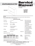
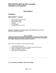
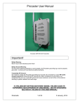
2005
Down to1
™
HIGH SPEED TROUBLESHOOTING
V25-V27 CHASSIS
V25
V25+
V25++
WS-48515
WS-55515
WS-65515
WS-55615
WS-65615
WS-73615
WS-55815
WS-65815
V27
WS-55517
WS-65517
WS-73517
MITSUBISHI DIGITAL ELECTRONICS AMERICA, INC.
9351 Jeronimo Road, Irvine, CA 92618-1904
Copyright © 2005 Mitsubishi Digital Electronics America, Inc.
All Rights Reserved
V25 / V27 Chassis Down to 1
V25 / V27 CHASSIS
Down to 1 - High Speed Troubleshooting
TABLE of CONTENTS
Safety Precautions ......................................................................................................................... 2
Cabinet Disassembly ...................................................................................................................... 3
Chassis Removal ............................................................................................................................ 5
Troubleshooting .............................................................................................................................. 6
PCB Locations and Functions......................................................................................................... 8
PCB Parts Reference ...................................................................................................................... 9
Page 1
V25 / V27 Chassis Down to 1
PRODUCT SAFETY NOTICE
Many electrical and mechanical parts in television receivers have special safety related characteristics. These characteristics are often not evident from visual inspection nor can the protection afforded by them necessarily be obtained by using
replacement components rated for higher voltage, wattage, etc.
Replacement parts which have special safety characteristics are identified in this manual. The replacement for any safety
part should be identical in value and characteristics.
SAFETY PRECAUTIONS
NOTICE: Observe all cautions and safety related notes located inside the receiver cabinet and on the receiver chassis.
WARNING:
1. Operation of this receiver outside the cabinet or with the cover removed presents a shock hazard from the
receiver's power supplies. Work on the receiver should not be attempted by anyone who is not thoroughly
familiar with the precautions necessary when working on high voltage equipment.
2. Do not install, remove or handle the picture tubes in any manner unless shatterproof goggles are worn.
People not so equipped should be kept away while the picture tube is being handled. Keep the picture tube
away from the body while handling.
3. When service is required, observe the original lead dress. Extra precaution should be taken to assure correct
lead dress in the high voltage area. Where a short-circuit has occurred, replace those components that
indicate evidence of overheating.
X-Radiation warning
The surface of the cathode ray tubes (CRTs) may generate X-Radiation, so take proper precautions when servicing. It is
recommended that a lead apron be used for shielding while handling the CRT. Use this method if possible.
When replacing the CRTs, use only the designated replacement part since it is a critical component with regard to XRadiation. High voltage must be set as prescribed under the section titled Electrical Adjustments.
Leakage current check
Before returning the receiver to the customer, it is recommended that leakage current be measured according to the
following methods.
1. Cold Check
With the alternating current (AC) plug removed from the AC source, place a jumper across the two AC plug
prongs. Connect one lead of an ohm meter to the AC plug and touch the other lead to each exposed metal
part (i.e. antennas, handle bracket, metal cabinet, screw heads, metal overlay, control shafts, etc.), particularly any exposed metal part that has a return path to the chassis. The resistance of the exposed metal
parts having a return path to the chassis should be a minimum of 1 Meg Ohm. Any resistance below this
value indicates an abnormal condition and requires corrective action.
2. Hot Check ...Use the circuit shown below to perform the hot check test.
1. Keep switch S1 open and connect the receiver to the measuring circuit. Immediately after connection,
and with the switching devices of the receiver in their operating positions, measure the leakage current for
both positions of switch S2.
2. Close switch S1, energizing the receiver. Immediately after closing switch S1, and with the switching
devices of the receiver in their operating positions, measure the leakage current for both positions of
switch S2. Repeat the current measurements of items 1 and 2 after the receiver has reached thermal
stabilization. The leakage current must not exceed 0.5 milliampere (mA).
Page 2
V25 / V27 Chassis Down to 1
CABINET DISASSEMBLY (FRONT VIEW)
Typical Procedure - Disassembly will vary by model.
For exact procedures by model, refer to the Service Manual.
Front Cabinet Disassembly
1.
2.
3.
4.
5.
6.
Remove the Speaker Grille by pulling forward.
Remove the Board Front by removing screws (a).
Remove 4 screws (b) holding the Screen Assembly (all models).
Remove screws (c) from the Screen Assembly (65 & 73 inch models only)
Unplug the CC, ZF and GR connectors from the Control Panel.
Lift the Screen Assembly up and away from the cabinet.
Page 3
V25 / V27 Chassis Down to 1
CABINET DISASSEMBLY (REAR VIEW)
Typical Procedure - Disassembly will vary by model.
For exact procedures by model, refer to the Service Manual.
Rear Cabinet Disassembly
1.
2.
3.
4.
5.
6.
Remove the Back Board by removing screws (a), and screws (b).
Remove screws (c) to remove the Board Slide.
Remove screws (d) to remove the Board Shelves.
Remove screw (e) holding the chassis.
Remove 4 screws (f) securing the Light Box Assembly.
Be certain that all cables and connectors between the Light Box Assembly and external items are
disconnected (e.g. speaker plugs, etc.), including the USB and 1394 connectors.
7. Slide the Light Box Assembly from the cabinet.
Page 4
V25 / V27 Chassis Down to 1
CABINET SEPARATION PROCEDURE
Typical Procedure - Disassembly will vary by model.
For exact procedures by model, refer to the Service Manual.
65 & 73 Inch Models
Cabinet Separation Procedure
1. Pull the Speaker Grill from the cabinet.
2. Unplug the CC, ZF and GR connectors.
3. Remove 4 plastic covers and screws (a)
from each side of the cabinet.
4. Carefully lift the cabinet top and place it on
the floor.
5. Place the cabinet bottom in the desired
location.
6. Reverse the procedure and mount the
cabinet top on the cabinet bottom.
Main Chassis Removal
Chassis Removal
1.
2.
2.
3.
4.
5.
Undo the cable wire ties to the Front Panel, Speakers, CRTs, etc.
Unplug the 1394 cables from the DM module.
Remove screw (a) securing the Main Chassis.
Release the Chassis Locks on each side of the chassis.
Slide the Chassis out the rear of the unit.
Tilt upward to access the bottom of the main chassis.
Page 5
V25 / V27 Chassis Down to 1
Troubleshooting
Troubleshooting Steps:
1. If the Power LED is continuously flashing or if other TV controls seem locked, perform a System Reset by
pressing the front panel button or by removing and re-applying AC power.
2. If the Power LED seems abnormal, use the chart below to determine the condition.
LED Indications
Off
Fast Blink for 70 sec.
Fast Blink (doesn't stop)
Slow Blink
Conditions
After AC is applied
After AC is applied
After AC is applied
Set is Off
Probable Cause
Standy Power Supply or TV µPC not running
Normal - DM µPC is booting up
TV µPC is running, but DM3 failed to boot up.
Normal - Timer is set for Automatic Turn ON
3. If the set will not power on or if the Power LED lights then goes out when the Power On command is given
(shut down) perform the Self Diagnostics.
While the set is shut down, on the front panel, press the “DEVICE” and “MENU” buttons at the same time
and hold for 5 seconds. The LED will then flash denoting a two digit Code.
Note: The front panel buttons must be used, NOT those on the Remote Control.
• The number of flashes indicates the Error Code.
• The LED will flash 1, 2 or 3 times, then pause for about 1/2 second then flash 1, 2, 3 or 5 times.
• The Error Code is repeated a total of 5 times.
Use the table below to help narrow down the problem.
Error Code
Indication
12
No Error
21
X-Ray Protection
22
Short Circuit Protection
23
35
Possible Cause
Power Supply Failure
High Voltage Circuit Failure
Power Supply Failure
Horizontal or Vertical
Deflection Loss Protection
Deflection Circuit Failure
DM Fan Failure
DM Fan or Connector
Circuit Location
PCB-MAIN
PCB-MAIN
PCB-MAIN
PCB-MAIN (Horiz)
PCB-SIGNAL (Vert)
PCB-DM3
Note: The DM Fan should be running any time the set is plugged in.
4. Other Problems:
• For picture and/or audio complaints that may be related an improper customer setting or adjustment,
press the A/V Reset button on the front panel to restore factory default settings.
• For other feature complaints, reset all user controlled functions by pressing <TV MENU><1-2-3>. Then
at the Reset System Defaults screen, press <ENTer>. Note: All customer settings, including
NetCommand will be reset.
• If the cable company is requesting information to enable CableCARD™ service, press <TV MENU>
<9-9-9> to display the host and CableCARD identification. (CableCARD must be installed)
• To place the remote in the NetCommand™ mode, hold the <POWER> button & press <9-3-5>.
• To place the remote back into the standard mode, hold the <POWER> button & press <0-0-0>.
5. PCB Level Troubleshooting:
• Use the Symptom/Cause information to aid in troubleshooting to the PCB level. While this method will
not be 100% accurate, checking all items listed in the Symptom column will increase the probability of
a successful diagnosis. Symptoms can also be caused by poor or mis-seated connectors between the
related PCB’s.
• Additional troubleshooting can be performed by using the PCB Function information to determine the
location of a circuit suspected of malfunctioning.
• PCB locations and part numbers are also provided.
6. Adjustments - For Adjustment Procedures, refer to the Service Manual
• Option Menu <MENU><2-4-7-0>
• Service Adjustment Mode <MENU><2-4-5-7> To reset data, press <0>
• Convergence Adjustment Mode <MENU><2-4-5-9> Coarse <5> Fine <4>
Page 6
V25 / V27 Chassis Down to 1
V25 & V27 Symptom/Cause Information
Symptom
Most Likely
Video Problems, all Inputs & Menu bad.
Audio OK
PCB-SIGNAL
Video&Audio Problems. All signals bad. HV
is OK
PCB-DM3
Analog Tuning problems. External Inputs &
Digital OK
PCB-SIGNAL
Analog Tuning & External Inputs Problems.
Digital OK
PCB-TERMINAL
Digital Tuning problems. Analog OK
PCB-TUNER
1394 Problems
PCB-DM3
Audio Problems. Speakers, Monitor A/V 1
& Audio 2 Bad
PCB-TUNER
Audio Problems. Speakers, Monitor A/V 1
Bad. Audio 2 Good
PCB-DM3
Audio Problems. Speakers Bad. Monitor
A/V 1 & Audio 2 Good
Control Problems
Control Problems (Front Panel)
Control Problems (Remote)
Won't power on. Power LED blinking
constantly. (Boot sequence incomplete.)
Won't power on. Boot sequence repeats
every 30 seconds.
Shut Down Problems - Error Code 12
Shut Down Problems - Error Code 21
Shut Down Problems - Error Code 22
Shut Down Problems - Error Code 23
Dead Set - Error Code 35
Dead Set
Convergence/Geometry Problems
PCB-SIGNAL
PCB-SIGNAL
PCB-CONTROL
REMOTE
PCB-DM3
PCB-E2P
PCB-MAIN
PCB-MAIN
PCB-MAIN
Q5A37, PCB-MAIN
FAN
PCB-MAIN
PCB-SIGNAL
Page 7
Other Possibilities
PCB-CRTs, PCB-DM3
PCB-SIGNAL
PCB-TERMINAL
PCB-SIGNAL
PCB-DM3
SPEAKERS
PCB-DM3
PCB-PREAMP
Bad connection between DM3 &
Signal PCBs.
PCB-SIGNAL
Bad connection between the
Fan and DM3
V25 / V27 Chassis Down to 1
DM3
TUNER
FIF
E2P
PCB Locations
&
Functions
SIGNAL
DBF
HDMI
TERMINAL
MAIN
PCB-DM3
NetCommand
PIP-P OP
IEEE1394
Picture Format
C ard Viewer
3:2 Pull D own
OSD-Menus
Line Double
D igital uPC Control 480i to 480p
MPEG D ecoder
Audio D/A C onv.
PC B-Tuner
PC B-Terminal
A/V Inputs
A/V Selection
3D-Y/C
NTSC Video
Decoders
Sys 5 - Learning
PCB -Signal
Control uPC
VCJ
Convergence
Audio A mp
Vertical Defl.
PC B-Main
PCB -DB F
PCB -HD MI
Tuners : Main, Sub & OOB Horizontal Defl.
Dynamic
DVI D ecoder
D igital Demodulator High Voltage
Beam
Audio D/A C onverter Power Supplies
Forming
Audio Processor
SVM
(Corner Focus)
PCB Functions
Page 8
V25 / V27 Chassis Down to 1
PCB, Main Component & Connector Locations (Top View)
W S-48515
W S-55515
W S-55615
W S-55815
W S-55517
W S-65515
W S-65615
W S-65815
W S-65517
W S-73615
W S-73517
MAIN
930B918001
930B918001
930B918002
930B918002
930B918002
930B918002
930B918002
930B918003
930B918002
930B918003
930B918003
W S-48515
W S-55515
W S-55615
W S-55815
W S-55517
W S-65515
W S-65615
W S-65815
W S-65517
W S-73615
W S-73517
CRTs
934C106001
934C106001
934C106001
934C106001
934C106001
934C106001
934C106001
934C106001
934C106001
934C106001
934C106001
V25 / V27 PCB PART NUMBERS
SIGNAL
TERMINAL
DM3
930B919001-48 930B920001
934C108001
930B919001-55 930B920001
934C108001
930B919002-55 930B920001
934C108003
930B919006
930B920002
934C108002
930B919002-55 930B920001
934C108003
930B919002-65 930B920001
934C108001
930B919002-65 930B920001
934C108003
930B919007
930B920002
934C108002
930B919002-65 930B920001
934C108003
930B919003
930B920001
934C108003
930B919003
930B920001
934C108003
HDMI
934C107001
934C107001
934C107001
934C107001
934C107001
934C107001
934C107001
934C107001
934C107001
934C107001
934C107001
E2P
934C109001-48
934C109001-55
934C109001-55
934C109001-55
934C109001-55
934C109001-65
934C109001-65
934C109001-65
934C109001-65
934C109001-73
934C109001-73
Page 9
PREAMP
935D762001
935D762001
935D762001
935D762001
935D762001
935D762001
935D762001
935D762001
935D762001
935D762001
935D762001
TUNER
934C110001
934C110001
934C110001
934C110001
934C110005
934C110001
934C110001
934C110001
934C110005
934C110001
934C110005
DBF
935D767001
935D767001
935D767001
935D767001
935D767001
935D767001
935D767001
935D767001
935D767001
935D767001
935D767001
FRONT
935D763001
935D763001
935D763001
935D763002
935D763001
935D763001
935D763001
935D763002
935D763001
935D763001
935D763001
CONTROL
935D764001
935D764001
935D772001
935D764001
935D772001
935D764001
935D772001
935D764001
935D772001
935D772001
935D772001