1
SYSTEM
ADMINISTRATION
AND
SPECIAL FEATURES GUIDE
iDCS 500 Release 2/OfficeServ™ System
March 2004
Samsung Telecommunications America reserves the right without prior notice to revise information in
this guide for any reason. Samsung Telecommunications America also reserves the right without prior
notice to make changes in design or components of equipment as engineering and manufacturing
may warrant. Samsung Telecommunications America disclaims all liabilities for damages arising from
the erroneous interpretation or use of information presented in this guide.
TABLE OF CONTENTS
ABOUT THIS BOOK .................................................................................... 1
SPECIAL FEATURES
System Ring Plans .......................................................................................................... 2
Manual Ring Plan Change ............................................................................................ 2
Temporary Ring Plan Override ....................................................................................2
Calling The System Operator ...................................................................................... 3
Operator Recalls .............................................................................................................. 3
Executive Barge-in .......................................................................................................... 3
Walking Class of Service ................................................................................................4
In/Out of Group ................................................................................................................4
Direct Inward System Access (DISA) ........................................................................ 5
DISA Security ................................................................................................................ 5–6
Forced Account Codes .................................................................................................. 6
Authorization Codes ...................................................................................................... 7
Using the Tie Line ...................................................................................................... 7–8
CALLER ID SPECIAL FEATURES
Abandon Call List ............................................................................................................ 9
CID on SMDR .................................................................................................................... 9
Number to Name Translation ......................................................................................9
SYSTEM ADMINISTRATOR PROGRAMMING
Customer Level Access .............................................................................................. 10
Customer Level Access Using the PROG Key ......................................................10
Change Feature Passcode ..........................................................................................11
Set Date and Time Display ................................................................................ 11–12
Reset Station Passcodes to Default ................................................................ 12–13
Program Station Names........................................................................................13–15
Program Trunk Names ..................................................................................................16
Program Station Group Names ................................................................................17
Program System Speed Dial Numbers .......................................................... 18–19
Program System Speed Dial Names........................................................................20
Program Personal Speed Dial Numbers for Other Stations ....................21–22
Program Personal Speed Dial Names for Other Stations ........................23–24
Create Programmed Station Messages ........................................................ 24–25
Set Alarm/Appointment Reminder with Message .................................... 25–26
Managing Key Assignments ............................................................................ 27–28
Programming Account Codes ..................................................................................29
Station Timers ..........................................................................................................30–31
Adding Names to the Translation Table ........................................................31–32
Holiday ..............................................................................................................................33
Customer Set Relocation......................................................................................34–35
SYSTEM MAINTENANCE ALARMS
......................................36
ABOUT THIS BOOK
This book contains instructions for special features that every telephone user may
not need to know.The owner can decide who the system administrator will be and
who will have access to these features. Station users can be trained on only the
items that apply to them. This procedure will help control costs and telephone
abuse.
Several of the features listed in this book are specific to the system operator or
attendant position.You can have more than one operator or set your system up to
be used without an operator.
The designated system administrator can access specific programs and modify
some functions to better manage the iDCS 500 Release 2 office telephone system.
Instructions are detailed and easy to follow. When assistance is needed, contact
your installation and service company.
1
SPECIAL FEATURES
SYSTEM RING PLANS
Your system is designed to have a maximum of six different Ring Plans. Each ring
plan can be programmed to allow different lines to ring different ring plans to ring
different station and/or station groups. Examples of why different ring plans are
required can include normal day operation, night operation, using different operators during different lunch shifts and Saturday or evening hours of operation.
While the system is in a ring plan, each station will be limited to its individual Ring
Plan class of service dialing restrictions. You can place the system in one of any six
of these ring plans at any time. Ring Plans are available on an individual tenant
basis and may be set automatically or manually. Automatic Ring Plans have an
individual start time and will remain in that mode until the beginning of the next
defined ring plan. If no automatic timer is set, you must change ring plans manually.
Any of these ring plans can be switched from one plan to another at any time by
manually pressing a ring plan button. There are two ways to override the automatic ring plans; one is a temporary override until the next programmed start
time, and the other is a permanent override until manually changed.
MANUAL RING PLAN CHANGE
Press the RTO button plus the ring plan passcode (four digits) and the ring plan (16) you wish to set. The system will override all the automatic time tables and will
remain in the set ring plan until manually changed. To manually change or cancel
the ring plan time override and return ring plan operation to the system clock:
press the RTO plus the ring plan passcode (four digits) and a “0” to cancel the ring
plan time override and return to normal operation.
TEMPORARY RING PLAN CHANGE
Press the RP button plus the ring plan passcode (four digits) and the ring plan (16) you wish to set. The system will remain in that ring plan until the next automatic start time for the next ring plan goes into effect.
NOTE: This button may also be assigned an extender of one of the six ring plans.
Example: An RP button is given an extender of 3 (RP3) and the operation of this
button is a push on/push off type of operation with the system always returning
to ring plan 1 when the key is turned off.When the system is operating in ring plan
3, the RP3 button will light steady red, and when off the light will also turn off.
2
CALLING THE SYSTEM OPERATOR
Any station that dials 0 will ring its assigned operator. (If tenant service is used,
each tenant may have a different operator or operator group.) Calls to the system
or tenant operator are easily identified because the CALL key will have a fast flashing red light. Station users will never receive a busy signal when they dial 0 or the
operator group number. The calls will continue ringing in queue until answered.
OPERATOR RECALLS
Transferred calls that go unanswered will recall to the station that originated the
transfer. Should the station that originated the transfer not answer the recall, the
call will be sent to the operator as a transfer recall.
A call left on hold will recall the station that put it on hold. If the hold recall is unanswered at the station that originated the hold, the call is sent to the operator.
Both types of recalls will ring and have a slow flashing amber light on the LINE key
or CALL key.
EXECUTIVE BARGE-IN
If you want to break into another conversation, you must be allowed to barge-in
and the other station or trunk must not be secure.
•
•
•
Dial the desired extension or trunk number and listen for the busy signal.
Press the BARGE button and begin speaking after the tone.
Hang up when you are finished.
The system can be set for one of the three following barge-in options:
•
•
•
No barge-in allowed
Barge-in with intrusion tone
Barge-in without intrusion tone (service observing)
When the second or third option is selected the barger will take priority over the
line. This means unless you (barger) hang up first, the station or line you barged
into will still be connected to you when the station you barged into hangs up.
When the third option is selected, the station that barges-in can monitor the conversation and no warning tone or display will be sent to the station being monitored.The handset transmitter and keyset microphone are disabled.The party that
originated the barge-in may join the conversation by pressing the MUTE button
on the keyset. Your service company must program these options for you.
3
WARNING
Barge-in without tone may violate state or federal laws concerning the
right to privacy. Samsung Telecommunications America is in no way
responsible for the possible misuse of this feature.
WALKING CLASS OF SERVICE
You can change a restricted station’s class of service to the same class as your station, allowing you to make calls or use features that would otherwise be restricted
from that station.
•
•
•
•
•
Lift the handset or press the SPK or the MONITOR key.
Dial 59 and then your extension number.
Dial your station passcode and receive internal dial tone.
Dial an access code and then the telephone number—OR—use the desired
feature as usual.
Hang up. The station will be returned to its restricted status.
NOTE: The default station passcode 1234 cannot be used.
IN/OUT OF GROUP
If the station does not have an IN/OUT key:
•
•
•
•
If the station has an IN/OUT key:
•
•
DIRECT INWARD SYSTEM ACCESS (DISA)
From outside of the office, selected individuals can call into the iDCS system on
special DISA line(s). A security code must be entered to gain access. Once these
individuals are in the system, they can make outside calls using the office lines or
call stations within the system. Individuals who will use DISA must have their stations assigned for DISA access and must change their station passcodes. The
default passcode 1234 cannot be used.
•
•
The number of groups available to choose from may vary depending on your iDCS
500 Release 2 system type:
•
•
iDCS 500 RLS 2 L
40 Groups
(500 through 539) or (5000 through 5039 depending if your
system is setup for 4 digits numbering plan)
80 Groups
(500 through 579) or (5000 though 5079 depending if your
system is setup for 4 digits numbering plan)
To create a backup or relief operator position, assign the main operator and one or
more backup individuals to the operator group. All but the main operator should
be out of the group.When it is necessary to use a backup operator, put the desired
backup station in the group and remove the main operator. When incoming call
traffic is heavy, you can have another station put itself in the operator group along
with the main operator to handle the extra call load.
4
Press the IN/OUT key. It will light red when the station is in the group.
Press the IN/OUT key again. The light is off when the station is out of the
group.
NOTE: A station can be in more than one group.
Any station assigned to a station group can remove itself from that group and
then reenter the group at a later time.When out of the group, a station can receive
calls to its extension number but not to the group.
iDCS 500 RLS 2 M
Lift the handset and dial the feature access code _________________.
Dial the group number.
Dial 0 to be out of the group or dial 1 to be in the group.
Receive confirmation tone and hang up.
•
•
Call in on the DISA line from any phone with tone dialing.
You will hear a dial tone. Dial your security code (your extension number
plus your station passcode).
If you are allowed access, you will receive a dial tone.
Dial any line access code, receive outside dial tone and then dial a telephone number OR dial any extension number to call a station in the system.
To make another call, press Q, receive dial tone and dial another number.
Press # and hang up when finished.
NOTE: Outgoing DISA calls are controlled by the dialing class of the station identified by the security code.The DISA line must have disconnect supervision from the
central office. Insist that this service is verified by your installation/service company.
DISA SECURITY
A common practice among hackers is to repeatedly dial a known DISA access
number (usually with a computer) and try a different passcode each time. The
hacker hopes to eventually chance upon the correct passcode and thus gain
5
access to your system. The iDCS security feature counts the number of sequential
incorrect passcode attempts. If a certain number is reached, DISA is disabled and
the system sends an alarm to designated display stations.The number of passcode
attempts and the disable duration are both programmable. In addition, the iDCS
system will print an SMDR record (a customer-provided printer is required) each
time an incorrect passcode is entered.
The DISA alarm will ring for a programmable time before canceling the ringing;
however, the DISA alarm display will remain until the alarm is cleared. To clear the
DISA alarm, follow the following procedure:
•
•
•
Lift the handset and dial 58.
Enter the DISA alarm passcode (see your service company).
Replace the handset.
WARNING
As it is impossible to prevent unauthorized access to your telephone system by hackers, we suggest that you do not turn the DISA feature on unless
you intend to use it. If you do use this feature, it is good practice to frequently change passcodes and periodically review your telephone records
for unauthorized use.
outside call in the usual manner. If an incorrect code is entered, the station
returns error tone.
This code will always print on SMDR reports. For information on entering and
changing forced account codes, see the system administrator programming section of this book.
AUTHORIZATION CODES
Authorization codes are used to validate a station user and give permission to
make a call. These four digit authorization codes can be either forced or optional,
but if used, are always verified from a system list of 500 entries. Each authorization
code has an associated class of service.When the code is entered, the class of service is changed to that of the authorization code.
USING AUTHORIZATION CODES
After going off-hook, the station user must dial Q followed by a four digit authorization code. If you enter a correct code, you will hear confirmation tone and then
receive a dial tone and you can make an outside call in the usual manner. The station then follows the dialing class for that authorization code. If you enter an incorrect code, the station returns error tone. This code may or may not print on SMDR
reports depending on SMDR programming.
FORCED ACCOUNT CODES
USING THE TIE LINE
VERIFIED
OUTGOING
When set for this option the user must enter an account code for all outgoing calls.
The account code entered will be verified from a system list of 999 entries. Forced
verified codes can contain the digits 0~9.
NOT VERIFIED
When set for this option the user must enter an account code for all outgoing calls,
but the account code is not verified against the system list. Non verified account
codes can contain the digits 0~9, * and #.
USING FORCED ACCOUNT CODES
•
•
•
6
Lift the handset and press the ACCT CODE key or dial 47.
Enter the account code.
Press the account code button again, press TRSF or hookflash (on an SLT).
If a correct code is entered, you will hear a dial tone and you can make an
Your office can be connected to another system with a tie line. Use this line to
make calls to stations in the other system. If programming allows, you can access
lines in the other system to make outside calls. Tie line calls can be put on hold,
transferred and conferenced in the same manner as are other outside calls.
•
•
•
•
Lift the handset or press the SPK or MONITOR key.
Dial the tie line access code or press the tie line key.
When you receive dial tone from the other system, you can dial extension
numbers or access outside lines. You must know the extension numbers
and the line access codes for the other system.
Finish the call by replacing the handset or pressing the ANS/RLS or the
MONITOR key if you are using a 7 button phone.
NOTE: Outgoing calls are controlled by the station’s dialing class.
7
INCOMING
CALLER ID
SPECIAL FEATURES
Station users in the other system can access the tie line and make intercom calls
to stations in your system. Answer tie line calls ringing at your station as you would
any other outside call.They can be put on hold, transferred and conferenced in the
same manner as are other outside calls.
IN AND OUT ON TIE LINE
NOTE: The Caller ID features below require optional software and/or hardware. Please ask your installation and service company for details.
Users accessing the tie line from the other system can get a line in your system and
make outgoing calls. These calls can be controlled by assigning a dialing class to
the tie line. For further information, see your service company.
ABANDON CALL LIST
The system has a system-wide abandoned calls list that stores CID information for
the last 100 calls that rang but were not answered and were accompanied with
valid CID information. Calls with CID information consisting of OUT OF AREA, PAYPHONE or PRIVATE will not be stored in the list. The abandoned calls list is
accessed using the system administrator’s passcode. When reviewing this list, you
are provided options to CLEAR the entry or DIAL the number. You can use the
NND key to toggle between the CID name, CID number and the date and time the
call came in. The system must be using LCR to dial numbers from the abandoned
calls list.
To view the list of abandoned incoming calls for which CID information has been
received:
•
•
Dial 64 and dial the system administrator passcode.
Scroll through the entries using the VOL keys.
CID ON SMDR
The Station Message Detail Records (SMDR) report can be set to include the CID
name and number for incoming calls. This format expands the printout to 113
characters.You must use a wide carriage printer or an 80 column printer set to the
condensed print option.
NUMBER TO NAME TRANSLATION
The system provides a translation table of 1000 entries in the iDCS 500 M, and
2000 entries in the iDCS 500 L for use in areas that do not provide name and
number (sometimes called “deluxe”) Caller ID or when ANI is received. When the
CID or ANI number is received, the table is searched. When a match is found, the
system will display the corresponding name from the table.This will allow users in
areas that do not support “deluxe” Caller ID or have only ANI service to provide
names for callers.
8
9
CALLER ID SPECIAL FEATURES
INVESTIGATE
Investigate allows selected stations with a special class of service to investigate any call in progress. If CID information is available for an incoming call,
you will know to whom this station user is speaking. For outgoing calls, you
can see the number that was dialed. After investigating, you may barge-in
on the conversation, disconnect the call or hang up your phone to end the
investigation.
TEAR HERE
•
•
•
•
At your keyset, press the INVESTIGATE key.
Enter your station passcode. (Default passcodes cannot be used.)
Enter the station number to be investigated.
You can now press BARGE to barge-in on the conversation.
OR
You can press NND to view more information about the call.
OR
You can press DROP to disconnect the call.
NOTES:
1. If the call is an outgoing call, the NND key will not appear.
2. This feature requires optional software and/or hardware. Please ask your
installation and service company for details.
WARNING
This feature may violate state or federal laws concerning the right
to privacy. Samsung Telecommunications America is in no way responsible for the possible misuse of this feature.
NOTE: This information is NOT repeated in this user guide.
SYSTEM
ADMINISTRATOR
PROGRAMMING
SYSTEM ADMINISTRATOR
PROGRAMMING
CUSTOMER LEVEL ACCESS
Before any customer programs can be accessed, you must first open system programming using the passcode you have been assigned. You must use a display
keyset. Should it become necessary to change this passcode, see your service
company.
•
•
•
•
•
While on-hook, press TRSF and then dial 200.
Your display shows [ENABLE CUS. PROG. PASSCODE].
Dial the four digit passcode.
The display shows [ENABLE CUS. PROG. - DISABLE].
Dial 1 to enable. The display shows [ENABLE CUS. PROG - ENABLE].
Press TRSF. The keyset returns to its idle condition.
Press TRSF and then dial the three digit program code you want to access.
Follow the instructions for that program.
NOTE:You must begin programming within 30 seconds. Once you are in programming, any delay of more than 30 seconds between key strokes will cause the system to automatically close programming.
CUSTOMER LEVEL ACCESS USING THE
PROG KEY
A designated keyset may be programmed with a “PROG” key which allows access
to the following areas of system programming.When pressed you must enter your
station passcode followed by the MMC number. The default station passcode
“1234” can not be used. The only MMCs that may entered from pressing the
“PROG” key are as follows:
•
•
•
•
•
•
•
•
•
MMC 100
MMC 102
MMC 104
MMC 115
MMC 116
MMC 505
MMC 705
MMC 706
MMC 722
Station Lock for All Stations
Station Forward for All Stations
Station Name
Program Message for all Stations
Alarm and Message
System Day and Time
System Speed Dial
System Speed Dial Name
Station Key Programming
10
CHANGING FEATURE PASSCODE
You can change individual feature passcodes. This program is used to change the
passcodes for several features. These features are the following: RING PLAN SERVICE, DISA ALARM, ALARM CLEAR, and AA RECORD. Note: Each passcode is four
digits long. Each digit can be 0 to 9.
PROGRAM KEYS
UP & DOWN - Select the extension number.
HOLD - Press to reset the passcode to default settings.
Open customer programming and follow the instructions below.
Failure to enter the time using the 24 hour clock will cause the date to change at
12:00 P.M. Open customer programming and follow the instructions below.
ACTION
DISPLAY
1. Press TRSF and then dial 505
Display shows
OLD:6010184:0047
NEW:WMMDDYY:HHMM
2. Enter the new time and date using
the above format
OLD:6010184:0047
NEW:3020994:1445
3. Verify the time and date and reenter
them if necessary
OLD:3020994:1445
NEW:WMMDDYY:HHMM
4. Press TRSF to store and exit
programming OR press SPK to store
and advance to the next program
ACTION
DISPLAY
1. Press TRSF and then dial 202
Display shows
CHANGE PASSCODE
RING PLAN: 0000
2. Use the UP and DOWN keys to scroll
through the different options and press
the right soft keys.
CHANGE PASSCODE
DISA ALARM:5678
If you have entered invalid data, you will receive an [ INVALID ENTRY ] message for
three seconds. Reenter the correct date and time. If the information you entered is
incorrect, repeat the procedure.
3. Press HOLD to reset the passcode
CHANGE PASSCODE
RING PLAN: 0000
RESET STATION PASSCODES
TO DEFAULT
4. Press TRSF to store and exit programming
OR press SPK to store and advance to the
next program
SET DATE AND TIME DISPLAY
Should it ever become necessary to correct the date and time displayed on all of
the keysets, do so as soon as you notice that they are incorrect. Automatic
Operating Mode will not work correctly and SMDR records will be of no value
when the date and time are not correct.
The display format is the following:
W (Day of the week): Enter 0 for Sunday and 6 for Saturday.
MM (Month): Enter 01 for January and 12 for December.
DD (Day of the month): Enter a number in the range of 01–31.
YY (Year): Enter the last two digits of the year.
HH (Hours): Use the 24 hour clock and enter a number in the range of 00–24.
MM (Minutes): Enter a number in the range of 00–59.
11
Individual keyset users can set or change their own individual passcodes. These
passcodes are used to lock and unlock keysets, override toll restriction and access
the DISA feature. At times, it may be necessary for the system administrator to
reset a station’s passcode to default “1234.”This program cannot be used to display
passcodes, only to reset them.
PROGRAM KEYS
UP & DOWN - Select the extension number.
HOLD - Press to reset the passcode.
Open customer programming and follow the instructions below.
ACTION
DISPLAY
1. Press TRSF and then dial 101
Display shows
[201] PASSCODE
PASSCODE:4444
12
2. Dial the station number OR use the
UP and DOWN keys to scroll through
the keyset numbers and press the
right soft key to move the cursor right
[205] PASSCODE
PASSCODE:4444
3. Press HOLD to reset the passcode
[205] PASSCODE
PASSCODE : 1234
4. Press TRSF to store and exit
programming OR press SPK to store
and advance to the next program
NOTE: Directory information is always 11 characters.
DEFAULT DATA: NONE
DEFAULT DATA: ALL STATION PASSCODES = 1234
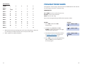
Names are written using the keypad. Each press of a key will select a character.
Pressing the dial pad key moves the cursor to the next position. For example, if the
directory name is “SAM SMITH,” press the number “7” three times to get the letter
“S.” Press the number “2” once to get the letter “A.” Continue selecting characters
from the table below to complete your message. Press the “A” key to change the
letter from upper case to lower case.
PROGRAM STATION NAMES
NOTE: When the character you want appears on the same dial pad key as does the
previous character, press the UP key to move the cursor to the right.
This program is used to assign a character name or identification for each extension. You may assign a name of 11 characters long.
DCS KEYSETS
PROGRAM KEYS
COUNT
1
2
3
4
5
4. Press the right soft key to return to
step 2 OR press TRSF to store and exit
programming OR press SPK to
store and advance to the next program
DIAL 0
Q
Z
.
)
0
UP & DOWN - Used to scroll and move cursor.
KEYPAD - Used to enter characters.
HOLD - Press to clear entry.
DIAL 1
space
?
,
!
1
DIAL 2
A
B
C
@
2
Open customer programming and follow the instructions below.
DIAL 3
D
E
F
#
3
DIAL 4
G
H
I
$
4
ACTION
DISPLAY
DIAL 5
J
K
L
%
5
1. Press TRSF and then dial 104
Display shows
[201] STN NAME
DIAL 6
M
N
O
^
6
DIAL 7
P
R
S
&
7
2. Dial station number (e.g., 205)
OR press UP or DOWN to select the
station and press the right soft key to
move the cursor
[205] STN NAME
DIAL 8
T
U
V
Q
8
DIAL 9
W
X
Y
(
9
DIAL 4
:
=
[
]
4
3. Enter the station name using the
procedure described on the next page
and press the right soft key to return to
step 2
[205] STN NAME
SAM SMITH
13
The # key can be used for the following special characters: #, space, &, !, :, ?, ., %, $, , /, =, [, ], @, ^, (, ), _, +, {, }, |, ;, \,“ and ~.
14
PROGRAM TRUNK NAMES
iDCS KEYSETS
COUNT
1
2
3
4
5
DIAL 0
<
>
.
)
0
DIAL 1
space
?
,
!
1
DIAL 2
A
B
C
@
2
DIAL 3
D
E
F
#
3
DIAL 4
G
H
I
$
4
DIAL 5
J
K
L
%
5
DIAL 6
M
N
O
^
6
DIAL 7
P
Q
R
&
7
DIAL 8
T
U
V
Q
8
DIAL 9
W
X
Y
Z
9
DIAL 4
:
=
[
]
4
1.
When the character you want appears on the same dial pad key as the previous character, press UP to move the cursor one space to the right.
2.
Other symbols are available for DIAL #.
This program is used to assign a character name or identification for each C.O. line.
You may assign a name of 11 characters long.
PROGRAM KEYS
UP & DOWN - Used to scroll and move cursor.
KEYPAD - Used to enter characters.
HOLD - Press to clear entry.
Open customer programming and follow the instructions below.
ACTION
DISPLAY
1. Press TRSF and then dial 404
Display shows
[701] TRUNK NAME
2. Dial trunk (e.g., 704) OR press UP or
DOWN to select trunk and press the right
soft key to move the cursor
[704] TRUNK NAME
3. Enter the trunk name using the procedure
in Program Station Names and press the
right soft key to return to step 2
[704] TRUNK NAME
SAMSUNG
4. Press TRSF to store and exit programming
OR press SPK to store and advance to
the next program
15
16
PROGRAM STATION GROUP NAMES
PROGRAM SYSTEM SPEED DIAL NUMBERS
This program is used to assign a character name or identification for each station
group. You may assign a name 11 characters long.
The system list starts with 200 numbers and can be increased in blocks of ten. The
system may have either 500 or 950 maximum depending on the setting in MMC
861. See your service company to increase or decrease the system list.
PROGRAM KEYS
The speed dial codes are 500–999 or 050–999. Each speed dial number consists of
a line access code and the telephone number to be dialed.The access code can be
any line group, individual line, station group or individual extension.The speed dial
number can be up to 24 characters long including 4, #, FLASH and PAUSE.
UP & DOWN - Used to scroll and move cursor.
KEYPAD - Used to enter characters.
HOLD - Press to clear entry.
Open customer programming and follow the instructions below.
ACTION
DISPLAY
1. Press TRSF and then dial 602
Display shows the first group
[501] SGR NAME
2. Dial the group number (e.g., 505) OR
press the UP or DOWN key to make a
selection and press the left or right
soft key to move the cursor
[505] SGR NAME
3. Enter the name using the method
in Program Station Names
[505] SGR NAME
SAMSUNG
4. Press the left or right soft key to return to
step 2 OR press TRSF to store and exit
programming OR press SPK to store and
advance to the next program
NOTE: If Least Cost Routing (LCR) is being used, the LCR access code must be
entered.
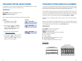
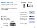
When you are entering a speed dial number, there are some special keys that you
will need to use. These are the bottom row of programmable keys on the LCD 12B
and LCD 24B keysets and are known as keys A, B, C, D, E and F.
PROGRAM KEYS
UP & DOWN - Select the speed dial bin.
KEYPAD - Used to enter number.
HOLD - Press to clear entry.
SPK/RLS - Save data and advance to next program.
A - Does not have a function.
B - Inserts a FLASH.
C - Inserts a PAUSE.
D - Changes the dialing type from pulse to tone.
E - Hides and displays digits.
F - Changes display to speed dial name entry.
DCS KEYSETS
12 BUTTON KEYSET
PROGRAMMABLE KEYS LAYOUT
A
17
B
C
D
E
F
24 BUTTON KEYSET
PROGRAMMABLE KEYS LAYOUT
A
B
C
D
E
F
18
PROGRAM SYSTEM SPEED DIAL NAMES
iDCS KEYSETS
8D KEYSET PROGRAMMABLE
KEYS LAYOUT
A
B
C
D
E
28D KEYSET, 18D KEYSET
PROGRAMMABLE KEYS LAYOUT
F
VOLUME
Transfer
A
C
E
B
D
F
Speaker
Transfer Speaker
This program is used to assign a character name or identification for each system
speed dial location. This name enables you to locate the speed dial number when
you are using the directory dial feature.You may assign a name 11 characters long.
PROGRAM KEYS
UP & DOWN - Used to scroll through speed dial bins.
KEYPAD - Used to enter selections.
SOFT KEYS - Move cursor left and right.
SPK - Used to store data and advance to next program.
HOLD - Used to clear previous entry.
Open customer programming and follow the instructions below.
ACTION
DISPLAY
1. Press TRSF and then dial 705
Display shows the first number
SYS SPEED DIAL
500:
2. Dial the speed bin desired (e.g., 505) OR
press UP or DOWN to choose and
press the right soft key to move the cursor
SYS SPEED DIAL
505:
3. Enter the access code (e.g., 9—the system
will automatically insert a dash) followed by
the phone number (up to 24 digits long)
and press the right soft key to return to
step 2
SYS SPEED DIAL
505:9–121223456789
4. Press the F key to toggle to Program
System Speed Dial Names, step 3 to
enter the name
SYS SPEED NAME
505:
5. Press TRSF to store and exit
programming OR press SPK to store
and advance to the next program
ACTION
DISPLAY
1. Press TRSF and then 706
Display shows the first name
SYS SPEED NAME
500:
2. Dial the system speed number (e.g., 505)
OR press UP or DOWN to select the entry
number and press the right soft key to
move the cursor
SYS SPEED NAME
505:
3. Enter the name as shown in Program
Station Names and press the right soft
key to return to step 2 OR press the
F key to toggle to the speed dial number
to return to Program System Speed Dial
Numbers, step 4
SYS SPEED NAME
505:SAMSUNG
4. Press the right soft key to return to step 2
above OR press TRSF to store and exit
programming OR press SPK to store and
advance to the next program
DEFAULT DATA: NO SPEED NUMBERS ASSIGNED
19
20
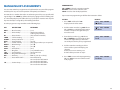
iDCS KEYSETS
PROGRAM PERSONAL SPEED DIAL
NUMBERS FOR OTHER STATIONS
8D KEYSET PROGRAMMABLE
KEYS LAYOUT
Individual station users can program their own numbers, but in cases where this is
not practical, or for single line telephone users, this program allows a system
administrator to view or change any station’s speed dial numbers. The station
speed dial codes are 00–49 or 000–049. Each station begins with ten numbers
(00–09) and can be assigned more in blocks of ten (up to a maximum of fifty numbers).
Each speed dial number consists of a line access code and the telephone number
to be dialed. The access code can be any line group, individual line, station group
or individual extension. The speed dial number can be up to 24 characters long
including 4, #, FLASH and PAUSE.
NOTE: If Least Cost Routing (LCR) is used, the LCR access code must be entered.
When you are entering a speed dial number, there are some special keys that you
will need to use. These are the bottom row of programmable keys on the LCD 12B
and LCD 24B keysets and are known as keys A, B, C, D, E and F.
PROGRAM KEYS
UP & DOWN - Scrolls through extension numbers and speed dial bins.
KEYPAD - Used to enter number.
HOLD - Press to clear entry.
A - Does not have a function.
B - Inserts a FLASH.
C - Inserts a PAUSE.
D - Changes the dialing type from pulse to tone.
E - Hides and displays digits.
F - Changes display to speed dial name entry.
DCS KEYSETS
12 BUTTON KEYSET
PROGRAMMABLE KEYS LAYOUT
A
21
B
C
D
E
F
24 BUTTON KEYSET
PROGRAMMABLE KEYS LAYOUT
A
B
C
D
E
A
B
C
D
E
28D KEYSET, 18D KEYSET
PROGRAMMABLE KEYS LAYOUT
F
VOLUME
Transfer
A
C
E
B
D
F
Speaker
Transfer Speaker
Open customer programming and follow the instructions below.
ACTION
DISPLAY
1. Press TRSF and then dial 105
Display shows
[201] SPEED DIAL
00 :
2. Dial the station number (e.g., 205) OR
press UP or DOWN to select the station
and press the right soft key to move the
cursor OR press the left soft key to go
to step 4
[205] SPEED DIAL
00 :
3. If the selected station has no speed dial
bins, this display will be shown and a new
station may be selected
[205] SPEED DIAL
SPDBLK NOT EXIST
4. Dial the location number (e.g., 05) OR
press UP or DOWN to select the location
and press the right soft key to move the
cursor OR press the left soft key to return
to step 2
[205] SPEED DIAL
05: _
5. Enter the trunk access code (e.g., 9)
followed by the number to be dialed
(e.g., 4264100) OR press the right
soft key to return to step 2 OR press the
left soft key to return to step 3 OR press
HOLD to clear an entry (if an error is made,
use the DOWN key to step back)
[205] SPEED DIAL
05 : 9-4264100_
F
22
6. Press the F key to access Program Station
Speed Dial Names OR press TRSF to save
and exit programming OR press SPK to save
and advance to the next program
4. Dial the speed dial location (e.g., 05) OR
use UP or DOWN to scroll through the
location numbers and use the right soft
key to move the cursor OR press the left
soft key to return to step 2 above
[205] SPEED NAME
01:_
DEFAULT DATA: NO SPEED DIAL NUMBERS PROGRAMMED
5. Enter the name using the procedure in
Program Station Names and press the
right soft key to return to step 2 OR
press the left soft key to return to step 3
[205] SPEED NAME
01:SAM SMITH
PROGRAM PERSONAL SPEED DIAL NAMES
FOR OTHER STATIONS
Each individual station user can program his/her own names but in cases where it
is impractical or for single line telephone users, this program allows a system
administrator to view or change any station’s speed dial names. The station speed
dial codes are 00–49. Each station begins with ten numbers (00–09) and can be
assigned more in blocks of ten up to a maximum of fifty numbers.
PROGRAM KEYS
UP & DOWN - Used to scroll through extension numbers and speed dial bins.
KEYPAD - Used to enter selections.
SOFT KEYS - Move cursor left and right.
SPK - Used to store data and advance to next program.
HOLD - Used to clear previous entry.
ANS/RLS - Used to select ALL.
ACTION
DISPLAY
1. Press TRSF and then dial 106
Display shows
[201] SPEED NAME
00:
6. Press the F key to access Program
Personal Speed Dial Numbers for
Other Stations OR press TRSF to
store and exit programming OR press
SPK to store and advance to the
next program
CREATE PROGRAMMED STATION
MESSAGES
The programmed station message feature lets you set a message at your phone to
notify users with Display Phones that you may be out of town. This way, when
Display Phone users call their display will show “OUT OF TOWN”and they will know
why you do not answer.
The iDCS 500 Release 2 system allows 15 messages to be programmed in the system list in MMC 715 and each station can program 5 messages individually.
PROGRAM KEYS
2. Dial the station number (e.g., 205) OR
press UP or DOWN to select the station
and press the right soft key to move the
cursor
[205] SPEED NAME
00:
3. If the selected station has no speed dial
bins, this display will be shown and a new
station may be selected
[205] SPEED DIAL
SPDBLK NOT EXIST
23
UP & DOWN - Select the message number.
KEYPAD - Used to enter characters.
HOLD - Press to clear entry.
Open customer programming and follow the instructions below.
ACTION
DISPLAY
1. Press TRSF and then dial 715
Display shows the first message
PGM.MESSAGE (01)
GIVE ME THE CALL
24
2. Dial in the message number (e.g., 11)
OR press UP or DOWN to scroll through
the messages and press the right soft
key to move the cursor
PGM.MESSAGE (16)
EMPTY MESSAGE
3. Enter in the message using the
procedure in Program Station Names
and press the right soft key to return
to step 2 above
PGM.MESSAGE (16)
IN THE SHOWROOM
4. Press TRSF to store and exit programming
OR press SPK to store and advance to
the next program
SET ALARM/APPOINTMENT
REMINDER WITH MESSAGE
Keyset users can set their own alarms but standard telephone users cannot. The
system administrator can set alarm/appointment reminders for other stations in
the system.
3. Dial 1–3 to select the alarm (e.g., 2) OR
press UP or DOWN to select the alarm
and press the right soft key to move the
cursor OR press the left soft key to
return to step 2
[201]ALM REM(1)
HHMM: NOTSET
4. Enter the alarm time in 24 hour clock
format (e.g., 1300) and the display will
automatically advance to step 5
[205]ALM REM (2)
HHMM:1300NOTSET
5. Enter the alarm type from the list above
OR press UP or DOWN to select the
alarm type and press the right soft key
to move the cursor
[205]ALM REM (2)
HHMM:1300DAILY
6. Enter the messages using the procedure
in Program Station Names and press the
right soft key to return to step 2
[205]ALM REM (2)
TAKE MEDICATION
7. Press TRSF to store and exit programming OR press SPK to store
and advance to the next program
PROGRAM KEYS
UP & DOWN - Scroll through extensions.
HOLD - Press to clear data.
KEYPAD - Used to enter data.
Open customer programming and follow the instructions below.
ACTION
DISPLAY
1. Press TRSF and then dial 116
Display shows
[201]ALM REM(1)
HHMM: NOTSET
2. Dial the station number (e.g., 205) OR
press UP or DOWN to select the station
and press the right soft key to move the
cursor OR press ANS/RLS to select all
stations
[205]ALM REM(1)
HHMM: NOTSET
OR
[ALL]ALM REM(1)
HHMM: NOTSET
25
26
MANAGING KEY ASSIGNMENTS
PROGRAM KEYS
You can view station key assignments and add extenders to some of the programmable keys for easy one touch operation of frequently used features.
UP & DOWN - Select the extension number.
KEYPAD - Used to enter extender codes.
HOLD - Used to clear the displayed data.
An extender is a number that makes an otherwise general key very specific. Adding the digit “4” to a PAGE key defines this key for paging zone four. Adding “225”
to a directed pickup key will define this key as pickup for extension 225 only. The
key must already be assigned by the installing technician.
Use this program to assign extenders to the following keys:
KEY
DESCRIPTION
EXTENDER
BOSS ..............Boss/Secretary ..............................(1–4)
DP ..................Direct Pickup ................................(Extension number or
station group number)
DS....................Direct Station ................................(Any extension number)
FWRD ............Call Forwarding ............................(0–7)
GCONF ..........Group Conference ......................(1–5)
GPIK ..............Group Pick-Up ..............................(01–20)
IG ....................In/Out of Group ..........................(Any group number you are part of )
MMPG ..........Meet Me Page ..............................(0–9, 4)
PAGE ..............Page ................................................(0–9, 4)
PARK ..............Park (orbits) ....................................(0–9)
RP....................Ring Plan ........................................(1–6), HOLD for none
SPD ................Speed Dialing ................................(00–49, 500–999)
PMSG ............Programmed Messages ............(01–30)
DIR ..................Directory..........................................PERS (1), SYS (2) or STN (3)
VT....................Voice Mail Transfer ......................Voice Mail Group
501–529 for the iDCS 500 M
501–549 for the iDCS 500 L
SG....................Station Group ................................501–539 for the iDCS 500 M
501–579 for the iDCS 500 L
27
Open customer programming and follow the instructions below.
ACTION
DISPLAY
1. Press TRSF and then dial 107
Display shows the first station
[201] KEY EXTEND
01:CALL1
2. Dial the station number (e.g., 205) OR use
UP or DOWN to scroll through the station
numbers and press the right soft key to
move the cursor
[205] KEY EXTEND
01:CALL1
3. Enter the key number (e.g., 18) OR use
UP and DOWN to scroll through the keys
and use the right soft key to move the
cursor OR press the key to be programmed
[205] KEY EXTEND
18:DS
4. Dial the extender according to the list
above and the system will display your
selection
If there are no more entries, press
the left soft key to return to step 2
5. Press TRSF to store and exit programming
OR press SPK to store and advance to the
next program
[205] KEY EXTEND
18:DS207
28
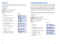
PROGRAMMING ACCOUNT CODES
STATION TIMERS
This program is used to add or change account code entries.
Each station can have five timers customized for them to accommodate station
users with individual work habits. These timers are as follows:
PROGRAM KEYS
NO ANS FWD
No Answer Forward
KEYPAD - Used to enter the account code (allowable digits 0–9).
UP & DOWN - Used to select entry number.
FLASH & TRSF - Used to view and change only the used entries.
SPK/RLS - Used to clear data.
This is the amount of time a call will ring at a station before it forwards to the
Forward No Answer destination. The default is 15 seconds and the range is 000 to
250 seconds. Make sure that this timer is not set to a greater value than the transfer recall timer or transferred calls will not forward.
Open customer programming and follow the instructions below.
DTMF DUR.
ACTION
DISPLAY
This is the duration of DTMF tones sent to an analog voice mail port. The default
duration is 100 milliseconds and the range is 0100 to 9900 milliseconds.
1. Press TRSF and then dial 708
Display shows
ACCOUNT CODE
(001)
2. Dial the account code entry (e.g., 005)
OR press UP or DOWN to select the
entry number and press the right soft
key to move the cursor
ACCOUNT CODE
(005)
3. Enter the account code via the dial pad,
e.g., 1234 (maximum of 12 digits) and
press the right soft key to move the
cursor back to step 2
ACCOUNT CODE
(005)123456789012
4. Press TRSF to store and exit programming OR press SPK to store and
advance to the next program
F-DGT DELY
DTMF Duration
First Digit Delay
This is the time the system will wait before sending DTMF digits to a voice mail
port. The default time is 600 milliseconds and the range is from 100 to 9900 milliseconds.
OFFHK SEL.
Off Hook Select
This timer controls the delay between going off hook (lifting the handset) and the
off hook select destination being called.The default duration is 10 seconds and the
range is from 000 to 250 seconds.
EFWD DELAY
External Forward Delay
This is the time that a station will ring before a call forwards to the external call
forward destination. The default duration is 10 seconds and the range is 1 second
to 250 seconds.
Open customer programming and follow the instructions below.
PROGRAM KEYS
KEYPAD - Used to set timer values.
UP & DOWN - Used to select extension number.
SPK/RLS - Save data and advance to next program.
29
ACTION
DISPLAY
1. Press TRSF and then dial 502
Display shows
[201] NO ANS FWD
010 SEC
30
2. Dial the station number (e.g., 205) OR
press UP or DOWN key to select the
station and press the right soft key OR
press ANS/RLS to select all stations
and press the right soft key
[205] NO ANS FWD
010 SEC
OR
[ALL] NO ANS FWD
010 SEC
3. Press UP or DOWN key to select the
station timer and press the right soft key
[205] DTMF DUR.
0100 MS→
4. Enter the new value via the dial pad,
e.g., 0300 and the system will return
to step 2
[205] DTMF DUR.
0100 MS→0300
5. Press TRSF to store and exit
programming OR press SPK to store
and advance to the next program
ADDING NAMES TO THE
TRANSLATION TABLE
This program allows the system administrator or technician to associate a CID or
ANI number received from the Central Office with a name programmed in this
translation table. If there is no match between a received number and a name in
this table, [no CID name] or [no ANI name] will be displayed.
ACTION
DISPLAY
1.
Press TRSF and then dial 728
Display shows first entry
TRANSLATION:(001)
DIGIT:
2.
Dial entry number (e.g., 005 or 0005)
OR use UP and DOWN to scroll
through entries and press right
soft key to select entry
TRANSLATION:(005)
DIGIT:_
3.
Enter telephone number and press
right soft key to advance to name entry
OR enter telephone number and press
left soft key to return to step 2 above
TRANSLATION:(005)
DIGIT:3054264100
4.
Enter the name using the method
in Program Station Names
and press right or left soft key to
return to step 2 above
OR press SPK to save and advance
to next MMC OR press TRSF to
save and exit programming
TRANSLATION:(005)
SAMSUNG TELECOM
DEFAULT DATA: NONE
The translation table consists of 1000 entries in the iDCS 500 Release 2 M system
or 2000 entries in the iDCS 500 Release 2 L system with each entry comprised of
a ten digit telephone number and a 16 digit name. See Program Station Names.
Open customer programming and follow the instructions below.
PROGRAM KEYS
UP & DOWN - Used to scroll through options.
KEYPAD - Used to enter selections.
SOFT KEYS - Move cursor left and right.
SPK - Used to store data and advance to next MMC.
HOLD - Used to clear previous entry.
31
32
HOLIDAY
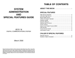
CUSTOMER SET RELOCATION
This program provides the ability to set as many as 20 different holidays. Each holiday will override the System Operating Mode for that particular date with a programmed ring plan.
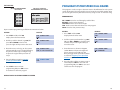
This program is used to swap information associated with two stations. All assignments such as trunk ring, station group, station COS, station speed dial etc. will follow this program. 12 button keysets and 24 button keysets can be exchanged.
Basic 7 button keysets can be exchanged with Basic 7 button key sets. Single line
stations numbers can be exchanged. If incompatible set types are selected the system will provide an ERROR: NO MATCH message. 12 button and 24 button key
assignments should be taken in consideration when relocating these type of sets.
The table below shows which phones can be switched with each other.
PROGRAM KEYS
UP & DOWN - Used to scroll through options.
KEYPAD - Used to enter selections.
SOFT KEYS - Move cursor left and right.
HOLD - Used to clear an entry.
ACTION
NOTE: In order to use this program it must first be activated by a technician. Please
see your installing company to have this done if you wish to use this program.
DISPLAY
PROGRAM KEYS
1. Press TRSF and then dial 512
Display shows
RING PLAN
FOLLOW1
2. Press the right soft key to move the
cursor to bottom half of display
RING PLAN
FOLLOW1
3. Enter the desired ring plan (e.g., 0-6)
Display will return to STEP 1
RING PLAN
FOLLOW4
4. Press UP or DOWN to change display
to holiday assignment
ASSIGN HOLIDAY
01:
5. Press the right soft key to move the
cursor to bottom half of display
ASSIGN HOLIDAY
01:
6. Enter a desired holiday date
(e.g., 1225)
ASSIGN HOLIDAY
01:
7. Press TRSF to store and exit
programming OR press SPK to store
and advance to the next program
ASSIGN HOLIDAY
01:1225
33
UP & DOWN - Used to scroll through options.
KEYPAD - Used to enter selections.
SOFT KEYS - Move cursor left and right.
SPK - Used to store data and advance to next program.
HOLD - Used to clear previous entry.
ANS/RLS - Used to select ALL.
ACTION
DISPLAY
1. Press TRSF 315
Display shows
SET RELOCATION
EXT _
EXT
2. Enter first station number (e.g., 202)
Press RIGHT soft key to move cursor
SET RELOCATION
EXT 202 EXT _
3. Enter second station number (e.g., 210)
Press RIGHT soft key to enter data
SET RELOCATION
EXT 202 EXT 210
4. Display will return to STEP 1
Go to STEP 2
OR press TRSF to store and exit
programming.
SET RELOCATION
EXT _
EXT
34
35
NO
NO
NO
NO
NO
NO
NO
NO
NO
NO
NO
NO
NO
NO
NO
BSC 12
LCD 12
BSC 24
LCD 24
32 AOM
DCS &
iDCS 64
AOM
iDCS 8B
iDCS 18B
DCS 18B
with iDCS
14 AOM
iDCS 28B
DCS 28B
with iDCS
14 AOM
ITP-5012L
ITP-5021D
NO
NO
NO
NO
NO
NO
NO
NO
NO
NO
NO
YES
NO
7 BTN
NO
YES
7 BTN
S/L
S/L
NO
NO
NO
NO
NO
NO
NO
NO
NO
NO
NO
YES
YES
NO
NO
BSC 12
NO
NO
NO
NO
NO
NO
NO
NO
NO
NO
NO
NO
NO
NO
NO
NO
NO
NO
NO
YES
NO
NO
NO
NO
YES
NO
NO
YES
NO
BSC 24
NO
LCD 12
NO
NO
NO
NO
NO
NO
NO
NO
NO
YES
YES
NO
NO
NO
NO
LCD 24
NO
NO
NO
NO
NO
NO
NO
NO
YES
NO
NO
NO
NO
NO
NO
32 AOM
NO
NO
NO
NO
NO
NO
NO
YES
YES
NO
NO
NO
NO
NO
NO
NO
NO
YES
NO
YES
NO
NO
NO
NO
NO
NO
NO
NO
iDCS 8B
NO
NO
DCS &
iDCS 64
AOM
NO
NO
NO
YES
NO
YES
NO
NO
YES
NO
NO
NO
NO
NO
NO
NO
NO
NO
NO
NO
YES
NO
NO
NO
YES
NO
YES
NO
NO
YES
NO
NO
NO
NO
NO
NO
NO
NO
NO
NO
NO
NO
NO
NO
NO
NO
NO
YES
NO
NO
NO
NO
NO
NO
NO
NO
NO
NO
NO
NO
NO
NO
NO
NO
NO
NO
NO
NO
NO
NO
NO
NO
NO
NO
YES
NO
NO
NO
NO
NO
NO
NO
NO
NO
NO
NO
NO
NO
YES
NO
DCS 28B
DCS 18B
iDCS 18B with iDCS iDCS 28B with iDCS ITP-5012L ITP-5021D
14 AOM
14 AOM
CUSTOMER SET RELOCATION ALLOW TABLE
SYSTEM MAINTENANCE
ALARMS
The iDCS 500 Release 2 system (with a LAN board installed) provide a feature that
self-checks for any failures. If a failure does occur in the iDCS software or hardware,
a fault error will be generated and buffered to an alarm report. During an alarm
state every phone with an assigned SYSTEM ALARM button will ring and cause
the SYSTEM ALARM button to flash amber. A phone with a display should be
used so that the alarm information can be viewed.When an alarm occurs, the user
can press the SYSTEM ALARM button to view and scroll through the alarms. This
will silence the audible part of the alarm, but the SYSTEM ALARM button will
continue to flash until your Service Company views and clears the alarms in the
alarm report located in the system software.
36