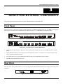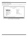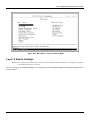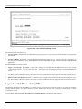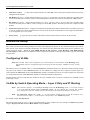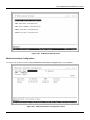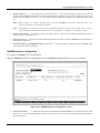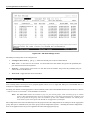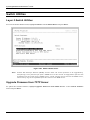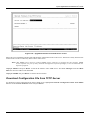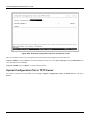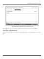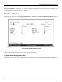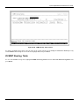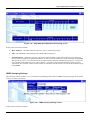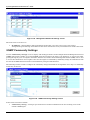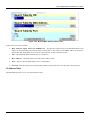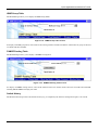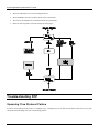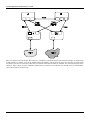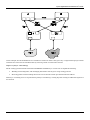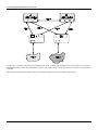
1
DGS-3308 Series 8-Port Gigabit Layer 3 Switch User’s Guide First Edition (December 2001) 651FG3308015 Printed In Taiwan RECYCLABLE Wichtige Sicherheitshinweise 1. Bitte lesen Sie sich diese Hinweise sorgfältig durch. 2. Heben Sie diese Anleitung für den spätern Gebrauch auf. 3. Vor jedem Reinigen ist das Gerät vom Stromnetz zu trennen. Vervenden Sie keine Flüssig- oder Aerosolreiniger. Am besten dient ein angefeuchtetes Tuch zur Reinigung. 4. Um eine Beschädigung des Gerätes zu vermeiden sollten Sie nur Zubehörteile verwenden, die vom Hersteller zugelassen sind. 5. Das Gerät is vor Feuchtigkeit zu schützen. 6. Bei der Aufstellung des Gerätes ist auf sichern Stand zu achten. Ein Kippen oder Fallen könnte Verletzungen hervorrufen. Verwenden Sie nur sichere Standorte und beachten Sie die Aufstellhinweise des Herstellers. 7. Die Belüftungsöffnungen dienen zur Luftzirkulation die das Gerät vor Überhitzung schützt. Sorgen Sie dafür, daß diese Öffnungen nicht abgedeckt werden. 8. Beachten Sie beim Anschluß an das Stromnetz die Anschlußwerte. 9. Die Netzanschlußsteckdose muß aus Gründen der elektrischen Sicherheit einen Schutzleiterkontakt haben. 10. Verlegen Sie die Netzanschlußleitung so, daß niemand darüber fallen kann. Es sollete auch nichts auf der Leitung abgestellt werden. 11. Alle Hinweise und Warnungen die sich am Geräten befinden sind zu beachten. 12. Wird das Gerät über einen längeren Zeitraum nicht benutzt, sollten Sie es vom Stromnetz trennen. Somit wird im Falle einer Überspannung eine Beschädigung vermieden. 13. Durch die Lüftungsöffnungen dürfen niemals Gegenstände oder Flüssigkeiten in das Gerät gelangen. Dies könnte einen Brand bzw. Elektrischen Schlag auslösen. 14. Öffnen Sie niemals das Gerät. Das Gerät darf aus Gründen der elektrischen Sicherheit nur von authorisiertem Servicepersonal geöffnet werden. 15. Wenn folgende Situationen auftreten ist das Gerät vom Stromnetz zu trennen und von einer qualifizierten Servicestelle zu überprüfen: a – Netzkabel oder Netzstecker sint beschädigt. b – Flüssigkeit ist in das Gerät eingedrungen. c – Das Gerät war Feuchtigkeit ausgesetzt. d – Wenn das Gerät nicht der Bedienungsanleitung ensprechend funktioniert oder Sie mit Hilfe dieser Anleitung keine Verbesserung erzielen. e – Das Gerät ist gefallen und/oder das Gehäuse ist beschädigt. f – Wenn das Gerät deutliche Anzeichen eines Defektes aufweist. 16. Bei Reparaturen dürfen nur Orginalersatzteile bzw. den Orginalteilen entsprechende Teile verwendet werden. Der Einsatz von ungeeigneten Ersatzteilen kann eine weitere Beschädigung hervorrufen. 17. Wenden Sie sich mit allen Fragen die Service und Repartur betreffen an Ihren Servicepartner. Somit stellen Sie die Betriebssicherheit des Gerätes sicher. 18. Zum Netzanschluß dieses Gerätes ist eine geprüfte Leitung zu verwenden, Für einen Nennstrom bis 6A und einem Gerätegewicht gr ßer 3kg ist eine Leitung nicht leichter als H05VV-F, 3G, 0.75mm2 einzusetzen. WARRANTIES EXCLUSIVE IF THE D-LINK PRODUCT DOES NOT OPERATE AS WARRANTED ABOVE, THE CUSTOMER'S SOLE REMEDY SHALL BE, AT D-LINK'S OPTION, REPAIR OR REPLACEMENT. THE FOREGOING WARRANTIES AND REMEDIES ARE EXCLUSIVE AND ARE IN LIEU OF ALL OTHER WARRANTIES, EXPRESSED OR IMPLIED, EITHER IN FACT OR BY OPERATION OF LAW, STATUTORY OR OTHERWISE, INCLUDING WARRANTIES OF MERCHANTABILITY AND FITNESS FOR A PARTICULAR PURPOSE. D-LINK NEITHER ASSUMES NOR AUTHORIZES ANY OTHER PERSON TO ASSUME FOR IT ANY OTHER LIABILITY IN CONNECTION WITH THE SALE, INSTALLATION MAINTENANCE OR USE OF D-LINK'S PRODUCTS D-LINK SHALL NOT BE LIABLE UNDER THIS WARRANTY IF ITS TESTING AND EXAMINATION DISCLOSE THAT THE ALLEGED DEFECT IN THE PRODUCT DOES NOT EXIST OR WAS CAUSED BY THE CUSTOMER'S OR ANY THIRD PERSON'S MISUSE, NEGLECT, IMPROPER INSTALLATION OR TESTING, UNAUTHORIZED ATTEMPTS TO REPAIR, OR ANY OTHER CAUSE BEYOND THE RANGE OF THE INTENDE D USE, OR BY ACCIDENT, FIRE, LIGHTNING OR OTHER HAZARD. LIMITATION OF LIABILITY IN NO EVENT WILL D-LINK BE LIABLE FOR ANY DAMAGES, INCLUDING LOSS OF DATA, LOSS OF PROFITS, COST OF COVER OR OTHER INCIDENTAL, CONSEQUENTIAL OR INDIRECT DAMAGES ARISING OUT THE INSTALLATION, MAINTENANCE, USE, PERFORMANCE, FAILURE OR INTERRUPTION OF A D- LINK PRODUCT, HOWEVER CAUSED AND ON ANY THEORY OF LIABILITY. THIS LIMITATION WILL APPLY EVEN IF DLINK HAS BEEN ADVISED OF THE POSSIBILITY OF SUCH DAMAGE. IF YOU PURCHASED A D-LINK PRODUCT IN THE UNITED STATES, SOME STATES DO NOT ALLOW THE LIMITATION OR EXCLUSION OF LIABILITY FOR INCIDENTAL OR CONSEQUENTIAL DAMAGES, SO THE ABOVE LIMITATION MAY NOT APPLY TO YOU. Limited Warranty Hardware: D-Link warrants each of its hardware products to be free from defects in workmanship and materials under normal use and service for a period commencing on the date of purchase from D-Link or its Authorized Reseller and extending for the length of time stipulated by the Authorized Reseller or D-Link Branch Office nearest to the place of purchase. This Warranty applies on the condition that the product Registration Card is filled out and returned to a D-Link office within ninety (90) days of purchase. A list of D-Link offices is provided at the back of this manual, together with a copy of the Registration Card. If the product proves defective within the applicable warranty period, D-Link will provide repair or replacement of the product. D-Link shall have the sole discretion whether to repair or replace, and replacement product may be new or reconditioned. Replacement product shall be of equivalent or better specifications, relative to the defective product, but need not be identical. Any product or part repaired by D-Link pursuant to this warrant y shall have a warranty period of not less than 90 days, from date of such repair, irrespective of any earlier expiration of original warranty period. When D-Link provides replacement, then the defective product becomes the property of D-Link. Warranty se rvice may be obtained by contacting a D-Link office within the applicable warranty period, and requesting a Return Material Authorization (RMA) number. If a Registration Card for the product in question has not been returned to D-Link, then a proof of pur chase (such as a copy of the dated purchase invoice) must be provided. If Purchaser's circumstances require special handling of warranty correction, then at the time of requesting RMA number, Purchaser may also propose special procedure as may be suitable to the case. After an RMA number is issued, the defective product must be packaged securely in the original or other suitable shipping package to ensure that it will not be damaged in transit, and the RMA number must be prominently marked on the outside of the package. The package must be mailed or otherwise shipped to D-Link with all costs of mailing/shipping/insurance prepaid. D-Link shall never be responsible for any software, firmware, information, or memory data of Purchaser contained in, stored on, or integrated with any product returned to D-Link pursuant to this warranty. Any package returned to D-Link without an RMA number will be rejected and shipped back to Purchaser at Purchaser's expense, and D-Link reserves the right in such a case to levy a reasonable handling charge in addition mailing or shipping costs. Software: Warranty service for software products may be obtained by contacting a D-Link office within the applicable warranty period. A list of D-Link offices is provided at the back of thi s manual, together with a copy of the Registration Card. If a Registration Card for the product in question has not been returned to a D-Link office, then a proof of purchase (such as a copy of the dated purchase invoice) must be provided when requesting warranty service. The term "purchase" in this software warranty refers to the purchase transaction and resulting license to use such software. D-Link warrants that its software products will perform in substantial conformance with the applicable product documentation provided by D-Link with such software product, for a period of ninety (90) days from the date of purchase from D-Link or its Authorized Reseller. D-Link warrants the magnetic media, on which D-Link provides its software product, against failure during the same warranty period. This warranty applies to purchased software, and to replacement software provided by D-Link pursuant to this warranty, but shall not apply to any update or replacement which may be provided for download via the Internet, or to any update which may otherwise be provided free of charge. D-Link's sole obligation under this software warranty shall be to replace any defective software product with product which substantially conforms to D-Link's applicable product documentation. Purchaser assumes responsibility for the selection of appropriate application and system/platform software and associated reference materials. D-Link makes no warranty that its software products will work in combination with any hardware, or any application or system/platform software product provided by any third party, excepting only such products as are expressly represented, in D-Link's applicable product documentation as being compatible. D-Link's obligation under this warranty shall be a reasonable effort to provide compatibility, but D-Link shall have no obligation to provide compatibility when there is fault in the third-party hardware or software. D-Link makes no warranty that operation of its software products will be uninterrupted or absolutely error-free, and no warranty that all defects in the software product, within or without the scope of D-Link's applicable product documentation, will be corrected. D-Link Offices for Registration and Warranty Service The product's Registration Card, provided at the back of this manual, must be sent to a D-Link office. To obtain an RMA number for warranty service as to a hardware product, or to obtain warranty service as to a software product, contact the D-Link office nearest you. An address/telephone/fax/e-mail/Web site list of D-Link offices is provided in the back of this manual. Trademarks Copyright 2001 D-Link Corporation. Contents subject to change without prior notice. D-Link is a registered trademark of D-Link Corporation/D-Link Systems, Inc. All other trademarks belong to their respective proprietors. Copyright Statement No part of this publication may be reproduced in any form or by any means or used to make any derivative such as translation, transformation, or adaptation without permission from D-Link Corporation/D-Link Systems Inc., as stipulated by the United States Copyright Act of 1976. FCC Warning This equipment has been tested and found to comply with the limits for a Class A digital device, pursuant to Part 15 of the FCC Rules. These limits are designed to provide reasonable protection against harmful interference when the equipment is operated in a commercial environment. This equipment generates, uses, and can radiate radio frequency energy and, if not installed and used in accordance with this user’s guide, may cause harmful interference to radio communications. Operation of this equipment in a residential area is likely to cause harmful interference in which case the user will be required to correct the interference at his own expense. CE Mark Warning This is a Class A product. In a domestic environment, this product may cause radio interference in which case the user may be required to take adequate measures. VCCI Warning BSMI Warning Table of Contents About This Guide...............................................................................................................................................................................................1 Overview of this User’s Guide .....................................................................................................................................................................1 Introduction.........................................................................................................................................................................................................2 Layer 3 Switching...........................................................................................................................................................................................2 The Functions of a Layer 3 Switch..........................................................................................................................................................3 Features ...........................................................................................................................................................................................................3 Ports...............................................................................................................................................................................................................3 Performance Features...................................................................................................................................................................................4 Layer 2 Switching Features......................................................................................................................................................................4 Layer 3 Switching Features......................................................................................................................................................................4 Traffic Classification and Prioritization...............................................................................................................................................5 Management ................................................................................................................................................................................................5 Optional Redundant Power Supply........................................................................................................................................................6 Fast Ethernet Technology.............................................................................................................................................................................6 Gigabit Ethernet Technology .......................................................................................................................................................................6 Unpacking and Setup........................................................................................................................................................................................7 Unpacking........................................................................................................................................................................................................7 Installation......................................................................................................................................................................................................7 Desktop or Shelf Installation...................................................................................................................................................................7 Rack Installation ........................................................................................................................................................................................8 Power on...........................................................................................................................................................................................................9 Power Failure...............................................................................................................................................................................................9 Identifying External Components ................................................................................................................................................................10 Front Panel....................................................................................................................................................................................................10 Rear Panel .....................................................................................................................................................................................................10 Side Panels....................................................................................................................................................................................................11 LED Indicators..............................................................................................................................................................................................11 Connecting The Switch ...................................................................................................................................................................................12 PC to Switch..................................................................................................................................................................................................12 Switch to Switch (other devices) ...............................................................................................................................................................12 Switch Management and Operating Concepts..........................................................................................................................................14 Local Console Management ...................................................................................................................................................................14 IP Addresses and SNMP Community Names ...................................................................................................................................15 Traps............................................................................................................................................................................................................16 MIBs ............................................................................................................................................................................................................17 SNMP..........................................................................................................................................................................................................17 Packet Forwarding....................................................................................................................................................................................18 MAC Address Aging Time......................................................................................................................................................................18 Filtering ......................................................................................................................................................................................................18 IP Addressing and Subnetting...............................................................................................................................................................19 802.1Q VLANs .........................................................................................................................................................................................23 Spanning Tree Protocol............................................................................................................................................................................28 Internet Protocols......................................................................................................................................................................................34 The Domain Name System.....................................................................................................................................................................42 DHCP Servers............................................................................................................................................................................................42 Routing........................................................................................................................................................................................................42 ARP..............................................................................................................................................................................................................43 Multicasting...............................................................................................................................................................................................43 Internet Group Management Protocol (IGMP)...................................................................................................................................45 Multicast Routing Algorithms...............................................................................................................................................................46 Multicast Routing Protocols...................................................................................................................................................................48 Routing Protocols......................................................................................................................................................................................48 Configuring the Switch Using the Console Interface ...............................................................................................................................54 Before You Start ...........................................................................................................................................................................................54 General Deployment Strategy................................................................................................................................................................54 VLAN Layout ............................................................................................................................................................................................55 Assigning IP Network Addresses and Subnet Masks to VLANs ..................................................................................................55 Defining Static Routes.............................................................................................................................................................................55 Connecting to the Switch............................................................................................................................................................................56 Console Usage Conventions ...................................................................................................................................................................56 Setup User Accounts ...................................................................................................................................................................................58 User Accounts Management ..................................................................................................................................................................59 Save Changes................................................................................................................................................................................................60 Reboot.............................................................................................................................................................................................................62 Logging Onto The Switch Console ............................................................................................................................................................63 Updating or Deleting User Accounts....................................................................................................................................................63 Viewing Current User Accounts............................................................................................................................................................64 Deleting a User Account ..........................................................................................................................................................................65 Setting Up The Switch................................................................................................................................................................................65 Basic Setup ................................................................................................................................................................................................65 Switch Information...................................................................................................................................................................................66 IP Setup.......................................................................................................................................................................................................67 Remote Management Setup...................................................................................................................................................................69 Configure Ports..........................................................................................................................................................................................70 Serial Port Settings..................................................................................................................................................................................71 Switch Operation Mode ..............................................................................................................................................................................72 Changing the Switch Operation Mode .................................................................................................................................................73 Layer 2 Switch Settings ..........................................................................................................................................................................76 Layer 3 Switch Mode - Setup RIP .........................................................................................................................................................77 Advanced Setup............................................................................................................................................................................................79 Configuring VLANs..................................................................................................................................................................................79 VLANs by Switch Operating Mode – Layer 2 Only and IP Routing..............................................................................................79 Setting Up IP Interfaces .............................................................................................................................................................................86 Multicasting..................................................................................................................................................................................................89 Layer 2 Multicast Setup .........................................................................................................................................................................89 IGMP Snooping Settings – by VLAN...................................................................................................................................................89 IEEE 802.1Q Multicast Forwarding .....................................................................................................................................................91 Static Router Port.....................................................................................................................................................................................92 Layer 3 Multicasting................................................................................................................................................................................93 Static Router Port.....................................................................................................................................................................................99 Mirroring..................................................................................................................................................................................................... 101 Priority......................................................................................................................................................................................................... 103 Filtering....................................................................................................................................................................................................... 104 Layer 2 Filtering .................................................................................................................................................................................... 104 Layer 3 (IP Routing) Filtering............................................................................................................................................................. 105 Forwarding.................................................................................................................................................................................................. 108 Layer 2 Forwarding ............................................................................................................................................................................... 108 IP Routing Forwarding.......................................................................................................................................................................... 109 MAC Address Forwarding................................................................................................................................................................... 109 Spanning Tree............................................................................................................................................................................................ 112 Switch Spanning Tree Settings .......................................................................................................................................................... 112 Port Group Spanning Tree Settings................................................................................................................................................... 114 Port Trunking............................................................................................................................................................................................. 115 Switch Utilities ......................................................................................................................................................................................... 117 Layer 2 Switch Utilities....................................................................................................................................................................... 117 Upgrade Firmware from TFTP Server.............................................................................................................................................. 117 Download Configuration File from TFTP Server............................................................................................................................ 118 Upload Configuration File to TFTP Server...................................................................................................................................... 119 Save Log to TFTP Server...................................................................................................................................................................... 120 Ping ........................................................................................................................................................................................................... 121 Layer 3 Utilities..................................................................................................................................................................................... 122 BOOTP/DHCP Relay............................................................................................................................................................................. 122 DNS Relay............................................................................................................................................................................................... 124 Network Monitoring ................................................................................................................................................................................. 126 Layer 2 Network Monitoring............................................................................................................................................................... 126 Port Utilization...................................................................................................................................................................................... 127 Port Error Packets ................................................................................................................................................................................. 128 Port Packet Analysis Table................................................................................................................................................................. 128 MAC Address Forwarding Table ....................................................................................................................................................... 129 IGMP Snooping....................................................................................................................................................................................... 130 Switch History........................................................................................................................................................................................ 131 Layer 3 Network Monitoring............................................................................................................................................................... 132 Browse IP Address................................................................................................................................................................................. 132 IP Routing Table .................................................................................................................................................................................... 133 ARP Table ............................................................................................................................................................................................... 134 Browse Router Port ............................................................................................................................................................................... 135 IP Multicast Forwarding Table .......................................................................................................................................................... 136 IGMP Group Table................................................................................................................................................................................. 137 DVMRP Routing Table ........................................................................................................................................................................ 138 Reboot and Factory Reset ....................................................................................................................................................................... 139 Web-Based Network Management........................................................................................................................................................... 142 Introduction ................................................................................................................................................................................................ 142 Before You Start ........................................................................................................................................................................................ 142 General Deployment Strategy............................................................................................................................................................. 142 VLAN Layout ......................................................................................................................................................................................... 143 Assigning IP Network Addresses and Subnet Masks to VLANs ............................................................................................... 143 Defining Static Routes.......................................................................................................................................................................... 143 Getting Started.......................................................................................................................................................................................... 144 Configuring the Switch............................................................................................................................................................................. 144 User Accounts Management ............................................................................................................................................................... 144 Saving Changes...................................................................................................................................................................................... 146 Factory Reset.......................................................................................................................................................................................... 146 Using Web-Based Management ............................................................................................................................................................ 147 Configuration ............................................................................................................................................................................................. 150 Switch IP Setup...................................................................................................................................................................................... 155 Switch Information................................................................................................................................................................................ 155 Power Supply & Cooling Fan Status ................................................................................................................................................. 156 Configure Ports....................................................................................................................................................................................... 157 Switch Settings ...................................................................................................................................................................................... 158 Configure Layer 3 - IP Networking..................................................................................................................................................... 159 VLANs ..................................................................................................................................................................................................... 162 Multicasting............................................................................................................................................................................................ 165 Priority..................................................................................................................................................................................................... 172 Mirroring.................................................................................................................................................................................................. 173 Spanning Tree Protocol......................................................................................................................................................................... 175 Port Trunking.......................................................................................................................................................................................... 179 Forwarding .............................................................................................................................................................................................. 180 Filtering ................................................................................................................................................................................................... 183 BOOTP/DHCP Relay............................................................................................................................................................................. 185 DNS Relay............................................................................................................................................................................................... 187 Remote Management Setup................................................................................................................................................................... 188 Management Station IP Settings ...................................................................................................................................................... 188 SNMP Community Settings ............................................................................................................................................................... 189 Setup Trap Receivers ............................................................................................................................................................................ 190 Setup User Accounts............................................................................................................................................................................. 190 Serial Port Settings............................................................................................................................................................................... 192 Network Monitoring ................................................................................................................................................................................. 193 Statistics ................................................................................................................................................................................................. 193 Address Table......................................................................................................................................................................................... 197 Applications ............................................................................................................................................................................................ 201 Maintenance............................................................................................................................................................................................... 205 Upgrade Firmware from TFTP Server.............................................................................................................................................. 206 Download Configuration File from TFTP Server............................................................................................................................ 206 Upload Configuration File to TFTP Server...................................................................................................................................... 206 Save Log to TFTP Server...................................................................................................................................................................... 207 Save Changes.......................................................................................................................................................................................... 207 Factory Reset.......................................................................................................................................................................................... 208 Restart System ...................................................................................................................................................................................... 209 Technical Specifications .............................................................................................................................................................................. 210 RJ-45 Pin Specification............................................................................................................................................................................... 213 Runtime Switching Software Default Settings...................................................................................................................................... 214 Understanding and Troubleshooting the Spanning Tree Protocol..................................................................................................... 215 Blocking State ........................................................................................................................................................................................ 215 Listening State....................................................................................................................................................................................... 216 Learning State........................................................................................................................................................................................ 217 Forwarding State................................................................................................................................................................................... 217 Disabled State........................................................................................................................................................................................ 218 Troubleshooting STP................................................................................................................................................................................ 219 Spanning Tree Protocol Failure.......................................................................................................................................................... 219 Full/Half Duplex Mismatch................................................................................................................................................................. 220 Unidirectional Link............................................................................................................................................................................... 221 Packet Corruption.................................................................................................................................................................................. 221 Resource Errors ...................................................................................................................................................................................... 221 Identifying a Data Loop........................................................................................................................................................................ 222 Avoiding Trouble.................................................................................................................................................................................... 222 Brief Review of Bitwise Logical Operations ........................................................................................................................................... 226 Index................................................................................................................................................................................................................. 227 8-port Gigabit Ethernet Switch User’s Guide A BOUT T HIS G UIDE This User’s guide tells you how to install your DGS-3308, how to connect it to your Ethernet network, and how to set its configuration using either the built-in console interface or Web-based management. Overview of this User’s Guide • Chapter 1, “Introduction.” Describes the Switch and its features. • Chapter 2, “Unpacking and Setup.” Helps you get started with the basic installation of the Switch. • Chapter 3, “Identifying External Components.” Describes the front panel, rear panel, and LED indicators of the Switch. • Chapter 4, “Connecting the Switch.” Tells how you can connect the Switch to your Ethernet network. • Chapter 5, “Switch Management and Operating Concepts.” Talks about Local Console Management via the RS-232 DCE console port and other aspects about how to manage the Switch. • Chapter 6, “Using the Console Interface.” Tells how to use the built-in console interface to change, set, and monitor Switch performance and security. • Chapter 7, “Web-Based Network Management.” Tells how to manage the Switch through an Internet browser. • Appendix A, “Technical Specifications.” Lists the technical specifications of the DGS-3308TG and DGS-3308FG. • Appendix B, “RJ-45 Pin Specifications.” Shows the details and pin assignments for the RJ-45 receptacle/connector. • Appendix C, “Factory Default Settings.” • Appendix D, “Understanding and Troubleshooting the Spanning Tree Protocol.” • Appendix E, “Brief Review of Bitwise Logical Operations.” 1 8-port Gigabit Ethernet Switch User’s Guide 1 INTRODUCTION This section describes the Layer 3 functionality and Layer 2 and Layer 3 features of the DGS-3308 Series switches. Some background information about Ethernet/Fast Ethernet, Gigabit Ethernet, and switching technology is presented. This is intended for readers who may not be familiar with the concepts of layered switching and routing but is not intended to be a complete or in-depth discussion. For a more detailed discussion of the functionality of the DGS-3308, please see Chapter 5, “Switch Management and Operating Concepts.” Layer 3 Switching Layer 3 switching is the integration of two proven technologies: switching and routing. In fact, Layer 3 switches are running the same routing routines and protocols as traditional routers. The main difference between traditional routing and Layer 3 switching is the addition of a group of Layer 2 switching domains and the execution of routing routines for most packets via an ASIC – in hardware instead of software. Where a traditional router would have one, or at best a few, Fast Ethernet ports, the DGS-3308 Layer 3 switch has eight Gigabit Ethernet ports, including two which are GBIC-based. Where a traditional router would have one or two high-speed serial WAN connections, the DGS-3308 relies upon Gigabit Ethernet ports to connect to a separate device, which in turn, connects the network to a WAN or the Internet. The DGS-3308 can be thought of as Fast Ethernet Layer 2 switching domains with a wire-speed router between each domain. It can be deployed in a network between a traditional router and the intranetwork. The traditional router and its associated WAN interface would then handle routing between the intranetwork and the WAN (the Internet, for example) while the Layer 3 switch would handle routing within the LAN (between the Fast Ethernet Layer 2 domains). Any installed Layer 2 switches, and indeed the entire subnetting scheme, would remain in place. The DGS-3308FG can also replace key traditional routers for data centers and server farms, routing between these locations and the rest of the network, and providing eight ports of Layer 2 switching performance combined with wire-speed routing. Backbone routers can also be replaced with DGS-3208FG and DGS-3208TG switches and a series of DGS-3308 switches could be linked via the Gigabit Ethernet ports. Routers that service WAN connections would remain in place, but would now be removed from the backbone and connected to the DGS-3308 via a Gigabit Ethernet port. The backbone itself could be migrated to Gigabit Ethernet, or faster technologies as they become available. Policy services can then be introduced (or enhanced) in the backbone infrastructure and maintained throughout the network – even to the desktop. With a distributed infrastructure and a logical management structure, network performance becomes easier to measure and fine-tune. With the completion of the migration of the backbone to Gigabit or higher-performance technologies, the result is inherently scalable and easily evolved for future technologies. This core network will also become the termination point for Virtual Private Networks (VPNs) for remote office access to the enterprise infrastructure. The DGS-3308 can then be thought of as accomplishing two objectives. First as a tool to provide high-performance access to enterprise data servers and infrastructure, and second, to enhance the performance of network equipment already 2 8-port Gigabit Ethernet Switch User’s Guide installed. Many network segments display poor performance, but the Ethernet wire is only carrying a fraction of its total traffic capacity. The problem is not the network, but the ability of the connected devices to utilize the full capacity of the network. The DGS-3308 can eliminate network bottlenecks to high-traffic areas, and improve the utilization of the network’s installed bandwidth. The Functions of a Layer 3 Switch Traditional routers, once the core components of large networks, became an obstacle to the migration toward nextgeneration networks. Attempts to make software-based routers forward packets more quickly were inadequate. A layer 3 switch does everything to a packet that a traditional router does: • Determines forwarding path based on Layer 3 information • Validates the integrity of the Layer 3 header via checksum • Verifies packet expiration and updates accordingly • Processes and responds to any optional information • Updates forwarding statistics in the Management Information Base • Applies security controls A Layer 3 switch can be placed anywhere within a network core or backbone, easily and cost-effectively replacing the traditional collapsed backbone router. The DGS-3308 Layer 3 switch communicates with a WAN router using a standard Gigabit Ethernet or GBIC-based port. Multiple DGS-3308 switches can be linked via the Gigabit Ethernet ports. Features The DGS-3308 was designed for easy installation and high performance in an environment where traffic on the network and the number of users increase continuously. Switch features include: Ports • Six 1000BASE-SX (SC-type fiber transceiver) for the DGS-3308FG or six 1000BASE-T (10/100/1000M Fast/Gigabit Ethernet) for the DGS-3308TG. • Two GBIC-based Gigabit Ethernet ports. • Fully compliant with IEEE 802.3z. • Fully compliant with IEEE 802.3 10BASE-T, IEEE 802.3u 100BASE-TX, and IEEE 802.3ab 1000BASE-T (DGS3308TG only). • Support Full Duplex operations. • Supports auto-negotiation for 10M/100M/1000M speed (DGS-3308TG only). • IEEE 802.3x compliant Flow Control support for full duplex. • Supports Head of Line Blocking. 3 8-port Gigabit Ethernet Switch User’s Guide • Per device packet buffer: 512Kbytes. • RS-232 DCE Diagnostic port (console port) for setting up and managing the Switch via a connection to a console terminal or PC using a terminal emulation program. Performance Features Layer 2 Switching Features • 16 Gbps switching fabric capacity • Wire speed packet forwarding rate per system. • Store and forward switching scheme. • Support 8K MAC address. • Support Broadcast Storm control function. • Support Port Mirroring. • Port Trunking support for Gigabit Ethernet ports. • 802.1D Spanning Tree support. • 802.1Q Tagged VLAN support, including GVRP (GARP VLAN Registration Protocol) support for automatic VLAN configuration distribution. • 802.1p priority support (4 priority queues). • Support IGMP Snooping. Layer 3 Switching Features • Wire speed IP forwarding. • Hardware-based Layer 3 IP switching. • IP packet forwarding rate up to 12 Mpps. • 2K active IP address entry table per device. • Supports RIP – (Routing Information Protocol) versions I and II. • Support OSPF routing protocol. • Supports IP version 4. • IGMP version 1 and 2 support (RFC 1112 and RFC 2236). • Supports PIM Dense Mode (draft-ietf-pim-v2-dm-03.txt). • Supports DVMRP (draft-ietf-idmr-dvmrp-v3-09.txt). • Supports IP multi-netting. 4 8-port Gigabit Ethernet Switch User’s Guide • Supports IP packet de-fragmentation. • Supports Path MTU discovery. • Supports 802.1D frame support. Traffic Classification and Prioritization • Based on 802.1p priority bits. • Based on MAC address. • 4 priority queues. Management • RS-232 console port for out-of-band network management and system diagnosis via a console terminal or PC. • Spanning Tree Algorithm Protocol for creation of alternative backup paths and prevention of network loops. • SNMP v.1 Agent. • Telnet remote control console. • In-band control and configuration via SNMP based software. • Flash memory for software upgrades. This can be done in-band via TFTP. • Built-in SNMP management: § RFC 1213 MIB II. § RFC 1493 Bridge MIB. § RFC 1757 Four groups of RMON: Statistics, History, Alarm, and Event. § RFC 1724 RIP v2 MIB. § RFC 2737 Entity MIB. § RFC 2674 P-Bridge MIB. § RFC 2233 IF MIB. § RFC 2096 IP Forward MIB. § RFC 1907 SNMPv2 MIB § IGMP IGMP-STD MIB. § PIM MIB. This was extracted from draft-ief-idmr-pim-mib-03.txt. § DVMRP MIB. This was extracted from draft-thaler-dvmrp-mib-04.txt. § IPMROUTE MIB. This was extracted from draft-ietf-idmr-multicast-routmib-05.txt. • Supports Web-based management. • TFTP support. 5 8-port Gigabit Ethernet Switch User’s Guide • BOOTP support. • IP filtering on the management interface. • DHCP Client support. • DHCP Relay Agent. • Password enabled. Optional Redundant Power Supply The DGS-3308FG supports the optional DPS-1000 (Redundant Power Supply) to provide automatic power supply monitoring and switchover to a redundant power supply (located in the chassis of the DPS-1000) in case of a failure in the Switch’s internal power supply. The DGS-3308TG does not support the optional redundant power supply. Fast Ethernet Technology 100Mbps Fast Ethernet (or 100BASE-T) is a standard specified by the IEEE 802.3 LAN committee. It is an extension of the 10Mbps Ethernet standard with the ability to transmit and receive data at 100Mbps, while maintaining the Carrier Sense Multiple Access with Collision Detection (CSMA/CD) Ethernet protocol. Gigabit Ethernet Technology Gigabit Ethernet is an extension of IEEE 802.3 Ethernet utilizing the same packet structure, format, and support for CSMA/CD protocol, full duplex, flow control, and management objects, but with a tenfold increase in theoretical throughput over 100Mbps Fast Ethernet and a one hundred-fold increase over 10Mbps Ethernet. Since it is compatible with all 10Mbps and 100Mbps Ethernet environments, Gigabit Ethernet provides a straightforward upgrade without wasting a company’s existing investment in hardware, software, and trained personnel. Gigabit Ethernet enables fast optical fiber connections and Unshielded Twisted Pair connections to support video conferencing, complex imaging, and similar data-intensive applications. Likewise, since data transfers occur 10 times faster than Fast Ethernet, servers outfitted with Gigabit Ethernet NIC’s are able to perform 10 times the number of operations in the same amount of time. 6 8-port Gigabit Ethernet Switch User’s Guide 2 U NPACKING AND S ETUP This chapter provides unpacking and setup information for the Switch. Unpacking Open the shipping carton of the Switch and carefully unpack its contents. The carton should contain the following items: • One DGS-3308TG or DGS-3308FG 8-port Gigabit Ethernet Layer 3 Switch • Mounting kit: 2 mounting brackets and screws • Four rubber feet with adhesive backing • One AC power cord • One Installation Guide • This User’s Guide on CD-ROM with Registration Card If any item is found missing or damaged, please contact your local D-Link reseller for replacement. Installation Use the following guidelines when choosing a place to install the Switch: • The surface must support at least 3 kg. • The power outlet should be within 1.82 meters (6 feet) of the device. • Visually inspect the power cord and see that it is secured to the AC power connector. • Make sure that there is proper heat dissipation from and adequate ventilation around the switch. Do not place heavy objects on the switch. Desktop or Shelf Installation When installing the Switch on a desktop or shelf, the rubber feet included with the device should first be attached. Attach these cushioning feet on the bottom at each corner of the device. Allow adequate space for ventilation between the device and the objects around it. 7 8-port Gigabit Ethernet Switch User’s Guide Figure 2-1. Installing rubber feet for desktop installation Rack Installation The DGS-3308 can be mounted in an EIA standard-sized, 19-inch rack, which can be placed in a wiring closet with other equipment. To install, attach the mounting brackets on the Switch’s side panels (one on each side) and secure them with the screws provided. Figure 2- 2A. Attaching the mounting brackets to the Switch Then, use the screws provided with the equipment rack to mount the switch on the rack. 8 8-port Gigabit Ethernet Switch User’s Guide Figure 2-2B. Installing the Switch on an equipment rack Power on The DGS-3308 can be used with AC power supply 100 - 240 VAC, 50 - 60 Hz. The Switch’s power supply will adjust to the local power source automatically and may be powered on without having any or all LAN segment cables connected. After the Switch is plugged in, the LED indicators should respond as follows: • All LED indicators will momentarily blink. This blinking of the LED indicators represents a reset of the system. • The Power LED indicator will blink while the Switch loads onboard software and performs a self-test. After approximately 20 seconds, the LED will light again to indicate the switch is in a ready state. • The Console LED indicator will remain ON if there is a connection at the RS-232 port, otherwise this LED indicator is OFF. Power Failure As a precaution in the event of a power failure, unplug the switch. When power is resumed, plug the Switch back in. 9 8-port Gigabit Ethernet Switch User’s Guide 3 IDENTIFYING E XTERNAL C OMPONENTS This chapter describes the front panel, rear panel, and LED indicators of the DGS-3308. Front Panel The front panel of the Switch consists of LED indicators, an RS-232 communication port, two GBIC-based Gigabit Ethernet ports, and either six 1000BASE-SX ports (DGS-3308FG) or six 1000BASE-T ports (DGS-3308-TG). Figure 3-1a. Front panel view of the DGS-3308FG Figure 3-1b. Front panel view of the DGS-3308TG • Comprehensive LED indicators display the status of the Switch and the network (see the LED Indicators section below). • An RS-232 DCE console port for setting up and managing the switch via a connection to a console terminal or PC using a terminal emulation program. • Six Gigabit Ethernet ports (1000BASE-SX for DGS-3308FG and 1000BASE-T for DGS-3308TG). • Two GBIC-based Gigabit Ethernet ports. Rear Panel The rear panel of the switch consists of a slot for the optional DPS-1000 (Redundant Power Supply) and an AC power connector. Figure 3-2. Rear panel view of the Switch 10 8-port Gigabit Ethernet Switch User’s Guide • The AC power connector is a standard three-pronged connector that supports the power cord. Plug-in the female connector of the provided power cord into this socket, and the male side of the cord into a power outlet. Supported input voltages range from 100 ~ 240 VAC at 50 ~ 60 Hz. Side Panels The right side panel of the Switch contains two system fans (see the top part of the diagram below). The left side panel contains heat vents. Figure 3-3. Side panel views of the Switch • The system fans are used to dissipate heat. The sides of the system also provide heat vents to serve the same purpose. Do not block these openings, and leave at least 6 inches of space at the rear and sides of the switch for proper ventilation. Be reminded that without proper heat dissipation and air circulation, system components might overheat, which could lead to system failure. LED Indicators The LED indicators of the Switch include Power, Console, Link/Act, and RPS In Use. The following shows the LED indicators for the Switch along with an explanation of each indicator. • Power – This indicator on the front panel should be lit during the Power-On Self Test (POST). It will light green approximately 2 seconds after the Switch is powered on to indicate the ready state of the device. • Console – This indicator is lit green when the Switch is being managed via out-of-band/local console management through the RS-232 console port using a straight-through serial cable. • Link/Act – These indicators are located to the left and right of each port. They are lit when there is a secure connection (or link) to a device at any of the ports. The LEDs blink whenever there is reception or transmission (i.e. Activity--Act) of data occurring at a port. • RPS in Use – This indicator is lit when the optional DPS-1000 Redundant Power Supply is being used. 11 8-port Gigabit Ethernet Switch User’s Guide 4 C ONNECTING T HE S WITCH This chapter describes how to connect the DGS-3308FG/DGS-3308TG to your Gigabit Ethernet network. PC to Switch A PC can be connected to the Switch via a four-pair Category 5 cable or a fiber optic cable. The PC should be connected to any of the eight ports of the DGS-3308FG/DGS-3308TG. Figure 4-1. Switch connected to a PC or Workstation The LED indicators for PC connection are dependent on the LAN card capabilities. If LED indicators are not illuminated after making a proper connection, check the PC’s LAN card, the cable, Switch conditions, and connections. The following LED indicator state is possible for a PC to Switch connection: • The Link/Act LED indicator lights up upon hooking up a PC that is powered on. Switch to Switch (other devices) The Switch can be connected to another switch or other devices (routers, bridges, etc.) via a fiber optic cable. 12 8-port Gigabit Ethernet Switch User’s Guide Figure 4-2. Switch to switch connection 13 8-port Gigabit Ethernet Switch User’s Guide 5 S WITCH MANAGEMENT AND O PERATING C ONCEPTS This chapter discusses many of the concepts and features used to manage the switch, as well as the concepts necessary for the user to understand the functioning of the Switch. Further, this chapter explains many important points regarding these features. Configuring the Switch to implement these concepts and make use of its many features is discussed in detail in the next chapters. Some concepts are presented that are not currently implemented on the Switch. They are included to give a user who is unfamiliar with the concepts a brief overview of IP routing that is more complete – aid in the incorporation of the DGS3308 in existing IP routed networks. Local Console Management A local console is a terminal or a workstation running a terminal emulation program that is connected directly to the switch via the RS-232 console port on the front of the switch. A console connection is referred to as an ‘Out-of-Band’ connection, meaning that console is connected to the switch using a different circuit than that used for normal network communications. So, the console can be used to set up and manage the switch even if the network is down. Local console management uses the terminal connection to operate the console program built-in to the Switch (see Chapter 6, “Using the Console Interface”). A network administrator can manage, control and monitor the switch from the console program. The DGS-3308 contains a CPU, memory for data storage, flash memory for configuration data, operational programs, and SNMP agent firmware. These components allow the Switch to be actively managed and monitored from either the console port or the network itself (out-of-band, or in-band). Diagnostic (console) port (RS-232 DCE) Out-of-band management requires connecting a terminal, such as a VT-100 or a PC running a terminal emulation program (such as HyperTerminal, which is automatically installed with Microsoft Windows) a to the RS-232 DCE console port of the Switch. Switch management using the RS-232 DCE console port is called Local Console Management to differentiate it from management performed via management platforms, such as D-View, HP OpenView, etc. Web-based Management describes management of the Switch performed over the network (in-band) using the switch’s built-in Web-based management program (see Chapter 7, “Web-based Network Management”). The operations to be performed and the facilities provided by these two built-in programs are identical. The console port is set at the factory for the following configuration: • Baud rate: 9,600 14 8-port Gigabit Ethernet Switch User’s Guide • Data width: 8 bits • Parity: none • Stop bits: 1 • Flow Control None Make sure the terminal or PC you are using to make this connection is configured to match these settings. If you are having problems making this connection on a PC, make sure the emulation is set to VT-100. If you still don’t see anything, try hitting <Ctrl> + r to refresh the screen. IP Addresses and SNMP Community Names Each Switch must be assigned its own IP Address, which is used for communication with an SNMP network manager or other TCP/IP application (for example BOOTP, TFTP). The Switch’s default IP address is 10.90.90.90. You can change the default Switch IP Address to meet the specification of your networking address scheme. The Switch is also assigned a unique MAC address by the factory. This MAC address cannot be changed, and can be found from the initial boot console screen – shown below. Figure 5-1. Boot screen The Switch’s MAC address can also be found from the console program under the Switch Information menu item, as shown below. 15 8-port Gigabit Ethernet Switch User’s Guide Figure 5-2. Switch Information screen In addition, you can also set an IP Address for a gateway router. This becomes necessary when the network management station is located on a different IP network from the Switch, making it necessary for management packets to go through a router to reach the network manager, and vice-versa. For security, you can set in the Switch a list of IP Addresses of the network managers that you allow to manage the Switch. You can also change the default SNMP Community Strings in the Switch and set the access rights of these Community Strings. In addition, a VLAN may be designated as a Management VLAN. Traps Note: Traps are messages that alert you of events that occur on the Switch. The events can be as serious as a reboot (someone accidentally turned OFF the Switch), or less serious like a port status change. The Switch generates traps and sends them to the network manager (trap recipient). Trap recipients are special users of the network who are given certain rights and access in overseeing the maintenance of the network. Trap recipients will receive traps sent from the Switch; they must immediately take certain actions to avoid future failure or breakdown of the network. You can also specify which network managers may receive traps from the Switch by entering a list of the IP addresses of authorized network managers. Up to four trap recipient IP addresses, and four corresponding SNMP community strings can be entered. Note: SNMP community strings function like passwords in that the community string entered for a given IP address must be used in the management station software, or a trap will be sent. The following are trap types the Switch can send to a trap recipient: 16 8-port Gigabit Ethernet Switch User’s Guide • Cold Start – This trap signifies that the Switch has been powered up and initialized such that software settings are reconfigured and hardware systems are rebooted. A cold start is different from a factory reset in that configuration settings saved to non-volatile RAM used to reconfigure the switch. • Warm Start – This trap signifies that the Switch has been rebooted, however the POST (Power On Self-Test) is skipped. • Authentication Failure – This trap signifies that someone has tried to logon to the switch using an invalid SNMP community string. The Switch automatically stores the source IP address of the unauthorized user. • New Root – This trap indicates that the Switch has become the new root of the Spanning Tree, the trap is sent by the switch soon after its election as the new root. This implies that upon expiration of the Topology Change Timer the new root trap is sent out immediately after the Switch’s election as the new root. • Topology Change (STP) – A Topology Change trap is sent by the Switch when any of its configured ports transitions from the Learning state to the Forwarding state, or from the Forwarding state to the Blocking state. The trap is not sent if a new root trap is sent for the same transition. • New Root (STP) – A New Root trap is sent be the switch whenever a new root port is elected within an STP group. • Link Up – This trap is sent whenever the link of a port changes from link down to link up. • Link Down – This trap is sent whenever the link of a port changes from link up to link down. MIBs Management and counter information are stored in the Switch in the Management Information Base (MIB). The Switch uses the standard MIB-II Management Information Base module. Consequently, values for MIB objects can be retrieved from any SNMP-based network management software. In addition to the standard MIB-II, the Switch also supports its own proprietary enterprise MIB as an extended Management Information Base. These MIBs may also be retrieved by specifying the MIB’s Object-Identity (OID) at the network manager. MIB values can be either read-only or read-write. Read-only MIBs variables can be either constants that are programmed into the Switch, or variables that change while the Switch is in operation. Examples of read-only constants are the number of port and type of ports. Examples of read-only variables are the statistics counters such as the number of errors that have occurred, or how many kilobytes of data have been received and forwarded through a port. Read-write MIBs are variables usually related to user-customized configurations. Examples of these are the Switch’s IP Address, Spanning Tree Algorithm parameters, and port status. If you use a third-party vendors’ SNMP software to manage the Switch, a diskette listing the Switch’s propriety enterprise MIBs can be obtained by request. If your software provides functions to browse or modify MIBs, you can also get the MIB values and change them (if the MIBs’ attributes permit the write operation). This process however can be quite involved, since you must know the MIB OIDs and retrieve them one by one. SNMP Simple Network Management Protocol (SNMP) is an OSI layer 7 (the application layer) protocol for remotely monitoring and configuring network devices. SNMP enables network management stations to read and modify the settings of gateways, routers, switches, and other network devices. SNMP can be used to perform many of the same functions as a directly connected console, or can be used within an integrated network management software package such as DView. The Switch has a software program called an ‘agent’ that processes SNMP requests, but the user program that makes the requests and collects the responses runs on a management station (a designated computer on the network). The SNMP agent and the user program both use the UDP/IP protocol to exchange packets. 17 8-port Gigabit Ethernet Switch User’s Guide Authentication The authentication protocol ensures that both the router SNMP agent and the remote user SNMP application program discard packets from unauthorized users. Authentication is accomplished using ‘community strings’, which function like passwords. The remote user SNMP application and the router SNMP must use the same community string. SNMP community strings of up to 20 characters may be entered under the Remote Management Setup menu of the console program. Packet Forwarding The Switch enters the relationship between destination MAC or IP addresses and the Ethernet port or gateway router the destination resides on into its forwarding table. This information is then used to forward packets. This reduces the traffic congestion on the network, because packets, instead of being transmitted to all ports, are transmitted to the destination port only. Example: if Port 1 receives a packet destined for a station on Port 2, the Switch transmits that packet through Port 2 only, and transmits nothing through the other ports. This process is referred to as ‘learning’ the network topology. MAC Address Aging Time The Aging Time affects the learning process of the Switch. Dynamic forwarding table entries, which are made up of the source and destination MAC addresses and their associated port numbers, are deleted from the table if they are not accessed within the aging time. The aging time can be from 10 to 1,000,000 seconds with a default value of 300 seconds. A very long aging time can result in dynamic forwarding table entries that are out-of-date or no longer exist. This may cause incorrect packet forwarding decisions by the Switch. If the Aging Time is too short however, many entries may be aged out too soon. This will result in a high percentage of received packets whose source addresses cannot be found in the forwarding table, in which case the switch will broadcast the packet to all ports, negating many of the benefits of having a switch. Static forwarding entries are not affected by the aging time. Filtering The Switch uses a filtering database to segment the network and control communication between segments. It can also filter packets off the network for intrusion control. Static filtering entries can be made by MAC Address or IP Address filtering. Each port on the Switch is a unique collision domain and the switch filters (discards) packets whose destination lies on the same port as where it originated. his keeps local packets from disrupting communications on other parts of the network. For intrusion control, whenever a switch encounters a packet originating from or destined to a MAC address or an IP Address entered into the filter table, the switch will discard the packet. Some filtering is done automatically by the switch: • Dynamic filtering – automatic learning and aging of MAC addresses and their location on the network. Filtering occurs to keep local traffic confined to its segment. • Filtering done by the Spanning Tree Protocol, which can filter packets based on topology, making sure that signal loops don’t occur. • Filtering done for VLAN integrity. Packets from a member of a VLAN (VLAN 2, for example) destined for a device on another VLAN (VLAN 3) will be filtered. 18 8-port Gigabit Ethernet Switch User’s Guide Some filtering requires the manual entry of information into a filtering table: • MAC address filtering – the manual entry of specific MAC addresses to be filtered from the network. Packets sent from one manually entered MAC address can be filtered from the network. The entry may be specified as either a source, a destination, or both. • IP address filtering – the manual entry of specific IP addresses to be filtered from the network (switch must be in IP Routing mode). Packets sent from one manually entered IP address to another can be filtered from the network. The entry may specified as either a source, a destination, or both (switch must be in IP Routing mode). IP Addressing and Subnetting This section gives basic information needed to configure your Layer 3 switch for IP routing. The information includes how IP addresses are broken down and how subnetting works. You will learn how to assign each interface on the router an IP address with a unique subnet. Definitions • • • • • • • IP Address – the unique number ID assigned to each host or interface on a network. IP addresses have the form xxx.xxx.xxx.xxx. Subnet – a portion of a network sharing a particular network address. Subnet mask – a 32-bit number used to describe which portion of a Network Address refers to the subnet and which portion refers to the host. Subnet masks have the form xxx.xxx.xxx.xxx. Interface – a network connection IP Interface – another name for subnet. Network Address – the resulting 32-bit number from a bitwise logical AND operation performed between an IP address and a subnet mask. Subnet Address – another name for network address. Note: In a subnetted network, all addresses consist of two parts: an IP address and a subnet mask. The two are used together and one is meaningless without the other. IP Addresses The Internet Protocol (IP) was designed for routing data between network sites. Later, it was adapted for routing between networks (referred to as “subnets”) within a site. The IP defines a way of generating an unique number that can be assigned each network in the internet and each of the computers on each of those networks. This number is called the IP address. IP addresses use a “dotted decimal” notation. Here are some examples of IP addresses written in this format: 1. 2. 3. 210.202.204.205 189.21.241.56 125.87.0.1 This allows IP address to be written in a string of 4 decimal (base 10) numbers. Computers can only understand binary (base 2) numbers, and these binary numbers are usually grouped together in bytes, or eight bits. (A bit is a binary digit – either a “1” or a “0”). The dots (periods) simply make the IP address easier to read. A computer sees an IP address not as four decimal numbers, but as a long string of binary digits (32 binary digits or 32 bits, IP addresses are 32-bit addresses). The three IP addresses in the example above, written in binary form are: 1. 2. 3. 11010010.11001010.11001100.11001101 10111101.00010101.11110001.00111000 01111101.01010111.00000000.00000001 The dots are included to make the numbers easier to read. 19 8-port Gigabit Ethernet Switch User’s Guide Eight binary bits are called a ‘byte’ or an ‘octet’. An octet can represent any decimal value between ‘0’ (00000000) and ‘255’ (11111111). IP addresses, represented in decimal form, are four numbers whose value is between ‘0’ to ‘255’. The total range of IP addresses are then: Lowest possible IP address Highest possible IP address - 0.0.0.0 255.255.255.255 To convert decimal numbers to 8-bit binary numbers (and vice-versa), you can use the following chart: Binary Octet Digit 27 26 25 24 23 22 21 2 0 Decimal Equivalent Binary Number 128+64+32+16+8+4+2+1= 255 128 1 64 1 32 1 16 1 8 1 4 1 2 1 1 1 Table 5-1. Binary to Decimal Conversion Each digit in an 8-bit binary number (an octet) represents a power of two. The left-most digit represents 2 raised to the 7th power (2x2x2x2x2x2x2=128) while the right-most digit represents 2 raised to the 0th power (any number raised to the 0th power is equal to one, by definition). IP addresses actually consist of two parts, one identifying the network and one identifying the destination (node) within the network. The IP address discussed above is one part and a second number called the Subnet mask is the other part. To make this a bit more confusing, the subnet mask has the same numerical form as and IP address. Address Classes Address classes refer to the range of numbers in the subnet mask. Grouping the subnet masks into classes makes the task of dividing a network into subnets a bit easier. There are 5 address classes. The first 4 bits in the IP address determine which class the IP address falls in. • • • • • Class A addresses begin with 0xxx, or 1 to 126 decimal. Class B addresses begin with 10xx, or 128 to 191 decimal. Class C addresses begin with 110x, or 192 to 223 decimal. Class D addresses begin with 1110, or 224 to 239 decimal. Class E addresses begin with 1111, or 240 to 254 decimal. Addresses beginning with 01111111, or 127 decimal, are reserved. They are used for internal testing on a local machine (called loopback). The address 127.0.0.1 can always be pinged from a local node because it forms a loopback and points back to the same node. Class D addresses are reserved for multicasting. Class E Addresses are reserved for future use. They are not used for node addresses. The part of the IP address that belongs to the network is the part that is ‘hidden’ by the ‘1’s in the subnet mask. This can be seen below: • • • Class A Class B Class C NETWORK.node.node.node NETWORK.NETWORK.node.node NETWORK.NETWORK.NETWORK.node For example, the IP address 10.42.73.210 is a Class A address, so the Network part of the address (called the Network Address) is the first octet (10.x.x.x). The node part of the address is the last three octets (x.42.73.210). To specify the network address for a given IP address, the node part is set to all “0”s. In our example, 10.0.0.0 specifies the network address for 10.42.73.210. When the node part is set to all “1”s, the address specifies a broadcast address. So, 10.255.255.255 is the broadcast address for the network 10.0.0.0. 20 8-port Gigabit Ethernet Switch User’s Guide Subnet Masking A subnet mask can be applied to an IP address to identify the network and the node parts of the address. A bitwise logical AND operation between the IP address and the subnet mask results in the Network Address. For example: 00001010.00101010.01001001.11010010 10.42.73.210 Class A IP address 11111111.00000000.00000000.00000000 255.0.0.0 Class A Subnet Mask 00001010.00000000.00000000.00000000 10.0.0.0 Network Address The Default subnet masks are: • • • Class A – 11111111.00000000.00000000.00000000 Class B – 11111111.11111111.00000000.00000000 Class C – 1111111.11111111.11111111.00000000 255.0.0.0 255.255.0.0 255.255.255.0 Additional bits can be added to the default subnet mask for a given Class to further subnet a network. When a bitwise logical AND operation is performed between the subnet mask and the IP address, the result defines the Subnet Address. Some restrictions apply to subnet addresses. Addresses of all “0”s and all “1”s are reserved for the local network (when a host does not know its network address) and for all hosts on the network (the broadcast address). This also applies to subnets. A subnet address cannot be all “0”s or all “1”s. A 1-bit subnet mask is also not allowed. Calculating the Number of Subnets and Nodes To calculate the number of subnets and nodes, use the formula (2n – 2) where n = the number of bits in either the subnet mask or the node portion of the IP address. Multiplying the number of subnets by the number of nodes available per subnet gives the total number of nodes for the entire network. Example 00001010.00101010.01001001.11010010 10.42.73.210 Class A IP address 11111111.11100000.00000000.00000000 255.224.0.0 Subnet Mask 00001010.00100000.00000000.00000000 10.32.0.0 Network Address 00001010.00101010.11111111.11111111 10.32.255.255 Broadcast Address This example uses an 11-bit subnet mask. (There are 3 additional bits added to the default Class A subnet mask). So the number of subnets is: 23 – 2 = 8 – 2 = 6 Subnets of all “0”s and all “1”s are not allowed, so 2 subnets are subtracted from the total. The number of bits used in the node part of the address is 24 – 3 = 21 bits, so the total number of nodes is: 221 – 2 = 2,097,152 – 2 = 2,097,150 Multiplying the number of subnets times the number of nodes gives 12,582,900 possible nodes. Note that this is less than the 16,777,214 possible nodes that an unsubnetted class A network would have. Subnetting reduces the number of possible nodes for a given network, but increases the segmentation of the network. 21 8-port Gigabit Ethernet Switch User’s Guide Classless InterDomain Routing – CIDR Under CIDR, the subnet mask notation is reduced to a simplified shorthand. Instead of specifying all of the bits of the subnet mask, it is simply listed as the number of contiguous “1”s (bits) in the network portion of the address. Look at the subnet mask of the above example in binary - 11111111.11100000.00000000.00000000 – and you can see that there are 11 “1”s or 11 bits used to mask the network address from the node address. Written in CIDR notation this becomes: 10.32.0.0/11 # of Bit s Subnet Mask 2 3 4 5 6 7 8 9 10 11 12 13 14 15 16 17 18 19 20 21 22 255.192.0.0 255.224.0.0 255.240.0.0 255.248.0.0 255.252.0.0 255.254.0.0 255.255.0.0 255.255.128.0 255.255.192.0 255.255.224.0 255.255.240.0 255.255.248.0 255.255.252.0 255.255.254.0 255.255.255.0 255.255.255.128 255.255.255.192 255.255.255.224 255.255.255.240 255.255.255.248 255.255.255.252 CID R Not atio n /10 /11 /12 /13 /14 /15 /16 /17 /18 /19 /20 /21 /22 /23 /24 /25 /26 /27 /28 /29 /30 # of Subnets # of Hosts Total Hosts 2 6 14 30 62 126 254 510 1022 2046 4094 8190 16382 32766 65534 131070 262142 525286 1048574 2097150 4194302 4194302 2097150 1048574 524286 262142 131070 65534 32766 16382 8190 4094 2046 1022 510 254 126 62 30 14 6 2 8388604 12582900 14680036 15728580 16252804 16514820 16645636 16710660 16742404 16756740 16760836 16756740 16742404 16710660 16645636 16514820 16252804 15728580 14680036 12582900 8388604 Table 5-2. Class A Subnet Masks # of Bits Subnet Mask 2 3 4 5 6 7 8 9 255.255.192 255.255.224.0 255.255.240.0 255.255.248.0 255.255.252.0 255.255.254.0 255.255.255.0 255.255.255.12 8 255.255.255.19 2 255.255.255.22 4 255.255.255.24 0 255.255.255.24 8 255.255.255.25 10 11 12 13 14 CIDR Notatio n /18 /19 /20 /21 /22 /23 /24 /25 # of Subnets # of Hosts Total Hosts 2 6 14 30 62 126 254 510 16382 8190 4094 2046 1022 510 254 126 32764 49140 57316 61380 63364 64260 64516 64260 /26 1022 62 63364 /27 2046 30 61380 /28 4094 14 57316 /29 8190 6 49140 /30 16382 2 32764 22 8-port Gigabit Ethernet Switch User’s Guide 2 Table 5-3. Class B Subnet Masks # of Bits 2 3 4 5 6 Subnet Mask 255.255.255.192 255.255.255.224 255.255.255.240 255.255.255.248 255.255.255.252 CIDR Notation /26 /27 /28 /29 /30 # of Subnets 2 6 14 30 62 # of Hosts 62 30 14 6 2 Total Hosts 124 180 196 180 124 Table 5-4. Class C Subnet Masks 802.1Q VLANs A VLAN is a collection of end nodes grouped by logic instead of physical location. End nodes that frequently communicate with each other are assigned to the same VLAN, regardless of where they are physically on the network. Logically, a VLAN can be equated to a broadcast domain, because broadcast packets are forwarded to only members of the VLAN on which the broadcast was initiated. Notes About VLANs 1. No matter what basis is used to uniquely identify end nodes and assign these nodes VLAN membership, packets cannot cross VLANs without a network device performing a routing function between the VLANs. 2. The DGS-3308 supports only IEEE 802.1Q VLANs. The port untagging function can be used to remove the 802.1 tag from packet headers to maintain compatibility with devices that are tagunaware. 3. The Switch’s default - in both Layer 2 Only mode and IP Routing mode - is to assign all ports to a single 802.1Q VLAN named DEFAULT_VLAN. As new VLANs are created, the member ports assigned to the new VLAN will be removed from the DEFAULT_ VLAN port member list. 4. The DEFAULT_VLAN has a VID = 1. An IP interface called System in the IP interface entry menu also has a VID = 1, and therefore corresponds to the DEFAULT_VLAN. 5. There is no difference in the creation, deletion, configuration, or editing of 802.1Q VLANs whether the Switch is in Layer 2 Only, or IP Routing mode. 6. There is a difference in the behavior of VLANs when the Switch is in Layer 2 Only or IP Routing mode. In Layer 2 Only mode, network resources cannot be shared across VLANs. In IP Routing mode, network resources are shared via routing. The Switch allows the assignment of an IP interface to each VLAN, in IP Routing mode. The VLANs must be configured before setting up the IP interfaces. In addition, an IP addressing scheme must be determined. Some consideration is required to arrive at a suitable combination of VLANs and IP interfaces. See the section titled IP Addressing and Subnetting in Chapter 5 for more information. A VLAN that is not assigned an IP interface will behave as a layer 2 VLAN – and IP routing will not be possible on this VLAN regardless of the Switch’s operating mode. IEEE 802.1Q VLANs Some relevant terms: • Tagging – The act of putting 802.1Q VLAN information into the header of a packet. 23 8-port Gigabit Ethernet Switch User’s Guide • Untagging – The act of stripping 802.1Q VLAN information out of the packet header. • Ingress port – A port on a switch where packets are flowing into the switch and VLAN decisions must be made. • Egress port – A port on a switch where packets are flowing out of the switch, either to another switch or to an end station, and tagging decisions must be made. IEEE 802.1Q (tagged) VLANs are implemented on the Switch. 802.1Q VLANs require tagging, which enables them to span the entire network (assuming all switches on the network are IEEE 802.1Q-compliant). IEEE 802.1Q VLANs also allow for dynamic VLAN registration using GVRP. VLANs can also provide a level of security to your network. IEEE 802.1Q VLANs will only deliver packets between stations that are members of the VLAN. Any port can be configured as either tagging or untagging. The untagging feature of IEEE 802.1Q VLANs allow VLANs to work with legacy switches that don’t recognize VLAN tags in packet headers. The tagging feature allows VLANs to span multiple 802.1Q-compliant switches through a single physical connection and allows Spanning Tree to be enabled on all ports and work normally. The IEEE 802.1Q standard restricts the forwarding of untagged packets to the VLAN the receiving port is a member of. The main characteristics of IEEE 802.1Q are as follows: • Assigns packets to VLANs by filtering. • Assumes the presence of a single global spanning tree. • Uses an explicit tagging scheme with one-level tagging. 802.1Q VLAN Packet Forwarding Packet forwarding decisions are made based upon the following three types of rules: • Ingress rules – rules relevant to the classification of received frames belonging to a VLAN. • Forwarding rules between ports – decides filter or forward the packet • Egress rules – determines if the packet must be sent tagged or untagged. 24 8-port Gigabit Ethernet Switch User’s Guide Figure 5-3. IEEE 802.1Q Packet Forwarding 802.1Q VLAN Tags The figure below shows the 802.1Q VLAN tag. There are four additional octets inserted after the source MAC address. Their presence is indicated by a value of 0x8100 in the EtherType field. When a packet’s EtherType field is equal to 0x8100, the packet carries the IEEE 802.1Q/802.1p tag. The tag is contained in the following two octets and consists of 3 bits or user priority, 1 bit of Canonical Format Identifier (CFI – used for encapsulating Token Ring packets so they can be carried across Ethernet backbones) and 12 bits of VLAN ID (VID). The 3 bits of user priority are used by 802.1p. The VID is the VLAN identifier and is used by the 802.1Q standard. The tag is inserted into the packet header making the entire packet longer by 4 octets. All of the information contained in the packet originally is retained. Figure 5-4. IEEE 802.1Q Tag 25 8-port Gigabit Ethernet Switch User’s Guide The EtherType and VLAN ID are inserted after the MAC source address, but before the originial EtherType/Length or Logical Link Control. Because the packet is now a bit longer than it was originally, the Cyclic Redundancy Check (CRC) must be recalculated. Figure 5-5. Adding an IEEE 802.1Q Tag Port VLAN ID Packets that are tagged (are carrying the 802.1Q VID information) can be transmitted from one 802.1Q compliant network device to another with the VLAN information intact. This allows 802.1Q VLANs to span network devices (and indeed, the entire network – if all network devices are 802.1Q compliant). Every physical port on a switch has a PVID. 802.1Q ports are also assigned a PVID, for use within the switch. If no VLANs are defined on the switch, all ports are then assigned to a default VLAN with a PVID equal to 1. Untagged packets are assigned the PVID of the port on which they were received. Forwarding decisions are based upon this PVID, in so far as VLANs are concerned. Tagged packets are forwarded according to the VID contained within the tag. Tagged packets are also assigned a PVID, but the PVID is not used to make packet forwarding decisions, the VID is. Tag-aware switches must keep a table to relate PVIDs within the switch to VIDs on the network. The switch will compare the VID of a packet to be transmitted to the VID of the port that is to transmit the packet. If the two VIDs are different, the switch will drop the packet. Because of the existence of the PVID for untagged packets and the VID for tagged packets, tag-aware and tag-unaware network devices can coexist on the same network. A switch port can have only one PVID, but can have as many VIDs as the switch has memory in its VLAN table to store them. Because some devices on a network may be tag-unaware, a decision must be made at each port on a tag-aware device before packets are transmitted – should the packet to be transmitted have a tag or not? If the transmitting port is connected to a tag-unaware device, the packet should be untagged. If the transmitting port is connected to a tag-aware device, the packet should be tagged. Tagging and Untagging Every port on an 802.1Q compliant switch can be configured as tagging or untagging. Ports with tagging enabled will put the VID number, priority and other VLAN information into the header of all packets that flow into and out of it. If a packet has previously been tagged, the port will not alter the packet, thus keeping the VLAN information intact. The VLAN information in the tag can then be used by other 802.1Q compliant devices on the network to make packet forwarding decisions. Ports with untagging enabled will strip the 802.1Q tag from all packets that flow into and out of those ports. If the packet doesn’t have an 802.1Q VLAN tag, the port will not alter the packet. Thus, all packets received by and forwarded by an untagging port will have no 802.1Q VLAN information. (Remember that the PVID is only used internally within the switch). Untagging is used to send packets from an 802.1Q-compliant network device to a non-compliant network device. 26 8-port Gigabit Ethernet Switch User’s Guide Ingress Filtering A port on a switch where packets are flowing into the switch and VLAN decisions must be made is referred to as an ingress port. If ingress filtering is enabled for a port, the switch will examine the VLAN information in the packet header (if present) and decide whether or not to forward the packet. If the packet is tagged with VLAN information, the ingress port will first determine if the ingress port itself is a member of the tagged VLAN. If it is not, the packet will be dropped. If the ingress port is a member of the 802.1Q VLAN, the switch then determines if the destination port is a member of the 802.1Q VLAN. If it is not, the packet is dropped. If the destination port is a member of the 802.1Q VLAN, the packet is forwarded and the destination port transmits it to its attached network segment. If the packet is not tagged with VLAN information, the ingress port will tag the packet with its own PVID as a VID (if the port is a tagging port). The switch then determines if the destination port is a member of the same VLAN (has the same VID) as the ingress port. If it does not, the packet is dropped. If it has the same VID, the packet is forwarded and the destination port transmits it on its attached network segment. This process is referred to as ingress filtering and is used to conserve bandwidth within the switch by dropping packets that are not on the same VLAN as the ingress port at the point of reception. This eliminates the subsequent processing of packets that will just be dropped by the destination port. Layer 3-Based VLANs The DGS-3308 allows an IP subnet to be configured for each 802.1Q VLAN that exists on the switch. Even though a switch inspects a packet’s IP address to determine VLAN membership, no route calculation is performed, the RIP or OSPF protocols are not employed, and packets traversing the switch are bridged using the Spanning Tree algorithm. A switch that implements layer 3 (or ‘subnet’) VLANs without performing any routing function between these VLANs is referred to as performing ‘IP Switching’. IP switching does not allow packets to cross VLANs (in this case – IP subnets) without a network device performing a routing function between the VLANs (IP subnets). The DGS-3308 does not directly support IP switching, however it is possible to do the equivalent by assigning IP subnets to configured VLANs and then disabling the Routing Information Protocol (RIP). This will prevent packets from crossing IP subnets without going through an external router. VLANs in Layer 2 Only Mode The switch initially configures one VLAN, VID = 1, called the DEFAULT_VLAN. The factory default setting assigns all ports on the switch to the DEFAULT_VLAN. As new VLANs are configured, there respective member ports are removed from the DEFAULT_VLAN. If the DEFAULT_VLAN is reconfigured, all ports are again assigned to it. Ports that are not desired to be part of the DEFAULT_VLAN are removed during the configuration. Packets cannot cross VLANs if the switch is in Layer 2 Only mode.If a member of one VLAN wants to connect to another VLAN, the link must be through an external router. When the switch is in Layer 2 Only mode, 802.1Q VLANs are supported. Setting up IP Interfaces The Layer 3 switch allows ranges of IP addresses (OSI layer 3) to be assigned to VLANs (OSI layer 2). Each VLAN must be configured prior to setting up the corresponding IP interface. An IP addressing scheme must then be established, and implemented when the IP interfaces are set up on the switch. 27 8-port Gigabit Ethernet Switch User’s Guide An example is presented below: VLAN Name VID Switch Ports System (default) 1 5 Engineering 2 6, 7 Marketing 3 8 Finance 4 2 Sales 5 3 Backbone 6 4 Table 5-5. VLAN Example – Assigned Ports In this case, 6 IP interfaces are required, so a CIDR notation of 10.32.0.0/11 (or a 11-bit) addressing scheme will work. This addressing scheme will give a subnet mask of 11111111.11100000.00000000.00000000 (binary) or 255.224.0.0 (decimal). Using a 10.xxx.xxx.xxx IP address notation, the above example would give 6 network addresses and 6 subnets. Any IP address from the allowed range of IP addresses for each subnet can be chosen as an IP address for an IP interface on the switch. For this example, we have chosen the next IP address above the network address for the IP interface’s IP address: VLAN Name VID Network Address IP Address System (default) 1 10.32.0.0 10.32.0.1 Engineering 2 10.64.0.0 10.64.0.1 Marketing 3 10.96.0.0 10.96.0.1 Finance 4 10.128.0.0 10.128.0.1 Sales 5 10.160.0.0 10.160.0.1 Backbone 6 10.192.0.0 10.192.0.1 Table 5-6. VLAN Example – Assigned IP Interfaces The 6 IP interfaces, each with an IP address (listed in the table above), and a subnet mask of 255.224.0.0 can be entered into the Setup IP Interface menu. Spanning Tree Protocol The IEEE 802.1D Spanning Tree Protocol allows for the blocking of links between switches that form loops within the network. When multiple links between switches are detected, a primary link is established. Duplicated links are blocked from use and become standby links. The protocol allows for the duplicate links to be used in the event of a failure of the primary link. Once the Spanning Tree Protocol is configured and enabled, primary links are established and duplicated links are blocked automatically. The reactivation of the blocked links (at the time of a primary link failure) is also accomplished automatically – without operator intervention. 28 8-port Gigabit Ethernet Switch User’s Guide This automatic network reconfiguration provides maximum uptime to network users. However, the concepts of the Spanning Tree Algorithm and protocol are a complicated and complex subject and must be fully researched and understood. It is possible to cause serious degradation of the performance of the network if the Spanning Tree is incorrectly configured. Please read the following before making any changes from the default values. The DGS-3308 STP allows two levels of spanning trees to be configured. The first level constructs a spanning tree on the links between switches. This is referred to as the Switch or Global level. The second level is on a port group basis. Groups of ports are configured as being members of a spanning tree and the algorithm and protocol are applied to the group of ports. This is referred to as the Port or VLAN level. The Switch STP performs the following functions: • Creates a single spanning tree from any combination of switching or bridging elements. • Creates multiple spanning trees – from any combination of ports contained within a single switch, in userspecified groups. • Automatically reconfigures the spanning tree to compensate for the failure, addition, or removal of any element in the tree. • Reconfigures the spanning tree without operator intervention. STP Operation Levels The Switch allows for two levels of operation: the switch level and the port level. The switch level forms a spanning tree consisting of links between one or more switches. The port level constructs a spanning tree consisting of groups of one or more ports. The STP operates in much the same way for both levels. Note: On the switch level, STP calculates the Bridge Identifier for each switch and then sets the Root Bridge and the Designated Bridges. Note: On the port level, STP sets the Root Port and the Designated Ports. The following are the user-configurable STP parameters for the switch level: Parameter Bridge Identifier (Not userconfigurable except by setting priority below) Priority Description A combination of the User-set priority and the switch’s MAC address. The Bridge Identifier consists of two parts: a 16-bit priority and a 48-bit Ethernet MAC address A relative priority for each switch – lower numbers give a higher priority and a 29 Default Value 32768 + MAC 32768 8-port Gigabit Ethernet Switch User’s Guide greater chance of a given switch being elected as the root bridge Hello Time The length of time between broadcasts of the hello message by the switch 2 seconds Maximum Age Timer Measures the age of a received BPDU for a port and ensures that the BPDU is discarded when its age exceeds the value of the maximum age timer. 20 seconds The amount time spent by a port in the learning and listening states waiting for a BPDU that may return the port to the blocking state. 15 seconds Forward Timer Delay Table 5-7. STP Parameters – Switch Level The following are the user-configurable STP parameters for the port or port group level: Variable Description Default Value Port Priority A relative priority for each port – lower numbers give a higher priority and a greater chance of a given port being elected as the root port 32768 Port Cost A value used by STP to evaluate paths – STP calculates path costs and selects the path with the minimum cost as the active path. 19 – 100Mbps Fast Ethernet ports 4 – 1000Mbps Gigabit Ethernet ports Table 5-8. STP Parameters – Port Group Level Bridge Protocol Data Units For STP to arrive at a stable network topology, the following information is used: • The unique switch identifier • The path cost to the root associated with each switch port • The port identifier STP communicates between switches on the network using Bridge Protocol Data Units (BPDUs). Each BPDU contains the following information: • The unique identifier of the switch that the transmitting switch currently believes is the root switch • The path cost to the root from the transmitting port 30 8-port Gigabit Ethernet Switch User’s Guide • The port identifier of the transmitting port The switch sends BPDUs to communicate and construct the spanning-tree topology. All switches connected to the LAN on which the packet is transmitted will receive the BPDU. BPDUs are not directly forwarded by the switch, but the receiving switch uses the information in the frame to calculate a BPDU, and, if the topology changes, initiates a BPDU transmission. The communication between switches via BPDUs results in the following: • One switch is elected as the root switch • The shortest distance to the root switch is calculated for each switch • A designated switch is selected. This is the switch closest to the root switch through which packets will be forwarded to the root. • A port for each switch is selected. This is the port providing the best path from the switch to the root switch. • Ports included in the STP are selected. Creating a Stable STP Topology to make the fastest link the root port. If all switches have STP enabled with default settings, the switch with the lowest MAC address in the network will become the root switch. By increasing the priority (lowering the priority number) of the best switch, STP can be forced to select the best switch as the root switch. When STP is enabled using the default parameters, the path between source and destination stations in a switched network might not be ideal. For instance, connecting higher-speed links to a port that has a higher number than the current root port can cause a root-port change. STP Port States The BPDUs take some time to pass through a network. This propagation delay can result in topology changes where a port that transitioned directly from a Blocking state to a Forwarding state could create temporary data loops. Ports must wait for new network topology information to propagate throughout the network before starting to forward packets. They must also wait for the packet lifetime to expire for BPDU packets that were forwarded based on the old topology. The forward delay timer is used to allow the network topology to stabilize after a topology change. In addition, STP specifies a series of states a port must transition through to further ensure that a stable network topology is created after a topology change. Each port on a switch using STP exists is in one of the following five states: • Blocking – the port is blocked from forwarding or receiving packets • Listening – the port is waiting to receive BPDU packets that may tell the port to go back to the blocking state • Learning – the port is adding addresses to its forwarding database, but not yet forwarding packets • Forwarding – the port is forwarding packets • Disabled – the port only responds to network management messages and must return to the blocking state first A port transitions from one state to another as follows: • From initialization (switch boot) to blocking • From blocking to listening or to disabled • From listening to learning or to disabled 31 8-port Gigabit Ethernet Switch User’s Guide • From learning to forwarding or to disabled • From forwarding to disabled • From disabled to blocking Figure 5-6. STP Port State Transitions You can modify each port state by using management software. When you enable STP, every port on every switch in the network goes through the blocking state and then transitions through the states of listening and learning at power up. If properly configured, each port stabilizes to the forwarding or blocking state. No packets (except BPDUs) are forwarded from, or received by, STP enabled ports until the forwarding state is enabled for that port. Default Spanning-Tree Configuration Feature Default Value Enable state STP enabled for all ports Port priority 128 Port cost 19 Bridge Priority 32,768 Table 5-9. Default STP Parameters 32 8-port Gigabit Ethernet Switch User’s Guide User-Changeable STA Parameters The factory default setting should cover the majority of installations. However, it is advisable to keep the default settings as set at the factory; unless, it is absolutely necessary. The user changeable parameters in the Switch are as follows: • Priority – A Priority for the switch can be set from 0 to 65535. 0 is equal to the highest Priority. • Hello Time – The Hello Time can be from 1 to 10 seconds. This is the interval between two transmissions of BPDU packets sent by the Root Bridge to tell all other Switches that it is indeed the Root Bridge. If you set a Hello Time for your Switch, and it is not the Root Bridge, the set Hello Time will be used if and when your Switch becomes the Root Bridge. Note: The Hello Time cannot be longer than the Max. Age. Otherwise, a configuration error will occur. • Max. Age – The Max. Age can be from 6 to 40 seconds. At the end of the Max. Age, if a BPDU has still not been received from the Root Bridge, your Switch will start sending its own BPDU to all other Switches for permission to become the Root Bridge. If it turns out that your Switch has the lowest Bridge Identifier, it will become the Root Bridge. • Forward Delay Timer – The Forward Delay can be from 4 to 30 seconds. This is the time any port on the Switch spends in the listening state while moving from the blocking state to the forwarding state. Note: Observe the following formulas when setting the above parameters: Max. Age 2 x (Forward Delay - 1 second) Max. Age 2 x (Hello Time + 1 second) • Port Priority – A Port Priority can be from 0 to 255. The lower the number, the greater the probability the port will be chosen as the Root Port. • Port Cost – A Port Cost can be set from 1 to 65535. The lower the number, the greater the probability the port will be chosen to forward packets. Illustration of STP A simple illustration of three switches connected in a loop is depicted in Figure 5-7. In this example, you can anticipate some major network problems if the STP assistance is not applied. If switch A broadcasts a packet to switch B, switch B will broadcast it to switch C, and switch C will broadcast it to back to switch A ... and so on. The broadcast packet will be passed indefinitely in a loop, potentially causing a network failure. In this example, STP breaks the loop by blocking the connection between switch B and C. The decision to block a particular connection is based on the STP calculation of the most current Bridge and Port settings. Now, if switch A broadcasts a packet to switch C, then switch C will drop the packet at port 2 and the broadcast will end there. Setting-up STP using values other than the defaults, can be complex. Therefore, you are advised to keep the default factory settings and STP will automatically assign root bridges/ports and block loop connections. Influencing STP to choose a particular switch as the root bridge using the Priority setting, or influencing STP to choose a particular port to block using the Port Priority and Port Cost settings is, however, relatively straight forward. 33 8-port Gigabit Ethernet Switch User’s Guide Figure 5-7. Before Applying the STA Rules In this example, only the default STP values are used. Figure 5-8. After Applying the STA Rules The switch with the lowest Bridge ID (switch C) was elected the root bridge, and the ports were selected to give a high port cost between switches B and C. The two (optional) Gigabit ports (default port cost = 4) on switch A are connected to one (optional) Gigabit port on both switch B and C. The redundant link between switch B and C is deliberately chosen as a 100 Mbps Fast Ethernet link (default port cost = 19). Gigabit ports could be used, but the port cost should be increased from the default to ensure that the link between switch B and switch C is the blocked link. Internet Protocols This is a brief introduction to TCP/IP, or the collection of Internet protocols that are commonly called TCP/IP. It is intended to give the reader some understanding of the terminology and the resources available. It is not intended to be a complete description. 34 8-port Gigabit Ethernet Switch User’s Guide Protocol Layering The task of connecting users to networks, and then networks to networks, is made somewhat easier by dividing up the overall job into simpler, but related, tasks. Each task is structured to be resilient to failures in the connecting hardware, software, data loss, data corruption, and data received out of order. Taken together, these tasks are referred to as a protocol suite. Each task, or protocol, must communicate with other protocols. To manage this communication, the concept of layering was introduced as a way of structuring the overall network. The idea of protocol layering is to start with the most basic layer, the physical (or hardware) layer, and to define data formats and functions for that layer. The physical layer passes data to next higher layer, the data link layer, and so on until one user is connected to another. Protocol layering then provides clearly defined breaks in the process of communicating over a network. Each break in the process has a clearly defined data format so that the layer below can perform its task in any way that is suitable, so long as the data it generates is in the format expected by the next layer. The advantage of this approach is that the exact method and tools (or software and hardware) used to accomplish the task at each layer is not critically important. Hardware and software designers are free to improve the performance or to reduce the cost of accomplishing the task of each protocol layer, so long as the data format between layers conforms to the defined formats (and of course, the layer’s task is accomplished). The protocol layer concept currently used by the Internet, the OSI seven-layer model, was developed from earlier, simpler layered models. Much of the current layer model owes its origin to the Xerox Network Systems (XNS) model. The OSI (Open Systems Interconnection) model actually refers to a system of protocols proposed by ISO (the International Standards Organization) that are themselves not widely used or supported. The layered model itself is, however, taken as the framework for nearly all modern networking. A diagram of the OSI model is shown below (note that this is not a complete listing of the protocols contained within each layer of the model): Figure 5-8. OSI Seven Layer Network Model Each layer has a distinct set of tasks to accomplish and clearly defined formats in which to receive and forward data and messages. A distinct set of programs, executing a distinct set of protocols, is required to accomplish the task set by each layer. Although the layers are separated from other layers in the model, they must all communicate and interoperate. For this to work, there must be very well-defined and well-known methods for transferring messages and data. Within a device connected to a network, this inter-layer communication is managed by the device’s protocol stack. 35 8-port Gigabit Ethernet Switch User’s Guide Using the protocol layering model to visualize the organization of the network software, Layer 2 represents switching and Layer 3 represents routing. In fact, the protocol layering model gives only guidelines for writing programs to accomplish certain tasks and functions. How the layers communicate within a protocol stack (for example, within a network device or a computer) is determined by the operating system programmers. So long as the communication between devices on the network follows the well-defined and well-known methods and data formats, the protocol stack can accomplish its tasks in any way suitable. Figure 5-9. The Protocol Stack Elements on the same layer of a protocol stack are known as peers. They communicate with other peers, in other protocol stacks (on other network devices) using the well-defined and well-known methods and formats. Messages and data are transferred via published (and therefore well-known) protocols. Elements within the same stack communicate using an internal interface. This interface is part of the operating system and is usually not published (and therefore not well-known). In addition, internal protocol stack interfaces are generally proprietary. This means that communication within the protocol stack has the same characteristics as a protocol in that two protocol stacks from the same operating system vendor will communicate (within the stack) in the same way. The difference from a protocol is that stacks from different operating system vendors (or two different operating system products from the same vendor) may communicate within the stack in completely different ways. The result is that communication between layers in within a protocol stack (and within a given network device) are often proprietary and different from communication within a second protocol stack. Communication between peers (between two protocol stacks, but at the same layer) is accomplished by well-known and published protocols. So, peers communicate in an open and consistent way, and peers from completely different systems from different vendors can communicate easily. This principle has allowed the rapid growth of layered networking. A brief description of the most commonly used layers of the OSI model is helpful to understand the scope of how protocol layering works. 36 8-port Gigabit Ethernet Switch User’s Guide Layer 1 Layer 2 This is commonly called the switching layer. It allows for the addressing of end stations and for the interconnection of end stations. This allows a practical way to construct simple but high-performance networks connecting thousands of end stations. Switching forwards packets based on the unique Media Access Control (MAC) address of each end station. Switches records the MAC address and the port number of end stations and enter the information into a lookup table. In this way, a switch ‘learns’ the location of end stations and other switches attached to its ports. Switching is usually limited to the Local Area Network (LAN) and requires a routing function to connect to the Internet or to a Wide Area Network (WAN). Layer 3 This is commonly called the routing layer. The backbone of the Internet, along with the backbones of the networks of many large organizations, is built on a layer 3 foundation. The Internet Protocol (IP) is the most important layer 3 protocol. In addition to layer 2 MAC addresses, each IP packet contains source and destination IP addresses. IP itself is not a very complex protocol. The IP suite of protocols do, however, provide an extensive range of functions. Some examples are: the Dynamic Host Configuration Protocol (DHCP) which can assign IP configurations to network devices, the Domain Name System (DNS) which manages the association of IP addresses with text names, the Routing Information Protocol (RIP) which enables layer 3 network devices to direct data to destinations in other networks. IP also allows for transmitting packets from a single point to multiple destinations (known as IP multicasting). Layer 4 This is commonly called the transport layer. It is responsible for the communication path between user applications and the network. The Transmission Control Protocol (TCP) and the User Datagram Protocol (UDP) are the most well-known layer 4 protocols. TCP is a ‘connection-oriented’ protocol. It requires a connection to be established before data is exchanged. UDP is a ‘connection-less’ protocol. It requires on connection to be setup before it transmits data. Because UDP does not have the overhead of establishing a connection before transmitting data, it is frequently used for multicast transmissions. TCP and UDP also have very different error recovery mechanisms. Both TCP and UDP are layered on top of IP, but IP has very limited error recovery or detection. TCP keeps track of the transmitted data and retransmits lost or corrupted data. UDP relies upon the application (at a higher layer) to keep track of transmitted data. Layer 7 This commonly called the application layer. It provides access to application software running either on a computer or other network device. Application software usually does not communicate directly with the transport layer, but uses other software from a communication library, such as the WinSock library. The application software designers must decide on the type of transport protocol that is most suitable for their task. Databases, for example, require error-free transmission, so TCP would be the best choice. Multimedia is much less sensitive to errors, so the low overhead of UDP becomes the best choice. 37 8-port Gigabit Ethernet Switch User’s Guide TCP/IP Transmission Control Protocol/Internet Protocol (TCP/IP) is the official name of a suite of protocols designed to allow computers to communicate and share resources across a network. TCP and IP are only the two best known protocols of the suite, but TCP/IP is used to refer to the entire suite. TCP/IP is itself a layered set of protocols. For two computers to communicate across a network, there is first a protocol that defines a set of commands used by the two computers to identify the sender, the recipient, and the content of the message. The application then relies on TCP/IP to actually transmit and receive the packets that make up the message. TCP keeps track of what was sent and received, and retransmits any lost or corrupted packets. If the message is too large for a single packet, TCP divides the message into as many packets as are necessary. TCP also makes sure these packets are receive and reassembled in the correct order. IP routes the packets generated by TCP from their source to their destinations. This may require the packets to cross other networks. IP can route packets through networks connected with gateways so that a user on one network can communicate with any user on any connected network. IP is not aware of the relationship between individual packets, or the contents of the packet – except for the source and destination IP addresses. This is called demultiplexing. The information required by IP is contained in a series of headers which are added to or removed from the packet as it travels from network to network. A header is a few octets of data added to the beginning of a packet to keep track of it. As more data is required for the packet to cross a network, a new header is added. When the data is no longer required, the header is removed and the data in the previous header is used to forward the packet. This process is called encapsulation. To send a packet over the internet, many levels of encapsulation may be used, and IP does all of this transparently to the user. TCP and UDP Well-Known Ports Network devices and computers connected to a network can have multiple connections with other devices and computers simultaneously. Received packets must be directed to the appropriate application at the receiving end. TCP and UDP use IP addresses to keep track of which devices are part of the connection, and port numbers to keep track of which applications within each device are communicating. To retrieve a file from a server using the File Transfer Protocol (FTP), a connection from the user, at 10.0.0.1 (for example) to an FTP Server, at 10.0.0.2 (for example). TCP then opens a connection on the user’s computer using some random port number, 1234. The connection on the FTP server is opened using the well-known port number 21 for the FTP application. So, FTP is running on 10.0.0.1 port number 1234, and FTP Server is running on 10.0.0.1 port number 21 (the well-known port for FTP). There is a published list of well-known ports (sometimes called sockets) for many applications. There is no need for a well-known port to be chosen for 10.0.0.1. It is only necessary for TCP to know which port has been chosen. The FTP Server, on the other hand, must have a well-known port number so that connections can be made, commands sent, and messages exchanged. Note that the connection is actually described by a set of four numbers, the IP address and the TCP port number for the local end and the IP address and the TCP port number for the remote end. The Internet address is in the IP header and the TCP port number is in the TCP header. No two connections can have the same set of numbers, but only one number of the four must be different. This allows two different users to send files to the same destination, at the same time. Two FTP Server Connections Internet addresses TCP ports 38 8-port Gigabit Ethernet Switch User’s Guide Connection 1 1234, 21 10.42.73.23 210.128.12.1 Connection 2 1235, 21 10.42.73.23 210.128.12.1 So the local computer, 10.42.73.23 has two connections to the FTP Server, 210.128.12.1. Commands sent from 10.42.73.23 are received by the FTP Server on the well-known TCP port number 21, but the transmitted files are received by 10.42.73.23 on either TCP port number 1234 or 1235, depending on which port issued the command. FTP actually uses two different connections. One for sending commands and a second one opened when a request to send data is issued. This is done to allow the user to continue sending commands (such as, abort the file transfer). Connections with a remote terminal use a single connection. When a command is to be sent, a special character is sent that indicates the next character is part of a command. UDP and ICMP TCP will divide large messages into several packets and manage the sending and receiving of all of these packets. Many applications do not require messages that must be divided into many smaller packets. The User Datagram Protocol (UDP) is designed for applications that do not need sequences of packets to be put together. UDP also does not keep track of what is sent and cannot resend data. UDP does use port numbers in much the same way as TCP. UDP allows several programs to make connections to a server at the same time. UDP port numbers are used just like TCP port numbers and there are well-known port numbers for servers that use UDP. Figure 5-10. UDP Packet Header Note that a UDP header is shorter than a TCP header, but it still has source and destination port numbers, and a checksum. The Internet Control Message Protocol (ICMP) is alternative protocol. It is used for messages intended for the TCP/IP software itself, such as error messages, rather than by any particular user program. ICMP can also be used for find information about the network. There are no port numbers since ICMP messages are processed by the network software itself. Packet Headers TCP TCP takes messages and data that are too long to fit into a single packet and divides the transmission up among a series of packets, transmits them, and reassembles them in the correct order when they are received. To do this, TCP needs to know how large a packet the network can handle. The TCPs at either end of a connection tell each other how large a packet they can process. The smaller of the two sizes is selected. 39 8-port Gigabit Ethernet Switch User’s Guide The TCP header is added to the beginning of each packet. This header contains at least 20 octets including the source and destination TCP port numbers. Each packet is given a sequence number that is used to ensure that the packets are received in the correct order. The packets themselves are not numbered, instead, the octets the packet contains is numbered. So if there are 100 octets of data in each packet, the first packet would be numbered 0, the second 100, the third 200, and so on. A checksum is calculated by adding up all the octets in the packet and the result is put in the header. The receiving TCP calculates its own checksum and if the two checksums differ, the packet is dropped. Figure 5-11. TCP Packet Header An acknowledgement is sent to indicate that the packets have been received. This is simply a packet with its acknowledgement number field filled in. The acknowledgement number is the number of octets of data received at the time the acknowledgement packet is sent. If the sender does not receive an acknowledgement within a reasonable amount of time, the data is resent. The window field controls the amount of data in transit at any one time. Each end of a connection indicates how much data it is currently able to receive by putting that number of octets in the window field. As the computer receives data, the number in the window field is decremented and when it reaches zero, the sender must stops transmitting. As the recipient processes data, it increases its window, indicating that it is ready to receive more data. IP TCP sends packets to IP, along with source and destination IP addresses. IP is not concerned with the contents of the packets or with the TCP header. IP routes the packet from the source to the destination. IP adds its own header to the packet to allow intermediate gateways or other network devices to forward the packet. The header contains the source and destination IP addresses, a protocol number, and a checksum. The protocol number allows IP to pass the packet to the appropriate protocol (usually TCP) at the receiving end. The checksum is calculated in same way as the TCP checksum and allows IP to verify that the data was not corrupted in transit. 40 8-port Gigabit Ethernet Switch User’s Guide Figure 5-12. IP Packet Header Flags and Fragment Offset are used when a packet must be divided into smaller pieces by a network device. This is sometimes necessary for a packet to cross a network that can not process large packet sizes. Time-to-Live (TTL) is the maximum number of gateways a packet can pass through. This number is decremented each time a packet is forwarded through a gateway. When the TTL reaches zero, the packet is dropped. Ethernet Ethernet uses its own headers and addresses. Each Ethernet device or NIC card has a 48 bit Media Access Control (MAC) address assigned to it by the manufacturer. An Ethernet header is a 14 octets and includes the source and destination MAC addresses and a type code. For a computer or network device to have an IP address, a database must exist somewhere on the network to keep track of which MAC address corresponds to which IP address. The type code is used to specify one of several protocol families that may be in use on the network. A checksum is calculated an put at the end of the packet. A receiving device recalculates the checksum and if the two numbers are different, the packet is dropped. Figure 5-13. Ethernet Packet Header When the packet is received, these headers are removed. The Ethernet NIC removes the Ethernet header and checks the checksum. It looks at the type code. Since the type code is assigned to IP, the Ethernet device driver passes the packet to IP. 41 8-port Gigabit Ethernet Switch User’s Guide IP removes the IP header. It looks at the IP protocol field. Since the protocol type is TCP, it passes the packet to TCP. TCP now looks at the sequence number and uses it to recombine the packets in the correct order. The Domain Name System Most network software uses a 32 bit IP address to identify network devices and computers on the network. User’s generally prefer to use text names for network nodes. So, a database is established that contains the text names and the corresponding IP addresses. The network software can then use the text name to look up an IP address. This database is located in a Domain Name System (DNS) server. DNS is used to associate IP addresses to text names throughout the Internet. The same method has been adapted for use within intranets. Resolving Domain Names To resolve a domain name, a query is sent to a DNS server. This server then checks if the name is in its database. If it is, the DNS server translates the text name into an IP address and sends the answer back by appending the answer to the original query. If the DNS server can not resolve the name, it checks to see what type of resolution is specified in the query. The query can specify a complete translation (recursive resolution). In this case, the DNS server contacts another DNS server and forwards the query. If the query specifies iterative resolution, the DNS server replies that it cannot resolve the name and specifies the DNS server that should be contacted next to resolve the name. Each client must be able to contact at least one DNS server, and each DNS server must be able to contact at least one root DNS server. The IP address of a local DNS server is often supplied by a DHCP or BOOTP server. DHCP Servers The Dynamic Host Configuration Protocol (DHCP) is used to dynamically assign a TCP/IP network configuration to network devices and computers on the network. It also ensures that IP address conflicts do not occur. IP addresses are assigned from a pool of free addresses. Each IP address assigned has a ‘lease’ and a ‘lease expiration period’. The lease must be periodically renewed. If the lease is expires, the IP address is returned to the pool of available IP addresses. Usually, it is a network policy to assign the same IP address to a given network device or computer each time. If the IP address lease expires, the network device sends a message to the DHCP server requesting a lease renewal. The DHCP server can send an acknowledgement containing a new lease and updated configuration information. If an IP address lease cannot be renewed, the network device or computer sends a request to all local DHCP servers attempting to renew the lease. If the DHCP returns a negative acknowledgement, the network device must release its TCP/IP configuration and reinitialize. When a new TCP/IP configuration is received from a DHCP server, the network device checks for a possible IP address conflict by sending an Address Resolution Protocol (ARP) request that contains its new IP address. Routing The task of determining how a packet should get from a source to a destination is referred to as routing. IP assumes that the networks a packet would be sent across are connected by gateways (also called routers). 42 8-port Gigabit Ethernet Switch User’s Guide The software in a traditional router (or the hardware in a layer 3 switch) is designed to forward packets from one network to another. Routing is based upon the Network Address of the destination IP address. Each network device or computer has at least one gateway address (the default gateway) and this is generally the best way to send packets out of the local network and into the WAN or the Internet. The network device or computer does not have to know the gateway address of the gateway to the destination network, only the local gateway out of the local network. When there is no specific gateway address to send the packet to, it is sent to the default gateway. The gateway itself must know a lot more about which routes are available and where they go. To do this, a gateway develops a routing table using a routing protocol that is designed to help gateways find each other and exchange information about their local routes to other gateways. ARP The Address Resolution Protocol (ARP) is used to determine the association of IP addresses and MAC addresses for network devices and computers. When a packet is to be transmitted, the destination’s IP address is first resolved into a MAC address. Network devices and computers (that operate on layer 3) maintain a local ARP cache. This is a local database of IP addresses and corresponding MAC addresses. If the destination IP address has an entry in the local ARP cache, the MAC address is written to the packet’s destination field and the packet is sent. If the destination IP address does not have an entry in the local ARP cache, an ARP request must be sent to resolve the IP address into a MAC address. The packet must wait for a response from the destination before being sent. ARP requests that are received from the network have their IP and MAC address pair extracted. The local ARP cache is then checked to see if there is already an entry for this pair. If an entry does not exist, the pair are added to the local ARP cache. If the entry already exists, the ARP request is dropped. If an ARP request is received and the receiving network device has the IP address the ARP request is trying to resolve, the receiving device replies by giving its MAC address. Multicasting Multicasting allows a single network device to transmit packets to multiple destinations. These connections typically are used over a considerable period of time. End nodes that are receiving the multicast transmissions are referred to as a multicast group. Multicast group members can reside on different subnets and even on different networks. Multicast Addressing A multicast group is given an IP address where the first four bits of the address are set to ‘1110’. This is a Class D IP address. The 28 bit number following the ‘1110’ are referred to as the multicast group ID. Some Class D addresses are reserved for special purposes. Addresses from 224.0.0.1 to 224.0.0.255 is reserved for use by routing protocols and some low-level protocols. Addresses from 239.0.0.0 to 239.255.255.255 are used by administrative applications for local networks. The Class D IP address format is shown below: 43 8-port Gigabit Ethernet Switch User’s Guide Figure 5-14. Class D Multicast Address Some of the assigned IP multicast addresses: Address Assignment 224.0.0.0 Base Address (reserved) 224.0.0.1 All Systems on this subnet 224.0.0.2 All Routers on this subnet 224.0.0.3 Unassigned 224.0.0.4 DVMRP Routers 224.0.0.5 OSPF IGP Routers 224.0.0.6 OSPF IGP Designated Routers 224.0.0.7 ST Routers 224.0.0.8 ST Hosts 224.0.0.9 All RIP2 Routers 224.0.0.10 All IGRP Routers 224.0.0.11 Mobile Agents 224.0.0.12 DHCP Servers and Relay Agents 224.0.0.13 All PIM Routers 224.0.0.14 RSVP Encapsulation 224.0.0.15 All CBT Routers 224.0.0.16 Designated Sbm 224.0.0.17 All Sbms 224.0.0.18 VRRP 224.0.0.19 through Unassigned 224.0.0.225 224.0.0.21 DVMRP on MOSPF Table 5-10. Some Permanent Multicast Address Assignments 44 8-port Gigabit Ethernet Switch User’s Guide Internet Group Management Protocol (IGMP) Computers and network devices that want to receive multicast transmissions need to inform nearby routers that they will become members of a multicast group. The Internet Group Management Protocol (IGMP) is used to communicate this information. IGMP is also used to periodically check the multicast group for members that are no longer active. In the case where there is more than one multicast router on a subnetwork, one router is elected as the ‘querier’. This router then keeps track of the membership of the multicast groups that have active members. The information received from IGMP is then used to determine if multicast packets should be forwarded to a given subnetwork or not. The router can check, using IGMP, to see if there is at least one member of a multicast group on a given subnetwork. If there are no members on a subnetwork, packets will not be forwarded to that subnetwork. IGMP Versions 1 and 2 Multicast groups allow members to join or leave at any time. IGMP provides the method for members and multicast routers to communicate when joining or leaving a multicast group. IGMP version 1 is defined in RFC 1112. It has a fixed packet size and no optional data. The format of an IGMP packet is shown below: Figure 5-15. IGMP Message Format The IGMP Type codes are shown below: Type 0x11 0x11 0x16 0x17 0x12 Meaning Membership Query (if Group Address is 0.0.0.0) Specific Group Membership Query (if Group Address is Present) Membership Report (version 2) Leave a Group (version 2) Membership Report (version 1) Table 5-11. IGMP Type Codes IGMP packets enable multicast routers to keep track of the membership of multicast groups, on their respective subnetworks. The following outlines what is communicated between a multicast router and a multicast group member using IGMP. • • • • A host sends an IGMP “report” to join a group A host will never send a report when it wants to leave a group (for version 1). A host will send a “leave” report when it wants to leave a group (for version 2). Multicast routers send IGMP queries (to the all-hosts group address: 224.0.0.1) periodically to see whether any group members exist on their subnetworks. If there is no response from a particular group, the router assumes that there are no group members on the network. The Time-to-Live (TTL) field of query messages is set to 1 so that the queries will not be forwarded to other subnetworks. IGMP version 2 introduces some enhancements such as a method to elect a multicast querier for each LAN, an explicit leave message, and query messages that are specific to a given group. 45 8-port Gigabit Ethernet Switch User’s Guide The states a computer will go through to join or to leave a multicast group are shown below: Figure 5-16. IGMP State Transitions Multicast Routing Algorithms Multicast routing is based on a tree concept where the multicast source is the trunk and the multicast group members are the leaves. Branches can be thought of as subnetworks. There are several algorithms that can be used to construct the multicast tree and then to prune it branches for the efficient delivery of multicast transmissions. Flooding Flooding is the simplest way to deliver multicast packets. When a multicast packet is received by a router, it checks to see if it has received this packet before. If it has not, the packet if forwarded to all ports except the one the packet was received on. Otherwise, the router drops the packet. This way, all routers on a network will receive at least on copy of the packet. Flooding generates a large number of duplicated packets and wastes network bandwidth. It also requires multicast routers to keep an entry in their table of recently received multicast packets, wasting some the router’s memory. Multicast Spanning Trees Spanning Trees are constructed from a subset of links between routers and a number of these links are selectively blocked such that there is only one active link between any two routers. The blocked links then act to provide some redundant links that may become active in the future, if the currently active link fails. When a router receives a multicast packet, it floods the packet to all ports belonging to the spanning tree, except the one it was received on. This guarantees the packet will reach all routers on the network. The spanning tree does not consider group membership in forwarding decisions. 46 8-port Gigabit Ethernet Switch User’s Guide Reverse Path Broadcasting (RPB) The RPB algorithm is a modification of the spanning tree algorithm. Instead of building a network-wide spanning tree, a virtual spanning tree is constructed for each multicast source. When a router receives a multicast packet from a source, the router will check to see if the link on which the packet was received is the shortest path to the source. If it is, the packet is forwarded to all ports except the one on which it was received. If it is not, the packet is dropped. If a link-state routing protocol is in use (such as OSPF), the router can determine if it is on the shortest path between itself and a neighboring router. If it is not, then the packet would be discarded at the next router. A link-state routing protocol would provide this information, so the first router could discard the packet. If a distance-vector routing protocol (such as RIP) is being used, the neighboring router can advertise its previous hop for the source as part of its routing table update messages or it can ‘poision-reverse’ the route. RPB does not use multicast membership information in the construction of multicast distribution trees. Truncated Reverse Path Broadcasting (TRPB) The TRPB algorithm is a modification of the RPB algorithm. It uses IGMP to determine if members of a multicast group are present on the router’s subnetwork. If the subnetwork has no multicast members and it is a leaf router (the only router on the subnetwork), TRPB will truncate the distribution tree. If the router is not a leaf router, the tree is not changed. TRPB does use multicast group membership information in the construction of distribution trees. Reverse Path Multicasting (RPM) The RPM algorithm is an enhancement of the RPB and TRPB algorithms. RPM constructs delivery trees that span only subnetworks with group members or subnetworks along the shortest path to routers attached to subnetworks that have group members. The RPM tree is then ‘pruned’ so that multicast packets are forwarded only along paths that lead to group members. The first multicast packet received by the router is forwarded according to the RPB algorithm. Leaf routers that receive a multicast packet for which they have no group members will send a ‘prune’ message back to the router from which the message was received. Prune messages indicate that multicast packets for a given membership group should not be forwarded on the link as there are no group members. Prune messages have a TTL of one, so they are only sent back one hop from the router that sends them. The router one hop closer to the multicast source records the prune information in its memory. If the closer router has no group members on its subnetwork, it will send its own prune message to the next router on the path back to the multicast source, and so on. This is continued until multicast packets from a given source are only forwarded on paths that lead to multicast group members for that source. The group membership and the topology of the network and the multicast distribution trees can change dynamically. To accommodate this, the RPM algorithm periodically removes all the prune information from the router’s memory. The next multicast packet received by the router gives new multicast group members on its subnet a chance to join the multicast group and leaf routers with new members on their subnetworks also get a chance to join. RPM requires a relatively large amount of router memory space to maintain all the information for the multicast source and group members. 47 8-port Gigabit Ethernet Switch User’s Guide Multicast Routing Protocols This section gives a brief review of two multicast routing protocols – the Distance Vector Multicast Routing Protocol (DVMRP) and the Protocol Independent Multicast – Dense Mode (PIM-DM). Distance Vector Multicast Routing Protocol (DVMRP) DVMRP was derived from the Routing Information Protocol (RIP). The main difference is the RIP forwards unicast packets based on information about the next-hop (next router) on the path to its destination, but DVMRP constructs delivery trees based on previous-hop (last router) toward the multicast source. DVMRP uses the RPM algorithm. The first multicast packet receive from a given source is flooded to all ports (except the one on which it was received). Prune messages are then used to identify links which do not have group members. These links are then pruned from the delivery tree. A new message is added that allows a previously pruned link to be grafted back onto the multicast delivery tree, to accommodate new group members. Graft messages are forwarded only one hop back toward the multicast source. If there is more than one router on a given subnetwork, the router closest to the multicast source is elected to forward that source’s multicast messages. All other routers will drop multicast messages from this source. DVMRP supports tunnel interfaces (that is, interfaces connecting two multicast routers through one or more multicastunaware routers). Each tunnel interface must be configured with the IP address of the local router’s tunnel interface and the IP address of the remote router’s tunnel interface. Protocol-Independent Multicast – Dense Mode The Protocol-Independent Multicast – Dense Mode (PIM-DM) routing protocol also uses the RPM algorithm for constructing distribution trees, but PIM-DM requires the presence of a unicast routing protocol for finding routes back to the multicast source. PIM-DM is, however, independent of the mechanisms used by the unicast routing protocol. It floods multicast messages until it receives prune messages and also uses graft messages similar to DV MRP. Routing Protocols Routing Information Protocol (RIP) The RIP protocol is a straightforward implementation of distance-vector routing. It partitions participants into active and passive. Active participants advertise their routes to others; passive participants listen to RIP messages and use them to update their routing table, but do not advertise. Only a router can run RIP in active mode; a host must use passive mode. A router running RIP in active mode broadcasts a routing update message every 30 seconds. The update contains a set of pairs, where each pair contains an IP network address and an integer distance to that network. RIP uses a hop count metric to measure distances. The update contains information taken from the router’s current routing database. Each update contains a set of pairs, where each pair contains an IP network address and and integer distance to that network. RIP uses a hop count metric to measure distances. In the RIP metric, a router is defined to be one hop from a directly connected network, two hops from a network that is reachable through one other router, and so on. Thus, the number of hops, or hop count, along a path from a given source to a given destination refers to the number of routers that a datagram encounters along a path. Both active and passive RIP participants listen to all broadcast messages, and update their tables according to the distance-vector algorithm described earlier. 48 8-port Gigabit Ethernet Switch User’s Guide RIP specifies a few rules to improve performance and reliability. Once a router learns a route from another router, it must apply hysteresis, meaning that it does not replace the route with an equal cost route. In other words, to prevent oscillation among equal cost paths, RIP specifies that existing routes should be retained until a new route has a strictly lower cost. RIP specifies that all listeners must timeout routes they learn via RIP. When a router installs a route in its table, it starts a timer for that route. The timer must be restarted whenever the router receives another RIP message advertising the route. The route becomes invalid if 180 seconds pass without the route being advertised again. There are three potential errors that can arise using the RIP algorithm. First, because the algorithm does not explicitly detect routing loops, RIP must either assume participants can be trusted or take precautions to prevent such loops. Second, to prevent instabilities RIP must use a low value for the maximum possible distance (RIP uses 16). Thus, for internets in which legitimate hop counts approach 16, managers must divide the internet into sections or use an alternative protocol. Third, the distance-vector algorithm used by RIP can create a slow convergence or count to infinity problem, in which inconsistencies arise because routing update messages propagate slowly across the network. Routing table inconsistency is a fundamental problem that occurs with any distance-vector protocol in which update messages carry only pairs of destination network and distance to that network. The slow convergence problem is solved using a technique known as split horizon update. When using split horizon, a router does not propagate information about a route back over the same interface from which the route arrived. With split horizon, no routing loop appears. Instead, after a few rounds of routing updates, all routers will agree that the network is unreachable. However, the split horizon heuristic does not prevent routing loops in all possible topologies as one of the exercises suggests. Another way to think of the slow convergence problem is in terms of information flow. If a router advertises a short route to some network, all receiving routers respond quickly to install that route. If a router stops advertising a route, the protocol must depend on a timeout mechanism before it considers the route unreachable. Once the time out occurs, the router finds an alternative route and starts propagating that information. Unfortunately, a router cannot know if the alternate route depended on the route that just disappeared. Thus, negative information does not always propagate quickly. Another technique used to solve the slow convergence problem employs hold down. Hold down forces a participating router to ignore information about a network for a fixed period of time following the receipt of a message that claims a network is unreachable. Typically, the hold down period is set to 60 seconds. The idea is to wait long enough to ensure that all machines receive the message that a network is unreachable and that the message is not out of date. It should be noted that all machines participating in a RIP exchange need to use identical hold down period, or routing loops can occur. The disadvantage of a hold down technique is that if routing loops occur, they will be preserved for the duration of the hold down period. More important, incorrect routes will be preserved for the hold down period, even when alternatives exist. A final technique for solving the slow convergence problem is called poison reverse. Once a connection disappears, the router advertising the connection retains the entry for several update periods, and includes an infinite cost (hop count of 16) in its broadcasts. To make poison reverse most effective, it must be combined with triggered updates. Triggered updates force a router to send an immediate broadcast when receiving a message that a network is unreachable, instead of waiting for the nest periodic broadcast. By sending an update immediately, a router minimizes the time it is vulnerable to believing inaccurate routes. Unfortunately, while triggered updates, poison reverse, hold down, and split horizon techniques all solve some problems, they introduce others. For example, consider what happens with triggered updates when many routers share a common network. A single broadcast may change all their routing tables, triggering a new round of broadcasts. If the second round of broadcasts changes tables, it will trigger even more broadcasts. A broadcast storm can result. The use of broadcast, potential for routing loops, and the use of hold down to prevent slow convergence can make RIP extremely inefficient in a wide area network. Broadcasting always takes substantial bandwidth. Having all machines broadcast periodically means that the traffic increases as the number of routers increases. The potential for routing loops can also be deadly when line capacity is limited. Once lines become saturated by looping packets, it may be difficult or impossible for routers to exchange the routing messages needed to break the loops. Also, in a wide area network, hold down periods are so long that the timers used by higher level protocols can expire and lead to broken connections. Despite these well-known problems, many groups continue to use RIP and an IGP in wide area networks. 49 8-port Gigabit Ethernet Switch User’s Guide RIP Version 1 Message Format RIP messages can be classified into two types: routing information messages and messages used to request information. Both use the same format which consist of a fixed header followed by and optional list of network and distance pairs. The message format used by version 1 is shown below. Figure 5-17. RIP v.1 Message Format The COMMAND field specifies an operation according the following table: Command Meaning 1 Request for partial or full routing information 2 Response containing network-distance pairs from sender’s routing table 3 Turn on trace mode (obsolete) 4 Turn off trace mode (obsolete) 5 Reserved for Sun Microsystem’s internal use 9 Update Request 50 8-port Gigabit Ethernet Switch User’s Guide 10 Update Response 11 Update Acknowledgement Table 5-12. RIP Command Codes A router or host can ask another router for routing information by sending a request command. Routers reply to requests using the response command. In most cases, however, routers broadcast unsolicited response messages periodically. The field VERSION contains the protocol version number (1 in this case), and is used by the receiver to verify it will interpret the message correctly. RIP 1 Address Conventions The generality of RIP is also evident in the way it transmits network addresses. The address format is not limited to use by TCP/IP. It can be used with multiple network protocol suites. Each network address reported by RIP can have an address of up to 14 octets. Of course, IP addresses need only 4. RIP specifies that the remaining octets must be zero. The field labeled FAMILY OF NET 1 identifies the protocol family under which the network address should be interpreted. RIP uses values assigned to address families under the 4BSD UNIX operating system (IP addresses are assigned a value of 2). In addition to normal IP addresses, RIP uses the convention that address 0.0.0.0 denotes a default route. RIP attaches a distance metric to every route it advertises, including default routes. Thus, it is possible to arrange for two routers to advertise a default route (for example, a route to the Internet) at different metrics, making one of them a primary path and the other a backup. The final field of each entry in a RIP message, DISTANCE TO NET 2, contains an integer count of the distance to the specified network. Distances are measured in router hops, but values are limited to the range 1 through 16, with the distance 16 used to signify infinity (unreachable). RIP 1 Route Interpretation and Aggregation Because RIP was originally designed to be used with classful addresses, version 1 did not include any provision for a subnet mask. When subnet addressing was added to IP, version 1 of RIP was extended to permit routers to exchange subnetted addresses. However, because RIP 1 update messages do not contain explicit mask information, an important restriction was added – a router can include host-specific or subnet-specific address in routing updates as long as all receivers can unambiguously interpret the addresses. In particular, subnet routes can be included in updates sent across a network that is part of the subnetted prefix, and only if the subnet mask used with the network is the same as the subnet mask used with the address. The restriction means the RIP 1 cannot be used to propagate variable-length subnet addresses or classless addresses. Note: RIP 1 can only be used with classful or fixed-length subnet addresses. If a router running RIP 1 connects to one or more networks that are subnets of a prefix N as well as to one or more networks that are not part of N, the router must prepare different update messages for the two types of interfaces. Updates sent over the interfaces that are subnets of N can include subnet routes, but updates sent over other interfaces cannot. Instead, when sending over other interfaces the router is required to aggregate the subnet information and advertise a single route to network N. RIP Version 2 Extensions The restriction on address interpretation means that version 1 of RIP cannot be used to propagate either variable length subnet addresses or the classless addresses used with CIDR. When version 2 of RIP (RIP2) was defined, the protocol was extended to include an explicit subnet mask along with each address. In addition, RIP2 updates include explicit next-hop information, which prevents routing loops and slow convergence. As a result, RIP2 offers significantly increased functionality as well as improved resistance to errors. 51 8-port Gigabit Ethernet Switch User’s Guide RIP2 Message Format The message format used with RIP2 is an extension of the RIP1 format, with additional information occupying unused octets of the address field. In particular, each address includes an explicit next hop as well as an explicit subnet mask. Figure 5-18. Rip Message Format RIP 2 also attaches a 16-bit Route Tag to each entry. A router must send the same tag it receives when it transmits the route. Thus, the tag provides a way to propagate additional information such as the origin of the route. In particular, if RIP2 learns a route from another autonomous system, it can use the Route Tag to propagate the autonomous system’s number. Because the version number in RIP2 occupies the same octet as in RIP1, both versions of the protocols can be used on a given router simultaneously without interference. Before processing an incoming message, RIP software examines the version number. Transmitting RIP Messages RIP messages do not contain an explicit length field or an explicit count of entries. Instead, RIP assumes that the underlying delivery mechanism will tell the receiver the length of an incoming message. In particular, when used with TCP/IP, RIP messages rely on UDP to tell the receiver the message length. RIP operates on UDP port 520. Although a RIP request can originate at other UDP ports, the destination UDP port for requests is always 520, as is the source port from which RIP broadcast messages originate. The Disadvantage of RIP Hop Counts Using RIP as an interior router protocol limits routing in two ways. First, RIP restricts routing to a hop-count metric. Second, because it uses a small value of hop count for infinity, RIP restricts the size of any network using it. In particular, RIP restricts the span of a network to 16 hops (or 15 routers, because 16 represents an unreachable destination). So an internet can have at most 15 routers between any two hosts. Note that the limit on network span is neither a limit on the total number of routers nor a limit on density. In fact, most campus networks have a small span even if they have many routers because the topology is arranged as a hierarchy. 52 8-port Gigabit Ethernet Switch User’s Guide Consider, for example, a typical corporate intranet. Most use a hierarchy that consists of a high-speed backbone network with multiple routers each connecting the backbone to a workgroup, where each workgroup occupies a single LAN. Although the corporation can include dozens of workgroups, the span of the entire intranet is only 2. Even if each workgroup is extended to include a router that connects one or more additional LANs, the maximum span only increases to 4. Similarly, extending the hierarchy one more level only increases the span to 6. Thus, the limit that RIP imposes affects large autonomous systems or autonomous systems that do not have a hierarchical organization. Even in the best cases, however, hop counts provide only a crude measure of network capacity or responsiveness. Thus, using hop counts does not always yield routes with the least delay or highest capacity. Furthermore, computing routes on the basis of minimum hop counts has the severe disadvantage that it makes routing relatively static because routes cannot respond to changes in network load. 53 8-port Gigabit Ethernet Switch User’s Guide 6 C ONFIGURING THE S WITCH U SING THE C ONSOLE INTERFACE Your 8-port Gigabit Ethernet Layer 3 Switch supports a console management interface that allows you to set up and control your Switch, either with an ordinary terminal (or terminal emulator), or over the network using the TCP/IP Telnet protocol. You can use this facility to perform many basic network management functions. In addition, the console program will allow you to configure the Switch for management using an SNMP-based network management system. This chapter describes how to use the console interface to access the Switch, change its settings, and monitor its operation. Notes are added where clarification is necessary. Where there is a difference in the setup of the switch between its two operational modes (Layer 2 Only and IP Routing), the sections are divided to correspond with the Switch operating mode that is applicable. Note: IP Routing mode switch configuration settings that are saved to non-volatile RAM using Save Changes from the Main Menu are retained in the Switch’s memory when the operational mode is changed. IP Routing mode settings are simply inactive when the Switch is in Layer 2 Only mode. Before You Start The DGS-3308 Layer 3 Switch supports a wide array of functions and gives great flexibility and increased network performance by eliminating the routing bottleneck between the WAN or Internet and the Intranet. Its function in a network can be thought of as a new generation of router that performs routing functions in hardware, rather than software. It is a router that also has up to 8 independent Ethernet collision domains – each of which can be assigned an IP subnet. This flexibility and rich feature set requires a bit of thought to arrive at a deployment strategy that will maximize the potential of the DGS-3308. General Deployment Strategy 1. 2. Determine how the network would be best segmented. This is probably done using VLANs in an existing layer 2 switched network. Develop an IP addressing scheme. This involves allocating a block of IP addresses to each network segment. Each network subnet is then assigned a network address and a subnet mask. See Chapter 5, “Switch Management Concepts” section titled IP Addressing and Subnetting for more information. 3. Determine which network resources must be shared by the subnets. Shared resources may be connected directly to the Layer 3 switch, if need be. Static routes to each of the shared resources should be determined. 4. Determine how each subnet will communicate with the WAN or Internet. Again, static routes should be determined and default gateways identified. 54 8-port Gigabit Ethernet Switch User’s Guide 5. 6. 7. Develop a security scheme. Some subnets on the network need more security or should be isolated from the other subnets. IP or MAC filtering can be used. Also, one or more VLANs on the Layer 3 switch can be configured without an IP subnet – in which case, these VLANs will function as a layer 2 VLAN and would require an external router to connect to the rest of the network. Develop a policy scheme. Some subnets will have a greater need for multicasting bandwidth, for example. A policy is a mechanism to alter the normal packet forwarding in a network device, and can be used to intelligently allocate bandwidth to time-critical applications such as the integration of voice, video, and data on the network. Develop a redundancy scheme. Planning redundant links and routes to network critical resources can save valuable time in case of a link or device failure. The Spanning Tree function can be used to block the redundant link until it is needed. VLAN Layout VLANs on the DGS-3308 have rather more functions than on a traditional layer 2 switch, and must therefore be laid-out and configured with a bit more care. Layer 3 VLANs could be thought of as network links – not just as a collection of associated end users. Further, Layer 3 VLANs are assigned an IP network address and subnet mask to enable IP routing between them. Layer 3 VLANs must be configured on the switch before they can be assigned IP subnets. Further, the static VLAN configuration is specified on a per port basis. On the DGS-3308, a VLAN can consist of end-nodes – just like a traditional layer 2 switch, but a VLAN can also consist of one or more layer 2 switches – each of which is connected to multiple endnodes or network resources. So, a Layer 3 VLAN, consisting of 4 ports, could be connected to 4 layer 2 switches. If these layer 2 switches each have 8 ports, then the Layer 3 VLAN would contain 4 x 8 = 32 end nodes. Assigning an IP subnet to the Layer 3 VLAN would allow wire-speed IP routing from the WAN to each end node and between end nodes. So, the IP subnets for a network must be determined first, and the VLANs configured on the switch to accommodate the IP subnets. Finally, the IP subnets can be assigned to the VLANs. Assigning IP Network Addresses and Subnet Masks to VLANs The DGS-3308 allows the assignment of IP subnets to individual VLANs. Any VLAN configured on the switch that is not assigned an IP subnet, will behave as a layer 2 VLAN and will not be capable of IP routing – even if the switch is in IP Routing mode. Developing an IP addressing scheme is a complex subject, but it is sufficient here to mention that the total number of anticipated end nodes – for each Layer 3 VLAN – must be accommodated with an unique IP address. It should be noted that the switch regards a VLAN with an IP network address and corresponding subnet mask assigned as an IP interface in IP Routing mode. Note: See the section titled IP Addressing and Subnetting in Chapter 5 for more information. Defining Static Routes Routes between the IP interfaces and a default gateway or other router with a WAN connection should be determined beforehand and entered into the static/default routing table on the DGS-3308. Existing WAN or Internet connections will probably have a router to connect the interface device to the network. This router can be connected to the DGS-3308 using a port designated as a ‘router port’. Designating a port as a router port allows multicasting messages to be passed to the router with a WAN or Internet connection without flooding these messages throughout the network. This saves considerable bandwidth and increases performance without additional investment in network equipment. 55 8-port Gigabit Ethernet Switch User’s Guide Connecting to the Switch You can use the console interface by connecting the Switch to a VT100-compatible terminal or a computer running an ordinary terminal emulator program (e.g., the terminal program included with the Windows operating system) using an RS232C serial cable. Your terminal parameters will need to be set to: • VT-100/ANSI compatible • 9,600 baud • 8 data bits • No parity • One stop bit • No flow control You can also access the same functions over a Telnet interface. Once you have set an IP address for your Switch, you can use a Telnet program (in VT-100 compatible terminal mode) to access and control the Switch. All of the screens are identical, whether accessed from the console port or from a Telnet interface. Console Usage Conventions The console interface makes use of the following conventions: 1. Items in <angle brackets> can be toggled between several choices using the space bar. 2. Items in [square brackets] can be changed by typing in a new value. You can use the backspace and delete keys to erase characters behind and in front of the cursor. 3. The up and down arrow keys, the left and right arrow keys, the tab key and the backspace key, can be used to move between selected items. 4. Items in UPPERCASE are commands. Moving the selection to a command and pressing Enter will execute that command, e.g. APPLY, etc. Please note that the command APPLY only applies for the current session. Use Save Changes from the main menu for permanent changes. Save Changes enters the current switch configuration into non-volatile ram, and then reboots the switch. First Time Connecting To The Switch The Switch supports user-based security that can allow you to prevent unauthorized users from accessing the Switch or changing its settings. This section tells how to log onto the Switch. Note: The passwords used to access the Switch are case-sensitive; therefore, “S” is not the same as “s.” When you first connect to the Switch, you will be presented with the first login screen (shown below). Note: Press Ctrl+R to refresh the screen. This command can be used at any time to force the console program in the switch to refresh the console screen. 56 8-port Gigabit Ethernet Switch User’s Guide Figure 6-1. Initial screen, first time connecting to the Switch Note: There is no initial username or password. Leave the username and password fields blank. Note: The Switch’s operational mode (Layer 3 or Layer 2) is displayed in the upper right-hand corner of every menu in the console. The switch operational mode is changed under Switch Settings from the Main Menu and is described later in this manual. Press Enter in both the username and password fields. You will be given access to the main menu shown below: 57 8-port Gigabit Ethernet Switch User’s Guide Figure 6-2. Main Menu Note: The first user automatically gets Root privileges (See Table 6-1). It is recommended to create at least one Root-level user for the Switch. Setup User Accounts To create a new user account, highlight Setup User Accounts from the Main Menu and press Enter: 58 8-port Gigabit Ethernet Switch User’s Guide Figure 6-3. Main Menu Figure 6-4. Setup User Accounts screen User Accounts Management From the Main Menu, highlight Setup User Accounts and press Enter, then the Setup User Accounts menu appears. 59 8-port Gigabit Ethernet Switch User’s Guide 1. Toggle the Action:< > field to <Add> using the space bar. This will allow the addition of a new user. The other options are <Delete> - this allows the deletion of a user entry, and <Update> - this allows for changes to be made to an existing user entry. 2. Enter the new user name, assign an initial password, and then confirm the new password. Determine whether the new user should have <Root>, <User+>, or <User> privileges. The space bar toggles between the three options. 3. Highlight APPLY and press enter to make the user addition effective. 4. Press Esc. to return to the previous screen or Ctrl+T to go to the root screen. 5. A listing of all user accounts and access levels is shown below the user setup menu. This list is updated when APPLY is executed. 6. Please remember that APPLY makes changes to the switch configuration for the current session only. All changes (including User additions or updates) must be entered into non-volatile ram using the Save Changes command on the Main Menu - if you want these changes to be permanent. Root, User+ and Normal User Privileges There are three levels of user privileges: Root and User+, and User. Some menu selections available to users with Root privileges may not be available to those with User+ and User privileges. The following table summarizes the Root, User+ and User privileges: Switch Configuration Management Privilege Root User+ User Configuration Yes Read Only Read Only Network Monitoring Yes Read Only Read Only Community Strings and Trap Stations Yes Read Only Read Only Update Firmware and Configuration Yes No No System Utilities Yes Ping Only Ping Only Factory Reset Yes No No Reboot Switch Yes Yes No Add/Update/Delete User Accounts Yes No No View User Accounts Yes No No Files User Accounts Management Table 6-1. Root, User+, and User Privileges After establishing a User Account with Root-level privileges, press Esc. Then highlight Save Changes and press Enter (see below). The Switch will save any changes to its non-volatile ram and reboot. You can logon again and are now ready to continue configuring the Switch. Save Changes The DGS-3308 has two levels of memory; normal RAM and non-volatile or NV-RAM. Configuration changes are made effective by highlighting Apply and pressing Enter. When this is done, the settings will be immediately applied to the switching software in RAM, and will immediately take effect. 60 8-port Gigabit Ethernet Switch User’s Guide Some settings, though, require you to restart the switch before they will take effect. Restarting the Switch erases all settings in RAM and reloads the stored settings from the NV-RAM. Thus, it is necessary to save all setting changes to NV-RAM before rebooting the Switch. To retain any configuration changes permanently, highlight Save Changes from the Main Menu. The following screen will appear to verify that your new settings have been saved to NV-RAM: Figure 6-5. Main Menu Figure 6-6. Save Changes screen 61 8-port Gigabit Ethernet Switch User’s Guide Once the Switch configuration settings have been saved to NV-RAM, they become the default settings for the switch. These settings will be used every time the Switch is rebooted. Reboot The only way to change the configuration stored in NV-RAM is to save a new configuration using Save Changes from the Main Menu or to execute a factory reset from the System Reboot menu (click Reboot on the Main Menu). This will clear all settings and restore them to their initial values listed in the Appendix. These are the configuration settings entered at the factory and are the same settings present when the Switch was purchased. Figure 6-7. Reboot menu Highlight the desired option on the menu above and press Enter. 62 8-port Gigabit Ethernet Switch User’s Guide Figure 6-8. Reboot screen Highlight Yes and press Enter to complete the desired option from the System Reboot screen. Please note that if either the third or fourth choice is selected, all User Accounts (and other configuration settings) you may have entered will be erased and the Switch will return to the state it was in when it was purchased. Logging Onto The Switch Console To log in once you have created a registered user, from the login screen: 1. Type in your username and press Enter. 2. Type in your password and press Enter. 3. The Main Menu screen will be displayed based on your access level or privilege. Updating or Deleting User Accounts To update or delete a user password: Choose Setup User Accounts from the Main Menu. The following Setup User Accounts screen appears: 63 8-port Gigabit Ethernet Switch User’s Guide Figure 6-9. Setup Users Accounts screen 1. Toggle the Action:<Add> field using the space bar to choose Add, Update, or Delete. 2. Type in the Username for the user account you wish to change and enter the Old Password for that user account. 3. You can now modify the password or the privilege level for this user account. 4. If the password is to be changed, type in the New Password you have chosen, and press Enter. Type in the same new password in the following field to verify that you have not mistyped it. 5. If the privilege level is to be changed, toggle the Access Level:<Root> field until the appropriate level is displayed – Root, User+ or User. 6. Highlight APPLY and press Enter to make the change effective. 7. You must enter the configuration changes into the non-volatile ram (NV-RAM) using Save Changes from the Main Menu if you want the configuration to be used after a switch reboot. Only a user with Root privileges can make changes to user accounts. Viewing Current User Accounts Access to the console, whether using the console port or via Telnet, is controlled using a user name and password. Up to eight user accounts can be created. The console interface will not let you delete the current logged-in user, to prevent accidentally deleting all of the users with Root privilege. Only users with the Root privilege can delete users. To view the current user accounts: 64 8-port Gigabit Ethernet Switch User’s Guide Highlight Setup User Accounts from the Main Menu. The current user accounts can be read from the Setup User Accounts screen that is displayed. Deleting a User Account To delete a user account: 1. Toggle the Action:<Add> field to Delete. 2. Enter the Username for the account you want to delete. 3. Highlight APPLY and press Enter to make the deletion of the selected user take effect. 4. You must enter the configuration changes into the non-volatile RAM (NV-RAM) using Save Changes from the Main Menu if you want the configuration to be used after a switch reboot. Only users with Root privileges can delete user accounts. Setting Up The Switch Basic Setup This section will help prepare the Switch user by describing the Switch Information, Remote Management Setup, Configure Ports, Serial Port Settings and Switch Settings menus. Figure 6-10. Main Menu 65 8-port Gigabit Ethernet Switch User’s Guide Switch Information Highlight Switch Information from the Main Menu and press Enter: Figure 6-11. Switch Information screen The Switch Information shows the type of switch (Layer 3), which (if any) external modules are installed, and the Switch’s MAC Address (assigned by the factory and unchangeable). In addition, the Boot PROM and Firmware Version numbers are shown. This information is helpful to keep track of PROM and Firmware updates and to obtain the Switch’s MAC address for entry into another network device’s address table – if necessary. You can also enter the name of the System, its location, and the name and telephone number of the System Administrator. It is recommended that the person responsible for the maintenance of the network system that this Layer 3 switch is installed on be listed here. Power Supply and Cooling Fan Status Highlight Power Supply and Cooling Fan Status on the Switch Information screen and press Enter to display the current status of the primary and secondary power supplies and the four cooling fans. The following screen appears: 66 8-port Gigabit Ethernet Switch User’s Guide Figure 6-12. Power Supply and Cooling Fan Status screen IP Setup Some settings must be entered to allow the Switch to be managed from an SNMP-based Network Management System such as SNMP v1 or to be able to access the Switch using the Telnet protocol or the Web-based Manager. Please see the next chapter for Web-based network management information. The IP Setup menu lets you specify how the Switch will be assigned an IP address to allow it to be identified on the network. To setup the Switch for remote management: Highlight IP Setup from the Main Menu. The following screen appears: 67 8-port Gigabit Ethernet Switch User’s Guide Figure 6-13. IP Setup screen Configuring the Switch’s IP Address The Switch needs to have an IP address assigned to it so that an In-Band network management system (e.g. Web-based Manager or Telnet) client can find it on the network. The IP Setup screen allows you to change the settings for this management interface used on the Switch. The fields listed under the Current Switch IP Settings heading are those that are currently being used by the Switch. The fields listed under the New Switch IP Settings heading are those that will be used after the Switch has been Rebooted. In Layer 2 mode, toggle the Get IP From: < > field using the space bar to choose from Manual, BOOTP, or DHCP. This selects how the Switch will be assigned an IP address on the next reboot (or startup). If the Switch is in Layer 3 mode, Manual is automatically assigned. The Get IP From: < > options are: • BOOTP – The Switch will send out a BOOTP broadcast request when it is powered up. The BOOTP protocol allows IP addresses, network masks, and default gateways to be assigned by a central BOOTP server. If this option is set, the Switch will first look for a BOOTP server to provide it with this information before using the default or previously entered settings. • DHCP – The Switch will send out a DHCP broadcast request when it is powered up. The DHCP protocol allows IP addresses, network masks, and default gateways to be assigned by a DHCP server. If this option is set, the Switch will first look for a DHCP server to provide it with this information before using the default or previously entered settings. • Manual – Allows the entry of an IP address, Subnet Mask, and a Default Gateway for the Switch. These fields should be of the form xxx.xxx.xxx.xxx, where each xxx is a number (represented in decimal form) between 0 and 255. This address should be a unique address on the network assigned for use by the Network Administrator. The fields which require entries under this option are as follows: 68 8-port Gigabit Ethernet Switch User’s Guide • § Subnet Mask – A Bitmask that determines the extent of the subnet that the Switch is on. Should be of the form xxx.xxx.xxx.xxx, where each xxx is a number (represented in decimal) between 0 and 255. The value should be 255.0.0.0 for a Class A network, 255.255.0.0 for a Class B network, and 255.255.255.0 for a Class C network, but custom subnet masks are allowed. § Default Gateway – IP address that determines where packets with a destination address outside the current subnet should be sent. This is usually the address of a router or a host acting as an IP gateway. If your network is not part of an intranet, or you do not want the Switch to be accessible outside your local network, you can leave this field unchanged. Management VID – Allows the input of a VLAN VID to restrict access to the management module on the Switch to a single VLAN. Remote Management Setup This allows the Switch to send traps (messages about errors, etc.) to management stations on the network. Highlight Remote Management Setup on the Main Menu and press Enter. The trap recipients can be setup from the following screen: Figure 6-14. Remote Management Setup screen The IP Address field is the IP address of a management station (usually a computer) that is configured to receive the SNMP traps from the Switch. The SNMP Community String is similar to a password in that stations that do not know the correct string cannot receive or request SNMP information from the Switch. The Status field can be toggled between Enabled and Disabled to enable or disable the receipt of SNMP traps by the listed management stations. Note: Up to four SNMP trap recipients can be entered. 69 8-port Gigabit Ethernet Switch User’s Guide Setup Trap Recipients Figure 6-15. Setup Trap Recipients screen Configure Ports Highlight Configure Ports from the Main Menu and press Enter: 70 8-port Gigabit Ethernet Switch User’s Guide Figure 6-16. Configure Ports screen To configure a specific port, toggle the Configure Port from [ appear. Toggle the State:< ] to [ ] field until the appropriate port numbers > field to either enable or disable a given port. Toggle the Speed/Duplex:< > field to select the speed and duplex state of the port. There are two choices: Auto and 1000M/Full. Auto allows the port to automatically determine the fastest settings the device the port is connected to can handle, and then to use those settings. There is no automatic adjustment of port settings with any option other than Auto. Serial Port Settings The Serial Port Settings screen allows the configuration of the Switch’s serial port through either the console port or through use of the Telnet protocol. Highlight Serial Port Settings and press Enter. 71 8-port Gigabit Ethernet Switch User’s Guide Figure 6-17. Serial Port Settings screen The following fields can then be set: • Baud Rate – Sets the serial bit rate that will be used to communicate the next time the Switch is restarted. Available speeds are 4800, 9600, 19200, 38400 and 57600 bits per second. The default setting is 9600. • Auto-Logout – This sets the time the interface can be idle before the Switch automatically logs-out the user. The options are 2 mins, 5 mins, 10 mins, 15 mins, or Never. • Telnet Time Out<min> – Select the desired Telnet age-out time in this field. • Telnet Sessions<1..4> – Select between 1 and 4 Telnet sessions in this field. Switch Operation Mode Note: The Switch will retain the configuration entered for IP Routing when in Layer 2 Only mode (if the configuration is saved to NV-RAM), but the IP Routing configuration will not be active. The IP Routing configuration will become active when the Switch is again put in IP Routing mode. Note: Putting the Switch in IP Routing mode does not – by itself – enable IP routing. The Switch must be configured to use IP interfaces before it is capable of IP routing. (See the section titled Setting up IP Interfaces below.) The Switch can operate in one of two modes: 1. Layer 2 Only with IEEE 802.1Q VLAN support: the switching process is based upon the source and destination MAC addresses only. 802.1Q VLANs are supported and the Switch is considered as a VLAN-tag aware device. 72 8-port Gigabit Ethernet Switch User’s Guide 2. IP Routing with IEEE 802.1Q VLAN support: the switching process is based upon the IP source and destination addresses, if present. If the IP addresses are not present, the switching process is based upon the MAC addresses (as in Layer 2 above). 802.1Q VLANs are supported and the Switch is considered as a VLAN-tag aware device. The Switch must be rebooted when changing the operation mode before the new operation mode can take effect. Changing the Switch Operation Mode To change the Switch’s operating mode: Highlight Switch Settings on the Main Menu and press Enter. Figure 6-18. Switch Settings screen Highlight Switch Operation Mode on the Switch Settings menu and press Enter. 73 8-port Gigabit Ethernet Switch User’s Guide Figure 6-19. Switch Mode Selection screen The field Select switch operation mode:< > can be toggled using the space bar to one of the two switch operation modes: Layer 2 Only, Support IEEE 802.1Q VLANs and IP Routing, Support IEEE 802.1Q VLANs. To make a change in the operation mode of the Switch effective, highlight APPLY and press Enter. Figure 6-20. Change Mode Confirmation screen Type y and press Enter. The Switch will then save the changes made during the current session and reboot. The Switch must be rebooted to change the operation mode. 74 8-port Gigabit Ethernet Switch User’s Guide Switch Settings – IP Routing Mode Once the Switch is configured for IP Routing (Layer 3 Switching), and rebooted, the Main Menu adds some functions compared to the Layer 2 Only mode. Figure 6-21. Main Menu – Layer 3 IP Routing Mode 75 8-port Gigabit Ethernet Switch User’s Guide Figure 6-22. Main Menu – Layer 2 Switching Mode Layer 2 Switch Settings Note: Layer 2 Switch functions and settings are also available when the Switch is configured to operate in the IP Routing (Layer 3) mode. To access the Layer 2 Switch Settings menu, highlight Layer 2 Switch Settings on the Switch Settings menu and press Enter: 76 8-port Gigabit Ethernet Switch User’s Guide Figure 6-23. Layer 2 Switch Settings screen The following fields can then be set: • Switch GVRP: <Disabled> – Group VLAN Registration Protocol is a protocol that allows members to dynamically join VLANs. • Switch GMRP: Disabled – Group Multicast Registration Protocol is a protocol that allows members to dynamically join Multicast groups. This function is not supported in the current version of the Switch software. Broadcast/Multicast Storm Control: • Upper Threshold: [255]Kpps – This is the number of thousands Broadcast/Multicast packets per second received by the Switch – on one of the base ports – that will trigger the Switch’s reaction to a Broadcast/Multicast storm. • Broadcast Storm Mode:<Disabled> – This field can be toggled between Enabled and Disabled using the space bar. This enables or disables, globally, the Switch’s reaction to Broadcast storms, triggered at the threshold set above. • Multicast Storm Mode:<Disabled> – This field can be toggled between Enabled and Disabled using the space bar. This enables or disables, globally, the Switch’s reaction to Multicast storms, triggered at the threshold set above. Layer 3 Switch Mode - Setup RIP The Routing Information Protocol (RIP) is a distance-vector protocol that uses the hop count as its criteria for making routing decisions. RIP is an Interior Gateway Protocol (IGP), which means that it performs routing within a single autonomous system. To setup RIP, click Layer 3 IP Networking on the Main Menu. The following menu appears: 77 8-port Gigabit Ethernet Switch User’s Guide Figure 6-24. Setup Layer 3 – IP Networking menu Now highlight Setup RIP Configuration from the Setup Layer 3 IP Networking menu above and press Enter to access the following screen: Figure 6-25. Setup RIP Configuration screen 78 8-port Gigabit Ethernet Switch User’s Guide • Interface name:[ ] – The name of the IP interface on which RIP is to be setup. This interface must be previously configured on the Switch. • TX Mode:<V2 Only> – Toggle among Disabled, V1 Only, V1 Compatible, and V2 Only. This entry specifies which version of the RIP protocol will be used to transmit RIP packets. Disabled prevents the transmission of RIP packets. • RX Mode:<V2 Only> – Toggle among Disabled, V1 Only, V2 Only, and V1 and V2. This entry specifies which version of the RIP protocol will be used to interpret received RIP packets. Disabled prevents the reception of RIP packets. • Authentication:<Enabled> – Toggle between Enabled and Disabled. When authentication is enabled, a password is used to authenticate communication between routers on the network. Authentication is only supported when RIP is in V1 Compatible or V2 only mode. • Password:[ ] – A password to be used to authenticate communication between routers on the network. Advanced Setup The switch operation mode setting changes the menus and configuration options for the Advanced Setup of the Switch. This section of the manual is therefore divided into two sections for each Advanced Setup menu item to reflect the two switch operation modes – Layer 2 with IEEE 802.1Q VLAN support and IP Routing with IEEE 802.1Q VLAN support. Where there is no difference in the setup between the two switch operation modes, only one section will be presented. Configuring VLANs Note: The Switch allows the assignment of an IP interface to each VLAN, in IP Routing mode. The VLANs must be configured before setting up the IP interfaces. VLANs in Layer 2 Only Mode The Switch reserves one VLAN, VID = 1, called the DEFAULT_VLAN for internal use. The factory default setting assigns all ports on the Switch to the DEFAULT_VLAN. As new VLANs are configured, there respective member ports are removed from the DEFAULT_VLAN. If the DEFAULT_VLAN is reconfigured, all ports are again assigned to it. Ports that are not desired to be part of the DEFAULT_VLAN are removed during the configuration. Packets cannot cross layer 2 VLANs. If a member of one layer 2 VLAN wants to connect to another layer 2 VLAN, it must be through a router. VLANs by Switch Operating Mode – Layer 2 Only and IP Routing Note: The Switch’s default - in both Layer 2 Only mode and IP Routing mode - is to assign all ports to a single 802.1Q VLAN named DEFAULT_VLAN. As new VLANs are created, the member ports assigned to the new VLAN will be removed from the default VLAN port member list. Note: The DEFAULT_VLAN has a VID = 1. An IP interface called System in the IP interface entry menu also has a VID = 1, and therefore corresponds to the DEFAULT_VLAN. To create a new 802.1Q VLAN: The VLAN menu adds an entry to edit the VLAN definitions and to configure the port settings for IEEE 802.1Q VLAN support. Highlight VLANs from the Main Menu and press Enter. 79 8-port Gigabit Ethernet Switch User’s Guide Figure 6-26. VLAN Menu To create an 802.1Q VLAN, highlight Edit 802.1Q VLANs and press Enter: Figure 6-27. Edit 802.1Q VLANs menu To create an 802.1Q VLAN, toggle the Action: <Add/Modify> field to Add/Modify using the space bar. Enter a VLAN ID number in the VID:[ ] field and a name for the new VLAN in the VLAN Name:[ ] field. 80 8-port Gigabit Ethernet Switch User’s Guide Choose which ports will be members of the new VLAN and enter their membership status in the Membership (E/F/-): [ ][ ][ ] field. The status indicators of the individual ports can be entered directly from the keyboard or toggled using the space bar. Moving between the status indicators of the individual ports is accomplished using the arrow keys. To set the 802.1Q VLAN membership status of a port: To enter the 802.1Q VLAN status for a port, highlight the first field of Membership (E/F/-): [ ][ ][ ]. Each port’s 802.1Q VLAN membership can be set individually by highlighting the port’s entry using the arrow keys, and then toggling between E, F, or – using the space bar. • E - (Egress Member) specifies the port as being a static member of the VLAN. Egress Member Ports are ports that will be transmitting traffic for the VLAN. These ports can be either tagged or untagged. • F - (Forbidden Non-Member) specifies the port as not being a member of the VLAN and that the port is forbidden from becoming a member of the VLAN dynamically. • (Non-Member) specifies the port as not being a member of the VLAN, but the port can become a member of the VLAN dynamically. Next, determine which of the ports that are members of the new VLAN will be Tagged or Untagged ports. To set a port as either a Tagged or an Untagged port: Highlight the first field of Tagging (U/T):[ ][ ][ ] field. Each port’s state can be set by highlighting the port’s entry using the arrow keys and then toggling between U or T using the space bar. • U - specifies the port as an Untagged member of the VLAN. When an untagged packet is transmitted by the port, the packet header remains unchanged. When a tagged packet exits the port, the tag is stripped and the packet is changed to an untagged packet. • T - specifies the port as a Tagged member of the VLAN. When an untagged packet is transmitted by the port, the packet header is changed to include the 32-bit tag associated with the PVID (Port VLAN Identifier – see below). When a tagged packet exits the port, the packet header is unchanged. If the port is attached to a device that is not IEEE 802.1Q VLAN compliant (VLAN-tag unaware), then the port should be set to U – Untagged. If the port is attached to a device that is IEEE 802.1Q VLAN compliant, (VLAN-tag aware), then the port should be set to T – Tagged. Press APPLY to make the additions/deletions effective for the current session. To make enter the IP Interfaces into Nonvolatile RAM, highlight Save Changes from the Main Menu and press Enter. In the following example screen, the VLAN “Accounting” - VID# 2 – has been added. Ports 7 and 8 are Egress ports (static members of “Accounting”). Ports 5 and 6 are Forbidden ports (non-members and are not allowed to join the VLAN “Accounting” dynamically. Example 802.1Q VLAN add screen: 81 8-port Gigabit Ethernet Switch User’s Guide Figure 6-28. Edit 802.1Q VLANs menu Note: The default VLAN includes all of the ports on the Switch at first boot. As new VLANs are added, the member ports of the new VLAN are deleted from the default VLAN. To configure the member ports of an 802.1Q VLAN: Figure 6-29. VLAN Menu 82 8-port Gigabit Ethernet Switch User’s Guide To configure the port settings of an 802.1Q VLAN, highlight Configure 802.1Q Port Settings and press Enter: Figure 6-30. Configure 802.1Q Port Settings screen Each port can be configured to use an Ingress Filter. The ports to be configured in a given session can be identified by either entering a range of port numbers or by entering the PVID#. Ingress filtering is toggled between On and Off using the space bar. To configure a port’s 802.1Q VLAN settings: Highlight the Configure Port from [ ] to [ ] field and enter the range of port numbers you want to configure. As an alternative you can use the arrow keys to highlight the PVID[ ] field and enter the PVID for the VLAN’s member ports you want to configure. • PVID – A Port VLAN Identifier is a classification mechanism that associates a port with a specific VLAN and is used to make forwarding decisions for untagged packets received by the port. For example, if port #2 is assigned a PVID of 3, then all untagged packets received on port #2 will be assigned to VLAN 3. This number is generally the same as the VID# number assigned to the port in the Edit 802.1Q VLANs menu above. Use the arrow keys to highlight the remaining fields and the space bar to toggle between On and Off. • Ingress Filter – This enables the port to compare the VID tag of an incoming packet with the PVID number assigned to the port. If the two are different, the port filters (drops) the packet. • GVRP – The Group VLAN Registration Protocol enables the port to dynamically become a member of a VLAN. • GMRP – The Group Multicast Registration Protocol enables the port to dynamically become a member of a multicast group. This function is not supported in the current version of the Switch software. To edit an existing 802.1Q VLAN: Highlight VLANs on the main menu and press Enter: 83 8-port Gigabit Ethernet Switch User’s Guide Figure 6-31. VLAN Menu To edit an existing 802.1Q VLAN, highlight Edit 802.1Q VLANs and press Enter: Figure 6-32. Edit 802.1Q VLANs screen To edit an existing 802.1Q VLAN, highlight the Action:<Add/Modify> field and toggle between Add/Modify and Delete. In the Add/Modify mode, both individual entrees to a selected VLAN and entire VLANs can be added. In the 84 8-port Gigabit Ethernet Switch User’s Guide Delete mode, entire VLANs can be deleted. VLANs to be edited can be selected by either the VID:[ ] field or the VLAN Name:[ ] fields. Enter either the VID or the VLAN Name for the 802.1Q VLAN you want to edit and press Enter. Note: To delete an entire VLAN, toggle the Action:<Add/Modify> field to Delete, enter either the VID or the VLAN Name in the appropriate field and press Enter. Highlight Apply and press Enter. The selected VLAN will be deleted. To enter the change into Non-volatile RAM, select Save Changes from the Main Menu. The 802.1Q VLANs are edited by specifying which ports will be Egress Members, Forbidden non-members or nonmembers. The ports are further set to be either a Tagged or an Untagged port. To edit the 802.1Q VLAN membership of a port: Highlight the first field of Membership (E/F/-): [ ][ ][ ]. Each port’s 802.1Q VLAN membership can be set individually by highlighting the port’s entry using the arrow keys, and then toggling between E, F, or – using the space bar. • E - (Egress Member) specifies the port as being a static member of the VLAN. Egress Member Ports are ports that will be transmitting traffic for the VLAN. These ports can be either tagged or untagged. • F - (Forbidden Non-Member) specifies the port as not being a member of the VLAN and that the port is forbidden from becoming a member of the VLAN dynamically. • (Non-Member) specifies the port as not being a member of the VLAN, but the port can become a member of the VLAN dynamically. To edit a port’s Tagged or Untagged status: Highlight the first field of Tagging (U/T):[ ][ ][ ] field. Each port’s state can be set by highlighting the port’s entry using the arrow keys and then toggling between U or T using the space bar. • U - specifies the port as an Untagged member of the VLAN. When an untagged packet is transmitted by the port, the packet header remains unchanged. When a tagged packet exits the port, the tag is stripped and the packet is changed to an untagged packet. • T - specifies the port as a Tagged member of the VLAN. When an untagged packet is transmitted by the port, the packet header is changed to include the 32-bit tag associated with the PVID (Port VLAN Identifier – see below). When a tagged packet exits the port, the packet header is unchanged. If the port is attached to a device that is not IEEE 802.1Q VLAN compliant (VLAN-tag unaware), then the port should be set to U – Untagged. If the port is attached to a device that is IEEE 802.1Q VLAN compliant, (VLAN-tag aware), then the port should be set to T – Tagged. Each port can be configured to have a PVID or to use an Ingress Filter. To configure a port’s 802.1Q VLAN settings: Highlight the Configure Port#[ ] field and enter the port number of the port you want to configure. Use the arrow keys to highlight the PVID#[ ] field and enter the PVID for the port. • PVID – A Port VLAN Identifier is a classification mechanism that associates a port with a specific VLAN and is used to make forwarding decisions for untagged packets received by the port. For example, if port #2 is assigned a PVID of 3, then all untagged packets received on port #2 will be assigned to VLAN 3. This number is generally the same as the VID# number assigned to the port in the Edit Existing 802.1Q VLANs menu above. Use the arrow keys to highlight the remaining fields and the space bar to toggle between On and Off. 85 8-port Gigabit Ethernet Switch User’s Guide • Ingress Filter – This enables the port to compare the VID tag of an incoming packet with the PVID number assigned to the port. If the two are different, the port filters (drops) the packet. • GVRP – Group VLAN Registration Protocol enables the port to dynamically become a member of a VLAN. • GMRP – Group Multicast Registration Protocol enables the port to dynamically become a member of a multicast group. This function is not supported in the current version of the Switch software. Setting Up IP Interfaces Note: A VLAN that does not have a corresponding IP interface defined for it, will function as a Layer 2 Only VLAN – regardless of the Switch Operation mode. Each VLAN must be configured prior to setting up the corresponding IP interface. An example is presented below: VLAN Name VID Switch Ports System (default) 1 5 Engineering 2 6, 7 Marketing 3 8 Finance 4 2 Sales 5 3 Backbone 6 4 Table 5-5. VLAN Example – Assigned Ports In this case, 6 IP interfaces are required, so a CIDR notation of 10.32.0.0/11 (or a 11-bit) addressing scheme will work. This addressing scheme will give a subnet mask of 11111111.11100000.00000000.00000000 (binary) or 255.224.0.0 (decimal). Using a 10.xxx.xxx.xxx IP address notation, the above example would give 6 network addresses and 6 subnets. Any IP address from the allowed range of IP addresses for each subnet can be chosen as an IP address for an IP interface on the switch. For this example, we have chosen the next IP address above the network address for the IP interface’s IP address: VLAN Name VID Network Address IP Address System (default) 1 10.32.0.0 10.32.0.1 Engineering 2 10.64.0.0 10.64.0.1 Marketing 3 10.96.0.0 10.96.0.1 Finance 4 10.128.0.0 10.128.0.1 86 8-port Gigabit Ethernet Switch User’s Guide Sales 5 10.160.0.0 10.160.0.1 Backbone 6 10.192.0.0 10.192.0.1 Table 5-6. VLAN Example – Assigned IP Interfaces The 6 IP interfaces, each with an IP address (listed in the table above), and a subnet mask of 255.224.0.0 can be entered into the Setup IP Interface menu. Note: IP interfaces consist of two parts – a subnet mask and an IP address. Note: Each IP interface listed above will give a maximum of 2,097,150 unique IP addresses per interface (assuming the 10.xxx.xxx.xxx notation). To setup IP Interfaces on the switch: Highlight Layer 3 IP Networking from the Main Menu and press Enter. Figure 6-33. Setup Layer 3 – IP Networking menu Highlight Setup IP Interface and press Enter. 87 8-port Gigabit Ethernet Switch User’s Guide Figure 6-34. Setup IP Interface screen Toggle the Action:<Add/Modify> field to Add/Modify. Choose a name for the interface to be added and enter it in the Interface Name:[ ] field. The corresponding VLAN ID must also be entered in the VID:[ ] field. Enter the interface’s IP address and subnet mask in the corresponding fields. Toggle the Active:<Yes> field to yes, highlight APPLY and press enter to make the IP interface effective. Use Save Changes from the Main Menu to enter the changes into NVRAM. • Action:<Add/Modify> – This field can be toggled between Add/Modify and Delete using the space bar. This enables the addition/modification of a new or existing IP interface entry or the deletion of an existing entry. • Interface Name:[ • IP Address:[ • Subnet Mask:[ • Active:<Yes> – Toggled between Yes and No. This entry makes determines whether the interface will be active or not. • VID:[ ] – Allows the entry of the VLAN ID number for the VLAN the IP interface belongs to. The VLAN must have been previously created. ] – Allows the entry of a name for the IP interface. The default IP interface is named “System”. ] – The IP address to be assigned to this subnet. ] – The subnet mask to be applied to this subnet. It has the same form as an IP address. Press APPLY to make the additions/deletions effective for the current session. To make enter the IP Interfaces into NVRAM, use Save Changes from the Main Menu. 88 8-port Gigabit Ethernet Switch User’s Guide Multicasting Layer 2 Multicast Setup To access the Multicasting Menu, highlight Multicasting from the Main Menu and press Enter. Figure 6-35. Multicasting Menu IGMP Snooping Settings – by VLAN To Enable or Disable IGMP Snooping for a VLAN, highlight IGMP Snooping Settings, and press Enter. 89 8-port Gigabit Ethernet Switch User’s Guide Figure 6-36. IGMP Snooping screen To edit a VLAN’s IGMP Snooping Settings: • Switch IGMP Snooping:< > – This field can be toggled between Enabled and Disabled using the space bar. This enables or disables IGMP snooping for the selected VLAN. • Querier State:< > – This field determines whether the Switch is able to send IGMP snooping queries. • Non-Querier – This indicates the IGMP interface will never try to become a querier in the VLAN. • V1-Querier – If there is no querier present in the VLAN or the interface’s IP address is smaller than the current querier—whether V1-Querier or V2-Querier—the IGMP interface will become the querier for the VLAN. An IGMPv1 query packet is sent in this mode. IGMPv2 Group Specific Query and leave packets are not handled. • V2-Querier – In this mode, if there is one V1-Querier present in the VLAN, the IGMP interface will keep silent. If there is no querier present in the VLAN or the interface’s IP address is smaller than the current V2Querier, the IGMP interface will become the querier for the VLAN. When receiving an IGMPv2 leave packet, the IGMP interface will issue an IGMPv2 Group Specific Query packet immediately and wait one second to see if any IGMP report is received on the Ethernet port. If not, the Ethernet port will be removed from the IGMP group member list and the group’s multicast data will not be forwarded to this port until an IGMP report is received again. • Robustness Variable – A numeric value between 2 and 255 that allows tuning for expected packet losses on a subnet. If a subnet is expected to have high packet losses, the robustness variable maybe increased. The default is 2. • Query Interval – The time in seconds between transmission of IGMP packets. • Max Response – Sets the maximum amount of time allowed before sending an IGMP response report value between 1 and 20 seconds can be entered, with a default of 10 seconds. Robustness Variable, Query Interval, and Max Response values are combined to produce an IGMP age-out timer value between 10 and 9,999 seconds. This timer determines how long a snooped multicast member’s IP and MAC 90 8-port Gigabit Ethernet Switch User’s Guide address remain in the IGMP address table. The default value is 260 seconds. To set the age-out timer for an individual IGMP snooping entry, you must enter values in the Robustness Variable, Query Interval, and Max Response fields as the age-out value is arrived at by multiplying the first two figures and then adding the last value. IEEE 802.1Q Multicast Forwarding To edit the IEEE802.1 Multicast Forwarding settings, highlight IEEE 802.1Q Multicast Settings from the Multicasting Menu and press Enter. Figure 6-37. Setup IEEE 802.1Q Multicast Forwarding The Action:< > field can be toggled between Add/Modify and Delete using the space bar. To add a new entry to the multicast forwarding table, select Add/Modify and enter the VID of the VLAN that will be receiving the multicast packets. Enter the MAC address of the multicast source, and then enter the member ports. Each port can be an Egress, Forbidden, or a Non-member of the multicast group, on a per-VLAN basis. To set a port’s multicast group membership status, highlight the first field of (E/F/-): [ ][ ][ ]. Each port’s multicast group membership can be set individually by highlighting the port’s entry using the arrow keys, and then toggling between E, F, or – using the space bar. • E - (Egress Member) specifies the port as being a static member of the multicast group. Egress Member Ports are ports that will be transmitting traffic for the multicast group. • F - (Forbidden Non-Member) specifies the port as not being a member of the multicast group and that the port is forbidden from becoming a member of the multicast group dynamically. • (Non-Member) specifies the port as not being a member of the multicast group, but the port can become a member of the multicast group dynamically. 91 8-port Gigabit Ethernet Switch User’s Guide Static Router Port Note: There is no difference between the setup of a ‘router port’ in Layer 2 Only mode and in IP Routing mode. Note: A router port allows UDP multicast and IGMP packets to be forwarded to a designated port on the switch regardless of VLAN configuration. Note: A router port functions within layer 2 of the OSI model. This section is repeated in the Layer 3 Multicasting section of this manual below because of the possible confusion caused by the term ‘router port’ when compared to a traditional router. A static router port is a port that has a router attached to it. Generally, this router would have a connection to a WAN or to the Internet. Establishing a router port will allow multicast packets coming from the router to be propagated through the network, as well as allowing multicast messages coming from the network to be propagated to the router. The purpose of a router port is to enable UDP multicast packets, and IGMP multicast group membership messages to reach multiple ports of a multicast-enabled router. Routers do not implement IGMP snooping or transmit/forward IGMP report packets. Thus, forwarding all IP UDP multicast packets to a static router port on the DGS-3308 guarantees that all ports of a multicast-enabled router – attached to the DGS-3308– can reach all multicast group members through the attached router’s other ports. To setup a static router port, highlight Static Router Port Settings from the Multicasting Menu and press Enter. Figure 6-38. Static Router Port Settings screen Note: All IGMP Report packets will be forwarded to the router port. Note: IGMP queries (from the router port) will be flooded to all ports. Note: All UDP multicast packets will be forwarded to the router port. Because routers do not send IGMP reports or implement IGMP snooping, a multicast-enabled router connected to the router 92 8-port Gigabit Ethernet Switch User’s Guide port of the Layer 3 switch would not be able to receive UDP data streams at all of its ports unless the UDP multicast packets were all forwarded to the router port. Note: A router port will be dynamically configured when IGMP query packets, RIPv2 multicast, DVMRP multicast, PIM-DM multicast packets are detected flowing into a port. It is recommended that router ports be statically configured whenever possible. The Action:< > field can be toggled between Add/Modify and Delete using the space bar. To add a port to the static router port table, select Add/Modify and enter the VID of the VLAN the router port will belong to. Highlight the first field of Router Port (M/-):[ ]. Each port can be set individually as a router port by highlighting the port’s entry using the arrow keys, and then toggling between M and – using the space bar. Highlight APPLY and press enter to make the changes current. Use Save Changes from the Main Menu to enter the changes into NV-RAM. To delete an entry, select Delete and enter the VID of the VLAN for which the router port table entry is to be deleted. Highlight APPLY and press Enter. The entry for the VLAN will be deleted. Use Save Changes from the Main Menu to enter the changes into NV-RAM. Layer 3 Multicasting With the Switch in IP Routing mode, highlight Multicasting from the Main Menu and press Enter. Figure 6-39. Multicasting Menu To set up IP multicasting on the Switch, highlight IP Multicast Settings from the Multicasting Menu and press Enter. 93 8-port Gigabit Ethernet Switch User’s Guide Figure 6-40. IP Multicast Settings menu Multicast Interface Configuration To configure the multicast interface, highlight Multicast Interface Configuration and press Enter. Figure 6-41. Multicast Interface Configuration screen 94 8-port Gigabit Ethernet Switch User’s Guide • Interface Name:[ ] – Enter the name of the IP interface that is to be configured for multicasting in this field. This must be a previously configured IP interface. See Setting up IP Interfaces in Chapter 6 of this manual for more information. • IGMP: < > – Toggle between Enabled and Disabled using the space bar. This will enable or disable IGMP for the IP interface entered above. • Protocol: < > – Toggle among PIM-DM (Protocol Independent Multicasting – Dense Mode), DVMRP (Distance Vector Multicasting Routing Protocol), and INACT (inactive). INACT is not a multicast routing protocol. It is used to make a given interface inactive for multicast routing. IGMP Interface Configuration To configure the IGMP interface, highlight IGMP Interface Configuration from the IP Multicasting Settings menu and press Enter. Figure 6-42. IGMP Interface Configuration screen ] – Enter the name of the interface in this field. This interface must be previously • Interface Name:[ defined. • Querier State:< > – This field can be toggled between V1-Querier and V2-Querier. This is the version of IGMP that the interface will use (IGMP version 1 or IGMP version 2). • Query:[ ] – This field allows an entry between 1 and 65,500 seconds and defines the time between transmitting IGMP queries. • Max Response:[ ] – This field allows an entry between 1 and 25 and defines the maximum time allowed before sending a response report to a query. This is used to adjust the “leave latency”, the time internal between the moment the last host leaves a group and when the routing protocol is notified there are no more members. 95 8-port Gigabit Ethernet Switch User’s Guide Robustness Var:[ ] – This is a tuning variable to allow for subnetworks that are expected to lose a large number of packets. A value between 2 and 255 can be entered, with larger values being specified for subnetworks that are expected to lose larger numbers of packets • IGMP Static Member Configuration To configure IGMP static members, highlight IGMP Static Member Configuration on the IP Multicasting Settings menu and press Enter. Figure 6-43. IGMP Static Member Configuration screen • Action:<Add/Modify> – This field can be toggled between Add/Modify and Delete. Add/Modify allows you to enter a new IGMP Static Member into the table, or to modify an existing entry. Delete allows you to delete an existing entry. • Interface Name:[ ] – Enter the IP Interface name the IGMP Static Member belongs to in this field. • IGMP Static Group:[ ] – Enter the IP address of the IGMP Static Group in this field. • Group MAC Addr: – Displays the MAC address corresponding to the IGMP Static Group IP address entered above. • IP Address: – Displays the IP address corresponding to the IP interface entered above. • State:<Enabled> – Can be toggled between Enabled and Disabled. • Total Entries: – Displays the total number of entries into the Switch’s IGMP Static Member table. DVMRP Interface Configuration To configure DVMRP for an IP interface, highlight DVMPR Interface Configuration from the IP Multicasting Settings menu and press Enter. 96 8-port Gigabit Ethernet Switch User’s Guide Figure 6-44. DVMRP Interface Configuration screen • Interface Name:[ ] – Enter the name of the IP interface for which DVMRP is to be configured in this field. This must be a previously defined IP interface. See Setting up IP Interfaces in Chapter 6 of this manual for more information. Note: The Distance Vector Multicast Routing Protocol (DVMRP) is a hop-based method of building multicast delivery trees from multicast sources to all nodes of a network. Because the delivery trees are ‘pruned’ and ‘shortest path’, DVMRP is relatively efficient. Because multicast group membership information is forwarded by a distance-vector algorithm, propagation is slow. DVMRP is optimized for high delay (high latency) relatively low bandwidth networks, and can be considered as a ‘best-effort’ multicasting protocol. See Chapter 5, Distance-Vector Multicasting Routing Protocol for more information. Note: DVMRP resembles the Routing Information Protocol (RIP), but is extended for multicast delivery. It relies upon RIP hop counts to calculate ‘shortest paths’ back to the source of a multicast message, but defines a ‘route cost’ to calculate which branches of a multicast delivery tree should be ‘pruned’ – once the delivery tree is established. Note: When a sender initiates a multicast, DVMRP initially assumes that all users on the network will want to receive the multicast message. When an adjacent router receives the message, it checks its unicast routing table to determine the interface that gives the shortest path (lowest cost) back to the source. If the multicast was received over the shortest path, then the adjacent router enters the information into its tables and forwards the message. If the message is not received on the shortest path back to the source, the message is dropped. Note: DVMRP version 3 incorporates the Reverse Path Multicasting algorithm. See Chapter 5, Reverse Path Multicasting, for more information. • Neighbor Time-Out Interval:[35 ] – This field allows an entry between 1 and 65,535 seconds and defines the time period for which DVMRP will hold Neighbor Router reports before issuing poison route messages. The default is 35 seconds. 97 8-port Gigabit Ethernet Switch User’s Guide • Route Metric:[1 ] – This field allows an entry between 1 and 255 and defines the route cost for the IP interface. The DVMRP route metric is a relative number that represents the real cost of using this route in the construction of a multicast delivery tree. It is similar to, but not defined as, the hop count in RIP. The default cost is 1. Note: Route metric is a relative number that is used by DVMRP to calculate which branches of a multicast delivery tree should be ‘pruned’. Note: The higher the route cost, the lower the probability that the current route will be chosen to be an active branch of the multicast delivery tree (not ‘pruned’) – if there is an alternative route. • Probe Interval:[10 ] – This field allows an entry between 1 and 65,535 seconds and defines the interval between ‘probes’. The default is 10. • State:<Disabled> – Toggle between Enabled and Disabled to enable or disable DVMRP for the IP interface. The default is Disabled. • Include Unknown Neighbor Report:<Disabled> – Allows the Layer 3 switch to accept a DVMRP route report from a non-adjacent neighbor. PIM-DM Interface Configuration To configure PIMDM for an IP interface: Highlight PIMDM Interface Configuration from the IP Multicasting Settings menu and press Enter. Figure 6-45. PIM-DM Interface Configuration screen • Interface Name:[ ] – Enter the name of the IP interface for which PIM-DM is to be configured in this field. This must be a previously defined IP interface. See Setting up IP Interfaces in Chapter 6 of this manual for more information. 98 8-port Gigabit Ethernet Switch User’s Guide Note: The Protocol Independent Multicast – Dense Mode (PIM-DM) protocol should be used in networks with a low delay (low latency) and high bandwidth as PIM-DM is optimized to guarantee delivery of multicast packets, not to reduce overhead. • Hello Interval:[30 ] – This field allows an entry of between 1 and 18,724 seconds and determines the interval between sending Hello packets to other routers on the network. The Hello messages are used by the router to determine if it is the root router on the delivery tree or not. If the router does not receive a Hello message within the Hello Interval, it will begin transmitting Hello messages to advertise its availability to become the root router. The default is 30 seconds. • Join/Prune Interval:[60 ] – This field allows an entry of between 1 and 18,724 seconds and determines the interval between transmitting (flooding to all interfaces) multicast messages to downstream routers, and automatically ‘pruning’ a branch from the multicast delivery tree. This interval also determines the time interval the router uses to automatically remove prune information from a branch of a multicast delivery tree and begin to flood multicast messages to all branches of that delivery tree. These two actions are equivalent. The default is 60 seconds. Note: The PIM-DM multicast routing protocol is assumes that all downstream routers want to receive multicast messages and relies upon explicit prune messages from downstream routers to remove branches from the multicast delivery tree that do not contain multicast group members. Note: PIM-DM has no explicit ‘join’ messages. It relies upon periodic flooding of multicast messages to all interfaces and then either waiting for a timer to expire (the Join/Prune Interval) or for the downstream routers to transmit explicit ‘prune’ messages indicating that there are no multicast members on their respective branches. PIM-DM then removes these branches (‘prunes’ them) from the multicast delivery tree. Note: Because a member of a pruned branch of a multicast delivery tree may want to join a multicast delivery group (at some point in the future), the protocol periodically removes the ‘prune’ information from its database and floods multicast messages to all interfaces on that branch. The interval for removing ‘prune’ information is the Join/Prune Interval. • State:<Enabled> – Toggle between Enabled and Disabled using the space bar to enable or disable PIM-DM for the IP interface. The default is Disabled. Static Router Port Note: There is no difference between the setup of a ‘router port’ in Layer 2 Only mode and in IP Routing mode. Note: A router port allows UDP multicast and IGMP packets to be forwarded to a designated port regardless of VLAN configuration. Note: A router port functions within layer 2 of the OSI model. This section is repeated in the Layer 2 Multicasting section of this manual above because of the possible confusion caused by the term ‘router port’ when compared to a traditional router. A static router port is a port that has a router attached to it. Generally, this router would have a connection to a WAN or to the Internet. Establishing a router port will allow multicast packets coming from the router to be propagated through the network, as well as allowing multicast messages coming from the network to be propagated to the router. The purpose of a router port is to enable UDP multicast packets, and IGMP multicast group membership messages, to reach multiple ports of a multicast-enabled router. Routers do not implement IGMP snooping or transmit/forward IGMP report packets. Thus, forwarding all IP UDP multicast packets to a static router port on the DGS-3308 guarantees that all ports of a multicast-enabled router – attached to the DGS-3308 – can reach all multicast group members through the attached router’s other ports. To setup a static router port: 99 8-port Gigabit Ethernet Switch User’s Guide Highlight Static Router Port Settings from the Multicasting Menu and press Enter. Figure 6-46. Static Router Port Setup screen Note: All IGMP Report packets will be forwarded to the router port. Note: IGMP queries (from the router port) will be flooded to all ports. Note: All UDP multicast packets will be forwarded to the router port. Because routers do not send IGMP reports or implement IGMP snooping, a multi-port router connected to the router port of the Layer 3 switch would not be able to receive UDP data streams at all of its ports unless the UDP multicast packets were all forwarded to the router port. Note: A router port will be dynamically configured when IGMP query packets, RIPv2 multicast, DVMRP multicast, PIM-DM multicast packets are detected flowing into a port. The Action:< > field can be toggled between Add/Modify and Delete using the space bar. To add a port to the static router port table, select Add/Modify and enter the VID of the VLAN the router port will belong to. Highlight the first field of Router Port (:[ ]. Each port can be set individually as a router port by highlighting the port’s entry using the arrow keys, and then toggling between M and – using the space bar. Highlight APPLY and press Enter to make the changes current. Use Save Changes from the Main Menu to enter the changes into NV-RAM. To delete an entry, select Delete and enter the VID of the VLAN for which the router port table entry is to be deleted. Highlight APPLY and press Enter. The entry for the VLAN will be deleted. Use Save Changes from the Main Menu to enter the changes into NV-RAM. 100 8-port Gigabit Ethernet Switch User’s Guide Mirroring To configure a port for port mirroring, highlight Mirroring from the Main Menu and press Enter. Figure 6-47. Mirroring Menu To select the target port, highlight Target Port Selection and press Enter. 101 8-port Gigabit Ethernet Switch User’s Guide Figure 6-48. Target Port Selection screen The target port is the port where information will be duplicated and sent for capture and network analysis. This is the port where a network analyzer would be attached to capture packets duplicated from the source port. To select the source port(s) for mirroring, highlight Port Mirroring Settings and press Enter. Figure 6-49. Port Mirroring Settings screen 102 8-port Gigabit Ethernet Switch User’s Guide The Action:< > field can be toggled between Add/Modify and Delete using the space bar. Entries can be added, modified or deleted based upon the port number entered in the Source Port [ ] field. The Direction:< > field can be toggled between Either, Ingress, and Egress. Either mirrors both received and transmitted packets at the given port. Ingress mirrors only received packets, while Egress mirrors only transmitted packets. Up to 25 entries can be made to the port mirroring table, but it should be noted that a faster port (a 1000 Mbps Gigabit Ethernet port, for example) should not be mirrored to a slower port, because many packets will be dropped. Priority To configure a forwarding priority for a given MAC address, highlight Priority from the Main Menu and press Enter. Figure 6-50. Setup MAC Address Priority screen > – Toggle between Add/Modify and Delete using the space bar. • Action:< • VID:[ • MAC Address:[ • Priority Level:< > – This field can be toggled among Low, Med-L (Medium Low), Med-H (Medium High), and High, corresponding to the priority of packets sent to or transmitted from the MAC address entered above. • Source/Destination:< > – This field can be toggled among Src. (Source), Dst. (Destination), and Either, corresponding to whether the MAC address entered above will be transmitting packets (a source), receiving packets (a destination) or both (either). ] – Enter the VID (VLAN ID) in this field ] – Enter the MAC address for which the priority queue is required this field. 103 8-port Gigabit Ethernet Switch User’s Guide Filtering Layer 2 Filtering Layer 2 Only switch operation mode. To enter a MAC address into the filtering table: Highlight Filtering from the Main Menu and press Enter. Figure 6-51. Filtering Menu Highlight MAC Address Filter and press Enter. 104 8-port Gigabit Ethernet Switch User’s Guide Figure 6-52. Setup MAC Address Filter screen The Action:< > field can be toggled between Add/Modify and Delete using the space bar. Enter the VLAN ID in the VID: [ ] field and the MAC address to be filtered in the MAC Address:[ address must be a unicast MAC address. The Source/Destination:< ] field. This > field can be toggled between Src. (source), Dst. (destination), and Either. Highlight APPLY and press Enter to make the changes current. Use Save Changes from the Main Menu to save the changes to NV-RAM. Layer 3 (IP Routing) Filtering The Switch is in IP Routing switch operation mode. With the Switch configured to Layer 3 Operation mode, both MAC and IP addresses can be entered into the filtering table. To enter an address, highlight Filtering from the Main Menu and press Enter. 105 8-port Gigabit Ethernet Switch User’s Guide Figure 6-53. Filtering Menu To enter a MAC address into the filtering table, highlight MAC Address Filter and press Enter. Figure 6-54. Setup MAC Address Filter screen The Action:< > field can be toggled between Add/Modify and Delete using the space bar. Enter the VLAN ID in the VID:[ ] field and the MAC address to be filtered in the MAC Address:[ ] field. 106 8-port Gigabit Ethernet Switch User’s Guide The Source/Destination: < > field can be toggled between Src. (source), Dst. (destination), and Either. The MAC address entered into the filtering table can be filtered as a source (packets will not be received from the MAC address), as a destination (packets will not be transmitted to the MAC address), or as either a source or destination (packets will not be received from or transmitted to the MAC address. Highlight APPLY and press Enter to make the changes current. Use Save Changes from the Main Menu to enter the changes into NV-RAM. To enter an IP address into the filtering table, highlight IP Address Filter from the Filtering Menu and press Enter. Figure 6-55. IP Address Filter screen The Action:< > field can be toggled between Add/Modify and Delete using the space bar. Enter the IP address to be filtered in the IP Address:[ ] field. The Source/Destination: < > field can be toggled between Src. (source), Dst. (destination), and Either. The IP address entered into the filtering table can be filtered as a source (packets will not be received from the IP address), as a destination (packets will not be transmitted to the IP address), or as either a source or destination (packets will not be received from or transmitted to the IP address. Highlight APPLY and press Enter to make the changes current. Use Save Changes from the Main Menu to enter the changes into NV-RAM. 107 8-port Gigabit Ethernet Switch User’s Guide Forwarding Layer 2 Forwarding Layer 2 Only switch operation mode To enter a MAC address into the switch’s forwarding table, highlight Forwarding from the Main Menu and press Enter. Figure 6-56. Forwarding Menu Highlight MAC Address Forwarding from the Forwarding Menu and press Enter. 108 8-port Gigabit Ethernet Switch User’s Guide Figure 6-57. MAC Address Forwarding screen The Action:< > field can be toggled between Add/Modify and Delete using the space bar. Enter the VLAN ID in the VID:[ ] field and the MAC address to be statically entered in the forwarding table in the MAC Address:[ ] field. Enter the port number in the Port: [ ] field. Highlight APPLY and press Enter to make the changes current. Use Save Changes from the Main Menu to enter the changes into NV-RAM. IP Routing Forwarding IP routing Switch Operation Mode With the Switch in Layer 3 Operation mode, entrees into the Switch’s forwarding table can be made using both MAC addresses and IP addresses. Static IP forwarding is accomplished by the entry of a Static IP Route. Static Address Resolution Protocol (ARP) entrees can also be made from the Forwarding Menu. MAC Address Forwarding To enter a MAC address into the Switch’s forwarding table, highlight Forwarding from the Main Menu and press Enter. 109 8-port Gigabit Ethernet Switch User’s Guide Figure 6-58. Forwarding Menu Highlight MAC Address Forwarding and press Enter. Figure 6-59. MAC Address Forwarding screen The Action:< > field can be toggled between Add/Modify and Delete using the space bar. Enter the VLAN ID in the VID:[ ] field and the MAC address to be statically entered in the forwarding table in the MAC Address:[ ] field. Enter the port number in the Port: [ ] field. 110 8-port Gigabit Ethernet Switch User’s Guide Highlight APPLY and press enter to make the changes current. Use Save Changes from the Main Menu to enter the changes into NV-RAM. IP Static Routes To enter a static IP route into the Switch’s forwarding table, highlight Static/Default Routes from the Forwarding Menu and press Enter. Figure 6-60. Setup Static IP Routes screen The Action:< > field can be toggled between Add and Delete using the space bar. Enter the IP address in the IP Address:[ ] field and subnet mask in the Subnet Mask:[ ] field. The IP address of the gateway (usually a router with a connection to a WAN or the Internet) is entered in the Gateway IP:[ ] field and a corresponding metric (a number representing the distance the gateway is from the IP interface in “hops” – or the number or routers between the IP interface and the gateway) is entered in the Metric:[ ] field. Highlight APPLY and press Enter to make the changes current. Use Save Changes from the Main Menu to enter the changes into NV-RAM. Static ARP To make a static ARP entry, highlight Static ARP from the Forwarding menu and press Enter. 111 8-port Gigabit Ethernet Switch User’s Guide Figure 6-61. Setup Static ARP Entries screen The Action:< > field can be toggled between Add/Modify and Delete using the space bar. Enter the IP interface name in the Interface:[ ] field, the corresponding IP address in the IP Address:[ ] field, and the MAC address in the last field. Highlight APPLY and press Enter to make the changes current. Use Save Changes from the Main Menu to enter the changes into NV-RAM. Spanning Tree Switch Spanning Tree Settings To globally configure STP on the Switch, highlight Spanning Tree on the Main Menu and press Enter. 112 8-port Gigabit Ethernet Switch User’s Guide Figure 6-62. Configure Spanning Tree screen Note: The Spanning Tree Protocol (STP) operates on two levels: on the switch level, the settings are globally implemented. On the port level, the settings are implemented on a per user-defined Group basis. Note: The factory default setting should cover the majority of installations. However, it is advisable to keep the default settings as set at the factory; unless, it is absolutely necessary. The user-changeable parameters in the Switch are as follows: • Max Age: [ ] – The Maximum Age can be set from 6 to 40 seconds. At the end of the Max. Age, if a BPDU has still not been received from the Root Bridge, your Switch will start sending its own BPDU to all other Switches for permission to become the Root Bridge. If it turns out that your Switch has the lowest Bridge Identifier, it will become the Root Bridge. • Hello Time:[ ] – The Hello Time can be set from 1 to 10 seconds. This is the interval between two transmissions of BPDU packets sent by the Root Bridge to tell all other Switches that it is indeed the Root Bridge. If you set a Hello Time for your Switch, and it is not the Root Bridge, the set Hello Time will be used if and when your Switch becomes the Root Bridge. Note: The Hello Time cannot be longer than the Max. Age. Otherwise, a configuration error will occur. • Forward Delay:[ ] – The Forward Delay can be from 4 to 30 seconds. This is the time any port on the Switch spends in the listening state while moving from the blocking state to the forwarding state. • Priority:[ ] – A Priority for the switch can be set from 0 to 65535. 0 is equal to the highest Priority. This number is used in the voting process between switches on the network to determine which switch will be the root switch. A low number indicates a high priority, and a high probability that this switch will be elected as the root switch. Note: Observe the following formulas when setting the above parameters: Max. Age 2 x (Forward Delay - 1 second) 113 8-port Gigabit Ethernet Switch User’s Guide Max. Age 2 x (Hello Time + 1 second) Port Group Spanning Tree Settings In addition to setting Spanning Tree parameters for use on the switch level, the DGS-3308 allows for the configuration of groups of ports, each port-group of which will have its own spanning tree, and will require some of its own configuration settings. An STP Group will use the switch-level parameters entered above, with the addition of Port Priority and Port Cost. Note: An STP Group spanning tree works in the same way as the switch-level spanning tree, but the root bridge concept is replaced with a root port concept. A root port is a port of the group that is elected on the basis of port priority and port cost, to be the connection to the network for the group. Redundant links will be blocked, just as redundant links are blocked on the switch level. Note: The STP on the switch level blocks redundant links between switches (and similar network devices). The port level STP will block redundant links within an STP Group. Note: It is advisable to define an STP Group to correspond to a VLAN group of ports. To define which ports will be members of an STP Group, highlight STP Group Configuration and press Enter. Figure 6-63. STP Group Configuration screen Toggle the Action:<Add/Modify> field to Add/Modify. Choose a name for the group and enter it in the Group Name:[ ] field. The group name does not necessarily have to correspond to any name that has been previously entered in the Switch’s configuration. Set the membership of the group by pressing the letter M for each desired port in the Membership (M/): [ ] field. Now highlight STP Port Settings on the Configure Spanning Tree screen and press Enter. The following screen is displayed: 114 8-port Gigabit Ethernet Switch User’s Guide Figure 6-64. STP Port Settings screen The STP port settings that can be configured are: • Configure Port from [ ] to [ ] – Enter the desired ports in the two fields offered. • Port Cost – A Port Cost can be set from 1 to 65535. The lower the number, the greater the probability the port will be chosen to forward packets. • Priority – A Port Priority can be from 0 to 255. The lower the number, the greater the probability the port will be chosen as the Root Port. • Fast STP – Toggle between Normal and Fast. Port Trunking Port trunking allows several ports to be grouped together and to act as a single link. This gives a bandwidth that is a multiple of a single link’s bandwidth. Trunking, also known as link aggregation, is most commonly used to link a bandwidth intensive network device or devices – such as a server or server farm – to the backbone of a network. Note: The DGS-3308 allows the creation of up to 4 port trunk groups, each consisting of up to 4 links (ports). The aggregated links must be contiguous (they must have sequential port numbers) and all of the ports in the group must be members of the same VLAN. Further, the linked ports must all be of the same speed and should be configured as full duplex. The configuration of the lowest numbered port in the group becomes the configuration for all of the ports in the aggregation group. This port is called the base port of the group, and all configuration options – including the VLAN configuration – that can be applied to the base port are applied to the entire link aggregation group. 115 8-port Gigabit Ethernet Switch User’s Guide Load balancing is automatically applied to the links in the port trunk group, and a link failure within the group causes the network traffic to be directed to the remaining links in the group. Note: The Spanning Tree Protocol will treat a port trunk group as a single link, on the switch level. On the port level, the STP will use the port parameters of the base port in the calculation of port cost and in determining the state of the link aggregation group. If two redundant port trunk groups are configured on the Switch, STP will block one entire group – in the same way STP will block a single port that has a redundant link. To configure a port trunk group, highlight Port Trunking on the Main Menu and press Enter. Figure 6-65. Port Trunking screen Enter the group ID of one of the six possible port trunk groups configurable on the switch in the Group ID:[1] field. Enter the desired port number in the second field and specify the Group Width:[2]. This is the number of ports, in sequential order from the base port that will be included in the port trunk group. The Method:<Disabled> field can be toggled between TRUNK and Disabled – and is used to turn a port trunk group on or off. This is useful for diagnostics, to quickly isolate a bandwidth intensive network device or to have an absolute backup port trunk group that is not under automatic control. Highlight Apply and press Enter to make the port trunk group configuration active. The Anchor column displays what port is receiving BPDUs, SNMP packets, etc. This is usually the same as the Master port. However, if the link is down for the master port, the closest port with a valid link will become the new anchor port. Use Save Changes from the Main Menu to enter the configuration into NV-RAM. 116 8-port Gigabit Ethernet Switch User’s Guide Switch Utilities Layer 2 Switch Utilities To access the Switch Utilities menu, highlight Utilities from the Main Menu and press Enter. Figure 6-66. Switch Utilities menu Note: Trivial File Transfer Protocol (TFTP) services allow the switch firmware to be upgraded by transferring a new firmware file from a TFTP server to the switch. A configuration file can also be loaded into the switch from a TFTP server, switch settings can be saved to the TFTP server, and a history log can be uploaded from the switch to the TFTP server. Upgrade Firmware from TFTP Server To update the Switch’s firmware, highlight Upgrade Firmware from TFTP Server on the Switch Utilities menu and press Enter. 117 8-port Gigabit Ethernet Switch User’s Guide Figure 6-67. Upgrade Firmware from TFTP Server screen Enter the server IP address and the path and filename of the firmware file on the server. Note that in many instances the firmware file is in the root directory of the C drive of the server. Note: The TFTP server must be running TFTP server software to perform the file transfer. TFTP server software is a part of many network management software packages, or can be obtained as a separate program. Highlight APPLY and press Enter record the IP address of the TFTP server. Use Save Changes from the Main Menu to enter the address into NV-RAM Highlight START and press Enter to initiate the file transfer. Download Configuration File from TFTP Server To download a switch configuration file from a TFTP server, highlight Download Configuration File from TFTP Server on the Switch Utilities menu and press Enter. 118 8-port Gigabit Ethernet Switch User’s Guide Figure 6-68. Download Configuration File from TFTP Server screen Enter the IP address of the server and specify the location of the switch configuration file on the server. Highlight APPLY and press Enter record the IP address of the server. Use Save Changes from the Main Menu to enter the address into NV-RAM Highlight START and press Enter to initiate the file transfer. Upload Configuration File to TFTP Server To upload a settings file to the TFTP server, highlight Upload Configuration File to TFTP Server and press Enter. 119 8-port Gigabit Ethernet Switch User’s Guide Figure 6-69. Upload Configuration File to TFTP Server screen Enter the IP address of the server and the path and filename of the settings file on the server and press APPLY. Save Log to TFTP Server To save a history log to a TFTP server, highlight Save Log to TFTP Server on the Switch Utilities menu and press Enter. 120 8-port Gigabit Ethernet Switch User’s Guide Figure 6-70. Save Log to TFTP Server screen Enter the IP address of the server and the path and filename for the history log on the server. Highlight APPLY and press Enter to make the changes current. Ping To test the connection with another network device using Ping, highlight Ping Test on the Switch Utilities menu and press Enter. 121 8-port Gigabit Ethernet Switch User’s Guide Figure 6-71. Ping screen Enter the IP address of the network device to be Pinged and the number of test packets to be sent (3 is usually enough). Highlight START and press Enter to initiate the Ping program. Layer 3 Utilities Layer 3 (IP Routing) switch operation mode adds BOOTP/DHCP Relay and DNS Relay to the utilities available on the Switch. BOOTP/DHCP Relay To enter the IP addresses of BOOTP/DHCP Relay servers, highlight Utilities on the Main Menu and press Enter. 122 8-port Gigabit Ethernet Switch User’s Guide Figure 6-72. Switch Utilities menu Highlight BOOTP/DHCP Relay on the Switch Utilities menu and press Enter. Figure 6-73. BOOTP/DHCP Relay screen Toggle between Enabled and Disabled in the first field. The BootP hops count limit allows the maximum number of hops (routers) that the BootP messages can be relayed through to be set. If a packet’s hop count is more than the hop count 123 8-port Gigabit Ethernet Switch User’s Guide limit, the packet is dropped. The range is between 1 and 16 hops, with a default value of 4. The relay time threshold sets the minimum time (in seconds) that the Switch will wait before forwarding a BOOTREQUEST packet. If the value in the seconds field of the packet is less than the relay time threshold, the packet will be dropped. The range is between 0 and 65,536 seconds, with a default value of 0 seconds. Highlight BOOTP/DHCP Relay Interface Configuration on the Switch Utilities menu and press Enter. Figure 6-74. BOOTP/DHCP Relay Interface Configuration screen The Action:< > field can be toggled between Add and Delete using the space bar. Toggle to Add and enter the subnet name for which BOOTP Relay will be active. The subnet’s network IP address will be displayed in the IP Addr field. Enter the IP address of the BOOTP/DHCP server (or servers, as the case may be) in the last field, highlight APPLY and press Enter to enter the information into the BOOTP/DHCP Relay table. Use Save Changes from the Main Menu to enter the information into NV-RAM. DNS Relay To enter the IP addresses of DNS Relay servers, highlight DNS Relay on the Switch Utilities menu and press Enter. 124 8-port Gigabit Ethernet Switch User’s Guide Figure 6-75. DNS Relay screen The DNSR Status <Disabled> can be toggled between Disabled and Enabled using the space bar. Toggle the field to Enabled, enter the IP address of Name Server 1 and Name Server 2, if so desired. The DNSR Cache Status:<Disabled> can be toggled between Disabled and Enabled. This determines if a DNS cache will be enabled on the switch. The DNSR Static Table Lookup Status:<Disabled> can be toggled between Disabled and Enabled. This determines if the static DNS table (entered on the DNS Relay - Static table configuration screen below) will be used or not. To make a static DNS table entry, highlight Static Table Configuration on the DNS Relay menu and press Enter. 125 8-port Gigabit Ethernet Switch User’s Guide Figure 6-76. DNS Relay – Static table configuration screen The Action:<Add/Modify> field can be toggled between Add/Modify and Delete. Enter the Domain name and its corresponding IP address. Highlight APPLY and press Enter to make the change current. Use Save Changes to enter the table into NV-RAM. Network Monitoring The DGS-3308 provides extensive network monitoring capabilities. Layer 2 Network Monitoring To display the network data compiled by the Switch, highlight Network Monitoring on the Main Menu and press Enter. 126 8-port Gigabit Ethernet Switch User’s Guide Figure 6-77. Network Monitoring Menu Port Utilization To view the port utilization, highlight Port Utilization on the Network Monitoring Menu and press Enter. Figure 6-78. Port Utilization screen 127 8-port Gigabit Ethernet Switch User’s Guide The Port Utilization screen shows the number of packets transmitted and received per second and calculates the percentage of the total available bandwidth being used on the port (displayed under %Util.). The Interval:<2 sec> field can be toggled from 2 seconds to 1 minute, or Suspend. Port Error Packets To view the error statistics for a port, highlight Port Error Packets on the Network Monitoring Menu and press Enter. Figure 6-79. Port Error Packets screen Enter the port number of the port to be viewed. The Interval:<2 sec> field can be toggled from 2 seconds to 1 minute, or Suspend. This sets the interval at which the error statistics are updated. Port Packet Analysis Table To view an analysis of the size of packets received or transmitted by a port, highlight Port Packet Analysis on the Network Monitoring Menu and press Enter. 128 8-port Gigabit Ethernet Switch User’s Guide Figure 6-80. Port Packet Analysis screen In addition to the size of packets received or transmitted by the selected port, statistics on the number of unicast, multicast, and broadcast packets are displayed. Enter the port number of the port to be viewed. The Interval:<2 sec> field can be toggled from 2 seconds to 1 minute, or Suspend. MAC Address Forwarding Table To view the MAC address forwarding table, highlight Browse MAC Address Table on the Network Monitoring Menu and press Enter. 129 8-port Gigabit Ethernet Switch User’s Guide Figure 6-81. Browse MAC Address Table screen The Browse By:<ALL > field can be toggled between ALL, MAC address, Port, and VLAN. This sets a filter to determine which MAC addresses from the forwarding table are displayed. ALL specifies no filter. To search for a particular MAC address, toggle the Browse By:<ALL > field to MAC Address. A MAC Address:[000000000000] field will appear. Enter the MAC address in the field and press Enter. IGMP Snooping To view the IGMP snooping table, highlight IGMP Snooping from the Network Monitoring Menu and press Enter. 130 8-port Gigabit Ethernet Switch User’s Guide Figure 6-82. IGMP Snooping screen Switch History To view the switch history log, highlight Switch History from the Network Monitoring Menu and press Enter. Figure 6-83. Switch History screen 131 8-port Gigabit Ethernet Switch User’s Guide Layer 3 Network Monitoring When the Switch is in Layer 3 (IP Routing) mode, several items are added to the Network Monitoring Menu. The following items are added to the Network Monitoring Menu when the Switch is in Layer 3 (IP Routing) mode: • Browse IP Address • Routing Table • ARP Table • IP Multicast Forwarding Table • IGMP Group Table • DVMRP Routing Table Figure 6-84. Network Monitoring Menu Browse IP Address To view the IP address forwarding table, highlight Browse IP Address from the Network Monitoring Menu and press Enter. 132 8-port Gigabit Ethernet Switch User’s Guide Figure 6-85. Browse IP Address screen To display a particular IP address, enter the IP address in the Jump to IP Address:[0.0.0.0] field, highlight GO, and press Enter. IP Routing Table To view the contents of the routing table, highlight Routing Table on the Network Monitoring Menu and press Enter. 133 8-port Gigabit Ethernet Switch User’s Guide Figure 6-86. Routing Table screen To display a particular Destination IP address, enter the IP address in the Jump to Destination Address:[0.0.0.0] field, the gateway address in the Gateway:[0.0.0.0] field, and the subnet mask in the Mask:[0.0.0.0] field, highlight GO, and press Enter. Highlighting CLEAR TABLE and pressing Enter will empty the table. ARP Table To view the ARP table, highlight ARP Table on the Network Monitoring Menu and press Enter. 134 8-port Gigabit Ethernet Switch User’s Guide Figure 6-87. ARP Table screen To display a particular IP interface or an IP address, enter the IP interface name in the Jump to Interface Name:[ ] field and the IP address in the IP Address:[0.0.0.0] field, highlight GO, and press Enter. Highlighting CLEAR TABLE and pressing Enter will empty the table. Browse Router Port To view the current router ports, highlight Browse Router Port from the Network Monitoring Menu and press Enter. 135 8-port Gigabit Ethernet Switch User’s Guide Figure 6-88. Browse Router Port screen To display a particular router port, enter the VLAN ID number in the Jump to VID:[0.0.0.0] field, highlight GO, and then press Enter. IP Multicast Forwarding Table To view the IP multicast forwarding table: Highlight IP Multicast Forwarding Table from the Network Monitoring Menu and press Enter. 136 8-port Gigabit Ethernet Switch User’s Guide Figure 6-89. Browse IP Multicast Forwarding Table screen To display a particular multicast group, enter the IP address in the Jump to Multicast Group:[0.0.0.0] field, the source IP address in the Source IP:[0.0.0.0] field, and the source subnet mask in the Source Mask:[0.0.0.0] field, highlight GO, and press Enter. IGMP Group Table To browse the IGMP Group Table, highlight IGMP Group Table from the Network Monitoring Menu and press Enter. 137 8-port Gigabit Ethernet Switch User’s Guide Figure 6-90. IGMP Group Table screen To display an IGMP Group Table, enter the name of the routing interface in the Jump to Interface Name:[0.0.0.0] and the Multicast Group in the second field, highlight GO, and press Enter. DVMRP Routing Table To view the DVMRP routing table, highlight DVMRP Routing Table from the Network Monitoring Menu and press Enter. 138 8-port Gigabit Ethernet Switch User’s Guide Figure 6-91. DVMRP Routing Table screen To display a particular source IP address, enter the IP address in the Jump to IP Address:[0.0.0.0] field, the source subnet mask in the Source Mask:[0.0.0.0] field, highlight GO, and press Enter. Highlighting CLEAR TABLE and pressing Enter will empty the table. Reboot and Factory Reset To access the reboot, save, and factory reset options, highlight Reboot on the Main Menu and press Enter. 139 8-port Gigabit Ethernet Switch User’s Guide Figure 6-92. Reboot menu The reboot options are as follows: • Reboot simply restarts the switch. Any configuration settings not saved using Save Changes from the Main Menu will be lost. The Switch’s configuration will be restored to the last configuration saved in NV-RAM. • Save Configuration & Reboot saves the configuration to NV-RAM (identical to using Save Changes) and then restarts the switch. • Reboot & Load Factory Default Configuration restarts the switch using the default factory configuration. All configuration data will be lost. This is identical to using Factory Reset and then Reboot. • Reboot & Load Factory Default Configuration Except IP Address restarts the switch using the default factory configuration, except the user configured IP address will be retained. All other configuration data will be lost. A confirmation screen will appear: 140 8-port Gigabit Ethernet Switch User’s Guide Figure 6-93. Reboot screen To reboot the Switch, in the mode entered above, highlight Yes and press Enter. Note: The factory defaults for the DGS-3308 are listed in Appendix D of this manual. 141 8-port Gigabit Ethernet Switch User’s Guide 7 WEB -B ASED N ETWORK MANAGEMENT Introduction The DGS-3308 offers an embedded Web-based (HTML) interface allowing users to manage the Switch from anywhere on the network through a standard browser such as Netscape Navigator/Communicator or Microsoft Internet Explorer. The Web browser acts as a universal access tool and can communicate directly with the Switch using the HTTP protocol. The Web-based management module and the Console program (and Telnet) are different ways to access the same internal switching software and configure it. Thus, all settings encountered in Web-based management are the same as those found in the console program. Note: This Web-based Management Module does not accept Chinese language input (or other languages requiring 2 bytes per character). Where there is a difference in the setup of the Switch between its two operational modes (Layer 2 Only and IP Routing), the sections are divided to correspond with the switch operating mode that is applicable. Note: IP Routing mode switch configuration settings that are saved NV-RAM using Save Changes from the Main Menu are retained in the switch’s memory when the operational mode is changed. IP Routing mode settings are simply inactive when the switch is in Layer 2 Only mode. Before You Start The DGS-3308 Gigabit Ethernet Layer 3 Switch supports a wide array of functions and gives great flexibility and increased network performance by eliminating the routing bottleneck between the WAN or Internet and the Intranet. Its function in a network can be thought of as a new generation of router that performs routing functions in hardware, rather than software. It is a router that also has up to eight independent Gigabit Ethernet collision domains – each of which can be assigned an IP subnet. This flexibility and rich feature set requires a bit of thought to arrive at a deployment strategy that will maximize the potential of the Switch. General Deployment Strategy 1. 2. Determine how the network would be best segmented. This is probably done using VLANs in an existing layer 2 switched network. Develop an IP addressing scheme. This involves allocating a block of IP addresses to each network segment. Each network subnet is then assigned a network address and a subnet mask. See Chapter 5, “Switch Management and Operating Concepts,” in the section titled IP Addressing and Subnetting for more information. 142 8-port Gigabit Ethernet Switch User’s Guide 3. Determine which network resources must be shared by the subnets. Shared resources may be connected directly to the Layer 3 switch, if need be. Static routes to each of the shared resources should be determined. 4. Determine how each subnet will communicate with the WAN or Internet. Again, static routes should be determined and default gateways identified. 5. 6. 7. Develop a security scheme. Some subnets on the network need more security or should be isolated from the other subnets. IP or MAC filtering can be used. Also, one or more VLANs on the Layer 3 switch can be configured without an IP subnet – in which case, these VLANs will function as a layer 2 VLAN and would require an external router to connect to the rest of the network. Develop a policy scheme. Some subnets will have a greater need for multicasting bandwidth, for example. A policy is a mechanism to alter the normal packet forwarding in a network device, and can be used to intelligently allocate bandwidth to time-critical applications such as the integration of voice, video, and data on the network. Develop a redundancy scheme. Planning redundant links and routes to network critical resources can save valuable time in case of a link or device failure. The DGS-3308 Series Spanning Tree function can be used to block the redundant link until it is needed. VLAN Layout VLANs on the DGS-3308 have rather more functions than on a traditional layer 2 switch, and must therefore be laid-out and configured with a bit more care. Layer 3 VLANs (VLANs with an IP interface assigned to them) could be thought of as network links – not just as a collection of associated end users. Further, layer 3 VLANs are assigned an IP network address and subnet mask to enable IP routing between them. Layer 3 VLANs must be configured on the switch before they can be assigned IP subnets. Further, the static VLAN configuration is specified on a per port basis. On the DGS-3308, a VLAN can consist of end-nodes – just like a traditional layer 2 switch, but a VLAN can also consist of one or more layer 2 switches – each of which is connected to multiple endnodes or network resources. So, a Layer 3 VLAN, consisting of 4 ports, could be connected to 4 layer 2 switches. If these layer 2 switches each have 8 ports, then the Layer 3 VLAN would contain 4 x 8 = 32 end nodes. Assigning an IP subnet to the Layer 3 VLAN would allow wire-speed IP routing from the WAN to each end node and between end nodes. So, the IP subnets for a network must be determined first, and the VLANs configured on the switch to accommodate the IP subnets. Finally, the IP subnets can be assigned to the VLANs. Assigning IP Network Addresses and Subnet Masks to VLANs The DGS-3308FG allows the assignment of IP subnets to individual VLANs. Any VLAN configured on the Switch that is not assigned an IP subnet, will behave as a layer 2 VLAN and will not be capable of IP routing – even if the switch is in IP Routing mode. Developing an IP addressing scheme is a complex subject, but it is sufficient here to mention that the total number of anticipated end nodes – for each Layer 3 VLAN – must be accommodated with a unique IP address. It should be noted that the Switch regards a VLAN with an IP network address and corresponding subnet mask assigned as an IP interface in IP Routing mode. Defining Static Routes Routes between the IP interfaces and a default gateway or other router with a WAN connection should be determined beforehand and entered into the static/default routing table on the DGS-3308. 143 8-port Gigabit Ethernet Switch User’s Guide Existing WAN or Internet connections will probably have a router to connect the interface device to the network. This router can be connected to the DGS-3308 using a port designated as a ‘router port’. Designating a port as a router port allows multicasting messages to be passed to the router with a WAN or Internet connection without flooding these messages throughout the network. This saves considerable bandwidth and increases performance without additional investment in network equipment. Getting Started The first step in getting started in using Web-based management for your Switch is to secure a browser. A Web browser is a program that allows a person to read hypertext, for example, Netscape Navigator or Microsoft Internet Explorer. Follow the installation instructions for the browser. The second and last step is to configure the IP interface of the Switch. This can be done manually through a console (see the Configure IP Address section in chapter 6, “Using The Console Interface”). To begin managing your Switch simply run the browser you have installed on your computer and point it to the IP address you have defined for the device. The URL in the address bar should read something like: http://123.123.123.123, where the numbers 123 represent the IP address of the Switch. Note: The factory default IP address for the Switch is 10.90.90.90. In the page that opens, click on the Login to DGS-3308FG (or DGS-3308TG) Manager button: Figure 7-1. Login Button This opens the main page in the management module. The switch management features available in the Web-based are explained below. Configuring the Switch User Accounts Management Click Setup User Accounts, the fourth item on the Remote Management Setup menu, to access the following window: Figure 7-2. User Accounts Control Table screen Click New to add a user. 144 8-port Gigabit Ethernet Switch User’s Guide Figure 7-3. User Accounts Control Table – Add screen 1. Enter the new user name, assign an initial password, and then confirm the new password. Determine whether the new user should have Root, User+, or User privileges. 2. Click on Apply to make the user addition effective. 3. A listing of all user accounts and access levels is shown on the user accounts control table. This list is updated when Apply is executed. 4. Please remember that Apply makes changes to the switch configuration for the current session only. All changes (including User additions or updates) must be entered into non-volatile ram using the Save Changes command on the Maintenance menu - if you want these changes to be permanent. Root, User+, and Normal User Privileges There are three levels of user privileges: Root, User+, and User. Some menu selections available to users with Root privileges may not be available to those with User+ and User privileges. The following table summarizes the Root, User+ and User privileges: Switch Configuration Management Root Privilege User+ Configuration Yes Read Only Read Only Network Monitoring Yes Read Only Read Only Community Strings and Trap Stations Yes Read Only Read Only Update Firmware and Configuration Yes No No System Utilities Yes Ping Only Ping Only Factory Reset Yes No No Reboot Switch Yes Yes No Yes No No Yes No No User Files User Accounts Management Add/Update/Delete User Accounts View User Accounts Table 7-1. Root, User+, and User Privileges 145 8-port Gigabit Ethernet Switch User’s Guide After establishing a User Account with Root-level privileges, click Apply and then press Save Changes on the Maintenance menu. The Switch will save any changes to its non-volatile ram and reboot. You can logon again and are now ready to continue configuring the Switch. Saving Changes The DGS-3308 has two levels of memory; normal RAM and non-volatile or NV-RAM. Configuration changes are made effective by clicking Apply and then pressing Save Changes on the Maintenance menu. When this is done, the settings will be immediately applied to the switching software in RAM, and will immediately take effect. Some settings, though, require you to restart the Switch before they will take effect. Restarting the Switch erases all settings in RAM and reloads the stored settings from the NV-RAM. Thus, it is necessary to save all setting changes to NV-RAM before rebooting the Switch. To retain any configuration changes permanently, highlight Save Changes from the Maintenance menu. The following screen will appear to verify that your new settings have been saved to NV-RAM: Figure 7-4. Save Changes screen Once the switch configuration settings have been saved to NV-RAM, they become the default settings for the switch. These settings will be used every time the Switch is rebooted. Factory Reset The following menu is used to restart the Switch using only the configuration that was supplied by the factory. A factory reset returns all configuration options to their default values and restores the Switch’s configuration to the factory settings. All user-entered configuration information will be lost. 146 8-port Gigabit Ethernet Switch User’s Guide Figure 7-5. Factory Reset to Default Value screen Select Yes if you want the Switch to retain its current IP address. Select No to reset the Switch’s IP address to the factory default, 10.90.90.90. Click the Reset to Factory Default button to restart the Switch. Using Web-Based Management Setting Up Web Management Before running Web-based management, some basic configuration of the Switch may need to be performed. The following at a minimum must be configured or known for the Switch to be managed: • IP Address • Administrator password In addition, several other parameters may need to be configured or known to properly communicate with the switch or allow full management capability. These include: • Default Gateway • Trap Destination and Community Name Configuration of these items may be made from the User Interface, which is accessible via either the serial console or Telnet. Refer to the User Guide that came with your system for more information that describes the required configuration. Setting an IP Address The IP address for the Switch must be set before it can be managed with the Web-based manager. The Switch IP address may be automatically set using BootP protocol, in which case the actual address assigned to the Switch must be known. The IP address may alternatively be set manually as follows: 147 8-port Gigabit Ethernet Switch User’s Guide 1. Starting at the main window of the User Interface, click Configuration and then press Switch IP Setup. 2. Enter the IP address, the subnet mask, and the management VD in the fields offered. 3. Click Apply to make the change effective. Use Save Changes on the Maintenance menu to enter the IP address into NV-RAM. Setting a Default Gateway The default gateway parameter defines the IP address of a router or other network device to which IP packets are to be sent if destined for a subnet outside of that in which the switch is operating. This parameter must be set if you are attempting to manage the Switch from a remote network or across the Internet. 1. Starting at the main window of the User Interface, click Configuration and then press Switch IP Setup. 2. Enter the router IP address and click Apply. Use Save Changes on the Maintenance menu to enter the IP address into NV-RAM. Setting the Administrator Password Management access to the Switch is restricted based on the administrator password. Administrators have read/write access for parameters governing the SNMP agent. You should therefore assign a password to the default administrator as soon as possible, and store it in a safe place. Setting Trap Destinations If you wish to record SNMP traps, or events, generated by the Switch, you must configure a destination for the IP Trap Managers. A trap destination is the IP address of the computer system on which the Web-based manager is being run. 1. Starting at the main menu of the User Interface, click Management and then press Trap Receivers. 2. Enter the IP address and community name. 3. Move to the Status field, and select Enabled. 4. Click Apply to make the changes effective. Use Save Changes on the Maintenance menu to enter the configuration into NV-RAM. Saving Configuration Changes Clicking the Apply button makes any configuration change active, but only for the current session. If the Switch is restarted (rebooted) without entering the configuration changes into the non-volatile RAM (flash RAM), the configuration changes will be lost. To enter configuration changes into the Switch’s non-volatile RAM, select Save Changes from the Maintenance menu. Click on the Save Configuration button to enter the current configuration into NV-RAM. The configuration will then be loaded into the Switch’s memory when it is restarted. 148 8-port Gigabit Ethernet Switch User’s Guide Figure 7-6. Save Changes screen Starting and Stopping the Web-based Manager Do the following to use the Web-based manager: 1. Start a Java-enabled Web browser from any machine with network access to the Switch. (Preferred browsers include Netscape Navigator 4.0 or above, or Internet Explorer 4.0 or above.) 2. Enter the IP address for the Switch you want to manage in the URL field of the browser. 3. The screen below will appear, prompting you to enter the user name and password for management access. Figure 7-7. Enter Network Password screen Use of the correct User Name and Password will allow read/write access to the Switch. The full application will now launch. A three-frame page will display, including a view of the front panel in the top frame. 4. To stop the Web-based manager, close the Web browser application. Web-based Manager’s User Interface The user interface provides access to various switch configuration and management screens, allows you to view performance statistics, and permits you to graphically monitor system status. 149 8-port Gigabit Ethernet Switch User’s Guide Areas of the User Interface The figure below shows the user interface. The user interface is divided into 3 distinct areas. Area 2 Area 1 Area 3 Figure 7-8. Main Web Manager screen Area 1 2 3 Function Presents a graphical near real-time image of the front panel of the Switch. This area displays the Switch’s ports and expansion modules, showing port activity, duplex mode, or flow control, depending on the specified mode. Various areas of the graphic can be selected for performing management functions, including the ports, expansion modules, management module, or the case. Allows the selection of commands. Presents switch information based on your selection and the entry of configuration data. Configuration The Configuration menu offers you a wide range of functions and features. Layer 3 Mode 150 8-port Gigabit Ethernet Switch User’s Guide 151 8-port Gigabit Ethernet Switch User’s Guide Layer 2 Mode 152 8-port Gigabit Ethernet Switch User’s Guide 153 8-port Gigabit Ethernet Switch User’s Guide 154 8-port Gigabit Ethernet Switch User’s Guide Switch IP Setup Use the IP Setup window to set the boot-up option, or to manually configure the IP address for the agent module. The window shown below is described below in the following table. Figure 7-9. IP Setup screen Items on the screen above include: • Get IP From – Specifies the method used to assign the Switch an IP address. The options are Manual, DHCP, and BOOTP, the latter two available in Layer 2 mode only. • IP Address – Allows the manual input of an IP address for the Switch. • Subnet Mask – Allows the input of a Subnet Mask. • Default Gateway – Allows the input of the IP address of a Default Gateway used to pass trap messages from the Switch’s agent to the management station. Note that the gateway must be defined if the management station is located on a different IP segment than the Switch. • VID – Allows the input of a VLAN VID to restrict access to the management module on the Switch to a single VLAN. Switch Information Use the Switch Information screen to display descriptive information about the Switch, or for quick system identification. 155 8-port Gigabit Ethernet Switch User’s Guide Figure 7-10. Switch Information – Basic Settings screen Items on the screen above include: • Device Type – Type of Switch. • MAC Address – The factory assigns each Switch a unique MAC address. • Boot PROM Version – Device startup code. • Firmware Version – System firmware version in ROM. • Hardware Version – Hardware version of the main board. • Device S/N – The factory assigns each Switch a unique serial number. • System Name – Name assigned to the switch system. • System Location1 – Specifies the area or location where the system resides. • System Contact 1 – Contact person for the system. Maximum string length is 99, but the screen only displays 45 characters. You can use the arrow keys to browse the whole string. 1 Power Supply & Cooling Fan Status The following window is used to view the current status of the power supply and each of the four cooling fans. 156 8-port Gigabit Ethernet Switch User’s Guide Figure 7-11. Power Supply & Cooling Fan Status screen Configure Ports You can select a port to be configured by clicking on the port at the top of the Web-based manager’s user interface. This port then becomes the currently selected port and all entries in the following figure will apply to this port. To configure more than one port at a time, use the Configure Port from 1 to drop-down list at the bottom of the panel and then click Apply. Figure 7-12. Configure Port screen Items on the screen above include: • Port Type – A read-only field that indicates the type of port currently selected. • Connection – A read-only field that indicates the current status of the selected port. • State – Allows the currently selected port to be Enabled or Disabled. • Speed/Duplex – Allows the specification of the speed and full- or half-duplex state of the selected port. The choices are Auto and 1000/Full. 157 8-port Gigabit Ethernet Switch User’s Guide • Flow Control – Allows flow control to be Enabled or Disabled for the selected port. • Configure Port from 1 to – Select the port range to be configured. Switch Settings The Switch can operate in one of two modes: • Layer 2 Only with IEEE 802.1Q VLAN support – The switching process is based upon the source and destination MAC addresses only. 802.1Q VLANs are supported and the Switch is considered as a VLAN-tag aware device. • IP Routing with IEEE 802.1Q VLAN support – The switching process is based upon the IP source and destination addresses, if present. If the IP addresses are not present, the switching process is based upon the MAC addresses (as in Layer 2 above). 802.1Q VLANs are supported and the switch is considered as a VLAN-tag aware device. The Switch must be rebooted when changing the operation mode before the new operation mode can take effect. Switch Operation Mode The field Restart Mode can be set using the drop-down menu on the Switch Operation Mode screen (under Switch Settings on the Configuration menu) to one of the two switch operation modes: Layer 2 Only, Support IEEE 802.1Q VLANs and IP Routing, Support IEEE 802.1Q VLANs. To make a change in the operation mode of the Switch effective, click the Apply button. The Switch must be restarted to change the operating mode. Figure 7-13. Switch Operation Mode screen Items on the screen above include: • Current Mode – Displays the Switch’s current operating mode. • Restart Mode – Allows the selection of the operating mode of the Switch after a switch restart. The options are Layer 2, Support IEEE 802.1Q VLANs, and IP Routing, Support IEEE 802.1Q VLANs. 158 8-port Gigabit Ethernet Switch User’s Guide Layer 2 Switch Settings Note: Layer 2 Switch functions and settings are also available when the Switch is configured to operate in the IP Routing (Layer 3) mode. Figure 7-14. Layer 2 Switch Settings screen Items on the screen above include: • Broadcast/Multicast Storm Mode – Allows the Broadcast/Multicast Storm control to be Enabled or Disabled. This enables or disables, globally, the Switch’s reaction to Multicast storms, triggered at the threshold set below. • Upper Threshold (Kpps) – This is the number of thousands Broadcast/Multicast packets per second received by the Switch – on one of the base ports – that will trigger the Switch’s reaction to a Broadcast/Multicast storm. Configure Layer 3 - IP Networking Routing Protocols Setup RIP The Routing Information Protocol (RIP) is a distance-vector protocol that uses the hop count as its criteria for making routing decisions. RIP is an Interior Gateway Protocol (IGP), which means that it performs routing within a single autonomous system. Figure 7-15. Setup RIP screen Items on the screen above include: • Interface Name – Displays the name of the subnet on which RIP is to be setup. This subnet must be previously configured on the Switch. • IP Address – Displays the IP address corresponding to the subnet name above. • Tx Mode – Displays whether transmitted RIP packets will be structured as Rip V1, V1 Compatible, Rip V2, or Disable. This entry specifies which version of the RIP protocol will be used to transmit RIP packets. Disable prevents the transmission of RIP packets. 159 8-port Gigabit Ethernet Switch User’s Guide • Rx Mode – Displays whether received RIP packets will be interpreted as RIP version Rip V1, Rip V2, V1 and V2, or Disable. This entry specifies which version of the RIP protocol will be used to receive RIP packets. The Disable entry prevents the reception of RIP packets. • Auth. – Displays whether RIP is configured to use a password. • Edit – A link to the Setup RIP – Edit screen. Setup RIP – Edit The following menu is used to edit the Switch’s RIP setup. Figure 7-16. Setup RIP – Edit screen Items on the screen above include: • Interface Name – Displays the name of the subnet on which RIP is to be edited. This subnet must be previously configured on the Switch. • IP Address – Displays the IP address corresponding to the subnet name above. • Password – Enter the password for this RIP entry, if applicable. • Tx Mode – Allows transmitted RIP packets to be structured as Rip V1, V1 Compatible, Rip V2, or Disabled. This entry specifies which version of the RIP protocol will be used to transmit RIP packets. Disabled prevents the transmission of RIP packets. • Rx Mode – Determines how received RIP packets will be interpreted – as RIP version Rip V1, Rip V2, V1 and V2, or Disabled. This entry specifies which version of the RIP protocol will be used to receive RIP packets. The Disabled entry prevents the reception of RIP packets. • Authentication – Allows RIP to be configured to use a password. Setup IP Interfaces The first menu displays the current IP interfaces on the Switch. The IP Subnet - Edit menu is used to add a new IP interface and to edit an existing IP interface. Each IP interface on the Switch corresponds to a VLAN. The VLAN must be configured before the IP interface can be setup. The IP interface must have the same name (and the same VID number) as its corresponding VLAN. 160 8-port Gigabit Ethernet Switch User’s Guide Note: A VLAN that does not have a corresponding IP interface defined for it, will function as a Layer 2 Only VLAN – regardless of the Switch Operation mode. Figure 7-17. Setup IP Interface screen Items on the screen above include: • Interface Name – Displays the name of the IP interface corresponding to the IP address and subnet mask. • IP Address – The IP address of the IP interface (sometimes referred to as a network address). • Subnet Mask – The subnet mask corresponding to the IP address and IP interface name. • VID – The VLAN ID of the VLAN corresponding to this IP interface. • Active – Displays whether the IP interface is active or inactive. • New – A link to the IP Subnet – Add menu. • Delete – Click this icon to delete an IP subnet from this table. IP Subnet - Edit The following window is used to add or modify an IP interface to the Switch. Figure 7-18. IP Subnet - Edit screen Items on the window above include: 161 8-port Gigabit Ethernet Switch User’s Guide • Interface Name – A name given to identify this IP interface. • IP Address – The IP address of this IP interface (sometimes referred to as a network address). • Subnet Mask – The subnet mask for this IP interface. • VID – The VLAN ID of the VLAN corresponding to this IP interface. • Active – Allows this IP interface to be Active or Inactive on the Switch. • Port Member – Allows the selection of ports to be members of this IP interface and its corresponding VLAN. VLANs The following section describes how to set up IEEE 802.1Q VLANs on the Switch. Figure 7-19. Edit 802.1Q VLANs screen Items on the screen above include: • VLAN ID (VID) – The VLAN ID of the VLAN on which the static router port resides. • VLAN Name – The name of the VLAN for which ports are to be configured. • New – A link to the 802.1Q Static VLANs Entry Settings – Edit window. • Delete – Click this icon to delete an entry from this table. 802.1Q Static VLANs Entry Settings - Edit The following window allows you to edit an 802.1Q VLAN on the Switch. 162 8-port Gigabit Ethernet Switch User’s Guide Figure 7-20. 802.1Q Static VLANs Entry Settings – Edit screen Items on the screen above include: • VLAN (VID) – The VLAN ID of the VLAN that is being created. • VLAN Name – The name of the VLAN that is being created. • Port – Corresponds to the ports that will be members of the VLAN. • Tag – Specifies the port as either 802.1Q tagging or 802.1Q untagging. Checking the box will designate the port as Tagging. • None – Specifies the port as not being a static member of the VLAN, but with no restrictions for joining the VLAN dynamically through GVRP. • Egress – Specifies the port as being a static member of the VLAN. Egress Member Ports are ports that will be transmitting traffic for the VLAN. • Forbidden – Specifies the port as not being a static member of the VLAN, and as being forbidden from joining the VLAN dynamically. 802.1Q Port Settings The following read-only window allows you to view the current 802.1Q VLAN port settings on the Switch. Figure 7-21. 802.1Q Port Settings screen 163 8-port Gigabit Ethernet Switch User’s Guide Port VLAN ID (PVID) The Port VLAN ID is used by the port to tag outgoing, untagged packets, and to make filtering decisions about incoming packets. If the port is specified as tagging, and an untagged packet if forwarded to the port for transmission, the port will add an 802.1Q tag using the PVID to write the VID in the tag. When the packet arrives at its destination, the receiving device will use the PVID to make VLAN forwarding decisions. If a packet is received by the port, and Ingress filtering is enabled, the port will compare the VID of the incoming packet to its PVID. If the two are unequal, the port will drop the packet. If the two are equal, the port will receive the packet Figure 7-22. Port VLAN ID (PVID) screen Description of item on the screen above: • PVID – Shows the current PVID assignment for each port. The Switch’s default is to assign all ports to the Default_VLAN with a VID of 1. Port Ingress Filter The following window allows you to configure a Port Ingress Filter on the Switch. Figure 7-23. Port Ingress Filter screen Items on the screen above include: • Port – The number of the port for which ingress filtering is to be Enabled or Disabled. • Ingress Filter – Specifies the port to check the VID of incoming packets against its VID or PVID. If the two are equal, the port will receive the packet. It the two are unequal, the port will drop the packet. This is used to limit traffic to a single VLAN. 164 8-port Gigabit Ethernet Switch User’s Guide Port GVRP Settings The following read-only window is used to configure the Port Group VLAN Registration Protocol (GVRP) on the Switch. Figure 7-24. Port GVRP Settings screen Items on the screen above include: • Port – The number of the port for which GVRP is to be Enabled or Disabled. • GVRP – For each corresponding port, GVRP can be Enabled or Disabled. Port GMRP Settings • The following read-only window is used to configure the Port Group Multicast Registration Protocol (GMRP) on the Switch. This function is not supported in the current version of the Switch software. Figure 7-25. Port GMRP Settings screen Items on the screen above include: • Port – The number of the port for which GMRP is to be Enabled or Disabled. • GMRP – For each corresponding port, GMRP can be Enabled or Disabled. Multicasting The following window enables you to set up Multicast forwarding on the Switch when you are in Layer 2 mode. 165 8-port Gigabit Ethernet Switch User’s Guide Figure 7-26. Setup IEEE 802.1Q Multicast Forwarding screen Items on the screen above include: • MAC Address – The MAC address of the static source of multicast packets. • VID – The VLAN ID of the VLAN the above MAC address belongs to. • PortMap/State – Allows the selection of ports that will be members of the static multicast group and ports that are either forbidden from joining dynamically, or that can join the multicast group dynamically, using GMRP. The options are: None – no restrictions on the port dynamically joining the multicast group, Egress – the port is a static member of the multicast group, and Forbidden – the port is restricted from joining the multicast group dynamically. For example, if None is chosen, then an end station attached to the port can join the multicast group using GMRP. IGMP Snooping Settings The following window enables you to set Internet Group Management Protocol (IGMP) snooping settings on the Switch when you are in Layer 2 mode. Figure 7-27. IGMP Snooping Settings screen Items on the screen above include: 166 8-port Gigabit Ethernet Switch User’s Guide • Switch IGMP Snooping – This enables or disables IGMP snooping on the Switch. • Querier State – Select the version number of the IGMP to be used for the IP interface from the drop-down list. • Query Interval – The time (in seconds) between the transmission of IGMP query packets. • Max Response – The maximum number of respondents to an IGMP query. Range is between 1 and 25. • Robustness Variable – This is a tuning variable to allow for sub-networks that are expected to lose a large number of packets. A value between 2 and 255 can be entered, with larger values being specified for subnetworks that are expected to lose larger numbers of packets. Multicast Interface Configuration The following window is used to configure a multicast interface (Layer 3 mode only). Figure 7-28. Multicast Interface Configuration screen Items on the screen above include: • Interface Name – The name of the IP interface (previously defined) on the Switch for which a multicast interface is to be configured. • IP Address – The IP address (sometimes referred to as a network address) that corresponds to the interface name above. • IGMP – Allows IGMP to be Enabled or Disabled for the IP interface. • Protocol – Allows the selection of the multicast routing protocol to be used with the above IP interface. The options are: DVMRP – Distance Vector Multicast Routing Protocol, PIMDM – Protocol Independent Multicasting Dense Mode, and INACT – the interface is inactive. For example, if DVMRP is chosen, then this routing protocol will be used to forward multicast packets for the above IP interface. IGMP Interface Configuration The following window is used to configure Internet Group Management Protocol (IGMP) on the Switch (Layer 3 mode only). 167 8-port Gigabit Ethernet Switch User’s Guide Figure 7-29. IGMP Interface Configuration screen Items on the screen above include: • Interface Name – The name of the IP interface (previously defined) on the switch for which a multicast interface is to be configured. • IP Address – The IP address corresponding to the IP interface name. • Querier State – Select the version number of the IGMP to be used for the IP interface from the drop-down list. • Query Interval – The time (in seconds) between the transmission of IGMP query packets. • Max Resp – The maximum number of respondents to an IGMP query. Range is between 1 and 25. • Robustness Var – The Robustness Variable is a numeric value between 1 and 255 defining the maximum time (in seconds) between the receipt of IGMP queries. If this timer expires without the receipt of another IGMP query, the Switch assumes the queerer is no longer present. IGMP Static Member Configuration The IGMP Static Member Configuration windows allow you to configure IGMP static members (Layer 3 mode only). Figure 7-30. IGMP Static Member Configuration screen Items on the screen above include: 168 8-port Gigabit Ethernet Switch User’s Guide • Interface – The name of the IP interface that the IGMP static member belongs to. • IGMP Static Group – The IP address of the IGMP static group. • Port Members – The ports that comprise the IGMP static group. • State – This indicates whether the IGMP static group is enabled or not. • New – Click this hyperlink to access the IGMP Static Member Configuration – Add screen • Delete – Click this hyperlink to delete a table entry. Add an IGMP Static Member The following window allows you to add an IGMP static member. Click on the Exit icon to return to the main IGMP Static Member Configuration window. Figure 7-31. IGMP Static Member Configuration – Add screen Items on the screen above include: • Interface Name – The name of the IP interface that the IGMP static member will belong to. • IGMP Static Group – The IP address of the IGMP static group. • IGMP Static Group MAC Addr – The MAC address of the IGMP static group. • State – This allows you to enable or disable the IGMP static group. • Port Membes – Check the ports that comprise the IGMP static group. DVMRP Interface Configuration The following window is used for the configuration of DVMRP on the Switch (Layer 3 mode only). 169 8-port Gigabit Ethernet Switch User’s Guide Figure 7-32. DVMRP Interface Configuration screen Items on the screen above include: • Interface Name – The name of the IP interface (previously defined) on the Switch for which a multicast interface is to be configured. • IP Address – The IP address (sometimes referred to as a network address) corresponding to the interface name above. • Probe Interval – This field allows an entry between 0 and 65,535 seconds and defines the interval between ‘probes’. The default is 10. DVMRP defines an extension to IGMP that allows routers to query other routers to determine if a multicast group is present on an given IP interface or not. • Neighbor Time-Out Interval – This field allows an entry between 1 and 65,535 seconds and defines the time period for which DVMRP will hold Neighbor Router reports before issuing poison route messages. The default is 35 seconds. • Route Metric – Allows the assignment of a DVMRP route cost to the above IP interface. A DVMRP route cost is a relative number that represents the real cost of using this route in the construction of a multicast delivery tree. It is similar to, but not defined as, the hop count in RIP. The default value is 1. • Include Unknown Neighbor Report – Allows the Layer 3 switch to accept a DVMRP route report from a non-adjacent neighbor. • State – Allows DVMRP to be Disabled or Enabled for the above IP interface. The default is Disabled. PIM-DM Interface Configuration The following window is used to configure a Protocol Independent Multicast - Dense Mode (PIMDM) interface on the Switch (Layer 3 mode only). 170 8-port Gigabit Ethernet Switch User’s Guide Figure 7-33. PIMDM Interface Configuration screen Items on the screen above include: • Interface Name – The name of the IP interface (previously defined) on the switch for which a multicast interface is to be configured. • IP Address – The IP address (sometimes referred to as a network address) corresponding to the interface name above. • Hello Interval – This field allows an entry of between 1 and 18,724 seconds and determines the interval between sending Hello packets to other routers on the network. The Hello messages are used by the router to determine if it is the root router on the delivery tree or not. If the router does not receive a Hello message within the Hello Interval, it will begin transmitting Hello messages to advertise its availability to become the root router. The default is 30 seconds. • Join/Prune Interval – This field allows an entry of between 1 and 18,724 seconds and determines the interval between transmitting (flooding to all interfaces) multicast messages to downstream routers, and automatically ‘pruning’ a branch from the multicast delivery tree. This interval also determines the time interval the router uses to automatically remove prune information from a branch of a multicast delivery tree and begin to flood multicast messages to all branches of that delivery tree. These two actions are equivalent. The default is 60 seconds. • State – Allows PIMDM to be Disabled or Enabled for the above IP interface. The default is Disabled. Setup Static Router Port The following window allows you to set up a static router port on the Switch. Figure 7-34. Setup Static Router Port screen Items on the screen above include: 171 8-port Gigabit Ethernet Switch User’s Guide • VID – The VLAN ID of the VLAN the static router port resides on. • Port Members – The ports that are set up as static router ports. • New – A link to the Static Router Port Settings – Add window. • Delete – Click on the icon to delete the entry from the static router port table. Add a Static Router Port The following figure and table describe how to add a static router port on the Switch. Click on the Exit icon to return to the Static Router Port Settings window. Figure 7-35. Setup Static Router Port – Add screen Items on the screen above include: • VID – The VLAN ID of the VLAN on which the static router port resides. • Port Member – Click the box corresponding to the port that will be a static router port. Priority The following window allows you to set up an entry in the Switch’s priority table. 172 8-port Gigabit Ethernet Switch User’s Guide MAC Address Priority Figure 7-36. Setup MAC Address Priority screen Items on the screen above include: Add an Entry • VID – The VLAN ID of the VLAN on which the MAC address above resides. • MAC Address – The MAC address for which priority on the Switch is to be established. • Priority Level – The priority of the above MAC address. The options are; Low, Med-L – medium low, Med-H – medium high, and High. • Src/Dst – The state under which the above priority will be active. The options are; Dst. – destionation, Src. – source, and Either. When Dst. is chosen, packets with the above MAC address as their destination will be given the selected priority. When Src. is chosen, packets with the above MAC address as their source will be given the selected priority. When Either is chosen, all packets with the above MAC address will be given the selected priority. Entries • VID – Displays the VLAN ID of the VLAN on which the MAC address above resides. • MAC Address – Displays the MAC address for which priority on the Switch is to be established. • Priority Level – Displays the priority of the above MAC address. The options are: Low, Med-L – medium low, Med-H – medium high, and High. • Src/Dst – Displays the state under which the above priority will be active. The options are; Dst. – destination, Src. – source, and Either. Mirroring Traffic from any source port to a target port can be mirrored for real-time analysis. A logic analyzer or an RMON probe can then be attached to study the traffic crossing the source port in a completely unobtrusive manner. When mirroring port traffic, note that the target port must be configured in the same VLAN and be operating at the same speed as the source port. If the target port is operating at a lower speed, the source port will be forced to drop its operating speed to match that of the target port. 173 8-port Gigabit Ethernet Switch User’s Guide The Target Port Selection window can be used to designate a single RJ-45 port pair for mirroring as shown below: Target Port Selection The following window is used to select a target port. A target port in a port mirroring pair is the port that will receive packets that are duplicated at the mirror port. Figure 7-37. Target Port Selection screen The item on the screen above includes: • Target Port – The port that will receive the packets duplicated at the mirror port. Port Mirroring Settings The following window is used in setting up a mirror port for port mirroring. A mirror port is the port (of a target – mirror pair) that will have its traffic duplicated and forwarded to the target port. Figure 7-38. Port Mirroring Settings screen Items on the screen above include: Add an Entry • Source Port – The port that will be mirrored. All packets entering and leaving the source port can be duplicated in the mirror port. 174 8-port Gigabit Ethernet Switch User’s Guide • Direction – Allows the specification of which packets will be mirrored based upon whether the packets are flowing into or out of a port, or all packets (both directions). The options are: Ingress – packets flowing into the mirror port, Egress – packets flowing out of the mirror port, and Either – both in to and out of the mirror port. For example, if Ingress is chosen, all packets flowing into the mirror port will be duplicated and forwarded to the target port. Entries • Source Port – Displays the port that will be mirrored. • Direction – Allows the specification of which packets will be mirrored based upon whether the packets are flowing into or out of a port, or all packets (both directions). The options are: Ingress – packets flowing into the mirror port, Egress – packets flowing out of the mirror port, and Either – both in to and out of the mirror port. Spanning Tree Protocol The Spanning Tree Protocol can be used to detect and disable network loops, and to provide backup links between switches, bridges, or routers. This allows the Switch to interact with other bridging devices (that is, STP compliant switches, bridges, or routers) in your network to ensure that only one route exists between any two stations on the network. For a more detailed description of how to use this protocol, refer to “Spanning Tree Concepts”, in Chapter Five. STP Group Configuration Figure 7-39. STP Group Configuration screen The DGS-3308 allows you to configure Spanning Tree Groups that consist of a group of ports that will be handled as though they were a single spanning tree device. Note: This function is available only when the Switch is in IP Routing mode. Items on the screen above include: • Group Name – A name given to identify a given STP group. • Port Members – A list of the ports that belong to a given group. • New – A link to the STP Group Configuration - Add window. • Pointer Icon – A link to the STP Group Configuration - Edit window. • Delete – Click this icon to remove an entry from this table. STP Group Configuration - Add The following window allows you to add an STP Group. Click on the Exit icon to return to the STP Group Configuration menu. 175 8-port Gigabit Ethernet Switch User’s Guide Figure 7-40. STP Group Configuration – Add screen Items on the screen above include: • Group Name – The group name of the Spanning Tree group to be added. • Status – Allows STP to be Enabled or Disabled. • Max Age: [6..40 sec] – The maximum time (in seconds) a device can wait without receiving a configuration message before attempting to reconfigure. All device ports (except for designated ports) should receive configuration messages at regular intervals. Any port that ages out STP information (provided in the last configuration message) becomes the designated port for the attached LAN. If it is a root port, a new root port is selected from among the device ports attached to the network. The minimum value is the higher of 6 or [2 x (Hello Time +1)]. The maximum value is the lower of 40 or [2 x (Forward Delay –1)]. • Hello Time: [1..10 sec] – The time interval (in seconds) at which the root device transmits a configuration message. • Forward Delay:[4..30 sec] – The maximum time (in seconds) the root device will wait before changing states (i.e., from the listening to learning to forwarding). This delay is required because every device must receive information about topology changes before it starts to forward packets. In addition, each port needs time to listen for conflicting information that would make it return to a blocking state; otherwise, temporary data loops might result. Maximum value is 30 Minimum value is 4 [(Max. Age/ 2) +1] 176 8-port Gigabit Ethernet Switch User’s Guide • Priority:[0..65535] – Device priority used in selecting the root device, root port, and designated port. The device with the highest priority becomes the STP root device. The lower the numeric value, the higher the priority. If all devices have the same priority, the device with the lowest MAC address will become the root device. • Port Member – Check the ports you want to be member of the STP group. STP Group Configuration - Edit The following window is used to configure Spanning Tree Protocol (STP) for a group on the Switch. 177 8-port Gigabit Ethernet Switch User’s Guide Figure 7-41. STP Group Configuration - Edit screen Items on the screen above include: • Group Name – The group name of the Spanning Tree group being edited. • Status – Allows STP to be Enabled or Disabled. • Max Age: [6..40 sec] – The maximum time (in seconds) a device can wait without receiving a configuration message before attempting to reconfigure. All device ports (except for designated ports) should receive configuration messages at regular intervals. Any port that ages out STP information (provided in the last configuration message) becomes the designated port for the attached LAN. If it is a root port, a new root port is selected from among the device ports attached to the network. The minimum value is the higher of 6 or [2 x (Hello Time +1)]. The maximum value is the lower of 40 or [2 x (Forward Delay –1)]. • Hello Time: [1..10 sec] – The time interval (in seconds) at which the root device transmits a configuration message. • Forward Delay:[4..30 sec] – The maximum time (in seconds) the root device will wait before changing states (i.e., from the listening to learning to forwarding). This delay is required because every device must receive information about topology changes before it starts to forward packets. In addition, each port needs time to listen for conflicting information that would make it return to a blocking state; otherwise, temporary data loops might result. Maximum value is 30 Minimum value is 4 [(Max. Age/ 2) +1] • Priority:[0..65535] – Device priority used in selecting the root device, root port, and designated port. The device with the highest priority becomes the STP root device. The lower the numeric value, the higher the priority. If all devices have the same priority, the device with the lowest MAC address will become the root device. • Port Member – Check the ports you want to be member of the STP group. STP Port Settings The following window is used to configure the current STP port settings on the Switch. 178 8-port Gigabit Ethernet Switch User’s Guide Figure 7-42. STP Port Settings screen Items on the screen above include: • Cost – A port cost can be set between 1 and 65535. The lower the cost, the greater the probability the port will be chosen as the designated port (chosen to forward packets). • Priority – A port priority can be set between 0 and 255. The lower the priority, the greater the probability the port will be chosen as the root port. • Status – Displays the status for the corresponding port. • Group Name – Displays the previously assigned name for the STP group the corresponding port belongs to. • Fast STP – Allows you to set the delay to Enabled or Disabled. Port Trunking Port trunks can be used to increase the bandwidth of a network connection or to ensure fault recovery. You can configure up to 4 trunk connections (combining 2 to 8 ports into a fat pipe) between any two DGS-3308 or other Layer 2 switches. However, before making any physical connections between devices, use the Trunk Configuration menu to specify the trunk on the devices at both ends. When using a port trunk, note that: • The ports used in a trunk must all be of the same media type (RJ-45, 100 Mbps fiber, or 1000 Mbps fiber). The ports that can be assigned to the same trunk have certain other restrictions (see below). • Ports can only be assigned to one trunk. • The ports at both ends of a connection must be configured as trunk ports. • None of the ports in a trunk can be configured as a mirror source port or a mirror target port. • All of the ports in a trunk have to be treated as a whole when moved from/to, added or deleted from a VLAN. • The Spanning Tree Protocol will treat all the ports in a trunk as a whole. 179 8-port Gigabit Ethernet Switch User’s Guide • Enable the trunk prior to connecting any cable between the switches to avoid creating a data loop. • Disconnect all trunk port cables or disable the trunk ports before removing a port trunk to avoid creating a data loop. Use the Port Trunking Configuration screen to set up port trunks as shown below. Figure 7-43. Port Trunking screen Items on the screen above include: • Group ID – The Switch allows up to 4 port trunks groups to be configured. The group number identifies each of these groups. • Master Port – The port of the trunk group whose configuration (speed, full- or half-duplex, etc.) will be used by all of the ports in the trunk group. • Group Width – The number of contiguous ports in the selected trunk group. • Method – Allows the trunk group to be Enabled or Disabled. • Anchor – This port displays what port is receiving BPDUs, SNMP packets, etc. This is usually the same as the Master Port. However, if the link is down for the Master Port, the closest port with a valid link will become the new anchor port. Forwarding The following figures and tables describe how to setup static packet forwarding on the Switch. 180 8-port Gigabit Ethernet Switch User’s Guide MAC Forwarding Figure 7-44. MAC Address Forwarding screen Items on the screen above include: Add an Entry • MAC Address – The MAC address to which packets will be statically forwarded. • VID – The VLAN ID number of the VLAN to which the above MAC address belongs. • PortMap – Allows the designation of the port on which the above MAC address resides. Entries • MAC Address – Displays the MAC address corresponding to the static forwarding table entry. • VID – Displays the VLAN ID number of the VLAN to which the above MAC address belongs. • PortMap – Displays the port on which the above MAC address resides. IP Forwarding The following window is used for the entry of a Static/Default Routes into the IP routing table. Static/Default Routes Figure 7-45. Static/Default Routes screen Items on the screen above include: 181 8-port Gigabit Ethernet Switch User’s Guide • IP Address – Displays the IP addresses statically entered into the IP forwarding table. • Subnet Mask – Displays the corresponding subnet mask for the IP address above. • Gateway IP – Displays the corresponding IP address of the next hop gateway for the IP address above. • Metric – Displays the Routing Information Protocol (RIP) metric. This is the number of hops between the IP address and the Gateway. This is a number between 1 and 15. • New – A link to Static/Default Routes – Add window. • Delete – Click on this icon to delete the entry. Static/Default Routes – Add The following figure and table describe the entry of a Static/Default Route into the Switch’s IP routing table. Click on the Exit icon to return to the Static/Default Routes window. Figure 7-46. Static/Default Routes – Add screen Items on the screen above include: • IP Address – The IP address to be statically entered into the IP forwarding table. • Subnet Mask – The corresponding subnet mask for the IP address above. • Gateway IP – The corresponding IP address of the next hop gateway for the IP address above. • Metric – The Routing Information Protocol (RIP) metric. This is the number of hops between the IP address and the Gateway. This is a number between 1 and 15. Static ARP The following window is used for the entry of a static Address Resolution Protocol (ARP) into the Switch’s static ARP table. 182 8-port Gigabit Ethernet Switch User’s Guide Figure 7-47. Static ARP screen Items on the screen above include: • Interface Name – Displays the IP interface on which the IP address previously entered into the static ARP table resides. • Interface IP – Displays the corresponding network address or IP address of the IP interface name above. • IP Address – Displays the IP address of the end node or station. • MAC Address – Displays the MAC address corresponding to the IP address above. • New – A link to the Static ARP – Add window. • Delete – Click on the icon to delete the static ARP entry. Static ARP – Add The following figure and table describe adding an entry to the Switch’s static ARP table. Click on the Exit icon to return to the Static ARP menu. Figure 7-48. Static ARP – Add screen Items on the screen above include: • Interface Name – The IP interface on which the IP address to be added to the static ARP table resides. • IP Address – The IP address of the end node or station. • MAC Address – The MAC address corresponding to the IP address above. Filtering The following figures and tables describe how to add a MAC or IP address to the MAC or IP filtering tables on the Switch. 183 8-port Gigabit Ethernet Switch User’s Guide MAC Filtering Figure 7-49. Setup MAC Address Filter screen Items on the screen above include: Add an Entry • VID – The VLAN ID number of the VLAN on which the MAC address above resides. • MAC Address – The MAC address that is to be filtered on the Switch. • Src/Dst – Allows the selection of the state of the MAC address under which packets will be dropped by the Switch. The options are; Dst – destination, Src – source, and Either. When Dst is chosen, packets with the above MAC address as their destination will be dropped. When Src is chosen, packets which the above MAC address as their source will be dropped. When Either is chosen, all packets to or from the above MAC address will be dropped by the Switch. Entries • VID – Displays the VLAN ID number of the VLAN on which the MAC address resides. • MAC Address – Displays the MAC address that is to be filtered on the Switch. • Src/Dst – Displays the state of the MAC address under which packets will be dropped by the Switch. The options are; Dst – destination, Src – source, and Either. • Delete – Click the icon to remove the entry from the filtering table. IP Filtering The following window is used to enter an IP address into the Switch’s filtering table. 184 8-port Gigabit Ethernet Switch User’s Guide Figure 7-50. Filter Address Setup screen Filter Address Table Items on the screen above include: • IP Address – The IP address that is to be filtered on the Switch. • Src/Dst – Select how you want packets to be dropped by the Switch. The options are: Dst – destination address, Scr – source address, and Either – either a destination or a source address. When Dst is chosen, packets with the above IP address as their destination will be dropped, When Scr is chosen, packets with the above IP address as their source will be dropped. When Either is chosen, all packets with the above IP address will be dropped by the Switch. The Filter Address Table • IP Address – Displays the IP address that is to be filtered on the Switch. • Src/Dst – Displays the state of the above IP address under which packets will be dropped by the Switch. The options are; Dst – destination address, Scr – source address, and Either – either a destination or a source address. • Delete – Click the icon to remove the entry from the filtering table. BOOTP/DHCP Relay BOOTP/DHCP relay enables end stations to use a BOOTP or DHCP server to obtain TCP/IP configuration information or boot files to be loaded into memory, even if the servers are not on the local IP interface. If the BOOTP or DHCP server and end station are on the same IP interface, no relay is necessary. If the servers and the end stations are on different IP interfaces, a relay agent is necessary for the switch to forward the messages. The relay agent forwards these packets between IP interfaces, and therefore must know the IP addresses of the BOOTP and DHCP servers and their respective subnet names (or IP interface names). When the Switch receives packets destined for a BOOTP or DHCP server, it forwards them to specific servers as defined in the following configuration. The Switch also forwards packets from the BOOTP or DHCP servers to the appropriate subnets. The first task is to set some parameters for the relay agent to decide whether or not to forward a given BOOTP/DHCP packet. 185 8-port Gigabit Ethernet Switch User’s Guide Figure 7-51. BOOTP/DHCP Relay screen Items on the screen above include: • BOOTP/DHCP Relay Status – Allows the BootP/DHCP relay function to be Enabled or Disabled. • BOOTP HOPS Count Limit – Allows the maximum number of hops (routers) that the BootP messages can be relayed through to be set. If a packet’s hop count is more than the hop count limit, the packet is dropped. The range is between 1 and 16 hops. The default value is 4. • BOOTP/DHCP Relay Time Threshold – Sets the minimum time (in seconds) that the switch will wait before forwarding a BOOTREQUEST packet. If the value in the seconds field of the packet is less than the relay time threshold, the packet will be dropped. The range is between 0 and 65,536 seconds. The default value is 0 seconds. BOOTP/DHCP Relay Interface Setup The second task is to tell the BOOTP/DHCP relay agent where the servers are located in terms of IP addresses and subnet names (IP interface names). The following figure and table describe how to set up the static Bootp Relay function on the Switch. Figure 7-52. BOOTP/DHCP Relay Interface Setup screen Items on the screen above include: 186 8-port Gigabit Ethernet Switch User’s Guide • Interface Name – The subnet name, or IP interface name, of the network that the BOOTP server is located on. • BOOTP/DHCP Server – The IP address of the BOOTP/DHCP relay server. Multiple servers may be entered for a given subnet name (IP interface name). • Remove – Click on the icon to remove the entry from the table. DNS Relay DNS relay enables end stations to use a DNS server to resolve domain names into IP addresses, even if the server and the end station are not on the local IP interface. If the DNS server and end station are on the same IP interface, no relay is necessary. If the servers and the end stations are on different IP interfaces, a relay agent is necessary for the switch to forward the messages. The relay agent forwards these packets between IP interfaces, and therefore must know the IP addresses of the DNS servers and their respective subnet names (or IP interface names). When the switch receives packets destined for a DNS server, it forwards them to specific servers as defined in the following configuration. The Switch also forwards packets from the DNS servers to the appropriate subnets. The first task is to set some parameters for the relay agent to decide whether or not to forward a given DNS packet. Figure 7-53. DNS Relay Setup screen Items on the screen above include: • DNS Relay State – Allows the DNS relay function to be Enabled or Disabled on the Switch. • Primary Name Server – The IP address of the primary DNS server. • Secondary Name Server – The IP address of a secondary DNS server. • DNS Relay Cache Server Status – Allows the DNS cache on the Switch to be Enabled or Disabled. • DNS Relay Static Table Lookup Status – Allows the DNS Static Table Lookup function on the Switch to be Enabled or Disabled. Static Setup The second task is to tell the DNS relay agent where the servers are located in terms of IP addresses and subnet names (IP interface names). 187 8-port Gigabit Ethernet Switch User’s Guide The following window is used to set up the static DNS Relay function on the Switch. Figure 7-54. Static DNS Relay Setup screen Items on the screen above include: • Domain Name – The host name of the IP address, for example, “accounting.dlink”. • IP Address – The IP address of the domain name. • State – Toggle to enable or disable this DNS Static Table entry. Remote Management Setup Use the five Remote Management Setup windows–which are the same whether the Switch is in Layer 2 mode or Layer 3 mode–to configure the IP addresses of up to 3 Management stations, to configure SNMP Community strings, to enter the IP addresses of Trap receivers, to create and manage user accounts, and to configure the Serial Port settings. Management Station IP Settings You can specify the IP addresses of up to 3 management stations that will be allowed to access the management agent of the Switch. If you enter IP addresses in this menu, then only management stations with those IP addresses will be allowed to access the management agent of the switch. All other IP addresses will be blocked. 188 8-port Gigabit Ethernet Switch User’s Guide Figure 7-55. Management Station IP Settings screen The item on the screen above is: • IP Address – The IP address of the management station that you want to give access to the switch’s management agent. Entering an IP address in this menu will block access by an IP address not listed in this table. SNMP Community Settings Use the Community Strings screen to display and modify parameters for the Simple Network Management Protocol (SNMP). The Switch includes an on-board SNMP agent that monitors the status of its hardware, as well as the traffic passing through its ports. A computer attached to the network, called a Network Management Station (NMS), can be used to access this information. Access rights to the on-board agent are controlled by community strings. To communicate with the switch, the NMS must first submit a valid community string for authentication. The following window is used to configure the community strings authorized for management access. Up to 4 community names may be entered. Figure 7-56. SNMP Community Settings screen Items on the screen above include: • Community String – A string of up to 20 characters used for authentication of users wanting access to the Switch’s SNMP agent. 189 8-port Gigabit Ethernet Switch User’s Guide • Rights – Specifies the level of access for an authorized user. The levels can be Read, for read only, or R/W, for read-write. • Status – Specifies whether the current string is Valid or Invalid. This is used to temporarily limit access to the Switch’s SNMP agent. Setup Trap Receivers The following figure and table describe how to specify management stations that will receive authentication failure messages or other trap messages from the Switch. Up to 4 trap managers may be entered. Figure 7-57. Setup Trap Receivers screen Items on the screen above include: • IP Address – The IP address of the management station that will receive traps generated by the Switch. • SNMP Community String – A string of up to 20 characters used for authentication of users wanting to receive traps from the Switch’s SNMP agent. • Status – Specifies whether the current string is Enabled or Disabled. This is used to temporarily limit the receipt of traps generated by the Switch. Setup User Accounts Click Setup User Accounts to access the following window: Figure 7-58. Setup User Accounts screen 190 8-port Gigabit Ethernet Switch User’s Guide Items on the screen above include: • User Name – The name given to identify the user account. • Access Level – Indicates the access level: Root, User+, or User. • New – A link to the Setup User Account - Add window. • Pointer Icon – A link to the Setup User Account - Edit window. • Delete – Click this icon to remove a user from this table. Setup User Account – Add Figure 7-59. Setup User Account – Add screen Enter the new user name, assign an initial password, and then confirm the new password. Determine whether the new user should have Root, User+, or User privileges. Click on Apply to make the user addition effective. A listing of all user accounts and access levels is shown on the Setup User Accounts table. This list is updated when Apply is executed. Please remember that Apply makes changes to the switch configuration for the current session only. All changes (including User additions or updates) must be entered into non-volatile ram using the Save Changes command on the Maintenance menu - if you want these changes to be permanent. Setup User Account – Edit Figure 7-60. Setup User Account – Edit screen 191 8-port Gigabit Ethernet Switch User’s Guide Enter the old password, the new password, and then confirm the new password. Determine whether the new user should have Root, User+, or User privileges. Click on Apply to make the user addition effective. A listing of all user accounts and access levels is shown on the Setup User Accounts table. This list is updated when Apply is executed. Please remember that Apply makes changes to the switch configuration for the current session only. All changes (including User additions or updates) must be entered into non-volatile ram using the Save Changes command on the Maintenance menu - if you want these changes to be permanent. Serial Port Settings The following screens are used to configure the Switch’s serial port (sometimes referred to as a ‘console port’). Figure 7-61. Serial Port Settings screen Items on the screen above include: Console Settings: • Baud Rate – Specifies the rate data will be exchanged over the serial link. The default value is 9600 baud. • Data Bits – Specifies the number of bits that will carry data over the serial link. The default value is 8 bits. • Stop Bits – Specifies the number of bits that indicate when a serial word ends. The default value is 1 bit. • Auto-Logout – Specifies length of time a management session can be idle. When this time has expired, the Switch’s management agent will disconnect the user. The default value is 10 minutes. Telnet Settings: 192 8-port Gigabit Ethernet Switch User’s Guide • Time Out – Specifies length of time a Telnet session can be idle. When this time has expired, the Switch will disconnect the user. The default value is 10 minutes. • Sessions – The number of Telnet sessions ranges from 1 to 4. Network Monitoring The Networking Monitoring menu has been divided into three main sections: Statistics, Address Table, and Applications. Statistics The Web Manager allows various statistics about the Switch’s performance to be viewed. Port Utilization The following port utilization statistics are compiled by the Switch’s management agent: Figure 7-62. Port Utilization screen The statistic counters displayed are defined as follows: • Update Interval – The interval (in seconds) that the table is updated. The default is Suspend. • TX frames/sec – The number of good bytes sent from the respective port per second. • RX frames/sec – The number of good bytes received per second. This also includes local and dropped packets. • % of Utilization – This shows the percentage of available bandwidth each port is using over the amount of time specified by the update interval. For example, when a 10 Mbps port is relaying packets at 5 Mbps, the utilization is 50%. Port Error Packets The following port error statistics are compiled by the Switch’s management agent: 193 8-port Gigabit Ethernet Switch User’s Guide Figure 7-63. Port Error Packet screen Items on the screen above include: • Update Interval – The interval (in seconds) that the table is updated. The default is Suspend. Rx Received packets • CRC Error – For 10 Mbps ports, the counter records CRC errors (FCS or alignment errors). For 100 Mbps ports, the counter records the sum of CRC errors and code errors (frames received with rxerror signal). • Undersize – The total number of frames received that were less than 64 octets long (excluding framing bits, but including FCS octets) and were otherwise well formed. • Oversize – The total number of frames received that were longer than 1518 octets (excluding framing bits, but including FCS octets) and were otherwise well formed. • Fragments – The total number of frames received that were less that 64 octets in length (excluding framing bits, but including FCS octets) and had either an FCS or an alignment error. • Jabbers – The total number of frames received that were longer than 1518 octets (excluding framing bits, but including FCS octets), and had either an FCS or an alignment error. 194 8-port Gigabit Ethernet Switch User’s Guide • Drop Pkts – The total number of events in which packets were dropped due to a lack of resources. • Tx – Transmitted packets. • ExDefer – The number of frames for which the first transmission attempt on a particular interface was delayed because the medium was busy. • CRC Error – For 10 Mbps ports, the counter records CRC errors (FCS or alignment errors). For 100 Mbps ports, the counter records the sum of CRC errors and code errors (frames received with rxerror signal). • Late Coll. – Late Collisions. The number of times that a collision is detected later than 512 bit-times into the transmission of a packet. • Ex. Coll. – Excessive Collisions. The number of frames for which transmission failed due to excessive collisions. • Single Coll. – Single Collision Frames. The number of successfully transmitted frames for which transmission is inhibited by more than one collision. • Coll. – An estimate of the total number of collisions on this network segment. Port Packet Analysis The following port packet statistics are compiled by the Switch’s management agent: Figure 7-64. Port Packet Analysis screen Items on the screen above include: • Update Interval – The interval (in seconds) that the table will be updated. The default is Suspend. 195 8-port Gigabit Ethernet Switch User’s Guide • Frame Size/Type – The size in octets (bytes) of frames transferred through the switch. • Frames – The total number of frames transferred through the switch of the corresponding size indicated. • Frames/sec – The number of frames per second transferred through the switch of the corresponding size indicated. • Packet Type Rx – This displays both the bytes and frames received. • Packet Type Tx – This displays both the bytes and frames transmitted. • Clear – Click this button to clear all counters. Port Utilization History The Switch allows you to display a graphical representation of a selected port’s utilization. These figures are the percentage of bandwidth being used. Figure 7-65. Switch Overview screen Select the desired polling increment in the Update Interval field: 10 seconds, 20 seconds, 30 seconds, 60 seconds, or Suspend. 196 8-port Gigabit Ethernet Switch User’s Guide Address Table The following section describes how to browse the Switch’s address tables. Browse MAC Address Table The Web Manager allows the Switch’s MAC address table (sometimes referred to as a forwarding table) to be viewed. 197 8-port Gigabit Ethernet Switch User’s Guide Figure 7-66. Browse MAC Address Table screen Items on the screen above include: • MAC Address Aging Time (10...1000000 sec) – Specifies the length of time a learned MAC Address will remain in the forwarding table without being accessed (that is, how long a learned MAC Address is allowed to remain idle). The Aging Time can be set to any value between 10 and 1,000,000 seconds. • VID – The VLAN ID of the VLAN the port is a member of. • MAC Address – The MAC address entered into the address table. • Port – The port that the MAC address above corresponds to. • Learned – How the Switch discovered the MAC address. The possible entries are Dynamic, Self, and Static. IP Address Table The Web Manager allows you to view the IP address table. 198 8-port Gigabit Ethernet Switch User’s Guide Figure 7-67. IP Address Table screen To display a particular IP address, enter the IP address in the Jump to IP Address field and click GO. Routing Table The Web Manager allows you to view the contents of the routing table. 199 8-port Gigabit Ethernet Switch User’s Guide Figure 7-68. Routing Table screen To display a particular Destination IP address, enter the IP address, netmask, and default gateway in the three fields above and then click Go. Clicking Clear Table will empty the table. ARP Table The Web Manager allows you to view the ARP table. 200 8-port Gigabit Ethernet Switch User’s Guide Figure 7-69. ARP Table screen To browse the ARP table, enter the IP interface name in the first field, the IP address in the second field, and then click Go. Clicking Clear Table will empty the table. Applications The following figures and tables describe the applications available when using the Web-based manager. GVRP The following read-only table displays current GVRP information. 201 8-port Gigabit Ethernet Switch User’s Guide Figure 7-70. GVRP Status screen Browse Router Port A static router port is simply a port that has a router attached to it. Generally, this router would have a connection to a WAN or to the Internet. Establishing a router port allows multicast packets coming from the router to be propagated throughout the network, as well as allowing multicast messages coming from the network to be propagated to the attached router. The purpose of a router port is to enable UDP multicast packets, and IGMP multicast group membership messages to reach multiple ports of a multicast-enabled router. Routers do not implement IGMP snooping or transmit/forward IGMP report packets. Thus, forwarding all IP UDP multicast packets to a static router port guarantees that all ports of a multicast-enabled router – attached to the Switch – can reach all multicast group members through the attached router’s other ports. The Switch monitors each port for UDP multicast packets and IGMP multicast group membership reports. When these packets are detected on a port, that port is dynamically assigned as router port. Figure 7-71. Browse Router Port screen Items on the screen above include: • Jump to VID – Allows a VID to be specified to search the router port table with. • Go – Click this button to search the router port table using the VID entered above. • VID – The VLAN ID number. 202 8-port Gigabit Ethernet Switch User’s Guide • Port Members – Ports that are router ports, both statically and dynamically assigned. IGMP Snooping The Switch’s IGMP snooping table can be browsed using the Web Manager. The table is displayed by VLAN IP (VID). Figure 7-72. IGMP Snooping Table screen Items on the screen above include: • VID – VLAN ID of the VLAN for which the IGMP Snooping table is to be displayed. • Go – Click on this button to display the IGMP Snooping Table for the current VID. • Multicast Group – The IP address of a multicast group learned by IGMP snooping. • MAC Address – The corresponding MAC address learned by IGMP snooping. • Port Map – Displays the ports that have forwarded multicast packets from the above source. • Reports – The number of IGMP reports for the listed source. IP Multicast Forwarding Table The Web Manager allows you to view the IP multicast forwarding table. Figure 7-73. IP Multicast Forwarding Table screen To display a particular multicast group, enter the IP address of the multicast group, the source IP Address, and the netmask in the first three fields, respectively, and then click Search. 203 8-port Gigabit Ethernet Switch User’s Guide IGMP Group Table The Web Manager allows you to display an IGMP Group Table. Figure 7-74. IGMP Group Table screen To display an IGMP group table, enter name of the routing interface and the IP address of the multicast group in the first two fields and then click Go. DVMRP Routing Table The Web Manager allows you to display a DVMRP routing table. Figure 7-75. DVMRP Routing Table screen To display a DVMRP routing entries, enter the IP address and source subnet mask in the first two fields and click GO. Clicking Clear Table will empty the table. Switch History The Web-based manager allows the Switch’s history log, as compiled by the Switch’s management agent, to be viewed. 204 8-port Gigabit Ethernet Switch User’s Guide Figure 7-76. Switch History screen Items on the screen above include: • Sequence # – A counter incremented whenever an entry to the switch’s history log is made. The table displays the last entry (highest sequence number) first. • Time – Displays the time in days, hours, and minutes since the switch was last restarted the history log entry was made. • Log Text – Displays text describing the event that triggered the history log entry. Maintenance The Maintenance menu—which is the same whether the Switch is in Layer 2 mode or Layer 3 mode—offers a range of utilities, including various TFTP services. Trivial File Transfer Protocol (TFTP) services allow the Switch firmware to be upgraded by downloading a new firmware file from a TFTP server to the Switch. A configuration file can also be loaded into the Switch, and Switch settings can be saved to a TFTP server. In addition, the Switch’s history log can be uploaded from the Switch to a TFTP server. 205 8-port Gigabit Ethernet Switch User’s Guide Upgrade Firmware from TFTP Server Note: The TFTP server must be on the same IP subnet as the Switch. The following figure and table describe how to update the Switch’s firmware from a server. Figure 7-77. Upgrade Firmware from TFTP Server screen Items on the screen above include: • Server IP Address – The IP address of the TFTP server. • Path and File Name – The full file name, including path, of the new firmware file on the TFTP server. Download Configuration File from TFTP Server A configuration file can be downloaded from a TFTP server to the Switch. This file is then used by the Switch to configure itself. Figure 7-78. Download Configuration File from TFTP Server screen Items on the screen above include: • Server IP Address – The IP address of the TFTP server. • Path and File Name – The full file name, including path, of the configuration file on the TFTP server. Upload Configuration File to TFTP Server The Switch’s current settings can be uploaded to a TFTP Server by the Switch’s management agent. 206 8-port Gigabit Ethernet Switch User’s Guide Figure 7-79. Upload Configuration File to TFTP Server screen Items on the screen above include: • Server IP Address – The IP address of the TFTP server. • Path and File Name – The full file name, including path, of the settings file on the TFTP server. Save Log to TFTP Server The switch’s management agent can upload its history log file to a TFTP server. Figure 7-80. Save Log To TFTP Server screen Items on the screen above include: • Server IP Address – The IP address of the TFTP server. • Path and File Name – The full file name, including path, of the history file on the TFTP server. Save Changes The DGS-3308 has two levels of memory, normal RAM and non-volatile or NV-RAM. To retain any configuration changes permanently, highlight Save Changes on the Maintenance menu. The following screen will appear to verify that your new settings have been saved to NV-RAM: 207 8-port Gigabit Ethernet Switch User’s Guide Figure 7-81. Save Changes screen Once the Switch configuration settings have been saved to NV-RAM, they become the default settings for the Switch. These settings will be used every time the Switch is rebooted. Factory Reset The following menu is used to restart the Switch using only the configuration that was supplied by the factory. A factory reset returns all configuration options to their default values and restores the Switch’s configuration to the factory settings. All user-entered configuration information will be lost. Figure 7-82. Factory Reset screen Click Yes if you want the Switch to retain its current IP address. Click No to reset the Switch’s IP address to the factory default, 10.90.90.90. Click the Reset to Factory Default button to restart the Switch. 208 8-port Gigabit Ethernet Switch User’s Guide Restart System The following menu is used to restart (reboot) the Switch. Click Yes to save the current Switch configuration to non-volatile RAM (flash RAM), or No if you want to restart the Switch using the last-saved (previous) configuration. Click the Restart button to restart the Switch. Figure 7-83. Restart System screen 209 8-port Gigabit Ethernet Switch User’s Guide A T ECHNICAL S PECIFICATIONS General Standards: IEEE 802.3 10BASE-T Ethernet (DGS-3308TG) IEEE 802.3u 100BASE-TX Fast Ethernet (DGS-3308TG) IEEE 802.3z 1000BASE-SX Gigabit Ethernet (DGS-3308FG) IEEE 802.3ab 1000BASE-T Gigabit Ethernet (DGS-3308TG) IEEE 802.1 P/Q VLAN IEEE 802.3x Full-duplex Flow Control ANSI/IEEE 802.3 NWay auto-negotiation Protocols: CSMA/CD Data Transfer Rates: Half-duplex Full-duplex Ethernet 10 Mbps 20Mbps Fast Ethernet 100Mbps 200Mbps n/a 2000Mbps Gigabit Ethernet Topology: Star Network Cables: 10BASE-T: 100BASE-TX: 2-pair UTP Cat. 3, 4, 5 (100 m) EIA/TIA- 568 100-ohm STP (100 m) 2-pair or 4-pair UTP Cat. 5 (100 m) EIA/TIA-568 100-ohm STP (100 m) 100BASE-FX: 50µm and 62.5µm multi-mode fiber 1000BASE-SX: 50µm and 62.5µm multi-mode fiber 210 8-port Gigabit Ethernet Switch User’s Guide General 1000BASE-LX: Fiber Optic: 50µm and 62.5µm multi-mode fiber or 10µm singlemode fiber IEC 793-2:1992 Type A1a - 50/125um multimode Type A1b - 62.5/125um multimode Both types use SC optical connectors Number of Ports: 8 Gigabit Ethernet (including 2 GBIC-based) Physical and Environmental AC inputs: 100 - 240 VAC, 50/60 Hz (internal universal power supply) Power Consumption: 40 watts maximum DC fans: 3 built-in 40 x 40 x10 mm fans Operating Temperature: 0 to 50 degrees Celsius Storage Temperature: -25 to 55 degrees Celsius Humidity: Operating: 5% to 95% RH non-condensing; Storage: 0% to 95% RH non-condensing Dimensions: 441 mm x 210 mm x 43 mm (1U), 19 inch rackmount width Weight: 2.6 kg EMI: FCC Class A, CE Mark, VCCI Class 1, BSMI Class A, C-Tick Class A Safety: UL/CUL, TUV/GS Performance Transmission Method: Store-and-forward RAM Buffer: 512 KB per device Filtering Address Table: 8K MAC address per device Packet Filtering/ Forwarding Rate: Full-wire speed for all connections. MAC Address Learning: Automatic update. 1,488,000 pps per port 211 8-port Gigabit Ethernet Switch User’s Guide Performance Forwarding Table Age Time: Max age: 10–1000000 seconds. Default = 300. IP Address 2K per device 212 8-port Gigabit Ethernet Switch User’s Guide B RJ-45 P IN S PECIFICATION When connecting the Switch to another switch, a bridge or a hub, a normal cable is necessary. Please review the following for matching cable pin assignment. Figure B-1. The standard RJ-45 receptacle/connector RJ-45 Connector pin assignment Contact Media Direct Interface Signal 1 2 3 4 5 6 7 8 Tx + (transmit) Tx - (transmit) Rx + (receive) Not used Not used Rx - (receive) Not used Not used Table B-1. The standard Category 3 cable, RJ-45 pin assignment 213 8-port Gigabit Ethernet Switch User’s Guide C R UNTIME S WITCHING S OFTWARE D EFAULT S ETTINGS Load Mode Switch Operation Mode Configuration update Firmware update Configuration file name Firmware file name Out-of-band baud rate RS232 mode IP address Subnet mask Default Gateway BootP service TFTP server IP address IGMP Snooping Console time out User name Password Device STP Port STP Port enable Bridge max age Bridge hello time Bridge forward delay Bridge priority Port STP cost Port STP priority Forwarding table aging time Nway Flow control Broadcast storm rising threshold Community string VLAN mode SNMP VLAN(802.1Q) Default port VID Ingress rule checking Mirror Ethernet Layer 2 Disable Disable None None 9600 Console 10.90.90.90 255.0.0.0 0.0.0.0 Disable 0.0.0.0 Disable 10 min None None Enable Enable Enable 20 secs 2 sec 15 sec 32768 19 (Gigabit=10) 128 300 secs Enable Enable 128Kpps “public”, “private” IEEE 802.1Q All 1 Disable Disable 214 8-port Gigabit Ethernet Switch User’s Guide D U NDERSTANDING AND T ROUBLESHOOTING THE S PANNING T REE P ROTOCOL When the spanning-tree algorithm determines a port should be transitioned to the forwarding state, the following occurs: • The port is put into the listening state where it receives BPDUs and passes them to the Switch’s CPU. BPDU packets from the CPU are processed. If no BPDUs that suggest the port should go to the blocking state are received: • The port waits for the expiration of the forward delay timer. It then moves to the learning state. • In the learning state, the port learns station location information from the source address of packets and adds this information to its forwarding database. • The expiration of forwarding delay timer moves the port to the forwarding state, where both learning and forwarding are enabled. At this point, packets are forwarded by the port. Blocking State A port in the blocking state does not forward packets. When the switch is booted, a BPDU is sent to each port in the switch putting these ports into the blocking state. A switch initially assumes it is the root, and then begins the exchange of BPDUs with other switches. This will determine which switch in the network is the best choice for the root switch. If there is only one switch on the network, no BPDU exchange occurs, the forward delay timer expires, and the ports move to the listening state. All STP enabled ports enter the blocking state following switch boot. A port in the blocking state does the following: • Discards packets received from the network segment to which it is attached. • Discards packets sent from another port on the switch for forwarding. • Does not add addresses to its forwarding database • Receives BPDUs and directs them to the CPU. • Does not transmit BPDUs received from the CPU. • Receives and responds to network management messages. 215 8-port Gigabit Ethernet Switch User’s Guide Listening State The listening state is the first transition for a port from the blocking state. Listening is an opportunity for the switch to receive BPDUs that may tell the switch that the port should not continue to transition to the forwarding state, but should return to the blocking state (that is, a different port is a better choice). There is no address learning or packet forwarding from a port in the listening state. A port in the listening state does the following: • Discards frames received from the network segment to which it is attached. • Discards packets sent from another port on the switch for forwarding. • Does not add addresses to its forwarding database • Receives BPDUs and directs them to the CPU. • Processes BPDUs received from the CPU. • Receives and responds to network management messages. 216 8-port Gigabit Ethernet Switch User’s Guide Learning State A port in the learning state prepares to participate in frame forwarding. The port enters the learning state from the listening state. A port in the learning state does the following: • Discards frames received from the network segment to which it is attached. • Discards packets sent from another port on the switch for forwarding. • Adds addresses to its forwarding database. • Receives BPDUs and directs them to the CPU. • Processes and transmits BPDUs received from the CPU. • Receives and responds to network management messages. Forwarding State A port in the forwarding state forwards packets. The port enters the forwarding state from the learning state when the forward delay timer expires. 217 8-port Gigabit Ethernet Switch User’s Guide A port in the forwarding state does the following: • Forwards packets received from the network segment to which it is attached. • Forwards packets sent from another port on the switch for forwarding. • Incorporates station location information into its address database. • Receives BPDUs and directs them to the system CPU. • Receives and responds to network management messages. Disabled State A port in the disabled state does not participate in frame forwarding or STP. A port in the disabled state is virtually nonoperational. A disabled port does the following: • Discards packets received from the network segment to which it is attached. • Discards packets sent from another port on the switch for forwarding. 218 8-port Gigabit Ethernet Switch User’s Guide • Does not add addresses to its forwarding database. • Receives BPDUs, but does not direct them to the system CPU. • Does not receive BPDUs for transmission from the system CPU. • Receives and responds to network management messages. Troubleshooting STP Spanning Tree Protocol Failure A failure in the STA generally leads to a bridging loop. A bridging loop in an STP environment comes from a port that should be in the blocking state, but is forwarding packets. 219 8-port Gigabit Ethernet Switch User’s Guide In this example, B has been elected as the designated bridge and port 2 on C is in the blocking state. The election of B as the designated bridge is determined by the exchange of BPDUs between B and C. B had a better BPDU than C. B continues sending BPDUs advertising its superiority over the other bridges on this LAN. Should C fail to receive these BPDUs for longer than the MAX AGE (default of 20 seconds), it could start to transition its port 2 from the blocking state to the forwarding state. It should be noted: A port must continue to receive BPDUs advertising superior paths to remain in the blocking state. There are a number of circumstances in which the STA can fail – mostly related to the loss of a large number of BPDUs. These situations will cause a port in the blocking state to transition to the forwarding state. Full/Half Duplex Mismatch A mismatch in the duplex state of two ports is a very common configuration error for a point-to-point link. If one port is configured as a full duplex, and the other port is left in auto-negotiation mode, the second port will end up in half-duplex because ports configured as half- or full-duplex do not negotiate. 220 8-port Gigabit Ethernet Switch User’s Guide In the above example, port 1 on B is configured as a full-duplex port and port 1 on A is either configured as a half-duplex port, or left in auto-negotiation mode. Because port 1 on B is configured as a full-duplex port, it does not do the carrier sense when accessing the link. B will then start sending packets even if A is using the link. A will then detect collisions and begin to run the flow control algorithm. If there is enough traffic between B and A, all packets (including BPDUs) will be dropped. If the BPDUs sent from A to B are dropped for longer than the MAX AGE, B will lose its connection to the root (A) and will unblock its connection to C. This will lead to a data loop. Unidirectional Link Unidirectional links can be caused by an undetected failure in one side of a fiber cable, or a problem with a ports transceiver. Any failure that allows a link to remain up while providing one-way communication is very dangerous for STP. In this example, port 2 on B can receive but not transmit packets. Port 2 on C should be in the blocking state, but since it can no longer receive BPDUs from port 2 on B, it will transition to the forwarding state. If the failure exists at boot, STP will not converge and rebooting the bridges will have no effect. (Note: Rebooting would help temporarily in the previous example). This type of failure is difficult to detect because the Link-state LEDs for Ethernet links rely on the transmit side of the cable to detect a link. If a unidirectional failure on a link is suspected, it is usually required to go to the console or other management software and look at the packets received and transmitted for the port. A unidirectional port will have many packets transmitted but none received, or vice versa, for example. Packet Corruption Packet corruption can lead to the same type of failure. If a link is experiencing a high rate of physical errors, a large number of consecutive BPDUs can be dropped and a port in the blocking state would transition to the forwarding state. The blocking port would have to have the BPDUs dropped for 50 seconds (at the default settings) and a single BPDU would reset the timer. If the MAX AGE is set too low, this time is reduced. Resource Errors The DGS-3308FG/DGS-3308TG Layer 3 switch performs its switching and routing functions primarily in hardware, using specialized ASICs. STP is implemented in software and is thus reliant upon the speed of the CPU and other factors to 221 8-port Gigabit Ethernet Switch User’s Guide converge. If the CPU is over-utilized, it is possible that BPDUs may not be sent in a timely fashion. STP is generally not very CPU intensive and is given priority over other processes, so this type of error is rare. It can be seen that very low values for the MAX AGE and the FORWARD DELAY can result in an unstable spanning tree. The loss of BPDUs can lead to data loops. The diameter of the network can also cause problems. The default values for STP give a maximum network diameter of about seven. This means that two switches in the network cannot be more than seven hops apart. Part of this diameter restriction is the BPDU age field. As BPDUs are propagated from the root bridge to the leaves of the spanning tree, each bridge increments the age field. When this field is beyond the maximum age, the packet is discarded. For large diameter networks, STP convergence can be very slow. Identifying a Data Loop Broadcast storms have a very similar effect on the network to data loops, but broadcast storm controls in modern switches have (along with subnetting and other network practices) have been very effective in controlling broadcast storms. The best way to determine if a data loop exists is to capture traffic on a saturated link and check if similar packets are seen multiple times. Generally, if all the users of a given domain are having trouble connecting to the network at the same time, a data loop can be suspected. The port utilization data in the switch’s console will give unusually high values in this case. The priority for most cases is to restore connectivity as soon as possible. The simplest remedy is to manually disable all of the ports that provide redundant links. Disabling ports one at a time, and then checking for a restoration of the user’s connectivity will identify the link that is causing the problem, if time allows. Connectivity will be restored immediately after disabling a data loop. Avoiding Trouble Know where the root is located. Although the STP can elect a root bridge, a well-designed network will have an identifiable root for each VLAN. Careful setup of the STP parameters will lead to the selection of this best switch as the root for each VLAN. Redundant links can then be built into the network. STP is well suited to maintaining connectivity in the event of a device failure or removal, but is poorly suited to designing networks. Know which links are redundant. Organize the redundant links and tune the port cost parameter of STP to force those ports to be in the blocking state. For each VLAN, know which ports should be blocking in a stable network. A network diagram that shows each physical loop in the network and which ports break which loops is extremely helpful. Minimize the number of ports in the blocking state. A single blocking port transitioning to the forwarding state at an inappropriate time can cause a large part of a network to fail. Limiting the number of blocked ports help to limit the risk of an inappropriate transition. 222 8-port Gigabit Ethernet Switch User’s Guide This is a common network design. The switches C and D have redundant links to the backbone switches A and B using trunks. Trunks, by default, carry all the VLAN traffic from VLAN 1 and VLAN 2. So switch C is not only receiving traffic for VLAN 1, but it is also receiving unnecessary broadcast and multicast traffic for VLAN 2. It is also blocking one port for VLAN 2. Thus, there are three redundant paths between switches A and B and two blocked ports per VLAN. This increases the chance of a data loop. 223 8-port Gigabit Ethernet Switch User’s Guide In this example, the VLAN definitions are extended to switches A and B. This gives only a single blocked port per VLAN and allows the removal of all redundant links by removing switch A or B from the network. Impact of Layer 3 Switching. The IP routing operational mode of the DGS-3308FG/DGS-3308TG Layer 3 switch can accomplish the following: • Building a forwarding table, and exchanging information with its peers using routing protocols. • Receiving packets and forwarding them to the correct interface based upon their destination address With layer 3 switching, there is no performance penalty to introducing a routing hop and creating an additional segment of the network. 224 8-port Gigabit Ethernet Switch User’s Guide Using layer 3 switches and IP routing eliminates the need for STP port blocking because the packets are routed by destination addresses. The link redundancy remains, and relying on the routing protocols gives a faster convergence than with STP. The drawback is that the introduction of layer 3 switching usually requires a new addressing scheme. 225 8-port Gigabit Ethernet Switch User’s Guide E B RIEF R EVIEW OF B ITWISE L OGICAL O PERATIONS AND The logical AND operation compares 2 bits and if they are both “ 1”, then the result is “1”, otherwise, the result is “0”. 0 1 0 0 0 1 0 1 OR The logical OR operation compares 2 bits and if either or both bits are “1”, then the result is “1”, otherwise, the result is “0”. 0 1 0 0 0 1 0 1 XOR The logical XOR (exclusive OR) operation compares 2 bits and if exactly one of them is a “1”, then the result is “1”, otherwise the result is “0”. 0 1 0 0 1 1 1 0 NOT The logical NOT operation simply changes the value of a single bit. If it is a “1”, the result is “0”, if it is a “0”, the result is “1”. This operation is carried out on a single bit. 0 1 1 0 226 8-port Gigabit Ethernet Switch User’s Guide INDEX Forward Delay...........................................................33, 180, 182 Forwarding ........................................................................18, 184 Fragments ..............................................................................199 Front Panel................................................................................10 A AC inputs ................................................................................216 AC power cord............................................................................7 Add a Static Router Port ...............................................172, 175 Add IP Interface .....................................................................164 Address Table ........................................................................202 Aging Time, definition of........................................................18 Aging Time, range of...............................................................18 Applications............................................................................206 Automatic learning...................................................................18 G gateway router..........................................................................16 Gigabit Ethernet..........................................................................6 H Hello Interval.........................................................................175 Hello Time..........................................................33, 114, 180, 182 Humidity ..................................................................................216 B Baud Rate ..................................................................................73 BOOTP protocol.......................................................................69 BOOTP server...........................................................................69 BOOTP/DHCP Relay..............................................................189 Broadcast/Multicast Storm Mode .......................................162 Browse MAC Address Table ...............................................202 Browse the Router Port .........................................................207 I IEEE 802.1Q VLANs .................................................................24 IGMP Group Table .................................................................209 IGMP Snooping......................................................................208 Illustration of STP ....................................................................33 Ingress filtering.........................................................................27 Ingress port ...............................................................................24 IP Address.................................................................................15 IP Addresses and SNMP Community Names ......................15 IP Configuration .....................................................................158 IP Setup......................................................................................69 C Changing your Password........................................................64 Coll...........................................................................................200 Community Name .....................................................................16 Configuration Files.................................................................211 Configure IP Address..............................................................69 Connecting to the Switch VT100-compatible terminal..................................................57 console...........................................................................11, 55, 57 console port ..........................................................................4, 10 Console port (RS-232 DCE).....................................................14 Console port settings ..............................................................14 Cost..........................................................................................183 CRC Error.......................................................................199, 200 Create/Modify User Accounts...............................................64 J Jabbers....................................................................................199 Join/Prune Interval...............................................................175 L LAN card ...................................................................................12 Late Coll.................................................................................200 Layer 2 Switch Settings .........................................................162 Layer 3 IP Routing Protocol Settings..................................162 LED Indicators ..........................................................................11 log in...........................................................................................64 D M Default Gateway ...............................................................70, 151 Diagnostic port ...........................................................................4 Dimensions..............................................................................216 Drop Pkts................................................................................200 DVMRP Routing Table..........................................................209 Dynamic filtering ......................................................................18 Egress.......................................................................................166 Egress port ................................................................................24 Ethernet protocol........................................................................6 Ex. Coll....................................................................................200 ExDefer....................................................................................200 MAC Address Aging Time ..................................................203 MAC address filtering.............................................................19 MAC Address Learning........................................................216 Main Menu................................................................................59 Management ...............................................................................5 Management Information Base (MIB) ..................................17 Management Station IP Settings .........................................193 Max. Age ...........................................................................33, 114 Metric......................................................................................186 MIBs ...........................................................................................17 Mirroring..................................................................................177 Multicasting............................................................................169 F N Filtering..............................................................................18, 187 Flash memory ..............................................................................5 Network Classes Class A, B, C for Subnet Mask...........................................70 E 227 8-port Gigabit Ethernet Switch User’s Guide NV-RAM............................................................................62, 149 Static ARP ...............................................................................186 Statis tics ..................................................................................198 Storage Temperature..............................................................216 Store and forward switching.....................................................4 STP Port Settings ...................................................................183 Subnet Mask.............................................................................70 Switch History ........................................................................209 Switch Operation Mode ........................................................161 System Information................................................................158 O Operating Temperature..........................................................216 Out-of-Band/Console Setting menu......................................72 Oversize...................................................................................199 P password ...................................................................................58 Port Configuration..................................................................160 Port Error Packets ...................................................................198 Port GMRP Settings...............................................................168 Port Ingress Filter...................................................................167 Port Priority ...............................................................................33 Port Trunking..........................................................................183 Port Utilization Statistics .......................................................198 Port VLAN ID (PVID).............................................................167 Power..........................................................................................11 Power Consumption...............................................................216 Priority................................................33, 114, 116, 181, 182, 183 T Tag............................................................................................166 tagging.................................................................................23, 24 Target Port Selection .............................................................177 Telnet .........................................................................................55 Telnet Settings ......................................................................197 terminal emulator......................................................................57 terminal parameters ..................................................................57 Third-party vendors’ SNMP software ..................................17 Transmission Methods .........................................................216 Trap managers ..........................................................................16 Trap Receivers ........................................................................194 Trap Type Authentication Failure .........................................................17 Cold Start ...............................................................................16 Link Change Event ...............................................................17 New Root ...............................................................................17 Topology Change.................................................................17 Warm Start .............................................................................17 Traps ..........................................................................................16 R RAM...................................................................................61, 149 RAM Buffer.............................................................................216 Rear Panel..................................................................................10 RJ-45 Pin Specification ..........................................................217 RS-232 ..........................................................................................4 S Save Log to TFTP Server......................................................212 Saving Changes................................................................61, 149 security ................................................................................16, 24 Serial Port Settings.................................................................197 Setting an IP Address............................................................150 Setting the Administrator Password ...................................151 Setting Trap Destinations.....................................................151 Setting Up The Switch.............................................................66 Setting Up Web Management..............................................150 Setup IP Interface...................................................................163 Setup RIP.................................................................................162 Single Coll ..............................................................................200 Spanning Tree Algorithm..........................................................5 Spanning Tree Algorithm (STA)............................................29 Spanning Tree Protocol...........................................................19 Spanning Tree Protocol Configuration...............................178 Static / Default Routes...........................................................185 U Undersize................................................................................199 Unpacking ...................................................................................7 untagging ............................................................................23, 24 Upload Configuration File to TFTP Server.........................212 username....................................................................................58 V View/Delete User Accounts ...................................................65 VLAN...........................................................................19, 23, 165 VT100-compatible terminal......................................................57 W Web-based management module.........................................145 Weight .....................................................................................216 228 Offices Australia D-Link Australasia Canada D-Link Canada Chile D-Link South America China D-Link China Denmark D-Link Denmark Egypt D-Link Middle East Finland D-Link Finland France D-Link France Germany D-Link Central Europe/D-Link Deutschland GmbH India D-Link India Italy D-Link Mediterraneo Srl/D-Link Italia Japan D-Link Japan Unit 16, 390 Eastern Valley Way, Roseville, NSW 2069 Australia TEL: 61-2-9417-7100 FAX: 61-2-9417-1077 TOLL FREE (Australia): 1800-177100 TOLL FREE (New Zealand): 0800-900900 URL: www.dlink.com.au E-MAIL: support@dlink.com.au & info@dlink.com.au 2180 Winston Park Drive, Oakville, Ontario, L6H 5W1 Canada TEL: 1-905-829-5033 FAX: 1-905-829-5095 BBS: 1-965-279-8732 TOLL FREE: 1-800-354-6522 URL: www.dlink.ca FTP: ftp.dlinknet.com E-MAIL: techsup@dlink.ca Isidora Goyeechea 2934 of 702, Las Condes, Santiago, Chile, S. A. TEL: 56-2-232-3185 FAX: 56-2-232-0923 URL: www.dlink.cl E-MAIL: ccasassu@dlink.cl & tsilva@dlink.cl 2F, Sigma Building, 49 Zhichun Road, Haidan District, 100080 Beijing, China TEL: 86-10-88097777 FAX: 86-10-88096789 URL: www.dlink.com.cn E-MAIL: liweii@digitalchina.com.cn Naverland 2, DK-2600 Glostrup, Copenhagen, Denmark TEL: 45-43-969040 FAX:45-43-424347 URL: www.dlink.dk E-MAIL: info@dlink.dk 7 Assem Ebn Sabet Street, Heliopolis, Cairo, Egypt TEL: 20-2-635-6176 FAX: 20-2-635-6192 URL: www.dlink-me.com E-MAIL: support@dlink-me.com & fateen@dlink-me.com Thlli-ja Pakkahuone Katajanokanlaituri 5, FIN– 00160 Helsinki TEL: 358-9-622-91660 FAX: 358-9-622-91661 URL: www.dlink-fi.com Le Florilege #2, Allee de la Fresnerie, 78330 Fontenay le Fleury, France TEL: 33-1-3023-8688 FAX: 33-1-3023-8689 URL: www.dlink-france.fr E-MAIL: info@dlink-france.fr Schwalbacher Strasse 74, D-65760 Eschborn, Germany TEL: 49-6196-77990 FAX: 49-6196-7799300 URL: www.dlink.de BBS: 49-(0) 6192-971199 (analog) BBS: 49-(0) 6192-971198 (ISDN) INFO: 00800-7250-0000 (toll free) HELP: 00800-7250-4000 (toll free) REPAIR: 00800-7250-8000 E-MAIL: info@dlink.de Plot No.5, Kurla-Bandra Complex Rd., Off Cst Rd., Santacruz (E), Bombay, 400 098 India TEL: 91-22-652-6696 FAX: 91-22-652-8914 URL: www.dlink-india.com E-MAIL: service@dlink.india.com Via Nino Bonnet n. 6/b, 20154, Milano, Italy TEL: 39-02-2900-0676 FAX: 39-02-2900-1723 URL: www.dlink.it E-MAIL: info@dlink.it 10F, 8-8-15 Nishi-Gotanda, Shinagawa-ku, Tokyo 141, Japan TEL: 81-3-5434-9678 FAX: 81-3-5434-9868 URL: www.d-link.co.jp E-MAIL: kida@d-link.co.jp Netherlands D-Link Benelux Norway D-Link Norway Russia D-Link Russia Singapore D-Link International South Africa D-Link South Africa Spain D-Link Iberia Sweden D-Link Sweden Taiwan D-Link Taiwan U.K. D-Link Europe U.S.A. D-Link U.S.A. Fellenoord 1305611 ZB, Eindhoven, the Netherlands TEL: 31-40-2668713 FAX: 31-40-2668666 URL: www.d-link-benelux.nl Waldemar Thranesgt. 77, 0175 Oslo, Norway TEL: 47-22-991890 FAX: 47-22-207039 Michurinski Prospekt 49, 117607 Moscow, Russia TEL: 7-095-737-3389 & 7-095-737-3492 FAX: 7-095-737-3390 URL: www.dlink.ru E-MAIL: vl@dlink.ru 1 International Business Park, #03-12 The Synergy, Singapore 609917 TEL: 65-774-6233 FAX: 65-774-6322 E-MAIL: info@dlink.com.sg URL: www.dlink-intl.com 102 – 106 Witchhazel Avenue, Einstein Park 2, Block B, Highveld Technopark, Centurion, South Africa TEL: 27 (0) 12-665-2165 FAX: 27 (0) 12-665-2186 URL: www.d-link.co.za E-MAIL: attie@d-link.co.za Gran Via de Carlos III, 843º Edificio Trade, 08028 Barcelona, Spain TEL: 34 93 4965751 FAX: 34 93 4965701 URL: www.dlinkiberia.es P. O. Box 15036, S-167 15 Bromma, Sweden TEL: 46-(0) 8-564-61900 FAX: 46-(0) 8-564-61901 E-MAIL: info@dlink.se URL: www.dlink.se 2F, No. 119 Pao-Chung Rd, Hsin-Tien, Taipei, Taiwan TEL: 886-2-2910-2626 FAX: 886-2-2910-1515 URL: www.dlinktw.com.tw E-MAIL: dssqa@tsc.dlinktw.com.tw 4th Floor, Merit House, Edgware Road, Colindale, London NW9 5AB United Kingdom TEL: 44 (0) 20-8731-5555 FAX: 44 (0) 20-8731-5511 BBS: 44 (0) 181-235-5511 URL: www.dlink.co.uk E-MAIL: info@dlink.co.uk 53 Discovery Drive, Irvine, CA 92618, USA TEL: 1-949-788-0805 FAX: 1-949-753-7033 BBS: 1-949-455-1779 & 1-949-455-9616 INFO: 1-800-326-1688 URL: www.dlink.com E-MAIL: tech@dlink.com & support@dlink.com Registration Card Print, type or use block letters. Your name: Mr./Ms _____________________________________________________________________________ Organization: ________________________________________________ Dept. ____________________________ Your title at organization: ________________________________________________________________________ Telephone: _______________________________________ Fax:________________________________________ Organization's full address: ______________________________________________________________________ ____________________________________________________________________________________________ Country: _____________________________________________________________________________________ Date of purchase (Month/Day/Year): _______________________________________________________________ Product Model Product Serial No. * Product installed in type of computer (e.g., Compaq 486) * Product installed in computer serial No. (* Applies to adapters only) Product was purchased from: Reseller's name: ______________________________________________________________________________ Telephone: _______________________________________ Fax:________________________________________ Reseller's full address: _________________________________________________________________________ _________________________________________________________________________ _________________________________________________________________________ Answers to the following questions help us to support your product: 1. Where and how will the product primarily be used? oHome oOffice oTravel oCompany Business oHome Business oPersonal Use 2. How many employees work at installation site? o1 employee o2-9 o10-49 o50-99 o100-499 o500-999 o1000 or more 3. What network protocol(s) does your organization use ? oXNS/IPX oTCP/IP oDECnet oOthers_____________________________ 4. What network operating system(s) does your organization use ? oD-Link LANsmart oNovell NetWare oNetWare Lite oSCO Unix/Xenix oPC NFS o3Com 3+Open oBanyan Vines oDECnet Pathwork oWindows NT oWindows NTAS oWindows '95 oOthers__________________________________________ 5. What network management program does your organization use ? oD-View oHP OpenView/Windows oHP OpenView/Unix oSunNet Manager oNovell NMS oNetView 6000 oOthers________________________________________ 6. What network medium/media does your organization use ? oFiber-optics oThick coax Ethernet oThin coax Ethernet o10BASE-T UTP/STP o100BASE-TX o100BASE-T4 o100VGAnyLAN oOthers_________________ 7. What applications are used on your network? oDesktop publishing oSpreadsheet oWord processing oCAD/CAM oDatabase management oAccounting oOthers_____________________ 8. What category best describes your company? oAerospace oEngineering oEducation oFinance oHospital oLegal oInsurance/Real Estate oManufacturing oRetail/Chainstore/Wholesale oGovernment oTransportation/Utilities/Communication oVAR oSystem house/company oOther________________________________ 9. Would you recommend your D-Link product to a friend? oYes oNo oDon't know yet 10.Your comments on this product? __________________________________________________________________________________________