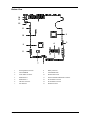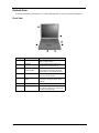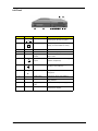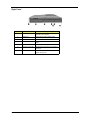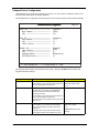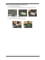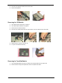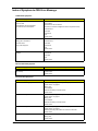
1
TravelMate 740
Service Guide
Service guide files and updates are available
on the AIPG/CSD web; for more information,
please refer to http://csd.acer.com.tw
PART NO.: 49.42R01.001
PRINTED IN TAIWAN
Revision History
Please refer to the table below for the updates made on Travelmate 740 service guide.
Date
II
Chapter
Updates
Copyright
Copyright © 2001 by Acer Incorporated. All rights reserved. No part of this publication may be reproduced,
transmitted, transcribed, stored in a retrieval system, or translated into any language or computer language, in
any form or by any means, electronic, mechanical, magnetic, optical, chemical, manual or otherwise, without
the prior written permission of Acer Incorporated.
Disclaimer
The information in this guide is subject to change without notice.
Acer Incorporated makes no representations or warranties, either expressed or implied, with respect to the
contents hereof and specifically disclaims any warranties of merchantability or fitness for any particular
purpose. Any Acer Incorporated software described in this manual is sold or licensed "as is". Should the
programs prove defective following their purchase, the buyer (and not Acer Incorporated, its distributor, or its
dealer) assumes the entire cost of all necessary servicing, repair, and any incidental or consequential
damages resulting from any defect in the software.
Acer is a registered trademark of Acer Corporation.
Intel is a registered trademark of Intel Corporation.
Pentium and Pentium II/III are trademarks of Intel Corporation.
Other brand and product names are trademarks and/or registered trademarks of their respective holders.
III
Conventions
The following conventions are used in this manual:
IV
Screen messages
Denotes actual messages that appear
on screen.
NOTE
Gives bits and pieces of additional
information related to the current
topic.
WARNING
Alerts you to any damage that might
result from doing or not doing specific
actions.
CAUTION
Gives precautionary measures to
avoid possible hardware or software
problems.
IMPORTANT
Reminds you to do specific actions
relevant to the accomplishment of
procedures.
Preface
Before using this information and the product it supports, please read the following general information.
1.
This Service Guide provides you with all technical information relating to the BASIC CONFIGURATION
decided for Acer's "global" product offering. To better fit local market requirements and enhance product
competitiveness, your regional office MAY have decided to extend the functionality of a machine (e.g.
add-on card, modem, or extra memory capability). These LOCALIZED FEATURES will NOT be covered
in this generic service guide. In such cases, please contact your regional offices or the responsible
personnel/channel to provide you with further technical details.
2.
Please note WHEN ORDERING FRU PARTS, that you should check the most up-to-date information
available on your regional web or channel. If, for whatever reason, a part number change is made, it will
not be noted in the printed Service Guide. For ACER-AUTHORIZED SERVICE PROVIDERS, your Acer
office may have a DIFFERENT part number code to those given in the FRU list of this printed Service
Guide. You MUST use the list provided by your regional Acer office to order FRU parts for repair and
service of customer machines.
V
VI
Table of Contents
Chapter 1
System Specifications
1
Features . . . . . . . . . . . . . . . . . . . . . . . . . . . . . . . . . . . . . . . . . . . . . . . . . . . . . . . .1
System Block Diagram . . . . . . . . . . . . . . . . . . . . . . . . . . . . . . . . . . . . . . . . . . . . .3
Board Layout . . . . . . . . . . . . . . . . . . . . . . . . . . . . . . . . . . . . . . . . . . . . . . . . . . . .4
Top View . . . . . . . . . . . . . . . . . . . . . . . . . . . . . . . . . . . . . . . . . . . . . . . . . . . .4
Bottom View . . . . . . . . . . . . . . . . . . . . . . . . . . . . . . . . . . . . . . . . . . . . . . . . .5
Outlook View . . . . . . . . . . . . . . . . . . . . . . . . . . . . . . . . . . . . . . . . . . . . . . . . . . . . .6
Front View . . . . . . . . . . . . . . . . . . . . . . . . . . . . . . . . . . . . . . . . . . . . . . . . . . . . . . .6
Left Pane . . . . . . . . . . . . . . . . . . . . . . . . . . . . . . . . . . . . . . . . . . . . . . . . . . . .7
Right Panel . . . . . . . . . . . . . . . . . . . . . . . . . . . . . . . . . . . . . . . . . . . . . . . . . .8
Rear Panel . . . . . . . . . . . . . . . . . . . . . . . . . . . . . . . . . . . . . . . . . . . . . . . . . .9
Bottom Panel . . . . . . . . . . . . . . . . . . . . . . . . . . . . . . . . . . . . . . . . . . . . . . .10
Indicators . . . . . . . . . . . . . . . . . . . . . . . . . . . . . . . . . . . . . . . . . . . . . . . . . . . . . .11
Lock Keys . . . . . . . . . . . . . . . . . . . . . . . . . . . . . . . . . . . . . . . . . . . . . . . . . . . . . .12
Embedded Numeric Keypad . . . . . . . . . . . . . . . . . . . . . . . . . . . . . . . . . . . . . . . .13
Windows Keys . . . . . . . . . . . . . . . . . . . . . . . . . . . . . . . . . . . . . . . . . . . . . . . . . .14
Hot Keys . . . . . . . . . . . . . . . . . . . . . . . . . . . . . . . . . . . . . . . . . . . . . . . . . . . . . . .15
Touchpad . . . . . . . . . . . . . . . . . . . . . . . . . . . . . . . . . . . . . . . . . . . . . . . . . . . . . .16
Touchpad Basics . . . . . . . . . . . . . . . . . . . . . . . . . . . . . . . . . . . . . . . . . . . .16
Hardware Specifications and Configurations . . . . . . . . . . . . . . . . . . . . . . . . . . .17
BIOS Setup Utility . . . . . . . . . . . . . . . . . . . . . . . . . . . . . . . . . . . . . . . . . . . . . . . .29
Navigating the BIOS Utility . . . . . . . . . . . . . . . . . . . . . . . . . . . . . . . . . . . . .29
Chapter 2
System Utilities
29
System Information . . . . . . . . . . . . . . . . . . . . . . . . . . . . . . . . . . . . . . . . . . .30
Basic System Settings . . . . . . . . . . . . . . . . . . . . . . . . . . . . . . . . . . . . . . . . .31
Startup Configuration . . . . . . . . . . . . . . . . . . . . . . . . . . . . . . . . . . . . . . . . .32
Onboard Device Configuration . . . . . . . . . . . . . . . . . . . . . . . . . . . . . . . . . .34
System Security . . . . . . . . . . . . . . . . . . . . . . . . . . . . . . . . . . . . . . . . . . . . .35
Load Default Settings . . . . . . . . . . . . . . . . . . . . . . . . . . . . . . . . . . . . . . . . .37
BIOS Flash Utility . . . . . . . . . . . . . . . . . . . . . . . . . . . . . . . . . . . . . . . . . . . . . . . .38
System Utility Diskette . . . . . . . . . . . . . . . . . . . . . . . . . . . . . . . . . . . . . . . . . . . .38
System Diagnostic Diskette . . . . . . . . . . . . . . . . . . . . . . . . . . . . . . . . . . . . . . . .38
Running PQA Diagnostics Program . . . . . . . . . . . . . . . . . . . . . . . . . . . . . .39
Chapter 3
Machine Disassembly and Replacement
41
General Information . . . . . . . . . . . . . . . . . . . . . . . . . . . . . . . . . . . . . . . . . . . . . .42
Before You Begin . . . . . . . . . . . . . . . . . . . . . . . . . . . . . . . . . . . . . . . . . . . .42
Disassembly Procedure Flowchart . . . . . . . . . . . . . . . . . . . . . . . . . . . . . . . . . . .43
Removing the Battery Pack . . . . . . . . . . . . . . . . . . . . . . . . . . . . . . . . . . . . . . . . 45
Removing the External DIMM Module . . . . . . . . . . . . . . . . . . . . . . . . . . . . . . . .46
Removing the External Modem Combo Card . . . . . . . . . . . . . . . . . . . . . . . . . . .47
Removing the CD-ROM/DVD-ROM Module . . . . . . . . . . . . . . . . . . . . . . . . . . . .48
Removing the Hard Disk Drive Module . . . . . . . . . . . . . . . . . . . . . . . . . . . . . . . .49
Removing the Floppy Disk Drive Module . . . . . . . . . . . . . . . . . . . . . . . . . . . . . .50
Disassembling the Main Unit . . . . . . . . . . . . . . . . . . . . . . . . . . . . . . . . . . . . . . .51
Removing the Hinge Caps . . . . . . . . . . . . . . . . . . . . . . . . . . . . . . . . . . . . .51
Removing the Keyboard . . . . . . . . . . . . . . . . . . . . . . . . . . . . . . . . . . . . . . .51
Removing the LCD Module . . . . . . . . . . . . . . . . . . . . . . . . . . . . . . . . . . . . .52
Removing the TouchPad Module . . . . . . . . . . . . . . . . . . . . . . . . . . . . . . . .52
Removing the CPU . . . . . . . . . . . . . . . . . . . . . . . . . . . . . . . . . . . . . . . . . . .53
Removing the RTC . . . . . . . . . . . . . . . . . . . . . . . . . . . . . . . . . . . . . . . . . . .54
Separating the Lower Case from the Upper Case . . . . . . . . . . . . . . . . . . . .55
Removing the Fan . . . . . . . . . . . . . . . . . . . . . . . . . . . . . . . . . . . . . . . . . . . .55
VII
Table of Contents
Removing the DC-DC Charger Board . . . . . . . . . . . . . . . . . . . . . . . . . . . . .56
Removing the System Board . . . . . . . . . . . . . . . . . . . . . . . . . . . . . . . . . . .56
Removing the Audio Jack Cover . . . . . . . . . . . . . . . . . . . . . . . . . . . . . . . . .57
Removing the PCMCIA Socket . . . . . . . . . . . . . . . . . . . . . . . . . . . . . . . . . .57
Removing the Modem Power Cable . . . . . . . . . . . . . . . . . . . . . . . . . . . . . .57
Disassembling the LCD Module . . . . . . . . . . . . . . . . . . . . . . . . . . . . . . . . . . . . .59
Removing the LCD Bezel . . . . . . . . . . . . . . . . . . . . . . . . . . . . . . . . . . . . . .59
Removing the Speaker Assembly Module . . . . . . . . . . . . . . . . . . . . . . . . .60
Removing the Inverter Board . . . . . . . . . . . . . . . . . . . . . . . . . . . . . . . . . . .60
Removing the LCD Bracket . . . . . . . . . . . . . . . . . . . . . . . . . . . . . . . . . . . .61
Removing the LED Board . . . . . . . . . . . . . . . . . . . . . . . . . . . . . . . . . . . . . .61
Removing the Microphone . . . . . . . . . . . . . . . . . . . . . . . . . . . . . . . . . . . . .62
Removing the Left and Right Hinges . . . . . . . . . . . . . . . . . . . . . . . . . . . . .62
Chapter 4
Troubleshooting
65
System Check Procedures . . . . . . . . . . . . . . . . . . . . . . . . . . . . . . . . . . . . . . . . .66
External Diskette Drive Check . . . . . . . . . . . . . . . . . . . . . . . . . . . . . . . . . .66
External CD-ROM Drive Check . . . . . . . . . . . . . . . . . . . . . . . . . . . . . . . . .66
Keyboard or Auxiliary Input Device Check . . . . . . . . . . . . . . . . . . . . . . . . .67
Memory Check . . . . . . . . . . . . . . . . . . . . . . . . . . . . . . . . . . . . . . . . . . . . . .67
Power System Check . . . . . . . . . . . . . . . . . . . . . . . . . . . . . . . . . . . . . . . . .67
Touchpad Check . . . . . . . . . . . . . . . . . . . . . . . . . . . . . . . . . . . . . . . . . . . . .69
Power-On Self-Test (POST) Error Message . . . . . . . . . . . . . . . . . . . . . . . . . . .70
Index of Error Messages . . . . . . . . . . . . . . . . . . . . . . . . . . . . . . . . . . . . . . . . . . .71
Index of Symptom-to-FRU Error Message . . . . . . . . . . . . . . . . . . . . . . . . . . . . .74
Intermittent Problems . . . . . . . . . . . . . . . . . . . . . . . . . . . . . . . . . . . . . . . . . . . . .77
Undetermined Problems . . . . . . . . . . . . . . . . . . . . . . . . . . . . . . . . . . . . . . . . . . .78
Index of AFlash BIOS Error Message . . . . . . . . . . . . . . . . . . . . . . . . . . . . . . . . .79
Index of PQA Diagnostic Error Code, Message . . . . . . . . . . . . . . . . . . . . . . . . .80
Chapter 5
Jumper and Connector Locations
81
Top View . . . . . . . . . . . . . . . . . . . . . . . . . . . . . . . . . . . . . . . . . . . . . . . . . . . . . . .81
SW1 Settings . . . . . . . . . . . . . . . . . . . . . . . . . . . . . . . . . . . . . . . . . . . . . . .82
Bottom View . . . . . . . . . . . . . . . . . . . . . . . . . . . . . . . . . . . . . . . . . . . . . . . . . . . .83
Chapter 6
FRU (Field Replaceable Unit) List
85
Appendix A
Model Definition and Configuration
97
Appendix B
Test Compatible Components
99
Microsoft Windows 2000 Environment Test . . . . . . . . . . . . . . . . . . . . . . . . . . .100
Microsoft Windows XP Environment Test . . . . . . . . . . . . . . . . . . . . . . . . . . . . .102
Appendix C
Index
VIII
Online Support Information
105
107
Chapter 1
System Specifications
Features
This computer was designed with the user in mind. Here are just a few of its many features:
Performance
!
Intel® Mobile Pentium® III Coppermine processor with 512 KB L2 cache and Intel® SpeedStepTM
technology support
!
64-bit memory bus
!
AcerMedia bay (removable CD or DVD drive)
!
Built-in floppy drive
!
High-capacity, Enhanced-IDE hard disk
!
Li-Ion main battery pack
!
Power management system with ACPI (Advanced Configuration Power Interface)
!
15” Thin-Film Transistor (TFT) Super eXtended Graphics Array+ (SXGA+) liquid crystal-display
(LCD)
!
3D capabilities
!
Simultaneous LCD and CRT display support
!
Supports other output display devices such as LCD projection panels for large-audience
presentations
!
“Automatic LCD dim” feature that automatically decides the best settings for your display and
conserves power
!
Dual display capability
Display
Multimedia
!
16-bit high-fidelity AC’97 stereo audio with 3-D sound and wavetable synthesizer
!
Built-in dual speakers
!
Built-in microphone
!
High-speed optical drive (AcerMedia bay)
!
External USB video capture kit option
Connectivity
Chapter 1
!
High-speed fax/data modem port
!
Fast infrared wireless communication
!
USB (Universal Serial Bus) ports
!
Ethernet/Fast Ethernet port
!
Optional Bluetooth wireless communication feature
!
Optional InviLink 802.11b wireless LAN
1
Expansion
!
Two type II or one type III CardBus PC Card slot(s) with Zoomed Video support on upper slot
!
Upgradeable memory
!
DockMate V
Keyboard and Pointing Device
!
84-/85-key Windows keyboard
!
Ergonomically-centered touchpad pointing device with scroll function
!
One fingerprint recognition sensor
!
Two type II or one type III CardBus PC Card slot(s) with Zoomed Video support on upper slot
!
One RJ-45 jack for Ethernet
!
One RJ-11 phone jack
!
One DC-in jack (AC adapter)
!
One parallel port (ECP/EPP compliant)
!
One external monitor port
!
One PS/2 keyboard/mouse port
!
One speaker/headphone-out jack
!
One audio line-in jack
!
One microphone-in jack
!
Two USB ports
!
One 9-pin RS-232 serial port (UART 16550)
!
One FIR port
!
Mini dock connector
I/O Ports
2
Chapter 1
System Block Diagram
Mobile CPU
CLK GEN.
ICS
Tualatin
RAMBUFFER
( 2 * 32bit) *2
HOST BUS (133MHz)
(133M)
MEMBUS
SO-DIMM*2
SO-DIMM*2
Almador-M
GCMH
(66M)
AGP 4X
CRT
VGA
ATI Mobility
M6S
LCD
version : A4
PRIMARY EIDE
ATA100
HUB I/F (66M)
HDD
DOCKV
ICH3-M
SECONDARY EIDE
HOT PLUG
TV OUT
LAN
CDROM
82562 EM
USB 1 . 0X2
POWER SW
M1C2564A
PCI BUS (33M)
DOCK V
AC - LINK
QSW
CARDBUS
0Z6933T
CARDBUS
SLOT A, B
LPC BUS (33M)
LINE IN
INT. SPKR
OP AMP
APA2020 VR
AC’97 CODEC
ALC200
MODEM
Daughter
Card
PRINTER
SERIAL
LINE OUT
SMsC
SIO
LPC47N267
LPC
KBC
FWH
DEBUG
M38859 82802AB CONN
CMOS
BAT
MIC
FIR
Chapter 1
FLOPPY
FINGER
PRINTER
TOUCH PAD
INT. KB
PS/2 CONN
3
Board Layout
Top View
2
4
3
1
5
6
8
7
9
30
10
29
11
12
13
28
14
15
16
24
17
22
25
27
4
26
23
21
20
19
18
1
Volume Control
16
Serial Port
2
Microphone-in Port
17
Modem Connector (RJ11)
3
Line-in Port
18
PS/2 Port
4
Line-out Port
19
LCD Cover Switch Connector
5
O2 OZ6933T
20
LED/Inverter Board Connector
6
Cardbus Socket
21
External CD/DVD-ROM Module Connector
7
FAN Connector
22
VGA Chip, Rage Mobility-M6-S
8
FIR
23
Internal Keyboard Connector
9
USB Port
24
SW1 Setting
10
VGA Port
25
Finger Print Check
11
CPU Socket
26
HDD Connector
12
LAN Connector (RJ45)
27
Battery Connector
13
RTC Battery Connector
28
TouchPad Connector
14
LCD FPC Connector
29
Debug Board
15
Parallel Port
30
SMSC LPC47N267
Chapter 1
Bottom View
14
13
1
12
11
2
10
4
9
3
8
5
7
6
1
Docking Station Connector
8
Battery Connector
2
Intel FW82830M
9
Intel FW82801CAM
3
Power Switch Connector
10
Modem board socket
4
DIMM Socket 2
11
External CD/DVD-ROM Module Connector
5
DIMM Socket 1
12
DC-DC Board Connector
6
FDD FPC Connector
13
DC-DC Board Connector
7
SST 49LF004
14
Modem Connector
Chapter 1
5
Outlook View
A general introduction of ports allow you to connect peripheral devices, as you would with a desktop PC.
Front View
#
6
Item
Description
1
Display screen
Also called LCD (liquid-crystal display),
diplays computer output.
2
Touchpad
Touch-sensitive pointing device which
functions like a computer mouse.
3
Click buttons (left,
center and right)
The left and right uttons function like the
left and right mouse buttons; the center
button serves as a scroll up/down button.
4
Palmrest
Comfortable support area for your hands
when you use the computer.
5
Fingerprint recognition
sensor
Identifies the authorized fingerprint, in
order for the user to gain access to the
computer.
6
Keyboard
Inputs data into your computer.
7
Status indicators
LEDs (light-emitting diode) that turn on and
off to show the status of the computer, its
functions and components.
Chapter 1
Left Panel
#
Icon
Item
Description
1
Infrared port
Interfaces with infrared devices (e.g.,
infrared printer, IR-aware computer).
2
PC Card slots
Accept one type III or two Type II 16-bit PC
Card(s) or 32-bit CardBus PC Card(s).
3
Eject buttons
Eject the selected PC Card from the slot.
4
Power switch
Turns on the computer power.
5
Floppy activity
indicator
LED that turns on and off when the floppy
drive is active.
6
Speaker/Headphoneout jack
Connects to audio line-out devices (e.g.,
speakers, headphones).
7
Line-in jack
Accepts audio line-in devices (e.g., audio
CD player, stereo walkman).
8
Microphone-in jack
Accepts a mono/stereo condenser
microphone.
9
Volume control
Controls the volume of the speakers.
10
Floppy drive
Internal diskette drive, accepts 3.5-inch
floppy diskettes.
11
Floppy disk eject
button
Push this button to eject the floppy disk.
12
Video capture kit slot
Accepts the video capture kit option on the
left side of the computer.
Chapter 1
7
Right Panel
#
8
Item
Description
1
Video capture kit slot
Accepts the video capture kit option on the
right side of the computer.
2
Battery bay
Houses the computer’s battery pack.
3
AcerMedia drive
Houses a removable media drive module.
4
AcerMedia indicator
Lights up when the AcerMedia drive is
active.
5
Eject button
Ejects the drive tray.
6
Emergency eject slot
Ejects the drive tray when the computer is
turned off.
7
Security keylock
Connects to a Kensington-compatible
coputer security lock.
Chapter 1
Rear Panel
#
Chapter 1
Icon
Item
Description
1
Power jack
Connects to an AC adapter
2
PS/2 port
Connects to any PS/2-compatible device
(e.g., PS/2 mouse).
3
Modem jack
Connects to a phone line.
4
Serial port
Connects to a serial device (e.g., serial
mouse).
5
Parallel port
Connects to a parallel device (e.g., parallel
printer).
6
Network jack
Connects to an Ethernet 10/100-based
network
7
External display port
Connects to a display device (e.g., external
monitor, LCD projector) and displays up to
64K colors at 1280x1024 resolution.
8
USB ports (two)
Connect to Universal Serial Bus devices
(e.g., USB mouse, USB camera).
9
Bottom Panel
#
10
Icon
Item
Description
1
AcerMedia bay
Houses an AcerMedia drive module.
2
Battery bay
Houses the computer’s battery pack.
3
Hard disk bay
Houses the computer’s hard disk (secured
by a screw).
4
Battery release latch
Unlatches the battery to remove the battery
pack.
5
Memory compartment
Houses the computer’s main memory.
6
Mini docking connector Connects to DockMate V mini docking
station.
7
AcerMedia bay release
latch
Unlatches the AcerMedia drive for removal
or swapping.
Chapter 1
Indicators
The computer has six easy-to-read status icons on the right of the display screen.
The Power and Standby status icons are visible even when you close the display cover so you can see the
status of the computer while the cover is closed.
#
1
Icon
Function
Power
Description
Lights when the computer is on.
Blinks when a battery-low condition occurs.
Chapter 1
2
Sleep
Lights when the computer enters Standby
mode and blinks when it enters into or
resumes from hibernation mode.
3
Media Activity
Lights when the floppy drive, hard disk or
AcerMedia drive is active.
4
Battery Charge
Lights when the battery is being charged.
5
Caps Lock
Lights when Caps Lock is activated.
6
Num Lock
Lights when Num Lock is activated.
11
Lock Keys
The keyboard has three lock keys which you can toggle on and off.
12
Lock Key
Description
Caps Lock
When Caps Lock is on, all alphabetic characters typed
are in uppercase.
Num Lock
(Fn-F11)
When Num Lock is on, the embedded keypad is in
numeric mode. The keys function as a calculator
(complete with the arithmetic operators +, -, *, and /).
Use this mode when you need to do a lot of numeric
data entry. a better solution would be to connect an
external keypad.
Scroll Lock
(Fn-F12)
When Scroll Lock is on, the screen moves one line up
or down when you press the up or down arrow keys
respectively. Scroll Lock does not work with some
applications.
Chapter 1
Embedded Numeric Keypad
The embedded numeric keypad functions like a desktop numeric keypad. It is indicated by small characters
located on the upper right corner of the keycaps. To simplify the keyboard legend, cursor-control key symbols
are not printed on the keys.
Desired Access
Number keys on embedded
keypad
Cursor-control keys on
embedded keypad
Main keyboard keys
Num Lock On
Num Lock Off
Type numbers in a normal
manner.
Hold j while using
cursor-control keys.
Hold Fn while using cursorcontrol keys.
Hold Fn while typing letters
on embedded keypad.
Type the letters in a normal
manner.
NOTE: If an external keyboard or keypad is connected to the computer, the Num Lock feature automatically
shifts from the internal keyboard to the external keyboard or keypad.
Chapter 1
13
Windows Keys
The keyboard has two keys that perform Windows-specific functions.
Key
Windows logo
key
Icon
Description
Start button. Combinations with this key perform
shortcut functions. Below are a few examples:
+ Tab (Activates next taskbar button)
+ E (Explores My Computer)
+ F (Finds Document)
+ M (Minimizes All)
Shift + + M (Undoes Minimize All)
+ R (Displays the Run...dialog box)
Application
key
14
Opens a context menu (same as a right-click).
Chapter 1
Hot Keys
The computer employs hot keys or key combinations to access most of the computer’s controls like screen
contrast and brightness, volume output and the BIOS Utility.
To activate hot keys, press and hold the Fn key before pressing the other key in the hot key combination.
Hot Key
Icon
Function
Description
Fn-F1
Hot key help
Displays a list of the hotkeys and their functions.
Fn-F2
Setup
Accesses the notebook’s configuration utility.
Fn-F3
Power Management
Scheme Toggle
Switches the power management scheme used by the
computer (function available if supported by operating
system).
Fn-F4
Sleep
Puts the computer in Sleep mode, which can be
defined via the advanced section of the Power
Management Properties in the Windows Control
Panel.
Fn-F5
Display toggle
Switches display output between the display screen,
external monitor (if connected) and both the display
screen and external monitor.
Fn-F6
Screen blank
Turns the display screen backlight off to save power.
Press any key to return.
Fn-F7
Touchpad toggle
Turns the internal touchpad on and off.
When you connect an external PS/2 mouse, the
computer automatically disables the touchpad.
Fn-F8
Speaker toggle
Turns the speakers on and off; mutes the sound.
Fn-F9
Docking eject button
When your computer is on, press this hotkey first
before removing it from the optional DockMate V
docking station.
Fn-→
Brightness up
Increases the screen brightness.
Fn-←
Brightness down
Decreases the screen brightness.
Euro
Types the Euro symbol.
Alt Gr-Euro
Chapter 1
15
Touchpad
The built-in touchpad is a PS/2-compatible pointing device that senses movement on its surface. This means
the cursor responds as you move your finger on the surface of the touchpad. The central location on the
palmrest provides optimum comfort and support.
NOTE: When using an external USB or serial mouse, you can press Fn + r to disable the touchpad. If you
are using an external PS/2 mouse, the touchpad is automatically disabled.
Touchpad Basics
The following items teach you how to use the touchpad:
!
Move your finger across the touchpad to move the cursor.
!
Press the left (1) and right (3) buttons located on the edge of the touchpad to do selection and
execution functions. These two buttons are similar to the left and right buttons on a mouse.
Tapping on the touchpad produces similar results.
!
Use the center (2) button (top and bottom) to scroll up or down a page. This button mimics your
cursor pressing on the right scroll bar of Windows applications.
Function
Left
Button
Right
Button
Center
Buttons
Tap
Execute
Click twice
quickly
Tap twice (at
the same speed
as doubleclicking a
mouse button)
Select
Click once
Tap once
Drag
Click and hold,
then use finger
to drag the
cursor on the
touchpad
Tap twice (at
the same speed
as doubleclicking a
mouse button)
then hold finger
to the touchpad
on the second
tap and drag
the cursor
Access context
menu
Scroll
Click once
Click and hold
the up/down
button
NOTE: Keep your fingers dry and clean when using the touchpad. Also keep the touchpad dry and clean. The
touchpad is sensitive to finger movements. Hence, the lighter the touch, the better the response.
Tapping harder will not increase the touchpad’s responsiveness.
16
Chapter 1
Hardware Specifications and Configurations
Processor
Item
Specification
CPU type
Intel Pentium III 1/1.133/1.2 GHz processor with 512KB L2 on-die Cache
CPU package
Micro-FCPGA package
CPU core voltage
1.40V/1.15V
CPU I/O voltage
1.25V
BIOS
Item
Specification
BIOS vendor
Acer
BIOS Version
V 3.3
BIOS ROM type
Flash ROM
BIOS ROM size
512KB
BIOS package
32-pin TSOP
Supported protocols
ACPI 1.0b, APM 1.2, PC Card 95, SM BIOS 2.3, EPP/IEEE 1284, ECP/
IEEE 1284 1.7 & 1.9, IrDA, PCI 2.2, PnP 1.0a, DMI 2.0, PS/2 keyboard and
mouse, USB, VESA VGA BIOS, DDC-2B, CD-ROM bootable, Windows
keyboard Microsoft Simple Boot Flag
BIOS password control
Set by switch, see SW1(SW1) setting
Second Level Cache
Item
Specification
Cache controller
Built-in CPU
Cache size
512KB
1st level cache control
Always enabled
2st level cache control
Always enabled
Cache scheme control
Fixed in write-back
System Memory
Item
Specification
Memory controller
Built-in Intel Amador-M
Onboard memory size
0MB
DIMM socket number
2 sockets (2 banks)
Supports memory size per socket
512MB
Supports maximum memory size
1024MB
Supports DIMM type
Synchronous DRAM
Supports DIMM Speed
133 MHz
Supports DIMM voltage
3.3V
Supports DIMM package
144-pin soDIMM
Memory module combinations
You can install memory modules in any combinations as long as they
match the above specifications.
Chapter 1
17
Memory Combinations
Slot 1
Slot 2
0 MB
Total Memory
64 MB
64 MB
64 MB
0 MB
64 MB
0 MB
128 MB
128 MB
64 MB
64 MB
128 MB
128 MB
0 MB
128 MB
64 MB
128 MB
192 MB
128 MB
64 MB
192 MB
128 MB
128 MB
256 MB
256 MB
64 MB
320 MB
64 MB
256 MB
320 MB
256 MB
128 MB
384 MB
128 MB
256 MB
384 MB
256 MB
256 MB
512 MB
Above table lists some system memory configurations. You may combine DIMMs with various capacities to
form other combinations.
NOTE: The shipping specification for DIMM combination is 64MB in slot 1.
LAN Interface
Item
Specification
Chipset
Intel 82562 ET
Supports LAN protocol
10/100 Mbps
LAN connector type
RJ45
LAN connector location
Rear side
Modem Interface
Item
Specification
Chipset
Ambit MDC module with Lucent modem controller
Fax modem data baud rate (bps)
14.4K
Data modem data baud rate (bps)
56K
Supports modem protocol
V.90 MDC
Modem connector type
RJ11
Modem connector location
Rear side
Floppy Disk Drive Interface
Item
Vendor & model name
Specification
Mitsumi D353G
Floppy Disk Specifications
18
Media recognition
2DD (720KB)
2HD (1.2MB, 3-mode)
2HD (1.44MB)
Sectors/track
9
15
18
Tracks
80
80
80
Data transfer rate
(Kbit/s)
1 MB
1.6 MB
2 MB
Rotational speed (RPM)
300
360
300
Chapter 1
Floppy Disk Drive Interface
Item
Specification
Read/write heads
2
Encoding method
MFM/FM
Power Requirement
Input Voltage (V)
+5V +/- 10%
Hard Disk Drive Interface
Item
Specification
Vendor & Model Name
IBM Travelstar 30GN
IC25N020ATDA04
IBM Travelstar 30GN
IC25N030ATDA04
Capacity (MB)
20000
30000
Bytes per sector
512
512
Data heads
3
4
Recording zone
16
16
Drive Format
Disks
2
2
Spindle speed (RPM)
4200 RPM
4200 RPM
Buffer size
2048KB
2048KB
Interface
ATA-5
ATA-5
Max. media transfer rate
(disk-buffer, Mbytes/s)
216
235
Data transfer rate
(host~buffer, Mbytes/s)
100 MB/Sec.
100 MB/Sec.
Ultra DMA mode-5
Ultra DMA mode-5
5V(DC) +/- 5%
5V(DC) +/- 5%
Performance Specifications
DC Power Requirements
Voltage tolerance
DVD-ROM Interface
Item
Specification
Vendor & model name
MKE SR-8176
Performance Specification
With CD Diskette
With DVD Diskette
Transfer rate (KB/sec)
Sustained:
Sustained:
Max 3.6Mbytes/sec
Data Buffer Capacity
Max 10.8Mbytes/sec
512 KBytes
Interface
IDE/ATAPI
Applicable disc format
DVD: DVD-5, DVD-9, DVD-10, DVD-R (3.95G)
CD: CD-Audio, CD-ROM (mode 1 and mode 2), CD-ROM XA (mode 2, form 1
and form 2), CD-I (mode 2, form 1 and form 2), CD-I Ready, CD-I Bridge, CDWO, CD-RW, Photo CD, Video CD, Enhanced Music CD, CD-TEXT
Loading mechanism
Soft eject (with emergency eject hole)
Power Requirement
Input Voltage
Chapter 1
5V(DC) +/- 5%
19
Audio Interface
Item
Specification
Audio Controller
Cirrus Logic Realtek ALC 200
Audio onboard or optional
Built-in
Mono or Stereo
Stereo
Resolution
20 bit stereo Digital to analog converter
18 bit stereo Analog to Ditial converter
Compatibility
Microsoft PC98/PC99, AC97 2.1
Mixed sound source
Line-in, CD, Video, AUX
Voice channel
8/16-bit, mono/stereo
Sampling rate
44.1 KHz
Internal microphone
Yes
Internal speaker / Quantity
Yes
Supports PnP DMA channel
DMA channel 0
DMA channel 1
Supports PnP IRQ
IRQ3, IRQ5, IRQ7, IRQ9, IRQ10, IRQ11
Video Interface
Item
Specification
Chip vendor
ATI M6-S
Chip name
Rage Mobility-M6-S
Chip voltage
Core/2.5V
Memory/2.5V
Supports ZV (Zoomed Video) port
No
Graph interface
4X AGP (Accelerated Graphics Port) bus
Maximum resolution (LCD)
1400x1050 (32 bit colors)
Maximum resolution (CRT)
2048x1536 (16 bit colors)
Video Memory
Item
Specification
Fixed or upgradeable
Fixed
Video memory size
16.0 MB
Video Resolutions Mode (for both LCD and CRT)
Resolution
20
8 bits
(256 colors)
16 bits
(High color)
24 bits
(True color)
32 bits
(True color)
640x480
Yes
Yes
Yes
Yes
720x480
Yes
Yes
Yes
Yes
800x600
Yes
Yes
Yes
Yes
848x480
Yes
Yes
Yes
Yes
1024x768
Yes
Yes
Yes
Yes
1152x864
Yes
Yes
Yes
Yes
1280x1024
Yes
Yes
Yes
Yes
1400x1050
Yes
Yes
Yes
Yes
1600x1200
Yes
Yes
Yes
Yes
Chapter 1
Parallel Port
Item
Specification
Parallel port controller
SMSC LPC47N267
Number of parallel port
1
Location
Rear side
Connector type
25-pin D-type connector, in female type
Parallel port function control
Enable/Disable by BIOS Setup
Supports ECP/EPP
Yes (set by BIOS setup)
Optional ECP DMA channel
(in BIOS Setup)
DMA channel 1 and 3
Optional parallel port I/O address
(in BIOS Setup)
3BCh, 278h, 378h
Optional parallel port IRQ
(in BIOS Setup)
IRQ7, IRQ5
Serial Port
Item
Specification
Serial port controller
SMSC LPC47N267
Number of serial port
1
Supports 16550 UART
Yes
Connector type
9-pin D-type connector, in male type
Location
Rear side
Serial port function control
Enable/Disable by BIOS Setup
Optional serial port (in BIOS Setup)
3F8h, 2F8h, 3E8h, 2E8h
Optional serial port IRQ (in BIOS Setup)
IRQ4, IRQ11
USB Port
Item
Specification
USB Compliancy Level
1.1
OHCI
USB 1.1
Number of USB port
2
Location
Rear side
Serial port function control
Enable/Disable by BIOS Setup
IrDA Port
Item
IrDA FIR port controller
Specification
SMSC LPC47N267
Number of IrDA FIR port
1
Location
Left side
IrDA FIR port function control
Enable/disable by BIOS Setup
IrDA FIR port (in BIOS Setup)
2F8
IrDA FIR port IRQ (in BIOS Setup)
IRQ3
ECP DMA channel
(in BIOS Setup)
DMA channel 3
Optional IrDA FIR port DRQ (in BIOS Setup)
Not available
Chapter 1
21
PCMCIA Port
Item
Specification
PCMCIA controller
O2 OZ6933
Supports card type
Type-III/II
Number of slots
One type-III or Two type-II
Access location
Left side
Supports ZV (Zoomed Video) port
No ZV support
Supports 32 bit CardBus
Yes (IRQ11)
System Board Major Chips
Item
Controller
System core logic
Intel Almador-M / ICH3-M
Super I/O controller
SMSC LPC47N267
Audio controller
Realtech ALC 200
Video controller
ATI Rage Mobility - M6-S
Hard disk drive controller
ICH3-M
Keyboard controller
M38859
RTC
Built-in Intel Almador-M / ICH3-M
Keyboard
Item
Specification
Keyboard controller
Mitsubishi M38859
Keyboard vendor & model name
SMK US
Total number of keypads
84/85-key
Windows 95 keys
Yes
Internal & external keyboard work simultaneously
Yes
Battery
Item
Vendor & model name
22
Specification
Sony BTP-30A1
Battery Type
Li-ion
Pack capacity
5880 mAH
Cell voltage
V/cell
Number of battery cell
9
Package configuration
3 cells in series, 3 series in parallel
Package voltage
11.1 V
Chapter 1
DC-AC LCD Inverter
Item
Specification
Vendor & model
name
Ambit T621124.00 730
Input voltage (V)
7.3 (min.)
-
21 (max.)
Input current (mA)
-
-
900 (max.)
Output voltage
(Vrms, no load)
-
565 (typ.)
-
Output voltage
frequency (kHz)
40 (min.)
-
65 (max.)
Output Current/
Lamp
Iout(Min)
0.7mA
1.0mA
1.3mA
Vadj=0V
Iout(Max)
6.3mA
7.0mA
7.7mA
Vadj=3.2V
NOTE: DC-AC inverter is used to generate very high AC voltage, then support to LCD CCFT backlight user,
and is also responsible for the control of LCD brightness. Avoid touching the DC-AC inverter area while
the system unit is turned on.
NOTE: There is an EEPROM in the inverter, which stores its supported LCD type and ID code. If you replace
a new inverter or replace the LCD with a different brand, use Inverter ID utility to update the ID
information.
LCD
Item
Specification
Vendor & model name
Hitachi
TX38D95VC1CAM
Mechanical Specifications
LCD display area (diagonal, inch)
15
Display technology
TFT
Resolution
SXGA+ (1400x1050)
Supports colors
262K
Optical Specification
Brightness control
keyboard hotkey
Contrast control
No
Electrical Specification
Supply voltage for LCD display (V)
3.3
Supply voltage for LCD backlight
(Vrms)
690
AC Adapter
Item
Vendor & model name
Specification
Delta ADT-60XB D 3P
Input Requirements
Maximum input current (A,
@90Vac, full load)
1.5 A
0.9 A
Nominal frequency (Hz)
47 - 63
Frequency variation range (Hz)
47 - 63
Nominal voltages (Vrms)
90 - 270
Inrush current
The maximum inrush current will be less than 50A and 100A when the adapter
is connected to 115Vac(60Hz) and 230Vac(50Hz) respectively.
Chapter 1
@ 90Vac
@ 180Vac
23
AC Adapter
Item
Efficiency
Specification
It should provide an efficiency of 83% minimum, when measured at maximum
load under 115V(60Hz).
Output Ratings (CV mode)
DC output voltage
+19.0V~20.0V
Noise + Ripple
300mvp-pmax (20MHz bandwidth)
Load
0 A (min.)
3.16 A (max.)
Output Ratings (CC mode)
DC output voltage
+12V ~ +19V
Constant output
2.75 ± 0.2 A
Dynamic Output Characteristics
Turn-on delay time
2 sec. (@115Vac)
Hold up time
4 ms min. (@115 Vac input, full load)
Over Voltage Protection (OVP)
24 V
Short circuit protection
Output can be shorted without damage
Electrostatic discharge (ESD)
15kV (at air discharge)
8kV (at contact discharge)
Dielectric Withstand Voltage
Primary to secondary
1500 Vac (or 2121 Vdc), 10 mA for 1 second
Leakage current
0.25 mA max. (@ 254 Vac, 60Hz)
Regulatory Requirements
Internal filter meets:
1. FCC class B requirements. (USA)
2. VDE 243/1991 class B requirements. (German)
3. CISPR 22 Class B requirements. (Scandinavia)
4. VCCI class II requirements. (Japan)
Power Management
Power Saving Mode
Phenomenon
!
The Sleep indicator lights up
Hibernation Mode
When customized functions for power
management are set to Hibernation and the
corresponding action is taken.
!
All power shuts off
Display Standby Mode
Keyboard, built-in touchpad, and an external
PS/2 pointing device are idle for a specified
period.
!
The display shuts off
Hard Disk Standby Mode
Hard disk is idle within a specified period of
time.
!
Hard disk drive is in standby mode.
(spindle turned-off)
Standby Mode
Waiting time specified by the System
Standby value or the operating system
elapses without any system activity.
Or
When the computer is about to enter
Hibernation mode (e.g., during a battery-low
condition), but the Hibernation file is invalid
or not present.
24
Chapter 1
Environmental Requirements
Item
Specification
Temperature
Operating
+5~+35 °C
Non-operating
-20~+60 °C
Non-operating
-20~+60 °C (storage package)
Humidity
Operating
20% to 80% RH, non-condensing
Non-operating
20% to 90% RH, non-condensing (unpacked)
Non-operating
20% to 90% RH, non-condensing (storage package)
Vibration
Operating (unpacked)
5~25.6Hz: 0.38mm (peak to peak)
Non-operating (unpacked)
5~27.1Hz: 0.6G
25.6~250Hz: 0.5G
27.1Hz~50Hz: 0.41mm (peak to peak)
50~500Hz: 2.0G
Non-operating (packed)
5~62.6Hz: 0.51mm (peak to peak)
62.6~500Hz: 4G
Mechanical Specification
Item
Specification
Dimensions
324.5 (W) x 271 (D) x 36(H)
Weight
7 lbs
I/O Ports
2 type II or one type III CardBus socket(s), 1 RJ-11 modem port, 1 RJ-45 LAN port,
1 DC-in jack(AC adapter), 1 FIR port, 1 parallel port, 1 serial port, 1 external
monitor port, 1 PS/2 keyboard/mouse port, 1 mini docking station connector, 2
USB ports, 1 speaker/headphone-out jack, 1 audio line-in jack, 1 microphone-in
jack, 1 fingerprint recognition sensor
Drive Bays
One
Material
Housing: MCS-050
Panel
: Plastic
Indicators
Power LED, Sleep LED, Media Activity, Battery Charge, Caps Lock, Num Lock
Switch
Power
Memory Address Map
Memory Address
00100000h-000F0000h
Size
Function
512 KB
System BIOS
000CD000h-000C0000h
40 KB
VGA BIOS
000C0000h-000A0000h
128 KB
Video memory (VRAM)
000F0000h-000CD000h
UMB Area
000A0000h-00000000h
Conventional memory
I/O Address Map
I/O Address
Function
000-00F
DMA controller-1
020-021
Interrupt controller-1
040-043
Timer 1
Chapter 1
25
I/O Address Map
I/O Address
Function
060, 064
Keyboard controller 38859 chip select
061
System speaker out
040B
DMA controller-1
061
System speaker
070-071
Real-time clock and NMI mask
080-08F
DMA page register
0A0-0A1
Interrupt controller-2
0C0-0DF
DMA controller-2
0F0-0FF
Numeric data processor
120-13F
Power management controller
180-18F
170-177
2nd EIDE device (CD-ROM) select
1F0-1F7
1st EIDE device (hard drive) select
220-22F
Audio
240-24F
Audio (optional)
278-27F
Parallel port 3
2E8-2EF
COM4
2F8-2FF
COM2 or FIR (optional)
378, 37A
Parallel port 2
3BC-3BE
Paraller port 1
3B0-3BB
Video Controller
3C0-3DF
3F0h-3F7
Standard Floppy Disk Controller
3E8-3EF
COM3 or LT Win modem (optional)
3F0-3F7
Floppy disk controller
3F8-3FF
COM1
480-48F, 4D6
DMA controller-1
4D0-4D1
PCI configuration register
CF8-CFF
IRQ Assignment Map
Interrupt Channel
IRQ0
26
Function
System timer
IRQ1
Keyboard
IRQ2
Cascade
IRQ3
IR
IRQ4
COM1 (Serial port)
IRQ5
Reserved for R2 card
IRQ6
Floppy
IRQ7
LPT (Parallel port)
IRQ8
CMOS/RTC
IRQ9
SCI IRQ used by ACPI bus
IRQ10
Audio (PIRQB#), Modem (PIRQB#), SMBUS controller (PIRQB#), IEEE 1394
(PIRQ#), 802.11b (PIRQE#), LAN (PIRQTE#)
IRQ11
VGA (PIRQA#), USB (PIRQA#, PIRQC#, INTD#), CardBus controller
(PIRQB#, PIRQB#)
Chapter 1
IRQ Assignment Map
Interrupt Channel
IRQ12
Function
PS/2 device
IRQ13
Math processor
IRQ14
1st EIDE device (hard disk)
IRQ15
2nd EIDE device (CD-ROM drive)
DMA Channel Assignment
DMA Channel
Function
DRQ0
Reserved
DRQ1
Reserved
DRQ2
Floppy
DRQ3
Reserved
DRQ4
DMA controller
DRQ5
Reserved
DRQ6
Reserved
DRQ7
Reserved
Chapter 1
27
28
Chapter 1
Chapter 2
System Utilities
BIOS Setup Utility
The BIOS Setup Utility is a hardware configuration program built into your computer’s BIOS (Basic Input/
Output System).
Your computer is already properly configured and optimized, and you do not need to run this utility. However,
if you encounter configuration problems, you may need to run Setup. Please also refer to Chapter 4
Troubleshooting when problem arises.
To activate the BIOS Utility, press m during POST (while the TravelMate logo is being displayed).
BIOS Utility
System Information
Basic System Settings
Startup Configuration
Onboard Device Configuration
System Security
Loading Default Settings
↑↓ = Move highlight bar,
Enter = Select, Esc = Exit
Navigating the BIOS Utility
There are six menu options: System Information, Basic System Settings, Startup Configuration, Onboard
Device Configuration, System Security and Loading Default Settings.
To enter a menu, highlight the item using the w / y keys, then press e.
Within a menu, navigate through the BIOS Utility by following these instructions:
!
Press the
w / y keys to move between the parameters.
!
Press the
z / x keys to change the value of a parameter.
!
Press the | key while you are in any of the menu options to return to the main menu.
NOTE: You can change the value of a parameter if it is enclosed in square brackets. Navigation keys are
shown at the bottom of the screen.
Chapter 2
29
System Information
The System Information screen displays a summary of your computer hardware information.
System Information
CPU Type & Speed -----------------Floppy Disk Drive -------------------Hard Disk Drive ---------------------HDD Serial Number ----------------System with -------------------------System BIOS Version --------------VGA BIOS Version ------------------Serial Number ----------------------Asset Tag Number ------------------Product Name ----------------------Manufacturer Name ----------------UUID ----------------------------------
Page 1/1
Pentium ® III 1133 MHz
1.44MB 3.5-inch
28615 MB
XXXXXXXXXX
DVD/CD-RW Attached
V3.3 R01-A2d1
VR005.000.006.000
XXXXXXXXXX
XXXXXXXXXX
TravelMate 740
Acer
XXXXXXXXXX
Esc = Exit
NOTE: The screen above is a sample and may not reflect the actual data on your computer. “X” may refer to a
series of numbers and/or characters.
The following table describes the information in this screen.
Parameter
Description
CPU Type & Speed
Describes the type of CPU installed in the system.
Floppy Disk Drive
Shows the floppy disk drive type (1.44 MB, 3.5-inch).
Hard Disk Drive
Shows the size or capacity of the hard disk.
HDD Serial Number
Shows the serial number of the hard disk.
System with
Shows the high-capacity disc drive installed.
System BIOS Version
Shows the system BIOS version.
VGA BIOS Version
Shows the video graphics accelerator BIOS version.
Serial Number
Shows the serial number of the computer.
Asset Tag Number
Shows the asset tag number of the computer.
Product Name
Shows the official name of the product.
Manufacturer Name
Shows the manufacturer of the computer.
UUID
Shows the universally unique identifier of your computer.
The items in this screen are important and vital information about your computer. If you experience computer
problems and need to contact technical support, this data helps our service personnel know more about your
computer.
30
Chapter 2
Basic System Settings
The Basic System Settings screen allows you to set the system date and time.
Basic System Settings
Date ----------------------------------Time -----------------------------------
Page 1/1
[Mon Aug 28, 2001]
[20:39:33]
↑↓ = Move highlight bar, ←→ = Change setting, F1 = Help
The following table describes the parameters in this screen.
Parameter
Description
Format
Date
Sets the system date.
DDD MMM DD, YYYY
(day-of-the-week month day, year)
Time
Sets the system time.
HH:MM:SS (hour:minute:second)
Chapter 2
31
Startup Configuration
The Startup Configuration screen contains parameter values that define how your computer behaves on
system startup.
The following table describes the parameters in this screen. Settings in boldface are the default and
suggested parameter settings.
Basic System Setting
Boot Display ------------------------------------Screen Expansion ----------------------------Resume on LAN/Modem Access -------Fast Boot ---------------------------------------Boot on LAN -----------------------------------CPU Power Management Mode --------
[Both]
[Enabled]
[Enabled ]
[Disabled ]
[Disabled ]
[Auto ]
Boot Drive Sequence:
1st. -------------------------------------------2nd. ------------------------------------------3rd. -------------------------------------------4rd. --------------------------------------------
[Floppy Disk]
[CD-ROM]
[Hard Disk]
[----------------]
Intel (R) SpeedStep(TM) Technology----------
[Automatic]
Page 1/1
↑↓ = Move highlight bar, ←→ = Change setting, F1 = Help
32
Chapter 2
The following table describes the parameters in this screen. Settings in boldface are the default and
suggested parameter settings
.
Parameter
Boot Display
Description
Sets the display device on boot-up.
Options
Both or Auto
When set to Auto, the computer automatically
determines the display device when the computer
starts up. If an external display device (e.g., monitor)
is connected, it becomes the boot display; otherwise,
the computer’s display screen is the boot display.
When set to Both, the computer outputs to both the
computer display screen and an external display
device if one is connected.
Screen Expansion
Expand the screen on the graphic/text mode.
Enabled or Disabled
When it is disabled, the graphic/text mode expansion
function is disabled and the graphic/text image will be
centralized on the LCD. If it is enabled, the graphic/
text image will be expanded to the full LCD screen.
Resume on LAN/Modem Access
Enabled or Disabled
Fast Boot
Allows you to define your system’s booting process;
whether to skip some POST routines or proceed with
the normal booting process.
Disabled or Ensabled
Boot on LAN
If disable Boot from LAN, BIOS should remove “boot
drive sequence --> LANDesk Service Agent” item.
Disabled or Enabled
CPU Power Management Mode
CPU power management setting
Auto or Disabled
Boot Drive Sequence
Specifies the order in which the computer starts up
from. Please refer to below section.
1st: Floppy Disk
2nd: CD-ROM
3rd: Hard Disk
4rd: ---
Intel
R
SpeedStep
TM
Technology
There are three CPU speeds available for users to
specify the CPU speed.
Automatic
Maximum
Battery Optimized
Setting the Boot Drive Sequence
The Boot Drive Sequence section lists boot priorities (1st, 2nd, 3rd and 4rd ) for bootable drives in your
computer.
For example, the default value (1st: Floppy Disk, 2nd: CD-ROM, 3rd: Hard Disk) tells the computer to first
search for a bootable floppy disk in the floppy drive. If it finds one present, it boots up from that floppy disk. If
not, the computer continues to search for a bootable CD-ROM in the CD-ROM drive. If it cannot boot up from
the CD-ROM drive, it continues by booting up from the hard disk.
To set the boot drive sequence, use the w / y keys to select a priority level (1st, 2nd, 3rd and 4rd), then use
the z / x keys to select the device for that priority level.
Chapter 2
33
Onboard Device Configuration
The parameters in this screen are for advanced users only. You do not need to change the values in this
screen because these values are already optimized.
The Onboard Device Configuration screen assigns resources to basic computer communication hardware.
Onboard Devices Configuration
Serial Port ---------------------------------------Base Address -------------------------------IRQ --------------------------------------------
[Enabled ]
[3F8h]
[4 ]
IrDA FIR -------------------------------------Base Address --------------------------------IRQ --------------------------------------------DMA Channel ---------------------------
[Disabled ]
[----]
[-]
[-]
Parallel Port -------------------------------------Base Address -------------------------------IRQ -------------------------------------------Operation Mode -----------------------------ECP DMA Channel ---------------------------
[Enabled ]
[378h]
[7]
[Bi-directional]
[--]
Page 1/1
↑↓ = Move highlight bar, ←→ = Change setting, F1 = Help
The following table describes the parameters in this screen. Settings in boldface are the default and
suggested parameter settings
Parameter
Serial Port
Description
Enables or disables the serial port.
When enabled, you can set the base I/O address and
interrupt request (IRQ) of the serial port.
IrDA FIR
Options
Enabled or Disabled
3F8h, 2F8h, 3E8h or 2E8h
4 or 11
Enables or disables the IrDA FIR.
Disabled or Enabled
The IrDA FIR is a PnP device. Enabled/Disabled
setting won’t affect the WinMe Device Manager
setting of the IrDA FIR.
----
When enabled, you can set the base I/O address and
interrupt request (IRQ) for the IrDA FIR.
The direct memory access (DMA) channel of the IrDA
FIR is set to 3.
Parallel Port
Enables or disables the parallel port.
When enabled, you can set the base I/O address,
interrupt request (IRQ) and operation mode of the
parallel port.
If operation mode is set to ECP, the direct memory
access (DMA) channel of the parallel port is set to 1.
34
Enabled or Disabled
378h, 278h, or 3BCh
7 or 5
Bi-directional, EPP, ECP or
Standard
Chapter 2
System Security
The System Security screen contains parameters that help safeguard and protect your computer from
unauthorized use.
System Security
Page 1/1
Setup Password ----------------------------------- [None]
Power-on Password ------------------------------ [None]
Hard Disk Password ------------------------------ [None]
Fingerprint ----------------------------------------- [Disabled]
Processor Serial Number ----------------------- [Enabled]
↑↓ = Move highlight bar, ←→= Change setting, F1 = Help
The following table describes the parameters in this screen. Settings in boldface are the default and
suggested parameter settings.
Parameter
Description
Options
Setup Password
When set, this password protects the computer and the BIOS
Utility from unauthorized entry. See the following section for
instructions on how to set a password.
None or Present
Power-on Password
When set, this password protects the computer from
unauthorized entry. See the following section for instructions
on how to set a password.
None or Present
Hard Disk Password
When set, this password protects the hard disk from
unauthorized access. See the following section for
instructions on how to set a password.
None or Present
Fingerprint
Fingerprint check
Disabled or Enabled
Processor Serial Number
A lot of the literature available on the serial number suggests
that it should be used to encrypt and decrypt data sent to and
from e-commerce sites.
Enabled or Disabled
Chapter 2
35
Setting a Password
Follow these steps:
1.
Use the cursor up/down keys to highlight a Password parameter (Setup, Power-on or Hard Disk) and
press the z / x key. The password box appears:
2.
Type a password. The password may consist of up to eight characters (A-Z, a-z, 0-9).
IMPORTANT:Be very careful when typing your password because the characters do not appear on the
screen.
3.
Press e. Retype the password to verify your first entry and press e.
4.
After setting the password, the computer automatically sets the chosen password parameter to Present.
Three password types protect your computer from unauthorized access. Setting these passwords creates
several different levels of protection for your computer and data:
!
Setup Password prevents unauthorized entry to the BIOS Utility. Once set, you must key-in this
password to gain access to the BIOS Utility.
!
Power-On Password secures your computer against unauthorized use. Combine the use of this
password with password checkpoints on boot-up and resume from hibernation for maximum
security.
!
Hard Disk Password protects your data by preventing unauthorized access to your hard disk.
Even if the hard disk is removed from the computer and moved to another computer, it cannot be
accessed without the Hard Disk Password.
When a password is set, a password prompt appears on the left-hand corner of the display screen.
1.
When the Setup Password is set, the following prompt appears when you press m to enter the BIOS
Utility at boot-up.
Setup Password
Type the Setup Password and press e to access the BIOS Utility.
2.
When the Power-on Password is set, the following prompt appears at boot-up.
Power-on Password
Type the Power-on Password (a symbol appears for each character you type) and press e to use the
computer. If you enter the password incorrectly, an x symbol appears. Try again and press e.
3.
When the Hard Disk Password is set, the following prompt appears at boot-up.
HDD Password
Type the Hard Disk Password (a symbol appears for each character you type) and press
e to use the
computer. If you enter the password incorrectly, an x symbol appears. Try again and press e.
36
Chapter 2
You have three chances to enter a password. If you successfully entered the password, the system starts
Windows.
If you fail to enter the password correctly after three tries, the system hangs.
To change a password, follow the same steps used to set a password.
To remove a password, follow the same steps used to set a password, except type nothing in the password
boxes.
Load Default Settings
If you want to restore all parameter settings to their default values, select this menu item and press e. The
following dialog box displays.
If you would like to load default settings for all parameters, use the cursor z / x keys to select Yes; then press
e.
Choose No if otherwise.
Chapter 2
37
BIOS Flash Utility
The BIOS flash memory update is required for the following conditions:
!
New versions of system programs
!
New features or options
Use the AFlash utility to update the system BIOS flash ROM.
NOTE: Do not install memory-related drivers (XMS, EMS, DPMI) when you use AFlash.
NOTE: This program contains a readme.txt file. This readme.txt file will introduce on how to use AFlash utility.
System Utility Diskette
This utility diskette is for the Acer TravelMate 740 notebook machine. It provides the following functions:
1.
Panel ID Utility
2.
Thermal & Fan Utility
3.
Mother Board Data Utility
To use this diskette, first boot from this diskette, then a “Microsoft Windows ME Startup Menu” prompt you to
choose the testing item. Follow the instructions on screen to proceed.
NOTE: This program contains a readme.txt file. This readme.txt file will introduce each test utility and its
functions.
System Diagnostic Diskette
IMPORTANT: 1The diagnostics program here that we used is called PQA (Product Quality Assurance) and is
provided by Acer Headquarters. You can utilize it as a basic diagnostic tool. To get this program,
either download it from http://csd.acer.com.tw or find it in the TravelMate 740 service CD kit.
To better fit local service requirements, your regional office MAY have other diagnostic program.
Please contact your regional offices or the responsible personnel/channel to provide you with further
technical details.
NOTE: This program contains a readme.txt file. This readme.txt file will introduce each test and its functions.
1
38
New added description. Please pay attention to it.
Chapter 2
Running PQA Diagnostics Program
PQA
Vx_x
Result
Diag
SysInfo
Option
xx-xx-xx
Exit
Press z / x to move around the main menu. Press e to enable the selected option. The main options are
Diag, Result, SysInfo, Option and Exit.
The Diag option lets you select testing items and times.
The following screen appears when you select Diag from the main menu.
PQA
Vx_x
Result
Diag
SysInfo
Option
xx-xx-xx
Exit
Diag
ONE
MULTI
FULL
QUICK
TEST
TEST
TEST
TEST
One Test performs a single test and Manual checks the selected test items in sequence.
Multi Test performs multiple tests of the selected items and check the selected test items in sequence.
Full Test performs all test items in detail for your system.
Quick Test performs all test items quickly for your system.
Chapter 2
39
The screen below appears if you select Multi Test.
PQA
PQA
Diag
Diag
Vx_x
Vx_x
Result
Result
Diag
Diag
ONE
One
MULTI
Multi
FULL
QUICK
SysInfo
SysInfo
xx-xx-xx
xx-xx-xx
Option
Option
Exit
Exit
TEST
TEST
TEST
TEST
TEST
TEST
TEST COUNT VALUE (1...9999) 1
Specify the desired number of tests and press e.
After you specify the number of tests to perform, the screen shows a list of test items (see below).
PQA
Diag
Result
Diag
Items
MANUALTest
TEST
[ ] System
AUTO
TESTBoard
[ ] Memory
[ ] Keyboard
[ ] Video
[ ] Parallel Port
[ ] Serial Port
[ ] Diskette Drive
[ ] Hard Disk
[ ] CD-ROM
[ ] Coprocessor
[ ] Pointing Dev.
[ ] Cache
Vx_x
SysInfo
Option
xx-xx-xx
Exit
SPACE: mark/unmark selecting item
ESC : return to upper menu
F1
: Help menu
F2
: test the marked item(s)
ENTER: open sub-item’s menu
Test Times = 1
Move the highlight bar from one item to another. Press Space to enable or disable the item. Press
e to view
the available options of each selected item. Press | to close the submenu.
The right corner screen information gives you the available function keys and the specified test number.
!
Space: Enables/disables the item
!
ESC: Exits the program
!
F1: Help
!
F2: Tests the selected item(s)
!
Enter: Opens the available options
Test Times: Indicates the number of tests to perform.
!
NOTE: The F1 and F2 keys function only after you finish configuring the Test option.
NOTE: When any errors are detected by diagnostic program, refer to “Index of PQA Diagnostic Error Code” for
troubleshooting.
40
Chapter 2
Chapter 3
Machine Disassembly and Replacement
This chapter contains step-by-step procedures on how to disassemble the notebook computer for
maintenance and troubleshooting.
To disassemble the computer, you need the following tools:
!
Wrist grounding strap and conductive mat for preventing electrostatic discharge
!
Flat-bladed screw driver
!
Phillips screw driver
!
Tweezers
Flat-bladed screw driver or plastic stick
!
NOTE: The screws for the different components vary in size. During the disassembly process, group the
screws with the corresponding components to avoid mismatch when putting back the components.
Chapter 3
41
General Information
Before You Begin
Before proceeding with the disassembly procedure, make sure that you do the following:
42
1.
Turn off the power to the system and all peripherals.
2.
Unplug the AC adapter and all power and signal cables from the system.
3.
Remove the battery pack.
Chapter 3
Disassembly Procedure Flowchart
The flowchart on the succeeding page gives you a graphic representation on the entire disassembly sequence
and instructs you on the components that need to be removed during servicing. For example, if you want to
remove the system board, you must first remove the keyboard, then disassemble the inside assembly frame in
that order.
Start
Start
Ax1
Battery
Battery
Bx1
Ax1
Modem
Modem Cover
Cover
CD-ROM/DVD
CD-ROM/DVD
ROM
ROM Module
Module
HDD
HDD Cover
Cover
DIMM
DIMM Cover
Cover
Main
Main unit
unit
(see
(see next
next page)
page)
Modem
Modem Board
Board
CD-ROM/
CD-ROM/
DVD-ROM
DVD-ROM Drive
Drive
HDD
HDD Module
Module
FDD
FDD
Connector
Connector
DIMM
DIMM
CD-ROM/
CD-ROM/
DVD-ROM
DVD-ROM
FPC
FPC Cable
Cable
HDD
HDD
Connector
Connector
FDD
FDD Module
Module
HDD
HDD
FDD
FDD Bracket
Bracket
FDD
FDD
Chapter 3
43
Main Unit
Dx3
Left & Right
Hinge Caps
Touchpad Frame
Middle Cover
Touchpad
Middle Hinge Cap
Cx4
Speaker Module
LCD Module
Keyboard
Ax2
Bx5 for 15"
Bx3 for 13.3/
14.1"
Bx4
Inverter Board
LCD Bezel
Heatsink Plate
Cx4,
Bx2
Ax2
Ax4
Bx2
LED Board
RTC Battery
CPU Heatsink
Bx6
LCD Bracket
Left & Right
Hinges
Microphone
Upper Case
Lower Case
Bx2
Touchpad
Cable
Fan
CPU
Dx1
DC-DC
Charger Board
Dx4
Mainboard
Ex4
Modem Cable
PCMCIA Socket
Screw List
Item
A
44
Description
Screw M2 X L4 (Black)
B
Screw M2.5 X L6 (Black)
C
Screw M2.5 X L10 ((Black)
D
Screw M2.5 X L3.5 (Black)
E
Screw M2 X L4 (Silver)
Chapter 3
Removing the Battery Pack
1.
Push the battery release button inward.
2.
Slide the battery pack out from the main unit.
Chapter 3
45
Removing the External DIMM Module
46
1.
Remove the screw of the DIMM cover, then remove the DIMM cover from the lower case.
2.
Use two flat-bladed screw drivers to push out the latches on either side of the DIMM socket and remove
the DIMM memory.
Chapter 3
Removing the External Modem Combo Card
1.
Remove the screw holding the modem cover.
2.
Use two flat-bladed screw drivers to push out the latches on either side of the modem socket.
3.
Remove the modem board from the main board.
4.
Disconnect the modem power cable from the modem board.
Chapter 3
47
Removing the CD-ROM/DVD-ROM Module
48
1.
Push the CD-ROM module release button inward.
2.
Slide the CD-ROM module out from the main unit.
Chapter 3
Removing the Hard Disk Drive Module
1.
Remove the screw of the hard disk cover, then remove the HDD cover.
2.
Pull the plastic tag to remove the HDD module.
Chapter 3
49
Removing the Floppy Disk Drive Module
1.
Remove the screw as shown here.
2.
Disconnect the FDD FPC cable.
3.
Slide out the FDD module from the upper case smoothly.
WARNING:Be careful not to break the FDD FPC cable, when sliding out the module.
50
Chapter 3
Disassembling the Main Unit
Removing the Hinge Caps
1.
First, release the left and right hinge caps.
2.
Slide the middle cover to the right, then remove it from the main unit.
3.
Remove the middle hinge cap from the main unit.
Removing the Keyboard
1.
See “Removing the Hinge Caps” on page 51
2.
Hold the keyboard upward.
Chapter 3
51
3.
Disconnect the keyboard cable from the main board.
4.
Remove the keyboard.
Removing the LCD Module
1.
See “Removing the Hinge Caps” on page 51
2.
See “Removing the Keyboard” on page 51
3.
Remove the two screws as shown.
4.
Disconnect the LED/inverter board FPC cable and the LCD FPC cable from the main board.
5.
Release the two screws on the main unit.
6.
Lift up the LCD module cautiously.
Removing the TouchPad Module
52
1.
Use a flat-bladed plastic screw driver to detach the touchpad frame from the upper case.
2.
Remove the left and right touchpad button and the touchpad lower button.
Chapter 3
3.
Disconnect the touchpad cable
4.
Remove the touchpad board.
Removing the CPU
1.
See “Removing the Hinge Caps” on page 51
2.
See “Removing the Keyboard” on page 51
3.
Release the four screws on the heatsink plate.
4.
Remove the heatsink plate.
5.
Release the six screws on the CPU heatsink.
6.
Remove the CPU heatsink.
Chapter 3
53
7.
Loose up the CPU secure knot.
8.
Remove the CPU.
Removing the RTC
1.
See “Removing the Hinge Caps” on page 51
2.
See “Removing the Keyboard” on page 51
3.
Disconnect the RTC connector from the mainboard.
4.
Remove the RTC battery.
NOTE: To replace the RTC battery, press the RTC battery into the socket and re-connect the cable with the
mainboard.
54
Chapter 3
Separating the Lower Case from the Upper Case
1.
See “Removing the Hinge Caps” on page 51
2.
See “Removing the Keyboard” on page 51
3.
See “Removing the CPU” on page 53
4.
Disconnect the touchpad cable from the main board.
5.
Release the six screws from the bottom of the main unit as shown below.
6.
Remove the upper case backward.
7.
Disconnect the LCD cover switch connector from the main board.
8.
Separate the upper case from the lower case.
Removing the Fan
1.
See “Removing the Hinge Caps” on page 51
2.
See “Removing the Keyboard” on page 51
3.
See “Removing the CPU” on page 53
4.
See “Separating the Lower Case from the Upper Case” on page 55
5.
Remove the fan cable from the main board.
6.
Release the two screws.
7.
Remove the fan from the main board.
Chapter 3
55
Removing the DC-DC Charger Board
1.
See “Removing the Hinge Caps” on page 51
2.
See “Removing the Keyboard” on page 51
3.
See “Removing the CPU” on page 53
4.
See “Separating the Lower Case from the Upper Case” on page 55
5.
Release the screw as shown.
6.
Remove the DC-DC charger board from the main board.
Removing the System Board
56
1.
See “Removing the Hinge Caps” on page 51
2.
See “Removing the Keyboard” on page 51
3.
See “Removing the CPU” on page 53
4.
See “Separating the Lower Case from the Upper Case” on page 55
5.
Remove the four screws on the main board as shown below.
6.
Remove the main board from the lower case with caution.
Chapter 3
Removing the Audio Jack Cover
1.
See “Removing the Hinge Caps” on page 51
2.
See “Removing the Keyboard” on page 51
3.
See “Removing the CPU” on page 53
4.
See “Separating the Lower Case from the Upper Case” on page 55
5.
See “Removing the System Board” on page 56
6.
Remove the audio jack cover from the main board.
Removing the PCMCIA Socket
1.
See “Removing the Hinge Caps” on page 51
2.
See “Removing the Keyboard” on page 51
3.
See “Removing the CPU” on page 53
4.
See “Separating the Lower Case from the Upper Case” on page 55
5.
See “Removing the System Board” on page 56
6.
From the back of the main board, release the four screws as shown below.
7.
Detach the PCMCIA socket from the main board.
Removing the Modem Power Cable
1.
See “Removing the Hinge Caps” on page 51
2.
See “Removing the Keyboard” on page 51
3.
See “Removing the CPU” on page 53
4.
See “Separating the Lower Case from the Upper Case” on page 55
5.
See “Removing the System Board” on page 56
6.
Disconnect the modem power cable from the main board.
7.
Remove the cable.
Chapter 3
57
58
Chapter 3
Disassembling the LCD Module
Removing the LCD Bezel
1.
See “Removing the Hinge Caps” on page 51
2.
See “Removing the Keyboard” on page 51
3.
See “Removing the LCD Module” on page 52
4. Remove the five mylars from the LCD module.
NOTE: 13.3” and 14.1” LCD have 5 mylars; 15” has only 3 mylars.
5. Remove the five screws from the LCD module.
NOTE: 13.3” and 14.1” LCD have 5 screws; 15” has only 3 screws.
6.
Snap the LCD bezel off carefully.
Chapter 3
59
Removing the Speaker Assembly Module
1.
See “Removing the Hinge Caps” on page 51
2.
See “Removing the Keyboard” on page 51
3.
See “Removing the LCD Module” on page 52
4. Turn the LCD module cover.
WARNING:Be careful not to break the LCD panel. Place a soft cushion below the LCD panel.
5.
Remove the three mylars and the three screws from the speaker module.
6.
Remove the speaker to LED cable.
7.
Remove the speaker assembly module.
Removing the Inverter Board
60
1.
See “Removing the Hinge Caps” on page 51
2.
See “Removing the Keyboard” on page 51
3.
See “Removing the LCD Module” on page 52
4.
See “Removing the Speaker Assembly Module” on page 60
5.
Remove the LCD power cable and inverter to LED cable from the inverter.
6.
Remove the two screws as shown below.
7.
Remove the inverter board.
Chapter 3
Removing the LCD Bracket
1.
See “Removing the Hinge Caps” on page 51
2.
See “Removing the Keyboard” on page 51
3.
See “Removing the LCD Module” on page 52
4.
See “Removing the LCD Bezel” on page 59
5.
Release the four screws as shown below.
6.
Take out the LCD panel from the LCD module carefully.
7.
Release the two screws on the left side of the LCD panel.
8.
Do the same for removing the two screws on the right side of the LCD panel.
9.
Remove the left and right LCD brackets.
Removing the LED Board
1.
See “Removing the Hinge Caps” on page 51
2.
See “Removing the Keyboard” on page 51
3.
See “Removing the LCD Module” on page 52
4.
See “Removing the LCD Bezel” on page 59
5.
Remove the two screws as shown below.
6.
Disconnect the microphone cable.
Chapter 3
61
7.
Disconnect the inverter to led cable, and speaker to led cable.
8.
Remove the LED board.
Removing the Microphone
1.
See “Removing the Hinge Caps” on page 51
2.
See “Removing the Keyboard” on page 51
3.
See “Removing the LCD Module” on page 52
4.
See “Removing the LCD Bezel” on page 59
5.
See “Removing the LED Board” on page 61
6.
Remove the microphone from the LCD module.
Removing the Left and Right Hinges
62
1.
See “Removing the Hinge Caps” on page 51
2.
See “Removing the Keyboard” on page 51
3.
See “Removing the LCD Module” on page 52
4.
See “Removing the LCD Bezel” on page 59
5.
Release the two screws as shown below.
6.
Remove the left and right hinges.
Chapter 3
Chapter 3
63
64
Chapter 3
Chapter 4
Troubleshooting
Use the following procedure as a guide for computer problems.
NOTE: The diagnostic tests are intended to test only Acer products. Non-Acer products, prototype cards, or
modified options can give false errors and invalid system responses.
1.
Obtain the failing symptoms in as much detail as possible.
2.
Verify the symptoms by attempting to re-create the failure by running the diagnostic test or by repeating
the same operation.
3.
Use the following table with the verified symptom to determine which page to go to.
Symptoms (Verified)
Go To
Power failure. (The power indicator does not go
on or stay on.)
“Power System Check” on page 67.
POST does not complete. No beep or error
codes are indicated.
“Power-On Self-Test (POST) Error Message” on
page 70
“Undetermined Problems” on page 78
POST detects an error and displayed messages
on screen.
“Error Message List” on page 71
The diagnostic test detected an error and
displayed a FRU code.
“System Diagnostic Diskette” on page 38
Other symptoms (i.e. LCD display problems or
others).
“Power-On Self-Test (POST) Error Message” on
page 70
Symptoms cannot be re-created (intermittent
problems).
Use the customer-reported symptoms and go to
“Power-On Self-Test (POST) Error Message” on
page 70
“Intermittent Problems” on page 77
“Undetermined Problems” on page 78
Chapter 4
65
System Check Procedures
External Diskette Drive Check
Do the following to isolate the problem to a controller, driver, or diskette. A write-enabled, diagnostic diskette is
required.
NOTE: Make sure that the diskette does not have more than one label attached to it. Multiple labels can cause
damage to the drive or cause the drive to fail.
Do the following to select the test device. See “System Diagnostic Diskette” on page 38 for details.
1.
Boot from the diagnostics diskette and start the PQA program (see “System Diagnostic Diskette” on page
38).
2.
Go to the diagnostic Diskette Drive in the test items.
3.
Press F2 in the test items.
4.
Follow the instructions in the message window.
If an error occurs with the internal diskette drive, reconnect the diskette connector on the system board.
If the error still remains:
1.
Reconnect the external diskette drive/CD-ROM module.
2.
Replace the external diskette drive/CD-ROM module.
3.
Replace the system board.
External CD-ROM Drive Check
Do the following to isolate the problem to a controller, drive, or CD-ROM. Make sure that the CD-ROM does
not have any label attached to it. The label can cause damage to the drive or can cause the drive to fail.
Do the following to select the test device:
1.
Boot from the diagnostics diskette and start the PQA program (refer to “System Diagnostic Diskette” on
page 38.
2.
Go to the diagnostic CD-ROM in the test items.
3.
Press F2 in the test items.
4.
Follow the instructions in the message window.
If an error occurs, reconnect the connector on the System board. If the error still remains:
66
1.
Reconnect the external diskette drive/CD-ROM module.
2.
Replace the external diskette drive/CD-ROM module.
3.
Replace the system board.
Chapter 4
Keyboard or Auxiliary Input Device Check
Remove the external keyboard if the internal keyboard is to be tested.
If the internal keyboard does not work or an unexpected character appears, make sure that the flexible cable
extending from the keyboard is correctly seated in the connector on the system board.
If the keyboard cable connection is correct, run the Keyboard Test. See “System Diagnostic Diskette” on page
38 for details.
If the tests detect a keyboard problem, do the following one at a time to correct the problem. Do not replace a
non-defective FRU:
1.
Reconnect the keyboard cables.
2.
Replace the keyboard.
3.
Replace the system board.
The following auxiliary input devices are supported by this computer:
!
Numeric keypad
!
External keyboard
If any of these devices do not work, reconnect the cable connector and repeat the failing operation.
Memory Check
Memory errors might stop system operations, show error messages on the screen, or hang the system.
1.
Boot from the diagnostics diskette and start the PQA program (please refer to “System Diagnostic
Diskette” on page 38.
2.
Go to the diagnostic memory in the test items.
3.
Press F2 in the test items.
4. Follow the instructions in the message window.
NOTE: Make sure that the DIMM is fully installed into the connector. A loose connection can cause an error.
Power System Check
To verify the symptom of the problem, power on the computer using each of the following power sources:
1.
Remove the battery pack.
2.
Connect the power adapter and check that power is supplied.
3.
Disconnect the power adapter and install the charged battery pack; then check that power is supplied by
the battery pack.
If you suspect a power problem, see the appropriate power supply check in the following list:
Chapter 4
!
“Check the Power Adapter” on page 68
!
“Check the Battery Pack” on page 69
67
Check the Power Adapter
Unplug the power adapter cable from the computer and measure the output voltage at the plug of the power
adapter cable. See the following figure
Pin 1: +19 to +20.5V
Pin 2: 0V, Ground
1.
If the voltage is not correct, replace the power adapter.
2.
If the voltage is within the range, do the following:
!
Replace the System board.
!
If the problem is not corrected, see “Undetermined Problems” on page 78.
If the voltage is not correct, go to the next step.
NOTE: An audible noise from the power adapter does not always indicate a defect.
!
68
3.
If the power-on indicator does not light up, check the power cord of the power adapter for correct
continuity and installation.
4.
If the operational charge does not work, see “Check the Battery Pack” on page 69.
Chapter 4
Check the Battery Pack
To check the battery pack, do the following:
From Software:
1.
Check out the Power Management in control Panel
2.
In Power Meter, confirm that if the parameters shown in the screen for Current Power Source and Total
Battery Power Remaining are correct.
3.
Repeat the steps 1 and 2, for both battery and adapter.
4.
This helps you identify first the problem is on recharging or discharging.
From Hardware:
1.
Power off the computer.
2.
Remove the battery pack and measure the voltage between battery terminals 1(+) and 6(ground). See the
following figure
3.
If the voltage is still less than 7.5 Vdc after recharging, replace the battery.
To check the battery charge operation, use a discharged battery pack or a battery pack that has less than 50%
of the total power remaining when installed in the computer.
If the battery status indicator does not light up, remove the battery pack and let it return to room temperature.
Re-install the battery pack.
If the charge indicator still does not light up, replace the battery pack. If the charge indicator still does not light
up, replace the DC/DC charger board.
Touchpad Check
If the touchpad doesn’t work, do the following actions one at a time to correct the problem. Do not replace a
non-defective FRU:
1.
Reconnect the touchpad cables.
2.
Replace the touchpad.
3.
Replace the system board.
After you use the touchpad, the pointer drifts on the screen for a short time. This self-acting pointer movement
can occur when a slight, steady pressure is applied to the touchpad pointer. This symptom is not a hardware
problem. No service actions are necessary if the pointer movement stops in a short period of time.
Chapter 4
69
Power-On Self-Test (POST) Error Message
The POST error message index lists the error message and their possible causes. The most likely cause is
listed first.
NOTE: Perform the FRU replacement or actions in the sequence shown in FRU/Action column, if the FRU
replacement does not solve the problem, put the original part back in the computer. Do not replace a
non-defective FRU.
This index can also help you determine the next possible FRU to be replaced when servicing a computer.
If the symptom is not listed, see “Undetermined Problems” on page 78.
The following lists the error messages that the BIOS displays on the screen and the error symptoms classified
by function.
NOTE: Most of the error messages occur during POST. Some of them display information about a hardware
device, e.g., the amount of memory installed. Others may indicate a problem with a device, such as the
way it has been configured.
NOTE: If the system fails after you make changes in the BIOS Setup Utility menus, reset the computer, enter
Setup and install Setup defaults or correct the error.
70
Chapter 4
Index of Error Messages
Error Code List
Error Codes
Error Messages
006
Equipment Configuration Error
010
Equipment Configuration Error
070
Real Time Clock Error 1
071
CMOS Battery Bad 4
072
CMOS Checksum Error 1
080
Battery Is Critical Low 1
110
Incorrect password specified, system halted 1
Error Message List
Error Messages
Failure Fixed Disk
FRU/Action in Sequence
Reconnect hard disk drive connector.
“Load Default Settings” in BIOS Setup Utility.
Hard disk drive
System board
Stuck Key
see “Keyboard or Auxiliary Input Device Check” on page 67 .
Keyboard error
see “Keyboard or Auxiliary Input Device Check” on page 67.
Keyboard Controller Failed
see “Keyboard or Auxiliary Input Device Check” on page 67.
Keyboard locked - Unlock key switch
Unlock external keyboard
Monitor type does not match CMOS - Run Setup
Run “Load Default Settings” in BIOS Setup Utility.
Shadow RAM Failed at offset: nnnn
BIOS ROM
System RAM Failed at offset: nnnn
DIMM
System board
System board
Extended RAM Failed at offset: nnnn
DIMM
System board
System battery is dead - Replace and run Setup
Replace RTC battery and Run BIOS Setup Utility to reconfigure
system time, then reboot system.
System CMOS checksum bad - Default
configuration used
RTC battery
System timer error
Run BIOS Setup Utility to reconfigure system time, then reboot
system.
RTC battery
Run BIOS Setup Utility to reconfigure system time, then reboot
system.
System board
Real time clock error
RTC battery
Run BIOS Setup Utility to reconfigure system time, then reboot
system.
System board
Previous boot incomplete - Default configuration
used
Run “Load Default Settings” in BIOS Setup Utility.
RTC battery
System board
Memory size found by POST differed from
CMOS
Run “Load Default Settings” in BIOS Setup Utility.
Diskette drive A error
Check the drive is defined with the proper diskette type in BIOS
Setup Utility
DIMM
System board
See “External Diskette Drive Check” on page 66.
Chapter 4
71
Error Message List
Error Messages
Incorrect Drive A type - run SETUP
FRU/Action in Sequence
Check the drive is defined with the proper diskette type in BIOS
Setup Utility
See “External Diskette Drive Check” on page 66.
System cache error - Cache disabled
System board
CPU ID:
System board
DMA Test Failed
DIMM
System board
Software NMI Failed
DIMM
Fail-Safe Timer NMI Failed
DIMM
System board
System board
Device Address Conflict
Run “Load Default Settings” in BIOS Setup Utility.
RTC battery
System board
Allocation Error for device
Run “Load Default Settings” in BIOS Setup Utility.
RTC battery
System board
Failing Bits: nnnn
DIMM
BIOS ROM
System board
Fixed Disk n
None
Invalid System Configuration Data
BIOS ROM
System board
I/O device IRQ conflict
Run “Load Default Settings” in BIOS Setup Utility.
RTC battery
System board
Operating system not found
Enter Setup and see if fixed disk and drive A: are properly identified.
Diskette drive
Hard disk drive
System board
72
Chapter 4
Error Message List
No beep Error Messages
No beep, power-on indicator turns off and LCD is
blank.
FRU/Action in Sequence
Power source (battery pack and power adapter). See “Power
System Check” on page 67.
Ensure every connector is connected tightly and correctly.
Reconnect the DIMM.
LED board.
System board.
No beep, power-on indicator turns on and LCD is
blank.
Power source (battery pack and power adapter). See “Power
System Check” on page 67.
Reconnect the LCD connector
Hard disk drive
LCD inverter ID
LCD cable
LCD Inverter
LCD
System board
No beep, power-on indicator turns on and LCD is
blank. But you can see POST on an external
CRT.
Reconnect the LCD connectors.
LCD inverter ID
LCD cable
LCD inverter
LCD
System board
No beep, power-on indicator turns on and a
blinking cursor shown on LCD during POST.
Ensure every connector is connected tightly and correctly.
No beep during POST but system runs correctly.
Speaker
System board
System board
Chapter 4
73
Index of Symptom-to-FRU Error Message
LCD-Related Symptoms
Symptom / Error
LCD backlight doesn't work
Action in Sequence
LCD is too dark
Enter BIOS Utility to execute “Load Setup Default Settings”, then
reboot system.
LCD brightness cannot be adjusted
Reconnect the LCD connectors.
LCD contrast cannot be adjusted
Keyboard (if contrast and brightness function key doesn't work).
LCD inverter ID
LCD cable
LCD inverter
LCD
System board
Unreadable LCD screen
Reconnect the LCD connector
Missing pels in characters
LCD inverter ID
Abnormal screen
LCD cable
Wrong color displayed
LCD inverter
LCD
System board
LCD has extra horizontal or vertical lines
displayed.
LCD inverter ID
LCD inverter
LCD cable
LCD
System board
Indicator-Related Symptoms
Symptom / Error
Indicator incorrectly remains off or on, but system
runs correctly
Action in Sequence
Reconnect the inverter board
Inverter board
System board
Power-Related Symptoms
Symptom / Error
Power shuts down during operation
Action in Sequence
Power source (battery pack and power adapter). See “Power
System Check” on page 67.
Battery pack
Power adapter
Hard drive & battery connection board
System board
The system doesn’t power-on.
Power source (battery pack and power adapter). See “Power
System Check” on page 67.
Battery pack
Power adapter
Hard drive & battery connection board
System board
The system doesn’t power-off.
Power source (battery pack and power adapter). See “Power
System Check” on page 67.
Hold and press the power switch for more than 4 seconds.
System board
Battery can’t be charged
See “Check the Battery Pack” on page 69.
Battery pack
System board
74
Chapter 4
PCMCIA-Related Symptoms
Symptom / Error
System cannot detect the PC Card (PCMCIA)
Action in Sequence
PCMCIA slot assembly
System board
PCMCIA slot pin is damaged.
PCMCIA slot assembly
Memory-Related Symptoms
Symptom / Error
Memory count (size) appears different from
actual size.
Action in Sequence
Enter BIOS Setup Utility to execute “Load Default Settings, then
reboot system.
DIMM
System board
Speaker-Related Symptoms
Symptom / Error
Action in Sequence
In Windows, multimedia programs, no sound
comes from the computer.
Audio driver
Internal speakers make noise or emit no sound.
Speaker
Speaker
System board
System board
Power Management-Related Symptoms
Symptom / Error
The system will not enter hibernation
Action in Sequence
Keyboard (if control is from the keyboard)
Hard disk drive
System board
The system doesn't enter hibernation mode and
four short beeps every minute.
See “Hibernation Mode” on page 24.
Press Fn+F4 and see if the computer enters hibernation mode.
Touchpad
Keyboard
Hard disk connection board
Hard disk drive
System board
The system doesn’t enter standby mode after
closing the LCD
See “Hibernation Mode” on page 24.
LCD cover switch
System board
The system doesn't resume from hibernation
mode.
See “Hibernation Mode” on page 24.
Hard disk connection board
Hard disk drive
System board
The system doesn't resume from standby mode
after opening the LCD.
See “Standby Mode” on page 24.
LCD cover switch
System board
Battery fuel gauge in Windows doesn’t go higher
than 90%.
Remove battery pack and let it cool for 2 hours.
Refresh battery (continue use battery until power off, then charge
battery).
Battery pack
System board
Chapter 4
75
Power Management-Related Symptoms
Symptom / Error
System hangs intermittently.
Action in Sequence
See “Thermal & Fan Utility” on page 38.
Reconnect hard disk/CD-ROM drives.
Hard disk connection board
System board
Peripheral-Related Symptoms
Symptom / Error
System configuration does not match the
installed devices.
Action in Sequence
Enter BIOS Setup Utility to execute “Load Default Settings”, then
reboot system.
Reconnect hard disk/CD-ROM/diskette drives.
External display does not work correctly.
Press Fn+F5, LCD/CRT/Both display switching
See “System Diagnostic Diskette” on page 38.
System board
USB does not work correctly
See “System Diagnostic Diskette” on page 38
System board
Print problems.
Ensure the “Parallel Port” in the “Onboard Devices Configuration” of
BIOS Setup Utility is set to Enabled.
Onboard Devices Configuration
Run printer self-test.
Printer driver
Printer cable
Printer
System Board
Serial or parallel port device problems.
Ensure the “Serial Port” in the Devices Configuration” of BIOS Setup
Utility is set to Enabled.
Device driver
Device cable
Device
System board
Keyboard/Touchpad-Related Symptoms
Symptom / Error
Keyboard (one or more keys) does not work.
Action in Sequence
Reconnect the keyboard cable.
Keyboard
System board
Touchpad does not work.
Reconnect touchpad cable.
Touchpad board
System board
Modem-Related Symptoms
Symptom / Error
Internal modem does not work correctly.
Action in Sequence
See “System Diagnostic Diskette” on page 38.
Modem phone port
modem combo board
System board
NOTE: If you cannot find a symptom or an error in this list and the problem remains, see “Undetermined
Problems” on page 78.
76
Chapter 4
Intermittent Problems
Intermittent system hang problems can be caused by a variety of reasons that have nothing to do with a
hardware defect, such as: cosmic radiation, electrostatic discharge, or software errors. FRU replacement
should be considered only when a recurring problem exists.
When analyzing an intermittent problem, do the following:
1.
Run the advanced diagnostic test for the system board in loop mode at least 10 times.
2.
If no error is detected, do not replace any FRU.
3.
If any error is detected, replace the FRU. Rerun the test to verify that there are no more errors.
Chapter 4
77
Undetermined Problems
The diagnostic problems does not identify which adapter or device failed, which installed devices are incorrect,
whether a short circuit is suspected, or whether the system is inoperative.
Follow these procedures to isolate the failing FRU (do not isolate non-defective FRU).
NOTE: Verify that all attached devices are supported by the computer.
NOTE: Verify that the power supply being used at the time of the failure is operating correctly. (See “Power
System Check” on page 67):
78
1.
Power-off the computer.
2.
Visually check them for damage. If any problems are found, replace the FRU.
3.
Remove or disconnect all of the following devices:
!
Non-Acer devices
!
Printer, mouse, and other external devices
!
Battery pack
!
Hard disk drive
!
DIMM
!
CD-ROM/Diskette drive Module
!
PC Cards
4.
Power-on the computer.
5.
Determine if the problem has changed.
6.
If the problem does not recur, reconnect the removed devices one at a time until you find the failing FRU.
7.
If the problem remains, replace the following FRU one at a time. Do not replace a non-defective FRU:
!
System board
!
LCD assembly
Chapter 4
Index of AFlash BIOS Error Message
Error Message
Action in Sequence
Hardware Error
See “System Diagnostic Diskette” on page 38
VPD Checksum Error
Reboot the system and then restest with this diskette.
BIOS Update Program Error
Turn off the power and restart the system.
System Error
Make sure this AFlash BIOS diskette for this model.
Without AC adapter
make sure to connect AC adapter
Battery Low
make sure to install a highly charged battery, and reboot
system.
Chapter 4
79
Index of PQA Diagnostic Error Code, Message
Error Code
Message
Action in Sequence
16XXX
Backup battery error
Backup battery
01XXX
CPU or main board error
Reload BIOS default setting.
System board
02XXX
Memory error
DIMM
03XXX
Keyboard error
Reset Keyboard
System board
Keyboard
System board
04XXX
Video error
System board
05XXX
Parallel Port error
System board
06XXX
Serial port or main board error
System board
07XXX
Diskette drive error
Diskette drive
System board
08XXX
Hard disk error
Reload BIOS default setting
Hard disk
System board
09XXX
CD-ROM error
Reset CD-ROM cable
CD-ROM drive
System board
10XXX
Co-processor error
System board
11XXX
Pointing device error
Reset Keyboard
Keyboard
System board
12XXX
80
Cache test error
System board
Chapter 4
Chapter 5
Jumper and Connector Locations
Top View
PH3 PH1
VR1 PH2
CN13
CN8
U2
CN7
CN2
CN19
CN5
CN14
CN17
CN11
CN4
CN3
SW1
CN6
CN16
CN26
Chapter 5
CN18
CN15 CN12
CN9
CN10
CN1
81
PCB 01200-S
VR1
Volume Control
CN1
PS/2 Port
PH3
Microphone-in Port
CN9
LCD Cover Switch Connector
PH2
Line-in Port
CN10
LED/Inverter Board Connector
PH1
Line-out Port
CN12
External CD/DVD-ROM Module
Connector
CN13
Cardbus Socket
CN15
Internal Keyboard Connector
CN8
FAN Connector
SW1
See SW1 Setting listed below
U2
FIR
CN16
Finger Print Check
CN7
USB Port
CN18
HDD Connector
CN2
VGA Port
CN26
Battery Connector
CN5
LAN Connector (RJ45)
CN19
Debug Board
CN4
Parallel Port
CN11
LCD FPC Connector
CN3
Serial Port
CN14
RTC Batteru Connector
CN6
Modem Connector (RJ11)
CN17
TouchPad Connector
SW1 Settings
SW4
82
Setting
Switch 1
ON: Enable password check
OFF: Disable password check
Switch 2
ON: Enable BootBlock Erasable
OFF: Disable BootBlock Erasable
Switch 3
OFF:
ON:
OFF:
OFF:
US keyboard
Japanese keyboard
Europe keyboard
US International keyboard
Switch 4
OFF:
OFF:
ON:
OFF:
US keyboard
Japanese keyboard
Europe keyboard
US International keyboard
Chapter 5
Bottom View
CN20
CN22
CN21
CN23
CN12
CN24
DM2
CN25
CN26
DM1
CN27
Chapter 5
CN21
Docking Statiion Connector
CN23
DC-DC Board Connector
CN25
Power Switch Connector
CN22
DC-DC Board Connector
CN27
FDD FPC Connector
CN20
Modem Connector
CN26
Battery Connector
DM2
DIMM Socket 2
CN24
Modem board socket
DM1
DIMM socket 1
CN12
External CD/DVD-ROM Module
Connector
83
84
Chapter 5
Chapter 6
FRU (Field Replaceable Unit) List
This chapter gives you the FRU (Field Replaceable Unit) listing in global configurations of TravelMate 740.
Refer to this chapter whenever ordering for parts to repair or for RMA (Return Merchandise Authorization).
Please note that WHEN ORDERING FRU PARTS, you should check the most up-to-date information available
on your regional web or channel. For whatever reasons a part number change is made, it will not be noted on
the printed Service Guide. For ACER AUTHORIZED SERVICE PROVIDERS, your Acer office may have a
DIFFERENT part number code from those given in the FRU list of this printed Service Guide. You MUST use
the local FRU list provided by your regional Acer office to order FRU parts for repair and service of customer
machines.
NOTE: To scrap or to return the defective parts, you should follow the local government ordinance or
regulations on how to dispose it properly, or follow the rules set by your regional Acer office on how to
return it.
Chapter 6
85
Exploded Diagram
86
Chapter 6
Picture
No.
Partname
Description
CPU/Processor
31
CPU PIII 1.0GMHZ 512K INTEL
IC CPU TULAT1.0G 512K UFCPGA
31
CPU PIII 1.13GMHZ 512K INTEL
IC CPU TULAT1.13G 512K UFCPGA
33
MEMORY SODIMM 128MB PC-133
INFINEON
SDIMM 128MB HYS64V16220GDL7.5
NS
LCD MODULE 15" TFTXGA HITACHI
TX38D95VCICAM
LCD MODULE 15.1” TFT SXGA
HITACHI/TX38D95VC1CAM
NS
LCD 15" TFTXGA HITACHI/
TX38D95VC1CAM
LCD 15"SXGA+HITA/
TX38D95VC1CAM
NS
PCMCIA SLOT
CONN CARDBUS C-P99FJ100-2218
14
FDD 1.44M MITSUMI/D353G W/O
BRACKET W/O CABLE
FDD 1.44M MITSUNI/D353G
Memory
LCD
PCMCIA Slot/PC Card slot
FDD/Floppy Disk Drive
Chapter 6
87
Picture
No.
Partname
Description
HDD/ Hard Disk Drive
19
HDD 20G IBM/DJSA220 MLC: H32029 HDD 20G IBM/DJSA-220 H32029
19
HDD 30GB MLC: H32162 IBM/
IC25N030ATDA04
HDD 30G IBM/IC25N030ATDA04
HDD MODULE 20G IBM/DJSA-220
MLC: H32029 W/CASE W/HDD
CONNECTOR
HDD MODULE 20GB 9.5MM IBM/
DJSA-220 MLC: H32029
HDD MODULE 30G IBM/
IC25N030ATDA04 MLC: H32162 W/
CASE W/HDD CONNECTOR
HDD MODULE 30G 9.5MM IBNM/
IC25N030ATDA04
27
DVD/CDR MODULE 8X KME/
UJDA710AC3-B
ASSY DVD+RW MODULE
FLAMINGO
27
DVD/CDR DRIVE 8X KME/
UJDA710AC3-B
DVD/CDR 8X KME/UJDA710AC3-B
3
CPU HEATSINK
CPU HEAT SINK 57*54.6MM 740
Combo Drive
Heatsink
88
Chapter 6
Picture
No.
Partname
Description
Fan
17
FAN 45*45*9.5MM
FAN 45*45*9.5MM AL(FLAMINGO)
30
KEYBOARD US NSK-84X21
KB US NSK-84X21
NS
POWER CODE 125V 3PIN
CORD 125V UL 3P K01081B1183WP
NS
MODEM CABLE
CABLE MODEM (FLAMINGO)
18
FDD CABLE
CABLE FPC FDD MISTIMI
NS
CD-ROM CABLE
C.A FPC CD-ROM 730
Keyboard
Cables
Chapter 6
89
Picture
No.
Partname
Description
25
FINGER PRINT CABLE
C.A.FPC FINGER PRINT(FLAMINGO)
NS
MICROPHONE CABLE 2PIN 40MM
W.A 2P/MIC 40MM 730
NS
SPEAKER CABLE
W.A 4/4P 50MM SPK&LED 730
NS
INVERTER&LED CABLE
C.A LED INVERTER COAXIA
NS
LCD CABLE 15.1"
CABLE LCD 15.1"(FLAMINGO)
8
MAINBOARD/FLAMINGO W/MODEM
CABLE W/O MODEM
MAIN BOARD FLAMINGO W/
Main board
90
Chapter 6
Picture
No.
Partname
Description
Boards
NS
MODEM BOARD AMBIT/U98M005.01
MODEM MDC AMBIT/U98M005.01
NS
HDD CONNECTOR
SKT 44P HDD 20120S-44/43G5-0
NS
HDD CASE W/SUPPORT W/GASKET
W/SPONGE
ASSY HDD 9.5MM BRKT 730
NS
INVERTER BOARD
INVERTER T62I124.00 730
NS
LED BOARD
730 LED BOARD
NS
ADAPTER 3PIN LITEON/PA160002AE
ADT 3P PA-1600-02AE W
ACER(NEW
Adapter
Chapter 6
91
Picture
No.
Partname
Description
Battery
22
BATTERY PACK SONY/BTP-30A1
ASSY BTY PACK LINO BTP-30A1 730
NS
BATTERY LI 3V 210MHZ 50MM
BTY LI 3V CR2032T6 210MAH 50MM
13
DC-DC CHARGER T62.136.C.20-40
CHARGER T62.136.C.20-4D TM730
15
FDD BRACKET
BRKT FDD SECC 730
4
HINGE CAP RIGHT
HINGE CAP R KU2-1518 730
5
HINGE CAP LEFT
HINGE CAP L KU2-1518 730
Charger
Case/Cover/Bracket Assembly
92
Chapter 6
Picture
Chapter 6
No.
Partname
Description
6
MIDDLE COVER W/O NAME PLATE
CVR MIDDLE KU2-1518 730
7
MIDDLE COVER CAP
CVR CAP MIDDLE PC 730
21
BATTERY DOOR
DOOR BATTERY KU2-1518 730
26
FINGER PRINT PLATE
PLT FINGER PRINT SECC 730
11
DIMM COVER W/O SCREW
ASSY DIMM CVR BCG955 730
NS
MODEM COVER W/O SCREW
ASSY MODEM CVR BCG955 730
2
HEATSINK PLATE
PLT HEATSINK 2 AL 730
93
Picture
94
No.
Partname
Description
9
LOWER CASE W/O DIMM COVER W/
O MODEM COVER
ASSEMBLY LOWER
CASE(FLAMINGO)
12
UPPER CASE W/O FINGER PRINT W/ ASSEMBLY UPPER
TOUCH PAD
CASE(FLAMINGO)
32
HDD BEZEL
BZL HDD KU2-1518 730
NS
LCD PANEL W/O SPEAKER
ASSEMBLY LCD PANEL(15.1")
NS
HINGE PACK RIGHT&LEFT
HINGE PACK
NS
LCD BEZEL W/LED LABLE
ASSY LCD BEZEL 15" FLAMING
NS
COMBO DRIVE CASE
ASSY DVD-ROM 730
Chapter 6
Picture
No.
Partname
Description
Speaker
NS
SPEAKER MODULE W/O LOGO
ASSEMBLY SPEAKER(FLAMINGO)
NS
MICROPHONE RUBBER
RUBBER MICROPHONE 730
NS
CAMERA RUBBER
RUBBER CAMERA SILICON 520
29
NAME PLATE
PLT NAME (740LCF) 99.8*803 TM740
NS
LOGO PLATE
PLATE LOGO 37*11MM(FLAMINGO)
NS
LCD RUBBER CUSHION ELLIPSE
FOR 15" ONLY
NS
LCD SCREW CAP SRUARE
NS
SPEAKER SCREW CAP
NS
SCREW
SCRW MACH PAN M2*10L
NS
SCREW
SCR. HEX NUT W/WASHER &
NYLOK #4
35
SCREW
SCRW BIND M2*L3 B-ZN SHIVA
24
SCREW
SCRW WAFER MYLO M2.5*3.5L
B-ZN
23
SCREW
SCREW M2.5X6
Miscellaneous
Screws
Chapter 6
95
Picture
96
No.
Partname
Description
16
SCREW
SCRW BINDING BL-ZN M2.5*L10
20
SCREW
SRW M2.5*8L B/ZN NYLOK 700
NS
SCREW
SCREW WAFER NYLOK NI 2ML3
24
SCREW
SCRW WAFER MYLO M2.5*3.5LB-ZN
23
SCREW
SCREW M2.5*6
24
SCREW
SCRW WAFER MYLO M2.5*3.5LB-ZN
23
SCREW
SCREW M2.5*6
NS
SCREW
BH MSN+N SCREW M2.0*6
Chapter 6
Appendix A
Model Definition and Configuration
Model Number Definitions
Model
Number
LCD
CPU
Memory
HDD
Combo
Battery
740LF
15” SXGA+
Tualatin 933Hz
128MB
20GB
24X CD
Li-Ion
740LVF
15” SXGA+
Tualatin 933Hz
128MB
20GB
8X DVD
Li-Ion
741LVF
15” SXGA+
Tualatin 1.0G
128MB
20GB
8X DVD
Li-Ion
741LCF
15” SXGA+
Tualatin 1.0G
128MB
30GB
8/8/4/24X
(DVD+RW)
Li-Ion
743LCF
15” SXGA+
Tualatin 1.13G
128MB
30GB
8/8/4/24X
(DVD+RW)
Li-Ion
744LCF
15” SXGA+
Tualatin 1.20G
128MB
30GB
8/8/4/24X
(DVD+RW)
Li-Ion
Appendix A
97
98
Appendix A
Appendix B
Test Compatible Components
This computer’s compatibility is tested and verified by Acer’s internal testing department. All of its system
functions are tested under Windows 2000 and Windows XP environment.
Refer to the following lists for components, adapter cards, and peripherals which have passed these tests.
Regarding configuration, combination and test procedures, please refer to the TravelMate 740 Compatibility
Test Report released by the Acer Mobile System Testing Department.
Appendix B
99
Microsoft Windows 2000 Environment Test
Item
Monitor
Specifications
Compaq Color Monitor V70
NEC 20” Color Monitor E1100
ViewSonic PF790 19” CRT Monitor
Network Adapters
OEM Ethernet/10baseT/100baseT
3Com EtherLink III 3C589D
10/100 16 bits Fast EtherLink 3C574-TX
Xircom Credit Card Ethernet Adapter CE-10BT
Xircom Credit Card Ethernet Adapter IIps PS-CE2-10
Xircom Credit Card Ethernet Adapter 10/100 CE3-10/100
Token Ring
Madge Smart 16/4 RingNode MK2 20-00
IBM Ethernet/10baseT/100baseT
IBM EtherJet PC Card EN533
IBM Token Ring
Turbo 16/4 Token Ring PC Card 85H3629
Multifunction Card
3Com 10/100 Fast EtherLink LAN + 56K , 3CCFE56
D-Link Winconnect 33.6 LAN/FAX modem Combo
Xircom Credit Card Ethernet 10/100 + Modem 56, CEM56-100
CardBus
3Com 10/100 LAN CardBus 3CCFE575BT
Intel EtherExpress PRO/100 Mobile Adapter MBLA3200
TDK CardBus Ethernet 10/100 Base TX LAK-CB100X
D-Link Fast Ethernet CardBus 10/100 Mbps DFE-660
IBM 10/100 EtherJet CardBus Adapter (32-bit) 25L4B55
Xircom CardBus EtherJet 10/100 CBE-10/100BTX
Others
Lucent Wave LAN IEEE 802.11 PCMCIA Card PC24E-H-FC
Modem Adapters
Modem (up to 56K)
ActionTec DataLink 56Kbps FAX/Modem 744L1075
TDK V.90/K56Kflex Data/FAX Modem
Xircom Credit Card Modem 56 CM-56
USR Megahertz 56K Modem, XJ1560
ISDN
USR Megahertz ISDN 128K CC128ST
I/O Peripheral
I/O - Keyboard
Chicony, keyboard USB KU-8933
IBM Numeric Keypad III 07G0032/79F6408
Compaq Keyboard
IBM US English KBD (PS/AT Style) 92G7454/92G7454
Microsoft Natural KBD USB e06401comb
Acer 101 keyboard 6311
I/O - Mouse
Logitech USB Wheel Mouse M-BB4B
Acer Aspire USB mouse (USB) M-UB48
Logitech PS Style Mouse M-S34
Microsoft Intelli Mouse USB x03-46340
Logitech Serial Mouse
I/O Projector
I/O - Parallel (Printer)
NEC MT1040 LCD Projector
CANON Color Bubble Jet BJC600
EPSON Stylus Color 740
HP DeskJet 880C Printer
HP LaserJet 6MP
CANON USB Printer BJC-430C
100
Appendix B
Item
Specifications
I/O - Parallel (Scanner)
HP ScanJet 3300C Color Scanner (USB) MY97712194
I/O - USB
Sanwa USB HUB (Self Power)
AcerScan Prisa 620s
USB HUB 4 PORT TI-CHIP W-USB104T
EIZO I. Station USB HUB OFTD0003A
Iomega USB ZIP250
ELECOM USB HUB 4-PORT UH-4S
I/O - USB (Speaker)
Panasonic USB Speaker EAB-MPC57
AIWA Multimedia Digital Speaker System (USB) SC-UC78
I/O - USB (Joystick)
Microsoft Sidewinder Precision Pro (USB) 326-00069
I/O - USB MO Drive
Logitec USB MO 1.3GB
I/O - 1394 MO Drive
IEEE1394 MO 1.3GB
I/O - USB Camera
Acer USB Video Capture Kit DVC-V6
Intel Digital Camera
I/O Adapter
PCMCIA - SCSI
PCMCIA - ATA
Adaptec SlimSCSI APA-1460AB
SunDisk ATA 15MB
IBM 340MB MicroDrive + PC Card Adapter 00N8073
Sony Memory Stick (64MB) + PC Card Adapter
EPSON Flash Packer 6MB FP6
IOMega Clik! PC Card Drive 40MB
PCMCIA - Others
I-O DATA IEEE1394 interface CB1394/DVC
LACIE, LACIE IEEE 1394 (Fire Wire) Hard Dirve
I/O Data IEEE 1394 External 30GB Hard Drive HDA-i30G/1394
Buffalo I. Link IEEE 1394 DIL-G 20GB Hard Drive
Sony IEEE 1394 4 pin to 6 pin Connect Cable (4.5m)
DCR TRV-10/ACCKIT M90 (1394 Camera) w/ Video Capture PC Card
DVBK-CW200
BUFFALO IEEE1394 interface IFC-ILCB/DV Cardbus
Appendix B
101
Microsoft Windows XP Environment Test
Item
Monitor
Specifications
Compaq Color Monitor V70
NEC 20” Color Monitor E1100
ViewSonic PF790 19” CRT Monitor
Network Adapters
OEM Ethernet/10baseT/100baseT
3Com EtherLink III 3C589D
10/100 16 bits Fast EtherLink 3C574-TX
Xircom Credit Card Ethernet Adapter CE-10BT
Xircom Credit Card Ethernet Adapter IIps PS-CE2-10
Xircom Credit Card Ethernet Adapter 10/100 CE3-10/100
Token Ring
Madge Smart 16/4 RingNode MK2 20-00
IBM Ethernet/10baseT/100baseT
IBM EtherJet PC Card EN533
IBM Token Ring
IBM Turbo 16/4 TokenRing PC Card 85H3629
Multi-function Card
3Com 10/100 Fast EtherLink LAN + 56K 3CCFEN56
Xircom Credit Card Ethernet 10/100 + Modem 56 CEM56-100
CardBus
3Com 10/100 LAN CardBus 3CCFE575BT
Intel EtherExpress PRO/100 Mobile Adapter MBLA3200
TDK CardBus Ethernet 10/100 Base TX LAK-CB100X
D-Link Fast Ethernet CardBus 10/100 Mbps DFE-660
IBM 10/100 EtherJet CardBus Adapter (32-bit) 25L4B55
Xircom CardBus EtherJet 10/100 CBE-10/100BTX
Others
Lucent Wave LAN IEEE 802.11 PCMCIA Card PC24E-H-FC
Modem Adapters
Modem (up to 56K)
ActionTec DataLink 56Kbps FAX/Modem 744L1075
TDK V.90/K56Kflex Data/FAX Modem
Xircom Credit Card Modem 56 CM-56
USR Megahertz 56K Modem XJ1560
ISDN
USR Megahertz ISDN 128K CC128ST
I/O Peripheral
I/O - Keyboard
Chicony, keyboard USB KU-8933
IBM Numeric Keypad III 07G0032/79F6408
Compaq Keyboard
IBM US English KBD (PS/AT Style) 92G7454/92G7454
Microsoft Natural KBD USB e06401comb
Acer 101 keyboard 6311
I/O - Mouse
Logitech USB Wheel Mouse M-BB4B
Acer Aspire USB mouse (USB) M-UB48
Microsoft IntelliMouse Optical X05-48976
Logitech PS Style Mouse M-S34
Microsoft IntelliMouse USB x03-46340
Logitech Serial Mouse
I/O - Projector
I/O - Parallel (Printer)
NEC MT1040 LCD projector
CANON Color Bubble Jet BJC600
EPSON Stylus Color 740
HP DeskJet 880C Printer
HP LaserJet 6MP
CANON USB Printer BJC-430C
I/O - Parallel (Scanner)
HP ScanJet 3300C Color Scanner (USB) MY97712194
AcerScan Prisa 620s
102
Appendix B
Item
I/O - USB
Specifications
Sanwa USB HUB (Self Power)
USB HUB 4 PORT TI-CHIP W-USB104T
EIZO I. Station USB HUB OFTD0003A
Iomega USB ZIP250
ELECOM USB HUB 4-PORT UH-4S
I/O - USB (Speaker)
Panasonic USB Speaker EAB-MPC57
AIWA Multimedia Digital Speaker System (USB) SC-UC78
I/O - USB (Joystick)
Microsoft Sidewinder Precision Pro (USB) 326-00069
I/O - USB MO Drive
Logitec USB MO 1.3GB
I/O - 1394 MO Drive
Logitec IEEE1394 MO 1.3GB
I/O - USB Camera
Acer USB Video Capture Kit DVC-V6
Intel Digital Camera
I/O Adapter
PCMCIA - SCSI
PCMCIA - ATA
Adaptec SlimSCSI APA-1460AB
SunDisk ATA 15MB
IBM 340MB MicroDrive + PC Card Adapter 00N8073
Sony Memory Stick (64MB) + PC Card Adapter
EPSON Flash Packer 6MB FP6
IOMega Clik! PC Card Drive 40MB
PCMCIA - Others
I-O DATA IEEE1394 interface CB1394/DVC
LACIE, LACIE IEEE 1394 (Fire Wire) Hard Dirve
I/O Data IEEE 1394 External 30GB Hard Drive HDA-i30G/1394
Buffalo I. Link IEEE 1394 DIL-G 20GB Hard Drive
Sony IEEE 1394 4 pin to 6 pin Connect Cable (4.5m)
DCR TRV-10/ACCKIT M90 (1394 Camera) w/ Video Capture PC Card
DVBK-CW200
BUFFALO IEEE1394 interface IFC-ILCB/DV Cardbus
Appendix B
103
104
Appendix B
Appendix C
Online Support Information
This section describes online technical support services available to help you repair your Acer Systems.
If you are a distributor, dealer, ASP or TPM, please refer your technical queries to your local Acer branch
office. Acer Branch Offices and Regional Business Units may access our website. However some information
sources will require a user i.d. and password. These can be obtained directly from Acer CSD Taiwan.
Acer's Website offers you convenient and valuable support resources whenever you need them.
In the Technical Information section you can download information on all of Acer's Notebook, Desktop and
Server models including:
!
Service guides for all models
!
User's manuals
!
Training materials
!
Main manuals
!
Bios updates
!
Software utilities
!
Schematics
!
Spare parts lists
!
Chips
!
TABs (Technical Announcement Bulletin)
The service repair section provides you with downloadable information on:
!
Troubleshooting guides
!
Tooling box information
!
Repair instructions for specific models
!
Basic repair guidelines
!
Debug cards for Acer's latest models
For these purposes, we have included an Acrobat File to facilitate the problem-free downloading of our
technical material.
Also contained on this website are:
!
Detailed information on Acer's International Traveler's Warranty (ITW)
!
Returned material authorization procedures
!
An overview of all the support services we offer, accompanied by a list of telephone, fax and email
contacts for all your technical queries.
We are always looking for ways to optimize and improve our services, so if you have any suggestions or
comments, please do not hesitate to communicate these to us.
Appendix C
105
106
Appendix C
Index
A
on indicator 11
contrast
AC Adapter 23
hotkeys 15
ACPI 1.0a 17
Core logic 22
AFLASH Utility 38
CPU
APM 1.2 17
core voltage 17
I/O voltage 17
package 17
Removing 53
type 17
Audio 20, 22
Audio Jack Cover
Removing 57
B
D
Battery 22
DC-DC Charger Board
Battery Pack 45
Removing 56
battery pack
DIMM 17
charging indicator 11
Combinations 18
external 46
package 17
removing 46
Speed 17
voltage 17
BIOS 17
package 17
password control 17
ROM size 17
ROM type 17
vendor 17
Version 17
Disassembly
Battery Pack 45
CD-ROM/DVD-ROM Module 48
Floppy Disk Drive 50
Hard Disk Drive 49
LCD Module 52
Machine 41
Procedure Flowchart 43
BIOS Setup Utility 29
BIOS Supports protocol 17
BIOS Utility 29–37
Basic System Settings 31
Load Default Settings 37
Navigating 29
Onboard Device Configuration 34
Startup Configuration 32
System Information 30
System Security 35
Display 3
display
hotkeys 15
Display Standby Mode 24
Board Layout 4
DMA Channel Assignment 27
Bottom View 5
Top View 4
brightness
DVD-ROM Interface 19
E
hotkeys 15
Environmental Requirements 25
C
Error Symptom-to-Spare Part Index 70
External CD-ROM Drive Check 66
Cache
controller 17
size 17
caps lock
on indicator 11
CardBus 22
computer
Index
External Diskette Drive Check 66
F
Fan
Removing 55
Features 1
107
FIR 21
Flash Utility 38
Floppy Disk
Removing 61
M
Machine Disassembly 41
removing the 50
Floppy Disk Drive Interface 18
Mechanical Specification 25
FRU (Field Replaceable Unit) List 85
media access
on indicator 11
H
Memory
Hard disk 19, 22
Address Map 25
removing the 49
Memory Address Map 25
Hard Disk Standby Mode 24
Memory Check 67
Hardware Specifications and Configurations 17
Microphone
HDD 19, 22
Removing 62
Hibernation Mode 24
Microsoft Windows XP Environment Test 102
Hibernation mode
Model Number Definitions 97
hotkey 15
Modem 18
Hinge
Modem Combo Card
Removing 62
external 47
Hot Keys 12
Modem Power Cable
Removing 57
I
I/O Address Map 25
N
Notebook Manager
Indicators 11
hotkey 15
Intermittent Problems 77
num lock
Inverter Board
on indicator 11
Removing 60
IrDA 21
IRQ Assignment Map 26
O
Online Support Information 105
J
Jumper and Connector Locations 81
Top View 81
K
Keyboard 22
Removing 51
Keyboard or Auxiliary Input Device Check 67
L
P
Panel 6
Bottom 10
left 6
Rear 8
right 8
Parallel Port 21
parallel port
setting in BIOS Utility 34
Password Setting
L2 cache 17
LAN/Modem Combo 18
LCD 23
DC-AC LCD Inverter 23
LCD Bezel
Removing 59
LCD Bracket
Removing 61
LED Board
108
Hard Disk Password 36
Power-On Password 36
Setup Password 36
PC Card 11, 17, 22
PCMCIA 22
PCMCIA Socket
Removing 57
Pentium III 17
Power Management 24
Index
Power System Check 67
System Memory 17
Battery Pack 69
Power Adapter 68
PQA 38
Processor 17
System Utilities 29
System Utility Diskette 38
T
Temperature 25
R
Test Compatible Components 99
RMA 85
touchpad
RTC 22
hotkey 15
Removing 54
Touchpad Check 69
TouchPad Module
S
Removing 52
Screw List 44
Second Level Cache 17
Serial Port 21
Troubleshooting 65
U
Speaker Assembly Module
Undetermined Problems 78
Removing 60
USB 21
speakers
utility
hotkey 15
Standby Mode 24
Super I/O 22
BIOS 29–37
V
System
Video 20
Block Diagram 3
Layout 4
Resolutions 20
Video controller 22
System Board
Removing 56
System Check Procedures 66
System Diagnostic Diskette 38
Index
W
Windows 2000 Environment Test 100
109
110
Index