1
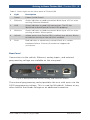
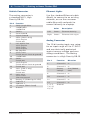
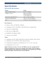
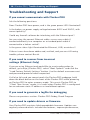
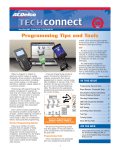
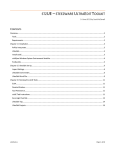
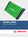
Flasher-PRO
User’s Manual
Table of Contents | Flasher-PRO | 1
Flasher-PRO Contents
2
Getting to know Flasher-PRO
Connectors and Status Indicators
Vehicle Connector
Ethernet Lights
Analog Connector
5
Setting up the Flasher-PRO
Powering Flasher-PRO
Connecting and Configuring Flasher-PRO
Flasher-PRO Checker Program
8
Reprogramming with J2534
9
Specifications
10 Troubleshooting and support
If you cannot communicate with Flasher-PRO
If you need to recover from incorrect settings (Ethernet Only)
If you need to generate a logfile for debugging
If you need to update drivers or firmware
Verify the network is configured correctly
If all else fails...
Flasher-PRO User’s Manual | August 2008 Robert Bosch LLC
2 | Flasher-PRO | Getting to Know Flasher-PRO
Getting to Know Flasher-PRO
The Flasher-PRO supports all modern vehicle reprogramming protocols
including: J1850VPW, J1850PWM, CAN, ISO 15765, ISO 9141, ISO
14230/KWP2000, and Chrysler SCI
Your package includes: the Flasher-PRO hardware, a MVCI-J1962
vehicle interface cable, a USB cable, an Ethernet cable, and a CD
including drivers and support tools.
Because J2534-1 is a widely accepted standard, the Flasher-PRO will
work with a variety of ECM reprogramming applications. The EPAPublished regulation has led to publicly available reprogramming
applications from almost every major automaker. These applications
will allow independent repair shops to update the calibrations on
newer automobiles.
Connectors and Status Indicators
Front Panel
There are 6 status lights on the front panel of the Flasher-PRO.
These status lights are useful for troubleshooting the Flasher-PRO’s
connection to a PC.
Figure 1: Flasher-PRO front plate
The yellow warning light indicates that Flasher-PRO is communicating
with the vehicle. Do not disconnect while this is illuminated! If you
interrupt a reflash while the vehicle’s ECU s blank or only partially
programmed, the module may be unrecoverable. Refer to Table 1 for a
description of the other status lights.
Robert Bosch LLC
Flasher-PRO User’s Manual | August 2008
Getting to Know Flasher-PRO | Flasher-PRO | 3
Table 1: Status lights on the front panel of Flasher-PRO
#
Light
Description
Power
Power (Solid Green)
1
Ethernet
Green indicates a good connection directly to a PC or to an
existing Ethernet network.
2
USB
Green indicates a good USB connection. The PC has
identified and configured Flasher-PRO properly.
3
Wireless
Green indicates a good connection directly to a PC or to an
existing wireless access point.
4
Vehicle
Yellow warns that Flasher-PRO is talking to a vehicle. Blinks
to indicate activity on the vehicle’s network.
5
Fault
Red indicates a momentary network fault or a serious
hardware failure. Please call technical support for
assistance.
Rear Panel
Connections to the vehicle, Ethernet, analog inputs, and external
programming voltage are available on the rear panel.
Figure 2: Rear panel with vehicle, analog, and Ethernet sockets
The external programming socket provides the user with access to the
5-20V programming voltage. This is used for Mitsubishi, Subaru or any
other vehicle that needs voltage on an additional connector.
Flasher-PRO User’s Manual | August 2008 Robert Bosch LLC
4 | Flasher-PRO | Getting to Know Flasher-PRO
Vehicle Connector
Ethernet Lights
The mating connector is
a standard MVCI, High
Density DB-26.
Use the standard Ethernet cable
(black) to connect to an existing
network, or use the crossover
cable (blue with red ends) to
connect directly to a laptop.
Pin #
1
2
3
4
5
6
7
8
9
10
11
12
13
14
15
16
17
18
23
26
Function
CAN2 Single Wire
J1850PWM+
J1850VPW
CAN2+
Case Ground
Signal Ground
CAN+ (CAN-C only)
SCI A Engine
5v-20v out
ISO-9141 K-line
SCI A Engine
SCI A Trans
SCI B Engine
No Connect
SCI B Trans
5v-20v out or short-to-ground
J1850PWMCAN25v-20v out
SCI B Engine
5v-20v out or short-to-ground
5v-20v out
CAN- (CAN-C only)
SCI A Trans
5v-20v out
ISO L Line
SCI B Trans
Short-to-ground
Battery In (150mA @ 12 VDC)
Cable ID 2
Cable ID 1
+5 output (50mA fused)
Ground
Robert Bosch LLC
Color
Description
Left
Green
Ethernet Activity
Right
Green
Ethernet Link Light
Analog Connector
The 12-bit analog inputs are setup
for an input range of 0 to 27.5VDC
and are electrically protected
against reverse voltage and over
voltage conditions. The Mating
connector is a High Density DB-15
Pin #
Function
Direction
2
Channel 6
In
4
Channel 3
In
6
Battery
Voltage
Out (200mA
max)
8
Channel 4
In
10
Channel 1
In
12
Channel 5
In
14
Channel 2
In
1, 3, 5,
7, 9, 11,
13, 15
Ground
Flasher-PRO User’s Manual | August 2008
Setting Up the Flasher-PRO | Flasher-PRO | 5
Setting Up the Flasher-PRO
Powering Flasher-PRO
First, determine how the Flasher-PRO will receive power:
1. Vehicle power: The optional MVCI to OBD-II cable provides power to
the Flasher-PRO from a vehicle. Most vehicles built after 1996 have
an OBD-II port somewhere under the dash on the driver’s side, as
specified in SAE J1962.
2. Bench top power supply: When using the Flasher-PRO on a bench,
put power on pin 16 (VBATT) and ground on pin 5 (Signal Ground).
When Flasher-PRO is first powered-on, the lights will cycle through a
self-test procedure. Remember that the Flasher-PRO does not receive
power from your PC’s Ethernet or USB ports.
Connecting and Configuring Flasher-PRO
Second, connect the Flasher-PRO to your PC:
Using USB
The Flasher-PRO is powered from the vehicle connector, so it will have
to be connected to a vehicle or powered from an external power supply
to use USB. Once powered, connect your PC to the Flasher-PRO thru
USB to install the drivers.
1. Once connected, you
will be prompted from
windows with new
hardware found.
2. Select Install from a list
or specific location. Click
browse and point to
the CD drive, under the
Drivers-USB folder. If your
CD-ROM is Drive letter E,
the path would be
e:\Drivers-USB.
3. Follow the process; it will install the USB drivers.
Flasher-PRO User’s Manual | August 2008 Robert Bosch LLC
6 | Flasher-PRO | Setting Up the Flasher-PRO
Using Ethernet
We strongly recommend Flasher-PRO’s default Client then Server
mode, because no configuration changes would be required when
moving the Flasher-PRO between LAN and in-vehicle use.
To a Laptop Directly
Connect a cross-over type Ethernet cable (blue with red ends) between
a PC and the Flasher-PRO.
To an Existing LAN
Connect a standard Ethernet cable. On most LANs, Flasher-PRO can
obtain its IP address automatically using DHCP. Ask your network
administrator if this service is available on your network.
Flasher-PRO Checker Program
The Flasher-PRO Checker Program is a handy tool for collecting current
state information of your Flasher-PRO. The program allows you to
change Ethernet configurations, update the firmware, find the current
IP address, and firmware revision.
To run the Flasher-PRO Checker Program, insert the CD that came with
your Flasher-PRO into your PC. Using My Computer, double click on the
CD Rom drive. Next, double click on the “FLPCheckerProject” file.
Updating Firmware with the Flasher-PRO Checker Program
The Flasher-PRO Checker Program can update the Firmware of your
Flasher-PRO either over the Ethernet connection or over USB.
To begin, make sure your Flasher-PRO is connected to your PC. Run the
Flasher-PRO Checker Program. Your Flasher-PRO will automatically be
found. If you have more than one Flasher-PRO attached to your local
network, you have the option to pick a specific unit from the drop down
at the top. Once your Flasher-PRO has been selected, click on “Update
Firmware.” Browse to the location of the Flasher-PRO firmware file,
select the file, and click “Open.” Your Flasher-PRO will now be updated.
This process can take up to 10 minutes. DO NOT UNPLUG YOUR
FLASHER-PRO UNTIL THE PROGRAM HAS FINISHED.
Install Check Program
The Install Check program allows users to view information on the
status of drivers currently installed on a PC. To make sure your Flasher-
Robert Bosch LLC
Flasher-PRO User’s Manual | August 2008
Setting Up the Flasher-PRO | Flasher-PRO | 7
PRO drivers are installed correctly, run “Install_Check.exe” from the CD
included with your Flasher-PRO. If your drivers are installed correctly
the program will show:
“Flasher-PRO USB Installed”
If you do not see either of these entries then your Flasher-PRO drivers
are not installed.
Vehicle Check Program
The Vehicle Check program is a handy utility that allows a user to
find what communication protocol a vehicle uses and the VIN number
associated with that vehicle. To use the Vehicle Check program first
make sure that your Flasher-PRO is connected to a vehicle and to
your PC, and also have the vehicle’s key in the ON position. Run the
“Vehicle_Check.exe” program from the CD. Make sure your FlasherPRO is selected from the drop down box and click “Check Connection.”
Each OBD protocol will be checked for a vehicle connection and VIN.
The results will be displayed in the appropriate column.
Debug Check Program
The Debug Check Program is a tool that our customers can use when
they are having trouble with J2534 communications. The program
enable debugging for the Flasher-PRO and gives Tech Support good
insight into a problem.
To turn debugging on, run the “Debug_Check.exe” from the CD that
came with your Flasher-PRO. Once the program is running, make sure
there is a check mark next to “Flasher-PRO” in the upper left corner.
Next Click “Enable Debug.” Now when you run your J2534 application
a file is made that allows us to see what messages get sent through
the Flasher-PRO. This file is saved in the C:\Documents and Settings\
USERNAME\Local Settings\Temp directory for XP and the C:\Users\
USERNAME\AppData\Local\Temp directory for Vista.
To send support a debug file, run “Debug_Check.exe” from the CD
and click on “Read Debug file.” You will have to pick the debug file
from the window. They are saved as a text file and look similar to this:
“DebugPlus_1216221943_6936.txt” Once you have the file selected
click “Open.” Now copy all of the text in the screen and E-mail it to
support.
Flasher-PRO User’s Manual | August 2008 Robert Bosch LLC
8 | Flasher-PRO | Reprogramming with J2534
Reprogramming with J2534
If you want to reprogram vehicles using OEM software, you can find a
list below of websites that offer subscription software.
Automaker
Website
BMW
http://www.bmwtechinfo.com/
Mini
http://www.minitechinfo.com/
Porsche
http://techinfo.porsche.com/
Chrysler, Jeep, Dodge
http://www.techauthority.com/
Ford, Lincoln,
Mercury,
http://www.motorcraft.com/
Land Rover
http://www.landrovertechinfo.com/
Volvo
http://www.volvotechinfo.com/
Cadillac, Chevrolet,
http://www.gmtechinfo.com/
Daewoo, GM, GEO,
Pontiac, Buick, Saturn,
SAAB
Acura, Honda
http://www.serviceexpress.honda.com/
Isuzu
http://www.isuzutechinfo.com/
Mazda
http://www.mazdatechinfo.com/
Mercedes
http://www.startekinfo.com/
Mitsubishi
http://www.mitsubishitechinfo.com/
Nissan
http://www.nissan-techinfo.com
Toyota, Lexus, Scion
http://techinfo.toyota.com/
Volkswagen
http://www.erwin.volkswagen.de/erWinVW
Audi
http://erwin.audi.de/erWinAudi
When reprogramming, always be sure the vehicle battery is fully
charged and in good working condition. We recommend connecting an
external battery charger to ensure a successful operation.
More information on how to use J2534 reprogramming can be found at
www.boschdiagnostics.com
Robert Bosch LLC
Flasher-PRO User’s Manual | August 2008
Specifications | Flasher-PRO | 9
Specifications
Flasher-PRO Specifications:
Name
Value
Input Voltage Range
6VDC to 26VDC
Supply Current
320mA @ 6VDC
200mA @12VDC
170mA @15VDC
Operating Temperature
+0C to +60C ambient
Storage Temperature
-65C to +100C ambient
Size
1.25”H x 7.5”D x 5.25”W
Bus Protocols
ff Primary CAN / ISO15765 / GMLAN
ff Secondary CAN / ISO15765 / GMLAN (Dual or Single Wire)
ff Ford SCP (J1850PWM)
ff GM Class2 (J1850VPW)
ff K WP2000 (ISO9141/14230)
ff Chrysler SCI (J2610)
Other
ff Compliant to SAE J2534 (Feb 2002) and SAE J2534-1 (Dec 2004)
ff Compliant to ISO 22900-1 MVCI physical layer
ff Programming voltage on J1962 pin 6, 9, 11, 12, 13, 14 or Aux
ff Ground pins 9, 12, or 15
Note: Drawing current in excess of 200ma on a line configured for
FEPS programming voltage may damage the Flasher-PRO hardware.
Avoid grounding any output pin configured for programming voltage!
Battery Voltage is fused (auto reset) at 200mA.
Flasher-PRO User’s Manual | August 2008 Robert Bosch LLC
10 | Flasher-PRO | Troubleshooting and Support
Troubleshooting and Support
If you cannot communicate with Flasher-PRO
Ask the following questions:
Does Flasher-PRO have power, and is the green power LED illuminated?
Is the battery or power supply voltage between 6VDC and 15VDC, with
correct polarity?
Could any firewall software be interfering with the Ethernet port?
Are you using the correct Ethernet cable: a cross-over cable if
connected directly to a computer or a standard patch cable if
connected to a hub or switch?
Is the green status light illuminated for Ethernet, USB, or wireless?
If these issues have been addressed, verified, and you are still having
trouble, please contact Bosch.
If you need to recover from incorrect
settings (Ethernet Only)
If you are using Ethernet and would like to reset configuration to
default, go to http://Flasher-PRO/, select “Boot Options” and click the
“Load Factory Default Settings” button. Use the default username root
and password powerful when requested.
If all else fails and you cannot reach the Flasher-PRO webpage, hold
down the black button on the front of the Flasher-PRO while powering
on Flasher-PRO to enter recovery mode. This resets Flasher-PRO to
“Client Then Server” mode; it is useful when Flasher-PRO is configured
for an unknown static IP address or invalid boot options.
If you need to generate a logfile for debugging
Please see previous section: Flasher-PRO Debug Check Program
If you need to update drivers or firmware
Your Flasher-PRO contains field-upgradeable firmware. Updates are
regularly released which: include new features, improve performance,
Robert Bosch LLC
Flasher-PRO User’s Manual | August 2008
Troubleshooting and Support | Flasher-PRO | 11
and correct problems. Please visit the Bosch download page at:
http://www.boschdiagnostics.com
To update the Flasher-PRO firmware: Apply power to Flasher-PRO.
Load the configuration webpage in a web browser, and follow the
instructions for selecting and uploading a new firmware file.
To update the PC driver: click on the Installer link like a new
installation.
Verify the network is configured correctly
Try to connect to the Flasher-PRO web page. Consult the networking
section above for details.
If that does not work, try:
ff Turning off any firewall/antivirus software.
ff P
icking a different connection method. For example, try the fixed IP
addressing mode.
ff U
sing recovery mode to make sure the Flasher-PRO is configured
correctly. Recovery mode is entered by holding down the front
button during power-on.
If the Flasher-PRO web page works, but applications don’t work:
ff T
he DLL may not be installed. Install the DLL using the instructions
on page 5 of this quick start guide.
ff T
he network settings may be incorrect. Specifically, verify that
the Flasher-PRO netmask setting is the same as the PC/laptop’s
netmask setting.
ff T
he application may be looking for the wrong J2534 device. Make
sure “Flasher-PRO” is selected.
If applications work, but not the Flasher-PRO web page:
ff V
erify that your web browser is not using a proxy. (Under Tools >>
Options >> Local Area Network Settings)
ff If your PC/Laptop is running firewall software, try turning it off to
see if that is the problem.
Flasher-PRO User’s Manual | August 2008 Robert Bosch LLC
12 | Flasher-PRO | Troubleshooting and Support
ff In DHCP Client mode, the IP address of the Flasher-PRO can
change. Enter http://Flasher-PRO/ in your browser, but only after
waiting a few minutes for the Flasher-PRO to register itself on the
network. Alternately, look at the logs for your network DHCP server.
ff U
se recovery mode to verify the Flasher-PRO has the correct
settings.
If all else fails...
Please contact Bosch for technical support at 1-800-321-4889, ext. 7
or techsupport.diagnostics@us.bosch.com. If technical support finds it
necessary for the unit to be returned for repair, you will be asked for
your contact information and then provided with a Return Merchandise
Authorization number (RMA#) that will be used to track the unit
through the repair department back to you. Please write this number
on the outside of your shipping box so it can be routed to the correct
department. If the necessary repair is not covered by the warranty, you
will be contacted for payment arrangements.
Robert Bosch LLC
Flasher-PRO User’s Manual | August 2008
Robert Bosch LLC
Automotive Aftermarket Division
Diagnostics Business Unit
2040 Alameda Padre Serra, Ste 220
Santa Barbara, CA 93103
Phone 800-321-4889
©2008 All rights reserved.
2213437