1
FAAC 746 & 844
SLIDING GATE AUTOMATION
WITH CP81 CONTROLLER
INSTALLATION
MANUAL
Latest Revision: 05.04.2004
Document Ref.: 1074.D.01.0001_4
Table of Contents
1. PRODUCT TECHNICAL DETAILS . . . . . . . . . . . . . . . . . . . . . 2
1.1 DIMENSIONS . . . . . . . . . . . . . . . . . . . . . . . . . . . . . 2
1.2 TECHNICAL SPECIFICATIONS . . . . . . . . . . . . . . . . . . . . 3
2 PRODUCT INSTALLATION. . . . . . . . . . . . . . . . . . . . . . . . . 4
2.1 RECOMMENDED TOOLS . . . . . . . . . . . . . . . . . . . . . . . 4
2.2 CABLE REQUIREMENTS . . . . . . . . . . . . . . . . . . . . . . . 5
2.3 GATE REQUIREMENTS . . . . . . . . . . . . . . . . . . . . . . . . 6
2.4 UNIT INSTALLATION . . . . . . . . . . . . . . . . . . . . . . . . . 8
2.4.1 FOUNDATION PLATE DETAILS . . . . . . . . . . . . . . . . . 8
2.2.2 FOUNDATION PLATE POSITIONING . . . . . . . . . . . . . . 9
2.4.3 ACCESSING CONTROLLER MODULE . . . . . . . . . . . . . 10
2.4.4 POSITIONING GEARBOX . . . . . . . . . . . . . . . . . . . . 10
2.4.5 ADJUSTING GEARBOX POSITION . . . . . . . . . . . . . . . 11
2.4.6 MOUNTING OF RACK . . . . . . . . . . . . . . . . . . . . . . 11
2.4.7 MOUNTING AND POSITIONING LIMIT SWITCH PLATES . . . . 13
3 ELECTRICAL CONNECTIONS . . . . . . . . . . . . . . . . . . . . . . . 14
4. COMMISSIONING PROCEDURE . . . . . . . . . . . . . . . . . . . . . 24
4.1 REMOVE OIL BLEED SCREW. . . . . . . . . . . . . . . . . . . . . 24
4.2 ADJUSTMENT OF ANTI-CRUSHING SYSTEM . . . . . . . . . . . . 24
4.3 APPLYING MAINS POWER . . . . . . . . . . . . . . . . . . . . . . 25
4.4 SETTING UP THE ELECTRONIC CONTROLLER . . . . . . . . . . . 26
4.5 TESTING THE AUTOMATION . . . . . . . . . . . . . . . . . . . . . 35
5 MANUAL OPERATION . . . . . . . . . . . . . . . . . . . . . . . . . . . 36
6 MAINTENANCE . . . . . . . . . . . . . . . . . . . . . . . . . . . . . . 37
1
1. PRODUCT TECHNICAL DETAILS
THE FAAC 746 & 844 GATE OPERATORS ARE SELF-CONTAINED UNITS CONSISTING OF A
WORMGEARED ELECTRIC MOTOR , AN ELECTRONIC CONTROL CARD AND A PROXIMITY LIMIT
SWITCH SYSTEM WHICH STOPS THE GATE AT THE CORRECT END POSITION.
THE UNITS HAVE A PLEASANT, MODERN DESIGN WHICH INTEGRATE HARMONIOUSLY WITH THE
ENVIRONMENT OF HOME OR OFFICE.
THE FAAC RANGE ARE QUALITY PRODUCTS DESIGNED TO GIVE MANY YEARS OF TROUBLE
FREE SERVICE
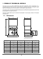
1.1. - Dimensions
A
F
G
H
B
D
E
C
N.B. All dimensions in mm.
DIMENSION
746
20 Tooth Pinion
844
16 Tooth Pinion
844
20 Tooth Pinion
844 3 Phase
16 Tooth Pinion
A
275
280
280
208
B
312
385
385
385
C
210
209
209
209
D
155
158
158
158
E
191
191
191
191
F
64
64
64
64
G
-
112
-
112
H
120
-
120
-
2
3
MODEL
POWER SUPPLY
ABSORBED POWER
CURRENT DRAW
MAX. STARTING THRUST
TEMPERATURE RANGE
MOTOR SPEED
REDUCTION RATIO
No. OF PINION TEETH
RACK PITCH
GATE SPEED
WINDING THERMAL PROTECTION
DUTY CYCLE
OIL QUANTITY
TYPE OF OIL
HOUSING PROTECTION
GEAR MOTOR WEIGHT
STARTING CAPACITOR
CLUTCH
CONTROL UNIT
LIMIT SWITCH
MAX. GATE WEIGHT
746
230V~ (+6% - 10%) 50Hz
300W
1.5A
18kgF (Z20)
-20 TO 55OC
1400rpm
1 ÷ 30
Z20
4 MODULE
12m/min
120OC
40% (SEE PAGE 6)
1.8 LITRES
FAAC XD 220
IP 55
14kg
25µF
BIDISK IN OIL BATH
CENTURION CP81
INDUCTIVE
(Z20) 800kg
1.2 TECHNICAL SPECIFICATIONS
844
230V~ (+6% - 10%) 50Hz
650W
3.5A
45khF (Z16) - 35kgF (Z20)
-20 TO 55OC
1400rpm
1 ÷ 30
Z16 (Z20)
4 MODULE
9.5m/min (Z16), 12m/min (Z20)
135OC
40% (SEE PAGE 6)
1.8 LITRES
FAAC XD 220
IP 55
15kg
35µF
BIDISK IN OIL BATH
CENTURION CP81
INDUCTIVE
(Z16) 1800kg
(Z20) 1000kg
844 3 PHASE
380V, 3 Phase 4 wire available
900W
2.5A
50kgF (Z16)
-20 TO 55OC
1400rpm
1 ÷ 30
Z16
4 MODULE
9.5m/min
135OC
40% (SEE PAGE 6)
1.8 LITRES
FAAC XD 220
IP55
18kg
N/A
BIDISK IN OIL BATH
CENTURION CP81 3 PHASE
INDUCTIVE
(Z16) 2200kg
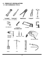
2. PRODUCT INSTALLATION
2.1 RECOMMENDED TOOLS
SCREW DRIVER
FLAT and RING
5mm FLAT
SPANNER
8, 10, 13, 17 & 19mm No 1. PHILLIPS
TAPE MEASURE
ELECTRIC
DRILLING
MACHINE
CRIMPING TOOL
AND PIN LUGS
ALLEN KEYS
3mm ACROSS FLATS
5mm ACROSS FLATS
PLIERS/SIDE
CUTTER
HACKSAW
HAMMER
G-CLAMP
STEEL BITS, 3 - 12mm
WELDING MACHINE
SOLDERING IRON
SPADE
PICK
LEVEL
4
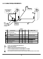
2.2 CABLE REQUIREMENTS
INTERCOM
GOOSENECK
C
220V MAINS
ISOLATOR
F
E
G
220V
MAINS
A
INTERCOM
TO HOUSE
FAAC
746/844
B
F
TABLE 1
NO
DESCRIPTION
NO OF
CORES
220V AC SUPPLY CABLE
2+E
or 380V 3 ALTERNATIVE MODEL
4+E
B
INTERCOM IN HOUSE & STATUS
SIGNALLING
C
A
SIZE2 OPTIONAL
mm
* CABLE TYPE
1,5
NORSK IN CONDUIT OR S.W.A.
n1 + 6
0,2
INTERCOM IN CONDUIT
INTERCOM IN CONDUIT
INTERCOM - GEARBOX TO GOOSENECK
n2
0,2
D
PILLAR LIGHTS
2+E
0,5
X
E
REMOTE RECEIVER
3
0,2
X
F
PEDESTRIAN KEYSWITCH
2
0,2
X
G
INFRA RED BEAM
3
0,2
X
NORSK IN CONDUIT OR S.W.A.
INTERCOM/CABTYRE/
G.P. IN CONDUIT
INTERCOM/CABTYRE/
G.P. IN CONDUIT
INTERCOM/CABTYRE/
G.P. IN CONDUIT
= CABLE TYPE IS MINIMUM RECOMMENDATION
S.W.A. = STEEL WIRE ARMOURED
G.P.
= GENERAL PURPOSE HOUSE WIRING OR PANEL FLEX
n1
= CONSULT INTERCOM SUPPLIER FOR REQUIRED NO. OF CORES
n2
= CONSULT INTERCOM SUPPLIER FOR REQUIRED NO. OF CORES
= FOR OPTIMUM LIGHTNING PROTECTION USE SCREENED CABLE EARTHED AT BOTH ENDS
5
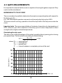
2.3 GATE REQUIREMENTS
It is important to ensure that the motor is capable of moving the gate as required. Duty
cycle must be considered:
MAXIMUM DUTY CYCLE CURVE
The curve makes it possible to determine the maximum operating time with respect to
the duty cycle (F).
e.g., the 746 and 844 operators can work continuously at a duty cycle of 40%.
To ensure smooth running, operation should be kept within the duty area under the
curve.
Important note. The curve was plotted on the basis of operation at a temperature of
24OC. Allow for up to 20% reduction of the duty cycle in case of exposure to direct
sunlight and/or higher ambient temperatures.
Calculating the duty cycle
The duty cycle is the percentage of the actual operating time (opening plus closing
plus pause time). The formula for calculating it is the following:
To + Tc
%F =
x 100
To + Tc + Tp + Ti
where: To = opening time;
Tc = closing time;
Tp = pause time;
Ti = interval between a complete cycle and the next
100
90
Duty Cycle ( % )
80
70
60
50
40
30
1 2 3
4 5 6
7 8 9 10 11 12
6
Time ( h )
ENSURE THAT THE GATE IS FITTED WITH CORRECT END STOPS, ETC.
AS SHOWN IN THE SKETCHES BELOW.
C
(See note 4)
Catch Bracket
(See NOTE 3)
GATE TAIL
B
END STOP
(See Page 8)
(See note 2)
16 ( 20)
ROUND BAR
A.2
A.x
(See details below
and note 1)
A.1
STITCH WELDED
BOTH SIDES
STITCH WELDED
BOTH SIDES
CHANNEL IRON
" T " PROFILE
RECOMMENDED OPTION
ALTERNATE OPTION
NOTE 2: Requirements of END STOP:
- Stop Gate in Fully Open Position;
- Strong Enough to Resist Full Thrust of
Motor.
ANGLE IRON
A.3
16 ( 20)
ROUND BAR
NOTE 3: CATCH BRACKET
- Secure Front of Gate When Fully Closed;
- Prevent Front of Gate from Being Lifted;
- Strong Enough to Resist Full Thrust of
Motor;
- Gate Must Slide Smoothly into Catch
Bracket.
STITCH WELDED
BOTH SIDES
" T " PROFILE
NOT RECOMMENDED
NOTE 4: GUIDE ROLLERS
- Guide rollers must be installed. Ensure that
the gap between the gate and the guide roller
bracket is such that the gate cannot be lifted
off the motor pinion.
NOTE 1: The Bottom of the Round Bar (T Bar or
Channel Iron) should be Level with the Ground
(or not exceeding 5 mm High).
7
GATE MASS
DUTY
(A) A
up to
300kg
up to
600kg
up to
1200kg
up to
2400kg
WHEEL OUTER DIAMETER ( ROOT DIAMETER)
B
A
80mm
(*65mm)
B
16mm
A
80mm
(65mm)
B
16mm
Low
duty
80mm
(65mm)
120mm
(100mm)
190mm
(165mm)
ROUND BAR TRACK DIAMETER
16mm
20mm
25mm
WHEEL OUTER DIAMETER ( ROOT DIAMETER)
CONSULT THE ADJACENT TABLE TO
DETERMINE THE CORRECT GATE
WHEEL ROOT SIZE AND ROUND BAR
TRACK DIAMETER REQUIRED IN
RESPECT OF GATE MASS AND DUTY.
High
duty
120mm
(100mm)
190mm
(165mm)
ROUND BAR TRACK DIAMETER
20mm
25mm
*V Profile
2.4 UNIT INSTALLATION
5
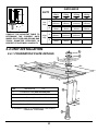
2.4.1 FOUNDATION PLATE DETAILS
160
42
4
60
42
290
75
1
75
30
ITEM
1
)
DESCRIPTION
QTY
2
130
Foundation Plate (6mm mild steel plate
1
2
Anchor Bracket (2mm mild steel flat bar)
4
3
Set Screw, M10 x 60
4
4
Washer, M10
8
A foundation plate kit is available from CENTURION Reference: CP25SR844
8
15
40
3
(ALL DIMENSIONS SHOWN IN MILLIMETRES)
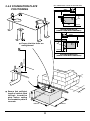
2.4.2 FOUNDATION PLATE
POSITIONING
WALL
44
GATE
BASEPLATE
225
90
0 to 50
MOTOR MOUNTED LHS
(VIEWED FROM INSIDE PROPERTY)
WALL
GATE
Ensure that the bolts are
well tightened.
90
44
l
0 to 50
155
l
Ensure that sufficient
length of cable is fitted
through foundation
plate before setting
the foundation plate in
concrete.
300mm
400mm
MOTOR MOUNTED RHS
(VIEWED FROM INSIDE PROPERTY)
400mm
400mm
9
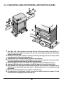
2.4.3 ACCESSING CONTROLLER MODULE
Model 746
l
Remove screws from cover to gain access
to the controller enclosure.
Model 844
l
Open up cover of
operator to allow
easy access in
order to feed in
main supply and
signal cables.
1
3
l
Loosen the earth screw
(1)
l
Slide controller
mounting plate sideways
(2)
l
Lift out of position (3) to
gain access to the cable
entry hole (4)
2
4
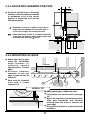
2.4.4 POSITIONING GEARBOX
l
Leave at least a 5mm gap
between the lower gearbox
nuts (1) and the nuts which
secure the foundation plate
bolts.
l
Feed cables (2) into the
operator while lowering
gearbox onto the studs (3).
l
Gearbox must be firmly
secured between top and
bottom nuts (4) and washers
(5) as shown.
4
5
3
1
5mm
10
2
2.4.5 ADJUSTING GEARBOX POSITION
38
5 max
l
Using the slotted holes in the angle
brackets, slide the operator forwards
or backwards to be in the correct
position to mount the rack and the
limit switch plates.
*
**
- Dimension is critical, if striker is too close it
might foul and damage the inductive limit. If
it is too far it might not activate the limit.
5
- Check that there is little or no lateral movement
of the gate, particularly when striker slides past
inductive limit. See note above.
44
2.4.6 MOUNTING OF RACK
l
l
l
Attach steel rack to gate
using the 25x25x2mm
angle brackets (1)
supplied, spaced
approximately 350mm
apart.
Distance between
centreline of rack and
edge of gate should be
25mm (2)
Rack must be mounted
level with a 2-3mm
clearance (3)
1
±350 mm
2
3
USEFUL TIP
l
l
l
l
11
Raise gearbox by an additional 3mm.
Put gearbox into manual mode (see page
36)
Mesh rack and pinion fully and mount rack.
Slide gate backwards and forwards
ensuring that rack mesh is smooth and
never tight.
Drop gearbox by 3mm to create 3mm tooth
clearance.
JOINING STEEL RACK
l
Cut off short length of rack (approx. 200mm)
l
Clamp the new pieces to the off cut.
l
Weld pieces together where indicated.
WELD HERE
N.B. DO NOT WELD NEAR
MESHING SURFACES
RACK MUST BE LEVEL
200 - 300mm RACK OFFCUT
MOUNTING and JOINING
of NYLON RACK (RAZ)
l
Work from RHS of the gate to LHS to ensure
rack clips together.
l
Screw nylon rack onto gate using fasteners
provided.
l
Use fasteners 230mm apart.
( MAXIMUM GATE MASS 500 kg )
LEVEL
230mm
12
230mm
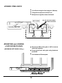
2.4.7 MOUNTING AND POSITIONING LIMIT SWITCH PLATES
2
3
1
B
N
l
l
l
l
l
l
l
l
l
The FAAC 746 & 844 operators are fitted with an inductive proximity limit switch (1).
When the limit switch plate mounted to the top of the rack slides past the limit switch the
operator stops the gate.
Assemble the limit switch plate as shown, positioning the stop plate (2) centrally on the
mounting studs of the support bracket (3).
Slide the gate open leaving a 20mm gap before the end stop.
Position the support bracket and stop plate on top of the rack with the center line of the
stop plate adjacent either mark (B) or (N) of the limit switch .
Use mark (B) if the motor is mounted on the LHS (viewed from inside the property).
Use mark (N) if the motor is mounted on the RHS (viewed from inside the property).
Gap between the stop plate and limit switch must be less than 5mm. Compensate for
sideways movement of the gate (see page 11). Repeat steps above for closed limit using
other mark.
Refer to commissioning section 4, page 24, before testing.
Fine adjustment of stop plates is done once the limit switch polarity (see page 27) and
motor direction (see page 29) are correctly set.
13
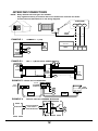
3. ELECTRICAL CONNECTIONS
N.B.
1) FOR SINGLE PHASE FAAC 746/844 MOTORS THE CP81 CONTROLLER
COMBINED WITH THE CP89 POWER SUPPLY BOARD IS USED;
2) THE THREE PHASE FAAC 844 MOTOR IS SUPPLIED WITH A CP81
CONTROLLER, CP89 POWER SUPPLY, CONTACTORS AND THERMAL
CUT OUT ( see Wiring Diagram, pg.16 );
3) DIFFERENT PIC MICROCONTROLLERS ARE USED ON 1Ø AND
3Ø VERSIONS.
NOTES:
FOLLOWING ARE THE WIRING DIAGRAMS FOR THE DIFFERENT
CONTROLLER ASSEMBLIES:
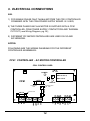
CP81 CONTROLLER - AC MOTOR CONTROLLER
CP81 CONTROL CARD
POWER
L1
L2
RX
FAAC V1.XX or,
FAAC 3 V1.X
1A F/B
CP81
DOSS
STATUS
COURTESY LIGHT
FUSE
3A F/B
AUXILLIARIES
FUSE
MOTOR FUSE
5A F/B
SET
LCK
LED
PED
IRB
FRX
12V
14
TRG
COM
COM
LIGHT
E
LIGHT
L
N
M3
M1
M2
SET
15
1 AC
MOTOR
10 w
REVERSE (Black)
COMMON (Blue)
J4
J5
CH
J3
COM
FAAC 746 / 844
TERMINATION BOARD
J1
J2
LS
LS
Purple
Red
RIBBON
CABLE
Black
Orange
PROXIMITY
LIMIT SWITCH
ON OUTSIDE
OF CASING
AP
Black
Blue
Brown
THESE CABLES
MAY NEED
REVERSAL
(see Installation
Manual page 28)
FORWARD (Brown)
MOTOR
CAPACITOR
0.47
M1, M3 CABLES MAY NEED
REVERSAL DEPENDING ON
REQUIRED MOTOR DIRECTION
(see page 29)
OPERATOR MOUNTED ENCLOSURE
Red
Black
Purple
Orange
LS
LS
L
E
N
L N E
Black
Brown
Green
220V AC
INPUT SUPPLY
M1
BLACK
RED
COM
COM
LIGHT
LIGHT
E
N
L
M3
M2
DOSS CABLE
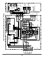
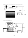
POWER WIRING DIAGRAM FOR 1 MOTOR (746 / 844)
DOSS
12V DC
CENTURION
CP81 PCB
PIC REF:
FAAC V1.XX
SIGNAL CABLING
(see Inst. Manual
pages 15 to 21)
CENTURION CP89
POWER SUPPLY PCB
380V 3 4 WIRE SUPPLY
16
5
6
7
8
LINE 3
NEUTRAL
EARTH
4
LINE 2
LINE 1
BN
BU
GN
BU
RD
WH
L
N
E
LS LS
OR AC
PU AC
RD
220V
220V
BN
BN
M1
M2
OR
DOSS CABLE
CENTURION
CP81 PCB
M3
CONTACTOR B
MOTOR
OVER
LOAD
CONTACTOR A
PU
BN
CENTURION
CP89
INTERFACE PCB
L
BN
BK
N
BU
SEPARATE WEATHERPROOF ENCLOSURE
E
GN
T1
T2
T3
RD
BU
WH
Red
Black
Yellow/Purple
Grey/Orange
PIC REF:
813PHS V1.X
3
2
1
12
11
10
9
LS
LS
MOTOR (844 3 PHASE)
DOSS
POWER WIRING DIAGRAM FOR 3
J1
J2
J3
COM
M
CH
N/C LIMIT
SWITCH 2
N/C LIMIT
SWITCH 1
OR
J4
J5
380V
3 AC
MOTOR
FAAC
PROXIMITY
LIMIT SWITCH
LS
LS
AP
OPERATOR MOUNTED
ENCLOSURE
FAAC 746 / 844
TERMINATION BOARD
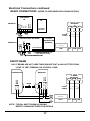
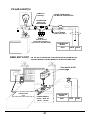
Electrical Connections continued
RADIO CONNECTIONS - (REFER TO CENTURION FOR CODING DETAILS)
CENTURION
RX
NO
NC
COM
LEARN
ERASE
RECEIVER
12-24V
AC/DC
EXAMPLE 1
TX
+12V COM
TRG
+12V
COM
2
0,2mm
CABLE
TYPICAL RADIO RECEIVER
TYPICAL
TRANSMITTER
(REMOTE)
+12V
EXAMPLE 2
COM
NC
NO
CODE SWITCHES
COM
+12V
}
POWER
SUPPLY
N/O
NO CODING
SWITCHES
1 2 3 4 5
+ -
CODE SWITCHES
1
12
CONTROLLER
MODEL
CP81
12V
COM TRG
}
}
+12V
COM
FOR DETAILS OF SETTING CODE
SWITCHES REFER TO
RADIO MANUFACTURER
OPTIONAL EXTERNAL LINK
IF NOT INTERNALLY FITTED
TRG
SAFETY BEAM
N.B. IF BEAMS ARE NOT USED THEN ENSURE THAT A LINK IS FITTED FROM
"COM" TO "IRB" TERMINAL ON CONTROL CARD.
RECEIVER
POWER
SUPPLY
I R BEAM
RECEIVER
N/C
N/O
NEG (0V)
BEAM
+ 12V
+12V POWER
COM SUPPLY
TRANSMITTER
LINK
COM
N/C
12V
COM
IRB
2
0,2mm
CABLE
COM
+12V
CONTROLLER
MODEL
CP81
IRB
NOTE - TYPICAL SAFETY BEAM IS SHOWN.
REFER TO MANUFACTURER FOR DETAILS
17
+12V
INTERCOM CONNECTIONS
NOTE: - Many different intercom types are available.
- Only signals necessary to interface intercom to Centurion's controller are shown.
- Consult intercom manufacturer for full wiring diagrams.
INTERCOM
+12V NEG N/O
2
0,5mm
CABLE
EXAMPLE 1
1
2
3
4
5
6
7
8
DP-2RN
OR
DP-2SN
HOUSE
TELEPHONE
EXAMPLE 2
COMMAX 1 - 1 (12V)
CONTROLLER
MODEL
1
2
DR2D
GATE
STATION
TRG
CP81
12V COM TRG
NEG
+12V
BPT 1 - 1 (WITH 12V DC POWER SUPPLY)
TELEPHONE
FOR 1
HOUSE 2
3
E/200 4
A
1 C
2
3
B
5
E/305
POWER
SUPPLY
1
D
2 E
1
2
1
2
8
7
6
5
4
1
2
+12V NEG
8
7
6
5
4
E/1-3
GATE
3 STATION
2
1
TRG
EXAMPLE 3 TEGUI 12V DC INTERCOM
T-200
PHONE
E-14
POWER
SUPPLY
11
GATE
STATION
+12V
NEG
MIN 5
CORE
EXAMPLE 4
MIN 7
CORE
TRG
TYPICAL 220V AC POWERED INTERCOM
RECTIFIER
INTERCOM
1
RELAY
COIL
AC SOLENOID
{ 12VLOCK
SUPPLY
{
N.C.
N.O.
FROM INTERCOM
COM
18
TRG
COM
2
REMOTE GATE STATUS LIGHT EMITTING DIODE (LED)
FITTED TO HANDSET BASE SEPARATELY
ANODE +
CATHODE -
LED
COM
SIGNAL COMMON
STATUS LED
2
0,2mm
CABLE
GATE STATUS
LED INDICATION
PILLAR LIGHT ON
CONTINUOUSLY
1 FLASH / 2 sec
GATE CLOSED
OFF
GATE OPEN
ON
GATE OPENING
SLOW EVEN FLASH
GATE CLOSING
FAST EVEN FLASH
CONTROLLER
MODEL
CP81
COM
LED
PEDESTRIAN KEYSWITCH
SPRING RETURN SWITCH
COM
PED
2
0,2mm
CABLE
CONTROLLER
MODEL
CP81
19
PED
COM
HOLIDAY LOCKOUT
COM
LOCK
+12V
ELECTRONICS
COM
NEG
OR
COM
2 POSITION SWITCH
N.O.
*
LOCK
N.C.
LATCH TYPE
RADIO RECEIVER
*
RELAY MUST HAVE LATCHING CONTACT.
LOCKOUT IS ACTIVE WHEN CONTACT IS OPEN.
+12V
ELECTRONICS
NEG
COM
1
COM
CONTROLLER
MODEL
N.O.
LOCK
N.C.
OR
2
2
0,2mm
CABLE
CP81
3
4
5
6
7
8
9
12V LCK COM
PUSHBUTTON
KEYPAD
NB: IF HOLIDAY LOCKOUT IS NOT USED, ENSURE THAT A LINK IS
FITTED FROM "COM" TO "LCK" TERMINAL ON CONTROL CARD.
REMOTE PROGRAMME SWITCH ( Activate pillar lights )
TYPICAL
PUSHBUTTON IS
SHOWN FITTED TO
AN INTERCOM
TELEPHONE
N/O
PUSHBUTTON
SET
COM
2
0,2mm
CABLE
CONTROLLER
MODEL
CP81
TO MOTOR
CONTROLLER
20
COM
SET
PILLAR LIGHT(S)
CABLE TO
LIGHT(S)
CABLE FROM SUPPLY
TO MOTOR CONTROLLER
CONNECTOR
BLOCK TO
JOIN CABLES
LIGHT
LIVE
2
0,5mm NORSK
CABLE OR (S.W.A.)
}
EN L
220V AC SUPPLY
(OR OTHER VOLTAGE TO
SUIT TYPE OF GLOBES USED)
CONTROLLER
MODEL
CP81
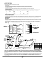
FREE EXIT LOOP -
LIGHT
LIGHT
LD 100 OR 101 INDUCTIVE LOOP DETECTOR IS SHOWN BELOW.
MODIFY WIRING IF OTHER MAKES OF DETECTORS ARE USED.
See details A & B
next page
B
FREQ
PRES
SENS
SENS
OR
FILTER
CT
TE
PULSE
DE
ASB
OP 0
S
RESET
L O 10 NG
LE LD WIRI TION
~
IC
EC
~~~
VEH
NN
~~~~
CO
~~~~ ~~~
H
~ ~ ~ ~ ~~
ITC GS
~~~~ ~~
~~
SW TIN
~~~~ ~
~~ ~
T
~~~~ ~~~~ ~~~~~ ~
SE
~
~
~~ ~ ~ ~~
~~~~ ~~~~~
~ ~ ~
~ ~ ~ ~~ ~~
~~~~ ~~~~~
~ ~~ ~ ~ ~~
~~~~ ~~~~~~
~
~
~
~
~
~
N
~ ~~~~~~ ~~ ~~ ~ ~
rO
we
~~~~~~ ~~ ~~ ~~
Po
~
~ ~
th
~~~ ~~ ~~ ~
Wi
g
~~~~ ~~~~~~
in
us
~~ ~~~~~
Ho
en
~~~~
t Op
No
~~
A
LD100
OR
LD 101
DETECTOR
UNIT
IN
G:
Do
RN
WA
COM
N/O
TWISTED WIRES
FROM LOOP
UNDERGROUND
LOOP
1 2
8 7
6
11 PIN PLUG
IN RELAY BASE
POWER SUPPLY
LD100 - 220V AC
LD101 - 12V DC
21
2
0,2mm
CABLE
5
CONTROLLER
MODEL
CP81
FRX
COM
LOOP DETAILS
DIP DIP
8
3
4 5
6
7
ON
1 2
9 10
STANDARD FEATURES OF THE DETECTOR ARE:
- Reset Switch.
The reset switch enables the detector to be manually reset during commissioning and testing.
This results in the detector re-tuning the sensing loop and becoming ready for vehicle detection.
- Selectable Pulse Time.
This feature sets the length of time that the pulse relay will be energised for. 1 Second or 0.2 Second.
- Pulse Relay Selection.
The Pulse relay may be configured to energise on detection of vehicle leaves the loop or when the vehicle leaves the loop.
- Switch selectable Sensitivity. Four sensitivity settings are available on the switches to allow flexibility in configuration.
1
High
- 0.01%
5
- 0.2%
2
- 0.02%
6
- 0.5%
3
- 0.05%
7
1%
4
- 0.1%
8
Low
2%
- Switch selectable Frequency.
Two frequency settings are available to prevent cross-talk between adjacent loops.
- Permanent Presence Option.
This feature ensures detection of the vehicle will be maintained when the vehicle is parked over the loop for extended periods.
- Sensitivity Boost.
This feature sets the undetect level to maximum sensitivity and is used to prevent loss of detection of high-bed vehicles.
- Filter Option
This option is used to provide a delay between detection of the vehicle and switching of the output relay. This delay is normally
used to prevent false detection of small or fast moving objects.
- Loop Fault Indicator
This LED Indicator is illuminated when the loop is either open circuit or short circuit and is used to give a visual indication of
a faulty loop.
POWER
VEHICLE LOOP DETECTOR
DETECT
LD 100
WIRING
LOOP FAULT
ON
OFF
CONNECTIONS
ON
OFF
RESET
RESET
PIN
- S7/S8/S9 CONNECTION
SENS 0,02%
SENS
DETAIL B
S9 S7/S8
0.01%
DETAIL A SENS
220V
AC
1
SENS
S8 S7/S8
SENS 0.05%
220V AC
2
S8/S9 S7
SENS 0.1%
SENS
(Recommended
3
S7 S8/S9 PULSE RLY N/O
SENS 0.2%
FREQ
4
PULSE RLY COM
S7/S9 S8
SENS 0.5%
settings)
ASB
5
PRESENCE RLY N/O
S7/S8 S9
SENS 1%
6
PRESENCE RLY COM
FILTER
S7/S8/S9 SENS 2%
7
LOOP
LOW
HI
FREQ.
Note: If two
PERM PRES
8
LOOP
ON
OFF
ASB
PULSE MODE
detectors are used,
9
EARTH
2SEC OFF
FILTER
PULSE
TIME
10
PRES. RLY N/C
ON
OFF
PERM.PRES
set different
PULSE MODE UNDET DET
1SEC 0.2SEC
PULSE TIME
11
PRES. RLY N/C
PROCON
Loop
detector
TWIST FEEDER
AT LEAST 20
TURNS PER METRE
Width of cut
4mm
45
1m
Min.
100mm
3 TURNS OF
CABLE MULTI
STRANDED
(SILICON COATED)
(TYPICAL)
Brick
Paving
Max
imum
rec
feed
er le ommen
d
ngth
100m ed
4mm
DEPTH INTO ROAD
MIN. 30-50mm
ROAD
SURFACE
30-50mm
DEEP
FILL WITH EPOXY
COMPOUND OR
BITUMEN MASTIC
300
mm
2m
3 TURNS MULTI
STRANDED
frequencies (S6)
ELECTRONICS
WARNING: DO NOT OPEN HOUSING WITH POWER ON.
PLASTIC
CONDUIT
ROAD
300
mm
LOOP
No. OF
CIRCUMFERENCE
TURNS
IN METRES
> 10
2
6 - 10
3
<6
4
- WIRE: 1.5mm SQUARED MULTI STRANDED CABLE (USE SILICON COATED IF PLACED DIRECTLY INTO THE GROUND)
- SPACING BETWEEN TWO ADJACENT LOOPS > 2 METRES. ALTERNATE ADJACENT LOOPS USING DIFFERENT NUMBERS
OF TURNS.
- LOOP AND FEEDER SHOULD COMPRISE ONE LENGTH OF UNJOINED WIRE. IF JOINTS ARE MADE, THEN SOLDER JOINT.
- USE SCREENED FEEDER CABLE IN ELECTRICALLY NOISY ENVIRONMENTS OR WHERE FEEDER RUNS PARALLEL TO
POWER CABLES.
22
Electrical Connections continued
220V AC MOTOR
220V AC MOTOR
CP81
control card
MOTOR FUSE RATING
5A F/B
FORWARD
MOTOR
220V
AC
COMMON
REVERSE
STARTING
CAPACITOR
BROWN
220VAC MOTOR
BLUE
BLACK
GATE
M1 M2 M3
CLOSING
DIRECTION
NOTE: For 3 Phase Motor connect to the separate box; see diagram inside the box.
(See also page 16 for 3 Phase Motor Wiring Diagram).
TRANSFORMER POWER SUPPLY
220V AC supply
Transformer
15VAC
1,5mm 2
CABLE
CP89 POWER SUPPLY
12V DC SUPPLY TO
CP81 CONTROLLER
TO FAAC
TERMINATION
BOARD
CP89 card
in motor
enclosure
DC
+12V
0V
TO CP81
CONTROLLER
CP89
CP81
control card
L NE
220V AC
SUPPLY
AC
L1 L2
TEST
STATUS
TO CP81
CONTROLLER
SET
23
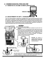
4. COMMISSIONING PROCEDURE
4.1 REMOVE OIL BLEED SCREW (IMPORTANT)
REMOVE
4.2 ADJUSTMENT OF ANTI - CRUSHING SYSTEM
The 746 & 844 automation systems are equipped with an anti-crushing mechanical clutch
which stops the opening / closing if the gate meets an obstacle during its movement. When
the obstacle is removed, the gate resumes its movement until the relevant limit switch trips or
the safety time (TIME OUT ) is over. This torque limiter must be set in compliance with current
local standards. FAAC recommends a force not to exceed 15kgF, measured on the GATE. To
adjust the threshold of the anti-crushing system, proceed as follows:
Model 844
l
l
l
Switch off the power supply.
Access the controller enclosure as shown in section 2.4.3 on
page 10
Remove the cover (1) exposing the motor shaft and unscrew
the cap (2) of the clutch adjusting screw (3). Keep the driving
shaft in position by means of a wrench, and adjust the clutch
adjusting grub screw as shown in the drawing below. To
increase torque, turn the screw clockwise. To decrease
torque, turn the screw counterclockwise.
1
2
3
WARNING: the operator is
supplied with the clutch set to
maximum torque. Initially, the
working torque of the system
must be decreased.
5mm
HEAVIER SPRING FOR
1000kg < GATES < 1800kg
15mm
A/F
LIGHT SPRING FOR
GATES <1000kg
Important: The 844 operator is factory-equipped with a clutch adjustment spring
for gates weighing up to 1000kg. For heavier gates, fit the spring supplied. The
procedure for replacing the spring is shown in the drawing below.
24
Model 746
l
l
l
2
Switch off the power supply.
Access the controller enclosure as shown in
section 2.4.3 on page 10
Swing the controller module outward to expose the
motor shaft (2) Keep the driving shaft in position
with the lever supplied (3), and adjust the clutch
adjusting grub screw (4) as shown in the drawing
below, with a flat screwdriver. To increase torque,
turn the screw clockwise. To decrease torque, turn
the screw counterclockwise.
1
3
+
-
4
4.3 APPLYING MAINS POWER
See also Page 15 Wiring diagram for 1
See also Page 16 Wiring diagram for 3
motor
motor
- APPLY 220V AC POWER
12V DC SUPPLY TO
CP81 CONTROLLER
- CHECK POWER ON INDICATION
ON CP81 CONTROLLER
TO FAAC
TERMINATION
CARD
LIMIT SWITCH
CABLE TO CP81
CP89
CP81
CONTROLLER
x
L N E
220V AC
SUPPLY
GREEN
POWER ON
TO CP81
CONTROLLER
25
Commissioning Procedure continued
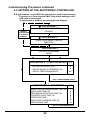
4.4 SETTING UP THE ELECTRONIC CONTROLLER
N.B.
Procedure 1 and 2 MUST be performed on initial commissioning.
Procedure 3 to 5 are required ONLY if the default settings on the
PCB need to be changed.
The procedure is shown in the following block diagram.
PROCEDURE 1
BYPASS
PROCEDURES
IF ALREADY
CORRECT
SET CORRECT LIMIT SWITCH
POLARITY
PROCEDURE 2
CHECK FOR CORRECT MOTOR
DIRECTION
PROCEDURE 3
GET INTO PROGRAMME
MODE
PROCEDURE 4 - FUNCTION SELECT L 1
- AUTOCLOSE ON/OFF, OR
- SELECT MODE OF OPERATION, OR
- SELECT PREFLASHING MODE
2
4
10
EXIT TO PROGRAMME START
PROCEDURE 5 - SET TIMERS
L1
- SELECT PEDESTRIAN OPENING TIME, OR
- AUTOCLOSE TIME, OR
- PEDESTRIAN AUTOCLOSE TIME, OR
- COURTESY LIGHT TIME, OR
- MOTOR RUN TIME
- AUTOCLOSE OVERRIDE TIME, OR
- PREFLASHING TIME
1
3
5
6
7
8
11
EXIT TO PROGRAMME START
26
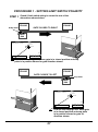
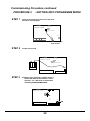
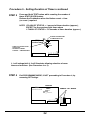
PROCEDURE 1 - SETTING LIMIT SWITCH POLARITY
STEP 1
Check if limit switch wiring is correct for one of the
alternatives shown below
PILLAR
PILLAR
Striker Plate
GATE CLOSES TO RIGHT
FAAC
844
CP81
control card
L1 L2
TEST
STATUS
SET
STATUS LED must go OFF when gate is in closed position and stop
plate is in position shown for gate direction shown.
PILLAR
PILLAR
GATE CLOSES TO LEFT
Stop Plate
FAAC
844
CP81
control card
L1 L2
TEST
STATUS
SET
STATUS LED must go OFF when gate
is in closed position and stop plate
is in position shown for gate for
direction shown.
27
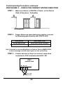
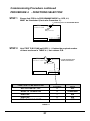
Procedure 1 - Setting Limit Switch Polarity continued
STEP 2
If Step 1 is incorrect then swop limit switch polarity as shown below:
OPTION 1 Motors fitted with FAAC termination board
(See Page 15 for wiring diagram)
To Motor
To Capacitor
TO CP81 MOTOR
CONTROL CARD (M1-M3)
FAAC 844 MPS
Interface PCB
SWOP THESE
TWO WIRES
RIBBON CABLE
TO PROXIMITY
LIMIT SWITCH
From CP89
Interface PCB
OPTION 2 Motors using CP89 power supply ONLY.
220V AC
Supply
(IE NO FAAC TERMINATION BOARD FITTED)
(See also Page 16 for 3 Phase Motor Wiring Diagram)
L
N
E
CP89
POWER SUPPLY
12V DC
TO CP81
Ls Ls
To DOSS
CONNECTOR
ON CP81
SWOP THESE
TWO WIRES
28
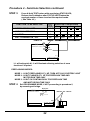
Commissioning Procedure continued
PROCEDURE 2 - CHECK FOR CORRECT MOTOR DIRECTION
STEP 1 - Make sure Gate is in CENTRE of Travel ( or that Rack is
lifted off the pinion - Preferable)
GATE HALFWAY
STEP 2 - Trigger Motor and check that pinion rotation is correct
by comparing gate direction with STATUS LED.
STATUS LED
GATE DIRECTION
SLOW EVEN FLASH
GATE SHOULD BE OPENING
FAST EVEN FLASH
GATE SHOULD BE CLOSING
N.B. If direction is incorrect Stop Motor (or Remove Power) IMMEDIATELY,
or serious damage could be done if gate runs into an End Stop.
STEP 3 - If motor direction in Step 2 is incorrect, swop wires
connected to CP81 terminals marked M1, M3.
AC MOTOR
CP81
control card
M1 M2 M3
SWOP THESE
TWO WIRES
29
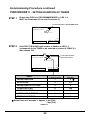
Commissioning Procedure continued
PROCEDURE 3
STEP 1
- GETTING INTO PROGRAMME MODE
Remove the electronics power from the PCB.
All LED' s will extinguish.
CP81
control card
L1
L2
STATUS
SET
Remove 12V Supply
from socket
STEP 2
Fit SET link to PCB.
CP81
control card
L1
L2
STATUS
SET
STEP 3
Reapply power ( Reversal of STEP 1 above ).
Check that STATUS LED flashes 5 times
and then " L 2 " LED must be illuminated
indicating PROGRAMME MODE.
CP81
control card
L1
ON
L2
STATUS
SET
ON
30
Commissioning Procedure continued
PROCEDURE 4 - FUNCTIONS SELECTION
STEP 1
Ensure that PCB is in PROGRAMME MODE i.e. LED, L 2,
MUST be illuminated (if not refer Procedure 3 ).
L 2 indicating PCB is in PROGRAMME MODE
CP81
control card
L1 L2
TEST
STATUS
SET
STEP 2
Hold TEST P/B DOWN until LED, L 1, flashes the required number
of times as shown in TABLE 4.1, then release P/B.
CP81
control card
L 2 will extinguish when
TEST P/B is released.
L1 L2
TEST
STATUS
SET
FUNCTION TO BE SELECTED
NO. OF TIMES L1
IS FLASHING
DEFAULT
STATUS
AUTOCLOSE ON / OFF
2
OFF
MODE OF OPERATION
4
STANDARD
INACTIVE
7
N/A
INACTIVE
9
N/A
PRE - FLASHING MODE
10
OFF
TABLE 4.1
31
Procedure 4 - Functions Selection continued
STEP 3
Press & Hold TEST button while monitoring STATUS LED;
Release the Pushbutton after STATUS LED Flashes the
required number of times to select the required mode.
( See Table 4.2 )
No. of
times
L1 is
flashing
FUNCTION TO BE SELECTED
AUTOCLOSE ON / OFF
2
MODE OF OPERATION
4
REQUIRED NO. OF FLASHES OF
STATUS LED TO SELECT MODE
1
2
ON
OFF
STANDARD CONDOMINIUM
INACTIVE
9
PRE - FLASHING ON / OFF
10
MODE 1
MODE 2
3
4
PIRAC
REVERSING
MODE 3
OFF
TABLE 4.2
CP81
control card
L1 L2
TEST
STATUS
SET
L 1 will extinguish & L 2 will illuminate allowing selection of more
functions if required.
PREFLASHING MODES:
MODE 1 - LIGHT PREFLASHES AT 1 HZ, THEN ACTS AS COURTESY LIGHT
MODE 2 - LIGHT FLASHES AT 1 HZ FOR PREFLASH TIME AND
MOTOR RUN TIME ONLY
MODE 3 - LIGHT ON CONTINUOUSLY FOR PREFLASH TIME
AND MOTOR RUN TIME ONLY
STEP 4 Exit PROGRAMME MODE, if NOT proceeding to procedure 5,
by removing set bridge.
BOTH OFF
CP81
control card
L1 L2
TEST
REMOVE " SET " BRIDGE
STATUS
SET
32
Commissioning Procedure continued
PROCEDURE 5 - SETTING DURATION OF TIMERS
STEP 1
Ensure that PCB is in PROGRAMME MODE i.e. LED, L 2,
MUST be illuminated (if not refer Procedure 3).
L 2 indicating PCB is in PROGRAMME MODE
CP81
control card
L1 L2
TEST
STATUS
SET
STEP 2
Hold TEST P/B DOWN until number of flashes of LED, L1,
corresponds to the TIMER to be selected as shown in TABLE 5.1,
then release P/B.
CP81
control card
L 2 will extinguish when
TEST P/B is released.
L1 L2
TEST
STATUS
SET
NO. OF TIMES LED
L1 SHOULD FLASH
DEFAULT TIME
(SECONDS)
PEDESTRIAN RUN
1
6
AUTOCLOSE
3
15
PEDESTRIAN AUTOCLOSE
5
5
COURTESY LIGHT
6
120
MOTOR RUN TIME
7
40
AUTOCLOSE OVERRIDE
8
3
PREFLASHING TIME
11
5
TIMER
Default time of 6 seconds = Approx. 1.2m (Z20)
1.0m (Z16)
TABLE 5.1
33
Procedure 5 - Setting Duration of Timers continued
STEP 3
Press and Hold TEST button while counting the number of
times STATUS LED flashes;
Release the Pushbutton when the flashes count = time
(or count ) required.
NOTE: 1 FLASH OF STATUS = 1 second of timer duration (approx.),
EXCEPT for the courtesy light timer where
1 FLASH OF STATUS = 10 seconds of timer duration (approx.).
FLASHES CORRESPOND
TO TIMER SELECTED
CP81
control card
L1 L2
TEST
STATUS
- PRESS, HOLD AND COUNT
STATUS LED.
- RELEASE P/B WHEN
FLASHES = TIME REQUIRED
SET
L 1 will extinguish & L 2 will illuminate allowing selection of more
timers or functions. (See Procedure 4 or 5).
STEP 4
Exit PROGRAMME MODE, if NOT proceeding to Procedure 4, by
removing SET bridge.
BOTH OFF
CP81
control card
REMOVE " SET " BRIDGE
L1 L2
TEST
STATUS
SET
34
PROCEDURE 6 - PROGRAM THE CP81 TO DEFAULT SETTINGS
1. REMOVE POWER.
2. FIT THE "SET" LINK.
3. CONNECT "PED" AND "FRX" TO "COM".
4. RECONNECT POWER. L1 AND L2 WILL ILLUMINATE.
5. REMOVE THE POWER.
6. REMOVE THE "SET" LINK AND DISCONNECT "PED" AND "FRX"
FROM "COM".
7. THE CARD IS NOW PROGRAMMED TO DEFAULT SETTINGS AS
SHOWN IN TABLES 4.1 (see page 31) AND 5.1 (see page 33)
(GATE END POINTS ARE NOT AFFECTED)
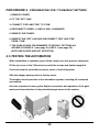
4.5 TESTING THE AUTOMATION
When installation is complete, press fit the covers over the operator fixing bars.
Fit the top cover to the 746 and secure with the screws and bushes supplied.
Close and lock the controller enclosure cover of the 844 operator
Affix the danger warning decal to the top cover.
Thoroughly check operation of the automation system, including all connected
accessories.
Give the customer the user guide. Explain correct use and operation of the gate
motor and draw attention to the potential danger zones of the system.
35
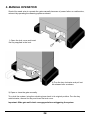
5. MANUAL OPERATION
Should the need arise to operate the gate manually because of power failure or malfunction,
release it by operating the releasing system as shown:
1) Open the lock cover and insert
the key supplied in the lock.
2) Turn the key clockwise and pull out
the release lever as shown.
3) Open or close the gate manually.
To re-lock the system, bring the unlocking lever back to its original position. Turn the key
anticlockwise, remove the key and close the lock cover.
Important: Slide gate until clutch re-engages before retriggering the system.
36
6. MAINTENANCE
OIL LEVEL
Periodically check the oil level. For medium to low duty cycles, it is advisable to perform the
check annually. Where more intensive use has occured, check every 6 months.
The tank is accessed by removing the oil filler cap.
The oil level can be checked visually: it should soak the copper coil of the electric motor.
If topping up is needed, use only FAAC XD 220 oil.
OIL FILLER
CAP
PROTECTIVE
CAP
ma
x. o
ma
il le
vel
x.
e
lev
oil
l
ANTI-CRUSHING AND SAFETY DEVICES
It is also necessary to ensure that the mechanical anti-crushing clutch is functioning and is
correctly set to deliver no more than 15kgF. The safety devices installed on the system
must be checked every 6 months.
7. REPAIRS
If any repair is needed, contact your authorized Centurion repair centre.
37
CENTURION
THE AUTOMATIC CHOICE
CENTURION SYSTEMS (PTY) LTD HEAD OFFICE:
TEL: +27 (0)11 699-2400, FAX: +27 (0)11 704-3412 or 462-6669
148 EPSOM AVENUE, NORTH RIDING
P.O. BOX 506, CRAMERVIEW, 2060
SOUTH AFRICA
WEB: http://www.centsys.co.za
General information e-mail: info@centsys.co.za
FOR TECHNICAL SUPPORT CONTACT:
SOUTH AFRICA
EAST RAND. . . . . . . . . . . . . . . (011) 397-6401
DURBAN . . . . . . . . . . . . . . . . . (031) 701-9583
NELSPRUIT . . . . . . . . . . . . . . . (013) 752-8074/5
PRETORIA . . . . . . . . . . . . . . . . (012) 362-8819/8893
CAPE TOWN . . . . . . . . . . . . . . (021) 447-1295
PORT ELIZABETH. . . . . . . . . . . (041) 581-6994/5
EAST LONDON . . . . . . . . . . . . . . (043) 743-4923
BLOEMFONTEIN . . . . . . . . . . . . . (051) 448-1714
KIMBERLEY . . . . . . . . . . . . . . . . . (053) 832-3231
VEREENIGING . . . . . . . . . . . . . . . (016) 422-5667
AFRICA
ECHO-LINE, NAMIBIA . . . . . . . . . . . . . . . . . . . . . . . . . . . . . . . . . . . . . . . . . . . . . . . . . . . . . . . . . . . . . Tel: (61) 220-8309
MOLECULAR CONSULTANTS, NIGERIA . . . . . . . . . . . . . . . . . . . . . . . . . . . . . . . . . . . . . . . . . . . . . . . Tel: 803-3123182
SECURITY DISTRIBUTORS, ZIMBABWE . . . . . . . . . . . . . . . . . . . . . . . . . . . . . . . . . . . . . . . . . . . . . . . . Tel: (4) 795-873
SEKANYOLYA TIMBER WORKS, UGANDA. . . . . . . . . . . . . . . . . . . . . . . . . . . . . . . . . . . . . . . . . . . . . . . Tel: (41) 231-40
EUROPE
AUTOMATISME BATIMENT, FRANCE. . . . . . . . . . . . . . . . . . . . . . . . . . . . . . . . . . . . . . . . . . . . . . . . . Tel: (1) 697-93120
CROWN AXXESS LTD U.K. UNITED KINGDOM . . . . . . . . . . . . . . . . . . . . . . . . . . . . . . . . . . . . . . . . Tel: (1483) 450-011
NESTOR, BELGIUM . . . . . . . . . . . . . . . . . . . . . . . . . . . . . . . . . . . . . . . . . . . . . . . . . . . . . . . . . . . . . . . Tel: (9) 380-4020
NORTH AMERICA
BILLY GATES, CANADA . . . . . . . . . . . . . . . . . . . . . . . . . . . . . . . . . . . . . . . . . . . . . . . . . . . . . . . . . . Tel: (250) 334-1553
AUSTRALASIA
ABA GATES, WESTERN AUSTRALIA . . . . . . . . . . . . . . . . . . . . . . . . . . . . . . . . . . . . . . . . . . . . . . . . . Tel: (8) 933-03061
DOMINATOR SYSTEMS, NEW ZEALAND . . . . . . . . . . . . . . . . . . . . . . . . . . . . . . . . . . . . . . . . . . . . . . Tel: (3) 384-5145
ICBT, VICTORIA . . . . . . . . . . . . . . . . . . . . . . . . . . . . . . . . . . . . . . . . . . . . . . . . . . . . . . . . . . . . . . . . . . Tel: (3) 933-54213
ROTECH, QUEENSLAND . . . . . . . . . . . . . . . . . . . . . . . . . . . . . . . . . . . . . . . . . . . . . . . . . . . . . . . . . . Tel: (7) 326-47330
SA GATES, SOUTHERN AUSTRALIA . . . . . . . . . . . . . . . . . . . . . . . . . . . . . . . . . . . . . . . . . . . . . . . . . Tel: (8) 826-64235
SECURITE DU PACIFIQUE, NEW CALEDONIA . . . . . . . . . . . . . . . . . . . . . . . . . . . . . . . . . . . . . . . . . . . . . . Tel: 283-760
INDIAN OCEAN
SECULOGIX LTD, MAURITIUS . . . . . . . . . . . . . . . . . . . . . . . . . . . . . . . . . . . . . . . . . . . . . . . . . . . . . . . . . . Tel: 467-8509
SECURITE AUTOMATISMES REUNION, REUNION . . . . . . . . . . . . . . . . . . . . . . . . . . . . . . . . . . . . . . . . . . Tel: 280-368
ASIA & PACIFIC
VAST VIDEO, MALAYSIA . . . . . . . . . . . . . . . . . . . . . . . . . . . . . . . . . . . . . . . . . . . . . . . . . . . . . . . . . . . Tel: (3) 214-34931
BLT ASSOCIATES, THAILAND . . . . . . . . . . . . . . . . . . . . . . . . . . . . . . . . . . . . . . . . . . . . . . . . . . . . . . . Tel: (2) 691-6793