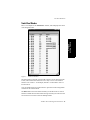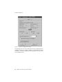
1
AltiWare™ OE
Release 4.0
Getting Started Manual
Revised 09/2000 4403-0003-4.0
WARNING!
Toll fraud is committed when individuals unlawfully gain access to
customer telecommunication systems. This is a criminal offense.
Currently, we do not know of any telecommunications system that is
immune to this type of criminal activity. AltiGen Communications, Inc.
will not accept liability for any damages, including long distance charges,
which result from unauthorized and/or unlawful use. Although AltiGen
Communications, Inc. has designed security features into its products, it is
your sole responsibility to use the security features and to establish security
practices within your company, including training, security awareness, and
call auditing.
NOTICE
While every effort has been made to ensure accuracy, AltiGen
Communications, Inc. will not be liable for technical or editorial errors or
omissions contained within the documentation. The information contained
in this documentation is subject to change without notice.
This documentation may be used only in accordance with the terms of the
AltiGen Communications, Inc. License Agreement.
AltiGen Communications, Inc.
47427 Fremont Blvd.
Fremont, CA 94538
Telephone: 510-252-9712
Fax:
510-252-9738
E-mail:
info@altigen.com
Web site:
www.altigen.com
TRADEMARKS
AltiGen, AltiServ, AltiWare, AltiSpan, AltiReach, AltiLink, AltiConsole,
AltiAdmin, Zoomerang and Dynamic Messaging are trademarks or
registered trademarks of AltiGen Communications, Inc.
All other brand names mentioned are trademarks or registered trademarks
of their respective manufacturers.
Copyright © AltiGen Communications, Inc. 1998, 2000. All rights
reserved.
Printed in U.S.A. 09/2000 Part Number 4403-0003-4.0
Table of Contents
Contents
Liability & Warranty
Limitation of Liability . . . . . . . . . . . . . . . . . . . . . . . . . . . . . . . . . vii
FCC and Industry Canada Compliance . . . . . . . . . . . . . . . . . . . . vii
Statement . . . . . . . . . . . . . . . . . . . . . . . . . . . . . . . . . . . . . . . . . . vii
FCC Requirements . . . . . . . . . . . . . . . . . . . . . . . . . . . . . . . . . . . . viii
Service Requirements. . . . . . . . . . . . . . . . . . . . . . . . . . . . . . . . . viii
Equipment Attachment Limitations - Industry Canada . . . . . . . . ix
Port Identification, Facility Interface and Service Order Codes . . x
Disruption of Network . . . . . . . . . . . . . . . . . . . . . . . . . . . . . . . . . xi
Direct Inward Dialing (DID) Answering Supervision. . . . . . . . . xi
Safety . . . . . . . . . . . . . . . . . . . . . . . . . . . . . . . . . . . . . . . . . . . . . xii
Important Safety Instructions. . . . . . . . . . . . . . . . . . . . . . . . . . . xii
Safety with Electricity . . . . . . . . . . . . . . . . . . . . . . . . . . . . . . . . xii
UL Regulatory Safety Requirements . . . . . . . . . . . . . . . . . . . . . xiv
Warranty . . . . . . . . . . . . . . . . . . . . . . . . . . . . . . . . . . . . . . . . . . . . xix
What The Warranty Covers . . . . . . . . . . . . . . . . . . . . . . . . . . . . xix
How Long is the Warranty Effective . . . . . . . . . . . . . . . . . . . . . xix
Who the Warranty Protects . . . . . . . . . . . . . . . . . . . . . . . . . . . . xix
What the Warranty Does Not Cover . . . . . . . . . . . . . . . . . . . . . xix
How to Get Service . . . . . . . . . . . . . . . . . . . . . . . . . . . . . . . . . . . xx
Effect of State Law. . . . . . . . . . . . . . . . . . . . . . . . . . . . . . . . . . . xxi
Sales Outside the U.S.A. . . . . . . . . . . . . . . . . . . . . . . . . . . . . . . xxi
Preface: About this Manual
Target Audience . . . . . . . . . . . . . . . . . . . . . . . . . . . . . . . . . . . . . xxiii
Using this Manual . . . . . . . . . . . . . . . . . . . . . . . . . . . . . . . . . . . xxiii
Related Publications . . . . . . . . . . . . . . . . . . . . . . . . . . . . . . . . . . xxiv
CHAPTER 1
System and Hardware Requirements . . . . . . . . . . . . . . . . . 1
System Requirements . . . . . . . . . . . . . . . . . . . . . . . . . . . . . . . . . . . .
Selecting the AltiServ Platform . . . . . . . . . . . . . . . . . . . . . . . . . . .
Minimum System Requirements . . . . . . . . . . . . . . . . . . . . . . . . . .
System Limitations. . . . . . . . . . . . . . . . . . . . . . . . . . . . . . . . . . . . .
Power Requirements . . . . . . . . . . . . . . . . . . . . . . . . . . . . . . . . . . .
Uninterruptible Power Supply (UPS). . . . . . . . . . . . . . . . . . . . . . .
Proper Grounding and Loop Current . . . . . . . . . . . . . . . . . . . . . . .
1
1
1
2
3
4
4
AltiWare OE 4.0 Getting Started Manual iii
Table of Contents
Operating Environment . . . . . . . . . . . . . . . . . . . . . . . . . . . . . . . . .
Heat Factor. . . . . . . . . . . . . . . . . . . . . . . . . . . . . . . . . . . . . . . . . . .
Installing a Cooling Fan. . . . . . . . . . . . . . . . . . . . . . . . . . . . . . . . .
AltiGen Board Specifications . . . . . . . . . . . . . . . . . . . . . . . . . . . . .
Functional Specifications. . . . . . . . . . . . . . . . . . . . . . . . . . . . . . . .
AltiGen Board Installation. . . . . . . . . . . . . . . . . . . . . . . . . . . . . . .
AltiGen Board Options . . . . . . . . . . . . . . . . . . . . . . . . . . . . . . . . .
Software Licensing . . . . . . . . . . . . . . . . . . . . . . . . . . . . . . . . . . . . .
4
5
5
6
6
7
8
9
CHAPTER 2
Software Installation . . . . . . . . . . . . . . . . . . . . . . . . . . . . . . 11
AltiWare as an NT Service . . . . . . . . . . . . . . . . . . . . . . . . . . . . . .
Preparing to Install AltiWare OE . . . . . . . . . . . . . . . . . . . . . . . . .
Firewall Considerations . . . . . . . . . . . . . . . . . . . . . . . . . . . . . . . .
Installing AltiWare OE on Windows 2000 . . . . . . . . . . . . . . . . .
AltiWare OE - New Installation . . . . . . . . . . . . . . . . . . . . . . . . . .
AltiWare OE - Upgrading . . . . . . . . . . . . . . . . . . . . . . . . . . . . . . .
Software License Capacity Upgrades . . . . . . . . . . . . . . . . . . . . .
Windows Emergency Repair Disk . . . . . . . . . . . . . . . . . . . . . . . .
Installing AltiAdmin on Remote Systems . . . . . . . . . . . . . . . . . . .
Running AltiWare Administrator . . . . . . . . . . . . . . . . . . . . . . . . .
Shutting Down AltiServ when Changing or Adding Hardware . .
Transferring the AltiServ to Another Server Chassis . . . . . . . . . .
AltiWare Uninstall . . . . . . . . . . . . . . . . . . . . . . . . . . . . . . . . . . . . .
Downgrade Procedure . . . . . . . . . . . . . . . . . . . . . . . . . . . . . . . . . .
11
12
13
14
14
15
16
17
18
19
19
20
21
21
CHAPTER 3
Getting Around AltiAdmin . . . . . . . . . . . . . . . . . . . . . . . . . 23
AltiAdmin: the AltiWare Administrator . . . . . . . . . . . . . . . . . . . .
The AltiWare Administrator Main Window . . . . . . . . . . . . . . . . .
The Main Menu . . . . . . . . . . . . . . . . . . . . . . . . . . . . . . . . . . . . . .
Quick Access Toolbar . . . . . . . . . . . . . . . . . . . . . . . . . . . . . . . . . .
Status Bar. . . . . . . . . . . . . . . . . . . . . . . . . . . . . . . . . . . . . . . . . . .
The View Windows . . . . . . . . . . . . . . . . . . . . . . . . . . . . . . . . . . . .
Boards View Window . . . . . . . . . . . . . . . . . . . . . . . . . . . . . . . . .
Extension View Window. . . . . . . . . . . . . . . . . . . . . . . . . . . . . . .
Trunk View Window . . . . . . . . . . . . . . . . . . . . . . . . . . . . . . . . . .
WorkGroup View Window . . . . . . . . . . . . . . . . . . . . . . . . . . . . .
Call Log View Window. . . . . . . . . . . . . . . . . . . . . . . . . . . . . . . .
IP Trunk Current Traffic Statistics Window . . . . . . . . . . . . . . . .
Logging in for the First Time . . . . . . . . . . . . . . . . . . . . . . . . . . . .
iv
AltiWare OE 4.0 Getting Started Manual
23
24
24
25
26
27
27
28
29
30
31
32
33
Table of Contents
Logging In and Out . . . . . . . . . . . . . . . . . . . . . . . . . . . . . . . . . . . 33
Changing the Password . . . . . . . . . . . . . . . . . . . . . . . . . . . . . . . . 33
Stop the AltiGen Switching Service . . . . . . . . . . . . . . . . . . . . . . 33
CHAPTER 4
Initial Configuration . . . . . . . . . . . . . . . . . . . . . . . . . . . . . . 35
A Note About Applying Edits to One or Multiple Objects . . . . . 35
Extension and Workgroup Configuration . . . . . . . . . . . . . . . . . . . 36
System Configuration . . . . . . . . . . . . . . . . . . . . . . . . . . . . . . . . . . 37
Auto Attendant Configuration . . . . . . . . . . . . . . . . . . . . . . . . . . . . 37
Audio Peripheral Configuration . . . . . . . . . . . . . . . . . . . . . . . . . . . 38
Trunk Configuration . . . . . . . . . . . . . . . . . . . . . . . . . . . . . . . . . . . 38
Out Call Routing . . . . . . . . . . . . . . . . . . . . . . . . . . . . . . . . . . . . . . 38
Setting Up DID/DNIS . . . . . . . . . . . . . . . . . . . . . . . . . . . . . . . . . . 39
Using Professionally Recorded Greetings . . . . . . . . . . . . . . . . . . . 40
CHAPTER 5
T1/PRI Configuration . . . . . . . . . . . . . . . . . . . . . . . . . . . . . 41
T1/PRI for AltiWare OE . . . . . . . . . . . . . . . . . . . . . . . . . . . . . . . .
Triton T1/PRI Board . . . . . . . . . . . . . . . . . . . . . . . . . . . . . . . . . . .
Service Parameters for T1 . . . . . . . . . . . . . . . . . . . . . . . . . . . . . . .
T1 Service Request Information . . . . . . . . . . . . . . . . . . . . . . . . .
CSU/DSU Requirements . . . . . . . . . . . . . . . . . . . . . . . . . . . . . . .
Service Parameters for PRI . . . . . . . . . . . . . . . . . . . . . . . . . . . . . .
PRI Service Request Information. . . . . . . . . . . . . . . . . . . . . . . . .
CSU/DSU Requirements . . . . . . . . . . . . . . . . . . . . . . . . . . . . . . .
Troubleshooting - Common Symptoms . . . . . . . . . . . . . . . . . . . . .
41
41
42
42
43
44
44
45
45
CHAPTER 6
VoIP Setup . . . . . . . . . . . . . . . . . . . . . . . . . . . . . . . . . . . . . . 47
Voice over IP for AltiWare OE . . . . . . . . . . . . . . . . . . . . . . . . . . .
Triton VoIP Board . . . . . . . . . . . . . . . . . . . . . . . . . . . . . . . . . . . . .
Features . . . . . . . . . . . . . . . . . . . . . . . . . . . . . . . . . . . . . . . . . . . .
Network Configuration Guidelines for VoIP . . . . . . . . . . . . . . . . .
Setting Up AltiServ-to-AltiServ IP Network . . . . . . . . . . . . . . . . .
Troubleshooting - Common Symptoms and Solutions . . . . . . . . .
Poor Voice Quality. . . . . . . . . . . . . . . . . . . . . . . . . . . . . . . . . . . .
Cannot Make a Connection . . . . . . . . . . . . . . . . . . . . . . . . . . . . .
IP Trunk Does Not Appear in Trunk View . . . . . . . . . . . . . . . . .
Index . . . . . . . . . . . . . . . . . . . . . . . . . . . . . . . . . . . . . . . . . . . . . .
47
47
48
48
50
52
52
53
53
55
AltiWare OE 4.0 Getting Started Manual v
Table of Contents
Readers Comment Form . . . . . . . . . . . . . . . . . . . . . . . . . . . . . . 61
vi
AltiWare OE 4.0 Getting Started Manual
Liability & Warranty
Liability & Warranty
Limitation of Liability
Except for personal injury, direct damages to tangible personal property
proximately caused by AltiGen products and liability otherwise expressly
assumed in a written agreement signed by AltiGen, the liability of AltiGen,
its affiliates, suppliers, and authorized resellers for any claims, losses,
damages, or expenses from any cause whatsoever (including acts of
omission of third parties), regardless of the form of action, whether in
contract, tort or otherwise, shall not exceed an amount equal to the lesser of
the direct damages proven or the purchase price of the product. In no event
shall AltiGen or its affiliates, suppliers, or authorized resellers be liable for
incidental, consequential or any other indirect loss or damage (including
lost profits or revenues) incurred in connection with the product. This
limitation of liability shall survive failure of the exclusive remedy set forth
in the limited warranty referred to in this book under “Warranty”.
FCC and Industry Canada Compliance
This section describes the requirements for compliance with Federal
Communications (FCC) Rules and Industry Canada CS-03 standard.
Statement
This equipment has been tested and found to be in compliance with the
limits for a Class B digital device pursuant to Part 15 and Part 68 of the
FCC Rules. These limits are designed to provide reasonable protection
against harmful interference when the equipment is operated in a
commercial or residential environment. This equipment generates and can
radiate radio frequency energy and, if not installed and used in accordance
with the instruction manual, may cause harmful interference to radio
communications.
This Class B digital apparatus meets all requirements of the Canadian
interference-causing Equipment Regulations. Cet apparell numérique de la
Classe B respecte toutes les exigences du Reglement sur le materiel
brouilleur du Canada.
AltiWare OE 4.0 Getting Started Manual vii
Liability & Warranty
FCC Requirements
1. The Federal Communications Commission (FCC) has established
Rules which permit this device to be directly connected to the telephone
network. Standardized jacks are used for these connections. This
equipment should not be used on party lines or coin phones.
2. If this device is malfunctioning, it may also be causing harm to the
telephone network; this device should be disconnected until the source
of the problem can be determined and until repair has been made. If this
is not done, the telephone company may temporarily disconnect
service.
3. The telephone company may make changes in its technical operations
and procedures; if such changes affect the compatibility or use of this
device, the telephone company is required to give adequate notice of
the changes. You will be advised of your rights to file a complaint with
the FCC.
4. If the telephone company requests information on what equipment is
connected to their lines, inform them of:
a. The telephone number to which this unit is connected.
b. The ringer equivalence number. [0.0B]
c. The USOC jack required. [RJ11C]
d. The FCC Registration Number. [see label on board]
e. Industry Canada (Industrie Canada) Certification Number.
[see label on board]
Items (b) and (d) are indicated on the label. The Ringer Equivalence
Number (REN) is used to determine how many devices can be connected
to your telephone line. In most areas, the sum of the RENs of all devices on
any one line should not exceed five (5.0). If too many devices are attached,
they may not ring properly.
Service Requirements
In the event of equipment malfunction, all repairs should be performed by
our Company or an authorized agent. It is the responsibility of users
requiring service to report the need for service to AltiGen or to one of our
authorized agents. Service can be obtained at your Authorized AltiGen
Dealer.
viii AltiWare OE 4.0 Getting Started Manual
Liability & Warranty
Equipment Attachment Limitations - Industry Canada
NOTICE: The Canadian Industry Canada label identifies certified
equipment. This certification means that the equipment meets certain
telecommunications network protective, operational, and safety
requirements. The Department does not guarantee the equipment will
operate to the user’s satisfaction.
Before installing this equipment, users should ensure that it is permissible
to be connected to the facilities of the local telecommunications company.
The equipment must also be installed using an acceptable method of
connection. In some cases, the company’s inside wiring associated with the
single line individual service may be extended by means of a certified
connector assembly (telephone extension cord). The customer should be
aware that compliance with the above conditions may not prevent
degradation of service in some situations.
Repairs to the certified equipment should be made by an authorized
Canadian maintenance facility designated by the supplier. Any repairs or
alterations made by the user to this equipment, or equipment malfunctions,
may give the telecommunications company cause to request the user to
disconnect the equipment.
Users should ensure for their own protection that the electrical ground
connections of the power utility, telephone lines and internal metallic water
pipe system, if present, are connected together. This precaution may be
particularly important in rural areas.
Caution! Users should not attempt to make such connections
themselves, but should contact the appropriate electrical inspection
authority, or electrician, as appropriate.
The Load Number (LN) assigned to each terminal device denote the
percentage of the total load to be connected to a telephone loop which is
used by the device, to prevent overloading. The termination on a loop may
consist of any combination of devices subject only to the requirement that
the total of the Load Number of all the devices does not exceed 100.
WARNING! Changes or modifications to this unit not expressly
approved in writing by AltiGen Communications, Inc. could void the
user’s authority to operate this equipment.
AltiWare OE 4.0 Getting Started Manual ix
Liability & Warranty
Port Identification, Facility Interface and Service Order
Codes
The following tables list the manufacturer’s network interface port
designations., Facility Interface Codes (FIC), Ringer Equivalence Number
(REN) or Service Codes and the network jacks for the required facilities.
The facility interface and service order codes are with reference to the
codes specified in Table 5 of Appendix D of FCC Form 730 Application
Guide of January 1998.
1. Quantum Network Trunk Interfaces for Loop Start, Ground Start and
DID Services
Registration
Status
Manufacturer Port
Identifier
Facility Interface
Code (FIC)
REN
Network
Jack
2. Network Digital Trunk Interfaces for Digital Services
Triton T1/PRI
Registration
Status
Manufacturer Port
Identifier
Facility Interface
Code (FIC)
Service
Order Code
(SOC)
Network
Jack
*The Triton T1/PRI interface connects to the Public Switched Telephone Network through an
FCC registered NCTE which specifies the type of network jack to be used.
x
AltiWare OE 4.0 Getting Started Manual
Liability & Warranty
Disruption of Network
If the Triton T1/PRI disrupts the telephone network, the telephone
company can discontinue your service temporarily. If possible, the
telephone company will notify you in advance. If advance notice is not
practical, they will notify you as soon as possible. You are also informed of
your right to file a complaint with the FCC.
Direct Inward Dialing (DID) Answering Supervision
Customers allowing Triton T1/PRI, Quantum or Triton Analog Station
Analog DID to be operated in such a manner as to not provide for proper
answer supervision is a violation of Part 68 of the FCC rules.
Proper answer supervision is when:
a. The AltiServ system returns answer supervision to the PSTN when
DID calls are:
— Answered by the called station.
— Answered by the attendant.
— Routed to a recorded announcement that can be administered by the
customer.
b. The AltiServ system returns answering supervision on all DID calls
forwarded to the PSTN.
AltiWare OE 4.0 Getting Started Manual xi
Liability & Warranty
Safety
The following information is included in this publication for the use and
safety of installation and maintenance personnel.
Important Safety Instructions
•
Read all of the instructions before attempting to operate the equipment
and before connecting the power supply.
•
Always follow basic safety precautions to reduce the risk of fire,
electrical shock and injury to persons.
•
To prevent fire or shock hazard, do not expose the unit to rain,
moisture or install this product near water. Never spill liquid of any
kind on this product.
•
Never push objects of any kind into this product through module
openings or expansion slots, as they may touch dangerous voltage
points or short out parts, which could result in the risk of fire or
electrical shock.
•
Refrain from opening the cabinet as there are high voltage components
inside. Refer servicing to qualified service personnel. If you are a
qualified service personnel, power down everything before opening.
•
Do not attach the power supply cord to building surfaces. Do not allow
anything to rest on the power cord or allow the cord to be abused by
persons walking on it.
•
To protect this equipment from overheating, do not block the slots and
openings in the module housings that are provided for ventilation.
Safety with Electricity
DANGER
Do not take chances with your life. Follow these safety
guidelines carefully.
High Voltages
•
Observe all safety regulations and read the warnings, cautions, and
notes posted on the equipment.
xii
AltiWare OE 4.0 Getting Started Manual
Liability & Warranty
•
Find the switch to power off the cabinet. Read the posted instructions.
•
Ensure that equipment can not be powered from another source or
controlled from a different circuit breaker or disconnecting switch.
•
When a procedure requires that you power off the system:
— Lock the wall box-switch in the off position.
— Attach a DO NOT OPERATE tag to the wall box-switch.
•
Never assume that the power is turned off. Always check to ensure that
a circuit does not have power.
Note:
Unit must have ground wire attached if trunks are attached and
system is unplugged.
•
Do not work alone. Work with another person who knows the
locations of the power-off switches, especially if you are working with
exposed electrical circuits. (See note above.)
•
Follow the instructions in the manual carefully, especially when
working with circuits that are powered. Disconnect power when
instructed to do so in the procedures.
•
Disconnect all power before working near power supplies unless
otherwise instructed by a maintenance procedure.
•
Disconnect all power before installing changes in machine circuits
unless otherwise instructed by a maintenance procedure.
•
High voltages capable of causing shock are used in this equipment. Be
extremely careful when measuring high voltages and when servicing
cards, panels, and boards while the system is powered on.
•
Do not wear jewelry or other metal objects when working on the
equipment.
•
When possible, work with one hand so that a circuit is not created.
•
Use caution when installing or modifying telephone lines. Never
install telephone wiring during an electrical storm.
•
Never install a telephone jack where it can get wet unless the jack is
specifically designed for wet conditions.
•
Never touch un-insulated telephone wires or terminals unless the
telephone line has been disconnected at the network interface.
AltiWare OE 4.0 Getting Started Manual xiii
Liability & Warranty
UL Regulatory Safety Requirements
Host Computer
1.
Model AltiGen/AltiServ apparatus is approved for connection to
Telecommunications Systems specified in these instructions for use
subject to the conditions set out in them. Any other usage will
INVALIDATE this approval.
2.
The host machine shall be “CE” marked, with the internal ISA and PCI
slots operating at SELV in accordance with EN60950, 1992, issue 2,
+A4.
3.
This apparatus MUST be professionally installed.
4.
The host machine MUST be hardwired earthed in accordance with
EN60950, 1992, issue 2, +A4, 1997, cl. 6.2.1.2 with an earth wire from
the host machine earthing terminal to the building earth.
5.
The host machine SELV circuit is connected to the protective earthing
terminal in accordance with EN60950 cl. 2.5.
6.
The host machine ISA bus pins B1, B10 or B31 (edge connectors on
CPU mother-board/backplane) MUST be less than 0.1 Ohms to host
machine earthing terminal.
,6$ EXV
,6$ EXV
7.
AltiGen complies with PCI Board specifications Rev. 2.1 (5V 32-bit).
8.
The power required by the host machine and the total of all adapter
cards installed within the host environment, together with any
ancillary apparatus, shall not exceed the power specification of the
host machine.
9.
It is essential that, when other option cards are introduced which use
or generate a hazardous voltage, the minimum creepages and
clearances specified in the table below are maintained. A hazardous
voltage is one that exceeds 42.4V peak AC or 60V DC. If you have any
xiv
AltiWare OE 4.0 Getting Started Manual
Liability & Warranty
doubt, seek advice from a competent engineer before installing other
adapters into the host machine.
Clearance (mm)
Creepage (mm)
Voltage used or generated by
host or other cards
For a host or other expansion card fitted in the host, using or generating
voltages greater than 300V (rms or dc), advice from a competent safety
engineer must be obtained before installation of the relevant equipment.
Any other usage will INVALIDATE the approval of the apparatus, if as a
result, it then ceases to conform to the standards against which approval
was granted.
Approved Hardware
1.
Host computer, with an earthing terminal, which is “CE” marked to
include compliance to LVD and EMC European Directives.
2.
Computer chassis will comprise the following as minimum:
a. Pentium PC, 5 expansion slots, SVGA, IDE, 1.0 GB, keyboard
b. Color monitor, non-interlaced, 1024 x 768
c. Mouse, two button
d. Memory, at least 128 MB RAM
e. CD ROM
f. Floppy disk drive
g. Modem 28,800 baud, approved by BABT (optional)
3.
AltiGen Quantum cards, Rev. D:
a. ALTI-CD0804UD
b. ALTI-CD0408UD
c. ALTI-CD0012UD
AltiWare OE 4.0 Getting Started Manual xv
Liability & Warranty
d. ALTI-DID0408UD
4.
AltiGen Triton cards
a. ALTI-TTAS-12
b. ALTI-TTIP-4
c. ALTI-TTIP-8
d. ALTI-TTT1
e. ALTI-TTRS-12
Operating Software
Provided by AltiGen: AltiWare OE Rev. 4.0 or above.
Power Fail
In the event of a power fail, the first telephone extension on each card
(except for the CD0012UD) is connected directly to the first exchange
line, thus permitting access to dial the emergency services. This telephone
must be powered from the PSTN or have local battery backup capable of
calling the emergency services four hours after the power fail event
occurs.
Wiring
All wiring must conform to National Telecommunications Wiring Regulations and the National Electrical Wiring Regulations.
Additional Requirements for Australia
1.
Warning: For safety reasons, connect only ACA or AUSTEL
permitted or certified equipment to the telephone ports (RJ11) of the
patch panel or the audio in/out jacks on the AltiServ card.
2.
Warning: THIS EQUIPMENT MUST ONLY BE INSTALLED
AND MAINTAINED BY SERVICE PERSONNEL
Additional Requirements for USA and Canada
1.
The interconnecting trunk line cord should be at least size 26AWG.
2.
This trunk card must be fitted in host equipment with fire enclosures
complying with the flammability requirements of sub-clause UL1950/
CSA C22: 1995 4.4.3. In addition, the card must be separated from
xvi AltiWare OE 4.0 Getting Started Manual
Liability & Warranty
internal materials of flammability class or lower by at least 25 mm of
air Class V-1 or better. Also, the card must be separated from openings
in the top or sides of the enclosure by at least 25 mm of air or by a
barrier of flammability Class V-1 or better unless the openings comply
with one of the following:
— not exceed 5 mm in any direction, or
— not exceed 1 mm in width, regardless of length
3.
Any holes in the chassis not conforming to the above should be
covered with a metal perforated screen, with holes not exceeding 5 mm
diameter, fixed internally.
Instructions for Hardwired Earth Connection
1.
A supplementary equipment earthing conductor is to be installed
between the product or system and earth, that is, in addition to the
equipment earthing conductor in the power supply cord.
2.
The supplementary equipment earthing conductor may not be smaller
in size (8 AWG minimum, recommend 6 AWG) than the unearthed
branch-circuit supply conductors. The supplementary equipment
earthing conductor is to be connected to the product at the terminal
provided, and connected to earth in a manner that will retain the earth
connection when the power supply cord is unplugged. The connection
to earth of the supplementary earthing conductor shall be in
compliance with the appropriate rules for terminating bonding jumpers
in Park K of Article 250 the National Electrical Code, ANSI/NFPA 70,
and Article 10 of Part I of the Canadian Electrical Code, Part I, C22.1.
Termination of the supplementary equipment earthing conductor is
permitted to be made to building steel, to a metal electrical raceway
system or to any earthed item that is permanently and reliably
connected to the electrical service equipment earthed.
3.
Bare, covered or insulating earthing conductors are acceptable. A
covered or insulating earth conductor must have a continuous outer
finish that is either green, or green with one or more yellow stripes.
4.
Earthing conductor shall not run through steel conduit.
AltiWare OE 4.0 Getting Started Manual
xvii
Liability & Warranty
UL Hardware Preparation
Prepare the hardware as follows ensuring that the relevant manufacturer’s
installation instructions are complied with. If you have doubts about any of
these, call your supplier.
1.
This apparatus must be professionally installed.
2.
Select a “CE” computer chassis according to the Safety Requirements
above, ensuring that it has an external marked earth point.
3.
The host machine ISA bus pins B1, B10 or B13 MUST be tested to
ensure that there is less than 0.1 Ohms to the earthing terminal.
4.
The host machine PCI bus pins complies with PCI Board
specifications Rev. 2.1 (5V 32-bit).
5.
Prepare the chassis, in accordance with the PC manufacturers
instructions, to receive the necessary PC cards, ensuring the
installation of extension cards does not result in non-conformance to
the Safety Requirements above.
6.
When installing a system using AltiGen’s cards, note that the
continued compliance to the LVD and EMC EU Directives at the
system level is the responsibility of the system supplier.
7.
Prepare above cards ensuring all jumpers are set according to the
manufacturer’s instructions.
8.
Attach suitable grounded ESD wrist strap between wrist and earth.
9.
Follow the manufacturer’s instruction and install above cards into PC.
10. Note: If more than three cards are using the MVIP, ensure that the
Quantum or Triton board set as board zero is installed at one end of the
MVIP cable and the board at the far end of the MVIP cable has its
switch set to terminated (switch closed).
11. Replace PC outer case.
12. Connect a fixed earth from the PC to a suitable premises fixed earthing
point. Note that the earth cable must be at least the same gauge as the
live wire of the main cord and fixed to the earth terminal and the rear
of the PC. (6 AWG recommended, 8 AWG minimum.)
13. Connect cable supplied with AltiServ to the “D-type sub-miniature”
(25 pin) connector on the AltiServ card and the connector to the
Modular RJ-11 Patch Panel.
14. Connect the building telecommunication wiring to the RJ-11 sockets.
15. Building telecommunication wiring should be installed according to
the National Wiring Regulations for Telecommunications.
xviii AltiWare OE 4.0 Getting Started Manual
Liability & Warranty
Warranty
What The Warranty Covers
AltiGen Communications warrants its hardware products to be free from
defects in material and workmanship during the warranty period. If a
product proves to be defective in material or workmanship during the
warranty period, AltiGen Communications will, at its sole option, repair,
refund or replace the product with a like product.
How Long is the Warranty Effective
All AltiGen Communications products are warranted for one (1) year for
all parts from the date of the first end user purchase.
Who the Warranty Protects
This warranty is valid only for the first end user purchaser.
What the Warranty Does Not Cover
1. Any product on which the serial number has been defaced,
modified or removed.
2. Damage, deterioration or malfunction resulting from:
a) Accident, misuse, neglect, fire, water, lightning, or other acts of
nature, unauthorized product modification, or failure to follow
instructions supplied with the product.
b) Repair or attempted repair by anyone not authorized by AltiGen
Communications.
c) Any damage of the product due to shipment.
d) Removal or installation of the product.
e) Causes external to the product, such as electric power fluctuations
or failure.
f) Use of supplies or parts not meeting AltiGen Communications’
specifications.
g) Normal wear and tear.
h) Any other cause which does not relate to a product defect.
AltiWare OE 4.0 Getting Started Manual xix
Liability & Warranty
3. Shipping, installation, set-up and removal service charges.
How to Get Service
End user customers should contact your Authorized AltiGen Dealer for
service.
Authorized AltiGen Dealers must follow the steps below for service:
1. Take or ship the product (shipment prepaid) to your AltiGen
distributor or to AltiGen Communications, Inc.
All materials being returned to AltiGen must have an associated RMA
number. RMA numbers are issued by AltiGen Customer Service and
can be obtained by calling 1-888-ALTIGEN (258-4436) or faxing an
RMA form (See Appendix D in the System Administration Manual) to
510-252-9738, attention to Customer Service. AltiGen reserves the
right to refuse return of any material that does not have an RMA
number. The RMA number should be clearly marked on the
outside of the box in which the material is being returned. Please see
the example below:
Attn.: RMA # 123
AltiGen Communications, Inc.
47427 Fremont Blvd.
Fremont, CA 94538
Upon authorization of return, AltiGen will decide whether the
malfunctioning product will be repaired or replaced.
2. To obtain warranty service, you will be required to provide:
a) the date and proof of purchase
b) serial number of the product
c) your name and company name
d) your shipping address
e) a description of the problem.
3. For additional information contact your AltiGen Dealer or AltiGen
Communications, Inc. directly at 1-888-ALTIGEN (258-4436) or
via e-mail at service@altigen.com.
xx
AltiWare OE 4.0 Getting Started Manual
Liability & Warranty
Effect of State Law
This warranty gives you specific legal rights, and you may also have other
rights which vary from state to state. Some states do not allow limitations
on implied warranties and/or do not allow the exclusion of incidental or
consequential damages, so the above limitations and exclusions may not
apply to you.
Sales Outside the U.S.A.
For AltiGen Communications products sold outside of the U.S.A., contact
your AltiGen Communications dealer for warranty information and
services.
AltiWare OE 4.0 Getting Started Manual xxi
Liability & Warranty
xxii
AltiWare OE 4.0 Getting Started Manual
Preface
Preface: About this Manual
This guide describes how to set up and configure the AltiServ system for
the first time or for upgrading from a previous version of AltiWare OE.
Target Audience
This guide is designed for the dealers, administrators and technicians that
are responsible for installation, configuration, and administration of the
AltiServ system.
Using this Manual
This guide contains the following chapters:
•
Chapter 1, “System and Hardware Requirements,” describes the
system and hardware specifications needed, based on the number of
trunks and extensions required.
•
Chapter 2, “Software Installation,” describes software specifications of the AltiServ system.
•
Chapter 3,“Getting Around AltiAdmin,” describes how navigate
the AltiWare Administrator application used to configure and maintain the AltiServ system.
•
Chapter 4, “Initial Configuration,” includes short, easy-to-use
steps to quickly configure the AltiServ system.
•
Chapter 5, “T1/PRI Configuration,” describes how to set up the
digital T1 or PRI option in AltiWare.
•
Chapter 6, “VoIP Setup,” describes how to configure and administer
the Voice over IP option in AltiWare.
This publication also contains an index and a readers’ comment form.
AltiWare OE 4.0 Getting Started Manual xxiii
Preface
Related Publications
Related publications include:
• AltiWare OE System Administration Manual
• AltiServ User Guide
• AltiConsole User Guide
• Informal Call Center Manual
• AltiView User Guide
• AltiAgent User Guide
• AltiSupervisor User Guide
xxiv
AltiWare OE 4.0 Getting Started Manual
System Requirements
System and Hardware
Requirements
System Requirements
AltiServ hardware requirements depend on the number of extensions
(lines) and trunks your site requires. Refer to Table 2 on page 3 for AltiServ
platform selection.
Selecting the AltiServ Platform
In order to maintain your AltiServ system integrity and plan for future site
expansion, you should take into consideration the following points before
selecting the AltiServ platform:
• Reliability
• Expandability
• System performance
Microsoft Windows 2000 and NT Support
The AltiServ platform can be installed on a Microsoft Windows NT 4.0
(Service Pack 6a or higher) or a Microsoft Windows 2000 operating
system. See “AltiWare OE Installation on Windows 2000” on page
“Installing AltiWare OE on Windows 2000” on page 14 for more
information.
Minimum System Requirements
To accommodate Quantum and Triton telephony boards with AltiWare
software, the AltiServ system requires the following minimum system
configuration:
• IBM/PC compatible system with adequate number of full-size ISA
and PCI slots
• Microsoft Windows NT Server 4.0 with Service Pack 6a (or higher)
installed or Microsoft Windows 2000 Server.
AltiWare OE 4.0 Getting Started Manual 1
System & HardWare
Requirements
CHAPTER 1
System and Hardware Requirements
You can download Service Pack 6a from the Microsoft web site at
http://www.microsoft.com/ntserver/nts/downloads/recommended/
SP6.
• Microsoft Internet Information Services (ver. 5 or higher for NT,
ver. 3 or higher for Windows 2000)—web server software that is
supplied with Windows—must be installed prior to installing
AltiWare. This is necessary so that AltiReach, the web-based call
handling application, can run.
• Channel Service Unit for T1/PRI
Hardware selection may have to be adjusted based on the following
variables:
• The number of AltiGen telephony boards required
• The maximum AltiServ extension and trunk traffic anticipated
• The number of simultaneous client software connections.
Table 3, “Individual Board Power Requirements” shows the AltiServ
system requirements guidelines depending on the number of AltiGen
boards that will be installed.
System Limitations
•
A total 10 Triton T1/PRI, VoIP, and Resource boards can be installed
in one system.
•
Up to 6 Triton VoIP boards can be installed on the same system.
•
Up to 4 Triton T1/PRI boards can be installed on the same system. The
board ID must be in the range of 0 to 3.
•
Up to 2 Triton Resource boards can be used on the same system.The
board ID must be in the range of 0 to 15.
2
AltiWare OE 4.0 Getting Started Manual
System Requirements
"#$%& '
12V Requirement
5V Requirement
Hard Disk
Controller
Available
Memory
CPU Type
Power Supply
System Selection Guidelines
Number of
Quantum or Triton
Boards per System
Table 2.
! (
! "#$%& ' (
*+% '
%+ ,+"#$
&&#&
(
-
! *+% '
.", %+
,+"#$
&/*"&
(
(
( )&&
Power Requirements
The power requirements are as follows for each individual board:
Table 3.
Individual Board Power Requirements
Board
5V
12V
Slot Type
*1A@12V is provided by power connector.
AltiWare OE 4.0 Getting Started Manual 3
System & HardWare
Requirements
AltiServ System Requirement Guidelines
System and Hardware Requirements
Uninterruptible Power Supply (UPS)
Using a UPS prevents power fluctuations and surges on power sources
from utilities. Windows NT files can be corrupted as a result of power
failure or improper system shutdown.
Caution! Corrupted files may not be repairable and may require reinstallation of Windows NT and AltiWare. To protect your system from
surges and power outages, it is strongly recommended that an adequate
UPS (providing between 600VA and 1000VA) and power surge protector
is used with the system.
Proper Grounding and Loop Current
Proper grounding is essential for any PBX system. This is a simple but
very important step and is highly recommended. Run a wire from the
server chassis to earth ground. Don’t wait for a problem to arise before
taking this step. Make sure this is one of the first things you do before
turning the AltiGen system on.
Also, check the loop current on incoming trunks before connecting any
AltiGen boards. The desired loop current measurement is 25mA-28mA.
This is another essential step to ensure proper operation of AltiGen
systems. For more information on loop current issues, please refer to the
Tech Support section of AltiGen’s web site at http://www.altigen.com.
Operating Environment
Before you set up and use the system, consider the environment in which
the system will reside:
•
Choose a work surface large enough to accommodate the entire
system.
•
Use a flat, stable work surface with enough space around it for proper
air circulation. For proper heat dissipation, a fan is recommended in
front of the AltiGen telephony boards to ensure sufficient air flow. Be
sure the fan filter is clean and does not block the air flow.
4
AltiWare OE 4.0 Getting Started Manual
System Requirements
Table 4.
AltiGen Board Operating Environmentals
Description
Specification
Operating Temperature
0° to + 50° C
Storage Temperature
-20° to +70° C
Relative Humidity
10% to 80% non-condensing
Heat Factor
Internal system temperature must not exceed the specified operating
temperature. If more than two AltiGen telephony boards are installed in the
system, then additional cooling fans are suggested. These fans need to
effectively reduce heat and increase air flow to the AltiGen telephony
boards to insure system reliability.
Installing a Cooling Fan
If more than two AltiGen telephony boards are installed into the AltiServ
system, then an additional cooling fan will be required. This fan needs to
effectively reduce heat and increase air flow to the AltiGen telephony
boards to insure system dependability and reliability. To install a cooling
fan into the AltiServ system, read the instructions included with the fan
unit.
AltiWare OE 4.0 Getting Started Manual 5
System & HardWare
Requirements
The following table contains the operating specifications for the AltiGen
telephony board.
System and Hardware Requirements
AltiGen Board Specifications
AltiGen telephony boards are installed into the AltiServ motherboard
expansion slots or can be used individually as a third-party developer
application platform. To obtain maximum performance reliability and
long-term, fault-free operation, you must maintain power and
environmental conditions specified in this section.
Functional Specifications
Quantum Board
The Quantum telephony board has the following functional characteristics:
•
MVIP compatible
•
256 Port Non-Blocking Switch Matrix
•
Audio Peripheral Input & Output
•
Jumper Free Configuration
•
On-Board Telephony Power Supply for Quantum D Board
•
Automatic Power Failure Transfer
•
ISA Bus
Triton Analog Station Board
The Triton Analog Station telephony board has the following functional
characteristics:
•
MVIP Compatible
•
256 Port Non-Blocking Switch Matrix
•
Jumper Free Configuration
•
PCI Bus
•
12 analog extensions
•
Compliant with ZIAIAIA464
Note:
6
When the board is configured for audio input, the first port cannot
be used for an extension.
AltiWare OE 4.0 Getting Started Manual
System Requirements
The Triton VoIP telephony board has the following functional
characteristics:
•
MVIP-90 Compatible
•
256 Port Full-Duplex Switch Matrix
•
Jumper Free Configuration
•
PCI Bus
Triton T1/PRI Board
The Triton T1/PRI telephony board, which supports either T1 or PRI
through software configuration, has the following functional
characteristics:
•
MVIP Compatible
•
256 Port Non-Blocking Switch Matrix
•
Jumper Free Configuration
•
PCI Bus
Triton Resource Board
The Triton Resource board has the following functional characteristics:
•
MVIP Compatible
•
Jumper Free Configuration
•
12 ports for silent monitoring and barge-in
•
PCI Bus
AltiGen Board Installation
For instructions on how to install Triton and Quantum boards, please refer
to the Quick Installation Guide which is provided with every AltiGen
board package.
AltiWare OE 4.0 Getting Started Manual 7
System & HardWare
Requirements
Triton VoIP Board
System and Hardware Requirements
AltiGen Board Options
Table 5 lists the available AltiGen telephony board modules. This selection
allows you to optimize your system based on the trunk/extension mix
required at your site.
Table 5.
AltiGen Telephony Board Options
Board
8
Model Number
Description
Quantum
ALTI-CD0408UDSPH001
4 trunks and 8 extensions
Quantum
ALTI-CD0804UDSPH001
8 trunks and 4 extensions
Quantum
ALTI-CD0012UDSPH001
12 extensions
Quantum
ALTI-DID0408UDSPH001
4 DID trunks and 8 extensions
Triton
ALTI-TTAS-12
12 extensions (stations)
Triton
ALTI-TTIP-4
4 VoIP trunks or extensions
Triton
ALTI-TTIP-8
8 VoIP trunks or extensions
Triton
ALTI-TTT1
1 T1 or 1 PRI
Triton
ALTI-TTRS
12 ports for supervisor
monitoring
AltiWare OE 4.0 Getting Started Manual
System Requirements
AltiWare OE 4.0 station licenses can be obtained singly or in combination
depending on the number of physical extensions or stations. Customers
purchase one or more of these packages for the desired capacity of physical
extensions.
Table 6.
Software Licensing Options
Software
Model Number
# of Stations License
OE 4.0
ALTI-OELIC-008
8 stations license
OE 4.0
ALTI-OELIC-016
16 stations license
OE 4.0
ALTI-OELIC-024
24 stations license
OE 4.0
ALTI-OELIC-032
32 stations license
OE 4.0
ALTI-OELIC-064
64 stations license
OE 4.0
ALTI-OELIC-096
96 stations license
OE 4.0
ALTI-OELIC-128
128 stations license
To upgrade the number of station licenses, you must purchase additional
licensing from your Authorized AltiGen Dealer. Refer to Chapter 2 Software Installation for more information on software licensing upgrade
installation.
Session Licensing - Client Connections
AltiGen OE 4.0 client software (AltiView 4.0, Center 4.0, WebCall and
AltiReach) accesses the AltiWare OE 4.0 server software using IP
connections which are counted by the AltiWare server as simultaneous
sessions. Even Partner and system integrator applications using AltiGen’s
ActiveX control take up one session connection for each application
connecting to AltiWare via AltiLink+. Consequently, the maximum total
number of simultaneous sessions most likely to occur should be accounted
for by purchasing this maximum in session licenses. Licenses can be
combined to reach the total required; the maximum is 48 sessions.
AltiWare OE 4.0 Getting Started Manual 9
System & HardWare
Requirements
Software Licensing
System and Hardware Requirements
Table 7.
Simultaneous Session Licenses
Software
Model Number
# of Stations License
OE 4.0
ALTI-SL004
4 session license
OE 4.0
ALTI-SL008
8 session license
OE 4.0
ALTI-SL016
16 session license
OE 4.0
ALTI-SL024
24 session license
OE 4.0
ALTI-SL032
32 session license
OE 4.0
ALTI-SL048
48 session license
10
AltiWare OE 4.0 Getting Started Manual
AltiWare as an NT Service
CHAPTER 2
Software Installation
•
AltiWare OE - contains the AltiWare Administrator as well as the
switching service, SMTP/POP3 server, messaging agent, Exchange
integration, AltiBackup that can be installed on any Windows NT
Server with Service Pack 6a (or higher) or on Window 2000 Server on
the LAN to control the AltiServ system(s).
•
AltiAdmin - contains the AltiWare Administrator that can be installed
on any Windows NT with Service Pack 6a (or higher) or Windows
2000 on the LAN to control the AltiServ system(s).
•
Documentation - contains the AltiWare OE Getting Started and
System Administration Manuals and the AltiServ User Guide in the
Adobe Acrobat PDF format.
•
README.TXT - contains late breaking information about AltiWare
OE. Please be sure to take a moment to read this brief file which
contains very important information you need to be aware of
before you install AltiWare OE.
AltiWare as an NT Service
AltiWare components such as the switching, messaging agent, and
AltiBackup are NT services that are automatically launched when
AltiWare OE is installed and the AltiServ system is restarted. Benefits of
AltiWare as an NT service:
•
The AltiWare Administrator user interface does not have to be tied to
the switching service so that if there is a problem with the user
interface, the switching service is not affected.
•
Remote administration is possible through AltiAdmin.
Do not tamper with the startup settings of AltiGen services in
the Services applet of the Control Panel. Only the AltiGen
Switching Service should be set to Automatic; all other
AltiGen services should be set to Manual.
AltiWare OE 4.0 Getting Started Manual 11
Software Installation
The AltiWare OE software is provided on a CD-ROM and contains the
following components or folders:
Software Installation
Preparing to Install AltiWare OE
The following is a step-by-step procedure for installing or upgrading the
AltiWare OE software from the AltiWare OE Release 4.0 CD-ROM.
It should take about 15 to 20 minutes to install the AltiWare OE software
program. Before you begin installation, however, please note the
following:
•
NT Service Pack 6a. In a Windows NT environment, Service Pack 6a
(or higher) is required and must be installed before AltiWare OE 4.0
can be installed or upgraded.
•
User Account. During installation, a user account is created
automatically to run AltiWare services. Do not delete this account or
change its password. The account name is in the form:
(user name: AltiGen_<servername>)
•
Third party applications. AltiWare OE must be installed before any
third party applications on a Windows NT with Service Pack 6a (or
higher) or Windows 2000 system. Contact your third party application
vendor(s) to find out if an upgrade is required for their product to work
with the AltiWare OE release you are about to install.
•
Installing over old versions. If AltiWare 3.5X is installed, there is no
need to uninstall it before installing Altiware OE. If, for any reason,
you do uninstall AltiWare, you must back up and restore all custom
prompts. You can do this by copying all files located at
\altiserv\phrases\langcustom\phase0XXX (where XXX is a number
from 001 to 999) to your network drive and then copying them back
onto the server after installation is complete.
If AltiWare 2.x is installed, first upgrade to 3.5, then upgrade to 4.0.
•
Backup prior to install. Before upgrading your system from
AltiWare Release 2.1, 3.0, or 3.5 you should back up all the
configuration information to a floppy or a different location, such as
the network drive. (The user can do this by using the backup utility OR
copy the contents of \altiserv\db\ and \altiserv\Phrases\LangCustom
folders to a backup location.) This backup information is also required
when downgrading back to these prior releases.
12
AltiWare OE 4.0 Getting Started Manual
Preparing to Install AltiWare OE
Firewall Considerations
If you are using a firewall in the AltiWare OE 4.0 environment, here are the
network ports used:
Network Ports Used by AltiWare OE
Client
Server
TCP
AltiAdmina
AltiWare DCOM
135
AltiConsole
AltiLink
10015
AltiControl
AltiLink+
10025
AltiReach
AltiLink
10015
AltiView/AltiAgent
AltiLink+
VM Service
10025
10028
Supervisor
AltiLink+
Internal/External
CDR Logger
10025
10027
CDRSearch
AltiLink+
Internal/External
CDR Logger
10025
10027
TAPI Client
TAPI Gateway
10026
VoIP H.323/H.225
VoIP Message
Waiting
VoIP H.323/H.225
VoIP Message
Waiting
VoIP H.245
VoIP H.245
1720
49151
(Quicknet
IP ext only)
From 49152
to 49248
VoIP RTP
VoIP RTP
Web Client
AltiLink+
NetMeeting Chat
plus VoIP ports
described above
UDP
135
From 49152
to 49248
10025
1720
a. It is recommended that this be run only in an intranet.
AltiWare OE 4.0 Getting Started Manual 13
Software Installation
Table 3.
Software Installation
Installing AltiWare OE on Windows 2000
•
AltiWare OE supports the Windows 2000 Server platform. Earlier
software releases must be upgraded to OE 3.5A or OE 4.0 to work with
the Windows 2000 Server platform.
•
If installing AltiWare OE for the first time and wish to use the software
with Windows 2000, you must already be running Windows 2000
server prior to the AltiWare software installation.
AltiWare OE - New Installation
Before you begin, have the following information at hand:
•
The 20-digit software license key (located on the End User License
Agreement).
•
The system home area code.
•
The extension length.
The extension length, which is from 2 – 7 digits, is the number
of digits for all extension numbers. All extensions in the
AltiServ configuration must be the same length.
Note that you cannot change the extension length once the first
extension is configured, which is something you do later running the
AltiWare Setup. To change the extension after extensions are
configured requires re-configuring the entire system or deleting all the
extensions already configured.
To install AltiWare OE:
1.
Make sure you have prepared for installation as described beginning
on page 12.
2.
Login to Windows NT or Windows 2000 as a domain user account
which has both local and domain administrator privileges.
If your machine is a stand-alone server, you need to login as a local
administrator account.
3.
Insert the AltiWare OE CD-ROM into the CD-ROM drive.
4.
Select and read the Readme.txt file.
5.
After reading the Readme.txt file, click on SETUP.EXE in the
AltiWare OE folder.
14
AltiWare OE 4.0 Getting Started Manual
AltiWare OE - Upgrading
Follow the instructions on the AltiWare installation wizard to
complete the file setup.
7.
After installation, you must shut down and reboot the computer in
order to activate the installed AltiWare Services.
8.
Create the Windows NT or Windows 2000 Emergency Repair Disk.
Refer to “Windows Emergency Repair Disk” on page17.
AltiWare OE - Upgrading
Before you begin, you’ll need to have at hand the 20-digit software license
key located on the back of the End User License Agreement.
There is no need to uninstall the earlier version of AltiWare software.
However, if you decide uninstall the previous version, first backup your
custom phrases from the \altiserv\phrases\LangCustom directory. To
uninstall click the Uninstall icon in the AltiWare program group. The
uninstall does not remove the AltiWare configuration and messages.
Shutting Down the AltiGen Switching Service
Before installing this upgrade on the AltiServ system, please make sure that
the AltiAdmin application and the AltiGen Switching Service are not
running.
You can shutdown the AltiGen Switching Service Com Server and the
AltiAdmin application at the same time by running AltiAdmin, logging in
and selecting Services
Shutdown Switching.
Note that stopping the AltiGen Switching Service COM Server will
automatically stop all the auxiliary services.
These are the Windows 2000 / NT services distributed with AltiWare:
•
AltiGen Switching Service COM Server
•
AltiGen Messaging Service COM Server
•
AltiGen SMTP Service COM Server
•
AltiGen POP3 Service COM Server
•
AltiGen Exchange Integration Service COM Server
•
AltiGen Backup/Restore Service
•
AltiGen Keep Up Service
•
AltiGen Internal Logger Server
AltiWare OE 4.0 Getting Started Manual 15
Software Installation
6.
Software Installation
Option: Shutting Down Switching as a Windows 2000 / NT Service
Optionally, if you’re not running AltiAdmin, you can shut down the
services using Windows 2000 / NT Services.
1.
Do one of the following:
- On the Windows 2000 desktop, select Start
Administrative Tools
Services.
Programs
- On the NT desktop, Open the Control Panel and double-click Services.
2.
Highlight AltiGen Switching Service COM Server.
3.
Stop the service.
If the status column is empty, proceed to the next step. If status column
says Started, double-click the listing to open the Properties dialog
box, then click the Stop button followed by the OK button to close the
dialog.
To complete the upgrade
Follow the steps listed under “AltiWare OE - New Installation” on page 14.
Software License Capacity Upgrades
In AltiWare OE, a software license allows you to increase the capacity for
the following:
•
Physical and IP extensions - A Quantum board can provide 4, 8 or 12
extensions (depending on the type of Quantum board) and the Triton
Analog Station board provides 12 extensions. You may increase the
number of software supported extensions up to the maximum available
by entering in the 8, 16, 32, 64, 96 or 128 station licenses. Each license
you enter adds to the previous total.
Each IP extension needs a license. For example, if a user has a station
in the office, a station at home and a station at the Lake Tahoe Conference House, licenses for three stations are required.
•
Sessions - AltiWare OE includes a single session license. You may
increase the number of concurrent client sessions by 4, 8, 16 or 32
session licenses. Each license you enter adds to the previous total.
16
AltiWare OE 4.0 Getting Started Manual
Windows Emergency Repair Disk
Capacity Upgrade Procedures
To increase the number of physical extensions, follow these steps:
1.
Insert the AltiWare OE CD into the CD drive.
2.
Run the SETUP.EXE in the AltiWare OE folder to run the setup
program.
3.
Select the Upgrade Port License option and click OK to open an
AltiWare OE Setup window.
4.
Enter the 20-digit software license key located on the End User
License Agreement shipped with your upgrade package and click
Next.
5.
After the code is validated, the system will confirm that the upgrade
was successful and ask if you wish to add additional licenses. You can
add other licenses now or by repeating these this set of steps from the
beginning at another time.
6.
You can verify the new number of extensions when you run AltiAdmin
by selecting About AltiWare… on the Help menu, then clicking the
License Information button to view a window that displays licenses
and session information.
Windows Emergency Repair Disk
After installing AltiWare, you should create the Windows Emergency
Repair Disk, even if you have previously created a repair disk. This repair
disk is needed to repair any corrupted Windows files.
•
To create the disk on the NT, choose Run from the Windows NT Start
button and type rdisk at the prompt.
•
For Windows 2000, use the Accessories
System
Tools
Backup utility program and select Create an Emergency
Repair Disk from the Tools menu.
AltiWare OE 4.0 Getting Started Manual 17
Software Installation
In AltiWare OE 4.0, the Center Server license allows you to enable this
add-on option for call center features. (For more information on the
Informal Call Center Option, refer to the Informal Call Center Manual
shipped with the option package.)
Software Installation
Installing AltiAdmin on Remote Systems
AltiAdmin contains the AltiWare Administrator application that can be
installed on any Windows NT Server or Workstation 4.0 system with
Service Pack 6a (or higher), or Windows 2000 and a network connection.
AltiAdmin does not support Windows 95 or Windows 98.
When you install AltiAdmin on a machine that is not an
AltiServ server, it does not contain the switching, SMTP/
POP3 server, messaging agent, AltiBackup, Exchange
integration services that are included in the full AltiWare OE installation
described above. Remote AltiAdmin does not utilize the System Data
Management or Shutdown Switching Service functions on the AltiServ
system.
AltiAdmin provides the ability to manage the AltiServ system from a
remote client system on the LAN. If there is no firewall on the LAN where
AltiServ resides, AltiAdmin can be installed and used to manage AltiServ
over the Internet from a remote site as well.
To install AltiAdmin on a non-AltiServ PC for the first time,
1.
Insert the AltiWare CD-ROM into the appropriate drive.
2.
Run SETUP.EXE from the AltiAdmin folder.
3.
Follow the instructions on the window.
4.
To open AltiWare Administrator, refer to “Running AltiWare
Administrator” on page 19.
18
AltiWare OE 4.0 Getting Started Manual
Shutting Down AltiServ when Changing or Adding Hardware
Running AltiWare Administrator
To run AltiWare Administrator,
Choose Programs from the Windows NT Start button and click on
AltiWare Administrator in the AltiWare or AltiAdmin folder.
2.
If you are opening AltiAdmin, enter the server name when prompted.
If you are logging into AltiAdmin at a remote site to administer
AltiServ over the Internet, enter the IP address (e.g. 100.100.100.100)
of the AltiServ system when prompted for the server name. Multiple
AltiServ systems can be managed at a single location with an
AltiAdmin open for each AltiServ system.
3.
Login by Selecting the Services
Login or clicking the
Login icon—the left-most icon in the Toolbar. The Login
Password window prompts you to enter the password and
click OK. The system default password is “22222”. You should
change the system password as soon as possible to ensure system
security. For more information, refer to “Logging in for the First
Time” on page 33.
Once you are logged in, you can configure the AltiServ system. To start
system configuration, go to “A Note About Applying Edits to One or
Multiple Objects” on page 35.
Shutting Down AltiServ when Changing or Adding
Hardware
When you add or change hardware, follow these procedures to back up and
shut down the AltiServ system. The best time to do this is during off
hours—the system should be idle.
1.
Using the AltiAdmin application System Data Management function,
backup the AltiServ data, messages, and custom files using the
procedures in the AltiWare System Administration Manual chapter on
“System Data Management.”
2.
In AltiAdmin, shutdown the AltiGen Switching Service and exit
AltiAdmin, as described in “Shutting Down the AltiGen Switching
Service” on page 15.
3.
Shut down and power down the Windows 2000 / NT system using the
standard Windows shutdown procedure.
AltiWare OE 4.0 Getting Started Manual 19
Software Installation
1.
Software Installation
Transferring the AltiServ to Another Server Chassis
If you transfer the AltiServ system to another platform—for example, to
upgrade or expand your system or for other reasons—you need to backup
the database, move the telephony boards, install the AltiWare software, and
restore the database to the new platform.
The new platform should have access via a LAN to the system to which you
backed up the files from the old platform.
To transfer the system to another platform:
1.
Back up the system files, then shut down and unplug the AltiServ
system computer, following the “Shutting Down AltiServ when
Changing or Adding Hardware” on page 19.
2.
Remove the computer cover, following the computer manual
instructions.
3.
Disconnect the MVIP internal data cable.
4.
Label and disconnect the DB-25 to 50 pin Telco cable(s) from the
board I/O connectors.
5.
Remove the telephony board(s) from the original system.
6.
Install the board(s) into the new system.
7.
Install the AltiWare OE software as described beginning with
“Preparing to Install AltiWare OE” on page 12.
8.
Restore the AltiServ system database as follows:
a. Run AltiAdmin and select Services
System Data
Management to run the data management utility.
b. Click the Restore icon to open a dialog that allows you to choose
files to restore.
c. Make sure all the Component check boxes are selected.
d. In the Restore From drop-down list, select the drive and directory
to which you backed up the files in Step 1.
e. Click OK to start the restore.
f. Once the restore is complete, click the Exit icon to exit the data
manager.
g. Shut down and exit the system by selecting Shutdown Switching
from the Services menu.
9.
Reboot the system; there may be configuration restores that require
reboots to take effect.
20
AltiWare OE 4.0 Getting Started Manual
AltiWare Uninstall
AltiWare Uninstall
In the event that the auxiliary services were not stopped, please stop them
one at a time using the Start
Administrative
Programs
Tools
Services applet.
Then launch the Uninstall program by clicking the Uninstall AltiWare OE
icon in the AltiWare program folder.
Downgrade Procedure
To downgrade, you must have been running the earlier version prior to the
4.0 installation. To download to OE 3.5, you must have been running OE
3.5 prior to the 4.0 installation. You’ll also need to remove the new Triton
boards and re-install the old ones, since the new boards are designed to run
with AltiWare 4.0 or higher.
Downgrading from AltiWare OE 4.0 to OE 3.5 or lower requires that you
restore backed up files from the prior release. Before you begin, you should
have backed up all the prior release configuration information as described
for installation preparation on page 12.
To downgrade, follow these steps.
1.
Stop the AltiGen services as described on page 15.
2.
Uninstall OE AltiWare 4.0 as described on page 21.
3.
If they are installed, uninstall AltiView, AltiConsole, AltiAdmin, and
CDR Search, following the manual procedures for those applications.
4.
Delete the following components using the Control Panel
Remove Program:
Add/
• AltiView VM Service
• Quantum SP
• Triton SP
• Triton Analog SP
• Triton T1 PRI SP
• Triton VoIP SP.
5.
Remove the “\altiserv” directory and any subdirectories.
AltiWare OE 4.0 Getting Started Manual 21
Software Installation
To back out the upgrade, be sure to stop all AltiWare-related services
before uninstallation. To do this, run AltiAdmin, log in, and select
Shutdown Switching from the Services menu.
Software Installation
6.
Shut down Windows NT and power down the computer.
7.
Remove Triton Analog Station boards, Triton Resource Boards, and
8-Port Triton IP boards.
8.
Put the previously removed older Quantum/Triton boards back into the
computer.
9.
Reboot the computer.
10. Reinstall Restore OE 3.5A and the 3.5 version of other client/server
programs such as AltiView, AltiConsole, AltiAdmin, and CDR
Search.
11. Reboot the computer.
12. Login to AltiAdmin to restore AltiWare OE 3.5A database files via
System Data Management.
13. Reboot the computer to restart and run AltiWare OE 3.5A.
22
AltiWare OE 4.0 Getting Started Manual
AltiAdmin: the AltiWare Administrator
CHAPTER 3
Getting Around AltiAdmin
AltiAdmin: the AltiWare Administrator
This chapter describes how to configure and administer the AltiServ system
using the AltiWare Administrator system application software.
AltiAdmin can be used at the AltiServ system or on any other system on the
LAN for remote maintenance. On a remote Windows NT or Windows 2000
client system on the LAN, AltiAdmin allows control of one or more
AltiServ systems. System Data Management, and Stop Switching Service
cannot be performed over the LAN.
Instructions for installing AltiAdmin are described in “Installing
AltiAdmin on Remote Systems” on page 18.
AltiWare OE 4.0 Getting Started Manual 23
Getting Around
AltiAdmin
AltiWare Administrator, or AltiAdmin, allows you to configure
sophisticated switching and messaging functions using windows that guide
you through the configuration steps for each feature.
Getting Around AltiAdmin
The AltiWare Administrator Main Window
Once you run the AltiWare Administrator, the first window you see is the
AltiWare Administrator main window.
Figure 1.
AltiWare Administrator main window
At the top you see the Main Menu bar and below that, the Quick Access
Toolbar. At the bottom is a status bar that contains information on the
current runtime status.
The main window contains separate child windows, or different views of
the system. There are five default views: the boards, extensions, trunks,
workgroups and call traffic.
Additionally, if appropriate, you can also run a view of IP Trunk Traffic,
which is the 6th window, at the bottom in the above example.t
The Main Menu
The Main Menu functions are as follows:
•
Services—application management
Login and logout, change password, backup and restore functions, and
shutdown the switching service.
•
Management—system setup, configuration and maintenance
24
AltiWare OE 4.0 Getting Started Manual
Quick Access Toolbar
Opens windows to work with boards, trunks, extensions, out call
routing, Auto Attendant, MVIP clock, audio peripheral, and Quantum
Board channels.
•
Reports—system Status and Traffic Statistics
System Summary, System Log, and IP Traffic Statistics.
•
Diagnostic—reserved for use by authorized technical personnel
•
View—show or hide AltiAdmin desktop elements
Show or hide the various windows, the toolbar and status bar.
•
Help—online help and AltiWare version and license information
Getting Around
AltiAdmin
Quick Access Toolbar
Figure 2.
AltiAdmin Quick Access Toobar
The toolbar contains icons representing shortcuts to frequently accessed
functions: logging on and off, opening board, trunk, extension, and Auto
Attendant configuration windows, displaying the system summary and
system log windows, and getting online help. From left to right, the toolbar
icons are as follows:
Logout and login. Click the light blue monitor at the left
to login. When you do, the monitor grays out and the logout
monitor at the right turns black. The monitors provide a
clear indication of login status. While you’re logged in,
anyone at the keyboard can modify system settings.
System Configuration icon: opens the System Configuration
window to set system-wide options and parameters, the same
function as Management
System Configuration….
Extension Configuration icon: opens the Extension
Configuration window, the same function as Management
Extension Configuration….
Trunk Configuration icon: opens the Trunk Configuration
window, the same function as Management
Trunk
Configuration….
AltiWare OE 4.0 Getting Started Manual 25
Getting Around AltiAdmin
Auto Attendant Select icon: opens the Auto Attendant Select
window, the same function as Management
Auto
Attendant Select….
System Summary icon: opens the System Summary window, the
same function as Report
System Summary….
System Log icon: opens the System Log window, the same
function as Report
System Log….
System Help icon: opens the on-line help system main window,
the same function as Help
Help….
About icon: opens the About AltiWare window which displays
license and file information as well as version information, the
same function as Help
About AltiWare….
Status Bar
The information at the bottom of the window in the Status Bar displays
informational and status messages such as name of the operator, disk usage
status, status of external logging, current time, and other data.
26
AltiWare OE 4.0 Getting Started Manual
The View Windows
The View Windows
As noted in the discussion on page 24, the AltiAdmin main window hosts
a number of child windows, which are called view windows in AltiWare
because they provide various views into the internal system setup and
active status.
Boards View Window
Figure 3.
Boards window
Each board is represented by a board icon, followed by the logical ID ([0],
the sequential location of the board), card model number (name of the
board) and physical ID (the ID set using the dial on the faceplate of the
board). For example, QtmAM0408U-1 is a Quantum board with four (4)
trunk ports and eight (8) extension ports.
AltiWare OE 4.0 Getting Started Manual 27
Getting Around
AltiAdmin
The graphic below is an example of a Boards window. This window
displays the AltiServ Quantum or Triton boards hardware status. It displays
the card location in the ISA or PCI slots and board model numbers.
Getting Around AltiAdmin
Extension View Window
Here’s an example of an Extension View window, which displays the
status of all assigned extensions.
Figure 4.
Extension View window
The radio button to the left of each extension number is green when the
extension is idle, and red when the extension is not ready or in use.The
location number (i.e. 01:04) identifies the card ID and port (channel)
number on the board. For example, in location 01:04, the card ID is 1 and
the port number is 4.
You can double click any extension number to open the Extension
Configuration window for the selected extension.
The Reset button resets the selected extension to the idle status. When you
click the Reset button, a small dialog box opens, asking if you want to
continue with the reset and displaying the selected extension number and
the name of the person assigned to the extension.
You can click the Reset button without selecting an extension, and then
type in the extension number for the extension to reset.
28
AltiWare OE 4.0 Getting Started Manual
The View Windows
Trunk View Window
Here’s an example of the Trunk View window, which displays the status
of all assigned trunks.
Getting Around
AltiAdmin
Figure 5.
Trunk View Window
The radio button to the left of each trunk location is green when the trunk
is idle, and red when the extension is not ready or in use. The location
format is slot:channel—for example, channel 3 on the board in slot 9 is
location 09:03.
You can double click any trunk location to open the Trunk Configuration
window for the selected trunk.
The Reset button resets the selected trunk(s) to the idle status. You’ll be
asked to confirm the reset and a status message will tell you if the reset was
successful. You can select and reset multiple trunks.
AltiWare OE 4.0 Getting Started Manual 29
Getting Around AltiAdmin
WorkGroup View Window
Here’s an example of the WorkGroup View window, displaying data and
statistics for workgroups:
Figure 6.
WorkGroup View window
This window displays the following data:
•
Extension - the workgroup pilot extension number
•
Name - the workgroup name
•
Agents -the number of agents assigned to the workgroup
•
Logon - the number of agents logged into the workgroup
•
Busy - the number of agents who are currently on the phone, or who are
unavailable with the Do Not Disturb or other status.
•
Wrapup - the number of agents who are in wrapup mode
•
Queue - the number of calls waiting to be answered
•
Waiting Time - the average waiting period before incoming calls are
answered
•
Service Level - displays the percentage of calls being answered within
an acceptable period of time
•
In Calls - displays the number of incoming calls to each workgroup.
30
AltiWare OE 4.0 Getting Started Manual
The View Windows
Call Log View Window
Here’s an example of the Call Log View window, which displays the line
and trunk traffic history.
Getting Around
AltiAdmin
Figure 7.
Call Log View window
The window displays, for the last 30 calls, the caller line or number, the
callee, the starting time in 24 hour format and the length of the call.
You can select calls and click the Print button to print the selected log
entries for the call.
You can click the Clear button to clear the window of all data.
AltiWare OE 4.0 Getting Started Manual 31
Getting Around AltiAdmin
IP Trunk Current Traffic Statistics Window
Here’s an example of the IP Trunk Current Traffic Statistics window.
Figure 8.
IP Trunk Current Traffic Statistics window
The information you see, which is for currently active calls, is as follows.
The packet and byte data that follows is for data sent or received from other
AltiServ systems over the public or private IP network :
•
Location - the Triton VoIP board ID:channel ID
•
Packets Sent - the number of voice packets sent
•
Packets Received - the number of voice packets received
•
Bytes Sent - the total size (in bytes) of all voice packets sent
•
Bytes Received - the total size (in bytes) of all voice packets received
•
Packets Lost - the number of voice packets that have been lost due to
prolonged delays, network congestion or routing failure.
•
Average Jitter - displays the average length of delay per voice packet
in milliseconds. This number can be used to measure the quality of
service on the network that connects the source and destination sites.
Under 100 milliseconds is good, while a higher figure indicates a longer
than average delay.
Setting the Refresh Interval
The IP Trunk Current Traffic Statistics window is updated according to
the Refresh Interval configuration. By default, the Refresh Interval is set
at refresh the data in the window every 5 seconds. To change the refresh
interval, click the Refresh Interval button and use the slide rule to set the
time to an interval to a number of seconds up to one minute. Each tick on
the rule represents 5 seconds. To set the time to 0 is to turn off refreshing
the data.
32
AltiWare OE 4.0 Getting Started Manual
Logging in for the First Time
Logging in for the First Time
To access AltiWare functions to configure and administer the AltiServ
system, you must first log in as an administrator. The first time you log in,
use the system default password, “22222”.
To ensure system security, change the system password as
soon as possible. See “Changing the Password” below.
Logging In and Out
To log out, click the Logout icon (second icon from the left of the toolbar),
or select Logout from the Services menu.
Logout option in the Services menu allows the system administrator to
logout of the system. You should always log out after you have completed
the administrative or configuration tasks. This will prevent unauthorized
persons from accessing the AltiWare configuration functions. AltiWare
telephony functions continue to run in the background on the AltiServ.
Changing the Password
Change the password frequently to prevent unauthorized access to the
system. You can change the password only if you’re already logged in.
Select Change Password from the Services menu to open a Change
Password dialog box. You’ll be prompted type in and verify the new
password and then click OK.
Stop the AltiGen Switching Service
Normally, when you exit AltiAdmin, the AltiGen services that provide the
various telephony and data services remain active—they are needed to run
the system, of course. If you need to shut the entire system down, select the
the Stop Switching Service option from the Services menu. This stops the
AltiWare system services, including the AltiAdmin application itself.
When you re-open AltiAdmin, the switches services are reactivated.
This option is available when you are logged in at the AltiServ system
computer; it is not available from a remote AltiAdmin client.
AltiWare OE 4.0 Getting Started Manual 33
Getting Around
AltiAdmin
To log in and use the AltiAdmin functions, click the Login
icon (the left-most icon in the toolbar) or select Login… on
the on the Services menu. You’ll be prompted to enter the
password and click OK.
Getting Around AltiAdmin
34
AltiWare OE 4.0 Getting Started Manual
CHAPTER 4
Initial Configuration
After installing AltiServ and AltiAdmin, the next step in getting started, is
to set up an initial configuration for the system—a minimum configuration
needed to run the system. You need to configure certain parameters for the
System, Trunks, Extensions, and Auto Attendant to bring the AltiServ to a
fully functional level of operation.
The detailed AltiWare configuration is the subject of the
AltiWare System Administration Guide. This manual covers
initial configuration and tips for quick configuration tips.
Many AltiAdmin configuration windows—especially extension and
trunk—allow you apply changes to a particular object (trunk, extension,
workgroup, etc.) (Apply), or to select many objects to which to apply the
changes (Apply To…).
Generally, the way you work with extensions or trunks is to select the trunk
or extension in the General tab window, then click the other tabs to open
the other windows to configure other options for the selected trunk or
extension. The selected trunk or extension number appears in the title bar
for each window.
When you click the Apply To… button, you pop up a list of all extensions
or trunk to which the change could apply. By default, all the extensions or
trunks are selected. You then de-select the ones you don’t want, or de-select
all and select the ones you want.
The Apply To… button is disabled unless there is a change that can be
applied to multiple extensions or trunks, and when you use it to apply
changes to multiple objects, it works on only those changed attributes that
can be applied.
For example, if you use Apply To… on the Extension General window
after you changed the person’s name, you do not re-assign the same name
to others, because the name is not an attribute on which you can use Apply
to… multiple extensions.
AltiWare OE 4.0 Getting Started Manual 35
Initial Configuration
A Note About Applying Edits to One or Multiple Objects
Initial Configuration
Extension and Workgroup Configuration
While there is no required order for initial setup, the order presented here
is recommended for efficiency. For example, if you set up extensions and
workgroups first, you’ll already have these settings available to use in
subsequent setup such as assigning the operator extension in System
Configuration or making in-call assignments for trunks.
1.
Note the discussion about editing extension options on page 35. Then,
in the AltiWare Administrator, select Management
Extension
Configuration…. and follow these steps: Add the extension and set
the following extension attributes on the General tab window:
• Type (physical, virtual or workgroup)
• First Name and Last Name for the extension user
• Enable Dial-By-Name - this field is used to include the extension
in the Dial-By-Name or Directory Service. If you select this option,
instruct users to record their name in the Personal Options of
AltiMail to be included in these services.
2.
If needed, assign extensions to workgroups in the Workgroup
window.
Also, if you want to set up custom audio prompts workgroups, use this
page to do that, after you have set up the Auto Attendant and/or audio
peripherals.
3.
Configure the Outcall Restrictions and Other Call Restrictions on
the Restriction tab window.
4.
In the Mailbox Setting window, set the user’s mailbox Capacity.
5.
Set the No Answer and Busy Call Handling options in the
Answering tab window.
6.
Click OK.
See the Extension Configuration chapter of the System Administration
Manual for more detailed explanation.
36
AltiWare OE 4.0 Getting Started Manual
System Configuration
System Configuration
In the AltiWare Administrator, select Management
Configuration…. and follow these steps:
System
1.
In the General tab window, set the Manager extension, Operator
extension or workgroup, System Home Area Code, and Country.
2.
Assign First Digit functions on the Number Plan tab window. If
you’re using an out call routing scheme, assign at least one digit—
normally 8—to Route Access.
3.
Indicate your hours of business on the Business Hours tab window.
4.
Set system-wide call restrictions in the Call Restriction tab window.
5.
Click OK when you’re done
Auto Attendant Configuration
Plan the basics of the Auto Attendant structure—what options should be
made available to the caller at each menu level, what types of prompts are
needed and their prompt numbers, and so forth.
In the AltiWare Administrator, select Management
Select…. and follow these steps for each prompt:
Auto Attendant
1.
Select the menu item ID and click Edit. Choose an action and prompt
for the item. The default prompt, 0001, is a generic greeting that can
be used. If you wish to record a customized greeting, refer to the
Phrase Management chapter of the System Administration Manual.
2.
Indicate the Action that the Auto Attendant should take when the
caller selects the particular digit on the keypad.
3.
Click OK.
If you want to use professionally recorded announcements, see the
discussion on page 40. For a more detailed explanation of the Auto
Attendant, see chapter on that topic in the System Administration Manual.
AltiWare OE 4.0 Getting Started Manual 37
Initial Configuration
See the System Configuration chapter of the System Administration
Manual for a more detailed explanation of the functions described here.
Initial Configuration
Audio Peripheral Configuration
While the Auto Attendant provides the menus, the audio Peripheral can
provide music-on-hold, starting prompts and update prompts for callers
who are on hold. In order to use music-on-hold, a Quantum or Triton
Analog Station board must have the audio Peripheral equipment attached.
In the AltiWare Administrator, select Management
Auto
Peripheral…. Select the board to which the audio peripheral equipment is
attached, and select the initial and update prompts the users will hear when
on hold.
Trunk Configuration
Note the discussion about editing trunk options on page 35. Then, in the
AltiWare Administrator, select Management
Trunk
Configuration…. and follow these steps:
1.
Set up trunk attributes on the General tab window.
2.
Indicate incoming call routing options on the In Call Route tab
window.
3.
Click OK.
See the Trunk Configuration chapter of the System Administration Manual
for a more detailed explanation.
Out Call Routing
To define and set out call routes assign trunks to those routes for local
routes, long distance, international, and 911 calls: in the AltiWare
Administrator, select Management
Out Call Routing
Configuration…. and follow these steps:
1.
Create the route definitions and make trunk assignments to each
definition in the Route Definition window.
2.
Assign the routes you have defined to use for local, long distance,
international, and 911 calls in the Default Routes window.
If you use out call routing for 911, make sure that the default 911 route
is configured to the route that can accept 911 calling capability.
3.
If you need to set up or restrict routes to specific prefixes or dialing
patterns, use the Dialing Pattern window to create the setup.
38
AltiWare OE 4.0 Getting Started Manual
Setting Up DID/DNIS
To use out call routing, you must set up an access digit in the System
Configuration Numbering Plan, as noted under “System Configuration” on
page 37.
See the Out Call Routing chapter of the System Administration Manual for
a more detailed explanation.
Setting Up DID/DNIS
To setup DNIS (Dialed Number Identification Service) or DID (Direct Inward
Dialing), follow the steps below:
1. Subscribe to DNIS/DID service and obtain the DNIS/DID telephone
numbers for each DNIS/DID user from your local telephone company.
Find out how many digits the telephone company will pass through
(usually 3 or 4 digits).
3. Assign a DID number to each DID user and enter it into the DID
Number field in the Personal Information group box on the General tab
window of Extension Configuration. It is not necessary to match the
DID number with the extension number. It is highly recommended
that the user enter the full 10 digit DNIS/DID number into this
field. This number should correspond to the information provided to
the 911 service provider. This will guarantee that the system will send
the correct number as the Caller ID on PRI lines. If fewer than 10 digits
are entered, the system will send the trunk’s configured phone number
as the Caller ID. (If the trunk number is not configured, the system main
number is sent as the Caller ID.) Refer to the Extension Configuration
chapter of the System Administration Manual for more information.
4. Configure the Incoming Call Routing tab window of Trunk
Configuration for each DNIS/DID trunk. Normally, the call goes
directly to the matching extension number. The system carries out what
is configured here only when it is unable to match a DNIS/DID number
to an extension. Refer to the Extension Configuration chapter of the
System Administration Manual for more information.
5. Have the DNIS/DID service activated by the local exchange carrier. If
your local carrier provides ANI/DNIS caller ID, this information will
also be displayed.
AltiWare OE 4.0 Getting Started Manual 39
Initial Configuration
2. Install the DNIS/DID Quantum telephony board(s) or the Triton T1/
PRI board(s) with E&M wink start signaling. Follow the step-by-step
instructions in the Quick Installation Guide that is provided with the
AltiGen board.
Initial Configuration
See the System Configuration chapter of the System Administration
Manual for a more detailed explanation of DNIS setup.
Using Professionally Recorded Greetings
Professionally recorded greetings can be used with the AltiServ. AltiGen
highly recommends using the Worldly Voices (800-2VOICES) recording
studio.
1.
Submit your prompt script and prompt number(s) between 0299 to
0999 to the recording studio. Remember that prompts numbered 0001
and 0291 through 0297 are provided by AltiGen for your convenience.
For a script of these phrases, refer to the Phrase Management section
in the Auto Attendant chapter of the System Administration Manual.
2.
Once you receive the prompts in the AltiWare format, place them in
the altiserv\phrases\LangCustom directory on the AltiServ.
Your prompts are ready to be used in Auto Attendant or Workgroup setup.
40
AltiWare OE 4.0 Getting Started Manual
T1/PRI for AltiWare OE
CHAPTER 5
T1/PRI Configuration
This chapter defines the following:
•
T1 and PRI option for AltiWare OE
•
the Triton T1/PRI board
•
T1 service parameters
•
CSU/DSU requirements
•
PRI service parameters
•
Troubleshooting
For information on how to configure the Triton T1/PRI board and trunks,
please refer to Board Configuration and Trunk Configuration chapters of
the System Administration Manual.
T1/PRI for AltiWare OE
Both T1 and PRI carry 24 pulse code modulation (PCM) signals using
time-division multiplexing (TDM) at an overall rate of 1.544 Mbps. Voice
T1 provides twenty-four 64K channels with robbed bit signaling. PRI
provides twenty-three 64K channels, using one 64K channel for D channel
messaging.
Triton T1/PRI Board
The Triton T1/PRI board is used to provide voice processing resources for
AltiWare OE, similar to the way Quantum telephony boards are used for
analog trunks and extension lines. AltiWare OE uses DSP engines residing
on the Triton T1/PRI board to perform the voice processing functions
needed for either T1 or PRI service. Quantum and Triton boards are
connected via MVIP connectors.
AltiWare OE 4.0 Getting Started Manual 41
T1/PRI
Configuration
AltiWare OE 3.5 and higher includes the option for digital T1 or PRI
(Primary Rate Interface) functionality. Through AltiAdmin, the Triton T1/
PRI board can be configured for either T1 or PRI.
T1/PRI Configuration
For information on how to install Triton T1/PRI boards, please refer to the
Triton Board Quick Installation Guide, which is provided with every
board package.
Service Parameters for T1
To subscribe to T1 service, certain parameters are required to establish
service. The information provided below identifies the recommended and
supported parameters for T1 service.
T1 Service Request Information
When ordering T1 service, provide the following service request
information:
Equipment Information
Product Manufacturer - AltiGen Communications, Inc.
Product Name - AltiServ PBX Phone System
CSU/DSU - ADTRAN T1 ACE (recommended) or other CSU/DSU
Technical Information for T1 with Voice
Signaling Protocol:
- E&M Wink Start (recommended)
- E&M Immediate Start
- Ground Start
- Loop Start (not recommended)
Trunk Type:
- DID
- 2-Way DID (recommended)
- DOD
Framing:
- Super Frame (SF)/D4
- Extended Super Frame (ESF) (recommended)
42
AltiWare OE 4.0 Getting Started Manual
Service Parameters for T1
Line Coding:
- Alternate Mark Inversion (AMI)
- B8ZS (recommended)
DNIS, Caller ID - DTMF (Dual Tone Multi-Frequency)
Physical Termination - RJ-48X or RJ-48C
Wire: 4 wires
800 Service: you decide
Termination Impedance - 100 ohms
Type of Registered Services Provided
BN 1.544 Mbps SF without power
DN 1.544 Mbps SF B8ZS without power
1KN 1.544 Mbps ANSI ESF without power
1SN 1.544 Mbps ANSI ESK, B8ZS without power (recommended)
Service Order Code
SOC 6.0P AS.2
Trunk Type: In, Out, or 2-Way (recommended)
Channels Assigned: 24 (Enter partial channels if you wish to subscribe to
both voice and data service.)
Hunting: Most Idle, Least Idle, Ascend, Descend
DNIS Digits/Signal: 3/DTMF (can be 3 to 10 digits)
Caller ID Signal: DTMF, if available (Not every service provider provides
Caller ID over T1 lines.)
CSU/DSU Requirements
The CSU (channel service unit) is a device used to connect a digital trunk
line coming in from the phone company to the PBX. A CSU can terminate
signals, repeat signals and respond to loopback commands sent from the
central office.
AltiWare OE 4.0 Getting Started Manual 43
T1/PRI
Configuration
T1 Channel Assignment
T1/PRI Configuration
Service Parameters for PRI
To subscribe to PRI service, certain parameters are required to establish
service. The information provided below identifies the recommended and
supported parameters for PRI service.
PRI Service Request Information
When ordering PRI service, provide the following service request
information:
Equipment Information
Product Manufacturer - AltiGen Communications, Inc.
Product Name - AltiServ PBX Phone System
CSU/DSU - ADTRAN T1 ACE (recommended) or other CSU/DSU
Technical Information for PRI with Voice
Switch Type:
- 5ESS (recommended)
- DMS (recommended)
- NI2 (recommended)
- 4ESS
- MEGACOMM
Framing:
- Super Frame (SF)/D4
- Extended Super Frame (ESF) (recommended)
Line Coding:
- Alternate Mark Inversion (AMI)
- B8ZS (recommended)
Physical Termination - RJ-48X or RJ-48C
Wire: 4 wires
PRI Channel Assignment
D Channels Assignment: 24th channel (channel ID 23)
44
AltiWare OE 4.0 Getting Started Manual
Troubleshooting - Common Symptoms
Note: AltiServ can configure any channel in a PRI span to be the D
channel. The default setting is the last channel. Every span
should select a D channel within the span. OE 3.5A (and
higher) does not support shared D channel (NFAS) or back up
D channel.
Hunting: Most Idle, Least Idle, Ascend, Descend
DNIS Digits: can be 3 to 10 digits
CSU/DSU Requirements
The CSU (channel service unit) is a device used to connect a digital trunk
line coming in from the phone company to the PBX. A CSU can terminate
signals, repeat signals and respond to loopback commands sent from the
central office.
Troubleshooting - Common Symptoms
The most common problems when installing T1 or PRI services:
1. The service provider mis-configures your T1/PRI service or terminates
your service improperly.
3. T1 is turned on but channel is not in service.
AltiAdmin provides basic troubleshooting information in the T1 Span
Configuration window, as shown in Figure 9. (For a detailed explanation of
this window, refer to “Board Configuration” in Chapter 3 of the System
Administration Manual.)
AltiWare OE 4.0 Getting Started Manual 45
T1/PRI
Configuration
2. T1 is installed but not turned on because there is no termination device
for a period of time.
T1/PRI Configuration
Figure 9.
Triton T1 Configuration window
Several diagnostic tools are available that can help troubleshoot these
situations, such as a T1 watcher (“T-Berd”) or a multimeter. For more
information, check the Communication Technology Corp. web site at
www.commtech.com.
46
AltiWare OE 4.0 Getting Started Manual
Voice over IP for AltiWare OE
CHAPTER 6
VoIP Setup
If you want to include Voice over IP in your initial configuration, the
information in this chapter provides the information you need:
•
Voice over IP option for OE
•
the Triton VoIP board
•
Configuration guidelines
•
Initial setup
•
Troubleshooting
For information on how to configure the Triton VoIP board and trunks,
please refer to Board Configuration and Trunk Configuration chapters of
the System Administration Manual.
Voice over IP for AltiWare OE
AltiWare OE includes the option for Voice over IP (VoIP) functionality,
which in previous releases required the installation of AltiWare IP
software.
Triton VoIP Board
The Triton VoIP board is used to provide voice processing resources for
AltiWare OE, similar to the way Quantum telephony boards are used for
analog trunks and extension lines. Unlike the Quantum telephony boards,
however, only IP trunks are provided on the Triton VoIP board. AltiWare
VoIP uses DSP engines residing on the Triton VoIP board to perform the
voice processing functions needed for H.323 devices. Quantum and Triton
boards are connected via MVIP connectors.
AltiWare OE 4.0 Getting Started Manual 47
VoIP Setup
VoIP for AltiWare OE runs on an H.323 platform that allows voice calls to
be made through an IP network. It includes an integrated VoIP gateway to
convert voice calls into IP packets and transmit them through the IP
network. It also has the capability of networking multiple AltiServs into a
virtual PBX network. This enables calls to be made through the IP network
which allows for significant savings in toll charges.
VoIP Setup
Features
The following features are automatically enabled during AltiWare OE
installation.
PCI Plug and Play
Triton VoIP boards fit into standard PCI slots. Once installed, it is
recognized by AltiWare OE and appears on the Boards window of
AltiWare Administrator.
Device Driver
A kernel mode device driver is implemented for the Triton VoIP board. The
device driver provides access to resources on the Triton VoIP board to
applications.
Port Specifications
The Triton VoIP board provides four (4) IP trunks, up to six (6) boards per
system (48 ports maximum).
Network Configuration Guidelines for VoIP
Real-time applications such as voice communications require a networking
environment that meets certain requirements to deliver and maintain good
voice quality. The following network configuration guidelines are highly
recommended when using AltiWare’s VoIP features.
ISP/Intranet Quality of Service (QoS)
•
If you subscribe to the public IP network or use your own Intranet,
make sure the maximum network delay is less than 150 milliseconds.
•
Also, the typical packet loss rate should be less than 5%.
WAN Bandwidth
•
If you are running G.723.1 compression, you should reserve 17 kbps
WAN link bandwidth for each channel.
•
You should reserve a minimum of 75 kbps WAN link bandwidth for
each IP G.711 channel.
48
AltiWare OE 4.0 Getting Started Manual
Network Configuration Guidelines for VoIP
•
When a small data application (e.g. one FTP transfer session) is
running across the same WAN as AltiWare IP, make sure bandwidth
is reserved for data traffic. An example would be, if you have 64 kbps
WAN link, you can run one G.723.1 session concurrently with one
FTP file transfer session, provided that the router fragments each TCP
packet to 500 bytes.
•
The Jitter Buffer should be adjusted according to the bandwidth
allocated to data traffic. For example, a long Ethernet packet
(approximately 1500 bytes) traversing through a WAN which is
allocated with 256 kbps of data traffic bandwidth will take about 50
milliseconds. The Jitter Buffer value should be set to this WAN link
transmission delay plus the typical network jitter delay. Refer to VoIP
Trunk Configuration section in Chapter 4 of the System Administration
Manual for more information on how to configure the Jitter Buffer.
•
If you have heavier data applications running concurrently, the
bandwidth reserved for data traffic should be increased.
•
If your router supports multilink or TCP fragmentation, configure your
WAN router to user smaller packet sizes, e.g. 500 bytes.
WAN Router Configuration
The router which connects your LAN and the WAN should support priority
queuing.
•
Configure the router so that the IP/UDP packets being sent to and from
an IP station have higher priority than the packets generated by other
stations on the same network. Please consult your router manufacturer
for more information on setting up this configuration.
Please note the following, very important guidelines when working with
a firewall on your network:
•
If a firewall is used to protect your network access security,
reconfigure the firewall to open up the following TCP and UDP ports
to the IP system’s IP address:
1. - 49152-49159 (1 board)
- 49152 - (49151 + # of board + *8) (more than 1 board)
2. TCP Port 1720
AltiWare OE 4.0 Getting Started Manual 49
VoIP Setup
Firewall Configuration
VoIP Setup
This allows IP’s voice and H.323 packets to pass through the firewall
freely. If the firewall supports H.323 protocol, configure the firewall
using H.323 instead of opening up the specific ports.
•
Ensure that the rules to permit IP’s H.323 traffic are at the beginning
of your access filter list. This will minimize the delay of latencysensitive voice packets. This is ESPECIALLY important with long
access lists and/or slow routers.
Network Using NAT
•
If you plan to connect to your AltiServ system via the Internet and your
router or Internet access provider is using Network Address
Translation (NAT), please note that most NAT implementations DO
NOT support H.323.
— You are probably using NAT if both of the following conditions
apply:
a) Your AltiServ server's IP address matches any of the following
numbers (where x is any number from 0-255):
• 10.x.x.x
• 172.16.x.x to 172.32.x.x
• 192.168.x.x
b) You are able to connect to the Internet directly WITHOUT using
a proxy or socks server.
— Contact your router/firewall vendor to obtain a software update for
your networking equipment, or obtain routable address space from
your Internet provider. If you are unsure whether or not you are
using NAT, contact your router/firewall vendor or Internet
provider.
Setting Up AltiServ-to-AltiServ IP Network
Two or more AltiServ systems can be networked together to provide
extension to extension connections via IP trunk calls. Users may dial a
remote AltiServ’s auto attendant or direct dial to an extension, without
having to dial out through the PSTN. A diagram illustrating a multiple
AltiServ-to-AltiServ connection is provided in Figure 10 and is referred to
as an example throughout the configuration instructions below.
50
AltiWare OE 4.0 Getting Started Manual
Setting Up AltiServ-to-AltiServ IP Network
Figure 10.
AltiServ to AltiServ Connection
Follow the steps below to configure IP trunks for AltiServ-to-AltiServ tietrunk line connection:
Confirm that the correct number of Triton VoIP boards are installed
and connected by checking the Boards window on the Main Window
of AltiWare Administrator. Refer to the section “Boards View
Window” on page 27 for more details about this window.
2.
Assign the IP trunk access code on the Number Plan tab window of
System Configuration. See “Assigning the IP Trunk Access Code” in
Chapter 2 of the System Administration Manual.
3.
Configure general trunk parameters on the General tab window of
Trunk Configuration. Refer to “Triton IP Trunk Configuration” in
Chapter 4 of the System Administration Manual.
4.
Configure the dialing plan for connection to remote AltiServ systems
on the IP Dialing Table tab window of System Configuration. Set
the Number of Dialed Digits to ‘None.’ Refer to “IP Dialing Table”
in Chapter 2 of the System Administration Manual.
5.
Repeat steps 1 through 5 for all local and remote AltiServ systems that
are to be networked via tie-trunk line connection.
AltiWare OE 4.0 Getting Started Manual 51
VoIP Setup
1.
VoIP Setup
This completes the AltiServ-to-AltiServ network connection. Your
organization is now ready to make and receive IP trunk calls through public
or private IP networks. Refer to “Dialing a Remote AltiServ” in Appendix
A of the System Administration Manual for instructions on how to dial a
remote AltiServ. For IP monitoring and maintenance procedures, also refer
to the System Administration Manual.
Note:
Be sure to distribute the Remote Locations Dialing Chart with
your organization’s unique dialing plan. This information is
available in Appendix A of the System Administration Manual.
Troubleshooting - Common Symptoms and Solutions
The following are some of the most common problems you may encounter
and a list of steps to troubleshoot and resolve these problems.
Poor Voice Quality
When voice quality is poor, try the following:
1. Perform a Loop-Back Test - Call yourself by dialing out and dialing
back into yourself. If you don’t have any problems performing this
test, the problem is most likely in the network or at the remote site.
2. Check Traffic Between AltiWare IP Stations - Open the IP Trunk
Current Traffic Statistics window and the AltiWare IP Cumulative
Traffic Statistics window in AltiWare Administrator or AltiAdmin to
view network traffic.
3. Check the RTP and RTCP Settings - Make sure UDP port numbers
49152-49199 are not assigned to other applications. RTP/RTCP is the
acronym for Real-time Transport (Control) Protocol, a transport
protocol for real-time applications used to transport packetized voice
packets over the IP network.
4.
Check Network Configurations - Follow all network configuration
guidelines provided under “Network Configuration Guidelines for
VoIP” on page 48. Make sure the router, WAN bandwidth and Jitter
Buffer are configured properly.
52
AltiWare OE 4.0 Getting Started Manual
Troubleshooting - Common Symptoms and Solutions
Cannot Make a Connection
1. Check Network Connectivity Using “ping”
2. Check Network Firewall Settings - See “Network Configuration
Guidelines for VoIP” on page 48 for more details.
3. Check IP Address of Destination System
4. Check the RTP and RTCP Settings - Make sure UDP port numbers
49152-49199 are not assigned to other applications. RTP/RTCP is the
acronym for Real-time Transport (Control) Protocol, a transport
protocol for real-time applications used to transport packetized voice
packets over the IP network.
5. Check the AltiWare IP Dialing Table for Dialed Digits Length Refer to “IP Dialing Table” in Chapter 2 of the System Administration
Manual.
6. Check if Called Extension is a Workgroup or has Multiple Call
Waiting Enabled - when the called party is a workgroup pilot number
or has Multiple Call Waiting enabled, the caller is placed on hold and
hears ringback or music.
IP Trunk Does Not Appear in Trunk View
When an IP trunk doesn’t appear in the Trunk View, there are two possible
causes:
2. Triton VoIP Board is Not Installed Properly - Refer to the Triton
Board Quick Installation Guide for more details on proper installation
of the Triton VoIP board.
AltiWare OE 4.0 Getting Started Manual 53
VoIP Setup
1. Device Driver is Not Running - check the device driver. Make sure
it’s installed and working properly.
Windows NT 4.0 does not support Plug and Play. Therefore, the PnP
ISA Enable Driver (PNPISA.SYS) must be installed if it is not
installed already. Refer to the Microsoft Web site for installation
instructions.
VoIP Setup
54
AltiWare OE 4.0 Getting Started Manual
Index
Index
A
B
backup 12
database 19
bandwidth
WAN 48
board
Boards window 51
options 8
Board configuration 45
boards
T1/PRI 41 – 46
VoIP 47 – 53
Boards view window 27
Business Hours 37
Busy Call Handling 36
Bytes Received 32
Bytes Sent 32
C
Call Log view window 31
call log window 31
Call Restriction 37
call restriction 38
Caller ID 39
Capacity 36
card ID 28
change hardware 20
change password 33
changing hardware 19
changing password 33
channel 29
channel service unit 43, 45
child windows 27 – 32
client connections 9
COM Server 15
configuration
firewall 49
initial 35 – 40
network 52
configure
AltiWare OE 4.0 Getting Started Manual 55
Index
About icon 26
access
system 33
ActiveX 9
adding or changing hardware 19
address
AltiGen Communications, Inc. ii
Adobe Acrobat PDF 11
AltiAdmin 11
installation 18
login 19
menus & windows 23 – 33
AltiBackup 11
AltiGen
client applications 9
AltiGen Communications, Inc.
address ii
phone numbers ii
AltiGen Switching Service 15
AltiReach 37, 40
AltiServ
hardware requirements 1 – 10
platform selection 1
AltiServ-to-AltiServ network 50
AltiWare
installation 11 – 22
main window 24
hardware status 27
NT service 11
AltiWare Administrator 11, 23 – 33
login 19
AltiWare OE
new installations 14
upgrade from an earlier
version 15
Answering window 36
Apply To, multiple extensions 35
Audio Peripheral Configuration 38
Auto Attendant configuration 37
Auto Attendant Select 37
Auto Attendant Select icon 26
Average Jitter 32
Audio Peripheral 38
Auto Attendant 37
DNIS / DID 39
extensions, workgroups 36
firewall 49
network for VoIP 48
out call routing 38
system settings 37
T1/PRI board 41 – 46
trunks 38
VoIP board 47 – 53
WAN router 49
connection difficulty 53
cooling fan
installation 5
creating
NT Emergency Repair Disk 17
CSU 43, 45
CSU/DSU Requirements 43, 45
current traffic statistics
refresh interval 32
D
data service unit 43, 45
database
backup 19
default login 33
Default Routes 38
desktop 24
device driver 53
Diagnostic menu 25
Dial-By-Name 36
dialed digits 53
DID configuration 39
DNIS configuration 39
documents 11
downgrade AltiWare 21
DSU 43, 45
E
E&M 42
Emergency Repair Disk for Windows
NT 17
Extension Configuration icon 25
Extension view window 28
extensions
configuration 36
upgrade licenses 16
56
F
FCC statement vii
firewall 53
configuration 49
first time AltiWare setup 35 – 40
first time login 33
functional specification 6
G
G.711 channel 48
G.723.1 48, 49
greetings 37, 40
grounding 4
H
H.323 50
hardware
adding or changing 19
basic requirements 1
hardware status 27
installation 1
cooling fan 5
heat factor 5
operating environment 4
system requirements 1 – 10
uninterrupted power supply 4
Help menu 25
I
icons, toolbar 25 – 26
In Call Route 38
initial configuration 35 – 40
initial prompts 38
install
previous version 21
installation
AltiAdmin 18
cooling fan 5
hardware 1
heat factor 5
operating environment 4
Windows NT Emergency Repair
Disk 17
installation, AltiWare 11 – 22
Intranet 48
IP dialing table 51
AltiWare OE 4.0 Getting Started Manual
IP trunk
access code 51
appearance 53
configuration 51
IP trunk current traffic statistics
screen 32
IP trunk traffic window 32
ISP 48
J
jitter
average 32
Jitter Buffer 49
L
liability vii
licenses
capacity upgrades 16
extensions 9
session 9
limitations 2
location format 29
log entries 31
login
default 33
first time 33
Login and Logout icons 25
login, logout 33
loop current 4
M
NAT 50
navigating AltiAdmin 23 – 33
network
configuration 52
multiple AltiServs 50
quality of service 48
Network Address Translation
(NAT) 50
network configuration for VoIP 48
new installations
AltiWare OE 14
NT service
AltiWare 11
Number Plan 37
number plan 51
O
OE Installation
Windows 2000 14
old versions 12
online help 25
Operator extension 37
options
boards 8
out call routing configuration
Outcall Restrictions 36
38
P
Packets Lost 32
Packets Received 32
Packets Sent 32
partner systems 9
password 19, 33
changing 33
password, change 33
PCI Plug and Play 48
phrases 37, 40
physical and IP extensions
licenses 16
ping 53
platform
selection 1
selection guidelines 3
AltiWare OE 4.0 Getting Started Manual 57
Index
Mailbox Setting 36
main menu 24
making a connection
difficulty 53
Management menu 24
Manager extension 37
maximum sessions 9
menu, AltiAdmin main 24
moving system 20
multilink 49
music-on-hold 38
N
poor voice quality 52
port 28
port specifications 48
power
on-board telephony power
supply 6
uninterrupted power supply 4
PRI 44
channel assignment 44
equipment information 44
service request information 44
service requirements 44
with Voice 44
PRI (see also T1, T1/PRI)
professionally recorded greetings 40
prompts 37, 40
greeting and update 38
PSTN 50
Q
quality of service (QoS) 48
Quantum board
specifications 6
Quick Access toolbar 25 – 26
R
readme.txt 11
Realtime Transport Control Protocol
(RTP/RTCP)
definition 52, 53
recordings 37, 40
refresh interval 32
remote systems 18
Reports menu 25
requirements
basic AltiServ platform 1
requirements, system hardware 1 –
10
Reset button 28, 29
restore files 20
Route Access 37
Route Definition 38
router 49
RTP & RTCP 52, 53
58
RTP/RTCP
definition 52, 53
run AltiAdmin 19
S
safety xii
electricity xii
service level 30
service parameters 44
services
NT 11
session licensing 9
sessions
licenses 16
maximum 9
setup (see also configuration)
setup AltiWare 35 – 40
Shutdown Switching 15
shutting down AltiServ 19
slot 29
SMTP/POP3 11
software license upgrade
physical extensions 16
software licensing
physical extensions 9
specifications
functional 6
Quantum board 6
Triton Analog Station board 6
Triton Resource board 7
TritonT1/PRI board 7
statistics 52
IP traffic 32
status bar 26
Stop Switching Service 33
stop/start
AltiWare services 33
switching service 11, 15
switching, shutting down 19
system configuration 37
System Configuration icon 25
System Help icon 26
System Home Area Code 37
system integrator applications 9
system limitations 2
AltiWare OE 4.0 Getting Started Manual
U
System Log icon 26
system password 19
system requirements 1 – 10
System Summary icon 26
T
T1
V
View menu 25
view window
call log 31
View windows 27 – 32
voice
quality 52
voice menus 37, 40
voice over IP 47 – 53
VoIP 47 – 53
VoIP troubleshooting 52 – 53
W
waiting time 30
WAN
bandwidth 48
router configuration 49
warranty xix
how to get service xx
windows
view (boards, trunks, etc.) 27 –
32
Windows 2000 14
Workgroup view window 30
workgroups
configuration 36
Worldly Voices 37, 40
wrapup 30
AltiWare OE 4.0 Getting Started Manual 59
Index
channel assignment 43
equipment information 42
service parameters 42
service request information 42
types of services 43
with Voice 42
T1 service 42
T1/PRI
troubleshooting 45
T1/PRI board 41
T1/PRI configuration 41 – 46
TCP fragmentation 49
Third party applications 12
toolbar 25 – 26
traffic statistics 32, 52
transfer system 20
Triton
T1/PRI board 41
Triton Analog Station board
specifications 6
Triton Resource board
specifications 7
Triton T1/PRI (see also T1/PRI)
Triton VoIP board (see also VoIP)
Triton VoIP configuration 47 – 53
TritonT1/PRI board
specifications 7
troubleshooting
cannot make connection 53
loop-back test 52
poor voice quality 52
VoIP board 52 – 53
troubleshooting T1/PRI 45
trunk configuration 38
Trunk Configuration icon 25
Trunk Configuration window 29
trunk traffic, IP statistics 32
trunk view 53
Trunk view window 29
UDP 49
uninstall AltiWare 21
uninterrupted power supply (UPS) 4
update prompts 38
upgrading 15
upgrading licenses 16
upgrading physical extensions 16
UPS 4
User Account 12
user interface 23 – 33
60
AltiWare OE 4.0 Getting Started Manual
Readers Comment Form
AltiWare OE Release 4.0, Getting Started Manual
Please use this form to provide comments about this publication, its
organization, or the subject matter. Suggestions for improvement or
enhancements to our documentation are always welcome.
On a scale of 1 to 5, 1 is the lowest score and 5 is the highest score. Please
complete the following questionnaire.
Rating Scale
1-5
Question
! " #
$ %
& ' ())*
+
# # ,-, #.
AltiWare OE 4.0 Getting Started Manual 61
COMMENTS:
Mail to:
AltiGen Communications, Inc.
47427 Fremont Blvd.
Fremont, CA 94538
Or
Call us at: (510) 252 - 9712
Fax us at: (510) 252 - 9738
E-Mail us at: docs@altigen.com
62
AltiWare OE 4.0 Getting Started Manual