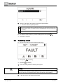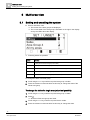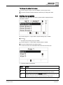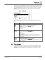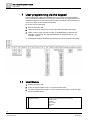
1
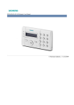
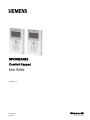
SPCK620/623 Comfort Keypad User Guide Version 3.1 A6V10271018 26.09.2011 Siemens AB Security Products Copyright Copyright Technical specifications and availability subject to change without notice. © Copyright Siemens AB We reserve all rights in this document and in the subject thereof. By acceptance of the document the recipient acknowledges these rights and undertakes not to publish the document nor the subject thereof in full or in part, nor to make them available to any third party without our prior express written authorization, nor to use it for any purpose other than for which it was delivered to him. Edition: 26.09.2011 Document ID: A6V10271018 2 Siemens AB Security Products A6V10271018 26.09.2011 Table of contents 1 Security ...........................................................................................................5 1.1 Target group .....................................................................................................5 1.2 General safety instructions................................................................................5 1.2.1 General information ...........................................................................5 1.2.2 Operation ...........................................................................................5 1.3 1.4 1.2.3 Service and maintenance ...................................................................5 Meaning of written warning notices ...................................................................6 Meaning of hazard symbols ..............................................................................6 2 2.1 Directives and standards ...............................................................................7 EU directives ....................................................................................................7 3 Introduction ....................................................................................................8 3.1 LED description ..............................................................................................10 3.2 3.3 Viewing mode description ...............................................................................11 Function keys in idle state ...............................................................................12 4 Login .............................................................................................................13 4.1 Login with PIN ................................................................................................13 4.2 Login with card (SPCK623) .............................................................................13 4.3 Login with PIN and card (SPCK623) ...............................................................13 5 Single area view............................................................................................14 5.1 5.2 Setting and unsetting the system ....................................................................14 Setting not possible ........................................................................................14 5.3 Restoring an alarm .........................................................................................15 5.4 Resetting a fault..............................................................................................16 6 Multi area view ..............................................................................................18 6.1 Setting and unsetting the system ....................................................................18 6.2 Setting not possible ........................................................................................19 6.3 6.4 Restoring an alarm .........................................................................................20 Resetting a fault..............................................................................................21 6.5 Automatic Calendar Setting ............................................................................22 6.6 6.7 Time Locked ...................................................................................................23 Interlocked Areas ............................................................................................24 7 User programming via the keypad...............................................................26 7.1 User Menus ....................................................................................................26 7.1.1 7.1.2 7.1.3 SYSTEM STATUS ...........................................................................27 ISOLATE .........................................................................................28 INHIBIT............................................................................................28 7.1.4 7.1.5 SET DATE/TIME ..............................................................................29 TEST ...............................................................................................29 7.1.5.1 BELL TEST......................................................................................29 7.1.5.2 7.1.5.3 WALK TEST ....................................................................................29 WPA TEST ......................................................................................30 3 Siemens AB Security Products A6V10271018 26.09.2011 7.1.5.4 AUDIBLE OPTIONS ........................................................................ 30 7.1.5.5 SEISMIC TEST................................................................................ 30 7.1.6 7.1.7 7.1.8 EVENT LOG .................................................................................... 31 CHIME............................................................................................. 31 USERS ............................................................................................ 31 7.1.8.1 7.1.9 ADD ................................................................................................ 31 CHANGE PIN .................................................................................. 32 7.1.10 SMS ................................................................................................ 33 7.1.10.1 SMS CONTROL .............................................................................. 33 7.1.10.2 SMS EVENTS ................................................................................. 34 7.1.10.3 SMS Commands.............................................................................. 35 7.1.11 DOOR CONTROL ........................................................................... 36 7.1.12 GRANT ACCESS ............................................................................ 37 7.1.13 7.1.14 REPORT TO ENG ........................................................................... 37 ACCESS LOG ................................................................................. 37 8 Appendix ....................................................................................................... 39 8.1 User rights ...................................................................................................... 39 8.2 Zone chart ...................................................................................................... 41 4 Siemens AB Security Products A6V10271018 26.09.2011 Security Target group 1 1 Security 1.1 Target group The instructions in this documentation are directed at the following target group: 1.2 1.2.1 Target readers Qualification Activity Condition of the product End user Instruction by technical specialists is necessary. Performs only the procedures for proper operation of the product. The product is installed and configured. General safety instructions General information Keep this document for later reference. Always pass this document on together with the product. Please also take into account any additional country-specific, local safety standards or regulations concerning project planning, operation and disposal of the product. Liability claim 1.2.2 Do not make any changes or modifications to the device unless they are expressly mentioned in this manual and have been approved by the manufacturer. Operation Dangerous situation due to false alarm 1.2.3 Make sure to notify all relevant parties and authorities providing assistance before testing the system. To avoid panic, always inform all those present before testing any alarm devices. Service and maintenance Danger of electrical shock during maintenance Maintenance work must only be carried out by trained specialists. Danger of electrical shock while cleaning the device Do not use liquid cleaners or sprays that contain alcohol, spirit or ammonia. 5 Siemens AB Security Products A6V10271018 26.09.2011 1 Security Meaning of written warning notices 1.3 1.4 Meaning of written warning notices Signal Word Type of Risk DANGER Danger of death or severe bodily harm. WARNING Possible danger of death or severe bodily harm. CAUTION Danger of minor bodily injury or property damage IMPORTANT Danger of malfunctions Meaning of hazard symbols WARNING Warning of hazard area WARNING Warning of dangerous electrical voltage 6 Siemens AB Security Products A6V10271018 26.09.2011 Directives and standards EU directives 2 2 Directives and standards 2.1 EU directives This product complies with the requirements of the European Directives 2004/108/EC “Directive of Electromagnetic Compatibility” and 2006/95/EC “Low Voltage Directive”. The EU declaration of conformity is available to the responsible agencies at: Siemens AB Building Technologies Division International Headquarters Fire Safety & Security Products Postal Address P.O. Box 1275 SE-171 24 Solna, Sweden European Directive 2004/108/EC „Electromagnetic Compatibility” Compliance with the European Directive 2004/108/EC has been proven by testing according to the following standards: emc emission EN 55022 Class B emc immunity EN 50130-4 European Directive 2006/95/EC „Low-Voltage Directive” Compliance with the European Directive 2006/95/EC has been proven by testing according to the following standard: Safety EN 60950-1 7 Siemens AB Security Products A6V10271018 26.09.2011 3 Introduction EU directives 3 Introduction The keypad is a wall-mounted interface that allows: Engineers to program the system through the Engineer Programming menus (password protected) and to set/unset the system; a user can control the system on a day-to-day basis. Users to enter User Programming menus (password protected), and to perform operational procedures (set/unset) on the system. (Please refer to the SPC620/623 User Manual for more details of user programming) The SPCK620 is equipped with soft keys and large graphical LCD for easy operation. The functionality can be enhanced with key switch expander SPCE110 or indication expander SPCE120. The SPCK623 is equipped with a proximity card reader (125 kHz EM 4102) for easy user access, soft keys, large graphical LCD and voice annunciation support. The functionality can be enhanced with key switch expander SPCE110 or indication expander SPCE120. 1 LED status indicators The LED status indicators provide information on the current status of the system as detailed in the table below. 2 LCD display The keypad display shows all alert and warning messages and provides a visual interface for programming the system (engineer programming only). (See Display Message Prioritization below) The display can be configured under which conditions the backlight comes on. 8 Siemens AB Security Products A6V10271018 26.09.2011 Introduction EU directives 3 3 Soft function keys Context sensitive keys to navigate through menus/programming. 4 Enter key Confirm display or input. 5 Back menu key Go back in the menu Reset buzzers, siren and alarms in the memory. 6 Proximity device receiver area Only SPCK 623: If the keypad has been fitted with a proximity device receiver, users should present the Portable ACE Fob to within 1 cm of this area. 7 Alphanumeric keys Alphanumeric keypad allow for both text and numeric data entry during programming. Alphabetic characters are selected by applying the appropriate number of key presses. To switch between upper and lower case characters, press the hash (#) key. To enter a numeric digit, hold down the appropriate key for 2 seconds. 8 Multi-functional navigation key Navigation through menus and to scroll through alert messages. (See Display Message Prioritization below) 9 Information key Displays information. Prioritization of display messages Trouble messages and alerts are displayed on the keypad in the following order: Zone – Alarms – – Tamper Trouble Area Alerts – Fail to set – Entry time out – Code tamper System Alerts – – – Mains Battery PSU fault – Aux fault – – External bell fuse Internal bell fuse – – Bell tamper Cabinet tamper – Aux tamper 1 – – Aux tamper 2 Wireless jamming – – Modem 1 fault Modem 1 line 9 Siemens AB Security Products A6V10271018 26.09.2011 3 Introduction LED description 3.1 – Modem 2 fault – – Modem 2 line Fail to communicate – User panic – – XBUS cable fault XBUS communications fault – – XBUS mains fault XBUS battery fault – XBUS power supply fault – – XBUS fuse fault XBUS tamper fault – XBUS antenna fault – – XBUS wireless jamming XBUS panic – XBUS fire – – XBUS medical XBUS Power supply link – Engineer restore Required System information – Soaked zones – – Open zones Area state – Low battery (sensor) – – – Sensor lost WPA Low battery WPA lost – – WPA Test overdue Camera offline – Reboot – – Hardware fault Aux over current – Battery low LED description Description Information Symbol Color Operation Blue On Flashing Off Description The system or area cannot be set. Forced setting is possible (faults or open zones can be inhibited). The system or area cannot be set or forced set (faults or open zones cannot be inhibited). The system or area can be set. 10 Siemens AB Security Products A6V10271018 26.09.2011 Introduction Viewing mode description User Amber Flashing Green On Flashing Alarm Red Alert ! Amber Green Assigned area is unset. Assigned area is Partset A / B Assigned area is fullset On Alarm - Off No alarm On - Flashing Mains Engineer is on site. Off Flashing Trouble Off No trouble On System ok Flashing Mains fault Off 3 No bus connection NOTICE The LED indications for information, area status, alarm and fault is deactivated in idle state of the keypad. A valid user PIN has to be entered. It is configurable if the power indication can be seen in idle state. 3.2 Viewing mode description There are 2 viewing modes (automatic): Multi area view: User has access to several areas. Displaying the areas is done via area groups. If no area group is configured, only the general group “All my areas” is displayed. Single area view: The user has only rights for 1 area. In the single area view, only one area is displayed in large fonts and can be controlled directly. NOTICE The rights of a user can be restricted by the user settings or the settings of the keypad the user is logging in to. Only if the user and the keypad that is being used for logging in have the right for an area, the area is displayed. If the user has the right for several areas but the keypad has only the right for one area, the user will also see the single area view. 11 Siemens AB Security Products A6V10271018 26.09.2011 3 Introduction Function keys in idle state 3.3 Function keys in idle state Emergency Keys Depending on configuration emergency keys are displayed. A simultaneous pressing of the keys activates an emergency call. Panic Alarm Fire alarm Medical Alarm The activated process depends on the system configuration. Please ask the installer for details. Direct Settings Depending on configuration the direct set option is displayed. A forced set / part set without PIN is possible of the area the keypad is assigned to. 12 Siemens AB Security Products A6V10271018 26.09.2011 Login Login with PIN 4 4 Login 4.1 Login with PIN The display in idle state shows an analogue clock as default, but may differ depending on system configuration. The keypad is in idle state. Enter the valid user code with the digit keys to . The state of the area/area groups will be displayed. NOTICE How to correct input error Delete incorrect input using the key and then enter the PIN again. If the PIN is entered incorrectly 4 times, then input is blocked for one minute. Wait for this amount of time and subsequently enter the PIN correctly. 4.2 Login with card (SPCK623) The card / pace must be assigned to a user and stored in the control panel. Present the card to the card reader of the keypad. The card reader receiving area is next to the alphanumeric keypad and is indicated by following icon: 4.3 Login with PIN and card (SPCK623) The card and PIN option has to be activated in the control panel. 1. Present the card / pace to the keypad. 2. Enter the PIN with the keys to . NOTICE The pace has to be presented first. If a code is entered first, the message “present pace” will be displayed. After presenting the pace, due to the forced order, the PIN has to be entered again. 13 Siemens AB Security Products A6V10271018 26.09.2011 5 Single area view Setting and unsetting the system 5 Single area view 5.1 Setting and unsetting the system 1. Enter a valid User code. The following screen will be displayed. 2. Press the relevant context-sensitive function key to change the state of the area. Following states are possible: Symbol Function Fullset Unset Partset A Partset B 5.2 Setting not possible If there is e.g. an open zone, the setting symbol will be displayed with an information symbol: Press the softkey below the setting symbol. 14 Siemens AB Security Products A6V10271018 26.09.2011 Single area view Restoring an alarm 5 In the next screen, the information will be shown. Following states are possible: Symbol Function None This open zone can be inhibited (forced set is possible). This open zone can not be inhibited (no forced set possible). Please contact your installer if symbol is still indicated after closing according zone (e.g. window). Only available if the zone attribute Exit open is enabled. The Entry – Exit zone is open. Zone will not prevent setting process. Zone has to be closed at the end of the exit timer. If the zone is still open, setting will fail. 5.3 Restoring an alarm If there is any alarm, the alarm will be displayed after login. 1. The alarm will be displayed by the blinking symbol and the blinking LED . 2. Press the softkey below the blinking alarm symbol. NOTICE The location of the different setting softkeys is fixed. Due to this the location of the alarm icon can vary. In the above picture, there is an alarm in fullset condition. In the next screen, the alarm(s) will be listed. 15 Siemens AB Security Products A6V10271018 26.09.2011 5 Single area view Resetting a fault 3. Use the up and down arrow keys to scroll through the alarms. There are 2 alarm symbols possible: !! Alarm can not be restored. Alarm condition still present (e.g. the zone which caused the alarm is still open). Please contact your installer if symbol is still indicated after closing according zone (e.g. window). Alarm can be restored. If the alarm can be restored, press the softkey below the symbol . The alarm is restored. 5.4 Resetting a fault If there is any fault, this will be displayed after login: The symbol The LED ! is blinking. ! is blinking. 1. Press the softkey below the blinking fault symbol. NOTICE The location of the different setting softkeys is fixed. Due to this the location of the fault icon can vary. In the above picture, there is a fault in unset condition. 2. In the next screen, the fault(s) will be listed. 16 Siemens AB Security Products A6V10271018 26.09.2011 Single area view Resetting a fault 5 3. Use the up and down arrow keys to scroll through the lists of faults. 4. Highlight the required fault. There are 2 fault symbols to indicate possible actions: !! ! Fault can not be restored. Fault condition still present. Please contact your installer. Fault can be restored. If the fault can be restored, press the softkey below the symbol . The fault is restored. Ready will be shown on the display. 17 Siemens AB Security Products A6V10271018 26.09.2011 6 Multi area view Setting and unsetting the system 6 Multi area view 6.1 Setting and unsetting the system Enter a valid User code The names of the area groups are displayed. The current state of the area group is indicated on the right in the display and by the LEDs above the display. Following states are possible: Symbol Function Fullset (all aras of the area group are Fullset) Unset (all aras of the area group are Unset) Mixed set (the areas of the area group have different setting states.). Partset A (all aras of the area group are Partset A) Partset B (all aras of the area group are Partset B) To change the state of an area group: 1. Scroll using the ▲ ▼ keys until the required area group is visible. 2. Press the relevant context-sensitive function key to change the state of the whole area group. To change the state of a single area (mixed set possible): 1. Scroll using the ▲ ▼ keys until the required area group is visible. 2. Press . All areas of this area groups are listed. 3. Scroll using the ▲ ▼ keys until the required area is visible. 4. Press the relevant context-sensitive function key to change the state. 18 Siemens AB Security Products A6V10271018 26.09.2011 Multi area view Setting not possible 6 To change the state of all areas: 1. Scroll using the▼ key to ALL MY AREAS. (in area group view) 2. Press the relevant context-sensitive function key to change the state 6.2 Setting not possible If there is e.g. an open zone, the setting symbol will be displayed with an information symbol: 1. Scroll using the ▲ ▼ keys until the required area group is visible. 2. Press . All areas of this area groups are visible. 1. Scroll using the ▲ ▼ keys until the required area is visible. 2. Press the softkey below the setting symbol. In the next screen, the information about that zone will be shown. Following states are possible: Symbol Function None This open zone can be inhibited (forced set is possible). This open zone can not be inhibited (no forced set possible). Please contact your installer if symbol is still indicated after closing according zone (e.g. window). Only available if the zone attribute Exit open is enabled. The Entry – Exit zone is open. Zone will not prevent setting process. Zone has to be closed at the end of the exit timer. If the zone is still open, setting will fail. 19 Siemens AB Security Products A6V10271018 26.09.2011 6 Multi area view Restoring an alarm 6.3 Restoring an alarm If there is any alarm, the alarm will be displayed after login. The alarm will be displayed by the blinking symbol and the blinking LED . NOTICE There is a fixed soft key assignment to set / partset / unset areas or area groups. Due to this the location of the alarm icon can vary. In the graphics below, there is an alarm in fullset condition. 1. Scroll using the ▲ ▼ keys until the required area group is visible. 2. Press . 3. Scroll using the ▲ ▼ keys until the required area is visible. 4. Press the softkey below the blinking alarm symbol. In the next screen, the alarm(s) will be listed. 20 Siemens AB Security Products A6V10271018 26.09.2011 Multi area view Resetting a fault 6 There are 2 alarm symbols possible: !! Alarm can not be restored. Alarm condition still present (e.g. the zone which caused the alarm is still open). Please contact your installer if symbol is still indicated after closing according zone (e.g. window). Alarm can be restored. If the alarm can be restored, press the key . The alarm is restored. 6.4 Resetting a fault If there is any fault, this will be displayed after login. The symbol The LED ! is blinking. ! is blinking. NOTICE In the below pictures a system wide fault (e.g. X-Bus cable fault) is indicated. Due to this the fault symbol is displayed behind all area groups / areas. It is sufficient to restore the fault once. In this case it does not matter which area group / area is selected. 1. Scroll using the ▲ ▼ keys until the required area group is visible. 21 Siemens AB Security Products A6V10271018 26.09.2011 6 Multi area view Automatic Calendar Setting 2. Press . 3. Scroll using the ▲ ▼ keys until the required area is visible. 4. Press the softkey below the blinking fault symbol. NOTICE There is a fixed soft key assignment to set / partset / unset areas or area groups. Due to this the location of the fault icon can vary. In the above picture, there is a fault in unset condition. 5. In the next screen, the fault(s) will be listed. There are 2 fault symbols possible: !! ! Fault can not be restored. Fault condition still present. Please contact your installer. Fault can be restored. If the fault can be restored, press the softkey below the symbol . The fault is restored. Ready will be shown on the display. 6.5 Automatic Calendar Setting A calendar may be assigned to an area to control setting and unsetting. When an area is unset, you will hear an audible beep from the keypad. A warning time is 22 Siemens AB Security Products A6V10271018 26.09.2011 Multi area view Time Locked 6 configurable by the installer (default 10 minutes) to inform the user before the area sets. The timer symbol will display next to the area at the configured warning time. The keypad displays that the area will set in ‘X’ minutes or seconds. You will hear an audible beep for each elapsed minute and every 10 seconds during the final minute. When the timer displays next to an area, 3 timer symbols display above the soft keys: Symbol Function To view the number of minutes left before the area sets: Press the soft key below the Timer Info symbol. Example: TIME TO FULLSET 9 MIN 3 SEC To delay setting by the configured time (default 30 minutes): Press the soft key below the Delay Timer symbol. Example: TIME TO FULLSET 68 MIN 30 SEC. You can press this soft key up to 3 times by default (configurable by installer) to increment the configured time. In this case, the icon is no longer displayed. To cancel automatic setting for a standard area: Press the soft key below the Cancel Timer symbol. The Timer Info and Delay Timer icons are no longer displayed. You must manually set this area. 6.6 Time Locked Time locked applies to a vault type of area only. If time locked is applied to a vault area, you can only unset the vault during times defined by the assigned calendar. The padlock symbol is displayed next to the vault area to indicate when it cannot be unset. 23 Siemens AB Security Products A6V10271018 26.09.2011 6 Multi area view Interlocked Areas Symbol Function The Time Lock symbol indicates if a vault area is time locked. This means that the vault area cannot be unset outside of the times defined by the calendar assigned to the area. 6.7 Interlocked Areas Vault and ATM area types can be interlocked. This means that if more than one of these area types is assigned to the same Interlock group, only one of the group may be unset at a time. A padlock symbol displays next to an interlocked vault or ATM area to indicate that it cannot be unset. Once you set one area in the group, the padlock symbol is removed to indicate that you can unset another area in the interlock group. When a calendar is assigned to an interlocked group to unset automatically, the first area listed in the interlocked group will unset first and the Timer Info and Timer Delay symbols will display as described in the section Automatic Calendar Setting [➙ 22]. It is not possible to cancel setting for an ATM or Vault area. 24 Siemens AB Security Products A6V10271018 26.09.2011 Multi area view Interlocked Areas Symbol 6 Function The Interlock symbol indicates if a group of ATM or Vault areas is interlocked. Within the interlock group, only one area can be unset at a time. The padlock symbol displays next to the other areas in the group to indicate that they cannot be unset. 25 Siemens AB Security Products A6V10271018 26.09.2011 7 User programming via the keypad User Menus 7 User programming via the keypad User programming options are available using the LCD and Comfort Keypads. Menus and options available on the intrusion control panel is programmed by the installation engineer. If users cannot see an option described in this manual, they do not have rights to access that functionality. To access user programming: 1. Enter a valid User PIN. 2. Using the up/down arrow keys, scroll to the desired programming option. 3. Within a menu option, press # to select or enable/disable a parameter (for example, a user right). The selected parameter is displayed with an * (for example, *Inhibit). The keypad displays UPDATED momentarily to indicate a parameter change. 7.1 User Menus 1. Enter a valid User PIN. 2. Press the right navigation key ► to access the main menu. 3. To select a programming option, use the up/down arrow keys or enter the digit listed in the table below. 1 SYSTEM STATUS Allows user to view the status of the following: OPEN ZONES ALERTS ISOLATIONS BATTERY AUX 26 Siemens AB Security Products A6V10271018 26.09.2011 User programming via the keypad User Menus 7 2 INHIBIT Allows users to inhibit a zone. 3 ISOLATE Allows users to isolate a zone. 4 SET DATE/TIME Allows users to set the time and date. 5 TEST Allows users to perform a BELL TEST, WALK TEST, WPA TEST or change AUDIBLE OPTIONS. 6 EVENT LOG Allows users to view a log of the most recent events on the system. 7 ACCESS LOG Allows users to view a log of the most recent access on the system. 8 CHIME Allows user to enable or disable chime function on all zones where the chime has been programmed as an audible alert feature. 9 USERS Allows Manager type users to add, edit, and delete users. 10 CHANGE PIN Allows users to change their user PIN.. 11 SMS CONTROL Allows users to configure SMS PIN. 12 SMS EVENTS Allows users to set up the SMS service for sending short text messages to mobile phones via the PSTN Line. 13 DOOR CONTROL Allows the user to control doors. He can lock / unlock and reset the door to normal operation. 14 GRANT ACCESS Allows users to grant Engineer or Manufacturer access to the system. 15 REPORT TO ENG Allows the user to request that the last 10 events in the log be sent to the engineer by SMS message. The 10 events may require more than one SMS message, depending on the size of their string. If the Security Grade of the system is set to ’Unrestricted’, then the INHIBIT, ISOLATE and GRANT ACCESS features may not be available in the user menu. A Standard or Manager Type User profile is required to access the user programming menus. 7.1.1 SYSTEM STATUS The System Status feature displays all faults on the system. To view these faults: 1. Scroll to SYSTEM STATUS. 2. Press SELECT. A list of the alerts, isolations or open zones will be displayed. The status of the battery and auxiliary power is also displayed. 27 Siemens AB Security Products A6V10271018 26.09.2011 7 User programming via the keypad User Menus 7.1.2 ISOLATE Zones, system alerts or alerts from X-BUS devices can be manually isolated from the keypad. Isolating a zone removes that zone from the system until the user deisolates it. To isolate zones, system alerts or alerts from X-BUS devices: 1. Scroll to ISOLATE and press SELECT. 2. Scroll to the desired option in the table below and press SELECT. 7.1.3 ZONE Select the required zone and toggle the setting from NOT ISOLATED to ISOLATED. SYSTEM Isolate the desired system alert. XBUS Isolate the desired alert from EXPANDERS or KEYPADS: XBUS COMMS LOST XBUS FUSE FAULT (Expanders only) X-BUS TAMPER VIEW ISOLATIONS To view a list of the isolated zones, system alerts and X-BUS devices alerts. INHIBIT Zone and alerts from X-BUS devices can be manually inhibited from the keypad. Inhibiting a zone removes that zone from the system for one alarm set period only. To inhibit zones or alerts from X-BUS devices: 1. Scroll to INHIBIT and press SELECT. 2. Scroll to the desired option in the table below and press SELECT: ZONES Select the required zone and toggle the setting from NOT INHIBITED to INHIBITED. SYSTEM Select the required system alert and toggle the setting from DISABLED to ENABLED to inhibit it. XBUS MAINS FAULT BATTERY FAULT AUX FUSE FAULT EXT FUSE FAULTINT FUSE FAULT BELL TAMPER AUX 1 TAMPER AUX 2 TAMPER ANTENNA TAMPER MODEM 1 L FAULT MODEM 2 L FAULT XBUS CABLE FAULT FAIL TO REPORT PSU FAULT Isolate the desired alert from EXPANDERS or KEYPADS: XBUS COMMS LOST XBUS FUSE FAULT (Expanders only) 28 Siemens AB Security Products A6V10271018 26.09.2011 User programming via the keypad User Menus VIEW INHIBITS 7 X-BUS TAMPER To view a list of the inhibited zones, system alerts and X-BUS device alerts. Only the ALARM, EXIT/ENTRY, FIRE EXIT and LINE zone types can be inhibited on the SPC system. All other zone types are not displayed in the inhibit menus. 7.1.4 SET DATE/TIME The date and time can be manually entered on the system. The time and date information is displayed on the keypad and browser and is used on time-related programming features. 1. Scroll to SET DATE/TIME and press SELECT. The date displays on the top line of the display. 2. To enter a new date, press the required numeric keys. To move the cursor to the left and right, press the left and right arrow keys. 3. Press ENTER to save the new date. If an attempt is made to save an invalid date value, the text INVALID VALUE is displayed for 1 second and the user is prompted to enter a valid date. 4. To enter a new time, press the required numeric keys. To move the cursor to the left and right, press the left and right arrow keys. 5. Press ENTER to save the new time. If an attempt is made to save an invalid time value, the text INVALID VALUE is displayed for 1 second and the user is prompted to enter a valid time. 7.1.5 TEST 1. Scroll to TEST and press SELECT. 2. Scroll to the desired programming option. 7.1.5.1 BELL TEST To perform a bell test: Scroll to TEST > BELL TEST and press SELECT. When BELL TEST is selected, the following options available: EXTERNAL BELLS, STROBE, INTERNAL BELLS and BUZZER. When each of these options is selected, the device sounds to verify it is operating correctly. 7.1.5.2 WALK TEST A walk test ensures that the sensors are operating correctly on the SPC system. To perform a walk test: 1. Scroll to TEST > WALK TEST. 29 Siemens AB Security Products A6V10271018 26.09.2011 7 User programming via the keypad User Menus 2. Press SELECT. 3. The display indicates the number of zones to be tested on the system with the text TO TEST XX (where XX is the number of valid walk test zones). Locate the sensor on the first zone and activate it (open the door or window). The keypad buzzer sounds continuously for approximately 2 seconds to indicate that the zone activation has been detected and the number of zones left to test (displayed on the keypad) decreases. 4. Continue with the remaining zones on the system until all zones have been tested. If a zone activation does not get acknowledged by the system, check the wiring of the sensor and/or replace with another sensor if necessary. NOTICE Only ALARM, ENTRY/EXIT and FIRE EXIT are valid zone types which are included in a User walk test 7.1.5.3 WPA TEST To perform a WPA test, the installer must have enrolled the WPA. 1. Scroll to TEST > WPA TEST. 2. Press SELECT. The keypad display flashes ACTIVATE WPA. 3. Press and hold all 3 buttons on the WPA. The LED on the WPA turns on. The WPA transmitter ID, status and signal strength are displayed on the keypad. 7.1.5.4 AUDIBLE OPTIONS The audible options are applied as indicators within a walk test. To set the audible options: 1. Scroll to AUDIBLE OPTIONS. 2. Press SELECT. 3. Scroll to one of the following options: ALL, INT BELL, EXT BELL, KEYPAD 4. Press SAVE. 5. Press BACK to exit. 7.1.5.5 SEISMIC TEST To perform a seismic test: 1. Scroll to TEST > SEISMIC TEST. 2. Press SELECT. 30 Siemens AB Security Products A6V10271018 26.09.2011 User programming via the keypad User Menus 7 3. Select TEST ALL AREAS, or select an individual area to test. 4. If you select an individual area to test, you can select either TEST ALL ZONES or select a specific seismic zone to test. The message ‘SEISMIC TEST’ is display on the keypad while the test is being performed, If the test fails, the message ‘SEISMIC FAIL’ is displayed. If the “i” or VIEW key is pressed, a list of the failed zones is displayed which can be scrolled through. If the test succeeds, ‘SEISMIC OK’ is displayed. See also Seismic Sensor Testing. 7.1.6 EVENT LOG Recent events on the system are displayed in the EVENT LOG option. Events flash in one second intervals. 1. Scroll to EVENT LOG and press SELECT. 2. To view an event from a particular date, enter the date with the numeric keys. The most recent events are displayed on the bottom line of the display. All previous events are displayed for one second in turn. 7.1.7 CHIME The chime function can be enabled or disabled on all zones where the chime has been programmed as an audible alert feature. To enable or disable the chime function: 1. Scroll to CHIME and press SELECT. 2. Toggle between ENABLED and DISABLED for the chime. 7.1.8 USERS Only Manager type users have the ability to add, edit, or delete users, unless a user profile has this capability assigned to their profile. Managers may add, edit or delete users with these steps: 7.1.8.1 ADD To add users to the system: NOTICE The creator must be user type MANAGER. 1. Scroll to USERS > ADD. The system generates and displays next available user name. 31 Siemens AB Security Products A6V10271018 26.09.2011 7 User programming via the keypad User Menus 2. Press SELECT for the default name and number. Or enter a customized user name and press SELECT. There are 3 types of users available: STANDARD USER, LIMITED USER, or MANAGER. 3. Scroll to the preferred type and press SELECT. The system generates a default code for each new user. 4. Press SELECT to accept the default code. Or enter a new user code and press SELECT. The keypad confirms that the new user has been created. 7.1.9 CHANGE PIN To change a PIN: 1. Scroll to CHANGE PIN and press SELECT. A randomly generated PIN appears. 2. Select this new PIN or overwrite by entering a new PIN and press ENTER. NOTICE If the system is set for 5-digit PINs, a new 5-digit PIN must be entered. The system will not accept a PIN with fewer numbers than it is set to receive. 1. Confirm the new PIN and press SAVE. 2. Press BACK to return to the previous screen to amend the PIN. During the process if the display times out, the old PIN remains valid. NOTICE Where USER DURESS feature is enabled, consecutive user codes (i.e. 2906, 2907) are not permitted, as entering this PIN from the keypad would activate a user duress event. NOTICE Engineer PINs should be noted down. If a PIN is forgotten, a factory default of the system is required to reset PINs. 32 Siemens AB Security Products A6V10271018 26.09.2011 User programming via the keypad User Menus 7.1.10 7 SMS The SPC system support SMS communication from the panel to selected users’ mobile phones as well as users being able to control the SPC system remotely via SMS. These two features work hand in hand as it allows the user to take action using the SMS control after a SMS notification without the need to be physically at the premises. SMS control The SMS control can be set up so that a remote user can send a SMS message to perform the following actions at the panel: Setting / unsetting Enable / disable engineer Enable / disable manufacturer access. Mapping gate on/off. SMS events The SMS notification can be set up to send a range of events that occur on the system such as: Alarm activation Confirmed alarms Fault & tamper Setting & unsetting Inhibit & isolate All other types of events The SMS notification can operate with a PSTN modem if the PSTN operator supports SMS over PSTN where as SMS control will need a GSM modem at the panel. A GSM modem will support both SMS notification and control. 7.1.10.1 SMS CONTROL There is a maximum of four users for SMS configuration on 1 panel and only 1 phone number for each user for use with SMS control functionality. It is important prerequisites such as an SMS-enabled modem and correct user profile are met for SMS control. Depending on the SMS AUTHENTICATION MODE (OPTIONS menu) chosen by the installation engineer, the user’s mode of SMS may vary. If the system SMS authentication is set to the SMS PIN Code, Caller ID or PIN & Caller ID, it is necessary to set up SMS control: 1. Scroll to SMS CONTROL and press SELECT. 2. Select the desired configuration option shown in the table below. 3. Press BACK to exit. 33 Siemens AB Security Products A6V10271018 26.09.2011 7 User programming via the keypad User Menus CONTROL ENABLE Enable or disable SMS Control. SMS CALLER ID Provide phone number (requires 3-digit country code prefix) SMS PIN CODE Provide pin number DELETED Remove phone number as required. COMMANDS ALLOWED Select the functions that can be performed via SMS. See SMS Commands [➙ 35] for a list of SMS commands to perform these functions. Beyond user type, Engineer settings allow specific rights for functionality to be granted to each user. If a function explained herein does not appear on user keypad menus, the user does not have permission for that functionality. Consult with authorised installation Engineer for appropriate rights and settings. 7.1.10.2 SMS EVENTS To receive event notifications, SMS setup must have the phone number; the number must be enabled for SMS; the events must be toggled for SMS Event notification. There is a maximum of four users for SMS configuration on one panel and user may set a maximum of 5 phone numbers for SMS receipt. Adding a phone number To add a phone number for SMS use: 1. Scroll to SMS EVENTS and press SELECT. 2. Scroll to ADD NUMBER and press SELECT. The LCD displays SMS NUMBER. 3. Enter a phone number and press ENTER. The LCD displays UPDATED. 4. Press BACK to exit Enabling a phone number To enable a phone number for SMS [receipt]: 1. Scroll to SMS EVENTS and press SELECT. 2. Scroll to EDIT NUMBER and press SELECT. 3. Scroll to the appropriate registered number and press SELECT. 4. Scroll to ENABLE NUMBER and press SELECT. 5. Press SELECT for ENABLED [Alternatively, press SELECT for DISABLED.] 6. Press BACK to exit the SMS EVENTS menu. 34 Siemens AB Security Products A6V10271018 26.09.2011 User programming via the keypad User Menus 7 The keypad displays UPDATED once the setting has been saved Reported events To select events for SMS notification: 1. Scroll to SMS EVENTS and press SELECT. 2. Select EDIT NUMBER and press SELECT. 3. Scroll to the appropriate enabled number and press SELECT. 4. Scroll to REPORTED EVENTS and press SELECT. 5. Scroll to the desired event notification. Events selected are displayed preceded by an asterisk. 6. Press BACK to exit. 7.1.10.3 SMS Commands Once the SMS setup and configuration is complete, SMS features may be activated. Commands, depending on SMS configuration are sent using a code or caller ID. The type of code depends on what is set for SMS Authentication. See page. The table below provides all available SMS commands. Subsequent action and response are also provided. SMS Commands are sent as texts to the phone number of the SIM card on the controller. For commands using code, the format of the text is the code followed by either a space or a full stop. Where **** is the code and “command” is the command: ****.command or **** command. For example, the command “HELP” is this text: **** HELP or ****.HELP COMMANDS (**** = code) Using Code Using Caller ID Action Response **** HELP HELP All available commands displayed All available commands FSET Fullset Alarm Time/date of system set. If applicable, responds with open zones/forceset zones USET Unset Alarm System Unset SSTA Status displayed Status of system and applicable areas Where X10 device is identified as “A1”, it is triggered on. Status of “A1” Where X10 device is identified as “A1”, it is triggered off. Status of “A1” ****.HELP **** FSET ****.FSET **** USET ****.USET **** SSTA ****.SSTA **** XA1.ON ****.XA1.ON **** XA1.OFF 35 Siemens AB Security Products A6V10271018 26.09.2011 7 User programming via the keypad User Menus ****.XA1.OFF **** LOG Up to 10 recent events displayed Recent events ENG.ON Enable Engineer access Engineer status ENG.OFF Disable Engineer access Engineer status Enable Manufacturer access Manufacturer status Disable Manufacturer access Manufacturer status **** O5.ON ****.O5.ON Where mapping gate is identified as “O5”, it is triggered on Status of “O5” **** O5.OFF Where mapping gate is identified as “O5”, it is triggered off Status of “O5” ****.O5.OFF ****.ASET Allows Partset A of alarm by SMS ****.BSET Allows Partset B of alarm by SMS ****.CLR Allows clear alerts by SMS ****.LOG **** ENGA.ON ****.ENGA.ON **** ENGA.OFF ****.ENGA.OFF **** MANA.ON ****.MANA.ON **** MANA.OFF ****.MANA.OFF For SMS recognition, mapping gate identification uses the format ONNN, where O stands for mapping gate, and NNN are the numeric placeholders, of which not all are necessary. (Example: O5 for mapping gate 5) For SMS recognition, X-10 device uses the format: XYNN, where X stands for X10; Y stands for the alphabetic identity and NN are the available numeric placeholders. (Example: XA1) The SMS operates using a standard protocol that is used in SMS telephones. Please note that some PSTN operators do not provide the service of SMS over PSTN. For SMS to operate over PSTN the following criteria is required: Caller ID needs to be enabled on the telephone line. 7.1.11 Direct telephone line – not through PABX or other comms equipment. Please also note that most Service Providers only allow SMS to a telephone registered in the same country. (This is due to billing issues) DOOR CONTROL This option allows you to control all the doors of the system. 1. Scroll to DOOR CONTROL and press SELECT. 2. Select the door which should be controlled and press SELECT. 3. Select one of the door states listed below as new door state and press SELECT. 36 Siemens AB Security Products A6V10271018 26.09.2011 User programming via the keypad User Menus 7.1.12 7 NORMAL The door is in normal operation mode. A card with the corresponding access rights is needed to open the door. MOMENTARY The door is opened only for a timed interval to allow access. LOCKED The door is locked. The door remains closed even if a card with the corresponding access rights is presented. UNLOCKED The door is unlocked. GRANT ACCESS NOTICE These menu options are not available if the ALLOW ENGINEER or ALLOW MANUFACTURER options are disabled in the OPTIONs menu. These options can be enabled or disabled only when the system is in ‘Unrestricted’ mode. When engineer or manufacturer access has been allowed, the keypad displays the text ENGINEER ENABLE or MANUFACT ENABLE. When access has been granted, the user cannot access the system until the engineer has logged off. To allow engineer access: 1. Scroll to GRANT ACCESS and press SELECT. 2. Select to ALLOW ENGINEER and select ENABLED. 3. Select to ALLOW MANUFACT. and select ENABLED. 4. To disallow engineer/manufacturer access, follow the same path and toggle to DISABLED and press SELECT. For Swiss CAT 1 and CAT 2 regional requirements, when Engineer Access is granted, all areas must be unset otherwise the engineer will be denied access. 7.1.13 REPORT TO ENG The user can request that the last 10 events in the log be sent to the engineer by SMS message. 1. Scroll to REPORT TO ENG and press SELECT. 2. Enable or disable this option as required. Note: The 10 events may require more than one SMS message, depending on the size of their string. 7.1.14 ACCESS LOG Zone access on the system is displayed in the ACCESS LOG option. 1. Scroll to ACCESS LOG and press SELECT. 2. Select a door on the system for which you want to display access events. The most recent access events are displayed with a date and time. 37 Siemens AB Security Products A6V10271018 26.09.2011 7 User programming via the keypad User Menus 3. Scroll down through the access events or enter a date and press ENTER to find a particular access event. 38 Siemens AB Security Products A6V10271018 26.09.2011 Appendix User rights 8 8 Appendix 8.1 User rights Based on the operational features of the SPC system, described below, users have rights attributed to the user profiles. The installation engineer will inform users of their user rights assigned to each user profile. Depending on how the system has been programmed, users may have rights to all or some of these features. User rights User Profile Default User type Description Fullset Limited Standard Manager The FULLSET operation fully sets the alarm system and provides full protection to a building (opening of any alarm zones activates the alarm). On selecting FULLSET, the buzzer sounds and the keypad display counts down the exit time period. Exit the building before this time period has expired. When the exit time period has expired, the system is set and opening of entry/exit zones starts the entry timer. If the system is not Unset before the entry timer expires, the alarm is activated. Partset A Standard Manager The PARTSET A option provides perimeter protection to a building while allowing free movement through the exit and access areas. Zones that have been classified as EXCLUDE A remain unprotected in this mode. By default, there is no exit time; the system sets instantly on selection of this mode. An exit timer can be applied to this mode by enabling the Partset A timed variable. Partset B Standard Manager The PARTSET B option applies protection to all zones except those that have been classified as EXCLUDE B. By default there is no exit time; the system sets instantly on selection of this mode. An exit timer can be applied to this mode by enabling the Partset B timed variable. Forceset Standard Manager The FORCESET option is presented on the keypad display when an attempt is made to set the system while an alarm zone is faulty or still open (the top line of the display shows the open zone). Selecting this option sets the alarm and inhibits the zone for that set period. Unset Limited Standard Manager The UNSET operation unsets the alarm. This menu option is only presented on the keypad after an alarm has been activated and a valid user code has been entered. Restore Standard Manager The RESTORE operation restores an alert condition on the system and clears the alert message associated with that alert condition. An alert condition can only be restored after the zone(s) or fault(s) that triggered the alert condition have been restored to their normal operating state and the 39 Siemens AB Security Products A6V10271018 26.09.2011 8 Appendix User rights User Profile Default User type Description RESTORE option in user programming is selected for that zone. Isolate Standard* Manager Isolating a zone deactivates that zone until such time as the zone is de-isolated. All zone types on the SPC can be isolated. Use of this feature to deactivate faulty or open zones should be considered carefully; once a zone is isolated, it is ignored by the system and could be overlooked when setting the system in the future, compromising the security of the premises. Inhibit Standard Manager Inhibiting a zone [➙ 28] deactivates that zone for one alarm set period. Only alarm, entry/exit, fire exit and line zone types can be inhibited. This is the preferred method of deactivating a faulty or open zone as the fault or open condition is displayed on the keypad each time the system is being set to remind the user to attend to that zone. Change PIN Standard Manager This menu option allows users to change their user PIN. Engineer Manager This option allows users to grant access to manufacturer and engineer programming. Set Date / Time Standard Manager Use this menu option to program the time and date on the system. Ensure the time and date information is accurate; these fields are presented in the event log when reporting system events. Test Standard Manager This menu option provides the following test features: 1. Bell test: The bell test activates the external bells, strobe, internal bells, and buzzer in turn for 5 seconds to ensure their correct operation. 2. Walk test: A walk test allows for testing of the operation of all alarm sensors on a system. When this option is selected, the keypad displays the number of zones to test on the system. Activate each alarm sensor (by opening the door or window) and check for an audible beep at the keypad. Isolated and inhibited zones are not included in the walk test. 3. Audible Options: This option allows users to select which devices will activate during the walk test and which will be silent. View Log Standard Manager This menu option displays the most recent event on the keypad display. The event log details the time and date of each logged event. Chime Standard Manager All zones that have the CHIME attribute [➙ 31] set generate a short burst of audible tone on the keypad buzzer when they are opened (while the system is unset). This menu option allows for enabling or disabling of the chime feature on all zones. SMS Standard* Manager This feature allows users to set up the SMS messaging service if a modem is installed on the system. 40 Siemens AB Security Products A6V10271018 26.09.2011 Appendix Zone chart User Profile Default User type Description Users Manager User can configure user on the panel. 8 Delay autoarm Standard* Manager User can delay auto setting. Bypass delay Standard Manager User can automatically override the Unset Delay. Only available for Financial installations. See Setting/Unsetting Upgrade Manager User can grant manufacturer access to panel to perform firmware upgrade. X-10 Standard Manager Access Control User can activate/deactivate configured X-10 devices. Door Control Standard* Manager Access Control User can lock/unlock doors. Web Access Standard* Manager User can access panel through web browser. Outputs Standard Manager User can turn outputs (mapping gates) on and off. See WPA Test Standard Manager User can test a WPA. * Functions not enabled by default for this user but can be selected. 8.2 Zone chart Zone # Description 41 Siemens AB Security Products A6V10271018 26.09.2011 8 Appendix Zone chart Zone # Description 42 Siemens AB Security Products A6V10271018 26.09.2011 Issued by Siemens AB Industry Sector Security Products International Headquarters Englundavägen 7 SE-171 24 Solna Tel. +46 8 629 0300 www.siemens.com/securityproducts Document ID A6V10271018 Edition 26.09.2011 © 2011 Copyright Siemens AB Technical specifications and availability subject to change without notice.