1
Rev. 3
Disclaimer
Data Ltd., Inc. (DLI) reserves the right to make changes in specifications and other information
contained in this document without prior notice, and the reader should in all cases consult DLI
to determine whether any such changes have been made. The information in this publication
does not represent a commitment on the part of DLI.
DLI shall not be liable for technical or editorial errors or omissions contained herein: nor for
incidental or consequential damages resulting from the furnishing performance, or use of
this material.
This document contains proprietary information that is protected by copyright. All rights are
reserved. No part of this document may be photocopied, reproduced, or translated into another
language without the prior written consent of DLI.
© 2011 Data Ltd., Inc. All rights reserved.
Web Address: www.dataltd.com
Trademarks
DLI 8400 is a trademark or registered trademark of Data Ltd., Inc.
Windows CE, Windows XP, Windows Embedded XP, Windows Tablet PC, ActiveSync, and the
Windows logos are trademarks or registered trademarks of Microsoft Corporation.
The Bluetooth trademarks are owned by Bluetooth SIG, Inc., USA and licensed to DLI
The Adaptus trademark is owned by Honeywell Inc., and licensed to DLI
The Symbol & Motorola trademarks are owned by Motorola Corporation, USA and licensed to DLI
The PenMount trademarks are owned by PenMount International Corp. and licensed to DLI
Other product names mentioned in this manual may be trademarks or registered trademarks
of their respective companies and are hereby acknowledged.
Table of Contents
Thank You! ...................................................................................................................................... 3
DLI 8400 Peripherals and Accessories ........................................................................................... 3
Hardware Overview ......................................................................................................................... 4
Setting Up the DLI 8400 Terminal ................................................................................................... 8
Unpack the Carton and Verify its Contents ..................................................................................... 9
Battery Status LED’s ....................................................................................................................... 9
Charging the Battery in the DLI 8400 .............................................................................................. 9
Power Management Utility............................................................................................................. 10
Adjusting the Backlight .................................................................................................................. 11
Integrated Keyboard ...................................................................................................................... 12
Using the Stylus ............................................................................................................................. 14
Using the Programmable Keys ...................................................................................................... 16
SIM Card Insertion ......................................................................................................................... 20
Using the WiFi Radio ..................................................................................................................... 21
DLI 8400 PRODUCT MANUAL
PAGE 2/49
Rev. 3
Using the Bluetooth Radio ............................................................................................................. 23
Using the Camera Option .............................................................................................................. 31
Using the RS-232 DB9M ............................................................................................................... 31
Using the Barcode Scanner ........................................................................................................... 33
Biometric Reader ........................................................................................................................... 34
Using GPS ..................................................................................................................................... 34
DLI 8400 Cradle............................................................................................................................. 38
Installing the Vehicle Cradle .......................................................................................................... 41
Cradle Power Filtering DC Converter ............................................................................................ 41
Shipping your DLI Device .............................................................................................................. 42
Technical Assistance ..................................................................................................................... 44
Product Service and Repair ........................................................................................................... 44
Limited Warranty............................................................................................................................ 44
Regulatory and Safety Approvals for the DLI 8400 ....................................................................... 45
FCC Compliance ........................................................................................................................... 47
Thank You!
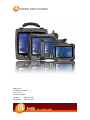
Data Ltd Inc. would like to thank you for selecting the DLI 8400. The DLI 8400 was designed as
a forward thinking product that is modular in design and upgradeable. We thank you the
customer for giving us the inspiration for the following features:
Impact Resistant Case
Color Camera with Picture & Video capture
Ergonomic form factor and lightweight design
Integrated four radio technology (WiFi, Bluetooth, GPS, and Cellular)
Boot media via SSD (Solid State Drive) or (HDD) (Hard Disk Drive)
DLI 8400 Peripherals and Accessories
8400-VMC-1
Vehicle Mount Cradle w/ 3-USB Locking, 3-RS232 Ports, 1-Power Locking
with RAM 202U mounting ball.
8400-VMC-2
Vehicle Mount Cradle w/ 3-USB Locking, 3-RS232 Ports, 1-Power Locking
J1708/J1939 Module, with RAM 202U mounting ball.
Requires (4-PIN J1708/J1939 Cable)
Vehicle Mount Cradle w/ 3-USB Locking, 3-RS232 Ports, 1-Power Locking
10V~60VDC/DC Converter, with RAM 202U mounting ball.
8400-VMC-3
8400-VMC-4
Vehicle Mount Cradle w/ 3-USB Locking, 3-RS232 Ports, 1-Power Locking
10V~60VDC/DC Converter, J1708/J1939 Module, with RAM 202U
mounting ball
Requires (4-PIN J1708/J1939 Cable)
8400-DTC
Desktop Cradle
Requires AC Adapter with Country-specific Line Cord.
2214011250002P
2500mAh, Lithium-Ion Battery Pack. (Spare)
5421112020900P
AC Wall Adapter
Requires Line Cord
6705200041000P
Cigarette Lighter Adapter With Standard Adapter. (12-24V DC Input)
8400-3B-CHG
3-Bay Battery Charger
DLI 8400 PRODUCT MANUAL
PAGE 3/49
Rev. 3
Requires AC Adapter with Country-specific Line Cord.
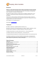
Hardware Overview
Front Panel
Battery Status LED
Barcode Scanner LED
Bluetooth LED
2MP Color Camera
Stylus
Mag Stripe Reader
Biometric Reader / Mouse
Power LED
Microphones
Impact Resistant
Case
Speaker
Speaker
Keyboard
(QWERTY) or (NUMERIC)
DLI 8400 PRODUCT MANUAL
LCD with Touch Panel
PAGE 4/49
Rev. 3
Front Panel Status Indicator Lights
The front panel includes status indicator lights for the following:
Power On / Off
Barcode Scanner
Bluetooth
Battery
Indicator Light
Power
Status
Solid Green
Description
Powered On
Barcode Scanner
Solid Red
Flash Green
Scanning
Good Scan
Bluetooth
Blinking Blue
No Light
Enabled
Disabled or Not Available
Refer to Battery Status LED
section. Page 9
Battery Status
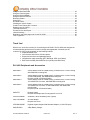
Bottom Panel
Ethernet
Port
Serial
Port
AC Power
DLI 8400 PRODUCT MANUAL
Cradle Interface
USB
Ports
PAGE 5/49
Rev. 3
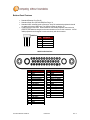
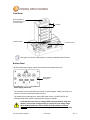
Bottom Panel Features
Standard Ethernet Port (RJ-45)
Standard Serial Port (RS-232 DB9) See Page. 31
Standard USB, industrial grade connectors. Only DLI authorized peripherals should
be attached to these USB ports. The USB port power is rated to 1A.
Cradle Interface Connector. When seated in a DLI 8400 peripheral, the terminal is
powered, the batteries charged, and communication occurs via this connector. All DLI
8400 peripherals are designed to work exclusively with his connector.
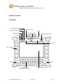
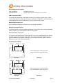
USB Port
1 2 3 4
Pin #
Description
1
2
(+5V)
Data +
3
Data -
4
GND
8400 Cradle Interface
TOP
Pin#
1
2
3
4
5
6
7
8
9
10
11
12
13
14
15
16
17
18
19
20
DLI 8400 PRODUCT MANUAL
Description
GND
GND
+20V DOCKING
LAN TRL3+
+20V DOCKING
LAN TRL3+20V DOCKING
LAN TRL2+
+3.3VS DOC
LAN TRL2+3.3VS DOC
GND
+5VS DOC
LAN TRL1+
+5VS DOC
LAN TRL1GND
LAN TRL0+
GND
LAN TRL0-
Pin#
21
22
23
24
25
26
27
28
29
30
31
32
33
34
35
PAGE 6/49
Description
GND
GND
Docking GPIO1
H_USB5+
Docking GPIO2
H USB5Docking GPIO3
GND
Docking GPIO4
GND
Docking GPIO5
CRADLE IN#
GND
GND
GND
Rev. 3
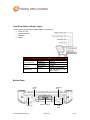
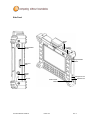
Side Panel
Left Side
Stylus
Slot
Programmable
Button
Imager
Window
Programmable
Button
SD Card
Slot
On/Off
Button
Microphone Port
K-Lock
Speaker Port
Master Reset
Button
DLI 8400 PRODUCT MANUAL
PAGE 7/49
Rev. 3
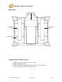
Back Panel
2MP Color Camera
Hot-swappable
Battery
Hot-swappable
Battery
Impact Resistant
Case
Setting Up the DLI 8400 Terminal
1.
3.
4.
5.
Unpack the carton and verify its contents. – Page 9
Charge the batteries for 3hrs.
Power on the terminal via the power button on the left side of the terminal.
Let the device load and end on the Desktop screen.
DLI 8400 PRODUCT MANUAL
PAGE 8/49
Rev. 3
Unpack the Carton and Verify its Contents
Verify that the carton contains the following items:
•
•
DLI 8400 Industrial Tablet Computer (terminal)
DLI 8400-BAT Hot-swappable Batteries (2)
If you ordered peripherals and/or accessories, verify that they are also included
with the order.
Be sure to keep the original packaging in case the DLI 8400 needs to be returned for
service– See page 43.
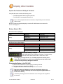
Battery Status LED’s
On Power Source (Charger)
Battery Indicator Light
Power
Status
Battery
Solid Green
Description
Powered On
Solid Green
Blinking Green
Blinking Yellow
Blinking red
Capacity level = 100%
Capacity level > 70%
Capacity level > 20% - < 70%
Capacity level < 20%
Off Power Source (No Charger)
Battery Indicator Light
Power
Battery
Status
Solid Green
Description
Powered On
Solid Green
Solid Yellow
Solid Red
Blinking red
Capacity level > 70%
Capacity level < 70% - > 20%
Capacity level < 20% - > 10%
Capacity level < 10%
Push Button Battery Life Status
All DLI 8400 batteries have a Battery Life Status. Push the battery
symbol and LEDs show the life status. Each LED is ~25%
For charging, use only Data Ltd. Inc., DLI 8400 peripherals and the power
cables. Use of peripherals or cables not sold/manufactured by Data Ltd will
void the warranty and may damage the terminal.
Charging the Battery in the DLI 8400
1. Connect the DLI 8400 to the power supply provided by Data Ltd.
2. The battery will begin charging immediately
3. Charge the batteries for three hours, then power on the terminal.
Due to the nature of Lithium Ion, be sure to periodically charge your
batteries, as months of inactivity can have a long-term negative effect on
the life of the battery.
The battery will charge even if the terminal is in use as long as AC is applied to
the terminal.
DLI 8400 PRODUCT MANUAL
PAGE 9/49
Rev. 3
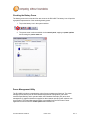
Checking the Battery Power
The battery power can be checked from two areas on the DLI 8400. The battery icon will provide
a graphical representation of the remaining battery power.
1. Tap on the battery icon in the system task bar.
2. The power meter is also accessible via the control panel, tapping on power options
and choosing the power meter tab
Power Management Utility
The DLI 8400 includes a comprehensive suite of power management functions. The power
management is based upon the ACPI Standard (Advanced Configuration and Power
Interface Specification) and is operated within the Embedded Controller (EC) at low level
management. A graphical interface is supplied so that customer specific power schemes can
be controlled. The Power Management Utility is accessible from the DLI Control Center
application as well as from the control panel within Windows XP.
DLI 8400 PRODUCT MANUAL
PAGE 10/49
Rev. 3
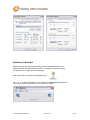
Adjusting the Backlight
Brightness levels of the liquid crystal display (LCD) are adjustable based on the
lighting conditions. By default the level is set to 7. (0 being the lowest and 7 being
the highest level) To adjust the level of backlight:
Start>Control Panel. Choose the DLI Brightness icon.
Tap “-” or “+” to adjust the brightness. The settings are auto saved after adjustment.
Tap Options>Place in system tray for quick access to this utility.
DLI 8400 PRODUCT MANUAL
PAGE 11/49
Rev. 3
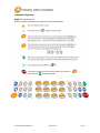
Integrated Keyboard
QWERTY Keyboard Layout
Below are keys & symbols above the keys that may require definition:
DLI 8400 PRODUCT MANUAL
PAGE 12/49
Rev. 3
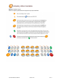
Numeric Keyboard Layout
Below are keys & symbols above the keys that may require definition:
DLI 8400 PRODUCT MANUAL
PAGE 13/49
Rev. 3
Using the Stylus
Calibrating and Using the Stylus
Calibration ensures the accuracy of the stylus and adjusts the input angle for each person who
uses it. The terminal stores calibration data and settings on a per-user basis.
The stylus functions as a mouse; generally, a tap is the same as a mouse click.
Tap:
Drag:
Right Mouse Click:
Tap the touch screen once to open menu items and select options.
Hold the stylus on the screen and drag across the screen to select text
and images. Drag in a list to select multiple items.
Holding down the stylus for 3 seconds will activate the right mouse click.
Calibration:
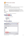
1. Right tap on the PenMount icon in the system stray.
2. Select the PenMount Control Panel.
3. Chose the PenMount 6000 USB icon and tap the Configure button.
DLI 8400 PRODUCT MANUAL
PAGE 14/49
Rev. 3
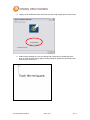
4. Tapping on the Calibration button will prompt the user to tap multiple points on the screen.
5. Hold the stylus naturally as if you were writing with a ball point pen, holding the stylus
down on each red point as they appear. During calibration, position the terminal as close
to the way you would use it.
DLI 8400 PRODUCT MANUAL
PAGE 15/49
Rev. 3
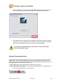
6. After completion the screen returns to the Standard Calibration window. Selecting OK
will save the settings. Tapping Standard Calibration will start the process again.
7. The calibration is now complete and the PenMount Control Panel window is displayed.
Select OK to close the application down. The PM icon will still be present in the system
tray for quick configuration should your touch screen need recalibration.
Do not write on the terminal display with ink pens or other sharp objects
that may damage the display.
Using the Programmable Keys
The DLI 8400 has 2 integrated function keys. Each of the keys is user configurable via the DLI
KeyMon Utility. The keys can be assigned to perform executable applications or to Data Ltd.
predefined functions. The predefined functions are as follows: Right button assigned to activate
the imager and Left button assigned to DLI Camera.
The DLI KeyMon utility can be launched from the system tray or from the
Start>Programs>DLI>DLI KeyMon. The procedure below will assist you in defining the keys.
1. Tap on the DLI KeyMon icon in the system tray
DLI 8400 PRODUCT MANUAL
PAGE 16/49
Rev. 3
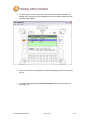
2. The DLI KeyMon screen is presented. Choose a key that requires a definition by
tapping on the orange keys or by highlighting the key in the button assignment area
and then double tapping.
3. There are 5 options for key assignment. Choose the assignment that is required for
the key.
4. To assign an application choose External program and tap on the browser icon.
(See page. 18)
DLI 8400 PRODUCT MANUAL
PAGE 17/49
Rev. 3
Browser Icon
5. The user is returned to the assign menu once the selection has been chosen from
the browser icon. Selecting the apply button saves the change to the key. The path
to the application will appear in blue below the Current Assignment:
DLI 8400 PRODUCT MANUAL
PAGE 18/49
Rev. 3
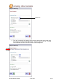
6. To select a predefined action or keystroke choose Command and tap the down arrow
to display a drop menu.
7. The drop menu has a list of various actions and keystrokes to choose from. Once you
have selected the command, tap the apply button to save.
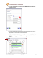
8. The DLI KeyMon program can be used to send data received by the Mag Stripe Reader
(MSR) to the keyboard buffer. To setup your MSR to forward data, Select Tools then
MSR Setup or by highlighting the MSR in the button assignment area and then double
tapping.
DLI 8400 PRODUCT MANUAL
PAGE 19/49
Rev. 3
9. The default MSR Data Properties are 19200 Baud Rate and COM2 for the Com Port.
10. To Close the DLI KeyMon tap on the “X” on the top right of the Main Window.
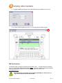
SIM Card Insertion
The SIM Card Slot is located in the battery bed of Battery Slot 1. The SIM Card Slot is intended
for use of the MC8790 (GPRS Wireless Radio) ONLY. If you are unaware of what type of WWAN
Radio you have please contact DLI Technical Support; (800) 526-1299 x774 or
support@dataltd.com.
The unit must be power down prior to inserting the SIM card. Failure to do so
may result in harm to the unit and the SIM.
DLI 8400 PRODUCT MANUAL
PAGE 20/49
Rev. 3
Using the WiFi Radio
The DLI 8400 has two WiFi options. First is a PCI Intel 802.11a/b/g integrated radio. The other is
a USB 802.11a/b/g/n integrated radio. Each radio is configured using either Intel WiFi Connection
Utility or Ralink Wireless Utility (RaUI). These programs provide features to Administrators and
end-users:
Disable the radio (turn it off) and enable the radio (turn it on)
View the contents of configuration profiles, or profiles, each of which houses the RF,
security, and other settings for the radio
Select the profile to be used to connect to a WLAN
View status information on the radio, the access point (AP) or WLAN router to which it
is connected, and the RF connection or link between the two
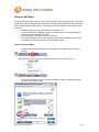
Intel PCI Integrated Radio
Start the Intel Connection Utility by double tapping on the Utilities icon found in the
task tray.
(Right clicking on the icon allows for additional options such as WiFi on or off.)
The Intel utility window will pop up showing available networks. Highlight a network
and click the "Connect" button.
DLI 8400 PRODUCT MANUAL
PAGE 21/49
Rev. 3
If the SSID is broadcasted and no securities are found, you will connect. Connection
is indicated by the blue Intel icon next to the network.
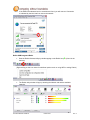
Ralink USB Integrated Radio
Start the Ralink Wireless Utility by double tapping on the Ralink icon( R+) found in the
task tray.
(Right clicking on the icon allows for additional options such as using WZC or exiting Ralink.)
The Ralink utility window will pop up showing the Network tab and the available
networks.
DLI 8400 PRODUCT MANUAL
PAGE 22/49
Rev. 3
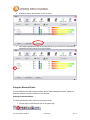
Highlight a network and click the "Connect" button.
If the SSID is broadcasted and no securities are found, you will connect. Connection is
indicated by the blue triangle next to the network.
Using the Bluetooth Radio
The internal Bluetooth Class II wireless radio in the DLI 8400 is disabled by default. Microsoft™
Bluetooth software comes pre-installed on your terminal.
Enabling the Bluetooth Radio
To enable the Bluetooth radio, follow the instructions below:
1. Hold the stylus on the Bluetooth icon in the system tray.
DLI 8400 PRODUCT MANUAL
PAGE 23/49
Rev. 3
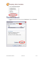
2. Select Open Bluetooth Settings.
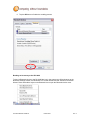
3. From the tabs at the top of the screen choose the Hardware tab. Tap on the Properties
button.
DLI 8400 PRODUCT MANUAL
PAGE 24/49
Rev. 3
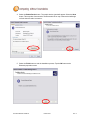
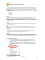
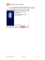
4. Select the Enable Device button. The enable device wizard will appear. Select the Next
button. This may take a few seconds. The Bluetooth LED on top of the terminal will begin
to flash when the radio is turned on.
5. Select the Finish button to end the installation process. Tap the OK button at the
Bluetooth properties screen.
DLI 8400 PRODUCT MANUAL
PAGE 25/49
Rev. 3
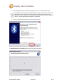
6. Tap the OK button to finalize the enabling process.
Bonding an Accessory to the DLI 8400
To bond a Bluetooth device to the DLI 8400 the icon in the system tray offers shortcuts to the
Bluetooth Settings window; the Bluetooth File Transfer Wizard and the Add New Connection
Wizard. Press and hold the stylus on the Bluetooth icon to open the Bluetooth device menu.
DLI 8400 PRODUCT MANUAL
PAGE 26/49
Rev. 3
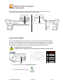
The following process is generally common for connecting most Bluetooth devices (keyboard,
mouse, printer, cellular phone, PDA, Tablet PC, notebook PC, etc.). The actual steps may be
slightly different for every type and brand of Bluetooth device. Read and follow the installation
instructions included with your specific device. These are the four generic steps for connecting
to a Bluetooth device.
1.
2.
3.
4.
Discover
Search
Pair
Connect
Discover
Making a Bluetooth device discoverable makes it visible to other Bluetooth devices. Each
Bluetooth device uses a different method (pressing a button or key combination) to make it
discoverable. This is generally described in the device’s documentation. When you activate
Bluetooth on your Tablet PC it is the signal for the Tablet PC to look for, or discover any Bluetooth
devices within range.
Search
This process will find every Bluetooth device that is discoverable and available for connection
within 33 feet (10 meters).
Pair
Using a passkey creates a secure connection (pairing) between the Tablet PC and
Bluetooth device. This passkey helps prevent data from being intercepted and interpreted by
another device.
Though the passkey exchange helps to secure your data, Bluetooth wireless
technology should not be considered completely secure.
Connect
The first time a Bluetooth device is connected to the terminal the drivers are loaded for that
device. After this initial connection, some Bluetooth devices may disconnect when they go into
power-saving mode. Most will automatically reconnect when they become active again.
Using the Bluetooth Application
1. Make sure that either the Bluetooth indicator light is flashing or that there is a
checkmark beside Enable Internal Bluetooth Wireless Radio (both indicate that
Bluetooth is running)
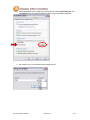
2. Using your stylus, Right mouse click the Bluetooth Devices icon in the system tray.
3. Tap Add a Bluetooth Device to launch the Bluetooth Add Bluetooth Device
Wizard.
DLI 8400 PRODUCT MANUAL
PAGE 27/49
Rev. 3
4. Place the Bluetooth device (headset, keyboard, printer, etc.) in discoverable mode.
Each Bluetooth device may have a different way to make it discoverable. Some have a
small button on the headset or keyboard; others may require that you press a key
sequence to invoke discovery. Look at the documentation that came with the Bluetooth
device or visit the manufacturer’s website for information.
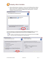
5. After you make the Bluetooth device discoverable, tap Next.
The Add Bluetooth Device Wizard will search for the Bluetooth device.
DLI 8400 PRODUCT MANUAL
PAGE 28/49
Rev. 3
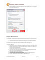
6. When the Bluetooth device is detected, it is shown in the Add Bluetooth Device Wizard
Select a device window. If multiple devices are detected, each is shown in the window.
Select the device to be connected. Tap Next to add the Bluetooth device. The wizard
searches for remote device services.
The Wizard will display a message Do you need a passkey to add your device. If your device
does not require a passkey, Windows will choose one for you. Press Next to continue
If required, immediately enter the number shown in the passkey field and press Next.
Consult your device documentation for more information.
DLI 8400 PRODUCT MANUAL
PAGE 29/49
Rev. 3
7. When the Completing the Add Bluetooth Device Wizard window appears, the
Bluetooth installation is nearly complete. Tap Finish to complete the installation.
DLI 8400 PRODUCT MANUAL
PAGE 30/49
Rev. 3
Using the Camera Option
The two 2MP Color Cameras are located on the front and back panels of the terminal. The
camera can be used for picture capture as well as streaming video.
2MP Color Camera
2MP Color Camera
Front Panel
Back Panel
Using the RS-232 DB9M
The integrated RS-232 Port can be configured to work with many peripherals including (Barcode
Scanners, Printers, ODBII (Vehicle Interface), and Remote Monitoring apparatuses). To configure
the RS-232 port so that the data is sent to the keyboard buffer the following procedure is required.
This procedure is typically used when using an external barcode scanner on the device.
All DLI Devices have power to Pin 9.
DO NOT plug-in or unplug any serial devices while the DLI Device is powered on!
Bottom Panel
1 2 3 4 5
6 7 8 9
Serial
Port
1.
Open the Control Panel, tap Start>Control Panel.
2.
Tap on Accessibility Options Icon.
DLI 8400 PRODUCT MANUAL
PAGE 31/49
Pin
1
2
3
4
5
6
7
8
9
Description
DCD
TXD
RXD
DSR
GND
DTR
CTS
RTS
+5V
Rev. 3
3.
Chose the General Tab to configure the RS-232 port and check Use Serial Keys. Tap
the Settings button to access the Baud Rate and Com port that will be configured.
4. Set Serial Port to Com1 and Baud Rate to 9600, tap OK.
DLI 8400 PRODUCT MANUAL
PAGE 32/49
Rev. 3
5. Save the settings by choosing the Apply button, then tap OK. Now you can plug the
device into the RS-232 port.
Using the Barcode Scanner
The DLI 8400 is available with an optional integrated barcode imager for scanning barcodes.
Honeywell® 5300 Class 2 Standard Range Imager with Cross Hairs (Integrated)
The Imager can be configured by using the DLI 8400 KeyMon (See Page 16).
To Decode a Barcode
1. Point the top of the DLI 8400 terminal directly at the barcode. The Imager faces
straight out of the top panel. The Cross Hairs should be oriented in line with the bar
code to achieve optimal decoding.
(Distance from barcode should be 2 to 15 inches)
2. Project the Imager and Cross Hairs by pressing and holding the programmed scan
button which is set in KeyMon(default is Left Side Button).
3. Center the cross hairs over the barcode.
4. When the barcode is successfully decoded, the decode LED lights green and
the terminal beeps. (Bad read, LED lights red)
5. The bar code information is entered into the application in use.
DLI 8400 PRODUCT MANUAL
PAGE 33/49
Rev. 3
Biometric Reader
The fingerprint reader is located top right on the Front Panel and enables you to scan your
fingerprint and associate it with passwords. This feature offers a quick and convenient way to log on
to your DLI 8400 terminal, provides global password management, and protects your terminal data
from unauthorized access.
Fingerprint
Scanning
or
Using GPS
The optional GPS module with active antenna provides the SiRFstar III chip set and TTFF (Time
to First Fix) technology which speeds the time to lock to a satellite. The Geohelix active antenna
provides 25db gain. Along with each of these features Data Ltd’s patent pending RF antenna
switching technology provides you with the functionality of switching between external and
internal antennas without software requirements.
Data Ltd has included in the DLI 8400 a GPS software tool to verify that all functions of the GPS
module are working properly.
1. To launch the application tap on the VisualGPS icon on the DLI 8400 desktop.
Visual GPS can also be found under Start>All Programs>VisualGPS.
DLI 8400 PRODUCT MANUAL
PAGE 34/49
Rev. 3
2. Choose the Settings option from the main menu and select Communications from the
drop down menu.
3. The configuration screen is displayed. Set the Com Port to Comm 1. This is the com port
that your GPS module is using. Set the Baud Rate to 9600. Tap the OK button to save the
settings.
DLI 8400 PRODUCT MANUAL
PAGE 35/49
Rev. 3
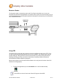
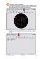
4. From the Toolbar choose the NMEA icon. The raw NMEA code will continue to load until
the NMEA window is closed. This test assures that the GPS module is talking to the Main
CPU of the terminal.
5. To verify the Signal Quality you must be outside a building as GPS antennas do not work
inside buildings. From the main menu choose the Signal icon. The screen will display
the db gain to each satellite that the GPS module is communicating with.
The blue bar indicates a lock to a satellite and the gray bar indicates that the module
is communicating with the satellite but does not have a complete fix on your location.
DLI 8400 PRODUCT MANUAL
PAGE 36/49
Rev. 3
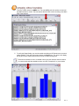
6. To verify the satellites that the GPS module are fixed to, Tap on the Satellite icon. The
screen displays the satellites in red that the module is fixed with. The gray satellites are
being communicated with but are not locked on the modules position.
7. To verify the longitude and latitude reading from the DLI 8400 location choose the
Navigation icon. The module must be locked onto 3 satellites before the reading is
accurate.
DLI 8400 PRODUCT MANUAL
PAGE 37/49
Rev. 3
DLI 8400 Cradle
Overview
DLI 8400 Cradle is a Desktop and Vehicle Cradle all in one. It features a quick release locking
mechanism, flexible mounting, and power options for all types of applications and devices.
When the DLI 8400 is seated in the Cradle, both Hot-swappable batteries are charged in 4 hours.
The configurable I/O Ports support USB, RS232, Ethernet; all with DLI Locking connector
providing security and reliability. The patent pending RF design provides operating with ease
using internal and external antennas.
Charging
The Cradle provides power to the intelligent battery charging system in the DLI 8400 that senses
when a full charge has been achieved and switches to a trickle charge to maintain a full charge.
Communications
The Cradle transmits via USB 2.0 and serial devices at speeds of up to 115K baud. The
Ethernet transmits at 10/100 mbps.
RF Communication
The DLI 8400 Terminal with its integrated RF switching circuit provides a pass through for the RF
external connectors. This technology optimizes the ability for quick disconnect from the cradle and
switches the RF signal from the cradle to the internal antennas on the DLI 8400 Terminal.
Use only DLI 8400 peripherals, power cables, and power adapters. Use of
peripherals, cables, or power adapters not sold/manufactured by Data Ltd. Inc.
will void the warranty and may damage the terminal.
Use only Li-Ion battery packs provided by Data Ltd. Inc. The use of any battery
pack not sold/manufactured by Data Ltd. Inc. will void the warranty and may
damage the terminal.
DLI 8400 PRODUCT MANUAL
PAGE 38/49
Rev. 3
Front Panel
Button Release to
Disengage the Unit
from the Cradle
Latches
Cradle Interface
Connection LED
Solid green Connection LED indicates connection established with Terminal.
Bottom Panel
The I/O and the power supply connector are located on the bottom of the unit.
Power Supply
Connector
Power Supply Connector
The connector is to be used with the DLI series of power supplies. Please see below for a
reference of those recommended power sources.
The Cradle can be powered by an external DC power source of 18VDC~22VDC. An
optional internal 6VDC~60VDC regulated power supply is available.
Verify that the power source is always within the specification range and
observe correct input voltage polarity. An improper input voltage range
above 22VDC(standard) or above 60VDC directly to battery terminals
(optional) or reverse polarity could damage the power conversion circuitry.
DLI 8400 PRODUCT MANUAL
PAGE 39/49
Rev. 3
Recommended Power Supplies:
5421112020900P
6705200041000P
AC Adapter W/Line Cord
Cigarette Lighter Adapter for charging the unit in a vehicle
USB Communication Port
The Cradle was designed with locking USB connectors. The USB port power is rated to 1 AMP.
Locking USB cables are available for the Symbol LS3408 & DLI 72K QWERTY Industrial Keyboard
(6700110200000P). Standard USB cables can also be connected to the cradle.
RS232 Communication Port
Use a standard serial cable to connect the unit to a host device via RS232
Ethernet Communication Port
The locking Ethernet connection supports 10/100mbps communication via a wired LAN. Standard
Ethernet cables can be use to attach the cradle to a host system.
Quick Release RF Connectors
The Vehicle Cradle patent pending quick release RF connectors provide a switching pass through
to the RF connectors on the bottom of the cradle. The 2 options available are FME for cellular
support and SMA for GPS support. Should you require a custom connection please consult your
DLI product vendor or DLI sales representative.
Connector Locations
Ethernet
USB Qty. 3
Power
Ask your Salesperson for a Product Catalog
to get more information for this VMC option.
8400-VMC-1
Ethernet
USB Qty. 3
8400-VMC-2
Power
Ask your Salesperson for a Product Catalog
to get more information for this VMC option.
J-Bus
DB-9m (RS232) Qty. 3
8400-VMC-3
DLI 8400 PRODUCT MANUAL
8400-VMC-4
PAGE 40/49
Rev. 3
Installing the Vehicle Cradle
Mounted to the back panel of the Vehicle Cradle is a RAM-202U ball. Optional RAM mounting
arms are available for a variety of secure options. When selecting a location to mount the cradle,
keep in mind that the power supply, RF connectors, and I/O point straight out of the bottom panel.
Lock
RAM-202U Ball
K-Lock
Base
Please ensure that you give a minimum of 2.75 inches of clearance from the
base of the cradle. Proper cable routing and clearance will help with less strain
on cables and connectors, while also allowing for better access to the ports.
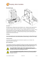
Cradle Power Filtering DC Converter
The DLI 8400 Cradle has an optional 10~60V DC/DC Converter. The DLI 8400 Cradle must be
installed pre-ignition (directly to battery terminals) with a 10AMP in-line fuse. Failure to
connect to battery terminals could damage the power conversion circuitry.
DC Converter: 10~60V Input
Red
Positive
Black
Tie
Ground
Yellow together
Please consult your fork truck manufacturer for proper installation instructions.
DO NOT connect power to the hydraulics!
We recommend installation by trained service personnel only. The fuse should
be installed in the positive lead within 5 inches of the battery positive (+)
terminal.
DLI 8400 PRODUCT MANUAL
PAGE 41/49
Rev. 3
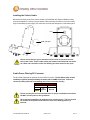
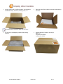
Shipping your DLI Device
Proper way to pack your DLI device
DO NOT ship any DLI Device without a proper UPS or FedEx container. The DLI
Container is not meant for stand-alone shipping.
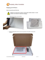
Place device in foam cover as shown.
Place the wrapped DLI device in the correct position in the spacer inside the DLI
Container.
DLI 8400 PRODUCT MANUAL
PAGE 42/49
Rev. 3
Using a proper UPS or FedEx container, line the bottom
with Bubble Wrap, Air Pillows, Packing Foam, etc.
Place the closed DLI container inside the lined Shipping
Container.
Seal the Shipping Container and ship to:
Data LTD
703 Data Ltd Parkway
La Porte, IN 46350
The dimensions of the box shown are 27x17x10.
Fill the rest of the Shipping Container with packing
material.
DLI 8400 PRODUCT MANUAL
PAGE 43/49
Rev. 3
Technical Assistance
If you need assistance installing or troubleshooting, please call your DLI vendor or the Data
Ltd. Inc. Technical Support Office.
North America/Canada:
Telephone:
(800) 526-1299, Ext 774 (8 AM to 4 PM CST)
Fax number:
(219) 362-1937
E- mail:
support@dataltd.com
Website:
http://www.dataltd.com/html/support-ticket.html
Product Service and Repair
Data Ltd. Inc. provides service for all its products through service centers throughout North
America. To obtain warranty or non-warranty service, return the unit to Data Ltd. Inc. (postage
paid) with a copy of the dated purchase record attached. Contact the appropriate location below
to obtain a Return Material Authorization number (RMA #) before returning the product.
Telephone:
(800) 526-1299 ext 723
Fax number:
(219) 362-1937
E-mail:
RMA@dataltd.com
Website:
http://www.dataltd.com/html/request-rma.html
Limited Warranty
Data Ltd. Inc. warrants its products to be free from defects in materials and workmanship and to
conform to Data Ltd. Inc. published specifications applicable to the products purchased at the time
of shipment. This warranty does not cover any product which is (i) improperly installed or used; (ii)
damaged by accident or negligence, including failure to follow the proper maintenance, service,
and cleaning schedule; or (iii) damaged as a result of (A) modification or alteration by the
purchaser or other party, (B) excessive voltage or current supplied to or drawn from the interface
connections, (C) static electricity or electro-static discharge, (D) operation under conditions
beyond the specified operating parameters, or (E) repair or service of the product by anyone
other than Data Ltd. Inc. or its authorized representatives.
This warranty shall extend from the time of shipment for the duration published by Data Ltd. Inc.
for the product at the time of purchase ("Warranty Period"). Any defective product must be
returned (at purchaser’s expense) during the Warranty Period to Data Ltd. Inc.’s factory or
authorized service center for inspection. No product will be accepted by Data Ltd. Inc. without a
Return Materials Authorization, which may be obtained by contacting Data Ltd. Inc. In the event
that the product is returned to Data Ltd. Inc. or its authorized service center within the Warranty
Period and Data Ltd. Inc. determines to its satisfaction that the product is defective due to defects
in materials or workmanship, Data Ltd. Inc., at its sole option, will either repair or replace the
product without charge, except for return shipping to Data Ltd. Inc..
EXCEPT AS MAY BE OTHERWISE PROVIDED BY APPLICABLE LAW, THE FOREGOING
WARRANTY IS IN LIEU OF ALL OTHER COVENANTS OR WARRANTIES, EITHER
EXPRESSED OR IMPLIED, ORAL OR WRITTEN, INCLUDING, WITHOUT LIMITATION, ANY
IMPLIED WARRANTIES OF MERCHANTABILITY OR FITNESS FOR A PARTICULAR
PURPOSE.
DLI 8400 PRODUCT MANUAL
PAGE 44/49
Rev. 3
DATA LTD. INC’S RESPONSIBILITY AND PURCHASER’S EXCLUSIVE REMEDY UNDER THIS
WARRANTY IS LIMITED TO THE REPAIR OR REPLACEMENT OF THE DEFECTIVE
PRODUCT. IN NO EVENT SHALL DATA LTD. INC. BE LIABLE FOR INDIRECT, INCIDENTAL,
OR CONSEQUENTIAL DAMAGES, AND, IN NO EVENT, SHALL ANY LIABILITY OF DATA LTD.
INC’S ARISING IN CONNECTION WITH ANY PRODUCT SOLD HEREUNDER (WHETHER
SUCH LIABILITY ARISES FROM A CLAIM BASED ON CONTRACT, WARRANTY, TORT, OR
OTHERWISE) EXCEED THE ACTUAL AMOUNT PAID TO DATA LTD. INC. FOR THE
PRODUCT. THESE LIMITATIONS ON LIABILITY SHALL REMAIN IN FULL FORCE AND
EFFECT EVEN WHEN DATA LTD. INC. MAY HAVE BEEN ADVISED OF THE POSSIBILITY OF
SUCH INJURIES, LOSSES, OR DAMAGES. SOME STATES, PROVINCES, OR COUNTRIES
DO NOT ALLOW THE EXCLUSION OR LIMITATIONS OF INCIDENTAL OR CONSEQUENTIAL
DAMAGES, SO THE ABOVE LIMITATION OR EXCLUSION MAY NOT APPLY TO YOU.
All provisions of this Limited Warranty are separate and severable, which means that if any
provision is held invalid and unenforceable, such determination shall not affect the validity of
enforceability of the other provisions hereof.
Data Ltd. Inc., Inc. extends these warranties only to the first end users of the products. These
warranties are non-transferable.
The limited duration of the warranty for the DLI 8400 is as follows:
DLI 8400 terminal with an integrated modules are covered by a one-year limited
warranty.
Touch screens are covered by a one-year limited warranty.
DLI 8400 Vehicle Mount Cradle, 3-Bay Battery Charger, and 3-Way Battery Adapter
Cable, are covered by a one-year limited warranty.
The limited duration of the warranty for batteries is one year. Use of any battery not sold/
manufactured by Data Ltd. Inc. may damage the terminal and/or the battery and will void
the warranty. Batteries returned to Data Ltd. Inc. in a reduced state may or may not be
replaced under this warranty. Battery life will be greatly increased when following the
battery instructions in the DLI 8400 User’s Guide.
Use of any peripheral not manufactured/sold by Data Ltd. Inc. will void the warranty.
This includes but is not limited to: cables, power supplies, cradles, and docking stations.
Regulatory and Safety Approvals for the DLI 8400
The DLI 8400 terminal meets or exceeds the requirements of all applicable standards
organizations for safe operation. However, as with any electrical equipment, the best
way to ensure safe operation is to operate them according to the agency guidelines
that follow. Please read these guidelines carefully before using your DLI 8400
terminal.
Embedded Safety Information Text
The DLI 8400 has the following safety information on the back label of the terminal
DLI 8400 PRODUCT MANUAL
PAGE 45/49
Rev. 3
DLI 8400 RF terminal is designed to comply with the most current applicable standards on safe
levels of RF energy developed by the Institute of Electrical and Electronics Engineers (IEEE) and
the American National Standards Institute (ANSI) and has been recommended for adoption by
the Federal Communications Commission (FCC).
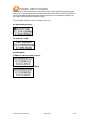
The compliance labels are located on the back of the unit:
DLI 8400 WPAN (Bluetooth)
DLI 8400 802.11 A/B/G
DLI 8400 WWAN
(CDMA Sierra Wireless Radio) Verizon®
(GPRS Sierra Wireless Radio) AT&T®
DLI 8400 PRODUCT MANUAL
PAGE 46/49
Rev. 3
The CE Mark on the product indicates that the system has been tested to and
conforms to the provisions noted within the 89/336/EEC Electromagnetic Compatibility Directive
and the 73/23/EEC and 93/68/EEC Low Voltage Directive.
For further information, please contact:
Data Ltd. Inc.
703 Data Ltd Parkway
P.O. Box 761
La Porte, IN 46352 USA
(800) 526-1299
Data Ltd. Inc. shall not be liable for use of our product with equipment (i.e., power supplies,
personal computers, etc.) that is not CE marked and does not comply with the Low Voltage
Directive
FCC Compliance
This device complies with Part 15 of the FCC Rules. Operation is subject to the following two
conditions: (1) this device may not cause harmful interference, and (2) this device must accept
any interference received, including interference that may cause undesired operation.
This equipment has been tested and found to comply with the limits for a Class B digital device
pursuant to Part 15 of the FCC Rules. These limits are designed to provide reasonable protection
against harmful interference in a residential installation. This equipment generates, uses, and can
radiate radio frequency energy and, if not installed and used in accordance with the instructions,
may cause harmful interference to radio communications. If this equipment does cause harmful
interference to radio or television reception, which can be determined by turning the equipment
off and on, the user is encouraged to try to correct the interference by one or more of the
following measures:
Reorient or relocate the receiving antenna.
Increase the separation between the equipment and receiver.
Connect the equipment into an outlet on a circuit different from that to which the receiver is
connected.
Consult the dealer or an experienced radio/TV technician for help.
If necessary, the user should consult the dealer or an experienced radio/television technician for
additional suggestions. The user may find the following booklet helpful: “Something About
Interference.” This is available at FCC local regional offices. Our company is not responsible for
any radio or television interference caused by unauthorized modifications of this equipment or the
substitution or attachment of connecting cables and equipment other than those specified by our
company. The correction is the responsibility of the user. Use only shielded data cables with this
system. In accordance with FCC 15.21, changes or modifications not expressly approved by the
party responsible for compliance could void the user’s authority to operate the equipment.
This device and its antenna must not be co-located or operating in conjunction
with any other antenna or transmitter. To maintain compliance with FCC RF
exposure guidelines for body-worn operation, do not use accessories that
contain metallic components.
When using accessories where the terminal is worn on the body, the terminal’s touch screen
must face away from the body.
DLI 8400 PRODUCT MANUAL
PAGE 47/49
Rev. 3
CAUTION!
Any changes or modifications not expressly approved by the grantee of this
device could void the user's authority to operate the equipment.
Canadian Compliance
This Class B digital apparatus complies with Canadian ICES-003. Operation is subject to the
following two conditions: (1) this device may not cause harmful interference, and (2) this device
must accept any interference received, including interference that may cause undesired
operation.
To prevent radio interference to the licensed service, this device is intended to be operated
indoors and away from windows to provide maximum shielding. Equipment (or its transmit
antenna) installed outdoors is subject to licensing.
Cet appareil numérique de la Classe B est conforme à la norme NMB-003 du Canada.
For European Community Users
Data Ltd. Inc. complies with Directive 2002/69/EC OF THE EUROPEAN PARLIAMENT AND OF
THE COUNCIL of 27 January 2003 on waste electrical and electronic equipment (WEEE).
Waste Electrical and Electronic Equipment Information
This product has required the extraction and use of natural resources for its production. It
may contain hazardous substances that could impact health and the environment, if not
properly disposed.
In order to avoid the dissemination of those substances in our environment and to diminish the
pressure on the natural resources, we encourage you to use the appropriate take-back
systems for product disposal. Those systems will reuse or recycle most of the materials of the
product you are disposing in a sound way.
The crossed out wheeled bin symbol informs you that the product should not be
disposed of along with municipal waste and invites you to use the appropriate
separate take-back systems for product disposal.
If you need more information on the collection, reuses, and recycling systems, please contact
your local or regional waste administration.
You may also contact your supplier for more information on the environmental performances
of this product.
DLI 8400 PRODUCT MANUAL
PAGE 48/49
Rev. 3
Data Ltd. Inc.
703 Data Ltd. Parkway
P.O. box 761
La Porte, IN 46350
Telephone:
Fax number:
(800) 526-1299
(219) 362-1937
DLI 8400 PRODUCT MANUAL
PAGE 49/49
Rev. 3