1
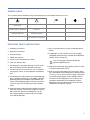
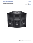
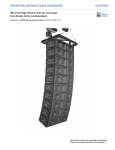
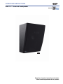
OPERATING INSTRUCTIONS
HMS-10™ Surround Loudspeaker
Keep these important operating instructions.
Check www.meyersound.com for updates.
DECLARATION OF CONFORMITY ACCORDING TO ISO/IEC GUIDE 22 AND EN 45014
Manufacturer’s Name: Meyer Sound Laboratories Inc.
Manufacturer’s Address: 2832 San Pablo Avenue
Berkeley, CA 94702-2204, USA
Declares that the product:
Product Names: HMS-10 Cinema Surround Loudspeaker
Product Options: All
Conforms to the following Product Specifications:
Safety: EN 60065:2002
EMC: EN55103-1: 1997 emission1
EN55103-2: 1997 immunity2
This device also complies with EN 55103-1 & -2. Operation is subject to the following two conditions:
(1) this device may not cause harmful interference, and
(2) this device must accept any interference received, including interference
that may cause undesired operation.
Supplementary Information: The product herewith complies with the requirements of the Low Voltage
Directive (LVD) 2006/95/EC and the EMC Directive 2004/108/EC.
Signature:
Director of Quality
Meyer Sound Laboratories Inc.
Berkeley, California 94702 USA
Issued June 2, 2009
European Contact:
Your local Meyer Sound dealer or
Meyer Sound Germany, GmbH.
© 2009, 2011
Meyer Sound. All rights reserved.
HMS-10 Operating Instructions, PN 05.198.011.01 B
The contents of this manual are furnished for informational purposes only, are subject to change without notice, and should not be construed as a commitment by Meyer Sound Laboratories Inc. Meyer Sound assumes no responsibility or liability for any errors or inaccuracies that may appear in this manual. Except as permitted by applicable copyright law, no part of this publication may be reproduced,
stored in a retrieval system, or transmitted, in any form or by any means, electronic, mechanical, recording or otherwise, without prior written permission from Meyer Sound.
EXP, HMS-10, and all alpha-numeric designations for Meyer Sound products and accessories are trademarks of Meyer Sound. Acheron,
Meyer Sound, and the Meyer Sound wave logo are registered trademarks of Meyer Sound Laboratories Inc. (Reg. U.S. Pat. & Tm. Off.). All
third-party trademarks mentioned herein are the property of their respective trademark holders.
ii
SYMBOLS USED
These symbols indicate important safety or operating features in this booklet and on the chassis:
!
Dangerous voltages: risk of
electric shock
Important operating instructions
Frame or chassis
Protective earth ground
Pour indiquer les risques
résultant de tensions dangereuses
Pour indequer important
instructions
Masse, châssis
Terre de protection
Warnung vor gefährlicher
elektrischer Spannung
Wichtige Betriebsanweisung oder
Gebrauchsanleitung
Rahmen oder Gehäuse
Masse Schutzleiter
Para indicar voltajes peligrosos
Instrucciones importantes de
funcionamiento y/o manteniento
Armadura o chassis
Tierra proteccionista
IMPORTANT SAFETY INSTRUCTIONS
1. Read these instructions.
2. Keep these instructions.
3. Heed all warnings.
4. Follow all instructions.
11. Only use attachments/accessories specified by Meyer
Sound.
12. If applicable, use only with the caster rails or rigging
specified by Meyer Sound, or sold with the loudspeaker.
Handles are for carrying only.
5. Do not use this loudspeaker near water.
6. Clean only with dry cloth.
7. Do not block any ventilation openings. Install in accordance with Meyer Sound’s installation instructions.
8. Do not install near any heat sources such as radiators,
heat registers, stoves, or other apparatus that produce
heat.
9. Do not defeat the safety purpose of the grounding-type
plug. A grounding type plug has two blades and a third
grounding prong. The third prong is provided for your
safety. If the provided plug does not fit into your outlet,
consult an electrician for replacement of the obsolete
outlet.
!
CAUTION: Rigging should only be done by
experienced professionals.
13. Unplug this loudspeaker during lightning storms or when
unused for long periods of time.
14. Refer all servicing to qualified service personnel. Servicing is required when the loudspeaker has been damaged
in any way, such as when the power-supply cord or plug
has been damaged; liquid has been spilled or objects
have fallen into the loudspeaker; rain or moisture has
entered the loudspeaker; the loudspeaker has been
dropped; or when for undetermined reasons the loudspeaker does not operate normally.
10. Protect the power cord from being walked on or pinched,
particularly at plugs, convenience receptacles, and the
point where they exit from the loudspeaker. The AC
mains plug or appliance coupler shall remain readily
accessible for operation.
iii
SAFETY SUMMARY
English
■
■
■
To reduce the risk of electric shock, disconnect the loudspeaker from the AC
mains before installing audio cable.
Reconnect the power cord only after
making all signal connections.
Connect the loudspeaker to a two-pole,
three-wire grounding mains receptacle.
The receptacle must be connected to a
fuse or circuit breaker. Connection to
any other type of receptacle poses a
shock hazard and may violate local
electrical codes.
Do not install the loudspeaker in wet or
humid locations without using weather
protection equipment from Meyer
Sound.
■
Do not allow water or any foreign object
to get inside the loudspeaker. Do not
put objects containing liquid on or near
the unit.
■
To reduce the risk of overheating the
loudspeaker, avoid exposing it to direct
sunlight. Do not install the unit near
heat-emitting appliances, such as a
room heater or stove.
■
■
Ne pas installer l’haut-parleur dans un
endroit où il y a de l’eau ou une humidité excessive.
■
Ne pas laisser de l’eau ou tout objet
pénétrer dans l’haut-parleur. Ne pas
placer de r´cipients contenant un liquide
sur cet appareil, ni à proximité de celuici.
■
Pour éviter une surchauffe de l’hautparleur, conserver-la à l’abri du soleil.
Ne pas installer à proximité d’appareils
dégageant de la chaleur tels que radiateurs ou appareils de chauffage.
■
Ce haut-parleur contient des circuits
haute tension présentant un danger. Ne
jamais essayer de le démonter. Il n’y a
aucun composant qui puisse être
réparé par l’utilisateur. Toutes les réparations doivent être effectuées par du
personnel qualifié et agréé par le constructeur.
■
■
Um die Gefahr eines elektrischen
Schlages auf ein Minimum zu
reduzieren, den Lautsprecher vom
Stromnetz trennen, bevor ggf. ein
Audio-Schnittstellensignalkabel angeschlossen wird. Das Netzkabel erst
nach Herstellung aller Signalverbindungen wieder einstecken.
■
Der Lautsprecher an eine geerdete
zweipolige Dreiphasen-Netzsteckdose
anschließen. Die Steckdose muß mit
einem geeigneten Abzweigschutz
(Sicherung oder Leistungsschalter) verbunden sein. Der Anschluß der unterbrechungsfreien Stromversorgung an
einen anderen Steckdosentyp kann zu
Stromschlägen führen und gegen die
örtlichen Vorschriften verstoßen.
This loudspeaker contains potentially
hazardous voltages. Do not attempt to
disassemble the unit. The unit contains
no user-serviceable parts. Repairs
should be performed only by factorytrained service personnel.
iv
Pour réduire le risque d’électrocution,
débrancher la prise principale de l’hautparleur, avant d’installer le câble d’interface allant à l’audio. Ne rebrancher le
bloc d’alimentation qu’après avoir
effectué toutes les connections.
Branchez l’haut-parleur dans une prise
de courant à 3 dérivations (deux pôles
et la terre). Cette prise doit être munie
d’une protection adéquate (fusible ou
coupe-circuit). Le branchement dans
tout autre genre de prise pourrait
entraîner un risque d’électrocution et
peut constituer une infraction à la réglementation locale concernant les installations électriques.
Um ein Überhitzen dem Lautsprecher
zu verhindern, das Gerät vor direkter
Sonneneinstrahlung fernhalten und
nicht in der Nähe von wärmeabstrahlenden
■
Haushaltsgeräten (z.B. Heizgerät oder
Herd) aufstellen.
■
Im Inneren diesem Lautsprecher herrschen potentiell gefährliche Spannungen. Nicht versuchen, das Gerät zu
öffnen. Es enthält keine vom Benutzer
reparierbaren Teile. Reparaturen dürfen
nur von ausgebildetem Kundenienstpersonal durchgeführt werden.
Español
■
Para reducir el riesgo de descarga eléctrica, desconecte de la red de voltaje el
altoparlante antes de instalar el cable
de señal de audio. Vuelva a conectar la
alimentacion de voltaje una vez efectuadas todas las interconexiones de
señalizacion de audio.
■
Conecte el altoparlante a un tomacorriente bipolar y trifilar con neutro de
puesta a tierra. El tomacorriente debe
estar conectado a la protección de derivación apropiada (ya sea un fusible o un
disyuntor). La conexión a cualquier otro
tipo de tomacorriente puede constituir
peligro de descarga eléctrica y violar los
códigos eléctricos locales.
■
No instale el altoparlante en lugares
donde haya agua o humedad excesiva.
■
No deje que en el altoparlante entre
agua ni ningún objeto extraño. No
ponga objetos con líquidos encima de
la unidad ni cerca de ella.
■
Para reducir el riesgo de sobrecalentamiento, no exponga la unidad a los
rayos directos del sol ni la instale cerca
de artefactos que emiten calor, como
estufas o cocinas.
■
Este altoparlante contiene niveles de
voltaje peligrosos en potencia. No
intente desarmar la unidad, pues no
contiene piezas que puedan ser repardas por el usuario. Las reparaciones
deben efectuarse únicamente por parte
del personal de mantenimiento capacitado en la fábrica.
Deutsch
Français
■
■
■
■
Der Lautsprecher nicht an einem Ort
aufstellen, an dem sie mit Wasser oder
übermäßig hoher Luftfeuchtigkeit in
Berührung kommen könnte.
Darauf achten, daß weder Wasser noch
Fremdkörper in das Innere den
Lautsprecher eindringen. Keine
Objekte, die Flüssigkeit enthalten, auf
oder neben die unterbrechungsfreie
Stromversorgung stellen.
CONTENTS
Chapter 1: Introduction
How to Use This Manual
HMS-10 Surround Loudspeaker
Chapter 2: HMS-10 Loudspeaker
HMS-10 Input Connector
HMS-10 Current Draw and Cable Requirements
Wiring HMS-10 Loudspeaker Cables with Belden 1502 Cable (or Equivalent)
Chapter 3: Powering HMS-10 Loudspeakers
Connecting HMS-10 Loudspeakers to the MPS-488HP External Power Supply
Connecting HMS-10 Loudspeakers to the MPS-488 External Power Supply
Chapter 4: Mounting HMS-10 Loudspeakers
Important Safety Considerations
Mounting HMS-10 Loudspeakers with the Fixed Mount Bracket
Mounting HMS-10 Loudspeakers with the Adjustable Mount Bracket
Mounting HMS-10 Loudspeakers in Soffits
7
7
7
9
9
9
10
11
11
12
13
13
13
15
16
Appendix A: HMS-10 Accessories
17
Appendix B: HMS-10 Cable Assembly
19
Appendix C: HMS-10 Specifications
21
v
CONTENTS
vi
CHAPTER 1: INTRODUCTION
HOW TO USE THIS MANUAL
HMS-10 SURROUND LOUDSPEAKER
Make sure to read these operating instructions in their
entirety before configuring a loudspeaker system with
HMS-10s. In particular, pay close attention to material
related to safety issues.
Meyer Sound's HMS-10™ is a full-range, two-way loudspeaker optimized for surround channels in cinemas,
theatres, and re-recording stages. The self-powered
HMS-10 maintains a wide dynamic range, full fidelity, and
complete clarity during the most demanding of digital
soundtracks. As part of the EXP line of cinema products, the
HMS-10 is optimized for use with other EXP loudspeakers,
including the Acheron® screen channel loudspeakers.
Boasting a wide frequency range of 55 Hz to 18 kHz and a
maximum peak SPL of 126 dB at 1 meter with very low distortion, the HMS-10 ensures that the full intensity and
nuance of cinema surround channels reach each listener
without compromise.
As you read these operating instructions, you will encounter
the following icons for notes, tips, and cautions:
NOTE: A note identifies an important or useful
piece of information relating to the topic under
discussion.
TIP: A tip offers a helpful tip relevant to the topic
at hand.
CAUTION: A caution gives notice that an
action may have serious consequences and
could cause harm to equipment or personnel, or
could cause delays or other problems.
!
Information and specifications are subject to change.
Updates and supplementary information are available at
www.meyersound.com.
Meyer Sound Technical Support is available at:
■
Tel: +1 510 486.1166
■
Tel: +1 510 486.0657 (after hours support)
■
Web: www.meyersound.com/support
■
Email: techsupport@meyersound.com
HMS-10 Surround Loudspeaker (Shown without Grille)
The HMS-10’s transducers include a 10-inch low-frequency
long excursion cone driver and a 2-inch diaphragm high-frequency compression driver on a symmetrical constantdirectivity 80-degree horn that delivers exceptional coverage. The proprietary drivers — designed and manufactured
at Meyer Sound's headquarters in Berkeley, California — are
powered by two channels of onboard amplification that
include an active crossover, driver protection, and frequency
and phase response correction circuitry.
7
CHAPTER 1: INTRODUCTION
Balanced audio and DC power are received by the HMS-10
from a Phoenix™ 5-pin male connector on its top panel.
Powering the unit from an external source eliminates the
need for wiring conduits while still preserving the advantages of self-powered loudspeaker systems. The HMS-10's
amplifier and signal-processing circuits store DC power and
tolerate voltage drops, thereby accommodating light-gauge
cables and lengthy cable runs.
The HMS-10's compact size, textured finish, and black cloth
grille blend smartly with any theater decor. The HMS-10
comes standard with a fixed bracket; an optional adjustable
bracket is also available for wall mounting the HMS-10 with
downtilt or uptilt.
HMS-10 loudspeakers require a Meyer Sound 48 V DC
external power supply, such as the MPS-488HP. The singlespace 19-inch rack unit receives eight channels of balanced
audio from its XLR female Channel Inputs and routes the
audio, along with 48 V of DC power, to its eight Channel
Outputs. The Channel Outputs, which are available as
Phoenix 5-pin male connectors, deliver DC power to up to
eight HMS-10 loudspeakers at cable lengths up to 150 feet
with just 1 dB of loss in peak SPL using 18 AWG wire. The
use of composite multiconductor cables (such as Belden®
1502 or equivalent) allows a single cable to carry both DC
power and balanced audio to the HMS-10. Longer cable
runs are possible for moderate applications that don't drive
the loudspeakers to maximum output, or for installations
using heavier wire gauges.
HMS-10 with Fixed Mount Bracket
MPS-488HP External Power Supply
TIP: For complete information on using the
MPS-488HP external power supply, refer to the
MPS-488HP Operating Instructions.
NOTE: The MPS-488HP external power supply
replaces the MPS-488 model, which was originally designed for use with MM-4XP loudspeakers.
The MPS-488 is also compatible with HMS-10 loudspeakers and can drive up to four units (using every
other Channel Output).
Meyer Sound's industry standard self-powered loudspeaker
technology not only delivers unparalleled and consistent
audio fidelity but also simplifies installation, whether designing a new room from scratch or adding surround channels to
an existing setup.
HMS-10 with Adjustable Mount Bracket
8
CHAPTER 2: HMS-10 LOUDSPEAKER
HMS-10 INPUT CONNECTOR
The HMS-10 receives DC power and balanced audio from
its Phoenix 5-pin male connector on the top panel. The connector’s five pins include two pins for DC power (negative
and positive) and three pins for balanced audio (shield, negative, and positive). These pins are clearly labeled on the
HMS-10 top panel. The connector accepts conductors up to
12 AWG (American Wire Gauge) or 2.5 mm2. To function
properly, the HMS-10 requires an external 48 V DC power
supply.
HMS-10 CURRENT DRAW AND CABLE
REQUIREMENTS
Each HMS-10 loudspeaker draws a maximum current of
3.31 A rms and 3.45 A peak from its external 48 V DC power
supply. The current draw for the HMS-10 is dynamic and
fluctuates as operating levels change. The cabling between
the HMS-10 and its external power supply adds resistance
and hence causes a voltage drop at the loudspeaker.
Because lower voltages compromise peak SPL, and in
some cases frequency response, cable resistance should be
minimized.
NOTE: For long cable runs, you can use a large
cable gauge for DC power and a separate balanced audio cable for audio.
Cable Lengths and Cable Gauges for HMS-10
Loudspeakers
HMS-10 Input Connector
A single composite cable (such as Belden 1502 or equivalent) can be used to route both DC power and balanced
audio to the HMS-10 loudspeaker.
Each HMS-10 loudspeaker comes with one Phoenix 5-pin
female cable connector for making loudspeaker cables. For
information on HMS-10 cable requirements, see “HMS-10
Current Draw and Cable Requirements” on page 9. For
information on cables and cable accessories available from
Meyer Sound, see Appendix A, “HMS-10 Accessories.” For
information on cable assembly, see Appendix B, “HMS-10
Cable Assembly.”
CAUTION: When wiring HMS-10 loudspeaker
cables, it is extremely important that each pin
be wired correctly. Make sure the 48 V DC from the
external power supply is wired directly (and only) to
the 48 V DC pins on the HMS-10 loudspeaker connector, and that the polarity is observed (negative to
negative, positive to positive) to avoid damage to the
loudspeaker. In addition, make sure that audio pins
are wired correctly; polarity reversals for audio signals
affect system performance.
!
Cable lengths of up to 150 feet between the HMS-10 and its
external power are supported with only 1 dB of peak SPL
loss when using 18 AWG wire. Longer cable lengths are
possible with heavier wire gauges (see Table 1 and Table 2).
Table 1: HMS-10 Loudspeaker Cable Lengths (AWG)
Cable Gauge
Resistance
(:/ft)
Approximate
Max. Length
12 AWG
0.0016
600 ft
14 AWG
0.00253
375 ft
16 AWG
0.00402
237 ft
18 AWG
0.00636
150 ft
20 AWG
0.01008
87 ft
Table 2: HMS-10 Loudspeaker Cable Lengths (European)
Cable Gauge
Resistance
(:/m)
Approximate
Max. Length
2.50 mm2
0.0052
157 m
1.50
mm2
0.01076
87 m
1.00
mm2
0.02087
45 m
0.75
mm2
0.03307
27 m
NOTE: The total cable resistance between the
HMS-10 and its external power supply should
not exceed 2 ohms.
9
CHAPTER 2: HMS-10 LOUDSPEAKER
Calculating the Maximum Cable Length
The maximum cable length for an HMS-10 can be calculated with the following formula:
maximum length = 2 ohms / 2 * cable resistance
For example, the maximum length of an 18 AWG cable with
a resistance of 0.00636 is 157.2 feet (2 / 2 * 0.00636).
WIRING HMS-10 LOUDSPEAKER CABLES
WITH BELDEN 1502 CABLE (OR EQUIVALENT)
When wiring HMS-10 loudspeaker cables with Belden 1502
cable, use the conventions in Table 3. The red and black
wires in the Belden 1502 cable have a thicker gauge than
the other three wires and should be used for DC power. The
blue, white, and shield wires are shielded together and
should be used for audio.
Red: DC power (+)
Black: DC power (–)
White: audio (+)
Blue: audio (–)
Audio shield
Belden 1502 Composite Cable
Table 3: Wiring HMS-10 Loudspeaker Cables with Belden 1502
Wire
Gauge
Gauge
Red
DC power, positive (+)
18 AWG
Black
DC power, negative (–)
18 AWG
White
Balanced audio, positive (+)
22 AWG
Blue
Balanced audio, negative (–)
22 AWG
Shield
Balanced audio, shield
24 AWG
CAUTION: When wiring HMS-10 loudspeaker
cables, it is extremely important that each pin
be wired correctly. Make sure the 48 V DC from the
external power supply is wired directly (and only) to
the 48 V DC pins on the HMS-10 loudspeaker connector, and that the polarity is observed (negative to
negative, positive to positive) to avoid damage to the
loudspeaker. In addition, make sure that audio pins
are wired correctly; polarity reversals for audio signals
affect system performance.
!
10
CHAPTER 3: POWERING HMS-10 LOUDSPEAKERS
CONNECTING HMS-10 LOUDSPEAKERS TO
THE MPS-488HP EXTERNAL POWER SUPPLY
HMS-10 loudspeakers require a Meyer Sound 48 V DC
external power supply, such as the MPS-488HP. The singlespace 19-inch rack unit receives eight channels of balanced
audio from its XLR female Channel Inputs and routes the
audio, along with 48 V of DC power, to its eight Channel
Outputs. The Channel Outputs, which are available as
Phoenix 5-pin male connectors, deliver DC power to up to
eight HMS-10 loudspeakers at cable lengths up to 150 feet
with just 1 dB of loss in peak SPL using 18 AWG wire. The
use of composite multiconductor cables (such as Belden
1502 or equivalent) allows a single cable to carry both DC
power and balanced audio to the HMS-10. Longer cable
runs are possible for moderate applications that don't drive
the loudspeakers to maximum output, or for installations
using heavier wire gauges.
MPS-488HP
TIP: For complete information on using the
MPS-488HP external power supply, refer to the
MPS-488HP Operating Instructions.
To connect HMS-10 loudspeakers to the MPS-488HP:
1. Power off the MPS-488HP.
2. Connect audio sources (from a mixer or processor) to the
MPS-488HP Channel Inputs. Use balanced XLR cables.
3. Use the MPS-488HP Link switches to route Channel
Inputs to the desired Channel Outputs. For information
on the MPS-488HP Link switches, refer to the
MPS-488HP Operating Instructions.
4. Connect the HMS-10 loudspeakers to the MPS-488HP
Channel Outputs. Use a composite cable (such as
Belden 1502 or equivalent) outfitted with Phoenix connectors and wired for both DC power and balanced
audio.
CAUTION: Make sure HMS-10 loudspeaker
cables are wired correctly. For details on
assembling loudspeaker cables, see Appendix B,
“HMS-10 Cable Assembly.”
!
MPS-488HP with Eight HMS-10 Loudspeakers
TIP: You can use two separate cables for
HMS-10 loudspeaker connections: a 2-conductor cable for DC power and a 3-conductor cable for
balanced audio, both attached to a single Phoenix
connector on each cable end. This allows you to use
a larger gauge for the DC cable so you can achieve
longer cable runs (see “Cable Lengths and Cable
Gauges for HMS-10 Loudspeakers” on page 9).
5. Power on the MPS-488HP and monitor the LEDs on the
front panel to verify connections. For information on the
MPS-488HP LEDs, refer to the MPS-488HP Operating
Instructions.
6. Enable output from the audio sources (from the mixer or
processor) connected to the MPS-488HP.
11
CHAPTER 3: POWERING HMS-10 LOUDSPEAKERS
CONNECTING HMS-10 LOUDSPEAKERS TO
THE MPS-488 EXTERNAL POWER SUPPLY
The original MPS-488 was designed for use with the
MM-4XP miniature loudspeaker. While the MPS-488 can
power up to eight MM-4XP loudspeakers, it can only power
up to four HMS-10 loudspeakers (due to the HMS-10’s
higher power requirements and current draw).
X X
X X
X X
X
X
MPS-488
MPS-488 with Four HMS-10 Loudspeakers
Because the MPS-488 can power a maximum of four
HMS-10 loudspeakers, the loudspeakers should only be
connected to Channel Outputs 1, 3, 5, and 7. Do not use the
even-numbered channel outputs.
NOTE: The MPS-488HP external power supply
replaces the MPS-488 model, which was originally designed for use with MM-4XP loudspeakers.
The MPS-488 is also compatible with HMS-10 loudspeakers and can drive up to four units (using every
other Channel Output).
12
CHAPTER 4: MOUNTING HMS-10 LOUDSPEAKERS
The HMS-10 comes standard with a fixed bracket; an
adjustable bracket is also available for wall mounting the
HMS-10 with downtilt or uptilt. This chapter describes how
to mount the HMS-10 with these two mounting options.
IMPORTANT SAFETY CONSIDERATIONS
MOUNTING HMS-10 LOUDSPEAKERS WITH
THE FIXED MOUNT BRACKET
The HMS-10 can be mounted with a fixed mount bracket at
a fixed angle of 0 degrees. The low profile bracket allows the
HMS-10 to be mounted less than 0.6” (15 mm) from the
wall.
5.60
[142.24 mm]
When installing Meyer Sound loudspeakers, the following
precautions should always be observed:
■
All Meyer Sound products must be used in accordance
with local, state, federal, and industry regulations. It is
the owner’s and user’s responsibility to evaluate the reliability of any rigging or mounting method for their application. Rigging should only be carried out by
experienced professionals.
■
Use mounting and rigging hardware that has been rated
to meet or exceed the weight being hung.
■
Make sure to attach mounting hardware to the building's
structural components (studs or joists), and not just to
the wall surface. Verify that the building's structure and
the anchors used for the installation will safely support
the total weight of the mounted loudspeakers.
■
Use mounting hardware appropriate for the surface
where the loudspeaker will be installed.
■
Make sure bolts are tightened securely. Meyer Sound
recommends using Loctite® on bolt threads and safety
cables.
■
Inspect mounting and rigging hardware regularly. Immediately replace any worn or damaged components.
4.80
[121.92 mm]
Wall Plate
3.00
[76.20 mm]
5.10
[129.54 mm]
0.50
[12.70 mm]
Loudspeaker
Plate
3.94
[100.00 mm]
3.94
[100.00 mm]
Fixed Bracket (OmniMount 17FM-F)
NOTE: When ordering the HMS-10 with the
fixed mount bracket, the bracket is factory
installed and already attached to the loudspeaker.
13
CHAPTER 4: MOUNTING HMS-10 LOUDSPEAKERS
To mount the HMS-10 with the fixed mount bracket:
1. Disassemble the fixed bracket by removing the two bottom screws. Separate the wall plate from the loudspeaker plate (labeled “Monitor”). Leave the loudspeaker
plate attached to the HMS-10.
■
–
Drill two 1/8” pilot holes, 2.0 inches deep, at the
marked locations.
–
Secure the wall plate to the wall with the two wood
screws.
To mount the HMS-10 on a concrete wall:
–
Mark two mounting holes on the wall using the wall
plate’s center holes as a guide.
–
Drill two 5/16” pilot holes, 2.5 inches deep, at the
marked locations.
–
Install the wall anchors in the pilot holes so they are
flush with the wall surface.
–
Secure the wall plate to the wall with the wood
screws.
3. Hang the HMS-10 on the wall by carefully sliding the
loudspeaker plate (attached to the HMS-10) down into
the wall plate’s grooves.
4. For additional stability, secure the loudspeaker plate to
the wall plate with the two bottoms screws previously
removed.
2. Choose one of the following mounting options:
■
To mount the HMS-10 on a wall with a wood stud:
–
Locate the wall stud and mark two holes on the wall
using the wall plate’s center holes as a guide.
Mounting holes
14
NOTE: When mounting the HMS-10 in a soffit,
allow at least 3 inches above the unit for the
mounting bracket to slide into place. The extra space
also provides the necessary ventilation for the
HMS-10’s amplifier and heat sink.
HMS-10 OPERATING INSTRUCTIONS
MOUNTING HMS-10 LOUDSPEAKERS WITH
THE ADJUSTABLE MOUNT BRACKET
2. Choose one of the following mounting options:
■
The HMS-10 can be wall mounted with the adjustable
mount bracket at downtilt angles up to 13 degrees and uptilt
angles up to 5 degrees (uptilt).
To mount the HMS-10 on a wall with a wood stud:
–
Locate the stud and mark two mounting holes on the
wall using the wall plate’s center mounting slots as a
guide.
5.16
[131.06 mm]
4.75
[120.65 mm]
+5°/–13°
Wall Plate
Mounting slots
3.00
[76.20 mm]
3.94
[100.00 mm]
Loudspeaker
Plate
–
Drill two 1/8” pilot holes, 2.0 inches deep, at the
marked locations.
–
Install the wood screws in the pilot holes. Leave the
screws extended approximately 3/8” from the wall
surface.
3.94
[100.00 mm]
1.84
[46.74 mm]
Adjustable Bracket (OmniMount 17FM-T)
3/8”
NOTE: When ordering the HMS-10 with the
adjustable mount bracket, the bracket is factory installed and already attached to the loudspeaker.
To mount the HMS-10 with the adjustable mount bracket:
1. Disassemble the adjustable bracket by removing the four
side screws and washers. Separate the wall plate from
the loudspeaker plate (labeled “Monitor”). Leave the
loudspeaker plate attached to the HMS-10.
■
To mount the HMS-10 on a concrete wall:
–
Mark two mounting holes on the wall using the wall
plate’s center mounting slots as a guide.
–
Drill two 5/16” pilot holes, 2.5 inches deep, at the
marked locations.
–
Install the wall anchors in the pilot holes so they are
flush with the wall surface.
–
Install the wood screws in the wall anchors. Leave the
screws extended approximately 3/8” from the wall
surface.
3. Reattach the wall plate to the loudspeaker plate with the
previously removed four washers and screws. The washers should be placed on the outside of the loudspeaker
plate.
4. Hang the mounting bracket, with the HMS-10 attached,
on the wall screws.
15
CHAPTER 4: MOUNTING HMS-10 LOUDSPEAKERS
5. Adjust the tilt of the HMS-10 from –13 degrees (downtilt)
to +5 degrees (uptilt). Tighten the four side screws to
secure the HMS-10.
NOTE: Make sure the four side screws are
completely tightened to ensure that the
HMS-10 won’t move from its desired position.
-13°
NOTE: When mounting the HMS-10 in a soffit,
allow at least 3 inches above the unit to provide the necessary ventilation for its amplifier and
heat sink.
MOUNTING HMS-10 LOUDSPEAKERS IN
SOFFITS
When mounting the HMS-10 in a soffit, use a soffit that measures at least 24" wide by 36" high by 15" deep (610 mm x
914 mm x 381 mm). This ensures that the loudspeaker's full
80-degree horizontal by 80-degree vertical horn coverage
will reach the listener. If the soffit is deeper than 15”, or the
HMS-10 is angled down, the overall height of the soffit
should be increased to accommodate the horn’s vertical
coverage.
24.00
[610 mm]
15.00
[381 mm]
80°
HMS-10 in Soffit, Top View
In addition, make sure to allow at least 3 inches above the
HMS-10 for the mounting bracket to slide into place. The
extra space also provides the necessary ventilation for the
unit’s amplifier and heat sink.
3.00
[76 mm]
5°
36.00
[914 mm]
80°
13.50
[343 mm]
TIP: If more than 5 degrees of uptilt are needed
for the HMS-10, the adjustable bracket can be
oriented upside down (mount the wall plate on the
wall upside down and remove and reattach the loudspeaker plate to the HMS-10 also upside down). This
orientation allows uptilt angles up to 13 degrees.
15.00
[381 mm]
HMS-10 in Soffit, Side View
16
APPENDIX A: HMS-10 ACCESSORIES
The following HMS-10 accessories are available from Meyer Sound.
HMS-10 Accessories
Part Number
Accessory
Notes
09.183.001.01
MPS-488HPp external power supply
(with US power cord)
Channel Outputs equipped with Phoenix 5-pin male
connectors
09.183.001.02
MPS-488HPp external power supply
(with CE power cord)
484.065
Phoenix 5-pin female cable mount connector
Connects to MPS-488HPp Channel Output connectors and HMS-10 Input connectors
524.014
Bulk cable, no connetors (regular)
500-ft spool, black
524.015
Bulk cable, no connetors (plenum)
500-ft spool, white
NOTE: The MPS-488HP external power supply replaces the MPS-488 model, which was originally designed
for use with MM-4XP loudspeakers. The MPS-488 is also compatible with HMS-10 loudspeakers and can
drive up to four units (using every other Channel Output).
NOTE: Bulk cables use Belden 1502R (regular) or Belden 1502P (plenum) cable. Belden 1502 is a composite
cable comprised of two 18 AWG wires for DC power, two 22 AWG wires for balanced audio, and one 24 AWG
wire for audio shield. This single cable can deliver both DC power and balanced audio to loudspeakers at cable runs
of up to 150 feet with only 1 dB of loss in peak SPL. Longer cable runs are possible with heavier gauges for DC
power and separate cables for balanced audio. For more information, see “HMS-10 Current Draw and Cable
Requirements” on page 9.
17
APPENDIX A: HMS-10 ACCESSORIES
18
APPENDIX B: HMS-10 CABLE ASSEMBLY
CAUTION: When wiring HMS-10 loudspeaker cables, it is extremely important that each pin be wired correctly.
Make sure the 48 V DC from the external power supply is wired directly (and only) to the 48 V DC pins on the
HMS-10 loudspeaker connector, and that the polarity is observed (negative to negative, positive to positive) to avoid
damage to the loudspeaker. In addition, make sure that audio pins are wired correctly; polarity reversals for audio signals affect system performance.
!
ASSEMBLING PHOENIX-TO-PHOENIX LOUDSPEAKER CABLES
To connect the HMS-10 loudspeaker directly to the MPS-488HPp power supply, you need a Phoenix 5-pin female to
Phoenix 5-pin female cable. The following procedure documents how to assemble this cable.
Assembled Phoenix-to-Phoenix Cable
To assemble a Phoenix-to-Phoenix cable:
1. If the cable has not yet been stripped, strip one end of the cable. Strip the outer shielding 1 inch and then strip the black,
red, blue, and white wires .275 inch.
1”
0.275”
2. Insert the five exposed conductors, from one end of the cable, into the five cable holes in one of the Phoenix connectors.
Use the following wiring scheme.
Side (cable attached)
Pin #1
Black
48 V DC (–)
Pin #2
Red
48 V DC (+)
Pin #3
Shield
Audio shield
Pin #4
Blue
Audio (–)
Pin #5
White
Audio (+)
Connector side up
Phoenix 5-Pin Female Cable Mount Connector
19
APPENDIX B: HMS-10 CABLE ASSEMBLY
3. Secure the conductors by tightening the five screws in the Phoenix connector.
Tighten screws
4. Repeat the previous steps and attach the other end of the cable to the other Phoenix connector.
5. Verify the wiring polarity is correct for both connectors.
20
APPENDIX C: HMS-10 SPECIFICATIONS
HMS-10 Specifications
ACOUSTICAL
Operating Frequency Range
55 Hz – 18 kHz
Note: Recommended maximum operating frequency range. Response depends on loading conditions and room acoustics.
Frequency Response
58 Hz – 17.5 kHz ±4 dB
Note: Measured free-field with pink noise at 1 meter, 1/3rd octave resolution.
Maximum Peak SPL
126 dB
Note: Measured free-field with music, referred to 1 meter.
Dynamic Range
100 dB
Note: Taken from peak SPL, referred to A-wtd noise floor.
Phase Response
290 Hz – 18 kHz ±45°
Coverage
80° symmetrical
Acoustical Crossover
2.5 kHz
Note: At this frequency, the transducers produce equal sound pressure levels.
TRANSDUCERS
Low Frequency
One 10" low-frequency long excursion cone driver
High Frequency
One 2" high-frequency diaphragm compression driver
CONNECTOR
Audio/Power Connector
Single Phoenix 5-pin male (3 pins for balanced audio, 2 pins for DC power)
Power Wiring
Pin 1: 48 V DC –
Pin 2: 48 V DC +
Audio Wiring
Pin 3: Chassis/earth through 220 k:, 1000 pF, 15 V clamp network to provide virtual ground lift at
audio frequencies
Pin 4: Signal –
Pin 5: Signal +
AUDIO INPUT
Type
Differential, electronically balanced
Maximum Common Mode Range
±15 V DC, clamped to earth for voltage transient protection
Input Impedance
10 k: differential between pins 4 (–) and 5 (+)
DC Blocking
Differential DC blocking on input up to the maximum common mode voltage
CMRR
>50 dB, typically 80 dB (50 Hz – 500 Hz)
RF Filter
Common mode: 425 kHz
Differential mode: 142 kHz
TIM Filter
<80 kHz, integral to signal processing
Nominal Input Sensitivity
6.0 dBV (2.0 V rms, 2.8 V peak) continuous average is typically the onset of limiting for noise and
music
Input Level
Audio source must be capable of producing +16 dBV (6.3 V rms, 9.0 V peak) into 600 :to produce
the maximum peak SPL over the operating bandwidth of the loudspeaker
AMPLIFIER
Amplifier Type
Two-channel complementary MOSFET output stages (class AB/Bridged)
21
APPENDIX C: HMS-10 SPECIFICATIONS
HMS-10 Specifications
Output Power
300 W total
Note: Wattage rating based on the maximum unclipped burst sine-wave rms voltage the amplifier
will produce into the nominal load impedance.
THD, IM TIM
<.02%
Load Capacity
4 : low channel, 12 : high channel
Cooling
Convection
DC POWER
Voltage Requirement
48 V DC
Current Draw
Note: At 48 V DC.
Idle Current
0.35 A rms
Maximum Long-Term Continuous Current
2.03 A rms
Burst Current
3.31 A rms
Ultimate Short-Term Peak Current
3.45 A peak
Inrush Current
4.55 A peak
PHYSICAL
Enclosure
Multi-ply hardwood
Finish
Black textured
Protective Grille
Acoustically transparent, black cloth-covered frame
Mounting
Fixed bracket or optional adjustable bracket with 13° downtilt and 5° uptilt
Dimensions
15.5” W x 19.5” H x 12.5” D without mounting bracket
(394 mm x 495 mm x 317 mm)
Weight
29.1 lbs (13.2 kg) with mounting bracket
ENVIRONMENTAL
Operating Temperature
0° C to +45° C
Non Operating Temperature
<–40° C or >+75° C
Humidity
To 95% at 35° C
Operating Altitude
To 4600 m (15,000 ft)
Non operating Altitude
To 95% at 35° C
Shock
30 g 11 msec half-sine on each of 6 sides
Vibration
10 Hz – 55 Hz (0.010 m peak-to-peak excursion)
Rheinlan
UV
22
rt
.
In c
a,
o
of N
C
d
T
HMS-10 COMPLIANCE
h A e ri c
m
US
HMS-10 OPERATING INSTRUCTIONS
HMS-10 DIMENSIONS
5.60
[142 mm]
13.05
[331 mm]
15.50
[394 mm]
12.48
[317 mm]
7.42
[188 mm]
5.00
[127 mm]
19.50
[495 mm]
3.00
[76 mm]
7.80
[198 mm]
15°
6.87
[174 mm]
HMS-10 Dimensions with Fixed Bracket (OmniMount 17FM-F)
5.58
[142 mm]
14.34
[364 mm]
15.50
[394 mm]
7.42
[188 mm]
3.00
[76 mm]
12.48
[317 mm]
5.00
[127 mm]
19.50
[495 mm]
7.80
[198 mm]
15°
6.87
[174 mm]
HMS-10 Dimensions with Adjustable Bracket (OmniMount 17FM-T)
23
APPENDIX C: HMS-10 SPECIFICATIONS
24
Meyer Sound Laboratories Inc.
2832 San Pablo Avenue
Berkeley, CA 94702
www.meyersound.com
T: +1 510 486.1166
F: +1 510 486.8356
© 2009, 2011
Meyer Sound. All rights reserved.
HMS-10 Operating Instructions, PN 05.198.011.01 B