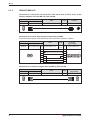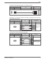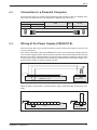
1
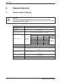
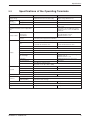
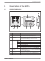
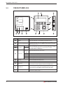
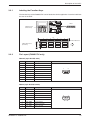
MITSUBISHI ELECTRIC
Graphic Operation Terminals
Human-Machine-Interface
Installation Manual
F920GOT-BBD5-K-E
F930GOT-BBD-K-E
Art.-Nr.: 160242
041202
Version A
MITSUBISHI ELECTRIC
INDUSTRIAL AUTOMATION
About this Manual
The texts, illustrations, diagrams, and examples contained in this manual
are intended exclusively as support material for the explanation, handling
and operation of the graphic operation terminals F920GOT-BBD5-K-E and
F930GOT-BBD-K-E.
If you have any questions concerning the programming and operation of
the equipment described in this manual, please contact your relevant sales
office or department (refer to back of cover).
Current information and answers to frequently asked questions are also
available through the Internet (www.mitsubishi-automation.com).
MITSUBISHI ELECTRIC EUROPE B.V. reserves the right to change the
specifications of its products and/or the contents of this manual at any time
without prior notice.
Installation Manual
Graphic Operation Terminals F920GOT-BBD5-K-E and F930GOT-BBD-K-E
Article No.: 160242
Version
A
2
12/2004
Changes/Additions/Corrections
pdp-dk
First Edition
MITSUBISHI ELECTRIC
1
Introduction
1.1
General Description . . . . . . . . . . . . . . . . . . . . . . . . . . . . . . . . . . . . . . . . . . . . . . . . .7
1.2
Connections . . . . . . . . . . . . . . . . . . . . . . . . . . . . . . . . . . . . . . . . . . . . . . . . . . . . . . .7
2
Specifications
2.1
General Specifications . . . . . . . . . . . . . . . . . . . . . . . . . . . . . . . . . . . . . . . . . . . . . . .8
2.2
Specifications of the Operating Terminals . . . . . . . . . . . . . . . . . . . . . . . . . . . . . . . . 9
2.3
Dimensions and Panel-cutout . . . . . . . . . . . . . . . . . . . . . . . . . . . . . . . . . . . . . . . . .10
3
Description of the GOTs
3.1
F920GOT-BBD5-K-E. . . . . . . . . . . . . . . . . . . . . . . . . . . . . . . . . . . . . . . . . . . . . . . .11
3.2
F930GOT-BBD-K-E. . . . . . . . . . . . . . . . . . . . . . . . . . . . . . . . . . . . . . . . . . . . . . . . .12
3.2.1
Labeling the Function Keys . . . . . . . . . . . . . . . . . . . . . . . . . . . . . . . . . . . 13
3.2.2
Pin Layout (F930GOT-K only). . . . . . . . . . . . . . . . . . . . . . . . . . . . . . . . . . 13
4
Installation
4.1
Preparing the Panel Surface. . . . . . . . . . . . . . . . . . . . . . . . . . . . . . . . . . . . . . . . . .14
4.2
Mounting . . . . . . . . . . . . . . . . . . . . . . . . . . . . . . . . . . . . . . . . . . . . . . . . . . . . . . . . .15
5
Wiring
5.1
Connection with the PLC . . . . . . . . . . . . . . . . . . . . . . . . . . . . . . . . . . . . . . . . . . . .16
5.1.1
F920GOT-BBD5-K-E . . . . . . . . . . . . . . . . . . . . . . . . . . . . . . . . . . . . . . . .16
5.1.2
F930GOT-BBD-K-E . . . . . . . . . . . . . . . . . . . . . . . . . . . . . . . . . . . . . . . . .18
5.2
Connection to a Personal Computer. . . . . . . . . . . . . . . . . . . . . . . . . . . . . . . . . . . .21
5.3
Wiring of the Power Supply (F930GOT-K) . . . . . . . . . . . . . . . . . . . . . . . . . . . . . . . 21
6
Start Up
6.1
Data Transfer to the F920GOT . . . . . . . . . . . . . . . . . . . . . . . . . . . . . . . . . . . . . . . .22
7
Maintenance
7.1
Replacement of the battery (F930GOT-K only) . . . . . . . . . . . . . . . . . . . . . . . . . . . 23
F920GOT-K / F930GOT-K
3
Safety Information
For qualified staff only
This manual is only intended for use by properly trained and qualified electrical technicians who
are fully acquainted with automation technology safety standards. All work with the hardware
described, including system design, installation, setup, maintenance, service and testing, may
only be performed by trained electrical technicians with approved qualifications who are fully
acquainted with the applicable automation technology safety standards and regulations.
Proper use of equipment
The graphic operation terminals F920GOT-BBD5-K-E and F930GOT-BBD-K-E are only
intended for the specific applications explicitly described in this manual. Please take care to
observe all the installation and operating parameters specified in the manual. All products are
designed, manufactured, tested and documentated in agreement with the safety regulations.
Any modification of the hardware or software or disregarding of the safety warnings given in this
manual or printed on the product can cause injury to persons or damage to equipment or other
property. Only accessories and peripherals specifically approved by MITSUBISHI ELECTRIC
may be used. Any other use or application of the products is deemed to be improper.
Relevant safety regulations
All safety and accident prevention regulations relevant to your specific application must be
observed in the system design, installation, setup, maintenance, servicing and testing of these
products. The regulations listed below are particularly important. This list does not claim to be
complete; however, you are responsible for knowing and applying the regulations applicable to
you.
쎲 VDE Standards
– VDE 0100
(Regulations for electrical installations with rated voltages up to 1,000V)
– VDE 0105
(Operation of electrical installations)
– VDE 0113
(Electrical systems with electronic equipment)
– VDE 0160
(Configuration of electrical systems and electrical equipment)
– VDE 0550/0551
(Regulations for transformers)
– VDE 0700
(Safety of electrical appliances for household use and similar applications)
– VDE 0860
(Safety regulations for mains-powered electronic appliances and their accessories for
household use and similar applications)
쎲 Fire prevention regulations
쎲 Accident prevention regulations
– VBG No. 4 (Electrical systems and equipment)
4
MITSUBISHI ELECTRIC
Safety warnings in this manual
In this manual special warnings that are important for the proper and safe use of the products are
clearly identified as follows:
P
DANGER:
Personnel health and injury warnings. Failure to observe the precautions described
here can result in serious health and injury hazards.
E
CAUTION:
Equipment and property damage warnings. Failure to observe the precautions
described here can result in serious damage to the equipment or other property.
General safety information
E
CAUTION:
쎲 Don't mount the graphic operation terminal in an enviroment that contains
dust, soot, conductive or corrosive dusts, corrosive or flammable gas, or
expose the unit to high temperatures, dew condensation or impact and
vibration.
쎲 Make sure to press touch keys on the display screen with the hand only. Don't
use excessive force. Don't use hard or sharp objects such as screw drivers or
pens.
쎲 Don't bind the communication cable together with the main circuit, the power
line or cables containing high voltages or currents.
Keep a distance of at least 100 mm to this cables to prevent malfunction caused
by noise.
P
CAUTION:
쎲 When the communication between the operation terminal and the PLC fails
(e.g. caused by a cable breakage) it is impossible to operate keys or devices in
the PLC via the GOT. After the error is gone the communication will be resumed. Make sure that a switch which gives a significant operation to the system
is executed from any equipment other than the operation terminal and that
there are no adverse consequences in the event of a communication failure .
Emergency stops and other safety functions must not be controlled via the
PLC.
쎲 Switch off the power supply before starting the installation or wiring.
F920GOT-K / F930GOT-K
5
General safety information and precautions
The following safety precautions are intended as a general guideline for using the PLC together
with other equipment. These precautions must always be observed in the design, installation
and operation of all control systems.
P
CAUTION:
쎲 Observe all safety and accident prevention regulations applicable to your
specific application. Installation, wiring and opening of the assemblies, components and devices may only be performed with all power supplies disconnected.
쎲 Assemblies, components and devices must always be installed in a shockproof
housing fitted with a proper cover and protective equipment.
쎲 Devices with a permanent connection to the mains power supply must be integrated in the building installations with an all-pole disconnection switch and a
suitable fuse.
쎲 Check power cables and lines connected to the equipment regularly for breaks
and insulation damage. If cable damage is found, immediately disconnect the
equipment and the cables from the power supply and replace the defective
cabling.
쎲 Before using the equipment for the first time check that the power supply rating
matches that of the local mains power.
쎲 Residual current protective devices pursuant to DIN VDE Standard 0641 Parts
1-3 are not adequate on their own as protection against indirect contact for
installations with positioning drive systems. Additional and/or other protection
facilities are essential for such installations.
쎲 EMERGENCY OFF facilities pursuant to EN 60204/IEC 204 VDE 0113 must remain
fully operative at all times and in all control system operating modes. The EMERGENCY OFF facility reset function must be designed so that it cannot cause an
uncontrolled or undefined restart.
쎲 You must also implement hardware and software safety precautions to prevent
the possibility of undefined control system states caused by signal line cable or
core breaks.
쎲 All relevant electrical and physical specifications must be strictly observed
and maintained for all the modules in the installation.
6
MITSUBISHI ELECTRIC
Introduction
1
Introduction
This Installation Manual includes a brief summary of the main specifications of the graphic operation terminals F920GOT-BBD5-K-E and F930GOT-BBD-K-E, which should be sufficient to
enable experienced users to install and configure the units. For further information on the operation terminals please refer to the manuals of the GOT F900 series. These manuals can be
ordered or downloaded free of charge from the Mitsubishi website at "www.mitsubishi-automation.com".
1.1
General Description
The graphic operation terminals (GOT) F920GOT-BBD5-K-E and F930GOT-BBD-K-E (or
F920GOT-K and F930GOT-K for short) are designed to be mounted in a panel or control cabinet. They are equipped with a high-resolution graphical dispay and a key pad with function keys
and ten-keys for entering numeric values.
With the additional touch screen function of the F930GOT-K you can make inputs or control a
machine easily by a touch of your hand.
The GOTs also offer diagnostic and monitor functions such as the display of the current value of
PLC devices.
The screen creation software FX-PCS/DU-WIN-E (from version 2.7 onward) or GT-Designer
(from version 5.26C) makes it easy to create user defined screens tailored to your application.
The build-in serial interfaces (RS422 and RS232C) of the operation terminals not only allow the
connection to all types of MELSEC (Mitsubishi Electric) PLCs, but also to programmable logic
controllers from third party manufacturers.
1.2
Connections
F920GOT-K
쎲 Via the RS422 port:
– direct connection to an PLC of the FX family (also to the interface adapters FX1N-422-BD
and FX2N-422-BD) and to CPU modules of the MELSEC A and QnA series
쎲 Via the RS232C-port:
– direct connection to a CPU module of the MELSEC System Q
F930GOT-K
쎲 Via the RS422 port:
– Connection to the MELSEC FX range of PLCs (either direct or with an interface adapter
FX1N-422-BD or FX2N-422-BD)
– Connection to the MELSEC A and QnA series (either direct or via an interface module)
– Connection to positioning modules FX2N-10/20GM
– Connection to MITSUBISHI frequency converters of the S500, E500 or A500 series
– Connection to PLCs from third party manufacturers
쎲 Via the RS232C-port:
– direct connection to a CPU module of the MELSEC System Q
– Connection to a PLC of the MELSEC FX family via interface adapter FX첸-232-BD or
the active data interface module FX0N-232ADP
– Connection to an interface module of the MELSEC A and QnA series, or the MELSEC
System Q
– Connection of a printer equipped with a serial RS232C port
– Connection of a bar-code reader
– Connection to PLCs from third party manufacturers
F920GOT-K / F930GOT-K
7
Specifications
2
Specifications
2.1
General Specifications
E
CAUTION:
Please operate the Graphic Operation Terminal in the listed conditions only.
If the GOT is used under other conditions, electric shock, fire, malfunction, damages
or deterioration may be caused.
Item
Specifications
Operating ambient
temperature
0 to +50 °C
Storage ambient
temperature
-20 to +60 °C
Ambient humidity for operation and storage
35 to 85 % relative humidity, non-condensing
Intermittent Vibration
Acceleration
Amplitude
(half)
10 to 57 Hz
—
0,075 mm
57 to 150 Hz
9,8 m/s2 (1 g)
—
Frequency
Vibration resistance
Conforms to
IEC61131-2
Continuous Vibration
Shock resistance
Noise immunity
—
0,035 mm
57 to 150 Hz
2
—
4,9 m/s (0,5 g)
10 times
(80 minutes in
each direction)
2
Conforms to IEC61131-2, 147 m/s (15 g), 3 times in each direction X, Y und Z
1000 Vp-p tested by noise simulator, 1 µs at 30 to 100 Hz
Dielectric withstand voltage
500 V AC > 1 min., tested between power terminals and ground
(For F920GOT-BBD5-K-E only: between all power terminals of the PLC and ground
terminal)
Insulation resistance
5 MΩ at 500 V DC, tested between power terminals and ground
(For F920GOT-BBD5-K-E only: between all power terminals of the PLC and ground
terminal)
Grounding
Class D grounding (Grounding resistance 100 Ω or less), If grounding is impossible,
it can be omitted.
Operating environment
Protection
8
10 to 57 Hz
Sweep count for
X, Y, Z
No dust, soot, corrosive or conductive dust, corrosive or flammable gas
IP65
MITSUBISHI ELECTRIC
Specifications
2.2
Specifications of the Operating Terminals
Item
F920GOT-BBD5-K-E
F930GOT-BBD-K-E
Supply voltage
5 V DC (±5%)
(supplied from PLC via the data cable)
24 V DC (+10% / –15%),
Ripple voltage 200 mV or less
Backlight ON
220 mA @ 5 V DC
220 mA @ 24 V DC
Backlight OFF
180 mA @ 5 V DC
120 mA @ 24 V DC
—
Build-in, irreplaceable
—
5 ms or less
If less than 5 ms, the GOT will continue
operation. If 5 ms or more, the GOT will
shut down.
Clock data,
Alarm history,
Sampled data
—
By build-in FX2NC-32BL lithium battery,
Life: approximately 3 years,
Guaranteed term: 1 year
Screens
Screens are stored in the build-in flash memory and are not deleted even in the case of
a cut down power supply and a low battery.
Current
consumption
Fuse
Allowable momentary power supply failure
time
Backup of data
Display
Key-pad
Type
STN monochrome liquid cristal (blue/white)
Size
60 mm x 30 mm
4 rows with 16 characters each
240 mm x 80 mm
5 rows with 30 characters each
Resolution
128 x 64 dots
320 x 240 dots
Dot pitch
0.47 mm x 0.47 mm
Life
approximately 50,000 hours at a operating temperature of 25 쎷C
Backlight
LED, white or red is selectable
Cold cathode tube
Life of backlight
—
50,000 hours or more at a operating temperature of 25 쎷C
Guaranteed term: 1 year
Touch Keys
—
maximum 50 touch keys per screen
Size of touch keys
—
15 x 4 dots
Number of screens
max. 500 user created screens
30 system screens (No. 1001 to 1030)
Overall number of key
26
28
Function keys
6
8
Ten-keys
12 (numbers 0 to 9, „-“ and „.“)
Other
8 (four keys for cursor movement and „SET“, „DEV“, „ESC“ and „ENT“ keys)
RS422 (COM 0)
1 port (9-pin D-sub, female) for communication with PLC
RS232C (COM1)
1 port (9-pin D-sub, male) for communication with PLC and connection of a personal
computer for data exchange
User memory
Interfaces
Flash ROM 128 kB
LED indicators
—
Acustic indication
With build-in buzzer
Weight
0.3 kg
F920GOT-K / F930GOT-K
Flash ROM 256 kB
One green LED in each function key
0.6 kg
9
Specifications
2.3
Dimensions and Panel-cutout
COM0 RS-422
COM1 RS-232C
F1
F2
F3
7
8
9
4
5
6
1
2
3
0
-
.
90
F4
F5
F6
SET
ESC
DEV
ENT
118
134
F920-GOT-BBD5-K-E
106
5
35,5
119
Panel-cutout
92
183
169
F930-GOT-BBD-K-E
COM1
RS-232C
COM0
RS-422
24VDC
-
154
+
7
8
9
4
5
6
1
2
3
0
-
.
SET
ESC
DEV
ENT
168
6
170
37,5
Panel-cutout
All dimensions in mm
155
10
MITSUBISHI ELECTRIC
Description of the GOTs
3
Description of the GOTs
3.1
F920GOT-BBD5-K-E
�
�
�
�
F2
F3
7
8
9
4
5
6
1
2
3
0
-
.
F1
COM0 RS-422
COM1 RS-232C
�
Number
�
F4
F6
SET
ESC
DEV
ENT
�
�
F5
�
�
�
�
Item
Description
쐃
Display
Monochrome liquid cristal display (LCD)
�
Slots for mounting brackets
Four mounting brackets (two on each side) are used to press the GOT
from the backside of the panel against the panel-cutout.
Function keys
No wiring is required for the function keys. They can be used in the program as normal inputs. The function of each key (push button or switch,
set or reset, screen changing etc.) is specified in the software
FX-PCS/DU-WIN-E or GT-Designer.
�
„왖“
„왗“ „왘“
„왔“
„SET“
�
Cursor keys
„ESC“
„ENT“
„DEV“
�
Ten-keys
�
RS232C port
�
RS422 port
F920GOT-K / F930GOT-K
These keys move the cursor on a screen.
This key is used to display the cursor.
쎲 To cancel an input operation
쎲 To exit a system screen
After pressing this key an input numeric value is taken over.
쎲 Change over from user screens to system screens
쎲 For entering devices on the system screen „DEVICE MONITOR“
The keys 0 to 9, „-“ and „폷“ are used to enter numeric values. The key „폷“
changes the data format of the value between decimal and hexadecimal.
The hexadecimal values „A“, „B“, „C“ … and „F“ are entered with the keys
„1“, „2“, „3“ ... and „6“ respectively.
쎲 Communication port for data transfer from a personal computer
쎲 Serial port for connection to a PLC of the MELSEC System Q
Serial port for connection to a A, QnA, or FX series PLC
11
Description of the GOTs
3.2
F930GOT-BBD-K-E
�
�
�
�
�
�
�
COM1
RS-232C
COM0
RS-422
24VDC
-
쐅
Number
�
�
+
�
7
8
9
4
5
6
1
2
3
0
-
.
�
�
SET
ESC
DEV
ENT
�
�
�
�
Item
Description
쐃
Display
Monochrome liquid cristal display (LCD) with touch-sensitive surface.
That means that inputs can be made by touching the screen.
�
Slots for mounting brackets
Six mounting brackets (two on each side and one on top and one on top
and bottom) are used to press the GOT from the backside of the panel
against the panel cutout.
�
쐏
F1 to F4
Function keys
with LEDs
F5 to F8
„왖“
„왗“ „왘“
„왔“
�
Cursor keys
„SET“
No wiring is required for the function keys. They can be used in the program as normal inputs. The function of each key (push button or switch,
set or reset, screen changing etc.) is specified in the software
FX-PCS/DU-WIN-E or GT-Designer.
These keys move the cursor on a screen.
This key is used to display the cursor.
„ESC“
Use this key to cancel an input operation
„ENT“
After pressing this key an input numeric value is taken over.
„DEV“
For entering devices on the system screen „DEVICE MONITOR“
�
Ten-keys
The keys 0 to 9, „-“ and „폷“ are used to enter numeric values. Other characters are entered on the touch screen.
�
Power supply terminals
The power supply (24 V DC) is connected to these screw terminals (M3).
�
RS422 port
�
RS232C port
쎲 For connection to a PLC when the RS422 interface is used
쎲 Connection to another operation terminal of the GOT series
쎲 Communication port for data transfer from a personal computer
쎲 For connection to a PLC when the RS232C interface is used
쎲 Connection to another GOT, a printer, or a bar-code reader
쐅
12
Battery compartment
A battery FX2NC-32BL for backing up the clock and alarm data is
mounted in this battery holder.
MITSUBISHI ELECTRIC
Description of the GOTs
3.2.1
Labeling the Function Keys
The function keys of the F930GOT-K can be labeled to suit the application. Insert the label from
the rear of the GOT:
Label
Labeling of the
function keys
143
8
23
8
23
8
23
6
2
23
5
10
30
Label dimensions
(Unit: mm)
10
Insertion direction
3.2.2
Pin Layout (F930GOT-K only)
RS232C (9-pin D-SUB, male)
PIN
Signal
Description
1
NC
Not used
2
RD (RXD)
Receive Data
3
SD (TXD)
Transmit Data
4
ER (DTR)
Data Terminal Ready
5
SG (GND)
Ground
6
DR (DSR)
Data Set Ready
7
RS (RTS)
Request to Send
8
CS (CTS)
Clear to Send
9
—
Do not connect this pin.
1
6
5
9
RS422 (9-pin D-SUB, female)
PIN
Signal
Description
1
TXD+ (SDA)
Send Data A
2
RXD+ (RDA)
Receive Data A
3
RTS+ (RSA)
Request to Send A
4
CTS+ (CSA)
Clear to Send A
5
SG (GND)
Ground
6
TXD- (SDB)
Send Data B
7
RXD- (RDB)
Receive Data B
8
RTS- (RSB)
Request to Send B
9
CTS- (CSB)
Clear to Send B
F920GOT-K / F930GOT-K
5
9
1
6
13
Installation
4
Installation
The operation terminals of the GOT F900 series are designed to be mounted in a control panel
or the door of a control cabinet.
All mounting angles from 0쎷 (horizontal, e. g. in an control panel) to 90쎷 (vertical, e. g. in a door)
are allowed, but the ambient temperature must kept below 50 쎷C.
90°
GOT
Display
0°
Control panel etc.
4.1
Preparing the Panel Surface
Cut a rectangular mounting hole in the panel surface with the dimensions shown on page 10.
A space of approx. 10 mm is required inside the panel on each side of the cutout for the mounting
brackets. There is no need for drilling additional holes for mounting the GOT. The maximum
thickness of the panel surface is 5 mm.
E
14
CAUTION:
During mounting of the GOT make sure that no electric wire chips or cutting chips
drop into the ventilation holes of the operating terminal.
MITSUBISHI ELECTRIC
Installation
4.2
Mounting
The GOT is fixed in the panel with the mounting brackets (four for the F920GOT-K, six for the
F930GOT-K) delivered with the operation panel. Because no holes are needed for these fixings,
they are invisible from the front.
햲 Attach the packing seal to the backside of the GOT.
햳 Insert the GOT from the front of the panel
into the cutout.
7
8
9
4
5
6
1
2
3
0
-
.
SET
ESC
DEV
ENT
햴 Hang the hook of the mounting brackets into the slots on the sides of the GOT. Use all supplied mounting brackets to prevent dust and moisture from creeping in.
F930GOT-K
F920GOT-K
PROGRAMMABLE
CONTROLLER
MITSUBISHI
MODEL F930GOT-BBD-K
GRAPHIC OPERATION TERMINAL
V.1 . 11
SERIAL NO. XXXXXX
MITSUBISHI ELECTRIC CORPORATION
COM1
RS232C
COM2
RS422
햵 Tighten the screws of the mounting brackets just enough to fix the GOT.
햶 Check the orientation of the display and the correct mounting of the packing seal.
햷 Now tighten the screws of the mounting brackets until the GOT is securely fixed (tightening
torque: 0.3 to 0.5 Nm).
F920GOT-K / F930GOT-K
15
Wiring
5
Wiring
5.1
Connection with the PLC
5.1.1
F920GOT-BBD5-K-E
E
CAUTION:
Do not connect a PLC to the RS422 port and at the same time a second PLC to the
RS232C port of the GOT.
Doing so can damage the GOT or the PLCs.
Connection to a CPU of the FX0, FX0S, FX0N, FX1S, FX1N, FX2N or FX2NC series, or the
interface adapters FX1N-422-BD and FX2N-422-BD:
F920GOT-K side
Port
Connector
RS422
9-pin D-SUB, male
Cable
Length
PLC side
FX-50DU-CAB0
3.0 m
8-pin MINI-DIN
Connection to the programming port of a A or QnA series CPU
F920GOT-K side
Port
Cable
Connector
RS422
9-pin D-SUB, male
1
6
5
9
Prepared by the user
PIN (cross section 0.08 mm2
or more)
Length
max.
3.0 m
PLC side
PIN
1
2
2
3
3
4
4
20
5
7
6
15
7
16
8
17
9
12
25-pin D-SUB, male
1
13
14
25
8
21
16
MITSUBISHI ELECTRIC
Wiring
Connection to a CPU of the MELSEC System Q
The RS232C port of the GOT is used to connect a F920GOT-K with the programming port of a Q
series CPU:
F920GOT-K side
Port
Cable
Connector
Prepared by the user
9-pin D-SUB, female PIN (cross section 0.08 mm2
or more)
RS232C
PLC side
(Q series)
Length
max.
3.0 m
PIN
6-pin MINI-DIN
Shielding to the hood of the
connectors
5
1
9
2
2
3
1
4
5
5
3
6
6
3
5
1
2
6
6
4
7
8
9
4
When a personal computer (e.g. for data transfer) is connected to the RS232C port of the GOT,
the RS422 port of the GOT is used to supply the F920GOT-K with power. Prepare a cable as
shown below to connect the programming port (RS232C) of the CPU with the RS422 port of the
GOT. Please refer also to section 6.1 for further information about data transfer.
F920GOT-K side
Port
Connector
RS422
9-pin D-SUB, female PIN
5
1
Cable
Length
Prepared by the user
(cross section 0.08 mm2
or more).
max.
3.0 m
5
PLC side
(Q series)
PIN
6-pin MINI-DIN
3
3
5
1
2
9
6
6
9
4
4
Connection to PLCs of third party manufacturers
A F920GOT-K can not be connected to other logic controllers than the MELSEC FX, A, or QnA
series or the MELSEC System Q from Mitsubishi Electric.
F920GOT-K / F930GOT-K
17
Wiring
5.1.2
F930GOT-BBD-K-E
Connection to a CPU of the FX0, FX0S, FX0N, FX1S, FX1N, FX2N or FX2NC series, or the
interface adapters FX1N-422-BD and FX2N-422-BD:
F930GOT-K side
Port
Connector
RS422
9-pin D-SUB, male
Cable
Length
PLC-Side
FX-50DU-CAB0/EN
3.0 m
8-pin MINI-DIN
Connection to an active data interface module FX0N-232ADP
A communication adapter FX1N-CNV-BD or FX2N-CNV-BD is required in addition.
F930GOT-K side
Port
Connector
RS232C
9-pin D-SUB, female PIN
Cable
Length
Prepared by the user
max.
15 m
Shielding
5
9
1
6
PLC side
(FX0N-232ADP)
PIN
25-pin D-SUB, male
1
2
2
3
3
8
5
4
6
5
7
6
20
1
13
14
25
Connection to an interface adapter FX1N-232-BD or FX2N-232-BD
F930GOT-K side
18
Port
Connector
RS232C
9-pin D-SUB, female
Cable
Length
PLC side
(FX -232-BD)
FX-232-CAB1
3.0 m
9-pin D-SUB, female
MITSUBISHI ELECTRIC
Wiring
Connection to the programming port of a A or QnA series CPU
F930GOT-K side
Port
Connector
RS422
9-pin D-SUB, male
Cable
Length
FX-40DU-CAB/EN
3.0 m
Verbindung zur SPS
25-pin D-SUB, male
Connection to the interface modules AJ71UC24, AJ71QC24N, A1SJ71UC24-R4,
A1SJ71QC24, and QJ71C24
F930GOT-K side
Port
Connector
RS422
9-pin D-SUB, male
PIN
Cable
Length
Prepared by the user
max.
30 m
PLC side
(interface module)
Signal
Shielding to the hood of the
connectors
1
6
5
9
1
RXD+ (RDA)
6
RXD- (RDB)
2
TXD+ (SDA)
7
TXD- (SDB)
5
SG (GND)
Terminal block
of the interface
module
Connection to an interface module AJ71QC24-R4
F930GOT-K side
Port
Connector
RS422
9-pin D-SUB, male
PIN
Cable
Length
Prepared by the user
max.
30 m
AJ71QC24-R4
PIN
25-pin D-SUB, male
Shielding to the hood of the
connectors
1
6
5
1
2
6
15
2
3
7
16
5
8
9
1
13
14
25
21
F920GOT-K / F930GOT-K
19
Wiring
Connection to the interface modules AJ71C21-S1, AJ71UC24, AJ71UC24-S2,
AJ71QC24N-R2, and AJ71QC24N
F930GOT-K side
Port
Connector
RS232C
9-pin D-SUB, male
PIN
Cable
Length
Prepared by the user
max.
15 m
PIN
Connect the shield at the
PLC side only
5
1
9
6
PLC side
(interface module)
25-pin
D-SUB,
male
Signal
Hood
2
2
SD (TXD)
3
3
RD (RXD)
7
4
RS (RTS)
8
5
CS (CTS)
6
20
ER (DTR)
5
7
SG (GND)
4
6
DR (DSR)
1
13
14
25
Connection to the interface modules A1SJ71UC24-R2, A1SJ71C24-PRF,
A1SJ71UC24-R2-S2, A1SJ71QC24(-R2), and QJ71C24(-R2)
F930GOT-K side
Port
Connector
RS232C
9-pin D-SUB, female PIN
Cable
Length
Prepared by the user
max.
15 m
Connect the shield at the
PLC side only
5
9
1
6
PLC side
(interface module)
PIN
9-pin D-SUB,
male
Signal
Hood
2
3
SD (TXD)
3
2
RD (RXD)
4
6
DR (DSR)
5
5
SG (GND)
6
4
ER (DTR)
7
7
RS (RTS)
8
8
CS (CTS)
5
9
1
6
Connection to a CPU of the MELSEC System Q
F930GOT-K side
Port
Connector
RS232C
9-pin D-SUB, female
Cable
Length
PLC side
QC30R2
3.0 m
6-pin MINI-DIN
Connection to PLCs of third party manufacturers
For further information on the connection of the operation terminals to logic controllers of third
party manufacturers or e.g. frequency converters from Mitsubishi Electric please refer to the
hardware manual of the GOT F900 series (connection).
20
MITSUBISHI ELECTRIC
Wiring
5.2
Connection to a Personal Computer
For the transfer of the user screens to the operation terminal, connect a PC or a notebook computer (with the required software installed) to the RS232C port of the GOT.
Anschluss am F920GOT/F930GOT
5.3
Port
Connector
RS232C
9-pin D-SUB, female
Cable
Length
PC side
FX-232-CAB1
3.0 m
9-pin D-SUB, female
Wiring of the Power Supply (F930GOT-K)
2
Please use wires with a cross section of at least 0,75 mm for the power supply . Install a fuse of
2 A in the power line.
If the GOT is conected to a PLC of the MELSEC FX series, the service power supply of the PLC
can be used to supply the GOT. Please make sure that the current consumption of all connected
devices such as GOT, extension blocks or special function modules is within the capacity of the
service power supply. If the total current exceeds the capacity of the service power supply, use a
external power supply (24 V DC) to power the GOT.
2A
24V
0V
S/S
X0
X1
X2
X3
X4
FG
+
-
24 V DC
MELSEC FX series
F930GOT--BBD-K-E
When the GOT is connected to an external power supply, ground the GOT and the PLC separately:
2A
24V
0V
S/S
X0
PLC
F920GOT-K / F930GOT-K
X1
X2
X3
X4
+
-
24 V DC
F930GOT--BBD-K-E
21
Start Up
6
Start Up
햲 Make all connection required as shown in chapter 5.
햳 Turn on the power of the GOT.
햴 Check the display. On the system screen „SET-UP MODE“ you can adjust the brightness
of the screen („LCD CONTRAST“).
햵 Set the required mode and the type of the connected PLC on the „SET-UP MODE“ screen.
If this setting is not correct, communication between GOT and PLC is not possible.
햶 Transfer the user screens to the GOT.
NOTE
6.1
If the PLC has already communicated with the GOT via the RS232C port, the port for the
data transfer has to be selected manually:
Select „DATA TRANSFER“ in the „OTHER MODE“ screen.
Data Transfer to the F920GOT
The voltage (5 V DC) to power the F920GOT-BBD5-K-E is supplied via the communication
ports. Therefore during the transfer of screen data using the RS232C port a PLC must be connected to the RS422 port to power the GOT.
If the F920GOT is connected to a PLC of the MELSEC FX, AnU, or QnA series:
There is no need to change the configuration. Connect a PC to the RS232C port of the GOT,
make sure the power supply of the PLC is still switched on and start the data transfer.
If the F920GOT is connected to a PLC of the MELSEC System Q:
The RS232C port of the GOT is used for communication with a System Q CPU. During data
transfer however, when the RS232C port is occupied by a PC, use the RS422 port of the GOT to
supply the F920GOT-K with power from the PLC. Prepare a cable as shown in the lower figure
on page 17.
For data transfer please follow the procedure given below:
햲 Switch off the power supply of the PLC.
햳 Remove the cable connecting the RS232C port of the GOT and the programming port of
the System Q CPU.
햴 Connect the PC and the GOT using the cable FX-232-CAB1.
햵 Use the power supply cable shown on page 17 to connect the RS422 port of the GOT with
the programming port of the System Q CPU.
햶 Switch on the power supply of the PLC (and thereby the GOT), select „DATA TRANSFER“,
in the „OTHER MODE“ screen and transfer the data to the GOT.
햷 When the data transfer is finished, switch off the PLC, remove the power supply cable and
make a connection between the RS232C port of the GOT and the programming port of the
CPU using the cable shown in the upper figure on page 17.
22
MITSUBISHI ELECTRIC
Maintenance
7
Maintenance
P
7.1
DANGER:
Always switch off the power supply of the GOT before starting the replacement of the
battery.
Replacement of the battery (F930GOT-K only)
When the voltage of the battery drops, an interface device (system information) in the connected
PLC turns on. The device is allocated by the screen design software. Check this device in the
program of the PLC und use it for instance to control a lamp so that the voltage drop can be monitored outside the GOT. For further information on the interface devices (FX-PCS/DU-WIN-E) or
system informations (GT-Designer) please refer to the manuals of the screen design software.
NOTE
For approximately one month after the control device for battery voltage turns on, the battery
backs up the alarm history, sampled data, and the clock.
Screen data is stored in the flash memory. Even if the battery is totally worn out, the screen
data remains stored.
Procedure for the replacement of the battery:
햲
햳
햴
햵
햶
햷
Turn off the power supply of the GOT.
Remove the cover of the battery holder.
Remove the battery from the battery holder and disconnect the battery.
Connect a new battery within 30 seconds.
Insert the new battery into the battery holder and attach the cover.
Turn on the power supply of the GOT.
F920GOT-K / F930GOT-K
23
MITSUBISHI ELECTRIC
HEADQUARTERS
EUROPEAN REPRESENTATIVES
EUROPEAN REPRESENTATIVES
EURASIAN REPRESENTATIVES
MITSUBISHI ELECTRIC
EUROPE
EUROPE B.V.
German Branch
Gothaer Straße 8
D-40880 Ratingen
Phone: +49 (0) 2102 / 486-0
Fax: +49 (0) 2102 / 486-1120
e mail: megfamail@meg.mee.com
MITSUBISHI ELECTRIC
FRANCE
EUROPE B.V.
French Branch
25, Boulevard des Bouvets
F-92741 Nanterre Cedex
Phone: +33 1 55 68 55 68
Fax: +33 1 55 68 56 85
e mail: factory.automation@fra.mee.com
MITSUBISHI ELECTRIC
IRELAND
EUROPE B.V.
Irish Branch
Westgate Business Park, Ballymount
IRL-Dublin 24
Phone: +353 (0) 1 / 419 88 00
Fax: +353 (0) 1 / 419 88 90
e mail: sales.info@meir.mee.com
MITSUBISHI ELECTRIC
ITALY
EUROPE B.V.
Italian Branch
Via Paracelso 12
I-20041 Agrate Brianza (MI)
Phone: +39 039 6053 1
Fax: +39 039 6053 312
e mail: factory.automation@it.mee.com
MITSUBISHI ELECTRIC
SPAIN
EUROPE B.V.
Spanish Branch
Carretera de Rubí 76-80
E-08190 Sant Cugat del Vallés
Phone: +34 9 3 / 565 3131
Fax: +34 9 3 / 589 2948
e mail: industrial@sp.mee.com
MITSUBISHI ELECTRIC
UK
EUROPE B.V.
UK Branch
Travellers Lane
GB-Hatfield Herts. AL10 8 XB
Phone: +44 (0) 1707 / 27 61 00
Fax: +44 (0) 1707 / 27 86 95
e mail: automation@meuk.mee.com
MITSUBISHI ELECTRIC
JAPAN
CORPORATION
Office Tower “Z” 14 F
8-12,1 chome, Harumi Chuo-Ku
Tokyo 104-6212
Phone: +81 3 6221 6060
Fax: +81 3 6221 6075
MITSUBISHI ELECTRIC
USA
AUTOMATION
500 Corporate Woods Parkway
Vernon Hills, IL 60061
Phone: +1 847 / 478 21 00
Fax: +1 847 / 478 22 83
GEVA
AUSTRIA
Wiener Straße 89
AT-2500 Baden
Phone: +43 (0) 2252 / 85 55 20
Fax: +43 (0) 2252 / 488 60
e mail: office@geva.at
TEHNIKON
BELARUS
Oktjabrskaya 16/5, Ap 704
BY-220030 Minsk
Phone: +375 (0)17 / 22 75 704
Fax: +375 (0)17 / 22 76 669
e mail: tehnikon@belsonet.net
Getronics b.v.
BELGIUM
Control Systems
Pontbeeklaan 43
B-1731 Asse-Zellik
Phone: +32 (0) 2 / 467 17 51
Fax: +32 (0) 2 / 467 17 45
e mail: infoautomation@getronics.com
TELECON CO.
BULGARIA
4, A. Ljapchev Blvd.
BG-1756 Sofia
Phone: +359 (0) 2 / 97 44 05 8
Fax: +359 (0) 2 / 97 44 06 1
e mail: —
INEA CR d.o.o.
CROATIA
Losinjska 4 a
HR-10000 Zagreb
Phone: +385 (0) 1 / 36 940-01
Fax: +385 (0) 1 / 36 940-03
e mail: inea@inea.hr
AutoCont
CZECH REPUBLIC
Control Systems s.r.o.
Nemocnicni 12
CZ-702 00 Ostrava 2
Phone: +420 59 / 6152 111
Fax: +420 59 / 6152 562
e mail: consys@autocont.cz
louis poulsen
DENMARK
industri & automation
Geminivej 32
DK-2670 Greve
Phone: +45 (0) 70 / 10 15 35
Fax: +45 (0) 43 / 95 95 91
e mail: lpia@lpmail.com
UTU Elektrotehnika AS
ESTONIA
Pärnu mnt.160i
EE-11317 Tallinn
Phone: +372 (0) 6 / 51 72 80
Fax: +372 (0) 6 / 51 72 88
e mail: utu@utu.ee
Beijer Electronics OY
FINLAND
Ansatie 6a
FIN-01740 Vantaa
Phone: +358 (0) 9 / 886 77 500
Fax: +358 (0) 9 / 886 77 555
e mail: info@beijer.fi
UTECO A.B.E.E.
GREECE
5, Mavrogenous Str.
GR-18542 Piraeus
Phone: +302 (0) 10 / 42 10 050
Fax: +302 (0) 10 / 42 12 033
e mail: sales@uteco.gr
Meltrade Automatika Kft.
HUNGARY
55, Harmat St.
HU-1105 Budapest
Phone: +36 (0)1 / 2605 602
Fax: +36 (0)1 / 2605 602
e mail: office@meltrade.hu
SIA POWEL
LATVIA
Lienes iela 28
LV-1009 Riga
Phone: +371 784 / 22 80
Fax: +371 784 / 22 81
e mail: utu@utu.lv
UAB UTU POWEL
LITHUANIA
Savanoriu pr. 187
LT-2053 Vilnius
Phone: +370 (0) 52323-101
Fax: +370 (0) 52322-980
e mail: powel@utu.lt
INTEHSIS SRL
MOLDOVA
Cuza-Voda 36/1-81
MD-2061 Chisinau
Phone: +373 (0)2 / 562 263
Fax: +373 (0)2 / 562 263
e mail: intehsis@mdl.net
Getronics b.v.
NETHERLANDS
Control Systems
Donauweg 2 B
NL-1043 AJ Amsterdam
Phone: +31 (0) 20 / 587 67 00
Fax: +31 (0) 20 / 587 68 39
e mail: info.gia@getronics.com
Beijer Electronics AS
NORWAY
Teglverksveien 1
N-3002 Drammen
Phone: +47 (0) 32 / 24 30 00
Fax: +47 (0) 32 / 84 85 77
e mail: info@beijer.no
MPL Technology Sp. z o.o.
POLAND
ul. Sliczna 36
PL-31-444 Kraków
Phone: +48 (0) 12 / 632 28 85
Fax: +48 (0) 12 / 632 47 82
e mail: krakow@mpl.pl
Sirius Trading & Services srl
ROMANIA
Str. Biharia No. 67-77
RO-013981 Bucuresti 1
Phone: +40 (0) 21 / 201 1146
Fax: +40 (0) 21 / 201 1148
e mail: sirius@siriustrading.ro
INEA SR d.o.o.
SERBIAANDMONTENEGRO
Karadjordjeva 12/260
SCG-113000 Smederevo
Phone: +381 (0)26/ 617 - 163
Telefax: +381 (0)26/ 617 - 163
E-Mail: inea_sr@verat.net
INEA d.o.o.
SLOVENIA
Stegne 11
SI-1000 Ljubljana
Phone: +386 (0) 1-513 8100
Fax: +386 (0) 1-513 8170
e mail: inea@inea.si
Beijer Electronics AB
SWEDEN
Box 426
S-20124 Malmö
Phone: +46 (0) 40 / 35 86 00
Fax: +46 (0) 40 / 35 86 02
e mail: info@beijer.se
ECONOTEC AG
SWITZERLAND
Postfach 282
CH-8309 Nürensdorf
Phone: +41 (0) 1 / 838 48 11
Fax: +41 (0) 1 / 838 48 12
e mail: info@econotec.ch
GTS
TURKEY
Darülaceze Cad. No. 43 Kat. 2
TR-80270 Okmeydani-Istanbul
Phone: +90 (0) 212 / 320 1640
Fax: +90 (0) 212 / 320 1649
e mail: gts@turk.net
CSC Automation Ltd.
UKRAINE
15, M. Raskova St., Fl. 10, Office 1010
UA-02002 Kiev
Phone: +380 (0) 44 / 238-83-16
Fax: +380 (0) 44 / 238-83-17
e mail: csc-a@csc-a.kiev.ua
Avtomatika Sever Ltd.
RUSSIA
Lva Tolstogo St. 7, Off. 311
RU-197376 St Petersburg
Phone: +7 812 / 11 83 238
Fax: +7 812 / 11 83 239
e mail: as@avtsev.spb.ru
CONSYS
RUSSIA
Promyshlennaya St. 42
RU-198099 St Petersburg
Phone: +7 812 / 325 36 53
Fax: +7 812 / 147 20 55
e mail: consys@consys.spb.ru
Electrotechnical
RUSSIA
Systems Siberia
Partizanskaya St. 27, Office 306
RU-121355 Moscow
Phone: +7 095/ 416-4321
Fax: +7 095/ 416-4321
e mail: info@eltechsystems.ru
Electrotechnical
RUSSIA
Systems Siberia
Shetinkina St. 33, Office 116
RU-630088 Novosibirsk
Phone: +7 3832 / 22-03-05
Fax: +7 3832 / 22-03-05
e mail: info@eltechsystems.ru
Elektrostyle
RUSSIA
ul. Garschina 11
RU-140070 Moscow
Phone: +7 095 / 514 9316
Fax: +7 095 / 514 9317
e mail: info@estl.ru
Elektrostyle
RUSSIA
Krasnij Prospekt 220-1
Office No. 312
RU-630049 Novosibirsk
Phone: +7 3832 / 10 66 18
Fax: +7 3832 / 10 66 26
e mail: info@estl.ru
ICOS
RUSSIA
Industrial Computer Systems Zao
Ryazanskij Prospekt 8a, Office 100
RU-109428 Moscow
Phone: +7 095 / 232 - 0207
Fax: +7 095 / 232 - 0327
e mail: mail@icos.ru
NPP Uralelektra
RUSSIA
ul. Sverdlova 11a
RU-620027 Ekaterinburg
Phone: +7 34 32 / 53 27 45
Fax: +7 34 32 / 53 27 45
e mail: elektra@etel.ru
STC Drive Technique
RUSSIA
ul. Bajkalskaja 239, Office 2 - 23
RU-664075 Irkutsk
Phone: +7 3952 / 24 38 16
Fax: +7 3952 / 23 02 98
e mail: privod@irk.ru
STC Drive Technique
RUSSIA
Poslannikov Per. 9, str.1
RU-107005 Moscow
Phone: +7 095 / 790-72-10
Fax: +7 095 / 790-72-12
e mail: info@privod.ru
MIDDLE EAST REPRESENTATIVE
Ilan & Gavish Ltd.
ISRAEL
Automation Service
24 Shenkar St., Kiryat Arie
IL-49001 Petah-Tiqva
Phone: +972 (0) 3 / 922 18 24
Fax: +972 (0) 3 / 924 07 61
e mail: iandg@internet-zahav.net
MITSUBISHI ELECTRIC
Gothaer Straße 8
D-40880 Ratingen
Telefon: 02102 486-0
Hotline: 01805 000-7650
AFRICAN REPRESENTATIVE
CBI Ltd.
SOUTH AFRICA
Private Bag 2016
ZA-1600 Isando
Phone: +27 (0) 11/ 928 2000
INDUSTRIAL AUTOMATION
Fax:
02102 486-7170
megfa-mail@meg.mee.com
www.mitsubishi-automation.de
www.mitsubishi-automation.com