1
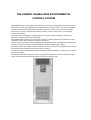
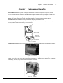
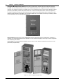
Partnerships
TM
for Business-Critical Continuity
Liebert DM Technical Data Manual
Contents
THE LIEBERT DataMate3000 ENVIRONMENTAL CONTROL SYSTEM ................................................4
Chapter 1 Features and Benefits............................................................................................................1
Chapter 2 Model Configuration...............................................................................................................3
2.1 Model Number Designations ......................................................................................................3
2.2 Unit Mechanical Parameters.......................................................................................................3
2.3 Units Configuration .....................................................................................................................5
2.4 Refrigeration circuit.....................................................................................................................5
Chapter 3 Operation Range ...................................................................................................................6
Chapter 4 Technical Data.......................................................................................................................7
Chapter 5 Microprocessor Control..........................................................................................................9
5.1 LCD Screen .............................................................................................................................9
5.2 Control Buttons ........................................................................................................................9
5.3 Setpoints ................................................................................................................................ 10
5.4 Control Screen ....................................................................................................................... 11
5.4.1
Off Screen................................................................................................................... 11
5.4.2
On Screen................................................................................................................... 11
5.4.3 Normal Screen............................................................................................................ 11
5.4.4 Password Screen........................................................................................................ 11
5.5
Main Menu ............................................................................................................................. 12
5.6 Alarm Menu............................................................................................................................ 12
5.6.1 Alarm Status ............................................................................................................... 12
5.6.2 Alarm History .............................................................................................................. 13
5.6.3 Alarm Setpoint ............................................................................................................ 13
5.6.4 Alarm Output............................................................................................................... 13
5.6.5 Custom Alarm ............................................................................................................. 14
5.6.6 Service Interval ........................................................................................................... 14
5.7 Setpoints ................................................................................................................................ 15
5.8
System Status ........................................................................................................................ 15
5.8.1 Tem/ Hum ................................................................................................................... 15
5.8.2 Time/Date ................................................................................................................... 15
5.8.3 Output Status.............................................................................................................. 15
5.8.4 Run Time .................................................................................................................... 16
5.8.5 Comp Run Record ...................................................................................................... 16
5.9
System Menu ......................................................................................................................... 16
5.9.1 Setup System ............................................................................................................. 16
5.9.2
Select Options ............................................................................................................ 17
5.9.3 Sensor Calibrate ......................................................................................................... 18
5.9.4 Diagnose..................................................................................................................... 18
5.9.5 Change Password ...................................................................................................... 18
5.9.6 Factory Reset ............................................................................................................. 19
5.10 Help Menu............................................................................................................................ 19
5.10.1
Normal Info ............................................................................................................... 19
5.10.2 Service Info............................................................................................................... 20
Appendix 1 Control System Menu Structure......................................................................................... 21
Appendix 2
Wiring Diagram.................................................................................................................. 22
Appendix 3
Spare Parts ....................................................................................................................... 24
THE LIEBERT DataMate3000 ENVIRONMENTAL
CONTROL SYSTEM
The DataMate3000 is a small precise environmental control system specially designed for electrical system
room cooling. Featuring high reliability, high sensible heat ratio and big air volume, the system is suitable for
controlling the temperature and humidity (optional) in system or computer room to maintain a favorable
environment for precise systems such as sensitive systems, process control systems, communication
systems and computers.
This system has two models with nominal ratings of 5 kW, 7kW and 12kW respectively, which can be
selected according to the actual room heat loads.
Each DataMate3000 consists of an indoor direct expansion evaporator module and an outdoor air cooled
condensing module. Both modules are installed on the ground.
The indoor unit has two series, standard DME3000 and DME3000 S series. The DME3000 S series is mainly
for 220V/1 Ph/50Hz use and the standard DME3000 is for 380V/3 Ph/50Hz power supply.
The outdoor unit has two models, standard model and Lee Temp model. The Lee Temp model can be used
at lower temperature. Detailed parameters are shown in Table 3-1.
The system may also include optional heater and humidifier. Models available for cooling only do not include
heater and humidifier.
The standard DataMate3000 system includes cooling parts for temperature control. The optional humidity
control uses the optional heater and humidifier to keep the favorable humidity.
Chapter 1 Features and Benefits
Chapter 1
Features and Benefits
Computer Matched-Liebert systems are designed to create the environment required for computers, telecom
and other sensitive electronic equipment. DataMate3000 provides complete control of temperature, humidity and
air cleanliness on an around the clock basis, as well as the high sensible heat ratio required by sensitive
2
electronic equipment. Space Saving-Requires 5 square feet (.5m ) or less.
Reliable-The Liebert reputation for quality and a nationwide service network ensures maximum uptime.
Designed to Fit-Models available to fit any room without disrupting work-station layout.
Steam Generating Humidifier-The optional humidifier is provided with an automatic flushing circuit strainer, inlet
and drain, solenoid valves and necessary control hardware.
Bracket
Steam canister
Water inlet
solenoid valve
Drain solenoid valve
Figure 1-1 humidifier
Air Distribution Fans-Direct drive centrifugal fans are located behind removable panels and are quiet in operation.
Figure 1-2
Fan In Unit
The fans are newly developed and manufactured products with internationally advanced technology of similar
products. They have the low noise. With volume ranging from 800m3 /h~ 4000m3/h, they are driven by single-phase
motor directly, low noise, easy speed-control and compact construction.
Figure 1-3
Inner Fan
DataMate 3000 Series Air Conditioner Technical Manual
1
2
Chapter 1 Features and Benefits
Intelligent Microprocessor Control- The system controller has a 128×64-matrix dot LCD screen with blue
backlight. The man-machine-interface is easy-to-use. Multilevel passwords are configured to prevent unauthorized
operation. The program is stored in non-volatile memory. The controller also has functions of high-voltage/low-voltage
protection, phase failure protection and phase switchover in case of reverse phase rotation. Users can acquire the
accurate running time of major parts by browsing the menu. Expert-level troubleshooting system enables the LCD to
display the fault information automatically for convenient maintenance. The controller can store up to 30 history alarms.
It can communicate to a host through the RS485 port.
Figure 1-4
Control Panel
Easy Installation-All components of the DataMate3000 are pre-charged and require no field brazing, evaluation or
charging. Pre-charged refrigerant lines are available in 15-foot and 30-foot lengths (4.5 and 9m) to connect evaporator
and condensing unit modules.
Serviceability-The DataMate3000 is designed with front service access. Routine maintenance and service can be
performed quickly and easily.
Figure 1-5
Indoor unit appearance(open door)
DataMate 3000 Series Air Conditioner Technical Manual
Chapter 2 Model Configuration
Chapter 2
3
Model Configuration
2.1 Model Number Designations
DM E 07 M C 1
DataMate3000
Version
1
DME3000 standard version 1
E1 DME3000 S series version 1
Unit Model
Optional Features
E Indoor unit
C Cooling only
C Standard outdoor unit
O With electric reheat
H With humidifier and reheat
Capability Rate
Main Power Supply
05 5kW
M 380V/3 Ph/50Hz
07 7kW
W 220V/1 Ph/50Hz
2.2 Unit Mechanical Parameters
The mechanical parameters of the indoor units are shown in Figure 2-1 and Table 2-1.
600
55
0
510
1740
1900
38
6
60
600
DME3000 Standard
Figure 2-1
0
51
0
510
DME3000 S Series
Dimensions of indoor unit(unit: mm)
DataMate 3000 Series Air Conditioner Technical Manual
Chapter 2 Model Configuration
The shadow in Figure 2-1 indicates a reasonable service access area. The indoor units can be installed against a wall.
Air conditioners with heaters should keep a distance of minimum 150mm from combustible substance. When testing
the air conditioner, the exterior fine pressure should be kept below 150Pa lest the air quantity should be low and the
heater should overheat,
The mechanical parameters of the outdoor units are shown in Figure 2-2, Figure 2-3 and Table 2-1.
353
353
702
626
1238
702
Figure 2-2
Dimensions of standard outdoor units (unit: mm)
353
702
702
353
1238
250
250
Figure 2-3
Dimensions of Lee Temp outdoor units (unit: mm)
Table 2-1
Parameters
575
575
626
4
Mechanical parameters of units
Cooling capacity
(kW)
Dimensions
(W*D*H) (mm)
Net weight (kg)
DME05W
5.5
510×386×1740
80
DME07W
7.5
510×386×1740
85
DME07M
7.5
600×550×1900
150
DME12M
12.5
600×550×1900
160
DMC07
-
702×353×626
34
DMC12
-
702×353×1238
58
DML07
-
952×353×626
53
DML12
-
952×353×1238
95
Models
The dimensions of the heater (optional parts) are illustrated below.
DataMate 3000 Series Air Conditioner Technical Manual
Chapter 2 Model Configuration
5
15
20
35
11
1750 ± 15 (blue)
14
13
24
50
12
2、3、4、5、6、7、8
1
10
9
1600 ± 15 (brown)
426 ± 1
Figure 2-4
15
Dimensions of heater (unit: mm)
2.3 Units Configuration
Table 2-2 Configuration Table Of Indoor Units And Outdoor Units
Indoor Unit
Model
Series
Main Power
Supply
Capability
Rate
Cooling Only
DME3000
S Series
220V/1
Ph/50Hz
5kW
7kW
DME3000
Standard
380V/3
Ph/50Hz
Outdoor Unit
With Reheat
With Humidifier
And Reheat
Standard
Lee-Temp
DME05WCE1
DME05WOE1
--
DMC07W1
DML07W1
DME07WCE1
DME07WOE1
--
DMC07W1
DML07W1
7kW
DME07MC1
DME07MO1
DME07MH1
DMC07W1
DML07W1
12kW
DME12MC1
DME12MO1
DME12MH1
DMC12W1
DML12W1
2.4 Refrigeration circuit
The compressor (1) pumps the hot gaseous refrigerant into an outdoor air – cooled condenser (2). The liquefied
refrigerant flows through the thermostatic expansion valve (3) and then arrives to the evaporator (5). Here the
refrigerant, thanks to the heat –exchanged with the room air moved by the fan (5).-evaporates and returns to the
compressor (1); From this, the refrigerant begins a new refrigeration cycle. To maintain the correct refrigerant
discharge pressure, the speed of the motor fan (6) is controlled (on-off or an optional rate).
The compressor (1) has a crankcase heater to avoid return of liquid return of liquid refrigerant from the condenser in
summertime, thus protecting the compressor from undesired refrigerant slugging during the start up.
Figure 2-5
System Elements Drawing
DataMate 3000 Series Air Conditioner Technical Manual
6
Chapter 2 Model Configuration
Chapter 3
Operation Range
DME3000 are provided for operating within the following working ranges:
Table
Installing position between indoor unit
and outdoor unit
Room air conditions
Ambient temperature
horizontal
≤50m
vertical
ΔH(1):-5m≤ΔH≤20m
temperature
0°C ~30°C
humidity
30%~80%RH
standard outdoor unit
-15°C ~+45°C
with Lee-Temp unit
-34°C ~+45°C
<1000m (2)
Altitude
Power supply tolerances
Storage conditions
3-1
voltage
-15%~+15%
frequency
±2Hz
(3)
entironment
Indoor, clean (without dust)
temperature
-40°C ~70°C
humidity
5%~95%RH
storage hours
<6 months(4)
Notes:
1) ΔH = the altitude of outdoor unit - the altitude of indoor unit;
2) The system should be derated where the altitude is higher than 1000m;
3) The error (because of sensors) in 3% is permitted;
4) The shipment and storage time should not exceed 6 months. Otherwise, the system shall be re-tested.
DataMate 3000 Series Air Conditioner Technical Manual
Chapter 4 Technical Data
Chapter 4
Technical Data
Table 4-1 Standard DME3000 Technical Data
Air cooled
Nominal Cooling Capacity (kW)
Indoor Unit Model
7.5
12.5
DME07MC1
DME07MO1
DME07MH1
DME12MC1
DME12MO1
DME12MH1
Net Capacity Data - kW High Fan Speed
27DB
50%RH
Total
8600
13500
Sensible
7500
12000
24DB
50% RH
Total
7900
12800
Sensible
6900
11500
22DB
50% RH
Total
7500
12500
Sensible
6800
11300
Net Capacity Data - kW Low Fan Speed
27DB
50%RH
Total
8500
13200
Sensible
7150
11700
24DB
50% RH
Total
7800
12550
Sensible
6600
11250
22DB
50% RH
Total
7350
12200
Sensible
6650
11000
Fan Data - Direct Drive
Air Volume - CMH
High
2250
2700
Air Volume - CMH
Low
1950
2400
550
550
R-22
R-22
0.37
0.37
2
3
4
4
2.5
2.5
Fan Motor - W
Compressor Data - Scroll
Refrigerant
Evaporator Coil - Copper Tube/Aluminum Fin
Face area - m2
Rows of Coil
Reheat Data - Electric (Exclude Fan Motor)
Capacity - kW
Humidifier Data - Steam Generator Type
Capacity - kg/h
Connection Sizes
Liquid Line - mm
9.52
12.7
Suction Line - mm
12.7
15.88
Humidifier Supply -OD, mm
20
20
Humidifier Drain - OD, mm
20
20
Evaporator Drain - OD, mm
20
20
Outdoor Unit Options
Standard Outdoor Unit
Outdoor Unit Model
DMC07W1
DMC12W1
Air Volume - CMH
2600
5200
Face Area - m2
0.49
0.98
Rows of Coil
2
2
150
300
Operating Temperature Range - °C
Low Ambient Temperature Outdoor Unit - LeeTemp Options
-15~45°C
-15~45°C
Outdoor Unit Model
Motor - W
DML07W1
DML12W1
Air Volume - CMH
2600
5200
Face Area - m2
0.49
0.98
Rows of Coil
Motor - W
Operating Temperature Range - °C
2
2
150
300
-34~45°C
-34~45°C
DataMate 3000 Series Air Conditioner Technical Manual
7
8
Chapter 4 Technical Data
Table 4-2 DME3000 S Series Technical Data
Air cooled
Nominal Cooling Capacity (kW)
Indoor Unit Model
Power Supply
5.5
7.5
DME05WCE1
DME05WOE1
DME07WCE1
DME07WOE1
220V~50Hz
220V~50Hz
Net Capacity Data - kW High Fan Speed
27DB
50%RH
Total
5700
7900
Sensible
4400
6100
Total
5500
7500
Sensible
4100
5500
Total
5100
7200
Sensible
3700
5200
24DB
50% RH
22DB
50% RH
Net Capacity Data - kW Low Fan Speed
27DB
50%RH
Total
5500
7600
Sensible
4100
5750
24DB
50% RH
Total
5200
7100
Sensible
3700
5250
22DB
50% RH
Total
4800
6800
Sensible
3400
4900
Fan Data - Direct Drive
Air Volume - CMH
High
1200
1300
Air Volume - CMH
Low
1100
1200
200
200
R-22
R-22
0.156
0.208
4
4
2.7
2.7
Fan Motor - W
Compressor Data
Refrigerant
Evaporator Coil - Copper Tube/Aluminum Fin
Face area - m2
Rows of Coil
Reheat Data - Electric (Exclude Fan Motor)
Capacity - kW
Connection Sizes
Liquid Line - mm
9.52
9.52
Suction Line - mm
12.7
12.7
20
20
Evaporator Drain - OD, mm
Outdoor Unit Options
Standard Outdoor Unit
Outdoor Unit Model
DMC07W1
DMC07W1
Air Volume - CMH
2600
2600
Face Area - m2
0.49
0.49
Rows of Coil
Motor - W
Operating Temperature Range - °C
2
2
150
150
-15~45°C
-15~45°C
Low Ambient Temperature Outdoor Unit - LeeTemp Options
Outdoor Unit Model
DML07W1
DML07W1
Air Volume - CMH
2600
2600
Face Area - m2
0.49
0.49
Rows of Coil
Motor - W
Operating Temperature Range - °C
2
2
150
150
-34~45°C
-34~45°C
Notes:
All capacities are nominal values, actual performance will be ±5%.
DataMate 3000 Series Air Conditioner Technical Manual
Chapter 5 Microprocessor Control
Chapter 5
9
Microprocessor Control
The microprocessor control features an easy-to-use menu-driven LCD display. It monitors and displays the operation
status of the precision cooling unit to maintain a reasonable environment in the controlled room. The menus, control
features and parameter settings are described in this chapter.
5.1
LCD Screen
LCD screen displays English menus with blue backlight. It displays temperature and relative humidity readings,
operating mode (cool, heat, dehumidify, humidify), alarm information, current date and time, as shown in Figure 5-1.
28 ℃
Co o l
50 % r h
Hum
H i gh T e mp
1 / 4
2004 / 01 / 01 0 0 : 0 0
Figure 5-1
LCD screen
Users can browse more detailed information such as the operation status of a certain part and alarm information by
activating the sub-menus in the main menu screen. The selected item will highlight in a menu. The digit to be changed
will highlight when a parameter is being changed.
5.2
Control Buttons
There are nine control buttons on the keypad, namely Up, Down, Left, Right, Enter, Esc, ON/OFF, Mute, and Help
buttons, as shown in Figure 5-2.
8 Up
9 Mute
1 ON/OFF
7 Right
6 Enter
2 Help
4 Left
3 Esc
Figure 5-2
5 Down
Control keypad
1. ON/OFF —— When the system is in standby status after power-on, pressing this button makes it operate, and LCD
displays the On screen. When the system is operating, pressing this button switch it to the standby status and LCD
displays the Off screen.
2. Help —— Pressing this button displays associated help screen.
3. Esc —— Pressing this button returns to the Normal screen or previous menu/screen or aborts any changes on the
input data field before validating the changes.
4. Left —— This button moves the cursor left in the input data field.
5. Down —— This button moves the cursor down the menu or decreases the number in the input data field.
6. Enter —— This button allows entry into the next level of a menu or validates the modified data in the input data field.
7. Right —— This button moves the cursor right in the input data field.
8. Up —— This button moves the cursor up on the menu or increases the value displayed in the input data field.
9. Mute —— If an alarm is present, it will be displayed on the LCD and sound an audible beeper. Pressing this button
eliminates the prompted alarm screen and silences the alarm.
DataMate 3000 Series Air Conditioner Technical Manual
10
5.3
Chapter 5 Microprocessor Control
Setpoints
The default setpoints have been configured before delivery. They are configured according to the general operation
status or optional components. Change the defaults only when they do not satisfy the user’s requirement. Refer to
Figure 5-1 for the setpoints and the value range. Users need to enter the password in corresponding level before
changing the information such as setpoints, date, time, and so on (refer to section 5.4.4).
Table 5-1
Menu
Parameter
Alarm
Setpoint
Alam
Menu
Alarm
Outputs
Custom
Alarm
Service
Interval
Setpoints
Default
High Temp
29°C
Low Temp
18°C
High Hum
65%RH
Low Hum
35%RH
observation alarms
major alarms
Custom #1
Custom #2
Main Fan Chng Time
Humidifier Chng Time
Filter Chng Time
Unit No
Cntl Brd
Unit No.
Hot Start
Main fan
Cp Start
Cp MinOn
Cp MinOff
OPEN
OPEN
No
No
360 days
180 days
180 days
24°C
3°C
50%RH
5%RH
1
0
0
10 seconds
30 seconds
90 seconds
180 seconds
180 seconds
Min.
Max.
The larger value of
temperature setpoint plus 45°C
5°C and 28°C
The smaller value of temperature
5°C
setpoint minus 5°C and 18°C
The larger value of
humidity setpoint plus
90%RH
10%RH and 65%RH
The larger value of humidity
10%RH
setpoint minus 10%RH and
35%RH
STOP
OPEN
CLOSE
OPEN
No
Other alarms
No
Other alarms
180 days
720 days
90 days
360 days
90 days
360 days
15°C
35°C
1°C
5°C
20%RH
80%RH
1%RH
10%RH
1
254
0
15
0
15
10 seconds
240 seconds
10 seconds
240 seconds
10 seconds
240 seconds
60 seconds
300 seconds
60 seconds
300 seconds
LP Switch
180 seconds
30 seconds
240 seconds
°C
Rel
ON
ON
30%
OFF
OFF
SGL
24 hours
24 hours
°C
Rel
OFF
OFF
28%
OFF
OFF
SGL
12 hours
12 hours
°F
ABS
ON
ON
38%
ON
ON
HST/SPR
48 hours
48 hours
30 seconds
OFF
OFF
0.0°C
0.0%RH
0001
0002
10 seconds
OFF
OFF
-5.0°C
-10.0%RH
0000
0000
90 seconds
ON
ON
+5.0°C
+10.0%RH
9999
9999
Temp Stpt
Tem Bias
Hum Stpt
Hum Bias
Monitor
Teamwork
Start Delay
System Setup
Menu System
Select
Options
System
Menu
Sensor
Calibrate
Change
Password
System settable parameters
C/F Degrees
Hum Control
Beeper
LCD Backlight
Contrast
LowFanSpeed
TempCompsen
Unit Sta
Host Time
Standby
Spare Time
Swtch Time
Heat
Hum
Temp Snsr
Hum Snsr
Level One
Level Two
DataMate 3000 Series Air Conditioner Technical Manual
Chapter 5 Microprocessor Control
5.4
Control Screen
5.4.1
Off Screen
11
The LCD displays this screen after the system is powered on. In addition, it will be displayed by pressing the ON/OFF
button during system operation, as shown in Figure 5-3. You can press the Left/Right button and the Enter button to
select the display language.
EMERSON
中 文
En g l i s h
Figure 5-3
5.4.2
Off screen
On Screen
When the system is in automatic turn-on status after powered on, the LCD displays the On screen. Press the ON/OFF
button from the Off screen, and the On screen will also be displayed, as shown in Figure 5-4.
S t a r t i ng
10s
Figure 5-4
5.4.3
On screen
Normal Screen
After the system is powered on, the Normal screen will be displayed after 10 seconds (default) for heat startup delay or
after Enter button is pressed. The Normal screen displays the current temperature and relative humidity readings,
operating mode (cool, heat, dehumidify, humidify), alarm information, current date and time, as shown in Figure 5-5.
28 ℃
Co o l
50 % r h
Hum
H i gh T e mp
1 / 4
2004 / 01 / 01 0 0 : 0 0
Figure 5-5
5.4.4
Normal screen
Password Screen
There are three levels of password in the microprocessor control.
Level one password (0001) is intended for the ordinary user. Users can view all menus by entering this password, but
has no authority to change the parameters except for those of temperature and humidity.
Level two password is intended for trained service personnel. Users can change all parameters by entering this
password.
Level three password is intended for the manufacturer’s personnel only.
Press Enter button from the Normal screen, Password screen is displayed, as shown in Figure 5-6.
P a s sw o r d :
Figure 5-6
1* * *
Password screen
Method of entering password:
Press Left/Right button to move the cursor to the digit to be changed, and then Up/Down button to change the value.
Press Enter button to validate the password and enter the main menu. Press Esc button to return to the Normal
screen.
DataMate 3000 Series Air Conditioner Technical Manual
12
Chapter 5 Microprocessor Control
If the password entered is incorrect, the user can view the menu but cannot change the parameters. The user can
return to the Normal screen by pressing Esc button and enter the password again. If the password entered is correct,
any parameter under the main menu can be changed.
Note
If press Enter button from the Password screen instead of inputting any password, the user can only view the menu and cannot
change the parameters.
5.5
Main Menu
Press Enter button from the Normal screen, enter password and then press Enter to validate the password, the main
menu is displayed, as shown in Figure 5-7.
He l p
A l a r m M e nu
Se t p o i n t s
Sys t e m S t a t us
S y s t e m Menu
Figure 5-7
Me nu
Main menu
The items in the main menu are listed below.
Alarm Menu - For setting alarm parameters, browsing alarm history and alarm status.
Setpoints - For setting temperature and humidity parameters, temperature and humidity precision parameters.
System Status - For setting the system date and time and viewing environmental temperature and humidity readings,
the date, time, system output status and system operation records.
System Menu - For setting system parameters, configuring system optional components, calibrating sensors,
changing password, diagnosing components output, and restoring default values.
Help Menu - For querying product and mantenance information.
5.6
Alarm Menu
Use the Up/Down buttons to move the cursor to Alarm Menu in the main menu and press Enter. The Alarm Menu will
be displayed, as shown in Figure 5-8. There are six sub-menus under this menu and they are displayed in two screens.
Press Up/Down buttons to scroll all sub-menus.
Alarm Status
Alarm History
Alarm Setpoint
Alarm Output
Custom Alarm
Service Interval
Reset History
Figure 5-8
5.6.1
N
Alarm Menu
Alarm Status
Select Alarm Status from the Alarm Menu to enter the Alarm Status screen. This screen displays all active alarms.
The alarm No/ the total number active, alarm name, the time/date occurrence are indicated for each alarm, as shown
in Figure 5-9.
Active:
Hi Temp
2004/01/01
Figure 5-9
1/4
00:00
Alarm Status screen
The latest alarm is shown as alarm 1. Use Up/Down buttons to scroll if there are more alarms.
This system can store up to 25 latest active alarms. They will be lost when the system is powered off.
DataMate 3000 Series Air Conditioner Technical Manual
Chapter 5 Microprocessor Control
5.6.2
13
Alarm History
Select Alarm History from the Alarm Menu screen to view the Alarm History screen. The screen displays the detailed
inactive alarm information or “No alarms” if no inactive alarm exists.
The alarm No./the total number inactive, alarm name, the time/date occurrence are indicated for each alarm, as shown
in Figure 5-10.
History:
Hi Temp
01/ 01
01/ 01
Figure 5-10
1/4
00:00:00
00:00:00
Alarm History screen
Use Up/Down buttons to scroll if there are more alarms.
This system can store up to 30 latest inactive alarms. They will not be lost when the system is powered off.
5.6.3 Alarm Setpoint
The alarm setpoints will not be lost when power fails. Select Alarm Setpoint from the Alarm Menu to browse or change
the setpoints listed in Figure 5-11.
The defaults are sufficient for most applications and changing them is normally unnecessary. For special application,
they must be changed under the guidance of trained professional personnel.
Hi Temp
Lo Temp
Hi Hum
Lo Hum
29°C
29°C
60%rh
40%rh
Figure 5-11
Alarm Setpoint screen
To change the setpoint, use Up/Down buttons to move the cursor to the item desired to be changed and press Enter to
select it. Press Enter again, use Up/Down buttons to change the value of each digit, and then press Enter to validate
the change.
Refer to Table 5-1 for the defaults and the setting ranges.
5.6.4 Alarm Output
The alarm output settings will not be lost when power fails. Select Alarm Outputs from the Alarm Menu to browse or
change the settings listed in Figure 5-12.
Hi Press
Lo Press
Hi Temp
Lo Temp
ENAB
ENAB
ENAB
ENAB
Hi Hum
Lo Hum
Power Fail
ShortCycle
ENAB
ENAB
ENAB
ENAB
Custom #1
Custom #2
Rpr MnFan
Rpr Humid
ENAB
ENAB
ENAB
ENAB
Rpr Filter
Comm Fail
Coil Froze
Humid Fail
ENAB
ENAB
ENAB
ENAB
SnsrB Lost
Dschg Temp
Power Lost
Power OLV
ENAB
ENAB
ENAB
ENAB
Power PL
Power FS
ENAB
ENAB
Figure 5-12
Alarm output menu
The alarm output can be set to OPEN, CLOSE or STOP. Move the cursor to the item to be changed, press Enter to
move the cursor to the OPEN/ CLOSE /STOP field. Use Up/Down buttons to toggle among OPEN, CLOSE and STOP.
Press Enter to validate the setting.
DataMate 3000 Series Air Conditioner Technical Manual
14
Chapter 5 Microprocessor Control
Table 5-2
Alarm output logic
Settings
Alarm History
Alarm Status
Audible alarm
OPEN
Yes
Yes
Yes
Alarm prompt
Yes
CLOSE
Yes
Yes
No
Yes
STOP
No
No
No
No
Note
As the high pressure alarm, low pressure alarm and power failure alarm are major alarms, they cannot be set to STOP.
5.6.5
Custom Alarm
The custom alarm settings will not be lost when power fails. Move the cursor to Custom Alarm on the Alarm Menu, and
press Enter to enter the Custom Alarm menu, as shown in Figure 5-13.
Cu s t o m
#1
S mo k e S n s r
Cu s t o m # 2
N o Al a rm
Figure 5-13
Custom Alarm menu
There are two custom alarms: Custom #1 and Custom #2.
Custom #1 is input through control terminal J67.
Custom #2 is input through control terminal J68.
Use Up/Down buttons to move the cursor to the corresponding row and use Up/Down buttons to toggle among no
alarm, smoke sensor, fire sensor, water under floor, no airflow, filter obstructed and others (LCD displays No Alarm,
Smk Snsr, Fire Snsr, High Water, Loss Air, Fltr Clog and Others). Press Enter to validate the setting.
5.6.6
Service Interval
Service intervals are applicable to those components that require periodical maintenance. The controller will trigger an
alarm to remind the maintenance personnel to maintain the component when the set interval values are exceeded.
The main fan, air filter and humidifier can be set with service intervals. Refer to Table 5-1 for the defaults and setting
ranges.
These settings will not be lost when power fails. Select Service Intervals from the Alarm Menu and press Enter to
display the items listed in Figure 5-14.
Ma i n F a n
H um i d i f i e r
F i l te r
Figure 5-14
Service Interval menu
Use Up/Down buttons to move the cursor to the Main Fan, and press Enter to enter the Main Fan Service Interval
sub-menu, as shown in Figure 5-15.
Run Time
Rpr time
Reset
Figure 5-15
100 d
360 d
NO
Main Fan Service Interval sub-menu
The Run Time is the actual operation days of the component. It is real time clock counter days and is unchangeable.
The Spr Time is the recommended operation days of the component. It can be changed. The default value is
recommended. Otherwise change it according to the actual condition.
The Reset indicates whether the component has been maintained or replaced or not. Select YES if it is maintained or
replaced, and the service time will be reset to zero automatically and then be recounted again. Otherwise, select NO.
DataMate 3000 Series Air Conditioner Technical Manual
Chapter 5 Microprocessor Control
5.7
15
Setpoints
The setpoints will not be lost when power fails. Select the Setpoints from the main menu and press Enter to configure
the setpoints listed in Figure 5-16.
TempStpt
TempSens
Hum Stpt
Hum Sens
24°C
3°C
50%RH
5%RH
Figure 5-16
Setpoints menu
Use the Up/Down buttons to select a certain item and press Enter to access the input data field. Use the Up/Down
buttons again to increase or decrease the digit. Press Enter to validate the new setpoint.
Refer to Table 5-1 for the defaults of the setpoints in Figure 5-16 and their setting ranges.
5.8
System Status
Use the Up/Down buttons to select System Status from the main menu and press Enter to view the system status
information listed in Figure 5-17.
Temp/ Hum
Time/ Date
Output Status
Run Time
Comp Run Record
Figure 5-17
5.8.1
System Status menu
Tem/ Hum
The Tem/ Hum screen precisely displays the indoor temperature and humidity and the outdoor temperature, as shown
in Figure 5-18.
I n T em p
24 . 6 ℃
I n Hum
6 7 . 8%RH
Ou t T e mp 2 4 . 6 ℃
Figure 5-18
5.8.2
Tem/ Hum screen
Time/Date
The Time/Date screen displays the current time of the system in the format of Year/Month/Date and
Hour/Minute/Second.
Method of changing the time:
Press Enter button and use Left/Right buttons to move the cursor to the digit to be changed. Then use Up/Down
buttons to increase or decrease the value and finally press Enter to validate the value. If the change is successful, the
current time will be changed to the set time automatically. Otherwise, the current time will not be changed. The
Time/Date screen is shown in Figure 5-19.
2 0 0 4 / 01 / 0 1
0 0 : 00:00
Figure 5-19
5.8.3
Time/Date screen
Output Status
The Output Status screen displays the current output status of the system. Use Up/Down buttons to scroll the items, as
shown in Figure 5-20.
DataMate 3000 Series Air Conditioner Technical Manual
16
Chapter 5 Microprocessor Control
Fan
Co o l
He a t
L oSp d / De h um
ON
ON
OFF
OFF
Hum
Ho s T
Sp a r e
Sy s t em
Figure 5-20
5.8.4
OF F
OF F
OF F
No r m
H i Pr ess
Lo P r e s s
Sho r t Cy c l e
Un i t
No r m
No r m
No r m
No r m
Output Status screen
Run Time
Run Time screen displays the total operation hours of the system. Press Up/Down buttons to scroll the items, as
shown in Figure 5-21.
Fan
Co o l
He a t
H um
80
20
20
20
Figure 5-21
5.8.5
New Flow
0h
0h
0h
0h
100h
Run Time screen
Comp Run Record
Comp Run Record screen displays the total run record of the compressor. Press Up/Down buttons to scroll the items,
as shown in Figure 5-22.
Run Record:
Start Time:
2004/ 01/ 01
Figure 5-22
5.9
1/4
00:00
Comp run record screen
System Menu
Select System Menu from the main menu and press Enter to display the items listed in Figure 5-23.
Setup System
Select Options
Sensor Calibrate
Diagnostics
Change Password
Factory Reset
Figure 5-23
5.9.1
N
System Menu
Setup System
System settings will not be lost when power fails. Select Setup System from the System Menu to display the items
listed in Figure 5-24.
Mon i t o r
T e a m wo r k
S t a r t De l a y
C / F De g r ees
H um C o n t r o l
Be epe r
Ba c k l i g h t
℃ Co n t r a s t
Figure 5-24
RE L L o w F a n S p eed
ON T e m p C o m p s e n
ON
3 0%
O FF
O FF
Setup System sub-menu
Use Up/Down buttons to move the cursor to Monitor as shown in Figure 5-23, and press Enter to display the sub-menu,
as shown in Figure 5-25. Press Enter to set the system address for communicating with a host. The setting range is
1~244 and the default value is 1.
Un i t
No
Figure 5-25
1
Monitor sub-menu
DataMate 3000 Series Air Conditioner Technical Manual
Chapter 5 Microprocessor Control
17
1. Use Up/Down buttons to move the cursor to Teamwork in the System Setup menu, and press Enter to display the
Teamwork sub-menu, as shown in Figure 5-26. Use Up/Down buttons to move the cursor to Cntl Board, and press
Enter to set the control board number for communication with other control boards. It can be set from 0 to 15, and the
default value is 0. Use Up/Down buttons to move the cursor to Unit No, and press Enter to set the unit number. It can
be set from 0 to 15, and the default value is 0.
Cntl Board
Unit NO
Figure 5-26
1
1
Teamwork sub-menu
2. Use Up/Down buttons to move the cursor to Start Delay in the System Setup menu, and press Enter to display the
sub-menu, as shown in Figure 5-27. The default values and the setting ranges of the delays in Figure 5-27 are listed in
Table 5-1.
Cold Start
Hot Start
Main Fan
Cp Start
180s
10s
30s
90s
Figure 5-27
Cp MinOn
Cp MinOff
LP Switch
180s
180s
180s
Start Delay sub-menu
3. Press Up/Down buttons to move the cursor to C/F Degrees in the System Setup menu, and press Enter to set the
displayed temperature unit to Celsius (°C) or Fahrenheit (°F). The default unit is Celsius scale.
4. Use Up/Down buttons to move the cursor to Hum Control in the System Setup menu and press Enter to set the
humidity control method to absolute humidity control or relative humidity control. The default method is relative
humidity control.
5. Use Up/Down buttons to move the cursor to Beeper in the System Setup menu, and press Enter to set the beeper to
ON or OFF. The default is ON.
6. Use Up/Down buttons to move the cursor to Backlight in the System Setup menu, and press Enter to set the
backlight to ON or OFF. The default setting is ON.
7. Use Up/Down buttons to move the cursor to Contrast in the System Setup menu, and press Enter to set the contrast
of the LCD. The setting range is from 28% to 38%, and the default setting is 30%.
5.9.2
Select Options
The optional function settings will not be lost when power fails. Select Options from the System Menu to display the
functions listed in Figure 5-28.
Heat
Hum
NewFlow
Standby
Figure 5-28
OFF
OFF
OFF
Select Options menu
1. Use Up/Down buttons to move the cursor to Heat, and press Enter to set the optional heater to ON or OFF. The
default setting is OFF.
2. Use Up/Down buttons to move the cursor to Hum, and press Enter to set the optional humidifier to ON or OFF. The
default setting is OFF.
3. Use Up/Down buttons to move the cursor to NewFlow, and press Enter to set the new flow to ON or OFF. The
default setting is OFF.
4. Use Up/Down buttons to move the cursor to Standby, and press Enter to display the Standby sub-menu, as shown
in Figure 5-29.
DataMate 3000 Series Air Conditioner Technical Manual
18
Chapter 5 Microprocessor Control
Unit Status
Hst Time
Spr Time
Chg Time
Figure 5-29
SIG
24h
24h
30s
Standby sub-menu
1) Use Up/Down buttons to move the cursor to Unit State in the Standby sub-menu, and press Enter to set the system
to Hst Time (Duty unit), Spr Time (Standby unit) or Chg Time (Single unit). The default setting is HST.
2) Use Up/Down buttons to move the cursor to Host Time, and press Enter to set the operation cycle of the duty unit.
The setting range is from 12 hours to 48 hours and the default setting is 24 hours.
3) Use Up/Down buttons to move the cursor to Spare Time, and press Enter to set the operation cycle of the standby
unit. The setting range is from 12 hours to 48 hours and the default setting is 24 hours.
4) Use Up/Down buttons to move the cursor to Switch Time, and press Enter to set the system transfer time delay. The
setting range is from 10 seconds to 90 seconds and the default setting is 30 seconds.
When the Unit Sta is set to SPR or SGL. The Host Time, Spare Time and Switch Time can be set, but they are
invalidated.
5.9.3
Sensor Calibrate
The technical person can use this function and a precise instrument (0.1°C or 0.1%RH in precision) to calibrate the
temperature sensor and humidifier sensor. The settings will not be lost when power fails. Select Sensor Calibrate item
from the System Menu to calibrate the items listed in Figure 5-30.
T e mp Sn s r 0 . 0 ℃
Hum Sn s r
0 . 0%RH
Re s e t
NO
Figure 5-30
Sensor Calibrate menu
1. Use Up/Down buttons to move the cursor to Temp Snsr, and press Enter to set the tolerance of the temperature
sensor. The setting range is from -5°C to +5°C and the default setting is 0°C.
2. Use Up/Down buttons to move the cursor to Hum Snsr, and press Enter to set the tolerance of the humidifier sensor.
The setting range is from -10%RH to +10%RH and the default setting is 0%RH.
3. Use Up/Down buttons to move the cursor to Reset and press Enter button. If it is set to YES, the tolerance settings
will be reset to the defaults.
5.9.4
Diagnose
This function is used to detect the output status of the system components. Select Diagnose item to set the items listed
in Figure 5-31.
Ma i n
C o mp r
He a t e
H um i d
Fan
essor
r
i f i er
Figure 5-31
ON
ON
OF F
OF F
Diagnose menu
Press Up/Down buttons to move the cursor to the component to be diagnosed and press Enter. Press Left/Right
buttons to set it to ON. If the main fan is set to ON, the other components will be set to OFF automatically.
There is a time limit for output diagnosis. When the unit enters output diagnosis status, it will exit the status
automatically and returns to normal operation if the output diagnosis status has not changed for a certain period of
time (15 seconds for compressor and 5 minutes for other components).
5.9.5
Change Password
The new password will not be lost when power fails. Select Change Password menu from the System Menu to set the
level one and level two passwords, as shown in Figure 5-32.
DataMate 3000 Series Air Conditioner Technical Manual
Chapter 5 Microprocessor Control
Leve l
Leve l
Figure 5-32
On e
Two
19
* * * *
* * * *
Change Password menu
Use Up/Down buttons to move the cursor to the password to be changed and press Enter. Use Left/Right buttons to
move the cursor to the digit to be changed, and then Up/Down buttons to change the value. Press Enter to validate the
password or press Esc to abort.
5.9.6
Factory Reset
Use Up/Down buttons to move the cursor to Factory Reset in the System Menu and press Enter. Use Up/Down
buttons to set it to YES and press Enter to validating the setting. Then all the setpoints will be restored to their default
values, but the operation time and alarm log will not be cleared.
Note
As System Reset function will reset all the setpoints configured by the user, be cautious to use it.
5.10
Help Menu
Select Help Menu from the main menu and press Enter to display the items listed in Figure 5-33. The Version Info and
Bar Code Info are not disclosed to users. The following just shows how to view the Normal Info and how to view and
change the Service Info.
No
Se
Ve
Ba
rma l I nfo
r v i ce Info
r s i on Info
r Code Info
Figure 5-33
5.10.1
Help Menu
Normal Info
Use Up/Down buttons to move the cursor to Normal Info in the Help Menu and press Enter to display the items shown
in Figure 5-34.
Sup p l i e r I n f o
Prod u c t Info
Op e r a t i o n H e l p
Figure 5-34
Normal Info screen
Press Up/Down buttons to move the cursor to Supplier Info and press Enter to display the information shown in Figure
5-35.
E M E R S O N NE T WORK
P OW E R C o . , L t d
Figure 5-35
Supplier Info screen
Press Up/Down buttons to move the cursor to Product Info and press Enter to display the information shown in Figure
5-36.
DataMate 3000 Series Air Conditioner Technical Manual
20
Chapter 5 Microprocessor Control
Da t a M a t e 30 0 0
Figure 5-36
Product Info screen
Operation Help is not available at present.
5.10.2
Service Info
Select Service Info from the Help Menu and press Enter to display the items listed in Figure 5-37.
Se
Se
Se
Se
r
r
r
r
v
v
v
v
i
i
i
i
ce
ce
ce
ce
Figure 5-37
By
Phone
ACK
Re co r d
N
Service Info screen
Use Up/Down buttons to move the cursor to Service By item and press Enter to view or change the information about
the service personnel, as shown in Figure 5-38.
Se r v i c e
Liebe r t
Figure 5-38
By
Enpc
Service By screen
Use Up/Down buttons to move the cursor to Service Phone item and press Enter to view or change the service phone
call, as shown in Figure 5-39.
Se r v i c e Phon e
012388 888888
Figure 5-39
Service Phone screen
Press Up/Down buttons to move the cursor the Service ACK item, press Left/Right button the select Y and then press
Enter to confirm. The service information including service personnel and service time will be recorded and can be
view in the Service Record screen.
Use Up/Down buttons to move the cursor to Service Record and press Enter to view all previous service information,
as shown in Figure 5-40.
Se r v i c e
Reco r d
3 / 10
L i ebe r t Enpc
2005 / 03 / 1 5 11 : 45
Figure 5-40
Service Record screen
DataMate 3000 Series Air Conditioner Technical Manual
Chapter 5 Microprocessor Control
Appendix 1
21
Control System Menu Structure
Main Menu
Alarm Menu
Setpoints
System Status
Temp Sens
Temp / Hum
Alrm History
Alarm Setpoint
Hum Sens
Time / Date
Hi Temp
Operation Help
Main fan
Setup System
Lo Spd/Dehum
Hum
Cp Start
C/F Degree
Cp MinOn
Hum Control
Cp MinOff
Beeper
Host
Backlight
Spare
Contrast
Hi Hum
System
Low Fanspeed
Hi Press
Temp compsen
Power Fail
Lo Press
Short cycle
Short Cycle
Custom #1
Unit
Custom #2
Fan
Standby
Cool
Temp Snsr
Rpr Humid
Rpr Filter
Comp Run
Record
Heat
Select Options
Hum
New Flow
Sensor Calibrate
Hum Snsr
Reset
Hum
Main Fan
Coil Froze
Diagnostics
Humid Fail
Compressor
Heater
SnsrB Lost
Humidifier
Dschg Temp
Level one
Change Password
Power Lost
Power OLV
Power PL
Power FS
Custom #1
Custom #2
No alarm
Level Two
Factory Reset
Smk Snsr
Fire Snsr
High Water
Loss Air
Fltr Colg
Other Alrm
Run Time
Service Interval
Main Fan
Spr Time
Humidifier
Reset
Filter
Reset History
DataMate 3000 Series Air Conditioner Technical Manual
Service Info
Version Info
Bar Code Info
Unit Status
HstTime
Spr Time
Chg Time
Service Phone
Service ACK
Service Record
LP Switch
Heat
Comm Fail
Custom Alarm
Start Delay
Lo Hum
Run Time
Product Info
Service By
Heat
Rpr MnFan
Supplier Info
Normal Info
Cold Start
Lo Hum
Output Status
Unit No
Hot Start
Fan
Hi Temp
Cntl Board
yyyy-mm-dd
Cool
Lo Temp
Teamwork
Unit No
hh:mm:ss
Hi Hum
Lo Prees
Alarm Outputs
In Hum
Lo Temp
Hi Press
Help Menu
Monitor
Out Temp
Hum Stpt
Alarm Status
System Menu
In Temp
Temp Stpt
22
Appendix 2 Wiring Diagram
Appendix 2
Wiring Diagram
Wiring Diagram Of DME3000 Standard
DataMate 3000 Series Air Conditioner Technical Manual
Appendix 2
Wiring Diagram Of DME3000 S Series
DataMate 3000 Series Air Conditioner Technical Manual
Wiring Diagram
23
24
Appendix 2 Wiring Diagram
Appendix 3
Spare Parts
Indoor Unit Spare Parts:
Code
Spare Parts
DME05WCE1
DME05WOE1
DME07WCE1
DME07WOE1
DME07MC1
DME07MO1
DME07MH1
DME12MC1
DME12MO1
DME12MH1
Dosage each
unit
Compressor
02520014
02520015
02520011
02520012
1
Compressor Capacitor
08030214
08030316
--
--
1
Crankcase Heater
02510020
02510020
02510001
02510001
1
Inner Fan
32010123
32010123
32010111
32010111
1
Expansion Valve
27010009
27010002
27010002
27010003
1
1
Sight Glasses
--
--
23500002
23500002
Filter
02560003
02560003
02560002
02560002
1
Main control Board
03034252
03034252
03034252
03034252
1
I/O Board
03034390
03034390
03034251
03034251
1
Display/Keyboard Board
03025877
03025877
03025877
03025877
1
1
Temp./Hum. Testing Board
03025878
03025878
03025878
03025878
High Press. Swith
11500000
11500000
11500000
11500000
1
Low Press. Swith
11500001
11500001
11500001
11500001
1
Fan Press. Swith
27090004
27090004
27090004
27090004
1
Fan Relay
11019504
11019504
11019504
11019504
2
Fuse F1
19040090
19040090
19040143
19040143
1
Fuse F2
19040143
19040143
19040143
19040143
1
Fuse F3
--
--
19040143
19040143
1
Fuse F4
--
--
19040090
19040090
1
Circuit Breaker
16020428
16020428
16020174
16020174
1
Compressor Contactor
11020083
11020083
11020074
11020074
1
Transformer T1
09029501
09029501
09029501
09029501
1
Transformer T2
09020138
09020138
09020112
09020112
1
Heater Relay
11019500
11019500
11019500
11019500
1
PTC Heater
02510013
02510013
02510013
02510013
2
Outdoor Unit Spare Parts:
Spare Parts
Code
Dosage each unit
DMC07W1
DMC12W1
DML07W1
DML12W1
Outer Motor
32030002
32030002
32030002
32030002
1 or 2 (1)
Fan Vane
32010085
32010085
32010085
32010085
1 or 2 (2)
Temp. Swith
27100006
27100006
27100006
27100006
1
Sight Glasses
--
--
02580001
02580001
1
Receiver
--
--
02570010
02570010
1
Fuse
--
--
19040016
19040016
1
Head Pressure Valve
--
--
16130008
16130008
1
Crankcase Heater
--
--
02510018
02510018
1
Check Valve
--
--
27050002
27050002
1
Press. Swith
--
--
27090003
27090003
1
Notes:
1) DMC07W1/DML07W1 has only one motor, and DMC12W1/DML12W1 has two;
1) DMC07W1/DML07W1 has only one fan vane, and DMC12W1/DML12W1 has two.
DataMate 3000 Series Air Conditioner Technical Manual
Emerson Network Power Asia Pacific
(Headquarters)
T: 852-25722201
F: 852-28029250
Australia
T: 1800-065345
China
T: 86-755-86010808
Hong Kong
T: 852-25722201
India
T: 91-22-25807000 / 2388
Indonesia
T: 62-21-2513003
Japan
T: 81-3-54038594
Korea
T: 82-2-34831502
Malaysia
T: 603-7884 5000
New Zealand
T: 64-3-3430235
Philippines
T: 63-2-8934177 / 178
Singapore
T: 65-64672211
Taiwan
T: 886-2-2528 3535
Thailand
T: 66-2-6178260
Vietnam
T: 84-4-762 8908
Emerson Network Power.
The global leader in enabling business-critical continuity.
AC Power Systems
Connectivity
DC Power Systems
Embedded Power
Integrated Cabinet Solutions
Outside Plant
F: 61-2-97438737
F: 86-755-86010909
F: 852-28310114
F: 91-22-25828358
F: 62-21-2510622
F: 81-3-54032924
F: 82-2-5927883
F: 603-7884 5188
F: 64-3-3430250
F: 63-2-8112027
F: 65-64670130
F: 886-2-2528 3100
F: 66-2-6178277 / 278
F: 84-4-762 8909
www.EmersonNetworkPower.com
Power Switching and Control
Precision Cooling
Site Monitoring
Surge Protection
Embedded Computing
Services
Business-Critical Continuity, Emerson Network Power and the Emerson Network Power logo are trademarks and service marks of Emerson Electric Co.
C 2006 Emerson Electric Co.