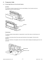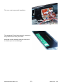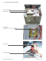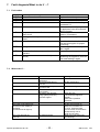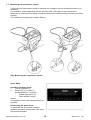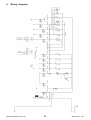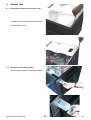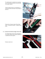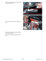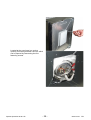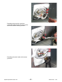
1
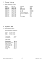
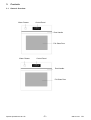
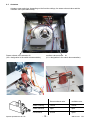
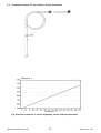
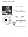
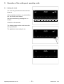
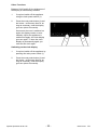
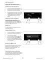
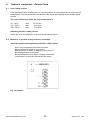
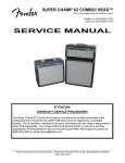
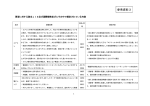
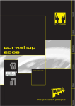
SERVICE MANUAL
COOKING
AEG
Fitted Fan
Steam Cooking oven
© Electrolux Distriparts
Muggenhofer Straße 135
D-90429 Nürnberg
Germany
Fax +49 (0)911 323 1022
DGS-TDS-N
Edition:
05.02
Publ.-Nr.:
599 517 401
685
EN
Table of contents
Safety instructions ........................................................................................................... 3
1.
1.1
General features ................................................................................................ 4
Model Designation / PNCs ................................................................................ 4
2.
2.1
Appliance data ................................................................................................... 4
Dimensions and Power ..................................................................................... 4
3.
3.1
3.2
Controls ............................................................................................................. 5
General Overview .............................................................................................. 5
Control Panel ..................................................................................................... 6
4.
4.1
4.2
4.3
4.4
4.5
Component data ................................................................................................ 7
Prisma High Electronic Oven Control System .................................................. 7
Steam Thermostat / Steam Relay ..................................................................... 9
Actuators ......................................................................................................... 10
Temperature sensor PT 500 / Buzzer / Safety thermostat ............................. 11
Steam generator/ Steam covering / Fan covering ........................................... 12
5.
5.1
5.2
5.3
5.4
5.4.1
5.4.2
5.4.3
5.4.4
5.4.5
5.4.6
Operation of the setting and operating units .................................................... 13
Setting the clock .............................................................................................. 13
Setting the display language ............................................................................ 14
Set the display brightness ............................................................................... 15
Using the Oven ................................................................................................ 16
The Electronic Oven Control ........................................................................... 16
Oven Functions ............................................................................................... 17
Switching the Oven On and Off ....................................................................... 18
Steam Cooking Functions ............................................................................... 20
Additional Functions ........................................................................................ 21
Clock Functions .............................................................................................. 24
6.
6.1
6.2
Technical equipment / General hints ............................................................... 32
Oven Safety Cut-out ........................................................................................ 32
Measures to prevent wrong electrical connection ........................................... 32
7.
7.1
7.2
7.3
7.4
Fault diagnosis/What to do if …? .................................................................... 33
Fault codes ...................................................................................................... 33
What to do if … ............................................................................................... 33
Measuring the temperature sensor ................................................................. 34
Demo Mode ..................................................................................................... 34
8.
9.
9.1
9.2
9.3
9.6
9.7
9.8
Wiring diagrams .............................................................................................. 35
Service tips ...................................................................................................... 36
Removing the two-part housing cover ............................................................. 36
Removal of the switch panel ........................................................................... 36
Removal of the Prisma High Control Unit ........................................................ 37
Dismounting the thermal sensor / steam thermostat ...................................... 44
Other information ............................................................................................ 45
ESD - Electrostatic Discharge and its effects to the control system .............. 45
Spares Operation 03.02 A. B.
-2-
599 517 401
EN
Safety instructions
Attention: In case of any interventions with this appliance pay attention to the safety specifications
according to DIN/VDE 0701 (related to repairs) resp. VDE 0700/ICE 65 (related to appliances)!
Components according to IEC resp. VDE guidelines! In case of an exchange use only parts with the
same specifications.
In case of controls which are provided with MOS modules, use only parts with the same specifications.
Pay attention to the MOS instructions when handling MOS components!
Mechanical repairs resp. inspections of mechanical components may only be made in a voltage-free
condition.
Spares Operation 03.02 A. B.
-3-
599 517 401
EN
1.
General features
1.1
Model Designation / PNCs
Model
B8920-1-M
B8920-1-A
B8920-1-M
B8920-1-A
B8920-1-M
B8920-1-A
B8920-1-M
B8920-1-A
B8924-1-M
B8924-1-A
B8920-1-M
PNC new
941 047 080
941 047 081
941 047 082
941 047 083
941 047 084
941 047 085
941 047 086
941 047 087
941 047 088
941 047 089
941 047 097
2.
Appliance data
2.1
Dimensions and Power
Countrys
D; A
D; A
Europe North
Europe North
GB; SAF
GB; SAF
Europe Central/ South
Europe Central/ South
CH
CH
Europe East
Voltage
230 V
230 V
230 V
230 V
230-240 V
230-240 V
230 V
230 V
400V
400V
230 V
Dimensions/ Oven Dimensions
Height
Width
Depth
59,4 cm/ 31 cm
59,2 cm/ 41 cm
56,7 cm/ 41 cm
Total Weight
Volume Muffle
44,0 kg
52,0 l
Power Input
Top element
Bottom element
Ring heating element
Steam generator
Small-Surface Grill
Large-Surface Grill
Turbo-Grill
Pizza setting
Lighting
Spares Operation 03.02 A. B.
1000 W
1000 W
2400 W
1800 W
1900 W
2900 W
1800 W
3400 W
2x25 W
-4-
599 517 401
EN
3.
Controls
3.1
General Overview
Water Drawer
Control Panel
Door Handle
Full Glass Door
Water Drawer
Control Panel
Door Handle
Full Glass Door
Spares Operation 03.02 A. B.
-5-
599 517 401
EN
3.2
Control Panel
Water Drawer
Oven/Time Display
Temperature Display
Main Power Button
Oven Functions
Selector Buttons
Clock Functions
Oven Light
Water Drawer
Oven/Time Display
Temperature Display
Main Power Button
Oven Functions
Selector Buttons
Clock Functions
Oven Light
Spares Operation 03.02 A. B.
-6-
599 517 401
EN
4.
Component data
4.1
Prisma High Electronic Oven Control System
Interface
The interface includes components for the entry and display of oven functions and oven
temperature as well as clock functions.
Interface
Powerboard
The power boards accommodate the components to control the heaters, hot air blowers and
cooling fan.
In addition, the primary side of the power pack includes the fuse (sluggish, 100 mA) of the
appliance.
If this fuse is defective, the appliance does not function and the displays and lighting system are out
of service.
Powerboard
Electronic case
Spares Operation 03.02 A. B.
-7-
599 517 401
EN
The oven control system after installation.
The appropriate Touch Sensor Keys for entries are
firmly affixed to the switch panel back.
Keep this in mind especially during the removal of
the switch panel to avoid damages.
Spares Operation 03.02 A. B.
-8-
599 517 401
EN
4.2
Steam Thermostat / Steam Relay
Steam Thermostat
Steam Relay
Steam Relay
Designation „rt“ in the circuit diagram
Thermostat
Thermostat Probe
Spares Operation 03.02 A. B.
-9-
599 517 401
EN
4.3
Actuators
Actuators open and close, depending on the function settings, the steam exhaust valve and the
ventilator valve (see table below).
ventilator valve actuator A1
(A1 = designation in the switch documentation)
Steam exhaust valve actuator A2
(A2 = designation in the switch documentation)
Spares Operation 03.02 A. B.
Steam exhaust valve
ventilator valve
Steam cooking
closed
closed
Steam exhaust
open
open
conventional
closed
open
- 10 -
599 517 401
EN
4.4
Temperature sensor PT 500 / Buzzer / Safety thermostat
Resistance W
Temperatur °C
Fig. Electrical resistance of sensor depending on the ambient temperature
Spares Operation 03.02 A. B.
- 11 -
599 517 401
EN
4.5
Steam generator/ Steam covering / Fan covering
Fan covering
Material:
chromed brass
Steam generator covering
Material:
chrome steel
The covering prevents contamination of the
steam generator
Steam generator
Material:
Capacity:
Electrical Power:
stainless steel
0.7 L
1800 W
Support for 2 Thermal Sensors (Klixons)
TR1/ F2: 120 °C signal sound No water
TR2/ F2: 200 °C disconnection of steam
generator
200 °C Klixon
The 200 °C Klixon can be recognized by
the plug-lug bent up on one side
Spares Operation 03.02 A. B.
- 12 -
599 517 401
EN
5.
Operation of the setting and operating units
5.1
Setting the clock
The oven only operates when the clock has
been set.
9
10
11
12
After electrical connection, or a power failure,
the “Set Clock” arrow flashes.
Set the current time by pressing the + or buttons.
1
2
3
4
5
6
7
8
5 Wait for a few seconds.
The flashing stops and the clock shows the
time you have set.
The appliance is now ready for use.
Spares Operation 03.02 A. B.
- 13 -
599 517 401
EN
5.2
Setting the display language
1.
Switch on the appliance by pressing
the main Power button (1).
2.
Press the main Power (1) and the
Clock Functions (6) buttons at the
same time.
3.
Select one of the available languages
using the + and - buttons.
4.
Press the main Power (1) and the
Clock Functions (6) buttons at the
same time, to store the selected
language.
Spares Operation 03.02 A. B.
- 14 -
599 517 401
EN
5.3
Set the display brightness
The brightness of the display can be
adjusted for better readability on ovens fitted
at high positions.
1.
Switch on the appliance by pressing
the main Power button (1).
2.
Press the main Power (1) and the
Clock Functions (6) buttons at the
same time
3.
Press the Oven Functions (2) button .
4.
Set the brightness using the + or buttons.
5.
Press the main Power (1) and the
Clock Functions (6) buttons at the
same time, to store the brightness
setting.
Spares Operation 03.02 A. B.
- 15 -
599 517 401
EN
5.4
Using the Oven
5.4.1 The Electronic Oven Control
Display
Oven Functions
Temperature Display
Time Display
Cooking Time Display
Time Functions
Main Power Button
End Time Display
Time/Countdown
Time Functions
Meat Probe
Selector Buttons
Clock Functions
Oven Functions
Programme
Oven Light
General Instructions
Always switch the appliance on first by pressing the main power switch .
When the selected function is lit, the oven begins to heat up or the time set begins to count
down.
Switch on the oven light using the button.
Switch the appliance off by pressing the main power switch .
When the selected temperature is reached, an audible signal sounds.
Spares Operation 03.02 A. B.
- 16 -
599 517 401
EN
5.4.2 Oven Functions
Vigorous Steam Cooking
Fixed temperature setting: 96°C.
Steam generator and fan are on.
Steam Interval
Suggested temperature: 180 °C.
Hot air and steam generator operate alternately.
Fan Cooking
Suggested temperature: 150 °C.
The fan and the rear heating element are on.
Pizza Setting
Suggested temperature: 200 °C.
Bottom heat, rear heating element, and fan are on.
Rotitherm
Recommended temperature: 180°C
The grill element and top element operate alternatively with the fan.
Dual Grill
Suggested temperature: 230°C
Top heat and grill heating elements are on.
Single Grill
Suggested temperature: 230 °C.
The grill heating element is on.
Top/Bottom Heat (Conventional)
Suggested temperature: 200°C
The Top and Bottom Heat heating elements are on.
Defrost/ Dry
Suggested temperature: 30°C.
Bottom heating element and fan are on.
Low Temperature Cooking
Temperature setting: 120/80 °C.
Rear heating element and fan are on.
Spares Operation 03.02 A. B.
- 17 -
599 517 401
EN
5.4.3 Switching the Oven On and Off
Setting oven functions
1.
Switch on the appliance by pressing
the button (1).
2.
Press the Oven Function button (2) as
many times as necessary until the
desired oven function appears.
The suggested temperature appears on the temperature display.
If the suggested temperature is
not changed within about 5
seconds, the oven begins to
heat.
Changing the oven temperature
Press the + or - button, to raise or lower the
temperature. The temperature setting
changes in steps of 5 °C.
Thermometer Symbol
The thermometer symbol rises slowly,
indicating the degree to which the oven
is currently heated.
The three parts of the thermometer
symbol flash one after the other,
indicating that Fast Warm Up is in
operation.
Checking the temperature
Press the + and - buttons at the same time.
The present oven temperature ap-pears on
the temperature indicator.
Spares Operation 03.02 A. B.
- 18 -
599 517 401
EN
Changing the Oven Function
Press the Oven Function button (2) as often
as necessary, until the desired function
appears.
Switching the Oven Function off
To switch off the oven, press the Oven
Function button (2) as often as necessary,
until no oven function appears.
Switching the oven off
Switch off the appliance by pressing the
button (1).
Spares Operation 03.02 A. B.
- 19 -
599 517 401
EN
5.4.4 Steam Cooking Functions
Important: The steam cooking functions must always be set in con-junction with the clock functions
Cook Time (9) or End Time (11) (see chapter Clock Functions Cook Time and End Time).
Important: Only water can be used as liquid. A buzzing sound is heard when the water has been
used up. When more water is added, the buzzing sound is switched off.
To prevent limescale forming, only use decalcified water, for example, from a water filter.
Because of the automatic steaming dispersal period of approx. 5 min-utes at the end of the cooking
time and the heating up time of approx. 2 minutes, settings of less than 10 minutes have little effect.
During steam dispersal, the oven door may get slightly steamed up. Steam will also escape when
the door is opened. The slight condensation on the control panel will quickly evaporate.
Vigorous Steam
1.
Water (approx. 700 ml) is not poured
directly into the steam generator, but
into the water drawer in the control
panel. The water supply lasts for
approx. 30 minutes.
2.
Switch the oven on using the main
power switch (1).
3.
Using the Oven Function button (2)
select the Vigorous Steam function.
4.
Using the clock function buttons (6)
select Cook Time (9) or End Time (11)
and using the + or - buttons, set the
desired cooking time or switch-off time.
After about 2 minutes, the first steam
appears. A single audible sig-nal
indicates when the cooking temperature of around 96°C is reached. A
triple signal is sounded at the end of
cooking time.
5.
Stop the signal and switch off the oven
by pressing the main power switch (1).
After the oven has cooled down, soak
up any remaining water from the steam
generator using a sponge and, if
necessary, wipe out with a little
vinegar. Leave the door open to let the
oven dry completely.
Spares Operation 03.02 A. B.
- 20 -
599 517 401
EN
Interval Steam
The continual change from fan to steam
takes place automatically.
1.
The water (about 250 ml) is not poured
directly into the steam generator, but
into the water drawer in the control
panel. The water supply lasts for
approx. 60 minutes.
2.
Switch the oven on using the main
power switch (1).
3.
Using the Oven Function button , select
the Interval Steam function and using
the button or the button set the desired
temperature.
4.
Using the clock function buttons (6)
select Cook Time (9) or End Time(11)
and using the + or - buttons, set the
desired cooking time or switch-off time.
Then proceed as for Vigorous Steam
Cooking.
5.4.5 Additional Functions
Baking and Roasting Programmes
Selecting baking and roasting
programmes
1.
Press the Programme button (3) as
often as necessary, until the desired
baking/roasting programme appears.
-
2.
3.
In the function display field the symbols for the oven function and the recommended
oven shelf appear.
The suggested temperature ap-pears on the temperature dis-play.
The cooking time and the end time appear in the clock display.
After about 5 seconds, the oven is switched on.
Before the programme ends, an audible signal sounds.
Check the cooking at this point.
When the cooking time is completed, an audible signal sounds. ”0:00” flashes in the
clock display.
The signal can be stopped by pressing any button.
Delaying the start
The cooking time can be delayed (see Clock Functions End Time). The clock function End Time
can be set, if the programme has been running for less than two minutes.
Ending the cooking time early
Press the Programme button (3) as often as necessary until no baking/ roasting programme is
displayed.
Spares Operation 03.02 A. B.
- 21 -
599 517 401
EN
Meat Probe
Ensures that the oven switches itself off as
soon as the temperature at the centre of a
roast reaches a set temperature. The meat
probe is best used together with the
Conventional (Top/Bot-tom heating), Fan
Cooking and Rotitherm functions.
There are two temperatures to be set:
Oven temperature
Core temperature
1.
Push the tip of the meat probe in as
fully as possible, so that the tip is in the
centre of the meat.
2.
Insert the meat probe plug into the
socket on the side wall of the oven,
pushing it in fully.
3.
Press the Oven Function button (2) as
often as necessary, until the de-sired
oven function appears.
4.
Start setting the desired core temperature within 5 seconds, using the +
or - buttons. The display changes to
the current core temperature.
Spares Operation 03.02 A. B.
- 22 -
599 517 401
EN
-
-
-
-
The core temperature is
displayed from 30°C.
Should the current core temperature already be being displayed,
before the desired core temperature is set, press the meat probe
button (4) and carry out the
setting process.
To set the oven temperature,
press the meat probe button (4)
twice.
Start setting the desired oven
temperature within 5 seconds,
using the + or - buttons.
As soon as the core temperature
set is reached, an audible signal
sounds and the oven switches
itself off automatically.
5.
To switch off the signal, press any
button.
6.
Remove the meat probe’s plug from
the socket and take the meat out of the
oven with the meat probe still inserted.
7.
If applicable, switch off the appliance.
Checking or changing the core
temperature
-
By pressing the meat probe button, you
can change between the current and
the set core temperatures and the set
oven temperature.
-
If necessary, change the temperature
using the + or - buttons.
The automatic oven switch off function
cannot be used in conjunction with the oven
function Low Temperature Cooking.
Spares Operation 03.02 A. B.
- 23 -
599 517 401
EN
5.4.6 Clock Functions
Countdown
To set a countdown. A signal sounds after the time has elapsed. This function does not affect the
functioning of the oven.
Cook time
To set how long the oven is to be in use.
End time
To set when the oven is to switch off again.
Time
To set, change or check the time.
General hints
When a clock function has been selected, the related arrow flashes for around 5 seconds.
During this time, the desired setting can be made using the or buttons.
After the desired time has been set, the arrow flashes again for around 5 seconds. The arrow
then remains lit. The set time begins to run.
Spares Operation 03.02 A. B.
- 24 -
599 517 401
EN
Countdown (9)
1.
Press the clock functions button (6) as
often as necessary, till the Countdown
arrow flashes.
2.
Use the + or - buttons to set the
desired length of time (99 minutes
maximum).
The time remaining appears after about
5 seconds. The Countdown arrow (10)
is lit.
When the set time has elapsed, a
signal is sounded for 2 minutes. The
“0.00” indication, and the Countdown
arrow (10) appear flashing.
To stop the signal:
Press any of the buttons.
Spares Operation 03.02 A. B.
- 25 -
599 517 401
EN
Cook Time (9)
1. Select Oven Function and Temperature.
2.
Press the clock functions button (6) as
often as necessary, until the Cook
Time arrow (9) flashes.
3.
Set the desired cooking time using the
+ or - buttons. The Cook Time arrow is
lit.
When the set time has elapsed, a
signal sounds for 2 minutes. The oven
switches itself off. The “0.00” indication
and the Cook Time arrow appear
flashing.
To stop the signal:
Press any of the buttons.
Spares Operation 03.02 A. B.
- 26 -
599 517 401
EN
End (11)
1.
Select an oven function and temperature.
2.
Press the clock functions button (6) as
often as necessary, until the End arrow
appears flashing.
3.
Set the desired switch-off time using
the + or - buttons. The End arrow is lit.
When the set time has elapsed, a
signal sounds for 2 minutes. The oven
switches itself off. The “0.00” indication
and the End arrow appear flashing.
To stop the signal:
Press any of the buttons.
Spares Operation 03.02 A. B.
- 27 -
599 517 401
EN
Combining the Cook Time (9) and End
functions (11)
The Cook Time and End functions can be
used at the same time, to switch the oven on
and off at a later time.
1.
Select an oven function and
temperature.
2.
Using the Cook Time function (9), set
the time necessary to cook the item
concerned. For example, 1 hour.
3.
Using the End function (11), set the
time at which the item concerned
should be ready. For example, 14:05.
The Cook Time (9) and End (11)
arrows are lit. The oven switches on
automatically at the required time. In
this example, 13:05.
When the set cooking time has
elapsed, a signal sounds for 2 minutes,
and the oven switches it-self off. In this
example, 14:05.
Spares Operation 03.02 A. B.
- 28 -
599 517 401
EN
Adjusting the Clock (12)
1.
Press the clock functions button (6) as
often as necessary, until the Time Display arrow flashes.
2.
Set the current time using the + or buttons.
3.
After about 5 seconds, the arrow stops
flashing and the clock shows the set
time. The appliance is once more
ready for use.
The clock can be adjusted only if the
Child Safety device is not engaged,
neither of the Cook Time (9) or End
(11) functions is set, and none of the
oven functions is set.
Spares Operation 03.02 A. B.
- 29 -
599 517 401
EN
Other Functions
Between 22:00 and 6:00, the brightness of
the display is automatically reduced.
1.
If required, switch off the appliance
using the main power switch (1).
2.
Press the meat probe button (4) and
the button - at the same time for as
long as necessary, until the display
goes out (about 2 seconds).
As soon as the oven is switched on
again, the display comes on automatically. When the appliance is
switched off again, the clock display
goes out again. To have the clock
display on permanently again, you
must set the clock again.
Switching on the clock display
1.
If required, switch off the appliance by
pressing the main power switch (1).
2.
Press the meat probe button (4) and
the button - at the same time for as
long as necessary, until the display
goes out (about 2 seconds).
Spares Operation 03.02 A. B.
- 30 -
599 517 401
EN
Child Safety Device
As soon as the child safety device is
engaged, the oven cannot be switched on.
Activating the child safety device
1.
If required, switch on the appliance by
pressing the main power switch (1). No
Oven Function must be selected.
2.
Press and hold the Programme (3) and
- buttons at the same time, until CHILD
SAFETY appears on the display field.
The child safety device is now engaged.
Releasing the child safety device
Press and hold the Programme (3) and buttons at the same time, until CHILD
SAFETY disappears from the display field.
The child safety device is now released and
the oven is again ready for use.
Button Lock
To ensure that oven functions set are not
accidentally altered.
Setting the Button Lock
1.
If required, switch on the appliance by
pressing the main power switch (1).
2.
Select the oven function.
3.
Press and hold Programme (3) and buttons at the same time for about 2
seconds, until PROGRAMME LOCK
appears in the display. The button lock
is now engaged.
Releasing the Button Lock
Press and hold Programme and buttons at
the same time for about 2 seconds. The
button lock is automatically lifted, if the
appliance is switched off.
Programmed Functions and Recipes
The appliance has 12 programmed functions
and recipes, which can be selected one after
the other using the Programme button.
Spares Operation 03.02 A. B.
- 31 -
599 517 401
EN
6.
Technical equipment / General hints
6.1
Oven Safety Cut-out
If not switched off after a certain time, or if the temperature is not modified, the oven switches off
automatically. The last temperature set flashes in the temperature display and an audible signal
sounds.
The oven switches off when the oven temperature is:
30 - 120°C
120 - 200°C
200 - 230°C
after
after
after
12.5 hours
8.5 hours
5.5 hours
Switching on after a safety cut-out
Switch the oven off completely. It can then be switched on again.
6.2
Measures to prevent wrong electrical connection
400 V Recognition with appliances with 230 V rated voltage
-
400 V are recognized by the micro-processor
Micro-processor switches to error mode
Bad connection is shown on display by error code F7
No heating element is energized
During this time the oven can be correctly connected
if connection is correct all functions will be normal
Fig. Connection
Spares Operation 03.02 A. B.
- 32 -
599 517 401
EN
7.
Fault diagnosis/What to do if …?
7.1
Fault codes
Display
F0
F0
F1
F2
F3
Checksum error
F4
F6
Temperature sensor without contact or
short-circuit.
Sticking heater relay contacts at power
board.
Power board has too high a temperature
F7
Wrong electrical connection
F8
No connection between power board and
interface
Micro processor resets automatically
(Reset).
F5
F9
7.2
Fault
Internal Powerboard Error
No alarm
Door cannot be locked.
Door cannot be unlocked.
Action
Replace electronic system.
None
Check door lock.
Check door lock and unlocking
thermostat f11.
Make a mains reset by separating
the appliance from the main and
starting it again.
Check temperature sensor,
replace, if necessary.
Replace electronic system.
Check installation situation of air
duct and cooling fan for proper
functioning.
Connect appliance correctly and
start it again.
Replace electronic system.
Carry out a mains reset by
separating the appliance from the
main and starting it again.
What to do if …
Fault
The oven will not heat.
Possible cause
The oven has not been
switched on.
The correct time has not
been set.
The required settings have
not been made.
The oven's safety fuse has
been tripped.
The fuse in the domestic
wiring system (fuse box)
has been tripped.
“F 9” appears on the display.
The oven is not heating up,
and the function display is
operating.
A small arrow will light up.
The oven light will not
come on.
Spares Operation 03.02 A. B.
The bulb has blown.
- 33 -
Remedy
Switch the oven on.
Set the correct time.
Check the settings.
Check the safety fuse.
Check the fuse.
If the fuses are tripped repeatedly,
please call a qualified
electrician.
Press the mains button.
Set the oven function to
ZERO. Do not switch off
the oven. Press and hold
down the three centre buttons
simultaneously until a
signal can be heard.
Replace the bulb (see Care
and Cleaning).
599 517 401
EN
7.3
Measuring the temperature sensor
If a failure at the temperature sensor is assumed, the resistance can be checked by means of an
ohmmeter.
The resistance of the temperature sensor should be 500 – 600 ohms at room temperature.
Make sure to measure the insulation resistance between the metallic housing and each connection
terminal.
The resistance should be higher than 2 MOhms.
Abb. Measuring the temperature sensor
Demo Mode
Activating the demo mode
1.
Turn on appliance (1)
2.
Press keys (3), (4) and (7)
simultaneously for 5 seconds audible signal goes off
Demo Modus is active
Status:
The appliance can be fully operated but is not
powered
Deactivating the demo mode
To deactivate the demo mode, keep the
appliance turned on and proceed in the same
way as with activation.
Spares Operation 03.02 A. B.
- 34 -
599 517 401
EN
8.
Wiring diagrams
Spares Operation 03.02 A. B.
- 35 -
599 517 401
EN
9.
Service tips
9.1
Removing the two-part housing cover
Loosen the two right and left mounting bolts.
Lift front half of cover.
9.2
Removal of the switch panel
Pull the clipsed grip out of the water drawer.
Spares Operation 03.02 A. B.
- 36 -
599 517 401
EN
The switch panel is retained by two springs,
one on the right and another on the left side
of the panel support.
Take the switch panel in your hands by its
left and right side and draw off horizontally to
the front.
Please do not forget to draw off the ribbon
cable – connection Interface + affixed Sensor
Keys.
9.3
Removal of the Prisma High Control Unit
The Prisma High Control Unit is suspended
in the panel support and is kept in position by
a catch hook on the upside.
Release catch hook
Spares Operation 03.02 A. B.
- 37 -
599 517 401
EN
Move Prisma High Control Unit to the right
(viewed from the front).
Pull off wires and take out the electronics
unit.
Move Prisma High Control Unit to the right
(viewed from the front).
Pull off wires and take out the electronics
unit.
Spares Operation 03.02 A. B.
- 38 -
599 517 401
EN
Located at the oven base is a service
opening for steam generator removal, which
can be opened by unscrewing the four
fastening screws.
Spares Operation 03.02 A. B.
- 39 -
599 517 401
EN
Detaching the protective conductor
connection and removal of the lines of the
two klixons and the heating element.
Detaching the water intake at the steam
generator.
Spares Operation 03.02 A. B.
- 40 -
599 517 401
EN
Removal of the two klixons by unscrewing
the upper and lower fastening screws.
Six bore holes are provided in the oven muffle six through which the threaded pins
mounted on the steam generator are
inserted. The steam generator is fixed in
position by a hole ring and six hexagonal
nuts.
Unscrew the six fastening screws.
Spares Operation 03.02 A. B.
- 41 -
599 517 401
EN
Place a purposeful knock with the rubber
hammer against the steam generator base
to loosen the tight seat.
Now you can remove the steam generator
towards the oven inside.
Spares Operation 03.02 A. B.
- 42 -
599 517 401
EN
Spares Operation 03.02 A. B.
- 43 -
599 517 401
EN
9.6
Dismounting the thermal sensor / steam thermostat
Protective cover removal
The thermal probe is located under the
cover.
After removing the cover, you can pull the
thermal probe with rubber collar out by lifting
it out of the retainer.
Spares Operation 03.02 A. B.
- 44 -
599 517 401
EN
9.7
Other information
-
It is recommended wearing protective gloves for all mechanical work on sharp-edges metal
sheets to prevent injuries.
-
If you are supplied with a spare part set with new sealings when replacing defect component
parts, it is compulsory to replace these sealings too.
-
Only specialised technicians may install the appliance (mounting and power connection).
-
Proceed with utmost care when opening the oven door to check the food during steam
boiling, since hot and moist steam comes out of the open door.
Warning! Keep to safety precautions when intervening on the appliance.
9.8
ESD - Electrostatic Discharge and its effects to the control system
Since the control unit interface is in the open, the customer service technician must make sure on
any repair work to initiate equipotential bonding by touching the appliance housing in order to
neutralise any charges and prevent the control unit from damage. The same must be done on the
service control unit which should be removed from its ESD protection film only after doing
equipotential bonding on the appliance before installing the unit.
Note:
It is not important to know about the theories of charging and discharging process – these are not
interesting here. But he practical effects should be known. We see (sense) them every day if there
is equipotential bonding on gripping a door handle.
What happens during equipotential bonding with the semi-conductor component parts
(element of an electronic subassembly)?
Charge equalisation is by the inner structures of the component part. The component will not be
destroyed immediately; but possible later failures due to damaged inner connections which only
occur after loading by temperature or power are much more unpleasant.
On the one hand, almost all sensitive semi-conductor elements (MOS circuits,for instance) have
been improved by integrated safety measures, on the other the inner structures of such parts are
today much smaller than some 10 years ago, and this will increase sensitivity again.
Warning:
Which of the component parts are at risk on service interventions?
All subassemblies provided with control inputs (door switches, food thermometre, …) open strip
conductor and freely accessible processors.
Practical examples:
Switch clocks with inputs for food thermometres and door switches
Switch clocks whose control processors could be touched (housing only forms a half shell for
cost reasons)
WOEC control unit
Spares Operation 03.02 A. B.
- 45 -
599 517 401
EN