1
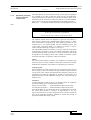
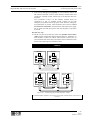
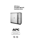
7400 Series UPS
Single Module
and
1+1 Configuration
INVERTER
MEASUREMENTS
ALARM
EMERGENCY
Io
Vo
f
OFF
B
(( ))
ON
MEASUREMENTS
MEASUREMENTS
Vo
f
INVERTER
ALARM
Io
B
ALARM
Vo
Io
f
B
INVERTER
EMERGENCY
OFF
(( ))
ON
EMERGENCY
OFF
(( ))
ON
MEASUREMENTS
Vo
f
INVERTER
ALARM
Io
B
EMERGENCY
OFF
(( ))
ON
User Manual
Manual Reference: 6310018A - 2
(02/98) LCA 10/01
7400 Series UPS
Single and 1+1 IOM Manual
6310018a.02.doc
IMPORTANT
This manual contains information concerning the installation, operation and maintenance of the
Liebert Series 7400 Uninterruptible Power System (UPS) for the Single Module and One plus
One Systems.
All relevant parts of the manual should be read prior to commencing installation.
The UPS must be commissioned by an engineer approved by the manufacturer (or his
agent) before being put into to service. Failure to observe this condition will invalidate any
implied warranty.
The Series 7400 UPS has been designed for Commercial/Industrial use only.
The Series 7400 UPS has not been designed for direct use in any life support applications.
If you encounter any problems with the procedures contained in this manual you should seek
immediate assistance from the Liebert Sales Office from whom the equipment was purchased.
Alternatively contact the manufacturer's Customer Support department at the address shown
below:
Customer Service and Support Department,
Customer Support Systems,
Liebert Europe
Globe Park, Marlow, SL7 1YG, U.K.
Telephone (01628) 403200
Fax (01628) 403302
Outside the UK prefix the number with - (44 - 1628)
The manufacturer reserves the right to change the equipment design without notice.
©Copyright 1998 by Liebert Europe.
Unauthorised reproduction prohibited
Prelim i
Issue 2
(02/98)
6310018a.02.doc
All rights reserved.
Prelim ii
Issue 2
(02/98)
7400 Series UPS
Single and 1+1 IOM Manual
7400 Series UPS
Single and 1+1 IOM Manual
6310018a.02.doc
ELECTRO MAGNETIC COMPATIBILITY
WARNING
This is a UPS for restricted sales distribution to informed partners with the appropriate
EMC technical competence. Installation restrictions or additional measures may be needed
to prevent disturbances (EMC Standard 50091-2).
To convert to a class `A' UPS, the following factory installed
optional e.m.c. kits must be fitted:
80 kVA Module - Option kit part number 4641018 S
120 kVA Module - Option kit part number 4641014 O
200 kVA Module - Option kit part number 4641029 D
300 kVA Module - Option kit part number
-
400 kVA Module - Option kit part number
-
When fitted with the above optional e.m.c. kits the following warning applies:
This is a class `A' UPS product. In a domestic environment this product
may cause radio interference in which case the user may be
required to take additional measures.
This equipment complies with the requirements of the EMC Directive 89/336/EEC
and the published technical standards.
Continued compliance requires installation in accordance with these instructions
and the use of manufacturer approved accessories only.
Prelim iii
Issue 2
(02/98)
6310018a.02.doc
7400 Series UPS
Single and 1+1 IOM Manual
This manual describes the following equipment:
EQUIPMENT
PART NUMBER
80 kVA UPS Module
5410270 I
120 kVA UPS Module
5410272 K
200 kVA UPS Module
5410276 O
300 kVA UPS Module
5410250 O
400 kVA UPS Module
5410252 Q
300 kVA UPS 12 pulse Module
5410251 P
400 kVA UPS 12 pulse Module
5410253 R
80 kVA 12 Pulse option
5332001 Z
120 kVA 12 Pulse option
5332002 A
200 kVA 12 Pulse option
5332004 C
80 kVA EMC compatibility kit
4641018 S
120 kVA EMC compatibility kit
4641014 O
200 kVA EMC compatibility kit
4641029 D
300 kVA EMC compatibility kit
400 kVA EMC compatibility kit
860 mm Battery Cabinet (250 Amp)
5320024 I
Battery Circuit Breaker Box for UPS 80 kVA (250 A)
4641007 H
Battery Circuit Breaker Box for UPS 120 kVA (400 A)
4641008 I
Battery Circuit Breaker Box for UPS 200 kVA (630 A)
4641009 J
Battery Circuit Breaker Box for UPS 300 kVA (800 A)
4641011 L
Battery Circuit Breaker Box for UPS 400 kVA (1000 A)
4641012 M
5th Harmonic Input filter 80 kVA
5331016 C
5th Harmonic Input filter 120 kVA
5331018 E
5th Harmonic Input filter 200 kVA
5331020 G
5th Harmonic Input filter 300 kVA (internal to UPS)
4641010 K
5th Harmonic Input filter 400 kVA (internal to UPS)
4641013 N
AS400 alarm interface board
4590041 B
AS400 ( X4 ) alarm interface board
4590045 F
External interface board
4590044 E
Remote Alarm Monitor (RAM)
4305001 Z
Remote alarm and control Panel
4305002 A
RS-232 Communications Interface (SGC)
4550002 C
Top cable entry kit for 80 kVA - 120 kVA
2174011 V
Top cable entry kit for 200 kVA
2174033 R
Prelim iv
Issue 2
(02/98)
7400 Series UPS
Single and 1+1 IOM Manual
6310018a.02.doc
Safety Precautions
WARNING
THIS UPS DOES NOT INCORPORATE AUTOMATIC BACKFEED PROTECTION. A
WARNING LABEL MUST BE FITTED TO ALL EXTERNAL PRIMARY POWER
ISOLATORS STATING:
ISOLATE THE UNINTERRUPTIBLE POWER SYSTEM BEFORE WORKING ON THIS
CIRCUIT.
General
In common with other types of high power equipment, dangerous voltages are present within the UPS
and battery enclosure. The risk of contact with these voltages is minimised as the live component parts
are housed behind a hinged, lockable door. Further internal safety screens make the equipment
protected to IP20 standards. No risk exists to any personnel when operating the equipment in the
normal manner, following the recommended operating procedures.
All equipment maintenance and servicing procedures involve internal access and should be carried out
only by trained personnel.
Batteries
Battery manufacturers supply details of the necessary precautions to be observed when
working on, or in the vicinity of, a large bank of battery cells. These precautions should be
followed implicitly at all times.
Particular attention should be paid to the recommendations concerning local environmental
conditions and the provision of protective clothing, first aid and fire-fighting facilities.
Test Equipment
When the battery is under charge it is earth-referenced about its mid-point e.g. if the battery
is being charged at 446 V the battery extremities will be at +223V and -223V with respect to
neutral (earth). When using mains-powered test equipment such as oscilloscopes in the UPS
high voltage area, always use a differential mode of operation to avoid the need to
disconnect the oscilloscope frame earth.
Personnel
When working inside the UPS (trained personnel only) it is recommended that protection be
worn to prevent eye damage, should an electrical arc be struck by mishandling or severe
electrical fault.
Some of the power components are very heavy. If their removal is necessary ensure that
sufficient manpower is available, otherwise use adequate mechanical handling
equipment.When working in the general area of the UPS where high voltages are present, a
second person should be standing-by to assist and summon help in case of accident.
Prelim v
Issue 2
(02/98)
6310018a.02.doc
7400 Series UPS
Single and 1+1 IOM Manual
Table of Contents
1. Chapter 1 - General Description .............................................................................................................................1-1
1.1 Introduction ..........................................................................................................................................................1-1
1.2 Design Concept ....................................................................................................................................................1-1
1.2.1 Module Design ..............................................................................................................................................1-1
1.2.2 Bypass supplies .............................................................................................................................................1-5
1.2.3 UPS Power Switch Configuration ..............................................................................................................1-5
1.2.4 Battery circuit breaker ...................................................................................................................................1-6
1.2.5 Battery Cabinet..............................................................................................................................................1-6
1.2.6 Battery circuit breaker box ............................................................................................................................1-6
1.3 One Plus One System ...........................................................................................................................................1-8
1.3.1 Redundant vs Non-Redundant configuration................................................................................................1-8
1.3.2 One-Plus-One Parallel Control ......................................................................................................................1-8
1.3.3 Common battery ..........................................................................................................................................1-10
1.4 Operator Control Panel.......................................................................................................................................1-12
1.4.1 Mimic indications ........................................................................................................................................1-12
1.4.2 Control switches ..........................................................................................................................................1-13
1.4.3 LCD Display................................................................................................................................................1-15
2. Chapter 2 - Operating Instructions..........................................................................................................................2-1
2.1 Introduction ..........................................................................................................................................................2-1
2.1.1 General notes .................................................................................................................................................2-1
2.2 One plus One ........................................................................................................................................................2-1
2.2.1 Redundant module system .............................................................................................................................2-1
2.2.2 Non-Redundant module system .....................................................................................................................2-3
3. Chapter 3 - Installation Procedure ..........................................................................................................................3-1
3.1 Introduction ..........................................................................................................................................................3-1
3.1.1 Equipment positioning and environmental considerations ...........................................................................3-2
3.1.2 Raised floor installation.................................................................................................................................3-3
3.1.3 Battery Location ............................................................................................................................................3-3
3.2 Preliminary Checks.............................................................................................................................................3-13
3.3 Reassembling the 300 kVA and 400 kVA cabinets ............................................................................................3-14
3.4 Connecting the UPS power cables......................................................................................................................3-16
3.4.1 Cable entry...................................................................................................................................................3-16
3.4.2 Cable rating .................................................................................................................................................3-16
3.4.3 Cable connections........................................................................................................................................3-17
3.4.4 Safety earth..................................................................................................................................................3-17
3.4.5 Cabling procedure .......................................................................................................................................3-18
3.5 Battery Installation .............................................................................................................................................3-24
3.5.1 860 mm cabinet (250 Amp circuit breaker) .................................................................................................3-25
3.5.2 Battery circuit breaker boxes .......................................................................................................................3-28
3.5.3 Battery Display Initialisation .......................................................................................................................3-31
4. Chapter 4 - Optional equipment .............................................................................................................................4-1
4.1 AS400 Interface Board (4590041B).....................................................................................................................4-2
4.1.1 AS400 Interface Board outputs .....................................................................................................................4-2
4.1.2 Remote control inputs....................................................................................................................................4-2
4.1.3 Calibration .....................................................................................................................................................4-2
4.2 4-Way AS400 Interface Board (4590045F) .........................................................................................................4-4
4.2.1 Remote control inputs....................................................................................................................................4-4
4.2.2 Calibration .....................................................................................................................................................4-4
4.3 Output Interface (Remote Alarms) Boards (4590044E) .......................................................................................4-6
4.3.1 Alarm outputs ................................................................................................................................................4-6
4.3.2 Remote control inputs....................................................................................................................................4-6
4.4 Remote Alarm Monitor (RAM) (P/N 4305001Z).................................................................................................4-8
Prelim vi
Issue 2
(02/98)
7400 Series UPS
Single and 1+1 IOM Manual
6310018a.02.doc
4.4.1 Connections ...................................................................................................................................................4-8
4.5 Remote Alarm and Control Panel (Part No. 4305002 A) ...................................................................................4-10
4.5.1 Introduction .................................................................................................................................................4-10
4.5.2 Connections .................................................................................................................................................4-11
4.6 RS 232 Communications Management Board (SGC) (4550002C) ....................................................................4-15
4.6.1 Introduction .................................................................................................................................................4-15
4.6.2 General Information ....................................................................................................................................4-16
4.7 5th Harmonic Input Filter ...................................................................................................................................4-18
4.7.1 Introduction .................................................................................................................................................4-18
4.7.2 Specification ................................................................................................................................................4-18
4.7.3 Notes on connection ....................................................................................................................................4-18
4.8 Cable top entry kit ..............................................................................................................................................4-24
4.8.1 Introduction .................................................................................................................................................4-24
4.9 Pulse Option .......................................................................................................................................................4-25
4.9.1 Introduction .................................................................................................................................................4-25
4.9.2 Electrical connection ...................................................................................................................................4-25
4.10 Option Board Kit (Part no. 77000005) .............................................................................................................4-29
4.10.1 Introduction ...............................................................................................................................................4-29
4.10.2 Installation .................................................................................................................................................4-29
5. Chapter 5 - Maintenance.........................................................................................................................................5-1
5.1 Introduction ..........................................................................................................................................................5-1
5.2 Safety Precautions ................................................................................................................................................5-1
5.3 Scheduled Maintenance........................................................................................................................................5-1
5.3.1 Daily checks ..................................................................................................................................................5-1
5.3.2 Weekly checks...............................................................................................................................................5-3
5.3.3 Annual Service ..............................................................................................................................................5-3
5.3.4 Extended service............................................................................................................................................5-4
5.3.5 Battery maintenance ......................................................................................................................................5-4
6. Chapter 6 - Troubleshooting...................................................................................................................................6-1
6.1 Troubleshooting UPS Systems .............................................................................................................................6-1
6.1.1 Operating parameters and limitations ............................................................................................................6-1
6.1.2 General Troubleshooting Procedure .............................................................................................................6-1
6.2 Display panel message interpretation ...................................................................................................................6-5
7. Chapter 7 - SPECIFICATION................................................................................................................................7-1
Prelim vii
Issue 2
(02/98)
7400 Series UPS User Manual
Single Module and One plus One Systems
Chapter 1 - General Description
Introduction
6310018a.02.doc
1.
1.1
Chapter 1 - General Description
Introduction
The 7400 Series uninterruptible power supply (UPS) system is connected
between a critical load, such as a computer, and its three phase mains
power supply. Being designed to furnish a well regulated 3 phase output
power supply under all rated load and input supply conditions, the
system offers the user the following advantages:Increased power quality:
The UPS has its own internal voltage and frequency regulator circuits
which ensure that its output is maintained within close tolerances
independent of voltage and frequency variations on the mains power
lines.
Increased noise rejection:
By rectifying the input a.c. power to d.c. power, and then converting it
back to a.c., any electrical noise present on the input mains supply line is
effectively isolated from the UPS output, therefore the critical load sees
only clean power.
Power blackout protection:
If the mains power fails, the UPS continues to power the critical load
from its battery source, leaving the load immune from power
disturbances.
1.2
1.2.1
Design Concept
Module Design
This section describes an individual module’s operating principles for
both 6 and 12 pulse systems - the effects of the additional parallel control
facilities required on the one plus one system on the standard module are
described later.
6 pulse Rectifier
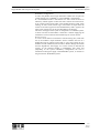
The UPS basically operates as an AC-DC-AC converter (see figure 1-1).
The first conversion stage (from a.c. to d.c.) uses a 3 phase, fullycontrolled SCR bridge rectifier to convert the incoming mains supply
into a regulated 446 V d.c. busbar for a 400 V a.c. input (or 432 V d.c.
for a 380 V a.c. input or 459 Vd.c. for a 415V a.c. input).
1-1
Issue 2
(02/98)
Chapter 1- General Description
Design Concept
7400 Series UPS User Manual
Single Module and One plus One Systems
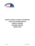
Figure 1-1. Series 7400 UPS Single Module block diagram
Bypass
Supply
RECTIFIER
INVERTER
UPS
Output
Supply
Mains
Supply
BATTERY
1-2
Issue 2
(02/98)
STATIC
SWITCH
7400 Series UPS User Manual
Single Module and One plus One Systems
Chapter 1 - General Description
Introduction
12 Pulse Rectifier
The UPS basically operates as an a.c.-d.c.-a.c. converter (see figure 1-1).
The first conversion stage (from a.c. to d.c.) uses a 3 phase 12 pulse (2 x
6 pulse), fully-controlled SCR bridge rectifier system to convert the
incoming mains supply into a regulated d.c. busbar (432V d.c. for a
380V a.c. input; 446V d.c. for a 400V a.c. input or 459V d.c. for a 415V
a.c. input).
The input a.c. supply is applied (a) directly into a six pulse rectifier and
(b) via a 30° phase shift transformer into a second six pulse rectifier (see
figure 1-2). This phase shifting results in less distortion of the alternating
Mains
Supply
Rectifier
bridges
Inductor
DC
Inductor
L2
L1
To DC
Busbar
Phase
displacement
transformer
AT1
Rectifier
bridges
12 Pulse
(2 x 6 pulse)
Rectifier system
Figure 1-2 . 12 Pulse rectifier block diagram
input supply (i.e. the lower order harmonics are cancelled).
Inverter
The d.c. busbar produced by the rectifier provides both battery charging
power and power to the inverter section-which uses the latest IGBT
switched pulse width modulation (PWM) design and provides the second
conversion phase; i.e. reconverting the d.c. busbar voltage back into an
a.c. voltage waveform.
During normal operation both the rectifier and inverter sections are
active and provide regulated load power whilst simultaneously float
charging the battery. In the event of a mains power failure, the rectifier
becomes inoperative and the inverter is powered solely from the battery.
Critical load power is maintained under these conditions until the battery
is fully discharged, whereupon the UPS shuts down. The end of battery
discharge is assumed when the battery voltage falls to 320 Vd.c. for a
system with a 380V a.c. input supply, 330V d.c. with a 400V a.c. input
supply and 340V d.c. with a 415V a.c. input supply.
The period for which the load can be maintained following a mains
power failure is known as the system’s ‘Autonomy Time’ and is
dependent upon both the battery A/Hr capacity and the applied
percentage load. It is usual in larger installations to provide an
alternative UPS input power source from a standby generator when the
1-3
Issue 2
(02/98)
Chapter 1- General Description
Design Concept
7400 Series UPS User Manual
Single Module and One plus One Systems
6310018a.02.doc
mains supply fails. Once such a generator has been brought on-line, and
the UPS input power has been re-established, the batteries
1-4
Issue 2
(02/98)
7400 Series UPS User Manual
Single Module and One plus One Systems
Chapter 1 - General Description
Design Concept
6310018a.02.doc
immediately begin to recharge. Modern generators can be started and
brought on-line very quickly and where such a facility is incorporated
into the UPS installation it results in short battery discharge periods and
correspondingly rapid recharge times.
1.2.2
Bypass supplies
1.2.3
UPS Power Switch
Configuration
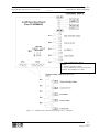
The circuit block annotated ‘Static Switch’ in figure 1-3 contains an
electronically controlled switching circuit which enables the critical load
to be connected either to the inverter output or to a bypass power source
via the ‘static bypass line’. Normally, the load is connected to the
inverter; but in the event of a UPS overload, or inverter failure, it is
automatically transferred to the static bypass line due to the static switch
action.
To provide a clean (no-break) load transfer between the inverter output
and static bypass line, the inverter output and bypass supply must be
fully synchronised during normal operating conditions. This is achieved
through the inverter control electronics which make the inverter
frequency track that of the static bypass supply-provided that the bypass
remains within an acceptable frequency window. The synchronising
window is pre-selected to 2% of nominal frequency, giving an acceptable
frequency window of ±1Hz.
An [INVERTER UNSYNCHRONIZED] warning message is displayed on the
operator control panel when the inverter and bypass supplies are not
synchronized.
A second, manually controlled, ‘maintenance bypass’ supply is also
incorporated into the UPS design. Its purpose is to enable the critical
load to be powered from the mains (bypass) supply while the UPS is shut
down
for
maintenance
or
troubleshooting.
Note:- The load is unprotected against mains power supply aberrations or
failure when it is connected to either the static bypass or maintenance
bypass supply.
The power switch locations in the various 7400 models are shown in
Figure
1-4.Figure 1-3 illustrates the 7400 series UPS module power
switches in what is known as a “Split Bypass” configuration. This is the
standard configuration for all models in the 7400 range.
In the “Split Bypass” configuration the static bypass line is switched by a
separate isolator to a dedicated ‘bypass’ power source which also feeds
the maintenance bypass line.
With the exception of the maintenance bypass isolator, all the isolators
shown must be closed during normal UPS operation.
Although it cannot be classified as a ‘power switch’, the reset switch may
be used as part of the UPS operating procedure. Fitted to the UPS Logic
Board, the reset switch is used by the operator to re-transfer the load to
the inverter following a detected overload or over temperature fault.
1-5
Issue 2
(02/98)
Chapter 1- General Description
Design Concept
7400 Series UPS User Manual
Single Module and One plus One Systems
6310018a.02.doc
Maintenance
Bypass Isolator
Bypass
Supply
Bypass Isolator
INVERTER
RECTIFIER
Mains
Supply
Input
Isolator
UPS
Output
Supply
STATIC
SWITCH
Output
Isolator
Battery
Circuit
Breaker
BATTERY
Figure 1-1 . Series 7400 UPS isolator configuration
1.2.4
Battery circuit breaker The battery is connected to the d.c. Busbar through a circuit breaker
fitted inside the battery cabinet or located adjacent to the batteries where
a battery cabinet is not used. This circuit breaker is closed manually, but
it contains an undervoltage release coil which enables it to be tripped
from the UPS control electronics following certain detected faults. It also
has a magnetic trip facility for overload protection.
1.2.5
Battery Cabinet
1.2.6
Battery circuit breaker
For the larger units and as an alternative to the battery cabinets, a
box
battery circuit breaker can be provided in a custom built box. This
Battery Circuit Breaker Box is designed to be wall or rack mounted and
is connected between the UPS and Battery.
1-6
Issue 2
(02/98)
In the case of the 80kVA and 120kVA UPS models, the batteries
associated with the UPS are generally housed in a purpose-built cabinet
located along-side the main UPS equipment.
It is possible to install batteries of various types and capacity in the
cabinet to obtain the required autonomy characteristics.
The battery cabinet can be purchased in one of the following forms:
1. Complete installation comprising the battery cabinet, batteries and
circuit breaker.
2. Battery cabinet and circuit breaker only with no batteries.
3. Battery cabinet only with no batteries or circuit breaker.
7400 Series UPS User Manual
Single Module and One plus One Systems
Chapter 1 - General Description
Design Concept
6310018a.02.doc
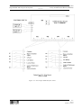
120 kVA
I4
I3
I1 =
I2 =
I3 =
I4 =
I2
200 kVA
I1
I4
I3
I2
I1
Input Isolator
Static Bypass Isolator
Maintenance Bypass Isolator (with padlock)
Output Isolator
300-400 kVA
80 kVA
I4
I1
I3
I4
I3
I2
I1
I2
Figure 1-1 . Power isolator identification
1-7
Issue 2
(02/98)
Chapter 1- General Description
One Plus One System
7400 Series UPS User Manual
Single Module and One plus One Systems
6310018a.02.doc
1.3
One Plus One System
The one-plus-one system comprises two standard 7400 series UPS
modules which are modified to allow their outputs to be connected in
parallel. These can then be used in a "redundant" or "non-redundant"
configuration as explained below.
1.3.1
Redundant vs
Non-Redundant
configuration
1.3.2
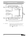
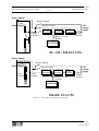
One-Plus-One Parallel When two of the standard 7400 modules just described are connected
Control
together to form a one-plus-one system, each module is fitted with an
additional circuit board which allows the two modules to communicate
with each other. Communication takes place via a single ribbon cable
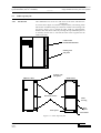
connected between the modules as illustrated in figure 1-5.
The inter-module parallel control responsibilities are complex but can be
summarised as follows:
Synchronisation:
As the outputs from both UPS modules are connected together to provide
a single load supply, it is imperative that the inverters are fully
synchronised both in frequency and phase. This is achieved by digitally
locking the two inverter control oscillators. Similarly, as has already
been mentioned, it is necessary for the inverters to be synchronised to the
bypass supply to enable a "no-break" transfer to be achieved when the
static switch transfers the load to the bypass supply. The inverter control
oscillators are therefore not only locked together but are also made to
track the bypass frequency.
Current sharing:
The parallel control circuit compares the module’s output current with
that of its partner and is thereby able to effect current sharing between
the modules by making fine adjustments of an individual module’s
output voltage.
1-8
Issue 2
(02/98)
In a non-redundant module configuration, the system is sized such that
both UPS modules are required to feed the potential load, and if one of
the two modules develops a fault, or is for some reason shut down, the
other module automatically shuts down also.
Note: In such an event the load is transferred to an unprocessed bypass
supply -as described later.
In a redundant module configuration the system is sized such that the
potential load can be provided by just one of the two modules. Under
normal circumstances both modules are operational and share the load
current equally; but if one module develops a fault, or is shut down, the
second module is able to take over the full load demand and continue to
provide it with processed, backed-up power. The advantages of a
redundant system over a non-redundant system in terms of overall system
reliability are self evident.
Changing a one-plus-one system’s configuration between redundant and
non-redundant is quite straightforward, being carried out by
configuration links on the circuit board which governs the modules’
parallel control operation.
7400 Series UPS User Manual
Single Module and One plus One Systems
Chapter 1 - General Description
One Plus One System
6310018a.02.doc
Redundancy configuration:
A link in the parallel control logic determines whether the one-plus-one
system operates in a "redundant" or "non-redundant" configuration.
If a non-redundant mode is selected the two static switch sections are
effectively locked together in that both static switches are turned off or
on by a single control signal. Thus if one module develops a fault, when
running, its static switch control logic will transfer its output from the
inverter to the static bypass line and simultaneously send a signal to the
static switch control logic in the second module to do likewise.
This does not happen if the system is configured as a redundant system,
in which case the second module is allowed to continue supplying the
load from its inverter when the first module trips its inverter off line.
Reverse current:
A reverse current monitor circuit detects current flowing into, rather than
out of, the module’s output terminals. Such a condition can arise if a
module develops an internal power fault or if for some reason the two
modules become unbalanced, and is liable to further damage the module
and also degrade the load supply. If a reverse current is detected the
inverter on the affected module is immediately shut down and
(depending on the system redundancy configuration) the load is
transferred to the bypass supply "Non-Redundant system", or remains on
the good inverter "Redundant system".
1-9
Issue 2
(02/98)
Chapter 1- General Description
One plus One System
7400 Series UPS User Manual
Single Module and One plus One Systems
6310018a.02.doc
Mains
Supply
RECTIFIER
INVERTER
STATIC
SWITCH
1+1 Parallel Control
BATTERY
UPS
Output
Supply
BATTERY
1+1 Parallel Control
Mains
Supply
RECTIFIER
INVERTER
STATIC
SWITCH
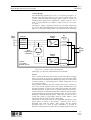
Figure 1-1 . Parallel control in a one-plus-one system
1.3.3
1-10
Issue 2
(02/98)
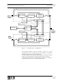
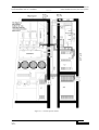
Common battery
The illustration in figure 1-5 shows a dedicated battery installation for each
module; however, it is possible to fit an option kit which allows the two
modules in a one-plus-one system to share a common battery. Such an
installation is shown in figure 1-6 overleaf.
Note: the "Common battery" configuration is possible with 6 pulse
rectifiers only, not with 12 pulse rectifiers.
7400 Series UPS User Manual
Single Module and One plus One Systems
Chapter 1 - General Description
One Plus One System
6310018a.02.doc
Main
Supply
RECTIFIER
INVERTER
STATIC
SWITCH
1+1 Parallel Control
Control
Logic
BATTERY
UPS
Output
Supply
1+1 Parallel Control
Main
Supply
RECTIFIER
INVERTER
STATIC
SWITCH
Figure 1-1 . “Common battery” configuration
The "Common Battery" option kit contains a DCCT (d.c. Current
Transformer) in series with the battery, which replaces the equivalent
DCCT’s inside the UPS’s (these are inhibited).
To ensure balance of the rectifiers output currents a link on the Parallel
control p.c.b. interconnects the control circuits of the two rectifiers.
The components used by the "Common Battery Option" are contained in
a separate cabinet known as the Common Battery Panel.
1-11
Issue 2
(02/98)
Chapter 1- General Description
Operator Control Panel
7400 Series UPS User Manual
Single Module and One plus One Systems
6310018a.02.doc
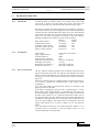
1.4
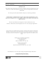
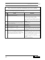
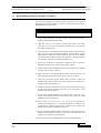
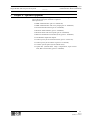
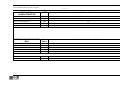
Operator Control Panel
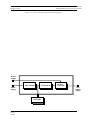
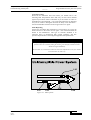
The operator control panel is divided into three functional areas; ‘mimic
indications’, ‘control switches’, and ‘LCD display panel’.
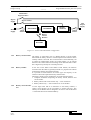
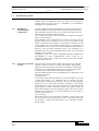
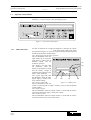
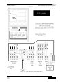
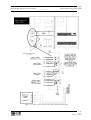
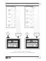
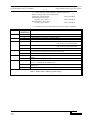
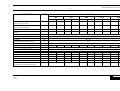
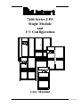
Figure 1-1 . Operator control panel
1.4.1
1-12
Issue 2
(02/98)
Mimic indications
Six leds are mounted on a single line diagram to represent the various
UPS power paths. These leds, which
are annotated in figure 1-8, show the current UPS operational status and
should be interpreted as detailed below.
LS1 - Input supply OK / Rectifier operative:
This led illuminates when the
input isolator (I1) is closed, the
input supply is within 20% of
nominal voltage, and the
rectifier is operative.
LS2 - Battery volts OK: This
led illuminates when the
battery circuit breaker is closed
and the battery voltage is
within the UPS operating range
(320V - 490V nominal).
LS3 - bypass supply OK: This
led illuminates when the static
LS1
LS2
LS4
bypass supply is within ±10%
of its nominal voltage.
Figure 1-1 . Mimic panel
LS4 - Inverter output OK:
This led illuminates when the
inverter is operating and its output is within a preset (±10%) acceptable
voltage window.
LS5 - Load on bypass
This led illuminates when the output isolator is closed and the load is
connected to the bypass supply via the static switch.
LS6 - Load on inverter:
This led illuminates when the output isolator is closed and the load is
connected to the inverter via the static switch.
LS3
LS5
LS6
7400 Series UPS User Manual
Single Module and One plus One Systems
Chapter 1 - General Description
Operator Control Panel
6310018a.02.doc
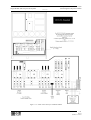
1.4.2
Control switches
Seven tactile switches are located on the Operator Panel, together with
an emergency stop pushbutton which is fitted with a safety cover to
prevent inadvertent operation.
S1
S2
S3
S4
LS7
S5
S6
S7
LS8
S8
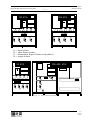
Figure 1-1 . Control panel switches
Switch S1 (Vo) - Output volts:
When this switch is pressed, the lower line of the LCD Display shows
the output line-to-line voltages on all three phases.
Switch S2 (Fo) - Output frequency:
When this switch is pressed, the lower line of the LCD Display shows
the output frequency.
Switch S3 (Io) - Output current:
When this switch is pressed, the lower line of the LCD Display shows
the output line (and neutral) currents.
Switch S4 (B) - Battery:
When this switch is pressed, the lower line of the LCD Display shows
the battery voltage, current and % charge or autonomy time remaining in
minutes. Note that a discharging current is symbolised by a preceding
minus [] sign.
Switch S5 - ((.)) - Alarm reset:
Pressing this switch cancels the audible alarm. The alarm led and
messages will remain active if a detected fault condition is still present.
Switch S6 - Inverter OFF:
Pressing this switch turns OFF the inverter and causes the load to be
transferred to the static bypass supply.
Switch S7 - Inverter ON:
Pressing this switch activates the inverter and causes the load to be
transferred to the inverter side of the static switch after the inverter
voltage has had time to stabilise.
Switch S8 - Emergency stop:
When the emergency stop switch is pressed it disables the static switch
block entirely (so removing load power). It also disables the rectifier and
inverter, and trips the battery circuit breaker. Under normal
circumstances it does not remove UPS input power since this is applied
through a manually controlled isolator; however, if the UPS input supply
is connected via a circuit breaker having an electrical trip facility the
emergency stop signal can be used to drive the external circuit breaker’s
trip circuit.
There are two leds contained within the switch panel area:
LS7 - Alarm:
This led accompanies the audible alarm warning when any alarm
condition is initiated. The audible warning can be cancelled by the reset
switch (S5) but LS7 will only extinguish after the alarmed condition has
reverted to normal.
1-13
Issue 2
(02/98)
Chapter 1- General Description
Operator Control Panel
7400 Series UPS User Manual
Single Module and One plus One Systems
6310018a.02.doc
LS8 - Inverter status:
This green led situated near the inverter ON switch illuminates when the
inverter is selected ON.
1-14
Issue 2
(02/98)
7400 Series UPS User Manual
Single Module and One plus One Systems
Chapter 1 - General Description
Operator Control Panel
6310018a.02.doc
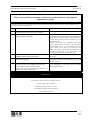
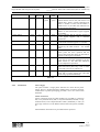
1.4.3
LCD Display
An LCD display, capable of
showing two rows of 40
characters, is used to indicate
the
UPS
operating
parameters, warnings and
alarms.
A DIP switch fitted to the
display microprocessor board
enables the displayed language
to be easily selected to English,
French, Italian, Spanish or
German.
The lower row of characters
are used to display metered
parameters; which include
output (or bypass) voltage,
frequency, or current together
with battery current, voltage
and % charge or time
remaining on battery.
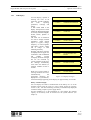
Warning and alarm messages
are displayed on the upper row
of characters. The ALARM led
and
audible
warning
accompany all alarm messages
but are not activated by
warning messages. In all cases,
the message automatically
resets when the alarmed (or
warning) condition reverts to
normal.
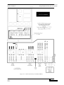
*** ALARM ***
EMERGENCY STOP
*** ALARM ***
INVERTER OFF OR FAILED
*** ALARM ***
OVER TEMPERATURE
*** ALARM ***
OVERLOAD
*** ALARM ***
BATTERY CB OPEN
*** ALARM ***
OUTPUT CB OPEN
*** ALARM ***
INPUT CB OPEN
*** ALARM ***
RECTIFIER OFF OR FAILED
** WARNING *
UPS ON MAINTENANCE
BYPASS
** WARNING *
INVERTER UNSYNCHRONIZED
** WARNING *
BATTERY ON LOAD
** WARNING *
MAINS FAILURE
LOAD ON BYPASS
** WARNING *
When two (or more) alarm or
warning conditions are active
simultaneously,
the
appropriate messages are
Figure 1-1 .Display messages
displayed in a cyclic fashion,
with each message appearing on the display for approximately 10 seconds.
Battery condition display
You can display the relative condition/state of the battery as a % of the
nominal capacity with the input a.c. power supply present by pressing
switch 4 (‘B’) . The time remaining on battery is automatically displayed
in minutes during a input ac power supply failure.
On first installation or on the installation of a new battery the nominal
capacity of the battery must be entered into the system software (see
chapter 3).
1-15
Issue 2
(02/98)
7400 Series UPS User Manual
Single Module and One plus One Systems
Chapter 2 - Operating Instructions
Introduction
6310018a.02.doc
2.
2.1
Chapter 2 - Operating Instructions
Introduction
The UPS can be considered to be in one of three operating conditions:
•
•
Shutdown - All power isolators and circuit breakers open - no
load power.
On Maintenance Bypass - UPS shut down but the load connected
to the unprotected mains via the Maintenance Bypass Supply line.
•
Normal operation - All relevant power isolators and circuit
breakers closed, the load is powered by the UPS.
This chapter contains detailed instructions to enable you to switch
between these three conditions.
2.1.1
2.2
General notes
Note 1: All the user controls and indicators mentioned in these
procedures are identified in chapter 1 (figures 1-3, 1-4, 1-7, 1-8 and 1-9).
Note 2: The audible alarm may annunciate at various points in these
procedures. It can be cancelled at any time by pressing the `Alarm Reset'
pushbutton.
Note 3: The 7400 series UPS incorporates an optional automatic boost
charge facility which can be used in systems containing non-sealed leadacid batteries. If this type of battery is used in your installation you may
notice that the battery charger voltage will be greater than its normal
value when the mains supply returns from a prolonged outage. The
revised voltage will be 460V d.c. for a 380V a.c. system, 475V d.c. for a
400V a.c. system and 490V d.c. for a 415V a.c system. This is the
normal response of the boost charge facility: the charger voltage should
return to normal after a few hours.
One plus One
Starting and stopping the one-plus-one system is the same as a single
module, however the modules' response depends on whether it is
configured as a Redundant or Non-Redundant system. The operating
procedures are the same irrespective of the selected redundancy mode; in
simple terms you start (stop) one module and then repeat the operation
on the second module.
The difference in the system response concerns the point at which the
load is transferred between the bypass and uninterruptible (i.e. inverter)
supplies and is summarised below:
2.2.1
Redundant module
system
Starting:
When starting a redundant module system the load is transferred from
the bypass to the inverter of the first module as soon as the first module
is started and its inverter is brought on line. When the second module is
started its static bypass line is totally inhibited due to the first module
being on line, and the second module will not be connected to the load
until its inverter is operational and fully synchronised with the first
module.
Stopping:
2-1
Issue 2
(02/98)
When the first module is stopped its static bypass is inhibited because the
load will be fully maintained by the inverter of the second module.
Chapter 2 - Operating Instructions
One plus One
7400 Series UPS User Manual
Single Module and One plus One Systems
6310018a.02.doc
When shutting down the second module, the static bypass lines of both
modules will be turned on as soon as its inverter is stopped. That is, both
modules will provide load power through their paralleled bypass lines.
2.2.2
Non-Redundant
module system
Starting:
In a Non-Redundant module system both modules must be running
before the load is transferred to their paralleled inverters. Therefore,
when the first module is started, the load will remain connected to its
static bypass line while waiting for the second module to synchronise.
Stopping:
The load will be transferred to the static bypass lines in both modules
simultaneously as soon as the inverter stops in the first module to be shut
down.
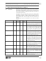
How to turn on the system from a shutdown condition
This procedure should be followed when turning on the UPS from a fully powered down condition - i.e. where the load is not
being initially supplied through the internal Maintenance Bypass supply.
Note: For a one plus one system, complete these actions on one module at a time.
Step
1.
2.
Action
Response
Close the module's Output Isolator and check that the UPS
input mains supply (and bypass supply if separate) is
turned on externally.
Close the Input Isolator and Static Bypass Isolator .
Mimic panel leds
LS1 LS3 and LS5 should illuminate immediately, to
indicate that the load is being supplied through the static
bypass line. (NB: In a one plus one Redundant Module
system LS5 will not illuminate on the second module to
be started as its static bypass line is inhibited).
The inverter should start automatically once the d.c.
Busbar reaches its working voltage (after about 30
seconds), and when this occurs LS4 (inverter OK) will
illuminate followed by LS6 (load on inverter). (NB: In a
one plus one Non-Redundant module system LS6 will not
illuminate on the first module to be started until you
reach this point in starting the second module.)
Note that LS5 will extinguish when LS6 illuminates.
3.
Wait 20 seconds then close the battery circuit breaker: This Mimic panel leds
is located inside the battery cabinet (if used) or is LS2 should illuminate on the mimic panel and LS7
(alarm) should extinguish.
otherwise located adjacent to the battery racks
4.
Press the battery metering selector switch [B]:
2-3
Issue 2
(02/98)
The display should indicate a positive (+) battery
charging current.
Chapter 2 - Operating Instructions
One plus One
7400 Series UPS User Manual
Single Module and One plus One Systems
6310018a.02.doc
How to turn on the system from a maintenance power-down condition
This procedure should be followed to start the UPS from a MAINTENANCE power-down condition - i.e. where the load is
being initially powered through the internal maintenance bypass supply.
Note: For a one plus one system, complete these actions on one module at a time.
Step
1.
2.
3.
4.
5.
6.
7.
Action
Response
Check that the UPS input mains supply (and bypass supply
if separate) is turned on externally.
Close the Input Isolator and Static Bypass Isolator.
Mimic panel leds
LS1 and LS3 should illuminate immediately, to indicate
that the input and bypass supplies are healthy.
The inverter should start automatically once the d.c.
Busbar reaches its working voltage (after about 30
seconds), and when this occurs LS4 (inverter OK) will
illuminate
Wait 20 seconds then close the battery circuit breaker: This Mimic panel leds
LS2 should illuminate.
is located inside the battery cabinet (if used) or otherwise
adjacent to the battery racks.
Press the battery metering selector switch [B]:
The display should indicate a positive (+) battery
charging current.
Press the Inverter OFF pushbutton (S6).
Mimic panel leds
LS4 should extinguish.
( On both modules for a 1 + 1 system ).
Close the Output Isolator.
Mimic panel leds
LS5 should illuminate to indicate that the load is
( On both modules for a 1 + 1 system ).
connected to the static bypass line. (On both modules for
a 1 + 1 system).
Mimic panel leds
Open the Maintenance Bypass Isolator (on both modules
LS4 (Inverter OK) and LS6 (Load on inverter) should
in a one plus one system) then Press the Inverter ON
switch (S7) (on both modules in the one plus one system). illuminate after approximately 30 seconds. (NB: In a one
plus one Non-Redundant module system LS6 will not
(NB: The inverters of both modules are inhibited if either
illuminate on the first module to be started until you
modules' Maintenance Bypass Isolator is closed.)
reach this point in starting the second module.).
LS5 should extinguish at the same time as LS6
illuminates.
LS7 (alarm) should extinguish.
2-4
Issue 2
(02/98)
7400 Series UPS User Manual
Single Module and One plus One Systems
Chapter 2 - Operating Instructions
One plus One
6310018a.02.doc
How to turn off the system but continue to provide load power through the
maintenance bypass
This procedure should be followed if the UPS is to be powered-down while continuing to supply the load through the
maintenance bypass line. Note that during this procedure the load will be unprotected against mains supply disturbances once
the inverter(s) has been switched off.
Step
Action
Response
1.
Ensure that LS3 is illuminated on the mimic panels
(indicating that the static bypass supply is healthy).
2.
Press the Inverter OFF switch (S6) (on both modules Mimic panel leds
LS4 and LS6 should extinguish (on both modules in
in the one plus one system)
the one plus one system) and LS5 should illuminate
to show that the load has been transferred to the
static bypass line.
Note: On a one plus one redundant system both
Inverter OFF switches (S6) must be operated before
LS5 illuminates but in a non-redundant system the
Inverter OFF switch must be pressed on one
module only before LS5 illuminates. However, as
the load is transferred to the static bypass, the
second module should be turned OFF also.
Mimic panel leds
Close the Maintenance Bypass Isolator (on both
No change.
modules in the one plus one system).
Mimic panel leds
Open the Output Isolator (on both modules in the
LS5 should extinguish (on both modules in the one
one plus one system).
plus one system).
All the operator panel led indications and messages
(On each module in the one plus one system)
should extinguish as the mains driven internal
Open the battery circuit breaker followed by the
power supplies decay.
.
Input Isolator and Static Bypass Isolator.
On 80 - 120 - 200 kVA: open auxiliary fuses F1... F6
WAIT AT LEAST 5 MINUTES
3.
4.
5.
WARNING
Wait at least 2 minutes for the d.c. capacitors to discharge.
The following points will be live within the UPS:
- Bypass supply input terminals - Maintenance Bypass Isolator switch - Static Bypass Isolator Switch (if fitted) - UPS output terminals -
2-5
Issue 2
(02/98)
Chapter 2 - Operating Instructions
One plus One
7400 Series UPS User Manual
Single Module and One plus One Systems
6310018a.02.doc
How to totally power-down the system
This procedure should be followed only if the UPS AND LOAD are to be completely powered down.
Step
1.
2.
3.
Action
Response
Press the Inverter OFF switch (S6) (on both modules
in the one plus one system):
Mimic panel leds
LS4 and LS6 should extinguish, and LS5 should
illuminate to show that the load has been transferred
to the static bypass line. (NB: in a Non-Redundant
Module system LS5 and LS6 will also change-over
on the second module).
Open the battery circuit breaker:
Mimic panel leds
LS2 should extinguish.
Open the Input Isolator and Static Bypass Isolator.
All the operator panel led indications and messages
On 80 - 120 - 200 kVA open auxiliary fuses F1 ... F6 should extinguish as the mains driven internal
power supplies decay.
IMPORTANT
The Maintenance Bypass Isolator may be operated at any time
when the UPS is powered down to connect/disconnect the load
to the raw maintenance bypass supply if required.
Emergency stop
The emergency stop pushbutton is located behind a hinged safety shield to prevent
inadvertent operation. When this switch is pressed modules are electronically shut down and
battery circuit breakers are tripped. Power is removed from the critical load,
but pressing the emergency stop pushbutton will not remove the modules' input mains
supply unless an external contactor, controlled via the emergency stop pushbutton auxiliaries,
is fitted in the mains supply line..
2-6
Issue 2
(02/98)
7400 Series UPS User Manual
Single Module and One plus One Systems
Chapter 2 - Operating Instructions
One plus One
6310018a.02.doc
2-7
Issue 2
(02/98)
7400 Series UPS User Manual
Single Module and One plus One Systems
Chapter 3 - Installation Procedure
Introduction
6310018a.02.doc
3.
3.1
Chapter 3 - Installation Procedure
Introduction
WARNING
Do not apply electrical power to the UPS equipment before the arrival of the
commissioning engineer.
WARNING
The UPS equipment should be installed by a qualified engineer in accordance with the
information contained in this chapter and the drawing package shipped inside the
UPS cabinet.
WARNING
Battery hazards
Special care should be taken when working with the batteries associated with this
equipment. When connected together, the battery terminal voltage will exceed 400
Vd.c. and is potentially lethal.
Eye protection should be worn to prevent injury from accidental electrical arcs.Remove
rings , watches and all metal objects.
Only use tools with insulated handles.
Wear rubber gloves.
If a battery leaks electrolyte, or is otherwise physically damaged,
it should be placed in a container resistant to sulphuric acid and
disposed of in accordance with local regulations.
If electrolyte comes into contact with the skin the affected area
should be washed immediately.
This chapter contains information regarding the positioning and cabling
of the UPS equipment and batteries.
Because every site has its peculiarities, it is not the aim of this chapter to
provide step-by-step installation instructions, but to act as a guide as to
the general procedures and practices that should be observed by the
installing engineer.
3-1
Issue 2
(02/98) LCA 10/01
Chapter 3 - Installation Procedure
Introduction
7400 Series UPS User Manual
Single Module and One plus One Systems
6310018a.02.doc
3.1.1
The UPS cabinets can be moved by fork lift or crane. Fork lift apertures
Equipment positioning
are provided in the sides of the base plate and are accessible after
and environmental
removing blanking covers fitted to the side panel ventilation grills. Roofconsiderations
mounted eye-bolts are fitted to enable the cabinet to be crane-handled.
These can be removed once the equipment has been finally positioned.
Note: In a 1 + 1 system the models should be positioned adjacent to each
other.
WARNING
Ensure that the UPS weight is within the designated S.W.L. of any handling equipment.
See the UPS specification for weight details.
Do not move the battery cabinet with the batteries fitted..
The 300kVA and 400 kVA UPS modules are split into two cabinets, a
Main Inverter cabinet and a Rectifier/Static Bypass cabinet, to allow
easier transportation and positioning. Once finally positioned, the two
cabinets have to be bolted together and the interlinking power and
control cable connections made. It is therefore necessary to observe
cabinet A & B positioning (see figures 3-5 and 3-6 ).
The UPS module should be located in a cool, dry, clean-air environment
with adequate ventilation to keep the ambient temperature within the
specified operating range. If necessary, a system of extractor fans should
be installed to aid cooling-air flow, and a suitable air filtration system
used where the UPS is to operate in a dirty environment.
Cables
All control cables whether screened or not, should be run, separate from
the power cables, in metal conduits or metal ducts which are electrically
bonded to the metalwork of the cabinets to which they are connected.
Cooling air flow
All the models in the 7400 range are force-cooled with the aid of internal
fans. Cooling air enters the module through ventilation grills located at
various parts of the cabinet and exhausted through grills located in the
equipment roof. When the equipment is located on a raised floor, and
bottom cable entry is used, additional cooling air also enters the UPS via
the floor void.
Clearances
To allow adequate cooling air flow, you should position the equipment
with the following space around the back and sides.
80kVA-120 kVA Models 100mm minimum required in all cases.
200/300/400 kVA Models 300mm minimum required in all cases.
The UPS modules do not require back-access for maintenance servicing;
but, where space permits, a clearance of approximately 4 feet (1.2
metres) will ease access to some component parts. Clearance around the
front of the equipment should be sufficient to enable free passage of
personnel with the doors fully opened.
3-2
Issue 2
(02/98)
7400 Series UPS User Manual
Single Module and One plus One Systems
Chapter 3 - Installation Procedure
Introduction
6310018a.02.doc
3.1.2
Raised floor
installation
If the equipment is to be located on a raised floor it should be mounted
on a pedestal suitably designed to accept the equipment point loading.
The installation diagrams in the back of this manual identify the location
of the holes in the base plate through which the equipment can be bolted
to the floor.
3.1.3
Battery Location
Note: Temperature is a major factor in determining the battery life and
capacity. Battery manufacturers quote figures for an operating
temperature of 20°C. Operating above this temperature will reduce the
battery life, operation below this temperature will reduce the battery
capacity. On a normal installation the battery temperature is maintained
between 15°C and 25°C.
In 80kVA and 120 kVA module installations the batteries associated
with the UPS equipment are usually contained in a purpose-built battery
cabinet which sits alongside the main UPS equipment. Sealed,
maintenance-free batteries are normally used in this type of installation.
Due to their increased capacity, the batteries associated with larger UPS
installations are usually too big to be mounted in a single cabinet and are
either rack mounted or fitted in multiple, or bespoke, battery cabinets.
Such installations may utilise non-sealed lead acid cells, requiring
regular attention and impose their own environmental requirements.
Pedestals are required for the battery cabinets when they are located on
raised floors, in the same way as for the UPS cabinets.
The batteries are connected to the UPS through a circuit breaker which is
manually closed and electronically tripped via the UPS control circuitry.
If the batteries are cabinet-mounted this circuit breaker is fitted within
the cabinet; however, if the batteries are rack-mounted or otherwise
located remote to the main UPS cabinet then the battery circuit breaker
must be mounted as near as possible to the batteries themselves, and the
power and control cables connected to the UPS using the most direct
route possible. Liebert offer a purpose-designed remote battery circuit
breaker box, containing the circuit breaker and its necessary control
board, as a standard option kit.
3-3
Issue 2
(02/98) LCA 10/01
Chapter 3 - Installation Procedure
Introduction
7400 Series UPS User Manual
Single Module and One plus One Systems
6310018a.02.doc
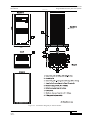
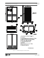
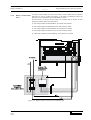
Figure 3-1 . Installation Diagram for 80 kVA Module
3-4
Issue 2
(02/98)
7400 Series UPS User Manual
Single Module and One plus One Systems
Chapter 3 - Installation Procedure
Introduction
6310018a.02.doc
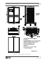
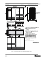
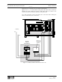
Figure 3-2 . Installation Diagram for 120 kVA Module
3-5
Issue 2
(02/98) LCA 10/01
Chapter 3 - Installation Procedure
Introduction
7400 Series UPS User Manual
Single Module and One plus One Systems
6310018a.02.doc
3-6
Issue 2
(02/98)
7400 Series UPS User Manual
Single Module and One plus One Systems
Chapter 3 - Installation Procedure
Introduction
6310018a.02.doc
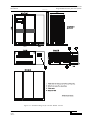
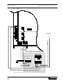
Figure 3-3 . Installation Diagram for 200 kVA Module
3-7
Issue 2
(02/98) LCA 10/01
Chapter 3 - Installation Procedure
Introduction
7400 Series UPS User Manual
Single Module and One plus One Systems
6310018a.02.doc
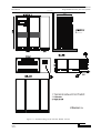
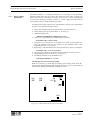
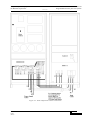
Figure 3-4 . Installation Diagram for 300/400 kVA Module 6 & 12
3-8
Issue 2
(02/98)
7400 Series UPS User Manual
Single Module and One plus One Systems
Chapter 3 - Installation Procedure
Introduction
6310018a.02.doc
Figure 3-5 . Inst. Diagram for 80 kVA Modules 12 Pulse
3-9
Issue 2
(02/98) LCA 10/01
Chapter 3 - Installation Procedure
Introduction
7400 Series UPS User Manual
Single Module and One plus One Systems
6310018a.02.doc
Figure 3-6 . Installation Diagram for 120 kVA Module 12 Pulse
3-10
Issue 2
(02/98)
7400 Series UPS User Manual
Single Module and One plus One Systems
Chapter 3 - Installation Procedure
Introduction
6310018a.02.doc
3-11
Issue 2
(02/98) LCA 10/01
Chapter 3 - Installation Procedure
Introduction
7400 Series UPS User Manual
Single Module and One plus One Systems
6310018a.02.doc
Figure 3-7 . Installation Diagram for 200 kVA Module 12 Pulse
3-12
Issue 2
(02/98)
7400 Series UPS User Manual
Single Module and One plus One Systems
Chapter 3 - Installation Procedure
Preliminary Checks
6310018a.02.doc
3.2
Preliminary Checks
Before you install the UPS hardware you should carry out the following
preliminary checks:
1. Verify that the UPS room satisfies the environmental conditions
stipulated in the equipment specification, paying particular attention
to the ambient temperature and air exchange system.
2. Remove any packaging debris then visually examine the UPS and
battery equipment for transit damage, both internally and externally.
Report any such damage to the shipper immediately.
3. Verify that the shipment is complete e.g. that the battery contains
the correct number of cells etc. Report any discrepancy immediately.
4. When you are satisfied that the equipment is complete and in good
condition move it to its proposed final position.
Note: If ‘side’ cable entry is to be used (see below) ensure that the
blanking plates are removed before finally fixing the cabinets in
position.
5. All models have a stabilising bar fitted to the output transformer T1
during shipment, this should be removed when the UPS has been
placed in its final position.
Caution
Ensure the stabilising bar fitted to the output transformer T1 is removed before
proceeding with the installation.
3-13
Issue 2
(02/98)
Chapter 3 - Installation Procedure
Reassembling the 300kVA and 400kVA cabinets
7400 Series UPS User Manual
Single Module and One plus One Systems
6310018a.02.doc
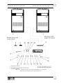
3.3
Reassembling the 300 kVA and 400 kVA cabinets
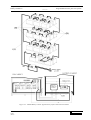
Place the cabinets in their final position as shown in figure 3-6 ensuring
any protective packaging is removed (Inverter Cabinet on the right and
Rectifier/Static Switch Cabinet on the left), and connect them together
following the procedure below:
Caution
Ensure loose cables are not trapped between the two cabinet frames.
1. Align the Rectifier/Static switch and Inverter Cabinets and bolt them
together through the holes provided.
2. Open the doors to the Inverter cabinet and remove the lower
protective cover to gain access to the a.c. busbars R, S, T & N from
the output transformer T1.
3. Locate the four a.c. busbars from the Output Isolator numbered 7(R),
8(S), 9(T) and 10(N) in the Rectifier/Static Switch cabinet and the
linking straps connected to them. Take the free end of the linking
straps and connect them to the Inverter cabinet a.c. busbars ensuring
correct phase connection as illustrated in figure 3-6.
4. Ensure the transformer transportation stabilising bar is removed.
Refit the lower protective cover to the Inverter cabinet.
5. Open the upper inner left hand protective door of the inverter cabinet
to gain access to the d.c. busbars.
6. Open the doors to the Rectifier/Static Switch cabinet and open the
inner upper right hand door to gain access to the d.c. busbars.
7. Using the two angled copper busbar links provided, connect the
Rectifier/Static Switch cabinet d.c. busbar to the Inverter Cabinet d.c.
busbar as illustrated in figure 3-6.
8. Locate the flat cable assembly FC17 from CN8 on the Inverter Logic
board in the Inverter cabinet and secure to the end panel, in the
position illustrated in figure 3-6.
9. Locate the flat cable assembly FC17 from CN2 on the UPS Logic
board in the Rectifier/Static Switch cabinet and connect to cable
assembly FC17 secured above.
10. Locate wires 27, 28, 29, 30, 31, 32, 33, 98 & 99 terminated in
connector CN4 and wires 7, 8, 9 & 10 terminated in connector CN5
in the Inverter cabinet and secure the connectors into cabinet end
panel in the positions illustrated in figure 3-6.
11. Locate the Rectifier/Static Switch cabinet cable assemblies from the
Interface board which terminate in connectors CN4 and CN5 and
connect to CN4 and CN5 secured above.
12. Close the inner protective doors and outer doors to both cabinets.
3-14
Issue 2
(02/98)
7400 Series UPS User Manual
Single Module and One plus One Systems
Chapter 3 - Installation Procedure
Reassembling the 300kVA and 400kVA cabinets
6310018a.02.doc
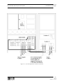
Figure 3-1 . 300/400 kVA model inter-connection cables
3-15
Issue 2
(02/98) LCA 10/01
Chapter 3 - Installation Procedure
Battery Installation
7400 Series UPS User Manual
Single Module and One plus One Systems
6310018a.02.doc
Connecting the UPS power cables
3.4
WARNING
Before cabling-up the UPS, ensure that you are aware of the location and operation of
the external isolators that connect the UPS input/bypass supply to the mains
distribution panel.
Check that these supplies are electrically isolated, and post any necessary warning signs
to prevent their inadvertent operation.
3.4.1
Cables can enter the smaller UPS modules and battery cabinet either
from below or through either side. Side entry is made possible by
removing blanking pieces fitted in the side ventilation grills to reveal the
cable entry holes. This cable entry method allows the equipment to be
positioned on a solid floor without the need for cable trenching and also
allows cables to pass from one module to the other when positioned side-
Cable entry
by-side.
On units up to 200kVA normal cable entry is from the bottom, however,
if top entry is necessary, the optional top entry kit Pt.No. 2174011 Vfor
80 and 120kVA or Pt. No. 2174033 R for 200kVA is required. On the
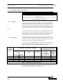
300/400kVA unit cable entry is from the bottom or top of the unit.
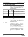
3.4.2
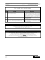
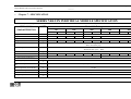
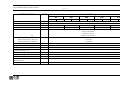
The maximum current ratings for the power cables are given in table 3-1.
The neutral cable (bypass and output) should be sized at up to 1.5 times
the phase current to take into account the possible presence of 3rd
armonic currents due to single phase "computer loads".
Cable rating
In a one-plus-one Non-Redundant system, the lenght of the cables on the
Bypass line of the two UPS’s should be equal (+/- 20%) to ensure the
balance of the currents, when the load is supplied by the mains.
UPS
RATING
(kVA)
NOMINAL CURRENT (Amps)
Input Mains
(with full battery recharge)
380V
80
120
200
300
400
6 Pulse
12 Pulse
167
251
412
609
808
158
237
390
579
769
Bypass/output
380V
121
182
304
442
608
Battery
(at low battery
disconnect)
216
322
534
791
1053
CABLE CONNECTION
MAXIMUM SIZE
Input/output
Battery
Cable
TerminTerminations
ations
U-V-W-N
+ve & -ve
Secure with M8 Bolt
Secure with M10 Bolt
Secure with M10 Bolt
Secure with M12 Bolt
Secure with M12 Bolt
M8 Bolt
M10 Bolt
M10 Bolt
M12 Bolt
M12 Bolt
Table 3-1 - Nominal current for power cables
When sizing battery cables, a maximum volt drop of 3V d.c. is
permissible at the urrent ratings given in table 3-1.
3-16
Issue 2
(02/98)
7400 Series UPS User Manual
Single Module and One plus One Systems
Chapter 3 - Installation Procedure
Connecting the UPS power cables
6310018a.02.doc
3.4.3
Cable connections
Power cables are connected either directly to their respective circuit
breakers, or to busbars which are themselves connected to the circuit
breakers see figures 3-8 to 3-12.
Note: If the installation includes the use of optional Input Filter Cabinets
refer immediately to the Options Chapter, Where these cabinets are fully
described. The inclusion of these cabinets in the system affects the
method of connecting the UPS power cables given below.
3.4.4
Safety earth
The safety earth busbars are located near the input and output power
supply connections as shown in the
following diagrams. The safety cable must be connected to the earth
busbar bonded to each module cabinet.
All cabinets and cable trunking should be earthed in accordance with
local regulations.
WARNING
FAILURE TO FOLLOW ADEQUATE EARTHING PROCEDURES CAN RESULT IN
ELECTRIC SHOCK HAZARD TO PERSONNEL, OR THE RISK OF FIRE, SHOULD
AN EARTH FAULT OCCUR.
3-17
Issue 2
(02/98) LCA 10/01
Chapter 3 - Installation Procedure
Battery Installation
7400 Series UPS User Manual
Single Module and One plus One Systems
6310018a.02.doc
3.4.5
Cabling procedure
Power Cables
Once the equipment has been finally positioned and secured, connect the
power cables as described in the following procedure.
Study the connection diagrams in figures 3-8 to 3-11 and positively
identify the diagram relevant to your equipment before commencing
cabling.
1. Verify that the UPS equipment is totally isolated from its external
power source and all the UPS isolators are open.
2. On each module, connect the input supply cables between the mains
distribution panel and the UPS input mains terminals. Check that
links are fitted between input mains bus bars and bypass supply bus
bars (U1 - U3; V1 - V3; W1 - W3).
ENSURE CORRECT PHASE ROTATION.
3. If a "split-bypass" configuration is used, connect the UPS bypass
supply cables between the bypass distribution panel and the UPS
bypass supply terminals on each module. Ensure any links fitted
between input and bypass bus bars are removed.
ENSURE CORRECT PHASE ROTATION.
4. On a Single module connect the UPS output cables between the UPS
and the load distribution panel.
5. On modules in a one plus one system connect the output terminals of
both modules together (in parallel).
ENSURE CORRECT PHASE-PHASE CONNECTION (U2-U2, V2V2, W2-W2, N2-N2).
Then connect the UPS output cables between the paralleled UPS output
terminals and load distribution panel.
Note: If the UPS is to be commissioned before the load equipment is
ready to receive power then SAFELY isolate the load cables.
6. On each module, connect the battery cables between the UPS battery
terminals and its associated battery circuit breaker see figures 3-13
to 3-17. As a safety precaution remove the battery fuse in the module
until the arrival of the commissioning engineer.
OBSERVE THE BATTERY CABLE POLARITY.
WARNING
Do not close the battery circuit breaker before the equipment has been commissioned
7. Connect the safety earth and any necessary bonding earth cables to
the copper earth busbar located on the floor of the equipment below
the power connections.
Note:- The earthing and neutral bonding arrangement must be in
accordance with local and national codes of practice.
Control Cables
8. Connect the battery circuit breaker control cables between the UPS
auxiliary terminal block and battery circuit breaker controller board
as shown in figures 3-13 to 3-17.
3-18
Issue 2
(02/98)
7400 Series UPS User Manual
Single Module and One plus One Systems
Chapter 3 - Installation Procedure
Connecting the UPS power cables
6310018a.02.doc
9. If an external emergency stop facility is to be used then remove the
link between terminals 4 and 5 of the auxiliary terminal block and
connect the ‘normally closed’ remote stop circuit between these two
terminals.
Note: Terminals 8 and 9 on the auxiliary terminal block are
connected to a pair of ‘normally closed’ contacts on the UPS
emergency stop button and will go open circuit when the emergency
stop push-button is pressed. These terminals can be used to control
an external circuit breaker connected in the UPS input mains supply
line to isolate the UPS input power when the emergency stop button
is pressed.
One plus one only
10. On the one-plus-one system only connect the parallel control ribbon
cables between the Parallel Interface Boards (Part no. 4590049 J) of
both modules. Connect one ribbon cable between sockets CN1 on
one board and CN2 on the other, and connect the second ribbon cable
between the remaining CN1 and CN2 sockets.
Caution
Module 1
Module 2
CN3
CN3
CN2
CN1
CN2
CN1
Module 1
Module 2
CN3
CN3
CN2
CN1
Common Battery
Panel
CN3
CN2
CN2
CN1
CN1
Figure 3-1 . Connecting the parallel interface cables
To maintain EMC compliance all external control and communications cables must be
screened.
3-19
Issue 2
(02/98) LCA 10/01
Chapter 3 - Installation Procedure
Battery Installation
7400 Series UPS User Manual
Single Module and One plus One Systems
6310018a.02.doc
Figure 3-2 . Cable connections for standard 80kVA
3-20
Issue 2
(02/98)
7400 Series UPS User Manual
Single Module and One plus One Systems
Chapter 3 - Installation Procedure
Connecting the UPS power cablesù
6310018a.02.doc
Figure 3-3 . Cable connections for standard 120kVA
3-21
Issue 2
(02/98) LCA 10/01
Chapter 3 - Installation Procedure
Battery Installation
7400 Series UPS User Manual
Single Module and One plus One Systems
6310018a.02.doc
Figure 3-4 . Cable connections for standard 200kVA
3-22
Issue 2
(02/98)
7400 Series UPS User Manual
Single Module and One plus One Systems
Chapter 3 - Installation Procedure
Connecting the UPS power cablesù
6310018a.02.doc
Figure 3-5 . Cable connections for 6 & 12 Pulse 300/400 kVA modules
3-23
Issue 2
(02/98) LCA 10/01
Chapter 3 - Installation Procedure
Battery Installation
7400 Series UPS User Manual
Single Module and One plus One Systems
6310018a.02.doc
3.5
Battery Installation
WARNING
Only qualified personnel should install or service batteries.
A battery can present a risk of electric shock or burn from high short circuit currents.
Eye protection should be worn to prevent injury from accidental electrical arcs.
Remove rings , watches and all metal objects.
Only use tools with insulated handles.
Wear rubber gloves.
If a battery leaks electrolyte, or is otherwise physically damaged, it should be placed in a
container resistant to sulphuric acid and disposed of in accordance with local regulations.
If electrolyte comes into contact with the skin the affected area should be washed
immediately.
Batteries must be disposed of according to local environmental laws.
Due to the inverter design the d.c. bus bar voltage level is dependent on the
system output a.c. voltage. Therefore, the number of battery blocks required
will differ according to the system requirements, as shown below:
380V a.c. system requires 432V d.c. bus bar = 32 battery blocks / 12 V (192
cells).
400V a.c. system requires 446V d.c. bus bar = 33 battery blocks / 12 V (198
cells).
415V a.c. system requires 459V d.c. bus bar = 34 battery blocks / 12 V (204
cells).
The batteries associated with the 80 kVA and 120 kVA UPS can be
contained in a purpose-built battery cabinet ( part number 5320024I
{860mm wide, 250 A circuit breaker}) which sits along side the main UPS
equipment. Sealed, maintenance-free batteries are normally used in this type
of installation.
Where battery racks are used, they should be sited and assembled in
accordance with the battery manufacturer’s recommendations. In general,
batteries require a well ventilated, clean and dry environment at reasonable
temperatures to obtain efficient battery operation.
Battery manufacturers’ literature provides detailed safety measures to be
observed when employing large battery banks and these should be studied
and the proposed battery installation checked to verify compliance with the
appropriate recommendations.
In general a minimum space of 10 mm must be left on all vertical sides of
the battery block. A minimum clearance of 20 mm should be allowed
between the cell surface and any walls. A clearance of 150 mm should be
allowed between the top of the cells and the underside of the shelf above
(this is necessary to for monitoring and servicing the cells). All metal racks
and cabinets must be earthed. All live cell connections must be shrouded.
The batteries are connected to the UPS through a circuit breaker which is
manually closed and electronically tripped via the UPS control circuitry. If
the batteries are cabinet-mounted this circuit breaker is fitted within the
cabinet; however, if the batteries are rack-mounted or otherwise located
remote to the main UPS cabinet then the battery circuit breaker must be
mounted as near as possible to the batteries themselves, and the power and
control cables connected to the UPS using the most direct route possible.
Liebert offer a purpose designed remote battery circuit breaker box,
containing the circuit breaker and its necessary control board, as a standard
option kit. The battery cabinet or circuit breaker box must be bonded to the
UPS cabinet.
3-24
Issue 2
(02/98)
7400 Series UPS User Manual
Single Module and One plus One Systems
Chapter 3 - Installation Procedure
Battery Installation
6310018a.02.doc
3.5.1
860 mm cabinet
(250 Amp circuit
breaker)
The 860 mm cabinet with a 250 Amp circuit breaker and extension
cabinets are designed for use with the Series 7400 80-120 kVA UPS.
The 860mm battery battery cabinet autonomy time can be extended by
attaching a 320mm wide extension cabinet part N°5320025J to the main
cabinet.
All cabinets are secured and bonded together using the bolts supplied
and the holes proved in the cabinet side struts.
A typical battery layout for a single cabinet is shown in figure 3-13, this
can be extended by using extension cabinets attached to the basic unit.
Each extension cabinet is supplied without side covers, as the covers
from the basic unit are then used. This side access allows batteries to be
positioned from either the front or side.
As many different battery combinations can be used only the connections
for the basic unit have been shown in figure 3-13, additional battery
strings can be added and would be connected in parallel.
The battery cabinets are designed to hold between 32 and 34 batteries on
4 levels, free standing on adjustable rails. Nine batteries can be fitted to
the 3 upper levels with up to seven batteries on the lower level. The rails
are adjustable giving a maximum battery width of 176mm and a
maximum depth of 270mm, this allows batteries to be positioned as
shown or turned through 90°. The rails can also be removed or repositioned to accommodate batteries of different sizes.
Figure 3-14 shows an alternative arrangement to that above. In this
example larger capacity batteries are used. As can be seen, the rails have
been adjusted and removed to accommodate the larger battery of which
only sixteen can be fitted within the cabinet. The other sixteen batteries
(needed to maintain a 432 V d.c. bus bar) are arranged within an
extended battery cabinet and connected in series to the main cabinet
batteries. Further pairs of extended battery cabinets can be added in
parallel.
The basic cabinet is supplied with the battery circuit breaker and
interface board. Connection to the UPS is shown in figure 3-13.
Due to the flexibility of the type and size of cells that can be used in this
installation it would be impracticable to provide specific installation
instructions. However as a general guide:Always install the batteries starting from the bottom and work
upwards.
Leave the end links marked (B) see figure 3-13 until the last
connection on each level.
After each connection is made fit the insulation shroud for that
terminal into position.
As an added safety precaution we suggest that link (A) see figure 313 is left disconnected until all batteries are fitted. Once all the
batteries are fitted connect link (A).
Please refer to the battery manufacturers instructions and the drawings
supplied with the module for safety and specific installation instructions.
3-25
Issue 2
(02/98) LCA 10/01
Chapter 3 - Installation Procedure
Battery Installation
7400 Series UPS User Manual
Single Module and One plus One Systems
6310018a.02.doc
Figure 3-1 . 860mm Battery cabinet Typical battery layout and connection delail
3-26
Issue 2
(02/98)
7400 Series UPS User Manual
Single Module and One plus One Systems
Chapter 3 - Installation Procedure
Battery Installation
6310018a.02.doc
Figure 3-2 . Typical example of battery cabinet with extension cabinet
3-27
Issue 2
(02/98) LCA 10/01
Chapter 3 - Installation Procedure
Battery Installation
7400 Series UPS User Manual
Single Module and One plus One Systems
6310018a.02.doc
3.5.2
A battery circuit breaker box houses the battery circuit breaker and its controller
Battery circuit breaker
board and is used to connect the battery to the UPS in installations where the
boxes
batteries are not contained in the standard battery cabinet.
Several ‘boxes’, of various current ratings, are available and are similar in their
design and content. These are listed below:
•
•
•
•
•
250 Amp C/B Part No4641007H for use with 80 kVA models.
400 Amp C/B Part No4641008I for use with 120 kVA model.
630 Amp C/B Part No4641009D for use with 200 kVA model.
800 Amp C/B Part No4641011L for use with 300 kVA model.
1000 Amp C/B Part No4641012M for use with 400 kVA model.
Figure 3-1 . Battery C/B box connections 80-120 kVA UPS
3-28
Issue 2
(02/98)
7400 Series UPS User Manual
Single Module and One plus One Systems
Chapter 3 - Installation Procedure
Battery Installation
6310018a.02.doc
Usually the ‘box’ is fitted as close as possible to the batteries.
Figures 3-15 to 3-17 show details of the power and control cable connections
between the circuit breaker box and the UPS itself. These are similar to the
connections made to the battery cabinet previously described.
As a safety precaution, remove the battery fuse in the UPS before making the
battery circuit breaker power connections.
To Barrery
-ve
+ve
BATTERY
CIRCUIT
BREAKER BOX
Battery C.B
Controller Bd
(4520063 P)
+ + - -
+ve
-ve
Figure 3-2 . Battery C/B box connections200 kVA UPS
3-29
Issue 2
(02/98) LCA 10/01
Chapter 3 - Installation Procedure
Battery Installation
7400 Series UPS User Manual
Single Module and One plus One Systems
6310018a.02.doc
+ve
-ve
To Battery
+ve
-ve
BATTERY CIRCUIT BREAKER
Battery C.B
Controller
Bd (4520063P)
- - + +
+ve
-ve
Figure 3-3 . Battery C/B box connections for 300kVA and 400 kVA Modules
3-30
Issue 2
(02/98)
7400 Series UPS User Manual
Single Module and One plus One Systems
Chapter 3 - Installation Procedure
Battery Installation
6310018a.02.doc
On initial installation or on change of the battery, it is necessary to enter the battery
nominal capacity data into the system. This allows the front panel to display the
battery state either as a percentage of charge with the input a.c. power supply present
or as the time remaining on battery with the a.c. power supply absent. The battery
circuit breaker must be closed during this procedure.
To initialise the system and insert the nominal battery capacity, press push buttom
‘B’ then carry out the following procedure:
1. On the PCB 4550001 B move the link on SH7 to position on pins 2-3.
2. On the display panel press push buttons ‘f’, ‘B’ and ((*)).
3. Check the display reads:
‘PHASE CALIBRATION’ FREQUENCY: XX,X
4. Press the ((*)) push-button twice and the display will show:BATTERY (AH) = NEW VALUE
5. Using the keys: Vo(forward 1), I (forward 10), f (back 1) and B (back 10),
insert the nominal value for the capacity of the installed battery, when
completed press the ((*)) key again.
6. Repeat step 3 and check that the new value for the battery capacity is displayed.
BATTERY (AH) = (new inserted value)
7. On conclusion of the above procedure reposition the link on SH7 to pins 1-2.
8. On the display panel press the keys ‘f’, ‘B’ and ((*)).
9. The display should revert to the default screen
UPS BIOS VERSION 2.1 1-7-1995
The unit has now been restored to normal.
Note: It is necessary to ensure that the reading on the display panel shows B =
100% both on initial installation and on change of battery. This is to ensure that the
measurement reading and subsequent readings are correct.
CN3
LED 1
SH1
1
3
SH4
1
TM2
3
Battery Display
Initialisation
3
SH7
CN4
1
3.5.3
1
I1
3
SH9
TM1
CN2
Figure 3-1 . SH7 location on Microprocessor PCB
3-31
Issue 2
(02/98) LCA 10/01
Chapter 3 - Installation Procedure
Battery Installation
7400 Series UPS User Manual
Single Module and One plus One Systems
6310018a.02.doc
3-32
Issue 2
(02/98)
7400 Series UPS User Manual
Single Module and One plus One Systems
Chapter 4 - Optional equipment
AS400 Interface Board (4590041B)
6310018a.02.doc
4.
Chapter 4 - Optional equipment
Several items of optional equipment are available for fitting to the 7400
series UPS for use by the customer as required.
These options are:
•
•
•
•
•
•
•
•
•
•
•
IBM AS400 Interface (part no. 4590041 B).
IBM AS400 Interface with 4-way output (part no. 4590045F).
External Interface Board (part no. 4590044E).
Remote Alarms Monitor (part no. 4305001Z).
Remote alarms and control panel (part no. 4305002A).
RS232 communications interface (SGC) (part no. 4550002C).
5th Harmonic Input filter Option.
Cable top entry kit for 80 and 120 kVA (part no. 2174011V).
Cable top entry kit for 200 kVA (part no. 2174033 R).
12 Pulse system option (80,120 and 200 kVA).
Option Kit (includes Batt. Temp. compensation; Input current
limit; Batt. Current limit) (part no. 77000005).
4-1
Issue 2
(02/98) LCA 10/01
Chapter 4 - Optional equipment
AS400 Interface Board (4590041 B)
7400 Series UPS User Manual
Single Module and One plus One Systems
6310018a.02.doc
4.1
AS400 Interface Board (4590041B)
The AS400 Interface board connects the five most operationally critical
UPS alarms to an IBM AS400 computer, which is designed to monitor
such alarms and respond to their appearance.
The alarms in question are:
•
•
•
•
•
Mains failure
Load on inverter
Low battery and/or battery circuit breaker open
Load on mains (bypass)
Load on maintenance bypass
These alarm signals are provided by volt-free relay contacts.
The AS400 Interface Board is fitted to the bottom of the UPS cabinet door
and connected to the UPS control electronics by a ribbon cable (FC13 in
the 80/120/200 kVA models and FC19 in the 300 - 400kVA models )
which is fitted to all modules and normally stowed in the cable loom when
this option is not used.
4.1.1
AS400 Interface Board Two female D-type connectors are provided on the Interface Board to
outputs
enable the above signals to be connected to the AS400 computer. One
connector, CN1, has 9 pins and the other, CN2, has 15. Figure 4-1
provides pin-out details for these connectors.
Note: Use one connector only -i.e.
don't use both connectors simultaneously.
In addition to the D-type connectors, the AS400 Interface Board also
contains a number of volt-free relays whose contacts provide a duplicate
set of volt-free alarm outputs that are connected to terminal block M1
Äas shown in figure 4-1. These outputs can be used to drive an external
alarms monitoring device. Maximum contact rating on M1 terminals =
50 Vcc @ 1 Amp.
Note: When using the above contacts for remote alarm annunciation, the
power supply for the remote indicators must be provided from an external
power source. Under no circumstances should the UPS internal low voltage
supplies be used for this purpose.
4.1.2
Remote control inputs
The Interface Board has facilities to accept two remote control inputs, as
shown in figure 4-1. One remote input allows the inverter to be shut
down (transferring the load to the bypass supply) and the other enables
the inverter synchronisation feature to be inhibited. The inverter
synchronisation inhibit feature is most often used if the UPS is powered
from a standby generator when the input mains supply fails and the
generator frequency is unstable.
The external control signals (12V dc or ac) should be connected to
terminal block M2 as shown in figure 4-1. Once again, the voltage
applied to these terminals must be generated by an external power source
and not taken from the UPS internal low voltage supplies.
4.1.3
4-2
Issue 2
(02/98)
Calibration
When fitting the AS400 interface board to the 7400 series, ensure that
link SH-1 is in position 1-2.
7400 Series UPS User Manual
Single Module and One plus One Systems
Chapter 4 - Optional equipment
AS400 Interface Board (4590041B)
6310018a.02.doc
Notes:
1.All relays operate on Event
2. M1 pin numbering starts physically from
Bottom.. Pin Numbers are correct.
Figure 4-1 . AS400 Interface Board outputs Single and 1+1 Modules
4-3
Issue 2
(02/98) LCA 10/01
Chapter 4 - Optional equipment
4-Way AS400 Interface Board (4590045F)
7400 Series UPS User Manual
Single Module and One plus One Systems
6310018a.02.doc
4.2
4-Way AS400 Interface Board (4590045F)
The 4-way AS400 Interface board connects five critical UPS alarms to
four output terminal blocks M1 - M4 as shown in figure 4-2. These alarm
signals can be connected to a IBM AS400 computer designed to monitor
such alarms, or to a Remote Alarm Monitor panel.
The alarms monitored are:
•
•
•
•
•
Mains failure
Load on inverter
Low battery and/or battery circuit breaker open
Load on mains (bypass)
Load on maintenance bypass
The signals commonly interfaced with the AS400 are:
•
•
•
Mains failure
Load on inverter or UPS ON
Low battery .
These alarm signals are provided by volt-free relay contacts (maximum
rating 50V @ 1 Amp).
Note: When using the above contacts for remote alarm annunciation, the
power supply for the remote indicators must be provided from an
external power source. Under no circumstances should the UPS internal
low voltage supplies be used for this purpose.
The 4-way AS400 Interface Board is also positioned in the UPS cabinet
(below the power isolators), and connected to the UPS control
electronics by a ribbon cable (FC13 in 80-120 and 200 kVA modules
and FC19 in 300-400 kVA modules) connected to CN1.
4.2.1
Remote control inputs
The Interface Board has facilities to accept two remote control inputs, as
shown in figure 4-2. One remote input allows the inverter to be shut
down (transferring the load to the bypass supply) and the other enables
the inverter synchronisation feature to be inhibited. The inverter
synchronisation inhibit feature is most often used if the UPS is powered
from a standby generator when the input mains supply fails and the
generator frequency is unstable.
The external control signals (12V dc or ac) should be connected to
terminal block M1 as shown in figure 4-2. Once again, the voltage
applied to these terminals must be generated by an external power source
and not taken from the UPS internal low voltage supplies.
4.2.2
4-4
Issue 2
(02/98)
Calibration
When fitting the AS400 interface board to the 7400 series, ensure that
link SH-1 is in position 1-2.
7400 Series UPS User Manual
Single Module and One plus One Systems
Chapter 4 - Optional equipment
4-Way AS400 Interface Board (4590045F)
6310018a.02.doc
Figure 4-1 . Four output AS400 interface board
4-5
Issue 2
(02/98) LCA 10/01
Chapter 4 - Optional equipment
Output Interface (Remote Alarms) Boards (4590044E)
7400 Series UPS User Manual
Single Module and One plus One Systems
6310018a.02.doc
4.3
4.3.1
Output Interface (Remote Alarms) Boards (4590044E)
Alarm outputs
One remote alarm board, shown in figure 4-3, enables the alarm signals
generated within the UPS to be connected by means of volt-free changeover relay contacts to a remote monitoring device. The board can be
fitted on the bottom of the UPS cabinet door, together with the AS400
Interface Board.
Note: When using the contacts for remote alarm annunciation, the power
supply for the remote indicators must be provided from an external
power source. Under no circumstances should the UPS internal low
voltage supplies be used for this purpose.
4.3.2
Remote control inputs
The board has facilities to accept two remote control inputs, as shown in
figure 4-3. One remote input allows the inverter to be shut down
(transferring the load to the bypass supply) and the other enables the
inverter synchronisation feature to be inhibited. The inverter
synchronisation inhibit feature is most often used if the UPS is powered
from a standby generator when the input mains supply fails and the
generator frequency is unstable.
The external control signals (12V dc or ac) should be connected to
terminal block M2 as shown. Once again, the voltage applied to these
terminals must be generated by an external power source and not taken
from the UPS internal low voltage supplies.
4-6
Issue 2
(02/98)
7400 Series UPS User Manual
Single Module and One plus One Systems
Chapter 4 - Optional equipment
Output Interface (Remote Alarms) Boards (4590044E and 4590036 W)
6310018a.02.doc
Figure 4-1 . Output Interface Board Part N°4590044E
4-7
Issue 2
(02/98) LCA 10/01
Chapter 4 - Optional equipment
AS400 Interface Board (4590041 B)
7400 Series UPS User Manual
Single Module and One plus One Systems
6310018a.02.doc
4.4
Remote Alarm Monitor (RAM) (P/N 4305001Z)
When used in conjunction with one of the alarm interface boards
described previously, the Remote Alarm Monitor enables the auxiliary
alarm signals to be displayed at a remote station up to 200 metres from
the main equipment.
The RAM, which can be mounted either horizontally or vertically,
contains a mains-driven power supply for alarm LED annunciation and
displays the following warnings:
Panel Indication
Colour Normal
state
Inverter ON:
green
ON
Utility failure:
Battery low:
red
red
OFF
OFF
Bypass ON:
red
OFF
Maintenance:
red
OFF
Alarm:
red
OFF
Interpretation
Normal operating condition indicating that the load is being
supplied by the inverter. This is not an ‘alarm’indicator.
When lit, it indicates that the input mains are out of tolerance.
When lit, it indicates that the battery voltage is below
minimum or that the battery circuit breaker is open.
When lit, it indicates that the load is being fed from the
bypass supply, possibly due to a UPS failure.
When lit, it indicates that the UPS has been selected to
operate on the maintenance bypass and the load is
unprotected.
This is a ‘common alarm’and is lit when any of the red leds
described above are lit.
Table 4-1
An audible warning accompanies any of the above alarm conditions.
This is, however, subject to a short time delay when activated in
conjunction with the ‘Utility Failure’and ‘Bypass ON’alarms, to prevent
the warning being activated by transient conditions. Pressing the
‘reset’pushbutton cancels the audible warning but the alarm indications
remain until the condition is rectified.
4.4.1
Connections
Power supply
The RAM contains a single phase 220-240 Vac mains-driven power
supply. Power is applied through a standard CEE22 three-pin fused
mains connector located in the RAM top panel (plug provided) - use 3core 0.5mm cable (min).
The supply is rated at approximately 4 Watts and fused at 1A.
It is advised that this power supply is taken from the output of the UPS,
otherwise in the event of a mains power supply failure the RAM will be
inoperative.
Alarm connections
A 9 pin D-type connector with solder points is provided with the RAM.
This connector fits into the 9 pin socket on the top of the RAM and
should be cabled to the AS400 Interface Board (4590041B or
4590045F), fitted to the UPS, using 9 core, 0.22mm. (minimum) cable as
shown.
4-8
Issue 2
(02/98)
7400 Series UPS User Manual
Single Module and One plus One Systems
Chapter 4 - Optional equipment
Remote Alarm Monitor (RAM) (P/N 4305001Z)
6310018a.02.doc
Figure 4-1 . Remote Alarm Monitor connection details
for both the single way (on the left) and four way (on the right) Interface boards.
4-9
Issue 2
(02/98) LCA 10/01
7400 Series UPS User Manual
Single Module and One plus One Systems
Chapter 4 - Optional equipment
Remote Alarm and Control Panel (Part No. 4305002 A)
6310018a.02.doc
Remote Alarm and Control Panel (Part No. 4305002 A)
4.5
4.5.1
When used in conjunction with the Output Interface Board (4590044E)
described previously, the Remote Alarm and Control Panel enables the
alarm signals to be displayed at a remote station up to 100 metres away
from the main equipment. In addition the panel allows the operator to
switch OFF the UPS inverters.
Introduction
The Remote Alarm and Control Panel, which can be mounted either
horizontally or vertically, contains a mains driven power supply for
alarm LED annunciation. An audible warning accompanies any of the
alarm indications after a short time delay, this can be silenced by the
operator.
The following list gives an interpretation of the controls and alarm
facilities:
Panel Indication
Priority
BATTERY ON LOAD
Alarm
Ident
Fig. 4-5
8
LOW BATTERY
Alarm
9
OVERLOAD
Alarm
10
OVERTEMPERATURE
Alarm
11
MAINS FAULT
Alarm
12
UPS FAULT
Alarm
13
MAINTENANCE
BYPASS
Alarm
14
LOAD ON MAINS
Alarm
15
Colour Normal
Interpretation
State
red
OFF
This is a status alarm showing a UPS is running
on the battery, this may be accompanied with a
mains fault alarm and the indication from the
associated UPS (6) changing from green to red.
red
OFF
This indicates that either the battery voltage is
low or the battery circuit breaker is open and
would normally follow the BATTERY ON
LOAD (8) alarm. The indication from the
associated UPS (6) will change from green to
red.
red
OFF
This indicates that the system has reached
100% load, after a short period of time it will
be accompanied by the LOAD ON MAINS
(15) alarm. The indication from the associated
UPS (6) will change from green to red.
red
OFF
If an over temperature condition arises the unit
involved will shut down after 3 minutes, should
this exceed the module redundancy the system
will switch to the bypass. This may be
accompanied by a UPS FAULT alarm (13) and
the indication from the associated UPS (6)
changing from green to red.
red
OFF
This indicates that the mains power has either
failed or is out of the specified range. This may
be accompanied by a BATTERY ON LOAD
alarm (8) and the indication from the associated
UPS (6) changing from green to red.
red
OFF
This is taken from the UPS common alarm
output and would normally be accompanied
with a UPS alarm and the indication from the
associated UPS (6) changing from green to red.
red
OFF
This indicates that the UPS system has been
selected to run on the maintenance bypass
supplies and the load is unprotected from
disturbances.
red
OFF
This is a status alarm warning that the load is
being powered through the static bypass system
and is therefore unprotected.
4-10
Issue 2
(02/98)
7400 Series UPS User Manual
Single Module and One plus One Systems
Chapter 4 - Optional equipment
Remote Alarm and Control Panel (Part No. 4305002 A)
6310018a.02.doc
Panel Indication
Priority
UPS Module status
status
Ident
Fig. 4-5
6
Mains OK
status
21
Load on Mains
status
19
UPS OK
status
20
Load on UPS
status
18
UPS OFF
status
17
UPS OFF switch
16
Alarm silence switch
7
UPS OFF enable switch
4
Colour Normal
Interpretation
State
red/
ON
These are bi-coloured indicators, when lit green
green
green indicate that the UPS is OK, and when lit red
indicate that a fault is present. Indication for
number 1 module is on the left and number 2
module next to it, the other four indicators are
not used for this application.
green
ON
When lit indicates that the mains supply to the
modules is OK and therefore bypass supplies
are available.
green
OFF
When lit indicates that the load has transferred
to the bypass supplies and is therefore
unprotected.
green
ON
When lit indicates that the UPS inverters are
synchronised and UPS supplies are available.
green
ON
When lit this indicates that the load is being
supplied by the UPS inverters - the normal
status.
red
OFF
This shows that the UPS OFF switch, on the
remote panel has been operated and the
inverters have been shut down, the load will be
supplied via the bypass if available.
OFF
This switch selects all the UPS inverters OFF.
It can only be used when enabled by the key
enable switch (4). The UPS OFF indication
(17) accompanies its operation.
OFF
This switch silences the horn on the Remote
Alarm and Control panel only, it has no effect
on the UPS system or any indications.
OFF
This key operated switch enables the UPS OFF
switch and is security against the UPS OFF
switch being operated accidentally.
Table 4-2
4.5.2
Connections
Power Supply
The panel contains a single phase 220-240 Vac mains driven power
supply. Power is applied through a standard three pin mains connector
located at the top of the panel (plug provided) - use 3 core 0.5mm cable
minimum.
Alarm connections
Alarm connections from the UPS modules are provided by connectors
M1 (5 way terminal block), M2 (15 way terminal block) and M3 (15 way
terminal block) on the Output Interface boards (4590044E), to CN1 (50
pin D-type connector) on the Remote Alarm and Control panel (4305002
A).
Full installation instructions are provided with the option kit.
4-11
Issue 2
(02/98) LCA 10/01
7400 Series UPS User Manual
Single Module and One plus One Systems
Chapter 4 - Optional equipment
Remote Alarm and Control Panel (Part No. 4305002 A)
6310018a.02.doc
Figure 4-1 . UPS System connection and identification of the control and
indication of the Remote Alarms and Control Panel
4-12
Issue 2
(02/98)
7400 Series UPS User Manual
Single Module and One plus One Systems
Chapter 4 - Optional equipment
RS 232 Communications Management Board (SGC) (4550002C)
6310018a.02.doc
UPS 1
(or Single Module)
Remote Alarm and
Control Panel
UPS 2
(when 1 + 1 system)
Remote Alarm and
Control Panel
Interface board
Pt. No. 4590044 E
M3 Terminals
15
14, 11, 8, 5, 2
12
9
6
3
Pt. No. 4305002 A
Pt. No. 4305002 A
15
29
33
17
31
14
Interface board
Pt. No. 4590044 E
M3 Terminals
15
14, 11, 8, 5, 2
12
9
6
3
10
24
28
12
26
9
M2 Terminals
15
14, 11, 8, 5, 2
12
9
6
3
2
30
46
13
16
32
49
50
M2 Terminals
15
14, 11, 8, 5, 2
12
9
6
3
2
25
41
8
11
27
44
45
M1 Terminals
5
4
47
48
M1 Terminals
5
4
42
43
CN1 Pins
CN1 Pins
Table 4-3
UPS module Interface board terminal connections to Remote alarm and control panel socket pins.
4-13
Issue 2
(02/98) LCA 10/01
7400 Series UPS User Manual
Single Module and One plus One Systems
Chapter 4 - Optional equipment
Remote Alarm and Control Panel (Part No. 4305002 A)
6310018a.02.doc
Figure 4-2 . Interconnections between the UPS modules and the Remote Alarms and Control Panel
4-14
Issue 2
(02/98)
7400 Series UPS User Manual
Single Module and One plus One Systems
Chapter 4 - Optional equipment
RS 232 Communications Management Board (SGC) (4550002C)
6310018a.02.doc
4.6
4.6.1
RS 232 Communications Management Board (SGC) (4550002C)
Introduction
The optional RS232 Communications Management Board takes existing
information available from the display
assembly, stores it and converts it into a customer usable form for display
either locally or remote to the UPS. It can be interrogated via a telephonemodem system from a remote service centre and it can activate a remote
station in the event of an alarm to down-load the current status.
Figure 4-7 shows a typical system using the RS232 Communications
Management Board, which is referred to as the SGC (Scheda Gestione
Communicazione). One would be fitted to the MSSC for system
information and one to each UPS module for individual module
information. The SGC has two outputs; the first, as shown, is the modem
connection and the second connects directly into a PC for local
monitoring where required.
Remote communications can be via a dedicated telephone line or a non
dedicated line, in the second case a "Data Switch" will be required to
select the modem connected to the UPS when required.
The information stored on this board is maintained in the event of a UPS
shutdown by (alkaline) batteries. These batteries also maintain an onboard clock which times and dates events as they occur.
The SGC board continually stores information on the dynamic power
parameters within the UPS. Four hundred of these events are stored in a
recirculating memory, the most recent displacing the earliest in the
‘Power History’store. A similar ‘Event History’store tracks the changing
operational status of the machine. This memory reflects the alphanumeric display on the front panel and updates whenever a change takes
place. The message would normally read ‘NORMAL OPERATION’ but
would change when a ‘WARNING’ or ‘ALARM’ condition occurred. If
an ‘ALARM’ occurs the SGC board marks the event in the ‘Power
History’and after a further 199 events, the system locks out any further
updates. This gives a snap-shot of the events on either side of the alarm.
On ‘ALARM’ the SGC board can be configured to automatically dial out
to the remote site or service centre. Two telephone numbers can be
stored within the memory. The primary number will be tried
preferentially but the system will revert to the secondary number should
the primary connection prove unsuccessful.
An LED located on the SGC board flashes at two hertz per second when
communication is taking place.
A software package is provided with the option to be used with the PC.
This software is used to configure the system and to run the diagnostics.
It has a screen driven menu with an on screen help facility. The software
can be operated in several languages which are set up at the terminal.
Each terminal can be set up to monitor 1000 UPS.
The remote terminal, as well as receiving information from the UPS, can
interrogate the system. It can do this in two ways:
1. Manual input from the keyboard will allow the operator to select any
one of the UPS on the system and request the current status.
2. The operator may select any or all the UPS from a list residing in the
computer and call automatically, overnight if necessary.
4-15
Issue 2
(02/98) LCA 10/01
Chapter 4 - Optional equipment
RS 232 Communications Management Board (SGC) (4550002C)
7400 Series UPS User Manual
Single Module and One plus One Systems
6310018a.02.doc
4.6.2
within
General Information
The system is made up of the following parts or sub-systems:
1. RS 232 Communications Management Board (SGC), for installation
the UPS.
2. Batteries:
these may be of any non-rechargeable type (alkaline, ‘environmentfriendly', etc.) as long as they are of the correct size (AAA).
3. Personal computer for local connection
4. Flat, 25-wire cable ending in two 25 pin connectors, one male and
one female, for UPS-PC connection.
5. Digital telephone modem for connection to the board.
6. Flat, 25-wire cable ending in two 25 pin connectors, one male and
one female, for local UPS- modem connection.
7. Personal computer plus digital telephone modem for remote station.
8. Flat, 25-wire cable ending in two 25 pin connectors, one male and
one female, for remote modem-PC connection.
The possible types of connection, as shown in figure 4-8 , are as follows:
Direct Connection
This type of connection requires items 1, 2, 3, and 4 from the above list.
It is possible to obtain data from a distance of upto 15 metres through the
EIA RS232E interface.
Remote Connection (i.e. via telephone modem)
This type of connection requires items 1, 2, 5, 6, 7, 8 and a commuted
telephone line.
Complete Connection
Complete connection require the total resources of the above.
Full installation and operating instructions are supplied with the option.
4-16
Issue 2
(02/98)
7400 Series UPS User Manual
Single Module and One plus One Systems
Chapter 4 - Optional equipment
RS 232 Communications Management Board (SGC) (4550002C)
6310018a.02.doc
Figure 4-1 . Typical Series 7400 RS232 Communications configuration
4-17
Issue 2
(02/98) LCA 10/01
Chapter 4 - Optional equipment
5th Harmonic Input Filter
7400 Series UPS User Manual
Single Module and One plus One Systems
6310018a.02.doc
4.7
4.7.1
5th Harmonic Input Filter
Introduction
An optional input 5th harmonic filter can be added to the 6 pulse 7400
series UPS to improve the UPS input power factor and reduce the
amount of electrical noise reflected into the input three phase supply.
On units upto 200 kVA the filter components are contained in a purposebuilt cabinet which is positioned alongside the main UPS equipment and
connected in series with the UPS input supply. In the case of the 300/400
kVA models the input filter is located within the UPS as illustrated in
figure 4-12. The filter components are matched to the UPS capacity,
resulting in different part numbers for each system as follows:
Part No.
Weight
80kVA filter cabinet
5331016 C
220kg.
120kVA filter cabinet
5331018 E
240
kg.200 kVA filter cabinet
5331020 G
280
kg.300 kVA filter (internal)
4641010 K
N/A
400 kVA filter (internal)
4641013 N
N/A
4.7.2
Specification
4.7.3
Notes on connection
4-18
Issue 2
(02/98)
Input voltage
Input voltage tolerance
Nominal frequency
Input frequency tolerance
UPS input current distortion
UPS input power factor
Dimensions (80-120 kVA)
Dimensions (200 kVA)
380-400-415, three phase.
±15%.
50Hz.
±5%.
10% max. at full load.
>0.9 lag.
600 x 800 x 1800 mm.
600 x 800 x 1900 mm.
The 80 - 200 kVA module input filters have a manually operated isolator
I2 plus internal fuse protection. The 300 kVA and 400 kVA filter when
fitted is connected permanently in circuit between the UPS input isolator
and inductor L1. The circuit position of both types of filter are shown in
figure 4-8.
The block diagram in figure 4-9 and the models’connections in figures 49, 10, and 11 , illustrate the installation with a "split bypass" supply
configuration.
Note: The input Neutral connection must always be connected to the
bypass input ‘N3’on the UPS.
If the UPS is configured to operate with a "common bypass", a three
phase supply with a separate neutral, or a standard four wire input, may
be used. The bypass supplies may be linked via the input connections of
the filter input isolator I1 or at a junction box/external isolator prior to
the supplies entering the filter cabinet. Ensure all internal links between
the UPS input and bypass bus bars are removed so that the filter does not
carry any bypass supplies. The Neutral must be terminated at the UPS
bypass input terminal ‘N3', as shown in figure 4-11 for the 200 kVA
model.
Note: The Neutral connection ‘N1’on each input filter Isolator I1 is a
convenient point to terminate or link the Neutral cable. It is not
connected internally to the input filter.
7400 Series UPS User Manual
Single Module and One plus One Systems
Chapter 4 - Optional equipment
5th Harmonic Input Filter
6310018a.02.doc
Bypass Supply
Isolator 1
Bypass Supply
UPS
Output
Supply
Bypass Isolator
Mains Supply
RECTIFIER
Input
Isolator
STATIC
SWITCH
INVERTER
Battery Circuit
Breaker
Output
Isolator
BATTERY
80 - 120 - 200 kVA UPS
Bypass Supply
Input Isolator
Bypass Supply
Mains Supply
Fitted
internally
Bypass Isolator
RECTIFIER
Input
Isolator
INVERTER
STATIC
SWITCH
Battery Circuit
Breaker
UPS
Output
Supply
Output
Isolator
BATTERY
300-400 kVA UPS
Figure 4-1 . Block diagram of Input Filter and UPS
4-19
Issue 2
(02/98) LCA 10/01
Chapter 4 - Optional equipment
5th Harmonic Input Filter
7400 Series UPS User Manual
Single Module and One plus One Systems
6310018a.02.doc
Figure 4-2 . 80 kVA Input Filter cabinet connections
4-20
Issue 2
(02/98)
7400 Series UPS User Manual
Single Module and One plus One Systems
Chapter 4 - Optional equipment
5th Harmonic Input Filter
6310018a.02.doc
Figure 4-3 . 120 kVA Input Filter cabinet connections
4-21
Issue 2
(02/98) LCA 10/01
Chapter 4 - Optional equipment
5th Harmonic Input Filter
7400 Series UPS User Manual
Single Module and One plus One Systems
6310018a.02.doc
Figure 4-4 . 200 kVA Input Filter cabinet connections
4-22
Issue 2
(02/98)
7400 Series UPS User Manual
Single Module and One plus One Systems
Chapter 4 - Optional equipment
5th Harmonic Input Filter
6310018a.02.doc
CN8
+ve
-ve
Internal Input Filter
Figure 4-5 . 300-400 kVA Input Filter location
4-23
Issue 2
(02/98) LCA 10/01
Chapter 4 - Optional equipment
Option Board Kit (Part no. 77000005)
7400 Series UPS User Manual
Single Module and One plus One Systems
6310018a.02.doc
4.8
4.8.1
Cable top entry kit
Introduction
This modification kit is for use with 80 kVA 120 kVA and 200 kVA
models only.
As can be seen in figure 4-13 this kit comprises front, rear and top panels
which when assembled using the extension brackets and existing UPS
end panel, allows you to extend the UPS width by approximately
200mm. This then allows cable entry through the top aluminium panel. It
is necessary for the user to size and cut holes in the top panel for the
cables to be used.
CABLE TOP
ENTRY EXTENSION
Existing UPS
side panel
Existing UPS
side panel
FRONT VIEW
SIDE VIEW
Extension bracket
Cable
securing
Front panel
Rear
panel
UPS Cabinet
Figure 4-1 . Cable Top Entry Kit
4-24
Issue 2
(02/98)
7400 Series UPS User Manual
Single Module and One plus One Systems
Chapter 4 - Optional equipment
Option Board Kit (Part no. 77000005)
6310018a.02.doc
4.9
Pulse Option
4.9.1
Introduction
4.9.2
Electrical connection
The 12 pulse option for the series 7400 UPS is normally factory fitted.
The power and control cable connections for all units are identical to
those given in chapter 3 of this manual. The 300/400 kVA units have the
option fitted into the existing cabinet. However, for 80, 120 and 200
kVA units with part numbers as indicated in the front of this manual, the
option can be fitted on site by a Liebert certified service engineer. The
option is fitted into a purpose designed cabinet that when bolted to the
side of the UPS cabinet extends the system width by 400mm. As with all
series 7400 bolt-on options, the mechanical connection is achieved by
removing the UPS cabinet side panel; the additional cabinet is then
bolted on to the UPS cabinet at the four corners; the side panel removed
from the UPS cabinet is then fitted to the additional cabinet side wall to
complete the system.
For electrical connection of the 12 pulse option part no. 53320001 Z for
80 kVA unit 5332002 A for the 120 kVA unit and 5332004 C for the
200 kVA refer to figures 4-14 and 4-15 and the following instructions.
The details given in figure 4-15 refer to the 80kVA unit. The 120kVA
and 200 kVA units are identical except for the following identification
numbers:
Connector ident
Extractor fan
80kVA
120kVA
200kVA
CN3
VL8
CN4
VL10
CN4
VL12
WARNING
BEFORE STARTING INSTALLATION OF THIS OPTION ENSURE ALL EXTERNAL
ELECTRICAL POWER SUPPLIES ARE SWITCHED OFF AND MADE SAFE.
DISPLAY THE RELEVANT NOTICES. ENSURE THE BATTERIES ARE ISOLATED
FROM THE UPS. CARRY OUT VOLTAGE CHECKS ON ALL INPUT, OUTPUT AND
BATTERY CONNECTIONS..
1. Gain access to UPS interior, open upper hinged panel. Remove the
bus bar +ve and -ve connection links from between the rectifier
output and the d.c. bus bar.
2. Connect cable 88 from the option cabinet TC4 to the UPS rectifier
output +ve bus bar.
3. Connect cable 89 from the option cabinet L2 (term A1) to the UPS
rectifier output -ve bus bar.
4. Connect cable 49 from the option cabinet L2 (term B) to the UPS
d.c. bus bar +ve connection.
5. Connect cable 50 from the option cabinet L2 (term A) to the UPS
d.c. bus bar -ve connection.
4-25
Issue 2
(02/98) LCA 10/01
Chapter 4 - Optional equipment
Option Board Kit (Part no. 77000005)
7400 Series UPS User Manual
Single Module and One plus One Systems
6310018a.02.doc
6. Connect cables 4, 5 and 6 from the option cabinet AT1 (terminals A,
B and C) to the UPS input inductor L1 (terminals A', B’and C').
7. Connect flat cable FC22 from the option cabinet PCB 4590051L
(connector CN1) to the UPS PCB 4520073Z (connector CN9).
8. Connect flat cables FC19, FC20 and FC21 from the option cabinet
PCB 4612141 B (connectors CN1, CN2 and CN3) to the UPS PCB
4520073Z (connectors CN6, CN7 and CN8).
9. Connect wire No.80 from the option cabinet fan CN3 (1) to the UPS
fuse F12.
10. Connect wire No.82 from the option cabinet fan CN3(2) to the UPS
fuse N.
11. For UPS 200 kVA only: move wires No. 46/48 from terminal 4 to
terminal 2 of TA1 - TA2 in the UPS.
Figure 4-1 . Electrical schematic of 12 Pulse option cabinet
This completes the electrical connection of this option.
4-26
Issue 2
(02/98)
7400 Series UPS User Manual
Single Module and One plus One Systems
Chapter 4 - Optional equipment
Option Board Kit (Part no. 77000005)
6310018a.02.doc
4-27
Issue 2
(02/98) LCA 10/01
Chapter 4 - Optional equipment
Option Board Kit (Part no. 77000005)
7400 Series UPS User Manual
Single Module and One plus One Systems
6310018a.02.doc
Figure 4-2 . 12 Pulse option cabinet
4-28
Issue 2
(02/98)
7400 Series UPS User Manual
Single Module and One plus One Systems
Chapter 4 - Optional equipment
Option Board Kit (Part no. 77000005)
6310018a.02.doc
4.10
4.10.1
Option Board Kit (Part no. 77000005)
Introduction
This kit is intended for use in to any Series 7400 UPS fitted with the
appropriate Rectifier Logic Board (part no. 4520073Z). The kit provides
the following facilities:
p Battery temperature compensation:
With this feature fitted and enabled the nominal float voltage
supplied to the battery is adjusted so as to be inversely proportional
to the ambient battery cabinet/room temperature ( as monitored by a
remote temperature sensor ). This prevents the battery being over
charged at high ambient temperatures.
Example: - the d.c. float voltage is reduced by 1.5V d.c. per oC rise
in battery Temperature from 25oC to 35oC.
p Reduced input current limit:
This facility allows the UPS input current limit to be reduced to a
predetermined level. This may be necessary when running the UPS
on a standby generator. The system is activated by the closure of a
normally open contact. The input current limit can be reduced from
115% to 50% of nominal.
p Reduced battery current limit:
This facility allows the UPS battery current limit ( i.e. the magnitude
of the battery charging current) to be reduced to a preset value. This
may advisable if the battery cabinet/room ventilation system failed.
The system is activated by the closure of a normally open contact.
The battery current limit can be reduced from 100% to 10% of its
initial setting.
4.10.2
Installation
Unpack the kit carefully and examine the parts for any signs of transit
damage . Check that the following items are included in the kit:
1
77000002
PCA Option board.
1
83696005
Temperature sensor kit.
4
49030060
Screws (M3 x 6).
Fit the supplied equipment as follows:
1. If the module is operating and on load, transfer the load to bypass
and open the input isolator (I1) following the instructions in chapter
2 of this manual.
2. Locate onto the plastic stand-offs and secure the option board into
position as shown in figure 4-16 using the screws provided.
3. Fit links into position on the option board for the features required.
See table 1 for enabling link positions
4. Connect 10 way ribbon cable between PL1 on the option board and
connection CNx on the Rectifier Logic board following existing
cable routes.
5. The remote temperature sensor required for the battery temperature
compensation feature should be located in such a position so as to
monitor the ambient air temperature of the battery bank. It is
recommended that the remote sensor is connected to the option
board using a twisted pair (1-2 mm2) of maximum length 25m.
4-29
Issue 2
(02/98) LCA 10/01
Chapter 4 - Optional equipment
Option Board Kit (Part no. 77000005)
7400 Series UPS User Manual
Single Module and One plus One Systems
6310018a.02.doc
4-30
Issue 2
(02/98)
7400 Series UPS User Manual
Single Module and One plus One Systems
Chapter 4 - Optional equipment
Option Board Kit (Part no. 77000005)
6310018a.02.doc
Figure 4-1 . Option board fixing location
Figure 4-2 . Option board connection and layout
4-31
Issue 2
(02/98) LCA 10/01
Chapter 4 - Optional equipment
Option Board Kit (Part no. 77000005)
7400 Series UPS User Manual
Single Module and One plus One Systems
6310018a.02.doc
6. Connect auxiliary wiring required as shown in figure 4-18
Battery charging temperature compensation
temperature sensing element
TB1-1 and TB1-2
Reduced input current limit
normally open contacts
TB1-3 and TB1-4
Reduced battery current limit
normally open contacts
TB1-5 and TB1-6.
7. Calibrate the options using instructions sheet part number 77000008.
SHUNT
LINK
POSITION
DESCRIPTION
1
1-2
2-3
1-2
2-3
1-2
Reduced Input current limit Calibration Mode.
Normal Operation.
Reduced Battery current limit Calibration Mode.
Normal Operation.
Reduced Input current limit:
Link fitted - System enabled
Link not fitted - System Disabled.
Reduced battery current limit:
Link fitted - System enabled
Link not fitted - System Disabled.
Reduced battery current activated when reduced input current limit isactive.
Temperature Compensation Calibration mode selected. (The remote temperature
sensor MUST be removed before operation in this mode.
Temperature Compensation mode selected.
LED 4 illuminates at temperatures set by SOT R26 (i.e. Battery Over Temp
Alarm).
LED 4 illuminates when the Temperature Compensation system becomes active.
Temperature compensation enabled: This applies to a 6 pulse Rectifier logic board
(part no. 4520049B) NOW OBSOLETE.
Temperature compensation enabled. 12 pulse Rectifier Logic board (part no.
4520073 Z).
Temperature compensation disabled.
2
3
3-4
4
1-2 & 5-6
1-3
5
2-4
1-2
6
2-3
1-2
2-3
No links
Table 3 - Option board - Summary of link settings
4-32
Issue 2
(02/98)
7400 Series UPS User Manual
Single Module and One plus One Systems
Chapter 4 - Optional equipment
Option Board Kit (Part no. 77000005)
6310018a.02.doc
4-33
Issue 2
(02/98) LCA 10/01
7400 Series UPS User Manual
Single Module and One plus One Systems
Chapter 5 - Maintenance
Introduction
6310018a.02.doc
5.
Chapter 5 - Maintenance
5.1
Introduction
This chapter contains the procedures necessary to effect general
maintenance of the UPS module and battery. Certain procedures entail
gaining internal access to the UPS, and should only be undertaken by a
competent engineer who is familiar with the operation and layout of the
equipment and understands the areas of potential hazard. If you have any
doubts concerning safety or the method of carrying out any procedure
then contact an approved service agent for assistance or advice. If the
locally approved agent is not known to you, then you should contact the
Customer Services & Support department at the address shown at the
front of this manual.The manufacturer offers customer training, at a
nominal fee, if required. Such training can range from a one-day operator
course to in-depth training on maintenance and troubleshooting lasting
several days, and can be carried out at the manufacturer’s plant or at the
customer premises.
5.2
Safety Precautions
When working on the UPS remember that the equipment contains live
voltages at ALL TIMES unless it is externally isolated from the mains
supply, bypass supply and batteries. It is essential that the safety and
precautionary notes contained throughout this manual are read and
FULLY UNDERSTOOD before touching any UPS internal component
part.
5.3
Scheduled Maintenance
The UPS utilises solid-state components which are not subject to wear,
with the only moving parts being the cooling fans. Scheduled
maintenance requirements, beyond ensuring that the environmental
conditions remain suitably cool and clean, are therefore minimal.
However, a well documented periodic program of inspection and
preventive maintenance, as suggested below, will help to ensure
optimum equipment performance and may serve to detect certain minor
malfunctions prior to them developing into a major fault.
5.3.1
Daily checks
Carry out a daily walk-by inspection of the UPS, checking the following
points:
1. Carry out a spot check of the operator control panel; ensuring that all
mimic LED indications are normal, all metered parameters are
normal and no warning or alarm messages are present on the display
panel.
2. Check for obvious signs of overheating.
3. Listen for any noticeable change in audible noise.
4. Ensure that the ventilation grills around the UPS are unobstructed.
5. If possible, log the results of the inspection, noting any discrepancies
from the norm.
5-1
Issue 2
(02/98)
Chapter 5 - Maintenance
Scheduled Maintenance
7400 Series UPS User Manual
Single Module and One plus One Systems
6310018a.02.doc
5-2
Issue 2
(02/98)
7400 Series UPS User Manual
Single Module and One plus One Systems
Chapter 5 - Maintenance
Scheduled Maintenance
6310018a.02.doc
5.3.2
Weekly checks
Carry out the following checks from the mimic panel and log the results:
1. Measure and record the battery float charge voltage.
2. Measure and record the battery charge current.
3. Measure and record the UPS output voltage on all three phases.
4. Measure and record the UPS output line currents. If these are
significantly different from the values previously logged then, if
possible, record the size, type and location of any additional load
connected to the UPS supply since the previous inspection. This type
of information could prove useful to the troubleshooting engineer
should a problem occur.
If any of the above indications differ greatly from the previously
logged values for no apparent reason then you should contact the
Customer Service & Support Department at the address given at the
front of this manual for advice.
5.3.3
Annual Service
The equipment should be thoroughly cleaned and the following checks
carried out annually. This entails working inside the equipment in
regions containing hazardous voltages.
A manufacturer-trained engineer is fully aware of the hazards concerned
and will carry out this procedure with the load connected to the
maintenance bypass supply; however if the customer decides to carry out
this service procedure himself it is imperative that the UPS be totally
shut down and isolated from the input mains and bypass supplies and
batteries using the procedure given below. We therefore strongly
recommend that the annual service is carried out by trained personnel.
1. Carry out the weekly checks detailed above.
2. Shut down the UPS following the recommended operating
procedure.
3. Isolate the UPS input mains supply externally (also the bypass
supply if a split bypass system is in use) and isolate the battery.
4. Ensure that the UPS is totally powered down by checking for voltage
at the mains input terminals, battery connection terminals, and
output terminals (and bypass mains input terminals in a split bypass
configuration).
5. Gain full access to the UPS interior by opening its internal hinged
safety panel.
5-3
Issue 2
(02/98) LCA 10/01
Chapter 5 - Maintenance
Scheduled Maintenance
7400 Series UPS User Manual
Single Module and One plus One Systems
6310018a.02.doc
6. Carry out a thorough examination of the UPS power components
and sub-assemblies, paying particular attention to the following:
Electrolytic capacitors - Check for signs of leakage, buckling etc.
Magnetic components - Check for signs of overheating, security of
fixture and signs of delamination.
Cables and connections - Check cables for chaffing, fraying or signs of
overheating. Check that all printed circuit board connectors are
secure.
Printed circuit boards - check the cleanliness and integrity of the circuit
boards and replace if any signs of deterioration are found.
7. Thoroughly clean inside the equipment enclosure using a vacuum
cleaner and low pressure air to remove any foreign debris.
8. Reconnect the UPS input mains power.
9. Start the UPS and transfer the load to the inverter following the
appropriate operating procedure.
10. If possible, check the battery autonomy time by opening the input
isolator (I1) with the UPS on-load. Close the input isolator
immediately the dc busbar voltage falls within 5 volts of the battery
end of discharge voltage. (note For units operating at 380V a.c. the
end of battery discharge is assumed when the battery voltage falls to
320 Vd.c. For units operating at 400V a.c. the end of discharge
voltage is taken as 330 Vd.c. For units operating at 415V a.c. the
end of discharge voltage is taken as 340 Vd.c. At these voltages the
battery circuit breaker will trip and the load will power-down, unless
a split bypass system is in use whereupon the load will transfer to
bypass). Ensure that the available battery autonomy time meets the
installation specifications.
5.3.4
Extended service
5.3.5
Battery maintenance
5-4
Issue 2
(02/98)
We recommend that ALL the input/output power cables and their
connections are checked periodically. As this requires the UPS to be
completely shut down such a check should be carried out on an
‘opportunity’ basis but at an interval not exceeding 2 years.
The batteries used with the UPS are generally of a sealed, valveregulated type, and the only maintenance requirement is to ensure that
the cells are kept clean and dry. Maintenance procedures appropriate to
both valve-regulated and non-sealed batteries vary, and should be
obtained from the battery manufacturer.
7400 Series UPS User Manual
Single Module and One plus One Systems
Chapter 5 - Maintenance
Scheduled Maintenance
6310018a.02.doc
5-5
Issue 2
(02/98) LCA 10/01
7400 Series UPS User Manual
Single Module and One plus One Systems
Chapter 6 - Troubleshooting
Troubleshooting UPS System
6310018a.02.doc
6.
6.1
Chapter 6 - Troubleshooting
Troubleshooting UPS Systems
The UPS contains complex electronic control circuits that require a firm
understanding in order to carry out comprehensive fault diagnosis and
repair of the equipment. The following information aims to provide a
trained user with sufficient knowledge to understand the nature of a fault
through the correct interpretation of the accompanying alarms and
indications, and to carry out any necessary first aid repair action.
WARNING
Some of the instructions in the charts at the end of this chapter involve checking internal
fuses. This should be undertaken (after the equipment has been shut down) only by a
trained electrician who is familiar with the layout and operation of the equipment and
fully conversant with the areas of potential hazard .
6.1.1
Operating parameters
and limitations
6.1.2
General
Troubleshooting
Procedure
There is no practical way of detecting an impending UPS malfunction.
Most problems do not emerge as a gradual performance degradation;
generally the UPS either works correctly or it will shut down - and
transfer the load to the bypass supply if applicable. However, it is
important to maintain a regular record of the UPS meter indications, as
suggested in the maintenance instructions, in order that any change in the
system or load characteristics are readily identified.
In general, the output voltage should be within 2% of nominal. If the
UPS has not operated on battery power within the previous ten hours the
battery charge current should be typically less than 6A.
If any indication differs significantly from the typical figures given above
the cause should be investigated.
Information concerning prevailing load conditions can prove useful
when discussing problems with the service agent - for example, details of
any particular load being started or shed at the time that the fault
occurred.
Troubleshooting should be carried out methodically using the following
guidelines:
Fault Identification
When first summoned to the scene of a UPS fault, your immediate action
should be to observe and record the displayed messages, mimic
indications, meter indications and the position of the UPS power isolator
switches. This should be completed before you touch any switch.
6-1
Issue 2
(02/98)
Chapter 6 - Troubleshooting
Troubleshooting UPS System
7400 Series UPS User Manual
Single Module and One plus One Systems
6310018a.02.doc
Corrective Action
When all the indications have been noted, you should refer to the
following fault interpretation charts and carry out the actions detailed
against any led whose status is abnormal. If you are unsure as to how to
undertake the actions detailed - or if several led indications are abnormal
and you are unable to distinguish between the likely cause and affects then seek immediate assistance from an approved service agent.
Fault Reporting
Irrespective of whether fault rectification is successful or not, report the
fault occurrence to the nearest service agent - who will then forward the
details to the manufacturer. This type of customer feedback is an
important factor in maintaining high product reliability, and also
provides important data concerning the equipment field performance.
Caution
The following diagnostic charts are designed for 'first aid’troubleshooting only. If a
problem cannot be resolved by taking the actions given then fully trained assistance
should be sought immediately.
Do not under any circumstances make internal circuit adjustments or interfere with the
circuit boards in any other way.
LS3
LS5
LS4
LS1
LS2
Figure 6-1 . Mimic pannel
6-2
Issue 2
(02/98)
LS6
7400 Series UPS User Manual
Single Module and One plus One Systems
Chapter 6 - Troubleshooting
Troubleshooting UPS System
6310018a.02.doc
LED
NORMAL
NUMBER
STATE
LS1
ON
LS2
ON
LS3
ON
LS4
ON
LS5**
OFF
ACTIONS TO BE TAKEN IF ABNORMAL
If this led is OFF it signifies a problem either with the incoming mains supply or
the rectifier section. See accompanying alarm messages.
Check the following:
a) Input isolator is closed.
b) Input supply voltage is within 20% of nominal.
c) Input fuses are OK.
d) Power supply fuses are OK (Note: LS1 and LS2 on the AC Power
Supply Board will be OFF if either of these fuses are ruptured).
e) Mains sensing fuses on the High Voltage Interface board F4,F5,F6.
are OK
f) Check that slide switch I3 on the UPS Logic Board is closed.
g) Phase rotation of the incoming supply and cables is correct
If the above checks prove unsatisfactory then seek qualified assistance.
If this led is OFF it signifies that either the battery circuit breaker is open or that
the dc busbar voltage is below 320 Vdc.
Note: The dc busbar low voltage level is 330 Vdc for a 400V input supply and 340
Vdc for 415V input supply. The battery circuit breaker will open automatically if
the dc voltage falls below these levels.
Check the following:
a) Battery circuit breaker is closed.
b) DC busbar voltage - if not above 320V (330 Vdc for a 400V input
supply and 340 Vdc for 415V input supply ) then carry out checks as
per LS1 (mains failure) above. If the dc busbar voltage is greater than
320V(330 Vdc for a 400V input supply and 340 Vdc for 415V input
supply ) but you are unable to close the battery circuit breaker then
seek qualified assistance.
c) If the battery circuit breaker trips as soon as mains power is
disconnected then check the dc power supply fuses.
If this led is OFF it signifies either that the bypass supply is not within acceptable
tolerances or that the bypass supply isolator is open (in a split bypass system).
Check that the bypass circuit breaker is closed, the supply is available and within
specification, and phase rotation is correct.
If this led is OFF it signifies that the inverter is not producing its correct output
voltage.
Check the following:
a) If [OVER TEMPERATURE] OR [OVERLOAD] alarm messages are
active then (after allowing the UPS to cool / checking that the load
current on the bypass line is not excessive) press the reset switch (PS1)
on the UPS Logic Board.
b) Press the Inverter ON pushbutton on the mimic display.
c) If the dc busbar is below 320V (330 Vdc for a 400V input supply and
340 Vdc for 415V input supply ) hen do checks as per LS1 above.
d) Check that slide switch I2 is closed on the UPS Logic Board.
e) If the inverter works OK when mains is available but not when mains is
unavailable then check the dc power supply fuses.
If the above checks prove unsatisfactory then seek qualified assistance.
If this led is ON then it signifies that the load has been transferred to the static
bypass supply and the output circuit breaker is closed. This indication should be
mutually exclusive with LS6 described below - check out LS6 actions.
6-3
Issue 2
(02/98) LCA 10/01
Chapter 6 - Troubleshooting
Troubleshooting UPS System
7400 Series UPS User Manual
Single Module and One plus One Systems
6310018a.02.doc
LS6**
ON
If LS4 is also OFF then refer to LS4 checks.
If LS6 is OFF but LS4 is ON then check the following:
a) Ensure that the output circuit breaker is closed then press the Reset
button (PS1) on the UPS Logic Board.
b) Ensure that slide switch I1 on the Static Switch Logic Board is in the
AUTO position.
If the above checks prove unsatisfactory then seek qualified assistance.
**Note that in a one-plus-one system configured with a redundant
module, it is possible for one of the two modules to shut down (due to a
fault for example) without turning on its static switch. In a redundant
module configuration, a module's static switch is disabled whenever its
partnering module is on line. Therefore in the event of a fault you are
likely to see LS4,5,6 all OFF.
6-4
Issue 2
(02/98)
7400 Series UPS User Manual
Single Module and One plus One Systems
Chapter 6 - Troubleshooting
Troubleshooting UPS System
6310018a.02.doc
6.2
Display panel message interpretation
The following table lists the various messages displayed on the operator
panel together with a description of their interpretation.
DISPLAY
MESSAGES
INTERPRETATION
EMERGENCY STOP
ALARM
This alarm indicates that the UPS was shut down by means of the local or remote (if
fitted) emergency stop pushbutton which of course is normally due to operator action
- investigate why the emergency stop pushbutton was pressed.
If the emergency stop pushbutton was not pressed then check the continuity of the
remote emergency stop line (if fitted), and if no remote emergency stop line is fitted
then check that a link is connected between terminals 4 and 5 of the UPS auxiliary
terminal block.
INVERTER OFF OR
FAILED ALARM
This alarm is active whenever the inverter is not producing its correct output voltage;
either because it has been switched OFF or due to an internal fault.
The alarm will accompany other alarms such as [OVERLOAD], [LOAD ON
BYPASS]
OVER TEMPERATURE
ALARM
Over temperature is sensed by a normally-close thermostat (90°C operating) fitted to
each inverter heat sink. If an over temperature condition arises, the audible alarm
will accompany this message - the inverter stops and load transfers to bypass after 3
minutes.
OVERLOAD
ALARM
The inverter overload has an inverse load/time characteristic - i.e. it will accept
125% overload for 10 minutes and 150% for 60 seconds. If this characteristic is
exceeded then the load transfers to the bypass supply, the inverter stops and the
overload alarm annunciates. The [OVERLOAD] alarm will annunciate at soon as the
load exceeds 100% of the UPS rating, and the load will transfer to bypass some time
later -depending on the degree of overload present.
BATTERY CB OPEN or
BATTERY FUSE FAIL
ALARM
This is a status indication only. Note that if the UPS if operating with the battery
circuit breaker open and the mains power fails then the UPS output will also fail
together with load power. Also check battery fuses.
OUTPUT CIRCUIT
BREAKER OPEN ALARM
This is a status alarm. The output isolator must be selected ‘CLOSED’at all times
except when operating on the maintenance bypass supply.
RECTIFIER OFF OR
FAILED ALARM
This alarm is active whenever the battery charger (rectifier) is not producing its
correct output voltage; due to either an input supply failure, an internal fault, or an
open input circuit breaker.
UPS ON
MAINTENANCE BYPASS
WARNING
This is a status warning that the load is being powered through the maintenance
bypass line and is unprotected from mains supply abbreviations. Due to the fact that
the UPS power supplies are fed by the input circuit breaker, this message will
disappear if the input isolator is opened (and bypass isolator opened on a split bypass
system) while the load is on the maintenance supply.
6-5
Issue 2
(02/98)
Chapter 6 - Troubleshooting
Troubleshooting UPS System
7400 Series UPS User Manual
Single Module and One plus One Systems
6310018a.02.doc
INVERTER
UNSYNCHRONIZED
WARNING
This warns that the inverter is not synchronised with the bypass supply, which is
normally due to a problem with the bypass supply being outside an acceptable
frequency window. Do not switch OFF the inverter when this alarm is active or the
load will experience a 20 msecond power break.
BATTERY ON LOAD
WARNING
This is a status warning that the battery is discharging. It normally accompanies a
[MAINS FAILURE] or [RECTIFIER OFF OR FAILED] message.
MAINS FAILURE
WARNING
MAINS FAILURE. Or mains supply out of specified acceptable range. Do not switch
OFF the inverter while this indication is active or the load will lose its power.
BYPASS CB OPEN
ALARM
This is a status alarm. The bypass isolator must be closed at all times
LOAD ON BYPASS
WARNING
This is a status warning that the load is being powered through the static bypass line
and is unprotected from mains supply aberrations.
Note: The dc busbar low voltage level is 330 Vdc for a 400V input
supply and 340 Vdc for 415V input supply.
The battery circuit breaker will open automatically if the dc voltage falls
below these levels.
Check the following:
b) DC busbar voltage - if not above 320V (330 Vdc for a 400V input
supply and 340 Vdc for 415V input supply ) then carry out checks as per
LS1 (mains failure) above. If the dc busbar voltage is greater than
320V(330 Vdc for a 400V input supply and 340 Vdc for 415V input
supply) but you are unable to close the battery circuit breaker then seek
qualified assistance.
c) If the dc busbar is below 320V (330 Vdc for a 400V input supply and
340 Vdc for 415V input supply) then do checks as per LS1 above.
6-6
Issue 2
(02/98)
7400 Series UPS User Manual
Single Module and One plus One Systems
Chapter 7 - Specificatio
6310018a.02.doc
7.
Chapter 7 - SPECIFICATION
SERIES 7400 UPS INDIVIDUAL MODULE SPECIFICATION
Note: These specifications give the parameters for the standard 6 Pulse module and the 6 Pulse module with the 12 Pulse option fitted.
MECHANICAL
CHARACTERISTICS
UNITS
80
Height
Width
Depth
Weight
Colour (two tone)
mm
mm
mm
kg
—
Protection grade
—
Ventilation
Airflow
Cable entry
—
m3/h
—
Model kVA Rating
200
120
6 Pulse
12 Pulse
900
1300
750
950
1800
2150
6 Pulse
12 Pulse
6 Pulse
1 250
1650
1 400
1000
1200
12 Pulse
300
6 Pulse
1 800
400
12 Pulse
6 Pulse
12 Pulse
1900
2600
2950
Bottom or either side
1 900
800
1 350
1 750
2140
RAL 7035 (light grey)
RAL 7016 (dark grey)
With enclosure shut — IP20
With front door open — IP20
by internal intake fans
4400
4750
6160
2 460
2650
2340
6160
8820
Top or Bottom
2850
8820
ENVIRONMENTAL
Operating temperature
oC
Maximum temperature for 8 hr
day
Mean temperature for 24 hr day
—
oC
Relative humidity
—
≤ 90% at 20°C
oC
≤ 1000m asl (derate by 1% per 100m between 1000 and 2000m)
-25 to +70
Altitude
Storage temperature
0 — 40
40 oC derate by 1,5% per oC between 40° C — 50° C
35 max
7-
Issue
(02/9
Chapter 7 - Specification
7400 Series UPS User Manual
Single Module and One plus One Systems
6310018a.02.doc
INPUT RATINGS
UNITS
80
Model kVA Rating
200
120
300
400
6 Pulse
12 Pulse
6 Pulse
12 Pulse
6 Pulse
12 Pulse
6 Pulse
12 Pulse
6 Pulse
12 Pulse
kVA
87
84
129
125
216
206
320
309
428
412
kVA
109
104
161
156
270
257
401
386
534
514
A
A
134
167
127
158
202
251
190
237
330
412
313
390
486
609
463
579
646
808
615
769
±5
Progressive over 10 seconds
0,8
0,84
0,8
0,84
0,8
0,84
93,1
92,5
19,5
21
6
71
94,0
93,3
22,2
24,4
6
71
93,5
92,5
25,9
27,9
7
73
Power consumption at rated load while
float charging the battery
Power consumption at rated load while
boost charging the battery
Input current level normal running (380V)
Input current level full battery recharge
(380V)
Line voltage
Permissible input voltage variation
Frequency
Permissible input voltage variation
V a.c.
%
Hz
%
Power walk-in
Power factor at rated voltage and load
cos Φ
380 - 415 3Ph
+10 -15
50 or 60
0,8
0,84
0,8
0,84
with optional input filter fitted (only 6p)
>0,9
SYSTEM DATA
Efficiency at 50% load
Efficiency at 100% load
Losses at rated load
Losses with battery on boost charge
Losses with no load
Acoustic noise at rated load. (1 metre from
the apparatus according to ISO3746)
7-2
Issue 2
(02/98)
%
%
kW
kW
kW
dBA
92,5
92,0
5,8
6,1
1,8
91,3
90,2
6,9
7,3
1,8
63
92,8
92,8
7,5
8,1
2,5
91,6
90,6
10
10,6
2,5
63
93,0
92,8
12,4
13,5
4,0
68
91,8
91,5
14,9
15,8
4,0
70
94,1
93,4
17,0
18,5
4,8
69
7400 Series UPS User Manual
Single Module and One plus One Systems
Chapter 7 - Specificatio
6310018a.02.doc
OUTPUT RATINGS
UNITS
80
6 Pulse
Voltage
Frequency
Power at 0,8pf
Power at 1,0pf
V a.c.
Hz
kVA
kW
Overload ability at 0,8pf
3∅
1∅
Current limiting short circuit (inverter)
150% rated current (3 phase) for
220% rated current (1 phase) for
Maximum permissible non linear load
12 Pulse
80
64
120
6 Pulse
12 Pulse
Model kVA Rating
200
6 Pulse
12 Pulse
300
6 Pulse
12 Pulse
380/400/415 (preset on commissioning) 3 Ph N
50 or 60 (presettable)
120
200
300
96
160
240
110% for 60 minutes
125% for 10 minutes
150% for 1 minute
200% for 30 seconds
400
6 Pulse
12 Pulse
400
320
%
< 5 seconds
< 5 seconds
100 with 3:1 crest factor
Voltage stability steady state
± 1%
Voltage stability transient state
Reset time to within ± 1%
± 5%
20 ms
Frequency stability synchronised
The output will synchronise with the input supply within ±1 Hz of nominal frequency (adjustable to ±2 Hz)
Frequency stability unsynchronised
± 0,1% when the input supply frequency is outside the synchronising range
Phase voltage asymmetry balanced load
± 1%
Phase voltage dissymmetry 100%
unbalanced load
± 2%
Angle°
120 ± 1
Voltage phase shift
with balanced load
7-
Issue
(02/9
Chapter 7 - Specification
7400 Series UPS User Manual
Single Module and One plus One Systems
6310018a.02.doc
OUTPUT RATINGS
UNITS
80
6 Pulse
12 Pulse
120
6 Pulse
12 Pulse
Model kVA Rating
200
6 Pulse
12 Pulse
Voltage phase shift with unbalanced
load
Angle°
120 ± 1
Output voltage distortion linear load
1% typical 2% max
Output voltage distortion non-linear
load (3:1 crest factor)
Maximum frequency slew rate
Synchronised transfer to bypass
Unsynchronised transfer to bypass
≤ 5% max
Hz/sec
ms
ms
0,1
0 approximately
20 approximately
7-4
Issue 2
(02/98)
300
6 Pulse
12 Pulse
400
6 Pulse
12 Pulse
7400 Series UPS User Manual
Single Module and One plus One Systems
Chapter 7 - Specificatio
6310018a.02.doc
INTERMEDIATE DC CIRCUIT
UNITS
80
6 Pulse
Voltage limits of inverter operation
minimum
maximum
Number of lead-acid cells UPS 380 V
UPS 400 V
UPS 415 V
12 Pulse
120
6 Pulse
12 Pulse
Model kVA Rating
200
6 Pulse
12 Pulse
Vdc
320
Nº
Nº
Nº
500
192
198
204
Float charge voltage
UPS 380 V
UPS 400 V
UPS 415 V
V d.c.
V d.c.
V d.c.
432
446
459
Boost charge voltage
UPS 380 V
UPS 400 V
UPS 415 V
V d.c.
V d.c.
V d.c.
460
475
490
End of discharge voltage
UPS 380 V
UPS 400 V
UPS 415 V
V d.c.
V d.c.
V d.c.
320
330
340
Absolute maximum voltage
(manual charge)
UPS 380 V
UPS 400 V
UPS 415 V
V d.c.
480
V d.c.
V d.c.
495
500
300
6 Pulse
12 Pulse
400
6 Pulse
12 Pulse
7-
Issue
(02/9
Chapter 7 - Specification
7400 Series UPS User Manual
Single Module and One plus One Systems
6310018a.02.doc
INTERMEDIATE DC CIRCUIT
UNITS
80
6 Pulse
12 Pulse
Model kVA Rating
200
120
6 Pulse
12 Pulse
6 Pulse
12 Pulse
300
6 Pulse
12 Pulse
400
6 Pulse
12 Pulse
Voltage stability with rectifier
± 1%
Residual alternating voltage
≤ 1%
Characteristics to DIN 41772 I-U, boost-to-floating charge switching, with current measuring criterion plus control of charging time
1 to 15 selectable in 1 hr steps
8-40
10-60
20-100
30- 150
40-200
69
102
171
253
337
209
309
517
791
1059
Battery charging cycle
Maximum boost charge duration
Charging current
Power consumption at rated load
Input current to inverter at minimum
voltage
Efficiency of inverter + static switch
@50% load
Efficiency of inverter + static switch
@100% load
hours
A
kW
A
%
94
94,2
94,4
95,5
95,0
%
93,4
94,0
94,0
94,8
94,5
STATIC SWITCH CIRCUIT
Overload from standby mains
A
Current rating of neutral cable
A
14,3 times rated current for 10 mS
12,6 times rated current for 20mS
11,0 times rated current for 50mS
10,0 times rated current for 100mS
9,0 times rated current for 200mS
8,0 times rated current for 500mS
7,1 times rated current for 1 Second
6.6 times rated current for 2 Seconds
5,7 times rated current for 5 Seconds
1,5 times rated current
BATTERY CABINETS
7-6
Issue 2
(02/98)
rated current
7400 Series UPS User Manual
Single Module and One plus One Systems
Chapter 7 - Specificatio
6310018a.02.doc
MECHANICAL
CHARACTERISTICS
Dimensions (W X D X H)
Weight (without batteries)
Battery circuit breaker size
Ventilation
Lifting
BATTERY CIRCUIT BREAKER
BOX
UNITS
860 mm Cabinet
mm
kg
Amps
860 X 800 X 1800
140
250
Natural
Top (via eyes) or bottom (trans-pallet entry)
N° of
Poles
Suitable for UPS size (kVA)
250 A
400 A
630 A
800 A
1000 A
3
4
4
4
4
80 - 120
120
200
300
400
Undervoltage trip coil rating all units
Auxiliary contacts (for signalling) all units
110Vdc (6,7 9,2 kOhms)
1 set changeover
7-
Issue
(02/9