1
Installation manual
OVERVIEW D 50"
Title:
Date:
ProdID:
Installation manual OVERVIEW MDG50-DL/OVERVIEW MDR50-DL / OVERVIEW MDR+50
September 2006
doc-3303-5
Rev:
10
This manual is divided into 11 chapters:
main
issue
update
chapter 1
chapter 2
chapter 3
Rev. 10 seamless screen added
chapter 4
Rev. 04: earthquake protection kit added,
chapter 5
Rev. 08: wall fixation added
chapter 6
Rev. 10 installation of 3200 color filter
chapter 7
chapter 8
Chapter9
Chapter10
Chapter11
new:
corr.:
add.:
Revision 10 deinstallatin of seamless screen
The corresponding chapters are new or completely revised.
Passages of the corresponding chapter were corrected; see modification bars.
Passages of the corresponding chapter were added; see modification bars.
1. Assembly of support frame
Table of contents
1 Assembly of support frame ............................................................................................................... 1-1
1.1 Contents of support frame carton...............................................................................................................1-2
1.2 Required tools..............................................................................................................................................1-3
1.3 Assembly of left and right frame ...............................................................................................................1-3
1.4 Installation of horizontal profiles................................................................................................................1-4
2 Set up of OverView mD...................................................................................................................... 2-1
2.1 Set up of Supporting Frame ........................................................................................................................2-2
2.2 Set up of Dark Boxes ...................................................................................................................................2-4
2.3 Installation of Safety Brackets ....................................................................................................................2-8
2.4 Grounding of the structure..........................................................................................................................2-9
2.5 Pick up the protective foil of the mirror.................................................................................................. 2-10
3 Installation of Screen Module............................................................................................................ 3-1
3.1 Installation of the standard screen module for systems with SXGA emulation.......................................3-2
3.2 Installation of the standard screen module ...............................................................................................3-4
3.3 Installation of the seamless screen module ..............................................................................................3-6
4 Additional fixation facilities of systems employed with earthquake protection............................. 15
4.1.1 Fixation to the support or to the adjacent dark box of the previous row, respectively. ................. 15
4.1.2 Fixation of the screen frame ............................................................................................................... 16
5 Wall fixation........................................................................................................................................ 17
6 Installation of Projection System ...................................................................................................... 6-1
6.1 Installation of Illumination Unit ..................................................................................................................6-2
6.2 Installation of Projection Unit .....................................................................................................................6-5
6.3 Installation of the 3200K color filter cartridge ...........................................................................................6-8
6.4 Installation of the Multi Input Module (SXGA emulation) ...................................................................... 6-11
6.4.1 Installing the sensor of the Multi Input Module............................................................................. 6-12
6.4.2 Cabling of the Multi Input Module and installation of the unit ..................................................... 6-13
6.5 Cabling .........................................................................................................................................................6-1
6.6 Inserting the Lamp Modules (Illumination unit with lamps of 100W/120W)..........................................6-2
6.7 Inserting the Lamp Modules (Illumination unit with lamps of 200W) .....................................................6-3
6.8 Selecting the correct lamp driver ...............................................................................................................6-4
6.9 Running the fans .........................................................................................................................................6-1
Barco – OverView D 50" – DOC-3303-5 – installation manual – Revision 11 – November 2006
______________________________________________________________
1-1
1. Assembly of support frame
6.10 Settings of the Multi Input Module and the controller (SXGA emulation) .............................................6-1
6.10.1 Multi Input Module ...........................................................................................................................6-1
6.10.2 Controller...........................................................................................................................................6-1
7 Optical Adjustment ............................................................................................................................ 7-1
7.1 Testpattern for SXGA emulation .................................................................................................................7-1
7.2 The projection lens for SXGA systems ........................................................................................................7-2
7.3 The projection lens for XGA systems ..........................................................................................................7-3
7.4 Strictly prohibited devices...........................................................................................................................7-4
7.5 Adjustment devices.....................................................................................................................................7-5
7.6 First steps.....................................................................................................................................................7-6
7.7 Focus adjustment ........................................................................................................................................7-6
7.8 Picture size...................................................................................................................................................7-7
7.9 Vertical Trapezoid ........................................................................................................................................7-8
7.10 Horizontal trapezoid ..................................................................................................................................7-9
7.11 Rotation .................................................................................................................................................. 7-10
7.12 Horizontal picture shift........................................................................................................................... 7-11
7.13 Vertical picture shift ............................................................................................................................... 7-12
7.14 Locking the Projection Unit .................................................................................................................... 7-12
8 Final Adjustment and Configuration ................................................................................................. 8-1
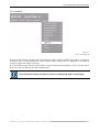
8.1 The IR Remote-Control Unit ........................................................................................................................8-1
8.1.1 Terminology of RCU controls ..............................................................................................................8-2
8.2 General.........................................................................................................................................................8-3
8.3 Menu Layout ................................................................................................................................................8-3
8.3.1 Navigating...........................................................................................................................................8-3
8.4 Activating the Menu Bar .............................................................................................................................8-3
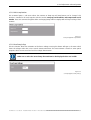
8.4.1 Reset Runtime ....................................................................................................................................8-3
8.4.2 Lamp Optimization .............................................................................................................................8-4
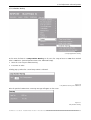
8.5 Access to the service menu ........................................................................................................................8-6
8.5.1 Projector Address................................................................................................................................8-7
8.5.2 RS232 baudrate ..................................................................................................................................8-9
8.5.3 Internal patterns .............................................................................................................................. 8-10
8.5.4 Color/Brightness.............................................................................................................................. 8-12
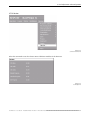
8.5.5 Orientation ....................................................................................................................................... 8-26
8.5.6 Maintenance .................................................................................................................................... 8-27
8.5.7 No Source Counter ........................................................................................................................... 8-32
8.5.8 I2C Diagnostics ................................................................................................................................. 8-33
8.5.9 Dimmer Sensor Power..................................................................................................................... 8-34
8.5.10 Save................................................................................................................................................ 8-35
Barco – OverView D 50" – DOC-3303-5 – installation manual – Revision 11 – November 2006
______________________________________________________________
1-2
1. Assembly of support frame
8.5.11 Freeze............................................................................................................................................. 8-36
8.5.12 Disable IR ....................................................................................................................................... 8-37
8.5.13 Lamps ............................................................................................................................................. 8-38
8.5.14 Version ........................................................................................................................................... 8-42
8.5.15 More ............................................................................................................................................... 8-43
9 Updating projectors to Firmware 2.0 ................................................................................................ 9-1
9.1 Update procedure........................................................................................................................................9-1
10 Manual User Interface ................................................................................................................... 10-1
10.1.1 Power Switch ................................................................................................................................. 10-1
10.1.2 Standby Switch .............................................................................................................................. 10-2
10.1.3 Active Lamp Selection Switch ....................................................................................................... 10-3
10.1.4 Indication of Power LED ................................................................................................................ 10-4
10.1.5 Indication of Lamp Door LED ......................................................................................................... 10-4
10.1.6 Indication of the Status LEDs......................................................................................................... 10-5
11 De-mounting the seamless screens .............................................................................................. 11-1
Barco – OverView D 50" – DOC-3303-5 – installation manual – Revision 11 – November 2006
______________________________________________________________
1-3
1. Assembly of support frame
1 Assembly of support frame
In deliveries for over sea destination the supports are completely disassembled
This section describes how to assemble the support frame for OverView mD.
__________________________________________________________
__________________________ 1-1
OverView D 50" – DOC-3303-5 – installation manual – Revision 11 – November 2006 ________________________________
1. Assembly of support frame
1.1 Contents of support frame carton
Before starting to assemble the support frame check if the material is complete.
Quantity
Description
Description
Support
875mm
Support
1000mm
Support
1200mm
2
Front profile ( vertical )
PU I 1, PU I 2
PU 4I 1, PU 41 2
PU 3I 1, PU 31 2
2
Rear profile ( vertical )
PU II 4, PU II 5
PU 4I 4, PU 4I 5
PU 3I 4, PU 3I 5
2
Front profile ( horizontal)
PU II 3
PU 2I 12, PU II 3
PU 2I 12, PU II 3
2
Rear profile ( horizontal )
PU II 3
PU II 3
PU II 3
4
Side profile
PU I 7
PU I 7
PU I 7
1
Angle with multi socket installed [2]
12
Reinforcing angle [1]
1
Box with screws
4
Adjustable foot
4
Profile connector
1
Cable channel
2
safety bracket
Table 1
List of Contents 1 support frame
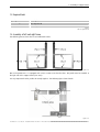
Figure 1-1
Overview of support frame, labels refer to support 875mm, for other other heights see table!
__________________________________________________________
__________________________ 1-2
OverView D 50" – DOC-3303-5 – installation manual – Revision 11 – November 2006 ________________________________
1. Assembly of support frame
1.2 Required tools
Quantity
Description
1
Torx key size 30
1
Allen key size 6
Table 2
List of required tools
1.3 Assembly of left and right frame
The following picture shows how to assemble both frames.
Figure 1-2
One of the profiles PU I 7 is equipped with 3 more counter nuts than the other. This profile must be installed at
the right side of the support frame (rear view).
It is very important that the profiles fit exactly together. The following figure shows details.
Figure 1-3
__________________________________________________________
__________________________ 1-3
OverView D 50" – DOC-3303-5 – installation manual – Revision 11 – November 2006 ________________________________
1. Assembly of support frame
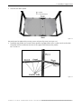
1.4 Installation of horizontal profiles
•
Install the two horizontal profiles PU II 3 at the profiles PU I 2 and PU II 4
Figure 1-4
•
Turn the support that the two profiles PU II 3 touch the ground.
•
Install the second frame at the profiles PU II 3.
Figure 1-5
__________________________________________________________
__________________________ 1-4
OverView D 50" – DOC-3303-5 – installation manual – Revision 11 – November 2006 ________________________________
1. Assembly of support frame
•
Insert the two lower panels.
Figure 1-6
The panels must be tightened by securing screws and joined by rivets (see Figure 1-6).
•
Install both top profiles PU II 3. One of these profiles is equipped with 3 more counter nuts than the other.
This profile must be installed at the front of the support frame between the profiles
PU I I and PU I 2.
Figure 1-7
__________________________________________________________
__________________________ 1-5
OverView D 50" – DOC-3303-5 – installation manual – Revision 11 – November 2006 ________________________________
1. Assembly of support frame
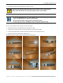
•
Install the multi socket angle (position see Figure 1-1 [2])
The power strip includes 6xIEC 320 sockets and is rated for a max. current of 10A.
Always take care that the max. rating of the power strip is not exceeded!
In case the installation site is in a 110V country, and in case the display wall is higher than
3 rows, an additional power strip has to be installed.
Of course the two power strips may not be connected in serie!
In 110V countries, at max. 3 darkboxes may be connected to a power strip!
In case a second power strip is required, proceed as follows:
•
De-mount the power strip attached to the multi socket angle.
•
Unpack the second power strip: it is already attached to the metal base plate.
•
Fix the de-mounted power strip to the metal base plate of the second power strip.
•
Attach the metal base plate to the angle bracket.
The following picture sequence shows the procedure stept by step:
__________________________________________________________
__________________________ 1-6
OverView D 50" – DOC-3303-5 – installation manual – Revision 11 – November 2006 ________________________________
1. Assembly of support frame
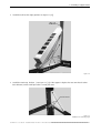
•
Install the multi socket angle (position see Figure 1-1 [2])
Figure 1-8
•
Install the reinforcing brackets ( see Figure 1-1 [1]). If the support is higher than 875 mm these brackets
look different, but the install procedure is exactly the same.
Figure 1-9
Installation of reinforcing angle
__________________________________________________________
__________________________ 1-7
OverView D 50" – DOC-3303-5 – installation manual – Revision 11 – November 2006 ________________________________
1. Assembly of support frame
Figure 1-10
•
Insert the adjustable feet.
Figure 1-11
__________________________________________________________
__________________________ 1-8
OverView D 50" – DOC-3303-5 – installation manual – Revision 11 – November 2006 ________________________________
1. Assembly of support frame
Figure 1-12
Rear view of complete support frame
Figure 1-13
Front view of complete support frame
__________________________________________________________
__________________________ 1-9
OverView D 50" – DOC-3303-5 – installation manual – Revision 11 – November 2006 ________________________________
2. Set up of OverView mD
2 Set up of OverView mD
This section describes the set up of OverView mD
Two engineers are required to set up the system.
The room in which the installation is carried out should already have been cleaned.
The set up comprises the following steps:
•
Installation of supporting frame.
•
Installation of dark-boxes.
•
Installation of screen module.
•
Installation of illumination unit
•
Installation of projection unit
•
Optical adjustment
__________________________________________________________
__________________________ 2-1
OverView D 50" – DOC-3303-5 – installation manual – Revision 11 – November 2006 ________________________________
2. Set up of OverView mD
2.1 Set up of Supporting Frame
The following tools are required to set up the supporting frame:
Size 5 and 6 hexagon keys.
Size 12 and 13 fork wrenches.
Size 10-socket spanner.
Precision spirit level.
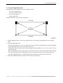
Proceed as follows to set up a linear arrangement:
Front side
2
1
Positions of
adjustable feet
3
4
Back side
Figure 2-1
adjustable feet
•
Unpack supporting frame, screw in the adjustable feet as far as possible, and position frames at required
place.
•
Adjust the supporting frame.
Using the adjustable feet 1 and 2, first adjust the front axis of the first supporting frame exactly horizontally
(use precision spirit level). Secure feet using counter nuts.
Subsequently align the depth axis exactly horizontally using adjustable feet 3 and 4. Also secure the feet
using counter nuts.
Once the supporting frame has been aligned, unscrew the feet 5 and 6 until they support the load. Carefully
check that the alignment of the supporting frame is not changed in the process (check using spirit level).
First adjust supporting frame 1, and then align and adjust the adjacent frames with respect to this.
•
Attach the supporting frames to the floor via the lower anchoring devices
__________________________________________________________
__________________________ 2-2
OverView D 50" – DOC-3303-5 – installation manual – Revision 11 – November 2006 ________________________________
2. Set up of OverView mD
•
Screw the supporting frames together (size 10 socket spanner and size 5 hex key).
•
Be sure that the 2 frames are exactly adjusted (check area).
O.K.
Check area
Check area
Frame 1
Frame 2
Figure 2-2
position of securing screws and check area
In order to assemble a polygonal arrangement, proceed as follows:
•
Concerning the feet adjustment of the supporting frames proceed as mentioned above.
•
Screw the supporting frames together using the polygonal kit (see Figure 2-3). Don’t tighten the securing
screws.
Figure 2-3
polygonal installation front view
__________________________________________________________
__________________________ 2-3
OverView D 50" – DOC-3303-5 – installation manual – Revision 11 – November 2006 ________________________________
2. Set up of OverView mD
Figure 2-4
Polygonal installation of support rear view
2.2 Set up of Dark Boxes
When assembling the dark boxes, take special care that adjacent dark boxes are fitted exactly lined up.
The following tools are required when assembling the dark boxes:
Size 5 and 6 hexagon keys.
Size 10 socket spanner.
Size 12 and 13 fork wrenches.
Figure 2-5
profile connector
•
Insert profile connectors into the corner profiles of each supporting frame and tighten securing screws (size 6
hexagon key).
__________________________________________________________
__________________________ 2-4
OverView D 50" – DOC-3303-5 – installation manual – Revision 11 – November 2006 ________________________________
2. Set up of OverView mD
Profile connector
Securing screw
Supporting frame
Figure 2-6
profile connectors
•
Unpack the dark boxes.
•
Remove the two covers from the backside of each dark box.
•
Place the dark boxes of the first row onto the profile connectors of the supporting frame.
Dark box
Supporting frame
Figure 2-7
Installing dark box onto the supporting frame
•
Screw the dark boxes together through the holes in vertical profiles (only linear arrangement)
•
Screw the dark boxes together using the polygonal connector kit (polygonal arrangement).
__________________________________________________________
__________________________ 2-5
OverView D 50" – DOC-3303-5 – installation manual – Revision 11 – November 2006 ________________________________
2. Set up of OverView mD
Figure 2-8
Polygonal installation of dark boxes rear view
•
Use the polygonal template to align the two dark boxes. The two profiles (A + B) must fit exactly together
with the template (polygonal arrangement).
Figure 2-9
polygonal alignment of dark boxes
•
Insert profile connectors into the corner profiles of each dark box of the first row and tighten securing screws
(size 6 hexagon key).
•
Place the dark boxes of the second row onto the profile connectors of the dark boxes at the first row.
__________________________________________________________
__________________________ 2-6
OverView D 50" – DOC-3303-5 – installation manual – Revision 11 – November 2006 ________________________________
2. Set up of OverView mD
Dark box
Dark box
Supporting frame
Figure 2-10
Installation of the second row
•
Screw the dark boxes together as mentioned above (see Figure 2-10).
•
If the configuration consists of more than two rows of dark boxes the system have to be fixed to the wall.
__________________________________________________________
__________________________ 2-7
OverView D 50" – DOC-3303-5 – installation manual – Revision 11 – November 2006 ________________________________
2. Set up of OverView mD
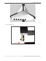
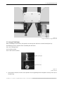
2.3 Installation of Safety Brackets
•
Before the installation of the safety brackets check again the position of the supports.
•
Each support has to be anchored by two safety brackets on the floor to avoid any movement.
Figure 2-11
Position of safety brackets
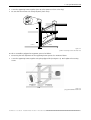
•
The safety brackets have to be fixed to the floor by one securing screw and two securing screws on the
profile.
Figure 2-12
How to install the safety bracket
•
Use a drill bit size 4.9mm to drill a hole in the profile in the position of the security pin.
•
Force the security pin (size 5x32mm) into the hole.
__________________________________________________________
__________________________ 2-8
OverView D 50" – DOC-3303-5 – installation manual – Revision 11 – November 2006 ________________________________
2. Set up of OverView mD
2.4 Grounding of the structure
Every support of OverView comes with a grounding kit which consists of a grounding wire (5m), the required
fixation material and the label:
Figure 2-13
grounding kit
The wire has to be connected on a vertical profile of the support. The following picture shows the connection
point – at this position, from the backside of the profile, a counter nut is attached.
Figure 2-14
where to fix the grounding cable
Fix the grounding wire to the support according the instruction shown below and attach the label above the
connection point:
label
annular cable lug
spring washer
20mm
washer
fixation screw
grounding wire
Figure 2-15
connecting the grounding cable to the support
At least every second projection module has to be grounded! The connection of the
grounding wire to the power net of the building has to be done by a qualified electrician
of the customer!
__________________________________________________________
__________________________ 2-9
OverView D 50" – DOC-3303-5 – installation manual – Revision 11 – November 2006 ________________________________
2. Set up of OverView mD
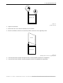
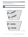
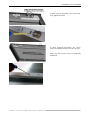
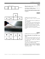
2.5 Pick up the protective foil of the mirror
The following figure shows how to pick up the protective foil of the mirror.
Only pull parallel to the mirror to prevent it from vaulting!
Figure 2-16
How to remove the protective foil
_________________________________________________________
_________________________ 2-10
OverView D 50" – DOC-3303-5 – installation manual – Revision 11 – November 2006 ________________________________
3. Installation of Screen Module
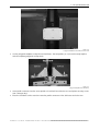
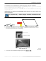
3 Installation of Screen Module
The screen modules are precision optical components! Do not touch with your bare hands.
Unpack always with two persons!
Use fabric gloves!
Figure 3-1
Unpacking a screen module
Lift simultaneously on both sides - don't tilt.
Unpacked screens shall directly be installed! Don't park on the floor!
Danger of breaking!
The following tools are required to assemble the screens:
Cloth gloves.
Long hexagon key size 5 mm.
Proceed as follows to assemble a screen module:
•
Remove the covers at the rear of the dark boxes.
•
Pull on cloth gloves.
•
Unpack screen module.
__________________________________________________________
__________________________ 3-1
OverView D 50" – DOC-3303-5 – installation manual – Revision 11 – November 2006 ________________________________
3. Installation of Screen Module
3.1 Installation of the standard screen module for systems with SXGA emulation
In case of an SXGA system with an SXGA+ projection unit and a Multi Input Module, a spacer has to be mounted
between the darkbox and the screen to enhance the depth.
The spacer comprises 2 horizontal and two vertical profiles which have to be assembled. This frame then is hung
on the pins of the darkbox.
Subsequently the screen module is hung on the guide pins, and then the spacer frame together with the screen
is fixed by 4 M8x45 bolts.
Do not insert the bolts in the spacer frame! The picture below only demonstrates where
the bolts will fix the spacer frame. Actually the bolts are inserted from inside the darkbox
and fix the spacer frame and the screen module!
•
Assemble the spacer frame (no bolts!) and hang it on the 4 guide pins on the front of the dark box.
•
Place also the screen module on the guide pins (Figure 3-3) on the front of the dark box. Be careful to
ensure that the edges of the screens are not damaged.
Figure 3-2
Screen module
•
Screw on the screen module with an hexagon key size 5 mm (torque 11-2 NM).
__________________________________________________________
__________________________ 3-2
OverView D 50" – DOC-3303-5 – installation manual – Revision 11 – November 2006 ________________________________
3. Installation of Screen Module
Figure 3-3
positions of screw connectors
•
The spacer frame and the screen module is held by four screw connectors fitted in the dark box. Figure 3-3
shows the positions of these screws at the dark box.
Figure 3-4
securing screen module
•
Align screen modules and lock screw connectors. Take care not to de-form the spacer frame!
The edges of the screens must be parallel and separated by 0.4 to 1.2 mm (expansion gap).
__________________________________________________________
__________________________ 3-3
OverView D 50" – DOC-3303-5 – installation manual – Revision 11 – November 2006 ________________________________
3. Installation of Screen Module
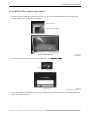
3.2 Installation of the standard screen module
•
Place the screen module on the guide pins (Figure 3-3) on the front of the dark box. Be careful to ensure
that the edges of the screens are not damaged.
Figure 3-5
Screen module
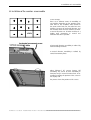
•
Screw on the screen module with an hexagon key size 5 mm (torque 11-2 NM).
Figure 3-6
positions of screw connectors
•
The screen module is held by four screw connectors fitted in the dark box. Figure 3-3 shows the positions of
these screws at the dark box.
__________________________________________________________
__________________________ 3-4
OverView D 50" – DOC-3303-5 – installation manual – Revision 11 – November 2006 ________________________________
3. Installation of Screen Module
Figure 3-7
securing screen module
•
Align screen modules and lock screw connectors. The edges of the screens must be parallel and separated by
0.4 to 1.2 mm (expansion gap).
__________________________________________________________
__________________________ 3-5
OverView D 50" – DOC-3303-5 – installation manual – Revision 11 – November 2006 ________________________________
3. Installation of Screen Module
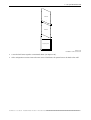
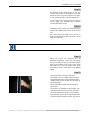
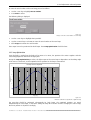
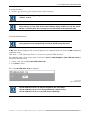
3.3 Installation of the seamless screen module
Screen concept:
static
There are 4 different states of movability of
one module depending on the position in the
wall. There is one complete static module in
the centre of the base row; the other base row
modules can move in horizontal direction; and
the modules above the static module can move
in vertical direction. For all other modules of a
display wall, movement in vertical and
horizontal direction is possible.
In horizontal direction, movability is realized by
horizotal sliding elements.
In vertical direction, movability is realized by
vertical movement plates.
When delivered, all screens feature full
movability! The screws to block movability in
horizontal and/or vertical direction have to be
installed according the position of the screen in
the display wall.
The picture shows the position of the screws.
__________________________________________________________
__________________________ 3-6
OverView D 50" – DOC-3303-5 – installation manual – Revision 11 – November 2006 ________________________________
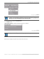
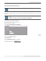
3. Installation of Screen Module
To block vertical movement, 4x2 screws have
to be applied and fixed.
To block horizontal movement, 2x1 screws
have to be applied and fixed, one at each side.
Make sure that the two screws are diagonally
positioned!
__________________________________________________________
__________________________ 3-7
OverView D 50" – DOC-3303-5 – installation manual – Revision 11 – November 2006 ________________________________
3. Installation of Screen Module
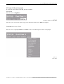
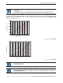
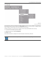
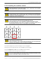
0 screws 0 screws 2 screws 0 screws
0 screws 0 screws 2 screws 0 screws
static
8 screws 8 screws 10 screws 8 screws
All screens are delivered with full movability,
i.e. no screws attached.
The number of screws to be applied and fixed
depends on the position of the screen in the
display wall.
Depending on the position of the screen in the
display wall, zero, 8 (4x2), 2 (2x1) or
10 (4x2 + 2x1) screws have to be installed.
Step1
Please note:
Installation of the screens starts on the bottom
row.
Every darkbox provides the fixation facilities for
the screen. The fixation facilities comprise 4
screw connectors (one at each corner), and in
addition next to the top screw connectors a
guide pin to put on the screeen.
The fixation facilities and their use are the
same for the screen modules and the seamless
screens.
Step2
Start installing the static screen:
The static screen is the screen in the mid of the
bottom row.
In case of an even number of colums (no
"center module") the static screen is the first
screen of the right half of the display wall,
seen from front.
For the static screen, apply and fix all 10
screws: both, movability in vertical and in
horizontal direction has to be locked!
__________________________________________________________
__________________________ 3-8
OverView D 50" – DOC-3303-5 – installation manual – Revision 11 – November 2006 ________________________________
3. Installation of Screen Module
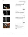
Step3
When all screws have been applied and fixed,
place the screen module on the guide pins on
the front of the dark box. Be careful to ensure
that the edges of the screens are not damaged.
Screw on the screen module with an hexagon
key size 5 mm (torque 1-2 NM).
The picture on the right shows tightening one
of the screws at the bottom.
Try to fix the screen centered to the darkbox
(visual check)
Tighten all 4 screws!
Completely remove
movement screws.
the
two
horizontal
Step4
The static screen itself and also the projection
module equipped with the static screen has to
be labeled! Wrt screen, put the label between
the two facilites to block horizontal mevement.
For the label and the position of the label on
the profile see picture on the right!
It is mandatory to stick to the rule mentioned
above and also to put on the label.
In case the screens have to be removed (either
the display wall has to be de-installed, or
either a screen has to be replaced) there is a
high risk of crashing all screens if the static
screen is not known!
Mark the static screen!
The static screen defines the movability of all screens in a display wall.
Dismounting a screen requires the knowledge of it's movability, cf. De-mounting the
seamless screens
__________________________________________________________
__________________________ 3-9
OverView D 50" – DOC-3303-5 – installation manual – Revision 11 – November 2006 ________________________________
3. Installation of Screen Module
Step5
All other screens of the bottom row are
installed following the procedure below:
Apply the 4x2 screws to block the vertical
movement.
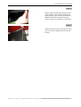
Step6
Screw in the horizontal movement screws until
the screen front is moved approx. 1mm against
the vertical frame towards the horizontal
movement screw.
Hang the screen on the pins. Make sure that
the horizontal movement screws always show
towards the border of the display wall – this
means that the left neighbor of the static
screen is rotated by 180° compared to the
right neighbor of the static screen.
Lock the 4 securing screws from behind.
The horizontal movement screws of all screens right to the static screen look in the same
direction.
The horizontal movement screws of all screens left from the static screen also look in the
same direction, but opposite to the horizontal movement screws of the screens right to
the static screen.
Step7
After locking the screen there will be a screen
gap to the neighbored screen of around 1mm.
To close this gap, drill out (turn left) the
horizontal movement screw.
The screen is now moving and the gap will be
closed.
Never drill only one of the horizontal movement screws completely out before turning
the seconed!
Make several turns on one screw and than go to the second, turn it, go back to the first
… continue until the gap is closed.
Step8
Completely remove the horizontal movement
screws!
_________________________________________________________
_________________________ 3-10
OverView D 50" – DOC-3303-5 – installation manual – Revision 11 – November 2006 ________________________________
3. Installation of Screen Module
Step9
adjusted to one level
When all screens of the bottom row are
installed, level the screens!
bottom row
Loosen the 4 locking screws to move the
screen slightly in vertical direction.
Adjust the vertical position of the screens that
the upper border of the front elements make a
straight line.
Step10
Install the screens of the second row:
Start with the screen on top of the static
screen.
Lock it in horizontal direction by applying 2x1
screw diagonally.
Take care that all 4 vertical movement plates
are in their nominal position, i.e. the drillings of
the plate flush with the threads of the frame.
Mount the screen that its position is symmetric
and that it is touching the screen below.
Completely remove the horizontal movement
screws.
Step11
Install the other screens of the second row.
These screens must not be locked in any
direction! Therefore no screws have to be
applied!
Screw in the horizontal movement screws until
the screen front is moved approx. 1mm against
the vertical frame towards the horizontal
movement screw.
Since these screen feature full movability, no
screws have to be applied and fixed.
When the screens are mounted and the gap to
the adjacent screen closed by turning the
horizontaol movement screws, completely
remove these screws!
_________________________________________________________
_________________________ 3-11
OverView D 50" – DOC-3303-5 – installation manual – Revision 11 – November 2006 ________________________________
3. Installation of Screen Module
Step12
The leveling of the upper border of that row
and the rows above is determined just by the
tolerance of the screen size which is very tight.
So the leveling should be already quite good.
In case there is still a small gap to the adjacent
screen, apply the leveling tape B195707,
covering the entire width!
Step13
Installation of the screens for all other rows are
identical to installing the screens of the second
row:
The screen above the static screen has to be
locked in horizontal direction, all other screens
must not be locked.
Take care that the screens are locked according their position!
Step14
When all screens are mounted, put all
horizontal movement screws into the plastic
bag (24 screws per bag) and fix these plastic
bags in the darkbox of the static screen using
the cable ties! In case the screens have to be
de-installed, these screws need to be applied
again!
Step15
Now the brushes have to be mounted.
The brushes serve as a light shield and close
the gap between the screen module and the
darkbox. They have to be glued on all edges of
the display wall..
They are flexible to allow the movement of
the screens.
The brushes are available in two lengths, one
matching the horizontal, the other matching
the vertical dimension of the screen module.
First clean the surface where the brushes have
to be fixed with alcohol to remove any grease!
_________________________________________________________
_________________________ 3-12
OverView D 50" – DOC-3303-5 – installation manual – Revision 11 – November 2006 ________________________________
3. Installation of Screen Module
Step16
Start with the vertical brush on the bottom
row!
Remove the protective tape.
Step17
Position and align the brush to the top edge of
the dark box.
Carefully fix the brush to the darkbox. Take
care that the bristles are aligned with black
metal border of the screen!
Step18
Proceed accordingly to attach the brush on the
next module.
Take care for a neat and proper joint!
Step19
When all the vertical brushes are attached,
proceed with the horizontal brushes on the
bottom row.
Please note:
Since the brush is in-between the support
profiles, it has to be cut by 2x30 = 60mm.
Use a saw to adjust the length!
You have to shorten half of the horizontal
brushes!
_________________________________________________________
_________________________ 3-13
OverView D 50" – DOC-3303-5 – installation manual – Revision 11 – November 2006 ________________________________
3. Installation of Screen Module
Step20
Position, align and attach the shortened brush
on the bottom of the module in-between the
support profiles. Take care that the bristles are
aligned with the black metal border of the
screen to make sure that there is no light gap!
Step21
Finally attach the brushes on the top row! Take
care for a neat and proper joint to the vertical
brushes!
_________________________________________________________
_________________________ 3-14
OverView D 50" – DOC-3303-5 – installation manual – Revision 11 – November 2006 ________________________________
4. Additional fixation facilities of systems employed with earthquake protection
4 Additional fixation facilities of systems employed with
earthquake protection
For special requirements, the OverView mD50 system can be built up using a special support ("earthquake
support") and the earthquake protection kit for the dark box.
The earthquake protection kit consists of some additional fixation facilities for screws and some additional plates
to increase the stiffness of the dark box. This kit is already installed in the factory. However, when building up
such a system, it is mandatory that the additional screws are installed in the correct way.
4.1.1 Fixation to the support or to the adjacent dark box of the previous row, respectively.
This fixation is done by means of a screw M6x55 DIN 912 with star washer and nut.
The following pictures show overview and detail of this fixation:
star washer
nut
__________________________________________________________
__________________________ 15
OverView D 50" – DOC-3303-5 – installation manual – Revision 11 – November 2006 ________________________________
4. Additional fixation facilities of systems employed with earthquake protection
4.1.2 Fixation of the screen frame
After the screen has been aligned, the screen frame is additionally fixed to the left and right vertical profile of
the dark box by means of a screw M6x55 DIN 912 with washer. Look at the big picture and the detailed view to
see where the additional screws are installed. Of course it is the same for the left vertical profile (seen from
behind).
screw
washer
__________________________________________________________
__________________________ 16
OverView D 50" – DOC-3303-5 – installation manual – Revision 11 – November 2006 ________________________________
5. Wall fixation
5 Wall fixation
General
The wall fixation comprises some standard parts (brackets, screws) and some project
specific parts (profiles).
The wall fixation is available in a linear version and in an A-shape version.
Rules
The display wall has to be fixed to the floor, and in case of (more than) three rows, to the wall, too.
Fixation to the floor only:
In case a system has only to be fixed to the floor, every support is attached on the front side and on the back
side. These two anchoring devices are in a diagonal arrangement, see schematics:
Figure 5-1
fixation on the floor
Fixation to the floor and to the wall:
In case a system has to be fixed to the wall, too, the lower anchoring devices are only applied on the rear side.
For the upper anchoring devices (wall fixations), the following rules apply for each row which must be attached
to the wall:
The fixations are mounted on the inner side of the most left and the most right projection module, too. Within
the distance of these fixations, additional fixations are mounted in such a way that the distance between two
fixations does not exceed three projection modules, and that the fixations are equally distributed.
The following rows have to be fixed:
Entire height (number of rows)
Fixation attached to row
3 or 4
3
5 or 6
2, 5
Example:
Since the display wall is attached to the wall,
the supports are attached to the floor on the
rear side only.
Wall fixations are attached on the inner side of
the most left/right projection module. Since
the max. allowed distance between two
fixations is 3 modules, one additional fixation
is required. This additional fixation is mounted
in a way that all fixations have the same
distance.
Position of the lower and upper anchoring devices (schematics)
Lower anchor point (e.g. Chemical Anchor Upat UMV 60 M 10 when anchored to concrete)
Upper anchor point with wall (A connection has to be chosen that is designed for a maximal resulting
traverse force of F=1.0 kN in the dowel vertical and parallel to the Display Wall)
Upper anchor point Display Wall
30° - 60°
__________________________________________________________
__________________________ 17
OverView D 50" – DOC-3303-5 – installation manual – Revision 11 – November 2006 ________________________________
5. Wall fixation
Linear version
The length of the profile is project specific and defined by the distance between the rear
side of the display wall and the wall of the building!
The attachment of the profile on the wall of the building allows to be positioned between
30degrees and 60degrees off the straight connection thus also eliminating unevenness of
the wall.
The following pictures show a sketch of the installed wall fixation on the display wall:
Figure 5-2
wall fixation, linear version
Item no.
quantities
Description
7
1
Profile (length: project specific)
9
1
Screw M10x110
4
1
Fixation bracket display wall side
5
2
Washer U-6-125
1
2
Screw M6x40
8
1
Distance bushing
10
1
Nut M10
11
1
Washer U-10-125
__________________________________________________________
__________________________ 5-1
OverView D 50" – DOC-3303-5 – installation manual – Revision 11 – November 2006 ________________________________
5. Wall fixation
To install the wall fixation at the display wall, proceed as follows:
•
Take the fixation bracket [4] and attach it to the profile of the dark box (linear setup of the display wall)
using the screws M6x40 [1] and the washers U-6-125 [5]. In case of a polygonal setup, the bracket is
attached to the polygonal connection bracket.
Figure 5-3
connection bracket, fixation points for linear wall fixation
•
Position the profile [7] and apply the bushing [8] (either on top of the profile as shown in the drawing, or
beneath the profile).
•
Insert the screw M10 [9].
•
Use the washer [11] and nut [10] to fix it.
The following picture shows a sketch about the fixation on the wall of the building:
Figure 5-4
wall fixation, side of wall of the building
Attach the wall fixation bracket to the end of the profile by means of M10x85. Use the spring washer and nut to
fix it.
•
Position the bracket at the wall of the building, and mark the position to drill the holes.
•
Remove the profile from the bracket to be attached to the wall of the building (otherwise drilling and
fixation is very difficult!).
•
Use two dowels FUR 10 to attach the fixation bracket to the wall of the building.
•
Reattach the profile to the bracket now fixed to the wall of the building.
__________________________________________________________
__________________________ 5-2
OverView D 50" – DOC-3303-5 – installation manual – Revision 11 – November 2006 ________________________________
5. Wall fixation
A-shape version
The length of the profile is project specific and defined by the distance between the rear
side of the display wall and the wall of the building!
The attachment of the profile on the wall of the building allows to be positioned between
30degrees and 60degrees off the straight connection thus also eliminating unevenness of
the wall.
An assembled A-shape version looks like this:
Figure 5-5
photo of wall fixation, A-shape version
First install the bracket to the dark box, then the legs, subsequently apply the short horizontal profile, then the
brackets to be fixed to the wall of the building.
In case of a curved setup, the A-shape version is fixed via the center screws (2 screws
only), fixed to the polygonal connection bracket, whereas for a linear setup the left and
the right screws are used (4 screws), fixed to the profiles.
__________________________________________________________
__________________________ 5-3
OverView D 50" – DOC-3303-5 – installation manual – Revision 11 – November 2006 ________________________________
5. Wall fixation
The following pictures show a sketch of the installed wall fixation on the display wall:
Figure 5-6
wall fixation, A-shape
Item no.
quantities
Description
1
2
Profile (length: project specific)
6
2
Screw M10x110
5
1
Fixation bracket display wall side
2
4
Washer U-6-125
12
4
Screw M6x40
4
1
Distance bushing
7
2
Nut M10
8
2
Washer U-10-125
To install the wall fixation at the display wall, proceed as follows:
•
Take the fixation bracket [5] and attach it to the profiles of the dark box (linear setup!!) using the screws
M6x40 [12] and the washers U-6-125 [2] (4 screws). In case of a curved setup, the center of the bracket is
fixed to the polygonal connection bracket with 2 screws.
•
Position the profiles [1] and apply the bushings [4] (either on top of the profiles as shown in the drawing, or
beneath the profiles).
•
Insert the screws M10 [6].
•
Use the washers [8] and nuts [7] to fix it.
__________________________________________________________
__________________________ 5-4
OverView D 50" – DOC-3303-5 – installation manual – Revision 11 – November 2006 ________________________________
5. Wall fixation
To complete the A-shape,
•
apply one of the brackets at each side of the short connection profile by means of M10x85. User the spring
washer and nut to fix it.
Figure 5-7
Wall fixation, A-shape version, bracket at the "leg" of the A
•
Fix the brackets at the legs of the "A": insert 4 Kanya nuts into each of the leg profiles and fix the bracket
using screws M6x10 and spring washers. Do only tighten them loosely: by shifting this profile, the angle
between the legs is determined and thus the distance to the wall of the building gets varied.
•
Attach the wall fixation bracket to the end of the profile by means of M10x85. Use the spring washer and
nut to fix it.
•
Position the legs at the wall of the building, and mark the position to drill the holes.
•
Remove the profile from the bracket to be attached to the wall of the building (otherwise drilling and
fixation is very difficult!).
•
Use two dowels FUR 10 to attach the fixation bracket to the wall of the building.
•
Reattach the leg profiles to the brackets now fixed to the wall of the building.
•
Finally really tighten the screws of the brackets at the legs of the "A".
Figure 5-8
wall fixation, A-shape version, fixation to wall of the building
__________________________________________________________
__________________________ 5-5
OverView D 50" – DOC-3303-5 – installation manual – Revision 11 – November 2006 ________________________________
6. Installation of Projection System
6 Installation of Projection System
Check the power rating on your outlet before connecting the multiMedia-Terminal and the
projection modules to the wall outlet or to a power strip. Contact your facilities manager or
a qualified electrician if you are not sure what type of power is supplied to your building.
The devices are designed to operate with single-phase power systems having a grounded
neutral conductor. To reduce the risk of electrical shock, do not plug into any other type of
power system.
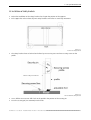
In OverView D series, the projection unit and the illumination unit are separated to enable an easy installation
and maintenance or replacement.
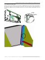
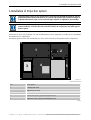
The following picture shows the removeable rear covers of the dark box and the position of the components.
1
3
A
4
B
2
5
Figure 6-1
Rear View of dark box
Pos
Description
1
Left top rear cover
2
Right top rear cover
3
Fan module with filter pad
4
Center rear cover, gray part: projection unit
5
Right rear cover, gray part: illumination unit
Table 3
__________________________________________________________
__________________________ 6-1
OverView D 50" – DOC-3303-5 – installation manual – Revision 11 – November 2006 ________________________________
6. Installation of Projection System
6.1 Installation of Illumination Unit
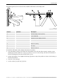
Remove the left top [1], center [4]and the right rear cover [5]. (see Figure 6-1)
Figure 6-2
Rear view dark box
with removed rear covers
Pos
Description
A
Projection mirror
B
Guide pins for predefined projector position
C
Position of projector securing screws
D
Cooling hose illumination unit
E
Cooling hose projector
F
Guide pins for predefined illumination unit position
Table 4
Unpack the illumination unit. Connect the cooling hose [D] at the illumination unit. Install the illumination unit
into the dark box. The position of the illumination unit at the dark box is predefined by 2 guide pins (see Figure
6-2). The illumination unit is fixed with 4 securing screws.
__________________________________________________________
__________________________ 6-2
OverView D 50" – DOC-3303-5 – installation manual – Revision 11 – November 2006 ________________________________
6. Installation of Projection System
Figure 6-3
Connection of cooling hose
Figure 6-4
Insertion of illumination unit
__________________________________________________________
__________________________ 6-3
OverView D 50" – DOC-3303-5 – installation manual – Revision 11 – November 2006 ________________________________
6. Installation of Projection System
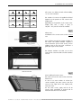
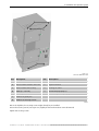
Figure 6-5
Overview illumination unit
Pos
Description
Pos
Description
A
Main Power
1
Connectors
B
Rocker switch On/Res. with LED
2
Optical interface
C
Rocker switch active Lamp
3
Cooling air outlet
D
LEDs (L1, L2, Fan)
4
Cover lamp top (lamp 1)
E
LED lamp door
5
Cover lamp bottom (lamp 2)
F
Position of guide pins
G
Position of securing screws
Table 5
Due to the keyholes, the securing screws might already be pre-installed.
Loosen the securing screws (see Figure 6-2) slightly and move them about 5 mm downwards
Tighten the securing screws.
__________________________________________________________
__________________________ 6-4
OverView D 50" – DOC-3303-5 – installation manual – Revision 11 – November 2006 ________________________________
6. Installation of Projection System
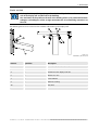
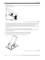
6.2 Installation of Projection Unit
Unpack the projection unit and remove the protective cover of the optical interface.
Figure 6-6
Pos
Description
A
Position of guide pins
B
Mounting angle
C
Protective cover of optical interface
__________________________________________________________
__________________________ 6-5
OverView D 50" – DOC-3303-5 – installation manual – Revision 11 – November 2006 ________________________________
6. Installation of Projection System
Figure 6-7
Pos
Description
A
Position of guide pins
B
Position of securing screws
C
Rear cover
D
Connectors
E
Protective cover cooling air input
F
Housing of light sensor
Table 6
Install the projection unit at the foreseen position (see Figure 6-8).
__________________________________________________________
__________________________ 6-6
OverView D 50" – DOC-3303-5 – installation manual – Revision 11 – November 2006 ________________________________
6. Installation of Projection System
Figure 6-8
Projection unit installed
Pos
Description
A
Position of guide pins
B
Position of securing screws
C
Protective cover
Table 7
Tighten the securing screws [B].
Make sure that the screws fit tightly! Especially the mid screw of the upper row!
A tight fitting is mandatory for a stable adjustment!
Remove the protective cover [C] and install the cooling hose.
Figure 6-9
Cooling hose installed
__________________________________________________________
__________________________ 6-7
OverView D 50" – DOC-3303-5 – installation manual – Revision 11 – November 2006 ________________________________
6. Installation of Projection System
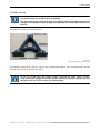
6.3 Installation of the 3200K color filter cartridge
To install the 3200K color filter cartridge,
•
switch the projector to standby.
•
power off the projector.
•
remove the rear shielding of the projection unit.
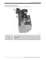
The following pictures show an overview of the projection unit and a detailed view on the position where the
filter cartridge has to be installed.
black sheet metal covering the slit
where the filter cartridge has to be inserted
Take a torx key size T10 and remove the black sheet metal covering the slit.
__________________________________________________________
__________________________ 6-8
OverView D 50" – DOC-3303-5 – installation manual – Revision 11 – November 2006 ________________________________
6. Installation of Projection System
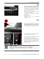
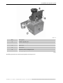
The 3200 K filter assembly looks like this:
The fixation angle will be fixed to the drills of the removed black sheet metal cover.
The activation handle allows sliding the filter in and out.
In-position: the filter is inactive, color temperature = 6500K.
Out-position: the filter is active, color temperature = 3200K
Insert the filter assembly into the slit of the projection unit. The activation handle shows towards the lens.
Use 2x screws B360322 to attach the fixation angle to the projection unit.
Use 1x screw B360322 to cover the M3 drill in the base plate.
fixation angle
towards color wheel
filter activation handle
towards lens
__________________________________________________________
__________________________ 6-9
OverView D 50" – DOC-3303-5 – installation manual – Revision 11 – November 2006 ________________________________
6. Installation of Projection System
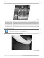
The following pictures show the projection unit after the installation of the 3200K color filter cartridge:
B
For a color temperature of 3200K, move down the activation handle to activate the filter.
Close the shielding of the projection unit.
Please note:
To switch the color temperature back to 6500K, the shielding has to be removed again to move the activation
handle up.
Switching of the color temperature always requires removing the back shielding of the projection unit.
_________________________________________________________
_________________________ 6-10
OverView D 50" – DOC-3303-5 – installation manual – Revision 11 – November 2006 ________________________________
6. Installation of Projection System
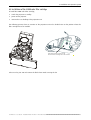
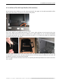
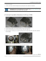
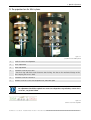
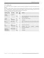
6.4 Installation of the Multi Input Module (SXGA emulation)
On the left side of the darkbox you see the enforcement metal. The support for the Multi Input Module will be
fixed to this enforcement. Unscrew the screw shown in the picture.
Into the vertical profile, a movable nut has to be inserted.
Look at the support of the Multi Input Module. It has a "nose" which will have to be fit into the hole of the
enforcement metal indicated by the arrow. In addition, it has 4 spares, labeled 1-1', 2-2'. For internal installation
of the Multi Input Module, the unit will be hooked into the spares 1-1'. The lateral front edge of the Multi Input
Unit will fit into the slot of the support.
Insert the support. Fit the nose into the enforcement metal. The support of the Multi Input Module will be fixed
on the bottom by means of the screw you previously loosend, and on the top by an additional screw which will
be tightened using the nut inserted into the profile.
After the support has been attached, the IR sensor for operating the Multi Input Module via IR remote control has
to be installed.
_________________________________________________________
_________________________ 6-11
OverView D 50" – DOC-3303-5 – installation manual – Revision 11 – November 2006 ________________________________
6. Installation of Projection System
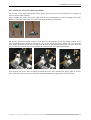
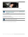
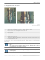
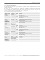
6.4.1 Installing the sensor of the Multi Input Module
The IR sensor of the Multi Input Module will be placed upon the IR sensor of the projection unit. Therefore it
comes with two fixation facilities.
Before installing the sensor, plug in the cable! Mind the correct orientation! For better recognition, the socket
NOT to be connected to the sensor (but to the Multi Input Module) is painted black:
One by one, replace the fixation screws of the IR sensor of the projection unit by the fixation facilities of the
sensor of the Multi Input Module. In the picture, you can see the required steps: replace one screw, then the
other, finally attach the second sensor on top of the IR sensor of the projection unit. Make sure not to block the
sensor of the projection unit by a wrong attachment of the IR sensor of the Multi Input Module!
Since the back side of the unit is no longer accessible when the unit is installed, the power cables to and the
sensor cable have to be connected to the Multi Input Module BEFORE inserting the unit into the darkbox.
_________________________________________________________
_________________________ 6-12
OverView D 50" – DOC-3303-5 – installation manual – Revision 11 – November 2006 ________________________________
6. Installation of Projection System
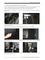
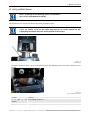
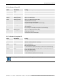
6.4.2 Cabling of the Multi Input Module and installation of the unit
The power cable of the illumination unit has to be unplugged and lenghtened by the extension cord. The second
interface of the extension cord has to be connected to the power in socket of the Multi Input Module.
The power out socket of the Multi Input Module has to be connected to the illumination unit.
The sensor cable has to be plugged in, as well as the remote control cables and the data cable (DVI) to the
projection unit.
Make sure to guide all cables inside the dark box!
Now you can insert the Multi Input Module into the dark box. Tilt it to enable the insertion and put it up only
when inside the dark box.
Hook the two rods on the bottom of the Multi Input Module into the spares 1-1' of the support.
Tighten the curled screw on the bottom of the Multi Input Module. That's it. No additional fixation is required.
Now the cabling of the sources (front interfaces can be done. When all cables are connected, carefully guide
them through the dark box. Make sure that they are not within the range of projection – otherwise you will see
the cables on the screen!
When all cables are attached, switch on the Multi Input Unit and test it. Subsequently re-attach the top rear cover
of the OverView projection system.
_________________________________________________________
_________________________ 6-13
OverView D 50" – DOC-3303-5 – installation manual – Revision 11 – November 2006 ________________________________
6. Installation of Projection System
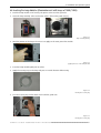
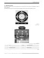
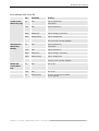
6.5 Cabling
The following figure shows a block diagram about the cabling.
dvi
external
IR - sensor
pu
external
fan
data
data
power
power
pu = projection unit
iu
main
power
iu = illumination unit
Figure 6-10
Block diagram
Figure 6-11
Overview cabling
Pos
Description
A
Projection unit
B
Illumination unit
1
DVI connector
2
External infrared sensor
3
COM in
4
COM out
5
Data
6
Power
Table 8
When using optical(fibre) data cables, please note that they may not be bent to a
curvature with a bend radius less than 15.4cm!
As soon as the illumination unit and the projection unit are connected by the signal cable
and/or the power cable, DO NOT disconnect either of these cables under operation or in
standby!
Disconnect only when the system is completely powered off (all LEDs are off)!
Otherwise the trinamic board of the IU will be damaged.
6. Installation of Projection System
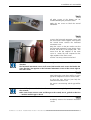
6.6 Inserting the Lamp Modules (Illumination unit with lamps of 100W/120W)
•
Fetch the lamp module on its housing. The power socket is on the right side.
•
Insert the lamp carefully. Take care that the "tubes" slide on the guide rods [2].
Figure 6-12
lamp and lamp housing
•
Mind the position of the fingers: the force is to apply on the outer part of the module
Figure 6-13
applying the force on the lamp module
•
Press the lamp module tightly into its socket
•
Apply the securing ring on the lamp and press it in axial direction while turning
Figure 6-14
inserting the securing ring
•
Turn the securing ring until its hooks click round the guide rods.
Figure 6-15
inserting the securing ring
__________________________________________________________
__________________________ 6-2
OverView D 50" – DOC-3303-5 – installation manual – Revision 11 – November 2006 ________________________________
6. Installation of Projection System
•
Close the lamp door
•
Use the screw driver and lock the lamp door by turning the screw a quarter turn clockwise.
The Serial Number of the lamps have to be entered, cf. Reset Runtime. In addition, Lamp
Optimization has to be performed once for both lamps, cf. Lamp Optimization. It is
recommended to do these step as soon as possible.
6.7 Inserting the Lamp Modules (Illumination unit with lamps of 200W)
•
Fetch the lamp module on its housing. The power socket is on the right side.
•
Insert the lamp carefully. Take care that the "tubes" slide on the guide rods.
•
When the lamp is removed, you see the two guiding rods on the upper right/lower left and the additional
fan for cooling.
•
Press the lamp module tightly into its socket.
•
Lock the lamp into its position by pressing the locking slider to the left.
Figure 6-16
inserting the lamp and locking it
__________________________________________________________
__________________________ 6-3
OverView D 50" – DOC-3303-5 – installation manual – Revision 11 – November 2006 ________________________________
6. Installation of Projection System
•
Close the lamp door
•
Use the hexagon key and lock the lamp door by turning the screw a quarter turn clockwise.
After the replacement of a lamp module, the new serial number has to be entered, and it is
highly recommended to select the lamp optimization procedure, cf. Error! Reference source not
found.,
found. Error! Reference source not found..
found.
In emergency cases the lamp optimization procedure can be skipped for the moment and
carried out later.
6.8 Selecting the correct lamp driver
There are four kinds of lamp drivers for the illumination unit of OverView D. it is mandatory that you check if the
default lamp driver is the correct one for your system!
SXGA+ systems only run with Power Pack lamp driver!
Please refer to Lamp Driver to learn how to set the correct lamp driver!
__________________________________________________________
__________________________ 6-4
OverView D 50" – DOC-3303-5 – installation manual – Revision 11 – November 2006 ________________________________
6. Installation of Projection System
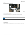
6.9 Running the fans
Before taking the system into operation it must be ensured that the fans and the hoses are dust free. Therefore
remove again the hoses from the illumination unit and the projection unit and start the fan.
Run the system in standby! Do not switch on the lamps!
The fans should run for about 5 minutes before continuing. Then re-attach the hoses.
Now you can start with the adjustment procedure
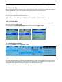
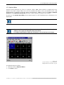
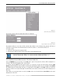
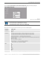
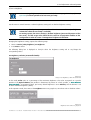
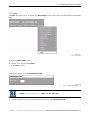
6.10 Settings of the Multi Input Module and the controller (SXGA emulation)
6.10.1 Multi Input Module
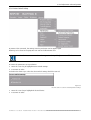
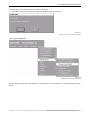
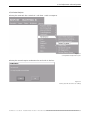
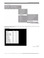
The Multi Input Module has to be set to the SXGA resolution. In the main menu, select Geometry|Display|Pixel.
Adjust the value from 1400 to 1280.
Subsequently go to Geeometry|Display|Line and adjust the value from 1050 to 1024.
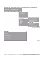
Select Geometry|Advanced|Original.
Set both, the X-position and the Y position, to zero
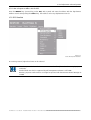
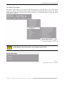
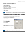
6.10.2 Controller
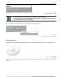
The Multi Input Module processes the incoming SXGA signal into an SXGA+Signal with black borders.By zooming
out you can remove the black border.– With TransForm A controller,,take care to switch the rotary switch on the
UGX graphics card to position 8.For Hydra controller,change the resolution in I-studio
(module->setup module ->screen)to “DLP SXGA native size ”and reboot the Hydra.
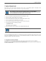
7. Optical Adjustment
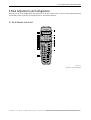
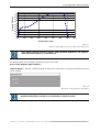
7 Optical Adjustment
After setting up the system optical adjustment must be done. In the following chapter a description of the
adjustment facility is given as well as some hints to carry out this procedure.
Only authorized and specially trained personnel should carry out adjustment!
Keep in mind that electrical power is supplied! Never touch anything different from the
parts described below due to the dangers of electrical shock.
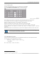
•
Switch on main power by pressing I (rocker switch I/O) Figure 6-5 [A]
•
Wait at least half a minute while the fan is blowing.
•
Switch on the lamp by pressing On (rocker switch On/Res.) Figure 6-5 [B]
•
The last 3 steps have to be repeated for each module.
•
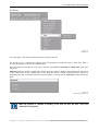
Insert a DOS boot diskette into the ARGUS-Processor and boot the system.
•
Start the program with the following command:
A>grid2728 <CR>
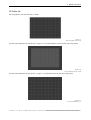
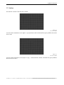
The adjustment grid is displayed.
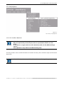
•
Check the distortion and the sharpness of the displayed adjustment grid.
You can also use the internal test pattern hatch, cf. Internal patterns.
To carry out the following procedures it is recommended to observe the displayed image from the back of the
screen thus immediately seeing the effects of the adjustment procedures. To enhance contrast it may be
necessary to veil the screens with a dark cover.
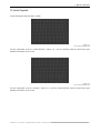
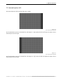
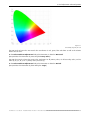
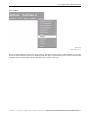
7.1 Testpattern for SXGA emulation
The adjustments of the projection unit have to be made using an external software tool or by applying
thetestpattern from the OSD:Service |Internal Patterns|Outline/Hatch. This test pattern has been completed by
an outline 1280x1024 pixel.
7. Optical Adjustment
7.2 The projection lens for SXGA systems
Figure 7-1
projection lens for SXGA systems
1
Scale for screen size adaptation
2
Focus adjustment
3
Zoom adjustment
4
2 fixation screws for focus lock
- the focus ring still shows some clearance after locking. This due to the mechanical design of the
lens. Anyway, the focus is fixed.
5
2 fixation screws for zoom lock
6
Fixation screws for screen size adaptation lock, filled with paint
No adjustment should be required wrt screen size adaptation. In production, screen size is
set to 50", see picture below.
Figure 7-2
scale for screen size adaptation
__________________________________________________________
__________________________ 7-2
OverView D 50" – DOC-3303-5 – installation manual – Revision 11 – November 2006 ________________________________
7. Optical Adjustment
7.3 The projection lens for XGA systems
Figure 7-3
projection lens for XGA systems
1
Scale for screen size adaptation, turn left for 50" systems, right for 67" systems
2
Fixation screws for screen size adaptation lock, filled with paint
3
Zoom adjustment
4
Focus adjustment
5
3 fixation screws for zoom lock
6
2 fixation screws for focus lock
- the focus ring still shows some clearance after locking. This due to the mechanical design of the
lens. Anyway, the focus is fixed.
The projection lens allows to zoom and to focus the picture. The adjusted settings can be locked by means of
fixation screws.
It is recommended to lock the lens only after the entire adjustment procedure has been
done.
After locking the focus adjustment ring and the zoom adjustment ring it might be
necessary to correct again x, y shift of the picture.
Even if locked, the focus adjustment ring can be slightly turned. Do not worry! The focus
is locked anyway!
__________________________________________________________
__________________________ 7-3
OverView D 50" – DOC-3303-5 – installation manual – Revision 11 – November 2006 ________________________________
7. Optical Adjustment
7.4 Strictly prohibited devices
Have a careful look on the following picture and remember:
These screws shall NEVER be touched!!!
The projection lens is mounted on the housing of the projection engine.
All screws mounted on the level indicated by a black arrow are NOT to be touched. These
screws are fixation screws for the entire projection lens or screws required for the
Scheimpflug adjustment which has already be done in the factory!
Figure 7-4
restricted area
For better recognition, these screws are locked with paint. The following picture shows the respective screws
in detail:
Figure 7-5
Never touch these screws!
Screws
1, 2 (and
visible)
4, 5, 6
Function
3,
not
Scheimpflug adjustment
Mounting and fixation screws
__________________________________________________________
__________________________ 7-4
OverView D 50" – DOC-3303-5 – installation manual – Revision 11 – November 2006 ________________________________
7. Optical Adjustment
7.5 Adjustment devices
Besides the adjustment rings on the projection lens to adjust focus and size, there are adjustment screws to
correct distortions.
The following picture gives an overview about the position and the function of the adjustment screws.
Figure 7-6
top view of lens
F
Figure 7-7
side view (lens and adjustment devices)
A Lens
H1, H2
Horizontal tapezoid
B Lens securing screws
V1, V2
Vertical trapezoid
C Horizontal lens shift
E
Mounting angle
D Vertical lens shift
F
Rotation
Table 9
__________________________________________________________
__________________________ 7-5
OverView D 50" – DOC-3303-5 – installation manual – Revision 11 – November 2006 ________________________________
7. Optical Adjustment
7.6 First steps
The entire projection unit is locked via the lock ring:
Figure 7-8
Lock ring
•
Unlock the system (loosen the lock ring)
•
Loosen the screen size adaptation lock screws and the zoom lock screws on the projection lens.
•
Loosen slightly the securing screws of the projection lens [B].
Without unlocking the system, no adjustment is possible!
7.7 Focus adjustment
The sharpness of the outlines of the squares (test pattern) is adjusted by turning the focus adjustment ring.
__________________________________________________________
__________________________ 7-6
OverView D 50" – DOC-3303-5 – installation manual – Revision 11 – November 2006 ________________________________
7. Optical Adjustment
7.8 Picture size
The wrong picture size looks like this or similar:
Figure 7-9
Rear view picture size too big
Turn the zoom adjustment ring at the lens ( Figure 7-1 ) counterclockwise to decrease the size of the picture.
Figure 7-10
Rear view picture size too small
Turn the zoom adjustment ring at the lens ( Figure 7-1 ) clockwise to increase the size of the picture.
Figure 7-11
Rear view picture size o.k.
__________________________________________________________
__________________________ 7-7
OverView D 50" – DOC-3303-5 – installation manual – Revision 11 – November 2006 ________________________________
7. Optical Adjustment
7.9 Vertical Trapezoid
A vertical distortion looks like this or similar.
Figure 7-12
Rear view vertical trapezoid
Turn the adjustment screw V1 counterclockwise ( Figure 7-6 ) and V2 clockwise until the vertical lines gets
parallel to the border of the screen.
Figure 7-13
Rear view vertical trapezoid
Turn the adjustment screw V1 clockwise (Figure 7-6 ) and V2 counterclockwise until the vertical lines gets
parallel to the border of the screen.
__________________________________________________________
__________________________ 7-8
OverView D 50" – DOC-3303-5 – installation manual – Revision 11 – November 2006 ________________________________
7. Optical Adjustment
7.10 Horizontal trapezoid
A horizontal distortion looks like this or similar.
Figure 7-14
Rear view horizontal trapezoid
Turn the adjustment screw H1 counterclockwise ( Figure 7-6 ) and H2 clockwise until the vertical lines gets
parallel to the border of the screen.
Figure 7-15
Rear view horizontal trapezoid
Turn the adjustment screw H1 clockwise ( Figure 7-6 ) and H2 counterclockwise until the vertical lines gets
parallel to the border of the screen.
__________________________________________________________
__________________________ 7-9
OverView D 50" – DOC-3303-5 – installation manual – Revision 11 – November 2006 ________________________________
7. Optical Adjustment
7.11 Rotation
The distortion “rotation” looks like this or similar:
Figure 7-16
Rear view rotation
Turn the rotation adjustment screw (Figure 7-7) [F] clockwise until the horizontal lines gets parallel to the border
of the screen.
Figure 7-17
Rear view rotation
Turn the rotation adjustment screw (Figure 7-7) [F]
the border of the screen.
counterclockwise until the horizontal lines gets parallel to
_________________________________________________________
_________________________ 7-10
OverView D 50" – DOC-3303-5 – installation manual – Revision 11 – November 2006 ________________________________
7. Optical Adjustment
7.12 Horizontal picture shift
The horizontal picture shift may looks like this or similar:
Figure 7-18
Rear view horizontal position
Use the adjustment screws for horizontal lens shift Figure 7-6 [C]. Tighten the left and loosen the right screw to
move the picture to the right.
Figure 7-19
Rear view horizontal position
Use the adjustment screws for horizontal lens shift Figure 7-6 [C]. Loosen the left and tighten the right screw to
move the picture to the right.
_________________________________________________________
_________________________ 7-11
OverView D 50" – DOC-3303-5 – installation manual – Revision 11 – November 2006 ________________________________
7. Optical Adjustment
7.13 Vertical picture shift
The vertical picture shift may look like this or similar:
Figure 7-20
Rear view vertical picture shift
Use the adjustment screws for vertical lens shift Figure 7-6 [D]. Tighten the top and loosen the lower screw to
move the picture downwards
Figure 7-21
Use the adjustment screws for vertical lens shift Figure 7-6 [D]. Loosen the top and tighten the lower screw to
move the picture upwards
7.14 Locking the Projection Unit
After the adjustment procedures the projection unit must be locked.
•
Turn the lock ring counterclockwise until it does not move any more. ( don’t tighten this ring too strong)
•
Lock the zoom and the focus adjustment by means of the fixation screws.
•
Tighten carefully the four securing screws of the lens.
•
Check if the position of the picture didn’t change while locking the projection unit.
_________________________________________________________
_________________________ 7-12
OverView D 50" – DOC-3303-5 – installation manual – Revision 11 – November 2006 ________________________________
8. Final Adjustment and Configuration
8 Final Adjustment and Configuration
After the set up of the Display Wall, the system has to be fine adjusted. This is done via the IR Remote-Control
and the OSD (or the respective commands via the RS 232 Remote-Control).
8.1 The IR Remote-Control Unit
Figure 8-1
IR Remote Control Unit (RCU)
__________________________________________________________
__________________________ 8-1
OverView D 50" – DOC-3303-5 – installation manual – Revision 11 – November 2006 ________________________________
8. Final Adjustment and Configuration
8.1.1 Terminology of RCU controls
1
Function keys
have no function for this projector
2
ADJ
ADJUST key, to enter or exit the adjustment mode.
3
Address key
(recessed key), to enter the address of the projector (between 0 and 9). Press the
recessed address key with a pencil, followed by pressing one digit button
between 0 and 9.
4
Selection key
has no function for this projector
5
PAUSE
has no function for this projector
6
Standby
stand by button, to start projector when the power switch is switched on and to
switch off the projector without switching off the power switch.
7
Mute
has no function for this projector
8
Help
has no function for this projector
9
Digit buttons
To enter the remote control address
10
Audio controls
have no function for this projector
11
Picture controls
Except for brightness and contrast, these keys have no function for this projector.
The controls of brightness and contrast are only enabled in case the optical
dimmer is disabled, cf. Optical Dimmer
12
PHASE
has no function for this projector
13
Freeze
has no function for this projector
14
TEXT
has no function for this projector
15
ENTER
to start up the adjustment mode or to confirm an adjustment or selection in the
adjustment mode.
16
Cursor Keys
to make menu selections when in the adjustment mode.
RCU
cursor key up
cursor key down
cursor key right
cursor key left
Use the cursor keys up or right for increasing a value.
Use the cursor keys down or left for decreasing a value.
17
EXIT
to leave the adjustment mode or to scroll upwards when in the adjustment mode.
18
RC operating
indication
lights up when a button on the remote control is pressed. (This is a visual indicator
to check the operation of the remote control)
__________________________________________________________
__________________________ 8-2
OverView D 50" – DOC-3303-5 – installation manual – Revision 11 – November 2006 ________________________________
8. Final Adjustment and Configuration
8.2 General
OVERVIEW MDG50-DL has a build in "PC like" toolbar menu which allows easy access to different parameters for
setting up the projector.
The toolbar menu is activated by pressing ADJ
Menu items which are not applicable are grayed out.
8.3 Menu Layout
The existence of a submenu is indicated by a white arrow
Three suspension points indicate that the menu item hides a dialog box or a text box.
A dot indicates which option is selected.
Grayed out menus or items are not available in this software version.
8.3.1 Navigating
Use the cursor keys on the RCU to navigate within a menu or a submenu.
Press Enter to select a menu item
Press Enter to open the submenu.
Press Exit to exit a submenu or menu
8.4 Activating the Menu Bar
Press the ADJ key on the RCU to display the menu bar.
Figure 8-2
menu bar
Use the cursor key on the RCU to select a menu. Press Enter to activate it.
8.4.1 Reset Runtime
After insertion of a new the lamp, its serial number has to be entered.
The command Reset runtime displays the dialog to enter the serial number.
Figure 8-3
Reset runtime
__________________________________________________________
__________________________ 8-3
OverView D 50" – DOC-3303-5 – installation manual – Revision 11 – November 2006 ________________________________
8. Final Adjustment and Configuration
To enter the serial number of the new lamp, proceed as follows:
•
Use the cursor key to highlight Reset runtime.
•
Press Enter to select.
The following dialog is displayed:
Figure 8-4
dialog to enter the serial number of a new lamp
•
Use the cursor keys to highlight the input field.
•
Use the numeric keys on the RCU to enter the serial number of the new lamp.
•
Click Accept to activate the serial number.
These steps have to be performed for both lamps. Then Lamp Optimization should be done.
8.4.2 Lamp Optimization
Since the light is coupled into the light rod by means of a mirror, the position of the mirror together with the
actual lamp properties determine the light yield.
During the Lamp Optimization procedure, the light output of the active lamp in dependence of the tilting angle
of the mirror is measured, and the optimized mirror position for the lamp is determined.
sensitivity of tilt mirror adjustment
1.2
1
intensity [ a.u. ]
0.8
0.6
0.4
0.2
0
0
0.5
1
1.5
2
2.5
3
3.5
4
angle [ deg ]
Figure 8-5
influence of tilt mirror adjustment on light intensity
The procedure should be performed subsequently for both lamps. The optimized positions are stored
independently for both lamps, so that after setting the lamp lift in motion and thus changing the active lamp,
the mirror position is adjusted accordingly.
__________________________________________________________
__________________________ 8-4
OverView D 50" – DOC-3303-5 – installation manual – Revision 11 – November 2006 ________________________________
8. Final Adjustment and Configuration
Figure 8-6
Lamps menu, Lamp optimization
This procedure optimizes the coupling of the active lamp into the optical system of the
projector and is immediately triggered by selecting the command Lamp Optimization.
During this procedure, the display gets dark for about 30seconds.
•
Use the cursor keys to highlight Lamp Optimization
•
Press ENTER to select.
If Operation|Message Box is enabled, the following message box is displayed:
Figure 8-7
Lamp optimization in progress
The procedure should be performed subsequently for both lamps.
All other steps to configure the system have to be done in the service menu.
__________________________________________________________
__________________________ 8-5
OverView D 50" – DOC-3303-5 – installation manual – Revision 11 – November 2006 ________________________________
8. Final Adjustment and Configuration
8.5 Access to the service menu
To access the service menu of the OSD, proceed as follows:
Start the OSD
Move the cursor to Brightness
Figure 8-8
first step to activate the Service Menu
Enter the access code via the numeric keys on the IR Remote-Control. Press Enter to complete!
The Service menu entry is shown.
Move the cursor to highlight Service. Press Enter to select. The following menu items are displayed:
Figure 8-9
Service Menu
__________________________________________________________
__________________________ 8-6
OverView D 50" – DOC-3303-5 – installation manual – Revision 11 – November 2006 ________________________________
8. Final Adjustment and Configuration
8.5.1 Projector Address
Projectors leaving production are all set to a projector address "255". When installed in a Display Wall, every
projector has to get a unique address via it can be controlled. This address can be set between 0 and 9 (IR
Remote-Control) or between 0 and 255 (RS232 Remote-Control). CAST as well as the RS232 command
interface and the IR Remote-Control Unit will talk to a specific projector by means of this address.
By means of the common RC5 address the IR Remote-Control can talk simultaneously to all projectors of a
Display Wall.
The common RC5 address can be set either to 0 or to 1.
Please note that CAST (Color Adjustment Service Tools) requires that the projector
addresses are assigned as indicated in the picture below.
It is highly recommended to follow this instruction in case for the future use of CAST!
Figure 8-10
projector addresses as required by CAST,
Display Wall seen from front, A: top row
To modify the projector address:
•
Move the cursor to Projector Address.
•
Press Enter to select.
__________________________________________________________
__________________________ 8-7
OverView D 50" – DOC-3303-5 – installation manual – Revision 11 – November 2006 ________________________________
8. Final Adjustment and Configuration
Figure 8-11
Service Menu, Projector Address
The projector address and the common RC5 address is displayed.
Figure 8-12
Projector Address and common address
The projector address is set to five, and the common RC5 address is zero. Therefore the projector will listen to
commands received from an IR Remote-Control unit with the address “5” and with the address “0”.
To change a value:
•
Move the cursor key to the respective field.
•
Enter the new value by means of the numeric keys of the IR Remote-Control.
For an application it might be useful to have the Display Wall split into two parts, one
with the common RC5 address “0” and one with the common RC5 address “1”.
8.5.1.1 Displaying a Projector Address by means of the Remote-Control Unit
Press the ADDRESS key (recessed key on the RCU) with a pencil. The projector's address will be displayed in a
'Text box'. This text box disappears after a few seconds.
To continue using the RCU with that specific address, it is necessary to enter the same address with the digit
buttons (address between 0 and 9) within 5 seconds after pushing the address key. For example if the Address
key displays projector address 005, then press "5" digit button on the RCU to set the RCU's address to match the
projector's address. Do not press 005 digits. This will address the remote control to '0' and control all projectors in
the room.
If the address is not entered within 5 seconds, the RCU returns to its default address (zero address) and control
all projectors in the room.
__________________________________________________________
__________________________ 8-8
OverView D 50" – DOC-3303-5 – installation manual – Revision 11 – November 2006 ________________________________
8. Final Adjustment and Configuration
8.5.1.2 How to Program an Address into the RCU?
Press the ADDRESS key (recessed key on the RCU) with a pencil and enter the address with the digit buttons
within 5 seconds after pushing the address key. That address can be any digit between 0 and 9.
8.5.2 RS232 baudrate
Figure 8-13
Service Menu, RS232 baud rate
For servicing reasons, higher baud rates can be selected.
Please keep in mind that with firmware 2.x 115200 should only be selected in a single projector
connection.
Standard baud rate which is supported by wall management software is still 9600!
However, projectors with Firmware 3.x might be operated with the OverView Control Manager at
115200.
__________________________________________________________
__________________________ 8-9
OverView D 50" – DOC-3303-5 – installation manual – Revision 11 – November 2006 ________________________________
8. Final Adjustment and Configuration
8.5.3 Internal patterns
Use Internal Patterns to check some properties of the system.
Figure 8-14
Service Menu, Internal Patterns
•
Move the cursor to Internal Patterns
•
Press enter to select
A list of available patterns is displayed.
•
Move the cursor key to select the desired pattern.
•
Press Enter to select.
The test pattern is applied.
The following table gives some recommendations what the various test pattern can be used for:
Pattern
use
Outline/Hatch
for geometry adjustment
Color bars
to check primaries and secondaries
Checkerboard
to check for straylight
Pixel On/Off
to check electronics and projection lens performance
Lens Adjustment
to check the projection lens adjustment
RGB
arbitrary colors, explanation see below
_________________________________________________________
_________________________ 8-10
OverView D 50" – DOC-3303-5 – installation manual – Revision 11 – November 2006 ________________________________
8. Final Adjustment and Configuration
8.5.3.1 The RGB test pattern
By means of the RGB test pattern menue, any desired colorc can be applied.
Selecting Service|Internal Patterns|RGB displays the following dialog box:
Figure 8-15
dialog box to define the desired color
On this dialog box, the values for red, green, blue can be entered by means of the arrow buttons.
Arrows pointing to the left decrease a value, arrows pointing to the right increase a value.
4) /decreases(3) the value per 1.
Clicking on the double arrows increases (
44) /decreases (33) the values per 64.
Clicking on a single arrow increases (
Clicking on the right most / left most arrow sets the value to the maximum (1023) or minimum (0).
Using the All button will manipulate all individual RGB settings to be equally increased or decreased,
respectively.
Besides the dialog box to enter the RGB values, a square frame is displayed to indicate the center of the screen.
Both, the RGB value dialog box and the square frame can be switched on/off by pressing
the text button on the IR Remote-Control Unit.
8.5.3.2 Understanding the color values
Since the ASIC• allows 10 bit input per color, on this dialog box the values are in the range from 0 to 1023.
The relationship to 8-bit input DVI RGB-Data is given by:
(R, G, B )intern = (4 ∗ R − 1,
4 ∗ G − 1, 4 ∗ B − 1)extern
for example :
(511, 439, 1019)intern = (128, 110, 255)extern
•
ASIC: application specific integrated circuit
_________________________________________________________
_________________________ 8-11
OverView D 50" – DOC-3303-5 – installation manual – Revision 11 – November 2006 ________________________________
8. Final Adjustment and Configuration
8.5.4 Color/Brightness
Figure 8-16
Service Menu, Color/Brightness
8.5.4.1 Color Coordinate Adjustment
Color Adjustment has to be done by CAST!
Only very experienced personnel in possession of a spectrometer should access this
menu!
In case there is an urgent need to use this menu item, make sure that White Peaking is
set first.
Color adjustment is only valid for one White Peaking value.
This menu provides some essential information for the ASIC: the factory colors of the DLP engine and the desired
target colors.
The color locations for DLP are indicated in coordinates of the x, y color space (CIE 1931).
_________________________________________________________
_________________________ 8-12
OverView D 50" – DOC-3303-5 – installation manual – Revision 11 – November 2006 ________________________________
8. Final Adjustment and Configuration
Figure 8-17
Chromaticity diagram, CIE 1931
The ASIC needs to know the uncorrected color coordinates for red, green, blue and white as well as the relative
lumens of each color.
On the Color Coordinate Adjustment dialog this information is related to Measured.
(CAST provides this information by measuring the factory colors).
The ASIC then needs to know the target color coordinates for all primary colors, for all secondary colors, and for
white (R, G, B, C, M, Y, W: "7 primary colors processing")
On the Color Coordinate Adjustment dialog this information is related to Desired
(CAST provides this information by determining the Target)
_________________________________________________________
_________________________ 8-13
OverView D 50" – DOC-3303-5 – installation manual – Revision 11 – November 2006 ________________________________
8. Final Adjustment and Configuration
Selecting Service | Color/Brightness | Color Coordinate Adjustment displays the following dialog box:
Figure 8-18
dialog box Color Coordinate Adjustment
The dialog box refers to the active lamp!
The data need to be set individually for each lamp!
The Enable/Disable selection always refers to both lamps!
Click on the arrow next to the respective text field to get a list of the available options:
Parameter
Possible value
Parameter 1
Measured
Desired
Parameter 2
X coordinate (should be within the measured triangle of the factory colors)
Y coordinate (should be within the measured triangle of the factory colors)
Luminance (if Parameter 1 == Measured), otherwise grayed out
The relative luminance of a color is defined as the ratio of the luminance of this color to the
luminance of white
(which – per definition – equals 1).
Gain (if Parameter 1 == Desired), otherwise grayed out.
Gain should be set to 1 to prevent clipping!
Colour
Red
Green
Blue
Cyan
Yellow
Magenta
White
Value
Value of coordinate in the x, y chromaticity diagram, CIE 1931
_________________________________________________________
_________________________ 8-14
OverView D 50" – DOC-3303-5 – installation manual – Revision 11 – November 2006 ________________________________
8. Final Adjustment and Configuration
There are transformation algorithms between the different color spaces. CAST allows to
switch between the presentation of the coordinates in the u', v' color space (CIE 1976)
and the x, y color space (CIE 1931).
The DLP Engine itself only "knows" the x, y color space, and requires that the values are
entered as x, y coordinates.
Only experienced personnel should edit this dialog! There is a risk of severe damages!
Use CAST to do the color adjustment.
Due to the influence of the dimmer the values indicated by CAST and those listed on this
dialog might slightly differ.
Changes become only active if Enabled is checked and if the menu is left by pressing the Exit button on the IR
Remote-Control Unit.
8.5.4.2 White Peaking
After changing the White Peaking Value, the color adjustment has to be repeated!
The color correction model is only valid for one White Peaking Value setting!
Before setting the White Peaking value, some background information on the generation of white is required.
The color wheel incorporated in the DLP projection engine has 4 sectors: red ( R), green (G), white (W) and blue
(B)
"White" is generated by the primary colors, via the addition of full red, full green, and full blue. W1 = R + G + B
"White" is also generated by the white segment: W2 = W
"White" is also generated by the so-called spoke light recapture: If the DMD is left ON while the color segments
change, there are additional contributions of adjacent segments:
R+G
G+W
W+B
B+R
Spoke light
recapture
R
G
W
B
R
Time
Spoke Light Recapture (SLR) = (R+G) + (G+W) + (W+B) + (B+R) = 2*(R+G+B) + 2*W = W3
In case the white segment and spoke light recapture are activated, the white output is boosted.
The White Peaking Factor is defined as the relation of "all whites" to the RGB-White:
_________________________________________________________
_________________________ 8-15
OverView D 50" – DOC-3303-5 – installation manual – Revision 11 – November 2006 ________________________________
8. Final Adjustment and Configuration
White Peaking Factor =
W1 + W2 + W3 RGB + W + SLR
=
W1
RGB
It's obvious that the minimum of the White Peaking Factor equals 1 (no white segment, no spoke light
recapture).
The maximum of the White Peaking Factor (all three contributions) is about 1.8. It varies slightly with different
lamps.
The White Peaking Factor can be linear scaled between its minimum and its maximum by
means of thw White Peaking Value.
The White Peaking Value can be set by means of the command Service|Color/Brightness|White Peaking.
A dialog box is opened where the desired White Peaking Value can be entered.
Figure 8-19
Adjusting the White Peaking Value
A White Peaking Value of 10 is related to the max. White Peaking Factor (1.8; incl. white segment, spoke
light recapture).
A White Peaking Value of 0 is related to the min. White Peaking Factor (0, no white segment, no spoke light
recapture).
The intermediate values are set by means of the corresponding White Peak Value, which are listed in the
following table. Please note that the table lists approximate values:
White Peaking Value
White Peaking Factor
0
1
1
1.08
2
1.16
3
1.24
4
1.32
5
1.4
6
1.48
7
1.56
8
1.64
9
1.72
10
1.8
The White Peaking Value must not be changed after color adjustment!
The color correction model is only valid for one White Peaking Value setting!
The White Peaking Value has also impacts on the gamma valu, cf. Degamma
_________________________________________________________
_________________________ 8-16
OverView D 50" – DOC-3303-5 – installation manual – Revision 11 – November 2006 ________________________________
8. Final Adjustment and Configuration
8.5.4.3 Degamma
Use Service | Color/Brightness | Degamma to change the gamma value.
A list of the available gamma values pop up. The current setting is indicated by a white dot.
Figure 8-20
list of available gamma values
Disable applies a gamma value of “1”
For OverView D series, do NOT use any of the TI gamma values.
gamma = 2.7 should be used with utmost care!
Influence of White Peaking on Gamma
For DLP projection engines which use the white segment and spoke light recapture, the influence of the gamma
value on white and on gray levels is much higher. The primary colors and secondary colors are not affected. The
following table shows the selected gamma value and its effective equivalent:
gamma value (White Peaking value = 0)
effective gamma value (White Peaking value = 10)
1.0
1.6
2.0
3.2
2.2
3.4
2.3
3.6
2.7
4.0
Due to the White Peaking, for white and gray (R=G=B) even a gamma value of “1”
(disabled) results in a non-linear effective gamma curve and thus in a non-linear
response.
_________________________________________________________
_________________________ 8-17
OverView D 50" – DOC-3303-5 – installation manual – Revision 11 – November 2006 ________________________________
8. Final Adjustment and Configuration
It is recommended to set the White Peaking value first and then adjust the gamma
accordingly!
A subsequent change of the White Peaking value will influence the gamma response.
The following diagrams show the gamma curves for the gamma values 1 and 2.3 for an operation without white
segment and without spoke light recapture (White Peaking =0) and for an operation with full white segment and
full spoke light recapture (White Peaking = 1). These diagrams clearly show the influence of the White Peaking
value on the gamma curve.
100
Relative Brightness in [%]
White Peaking = 0
80
γ = 1.0
60
40
γ = 2.3
20
0
0
32
64
96
128
160
192
224
RGB Input Value
Figure 8-21
gamma curves, no White Peaking
100
White Peaking = 10
Relative Brightness in [%]
80
60
γ = 1.0
40
γ = 2.3
20
0
0.0
32.0
64.0
96.0
128.0 160.0 192.0 224.0
RGB Input Value
Figure 8-22
gamma curves, full white peaking
Since the effective gamma values are enlarged due to White Peaking, the default setting
for OverView D is 2.0
Please note that this effect only applies for white and gray (R=G=B). The primary colors
and secondary colors are not affected, for those the set gamma value is exactly the
effective gamma value.
_________________________________________________________
_________________________ 8-18
OverView D 50" – DOC-3303-5 – installation manual – Revision 11 – November 2006 ________________________________
8. Final Adjustment and Configuration
8.5.4.4 Set Brightness
Before setting brightness, it is recommended that Lamp Optimization, (cf. Lamp
Optimization) has been performed at least once per lamp!
Use this menu to switch between a relative brightness setting and an absolute brightness setting.
Per factory default, in new systems the value is set to relative (no brightness
information about the used lamp is available).
In running system, the correct setting is absolute brightness (measured by means of the
DIS sensor, and the target value should be the same for all projection modules of the
configuration in order to ensure a homogeneous brightness distribution.
Changing the brightness setting, requires the following steps:
•
Move to Service | Color/Brightnes | Set Brightness
•
Press Enter to select.
The following dialog box is displayed to show/to select the brightness setting and to see/change the
corresponding values.
Set Brightness, Relative (uncontrolled mode)
Figure 8-23
dialog box Set Brightness, relative mode activated
In this mode, Value refers to a percentage of the maximum brightness. This value corresponds to a specific
position of the Optical Dimmer (the position is determined by means of a look up table, cf. Error! Reference
source not found.).
found. As mentioned above, per factory default brightness is set to Relative, and the dimmer is set
to allow maximum brightness (100%).
In this operation mode, the entries of the Brightness menu are grayed out, since these refer to absolute values!
Figure 8-24
Brightness menu entries are grayed out
_________________________________________________________
_________________________ 8-19
OverView D 50" – DOC-3303-5 – installation manual – Revision 11 – November 2006 ________________________________
8. Final Adjustment and Configuration
The dimmer will be positioned immediately after entering a new target value, and the related DIS value is
adjusted accordingly.
Due to the fact that the lamps show tolerances in burner position and arc length, multiple lamps with the
identical relative brightness value will show differences in emitted brightness. This can be checked by reading
out the value of the direct illumination sensor (DIS).
In relative mode, values can be entered in the range from 50 to 100 (50% to 100%).
To modify the light level:
•
Use the cursor keys to set the focus to the Value text field.
•
Press Enter to activate.
•
Use the left/right cursor key to decrease/increase the value, or set a new value by means of the numeric
keys on the Remote-Control unit.
Since it is the result of the measurement, the DIS value cannot be modified, it is read-only.
Set Brightness, Absolute (controlled mode)
Figure 8-25
Dialog box Set Brightness, absolute mode activated
It is recommended first to run DIS calibration, cf. DIS Calibration Factor!
In this operation mode, the dimmer is positioned by the brightness control algorithm utilizing the readout level
of the direct illumination sensor DIS as feedback signal.
The control loop is triggered each time a new target value is entered. It also becomes active after change of
mode from relative to absolute. The control loop stops once the target value is reached within an accuracy limit
of ± 1%. Typically this takes about 10 sec.
The target value is in same units as the DIS value. If the DIS is calibrated to lux by appropriate setting of the DIS
calibration factor, then the target value is to be entered in lux.
If the dimmer fails to reach the target brightness because it is operated at it’s upper or
lower limits an error message will show up.
_________________________________________________________
_________________________ 8-20
OverView D 50" – DOC-3303-5 – installation manual – Revision 11 – November 2006 ________________________________
8. Final Adjustment and Configuration
Figure 8-26
message at dimmer range limit
Please note: this error message does not indicate a dimmer failure!
This message indicates that the dimmer cannot achieve the desired value but operates
at his limits (100%, or 50% respectively).
In this operation mode, the commands of the Brightness menu are available:
Figure 8-27
Brightness menu commands are available
8.5.4.5 Optical Dimmer
OverView D uses a dimmer wheel with a variable slit. The slit defines the light aperture of the light pipe entry.
Figure 8-28
Dimmer Wheel, variable slit
The amount of light emitted into the projection unit depends on the position (i.e. slit width) of the dimmer
wheel.
_________________________________________________________
_________________________ 8-21
OverView D 50" – DOC-3303-5 – installation manual – Revision 11 – November 2006 ________________________________
8. Final Adjustment and Configuration
1
normalized DIS value
0,9
0,8
0,7
0,6
0,5
0,4
0,3
0,2
0,1
0
1400
1600
1800
2000
2200
2400
2600
2800
3000
dimmer position [ steps ]
Figure 8-29
intensity of emitted light depends on the position of the dimmer wheel
Only dimmer positions between (approx.) 1600 (minimum brightness) and (approx.)
2600 (maximum brightness) can be addressed.
The dimmer wheel can be enabled or disabled by means of the menu
Service | Color/Brightnes |Optical Dimmer.
If Optical Dimmer is selected, a dialog box pops up where the current status is indicated and where this status
can be changed:
Figure 8-30
Dialog Box to enable/disable the optical dimmer
The correct setting is Enabled!
Disabled should only be selected in case the dimmer is defective (stuck)!
_________________________________________________________
_________________________ 8-22
OverView D 50" – DOC-3303-5 – installation manual – Revision 11 – November 2006 ________________________________
8. Final Adjustment and Configuration
Optical Dimmer, enabled
This is the default setting. which allows automated brightness control and the lumens lock mode. At reboot the
home position of the dimmer is searched.
Since in this operation mode brightness is automatically controlled, the electronic control
of brightness and contrast of the IR Remote-Control unit is not available! (No manual
interference in the automated operation mode).
Optical Dimmer, disabled
The correct setting is Enabled!
Disabled should only be selected in case the dimmer is defective (stuck)! This mode
should only be used by advanced support engineers!
If disabled is selected, the dimmer will stay at its current position, and even at reboot no search for the home
position of the dimmer is performed.
In this mode the addressing of reference slits on the dimmer wheel will not be available to the lamp
optimization algorithm. In consequence it will be less powerful.
A non-uniformity in brightness might appear.
To provide a workaround, brightness and contrast can be adjusted by means of the respective buttons on the IR
Remote-Control unit.
Brightness adjusts the offset applied to the RGB input data.
Contrast changes the gain applied to the RGB input data.
The Brightness and Contrast dialog boxes show up after pressing the Brightness/Contrast button on the IR
Remote-Control unit.
Figure 8-31
Brightness setting, only available if Optical Dimmer is disabled
Figure 8-32
Contrast setting, only available if Optical Dimmer is disabled
Only the settings for the active lamp can be modified. The active lamp is indicated in the
caption of the settings dialog.
The values are stored for both lamps individually.
_________________________________________________________
_________________________ 8-23
OverView D 50" – DOC-3303-5 – installation manual – Revision 11 – November 2006 ________________________________
8. Final Adjustment and Configuration
To change the values
•
Increase
4or decrease 3the value by means of the arrow keys.
The menus vanish by pressing Exit on the IR Remote-Control unit or if there is no change
within 5 seconds.
Please note:
These settings are only valid for the optical dimmer being disabled. In case the optical
dimmer is enabled again, these settings are set back to their neutral positions (50)!
8.5.4.6 DIS Calibration Factor
The DIS Calibration Factor is determined by CAST.
Only experienced user equiped with a lux meter should change the value!
All DIS values that are displayed and used in the projector are composed by the raw data of the DIS multiplied by
a calibration factor.
DIS value = DIS Calibratin Factor *( 1-correction factor)*DIS raw data
This calibration factor can be set by means of the menu Service | Color/Brightness | DIS calibration factor.To
change the calibration factor:
•
Use the cursor key to highlight DIS Calibration Factor.
•
Press Enter to select.
The current DIS Calibration Factor is displayed.
Figure 8-33
DIS calibration factor
The DIS Calibration Factor can only be changed for the active lamp!
The DIS Calibration Factor can be changed between 1.000 and 9.999
The DIS Calibration Factor is set for both lamps individually.
_________________________________________________________
_________________________ 8-24
OverView D 50" – DOC-3303-5 – installation manual – Revision 11 – November 2006 ________________________________
8. Final Adjustment and Configuration
How to determine the DIS Calibration Factor
The DIS Calibration Factor is determined by CAST.
The following description applies if there is urgent need to define the DIS Calibration Factor, and if no CAST is
available.
To determine the DIS Calibratin Factor, it is mandatory to set the DIS correction factor to
0.0.
This has to be done in the menu Color/Brightness| Set Brightness
To calibrate the DIS, a lux meter is required.
Press the sensor of the lux meter on the screen.
Read the value of the lux meter
Select Service | Color/Brightness | Set Brightness
Figure 8-34
DIS value
Make sure that Absolute is enabled
Read the DIS value.
Now the DIS Calibration Factor can be calculated:
DIS Calibration Factor =
Brightness Luxmeter
Brightness DIS Value
_________________________________________________________
_________________________ 8-25
OverView D 50" – DOC-3303-5 – installation manual – Revision 11 – November 2006 ________________________________
8. Final Adjustment and Configuration
8.5.5 Orientation
Figure 8-35
Service menu: Orientation
For DLP projection engines incorporated in OverView D systems, this menu entry is irrelavant: The orientation of
the projection engine is fixed and defined as Front/Ceiling. However, in case your picture is displayed upside
down, it might be recommended to check the orientation set on this menu.
(The other orientations are required for test situations with the engine NOT installed in the structure.)
•
To check the set orientation, proceed as follows:
•
Move the cursor keys to highlight Orientation.
Press Enter to select.
The possible orientations are displayed. The actual orientation is indicated by a white dot:
For OverView D series, the only correct orientation is Front/Ceiling!
_________________________________________________________
_________________________ 8-26
OverView D 50" – DOC-3303-5 – installation manual – Revision 11 – November 2006 ________________________________
8. Final Adjustment and Configuration
8.5.6 Maintenance
Figure 8-36
Service menu: Maintenance
8.5.6.1 Color Wheel Alignment
This setting specifies the delay value between the color wheel index signal and the DLP electronics. Each step
equals 100 ns.
The value is specific for each color wheel cassette and will be programmed in production.
Do not change/alter this value!
In case of color wheel exchange a new delay value has to be entered by the support
engineer. This specific delay value will be shipped together with the spare color wheel
To enter a new delay value, proceed as follows:
• On the service menu entries, move the cursor to Color Wheel Alignment
• Press Enter to select.
A dialog box pops up to enter the new value:
Figure 8-37
Index Delay
Arrows pointing to the left decrease a value, arrows pointing to the right increase a value.
4) /decreases(3) the value per 1.
Clicking on the double arrows increases (
44) /decreases (33) the values per 10.
Clicking on a single arrow increases (
Clicking on the right most / left most arrow sets the value to the maximum or minimum (0).
_________________________________________________________
_________________________ 8-27
OverView D 50" – DOC-3303-5 – installation manual – Revision 11 – November 2006 ________________________________
8. Final Adjustment and Configuration
8.5.6.2 Restore Default Settings
By means of this command, the settings stored in production can be applied again.
Restoring can be done for the projection unit and for the illumination unit.
After the Restore command for the respective device, all adjustments will be lost!
To restore the parameters set in production:
•
Move the cursor key to highlight Restore Default Settings.
•
Press Enter to select.
A selection box shows up to select the device which settings should be restored:
Figure 8-38
select the device to restore its default production settings.
•
Move the cursor key to highlight the desired device.
•
Press Enter to select.
_________________________________________________________
_________________________ 8-28
OverView D 50" – DOC-3303-5 – installation manual – Revision 11 – November 2006 ________________________________
8. Final Adjustment and Configuration
A warning pops up to inform that the user settings will be lost.
•
Select Yes to restore the production settings, select No to abort the procedure.
Figure 8-39
warning about the loss of the user settings
8.5.6.3 Program Inputboard
Figure 8-40
Servic|Maintenance|Porgram Input Board
Use this command to program the input board. This procedure is recommended e.g. when replacing the Pico2+
board!
_________________________________________________________
_________________________ 8-29
OverView D 50" – DOC-3303-5 – installation manual – Revision 11 – November 2006 ________________________________
8. Final Adjustment and Configuration
8.5.6.4 Restart Projector
Selecting this command does a switch off – cool down – switch on sequence.
Figure 8-41
Service|Maintenance|Restart Projector
Selecting this comand requires confirmation due to the risk of data loss:
Figure 8-42
warning about the loss of the user settings
_________________________________________________________
_________________________ 8-30
OverView D 50" – DOC-3303-5 – installation manual – Revision 11 – November 2006 ________________________________
8. Final Adjustment and Configuration
8.5.6.5 Lamp Driver
Selecting this entry, displays a list with the lamp drivers of the different versions of the illumination unit:
Figure 8-43
Service |Maintenance|Lamp driver
Selecting this command opens a dialog to select the correct lamp driver. Default setting (factory setting) is
PowerPack 120W. This selection has to be adjusted according the actual lamp driver employed in the system.
Figure 8-44
select the correct lamp driver
_________________________________________________________
_________________________ 8-31
OverView D 50" – DOC-3303-5 – installation manual – Revision 11 – November 2006 ________________________________
8. Final Adjustment and Configuration
The following table lists the article number of the illumination unit and the required lamp driver:
R764226
Compact
R764581
Powerpack 100W
R764582
Powerpack 120W
Make sure to have the correct settings! Otherwise color artifact and wrong control parameters
will affect the performance of the projector! SXGA+ projectors ONLY run with Power Pack
lamp driver!
Please keep in mind:
In case of the Powerpack lamp drivers, the following feature is normal and cannot be avoided: During ignition of
the lamp some color alternation on the screen will show up for about one second. This behavior can be observed
•
•
•
When the projector is in cold standby and is switched to hot standby
When the projector is in cold standby and the active lamp is changed by the operator
When the projector is in Auto Switch Mode, and the projector initiates the change of the active lamp.
The alternation speed depends on the current projector timing.
8.5.7 No Source Counter
Figure 8-45
Service|Maintenance|No Source Counter
In case of color bar problems (the projector suffers from loss of signal although the sources are connected, this
command can be selected to check how often the signal has been lost.
A dialog opens which shows the actual value:
igure 8-46
No Source Counter to check how often the signals has been lost
_________________________________________________________
_________________________ 8-32
OverView D 50" – DOC-3303-5 – installation manual – Revision 11 – November 2006 ________________________________
8. Final Adjustment and Configuration
8.5.8 I2C Diagnostics
igure 8-47
Service|Maintenance|I2C Diagnostics
This command displays the I2C Diagnositc table of the devices, including their addres and their status. Consult
this table in case an error occurs!:
igure 8-48
I2C Diagnostics information
_________________________________________________________
_________________________ 8-33
OverView D 50" – DOC-3303-5 – installation manual – Revision 11 – November 2006 ________________________________
8. Final Adjustment and Configuration
8.5.9 Dimmer Sensor Power
The dimmer sensors requires to be powered only when performing a reference search. Thus during normal
operation the life time of the dimmer sensor could be enhanced by shutting off the power. However, the effects
of this have not yet been investigated thouroughly, therefore it is recommended NOT to change the default
setting which is enabled.
igure 8-49
Service|Maintenance|Dimmer Sensor Power
Disable Dimmer Sensor Power only on special request/special advise.
igure 8-50
enable/disable the dimmer sensor power
_________________________________________________________
_________________________ 8-34
OverView D 50" – DOC-3303-5 – installation manual – Revision 11 – November 2006 ________________________________
8. Final Adjustment and Configuration
8.5.10 Save
igure 8-51
Service|Save
This entry opens a sub menu with the items Save now and Auto save:
Per default, every 15 minutes the projector saves all parameters. During this process, which lasts about 7
seconds, the projector is blocked for communication.
Since this might be annoying in some cases, the new functionalities Save now and Auto Save have been
introduced.
Auto Save allows to disable or enable the regularly saving procedure. If disabled, the projector only stores back
a very small subset of the available data, a fast procedure which is hardly noticed. However, changes of
parameters like color coordinates will not be stored regularly. To store them, the Save now command has to be
given.
igure 8-52
enable/diasbale Auto Save
When the projector is switched to standby, it will store all data. No extra "Save now"
command has to be given.
_________________________________________________________
_________________________ 8-35
OverView D 50" – DOC-3303-5 – installation manual – Revision 11 – November 2006 ________________________________
8. Final Adjustment and Configuration
8.5.11 Freeze
Figure 8-53
Service menu: Freeze
This new function allows to freeze the current picture. The picture will be stored in the formatter board at the
end of the data treatement chain. Thus dithering properties which are introduced earlier in the processing chain
cannot be observed dynamically. Also the dithering noise is frozen in that case.
_________________________________________________________
_________________________ 8-36
OverView D 50" – DOC-3303-5 – installation manual – Revision 11 – November 2006 ________________________________
8. Final Adjustment and Configuration
8.5.12 Disable IR
Figure 8-54
Service menu: Disable IR
By selecting this command, all OSD content will disappear and the IR will be disabled. This function is intended to
be used to close a service/maintenance session. It goes without saying, that it is impossible to re-enable IR
control by using the IR remote control unit.
IR can be enabled using the RS232 remote control, or by pressing the On/Reset button on the rear side for about
10 seconds. After this time the IR will be available again.
Press the On/Reset button for about 10 seconds to enable the IR remote control again!
_________________________________________________________
_________________________ 8-37
OverView D 50" – DOC-3303-5 – installation manual – Revision 11 – November 2006 ________________________________
8. Final Adjustment and Configuration
8.5.13 Lamps
Figure 8-55
Service Menu: Lamps
8.5.13.1 Clear Lamp History
Clear Lamp History will erase all former data of all lamps ever used with the system. Be carefully when
selecting this command!
igure 8-56
confirmation dialog
_________________________________________________________
_________________________ 8-38
OverView D 50" – DOC-3303-5 – installation manual – Revision 11 – November 2006 ________________________________
8. Final Adjustment and Configuration
8.5.13.2 Write Lamp Runtime
This command opens a sub menu where the runtimes of lamp top and lamp bottom can be changed. This
function is intended to be used together with the function Lamp Top Serial Number and Lamp Bottom Serial
number. These two commands together allow exchanging lamps within a Display Wall and keep tracking of their
runtimes.
Figure 8-57
Service|Lamps|Write Lamp Runtime
8.5.13.3 Read Lamp Voltage
This new function allows the estimation of the burner voltage. Pressing this button will open a sub menu which
shows the voltage value after a few seconds measurement time. This measurement is based on some optical
properties which are measured and used for voltage determination.
Make sure to select the correct lamp driver! Otherwise the displayed values are invalid!
Figure 8-58
Service|Lamps|Read Lamp Voltage
_________________________________________________________
_________________________ 8-39
OverView D 50" – DOC-3303-5 – installation manual – Revision 11 – November 2006 ________________________________
8. Final Adjustment and Configuration
8.5.13.4 Runtime Warning
Figure 8-59
Service|Lamps|Runtime Warning
In this menu the limit for a Lamp Runtime Warning can be set in the range 0 hours to 15000 hours. Default
value is 6000 hours (nominal operation time of the 120W UHP lamps).
•
Move the cursor key to Runtime Warning
•
Press Enter to select.
A dialog pops up where the current lamp runtime is indicated.
Figure 8-60
Lamp Runtime Warning set to 6000 hours
After the specified runtime time a warning message will appear on the screen.
Figure 8-61
Lamp Runtime Warning
_________________________________________________________
_________________________ 8-40
OverView D 50" – DOC-3303-5 – installation manual – Revision 11 – November 2006 ________________________________
8. Final Adjustment and Configuration
To change the specified runtime:
•
Move the cursor key to the respective field.
•
Enter the new value by means of the numeric keys of the IR Remote-Control.
in Hot Standby mode. the warning pops up if the operation time of one of the lamps
exceed the specified value.
In Cold Standby mode: the warning pops up if the operation time of the active lamp
exceeds the specified value.
8.5.13.5 Lamp Top Serial Number / Lamp Bottom Serial Number
This menu allows to change the serial number of the currently used lamp, and should be used in conjunction
with the menu Write Lamp Runtime as mentioned above.
Figure 8-62
Enter serial number (after lamp exhange)
Use these commands when exchanging lamps within a Display Wall.
_________________________________________________________
_________________________ 8-41
OverView D 50" – DOC-3303-5 – installation manual – Revision 11 – November 2006 ________________________________
8. Final Adjustment and Configuration
8.5.14 Version
Figure 8-63
Service menu: Version
Select this command to see the release status of different modules of the firmware.
Figure 8-64
Service|Version
_________________________________________________________
_________________________ 8-42
OverView D 50" – DOC-3303-5 – installation manual – Revision 11 – November 2006 ________________________________
8. Final Adjustment and Configuration
8.5.15 More
The More menu gives access to activate the Hot Standby mode, which is only accessible with an authorization
code.
Figure 8-65
Service menu: More
To access the Hot Standby option:
•
Use the cursor key to highlight More
•
Press Enter to select.
A dialog box opens to enter the Authorization Code:
Figure 8-66
Access requires Authorization Code
Contact Bernard Geitz to receive the projector-specific Authorization Code
(email: bernhard.geitz@barco.com; phone +49 721 6201 110)
•
Use the numeric keys of the IR Remote-Control unit to enter the Authorization Code.
_________________________________________________________
_________________________ 8-43
OverView D 50" – DOC-3303-5 – installation manual – Revision 11 – November 2006 ________________________________
8. Final Adjustment and Configuration
The correct Authorization Code opens a dialog box to enable (On)/disable (Off) Hot Standby Mode:
Figure 8-67
dialog box to switch on/off Hot Standby functionality
In case Hot Standby is enabled, it is mandatory to inform Project Management. Hot
Standby requires special actions, e.g. with service contracts.
_________________________________________________________
_________________________ 8-44
OverView D 50" – DOC-3303-5 – installation manual – Revision 11 – November 2006 ________________________________
9. Updating projectors to Firmware 2.0
9 Updating projectors to Firmware 2.0
Firmware 2.0 of the OverView D projectors, amongst other features the following improvements:
•
SXGA standard timing now at 60Hz
•
Supports Genlock PAL and NTSC
•
Faster and more acurate readout of DIS
•
Improved, continuously running brightness control loop
•
Feedback on actural dimmer position for improved wall control
•
Additional counter for hot standby hours
•
Compatible to the new illumination units base on new Powerpack lamp drivers
9.1 Update procedure
Since the timing of SXGA projectors will be changed, these projectors require some additional
steps when being upgraded. One of these steps has to be performed before the general upgrade
procedure, the other has to be performed to complete the procedure:
•
SXGA projectors must fi
first
rst be switched off! Disconnect them from the DVI source, and switch them on
again with no source connected.
•
All projectors to be upgraded are switched on.
•
Use serial connection via RS232 Remote-Control chain or an individual connection.
•
Select the projector address or address the entire chain.
•
In case the projectors are in a chain, select baud rate 9600.
9600 For single connected projectors, the baud rate
can be set to 115200.
In the Serial Programmer dialog,
•
select flash section: project file
•
Select file: project_02_00.bin
•
Checkbox: project file
•
In project file section: Check previous version
•
Press the button ProgramPico2
Wait until the download is finished, and the projector
has completely rebooted.
For SXGA projectors: Press the button Program Input
Board!
SXGA+ systems run with Firmware 3.x. Firmware 3.x is NOT an upgrade of Firmware 2.x!!
So do not try to update XGA or SXGA projectors to Firmware 3.x!
__________________________________________________________
__________________________ 9-1
OverView D 50" – DOC-3303-5 – installation manual – Revision 11 – November 2006 ________________________________
10. Manual User Interface
10 Manual User Interface
The manual user interface located at the rear of OverView D includes the switches of the illumination unit [A],
[B], [C], the LED’s of the illumination unit, and the LED’s of the lamp doors.
The manual user interface is intended to operate the projection module when servicing. The trained Barco
support technicians can analyze errors by evaluating the status of the LEDs.
Figure 10-1
detail of rear view OverView mD
10.1.1 Power Switch
The power switch [A] connects/disconnects the projector from the mains. Once switched on, the projector should
be disconnected from the mains only for servicing.
Do not press the power switch while the projector is running. The projector has to be
switched to Standby first!
_________________________________________________________
_________________________ 10-1
OverView D 50" – DOC-3303-5 – installation manual – Revision 11 – November 2006 ________________________________
10. Manual User Interface
10.1.2 Standby Switch
The Standby Switch [B] has 3 positions: neutral (not pushed), up (pushed to the top), down (pushed to the
bottom).
The switch is slope sensitive and reacts when changing from one position to the other. To prevent operation
errors, a minimum time is required for pushing. After sending a command (after pushing the switch), the next
command can only be sent after the release of the switch for at lease 0.5s.
In case the power switch [A] is off, there is no reaction.
Projector status
Power LED
Action Push
time
Function
Standby
(no error)
red, static
Up
switching on the projector
Down
only in combination with active lamp selection switch
[3], for servicing only
Standby
(error)
red,
blinking fast
Up
Down
no function
On
(no error)
green, static
Up
only in combination with active lamp selection switch
[3]
3sec
reset of error after servicing
Down
3sec
switching off the projector (standby)
On
(error)
Up
green,
blinking slowly
down
6sec
reset of non critical error
3sec
switching
off
the
reset of non critical error
Projector is
starting up or
shutting down
blinking yellow Up
Down
projector
(standby),
no function
no function
_________________________________________________________
_________________________ 10-2
OverView D 50" – DOC-3303-5 – installation manual – Revision 11 – November 2006 ________________________________
10. Manual User Interface
10.1.3 Active Lamp Selection Switch
The Active Lamp Selection Switch [C] has 3 positions: neutral (not pushed), up (pushed to the top), down
(pushed to the bottom).
The switch is slope sensitive and reacts when changing from one position to the other. To prevent operation
errors, a minimum time is required for pushing. After sending a command (after pushing the switch), the next
command can only be sent after the release of the switch for at lease 0.5s.
In case the power switch [A] is off, there is no reaction.
Projector status
Power LED
Action Function
Standby
(no error)
red, static
Up
Lamp Top becomes active,
lift is going down
Down
Lamp bottom becomes active,
lift is going up
Up
Toggling between the status level modes
(for servicing only)
Down
Toggling between the status level modes
(for servicing only)
Standby
(no error)
Standby switch
pushed down
red, static
Standby
(error)
red,
blinking fast
Up
no function
Down
no function
On
(no error)
green, static
Up
Lamp Top becomes active,
lift is going down
Down
Lamp bottom becomes active,
lift is going up
Up
Toggling between the status level modes
(for servicing only)
Down
Toggling between the status level modes
(for servicing only)
On
(no error)
Standby switch
pushed up
green, static
On
(error)
Up
green,
blinking slowly
down
no function
Projector is
starting up or
shutting down
blinking yellow Up
no function
Down
no function
no function
_________________________________________________________
_________________________ 10-3
OverView D 50" – DOC-3303-5 – installation manual – Revision 11 – November 2006 ________________________________
10. Manual User Interface
10.1.4 Indication of Power LED
Color
Blink Mode
Meaning
Red
Static
Projector is in Standby-Mode (=Off)
Green
Static
Projector is in Operation-Mode (=On)
Yellow
Blinking/Fast
Projector is starting up
Yellow
Blinking/Slowly
Projector is switching off
Green
Blinking/Slowly
Projector is in Operation-Mode (=On);
a Non Critical Error occurred;
Check status for more information;
then press Standby Switch/On for acknowledge
Red
Blinking/Fast
Projector off (Standby) because of a Critical Error;
Service required;
after service press Standby Switch/On for acknowledge
Green
Blinking/Fast
Projector is in Operation-Mode (=On);
a Critical Error occurred;
Check status for more information.
10.1.5 Indication of Lamp Door LED
Color
Blink Mode
Meaning
Red
Static
lamp is switched off,
lamp door can be opened for servicing
Green
Static
lamp is switched on,
DON’T open the lamp door!
(in case the door is opened, the lamp is switched off automatically)
Yellow
Static
lamp is switched on for Hot Standby mode or Auto Switch mode (17
minutes changeover time),
DON’T open the lamp door!
(in case the door is opened, an error occurs)
Only open the lamp door in case the lamp door LED shines red.
_________________________________________________________
_________________________ 10-4
OverView D 50" – DOC-3303-5 – installation manual – Revision 11 – November 2006 ________________________________
10. Manual User Interface
10.1.6 Indication of the Status LEDs
Color
Blink Mode
Meaning
Static
lamp is switched off,
cooled down
Green
Static
lamp is switched on,
Yellow
blinking fast
lamp is starting (15 minutes)
Yellow
blinking slowly
lamp is cooling down
Red
blinking slowly
lamp is switched off, cooled down
an error occurred, service required!
Red
Static
lamp is switched off,
cooled down
Green
Static
lamp is switched on,
Yellow
blinking fast
lamp is starting (15 minutes)
Yellow
blinking slowly
lamp is cooling down
Red
blinking slowly
lamp is switched off, cooled down
an error occurred, service required!
Red
Static
Fans are off
Green
Static
Fans are on
Red
blinking slowly
Fan error, at least one fan failed
service required!
Red
Top LED (status
LED of Lamp Top)
Mid LED (status
LED of Lamp
Bottom)
Bottom LED
(status LED of
Fan)
_________________________________________________________
_________________________ 10-5
OverView D 50" – DOC-3303-5 – installation manual – Revision 11 – November 2006 ________________________________
11. De-mounting the seamless screens
11 De-mounting the seamless screens
When de-installing the system with seamless screens, strictly keep to the procedure
below! Otherwise the screens will be damaged!
Since there are four different types of screens with respect to movability (static, in
horizontal direction only, in vertical direction only, in horizontal and vertical direction),
not only the entirety of the projection systems has to be cared for, but also the position of
the projection system in the display wall!
It is crucial to know the position of the static screen in the bottom row. Above the static
screen, in all rows the screen with vertical movability only is placed!
The module with the static screen is marked by a red label on the right rear profile.
The Horizontal Movement Screws which are required to de-install the screens are in a
plastic bag which is fixed via cable ties in the darkbox of the static module.
2
3
4
1
static
Start de-installation only after the respective screen has been equipped with the top and
bottom horizontal movement screws!
Before de-installaing a screen, apply the Horizontal Movement screw! Turn the horizontal
movement screws until there is at least 1mm gap to the neighbor!
To de-install the display wall, start with de-installing the screens of the top row.
In the top row, the screen above the static screen is the last one to be de-mounted!
In the entire display wall, the static screen is the last one to be de-mounted!
Start the de-installation with the most right screen of the top row.
In case of a only two columns, one of the outer screens is naturally the one which is above
the static screen! Make sure NOT to start with this screen!
_________________________________________________________
_________________________ 11-1
OverView D 50" – DOC-3303-5 – installation manual – Revision 11 – November 2006 ________________________________
11. De-mounting the seamless screens
When the screen to start de-installation has been defined,
turn in the two horizontal movement screws of this screen until the screen front is moved approx. 2mm against
the vertical frame towards the horizontal movement screw.
Only when there is a gap of 2mm to the adjacent screen, from the rear side of the display
wall unlock the 4 securing screws of this screen and de-mount this screen
On the screen, mark it's position in the display wall!
Proceed with the next screen, provided this is not the screen above the static screen.
Otherwise proceed with the most left screen of the top row.
It is the screen above the static screen which is the last one to be de-installed in a row!
Since horizontal movement of this screen is locked, there is no need to turn in the
horizontal movement screws.
When all screens of the top row are de-installed, proceed with the next row. The de-installation sequence and
procedure is identical to the procedure of the top row.
Proceed until all screens are de-installed.
_________________________________________________________
_________________________ 11-2
OverView D 50" – DOC-3303-5 – installation manual – Revision 11 – November 2006 ________________________________