1
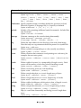
DASMx Version 1.30, 6th October 1999 A microprocessor opcode disassembler © Copyright 1996-1999 Conquest Consultants Introduction DASMx is a disassembler for a range of common 8-bit microprocessors. The following main processor families are supported: ❏ Motorola 6800 family and single chip variants (including Hitachi 630X devices); ❏ Motorola 6809; ❏ MOS Technology 6502 and Rockwell 65C0X; ❏ Zilog Z80; ❏ Sharp LR35902 (single chip Z80 variant as used in the Nintendo GameBoy); ❏ Intel MCS-80/85TM family (i.e. 8080 and 8085); ❏ Intel MCS-48TM family (i.e. 8048 et al); ❏ Intel MCS-51TM family (i.e. 8051 et al); ❏ Signetics 2650. The disassembler takes as input a binary code/data image file (typically a ROM image) and generates either an assembler source file or a listing file. DASMx is a multi-pass disassembler with automatic symbol generation. DASMx can optionally use a symbol file containing user-defined symbols and specifications of data areas within the source image. DASMx includes a powerful feature called code threading. Using known code entry points (e.g. reset and interrupt vectors) and by performing partial emulation of the processor, the disassembler is able to follow known code paths within a source binary image. Use of code threading, together with the multi-pass operation and symbol table management permits readable assembly code output from source images that contain large amounts of data (which tend to confuse most disassemblers). DASMx is copyright software. This version (1.30) may be distributed and used freely provided that all files are included in the distribution, no files are modified (including the distribution zip file) and no charge is made beyond that reasonable to cover copying (say 5 UK pounds). Historical note: Version 1.10 of DASMx superseded the Motorola 680x disassembler, dasm6800 (last released as version 1.00 on 25th January 1997). The change of name reflected the wide range of processors then covered. Page 1 Summarising, the key features of DASMx are: ❏ Disassembly of object code images for the following microprocessors: • Motorola 6800, 6802 and 6808; • Motorola 6801 and 6803; • Hitachi 6301 and 6303; • Motorola 6809 and Hitachi 6309; • MOS Technology/Rockwell 6502; • Rockwell 65C00/21 and 65C59; • Rockwell 65C02, 65C102 and 65C112; • Zilog Z80; • Intel 8080 and 8085; • Sharp LR35902 (i.e. GameBoy processor); • Intel 8048; • Intel 8051; • Signetics 2650. ❏ Multi-pass operation, with automatic symbol generation for jump, call and data target addresses; ❏ Code threading (used to automatically differentiate code from data); ❏ Control file containing user defined symbols, specifications of data areas and code entry points; ❏ Generation of full listing or assembler output file; ❏ Runs from the command line under Windows 95/98 or Windows NT/2000. Page 2 Version history Version Date Comments 0.90 28th July 1996 1.00 25th January 1997 1.10 16th July 1997 Third release (now renamed DASMx): 6502, Z80 and 8048 processor support added; minor improvements and bug fixes. 1.20 2nd April 1998 8080, 8085 and 2650 processor support added; improvements and bug fixes. 1.30 6th October 1999 First public release (as dasm6800): with support for 6800/6802/6808 only. Second release (as dasm6800): 6801/6803 and 6809 support added; other improvements in performance and listing output. 6301, 6303, 65C00/21, 65C29, 65C02, 65C102, 65C112, 8051 and LR35902 processor support added; wide listing format showing execution cycles; checksum and CRC-32 calculation; number format improvements; new symbol file directives; other improvements and bug fixes. The changes from version 1.20 are: ❏ Disassembly of Hitachi 6301 and 6303 added; ❏ Disassembly of Rockwell 65C00/21, 65C29, 65C02, 65C102 and 65C112 added; ❏ Disassembly of Intel 8051 added; ❏ Disassembly of Sharp LR35902 (GameBoy processor) added; ❏ Corrected documentation concerning Hitachi 6309 (which has, in fact, an identical instruction set to the 6809); ❏ Labelling and threading improvements for 8080, 8085 and Z80 disassembly (affects RST and indirect addressing instructions); ❏ Correction to instruction format for 2650 lodz/eorz/andz/…; ❏ New wide listing format showing execution cycles for each instruction; ❏ File size, checksum and CCITT CRC-32 calculated and shown in listing header; ❏ Auto number format determined by processor type (which can be overriden by a directive in the symbol file); Page 3 ❏ User messages can now be specified and generated from the symbol file; ❏ Symbol file includes (which may be nested) now permitted. The changes between versions 1.10 and 1.20 were: ❏ Disassembly of Intel 8080 and 8085 added (in addition to existing support for 8080 provided by Z80 disassembly); ❏ Disassembly of Signetics 2650 added; ❏ New symbol file command to skip areas of source image; ❏ Origin can now be specified in symbol file; ❏ New command line option to specify a single code entry point for threading; ❏ New command line option to list all processors supported; ❏ Fix to incorrect disassembly of 6801/6803 subd instruction (opcode 0x93); ❏ Bug fixes and other minor changes. The changes between versions 1.00 and 1.10 were: ❏ All references to "dasm6800" replaced by "DASMx"; ❏ Disassembly of 6502 added; ❏ Disassembly of Z80 added; ❏ Disassembly of 8048 added; ❏ Minor bug fix for code threading of 6801/6803 direct branch instructions; ❏ Minor changes to listing output; ❏ Bug fixes and other minor improvements. The changes between versions 0.90 and 1.00 were: ❏ Disassembly of 6801/6803 added; ❏ Disassembly of 6809 added; ❏ Define byte pseudo-op now generates full listing; ❏ Two new commands supported in symbol file: cpu (to select processor type) and addrtab (to define a table of addresses, each of which points to data); ❏ New command line switch to select processor type; ❏ Performance improvement to pass 1; ❏ Minor changes to listing output; ❏ Bug fixes and other minor improvements. Page 4 Copyright DASMx and all associated documentation are copyright Conquest Consultants. Disclaimer DASMx comes without any express or implied warranty. You use this software at your own risk. Conquest Consultants have no obligation to support or upgrade this software. Conquest Consultants cannot be held responsible for any act of copyright infringement or other violation of applicable law that results from use of this disassembler software. Distribution DASMx is copyright software. This version (1.30) may be distributed and used freely provided that all files are included in the distribution, no files (including the distribution zip file) are modified and no charge is made beyond that reasonable to cover copying (say 5 UK pounds). Conquest Consultants reserve the right to alter the free distribution and use terms for any future versions or derivatives of DASMx that may be produced. DASMx version 1.30 is distributed as file dasmx130.zip in the /msdos/disasm section of the Simtel and Simtel.net archives. Provided that the above distribution terms are adhered to, this file may be freely copied to and mirrored at other ftp and WWW sites. Operation Before describing the operation of DASMx in detail, here is an overview of how the disassembler will be typically used in practice. First, you must obtain a file containing a binary image of the code/data that you wish to disassemble. Typically, this will be from one or more ROMs or EPROMs that have been read using a PROM programmer. Some PROM programmers output data in a form of ASCII hexadecimal format (Intel and Motorola are two common formats). If that is the case, then you must use a conversion utility to generate a raw binary image. A good check that you have a correct binary image of a complete ROM is that the file length (shown by a DIR command) will be a Page 5 power of two and will correspond to the length of the ROM. For example, the file size of a complete image of a 27256 EPROM will be 32,768 bytes. Assuming at this stage that you do not know which areas of the binary image are code and which are data, it is sensible to use the code threading feature. For code threading to work, you must provide at least one code entry point. This requires code, vector or vectab entries in a symbol file. For example, if you are disassembling a ROM image from the uppermost region of the 6800 microprocessor address space, then four vector entries for the standard interrupt and reset vectors will be all that is initially required to provide the necessary entry points. You can also improve the readability of the disassembled output by defining symbols for all known hardware addresses (e.g. PIA registers and other ports). Try modifying one of the supplied example symbol files to suit your application. It is important that the correct processor type is specified using a cpu directive in the symbol file (or by command line switch). The disassembler will not make much sense of Z80 code if it thinks that the processor is a 6502! Run the disassembler with code threading. This will identify all known areas of code. Data and unknown areas will be listed as byte data rather than disassembled into instruction mnemonics. Due to limitations of the code threading process (see below) not all code areas may be identified. Any additional code entry points or address vector tables can be added to the symbol file. Similarly, areas of byte, word or string data that can be identified from examination of the disassembly listing can also be recorded in the symbol file. Using a repeated "disassemble, inspect listing, update symbol file" cycle a comprehensive disassembly of an image can be built up quite quickly. Finally, if you are satisfied that you have identified all main data areas, try disassembling without code threading. This will help pick up areas of code that may have been missed by the code threading and subsequent manual investigation process. Platform DASMx is a Win32 console application. This means that it is a 32-bit application that requires Windows 95/98/Millenium or Windows NT/2000 to run. Typically, you will run the disassembler from a DOS box command line. Page 6 Command line options DASMx has the following command line options: -a generate assembler output (default is to generate a full listing file); -cTYPE set the CPU processor type – overrides any cpu statement in the symbol file, where TYPE is one of the types reported by the -l option (6800, 6809, 6502, Z80 etc.) (default is 6800); -eNNNN specify a code entry point NNNN for threading; -l list all processors supported and exit; -oNNNN set the origin, or start address to NNNN (default is top of address space less the length of the source image); -t perform code threading (requires at least one code entry point to be specified); -v display version information and exit; -w wide listing format (shows instruction cycles and up to 8 data bytes per line). When specifying addresses, the number NNNN should be specified using C language conventions (i.e. default is decimal, prefix with 0x for hex, prefix with 0 for octal). Input files The primary input file is a binary image of the code/data to be disassembled. This must be code for one of the supported microprocessors (or other manufacturer equivalent). DASMx will produce meaningless output for any other type of processor. DASMx assumes a file extension of ".bin" unless otherwise specified for the binary image file. DASMx looks for a symbol file of the same base name as the source binary file, but with a ".sym" file extension. If a symbol file is found, it will be used. Provision of a symbol file is optional, except where code threading is used (where a symbol file must be used to define at least one code entry point). Page 7 Symbol file syntax The symbol file is a plain text file that may be created/modified with any text editor. The file contains lines that fall into one of three categories: ❏ comment lines; ❏ command lines; ❏ blank lines. Comment lines are denoted by ';' as the first non-whitespace character on the line. Command lines start with one of the specified keywords. Parameters follow the command keyword, separated by spaces or tabs. A comment may be added to the end of a command, preceded by the ';' character. Blank lines are ignored. Number value parameters may be given in decimal (the default), octal or hex using standard C language conventions (e.g. 0x prefix for hex). The symbol file command syntax contains an include directive which allows one symbol file to be included within another. Included files may be nested to any practical depth. A particular use of this feature is to have a symbol file containing a generic set of defintions for a processor or item of hardware. This can then be included within a symbol file with additional definitions for a specific software image that runs on that processor/hardware. The pair of example files, gameboy.sym and tetris.sym, shows this in action with generic GameBoy definitions in one file and specific defintions for a tetris game cartidge in the other. Valid command keywords and their meaning are summarised in the table below. Page 8 Command Function/syntax cpu Specify the processor type. Syntax: cpu 2650 | 6502 | 65C00 | 65C59 | 65C02 | 65C102 | 65C112 | 6301 | 6303 | 6800 | 6801 | 6802 | 6803 | 6808 | 6809 | 8048 | 8051 | 8080 | 8085 | Z80 | LR35902 numformat Specify number format (overriding default for processor) as Intel, Motorola, Signetics, C language hex (i.e. 0x prefix) or decimal. Syntax: numformat I | M | S | C | D include Include a file containing additional symbol commands. Include filess may be nested. Syntax: include <filename> message Generate a message to the console during disassembly. Syntax: message "<message string>" or: message <word1> [<word2> <word3> ...] org Define the start address for the first byte of the code/data image. Note that only one org statement should be present in a symbol file. Syntax: org <address> symbol Define a symbol corresponding to a value (usually an address). Syntax: symbol <value> <name> vector Define a location that contains a word pointing to a code entry (for example, the reset entry point). Syntax: vector <address> <vector name> [<destination name>] vectab Define a table of vectors (i.e. a jump table) of length <count>. Each vector will be used as a code entry point if threading is used. Syntax: vectab <address> <name> [<count>] code Define a code entry point (for code threading). Syntax: code <address> [<name>] byte Define a single data byte, or <count> length array of bytes. Syntax: byte <address> <name> [<count>] word Define a single data word, or <count> length array of words. Syntax: word <address> <name> [<count>] addrtab Define a table of addresses, which point to data, of length <count>. Syntax: addrtab <address> <name> [<count>] string Define a single data character, or <count> length string of chars. Syntax: string <address> <name> [<count>] skip Skip (i.e. omit from disassembly and listing) <count> length data bytes. Syntax: skip <address> <count> Page 9 Output files By default, DASMx generates a disassembly listing file. This is similar to the full listing file generated by most assemblers. Optionally, DASMx can be made to produce an assembly file instead. This could then be used as a source file to an assembler of your choice (with certain provisos concerning pseudo-ops and number formats noted later). As an aid to readability, DASMx inserts a comment line after all breaks in a sequence of instructions (e.g. after an unconditional branch or jump, or a return from subroutine). Comment lines are also inserted between code and data areas. This use of comment lines breaks the output listing into identifiable sections and aids manual inspection of the resultant disassembly listing. Note that output files tend to be large. For example, a 32 Kbyte ROM image will generate a listing file of around half a megabyte in length. The output file is named based upon the name of the source image file, but with a file extension of ".lst" for the list file or ".asm" for the assembly output file. Listing file The list file format is largely self-explanatory. Program counter and code/data byte values are given in hex. Code/data is also shown as ASCII characters (where printable) as an aid to identifying strings within the binary image. If the wide listing format is selected then instruction cycle counts are also given for every instruction. Instruction cycles are shown within [square braces]. If an instruction takes a variable number of cycles to execute (e.g. a conditional branch on many processors) then two values are shown: the minimum and the maximum. Code threading Code threading is a very powerful feature that will automatically identify known areas of code. It can prove particularly useful in the early stages of disassembly of an image that contains large areas of data. Such data areas would otherwise be disassembled incorrectly as code and would add many erroneous symbols to the symbol table. Code threading works by performing a partial emulation of the processor; executing instructions starting from one or more known entry points. Code threading follows calls to subroutines and conditional and unconditional branches. In certain cases, the code threading may fail to follow certain code paths (i.e. leaving valid code still defined as data). The following are examples of where the code threader will fail to follow a correct execution path: Page 10 ❏ pushing an address onto the stack and then, later, performing a return from subroutine instruction (i.e. as a method of performing a jump); ❏ performing an indexed branch instruction (e.g. using addresses taken from a vector table); ❏ use of undocumented instruction opcodes – since threads are abandoned when an invalid opcode is detected; ❏ self-modifying code. Indexed branch instructions are highlighted in the output listing by automatically generated comments. These are an indication that you need to manually identify what the contents of the index register will be prior to the branch (often obvious – look for a preceding load index register instruction.) Then, you can add a code or a vectab entry to the symbol file and repeat the disassembly. In rare cases, code threading may incorrectly identify data as code: ❏ A call to a subroutine that never returns (e.g. the subroutine discards the return address); the other side of the call containing data rather than code. ❏ A conditional branch that is always, or never, executed (and the other side of the branch contains data rather than code). Normally this latter scenario is pretty unlikely and requires a particularly perverse programmer of the original code. However, it is a technique that may be encountered on those processors which had a "better" (i.e. fewer cycles and/or fewer bytes) conditional jump than unconditional jump. So, in general, code threading will identify guaranteed known areas of code that may be a subset of the overall actual code. Most of the above problem areas can be dealt with by manual inspection of the disassembly listing and subsequent additions to the symbol file. A thread of execution will be abandoned for one of two reasons. If a branch or subroutine call is made outside the address range corresponding to the source image then that thread is not followed. Also, if an invalid instruction is detected then the thread terminates immediately. This will produce a command line error message identifying the address where the problem occurred. Normally this represents an error condition that can be corrected by the person operating the disassembler: ❏ the processor type is incorrectly specified; ❏ the source binary image is not real code; ❏ an incorrect code entry point has been supplied; ❏ so called "undocumented" instructions have been used. In rare cases, the original programmer may have done something that causes the code threader to incorrectly identify data as code. These cases may also result in invalid instruction messages. Page 11 Microprocessor specifics The following sub-sections detail items of note relating to disassembly for the specific microprocessors (and their variants) supported by DASMx. Motorola 6800, 6802 and 6808 The Motorola 6800, 6802 and 6808 share an identical instruction set. Assembler mnemonics follow the Motorola standard definitions (see reference [1]). Note that there are two common styles for instructions involving the A and B registers: ❏ the A or B register name is separated by whitespace from the base instruction (e.g. lda b value); ❏ the A or B register name is used as a suffix to the instruction mnemonic (e.g. ldab value). DASMx uses the latter style. This point also applies to the 6801/6803 and 6809 mnemonics generated by the disassembler. Motorola 6801 and 6803 The Motorola 6801 and 6803 share an identical instruction set that is an object code compatible superset of that of the base 6800. These processors contain on-chip timer and I/O plus an expanded interrupt vector area over that of the 6800. Definitions for these in a symbol file will be useful for disassembly of any 6801/6803 code. See the supplied 6803 symbol file, ebcgame.sym, for an example that could be used as a template for other 6801/6803 disassembly. Hitach 6301 and 6303 The Hitachi 6301 and 6303 are enhanced versions of the Motorola 6801/6803 with an enhanced object code compatible instruction set. Differences include a few additional instructions and pipelining that improves some instruction times. Motorola 6809 and Hitachi 6309 The Motorola 6809 has an instruction set that is compatible with that of the 6800 at the assembler level (i.e. it is not binary compatible, but every 6800 instruction mnemonic is present in the 6809 instruction set). The 6809 also has many additional instructions that are not present in the 6800. The Hitach 6309 is a CMOS version of the 6809 (which is fabricated using NMOS technology) that shares an identical instruction set. Consequently, setting the processor type to 6809 may correctly disassemble 6309 code. Page 12 MOS Technology/Rockwell 6502 The MOS Technology/Rockwell 6502 has a similar instruction set to that of the 6800 (but totally opcode incompatible). A number of 6502 variants, with expanded instruction sets and addressing capabilities have appeared over the years. DASMx copes with some, but not all, of these variants (see next sections). If you know that a processor is based on the 6502 architecture, but are unsure of the variant then try disassembling with the CPU type set to 6502, 65C02 and 65C00. Inspect the results and select whichever gives the most intelligent disassembly. [Tip: try this with code threading and select the processor that gives least threading errors.] Rockwell 65C00/21 and 65C29 The Rockwell 65C00/21 and 65C29 each contain two enhanced CMOS 6502 CPU cores plus on-chip masked ROM, RAM, two timers and general purpose I/O. Instruction set differences over the basic NMOS 6502 include new instructions for unsigned multiply, memory bit set and reset, branch on bit set/reset, unconditional branch and push/pop for the index registers. With the exception of the multiply instruction, these new instructions are a subset of the additional instructions in the 65C02. Note that the CPU type for the 65C00/21 should be specified as 65C00 (i.e. without the trailing "/21"). Rockwell 65C02, 65C102 and 65C112 The Rockwell 65C02 is an improved version of, and object code compatible with, the original NMOS 6502 with twelve new basic instructions (giving 59 new opcodes with variants). The 65C02 is pin compatible with the original 6502. The 65C102 is similar, but with minor pinout differences to provide for multi-processor bus operation. The 65C112 has no internal clock oscillator and is designed as a slave processor to the 65C102. The extra instructions include all of the additions found in the 65C00/21 and 65C29 dual processors – with the exception of the multiply instruction found in those devices. Zilog Z80 The Zilog Z80 (also made by Mostek, Sharp, NEC and other second sources) has an instruction set that is binary compatible with that of the Intel 8080, but with many additional instructions. Although each 8080 instruction has an identical Z80 instruction, Zilog chose to use a different mnemonic style for almost every instruction. Consequently, Z80 assembler (even if restricted to the 8080 subset) appears quite different even though the resulting binary image is identical. Page 13 The Z80 has a great many (so called) undocumented instructions that (sometimes) perform useful functions. DASMx does not currently support these additional instructions. Like the 6502, the Z80 has spawned many variants with opcode compatible instruction supersets. DASMx can be used on code for these devices with the standard caveat that any of the new instructions will not be disassembled as valid code (and therefore code threading is not advised.) Sharp LR35902 (GameBoy processor) The Sharp LR35902 is the processor used in the hugely popular Nintendo GameBoy. This processor is a single chip variant of the Zilog Z80. The instruction set is based on a subset of that of the Z80 but with some additional instructions. Of those instructions that are shared with the Z80, most are opcode compatible but there are a few differences. As a single chip microcontroller, the LR35902 contains various on-chip I/O and timer functions. These are accessed through a 256 byte memory page starting at address 0xFF00. The supplied file, gameboy.sym, contains a set of known symbol definitions for these memory mapped registers. This generic GameBoy processor symbol file may be included in the main symbol file for the disassembly of a specific binary image. The supplied tetris.sym file shows an example of this. WARNING: unlike all the other processors supported by DASMx, it has not been possible to obtain official manufacturer's data on the Sharp LR35902. The information used is derived from a number of different public domain documents – some of which conflict over certain details. Consequently, the LR35902 disassembly should be considered provisional and potentially subject to error. If anyone has access to genuine Sharp (or other official) data on this device please contact the author: pclare@bigfoot.com. Intel MCS-80/85™ (8080 and 8085) The Intel 8080 and 8085 share an almost identical instruction set. The Intel 8085 is an enhanced version of the 8080, with two additional instructions (rim and sim) used to control new serial in and out pins and interrupt inputs. When disassembling 8080 (and, with provisos, 8085) code the user has the option of generating either Intel or Zilog mnemonics. To generate Intel mnemonics, simply specify the CPU type to be 8080 or 8085 as required. Page 14 Generating Zilog Z80 style mnemonics from Intel 8080 code is possible because the 8080 has an instruction set that is a compatible binary subset of those of the Z80. Simply specify the CPU type is as Z80 and DASMx will correctly disassemble 8080 code into Zilog mnemonics. This will not suit Intel assembler die-hards, but may be preferred by those more familiar with the Z80. WARNING: if DASMx is used as a Z80 disassembler on 8085 code and either of the two 8085 specific instructions are used (rim and sim) then problems will result. In such cases Zilog disassembly is probably best avoided. If you really must have Zilog mnemonics then read the following description of how these instructions are handled and be prepared for code threading to work incorrectly. rim is a one byte instruction, but DASMx will attempt to disassemble this as the two byte jr nz Z80 instruction. This will both generate a false label and ignore the next byte in the 8085 opcode stream. Since that could be the first byte in a multi-byte opcode it could take a number of erroneously disassembled instructions before synchronisation is achieved. sim is a one byte instruction that will be disassembled as the first byte of the three byte ld hl immediate instruction. The results will be similar to those for rim. Intel MCS-48™ family (8048 etc.) DASMx will disassemble opcodes for the following Intel MCS-48™ family devices (and equivalents from second source manufacturers): 8021, 8022, 8035, 8039, 8041, 8741, 8048, 8049 and 8748. The CPU type should be set to 8048 and the term "8048" is used throughout this documentation to refer to this family of devices. The 8021 instruction set is a much reduced subset of the full 8048 set of instructions. The 8022 has a very similar instruction set to the 8021, but with slightly more of the 8048 instructions and a few new instructions to handle the on-chip analogue to digital converter. The 8041/8741 has almost the same instruction set as the 8048, but with just a few instructions missing. DASMx can disassemble code for the 8021, 8022, 8041 and 8741 variants with the caveat that data areas may be disassembled as 8048 instructions that are in fact illegal on the variant. The 8048 jump and call instructions operate on an 11-bit address (i.e. within a 2 Kbyte memory bank). A memory bank select bit (controlled by the sel mb0 and sel mb1 instructions) is combined with the 11-bit jump/call address to give full 12-bit addressing within the 4 Kbyte address space of the 8048. This presents a problem for the code threading and automatic label generation functions of DASMx since a destination address can only be fully calculated if the last memory bank select operation is known. Tracking the state of the memory bank select bit is Page 15 currently beyond the capabilities of DASMx. For this reason, it is advised that code threading be not used if the size of the 8048 source image exceeds 2 Kbytes. If images greater than this are disassembled, even with threading disabled, some errors in automatically generated labels may be expected. Intel MCS-51™ family (8051 etc.) Intel introduced the 8051 to provide an upgrade path from the 8048. It would do all that the 8048 would do and more. The heritage of the 8048 is obvious in the architecture and instruction set of the 8051. Like the 8048, the 8051 was initially available in a number of variants (e.g. 8031 and 8751). Subsequently, many further variants of the 8051 have been produced by Intel and by other manufacturers. Some of these added to the instruction set. DASMx will only correctly disassemble code for the original 8051 devices that shared the MCS-51™ instruction set. Signetics 2650 The Signetics 2650 is a rather oddball processor when compared to most other processors handled by DASMx. It operates on 8-bit data and can address 32,768 bytes of memory organised in four pages of 8,192 bytes each. It has a large range of addressing modes, made possible by the use of bits encoded in the second byte of two and three byte instructions. It has a 3-bit stack pointer which means that subroutines can be nested to, at most, eight deep. Assembler pseudo operations Assembler pseudo operations (e.g. that to define a data word) are not in a standard style that matches the chosen processor. The pseudo-ops are common across all processor disassembly output. In general, the pseudo-ops follow Intel conventions: ❏ the ';' character to denote a comment; ❏ the ':' character following a label; ❏ db, to define a data byte, character or string; ❏ dw, to define a data word; ❏ org, to specify a starting address. If these do not suit your preferred assembler, then use of search and replace in a text editor can probably effect the required changes. Page 16 Number format Microprocessor manufacturers have chosen a variety of different formats for representing hexadecimal numbers. [Some sort of formatting is essential, otherwise a hex number starting with an alpha character could be confused with a label or symbol name.] DASMx supports five different hex number format styles. These are summarised in the table below, with an example in each case for the hex number F12C. Number format numformat parameter Example Intel I 0F12CH Motorola M $F12C Signetics S H'F12C' C language C 0xF12C Decimal D 61740 DASMx chooses a default number format according to the CPU type setting. The default choice can be overriden by a numformat statement in the symbol file. The number format defaults for the processors supported by DASMx are given in the following table. Page 17 Manufacturer Signetics MOS Technology Rockwell Rockwell Rockwell Rockwell Rockwell Hitachi Hitachi Motorola Motorola Motorola Motorola Motorola Motorola Intel Intel Intel Intel Zilog Sharp cpu parameter 2650 6502 65C00 65C02 65C29 65C102 65C112 6301 6303 6800 6801 6802 6803 6808 6809 8048 8051 8080 8085 Z80 LR35902 Format Signetics Motorola Motorola Motorola Motorola Motorola Motorola Motorola Motorola Motorola Motorola Motorola Motorola Motorola Motorola Intel Intel Intel Intel Intel Intel The number formatting applies to all operands in disassembled instructions with the exception of small positive or negative offsets in 6809 index instructions. These are given as a signed decimal number. Future enhancements Whilst there is no guarantee that future versions of this disassembler software will be released, some or all of the following areas are likely to receive attention in any future version: ❏ fixing any errors discovered in the instruction mnemonics or disassembly of an opcode to its instruction; ❏ rationalisation of the pseudo-ops such that the assembler output can be fed directly into at least one common assembler without further text editing; Page 18 ❏ improved code threading (through use of a more complete emulation of the processor); ❏ improved symbol table output in listing file; ❏ specifying comments in the symbol file for inclusion in the output files; ❏ additional memory map output in listing file; ❏ better support for 8048 code greater than 2 Kbytes and for 8048 variants; ❏ support for additional microprocessors; ❏ support for further variants of the currently supported processors; ❏ disassembly of commonly known "undocumented" instructions. Fixing actual disassembly errors (if any are discovered) will be treated with priority. Note that it is not currently intended to support platforms other than Windows 95/98/Millenium or Windows NT/2000. In particular, there will be no 16-bit versions for DOS or any other 16-bit operating systems. If the demand exists, a Linux version may be produced. Contacting the author Feedback to Conquest Consultants may be made via pclare@bigfoot.com. References The following publications were referred to in the course of the development of DASMx. This may also be considered to be a useful reference list for anyone programming these processors at assembler level and/or inspecting the output of DASMx. [1] M6800 Microprocessor Applications Manual, Motorola Semiconductor Products Inc., First Edition, 1975. [2] Hitachi Microcomputer Databook 8-bit HD6800 & 16-bit HD68000, Hitachi Ltd., March 1983. [3] Programming the 6502, Rodnay Zaks, Sybex, ISBN 0-89588-046-6, Third Edition, 1980. [4] 6502 Assembly Language Programming, Lance A.Leventhal, Osborne/McGraw-Hill, ISBN 0-931988-27-6, 1979. Page 19 [5] 6502 Assembly Language Programming, Second Edition, Lance A.Leventhal, Osborne/McGraw-Hill, ISBN 0-07-881216-X, 1986. [6] R650X and R651X Microprocessors (CPU), Rockwell, 29000D39, Data Sheet D39, Revision 6, February 1984. [7] MCS6500 Microcomputer Family Programming Manual, MOS Technology Inc., Second Edition, Publication Number 6500-50A, January 1976. [8] 1984 Data Book, Semiconductor Products Division, Rockwell International, March 1984. [9] TLCS-Z80 System Manual, Toshiba, 4419 '84-05(CK), June 1984. [10] Microcomputer Components Databook, Mostek, MK79778, July 1979. [11] Z80-Assembly Language Programming Manual, Zilog, 03-0002-01, Rev B, April 1980. [12] The MCS-80/85 Family User's Manual, Intel, ISBN 1-55512-009-1, 1986. [13] MCS-48TM User's Manual, Intel, 9800270D, July 1978. [14] 48-Series Microprocessors Handbook, National Semiconductor, 1980. [15] Component Data Catalog, Intel, 1980. [16] An Introduction to Microcomputers: Volume 1, Basic Concepts, Second Edition, Adam Osborne, Osborne/McGraw-Hill, ISBN 0-931988-34-9, 1980. [17] Osborne 4 & 8-Bit Microprocessor Handbook, Adam Osborne & Gerry Kane, Osborne/McGraw-Hill, ISBN 0-931988-42-X, 1980. [18] 2650A/2650A-1 Data Sheet, Signetics. Page 20