1
P73335u_UPS_man.qxd
4/30/01
12:19 PM
Page 1
UK
En
UPS
Uninterruptible Power Supply
Fr
Onduleur
Dispositif d'alimentation sans coupure
USV
Unterbrechungsfreie Stromversorgung
FOR MODELS:
F6C700-EUR/F6C1000-EUR/F6C1400-EUR
POUR LES MODELES :
F6C700-EUR/F6C1000-EUR/F6C1400-EUR
FÜR DIE MODELLE
F6C700-EUR/F6C1000-EUR/F6C1400-EUR
User Manual
Manuel de l'utilisateur
Benutzerhandbuch
P73335
De
P73335u_UPS_man.qxd
4/30/01
12:19 PM
Page 2
P73335u_UPS_man.qxd
4/30/01
12:19 PM
Page 3
Language Table of Contents
UK
En
English . . . . . . . . . . . . . . . . . . . . . . . . . . . . . . . . . . . . . . . . . . . . 1
Français . . . . . . . . . . . . . . . . . . . . . . . . . . . . . . . . . . . . . . . . . . 29
Fr
Deutsch . . . . . . . . . . . . . . . . . . . . . . . . . . . . . . . . . . . . . . . . . . .59
De
P73335u_UPS_man.qxd
4/30/01
12:19 PM
Page 4
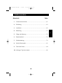
Table of Contents
Section
Page
1.
Safety Instructions ..........................................................................1
2.
Introduction ....................................................................................3
3.
Installation ......................................................................................9
4.
Operation......................................................................................11
5.
Maintenance..................................................................................16
6.
Replacing Battery..........................................................................16
7.
Troubleshooting ............................................................................19
8.
Communication Interface..............................................................21
9.
Specifications ................................................................................24
10. Appendix A: Typical Run Time......................................................26
P73335u_UPS_man.qxd
4/30/01
12:19 PM
Page 1
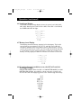
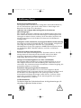
1. Important Safety Instructions
En
1-1 TUV Safety Instruction
• Please observe the following precautions to ensure personnel safety and
reliable equipment observation:
• The sound pressure level at the operator’s position according to IEC
704-1:1982 is equal to or less than 70dB(A).
For installation:
• The unit should be installed by service personnel only.
• Upon installation, it should be ensured that the sum of leakage current
of the UPS and the connected equipment does not exceed 3.5mA.
• The socket outlet should be located near the equipment and
easy to access.
Other safety instructions:
• The UPS contains electrical voltage which makes it potentially hazardous.
All repairs should be performed by qualified service personnel. The UPS
has its own internal energy source (battery). The output receptacles may
be alive even when the UPS is not connected.
• When replacing batteries, always use the same type and quantity as the
previous one. Batteries of GP1270-F2(CSB 12V/7AH*2) for 450VA and
700VA; GP12110-F2(CSB 12V/11AH*2) for 1000VA, and GP12170-B1
(CSB 12V/17AH*2) for 1400VA models.
• Do not dispose the battery or batteries in fire as they may explode.
• Do not open or mutilate the battery or batteries as released electrolyte
is toxic and harmful to skin and eyes.
• A battery can present a risk of electric shock and high short circuit current.
The following precautions should be observed when working on batteries:
• Remove watches, rings, or other metal objects.
• Use tools with insulated handles.
• The equipment is to be operated by fully trained personnel.
1
P73335u_UPS_man.qxd
4/30/01
12:19 PM
Page 2
Safety Instructions (continued)
EC Conformity Declaration
The devices comply with the following regulatory guidelines:
• 73/23/EEC guideline of the Council for Approximation of the Legal
Regulations of the EC Countries concerning the electrical apparatus within
certain voltage tolerances, modified by the guideline RL 93/68/EEC of
the Council.
• 89/336/EEC guideline of the Council for Approximation of the Legal
Regulations of the EC Countries concerning the electromagnetic
compatibility, modified by the guidelines RL 91/236/EEC and 93/68/EEC
of the Council.
The compliance with the following standards provides the conformity:
EN 50091-1-1
EN 55022, class B
2
P73335u_UPS_man.qxd
4/30/01
12:19 PM
Page 3
2. Introduction
En
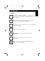
2-1 SYMBOLS
PROTECTIVE GROUNDING TERMINAL: A terminal that must be
connected to earth ground prior to making any other connection
to the equipment.
A terminal to which or from which an alternating (sine wave)
current or voltage may be applied or supplied.
A terminal to which or from which a direct current or voltage may
be applied or supplied.
This symbol indicates the word "phase".
This symbol indicates the principal on/off switch is in the
ON position.
This symbol indicates the principal on/off switch is in the
OFF position.
May be used in lieu of the wording "Caution Risk of Electric
Shock" for any cautionary marking.
3
P73335u_UPS_man.qxd
4/30/01
12:19 PM
Page 4
Introduction
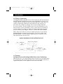
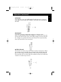
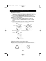
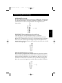
2-2 Theory of Operation
The Regulator PRO™ NetUPS Series is a line-interactive UPS with Automatic
Voltage Regulation (AVR) that provides clean and reliable AC power to the
computer system through the input and output EMI filter, surge suppressor
and line-conditioning transformer (autotransformer) that can boost or
buck-down line voltage according to the AC input voltage amplitude.
In normal condition, the UPS supplies power from the utility power to the
load (computer system, workstation, server or other device). The bilateral
converter works as a charger to charge the battery and at the same time
keeps the battery fully charged. This term is called "ON UTILITY MODE".
When utility power fails, the converter supplies AC power to the load by
transferring power coming from the batteries. This term is called "ON
BATTERY MODE". The UPS supplies regulated power, shutdown results
when battery power becomes low.
BLOCK DIAGRAM OF LINE INTERACTIVE UPS
AVR: Auto Voltage Regulator
Utility
EMI filter &
Surge
Suppressor
BATTERY
EMI filter &
Surge
Suppressor
Bi-lateral
converter
AC
OUTPUT
2-3 Features
Intelligent Boost and Intelligent Buck-Down Line-Conditioning
When brownout or over utility voltage is detected, the boost and buck-down
line-conditioning will automatically adjust the incoming voltage and deliver a
regulated AC power to the equipment connected to the UPS.
4
P73335u_UPS_man.qxd
4/30/01
12:19 PM
Page 5
Introduction (continued)
User replaceable battery
The Regulator PRO™ NetUPS Series has a "user-replaceable battery
function" so that users can easily swap the batteries inside the UPS by
themselves. Battery replacement procedures are described in section 6.
Charging current with low ripple and harmonics
A special controlled circuit is used to provide charging current with PFC
(Power Factor Correction). This reduces the conducted electro-magnetic
interference to other facilities sharing the same distribution panel with your
UPS and therefore extends the battery life of the UPS.
Intelligent communication interface and powerful network
support capability
The built-in communication interface (RS-232 and dry contact) allows you to
control and manage your UPS via powerful Belkin Sentry Bulldog Shutdown
Management Software. Moreover, an optional built-in SNMP accessory slot
lets your Regulator PRO™ NetUPS be easily managed through a network.
User-friendly interface
You can instantly assess the status of your UPS without pushing any button.
The LED display provides complete and easy to understand information,
such as load level, battery level, intelligent boost, intelligent buck-down,
on battery, replace battery, and overload.
Optional network surge protection
The Regulator PRO™ NetUPS Series provides built-in Novell network cable
(RJ-45) jacks. These jacks protect your hardware from surges and spikes that
travel along communication lines. They protect from all potential damage as
a result from surges, spikes, and line-noise.
2-4 Annotation
The two signs shown below indicate that important instructions need to
be followed:
5
En
P73335u_UPS_man.qxd
4/30/01
12:19 PM
Page 6
Introduction (continued)
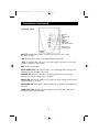
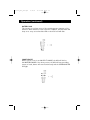
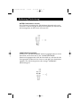
2-5 Front Panel
ON-TEST
OFF
ON BATTERY
BUCK
NORMAL
BOOST
OVERLOAD
REPLACE BATTERY
LOAD LEVEL
BATTERY LEVEL
ON/TEST: Pressing the button activates two functions. One is ON,
the other is TEST.
*ON: Pressing the button on the UPS and power the load.
*TEST: To activate UPS self-test. It can verify both the operation of the UPS
and the condition of the battery.
OFF: To turn off the UPS.
BUCK-DOWN LED: Indicates the UPS is correcting high utility voltage and
offering a normal voltage to the load.
NORMAL LED: Indicates the UPS is supplying utility power to the load
without affecting the utility power condition.
BOOST LED: Indicates the UPS is correcting low utility voltage and offering a
normal voltage to the load.
OVERLOAD LED: Indicates the UPS exceeds the acceptable rated capacity of
the UPS.
LOAD LEVEL LED: Displays the percentage of the loads (20%, 40%, 60%,
and 80%) connected to the UPS.
6
P73335u_UPS_man.qxd
4/30/01
12:19 PM
Page 7
Introduction (continued)
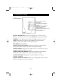
ON BATTERY LED: Indicates the UPS is supplying the load from the
battery power.
REPLACE BATTERY: Indicates the UPS battery is no longer useful and must
be replaced immediately.
BATTERY LEVEL LED: Displays the remaining percentage of battery capacity
(25%, 50%, 75%, and 100%).
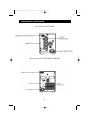
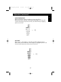
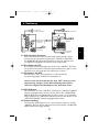
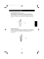
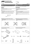
2-6 Rear Panel
OUTPUT RECEPTACLES: The UPS supplies AC power to the load via
these receptacles.
BREAKER: This is used to prevent high-input current from reaching the UPS.
INPUT RECEPTACLE: AC input utility power supplies to the UPS
via the receptacle.
SNMP SLOT: A SNMP adapter can be plugged into this port for managing
UPS on the network.
TVSS SURGE PROTECTOR: This connector is used for protecting the
transmission line of the Ethernet card from surges, line-noise, and spikes.
COMMUNICATION INTERFACE (RS-232/DRY CONTACT): The communication
port is used to allow the PC and the UPS to communicate. Please refer to
section 8 for more information.
7
En
P73335u_UPS_man.qxd
4/30/01
12:19 PM
Page 8
Introduction (continued)
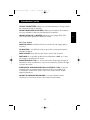
Rear panel of F6C700-EUR
Rear panel of F6C1000-EUR/F6C1400-EUR
8
P73335u_UPS_man.qxd
4/30/01
12:19 PM
Page 9
3. Installation
En
3-1 Unpacking
• Please read this user manual before installing the UPS.
• This UPS contains batteries that are potentially hazardous to the user,
even when the UPS is not connected to the utility power.
• All repairs should be performed by qualified service personnel.
• Before unpacking the UPS, check the packing box. If there is any visible
damage, contact your dealer at once.
3-2 Before Installation
• Avoid exposing the UPS to direct sunlight or other heat source.
The UPS should be facing away from direct sunlight glare.
• Choose a well-ventilated area to position your UPS to allow adequate
dissipation of heat.
• Ensure that the UPS surrounding area is clean and free from moisture.
• Do not put heavy objects on the cable or power cord.
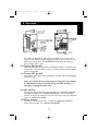
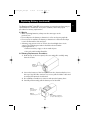
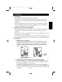
3-3 Installation
1. Connecting to utility power
Belkin Sentry Bulldog Shutdown Management Software and RS232
cables can be used with this UPS. To use, connect the interface cable
to the computer interface port on the back panel of the UPS and
then connect the cable to the serial port on your PC.
F6C1000-EUR/F6C1400-EUR
F6C700-EUR
9
P73335u_UPS_man.qxd
4/30/01
12:19 PM
Page 10
Installation (continued)
2. Charging the battery
The battery charger of the UPS automatically charges the battery
whenever the power cord of the UPS is connected to a normal
utility power.
When the UPS is running for the first time, charge the UPS for
at least six hours to ensure batteries inside are fully charged
before operation.
You may immediately use the UPS without having to wait for the
batteries to be fully charged. However, it is advisable not to do this
as the UPS will have a shorter back-up time than expected if such
action is taken.
3. Connecting the load
Calculate the power consumption of your loads to ensure that an
overload condition will not happen.
Plug the equipment into the output receptacles on the rear
panel of the UPS.
Turn on the equipment connected to the UPS.
Caution: Do not connect a laser printer to the UPS.
4. Connecting the RS-232/DRY CONTACT
Connect the interface signal cable between the RS-232/DRY Contact
port on the rear panel of UPS and COM1 or COM2 of the computer
if necessary.
The DB-9 connector can work as a dry contact or RS-232
communication port depending on the type of cable and software
used. Refer to section 8 of the communication interface for
more information.
10
P73335u_UPS_man.qxd
4/30/01
12:19 PM
Page 11
En
4. Operation
En
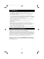
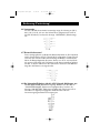
4-1 Cold Start when utility is not present
Even with the absence of utility power, the UPS can be turned "On".
Just push the ON/TEST button and wait for about two seconds for the
UPS to be turned "On". The INVERTER LED will light followed by a
beep and the UPS is "On".
4-2 Turning 'ON' the UPS
Under normal utility power, push the ON/TEST button for the UPS to be
turned "On". Once the UPS is "On", it will emit a beep and then supply
power to the loads.
4-3 Turning 'OFF' the UPS
Pressing the "Off" button will immediately stop the UPS from supplying
power to loads.
Note: It is possible that the utility power is still present even though
the OFF button has been pressed. To fully turn OFF the UPS, it is
advisable to unplug the power cord.
4-4 UPS Self-Test
Pressing the ON/TEST button when the UPS is in "ON UTILITY MODE"
will make the UPS shift to "ON BATTERY MODE" and automatically
perform a self-test for about 10 seconds. After the self-test, the UPS will
return to "ON UTILITY MODE".
4-5 Silence Function
The buzzer can be turned "On" or "Off" by toggling the ON/TEST
button when the UPS is in "ON BATTERY MODE".
11
P73335u_UPS_man.qxd
4/30/01
12:19 PM
Page 12
Operation (continued)
4-6 Load Level Display
The 4-LED load percentage display shows the power level (20%, 40%,
60%, 80%) drawn by the loads from the UPS. If the UPS is overloaded,
the OVERLOAD LED will light.
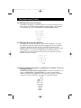
4-7 Battery Level Display
This display shows the battery capacity left in the battery. The level is
represented by percentages of 25, 50, 75, and 100. These LED will
extinguish gradually when using battery power. When battery capacity
reaches the minimal level of 25%, the lowest LED (25%) blinks and there
is an immediate need to charge the battery. Under this condition, the
battery can only supply less than five minutes of run time for the load.
4-8 If certain abnormal conditions occur, the UPS will send the
following messages:
ON BATTERY MODE: When the UPS is in ON BATTERY MODE, the ON
BATTERY LED will light, preceded by a beep every two seconds, and
then the UPS will start supplying power to the load through the battery.
12
P73335u_UPS_man.qxd
4/30/01
12:19 PM
Page 13
Operation (continued)
OVERLOAD:
If an overload occurs, the OVERLOAD LED will light and a continuous
beep will be heard. Under this condition, check the load connected to
the UPS.
BUCK/BOOST:
If the UPS encounters a high utility voltage, the function of the
buck is to automatically curtail this voltage to a normal level. In the case
that the UPS should come upon a low utility voltage, the boost will raise
the voltage to a normal level. These two functions are represented by
their respective LED on the front panel.
BATTERY REPLACE:
This function is to alert users of the need to replace the batteries. When
the microprocessor in the UPS detects battery fault, the UPS alarm will
give out three beeps. Each beep lasts for 0.5 seconds and interrupted
by an interval of 0.5 seconds. After the initial three beeps, the alarm will
continue to sound every one hour.
13
En
P73335u_UPS_man.qxd
4/30/01
12:19 PM
Page 14
Operation (continued)
BATTERY LOW:
This function is to inform users of the remaining power capacity of the
batteries. When batteries reach a low-level condition, the UPS alarm will
beep once every second and the LED on the 25% level will flash.
SHORT CIRCUIT:
When a short occurs in an ON UTILITY MODE, the UPS will shift to
ON BATTERY MODE. If the short persists, the UPS will stop providing
power to loads, alarms will sound continuously and the OVERLOAD LED
will light.
14
P73335u_UPS_man.qxd
4/30/01
12:19 PM
Page 15
Operation (continued)
OVER TEMPERATURE
When temperature inside the UPS is too high, the LED of
Buck-Down, Boost, Normal, and On Battery will light, the alarm will
sound continuously and, after a minute, the UPS will stop supplying
power to the load.
UPS FAULT
When there is a breakdown on the UPS, all LEDs will light and the
buzzer will sound continuously. If this happens, unplug the power cord
from the wall outlet and contact service personnel.
15
En
P73335u_UPS_man.qxd
4/30/01
12:19 PM
Page 16
5. Maintenance
• The normal life of a battery is 3-5 years. But extreme operating
conditions and environmental conditions may shorten its life-span.
• To replace batteries, contact qualified personnel.
• When the UPS has been unused for some time, the batteries inside will
discharge slightly. It is recommended to charge the UPS once every
three months.
• Use a vacuum cleaner to get rid of any dust that may rest on the opening
of the fan.
• Unplug the UPS when it is not used for a long time.
• When cleaning the plastic case or front panel, only use a soft, dry cloth. If
the case or front panel is dirty, use a neutral, non-abrasive detergent. Do
not use alcohol- or ammonia-based solutions.
• When moving your UPS, always handle it with care.
• Avoid spilling liquid on the UPS.
6. Replacing Battery
EcoBattery Replacement Program
In the event that the UPS needs a battery replacement, Belkin offers its
EcoBattery Replacement Program. It ensures that the battery in the UPS is
discarded properly in an effort to keep our environment clean. All
participants in the program will receive a two-year extended
product warranty.
Please call Belkin Components for detailed information regarding the cost of
the program and shipping procedures. +44 (0) 1604 67 8300
16
P73335u_UPS_man.qxd
4/30/01
12:19 PM
Page 17
Replacing Battery (continued)
The Regulator PRO™ NetUPS Series provides a convenient and easy way to
replace batteries. If batteries are in poor condition, follow the proper
procedure for battery replacement.
6-1 Notice
• When replacing batteries, always use the same type as the
previous one.
• Do not dispose the battery or batteries in a fire as they may explode.
• Do not open or mutilate the battery or batteries as released electrolyte
is toxic and harmful to skin and eyes.
• A battery may present a risk of electric shock and high short circuit
current. The following precaution should be observed when
replacing batteries:
• Remove watches, rings, or other metal objects.
• Use tools with insulated handles.
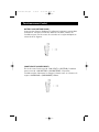
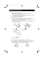
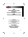
6-2 Battery Replacement Procedures
1. Hold the top of the front panel, tilt it out and pull it carefully away
from the chassis.
Step 1
Grasp and tilt out
and down
2. Loosen the bottom of the front panel from the chassis and place it on
the top of the UPS. Be cautious so as not to pull the ribbon cable and
touch the LED printed circuit board.
3. Use a Phillips screwdriver to remove and open the battery door.
4. Carefully and smoothly pull the battery out of the UPS.
Step 2
Place the front
panel above
Step 4
Pull battery out
Step 3
Use a Phillips screwdriver
to release the battery door
17
En
P73335u_UPS_man.qxd
4/30/01
12:19 PM
Page 18
Replacing Battery (continued)
5. Disconnect the battery:
• For F6C700-EUR (700VA) and F6C1000-EUR (1000VA) models,
disconnect the batteries and UPS by loosening the connectors.
• For F6C1400-EUR (1400VA) model, disconnect the batteries
and UPS by pulling apart the two white couplers that are
connected together.
6. Connect the new battery:
• For 700VA and 1000VA models, connect positive (+) connectors
(RED-RED) and negative (-) connectors (BLACK-BLACK) together.
• For 1400VA model, connect the two white connected couplers on
battery and UPS together.
Black (-)
Red (+)
Black (-)
700VA
1000VA
Red (+)
Push back to UPS
Push back to UPS
Black (-)
Red (+)
1400VA
Push back to UPS
7. Re-assemble the UPS as shown above.
8. For environmental protection, do not dispose old batteries anywhere.
Contact your battery supplier for proper recycling of old batteries.
18
P73335u_UPS_man.qxd
4/30/01
12:19 PM
Page 19
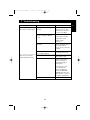
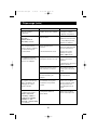
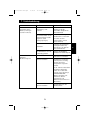
7. Troubleshooting
PROBLEM
POSSIBLE CAUSE
ON/TEST button is not
UPS is not turned on.
(No alarm, no LED lights.) pushed.
The rear panel circuit
breaker is tripped. (Button
is out.)
SOLUTION
Press the ON/TEST
button to turn on the
UPS. (Refer to section 4
to turn on the UPS.)
1. Reduce some loads
connected to the UPS
2. Reset the circuit
breaker. (Push
button in.)
UPS does not provide
expected back-up time.
UPS fault
Call for qualified service
personnel if above
actions do not solve the
problem.
Batteries inside the UPS
are not fully charged.
Recharge the batteries
for at least four hours.
UPS is overloaded.
Remove some
unnecessary loads.
Batteries are weak.
Batteries wear faster
when used often or
operating at higher
temperature.
If the battery is near
the end of its life,
replace the battery
even if the REPLACE
BATTERY LED does not
light. (Refer to section 6
for replacing batteries.)
Batteries are weak.
19
Call for service.
En
P73335u_UPS_man.qxd
4/30/01
12:19 PM
Page 20
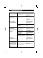
Troubleshooting
PROBLEM
All LEDs light.
POSSIBLE CAUSE
Internal UPS fault.
SOLUTION
1. Turn off UPS.
2. Call for service.
'REPLACE BATTERY'
LED lights.
Weak batteries.
1. Recharge the batteries
for at least 4 hours.
2. If problem remains,
replace the batteries.
PC-UPS communication
does not work
properly.
Incorrect transmission
speed.
Incorrect RS-232
connection.
UPS operates on
battery even though
good line voltage may
be present.
UPS over temperature.
( BUCK, BOOST,
NORMAL, ON
BATTERY LEDs light)
Re-test after using
another different
transmission speed.
Re-connect the UPS with
COM1 / COM2 on PC
again.
The rear panel circuit
breaker is tripped. (Button
is out)
1. Reduce some loads
connected to the UPS.
Very high, low, or
distorted utility voltage.
Have qualified electrician
check the input voltage.
Wiring error such as
reversed hot/neutral.
Get wiring checked by
electrician.
The environment
temperature exceeds
40°C (104°F).
Position your UPS in
cooler area.
20
2. Reset the circuit
breaker. (Push button in)
P73335u_UPS_man.qxd
4/30/01
12:19 PM
Page 21
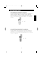
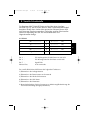
8. Communication Interface
The Regulator PRO™ NetUPS Series has a 9-pin D-type connector that
concurrently provides protocols for RS-232 and Dry contact. Using the
optional software, the UPS and computer can transmit signals to each
other. These two communication ports are used to control the UPS and
its connector pin are defined as follows:
8-1 RS-232
NC ------------------
1
6 ------------
NC
TX ------------------
2
7 ------------
NC
RX ------------------
3
8 ------------
NC
NC ------------------
4
9 ------------
NC
Signal Ground -----
5
Pin 2
:
PC receives line RS-232 data from UPS.
Pin 3
:
PC transmits line RS-232 data to UPS.
Pin 5
:
Signal ground.
Other pins:
Not used.
The RS-232 communication port provides the following functions:
1) Monitoring charger status
2) Monitoring battery status and condition
3) Monitoring inverter status
4) Monitoring UPS status
5) Monitoring the utility status
6) Providing the power switch function for the computer to turn on/off the
utility schedule for power saving
21
En
P73335u_UPS_man.qxd
4/30/01
12:19 PM
Page 22
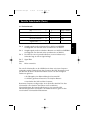
Communication Interface (continued)
The UPS data is provided at 2400 bps baud rate and made up of 8-bit,
1 stop-bit, and no parity bit. All information is encoded in ASCII format.
HARDWARE:
BAUD RATE ------------------------2400 bps
DATA LENGTH --------------------8 bits
STOP BIT ---------------------------1-bit
PARITY ------------------------------NONE
CABLING:
COMPUTER
UPS
RX
(pin2)
TX
(pin2)
TX
(pin3)
RX
(pin3)
GND
(pin5)
GND
(pin5)
22
P73335u_UPS_man.qxd
4/30/01
12:19 PM
Page 23
Communication Interface (continued)
En
8-2 Dry Contact
NC -----------------
1
6--------------
Low Battery
NC -----------------
2
7--------------
NC
Shut Down--------
3
8--------------
NC
AC Fail ------------
4
9--------------
NC
Signal Ground ----
5
Pin 4:
Output signal transfers from HIGH to LOW when utility fails.
The pin is normally at high level.
Pin 6:
Output signal transfers from HIGH to LOW upon low battery.
The pin is normally at a high level.
Pin 3:
The UPS will shut down when a high level sustained for at least
3.8 seconds is applied.
Pin 5:
Signal ground.
Other: Not used.
The communication port at the back of the UPS may be connected to a
computer. This port allows the computer to monitor the UPS and control the
operation of the UPS in some cases. Its major functions normally include
the following:
• To broadcast a warning when power fails.
• To close the files before the battery is exhausted.
• To turn off the UPS and computers.
Some computers may have a special connector to link this communication
port, or require a special plug-in card, or need a special UPS monitoring
software. Contact your dealer for details of different interface kits.
23
P73335u_UPS_man.qxd
4/30/01
12:19 PM
Page 24
9. Specifications
Voltage
ELECTRICAL INPUT
191V~250V for 220V Model
Line Conditioning
Boost: +17%; Buck-Down: -13%
220V Model: 191V~205V (Boost);
232V~250V (Buck-Down)
Frequency
50Hz
Maximum Load
Voltage
(On Battery Mode)
ELECTRICAL OUTPUT
F6C700-EUR: 700VA/450W
F6C1000-EUR: 1000VA/670W
F6C1400-EUR: 1400VA/950W
Nominal Voltage (220V/230V/240V) ± 5%
-10% after low battery warning,
Synchronized to utility line
Output
Wave Form
Pure Sine Wave
Frequency
50Hz
Transfer Time
4 ms Typically, Including Detection Time
BATTERY
Back-up Time
Please refer to Appendix A for more details.
Battery Type
Sealed Lead-Acid Maintenance-Free Battery
24
P73335u_UPS_man.qxd
4/30/01
12:19 PM
Page 25
Specifications (continued)
Battery Number
and Capacity
F6C700-EUR
F6C1000-EUR
F6C1400-EUR
Typical Recharge Time
< 8 hours recharge to 90% capacity
12V/7Ah
12V/12Ah
12V/17Ah
*2
*2
*2
INTERFACE
Communication
One female DB9 connector for RS-232 and
Dry Contact
Single LED Indicator
Inverter, Replace Battery, Buck-Down
Normal, Boost
Sequenced LED Indicator
Battery Level, Load Level
MECHANICAL
Dimension
and Weight
F6C700-EUR W=13.84cm; H=1.9m; D=40.01cm; 30.8 lbs
F6C1000-EUR W=17.02cm; H=2.64m; D=41.91cm; 44 lbs
F6C1400-EUR W=17.02cm; H=2.64m; D=41.91cm; 44 lbs
PHYSICAL
Operating Temperature
0˚C ~ 40˚C (32˚F ~ 104˚F)
Relative Humidity
0 TO 95%, Non-condensing
Audible Noise
< 41dBA at 1m (3ft) in front of UPS panel
APPROVAL
Safety
CE, TÜV GS, TÜV EMC
EMI/RFI
EC
25
En
P73335u_UPS_man.qxd
4/30/01
12:19 PM
Page 26
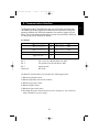
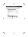
10. APPENDIX A: Typical Run Time
F6C700-EUR (700VA/450W)
Load
20% (90W)
40% (180W)
60% (270W)
80% (360W)
100% (450W)
Typical Run Time
55 minutes
22 minutes
13 minutes
8 minutes
5 minutes
F6C1000-EUR (1000 VA/670W)
Load
20% (134W)
40% (268W)
60% (402W)
80% (536W)
100% (670W)
Typical Run Time
60 minutes
24 minutes
13 minutes
9 minutes
6 minutes
F6C1400-EUR (1400 VA/950W)
Load
20% (190W)
40% (380W)
60% (570W)
80% (760W)
100% (950W)
Typical Run Time
65 minutes
25 minutes
14 minutes
10 minutes
7 minutes
26
P73335u_UPS_man.qxd
4/30/01
12:19 PM
Page 27
Information
En
FCC Statement
DECLARATION OF CONFORMITY WITH FCC RULES FOR
ELECTROMAGNETIC COMPATIBILITY
We, Belkin Components, of 501 West Walnut Street, Compton CA 90220, declare
under our sole responsibility that the product:
F6C700/1000/1400-EUR
to which this declaration relates:
Complies with Part 15 of the FCC Rules. Operation is subject to the following two
conditions: (1) this device may not cause harmful interference, and (2) this device
must accept any interference received, including interference that may cause
undesired operation.
CE Declaration of Conformity
We, Belkin Components, declare under our sole responsibility that the
F6C700/1000/1400-EUR, to which this declaration relates, is in conformity with Generic
Emissions Standard EN50081-1 and with Generic Immunity Standard EN50082-1 1992.
Belkin Components Limited Lifetime Product Warranty
Belkin Components warrants this product against defects in materials and workmanship for
its lifetime. If a defect is discovered, Belkin will, at its option, repair or replace the product at
no charge provided it is returned during the warranty period, with transportation charges
prepaid, to the authorized Belkin dealer from whom you purchased the product. Proof of
purchase may be required.
This warranty does not apply if the product has been damaged by accident, abuse, misuse,
or misapplication; if the product has been modified without the written permission of Belkin;
or if any Belkin serial number has been removed or defaced.
THE WARRANTY AND REMEDIES SET FORTH ABOVE ARE EXCLUSIVE IN LIEU OF ALL OTHERS,
WHETHER ORAL OR WRITTEN, EXPRESSED OR IMPLIED. BELKIN SPECIFICALLY DISCLAIMS
ANY AND ALL IMPLIED WARRANTIES, INCLUDING, WITHOUT LIMITATION, WARRANTIES OF
MERCHANTABILITY AND FITNESS FOR A PARTICULAR PURPOSE.
No Belkin dealer, agent, or employee is authorized to make any modification, extension, or
addition to this warranty.
BELKIN IS NOT RESPONSIBLE FOR SPECIAL, INCIDENTAL, OR CONSEQUENTIAL
DAMAGES RESULTING FROM ANY BREACH OF WARRANTY, OR UNDER ANY OTHER
LEGAL THEORY, INCLUDING BUT NOT LIMITED TO LOST PROFITS, DOWNTIME,
GOODWILL, DAMAGE TO OR REPROGRAMMING, OR REPRODUCING ANY PROGRAM
OR DATA STORED IN OR USED WITH BELKIN PRODUCTS.
27
P73335u_UPS_man.qxd
4/30/01
12:19 PM
Page 28
Belkin Components
501 West Walnut Street
Compton • CA • 90220 • USA
Tel: 310.898.1100
Fax: 310.898.1111
Belkin Components, Ltd.
Unit 13 • Gatelodge Close • Round Spinney
Northampton • Northants • NN3 8RX • UK
Tel: +44 (0) 1604678300
Fax: +44 (0) 1604678330
Belkin Components B.V.
Starparc Building • Boeing Avenue 333
1119 PH Schiphol-Rijk • The Netherlands
Tel: +31 (0) 20 654 7300
Fax: +31 (0) 20 654 7349
Belkin Components, Ltd.
7 Bowen Cresent • West Gosford
NSW 2250 • Australia
Tel: +61 (2) 4325 4666
Fax: +61 (2) 4325 4277
© 2001 Belkin Components. All rights reserved. All trade names are registered trademarks of respective manufacturers listed.
28
P73335f–UPS–man.qxd
4/30/01
12:22 PM
Page 29
Table des matières
Section
Page
1.
Consignes de sécurité ..................................................................31
2.
Introduction ..................................................................................33
3.
Installation ....................................................................................39
4.
Fonctionnement ............................................................................41
5.
Maintenance..................................................................................46
6.
Remplacement de la batterie ......................................................46
7.
Dépannage....................................................................................49
8.
Interface de communication ........................................................51
9.
Spécifications ................................................................................54
10. Annexe A : Fonctionnement normal ............................................56
29
Fr
P73335f–UPS–man.qxd
4/30/01
12:22 PM
Page 30
P73335f–UPS–man.qxd
4/30/01
12:22 PM
Page 31
Consignes de sécurité importantes
1-1 Consignes de sécurité TUV
• Veuillez observer les règles suivantes afin de veiller à la sécurité du
personnel et d'assurer du bon fonctionnement du matériel :
• Le niveau de pression sonore pour la personne qui utilise l'appareil est
égal ou inférieur à 70 dB(A) selon la norme IEC 704-1:1982.
Pour l'installation :
• L'installation de l'unité doit être effectuée uniquement par
une personne qualifiée.
• Lors de l'installation, vous devez vous assurer que le total de
courant de fuite de l'onduleur et des appareils connectés ne dépasse
pas 3,5 mA.
• La prise de courant doit se trouver près de l'appareil et être
facile d'accès.
Autres consignes de sécurité :
• La tension à l'intérieur de l'onduleur est potentiellement dangereuse.
Toutes les réparations doivent être effectuées par une personne
qualifiée. L'onduleur dispose de sa propre source d'énergie interne (la
batterie). Les prises de sortie risquent d'être sous tension, même si
l'onduleur n'est pas relié au secteur.
• Lorsque vous remplacez les batteries, utilisez toujours le même type et
la même quantité que celles que vous retirez. Batteries GP1270-F2(CSB
12V/7AH*2) pour les modèles 450 VA et 700 VA ; GP12110-F2(CSB
12V/11AH*2) pour le modèle 1000 VA et GP12170-B1(CSB 12V/17AH*2)
pour le modèle 1400 VA.
• Ne jetez pas les batteries au feu sous risque d'explosion.
• N'ouvrez pas ou n'abîmez en aucune façon les batteries, car l'électrolyte
qu'elles contiennent est toxique et risque de provoquer des lésions au
niveau de la peau ou des yeux.
• Une batterie peut présenter un risque d'électrocution et un fort courant
de court-circuit. Vous devez observer les précautions suivantes lorsque
vous manipulez des batteries.
• Retirez montres, bagues ou tout autre objet métallique.
• Utilisez des outils dont le manche est isolé.
• L'appareil doit être utilisé par une personne qualifiée.
31
Fr
P73335f–UPS–man.qxd
4/30/01
12:22 PM
Page 32
Consignes de sécurité (suite)
Déclaration de conformité EC
• Ces dispositifs sont conformes aux directives suivantes :
• Directive 73/23/EEC du Conseil pour l'harmonisation des lois des
membres de l'UE relatives aux appareils électriques présentant des
tolérances de tension, modifiée par la directive RL 93/68/EEC du Conseil.
• Directive 89/336/EEC du Conseil pour l'harmonisation des lois des
membres de l'UE relatives à la compatibilité électromagnétique, modifiée
par les directives RL 91/236/EEC et 93/68/EEC du Conseil.
Conformité avec les normes suivantes :
EN 50091-1-1
EN 55022, classe B
32
P73335f–UPS–man.qxd
4/30/01
12:22 PM
Page 33
2. Introduction
2-1 SYMBOLES
FIL DE PROTECTION POUR MISE A LA TERRE : Fil devant
être mis à la terre avant d'effectuer tout autre branchement
sur l'appareil.
Fr
Fil auquel, ou depuis lequel, il est possible d'appliquer ou de
fournir un courant alternatif ou une tension (onde sinusoïdale).
Fil auquel, ou depuis lequel, il est possible d'appliquer ou de
fournir un courant direct ou une tension.
Ce symbole indique le mot « phase ».
Ce symbole indique que le commutateur marche/arrêt principal
est en positon MARCHE.
Ce symbole indique que le commutateur marche/arrêt principal
est en position ARRET.
Peut être utilisé pour indiquer « Attention, risque de décharge
électrique » pour tout marquage appelant à la prudence.
33
P73335f–UPS–man.qxd
4/30/01
12:22 PM
Page 34
Introduction (suite)
2-2 Théorie de fonctionnement
Le Regulator PRO™ série NetUPS est un onduleur interactif doté d’un
régulateur automatique de tension (AVR) qui fournit aux systèmes
informatiques une alimentation CA fiable et sans parasite par l'intermédiaire
d'un filtre EMI d'entrée/sortie, d'un parasurtenseur et d'un
transformateur/conditionneur de ligne (transformateur automatique) qui
génère une hausse ou une baisse de tension selon l'amplitude du de la
tension en entrée.
Dans des conditions normales, l'onduleur fournit le courant du secteur à la
charge (système informatique, poste de travail, serveur ou autre). Le
convertisseur bilatéral fonctionne comme un chargeur pour charger la
batterie et, en même temps, maintenir la batterie à pleine charge. Il s'agit
du mode « ON UTILITY » (SECTEUR).
En cas de panne de courant, le convertisseur fournit du courant CA à la
charge grâce au courant provenant des batteries. Il s'agit du mode « ON
BATTERY » (SUR BATTERIE). L'onduleur fournit un courant régulé. La mise
hors tension résulte du manque d'électricité dans les batteries.
SCHEMA DE L'ONDULEUR INTERACTIF
AVR : Régulateur de tension automatique
Secteur
Filtre EMI et
parasurtenseur
BATTERIE
Filtre EMI et
parasurtenseur
Convertisseur
bilatéral
SORTIE
CA
2-3 Fonctionnalités
Conditionneur de ligne avec gestion intelligente des hausses et
des baisses de tension
Si une baisse de tension ou une surtension du secteur est détectée, le
conditionneur de ligne ajuste automatiquement la tension entrante et fournit
un courant CA régulé à l'appareil relié à l'onduleur.
34
P73335f–UPS–man.qxd
4/30/01
12:22 PM
Page 35
Introduction (suite)
Batterie remplaçable par l'utilisateur
Le Regulator PRO™ série NetUPS dispose d'une fonction de remplacement
de batterie par l'utilisateur de manière à ce que les utilisateurs puissent
aisément changer eux-mêmes les batteries qui se trouvent à l'intérieur de
l'onduleur. La procédure est décrite dans la section 6.
Courant de charge à faibles ondulations et harmoniques
Un circuit contrôlé spécial est employé pour fournir un courant de charge
avec correction du facteur de puissance. Cette fonctionnalité permet de
réduire les interférences électromagnétiques transportées vers d'autres
installations partageant le même circuit de distribution que votre onduleur
et, par conséquent, de prolonger la durée de vie de la batterie
de l'onduleur.
Interface de communication intelligente et prise en charge de
réseau puissante
L'interface de communication incorporée (RS-232 et contact sec) vous
permet de contrôler et de gérer votre onduleur via le puissant logiciel Sentry
Bulldog d'arrêt du système. En outre, le port auxiliaire facultatif SNMP
incorporé permet de gérer le Regulator PRO™ série NetUPS par
l'intermédiaire du réseau.
Interface conviviale
Vous pouvez connaître immédiatement l'état de votre onduleur sans devoir
appuyer sur des boutons. L'écran fournit des informations complètes et
faciles à comprendre (niveau de charge, niveau des batteries, hausse de
tension intelligente, baisse de tension intelligente, sur batterie, remplacer la
batterie et surcharge).
Indication d'un problème de câblage (modèle 120V uniquement)
Le Regulator PRO™ série NetUPS dispose d'une fonction de détection de
problèmes de câblage. En cas de problème, tel que mise à la terre
inexistante ou polarité inversée, vous êtes averti. La conception de cet
appareil visant à favoriser la sécurité, elle écarte tout danger.
Protection réseau facultative contre les surtensions
Le Regulator PRO™ série NetUPS est équipé de prises pour câble réseau
Novell incorporées (RJ-45). Ces prises protègent votre matériel contre les
surtensions et les crêtes de tension qui se propagent par les lignes de
communication. Elles protègent de tout dommage potentiel résultant de ces
phénomènes ainsi que des parasites.
2-4 Commentaire
Les deux signes ci-dessous indiquent qu'il s'agit d'instructions
importantes que vous devez suivre impérativement :
35
Fr
P73335f–UPS–man.qxd
4/30/01
12:22 PM
Page 36
Introduction (suite)
2-5 Face avant
ON-TEST (MARCHE-TEST)
OFF (ARRET)
ON BATTERY (SUR BATTERIE)
BUCK (BAISSE DE TENSION)
NORMAL
BOOST (HAUSSE DE TENSION)
OVERLOAD (SURCHARGE)
REPLACE BATTERY
(REMPLACER LA BATTERIE)
LOAD LEVEL (NIVEAU DE CHARGE)
BATTERY LEVEL (NIVEAU
DE LA BATTERIE)
ON-TEST (MARCHE-TEST): Lorsque vous appuyez sur ce bouton, deux
fonctions sont activées. L'une est « ON » (MARCHE) et l'autre est « TEST ».
*MARCHE: Si vous appuyez sur ce bouton, la charge est mise sous tension.
*TEST: Permet d'activer l'autotest de l'onduleur. Il vérifie à la fois le
fonctionnement de l'onduleur et l'état de la batterie.
OFF (ARRET): Eteint l'onduleur.
VOYANT BAISSE DE TENSION: Indique que l'onduleur corrige la haute
tension du secteur et délivre une tension normale à la charge.
VOYANT NORMAL: Indique que l'onduleur fournit le courant du secteur à la
charge sans affecter l'état de ce courant.
VOYANT HAUSSE DE TENSION: Indique que l'onduleur corrige la basse
tension du secteur et délivre une tension normale à la charge.
VOYANT SURCHARGE: Indique que l'onduleur dépasse sa capacité
nominale acceptable.
VOYANT NIVEAU DE CHARGE: Affiche le pourcentage (20 %, 40 %, 60 % et
80 %) des charges connectées à l'onduleur.
36
P73335f–UPS–man.qxd
4/30/01
12:22 PM
Page 37
Introduction (suite)
VOYANT SUR BATTERIE: Indique que l'onduleur alimente la charge à partir
du courant fourni par les batteries.
VOYANT REMPLACER LA BATTERIE: Indique que la batterie de l'onduleur
n'est plus utilisable et doit être immédiatement remplacée.
VOYANT NIVEAU DE LA BATTERIE: Affiche le pourcentage (25%, 50%,
75% et 100 %) de capacité des batteries restant.
2-6 Face arrière
PRISES DE SORTIE: L'onduleur fournit un courant CA à la charge grâce à
ces prises.
DISJONCTEUR: Il est utilisé pour éviter qu'un fort courant entrant puisse
atteindre l'onduleur.
PRISE D'ENTREE: Prise d'arrivée du courant secteur CA en entrée.
PORT SNMP: Il est possible de brancher un adaptateur SNMP sur ce port
afin de gérer l'onduleur par le réseau.
PARASURTENSEUR TVSS: Ce connecteur permet de protéger la ligne de
transmission de la carte Ethernet contre toute surtension, parasites de ligne
et crêtes de tension.
INTERFACE DE COMMUNICATION (RS-232/CONTACT A SEC): Le port de
communication est employé pour permettre au PC et à l'onduleur de
communiquer. Veuillez vous référer à la section 8 pour obtenir de plus
amples informations.
VOYANT DE PROBLEME DE CABLAGE: Ce voyant s'allume lorsque
l'onduleur est connecté à une prise de courant CA mal câblée.
37
Fr
P73335f–UPS–man.qxd
4/30/01
12:22 PM
Page 38
Introduction (suite)
Face arrière du modèle F6C700-EUR
INTERFACE DE COMMUNICATION
VOYANT DE PROBLEME
DE CABLAGE
PRISE DE SORTIE
PORT SNMP
PRISE D'ENTREE
Face arrière des modèles F6C1000-EUR/F6C1400-EUR
INTERFACE DE COMMUNICATION
VOYANT DE PROBLEME DE CABLAGE
DISJONCTEUR CA
PORT SNMP
PRISE DE SORTIE
PRISE D'ENTREE
38
P73335f–UPS–man.qxd
4/30/01
12:22 PM
Page 39
Installation
3-1 Déballage
• Veuillez lire ce manuel avant d'installer l'onduleur.
• Cet onduleur contient des batteries qui peuvent être potentiellement
dangereuses pour l'utilisateur, même lorsque l'onduleur n'est pas relié
au secteur.
• Toutes les réparations doivent être réalisées par un réparateur qualifié.
• Avant de déballer l'onduleur, vérifiez l'emballage. S'il est endommagé,
contactez immédiatement votre revendeur.
3-2 Avant de commencer l'installation
• Evitez d'exposer l'onduleur à la lumière directe du soleil ou autre source
de chaleur. L'onduleur ne doit pas être exposé directement à l'éclat
du soleil.
• Choisissez un local bien ventilé afin de permettre une dissipation correcte
de la chaleur de votre onduleur.
• Assurez-vous que le local dans lequel se trouve l'onduleur est propre et sec.
• Ne placez pas d'objets lourds sur le câble ou sur le cordon d'alimentation.
3-3 Installation
1. Branchement sur le secteur
Le logiciel Sentry Bulldog d'arrêt du système de Belkin ainsi que le
câble RS232 peuvent être utilisés avec cet onduleur. Pour l'utiliser,
branchez le câble d'interface au port d'interface correspondant à
l'ordinateur à l'arrière de l'onduleur, puis l'autre extrémité au port
série de votre ordinateur.
F6C1000-EUR/F6C1400-EUR
F6C700-EUR
2. Vérification du voyant indiquant un problème de câblage
Une fois l'onduleur relié au secteur, vérifiez le voyant indiquant d'éventuels
problèmes de câblage sur la face arrière. Si l'onduleur est branché à une prise
de courant CA mal câblée, le voyant s'allume.
Les problèmes de câblage peuvent être dus à une mise à la terre absente, à
l'inversion de la polarité sous tension et neutre ou à un circuit neutre surchargé.
Si le voyant s'allume, débranchez l'onduleur et faites vérifier votre câblage par
un électricien.
39
Fr
P73335f–UPS–man.qxd
4/30/01
12:22 PM
Page 40
Installation (suite)
3. Mise en charge de la batterie
Le chargeur de batterie de l'onduleur charge automatiquement la
batterie lorsque le cordon d'alimentation de l'onduleur est raccordé
au secteur.
Lors de la première utilisation, mettez l'onduleur en charge pendant
au moins 6 heures afin de vous assurer que les batteries qu'il contient
sont complètement chargées avant de fonctionner.
Vous pouvez utiliser l'onduleur sans attendre que les batteries soient
chargées. Toutefois, nous vous déconseillons de le faire car, dans ce
cas, l'onduleur disposerait d'une durée d'usage de secours plus
courte qu'il ne devrait.
4. Branchement de la charge
Calculez la consommation électrique de vos charges de manière à
vous assurer qu'aucune surcharge ne se produire.
Branchez l'équipement sur les prises de sortie à l'arrière de
l'onduleur.
Allumez l'équipement branché à l'onduleur.
Attention : Ne branchez pas d'imprimante laser à l'onduleur.
5. Branchement du RS-232/CONTACT SEC
Branchez le câble de signal d'interface entre le port RS-232/Contact
sec à l'arrière de l'onduleur et au port COM1 ou COM2 de
l'ordinateur si nécessaire.
Le connecteur DB-9 peut servir de contact sec ou de port de
communication RS-232 selon le type de câble et le logiciel utilisés.
Reportez-vous à la section 8 de l'interface de communication pour
obtenir de plus amples informations.
40
P73335f–UPS–man.qxd
4/30/01
12:22 PM
Page 41
4. Fonctionnement
Branchement au port
COM1 ou COM2 du PC
Branchement au port COM1 ou COM2 du PC
Branchement à
l'équipement
Branchement à
l'équipement
Branchement
au secteur
Branchement
au secteur
4-1 Démarrage à froid lorsque le secteur est absent
L'onduleur peut être allumé, ceci même en l'absence de courant du
secteur. Il vous suffit de maintenir enfoncé le bouton « ON/TEST »
(MARCHE/TEST) pendant 2 secondes pour que l'onduleur s'allume. Le
voyant « INVERTER » (INVERSEUR) s'allume, puis un signal sonore se fait
entendre. L'onduleur est allumé.
4-2 Démarrage de l'onduleur
En mode secteur normal, appuyez sur le bouton « ON/TEST »
(MARCHE/TEST) pour allumer l'onduleur. Une fois allumé, l'onduleur
émet un signal sonore, puis transmet le courant aux appareils branchés.
4-3 Mise hors tension de l'onduleur
Lorsque vous appuyez sur le bouton « OFF » (ARRET), l'onduleur
s'arrête immédiatement de fournir du courant aux charges.
Remarque: Il est possible que du courant soit toujours présent même
si vous avez appuyé sur le bouton « OFF » (ARRET). Pour éteindre
complètement l'onduleur, nous vous conseillons de débrancher le
cordon d'alimentation.
4-4 Autotest de l'onduleur
Lorsque l'onduleur est en mode « ON UTILITY » (SECTEUR), il vous
suffit d'appuyer sur le bouton « ON/TEST » (MARCHE/TEST) pour faire
passer l'onduleur en mode « ON BATTERY » (SUR BATTERIE) et
effectuer un autotest d'une durée de 10 secondes environ. Une fois le
test terminé, l'onduleur repasse en mode « ON UTILITY » (SECTEUR).
4-5 Fonction silence
Il est possible d'activer ou de désactiver l'avertisseur sonore. Pour cela,
utilisez le bouton « ON/TEST » (MARCHE/TEST) lorsque l'onduleur est
en mode « ON BATTERY » (SUR BATTERIE).
41
Fr
P73335f–UPS–man.qxd
4/30/01
12:22 PM
Page 42
Fonctionnement (suite)
4-6 Affichage du niveau de charge
L'indicateur de charge à 4 voyants affiche le niveau de puissance (20 %,
40 %, 60 %, 80 %) demandé à l'onduleur par les charges. Si l'onduleur
est surchargé, le voyant « OVERLOAD » (SURCHARGE) s'allume.
4-7 Affichage du niveau des batteries
Cet indicateur montre la puissance restant dans la batterie. Le niveau
est représenté par des voyants de pourcentages (25, 50, 75 et 100). Ils
s'éteignent progressivement lorsque vous utilisez l'électricité des
batteries. Une fois le niveau minimum de 25 % atteint, le dernier voyant
(25 %) clignote : vous devez immédiatement mettre la batterie en
charge. A ce niveau, la batterie pourra fournir au maximum 5 minutes
d'alimentation à la charge.
4-8 Si des situations anormales se produisent, l'onduleur envoie les
messages suivants :
ON BATTERY MODE (MODE SUR BATTERIE) : Lorsque l'onduleur est en
mode « ON BATTERY » (SUR BATTERIE), le voyant correspondant
s'allume, précédé d'un signal sonore toutes les 2 secondes. L'onduleur
commence ensuite à alimenter la charge en utilisant la batterie.
42
P73335f–UPS–man.qxd
4/30/01
12:22 PM
Page 43
Fonctionnement (suite)
OVERLOAD (SURCHARGE):
En cas de surcharge, le voyant « OVERLOAD » (SURCHARGE) s'allume
et un signal sonore continu se fait entendre. Dans ce cas, vous devez
vérifier la charge connectée à l'onduleur.
Fr
BUCK/BOOST (BAISSE/HAUSSE DE TENSION):
Lorsque l'onduleur détecte une tension élevée au niveau du secteur, le
dispositif de baisse de tension a pour fonction de la réduire jusqu'à
atteindre un niveau normal acceptable par les charges. Dans le cas où
l'onduleur détecte une tension faible, le dispositif de hausse de tension
augmente la tension jusqu'à atteindre un niveau normal afin de pouvoir
alimenter les charges. Ces deux fonctions sont indiquée par leur voyant
respectif sur la face avant de l'onduleur.
BATTERY REPLACE (REMPLACER LA BATTERIE):
Cette fonction permet d'informer l'utilisateur que les batteries doivent
être changées. Lorsque le microprocesseur contenu dans l'onduleur
détecte un problème de batterie, une alarme sous la forme de 3 signaux
sonore se fait entendre. Ces signaux ont une durée de 0,5 seconde et
sont séparés par un intervalle de 0,5 seconde. Après les 3 premiers
signaux, l'alarme se déclenche toutes les heures.
43
P73335f–UPS–man.qxd
4/30/01
12:22 PM
Page 44
Fonctionnement (suite)
BATTERY LOW (BATTERIE FAIBLE) :
Cette fonction permet d'indiquer à l'utilisateur la puissance restant dans
les batteries. Lorsque le niveau des batteries est faible, l'alarme de
l'onduleur sonne une fois toutes les secondes et le voyant indiquant un
niveau de 25 % clignote.
SHORT CIRCUIT (COURT-CIRCUIT):
En cas de court-circuit en mode « ON UTILITY » (SECTEUR), l'onduleur
passe en mode « ON BATTERY » (SUR BATTERIE). S'il persiste,
l'onduleur arrête d'alimenter les charges, l'alarme sonne en continu et le
voyant « OVERLOAD » (SURCHARGE) s'allume.
44
P73335f–UPS–man.qxd
4/30/01
12:22 PM
Page 45
Fonctionnement (suite)
OVER TEMPERATURE (TEMPERATURE EXCESSIVE)
Lorsque la température à l'intérieur de l'onduleur est trop élevée, les
voyants « Buck-Down » (Baisse de tension), « Boost » (Hausse de
tension), Normal et « On Battery » (Sur batterie) s'allument, l'alarme
sonne en continu et, après une minute, l'onduleur cesse d'alimenter
la charge.
Fr
UPS FAULT (DYSFONCTIONNEMENT DE L'ONDULEUR)
Lorsque l'onduleur tombe en panne, tous les voyants s'allument et
l'avertisseur sonore se fait entendre de manière continue. Si cela se
produit, débranchez le cordon d'alimentation de la prise de courant et
contactez un réparateur.
45
P73335f–UPS–man.qxd
4/30/01
12:22 PM
Page 46
5. Maintenance
• La durée de vie normale d'une batterie se situe entre 3 et 5 ans.
Cependant, des conditions de fonctionnement et ambiantes extrêmes
peuvent réduire cette durée.
• Pour remplacer les batteries, faites appel à une personne qualifiée.
• Si vous n'utilisez pas l'onduleur pendant un certain temps, les batteries qui
se trouvent à l'intérieure se déchargent légèrement. Nous vous conseillons
de charger l'onduleur une fois tous les trois mois.
• Utilisez un aspirateur pour ôter la poussière qui pourrait s'être déposée
sur l'ouverture du ventilateur.
• Débranchez l'onduleur si vous devez pas l'utiliser pendant une
longue durée.
• Utilisez uniquement un chiffon doux et sec pour nettoyer le carter
plastique, la face avant ou la face arrière. Si le carter ou la face avant sont
sales, employez un détergent neutre et non abrasif. N'utilisez pas de
solutions à base d'alcool ou d'ammoniaque.
• Lorsque vous déplacez l'onduleur, manipulez-le toujours avec précaution.
• Evitez de renverser du liquide sur l'onduleur.
6. Remplacement de la batterie
Programme de remplacement de la batterie EcoBattery
Si la batterie de votre onduleur doit être remplacée, Belkin vous propose son
programme de remplacement de batterie EcoBattery. Il veille également à ce
que la mise au rebut des anciennes batteries s'effectue dans des conditions
préservant l'environnement. Tous les participants au programme bénéficient
également d'une prolongation de garantie du produit de deux ans.
Veuillez appeler Belkin Components (1-800-2BELKIN extension 2263 aux
Etats-Unis) pour avoir de plus amples informations sur le coût du programme
et les modalités d'envoi.
46
P73335f–UPS–man.qxd
4/30/01
12:22 PM
Page 47
Remplacement de la batterie (suite)
Le Regulator PRO™ série NetUPS permet un remplacement pratique et
simple vos batteries. Si celles-ci sont en mauvais état, suivez la procédure
adaptée au remplacement des batteries.
6-1 Avertissement
• Lorsque vous remplacez des batteries, utilisez toujours des batteries du
même type que les précédentes.
• Ne jetez pas les batteries au feu sous risque d'explosion.
• N'ouvrez pas ou n'abîmez en aucune façon les batteries, car l'électrolyte
qu'elles contiennent est toxique et risque de provoquer des lésions au
niveau de la peau ou des yeux.
• Une batterie peut présenter un risque d'électrocution et un fort courant
de court-circuit. Vous devez observer les précautions suivantes lorsque
vous la remplacez:
• Retirez montres, bagues ou tout autre objet métallique.
• Utilisez des outils dont le manche est isolé.
6-2 Procédure de remplacement des batteries
1. Saisissez la partie supérieure de la face avant, faites-la basculer vers
vous et tirez-la doucement pour la retirer du châssis.
Etape 1
Saisir et faire basculer
2. Retirez le bas de la face avant du châssis, puis placez-la sur
l'onduleur. Faites attention de ne pas tirer sur le câble ruban et de ne
pas toucher le circuit imprimé des voyants.
3. Utilisez un tournevis cruciforme pour ouvrir et retirer la porte d'accès
à la batterie.
4. Retirez doucement la batterie de l'onduleur, sans à-coups.
Etape 2
Placer la face
avant dessus
Etape 4
Sortir la batterie
Etape 3
Utiliser un tournevis cruciforme pour
dégager la porte d'accès à la batterie
47
Fr
P73335f–UPS–man.qxd
4/30/01
12:22 PM
Page 48
Remplacement de la batterie (suite)
5. Débranchez la batterie:
• Pour les modèles F6C700-EUR (700VA) et F6C1000-EUR (1000VA),
débranchez les batteries de l'onduleur en défaisant les connecteurs.
• Pour le modèle F6C1400-EUR(1400VA), débranchez les batteries de
l'onduleur en désolidarisant les deux coupleurs blancs branchés ensemble.
6. Branchez la nouvelle batterie:
• Pour les modèles 700VA et 1000VA, branchez ensemble les
connecteurs positifs (+) (ROUGE-ROUGE) et négatifs (-) (NOIRNOIR).
• Pour le modèle 1400VA, branchez ensemble les deux coupleurs
blancs connectés sur la batterie et sur l'onduleur.
Noir (-)
Rouge (+)
Noir (-)
700VA
1000VA
Rouge (+)
Remettre dans l'onduleur
Remettre dans l'onduleur
Noir (-)
Rouge (+)
1400VA
Remettre dans l'onduleur
7. Remontez l'onduleur comme indiqué ci-dessus.
8. Pour le respect de l'environnement, ne jetez pas vos anciennes
batteries n'importe où. Contactez votre fournisseur de batteries afin
de savoir comment les recycler.
48
P73335f–UPS–man.qxd
4/30/01
12:22 PM
Page 49
7. Dépannage
PROBLEME
L'onduleur n'est
pas allumé.
(Pas d'alarme, pas
de voyant)
CAUSE POSSIBLE
Le bouton « ON/TEST »
(MARCHE/TEST) n'est
pas enfoncé.
Le disjoncteur de la face
arrière est bloqué (le bouton
est sorti).
SOLUTION
Appuyez sur le bouton
« ON/TEST »
(MARCHE/TEST) pour
allumer l'onduleur
(reportez-vous à la section 4
pour savoir comment
allumer l'onduleur).
1. Réduisez ne nombre
d'appareils branchés à
l'onduleur.
2. Réinitialisez le disjoncteur
(rentrez
le bouton)
L'onduleur ne fournit
pas d'alimentation
électrique pendant la
durée prévue.
Dysfonctionnement de
l'onduleur
Faites appel à un réparateur
qualifié si les actions
indiquées ne suffisent pas à
résoudre le problème.
Les batteries contenues dans
l'onduleur ne sont pas
complètement chargées.
Rechargez les batteries
pendant au moins
4 heures.
L'onduleur est en surcharge.
Retirez les appareils inutiles.
Les batteries sont faibles.
Les batteries s'usent plus
rapidement lorsqu'elles sont
souvent utilisées ou qu'elles
fonctionnent à des
températures élevées.
Si la batterie est proche de
la fin de sa durée de vie,
remplacez-la même si le
voyant « REPLACE BATTERY
» (REMPLACER LA
BATTERIE) n'est pas allumé
(reportez-vous à la section 6
pour savoir comment
remplacer les batteries).
Les batteries sont faibles.
49
Faites appel à un réparateur.
Fr
P73335f–UPS–man.qxd
4/30/01
12:22 PM
Page 50
Dépannage (suite)
PROBLEME
CAUSE POSSIBLE
SOLUTION
Tous les voyants
s'allument.
Problème interne de l'onduleur.
Le voyant « REPLACE
BATTERY »
(REMPLACER LA
BATTERIE) s'allume.
Batteries faibles.
Les communications
entre le PC et l'onduleur
ne fonctionnent pas
correctement.
Vitesse de transmission
incorrecte.
Effectuez un nouveau test
après avoir utilisé une autre
vitesse de transmission.
Connexion RS-232 incorrecte.
Branchez de nouveau
l'onduleur sur le port
COM1 / COM2 du PC.
L'onduleur fonctionne
sur batterie même si la
tension est adaptée.
Le disjoncteur de la face arrière
est bloqué (le bouton est sorti).
1. Réduisez le nombre de
charges connectées à
l'onduleur.
1. Eteignez l'onduleur.
2. Appelez un réparateur.
1. Rechargez les batteries
pendant au moins 4 heures.
2. Si le problème persiste,
remplacez les batteries.
2. Réinitialisez le disjoncteur
(rentrez le bouton).
Le voyant « Site wiring
fault » (Problème de
câblage) sur la face
arrière s'allume.
La tension du secteur est très
haute, très basse ou faussée
Faites vérifier la tension
d'entrée par un électricien
qualifié.
Erreur de câblage (inversion
sous tension/neutre, par
exemple).
Faites vérifier le câblage
par un électricien.
Les ventilateurs et les grilles
d'évacuation sont peut-être
bouchés.
Installez votre onduleur
dans un local bien ventilé
afin de permettre une
bonne dissipation de la
chaleur.
Température excessive de
La température ambiante
l'onduleur (les voyants «
dépasse 40°C.
BUCK » (BAISSE DE
TENSION), « BOOST »
(HAUSSE DE TENSION),
NORMAL et « ON
BATTERY » (SUR BATTERIE)
sont allumés).
50
Installez votre onduleur
dans un endroit plus frais.
P73335f–UPS–man.qxd
4/30/01
12:22 PM
Page 51
8. Interface de communication
Le Regulator PRO™ série NetUPS est équipé d'un connecteur de type D
à 9 broches qui fournit simultanément des protocoles aux ports RS-232
et Contact sec. A l'aide du logiciel facultatif, l'onduleur et l'ordinateur
peuvent se transmettre des signaux. Ces deux ports de communication
sont utilisés pour contrôler l'onduleur. Les broches de connexion sont
définies de la manière suivante :
8-1 RS-232
NC ------------------
1
6 ------------
NC
TX ------------------
2
7 ------------
NC
RX ------------------
3
8 ------------
NC
NC ------------------
4
9 ------------
NC
Signal de mise à la terre
-----------
5
Broche 2
:
Le PC reçoit des données de ligne RS-232 de l'onduleur.
Broche 3
:
Le PC transmet des données de ligne RS-232 à l'onduleur.
Broche 5
:
Signal de mise à la terre.
Autres broches :
Inutilisés.
Le port de communication RS-232 possède les fonctions suivantes:
1) Surveiller l'état du chargeur.
2) Surveiller l'état et de la condition de la batterie.
3) Surveiller l'état de l'inverseur.
4) Surveiller l'état de l'onduleur.
5) Surveiller l'état du secteur.
6) Jouer le rôle de commutateur pour l'ordinateur de manière à activer et à
désactiver le dispositif d'économie d'énergie.
51
Fr
P73335f–UPS–man.qxd
4/30/01
12:22 PM
Page 52
Interface de communication (suite)
Les données de l'onduleur sont fournies avec un débit de 2400 bps.
Elles sont de type 8 bits avec un bit d'arrêt et aucun bit de parité.
Toutes les informations sont codées au format ASCII.
MATERIEL:
DEBIT EN BAUDS ---------------------------------2400 bps
LONGUEUR DES DONNEES--------------------8 bits
BIT D'ARRET ---------------------------------------1 bit
PARITE ------------------------------------------------AUCUNE
CABLAGE:
ORDINATEUR
ONDULEUR
RX
(broche2)
TX
(broche2)
TX
(broche3)
RX
(broche3)
GND
(broche5)
GND
(broche5)
52
P73335f–UPS–man.qxd
4/30/01
12:22 PM
Page 53
Interface de communication (suite)
8-2 Contact sec
NC -----------------
1
6-------------- Batterie faible
NC -----------------
2
7--------------
NC
Mise hors tension
3
8--------------
NC
Panne CA ------------
4
9--------------
NC
Signal de mise à la terre
5
Broche 4:
Le signal de sortie passe de « HIGH » (ELEVE) à « LOW »
(FAIBLE) en cas de problème du secteur.
Broche 6:
Le signal de sortie passe de « HIGH » (ELEVE) à « LOW »
(FAIBLE) si les batteries sont faibles. La broche est
normalement réglée pour un niveau élevé.
Broche 3:
L'onduleur s'éteint lorsqu'un niveau élevé d'une durée d'au
moins 3,8 secondes est appliqué.
Broche 5:
Signal de mise à la terre.
Autres:
Inutilisées.
Le port de communication situé à l'arrière de l'onduleur peut être relié à
l'ordinateur. Il permet à ce dernier de surveiller l'onduleur et de contrôler
son fonctionnement dans certaines situations. Ses principales fonctions sont
les suivantes:
• Emettre un avertissement lors d'une panne de courant.
• Fermer les fichiers avant l'épuisement de la batterie.
• Eteindre l'onduleur et les ordinateurs.
Certains ordinateurs peuvent disposer d'un connecteur spécial leur
permettant de se brancher à ce port de communication, alors que d'autres
nécessitent une carte additionnelle spéciale ou encore un logiciel de
surveillance d'onduleur particulier. Contactez votre revendeur afin d'obtenir
des informations sur les différents kits d'interface.
53
Fr
P73335f–UPS–man.qxd
4/30/01
12:22 PM
Page 54
9. Spécifications
Tension
ALIMENTATION D'ENTREE
191V~250V pour le modèle 220V
Conditionneur de ligne
Hausse de tension : +17 % ; Baisse de tension: -13 %
(Baisse de tension) 220V Modèle : 191V~205V (Hausse de
tension) ; 232V~250V (Baisse de tension)
Fréquence
50Hz
Charge maximum
Tension
(Mode Sur batterie)
PUISSANCE EN SORTIE
F6C700-EUR: 700VA/450W
F6C1000-EUR: 1000VA/670W
F6C1400-EUR: 1400VA/950W
Tension nominale (220V/230V/240V)
± 5 %-10 % après indication de niveau de batterie faible,
synchronisée avec le secteur
Sortie
Forme d'onde
Onde sinusoïdale pure
Fréquence
50Hz
Temps de transfert
Généralement 4 ms (temps de détection compris)
BATTERIE
Durée en autonomie
Veuillez vous reporter à l'annexe A
pour obtenir de plus amples informations.
Type de batterie
Batterie en acide de plomb, scellée, sans entretien
54
P73335f–UPS–man.qxd
4/30/01
12:22 PM
Page 55
Spécifications (suite)
Nombre de batteries
et capacité
F6C700-EUR
F6C1000-EUR
F6C1400-EUR
12V/7Ah
12V/12Ah
12V/17Ah
*2
*2
*2
Temps de recharge normal
< 8 heures de recharge pour obtenir une
capacité jusqu'à 90 %
Fr
INTERFACE
Communication
Un connecteur femelle DB9 pour le port
RS-232 et le contact sec
Voyant unique
Inverseur, Remplacer la batterie, Baisse de
tension, Normal, Hausse de tension
Voyant en séquence
Niveau de la batterie, Niveau de charge
MECANIQUE
Dimensions
et poids
F6C700-EUR L = 13,85 cm ; H = 15,62 cm ; P =40 cm ; 14 kg
F6C1000-EUR L = 17 cm ; H = 22 cm ; P = 42 cm ; 20 kg
F6C1400-EUR L = 17 cm ; H = 22 cm ; P = 42 cm ; 20 kg
PHYSIQUE
Température de fonctionnement
0°C à 40°C
Humidité relative
0 à 95 %, sans condensation
Bruit
< 41dBA à 1 m face à l'onduleur
CERTIFICATION
Sécurité
CE, TÜV GS, TÜV EMC
EMI/RFI
EC
55
P73335f–UPS–man.qxd
4/30/01
12:22 PM
Page 56
ANNEXE A : Fonctionnement normal
F6C700-EUR (700VA/450W)
Charge
20% (90W)
40% (180W)
60% (270W)
80% (360W)
100% (450W)
Fonctionnement normal
55 minutes
22 minutes
13 minutes
8 minutes
5 minutes
F6C1000-EUR (1000 VA/670W)
Charge
20% (134W)
40% (268W)
60% (402W)
80% (536W)
100% (670W)
Fonctionnement normal
60 minutes
24 minutes
13 minutes
9 minutes
6 minutes
F6C1400-EUR (1400 VA/950W)
Charge
20% (190W)
40% (380W)
60% (570W)
80% (760W)
100% (950W)
Fonctionnement normal
65 minutes
25 minutes
14 minutes
10 minutes
7 minutes
56
P73335f–UPS–man.qxd
4/30/01
12:22 PM
Page 57
Information
Réglementation FCC
DECLARATION DE CONFORMITE AVEC LES REGLES FCC
POUR LA COMPATIBILITE ELECTROMAGNETIQUE
Nous, Belkin Components, sis au 501 West Walnut Street, Compton CA 90220,
déclarons sous notre seule responsabilité que le produit
F6C700/1000/1400fEUR
auquel se réfère la présente déclaration, est conforme à la partie XV des règles
FCC. Le fonctionnement doit remplir les deux conditions suivantes : (1) ce
périphérique ne doit pas causer d’interférences nuisibles et (2) ce périphérique
doit accepter toute interférence reçue, y compris les interférences pouvant
entraîner un fonctionnement non désiré.
Déclaration de conformité CE
Nous, Belkin Components, déclarons sous notre seule responsabilité que le produit
F6C700/1000/1400fEUR auquel se réfère la présente déclaration, est conforme à la norme
sur les émissions génériques EN50081-1 et à la norme sur l’immunité générique EN50082-1
1992.
Garantie produit limitée à vie de Belkin Components
Belkin garantit ce produit à vie contre tout défaut de matériau et de fabrication. Si l’appareil
s’avère défectueux, Belkin Components le réparera ou le remplacera gratuitement, à sa
convenance, à condition que le produit soit retourné, port payé, pendant la durée de la
garantie, au distributeur Belkin agréé auquel le produit a été acheté. Une preuve d’achat
peut être exigée.
La présente garantie est caduque si le produit a été endommagé par accident, abus, usage
impropre ou mauvaise application, si le produit a été modifié sans autorisation écrite de
Belkin, ou si un numéro de série Belkin a été supprimé ou rendu illisible.
LA GARANTIE ET LES VOIES DE RECOURS SUSMENTIONNÉES FONT FOI EXCLUSIVEMENT
ET REMPLACENT TOUTES LES AUTRES, ORALES OU ÉCRITES, EXPLICITES OU IMPLICITES.
BELKIN REJETTE EXPRESSÉMENT TOUTES LES GARANTIES IMPLICITES, Y COMPRIS MAIS
SANS RESTRICTION, LES GARANTIES AFFÉRENTES À LA QUALITÉ LOYALE ET
MARCHANDE ET À LA POSSIBILITÉ D’UTILISATION À UNE FIN DONNÉE.
Aucun revendeur, représentant ou employé de Belkin n’est habilité à apporter des
modifications ou adjonctions à la présente garantie, ni à la proroger.
BELKIN N’EST PAS RESPONSABLE DES DOMMAGES SPÉCIAUX, DIRECTS OU INDIRECTS,
DÉCOULANT D’UNE RUPTURE DE GARANTIE, OU EN VERTU DE TOUTE AUTRE THÉORIE
JURIDIQUE, Y COMPRIS MAIS SANS RESTRICTION LES PERTES DE BÉNÉFICES, TEMPS
D’ARRÊT, FONDS DE COMMERCE, REPROGRAMMATION OU REPRODUCTION DE
PROGRAMMES OU DE DONNÉES MÉMORISÉS OU UTILISÉS AVEC DES PRODUITS BELKIN
OU DOMMAGES CAUSÉS À CES PROGRAMMES OU À CES DONNÉES.
57
Fr
P73335f–UPS–man.qxd
4/30/01
12:22 PM
Page 58
Belkin Components
501 West Walnut Street
Compton • CA • 90220 • USA
Tel: 310.898.1100
Fax: 310.898.1111
Belkin Components, Ltd.
Unit 13 • Gatelodge Close • Round Spinney
Northampton • Northants • NN3 8RX • Royaume-Uni
Tel: +44 (0) 1604678300
Fax: +44 (0) 1604678330
Belkin Components B.V.
Starparc Building • Boeing Avenue 333
1119 PH Schiphol-Rijk • The Netherlands
Tel: +31 (0) 20 654 7300
Fax: +31 (0) 20 654 7349
Belkin Components, Ltd.
7 Bowen Cresent • West Gosford
NSW 2250 • Australia
Tel: +61 (2) 4325 4666
Fax: +61 02 4325 4277
© 2001 Belkin Components. Tous droits réservés. Toutes les raisons commerciales sont des marques déposées de leurs fabricants respectifs. P32921
58
P73335g–UPS–man.qxd
4/30/01
12:24 PM
Page 59
Inhaltsverzeichnis
Abschnitt
Seite
1.
Sicherheitsvorschriften..................................................................61
2.
Einführung ....................................................................................63
3.
Installation ....................................................................................69
4.
Bedienung ....................................................................................71
5.
Pflege und Wartung......................................................................76
6.
Batteriewechsel ............................................................................76
7.
Fehlerbehebung............................................................................79
8.
Serielle Schnittstelle......................................................................81
9.
Technische Daten ..........................................................................84
De
10. Anhang A: Typische Laufzeit ........................................................86
59
P73335g–UPS–man.qxd
4/30/01
12:24 PM
Page 60
P73335g–UPS–man.qxd
4/30/01
12:24 PM
Page 61
Wichtige Sicherheitshinweise
1-1 TÜV-Sicherheitshinweise
• Bitte beachten Sie die folgenden Sicherheitsvorkehrungen, um Gefahren
für Leib und Leben der Bediener zu vermeiden und einen zuverlässigen
Betrieb zu gewährleisten:
• Der Schalldruckpegel an der Bedienerposition beträgt gemäß IEC 7041:1982 höchstens 70 dB(A).
Installationsanweisungen:
• Das Gerät darf nur von qualifiziertem Fachpersonal installiert werden.
• Bei der Installation muß gewährleistet sein, daß der Ableitstrom aus
der USV und dem angeschlossenen Verbraucher insgesamt höchstens 3,5
mA beträgt.
• Die Steckdose sollte sich in der Nähe der Geräte befinden und muß
leicht zugänglich sein.
Weitere Sicherheitshinweise:
• In der USV liegen potentiell gefährliche Spannungen an. Alle Reparaturen
müssen daher von qualifizierten Fachkräften vorgenommen werden. Die
USV enthält eine eigene Stromquelle (Batterie). Daher kann an den
Stromausgängen auch dann eine Spannung anliegen, wenn die USV nicht
mit dem Stromnetz verbunden ist.
• Batterien dürfen nur durch Ersatzbatterien gleichen Typs und gleicher
Anzahl ersetzt werden. Batterien des Typs GP1270-F2 (CSB 12V/7Ah*2)
eignen sich für die Modelle mit 450 bzw. 700 VA; GP12110-F2 (CSB
12V/11Ah*2) für die Modelle mit 1000 VA und GP12170-B1 (CSB
12V/17Ah*2) für die Modelle mit 1400 VA.
• Batterien von Feuer fernhalten! Explosionsgefahr!
• Batterien dürfen nicht geöffnet oder beschädigt werden. Die freigesetzte
Elektrolytflüssigkeit ist giftig und kann Verätzungen an der Haut und den
Augen hervorrufen.
• Batterien können Verletzungen durch Stromschläge und hohe
Kurzschlußströme verursachen. Beim Umgang mit Batterien und Akkus
sind die folgenden Sicherheitsvorkehrungen zu beachten:
• Legen Sie Uhren, Ringe und andere Gegenstände aus Metall ab.
• Verwenden Sie Werkzeuge mit isolierten Griffen.
• Die Geräte dürfen nur von hinreichend qualifiziertem Fachpersonal
bedient werden.
61
De
P73335g–UPS–man.qxd
4/30/01
12:24 PM
Page 62
1. Sicherheitsvorschriften (Forts.)
EU-Konformitätserklärung
• Die Geräte entsprechen den Bestimmungen der folgenden Richtlinien:
• Richtlinie 73/23/EWG des Europäischen Rates zur Angleichung der
Rechtsvorschriften der EU-Mitgliedsstaaten zu elektrischen Geräten mit
bestimmten Spannungstoleranzen (Niederspannungsrichtlinie), geändert
durch die Richtlinie RL 93/68/EWG des Rates.
• Richtlinie 89/336/EWG des Europäischen Rates zur Angleichung der
Rechtsvorschriften der EU-Mitgliedsstaaten zur elektromagnetischen
Verträglichkeit, geändert durch die Richtlinien RL 91/236/EWG und
93/68/EWG des Rates.
Der bestimmungsgemäße Zustand der Geräte wird durch die Einhaltung
der folgenden Normen gewährleistet:
DIN EN 50091-1-1
DIN EN 55022, Klasse B
62
P73335g–UPS–man.qxd
4/30/01
12:24 PM
Page 63
2. Einführung
2-1 Symbole
SCHUTZERDE: Das gekennzeichnete Endgerät muß geerdet
werden, bevor weitere Geräte angeschlossen werden.
Gerät, das eine (sinusförmige) Wechselspannung abgeben bzw.
mit Wechselspannung betrieben werden kann.
Gerät, das eine Gleichspannung abgeben bzw. mit
Gleichspannung betrieben werden kann.
Dieses Symbol steht für den Begriff "Phase".
Dieses Symbol kennzeichnet den Hauptschalter in der Position
"ON" (EIN).
Dieses Symbol kennzeichnet den Hauptschalter in der Position
"OFF" (AUS).
entspricht dem Warnhinweis: "VORSICHT! GEFAHR VON
STROMSTÖSSEN!"
63
De
P73335g–UPS–man.qxd
4/30/01
12:24 PM
Page 64
Einführung (Forts.)
2-2 Funktionsbeschreibung
Die Regulator PRO™ NetUPS Series ist eine interaktive USV mit
automatischem Spannungsregler (ASR), der das Computersystem über einen
EMI Eingangs- und Ausgangsfilter mit sauberer, zuverlässiger Energie
versorgt. Zudem bietet sie Schutz vor Überspannung und verfügt über einen
Ausgleichsregler (Autotransformator), der die anliegende Spannung im
Bedarfsfall auf die Normspannung hoch- bzw. herunterregelt.
Im Normalbetrieb versorgt die USV die angeschlossenen Verbraucher
(Computersystem, Workstation, Server usw.) mit Strom aus dem Stromnetz.
Der zweiseitige Stromrichter dient als Ladegerät für die Batterie und hält
gleichzeitig die volle Ladung der Batterie aufrecht. Dies wird auch als "ON
UTILITY MODE" (Netzversorgungsmodus) bezeichnet.
Fällt die Netzversorgung aus, versorgt der Stromrichter die Verbraucher über
die Batterien mit der benötigten Wechselspannung. Dies wird auch als "ON
BATTERY MODE" (Batterieversorgungsmodus) bezeichnet. Die USV stellt
eine regelmäßige Stromversorgung bereit und fährt das System geordnet
herunter, wenn die Batterien entladen sind.
BLOCKDIAGRAMM DER INTERAKTIVEN USV
ASR: Automatischer Spannungsregler
Stromnetz EMI-Filter und
Überspannungsschutz
Batterie
EMI-Filter und
Überspannun- AC-Ausgang
gsschutz
Zweiseitiger
Stromrichter
2-3 Technische Daten
Intelligente Spannungsbegrenzung und -verstärkung
Stellt die USV einen Spannungsmangel oder eine Spannungsspitze fest, so
paßt der Ausgleichsregler die Eingangsspannung automatisch an und
versorgt die angeschlossenen Geräte mit der erforderlichen
Wechselspannung.
64
P73335g–UPS–man.qxd
4/30/01
12:24 PM
Page 65
Einführung (Forts.)
Benutzeraustauschbare Batterie
Die Regulator PRO™ NetUPS Series verfügt über austauschbare Batterien,
die von den Benutzern gewechselt werden können. Anweisungen zum
Batteriewechsel finden Sie in Abschnitt 6.
Ladestrom mit niedrigem Oberwellengehalt und reduzierten
Oberschwingungen
Eine spezielle, gesteuerte Schaltung sorgt für Blindleistungsverbesserung
beim Ladestrom. Dadurch werden die übertragenen elektromagnetischen
Störungen an anderen Geräte, reduziert, die an denselben Stromkreis wie
die USV angeschlossen sind, wodurch die Lebenszeit der USV-Batterie
verlängert wird.
Intelligente serielle Schnittstelle, leistungsstarke Netzwerk-Unterstützung
Die integrierte serielle Schnittstelle (RS-232, Trockenkontakt) ermöglicht die
Steuerung und Verwaltung der USV über die Sentry Bulldog
Abschaltsoftware. Durch den integrierten SNMP-Zubehörsteckplatz können
Sie die Regulator PRO™ NetUPS wahlweise auch über ein Netzwerk
verwalten.
Benutzerfreundliche Bedienoberfläche
Sie können den Status der USV ganz ohne Tastendruck ablesen. Die LEDAnzeige bietet alle Informationen übersichtlich und auf einen Blick:
Lastpegel, Ladezustand, intelligente Spannungsverstärkung und begrenzung, Batteriewechsel sowie Überlastung.
Anzeige von Verdrahtungsfehlern (nur beim 120 V-Modell)
Die Regulator PRO™ NetUPS Series zeigt Verdrahtungsfehler an, um Sie
über mögliche Probleme wie fehlende Erdung oder vertauschte Pole zu
unterrichten. Die sicherheitsorientierte Konstruktion ist darauf ausgelegt, alle
potentiellen Gefahren zu vermeiden.
Zusätzlicher Überspannungsschutz für Netzwerke
Die Regulator PRO™ NetUPS Series ist mit einem integrierten NovellNetzwerkkabel (RJ-45) ausgestattet. Mit den betreffenden Anschlüssen wird
Ihre Hardware vor Spannungsstößen und -spitzen geschützt, die über
Kommunikationsleitungen übertragen werden können. Sie bieten Schutz
gegen alle potentiellen Schäden, die aus Spannungsstößen und -spitzen
oder Leitungsrauschen resultieren.
2-4 Konventionen
Die beiden folgenden Symbole bezeichnen wichtige Anweisungen, die
unbedingt eingehalten werden müssen.
65
De
P73335g–UPS–man.qxd
4/30/01
12:24 PM
Page 66
Einführung (Forts.)
2-5 Vorderseite
ON-TEST (Ein/Test)
OFF (Aus)
ON BATTERY (Batterieversorgung)
BUCK (Begrenzen)
NORMAL (Normal)
BOOST (Verstärken)
OVERLOAD (Überlastung)
REPLACE BATTERY (Batterie wechseln)
LOAD LEVEL (Lastpegel)
BATTERY LEVEL (Ladezustand)
ON-TEST (Ein/Test): Diese Taste hat zwei Funktionen: Sie dient zum
Einschalten und zum Testen der USV.
*ON (An): Durch Drücken der Taste aktivieren Sie die Stromversorgung der
Verbraucher über die USV.
*TEST: Der Selbsttest der USV wird ausgelöst. Er überprüft sowohl die USVFunktion als auch den Batteriezustand. Der Selbsttest kann sowohl die
Funktion der USV als auch den Ladezustand der Batterie überprüfen.
OFF (Aus): Zum Ausschalten der USV.
BUCK-DOWN (Spannungsbegrenzung): Zeigt an, daß die USV übermäßige
Spannung aus dem Netz auf die Normspannung für die Verbraucher
herunterregelt.
NORMAL (Normal): Zeigt an, daß die USV die Verbraucher mit
Netzspannung versorgt, ohne die Spannung regeln zu müssen.
BOOST (Spannungsverstärkung): Zeigt an, daß die USV zu niedrige
Spannung aus dem Netz auf die Normspannung für die Verbraucher
heraufregelt.
OVERLOAD (Überlastung): Zeig an, daß der Strombedarf der Verbraucher
die Nennleistung der USV übersteigt.
LOAD LEVEL (Lastpegel): Zeigt die Auslastung der USV durch die
angeschlossenen Verbraucher in Prozent an 20 %, 40 %, 60 % oder 80 %).
66
P73335g–UPS–man.qxd
4/30/01
12:24 PM
Page 67
Einführung (Forts.)
ON BATTERY (Batterieversorgung): Zeigt an, daß die Verbraucher über die
USV-Batterie versorgt werden.
REPLACE BATTERY (Batterie wechseln): Zeigt an, daß die Batterie nicht mehr
funktionsfähig ist und baldmöglichst gewechselt werden muß.
BATTERY LEVEL (Ladezustand): Zeigt die verbleibende Kapazität der Batterie
an (25 %, 50 %, 75 % oder 100 %).
2-6 Rückseite
OUTPUT RECEPTACLES (Stromausgänge): Die Stromversorgung der Geräte,
die an diese Ausgänge angeschlossen sind, erfolgt über die USV.
BREAKER ( Schutzschalter): Verhindert, daß die USV hohen Strömen
ausgesetzt wird.
INPUT RECEPTACLE (Eingangsbuchse): Versorgt die USV mit Netzstrom.
SNMP SLOT (SNMP-Steckplatz): An diese Schnittstelle kann ein SNMPAdapter zu Verwaltung der USV über ein Netzwerk angeschlossen werden.
TVSS SURGE PROTECTOR (Überspannungsbegrenzer): Dieser Anschluß
schützt das Übertragungskabel der Ethernet-Karte vor Spannungsstößen,
Leitungsrauschen und Spannungsspitzen.
COMMUNICATION INTERFACE (Serielle Schnittstelle, RS-232/Trockenkontakt): Die
serielle Schnittstelle ermöglicht die Kommunikation zwischen PC und USV.
Weitere Informationen hierzu finden Sie in Abschnitt 8.
SITE WIRING FAULT LED (Verdrahtungsfehler-Anzeige): diese LED leuchtet
auf, wenn die USV mit einer falsch verdrahteten Steckdose verbunden wird.
67
De
P73335g–UPS–man.qxd
4/30/01
12:24 PM
Page 68
Einführung (Forts.)
Rückseite F6C700-EUR
COMMUNICATION INTERFACE (Serielle
Schnittstelle)
OUTPUT RECEPTACLE
(Stromausgang)
SNMP SLOT (SNMP-Steckplatz)
INPUT RECEPTACLE
(Eingangsbuchse)
Rückseite F6C1000-EUR/F6C1400-EUR
COMMUNICATION INTERFACE (Serielle Schnittstelle)
SITE WIRING FAULT LED (Verdrahtungsfehler-Anzeige)
AAC BREAKER (Schutzschalter)
SNMP SLOT (SNMP-Steckplatz)
OUTPUT RECEPTACLE
(Stromausgang)
INPUT RECEPTACLE (Eingangsbuchse)
68
P73335g–UPS–man.qxd
4/30/01
12:24 PM
Page 69
3. Installation
3-1 Auspacken des Geräts
• Bitte lesen Sie dieses Benutzerhandbuch vor der Installation der USV
sorgfältig durch.
• Diese USV enthält Batterien mit einem Gefährdungspotential für den
Benutzer, auch wenn die USV nicht an das Stromnetz angeschlossen ist.
• Alle Reparaturen müssen von qualifizierten Fachkräften
vorgenommen werden.
• Überprüfen Sie vor der Entnahme der USV die Verpackung. Setzen Sie sich bei
sichtbaren Beschädigungen sofort mit dem Händler in Verbindung.
3-2 Vor der Installation
• Die USV nicht direktem Sonnenlicht oder anderen Wärmequellen aussetzen.
• Die USV muß so aufgestellt werden, daß sie vor direkter Sonneneinstrahlung
geschützt ist.
• Der Umgebungsbereich der USV ist sauber und frei von Feuchtigkeit zu halten.
• Keine schweren Gegenstände auf Kabel oder Netzkabel stellen.
3-3 Installation
1. Netzanschluß
Diese USV kann über ein RS232-Kabel mit der Sentry Bulldog
Abschaltsoftware betrieben werden. Schließen Sie hierzu das
Schnittstellenkabel an die Computerschnittstelle an der Rückseite der USV
an, und verbinden Sie es dann mit der seriellen Schnittstelle an Ihrem PC.
F6C700-EUR
F6C1000-EUR/F6C1400-EUR
2. Überprüfen der Verdrahtungsfehler-Anzeige
Überprüfen Sie nach dem Anschluß der USV an das Netz die
Verdrahtungsanzeige auf der Rückseite der USV. Wenn die USV an eine falsch
verdrahtete Steckdose angeschlossen ist, leuchtet die Anzeige auf.
Ein Verdrahtungsfehler liegt vor, wenn die Erdung fehlt, der stromführende
und der neutrale Pol vertauscht wurden oder der neutrale Pol überlastet ist.
Leuchtet die Anzeige auf, trennen Sie die USV vom Netz, und lassen Sie den
Stromkreis durch einen qualifizierten Elektriker überprüfen.
69
De
P73335g–UPS–man.qxd
4/30/01
12:24 PM
Page 70
Installation (Fortsetzung)
3. Laden der Batterie
Das Batterieladegerät der USV lädt die Batterie automatisch, wenn
das Netzkabel der USV mit dem normalen Stromnetz verbunden ist.
Nach dem ersten Anschließen muß die USV vor der Inbetriebnahme
mindestens 6 Stunden lang geladen werden, um ein vollständiges
Laden der Batterien zu gewährleisten.
Sie können die USV jedoch sofort in Betrieb nehmen, ohne das
vollständige Laden der Batterien abzuwarten. Allerdings sinkt
dadurch die Überbrückungszeit der USV entsprechend, so daß der
Ausfallschutz verringert wird.
4. Anschließen der Verbraucher
Berechnen Sie die Leistungsaufnahme der Verbraucher, um eine
Überlastung der USV auszuschließen.
Schließen Sie die Geräte an die Stromausgänge auf der Rückseite der
USV an.
Schalten Sie die angeschlossenen Geräte an.
Achtung: Laserdrucker sollten nicht an die USV angeschlossen
werden.
5. Anschluß an die RS-232-Schnittstelle / DRY CONTACT
(Trockenkontakt)
Schließen Sie das Signal-Schnittstellenkabel erforderlichenfalls an die
RS-232/DRY CONTACT-Schnittstelle auf der USV-Rückseite und an
den COM1- bzw. COM2-Anschluß des Rechners an.
Der DB-9-Stecker kann als Trockenkontakt- oder RS-232-Schnittstelle
verwendet werden, je nach dem verwendeten Kabel und der
Software. Weitere Informationen hierzu finden Sie in Abschnitt 8 zur
seriellen Schnittstelle.
70
P73335g–UPS–man.qxd
4/30/01
12:24 PM
Page 71
4. Bedienung
an COM1 oder
COM2 (PC) anschließen
an COM1 oder COM2 (PC) anschließen
mit Geräten
verbinden
mit Geräten
verbinden
an Stromnetz
anschließen
an Stromnetz
anschließen
4-1 Kaltstart ohne Stromnetz
Auch ohne Netzstrom kann die USV eingeschaltet werden. Hierzu
drücken Sie zwei Sekunden lang die Taste "ON/TEST" (EIN/TEST).
Die INVERTER LED (Wechselrichter-LED) leuchtet auf. Danach wird
ein Signalton ausgegeben. Die USV ist jetzt eingeschaltet.
4-2 Einschalten der USV
Bei normaler Netzversorgung drücken Sie die Taste "ON/TEST" (Ein/Test),
um die USV einzuschalten. Sobald die USV betriebsbereit ist, gibt sie einen
Signalton aus und versorgt dann die Verbraucher mit Strom.
4-3 Ausschalten der USV
Wird die Taste "OFF" (Aus) gedrückt, so stellt die USV die
Stromversorgung der Verbraucher unmittelbar ein.
Hinweis: Auch nach dem Drücken der Taste "OFF" (Aus) kann noch
Netzspannung anliegen. Um die USV vollständig auszuschalten,
sollten Sie möglichst das Netzkabel aus der Steckdose ziehen.
4-4 USV-Selbsttest
Durch Drücken der Taste "ON/TEST" (Ein/Test) im "ON UTILITY MODE"
(Netzversorgungsmodus) versetzen Sie die USV in den "ON BATTERY
MODE" (Batterieversorgungsmodus) und lösen einen ca. 10 Sekunden
langen Selbsttest aus. Nach dem Selbsttest kehrt die USV wieder in den
"ON UTILITY MODE" (Netzversorgungsmodus) zurück.
4-5 Stummschaltung
Sie können den Gerätelautsprecher ein- oder ausschalten, indem Sie die Taste
"ON/TEST" (Ein/Test) drücken, während sich die USV im Modus "ON BATTERY
MODE" (Batterieversorgung) befindet.
71
De
P73335g–UPS–man.qxd
4/30/01
12:24 PM
Page 72
Bedienung (Fortsetzung)
4-6 Lastanzeige
Die aus vier LEDs bestehende Lastanzeige zeigt die Leistung an (20 %,
40 %, 60 %, 80 %), die von den Verbrauchern aufgenommen wird. Ist
die USV überlastet, leuchtet die Anzeige "OVERLOAD" (Überlastung)
auf.
4-7 Batterieladezustand
Diese Anzeige gibt die verbleibende Batteriekapazität an. Die Kapazität
wird in Prozentstufen (25, 50, 70 und 100 %) angegeben. Entsprechend
erlöschen die einzelnen LEDs bei Belastung der Batterie nacheinander.
Wenn die Batteriekapazität die untere Grenze von 25 % erreicht, blinkt
die unterste LED (25%) auf. Die Batterie muß dann unmittelbar geladen
werden. In diesem Fall können die Verbraucher höchstens fünf Minuten
lang über die Batterie versorgt werden.
4-8 Bei Unregelmäßigkeiten gibt die USV folgende Meldungen aus:
ON BATTERY MODE (Batterieversorgung): Befindet sich die USV im
"ON BATTERY MODE" (Batterieversorgungsmodus), leuchtet die
Anzeige "ON BATTERY" (Batterieversorgung) auf, wobei zuvor alle 2
Sekunden ein Signalton ausgegeben wird. Die USV stellt die
Stromversorgung auf Batterieversorgung um.
72
P73335g–UPS–man.qxd
4/30/01
12:24 PM
Page 73
Bedienung (Fortsetzung)
OVERLOAD (Überlastung):
Bei einer Überlastung leuchtet die Anzeige "OVERLOAD" (Überlastung)
auf. Gleichzeitig wird ein konstanter Signalton ausgegeben. In diesem
Fall überprüfen Sie die Leistungsaufnahme der angeschlossenen
Verbraucher.
De
BUCK/BOOST (Spannungsbegrenzung/-verstärkung)
Stellt die USV eine zu hohe Netzspannung fest, regelt die
Spannungsbegrenzung die Spannung automatisch auf das normale
Niveau für die Verbraucher herunter. Ist die Netzspannung zu niedrig, so
wird sie von der Spannungsverstärkung entsprechend erhöht. Diese
beiden Funktionen werden durch die entsprechenden LEDs auf der USVVorderseite angezeigt.
REPLACE BATTERY (Batterie wechseln):
Diese Funktion weist darauf hin, daß die Batterien gewechselt werden
müssen. Stellt der Mikroprozessor in der USV einen Batteriefehler fest,
gibt die USV drei Signaltöne aus. Die Signaltöne dauern je eine halbe
Sekunde an und werden in Intervallen von 0,5 Sekunden ausgegeben.
Nach den ersten drei Signaltönen wird der Alarm stündlich wiederholt.
73
P73335g–UPS–man.qxd
4/30/01
12:24 PM
Page 74
Bedienung (Fortsetzung)
BATTERY LOW (Batterie schwach):
Diese Funktion weist darauf hin, daß die Batteriekapazität nicht mehr
ausreicht. In diesem Fall gibt die USV einen Signalton pro Sekunde auf.
Gleichzeitig blinkt die LED für die 25%-Stufe auf.
SHORT CIRCUIT (Kurzschluß):
Kommt es im "ON UTILITY MODE" (Netzversorgungsmodus) zu einem
Kurzschluß, wechselt die USV in den "ON BATTERY MODE"
(Batterieversorgungsmodus). Hält der Kurzschluß an, stellt die USV die
Versorgung der Verbraucher mit Strom ein und gibt einen dauerhaften
Signalton aus. Gleichzeitig leuchtet die Anzeige "OVERLOAD"
(Überlastung) auf.
74
P73335g–UPS–man.qxd
4/30/01
12:24 PM
Page 75
Bedienung (Fortsetzung)
OVER TEMPERATURE (Übertemperatur)
Ist die Temperatur in der USV zu hoch, leuchten die Anzeigen für
Spannungsbegrenzung, Spannungsverstärkung, Normalbetrieb und
Batterieversorgung auf, es wird ein konstanter Signalton ausgegeben,
und nach einer Minute stellt die USV die Versorgung der Verbraucher
ein.
De
UPS FAULT (USV-Fehler)
Kommt es zu einer Betriebsstörung in der USV, leuchten alle LEDs auf,
und es wird ein konstanter Signalton ausgegeben. In diesem Fall ziehen
Sie das Netzkabel aus der Steckdose, und verständigen Sie den
Kundendienst.
75
P73335g–UPS–man.qxd
4/30/01
12:24 PM
Page 76
5. Pflege und Wartung
• Normalerweise hält eine Batterie ca. 3 bis 5 Jahre. Extreme Betriebs- und
Umgebungsbedingungen können die Lebensdauer jedoch herabsetzen.
• Zum Wechsel der Batterien wenden Sie sich bitte an einen qualifizierten
Kundendienst.
• Wenn die USV eine Zeitlang nicht verwendet wird, kommt es zu einer
geringfügigen Entladung der Batterie. Die USV sollte alle drei Monate
geladen werden.
• Entfernen Sie Staub an den Öffnungen des Ventilators regelmäßig mit einem
Staubsauger.
• Trennen Sie die USV vom Netz, wenn sie längere Zeit nicht gebraucht wird.
• Verwenden Sie zum Reinigen des Kunststoffgehäuses oder der vorderen
Abdeckung ausschließlich ein weiches, trockenes Tuch. Ist eine gründliche
Reinigung des Gehäuses oder der Abdeckung erforderlich, verwenden Sie
ein neutrales, abriebfreies Reinigungsmittel. Alkohol- oder ammoniakhaltige
Reinigungslösungen dürfen nicht verwendet werden!
• Beim Transport der USV stets mit Vorsicht vorgehen!
• Die USV darf nicht mit Flüssigkeiten in Kontakt kommen
6. Batteriewechsel
Austauschprogramm ÖkoBatterie
Für den Fall, daß die Batterie der USV ersetzt werden muß, bietet Belkin das
Austauschprogramm ÖkoBatterie an. Es wird ebenfalls sichergestellt, daß
der USV-Batteriesatz umweltfreundlich entsorgt wird. Sämtliche Teilnehmer
an diesem Programm erhalten eine erweiterte 2-Jahres-Produktgarantie.
Detaillierte Informationen über die Programmkosten und die
Auslieferungsmodalitäten können Sie bei Belkin Components erfragen. 1800-2BELKIN, Durchwahl 2263 (USA).
76
P73335g–UPS–man.qxd
4/30/01
12:24 PM
Page 77
Batteriewechsel (Forts.)
An der Regulator PRO™ NetUPS Series können Batterien leicht und
problemlos gewechselt werden. Befinden sich die Batterien in schlechtem
Zustand, befolgen Sie die entsprechenden Anweisungen zum
Batteriewechsel.
6-1 Hinweis
• Batterien dürfen nur durch Ersatzbatterien gleichen Typs ersetzt werden.
• Batterien von Feuer fernhalten! Explosionsgefahr!
• Batterien dürfen nicht geöffnet oder beschädigt werden. Die freigesetzte
Elektrolytflüssigkeit ist giftig und kann Verätzungen an der Haut und den
Augen hervorrufen.
• Batterien können Verletzungen durch Stromschläge und hohe
Kurzschlußströme verursachen. Beim Wechsel der Batterien sind die
folgenden Sicherheitsvorkehrungen zu beachten:
• Legen Sie Uhren, Ringe und andere Metallgegenstände ab.
• Verwenden Sie Werkzeuge mit isolierten Griffen.
6-2 Vorgehensweise zum Wechseln der Batterien
1. Ziehen Sie die vordere Abdeckung an der Oberkante vorsichtig vom
Gehäuse ab.
Schritt 1
Nach unten
herausziehen
2. Lösen Sie die vordere Abdeckung unten vom Gehäuse, und legen Sie
sie auf der USV ab. Achten Sie darauf, daß das Befestigungsband
nicht beschädigt wird. Die LED-Platine nicht berühren!
3. Lösen Sie die Batteriefachabdeckung mit einem
Kreuzschlitzschraubendreher
4. Ziehen Sie die Batterie vorsichtig aus der USV heraus.
Schritt 2
Abdeckung auf der
USV ablegen
Schritt 4
Batterie herausziehen
Schritt 3
Batteriefachabdeckung mit einem
Kreuzschlitzschraubendreher
lösen.
77
De
P73335g–UPS–man.qxd
4/30/01
12:24 PM
Page 78
Batteriewechsel (Forts.)
5. Lösen Sie die Batteriekontakte:
• Bei den Modellen F6C700-EUR (700 VA) und F6C1000-EUR
(1000 VA) ziehen Sie hierzu die Stecker ab.
• Beim Modell F6C1400-EUR (1400 VA) ziehen Sie hierzu die beiden
weißen Kupplungen voneinander ab.
6. Schließen Sie die neue Batterie an.
• Bei den Modellen mit 700 VA und 1000 VA verbinden Sie die beiden
positiven Anschlüsse (Rot/Rot) miteinander, dann die beiden
negativen Anschlüsse (Schwarz/Schwarz).
• Beim Modell mit 1400 VA verbinden Sie die beiden Kupplungen an
der Batterie und der USV.
Schwarz (-)
Schwarz (-)
700VA
Rot (+)
Rot (+)
1000VA
in USV einlegen
in USV einlegen
Schwarz (-)
Rot (+)
1400VA
in USV einlegen
7. Setzen Sie die USV wieder zusammen wie oben gezeigt.
8. Zum Schutz unserer Umwelt dürfen alte Batterien nicht weggeworfen
werden. Bringen Sie sie zurück zu Ihrem Fachhändler, der für die
ordnungsgemäße Wiederverwertung zuständig ist.
78
P73335g–UPS–man.qxd
4/30/01
12:24 PM
Page 79
7. Fehlerbehebung
FEHLER
USV läßt sich nicht
einschalten. (Kein
Warnton, Anzeigen
leuchten nicht auf.)
MÖGLICHE URSACHE
Taste "ON/TEST"
("EIN/TEST") nicht
gedrückt.
Der Schutzschalter an der
Gehäuserückseite wurde
ausgelöst. (Taste
herausgesprungen)
Drücken Sie die Taste "ON/TEST"
(Ein/Test), um die USV
einzuschalten. (Vergleichen Sie
hierzu Abschnitt 4.)
1. Trennen Sie einige
Verbraucher von der USV.
2. Setzen Sie den
Schutzschalter zurück.
(Taste drücken)
Schlagen die genannten
Lösungsversuche fehl,
wenden Sie sich bitte an
den Kundendienst.
USV-Fehler.
USV bietet nicht die
erwartete
Überbrückungszeit
LÖSUNG
Die USV-Batterie ist nicht
vollständig geladen.
Laden Sie die USV-Batterie
mindestens vier Stunden lang auf.
UVS überlastet.
Trennen Sie nicht benötigte
Verbraucher von der USV.
Batterien entladen.
Die Batterien verschleißen
schneller, wenn sie häufig
benutzt oder hohen
Temperaturen ausgesetzt
werden.
Ist die erwartete Lebensdauer
der Batterie abgelaufen,
sollten Sie sie auch dann
ersetzen, wenn die Anzeige
"REPLACE BATTERY"
(Batterie wechseln) nicht
aufleuchtet. (Weitere
Informationen zum
Batteriewechsel finden Sie in
Abschnitt 6.)
Batterien entladen.
79
Verständigen Sie den
Kundendienst.
De
P73335g–UPS–man.qxd
4/30/01
12:24 PM
Page 80
7. Fehlerbehebung (Forts.)
FEHLER
Alle LEDs leuchten auf.
MÖGLICHE URSACHE
Interner USV-Fehler.
LÖSUNG
1. Schalten Sie die USV ab.
2. Verständigen Sie den
Kundendienst.
Die LED "REPLACE
BATTERY" (Batterie
wechseln) leuchtet auf.
Batterien entladen.
1. Laden Sie die USV-Batterie
mindestens vier Stunden lang auf.
2. Hält das Problem an, ersetzen
Sie die Batterien.
Falsche Übertragungsrate.
Die Kommunikation
zwischen PC und USV
ist gestört.
Fehlerhafte RS-232Verbindung.
Die USV wird
batteriebetrieben,
obwohl vermutlich kein
Fehler in der
Netzversorgung
vorliegt.
Die Anzeige
"Verdrahtungsfehler" an
der Gehäuserückseite
leuchtet auf.
Ändern Sie die
Übertragungsgeschwindigkeit,
und überprüfen Sie die
Kommunikation abermals.speed.
Wechseln Sie den seriellen
Anschluß der USV am PC (COM1
bzw. COM2).
Der Schutzschalter an der
Gehäuserückseite wurde
ausgelöst. (Taste
herausgesprungen)
1. Trennen Sie einige Verbraucher
von der USV.
Zu hohe, zu niedrige oder
unregelmäßige
Netzspannung.
Lassen Sie die Eingangsspannung
von einem qualifizierten Elektriker
überprüfen.
Verdrahtungsfehler, zum
Beispiel falsche Verpolung.
Lassen Sie die Verdrahtung von
einem Elektriker überprüfen.
Möglicherweise sind Lüfter
und Lüftungsschlitze
verdeckt.
Die USV muß ein einem gut
belüfteten Bereich aufgestellt
werden, um eine ausreichende
Wärmeabführung zu
gewährleisten.
2. Setzen Sie den Schutzschalter
zurück. (Taste drücken)
Überhitzung der USV. (Die
Anzeigen BUCK, BOOST,
NORMAL, ON BATTERY
Die Umgebungstemperatur Stellen Sie die USV an einem
[Spannungsbegrenzung,
kühleren Ort auf.
übersteigt 40°C (104°F).
Spannungsverstärkung,
Normalbetrieb,
Batterieversorgung] leuchten
auf.)
80
P73335g–UPS–man.qxd
4/30/01
12:24 PM
Page 81
8. Serielle Schnittstelle
Die Regulator PRO™ NetUPS Series verfügt über einen 9poligen
Anschluß (Typ D), der mit einem RS-232- oder Trockenkontakt-Protokoll
betrieben werden kann. Anhand der optionalen Software können USV
und Computer Signale austauschen. Die beiden seriellen Schnittstellen
dienen zur Steuerung der USV. Die Anschlußkontakte sind
folgendermaßen belegt:
8-1 RS-232
NC ------------------
1
6 ------------
NC
TX ------------------
2
7 ------------
NC
RX ------------------
3
8 ------------
NC
NC ------------------
4
9 ------------
NC
Signal Erde
5
-----
Pin 2
:
PC empfängt über RS 232 Daten von der USV.
Pin 3
:
PC überträgt über RS 232 Daten an die USV.
Pin 5
:
Signal Erde
Weitere Pins:
nicht verwendet.
Der serielle RS-232 Anschluß bietet die folgenden Funktionen:
1) Überwachen des Ladegerätstatus
2) Überwachen des Batteriestatus und -zustands
3) Überwachen des Wechselrichterstatus
4) Überwachen des USV-Status
5) Überwachen des Netzstatus
6) Netzschalterfunktion für den Computer zur Aktivierung/Deaktivierung der
Stromnetzverbindung (Energiesparfunktion).
81
De
P73335g–UPS–man.qxd
4/30/01
12:24 PM
Page 82
Serielle Schnittstelle (Forts.)
Die USV-Daten werden mit 2400 bps bereitgestellt (8 Bit, 1 Stopp-Bit,
keine Parität). Sämtliche Informationen werden im ASCII-Code geliefert.
HARDWARE:
BAUDRATE ------------------------2400 bps
DATENLÄNGE ------------------------8 bits
STOPBIT ---------------------------------1 bit
PARITÄT: ------------------------------KEINE
VERKABELUNG:
COMPUTER
USV
RX
(pin2)
TX
(pin2)
TX
(pin3)
RX
(pin3)
GND
(pin5)
ERDE
(pin5)
82
P73335g–UPS–man.qxd
4/30/01
12:24 PM
Page 83
Serielle Schnittstelle (Forts.)
8-2 Trockenkontakt
NC -----------------
1
6---------------- Batterie entladen
NC -----------------
2
7--------------
NC
Systemabschluß-------- 3
8--------------
NC
Wechselstromausfalll------- 4
9--------------
NC
Signal Erde------Pin 4:
5
Ausgabesignal wird bei Netzausfall von HOCH auf NIEDRIG
zurückgestuft. Der Kontakt steht normalerweise auf HOCH.
Pin 6:
Ausgabesignal wird bei entladener Batterie von HOCH auf NIEDRIG
zurückgestuft. Der Kontakt steht normalerweise auf HOCH.
Pin 3:
Die USV löst einen Systemabschluß aus, wenn mindestens 3,8
Sekunden lang ein hohes Signal anliegt.
Pin 5:
Signal Erde
Weitere
Pins:
Nicht verwendet.
Die serielle Schnittstelle an der USV-Rückseite kann mit einem Computer
verbunden werden. Dadurch kann der Computer die USV überwachen und
den Betrieb der USV in bestimmten Fällen steuern. Zu den wichtigsten
Funktionen gehören:
• die Übergabe einer Warnmeldung bei Stromausfall
• Schließen geöffneter Dateien bei erschöpfter Batterie
• Ausschalten der USV und der Computer.
Bestimmte Computer verfügen über einen speziellen Anschluß für diese
Schnittstelle oder erfordern den Einbau einer zusätzlichen
Schnittstellenkarte. Bei manchen Rechnern ist eine spezielle USVÜberwachungssoftware erforderlich. Ihr Händler berät Sie gerne zu den
verschiedenen Schnittstellen-Einbausätzen.
83
De
P73335g–UPS–man.qxd
4/30/01
12:24 PM
Page 84
9. Technische Daten
Spannung
NETZEINGANG
191 V~250 V für 220 V-Modell
Spannungsausgleich
Verstärkung: +17 %; Begrenzung: -13 %
(Begrenzung) 220 V Modell: 191 V~205 V (Verstärkung);
232 V~250 V (Begrenzung)
Frequenz
50 Hz
max. Auslastung:
Spannung
(Batterieversorgung)
STROMAUSGANG
F6C700-EUR: 700VA/450W
F6C1000-EUR: 1000VA/670W
F6C1400-EUR: 1400VA/950W
Nennspannung (220 V / 230 V / 240 V) ± 5%-10%
nach Meldung der entladenen Batterie; synchronisiert
mit Netzversorgung
Ausgang
Wellenform
reine Sinuswelle
Frequenz
50 Hz
Umschaltzeit
4 ms typisch, einschließlich Erkennungszeit
BATTERIE
Überbrückungszeit
Weitere Informationen hierzu finden Sie in Anhang A.
Batterietyp
verschlossene, wartungsfreie Blei-Säure-Batterie
84
P73335g–UPS–man.qxd
4/30/01
12:24 PM
Page 85
Technische Daten (Forts.)
Anzahl der Batterien,
Kapazität
F6C700-EUR
F6C1000-EUR
F6C1400-EUR
12V/7Ah
12V/12Ah
12V/17Ah
*2
*2
*2
Typische Ladedauer
< 8 Stunden bis auf 90 % Kapazität
SCHNITTSTELLE
Seriell
eine DB9-Buchse für RS-232 und
Trockenkontakt
Einzelne LED-Anzeige
Wechselrichter, Batterie wechseln,
Begrenzung, Normal, Verstärkung
Abgestufte LED-Anzeige
Ladezustand, Auslastung
MECHANISCHE DATEN
Abmessungen F6C700-EUR
und Gewicht F6C1000-EUR
F6C1400-EUR
B = 13,8 cm, H = 15,6 cm, T = 40 cm; 14 kg
B = 17 cm, H = 22 cm, T = 42 cm; 20 kg
B = 17 cm, H = 22 cm, T = 42 cm; 20 kg
PHYSIKALISCHE WERTE
Betriebstemperatur
0˚C ~ 40˚C (32˚F ~ 104˚F)
Relative Luftfeuchtigkeit
0 bis 95%, nicht-kondensierend
Akustischer Alarm
< 41 dBA in 1 m Entfernung zur USV-Vorderseite
ZULASSUNGEN:
Sicherheit
CE, TÜV GS, TÜV EMC
EMI/RFI
EC
85
De
P73335g–UPS–man.qxd
4/30/01
12:24 PM
Page 86
10. Anhang A: Typische Laufzeit
F6C700-EUR (700VA/450W)
Auslastung
20% (90W)
40% (180W)
60% (270W)
80% (360W)
100% (450W)
Typische Laufzeit
55 Minuten
22 Minuten
13 Minuten
8 Minuten
5 Minuten
F6C1000-EUR (1000 VA/670W)
Auslastung
20% (134W)
40% (268W)
60% (402W)
80% (536W)
100% (670W)
Typische Laufzeit
60 Minuten
24 Minuten
13 Minuten
9 Minuten
6 Minuten
F6C1400-EUR (1400 VA/950W)
Auslastung
20% (190W)
40% (380W)
60% (570W)
80% (760W)
100% (950W)
Typische Laufzeit
65 Minuten
25 Minuten
14 Minuten
10 Minuten
7 Minuten
86
P73335g–UPS–man.qxd
4/30/01
12:24 PM
Page 87
Information
FCC Behauptung
ERKLÄRUNG DER KONFORMITÄT MIT DEN FCC-VORSCHRIFTEN
ZUR ELEKTROMAGNETISCHEN VERTRÄGLICHKEIT
Wir, Belkin Components, 501 West Walnut Street, Compton CA 90220, USA, erklären hiermit
in alleiniger Verantwortung, daß der Artikel
F6C700/1000/1400gEUR
auf den sich diese Erklärung bezieht, in Einklang mit Teil 15 der FCC-Vorschriften steht.
Der Betrieb unterliegt den folgenden beiden Bedingungen: 1.) Dieses Gerät darf keine
Störbeeinflussung verursachen. 2.) Dieses Gerät muß empfangene Störbeeinflussung
akzeptieren, auch Störbeeinflussung, die unerwünschten Betrieb verursachen kann.
CE-Konformitätserklärung
Wir, Belkin Components, erklären hiermit in alleiniger Verantwortung, daß der Artikel
F6C700/1000/1400gEUR , auf den sich diese Erklärung bezieht, in Einklang mit der
Fachgrundnorm Störaussendung EN50081-1 und der Fachgrundnorm Störfestigkeit
EN50082-1 (1992) steht.
Begrenzte Belkin-Produktgarantie auf Lebenszeit
Belkin Components gewährleistet hiermit, daß dieses Produkt während seiner gesamten
Lebensdauer keine Material- und Verarbeitungsfehler aufweisen wird. Bei Feststellung eines
Fehlers wird Belkin das Produkt nach eigenem Ermessen entweder kostenlos reparieren oder
austauschen, sofern es während des Garantiezeitraums an den autorisierten Belkin-Händler
zurückgegeben wurde, bei dem es gekauft wurde. Die Kosten für den Rücktransport zum
Belkin-Händler sind vom Kunden zu tragen. Ein Kaufnachweis kann verlangt werden.
Diese Gewährleistung erstreckt sich nicht auf die Beschädigung des Produkts durch Unfall,
mißbräuchliche, unsachgemäße oder fehlerhafte Verwendung oder Anwendung. Ebenso ist
die Gewährleistung unwirksam, wenn das Produkt ohne schriftliche Genehmigung durch
Belkin verändert wurde oder wenn eine Belkin-Seriennummer entfernt oder unkenntlich
gemacht wurde.
DIE VORSTEHENDEN GEWÄHRLEISTUNGEN UND RECHTSBEHELFE SCHLIEßEN ALLE
ANDEREN GEWÄHRLEISTUNGEN UND RECHTSBEHELFE - OB MÜNDLICH ODER
SCHRIFTLICH, AUSDRÜCKLICH ODER KONKLUDENT - AUS UND TRETEN AN DEREN
STELLE. BELKIN ÜBERNIMMT INSBESONDERE KEINERLEI KONKLUDENTE
GEWÄHRLEISTUNGEN, U.A. AUCH KEINE GEWÄHRLEISTUNG DER EIGNUNG FÜR EINEN
BESTIMMTEN ZWECK UND DER HANDELSÜBLICHEN QUALITÄT.
Kein Händler, Bevollmächtigter bzw. Vertreter oder Mitarbeiter von Belkin ist befugt, diese
Gewährleistungsregelung in irgendeiner Weise abzuändern oder zu ergänzen.
BELKIN HAFTET NICHT FÜR BESONDERE, DURCH ZUFALL EINGETRETENE ODER
FOLGESCHÄDEN AUFGRUND DER VERLETZUNG EINER GEWÄHRLEISTUNG ODER NACH
MAßGABE EINER ANDEREN RECHTSLEHRE (U.A. FÜR ENTGANGENE GEWINNE,
AUSFALLZEITEN, GESCHÄFTS- ODER FIRMENWERTEINBUßEN BZW. DIE BESCHÄDIGUNG,
NEUPROGRAMMIERUNG ODER WIEDERHERSTELLUNG VON PROGRAMMEN ODER DATEN
P73335g–UPS–man.qxd
4/30/01
12:24 PM
Page 88
Belkin Components
501 West Walnut Street
Compton • CA • 90220 • USA
Tel: 310.898.1100
Fax: 310.898.1111
Belkin Components, Ltd.
Unit 13 • Gatelodge Close • Round Spinney
Northampton • Northants • NN3 8RX • UK
Tel: +44 (0) 1604678300
Fax: +44 (0) 1604678330
Belkin Components B.V.
Starparc Building • Boeing Avenue 333
1119 PH Schiphol-Rijk • The Netherlands
Tel: +31 (0) 20 654 7300
Fax: +31 (0) 20 654 7349
Belkin Components, Ltd.
7 Bowen Cresent • West Gosford
NSW 2250 • Australia
Tel: +61 (2) 4325 4666
Fax: +61 (2) 4325 4277
© 2001 Belkin Components. Alle Rechte vorbehalten. Alle Produktnamen sind eingetragene Warenzeichen der angegebenen Hersteller.
88