1
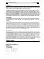
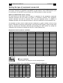
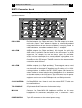
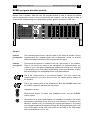
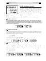
BCS70
USER MANUAL
EN
Dateq BCS70 Manual
Safety instructions
2
Safety instructions
1
All safety instructions, w arnings and operating instructions must be read first.
2
All w arnings on the equipment must be heeded.
3
The operating instructions must be follow ed.
4
Keep the operating instructions for future reference.
5
The equipment may never be used in the immediate vicinity of w ater; make sure that
w ater and damp cannot get into the equipment.
6
The equipment may only be installed or fitted in accordance w ith the manufacturer's
recommendations.
7
The equipment must be installed or fitted such that good ventilation is not obstructed in
any w ay.
8
The equipment may never be installed in the immediate vicinity of sources of heat, such
as parts of heating units, boilers, and other equipment w hich generates heat (including
amplifiers).
9
Connect the equipment to a pow er supply of the correct voltage, using only the cables
recommended by the manufacturer, as specified in the operating instructions and/or
show n on the connection side of the equipment.
10
The equipment may only be connected to a legally approved earthed mains pow er
supply.
11
The pow er cable or pow er cord must be positioned such that it cannot be w alked on in
normal use, and objects w hich might damage the cable or cord cannot be placed on it
or against it. Special attention must be paid to the point at w hich the cable is attached to
the equipment and w here the cable is connected to the pow er supply.
12
Ensure that foreign objects and liquids cannot get into the equipment.
13
The equipment must be cleaned using the method recommended by the manufacturer.
14
If the equipment is not being used for a prolonged period, the pow er cable or pow er
cord should be disconnected from the pow er supply.
15
In all cases w here there is a risk, follow ing an incident, that the equipment could be
unsafe, such as:
•
if the pow er cable or pow er cord has been damaged
•
if foreign objects or liquids (including w ater) have entered the equipment
•
if the equipment has suffered a fall or the casing has been damaged
•
if a change in the performance of the equipment is noticed it must be checked by
appropriately qualified technical staff.
16
The user may not carry out any w ork on the equipment other than that specified in the
operating instructions.
EN
Dateq BCS70 Manual
Introduction
3
Introduction
The Dateq BCS70 is a modular mixer unit which has been designed specially for use in radio
studios. The mixer unit consists of a frame (a split version is also available) with external power
supply, combined master / monitor module and various input modules.
Frame
The frame can take a maximum of 18 input modules, a script space and a master module. The
input modules can be positioned where wished in the frame. The BCS78 master / monitor
module is positioned at the right of the frame and the script space is positioned preferably in the
middle. A meter bridge is positioned on top of the frame. This contains a BCS62 VU, a 50
segment LED-bar meter with peak hold or a 101 segment Neon-bar meter. The meter bridge can
be expanded to include a BCS81 DCF-77 controlled clock / timer and a BCS68-2 extra set of 4
LED bar meters of 40 segments for reading CUE and AUD levels for example.
Pow er Supply
The BCS70 has an external power supply to prevent magnetic interference from the transformer.
The power supply is 19" wide, 2HE high and is connected to the frame via a 7-pin XLR
connector.
Input modules
There are many different modules available. All the modules (mono, stereo and telephone) are
available with and without tone control. The mono and stereo modules have two inputs which
are identical as regards facilities and which are available both with and without gain control.
The telephone module does not have a gain control because it is assumed that the external,
preferably digital, hybrid has an auto-gain function. Every module is equipped with trimmers to
allow the volume of all audio inputs and outputs to be set precisely. These controls are sited on
the modules' connector boards. The use of jumpers for modules is now minimal, most user
functions can be set via the software using a simple Setup function.
Microcontrollers
Each module is controlled by its own microcontroller. This controls all audio connections and
connected equipment. The microcontrollers can communicate with each other to allow 'global'
functions such as the control room mute and the Setup mode. Because all 'intelligent' functions
are contained within the software of the microcontroller, user-specific operation can easily be set
up without hardware modifications. What the user must specify is the type of equipment
connected to an input. There are a maximum of 16 preferred settings from which to choose.
Controls such as pulse/continuous contact, internal or external tally can be changed by this
means. Some 'non-standard' controls are pre-programmed, such as the standard setting for
Nautilus JukeBox automation, 360 Systems DigiCart and Denon CD and MD players.
Product support
If you have any questions concerning the BCS70, its accessories or other products, please
contact:
Dateq Audio Technologies B.V.
De Paal 37
1351 JG Almere
The Netherlands
Telephone:
Fax:
E-mail:
Internet:
+31 (36) 54 72 222
+31 (36) 53 17 776
info@dateq.nl
www.dateq.nl
EN
Dateq BCS70 Manual
Installation
4
Installing the mixer unit
The BCS70 is supplied as standard w ithout a cabinet or connector cables. It is possible to
make cables for connection to the Sub-D connectors of the various input and output modules
in-house. In that case, metal caps for the Sub-D connectors and cables w ith a separate
screening should be used, as per the CE norms.
Breakout boxes
Another possibility for connecting the mixer unit is to make use of so-called 'breakout boxes'.
All non-standard Sub-D connector on the rear of the BCS70 can be split up into more usual
connector types such as XLR plugs and TSR jacks. Breakout boxes should be connected to
the BCS70 using shielded Sub-D cable.
Installation into the cabinet
The BCS70 frame fits into an opening of 1050 x 547 x 75 mm (W x H x D). Without the meter
bridge the mixer unit projects 72 mm above the table top, w ith the meter bridge the highest
point is 205 mm. See also the dimensioned draw ing below .
EN
Dateq BCS70 Manual
Installation
5
Setting the type of equipment connected
Each module has a quad DIP sw itch for selecting the type of control of equipment connected
to an input. Therefore, on the BCS71 and BCS72 you w ill find tw o sets of DIP-sw itches (one
for each input). On the BCS73 you w ill find a set of DIP-sw itches for other functions.
BCS71 and BCS72 DIP-sw itch settings
For each input you can select from 16 types of operation for the equipment connected.
Whereas previously the only choice w as pulse or continuous contacts, now equipmentspecific operation can also be selected. This concerns equipment w hich, in addition to
standard operation, also has special functions or has to be operated in a non-standard w ay.
As standard, a choice can be made betw een continuous or pulse contacts (short or long
pulses), indication of internal or external tally on the ON and OFF buttons, giving a start pulse
again by pressing the ON button (Restart) and activating the CUE function by putting the
equipment w ith sw itched off module into the 'PLAY' state (Remote Cue).
Equipment control patterns available:
Type
0
1
2
3
4
5
6
7
8
9
10
11
12
13
14
15
Description
Normal consumer (default)
Normal consumer
Normal consumer
Normal pro
Normal pro
Normal pro
Reserved
Reserved
360 Systems DigiCart
Denon DN-xxxF
Tascam DA-30
Reserved
Reserved
Tally switches on/off
Tiesseci TS-35
Nautilus JukeBox
Start / Stop
Continuous
Pulse 100ms
Pulse 500ms
Continuous
Pulse 100ms
Pulse 500ms
Tally
Internal
Internal
Internal
External
External
External
Restart
No
No
No
No
No
No
Remote Cue
No
No
No
No
No
No
Pulse 100ms
Continuous
Pulse 1s
External
External
External
Yes
No
No
Yes
Yes
Yes
Continuous
Pulse 500ms
Special
Internal
Internal
Special
No
Yes
No
No
No
Yes
Í Type 0 (default)
The sw itches can easily be set w ith a ball-point pen.
DIP sw itch positions corresponding to certain types of equipm ent:
Type
0
1
2
3
4
5
6
7
1
Off
ON
Off
ON
Off
ON
Off
ON
2
Off
Off
ON
ON
Off
Off
ON
ON
3
Off
Off
Off
Off
ON
ON
ON
ON
4
Off
Off
Off
Off
Off
Off
Off
Off
Type
8
9
10
11
12
13
14
15
1
Off
ON
Off
ON
Off
ON
Off
ON
2
Off
Off
ON
ON
Off
Off
ON
ON
3
Off
Off
Off
Off
ON
ON
ON
ON
4
ON
ON
ON
ON
ON
ON
ON
ON
EN
Dateq BCS70 Manual
Installation
6
Use of non-standard equipment
One of the patterns given in the table on the previous page w ill suffice for most equipment. In
order to be able to connect up equipment w ith non-standard operation or tally outputs, it is
possible that other control softw are w ill be required, for example, or that any tally outputs w ill
have to be combined. In case of doubt or for special requirements, please contact Dateq.
BCS73 DIP-sw itch settings
The BCS73 w as originally designed for use w ith an external Telos ONE digital hybrid.
Therefore, connecting the ‘remote control’ cable is very easy. By default, the Telos ONE is
controlled by pulses. If you w ant to use a hybrid that must be controlled in a non-Telos w ay,
you can use DIP-sw itch settings corresponding to a control-pattern from the table below :
Control patterns available:
DIP-switch 1 DIP-switch 2 DIP-switch 3
Off
Off
Off
Off
ON
Off
ON
- (don’t care)
Off
Off
Off
ON
Off
ON
ON
ON
- (don’t care)
ON
Description
Telos ONE (default)
Long pulses
Continuous
DATEQ TH-2
Inverted long
Continuous inverted
Hybrid On / Off
Pulse 100ms
Pulse 500ms
Continuous
Inverted pulse 100ms
Inverted long pulse 500ms
Continuous inverted
The Telos ONE is a digital hybrid. If you use this type of hybrid, the rejection of return audio in
your program material is so high that you may w ant to allow talk-back to a caller during an onair situation. You can use DIP-sw itch 4 to select talk-back w hen on-air. If you use passive
hybrids or active hybrids w ith a low er rejection ratio, it is advisable to disable the talk-back
option. Otherw ise it is possible to hear the talk-back audio in your program w ith possible nasty
consequences...
Talkback if hybrid is on-air:
DIP-switch 4
Off
ON
Description
No talk-back if the hybrid’s audio is used in your program
Talk-back allowed, even if the hybrid’s audio is used in your program
EN
Dateq BCS70 Manual
BCS71(GE) dual mono input module
7
BCS71(GE) dual mono input module
BCS71
BCS71E
BCS71G
BCS71GE
Mono module w ithout gain or tone control
Mono module w ithout gain, w ith tone control
Mono module w ith gain, w ithout tone control
Mono module w ith gain and tone control
Mic / Line
Input selection. Sw itch pressed in is Line (LED lights
up).
Gain
Volume presetting (only on the BCS71G and
BCS71GE). Limited adjustment range: ± 12dB.
Low Cut
Low cut filter (20/80 Hz). Sw itch pressed in (LED
lights up) is active.
High
High tone control (only on the BCS71E and
BCS71GE). Shelving: ± 12dB @ 12kHz.
Mid
Mid tone control (only on the BCS71E and BCS71GE).
Bell curve: ± 16dB @ 1.3 kHz.
Low
Low tone control (only on the BCS71E and
BCS71GE). Shelving: ± 16dB @ 60 Hz.
AUX / AUD / PGM
Bus routing sw itches. The sw itch pressed in (LED
lights up) indicates that the signal is being routed
from the module to the bus concerned. AUX can be
set to PRE or POST fader w ith jumpers.
PAN
Panorama control. The signal is placed at the desired
position in the stereo image.
CUE
Monitoring. This button lights up green if the CUE
function on this module is active. The button lights up
red if an (external) mute is active.
Overload
This LED lights up if the signal level anyw here in the
module is too high and distortion can or does occur
(the limit is 6 dB under clip level).
Fader
100mm long volume control. Depending on the jumper
settings on the module, the volume on the AUX bus is
dependent (POST) or independent (PRE) of the
position of this fader.
ON / OFF
Sw itches w ith w hich the channel can be turned on
and off (if button start w as configured) and/or the
equipment connected can be started / stopped. The
lamps in the sw itches can light up dependent on the
channel status (internal tally) or can be controlled by
connected equipment (external tally).
EN
Dateq BCS70 Manual
BCS71(GE) dual mono input module
8
BCS71(GE) connector board
GAIN ADJUST
The input-level can be trimmed separately for both
the microphone and line input. Use a small
screw driver to adjust the trimmers in the holes
marked ‘mono’.
MIC
Mono microphone input on 25-pin female Sub-D
connector.
LINE
Electronically balanced mono line input on 25-pin
female Sub-D connector.
BCS71(GE) Audio and Control Input / Output (Sub-D 25-pin female)
Pin
1
14
2
15
3
16
4
17
5
18
6
19
7
20
8
21
9
22
10
23
11
24
12
25
13
Function
Channel ON / External CUE lamp
External CUE lamp / External CUE or Cough switch
External CUE or Cough switch
External tally ON (opto-coupler cathode)
External tally ON +
(opto-coupler anode)
External tally OFF (opto-coupler cathode)
External tally OFF +
(opto-coupler anode)
Remote control Start
(opto-coupler collector)
Remote control Start
(opto-coupler emitter)
Remote control Stop
(opto-coupler collector)
Remote control Stop
(opto-coupler emitter)
Audio Mono +
Audio Mono Audio GND
Insert Send +
(no insert used: connect to pin 11)
Insert Return +
(no insert used: connect to pin 10)
Insert Return (no insert used: connect to pin 25)
Insert GND
(no insert used: connect to pin 12)
Frame GND
Type
Out
D-GND
In
In
In
In
In
Out
Out
Out
Out
In
In
A-GND
Out
In
In
Out
FRAME
EN
Dateq BCS70 Manual
BCS71(GE) dual mono input module
9
Phantom power supply
Non-dynamic microphones usually need a 48V external pow er supply. If this pow er has to be
supplied by the BCS70, place jumper P7 in the ‘ON’ position. +48VDC (related to the (0)-input)
will be supplied to both the (+) and the (-) input.
Jumper P7 is positioned next to the bus connector of the BCS71(GE) module. The factory
default for this jumper is ‘OFF’.
Warning: central muting of multiple microphone channels
To prevent the line1/line2-selection of the input-modules from malfunctioning, pins #14
(common Cue / Cough) of the input-connectors can not be connected to each other. When
using a system that mutes multiple microphone channels with the ‘cough’-input (like FlexCom
FXS-D extensions), please note that if this system uses a common ground (like the FXS-D),
don’t connect this ground to pin #14 (common Cue / Cough), but rather use #13 (Frame) or
#25 (Ground).
EN
Dateq BCS70 Manual
BCS72(GE) dual stereo input module
10
BCS72(GE) dual stereo input module
BCS72
BCS72E
BCS72G
BCS72GE
Stereo module w ithout gain or tone control
Stereo module w ithout gain, w ith tone control
Stereo module w ith gain, w ithout tone control
Stereo module w ith gain and tone control
Line 1 / Line 2
Input selection. Sw itch pushed in (LED is lit up) is
Line 2.
Gain
Volume presetting (only on the BCS72G and
BCS72GE). Limited adjustment range: ± 12dB.
Mono
Makes the stereo input signal mono. Sw itch pushed
in (LED lit up) is active.
High
High tone control (only on the BCS72E and
BCS72GE). Shelving: ± 12db @ 12 kHz.
Mid
Mid-tone control (only on the BCS72E
BCS72GE). Bell curve: ± 16dB @ 1.3 kHz.
Low
Low tone control (only on the BCS72E and
BCS72GE). Shelving: ± 16dB @ 60 Hz.
AUX / AUD / PGM
Bus routing sw itches. Sw itch pushed in (LED lit up)
indicates that the signal is being routed from the
module to the bus concerned. AUX can be set to PRE
or POST fader w ith jumpers.
BAL
Balance control. This is used to set the balance
betw een the left and right channels.
CUE
Monitoring. This button lights up green if the CUE
function on this module is active. The button lights up
red if an (external) mute is active.
Overload
This LED lights up if the signal level anyw here in the
module is too high and if distortion can or does occur
(the limit is at 6 dB under clip level).
Fader
100 mm long volume control. Depending on the
jumper settings on the module, the volume is
dependent on the AUX bus (POST) or independent
(PRE) of the position of this fader.
ON / OFF
Sw itches w ith w hich the channel can be turned on
and off (if button start is configured) and/or the
connected equipment can be started / stopped. The
lamps in the sw itches can light up dependent on the
channel status (internal tally) or can be controlled by
connected equipment (external tally).
and
EN
Dateq BCS70 Manual
BCS72(GE) dual stereo input module
11
BCS72(GE) connector board
GAIN ADJUST
The input level can be trimmed separately for both
channels of both inputs. Use a small screw driver to
adjust the trimmers in the holes marked 'left' and
'right'.
LINE 1
First stereo line input on 25-pin female Sub-D
connector.
LINE 2
Second stereo line input on female 25-pin Sub-D
connector. Identical facilities to the first line input.
BCS72(GE) Audio and Control Input / Output (Sub-D 25-pin female)
Pin
1
14
2
15
3
16
4
17
5
18
6
19
7
20
8
21
9
22
10
23
11
24
12
25
13
Function
Channel ON / External CUE lamp
External CUE lamp / External CUE or Cough switch
External CUE or Cough switch
External tally ON (opto-coupler cathode)
External tally ON +
(opto-coupler anode)
External tally OFF (opto-coupler cathode)
External tally OFF +
(opto-coupler anode)
Remote control Start
(opto-coupler collector)
Remote control Start
(opto-coupler emitter)
Remote control Stop
(opto-coupler collector)
Remote control Stop
(opto-coupler emitter)
Audio Left +
Audio Right +
Audio Left Audio Right Audio Left GND
Audio Right GND
Insert Send Left +
(no insert used: connect to pin 23)
Insert Send Right +
(no insert used: connect to pin 11)
Insert Return Left +
(no insert used: connect to pin 22)
Insert Return Right +
(no insert used: connect to pin 10)
Insert Return Left (no insert used: connect to pin 25)
Insert Return Right (no insert used: connect to pin 25)
Insert GND
(no insert used: connect to pins 12 and 24)
Frame GND
Type
Out
D-GND
In
In
In
In
In
Out
Out
Out
Out
In
In
In
In
A-GND
A-GND
Out
Out
In
In
In
In
Out
FRAME
EN
Dateq BCS70 Manual
BCS73(E) external hybrid input module
12
BCS73(E) external hybrid input module
BCS73
BCS73E
Telephone module w ithout tone control
Telephone module w ith tone control
Com
Sw itches the signal from the telephone hybrid to the
COM bus, and sw itches the return signal from the
COM bus to the hybrid (see also QDM²).
TEL ON (ringer)
Sw itches the external hybrid on (the lamp in this
button flashes quickly if a ring is detected).
TEL OFF
Sw itches the external hybrid off if the channel is off
(keep pressed for 1 second to prevent operating
errors).
High
High tone control (only on the BCS73E). Shelving: ±
12dB @ 3 kHz.
Mid
Mid tone control (only on the BCS73E). Bell curve: ±
16dB @ 1.3 kHz.
Low
Low tone control (only on the BCS73E). Shelving: ±
16dB @ 600 Hz.
AUX / AUD / PGM
Bus routing sw itches. Sw itch pressed in (LED lit up)
indicates that the signal is being routed from the
module to the bus concerned. AUX can be set on
PRE or POST fader w ith jumpers.
PAN
Panorama control. The signal is positioned at the
desired place in the stereo image w ith this.
CUE
Monitoring. This button lights up green if the CUE
function on this module is active. The hybrid then
gets the CUE bus as return (see also QDM²). CUE
can not be selected if the channel is on. The button
lights up red if a mute is active.
Overload
This LED lights up if the signal level anyw here in the
module is too high and distortion can or does occur
(the limit is 6 dB under clip level).
Fader
100 mm long volume control. Depending on the
jumper settings on the module the volume is
dependent on the AUX bus (POST) or independent
(PRE) of the position of this fader.
ON / OFF
Sw itches w ith w hich the channel can be turned on
and off (if button start is configured) and / or the
equipment connected can be started / stopped. The
lamps in the sw itches light up dependently of the
channel status (intern tally).
EN
Dateq BCS70 Manual
BCS73(E) external hybrid input module
13
BCS73(E) connector board
GAIN ADJUST
The levels of the audio signal from the external
hybrid (receive) and the return audio signal to the
external hybrid (send) can be trimmed. Use a small
screw driver to adjust the trimmers in the holes
marked ‘send’ and ‘receive’.
AUDIO
Electronically balanced audio input and output for
audio coming from the external hybrid and return
audio to the external hybrid (QDM² return) on 9-pin
female Sub-D connector.
REMOTE
Remote control for the external hybrid on 9-pin male
Sub-D connector.
BCS73(E) Audio (Sub-D 9-pin female)
Pin
1
6
2
7
3
8
4
9
5
Function
Audio Send +
Audio Send Audio Send GND
GND
Frame GND
GND
Audio Receive GND
Audio Receive Audio Receive +
(audio to external hybrid)
(audio to external hybrid)
(audio from external hybrid)
(audio from external hybrid)
Type
Out
Out
A-GND
A-GND
FRAME
A-GND
A-GND
In
In
BCS73(E) Remote (Sub-D 9-pin male, Telos ONE compatible)
Pin
1
6
2
7
3
8
4
9
5
Function
External hybrid ON switch
(opto-coupler collector)
External hybrid ON / OFF switch common(opto-couplers emitter)
External hybrid OFF switch
(opto-coupler collector)
Telephone line ‘A’-lead
(used for ring-detector only)
Telephone line ‘B’-lead
(used for ring-detector only)
Type
Out
Out
Out
In
In
EN
Dateq BCS70 Manual
BCS78 master (monitor) module
14
BCS78 master (monitor) module
The master module is constructed using a new concept, w ith
microprocessor control and audio matrix to take care of routing to the
various outputs. Many of the buttons have a double function (see blue
print) w hich is used in the Setup mode.
SETUP
This is used to select the Setup mode. The LED
in this button flashes in Setup mode.
STUDIO
Volume control for the Studio output.
METER PGM / C.R.
Source selection for the meter in the meter
bridge: the PGM signal or the signal selected for
the Control Room (sw itch pushed in).
AUX
Volume control for the AUX output.
AUD
Volume control for the AUD output.
AIR..CUE
Selection of the signal on the Control Room
output (and on the Phones output). The active
selection can be seen from the LED w hich lights
up under a button. In Setup mode these LED’s
flash w hen the associated Setup option is
selected. The LED’s in the AIR and PGM button
are dimmed w hen MASTER-CUE is used in
combination w ith MIX.
Mute
This LED lights up if the Control Room output is
automatically sw itched off.
C.R.
Volume control for the Control Room output.
Overload
This LED lights up if the signal level in the master
module is too high.
Mono
Sw itches the signal from the Control Room to
mono.
PGM / AIR
This is used to select to w hich signal the DJ w ill
automatically listen if a DJ channel is on: AIR or
PGM. This selection also determines w hich of
these signals is mixed if another of the signals
from the CR selector panel is being monitored in
combination w ith the MIX function.
MIX
Mixes the dimmed signal chosen w ith the
PGM/AIR button w ith the signal selected w ith the
CR selector panel.
PHONES
Volume control for the Phones output.
EN
Dateq BCS70 Manual
BCS78 master (monitor) module
15
BCS78 master (monitor) module
COM (guest 1)
GST 1
COM (guest 2)
GST 2
ANN
COM (announcer)
Sw itches the signal from the COM bus to the
headphone output of Guest 1 and the signal
from the input module(s) configured as Guest 1
to the COM bus.
Volume control for the Guest 1 headphone
output.
Sw itches the signal from the COM bus to the
headphone output of Guest 2 and the signal
from the input module(s) configured as Guest 2
to the COM bus.
Volume control for the Guest 2 headphone
output.
Volume control for the Announcer headphone
output.
Sw itches the signal from the COM bus to the
announcer headphone output and the signal
from the input module(s) configured as
Announcer to the COM bus.
PGM / AIR (tbk src)
Selects the PGM or AIR signal as source for the
phones outputs of Guest 1, Guest 2 and
Announcer. The LED under this button lights up
if AIR is selected.
C.R. (tbk src)
Selects the signal selected on the Control Room
selector panel as the source for the headphone
outputs of Guest 1, Guest 2 and Announcer.
The LED under this button lights up if CR is
selected, and the selection made w ith PGM / AIR
is canceled.
MIC
Built-in microphone for talkback
TALK ALL
The DJ / technician can talk to Guest 1, Guest 2
and Announcer at the same time.
The DJ / technician can talk to Guest 1 using this
button.
The DJ / technician can talk to Guest 2 using this
button.
The DJ / technician can talk to the Announcer
using this button.
The DJ / technician can talk to everyone w ho is
routed to the COM bus.
The DJ / technician can talk to all telephone
modules on w hich the CUE function is active
(these modules have the CUE bus as return, see
also QDM²).
TALK GST 1
TALK GST 2
TALK ANN
TALK COM
TALK CUE
PHONES
Headphone output for the DJ / technician.
EN
Dateq BCS70 Manual
BCS78 master (monitor) module
16
BCS78 connector board
The BCS78 master (monitor) module has a number of connectors for audio inputs and outputs
and on-air indicating on the connector board.
AIR / SPARES
15-pin female Sub-D connector to w hich the balanced audio signals
for AIR, SPARE 1 and SPARE 2 can be connected. These inputs are
not electrically isolated. If a tuner w hich is connected to a cable
netw ork is connected up this can lead to an earth loop. To prevent this
it is advisable to have an isolating transformer in the aerial or audio
cable(s). These inputs can, for example, also be used for post-tape
check w ith recordings.
ANN / GST 1 / GST 2 15-pin female Sub-D connector w ith three independent stereo outputs
to w hich headphones of Announcer, Guest 1 and Guest 2 can be
connected directly. Also unbalance stereo Studio output.
INSERTS
Balanced insertion points in the stereo PGM signal.
CR-L / CR-R
Electronically balanced male XLR-3 outputs. These are used for
connecting the amplifier to the speakers in the Control Room. The
Control Room selector sw itches are used to select w hich signal can
be heard via this output. The volume of this output is determined w ith
the C.R. volume control. The Control Room output is automatically
sw itched off to prevent acoustic feedback.
AIR-L / AIR-R TRIM
The level of the AIR input can be trimmed. Use a small screw driver to
adjust the trimmers.
DIRECTOR
15-pin female Sub-D connection for an optional director's post.
ON-AIR 1 / ON-AIR 2
The ON AIR outputs are intended for connecting indicators, such as an
'ON AIR' lamp. The modules w hich these ON AIR outputs activate can
be set using the Setup mode. If there are microphones in tw o rooms,
for example a DJ microphone in the Control Room and other
microphones in the studio, then a separate 'ON AIR' indication can be
connected for each room. Configure the DJ microphone channel as ON
AIR 2 and the other microphone channels as ON AIR 1.
EN
Dateq BCS70 Manual
BCS78 master (monitor) module
BCS78 Director (Sub-D 9-pin female)
Pin
1
6
2
7
3
8
4
9
5
Function
BCSBus
Audio GND
+12V power supply
D-GND power supply
Audio Right
Audio Left
Audio GND
Director Mic +
Director Mic -
Type
Data
A-GND
POWER
POWER
Out
Out
A-GND
In
In
BCS78 Ann / Guest1 / Guest2 / Studio (Sub-D 15p female)
Pin
1
9
2
10
3
11
4
12
5
13
6
14
7
15
8
Function
Announcer Headphones Right
Announcer Headphones Common
Announcer Headphones Left
Guest 2 Headphones Right
Guest 2 Headphones Common
Guest 2 Headphones Left
Guest 1 Headphones Right
Guest 1 Headphones Common
Guest 1 Headphones Left
Studio Output Right
Studio GND
Studio Output Left
Type
Out
Out
Out
Out
Out
Out
Out
Out
Out
Out
A-GND
Out
BCS78 CR-L / CR-R (XLR 3p male)
Pin
1
2
3
Function
Audio GND
Audio +
Audio -
Type
A-GND
Out
Out
BCS78 ON-AIR 1 / ON-AIR 2 (TRS Jack 3p)
Pin
Tip
Ring
Sleeve
Function
On-Air Opto coupler collector
On-Air Opto-coupler emitter
Type
Out
Out
17
EN
Dateq BCS70 Manual
BCS78 master (monitor) module
BCS78 Inserts (Sub-D 9-pin female)
Pin
1
6
2
7
3
8
4
9
5
Function
Frame GND
Send Right +
Return Right Return Right +
Audio GND
Send Left +
Return Left Return Left +
Audio GND
(no insert used: connect
(no insert used: connect
(no insert used: connect
(no insert used: connect
(no insert used: connect
(no insert used: connect
(no insert used: connect
(no insert used: connect
to
to
to
to
to
to
to
to
pin
pin
pin
pin
pin
pin
pin
pin
7)
3)
6)
2)
9)
5)
8)
4)
Type
FRAME
Out
In
In
A-GND
Out
In
In
A-GND
BCS78 Air / Spare 1 / Spare 2 (Sub-D 15p female)
Pin
1
9
2
10
3
11
4
12
5
13
6
14
7
15
8
Function
Air GND
Air Right +
Air Right Air Left +
Air Left Spare 1 GND
Spare 1 Right +
Spare 1 Right Spare 1 Left +
Spare 1 Left Spare 2 GND
Spare 2 Right +
Spare 2 Right Spare 2 Left +
Spare 2 Left -
Type
A-GND
In
In
In
In
A-GND
In
In
In
In
A-GND
In
In
In
In
18
EN
Dateq BCS70 Manual
BCS70 connector board
19
BCS70 Connector board
At the back of the script space there are, in addition to the audio outputs of the BCS70,
various other connectors. There is also space for expansions such as extra audio outputs or
special accessories.
PGM-L/R/M
ProGraM outputs (Left, Right and Mono). The PGM output is the mixer
unit's main output. These balanced outputs are electrically isolated
using transformers and are therefore suitable for carrying signals to
cable modulators, transmitters and music lines, for example.
AUD-L/R/M
AUDition outputs (Left, Right and Mono). All channels for w hich the
AUD sw itch is pushed in can be heard on the AUD output. The AUD
output can, for example, be used as decor output, as post-fader
effect send, as extra output for a second edition of a programme, or to
quickly record a telephone interview w hilst the broadcast carries on
normally over the PGM output. The AUD control on the master module
controls the total AUD level.
AUX-L/R/M
AUXiliary outputs (Left, Right and Mono). These outputs can be used
to connect special-effects equipment, for example. Whether a channel
can be heard on the output is dependent on the setting of the AUXrouting sw itches. In addition, the PRE / POST jumpers can be used to
select w hether a channel must be mixed independent of or dependent
on the fader status on the AUX output. The AUX control on the master
module controls the total AUX level. Return signals from effects
equipment can be sent to the PGM output via a normal input module.
CLOCK ANTENNA
If a Dateq BCS81 clock / timer is used, the external DCF-77 aerial can
be connected here.
TOP CONSOLE
25-pin female Sub-D connector for the meter bridge.
MCA-100
Connector for Dateq MCA-100 headphone amplifiers so that more
headphones for announcers and guests can be connected - each
w ith their ow n volume control and cough / speak button.
POWER SUPPLY
7-pin XLR connector for the external pow er supply.
EN
Dateq BCS70 Manual
BCS70 connector board
BCS70 PGM-L/R/M / AUD-L/R/M / AUX-L/R/M (XLR 3p male)
Pin
1
2
3
Function
Audio GND
Audio +
Audio -
Type
A-GND
Out
Out
BCS70 CLOCK ANTENNA (TRS stereo jack)
Pin
Tip
Ring
Sleeve
Function
Antenna +
Antenna Frame GND
Type
In
In
FRAME
BCS70 TOP CONSOLE (Sub-D 25p female)
Pin
1
14
2
15
3
16
4
17
5
18
6
19
7
20
8
21
9
22
10
23
11
24
12
25
13
Function
Extra Meter 1 Left
Extra Meter 1 GND
Extra Meter 1 Right
Extra Meter 2 Left
Extra Meter 2 GND
Extra Meter 2 Right
Extra Meter 3 Left
Extra Meter 3 GND
Extra Meter 3 Right
-15V Power Supply
Extra Meter 4 Left
Extra Meter 4 GND
Extra Meter 4 Right
+12V Power Supply
+12V Power Supply
Main Meter Left
Main Meter GND
Main Meter Right
GND Power Supply
GND Power Supply
DCF Antenna Signal +
DCF Antenna Signal BCSBus
Digital Ground
BCSBus
(2nd function: Timer Control 1)
(2nd function: Timer Control 2)
Type
Out
A-GND
Out
Out
A-GND
Out
Out
A-GND
Out
POWER
Out
A-GND
Out
POWER
POWER
Out
A-GND
Out
D-GND
D-GND
Out
Out
Data
POWER
Data
20
EN
Dateq BCS70 Manual
Operating instructions
21
Setup-mode
The settings on the mixer unit can be changed using the Setup mode. This applies in particular
to the settings w hich used to have to be made w ith jumpers on all modules. The great
advantage is, of course, that the user can make changes in the use of the console quickly
w ithout having to unscrew the modules.
The Setup mode is activated by pressing the very noticeable red SETUP button. The LED
under this button and the ON and OFF button on all modules start to flash. The LED in the AIR
button on the CR selector panel flashes. BUTTON START appears next to this in blue. This
indicates that those channels that must w ork w ith button start can now be set. Should a
channel w ork w ith button start? If so, press the ON button on the channel concerned. Press
the channel's OFF button if that channel should be set as fader start.
The follow ing settings can be made in the same w ay (see blue print):
BUTTON START
MASTER CUE
DJ MODE
COUGH > COM
EXT MUTE
ONAIR 1
ONAIR 2
RES
Select ON if a channel should be sw itched on and off w ith the ON
and OFF button. Select OFF if the channel should be sw itched on and
off w ith the fader.
Select w hether a channel automatically sets the Control Room
selection on CUE w hen CUE is pressed (select ON), or w hether this
must be done manually (select OFF).
If a channel is for an announcer w ho is also the technician, select ON.
The Control Room speakers w ill then automatically be muted if this
channel is open. For the other non-DJ channels select OFF.
If the external mute on a microphone or line module is active (by
pressing the cough / talk button), the module automatically sw itches to
CUE (if OFF is selected) or to COM (if ON is selected). In this last case,
any 'coughing' is to the COM bus. In this w ay one can, for example,
speak directly to the director, instead of to the technician.
Select ON if the channel must be muted if an external sw itch is
pressed (cough / talk button). Select OFF if the external sw itch is used
as a remote CUE sw itch (positioned, for example, near a turn-table to
set the mixer unit to CUE by remote control).
Select ON if a module should be part of on-air group 1, select OFF if it
should not be part of this group.
Select ON if a module should be part of on-air group 2, select OFF if it
should not be part of this group.
Reserved for a BCS81 clock / timer (if installed). Select ON if a module
must be able to start and stop the timer w hen the module is turned on
and off. Select OFF if the module may not start or stop the timer.
NORMAL / SPLIT
During CUE the technician can choose w hether the signal from the
Control Room selector panel comes to the Phones output normally
(select N) or as a split signal (select S). In this last case, the PGM
signal goes to one earphone and the CR signal selected to the other
earphone of the headphones.
GST 1 COM
To route Guest 1 to the COM bus, the mixer unit must know w hich
module(s) belong to Guest 1. Select ON on these modules (thus
making a Guest 1 group!), OFF on the other modules.
The same for Guest(s) 2.
The same for the Announcer(s).
GST 2 COM
ANN COM
EN
Dateq BCS70 Manual
Operating instructions
22
Advanced module control
For special operation modes or in situations w here the normal module audio control circuitry is
‘too slow ’ (or the controls are too fast) for your application, it is possible to disable the
channel mute and introduce a startup-delay. Enter the setup-mode and select one of the
following setup-options (buttons just above the built-in talkback microphone):
PGM / AIR
C.R.
If you enable this setup-option on a module, you let the fader control
the channel mute, independent from the equipment or channel On/Off
status. If the fader is up, audio is enabled to the PGM, AUD and AUX
(post-fader) outputs. If the fader is closed, the channel is muted. In
this mode, starting and stopping equipment is most useful in
combination with button-start.
Equipment start-delay (100ms). If you enable this setup-option on a
module and you open the channel (either w ith fader- or button start),
the equipment connected to the module is started after a delay of
about 100ms. This ensures that the channel is completely open (mute
and VCA) as soon as the equipment gives audio.
Setup-mode time-out
If no buttons are pressed to change a setting for a period of ten seconds, then the Setup
mode w ill automatically be terminated. If an operation is carried out in Setup mode w hich has
nothing to do w ith this mode (moving a fader or pressing a CUE-button on a module, for
example), Setup mode is terminated immediately.
Is the Setup m ode dangerous?
Should the Setup button be accessible to all users? The button could of course be replaced
by a key sw itch, but the question is w hether that is really necessary. The settings that can be
made in the Setup mode are, after all, not so dangerous that they w ould affect the audio
processing of the mixer unit (as far as that is concerned, the routing sw itches on all modules
are really much more dangerous). For all these sorts of buttons, you must know w hat you are
doing. To indicate that the Setup button can be 'dangerous' for untrained users, it has been
made a very noticeable red color.
Virtually identical Setup facilities for m ono and stereo m odules
All the inputs of a mono or stereo module have virtually the same Setup facilities. Only the
functions relating to the COM bus are unavailable on the BCS72(GE) and cannot, therefore, be
set in the Setup mode. It is, how ever, possible to use a stereo module to w hich a microphone
pre-amplifier / processor is connected as a DJ channel w ithout modification. The sw itch
w hich on a stereo module w ould normally be used as an external cue button can be given the
function of 'cough' button.
Identical Setup facilities for both inputs
In the Setup mode the first line input (or Mic input for a BCS71(GE) module) can be configured
differently to the second line input. Select the Setup function required (for example button
start) and set this for the required input (for example, line 2). Now sw itch over to the other
input (in this case, Line 1) and set the function as required. The settings made are also stored
as Presets independently for Input 1 and Input 2 (Mic and Line).
EN
Dateq BCS70 Manual
Operating instructions
23
Presets
The settings entered in the Setup mode can be stored as preferred settings and can, of
course, be recalled. As standard, there is room for five settings. There is also a 'factory
preset' available w ith w hich the unit can alw ays be configured to the basic setting. It should
be noted that the settings are not so critical that the unit w ould no longer w ork!
Recalling presets
Select Setup mode w ith the SETUP button. Then quickly press (for less than tw o seconds)
one of the preset buttons (the talk buttons on the master section). The preset concerned is
printed in blue: GST 1 is preset 1, CUE is preset 5. The factory preset is special: this is the
ALL button.
Storing presets
Select the Setup mode w ith the SETUP button. Then press long (longer than tw o seconds) on
one of the preset buttons (the talk buttons on the master section). The preset concerned is
printed in blue: GST 1 is preset 1, CUE is preset 5. The factory preset can not be overw ritten.
The COM-bus
The BCS71 and BCS73 modules can put their audio signals onto the COM bus. The output of
the COM bus can be routed to all headphone outputs (Announcer, Guest 1, Guest 2), to the
technician and director monitoring the COM bus, and to the output from the external hybrids
w hich are connected to the BCS73 modules.
Linking the announcers and guests to the COM bus
In contrast to the BCS73(E), there is no COM button on the microphone modules to put the
signal from that module onto the COM bus and to take it off again. The Setup mode comes into
action again for this. Select the Setup mode and press the COM button by the Announcer's
volume control. Then select w hich module(s) belong to the Announcer. The same can be done
for Guest 1 and Guest 2.
Now leave the Setup mode and press, for example, the Announcer's COM button. The LED in
this button now indicates that the Announcer has been routed to the COM bus. The signal
from the microphone module(s), w hich has just been designated as Announcer microphone in
the Setup mode, is now sw itched to the COM bus. Also, the Announcer w ill listen via the
headphones to the COM bus. The same procedure applies to the COM button of the volume
controllers for Guest 1 and Guest 2.
Conferring using the COM bus
It is very easy to arrange for the announcers and callers to confer w ithout this being
broadcast using the COM bus. Using the COM sw itch next to the volume control for the
Announcer's headphone, sw itch the Announcer to the COM bus. The microphone(s) of the
Announcer(s) now supplies (supply) a signal to the COM bus and the signal on the COM bus
can now be heard on the headphones w hich are connected to the Announcer output. Now
sw itch the required hybrid(s) to the COM bus w ith the COM sw itch on the BCS73(E)
module(s). The announcers and callers can now talk to each other.
The announcer and guests can be linked together in the same w ay.
EN
Dateq BCS70 Manual
Operating instructions
24
Talking and coughing to the COM bus (Cough > Com )
Normally an announcer or guest can set the corresponding module in the mixer unit to CUE
using the cough button and at the same time mute the channel. In combination w ith the
MASTER CUE cue function, the DJ / technician can then be spoken to.
In the BCS70 it is also possible to have this form of communication going not via the CUE bus
but via the COM bus. Configure the required modules as COUGH > COM using the Setup mode.
Now , if the cough button is pressed, the channel is muted -and the user can still cough- but
the module’s signal is sent to the COM bus and thus to everyone w ho is listening to the COM
bus (the director, for example). The DJ / technician is then not disturbed unnecessarily.
QDM²
The external hybrid automatically gets the correct N-1 return from the COM, CUE, AUD or PGM
bus. This is the so-called Quadruple Dynamic Mix-Minus system, shortened to QDM2. Since the
BCS73 generates the N-1 signal itself, separate 'clean feeds' are not necessary. The number
of BCS73 modules w hich can be used at the same time is therefore theoretically unlimited. In
practice, the number of telephone lines w hich can be used at the same time is limited by the
quality of the telephone hybrids used.
If AUD is selected as w ell as PGM, the return from the PGM bus has priority over the return
from the AUD bus. The LED in the PGM button lights up more brightly than that in the AUD
button in this case.
CUE has a higher priority than AUD or PGM. As soon as CUE is selected on a BCS73 module,
the external hybrid gets the return from the CUE bus. This is only possible if the module is
sw itched off.
COM has the highest priority if the channel is sw itched off. If the COM button of a BCS73
module is pressed, the signal from the connected hybrid is routed to the COM bus. The LED in
the COM button then lights up and everyone listening to the COM bus can hear the external
hybrid. The external hybrid also gets the return signal from the COM bus so that the person on
the other end of the telephone line can listen to w hat is being said on the COM bus. Press on
the COM button again to sw itch the hybrid aw ay from the COM bus again. The LED in the COM
button goes out.
If COM has been selected and the channel is on, then, depending on the routing set, the
module gets the return from the PGM or AUD bus. To indicate that COM does not give a return
in this situation, the LED in the COM button starts to flash.
If the channel is turned off and COM and CUE are both active, the module gets the return from
both these busses.
EN
Dateq BCS70 Manual
Operating instructions
25
Automation
Because most of the functions of the BCS70 are determined by microcontrollers, existing and
new automatic functions could be implemented.
CUE reset w hen a channel is opened
To reduce the possibility of making mistakes, in this case listening to the CUE-signal in stead of
your program, the CUE-function on a module is reset if you open the channel.
CUE reset if you select a source other than CUE
As soon as you select a control-room source on the master module w hich is not the CUE
source, all active CUE’s on the input modules are reset. This ensures you of listening to the
selected source, even w ith master-CUE configured on one or more modules.
Rem ote CUE function w ithout external CUE sw itch
If a module has been configured w ith the Remote Cue function, then it is possible to put that
module on CUE by setting the connected equipment in the PLAY mode. This (softw are)
function makes an external CUE button superfluous. The reverse (starting the equipment if
CUE is pressed w ith the channel sw itched off) is also possible, although this is not
implemented as standard in the module's operating softw are. Please contact Dateq if you
really need this option for your application.
Control Room output is sw itched off
The signal to the Control Room output is automatically sw itched off as soon as there is a
possibility that there w ill be feedback from a microphone via the speakers connected to this
output. This can happen if, for example, a DJ channel is on, if CUE and MASTER CUE on a DJ
channel are active or if the technician is speaking to the COM bus or to the CUE bus w hen the
bus concerned has been selected on the Control Room selector panel.
Sw itching Control Room and Phones to AIR or PGM
To prevent mistakes, the Control Room automatically sw itches to the AIR or PGM signal at the
moment that a DJ channel is sw itched on. This guarantees that the DJ is listening to the
correct signal if he is about to go on air. The Control Room selection made earlier is restored
w hen the DJ channel is sw itched off again.
Equipment connected is stopped if input-selection changes
If you sw itch over from -for instance- input 1 to input 2, the equipment connected to input 1 is
stopped first before the module switches over to input 2.
NL
Dateq BCS70 Manual
BCS80 program director module
26
BCS80 program director module
Especially for setups w ith a separate engineer and program director, an optional program
director unit is available. With this unit, the program director is able to choose his monitor
source independent from the source selected by the engineer, and the director is able to
communicate independently to all destinations (guest1, guest2, announcer, COM, etc.).
Control
Internal
loudspeake
r
The selected monitor source can be heard on the external speaker. During
communication, the speaker signal w ill be temporarily muted, to prevent
unwanted background noise in the program director signal.
Internal
microphon
e
The internal microphone is located in the low right corner of the speaker.
There is no need to be close to this microphone for communications: the
volume of your voice w ill be automatically adjusted to a fixed level. Just look
in the direction of the FXS-station w hile talking, even from a distance of more
than an armlength, the intelligibility will be more than sufficient.
This is the volume-control of the internal speaker. Turn this control fully
counterclockw ise if you don’t w ant to have the monitor-source audible on
the speaker.
This is the volume-control of the headphones. Both the PHONES-output and
the GUEST-output are adjusted with this control.
Headphones output
Extra phones output. To adjust your headphone level, use the PHONESvolume control.
Connection for an external microphone, for example in a headset. The built-in
microphone is sw itched off as soon as a jack connector is inserted in the
MIC-input. Another w ay of connecting an external microphone is by looping
your normal broadcast microphone through the XLR-input/output at the rear
of the FXS-station. In that case, the sw itch at the back of the FXS-station
has to switched from “int” to “ext”.
NL
Dateq BCS70 Manual
BCS80 program director module
27
Pressing the “COM/MUTE”-button w ill initiate talkback from the program
director to the COM-bus.
Keypad
The m onitor selection keys offer the program director the possibility to select
to w hich signal is monitored: AIR, SPARE1, SPARE2, COM, PGM, AUD, AUX or
CUE.
With the talkback keys the director is able to talk to the different talkbackdestinations: ANN (announcer), GST1, GST2 (the guests), the COM-bus, the CUEbus, DJ/CR (the discjockey or engineer), the STUDIO-output, or all destinations at
the same time (ALL).
The TEL1..TEL4 keys w ill sw itch the corresponding telephone hybrid on-line. This
is indicated w ith green LED’s in these keys. The telephone hybrids in the BCS70console w ill be numbered TEL1..TEL4 from left to right (TEL3 and TEL4 are optional
keys).
The OFF key sw itches the hybrid off-line. Green LED’s in these keys indicate that
the hybrid is off-line.
The MUTE key mutes the hybrid signal on-air.
By pressing the TALK key the director talks back to the corresponding hybrid.
This is done by sw itching the hybrid-return temporarily to the COM-bus, and letting
the director talk to that COM-bus.
EN
Dateq BCS70 Manual
Block diagrams
28
BCS81 clock/timer module
The BCS81 clock/timer-module receives its time-of-dayinformation from the German DCF77-transmitter at
Mainflingen (near Frankfurt). The range of this transmitter
is approximately 1000 miles. Besides extreme accuracy,
the BCS81 keeps track of daylight-saving-time etc.
Unique is the infra-red remote control for selecting
operation mode and entering time.
Timer
The timer can be used counting up or down. The [MODE]-key selects the desired mode:
TIMER COUNTING UP
In the initial mode the BCS81 counts upw ards from 0:00.0. This mode can be useful for
keeping track of the elapsed time since the last record, jingle or other item w as started.
Triggering the timer w ith a microphone-channel can be useful to monitor the length of the
‘spoken’ parts of a radio-program.
TIMER COUTING DOWN
To indicate the (approaching) end of a pre-recorded item, for example, the BCS81 can be set
in the countdow n-mode. The timer w ill count dow n from a set point to 0:00.0. This time can be
entered with the remote control, for example:
[1] [2] [ENTER]
The timer will start counting down from 0:12.0.
TIMER COUNTING UP/DOWN
During an intro of a (music-) item the timer w ill count dow n to indicate the (approaching) end
of the intro. When 0:00:0 is reached, the timer sw itches to indicating the elapsed time from the
point w here the timer w as triggered. The intro-time can be set from the remote control the
same way, for example:
[1] [2] [ENTER]
The timer will start counting down from 0:12:0 to 0:00:0, then counting up from 0:12:0.
EN
Dateq BCS70 Manual
Block diagrams
29
TIMER COUNTING DOWN TO A SET TIME
In this mode the timer indicates the remaining time until a set time is reached, for example the
starting-time of commercials and/or new s. Enter this time from the remote control unit, for
example:
[1] [7] [5] [7] [3] [4] [ENTER]
...to count dow n to 17:57:34. There is an important distinction betw een this mode and the
other modes. This mode can be run in ‘background’, independent from the other timer-modes.
Once the set-time is programmed, the timer can be started, stopped and reset in all other
modes, w hile the countdow n timer keeps running. If you sw itch back to this mode, the
remaining time will be displayed again.
In case the set time is approaching w ith the timer in a different mode, a small blinking dot is
displayed on the left of the timer-display for the last 30 seconds, to draw the users attention.
INPUT-MASK-MODE
For external triggering of the timer 8 sw itch-signals can be connected to the BCS81. Since it is
not alw ays desired to trigger the timer w ith all connected signals, each signal can be
individually blocked out w ith the mask-option. In the initial situation all inputs are enabled, so
the display w ill show ‘1234/ 5678’. With the [1] .. [8] - keys of the remote control unit each
channel can be disabled or enabled. For example by pressing
[3] [5] [6]
the display w ill show ‘12-4 / --78‘. This means channels 3, 5 and 6 are disabled. Inputs 1, 2, 4,
7 and 8 are enabled.
Please note that the BCS70 uses input 1 and 2 to control the timer, so only inputs 3 through 8
are available for user-specific signals. You should alw ays have input 1 enabled. Input 2 can
be enabled or disabled to use the timer in tw o different operating modes. If you enable input 2,
each channel on the BCS70 w hich is configured to control the timer (by means of the RES
setup-option) w ill restart the timer as soon as the channel is opened. If you disable input 2, the
timer w ill run as long as there is at least one open channel on the BCS70 w ith the timer control
setup-option selected.
Setting the time
During normal reception-conditions the clock w ill be synchronized w ithin 2 minutes, and the
right time w ill appear on the display. It is also possible to use the clock w ith the antenna not
connected (‘free running’). In this case setting the clock to the right time can be done by
entering the time from the remote control unit, by pressing [0] [0] [0] w hen in input mask mode.
When this is done, ‘
/ SEt ‘ will appear. For example:
[1] [7] [2] [8] [0] [0] [ENTER]
The clock starts running from 17:28:00 as soon as the [ENTER] key is pressed.
When the clock is a little slow or fast it can be synchronised by pressing the [C] key at the
w hole hour w hen the timer is in counting-up-mode. This function is only available w hen no
valid DCF-signal is received and the time-deviation is less than 3 minutes.
EN
Dateq BCS70 Manual
Block diagrams
30
This function is available w hen your clock has firmw are version 1.5 or higher. To check your
firmware version go to the input-mask-mode and press the [C] key!
BCS81 jumpers
J1/J2/J3
RC5-ADRES
8
+
1
P8
1
3
P1 1
1
L1
P9
-
Q3
R3 9
+
1
P7
+
P1 0
REM 7
+
REM 6
+
REM 5
Q1
P6
Q2
+
R4 0
C2 1
1
C9
R4 3
C2 2
P5
R3 6
C2 0
R3 7
C1 6
4
U1 2
C1 9
R4 2C1 0
U14
R1 9
-
Q4
C5
R2 6
C1 8
2
1
R2 1R2 2
U13
L2
+
U18
R4 1
1
R2 5
C4
J1
D3
C1 1
P1 2.
J2
J3
ON
1
OF
C1 7
+
1
P4
R3 8
D1
REM 4
+
REM 3
1
RC5
ADRESS
+
REM 2
C2 3
U8
1
R4 4
+
U11
P3
R3 5
A1
P2
U10
U15
1
+
Jumper
J1
On/Off
ON
OFF
ON
OFF
J2
J3
A0 = 0
A1 = 1
A0 = 1
A1 = 0
A0 = 0
A1 = 1
A0 = 1
A1 = 1
-
1
1
U16
C8
A0
C6
0
U9
REM 1
P1 3.
C7
R2 4
P1
U17
XT1
R2 0
Function
BCS81 configured as slave (using another Dateq clock/timer-unit as
master)
BCS81 configured as master (default)
12-hour time format with AM/PM (default in the USA)
24-hour time format (default in Europe)
(not used)
Address 0 remote control (default)
Address 1 remote control (w hen using multiple Dateq clock/timer-units
in one room, it is recommended to use different remote control
addresses)
Address 2 remote control
Address 3 remote control
BCS81 antenna
The cable of the supplied DCF77-antenna can be extended w ithout any problem (up to a
maximum of 100 meters, 300 feet). Mount the antenne in a position w here reception quality of
the DCF77-transmitter is good. Be aw are of the fact that the direction of the antenna is
important. If the reception of the transmitter is good, the LED on the antenne w ill blink every
second on a regular basis. If the LED doesn't blink, or blinks irregularly, reception is bad. The
cause for a bad reception can often be found in computer-equipment nearby, or steel
constructions in the building, blocking the long-wave signal of the transmitter.
CAUTION:
The supplied antenna is not suitable for outside-mounting. The antenna is not
w aterproof, and the built-in electronic circuit w ill not operate properly below the freezing point
and above 50 degrees Celsius.
EN
Dateq BCS70 Manual
Dateq BCS70 block diagrams
Block diagrams
31
EN
Dateq BCS70 Manual
Block diagrams
32