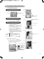
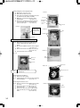
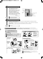
1
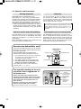
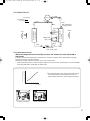
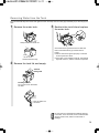
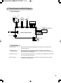
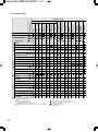
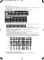
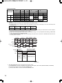
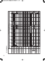
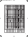
e_mj_e26vx_a1(01_23)33j.qk 05.12.20 10:15 AM ページ 1
MITSUBISHI ELECTRIC
ADVANCED AND EVER ADVANCING
2005
DEHUMIDIFIER
SERVICE MANUAL
Model
MJ-E26VX-A1
Sold from 2005
CONTENTS
1.
2.
3.
4.
5.
6.
7.
PRODUCT SPECIFICATIONS........................................................................................ 2
OUTER DIMENSIONS .................................................................................................... 3
TIPS ON DEHUMIDIFYING............................................................................................. 3
EXTERNAL VIEW, PARTS AND DISPLAY SECTION................................................. 4 ~ 8
TECHNICAL POINTS.................................................................................................. 9 ~ 11
MAINTENANCE ......................................................................................................... 12 ~ 14
WIRING DIAGRAM AND BLOCK DIAGRAM
7.1 Wiring Diagram....................................................................................................... 15
7.2 Function List ....................................................................................................... 16 ~ 19
7.3 Timing Charts ..................................................................................................... 20 ~ 23
7.4 General Block Diagram ...................................................................................... 24 ~ 25
8. TROUBLESHOOTING PROCEDURE
8.1 Troubleshooting flowchart ................................................................................. 26 ~ 27
8.2 Key Component Check Procedures ....................................................................... 28
8.3 Error Indications and Corrective Actions ............................................................... 29
8.4 Self-Test program and Execution Procedure .................................................... 29 ~ 30
9. DISASSEMBLY AND REASSEMBLY HINTS .......................................................... 31 ~ 33
10. CONTINUOUS DRAINAGE ........................................................................................... 33
PARTS CATALOG .......................................................................................................... 34 ~ 41
11. TROUBLESHOOTING ............................................................................................... 42 ~ 43
PRECAUTIONS ............................................................................................................... 44 ~ 46
1. Product Specifications
MJ-E26VX-A1
Model
50 Hz
Dehumidifying capacity
26.0
Low temp, laundry
47
Auto-dehumidification, low
39
Single phase, 230-240V, 50Hz
Power supply (phases,V,Hz)
Power consumption (W)
415
Operating current (A)
1.9
Starting current (A)
8.5
White (W)
Color tone
594 × 372 × 281
Dimensions (H × W × D mm)
15.5
Weight (kg)
HFC - 134a, 275g
Coolant quantity (g)
Evaporator
Slit fin
Condenser
Slit fin
Thermal overcurrent relay
Compressor
Compressor protection
YB691 VTE (rotary)
Model
240
Output (W)
Primary: 16.9 , subsidiary: 30
Winding resistance (Ω)
With temperature fuse
Sirocco fan
Type
20
Output (W)
4
Flow rate selection
Flow rate (m3/min)
4.0
[4.1]*
Operating room
temperature (reference) (°C)
603
4.0
2.6
863
[882]*
4.0
[4.1]*
4.0
Hot gas type
Humidity control
Built-in humidity sensor
Tank full protection
Reed switch (automatic)
Tank capacity (liters)
Auto-stopper tripped with about 5.0 liters of water
Continuous drainage
Commercial hose (inside diameter 15 mm)
Operation modes
863
1 ~ 35 (°C)
Defrosting method
AUTO, EASY DEHUMIDIFYING, LAUNDRY, MILDEW GUARD, HIGH, LOW, LOW TEMP,
AIR PURIFIER, MILDEW GUARD ELITE
Timer
On/Off timer (1-9h)
Air cleaning performance
Yes
Plug socket rating
7.5A
The operating noise levels indicated are
typical values measured in our anechoic room.
2
863
Low
3.3 or
2.6
863
[882]*
High
603 or
733
Laundry
Speed (rpm)
Autodehumidification
Blower
Product performance
Blower protection
Mildew guard
Operating noise
levels(dB)
(27°C room temperature,60% relative humidity) (liters/day)
Low temp
Electrical
characteristics
Performance
Item
* The brackets [ ] enclose values measured at a room
temperature of about 15°C or lower.
2. Outer Dimensions
3. Tips on Dehumidifying
Drain the water tank before use
Installing your dehumidifier
Refrain from opening
doors/windows during
operation
Make sure to leave some space around the
unit.
At least 50 cm
At least
20 cm
Drying laundry indoors
¡Thoroughly spin-dry the laundry
and hang so there are no wrinkles.
¡Direct the louvres at the laundry.
¡Space laundry to improve airflow.
At least
2 cm
At least
20 cm
At least 20 cm
Use the dehumidifier in
a small, enclosed room.
Operating noise
Place the unit on top of a mat. This reduces
vibration and noise. It also prevents leaving
depressions on carpets.
Maintain room temperature above 16°C
with a heater
¡ Drying times will vary depending on the nature of the
laundry and the room temperature.
¡ The airflow is strongest to the top right of the unit.
3
4. External View, Parts and Display Section
Front
Back
Louvre
Main Air Outlet
Handle
Raise handle to transport
Control panel
Washable photocatalytic filter
(hereafter: photocatalytic filter)
Supplied with unit. Set
before use.
Rear Air Intake
Downward louvre
Pre-filter
The pre-filter is made from
two layers: a blue air filter
and a white particle filter.
These layers cannot be
separated.
Air filter performance testing
facility
Japan Spinners Inspecting
Foundation (tested under
JIS L 1902 standards)
Tank lid
Tank Guard
Float
Water tank
Level window
Storage Hook
Sensor
Do not cover
Cord Tie
Remove during
operation
What is a washable photocatalytic filter?
The washable photocatalytic filter has a two-layer construction consisting of a
white particle filter and a blue air-freshener filter.
<Particle filter>
The fine particle filter removes pollen* and dust particles.
<Air-freshener Filter>
The special air-freshening agent contained in the fibres of the air-freshener
filter absorbs dorants such as ammonia. The odor is broken down by
photocatalysis renewing the airfreshening properties.
As the filter's particle and air-freshening properties are renewed by simply
soaking and leaving it to dry in the sun, the air purifier can be used
continuously over a long time. Cigarette smoke and toxins found in smoke,
such as carbon monoxide, cannot be removed with this filter.
* Diameter of pollen: approx. 10-100µm
Power plug
Continuous
drainage outlet
Wheel (4)
Control Panel
The water tank may contain water
residue at time of purchase. This is
from final product testing at the
factory and is not due to a defect.
¡Tank full light
This lights up to warn
that the water tank is
full.
¡Mildew guard elite lamp
Flashes during internal drying
operation.
¡Mildew guard elite button
Activate/deactivates internal drying.
¡Power lamp
Lights when unit is ON.
¡Power button
Use this to switch the
unit ON and OFF.
¡Lamps
Current mode lights
¡Selection button
Switches modes
You can select from 8
operating modes
¡
¡
¡
¡
¡
¡
¡
¡
EASY DEHUMIDIFYING
LAUNDRY
HIGH
LOW
MILDEW GUARD
LOW TEMP
AUTO
AIR PURIFIER
¡Mode button
For switching from one
perating mode to another
¡Humidity Selection
This is used to set the target
humidity.
All modes include
dehumidifier and air
purifier functions.
Air purifier only operation.
The dehumidifier function is disabled.
LCD Panel
¡Mode Indicator
Indicates the
current operating
mode.
4
¡Humidity Indicator
This indicates the
approximate humidity
indicates the
current humidity
indicates the
humidity setting in
AUTO mode
The current humidity is
displayed in a range from 30
to 80%.
¡Swing louvre
button
Sets swing louvre
direction or locks it
into position
¡Child lock
To set the child
lock, press the
mode button for
three seconds.
¡Timer ON/OFF
Sets timer
¡Information display
Indicates room and unit condition
Low
Temperature
Indicator
The
indicator comes
on if the room
temperature drops below
15°C.
Activating Low Temp
mode is recommended.
All indicators on the
LCD panel shown
below.
High humidity
warning
¡Swing monitor
Indicates the
direction of the
swing louvre.
¡Timer display
Displays the time
set for the
ON/OFF timer.
¡Air purifier lamp
Lights during air purifier only
operation
¡Air purifier button
Switches to air purifier only
operation
DEFROST
Indicator
Airflow (dehumidifying) will stop and
the frost that has accumulated inside
will be melted and dropped into the
tank when the
indicator is on.
Please wait a moment as operation
will resume in around 5 minutes.
While in DEFROST mode, airflow
(dehumidifying) and the louvre will
stop. The sounds coming from the
unit will also change.
DEFROST will start automatically
when room temperature drops below
15°C (This may be as often as once
every 40 minutes).
The indicator flashes when the humidity in the room exceeds 75%.
Activating the dehumidifier is recommended when the
indicator is
flashing.
If the High humidity warning is not used, remove the power plug from
the power socket.
Modes
¡ EASY DEHUMIDIFYING
¡ LAUNDRY
The unit operates intermittently controlling the
airflow to remove the damp feeling in the air.
(There is no need to set the humidity level)
When the room temperature is high, the blower
operates to decrease the damp feeling.
The unit operates for 12 hours and automatically
switches off.
50
0
20
Room temperature is
below 27°C - the unit
automatically sets the
humidity level
according to the
temperature.
¡HIGH
27 30
Room temperature is
above 27°C - the unit
lowers the humidity
level to 50%, then
activates the blower.
The dehumidifier is
reactivated when
humidity rises to 60%.
The dehumidifier operates regardless
of the humidity level. Airflow is strong.
Information
60
Room
temperature
(°C)
Humidity
level (%)
The airflow or louvre operation may stop
according to the humidity level.
∞ Drain the tank before use.
The unit may stop before the washing dries
because of a full tank.
∞ Do not use in conjunction with the OFF
timer.
The timer may turn the unit off before the
washing dries.
∞ The following conditions prevent clothes
from drying well:
Room temperature below 15°C, large
volume of laundry; laundry not spaced well;
clothes of thick fabric and spacious room.
¡LOW
The dehumidifier operates regardless
of the humidity level. Airflow is weak.
¡MILDEW GUARD
Information
The unit lowers humidity levels automatically once a day, suppressing mildew growth.
¡ The unit operates intermittently for 2-4 hours a day
(24 hours).
ON
¡ The operating time varies depending on the humidity.
24 hours
24 hours
The unit continues to operate when the humidity does not
Standby
Standby Repeat
decrease.
• Humidity 40%→Approx. 2 hours
Dehumidifies
Dehumidifies
• Humidity 50%→Approx. 4 hours
∞ Refrain from turning on ventilation fans or opening windows or doors as this lowers performance.
∞ Mildew growth may still occur due to the fungus type and conditions of the room.
• E.g. Rooms that contain excessive condensation, bathrooms, and places with bad airflow (insides of
closets and behind furniture).
∞ This mode does not remove existing mildew.
∞Do not use in conjunction with OFF Timer mode. Effects may not be achieved.
¡ LOW TEMP
The unit operates continuously and automatically by controlling airflow according to
room temperature. The air flow is strongest below 15°C. The use of LOW TEMP
mode is recommended when the Low temperature indicator
is lit.
Information When the temperature is low, condensation may still form on windows exposed to the outside
air even when LOW TEMP mode is operating
How is mildew
growth suppressed?
Mildew is unable to produce new spores (similar to plant seeds) if dried as
mycelia. The Mildew Guard feature applies this principle (However, the
spores themselves are resilient to dry conditions.).
“Identification of Aspergillus and Penicillium”
<Research paper by Dr. K. Abe of the Environmental Biology Research Center>
5
¡ AUTO
Information
The unit maintains the humidity level by
automatically controlling airflow and operating
intermittently as necessary. All you have to do is set
the humidity level.
¡ The unit turns off when current humidity drops
blow the set humidity level (airflow and louvre
stop). The unit restarts when humidity rises
above the set level.
¡ The unit operates for 6 minutes continuously
regardless of the humidity level immediately after
turning the power on.
Frequent use of exits and room size/conditions
may cause the humidity to not reach the set
level.
<To view set humidity level/ To set humidity level>
¡ Pressing the button once displays
the set humidify level with the
indicator. After 3
seconds, the display
returns to the current
Press
humidity display.
Press
again
¡ Pressing HUMIDITY
SELECTION while
is
displayed sets the humidity level.
Each time the button is pressed, the
humidity setting changes.
70
65 60
55 50
¡ AIR PURIFIER
Information
The unit cleans the air by passing it through the pre-filter and photocatalytic filter. The dehumidifying function is disabled.
∞ The air passes through the pre-filter and photocatalytic filter in all modes, cleaning the air even if the
air purifier lamp is not lit.
∞ Cigarette smoke and toxins found in smoke, such as carbon monoxide, cannot be removed with these filters.
¡ Swing louvre function (how to read the swing monitor)
The louvre can be made to swing. Select from the 5 possible settings to suit the purpose.
The swing operation stops when the power cord
¡ Starts swing operation.
is unplugged.
¡ The swing monitor is
displayed.
Press
Objective
To stop the
louvre at the
desired angle
To cover the
entire room
Recommended swing setting
¡Stop swing operation
Information
For directing air
into a closet
6
Explanations of the swing modes
The louvre stops in a vertical position. The swing
monitor turns off.
To change the louvre to a desired angle, wait
until the louvre stops, then adjust by hand.
¡WIDE
The louvre swings from the UPWARD position
through to the REAR position in order to send
air to all corners of the room.
¡UPWARD
Swing speed is automatically controlled to send
air at washing from the all angles.
For drying
clothes, etc.
Convenient for
drying carpets or
beds.
This indicates the range of louvre swing.
(The louvre and monitor do not move in synchronization.)
30°
¡LOW AIR OUTLET
The louvre moves slowly through the
last 30° of the swing, as the time
taken to traverse the rear arc is
shorter than that for the upward arc
when moving at a constant speed.
The swing function is not available.
Adjust the angle manually (from
three possible positions).
When using the low air outlet, do not close
the louvre, as it needs to open slightly to
Move the louvre
make directional adjustments.
from the sides.
¡REAR
Depending on the angle of the louvre, some air
may blow out of the low air outlet.
∞ The level of noise emitted from the unit varies according to the angle of the air-flow.
∞ The louvre may stop up to a maximum of 8 seconds to correct its position, after which it will start moving again.
∞ If the louvre is knocked out of the desired angle, readjust by following the above steps.
e_mj_e26vx_a1(01_23)33j.qk 05.12.20 11:32 AM ページ 7
¡ To dry the inside
The inside of the unit can be dried to suppress mildew growth on the cooler.
On days the dehumidifier is used, internal drying (drying the inside) is recommended.
Automatic operation
To activate internal drying after every use.
Press while the unit is on
¡Internal drying standby
(Mildew guard elite lamp lit)
Manual operation
To activate internal drying by pressing a
button.
Press while the unit is off
¡Internal drying starts
The mildew guard elite lamp flashes, the
humidity indicator turns off, and the louvre
stops in the vertical position.
Internal drying starts when operation ends
When the unit is turned off, LAUNDRY mode
ends, or the OFF timer ends.
¡Internal drying starts
The mildew guard elite lamp flashes, the
humidity indicator turns off, and the louvre
stops in the vertical position.
Internal drying mode
¡Internal drying ends
The mildew guard elite lamp turns off and the
louvres shut.
<To deactivate automatic operation>
Internal drying mode
¡Internal drying ends
Mildew guard elite lamp turns off and the
louvres shut.
To abort internal drying
Press the mildew guard elite button while
the unit is performing internal drying (the
mildew guard elite lamp turns off)
Press the power button to abort internal
drying, and resume normal operation.
Information
Press the MILDEW GUARD ELITE button while the
unit is on (the mildew guard elite lamp turns off)
∞ Turning off at the wall deactivates automatic operation.
∞ This function does not remove existing mildew. Also, aborting internal drying may cause the benefits
to diminish.
∞ Do not close the louvres while internal drying as this causes noise.
∞ The moisture expelled from inside the unit may cause the humidity level of the room to rise.
∞ The air leaving the unit may appear white depending on the humidity or temperature of the room.
∞ The moisture expelled from inside the unit may smell due to odorants* that were not caught by the
filter dissolving in the water.
* The photocatalytic filter is mainly for absorbing ammonia.
∞ The OFF timer cannot be set during internal drying.
<Internal drying operation>
OFF
Regular
operation
Dehumidifier
Air purifier
Airflow
Approx.
30min.
This operation takes approximately one hour. However, when the
room temperature is below 1°C, drying time is shortened to protect
the compressor.
Internal drying operation (approx. one hour.)
Airflow stops; compresOperating
Compressor
sor activates (operating
sounds
sound)
stops
Compressor operates
according to room temperature Approx. 20min.
Airflow
Approx.
10min.
Unit
stops
automatically
7
[Timer Operation]
OFF timer operation
ON timer operation
The OFF timer can be set for 1 to 9 hours.
Set the timer when the power is switched on.
The ON timer can be set for 1 to 9 hours.
Set the timer when the power is switched off.
2
3 421
1
2
3
4
4 2 3 1・5
3
To set
To set
1
2
Switch the power on.
Select operating mode.
Switch the power off.
Set the time you wish the unit to turn on.
Select desired operating mode.
Change the louvre swing direction.
Select the desired setting.
Press
Set the operating time.
¡ Press once. The Power lamp, Mode indicator, and a [ ]
on the digital display flash. The [ON] indicator lights.
¡ Each subsequent press changes the display in
order from 1 to 9 hours.
(Hold the button to run automatically through the
numbers.)
Press
¡ When pressed once the figure [ ] and [OFF] appear.
¡ Each subsequent press changes the display in order from 1 to 9 hours.
(Hold the button to run automatically through the numbers.)
No Display
(operation
is off)
3
No Display
(LOW mode)
➝ The OFF timer is set.
The following is an example of a display indicating AUTO dehumidifying
(set to 60%), swing set to WIDE and the OFF timer set for 2 hours.
4
5
Select operating mode.
Select desired operating mode.
Set internal drying (auto) as desired.
Change the louvre swing direction.
Select the desired setting.
Confirm the operating start time.
Press
¡ The time remaining until the unit switches itself off is
indicated in increments of one hour with a flashing numeral.
¡ Power lamp and Time display light.
➝ The ON timer is set.
The unit informs you if you forget to press the Power
button by making the Time display and Mode
indicator blink and sounding an alarm for 1 minute.
¡ When the set time is reached, the unit switches
itself off and the louvre closes automatically.
¡ Internal drying will commence if it has been
activated.
The following is an example of a display indicating
AUTO dehumidifying (set to 60%), swing set to WIDE
and the ON timer set for 5 hours.
To cancel the OFF timer
<When you want to turn the unit off>
Press the POWER button. (Power off)
Press
¡ The time remaining until the unit switches itself on
is indicated in increments of one hour.
¡ The OFF Timer is cancelled.
<When you want to disable the Timer OFF
mode, and continue operation>
Keep pressed until the remaining time display
disappears to return to continuous operation.
¡ When the set time is reached, the unit switches
itself on.
To cancel the ON timer
Press the Power button. (Power off)
Press
8
∞ Empty the water tank before operating. The unit
stops and the Tank full lamp lights if the tank
becomes full during operation.
∞ The OFF timer and ON timer cannot be set at the
same time.
∞ Do not use timer OFF mode in conjunction with
LAUNDRY or MIDEW GUARD.
∞ The OFF timer cannot be set during internal drying.
Press
¡ The ON timer is cancelled.
Information
Information
¡ The OFF Timer is cancelled.
∞ Internal drying is deactivated when the ON timer is
set during internal drying operations.
∞ The ON timer function is not operable using a
commercially-available timer plug outlet.
5. Technical points
5.1 The technical points of the new products
1) Internal drying
During dehumidification, moisture accumulates on the heat exchanger. If left, this can lead to mildew
growth, which is circulated around the room with the air discharge. Internal drying starts automatically
after operation, and dries any moisture inside the unit.
2) Powerful 26-litre/day dehumidifying
The uncomfortable damp feeling caused by humidity is something that needs to be removed quickly.
Mildew can grow and damage the home or clothing when closets, dressing rooms, shoe cabinets, and
other spaces where humidity is prone to collect are not dehumidified. A single high-capacity unit is
effective in dehumidifying and drying various locations throughout the home, quickly moving from one
point to the next.
3) Room humidity and sensible temperature comfortably controlled
The EASY DEHUMIDIFYING mode controls humidity according to room temperature. If the room
temperature rises during dehumidification, use CIRCULATION mode (*1) to lower the sensible
temperature.
*1 The automatic dehumidification and blower modes operate alternately controlling the sensible
temperature and humidity to a comfortable level (50%–60%).
4) Washable photocatalytic filter
The photocatalytic deodoring filter and particle filter are integrated.
This filter collects ammonia, the base for household smells, as well as dust, fungus spores, and pollen.
It is easy to clean, meaning longer lasting performance.
9
5.2 Operation and Performance
Working temperature
Defrosting
Dehumidification is possible with a room
temperature of 1 – 35°C. If the room temperature
exceeds 35°C, however, the temperature inside the
unit will increase; therefore, the protective device
may activate and halt operation in some cases. For
this reason, the louvres should be aimed upward.
• If the room temperature is lower than 1˚C, there is
danger of the removed water freezing, making
dehumidification impossible, so the fan will start
operating.
The unit may display
during operation and stop air
flow, followed by a change in the operating noise. The
unit has stopped the airflow, and is melting internal frost
into the water tank. The unit will resume automatically
when the defrost operation completes.
Wait for 3 minutes before dehumidifying
Room temperature may rise 2-4°C during operation
The dehumidifier will not operate for 3 minutes
when the unit is turned on immediately after being
turned off or plugged in. (In order to protect the
compressor.)
When dehumidifying begins, the operational noise
increases. This is not a malfunction.
The dehumidifier does not have a cooler function.
Due to heat produced during operation, the room
temperature may rise 2-4°C As a result, the unit may
blow warm air, but this is not due to a malfunction.
During winter, the air may not feel warm as the
temperature is below body temperature.
This operation will be performed automatically when
the room temperature is approximately 15°C or
lower. (When humidity is high, this will occur
approximately once every 40 minutes for 5 – 10
minutes.)
How does the dehumidifier work?
1 The unit draws air from the room, cools it with
its cooling coil, causing the moisture to
transform into water droplets.
2 The water droplets fall into the water tank.
3 The dehumidified air is reheated by the
heating coil, and then discharged.
The humidity of the room is thus reduced by
repeating steps 1, 2, and 3.
Even in the same room, temperature and
humidity levels may differ from place to place.
If the hygrometer and the unit are in different
parts of the room, the humidity levels are
prone to differ.
Moreover, humidity levels differ between
places that have good and no airflow.
Use the reading on the unit as an estimate.
10
Cooling coil
Re-heating coil
Moist air
Compressor
Water tank
they differ
are
ent?
The humidity reading on the unit
may differ from a hygrometer in
the same room
Dried (warm) air
Why
If you pour cold water into a cup, the air around it
becomes cold, causing water droplets to form on
the surface of the cup.
The dehumidifier takes advantage of this
phenomenon to remove moisture from the air.
<Cause>
● Inconsistencies
in temperature
and humidity
● Difference in
location
● Difference in
hygrometer
precision
e_mj_e26vx_a1(01_23)33j.qk 05.12.20 10:16 AM ページ 11
5.3 Coolant Circuit
φ7.00
Compressor
Coolant flow
Dehumidifying
Defrosting
φ5
φ5
φ9.52
Tube temperature
sensing thermistor
Solenoid
valve
(closed when
dehumidifying
and open
when
defrosting)
Heat exchanger
(heat radiation)
Blow
Fan
Capillary tube
φ5.0 × φ4.0
φ6.35
Humidity
sensor
Heat exchanger
(cooling)
φ6.35
Intake
Room
temperature
sensing thermistor
φ6.35
Capillary tube
φ2.0 × φ0.85 × 200
5.4 Performance curve
When the temperature and humidity are low, the amount of water collected is
decreased.
In winter, because the temperature is lower than in summer, the effect of the dehumidifier is greatly
reduced as shown in the graph below.
Although less water collects in the tank, this is not a malfunction.
* If the temperature is low, but the humidity is high due to snow or rain, operating the unit in LOW TEMP
mode will yield better results than in HIGH mode.
Dehumidification capacity (L/day)
26
24
22
20
18
16
14
12
10
8
6
4
2
0
¡ The values shown on the graph were measured at
constant temperature and humidity and do not
reflect values obtained in actual usage conditions.
5
10
15
20
25
30
Room temperature
Temp.
Summer (humidity)
Temp.
Winter (dampness)
11
6. Maintenance
Maintenance
Do not use detergents, cleaning agents for heat exchange equipment, abrasive powders, chemically treated
dusters, gasoline, benzene, thinners or other solvents, as they can damage the unit or the water tank, which
may result in leakage.
Cleaning
Water tank · Main unit
Wipe with a soft cloth.
Once every three months
Photocatalytic filter
Soaking the filter in water, and leaving it to dry
in the sun renews the performance and
prolongs service life. Perform this every three
months.
1 Remove the pre-filter.
Floating element
Do not remove or dismantle.
2 Remove the photocatalytic filter.
¡The unit draws in dust present in the air, and
this may cause the tank to gradually become
dirty. If the dirt does not come off easily,
wash with cold or warm water, then wipe with
a soft, dry cloth.
¡Mildew may form in the tank unless kept
clean.
Once every two weeks
Pre-filter
Debris clogging the pre-filter reduces the
effectiveness of the dehumidifier.
Clean once every 2 weeks.
3 Soak the photocatalytic filter in water.
Soak in cool to
lukewarm water for
30 minutes.
Do not use detergent or hot water.
Also, do not brush or rub while soaking
as this may damage the filter.
¡Stains may remain on the filter, but should
not affect performance.
¡The filter can be soaked for a total of eight
times. After that, replace with a new filter.
1 Remove the pre-filter.
2 Remove the photocatalytic filter.
3 Clean the pre-filter.
Remove grit with
vacuum cleaner
Hose with lukewarm water
when excessively soiled.
Dry well.
4 Fit the photocatalytic filter.
5 Attach the pre-filter.
12
4 Dry the photocatalytic filter.
Dry well in the sun
(The performance of
the filter renews with
soaking, and the
photocatalytic effect of
the sunlight removes
remaining odorants)
Do not hang with pegs as this may
damage the filter.
Do not use the filter while wet.
5 Fit the photocatalytic filter.
6 Attach the pre-filter.
Removing Water from the Tank
The unit automatically shuts down and lights the Tank full lamp when the tank (approximately 5L) is full. Empty the
tank.
1
Remove the water tank.
3
Reattach the tank lid and replace
the water tank.
Grasp handle and slide out.
Check the lid and guard are secure. Slide the
tank in with both hands (you should hear a
beep.)
¡ Secure the lid and guard properly or else the
tank may become stuck.
¡ If the tank is not installed correctly, the tank full
light will come on, and the unit will not operate.
Hold the tank this way
Remove the tank lid, and empty.
Tank lid
Tank guard
Floating element
Do not remove or dismantle
the float.
Pour the water out
as shown.
Note
2
Do not remove or dismantle the floating element
in the tank. If it is removed, the unit cannot detect
when the tank is full, and this could result in
leakage.
13
e_mj_e26vx_a1(01_23)33j.qk 05.12.20 11:33 AM ページ 14
Replacement Parts
The photocatalytic filter becomes depleted over
time.
Replace them when necessary.
Replacing the photocatalytic filter
Although the photocatalytic filter lasts roughly
2 years, replace it when:
¡ You have soaked the filter 8 times.
¡ The photocatalytic filter has turned brown due
to cigarette smoke or black with dust.
Filter life differs on usage and environmental
conditions.
Remove the pre-filter and replace the
photocatalytic filter.
Storage
After switching the unit off, leave for one day until
any water inside has had time to run off, then carry
out the following steps.
1
Perform drying inside
Performing internal drying to prevent mildew
growth is recommended.
2
3
Parts sold separately
Photocatalytic filter for replacement
Bundle
power cord.
Remove the
drainage
water.
Empty the water tank and
wipe away any remaining
drops of water.
∞ Type: MJPR-18TXFT
∞ Type code: 5C5 816
For these items contact your nearest Mitsubishi
Electric dealer.
4
Clean the
pre-filter.
Remove grit with
vacuum cleaner
5
Store the unit.
• When you are sure that all parts of the
unit are dry, cover it with a cloth to keep
it from dust.
• Store the unit in an upright position in a
place not exposed to direct sunlight.
When disposing the unit
Dispose according to the garbage regulations in
your district.
¡ Photocatalytic filter
Material: PET and PS
¡ Unit
Do not disassemble. Dispose according to the
garbage regulations in your district.
14
7. Wiring Diagram and Block Diagram
CM
R
FM
SV
S
Solenoid valve
Overload relay
C
Fan motor
Compressor
7.1 Wiring Diagram
Blue
Blue
White
Red
Gray
Yellow
Black
Blue
Control board
P200
P201
1 C (defrost)/12 C (end)
P5
Blue
Power plug
P2
P1
Brown
P3
P100
P101
P11
P10
Brown
Brown
White
White
P13
Gray
Power supply board
Sensors
(Humidity and room
temperature sensing)
Tank full switch
Gray
Gray
Run capacitor
Thermistor (Tube
temperature sensing)
White
White
P4
Gray
P20
Stepping motor
SM
Safety Devices
(1) Current fuse ....................Overcurrent flow caused by degraded electrical parts turns off the power.
Current setting: 2A
(2) Motor protector................Room temperatures exceeding about 40°C shut down the compressor.
(Overload relay)
The compressor also shuts down when it is locked or otherwise malfunctions,
with current flow exceeding 2.5A.
(3) Control circuitry ...............The room temperature thermistor, on sensing a room temperature below about
0°C, shuts down the compressor.
(4) Thermal fuse ...................The blower shuts down when it is locked or otherwise malfunctions, with its
temperature exceeding 134°C.
15
7.2 Function List
Compressor
Blower
Solenoid valve
LED indicator
Swing louvre
Power
Lamps
Air Purifier
Tank full
Mildew guard elite
Humidity (set/current)
Operation mode
HIGH
LCD indicator
Swing area
Swing monitor
On/off timer
Mildew guard
Defrost
Low temp
Child lock
Power
Selection
Mode
Button
Humidity Selection
Air purfier
Swing louvre
On/off timer
Mildew guard elite
Child lock
Note
16
: Display lamp/Operable
: Timer – flashes when on
: Off/stopped/inoperable
: Operable only when swing on/lit
: Operable only when swing on and blower fan rotates
: LCD lights at each operation mode
: LCD flashes at each operation mode
: Lights at room temperatures of 14°C or under
: Varies by conditions.
ON : ON LED lit or flashing
OFF : OFF LED lit
Child lock
On timer
counting
On timer
being set
Off timer on
Defrost
Tank full
Air purifier
Laundry
Easy
dehumidifying
Low Temp
Mildew guard
Low
High
Auto
Operation off
Dehumidifying operation
Mildew guard elite
Operation mode
<Operation Control>
1 Specifications shared at all operation modes
The compressor and blower fan will operate for about 6 minutes after turning on the operation switch or
activating the compressor, regardless of humidity or temperature levels.
2 Humidity set operation
Compressor and blower fan operation will switch by current humidity and set temperature.
Decline in
current
humidity
Current humidity
– Set humidity
Fan temperature table
Rise in current
humidity
27°C
29°C
34°C
Compressor
36°C
+5%
Rank 3
Rank 3
Rank 5
ON
+1%
Rank 1
Rank 2
Rank 5
ON
Rank 0
Rank 0
Rank 0
OFF
+3%
–1%
3 High, Low, Low Temp, Mildew Guard, Air Purifier
Compressor
14°C
High
ON
Fan temperature table
36°C
29°C
34°C
27°C
Rank 4
Rank 4
Rank 5
16°C
Rank 4
Low
ON
Rank 1
Rank 1
Rank 2
Rank 5
Low Temp
ON
Rank 6
Rank 4
Rank 4
Rank 5
Mildew Guard
ON
Rank 4
Rank 4
Rank 4
Rank 5
Air Purifier
OFF
Rank 1
Rank 1
Rank 1
Rank 1
4 Mildew Guard mode
1. Outline of Control
(a) Lowering the temperature once a day ‘suppresses’ mildew growth.
(b) The dehumidification time changes depending on how much the temperature was lowered (40%: 2 hours, 50%: 4 hours).
Target part
Compressor
Airflow fan
Solenoid valve
Louvre
Operation
ON/OFF
Rank control
OFF
ON/OFF
2. Under the following conditions, mildew guard will clear the time count and restart with initial settings.
Mildew guard starts with dehumidifier operations by turning ON the compressor and fan regardless of the present
humidity or time.
(a) The power is turned ON when mildew guard is selected (i.e.: power button is turned ON or ON timer time is reached).
(b) Mildew guard is selected with the MODE button.
(c) Mildew guard is reactivated by operating the air purifier button (Air purifier ON → OFF).
(d) Mildew guard is run for 24 hours.
3. While mildew guard is operating, the dehumidifier is deactivated under the following conditions.
(a) Current humidity below 35% detected followed by 2 hours of below 40%.
However, the accumulated time is cleared if the current humidity breaches 41% for 3 consecutive minutes during the count.
(b) Current humidity below 45% detected followed by 4 hours of below 50%.
However, the accumulated time is cleared if the current humidity breaches 51% for 3 consecutive minutes during the count.
4. After being deactivated in step 3, if the humidity level reaches 71%, the dehumidifier is automatically activated and runs
until the level drops below 65%. Below 65%, the dehumidifier remains deactivated until the humidity level again reaches
71% (limiter dehumidifier operation).
75%
Limit
71%
65%
Limit
recovered 65%
Humidity level
Below
45%
45%
40%
3 minutes
above 41%
elapse
35%
Below
35%
24HR
45%
Elapsed time
4HR
35%
Elapsed time
Compressor
Blower
4HR
2HR
2HR
ON
OFF
Mildew
Guard
ON
Below 45%
time count
start
Below 35%
time count
start
Below 35% Dehumidifier
time count deactivated
stop
Accumulated
time counts
reset
Below 35%
time count
start
Dehumidifier Dehumidifier
deactivated activated
Dehumidifier
deactivated
5. Mildew guard mode is disabled in the following cases.
(a) The mode button is used to activate Low Temp mode.
(b) The selection button is used to activate the previously set mode (EASY DEHUMIDIFYING/LAUNDRY).
(c) The air purifier button is used to activate AIR PURIFIER mode
17
5 Easy Dehumidifier
22°C
Temperature
20°C
29°C
Current humidity
Temperature table
0
1
– Set humidity
Set humidity
60%
50%
Dehumidification Dehumidifier mode Dehumidifier mode
Fan rank
Compressor
+5%
+3%
Fan rank
Compressor
Fan rank
Compressor
+1%
–1%
36°C
27°C
Rank 3
ON
Rank 1
ON
Rank 0
OFF
Rank 3
ON
Rank 1
ON
Rank 0
OFF
34°C
2
3
60%
Circulate
50%
Dehumidifier mode
60%
Circulate
To
Dehumidifier
mode
Rank 3
ON
Rank 2
ON
To
Dehumidifier
mode
Rank 3
OFF
To
Circulate
mode
Rank 5
OFF
50%
Dehumidifier mode
Rank 5
ON
Rank 5
ON
To
Circulate
mode
1. Controls
(a) Adjusts humidity according to room temperature for increased comfort.
(b) CIRCULATION mode is activated when the temperature is high and the humidity is low. This mode keeps the
compressor off.
Target part
Compressor
Airflow fan
Solenoid valve
Louvre
Operation
ON/OFF
Rank control
OFF
ON/OFF
(c) Switches temperature table every 60 seconds to prevent the blower from turning on and off at the 3-minute restart for
the coloured section in the chart above. (51% – 59%)
(d) When the room temperature is above 29°C (temperature rising) or 27°C (temperature decreasing), CIRCULATE
mode operates with the humidity below 50%.
(e) The unit activates the dehumidifier when the humidity rises above 60%, and returns to CIRCULATE mode when the
humidity drops below 50%.
Set humidity 60%
Circulate Dehumidifier mode
Circulate
Set humidity 50% set humidity 60% set humidity 50% set humidity 60%
60%
50%
Humidity
ON
OFF
Blower ON
OFF
Temperature ~20°C~
~27°C~
Compressor
Humidity
60%
Set humidity
60%
When 60% exceeded,
lowers to below 50%
Set humidity
50%
50%
Compressor Compressor
OFF
OFF
Fan rank 0 Fan rank 0
20°C
CIRCULATE mode
27°C
Room
temperature
2. Easy DEHUMIDIFYING mode is disabled in the following cases.
(a) The MODE button is used to activate the previously set mode (HIGH, LOW, AUTO, MILDEW GUARD, LOW TEMP).
(b) The selection button is used to activate LAUNDRY mode.
(c) The air purifier button is used to activate AIR PURIFIER mode.
18
6 Internal drying
1. Controls
(a) Prevents the growth of mildew by drying the moisture accumulated on the heat exchanger when the dehumidifier is
OFF.
(b) Internal drying operation does not depend on having a full water level.
(c) The following operations are performed during internal drying operation.
Target part
Compressor
Airflow fan
Solenoid valve
Louvre
Operation
ON/OFF
Rank control
OFF
Stops at 90°
2. Start conditions for internal drying operations
(a) Automatic internal drying mode - This mode starts when the Mildew guard elite button is set to ON, and any of the
following conditions are met.
• The Power button is turned OFF.
• The OFF timer time is reached.
• The LAUNDRY mode completes operations.
(b) Manual internal drying mode - This mode starts when the Mildew guard elite button is operated while the following
condition is met.
• The Power button is turned OFF.
3. Operating details
(a) The following indications are displayed during Internal drying operation
• LED indicator: Only mildew guard elite lamp flashes, others off
• LCD panel: All off
(b) Internal drying operates according to the following steps
• Step 1: Moisture is allowed to drip from the heat exchanger. The louvre is positioned upwards at 90˚.
• Step 2: Moisture on the heat exchanger is dried with air.
• Step 3: Moisture on the heat exchanger is dried with heat.
• Step 4: The heat exchanger is cooled if the temperature rises too high.
• Step 5: Internal humidity is discharged in Step 4, and the louvre moves to the closed position.
(c) Step 3 does not perform the tube temperature or room temperature check that accompanies a microprocessor reset,
and jumps directly to Step 5.
(d) Mechanisms operated in the above steps (* are deemed EEPROM data.)
Step
Fan
Compressor Solenoid valve Conditions for moving to next step
Step 1
Rank 1
OFF
OFF
Operates for 5 min.
Step 2
Rank 3
OFF
OFF
Operates for *25 min.
Step 3
Rank 0
ON
ON
Moves to Step 5 when tube temperature is above 45˚C *
or unit operates for MAX 20 min.
Step 4
Rank 0
OFF
OFF
Operates for 20 min including time for Step 3. *
Step 5
Rank 1
OFF
OFF
Internal drying stops after operating for 10 min.
(e) Internal drying operation does not stop even if tank full is detected.
4. Conditions for internal drying operation to end
(a) Upon completion of step 5 above.
(b) The following buttons terminate internal drying operation (during steps 1 to 5 above) when pressed.
• Power button
• Mildew guard elite button
• ON timer button
(c) The following operations are performed when internal drying ends.
Target part
Compressor
Airflow fan
Solenoid valve
Louvre
Operation
OFF
Rank 0
OFF
Closed
5. Internal drying operation is not performed under the following conditions.
(a) The power is ON.
(b) The ON timer is operating.
(c) An error is detected during self-diagnosis.
19
20
Swing
ON
Mildew guard
elite lamp
Buzzer
Louvre indicator
(For swing ON only)
Louvre
Swing
OFF
Low temp indicator
High humidity warning
Tube temperature
Humidity
Tank full indicator
Float switch
Solenoid valve
Fan
Compressor
Mode indicator
Power button
ON
OFF
OFF
ON
OFF
ON
OFF
ON
OFF
ON
Close
OFF
ON
OFF
ON
ON
0°C
12°C
61%
60%
59%
OFF
OFF
ON
OFF
ON
OFF
ON
OFF
ON
OFF
ON
OFF
ON
Mode
button
Stops at 90˚
Max 3 min
Mode
button
Low temp
Mode
button
Low (Continuous) Mildew guard
Power
ON
7.3. Timing Charts
Humidity setting 60%
3 sec standby
Min 3 min
Easy
modes
Easy dehumidifying
Easy
modes
Humidity setting 55%
Dehumidification
Dehumidification
stops Humidity set restarts
Lights when room temperature is below 14˚C
Auto
Humidity
set
Operation start/Mode button/Operation stop
Laundry
Power
OFF
Close
Close
21
Swing
ON
Mildew guard
elite lamp
Buzzer
Louvre indicator
Louvre
Swing
OFF
Low temp indicator
High humidity warning
Tube temperature
Humidity
Tank full indicator
Float switch
Solenoid valve
Fan
Compressor
Mode indicator
Power button
OFF
OFF
ON
OFF
ON
OFF
ON
OFF
ON
OFF
ON
OFF
ON
ON
0°C
12°C
75%
OFF
OFF
ON
OFF
ON
OFF
ON
OFF
ON
OFF
ON
OFF
ON
ON
40 min elapsed
Defrosting
start
Lights when room temperature is below 14˚C
Dehumidification
mode
Defrost
count start
Tank full
detected
Low priority
buzzer
Defrosting
stop
3 sec
standby
Swing louvre
button
Swing mode indicator changes
Swing mode changes
Close
Close
Power Humidity
OFF increase
Lights when room temperature is below 14˚C
Tank empty
detected
Defrosting / Tank full detection / High humidity warning
Flashes
Humidity
decrease
22
Swing
ON
Mildew guard
elite lamp
Buzzer
Louvre indicator
Louvre
Swing
OFF
Low temp indicator
High humidity warning
Tube temperature
Humidity
Tank full indicator
Float switch
Solenoid valve
Fan
Compressor
Mode indicator
Power button
OFF
OFF
ON
OFF
ON
OFF
ON
OFF
ON
OFF
ON
OFF
ON
ON
0°C
12°C
75%
OFF
OFF
ON
OFF
ON
OFF
ON
OFF
ON
OFF
ON
OFF
ON
ON
ON timer
ON
1 hour
Indicates swing area only
ON timer Power ON
ON (set to 2 hours)
2 hours
OFF timer OFF timer
ON
ON
1 hour
Stops at 90˚
Indicates swing mode
Lights when room temperature is below 14˚C
ON/OFF timer operation
2 hours
Close
Close
Swing
ON
Mildew guard
elite lamp
Buzzer
Louvre indicator
Louvre
Swing
OFF
Low temp indicator
High humidity warning
Tube temperature
Humidity
Tank full indicator
Float switch
Solenoid valve
Fan
Compressor
Mode indicator
Power button
ON
OFF
OFF
ON
OFF
ON
OFF
ON
OFF
ON
OFF
ON
OFF
ON
ON
0°C
45°C
75%
OFF
OFF
ON
OFF
ON
OFF
ON
OFF
ON
OFF
ON
OFF
ON
Air purifier
Dehumidifier mode
Mildew
guard elite
Air
purifier (internal drying)
Indicates swing mode
Lights when room temperature is below 14˚C
Dehumidifier
mode
Air purifier
Power
OFF
Stops at 90˚
Stops at 90˚
30 min
flashes
MAX 20 min
10 min
Close
Close
flashes
Stops at 90˚
Close
Close
Manual internal drying
override stop
Stops at 90˚
Automatic
internal drying Manual internal
complete
drying start
Air purifier operation / Internal drying operation
e_mj_e26vx_a1(01_23)33j.qk 05.12.20 10:16 AM ページ 23
23
7.4 General Block Diagram
24
25
e_mj_e26vx_a1(24_33)33j.qk 05.12.20 10:17 AM ページ 26
8. Troubleshooting Procedure
8.1 Troubleshooting flowchart
The unit does not operate
Start
Check AC power supply
Abnormal
Restore AC power supply
Normal
Blown
Has the fuse blown out?
Replace fuse
Not blown
Is the float switch turned on?
OFF
Mechanical check
ON
• Correct defects.
• Replace the switch if
defective.
Control board connector check
With the power plug removed from the
receptacle, remove and insert each connector
two to three times to improve its contact. Then,
insert the power plug into the receptacle to
make an operation check. Make sure that the
flat cable and the connectors are inserted
straight.
Uncorrected
Replace control board
Dehumidifier doesn’t operate at all
Step 1
Check operation
Set mode to HIGH.
Step 2
Does the fan operate?
YES
NO
Check connectors
NO
Are the resistor values of
the fan motor no good?
(See page 28)
NO
Replace board
to
26
A
Replace motor
A
Step 3
Does the compressor operate?
(NO if stalled)
NO
*The compressor does not operate for
3 minutes after turning the power ON
or OFF. (See page 10)
Is there an overcurrent?
(Surface is hot)
Replace compressor
NO
Check connectors
YES
Is the compressor relay
operating properly?
Check board
(open/bridge)
Check resistor values for
temperature sensor (See page 28)
Replace sensor or
repair open/bridge
Is the continuity of the
motor protector no good?
(Normal: CLOSE;
Malfunction: OPEN)
Replace motor protector
*Check when there is no
current and the unit is at
room temperature.
Are the resistor values of
the compressor no good?
(See page 28)
Replace compressor
Replace board
Step 4
Is the heat exchanger (evaporator) cold?
NO
* Check by operating for 30 minutes.
Check the coolant circuit.
(Leaks or blockages)
*The part of the cooler near the tube
temperature sensor should be at least 10˚C
lower than room temperature when normal.
YES
Step 5
Are the power consumption
and current normal?
NO
YES
Step 6
YES
Is the filter blocked?
Clean filter
NO
Step 7
Is the operating environment low
humidity or low temperature?
YES
NO
Is dehumidification taking place?
(Water drops are being collected)
NO
Dehumidification may not be possible
in low humidity and low temperature
environments. (See page 10)
Recheck Steps 3 to 5
YES
No problem
*
*If error indicators are lit, see Error Indications
and Corrective Actions on page 29.
If the customer complains that the unit won’t dehumidify, make the following checks before starting to repair the coolant
circuit:
1 Clogged filter, or dust: ➞ Action: Clean.
2 Low-temperature, low-humidity operating environment:
➞ Action: See the explanation of the graph on page 11, or move the unit to a kitchen or bathroom and request
verification of its performance.
3 Request checking whether the unit is in an automatically-stopping operation mode such as “AUTO” or “EASY
DEHUMIDIFYING”, etc.
➞ Action: Verify to dehumidify in “HIGH” operation mode. (See pages 5 – 7.)
27
8.2 Key Component Check Procedures
Component name
Tub temperature
sensing thermistor
P11
Room
temperature and
humidity sensor
board
Testing procedure
Detach the connector and measure the resistance using a multimeter
(component temperature: 10°C to 30°C).
Normal
Abnormal
Between P11 pins: 8.0kΩ to 20.8kΩ
Open or shorted
Detach the connector and measure the resistance using a multimeter
(component temperature: 10°C to 30°C).
Normal: 47 to 51kΩ (between P10 pins 3 and 4)
Abnormal: Open or shorted
With the connector detached, measure the resistance across the terminals using a multimeter
(winding temperature: 10°C to 30°C).
Abnormal
Normal
Compressor
C-R side
25.0Ω ~ 27.1Ω
C-S side
67.9Ω ~ 73.5Ω
Open or shorted
Measure the resistance between terminals using a multimeter
(winding temperature: 10°C to 30°C).
Solenoid valve
coil
Abnormal
Normal
Fan motor
Yellow-Blue
258Ω ~ 280Ω
Black-Blue
379Ω ~ 411Ω
Open or shorted
Measure the resistance between terminals using a multimeter
(component temperature: 10°C to 30°C).
Normal
Abnormal
2.6kΩ ~ 2.9kΩ
Open or shorted
Measure the resistance across terminals with a multimeter.
(Part temperature: approx 25°C)
Stepping motor
Terminals 1-3
Terminals 1-4
Terminals 1-5
28
Normal
Abnormal
342Ω ~ 418Ω
Open or shorted
Terminals 1-2
8.3 Error Indications and Corrective Actions
Indication
(Timer display)
Error (failure)
E0
P10 connector out of position
Room temperature thermistor blowout
E1
Room temperature thermistor short
Room temperature and humidity
sensor board failure
E7
P11 connector out of position
Tube temperature thermistor blowout
E8
Tube temperature thermistor short
Tube temperature sensor failure
A1
Microprocessor failure
RAM error
A2
Frequency determination error
(When power is on)
A3
Frequency determination error
(During operation)
A6
Watchdog timer error
Replace the main board.
P4
Compressor
Check blowing performance.
Check the tube temperature thermistor.
Check the compressor operating noise.
Corrective action
Check the P10 connection.
Check the room temperature and humidity sensor
board.
Check the P11 connection.
Check the tube temperature thermistor.
Replace the main board.
Outlet/power check
(Replace the main and power supply boards.)
8.4 Self-Test Program and Execution Procedure
(1) Deactivating 3-minute restart prevent lock
●Start:
Press the MODE and HUMIDITY SELECTION buttons together 3 times when the power
is off. Press the POWER button within 2 seconds.
●Functions:
1 Deactivates 3-minute restart prevention lock (immediate operation)
2 Fan: Fix at rank 6 (max. airflow)
3 Activates compressor
4 Operating mode: Low Temp
5 Low temperature is indicated on LCD.
6 When EEPROM error is detected, water full, mildew guard elite, air purifying and LED are lit.
●To end:
Turn power off. The solenoid valve functions for 3 seconds.
29
(2) LED, LCD and fan tests
●Start:
Press the MODE and HUMIDITY SELECTION buttons simultameously 4 times when the
power is off. Press the POWER button within 2 seconds.
●Mode select: Use the timer switch to change the diagnosis mode (0 - 5).
●Finish:
Turn the power OFF. The solenoid valves operate for approximately 3 seconds.
Current
humidity
LCD and
LED all lit
Room
temperature
indicator
Tube
temperature
indicator
Current fan
rank
Determined
frequency
Examples
Mode displayed
For current humidity
(all displays in decimal)
(3) Operation/Error history mode
●Start:
Press the MODE and HUMIDITY SELECTION buttons simultameously 5 times when the
power is off. Press the POWER button within 2 seconds.
●Mode select: Use the Timer button to select indicator mode (0-F).
●Finish:
Turn the power OFF. The solenoid valves operate for approximately 3 seconds.
Example: Latest error display
Compressor
malfunction detected
P4 error
Tube temperature
Thermistor short-circuit
detected
E8 error
Tube temperature
Thermistor short-circuit
detected
E7 error
Room temperature
Thermistor short-circuit
detected
E1 error
Room temperature
Thermistor short-circuit
detected
Error history display
0: Latest error
7: Oldest error
Watchdog error
A6 error
Frequency determination
error at power ON
A2 error
Latest error
Display mode
When “display mode” is 8 to F, the number of error
generations is displayed in hexadecimal.
Frequency error
when fan operated
A3 error
E0 error
(4) Demo program
●Start:
With the power OFF, hold down the MODE and SELECTION buttons, and press the power button.
The demo program starts in 3 seconds.
●Operations (all buttons are disabled):
1 Fan: Fixed at rank 3
2 Compressor/solenoid valve: Stopped
3 LCD/LED: Lights in random sequence
4 Swing louvre: Wide
●End:
Remove power plug.
30
9. Disassembly and Reassembly Hints
9.1 Disassembly procedure
1. Remove the filter and the water tank
Picture 2
(See Pictures 1 and 2.)
Filter
Picture 1
Front panel setscrews
(2 on each side of the front)
Water tank
Rear panel
Rear panel setscrews
(3 on each side)
2. Detach the rear panel
Picture 3
Step 1) Remove the rear panel setscrews (6).
2) Pull out the rear panel.
Front panel setscrew
(one on each side of the rear)
(See Picture 2.)
(See Picture 3.)
3. Detach the front panel assembly
Front panel assembly
Step 1) Detach the rear panel as directed in
Procedures 1 and 2 above.
2) Remove the front panel setscrews (2 on each
side of the front).
(See Picture 3.)
3) Remove the front panel setscrews (1 each on
the left and right) from the rear.
Thermal relay
(See Picture 3.)
4) Slide the front panel upward, then forward
(straight) to avoid the swing louvre.
5) Pull the front panel forward and remove it by
releasing the main board connectors (P100,
P101) and leadwire set tape from the power
supply board.
Repairable
parts
Picture 4
Control board, power supply board,
solenoid valve, tube temperature sensor,
room temperature and humidity sensor,
stepping motor
Detach 2 connectors with
leads
(See Picture 5.)
<<Demounting the control board>>
Step 1) Remove 2 board cover setscrews.
(See Picture 6.)
2) Remove the panel cover from the front panel.
3) Remove the 2 control board set screws.
4) Life off the control board.
Picture 5
Solenoid valve
Board cover setscrews (2)
Picture 6
Tube temperature
sensor
(Enlarged view)
Wrap the
cushion on the
leadwires and
insert halfway
into the hole.
Control board setscrews (2)
31
<<Demounting the power supply board>>
Step 1) Detach the connector cover.
2) Pull out the board connectors.
3) Pull out the board holder assembly setscrews
(2) and remove the holder assembly.
4) Open the cover by unhooking if from the
board holder.
(See Picture 7.)
5) Remove the compressor capacitor and the
connector (P4), demount the board and
remove mica sheet.
(See Picture 8.)
Picture 7
Setscrew
Board holder
assembly
Connector
cover
Setscrew
Picture 8
Be sure to attach
the mica sheet
when mounting
the board to the
holder.
Picture 9
Duct
Leadwires
Setscrew
4. Removing the blower fan assembly
Step 1) Detach the front panel assembly and rear
panel as directed in Procedures 1 to 3
above.
2) Disconnect leadwires from the motor support
case.
(See Picture 9.)
3) Remove blower fan assembly setscrews (2).
(See Picture 10.)
4) Lift off the blower fan assembly.
Picture 11
Picture 10
Blower fan
assembly
Float
switch
Setscrew
Setscrews
Picture 12
Repairable
parts
Blower fan setscrew
Float switch, blower motor,
and blower fan
<<Removing the float switch>>
Step 1) Remove the float switch.
Note: Handle the float switch with care when removing
and reinstalling it.
(See Picture 11.)
<<Removing the blower motor>>
Step 1) Remove setscrews (2) and then release duct
hooks (3).
(See Picture 12.)
2) Remove the blower fan and set nut (1) to
release the fan.
(See Picture 12.)
3) Remove the duct, the motor support frame
and setscrews (4) to release the support
frame.
(See Picture 13.)
32
Hook
Picture 13
Duct
Setscrew
5. Removing the drain pan assembly
Step 1) Remove the front pan assembly, rear
panel, and blower fan assembly as
directed in Procedures 1 to 4.
2) Remove filament tapes from the left and
right hooks between the drain pan and
base and from the middle (3).
3) With the heat exchangers (heat radiation,
cooling) lifted on the right side, raise the
drain pan upward to unhook it from the base.
4) Remove the drain pan assembly avoiding
the heat exchanger and piping.
Picture 14
Heat
exchanger
Thermal
relay
Drain pan assembly
Compressor
Base
(See Picture 14.)
Repairable
parts
Setscrews (3)
Heat exchangers (heat radiation,
cooling), dryer, thermal relay
6. Removing the compressor and the heat exchanger unit
Step 1) Remove the front pan assembly, rear panel, blower fan assembly, and drain pan assembly as directed in
Procedures 1 to 5. (See Picture 14.)
2) Place a support on the right side of the heat exchangers (heat radiation, cooling), and remove the compressor
setscrews (3).
3) Hold the compressor and heat exchangers by hand, and release them from the base.
Repairable
parts
Compressor
If a drain is available, the unit can continuously drain excess water by attaching a
commercially available hose (internal diameter 15mm).
The unit can be operated for extensive periods without the need to empty the water tank.
• Commercially available hose (I.D. 15mm)
Long enough to reach the drain
• Pincers
How to set up the drainage hose
Correctly
installed
CAUTION
Do not drain water continuously if there is a possibility that
temperatures around the hose could drop below freezing point.
Water inside the hose may freeze and water may leak from the unit and
damage surrounding objects.
When draining water continuously or left unattended for
long periods, inspect the unit once a fortnight.
Foreign objects, etc. could clog the hose resulting in overheating and/or leakage.
1
Remove the
water tank.
the
2 Open
drainage
Incorrectly • hose immersed
installed
in water
• hose raised to a
level higher than
the drainage outlet
→ The water will
not drain.
the hose into the
4 Insert
drainage outlet on the back.
Feed the commercially
available hose (ID 15 mm)
into the drainage outlet while
keeping the stopper pressed
Position of drainage outlet
outlet.
Hose
221mm
114mm
Feed the hose into the drainage outlet.
Confirm that the hose is securely attached
and does not leak.
Use pincers to cut away the three securing ribs of the continuous
drainage outlet. Remove carefully without letting any debris fall inside.
3 Press drain stopper.
5 Attach the tank and set the end of the hose in the drain.
The unit cannot operate without returning the tank.
Drain
Stopper
Push here
Note
Items to
prepare
10. Continuous Drainage
∞ Confirm that the hose does not show signs of deterioration such as
bending cracks and clogging.
∞ Inspect the hose every 2 weeks. Insects or dirt blocking the hose may
cause leakage resulting in malfunctions.
33
Parts Catalog
Model MJ-E26VX-A1 Exploded View
<Casing and Structure>
15
11
E
e
13
12
C
10
9
B
f
D
8
b
6
c
7
a
d
14
A
4
5
3
2
34
1
Parts Catalog
Model MJ-E26VX-A1 Parts List
<Casing and Structure>
Notes:
1. Circled reference numbers indicate performance parts.
2. New parts and the parts that are used only with these models lack compatibility.
3. Those parts that are marked by
and
are of critical importance for sustaining safety and performance. Use specified
parts atreplacement.
4. When ordering parts without part numbers, use the design number. The order may take a while to process.
Exploded
View
Matching No.
Part No.
Part Name
1
2
3
4
5
6
7
8
9
10
11
12
13
14
15
TANK-RX
A
B
C
D
E
SCW-PL-TBFZR 4×12
SCW-TBFN 3×10N
SCW-PL-TBFZR 4×12
SCW-TBFN 3×10N
SCW-MPFZR M4×14-TQRX
COVER-TANK*E26VX-W
LID-TANK*RX
LID-TANK2*RX
FLOAT-P(X)*ASSY
CASE-F*180VX
PANEL-F*E26VX-W
ESCUTCHEON-SW*E26VX-A
PCA*MJ-E26VX*M
CASE-R*180VX
HANDLE-180VX
MJPR-18TXFT
FILTER*180VX
LOUVER-F*E26VX-W
MJ-E100SPL
M22
M22
M22
M22
M22
M22
M22
M22
M22
M22
M22
M48
M22
M22
M48
Safety Pc/1
Part unit
B06 738
C52 320
B06 697
B06 737
J90 379
B26 233
C52 310
C52 468A
C51 531M
B22 232
B22 063
5C5 816
C51 349
C52 440A
5C7 810
1
1
1
1
1
1
1
1
1
1
1
1
1
1
1
4
4
6
4
2
Compatibility/Miscellaneous
180RX
180VX
140/180RX
140/180RX
100P
New
New
New
140TX
140TX
(expendable item)
New
180VX
New
New
New
*1. If the part is out of production, you may be required to use a common part.
*2. Parts found installed in products may have a different part number from service parts. However, there should be
no difference inperformance and can be installed.
35
Parts Catalog
Model MJ-E26VX-A1 Exploded View
<Casing and Structure>
30
31
32
e
I
f
H
26
29
25
27
28
K
24
J
22
23
G
37
21
b
33
c
34
35
20
F
a
d
36
36
Be careful not
to overtighten.
Parts Catalog
Model MJ-E26VX-A1 Parts List
<Casing and Structure>
Notes:
1. Circled reference numbers indicate performance parts.
2. New parts and the parts that are used only with these models lack compatibility.
3. Those parts that are marked by
and
are of critical importance for sustaining safety and performance. Use specified
parts atreplacement.
4. When ordering parts without part numbers, use the design number. The order may take a while to process.
Exploded
View
Matching No.
—
—
BASE*TX
DRAINPAN-RX
BOX-PCA*RX
COVER-BOX*RX
CASING-180VX
STEPPING MOTOR*NX-R
LEAD WIRE S/M*VX
DIVIDING-PLATE*180VX
DUCT*140/180TX
CUSHION-HEX-T*P(X)
LOUVER-180VX
SUPPORT-LOUVER*N(X)
NET*P(X)
SPRING-S*P(X)
STOPPER-PLATE*P(X)
PACKING-RUB
CASTER*SX(30)
CUSHION-HEX-U*P(X)
NAME-PLATE*E26VX-A
I.B*MJ-E26VX-A
F
G
H
I
J
K
SCW-SPL STOPPER
SCW-PL-TBFZR 4×12
SCW-TPFZR 3×8N
SCW-PL-TBFZR 4×12
SCW-PL-TBFZR 4×12
SCW-TBFZR 4×8
20
21
22
23
24
25
26
27
28
29
30
31
32
33
34
35
36
37
Part No.
Part Name
M22
M22
M22
M22
M22
M22
C51
B06
B06
B06
B61
C44
200
700
081
094
113
620
M22 B26 394
M22 B22 298
M22
M22
M22
M22
M22
M22
M22
B22
J67
J90
J90
J90
J67
B13
045
036
512
128
788
923
909
M22 C52 450A
M22 C52 936A
Safety Pc/1
Part unit
1
1
1
1
1
1
1
1
1
2
1
1
1
1
1
1
4
2
1
1
1
2
2
2
2
2
Compatibility/Miscellaneous
140/180RX
180RX
180RX
180VX
E16VX-S
180VX
140TX
140TX
100NX
100P
100P
100P
100NX
New
New
New
New
New
New
New
*1. If the part is out of production, you may be required to use a common part.
*2. Parts found installed in products may have a different part number from service parts. However, there should be no
difference inperformance and can be installed.
37
Parts Catalog
Model MJ-E26VX-A1 Exploded View
<Electrical Parts>
14
9
12
10
B
11
1
A
4
13
F
2
5
C
8
D
E
3
38
7
6
Parts Catalog
Model MJ-E26VX-A1 Parts List
<Electrical Parts>
Notes:
1. Circled reference numbers indicate performance parts.
2. New parts and the parts that are used only with these models lack compatibility.
3. Those parts that are marked by
and
are of critical importance for sustaining safety and performance. Use specified
parts atreplacement.
4. When ordering parts without part numbers, use the design number. The order may take a while to process.
Exploded
View
Matching No.
Part Name
Part No.
Safety Pc/1
Part unit
1
2
3
4
5
6
7
8
9
10
11
12
13
14
PCA*MJ-E26VX*P
SENSOR*HUM-180WX
PLUG CORD*ETX-A1
FAN-R(X)*ASSY
MOTOR-E26VX
C51 546
C51 501
B26 994
1
1
1
1
1
1
3
1
1
1
1
1
1
1
A
B
C
D
E
F
G
SCW-TBFZ 4×6 P TIGHT
NUT-LFZR M6
M22 B30 792
SCW-TPFZR 5×35M
SPL WASHER-R
SCW-PL-TBFZR 4×12
SCW-TPFZR 3×8N
SCW-MPBN M4×6
1
1
3
3
4
1
1
M22
M22
M22
M22
M22
HOLDING PLATE-M*WX-R M22
RUBBER MOUNT 14:04 P(X) M22
MOTOR PROTECTOR*E26R M22
LEAD WIRE -R/C*140TX
LEAD WIRE M-P*12P
LEAD WIRE M-P*8P
RUN CAPAITOR*E26VX
M22
M22
SWITCH-LEVEL*W(X)
INS-PLATE-MICA*18
M22
C51
B33
C37
B03
C51
C51
B13
C51
531
311
395
500
620
260
511
502
Compatibility/Miscellaneous
180WX
100RX
180SX
100TX
New
New
New
180VX
New
New
New
New
New
New
*1. If the part is out of production, you may be required to use a common part.
*2. Parts found installed in products may have a different part number from service parts. However, there should be no
difference inperformance and can be installed.
39
Parts Catalog
Model MJ-E26VX-A1 Exploded View
<Compressor Parts>
17
3 14 19 13
12 15
20
A
4
1
2
16
11
18
5
6
21
7
22
8
9
23
10
40
Parts Catalog
Model MJ-E26VX-A1 Parts List
<Compressor Parts>
Notes:
1. Circled reference numbers indicate performance parts.
2. New parts and the parts that are used only with these models lack compatibility.
3. Those parts that are marked by
and
are of critical importance for sustaining safety and performance. Use specified
parts atreplacement.
4. When ordering parts without part numbers, use the design number. The order may take a while to process.
Exploded
View
Matching No.
Part Name
1
2
3
4
5
6
7
8
9
10
11
12
13
14
15
16
17
18
19
20
21
22
23
SOLENOID COIL
SOLENOID VALVE-R
DRYER*P(X)
THERMISTOR-EVA*180WX
COOLER*180RX
CONDENSER*180RX
CLIP
TERMINAL COVER
PACKING
COMP*YB691VTE
PIPE IN COOL*P(X)
JOINT
PIPE IN CON*180RX
CHARGE PIPE*180S(X)
PIPE D-J*P(X)
PIPE SV-C.T*P(X)
PIPE C.T*RX
PIPE OUT CON*P(X)
PIPE SV-J*P(X)
PIPE OUT COOL*180RX
PIPE DIS*180RX*ASSY
PIPE SUC*180RX*ASSY
PIPE COVER*COMP
A
SCREW SEMS M4×0.7×6
Part No.
M22
M22
M22
M22
M22
M22
C44
C52
B03
C51
B06
B06
629
629
655
555
630
620
M22 J16 018
M22 J16 923
M22 C15 820
M22 J67 653
M22 B06 654
M22 B06 645
Safety Pc/1
Part unit
1
1
1
1
1
1
1
1
1
1
1
1
1
1
1
1
1
1
1
1
1
1
1
Compatibility/Miscellaneous
E16VX-S
100NX
100RX
180RX
180RX
63LGX
63LGX
YB691VTE
160PX
100NX
160PX
160PX
100P
180RX
180RX
100SX
1
*1. If the part is out of production, you may be required to use a common part.
*2. Parts found installed in products may have a different part number from service parts. However, there should be no
difference inperformance and can be installed.
41
11. Troubleshooting
Symptom
Cause/Remedy
The unit blows warm air
¡ Dehumidified air passes through heating coils causing it to warm
(this unit is not a cooler). This is not a malfunction.
Water does not collect in
the water tank (minimal
dehumidifying results)
¡ Check to see if the temperature/humidity is low.
Low room temperature/humidity reduces dehumidifying
effectiveness.
The unit does not operate
(no air comes out)
The unit stops
Stops after a
short time
Louvre does
not swing
Lights
Indicates
42
¡ Check to see if the power cord is correctly plugged.
➝ Plug the power cord properly into the power socket.
¡ Check to see if anything is blocking the air intake or outlet.
➝ Remove the obstruction.
¡ Check to see if the pre-filter is clogged.
➝ Clean according to the maintenance procedures.
¡ Check to see if the unit is in EASY DEHUMIDIFYING,
MILDEWGUARD, or AUTO.
➝ The unit is automatically controlling the dehumidifier, fan, and
standby times.
¡ Check to see if the water tank is full.
➝ Empty the water tank and return it to its original position.
¡ Check to see if the water tank is inserted properly.
➝ Adjust the position of the water tank.
¡ Check to see if the unit is in defrosting mode.
The unit activates defrosting mode when the room temperature
drops below 15°C. The dehumidifier and blower functions stop
during defrosting.
The unit continues to operate
even though it is turned off
¡ Is the unit set to internal drying mode?
This function activates automatically after ending operations.
The humidity level does
not reach the level set
¡ Check to see if the room is not too large.
¡ Check to see if the exits to the room are open.
➝ Refrain from opening doors/windows during operation.
¡ Check to see if steam producing appliances such as kerosene
heaters are on in the vicinity.
The hygrometer reading on
the unit differs from other
hygrometers in the room
¡ Hygrometer readings differ from place to place even if in the
same room. Use the unit humidity reading as an estimate.
The louvre does not move as set
¡ Press the Swing louvre switch again.
The water tank contains
liquid or white water residue
¡ The residue is from final product testing at the factory. It is not a
result of a malfunction.
There is black residue on the
inside of the water tank and lid.
¡ The residue is from debris in the air.
➝ Clean according to the maintenance procedures.
Cause/Remedy
Symptom
The unit
makes
noises
The operating
noise is
loud/reverberates
¡ Check to see if the unit is on a slope or uneven surface.
➝ Move to a sturdy even surface.
¡ Check to see if the pre-filter is clogged.
➝ Clean according to the maintenance procedures
¡ Operating the unit in small rooms or in tight spaces sometimes
causes the sound to reverberate.
➝ Place a mat underneath the unit.
The operating
sound suddenly
increases in volume
¡ The sound increases when the compressor activates (3 minutes
after turning on the unit or during Easy dehumidifying and
Automatic modes).
The wind sound
changes in volume
¡ The volume of the sound differs depending on the angle of the louvre.
The unit
produces a
simmering sound
¡ This is the sound of the refrigerant.
The sound can be heard while the refrigerant stabilizes after the
unit turns on, changes modes, or stops.
The unit
produces a buzz
that sounds
intermittently (or
the compressor
does not activate)
¡ This is the sound of the compressor.
In modes that monitor the humidity level, or during drying inside the
compressor operates intermittently causing the sound to be heard
occasionally.
The compressor does not activate after turning the unit off, or for
3 minutes after plugging the unit into a power socket. (This is to
protect the compressor from damage.)
The unit
produces
an odour
When first
used
¡ The heat converter heats rapidly causing a brief odour. This is not
a malfunction.
During
internal
drying
¡ The moisture expelled from inside the unit may smell due to
odorants that were not caught by the photocatalytic filter
dissolving in the water. This is not a malfunction.
¡ Error message (Humidity indicator)
Digital display
or
is displayed
¡ Check to see if the power cord is plugged into the power socket
properly.
➝ Plug the power cord into the power socket properly.
¡ Check to see if anything is blocking the air outlet.
➝ Remove the obstruction, and plug the power cord into the
power socket again.
¡ Check to see if the pre-filter is clogged.
➝ Clean according to the maintenance procedures.
is displayed
-
Cause/Remedy
appears
¡ Malfunction
➝ Take note of error message, unplug the power cord, and
contact the place of purchase.
If the symptoms persist even after following the prescribed remedies, or the error
message does not disappear, unplug the power cord, and contact the place of purchase.
43
Precautions
The following diagrams indicate
circumstances where danger can result from
mishandling the unit.
WARNING
Mishandling may
result in fatal or
serious injuries.
CAUTION
Mishandling may result in
injuries or damage to your
home or property, etc.
Meanings of the graphic symbols used in this manual and
on the unit are explained below.
Forbidden
Do not
disassemble
Keep
away
from fire
Do not
subject to
water
Always
follow the
instructions
WARNING
Do not start/stop the unit by
plugging/unplugging the power
cord.
Do not put the unit near heatgenerating devices (such as stoves,
fan heaters, etc.).
This may result in fire and/or electric shock.
Do not use extension cords or
multiple head adapters.
The plastic parts may melt and cause fire.
This may result in fire, electric shock or
malfunctions.
Do not damage or modify the
power cord or plug.
Do not modify, bundle, twist, bend or heat the
power cord. Do not place under objects or
use with the end close to the plug bent.
Wipe dust off the power plug and
insert the plug firmly.
If the plug is not fully inserted into the
socket, dust may gather on the connectors
which may cause fire and/or electric
shock.
Use 230-240V AC power sockets.
Connecting to power sockets other than 230240V AC may result in fire and/or electric
shock.
The cord may be damaged resulting in fire or
electric shock. (Keep pets from biting the
cord.)
Do not put your fingers
or any long object, into
the air intake/outlet. Do
not touch the swing
louvre.
The internal fan rotates at high speeds, and
such actions may result in injury or
malfunctions.
Do not attempt to repair,
disassemble, or modify the unit.
This may result in fire and/or electric shock.
Refer servicing to your dealer or Mitsubishi
Electric Service Centre.
44
Remove water that has collected in
the tank.
Accidentally drinking the water or using it for
other purposes may cause illness and/or
unforeseen accidents.
Should abnormal symptoms occur (a
burning smell, etc.), switch off the unit
and unplug it from the socket.
Continuing to operate the unit may result in
fire, electric shock, or malfunctions.
Contact your dealer or Mitsubishi Electric
Service Centre for consultation.
CAUTION
Do not cover the front or side air
intakes or the air outlet
with cloth, curtain, etc.
Do not use the unit in places
that may be subject to oil or
flammable gas leakage.
This results in poor ventilation and
may cause heat generation/fire.
Such a leak around the unit may cause
combustion and fire.
Do not stand on, sit on or lean
against the unit. Do not pull the
unit by the air outlet.
As the unit is on wheels, it may move, tip
over, or fall causing personal injury.
Do not put vases or any other
objects filled with water on the unit.
Water may leak into the unit adversely affecting
electric insulation and cause electric shock
and/or fire by short-circuiting.
Do not use the unit where it may be exposed
to direct sunlight or other weather conditions.
(This unit is for indoor
use only.)
This may cause overheating,
electric shock and/or fire
caused by an electric leak.
Do not remove the
Styrofoam from the
floating element.
The floating element will not
be able to detect a full tank
resulting in water leakage, which may
damage surrounding objects or cause
electric shock and/or an electric leak.
Do not wash the unit
with water. Do not
use the unit where it
is likely to come in
contact with water.
Exposure to water may result in fire or
electric shock caused by an electric leak.
Do not point air-flow from the unit
directly at the body.
Do not use the unit in narrow,
enclosed places such as inside
closets, between
pieces of furniture, etc.
If air-flow is directed at
the body for long
periods, it may harm
one’s physical
condition and lead to
dehydration.
This results in poor
ventilation and may cause
heat generation and/or fire.
Install the unit in a location where
the floor is flat and stable.
Do not use combustion appliances
in the path of the
air outlet.
If the unit falls over, the water collected in the
water tank may leak damaging surrounding
objects and in turn result in fire or electric
shock caused by an electrical leak.
This may cause
incomplete combustion
in the appliance.
Do not use the unit in places where
chemicals are used (such as
hospitals, factories, laboratories or
beauty salons).
Chemicals and solvents evaporated in the
air may harm the unit and cause water in the
tank to leak, resulting in damage to property.
Do not use the unit for special
purposes, such as preservation of
food, art or scientific
works.
This may negatively affect
the quality of the items stored.
Grasp the plug and
remove from the
power socket.
When removing the plug
from the power socket, do not pull
on it diagonally or by the cord as this may cause
the projections/wiring to be damaged resulting
in a short circuit, electric shock or fire.
Before moving the unit always
switch it off, unplug it and remove
water from the water tank.
Moving the unit with water in its tank may
cause the water to leak and damage the
surrounding objects and in turn result in
electric shock and/or an electric leak.
Do not drain water continuously if there
is a possibility that temperature around
the hose could drop to freezing point.
Water inside the hose may freeze and prevent
the water in the tank from flowing out.
The water may leak from the unit and damage
surrounding objects.
45
Precautions (cont.)
CAUTION
After emptying the tank,
transport the unit by grasping
the handle firmly.
Losing your footing while carrying the
unit may cause personal injury or
damage to the floor.
When using the continuous
drainage outlet, make sure to
position the hose so that the
water drains without
obstruction.
The water in the tank may leak and
damage surrounding objects.
When draining water continuously
or left unattended for long periods,
inspect the unit every two weeks.
Do not allow debris to clog the
filter/hose as this may cause overheating/leakage.
Use the unit with caution in rooms
where the walls, furniture and art
work are vulnerable to dry air, as it
may cause cracks and warping.
Switch the unit off
and unplug from
the power source
when cleaning it.
When the unit is on, the internal
fan rotates at high speeds and may
cause injury.
Unplug the unit from the power
source when not using the unit
for an extended period of time.
Otherwise it may cause fire and/or electric
shock caused by an electric leak.
● The appliance is not intended for use by young children or
infirm persons without supervision.
● Young children should be supervised to ensure that they do
not play with appliance.
46
Warning
● Keep the unit always in an upright position.
Inclining the unit may cause water in the tank
to leak into the unit, resulting in malfunction.
Should you incline the unit accidentally,
contact the place of purchase for advice.
● Damage to the
dehumidifier caused by
atmospheric conditions
(ie. Salt or Sulphur) will
not be covered under
warranty.
● Do not carry the unit horizontally.
This may result in malfunctions.
Such malfunctions are NOT covered under
warranty.
Issued in 2005.12
Printed in Japan