1
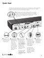
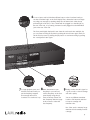
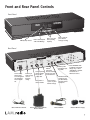
i. AM. Radio Transmitter
Installation and Operation
Easy to follow instructions on how to program and use your Model 5.0 i. AM. Radio Transmitter
Contents
Quick Start ............................................................................................3
Front and Rear Panel Controls...............................................................5
Frequency Selection and Antenna Connections.....................................6
Using the Outdoor Antenna..................................................................................................... 7
To mount the outdoor antenna unit:...................................................................................... 7
To tune the outdoor antenna unit:.......................................................................................... 7
Broadcasting Live...................................................................................8
Broadcast Live from a Microphone.......................................................................................... 8
Broadcast Live from a Studio or External Recorded Message................................................ 8
Broadcast a prerecorded message from the internal “Message Chip” storage..................... 8
Record Procedure - in detail..................................................................9
Recording a message onto the internal “message chip.”....................................................... 9
Technical Specifications and FCC Regulations.....................................10
Model 5.0 i. AM. Radio Transmitter........................................................................................10
Model ATU – Outdoor tuning Unit / Range Extender.............................................................10
Applicable FCC and Licence Regulations - FCCID: DLB5LTT98..............................................10
FCC part 15 rules, Section 15.219 Operation in the band 510–1705 kHz..............................10
Questions? Just call 856-467-8000
2
Quick Start
to prevent changes
Remove key
frequency
to message or
CH
This Quick Start contains the basic steps necessary to set ITup
and IToperate
your i. AM. Radio Transmitter
MODE SW
Live Radio
TRANSMChip
using the Indoor Wire Antenna. Please read the detailed
Messageprocedures in this manual for complete
PHONE: includes the Outdoor Antenna.
instructions, especially
if your
set-up
MICRO
BACK-UP on cabinet top
o vent
Speak int
ges
vent chan
key to pre ency
Remove
e or frequ
to messag
A
ANTENN
SELECT
Basic
Outdoor
R
OUTDOO
A
ANTENN
T
EC
N
N
O
C
T
TWO-PAR
E
MESSAG
SELECT
T
LINE INPU
POWER
CUSTOM T
INPU
5 minutes
1 Make sure the Control Lock Key is inserted in the Control Lock hole
120 VAC
PP/10K
500mV
rt 2
Part 1 Pa
18 VDC
ME
R VOLU
using a k
SPEAKE
ac
OFF when
Must be
oid feedb
one to av
microph
AGC the Transmitter. This key must be completely
located on the rear
WITHof
inserted to record messages and set the frequency on the transmitter.
Also, make sure that “ANTENNA SELECT” switch is in the
“Basic” position.
to prevent changes
Remove key
frequency
to message or
SWITCH
IT MODE Live Radio
TRANSMChip
Message
ONE:
MICROPH
BACK-UoPvent on cabinet top
Speak int
ges
vent chan
key to pre ency
Remove
e or frequ
to messag
A
ANTENN
SELECT
Basic
R
OUTDOO
A
ANTENN
T
CONNEC
Outdoor
T
TWO-PAR
E
MESSAG
T
C
SELE
T
LINE INPU
POWER
CUSTOM T
INPU
120 VAC
to prevent changes
Remove key
frequency
to message or
PP/10K
500mV
rt 2
Part 1 Pa
18 VDC
C
WITH AG
ME
R VOLU
using a
SPEAKE
ck
OFF when
Must be ne to avoid feedba
micropho
SWITCH
IT MODE Live Radio
TRANSMChip
Message
AC
eak into vent
P MIC cabinet top
BACK-U
to vent on
on cabinet to
TWO-PART
OR
AGE
MESS
A
anges
prevent chSELECT
CT
key to
ency
Remove
ge or frequ
to messa
E:
ROPHON
Part 1 Part 2
Speak in
A
ANTENN
SELECT
Basic
R
OUTDOO
A
ANTENN
T
CONNEC
Outdoor
RT
TWO-PA
E
MESSAG
SELECT
art 2
Part 1 P
2 Connect the indoor 3 Set the TWO-PART 4 Plug the hand-held
antenna and be sure
to uncoil and fully
extend the wire.
MESSAGE SELECT
switch to Part-one.
You are now
ready to record
a message to be
broadcast via the
internal or external
mic or any external
input source connected to the LINE
INPUT jack.
microphone into the
MIC jack located on
the back
TransACof the on
cabinet to
eak into vent
mitter. If you are not
TWO-PART
using aOR
hand-held
mic
MESSAGE
A
CT
SELE
CT
the transmitter
input
Part 1 Part 2
will default to the
internal microphone
located just under the
perforated lid.
Or, plug any line-level
source (Mp3 player,
Cassette deck) into the
LINE INPUT jack on the
rear panel.
UT
LINE INP
POWER
CUSTOM T
INPU
PP/10K
120 VAC
500mV
C
WITH AG
18 VDC
E
R VOLUM
SPEAKOEFF when using a ck
Must be e to avoid feedba
microphon
5 Next, plug the power 6 The SPEAKER
transformer into a
grounded wall outlet,
and then plug the power
cord into the CUSTOM
POWER input jack
located on the back
of the Transmitter.
VOLUME should be
turned off when
using the mic to
avoid feedback.
The Transmitter will
then begin calibrating
itself. When it is finished
AC
et to
vent on cabin
eak int
calibrating,
ao frequency
RT
will appear
onTWthe
O-PAfront
OR
MESSAGE
A
panel display.
SELECT
CT
Part 1 Part 2
3
NA
T
6 To record, press and hold the Record/Pause button on the Front Panel until you
see the countdown begin on the Front Display. Then, release the button and begin
recording your message by speaking clearly into the internal mic under the top
perforated grill of the unit, or into a hand held mic plugged in to the MIC jack on
the rear of the unit, or by starting an external source plugged into the LINE INPUT
jack on the rear of the unit.
The front panel digital display will count down the total record time available, but
you can pause recording at any time by pushing the record button again. Then, finish the record process by pushing the play button or continue recording by pushing
the record/pause button again.
SWITCH
IT MODE Live Radio
TRANSMChip
Message
E:
ROPHOtoNp
et
K-UP MIC
BAC
o vent on
Speak int
R
OUTDOO
A
ANTENN
T
EC
N
CON
door
cabin
T
TWO-PAR
E
MESSAG
T
C
LE
SE
rt 2
Part 1 Pa
T
LINE INPU
PP/10K
POWER
CUSTOM T
INPU
120 VAC
500mV
18 VDC
C
WITH AG
5 minutes
ME
R VOLU
using a
SPEAKE
ck
OFF when
Must be ne to avoid feedba
micropho
7 To begin playback, press and 8 Next, determine an open
ITCH
MODE SW
OPHONE:
MICR
BACK-UoPvent on cabinet top
Speak int
A
ANTENN
SELECT
Basic
Outdoor
R
OUTDOO
A
ANTENN
T
EC
N
CON
T
TWO-PAR
E
MESSAG
SELECT
rt 2
Part 1 Pa
IT
Live Radio
TRANSMChuntil
hold the Play button
you
ip
Message
see the frequency reappear.
The message will
now be
POWER
CUSTOM T
INPU
T
broadcast
in
a
continuous
loop.
PU
IN
E
N
LI
VAC
PP/10K
120
500mV
C
WITH AG
SP
18 VDC
LUME
EAKER VO
ing a
F when us
feedback
Must be OF
ne to avoid
micropho
frequency in your area and
set this frequency on the front
panel display using the up/
minutes
down arrow keys. Please5see
the “Frequency Selection” page
in this manual to select the
best frequency.
SWITCH
IT MODE Live Radio
TRANSMChip
Message
HONE:
MICROP
BACK-UPvent on cabinet top
Speak into
s
vent change
key to pre
Remove
uency
ge or freq
to messa
A
ANTENN
SELECT
Basic
Outdoor
R
OUTDOO
A
ANTENN
T
CONNEC
9 Finally, monitor the radio signal on
RT
TWO-PA
E
MESSAG
SELECT
rt 2
Part 1 Pa
T
LINE INPU
PP/10K
POWER
CUSTOM T
INPU
120 VAC
500mV
C
WITH AG
18 VDC
R VOLUME
SPEAKE when using a
F
feedback
Must be OF
e to avoid
microphon
a good car radio to check coverage
and audio quality.
You can try different transmitter
locations and frequency selection
to improve coverage and
minimize noise.
5 minutes
Use of the outdoor antenna/ range
extender will substantially increase
coverage.
4
Front and Rear Panel Controls
Front Panel
Push to Start Playback
of Recorded Message
AM frequency readout
Push to start and
pause internal
message recording
Push to raise and
lower operating
frequency
Back Panel
SWITCH
IT MODE Live Radio
TRANSMChip
Message
ONE:
MICROPH
BACK-UP on cabinet top
o vent
Speak int
es
vent chang
key to pre ency
Remove
ge or frequ
to messa
A
ANTENN
SELECT
Basic
Connect indoor
antenna here,
uncoil and stretch
out fully along a
wall or window
sill.
Outdoor
Insert key to
allow message
record or
frequency
change
Indoor AM Antenna
Model # IAM-Indoor Antenna
R
OUTDOO
A
ANTENN
T
CONNEC
RT
TWO-PA
MESSAGE
SELECT
T
LINE INPU
PP/10K
120 VAC
500mV
rt 2
Part 1 Pa
C
WITH AG
Connect optional
outdoor antenna
here via RG-6
coaxial cable
POWER
CUSTOM T
INPU
18 VDC
External
audio input.
Record to internal
storage chip and/
or broadcast live.
Select indoor or
outdoor antenna
Antenna Tuner / Range Extender
Model # IAM-ATU
Select recording
of part 1 or part 2
internal message
5 minutes
E
R VOLUM
using a k
SPEAKE
ac
OFF when
Must be e to avoid feedb
microphon
External power
transformer input
for 18VDC.
Select “MESSAGE CHIP”
to playback from internal
storage chip, or select
“LIVE RADIO” to transmit
via internal mic or
external line source.
External hand-held
microphone jack.
Use automatically
overrides internal
microphone.
Transmitter Hand-held Mic
Model # IAM-Mic
Transmitter Power Supply
Model # IAM-Power Supply
5
Frequency Selection and Antenna Connections
Set the Frequency
Determine an available frequency (preferably on the high end of the band) by using a good quality digital
car radio parked in your primary listening area. Select a channel on your car radio where no other radio
station is audible as well as on one channel above and one channel below. It is advisable to make this
listening test at dusk when radio reception is at best.
Use the front panel raise and lower controls to set this frequency.
SWITCH
IT MODE Live Radio
TRANSMChip
Message
NE:
CROPHO
Note: When using the indoor antenna, theBAtransmitter
will go through an automatic antenna calibration
CK-UP MI
POWER
CUSTOM T
inutes
O-PART will bePU
routine after a frequency has been set. OUThis
routine
automatically
repeated once an hour to5 mkeep
TW
INPU
T
E
TDOOR
LINE IN
MESSAG
CT
TENNA
LE
AN
SE
A
ME
LU
VO
ANTENN motor
NNECT sound will be heard.)
R
the transmitter calibrated (an internal
CO
SPEAKE
SELECT
inet top
vent on cab
Speak into
s
vent change
key to pre
Remove
uency
ge or freq
to messa
Basic
rt 2
Part 1 Pa
Outdoor
PP/10K
120 VAC
500mV
C
WITH AG
18 VDC
ng a
F when usi
feedback
Must be OF
e to avoid
microphon
Note: When operating the transmitter, the built in speaker can be used to monitor the broadcast signal or
manually turned off or down via the rear panel “SPEAKER VOLUME” control. The volume level setting of
the speaker volume will not affect the audio level of the broadcast signal.
Connect the Antenna
SWITCH
IT MODE Live Radio
TRANSMChip
Message
HONE:
MICROPinet top
cab
BACK-UP
Speak into
t changes
ven
key to pre
Remove
uency
ge or freq
to messa
A
ANTENN
SELECT
Basic
Outdoor
R
OUTDOO
A
ANTENN
T
CONNEC
vent on
RT
TWO-PA
E
MESSAG
SELECT
rt 2
Part 1 Pa
T
LINE INPU
PP/10K
POWER
CUSTOM T
INPU
C
WITH AG
5 minutes
120 VAC
ME
KER VOLU
500mV
18 VDC
SPEA OFF when using a ck
id feedba
Must be
e to avo
microphon
Connect the indoor antenna to the rear panel lug. Locate the transmitter by a window and stretch the full
length of antenna cable out in a straight a path as possible. Set the “ANTENNA SELECT” to “BASIC.”
OR
Utilize the outdoor antenna tuning unit for extended range. Set the “ANTENNA SELECT” to “OUTDOOR and
follow the “Using the Outdoor Antenna” page in this manual for installation and tuning instructions.
Note: make sure that the transmitter is grounded either via the three prong power transformer or ground
wire connected to a screw on the rear of the unit.
6
Using the Outdoor Antenna
POWER
LED
+3V Power
to DVR
+18V Power
from Plug in
Power Supply
100ft. CAT-5 Patch
cable to provide audio
and power. Enter via
waterproof grommet and
plug into provided RJ-45
connector inside lid.
Optional
Mic Input
Switch to Right
for DVR Playback
Switch to Left for
LIVE Broadcasting
Plug into
Headphone Jack
For best performance,
attach a wire (not supplied) from the Ground
Wire Connector on the
top of the ATU to a good
earth ground.*
Some examples of good
earth grounds are:
• The center screw that
holds the cover on a wall
electrical outlet.
• Plumbing and water
pipes (metal).
• A copper ground rod
driven into the earth.
Consult the DVR manual for recording and loop
playback. Note that the internal audio storage in the
transmitter is not available and the switch on the rear
of transmitter should be set to “LIVE” radio.
Mount the Outdoor Enclosure to a pole or top side of a building so that the antenna
is unobstructed and not near any trees or metal structures.
Connect the transmitter via the supplied CAT-5 patch cable.
Thread 3 meter whip
antenna securely into
connector on top of
antenna enclosure
CAUTION : DO NOT CONTACT ELECTRICAL OR HIGH TENSION WIRES WITH THE ANTENNA.
YOU CAN BE KILLED.
*Please note that Part 15 FCC regulations do not allow an antenna in excess of 3 meters in
length and usually the ground wire length is considered a part of this length and is added to
this total antenna measurement calculation.
7
Broadcasting
Live
ITCH
ODE SW
M
IT
M
S
N
TRA
Chip
Message
LINE INP
io
Live Rad
Broadcast Live from a Microphone.
POWER
and
automatically
s
CUSTOM T Set the Transmit Mode Switch on the Back Panel, to “Live Radio.” This immediately
ute
in
5m
INPU selects the built-in microphone (located inside the unit and under the top panel
grill) to act as the audio
120 VAC source for the transmission.
OLUME a
EAKER V
P
usinghigh-Z
S
whenheld,
Plugging
in a Fhand
feedback microphone into the “MIC” jack on the rear panel automatically superust be OF
id
o
M
v
a
to
C
e
n
o
h
18 VD sedes
p
ro
mic the built-in MIC and selects this MIC as the audio source for the transmission.
UT
PP/10K
500mV
C
WITH AG
Note that the built-in audio limiter will keep the signal from distorting, but it is still best to speak directly
into the microphone and at normal and consistent volume for best sound quality.
CH
DE SWITadthe
Note that when
using
MaOmicrophone,
io built-in speaker must be manually turned off or down via the rearIT
M
R
S
e
N
iv
A
L
TR
ip
h
panel ‘SPEAKER
VOLUME”
control
to
avoid feedback
C
e
essag
M
HONE:
et top
2
UT
LINE INP
PP/10K
500mV
C
WITH AG
Broadcast Live from a Studio or External Recorded Message.
POWER
s
CUSTOM T
inutote.5V,
Set IN
the
Transmit Mode Switch on the Back Panel, to “Live Radio” and plug a line-level signal
5 m(.1V
PU
unbalanced)
120 VAC into the “LINE INPUT” (1/8” mini phone) connector on the rear panel. This immediately and
E input to act as the audio source for the transmission or recording.
automatically selects this external
line
R VOLUM
SPEAKOEFF when using aack
edbkeep the signal from distorting, but it is still best to maintain the
Must beaudio
Note that
the built-in
will
avoid fe
tolimiter
18 VDC
icrophone
m
incoming signal level at a consistent volume for best sound quality.
Note that when recording or broadcasting a LINE INPUT, the built-in speaker can be used to monitor the
broadcast signal or manually turned off or down via the rear-panel “SPEAKER VOLUME” control. The volume
level of the internal speaker will not effect the audio level of the broadcast signal.
Broadcast a prerecorded message from the internal “Message Chip” storage.
Set the Transmit Mode Switch on the back panel, to “Message Chip”. The transmitter will automatically
begin and continue to playback any audio recorded on the internal “Message Chip.”
H
SWITC
IT MODE Live Radio
TRANSMChip
Message
ER
POW
CUSTOM T
INPU
120 VAC
18 VDC
Set the “Two-Part Message Select” switch in the “Part-1” position to playback only message one. Set the
“Two-Part Message Select” switch in the “Part-2” position to consecutively playback both messages parts
one and two.
5 minutes
E
R VOLUM
SPEAKOEFF when using a ck
Must be e to avoid feedba
microphon
8
Record Procedure - in detail
Front Panel
Recording a message onto the internal “message chip.”
1 Insert the Control Lock Key in the control lock hole located on the back of the Transmitter. Select either
Part-1 or Part-2 on the Two-Part Message Switch located on the back of the Transmitter. Note that you
can record or re-record either message part at any time and select to playback
either only Part-1 or
SWITCH
IT MODE
TRANSM
Part-1 and Part-2 when transmitting. Therefore, Part-1: is often used as a “wrap-around” or permanent
NE
CROPHO
CK-UP MI
part of the message while Part-2 is used BAfor
additional information
and topical updates.
POWER
Message
Speak into
s
vent change
key to pre
Remove
uency
ge or freq
to messa
A
ANTENN
SELECT
R
OUTDOO
A
ANTENN
T
CONNEC
Chip
Live Radio
inet top
vent on cab
RT
TWO-PA
E
MESSAG
SELECT
T
LINE INPU
PP/10K
CUSTOM T
INPU
5 minutes
120 VAC
VOLUME
500mV
R
SPEAKE
2 To record from the internal built-in MIC, speak into the top grill of the
unit.
To record from an external
MIC or LINE-INPUT plug either device into its corresponding rear panel connector.
Basic
Outdoor
rt 2
Part 1 Pa
C
WITH AG
18 VDC
ng a
F when usi
feedback
Must be OF
e to avoid
microphon
3 Press and hold the Record /Pause button on the front of the Transmitter until the Display Panel begins
counting down in seconds (i.e. 300, 299, 298...) and then immediately begin speaking or press the start
button on your external audio source.
4 To pause during recording, press the Record/Pause button. Push Record/Pause again to continue. Do
not use the Pause Button to end a recording.
5 When your message is complete, wait a second or two then press and hold the Play button located on
the front of the Transmitter until you see the frequency re-display on the front panel. The message will
begin to playback, and will repeat in a loop.
If desired, repeat the recording procedure for message PART-2 by selecting Part-2 on the
TWO-PART MESSAGE SELECT SWITCH.
6 To protect your message from accidental erasure or tampering, remove the Control Lock Key from the
Control Lock located on the back of the Transmitter and place it in a safe place where it cannot be lost.
Note - You can monitor your recording on the Transmitter’s Internal Speaker by turning up the
“SPEAKER VOLUME” control on the transmitter rear panel, but doing so when utilizing a MIC as the record
source may cause feedback. The setting for this internal speaker volume will not affect of audio transmission.
9
Technical Specifications and FCC Regulations
Model 5.0 i.AM. - AM Radio Transmitter
• Frequency Agile with front-panel selectability - frequency range: 520 to 1700 kHz
• Automatic Tuning – internal automatic servo-operated tuning circuit for range maximization
(U.S. Patent No. 6,295,443)
• Audio Inputs – internal microphone plus externa mic (mono) and line level (stereo) inputs
(on 1/8” “mini phone” connector-line level sensitivity .1 to .5 volts
• Audio Processing: built in automatic audio limitor / compressor
• Message Storage: digital voice record/playback solid state memory chip, 5 minutes max.
• Message Length: variable depending upon model of transmitter (see sticker on unit back panel)
• Microphone: built-in or hand-held
• Size: 8” x 14” x 2.5” (shipping size boxed - 12” x 20” x 6”)
• Weight: 4 lbs. (shipping weight - 7 lbs)
• Indoor Antenna: black, rubberized wire, approximately 8’ in length
• Power: 110/120VAC via included 18VDC 100mA external transformer / grounded AC plug adapter
• RF output power: 100 mW average
• Frequency Control: Crystal controlled phase locked loop tuner
• Frequency Stability: - +/- 30 Hz
• Range: typically 300-3000 feet (dependent on conditions and use of outdoor range extender
Model ATU – Outdoor tuning Unit / Range Extender
• Input Power: .01 mW to 1 watt
• Frequency Range: 520 to 1700 kHz
• Connectors: “F” type input, 3/8”-24 threaded antenna coupling, grounding post with knurled knob
• Radiator: 9’ fiberglass whip antenna (included)
• Internal controls: frequency range switch, tuning knob
• Internal indicator: signal strength meter
• Size: 5” x 7” x 3” (shipping size boxed - 6” x 8.5” x 4”)
• Weight: 1.5 lbs. (shipping weight - 2 lbs)
• Mounting: mounts to any metal pipe from 1/2” to 1 3/4” diameter (mounting brackets included,
pipe not included
• US Patent Number US 7, 437,130 B2
Applicable FCC and Licence Regulations - FCCID: DLB5LTT98
This device complies with Part 15 of the FCC rules. Operation is subject to the following two conditions:
1.) This device may not cause harmful interference, and 2.) this device must accept any interference
received, including interference that may cause undesired operation.
The model ATU Outdoor Manual Antenna Tuning unit is FCC accepted within this certification as serving as
the final output stage.
FCC part 15 rules, Section 15.219 Operation in the band 510–1705 kHz.
(a) The total input power to the final radio frequency stage (exclusive of filament or heater power) shall not
exceed 100 milliwatts.
(b) The total length of the transmission line, antenna and ground lead (if used) shall not exceed 3 meters.
(c) All emissions below 510 kHz or above 1705 kHz shall be attenuated at least 20 dB below the level of
the unmodulated carrier. Determination of compliance with the 20 dB attenuation specification may be
based on measurements at the intentional radiator’s antenna output terminal unless the intentional
radiator uses a permanently attached antenna, in which case compliance shall be demonstrated by
measuring the radiated emissions.
10
A Division of Radio Systems, Inc.
Radio Systems, Inc. • 601 Heron Drive • Logan Township, NJ 08085
Phone: 856-467-8000 • Fax: 856-467-3044 • Email: sales@radiosystems.com
www.radiosystems.com