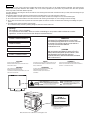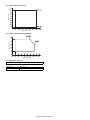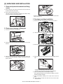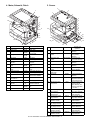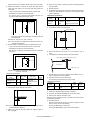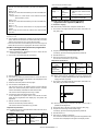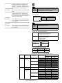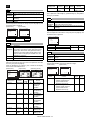
1
SERVICE MANUAL CODE: 00ZAR5127/A1E DIGITAL LASER COPIER/ PRINTER MODEL AR-5127 CONTENTS [1] NOTE FOR SERVICING. . . . . . . . . . . . . . . . . . . . . . . . . . . . . . . . . 1-1 [2] SYSTEM CONFIGURATION . . . . . . . . . . . . . . . . . . . . . . . . . . . . . 2-1 [3] SPECIFICATIONS . . . . . . . . . . . . . . . . . . . . . . . . . . . . . . . . . . . . . 3-1 [4] CONSUMABLE PARTS . . . . . . . . . . . . . . . . . . . . . . . . . . . . . . . . . 4-1 [5] UNPACKING AND INSTALLATION . . . . . . . . . . . . . . . . . . . . . . . . 5-1 [6] EXTERNAL VIEW AND INTERNAL STRUCTURE . . . . . . . . . . . . 6-1 [7] ADJUSTMENTS, SETTING . . . . . . . . . . . . . . . . . . . . . . . . . . . . . . 7-1 [8] SIMULATION . . . . . . . . . . . . . . . . . . . . . . . . . . . . . . . . . . . . . . . . . 8-1 [9] TROUBLE CODE LIST. . . . . . . . . . . . . . . . . . . . . . . . . . . . . . . . . . 9-1 [10] DISASSEMBLY, ASSEMBLY AND MAINTENANCE . . . . . . . . . . 10-1 [11] OTHERS . . . . . . . . . . . . . . . . . . . . . . . . . . . . . . . . . . . . . . . . . . . . 11-1 Parts marked with “ ” are important for maintaining the safety of the set. Be sure to replace these parts with specified ones for maintaining the safety and performance of the set. SHARP CORPORATION This document has been published to be used for after sales service only. The contents are subject to change without notice. CAUTION This product is a class 1 laser product that complies with 21CFR 1040.10 and 1040.11 of the CDRH standard and IEC825. This means that this machine does not produce hazardous laser radiation. The use of controls, adjustments or performance of procedures other than those specified herein may result in hazardous radiation exposure. This laser radiation is not a danger to the skin, but when an exact focusing of the laser beam is achieved on the eye’s retina, there is the danger of spot damage to the retina. The following cautions must be observed to avoid exposure of the laser beam to your eyes at the time of servicing. 1) When a problem in the laser optical unit has occurred, the whole optical unit must be exchanged as a unit, not as individual parts. 2) Do not look into the machine with the main switch turned on after removing the developer unit, toner cartridge, and drum cartridge. 3) Do not look into the laser beam exposure slit of the laser optical unit with the connector connected when removing and installing the optical system. 4) The middle frame contains the safety interlock switch. Do not defeat the safety interlock by inserting wedges or other items into the switch slot. Warning! This product is a class A product. If it is operated in households, offices or similar surroundings, it can produce radio interferences at other appliances, so that the user has to take adequate countermeasures. VAROITUS! CLASS 1 LASER PRODUCT LAITTEEN KÄYTTÄMINEN MUULLA KUIN TÄSSÄ KÄYTTÖOHJEESSA MAINITULLA TAVALLA SAATTAA ALTISTAA KÄYTTÄJÄN TURVALLISUUSLUOKAN 1 YLITTÄVÄLLE NÄKYMÄTTÖMÄLLE LASERSÄTEILYLLE. LASER KLASSE 1 LUOKAN 1 LASERLAITE VARNING OM APPARATEN ANVÄNDS PÅ ANNAT SÄTT ÄN I DENNA BRUKSANVISNING SPECIFICERATS, KAN ANVÄNDAREN UTSÄTTAS FÖR OSYNLIG LASERSTRÅLNING, SOM ÖVERSKRIDER GRÄNSEN FÖR LASERKLASS 1. KLASS 1 LASERAPPARAT CAUTION INVISIBLE LASER RADIATION, WHEN OPEN AND INTERLOCKS DEFEATED. AVOID EXPOSURE TO BEAM. VARO ! VORSICHT UNSICHTBARE LASERSTRAHLUNG, WENN ABDECKUNG GEÖFFNET UND SICHERHEITSVERRIEGELUNG ÜBERBRÜCKT. NICHT DEM STRAHL AUSSETZEN. VARNING ! AVATTAESSA JA SUOJALUKITUS OHITETTAESSA OLET ALTTIINA NÄKYMÄTTÖMÄLLE LASERSÄTEILYLLE ÄLÄ KATSO SÄTEESEEN. OSYNLIG LASERSTRÅLNING NÄR DENNA DEL ÄR ÖPPNAD OCH SPÄRREN ÄR URKOPPLAD. BETRAKTA EJ STRÅLEN. – STRÅLEN ÄR FARLIG. ADVARSEL USYNLIG LASERSTRÅLNING VED ÅBNING, NÅR SIKKERHEDSBRYDERE ER UDE AF FUNKTION. UNDGÅ UDSAETTELSE FOR STRÅLNING. Laserstrahl LASER RADIATION WHEN OPEN AND INTERLOCKS DEFEATED. LASERSTRÅLING NÅR DEKSEL ÅPNES OG SIKKERHEDSLÅS BRYTES. CAUTION INVISIBLE AVOID EXPOSURE TO BEAM. ADVERSEL USYNLIG UNNGÅ EKSPONERING FOR STRÅLEN. LASERSTRAHLUNG, WENN ABDECKUNG GEÖFFNET UND LASERSTRÅLNING NÄR DENNA DEL ÄR ÖPPNAD OCH SPÄRREN ÄR VORSICHT UNSICHTBARE VARNING OSYNLIG SICHERHEITSVERRIEGELUNG ÜBERBRÜCKT. NICHT DEM STRAHL AUSSETZEN. URKOPPLAD. BETRAKTA EJ STRÅLEN. – STRÅLEN ÄR FARLIG. LASERSTRÅLNING VED ÅBNING, NÅR SIKKERHEDSBRYDERE ER JA SUOJALUKITUS OHITETTAESSA OLET ALTTIINA NÄKYMÄTTÖMÄLLE ADVARSEL USYNLIG UDE AF FUNKTION. UNDGÅ UDSAETTELSE FOR STRÅLNING. VARO! AVATTAESSA LASERSÄTEILYLLE ÄLÄ KATSO SÄTEESEEN. CLASS 1 LASER PRODUCT LASER KLASSE 1 LASER WAVE – LENGTH : 795 ± 15 mm Pulse times : 0.481 ms/6 mm Out put power : 5 mW Disconnect the AC cord before servicing the unit. CONTENTS [1] NOTE FOR SERVICING [6] EXTERNAL VIEW AND INTERNAL STRUCTURE 1. Warning for servicing . . . . . . . . . . . . . . . . . . . . . . . . . . . . . 1-1 1. External view. . . . . . . . . . . . . . . . . . . . . . . . . . . . . . . . . . . .6-1 2. Precautions for servicing . . . . . . . . . . . . . . . . . . . . . . . . . . 1-1 2. Internal . . . . . . . . . . . . . . . . . . . . . . . . . . . . . . . . . . . . . . . .6-1 3. Note for installing site. . . . . . . . . . . . . . . . . . . . . . . . . . . . . 1-1 3. Operation panel . . . . . . . . . . . . . . . . . . . . . . . . . . . . . . . . .6-2 [2] SYSTEM CONFIGURATION 1. Structure . . . . . . . . . . . . . . . . . . . . . . . . . . . . . . . . . . . . . . 2-1 A. Key position . . . . . . . . . . . . . . . . . . . . . . . . . . . . . . . . . .6-2 B. LCD panel . . . . . . . . . . . . . . . . . . . . . . . . . . . . . . . . . . .6-2 A. Hardware . . . . . . . . . . . . . . . . . . . . . . . . . . . . . . . . . . . 2-1 4. Motor, Solenoid, Clutch . . . . . . . . . . . . . . . . . . . . . . . . . . . .6-3 2. System outline (Options) . . . . . . . . . . . . . . . . . . . . . . . . . . 2-2 5. Sensor. . . . . . . . . . . . . . . . . . . . . . . . . . . . . . . . . . . . . . . . .6-3 [3] SPECIFICATIONS 1. Basic specifications . . . . . . . . . . . . . . . . . . . . . . . . . . . . . . 3-1 2. Operation specifications. . . . . . . . . . . . . . . . . . . . . . . . . . . 3-1 6. PWB unit . . . . . . . . . . . . . . . . . . . . . . . . . . . . . . . . . . . . . . .6-4 7. Section . . . . . . . . . . . . . . . . . . . . . . . . . . . . . . . . . . . . . . . .6-4 [7] ADJUSTMENTS, SETTING A. Common operation . . . . . . . . . . . . . . . . . . . . . . . . . . . . 3-1 1. List of adjustment items . . . . . . . . . . . . . . . . . . . . . . . . . . .7-1 B. Copy mode . . . . . . . . . . . . . . . . . . . . . . . . . . . . . . . . . . 3-1 2. Copier adjustment . . . . . . . . . . . . . . . . . . . . . . . . . . . . . . . .7-1 3. Engine specifications . . . . . . . . . . . . . . . . . . . . . . . . . . . . . 3-2 A. Process section . . . . . . . . . . . . . . . . . . . . . . . . . . . . . . .7-1 A. Operation and display section . . . . . . . . . . . . . . . . . . . 3-2 B. Mechanism section . . . . . . . . . . . . . . . . . . . . . . . . . . . .7-2 B. Paper feed, transport, paper exit section . . . . . . . . . . . 3-2 C. Image density (exposure) adjustment . . . . . . . . . . . . . .7-9 C. Optical (Image scanning) section . . . . . . . . . . . . . . . . . 3-3 [8] SIMULATION D. Scanner (exposure) section . . . . . . . . . . . . . . . . . . . . . 3-3 1. Operating procedures and operations . . . . . . . . . . . . . . . .8-1 E. Image process section . . . . . . . . . . . . . . . . . . . . . . . . . 3-3 A. Basic operation . . . . . . . . . . . . . . . . . . . . . . . . . . . . . . .8-1 F. Fusing. . . . . . . . . . . . . . . . . . . . . . . . . . . . . . . . . . . . . . 3-4 B. Simulation kinds and valid key functions . . . . . . . . . . . .8-1 G. Drive . . . . . . . . . . . . . . . . . . . . . . . . . . . . . . . . . . . . . . . 3-4 2. Simulation code list . . . . . . . . . . . . . . . . . . . . . . . . . . . . . . .8-2 4. Safety and environmental protection standards. . . . . . . . . 3-4 3. Details . . . . . . . . . . . . . . . . . . . . . . . . . . . . . . . . . . . . . . . . .8-4 5. Environment conditions . . . . . . . . . . . . . . . . . . . . . . . . . . . 3-4 [4] CONSUMABLE PARTS 1. List . . . . . . . . . . . . . . . . . . . . . . . . . . . . . . . . . . . . . . . . . . . 4-1 A. LAG . . . . . . . . . . . . . . . . . . . . . . . . . . . . . . . . . . . . . . . 4-1 B. SMEF (Middle East, Africa)/Israel . . . . . . . . . . . . . . . . 4-1 C. Asia affiliates/Asia agent/STCL/SRH/SRS/SRSSC/SBI 4-2 2. Production number identification . . . . . . . . . . . . . . . . . . . . 4-3 [9] TROUBLE CODE LIST 1. List . . . . . . . . . . . . . . . . . . . . . . . . . . . . . . . . . . . . . . . . . . .9-1 2. Self diagnostics . . . . . . . . . . . . . . . . . . . . . . . . . . . . . . . . . .9-2 [10] DISASSEMBLY, ASSEMBLY AND MAINTENANCE 1. Maintenance table. . . . . . . . . . . . . . . . . . . . . . . . . . . . . . .10-1 2. Counter clear . . . . . . . . . . . . . . . . . . . . . . . . . . . . . . . . . .10-1 3. Environment conditions . . . . . . . . . . . . . . . . . . . . . . . . . . . 4-3 3. List of disassembly and assembly . . . . . . . . . . . . . . . . . .10-1 A. Ambient conditions for transporting . . . . . . . . . . . . . . . 4-3 4. Details . . . . . . . . . . . . . . . . . . . . . . . . . . . . . . . . . . . . . . . .10-2 B. Ambient storage conditions (sealed) . . . . . . . . . . . . . . 4-3 A. Process unit . . . . . . . . . . . . . . . . . . . . . . . . . . . . . . . . .10-2 C. Operating ambient conditions. . . . . . . . . . . . . . . . . . . . 4-3 B. Developing section . . . . . . . . . . . . . . . . . . . . . . . . . . .10-3 4. Life (packed conditions) . . . . . . . . . . . . . . . . . . . . . . . . . . . 4-3 C. Fusing section . . . . . . . . . . . . . . . . . . . . . . . . . . . . . . .10-4 [5] UNPACKING AND INSTALLATION D. Paper feed section. . . . . . . . . . . . . . . . . . . . . . . . . . . .10-6 E. Side door unit . . . . . . . . . . . . . . . . . . . . . . . . . . . . . .10-10 1. Removal of protective material and fixing screw . . . . . . . . 5-1 F. 1st paper exit unit . . . . . . . . . . . . . . . . . . . . . . . . . . .10-10 2. Removal and storage of fixing pin . . . . . . . . . . . . . . . . . . . 5-1 G. Laser unit . . . . . . . . . . . . . . . . . . . . . . . . . . . . . . . . . .10-12 3. Developer cartridge installation . . . . . . . . . . . . . . . . . . . . . 5-1 H. Power unit . . . . . . . . . . . . . . . . . . . . . . . . . . . . . . . . .10-13 4. Toner cartridge installation . . . . . . . . . . . . . . . . . . . . . . . . . 5-2 I. PWB . . . . . . . . . . . . . . . . . . . . . . . . . . . . . . . . . . . . .10-13 5. Toner concentration sensor level adjustment. . . . . . . . . . . 5-2 J. Ozone filter . . . . . . . . . . . . . . . . . . . . . . . . . . . . . . . .10-14 6. Paper size selection for paper feed tray . . . . . . . . . . . . . . 5-2 [11] OTHERS 1. Flash ROM version up procedure . . . . . . . . . . . . . . . . . . .11-1 A. Program download procedure (Main body program) . . . . . . . . . . . . . . . . . . . . . . . . . .11-1 2. User programs . . . . . . . . . . . . . . . . . . . . . . . . . . . . . . . . .11-2 [1] NOTE FOR SERVICING 6) Do not leave the machine with the cabinet disassembled. This Service Manual uses some photographs to assure safe operation. This Service Manual uses some photographs to assure safe operation. Please understand the meanings of photographs before servicing. WARNING: If this WARNING should be ignored, a serious danger to life or a serious injury would be resulted. CAUTION: If this CAUTION should be ignored, an injury or a damage to properties would be resulted. 1. Warning for servicing 1) Be sure to connect the power cord only to a power outlet that meets the specified voltage and current requirements. Avoid complex wiring, which may lead to a fire or an electric shock. It may cause a fire or an electric shock. 2) If there is any abnormality such as a smoke or an abnormal smell, interrupt the job and disconnect the power plug. It may cause a fire or an electric shock. 3) Be sure to connect the grounding wire. If an electric leakage occurs without grounding, a fire or an electric shock may be the result. To protect the machine and the power unit from lightening, grounding must be made. 4) When connecting the grounding wire, never connect it to the following points. It may cause an explosion, a fire or an electric shock. • Gas tube • Lightning conductor Do not allow any person other than a serviceman to touch inside the machine. It may cause an electric shock, a burn, or an injury. 7) When servicing, do not breathe toner, developer, and ink excessively. Do not get them in the eyes. If toner, developer, or ink enters you eyes, wash it away with water immediately, and consult a doctor if necessary. 8) The machine has got sharp edges inside. Be careful not to damage fingers when servicing. 9) Do not throw toner or a toner cartridge in a fire. Otherwise, toner may pop and burn you. 10) When replacing the lithium battery of the PWB, use a specified one only. If a battery of different specification is used, it may be broken, causing breakdown or malfunction of the machine. 11) When carrying a unit with PWB or electronic parts installed to it, be sure to put it in an anti-static-electricity bag. It may cause a breakdown or malfunctions. 3. Note for installing site Do not install the machine at the following sites. 1) Place of high temperature, high humidity, low temperature, low humidity, place under an extreme change in temperature and humidity. Paper may get damp and form dews inside the machine, causing paper jam or copy dirt. For operating and storing conditions, refer to the specifications described later. 2) Place of much vibrations • A water pipe or a water faucet, which is not recognized as a grounding object by the authorities. • Grounding wire for telephone line It may cause a breakdown. 3) Poorly ventilated place An electro-static type copier will produce ozone inside it. 5) Do not damage, brake, or work the power cord. Do not put heavy objects on the power cable. Do not bend it forcibly or do not pull it extremely. It may cause a fire or an electric shock. 6) Keep the power cable away from a heat source. The quantity of ozone produced is designed to a low level so as not to affect human bodies. However, continuous use of such a machine may produce a smell of ozone. Install the machine in a well ventilated place, and ventilate occasionally. 4) Place of direct sunlight. Do not insert the power plug with dust on it into a power outlet. It may cause a fire or an electric shock. 7) Do not put a receptacle with water in it or a metal piece which may drop inside the machine. It may cause a fire or an electric shock. 8) With wet or oily hands, do not touch the power plug, do not insert the telephone line jack, do not operate the machine, or do not perform servicing. It may cause an electric shock. Plastic parts and ink may be deformed, discolored, or may undergo qualitative change. It may cause a breakdown or copy dirt. 5) Place which is full of organic gases such as ammonium The organic photoconductor (OPC) drum used in the machine may undergo qualitative change due to organic gases such as ammonium. Installation of this machine near a diazo-type copier may result in dirt copy. 6) Place of much dust 2. Precautions for servicing 1) When servicing, disconnect the power plug, the printer cable, the network cable, and the telephone line from the machine, except when performing the communication test, etc. It may cause an injury or an electric shock. 2) There is a high temperature area inside the machine. Use an extreme care when servicing. It may cause a burn. 3) There is a high voltage section inside the machine which may cause an electric shock . Be careful when servicing. 4) Do not disassemble the laser unit. Do not insert a reflective material such as a screwdriver in the laser beam path. It may damage eyes by reflection of laser beams. When dusts enter the machine, it may cause a breakdown or copy dirt. 7) Place near a wall Some machine require intake and exhaust of air. If intake and exhaust of air are not properly performed, copy dirt or a breakdown may be resulted. 8) Unstable or slant surface If the machine drops or fall down, it may cause an injury or a breakdown. If there are optional paper desk and the copier desk specified, it is recommendable to use them. When using the optional desk, be sure to fix the adjuster and lock the casters. 5) When servicing with the machine operating, be careful not to squeeze you hands by the chain, the belt, the gear, and other driving sections. AR-5127 NOTE FOR SERVICING 1 - 1 OP interface PWB DRS1 ; Door Detector PCL1 ; Pick Up Clutch LUM1 ; Lift Up Motor TRCL ; Vertical transport roller clutch 2 OP-UP cassette PPD1 ; Paper Pass Detector PAP1 ; Paper Empty LUD1 ; Lift Up Detector CSS1 ; Casette Detector Fuser-Lamp THERMISTER Fuser Unit DRS2 ; Door Detector PCL2 ; Pick Up Clutch LUM2 ; Lift Up Motor OP-LO cassette PPD2 ; Paper Pass Detector PAP2 ; Paper Empty LUD2 ; Lift Up Detector CSS2 ; Casette Detector Pout Gate Solenoid CN140 CN129 CN103 CN104 CN131 Paper Full Sensor CN126 CN28 Pout 2 Sensor CSS1H : Cassette Detector PSRSOL : Paper Stop Roller Sol. PCL1H : PickUp Cluth LUM1H : Lift Up Motor CN132 CN113 CN134 Defog Heater Paper Size Sensor AB INCH FAX-OP-PWB OPERATION PANEL MAIN-Motor CN118 2nd POUT COVER SENSOR HPEMPTY : HandpaperEmpty sensor HPIN : Handpaper IN Sensor HPTRAY1 : HandpaperTRAY Sensor HPTRAY2 : HandpaperTRAY Sensor2 HPSIZE : Handpaper Size Sensor HPSIZE2 : Handpaper Size Sensor2 HPWS : Handpaper Width Sensor HPSOL : Handpaper PickUp Solenoid Manual feed unit Main body paper feed load Paper Feed Motor OP interface PWB Drum Initial Sensor Paper Remove Sol Duplex Paper Out Sensor Duplex-Motor Paper Feed Motor Multi-step cassette unit (Optional) PCL2H ; Pick Up Clutch LUM2H ; Lift Up Motor TRCLH ; Vertical transport roller clutch 2nd cassette unit (Optional) CSS2H ; Casette Detector DRS2H ; Door Detector PPD2H ; Paper Pass Detector PAP2H ; Paper Empty LUD2H ; Lift Up Detector PCS1H ; Pick Up Solenoid PAP1H ; Paper Empty LUD1H ; Lift Up Detector PPD1H(PIN):Paper IN Main body cassette unit Shifter-Motor Fuser Cooling Fan 2 Shifter HP Sensor Fuser Cooling Fan 1 Pout Sensor SPF-pressure SPF-DupSOL SPF-Motor release SOL LCD Coin Vender D-Sub 25pin CN108 CCD-PWB (AR5127 Optional) IMC PWB COPY-OP-PWB CN130 (AB Area ONLY) SPF-CON-PWB CN125 (INCH Area ONLY) Copy-Lamp CN136 L2 CN121 APC-PWB LSU-PWB Polygon-Motor BD-PWB BD-Sensor HVU Power Supply Power Unit Mother PWB Reactor CE Only PS-SW PS Cooling Fan Ozon Fan (AR5127 Optional) GDI PWB (AR5127 Optional) (AR5127 Optional) USB PWB Tray position sensor Upper Paper position sensor Tray position sensor Lower Off-set position sensor Lift-up drive control sensor Tray paper empty sensor Self priming sensor No. 1 tray paper exit sensor No. 2 tray paper exit sensor Shutter drive solenoid Paper exit roller clutch Transport select gate right solenoid Upper alignment plate drive FIN main motor solenoid Tray lift-up motor Transport select gate right Tray off-set motor solenoid 2 Rear edge plate drive solenoid Staple operation motor Staple HP sensor Stapler Side guide plate motor Rear edge plate drive motor Paper Size Detector Rear edge plate HP sensor Side guide plate HP sensor FAX PWB Tray JAM process sensor JAM process PG open/close sensor Cartridge empty sensor Staple supply cover open/close sensor Staple empty sensor Finisher Unit (Optional) Defog Heater Japan/SEC/SECL D -Sub 15pin MCU-PWB CN117 Option interface PWB InterLock DEV UNIT Toner-Motor Switch (include CRSM) CN111 L1 CN139 Mirror HP Sensor CN135 Scanner Cover Sensor CN112 SPF Paper Size Sens (x5) SPF BOOK Sens CN107 Down-Load-CON D-Sub 9pin CN106 SPF-PSOL CN110 SPF-SEN-PWB SPF Cover Sens SPF PS Sens SPF Paper Empty CN102 Mirror-Motor CN109 CN123 CN115 AR-5127 SYSTEM CONFIGURATION 2 - 1 TRAYPAPER SENSOR FINISHER PWB SFP/RSPF Unit (Optional) [2] SYSTEM CONFIGURATION 1. Structure A. Hardware Block diagram 2. System outline (Options) Option Item Reversing single pass feeder Single pass feeder 500-sheet paper feed unit 2X500-sheet paper feed unit Job separator tray kit Finisher Facsimile expansion kit Fax memory 2MB 4MB 8MB Dual function board Model AR-RP3 AR-SP4 AR-D11N AR-D12N AR-TR3 AR-FN5N AR-FX4 AR-MM5 AR-MM6 AR-MM7 AR-EB4 Main unit model Y Y Y Y Y Y Y Y Y Y Y NOTE For connection of the sort and staple, the AR-EB4 is required. Y: Installable For details of the options, refer to the Service Manual of each option. (1) Main units AR-5127 (2) Options AR-RP3 Reversing single pass feeder AR-SP4 Single pass feeder AR-D11N 500-sheet paper feed unit AR-D12N 2X500-sheet paper feed unit AR-TR3 Job separator tray kit AR-MM5/MM6/MM7 2/4/8MB Fax memory AR-FN5N Finisher AR-FX4 Facsimile expansion kit AR-EB4 Dual function board AR-5127 SYSTEM CONFIGURATION 2 - 2 [3] SPECIFICATIONS Copy magnification ratio Independent magnification width 1. Basic specifications (1) Type Machine Type Desktop type Magnification precision (2) Target users Average Max. 10,000 to 13,000 sheets/month 50,000 sheets/month (3) External dimensions Packaged Body About 55.95 kg 42.5 kg 800,000 sheets or 5 years 2. Operation specifications A. Common operation (1) Warm up time After turned on Recovery from power-save mode Recovery from paper jam Under 40 seconds Under 10 seconds 10 sec. (2) Jam recovery time About 10sec (Leaving the machine for 60 sec after opening the door, standard condition, polygon stop.) B. Copy mode Less than 4.8 seconds (when the single copy) b. Multi copy speed (sheets/minute) A3 B4 A4 (Horizontal feed) A4 (Vertical feed) B5 (Horizontal feed) B5 (Vertical feed) 11" × 17" 8-1/2" × 14" 8-1/2" × 13" 8-1/2" × 11" (Horizontal feed) 8-1/2" × 11" (Vertical feed) A5/INV (Normal copy/Reduction copy (50% to 99%)/Enlargement copy (100% to 200%) 15 17 27 18 27 21 15 16 17 27 18 27 ∗ The slowest speed is listed in enlargement/reduction copy. (5) Max. multi-copy (print) quantity A3 paper (11" × 17") 999 sheets (2) Picture quality mode Density adjustment step 1 step 5 steps 5 steps 5 steps (6) Picture quality Toner save mode Selectable Selectable Selectable — (3) Copy magnification ratio Zoom width Normal ∗ Single-side copy (1) Document size Copy magnification ratio Fixed magnification mode (4) Job speed Document Size (5) Machine life Auto mode Character mode Text/Photo mode Photo mode Normal copy: 100%±1.0% Enlargement copy: Set magnification ±1.0% Reduction copy: Set magnification ±1.0% • Copy magnification Packaged Copier body Picture quality mode Standard: 50 to 400% for horizontal/ vertical (50 to 200% for SPF/RSPF) With AR-EB4 installed: 25 to 400% for horizontal/vertical (50 to 200% for SPF/RSPF) a. First Copy Time 780 (W) × 760 (D) × 840 (H)mm 623 (W) × 585.5 (D) × 640.5 (H)mm (4) Weight Max. document size Magnification range/fixed magnification a. Image process Picture quality mode Auto mode Text mode Text/Photo mode Photo mode Image process (Software) • 2 gradations • Area separation • Error diffusion b. Toner save mode Magnification range/fixed magnification Standard 4R+5E AB Series: 50, 70, 81, 86, 100, 115, 122, 141, 200, 400% Inch Series: 50, 64, 77, 95, 100, 121, 129, 141, 200, 400% (However, 400% is inhibited when SPF/RSPF is used.) With AR-EB4 installed, 5R+5E AB Series: 25, 50, 70, 81, 86, 100, 115, 122, 141, 200, 400% Inch Series: 25, 50, 64, 77, 95, 100, 121, 129, 141, 200, 400% (However, 400% is inhibited when SPF/RSPF is used.) Standard: 50 to 400% (50 to 200% for SPF/ RSPF) With AR-EB4 installed: 25 to 400% (50 to 200% for SPF/RSPF) Set with the key operator program. Default: ON c. Zoom method Main scanning direction Sub scanning direction Performed through image processing Performed by image processing and changing scanning speed d. Resolution Scan Output Main scanning direction 400 dpi 600 dpi Copy magnification ratio 25% to 49% 50% to 69% 70% to 94% 95% to 105% 106% to 141% 142% to 400% AR-5127 SPECIFICATIONS 3 - 1 Sub scanning direction 600 dpi 600 dpi Position Center — 3.2 line/mm 3.6 line/mm 5.0 line/mm 5.0 line/mm 5.0 line/mm Corners — 2.8 line/mm 3.2 line/mm 4.5 line/mm 4.5 line/mm 4.5 line/mm e. Gradation d. Function Read Write 256 gradations 2 gradations This exit tray is set up above main exit tray, and can separate copier exit, printer exit and FAX exit. e. Many of tray 3. Engine specifications 1 (this tray can not set up more than 2) A. Operation and display section Display unit Operation system f. Separator system by control of main machine LED display system Button switch system g. Exit paper size B. Paper feed, transport, paper exit section (1) Paper feed ability Paper feed section Paper feed capacity Document Size Remaining detection Lower exit tray (Main machine exit tray) 2 cassettes + multi manual feed Paper kind Special paper Paper size selection Slide switch Cassette attachment/ detachment Remarks Paper kind Size detection Guide display A3 to A6 11 x 17 to 8.5 x 5.5 A3 to A6 11 x 17 to 8.5 x 5.5 52 to 128g/m2 (14 to 34.1lbs) AB Series: A3 to A6R Inch Series: 11"×17" to 8.5"×5.5" Cassette section: empty detection only available Manual paper feed section: empty detection only available — 56 to 80 g/m² (15 to 21.3 lbs) AB Series: A3/B4/A4/A4R/B5/B5R/A5 Inch Series: 8.5×11/8.5×14/11×17/8.5×13/ 8.5×11R/8.5×5.5 Standard paper (56 to 80 g/m²), special paper Reproduction paper User operation (LCD panel operation) — center (same as main unit) j. Exit area/finishing Upper exit tray (Job separator tray) Lower exit tray (main machine exit tray) A5, B5, 8.5 x 5.5 (only for upper cassette) B5 is not applicable to lower cassette (2nd stage). 100 sheets (52g to 80g/m²) 52 to 128 g/m² (14 to 34.1 lbs) AB Series: A3 to A6R Inch Series: 11"×17" to 8.5"×5.5" Multi feed: Standard paper (52 to 80 g/m²), special paper (Reproduction paper/OHP/label paper/postcard/envelope) Single feed: Standard paper (52 to 128 g/m²), special paper (Reproduction paper/OHP/label paper/postcard/envelope) Yes A3/A4,11,B4/B5,8.5,A4R/A5,B5R,A5R,5.5 ∗ When poor image quality is resulted by the use of OHP sheet, adjust with SIM 44-34. Power supply Power consumption DC 24V (from main machine) 5.6W l. Method of movement with original motor (not with main machine) m. Machine weight 0.6 kg 100 sheets 500 sheets (∗) ∗ 400 sheets for B4, Legal, Foolscap, A3, and W letter. o. Tray full detector Upper exit tray (Job separator) Lower exit tray (main machine exit tray) Yes No p. Concept of function Upper exit tray (Job separator) Lower exit tray (main machine exit tray) FAX/Printer (This setting can be done by users.) Copy/Printer/FAX (This setting can be done by users.) q. Reliance MCBJ MCBF 60k 10k r. Main color of cabinet Frosty white s. Setting to be easy setting C. Optical (Image scanning) section (2) Finishing ability (1) Type Paper exit tray (1 tray) 500 sheets Flat-bed type/monochrome (3) Job separator exit tray (AR-TR3) (2) Document reference position a. Condition Rear left reference In case of Optional function (printer, FAX) is set up as MFD. (3) Resolution b. Simultaneous wrapping in kit Job separator tray Setting manual book c. Simultaneous wrapping Setting manual book Face down Face down k. Power supply Upper exit tray (Job separator) Lower exit tray (main machine exit tray) Yes Paper exit section Capacity i. Paper pass n. Exit capacity • Manual feed section Capacity Paper weight Document Size AB system Inch system AB system Inch system h. Exit paper weight 500×2+100 • Details of paper feed section Capacity Paper weight Document Size Upper exit tray (Job separator tray) Scan Main scanning direction 400 dpi (4) Gradation 256 gradations (8-bit) AR-5127 SPECIFICATIONS 3 - 2 Sub scanning direction 600 dpi F. Fusing (5) Original size/Scanning area a. Max. original size Type Lamp Type Voltage Power consumption Fusing temperature A3 paper (11" × 17") b. Scanning area CENTER Heat roller Pressure roller Separation system Heat roller Halogen lamp 100V 1000W 185° (600 dpi) 160° (1200 dpi) Teflon coated roller Silicone rubber roller with roentgerized cube Natural separation (with pawl) G. Drive 356 mm Drive section Main motor Motor DC brushless motor 4. Safety and environmental protection standards (1) Safety and environmental protection standards 216 mm Item Safety standards (6) Scanning speed 122mm/sec (600 dpi: magnification ratio 100%) Radio wave noise standard EnergyStar (7) Light source (lamp) Xenon 1.5 kV Reduction optical system image sensor (CCD) Monochrome D. Scanner (exposure) section Sub scanning direction 600 dpi (3) Laser unit specifications Transfer Exposure Developing Separation Discharge Cleaning System Voltage System Voltage Less than 63dB Less than 40dB 5. Environment conditions 623 (W) × 585.5 (D) mm 889 (W) × 585.5 (D) mm (2) Operating ambient conditions 28,800 rpm 6 faces 0.4mW/600dpi, 0.2mW/1200dpi 60µ (Main scan) x 70µ (Sub scan) 785nm E. Image process section Charge (3) Noise level Folded multi manual feed Open multi manual feed 2 gradations Imaging speed Photo Type conductor LIFE Toner Type LIFE Less than 0.02mg/m³ Less than 0.075mg/m³ (1) Space required (2) Gradation r.p.m. Mirror surfaces Laser power Laser beam size Laser wave length Ozone Dust Operating On standby (1) Resolution Main scanning direction 600 dpi World-wide (2) Ozone level (8) Read sensor Type Country name Japan EU EU 600 dpi : 122 mm/sec. OPC drum (dia. 30mm) 50,000 sheets Developer (Black) 33,000 sheets (Toner, life: 33k, Developer life: 50k) (–) DC scorotron (saw tooth) 560µA constant electric current Transfer roller 18µA (electric current) Xenon lamp Dry, 2-component magnetic brush development (–) DC corotron — Blade Humidity (%) Type Drive voltage Standard name S mark SEMKO mark CE mark AR-5127 SPECIFICATIONS 3 - 3 Temperature (˚C) Humidity (%) (3) Ambient storage conditions Temperature (˚C) Humidity (%) (4) Ambient conditions for transporting Temperature (˚C) (5) Atmospheric pressure 595 mmHg or above (6) Standard temperature and humidity Temperature Humidity 20 to 25°C 65±5%RH AR-5127 SPECIFICATIONS 3 - 4 [4] CONSUMABLE PARTS 1. List A. LAG No. Item 1 Toner CA (Black) with IC chip 2 Developer 3 4 Drum Upper heat roller kit 5 Lower heat roller kit 6 100K maintenance kit 7 8 9 MC unit Cleaner Blade Drum frame unit Content Toner (Toner; Net Weight 745g) Polyethylene Bag Developer (Developer; Net Weight 400g) Drum Upper Heat Roller Fusing gear Upper heat roller bearing Fusing separation pawl (upper) Lower Heat Roller Fusing separation pawl (lower) Fusing busing (lower) Drum Separation Unit Transfer roller unit MC unit Cleaner Blade Drum frame unit ×10 Life 33K (×10) Model name AR-270MT Remarks * Life: A4 size at 6% coverage MT=NT*10 ×10 ×10 50K (×10) AR-270MD MD=ND*10 50K 150K AR-270DR AR-271UH 300K AR-271LH 100K AR-271KA1 ×1 ×1 ×1 ×2 ×4 ×1 ×4 ×2 ×2 ×1 ×10 ×10 ×1 50K (×10) 50K (×10) 200K AR-270MC AR-270CB AR-270DU * The life of the toner reception seat welded to the drum frame is 200K, and it can be used up to 4 times. (Supplied as a drum frame unit.) * Drum frame unit contains all the drum unit parts excluding Drum and Drum fixing plate. 10 Staple Cartridge Staple Cartridge ×3 3000 staples ×3 AR-SC1 * The other maintenance parts than the above are supplied as service parts. B. SMEF (Middle East, Africa)/Israel No. Item 1 Toner CA (Black) with IC chip 2 Developer 3 4 Drum Upper heat roller kit 5 Lower heat roller kit 6 100K PM kit 7 8 9 MC unit Cleaner Blade Drum frame unit Content Toner (Toner; Net Weight 745g) Polyethylene Bag Developer (Developer; Net Weight 400g) Drum Upper Heat Roller Fusing gear Upper heat roller bearing Fusing separation pawl (upper) Lower Heat Roller Fusing separation pawl (lower) Fusing busing (lower) Drum Separation Unit Transfer roller unit DV blade Side seal F Side seal R MC unit Cleaner Blade Drum frame unit ×10 Life 33K (×10) Model name AR-270ET Remarks * Life: A4 size at 6% coverage ET=FT*10 ×10 ×10 50K (×10) AR-270CD CD=SD*10 50K 150K AR-270DR AR-271UHG 300K AR-271LH 100K AR-271KA ×1 ×1 ×1 ×2 ×4 ×1 ×4 ×2 ×2 ×1 ×1 ×1 ×1 ×10 ×10 ×1 50K (×10) 50K (×10) 200K AR-270MC AR-270CB AR-270DU * The life of the toner reception seat welded to the drum frame is 200K, and it can be used up to 4 times. (Supplied as a drum frame unit.) * Drum frame unit contains all the drum unit parts excluding Drum and Drum fixing plate. * The other maintenance parts than the above are supplied as service parts. AR-5127 CONSUMABLE PARTS 4 - 1 C. Asia affiliates/Asia agent/STCL/SRH/SRS/SRSSC/SBI No. Item 1 Toner CA (Black) with IC chip 2 Developer 3 4 Drum Upper heat roller kit 5 Lower heat roller kit 6 100K PM kit 7 8 9 MC unit Cleaner Blade Drum frame unit Content Toner (Toner; Net Weight 745g) Polyethylene Bag Developer (Developer; Net Weight 400g) Drum Upper Heat Roller Fusing gear Upper heat roller bearing Fusing separation pawl (upper) Lower Heat Roller Fusing separation pawl (lower) Fusing busing (lower) Drum Separation Unit Transfer roller unit DV blade Side seal F Side seal R MC unit Cleaner Blade Drum frame unit ×10 Life 33K (×10) Model name AR-270CT Remarks * Life: A4 size at 6% coverage CT=ST*10 ×10 ×10 50K (×10) AR-270CD CD=SD*10 50K 150K AR-270DR AR-271UHG 300K AR-271LH 100K AR-271KA ×1 ×1 ×1 ×2 ×4 ×1 ×4 ×2 ×2 ×1 ×1 ×1 ×1 ×10 ×10 ×1 50K (×10) 50K (×10) 200K AR-270MC AR-270CB AR-270DU * The life of the toner reception seat welded to the drum frame is 200K, and it can be used up to 4 times. (Supplied as a drum frame unit.) * Drum frame unit contains all the drum unit parts excluding Drum and Drum fixing plate. 10 Staple Cartridge Staple Cartridge ×3 3000 staples ×3 AR-SC1 * The other maintenance parts than the above are supplied as service parts. AR-5127 CONSUMABLE PARTS 4 - 2 2. Production number identification 3. Environment conditions <TD cartridge> A. Ambient conditions for transporting Serial number (0001-9999) The end digit of production year ~ Destination ~ Unit version Production month 1 January September October November December 9 0 X Y Humidity (%) The label on the TD cartridge shows the date of production. Temperature (˚C) Humidity (%) B. Ambient storage conditions (sealed) Label position <Drum> The laser print indicates the date (year, month, day) of production. Temperature (˚C) Humidity (%) C. Operating ambient conditions 1 2 3 Use environment conditions 4 1 The last digit of the production year. 2 The prodoction month. Temperature (˚C) X stands for October, Y November, and Z December. 3, 4 Production date. 4. Life (packed conditions) Photoconductor drum (36 months from the production month) Developer, toner (24 months from the production month) AR-5127 CONSUMABLE PARTS 4 - 3 [5] UNPACKING AND INSTALLATION 1. Removal of protective material and fixing screw 1) Remove all tapes, then open the document cover and remove the protective material of sheet shape. 2) Remove the fixing screw using a coin. The fixing screw is required when transporting the machine. Keep it in the tray. (Refer to the later description.) Fixing screw ∗ If power is turned don without removing the fixing pin, it will be diffi- cult to pull out the tray. 3. Developer cartridge installation 1) Hold the both sides of the front cover, and pull down to open it. 2. Removal and storage of fixing pin 1) Lift the knob and gently pull out the tray. 2) Loosen the screw and remove the developer cartridge. TD cartridge lock release lever 2) Hold the paper pressure plate and turn the fixing pin in the arrow direction. 3) Store the removed fixing pin and the fixing screw which was removed in the above procedure, together in the specified storage place in the tray. 3) Remove the developer tank from the developer cartridge. 4) Supply developer into the developer tank while rotating the MG roller. Hook Fixing pin ∗ Shake the developer bag enough before opening it. ∗ Check to insure that the hook is engaged in two positions. 5) Attach the developer tank to the developer cartridge. After supplying developer into the developer cartridge, do not tilt or shake the developer cartridge. 6) Attach the developer cartridge to the copier, and fix it with the screw. Note: When replacing the OPC drum with a new one, be sure to clear the drum count. AR-5127 UNPACKING AND INSTALLATION 5 - 1 4. Toner cartridge installation • Screen display 1) Shake the toner cartridge several times horizontally, and remove the tape. 4 or 5 times 3) On the screen, all trays are indicated and the previously selected tray is highlighted. Use the Up/Down key to select the tray desired. Shutter • Screen display Tape Knob ∗ Do not hold the shutter lever when shaking. 2) Press the lock release lever, and insert the unit completely into the copier along the guide groove. Then fix the blue screw and the locking screw. ∗ Dirt or dust must be removed from the toner cartridge before installing. 4) After selecting the tray, press the Right cursor key to move to the paper size selection box on the right side of the screen (the highlighted size is the previously selected size). Use the Up/Down key to select the desired paper size. 5) After selecting the paper size, press the Left cursor key to return to the left side of the screen. At that time, the selected tray indicates the paper size selected above. 3) Take off the tape, and remove the shutter from the toner cartridge. Press the OK key to confirm the setting. The following message appears: • Message (M081) 5. Toner concentration sensor level adjustment 1) Open the cover. 2) Power ON (The mechanism cannot be initialized because the cover is open.) 3) Install the developing unit with new developer in it. 4) Enter SIM 25-2. 5) Close the cover immediately before starting the operation. 6) After the Start key is pressed, if the fed paper is different in size from the setting, the machine makes copy and then stops running with the mode retained. The following message appears for six seconds. the Start LED is ON): The tray set EXTRA size is not available for this specification. • Message (C449) 6) Press the OK key to start. After completion of the adjustment, be sure to cancel the simulation. Note: When replacing developer with new one, be sure to clear the developer counter. 6. Paper size selection for paper feed tray 1) The paper feed trays have no paper size detection mechanism and the paper size can be selected by entry from the operation panel. The bypass tray has a paper size detection mechanism and the paper size cannot be selected from the operation panel. 7) If any of Trays 2 to 4 is selected, the paper sizes of A5/5.5 x 8.5 are not available (because the A5/5.5 x 8.5-sized paper cannot be fed from these trays). 2) To select the paper size from the operation panel, press the Special Function key and choose "Paper Size Enter" from the function menu to open the paper size enter screen. AR-5127 UNPACKING AND INSTALLATION 5 - 2 [6] EXTERNAL VIEW AND INTERNAL STRUCTURE 1. External view 1 9 8 2 3 7 10 6 11 12 13 5 14 4 No. 1 2 3 4 5 6 7 8 9 10 11 12 13 14 Name Platen cover Paper output tray Front cover Paper trays Power switch Handles Operation panel Original table Upper exit area cover Side cover Side cover handle Bypass tray guides Bypass tray Bypass tray extension Function/Operation Place the original on the original table and close the platen cover before copying starts. Finished copies are deposited in the paper output tray. Open to remove misfeeds and for copier servicing. Each tray holds 500 sheets of copy paper. Press to turn copier power on and off. Use to move the copier. All copier controls are located here for easy operation. Place the document to be copied here. Open to remove misfeeds when an optional job separator tray kit or finisher is installed. Open to remove misfeeds. Lift and pull to open the side cover. Adjust to the width of the copy paper. Special papers (including transparency film) and copy paper can be fed from the bypass tray. Pull out when feeding large paper such as 8-1/2" x 14" and 11" x 17". 2. Internal 1 6 2 3 4 5 No. 1 2 3 4 5 6 Name Toner cartridge lock release lever Toner cartridge Paper guide Fusing unit release levers Photoconductor drum Roller rotating knob Function/Operation Use to unlock the toner cartridge. Contains toner. Open to remove misfed paper. Lower to remove misfed paper. A drum on which photoconductor is coated. Images are formed on this photoconductor drum. Turn to remove misfed paper. AR-5127 EXTERNAL VIEW AND INTERNAL STRUCTURE 6 - 1 3. Operation panel A. Key position 1 2 12 13 14 3 15 16 17 4 18 5 6 7 19 20 21 8 9 22 10 11 23 These keys and indicators are not used for the copier features No. 1 Name COPY key and indicator Function/Operation Press to select the COPY mode. Press and hold during standby to display the total output count. Quantity of toner remaining is also displayed. Displays information to assist the operator. Press to return the display to the previous screen. Press to display the detailed description when [i] is displayed at the upper right of the display. Press to check the settings of selected functions or the status of reserved output jobs. Press to register the selected setting. Displays the specified copy quantity during the ready condition and displays the copy countdown as copies are made. Used to select the desired copy quantity. Interrupts a copy run. 2 3 4 5 6 7 Display BACK key Information key JOB STATUS key OK key Copy quantity display 8 9 10 11 Numeric keys INTERRUPT key and indicator CLEAR ALL key START key and indicator 12 13 14 15 16 EXPOSURE key PAPER SELECT key COPY RATIO key AUTO IMAGE key 2-SIDED COPY key 17 OUTPUT key 18 19 20 21 SPECIAL FUNCTION key Arrow keys AUDIT CLEAR key Zero key 22 PROGRAM/READ END key CLEAR key 23 Clears all selected settings and returns the copier to the initial settings. Copying is possible when the indicator is on. Press to start copying. Used to select the exposure modes: AUTO, TEXT, TEXT/PHOTO, PHOTO or SUPER PHOTO. Used to manually select a paper tray. Press to select a reduction or enlargement copy ratio. Press for automatic copy ratio selection. Press to select the 1-sided to 1-sided, 1-sided to 2-sided, 2-sided to 1-sided* or 2-sided to 2-sided* copy mode. *To select the 2-sided to 1-sided or 2-sided to 2-sided copy mode, an optional RSPF must be installed. Press to select the sort, group or staple sort* mode. *To select the staple sort mode, an optional finisher must be installed. Press to select special functions. Press to move the highlighted item in the display. Press to close an open account. Use as part of numeric keys to enter copy quantity. Press during a continuous copy run to display the number of copies completed in the current run. Press to select the job memory mode. Press to finish scanning of originals and to start copying when copying from the original table. Press to clear the copy quantity display or press during a copy run to terminate copying. B. LCD panel (Basic screen) 1 4 2 5 3 No. 1 2 Name Exposure display Message display 3 4 Original size display Copy ratio display 5 Paper size display 6 Paper tray display 6 AR-5127 EXTERNAL VIEW AND INTERNAL STRUCTURE 6 - 2 Function/Operation Indicates the selected exposure mode. Messages are displayed regarding copier status and operation. The original paper size is displayed. Displays the copy ratios for reductions or enlargements. Displays the selected paper size. When "AUTO" is displayed, paper size matching the original and copy ratio will be automatically selected. The selected paper feed location is highlighted. 4. Motor, Solenoid, Clutch 5. Sensor 2 3 1 1 4 17 2 5 16 6 3 7 4 8 5 9 6 26 10 11 12 13 14 7 8 25 9 13 12 11 17 24 15 10 27 23 18 22 21 14 No. 1 2 3 Name Mirror motor Shifter motor Duplex motor 4 Cooling fan 5 6 7 Main motor PS clutch Manual paper feed solenoid Manual paper feed clutch Paper feed transfer clutch Paper feed clutch Cassette lift-up motor Paper feed solenoid 8 9 10 11 12 13 16 2nd cassette paper feed solenoid Toner motor Separation pawl solenoid Exhaust fan motor 17 Intake fan motor 14 15 20 Code MIRM SFTM DPXM TFAN MM PSRSOL HPSOL PCL1H LUM1H PCS1H TM PREMS OL PSFAN Function and operation Optical mirror base drive Shifter drive Duplex paper switching and exit roller Cools the inside of the unit. Main drive Main unit paper feed Manual paper feed solenoid Manual paper feed clutch Paper feed transfer clutch Paper feed roller drive Cassette paper lift-up Solenoid for the paper feed from the cassette Toner supply Separation pawl operation solenoid Cools the inside of the unit. 15 16 No. Name 19 Code 1 Original size sensor DSIN0 2 Mirror home position sensor MHPS 3 4 Document cover sensor Document size sensor 5 1st paper exit sensor POUT 6 SFTHP 8 Shifter home position sensor Paper exit sensor (DUP side) Thermistor 9 Thermostat 10 Manual feed paper entry sensor HPIN 11 1st cassette (paper tray) detection Manual feed paper empty sensor 2nd cassette (paper tray) detection Manual feed width detection volume Manual paper feed tray empty sensor 2 Manual paper feed tray empty sensor 1 Manual feed length detection sensor 2 Manual feed length detection sensor 1 CSS1 7 12 13 14 15 16 17 18 AR-5127 EXTERNAL VIEW AND INTERNAL STRUCTURE 6 - 3 OCCOVER DSIN3 PDPX RTHIN HPEMPTY CSS1A HPWS HPTRAY2 HPTRAY1 HPSIZE2 HPSIZE1 Function and operation Document size detection Mirror (scanner) home position detection Document cover open/close detection Document size detection 1st paper exit detection Shifter home position sensor detection Paper exit detection Fusing temperature detection Abnormal high temperature detection in the fusing section Sensor of paper entry from the manual paper feed tray, the 2nd/multi-stage desk, or the DUP 1st cassette (paper tray) empty detection Manual feed paper empty detection 2nd cassette (paper tray) empty detection Manual feed paper width detection Manual feed tray position detection Manual feed tray position detection Manual feed paper length detection Manual feed paper length detection No. 19 Name Code Door switch SW24V 20 2nd right door switch DRS1A 21 2nd cassette paper pass sensor 2nd cassette paper upper limit detection sensor 2nd cassette paper empty sensor 1st cassette paper upper limit detection sensor 1st cassette paper empty sensor Center tray paper YES/NO sensor 1st cassette paper pass sensor PPD1A 22 23 24 25 26 27 LUD1A PAP1A Function and operation Front door and side door open/close detection Side door open/close detection 2nd cassette paper pass 2nd cassette paper upper limit detection 7. Section 1 2 3 PAP1H 6 23 7 8 9 10 11 12 13 14 TRAYPAPER PIN 1st cassette paper empty detection Center tray paper YES/NO detection 1st cassette paper pass 16 17 18 19 22 No. 1 2 6. PWB unit 1 Name Copy lamp Copy lamp unit 2 3 4 11 5 6 10 9 No. 1 2 3 4 5 6 7 8 9 Name Inverter PWB CCD PWB Option connector PWB MCU PWB Tray interface PWB KEY/LED PWB (right side) LCD back light PWB KEY/LED PWB (left side) Power source PWB 5 2nd cassette paper empty detection 1st cassette paper upper limit detection LUD1H 8 4 3 LSU unit 4 Lens unit 5 MC holder unit 6 7 8 Paper exit roller Transport roller Upper heat roller 9 Lower heat roller 10 11 12 13 Drum unit DUP transport follower roller DUP transport roller Transport roller 14 Resist roller 15 16 Manual feed tray Manual paper feed roller 17 Manual feed transport roller 1st cassette pick-up roller 1st cassette paper feed roller 2nd cassette pick-up roller 2nd cassette paper feed roller MG roller 2nd/3rd mirror unit 7 Function and operation Copy lamp control For image scanning (read) Main unit control 2nd tray control For the copy operation LCD control For the FAX operation AC power input/DC voltage control 18 19 20 21 22 23 AR-5127 EXTERNAL VIEW AND INTERNAL STRUCTURE 6 - 4 15 21 20 Function and operation Image radiation lamp Operates in synchronization with 2nd/3rd mirror unit to radiate documents sequentially. Converts image signals into laser beams to write on the dum. Reads images with the lens and the CCD. Supplies negative charges evenly on the drum. Paper exit roller Paper transport roller Fuses toner on paper. (with the teflon roller) Fuses toner on paper. (with the silicone rubber roller) Forms images. Duplex paper transport Duplex paper transport Transfer images on the drum onto paper. Synchronize the paper lead edge with the image lead edge. Manual feed paper tray Picks up papers in manual paper feed port. Transports paper from the manual paper feed port. Picks up paper from the cassette. Transports the picked up paper to RESIST section. Picks up paper from the cassette. Transports the picked up paper to RESIST section. Puts toner on the OPC drum. Reflects the images from the copy lamp unit to the lens unit. [7] ADJUSTMENTS, SETTING 1. List of adjustment items A Section Process section B Mechanism section Adjustment item Developing doctor gap adjustment MG roller main pole position adjustment Developing bias voltage adjustment Grid bias voltage adjustment (High mode) Grid bias voltage adjustment (Low mode) OC image lead edge position/Sub scanning magnification ratio/Original offset auto adjustment Print start position adjustment SPF image lead edge position adjustment Rear edge void adjustment Paper off center adjustment Left edge void area adjustment Main scanning direction (FR direction) distortion balance adjustment (1) (2) (3) (4) (5) (1) (2) (3) (4) (5) (6) (7) (8) Sub scanning direction (scanning direction) distortion adjustment Main scanning direction (FR direction) distortion adjustment Main scanning direction (FR direction) magnification ratio adjustment Sub scanning direction (scanning direction) magnification ratio adjustment (9) (10) (11) (12) (13) (14) (15) C Image density (exposure) adjustment Off center adjustment (SPF mode) OC (SPF) open/close detection position adjustment Original sensor adjustment SPF white correction pixel position adjustment (required in an SPF model when replacing the lens unit) SPF scan position auto adjustment Copy mode (16) (1) 2. Copier adjustment Adjustment procedure/SIM No. Developing doctor gap adjustment MG roller main pole position adjustment SIM8-1 SIM8-2 SIM8-3 SIM48-3 SIM50-5 SIM50-6 SIM50-1-6 SIM50-10 SIM50-1-8 No. 2/3 mirror base unit installing position adjustment Copy lamp unit installing position adjustment Winding pulley position adjustment Rail height adjustment SIM48-1-1, 48-1-2 a b OC mode in copying (SIM 48-1-3) RSPF sub scanning direction magnification ratio (SIM48-1-4, 48-1-5) SIM50-12 SIM41-3 SIM41-2, 41-4 SIM63-7 SIM53-8, SIM46-20, SIM50-6 SIM46-2 <Adjustment specification> Developing doctor gap A. Process section +0.1mm F/R both ends (20mm from the both ends):1.5 -0.15mm (1) Developing doctor gap adjustment C (Center)(150mm from the both ends): 1) Loosen the developing doctor fixing screw A. 2) Insert a thickness gauge of 1.5mm to the three positions at 20mm and 150mm from the both ends of the developing doctor as shown. +0.15mm 1.55 -0.2mm (2) MG roller main pole position adjustment 1) Put the developing unit on a flat surface. 2) Tie a needle or pin on a string. 150mm 20mm 3) Hold the string and bring the needle close to the MG roller horizontally. (Do not use paper clip, which is too heavy to make a correct adjustment.) (Put the developing unit horizontally for this adjustment.) 10mm 4) Do not bring the needle into contact with the MG roller, but bring it to a position 2 or 3mm apart from the MG roller. Mark the point on the MG roller which is on the extension line from the needle tip. 10mm R 20mm DG:1.5 -+0.1 0.15 C 5) Measure the distance from the marking position to the top of the doctor plate of the developing unit to insure that it is 18mm. If the distance is not within the specified range, loosen the fixing screw A of the main pole adjustment plate, and move the adjustment plate in the arrow direction to adjust. DG:1.55 -+0.15 0.2 F DG:1.5 -+0.1 0.15 3) Tighten the developing doctor fixing screw. 4) Check the clearance of the developing doctor. If it is within the specified range, then fix the doctor fixing screw with screw lock. ∗ When inserting a thickness gauge, be careful not to scratch the developing doctor and the MG roller. AR-5127 ADJUSTMENTS 7 - 1 (5) Grid bias voltage adjustment (Low mode) (SIM 8-3) 1) Execute SIM 8-3. Sim8-3 MHV(L) COPY 1:AE 3 2:TEXT 5 3:TEXT/PHOTO 5 1/2 2) After selecting the mode, enter the adjustment value and press the [OK] key. 3) Output will be made for 30 sec. <Adjustment specification> Display items 1:AE 2:TEXT 3:TEXT/PHOTO 4:PHOTO 5:SUPER PHOTO 6:TONER SAVE A Setting range 1-8 Content AE Character Character/Photo Photo Super photo Toner save (3) Developing bias voltage adjustment (SIM 8-1) ∗ The input value is in the increment of –25V. 1) Execute SIM 8-1. B. Mechanism section Sim8-1 DV BIAS 1:AE 2:TEXT 3:TEXT/PHOTO 1/2 Default 3 (–400) 5 (–450) 5 (–450) 5 (–450) Disabled 2 (–375) (1) OC image lead edge position/Sub scanning magnification ratio/Original offset auto adjustment COPY 400 450 450 When executing the sub scan magnification ratio automatic adjustment (SIM 48-3), keep the side cover open. 1) Set the test chart (UKOG-0011QSZZ) on the OC table. 2) After selecting the mode, enter the adjustment value and press the [OK] key. 3) Output will be made for 30 sec. 2) Execute SIM 48-3. White Black Set the test chart (UKOG-0011QSZZ) <Adjustment specification> Display items 1:AE 2:TEXT 3:TEXT/PHOTO 4:PHOTO 5:SUPER PHOTO 6:TONER SAVE Content AE Character Character/Photo Photo Super photo Toner save Installation range 200-550 Default 400 (–400V) 450 (–450V) 450 (–450V) 450 (–450V) Disabled 376 (–376V) (4) Grid bias voltage adjustment (High mode) (SIM 8-2) 1) Execute SIM 8-2. Sim8-2 MHV(H) COPY 1:AE 3 2:TEXT 5 3:TEXT/PHOTO 5 1/2 3) Make a copy. (2) Print start position adjustment 1) Execute SIM 50-5. 2) After selecting the mode, enter the adjustment value and press the [OK] key. 3) Output will be made for 30 sec. 1:AE 2:TEXT 3:TEXT/PHOTO 4:PHOTO 5:SUPER PHOTO 6:TONER SAVE Pressing the [START] key makes a print. Pressing the [RETURN] key returns to the mode selection. <Adjustment specification> Display items Select the mode with the arrow keys, enter the adjustment value with the 10-key, and press the [OK] key. (Initial screen) Content AE Character Character/Photo Photo Super photo Toner save ∗ The input value is in the increment of –25V. Setting range 1-8 Default 3 (–530V) 5 (–580V) 5 (–580V) 5 (–580V) Disabled 2 (–505V) (Input screen) (Executing screen) Sim50-5 PRINT EDGE 1:TRAY1 50 2:OPTION 50 3:MANUAL 50 1/2 50 Display items 1:TRAY1 2:OPTION 3:MANUAL 4:DUPLEX AR-5127 ADJUSTMENTS 7 - 2 Content 1st cassette Option cassette Manual feed Back print Setting range 0-99 1-99 Default 53 Setup of various copy conditions: Similar to the normal copy mode. 2) Measure the distance H between the paper lead edge and the image print start position. Set the image print start position set value again. • 1 step of the set value corresponds to about 0.127mm shift. • Calculate the set value from the formula below. 99 – H/0.127 (mm) = Image print start position set value <H: Print start position measurement value (mm)> 0mm 0mm 5 3) Check the copy output. If necessary, perform the following adjustment procedures. 4) Execute SIM 50-6. 5) Set the SPF lead edge position set value so that the same image is obtained as that obtained in the previous OC image lead edge position adjustment. <Adjustment specification> Adjustment mode SPF image lead edge position SIM Set value Spec value 50-6 1 step: 0.127mm shift Lead edge void: 1 – 4mm Image loss: 3mm or less Setting range 1 – 99 (4) Rear edge void adjustment 1) Set a scale as shown in the figure below. 10 A4 (8.5" x 11") ∗ Fit the print edge with the paper edge, and perform the lead edge adjustment. Example: 99 – 5/0.127 = 99 – 39.4 = about 59 Note: If the set value is not obtained from the above formula, perform the fine adjustment. 3) Execute SIM 50-1-2 to adjust the main cassette lead edge void. • 1 step of the set value corresponds to about 0.127mm shift. • Calculate the set value from the formula below. B/0.127 (mm) = Lead edge void adjustment value <B: Lead edge void (mm)> Paper rear edge 2) Set the document size to A4 (8.5" x 11"), and make a copy at 100%. 3) If an adjustment is required, follow the procedures below. 2.5mm 5 Void amount (Standard value: 4mm or less) 2.5mm 10 Scale image Paper rear edge Example: When setting the lead edge void to 2.5mm: 2.5 /0.127 = about 20 <Adjustment specification> Adjustment mode Main cassette lead edge void Print start position SIM 50-12 50-5 Set value B/0.127 99 – H/0.127 Spec value Lead edge void: 1 to 4mm Image loss: 3mm or less Setting range 1 – 99 (3) SPF image lead edge position adjustment 1) Set a scale on the OC table as shown below. 4) Execute SIM 50-1 and set the density mode to DEN-B. The currently set adjustment value is displayed. 5) Enter the set value and press the start key. The correction value is stored and a copy is made. <Adjustment specification> Adjustment mode Rear edge void SIM 50-1-6 Set value 1 step: 0.127mm shift Spec value 4mm or less Setting range 1 – 99 (5) Paper off center adjustment 1) Perform this adjustment after execution of SIM 48-3. 2) Set a test chart (UKOG-0089CSZZ) on the document table. 3) Select a paper feed port and make a copy. Compare the copy and the test chart. If necessary, perform the following adjustment procedure. 4) Execute SIM 50-10. Select the mode with the arrow keys, enter the adjustment value with the 10-key, and press the [OK] key. Note: Since the printed copy is used as a test chart, put the scale in paralleled with the edge lines. Pressing the [START] key makes a print. Pressing the [RETURN] key returns to the mode selection. 2) Make a copy, then use the copy output as an original to make an SPF copy again. AR-5127 ADJUSTMENTS 7 - 3 (Initial screen) (Input screen) (6) Left edge void area adjustment (Executing screen) Note: Before performing this adjustment, be sure to check that the paper off center adjustment (SIM 50-10) is completed. Sim50-10 PRT.CENTER 1:BYPASS 50 2:TRAY1 50 3:TRAY2 50 1/2 50 1) Set a test chart (UKOG-0089CSZZ) on the document table. 2) Select a paper feed port and make two copies. Setting Display Content Default range items 1:BYPASS Manual feed 1-99 50 2:TRAY1 1st cassette 3:TRAY2 2nd cassette 4:TRAY3 3rd cassette 5:TRAY4 4th cassette 6:DUPLEX Back print Setup of various copy conditions: Similar to the normal copy mode. <Adjustment specification> Adjustment mode Paper off center SIM 50-10 -2 Second print surface off-center 50-10 -6 Set value Spec value Add 1: 0.127mm shift to R side. Reduce 1: 0.127mm shift to L side. Display items Single: Center ±2.0mm Duplex: Center ±2.5mm Setting range 1 – 99 Content 1:RRC-A Original scan start position adjustment 2:RRC-B RRC cancel adjustment (Main cassette) 3:RRC-MANUAL RRC cancel adjustment (Manual feed cassette) 4:RRC-OPTION RRC cancel adjustment (Option cassette) 5:RRC-DUPLEX RRC cancel adjustment (back of the machine) 6:DEN-B Rear edge void adjustment 7:DEN-B-DUP Rear edge void adjustment (Duplex) 8:SIDE VOID Left edge void adjustment (First print surface) 9:SIDE VOID-DUP Left edge void adjustment (Duplex) 10:LOSS(OC) Image loss quantity adjustment Setup of various copy conditions: Similar to the normal copy mode. Compare the second copy and the test chart. If necessary, perform the following adjustment procedure. ∗ The first copy does not show the void. Be sure to check the second copy. 3) Execute SIM 50-1. Select the mode with the arrow keys, enter the adjustment value with the 10-key, and press the [OK] key. Pressing the [START] key makes a print. Pressing the [RETURN] key returns to the mode selection. (Initial screen) (Input screen) (Executing screen) Sim50-1 LEAD EDGE 1:RRC-A 43 2:RRC-B 18 3:RRC-MANUAL 18 1/4 [ 1- 99] 43 Setting range 1-99 1-99 1-99 1-99 1-99 1-99 1-99 1-99 1-99 1-5 Default 43 18 18 18 18 30 50 18 18 3 Remark Tray selection: Made by user. Tray selection: Main cassette is specified. Tray selection: Manual feed cassette is specified. Tray selection: 2nd cassette is specified. Tray selection: Made by user. Tray selection: Made by user. Tray selection: Made by user. Tray selection: Made by user. Tray selection: Made by user. Tray selection: Made by user. <Adjustment specification> Adjustment mode Left edge void SIM Set value 50-1-8 1 step: 0.127mm shift Spec value 0.5 – 4mm Setting range 1 – 99 (7) Main scanning direction (FR direction) distortion balance adjustment 1) Remove the OC glass and the right cabinet. 2) Loosen the copy lamp unit wire fixing screw. 1) 1) 1) 2) 3) 1) Wire fixing screw 4) 5) AR-5127 ADJUSTMENTS 7 - 4 3) Manually turn the mirror base drive pulley and bring No. 2/3 mirror base unit into contact with the positioning plate. At that time, if the front frame side and the rear frame side of No. 2/ 3 mirror base unit are brought into contact with the positioning plate at the same time, the mirror base unit parallelism is proper. 6) Put No. 2/3 mirror base unit on the positioning plate again, push the projections on the front frame side and the rear frame side of the copy lamp unit to the corner frame, and tighten the wire fixing screw. If one of them is in contact with the positioning plate, perform the adjustment of 4). 4) Loosen the set screw of the scanner drive pulley which is not in contact with No. 2/3 mirror base unit positioning plate. 5) Without moving the scanner drive pulley shaft, manually turn the scanner drive pulley until the positioning plate is brought into contact with No. 2/3 mirror base unit, then fix the scanner drive pulley. (8) Sub scanning direction (scanning direction) distortion adjustment (Winding pulley position adjustment) This adjustment must be performed in the following cases: • When the mirror base drive wire is replaced. • When the lamp unit, or No. 2/3 mirror holder is replaced. • When a copy as shown is made. Lb La Paper exit direction Original Copy 1) Set A3 (11" x 17") white paper on the original table as shown below. Place a little clearance from the rear side original guide. Glass holding plate AR-5127 ADJUSTMENTS 7 - 5 A3 (11" x 17") white paper Fit the paper edge and the glass holding plate edge. 2) Open the original cover and make a normal (100%) copy. • When a following copy is made. 3) Measure the width of the black background at the lead edge and at the rear edge. Original Copy A Copy B 1) Make an original for the adjustment. Make test sheet by drawing parallel lines at 10mm from the both ends of A3 (11" x 17") white paper as shown below. (These lines must be correctly parallel to each other.) Parallel line Paper exit direction Parallel line 10mm 10mm 10mm 10mm La: Lead edge black background width Lb: Rear edge black background width If the width (La) of the black background at the lead edge is equal that (Lb) at the rear edge, there is no need to execute the following procedures of 4) – 7). 4) Loosen the mirror base drive pulley fixing screw on the front frame side or on the rear frame side. • When La < Lb Turn the mirror base drive pulley on the front frame side in the arrow direction A. (Do not move the mirror base drive pulley shaft.) • When La > Lb Turn the mirror base drive pulley on the rear frame side in the arrow direction A. (Do not move the mirror base drive pulley shaft.) White paper 2) Make a normal (100%) copy of the test sheet on A3 (11" x 17") paper. (Fit the paper edge and the glass holding plate edge.) 3) Measure the distances (La, Lb, Lc, Ld) at the four corners as shown below. La Lc Rear side A B Paper exit direction Front side Lb Ld When La = Lb and Lc = Ld, no need to perform the procedures 4) and 5). 4) Move the mirror base B rail position up and down (in the arrow direction) to adjust. 5) Tighten the fixing screw of the mirror base drive pulley. <Adjustment specification> La = Lb 6) Execute the main scanning direction (FR) distortion balance adjustment previously described in 2) again. (9) Main scanning direction (FR direction) distortion balance adjustment (Rail height adjustment) When there is no skew copy in the mirror base scanning direction and there is no horizontal error (right angle to the scanning direction), the adjustment can be made by adjusting the No. 2/3 mirror base unit rail height. Before performing this adjustment, be sure to perform the horizontal image distortion adjustment in the laser scanner section. This adjustment must be performed in the following cases: • When the mirror base wire is replaced. • When the copy lamp unit and no. 2/3 mirror unit are replaced. • When the mirror unit rail is replaced and moved. AR-5127 ADJUSTMENTS 7 - 6 • When La > Lb Shift the mirror base B rail upward by the half of the difference of La–Lb. • When La < Lb Shift the mirror base B rail downward by the half of the difference of Lb–La. Example: When La = 12mm and Lb = 9mm, shift the mirror base B rail upward by 1.5mm. • When Lc >Ld Shift the mirror base B rail downward by the half of the difference of Lc–Ld. • When Lc < Ld When Lc < Ld, move the mirror base B on the paper feed side upward. ∗ When moving the mirror base rail, hold the mirror base rail with your hand. • Error in the auto correction mode Copy quantity display "– –" Display Content The correction value calculated is over 5%. Paper jam lamp ON Reference line scanning error Major cause • Improper position of reference width line of the reference white plate • Improper installation of CCD unit • Defective CCD • No reference white plate (11) Sub scanning direction (scanning direction) magnification ratio adjustment (SIM 48-1-3) a. OC mode in copying Note: Execute the procedure after completion of SIM 48-1-3. 1) Put a scale on the original table as shown below, and make a normal (100%) copy. <Adjustment specification> La = Lb, Lc = Ld 5) After completion of adjustment, manually turn the mirror base drive pulley, scan the mirror base A and mirror base B fully, and check that the mirror bases are not in contact with each other. ∗ If the mirror base rail is moved extremely, the mirror base may be in contact with the frame or the original glass. Be careful to avoid this. (10) Main scanning direction (FR direction) magnification ratio adjustment (SIM 48-1) Note: Before performing this adjustment, be sure to check that the CCD unit is properly installed. 2) Compare the scale image and the actual scale. If necessary, perform the following adjustment procedures. 1) Put a scale on the original table as shown below. 3) Execute SIM 48-1-3. 4) Enter the set value and press the start key. The set value is stored and a copy is made. <Adjustment specification> Adjustment mode Sub scanning direction magnification ratio (OC mode) Spec value SIM Set value At normal: ±1.0% 48-13 Add 1: 0.05% increase Reduce 1: 0.05% decrease Setting range 1 – 99 b. RSPF sub scanning direction magnification ratio 2) Execute SIM 48-1. 3) After warm-up, shading is performed and the current set value of the main scanning direction magnification ratio is displayed on the display section in 2 digits. 4) Select the mode and press the start key again. Note: Before performing this adjustment, be sure to check that the CCD unit is properly installed and that OC mode adjustment in copying has been completed. 1) Put a scale on the original table as shown below, and make a normal (100%) copy to make a test chart. 5) Auto correction mode (SIM48-1-1) The mirror unit moves to the shading position, and the reference width of the reference white plate is scanned, and the correction value is automatically calculated from that scanned value. The correction value is displayed and a copy is made. 6) Compare the scale image and the actual scale. If a fine adjustment is required, switch to the manual correction mode with the magnification ratio display key and perform fine adjustment. 7) Manual correction mode (SIM48-1-2) Enter the set value and press the start key. Note: Since the printed copy is used as a test chart, put the scale in paralled with the edge lines. The correction value is stored and a copy is made. <Adjustment specification> 2) Set the test chart on the SPF and make a normal (100%) copy. Note: A judgement must be made with 200mm width, and must not be made with 100mm width. 3) Compare the scale image and the actual image. If necessary, perform the following adjustment procedures. Adjustment mode Main scanning direction magnification ratio Spec value At normal: ±1.0% SIM 48-1 Set value Add 1: 0.1% increase Reduce 1: 0.1% decrease Setting range 1 – 99 4) Execute SIM 48-1-4. 5) After warm-up, shading is performed. The current front surface sub scanning direction magnification ratio correction value is displayed in two digits on the display section. AR-5127 ADJUSTMENTS 7 - 7 6) Enter the set value and press the start key. The set value is stored and a copy is made. <Adjustment specification> 7) Execute SIM 48-1-5. The current back surface sub scanning direction magnification ratio is displayed in two digits on the display section. 3) If the distance is outside the specified range, adjust the open/close sensor attachment plate position as shown below. OC (SPF) open/close position A: 125 – 225mm 8) Enter the set value and press the start key. The set value is stored and a copy is made. ・ Distance < 125mm: Shift toward A. ・ Distance > 225mm: Shift toward B. <Adjustment specification> Adjustment mode Sub scanning direction magnification ratio (SPF mode) Spec value SIM Set value At normal: ±1.0% 48-1-4 48-1-5 Add 1: 0.05% increase Reduce 1: 0.05% decrease Setting range 1 – 99 A (12) Off center adjustment (SPF mode) Note: Before performing this adjustment, be sure to check that the paper off center is properly adjusted. 1) Place the center position adjustment test chart (sheet with a straight line in the scan direction at the center) on the SPF. B 2) Make a normal copy from the manual paper feed tray, and check the printed copy with the test chart. If any adjustment is required, perform the following procedure. 3) Execute SIM 50-12. (14) Original sensor adjustment (SIM 41-2, 41-4) 4) After warm-up, shading is performed and the current set value of the off center adjustment is displayed on the display section in 2 digits. 1) Set A3 (11" x 17") paper on the OC table. (Keep the SPF (OC cover) open.) 5) Enter the set value and press the start key. The set value is stored and a copy is made. 3) Keep A=125mm, and execute SIM 41-4. (Do not put paper on the table.) 4) Check the reaction with SIM 41-1. <Adjustment specification> Adjustment mode Original off center mode (SPF mode) 2) Execute SIM 41-2. Spec value SIM Set value Single: Center ± 3.0mm Duplex: Center ±3.5mm 50-12 Add 1: 0.1mm shift to R side Reduce 1: 0.1mm shift to L side Setting range 1 – 99 (13) OC (SPF) open/close detection position adjustment 1) Execute SIM 41-3. 2) Gradually close the OC (SPF) from the full open position, and measure distance A when the display on the operation panel changes. (See the figure below.) (15) SPF white correction pixel position adjustment (required in an SPF model when replacing the lens unit) (SIM63-7) 1) Fully open the SPF. 2) Execute SIM 63-7. 3) When the operation panel displays "COMPLETE," the adjustment is completed. 4) If the operation panel displays "ERROR," perform the following measures. • When the display is 0: Check that the SPF is open. Check that the lamp is ON. (If the lamp is OFF, check the MCU connector.) Check that the CCD harness is properly inserted into the MCU connector. • When the display is 281 or above: Distance A = Table glass top - OC (SPF) handle rib 1) Remove the table glass. 2) Remove the dark box. 3) Slide the lens unit toward the front side and attach it, then execute SIM. • When the display is 143 or below: 1) Remove the table glass. 2) Remove the dark box. A 3) Slide the lens unit toward the rear side and attach it, then execute SIM. F AR-5127 ADJUSTMENTS 7 - 8 R ∗ When the lens unit is moved, execute the OC main scanning magni- fication ratio auto adjustment, SIM 48-1-1, SIM48-3 and the SPF original off-center adjustment. C. Image density (exposure) adjustment (1) Copy mode (SIM46-2) 1) Set a test chart (UKOG-0162FCZZ) on the OC table as shown below. ∗ This adjustment is basically O.K. with SIM 63-7. (16) SPF scan position auto adjustment Rear [Function] Used to adjust the SPF scan position automatically. [Operation] 1) With the SPF or the OC cover open, place a chart of black background on the OC glass. (In the SPF standard model, the SPF glass surface is included.) ∗ Use a black chart (UKOG-0011QSZZ) or prepare a chart as shown below. Chart size: 310 x 470, prepared with cutting sheet No. 791 (Black) or an equivalent one. Reason: To prevent erroneous detection by disturbing light of a fluorescent lamp, etc. 2) Enter SIM53-08, and press [START] button. Outline of SIM: The optical unit is shifted to recognize the boundary between the OC glass and the SPF glass cover. With the same position as the reference, the SPF scan position is automatically adjusted. <Note> • After completion of the SPF scan position auto adjustment, the SPF lead edge adjustment must be executed. (Both surfaces) • There must be no other sheet than the black chart on the glass surface. • Especially when in SPF scan, the center area is scanned in the main scan direction. Be careful to prevent external light from entering the scan area. 3) Check that the lead edge is not shifted. (Both surfaces) (If the original lead edge adjustment has been made properly, even when the scan position is shifted, it is followed automatically.) Place only the black chart on the OC glass. For the SPF standard-provision machine, check that the black chart covers the SPF glass. Placing the black chart The black chart must cover this area. Front 2) Place three or more sheets of A3 (11" x 17") paper on the test chart. 3) Execute SIM 46-2. 4) After warm-up, shading is performed and the current set value of the density (exposure) level is displayed on the display section in 2 digits. For mode selection, use the [10-key]. 5) Change the set value with the [10-key] to adjust the copy image density. 6) Make a copy and check that the specification below is satisfied. Note: Place originals in the rear reference, and the test chart in the front reference when adjusting the exposure. <Adjustment specification> Density mode AUTO Display Lamp AUTO TEXT TEXT TEXT/ PHOTO PHOTO TEXT/ PHOTO PHOTO SUPER PHOTO TONER SAVE SUPER PHOTO AUTO (TS) TEXT (TS) TEXT PHOTO (TS) 4) Change the adjustment value of the SPF scan end position. (Change the adjustment value of SIM50-6-3 from 50 to 36.) Change the number of steps for Pin off – scan end position from 1,014 to 986. Be sure to execute this adjustment because an image may be cut off during FAX transmission though copying is normally performed. 5) Change the initial value of the SPF exposure adjustment (SIM4620) from 50 to 53. (For the CCD exposure adjustment with SPF, use the value of the OC adjustment value +3.) There are suffixes of –1 SPF and –2 SPF. Change each of them. AR-5127 ADJUSTMENTS 7 - 9 Exposure level – 3 3 3 3 3 3 3 Sharp Gray Chart output "3" is copied. "3" is copied. "3" is copied. "3" is copied. Disabled "3" is copied. "3" is copied. "3" is copied. Set value If too bright, increase the quantity displayed on the copy quantity display. If too dark, decrease the quantity displayed on the copy quantity display. Setting range 0 – 99 [8] SIMULATION 1. Operating procedures and operations Screen Maginification ratio selection A. Basic operation Procedure Key operation Execution 1 Simulation mode selection # → INTERRUPT → C → INTERRUPT 2 Main code selection 10-key (Input main code) → START 3 Sub code selection 10-key (Input sub code) → START 4 Selection of the mode and item 5 Start simulation operation Returns to the sub code 6 selection. Simulation mode clear 10-key and ↑ ↓ OK or START INTERRUPT CA • Selection of the main code and the sub code is set with the [START] key. • There are two or more screens, the adjustment "Current page/Max. page" is displayed. Press [↑] key (previous page) or [↓] key to select a screen. Key CA Interrupt ←, → ↓, ↑ OK Back CA Interrupt Back Load operation system with data setup Screen Key Selection of CA the adjustment Interrupt items C 10-key ↓, ↑ OK Adjustment CA value input Interrupt 10-key C OK Back Execution CA Interrupt Back B. Simulation kinds and valid key functions Single print system Data screen system Screen Key Selection of the CA adjustment Interrupt items C 10-key ↓, ↑ ←, → OK START Screen Key Counter display CA Interrupt ↓, ↑ Function Cancel simulation Sub code input screen appears. Page switch (in the case of multiple pages) Sensor check system Screen Sensor check screen Key CA Interrupt ↓, ↑ Function Cancel simulation Sub code input screen appears. Page switch (in the case of multiple pages) Data setting system Screen Key Selection of the CA adjustment Interrupt items C 10-key ↓, ↑ OK Adjustment CA value input Interrupt 10-key C OK Back Function Cancel simulation Sub code input screen appears. Input value clear Adjustment item selection Page switch (in the case of multiple pages) The adjustment value input screen appears. Cancel simulation The sub code input screen appears. Adjustment value input Input value clear Input final value The adjustment item select screen appears. Adjustment value input CA C Back 10-key START Execution CA C Execution Key CA Interrupt C 10-key ↓, ↑ OK CA Interrupt Back Function Cancel simulation Sub code input screen appears. Input value clear Load number selection Page switch (in the case of multiple pages) Shifts to the screen during operation. Cancel simulation Sub code input screen appears. The load selection screen appears. Screen Initial stage Execution Key CA Interrupt Selection of the C number of times 10-key OK Function Simulation cancel Sub code input screen appears. Input value clear Entry of the number of times Shifts to the magnification ration selection screen. Function Cancel simulation Sub code input screen appears. Input value clear Adjustment value input Page switch (in the case of multiple pages) Item switch The adjustment value input screen appears. Input value assured. → Print one page. → Shifts to the execution screen. Cancel simulation Input value clear The adjustment item selection screen appears. Adjustment value input Determination of the input value → Print of one page → shift to the execution screen. After the single print, the copy conditions are cleared and the adjustment value input screen appears. After the single print, the copy conditions are not cleared and the adjustment value input screen appears. Key CA Interrupt C 10-key OK CA Interrupt Back Function Cancel simulation Sub code input screen appears. Input value clear Speed number selection Shifts to the screen during operation. Cancel simulation Sub code input screen appears. The intial screen appears. Memory clear system Screen Counter selection Load operation system with magnification ratio setup Screen Function Cancel simulation Sub code input screen appears. Input value clear Adjustment item selection Page switch (in the case of multiple pages) The adjustment value input screen appears. Cancel simulation Sub code input screen appears. Adjustment value input Input value clear Set value check The adjustment item selection screen appears. Cancel simulation Sub code input screen appears. The adjustment value input screen appears. Load operation system with data display Load operation system Screen Load selection Function Cancel simulation Sub code input screen appears. Magnification ratio selection (1% increment) Fixed magnification ratio setting Shifts to the screen during operation. Shifts to the number of times selection screen. Cancel simulation Sub code input screen appears. Shifts to the magnification ratio setup menu. Check Key CA Interrupt C 10-key OK CA Interrupt OK Back Function Cancel simulation Sub code input screen appears. Input value clear Load number selection The check screen appears. Cancel simulation Sub code input screen appears. Clears and shifts to the counter select menu. Not clears and shifts to the counter select menu. Display check system Screen Display check AR-5127 SIMULATION 8 - 1 Key Function CA Cancel simulation Interrupt Sub code input screen appears. 2. Simulation code list For sub codes marked with "*", only display is provided. (Cannot be executed.) Code Main Sub 1 1 2 2 1 2 3 3 2 3 4 6 7 11 2 3 5 1 2 3 6 1 2 7 8 1 6 8 1 2 3 10 11 12 13 14 15 Code Main Sub 9 1 Function Used to check the operation of the scanner unit and its control circuit. Used to check the operation of sensor and detector in the scanning (read) section and the related circuit. Used to check the operation of the SPF unit and the related circuit. Used to check the operation of sensors and detectors in the SPF unit and the related circuit. Used to check the operation of the loads in the SPF unit and the control circuits. Used to check the operation of sensor and detector in the finisher and the related circuit. Used to check the operation of the load in the finisher and the control circuit. Used to adjust the finisher jogger position. Used to adjust the offset tray operations. Used to check the operation of the shifter. Used to check the operation of sensor and detector in the option tray and the related circuit. Used to check the operation of the load in the option tray and the control circuit. Used to check the operation of the display, LCD in the operation panel, and control circuit. Used to check the operation of the heater lamp and the control circuit. Used to check the operation of the copy lamp and the control circuit. Used to check the operation of the loads (clutches and solenoids) in the paper transport system and the control circuit. Used to check the operation of each fan motor and its control circuit. Used to set the aging operation conditions. Used to set the cycle of intermittent aging. Used to set the display of the warm-up time. Used to check and adjust the operation of the developing bias voltage in each copy mode and the control circuit. Used to check and adjust the operation of the main charger grid voltage (high mode) in each copy mode and the control circuit. Used to check and adjust the operation of the main charger grid voltage (low mode) in each copy mode and the control circuit. Used to check and adjust the operation of the developing bias voltage in each printer mode and the control circuit. Used to check and adjust the operation of the main charger grid voltage (high mode) in each printer mode and the control circuit. Used to check and adjust the operation of the main charger grid voltage (low mode) in each printer mode and the control circuit. Used to check and adjust the operation of the developing bias voltage in FAX mode and the control circuit. Used to check and adjust the operation of the main charger grid voltage (high mode) in FAX mode and the control circuit. Used to check and adjust the operation of the main charger grid voltage (low mode) in FAX mode and the control circuit. 4 5 10 0 14 0 16 17 21 22 0 0 1 1 2 3 4 5 7 8 9 10 11 12 24 19 1 2 3 4 5 6 7 9 25 AR-5127 SIMULATION 8 - 2 10 15 1 Function Used to check and adjust the operation of the load (motor) in the duplex section and the control circuit. Used to adjust the rotation speed of the duplex motor. Used to adjust the switch back time of the duplex motor. Used to check the operation of the toner motor and its control circuit. Used to cancel excluding the self-diag U2/PF troubles. Used to cancel the self-diag U2 trouble. Used to cancel the self diag "PF" trouble. Used to set the maintenance cycle. Used to check the counter value of each section. Used to check the total numbers of misfeed and troubles. (When the number of misfeed is considerably great, it is judged as necessary for repair. The misfeed rate is obtained by dividing this count value with the total counter value.) Used to check the misfeed positions and the number of misfeed at each position. (When the number of misfeed is considerably great, it can be judged as necessary for repair.) Used to check the total trouble (self diag) history. Used to check the ROM version of each unit (section). Used to display the key operator code Used to check the number of use of the staple, the SPF, and scanning. Used to check the number of use of each paper feed section. (the number of prints) Used to check the system configuration. FAX related counter display Used to check the misfeed positions and the number of misfeed at each position. (When the number of misfeed is considerably great, it can be judged as necessary for repair.) Used to display the scanner mode counter. Used to clear the misfeed counter, the misfeed history, the trouble counter, and the trouble history. (The counters are cleared after completion of maintenance.) Used to clear the number of use (the number of prints) of each paper feed section. Used to clear the number data of use of the staple, the SPF and scanning. Used to reset the maintenance counter. Used to reset the developer counter. (The developer counter of the DV unit which is installed is reset.) Used to reset the copy counter. Used to clear the OPC drum (membrane decrease) correction counter. (This simulation is executed when the OPC drum is replaced. Used to clear the printer print counter. (The counter is cleared after completion of maintenance.) FAX related counter clear Used to clear the scanner mode counter. Used to check the operation of the main drive (excluding the scanner section) and to check the operation of the toner concentration sensor. (The toner concentration sensor output can be monitored.) Code Main Sub 25 2 26 1 2 3 5 6 *10 *12 *14 *18 20 22 30 35 36 37 38 41 46 50 54 57 60 27 1 30 5 1 2 40 1 2 3 Function Used to make the initial setting of toner concentration when replacing developer. Used to set options. (This simulation is used to make option setting when an option is installed.) Used to detect the paper size. Used to set the specifications of the auditor. Setting must be made depending on the use condition of the auditor. Used to set the count mode of the total counter and the maintenance counter. Used to set the specifications depending on the destination. Used to enter the Software Key for the Network Scanner. (Setup is allowed only when the PCL board is installed. Used to input the Software Key for E-MAIL RIC. Used to input the Software Key for the PS extension kit. Used to set enable/disable of toner save operation. Used to set the job separator paper exit mode. Used to set the specification (language display) for the destination. Used to set the operation mode for CE mark. Used to set the mode of trouble memory. Used to set whether to stop when the maintenance life is reached. Used to set whether to stop when the developer life is reached. Used to set whether to stop when the drum life is reached. Used to set whether the automatic magnification ratio select (AMS) is always ON or not when setting the pamphlet (center binding) function. Used to set whether to meet with the output direction of images regardless of the mode when installing the finisher. Used to set whether to use the black/white reverse function. Used to set the PWM duty (brightness) at the center value of the LCD contrast. Used to set the model code. Used to set enable/disable of the FAX mode key when FAX is not installed. (When FAX is installed, the FAX mode is enabled regardless of this setup.) Used to set PC/MODEM communication trouble (U7-00) detection Yes/No. Used to enter the TAG No. of the copier. Used to check the operation of sensors and detectors in the sections other than the paper feed section of the copier and the related circuit. (The operation of sensors and detectors can be monitored with the LCD.) Used to check the operation of sensors and detectors in the paper feed section and the related circuits. (The operations of sensors and detectors in the paper feed section can be monitored with the LCD.) Used to check the operation of the manual paper feed tray paper size detector and the related circuit. (The operation of the manual paper feed tray paper size detector can be monitored with the LCD.) Used to adjust the manual paper feed tray paper width detector detection level. The AD conversion value of manual feed width detection is displayed. Code Main Sub 41 1 2 3 4 43 1 44 10 1 34 35 46 40 2 *7 9 10 11 12 13 to 16 18 19 48 20 30 1 2 3 50 8 9 10 1 5 6 8 9 10 12 51 AR-5127 SIMULATION 8 - 3 1 2 Function Used to check the document size detection photo sensor. Used to adjust the detection level of the document size photo sensor. Used to check the light reception level and the detection level of the original size detection photo sensor. Used to adjust the detection level of OC 20 degrees. Used to set the fusing temperature in each operation mode. Used to set the paper feed cycle for postcard. Used to make various setups in each mode of process control. Used to adjust the transfer current value. Correction temperature setup when correcting the ambient temperature. Used to set the rotating time before toner supply. Used to adjust the copy exposure level. Used to adjust individually the copy exposure level. (Super photo) Used to adjust individually the copy exposure level. (Character) Used to adjust individually the copy exposure level. (Character/Photo) Used to adjust individually the copy exposure level. (Photo) FAX exposure level adjustment (batch) FAX exposure level adjustment (individual) Used to adjust the copy contrast. (Inclination) Used to change the image quality in the exposure mode. Used to correct SPF exposure. Used to set the AE limit. Used to adjust the copy mode magnification ratio (main scanning direction, sub scanning direction). Used to adjust the scanner mode magnification ratio (main/sub scanning direction). Used to adjust the lead edge/sub scan magnification ratio automatically. FAX magnification ratio adjustment (read) FAX magnification ratio adjustment (print) FAX auto reduction magnification ratio (print). Used to adjust the copy lead edge position. Used to adjust the print image position (top margin) on the print paper in the print mode. Used to adjust the print image position (top margin) on print paper in the copy mode. (SPF/ RSPF) FAX lead edge adjustment (read) FAX lead edge adjustment (print) Used to adjust the print image center position. (Adjustment can be made for each paper feed section.) Used to adjust the print image center position. (Adjustment can be made for each document mode.) Used to adjust the OPC drum separation pawl ON time. Used to adjust the contact pressure of paper onto the resist roller in each section (copier paper feed section, duplex paper feed section, SPF paper feed section). (When the print image position varies greatly for the paper or when a lot of paper jam troubles occur, the adjustment is required.) Code Main Sub 51 8 9 53 61 63 8 1 1 7 64 65 66 67 1 5 1 2 3 4 6 7 8 10 11 13 17 21 *22 30 32 34 37 38 41 50 51 52 53 *11 *14 *17 *18 *20 3. Details Function Used to set to disable the operation of the separation pawl of the photoconductor drum. Used to adjust ON/OFF timing of the separation voltage. Used to adjust the mirror unit SPF scan position automatically. For the SPF scan position auto adjustment, the mirror unit is shifted to 11mm before the SPF glass cover edge and is moved by self-boost, and images are scanned in each step, and the position from the glass cover edge is automatically detected. [Adjustment value] Default: 50 Setting range: 1 to 99 Adjustment unit 1 = about 0.127mm Used to test the operation of the LSU. Used to check the result of shading correction. (The shading correction data are displayed.) Used to adjust the SPF white correction start pixel position automatically. This adjustment is performed after the lens unit is replaced. Self print Key input = 1 Self print is performed in the 2-by-4 mode (2-line print and 4-line non-print). Key input = 2 Grid print is performed. (1cm, 1-dot width WLT/A3 print (A3 main scan, WLT sub scan)) Used to check the operation panel. FAX related soft SW setting Initial set for the value of the FAX soft SW FAX PWB memory check Signal send mode Printing the confidential password Print the screen memory contents Voice Message send Image data memory clear 300bps signals send Send test and adjustment of the dial pulse and DTMF signal. DTMF signal send FAX information print Handset sound volume adjustment Recognize TEL/LIU state change. Receive data check Communication time measurement display Speaker sound volume adjustment Time setting/check CI signal check FAST SRAM clear Signal detection check Pseudo-ringer check SRAM backup Used to set the Select-IN signal. Used to check write/comparison of flash programs. Used to clear NVRAM. Used to clear the data area for FLASH ROM Network Scanner Application. Used to check the network connection when a scanner option is installed. 1 1-1 Purpose Function (Purpose) Section Item Operation test/check Used to check the operation of the scanner unit and its control circuit. Optical (Image scanning) Operation Operation/procedure Enter the number, set the magnification ratio and the original size and press the [OK] key, and the scanner unit will operate in a speed corresponding to the setup. (Initial screen) (Input/Selection screen) (Executing screen) Sim1-1 SCAN CHECK 115% A3 100% 86% ZOOM <100%> 0 Sim1-1 SCAN CHECK 115% A3 100% 86% ZOOM <100%> EXEC Sim1-1 SCAN CHECK 115% A3 100% 86% ZOOM <100%> EXEC The fixed magnification ratio (25% to 400%) can be changed in 11 steps with [↑] [↓] keys. (AB series) 25 → 50 → 70 → 81 → 86 → 100 → 115 → 122 → 141 → 200 → 400 (Inch series) 25 → 50 → 64 → 77 → 95 → 100 → 121 → 129 → 141 → 200 → 400 The scan counter is displayed during execution. Magnification ratio Default Document size Set number of times 25% to 400% 100% Varies depending on the destination. 1 to 999 (0: Continuous operation) 1-2 Purpose Function (Purpose) Section Item Operation test/check Used to check the operation of sensor and detector in the scanning (read) section and the related circuit. Optical (Image scanning) Operation Operation/procedure The status of sensors and detectors in the scanner section is displayed. The active sensors and detectors are highlighted. Sim1-2 SENSOR CHECK MHPS MHPS Mirror home position sensor 2 2-1 Purpose Function (Purpose) Section Item Operation test/check Used to check the operation of the SPF unit and the related circuit. SPF Operation Operation/procedure Set a document on the APF paper feed tray, and fix it with tape. Enter the number, set the magnification ratio and the original size and press the [OK] key, and the SPF unit will operate in a speed corresponding to the setup. AR-5127 SIMULATION 8 - 4 (Initial screen) (Input/Selection screen) (Executing screen) Sim2-1 SPF AGING 115% A3 1SIDE 100% 2SIDE 86% ZOOM <100%> 0 Sim2-1 SPF AGING 115% A3 1SIDE 100% 2SIDE 86% ZOOM <100%> EXEC Sim2-1 SPF AGING 115% A3 1SIDE 100% 2SIDE 86% ZOOM <100%> EXEC The magnification ratio can be selected in the range of 50% – 200% in 9 steps with ↑ ↓ keys. (AB series) 50 → 70 → 81 → 86 → 100 → 115 → 122 → 141 → 200 (Inch series) 50 → 64 → 77 → 95 → 100 → 121 → 129 → 141 → 200 The scan counter is displayed during execution. Magnification ratio Default Document size Single/duplex Set number of times 50% to 200% 100% Varies depending on the destination. Selectable only when RSPF is installed, fixed (single) for SPF. 1 to 999 (0: Continuous operation) Note: Executable only when the SPF/RSPF is installed. 2-2 Purpose Function (Purpose) Section Item Operation test/check Used to check the operation of sensors and detectors in the SPF unit and the related circuit. SPF Operation Operation/procedure The operations of sensors and detectors in the SPF section are displayed. The active sensors and detectors are highlighted. Sim2-2 SENSOR CHECK EMPS DLS1 DLS2 DWS1 DWS2 DWS3 FGOD DFD RDD OPCLS EMPS DLS1 DLS2 DWS1 DWS2 DWS3 FGOD DFD RDD OPCLS Empty sensor Tray length sensor (small) Tray length sensor (large) Tray width sensor (small) Tray width sensor (middle) Tray width sensor (large) Paper feed cover sensor Document entry detection sensor Document exit sensor Book sensor Note: Executable only when the SPF/RSPF is installed. Operation test/check Used to check the operation of the loads in the SPF unit and the control circuits. SPF Operation Operation/procedure The names of the loads which can be operated are displayed. Select the load to be checked with the 10-key. (Initial screen) (Executing screen) Sim2-3 OUTPUT CHECK 1:DTM-F 4:CLH 2:DTM-R 5:GSOL 3:DFSOL 6:RSOL EXEC 2 1:DTM-F 2:DTM-R 3:DFSOL 4:CLH 5:GSOL 6:RSOL 3-2 Purpose Operation test/check Function Used to check the operation of sensor and detector in (Purpose) the finisher and the related circuit. Section Sorter/Finisher Item Operation Operation/procedure Used to display the operations of sensors and detectors in the finisher section. The active sensors and detectors are highlighted. Sim3-2 SENSOR 1/2 INPD FWPS JGHP1 JGHP2 JGPD T1OD T1PF PGOP T2OD OFHP T2UP T2DN INPD FWPS JGHP1 JGHP2 JGPD T1OD T1PF PGOP T2OD OFHP T2UP T2DN JGDSW EVRE STHP READY LSTS NCTS STND T2PUD Finisher paper entry sensor Paper width sensor Side guide plate HP sensor Rear edge plate HP sensor Tray paper empty sensor 1st tray exit sensor 1st tray paper full sensor JAM processing PG open/close detection sensor 2nd tray transport sensor Offset HP sensor Tray position sensor (upper) Tray position sensor (lower) Tray jam processing interlock Lift-up drive control sensor Staple HP sensor Self priming sensor Staple empty sensor Cartridge empty sensor Staple supply cover open/close sensor 2nd tray upper surface sensor Note: Executable only when the finisher is installed. 3-3 2-3 Purpose Function (Purpose) Section Item 3 Operation test/check Used to check the operation of the load in the finisher and the control circuit. Sorter/Finisher Operation Operation/procedure The names of the loads which can be operated are displayed. Select the load to be checked with the key. (Initial screen) (Executing screen) Sim3-3 OUTPUT CHECK 1:JGM1 4:FM-1200 2:JGM2 5:EVM 3:FM-600 6:OFM 1/3 EXEC Sim2-3 OUTPUT CHECK 1:DTM-F 4:CLH 2:DTM-R 5:GSOL 3:DFSOL 6:RSOL EXEC 2 Sim3-3 OUTPUT CHECK 7:STM 10:JGSL1 8:OGSLR 11:JGSL2 9:OGSLL 12:SHTSL 2/3 EXEC 8 During execution, [EXEC] is highlighted. Under this state, press the [BACK] key to interrupt the operation. SPF motor forward rotation SPF motor reverse rotation SPF document pick-up solenoid SPF document exit transport clutch RSPF document exit gate solenoid RSPF document pressure solenoid The motor for 10sec, the solenoid ON for 500msec, OFF for 500msec. (20 times) Note: Executable only when the SPF/RSPF is installed. Purpose Function (Purpose) Section Item 1:JGM1 2:JGM2 3:FM-600 4:FM-1200 5:EVM 6:OFM 7:STM AR-5127 SIMULATION 8 - 5 Side guide plate drive motor Rear edge plate drive motor Finisher main motor (600dpi) Finisher main motor (1200dpi) Tray lift-up motor Tray offset motor Staple operation motor Disabled 8:OGSLR Transport selection gate solenoid (R) 9:OGSLL Transport selection gate solenoid (L) 10:JGSL1 Rear edge plate drive solenoid 11:JGSL2 Upper alignment plate drive solenoid 12:SHTSL Shutter drive solenoid 13:T2SCL Paper exit roller clutch 14:STGSL Paper holding solenoid The finisher main motor operates for 10sec, the staple motor 5 times, the tray lift-up motor one reciprocating operation, other motors max. 20 reciprocating operations from the home position, the solenoid repeats 500msec ON and 500msec OFF 20 times. The staple operation motor operates only when there is no cartridge installed. 3-7 Purpose Adjustment Function Used to adjust the offset tray operations. (Purpose) Item Operation Operation/procedure (Initial screen) (Input/Selection screen) (Executing screen) Sim3-7 OFFSET ADJ. 1:PAPER PUSH TMG 50 2:PAPER OUT DOWN 1 3:STAPLE UP 6 1/2 Sim3-7 OFFSET ADJ. 1:PAPER PUSH TMG 50 Display items Content [ 34- 66] Note: Executable only when the finisher is installed. 3-6 1:PAPER PUSH TMG Purpose Function (Purpose) Section Item Adjustment Used to adjust the finisher jogger position. Sorter/Finisher Operation Operation/procedure After the paper size is set, the side guide plate and the rear guide plate are set. Shifts to the specified paper size position. (Initial screen) (Input screen) Sim3-6 JOGGER ADJ. 1:PAPER SIZE 2:JOGGER POS X 3:JOGGER POS Y 1 1:PAPER SIZE 2:JOGGER POS X 3:JOGGER POS Y (Executing screen) Sim3-6 JOGGER ADJ. 2:JOGGER POS X 50 Sim3-6 JOGGER ADJ. 2:JOGGER POS X 50 EXEC [ 0- 99] EXEC [ 0- 99] Display items 2:PAPER OUT DOWN 50 Content Paper size (1:A3, 2:A4, 3:B4, 4:B5, 5:A4R, 6:WLT, 7:LT, 8:LG, 9:FC, 10:LTR, 11:8K, 12:16K) Side guide plate Rear edge guide plate Setting range 1-12 1-99 50 3:STAPLE UP Default 50 4:STAPLE DOWN There are 6 adjustment values for the side guide plate, and 12 for the rear guide plate. The adjustment position is determined from the table below according to the paper size. Example: When the side guide plate value is adjusted in A3, the same adjustment is made in A4. (Value 1 in the table) Paper size Side guide plate adjustment value number A3 A4 B4 B5 A4R WLT LT LG FC LTR 8K 16K 1 1 3 3 5 2 2 4 4 4 6 6 Adjustment value number of the rear edge guide plate 2 9 3 10 6 1 8 4 5 7 11 12 5:OFFSET INI.POS 50 Sim3-7 OFFSET ADJ. 5:OFFSET INI.POS 13 EXEC [ 0- 99] Installation range 34-66 13 Default Paper holder 50 descending timing in non-staple Used to adjust the descending timing of the paper holder lever before lift-up operation after paper exit or offset operation. (The paper holder lever prevents against paper shift in paper top surface detection and paper stacking.) Tray descending 0-12 1 distance after nonstaple paper exit Used to adjust the offset tray descending distance after non-staple paper exit. The descending distance is the relative distance from the non-staple standby position. Tray lift distance 0-12 6 before staple paper exit The height of the tray standby position in stapling is changed for that in non-stapling to improve stacking capacity in stapling. (The relative distance for the height of the tray standby position in non-stapling is set.) Tray descending 0-12 6 distance after staple paper exit Used to adjust the offset tray descending distance after staple paper exit. The descending distance is the relative distance from the non-staple standby position. Offset tray shift 0-99 13 position adjustment Used to shift the offset tray to the shipment position or the disassembly position. The offset tray is shifted to the specified counter position. (In the case of 0 - 94 (Shipment position: 13)) 1) Initialize the offset tray normally. 2) The tray descends to the parameter position + 1 pulse position. 3) The tray lifts up to the specified parameter position. (Disassembly position: 94 - 99) 1) The tray descends to the bottom. * If there is some paper in the offset tray, the tray cannot descend to the specified position. Check to insure that there is no paper in the tray before execution. Note: Executable only when the finisher is installed. Note: Executable only when the finisher is installed. AR-5127 SIMULATION 8 - 6 4-3 3-11 Purpose Operation test/check Function Used to check the operation of the shifter. (Purpose) Item Operation Operation/procedure Purpose Operation test/check Function Used to check the operation of the load in the option (Purpose) tray and the control circuit. Section Paper feed Item Operation Operation/procedure [Selection 1] Select the load to check with the 10-key. During execution of load operation, [EXEC] is highlighted. Pressing the [BACK] key under this state interrupts the operation. (Initial screen) (Executing screen) Select with the 10-key. (Initial screen) (Executing screen) Sim3-11 SHIFTER CHK 1:F-R 2:HP CHECK 1 1:F-R 2:HP CHECK Sim3-11 SHIFTER CHK 1:F-R 2:HP CHECK EXEC Sim4-3 OUTPUT CHECK 1:LUM2 4:TRC2 2:CPFC2 5:DM 3:CPFS2 6:LUM3 1/2 EXEC 1 Reciprocating operation Home position check [Selection 2] 1:LUM2 2:CPFC2 3:CPFS2 4:TRC2 5:DM (Input/Selection screen) Sim3-11 SHIFTER CHK SFTHP [ ]:R [ ]:HP [ ]:F SFTHP: Shifter home position (At detection, highlighted) [←] key [→] key [↑] key Shifts the position toward R side by the specified steps. Shifts the position toward F side by the specified steps. Shifts to the home position. 6:LUM3 7:CPFC3 8:CPFS3 9:TRC3 10:LUM4 11:CPFC4 12:CPFS4 Sim4-3 OUTPUT CHECK 7:CPFC3 10:LUM4 8:CPFS3 11:CPFC4 9:TRC3 12:CPFS4 2/2 EXEC 8 2nd cassette lift-up motor 2nd cassette pick-up solenoid 2nd cassette paper feed clutch 2nd cassette transport roller clutch 2nd cassette paper transport motor (3rd cassette paper transport motor) 3rd cassette lift-up motor 3rd cassette pick-up solenoid 3rd cassette paper feed clutch 3rd cassette transport roller clutch 4th cassette lift-up motor 4th cassette pick-up solenoid 4th cassette paper feed clutch The motor for 10sec, the solenoid ON for 500msec, OFF for 500msec. 4 The lift-up motor operates only when the tray is opened. (20 times) Note: Execution is possible only when the option cassette is installed. 4-2 Purpose Function (Purpose) Section Item Operation test/check Used to check the operation of sensor and detector in the option tray and the related circuit. Paper feed Operation Operation/procedure The operating states of the sensor and the detector are displayed. The active sensors and detectors are highlighted. Sim4-2 SENSOR CHECK PED2 LUD2 PFD2 CD2 PED3 LUD3 PFD3 CD3 PED4 LUD4 PFD4 CD4 DSWR2 DSWR3 DSWR4 PED2 LUD2 PFD2 CD2 PED3 LUD3 PFD3 CD3 PED4 LUD4 PFD4 CD4 DSWR3 DSWR2 DSWR4 5 5-1 Purpose Function (Purpose) Section Item Operation test/check Used to check the operation of the display, LCD in the operation panel, and control circuit. Operation (screen/operation) Operation Operation/procedure The LCD is displayed as follows. (All LED’s are ON.) (Initial screen) With the upper half section highlighted, Sim5-1 LCD/LED CHK. contrast changes "Standard → MAX → MIN." in every 2sec. 2nd cassette paper empty sensor 2nd cassette paper upper limit detection sensor 2nd cassette paper pass sensor 2nd cassette empty sensor 3rd cassette paper empty sensor 3rd cassette paper upper limit detection sensor 3rd cassette paper pass sensor 3rd cassette empty sensor 4th cassette paper empty sensor 4th cassette paper upper limit detection sensor 4th cassette paper pass sensor 4th cassette empty sensor 3rd cassette right door detection sensor 2nd cassette right door detection sensor 4th cassette right door detection sensor (6 sec later) Sim5-1 LCD/LED CHK. With the lower half section highlighted, contrast changes "Standard → MAX → MIN." in every 2sec. (6 sec later) Sim5-1 LCD/LED CHK. Note: Execution is possible only when the option cassette is installed. AR-5127 SIMULATION 8 - 7 The back light changes in the sequence of "OFF → Red → Yellow → Green" every 2 seconds. 5-2 Purpose Operation test/check Function Used to check the operation of the heater lamp and the (Purpose) control circuit. Section Fixing (Fusing) Item Operation Operation/procedure Press the [OK] key. ON/OFF operation of the heater lamp is repeated 5 times in an interval of 500ms. (Initial screen) (Executing screen) Sim5-2 HEATER LAMP PRESS OK KEY EXEC Sim5-2 HEATER LAMP Purpose Function (Purpose) Section Item EXEC Operation test/check Used to check the operation of the copy lamp and the control circuit. Optical (Image scanning) Operation Operation/procedure Press the [OK] key. The copy lamp lights up for 10 sec. (Initial screen) (Executing screen) Sim5-3 COPY LAMP PRESS OK KEY EXEC The lift-up motor operates only when the tray is opened. 6-2 5-3 Purpose Function (Purpose) Section Item 11:TRC2 2nd cassette transport roller clutch 12:LUM3 3rd cassette lift-up motor 13:CPFC3 3rd cassette pick-up solenoid 14:CPFS3 3rd cassette paper feed clutch 15:TRC3 3rd cassette transport roller clutch 16:LUM4 4th cassette lift-up motor 17:CPFC4 4th cassette pick-up solenoid 18:CPFS4 4th cassette paper feed clutch The motor for 10sec, the solenoid ON for 500msec, OFF for 500msec. (20 times) Operation test/check Used to check the operation of each fan motor and its control circuit. Others Operation Operation/procedure The names of the loads which can be operated are displayed. Select the load to be checked with the key. (Initial screen) (Executing screen) The selected fan motor is highlighted and it rotates for 10sec. Sim5-3 COPY LAMP 1:VFM 2:DCFM&DCFM2 EXEC 3:VFM&DCFM&DCFM2 When 10 sec passed, the copy lamp is turned OFF. 7-1 6-1 Section Item Operation test/check Used to check the operation of the loads (clutches and solenoids) in the paper transport system and the control circuit. Paper transport (Discharge/Switchback/Transport) Operation Operation/procedure The names of the loads which can be operated are displayed. Select the load to be checked with the 10-key. (Initial screen) (Executing screen) Sim6-1 OUTPUT CHECK 1:LUM1 4:MPFS 2:CPFC1 5:RRC 3:CPFS1 6:PSPS 1/2 EXEC 1:LUM1 2:CPFC1 3:CPFS1 4:MPFS 5:RRC 6:PSPS 7:OGS 8:LUM2 9:CPFC2 10:CPFS2 Only the fusing fan operates Power cooling fan, power cooling fan 2 operations Fusing fan, power cooling fan, and power cooling fan 2 are operated at the same time. 7 6 Purpose Function (Purpose) Sim6-2 FAN MOTOR 1:VFM 2:DCFM&DCFM2 3:VFM&DCFM&DCFM2 EXEC 2 Sim6-2 FAN MOTOR 1:VFM 2:DCFM&DCFM2 3:VFM&DCFM&DCFM2 EXEC 2 Sim6-1 OUTPUT CHECK 7:OGS 10:CPFS2 8:LUM2 11:TRC2 9:CPFC2 2/2 EXEC 8 1st cassette lift-up motor 1st cassette pick-up solenoid 1st cassette paper feed clutch Manual feed pick-up solenoid Resist roller clutch Separation pawl solenoid Paper exit gate switching solenoid 2nd cassette lift-up motor 2nd cassette pick-up solenoid 2nd cassette paper feed clutch Purpose Function (Purpose) Item Setting/Operation test/check Used to set the aging operation conditions. Operation Operation/procedure Select with the 10-key. Sim7-1 AGING SET. 1:AGING 4:INTERVL 2:MISFEED 5:WARMUP 3:FUSING 6:DV CHK. 2 1:AGING 2:MISFEED 3:FUSING 4:INTERVL 5:WARMUP 6:DV CHK. Aging enable/disable setting Jam detection enable/disable setting Fusing operation enable/disable setting The fusing temperature is not controlled. The heater is not turned ON. Intermittent setting (Valid only when set to AGING.) Warm-up save setting The machine goes into the ready state only by shading, disregarding fusing and process control. After going into the ready state, normal control is performed. Developing unit detection enable/disable setting Press [CA] key, and the simulation will be terminated and copying will be made with the set contents. AR-5127 SIMULATION 8 - 8 When selected without setup, the selected value is registered and highlighted. When selected with previous setup, the previous setup is canceled and it is displayed normally. This setting is canceled by power OFF. Note: In SIM 7-1, pressing [CA] key terminates the simulation and the machine enters the aging mode without resetting. Therefore, to perform "4. Intermittent setup," the intermittent cycle must be set with SIM 7-6 in advance. Reset is not performed when the machine enters the aging mode. 7-6 Purpose Function (Purpose) Item Setting/Operation test/check Used to set the cycle of intermittent aging. Operation Operation/procedure Enter the interval aging cycle time (sec) with the 10-key pad. Refer to 7-1. Setting range Default (Input/Selection screen) (Executing screen) Sim8-1 DV BIAS 1:AE 2:TEXT 3:TEXT/PHOTO 1/2 COPY 400 450 450 Display items Sim8-1 DV BIAS COPY 5:SUPER PHOTO 400 Sim8-1 DV BIAS COPY 5:SUPER PHOTO 400 EXEC [200-550] 400 EXEC [200-550] 400 Content Installation range 200-550 Default 1:AE AE (∗) 400 (–400V) 2:TEXT Character 450 (–450V) 3:TEXT/PHOTO Character/Photo 450 (–450V) 4:PHOTO Photo 450 (–450V) 5:SUPER PHOTO * Super photo Disabled 6:TONER SAVE Toner save 376 (–376V) (∗) Linked with the destinations of SIM 26-6. Linked with the auto exposure mode of SIM 46-19-1. * SUPER PHOTO (5:) cannot be executed. When [OK] or [START] key is pressed, a caution buzzer sounds. (Only the adjustment value can be entered.) The minimum increment is 2V. The result of (Set value – 199) / 2 is stored in the EEPROM. When reading a value from the EEPROM, the value of (EEP value *2) + 200 is used as the set value. Therefore, the set value entered must be an even number. If an odd number is entered the entered odd number + 1 is displayed after pressing [OK] key. Sim7-6 INTERVAL SET AGING INTERVAL 3 [ 1-255] (Initial screen) 3 1-255 3 8-2 7-8 Purpose Function (Purpose) Item Setting/Operation test/check Used to set the display of the warm-up time. Purpose Function (Purpose) Operation Section Operation/procedure Warm-up starts by the cover open/close. Operation/procedure (Can be performed repeatedly by open/close of the cover.) The warm-up time is counted up and displayed in the unit of sec. (Initial screen) (Executing screen) Sim7-8 WARM UP TIME PLEASE COVER OPEN AND CLOSE (Initial screen after completion) Sim7-8 WARM UP TIME WARMING UP, PLEASE WAIT. 1 Sim7-8 WARM UP TIME PLEASE COVER OPEN AND CLOSE WARM UP COMPLETED. 10 If the [CA] key is pressed at this time, count-up is interrupted to terminate the simulation. (However, warm-up is continued.) After completion of warming up, "WARM UP COMPLETED" is displayed and the control returns to the initial screen. 8 8-1 Purpose Function (Purpose) Section Adjustment/Operation test/check Used to check and adjust the operation of the main charger grid voltage (high mode) in each copy mode and the control circuit. Image process (Photoconductor/Developing/Transfer/ Cleaning) Photo conductor Adjustment/Operation test/check Used to check and adjust the operation of the developing bias voltage in each copy mode and the control circuit. Image process (Photoconductor/Developing/Transfer/ Cleaning) Developer/Toner hopper After selecting the mode, enter the adjustment value and press the [OK] key, and output will be made for 30sec. The input value is in the increment of –25V. (Initial screen) (Input/Selection screen) (Executing screen) Sim8-2 MHV(H) COPY 1:AE 3 2:TEXT 5 3:TEXT/PHOTO 5 1/2 Display items 1:AE 2:TEXT 3:TEXT/PHOTO 4:PHOTO 5:SUPER PHOTO * 6:TONER SAVE Sim8-2 MHV(H) COPY 5:SUPER PHOTO 3 Sim8-2 MHV(H) COPY 5:SUPER PHOTO 3 EXEC [ 1- 8] EXEC [ 1- 8] Content AE (∗) Character Character/Photo Photo Super photo Toner save 3 Setting range 1-8 3 Default 3 (–530V) 5 (–580V) 5 (–580V) 5 (–580V) Disabled 2 (–505V) (∗) Linked with the destinations of SIM 26-6. Linked with the auto exposure mode of SIM 46-19-1. * SUPER PHOTO (5:) cannot be executed. When [OK] or [START] key is pressed, a caution buzzer sounds. (Only the adjustment value can be entered.) Operation/procedure After selecting the mode, enter the adjustment value and press the [OK] key, and output will be made for 30sec. AR-5127 SIMULATION 8 - 9 NO. 1 2 3 4 5 6 7 8 Set value 480 505 530 555 580 605 630 655 Grid High –480V –505V –530V –555V –580V –605V –630V –655V Grid Low –350V –375V –400V –425V –450V –475V –500V –525V 8-10 Purpose Function (Purpose) Adjustment/Operation test/check Used to check and adjust the operation of the developing bias voltage in each printer mode and the control circuit. Section Image process (Photoconductor/Developing/Transfer/ Cleaning) Developer/Toner hopper Operation/procedure *1. The negative value of the set value corresponds to the grid high output voltage. *2. The set values can be selected from the above 8 patterns only. *3. The selected pattern determines the grid high voltage and the grid low voltage. If, for example, the grid high voltage is set to –480V (pattern 1), the grid low voltage is –350V. After selecting the mode, enter the adjustment value and press the [OK] key, and output will be made for 30sec. (Initial screen) (Input/Selection screen) (Executing screen) Sim8-10 DV BIAS 1:DENS1(600) 2:DENS2(600) 3:DENS3(600) 1/4 PRT 400 450 450 Sim8-10 DV BIAS PRT 5:DENS5(600) 500 Sim8-10 DV BIAS PRT 5:DENS5(600) 500 EXEC [200-550] 500 EXEC [200-550] 500 8-3 Purpose Function (Purpose) Section Adjustment/Operation test/check Used to check and adjust the operation of the main charger grid voltage (low mode) in each copy mode and the control circuit. Image process (Photoconductor/Developing/Transfer/ Cleaning) Photo conductor Operation/procedure After selecting the mode, enter the adjustment value and press the [OK] key, and output will be made for 30sec. The input value is in the increment of –25V. (Initial screen) (Input/Selection screen) (Executing screen) Sim8-3 MHV(L) COPY 1:AE 3 2:TEXT 5 3:TEXT/PHOTO 5 1/2 Display items 1:AE 2:TEXT 3:TEXT/PHOTO 4:PHOTO 5:SUPER PHOTO * 6:TONER SAVE Sim8-3 MHV(L) COPY 5:SUPER PHOTO 3 Sim8-3 MHV(L) COPY 5:SUPER PHOTO 3 EXEC [ 1- 8] EXEC [ 1- 8] 3 Content AE (∗) Character Character/Photo Photo Super photo Toner save Setting range 1-8 3 Default 3 (–400V) 5 (–450V) 5 (–450V) 5 (–450V) Disabled 2 (–375V) (∗) Linked with the destinations of SIM 26-6. Linked with the auto exposure mode of SIM 46-19-1. Set value 480 505 530 555 580 605 630 655 Grid High –480V –505V –530V –555V –580V –605V –630V –655V Content 1:DENS1(600) 2:DENS2(600) 3:DENS3(600) 4:DENS4(600) 5:DENS5(600) 6:TS(600) 7:DENS1(1200) 8:DENS2(1200) 9:DENS3(1200) 10:DENS4(1200) 11:DENS5(1200) Density 1 (600dpi) Density 2 (600dpi) Density 3 (600dpi) Density 4 (600dpi) Density 5 (600dpi) Toner save (600dpi) Density 1 (1200dpi) Density 2 (1200dpi) Density 3 (1200dpi) Density 4 (1200dpi) Density 5 (1200dpi) Grid Low –350V –375V –400V –425V –450V –475V –500V –525V Installation range 200-550 Default 400 (–400V) 450 (–450V) 450 (–450V) 450 (–450V) 500 (–500V) 350 (–350V) Disabled Disabled Disabled Disabled Disabled The minimum increment is 2V. The result of (Set value – 199) / 2 is stored in the EEPROM. When reading a value from the EEPROM, the value of (EEP value *2) + 200 is used as the set value. Therefore, the set value entered must be an even number. If an odd number is entered the entered odd number + 1 is displayed after pressing [OK] key. 8-11 Purpose Function (Purpose) Section * SUPER PHOTO (5:) cannot be executed. When [OK] or [START] key is pressed, a caution buzzer sounds. (Only the adjustment value can be entered.) NO. 1 2 3 4 5 6 7 8 Display items Adjustment/Operation test/check Used to check and adjust the operation of the main charger grid voltage (high mode) in each printer mode and the control circuit. Image process (Photoconductor/Developing/Transfer/ Cleaning) Photo conductor Operation/procedure After selecting the mode, enter the adjustment value and press the [OK] key, and output will be made for 30sec. The input value is in the increment of –25V. (Initial screen) (Input/Selection screen) (Executing screen) Sim8-11 MHV(H) PRT 1:DENS1(600) 3 2:DENS2(600) 5 3:DENS3(600) 5 1/4 *1. The negative value of the set value corresponds to the grid high output voltage. *2. The set values can be selected from the above 8 patterns only. *3. The selected pattern determines the grid high voltage and the grid low voltage. If, for example, the grid high voltage is set to –480V (pattern 1), the grid low voltage is –350V. AR-5127 SIMULATION 8 - 10 Sim8-11 MHV(H) PRT 5:DENS5(600) 7 Sim8-11 MHV(H) PRT 5:DENS5(600) 7 EXEC [ 1- 8] EXEC [ 1- 8] 7 7 Display items Content 1:DENS1(600) 2:DENS2(600) 3:DENS3(600) 4:DENS4(600) 5:DENS5(600) 6:TS(600) 7:DENS1(1200) 8:DENS2(1200) 9:DENS3(1200) 10:DENS4(1200) 11:DENS5(1200) Density 1 (600dpi) Density 2 (600dpi) Density 3 (600dpi) Density 4 (600dpi) Density 5 (600dpi) Toner save (600dpi) Density 1 (1200dpi) Density 2 (1200dpi) Density 3 (1200dpi) Density 4 (1200dpi) Density 5 (1200dpi) Installation range 1-8 Default 5 (–580V) 5 (–580V) 5 (–580V) 5 (–580V) 7 (–630V) 3 (–530V) Disabled Disabled Disabled Disabled Disabled NO. Set value Grid High Grid Low 1 480 –480V –350V 2 505 –505V –375V 3 530 –530V –400V 4 555 –555V –425V 5 580 –580V –450V 6 605 –605V –475V 7 630 –630V –500V 8 655 –655V –525V *1. The negative value of the set value corresponds to the grid high output voltage. NO. 1 2 3 4 5 6 7 8 Set value 480 505 530 555 580 605 630 655 8-12 Purpose Function (Purpose) Section Adjustment/Operation test/check Used to check and adjust the operation of the main charger grid voltage (low mode) in each printer mode and the control circuit. Image process (Photoconductor/Developing/Transfer/ Cleaning) Photo conductor Operation/procedure After selecting the mode, enter the adjustment value and press the [OK] key, and output will be made for 30sec. The input value is in the increment of –25V. (Initial screen) (Input/Selection screen) (Executing screen) Sim8-12 MHV(L) PRT 1:DENS1(600) 3 2:DENS2(600) 5 3:DENS3(600) 5 1/4 Display items 1:DENS1(600) 2:DENS2(600) 3:DENS3(600) 4:DENS4(600) 5:DENS5(600) 6:TS(600) 7:DENS1(1200) 8:DENS2(1200) 9:DENS3(1200) 10:DENS4(1200) 11:DENS5(1200) Sim8-12 MHV(L) PRT 5:DENS5(600) 7 EXEC [ 1- 8] Content Density 1 (600dpi) Density 2 (600dpi) Density 3 (600dpi) Density 4 (600dpi) Density 5 (600dpi) Toner save (600dpi) Density 1 (1200dpi) Density 2 (1200dpi) Density 3 (1200dpi) Density 4 (1200dpi) Density 5 (1200dpi) 7 Sim8-12 MHV(L) PRT 5:DENS5(600) 7 EXEC [ 1- 8] Installation range 1-8 7 Default 5 (–450V) 5 (–450V) 5 (–450V) 5 (–450V) 7 (–500V) 3 (–400V) Disabled Disabled Disabled Disabled Disabled Grid Low –350V –375V –400V –425V –450V –475V –500V –525V *1. The negative value of the set value corresponds to the grid high output voltage. *2. The set values can be selected from the above 8 patterns only. *3. The selected pattern determines the grid high voltage and the grid low voltage. If, for example, the grid high voltage is set to –480V (pattern 1), the grid low voltage is –350V. 8-13 Purpose Function (Purpose) Section *2. The set values can be selected from the above 8 patterns only. *3. The selected pattern determines the grid high voltage and the grid low voltage. If, for example, the grid high voltage is set to –480V (pattern 1), the grid low voltage is –350V. Grid High –480V –505V –530V –555V –580V –605V –630V –655V Adjustment/Operation test/check Used to check and adjust the operation of the developing bias voltage in FAX mode and the control circuit. Image process (Photoconductor/Developing/Transfer/ Cleaning) Developer/Toner hopper Operation/procedure Enter the adjustment value and press the [OK] key, and output operation is performed for 30sec. (Initial screen) (Executing screen) Sim8-13 DV BIAS FAX FAX 426 Sim8-13 DV BIAS FAX FAX 426 EXEC [200-550] 4260 EXEC [200-550] 426 Setting range Default 200-550 426 The minimum increment is 2V. The result of (Set value – 199) / 2 is stored in the EEPROM. When reading a value from the EEPROM, the value of (EEP value *2) + 200 is used as the set value. Therefore, the set value entered must be an even number. If an odd number is entered the entered odd number + 1 is displayed after pressing [OK] key. 8-14 Purpose Function (Purpose) Section Adjustment/Operation test/check Used to check and adjust the operation of the main charger grid voltage (high mode) in FAX mode and the control circuit. Image process (Photoconductor/Developing/Transfer/ Cleaning) Photo conductor Operation/procedure Enter the adjustment value and press the [OK] key, and output operation is performed for 30sec. (Initial screen) (Executing screen) Sim8-14 MHV(H) FAX FAX 5 Sim8-14 MHV(H) FAX FAX 5 EXEC [ 1- 8] 5 EXEC [ 1- 8] Setting range Default 1-8 5 AR-5127 SIMULATION 8 - 11 5 NO. Set value Grid High Grid Low 1 480 –480V –350V 2 505 –505V –375V 3 530 –530V –400V 4 555 –555V –425V 5 580 –580V –450V 6 605 –605V –475V 7 630 –630V –500V 8 655 –655V –525V *1. The negative value of the set value corresponds to the grid high output voltage. *2. The set values can be selected from the above 8 patterns only. *3. The selected pattern determines the grid high voltage and the grid low voltage. If, for example, the grid high voltage is set to –480V (pattern 1), the grid low voltage is –350V. 8-15 Purpose Function (Purpose) Section Adjustment/Operation test/check Used to check and adjust the operation of the main charger grid voltage (low mode) in FAX mode and the control circuit. Image process (Photoconductor/Developing/Transfer/ Cleaning) Photo conductor Operation/procedure Enter the adjustment value and press the [OK] key, and output operation is performed for 30sec. (Initial screen) (Executing screen) Sim8-15 MHV(L) FAX FAX 5 Sim8-15 MHV(L) FAX FAX 5 EXEC [ 1- 8] 5 EXEC [ 1- 8] Setting range Default 1-8 5 NO. 1 2 3 4 5 6 7 8 Set value 480 505 530 555 580 605 630 655 (Executing screen) Sim9-1 MOTOR CHECK 1:DMF600 4:DMR1200 2:DMF1200 3:DMR600 EXEC 2 Sim9-1 MOTOR CHECK 1:DMF600 4:DMR1200 2:DMF1200 3:DMR600 EXEC 2 Duplex motor forward rotation (600dpi) Duplex motor forward rotation (1200dpi) Duplex motor reverse rotation (600dpi) Duplex motor reverse rotation (1200dpi) 1:DMF600 2:DMF1200 3:DMR600 4:DMR1200 Disabled Disabled 9-4 Purpose Operation test/check Function Used to adjust the rotation speed of the duplex motor. (Purpose) Section Duplex Item Operation Operation/procedure Set the rotation speed of the duplex motor. Sim9-4 MOTOR SPEED MOTOR SPEED 3 [ 1- 13] Setting range Default 3 1-13 3 9-5 Purpose Function (Purpose) Adjustment Used to adjust the switch back time of the duplex motor. Operation/procedure 5 Set the switch back time of the duplex motor. (Initial screen) (Input screen) Grid High –480V –505V –530V –555V –580V –605V –630V –655V Sim9-5 SW BACK TIME 1:600dpi 50 2:1200dpi 50 Grid Low –350V –375V –400V –425V –450V –475V –500V –525V 1 Display items 1:600dpi 2:1200dpi *1. The negative value of the set value corresponds to the grid high output voltage. *2. The set values can be selected from the above 8 patterns only. *3. The selected pattern determines the grid high voltage and the grid low voltage. If, for example, the grid high voltage is set to –480V (pattern 1), the grid low voltage is –350V. 9 Sim9-5 SW BACK TIME 1:600dpi 50 [ 18- 76] Installation range 18-76 50 Default 50 Disabled 10 10-0 Purpose Function (Purpose) Section Item Operation test/check Used to check the operation of the toner motor and its control circuit. Image process (Photoconductor/Developing/Transfer/ Cleaning) Developer/Toner hopper Operation Operation/procedure 9-1 Purpose Function (Purpose) Section Item (Initial screen) Press the [OK] key and operate the toner motor for 30 sec. Operation test/check Used to check and adjust the operation of the load (motor) in the duplex section and the control circuit. Duplex Operation Pressing the [INTERRUPT] key interrupts the operation, and the display returns to the main code entry screen. Operation/procedure Select with the 10-key and operate for 30 seconds. AR-5127 SIMULATION 8 - 12 (Initial screen) (Executing screen) Sim10 TONER MOTOR 21 Sim10 TONER MOTOR 21-1 PRESS OK KEY EXEC Purpose Setting Function Used to set the maintenance cycle. (Purpose) Item Specifications Counter Operation/procedure EXEC 14 Enter the adjustment value and press the [OK] key. 14-0 Purpose Clear/Cancel (Trouble etc.) Function Used to cancel excluding the self-diag U2/PF troubles. (Purpose) Item Trouble Error Operation/procedure When the [OK] key is pressed, the trouble is canceled. (Initial screen) (Process check screen) Sim14 TROUBLE CLEAR TROUBLE CLEAR (WITHOUT U2,PF) Sim14 TROUBLE CLEAR TROUBLE CLEAR (WITHOUT U2,PF) PRESS OK KEY ARE YOU SURE? 16 Content 5K (5000 sheets) 10K (10000 sheets) 20K (20000 sheets) 25K (25000 sheets) 50K (50000 sheets) 80K (80000 sheets) FREE Setting range 0-6 Default 4 22-1 Clear/Cancel (Trouble etc.) Used to cancel the self-diag U2 trouble. Trouble Error Operation/procedure When the [OK] key is pressed, the trouble is canceled. (Initial screen) (Process check screen) Sim16 TROUBLE CLEAR U2 TROUBLE CLEAR Sim16 TROUBLE CLEAR U2 TROUBLE CLEAR PRESS OK KEY ARE YOU SURE? 17 17-0 Purpose Function (Purpose) Item Item 0 1 2 3 4 5 6 22 16-0 Purpose Function (Purpose) Item Sim21-1 CYCLE SET. MAINTE CYCLE 0 (0:5 1:10 2:20 3:25 4:50 5:80K 6:FREE) [ 0- 6] 0 Cancel (Trouble, etc) Used to cancel the self diag "PF" trouble. Purpose Function (Purpose) Item Adjustment/setting/operation data output/check (display/print) Used to check the counter value of each section. Counter Operation/procedure Counter is displayed. Sim22-1 TOTAL MAINTE DEVE DRUM COUNTER 1/3 : nnnnnnn : nnnnnnn : nnnnnnn : nnnnnnn TOTAL MAINTE DEVE DRUM COPY PRINTER Total Maintenance Developer counter Drum counter Copy counter Printer counter IMC DUPLEX IMC counter Duplex counter OTHERS FAX SEND FAX RCV The other counters FAX Send counter FAX receive counter 22-2 Trouble Error Operation/Procedure When the [OK] key is pressed, the trouble is canceled. (Initial screen) (Execution check screen) Sim17 TROUBLE CLEAR PF TROUBLE CLEAR Sim17 TROUBLE CLEAR PF TROUBLE CLEAR PRESS OK KEY ARE YOU SURE? Purpose Function (Purpose) Item Adjustment/setting/operation data output/check (display/print) Used to check the total numbers of misfeed and troubles. (When the number of misfeed is considerably great, it is judged as necessary for repair. The misfeed rate is obtained by dividing this count value with the total counter value.) Trouble Operation/procedure Counter data is displayed. AR-5127 SIMULATION 8 - 13 Sim22-2 JAM SPF JAM TROUBLE JAM SPF JAM TROUBLE JAM/TROUBLE : nnnnnnn : nnnnnnn : nnnnnnn JAM counter SPF JAM counter Trouble counter Error code DPX_END Name Duplex sensor rear edge jam 22-3 Purpose Adjustment/setting/operation data output/check (display/print) Function Used to check the misfeed positions and the number of (Purpose) misfeed at each position. (When the number of misfeed is considerably great, it can be judged as necessary for repair.) Item Trouble Mis-feed Operation/procedure The misfeed history is displayed in the sequence of recentness by the name of sensors and detectors. Max. 40 items of information can be stored in memory. (The old ones are deleted sequentially.) The trouble section may be determined by the data. Sim22-3 JAM HIS.1/5 XXXXXXX XXXXXXX XXXXXXX XXXXXXX XXXXXXX XXXXXXX XXXXXXX XXXXXXX UPO_TOP 2nd paper exit lead edge jam UPO_END 2nd paper exit rear edge jam LPO_TOP 1st paper exit lead edge jam LPO_END 1st paper exit rear edge jam Abnormality between PS paper 2ND_TOP 2nd paper pass lead edge jam *2 3RD_TOP 3rd paper pass lead edge jam *3 4th_TOP, END 4th paper pass jam DPX_SHORT Duplex short size error DPX_LONG Duplex long size error FIN_PIN Finisher paper in jam FIN_ESCP Escape (upper stage) tray jam FIN_OFST Offset (lower stage) tray jam FIN_STPL Staple tray jam Sensor name P-OUT sensor (1st paper exit sensor) DUP sensor (Paper exit sensor) DUP sensor (Paper exit sensor) P-OUT sensor (2nd paper exit sensor) P-OUT sensor (2nd paper exit jam) FIN_P_IN sensor DUP sensor P-OUT sensor (1st paper exit sensor) P-OUT sensor (1st paper exit sensor) Paper Reached/Not reached to Sensor Reached Either of Reached/Not reached Reached Not reached Reached Not reached Reached Not reached Reached PS Error code 1ST_PICK 2ND_PICK 3RD_PICK Name 1st cassette pickup mistake 2nd cassette pickup mistake 3rd cassette pickup mistake 4TH_PICK 4th cassette pickup mistake HND_PICK Multi manual feed pickup mistake P-IN sensor lead edge jam PIN_TOP PIN_END PIN_DUP DPX_TOP P-IN sensor rear edge jam P-IN sensor reversion jam Duplex sensor lead edge jam Paper Reached/Not Sensor name reached to Sensor 1st cassette P-IN Not Reached *1 sensor 2nd cassette Not reached *1 paper pass sensor 3rd cassette Not reached *1 paper pass sensor 4th cassette Not reached *1 paper pass sensor Manual feed P-IN Not reached sensor 2nd cassette paper pass sensor P-IN sensor or manual feed P-IN sensor P-IN sensor Reached (from 2nd cassette only) Not reached Reached (1st cassette) Manual feed P-IN Reached (2, 3, sensor 4, DUP, manual feed) Manual feed P-IN Not reached sensor (DUP) P-IN sensor or Reached manual feed P-IN sensor DUP sensor Not reached (Paper exit sensor) 3rd (4th) cassette paper pass sensor 4th cassette paper pass sensor Reached (from 3rd, 4th cassette only) Reached (from 4th cassette only) Does not occur. *4 *4 FIN_P_IN sensor Reached FIN_ESC sensor Reached *5 FIN_P_OFSET Reached sensor FIN_STPL sensor Reached *1. Not reached, double fed and the next paper reached the paper-in sensor. *2. Detects that paper from 3rd (4th) stage enters 2nd stage. *3. Detects that paper from 4th stage enters 3rd stage. *4. The passing time over P-IN sensor (manual feed P-IN sensor) of the front surface differs greatly from that of the back surface. *5. Occurs when not reached either of FIN_ESC sensor and FIN_P_OFSET sensor. AR-5127 SIMULATION 8 - 14 22-4 Purpose Adjustment/setting/operation data output/check (display/print) Used to check the total trouble (self diag) history. Function (Purpose) Item Trouble Operation/procedure The trouble error codes are displayed in the sequence of the latest one first. Max. 40 items of information are stored. (Older ones are deleted in sequence.) The machine condition can be estimated by this data. Sim22-4 TROUBLE 1/4 XX-XX XX-XX XX-XX XX-XX XX-XX XX-XX XX-XX XX-XX XX-XX XX-XX XX-XX XX-XX Panel display CHN Destination E/S E/R TW F/E GGR Selection code China distributors SCA/SCNZ SUK Philippine LAG2/LAG4 BE/BT BA/BN BK/BB AE/AT AE/AT Taiwan BE/BT SMEF BE/BT ––– 22-5 Purpose Function (Purpose) Item Adjustment/Setting/Check Used to check the ROM version of each unit (section). English, Spanish UG2 UB5/SF2 SF1 *2 English, Russian English, Taiwanese English, French English, German, Turkish, Greek, Polish, Hungarian, Czech, Russian Not defined *2: AB series agents (SRH (Hong Kong), Brazil, Saudi Arabia, STCL, Indonesia, South Africa, Special Countries, Yemen, Cyprus, Oman, Qatar, Barren, Kuwait, UAS, SRS, SRSSC) 22-7 Software Purpose Function (Purpose) Item Operation/procedure ROM and CPU data of each section are displayed. Sim22-5 S/N MCU IMC OPE UE5 Panel software support language Chinese ROM VER.1/2 :0000000000 :00.00 :00.00 :00.00 XXX User data output/Check (Display/Print) Used to display the key operator code Data User data Operation/procedure Key operation code is displayed. *1 Sim22-7 KEY OPE KEY OPE CODE: nnnnn [Display example] ROM version 1.250 → [1.25] (upto 2 decimal places) The display of the protocol monitor and the soft SW follows this display. S/N MCU IMC OPE Machine serial number Main Control Unit IMC Panel + Panel label code *1 PRINTER NIC FINISHER FAX PRINTER NIC FINISHER FAX When not installed, “- - - - - - - - - -” is displayed. *1: The LCD backlight PWB attachment label code is displayed in three ASCII characters after the version display of 10PE (panel). (Display, XXX section) * Execution is inhibited until GDI or PCL board is securely installed. (Because the board is detected by the software.) [Label code display content] 22-8 Purpose Function (Purpose) Item Adjustment/setting/operation data output/check (display/print) Used to check the number of use of the staple, the SPF, and scanning. Counter Operation/procedure The data shows the use frequency of each section. Sim22-8 SPF SCAN STAPLE ORG./STAPLE : nnnnnnn : nnnnnnn : nnnnnnn Display XXX section content Panel display E/F Destination Selection code SEC SECL Japan Other Europe distributors AB series agents BG/BD GG SEEG CG/GD DG SES DG/DD JP BG AJ/AM AL/AC Panel software support language American English, French Japanese BE/BT UH1/UQ3/ UQ2/SF4/ UE1/UE4/ UW2/SL4/ UE6 English, French, German, Italian, Dutch, Spanish、 Portuguese SPF SCAN STAPLE SPF counter Scan counter Stapler counter 22-9 Purpose Function (Purpose) Section Item English, German, Turkish, Greek, Polish, Hungarian, Czech English, German, Swedish, Finnish, Norwegian, Danish AR-5127 SIMULATION 8 - 15 Adjustment/setting/operation data output/check (display/print) Used to check the number of use of each paper feed section. (the number of prints) Paper feed Counter Operation/procedure 22-11 The data shows the use frequency of each paper feed section. Sim22-9 BYPASS TRAY1 TRAY2 TRAY3 BYPASS TRAY1 TRAY2 FEED 1/2 : nnnnnnn : nnnnnnn : nnnnnnn : nnnnnnn Manual feed counter Tray 1 counter Tray 2 counter TRAY3 TRAY4 Tray 3 counter Tray 4 counter Purpose Adjustment/Setting/Check Function FAX related counter display (Purpose) Operation/procedure The current counter value (number of send/receive pages) of the FAX send/receive counter and the accumulated reception time and the print counter are displayed. Note: Executable only when the FAX is installed. 22-12 22-10 Purpose Purpose Function (Purpose) Item Adjustment/setting/operation data output/check (display/print) Used to check the system configuration. Specifications Option Section Item Operation/procedure The detected machine composition is displayed. Operation/procedure Sim22-10 SYSTEM 1/4 SPEED : XXXXXXX DF : XXXXXXX OUTPUT : XXXXXXX CASSETTE1: XXXXXXX Display items SPEED DF OUTPUT CASSETTE1 CASSETTE2 IMC MEM PRINTER PS3 NIC SCANNER FAX FAX MEM HAND SET Function (Purpose) Fourty SPF JAM history datas are displayed sequentially from the latest. Sim22-12 SPF JAM1/5 XXXXXXX XXXXXXX XXXXXXX XXXXXXX XXXXXXX XXXXXXX XXXXXXX XXXXXXX Display items 23CPM/27CPM/25CPM NONE/[1: SPF]/[2: RSPF] NONE/[3: Finisher]/[4: Job separator] NONE/[5: One-step paper feed unit] NONE/[6: Two-step paper feed unit] 0/Expansion memory capacity (MB) NONE/[7: PCL] NONE/[8: PS3] NONE/[9: NIC] NONE/[10: SCANNER] NONE/[11: FAX] NONE/Memory capacity (MB) NONE/[12: Handset] Error code PI_TOP PI_END JAM_REV 1 2 3 4 5 6 7 8 9 10 11 12 SPF RSPF Finisher Job separator 1 tray paper feed unit 2 tray paper feed unit PRINTER PS3 NIC SCANNER FAX Handset Model code AR model DM model AR-SP4N DM-SP2 AR-RP3N DM-RP1 AR-FN5N DM-FN1 AR-TR3 STANDARD AR-D11N (*1) DM-DE3 (*1) AR-D12N (*1) DE-DE4 (*) GDI: AR-EB4 STANDARD AR-PK1 STANDARD AR-NC5J STANDARD AR-NS2 DM-NS1 AR-FX4 DM-FX2 AR-HN4 – *1: Installed quantity is displayed in ( ). For the cassettes, only the option cassette is displayed. Sensor name SPF paper-in SPF P-IN sensor lead edge jam SPF paper-in rear SPF P-IN sensor edge jam SPF duplex SPF P-IN sensor reversion jam SPF paper-out lead edge jam SPF P-IN sensor PO_END SPF paper-out rear edge jam SPF long size error SPF P-OUT sensor SPF P-OUT sensor SPF P-IN sensor SPF P-IN sensor [ ]: Shows the product code in the list below. Item Name PO_TOP NONE: "- - - - - - - - -" is displayed. No. Adjustment/setting/operation data output/check (display/print) Used to check the misfeed positions and the number of misfeed at each position. (When the number of misfeed is considerably great, it can be judged as necessary for repair.) SPF Trouble Mis-feed ORG_LONG ORG_SHORT SPF short size error Reached Not reached (paper after reversion) Reached, POUT not reached Reached, P-IN is passed (OFF). Reached Reached Pass (OFF at JAM) 22-19 Purpose Function (Purpose) Item Adjustment/setting/operation data output/check (display/print) Used to display the scanner mode counter. Trouble Operation/procedure Counter data is displayed. * Execution is inhibited until GDI or PCL board is securely installed. (Because the board is detected by the software.) Paper Reached/ Not reached to Sensor Not reached Sim22-19 SCAN MODE SCANMODE:nnnnnnnnn SCANMODE AR-5127 SIMULATION 8 - 16 Scanner mode counter 24 24-4 24-1 Purpose Function (Purpose) Data clear Used to clear the misfeed counter, the misfeed history, the trouble counter, and the trouble history. (The counters are cleared after completion of maintenance.) Item Counter Operation/procedure Each counter is cleared individually. (The history of each counter is deleted when clearing) (Initial screen) (Check screen) Sim24-1 COUNTER CLR 1:JAM 2:SPF JAM 3:TROUBLE 2 1:JAM 2:SPF JAM 3:TROUBLE Sim24-1 COUNTER CLR 1:JAM 2:SPF JAM 3:TROUBLE ARE YOU SURE? 2 JAM counter/JAM history SPF JAM counter/SPF JAM history Trouble counter/Trouble history Data clear Used to clear the number of use (the number of prints) of each paper feed section. Paper feed Counter Clear the counters individually. (Initial screen) (Check screen) Sim24-2 COUNTER CLR 1:BYPASS 4:TRAY3 2:TRAY1 5:TRAY4 3:TRAY2 ARE YOU SURE? 2 Manual feed counter Tray 1 counter Tray 2 counter 4:TRAY3 5:TRAY4 Tray 3 counter Tray 4 counter ARE YOU SURE? Clear the counters individually. (Initial screen) (Check screen) Sim24-3 COUNTER CLR 1:SPF 2:SCAN 3:STAPLE 2 Sim24-3 COUNTER CLR 1:SPF 2:SCAN 3:STAPLE ARE YOU SURE? 2 SPF counter Scan counter Stapler counter Data clear Used to reset the developer counter. (The developer counter of the DV unit which is installed is reset.) Image process (Photoconductor/Developing/Transfer/ Cleaning) Developer/Toner hopper Counter Developer Operation/procedure Press the [OK] key. (Initial screen) (Check screen) Sim24-5 COUNTER CLR DEVELOPER COUNTER CLEAR Sim24-5 COUNTER CLR DEVELOPER COUNTER CLEAR PRESS OK KEY ARE YOU SURE? Purpose Function (Purpose) Item Data clear Used to reset the copy counter. Counter Copier Operation/procedure Press the [OK] key. (Initial screen) Data clear Used to clear the number data of use of the staple, the SPF and scanning. Counter Operation/procedure 1:SPF 2:SCAN 3:STAPLE PRESS OK KEY 24-6 24-3 Purpose Function (Purpose) Item Sim24-4 COUNTER CLR MAINTENANCE COUNTER CLEAR Item Sim24-2 COUNTER CLR 1:BYPASS 4:TRAY3 2:TRAY1 5:TRAY4 3:TRAY2 2 (Check screen) Sim24-4 COUNTER CLR MAINTENANCE COUNTER CLEAR Purpose Function (Purpose) Section Operation/procedure 1:BYPASS 2:TRAY1 3:TRAY2 Press the [OK] key. (Initial screen) 24-5 24-2 Purpose Function (Purpose) Section Item Purpose Data clear Function Used to reset the maintenance counter. (Purpose) Item Counter Operation/procedure (Check screen) Sim24-6 COUNTER CLR COPIES COUNTER CLEAR Sim24-6 COUNTER CLR COPIES COUNTER CLEAR PRESS OK KEY ARE YOU SURE? 24-7 Purpose Function (Purpose) Section Item Data clear Used to clear the OPC drum (membrane decrease) correction counter. (This simulation is executed when the OPC drum is replaced. Image process (Photoconductor/Developing/Transfer/ Cleaning) Photo conductor Counter Operation/procedure Press the [OK] key. (Initial screen) (Check screen) Sim24-7 COUNTER CLR DRUM COUNTER CLEAR Sim24-7 COUNTER CLR DRUM COUNTER CLEAR PRESS OK KEY ARE YOU SURE? AR-5127 SIMULATION 8 - 17 Operation/procedure 24-9 Purpose Data clear Function Used to clear the printer print counter. (The counter is (Purpose) cleared after completion of maintenance.) Section Printer Item Counter Printer Operation/procedure Clear the counters individually. (Initial screen) (Check screen) Sim24-9 COUNTER CLR 1:PRINTER 4:OTHERS 2:IMC 3:DUPLEX 2 1:PRINTER 2:IMC 3:DUPLEX 4:OTHERS Toner density control sensor value is displayed. Select the mode with the 10-key and press the [OK] key, and the main motor will rotate and the toner concentration control sensor value will be displayed. After execution, interruption cannot be made for about 7 sec. ([CA] key, [INTERRUPT] key, and [BACK] key are invalid.) (Initial screen) (Executing screen) Sim25-1 MAIN MOTOR 1:600dpi 2:1200dpi Sim24-9 COUNTER CLR 1:PRINTER 4:OTHERS 2:IMC 3:DUPLEX ARE YOU SURE? 2 EXEC Sim25-1 MAIN MOTOR 1:600dpi 2:1200dpi [128] EXEC 2 2 * Even though in toner END, if no other error (including cover open) occurs after supplying power, execution of this command is allowed. Printer counter IMC counter DUPLEX counter The other counters 25-2 Purpose Function (Purpose) Section 24-10 Purpose Function (Purpose) The operation of the drive system is checked. Adjustment/Setting/Check FAX related counter clear Setting Used to make the initial setting of toner concentration when replacing developer. Image process (Photoconductor/Developing/Transfer/ Cleaning) Developer/Toner hopper Operation/procedure Operation/procedure The current counter value (number of send/receive pages) of the FAX send/receive counter and the accumulated reception time and the print counter are cleared to 0. 1) Open the cover. Note: Executable only when the FAX is installed. 3) Install the developing unit with new developer in it. 4) Enter SIM 25-2. 24-15 Purpose Function (Purpose) Item 2) Power ON. (The mechanism cannot be initialized because the cover is open.) 5) Close the cover immediately before starting the operation. Data clear Used to clear the scanner mode counter. 6) Press the [OK] key to start. Sampling is made 54 times every 600ms, and the average of the last three times in the last 1.8sec of 3min is stored. Counter When "EE-EU" or "EE-EL" after completion, an error display is shown. Operation/procedure Press the [OK] key. EU error occurs when the finally calculated toner concentration reference value is 179 or greater. The scanner mode counter and the number of send of the scanner are cleared. (Initial screen) (Process check screen) EL error occurs when the finally calculated toner concentration reference value is 77 or smaller. (Initial screen) (Executing screen) Sim24-15 COUNTERCLR SCANNER MODE COUNTER CLEAR Sim24-15 COUNTERCLR SCANNER MODE COUNTER CLEAR Sim25-2 AUTO DV ADJ AUTO DEVE ADJUST PRESS OK KEY ARE YOU SURE? PRESS OK KEY Sim25-2 AUTO DV ADJ AUTO DEVE ADJUST [128] * Execution is inhibited until GDI or PCL board is securely installed. (Because the board is detected by the software.) EXEC EXEC Note: After completion of execution, be sure to press the [CA] key to cancel the simulation. [CRUM-related error cancel procedure] • When “CRUM DEVICE ERROR” is displayed: 25 Error content: Occurs in case of a communication error between the machine and CRUM. Cancel procedure: Reset with [CA] key and cancel with SIM 16. 25-1 Purpose Function (Purpose) Section Item Operation test/check Used to check the operation of the main drive (excluding the scanner section) and to check the operation of the toner concentration sensor. (The toner concentration sensor output can be monitored.) DRIVE Operation • "CRUM DATA ERROR" Error content: CRUM identification error, CRUM model error, CRUM type error, CRUM destination error Cancel procedure: Install the CRUM which is satisfactory with the machine setup, reset with the [CA] key, and execute SIM 25-2 again. • "DEVE UNIT NONE" Error content: AR-5127 SIMULATION 8 - 18 Occurs when the developing unit is not installed in an AR model. Cancel procedure: It returns to the state before execution of auto developer adjustment. It is canceled by the operations of Cover open → Developing unit installation → Cover close. Therefore, developer adjustment is started by pressing [OK] key. • "TONER UNIT NONE" Error content: Occurs when the CRUM is not installed in a DM model. Cancel procedure: It returns to the state before execution of auto developer adjustment. It is canceled by the operations of Cover open → CRUM installation → Cover close. Therefore, developer adjustment is started by pressing [OK] key. • "EU ERROR" Error content: Occurs when the toner concentration reference value calculated in developer adjustment finally is 179 or greater. Cancel procedure: Reset with [CA] key and execute SIM 25-2 again. • "EL ERROR" Error content: Occurs when the toner concentration reference value calculated in developer adjustment finally is 77 or smaller. Cancel procedure: Reset with [CA] key and execute SIM 25-2 again. 26 26-1 Purpose Setting Function Used to set options. (This simulation is used to make (Purpose) option setting when an option is installed.) Item Specifications Option Operation/procedure Set the job separator. Sim26-1 OPTION SET. JOB SEPARATOR 0 (0:NONE 1:JOB SEPARATOR) [ 0- 1] 0 Set value 0 1 Connection option None (default) Job separator provided. 26-2 Purpose Function (Purpose) Section Item Setting Used to detect the paper size. Paper feed Specifications Operation/procedure Used to set the automatic size detection. Setting to detect B4/Legal as FC 0: B4 legal is detected as B4 legal. 1: B4 legal is detected as FC. 2:A4<->LT This setup detects Letter as A4 in the inch series and A4 as Letter in the AB series. 0: Detection disable 1: Detection valid (Initial screen) (Input screen) 1:B4/LG,FC Sim26-2 SIZE SET 1:B4/LG,FC 0 2:A4<->LT 0 Sim26-2 SIZE SET 1:B4/LG,FC 0 (0:OFF 1:ON) 1 [ 0- 1] 1 8.5" x 13" detection valid/invalid setup Set value 0 1 Setup Detection invalid Detection valid Remarks Default Detection size when 8.5" x 13" document/paper is used. Employed unit Document Document table/SPF Destination Document size AB series (Japan) FC (8.5” x 13”) LG (8.5” x 14”) B4 FC (8.5” x 13”) LG (8.5” x 14”) B4 FC (8.5” x 13”) LG (8.5” x 14”) B4 Set value 0 1 (Invalid) (Valid) B4 B4 B4 B4 B4 B4 B4 FC (8.5” x 13”) B4 FC (8.5” x 13”) B4 FC (8.5” x 13”) LG (8.5” x 14”) FC (8.5” x 13”) LG (8.5” x 14”) FC (8.5” x 13”) WLT (11” x 17”) WLT (11” x 17”) – Set with key operations. AB series Inch series Paper Machine paper feed cassette Manual paper feed tray All destinations Japan (AB series) AB series Inch series AR-5127 SIMULATION 8 - 19 FC (8.5” x 13”) LG (8.5” x 14”) B4 FC (8.5” x 13”) LG (8.5” x 14”) B4 FC (8.5” x 13”) LG (8.5” x 14”) B4 LG (8.5” x 14”) LG (8.5” x 14”) B4 LG (8.5” x 14”) LG (8.5” x 14”) B4 LG (8.5” x 14”) LG (8.5” x 14”) B4 LG (8.5” x 14”) LG (8.5” x 14”) B4 FC (8.5” x 13”) FC (8.5” x 13”) B4 FC (8.5” x 13”) FC (8.5” x 13”) B4 A4/LT (8.5" x 11") detection enable/disable setup In the inch series, Letter is detected as A4; in the AB series, A4 is detected as Letter. Set value 0 1 Setup Detection invalid Detection valid Remarks Default Detection size when A4/LT (8.5" x 11") document/paper is used. Employed unit Document Document table/SPF Destination AB series Inch series Paper Machine paper feed cassette Manual paper feed tray A4 LT (8.5” x 11”) A4 LT (8.5” x 11”) Set value 0 1 (Invalid) (Valid) A4 LT (8.5” x 11”) A4 LT (8.5” x 11”) LT (8.5” x 11”) A4 LT (8.5” x 11”) A4 – Set with key operations. – Regardless of the simulation setup. Document size All destinations All destinations 26-3 Purpose Function (Purpose) Section Item 26-6 Setting Used to set the specifications of the auditor. Setting must be made depending on the use condition of the auditor. Auditor Specifications Purpose Function (Purpose) Item Setting Used to set the specifications depending on the destination. Specifications Destination Operation/procedure Select the destination. Operation/procedure Sim26-6 DESTINATION DESTINATION 0 (0:JAPAN 1:SEC 2:SECL 3:SEEG 4:SUK 1/3 [ 0- 13] 0 Set the auditor. Sim26-3 AUDITOR SET AUDITOR 0 (0:P10 1:VENDOR 2:OTHER) [ 0- 2] 0 Display items 0:P10 1:VENDOR 2:OTHER Content Built-in auditor mode Coin vendor mode Others Setting range 0-2 Default 0 26-5 Purpose Function (Purpose) Item Setting Used to set the count mode of the total counter and the maintenance counter. Specifications Counter Operation/procedure Used to set the count up number (1 or 2) when an A3/WLT paper passes through. For the drum counter and the developer counter, double count is employed unconditionally. (Target counter selection) 1:TOTAL COUNTER 2:MAINTE COUNTER Total Maintenance Used to set the count up number of the selected counter. 1:SINGLE COUNT 2:DOUBLE COUNT Single count Double count Setting range Default (Initial screen) 1-2 2 (Input screen) Sim26-5 COUNT MODE 1:TOTAL COUNTER 1 2:MAINTE COUNTER 1 2 Display items 0:JAPAN 1:SEC 2:SECL 3:SEEG 4:SUK 5:SCA 6:SEF 7:INEG 8:ABEG 9:INEF 10:ABEF 11:CHINESE 12:TAIWAN 13:SEEG2 Content Japan SEC SECL SEEG SUK SCA SEF EX inch series EX AB series EX inch series (FC) EX AB series (FC) China Taiwan SEEG2 Setting range 0-13 Default 26-20 Function (Purpose) Used to set the job separator paper exit mode. Operation/procedure Input the set value with the 10-key and press the [OK] key. Sim26-20 JOBSEP OUT JOBSEP OUT MODE 0 (0:OFF 1:ON) [ 0- 1] Sim26-5 COUNT MODE 2:MAINTE COUNTER 1 (1:SINGLE COUNT 2:DOUBLE COUNT) [ 1- 2] 1 AR-5127 SIMULATION 8 - 20 0 0 Display items 0:OFF Setting range 0-1 Content Default Paper is discharged to No. 1 paper exit port. 1:ON Used to discharge paper to the job separator tray (No. 2 paper exit port). Note: Executable only when the finisher is not installed. 0 26-35 Purpose Setup Function Used to set the mode of trouble memory. (Purpose) Item Specifications Operation/procedure Used to set whether the trouble history of SIM 22-4 is displayed as one-time trouble or as a number of times of troubles continuously occurred when two or more troubles of the same kind occurred. 26-22 Enter the set value with 10-key, and press [OK] key. Purpose Function (Purpose) Item Setting Used to set the specification (language display) for the destination. Specifications Sim26-35 TROUBLE TROUBLE MODE 0 (0:ONCE 1:ANY) Operation/procedure [ 0- 1] 0 Select the language to be used according to the table below. This setup varies in connection with SIM 26-6 (Destination setup). Sim26-22 LANGUAGE LANGUAGE 0 (0:JAPANESE 1:ENG.US 2:ENG.UK 1/3 [ 0- 19] 0 Display item 0:ONCE Content When two or more troubles occur, only one is registered. All the troubles occurred are registered. 1:ANY Set range 0-1 Default 0 26-36 Display items 0:JAPANESE 1:ENG.US 2:ENG.UK 3:FRENCH 4:GERMAN 5:ITALIAN 6:DUTCH 7:SWEDISH 8:SPANISH 9:PORTUGUESE 10:TURKISH 11:GREEK 12:POLISH 13:HUNGARIAN 14:CZECH 15:RUSSIAN 16:FINNISH 17:NORWEGIAN 18:DANISH 19:CHINESE 20:TAIWANESE – Setting range 0-20 Default Depends on the destination. Purpose Function (Purpose) Item Setting Used to set whether to stop when the maintenance life is reached. Operation Operation/procedure Input the set value with the 10-key and press the [OK] key. Sim26-36 MAINTESTOP MAINTENANCE OVER 0 (0:STOP 1:NON STOP) [ 0- 1] 0 Display items 0:STOP 1:NON STOP 26-30 Content Stop Non stop Setting range 0-1 Default 1 Note: Executable only with SRU (AR models). Purpose Function (Purpose) Item Setting Used to set the operation mode for CE mark. Specifications 26-37 Operation mode (Common) Operation/procedure Input the set value with the 10-key and press the [OK] key. This setup varies in connection with SIM 26-6 (Destination setup). Display items 0:OFF 1:ON Setting Used to set whether to stop when the developer life is reached. Operation Operation/procedure Input the set value with the 10-key and press the [OK] key. Sim26-30 CE MARK CE MARK CONTROL 0 (0:OFF 1:ON) [ 0- 1] Purpose Function (Purpose) Item Sim26-37 DEVE. STOP DEVE. LIFE OVER 0 (0:STOP 1:NON STOP) [ 0- 1] 0 0 Setting range 0-1 Default Japan, SEC, SECL, SCA, SEF, Taiwan 0 Others 1 Display items 0:STOP 1:NON STOP Content Stop Non stop Setting range 0-1 Note: Executable only with CRU (DM models). AR-5127 SIMULATION 8 - 21 Default 0 Operation/procedure 26-38 Purpose Setting Function Used to set whether to stop when the drum life is (Purpose) reached. Item Operation Operation/procedure Input the set value with the 10-key and press the [OK] key. Sim26-50 B/W REV. B/W REVERSE 0 (0:ON 1:OFF) [ 0- 1] Input the set value with the 10-key and press the [OK] key. Sim26-38 DRUM STOP DRUM LIFE OVER 0 (0:STOP 1:NON STOP) [ 0- 1] 0 Display items 0:STOP 1:NON STOP Content Stop Non stop Display items 0:ON 1:OFF Content Enable Disable Setting range 0-1 Default 0 0 26-54 Setting range 0-1 Purpose Function (Purpose) Item Default 0 Setting Used to set the PWM duty (brightness) at the center value of the LCD contrast. Operation Operation/procedure Input the set value with the 10-key and press the [OK] key, and the LCD contrast will be immediately changed and displayed. Note: Executable only with CRU (DM models). 26-41 Sim26-54 LCD DUTY LCD PWM DUTY 0 Purpose Function (Purpose) Setting Used to set whether the automatic magnification ratio select (AMS) is always ON or not when setting the pamphlet (center binding) function. Item Operation Operation/procedure AMS mode is set when setting the pamphlet (center binding) function. Sim26-41 PAMPHLET AMS MODE SET 0 (0:OFF 1:ON) [ 0- 1] Display items 0:OFF 1:ON Item 0 Content AMS is not set automatically. AMS is set automatically. Setting range 0-1 Default 0 Operation/procedure Sim26-46 OUT DIR OUT DIRECTION 0 (0:OFF 1:ON) 26-57 Setting Used to set the model code. Operation Operation/procedure Input the set value with the 10-key and press the [OK] key. Display items 1:AR-265G 2:AR-265FG 3:AR-5127 Setting range 1-3 Default 1 26-60 Purpose Function (Purpose) 0 Content Setting No Setting Yes 30-70 50 If a model different from CPM setup (22cpm or 27cpm) of BOOT is set, a system error will occur after canceling the simulation. Input the set value with the 10-key and press the [OK] key. Display items 0:OFF 1:ON 0 Sim26-57 MACHINE MACHINE CODE 1 (1:AR-265G 2:AR-265FG 1/2 [ 1- 3] 1 Setting Used to set whether to meet with the output direction of images regardless of the mode when installing the finisher. Operation [ 0- 1] Setting range Default Purpose Function (Purpose) Item 26-46 Purpose Function (Purpose) [ 30- 70] Setting range 0-1 Default 0 Item Setting Used to set enable/disable of the FAX mode key when FAX is not installed. (When FAX is installed, the FAX mode is enabled regardless of this setup.) Operation Operation/procedure Note: Executable only when the finisher is installed. Input the set value with the 10-key and press the [OK] key. This setup varies in connection with SIM 26-6 (Destination setup). 26-50 Purpose Function (Purpose) Item Setting Used to set whether to use the black/white reverse function. Operation Sim26-60 FAX KEY FAX KEY SETTING 0 (0:ON 1:OFF) [ 0- 1] AR-5127 SIMULATION 8 - 22 0 Display items Content Effective (The message with FAX uninstalled is displayed.) Disable (Error Beep) 0:ON 1:OFF Setting range 0-1 Default JAPAN, SEC, SECL, Others SUK, SCA 0 1 27 27-1 Purpose Function (Purpose) Section Item Setting Used to set PC/MODEM communication trouble (U700) detection Yes/No. Communication (RIC/MODEM) Specifications Operation mode (Common) Operation/procedure Operation/procedure The operating conditions of sensors and detectors in the different sections than the paper feed section of the machine are displayed. The active sensors and detectors are highlighted. Sim30-1 MAIN SENSOR PPD1H PPD1L PPD2 POD1 DVCH DRST DSWR1 SFTHP POD2 TOPF DSWR0 LOEMP PPD1H PPD1L PPD2 POD1 DVCH DRST DSWR1 SFTHP POD2 TOPF DSWR0 LOEMP PS paper detection 1 sensor PS paper detection 2 sensor Duplex sensor 1st paper exit paper out sensor Developing cartridge detection sensor Drum initial detection sensor Interlock switch (side door) Shifter home position sensor 2nd paper exit paper out sensor 2nd paper exit full detection sensor 2nd paper exit cover open/close detection sensor 1st paper exit empty detection sensor Input the set value with the 10-key and press the [OK] key. 30-2 Sim27-1 U7-00 SET. DISABLE U7-00 0 (0:OFF 1:ON) [ 0- 1] Display items 0:OFF 1:ON Purpose Function (Purpose) 0 Content In case of the communication trouble, U7-00 is not displayed. In case of the communication trouble, U7-00 is displayed. Setting range 0-1 Default 0 Operation/procedure The operating conditions of sensors and detectors in the paper feed section of the machine are displayed. The active sensors and detectors are highlighted. 27-5 Purpose Function (Purpose) Item Section Item Operation test/check Used to check the operation of sensors and detectors in the paper feed section and the related circuits. (The operations of sensors and detectors in the paper feed section can be monitored with the LCD.) Paper feed Operation Sim30-2 TRAY SEN1/2 PED1 LUD1 CD1 PED2 LUD2 CD2 PFD2 DSWR2 MPED Setting Used to enter the TAG No. of the copier. Data Operation/procedure Current memory is displayed in PRESENT column. Enter a value (max. 8 digits) with the 10-key, and press the [OK] key. The input number is displayed instead of "NEW". The set value is stored and "PRESENT" of LCD is revised. Sim 27-5 TAG# SET. TAG# SETTING PRESENT : NEW :12345678 30 PED1 LUD1 CD1 PED2 LUD2 CD2 PFD2 DSWR2 MPED MPLS1 MPLS2 MPLD1 MPLD2 1st cassette paper empty sensor 1st cassette paper upper limit detection sensor 1st cassette empty sensor 2nd cassette paper empty sensor 2nd cassette paper upper limit detection sensor 2nd cassette empty sensor 2nd cassette paper pass sensor 2nd cassette right door detection sensor Manual tray paper empty detection Manual tray length detection 1 Manual tray length detection 2 Manual feed paper length detection 1 Manual feed paper length detection 2 Width detection size of the manual feed tray (one of them is displayed.) A4/A3, LT/WLT, B5/B4, INV/LTR, A5/A4R, B5R, POSTCARD, EXTRA (At detection, highlighted) 30-1 Purpose Function (Purpose) Section Item Operation test/check Used to check the operation of sensors and detectors in the sections other than the paper feed section of the copier and the related circuit. (The operation of sensors and detectors can be monitored with the LCD.) Others Operation AR-5127 SIMULATION 8 - 23 40 (Intermediate position S setting (Intermediate position S setting screen: AB series) screen: INCH series) 40-1 Sim40-2 MB SENSOR A5R PAPER SET Sim40-2 MB SENSOR INVR PAPER SET Purpose Function (Purpose) PRESS OK KEY PRESS OK KEY Operation test/check Used to check the operation of the manual paper feed tray paper size detector and the related circuit. (The operation of the manual paper feed tray paper size detector can be monitored with the LCD.) Section Paper feed Item Operation Operation/procedure The status of sensors and detectors in the manual paper feed section is displayed. The active sensors and detectors are highlighted. MPLS2 Manual tray length detection 1 Manual tray length detection 2 MPLD1 MPLD2 Manual feed paper length detection 1 Manual feed paper length detection 2 Width detection size of the manual feed tray (one of them is displayed.) A4/A3, LT/WLT, B5/B4, INV/LTR, A5/A4R, B5R, POSTCARD, EXTRA 40-2 Purpose Function (Purpose) Section Item Sim40-2 MB SENSOR MIN POSITION SET PRESS OK KEY (Paper width detection (+) setting screen) Sim40-1 MB SENSOR MPLS1 MPLS2 MPLD1 MPLD2 A3/A4 INV/LTR B5/B4 LT/WLT A5/A4R B5R POSTCARD EXTRA MPLS1 If the intermediate position adjustment is not performed, press the [OK] key without changing the guide position. (Minimum position setting screen) Adjustment Used to adjust the manual paper feed tray paper width detector detection level. Paper feed Operation Sim40-2 MB PAPER + MID-L ADJ. MID-S ADJ. [ 1- SENSOR 60 ON ON 99] 60 2) Set A4R/LetterR and fit the guide, then press the [OK] key. When the intermediate position adjustment is not performed, press the [OK] key without changing the guide position. 3) Set to A5R/INVOICE R and fit the guide, then press the [OK] key. When the intermediate position adjustment is not performed, press the [OK] key without changing the guide position. 4) Narrow the guide at minimum, press the [OK] key. 5) Set the paper detection width (+), and press the [OK] key. 6) Set the paper detection width (–), and press the [OK] key. If "FAILED" is displayed in procedure 1), 2), 3), or 4), it is NG of adjustment. Repeat the adjustment. (Maximum position setting screen: AB series) (Adjustment result screen) Sim40-2 MB SENSOR PAPER + 60 PAPER 40 COMPLETE LON SON Sim40-2 MB SENSOR WLT PAPER SET PRESS OK KEY PRESS OK KEY Adjustment state is displayed. Paper width detection (+) adjustment value Paper width detection (–) adjustment value Intermediate position L YES : LON Intermediate position L NO : LOFF Intermediate position S YES : SON Intermediate position S NO : SOFF 40-3 Purpose Adjustment Function The AD conversion value of manual feed width (Purpose) detection is displayed. Section Paper feed Item Operation Operation/procedure The AD conversion value of manual feed width detection is displayed. Sim40-3 MB SENSOR AD CONVERT VALUE [123] (Maximum position setting screen: Inch series) Sim40-2 MB SENSOR A3 PAPER SET Sim40-2 MB SENSOR PAPER40 MID-L ADJ. ON MID-S ADJ. ON [ 1 -99] 40 The intermediate position adjustment setup YES/NO is displayed. Operation/procedure 1) Set A3/W Letter and fit the guide, then press the [OK] key. (Paper width detection (–) setting screen) 41 41-1 (Intermediate position L setting (Intermediate position L setting screen: AB series) screen: INCH series) Sim40-2 MB SENSOR A4R PAPER SET Sim40-2 MB SENSOR LTR PAPER SET PRESS OK KEY PRESS OK KEY Purpose Function (Purpose) Section Item If the intermediate position adjustment is not performed, press the [OK] key without changing the guide position. AR-5127 SIMULATION 8 - 24 Operation test/check Used to check the document size detection photo sensor. Others Operation Operation/procedure 41-4 The operation status of the sensors and detectors in the original size detection section are displayed. The active sensors and detectors are highlighted. Sim41-1 PD SENSOR OCSW PD1 PD2 PD3 PD4 PD5 Purpose Adjustment Function Used to adjust the detection level of OC 20 degrees. (Purpose) Section Others Item Operation Operation/procedure Set the OC cover at 20 degrees detection and press the [OK] key. OCSW Original cover state Open: Highlighted display Close: Normal display PD1 to 5 Original sensor status Without original: Normal display With original: Highlighted display For AB series, PD1 - 5 is displayed, for inch series, PD1 - 4. (Executing screen) (Initial screen) Sim41-4 20˚ SENSOR PRESS OK KEY EXEC The detection output level of each sensor is displayed in real time. 41-2 OCSW Purpose Function (Purpose) Section Item Adjustment Used to adjust the detection level of the document size photo sensor. Others Operation Original cover state Open: Highlighted display Close: Normal display 1 to 5 PD sensor detection level The value in [ ] shows the threshold value of 20 degree detection adjustment. Operation/procedure For AB series, 1 - 5 is displayed, for inch series, 1 - 4. Place an A3 (or WLT) document on the document table, and press [OK] key with the OC cover open. During execution, [EXEC] is highlighted. The adjustment is performed and the result is displayed. 43 (Executing screen) (Initial screen) Sim41-2 PD SENSOR 43-1 PRESS OK KEY OCSW EXEC Original cover state Open: Highlighted display Close: Normal display 1 to 5 PD sensor detection level After the mode selection, enter the adjustment value and press the [OK] key. (Initial screen) (Input screen) During execution, [EXEC] is highlighted. 41-3 Section Item Setting Used to set the fusing temperature in each operation mode. Fixing (Fusing) Operation Operation/procedure The value in [ ] shows the threshold value. For AB series, 1 - 5 is displayed, for inch series, 1 - 4. Purpose Function (Purpose) Purpose Function (Purpose) Section Item Operation test/check Used to check the light reception level and the detection level of the original size detection photo sensor. Others Operation Operation/procedure Sim43-1 FUSER TEMP. 1:600dpi 185 2:1200dpi 160 3:POST CARD 185 2 Display items 1:600dpi 2:1200dpi 3:POST CARD Sim43-1 FUSER TEMP. 2:1200dpi 160 Content 600dpi 1200dpi Postcard [140-190] 160 Setting range 155-190 140-190 155-190 Default 185 Disabled 185 The detection output level of each sensor is displayed in real time. 43-10 OCSW Original cover state Open: Highlighted display Close: Normal display 1 to 5 PD sensor detection level Purpose Function (Purpose) Section Item Setting Used to set the paper feed cycle for postcard. Paper feed Operation Operation/procedure Input the set value with the 10-key and press the [OK] key. The value in [ ] shows the threshold value of 20 degree detection adjustment. Sim43-10 POST CARD PICK UP CYCLE 50 For AB series, 1 - 5 is displayed, for inch series, PD1 - 4. [ 1- 99] Setting range Default AR-5127 SIMULATION 8 - 25 50 1-99 50 44 44-35 44-1 Purpose Function (Purpose) Section Setting Used to make various setups in each mode of process control. Image process (Photoconductor/Developing/Transfer/ Cleaning) Item Operation Operation/procedure Enter the adjustment value with the 10-key and press the [OK] key, and the entered value is registered. Purpose Setting Function Correction temperature setup when correcting the (Purpose) ambient temperature. Operation/procedure Correction is performed when the temperature sensor installed to the MCU indicates 15°C or below. The content of correction is to raise the DVB-Bias and Grid by –50V. The simulation allows to vary the correction threshold value in the range of 0 to 20°C. If, however, the set temperature is increased, correction at a high voltage is performed in normal temperatures. Sim44-1 PROCON MODE ENVIRONMENT ADJ. 1 [ 0- 20] [ 0- 1] 0-20 15°C 15 1 Display items Content ENVIRONMENT ADJ. Environmental correction Valid/Invalid (0: Environmental correction invalid 1: Environmental correction valid) Setting range 0-1 Default 1 44-40 Purpose Function (Purpose) Setting Used to set the rotating time before toner supply. Operation/procedure Enter the set value with the 10-key, and the set value will be registered. 44-34 Purpose Function (Purpose) Setting range Default Sim44-35 ENV.ADJ. DVB/GRID ENV TMP 15 Sim44-40 TONER ROTATE TIME 50 [ 1- 99] 8 Adjustment Used to adjust the transfer current value. Setting range Default 1-99 8 Operation/procedure To support an individual necessity in paper and the environment, it is variable in the range of 5 to 30uA in the increment of 1uA in each mode. 46 When changing +V2, check with +V1 unchanged. If there is any trouble in the half tone image of graphics, keep the relationship between +V1 and +V2 at the default and change it. 46-2 When the image quality is deteriorated because the user selects the OHP mode and use other than the recommended OHP, decrease the transfer current to adjust deterioration of black background picture quality. If some of characters are not printed, increase the transfer current. (Initial screen) Sim44-34 1:+V1 2:+V2 F 3:+V2 R 1/4 TC ADJ. (600) 16 (600) 20 (600) 16 (Input/Executing screen) Content Picture quality Density Operation/procedure Select the mode with the arrow keys, enter the adjustment value with the 10-key, and press the [OK] key. Sim46-2 EXP. LEVEL 1:AE 50 2:TEXT 50 3:TEXT/PHOTO 50 1/3 50 22 Setting range 1:+V1 (600) 600dpi +V1 5-30 2:+V2 F (600) 600dpi +V2 front surface 5-30 3:+V2 R (600) 600dpi +V2 back surface 5-30 4:+V2 S-F(600) 600dpi +V2 small size front 5-30 5:+V2 S-R(600) 600dpi +V2 small size back 5-30 6:+V2 OHP(600) 600dpi +V2OHP 5-30 7:+V1 (1200) 1200dpi +V1 5-30 8:+V2 F (1200) 1200dpi +V2 front surface 5-30 9:+V2 R (1200) 1200dpi +V2 back surface 5-30 10:+V2 S-F(1200) 1200dpi +V2 small size front 5-30 11:+V2 S-R(1200) 1200dpi +V2 small size 5-30 back 12:+V2 OHP(1200) 1200dpi +V2OHP 5-30 Display items Adjustment Used to adjust the copy exposure level. When the [START] key is pressed, a print is made and the display returns to the mode selection menu. (Initial screen) (Input screen) (Executing screen) Sim44-34 TC ADJ. 4:+V2 S-F(600) 22 [ 5- 30] Purpose Function (Purpose) Item Default 16 20 16 22 16 16 Disabled Disabled Disabled Disabled Disabled (Auto adjustment) Display items 1:AE 2:TEXT 3:TEXT/PHOTO 4:PHOTO 5:SUPER PHOTO * 6:AE(TS) 7:TEXT(TS) 8:TEXT/PHOTO(TS) Setting range 1-99 Content AE Default 50 Character Level 3.0 Character/Photo Level 3.0 Photo Level 3.0 Super photo Level 3.0 Disabled Character (TS) Level 3.0 50 Character/Photo (TS) Level 3.0 AE (TS) Setup of various copy conditions: Similar to the normal copy mode. Disabled AR-5127 SIMULATION 8 - 26 Use of [SPECIAL FUNCTION] key, [JOB STATUS] key, and [INTERRUPT] key is inhibited. * SUPER PHOTO (5:) cannot be executed. When [OK] or [START] key is pressed, a caution buzzer sounds. (Only the adjustment value can be entered.) 46-9 Purpose Function (Purpose) Item Adjustment Used to adjust individually the copy exposure level. (Character) Picture quality Density Operation/procedure Select the mode with the arrow keys, enter the adjustment value with the 10-key, and press the [OK] key. When the [START] key is pressed, a print is made and the display returns to the mode selection menu. (Initial screen) (Input screen) (Executing screen) Sim46-9 TEXT 1: 1.0(SHIFT) 2: 1.0(GAMMA) 3: 2.0(SHIFT) 1/7 46-10 Purpose Adjustment Function Used to adjust individually the copy exposure level. (Purpose) (Character/Photo) Item Picture quality Operation/procedure Select the mode with the arrow keys, enter the adjustment value with the 10-key, and press the [OK] key. When the [START] key is pressed, a print is made and the display returns to the mode selection menu. (Initial screen) (Input screen) (Executing screen) Sim46-10 TEXT/PHOTO 1: 1.0(SHIFT) 50 2: 1.0(GAMMA) 50 3: 2.0(SHIFT) 50 1/7 50 Display items 50 50 50 50 1:1.0(SHIFT) 2:1.0(GAMMA) Display items 1:1.0(SHIFT) 2:1.0(GAMMA) 3:2.0(SHIFT) 4:2.0(GAMMA) 5:3.0(SHIFT) 6:3.0(GAMMA) 7:4.0(SHIFT) 8:4.0(GAMMA) 9:5.0(SHIFT) 10:5.0(GAMMA) 11:TS 1.0(SHIFT) 12:TS 1.0(GAMMA) 13:TS 2.0(SHIFT) 14:TS 2.0(GAMMA) 15:TS 3.0(SHIFT) 16:TS 3.0(GAMMA) 17:TS 4.0(SHIFT) 18:TS 4.0(GAMMA) 19:TS 5.0(SHIFT) 20:TS 5.0(GAMMA) Content Character level 1.0 (shift q’ty) Character level 1.0 (slant) Character level 2.0 (shift q’ty) Character level 2.0 (slant) Character level 3.0 (shift q’ty) Character level 3.0 (slant) Character level 4.0 (shift q’ty) Character level 4.0 (slant) Character level 5.0 (shift q’ty) Character level 5.0 (slant) Character (TS) level 1.0 (shift q’ty) Character (TS) level 1.0 (slant) Character (TS) level 2.0 (shift q’ty) Character (TS) level 2.0 (slant) Character (TS) level 3.0 (shift q’ty) Character (TS) level 3.0 (slant) Character (TS) level 4.0 (shift q’ty) Character (TS) level 4.0 (slant) Character (TS) level 5.0 (shift q’ty) Character (TS) level 5.0 (slant) Setting range 1-99 Default 3:2.0(SHIFT) 22 4:2.0(GAMMA) 1-99 1-99 44 36 5:3.0(SHIFT) 1-99 1-99 47 50 1-99 1-99 50 61 1-99 1-99 55 72 1-99 1-99 60 22 1-99 44 1-99 36 1-99 47 1-99 50 1-99 50 1-99 61 1-99 55 18:TS 4.0(GAMMA) 1-99 72 19:TS 5.0(SHIFT) 1-99 60 20:TS 5.0(GAMMA) 6:3.0(GAMMA) 7:4.0(SHIFT) 8:4.0(GAMMA) 9:5.0(SHIFT) 10:5.0(GAMMA) 11:TS 1.0(SHIFT) 12:TS 1.0(GAMMA) 13:TS 2.0(SHIFT) Setup of various copy conditions: Similar to the normal copy mode. Use of [SPECIAL FUNCTION] key, [JOB STATUS] key, and [INTERRUPT] key is inhibited. 14:TS 2.0(GAMMA) 15:TS 3.0(SHIFT) 16:TS 3.0(GAMMA) 17:TS 4.0(SHIFT) Content Character/Photo level 1.0 (shift q’ty) Character/Photo level 1.0 (slant) Character/Photo level 2.0 (shift q’ty) Character/Photo level 2.0 (slant) Character/Photo level 3.0 (shift q’ty) Character/Photo level 3.0 (slant) Character/Photo level 4.0 (shift q’ty) Character/Photo level 4.0 (slant) Character/Photo level 5.0 (shift q’ty) Character/Photo level 5.0 (slant) Character/Photo (TS) level 1.0 (shift q’ty) Character/Photo (TS) level 1.0 (slant) Character/Photo (TS) level 2.0 (shift q’ty) Character/Photo (TS) level 2.0 (slant) Character/Photo (TS) level 3.0 (shift q’ty) Character/Photo (TS) level 3.0 (slant) Character/Photo (TS) level 4.0 (shift q’ty) Character/Photo (TS) level 4.0 (slant) Character/Photo (TS) level 5.0 (shift q’ty) Character/Photo (TS) level 5.0 (slant) Setting range 1-99 Default 30 1-99 37 1-99 40 1-99 43 1-99 50 1-99 50 1-99 57 1-99 61 1-99 64 1-99 66 1-99 30 1-99 37 1-99 40 1-99 43 1-99 50 1-99 50 1-99 57 1-99 61 1-99 64 1-99 66 Setup of various copy conditions: Similar to the normal copy mode. Use of [SPECIAL FUNCTION] key, [JOB STATUS] key, and [INTERRUPT] key is inhibited. AR-5127 SIMULATION 8 - 27 46-13 to 16 46-11 Purpose Adjustment Function Used to adjust individually the copy exposure level. (Purpose) (Photo) Item Picture quality Density Operation/procedure Select the mode with the arrow keys, enter the adjustment value with the 10-key, and press the [OK] key. When the [START] key is pressed, a print is made and the display returns to the mode selection menu. (Initial screen) (Input screen) (Executing screen) Sim46-11 PHOTO 1: 1.0(SHIFT) 2: 1.0(GAMMA) 3: 2.0(SHIFT) 1/4 50 50 50 50 Purpose Adjustment Function FAX exposure level adjustment (individual) (Purpose) Operation/procedure The FAX exposure level can be adjusted separately for each mode by specifying a sub code. Since selection of Auto/Manual and Photo ON/ OFF is allowed separately for each mode, adjustments of 14 patterns in total can be made. (Refer to 46-12, "Exposure adjustment table".) Sub code 13 14 15 16 Mode STD (normal character) Fine (small character) S-fine (super fine) U-fine (super fine) Shading is performed to turn on the copy LED. Display items Setting range 1-99 Content 1:1.0(SHIFT) 2:1.0(GAMMA) 3:2.0(SHIFT) 4:2.0(GAMMA) 5:3.0(SHIFT) 6:3.0(GAMMA) 7:4.0(SHIFT) 8:4.0(GAMMA) 9:5.0(SHIFT) 10:5.0(GAMMA) Photo level 1.0 (shift q’ty) Photo level 1.0 (slant) Photo level 2.0 (shift q’ty) Photo level 2.0 (slant) Photo level 3.0 (shift q’ty) Photo level 3.0 (slant) Photo level 4.0 (shift q’ty) Photo level 4.0 (slant) Photo level 5.0 (shift q’ty) Photo level 5.0 (slant) The current exposure value of the selected mode is displayed. Default 32 50 41 50 50 50 56 61 62 66 Setup of various copy conditions: Similar to the normal copy mode. Use of [SPECIAL FUNCTION] key, [JOB STATUS] key, and [INTERRUPT] key is inhibited. 46-12 Purpose Function (Purpose) Shading is performed to turn on the copy LED. The current exposure value of "Normal character, Auto exposure" mode is displayed. Enter an adjustment value of 2 digits with the 10-key and press the START key, and the entered value will be set to all the modes and the self print will be made in the normal size. Exposure adjustment value table STD (Standard character) Fine (Small character) S-fine (Fine) U-fine (Super fine) AE Auto Manual Auto Manual Auto Manual Auto Manual Auto Manual Auto Manual Auto Manual Auto Manual Photo Exposure adjustment ON Note: Executable only when the FAX is installed. 46-18 Purpose Function (Purpose) Item Adjustment Used to adjust the copy contrast. (Inclination) Picture quality Operation/procedure Select the mode with the arrow keys, enter the adjustment value with the 10-key, and press the [OK] key. When the [START] key is pressed, a print is made and the display returns to the mode selection menu. (Initial screen) (Input screen) (Executing screen) Sim46-18 GAMMA SET. 1:AE 50 2:TEXT 50 3:TEXT/PHOTO 50 1/3 50 Adjustment FAX exposure level adjustment (batch) Operation/procedure Mode Enter the 2-digit adjustment value with the 10-key pad and push START key. The entered value is set for the specified mode, and the self print is made with the same magnification ratio for the mode. – OFF (Auto adjustment) Display items 1:AE 2:TEXT 3:TEXT/PHOTO 4:PHOTO 5:SUPER PHOTO * 6:AE(TS) 7:TEXT(TS) 8:TEXT/PHOTO(TS) Setting range 1-99 Content AE Character Level 3.0 Character/Photo Level 3.0 Photo Level 3.0 Super photo Level 3.0 AE(TS) Character (TS) Default 50 Disabled 50 Level 3.0 Character/Photo (TS) Level 3.0 ON Setup of various copy conditions: Similar to the normal copy mode. OFF Use of [SPECIAL FUNCTION] key, [JOB STATUS] key, and [INTERRUPT] key is inhibited. ON Individual adjustment enable (46-13 to 16) * SUPER PHOTO (5:) cannot be executed. When [OK] or [START] key is pressed, a caution buzzer sounds. (Only the adjustment value can be entered.) OFF ON OFF When initializing each data: 50 Note: Executable only when the FAX is installed. AR-5127 SIMULATION 8 - 28 46-19 46-30 Purpose Adjustment Function Used to change the image quality in the exposure (Purpose) mode. Item Picture quality Operation/procedure Purpose Setting Function Used to set the AE limit. (Purpose) Operation/procedure Select the mode with the 10-key and press the [OK] key. Enter the adjustment value with the 10-key and press the [OK] key, and the entered value is registered. Pressing the [BACK] key returns to the mode selection. Enter the adjustment value with the 10-key and press the [OK] key, and the entered value is registered. Select the mode with the 10-key and press the [OK] key. Auto exposure mode • When SIM 26-6 (Destination setup) is changed from EX to Japan, the setup value becomes 1 (Default: Japan). If, on the contrary, it is changed from Japan to EX, the set value becomes 2 (Default: EX) • If the auto exposure mode setup value is changed, the setup value of SIM 46-30 (AE limit setup) is reset to the default value. (Initial screen) (Input screen) Pressing the [BACK] key returns to the mode selection. If SIM 26-6 (Destination setup) and SIM46-19 (Auto exposure mode) are changed, this setup is also changed to the default value accordingly. (Initial screen) (Input screen) Sim46-30 AE LIMITTE 1:AE 0 2:AE(TS) 0 1 Sim46-19 AE MODE 1:AE MODE 2:AE STOP(COPY) 3:AE STOP(FAX) 1/2 1 0 0 1 Display items 1:AE MODE (1:EXPOSURE 2:TONER) 2:AE STOP(COPY) (0:FIXED 1:REAL TIME) 3:AE STOP(FAX) (0:FIXED 1:REAL TIME) 4:AE STOP(SCAN) (0:FIXED 1:REAL TIME) 5:1200dpi PHOTO (1:SOFT 2:HARD) Sim46-19 AE MODE 1:AE MODE 1 (1:EXPOSURE 2:TONER) [ 1- 2] 1 Display items 1:AE 2:AE(TS) Content Auto exposure mode (1: Priority on Image quality, 2: Priority on toner consumption) Auto exposure STOP mode (COPY) (0: Fixed, 1: Real-time) Auto exposure STOP mode (FAX) (0: Fixed, 1: Real-time) Auto exposure STOP mode (SCANNER) (0: Fixed, 1: Real-time) 1200dpi photo mode (Countermeasures for claims on dither) (1: Soft mode, 2: Hard mode) Default 2 48-1 0 Purpose Function (Purpose) Section Item Disabled Adjustment Used to correct SPF exposure. Picture quality Display items 1:SPF EXPOSURE 2:RSPF EXPOSURE Operation/procedure Select the mode with the arrow keys, enter the adjustment value with the 10-key, and press the [OK] key. When the [START] key is pressed, a print is made and the display returns to the mode selection menu. (Initial screen) (Input screen) (Executing screen) 1:F-R(AUTO) Select the mode with the 10-key and press the [OK] key. Enter the adjustment value with the 10-key and press the [OK] key, and the entered value is registered. Pressing the [BACK] key returns to the mode selection. (Initial screen) (Input screen) 1 2:F-R 3:SCAN 4:SPF(SIDE1) Sim46-20 SPF EXP. 1:SPF EXPOSURE 53 5:SPF(SIDE2) [ 1- 99] Content SPF RSPF 50 Setting range 1-99 Default 0 Adjustment Used to adjust the copy mode magnification ratio (main scanning direction, sub scanning direction). Image processing Picture quality Display items Operation/procedure Sim46-20 SPF EXP. 1:SPF EXPOSURE 53 2:RSPF EXPOSURE 53 Setting range 0-31 0 Sim48-1 COPY MAG. 1:F-R(AUTO) 50 2:F-R 50 3:SCAN 50 1/2 50 46-20 Purpose Function (Purpose) Item [ 0- 31] 48 0 0 Sim46-30 AE LIMITTE 1:AE 0 6:DUPLEX Default 53 Content Main scanning magnification ratio adjustment (auto) Main scanning magnification ratio adjustment Sub scanning magnification ratio adjustment SPF surface sub scan magnification ratio SPF back surface sub scan magnification ratio DUPLEX sub scanning magnification ratio adjustment Setting range – 1-99 Default – 50 60 50 Setup of various copy conditions: Similar to the normal copy mode. Use of [SPECIAL FUNCTION] key, [JOB STATUS] key, and [INTERRUPT] key is inhibited. AR-5127 SIMULATION 8 - 29 48-8 48-2 Purpose Adjustment Function Used to adjust the scanner mode magnification ratio (Purpose) (main/sub scanning direction). Section Image processing Item Picture quality Operation/procedure Purpose Adjustment Function FAX magnification ratio adjustment (read) (Purpose) Related soft SW76-1 to 8, SW77-1 to 8 SW Operation/procedure Select the mode with the arrow keys, enter the adjustment value with the 10-key, and press the [OK] key. Adjust and set FAX document read magnification ratio, read and print the document. When the [START] key is pressed, a print is made and the display returns to the mode selection menu. Input the offset for the copy adjustment. (Initial screen) (Input screen) Sim48-2 SCANNER 1:F-R 2:SCAN 3:SPF(SIDE1) 1/2 (Executing screen) MAG 50 50 50 50 Display items 1:F-R 2:SCAN 3:SPF(SIDE1) 4:SPF(SIDE2) Content Main scanning magnification ratio adjustment Sub scanning magnification ratio adjustment SPF surface sub scan magnification ratio SPF back surface sub scan magnification ratio Setting range 1-99 Default OC read main scanning magnification ratio OC read sub scanning magnification ratio SPF read main scanning magnification ratio SPF read sub scanning magnification ratio SW78-1 to 8, SW79-1 to 8 Operation/procedure Adjustment Used to adjust the lead edge/sub scan magnification ratio automatically. Operation Open the OC cover, and put the lead edge/sub scan automatic adjustment chart on the OC. (Keep the OC cover open.) Place the chart correctly on the OC reference position. (If not, a correct adjustment cannot be made.) If the adjustment is normally completed, the adjusted value is displayed and written into the EEPROM. In case of an abnormality, "ERR" is displayed and the value is not written into the EEPROM. After the adjustment/setting of FAX print magnification ratio, read and print the document. Adjustment magnification ratio AUTO [ 32] [ 53] [ 58] EXEC Adjustment unit 0.1% increment 48-10 Purpose Function (Purpose) Related soft SW Adjustment FAX auto reduction magnification ratio (print). SW25-1 to 4 Operation/procedure Set the FAX auto reduction magnification ratio (0 to 15%). Note: Executable only when the FAX is installed. Sim48-3 READ AUTO EXEC (Abnormal end screen) Sim48-3 READ RRC-A OC Center MirSpeed PRESS OK KEY Adjustment range 1 – 128 – 255% Note: Executable only when the FAX is installed. If no adjustment is made because of an abnormality, "---" is displayed. (Initial screen) (Execution screen) Sim48-3 READ RRC-A OC Center MirSpeed PRESS OK KEY 0.1% increment Adjustment FAX magnification ratio adjustment (print) Main scanning magnification ratio Sub scanning magnification ratio (Normal end screen) 1 – 128 – 255% Note: Executable only when the FAX is installed. Purpose Function (Purpose) Related soft SW 48-3 PRESS OK KEY EXEC Adjustment unit 48-9 Use of [SPECIAL FUNCTION] key, [JOB STATUS] key, and [INTERRUPT] key is inhibited. Sim48-3 READ AUTO Adjustment range 50 Setup of various copy conditions: Similar to the normal copy mode. Purpose Function (Purpose) Item Adjustment magnification ratio AUTO [ ERR] [ ERR] [ ---] EXEC AR-5127 SIMULATION 8 - 30 50 50-1 When the [START] key is pressed, a print is made and the display returns to the mode selection menu. (Initial screen) (Input screen) (Executing screen) Purpose Adjustment Function Used to adjust the copy lead edge position. (Purpose) Item Picture quality Image position Operation/procedure Select the mode with the arrow keys, enter the adjustment value with the 10-key, and press the [OK] key. Display items Content Original scan start position adjustment Lead edge cancel adjustment (Main cassette) Lead edge cancel adjustment (Manual feed cassette) 1:RRC-A 2:RRC-B 3:RRC-MANUAL 4:RRC-OPTION Lead edge cancel adjustment (Option cassette) 5:RRC-DUPLEX Lead edge cancel adjustment (back of the machine) 6:DEN-B Rear edge void adjustment 7:DEN-B-DUP Rear edge void adjustment (Duplex) 8:SIDE VOID Left edge void adjustment (First print surface) 9:SIDE VOID-DUP Left edge void adjustment (Duplex) 10:LOSS(OC) Image loss quantity adjustment Setup of various copy conditions: Similar to the normal copy mode. Sim50-1 LEAD EDGE 1:RRC-A 43 2:RRC-B 18 3:RRC-MANUAL 18 1/4 [ 1- 99] 43 Setting range 1-99 1-99 1-99 Default 1-99 1-99 1-99 1-99 1-99 1-99 1-5 43 18 18 18 18 30 50 18 18 3 Remark Tray selection: Made by user. Tray selection: Main cassette is specified. Tray selection: Manual feed cassette is specified. Tray selection: 2nd cassette is specified. Tray selection: Made by user. Tray selection: Made by user. Tray selection: Made by user. Tray selection: Made by user. Tray selection: Made by user. Tray selection: Made by user. Use of [SPECIAL FUNCTION] key, [JOB STATUS] key, and [INTERRUPT] key is inhibited. 50-5 Purpose Function (Purpose) Item 50-6 Adjustment Used to adjust the print image position (top margin) on the print paper in the print mode. Picture quality Print area Purpose Function (Purpose) Item Adjustment Used to adjust the print image position (top margin) on print paper in the copy mode. (SPF/RSPF) Picture quality Image position Operation/procedure Operation/procedure Select the mode with the arrow keys, enter the adjustment value with the 10-key, and press the [OK] key. Select the mode with the arrow keys, enter the adjustment value with the 10-key, and press the [OK] key. When the [START] key is pressed, a print is made and the display returns to the mode selection menu. (Initial screen) (Input screen) (Executing screen) When the [START] key is pressed, a print is made and the display returns to the mode selection menu. (Initial screen) (Input screen) (Executing screen) Sim50-5 PRINT EDGE 1:TRAY1 50 2:OPTION 50 3:MANUAL 50 1/2 50 Display items 1:TRAY1 Sim50-6 SPF EDGE 1:SIDE1 50 2:SIDE2 50 3:DEN-B 50 1/4 50 Content 1st cassette 2:OPTION Option cassette 3:MANUAL Manual feed 4:DUPLEX Back print Setting range 0-99 1-99 Default Remark 53 Tray selection: 1st cassette is specified. Tray selection: 2nd cassette is specified. Tray selection: Manual feed cassette is specified. Tray selection: Made by user. Display items 1:SIDE1 2:SIDE2 3:END EDGE 4:LOSS(SIDE1) 5:LOSS(SIDE2) 6:REARLOS(SIDE1) Setup of various copy conditions: Similar to the normal copy mode. Use of [SPECIAL FUNCTION] key, [JOB STATUS] key, and [INTERRUPT] key is inhibited. 7:REARLOS(SIDE2) Content Surface original scan start position adjustment value Back original scan start position set value Rear edge void adjustment value (SPF) Surface image loss quantity set value Back image loss quantity set value Surface rear edge image loss quantity set value Back rear edge image loss quantity set value Setting range 1-99 Default 50 1-99 50 1-99 36 1-5 3 1-5 3 1-5 3 1-5 3 Setup of various copy conditions: Similar to the normal copy mode. Use of [SPECIAL FUNCTION] key, [JOB STATUS] key, and [INTERRUPT] key is inhibited. AR-5127 SIMULATION 8 - 31 Operation/procedure 50-8 The adjustments on the machine side must have been normally completed. Purpose Adjustment Function FAX lead edge adjustment (read) (Purpose) Related soft SW SW44-5 to 8, SW45-5 to 8 Operation/procedure Adjust and set FAX document read lead edge position, read and print the document. A B C D E F G H Adjustment position Adjustment range OC read lead edge position OC read left edge position OC read rear edge position OC read right edge position SPF read lead edge position SPF read left edge position SPF read rear edge position SPF read right edge position 43 – 50 – 57 lines 43 – 50 – 57 lines 43 – 50 – 57 lines 43 – 50 – 57 lines 43 – 50 – 57 lines 43 – 50 – 57 lines 43 – 50 – 57 lines 43 – 50 – 57 lines OC read Adjustment unit 8 lines 8 dots 8 lines 8 dots 8 lines 8 dots 8 lines 8 dots Select the mode with the arrow keys, enter the adjustment value with the 10-key, and press the [OK] key. When the [START] key is pressed, a print is made and the display returns to the mode selection menu. (Initial screen) (Input screen) (Executing screen) Sim50-10 PRT.CENTER 1:BYPASS 50 2:TRAY1 50 3:TRAY2 50 1/2 50 Display items Content 1:BYPASS Manual feed 2:TRAY1 1st cassette 3:TRAY2 2nd cassette 4:TRAY3 3rd cassette 5:TRAY4 4th cassette 6:DUPLEX Back print Setting range 1-99 SPF read E A B F Read area Read area Default 50 Remark Tray selection: Manual feed cassette is specified. Tray selection: 1st cassette is specified. Tray selection: 2nd cassette is specified. Tray selection: 3rd cassette is specified. Tray selection: 4th cassette is specified. Tray selection: Made by user. Setup of various copy conditions: Similar to the normal copy mode. Use of [SPECIAL FUNCTION] key, [JOB STATUS] key, and [INTERRUPT] key is inhibited. D H C G Purpose Function (Purpose) Section Item Note: Executable only when the FAX is installed. 50-9 Purpose Function (Purpose) Related soft SW Operation/procedure SW74-1 to 4, SW75-5 to 8 When the [START] key is pressed, a print is made and the display returns to the mode selection menu. (Initial screen) (Input screen) (Executing screen) Select the mode with the arrow keys, enter the adjustment value with the 10-key, and press the [OK] key. After the adjustment/setting of FAX print lead edge position, read and print the document. Adjustment position Lead edge position Left edge position Adjustment range 43 – 50 – 57 43 – 50 – 57 Adjustment unit 16 lines 16 dots Note: Executable only when the FAX is installed. 50-10 Purpose Function (Purpose) Section Item Adjustment Used to adjust the print image center position. (Adjustment can be made for each document mode.) Image processing Picture quality Image position Adjustment FAX lead edge adjustment (print) Operation/procedure A B 50-12 Adjustment Used to adjust the print image center position. (Adjustment can be made for each paper feed section.) Image processing (ICU) Picture quality Image position Sim50-12 ORG.CENTER 1:OC 50 2:SPF(SIDE1) 50 3:SPF(SIDE2) 50 50 Display items 1:OC 2:SPF(SIDE1) 3:SPF(SIDE2) Content OC SPF front surface SPF back surface Setting range 1-99 Default 50 Setup of various copy conditions: Similar to the normal copy mode. Use of [SPECIAL FUNCTION] key, [JOB STATUS] key, and [INTERRUPT] key is inhibited. AR-5127 SIMULATION 8 - 32 51 Display items 8:SPF(SIDE2) 51-1 Purpose Function (Purpose) Section Adjustment Used to adjust the OPC drum separation pawl ON time. Image process (Photoconductor/Developing/Transfer/ Cleaning) Item Operation Operation/procedure Enter the adjustment value with the 10-key and press the [OK] key, and the entered value is registered. (Initial screen) (Input screen) [ 1- 99] 2 Display items 1:600dpi 2:1200dpi Setting range 1-99 Default SPF back surface Remark Tray selection: Made by user. Setup of various copy conditions: Similar to the normal copy mode. Use of [SPECIAL FUNCTION] key, [JOB STATUS] key, and [INTERRUPT] key is inhibited. 51-8 Purpose Function (Purpose) Section Item Sim51-1 D/F TIMING 2:1200dpi 50 Sim51-1 D/F TIMING 1:600dpi 50 2:1200dpi 50 Setting range Content Setting Used to set to disable the operation of the separation pawl of the photoconductor drum. Image process (Photoconductor/Developing/Transfer/ Cleaning) Operation Operation/procedure Enter the adjustment value with the 10-key and press the [OK] key, and the entered value is registered. 50 Default 50 Disabled Sim51-8 D/F SETTING DETACH FINGER 0 (0:ON 1:OFF) [ 0- 1] 1 51-2 Purpose Function (Purpose) Section Item Adjustment Used to adjust the contact pressure of paper onto the resist roller in each section (copier paper feed section, duplex paper feed section, SPF paper feed section). (When the print image position varies greatly for the paper or when a lot of paper jam troubles occur, the adjustment is required.) Paper transport (Discharge/Switchback/Transport) Operation Operation/procedure Select the mode with the arrow keys, enter the adjustment value with the 10-key, and press the [OK] key. When the [START] key is pressed, a print is made and the display returns to the mode selection menu. (Initial screen) (Input screen) (Executing screen) Sim51-2 RESIST ADJ. 1:BYPASS 50 2:TRAY1 50 3:TRAY2 50 1/3 50 Display items 1:BYPASS Display items 0:ON 1:OFF Content Manual feed Setting range 1-99 Purpose Function (Purpose) Item Adjustment Used to adjust ON/OFF timing of the separation voltage. Adjustment Operation/procedure Used to adjust ON/OFF timing of the separation voltage. (Initial screen) (Input screen) Sim51-9 SHV SETTING 1:SHV ON 50 2:SHV OFF 50 Display items 1:SHV ON Default 50 2:TRAY1 1st cassette 1-99 50 3:TRAY2 2nd cassette 1-99 50 4:TRAY3 3rd cassette 1-99 50 5:TRAY4 4th cassette 1-99 50 6:DUPLEX Back print 1-99 50 7:SPF(SIDE1) SPF front surface 1-99 50 Remark Tray selection: Manual feed cassette is specified. Tray selection: 1st cassette is specified. Tray selection: 2nd cassette is specified. Tray selection: 3rd cassette is specified. Tray selection: 4th cassette is specified. Tray selection: Made by user. Tray selection: Made by user. Default 0 51-9 1 Content Setting range 0-1 Enable Disable 2:SHV OFF AR-5127 SIMULATION 8 - 33 Sim51-9 SHV SETTING 1:SHV ON 50 [ 1- 99] 50 Content Separation voltage ON timing * Transfer V2ON reference (synchronized with the adjustment value of 50) Separation voltage OFF timing * Transfer V2OFF reference (synchronized with the adjustment value of 50) Setting range 25-90 50-90 Default 50 75 53 63 53-8 63-1 Purpose Function (Purpose) Purpose Adjustment Used to adjust the mirror unit SPF scan position automatically. For the SPF scan position auto adjustment, the mirror unit is shifted to 11mm before the SPF glass cover edge and is moved by self-boost, and images are scanned in each step, and the position from the glass cover edge is automatically detected. [Adjustment value] Default: 50 Setting range: 1 to 99 Adjustment unit 1 = about 0.127mm Operation/procedure Keep the OC cover open for execution of this test command. If the adjustment is normally completed, the adjusted value is displayed and written into the EEPROM. If the adjustment is abnormal, "ERR" is displayed and the value is not written into the EEPROM. For that which is not adjusted because of abnormality, "---" is displayed. (Initial screen) (Executing screen) Sim53-8 SPF AUTO PRESS OK KEY EXEC "EXEC" is highlighted during execution. (Normal end screen) Sim53-8 SPF AUTO SPF STOP ADJ [ERR] PRESS OK KEY PRESS OK KEY EXEC (Screen after execution screen) Sim63-1 SHADING Sim63-1 SHADING Sim63-1 SHADING PRESS OK KEY EXEC EXEC PRESS OK KEY EXEC 40 63-7 Section Item Adjustment Used to adjust the SPF white correction start pixel position automatically. This adjustment is performed after the lens unit is replaced. Scanner Operation [ ] indicates the order number of the pixel of the white sheet for SPF exposure correction in the SPF position. If the adjustment is normally completed, "COMPLETE" is displayed and data are written into the EEPROM. In case of an abnormality, "ERROR" is displayed and no data is written into the EEPROM. EXEC The SPF white correction start pixel = Displayed pixel position - 34 If the simulation is executed with the SPF unit closed, an error is resulted. (Initial screen) (Executing screen) Interruption is inhibited Sim63-7 SPF ADJ. Sim63-7 SPF ADJ. during execution. WHITE ADJUST WHITE ADJUST During execution, [EXEC] is highlighted. 61-1 Operation test/check Used to test the operation of the LSU. LSU Operation PRESS OK KEY Pressing the [OK] key performs the LSU test. Used to set the LSU to ON state and check that the sync signal (HSYNC/) is outputted or not. After operation for 30 sec, the result is displayed. (Interruption cannot be made for 5 sec after starting the operation.) (Initial screen) Sim63-7 SPF ADJ. WHITE ADJUST COMPLETE [160] PRESS OK KEY EXEC (Executing screen) Sim61-1 LSU CHECK Sim61-1 LSU CHECK Interruption is inhibited during execution. During execution, [EXEC] is highlighted. EXEC EXEC (Result screen/Normal) (Result screen/Abnormal) Sim61-1 LSU CHECK Sim61-1 LSU CHECK COMPLETE ERROR EXEC EXEC (Initial screen with the execution result displayed) Normal end screen Abnormal end screen Operation/procedure PRESS OK KEY (Executing screen) Set the SPF unit OPEN, and press the [OK] key. 61 Purpose Function (Purpose) Section Item (Initial screen) Operation/procedure (Abnormal end display) Sim53-8 SPF AUTO SPF STOP ADJ [ 47] Pressing the [OK] key performs shading, and displays the result (center pixel). Purpose Function (Purpose) Sim53-8 SPF AUTO EXEC Adjustment/setting/operation data output/check (display/print) Function Used to check the result of shading correction. (The (Purpose) shading correction data are displayed.) Section Scanner (Exposure) Item Operation Operation/procedure EXEC AR-5127 SIMULATION 8 - 34 Sim63-7 SPF ADJ. WHITE ADJUST ERROR [ 0] PRESS OK KEY EXEC 64 66 64-1 66-1 Purpose Function (Purpose) Operation test/check Self print Key input = 1 Self print is performed in the 2-by-4 mode (2-line print and 4-line non-print). Key input = 2 Grid print is performed. (1cm, 1-dot width WLT/A3 print (A3 main scan, WLT sub scan)) Section Printer Item Operation Operation/procedure Enter a figure with the 10-key. Purpose Adjustment/Setting/Check Function FAX related soft SW setting (Purpose) Operation/procedure Display FAX software SW on LCD, and set/change those with 10-key. Note: Executable only when the FAX is installed. 66-2 Purpose Function (Purpose) Adjustment/Setting/Check Initial set for the value of the FAX soft SW [When key input = 1] Operation/procedure Self print is performed in the 2-by-4 mode Used to clear the FAX-related soft switches except for the line signal adjustment value and the machine adjustment value and to set default values (which differ depending on the country code separately entered.) Since scanning is not performed, if a document is set on the SPF, the START key is invalid. * Duplex print is invalid. Note: Executable only when the FAX is installed. [When key input = 2] Grid print is performed. (1cm, 1-dot width WLT/A3 print (A3 main scan, WLT sub scan)) If the IMC board is not installed, key input cannot be made. * Duplex print is allowed. [7-seg LED display] 66-3 Purpose Function (Purpose) Adjustment/Setting/Check FAX PWB memory check 1: Self print (2-by-4) mode Operation/procedure 2: Grid print mode Read/write can be checked for FAX PWB memory. Pressing the [START] key makes a print by 2 by 4 mode. After completion of printing, the menu returns to the initial menu. The check result is displayed separately for each memory. Pressing the [CA] key cancels the simulation mode. (Input screen) (Executing screen) 1. Memory to be checked DRAM SRAM Flash ROM Program area Memory area Option memory SUM check only The memory size follows the automatically detected value. PAGE Note: Executable only when the IMC board is installed. 2. Detailed procedure 1 65 2 65-5 Function (Purpose) Section 3 Used to check the operation panel. Operation (screen/operation) Operation/procedure 4 Check the key input of the operation panel. Press the keys displayed on LCD sequentially. After completion of all key entries, "COMPLETE" is displayed. (1) (2) (3) 5 Sim65-5 KEY CHECK COPY Sim65-5 KEY CHECK FAX Sim65-5 KEY CHECK "55H" is written to all the addresses of each memory, and the address data are read in sequence to check that they were properly written. "AAH" is written to all the addresses of each memory, and the address data are read in sequence to check that they were properly written. "00H" is written to all the addresses of each memory, and the address data are read in sequence to check that they were properly written. Perform checks 1 - 3 sequentially. If there is no abnormality, it is "OK." If there is any abnormality, "NG" is notified to the error address. After completion of check, the memory is returned to the initial state. (CPU is not reset) Interruption cannot be made during operation. Note: Executable only when the FAX is installed. COMPLETE 66-4 Purpose Function (Purpose) Related soft SW AR-5127 SIMULATION 8 - 35 Adjustment/Setting/Check Signal send mode SW5-5 to 8 (signals send level) SW23-1 to 4 (RBT ON time) SW23-5 to 8 (RBT OFF time) SW43-1 to 5 (DTMF signal send time) Operation/procedure Operation/procedure By setting the message No., the signal is sent to the line and the speaker of the body. (The signal is continuously sent until the interruption command is provided by pressing the [BACK] key.) By setting the message No., the sound message is sent to the line and the speaker of the body. (The message is repeated until the interruption command is provided by pressing the [BACK] key.) The signal send level can be selected from 0dB or the soft SW set value. However, the level setup is not required for 01, 31 - 35, the selection may does not appear. After completion of the mode, the signal send level is returned to the soft SW set value before execution of the mode. Signal number 01 26 27 to 30 31 32 33 34 35 Other than the above Send signal Signal not send 7EH Flag signal Tone signal Pseudo-ringer sound ([ON HOOK] key ON) Voice message (no sound) Under the state where the ring back tone can be sent to the line, keep the sound composition IC volume to 0. Ring back tone (no sound) Under the state where the ring back tone can be sent to the line, keep the G/A volume to 0. Dial pulse (make) Maintain the make state with keeping the condition to be able to send to the dial pulse line. Dial pulse (break) Maintain the break state with keeping the condition to be able to send to the dial pulse line. FFH Send level Selection menu None Yes Yes None Voice message "Hold the line a minute, please send fax." (TEL/FAX voice response) "Hold the line a minute." (TEL/FAX voice response) "Not around here, please send fax." (TEL/FAX voice response) "Ding Dong" (Sound delivered when switching to remote reception) 2 3 4 Message No. 4 can be heard by an external telephone speaker. Note: Executable only when the FAX is installed. None 66-10 None Purpose Function (Purpose) Adjustment/Setting/Check Image data memory clear Operation/procedure Used to clear all image data (including confidential reception data) stored in image memory of the FAX section. 1: 0dB 2: Soft SW The management table is also cleared (initialized) at the same time. 1: 0dB 2: Soft SW 66-11 Yes Note: Executable only when the FAX is installed. Purpose Function (Purpose) Adjustment/Setting/Check 300bps signals send Operation/procedure By setting the signal number, the specified signal is delivered to the line at the speed of 300bps. (The signal is continuously sent until the interruption command is provided by pressing the [BACK] key.) Note: Executable only when the FAX is installed. The signal send level can be selected from 0dB or the soft SW set value. 66-6 Purpose Function (Purpose) Message number 1 Adjustment/Setting/Check Printing the confidential password The signal send level is returned to the soft SW set value before execution of the mode after completion of the mode. Operation/procedure The confidential ID table (confidential BOX numbers, confidential BOX names, and confidential password) is printed. The confidential data of My company mode is printed separately. Note: Executable only when the FAX is installed. Number 1 2 3 Signal No signal (CML ON) 11111 11110 Number 4 5 6 Signal 00000 010101 00001 Note: Executable only when the FAX is installed. 66-13 66-7 Purpose Function (Purpose) Purpose Function (Purpose) Related soft SW Adjustment/Setting/Check Print the screen memory contents Operation/procedure Used to input all image data (including confidential reception data, remote send image, not-sent image) stored in image memory of the FAX section. The output image is remained even after outputting. Note: Executable only when the FAX is installed. Operation/procedure The send test of dial pulse and DTMF signal is performed and the make time adjustment of dial pulse and the DTMF signal send level adjustment are performed if necessary. 1. Dial pulse (10pps) send test 66-8 Purpose Function (Purpose) Adjustment/Setting/Check Send test and adjustment of the dial pulse and DTMF signal. SW53-1 to 4 (DTMF high group end level) SW53-5 to 8 (DTMF low group send level) SW67-1 to 4 (DP 10PPS make time) SW67-5 to 8 (DP 10PPS make time) Adjustment/Setting/Check Voice Message send 2. Dial pulse (20pps) send test • Used to set the make time. By performing the test, the registered dial pulse of max. 100 digits can be sent from the line. • When "*" and "#" are included in the registered dial number, they are disregarded and the number is not processed as a dial. AR-5127 SIMULATION 8 - 36 • The make time set in the dial test is written into the corresponding soft SW. • Default: 1 2 3 4 5 6 7 8 9 0 Operate the [←] [→] key in DP dial selection menu to switch. (Time before pulse delivery can be changed as 2sec → 4sec → 8sec.) 3. DTMF signal send test • Set the signal send level to 0dB or the soft SW set value. Used to set the high level group and the low level group of DTMF signal send level. By executing the test, DTMF signal is sent from the line to a recorded dial number of max. 100 digits. • The high group/low group value of the DTMF signal send level set in the dial test is written into the corresponding soft SW. • Default: 1 2 3 4 5 6 7 8 9 * 0 # In the PB dial select menu, press [←][→] keys to select. Pressing the [CLEAR] key during the operation clears the input value and returns to the value input menu. • Max. 100 digits can be assigned to each dial (0 - 9, *, #). While the default value is displayed at first, a desired value can be entered and the entered value is stored on the FAX side until the menu is canceled. • After completion of the mode, the signal send level is returned to the soft SW set value before execution of the mode. Make time Break time DTMF signal adjustment 1ms for input value of 1. Adjust so that the dial pulse make rate is within 33±3%. (For North America, 40±3%.) Dial pulse make rate = Make time / (Make time + Break time) It is obtained from the formula below and automatically set. PPS = 1000 / (make time + break time) The signal send levels are classified into the high group and the low group. The send level is 0.5dB for each 1 of input value. Note: Executable only when the FAX is installed. Print information Protocol monitor 66-30 Purpose Function (Purpose) Adjustment/Setting/Check Recognize TEL/LIU state change. Operation/procedure When the relay state of the polarity reverse relay, the handset hook switch, or the external telephone hook switch is changed, the content of change is displayed regardless of the soft SW setup. The display of change is kept until an interruption command is supplied by pressing the [BACK] key. Notification contents Signal low Signal high ON OFF ON OFF ON OFF ON OFF Check signal HS2 HS1 RHS EXHS Note: Executable only when the FAX is installed. 66-32 Purpose Function (Purpose) Adjustment/Setting/Check Receive data check Operation/procedure The data received from the line are checked to insure that the following reception data are identical to the judgment data. If identical, "OK" is notified. If not, "NG." 66-17 Purpose Function (Purpose) Related soft SW Details Regardless of soft SW19-1 status, the protocol monitor of the preceding communication is printed. (Printing is allowed at any time before starting the next communication.) For this operation, the protocol monitor of one communication is always buffered. Note: Executable only when the FAX is installed. E Adjustment/Setting/Check DTMF signal send A judgment is made according to the reception start data. Continuous coincidence is required. SW53-1 to 4 (DTMF high group end level) SW53-5 to 8 (DTMF low group send level) Operation/procedure Set the signal send level to 0dB or the soft SW set value, and specify one dial to be delivered to. The DTMF signal of the specified dial number is delivered until the interruption command is provided by pressing the [BACK] key.) When another dial number is specified during delivery of the signal, the new dial number is delivered. The signal send level is returned to the soft SW set value before execution of the mode after completion of the mode. Receive speed Receive data Number of judgment data 300bps 00 100 Note: Executable only when the FAX is installed. 66-34 Purpose Function (Purpose) Related soft SW Adjustment/Setting/Check Communication time measurement display SW10-1 Note: Executable only when the FAX is installed. Operation/procedure 66-21 The send/receive test is performed, and the time required for send/ receive of the image data in the test is measured and displayed. Purpose Function (Purpose) Setup on the user side when executing communication Adjustment/Setting/Check FAX information print Operation/procedure The following FAX information is printed. A B C D Print information User switch list Soft SW list Dump list System error Measuring range Details Send Receive Used to print the system error log (error number and time). For this operation, the system error log is always stored as the ring buffer in the SRAM 256byte area. Mode when measuring AR-5127 SIMULATION 8 - 37 Communication : Memory send means : Normal Character Picture quality : Lighter Density : ON ECM : OFF Sender information From flag reception before sending of image data until sending of RCP frame From flag reception before reception of image data until reception of RCP frame Used to make communication not in a simulation process but in the normal screen and measure the time. Enter the simulation for communication time check and check the time. Measuring unit msec When there are two or more send/receive operations of image data in one communication, only the time of the last send/receive data near the end is measured. VR set value Sound volume 1 2 3 4 5 6 17 S M L 18 S M L 19 S M S=Small M=Medium L=Large Note: Executable only when the FAX is installed. Note: Executable only when the FAX is installed. 66-37 66-38 How to check the time Purpose Function (Purpose) Related soft SW Adjustment/Setting/Check Speaker sound volume adjustment Purpose Function (Purpose) SW 86-1, 2 (call sound) SW 85-1, 2 (line monitor sound) SW 84-1, 2 (on hook) SW 88-1, 2 (read end sound) SW 89-1, 2 (communication end sound) SW 87-1, 2 (DTMF send sound) SW75-1, 2 (send end sound length) SW75-3, 4 (receive end sound length) Sound 7 volume 1 2 VR set value 3 4 5 6 7 L Adjustment/Setting/Check Time setting/check Operation/procedure Read/write the time (year, month, day, min., sec.) on RTC of FAX PWB. Note: Executable only when the FAX is installed. 66-41 Operation/procedure The following test sound is delivered to the line and the speaker to adjust the sound kind and volume. Purpose Function (Purpose) Related soft SW Adjustment/Setting/Check CI signal check SW12-6 to 7, SW55-1 to 7 The send level to the line is the set value of soft SW. Operation/procedure The set values of the selected sound kind and volume are written to each soft SW. The call signal from CI pin is detected to deliver the call sound to the line and the speaker. The volume of call sound follows the soft SW. 1. Sound kinds pattern Signal detection and delivery of pseudo-call sound at detection are executed until the interruption command is provided by pressing the [BACK] key. Sound volume set value Sound kinds (Test sound) 1 2 3 4 5 6 Call sound Line monitor sound (Test sound: Communication signal sound) On hook (Test sound: Communication signal sound) Read complete sound Communication end sound DTMF signal send sound 0 1 2 3 NS NS S S M M L L Setting Disable S M L Sound volume Pattern 01 to 35 01 to 35 01 to 35 Note: Executable only when the FAX is installed. 66-50 Purpose Function (Purpose) Adjustment/Setting/Check FAST SRAM clear Operation/procedure SRAM data in FAST area is initialized. NS S M L 01 to 35 NS S M L 01 to 35 NS S M L 01 to 35 NS=No Sound S=Small M=Medium L=Large Note: Executable only when the FAX is installed. 66-51 Purpose Function (Purpose) Related soft SW 2. Sound volume pattern Sound volume 01 02 03 04 05 06 07 08 09 10 11 12 13 14 15 16 1 S S S S S S S S S S S S S S S 2 M M M M M VR set value 3 4 5 6 L L L L M M M M L L L M M M L L M M L M S M L Sound 7 volume 1 20 21 22 23 L 24 25 26 27 L 28 29 30 L 31 32 L 33 L 34 35 2 S S S S S S VR set value 3 4 5 6 M L M L M M L M M S M L S M L S M S M L S M S M S M L S M S M S M 7 L L L L L L L L L Adjustment/Setting/Check Signal detection check SW13-3, 4 (call sound volume) SW32-1 to 4 (Distinctive Ring) SW12-6, 7 (CI detection pattern) (00:4 Sine wave 10:3 Sine wave 01:2 Sine wave) SW26-3, 4 (speaker volume) SW35-3, 4 (CI extinction maximum OFF time) SW51-7, 8 (BT detection cycle) SW52-1, 2 (BT/DT detection level) SW55-1 to 7 (detection possible time of CI signal) SW56-5, 6 (DT, BT filter efficiency) SW56-7 (DP, BT detection level) Operation/procedure The detection test of signals is performed and the test result is displayed. 1. Detected signal Detected in off-hook. Detected in off-hook. CI, CNG, FNET, DTMF BusyTone, CNG DialTone, CED SDT, flag, DTMF CI displays the detected ring pattern simultaneously. AR-5127 SIMULATION 8 - 38 2. Display combination A B C D E Combination CI, CNG, FNET CED, CNG, BusyTone, DTMF CED, Flag, BusyTone CED, Flag, DialTone CED, Flag, SDT Hook state On hook Off hook The display conforms to the detection frequency and pattern specified according to each country information. The detection signal level conforms to the range set by the soft SW. The detected table and routines are shared with actual communications. Note: Executable only when the FAX is installed. 66-52 Purpose Function (Purpose) Adjustment/Setting/Check Pseudo-ringer check Operation/procedure • The pseudo-ringer sound is provided in both of the main speaker and the external telephone. • Holding the handset or the external telephone set stops the bell. Hanging it restarts ringing. This operation is continued until the interruption command is supplied by pressing the [BACK] key. • The LCD displays the TEL/LIU status, indicating the HOOK condition. • During sending the pseudo-ringer, RBT (Ring Back Tone) is delivered to the line. • The bell is ON for 1sec and OFF for 2sec. When off-hooking with the bell ON, the HOOK detection at pseudo-ringer ringing can be checked. When off-hooking with the bell OFF, the HOOK detection before pseudo-ringer ringing can be checked. Japan only 66-53 Purpose Function (Purpose) Adjustment/Setting/Check SRAM backup Used to save the SRAM data to the expanded memory and read it. When reading, however, the current FAX software version and the header FAX software version are collated together. If they are not identical, reading cannot be performed. 1. Back-up targets Data out of target Expanded memory Upper 2MB Content 0000 to Reserved FFAF FFB0 to TEST pattern FFCF FFD0 to ROM data FFDF name FFE0 to Data version FFEF No. FFF0 to Write FFF1 complete FLG FFF2 to SRAM clear FFF3 flag FFF4 to Start address FFF7 FFF8 to End address FFFB FFFC to SUM FFFF *TEST pattern ← TEST pattern *Reference REGISTRATION ASCII 16 Byte ASCII 16 Byte FAX program version No. ERASE=H'FFFF Completion=H'0000 Clear/No=H'0000 Clear/Yes=H'0001 Data start address ← Invalid Data end address ← Data check sum ← ← Recognized that the card normally reads the next data. Address FFB0 FFB2 FFB4 FFB6 FFB8 FFBA Date 0001 0002 0004 0008 0010 0020 Address FFBC FFBE FFC0 FFC2 FFC4 FFC6 Date 0040 0080 0100 0200 0400 0800 Address FFC8 FFCA FFCC FFCE – – Date 1000 2000 4000 8000 – – Additional process when turning on the power Process when reading the expanded memory Operation/procedure Target data Area name In normal cases, when installation of an expanded memory is detected after turning ON the power, the expanded memory is cleared. When, however, there are some SRAM data in the expanded memory, it must not be cleared. When the ROM data name (FED0 - FFDF) in the management information of the expanded memory is "REGISTRATION," the expanded memory is not cleared. Note: Executable only when the FAX is installed. Note Lowest address Registration information, soft SW information, FAX counter information (Information for each department is not required.) Image management information, communication reservation information 2. Internal process SRAM stack processing 1) Used to check if the installed expansion memory is ready to use. If an expanded memory is available, write the target data of the SRAM. 2) After completion of writing, management information is written to the management information block. 3) For the management information, refer to the table below. However, the FAX program version No. area is written into the data version no. area (FFF0 - FFFF). 1) After checking the data in the management information, reading from the expanded memory and writing into the SRAM are performed. 2) After completion of writing into the SRAM, the expanded memory is initialized for normal use again. 3) After completion of initializing the expanded memory, the SRAM RESTORE operation of the simulation is terminated. Remark 1: SRAM data saving procedure 1) Before saving, install the expanded memory to be used. (During power OFF) 2) In the SRAM backup menu (66-53), SRAM BACK UP is selected, and the process to save SRAM data into the expanded memory is executed. 3) After completion of saving, turn off the power. Remark 2: SRAM data reading procedure 1) Install the expanded memory into which data are written according to the above procedures. (During power OFF) 2) In the SRAM backup menu (66-53), SRAM RESTORE is selected to write the SRAM data which was saved into the expanded memory into the SRAM of the FAX board. Note: Executable only when the FAX is installed. AR-5127 SIMULATION 8 - 39 [9] TROUBLE CODE LIST 1. List Trouble code Main Sub code code E1 00 10 11 12 13 14 15 16 17 80 81 82 84 88 E7 F1 F2 F5 F6 02 10 11 12 00 01 06 08 11 15 02 04 02 00 10 80 81 82 84 88 99 Trouble detection Trouble contents IMC board communication trouble IMC board trouble IMC ASIC error IMC CODEC error IMC board flash ROM error IMC board Work RAM error IMC board Page Memory error IMC board image compression store memory error IMC board smoothing IC error IMC PWB communication trouble (protocol) IMC PWB communication trouble (Parity) IMC PWB communication trouble (Overrun) IMC PWB communication trouble (Framing) IMC PWB communication trouble (Timeout) LSU trouble Shading trouble (black correction) Shading trouble (white correction) Shading trouble Finisher communication trouble Finisher jogger shift trouble Finisher shift motor abnormality Finisher staple shift motor trouble Pusher motor trouble Finisher elevator motor trouble Toner supply failure Identification error Model error Type error Destination error Data abnormality Misc error Copy lamp lighting abnormality F6-**: MCU-FAX communication trouble FAX control PWB trouble FAX control PWB communication trouble (Protocol) FAX control PWB communication trouble (Parity) FAX control PWB communication trouble (Over-run) FAX control PWB communication trouble (Framing) FAX control PWB communication trouble (Timeout) Machine-FAX board language error Trouble code Main Sub code code F9 00 10 80 81 MCU 82 84 88 H2 H3 H4 H5 L1 L3 L4 L6 L8 U2 FIN U7 U9 99 00 00 00 01 02 00 00 01 11 10 01 04 11 12 20 40 00 00 80 81 82 84 88 MCU CE 99 00 01 02 03 04 05 EE EL EU PF 00 AR-5127 TROUBLE CODE LIST 9 - 1 Trouble contents F9-**: MCU-PRT communication trouble Printer PWB trouble Printer PWB communication trouble (Protocol) Printer PWB communication trouble (Parity) Printer PWB communication trouble (Overrun) Printer PWB communication trouble (Framing) Printer PWB communication trouble (Timeout) Machine-PCL board language error Thermistor open detection Heat roller abnormally high temperature Heat roller abnormally low temperature 5 continuous T10D(T20D) not-reaching JAM Fusing thermistor abnormality Scanner feed trouble Scanner return trouble Main motor lock Shifter motor trouble Polygon motor lock trouble Zero cross detection error EEPROM communication error Counter check sum error Adjustment value check sum error Machine speed code data error CRUM chip communication error RIC communication trouble U9-**: MCU-OPE communication trouble Operation control PWB communication trouble (Protocol) Operation control PWB communication trouble (Parity) Operation control PWB communication trouble (Overrun) Operation control PWB communication trouble (Framing) Operation control PWB communication trouble (Time-out) Operation panel language error The other communication error has occurred. The print server card (AR-NC3D) is not installed or defective. The specified mail server or the FTP server is not found. The specified server does not correspond during image transmission. The entered account name of the FTP server or the password is invalid. The entered directory of the FTP server is invalid. Developer adjustment trouble (Overtoner abnormality) Developer adjustment trouble (Undertoner abnormality) RIC copy inhibit signal received Trouble detection MCU OPE Network Network Network Network Network Network 2. Self diagnostics Trouble code Main Sub code code E1 00 Details of trouble Content Details Cause Check and remedy 10 Content Details Cause Check and remedy 11 12 13 14 Trouble code Main Sub code code E1 15 Content Details Cause Check and remedy Content Details Cause Check and remedy Remarks Content Details Cause Check and remedy Remarks Content Details Cause Check and remedy Remarks E1-**: MCU-IMC communication trouble Communication establishment error/ framing/parity/protocol error IMC PWB connector disconnection IMC PWB MCU PWB harness failure Motherboard connector pin breakage IMC PWB ROM defect, data failure Check the connectors and harness of the IMC PWB and MCU PWB. Check the grounding of the copier. Check the ROM of the IMC PWB. IMC PWB trouble Communication trouble between MCU and IMC PWB IMC PWB connector disconnection IMC PWB MCU PWB harness failure Motherboard connector pin breakage IMC PWB ROM defect, data failure Check the connectors and harness of the IMC PWB and MCU PWB. Check the grounding of the copier. Check the ROM of the IMC PWB. IMC board ASIC error ASIC abnormality on IMC board IMC board abnormality Replace the IMC PWB. IMC board CODEC IC error CODEC IC (JBIG chip) abnormality on IMC board IMC board abnormality Replace the IMC PWB. JBIG IC abnormality IMC board flash ROM error Flash ROM abnormality on IMC board IMC board abnormality Replace the IMC PWB. "When the program download is abnormally terminated, a error may occur. In this case, download the program again." Program ROM abnormality IMC board Work RAM error IMC extended compression memory module installation error IMC extended compression memory access error IMC expanded memory module installation trouble IMC expanded memory module trouble IMC expanded memory contact trouble IMC board abnormality Check installation of the expanded memory module. (Spec: Added to Slot 1.) Replace the expanded memory module. Replace the IMC PWB. Extend memory abnormality for compressed image store (DIMM module) 16 Details of trouble Content Details Cause Check and remedy Remarks Content Details 17 80 Cause Check and remedy Content Details Cause Check and remedy Content Details Cause Check and remedy 81 Content Details Cause Check and remedy 82 AR-5127 TROUBLE CODE LIST 9 - 2 Content Details Cause Check and remedy IMC board Page Memory error IMC Page Memory abnormality IMC board abnormality Replace the IMC PWB. Print Buffer Memory abnormality IMC board compression image store memory error IMC standard compression memory access error IMC board abnormality Replace the IMC PWB. IMC board smoothing IC error IMC smoothing IC abnormality IMC board abnormality Replace the IMC PWB. IMC PWB communication trouble (protocol) Communication trouble between MCU and IMC PWB (Protocol error) IMC PWB connector disconnection IMC PWB MCU PWB harness failure Motherboard connector pin breakage IMC PWB ROM defect, data failure Check the connectors and harness of the IMC PWB and MCU PWB. Check the grounding of the copier. Check the ROM of the IMC PWB. IMC PWB communication trouble (Parity) Communication trouble between MCU and printer IMC (Parity error) IMC PWB connector disconnection IMC PWB MCU PWB harness failure Motherboard connector pin breakage IMC PWB ROM defect, data failure Check the connectors and harness of the IMC PWB and MCU PWB. Check the grounding of the copier. Check the ROM of the IMC PWB. IMC PWB communication trouble (Overrun) Communication trouble between MCU and IMC PWB (Overrun error) IMC PWB connector disconnection IMC PWB MCU PWB harness failure Motherboard connector pin breakage IMC PWB ROM defect, data failure Check the connectors and harness of the IMC PWB and MCU PWB. Check the grounding of the copier. Check the ROM of the IMC PWB. Trouble code Main Sub code code E1 84 Details of trouble Content Details Cause Check and remedy 88 Content Details Cause Check and remedy E7 02 Content Details Cause Check and remedy 10 Content Details Cause 11 Check and remedy Content Details Cause Check and remedy IMC PWB communication trouble (Framing) Communication trouble between MCU and IMC PWB (Framing error) IMC PWB connector disconnection IMC PWB MCU PWB harness failure Motherboard connector pin breakage IMC PWB ROM defect, data failure Check the connectors and harness of the IMC PWB and MCU PWB. Check the grounding of the copier. Check the ROM of the IMC PWB. IMC PWB communication trouble (Timeout) Communication trouble between MCU and IMC PWB (Time-out error) IMC PWB connector disconnection IMC PWB MCU PWB harness failure Motherboard connector pin breakage IMC PWB ROM defect, data failure Check the connectors and harness of the IMC PWB and MCU PWB. Check the grounding of the copier. Check the ROM of the IMC PWB. LSU trouble BD signal from LSU is not detected in a constant cycle. (Kept OFF or ON) LSU connector or LSU inside harness trouble or disconnection Polygon motor rotation abnormality Laser does not illuminate. MCU PWB failure Check for disconnection of the LSU connector. Check the LSU operation with SIM 61-1. Check that the polygon motor rotates normally. Check laser LED lighting. LSU replacement Replace the MCU PWB. Shading trouble (black correction) CCD black reference plate scan level abnormality when the copy lamp turns off. Flat cable installation failure to CCD unit CCD unit error Check flat cable installation to the CCD unit. Check CCD unit. Shading trouble (white correction) Improper CCD white reference plate reading level for copy lamp lighting Flat cable installation failure to CCD unit "Dirt on the mirror, lens, and reference white plate" Copy lamp operation error CCD unit abnormality MCU PWB abnormality (Occurred in the SPF scan position.) "Clean the mirror, the lens, and the reference white plate." Check the copy lamp light quantity and its operation. (SIM 5-3) Check CCD unit. Check MCU PWB. Trouble code Main Sub code code E7 12 Details of trouble Content Details Cause Check and remedy F1 00 Content Details Cause Check and remedy 01 Content Details Cause 06 Check and remedy Content Details Cause 08 AR-5127 TROUBLE CODE LIST 9 - 3 Check and remedy Content Details Cause Check and remedy Shading trouble White correction is not completed in the specified number of times. Flat cable installation failure to CCD unit "Dirt on the mirror, lens, and reference white plate" Copy lamp lighting trouble CCD unit abnormality MCU PWB abnormality "Clean the mirror, the lens, and the reference white plate." Check the copy lamp light quantity and its operation. (SIM 5-3) Check CCD unit. Check MCU PWB. Finisher communication trouble Communication line test error occurs when power is turned on or after the exit of a simulation mode. Error in Finisher communication Connection trouble or disconnection of the connector and harness between the body and the finisher. Finisher control PWB trouble Control PWB failure Malfunction by noises Turn off/of the power to cancel the trouble. Check connector/harness of communication line Replace the finisher control PWB. Side guide plated home position error The side guide plate cannot return to the home position. Side guide plate drive motor abnormality Side guide plate home position sensor abnormality Use SIM3-3-1 to check the side guide plate motor operation. Offset motor trouble When the offset motor of the finisher is driven it does not reach the specified position. Offset motor abnormality Offset motor origin sensor abnormality Finisher PWB abnormality Use SIM 3-3-6 to check the offset motor operation. Staple motor error The staple motor cannot return to the home position. Staple motor abnormality Staple motor home position sensor abnormality Staple unit abnormality Use SIM 3-3-7 to check the staple motor operation. Trouble code Main Sub code code F1 11 Details of trouble Content Details Cause 15 Check and remedy Content Details Cause F2 02 Check and remedy Content Details Cause 04 Check and remedy Content Details Cause Check and remedy Rear edge plate home position error The rear edge plate cannot return to the home position. Rear edge plate drive motor abnormality Side guide plate home position sensor abnormality Finisher PWB abnormality Use SIM 3-3-2 to check the rear edge plate motor operation. Finisher lift-up motor trouble The finisher lift-up motor does not reach the specified position. Lift-up motor abnormality Lift-up motor upper limit sensor abnormality Finisher PWB abnormality Use SIM 3-3-5 to check the lift-up motor operation. Toner supply failure The value judged from the actual toner supply hysteresis differs greatly from the toner sensor value. Developing unit trouble Toner supply abnormality caused by installation of unpacked toner cartridge Replace the developing unit Use SIM 25-1 to perform DV stirring. Identification error Model error Type error Destination error Data abnormality Misc error Identification error When the CRUM trademark differs. When the CRUM company code differs. Model error When the boot program model code does not match with the CRUM model information. Type error When the CRUM type is other than [Genuine/Conversion/Production rotation]. Destination error The destination of the body differs from that of the CRUM. Data abnormality The initial check information includes an erroneous value. When the max. toner supply time is 00: When the print hard stop is 00: CRUM chip failure Erroneous developing unit Replace the CRUM chip. Replace the developing unit Trouble code Main Sub code code F5 02 Details of trouble Content Details Cause Check and remedy Remarks F6 00 Content Details Cause Check and remedy 10 Content Details Cause Check and remedy 80 AR-5127 TROUBLE CODE LIST 9 - 4 Content Details Cause Check and remedy Copy lamp lighting abnormality The copy lamp does not light up. Copy lamp error Copy lamp harness abnormality CCD PWB harness abnormality Check the copy lamp (SIM 5-3) When the lamp lights: Check the harnesses and connectors between the CCD unit and the MCU PWB. When the lamp does not light: Check the harness and connector between the copy lamp and the MCU PWB. Replace the copy lamp unit. Replace the MCU PWB. Copy lamp disconnection Cable is not attached. F6-**: MCU-FAX communication trouble Communication establishment error/ framing/parity/protocol error FAX control PWB connector disconnection Defective harness between FAX control PWB and MCU PWB Motherboard connector pin breakage FAX control PWB ROM error/Data error Check connector/harness of FAX control PWB and MCU PWB. Check the grounding of the copier. Check FAX control PWB ROM. FAX control PWB trouble Communication trouble between MCU and FAX control PWB FAX control PWB connector disconnection Defective harness between FAX control PWB and MCU PWB Motherboard connector pin breakage FAX control PWB ROM error/Data error Check connector/harness of FAX control PWB and MCU PWB. Check the grounding of the copier. Check FAX control PWB ROM. FAX control PWB communication trouble (Protocol) Communication trouble between MCU and FAX control PWB (Protocol error) FAX control PWB connector disconnection Defective harness between FAX control PWB and MCU PWB Motherboard connector pin breakage FAX control PWB ROM error/Data error Check connector/harness of FAX control PWB and MCU PWB. Check the grounding of the copier. Check FAX control PWB ROM. Trouble code Main Sub code code F6 81 Details of trouble Content Details Cause Check and remedy 82 Content Details Cause Check and remedy 84 Content Details Cause Check and remedy 88 Content Details Cause Check and remedy 99 Content Details Cause Check and remedy FAX control PWB communication trouble (Parity) Communication trouble between MCU and FAX control PWB (Parity error) FAX control PWB connector disconnection Defective harness between FAX control PWB and MCU PWB Motherboard connector pin breakage FAX control PWB ROM error/Data error Check connector/harness of FAX control PWB and MCU PWB. Check the grounding of the copier. Check FAX control PWB ROM. FAX control PWB communication trouble (Over-run) Communication trouble between MCU and FAX control PWB (Overrun error) FAX control PWB connector disconnection Defective harness between FAX control PWB and MCU PWB Motherboard connector pin breakage FAX control PWB ROM error/Data error Check connector/harness of FAX control PWB and MCU PWB. Check the grounding of the copier. Check FAX control PWB ROM. FAX control PWB communication trouble (Framing) Communication trouble between MCU and FAX control PWB (Framing error) FAX control PWB connector disconnection Defective harness between FAX control PWB and MCU PWB Motherboard connector pin breakage FAX control PWB ROM error/Data error Check connector/harness of FAX control PWB and MCU PWB. Check the grounding of the copier. Check FAX control PWB ROM. FAX control PWB communication trouble (Timeout) Communication trouble between MCU and FAX control PWB (Timeout error) FAX control PWB connector disconnection Defective harness between FAX control PWB and MCU PWB Motherboard connector pin breakage FAX control PWB ROM error/Data error Check connector/harness of FAX control PWB and MCU PWB. Check the grounding of the copier. Check FAX control PWB ROM. Machine-FAX board language error The machine language setup does not coincide with the FAX board language setup. FAX board correction error SIM setup error Check the firmware of the FAX board and the combination of the panel screen data, and download the correct version, if necessary. Check the machine language information. (Machine language setup: SIM 26-22) Trouble code Main Sub code code F9 00 Details of trouble Content Details Cause Check and remedy 10 Content Details Cause Check and remedy 80 Content Details Cause Check and remedy 81 AR-5127 TROUBLE CODE LIST 9 - 5 Content Details Cause Check and remedy F9-**: MCU-PRT communication trouble Communication establishment error/ framing/parity/protocol error Printer PWB connector disconnection Harness trouble between the printer PWB and the MCU PWB Motherboard connector pin breakage Printer PWB ROM trouble/Data disturbance Check the connectors and harness of the printer PWB and MCU PWB. Check the grounding of the copier. Check ROM on printer PWB. Printer PWB trouble Communication trouble between MCU and printer PWB Printer PWB connector disconnection Harness trouble between the printer PWB and the MCU PWB Motherboard connector pin breakage Printer PWB ROM trouble/Data disturbance Check the connectors and harness of the printer PWB and MCU PWB. Check the grounding of the copier. Check ROM on printer PWB. Printer PWB communication trouble (Protocol) Communication trouble between MCU and printer PWB (Protocol error) Printer PWB connector disconnection Harness trouble between the printer PWB and the MCU PWB Motherboard connector pin breakage Printer PWB ROM trouble/Data disturbance Check the connectors and harness of the printer PWB and MCU PWB. Check the grounding of the copier. Check ROM on printer PWB. Printer PWB communication trouble (Parity) Communication trouble between MCU and printer PWB (Parity error) Printer PWB connector disconnection Harness trouble between the printer PWB and the MCU PWB Motherboard connector pin breakage Printer PWB ROM trouble/Data disturbance Check the connectors and harness of the printer PWB and MCU PWB. Check the grounding of the copier. Check ROM on printer PWB. Trouble code Main Sub code code F9 82 Details of trouble Content Details Cause Check and remedy 84 Content Details Cause Check and remedy 88 Content Details Cause Check and remedy 99 Content Details Cause Check and remedy H2 00 Content Details Cause Check and remedy Remarks Printer PWB communication trouble (Overrun) Communication trouble between MCU and printer PWB (Overrun error) Printer PWB connector disconnection Harness trouble between the printer PWB and the MCU PWB Motherboard connector pin breakage Printer PWB ROM trouble/Data disturbance Check the connectors and harness of the printer PWB and MCU PWB. Check the grounding of the copier. Check ROM on printer PWB. Printer PWB communication trouble (Framing) Communication trouble between MCU and printer PWB (Framing error) Printer PWB connector disconnection Harness trouble between the printer PWB and the MCU PWB Motherboard connector pin breakage Printer PWB ROM trouble/Data disturbance Check the connectors and harness of the printer PWB and MCU PWB. Check the grounding of the copier. Check ROM on printer PWB. Printer PWB communication trouble (Timeout) Communication trouble between MCU and printer PWB (Timeout error) Printer PWB connector disconnection Harness trouble between the printer PWB and the MCU PWB Motherboard connector pin breakage Printer PWB ROM trouble/Data disturbance Check the connectors and harness of the printer PWB and MCU PWB. Check the grounding of the copier. Check ROM on printer PWB. Machine-PCL board language error The machine language setup does not coincide with the PCL board language setup. PCL board connection error SIM setup error Check the firmware of the PCL board and the combination of the panel screen data, and download the correct version, if necessary. Check the machine language information. (Machine language setup: SIM 26-22) Thermistor open detection Thermistor open detection Fusing unit not installed Thermistor defect Control PWB failure Fusing section connector contact failure Fusing unit not installed Check the harness and the connector of the thermistor and the MCU. Clear the display of self-diagnostics with SIM 14. Thermistor open Trouble code Main Sub code code H3 00 Details of trouble Content Details Cause Check and remedy H4 00 Content Details Cause Check and remedy H5 01 Content Details Cause Check and remedy 02 AR-5127 TROUBLE CODE LIST 9 - 6 Content Details Cause Check and remedy Heat roller abnormally high temperature The fusing temperature is over 220°C. Thermistor defect Control PWB failure Fusing section connector contact failure Check the heater lamp blinking with SIM 52. When the lamp blinks normally: Check the thermistor and the harness. Check the MCU PWB thermistor input circuit. If lamp lights and stays lit: Check the power PWB and the MCU PWB lamp control circuit. Clear the display of self-diagnostics with SIM 14. Heat roller abnormally low temperature The setup temperature (about 90°C is not reached within the specified time (about 35sec) from turning on the power ON SW. (When the temperature falls below 120°C in the standby mode.) Thermistor defect Heater lamp failure Thermostat failure Control PWB failure Check the heater lamp blinking with SIM 52. When the lamp blinks normally: Check the thermistor and the harness. Check the MCU PWB thermistor input circuit. When the lamp does not light: Check for disconnection of the heater lamp and thermostat. Check the interlock switch. Check the power PWB and the MCU PWB lamp control circuit. Clear the display of self-diagnostics with SIM 14. 5 continuous T10D(T20D) not-reaching JAM T10D(T20D) not-reaching JAM was detected 5 continuous times. The fusing JAM is not completely removed. (Jam paper remains.) T10D or T20D sensor breakdown or harness connection trouble Fusing unit installation failure Check for jam paper in the fusing section. (paper winding, etc.) Check fusing unit installation Clear the trouble with SIM 14. Fusing thermistor abnormality detect Fusing thermistor temperature transient abnormality (Paper winding) Paper wound around the fusing roller. Fusing pawl abnormality Fusing unit installation failure Check for jam paper in the fusing section. (paper winding, etc.) Check installation of the fusing unit. Check the fusing pawl. Clear the trouble with SIM 14. Trouble code Main Sub code code L1 00 Details of trouble Content Details Cause Check and remedy L3 00 Content Details Cause Check and remedy L4 01 Content Details Cause Check and remedy Scanner feed trouble Scanner feed is not completed within the specified time. Mirror unit defect Scanner wire disconnection Origin detection sensor error Mirror motor harness abnormality Check the scanning operation with SIM 11. Mirror base feed trouble Check for disconnection of the scanner wire. Check the harness and connector between the mirror motor and the MCU PWB. Replace the mirror unit. Replace the MCU PWB. When the mirror feeds: Check the mirror home position sensor with SiM 1-2. Scanner return trouble Scanner return is not completed within the specified time. "When OC copying with the mirror at the home position, the mirror is not in the home position. " Mirror unit defect The scanner wire is disconnected. Origin detection sensor error Mirror motor harness abnormality Check the scanning operation with SIM 11. Mirror base return trouble Check for disconnection of the scanner wire. Check the harness and connector between the mirror motor and the MCU PWB. Replace the mirror unit. Replace the MCU PWB. When the mirror feeds: Check the mirror home position sensor with SiM 1-2. Main motor lock The main motor does not rotate. The motor lock signal is detected for 1sec or more after the main motor rotates. The motor lock signal is detected for 1sec during rotation of the main motor. Main motor defect Main motor connection harness trouble or disconnection MCU PWB failure Check the main motor operation with SIM 25-1. Check connection of the main motor harness and connector. Replace the main motor. Replace the MCU PWB. Trouble code Main Sub code code L4 11 Details of trouble Content Details Cause Check and remedy L6 10 Content Details Cause Check and remedy L8 01 Content Details Cause Check and remedy U2 04 11 Content Details Cause Check and remedy Remarks Content Details Cause 12 Check and remedy Remarks Content Details Cause Check and remedy Remarks AR-5127 TROUBLE CODE LIST 9 - 7 Shifter motor trouble The shifter home position detection signal is not detected when the shifter is operating. Shifter motor trouble or harness connection trouble and disconnection Shifter home position sensor trouble Check the shift motor operation with SIM 3-11. Check connection of the shifter motor harness/connector. Replace the shifter motor. Replace the MCU PWB. Polygon motor lock trouble The polygon motor does not rotate. The motor lock signal is detected for 6sec or more after the polygon motor rotates. The motor lock signal is detected for 1sec during rotation of the polygon motor. Polygon motor unit failure Polygon motor connection harness trouble or disconnection MCU PWB failure Check the polygon motor operation with SIM 61-1. Check connector/harness of polygon motor Replace the polygon motor. Replace the MCU PWB. Zero cross detection error The zero cross signal is not detected. Power failure MCU PWB abnormality Check connection of the harness and connector. Replace the MCU PWB. Power unit replacement EEPROM communication error MCU PWB EEPROM access circuit failure EEPROM defective ICU PWB EEPROM access circuit failure Check that the EEPROM is properly set. Clear trouble with SIM 16. Replace the MCU PWB. EEPROM abnormality Counter check sum error Counter check sum value stored in the EEPROM is abnormal. EEPROM defective ICU PWB EEPROM access circuit failure Check that the EEPROM is properly set. Clear trouble with SIM 16. Replace the MCU PWB. Checksum error in counter data area Adjustment value check sum error Adjustment value check sum error (EEPROM) EEPROM defective ICU PWB EEPROM access circuit failure Check that the EEPROM is properly set. Clear trouble with SIM 16. Replace the MCU PWB. Checksum error in adjustment value data area Trouble code Main Sub code code 20 U2 Details of trouble Content Details Cause Check and remedy Remarks 40 Content Details Cause Check and remedy U7 00 Remarks Content Details Cause U9 00 Check and remedy Content Details Cause Check and remedy 80 Content Details Cause Check and remedy Machine speed code data error The machine information is not identical to the model code speed information. EEPROM defective SIM operation error Check that the machine set with SIM 2657 is identical to the model information. When the boot program speed code does not match with the body model information. CRUM chip communication error Error in MCU-CRUM chip communication CRUM chip failure Developing unit contact trouble MCU PWB failure Replace the CRUM chip. Check installation of the developing unit. Clear the trouble with SIM 16. Replace the MCU PWB. CRUM communication error RIC communication trouble Error in communication with RIC Error in communication test after turning on the power or canceling SIM. Connector harness contact trouble or disconnection RIC control PWB trouble MCU PWB failure Malfunction by noises check the communication cable connectors from the RIC box to the main body. U9-**: MCU-OPE communication trouble Communication establishment error/ framing/parity/protocol error Operation control PWB connector disconnection Operation control PWB MCU PWB harness failure Check the connectors and harness of the operation control PWB and MCU PWB. Check the grounding of the copier. Check ROM on the operation control PWB. Operation control PWB communication trouble (Protocol) Communication trouble between MCU and the operation control PWB (Protocol error) Operation control PWB connector disconnection Operation control PWB MCU PWB harness failure Check the connectors and harness of the operation control PWB and MCU PWB. Check the grounding of the copier. Trouble code Main Sub code code 81 U9 Details of trouble Content Details Cause 82 Check and remedy Content Details Cause 84 Check and remedy Content Details Cause 88 Check and remedy Content Details Cause 99 Check and remedy Content Details Cause CE 00 Check and remedy Content Detail Cause Check and remedy AR-5127 TROUBLE CODE LIST 9 - 8 Operation control PWB communication trouble (Parity) Communication trouble between MCU and the operation control PWB (Parity error) Operation control PWB connector disconnection Operation control PWB MCU PWB harness failure Check the connectors and harness of the operation control PWB and MCU PWB. Check the grounding of the copier. Operation control PWB communication trouble (Overrun) Communication trouble between MCU and the operation control PWB (Overrun error) Operation control PWB connector disconnection Operation control PWB MCU PWB harness failure Check the connectors and harness of the operation control PWB and MCU PWB. Check the grounding of the copier. Operation control PWB communication trouble (Framing) Communication trouble between MCU and the operation control PWB (Framing error) Operation control PWB connector disconnection Operation control PWB MCU PWB harness failure Check the connectors and harness of the operation control PWB and MCU PWB. Check the grounding of the copier. Operation control PWB communication trouble (Time-out) Communication trouble between MCU and the operation PWB (Time-out error) Operation control PWB connector disconnection Operation control PWB MCU PWB harness failure Check the connectors and harness of the operation control PWB and MCU PWB. Check the grounding of the copier. Operation panel destination error An error occurred in checking the operation panel and the destination of the body. Erroneous connection the operation panel unit SIM setup error Check the destination information of the operation panel unit and the MCU. (Use SIM 26-22 for the destination of the body.) The other communication error has occurred. Communication error Network Cable connection failure 1) Check that the Network Cable is properly inserted. Trouble code Main Sub code code CE 01 Details of trouble Content Detail Cause Check and remedy 02 Content Detail Cause Check and remedy The print server card (AR-NC3D) is not installed or defective. NC3D connection failure NC-3D is not installed to the AR-PB2A board. NC-3D control PWB trouble 1) Check that the NC-3D is installed to the AR-PB2A board. Trouble code Main Sub code code CE 05 Cause Check and remedy EE EL Cause 3) Check from the Web Page that the Primary/Secondary E-mail Server Address or the Destination FTP server/ Desktop PC address are properly set. EU Content Detail Cause Check and remedy 04 Content Detail Cause Check and remedy Check and remedy Content Details 4) If the above address is described with Hostname, check that the DNS server is properly set. 03 Content Details 2) Check that the connected network supports TCP/IP protocol. 5) Check that the SMTP server/FTP server/NST causes a trouble or not. The specified server does not correspond during image transmission. The specified server does not correspond during image transmission. Network Cable connection failure SMTP server/FTP server/NST trouble 1) Check that the Network Cable is inserted properly. Content Detail 2) Output the NIC Config. Page to check the NIC version. 3) Replace the NIC. The specified mail server or the FTP server is not found. The specified mail server or the FTP server is not found. Network Cable connection failure Network setup failure SMTP server/FTP server/NST trouble 1) Check that the Network Cable is inserted properly. Details of trouble Cause PF 00 2) Check that the SMTP server/FTP server/NST causes a trouble or not. The entered account name of the FTP server or the password is invalid. The entered account name of the FTP server or the password is invalid. Network Cable connection failure The account name of the FTP server recorded as the destination or the password for the account name is erroneous. 1) Check that the Network Cable is inserted properly. 2) Check that the account name of the FTP server recorded as the destination and the password for the account name are proper. AR-5127 TROUBLE CODE LIST 9 - 9 Check and remedy Content Details Cause Check and remedy The entered directory of the FTP server is invalid. The entered directory of the FTP server is invalid. Network Cable connection failure Check that the directory name exists in the FTP server recorded as the destination. 1) Check that the Network Cable is inserted properly. 2) Check that the directory name exists in the FTP server recorded as the destination. Developer adjustment trouble (Over-toner abnormality) An abnormality occurred in execution of automatic developer adjustment. Sample data over-toner was detected. Toner concentration sensor abnormality Toner concentration trouble Developing unit trouble MCU PWB failure Use SIM 25-2 to perform the auto developer adjustment. Developer adjustment trouble (Undertoner abnormality) An abnormality occurred in execution of automatic developer adjustment. Sample data under-toner was detected. Toner concentration sensor abnormality Toner concentration trouble Developing unit trouble MCU PWB failure Use SIM 25-2 to perform the auto developer adjustment. RIC copy inhibit signal received The copy inhibit command from RIC is received. Judged by the host. Information the host. Clear trouble with SIM 17. [10] DISASSEMBLY, ASSEMBLY AND MAINTENANCE 1. Maintenance table N: Check (Check, clean, replace or adjust according to necessity.) Y: Cleaning R: Replace L: Lubricate Unit Parts Process unit Drum Cleaning blade Drum frame unit Seal F/R MC unit Separation pawl unit DV unit Fusing unit Paper feed Transport roller unit Ozone filter Others LSU Developer DV seal Side seal (F/R) Upper heat roller Lower heat roller Upper separation pawl Lower separation pawl Thermistor Upper heat roller gear Upper heat roller bush Lower heat roller bearing Paper guide Cleaning pad Pickup roller (Multi bypass tray) Separation sheet (Multi bypass tray) Separation roller (Multi bypass tray) Pickup roller (500 sheets tray) Separation sheet (500 sheets tray) Separation roller (500 sheets tray) Transport roller unit Gears Ozone filter Paper feed rollers Gears Dust-proof glass 50k R R N N 100k R R N N 150k R R N N 200k R R R N 250k R R N N 300k R R N N R R R R R R R R R R R R R N N Y Y Y Y Y L N N Y N N N N N N N Y R R Y L R N N Y Y Y Y Y L N N Y N N N N N N N R R R Y L R N N R Y R Y Y R R N Y R N N N N N N Y R R Y L R N N Y Y Y Y Y L N N Y N N N N N N N R R R Y L R N N Y Y Y Y Y L N N Y N N N N N N N Y R R Y L R N N R R R R Y R R R Y R N N N N N N R R R Y L N N N N N N 2. Counter clear Item Maintenance cycle setting Jam/trouble counter clear Paper feed counter clear DF/Scan/Stapler counter clear Maintenance counter clear Developing counter clear Copy counter clear Drum counter clear Printer, other counter clear FAX related counter clear Scanner mode counter clear Note Unit supply only (Individual parts in the unit can not be supplied.) Unit supply only (Individual parts in the unit can not be supplied.) Changing criteria for parts: 50k Changing criteria for parts: 50k Changing criteria for parts: 50k Changing criteria for parts: 100k Changing criteria for parts: 100k Changing criteria for parts: 100k Unit supply only (Individual parts in the unit can not be supplied.) Clean only the outer surface of the glass with the developing CRU disassembled (with the LSU attached to the machine). 3. List of disassembly and assembly SIM SIM 21-1 SIM 24-1 SIM 24-2 SIM 24-3 SIM 24-4 SIM 24-5 SIM 24-6 SIM 24-7 SIM 24-9 SIM 24-14 SIM 24-15 Remarks Unit A. Process unit At maintenance At maintenance At drum replacement At developer replacement B. Developing unit At drum replacement C. Fusing unit Parts (1) Drum (2) Drum section a. Main charger b. Cleaning blade c. Drum frame unit d. Moquette F/R e. Separation pawl (1) Developer (2) DV seal/side seal (1) Upper heat roller (2) Lower heat roller (3) Fusing Separation Pawl (upper) (4) Fusing Separation Pawl (lower) (5) Thermistor (6) Upper heat roller gear (7) Upper heat roller bearing (8) Lower heat roller bearing (9) Paper guide AR-5127 DISASSEMBLY, ASSEMBLY AND MAINTENANCE 10 - 1 Unit D. Paper feed Parts (1) Multi manual a. Paper feed roller/pickup paper feed roller b. Separation sheet (2) Upper 500 a. Paper feed roller sheets tray b. Pickup roller paper feed c. Separation sheet (3) Lower 500 a. Paper feed roller sheets tray b. Pickup roller paper feed c. Separation sheet E. Side door unit (1) Transport roller unit F. 1st paper exit unit (1) Paper exit roller G. Laser unit (1) LSU H. Power unit (1) Power source I. PWB (1) Option CN PWB (2) MCU PWB (3) Second interface PWB J.Others Ozone filter 4. Details b. Cleaning blade 1) 1 2) c. Drum frame unit A. Process unit (1) Drum 2 No. Part name 1 Drum Service items Replace Cycle 50k Remarks d. Moquette F/R (2) Drum section a. Main charger 1) 4) 3 1) 2) 4 3) Note: If it disturbs the blade movement, replace it and attach new one. AR-5127 DISASSEMBLY, ASSEMBLY AND MAINTENANCE 10 - 2 e. Separation pawl Disassembly* Hold the tip of the separation pawl and remove it. Assembly* Press the center of the separation pawl and install it. 5 1 No. 1 2 3 4 Part name Cleaning blade Drum frame unit Service items Replace Check Replace Moquette F/R Check MC unit Replace Cycle 50k Separation pawl unit Check Replace ∗ 50k 200k 50k 50k 5 Remarks 50k 100k ∗ When assembling, check that the hook is securely engaged in two positions. Unit supply only (Individual parts in the unit can not be supplied.) Unit supply only (Individual parts in the unit can not be supplied.) (2) DV seal/side seal B. Developing section (1) Developer 2) 3 1) No. Part name 1 Developer 2 DV seal 3 DV side seal (F/R) 2 Service items Replace Check Check AR-5127 DISASSEMBLY, ASSEMBLY AND MAINTENANCE 10 - 3 3 Cycle 50k 50k 50k Remarks C. Fusing section 1) 2) 4) 3) 1) 2) 2) 1) 1) (1) Upper heat roller 1) 4) 3) 2) 2) 1) AR-5127 DISASSEMBLY, ASSEMBLY AND MAINTENANCE 10 - 4 (4) Fusing Separation Pawl (lower) 1 4 2) 1) (2) Lower heat roller 1) 4 4) 2 4) 3) 2) 3) 2) (5) Thermistor 2) 2) 3) 1) 4) 2) 3) 2) 5 1) (3) Fusing Separation Pawl (upper) 3 3 3 3 1) 1) (6) Upper heat roller gear 2) 1) 2) 2) 2) 1) 2) 3) 1) 3) 3) 3) 6 (7) Upper heat roller bearing 1) 2) 7 AR-5127 DISASSEMBLY, ASSEMBLY AND MAINTENANCE 10 - 5 1) 7 (8) Lower heat roller bearing No. Part name 1 Upper heat roller Service items Cleaning Replace 2 Lower heat roller Cleaning Replace 3 Upper separation pawl Cleaning Replace 4 Lower separation pawl Cleaning Replace 5 Thermistor Cleaning 6 Upper heat roller gear Lubricate Replace 7 Upper heat roller Check bearing Replace 8 Lower heat roller Check bearing Replace 9 Paper guide Cleaning 10 Cleaning pad U Check Replace 8 5) 4) 3) 2) 3) 2) 2) 5) 3) 2) 3) 8 1) Cycle 50k 150k 50k 300k 50k 150k 50k 300k 50k 50k 150k 50k 150k 50k 300k 50k 50k 150k Remarks D. Paper feed section A (9) Paper guide B 9 C 2) 1) A B C 10 Paper feed roller Pickup roller Separation sheet (1) Multi manual paper feed a. Paper feed roller/pickup roller 1) 3) 1) 4) 2) 7) 6) 5) 7) AR-5127 DISASSEMBLY, ASSEMBLY AND MAINTENANCE 10 - 6 Removal*Raise the shutter arm before its removal. 3) 2) 1) 1) 2) 2) 5) Installation*Install so that the boss of the lever arm comes into the rib of the shutter arm. L O CK T 4) 1 OK 2 b. Separation sheet 1) 2) 3 3) 1) 2) ∗ Slightly apply grease GP501MR (UKOG-0012QSZZ) around the axis. One rice grain for each. No. 1 2 Installation*Install so that the cam transmit arm (1) comes under the roller arm (2). 3 Part name Service items Check Pickup roller (Multi bypass tray) Separation roller (Multi Check bypass tray) Separation sheet (Multi Check bypass tray) 1) 2) AR-5127 DISASSEMBLY, ASSEMBLY AND MAINTENANCE 10 - 7 Cycle 50k 50k 50k Remarks Changing criteria for parts: 50k Changing criteria for parts: 50k Changing criteria for parts: 50k (2) Upper 500 sheets tray paper feed a. Paper feed roller/pickup roller 1) 2) 2) 1) ∗ When replacing, be careful not 3) to adhere conduction grease (black) to the drive section. Slightly apply grease GE676 (UKOG-0013QSZZ) to the drum boss. Note: When removing the screw 1 in the figure below, use a screw driver the whole length of which is 5cm or less and the iron tip of which is 3.5cm or less. 1 4) 2) 3) 4) 2 1) Note: With the toner cartridge installed, do not tilt or shake the developer cartridge. 2) b. Separation sheet 1) 2) 1) 1) AR-5127 DISASSEMBLY, ASSEMBLY AND MAINTENANCE 10 - 8 3 ∗ Slightly apply grease GP501MR (UKOG-0012QSZZ) around the axis. One rice grain for each. Grease should not come out when assembling. No. 1 2 3) 1) 3 Part name Service items Check Cycle Pickup roller (500 sheets tray) Separation roller (500 Check sheets tray) Separation sheet (500 Check sheets tray) 50k 50k 50k Remarks Changing criteria for parts: 50k Changing criteria for parts: 50k Changing criteria for parts: 50k (3) Lower 500 sheets tray paper feed a. Paper feed roller/pickup roller 1) 3) 2) 1) 1) 2) 3) 2) 1 4) 2) 2 4) 1) AR-5127 DISASSEMBLY, ASSEMBLY AND MAINTENANCE 10 - 9 ∗ Check that two springs are securely inserted into the transfer roller b. Separation sheet unit bosses. No. 1 Part name Transport roller unit Service items Cleaning Replace Cycle Remarks 50k Unit supply only (Individual parts in the unit can not be supplied.) 100k F. 1st paper exit unit (1) Paper exit roller 2) 1) 3 2) 1) ∗ Slightly apply grease GP501MR (UKOG-0012QSZZ) around the axis. One rice grain for each. Grease should not come out when assembling. No. 1 2 3 Service items Check Part name Pickup roller (500 sheets tray) Separation roller (500 Check sheets tray) Separation sheet (500 Check sheets tray) Cycle Remarks 50k Changing criteria for parts: 100k Changing criteria for parts: 100k Changing criteria for parts: 100k 50k 50k E. Side door unit (1) Transport roller unit 3) 1 2) 2) 1) 1) 3) AR-5127 DISASSEMBLY, ASSEMBLY AND MAINTENANCE 10 - 10 1) • Remove the delivery frame. 2) 1) 1) 2) 2) 1) 1) • Remove the front right cabinet. 1) 2) 3) 2) 1) • Remove the MCU PWB section connector. 1) 2) 1) AR-5127 DISASSEMBLY, ASSEMBLY AND MAINTENANCE 10 - 11 (1) LSU Note: Check to confirm that the solenoid shaft is in the gate bracket, and fix with the screw. 2) 1) 1) 1) 1) 1) 1) 2) 2) 1) G. Laser unit 1) 3) 4) Remove the panel unit, before performing the following works. 2) Note: Before removing the left cover, remove the No.1 cassette in advance. 1) AR-5127 DISASSEMBLY, ASSEMBLY AND MAINTENANCE 10 - 12 I. PWB (1) Option CN PWB 1) 2) 2) 2) 2) 2) 3) 1) 3) 1) (2) MCU PWB H. Power unit (1) Power source 2) (3) Second interface PWB 1) 1) 1) 1) 2) 1) AR-5127 DISASSEMBLY, ASSEMBLY AND MAINTENANCE 10 - 13 Note: Before removing the left cover, remove the No.1 cassette in advance. 2) 2) 1) 1) J. Ozone filter 1) 2) 1) 1 1) 1) 1 No. Part name 1 Ozone filter Service items Replace AR-5127 DISASSEMBLY, ASSEMBLY AND MAINTENANCE 10 - 14 Cycle 50k Remarks [11] OTHERS 4) Main body side: Turn on the power of the main body. The machine enters the download mode. 1. Flash ROM version up procedure (Items necessary for upgrade) A Personal computer B RS232C Cross cable (D-sub 9pin to D-sub 9pin, or D-sub 25pin to D-sub 9pin) C Software for upgrade (Type of ROM) Flash ROM is directly attached to each PWB (Targeted PWBs) 1 MCU-PWB 2 Panel-PWB Diagrammatic sketch for upgrade method (Personal computer) 5) PC side: Double click "Special" in the main tree item to develop the sub tree items, and double click "All Area Download" in the sub tree items. A 6) PC side: The maintenance program asks you the file name. Specify the download file (*.dat). RS232C connector (9pin or 25pin) B Download file • leopXXXX.dat: Collective download file (Main body, Panel) XXXXT: Whole release version C RS232C Cross cable (D-sub 9pin to D-sub 9pin) or (D-sub 25pin to D-sub 9pin) Download data 7) PC side: The download file is specified, download is automatically performed. Note: If the download file version is older than the machine file version, the following alert message is displayed during download. I/F Circuit (9pin) 1 Operation panel 2 MCU-PWB IMC-PWB FAX-PWB 3 4 Finisher 5 In this case, press the OK button to interrupt the current download operation, and the next download is performed. (AR-5127) 7) PC side: When the message below is displayed, download is completed. (Necessary files for download) • Maintenance software: mainte.exe Completion message: DOWNLOAD COMPLETE • Loader files Main body loader file: downbios.cvt Panel loader file: pnlbios.cvt 8) After-process: Terminate the maintenance program, and turn on the power of the main body. The maintenance program performs the following program download operations: ∗ If the machine is not booted normally after downloading the pro- • Main body program download A. Program download procedure (Main body program) The download procedures of the main body program follows: With the above procedures, download is completed. gram, there may be possibility of improper downloading. In that case, repeat procedures 1) – 4) and set the maintenance software to the download mode. Double-click “Special” in the main tree items to developed the sub tree items. Double-click “Error status acquisition” in the sub tree items. If the response is “There is no error.” it is normal. If not, perform downloading again. 1) Preliminary procedure: Connect the PC and the main body with the download cable (RS-232C cable). 2) PC side: The maintenance program is booted. (Ver. 3.00) The type selection dialog is shown. Select the type of the machine from the list. 3) PC side: Confirm that the tree is displayed on the maintenance program. AR-5127 OTHERS 11 - 1 2. User programs User Program Auditing Mode Copies per Account Reset Account Account Number Control Account Limit Account Number Security Key Operator Number Change Exposure Adjust Limit of Copies Initial Conditions Stream Feeding Offset Function Toner Save Mode Auto Power Off Auto Clear Preheat Mode Message Time Disable Auto Paper Selection Disable Auto Tray Switching Disable Job Program Changing Disable SPF Disable Center Tray Counting Disable Auto Power Shut-off Disable Beep at Key Touch Disable Backlight Change Total Count Description Enables or disables the basic auditing mode, which controls access to copier. Displays the total number of copies made against account numbers. Resets all audit accounts or selectively resets individual accounts. Registers accounts, deletes accounts or changes an account number. Sets the maximum number of copies which can be made against a registered account number. Guards against trial and error entering of audit account numbers. Changes the key operator code number. Lightens or darkens copies in the automatic exposure mode. Sets the maximum number of copies that can be selected. Sets the copier's initial settings in the ready condition. Enables the stream feeding mode for copying from the optional document feeder. Enables/disables the offset function in the center tray. Reduces toner consumption. Sets a time interval after which the copier enters the auto power shut-off mode. Sets a time interval after which the copier returns to the initial settings. Sets the time that elapses before the copier enters the preheat mode after copying is completed. Sets the length of time that messages are displayed. Prevents automatic paper selection. Prevents automatic switching between the paper trays. Prevents stored programs from being replaced or deleted. Prevents the use of the optional document feeder when it malfunctions. Disables count of paper output tray of the copier. Disables the auto power shut-off mode. Enables or disables sounding of beep when keys are touched. Disables change of LCD backlighting color. Recalls the total counts, including counts of the copier and document feeder. AR-5127 OTHERS 11 - 2 Default Setting range 00000 (5 digits) Level 3 999 5 steps 60sec 10/30/60/90/120/240min 60sec 0/30/60/90/120/240sec 15min 1/2/5/10/15/30/60/120/240min Normal (6sec) Slow (9sec)/Normal (6sec)/Slow (3sec) All rights reserved. Printed. No part of this publication may be reproduced, stored in a retrieval system, or transmitted, in any form or by any means, electronic; mechanical; photocopying; recording or otherwise without prior written permission of the publisher. Trademark Acknowledgments Microsoft Windows, MS-DOS, Windows NT, Windows 2000 are trademarks of Microsoft Corporation in the U. S. A. and other countries. Macintosh, Power Macintosh, Mac OS, LaserWriter, and AppleTalk are registered trademarks of Apple Computer, Inc. IBM, PC/ AT, and PowerPC are trademarks of International Business Machines Corporation. Pentium is a registered trademark of Intel Corporation. PCL is a trademark of the Hewlett- Packard Company. PostScript is a registered trademark of Adobe Systems Incorporated. NetWare is a registered trademark of Novell, Inc. All other trademarks and copyrights are the property of their respective owners. SHARP CORPORATION Digital Document System Group Products Quality Assurance Department Yamatokoriyama, Nara 639-1186, Japan 2002 July Printed