1
SERVICE MANUAL CODE: 00ZAR810//F1E DIGITAL COPIER MODEL AR-651 AR-810 CONTENTS 1. 2. 3. 4. 5. 6. 7. 8. 9. 10. 11. 12. 13. 14. 15. 16. 17. 18. 19. SPECIFICATIONS . . . . . . . . . . . . . . . . . . . . . . . . . . . . . . . . . . . . . 1-1 COMPONENT LAYOUT & FUNCTIONS . . . . . . . . . . . . . . . . . . . . 2-1 COPY PROCESS . . . . . . . . . . . . . . . . . . . . . . . . . . . . . . . . . . . . . . 3-1 GENERAL OPERATIONS . . . . . . . . . . . . . . . . . . . . . . . . . . . . . . . 4-1 CONTROL PANEL . . . . . . . . . . . . . . . . . . . . . . . . . . . . . . . . . . . . . 5-1 SCANNING SECTION . . . . . . . . . . . . . . . . . . . . . . . . . . . . . . . . . . 6-1 IMAGE PROCESSING . . . . . . . . . . . . . . . . . . . . . . . . . . . . . . . . . . 7-1 LASER & OPTICAL UNIT . . . . . . . . . . . . . . . . . . . . . . . . . . . . . . . . 8-1 PAPER FEEDING SECTION . . . . . . . . . . . . . . . . . . . . . . . . . . . . . 9-1 PROCESS SECTION . . . . . . . . . . . . . . . . . . . . . . . . . . . . . . . . . . 10-1 DRUM/CLEANER UNIT . . . . . . . . . . . . . . . . . . . . . . . . . . . . . . . . 11-1 DEVELOPER UNIT. . . . . . . . . . . . . . . . . . . . . . . . . . . . . . . . . . . . 12-1 TRANSFER/TRANSPORT UNIT . . . . . . . . . . . . . . . . . . . . . . . . . 13-1 FUSER UNIT . . . . . . . . . . . . . . . . . . . . . . . . . . . . . . . . . . . . . . . . 14-1 EXIT/REVERSING UNIT . . . . . . . . . . . . . . . . . . . . . . . . . . . . . . . 15-1 RADF (DOCUMENT FEEDER) . . . . . . . . . . . . . . . . . . . . . . . . . . 16-1 POWER SUPPLY UNIT . . . . . . . . . . . . . . . . . . . . . . . . . . . . . . . . 17-1 PRINTED WIRING BOARDS . . . . . . . . . . . . . . . . . . . . . . . . . . . . 18-1 UNPACKING AND INSTALLATION . . . . . . . . . . . . . . . . . . . . . . . 19-1 Parts marked with “ ” are important for maintaining the safety of the set. Be sure to replace these parts with specified ones for maintaining the safety and performance of the set. SHARP CORPORATION This document has been published to be used for after sales service only. The contents are subject to change without notice. GENERAL PRECAUTIONS REGARDING THE INSTALLATION AND SERVICE FOR THE COPIER AR-651/810 The installation and service should be done by a qualified service technician. 1. Transportation/Installation • When transporting/installing the copier, move it by the casters while lifting the stoppers. The copier is quite heavy and weighs approximately 200 kg (441 lb), therefore use caution when handling it. • Be sure to use a dedicated line with AC 115V or 120V/20A (220V, 230V, 240V/10A) or more for its power source. • The copier must be properly grounded for safety. Never ground it to a gas pipe or a water pipe. • Select a suitable place for installation. Avoid excessive heat, high humidity, dust, vibration, direct sunlight and areas where the temperature may change rapidly such as in direct line with a heating or cooling duct. • Also provide proper ventilation as the copier emits a slight amount of ozone. • To insure adequate working space for the copying operation, keep a minimum clearance of 80 cm (32”) on the left, 80 cm (32”) on the right and 10 cm (4”) in the rear. • The power source must be installed near the copier and should be easily accessible in proper safety. Do not use an extension cord to provide power. 2. Service of Machines • Basically, be sure to turn the main switch off and unplug the power cord during service. • Be sure not to touch high-temperature sections such as the exposure lamp, the fuser unit, the damp heater and their periphery. • Be sure not to touch the high-voltage sections such as the chargers, high-voltage transformer, exposure lamp control inverter, inverter for the LCD backlight and power supply unit. These components and their PWB's should not be touched even if the power has been turned off since an electirc charge may remain in their condensers, etc. • Be sure not to touch rotating/operating sections such as gears, belts, pulleys, fan, etc. • Be careful when removing the covers since there might be parts with very sharp edges underneath. • When servicing the machines with the main switch turned on, be sure not to touch live sections and rotating/operating sections. Avoid exposure to the laser's radiation. • Use suitable measuring instruments and tools with the proper specifications. • Avoid exposure to the laser's radiation during servicing. - Avoid direct exposure to the laser beam. - Do not insert tools, parts, etc. that are reflective into the path of the laser beam. - Remove all watches, rings, bracelets, etc. that are reflective. 3. Main Service Parts for Safety • The breaker's, door switch's, fuse's, thermostat's, thermofuse's, thermistor's, etc. are particularly important for safety. Be sure to handle/install them properly. Do not allow a short circuit to occur to maintain the safety rating of the equipment replace these parts with only genuine Sharp parts of the same type and makers. 4. Cautionary Labels • During servicing, be sure to check the rating plate and the cautionary labels such as “Unplug the power cord during service”, “Hot area”, “Laser warning label” etc. to ensure they are legrable a properly installed to the equipment. 5. Disposition of Consumable Parts, Packing Materials, Used batteries and RAM-ICs • Regarding the recovery and disposal of the copier, supplies, consumable parts, packing materials, used batteries and RAM-ICs including litium batteries, it is recommended to follow the relevant local regulations or rules. 6. When parts are disassembled, reassembly is basically the reverse of disassembly unless otherwise noted in this manual or other related documents. Be careful not to reassemble small parts such as screws, washers, pins, E-rings, star washers in the wrong places or in the wrong order. 7. Basically, the machine should not be operated with any parts removed or disassembled. 8. Precautions Against Static Electricity • The PC board must be stored in an anti-electrostatic bag and handled carefully using a wristband, because the ICs on it may become damaged due to static electricity. Caution: Before using the wristband, pull out the power cord plug of the copier and make sure that there are no uninsulated charged objects in the vicinity. Caution : Dispose of used batteries and RAM-ICs including lithium batteries according with Federal, State and local regulations. Attention : Se débarrasser de batteries et RAM-ICs usés y compris les batteries en lithium selon ce manuel. Vorsicht : Entsorgung des gebrauchten Batterien und RAM-ICs (inklusive der Lithium-Batterie) nach diesem Handbuch. CONTENTS 1. 2. 3. 4. 5. 6. 7. SPECIFICATIONS 1. 1. Specifications . . . . . . . . . . . . . . . . . . 1-1 1. 2. Accessories . . . . . . . . . . . . . . . . . . . 1-13 1. 3. Options . . . . . . . . . . . . . . . . . . . . . . 1-13 1. 4. Supplies. . . . . . . . . . . . . . . . . . . . . . 1-14 1. 5. System List . . . . . . . . . . . . . . . . . . . 1-15 COMPONENT LAYOUT & FUNCTIONS 2. 1. Sectional View. . . . . . . . . . . . . . . . . . 2-1 2. 2. Electric Parts Layout . . . . . . . . . . . . . 2-5 2. 3. Symbols and Functions of Various Components. . . . . . . . . . . . 2-16 2. 4. Symbols and Functions of RADF Various Components . . . . . . 2-24 2. 5. System Block Layout. . . . . . . . . . . . 2-26 2. 6. Disassembly and Replacement of Covers and PC Boards . . . . . . . . 2-27 8. 9. COPY PROCESS 3. 1. General Description. . . . . . . . . . . . . . 3-1 3. 2. Details of Copy Process . . . . . . . . . . 3-2 3. 3. Comparison of Copy Process to AR-650/800 . . . . . . . . . . . . . . . . . 3-10 IMAGE PROCESSING 7. 1. General Description . . . . . . . . . . . . . 7. 2. Image Processing Circuit . . . . . . . . . 7. 3. SLG Board (PWA-F-SLG-340) . . . . . 7. 4. PLG Board (PWA-F-PLG-340) . . . . . 7. 5. Scanning Section . . . . . . . . . . . . . . . 7. 6. Writing Section . . . . . . . . . . . . . . . . . 7-1 7-2 7-4 7-7 7-8 7-8 LASER & OPTICAL UNIT 8. 1. General Description . . . . . . . . . . . . . 8. 2. Structure . . . . . . . . . . . . . . . . . . . . . . 8. 3. Laser Diode . . . . . . . . . . . . . . . . . . . 8. 4. Disassembly and Replacement . . . . 8-1 8-3 8-7 8-8 PAPER FEEDING SECTION 9. 1. General Description . . . . . . . . . . . . . 9-1 9. 2. Functions . . . . . . . . . . . . . . . . . . . . . 9-1 9. 3. Operation . . . . . . . . . . . . . . . . . . . . . 9-4 9. 4. Drive Circuit for Tray-up Motor . . . . 9-10 9. 5. Disassembly and Replacement . . . 9-11 10. PROCESS SECTION 10. 1. Construction . . . . . . . . . . . . . . . . . . 10. 2. Functions . . . . . . . . . . . . . . . . . . . . 10. 3. Charger Wire Cleaner Operational Circuit . . . . . . . . . . . . . 10. 4. High-voltage Transformer Output Control Circuit . . . . . . . . . . . 10. 5. Surface Potential Sensor . . . . . . . . 10. 6. Disassembly and Replacement . . . GENERAL OPERATIONS 4. 1. Overview of Operation. . . . . . . . . . . . 4-1 4. 2. Operation. . . . . . . . . . . . . . . . . . . . . . 4-1 4. 3. Abnormality Detection . . . . . . . . . . . . 4-6 4. 4. Flowchart. . . . . . . . . . . . . . . . . . . . . 4-11 CONTROL PANEL 5. 1. Control Panel and Display Panel. . . . 5-1 5. 2. Items Shown on Display Panel . . . . . 5-2 5. 3. Relation between Copier State and Operator’s Action . . . . . . . . . . . . 5-7 5. 4. Operation. . . . . . . . . . . . . . . . . . . . . . 5-8 5. 5. Disassembly and Replacement. . . . 5-11 11. DRUM/CLEANER UNIT 11. 1. Construction . . . . . . . . . . . . . . . . . . 11. 2. Functions . . . . . . . . . . . . . . . . . . . . 11. 3. Drum Temperature Detection Circuit . . . . . . . . . . . . . . . . . . . . . . . 11. 4. Image Quality Control . . . . . . . . . . . 11. 5. Disassembly and Replacement . . . SCANNING SECTION 6. 1. Function. . . . . . . . . . . . . . . . . . . . . . . 6-1 6. 2. Construction . . . . . . . . . . . . . . . . . . . 6-2 6. 3. Operation. . . . . . . . . . . . . . . . . . . . . . 6-4 6. 4. Control for Exposure Lamp . . . . . . . . 6-7 6. 5. CCD Control . . . . . . . . . . . . . . . . . . 6-10 6. 6. Automatic Original Size Detection Circuit . . . . . . . . . . . . . . . 6-11 6. 7. Disassembly and Replacement. . . . 6-15 10-1 10-2 10-3 10-4 10-6 10-8 11-1 11-2 11-2 11-3 11-6 12. DEVELOPER UNIT 12. 1. Construction . . . . . . . . . . . . . . . . . . 12-1 12. 2. Functions . . . . . . . . . . . . . . . . . . . . 12-2 12. 3. Developer Unit Drive. . . . . . . . . . . . 12-4 12. 4. Motor Drive Circuit . . . . . . . . . . . . . 12-6 12. 5. Auto-toner Sensor Circuit . . . . . . . . 12-9 12. 6. Disassembly and Replacement . . 12-12 13. TRANSFER/TRANSPORT UNIT 13. 1. General Description . . . . . . . . . . . . 13. 2. Operation . . . . . . . . . . . . . . . . . . . . 13. 3. Functions . . . . . . . . . . . . . . . . . . . . 13. 4. Disassembly and Replacement . . . I 13-1 13-1 13-2 13-4 14. FUSER UNIT 14. 1. General Description. . . . . . . . . . . . . 14-1 14. 2. Operation. . . . . . . . . . . . . . . . . . . . . 14-1 14. 3. Functions. . . . . . . . . . . . . . . . . . . . . 14-2 14. 4. Heater Control Circuit . . . . . . . . . . . 14-4 14. 5. Fuser Motor Drive . . . . . . . . . . . . . 14-11 14. 6. Disassembly and Replacement. . . 14-13 15. EXIT/REVERSING UNIT 15. 1. General Description. . . . . . . . . . . . . 15-1 15. 2. Operation. . . . . . . . . . . . . . . . . . . . . 15-1 15. 3. Disassembly and Replacement. . . . 15-6 16. RADF (DOCUMENT FEEDER) 16. 1. General Description. . . . . . . . . . . . . 16-1 16. 2. Construction . . . . . . . . . . . . . . . . . . 16-2 16. 3. Drive System . . . . . . . . . . . . . . . . . . 16-3 16. 4. Signal Block Diagram . . . . . . . . . . . 16-6 16. 5. Operations. . . . . . . . . . . . . . . . . . . . 16-7 16. 6. Jams . . . . . . . . . . . . . . . . . . . . . . . 16-32 16. 7. Errors. . . . . . . . . . . . . . . . . . . . . . . 16-37 16. 8. Original Size Detection . . . . . . . . . 16-38 16. 9. Flow Chart . . . . . . . . . . . . . . . . . . . 16-41 16. 10. Timing Chart . . . . . . . . . . . . . . . . . 16-57 16. 11. Circuits . . . . . . . . . . . . . . . . . . . . . 16-62 16. 12. Input/Output Signals . . . . . . . . . . . 16-68 16. 13. Disassembly and Replacement. . . 16-73 17. POWER SUPPLY UNIT 17. 1. Construction . . . . . . . . . . . . . . . . . . 17. 2. Operation of DC Output Circuits . . . 17. 3. Output Channel . . . . . . . . . . . . . . . . 17. 4. Fuse . . . . . . . . . . . . . . . . . . . . . . . . 17. 5. Configuration of Power Supply Unit . . . . . . . . . . . . . . . . . . . . . . . . . 17. 6. Power Supply Sequence . . . . . . . . . 17-1 17-1 17-2 17-5 17-7 17-8 18. PRINTED WIRING BOARDS . . . . . . . . . . . 18-1 19. UNPACKING AND INSTALLATION . . . . . . 19-1 II 1. SPECIFICATIONS 1.1. Specifications 1.1.1. System Copy system Indirect electronic photo system (Dry type) Body type Console type Original table type Fixed type (Left rear reference) Original cover RADF standard provision Frame structure Fixed frame type Photoconductor OPC drum (φ100) Original scan system Scan sensor CCD line sensor (7500 pixel) Scan resolution 600 x 600 dpi Scan light source Xenon lamp Scan data output system 1 scan multi copy system Exposure system Exposure light source Semiconductor laser Exposure resolution 600 dpi Scan system Use of Polygon mirror Developing system 2-component magnetic brush development system Discharging system Photo discharge by red LED Charging system Negative corona system (Scorotron) Transfer system Transfer belt system Separation system Transfer belt system Transfer belt cleaning system Fur brush system + blade system Drum cleaning system Blade system + Fur brush system Toner supply system Front side toner cartridge supply Note: Toner supply inhibited during printing Toner concentration adjustment system Magnetic auto toner system Toner recycle Yes Toner empty detection system Electric detection system (Auto toner sensor) Note: When toner empty is detected, the toner supply symbol flashes and the message is displayed. Copying is inhibited until the toner concentration is recovered. Fusing system Heat roller system Induced heating 700 to 1450 W (100V) system 6000 to 1500 W (115V) 700 to 1500 W (230V) Roller diameter (Upper) φ60 Roller diameter (Lower) φ60 AR-651/810 SPECIFICATIONS 1 - 1 1.1.2. Basic specifications A. Copy speed (1) Continuous copy AR-651 (cpm) Paper feed system Cassette Paper size LCF (Note 3) Manual feed (Note 4) Face up Face down Face up Face down Face up Face down exit exit exit exit exit exit 65 65 48 48 A4-R, B5-R, LT-R 50 B4, FOLIO, LG, COMP A3, LD A4, B5, A5-R, LT, ST-R 65 65 (A4, LT) (A4, LT) 48 — — 42 42 43 40 — — 37 37 37 34 — — 33 33 AR-810 (cpm) Paper feed means PFP Paper size A4, B5, A5-R, LT, ST-R LCF (Note 3) Face up exit Face down exit 81 81 Face up exit Face down exit 81 81 (A4, LT) (A4, LT) Manual feed (Note 4) Face up exit Face down exit 50 50 A4-R, B5-R, LT-R 61 56 — — 44 44 B4, FOLIO, LG, COMP 52 45 — — 39 39 A3, LD 43 37 — — 34 34 Note 1: Specification for manual set document, single copy, non-sort continuous copy Note 2: State not entering the toner supply mode Note 3: LCF is a tandem LCF (standard provision). Note 4: Copy speed for manual feed is a speed with the size specified. If the size is not specified, the copy speed is same as that of A3/LD. (2) First copy First copy time 3.2 sec or less Note 1: The above specification is for manual set document, normal ratio, A4/LT size, 1st stage cassette paper feed, and face-up exit. Note 2: When APS is not used. B. Warm-up time Normal About 160sec (160sec + 20% or less) Note 1: State not entering the toner supply mode Note 2: When there is no preceding entry Pre-heating About 45sec Note 1: When the heater is at 155°C in preheating (AR-651) When the heater is at 70°C in preheating (AR-810) Note 2: State not entering the toner supply mode Note 3: When there is no preceding entry AR-651/810 SPECIFICATIONS 1 - 2 Evaluation conditions 1. Room temperature 20°C or above 2. Rated power C. Original Max. size A3 or LD Kind Sheet, cubic material, book Original size detection Glass surface: Yes Note 1: Fixed detection system with the RADF open RADF: Yes Note 1: Document width and length are detected in RADF paper feed. Note 2: Only the first paper is detected except when mixed sizes of sheets are loaded. Allowable original size for auto detection Fixed size AB series: A3, A4, A4-R, A5-R, B4, B5, B5-R LT series: LD, LG, LT, LT-R, ST-R D. Paper (1) Size Fixed size Cassette AB series: A3, A4, A4-R, A5-R, B4, B5, B5-R, FOLIO LT series: LD, LG, LT, LT-R, ST-R, COM Tandem LCF AB series: A4 LT series: LT Manual feed AB series: A3, A4, A4-R, A5-R, B4, B5, B5-R, FOLIO LT series: LD, LG, LT, LT-R, ST-R, COM Note 1: Postcards can be used. (Reverse copy and duplex copy are inhibited.) Note 2: Name cards cannot be used. Note 3: Same surface copy cannot be used. Note 4: Envelopes cannot be used. Note 5: Fixed-size paper width is detected with the manual feed tray guide width. Note 6: Manual feed of mixed-size sheets cannot be made. (2) Kind Cassette • PPC paper Note 1: Tracing paper, OHP films, label paper, postcards, and other special paper cannot be used. Note 2: Tab paper can be used only in the second stage cassette. Manual feed • PPC paper • Tracing paper: Out of warranty for reliability • OHP film: Out of warranty for reliability • Tab paper: Out of warranty for reliability (3) Max. weight Cassette/Manual feed 64 to 209 g/m² 17 lbs to 110 lbs-index Note 1: 80 to 209 g/m² or less available in the Heavy paper mode. AR-651/810 SPECIFICATIONS 1 - 3 E. Paper feed Paper feed means Cassette, 2 steps Tandem LCF Manual feed Capacity Cassette: 500 sheets (Loading height: 55mm or less) Tandem LCF: 1250 x 2 sheets (Loading height: 137mm or less) Manual feed: 100 sheets (Loading height: 11mm or less) Manual feed start START key start Priority paper feed means Yes Tandem LCF Note 1: Priority can be switched to the other paper feed means by date input in the adjustment mode. Manual feed size Can be specified by pressing the paper size key after loading specification paper. Note 1: Size specification allows binding margin, duplex edge Paper size change The paper guide in the cassette is shifted to the fixed size erase, and continuous paper copy. position, and the paper size is changed by the setup code or the setup of the special menu. F. Continuous copy Number of copies 1 to 9999 sheets (Max. number of copies), in increment of 1 Input system Input by 10 key Counting system Reduction system Note 1: "1" is displayed in auto clear or during warm-up. Note 2: Count-down display on the print status display for every print job Note 3: For a cop job, the status is also displayed on the copy display. G. Density adjustment Automatic density adjustment Yes Manual density adjustment 11-step adjustment (Operated by keys on the control panel LCD) Priority mode Automatic density adjustment Note 1: Selection of automatic/manual is available by data Factory setup: Auto input in the adjustment mode. H. Picture quality mode Image process mode Standard mode/Photo mode/Text mode Priority mode Standard mode Note 1: Selectable by data input in the adjustment mode. I. Magnification ratio (1) Reduction, enlargement Reduction, enlargement Automatic setup by selection of the document size and the paper size Note 1: Any fixed size (including different series) can be set to Japan A5, OTHER. AR-651/810 SPECIFICATIONS 1 - 4 (2) Selected magnification ratio a. AB series Paper Document A3 A3 B4 FOLIO A4 B5 A5 100 86 71 71 61 50 B4 115 100 82 82 71 57 FOLIO 127 110 100 90 78 63 A4 141 122 100 100 86 71 B5 163 141 115 115 100 82 A5 200 173 141 141 122 100 LD COMP LG LT ST LD 100 82 78 65 50 COMP 108 100 84 78 54 LG 121 100 100 78 60 LT 129 119 100 100 65 ST 200 165 154 129 100 b. LT Series Paper Document Note: Figures indicate the selected magnification ratios (%). (3) Others Zoom 25 to 400%, in increment of 1% 25 to 200%, in increment of 1% (when the RADF is used) Copy range display No Note 1: The center position is displayed in continuous paper copy and book copy. Automatic paper select(APS)/ Automatic magnification ratio Yes Priority on APS when shipping select (AMS) J. Counter display Total counter Mechanical, 7 digits Displayed on the control panel. A3/LD double count mode Yes (Electronic counter) Factory setup: ON PM counter Yes (Electronic counter) Factory setup: 460K, 500K Resettable counter No Document counter Yes (Electronic counter) Factory setup Europe: Yes Others: No JOB counter Copy counter Print counter Copy scan counter File/network scan counter AR-651/810 SPECIFICATIONS 1 - 5 K. Charger wire cleaning Charger wire cleaning Automatic cleaning system Note: The charger wire is cleaned. L. Special functions Interruption Pre-heating Sleep Auto off Yes Yes Note 1: Automatic pre-heat function can be set in the adjustment mode. Note 2: Time can be set in the adjustment mode. (Setup: 15, 20, 30, 45, 60 min) Note 3: The fusing unit temperature in pre-heating can be changed in the adjustment mode. Yes (when the controller is connected) Note: The power consumption in the sleep mode is max. 20W. Yes (When the controller is not connected) Note 1: Time up to off can be set in the adjustment mode or on the adjustment menu. (Max. 240 min.) Note 2: Use/Non-use can be selected by setup on the adjustment mode. Note 3: Selection of user setup allow/inhibit on time setup can be set. Key input can be accepted during warm-up or ready state. Factory setup (Note 2): 15 min Excluding the options and the dump heater. Factory setup (Note 1): 90 min Factory setup (Note 2): Yes Factory setup (Note 3) Japan, North America, Australia: Allow Europe: Inhibit Auto clear Yes Note: Setup can be changed in the adjustment mode or on the adjustment menu. (15 to 150sec (in increment of All clear Mode memory 15 sec)) Yes Yes Yes (The number of copies and the number of prints are managed for each department.) Note 1: Entry of the pass code in 5 digits is required when supplying the power or in auto clear for copying. Note 2: Common use with the key counter is inhibited. Note 3: Max. 150 kinds can be set. Yes (Option depending on the destination) Yes Note 1: Graphic LCD, back-light provided Yes Yes (4 modes) Cover mode Yes (following 4 modes) Self diag Error code history Department management (pass code function) Dew prevention Message (1) White cover mode (2) Copy cover mode (3) White cover/white back cover mode (4) Copy cover/white back cover mode AR-651/810 SPECIFICATIONS 1 - 6 Factory setup: 45sec Factory setup: OFF Entry of OOOO is rejected. (Note 1) Inhibited in interruption copy Sheet insertion mode Yes (following 2 modes) Weekly timer Pre-heat start Pre-heat copy (1) White sheet insertion mode (2) Copy paper insertion mode Yes Yes Yes Max. 6 jobs. Note 1: The next copy job mode setup can be made when document scan is completed. When the START key is pressed, preceding entry of document is started. Note 2: In the 6th job, the machine is in the scan reservation state. After completion of copy 1 job, scan is automatically started. Automatic duplex Yes automatic selection Time display Copy riser support Automatic sort Automatic cassette Yes No Yes Yes selection Network printer DSS Language selection Factory setup: OFF Factory setup: ON Network printer board can be connected. (Option) No Yes (Japanese, English, German, French, Spanish, Italian: Factory setup) FROM update Note: Language data depends on the HDD. Yes (following 2 methods) Serviceman support Adjustment code (1) Downloading from PC (2) Downloading from a jig PC board. Yes (05, 08 code) Serviceman support output Mixed-size document Yes (when the RADF is installed) mode Heavy paper mode Yes Note 1: One of the following two modes must be selected according to the kind of Heavy paper. • Heavy paper mode 1: For paper of 80 g/m² to 163 g/m² • Heavy paper mode 2: For paper of 163 g/m² - 209 g/m² Note 2: The copy speed standard for using Heavy paper is as shown below: • Cassette, LCF (Tandem) paper feed, A4/LT size AR-651 AR-810 Normal paper 65 81 Heavy paper mode 1 65 81 Heavy paper mode 2 65 65 Note 3: The duplex function is available. AR-651/810 SPECIFICATIONS 1 - 7 Paper used for evaluation North America: Wausau Exact/Index Europe: Noisydra Color Copy M. Edit functions Continuous paper copy Yes Edge erase Yes Note: The edge erase priority mode Factory setup: No priority can be selected by the adjustment mode. Binding margin (Image shift) Yes Trimming, masking Yes 2 in 1 Yes 4 in 1 Yes Normal position for document set N. Tab paper Paper feed means Supported only for manual paper feed and the second stage cassette. Paper feed direction The tab side must be on the rear side when feeding. Kind of tab paper A4/LT size Tab width • Manual paper feed: 10 to 20 mm • Cassette 2: 12 to 17mm Note 1: Initial value of tab width: 13mm Print on the tab Yes section Note 1: The overall input image is shifted toward the tab side (rear edge). Note 2: The copy speed is reduced similarly to the heavy paper mode. Duplex print No Note 1: Selection inhibited between Single ⇒ Duplex and Duplex ⇒ Duplex Note 2: In duplex print with tab paper inserted, single print is made only in the tab paper. Staple Yes Note: There is a limitation on the number of stapled sheets according to the heavy paper specifications. Punch Yes Note: When tab paper is inserted, tab paper is not punched. However, punching on tab paper can be set in the setup mode. Insert Yes O. Digital edit function Independent zoom Yes Mirror image Yes Black-white reversion Yes Electronic sort Yes Magazine sort Yes Page numbering Yes Rotation copy Yes Image overlay Yes Document storage Yes Date/time writing Yes Image direction Yes AR-651/810 SPECIFICATIONS 1 - 8 P. Operation panel Operation keys Status display Hard key Note 1: The number of keys is 19 as follows: ENERGY SAVER INTERRUPT CLEAR ALL (CA) CLEAR STOP START PRINTER/NETWORK COPY 0 to 9 (10 keys) JOB STATUS HELP Displayed with the message display and LED Message display Note 1: There are following 9 LEDs. ENERGY SAVER TIMER INTERRUPT CLEAR ALL PRINTER/NETWORK DATA ERROR COPY JOB STASUS Graphic LCD with touch panel (with back-light) Note 1: Detail of LCD Number of display dots: 320 x 240 (1/4 VGA) Display area: 115.17mm x 86.37mm Display mode: Blue mode Print status key Yes The display when the print status key is pressed is composed of the job list, the print status, and the cassette tab. • Job list: The print jobs are listed. The job sequence can be changed and any job can be deleted. • Print status: Indicates which paper feed stage is used. In case of paper empty, the paper feed stage blinks. • Cassette: The cassette size and the attribute (cover paper, sheet, special) can be set. Q. Environmental conditions Normal use 10 to 30°C, 20 to 85% RH, without dew Special use (1) –5 to 10°C, 20 to 85% RH, without dew (2) 30 to 35°C, 20 to 85% RH, without dew –10 to 35°C, 85% RH or less, without dew Recommended paper immediately after unpacking must be used. Transit and storage with consumable parts packed together Transit and storage with consumable parts packed together Transit and storage of consumable –40 to 50°C, 85% RH or less, without dew –10 to 35°C, 85% RH or less, without dew parts AR-651/810 SPECIFICATIONS 1 - 9 R. Noises When ready 45dB (A) or less When continuous copying 65dB (A) or less S. Complying standards Safety standards Interruption wave standards 1) Electric appliances safety regulation 2) S mark 3) UL 4) CSA (C-UL) 5) CDRH 6) TUV 7) CE mark 1) VCCI 2) FCC (IC) 3) CE mark 4) C-TICK (Australia) 5) Radio wave regulations 6) Domestic harmonic wave T. Power source Power voltage, frequency Power consumption Power cord 100V-50/60Hz, 115V-50/60Hz, 220 to 240V-50/60Hz 2.0 kW or less Note: Including options. 2m Note: Detachable for the 200 series. U. External view External dimensions (1) Machine: W698 x D777 x H1213 mm Weight Occupying area Note 1: Excluding the manual paper feed tray and the paper exit tray. (2) Machine + finisher: W1416 x D777 x H1213 mm Note 1: Excluding the manual paper feed tray. Machine only: 214 kg (including developer and the OPC drum) (1) Machine only: W1401 x D777 mm Note: Including the manual feed tray and the paper exit tray. (2) Machine + finisher: W1742 x D777 mm Note: Including the manual feed tray and the finisher tray. V. Packing External dimensions Weight Items packed together W764 x D867 x H1305 mm (including the pallet) 240 kg Operation Manual OPC drum Drum cover Operation Manual pocket Spacer for the document tray Rear edge guide for tab paper Maintenance management table (CCASZ0067FC02) Delivery and installation report (TCADZ1510FCZZ) (Australia) MSDS card (TCADZ) (North America, Europe) Warranty paper for Australia (TGANE1001QCZB) (Australia) cover-screws, 3 pcs. AR-651/810 SPECIFICATIONS 1 - 10 W. Maintenance (1) Periodic inspection Execution interval AR-651 AR810 460,000 sheets 500,000 sheets X. Automatic document feeder Automatic document feeder Standard provision (1)Functions Functions Automatic separation and feed of loaded documents a) Automatic magnification ratio/paper selection b) Duplex documents supported c) SADF/ADF Allowed documents Fixed size AB series: A3, A4, A4-R, A5-R, B4, B5, B5-R LT series: LD, LG, LT, LT-R, ST-R Kind: Quality paper Max. weight Single copy documents: 50 g/m² to 127 g/m² (13 to 34 Lbs) Duplex documents: 50 g/m² to 104 g/m² (13 to 28 Lbs) Document capacity 100 sheets or loading height 16 mm or less Note: All size 80 g/m² or 20lbs paper Process speed Corresponding to 65 sheets/min Document process method Loading: The last document at the bottom, face up Note 1: A4/LT size, single → Single mode, normal ratio Paper feed method: From the top, fed one by one to the copy section. Paper exit method: From the top, face down, accumulated sequentially Document position Center reference Power source Supplied from the machine Use frequency Print quantity: RADF = 5 : 1 (Single document : Duplex document = 20 : 1) Y. Automatic duplex unit Automatic duplex unit Standard provision Kind Stackless, switchback duplex unit Allowable paper Fixed size AB series: A3, A4, A4-R, A5-R, B4, B5, B5-R, FOLIO LT series: LD, LG, LT, LT-R, ST-R, COM Kind PPC paper Paper weight Weight: 64 to 209 g/m² (17 lbs to 110 lbs-index) Curl level 5 mm or less (Paper feed section) Transport reference Center reference AR-651/810 SPECIFICATIONS 1 - 11 Z. Tandem LCF Standard provision Kind Single paper feed (Right), single shift (Left) type large capacity paper feed unit Paper supply system Front loading type No separation of right and left (Overall pull-out) Max. loading capacity Loading height: 137mm or less x 2 stages (1250 x 2 sheets, paper thickness 0.106mm, 80 g/m² / 20 lbs paper) Allowable paper size AB series: A4 Paper kind PPC paper LT series: LT (OHP films, gum labels, and special paper cannot be used.) Paper weight 64 to 209 g/m² 17 lbs-bond to 110 lbs-index Transport reference Center reference Curl level 5 mm or less 1.1.3. Image, image specifications A. Image quality Image density 1.0 or above Original density: 1.0 Background copy 3.0% or less Difference in reflection ratio with non-transferred paper Resolution Normal ratio 100%: Vertical 4.0 mm or above/ Horizontal 3.6 mm or above Enlargement 200%: Vertical 4.5mm or above/ Horizontal 4.0 mm or above Reduction 50%: Vertical 2.0 mm or above/ Horizontal 1.7mm or above Gradation Standard: 5 steps or more Text: 4 steps or more Evaluated in the gradation evaluation step. Measured with Photo: 6 steps or more the background as 1 step. Distortion ±1.0% Magnification ratio error Normal ratio: ±1.0% Lead edge position shift Machine 0±2 mm System 0±4.0 mm Machine: Fixed document, single-side, normal ratio Horizontal shift Machine 0±3.0 mm System 0±4.0 mm Machine: Fixed document, single-side, normal ratio, sort Slant Machine 1.0 mm or less Machine: Fixed document, System 3.0 mm or less/200 mm single-side, normal ratio Enlargement 200% / Reduction 50%: ±1.5% mode AR-651/810 SPECIFICATIONS 1 - 12 1.2. Accessories Operation manual Drum Drum cover Operation Manual pocket Spacer for original tray Rear edge guide for tab paper Maintenance management table (CCASZ0067FC02) Delivery and installation report (TCADZ1510FCZZ) (Australia) MSDS card (TCADZ) (North America, Europe) Warranty paper for Australia (TGANE1001QCZB) (Australia) cover-screws, 3 pcs. 1.3. Options ITEM MODEL Large capacity paper feed tray AR-LC4 Finisher AR-F11 Punch unit NOTE AR-F12 Saddle stitch finisher AR-PN3A 2 holes (φ6.5) AR-PN3B 2 holes/3 holes automatic selection(φ8.0) AR-PN3C 4 holes (φ6.5) (80mm pitch) AR-PN3D 4 holes (φ6.5) (70, 21mm pitch) Inserter AR-CF1 Printer kit AR-P15 AR-PK2 AR-PK3 AR-651/810 SPECIFICATIONS 1 - 13 Europe North America France Sweden 1.4. Supplies SEC/SECL/(LAG) No. Item 1 Toner CA (Black) 2 Developer 3 Drum Life Model Name 240k (60K x 4) 460K (AR-651) 500K (AR-810) 460K (AR-651) 500K (AR-810) AR-810MT Packing Unit 1 AR-810ND 4 AR-810DR 10 Content Toner (Toner; Net Weight 1350g) Developer (Developer; Net Weight 1500g) Drum x4 x1 x1 Remarks * Life: A4 size at 6% AC MT=NT x 4 Note 1) Master/individual cartons are printed in 2 languages (English/French). Packaged for the machine: DR 460K/DV UN/Process UN European Subsidiary No. Item 1 Toner CA (Black) 2 Developer 3 Drum Life Model Name 240k (60K x 4) 460K (AR-651) 500K (AR-810) 460K (AR-651) 500K (AR-810) AR-810LT Packing Unit 1 AR-810DV 4 AR-810DM 10 Content Toner (Toner; Net Weight 1350g) Developer (Developer; Net Weight 1500g) Drum x4 x1 x1 Remarks * Life: A4 size at 6% AC MT=NT x 4 Note 1) Master/individual cartons are printed in 4 languages (English/French/Spanish/Germany). Packaged for the machine: DR 460K/DV UN/Process UN No. 1 Item Maintenance Kit 1 2 Maintenance Kit 2 3 Fusing Kit 4 5 6 7 8 DF Kit Roller Kit Waste toner bottle Stapler for Finisher 5000 staples Stapler for Saddle Stitch 2000 staples Content Drum cleaning blade Drum separation claw Drum cleaning roller Charger wire (Main) Charger wire cleaning pad Charger grid Transfer belt Transfer belt brush roller Transfer belt cleaning blade Ozone filter Air filter (toner filter) Heat roller upper Hear roller lower Upper separation claw Cleaning web Web press roller Heat roller cleaning roller (Upper) Heat roller cleaning roller (Lower) Pick-up roller (ADF) Feed roller (ADF) Separation Roller (ADF) Pick-up roller (Main) Feed roller (Main) Separation roller (Main) Waste toner bottle Staple cartridge x1 x2 x1 x1 x1 x1 x1 x1 x1 x1 x1 x1 x1 x6 x1 x1 x1 x1 x1 x1 x1 x1 x1 x1 x4 x3 Staple cartridge x3 Life Model Name Packing Unit Remarks 460K 500K AR-810KA 1 common between AR651 and AR810 460K 500K AR-810LC 1 common between AR651 and AR810 460K 500K AR-810FU 1 common between AR651 and AR810 500K AR-810DF 1 common between AR651 and AR810 200K 350K AR-810RT 1 AR-810HB 1 5000 x 3 SF-SC11 20 2000 x 3 AR-SC3 40 common between AR651 and AR810 200K: Tray 350K: Tandem LCC common between AR651 and AR810 Cartridge for AR-F11/12 Common with S55,S55N,FN8/9 For AR-F12 (Saddle Stitch Finisher) Common with FN9 Note 1: NO.1 to 3 item --- AR651 (460K), AR810 (500K) Note 2: Maintenance parts other than above items must be ordered through the parts department using the proper part number. Note 3: No.1 to 6 items are UNCOMPATIBLE with existing machine AR-651/810 SPECIFICATIONS 1 - 14 1.5. System List Finisher AR-F11 Staple cartridge AR-SC3 Hole punch unit AR-PN3 Staple cartridge SF-SC11 Inserter AR-CF1 Finisher AR-F12 Printer controller AR-PK2 AR-PK3 AR-651/810 SPECIFICATIONS 1 - 15 Printer board AR-P15 LCF AR-LC4 2. COMPONENT LAYOUT & FUNCTIONS 2. 1. Sectional View [A] Front side view 16 5 4 15 7 6 1 2 3 13 14 12 10 11 8 9 23A 23 32 33 22 40 34 35 41 24 20 17 21 36 25 52 18 43 54 55 19 53 44 37 29 26 27 30 31 28 56 51 38 57 42 39 45 58 47 46 48 49 50 60 59 61 62 63 64 65 69 70 66 67 68 71 AR-651/810 COMPONENT LAYOUT & FUNCTIONS 2 - 1 1 Exposure lamp 39 Cleaning roller (felt) 2 Reflector 40 Upper fuser roller thermistor 3 Mirror 1 41 Thermostat 4 Mirror 2 42 Pressure roller thermistor 5 Mirror 3 43 Engine exit rollers 6 Original glass 44 Reverse/exit switching gate 7 Lens 45 Reverse path rollers 1 8 CCD driving PC board 46 Reverse path rollers 2 9 Scanner control PC board SLG 10 Drum 47 Transfer rollers 1 11 Drum thermistor 48 Transfer rollers 2 12 Charger wire cleaner 49 Transfer rollers 3 13 Main charger 50 Transfer rollers 4 14 Discharge LED 51 Registration rollers 15 Drum cleaning blade 52 Bypass transfer rollers 16 Drum cleaning brush 53 Bypass separation roller 17 Drum recovery blade 54 Bypass feed roller 18 Image quality sensor 55 Bypass pickup roller 19 Drum separation finger 56 Intermeditate transfer rollers 20 Drum voltage sensor 57 1st cassette transfer rollers 21 Upper developer sleeve (Magnetic roller) 58 1st cassette feed roller 22 Lower developer sleeve (Magnetic roller) 59 1st cassette separation roller 23 Transport sleeve 60 1st cassette pickup roller 23A Doctor blade 61 2nd cassette transfer rollers 24 Scattered toner recovery roller 62 2nd cassette feed roller 25 Auto-toner sensor 63 2nd cassette separation roller 26 Transfer belt driven roller (idler) 64 2nd cassette pickup roller 27 Transfer belt power supply roller 65 Tandem LCF transfer rollers 28 Transfer belt 66 Tandem LCF feed roller 29 Transfer belt drive roller 67 Tandem LCF separation roller 30 Transfer belt cleaning blade 68 Tandem LCF cassette pickup roller 31 Transfer belt cleaning brush 69 1st cassette 32 Fuser roller cleaning web 70 2nd cassette 33 Cleaning web pushing roller 71 Tandem LCF tray 34 Upper fuser roller 35 Separation fingers 36 Fuser exit rollers 37 Pressure roller 38 Cleaning roller (metal) (Switch back rollers) AR-651/810 COMPONENT LAYOUT & FUNCTIONS 2 - 2 [B] Rear side view (Drive system) 4 3 2 1 6 5 14 18 9 7 8 15 10 19 16 11 12 13 17 AR-651/810 COMPONENT LAYOUT & FUNCTIONS 2 - 3 1 Scanner motor 2 Drive pulley 3 Drive belt 4 Driven pulley 5 Drum motor 6 Developer unit motor 7 Registration motor 8 Fuser motor 9 Web motor 10 Exit motor 11 Reverse motor 12 LCF tray-up motor 13 LCF end fence motor 14 Cleaner brush motor 15 TX belt lift cam motor 16 Tray 1 & 2 paper lift motor 17 Paper feed motor 18 TX belt drive motor 19 Waste toner transport motor (TX belt) AR-651/810 COMPONENT LAYOUT & FUNCTIONS 2 - 4 2. 2. Electric Parts Layout [A] Unit construction Reversing automatic document feeder unit Scanner unit Laser unit DV unit Process unit Fuser unit Transfer/Transport unit Copier unit Tandem tray unit Rear side AR-651/810 COMPONENT LAYOUT & FUNCTIONS 2 - 5 [B] Scanner unit (B-1) Motor/Exposure lamp EXP M31 M1 Rear side (B-2) Sensor/Switch S1-2 S1-1 S1-3 S1-5 S1-4 A4 series S2 Rear side S1-2 S1-3 S1-5 LT series S1-4 S2 Rear side AR-651/810 COMPONENT LAYOUT & FUNCTIONS 2 - 6 (B-3) PC board CCD INV SLG Rear side (B-4) Other parts DHR DHL THMO4 Rear side AR-651/810 COMPONENT LAYOUT & FUNCTIONS 2 - 7 [C] Laser unit GLV LDR1 M2 LDR2 SNS PLG Rear side [D] Transfer/Transport unit THMO3 DHT FUSE S5 S4 S3 CLT3 Rear side AR-651/810 COMPONENT LAYOUT & FUNCTIONS 2 - 8 CLT2 CLT1 [E] Fuser unit M30 IH M3 IHCOIL S6 THM1 THMO2 S7 THM2 THMO1 THM5 THM3 Rear side AR-651/810 COMPONENT LAYOUT & FUNCTIONS 2 - 9 [F] Copier unit (F-1) Motor/Fan M19 M18 M17 M25 M20 M24 M16 M15 M26 M21 M22 M27 M14 M28 M13 M23 M29 M12 M11 M10 M9 M8 M7 M4 M5 M6 M32 Rear side AR-651/810 COMPONENT LAYOUT & FUNCTIONS 2 - 10 (F-2) Clutch/Solenoid SOL2 SOL1 SOL3 CLT4 CLT5 CLT6 SOL5 CLT8 CLT7 CLT10 CLT9 CLT11 SOL4 Rear side AR-651/810 COMPONENT LAYOUT & FUNCTIONS 2 - 11 (F-3) Sensor/Switch S52 S14 S17 S16 S15 S19 S49 S50 S51 S21 S26 S27 S28 S29 S32 S33 S34 S35 S25 S38 S39 S40 S41 S18 S24 S20 S31 S30 S37 S36 S10 S23 S11 S22 S42 S13 S43 S44 S47 S45 S46 Rear side AR-651/810 COMPONENT LAYOUT & FUNCTIONS 2 - 12 S12 (F-4) PC board SYS HDD MOT LGC HVT MOT2 Rear side AR-651/810 COMPONENT LAYOUT & FUNCTIONS 2 - 13 (F-5) Other parts THM4 S8 S9 S48 ERS NF1 BRK1 PS Rear side AR-651/810 COMPONENT LAYOUT & FUNCTIONS 2 - 14 [G] Reversing automatic document feeder SSOL DFOPSW TRYS SMOT COPSW LMOT DFLG TLMOT TRVR RMOT FMOT SOES a b SSBS REGS APS ITFS c LLMTS ESSOL SIZE2 SIZE1 SIZE3 COPS ULMTS EMPS LNGS READS LOES DFOPNS LSOL AR-651/810 COMPONENT LAYOUT & FUNCTIONS 2 - 15 2. 3. Symbols and Functions of Various Components (1) Motors Symbol Name Function Remarks M1 SCAN-MOT Scanner motor Driving of the carriages (B-1) M2 M/DC-POL Polygonal motor Driving of the polygonal mirror [C] M3 WEB-MOT Web motor Cleaning web take-up [E] M4 FEED-MOT Feed motor Driving of the feeding section (F-1) M5 CST-TRY-MOT1 Cassette tray-up motor Driving ups of the 1st and 2nd cassettes (F-1) M6 CST-TRY-MOT2 Cassette tray-up motor 2 Driving ups of the tandem LCF tray (F-1) M7 RGST-MOT Registration motor Driving of the registration roller (F-1) M8 DEV-MOT Developer unit motor Driving of the developer unit (F-1) M9 DRUM-MOT Driving of the drum (F-1) Drum motor M10 TRB-CAM-MOT Transfer belt cam motor Contact/Release of the transfer belt (F-1) M11 REV-MOT Reverse motor Driving of the reverse section (F-1) M12 USTNR-AUG-MOT Used toner transport motor Recovery of the toner scraped with the transfer belt cleaning blade (F-1) M13 EXIT-MOT Exit motor Driving of the exit roller (F-1) M14 FUSER-MOT Fuser motor Driving of the fuser unit (F-1) M15 TRB-MOT Transfer belt motor Driving of the transfer belt (F-1) M16 FUR-MOT Driving of the transfer belt cleaning (F-1) Cleaning brush drive motor brush CH-CLN-MOT Driving of the charger wire cleaner (F-1) Toner supply (F-1) Driving of the recycle toner hopper (F-1) Transporting of the recycle toner (F-1) Cooling down of the copier inside (F-1) M17 Charger wire cleaner drive motor M18 TNR-MOT New toner supply motor M19 TNR-RCY-HOP-MOT Toner recycle hopper motor M20 RCY-TNR-MOT Recycle toner transport motor M21 HTR-FAN-MOT Heater fan motor AR-651/810 COMPONENT LAYOUT & FUNCTIONS 2 - 16 Symbol M22 Name ADU-FAN-MOT1 Function Remarks Cooling down the reverse section (F-1) Cooling down the reverse section (F-1) Cooling down of the exit section (F-1) Sucking of ozone (F-1) Cooling down of the laser unit (F-1) Cooling down of the copier inside (F-1) Cooling down of the copier inside (F-1) DEV-FAN-MOT Sucking of the toner in the developer (F-1) Developer unit fan motor unit M30 IH-FAN-MOT IH fan motor Cooling down of the IH board M31 SLG-FAN-MOT Cooling down of the SLG board (B-1) Moving of the end fence (F-1) Reverse section fan motor 1 M23 ADU-FAN-MOT2 Reverse section fan motor 2 M24 EXIT-FAN-MOT Exit fan motor M25 DUCT-OUT-FAN-MOT Duct out fan motor M26 LSU-FAN-MOT Laser unit fan motor M27 DUCT-IN-FAN-MOT Duct in fan motor M28 SYS-FAN-MOT System fan motor M29 [E] SLG fan motor M32 END-F-MOT End fence motor AR-651/810 COMPONENT LAYOUT & FUNCTIONS 2 - 17 (2) Sensors and switches Symbol S1-1 – S1-5 Name Function Remarks APS 1-5 Automatic original detection sensor Original size detection (B-2) S2 HOME-SNR Carriage home position sensor Carriage home position detection (B-2) S3 TR-SNR 1 Transport sensor 1 Paper detection at the duplex paper transport path [D] S4 TR-SNR 2 Transport sensor 2 Paper detection at the duplex paper transport path [D] S5 TR-SNR 3 Paper detection at the duplex [D] Transport sensor 3 paper transport path S6 WEB-SNR Web detection sensor Cleaning web take-up amount detection [E] S7 FUS-EXIT-SNR Fuser unit exit sensor Paper detection at the fuser unit [E] S8 MAIN-SW Main switch ON/OFF of the copier AC power supply (F-5) S9 DOOR-SW Front door switch Turning OFF of the AC power supply when opening the front cover (F-5) S10 EXIT-SNR Interlock switch Paper detection at the exit section (F-3) Exit sensor S11 RVS-SNR Reverse sensor 1 Paper detection at the reverse section (F-3) S12 RVS-SNR Reverse sensor 2 Paper detection at the reverse section (F-3) S13 EXIT-COV-SW Exit cover switch Left door cover open/close detection at the exit cover (F-3) S14 DEV-SW Developer unit switch Detection of the developer unit presence or absence (F-3) S15 TNR-SW Toner cartridge switch Toner cartridge detection (F-3) S16 DRUM-SUF-SNR Drum surface potential sensor Detection of the drum surface potential (F-3) S17 ATTNR-SNR Auto-toner sensor Toner density detection (F-3) S18 TNLVL-SNR Image quality sensor Toner adhesion amount detection (F-3) S19 CH-HOME-SW Wire cleaner home position switch Detection of the wire cleaner home position (F-3) S20 MID-TR-SNR Intermediate transport sensor Paper detection at the feeding section (F-3) S21 RGST-SNR Registration sensor Paper detection at the registration section (F-3) S22 TR-BELT-SW 1 Transfer belt release switch Transfer belt release position detection (F-3) AR-651/810 COMPONENT LAYOUT & FUNCTIONS 2 - 18 Symbol Name Function Remarks S23 TR-BELT-SW 2 Transfer belt contact switch Transfer belt contact position detection (F-3) S24 TNR-FULL-SNR Waste toner bottle full detection sensor Used toner full detection (F-3) S25 COV-R-SNR Feed cover sensor Right door feed cover open/close detection (F-3) S26 CST1-TR-SNR 1st cassette transport sensor 1st cassette paper detection (F-3) S27 CST1-TRY-SNR 1st cassette tray position detection (F-3) 1st cassette paper detection (F-3) CST1-EMP-SNR Detection of 1st cassette paper (F-3) 1st cassette empty sensor presence or absence S30 CST1-BTM-SNR 1st cassette bottom sensor 1st cassette position lower limit detection (F-3) S31 CST1-SNR Detection of 1st cassette presence or (F-3) 1st cassette detection sensor absence S32 CST2-TR-SNR 2nd cassette paper detection (F-3) S33 CST2-TRY-SNR 2nd cassette tray position detection (F-3) 2nd cassette paper detection (F-3) CST2-EMP-SNR Detection of 2nd cassette paper (F-3) 2nd cassette empty sensor presence or absence 1st cassette tray-up sensor S28 CST1-FED-SNR 1st cassette feed sensor S29 2nd cassette transport sensor 2nd cassette tray-up sensor S34 CST2-FED-SNR 2nd cassette feed sensor S35 S36 S37 S38 S39 CST2-BTM-SNR 2nd cassette position lower limit 2nd cassette bottom sensor detection CST2-SNR Detection of 2nd cassette presence (F-3) (F-3) 2nd cassette detection sensor or absence LCF-TR-SNR Paper detection at the tandem LCF Tandem LCF transport sensor feeder section LCF-TRY-SNR Tandem LCF tray position detection (F-3) LCF-FED-SNR Paper detection at the tandem LCF (F-3) Tandem LCF feed sensor feeder section LCF-EMP-SNR Detection of paper presence or Tandem LCF empty sensor absence at tandem LCF LCF-SNR Detection of the tandem LCF tray Tandem LCF detection sensor presence or absence LCF-BTM-SNR Tray home position detection (F-3) END-F-STP-SNR Tandem LCF end fence stop position (F-3) End fence stop position sensor detection (F-3) Tandem LCF tray-up sensor S40 S41 S42 S43 (F-3) (F-3) Tandem LCF bottom sensor S44 AR-651/810 COMPONENT LAYOUT & FUNCTIONS 2 - 19 Symbol S45 S46 S47 S48 S49 S50 Name Function EMP-SNR-SS Tandem LCF paper position Standby side empty sensor detection at the standby side END-F-HP-SNR Tandem LCF end fence home End fence home position sensor position detection Remarks (F-3) (F-3) PR-MST-SS Tandem LCF detection of paper Standby side paper mis-stacking sensor stacking error at the standby side (F-3) HTR-SW Detection of the fuser unit presence Fuser unit switch or absence SFB-COV-SNR Open/close detection of the bypass Bypass feed unit cover sensor feed unit cover SFB-FED-SNR Paper detection at the bypass feeding (F-3) SFB-SIZE-SNR Paper size detection at the bypass (F-3) Bypass paper size detection sensor feed width detection (F-5) (F-3) Bypass sensor S51 S52 TEMP/HUMI-SNR Detection of the temperature and Temperature/humidity sensor humidity of the copier inside AR-651/810 COMPONENT LAYOUT & FUNCTIONS 2 - 20 (F-3) (3) Electromagnetic spring clutches Symbol Name Function Remarks CLT1 TR-DRV-CLT Duplex paper transport driving clutch Driving of the reversed paper transport section [D] CLT2 REV-TR1-CLT Duplex paper transport clutch 1 Reversed paper transporting [D] CLT3 REV-TR2-CLT Duplex paper transport clutch 2 Reversed paper transporting [D] CLT4 MDL-TR-CLT Intermediate transport clutch Paper transporting (F-2) CLT5 SFB-FEED-CLT Bypass feed clutch Driving of the bypass pickup roller (F-2) CLT6 CST1-TR-CLT 1st cassette transport clutch 1st cassette paper transporting (F-2) CLT7 CST1-FED-CLT 1st cassette feed clutch Driving of 1st cassette pickup roller (F-2) CLT8 CST2-TR-CLT 2nd cassette paper transporting (F-2) Driving of 2nd cassette pickup roller (F-2) Tandem LCF paper transporting (F-2) LCF-FED-CLT Driving of the tandem LCF pickup (F-2) Tandem LCF feed clutch roller 2nd cassette transport clutch CLT9 CST2-FED-CLT CLT10 LCF-TR-CLT 2nd cassette feed clutch Tandem LCF transport clutch CLT11 (4) PC boards Symbol Name Function Remarks SLG PWA-F-SLG Control of the scanning section and Scanning section control PC board (SLG board) image processing (B-3) CCD PWA-F-CCD CCD driving PC board (CCD board) Preprocessing control of the CCD image data (B-3) SYS PWA-F-SYS System PC board (SYS board) Control of the whole copier Data processing (F-4) LGC PWA-F-LGC Logic PC board (LGC board) Control of the whole copier (F-4) LDR1 PWA-F-LDR1 Laser driving PC board 1 (LDR board 1) Driving of the laser diode #1 [C] LDR2 PWA-F-LDR2 Laser driving PC board 2 (LDR board 2) Driving of the laser diode #2 [C] SNS PWA-F-SNS H-Sync detection PC board Detection of the laser beam position [C] PS-IH Control of the fuser unit IH coil [E] PWA-F-FUS Cutting of the electric current to the [D] Fuse PC board damp heater IH IH control board FUSE AR-651/810 COMPONENT LAYOUT & FUNCTIONS 2 - 21 Symbol MOT MOT2 Name Function PWA-F-MOT Driving of the drum motor and Motor driving PC board transfer belt motor PWA-F-MOT2 Driving of the reverse motor Remarks (F-4) (F-4) Motor driving PC board 2 PLG PWA-F-PLG Control of the printing section and Laser control PC board (PLG board) image processing [C] (5) Heaters and lamps Symbol Name Function Remarks EXP LP-EXPO Exposure lamp Exposing of original to the light (B-1) DHR DNP-HTR-R Scanner damp heater (R) Preventing of the condensation in the scanning section (for mirrors) (B-4) DHL DNP-HTR-L Scanner damp heater (L) Preventing of the condensation in the scanning section (for lens) (B-4) DHT D-HTR Transfer belt unit damp heater Keeping of the drum warm [D] IH-COIL IH coil Heating up of the fuser roller [E] IHCOIL (6) Solenoid Symbol Name Function Remarks SOL1 SFB-SOL Bypass pickup solenoid Driving of the bypass pickup roller (F-2) SOL2 GATE-SOL Gate solenoid Switching of the gate at the reverse section (F-2) SOL3 SEP-FING-SOL Drum separation finger solenoid Driving of the drum separation finger (F-2) SOL4 END-F-SOL Moving of the lever to detect the (F-2) End fence solenoid paper mis-stacking at the standby side tray SOL5 LCF-PICK-SOL Driving of the Tandem LCF pickup Tandem LCF pickup solenoid roller (F-2) (7) Transformer Symbol HVT Name PS-HVT High-voltage transformer Function Generating of the voltages for the followings: • • • • main charger wire main charger grid developer bias drum cleaning brush • transfer belt • transfer belt cleaning brush AR-651/810 COMPONENT LAYOUT & FUNCTIONS 2 - 22 Remarks (F-4) (8) Others Symbol Name Function Remarks INV INV-EXP Lamp inverter Control of the exposure lamp (B-3) HDD HDD Hard disk Storing of the image data (F-4) GLV MIR-GLV Galvanometer mirror Control of the laser vertical position PS PS-ACC Switching power supply DC power supply THMO1 THERMO-C-HTR Center thermostat Preventing of the fuser unit over-heating [E] THMO2 THERMO-S-HTR Side thermostat Preventing of the fuser unit over-heating [E] THMO3 THERMO-DAMP-HTR Dump heater thermostat Preventing of the dump heater over-heating [D] THMO4 THERMO-EXP Expousre lamp thermostat Preventing of the dump heater over-heating in scanner section THM1 THMS-S-HTR Fuser roller side thermistor (front) Detection of the surface temperature at the hot roller edges/Abnormal detection [E] THM2 THMS-HTR Fuser roller center thermistor Detection of the surface temperature at the hot roller center [E] THM3 THMS-S-HTR Fuser roller side thermistor (rear) Detection of the surface temperature at the hot roller edges [E] THM4 THMS-DRM Detection of the drum surface [C] (F-5) (B-4) (F-5) Drum thermistor THM5 NF1 THMS-L-HTR Detection of the surface temperature Pressure roller thermistor of the pressure roller [E] NOIZ-FILTER1 Electrical noize reduction (F-5) Safety switch (F-5) CD-ERS Removing of the residual charge (F-5) Discharge lamp from the drum surface Noise filter 1 BRK1 BREAKER1 Breaker 1 ERS AR-651/810 COMPONENT LAYOUT & FUNCTIONS 2 - 23 2. 4. Symbols and Functions of RADF Various Components (1) Motors Symbol RMOT Name RMOT Function ·Driving of the transport roller Remarks Stepping motor Read motor SMOT SMOT ·Driving of the small original exit roller Stepping motor Small original exit motor TLMOT UDMOT and small original reverse roller ·Driving of the tray lift motor Stepping motor Tray lift motor FMOT LMOT FMOT ·Driving of the feed roller, pickup roller Stepping motor Feed motor and registration roller LMOT ·Driving of the large original exit roller Stepping motor Large original exit motor and large original reverse roller (2) Solenoids Symbol ESSOL LSOL Name Function ESSOL ·Disengagement of the large original Disengagement solenoid exit roller LSOL ·Switching of the large original exit Remarks DC solenoid DC solenoid Large original exit solenoid flapper SSOL SSOL ·Switching of the small original exit DC solenoid Small original exit solenoid flapper and reverse flapper (3) PC boards Symbol DFLG Name PWA-F-ADF Function ·Control of the ADF ADF PC control board (ADF board) AR-651/810 COMPONENT LAYOUT & FUNCTIONS 2 - 24 Remarks (4) Switches and sensors Symbol COPSW Name COV-OPN-SW Function Interrupts power to the DF motors Remarks Micro switch Cover open/close switch when the top cover is open DFOPSW DF-OPN-SW Interrupts power to the DF motors RADF open/close switch when the DF unit is up DFOPNS DF-OPN-SNS RADF open/close sensor Detecting if RADF is opened/closed APS AUTO-PS-SNS APS operation sensor Detecting the angle opened and Semiconductive switching ON/OFF of the APS sensor photosensor COPS COV-OPN-SNS Cover open/close sensor Detecting if the jam access cover is opened/closed EMPS EMP-SNS Detecting the presence or absence of Semiconductive Empty sensor original during feeding ULMTS UP-LMT-SNS Upper limit sensor Detecting the upper limit of the lifting tray Semiconductive photosensor SIZES1 SIZE-SNS1 Original width sensor 1 Detecting the original width Semiconductive photosensor SIZES2 SIZE-SNS2 Original width sensor 2 Detecting the original width Semiconductive photosensor SIZES3 SIZE-SNS3 Original width sensor 3 Detecting the original width Semiconductive photosensor REGS REG-SNS Registration sensor Detecting original at the registering section Semiconductive photosensor TRYS TRY-SNS Tray sensor Detecting the original length on the tray Semiconductive photosensor LLMTS LO-LMT-SNS Lower limit sensor Detecting the lower limit of the lifting tray Semiconductive photosensor ITFS INT-F-SNS Intermediate transport Detecting original on the small original Semiconductive transport path photosensor SOES sensor SO-EX-SNS Detecting original at the small original Semiconductive READS Small original exit sensor exit READ-SNS Detecting original at the scanning photosensor Semiconductive LNGS Read sensor LENG-SNS section Detecting the original length photosensor Semiconductive SSBS Original length sensor SO-SB-SNS photosensor Detecting original at the small original Semiconductive Small original reverse sensor reverse section TRY-VR Detecting the original width on the tray Rotary volume TRVR Micro switch Semiconductive photosensor Semiconductive photosensor photosensor photosensor Tray width sensor LOES LO-EX-SNS Detecting original at the large original Semiconductive Large original exit sensor exit photosensor AR-651/810 COMPONENT LAYOUT & FUNCTIONS 2 - 25 HDD 16 LCD 0 8 4 ASIC 32 1 2 3 4 5 6 7 8 9 CLR COPY ASY-COMPANE AR-651/810 COMPONENT LAYOUT & FUNCTIONS 2 - 26 LCF IPC TANDEM LCF PWA-F-SYS-340 SDRAM NVRAM RTC IDE-I/F or PFC 8 Serial-I/F 8 ASIC 32 32 PCI-Bus Serial-I/F Flash ROM SRAM Image Data Image Data 32 32 8 Flash ROM Gate Array 8 32 32 16 32 M-CPU SRAM SDRAM 32 32 16 Flash ROM Download JIG Serial-I/F NVRAM Flash ROM SRAM PWA-F-LGC-340 32 CPU PWA-F-SCN-340 Printer Controller ADR/DAT-Bus LocalBus ADR/DAT-Bus D/A L-CPU ASIC Image Data Serial-I/F SRAM Flash ROM ADR/DAT-Bus PWA-F-SLG-340 ADR/DAT-Bus Galvano DRV D/A Image Data Flash ROM SRAM Image Data PWA-F-PLG-340 ASIC S-CPU Serial-I/F ADF A/D LD Galvanic Mirror Laser Beam Sensor LD PWA-F-LDR-340 ASIC ASIC Laser Unit PWA-F-LDR-340 PWA-F-SNS-340 D/A A/D Amp PWA-F-CCD2-340 ASIC ASIC Amp CCD 2. 5. System Block Layout Printer Board Finisher 2. 6. Disassembly and Replacement of Covers and PC boards 2. 6. 1. Covers [A] Front cover/Front side right inner cover (1) Open the front cover. (2) Pull out 2 L-shaped pins and take off the front cover. L-shaped pin Front cover (3) Remove 2 screws and take off the front side Front side right inner cover right inner cover. [B] Feed side rear cover/Feed side top cover/ Feed side center cover Feed side top cover Feed side rear cover (1) Remove 1 screw and take off the feed side rear cover. (2) Remove 2 screws and take off the feed side top cover. (3) Open the bypass unit tray and remove 2 screws. Then remove 6 screws and take off the feed side center cover. Feed side center cover [C] Exit side top cover/Exit side rear cover/ Exit side bottom cover (1) Remove 2 screws and take off the exit side Exit side rear cover Exit side top cover top cover. (2) Remove 1 screw and take off the exit side rear cover. (3) Remove 6 screws and take off the exit side bottom cover. Exit side bottom cover AR-651/810 COMPONENT LAYOUT & FUNCTIONS 2 - 27 [D] Rear cover (1) Loosen 1 screw (shown by a white arrow), remove 6 screws, release 2 hooks and take off the rear cover. Hook [E] Right top cover Right top cover (1) Remove 1 screw and take off the right top cover. [F] Left top cover Left top cover (1) Remove 1 screw and take off the left top cover. AR-651/810 COMPONENT LAYOUT & FUNCTIONS 2 - 28 2. 6. 2. PC boards [A] System control board (SYS board)/Hard disk/ Rear feed side inner cover Rear exit side inner cover Logic board (LGC board) (1) Remove the rear cover. (2) Disconnect 1 connector. (3) Remove 2 screws (shown by 2 white arrows), loosen 14 screws and take off the rear feed side inner cover (plate cover). (4) Remove 1 screw (shown by a white arrow), loosen 8 screws and take off the rear exit side inner cover (plate cover). SYS board Hard disk bracket (5) Disconnect 7 connectors, remove 6 screws and take off the SYS board. (6) Disconnect 2 connectors, remove 4 screws and take off the hard disk with the bracket. (7) Remove 4 screws and release the hard disk from the bracket. (8) Disconnect 19 connectors, remove 6 screws LGC board and take off the LGC board. [B] High-voltage transformer SYS board (1) Disconnect 7 connectors to the SYS board and hard disk. (2) Remove 9 screws and take off the bracket with the LGC board and hard disk. AR-651/810 COMPONENT LAYOUT & FUNCTIONS 2 - 29 Hard disk (3) Disconnect 19 connectors to the LGC board. (4) Remove 6 screws and take off the bracket LGC board with the LGC board. (5) Disconnect 6 connectors, remove 1 screw, High-voltage transformer release 3 lock supports and take off the high voltage transformer. Lock support [C] Power supply unit (1) Remove the SYS board, hard disk and LGC board with the bracket. (2) Remove 4 screws and take off the bracket of the power supply unit. (3) Disconnect 1 link connector. (4) Remove 9 connectors and pull out the power supply unit. Note: Be careful not for the power supply unit to be caught by harnesses. Link connector (3) AR-651/810 COMPONENT LAYOUT & FUNCTIONS 2 - 30 3. COPY PROCESS 3. 1. General Description Image processing Original exposure Xenon lamp 29W 2 Scanning CCD 600dpi, 7500pixel 3 Writing 4 Semiconductor laser Pw=3.8nJ/mm2 1 10 Charging -733V (grid voltage) – – – 5 – Blade cleaning – – – – – – 8 Fur brush cleaning – – + + + + – + + + + Development Magnetic roller Bias -500VDC+AC – – – – – – – – – 7 Discharging Carrier Discharging LED array (wavelength 660nm x 16) 9 Toner ++++ Fusing Bypass feeding Transfer/Separation 80µA Fuser roller 700~1450W Cassette feeding 6 LCF feeding Cleaning brush + Blade 5µA (1) Charging: Negatively charges the surface of the OPC drum. (6) Transfer: Transfers the visible image on the OPC drum onto the paper. 훹 (2) Original exposure: Converts images into optical Separation: Separates the paper from the drum together with the toner. 훹 (7) Fusing: Fuses the toner on the paper by applying signals. 훹 (3) Scanning: Converts image optical signals into electrical signals. heat and pressure. 훹 훹 (4) Writing: Converts image electrical signals into (8) Fur brush cleaning: Cleans dirt and paper dust on the drum. optical signals (laser emission) and exposes them to the surface of the OPC drum. 훹 (9) Blade cleaning: Forcibly removes the residual 훹 (5) Development: Makes the negatively-charged toner adhere to the photoconductive drum and forms a visible image. toner on the drum. 훹 (10) Discharging: Discharges any remaining negative charge on the drum. 훹 AR-651/810 COPY PROCESS 3 - 1 Laser beam Surface Charge Prsipatron OPC Resulting Hall OPC Current Gen. AL core 3. 2. Details of Copy Process (1) OPC drum The OPC drum has two layers, an outer and an inner layer. The outer layer is a photovoltaic layer made of OPC layer Aluminum conductive base an organic photovoltaic carrier (OPC). The inner layer is an aluminum conductive base in a cylindrical form. The photovoltaic carrier has the characteristic that Structure of the OPC drum produces an electrical current depending on the strength of the light exposed. Example: Time (t) · Strong light 촞 0 · Weak light 촞 A relatively small current is produced [Formation of electrostatic latent image] In the processes of charging, scanning, printing and discharging described below, negative potential on Surface potential (V) A relatively large current is produced Discharging Charging process process the areas of the drum corresponding to black areas of the original is eliminated, while the areas of the drum corresponding to white areas remains the Black area of original – 500 White area of original – 1000 negative charge. As this image on the drum formed by the negative Electric potential on the OPC drum potential is invisible, it is called an “electrostatic latent image.” AR-651/810 COPY PROCESS 3 - 2 (2) Charging Main charger Charging is a process of applying a charge uniformly to the photoconductive drum surface. The charger wire produces a negative corona discharge, which is controlled by the grid so that the Rotation of drum drum surface is uniformly charged with negative potential. The surface potential on the drum is determined by the grid potential and controlled to a specifed value by the grid control circuit as determined by the proc- Discharge ess controll system. transformer Grid control circuit (3) Scanning Scanning is a process of exposing the original to the light and converting the reflection into electrical signals. CCD The light reflected from the original is imported to the charge coupled device (CCD) and this optical Image processing image information is converted into electrical sig- section nals (image signals), which are then sent to the image processing section. (Example) CCD light receiving amount Light 쩪 Value of image signals to be output 255 Difference between "light " and "dark" is divided into 256 steps. 쩪 Dark AR-651/810 COPY PROCESS 3 - 3 0 (4) Writing Writing is a process of converting the image signals Image processing section sent from the image processing section into optical signals and exposing the drum surface to the light. Laser Drive board Semiconductor laser elements convert image signals sent from the image processing section into optical signals (laser emission) and exposes the Polygonal mirror drum surface to the light to form an electrostatic Semiconduc- latent image on it. tor laser Photoconductive element drum (5) Development Development is a process of making the electrostatic latent images visible to the eye (visible images). Drum Magnetic roller Developer material is supplied to the photoconductive drum surface by magnetic roller. The toner in the developer material adheres to the areas on the drum surface where the potential is lower than the developer bias which is applied to the magnetic roller (reverse development method). Magnet Magnetic roller Toner Carrier (always attracted onto the magnet) White background Half tone Solid Toner The (–) potential of the drum being higher than the developer bias Bias voltage –500 VDC The (–) potential of the drum being lower than the developer bias Toner – 700V White background Image not developed – 600V – 500V – 400V Image is developed by toner – 300V – 200V – 100V OPC drum 0 OPC layer Aluminum conductive base AR-651/810 COPY PROCESS 3 - 4 Toner amount applied to the OPC drum’s surface Bias potential • Developer material Carbon (5~10%) The developer material is a mixture of toner and carrier. The toner is charged to negative polarity and the carrier to positive polarity, due to the friction with Ferrite 5~20µm each other caused by mixing. Toner : Mainly consists of resin and carbon. Carrier : Consists of ferrite and resin coating on its Resin (90~95%) [Toner] surface to provide consistent frictional elec- 30~100µm trification. (Charge controll) [Carrier] Toner Note: Carrier If the developer material is used for a long time (beyond its normal life span), the toner is caked onto the carrier. 훹 The carrier’s (charging) performance is lowered. Symptom: 1. Image density is decreased. 2. Toner scattering occurs. 3. Background fogging occurs. Solution: Replace with new developer material. No frictional electrification on the area where the toner is caked on • Magnetic roller Lines of magnetic force - Magnetic brush development The south and north poles are arranged inside the magnetic rollers, as shown in the right figure. This fluff which contacts the photoconductive drum sur- S causes the developer material to form a brush-like OPC drum S face. N 훹 This is caused by the lines of magnetic force beMagnetic roller tween the south and north poles. AR-651/810 COPY PROCESS 3 - 5 Additional Explanation The life of the toner cartridge (number of copies) varies depending on the following conditions. 1. Coverage of originals (printing image ratio of the original size) and density of original background 2. Size and density of originals 3. The existence of solid black when making copies (when a book is copied and the original cover is partially open) 4. Temperature and humidity in the room when making copies 5. Copy density and image quality mode As indicated in the figure below, the life of the toner cartridge varies depending on the copy mode and coverage of originals Type of originals 74,000 70,000 60,000 A. 50,000 40,000 30,000 38,000 30,000 46,000 40,000 20,000 20,000 30,000 A 20,000 27,000 A 20,000 B. 15,000 A B C C. AR-651/810 COPY PROCESS 3 - 6 (6) Transfer/Separation Drum Transfer: Transfer is a process of transferring the toner image (visible image) formed on the drum surface onto the paper. An electric charge applied by the high voltage power Transfer belt supply flows to the transfer belt from the power supply roller. Then it flows to the paper and OPC drum. The toner, which has been developed on the Paper drum's surface, is transferred to the paper by electrostatic attraction. Separation: base ctive u d n co inum Alum yer C la OP The paper is held to the belt and separated from the drum by the electrostatic attraction acting between the belt (plus charge) and the polarization charge (minus charge) on the bottom surface of the paper. Toner Dr E Paper Transfer belt Power supply roller Reference • Combined use of transfer belt and Separation finger separation finger To prevent the copy paper from failing to Rotation of drum be separated during the operation, due to incomplete transfer belt charging or absorption of moisture, and thus jamming Paper movement up the cleaner, a separation finger mechanically separates any copy paper which fails to be separated. AR-651/810 COPY PROCESS 3 - 7 Transfer belt um (7) Fusing Fusing is a process of melting and fixing the toner Fuser roller on the paper. Method : The melting point of the toner (main Paper ingredient: resin) is 100~110°C. 훹 (Heat) The toner is melted by the heat of the surface of the fuser roller. + Pressure (Pressure) The pressure roller is pressed against the fuser roller by the springs to increase adherence of the melted toner to the paper. IH coil Fuser roller Separation finger 훹 Paper movement Heat and pressure are applied to the Heat paper when it passes between the fuser roller and pressure roller. || (Fusing) Pressure The toner is fixed on the paper. Pressure roller (8) Cleaning Cleaning is a process of recovering any residual toner on the photoconductive drum. Cleaning blade 1. The cleaning brush scrapes off any toner and paper wastes. The flicker scrapes off any toner on the brush. Also, too prevent the cleaning blade from Drum rotation scratching the surface of the drum to make a circumferential streak, the varistor is attached between the brush and earth. Cleaning brush Flicker 2. Cleaning blade scrapes off any residual toner from the drum. 3. The recovery blade picks up any falling toner. AR-651/810 COPY PROCESS 3 - 8 Recovery blade (9) Discharging Discharging is a process of eliminating any (–) charge remaining on the OPC drum before the next Dischage LED array charging process begins. If discharging does not occur, the following phenomenon could occur: Drum The (–) charge remains on the photoconductive drum. 훹 Uneven charge is applied to the drum during the next copy. 훹 The next copy has a double image. (Preceding image appears.) Solution : Expose the entire surface of the OPC drum to the light by the discharge LED array. 훹 The OPC drum becomes electrically discharged. 훹 All the (–) charges remaining on the OPC drum are conducted to the ground. 훹 The preparation for the next copy is completed. AR-651/810 COPY PROCESS 3 - 9 3. 3. Comparison of Copy Process to AR-650/800 Process 1. Photoconductive drum AR-650/800 OD-6570 (OPC drum) AR-651/810 OD-6510 (OPC drum) (1) Sensitivity Highly sensitized drum Same as AR-650/800 (2) Surface potential –650 V (grid voltage –720V) –700 V (grid voltage –733V) 2. Charging Scorotron method (constant current) Same as AR-650/800 Grid output variable Same as AR-650/800 None Surface potential sensor (1) Light source Semiconductor laser (adjustment not required) Same as AR-650/800 (2) Light amount 5. Image density control 4.0 nJ/mm2 Image quality sensor 3.8nJ/mm2 Same as AR-650/800 6. Development (1) Magnetic roller Two magnetic rollers Same as AR-650/800 (2) Auto-toner Magnetic bridge-circuit method Same as AR-650/800 (3) Toner supply Toner hopper system Toner cartridge system (4) Toner-empty detection Density detection method/lever joint Density detection system 3. Surface potential controlling 4. Writing (There is a toner recycle system.) use (5) Toner T-6570/6570E T-6510/6510E/6510D (6) Developer material D-6570J D-6510 (7) Developer bias DC-400V + AC DC-500V + AC Transfer belt Transfer belt 7. Transfer (1) Transfer (Electrical resistance is lower than AR-650/800.) (2) Power supply roller Separation auxiliary roller 8. Separation Power supply roller Power supply roller Separation auxiliary roller Transfer belt charging Same as AR-650/800 Separation finger applied Same as AR-650/800 9. Discharging (1) Discharging position Discharge by exposure after cleaning Same as AR-650/800 (2) Discharge lamp Discharge by red LED Same as AR-650/800 (3) Pre-cleaning discharge None Same as AR-650/800 (1) System Blade + Brush Same as AR-650/800 (2) Recovered toner Not acceptable Reuse (by the toner recycle system) 11. Cleaning brush bias Earth Varistor 430V 10. Cleaning AR-651/810 COPY PROCESS 3 - 10 Process AR-650/800 AR-651/810 12. Fusing (1) System Long-life heat roller system Same as AR-650/800 · Fuser roller: · Fuser roller: Fluoroplastic-coated roller (ø60) · Pressure roller: Fluoroplastic-coated roller (ø60) · Pressure roller: PFA tube roller (ø60) (2) Cleaning · Fuser roller cleaning roller (ø33) PFA tube roller (ø60) · Cleaning web (for fuser roller cleaning) · Cleaning felt roller (ø27) · Pressure roller cleaning felt roller (ø28) · Pressure roller cleaning felt roller (3) Heater · Cleaning metal roller · Pressure roller cleaning metal roller Halogen lamp (Lamp system) IH coil (Induction heating system) (Lamp rating: 800W + 300W) ON/OFF control by thermistor AR-651/810 COPY PROCESS 3 - 11 Same as AR-650/800 4. GENERAL OPERATIONS 4. 1. Overview of Operation Copier operation Operation during warming-up, pre-running and standby Automatic feed copying by pressing [START] key Copying operation Bypass copying Interrupt copying 4. 2. Operation 4. 2. 1. Warming-up (1) Initialization • Power turned ON • IH coil turned ON • Set number “1” and “WAIT WARMING UP” displayed • Fan motors turned ON • Scanning section initialization ~ Carriage moving to home position and stopping there ~ Carriage moving to peak detection position ~ Exposure lamp turned ON ~ Peak detection (White color is detected by the shading correction plate.) ~ Exposure lamp turned OFF ~ Carriage moving to home position • Feed unit initialization ~ Each cassette tray going up • Writing section initialization ~ Polygonal motor rotating ~ Beam position controlled • Other ~ Main charger cleaner operating (2) Pre-running operation Pre-running operation is started when the temperature of the fuser roller reaches a certain temperature. (Pre-running is not carried out when the fuser roller has been already hot enough.) • Fuser roller rotating • Drum rotating ~ Drum motor, used toner transport motor turned ON • Image quality control ~ Patch formed on drum and its reflective ratio read out to set an optimal condition. (3) When fuser roller temperature becomes sufficient for fusing: • IH coil turned OFF • Set number “1” and “READY” displayed AR-651/810 GENERAL OPERATIONS 4 - 1 4. 2. 2. Standby state (ready for copying) • Keys on control panel enabled • When no key is pressed for a certain period of time: ~ Set number “1” and reproduction ratio “100%” displayed and copier returning to normal standby state 4. 2. 3. Cassette feed copying with [START] key ON (1) [START] key ON • “READY” display changed to “COPYING” • Main charger, developer bias and discharge lamp turned ON/Each fan rotating at a high speed • Drum, transfer belt, fuser unit and developer unit rotating (2) Cassette paper feeding • Feed motor and feed clutch turned ON ~ Pickup roller, feed roller and transport roller rotating • Paper reaching transport roller ~ Cassette transport sensor turned ON • Feed clutch turned OFF after a certain period of time • Paper reaching registration roller ~ Registration sensor turned ON and aligning performed • Feed motor stopping after a certain period of time (3) Carriage operation • Exposure lamp turned ON → White shading compensation is carried out. • Scanning motor turned ON → Carriages 1 and 2 start to advance. • Copier entering toner supply operation with developer material toner density being lower than pre-set value (4) In a certain time after carriage operation: • Registration motor turned ON → Paper is sent to the transfer section. • Copies counted (5) In a certain time after registration motor is turned ON: • Transfer charger ON (6) Carriage scanning termination • Scanning motor turned OFF • Exposure lamp turned OFF • Registration motor turned OFF (after paper trailing edge has passed registration sensor) AR-651/810 GENERAL OPERATIONS 4 - 2 (7) Paper discharging • Exit sensor detecting passing of paper trailing edge • Main charger, developer bias and discharge lamp turned OFF • Each operation of drum, transfer belt, fuser unit and developer unit stopping and each fan returning to standby mode rotation • “READY” displayed and copier entering standby mode AR-651/810 GENERAL OPERATIONS 4 - 3 Reverse rotation AR-651/810 GENERAL OPERATIONS 4 - 4 Exit sensor Discharge lamp Developer bias Main charger MVDEN signal Registration motor Registration sensor 1st cassette feed sensor 1st cassette feed clutch Drum motor Exposure lamp Scanner motor Forward rotation 22 0 260 260 430 830 260 890 830 220 250 236 536 1270 1280 1365 1365 1423 1780 1830 1790 1906 2470 2980 3330 3240 3680 4040 (ms) Timing chart for copying one A4 sized sheet fed from the 1st cassette 4. 2. 4. Bypass copying (1) Paper inserted into bypass feed tray. • SFB feed sensor turned ON ~ “READY FOR BYPASS FEEDING” displayed (2) [START] key pressed • “READY FOR BYPASS FEEDING” display changed to “COPYING” • Main charger, developer bias and discharge lamp turned ON/Each fan rotating at a high speed • Drum, developer unit, transfer belt, and fuser roller rotating (3) Sheet-bypass feeding • Bypass pickup solenoid turned ON and feed motor rotating in reverse ~ Bypass pickup roller lowered • Bypass feed clutch turned ON ~ Bypass feed roller, paper feed roller, and separation roller rotating • Aligning operation • Paper reaching registration roller • Bypass pickup solenoid, feed motor and bypass feed clutch turned OFF in a certain period of time later (4) Same operations as (3) through (6) of cassette feed copying with [START] key ON carried out 4. 2. 5. Interrupt copying (1) [INTERRUPT] key pressed • Interruption lamp turned ON • Copying operation temporarily halted and carriages-1 and -2 returning to their home position • “JOB INTERRUPTED JOB 1 SAVED” displayed • Copying mode set to automatic density and 1-to-1 reproduction ratio and copy quantity indicator unchanged (2) Preferred copying modes specified (3) After an interrupt copying is terminated: • “PRESS INTERRUPT TO RESUME JOB 1” displayed • Interruption lamp turned OFF/Copier returning to conditions before interruption when [INTERRUPT] key is pressed again • “READY TO RESUME JOB 1” displayed (4) [START] key pressed • Back to copying operation before interruption AR-651/810 GENERAL OPERATIONS 4 - 5 4. 3. Abnormality Detection When an abnormality occurs in the copier, a symbol corresponding to the type of the abnormality is displayed to draw the operator’s attention. 4. 3. 1. Abnormality classification A) Abnormalities which can be cleared without resetting the door switch (1) Add paper (2) Paper misfeed in bypass (3) Set key copy counter B) Abnormalities which cannot be cleared without resetting the door switch. (1) Misfeed in copier (2) Developer unit not installed properly (3) Add toner C) Abnormalities which cannot be cleared without turning OFF the main switch (1) Call for service 4. 3. 2. Abnormality description A-1) Add paper Empty sensor detects the presence or absence of paper. [When cassette is not installed] No Cassette detected 훹 Tray not going up (empty sensor OFF) 훹 “Add paper” displayed 훹 [START] key disabled [When cassette is installed] Cassette detected 훹 Tray going up (empty sensor OFF) 훹 “Add paper” displayed 훹 [START] key disabled AR-651/810 GENERAL OPERATIONS 4 - 6 • When power is turned ON or feed unit initializing is operated: ↓ Presence or absence of paper detected Tray motor ON ~ Tray going up When tray-up sensor is not turned ON within a certain period of time: ↓ Tray being abnormal “Add paper” displayed regardless of paper being present ↔ or not Turn ON and OFF the power to clear this condition. When tray-up sensor is turned ON within a certain period of time: ~ Tray motor stopping At this time, if empty sensor is ON ~ Determined there is a paper if empty sensor is OFF ~ Determined there is no paper ↓ “Add paper” display blinked • When the remaining sheets of paper are getting short during copying: → Tray-up sensor turned OFF → Tray-up motor turned ON ~ Tray going up → Tray-up sensor turned ON → Tray motor stopping • When empty sensor is turned OFF despite tray-up sensor being ON during copying: ↓ Determined there is no paper ↓ “Add paper” display blinked ↓ Copying stopped AR-651/810 GENERAL OPERATIONS 4 - 7 A-2) Bypass misfeed ( ) • When doing a bypass feeding: Bypass feed pickup solenoid turned ON ↓ Registration sensor turned ON * When the registration sensor is not turned ON after a certain period of time (E12): ↓ Bypass misfeeding ↓ “Clear paper” symbol ( ) displayed ↓ Copying operation disabled Solution: Remove paper from the bypass tray, and the bypass sensor will be turned OFF. A-3) Set key copy counter • When the key copy counter (optional) is pulled out from the copier which installs it: “Set key copy counter” displayed ↓ Copying operation disabled • When the counter is pulled out during copying: Copying is stopped when the key copy counter is pulled out. AR-651/810 GENERAL OPERATIONS 4 - 8 B-1) Misfeed in copier ( ) • Paper leading edge jam detected by exit sensor Registration motor turned ON ↓ Exit sensor not turned ON within 0.975 sec. ON ↓ “Clear paper” symbol ( Exit sensor ) displayed (E01) ↓ Timer 0.975sec. 0 Copying stopped • Paper trailing edge jam detected by exit sensor Registration motor OFF Misfeed in copier (E01) Registration motor ↓ Exit sensor not turned OFF within 0.952 sec. ↓ “Clear paper” symbol ( ON Registration motor OFF Exit sensor ON ) displayed (E02) ↓ Timer 0 Copying stopped • Immediately after power is turned ON: 0.952sec. Misfeed in copier (E02) ↓ Any of all sensors at transport path detecting paper (ON) ↓ “Clear paper” symbol ( ) displayed (E03) • Front cover opened during copying ↓ “Clear paper” symbol ( ) displayed (E41) • Paper leading edge jam detected by registration sensor Registration sensor not turned ON within a certain period of time after paper leading edge has passed transport roller ↓ “Clear paper” symbol ( ) displayed (E20, 22, 25, 30, 34, 3C) • When a sheet of paper is fed at reverse section: Registration sensor not turned ON within a certain period of time after reverse motor has been turned ON ↓ “Clear paper” symbol ( ) displayed (E11) AR-651/810 GENERAL OPERATIONS 4 - 9 • When a sheet of reversed paper is transported: Transport sensor 1 not detecting paper in a certain timing ↓ “Clear paper” symbol ( ) displayed (E51, 52, 53, 54) • When a sheet of paper is fed: Feed sensor not turned ON after feed clutch has been turned ON ↓ “Clear paper” symbol ( ) displayed (E13, 14, 15, 16, 18, 19: Error codes change depending on the cassette used.) B-2) Add toner ( ) Toner density lowered ↓ Toner empty detected: Auto toner sensor Control circuit ↓ ↓ “Replace toner cartridge” symbol ( ) displayed: Copying cannot be started. Solution: Open the front cover and replace the toner cartridge. Toner supply operation: copying can be started. B-3) Replace toner bottle ( ) Toner bag becoming full with used toner ↓ Used toner transport auger moving to feed side: Toner bottle full detection sensor ON ↓ “Replace toner bottle” symbol ( ) displayed • Toner bottle full detection sensor turned ON during copying ↓ Copying stopped after the last sheet copied has been discharged Solution: Replace to a new toner bottle by a service technician. B-4) Developer unit not installed properly Developer unit disconnected ↓ “Developer unit not installed properly” displayed Solution: Connect the developer unit connector and close the front cover. C-1) Call for service When the [CLEAR] and “8” keys are pressed simultaneously when the “Call for service” symbol is blinking, an error code appears on the message display. For the contents of the error codes, refer to the “SERVICE HANDBOOK”. AR-651/810 GENERAL OPERATIONS 4 - 10 4. 4. Flowchart 4. 4. 1. Power ON to ready Main SW ON DC power supply ON Restart YES Is cover opened? NO IH coil ON · Scanner motor ON (Start initializing) · Cassette tray-up motor ON Is registration sensor ON? YES NO Is exit sensor ON? YES NO Is transport sensor 1 ON? YES NO A AR-651/810 GENERAL OPERATIONS 4 - 11 Jam "E03" A Polygonal motor rotating Scanning section initialization Is toner full detection sensor ON? YES NO NO Is toner empty? Drum motor ON (used toner full clear operation) for 6 sec. NO YES Is toner full detection sensor ON? YES Toner bag replacement Toner supply Is initialization finished? NO Have 20sec. passed after initialization started? YES NO YES Call for service "C26" Is fuser roller temperature high enough to start pre-running? NO YES Pre-running started Is thermistor cut down? YES NO Is fuser roller temperature high enough to be ready? YES NO Is heater cut down? YES NO Is polygonal motor NG? YES Call for service Call for service Call for service "C41" "C44" "CA1" Pre-running finished Ready AR-651/810 GENERAL OPERATIONS 4 - 12 NO 4. 4. 2. Automatic feed copying Press [START] key Developer bias ON Fuser motor ON Main charger ON Developer unit motor ON Discharge lamp ON Transfer belt motor ON Drum motor ON Used toner transport motor ON Recycle toner transport motor ON Process system control Scanning system control Transport system control Is polygonal motor ON? NO YES Call for service "CA1" Laser ON Intermediate transport clutch ON Exposure lamp ON Transfer belt bias ON Intermediate transport clutch OFF Carriege moving forward Registration motor ON Carriage stopped Transfer belt bias OFF Exposure lamp OFF Drum separation finger solenoid ON NO Drum separation finger solenoid OFF Registration motor OFF Is H-sync OK? Carriage moving backward YES Call for service NO "CA2" NO Is remaining set number 0? YES Laser OFF Is remaining set number 0? Carriage stopped YES Is fuser unit exit sensor ON? Scanning system control finished NO YES Process system control finished B AR-651/810 GENERAL OPERATIONS 4 - 13 Paper jam "E01" B Paper jam "E02" NO Is fuser unit exit sensor ON? YES Main charger OFF Discharge lamp OFF Developer bias OFF Drum motor OFF Transfer belt motor OFF Fuser motor OFF Developer unit motorOFF Recycle toner transport motorOFF Used toner transport motor OFF Drum reversed Standby AR-651/810 GENERAL OPERATIONS 4 - 14 5. CONTROL PANEL 5. 1. Control Panel and Display Panel The display unit consists of key switches and touch-panel switches to operate the copier and select various modes. LEDs and an LCD are used to display the state of the copier and show messages. When the operator’s attention is required, graphic symbols appear with messages explaining the condition of the copier in the LCD panel. Control Panel Exterior View AR-651/810 CONTROL PANEL 5 - 1 5. 2. Items Shown on Display Panel 5. 2. 1. Display during normal copying Note No. Message 1 WAIT WARMING UP - The set number “1” and the reproScanner warming up - Displayed when the power is turned ON un- duction ratio “100%” are displayed til the copier becomes ready to start scan- when the power is turned ON. ning. 2 READY(WARMING UP) Ready for scanning 3 READY State of copier - The set number “1” is displayed. Press - The copier is ready for scanning and waiting the digital key to change the number. for operator to select the copying conditions. - The number is reset to “1” by pressing - Returns to default setting if no key is the [CLEAR] key. - Bypass feed copying is enabled. operated within 45 seconds. - The set number “1” is displayed. Press Ready for copying - The copier is ready for copying and waiting for the digital key to change the number. the operator to select the copying conditions. - The number is reset to “1” by pressing - Returns to default setting if no key is operated the [CLEAR] key. - Bypass feed copying is enabled. within 45 seconds. 4 COPYING The original is being scanned - Displayed by pressing the [START] key. - After scanning is completed, the copier becomes ready for the next scanning. 5 Saving energy - Press [START] The copier is in the energy saver mode. - Can be cleared by pressing the [START] key or function select key. 6 Place next original Press [START] to copy - Displayed for SADF and manually Ready for the next original - Displayed by pressing the [Next original; placed originals. — Power is OFF 7 YES] key. - Nothing is displayed in the display panel. - Timer LED is lit. - Press the [START] key or function select key. 8 READY (PRINTING) - Since background printing is in Ready for scanning - The copier is ready for scanning and waiting progress, the scanned image is not for the operator to select the copying conditions. output immediately. Background printing is in progress. 9 READY (ADD PAPER) Ready for scanning 10 READY (FINISHER FULL) - The copier is ready for scanning and waiting for the operator to select the copying conditions. Paper in the cassette has run out during printing. - Printing is resumed by adding paper to the cassette. - Printing is resumed by removing Ready for scanning - The copier is ready for scanning and waiting paper from the finisher. for the operator to select the copying conditions. The finisher is full of paper. 11 READY (HOLE PUNCH DUST FULL) Ready for scanning - The copier is ready for scanning and waiting for operator to select the copying conditions. The punching dust box is full. AR-651/810 CONTROL PANEL 5 - 2 - Printing is resumed by removing punching dust from the dust box. No. Message 12 READY (SADDLE STITCH TRAY FULL) State of copier Note Ready for scanning Printing is resumed by removing pa- The copier is ready for scanning and waiting per from the saddle stitcher unit. for the operator to select the copying conditions. The saddle stitcher is full of paper. 13 READY (SET CORRECT CASSETTE) Ready for scanning - Printing is resumed by changing - The copier is ready for scanning and waiting for the setting for cassette selection, the operator to select the copying conditions. then pressing the [START] key. Correct size cassette not installed during printing 14 READY (ADDING Ready for scanning - The copier is ready for scanning and waiting TONER) - Printing is resumed automatically when the toner supply is completed. for the operator to select the copying conditions. Copier is adding toner to the DV. 15 READY (CHECK STAPLER) Ready for scanning - The copier is ready for scanning and waiting for the operator to select the copying conditions. - Printing is resumed automatically when the staple cartridge is replaced with a new one. The finisher unit is out of staples. 16 READY (CHECK SADDLE STITCH STAPLER) Ready for scanning - The copier is ready for scanning and waiting for the operator to select the copying conditions. - Printing is resumed automatically when the staple cartridge is replaced with a new one. The saddle stitcher unit is out of staples. 17 READY (USE GENUINE SHARP TONER) Ready for scanning - The copier is ready for scanning and waiting for the operator to select the copying conditions. The display is made to disappear by using the toner provided by Sharp. Toner other than Sharp’s has been used. 18 ENTER DEPARTMENT CODE The copier is waiting for the operator to enter the department code. - Displayed when the department manage- The copier becomes ready to start copying when the correct department code is entered. ment function has been used Ready for scanning 19 READY (ADD INSERTER PAPER) - The copier is ready for scanning and waiting for the operator to select the copying conditions. No inserter paper Ready for scanning 20 READY (ADD TAB - The copier is ready for scanning and SHEET) waiting for the operator to select the copying conditions. No tab paper 21 READY (FINISHER IN USE) Ready for scanning -The copier is ready for scanning and waiting for the operator to select the copying conditions. Finisher manually operating AR-651/810 CONTROL PANEL 5 - 3 Printing is resumed when the [START] key is pressed under the condition the printing UI is displayed ([JOB STATUS] key pressed) after adding inserter paper. Printing is resumed when the [START] key is pressed under the condition the printing UI is displayed ([JOB STATUS] key pressed) after adding tab paper. Printing is started when pressing the [START] key. C A Fig. 5.2-1 G I E J D H F E K B Fig. 5.2-2 AR-651/810 CONTROL PANEL 5 - 4 5. 2. 2. Display in abnormal condition No. 1 Message Add paper Abnormal state and indication on display panel Solution Paper run out [Fig.5.2-1 A] - Add paper to the cassette. - The cassette with no paper flashes. - Select a different cassette. 2 Add toner Press [HELP] - Replace the toner cartridge and close Toner run out [Fig.5.2-2 B] the front door. - The toner cartridge is empty. - The message is displayed and the copier is stopped. 3 Set key copy counter Key copy counter not installed [Fig.5.2-1 C] - Insert the key copy counter (option). - The key copy counter was pulled out when copier was ready for scanning. - The copier is stopped when the key copy counter is pulled out after the [START] key was pressed. 4 Paper misfeed in bypass Bypass paper jam [Fig.5.2-2 D] - Paper jam at the bypass tray - Remove the paper from the bypass tray. 5 Misfeed in copier Paper jam in the copier [Fig.5.2-2 E] - Press the [HELP] key and remove the paper following the messages shown on the display panel. Press [HELP] 6 Misfeed in copier Press [HELP] - Press the [HELP] key and remove the Misfeeding of cassette paper [Fig.5.2-2 F] - Paper fed from the cassette does not reach paper following the messages shown on the display panel. the feed sensor in a fixed time. 7 Misfeed in doc. feeder Press [HELP] Original jam [Fig.5.2-2 G] - Original jamming in RADF - Open the jam-access cover and RADF unit to remove the original. 8 Misfeed in finisher Press [HELP] Paper jam in the finisher [Fig.5.2-2 H] - Press the [HELP] key and remove the paper following the messages shown on the display panel. 9 Misfeed in INSERTER Paper jam in the inserter [Fig.5.2-2 I] - Press the [HELP] key and remove the paper following the messages shown on the display panel. 10 Call for service Motors, sensors, switches, etc. do not work - Turn OFF the power and solve the problem, then turn ON the power again. properly. [Fig.5.2-2 J] 11 Time for periodic maintenance PM cycle - Time for maintenance - Copying is possible. - Maintenance and inspection are performed by a qualified service technician. 12 Check paper in LCF Paper misloading in the tandem LCF - Set the paper correctly. - Displayed when a paper is set out of alignment 13 — Toner bottle full - The toner bottle is full of used toner. - Replace the toner bag with a new one and close the front cover. The copier stops its operation. [Fig.5.2-2 K] 14 Select the same sized Tab sheets as the originals Displayed when the paper sizes for the tab sheets and originals are different AR-651/810 CONTROL PANEL 5 - 5 - Select the same size for tab sheets and originals. No. Message Abnormal state and indication on display panel Solution 15 Select the same Displayed when the paper sizes for sized Inserter sheets inserter paper and original are different as the originals - Select the same size for the inserter sheets and originals. 16 Set Tab sheets in the Displayed when the paper directions for same direction as tab paper and original are different the originals - Set the tab sheets in the same direction as the originals. 17 Set Inserter sheets in Displayed when the paper directions for the same direction as inserter paper and original are different the originals - Set the inserter sheets in the same direction as the originals. 18 Only one paper source can be used with Cover Sheet feature. - Release either the cover mode or inserter cover mode. Displayed when both the cover mode and inserter cover mode are selected 19 Only two paper Displayed when all the sheet insertion sources can be used mode, tab insertion mode and inserter with Sheet Insertion sheet insertion mode are selected feature. - Release any of three modes Displayed when the inserter mode is valid 20 ADD PAPER TO INSERTER FEEDER and the [START] key is pressed without papers on the tray - Release the inserter mode - Set papers on the inserter tray 21 Set the paper source Displayed when the tab paper mode is valid - Select the 2nd cassette property to the tab to release this state. and the tab cassette is not selected for Tab sheet 22 Cannot use OHP Displayed when the paper is OHP and duplex printing is carried out - The display is released when either the setting for OHP or for duplex printing is released. 23 Wait Saving form Displayed during inputting the form combination original - The display is released when the saving has finished. 24 Fuser cleaning web decreased Displayed when the fuser unit cleaning web gets decreased - Replace the cleaning web. * This message is set not to be displayed at shipment, but the setting can be changed at the setting mode (08-938). 25 Time for periodic maintenance (Fuser cleaning web) Displayed when the fuser unit cleaning web gets run out - Replace the cleaning web. 26 Tab size: A4/LT only Displayed when the tab paper mode is valid and other than A4/LT is selected for the tab paper size - Select A4 or LT for tab paper. 27 Please divide and set Displayed when there are too many the documents which originals set in the RADF is loading over 28 Service recommended for SPC Displayed when the surface potential control error occurs AR-651/810 CONTROL PANEL 5 - 6 - Remove originals from RADF. - The condition is released when the surface potential control has finished normally. Operation - - Paper jammed inside the machine Service call indicated AR-651/810 CONTROL PANEL 5 - 7 : Operation enabled - : Operation disabled - Power OFF Manual operating - - - In energy saver mode Ready for interrupt copying - - Paper misfeed in bypass copying (optional) Key copy counter not inserted Toner empty Paper run out Scanning Printing - - - - - - - - - - - - - - - - - - key - - - - - - - key - feeding Cassette INTERRUPT ENERGYSAVER Bypass selection - panel Touch - - - - - - - - - - - - - - - - key - - - - - - key Function select JOBSTATUS - key STOP - - - - - - - - - - keys Digital Ready for copying - key CLEAR - - key START Printer warming up Scanner warming up State of copier 5. 3. Relation between Copier State and Operator’s Action 5. 4. Operation 5. 4. 1. Dot matrix LCD circuit (1) Structure (320 x 240) The DSP-LCD-320 is an STN blue mode transmissive type LCD with a 320 x 240-dot display capacity. It consists of a driver LSI, frame, printed circuit board, and lateral type CFL backlight. * STN:Super Twisted Nematic (2) Block diagram XSCL UD0 UD1 UD2 UD3 WF IC5 80 IC6 80 IC7 80 IC1 IC2 IC3 IC4 80 80 80 80 LP LCDEN VDD GND V0 VEE Power supply LCD PANEL 320 x 240 DOTS AR-651/810 CONTROL PANEL 5 - 8 (3) LCD drive operation The following describes the drive operation to display the message “READY”. PWA-F-SYS-300 PWA-F-SYS-340 (a) The System CPU requests the PROM data to display “READY”. (a) GA System CPU (c) (c) LCD controller (d) PROM (b) The PROM outputs data to display the message to the System CPU. (b) R A M (c) The System CPU writes the data to be displayed on the LCD into the RAM. (d) The LCD controller/driver reads the LED display data from the RAM, and outputs the data to the LCD. (d) LED driver KEY CPU LCD Key switches and touch panel PWA-F-DSP-300PWA-F-MKEY-340, PWA-F-SKEY-340 PWA-F-DSP-340, (4) Data transmission 1/tF 1/tF FRAME 240 1 2 240 1 2 LOAD FRAME LOAD CP CP x(320/4) pulses D0-D3 AR-651/810 CONTROL PANEL 5 - 9 240 1 2 5. 4. 2. LED display circuit (1) Method of LED display ex) Displaying “COPY” 5VL Current LDON0 "L" Q3 "L" 17 D7 G (COPY) LED4 R3 IC8(7932) The transistor is turned ON when the LDON 0 signal becomes “L” level. Also, when IC8-17pin (D7) changes to “L”, the current flows from 5VL via the transistor to LED4 (“COPY”) to turn ON LED4 (“COPY”). Conditions to turn ON the LED (a) The transistor (Q3) connected to the LED anode is ON. (b) The output from the cathode side of the LED is “L” level. The LED is turned ON when (a) and (b) are satisfied. AR-651/810 CONTROL PANEL 5 - 10 5. 5. Disassembly and Replacement [A] Control panel unit (1) Open the front cover and take off the front side right inner cover, toner cartridge drive unit and toner recycle unit. (2) Remove 2 screws and take off the control panel bottom cover. Control panel bottom cover Clamp (3) Disconnect 3 connectors, remove 2 screws, release harnesses from 2 clamps and take off the control panel unit. Connector (4) Remove 10 screws, disconnect 2 connectors Connector and release the bracket after disconnecting 1 connector at the counter. (5) Disconnect 7 connectors, remove 6 screws and Connector take off the DSP board. DSP board Connector Connector AR-651/810 CONTROL PANEL 5 - 11 (6) Remove 9 screws and take off the MKEY board. (7) Remove 8 screws and take off the SKEY board. (8) Remove 4 screws and take off the LCD panel. MKEY board AR-651/810 CONTROL PANEL 5 - 12 LCD panel SKEY board 6. SCANNING SECTION 6. 1. Function In the scanning section of this copier, the surface of an original is irradiated with a direct light and the reflected light is led through mirrors and lens to the CCD where the optical-to-electrical conversion is performed, converting the optical image data into an electrical signal. This analog signal is changed to a digital signal, and then undertakes various corrective processes necessary for image formation. After that, an arithmetic operation is performed on the digital signal, which is then sent to the data writing section. Exposure lamp Reflector Carriage-1 Shading correction plate Drive pulley Rail for carriage-1 Original glass CCD board Carriage-2 Lens CCD sensor Rail for carriage-2 AR-651/810 SCANNING SECTION 6 - 1 SLG board 6. 2. Construction The construction and purpose of the scanning system are described in this section. (1) Original glass This is the glass on which originals to be copied are placed. The light from the exposure lamp is irradiated to the original through this glass. (2) Carriage-1 The carriage-1 consists of the exposure lamp, lamp inverter, reflector, mirror-1, etc. It is driven by the scanner motor and scans the original on the glass. a. Exposure lamp This lamp is the light source to irradiate the original on the glass (one 29W Xenon lamp). b. Lamp inverter This inverter controls lighting of the Xenon lamp. c. Reflector This is a plate to direct the light from the exposure lamp efficiently to the surface of the original on the glass. d. Mirror-1 This is a mirror to direct the reflected light from the original to the mirror-2 that is described later. Original Original glass Exposure lamp Reflector Mirror-1 AR-651/810 SCANNING SECTION 6 - 2 (3) Carriage-2 The carriage-2 consists of mirror-2, mirror-3, etc. and directs the reflected light from the mirror-1 through mirrors-2 and -3 to the lens. This carriage-2 is driven by the scanner motor as the carriage-1, at half the scanning speed of carriage-1 (the scanning distance is also half of carriage-1). (4) Lens unit The light reflected from mirror-3 is led to the CCD placed at the focal point of the lens which is fixed in position. (5) CCD board Processes such as signal amplification, signal integration, A/D conversion and shading correction are applied to the electrical signal which has been converted by the CCD. (6) Automatic original detection sensor The size of the original placed on the glass is instantly detected using the automatic original detection sensors (APS sensor) fixed on the optics base frame without carriage-1 having to move. AR-651/810 SCANNING SECTION 6 - 3 6. 3. Operation 6. 3. 1. Scanner motor Scanner motor Carriage wire Carriage-1 Pulleys for carriage-2 Ø20 Idler pulley Motor pulley Ø20 2GT-Z24 Carriage-2 Wire pulley Ø30.83/2GT-Z84 (a) Scanning original on original glass This motor drives the carriages-1 and -2 through the timing belt and carriage wire. The scanner motor first drives carriages-1 and -2 to their respective home positions. The home positions are detected when carriage-1 passes the home position sensor. When the [START] key is pressed, both carriages start to move and scan the original on the glass. (b) Scanning original on RADF Carriage-1 starts at the shading position during the shading correction. Then moves to the fixed position for RADF exposure operations. Exposure glass for scanning operation Shading correction plate Slit glass for RADF exposure operations (Scanner fixed) AR-651/810 SCANNING SECTION 6 - 4 9 M2 AR-651/810 SCANNING SECTION 6 - 5 ENABLE 15 Mol 14 RESET 13 M3 12 CLOCK 11 CWB 10 8 M1 CR oscillation Excitation status monitor Switching pulse ON/OFF detection Excitation mode setting Generation of reference clock Phase counter PWM control Generation of phase excitation signal Generation of pseudo sine wave SUB 7 6 Switching current fraction ratio Vref Vcc2 5 A 4 AB 3 B 2 BB 1 PG 6. 3. 2. Two-phase motor drive circuit (fixed-current type) The scanner motor is driven by the unipolar transistors as shown below. The current chopper method is employed by the driver circuit to improve motor torque STK672-080 (IC4). PWA-F-SLG J8 SCNREF-0A 6 SCNEN-0 2 SCNRST Scanner CPU SCN-MOT 1 3 SCNDIR-0 Motor 4 SCNCLK-0 driver 5 5 4 SCNMD1-0 3 2 1 6 SCNMD2-0 IC4 IC9 J9 +36V +36V SCNMD3-0 1 2 3 4 Circuit diagram Input signals SCNCLK-0 CLK input Input The motor is rotated by setting the number of pulses. * The internal circuit of the motor driver works at the rising and falling edge of the pulse. The direction of the motor rotation is determined by the setting level of the signal SCNDIR-0 Sets the direction Input of motor rotation “H”…Clockwise direction (as seen from the output shaft) “L”…Counterclockwise direction (as seen from the output shaft) Note: When SCNMD3-0 is “L”, do not change the rotation direction within 6.25µs before and after the rising and falling edge of the pulse of SCNCLK-0. SCNEN-0 Cuts OFF the Input “H” …Normal operation (The motor has been excited.) “L”…Excitation drive output is forcibly shut OFF (the motor has not been excited). Input Motor wire current value is set in the range of 0 to 2.25 (A)/phase by applying the analog voltage 0 to 5 (V). drive output SCNREF-0A Voltage to set value for the motor current SCNMD1~3-0 Sets the excitation Input mode (1)–(3) SCNRST Reset Input Sets the excitation mode. Note: Do not change the setting within 5µs before and after the rising and falling edge of the pulse of SCNCLK-0. Internal circuit of the driver is initialized by setting the motor to “L” level (pulse interval: 10µs or more). The motor drive circuit is automatically reset when the power is turned ON. AR-651/810 SCANNING SECTION 6 - 6 6. 4. Control for Exposure Lamp 6. 4. 1. General description Control circuit of the exposure lamp consists of the following 3 blocks. (1) Lighting device for the Xenon lamp (Inverter) Turns the exposure lamp ON/OFF. (2) CCD sensor circuit This circuit works to the convert the reflected light amount from the original surface and the shading correction plate to the electrical signals. The reflected light amount from the shading correction plate is read to control the exposure amount. (3) Image processing circuit The output signals from the CCD are digitized and the image processing such as gamma correction and shading correction is applied to them. Shading correction plate Original Exposure lamp (Xenon lamp) Lighting device for Xenon lamp (Inverter) PWA-CCD CCD sensor PWA-CCD PWA-SLG A/D Image processing circuit Construction of exposure lamp control circuit AR-651/810 SCANNING SECTION 6 - 7 Scanner Main CPU CPU IC37 6. 4. 2. Exposure lamp External electrode type Xenon fluorescent lamp is used as an exposure lamp in this copier. (1) Structure The fluorescer is applied to the inside surface of the lamp pipe (except for a part which serves as an opening) which is filled with the Xe- PET film Aluminum tape electrode Glass valve non gas. A pair of the external electrodes Fluorescer covered by film with adhesive agent is attached around the pipe. Xenon gas Adhesive agent (6) (2) Behavior inside the lamp (1) The electron inside the pipe is led to the electric field by applying volt- (5) age to the pair of the external electrodes, and the discharge is started. The electrons then flow and clash (7) (2) (4) (8) (3) with the Xenon atoms inside the pipe to excite them and allow them to generate ultraviolet rays. This ultraviolet rays convert the fluorescer into (1)Electrode (2)Electron (3)Xenon atom (4)Ultraviolet ray (5)Fluorescer (6)Visible light (irradiated from the opening to outside the pipe) (7)Opening (8)Harness visible light. AR-651/810 SCANNING SECTION 6 - 8 6. 4. 3. Control circuit for exposure lamp Xenon lamp +5VSW +5V Q3:RN2401 P24 WDTOUT P23 HCT00 IC16 EXPON–0 WDTOUT–0 Xenon lamp lighting device D1:1SS184 HCT00 IC16 WDTEN–0 EXPON–0A HCT00 IC16 HC14 IC17 Q2:RN1401 SG Scanner CPU IC9 PWA–F–SLG–340 Working conditions WDTOUT-0 WDTEN-0 H H H EXPON-0 +5VSW Q2 Xenon lamp H ON OFF OFF H L ON ON ON L X X OFF OFF OFF Scanner CPU overdriving H L X OFF OFF OFF Call for Service (Lamp drive signal) AR-651/810 SCANNING SECTION 6 - 9 State of copier Normal operation 6. 5. CCD Control 6. 5. 1. Opto-electronic conversion A CCD (charge-coupled device) is used to produce an electrical signal corresponding to the reflected light amount from the original. The CCD is a one-chip opto-electronic conversion device, comprised of several thousand light-receiving elements arranged in a line; each one of them is a few microns square. This model is equipped with a CCD which has 7,500 light-receiving elements. Each element of the light-receiving section consists of the semiconductive layers P and N. When the light irradiates the element, the light energy produces a (-) charge in the P layer, the amount of the charge produced is proportional to the energy and irradiating time. The charges produced in the light-receiving section are then sent to the transfer section where they are shifted by the transfer clock from left to right as shown in the figure below, and are finally output from the CCD. At this time, to increase the transfer speed of the CCD, image signals in the even-number and odd-number elements are separated and output in parallel via two channels. Transfer clock Light energy Transfer section Light receiving section layer N 1 2 3 4 7497 7498 7499 7500 layer P Details of light receiving element Transfer section Shift register Transfer clock [Principle of the opto-electronic conversion by CCD] 6. 5. 2. Shading correction Signal voltages read by the CCD have the following characteristics. (1) Light source has variation in its light distribution. (2) Since the light beam reflected from the original is converged using a lens, the light path is the shortest at the center of the CCD and the longest at ends. This causes difference in the amount of light reaching the CCD (i.e. the light amount is maximum at the CCD center, gradually decreases towards the ends). (3) Each of the 7,500 elements varies slightly in their opto-electronic conversion efficiency. These variations need to be corrected and this correction is referred to as shading correction. Based on the black and white data obtained in advance, a normalization process using the following formula is applied to the raw image data to correct lighting variance and element variation of the image data. I=k× (S — K) (W — K) k : Coefficient S : Image data before correction K : Black data (stored in “black” memory) W : White data (stored in “white” memory) AR-651/810 SCANNING SECTION 6 - 10 6. 6. Automatic Original Size Detection Circuit This circuit detects the size of original (standard sizes only) using the reflection type photosensors arranged on the base frame of the scanner unit. 6. 6. 1. Principle of original size detection The reflection type photosensors are placed on the base frame of the scanner unit as shown in the Fig. 6.61. Each sensor consists of an infrared light emitting diode (LED) on the light emitting side, and a phototransistor on the light receiving side. When there is an original on the original glass, light beams from the LEDs are reflected by the original and led to the phototransistors. This means that the size of the original is detected by checking which phototransistors are turned on or are not. [A4 Series] [LT Series] Original glass Original APS-4 Original glass Original APS-5 APS-5 APS-2 APS-2 APS-4 APS-3 APS-1 APS-3 Fig. 6.6-1 6. 6. 2. Process of original size detection (1) When the copier is in the original size detection mode, the carriage-1 is set at its home position. (2) When the RADF is opened, the sensors receive the light reflected from the original and if one of the matrix conditions shown in (4) for original sizes is satisfied, the size of the original is instantly detected. (3) The output signal from each sensor is input to the CPU on the scanner control PC board to determine the size of the original. [A4 Series] APS-5 APS-4 Reflection type photosensor APS-3 VDD 33 32 30 VDD [LT Series] P81 APS-5 P80 33 P81 APS-4 30 P80 APS-3 29 Reflection type P96 photosensor APS-2 APS-1 29 P95 28 APS-2 P94 GND PWA-SLG Fig. 6.6-2 Original size detection circuit AR-651/810 SCANNING SECTION 6 - 11 28 P96 P95 GND PWA-SLG [A4 Series] A5 B5 A4 APS-5 APS-4 A5–R B5–R A4–R APS-3 APS-1 B4 APS-2 A3 [LT Series] ST LT APS-5 APS-4 ST–R APS-3 LT–R LG APS-2 LD Fig.6.6-3 Sensor detection points AR-651/810 SCANNING SECTION 6 - 12 (4) Original size is determined by the combination of the presence/absence of signals which are output at each detection point. The combination chart for size determination of A4 series and LT series are as followed. [A4 Series] Size APS-1 APS-2 APS-3 APS-4 APS-5 A3 0 0 0 0 0 A4 B4 B5 A4-R A5 B5-R A5-R 0 0 1 0 1 0 0 0 0 0 0 0 1 1 0 0 0 1 1 1 1 0 1 1 1 1 1 1 1 0 1 0 1 0 1 APS-2 APS-3 APS-4 APS-5 [LT Series] Size LD 0 0 0 0 LT LG LT-R ST ST-R 0 0 0 1 0 0 0 0 0 1 0 1 1 1 1 1 0 1 1 1 Code 1 0 Output signal H L Original Absent Present * When the APS operation sensor is OFF; • The following points are determined by the output signals from APS sensors Size (The combination of the signals satisfy the above chart) : Size is displayed on the control panel and an appropriate paper and reproduction ratio are selected. Size retention (The combination of the signals do not satisfy the above chart) : Retains the latest original size recognized (or no original state) until a new paper size is recognized. No original (output from all the sensors are “1”.) : Reproduction ratio and paper size are not selected. • Size change is always observed and detected. • Carriage-1 stays at the standby position even if the reproduction ratio changes corresponding to the change of the original size. * When the APS operation sensor is ON; Retains the latest original size (or no original state) recognized right before the APS operation sensor is turned ON regardless of the state of the APS sensor output signals. AR-651/810 SCANNING SECTION 6 - 13 About reflection type photosensor The reflection type photosensor is comprised of an infrared light emitting diode and a phototransistor. It uses the pulse modulation to detect an original. Original 8µsec 130µsec LED Phototransistor The light emitting diode is driven by a pulse having a 130-µsec cycle and an 8-µsec ON time. When the phototransistor receives the same signal as this pulse, it is determined that there is an original. The pulse modulation is performed inside the reflection type phototransistor. AR-651/810 SCANNING SECTION 6 - 14 7. IMAGE PROCESSING 7. 1. General Description The following diagram shows the process from scanning of the original to data writing on the photoconductive drum surface of the digital copier. ASIC stands for “Application Specific IC”, meaning an IC designed for a particular use. Scanning section Image processing section Writing section Original System control section [SYS] Original glass Scanning section [CCD] Image processing section [SLG] Laser drive board [LDR] Image processing/ writing control section [PLG] Polygonal motor Machine control section [LGC] Semiconductive laser element Photo conductive drum The followings are the boards used for the image processing. Board Number of image Function processing ASIC SLG board (PWA-F-SLG-340) PLG board (PWA-F-PLG-340) 1 High-quality image processing, image memory editing, editing processing, gamma correction, gradation processing, external output system interface 1 Smoothing processing, external input system interface, image area control, laser related control AR-651/810 IMAGE PROCESSING 7 - 1 7. 2. Image Processing Circuit 7. 2. 1. General description The image of an original placed on the original glass is scanned by the carriage. The CCD (Charge Coupled Device) reads the optical image signals and converts them into the electrical signal. The electrical signals then undergo the analog-to-digital conversion and are changed into digital signal. The shading correction (correction of variance in CCD elements and the light source) is performed on the digital signal, then it is output as an image signal from the scanning section. The image processing section receives this image signal from the scanning section and applies various types of image processing to it, then sends the output result to the writing section. Images are processed by the SLG board (PWA-F-SLG-340) and PLG board (PWA-F-PLG-340). (1) Image processing circuit on the SLG board One image processing ASIC is mounted on the SLG board, realizing the following functions: <Functions> High-quality image processing, image memory editing, edit processing, gamma correction, gradation processing and external output system interface (2) Image processing circuit on the PLG board One image processing ASIC is mounted on the PLG board, realizing the following functions: <Functions> Smoothing processing, external input system interface, image area control and laser related control AR-651/810 IMAGE PROCESSING 7 - 2 7. 2. 2. Configuration The following diagram shows the image processing section of this copier. CCD board (PWA-F-CCD-340) CCD A/D conversion Shading correction Image processing section SLG board (PWA-F-SLG-340) Image processing ASIC for scanner section High-quality image processing Image memory editing Editing processing Gamma correction Gradation processing External output system interface SYS board (PWA-F-SYS-340) Sorting, group copy, magazine sorting, 2in1/4in1 (single-sided/ double-sided), image composition, date insertion, sheet insertion mode, etc. PLG board (PWA-F-PLG-340) Image processing ASIC for printer section Smoothing processing External input system interface Image area control Laser related control Laser drive board (PWA-F-LDR-340) Image data flow Laser drive Configuration of image processing section AR-651/810 IMAGE PROCESSING 7 - 3 7. 3. SLG Board (PWA-F-SLG-340) 7. 3. 1. Features (1) The image processing ASIC on the SLG board is controlled by the CPU on the SLG board. (2) The image processing ASIC on the SLG board realizes the following functions: • High-quality image processing • Image memory editing • Editing processing • Gamma correction • Gradation processing • External output system interface 7. 3. 2. Functions of image processing circuit An image processing ASIC mounted on the SLG board realizes the following functions: (1) High-quality image processing (a) Range correction This function corrects the density range of the image signals, and adjusts it so that it is suited to each original image. It is possible to eliminate undesirable background density when an original with a certain level of density on the background, for example a newspaper, is copied. <Example> Extended dynamic range No. of pixels Background Large After range correction Small Text Small No. of pixels Large Dynamic range Density Density Low Low High Histogram AR-651/810 IMAGE PROCESSING 7 - 4 High (b) Filtering This function is enabled by a low-pass filter circuit and a high-pass filter circuit. • Low-pass filter circuit This circuit removes image noise and electrical noise, decreases moire, and realizes high reproducibility of original by applying an averaging operation on the image signal of the targeted pixel and those of the pixels positioning next to it. <Example> The density of the targeted pixel position is “x”. The density of the pixel positions at the front and back of the targeted pixel are “a” and “b” respectively, “x” is converted to “ x’ ” through low pass filtering. When the matrix is (3 x 1): a x b x’ = a+b+x 3 The above averaging operation is performed for all the pixel positions to accomplish the high reproducibility of the original. The following is when low pass filtering is applied on the primary scanning pixel. Density Density After low-pass filtering 0 1 2 3 4 5 6 7 8 9 0 1 2 3 4 5 6 7 8 9 Primary scanning pixel positions Primary scanning pixel positions • High-pass filter circuit The change of the density at the character outline becomes smooth when an original, such as text, with a great difference in density between the pixels placed next to one another is optically scanned and output from the CCD. This is caused by the characteristic of the lens and other factors. In this copier, the process such as the edge enhancement, is applied on the targeted pixel and the pixels around it to eliminate this phenomenon and realize high reproducibility of the original. Solid black area Low contrast area Original Image signal After correction AR-651/810 IMAGE PROCESSING 7 - 5 (2) Image memory editing This function performs editing such as enlargement/reduction, mirror imaging, etc. using the line memory. Pixel data for one line in the primary scanning direction are stored in the line memory and the memory is renewed at each line. (a) Enlargement/reduction The enlargment/reduction is accomplished by using the line memory control function in the process of the image processing operation. <Example> Enlargement 100% 1 2 3 4 5 6 7 8 9 10 200% 1 1 2 2 3 3 4 4 5 5 6 7 8 9 10 <Example> Reduction 100% 1 2 3 4 5 50% 1 3 5 7 9 (b) Mirror imaging This is accomplished by reading and outputting data from its end. (3) Edit processing This function performs trimming, masking and negative/positive reversing. (a) Trimming Using rectangular area signals, the image signals inside the rectangular area are left and the other image signals outside the area are eliminated. (b) Masking Using rectangular area signals, the image data inside the rectangular area are erased. (c) Negative/positive reversing This function reverses the entire data from negative to positive or vice versa. (4) Gamma correction This function corrects the input/output characteristics of the scanner/printer and adjusts the image signals so that their input/output characteristics match with the copy mode. (5) Gradation processing This function works for genuine reproduction of halftone image such as photographs. (6) External output system interface This function controls the output of the output interface between the SLG board and the SYS board (PWA-F-SYS-340). AR-651/810 IMAGE PROCESSING 7 - 6 7. 4. PLG Board (PWA-F-PLG-340) 7. 4. 1. Features (1) The image processing ASIC on the PLG board is controlled by the CPU on the PLG board. (2) The image processing functions of the PLG board realizes the following functions: • Smoothing processing • External input system interface • Image area control • Laser related control 7. 4. 2. Functions of image processing circuit An image processing ASIC mounted on the PLG board enables the following functions: (1) Smoothing processing This function removes jaggedness and smoothes character outline of the text images input from the external input system interface, then outputs them. (2) External input system interface This function controls the input interface between the PLG board and the SYS board (PWA-F-SYS340). (3) Image area control This function sets the effective image area of four directions for the image to be output. (4) Laser related control This function controls the APC (Auto Power Control) for the laser diodes. AR-651/810 IMAGE PROCESSING 7 - 7 7. 5. Scanning Section Light reflected from original surface is directed to the CCD which performs the opto-electronic conversion, and the optical image data is converted into an electrical signal. This analog signal undergoes the A/D conversion processing and is changed into a digital signal. The signal then undertakes various corrective processes necessary for image formation. CCD Signal amplification A/D conversion Shading correction Next stage (1) Opto-electronic conversion The CCD elements convert the optical signal (light) into electrical signal (voltage). ( Chap.6.5.1) (2) Signal amplification Amplifies the electrical signals received from the CCD. (3) A/D conversion Converts the analog signal into a digital signal. (4) Shading correction Shading correction is applied to the signal received front the CCD. ( Chap.6.5.2.) 7. 6. Writing Section The image signal is processed by the PLG board ASIC for the writing operation. The laser is controlled based on this signal, writing the image data on the drum. (1) Setting the effective image area........................ • Top, bottom, left and right margins (2) Horizontal synchronization signal (H-Sync) ....... • The reference clock signal in the printer section clock generation section is synchronized with the H-Sync signal from the LSU. (3) Laser drive section ............................................ • The ON/OFF control of the semiconductive laser and APC (Auto Power Control) control is performed based on the processed image data. AR-651/810 IMAGE PROCESSING 7 - 8 8. LASER & OPTICAL UNIT 8. 1. General Description The laser optical unit radiates the laser beam onto the photoconductive drum responding to the digital image signals, which have been sent from the scanner, printer controller, etc., to create a latent image. The Image signal is converted into the light emission signal of the laser diode on the laser driver board, and it is radiated on the drum through the optical elements such as cylinder lenses, polygonal mirror and fØ lens. Caution: This unit must not be disassembled in the field since it is finely adjusted and very sensitive to dust. [Laser optical unit exterior view] AR-651/810 LASER & OPTICAL UNIT 8 - 1 Laser emission unit 1st laser diode 1st laser drive PC board Finite focus lens 2nd laser drive PC board fØ lens 2 2nd laser diode Finite focus lens Half mirror Galvanic mirror Cylinder lens Polygonal motor fØ lens 1 H-Sync detection PC board Front side H-Sync turnup mirror 2nd turnup mirror Front side 1st turnup mirror Slit glass (Laser light exit) Rear side [Laser optical unit overview] AR-651/810 LASER & OPTICAL UNIT 8 - 2 8. 2. Structure (1) Laser emission Unit This unit consists of the laser diode, finite focus lens and aperture. a. Laser diode This laser diode features low droop, small laser variation and low threshold current. An aperture determines the shape of the laser beam at the laser emission position. The laser diode radiates the laser beam responding to the laser emission control (ON/OFF) signals from the laser drive board. The laser beam which passed through the finite focus lens are focused on the drum surface. b. Caution: The beam of the semiconductor laser is very weak (about 5 mW), but focused parallel rays can create enough energy to be hazardous. Some material of the components of the laser optical unit are metal. Since the unit is in a sealed container, there is no danger of laser leakage during normal operation. Note: The laser beam is not visible. Pay the close attention when handling the laser unit components or performing operations such as adjustment of the laser beam. This kind of operation, which can be very dangerous, must be performed only by specially trained staff. The warning label shown below is attached on the front side left inner cover. >PS< [CAUTION] • Do not place reflective tools near the path of the laser beam. • Take off your watches, rings, bracelets, etc. when handling the unit. AR-651/810 LASER & OPTICAL UNIT 8 - 3 (2) Polygonal motor unit (A) This unit consists of the polygonal motor, polygonal mirror and polygonal mirror cover. a. Polygonal motor Drum This motor rotates the polygonal mirror at high speed. The DC motor controls the rotation speed of the mirror polygon as follows: During standby :10,000.000 rpm (approx.) During copying :37,216.337 rpm (approx.) Laser light (B) b. Polygonal mirror Laser beams emitted from the laser diode are reflected by this mirror. As the polygonal mirror Drum is rotated by the polygonal motor, the reflected laser light moves in sync with the rotation. The direction of the movement is the primary scanning direction of the image. Two scans are performed on one plane of the polygonal mirror. Laser light (C) As the polygonal mirror has eight planes, sixteen scans are performed in one rotation of the Drum polygonal mirror. c. Polygonal mirror cover Polygonal mirror cover reduces the wind and noise, prevents adhesion of foreign objects onto the mirror surface and releases heat. Laser light Fig. 8.2-1 2 scans are completed by completion of steps (A) to (C). There are two lines of data are written on one plane of the polygonal mirror. 16 lines of data can be written with one rotation of the polygonal mirror. AR-651/810 LASER & OPTICAL UNIT 8 - 4 (3) fØ lenses 1 and 2 These two lenses perform the following adjustment on the laser beams reflected by the polygonal mirror. Wider a. Uniform-velocity scanning Since the polygonal mirror is rotating at a uniform velocity, the laser beam reflected from the Narrower mirror scans over the drum surface at a uniform angular velocity; namely, the pitch between the dots on the drum is wider at both ends than at Drum the center of the scanning range. The fØ lenses help to correct this difference, making all the dot-to-dot pitches equal on the drum surface. Lens 1 Lens 2 Same intervals Fig. 8.2-2 Mirror plane is tilted. b. Face tilt connection The reflecting face of the polygonal mirror is tilted Deviation slightly to one side against the perfect vertical. Horizontal deviation of the laser light which is caused by the tilt is corrected. c. Sectional shape of laser beam The shape of the laser beam spotted on the drum is adjusted. Fig. 8.2-3 (4) H-Sync detection PC board The laser light which is started to be scanned from one of the reflected faces of the polygonal mirror is reflected by the H-Sync detection mirror and goes into the PIN diode on the H-Sync detection PC board. The primary scanning synchronizing signal is generated based on this reflected laser light timing. The rudder sensor is attached to the H-Sync sensor to evenly space (42.3µm), by its detection value, the intervals of the secondary scanning of the first and second beams. AR-651/810 LASER & OPTICAL UNIT 8 - 5 (5) Laser drive board This control board has the following functions: a. APC control function (adjusts disparity of the laser intensity caused by temperature) b. Laser ON/OFF function c. Function to generate the primary scanning synchronizing signals (6) Slit glass Slit glass is located where the laser beams are output from the laser optical unit, and it protects the unit from dust. AR-651/810 LASER & OPTICAL UNIT 8 - 6 8. 3. Laser Diode The laser used in this copier is a A1GaAs type semiconductive laser. It is generated in the single-horizontal mode, and its wavelength is approx.780nm. This semiconductive laser outputs 15mW with standard DC power supply. Laser intensity is controlled by using the output from the PIN diode for monitoring light output in the semiconductive laser. The relation between the current and optical output of the semiconductive laser is as shown at right. reaches or becomes greater than the threshold current and outputs the monitor current which is proportional to the optical output. The threshold current and monitor current differs depending on the High temp. Regulation Optical Output (mW) Light emission is started when the forward current Low temp. semiconductive lasers due to their individual nature. Forward current Monitor current Optical output has to be adjusted to maintain a constant value. Current (mA) Since the optical output of the semiconductive laThreshold current ser is decreased when the temperature of the laser Fig. 8.3-1 rises, APC control needs to be performed to maintain a constant optical output. Power source Semiconductive laser Laser power comparison circuit Laser driver circuit Constant optical output Monitor efficiency regulation circuit Monitor output Fig. 8.3-2 Block diagram Fig. 8.3-2 shows a block diagram of the semiconductive laser control circuit. The semiconductive laser monitors the efficiency of the user drode and the laser itself is adjusted to initially output approx. 2.6mW (395µW on the drum surface). The regulated voltage of the monitor output provides feedback to the laser power comparison circuit. This monitor output voltage is compared with the laser power voltage set by the control circuit for every scanning line. Laser driver circuit increases the forward current if the laser power is insufficient and decreases the current when the power is excessive to maintain a constant optical output. AR-651/810 LASER & OPTICAL UNIT 8 - 7 8. 4. Disassembly and Replacement [A] Laser fan motor (1) Remove the top right cover, feed side upper cover and feed side center cover. Remove 1 screw and loosen 10 screws and take off the plate cover. (2) Remove 2 screws and take off the optical unit fixing stay. (3) Disconnect 1 connector and remove 2 screws Laser fan motor to take off the laser fan motor. Connector AR-651/810 LASER & OPTICAL UNIT 8 - 8 [B] Laser optical unit (1) Remove the original glass and lens cover. ( Chap.6) (2) Loosen 2 laser unit set screws. (3) Remove the laser fan motor. (4) Disconnect 3 connectors and pull out the laser unit. Laser unit [C] Laser control PC board (PLG board) (1) Remove the laser unit. (2) Disconnect 5 connectors and remove 4 screws to take off the PLG board. Notes: 1. Do not leave fingerprints or stain on the slit glass. 2. Pay close attention not to make an impact or vibration on the laser optical unit since it is a precise apparatus. 3. The laser optical unit, which has been removed, should be placed as shown, on a left surface. 4. Do not disassemble the laser optical unit in the field since it is precisely adjusted and very sensitive to dust and stains. AR-651/810 LASER & OPTICAL UNIT 8 - 9 Connector 9. PAPER FEEDING SECTION 9. 1. General Description The paper feeding system is for transporting paper set on the cassette, bypass tray and tandem LCF to the transfer section. The clutch controls to convey the motor drive to each roller, and each sensor detects the transporting state of the paper. 9. 2. Functions 5 15 4 2 1 3 7 6 8 14 9 10 13 11 12 Paper feeding system sectional view (Front side) No. Name No. Name 1 Bypass pickup roller 9 1st cassette pickup roller 2 Bypass feed roller 10 1st cassette feed roller 3 Bypass separation roller 11 1st cassette separation roller 4 Bypass transport rollers 12 1st cassette feed sensor 5 Registration roller (metal) 13 1st cassette transport sensor 6 Registration roller (rubber) 14 Intermediate transport sensor 7 Intermediate transport rollers 15 Registration sensor 8 Transport rollers — AR-651/810 PAPER FEEDING SECTION 9 - 1 (1) Pickup roller These rollers draw paper off the stack from the bypass tray, cassette or tandem LCF and send it to the feed roller. (2) Feed roller This roller is placed against the separation roller. It transports paper from the pickup roller to the transport roller. (3) Separation roller This roller is placed against the feed roller. When two or more sheets of paper are sent from the pickup roller, the load of the torque limiter of the separation roller is greater than the frictional force between the sheets of paper. As a result, the separation roller is stopped and the lower paper is not advanced any further. When only one sheet of paper is sent from the pickup roller, the separation roller rotates following the feed roller. (4) Transport rollers These rollers transports the paper sent from the feed roller to the registration roller. (5) Registration roller The paper sent from the transport rollers is pushed against the registration roller which aligns its leading edge of paper. As the correct timing the registration roller rotates to transport the paper to the transfer section so as to align the leading edge of the paper with the leading edge of the image on the OPC drum. (6) Bypass feed sensor This sensor detects if paper is set in the bypass tray. If it is, bypass feeding takes priority over cassette feeding. (7) Cassette empty sensor This is an emission type sensor that detects the availability of paper in the cassette by using an actuator. When there is no paper in the cassette, the actuator blocks the light path of the sensor, and the sensor output in a rates that there is no paper. (8) Feed sensor, Transport sensor The feed sensor detects if the leading edge or trailing edge of the paper passed the feed roller. The transport sensor detects if the leading edge or trailing edge of the paper passed the transport roller. They also detect jams like misfeeding. (9) Registration sensor This sensor detects that the leading edge of paper has reached the registration roller and the trailing edge of paper has passed the registration roller at the proper time. AR-651/810 PAPER FEEDING SECTION 9 - 2 (10) Tray-up sensor This sensor detects the tray position when the paper lift plate of the cassette and tandem LCF is in the up position. (11) Bottom sensor This sensor detects when the paper lift plate is at the lower unit position for the cassette and tandem LCF. AR-651/810 PAPER FEEDING SECTION 9 - 3 9. 3. Operation 9. 3. 1. Operation of bypass pickup roller Bypass pickup solenoid Spring Pickup arm Lever Bypass pickup roller Shaft Bypass feed roller When the bypass pickup solenoid is turned ON, the plunger is pulled and the lever is rotated and lowered. The pickup arm, which is linked with the lever, is also lowered with the lever by its own weight. When the bypass pickup solenoid is turned OFF, the pickup arm is brought up by the spring force. The driving force transmitted through the bypass feed clutch is also transmitted to the bypass feed roller through the shaft and then to the bypass pickup roller through the timing belt. The roller is rotated by this driving force. 9. 3. 2. Operation of cassette pickup roller a A B When the cassette is inserted, the protrusion at the rear side of the cassette pushes the lever (a) in the A direction. Then, the pickup roller and roller holder are lowered by the spring force of (B). AR-651/810 PAPER FEEDING SECTION 9 - 4 9. 3. 3. Paper separation This model is equipped with a separation roller which Feed roller works to prevent multiple paper feeding. The separation roller unit consists of the feed roller, separation roller, torque limitter, etc., as shown at the right. The feed roller is rotated by the feed clutch in the direction of the arrow ( ) at the same timing as the pick up roller rotation. The figure at lower right shows how duplicate feed- Torque limitter ing is prevented: Since the friction between two sheets is small, the lower sheet is not transported Separation roller any further while the upper sheet is transported by the feed roller in the direction of the arrow ( ). [Example] • When only one sheet enters between the rollers: Feed roller Since the transporting force of the feed roller is greater than the braking force of the separation roller, the separation roller follows the feed roller, making the sheet go forward to the registration A roller. B • When two sheets enter between the rollers at the same time: Since the transporting force of the feed roller and the breaking force of the separation roller are greater than the frictional force between two sheets, the paper A is transported to the direction of the arrow ( ) and the paper B is braked by the separation roller and is not transported any further. AR-651/810 PAPER FEEDING SECTION 9 - 5 Separation roller 9. 3. 4. General operation [A] From power ON to standby status (1) When the copier is turned ON, the tray-up motor is activated and the 1st cassette tray starts to rise. When the tray-up sensor is turned ON (H 촞 L), the tray-up motor is turned OFF and the tray is stopped. At this time, if the empty sensor is OFF (L), it is judged that there is no paper in the cassette. With the empty sensor being ON (H), there is paper in the cassette. The tray stops at the raised position regardless of availabilty of paper. Then the tray-up motor starts to rotate in the reverse direction and 2nd cassette starts to be lifted. The 2nd cassette tray is stopped in the same manner as the 1st cassette tray and the empty sensor detects if there is paper in the cassette. (2) If the cassette is not completely inserted when the copier is turned ON, the tray for that cassette is not raised. When the cassette is inserted completely, the tray is raised and checked for the availability of paper. (3) If either of the sensors at the transport path are ON (meaning there is paper on the transport path) when the copier is turned ON, it is determined that a paper jam has occurred and paper lift operation is disabled until after the jamed paper is removed. [B] Standby status (1) After the tray is moved up and availability of paper is checked as described above, the copier enters the standby state. In the standby mode, the tray remains at the raised position. (2) When a cassette is inserted or removed in the standby state, the tray is raised again to check the availability of paper. [C] Bypass feeding • The bypass sensor detects the availability of paper. • The bypass feed clutch is turned ON and the bypass pickup roller and bypass feed roller rotate. • The bypass pickup solenoid is turned ON and the bypass pickup roller is lowered to start feeding. • The leading edge of the paper turns ON the registration sensor and the paper is aligned with the registration roller. • The bypass feed clutch is turned OFF and the bypass pickup roller and the bypass feed roller are stopped, and then the bypass pickup roller is raised. • The registration motor is turned ON and paper is transported to the transfer unit. [D] Cassette feeding • The feed clutch is turned ON and the pickup roller and feed roller rotate to start feeding. • The leading edge of paper turns ON the transport sensor, then the feed clutch is turned OFF and the transport clutch is turned ON. • The leading edge of paper turns ON the registration sensor and paper is aligned with the registration roller. • The transport clutch is turned OFF and the transport roller is stopped. • The registration motor and transport clutch are turned ON and paper is transported to the transfer unit. AR-651/810 PAPER FEEDING SECTION 9 - 6 [E] Tandem LCF (E-1) From power ON to standby status (1) When the copier is turned ON, the power is supplied to start the pre-running operation. The tandem LCF tray-up motor starts to rotate forward and raises the tray. The tandem LCF tray-up motor is turned OFF when the tray turns ON the tandem LCF tray-up sensor, and the tray is then stopped. At this time, it is judged whether there is paper on the feed side tray when the tandem LCF empty sensor is ON. On the other hand, the absence of paper on the feed side tray is assumed when the sensor is OFF, and the tandem LCF standby side empty sensor is subsequently checked. When the tandem LCF standby side empty sensor is OFF, paper is absent on the standby side tray and it is therefore assumed that there is no paper in the tandem LCF. When the tandem LCF standby side empty sensor is ON, paper on the standby side tray is moved onto the feed side tray. The tandem LCF tray-up motor is rotated in reverse and lowers the feed side tray. The lowered tray turns ON the tandem LCF tray bottom sensor, and the tandem LCF tray-up motor is turned OFF to stop the tray. The end fence solenoid and pickup solenoid are then turned ON. The end fence motor rotates forward and the paper on the standby side tray is moved onto the feed side tray. The end fence motor is stopped for a second when the end fence stop position sensor is turned ON, and the motor immediately starts to rotate in reverse to return the end fence to the position where the end fence home position sensor is turned ON. When the returning operation is started, the end fence solenoid and pickup solenoid are turned OFF, and the tandem LCF tray-up motor is rotated forward to raise the tray. The tandem LCF tray-up motor is turned OFF when the tray being raised turns ON the tandem LCF tray-up sensor and stops the tray. At this time, the presence of paper is judged when the tandem LCF empty sensor is ON. (2) Whe the power is turned ON after the tray unit is removed, the tandem LCF tray-up motor is turned ON. The tray is raised as soon as the tray unit detects that the tray is fully inserted. (3) If either of the tandem LCF feed sensors is ON (there is paper at the transportation path) when turning ON the power, a paper jam is judged and the operation is disabled until the paper is removed. AR-651/810 PAPER FEEDING SECTION 9 - 7 (E-2) Standby status (1) Trays detect the paper as described above, and the copier goes into the standby status. (2) The tray goes down automatically when the tray unit is removed and is raised as soon as the tray unit is reinstalled it then checks if there is paper in the tray. (E-3) From the start to the end of copying (1) The drum motor of the copier is turned ON when the [START] key is pressed. The transport motor is also turned ON to drive the transfer belt unit. (2) When the copier judges that the tandem LCF is ready for feeding paper, it turns ON the tandem LCF feed clutch on the selected tray. This clutch drives the pickup roller and feed roller to feed paper from the tray. (3) In a specified time after the feeding has started, the appropriate transport clutch is turned ON to drive the transport roller. (4) The leading edge of the paper turns the feed sensor ON. These are located right next to the exit side of the selected tray. The feed clutch is then turned OFF and feeding from the tray is complete. (5) The paper is then transported to the copier by the transport rollers. If the trailing edge of the previous sheet still remains at the transport sensor when the leading edge of the paper reaches the feed sensor, the transport clutch is turned OFF to stop the transport of the paper at that time. (6) The trailing edge of the paper turns the feed sensor OFF. These are located right next to the exit side of the selected tray. The selected tray then becomes ready for feeding the next sheet of paper, and the procedures (2) to (5) are repeated. (7) When the copying operation is completed, the drum motor, the tandem LCF transport motor and transport clutch are turned OFF and the transport roller is stopped. (E-4) Error detection a) Jam detection (1) A paper jam occurs in the following cases. a. Feed sensor is not turned ON within a specified time after the feeding has started. b. The leading edge of the paper does not pass the feed sensor in the transport path within a fixed time. (2) Open the feed side lower cover and remove all the paper remaining on the transport path and close the cover to clear the jammed paper. If either of the feed sensors is still ON when the cover is closed, it is determined that there is still paper on the transport path and the paper jam status is not canceled. (3) When a paper jam occurs in the paper feeder during multiple copying, the sheet that was fed before the jam is copied normally. AR-651/810 PAPER FEEDING SECTION 9 - 8 b) Call for service (1) When the tandem LCF tray-up sensor is not turned ON even through a specified time has passed since the tray started to be raised, it is assumed that the tray cannot be used (there is no paper) and the corresponding message is displayed on the control panel. (2) When the tandem LCF tray bottom sensor is not turned ON even through a specified time has passed since the tray started to be lowered, it is assumed that the tray cannot be used (there is no paper) and the corresponding message is displayed on the control panel. (3) When the end fence stop position sensor is not turned ON even through a specified time has passed since the end fence started to move the paper in the standby side tray, it is assumed that the tray cannot be used (there is no paper) and the corresponding message is displayed on the control panel. (4) When the end fence home position sensor is not turned ON even through a specified time has passed since the end fence started to move the paper in the standby side, it is assumed that the tray cannot be used (there is no paper) and the corresponding message is displayed on the control panel. (5) The states (1) to (4) are cleared by removing the tray unit. AR-651/810 PAPER FEEDING SECTION 9 - 9 9. 4. Drive Circuit for Tray-up Motor Cassette tray-up motor (MOT) : Driven by IC72 (tray-up motor 1) and IC36 (tray-up motor 2) (LGC: TA8428) Block diagram of TA8428 Thermal shutdown overcurrent protection circuit Control logic 1 2 3 4 5 6 7 IN1 IN2 M(+) GND M(–) N.C. VCC IN1 and IN2 are input terminals to receive the signals from the microcomputer. The control logic, based on the signals from the microcomputer, controls the rotation direction and ON/OFF of the motor. Input Output Remarks IN1 IN2 M (+) M (–) H H L L BRAKE L H L H CW H L H L CCW L L OFF (high impedance) STOP AR-651/810 PAPER FEEDING SECTION 9 - 10 9. 5. Disassembly and Replacement [A] Feed unit (A-1) Pickup roller/Feed roller/Separation roller (1) Remove the feed side rear cover. (2) Open the feed side center cover and disconnect 1 connector. Connector (3) Remove 2 pins and lift the bypass feed unit with the feed side center cover to take off. (4) Open the feed side bottom cover and lift it to take off. (5) Pull out the cassette or tandem LCF completely. Note: With failing that, sensors may be damaged. (6) Disconnect 1 connector, remove 3 screws and take off the feed unit. AR-651/810 PAPER FEEDING SECTION 9 - 11 (7) Remove 1 clip and take off the pickup roller. (8) Remove 3 screws and take off the guide. Clip (9) Remove 1 clip and take off the feed roller. Feed roller (10)Remove 1 clip and take off the separation roller. Clip Separation roller AR-651/810 PAPER FEEDING SECTION 9 - 12 (A-2) Empty sensor/Tray-up sensor/Transport sensor Connector (1) Disconnect 1 connector and take off the empty/ tray-up sensors. Empty sensor Tray-up sensor (2) Disconnect 1 connector, remove 1 screw and take off the transport sensor. Note: Make sure to put on the spring properly after replacing the sensors. Spring Spring AR-651/810 PAPER FEEDING SECTION 9 - 13 (A-3) Feed clutch/Transport clutch (1) Release the harness from the harness clamp. Then remove 1 screw and take off the clutch cover. Clutch cover (2) Disconnect 1 connector, remove 1 E-ring for each clutch and take off the feed and transport Transport clutch clutches. Harness: purple Notes: 1. When installing the clutches, pay attention to the color of harness and fit the stoppers on them completely. 2. Make sure that the E-rings are tightly fit not to be loosen and one end of E-ring does not ride too much on the flat part of shaft. Harness: black Feed clutch Bracket (A-4) Pickup solenoid (1) Remove the feed unit for the tandem LCF. (2) Release the feed clutch and transport clutch. (3) Remove 2 screws and take off 2 brackets and 2 guides. Guide Guide (4) Remove 1 screw and take off the bracket. AR-651/810 PAPER FEEDING SECTION 9 - 14 (5) Remove 4 screws (2 in the front and 2 in the rear side) and take off the guide. E-ring Remove 2 E-rings (1 in the front and 1 in the rear side) and take off the transport roller. REAR E-ring FRONT (6) Disconnect 1 connector, remove 2 screw and take off the solenoid. [B] Transport unit (1) Disconnect 1 connector and remove 2 screws to take off the transport unit. AR-651/810 PAPER FEEDING SECTION 9 - 15 Connector (2) Remove 1 E-ring, disconnect 1 connector and release the intermediate transport clutch. Note: 1. When installing the clutch, fit the stopper on it completely. 2. Make sure that the E-rings are tightly fit not to be loosen and one end of E-ring does not ride too much on the flat part of shaft. [C] Bypass feed unit (1) Remove the bypass feed unit. (2) Remove 1 clip and 1 bushing and displace the bypass transport roller. Clip Bushing (3) Remove 2 clips and 1 bushing and take off the pickup/feed roller unit. Clip (4) Remove 3 clips and take off the pickup roller. (5) Remove 3 clips and take off the feed roller. One-way clutch Feed roller Notes: 1. When installing the rollers, be careful not to use the bushing of a wrong material. 2. Install the feed roller for the one-way clutch to come to the rear side. Plastic bushing Pickup roller AR-651/810 PAPER FEEDING SECTION 9 - 16 Metal bushing Bypass feed clutch (6) Remove 1 clip, disconnect 1 connector, take off 1 harness band and release the bypass feed clutch. Clip Harness band (7) Remove 5 screws, disconnect 1 connector and Connector take off the stay. (8) Disconnect 1 connector and remove 2 screws to take off the solenoid. Notes: 1. When installing the solenoid, install it for the edge of the solenoid to get in phase with the edges of the plate. 2. When installing the solenoid, fix it at the Bosses position where the bosses of two gears are put each other. 3. Put on the spring in the place shown by the figure. Spring AR-651/810 PAPER FEEDING SECTION 9 - 17 (9) Remove 4 screws and take off the guide. (10)Remove 1 clip, displace the shaft and take off the separation roller. Separation roller Clip (11)Remove 2 screws for each bracket and release 2 fixing brackets. Then take off the bypass tray. Fixing bracket (12)Remove 3 screws, release 4 latches and take off the bypass tray upper cover. Bypass tray upper cover Latch Latch AR-651/810 PAPER FEEDING SECTION 9 - 18 (13)Remove 1 screw and take off the plate spring. (14)Remove 1 screw (as shown with the white arrow) from the back side and release the bracket. Bracket Earth plate spring (15)Disconnect 1 connector, remove 1 screw and take off the paper size detection sensor board. Paper size detection sensor board Connector Note: When installing the bracket, install it so that the Pointer pointer of the bracket comes to the position where it has been before being removed. Notes: Pay attention to the following things when setting up the bypass feed roller and pickup roller. 1. Put the clip in the groove of the shaft completely. Feeding direction Feed roller 2. Make sure there is no adhesion of oil and such on the timing belt, pulley and roller. 3. Be careful not to install the bypass pickup roller and feed roller in a wrong direction. Pickup roller Separation roller 4. Install the feed roller for the one-way clutch to come to the rear side. AR-651/810 PAPER FEEDING SECTION 9 - 19 [D] Tray drive unit (1) Remove the rear cover and take off the power supply unit. (2) Remove 4 screws and take off the tray drive unit. (3) Turn over the tray drive unit. Then release 6 Latch latches and take off the cover. Note: Since the spring inside the tray drive unit is forcing the cover to extend, be careful when taking off the cover. Latch (4) Remove the tray-up motor. Note: Make sure the bosses of the gear fit into the hole of the cover when installing the unit. Boss Tray-up motor [E] Feed motor (1) Remove the rear cover. (2) Disconnect 1 connector, remove 2 screws and take off the feed motor. AR-651/810 PAPER FEEDING SECTION 9 - 20 [F] Feed drive unit (1) Remove the power supply unit. (2) Remove 3 screws and take off the power cable connecting section. (3) Remove 6 screws and take off the feed drive unit. AR-651/810 PAPER FEEDING SECTION 9 - 21 [G] Tandem LCF (G-1) Feed side front guide (1) Remove 2 screws fixing the feed side front guide. (2) Lift the paper guide a little and insert it in the groove of the paper size marking. Then tighten up the screw after confirming the screw hole position. Paper size marking A4 LT (G-2) Feed side rear guide (1) Remove 2 screws fixing the feed side rear guide. (2) Lift the paper guide a little and insert it in the groove of the paper size marking. Then tighten up the screw after confirming the screw hole position. Paper size marking LT AR-651/810 PAPER FEEDING SECTION 9 - 22 A4 (G-3) Standby side front guide (1) Remove 1 screw fixing the standby side front guide and move the guide toward the direction of the white arrow. (2) Lift the paper guide a little and insert it in the groove of the paper size marking. Then tighten up the screw after confirming the screw hole position. LT A4 (G-4) Standby side rear guide (1) Remove 1 screw fixing the standby side rear guide and move the guide toward the direction of the white arrow. (2) Lift the paper guide a little and insert it in the groove of the paper size marking. Then tighten up the screw after confirming the screw hole position. LT AR-651/810 PAPER FEEDING SECTION 9 - 23 A4 (G-5) Standby side paper mis-stacking detection sensor (1) Remove 2 screws and release the sensor bracket. (2) Disconnect 1 connector. (3) Release the latches and take off the sensor. Latch (G-6) End fence home position sensor/Standby side empty sensor (1) Disconnect 1 connector and release the harness from the clamp. (2) Remove 1 screw fixing the standby side rear guide. Then move the guide toward the direction of the white arrow and take it off. Connector Clamp (3) Remove 1 screw and release the bracket. (4) Disconnect the connector. (5) Release the latches from the back side of the tandem LCF cassette, and take off the end fence home position sensor and standby side empty sensor. Standby side empty sensor End fence home position sensor AR-651/810 PAPER FEEDING SECTION 9 - 24 (G-7) End fence stop position sensor (1) Disconnect 1 connector, remove 1 screw and release the bracket. (2) Release the latches and take off the sensor. Note: Remember that the position where the end fence stop position sensor is installed depends on a [A4 size] [LT size] End fence stop position sensor Feed side paper size. Bracket (G-8) End fence motor (1) Disconnect 1 connector. (2) Remove 3 screws, and take off the end fence motor. Connector AR-651/810 PAPER FEEDING SECTION 9 - 25 End fence motor Standby side 10. PROCESS SECTION 10. 1. Construction This chapter describes the image formation process related units, parts and control circuit, etc. Mainly included in this chapter are the followings. • Main charger • Charger wire cleaner • Discharge lamp • Ozone filter • High-voltage transformer • Surface potential sensor • Exhaust duct The drum/cleaner unit, developer unit and transfer belt unit are described in other chapters. Main charger Charger wire cleaner Discharge lamp Surface potential sensor [Sectional view] AR-651/810 PROCESS SECTION 10 - 1 10. 2. Functions (1) Drum The drum is a cylindrical aluminum base which has thinly applied to it an organic photosensitive material. The photosensitive material produces an electrical current when exposed to light. The amount of current produced is indirect proportion to the light intensity and exposure time. (2) Main charger The main charger is configured by stretching a thin wire between two insulation blocks provided at both ends of the U-shaped metal housing. When a high voltage is applied to the charger wire, the air around the wire is ionized (electro-statically charged), and this ionized air is attracted onto the drum’s surface. This phenomenon is referred to as a “corona discharge”. In the dark, the surface of the drum is negatively (–) charged by the corona discharge of the main charger. (3) Charger wire cleaner The charger wire cleaner removes contamination collected on the charger wire. It moves backward and forward to clean the charger wire after the power is turned ON and more than 2000 continuous copies have been made since the door switch was turned ON or the previous cleaning operation was performed. (4) Discharge lamp Discharging is the process of reducing or eliminating unwanted electrostatic charges on the drum. The discharge lamp has two effects, a cleaning effect and pre-exposure effect. By the cleaning effect, it neutralizes and eliminates the residual charges on the drum surface by exposing it to light. The preexposure effect ensures a fixed drum surface potential before the next charging process. (5) Ozone filter The ozone filter decomposes ozone by exposing it to activated charcoll the ozone has been generated through the corona discharge of the main charger, and is forced through the filter by the exhaust fan. (6) Surface potential sensor The surface potential sensor detects the surface potential of the OPC drum and controls it to keep the copy quality constant. AR-651/810 PROCESS SECTION 10 - 2 10. 3. Charger Wire Cleaner Operational Circuit (1) Role of the charger wire cleaner circuit This circuit is for cleaning the main charger wire. It reciprocates the wire cleaner regularly to avoid a poor charging and irregularities of the drum. (2) Configuration of the charger wire cleaning circuit • Wire cleaner drive motor : Driving of the wire cleaner • Wire cleaner stop position switch : Detection of the wire cleaner reaching the limit (rear side) • Control section : Controlling of the cleaner drive unit and cleaning of the wire [Front side] [Rear side] Control section PWA-F-LGC-340/341/342 Wire cleaner Wire cleaner drive motor MCLSW-0 stop position Gate Main array CPU switch Motor CLMTA-0 CLMTB-0 driver Wire cleaner Main charger wire IC58 IC56 IC9 Drive unit control signal Signal Status CLMTA-0 CLMTB-0 Wire cleaner “L” level “L” level OFF drive motor “H” level “L” level Reverse rotation (Home position limit) “L” level “H” level Forward rotation (Limit Home position) “H” level “H” level Brake Stop position switch input signal Signal MCLSW-0 (Stop position switch) Status “H” level “L” level Not detected Detected AR-651/810 PROCESS SECTION 10 - 3 10. 4. High-voltage Transformer Output Control Circuit 10. 4. 1. General description The high-voltage transformer output control circuit is a circuit that generates the output control voltage (Vc) for the main charger (Main), transfer belt power supply roller (Transfer), drum cleaning brush (Brush) and developer bias (Developer). It changes the output current linearity by changing the Vc. 10. 4. 2. Operation PWA-F-LGC-340/341/342 BC-RAM PS-HVT-340 Adjustment mode Main CPU Digital Gate data array IC27 Analog data Vc Main Transfer Developer Output IC18 IC58 • D/A conerter IC56 Each adjustment value of the Main, Transfer and Developer in the BC-RAM is output to the main CPU. The Vc data is output to the D/A converter from the main CPU. • The data is converted into the analog data at the D/A converter. • The Vc is output to the Main, Transfer, and Developer transformer. • The Main, Transfer, and Developer transformer generate an output current or voltage which is • proportional to the Vc. * The adjustment of the Vc (changing of the adjusted data) is carried out at the adjustment mode. * The output value of the drum cleaning brush bias is fixed when the high-voltage transformer is delivered to the market. AR-651/810 PROCESS SECTION 10 - 4 J347-2 HVTVR D/A converter J347-8 HVDVR J347-5 HVMVR Gate array IC18 IC56 Main CPU BC-RAM IC58 IC27 AR-651/810 PROCESS SECTION 10 - 5 Transfer Developer Main 10. 5. Surface Potential Sensor 10. 5. 1. General description The surface potential sensor detects the surface potential of the photoconductive drum and controls it to keep constant. 10. 5. 2. Construction The surface potential is controlled by the following construction. • Surface potential sensor : Detecting the surface potential of the photoconductive drum • Control section : Controlling to keep the surface potential constant • High-voltage transformer : Supplying voltage to the main charger grid PWA-F-LGC-340/341/342 Main charger grid Control Surface potential sensor voltage High-voltage signal D/A converter transformer IC18 Gate array IC56 Main CPU IC58 Photoconductive BC-RAM drum IC27 10. 5. 3. Control method (1) Surface potential correction control The adjusted output value of the main grid voltage in the BC-RAM is output to the main CPU. Then control voltage data is output to the D/A converter from the main CPU through the gate array. The data is converted into the analog data by the D/A converter and then amplified. The control voltage of the main output is output to the high-voltage transformer. The high-voltage transformer outputs the main grid voltage proportionate to the control voltage. The surface potential sensor detects the potential on the photoconductive drum and gives it feedback to the main CPU. The potential is compared to the control allowable level specified in the BC-RAM. If the potential is out of the control allowable level, the main grid voltage to be changed is calculated from the difference between the targeted value and detection value. The output value of the main grid voltage is changed. AR-651/810 PROCESS SECTION 10 - 6 (2) Conrol during warming-up When the warming-up begins, the control is carried out following (1) at the previous page and the warming-up ends within the control allowable level. (3) Control when finishing printing job When the printing job has finished, the control is carried out following (1) at the previous page and the printing operation ends within the control allowable level. AR-651/810 PROCESS SECTION 10 - 7 10. 6. Disassembly and Replacement Main charger [A] Main charger (1) Open the front cover and take off the front side right inner cover, toner cartridge drive Chap.12.6) unit and toner recycle unit. ( (2) Remove 1 screw and pull out the main charger. (3) Push the button to release the tension of the Main charger grid main charger grid and take off the grid. (4) Release 1 latch and take off the front side Terminal cover terminal cover. Latch (5) Release 2 latches and take off the rear side terminal cover. AR-651/810 PROCESS SECTION 10 - 8 Latch Terminal cover (6) Pull up the terminal, release the spring, Terminal unhook the rear side hook and take off the charger wire. Charger wire (7) Remove 1 screw and take off the cleaning Spring Cleaning pad pad. Note: When installing the cleaning pad, install it so that the charger wire go through the pad side. Pad Wire [B] Wire cleaner drive unit Main charger (1) Remove the main charger and cleaner unit. (2) Disconnect 1 connector, remove 1 screw and take off the charger guide. Charger guide Cleaner unit AR-651/810 PROCESS SECTION 10 - 9 (3) Disconnect 1 connector, remove 2 screws and Wire cleaner drive motor take off the wire cleaner drive motor with the bracket. (4) Remove 2 screws and take off the motor. (5) Disconnect 2 connectors, remove 1 screw and take off the wire cleaner stop position switch. Purple Black 45 Connector A Note: When installing the switch, fix it with pushing it toward the arrow 훽. Also, pay attention to the color of the harness when connecting the connectors to the terminals, and then bend the terminals 45 degrees. [C] Discharge lamp (1) Remove the main charger and cleaner unit. (2) Disconnect 1 connector, remove 1 screw and take off the discharge lamp. Connector [D] Ozone filter (1) Remove 1 screw and pull out the ozone filter at the exit side. AR-651/810 PROCESS SECTION 10 - 10 [E] Surface potential sensor (1) Take off the developer unit, main charger, cleaner unit and control panel bottom cover. (2) Disconnect 1 connector, remove 1 screw and take off the bracket. Bracket (3) Disconnect 1 connector, remove 1 screw and take off the surface potential sensor. Connector Surface potential sensor [F] Temperature/humidity sensor (1) Take off the control panel unit ( Chap.5.5). (2) Disconnect 1 connector, remove 1 screw and take off the temperature humidity sensor. Temperature/humidity sensor AR-651/810 PROCESS SECTION 10 - 11 [G] Exhaust duct Clamp Connector (1) Take off the exit side upper cover and open the exit cover. (2) Disconnect 3 connectors and release the harnesses from 4 clamps. (3) Unhook the exhaust duct with sliding it toward the front side and pull it out. Connector (4) Disconnect 1 connector and pull out the duct Duct out fan out fan. (5) Remove 2 screws and take off the exit fan with the bracket. (6) Remove 2 screws and release the exit fan from the bracket. Exit fan AR-651/810 PROCESS SECTION 10 - 12 11. DRUM/CLEANER UNIT 11. 1. Construction This chapter describes about the drum and cleaner unit related units, parts, control circuit, etc. The cleaner unit consists of the drive section, cleaning section, recovered toner transport section, image quality sensor, drum separation finger, etc. Drum cleaning blade Drum thermistor Drum Drum cleaning brush Recovered toner transport auger Drum recovery blade Image quality sensor Drum separation finger [Sectional view] G16 G17/30 G25 G15 [Drive system] AR-651/810 DRUM/CLEANER UNIT 11 - 1 11. 2. Functions (1) Drum cleaning blade It is pushed to the drum with a certain pressure by a weight and scrapes off the residual toner on the drum surface. The pressure is released and the blade is separated from the drum by turning the cam manually. (2) Drum recovery blade It catches the toner scraped by the drum cleaning blade. (3) Recovered toner transport auger It transports the scraped toner to the recycle unit. (4) Drum separation finger It is pushed to the drum by a solenoid only when the leading edge of the paper passes in order to separate the paper which has not been separated by the transfer belt. (5) Image quality sensor It assesses the relative reflective rate for the test pattern (toner image) formed on the drum in order to keep the image density and line width properly. (6) Drum thermistor Since the charging amount changes depending on the temperature of the drum surface, the drum thermistor detects the temperature of the drum surface and controls to unify the charging amount. (7) Drum cleaning brush It eliminates the paper dusts and extraneous substance adhered to the drum surface after separating the paper and also decrease the friction of the drum cleaning blade to lengthen its life span, which improves the image reliability. 11. 3. Drum Temperature Detection Circuit +5V R33 R32 Main CPU Thermistor C186 IC58 Drum temperature detection circuit At this detection circuit, the voltage gained by the R33 and thermistor is input into the A/D converter of IC 58 to detect the drum surface temperature. AR-651/810 DRUM/CLEANER UNIT 11 - 2 11. 4. Image Quality Control 11. 4. 1. General description This copier carries out the image quality control with the image quality sensor. The image quality control is for changing the image formation condition to minimize the changing of the image density and line width caused by the environment and life. The image quality sensor detects the density of the test pattern developed on the drum, and the image formation condition is changed depending on the result. 11. 4. 2. Principle of sensor The image quality sensor applies the light to the drum and toner image (test pattern) developed on the drum and outputs the voltage corresponding to its reflected light amount. A relative reflectivity is assessed by the reflected light amount obtained by the image quality sensor. Image quality sensor Light source intensity signal Reflected light intensity signal Light emitting element Light sensing element Test pattern (toner image) Drum AR-651/810 DRUM/CLEANER UNIT 11 - 3 11. 4. 3. Outline of control Start controlling (e.g. during the pre-running after the power has been turned ON) 촞 [1] Setting of the reference image formation condition 촞 [2] Adjustment of the sensor light source 촞 [3] Formation of the test pattern 촞 [4] Reading of the value for the image quality sensor 촞 [5] Determination Back to [3] (Is the toner amount of the test pattern within the permissible amount?) NO [6] Changing of the image formation condition YES [7] Finish controlling (Reflecting the determined image formation condition to the following printing) AR-651/810 DRUM/CLEANER UNIT 11 - 4 11. 4. 4. Construction • Image quality sensor : Emitting of the light which corresponds to the light control voltage to output the voltage which corresponds to the reflective light amount for the toner image on the drum • D/A converter : Outputting of the light source light control voltage • Laser optical unit : Carrying out the test pattern exposure to form the toner image • A/D converter : Converting of the sensor output voltage into the digital value • Image formation process system : Charging/Laser exposuring/Developing • CPU : Carrying out of the procedure [1]~[7] described in the previous page Image formation process system Laser exposure Main charger Developing Drum Image quality sensor Test pattern Reflected light Light source amount signal amount signal A/D D/A Various image formation conditions Main CPU AR-651/810 DRUM/CLEANER UNIT 11 - 5 11. 5. Disassembly and Replacement Cleaner unit [A] Cleaner unit Main charger (1) Open the front cover and take off the front side right inner cover, toner cartridge drive unit, toner recycle unit, developer unit and main charger. (2) Remove 2 screws and pull out the cleaner unit. [B] Drum thermistor/Drum Connector (1) Disconnect 1 connector and remove 1 screw. Drum thermistor Then take off the drum thermistor with the bracket. (2) Turn the cam to release the pressure of the Drum shaft cleaning blade. (3) Remove 1 screw and take off the drum shaft. Cam (4) Pull out the drum upward. AR-651/810 DRUM/CLEANER UNIT 11 - 6 (5) Remove 3 screws and take off the front side flange. (6) Pull out the drum upward. [C] Cleaning blade Cleaner top cover (1) Pull out the drum. (2) Remove 4 screws and take off the cleaner top cover. (3) Turn over the cleaning blade with holding the bracket. (4) Remove 1 screw. (5) Pull out the cleaning blade with holding each foot of 2 screws. Foot of screw AR-651/810 DRUM/CLEANER UNIT 11 - 7 [D] Recovery blade Recovery blade (1) Remove the recovery blade. Notes: 1. The recovery blade is attached with a double-faced tape, so remove the tape completely before attaching a new blade. Recovery blade 2. Attach the recovery blade fitting its A bottom edge into the notch of the cleaner frame. Cleaner flame Drum surface [E] Cleaning brush (1) Pull out the rear side holding shaft and take off the cleaning brush. Holding shaft Cleaning brush [F] Drum separation finger (1) Remove 2 screws and take off the plate at the rear side. Plate AR-651/810 DRUM/CLEANER UNIT 11 - 8 (2) Remove 1 E-ring and take off the cam. E-ring Cam (3) Move the shaft of the separation finger toward the rear side and pull it out. (4) Remove the screws and pull out the separation fingers from the shaft. Separation finger [G] Image quality sensor (1) Remove 2 screws and take off the sensor with the bracket. (2) Remove 2 screws and take off the image quality sensor. AR-651/810 DRUM/CLEANER UNIT 11 - 9 Connector [H] Drum motor (1) Remove the rear cover and take off the SYS Drum wheel board and hard disk with the bracket. (2) Remove 3 screws and take off the drum wheel. (3) Disconnect 1 connector and remove 3 screws to take off the drum motor with the bracket. Drum motor (4) Remove 3 screws and take off the motor. Note: When installing the drum motor, fix it keeping the bracket in the direction of the white arrow. AR-651/810 DRUM/CLEANER UNIT 11 - 10 Connector 12. DEVELOPER UNIT 12. 1. Construction This chapter describes about the following units related to the development process, parts, control circuit, etc. • Toner cartridge drive unit • Toner recycle unit • Developer unit Developer material Mixer unit Paddle Transport sleeve (magnetic roller) Upper/Lower developer sleeve Doctor blade Auto-toner sensor Scattered toner recovery roller • Developer unit drive section Upper developer sleeve Lower developer sleeve Transport sleeve Drum Doctor blade Mixer unit Auto-toner sensor Scattered toner recovery roller Paddle [Developer unit sectional view] AR-651/810 DEVELOPER UNIT 12 - 1 12. 2. Functions (1) Toner cartridge drive unit The toner cartridge is filled with toner and supplies it to the developer unit with the driving of the new toner supply motor. (2) Toner recycle unit This copier takes a toner recycle method. The toner recovered from the drum surface with the cleaner is transported to the developer unit by the toner recycle unit and then reused. (3) Developer unit a. Developer material The developer material consists of the carrier and toner. The carrier is made up of the electrically conductive ferrite which ranges in size from 30~100µm and the toner is made up of the resin particles ranges in size from 5~20µm. Since the developer material gets deteriorated over time with use, regular replacement is needed. b. Mixer unit When stirring the developer material, the carrier and toner create a static charge when mixed, the carrier develops a positive (+) charge and the toner develops a negative (–) charge. The toner adheres to the drum surface as a result of the electrostatic force. c. Paddle The paddle supplies the developer material stirred with the mixer unit to the transport sleeve and gets the material separated from the lower developer sleeve back to the mixer. d. Transport sleeve/Developer sleeve (magnetic roller) These rollers are made of aluminum each having a magnet inside. With this magnet, the developer material is absorbed to form the magnetic brush. The magnet is fixed, so only its ambient sleeve rotates. By this rotation, the developer material is transported to the developer sleeve from the transport sleeve. Then the magnetic brush formed at the developer sleeve moves on the drum surface like a sweeping broom and the development is carried out. e. Doctor blade This is for controlling the amount of the developer material which is to be transported from the transport sleeve so that the magnetic brush can get in touch with the drum surface properly. f. Auto-toner sensor To output a normal image, the proportion (toner density ratio) of the carrier and toner in the developer material must remain constant. The auto-toner sensor detects the toner ratio in the developer material via the magnetic bridge circuit and supplies the toner from the toner cartridge and recycle toner hopper by driving the new toner supply motor and recycle toner hopper motor when the toner starts to run short. AR-651/810 DEVELOPER UNIT 12 - 2 g. Scattered toner recovery roller This is a roller for trapping and recovering the toner scattered from the developer sleeve not to get outside of the developer unit. AR-651/810 DEVELOPER UNIT 12 - 3 12. 3. Developer Unit Drive Upper developer sleeve gear Idle gear Idle gear (G24) Mixer gear 1 (G17) (G20) (G45/G24) Drive input gear Mixer gear 2 Rear paddle gear (G45) (G31) Lower developer sleeve gear (G27) (G17) [Rear side] Transport sleeve gear (G23) Idle gear (G19) Scattered toner Idle gear Idle gear recovery roller gear (G20) (G30/16) (G20) [Front side] AR-651/810 DEVELOPER UNIT 12 - 4 Front paddle gear (G18/16) Developer unit drive Motor shaft G10 Idle gear G48 P25 Idle gear P25 Developer unit Paddle G25 Drive input gear G27 Idle gear G24 Rear paddle gear G31 Idle gear G20 Lower and upper developer sleeves G17 Front paddle gear G18 Idle gear G19 Transport sleeve G23 Copier rear side drive Rear side Mixer-1 G24 Mixer-2 G45 G45 G18 Idle gear G16 Idle G30 gear G16 Idle gear G20 AR-651/810 DEVELOPER UNIT 12 - 5 Scattered toner recovery roller G20 Front side 12. 4. Motor Drive Circuit 12. 4. 1. New toner supply motor The new toner supply motor (brush motor) is a motor for supplying toner to the developer unit from the toner cartridge. It is driven by the motor driver IC38, and its circuit configuration is shown in the following. TRSM1A-0 Motor driver Gate array TRSM1B-0 New toner supply motor IC38 IC56 Signal level for motor circuit Signal State TRSM1A-0 TRSM1B-0 Level L L OFF H L CW (when supplying toner) L H CCW (detecting cartridge installation) H H Brake AR-651/810 DEVELOPER UNIT 12 - 6 12. 4. 2. Developer motor FG pulse 5.1V Wave shaping DEVCK Reference requency V-phase Phase comparator Difference Current detection circuit Speed comparator Difference Control signal +24VA DEVON Rotation control U-phase Excited phase switching unit W-phase C A B Developer motor (M13) Roter position detector A, B, C: Hall element (1) The LGC transmits control signals for the developer motor rotation (DEVON: motor rotation command). (2) The excitation phase switching unit excites each phase on the developer motor. Developer motor rotates. (3) Hall elements A to C are used to detect the rotational position of the motor (rotor). (4) The excitation phase switching unit switches the excitation for each phase. (By repeating steps (2) through (4) above, the motor keeps rotating.) (5) The FG pulse is generated by the rotation of the developer motor. (6) The phases and velocities of the FG pulse and the reference frequency from the LGC are compared, and the differences are added. Further to this are added the fluctuations in the power supply voltage (signal generation). (7) Changes the switching timing for the excitation phase switching unit to match the signal amount obtained in step (6). That is, the FG pulse and reference frequency are controlled to be equal. The developer motor rotates at a constant speed (locked range state). (8) When the DEVON signal changes to “H” level, the developer motor stops. AR-651/810 DEVELOPER UNIT 12 - 7 <Control signals> (1) DEVCK signal (LGC DEV-MOT: input) This signal is a reference clock signal for the developer motor to rotate at a fixed speed. The frequency of the reference clock is 821.2Hz. When the cycle of the FG pulse deviation from the reference frequency is within +6.25%, this state is specified as lock range (normal rotation). Also, at this time, the LED “D4” light comes ON. (2) DEVON signal (LGC DEV-MOT: input) This signal is the motor ON/OFF control signal. When it becomes “L” level, the motor rotates. Signal level for motor circuit Signal DEVCK DEVON “H” level “L” level Reference clock (821.2Hz) Motor OFF Motor ON AR-651/810 DEVELOPER UNIT 12 - 8 12. 5. Auto-toner Sensor Circuit 12. 5. 1. General description (1) Functions of auto-toner circuit • Detection of the toner density in the developer material ~ density lowered 촞toner supplied • Detection of the toner being empty in the toner cartridge (2) Configuration of auto-toner circuit • Auto-toner sensor : Detecting the toner density • Control section : Controlling to keep the developer material toner density constant • New toner supply motor : Supplying new toner to the developer material • Display unit : Displaying the toner empty status • Recycle toner hopper motor : Supplying the recycle toner to the developer material Operation/control section PWA-SYS BC-RAM IC32 Control panel GA IC27 Display unit Recycle toner hopper Hopper motor Recycle toner CPU IC6 Toner cartridge New toner Toner motor Control voltage signal Auto-toner sensor D/A converter IC18 MB88347 PWA-LGC GA IC56 LCA301 Main Toner density signal TA8428 IC38 Developer material Developer unit TA8428 IC37 AR-651/810 DEVELOPER UNIT 12 - 9 CPU IC58 95C063F 12. 5. 2. Operation of auto-toner sensor (1) Functions of the auto-toner sensor a. Initializing function: When the copier is set up or when the developer material is replaced The automatic adjustment is made so that the output of the auto-toner sensor (input value of the main CPU) will be 2.45 to 2.55V for the toner density of new developer material. b. Toner density stabilizing function: During the printing operation Through the following phases, the toner density is kept constant. Toner consumed 촞 Toner density decreased 촞 Output change of the auto-toner sensor depending on the humidity detected 촞 Recycle toner hopper and new toner supply motor driven 촞 Toner supplied to the developer unit from the recycle toner hopper and toner cartridge c. Toner-empty detection, release function Toner-empty detection in the toner cartridge. New toner supply motor driven 촞 Output of the auto-toner sensor not changed 촞 Toner density not changed 촞 Toner-empty detected Toner-empty release New toner supply motor driven 촞 Toner supplied from the toner cartridge 촞 Output of the auto-toner sensor changed 촞 Toner density recovering to its normal value 촞 Toner-empty released (2) Operation of the auto-toner sensor The auto-toner sensor is composed of the following circuits. Drive winding : Magnetic head (primary side) with a high-frequency magnetic field, which forms a magnetic circuit in the developer material Detection winding : Receiving the changes in the magnetic resistance of the developer material via a magnetic circuit (secondary side) DC conversion circuit : Converting the high-frequency output from the detection winding to a DC signal Magnetic resistance Drive Detection winding winding Auto-toner output DC Main CPU conversion circuit VATS (LGC) (Developer material) Magnetic circuit AR-651/810 DEVELOPER UNIT 12 - 10 When the toner density is low: Toner ratio to the carrier in the developer material decreased 촞 Magnetic resistance decreased 촞 Detection output increased 촞 Auto-toner output VATS increased When the toner density is high: Toner ratio to the carrier in the developer material increased 촞 Magnetic resistance increased 촞 Detection output decreased 촞 Auto-toner output VATS decreased AR-651/810 DEVELOPER UNIT 12 - 11 12. 6. Disassembly and Replacement [A] Toner cartridge drive unit (A-1) Toner cartridge drive unit (1) Open the front cover and take off the toner cartridge and front side inner cover. (2) Loosen 1 screw and take off the bracket. (3) Disconnect 1 connector. (4) Pull down the fixing pin and turn it 90 degrees. Fixing pin (5) Pull out the toner cartridge drive unit about 30 degrees and take it off toward the direction of the arrow. (A-2) Toner cartridge switch Top cover (1) Disconnect 2 connectors, remove 2 screws and take off the toner cartridge switch. (A-3) New toner supply motor (1) Remove 3 screws and take off the top cover. Toner cartridge switch (2) Disconnect 1 connector, remove 2 screws and take off the new toner supply motor. New toner supply motor Connector AR-651/810 DEVELOPER UNIT 12 - 12 [B] Toner recycle unit (B-1) Toner recycle unit (1) Remove the toner cartridge drive unit. (2) Remove 2 screws and take off the toner recycle unit. Notes: 1. Be careful when treating this unit because the toner is liable to be spilled out from the connecting section among the toner recycle unit, cleaner unit and developer unit. 2. When installing the toner recycle unit, put the window of the toner recycle unit shutter section and protrusion of the developer unit together. 3. Be careful not to give vibrations as less as possible when removing/installing the Protrusion toner recycle unit, for they may cause stains on images. Especially, the images are more likely to be stained when the remaining toner in the toner cartridge is decreased. (B-2) Recycle toner transport motor/Hopper motor Connector (1) Disconnect 2 connectors. (2) Remove 2 screws and take off the transport motor. (3) Remove 2 screws and take off the hopper motor. Hopper motor AR-651/810 DEVELOPER UNIT 12 - 13 Transport motor [D] Developer unit Developer unit (1) Remove the toner cartridge drive unit and toner recycle unit. (2) Turn the L-shaped shaft upward to release the lock. (3) Disconnect 1 connector and pull out the developer unit to the front side. L-shaped shaft [E] Developer material Top cover (1) Remove the developer unit. (2) Remove 2 screws and take off the top cover. (3) Tilt the developer unit and get out the developer material with turning the rear side Gear gear. (4) Put in a new material. (5) Turn the rear side gear several times to uniform the material. Gear AR-651/810 DEVELOPER UNIT 12 - 14 Note: When installing the top cover, insert the latches completely and be careful not to catch up the urethane seal. Also, pay attention to the lap of the urethane sheets. [F] Doctor blade (1) Remove the developer material. Doctor blade (2) Remove 2 screws and take off the doctor blade. Note: When installing the doctor blade, put the both Protrusion edges of it against the protrusions at the front and rear side frames, and tighten up the screws to fix it. This procedure makes it unnecessary to adjust the doctor-sleeve gap. [G] Auto-toner sensor (1) Remove the developer material. Auto-toner sensor (2) Remove 2 screws and take off the auto-toner sensor. AR-651/810 DEVELOPER UNIT 12 - 15 [H] Guide roller (1) Remove the developer unit. (H-1) Front side (2) Remove 2 screws and take off the bracket and 3 gears. Bracket (3) Remove 1 E-ring and take off the spring. (4) Remove 2 E-rings and take off 2 guide rollers. Guide roller Spring E-ring E-ring (H-2) Rear side Bias connector Bushing (5) Remove 1 E-ring and take off the gear. (6) Remove 1 E-ring and 1 spring and take off the bushing. (7) Remove 4 screws, take off the rear side frame and disconnect the bias connector. Gear (8) Remove the bias plate and spring. Spring Spring (9) Remove 2 E-rings and take off 2 guide rollers. Guide roller Note: When installing the guide roller, pay attention to its color (upside: white, downside: black). Bias plate AR-651/810 DEVELOPER UNIT 12 - 16 E-ring [I] Scattered toner recovery roller/Developer sleeves (magnetic roller) (1) Remove 3 screws and take off the front side plate. Front side plate (2) Remove the scattered toner recovery roller. Developer sleeve holder (3) Remove 2 screws of the front side developer sleeve holder. Scattered toner recovery roller (4) Remove the bearing and E-ring and take off Developer sleeve holder the gear and parallel pin. (5) Remove 2 screws of the rear side developer sleeve holder. (6) Remove both the upper and lower developer sleeves with the holders. Bearing, E-ring, Gear, Parallel pin (7) Take off 2 pole position fixing bushings and Pole position fixing bushing remove 2 E-rings. AR-651/810 DEVELOPER UNIT 12 - 17 (8) Remove 4 E-rings and take off 2 gears. Developer sleeve holder (9) Take off the developer sleeve holders at both the front and rear sides. Gear (10) Remove 2 seals, 4 shield bushings and the scraper and take off both the upper and lower Seal Shielded bushing Scraper side developer sleeves. (11) If necessary, replace the oil seals that are pressed in 2 rear side shield bushings. * Procedure for replacing an oil seal: Page 12-20 [J] Transport sleeve Pole position fixing bushing (1) Remove 1 screw and take off the rear side pole position fixing bushing. (2) Remove the front side gear, E-ring and bearing and pull out the transport sleeve. (3) If necessary, replace the oil seal that is pressed in the front side of the frame. * Procedure for replacing an oil seal: Page 12-20 Gear Bearing E-ring AR-651/810 DEVELOPER UNIT 12 - 18 [K] Mixer Gear (1) Remove the auto toner sensor. (2) Remove 2 E-rings and take off 2 rear side gears. (3) If necessary, remove 2 bearings and replace 2 oil seals that is pressed in the frame. Note: When installing the bearing, install it after E-ring spreading the grease (Albania No.2) all round the mixer shaft. (4) Remove 2 E-rings and 2 screws and take off Mixer nozzle the front side mixer nozzle. (5) Pull out 2 mixers. (6) If necessary, replace the oil seal that is pressed in the mixer nozzle. * Procedure for replacing an oil seal: Page 12-20 E-ring [L] Paddle (1) Remove 1 E-ring and take off the rear side Gear gear and parallel pin. E-ring (2) Remove 1 E-ring and pull out the rear side paddle bushing. (3) If necessary, replace the oil seal that is pressed in the paddle bushing. Paddle bushing E-ring AR-651/810 DEVELOPER UNIT 12 - 19 (4) Remove the gear and 1 E-ring and take off the E-ring front side paddle bushing. (5) If necessary, replace the oil seal that is pressed in the paddle bushing. (6) Pull out the paddle. * Procedure for replacing an oil seal: Page 12-20 Paddle bushing <<Procedure for replacing an oil seal>> In the developer unit, the oil seals are used at the following 9 places. • Rear side of the upper and lower developer sleeves (1pc. for each) • Front side transport sleeve (1pc.) • Rear and front sides of the mixer (2pcs. for each) • Rear and front sides of the paddle (1pc. for each) An oil seal is replaced by the following steps. 1. Take off the oil seal by hooking out its inside Inside with a fine driver and such. Outside 2. Push in a new oil seal parallel to the frame, bushing and so on with paying attention to its direction (as shown by the right figure). Grease 3. Spread the grease (Albania No.2; about 2-rice-grain’s amount) all round the inside Oil seal diameter. Note: Wipe off the grease which has run off to the inner side of the oil seal. AR-651/810 DEVELOPER UNIT 12 - 20 [M] Developer unit motor Connector (1) Remove the rear cover. (2) Remove the SYS board and hard disk with the bracket. (3) Disconnect 1 connector, remove 3 screws, and take off the developer unit motor with the bracket. (4) Remove 2 screws and release the motor from the bracket. Developer unit motor [N] Developer unit switch (1) Remove the developer unit, main charger, cleaner unit and control panel bottom cover. (2) Disconnect 1 connector, remove 1 screw and take off the bracket. Bracket (3) Disconnect 2 connectors, remove 1 screw and Developer unit switch take off the developer unit switch. [O] Toner filter unit (1) Remove the feed side rear cover. Toner filter (2) Pull out the toner filter. (3) Remove 2 screws and pull out the filter duct. (4) Disconnect 1 connector of the fan. (5) Remove 3 screws and take off the fan. AR-651/810 DEVELOPER UNIT 12 - 21 Filter duct 13. TRANSFER/TRANSPORT UNIT 13. 1. General Description Transfer/Transport unit consists of the transfer belt unit, fuser unit and transport path through which a duplex printing is carried out. This chapter excludes the description of the fuser unit. 4 3 2 1 No. 5 6 Name 1 Follower roller 2 Power supply roller 3 Transfer belt 4 Transfer belt drive roller 5 Cleaning blush 6 Recovery auger 7 Cleaning blade 7 Fig. 1 Belt transport unit sectional view 13. 2. Operation 쩸 While the copier is ready, the transfer belt stands by at a position separated from the photosensitive drum. 쩹 When printing starts, the transfer belt is lifted and held in contact against the photoconductive drum. 쩺 Voltage from the high-voltage transformer unit is applied to the transfer belt via the power supply roller. 쩻 As the surface of the transfer belt is electrified by a plus voltage by dielectric polarization, the paper is held in contact by static electricity, and the processes of transfer, separation, and paper transport can be carried out continuously. 쩼 After printing ends, the transfer belt is lowered and separated from the photoconductive drum to stand by again. AR-651/810 TRANSFER/TRANSPORT UNIT 13 - 1 13. 3. Functions (1) Transfer belt unit The transfer belt is coated with a high-precision flat rubber belt and has electrical resistance. The transfer belt unit is divided into a belt support/power supply section and a cleaning mechanism. The belt support/power supply section supports the belt and rotates to supply power, and the cleaning mechanism scrapes of toner from the belt surface. (2) Transfer belt support/power supply mechanism As shown in Figure 1, the transfer belt is supported by 3 rollers (transfer belt drive roller, follower roller and power supply roller). Voltage having a polarity opposite to that of the toner on the photoconductive drum is applied to the power supply roller. The current flowing to the transfer belt is controlled to a constant current of 80µA. (Though the applied voltage changes as current is constant, the voltage change is normally within the range +2 to +5kV.) +510 voltage is applied to the follower roller by the varistor. A voltage probe is required for measurement. To prevent danger, do not use a digital voltmeter. (3) Transfer belt cleaning mechanism The cleaning mechanism has two functions, a function for scraping off residual toner and paper dust from the belt surface by the cleaning blade and cleaning brush and transporting the used toner with the recovery auger, and a function for bringing the transfer belt into contact with and separating from the drum. (4) Cleaning blade After the paper is separated, the cleaning blade removes paper dust and foreign matter remaining on the belt surface. (5) Cleaning brush The cleaning brush is electroconductive for electro-statically cleaning the toner. A voltage opposite to that of the toner is applied to the toner. The current flowing to the brush is controlled to a constant current of 5µA. (Though the applied voltage changes as current is constant, the voltage change is normally within the range +100 to +500V.) A voltage probe is required for measurement. To prevent danger, do not use a digital voltmeter. (6) Recovery auger The recovery auger transports the scraped toner to the used toner transport auger section. (7) Transport guide The transport guide guides the paper that is held in contact by static electricity to the fuser unit. It is made of the material that prevents electrification caused by the friction with the paper. AR-651/810 TRANSFER/TRANSPORT UNIT 13 - 2 (8) Belt transport unit lock/unlock mechanism The belt transport unit is locked inside the copier. It is structured in such a way that it is locked when a paper jam is cleared, and can be drawn out towards you. The belt transport unit has a function for separating the transfer belt from the drum and a function for preventing erroneous operation of the handle when it is drawn out. • When the handle is rotated clockwise when viewed from the front, the belt transport unit can be drawn out horizontally. • When the belt transport unit is inserted into the copier and the handle is rotated in counterclockwise as seen from the front, the unit (at the vertical position) is locked. • If the belt transport unit is not completely inserted into the copier, the handle cannot be rotated from the horizontal position. (9) Damp heater (for preventing condensation) The damp heater is located under the transfer belt, and is powered when the main power switch is turned OFF. Standard accessories: TWD, SAD, ASD, AUD Options: Other than the above (10) Transfer belt drive unit Drive is transferred from the transfer belt motor, travels via the timing belt and the relay gears, and is transmitted to the transfer belt drive gear to rotate the drive roller. Drive is transmitted to the belt transport unit via a gear having a planetary joint. (11) Transfer belt contact/release mechanism This mechanism has two functions: separating the transfer belt from the photoconductive drum when a jam occurs and bringing the transfer belt in touch with it when copying is started. • The rotation of cam by a driving force, which has been transmitted by the gear from the cam motor, makes the rear side lever in the transfer belt move up and down. • The transfer belt is separated from/brought in touch with the photoconductive drum by handling the lever vertically. • The cam phases are controlled by two sensors. (12) Duplex printing transport section When carrying out a duplex printing, reversed paper goes through this section. AR-651/810 TRANSFER/TRANSPORT UNIT 13 - 3 13. 4. Disassembly and Replacement [A] Transfer belt unit (1) Open the front cover, turn the handle clockwise and pull out the transfer/transport unit. (2) Remove 1 screw and take off the handle. (3) Remove 2 screws and take off the cover. (4) Disconnect 2 connectors, remove 1 clip and take Clip Connector off the front side bearing. Then remove 4 screws and take off the transfer belt unit. Note: When installing the transfer belt unit, install it as the lever comes under the cam. AR-651/810 TRANSFER/TRANSPORT UNIT 13 - 4 Cam Lever [B] Transfer belt (1) Remove the transfer belt unit. (2) Turn the transfer belt keeping/feeding section 90 degrees and pull it out upward. (3) Remove 2 screws. Note: When tightening up the screws, tighten them so that the link plate is securely fixed by pushing it toward the direction of the white arrows. (4) Turn the drive roller as the picture shows. (5) Pull out the transfer belt. Notes: 1. When installing the transfer belt, install it at the center not to be moved aside. 2. Do not touch the surface of the belt with bare hands. AR-651/810 TRANSFER/TRANSPORT UNIT 13 - 5 [C] Brush 2 (1) Remove the transfer belt keeping/feeding section. (2) Remove 1 screw and take off the plate spring. 1 (3) Move the transport guide to the rear side and pull it out upward. c (4) Remove 1 clip and take off 3 gears. b Notes: 1. The gears a/c has a latch, and remove the gears in the order a, b, c. 2. When installing each gear, make sure the a latch fits into the groove portion of the shaft. 2 (5) Remove 1 clip and take off the bushing. Clip (6) Push the brush to the rear side, take off the front side shaft and pull out the brush upward. 1 Note: Do not touch the top of the brush with bare hands. Bushing [D] Cleaning blade (1) Remove the transfer belt keeping/feeding section. (2) Remove 3 screws and take off the cleaning blade. Notes: 1. When installing the cleaning blade, make sure that both sides of the bosses are fit in and screwed shut. 2. Do not touch the blade with bare hands and make any scar on it. 3. Be careful not to mash the urethane seals at Urethane seal both sides. AR-651/810 TRANSFER/TRANSPORT UNIT 13 - 6 [E] Damp heater (1) Remove the transfer belt unit. (2) Remove 2 screws, disconnect 1 connector and take off the damp heater. Dump heater Note: When installing the dump heater, be careful not to catch it in the harness. Connector [F] Transfer/Transport unit (1) Open the front cover, turn the lever clockwise and pull out the transfer/transport unit. (2) Remove the fuser unit and transfer belt. Note: When removing the transfer/transport unit, remove each unit after removing the fuser and transfer belt units. (3) Remove 2 shoulder screws fixed at both sides slide rails. (4) Hold the A(shaft) or B(stay) section with the left hand and the right slide rail with the right hand. A AR-651/810 TRANSFER/TRANSPORT UNIT 13 - 7 B (5) 쩸 Lift the transfer/transport belt unit and take off the catch-up section. 쩹 Slack off the right slide rail a little. 쩺 Push the rail to the inside of the unit. 1 3 2 (6) Change the A or B section to the right hand and hold the C section with the left hand. Then lift the transfer/transport unit and take it off. Notes: 1. Since the guide is sometimes transformed when being pressured, be careful not to hold the D section when lifting the transfer/ transport unit. 2. Take the following steps when installing the transfer/transport unit. C 1) Pull out only the left slide rail. 2) Hang the transfer/transport unit on the left slide rail firmly. 3) Extend the right slide rail fully, especially, its leading edge. 4) Hang the transfer/transport unit on the right slide rail firmly. 5) Fix the transfer/transport unit with 2 shoulder screws. 6) Follow the reverse procedure of disassembling afterwards. AR-651/810 TRANSFER/TRANSPORT UNIT 13 - 8 D [G] Transport detection sensor (1) Remove the transfer belt and fuser unit. (2) Disconnect 1 connector, remove 1 screw and take off each sensor. [H] Transport clutch (H-1) Transport clutch 1, 2 E-ring (1) Disconnect 1 connector, remove 1 E-ring and take off each transport clutch. Notes: 1. When installing the clutches, pay attention to the color of harness. 2. Make sure that the E-rings are tightly fit not to be loosen and one end of E-ring does not ride too much on the flat part of shaft. Transport clutch 2 Transport clutch 1 (H-2) Drive clutch (1) Remove 1 E-ring and 3 screws and release the bracket. (2) Disconnect 1 connector and take off the drive clutch. Notes: 1. When installing the clutches, pay attention E-ring to the color of harness. 2. When fitting the E-rings on the clutches, make sure that the latches of E-ring do not protrude on the flat part of shaft. Black Drive clutch AR-651/810 TRANSFER/TRANSPORT UNIT 13 - 9 Bracket [I] Transfer belt drive motor unit Connector (1) Remove the rear cover and take off the flywheel. (2) Disconnect 1 connector, remove 1 spring and 2 screws and take off the drive motor unit. Note: When installing the motor, rotate it counterclockwise to fix. Spring [J] Transfer belt contact/release cam drive unit (1) Remove the rear cover and take off the flywheel. (2) Disconnect 1 connector, remove 2 screws and take off the cam drive unit. (3) Disconnect the connector and take off 2 sensors. Green board Silver board Note: When replacing each sensor, pay attention to the board color (shown in the right figure) and direction. AR-651/810 TRANSFER/TRANSPORT UNIT 13 - 10 14. FUSER UNIT 14. 1. General Description The toner is fused on the paper separated from the photoconductive drum by applying heat and pressure to it. The paper is then discharged through the paper exit section. The fuser unit consists of the IH coil, fuser roller, pressure roller, separation fingers, cleaning web, cleaning rollers, thermistors, thermostat, exit rollers, exit sensor, etc. Web pushing roller Cleaning web Web detection sensor Web motor Fuser roller thermistor Thermostat Exit roller IH coil Separation finger Fuser roller Pressure roller thermistor Fuser unit exit sensor Cleaning roller (metal) Pressure roller Cleaning roller (felt) [Sectional view] 14. 2. Operation At the fuser unit, the toner is fused on the paper which has been separated and transported from the photoconductive drum by applying heat and pressure to it. The fuser roller is rotated by the driving of the fuser motor and has an IH coil inside, which does not rotate itself. The fuser and pressure rollers are always pressured by a spring force. After being fused, the paper is separated smoothly from the fuser roller by the separation fingers. The thermistor detects the fuser roller temperature to control it, and when the temperature becomes abnormally high, which is detected by the thermostat, the power supply to the IH coil is cut off. AR-651/810 FUSER UNIT 14 - 1 14. 3. Functions (1) IH coil (IH: Induction heating) The IH coil is inside the fuser roller and applies the induction heat to the fuser roller. This IH coil is divided into two parts, the center IH coil heating the center of the fuser roller and the side IH coil heating both ends of the fuser roller. Those parts become ON/OFF separately to always keep the fuser roller at a certain temperature without wasting excessive electric power. (2) Fuser roller The fuser roller is made of iron and induction-heated by the IH coil. It is pressed by the pressure roller, which is mentioned below, and the toner is fused on the peper while the paper is passing through between these two rollers with the toner image on the paper facing the fuser roller. So, the toner soaks into the fibers of the paper by melting it with the heat of the fuser roller and improving the heat conductivity by the pressure from the pressure roller. The surface of the fuser roller is coated with plastic to prevent the toner adhering to the roller (the phenomenon called “offset”) and help it separate from the fuser roller. (3) Pressure roller The pressure roller is made of rubber to make it easier to press the fuser roller and always pressed by a spring force. (4) Separation fingers The separation fingers take off the paper that has stuck to the fuser and pressure rollers. (5) Cleaning web The cleaning web is attached in touch with the fuser roller by the web pushing roller to remove the toner and paper dust that have stuck to the fuser roller during the fusing process. It is rolled up by the motor so that its clean surface always touches the fuser roller, and also it contains silicon oil for coating the surface of the fuser roller, which makes it easier to clean up the toner and paper dust on the fuser roller. (6) Cleaning rollers The cleaning rollers are attached in touch with the pressure roller to remove the toner and paper dust that have stuck to the pressure roller during the fusing process. There are two kinds of rollers, a metal roller and felt roller. The felt cleaning roller contains silicon oil for coating the surface of the pressure roller, which makes it easier to clean up the toner and paper dust on the pressure roller. (7) Exit roller The exit roller of the fuser unit discharges the paper separated from the fuser and pressure rollers with the separation fingers through the fuser unit. (8) Fuser unit exit sensor AR-651/810 FUSER UNIT 14 - 2 This sensor is for detecting that the trailing edge of the paper has reached the fuser unit exit sensor and also for detecting of paper jams at the fuser unit exit section. (9) Fuser roller center thermistor/Fuser roller side thermistor (rear) This thermistor detects the temperature of the fuser roller to maintain it in a certain range, which is higher than the lower limit causing the poor fusing and lower than the upper limit causing the high temperature offset. When the temperature of the fuser roller is lower than the preset temperature, it turns ON the power supply to the IH coil, and when it is higher than the preset temperature, it cuts OFF the supply. It also detects the slight different of the temperatures at the center and rear end of the fuser roller to control ON/OFF of the center and side IH coil to keep the fuser roller at a certain temperature. (10) Fuser roller side thermistor (front) This thermistor cannot be used for the temperature control. It detects a temperature abnormality at the side area of the fuser roller where paper does not pass through. (11) Thermostats (center, front) The center and front thermostats cut off the power supply to the IH coil when the fuser roller becomes abnormally hot as the result of a problem such as the thermistor malfunction. The thermostats of this copier are used to prevent abnormal operations, and when they detect any abnormality, they must be replaced altogether with the other damaged parts of the fuser unit. AR-651/810 FUSER UNIT 14 - 3 AR-651/810 FUSER UNIT 14 - 4 Temperature control circuit 5V SW CPU LGC IH ON/OFF signal Error signal Electric power setting Power supply for photocoupler AC line DC line IH Photocoupler AC input N Fuse Control circuit including CPU L Fuser roller IH power source/ drive circuit Coil output Coil Side thermistor (rear) [Block diagram of fuser unit and IH control circuit] 5V SW Drum thermistor Center thermistor Thermostat Side thermistor (front) Noise filter Breaker Power code 14. 4. Heater Control Circuit 14. 4. 1. Configuration 14. 4. 2. Heating principle of IH coil The magnetic field is generated by applying a high frequency current to the IH coil inside the fuser roller, which then produces the eddy current in it. When the eddy current flows, the Joule heat is generated by the resistance element of the fuser roller, which is then heated. In the IH coil method, the thermal efficiency is higher than the lamp method because the fuser roller is directly heated. IH coil is divided into two parts to decrease the temperature difference between the center and both ends of the fuser roller. Current flowing on the surface of the fuser roller Center IH coil B High frequency power source A Side IH coil Magnetic field Eddy current Current flowing inside the fuser roller [Image of current flowing from A to B] Control circuit for high frequency current Fuser roller IH coil Smoothing circuit Tr1 IGBT drive C2 C3 (IGBT) Tr2 IGBT drive C1 D1 Photocoupler T1 Current input CPU Monitoring input current Voltage input I/F circuit on LGC board Monitoring input current [Block diagram of high frequency power supply (IH control board)] AR-651/810 FUSER UNIT 14 - 5 14. 4. 3. IH control circuit interface The IH control circuit uses a photocoupler as an insulator against the secondary circuit. The interface signals are as followed. Number Signal Direction J552-1 IH2ON J552-2 5V J552-3 H1PWR1 J552-4 H1PWR2 J552-5 H1PWR3 J552-6 H2PWR1 J552-7 H2PWR2 J552-8 H2PWR3 J553-1 IH1ON J553-2 SG J553-3 IHDUTY HOST to IH ON duty signal J553-4 IHERR1 HOST to IH Error signal J553-5 IHERR2 Definition HOST to IH OFF signal when the roller ends are heated abnormally HOST to IH Electric power setting HOST to IH ON/OFF signal AR-651/810 FUSER UNIT 14 - 6 14. 4. 4. IH control circuit abnormalities The IH output is stopped when an abnormality occurs in the IH control circuit. (1) When the power voltage of the copier is too high or too low IH output is stopped to protect the IGBT when the input voltage, which is higher or lower than specified range, is applied to the copier. This is an error [C47]. (2) When the AC is not applied to the IH control circuit The error that the AC is not applied to the IH control circuit properly is [C47]. The same error occurs when the thermostat is either activated or blown. (3) When the temperature of the IGBT is too high Normally, the IGBT is forcibly cooled down as it becomes hot while the power is supplied to the IH control circuit. The error [C48] is occurred when this cooling operation is not sufficient and the IGBT becomes too hot. (4) When the temperature detection sensor of the IH control circuit is malfunctioning The error [C49] occurs when the temperature detection sensor is malfunctioning or the IH coil is not connected properly. (5) When the ON/OFF of IH coil becomes out of control When an abnormality occurs at the IH control circuit and the ON/OFF of the IH coil becomes out of control, CPU decides the error code and counter value of the fuser roller thermistor error status after detecting the abnormal temperature at the thermistor. * Abnormal temperature Center thermistor : 230°C Side thermistor (rear) : 240°C Side thermistor (front) : 270°C AR-651/810 FUSER UNIT 14 - 7 14. 4. 5. Temperature detecting section To keep the fuser roller at a certain temperature, the center thermistor and side thermistor (rear) detect the temperature of the fuser roller and control ON/OFF of the IH coil. Outputs from the thermistors are used to detect abnormalities of the fuser roller temperature. (1) Relation between the thermistor output voltage and surface temperature of the fuser roller: Approx. 4.0V when the temperature is 200°C Approx. 3.8V when the temperature is 183°C, and approx. 3.7V when the temperature is 177°C. (2) Temperature control for the surface of the fuser roller: Temperature Fusing control 200°C and above IH coil turned OFF 183~200°C IH coil turned ON Normal copy speed 177~183°C Copying continued but the copy speed lowered (AR-810 only) Below 177°C Copying interrupted and back to the ready Warming-up Ready (200°C) During copying Ready C During During copying waiting 200 Temperature 183 of fuser roller 177 Herter ON Copy speed AR-810 (A4/LT) OFF ON OFF 0 0 0 ON ON ON ON 81 65 81 65 ON ON 0 81 ON ON 65 0 (3) Temperature control for both ends of the fuser roller During the multiple copying, the temperature of both ends of the fuser roller (where a paper does not pass on) generally becomes higher than that of the other areas (where a paper does pass on). The side thermistor (front) detects the temperature of the ends, in this case, it controls the center IH coil and side IH coil to unify the fuser roller temperature. (4) Error detection during warming up (1) If the output voltage of either the center thermistor or side thermistor (rear) does not go over approx. 0.5V(40°C) even in a certain period of time after the heater has turned ON, the “Call for service” [C41] is displayed. AR-651/810 FUSER UNIT 14 - 8 (5) Error detection during warming up (2) 쩸 If the output voltage of either the center thermistor or side thermistor (rear) does not go over approx. 1.9V(100°C) even in a certain period of time after it has exceeded 40°C or 쩹 if it does not go over approx. 3.2V(150°C) even in a certain period of time after it has exceeded 100°C, the “Call for service” [C44] is displayed (6) Error detection during warming up (3) If the output voltage of the thermistor does not go over approx. 4.0V(200°C) even in a certain period of time after it has exceeded 150°C, the “Call for service” [C44] is displayed. (7) Abnormality detection during standby/copying If the output voltage of either the center thermistor or side thermistor (rear) becomes 0.5V or lower for more than 0.5 sec., the “Call for service” [C43] is displayed, and if that of the side thermistor (front) becomes 0.5V or lower for more than 0.5 sec., the “Call for service” [C45] is displayed. (8) Fuser roller thermistor error status counter • To enhance the safety of the fuser unit, CPU provides the following protection: When the third [C41] error has occurred after two consecutive [C41] errors, even if an operator turns OFF the power and back ON, the IH coil is not turned ON and error [C41] is displayed immediately. However, if the copier becomes ready successfully with the fuser roller thermistor error status counter “1” or below, the counter is cleared to “0”. Note: If the heater is not turned ON and either of the error code [C41] to [C45] is still displayed even though the thermistor, thermostat and IH coil have been repaired and the power is turned ON, check the code “400” in the mode (08) to set the thermistor/heater status counter to “0”. Reference * The fuser roller thermistor error status counter does never have values other than 0 ~ 19 entered. • If the fuser lamp does not turn ON and the “Call for service” [C41] is displayed immediately after the power is turned ON, check the fuser roller thermistor error status counter. If it is “2” or over, be sure to check the thermistor, thermostat and IH coil. Reset the counter to “0” (code “400” in the (08) mode) after repairing them, then turn ON the power. • If the fuser roller thermistor error status counter is “20” or over (e.g., 21), there is a possibility that data in BCRAM or BCRAM itself may have been ruined due to causes such as leakage from the chargers. Check the bias, high-voltage transformers and charge wires to see if any of them is defective, and also look through all the data in the BCRAM. AR-651/810 FUSER UNIT 14 - 9 14. 4. 6. Detection of open-circuited thermistors A thermistor is a device which resistance decreases when it detects a high temperature. If the fuser roller thermistor is open-circuited, the control circuit finds that the fuser roller temperature is extremely low and keeps turning ON the IH coil. As a result, the fuser roller temperature rises, possibly activating the thermostat, which is a safety protection device. To prevent this, CPU works to detect if the thermistor is open-circuited or not. * The following is a circuit diagram of the thermistor open-circuit detection circuit common with the center and side thermistors. +5 · The input voltage is obtained by dividing the resistor 1, thermistor, resistor 2 and resistor 3. R1 Main CPU Thermistor R4 · The temperature of the fuser roller surface changes. The resistance of the thermistor changes. R2 C The input voltage changes. R3 · The main CPU detects this change of the input voltage to decide if the thermistor is abnormal or not. AR-651/810 FUSER UNIT 14 - 10 14. 5. Fuser Motor Drive 14. 5. 1. Outline of operation FG pulse +5.1V Reference Wave shaping Phase comparator V Current detecting circuit frequency Speed comparator (HTRCK) Control signal +36A Difference Difference HTRML HTRMT Rotation control Excited phase switching unit U W A B C Rotor position detection Fuser motor M/DC-HTR-340N U, V, W : Phase A, B, C : Hall element (2) The excited phase switching unit excites each phase on the fuser motor. (1) The LGC transmits control signals for the fuser motor rotation (HTRMT:Motor rotation command). Fuser motor rotates. (3) Hall elements A to C are used to detect the rotation position of the motor (or rotor). (4) The excited phase switching unit switches the excitation for each phase. (By repeating steps (2) through (4) above, the motor keeps rotating.) (5) An FG pulse is generated by the rotation of the fuser motor. (6) The phases and velocities of the FG pulse and the reference frequency from the LGC are compared, and the differences are added up. In addition to this are added the fluctuations in the supply voltage (Signal generation). step (6). That is, control ensures that the FG pulse and reference frequency are equal. (7) The switching timing for the excited phase switching unit is changed to match the signal obtained in The fuser motor rotates at a constant speed (locked range state). (8) When the HTRML signal changes to “H” level, the fuser motor stops rotating. (9) During standby, the HTRML level changes to “L” if the temperature of the pressure roller drops below the reference temperature, and the fuser motor rotates at a low speed. AR-651/810 FUSER UNIT 14 - 11 14. 5. 2. Control signals (1) HTRCK signal (LGC → MOT:Input) This signal is a reference clock signal for the fuser motor to rotate at a fixed speed. The frequency of the reference clock is 1247.6Hz. (2) HTRML signal (LGC → MOT:Input) This signal switches low-speed fuser motor rotation ON/OFF. When the signal is “L”, the fuser motor rotates at a low speed. (3) HTRMT signal (LGC → MOT:Input) This signal is the fuser motor ON/OFF control signal. When the signal changes to “L”, the fuser motor is turned ON. Signal level for motor circuit Signal “H” level “L” level HTRCK Reference clock (1247.6Hz) HTRMT Motor OFF Motor low-speed ON HTRML Motor OFF Motor ON AR-651/810 FUSER UNIT 14 - 12 14. 6. Disassembly and Replacement [A] IH control board (1) Open the front cover, turn the handle clockwise and take off the transfer/transport unit. (2) Remove 2 screws and open the cover forward slowly. (3) Remove 4 screws and release the IH coil fuser harness. C S IGBT Tighten 4 screws of the IH coil fuser harness FLOW C completely (tightening torque: 1.2~2.0Nm). Since the IH control board is a high-voltage section, S 3. S G When installing the IH coil fuser harness, be careful not to install it to a wrong place. 2. S C Cautions: 1. C S make sure to pull out the power cable at mainte- nance and checkup, especially, be careful not to touch the IGBT in turning on electricity at which it becomes high-voltage. C (4) Disconnect 4 connectors, remove 9 screws, and S G take off the IH control board. Connector (Yellow) Connector AR-651/810 FUSER UNIT 14 - 13 Connector (White) [B] Fuser unit Cover 2 C (1) Remove 2 screws and open the cover forward slowly. S C S G (2) Remove 4 screws and release the IH coil fuser harness. Disconnect 2 connectors. (3) Remove 1 screw and open the cover 2 forward. Connector (4) Remove 1 screw move the fuser unit forward and lift it off upward. Notes: 1. Make sure that the harness (A) at the right B figure does not touch the bearing and shaft A of the transfer/transport unit when installing the fuser unit. 2. Remove the fuser unit after fully lowering the temperature or wear gloves and such when removing it at a high temperature. 3. Hold B sections of the fuser unit when installing/removing it. [C] Cleaning web unit (1) Remove 2 black screws and take off the cleaning web unit. Note: The cleaning web unit can be taken off without removing the fuser unit. (2) Remove 4 E-rings and take off the cleaning web. (3) Remove 2 E-rings and take off the bushing and E-ring Cleaning web gear. Caution: Be careful not to create slack in the cleaning web when installing it. E-ring AR-651/810 FUSER UNIT 14 - 14 E-ring (4) Remove 2 E-rings and take off the web pushing roller. E-ring Cautions: 1. Take up the cleaning web a little (3~5 rotations with Pin hand) after replacing the cleaning web and web pushing roller. 2. When installing the cleaning web unit to the fuser unit, make sure that the web is not slacked off. 3. Turn the fuser unit jam access knob 10~15 times to adapt the cleaning web to the fuser roller. At this time make sure that there is no defect caused by an installing inadequacy. 4. Make sure that the cleaning web is not wrinkled or slacked off. 5. Set up the PM support mode “6S” and clear the cleaning web counter. After clearing it, the web motor automatically rotates for 65 seconds when turning the power ON. 6. Turn the power ON and make sure that “READY” is displayed. 7. 8. Finally confirm the fuser unit is in a proper condition. Do not rotate the web motor for more than 2 min. at the output check (03-124) since the cleaning web may be slacked off when rolled up. Full Note: Approximate remaining web can be seen through the window at the fuser unit (shown by the right Low figure). AR-651/810 FUSER UNIT 14 - 15 [D] IH coil (1) Remove the cleaning web unit. (2) Remove 2 screws and take off the fuser cover (front). (3) Remove 2 screws and take off the bracket. (4) Pull out the IH coil. Note: Make sure that the “C” and “S” harnesses of the power supply harness comes to the left side when installing the IH coil. C S AR-651/810 FUSER UNIT 14 - 16 [E] Upper separation finger unit (1) Remove 2 screws and take off the crank plate and upper separation finger unit. Crank plate Upper separation finger unit (2) Remove each spring and take off each separation finger. Spring Upper separation finger [F] Cleaning roller (metal)/Lower separation finger (1) Remove 2 screws and open the guide. (2) Remove the cleaning roller (metal). Cleaning roller (metal) Spring (3) Remove each spring and take off each lower separation finger. Lower separation finger AR-651/810 FUSER UNIT 14 - 17 (4) Remove 2 E-rings and take off the exit roller. Exit roller E-ring [G] Cleaning roller (felt) (1) Remove 2 screws and open the entrance lower guide unit. Entrance lower guide unit (2) Remove the cleaning roller (felt). Cleaning roller (felt) [H] Thermistor/Thermostat (1) Loosen 2 pressure screws completely. AR-651/810 FUSER UNIT 14 - 18 (2) Remove 2 screws and take off the stay. (3) Disconnect each connector, remove each screw and take off the thermistor and thermostat. Notes: 1. When installing the thermistor and thermostat, be careful not to deform them and plate to which they are installed. 2. Adjust the gap between the thermostat (2 points) and fuser roller to the range between 2~2.5mm. 2.0~2.5mm [I] Fuser roller (1) Loosen 2 pressure screws completely. (2) Remove 2 screws and take off the fuser unit cover (rear). Fuser unit cover (rear) AR-651/810 FUSER UNIT 14 - 19 (3) Remove 2 screws, release 2 harness clamp and Harness clamp take off the bracket with releasing the catching section. (4) Remove 2 screws and disconnect 1 connector. C-ring (rear) (5) Remove 1 C-ring (rear). Connector (6) Remove 1 E-ring and take off the gear. (7) Remove 2 screws and take off the bearing (rear). Bearing (rear) Gear (8) Remove 1 C-ring (front). C-ring (front) AR-651/810 FUSER UNIT 14 - 20 (9) Take off the fuser roller covering it with paper and such not to make scars on it. [J] Pressure roller (1) Remove the fuser roller and take off pressure roller. [K] Web detection sensor (1) Remove the fuser unit cover (front). (2) Remove 1 screw and take off the web detection sensor with the bracket. AR-651/810 FUSER UNIT 14 - 21 15. EXIT/REVERSING UNIT 15. 1. General Description This copier conducts a paper reverse operation when printing more than 2 sheet of paper or carrying out a duplex printing. Its reversing device once transports the paper from the fuser unit to the reverse path where the paper is switched back and reversed, and then transports it to the exit roller or transfer section. 2 1 No. 4 5 6 7 Name 1 Exit/Reverse gate 2 Exit roller 3 Reverse path roller 2 4 Reverse path roller 1 5 Horizontal transport roller 1 6 Horizontal transport roller 2 7 Horizontal transport roller 3 8 Horizontal transport roller 4 8 3 [sectional view] 15. 2. Operation The paper from the fuser unit is transported to the reverse path by the gate, which is usually directed toward the reverse path and switched by the solenoid only when the reverse operation is not carried out. When the trailing edge of the paper has passed through the fuser unit exit sensor, the paper transport speed at the reverse path is switched to a high one and switched back in a specified time after that. The paper is transported to the exit roller with keeping the high speed and discharged to the outside of the copier. When carrying out a duplex printing, the paper switched back at the reverse path is transported to the horizontal transport section, which is under the transfer/transport unit and switches the paper transport speed to a normal one at this time, and it is again transported to the transfer section and fused there. Then, after the duplex paper has passed through the fuser unit and the gate has been switched, it is discharged to the outside of the copier by the exit roller without being transported to the reverse path. AR-651/810 EXIT/REVERSING UNIT 15 - 1 (a) 3 sheets × 1 copy Single-sided printing operation (A4/LT) [3] [1] [2] Step 1 Step 6 [1] [2] [3] Step 2 [2] Step 7 [3] [3] [1] Step 8 Step 3 [2] [3] [1] Step 4 [3] [2] Step 5 AR-651/810 EXIT/REVERSING UNIT 15 - 2 (b) 5 sheets × 1 copy Duplex printing operation (A4/LT) [2] [1] [4] [3] Step 1 Step 6 [2] [2] [5] [1] [4] Step 2 [3] Step 7 [3] [3] [5] [2] [4] [1] Step 8 Step 3 [3] [1] [3] [4] [2] [5] Step 9 Step 4 [4] [1] [5] [4] [3] [2] Step 10 Step 5 AR-651/810 EXIT/REVERSING UNIT 15 - 3 (c) 3 sheets × 1 copy Single-sided printing operation (A3/LD/B4/LG/A4-R/LT-R) [3] [1] Step 1 Step 6 [2] [3] [2] [2] [1] Step 2 Step 7 [2] Step 8 Step 3 [3] [1] [2] [3] [1] Step 9 Step 4 [3] [2] Step 5 AR-651/810 EXIT/REVERSING UNIT 15 - 4 (d) 4 sheets × 1 copy Duplex printing operation (A3/LD/B4/LG/A4-R/LT-R) [2] [1] [4] [3] Step 1 Step 6 [3] [2] [1] Step 2 Step 7 [4] [3] [1] [4] Step 8 Step 3 [2] [1] [4] [3] [2] Step 9 Step 4 [4] [2] Step 10 Step 5 [3] AR-651/810 EXIT/REVERSING UNIT 15 - 5 15. 3. Disassembly and Replacement [A] Exit/Reverse unit (1) Remove 6 screws and take off the exit side cover. (2) Remove 1 screw and take off the fixing bracket. (3) Disconnect 1 connector and lift the exit/reverse unit to take it off. Connector [B] Reverse section fan (1) Remove the exit side cover. (2) Disconnect 1 connector, remove 2 screws and take off the fans. Connector AR-651/810 EXIT/REVERSING UNIT 15 - 6 [C] Reverse sensor (1) Disconnect 1 connector, remove 2 screws (1 for the lower sensor) and take off the sensors. Reverse sensor 1 Reverse sensor 2 [D] Gate solenoid (1) Disconnect 1 connector, remove 2 screws and take off the solenoid. Note: When installing the solenoid, position it so that it is flush with the edge of the mounting plate. While the solenoid is normally mounted in the A position, can be also be mounted in the B position. B A [E] Reverse motor (1) Remove the exit/reverse unit. (2) Disconnect 1 connector, remove 6 screws and take off the reverse section drive unit. Connector (3) Disconnect 1 connector, remove 2 screws and Connector take off the reverse motor. AR-651/810 EXIT/REVERSING UNIT 15 - 7 [F] O-ring E-ring When installing the receiving tray, add the O-rings (service parts) to the exit roller in order to improve the paper stacking condition. (1) Remove 6 screws and take off the exit side cover. (2) Remove 2 E-rings and move the 2 bearings toward the inside. (3) Move the exit roller to the near side and install 2 O-rings to the grooves of the exit roller. Note: O-ring: Refer to the parts list for the parts number and so on. O-ring AR-651/810 EXIT/REVERSING UNIT 15 - 8 Bearing 16. RADF (DOCUMENT FEEDER) 16. 1. General Description The Reversing Automatic Document Feeder (RADF) is a device that automatically feeds originals one by one to the ADF original glass and discharges them to the receiving tray after scanning is finished. RADF consists of the following sections. • Original feeding section This section, consisting of the pickup belt, feed roller, separation roller, registration roller, etc., feeds originals one by one to the ADF original glass. • Original transporting/scanning section This section, consisting of the read roller, transport roller, etc., transports an original on the ADF original glass and scans it at the same time. • Original reverse/exit section This section, consisting of the exit roller, reverse flapper, reverse roller, etc., discharges an original to either the large or small receiving tray after scanning is finished. When two-sided scanning is carried out, the original is reversed by switching the reverse flapper and fed again to the ADF original glass. Tray sensor Original length sensor Registration sensor Original width sensor Registration roller Separation roller Feed roller Pickup belt Empty sensor Small original exit sensor Large original exit flapper 1st roller Small original exit roller Intermediate transport roller Large original exit roller Small original reverse roller Read sensor Large original exit sensor Small original reverse sensor 4th roller Intermediate transport sensor Small original reverse flapper Read roller 3rd roller Small original exit flapper Reverse flapper 2nd roller Note: Large-sized original: A3, B4, LD, LG Small-sized original: A4, A4-R, B5, B5-R, A5-R, LT, LT-R, ST-R AR-651/810 RADF (DOCUMENT FEEDER) 16 - 1 16. 2. Construction Drive/control section Original feeding tray Jam access cover Small original receiving section Feeding/transporting section Large original receiving section Apparatus Electric parts Feeding/transporting • Jam access cover • Empty sensor section • Pickup belt • Upper limit sensor • Feed roller • Lower limit sensor • Separation roller • Cover open/close sensor • Registration roller • Original length sensor • Read roller • Registration sensor • Exit/Reverse roller • Original width sensor • Intermediate transport roller • Read sensor • Small original reverse roller • Intermediate transport sensor • Small original exit roller • Large original exit sensor • Small original reverse sensor • Small original exit sensor Original feeding tray • Original feeding tray • Tray sensor • Tray width sensor Drive/control section • Feed motor • Tray lift motor • Read motor • Large original exit motor • Disengagement solenoid • Large original exit solenoid • Small original exit solenoid • RADF open/close sensor • APS operation sensor • Cover open/close switch • RADF open/close switch AR-651/810 RADF (DOCUMENT FEEDER) 16 - 2 16. 3. Drive System (1) Feed motor rotating forward (seen in front) One-way pulley lock One-way pulley idling Feed motor Rear Registration roller Feed motor rotates clockwise to feed originals. Front (2) Feed motor rotating in reverse (seen in front) One-way pulley idling One-way pulley lock Rear Feed motor rotates counterclockwise to feed originals. Front AR-651/810 RADF (DOCUMENT FEEDER) 16 - 3 (3) Read motor rotating in reverse (seen in front) Large original Large original exit motor exit roller Rear Large original exit motor switches to the backside of an original by rotating clockwise and registers Read motor that side. Intermediate transport roller Read motor rotates counterclockwise to Front transport, scan and Read roller discharge originals. (4) large original exit motor rotating in reverse (seen in front) One-way pulley Small original exit motor Large original exit motor Small original exit motor rotates clockwise to transRear port and discharge originals. Small original exit roller Large original exit roller Small original Intermediate transport roller Large original exit motor rotates counterclockwise to discharge and reverse originals. Front AR-651/810 RADF (DOCUMENT FEEDER) 16 - 4 reverse roller (5) Tray lift motor rotating forward (seen in front) Tray lift motor Tray lift motor rotates clockwise to lower the tray. Lifting tray (6) Tray lift motor rotating in reverse (seen in front) Tray lift motor Tray lift motor rotates counterclockwise to lift the tray. LIfting tray AR-651/810 RADF (DOCUMENT FEEDER) 16 - 5 16. 4. Signal Block Diagram Copier RADF (Reversing automatic document reader) COP-SW COPSW DFOP-SW DF OP SW DFOPN-SNS DF OP NS AP-SNS APS SIZE1-SNS SIZE1 SIZE2-SNS SIZE2 SIZE3-SNS SIEZ3 REGS-SNS REGS EMPS-SNS EMPS ULMTS-SNS UL MTS LLMTS-SNS LLMTS IMT-F-SNS ITFS SOE-SNS SO ES COPS-SNS COPS TRYS-SNS TRYS TRVR-SNS TRVR SSBS-SNS READS-SNS EEPROM Sensor input circuit LSO L SSO L CPU SSBS ESSOL READS LOE-SNS LOES LNGS-SNS LN GS TLMO T RXD Driver SG ND RMOT TXD ACK Communication circuit REQ SCN_STR SMO T DF_ACK DF_REQ DF_CNT FMO T DC +24V DC +24V Irruptive current control circuit LMO T DC +5V DC +5V The following 8 lines are used for sending/receiving of signals between the copier and RADF. REQ ................................ Communication request signal (copier to RADF) DF-REQ .......................... Communication request signal (RADF to copier) DF-ACK .......................... Response signal to communication request signal (RADF to copier) ACK ................................ Response signal to communication request signal (copier to RADF) TxD ................................. Data sent to RADF from copier RxD ................................ Data sent to copier from RADF SCN_STR ....................... Scanning start signal DF_CNT .......................... Detection signal of connection to DF The data communication (RxD and TxD) between the copier and RADF is adopting a serial communication system which makes it impossible to check with a testing device whether signals are sent/received properly. AR-651/810 RADF (DOCUMENT FEEDER) 16 - 6 16. 5. Operations 16. 5. 1. A4 single-sided feeding (Operational condition: A4 original/Reproduction ratio: 100%) (1) Original setting The empty sensor turns ON when the original has been set on the original feeding tray. (2) Lifting of the lifting tray The tray lift motor rotates to lift the tray after receiving the original feeding signal from the copier. With a specified delay after the upper limit sensor has detected a top side of the original, the tray lift motor stops rotating. (3) Start of separation The feed motor starts to rotate forward. When the original length sensor detects the leading edge of the original, the tray lift motor starts to rotate to lower the tray to a specified level. The feed motor stops rotating when the original has been transported a specified distance after the registration sensor had detected the leading edge of the original. From 2nd original, feeding starts after the admission signal to start feeding is received. AR-651/810 RADF (DOCUMENT FEEDER) 16 - 7 (4) Start of feeding The feed motor starts to rotate in reverse. After the feed motor has finished accelerating, the read motor starts to rotate forward. With 1st original, both the feed and read motors start to slow down when the leading edge of the original has come to a specified distance before the read sensor. From 2nd original, the feed motor starts to slow down when the leading edge of the original has come to a specified distance before the 1st roller. The feed motor stops rotating when the original length sensor has detected the trailing edge of the original. At the same time, the tray lift motor starts to rotate to lift the tray. When the tray has come to a specified level after the upper limit sensor had detected the top side of the original, it stops rotating. The empty sensor detects whether or not there is a next original with a specified delay after the original length sensor has detected the trailing edge of the original. Without a next original, the tray lift motor starts to lower the tray to turn the original set signal OFF. When the lower limit sensor has detected the tray, it stops rotating. With a next original, the separation begins at the same time the scanning begins. When the original has been transported a specified distance by the read motor after the read sensor had detected the leading edge of the original, the read motor stops rotating and the original stop signal turns ON. (5) Start of 1st original scanning The scanning begins after receiving the original transport signal from the copier. At the same time, the original stop signal is reset. Then the read motor starts to rotate forward and to separate the next original. The SCN-STR turns ON when the leading edge of the original has reached the scanning section. When it has been transported to the intermediate transport section and come to a specified distance before the intermediate transport roller, the large original exit motor starts to rotate in reverse. Feeding of 2nd original starts when the original has been transported a specified distance by the read motor after the original length sensor had detected the trailing edge of the original. AR-651/810 RADF (DOCUMENT FEEDER) 16 - 8 The SCN-STR turns OFF when the trailing edge of the original has passed the scanning section, and before the trailing edge of the original passes the 3rd roller, 2nd original reaches the scanning waiting section and stops being transported. (6) Start of 2nd original scanning Scanning begins after receiving the original transport signal from the copier. At the same time,the original stop signal is reset. Then the read motor starts to rotate forward and the large original exit motor starts to rotate in reverse. The SCN-SCR turns ON when the leading edge of the original has reached the scanning section. When the trailing edge of 1st original has proceeded a specified distance after passing the 3rd roller, the large original exit motor starts to accelerate. When the leading edge of the original has been transported to the intermediate transport section and come to a specified distance before the intermediate transport roller, The large original exit motor starts to rotate in reverse. AR-651/810 RADF (DOCUMENT FEEDER) 16 - 9 The SCN-SCR turns OFF when the leading edge of the original has reached the scanning section. When the trailing edge of the original has proceeded a specified distance after passing the 3rd roller, the large original exit motor starts to accelerate. (7) After the original trailing edge has passed the 3rd roller When the leading edge of the original has come to a specified distance before the small original exit roller, the small original exit motor starts to rotate forward. When the intermediate transport sensor detects the trailing edge of 1st original, the large original exit motor stops rotating unless the leading edge of 2nd original has come to a given place. If it has, the large original exit motor slows down to the speed of scanning. When the trailing edge of the original has come to a specified distance before the small original exit roller, the small original exit motor starts to slow down. AR-651/810 RADF (DOCUMENT FEEDER) 16 - 10 When the original has proceeded a specified distance after the small original exit sensor had detected the trailing edge of the original, the small original exit motor stops rotating. Then the operation ends after 2nd original has been discharged. AR-651/810 RADF (DOCUMENT FEEDER) 16 - 11 16. 5. 2. A4 two-sided feeding (Operational condition: A4 original/Reproduction ratio: 100%) (1) Original setting Same operation as 16.5.1.(1) (2) Lifting of the lifting tray Same operation as 16.5.1.(2) (3) Start of separation Same operation as 16.5.1.(3) (4) Start of feeding Same operation as 16.5.1.(4) (5) Start of top side scanning Scanning starts after receiving the original transport signal from the copier. At the same time, the original stop signal is reset. The read motor starts to rotate forward and to separate 2nd original. When the leading edge of the original has reached the scanning section, both the SCN-STR and the large original exit solenoid turn ON. When the leading edge of the original has been transported to the large original exit side and reached to the 3rd roller, the large original exit motor starts to rotate in reverse . The SCN-STR turns OFF after the trailing edge of the original has passed the scanning section, and at the same time, both the read and large original exit motors start to accelerate. After the trailing edge of the original has passed the 4th roller and proceeded a specified distance, the large original exit motor slows down. After the large original exit sensor has detected the trailing edge of the original, the read motor stops rotating soon and the large original exit motor stops rotating when the original has proceeded a specified distance. Then the original is nipped by the large original exit roller. AR-651/810 RADF (DOCUMENT FEEDER) 16 - 12 The large original exit solenoid turns OFF when the large original exit motor stops rotating. (6) Start of 1st original back side registering The large original exit motor starts to rotate forward. After the large original exit sensor has detected the leading edge of the original then the original has proceeded a specified distance and been registered, the large original exit motor stops rotating. (7) Start of 1st original back side feeding Both the large original exit and read motors start to rotate forward, and when the leading edge of the original has come to a specified distance before the read sensor, they start to slow down. They stop to rotate when the leading edge of the original has reached the read sensor then the original has been transported a specified distance by the read motor. At the same time, the original stop signal is set. (8) Start of 1st original back side scanning Scanning starts after receiving the original transport signal from the copier. At the same time, the original stop signal is reset. When the read motor starts to rotate forward, the large original exit motor also starts to rotate forward and the disengagement solenoid turns ON. The SCN-STR turns ON when the leading edge of the original has reached the scanning section. The large original exit motor stops rotating when the disengagement solenoid has turned ON. AR-651/810 RADF (DOCUMENT FEEDER) 16 - 13 When the leading edge of the original has been transported to the intermediate transport section and come to a specified distance before the intermediate transport roller, the large original exit motor starts to rotate in reverse and the small original exit motor also starts to rotate in reverse and the small original exit solenoid turns ON. Feeding of the next original starts when the read motor has counted a specified time since the start of the scanning operation. The SCN-STR turns OFF when the trailing edge of the original has passed the scanning section. At the same time, the disengagement solenoid also turns OFF. The next original reaches the scanning waiting position and stops before the trailing edge of the original passes the 3rd roller. (9) Start of 2nd original back side scanning Scanning begins after receiving the original transport signal from the copier. At the same time the original stop signal is reset. The read motor starts to rotate forward and the large original exit motor starts to rotate in reverse. The SCN-STR turns ON when the leading edge of the original has reached the scanning section, and the large original exit solenoid turns ON, too. The large original exit motor starts to accelerate when the trailing edge of 1st original has passed the 3rd roller and traveled a specified distance. When the leading edge of the original has been transported to the large original exit side and come to the 3rd roller, the disengagement solenoid turns ON. The large original exit motor starts to slow down when the trailing edge of 1st original has passed the intermediate transport roller. AR-651/810 RADF (DOCUMENT FEEDER) 16 - 14 The SCN-STR turns OFF when the trailing edge of the original has passed the scanning section. At the same time, both the read and the large original exit motors start to accelerate and the disengagement solenoid turns OFF. When the trailing edge of the original has passed the 4th roller then proceeded a specified distance, the large original exit motor starts to slow down. After the large original exit sensor has detected the trailing edge of the original, the read motor stops rotating soon and the large original exit motor stops rotating when the original has proceeded a specified distance. The large original exit solenoid turns OFF when the large original exit motor stops rotating. (10) Start of 2nd original back side registering Same operation as (6) (11) Start of 2nd original back side feeding Same operation as (7) AR-651/810 RADF (DOCUMENT FEEDER) 16 - 15 (12) Start of 2nd original back side scanning Scanning begins after receiving the original transport signal from the copier. At the same time, the original transport signal turns OFF. When the read motor starts to rotate forward, the large original exit motor also starts to rotate forward and the disengagement solenoid turns ON. The SCN-STR turns ON when the leading edge of the original has reached the scanning section. The large original exit motor stops when the disengagement solenoid has turned ON. When the leading edge of the original has been transported to the intermediate transport section and come to a specified distance before the intermediate transport roller, both the large and small original exit motors start to rotate in reverse. (The small original exit solenoid has been ON from 1st original.) Both the SCN-STR and the disengagement solenoid turn OFF when the trailing edge of the original has passed the scanning section. The large original exit motor starts to accelerate when the trailing edge of the original has passed the 3rd roller and proceeded a specified distance. (13) After the original trailing edge has passed the 3rd roller The large original exit motor stops rotating when the trailing edge of the original has been detected by the intermediate transport sensor then proceeded a specified distance. The small original exit motor starts to slow down when the trailing edge of the original has come to a specified distance before the small original reverse sensor. Then it stops rotating when the trailing edge of the original has been detected by the small original reverse sensor and proceeded a specified distance. AR-651/810 RADF (DOCUMENT FEEDER) 16 - 16 The small original exit motor starts to rotate forward. Then it starts to slow down with a specified time delay after the small original reverse sensor has detected the leading edge of the original. The small original exit motor stops rotating when the trailing edge of the original has been detected by the small original exit sensor then proceeded a specified distance. The small original exit solenoid turns OFF and the operation ends when the original has been discharged. AR-651/810 RADF (DOCUMENT FEEDER) 16 - 17 16. 5. 3. A4 single-sided feeding (Operational condition: A3 original/Reproduction ratio: 100%) (1) Original setting Same operation as 16.5.1.(1) (2) Lifting of the lifting tray Same operation as 16.5.1.(2) (3) Start of separating Same operation as 16.5.1.(3) (4) Start of feeding The feed motor starts to rotate in reverse. When the feed motor has completed acceleration, the read motor starts to rotate forward. Both the feed and read motors start to slow down when the leading edge of the original has come to a specified distance before the read sensor. They stop rotating and the original stop signal turns ON when the leading edge of the original has been detected by the read sensor then proceeded a specified distance. AR-651/810 RADF (DOCUMENT FEEDER) 16 - 18 (5) Start of 1st original scanning Scanning begins after receiving the original transport signal from the copier. At the same time the original stop signal is reset. When the read motor starts to rotate forward, the feed motor also starts to rotate in reverse and the large original exit solenoid turns ON. The SCN-STR turns ON when the leading edge of the original has reached the scanning section. The large original exit motor starts to rotate in reverse when the leading edge of the original has been transported to the large original exit side and come to the 3rd roller. When the registration sensor has detected the trailing edge of the original, the feed motor stops rotating and the tray lift motor starts to rotate to lift the tray. The tray lift motor stops rotating when a specified number of counts is counted after the upper limit sensor has detected the top side of the original. The empty sensor detects whether or not there is a next original when a specified time passes after the registration sensor has detected the trailing edge of the original. With a next original, separating of the next original begins. When the trailing edge of the original has passed the scanning section, the SCN-STR turns OFF and both the read and large original exit motors start to accelerate. Feeding of 2nd original begins when the trailing edge of the original has passed the 4th roller. AR-651/810 RADF (DOCUMENT FEEDER) 16 - 19 When the trailing edge of the original has passed the 4th roller then proceeded a specified distance, the large original exit motor starts to slow down. After the large original exit sensor has detected the trailing edge of the original, the read motor stops rotating soon and the large original exit motor stops rotating when the original has proceeded a specified distance. Then the original is discharged. Both the read and feed motors stop when 2nd original has reached the scanning waiting section. (6) Start of 2nd original scanning Scanning begins after receiving the original transport signal from the copier. At the same time the original stop signal is reset. When the read motor starts to rotate forward, the feed motor also starts to rotate in reverse. (The large original exit solenoid has been ON from 1st original.) The SCN-STR turns ON when the leading edge of the original has reached the scanning section. The large original exit motor starts to rotate in reverse when the leading edge of the original has been transported to the large original exit side and come to the 3rd roller. When the registration sensor has detected the trailing edge of the original, the feed motor stops rotating and the tray lift motor starts to rotate to lift the tray. The tray lift motor stops rotating when a specified number of counts is counted after the upper limit sensor has detected the top side of the original. The empty sensor detects whether or not there is a next original when a specified time passes after the registration sensor has detected the trailing edge of the original. If not, the tray lift motor starts to rotate to lower the tray and the original set signal turns OFF. The tray lift motor stops rotating when the lower limit sensor has detected the tray. When the trailing edge of the original has passed the scanning section, the SCN-STR turns OFF and both the read and large original exit motors start to accelerate. AR-651/810 RADF (DOCUMENT FEEDER) 16 - 20 When the trailing edge of the original has passed the 4th roller then proceeded a specified distance, the large original exit motor starts to slow down and the read motor stops rotating. The large original exit motor stops rotating when the trailing edge of the original has been detected by the large original exit sensor then proceeded a specified distance. The large original exit solenoid turns OFF and the operation ends when the original has been discharged. AR-651/810 RADF (DOCUMENT FEEDER) 16 - 21 16. 5. 4. A3 two-sided feeding (Operational condition: A3 original/Reproduction ratio: 100%) (1) Original setting Same operation as 16.5.1.(1) (2) Lifting of the lifting tray Same operation as 16.5.1.(2) (3) Start of separation Same operation as 16.5.1.(3) (4) Start of feeding Same operation as 16.5.1.(4) (5) Start of 1st original top side scanning Scanning begins after receiving the original transport signal from the copier. At the same time the original stop signal is reset. When the read motor starts to rotate forward, the feed motor also starts to rotate in reverse and the large original exit solenoid turns ON. The SCN-STR turns ON when the leading edge of the original has reached the scanning section. The large original exit motor starts to rotate in reverse when the leading edge of the original has been transported to the large original exit side and come to the 3rd roller. When the registration sensor has detected the trailing edge of the original, the feed motor stops rotating and the tray lift motor starts to rotate to lift the tray. The tray lift motor stops rotating when a specified number of counts is counted after the upper limit sensor has detected the top side of the original. The empty sensor detects whether or not there is a next original when a specified time passes after the registration sensor has detected the trailing edge of the original. With a next original, separating of the next original begins. AR-651/810 RADF (DOCUMENT FEEDER) 16 - 22 When the trailing edge of the original has passed the scanning section, the SCN-STR turns OFF and both the read and large original exit motors start to accelerate. The large original exit motor slows down when the trailing edge of the original has passed the 4th roller and proceeded a specified distance. After the large original exit sensor has detected the trailing edge of the original, the read motor stops rotating soon and the large original exit motor stops rotating when the original has proceeded a specified distance. Then the original is nipped by the large original exit roller. (6) Start of 1st original back side registering Same operation as 16.5.2.(6) (7) Start of 1st original back side feeding Same operation as 16.5.2.(7) (8) Start of 1st original back side scanning Scanning begins after receiving the original transport signal from the copier. At the same time, the original transport signal is reset. When the read motor starts to rotate forward, the large original exit motor also starts to rotate forward and the disengagement solenoid turns ON. (The large original exit solenoid has been ON from 1st original.) The SCN-STR turns ON when the leading edge of the original has reached the scanning section. The large original exit motor stops when the disengagement solenoid has turned ON. AR-651/810 RADF (DOCUMENT FEEDER) 16 - 23 When the leading edge of the original has been transported to the large original exit side and come the 3rd roller, the large original exit motor starts to rotate in reverse . The SCN-STR turns OFF when the trailing edge of the original has passed the scanning section. At the same time, both the read and large original exit motors start to accelerate and the disengagement solenoid turns OFF. The large original exit motor slows down when the trailing edge of the original has passed the 4th roller and proceeded a specified distance. After the large original exit sensor has detected the trailing edge of the original, the read motor stops rotating soon and the large original exit motor stops rotating when the original has proceeded a specified distance. Then the original is nipped by the large original exit roller. AR-651/810 RADF (DOCUMENT FEEDER) 16 - 24 (9) Reversing and discharging of 1st original Both the large original exit and read motors start to rotate foward. When the leading edge of the original has reached the read sensor then been transported a specified distance by the read motor, the disengagement solenoid turns ON. The large original exit motor stops when the disengagement solenoid has turned ON. When the leading edge of the original has been transported to the large original exit and reached the 3rd roller, and the large original exit motor starts to rotate in reverse. Feeding of 2nd original begins when the trailing edge of the original has passed the 4th roller.(Same operation as 16.5.1(4)) When the trailing edge of the original has passed the 4th roller and proceeded a specified distance, the large original exit motor starts to slow down. When the trailing edge of the original has been detected by the large original exit sensor and proceeded a specified distance, it stops rotating. Then the original is discharged. Both the read and feed motors stop rotating when 2nd original has reached the scanning waiting position. AR-651/810 RADF (DOCUMENT FEEDER) 16 - 25 (10) Start of 2nd original top side scanning Scanning begins after receiving the original transport signal from the copier. At the same time the original stop signal is reset. When the read motor starts to rotate forward, the feed motor also starts to rotate in reverse. (The large original exit solenoid has been ON from 1st original.) The SCN-STR turns ON when the leading edge of the original has reached the scanning section. The large original exit motor starts to rotate in reverse when the leading edge of the original has been transported to the large original exit side and come to the 3rd roller. When the registration sensor has detected the trailing edge of the original, the feed motor stops rotating and the tray lift motor starts to rotate to lift the tray. The tray lift motor stops rotating when a specified number of counts is counter after the upper limit sensor has detected the top side of the original. The empty sensor detects whether or not there is a next original when a specified time passes after the registration sensor has detected the trailing edge of the original. If not, the tray lift motor starts to rotate to lower the tray and the original set signal is reset. The tray lift motor stops rotating when the lower limit sensor has detected the tray. When the trailing edge of the original has passed the scanning section, the SCN-STR turns OFF and both the read and large original exit motors start to accelerate. The large original exit motor slows down when the trailing edge of the original has passed the 4th roller and proceeded a specified distance. After the large original exit sensor has detected the trailing edge of the original, the read motor stops rotating soon and the large original exit motor stops rotating when the original has proceeded a specified distance. Then the original is nipped by the large original exit roller. AR-651/810 RADF (DOCUMENT FEEDER) 16 - 26 (11) Start of 2nd original back side registering Same operation as 16.5.2.(6) (12) Start of 2nd original back side feeding Same operation as 16.5.2.(7) (13) Start of 2nd original back side scanning Same operation as 16.5.2.(8) (14) Idle reversing and discharging of 2nd original Both the large original exit and read motors start to rotate foward. When the leading edge of the original has reached the read sensor then been transported a specified distance by the read motor, the disengagement solenoid turns ON. The large original exit motor stops when the disengagement solenoid has turned ON. When the leading edge of the original has been transported to the large original exit side and reached the 3rd roller and, the large original exit motor starts to rotate in reverse. The large original exit motor starts to slow down when the trailing edge of the original has passed the 4th roller and proceeded a specified distance. The read motor stops rotating without a next original. The large original exit motor stops rotating when the trailing edge of the original has been detected by the large original exit sensor and proceeded a specified distance. The large original exit solenoid turns OFF and the operation ends when the original has been discharged. AR-651/810 RADF (DOCUMENT FEEDER) 16 - 27 16. 5. 5. Single-sided feeding at mixed-original mode (Operational condition: A4-R and FOLIO originals/Reproduction rario: 100%) (1) Original setting Same operation as 16.5.1.(1) (2) Lift of the lifting tray Same operation as 16.5.1.(2) (3) Start of separation Same operation as 16.5.1.(3) (4) Start of feeding The feed motor starts to rotate in reverse. After the feed motor has finished accelerating, the read motor starts to rotate forward. Both the feed and read motors start to slow down when the leading edge of the original has come to a specified distance before the read sensor. The original is transported a specified distance by the read motor after the read sensor detects the leading edge of the original. Then after the original size is detected and the idle reversing is judged to be necessary, both the feed and read motors start to accelerate and the large original exit solenoid turns ON. The large original exit motor starts to rotate in reverse when the leading edge of the original has been transported to the large original exit side and passed the 3rd roller. When the registration sensor detects the trailing edge of the original, the feed motor stops rotating and the tray lift motor starts to rotate to lift the tray. Then the tray lift motor stops lifting the tray when a specified number of counts is counted after the upper limit sensor has detected the top side of the original. The empty sensor detects whether or not there is a next original when a specified time passes after the the registration sensor has detected the trailing edge of the original. With a next original, separating begins. Without it, the tray lift motor starts to rotate to lower the tray and the original set signal is reset. The tray lift motor stops rotating when the lower limit sensor has detected the tray. AR-651/810 RADF (DOCUMENT FEEDER) 16 - 28 The large original exit motor starts to slow down when the trailing edge of the original has proceeded a specified distance after passing the 4th roller. After the large original exit sensor has detected the trailing edge of the original, the read motor stops rotating soon and the large original exit motor stops rotating when the original has proceeded a specified distance. The original is nipped by the large original exit roller. (5) Start of back side registering Same operation as 16.5.2.(6) (6) Start of back side feeding Both the large original exit and read motors start to rotate forward. After the leading edge of the original has reached the read sensor and been transported a specified distance by the read motor, the disengagement solenoid turns ON. Then the large original exit motor stops rotating. The large original exit motor starts to rotate in reverse after the original has been transported to the large original exit and the leading edge of the original has reached the 3rd roller. The large original exit motor starts to slow down when the trailing edge of the original has proceeded a specified distance after passing the 4th roller. After the large original exit sensor has detected the trailing edge of the original, the read motor stops rotating soon and the large original exit motor stops rotating when the original has proceeded a specified distance. The original is nipped by the large original exit roller. AR-651/810 RADF (DOCUMENT FEEDER) 16 - 29 (7) Back side registering to set the top side Same operation as 16.5.2.(6) (8) Start of top side feeding Same operation as 16.5.2.(7) (9) Start of scanning Scanning begins after receiving the original transport signal from the copier, and at the same time, the original stop signal is reset. The read motor starts to rotate foward and so does the large original exit motor. Then the disengagement solenoid turns ON. (The large original exit solenoid has been ON since the original was idle reversed.) The SCN-STR turns ON when the leading edge of the original has reached the scanning section. When the leading edge of the original is transported to the large original exit and reaches the 3rd roller, the large original exit motor starts to rotate in reverse. When the trailing edge of the original has passed the scanning section, the SCN-STR turns OFF, and at the same time, both the read and large original exit motors start to accelerate. Then the disengagement solenoid turns OFF. With a next original, feeding of the original begins when the trailing edge of the original has passed the 4th roller. AR-651/810 RADF (DOCUMENT FEEDER) 16 - 30 The large original exit motor starts to slow down when the trailing edge of the original has proceeded a specified distance after passing the 4th roller. At the same time, the read motor stops rotating unless there is a next original. The large original exit motor stops rotating when the trailing edge of the original has proceeded a specified distance after being detected by the large original exit sensor. Then the original is discharged. If this is the last original, the operation ends when the large original exit solenoid turns OFF. AR-651/810 RADF (DOCUMENT FEEDER) 16 - 31 16. 6. Jams 16. 6. 1. Jams at feeding section (1) Original jammed not reaching the original length sensor • Jam detection This jam is detected during the time after the feed motor begins to rotate forward to start separation until an original reaches the original length sensor. • Jam timer setting The setting value for the jam timer is three times as much time as it takes to transport an original from the pickup position (where the empty sensor detects the original) to the original length sensor. (2) Original jammed not reaching the registration sensor • Jam detection This jam is detected during the time after an original comes to the position 10mm short of the registration sensor (24.6mm further from the original length sensor) until it reaches the registration sensor. • Jam timer setting The setting value for the jam timer is three times as much time as it takes to transport an original from the middle position between the original length sensor and registration sensor to the registration sensor. 16. 6. 2. Jams at transporting section (1) Original jammed at the original length sensor • Jam detection This jam is detected during time after the feed motor starts to rotate in reverse so that the registration roller starts to transport an original to the read roller until the trailing edge of the original passes through the original length sensor. • Jam pulse setting The setting value for the jam pulse is the equivalent number of pulses it takes for the longest original (LD) to pass through the original length sensor and proceed more 60mm. (2) Original jammed at the registration sensor • Jam detection This jam is detected during the time after the original passes through the original length sensor until it passes through the registration sensor. • Jam pulse setting The setting value for the jam pulse is the equivalent number of pulses it takes for an original to proceed the distance from the original length sensor to the registration sensor plus 60mm. AR-651/810 RADF (DOCUMENT FEEDER) 16 - 32 (3) Original jammed not reaching the read sensor • Jam detection This jam is detected during the time after an original comes to the 1st roller until it reaches the read sensor. • Jam pulse setting The setting value for the jam pulse is the equivalent number of pulses it takes for an original to proceed the distance from the 1st roller to the read sensor plus 60mm. (4) Original jammed at the read sensor (from the feeding side) • Jam detection This jam is detected during the time after an original passes through the 1st roller until it passes through the read sensor. • Jam pulse setting The setting value for the jam pulse is the equivalent number of pulses it takes for an original to proceed the distance from the 1st roller to the read sensor plus 30mm. (5) Original jammed at the read sensor (from the large original exit side) • Jam detection This jam is detected during the time after the scanning of an original from the large original exit side set at the scanning position until the original passes through the read sensor. • Jam pulse setting The setting value for the jam pulse is the equivalent number of pulses it takes for the longest original (LD) to pass through the read sensor and proceed more 30mm. 16. 6. 3. Jams at large original exit section (1) Original jammed not reaching the large original exit sensor (while discharging) • Jam detection This jam is detected during the time after an original comes to the 4th roller until it reaches the large original exit sensor. • Jam pulse setting The setting value for the jam pulse is the equivalent number of pulses it takes for an original to proceed the distance from the 4th roller to the large original exit sensor plus 30mm. AR-651/810 RADF (DOCUMENT FEEDER) 16 - 33 (2) Original jammed at the large original exit sensor (while discharging) • Jam detection This jam is detected during the time after the leading edge of an original passes the position 20mm further from the 4th roller until it passes through the large original exit sensor. • Jam pulse setting The setting value for the jam pulse is the equivalent number of pulses it takes for the leading edge of an original to proceed the distance from the position 20mm further from the 4th roller to the end of the large original exit sensor plus 60mm. (3) Original jammed not reaching the large original exit sensor (while registering the back side) • Jam detection This jam is detected during the time after the back side registration or transportation to the 1st roller starts until an original reaches the large original exit sensor. • Jam pulse setting The setting value for the jam pulse is the equivalent number of pulses it takes for an original to proceed the distance from the large original exit roller to the large original exit sensor plus 60mm. 16. 6. 4. Jams at small original reverse section (1) Original jammed not reaching the small original reverse sensor (to the small original reverse side) • Jam detection This jam is detected during the time after an original reaches the intermediate transport roller until it reaches the small original reverse sensor. • Jam pulse setting The setting value of the jam pulse is equivalent number of pulses it takes for an original to proceed the distance from the intermediate transport roller to the small original reverse sensor plus 60mm. (2) Original jammed at the small original reverse sensor (to the small original reverse side) • Jam detection This jam is detected during the time after the deceleration, which is set to finish at the position 20mm short of the small original reverse sensor, starts until an original passes through the small original reverse sensor. • Jam timer setting The setting value for the jam timer is the time mentioned above plus necessary time for an original to proceed 60mm. AR-651/810 RADF (DOCUMENT FEEDER) 16 - 34 (3) Original jammed not reaching the small original reverse sensor (from the small original reverse side to the small original exit side) • Jam detection This jam is detected during the time after discharging starts at the small original reverse section until an original reaches the small original reverse sensor. • Jam timer setting The setting value for the jam timer is three times as much time as mentioned above. (4) Original jammed at the small original exit sensor (from the small original reverse side to the small original exit side) • Jam detection This jam is detected during the time after an original reaches the small original exit sensor until it passes through the small original reverse sensor. • Jam timer setting The setting value for the jam timer is 1.5 times as much time as it takes for an LT, which is the longest original (of all kinds of small-sized paper) when discharging small originals, to pass through the small original reverse sensor. 16. 6. 5. Jams at small original exit section (1) Original jammed not reaching the small original exit sensor (from the intermediate transport section side) • Jam detection This jam is detected during the time after an original reaches the intermediate transport roller until it reaches the small original exit sensor. • Jam pulse setting The setting value for the jam pulse is the equivalent number of pulses it takes for an original to proceed the distance from the intermediate transport roller to the small original exit sensor plus 60mm. (2) Original jammed at the small original exit sensor (from the intermediate transport section side) • Jam detection This jam is detected during the time after the deceleration, which is set to finish at the position 20mm short of the small original exit sensor, starts until an original passes through the small original exit sensor. • Jam timer setting The setting value for the jam timer is the time mentioned above plus necessary time for an original to proceed 60mm. AR-651/810 RADF (DOCUMENT FEEDER) 16 - 35 (3) Original jammed not reaching the small original exit sensor (from the small original reverse side) • Jam detection This jam is detected during the time after an original reaches the small original reverse sensor until it reaches the small original exit sensor. • Jam timer setting The setting value for the jam timer is the time mentioned above plus necessary time for an original to proceed 60mm. (4) Original jammed at the small original exit sensor (from the small original reverse side) • Jam detection This jam is detected during the time after the deceleration, which is set to finish at the position 20mm short of the small original exit sensor, starts until an original passes through the small original exit sensor. • Jam timer setting The setting value for the jam timer is the time mentioned above plus necessary time for an original to proceed 60mm. 16. 6. 6. Jams at intermediate transport section (1) Original jammed not reaching the intermediate transport sensor • Jam detection This jam is detected during the time after an original reaches the 3rd roller until it reaches the intermediate transport sensor. • Jam pulse setting The setting value for the jam pulse is the equivalent number of pulses it takes for an original to proceed the distance from the 3rd roller to the intermediate transport sensor plus 30mm. (2) Original jammed at the intermediate transport sensor • Jam detection This jam is detected during the time after the trailing edge of an original passes the position 20mm further from the 3rd roller until it has passed through the intermediate transport sensor. • Jam pulse setting The setting value for the jam pulse is the equivalent number of pulses it takes for the trailing edge of an original to proceed the distance from the position 20mm further from the 3rd roller to the intermediate transport sensor plus 60mm. AR-651/810 RADF (DOCUMENT FEEDER) 16 - 36 16. 7. Errors Errors can be divided into the sensor adjustment error, EEPROM error and tray lift motor error. (1) Sensor adjustment error There are 4 kinds of sensor adjustment errors: 1) Original length sensor adjustment error 2) Read sensor adjustment error 3) Large original exit sensor adjustment error 4) Small original reverse sensor adjustment error The D/A output voltage is adjusted so that the A/D input voltage for each sensor is kept within the range between 3.16V~3.55V while carrying out the EEPROM initialization and all-sensor adjustment at the adjustment mode. At this time, the sensor adjustment error occurs when the D/A output voltage cannot be adjusted within the range between 0.04V~2.90V. (2) EEPROM error The EEPROM error occurs when the initialization value cannot be written on the EEPROM while carrying out the EEPROM initialization and all-sensor adjustment at the adjustment mode or when data cannot be read out from the EEPROM after turning ON the power. (3) Tray lift motor error The tray lift motor error occurs when a feeding jam because of which the upper limit/lower limit cannot be detected within a specified time while lifting/lowering the tray takes place 3 times continuously. AR-651/810 RADF (DOCUMENT FEEDER) 16 - 37 16. 8. Original Size Detection The original position base code is transmitted to the copier during the time after the feed signal is sent until 1st original passes through the original width sensor. The original size is detected whenever feeding an original and transmitted to the copier as a code before scanning starts. 16. 8. 1. Original size detection method (1) Original position base code The tray guide width is measured and stored when the feed signal is received. Altering of the tray guide position during the operation is ignored. (2) Width direction size The status of the original width sensor 1~3 are stored when the leading edge of an original reaches the position 10mm further from the 1st roller after feeding has started with the original at the pre-feeding position. (3) Feeding direction size When the leading edge of an original reaches the position 7mm further from the read sensor, the original size is decided by considering the information whether or not the original length sensor is ON, original position base code and status of the original width sensor 1~3. Then it is transmitted to the copier. However, when the original length sensor is ON at the mixed-original mode, the original size for some combinations cannot be decided. In this case, the size is decided by taking into consideration the feed motor pulses counted during the time after the original is idle reversed until it passes through the original length sensor and transmitted to the copier. AR-651/810 RADF (DOCUMENT FEEDER) 16 - 38 16. 8. 2. Original size detection chart A4 series Trayguide width Notover detected 160mm? receiving ORG-IN (mm) NO ~114 ~165 ~196 ~234 Trayguide width decided receiving ORG-IN (mm) 79 148 Original length sensor at scanning standby position OFF ON 182 OFF ON 210 OFF ON Size 2 (width 268.4mm or over) Size 1 Mixed (Width originals 196.0mm mode? or over) OFF OFF OFF ON OFF OFF OFF ON NO Reversal Tray Switch without sensor back reading receiving pro- length ORG-IN hibited? detected (mm) Reversal without Size reading (288.2mm length or over) decided (mm) OFF ON YES NO ~314 ~357 357~ 297 330 384 ~277 ~314 ~357 357~ 257 297 330 384 YES ~268 268~ 257 OFF ON 279 OFF ON OFF OFF OFF ON OFF OFF ON ON OFF OFF OFF ON OFF ON NO YES OFF ON NO ~314 ~357 357~ 297 330 384 YES OFF ON YES ~114 114~ ON 79 148 AR-651/810 RADF (DOCUMENT FEEDER) 16 - 39 OFF ON Size decided A5-R A5-R B5-R A5-R B5-R B5-R A4 B5-R A4-R FOLIO A4-R FOLIO A3 A4-R B5 B5-R A4-R FOLIO A3 B4 B4 B5 B5 LT A4 A4-R FOLIO A4-R FOLIO A3 A4-R B4 LD A3 A5-R A4-R LT series Trayguide width Not over detected 160mm? receiving ORG-IN (mm) NO ~110 ~178 ~237 Trayguide width decided receiving ORG-IN (mm) 79 140 Original length sensor at scanning standby position OFF ON 216 OFF ON Size 2 (Width 268.4mm or over) OFF ON Size 1 Mixed (Width originals 196.0mm mode? or over) OFF ON NO Reversal Tray Switch without sensor back reading receiving pro- length ORG-IN hibited? detected (mm) 257 OFF ON OFF OFF ON OFF 279 OFF ON OFF OFF ON OFF OFF ON ON OFF OFF NO YES ~110 110~ 279 330 356 432 ~305 ~343 ~394 394~ 279 330 356 432 OFF ON OFF ON OFF ON NO YES OFF ON ~305 ~343 ~394 394~ OFF ON YES 268~ Size (Width 288.2mm or over) OFF ON YES ~268 Reversal without reading length decided (mm) OFF ON ~305 ~343 ~394 394~ 279 330 356 432 ON 79 140 AR-651/810 RADF (DOCUMENT FEEDER) 16 - 40 OFF ON Size decided ST-R ST-R LD 8.5”x8.5” LT-R LT-R LG LT-R 13”LG LG LD 8.5”x8.5” 8.5”x8.5” LT LT-R LG LT-R 13”LG LG LD COMP COMP 8.5”x8.5” LT LT A4 LT-R LG LT-R 13”LG LG LD COMP LD A3 ST-R LT-R 16. 9. Flow Chart (1) Power ON → Start of communication line Power ON Jig board installed? NO YES Program rewritten Data read from EEPROM A Cover closed? YES Sensor adjusted Communication started B AR-651/810 RADF (DOCUMENT FEEDER) 16 - 41 NO (2) Rewriting of flash ROM A Normal ROM installed on jig board? NO YES ROM abnormality displayed on LED Flash ROM deleted Flash ROM succeeded to delete? NO YES Failure of deleting flash ROM displayed on LED Flash ROM rewritten Flash ROM rewriting succeeded? NO YES Success of rewriting displayed on LED Failure of rewriting displayed on LED Flash ROM rewriting completed AR-651/810 RADF (DOCUMENT FEEDER) 16 - 42 (3) Start of communication line → Operation monitoring 3 B Cover closed? 1 NO Operation started YES All sensors OFF? NO Operation completed? YES NO YES Initialization Cover opened? YES Initialization detected jam? YES 4 3 Finished due to jam? NO NO Cover open? YES YES NO NO Original setting signal received? 4 YES 1 Cover opened? NO 3 AR-651/810 RADF (DOCUMENT FEEDER) 16 - 43 NO (4) Initialization Initialization started Feed motor reverse rotation Read motor forward rotation Large original exit motor reverse rotation Small original exit motor forward rotation For paper no removal detection, specified time passed? Original found on the transporting path? YES NO Paper no removal detection Initialization completed AR-651/810 RADF (DOCUMENT FEEDER) 16 - 44 Jam (5) Control for separation Control for Separation started 2 1 Lifting tray up Registration sensor ON? NO From original length sensor ON, specified pulse passed? YES YES Lifting tray up completed? NO NO A Feed motor stopped Registration sensor ON? YES NO YES A Feed motor forward rotation Registration sensor OFF? NO Specified pulse passed? YES Original length sensor ON? YES NO Feed motor forward rotation Feed motor stopped YES 2 Lifting tray down Pre-feeding control from registration roller started 1 Pre-feeding trailing edge control started Control for Separation completed AR-651/810 RADF (DOCUMENT FEEDER) 16 - 45 NO (6) Control for pre-feeding from registration roller Control for pre-feeding from registration roller started Feed acceptable? Control for pre-feeding from the 1st roller started NO YES Read sensor ON? NO YES Feed motor reverse rotation Specified pulse passed? NO YES Feed motor acceleration completed? NO Size detected YES First copy? NO YES NO YES Read motor stopped Read motor forward rotation Reached the 1st roller? Size detection succeeded? NO Control for leading edge scanning started YES Pre-feeding control from the 1st roller started Control for pre-feeding from the 1st roller completed Control for pre-feeding from registration roller completed AR-651/810 RADF (DOCUMENT FEEDER) 16 - 46 Reversal without reading started (7) Trailing edge control for pre-feeding Trailing edge control for pre-feeding started Original trailing edge passed original length sensor? 1 NO Small original? YES NO YES A Feed motor stopped Original length data acquired NO Small original? Next original detection started YES Feed motor stopped Midpoint between registration roller and the 1st roller passed? YES Trailing edge control for pre-feeding completed Next original detection started Registration sensor OFF? NO YES 1 AR-651/810 RADF (DOCUMENT FEEDER) 16 - 47 NO (8) Control for next original detection Control for next original detection started Lifting tray up YES NO Specified time passed? YES NO Next original? YES NO Lifting tray up completed? Lifting tray down YES Next original separation started Lifting tray down completed? NO YES Control for next original detection completed AR-651/810 RADF (DOCUMENT FEEDER) 16 - 48 (9) Leading edge control during scanning Leading edge control during scanning started Original trailing edge on separation side? 1 NO Leading edge transported to large original exit side? NO YES YES A Original trailing edge passed original length sensor? YES Large original exit motor forward rotation Large original exit solenoid ON Disengagement solenoid ON Original trailing edge on large original exit side? NO Feed motor reverse rotation NO YES Previous original trailing edge passed the 3rd roller? YES Disengagement solenoid ON completed? NO NO YES Large original exit motor reverse rotation Large original exit motor stopped Read motor started The 3rd roller reached? YES Scanning position reached? NO C YES Scanning start signal set 1 AR-651/810 RADF (DOCUMENT FEEDER) 16 - 49 NO C Leading edge transported to large original exit side? NO YES Large original exit motor used in RADF transporting operation? NO Leading edge control during transporting started YES Disengagement solenoid ON Large original exit motor stopped? NO YES Large original exit motor started The 4th roller reached? NO YES Large original exit sensor ON? NO YES Large original exit roller reached? NO YES Leading edge control during scanning completed AR-651/810 RADF (DOCUMENT FEEDER) 16 - 50 (10) Trailing edge control during scanning Trailing edge control during scanning started Original trailing edge on separation side? 1 NO Transported to large original exit side? YES Original trailing edge passed the 1st roller? YES NO Read motor accelerated until max. speed YES Read sensor OFF? NO Large original exit motor accelerated until max. speed YES Scanning position passed? NO Disengagement solenoid OFF YES 2 Scanning start signal reset 1 AR-651/810 RADF (DOCUMENT FEEDER) 16 - 51 NO 2 The 3rd roller passed? NO YES Transported to large original exit side? NO YES The 4th roller passed? YES The 4th roller pass margin passed? NO The 3rd roller pass margin passed? YES Trailing edge control during transporting started YES Trailing edge control for large original discharging started Trailing edge control during scanning completed AR-651/810 RADF (DOCUMENT FEEDER) 16 - 52 NO (11) Trailing edge control for large original discharge Trailing edge control for large original discharging started 1 Large original exit motor decelerated Back side aligned? YES NO Large original sensor OFF? A NO Large original exit motor forward rotation NO Read motor forward rotation Large original exit motor forward rotation YES Original reversed? YES After transporting the specified pulse, large original exit motor stopped Large original exit roller passed? Large original exit sensor ON? NO YES YES Large original exit roller pass margin passed? Read motor stopped NO NO YES Back side aligned? NO NO YES YES Discharged on large original exit side? Specified pulse passed? Large original exit motor stopped YES The 1st roller reached? Large original exit motor stopped NO YES Large original exit solenoid OFF 1 Pre-feeding control from the 1st roller started Trailing edge control for large original discharging completed AR-651/810 RADF (DOCUMENT FEEDER) 16 - 53 YES Large original exit motor stopped? NO (12) Leading edge control during transporting Leading edge control during transporting started Specified pulse of original leading edge passed from the 3rd roller? 1 NO Intermediate transport roller reached? NO YES YES Large original exit motor reverse rotation Back side? NO YES Back side? NO Small original exit motor reversal sensor ON? YES YES Small original exit solenoid ON Leading edge control during transporting completed Small original exit motor reverse rotation Intermediate transport sensor ON? NO YES 1 AR-651/810 RADF (DOCUMENT FEEDER) 16 - 54 NO (13) Trailing edge control during transporting Trailing edge control during transporting started Intermediate transport sensor OFF? 1 NO Small original reversal sensor OFF? YES NO YES A Specified pulse of original trailing edge passed from intermediate transport roller? After counting specified pulse, small original exit motor stopped NO YES Next original leading edge reached? Small original exit motor forward rotation NO YES Large original exit motor stopped Small original reversal sensor ON? Large original exit motor speed changed to scanning one NO YES Front side? Small original exit sensor ON? NO YES YES Trailing edge control for small original discharging started Specified pulse passed? NO YES Small original exit motor decelerated 1 Trailing edge control during transporting completed AR-651/810 RADF (DOCUMENT FEEDER) 16 - 55 Trailing edge control for small original discharging started NO (14) Leading edge/trailing edge control for small original discharging Leading edge control for small original discharging started Trailing edge control for small original discharging started Specified pulse of original leading edge NO passed from intermediate transport roller? Back side? YES NO YES A Small original exit motor forward rotation Small original reversal sensor OFF? NO YES Small original exit sensor ON? YES NO Specified pulse passed? NO YES Leading edge control for small original discharging completed Small original exit motor decelerated Small original exit sensor OFF? NO YES Small original exit roller passed? YES Small original exit motor stopped Trailing edge control for small original discharging completed AR-651/810 RADF (DOCUMENT FEEDER) 16 - 56 NO OFF ON CW H CW L Stop Read sensor Read motor AR-651/810 RADF (DOCUMENT FEEDER) 16 - 57 OFF ON OFF ON Large original exit sensor Intermediate transport sensor OFF ON OFF ON OFF ON Small original reverse sensor Small original exit sensor Small original exit solenoid CW H CW L Stop CCW L CCW H OFF ON Disengagement solenoid Small original exit motor OFF ON Large original exit solenoid Large original exit motor CW H CW L Stop CCW L CCW H OFF ON OFF ON Registration sensor Reading start signal(SCN-STR) OFF ON Original length sensor CW Stop CCW L CCW H OFF ON Empty sensor Feed motor Upword Stop Downword OFF ON Lower limit sensor Tray lift motor OFF ON Upper limit sensor 0 811 950 1003 1129 1808 1705 2922 2859 2870 3304 3282 2860 2943 3070 2883 2954 3048 3152 2701 2510 2620 2483 2634 2483 3000 2954 3048 3076 2883 2943 2660 2869 2610 2510 2483 2360 2206 2137 2240 1998 2227 1898 2147 2227 1888 2000 1829 1818 1818 1580 1363 1385 1024 1151 964 761 1035 1129 1233 631 562 652 691 671 423 1035 1129 1151 964 1024 741 950 572 652 348 323 313 1000 3499 3727 3624 3737 3748 3822 3737 3817 3807 4789 4809 4778 4620 4429 4539 4402 4553 4402 4553 4279 4429 4539 4402 4145 4135 4000 5000 6000 7000 (ms) 16. 10. Timing Chart (a) Two sheets of A3 single-sided original OFF ON CW H CW L Stop Read sensor Read motor AR-651/810 RADF (DOCUMENT FEEDER) 16 - 58 OFF ON OFF ON Large original exit sensor Intermediate transport sensor OFF ON OFF ON OFF ON Small original reverse sensor Small original exit sensor Small original exit solenoid CW H CW L Stop CCW L CCW H OFF ON Disengagement solenoid Small original exit motor OFF ON Large original exit solenoid Large original exit motor CW H CW L Stop CCW L CCW H OFF ON OFF ON Registration sensor Reading start signal(SCN-STR) OFF ON Original length sensor CW Stop CCW L CCW H OFF ON Empty sensor Feed motor Upword Stop Downword OFF ON Lower limit sensor Tray lift motor OFF ON Upper limit sensor 0 652 681 671 1233 1003 1129 1385 1363 811 950 1024 1151 964 761 1035 1129 1233 631 562 1000 1035 1129 964 1151 1024 741 950 652 423 572 348 323 313 1995 1829 1923 1818 1808 1705 1580 1898 1818 3241 3135 3188 3262 3389 3202 3085 3273 3367 3471 3000 2701 2805 3367 31353185 3389 2786 3054 3262 3471 2744 3202 3601 3623 2483 2634 27643065 3085 3367 2733 3273 3482 2510 2620 2483 2736 2360 2510 2711 2483 2206 2137 2246 2227 2227 2147 2000 1888 4000 5052 4974 5022 4721 4939 4748 4758 5279 5500 5340 4982 5450 4721 4872 5002 5365 4721 4721 4598 4748 4949 5072 5000 5955 6166 6085 6099 6324 6335 7192 7089 7202 7213 8120 8170 8128 7867 8018 8148 8117 7894 8004 7867 7867 7744 7894 8095 7610 7600 (ms) 7282 7287 7272 7202 7000 6964 6769 6747 6334 6408 6535 6348 6513 6617 6387 6419 6513 6348 6408 6535 6125 6334 6075 6000 (b) Two sheets of A3 two-sided original AR-651/810 RADF (DOCUMENT FEEDER) 16 - 59 OFF ON CW H CW L Stop Read sensor Read motor OFF ON OFF ON Large original exit sensor Intermediate transport sensor OFF ON OFF ON OFF ON Small original reverse sensor Small original exit sensor Small original exit solenoid CW H CW L Stop CCW L CCW H OFF ON Disengagement solenoid Small original exit motor OFF ON Large original exit solenoid Large original exit motor 7867 8120 7894 8095 8519 8572 8773 8519 8572 8646 8773 8586 8469 8657 8751 8855 8625 9000 8085 8189 8751 8170 CW H 8128 8438 8586 8855 CW L 8646 8985 Stop 7867 8018 8148 8469 8751 CCW L 8449 8657 8866 9007 8117 CCW H 7894 8004 OFF ON OFF ON Registration sensor Reading start signal(SCN-STR) OFF ON Original length sensor CW Stop CCW L CCW H OFF ON Empty sensor Feed motor Upword Stop Downword OFF ON Lower limit sensor Tray lift motor OFF ON Upper limit sensor 8000 10105 10105 1035810406 10132 10333 10456 10652 10323 10105 10663 11339 11708 11719 11550 11469 11483 11494 11277 11469 11139 11000 10436 10724 10366 10256 10834 10105 10386 10749 10355 10132 10242 10884 9982 10000 12000 (ms) OFF ON CW H CW L Stop Read sensor Read motor AR-651/810 RADF (DOCUMENT FEEDER) 16 - 60 OFF ON OFF ON Large original exit sensor Intermediate transport sensor OFF ON OFF ON OFF ON Small original reverse sensor Small original exit sensor Small original exit solenoid Small original exit motor OFF ON Disengagement solenoid CW H CW L Stop CCW L CCW H OFF ON Large original exit solenoid Large original exit motor CW H CW L Stop CCW L CCW H OFF ON OFF ON Registration sensor Reading start signal(SCN-STR) OFF ON Original length sensor CW Stop CCW L CCW H OFF ON Empty sensor Feed motor Upword Stop Downword OFF ON Lower limit sensor Tray lift motor OFF ON Upper limit sensor 0 348 423 323 313 964 1044 1353 1433 2000 1985 974 1239 1003 1412 811 950 1024 1151 964 761 1035 1129 1233 631 2207 2575 2978 3453 3445 3355 3285 2505 2605 2123 3120 3268 2630 3165 2941 3140 2914 2340 2173 2488 2699 1922 2066 2134 2374 1911 2038 2161 2360 1762 1634 1612 2745 2925 1858 2914 1922 2016 2120 2622 3000 1911 2038 1735 1890 1890 2308 2298 2126 1900 1980 1970 1204 1433 995 1472 1911 964 1129 1452 1638 984 1900 741 950 1522 1624 562 1343 671 652 691 572 652 1034 1000 4000 5000 6000 7000 (ms) (c) Two sheets of A4 single-sided original OFF ON CW H CW L Stop Read sensor Read motor AR-651/810 RADF (DOCUMENT FEEDER) 16 - 61 OFF ON OFF ON Large original exit sensor Intermediate transport sensor OFF ON OFF ON OFF ON Small original reverse sensor Small original exit sensor Small original exit solenoid Small original exit motor OFF ON Disengagement solenoid CW H CW L Stop CCW L CCW H OFF ON Large original exit solenoid Large original exit motor CW H CW L Stop CCW L CCW H OFF ON OFF ON Registration sensor Reading start signal(SCN-STR) OFF ON Original length sensor CW Stop CCW L CCW H OFF ON Empty sensor Feed motor Upword Stop Downword OFF ON Lower limit sensor Tray lift motor OFF ON Upper limit sensor 0 348 423 322 313 984 1433 1435 1452 1239 1003 1233 1385 1365 1580 1412 1343 1129 974 1433 1353 1204 1064 811 950 1024 964 1151 761 1035 1129 1233 974 741 950 631 562 671 652 691 652 572 585 1054 1000 2494 2547 2621 2748 2561 2444 2632 2726 2826 2600 2076 2164 2123 2895 2726 3537 3517 4321 4967 5020 5094 5221 5034 4917 5105 5199 5303 5073 5000 3189 3259 3209 3359 3455 4043 3785 4257 4321 4150 4340 4187 4090 4207 4176 4076 3938 3806 4554 4815 4807 4717 4647 4630 4539 4637 4596 5368 5199 4967 5020 5221 4618 4886 5094 5303 3209 3498 3592 3983 4003 4576 5024 3732 4321 4472 4596 4897 5105 5316 4917 5199 3231 3487 3614 4025 4565 3759 3958 4348 4458 3696 3455 3498 3592 3696 3855 4194 4348 4458 4549 4321 4472 4560 4000 3845 3702 3487 3614 3332 3466 3437 3447 3458 3447 3527 3532 3098 3200 3048 3214 3000 2494 2547 2748 2143 2621 2826 2013 2145 2561 2009 2122 2424 2444 2841 1858 2092 2632 2726 1885 1995 1858 1735 1885 1995 2086 1858 2009 2097 2000 5732 5662 5928 5832 5682 5704 5928 5805 6348 6150 6612 6515 6695 6542 6455 6562 6531 6441 6303 6124 6323 6097 6108 6097 6000 6909 6985 7220 7072 7162 7002 7200 7000 (ms) (d) Two sheets of A4 two-sided original 16. 11. Circuits (1) Input circuits for read sensor, large original exit sensor, small original reverse sensor and original length sensor Since the read sensor, large original exit sensor, small original reverse sensor and original length sensor have almost the same circuitry, only the input circuit for the read sensor is described as followed. This circuit consists of the voltage-current conversion circuit, which adjusts the amount of light of the infrared LED, and the voltage comparison circuit, which compares the voltage output from a phototransistor (PTr) with a reference voltage and converts the output voltage into digital signals. The read sensor is a mirror reflection sensor, and consists of a pair of emission elements (infrared LEDs) and a light receiving element (PTr). Both elements have a light axis running in the same direction. There is a mirror on the extended light axis of these elements. When there is no original between the elements and the mirror, infrared light emitted from LED is reflected by PTr in high reflectance. If there is an original, light emission to the mirror and reflected light from the mirror are blocked by the original, and the reflected light entering PTr becomes extremely small. When a large amount of light is entering PTr (this means there is no original) the optical current flowing in the PTr is increased, and the voltage of IC6-8pin becomes higher due to a drop in voltage caused by R109. IC6 is a comparator which compares the reference voltage input to 9pin (non-reverse input terminal) with the signal voltage of 8pin (reverse input terminal). If the voltage of 8pin is higher, the output level (IC6-14pin) is "L". On the contrary, when the amount of the incoming light is small (this means there is an original), the voltage of 14pin is low and the voltage of IC6-14pin becomes "H". R56, C56 and C57 are noise filters. This circuit has an automatic sensitivity adjustment function to control the unevenness of the sensor sensitivity. Uneven sensor sensitivity is corrected by controlling the machine to have a constant PTr voltage when there is no original. The intensity of the infrared light emitted from the LEDs is changed to adjust the PTr voltage. When the sensor sensitivity adjustment mode is selected, the PTr output voltage (analog value) is measured by the A-D input terminals of CPU. The output voltage of the D-A converter is changed to keep the PTr output voltage to a certain level, and the LED current is adjusted by a voltage-current conversion circuit consisting of IC11, R65, Q6, etc. Each machine; has a different D-A output voltage value, which is stored in the volatile memory. AR-651/810 RADF (DOCUMENT FEEDER) 16 - 62 (2) Irruptive current control circuit This circuit controls the irruptive current flowing into the current regeneration condensers mounted on the drive circuits for the motors to a certain value. The circuit consists of a posister (PTH1) which controls the current and FET (Q12) which supplies the current in normal conditions. Base current is not supplied to Q2 and it becomes OFF after the RADF open/close switch and cover open/close switch are turned OFF till the cathode voltage of ZD3 reaches the zener voltage. At this time, both voltages are set by R36 and C107. Q12 is turned OFF correspondingly to supply the current to PTH1, and the current regeneration condensers are charged. After the current regeneration condensers are fully charged and when the cathode voltage of ZD3 exceeds the zener voltage after the time allowance given by C107 and R36, a base current is supplied to Q2 to turn it ON and Q12 comes ON correspondingly. The current limitation is canceled and the current flowing in the PTH1 starts to be supplied to Q12. R66, R67, R68 and R69 are discharge resistors to capture charge stored in the current regeneration condensers right after either of the RADF open/close switch or cover open/close switch is opened. The circuit consisted of PTH2 and D1 captures the charge stored in C107 right after either the RADF open/ close switch or the cover open/close switch is opened, and also controls incoming current for instantaneous opening/closing of the cover. AR-651/810 RADF (DOCUMENT FEEDER) 16 - 63 (3) Drive circuit for read motor This circuit controls the rotation/stoppage and the direction of rotation, excitation mode and motor current of the read motor. A drive clock signal (RMOT_CLK) and rotation direction signal (CWB) are input to control the speed and direction of the motor rotation. M1 and M2 are the exciting mode setting signals. The PWM signal of RMOT_CU is separated and smoothed at R80, R76 and C91, and it is input into IC10-7pin(Vref) to set the motor current value. The motor current value can be changed by altering duties of the PWM signal. (4) Drive circuit for feed motor This circuit controls the rotation/stoppage, the direction of the rotation of the feed motor and the motor current. The drive pattern signal is input into IC15-6, 7, 8, 9 to control the speed and direction of the motor rotation. The PWM signal is input into FMOT_CU and separated and smoothed at R89, R87 and C87, and it is input into IC15-12pin (Vref) to set the motor current value. The motor current value can be changed by altering duties of the PWM signal. AR-651/810 RADF (DOCUMENT FEEDER) 16 - 64 (5) Drive circuit for large original exit motor, small original exit motor and tray lift motor Since the large original exit motor, small original exit motor and tray lift motor have almost the same circuitries, the drive circuits for the small original exit motor and tray lift motor are not described. The following is the drive circuit for the large original exit motor. This circuit controls the rotation/stoppage, the direction of the rotation of the large original exit motor and the motor circuit. The drive pattern signal is input into IC2-5, 6, 16, 17pin to control the speed and direction of the motor rotation. The PWM signal is input into LMOT_CU and separated and smoothed at R90, R85 and C86, and it is input into IC2-3pin(RefA) and14pin(RefB) to set the motor current value. The motor current value can be changed by altering duties of the PWM signal. (6) Drive circuit for disengagement solenoid, small original exit solenoid and large original exit solenoid This circuit controls the closing/opening of the flappers of the disengagement, small original exit and large original exit solenoids. When the level of ESSOL, SSOL, LSOL is “H”, Q9, Q10, Q11 are turned ON and the flappers are closed. The drive signal for the disengagement solenoid is a PWM signal. The flappers are closed in the maximum torque of the solenoids and the duty value becomes 100% when the flappers start to be closed. After finishing closing, the duty value is decreased down to 50% and the flappers are kept closed while the temperature rise of the solenoids is being lowered. AR-651/810 RADF (DOCUMENT FEEDER) 16 - 65 (7) Reset circuit This circuit generates a CPU reset signal when the power is turned ON and the power voltage is detected to have become lower. The level of IC5-6pin (OUT) is normally "H" after the power is turned ON. However, when the power is turned OFF or the voltage of the +5V power supply is decreased to 4.25V or lower for some reason, the level of IC5-6pin becomes "L" and the CPU is reset. (8) EEPROM circuit This circuit is an EEPROM to store ADF data and its peripheral circuit. IC3 is a memory to store the adjustment value for reflection-type sensors, and data are sent/received between IC3 and CPU using a 4-line type serial interface. Data saved in the IC3 is not erased even if the power is turned OFF. IC3-1pin (CS) is a chip selection terminal and its level is "H" when data are being sent/received. IC3-2pin (SK) is a serial clock terminal, and the serial data are sent in synchronization with the clock input which is input to this terminal. IC3-3pin (DI) is a input terminal for serial data and IC3-4pin (DO) is an output terminal for serial data. AR-651/810 RADF (DOCUMENT FEEDER) 16 - 66 (9) Conversion circuit for D-A This is a circuit of the D-A converter to converse the digital signal from CPU to the analog signal. Controls of CPU are done by the serial communications of each DI, CLK, LD signal. The analog output signals from Ao1 to Ao4 are used to adjust the light intensity of the light emitting diode (LED) of the reflective sensor. Also, Ao5 and Ao6 output 5V or 0V and are used as the output ports. (10) Analog multiplexer circuit This is a circuit to connect to COM with one of the four analog input signals. As following table shows, the digital signals input into IC7-11pin(A), IC7-10pin(B) and IC7-9pin(C) switch the corresponding channels and IC7-3pin(COM) at a high speed, and they are input into the A-D input terminal of CPU. Each channel signal is an analog output signal of the reflective sensor and used to adjust the sensor automatically. C B A Corresponding Channel L L L 0 L L H 1 L H L 2 L H H 3 AR-651/810 RADF (DOCUMENT FEEDER) 16 - 67 16. 12. Input/Output Signals (1) TXD/ACK/REQ signals This is an input circuit to communicate with the copier. “1” substitutes 5V and “0” substitutes 0V. The same logic is used in both the connector and CPU input port. AR-651/810 RADF (DOCUMENT FEEDER) 16 - 68 (2) RXD/SCN-STR/DF_ACK/DF_REQ signals This is an input circuit to communicate with the copier. “1” substitutes 5V and “0” substitetes 0V. The same logic is used in both the connector and CPU output port. AR-651/810 RADF (DOCUMENT FEEDER) 16 - 69 (3) Input circuits for each sensor RADF open/close sensor APS operation sensor Original width sensor 1 Original width sensor 2 Original width sensor 3 Registration sensor Empty sensor Upper limit sensor Lower limit sensor Intermediate transport sensor Small original exit sensor Cover open/close sensor Tray sensor Tray width sensor AR-651/810 RADF (DOCUMENT FEEDER) 16 - 70 Small original reverse sensor Read sensor Large original exit sensor Original length sensor These are the input circuits from each photosensor. AR-651/810 RADF (DOCUMENT FEEDER) 16 - 71 Signal logic Sensor Connector level 5V(“1”) Connector level 0V(“0”) DFOPNS (RADF open/close sensor) RADF open RADF close APS (APS operation sensor) APS OFF APS ON COPS (Cover open/close sensor) Cover close Cover open EMPS (Empty sensor) No original Original existing ULMTS (Upper limit sensor) Upper limit — SIZES 1 (Original width sensor 1) Original existing No original SIZES 2 (Original width sensor 2) Original existing No original SIZES 3 (Original width sensor 3) Original existing No original REGS (Registration sensor) Original existing No original TRYS (Tray sensor) Original existing No original LIMTS (Lower limit sensor) Lower limit — ITFS (Intermediate transport sensor) Original existing No original SOES (Small original exit sensor) Original existing No original READS (Read sensor) No original Original existing SSBS (Small original reverse sensor) No original Original existing LOES (Large original exit sensor) No original Original existing LNGS (Original length sensor) No original Original existing Sensor TRVR (Tray width sensor) Connector level more than 4V Connector level less than 1V Guide maximum AR-651/810 RADF (DOCUMENT FEEDER) 16 - 72 Guide minimum 16. 13. Disassembly and Replacement [A] RADF unit (1) Remove the rear cover and disconnect 1 connector. Connector (2) Remove 2 screws, open and move the RADF unit toward the rear side and take it off upward. [B] Covers ADF front cover (B-1) ADF front cover (1) Open the jam access cover, remove 3 screws and take off the ADF front cover. (B-2) ADF rear cover ADF rear cover (1) Open the jam access cover, remove 4 screws and take off the ADF rear cover. AR-651/810 RADF (DOCUMENT FEEDER) 16 - 73 (B-3) ADF left cover ADF left cover (1) Remove 2 screws and take off the ADF left cover while moving it downward. [C] ADF board (4) Lock support (1) Remove 4 screws and take off the rear cover. (2) Disconnect all 15 connectors from the board. (3) Remove 1 screw and 2 lock supports and take (3) off the ADF board. (4) Remove 2 screws, release the harness from the clamp and take off the bracket. (4) Note: By disconnecting 15 connectors and removing ADF board 3 screws mentioned at the above (2), (3) and (4), ADF board can be taken off with the bracket. Upper guide cover [D] Rollers (D-1) Pickup roller/Feed roller (1) Open the jam access cover. (2) Remove 2 screws and take off the upper guide cover. (3) Remove the clips at the pickup unit, displace the bushings and take off the pickup unit. Clip Bushing AR-651/810 RADF (DOCUMENT FEEDER) 16 - 74 (4) Remove 3 clips and pull out the feed roller shaft, pickup roller belt and pickup Pickup belt Clip intermediate shaft. Then take off the pickup belt and feed roller. Feed roller (D-2) Separation roller Upper guide unit (1) Open the jam access cover. (2) Remove the pickup unit. (3) Remove 2 screws and take off the upper guide unit. (4) Remove 2 screws and take off the separation unit. Separation unit (5) Remove the clip at the rear side, displace the bushing and take off the separation roller from the holder. Separation roller AR-651/810 RADF (DOCUMENT FEEDER) 16 - 75 Clip, Bushing (6) Remove the clip and pull out the pulley, parallel Pulley, Parallel pin pin and separation roller from the shaft. Clip Separation roller [E] Motors (3) Connector (E-1) Feed motor (4) (1) Open the jam access cover. (2) Remove the ADF rear cover. (3) Remove 2 screws of the harness cover and (6) (4) slack off the harness. (3) (4) Disconnect 1 connector, take off the tension spring, remove 2 screws and take off the feed motor with the tension bracket. Feed motor (5) Remove 2 screws and release the feed motor from the tension bracket. <Installing procedure> (6) After installing the feed motor to the tension bracket, move it toward the direction of the white arrow and tack it temporarily to the feed motor bracket with 2 screws. (7) Hang the timing belt around the pulley of the feed motor. (8) Loosen 2 belt tension screws temporarily and hook the motor tension spring on the tension bracket and frame. Then tighten up the screws while stretching the timing belt. Note: Make sure that the timing belt is not moved to the edges. AR-651/810 RADF (DOCUMENT FEEDER) 16 - 76 Tension spring (E-2) Tray lift motor Tray lift motor (1) Remove the ADF rear cover. (2) Remove the ADF board with the bracket. (3) Remove 2 screws and take off the tray lift motor with the bracket. (4) Pull out 2 pulleys from the shaft and release the tray lift motor from the bracket. (E-3) Read motor Read motor (1) Remove the ADF rear cover. (2) Remove the tension spring. (3) Disconnect 1 connector. (4) Remove 2 screws and take off the read motor with the bracket. (5) Remove 2 screws and release the read motor from the bracket. Tension spring <Installing procedure> (6) Install the read motor to the bracket. While hanging the timing belt around both pulleys at the RADF unit and read motor, move the bracket downward and tack it there temporarily with 2 screws. (7) Hook the tension spring on the brackets. (8) Loosen the screws temporarily, and tighten them up while stretching the timing belt. Note: Make sure that the timing belt is not moved to the edges. AR-651/810 RADF (DOCUMENT FEEDER) 16 - 77 (E-4) Small original exit motor Tension spring Connector (1) Remove the ADF rear cover. (2) Remove the ADF board with the bracket. (4) (3) Remove the tension spring. (6) (4) Disconnect 1 connector, remove 2 screws and take off the small original exit motor with the tension bracket. (5) Remove 2 screws and release the small (4) original exit motor from the tension bracket. Small original exit motor <Installing procedure> (6) Install the small original exit motor to the tension bracket. While hanging the timing belt around the pulley of the small original exit motor, move the tension bracket fully to the right side and tack it there temporarily with 2 screws. (7) Hook the tension spring on the tension brackets. (8) Loosen the screws temporarily, and tighten them up while stretching the timing belt. Note: Make sure that the timing belt is not moved to the edges. (E-5) Large original exit motor Large original exit motor (1) Remove the ADF rear cover. (4) (2) Remove the ADF board with the bracket. (3) Loosen 2 screws, move the large original exit motor fully downward and tack it there (4) temporarily. (4) Remove 2 screws and take off the large original exit motor. (3) (3) <Installing procedure> (5) While hunging the timing belt around the pulley of the large original exit motor, tack the large original exit motor to the tension bracket temporarily with 2 screws. (6) Loosen the screws temporarily, and tighten them up while stretching the timing belt. Note: Make sure that the timing belt is not moved to the edges. AR-651/810 RADF (DOCUMENT FEEDER) 16 - 78 [F] Solenoids Small original exit solenoid (F-1) Small original exit solenoid (1) Remove the ADF rear cover. (2) Remove the ADF board with the bracket. (3) Remove the large original exit motor. (4) Remove 1 screw and take off the small original exit solenoid with the bracket. (5) Remove 2 screws and release the small original exit solenoid from the bracket. (F-2) Large original exit solenoid (1) Remove the ADF front cover while keeping the jam access cover open. Large original exit solenoid Estrangement solenoid link Connector (F-2)(3) (2) Disconnect 1 connector. (3) Remove 1 screw and take off the large Harness duct original exit solenoid with the bracket. (4) Remove 1 screw and release the large original exit solenoid from the bracket. Disengagement solenoid (F-3)(3) (F-3) Disengagement solenoid (1) Remove the ADF front cover. (2) Remove the clip and take off the disengagement solenoid link. (3) Remove 1 screw fixing the harness duct, release 2 latches and move the harness duct to the right side. (4) Remove 1 screw fixing the disengagement solenoid bracket, disconnect 1 connector and take off the disengagement solenoid with the bracket. (5) Remove 2 screws and release the disengagement solenoid from the bracket. AR-651/810 RADF (DOCUMENT FEEDER) 16 - 79 (F-3)(4) [G] Sensors/Switches Cover open/close sensor (G-1) Lifting tray upper limit sensor/Empty sensor/ Cover open/close sensor (1) Open the jam access cover, remove 2 screws Empty sensor and take off the upper guide cover. (2) Disconnect the connectors and release the latches and take off the lifting tray upper limit sensor, empty sensor and cover open/close Lifting tray upper limit sensor sensor. (G-2) Lifting tray lower limit sensor Upper guide stay (1) Remove the upper guide unit. (2) Remove 2 screws and take off the upper guide stay. (3) Open the reverse guide, detach the front side inlet and take off the guide toward the front Inlet Reverse guide side. (4) Remove 4 screws and take off the lower guide. Lower guide (5) Disconnect 1 connector and take off the lifting tray lower limit sensor. Lifting tray lower limit sensor AR-651/810 RADF (DOCUMENT FEEDER) 16 - 80 (G-3) Original length sensor Original length sensor (1) Remove the lower guide. (2) Remove 1 screw, disconnect 1 connector and take off the original length sensor with the bracket. (3) Remove 1 screw and release the original length sensor from the bracket. (G-4) Cover open/close switch (1) Remove the ADF rear cover. (2) Remove 1 screw and take off the cover open/ close switch. Cover open/close switch (G-5) Tray sensor Back cover (1) Open the tray, remove 3 screws and take off the back cover. (2) Disconnect 1 connector, release the latches and take off the tray sensor. Tray sensor AR-651/810 RADF (DOCUMENT FEEDER) 16 - 81 (G-6) Tray width sensor (1) Open the tray, remove 3 screws and take off the back cover. (2) Disconnect 1 connector, remove 1 screw and take off the tray width sensor. Note: Put together both marks at the rack and pinion as shown by the right figure when installing the tray width sensor. (G-7) APS operation sensor (1) Remove the ADF rear cover. (2) Disconnect 1 connector. (3) Remove 1 screw and take off the APS operation sensor with the bracket. (4) While turning the sensor flag to deflect the light shielding section from the sensor, release the latches and take off the APS operation APS operation sensor sensor. Sensor flag (G-8) Intermediate transport sensor (1) Open the platen sheet and remove 1 screw fixing the band. (2) Move the platen sheet toward the direction of the white arrow to deflect the fulcrum and take it off. Platen sheet (3) Remove 2 screws and take off the scanning end guide. (4) Remove 4 screws and take off the small original transport guide. Scanning end guide AR-651/810 RADF (DOCUMENT FEEDER) 16 - 82 Small original transport guide (5) Disconnect 1 connector, release the latches Intermediate transport sensor and take off the intermediate transport sensor. (G-9) RADF open/close switch (1) Remove the ADF rear cover. Blue Orange Brown (2) Disconnect 3 connectors. (3) Remove 1 screw and take off the RADF open/ close switch with the bracket. (4) Remove 1 screw and release the RADF open/ close switch from the bracket. <Installing procedure> (5) After installing the RADF open/close switch to the bracket, connect the connectors to it in RADF open/close switch the alignment shown by the right figure. (G-10) Large original exit sensor (1) Open the jam access cover. (2) Open the reverse guide and detach the front side inlet and take off the guide toward the front side. (3) Open the scanning guide, detach the inlets at both sides and take off the guide upward while holding both sides. Scanning guide (4) Remove 2 screws and take off the large original exit guide. Large original exit guide AR-651/810 RADF (DOCUMENT FEEDER) 16 - 83 (5) Remove 1 screw, disconnect 1 connector and Large original exit sensor take off the large original exit sensor with the bracket. (6) Remove 1 screw and release the large original exit sensor from the bracket. (G-11) Read sensor (1) Remove the ADF left cover. (2) Remove 1 screw, disconnect 1 connector and take off the read sensor with the bracket. (3) Remove 1 screw and release the read sensor from the bracket. Read sensor (G-12) Registration sensor/Original length sensor Upper transport guide (1) Remove the ADF left cover. (2) Open the jam access cover, remove 5 screws and take off the upper transport guide. (3) Release each latch, disconnect each Registration sensor connector, and take off the registration sensor and original width sensors. Original width sensor AR-651/810 RADF (DOCUMENT FEEDER) 16 - 84 [H] Platen guide Platen guide (1) Remove 2 screws fixing the platen guide. (2) Move the platen guide toward the direction of the white arrow until the right side edge of (2) the guide can be seen. (3) Remove the platen guide toward the direction of the white arrow. (3) AR-651/810 RADF (DOCUMENT FEEDER) 16 - 85 [I] Mylar and mirror seal (I-1) Mirror seal for original length sensor Ref. 0 ~ 0.5 mm Upper guide Ref. 0 ~ 0.5 mm Mylar AR-651/810 RADF (DOCUMENT FEEDER) 16 - 86 (I-2) Mylar for read sensor Attach the mylar aligning the edge of it with the 0 ~ 0.5 mm corner end of the guide. Positioning the mylar Ref. other than from the corner end of the guide is not allowed. Platen outside guide Attach the mylar passing through the guide window to prevent twisting and too strong contact on the edge of the guide window. Mylar AR-651/810 RADF (DOCUMENT FEEDER) 16 - 87 (I-3) Mirror seal for large original exit sensor Ref. Ref. 0 ~ 0.5 mm Large original exit guide Attach the mirror seal aligning the doublesided tape edge with the guide window edge. Attach the mirror seal Double-sided tape passing through the must not be out of the guide window to guide window edge. prevent twisting and too strong contact on the edge of the guide window. Mirror seal Double-sided tape on the back AR-651/810 RADF (DOCUMENT FEEDER) 16 - 88 (I-4) Mirror seal for small original reversal sensor Ref. Attach the mirror seal 0 ~ 0.5 mm with fitting the edge of it to the rib. Do not interfere the rib. Ref. 0 ~ 0.5 mm Under transport guide for small original AR-651/810 RADF (DOCUMENT FEEDER) 16 - 89 (I-5) Mirror seal for read sensor Reference hole: Attach the mirror seal with locating its edge to the reference hole position. Mirror seal Platen guide Mirror seal Reference hole Ref. 1 ~ 1.5 mm AR-651/810 RADF (DOCUMENT FEEDER) 16 - 90 (I-6) Mirror seal for large original exit sensor Positioning other than from the edge of the guide is not allowed. 0 ~ 1.0 mm Ref. Reverse guide Mirror seal Attach the mirror seal between ribs. Do not interfere the rib. AR-651/810 RADF (DOCUMENT FEEDER) 16 - 91 17. POWER SUPPLY UNIT 17. 1. Construction The power supply unit is comprised of the AC filter and insulation type DC output circuits. (1) AC filter AC filter eliminates noise from the outside and prevents the noise generated by the copier from leaking to the outside. (2) DC output circuits The DC outputs are roughly divided into the following two lines: 쩸Main switch system : Power supply used during image forming processes, consisting of the outputs of four voltages (+3.3V, +5.1V, +12V and +24V) which start up when the main switch is turned ON. 쩹Door switch system : Power supply used by the entire machine during image forming processes and supplied via the door switch, consisting of the outputs of 3 voltages (+5.1V, +24V and +36V) which start up when the main switch is turned ON with the door switch being ON. 17. 2. Operation of DC Output Circuits (1) Start of operation When the main switch of the copier is turned ON and if the door is closed, all the power supply systems start up at the same time. (2) Stop of operation When the main switch of the copier is turned OFF, a power-OFF signal (PWR-DN) is output after an instantaneous outage insurance time (20 ms mini.) has elapsed. After the power-OFF signal has been output, the main system power supply is allowed to retain its rated voltages for the minimum retaining time (50ms. or more) and then lets them start dropping. (3) Output protection Each output system includes an over-current protection circuit (a fuse and internal protection circuit) and an over-voltage protection circuit. This is to prevent abnormal operation or damage to the secondary circuit which may be caused by an over-current due to a shorted load or an over-voltage due to a short-circuit between different voltages. If the protection circuit has been activated and the fuse is not blown out, remove the cause of the shortcircuit and turn ON the power again to clear the circuit. AR-651/810 POWER SUPPLY UNIT 17 - 1 17. 3. Output Channel There are 4 output channels which do not work with the door switch. (1) 3.3V 3.3VA : J407 5pin Output to PLG board 3.3VB : J408 5pin Output to SLG board 3.3VC : J405 1pin, 2pin Output to SYS board (2) 5.1V 5.1VB : J405 5pin, 6pin Output to SYS board and printer board (via SYS board) 5.1VC : J405 7pin Output to HDD 5.1VD : J406 1pin, 2pin Output to LGC board 5.1VE : J408 7pin, 8pin Output to SLG board 5.1VF : J407 1pin Output to PLG board 5.1VG : J407 2pin Output to PLG board 5.1VH : J409 1pin Output to Finisher (3) 12V 12VA : J405 13pin Output to HDD 12VB : J407 6pin Output to PLG board 12VC : J408 11pin Output to SLG board 12VD : J406 8pin Output to LGC board AR-651/810 POWER SUPPLY UNIT 17 - 2 (4) 24V 24VF : J408 1pin, 2pin Output to RADF 24VG : J406 4pin Output to LGC board There are 3 output channels which work with the door switch. (1) 5.1V 5.1VA : J403 3pin Output to PLG board (2) 24V 24VA : J402 1pin Output to LGC board 24VB : J402 2pin Output to LGC board 24VC : J402 3pin Output to LGC board 24VD : J403 1pin Output to PLG board 24VE : J404 5pin Output to SLG board 24VH : J409 3pin, 4pin Output to Finisher (3) 36V 36VA : J402 7pin Output to LGC board 36VB : J402 8pin Output to LGC board 36VC : J404 1pin, 2pin Output to SLG board AR-651/810 POWER SUPPLY UNIT 17 - 3 <<Output connector>> Not working with the door switch J405 for SYS board J406 for LGC board J407 for PLG board J408 for SLG board J409 for Finisher (1pin, 2pin) Working with the door switch J402 for LGC board J403 for PLG board J404 for SLG board J409 for Finisher (3pin~6pin) AR-651/810 POWER SUPPLY UNIT 17 - 4 17. 4. Fuse When the power supply secondary fuse is blown out, confirm that there is no abnormality with each part using the following table. Voltage Board/Unit 24VA LGC Part System fan motor Fuse type F3: 4A (Semi time-lag) Duct in fan motor Laser unit fan motor Developer unit fan motor Developer unit motor Drum separation finger solenoid Total counter Key copy counter Gate solenoid Duct out fan motor 24VB LGC Main switch F4: 4A (Semi time-lag) Auto-toner sensor Drum surface potential sensor Discharge lamp High-voltage developer bias Reverse motor Exit motor Transfer belt cam motor Charger wire cleaner drive motor Used toner transport motor Cleaning brush drive motor New toner supply motor Toner recycle hopper motor 24VC LGC Reversed paper transport clutch 1/2 1st/2nd cassette transport clutch Tandem LCF transport clutch 1st/2nd cassette feed clutch Tandem LCF feed clutch Bypass feed clutch Reversed paper transport driving clutch Intermediate transport clutch Bypass pickup solenoid Tandem LCF pickup solenoid End fence solenoid Duct out fan motor Exit fan motor Reverse section fan motor 1/2 AR-651/810 POWER SUPPLY UNIT 17 - 5 F5: 4A (Semi time-lag) Voltage Board/Unit 24VC LGC Part Registration motor Fuse type F5: 4A (Semi time-lag) LCF unit IH fan motor Cassette tray-up motor 1/2 LCF tray-up motor 36VA LGC Fuser unit motor F6: 4A (Semi time-lag) Feed motor 36VB LGC Drum motor Transfer belt motor 24VD PLG (OPT) 24VE SLG (Scanner) Polygonal motor F7: 4A (Semi time-lag) Laser unit fan motor SLG fan motor SLG fan motor driver circuit (SLG board) Lamp inverter 36VC SLG (Scanner) Scanner motor F8: 4A (Semi time-lag) Scanner motor driver circuit (SLG board) 24VH Finisher F9: 8A (Semi time-lag) 24VF RADF F10: 5A (Semi time-lag) 24VG LGC Monitoring system Total Counter AR-651/810 POWER SUPPLY UNIT 17 - 6 17. 5. Configuration of Power Supply Unit IH Frequency reactor Breaker Main switch Live F1 Noise filter Neutral Noise filter Reg. Door switch F3 24VA(LGC) F4 F5 24VB(LGC) F6 36VA(LGC) 24VC(LGC) 36VB(LGC) F7 24VD(PLG) 24VE(SLG) F8 F9 Switching power supply 5.1VA(PLG) 36VC(SLG) 24VH(FIN) 3.3VC(SYS) 5.1VB(SYS) 12VA(SYS) Frequency reactor 5.1VC(SYS) 5.1VD(LGC) 12VD(LGC) F2 Noise filter 24VG(LGC) F10 Reg. 24VF(RADF) 3.3VB(SLG) 5.1VE(SLG) 12VC(SLG) 5.1VF(PLG) 5.1VG(PLG) 3.3VA(PLG) 12VB(PLG) 5.1VH(FIN) AR-651/810 POWER SUPPLY UNIT 17 - 7 17. 6. Power Supply Sequence ON AC input +3.3V(MAIN) OFF Within 700ms Within10ms 3.2V or more 3.2V or more 0~200ms 4.95V or more 0~200ms +5.1V(MAIN) 20ms 10ms 20ms or or or more more more 4.95V or more 10ms~120ms 0~200ms 50ms or more PWR-DN 0~200ms 5ms or more 5ms or more 11.4V or more 0ms or more 0ms or more 21.6V or more 11.4V or more +12V(MAIN) 21.6V or more +24V(MAIN) PWR-DN Within 200ms 4.95V or more 4.95V or more 21.6V or more 21.6V or more 34.2V or more 34.2V or more +5.1V(DOOR) 0~200ms +24V(DOOR) +36V(DOOR) AR-651/810 POWER SUPPLY UNIT 17 - 8 18. PRINTED WIRING BOARDS (1) PWA-F-SYS-340 AR-651/810 PRINTED WIRING BOARDS 18 - 1 (2) PWA-F-LGC-340 AR-651/810 PRINTED WIRING BOARDS 18 - 2 (3) PWA-F-SLG-340 AR-651/810 PRINTED WIRING BOARDS 18 - 3 (4) PWA-F-PLG-340 AR-651/810 PRINTED WIRING BOARDS 18 - 4 (5) PWA-F-CCD2-340 AR-651/810 PRINTED WIRING BOARDS 18 - 5 (6) PWA-F-LDR-340 (7) PWA-F-SNS-340 (8) PWA-F-MOT-340 AR-651/810 PRINTED WIRING BOARDS 18 - 6 (9) PWA-F-MOT2-340 (10) PBA-CONTROL (ADF CONTROL PC BOARD) AR-651/810 PRINTED WIRING BOARDS 18 - 7 19. UNPACKING AND INSTALLATION WARNING 5) UNLOAD 6) REMOVE 7) INSTALL The unpacking and set-up procedure shall be done by a qualified service technician. 1) REMOVE 52 4 30 7 9 64 56 41 (Japan only) 2) OPEN 3) REMOVE 4) INSTALL 8-1) REMOVE AR-651/810 UNPACKING AND INSTALLATION 19 - 1 8-2) REMOVE 12) REMOVE (Japan only) 2 3 1 9) 13) REMOVE REPLACE 10) OPEN 14) INSTALL 15) REMOVE 11) REMOVE 1 2 2 3 1 1 AR-651/810 UNPACKING AND INSTALLATION 19 - 2 1 20) REMOVE 16) ROTATE 1 2 21) REMOVE 17) DISCONNECT 1 3 2 18) REMOVE 22) REMOVE 1 2 2 19) REMOVE 23) REMOVE 1 2 2 1 1 AR-651/810 UNPACKING AND INSTALLATION 19 - 3 2 1 24) REMOVE 28) APPLY 29) LOCK 25) REMOVE 30) APPLY 26) REMOVE 31) INSTALL 27) REMOVE 1 2 AR-651/810 UNPACKING AND INSTALLATION 19 - 4 32) UNLOCK 36) INSTALL 33) ROTATE 37) INSTALL 1 2 34) APPLY 38) INSTALL 2 1 1 35) ROTATE 39) INSTALL 1 2 1 AR-651/810 UNPACKING AND INSTALLATION 19 - 5 2 44) INSTALL 40) REMOVE 41) FILL 45) INSTALL 1 2 2 42) INSTALL 46) INSTALL 2 1 43) INSTALL 47) ROTATE 3 1 2 2 1 AR-651/810 UNPACKING AND INSTALLATION 19 - 6 52) INSTALL 48) INSTALL • When options are installed, be sure to fasten the screw securely after the installation. 2 1 49) CONNECT 53) CLOSE 50) ROTATE 54) ADJUSTMENT 51) INSTALL 55) CHECK 1 2 3 3 AR-651/810 UNPACKING AND INSTALLATION 19 - 7 (4) After a short time, the value in Zone “B” will automatically stop changing and, at the same time, the message will also change as shown below. 56) PLUG IN AR-S810 (Japan only) (5) In this status, check that the value in Zone “B” is in the range of 245 to 255 (auto-toner sensor output range of 2.45V to 2.55V). (6) If the value in Zone “B” is in not in the range of 245 to 255, use the [ Down] / [ Up] keys to adjust the value. 57) INSTALL (7) Press the [SET] key. The message display will return to [100% TEST MODE A]. (8) Key in code “290” and press the START key. The copier will start operating. The message display will return to WAIT. 58) ADJUSTMENT Adjustment of the Auto-Toner Sensor (1) While pressing keys [0] and [5] simultaneously, turn on the power switch to show [100% TEST MODE A] on the message display. (2) Key in code “200” and press the START key. The copier will start operating, and certain values will appear in Zones “A” and “B”. (9) About 1 minute later, the copier will stop operating. The message display will return to TEST MODE. (10) Turn OFF the power switch to finish the adjustment. * Do not turn it on again. 59) SHAKE 60) REMOVE (3) About 2 minutes later, the values in Zone “B” will start changing. AR-651/810 UNPACKING AND INSTALLATION 19 - 8 64) INSTALL 61) INSTALL 1 2 62) TURN ON 65) INSTALL 66) PRESS 63) ADJUSTMENT Setting the time (1) Press the PROGRAM key to enter the program menu. Then, press the DATE/TIME key. • If the key for the desired function is not shown, press the Next key to switch the screen. (2) Key in the year (last two digits only), month, date, day of the week, time (24-hour format) and minute, in this order from the left column. • Press the → key to move to the next entry column. [Ex.] 67) END To enter 2002 / November..., 0 → 2 → → 1 → 1 → → ... Day Codes Day Sunday Code No. 1 Monday 2 Tuesday 3 Wednesday 4 Thursday 5 Friday 6 Saturday 7 (3) Press the SET key. AR-651/810 UNPACKING AND INSTALLATION 19 - 9 All rights reserved. Printed. No part of this publication may be reproduced, stored in a retrieval system, or transmitted, in any form or by any means, electronic; mechanical; photocopying; recording or otherwise without prior written permission of the publisher. Trademark Acknowledgments Microsoft Windows, MS-DOS, Windows NT, Windows 2000 are trademarks of Microsoft Corporation in the U. S. A. and other countries. Macintosh, Power Macintosh, Mac OS, LaserWriter, and AppleTalk are registered trademarks of Apple Computer, Inc. IBM, PC/ AT, and PowerPC are trademarks of International Business Machines Corporation. Pentium is a registered trademark of Intel Corporation. PCL is a trademark of the Hewlett- Packard Company. PostScript is a registered trademark of Adobe Systems Incorporated. NetWare is a registered trademark of Novell, Inc. All other trademarks and copyrights are the property of their respective owners. SHARP CORPORATION Digital Document System Group Products Quality Assurance Department Yamatokoriyama, Nara 639-1186, Japan 2002 July Printed


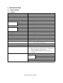
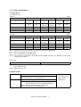


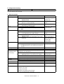


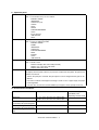
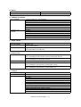


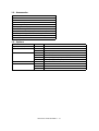
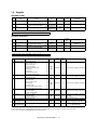
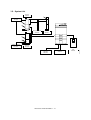

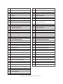

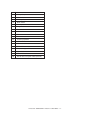
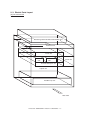
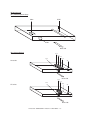

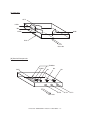
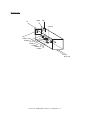
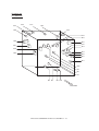


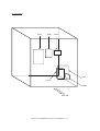
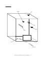
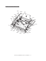

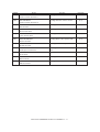

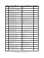

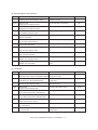
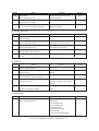
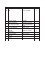
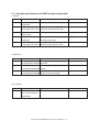
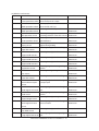


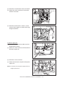
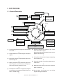
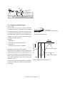


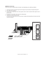
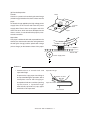
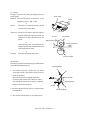
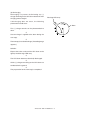

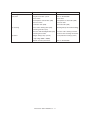
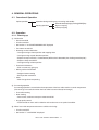


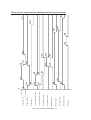


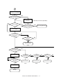

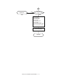
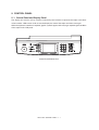
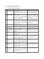
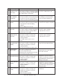
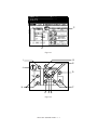


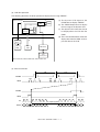

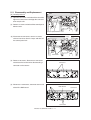
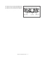
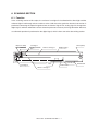
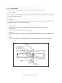

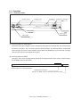
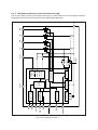
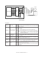
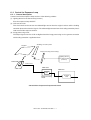

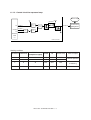
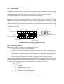
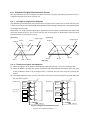

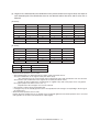
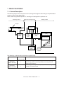
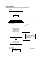
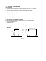


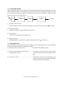
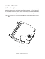
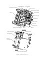


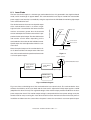
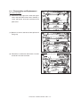


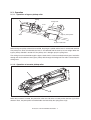
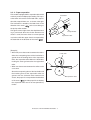


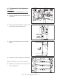
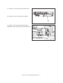

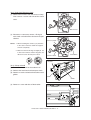
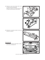

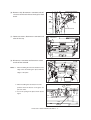
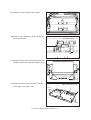

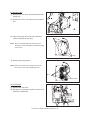
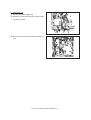

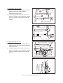
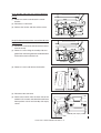
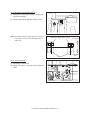
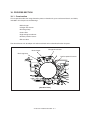
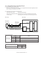
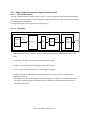
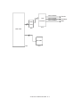


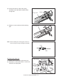
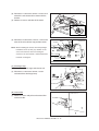

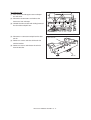
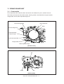
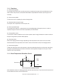
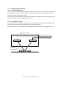
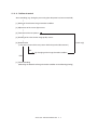

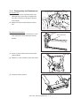
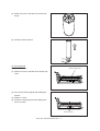


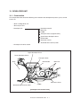


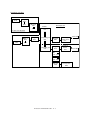
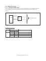


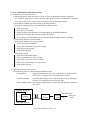


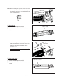


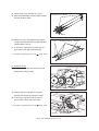

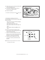


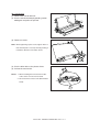
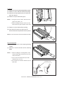
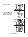
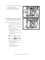

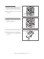
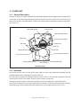
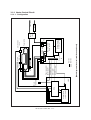

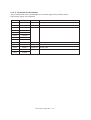


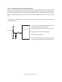
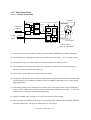
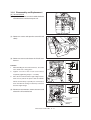
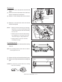
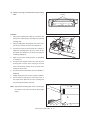

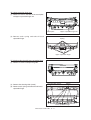
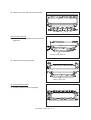


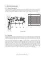
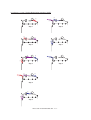

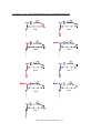
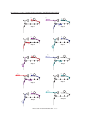
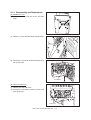

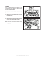


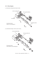


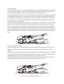

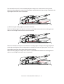

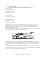

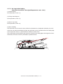
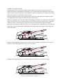
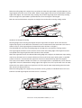


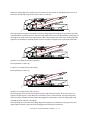
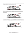
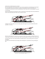
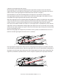

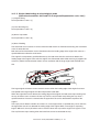


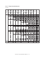
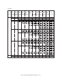


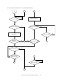

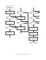


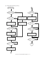
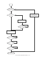

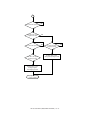

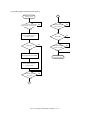
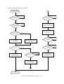
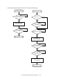


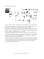
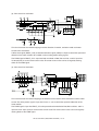
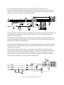

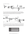
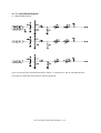
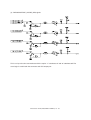
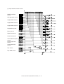
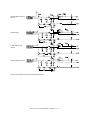
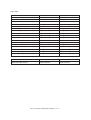


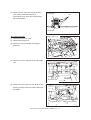


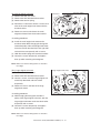
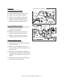
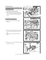

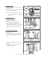

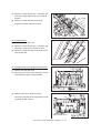
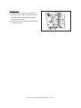
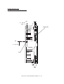
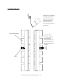
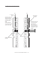
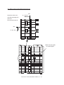

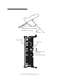


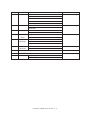
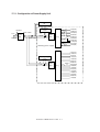
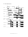
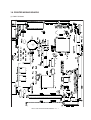
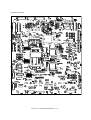
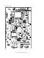
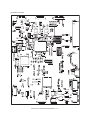
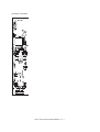
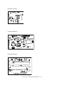
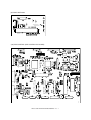
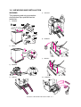

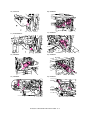


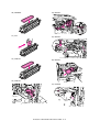
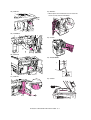

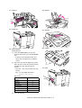


![取扱説明書[NI-FS350]](http://vs1.manualzilla.com/store/data/006555666_3-60968ee3a84023c894538f98d15ad355-150x150.png)