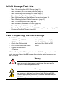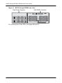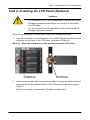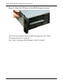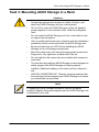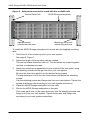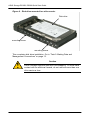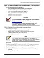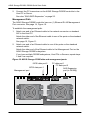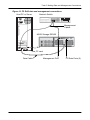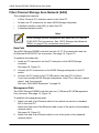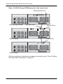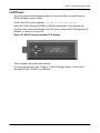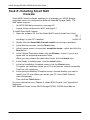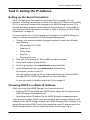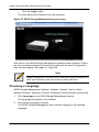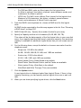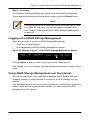
1
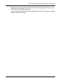
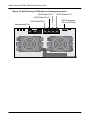
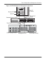
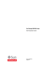
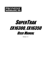
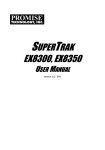
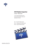
ASUS Storage
DS300f, DS300i
Quick Start Guide
Version 1.0
© 2011 ASUSTek COMPUTER INC.(Taiwan) All Rights Reserved.
ASUS Storage Task List
•
Task 1: Unpacking tthe ASUS Storage (page 2)
•
Task 2: Installing the LCD Panel (Optional) (page 5)
•
Task 3: Mounting ASUS Storage in a Rack (page 7)
•
Task 4: Installing Disk Drives (page 10)
•
Task 5: Making Data and Management Connections (page 13)
•
Task 6: Setting Up Serial Cable Connections (page 27)
•
Task 7: Connecting the Power (page 28)
•
Task 8: Installing Smart NAS Console (page 32)
•
Task 9: Setting the IP Address (page 33)
•
Task 10: Creating Logical Drives with ASUS Storage Management (page 39)
•
Contacting Technical Support (page 46)
Task 1: Unpacking tthe ASUS Storage
The ASUS Storage product box contains the following items:
•
ASUS Storage DS300f or
DS300i subsystem
•
Quick Start Guide printed
•
RJ11-to-DB9 serial data cable
•
Screws for disk drives
(70 pieces)
•
1.5m (4.9 ft) Power cords (2)
•
CD with SNMP files, User Manual,
and Quick Start Guide in PDF
format
A Battery Backup Unit (BBU) is optional on the ASUS Storage subsystem. In the
event of a power failure, the BBU powers the controller cache to preserve any
data it contains.
Warning
This is a Class A product. In a domestic environment this product
may cause radio interference in which case the user may be
required to take adequate measures.
Warning
The electronic components within the ASUS Storage enclosure
are sensitive to damage from Electro-Static Discharge (ESD).
Observe appropriate precautions at all times when handling the
ASUS Storage or its subassemblies.
2
Task 1: Unpacking tthe ASUS Storage
Caution
•
There is a risk of explosion if the battery is replaced by the
incorrect type.
•
Dispose of used batteries according to the instructions that
accompany the battery.
Figure 1. ASUS Storage front view
A defective drive may be replaced without interruption of data availability to the
host computer. If so configured, a hot spare drive will automatically replace a
failed drive, securing the fault-tolerant integrity of the logical drive. The selfcontained hardware-based RAID logical drive provides maximum performance in
a compact external enclosure.
Figure 2. ASUS Storage DS300f rear view
Dual Power Supplies
SAS RAID Controller
3
ASUS Storage DS300f, DS300i Quick Start Guide
Figure 3. ASUS Storage DS300i rear view
Dual Power Supplies
SAS RAID Controller
For a description of the LEDs, see pages 28 and 30.
4
Task 2: Installing the LCD Panel (Optional)
Task 2: Installing the LCD Panel (Optional)
Cautions
•
The LCD panel is NOT a hot-swap device. Be sure the ASUS
Storage is powered down before you connect or disconnect
the LCD panel.
•
You must install the LCD panel before you mount the ASUS
Storage subsystem in a rack.
The LCD panel mounts to the left ear of the ASUS Storage enclosure.
1.
Align the connector on the left bracket of the ASUS Storage enclosure to the
connector on the back of the LCD panel, as shown in Figure 4.
Figure 4. Align the connectors on the enclosure and the LCD panel
Connector on
the enclosure
2.
Connector on
the LCD panel
Insert the two screws that you removed in step 1 through the holes in the left
bracket and into the threaded holes in the LCD panel, as shown in page 6,
Figure 5.
Tighten the screws to secure the LCD panel to the bracket.
5
ASUS Storage DS300f, DS300i Quick Start Guide
Figure 5. Attach the LCD panel to the ASUS Storage enclosure
The LCD screen activates when the ASUS Storage boots. See “Task 7:
Connecting the Power” on page 28.
Go to “Task 3: Mounting ASUS Storage in a Rack” on page 7.
6
Task 3: Mounting ASUS Storage in a Rack
Task 3: Mounting ASUS Storage in a Rack
Cautions
•
At least two persons are required to safely lift, place, and
attach the ASUS Storage unit into a rack system.
•
Do not lift or move the ASUS Storage unit by the handles,
power supplies or the controller units. Hold the subsystem
itself.
•
Do not install the ASUS Storage unit into a rack without rails
to support the subsystem.
•
Only a qualified technician who is familiar with the installation
procedure should mount and install the ASUS Storage unit.
•
Be sure all switches are OFF before installing the ASUS
Storage unit or exchanging components.
•
Mount the rails to the rack using the appropriate screws and
flange nuts, fully tightened, at each end of the rail.
•
Do not load the rails unless they are installed with screws as
instructed.
•
The rails that ship with the ASUS Storage unit are designed to
safely support that ASUS Storage unit when properly
installed. Additional loading on the rails is at the customer’s
risk.
•
ASUSTek COMPUTER INC. (Taiwan) cannot guarantee that
the mounting rails will support your ASUS Storage unit unless
you install them as instructed.
Note
To lighten the ASUS Storage enclosure, remove the power
supplies. Replace the power supplies after the ASUS Storage unit
is mounted in your rack.
7
ASUS Storage DS300f, DS300i Quick Start Guide
Figure 6. Subsystem mounted in a rack with the available rails
Vertical Rack Post
ASUS Storage subsystem
Mounting rails mount
outside the rack post
Handles mount
outside the rack post
To install the ASUS Storage subsystem into a rack with the supplied mounting
rails:
1.
Check the fit of the mounting rails in your rack system.
2.
Adjust the length of the mounting rails as needed.
See page 9, Figure 7.
The rear rail slides inside the front rail. The rail halves are riveted together
and use no adjustment screws.
3.
Attach the mounting rail assemblies to the outside of the rack posts, using
the attaching screws and flange nuts from your rack system.
Be sure the front rail support is on the bottom facing inward.
The alignment pins fit into the rack holes above and below the attaching
screws.
Use the attaching screws and flange nuts from your rack system. Tighten the
screws and flange nuts according to your rack system instructions.
4.
Place the ASUS Storage subsystem onto the rails.
5.
Secure the ASUS Storage subsystem to the rack.
One screw each side, in the upper hole only. Use the attaching screws and
flange nuts from your rack system. Tighten the screws and flange nuts
according to your rack system instructions.
8
Task 3: Mounting ASUS Storage in a Rack
Figure 7. Rack mount assembly diagram
Rack front post
Alignment pins
two on each flange
Rack rear post
Rear rail
Front rail
Support for
subsystem
Inside of post
Rail attaching screws
(not included)
Inside of post
Note that only the front rail has a support for the subsystem.
This completes rack mounting. Go to “Task 4: Installing Disk Drives” on page 10.
9
ASUS Storage DS300f, DS300i Quick Start Guide
Task 4: Installing Disk Drives
The ASUS Storage DS300f and DS300i subsystems and DS300j expansion
units support:
•
SAS and SATA hard disk drives
•
3.5-inch hard disk drives
For a list of supported physical drives, download the latest compatibility list from
the ASUS support web site http://support.asus.com/.
Number of Drives Required
The table below shows the number of drives required for each RAID level
Level
Number of Drives
Level
Number of Drives
RAID 0
1 or more
RAID 6
4 to 32*
RAID 1
2 only
RAID 10
4 or more**
RAID 1E
2 or more
RAID 30
6 or more
RAID 3
3 to 32*
RAID 50
6 or more
RAID 5
3 to 32*
RAID 60
8 or more
* A JBOD expansion unit may be required.
** Must be an even number of drives.
Drive Slot Numbering
You can install any suitable disk drive into any slot in the enclosure. The diagram
below shows how ASUS Storage’s drive slots are numbered. Whether you have
the original or plus carriers, the slots are numbered the same.
Slot numbering is reflected in the ASUS Storage Management and CLU user
interfaces. See page 11, Figure 8.
10
Task 4: Installing Disk Drives
Figure 8. ASUS Storage drive slot numbering
Install all of the drive carriers o the ASUS Storage enclosure to ensure proper
airflow, even if you do not populate all the carriers with disk drives.
Installing Your Disk Drives
To install your disk drives:
1.
Remove a disk drive carrier.
2.
Carefully lay the disk drive into the drive carrier at the front, so that the screw
holes on the sides line up.
3.
Insert the screws through the holes in the drive carrier and into the sides of
the disk drive.
See page 12, Figure 9.
4.
•
Install only the counter-sink screws supplied with the ASUS Storage.
•
Install four screws per drive.
•
Snug each screw. Be careful not to over-tighten.
Reinstall the drive carrier into the ASUS Storage enclosure.
Repeat steps 1 through 3 until all of your disk drives are installed.
11
ASUS Storage DS300f, DS300i Quick Start Guide
Figure 9. Disk drive mounted in a drive carrier
Disk drive
mounting screw
mounting screw
This completes disk drive installation. Go to “Task 5: Making Data and
Management Connections” on page 13.
Caution
ASUS Storage supports disk drive hot-swapping. To avoid hand
contact with an electrical hazard, do not remove more than one
drive carrier a time.
12
Task 5: Making Data and Management Connections
Task 5: Making Data and Management Connections
You can configure your ASUS Storage for:
•
Fibre Channel Direct Attached Storage (DAS), see below
•
Fibre Channel Storage Area Network (SAN) (page 16)
•
iSCSI Direct Attached Storage (DAS) (page 19)
•
iSCSI Storage Area Network (SAN) (page 22)
•
SAS JBOD Expansion (page 25)
•
SAS JBOD Expansion (page 25)
Important
For a list of supported FC HBAs, Switches and SFPs, download
the latest compatibility list from the ASUS support web site
http://support.asus.com/.
ASUS Storage does not support cascading of multiple RAID
subsystems. Cascading is planned for a future release.
Fibre Channel Direct Attached Storage (DAS)
This arrangement requires:
•
A Fibre Channel (FC) interface card in the Host PC
•
At least one FC transceiver for each ASUS Storage subsystem
•
A network interface card (NIC) in the Host PC
•
A standard network switch
Note
ASUS Storage Fibre Channel subsystems also have two (2)
Ethernet RJ45 iSCSI Port connectors. See “iSCSI Direct Attached
Storage (DAS)” on page 19 for connection instructions.
Data Path
The ASUS Storage DS300f controller has two (2) FC Port connectors and one
(1) SFF-8088 SAS Expansion Port connector. See page 14, Figure 10.
To establish the data path:
1.
Install an FC transceiver into the FC data port on the ASUS Storage
controller.
See page 15, Figure 11.
13
ASUS Storage DS300f, DS300i Quick Start Guide
2.
Connect the FC transceiver on the ASUS Storage DS300f controller to the
Host PC or Server.
See also “SAS JBOD Expansion” on page 25.
Management Path
The ASUS Storage DS300f controller has one (1) Ethernet RJ-45 Management
Port connector. See page 14, Figure 10.
To establish the management path:
1.
Attach one end of an Ethernet cable to the network connector or standard
NIC in the Host PC.
Attach the other end of the Ethernet cable to one of the ports on the standard
network switch.
See page 15, Figure 11.
2.
Attach one end of an Ethernet cable to one of the ports on the standard
network switch.
Attach the other end of the Ethernet cable to the Management Port on the
ASUS Storage DS300f subsystem.
If you have multiple DS300f subsystems, Host PCs or Servers, repeat steps
1 and 2 as required.
Figure 10. ASUS Storage D300f data and management ports
iSCSI data port 2
iSCSI data port 1
FC data port 1
FC data port 2
SAS Expansion
port (to DS300j)
Management port
14
Task 5: Making Data and Management Connections
Figure 11. FC DAS data and management connections
Host PC or Server
Network Switch
Management
Cables
ASUS Storage DS300f
NIC
FC card
Data Cable
Management Port
15
FC Data Ports (2)
ASUS Storage DS300f, DS300i Quick Start Guide
Fibre Channel Storage Area Network (SAN)
This arrangement requires:
•
A Fibre Channel (FC) interface card in each Host PC
•
At least one FC transceiver for each ASUS Storage subsystem
•
A network interface card (NIC) in each Host PC
•
A standard network switch
Note
ASUS Storage DS300f subsystems also have two (2) Ethernet
RJ45 iSCSI Port connectors. See “iSCSI Storage Area Network
(SAN)” on page 22 for connection instructions.
Data Path
The ASUS Storage DS300f controller has two (2) FC Port connectors and two
(2) Ethernet RJ45 iSCSI Port connectors. See page 14, Figure 10.
To establish the data path:
1.
Install an FC transceiver into the FC data port on the ASUS Storage
controller.
See page 18, Figure 12.
2.
Connect the FC transceiver on the ASUS Storage subsystem to the FC
switch.
3.
Connect the FC switch to the FC HBA card in the Host PC or Server.
If you have multiple ASUS Storage subsystems, Host PCs or Servers, repeat
steps 1 and 2 as required.
See also “SAS JBOD Expansion” on page 25.
Management Path
The ASUS Storage DS300f controller has one (1) Ethernet RJ-45 Management
Port connector. See page 14, Figure 10.
To establish the management path:
1.
Attach one end of an Ethernet cable to the network connector or standard
NIC in the Host PC.
Attach the other end of the Ethernet cable to one of the ports on the standard
network switch.
See page 18, Figure 12.
2.
Attach one end of an Ethernet cable to one of the ports on the standard
network switch.
16
Task 5: Making Data and Management Connections
Attach the other end of the Ethernet cable to the Management Port on the
ASUS Storage DS300f subsystem.
If you have multiple ASUS Storage subsystems, Host PCs or Servers, repeat
steps 1 and 2 as required.
17
ASUS Storage DS300f, DS300i Quick Start Guide
Figure 12. FC SAN data and management connections
NIC
NIC
FC card
FC card
Host PCs or
Servers
Management Cables
Data Cables
Network
Switch
FC Switch
ASUS Storage DS300f
ASUS Storage DS300f
Management Port
18
FC Data Ports (2)
Task 5: Making Data and Management Connections
iSCSI Direct Attached Storage (DAS)
This arrangement requires:
•
A Gigabit Ethernet network interface card (GbE NIC) in the Host PC or
Server with iSCSI support in hardware or in software
•
A standard network switch
•
A network interface connector on the motherboard or network interface card
(NIC) in the Host PC
Note
These instructions also apply to the iSCSI Ports on ASUS Storage
Fibre Channel subsystems.
Configuring a Data Path
The ASUS Storage DS300i controller has four (4) Ethernet RJ45 iSCSI Port
connectors. See page 20, Figure 13.
To establish the data path:
1.
Attach one end of an Ethernet cable to the GbE (iSCSI) NIC in the Host PC.
2.
Attach the other end of the Ethernet cable to one of the four iSCSI ports on
the ASUS Storage DS300i controller.
See page 21, Figure 14.
If you have multiple ASUS Storage DS300i subsystems, Host PCs or
Servers, repeat steps 1 and 2 as required.
See also “SAS JBOD Expansion” on page 25.
Configuring a Management Path
The ASUS Storage DS300i controller has one (1) Ethernet RJ-45 Management
Port connector. See page 20, Figure 13.
To establish the management path:
1.
Attach one end of an Ethernet cable to the network connector or standard
NIC in the Host PC.
Attach the other end of the Ethernet cable to one of the ports on the standard
network switch. See page 21, Figure 14.
2.
Attach one end of an Ethernet cable to one of the ports on the standard
network switch.
Attach the other end of the Ethernet cable to the Management Port on the
ASUS Storage DS300i subsystem.
If you have multiple ASUS Storage subsystems, Host PCs or Servers, repeat
steps 1 and 2 as required.
19
ASUS Storage DS300f, DS300i Quick Start Guide
Figure 13. ASUS Storage D300i data and management ports
iSCSI Data Port 3
iSCSI Data Port 4
iSCSI Data Port 2
iSCSI Data Port 1
Management Port
20
SAS Expansion
Port (to DS300j)
Task 5: Making Data and Management Connections
Figure 14. iSCSI DAS data and management connections
Host PC
or Server
Standard NIC
GbE NIC
Management
Cables
Standard Network Switch
Data Cable
ASUS Storage DS300i
Management Port
21
iSCSI Data Ports (4)
ASUS Storage DS300f, DS300i Quick Start Guide
iSCSI Storage Area Network (SAN)
This arrangement requires:
•
A Gigabit Ethernet network interface card (GbE NIC) in the Host PC or
Server with iSCSI support in hardware or in software
•
A GbE network switch
•
A standard network switch
•
A network interface connector on the motherboard or network interface card
(NIC) in the Host PC
Note
These instructions also apply to the iSCSI Ports on ASUS Storage
D300f subsystems.
Use this configuration if you plan to set up Network Attached
Storage (NAS). See “Task 8: Installing Smart NAS Console” on
page 32.
Configuring a Data Path
Depending on the model, the ASUS Storage DS300i controller has two (2) or four
(4) Ethernet RJ45 iSCSI Port connectors. See page 20, Figure 13.
To establish the data path:
1.
Attach one end of an Ethernet cable to the GbE (iSCSI) NIC in the Host PC.
Attach the other end of the Ethernet cable to one of the ports on the GbE
network switch. See page 24, Figure 15.
If you have multiple ASUS Storage DS300i subsystems, Host PCs or
Servers, repeat steps 1 and 2 as required.
2.
Attach one end of an Ethernet cable to one of the ports on the GbE network
switch.
Attach the other end of the Ethernet cable to one of the four iSCSI ports on
the ASUS Storage DS300i controller.
Only one iSCSI data cable is required between the ASUS Storage DS300i
and GbE network switch. However, you can attach multiple cables to create
redundant data paths.
If you have multiple ASUS Storage DS300i subsystems, Host PCs or
Servers, repeat steps 1 and 2 as required.
See also “SAS JBOD Expansion” on page 25.
22
Task 5: Making Data and Management Connections
Configuring a Management Path
The ASUS Storage DS300i controller has one (1) Ethernet RJ-45 Management
Port connector. See page 20, Figure 13.
To establish the management path:
1.
Attach one end of an Ethernet cable to the standard NIC in the Host PC.
Attach the other end of the Ethernet cable to one of the ports on the standard
network switch. See page 24, Figure 15.
2.
Attach one end of an Ethernet cable to one of the ports on the standard
network switch.
Attach the other end of the Ethernet cable to the Management Port on the
ASUS Storage DS300i subsystem. See page 24, Figure 15.
If you have multiple ASUS Storage DS300i subsystems, Host PCs or
Servers, repeat steps 1 and 2 as required.
23
ASUS Storage DS300f, DS300i Quick Start Guide
Figure 15. iSCSI SAN data and management connections
Standard
NIC
Standard
NIC
GbE NIC
GbE NIC
Host PCs or
Servers
Standard
Network
Switch
GbE
Network
Switch
Management Cables
Data Cables
ASUS Storage DS300i
Management Port
iSCSI Data
Ports (4)
ASUS Storage DS300i
24
Task 5: Making Data and Management Connections
SAS JBOD Expansion
This arrangement requires:
•
One (1) or more ASUS DS300j expansion units
•
One (1) SFF-8088 to SFF-8088 SAS cable for each ASUS DS300j
expansion unit
Configuring the Data Path
All ASUS Storage subsystems have one (1) SFF-8088 SAS Expansion Port
connector.
To expand the data path:
1.
Attach one end of a SFF-8088 to SFF-8088 SAS cable to the SAS
Expansion Port on the ASUS Storage subsystem.
2.
Attach the other end of the SFF-8088 to SFF-8088 SAS cable to the SAS IN
Port on the ASUS DS300j expansion units.
See page 26, Figure 16.
If you have another ASUS DS300j expansion unit, attach one end of the
SFF-8088 to SFF-8088 SAS cable to the SAS OUT Port of the first ASUS
DS300j to the SAS IN Port of the second ASUS DS300j.
Important
ASUS Storage DS300j expansion units have one SAS IN port and
one SAS OUT port. If you connect them incorrectly, the ASUS
Storage does not recognize the ASUS Storage DS300j expansion
units.
For more information, see the ASUS Storage DS300j User
Manual on the CD that came with the ASUS DS300j expansion
unit.
Configuring a Management Path
The ASUS Storage controller manages the ASUS DS300j expansion unit. No
additional management connections are required for JBOD expansion.
25
ASUS Storage DS300f, DS300i Quick Start Guide
Figure 16. ASUS Storage DS300j expansion data connections
SAS Expansion Port
ASUS Storage DS300i
SAS data cable
ASUS DS300j
SAS OUT Port
SAS IN Port
ASUS DS300j
After you complete your data and management connection, go to “Task 6: Setting
Up Serial Cable Connections” on page 27.
26
Task 6: Setting Up Serial Cable Connections
Task 6: Setting Up Serial Cable Connections
Serial communication enables the Command Line Interface (CLI) and Command
Line Utility (CLU) on your PC to monitor and control the ASUS Storage
subsystem. The ASUS Storage package includes a RJ11-to-DB9 serial data
cable.
Figure 17. Serial connector on a DS300f controller
RJ11 Serial Connector
Figure 18. Serial connector on a DA300i controller
RJ11 Serial Connector
To set up a serial cable connection:
1.
Attach the RJ11 end of the serial data cable to the RJ11 serial connector on
the controller.
2.
Attach the DB9 end of the serial data cable to a serial port on the Host PC or
Server.
This completes the serial cable connection. Go to “Task 7: Connecting the
Power” on page 28.
27
ASUS Storage DS300f, DS300i Quick Start Guide
Task 7: Connecting the Power
Plug-in the power cords and turn on the switches on both power supplies.
Important
If you have a SAN, DAS, or JBOD expansion, always power on
the JBOD expansion units first.
When the power is switched on, the LEDs and LCD screen light up.
Front Panel LEDs
When boot-up is finished and the ASUS Storage DS300f or DS300i subsystem
is functioning normally:
•
Power, Global Enclosure Status, and Global RAID Status LEDs display
green continuously.
•
Controller Activity LED flashes green when there is controller activity.
•
System Heartbeat LED blinks green seven times in three seconds, goes
dark for six seconds, then repeats the pattern.
Figure 19. ASUS Storage subsystem front panel LED display
Power
Global Enclosure Status
Global RAID Status
Controller Activity
Reserved
System Heartbeat
28
Task 7: Connecting the Power
Controller LEDs
When boot-up is finished and the ASUS Storage subsystem is functioning
normally:
•
Battery, and Controller status LEDs display green continuously.
•
Ethernet LEDs display green or flash depending on your network
connection.
•
The FC, iSCSI, SAS, and Expansion LEDs display green or flash during port
activity.
Figure 20. ASUS Storage DS300f controller LEDs
Controller Status
Fan 2
Fan 1
Battery
FC Ports
1
2
Dirty Cache
USB 2
USB 1
JBOD Expansion
iSCSI
1 2
Fan 1
Fan 2
29
ASUS Storage DS300f, DS300i Quick Start Guide
Figure 21. ASUS Storage DS300i Controller LEDs
Controller Status
Fan 2
Fan 1
Battery
Dirty Cache
USB 2
USB 1
JBOD Expansion
iSCSI Ports
1
2 3 4
Fan 1
Fan 2
There are two LEDs on each Drive Carrier. They report the presence of a disk
drive, activity of the drive, and the drive’s current condition.
Figure 22. ASUS Storage drive carrier LEDs
Disk Status
Power/Activiyt
If there is a disk drive in the carrier, the Power/Activity LED displays Green. If not,
the Power/Activity LED remains dark. The Power/Activity LED flashes during
drive activity.
30
Task 7: Connecting the Power
LCD Panel
The LCD panel activates approximately 35 seconds after you switch on the
ASUS Storage’s power supply.
At first, the LCD screen displays System is Initializing.
When the ASUS Storage DS300f or DS300i subsystem is fully booted and
running under normal conditions, the LCD screen shows ASUS Storage and IP
address, as shown in Figure 23.
Figure 23. ASUS Storage optional LCD display
This completes the power and start-up.
For setup instructions, see “Chapter 3: ASUS Storage Setup” in the ASUS
Storage DS300f, DS300i User Manual.
31
ASUS Storage DS300f, DS300i Quick Start Guide
Task 8: Installing Smart NAS
Console
Smart NAS Console software enables you to manage your ASUS Storage
subsystem when it is configured as Network Attached Storage (NAS). The
NAS option requires:
•
An iSCSI SAN data connection, see page 22.
•
Logical drives configured for NAS, see page 51.
To install Smart NAS Console:
1. Open the software CD, find the Smart NAS Console install icon (right),
and drag it to your PC’s desktop.
2.
Double-click the Smart NAS Console Install icon to begin installation.
3.
In the Welcome screen, click the Next button.
4.
In the License screen, choose the I accept the terms... option and click the
Next button.
5.
In the Choose Destination folder, click the Browse... button if you do not
agree with the proposed destination folder.
When you have chosen the destination folder, click the Next button.
6.
In the Ready to Install screen, click the Install button.
7.
In the first Installation Complete screen, click the Finish button.
To register your software online, your PC must have an Internet connection.
Thank you for registering.
8.
In the second Installation Complete screen, choose whether you want to
restart your PC now. When you restart your PC, Smart NAS Console
runs automatically.
Then click the Finish button.
For more information, see “Chapter 5: Smart NAS Console” and “Appendix A:
Setting-up
NAS Network Drives” In the ASUS Storage DS300f, DS300i User Manual.
32
Task 9: Setting the IP Address
Task 9: Setting the IP Address
Setting up the Serial Connection
ASUS Storage has a Command Line Interface (CLI) to manage all of its
functions, including customizing. A subset of the CLI is the Command Line Utility
(CLU), a user-level interface that manages your ASUS Storage via your PC’s
terminal emulation program, such as Microsoft HyperTerminal. This procedure
uses the serial cable connection you made in “Task 6: Setting Up Serial Cable
Connections” on page 27.
You must use the CLI or CLU to assign an IP address to the ASUS Storage to
enable a network connection for ASUS Storage Management.
1.
Change your terminal emulation program settings to match the following
specifications:
•
Bits per second: 115200
•
Data bits: 8
•
Parity: None
•
Stop bits: 1
•
Flow control: none
2.
Start your PC’s terminal VT100 or ANSI emulation program.
3.
Press Enter once to launch the CLI.
4.
At the Login prompt, type administrator and press Enter.
5.
At the Password prompt, type password and press Enter.
At this point, you are in the CLI.
You can continue using the CLI to make network settings. See the ASUS
Storage DS300f, DS300i User Manual for more information.
Or you can switch to Setting up with the CLU on page 35.
Choosing DHCP or a Static IP Address
When you setup your ASUS Storage, you have the option of:
•
Enabling DHCP and letting your DHCP server assign the IP address to the
ASUS Storage’s management port.
•
Specifying a static IP address for the ASUS Storage’s management port.
If you choose to enable DHCP, have your Network Administrator dedicate an IP
address for the ASUS Storage, linked to the ASUS Storage’s MAC address. This
action will prevent the DHCP server from assigning a new IP address when the
ASUS Storage restarts, with the result that users can no longer log in.
33
ASUS Storage DS300f, DS300i Quick Start Guide
To access the MAC address for ASUS Storage’s management port:
1.
At the administrator@cli> prompt, type menu and press Enter.
The CLU main menu appears.
2.
In the CLU Main Menu, highlight Network Management and press Enter,
then highlight the management port and press Enter
Figure 24. Viewing the management port’s MAC address.
MAC Address
Default IP Addresses
ASUS Storage ships from the factory a default Management Port IP address of
192.168.0.1 and default iSCSI Port IP addresses of 10.0.0.2 through 10.0.0.5.
You must change these addresses to work with your network.
34
Task 9: Setting the IP Address
Setting up with the CLU
1.
At the administrator@cli> prompt, type menu and press Enter.
The CLU main menu appears.
Figure 25. CLU main menu
2.
With Quick Setup highlighted, press Enter.
The first Quick Setup screen enables you to make Date and Time settings.
Setting system date and time
To make date and time settings:
1.
Press the arrow keys to highlight System Date.
2.
Press the backspace key to erase the current date.
3.
Type the new date.
4.
Follow the same procedure to set the System Time.
5.
Press Ctrl-A to save these settings and move to the Management Port
configuration screen.
Making Manual IP Settings
To make Management Port and iSCSI Port settings manually:
1.
Press the arrow keys to highlight IP Address.
2.
Press the backspace key to erase the current IP Address.
35
ASUS Storage DS300f, DS300i Quick Start Guide
3.
Type the new IP Address.
4.
Follow the same procedure to specify the Subnet Mask, Gateway IP
Address and DNS Server IP Address.
If you do not have a DNS server, skip the DNS Server IP address.
5.
Highlight TCP Port Number to change the entry.
3260 is the default and recommended for most applications.
6.
Press Ctrl-A to save these settings and move to the RAID configuration
screen.
Making Automatic IP Settings
To make Management Port and iSCSI Port settings automatically:
1.
Press the arrow keys to highlight DHCP.
2.
Press the spacebar to toggle to Enable.
3.
Highlight TCP Port Number to change the entry.
4.
Press Ctrl-A to save these settings and move to the RAID configuration
screen.
3260 is the default and recommended for most applications.
Configuring the RAID
You can configure your RAID arrays and logical drives using the CLU at this time.
ASUS suggests that you highlight Skip the Step and Finish and press Enter. Then
create your disk array using ASUS Storage Management. See “Task 10: Creating
Logical Drives with ASUS Storage Management” on page 39.
Viewing IP Address and Settings
To view the current IP address and network settings when using DHCP:
1.
In the CLU Main Menu, highlight Network Management and press Enter.
2.
Highlight the Management Port or iSCSI Port you want and press Enter.
3.
Highlight DHCP and press the spacebar to toggle to Disable.
The current Management or iSCSI Port settings are displayed.
4.
Press the spacebar to toggle DHCP back to Enable.
5.
Press Ctrl-A to save these settings and move to the RAID configuration
screen.
Exiting the CLU
In the CLU Main Menu, highlight Return to CLI and press Enter.
This completes the Management Port setup.
36
Task 9: Setting the IP Address
Go to “Task 10: Creating Logical Drives with ASUS Storage Management” on
page 39
Setting up with the LCD
The LCD Panel displays the current IP address during normal operation. If you
did not install the LCD Panel, see “Task 2: Installing the LCD Panel (Optional)” on
page 5. The LCD does not have a date and time function.
Figure 26. LCD Panel default view
Making Manual IP Settings
To make Management Port settings manually:
1.
Press the
2.
Press the
3.
Press the
4.
Press the
or
button until the display says Management Port.
button and the display says Link Status Up.
If it says Link Status Down, reconnect to the network before preceding.
or
button and the display says IP Address.
button to make a change.
The current IP Address displays with the cursor under the first (extreme left)
digit.
5.
Press the
button to increment and the
Press the
button to move left and the
button decrement.
button to move right.
To set an IP address with double- or single-digit octets, for example,
192.168.1.50, type zeros as placeholders, 192.168.001.050.
After you have set the last (extreme right) digit, press the
button.
The current Subnet Mask displays with the cursor under the first (extreme
left) digit.
6.
Make the needed changes the same as in step 5.
After you have set the last (extreme right) digit, press the
button.
The current Gateway displays with the cursor under the first (extreme left)
digit.
37
ASUS Storage DS300f, DS300i Quick Start Guide
7.
Make the needed changes the same as in step 5.
After you have set the last (extreme right) digit, press the
button.
The display says Save Network Setting?
8.
Press the
button to confirm.
The display shows the new IP address you set.
Making Automatic IP Settings
To make Management Port settings automatically:
1.
Press the
2.
Press the
or
button until the display says Management Port.
button and the display says Link Status Up.
If it says Link Status Down, reconnect to the network before preceding.
3.
Press the
or
button and the display says DHCP Disable.
4.
Press the
button to make a change.
5.
Press the
button to Enable.
6.
Press the
button to confirm.
The display shows the new IP address set by the DHCP server.
This completes the Management Port setup. Go to “Task 10: Creating Logical
Drives with ASUS Storage Management” on page 39.
38
Task 10: Creating Logical Drives with ASUS Storage Management
Task 10: Creating Logical Drives with ASUS Storage
Management
Setting up ASUS Storage Management consists of the following actions:
•
Logging into ASUS Storage Management (below)
•
Choosing a Language (page 40)
•
Creating Your Logical Drives (page 41)
•
Logging out of ASUS Storage Management (page 45)
•
Using ASUS Storage Management over the Internet (page 45)
Logging into ASUS Storage Management
1.
Launch your Browser.
2.
In the Browser address field, type the IP address of the ASUS Storage
subsystem.
Use the IP address you obtained in Task 7 (see page 35). Note that the IP
address shown below is only an example. The IP address you type into your
browser will be different.
Regular Connection
•
ASUS Storage Management uses an HTTP connection . . . . . .http://
•
Enter the ASUS Storage’s IP address . . . . . . . . . . . . 192.168.10.85
Together, your entry looks like this:
http://192.168.10.85
Secure Connection
•
ASUS Storage Management uses a secure
HTTP connection . . . . . . . . . . . . . . . . . . . . . . . . . . . . . . . . . . .https://
•
Enter the ASUS Storage’s IP address . . . . . . . . . . . . 192.168.10.85
Together, your entry looks like this:
https://192.168.10.85
Note
Whether you choose a regular or a secure connection, your login
to ASUS Storage Management and your user password are
always secure.
3.
When the log-in screen appears:
•
Type administrator in the User Name field.
•
Type password in the Password field.
39
ASUS Storage DS300f, DS300i Quick Start Guide
•
Click the Login button.
The User Name and Password are case sensitive.
Figure 27. ASUS Storage Management log-in screen
After sign-in, the ASUS Storage Management opening screen appears. If there
are any unconfigured physical drives in the enclosure, an Array Configuration
menu will also appear. See page 41, Figure 29.
Note
Make a Bookmark (Firefox) or set a Favorite (Internet Explorer) of
the Login Screen so you can access it easily next time.
Choosing a Language
ASUS Storage Management displays in English, German, French, Italian,
Spanish, Russian, Japanese, Chinese Traditional, Chinese Simple, and Korean.
1.
Click Language on the ASUS Storage Management banner.
2.
Click on the language you prefer.
The language list appears in the Header.
The ASUS Storage Management user interface displays in the selected
language.
40
Task 10: Creating Logical Drives with ASUS Storage Management
Figure 28. Clicking “Language” on the ASUS Storage Management banner
Creating Your Logical Drives
On a newly activated ASUS Storage subsystem, there are no disk arrays or
logical drives. To create a logical drive:
1.
Click the Disk Arrays
icon, then click the Create tab.
The Array Configuration menu appears.
Figure 29. The Array Configuration menu
2.
3.
Choose one of the options:
•
Automatic – Creates a new disk array following a default set of
parameters. Makes one logical drive automatically. Also makes a hot
spare drive for all RAID levels except RAID 0, if at least four
unconfigured physical drives are available. See page 42.
•
Express – You choose the parameters for a new disk array by
specifying the characteristics you want. You can create multiple logical
drives at the same time, however they will all be identical. You can
choose to make a hot spare drive for all RAID levels except RAID 0, if at
least four unconfigured physical drives are available. See page 42.
•
Advanced – You directly specify all parameters for a new disk array.
Makes one logical drive automatically. You can create additional logical
drives at a later time, if additional configurable capacity is available.
Does not make a hot spare drive. See page 43.
Click the Next button.
41
ASUS Storage DS300f, DS300i Quick Start Guide
Automatic
When you choose the Automatic option, the following parameters appear on the
screen:
•
Disk Arrays – The number of physical drives in the disk array, their ID
numbers, configurable capacity, and the number of logical drives to be
created
•
Logical Drives – The ID number of the logical drive(s), their RAID level,
capacity, and stripe size
•
Spare Drives – The physical drive slot number of the dedicated hot spare
assigned to this disk array. A hot spare drive is created for all RAID levels
except RAID 0, when five or more unconfigured physical drives are available
If you accept these parameters, click the Submit button.
The new disk array appears in the Disk Array List on the Information tab.
If you do NOT accept these parameters, use the Express (below) or Advanced
(page 43) option to create your logical drive.
Express
When you choose the Express option, a set of characteristics and options
appears on the screen.
1.
Check the boxes to choose any one or a combination of:
•
Redundancy – The array will remain available if a physical drive fails
•
Capacity – The greatest possible amount of data capacity
•
Performance – The highest possible read/write speed
•
Spare Drive – A hot spare drive is created when you choose
Redundancy, Spare Drive, and five or more unconfigured physical
drives are available
•
Mixing SATA/SAS Drive – Check this box if you want to use both SATA
and SAS drives in the same disk array
If the box is unchecked, and you have both SATA and SAS drives,
different arrays will be created for each type of drive.
2.
In the Number of Logical Drives field, enter the number of logical drives you
want to make from this disk array.
The maximum possible number of logical drives appears to the right of this
field.
3.
From the Application Type menu, choose an application that best describes
your intended use for this disk array:
•
File Server
•
Transaction Data
•
Video Stream
•
Transaction Log
42
•
Other
Task 10: Creating Logical Drives with ASUS Storage Management
4.
Click the Update button.
Or check the Automatic Update box and updates will occur automatically.
The following parameters display:
•
Disk Arrays – The number of physical drives in the disk array, their slot
numbers, configurable capacity, and the number of logical drives to be
created
•
Logical Drives – The slot number of the logical drive(s), their RAID
level, capacity, and stripe size
•
Spare Drives – The physical drive slot number of the dedicated hot
spare assigned to this disk array (all RAID levels except RAID 0)
If you accept these parameters, proceed to the next step.
If you do NOT accept these parameters, review and modify your selections
in the previous steps.
5.
When you are done, click the Submit button.
The new disk array appears in the Disk Array List on the Information tab.
Advanced
Note
For an explanation of the parameters under the Advanced option,
see “Chapter 9: Technology Background” on page 319.
When you choose the Advanced option, the Step 1 – Disk Array Creation screen
displays.
Step 1 – Disk Array Creation
1.
Optional. Enter a name for the disk array in the field provided.
Maximum of 31 characters; letters, numbers, space between characters, and
underline.
2.
Uncheck the boxes if you want to disable Media Patrol or PDM.
ASUS recommends leaving these features enabled.
3.
Highlight physical drives you want in the disk array from the Available list and
press the >> button to move them to the Selected list.
4.
When you are done, click the Next button.
You can also double-click them to move them.
Step 2 – Logical Drive Creation
1.
iSCSI only. If you plan to use this logical drive for NAS, click the NAS option
beside LD Type.
2.
Do one of the following actions:
43
ASUS Storage DS300f, DS300i Quick Start Guide
3.
•
For DAS and SAN, enter an Alias (name) for the logical drive.
An Alias is optional. Use letters, numbers, space between words, and
underscore. An Alias is optional.
•
iSCSI only. For NAS, enter a Mount Point (name) for the logical drive.
Maximum of 20 characters. Use letters, numbers, space between
words, and underscore. A Mount Point is required.
From the RAID Level dropdown list, choose a RAID level for this logical
drive.
All RAID levels supported by the disk array appear in the list. See “Choosing
a RAID Level” on page 332
4.
RAID 50 and 60 only – Specify the number of axles for your array.
5.
Specify a Capacity and the unit of measure (B, KB, MB, GB, TB).
This value will be the data capacity of the first logical drive in your new disk
array. If you specify less than disk array's maximum capacity, the remaining
capacity is available for additional logical drives that you can create now or
later.
6.
For the following items, accept the default or choose a new value from the
dropdown menu:
•
Stripe size. 128 KB is the default.
64 KB, 128 KB, 256 KB, 512 KB, and 1 MB are available.
•
Sector size. 512 B is the default.
512 B, 1 KB, 2 KB, and 4 KB are available.
•
Read (cache) Policy. Read Ahead is the default.
Read Cache, Read Ahead Cache, and No Cache are available.
•
Write (cache) Policy. Write Back is the default.
Write Back and Write Through (Thru) are available.
7.
Click the Update button.
A new logical drive is displayed under New Logical Drives. If there is free
capacity remaining, you can specify another logical drive now or wait until
later.
8.
When you are done specifying logical drives, click the Next button.
44
Task 10: Creating Logical Drives with ASUS Storage Management
Step 3 – Summary
The Summary lists the disk array and logical drive information you specified.
To proceed with disk array and logical drive creation, click the Submit button.
Note
This function does not automatically create a hot spare drive. After
you create the disk array, you should create a hot spare drive.
See “Chapter 4: Management with ASUS Storage Management”
on page 55.
Logging out of ASUS Storage Management
There are two ways to log out of ASUS Storage Management:
•
Close your browser window
•
Click Logout on the ASUS Storage Management banner
Figure 30. Clicking “Logout” on the ASUS Storage Management banner
Clicking Logout brings you back to the Login Screen. See page 30.
After logging out, you must enter your user name and password in order to log in
again.
Using ASUS Storage Management over the Internet
The above instructions cover connections between ASUS Storage and your
company network. It is also possible to connect to a ASUS Storage from the
Internet.
Your MIS Administrator can tell you how to access your network from outside the
firewall. Once you are logged onto the network, you can access the ASUS
Storage using its IP address.
45
ASUS Storage DS300f, DS300i Quick Start Guide
Contacting Technical Support
ASUS Technical Support provides several support options for ASUS users to
access information and updates. We encourage you to use one of our electronic
services, which provide product information updates for the most efficient service
and support.
If you decide to contact us, please have the following information available:
•
Product model and serial number
•
BIOS, firmware, and driver version numbers
•
A description of the problem / situation
•
System configuration information, including: motherboard and CPU type,
hard drive model(s), SAS/SATA/ATA/ATAPI drives & devices, and other
controllers.
Technical Support Services
ASUS Technical Support
http://support.asus.com/
46