1
User Guide for
Cisco Digital Media Manager 5.4.x
Part
Part
Part
Part
1
2
3
4
–
–
–
–
Manage Platform Services
Manage Network and Endpoint Settings
Manage Content for Cisco Digital Signs
Manage IPTV Programming for Cisco Cast
Revised: September 17, 2012
Americas Headquarters
Cisco Systems, Inc.
170 West Tasman Drive
San Jose, CA 95134-1706
USA
http://www.cisco.com
Tel: 408 526-4000
800 553-NETS (6387)
Fax: 408 527-0883
Text Part Number: OL-15762-05
THE SPECIFICATIONS AND INFORMATION REGARDING THE PRODUCTS IN THIS MANUAL ARE SUBJECT TO CHANGE WITHOUT NOTICE. ALL
STATEMENTS, INFORMATION, AND RECOMMENDATIONS IN THIS MANUAL ARE BELIEVED TO BE ACCURATE BUT ARE PRESENTED WITHOUT
WARRANTY OF ANY KIND, EXPRESS OR IMPLIED. USERS MUST TAKE FULL RESPONSIBILITY FOR THEIR APPLICATION OF ANY PRODUCTS.
THE SOFTWARE LICENSE AND LIMITED WARRANTY FOR THE ACCOMPANYING PRODUCT ARE SET FORTH IN THE INFORMATION PACKET THAT
SHIPPED WITH THE PRODUCT AND ARE INCORPORATED HEREIN BY THIS REFERENCE. IF YOU ARE UNABLE TO LOCATE THE SOFTWARE LICENSE
OR LIMITED WARRANTY, CONTACT YOUR CISCO REPRESENTATIVE FOR A COPY.
The Cisco implementation of TCP header compression is an adaptation of a program developed by the University of California, Berkeley (UCB) as part of UCB’s public
domain version of the UNIX operating system. All rights reserved. Copyright © 1981, Regents of the University of California.
NOTWITHSTANDING ANY OTHER WARRANTY HEREIN, ALL DOCUMENT FILES AND SOFTWARE OF THESE SUPPLIERS ARE PROVIDED “AS IS”
WITH ALL FAULTS. CISCO AND THE ABOVE-NAMED SUPPLIERS DISCLAIM ALL WARRANTIES, EXPRESSED OR IMPLIED, INCLUDING,
WITHOUT LIMITATION, THOSE OF MERCHANTABILITY, FITNESS FOR A PARTICULAR PURPOSE AND NONINFRINGEMENT OR ARISING FROM
A COURSE OF DEALING, USAGE, OR TRADE PRACTICE.
IN NO EVENT SHALL CISCO OR ITS SUPPLIERS BE LIABLE FOR ANY INDIRECT, SPECIAL, CONSEQUENTIAL, OR INCIDENTAL DAMAGES,
INCLUDING, WITHOUT LIMITATION, LOST PROFITS OR LOSS OR DAMAGE TO DATA ARISING OUT OF THE USE OR INABILITY TO USE THIS
MANUAL, EVEN IF CISCO OR ITS SUPPLIERS HAVE BEEN ADVISED OF THE POSSIBILITY OF SUCH DAMAGES.
Cisco and the Cisco logo are trademarks or registered trademarks of Cisco and/or its affiliates in the U.S. and other countries. To view a list of Cisco trademarks, go to this
URL: www.cisco.com/go/trademarks. Third-party trademarks mentioned are the property of their respective owners. The use of the word partner does not imply a partnership
relationship between Cisco and any other company. (1110R)
Any Internet Protocol (IP) addresses and phone numbers used in this document are not intended to be actual addresses and phone numbers. Any examples, command display
output, network topology diagrams, and other figures included in the document are shown for illustrative purposes only. Any use of actual IP addresses or phone numbers in
illustrative content is unintentional and coincidental.
User Guide for Cisco Digital Media Manager 5.4.x
© 2002-2012 Cisco Systems, Inc. All rights reserved.
C O N T E N T S
PART
1
CHAPTER
Manage Platform Services
1
Administration Overview
1-1
Concepts 1-1
Glossary 1-2
Logical Ports That Cisco DMS Components Use
1-2
Procedures 1-4
Log in to DMM 1-4
Start DMS-Admin 1-5
Learn Your DMM Appliance Serial Number 1-6
Set a User Session Timeout for Components of Cisco DMS
Reference 1-7
FAQs and Troubleshooting
FAQs 1-7
CHAPTER
2
Administration Dashboard
1-6
1-7
2-1
Concepts 2-1
Dashboard Overview 2-1
Understand the Alerts Gauge 2-2
Understand the System Information Gauge 2-3
Understand the Status Gauge 2-3
Understand the Licensed Features Gauge 2-4
Understand the Users Logged In Gauge 2-4
Procedures 2-5
View Dashboard Gauges
CHAPTER
3
Licenses
2-5
3-1
Concepts 3-1
Understand Licenses
3-1
Procedures 3-2
Request License Keys 3-2
Install License Keys 3-4
View Installed Licenses 3-5
Check the Dashboard Gauge for Licenses
3-5
User Guide for Cisco Digital Media Manager 5.4.x
OL-15762-05
iii
Contents
Reference 3-6
Automatically Licensed Features on Cisco DMS Appliances and Endpoints
Optional Module Licenses 3-7
CHAPTER
4
Server Operations
4-1
Procedures 4-1
Check DMM Server Processes Remotely
Restart Appliances Remotely 4-3
Reference 4-4
Server Processes
CHAPTER
5
3-6
4-1
4-4
Analyze Cisco DMS System Logs
5-1
Procedures 5-1
Enable Syslog Analysis 5-1
Disable Syslog Analysis 5-2
CHAPTER
6
Configure Failover
CHAPTER
7
Cisco Hinter for RTSP
6-1
7-1
Concepts 7-1
Overview 7-1
Workflow 7-2
Restrictions 7-2
Procedures 7-3
Download Cisco Hinter 7-3
Windows 7-4
Install Cisco Hinter on Windows 7-4
Run Cisco Hinter on Windows 7-4
Linux 7-5
Install Cisco Hinter on Linux 7-5
Run Cisco Hinter on Linux 7-5
CHAPTER
8
Reference 7-6
FAQs and Troubleshooting 7-6
Troubleshoot RTP Over RTSP
7-6
Authentication and Federated Identity
8-1
Concepts 8-1
Overview 8-1
User Guide for Cisco Digital Media Manager 5.4.x
iv
OL-15762-05
Contents
Glossary 8-2
Understand the Requirement to Authenticate Users 8-9
Decide Which Authentication Method to Use 8-10
LDAP and Active Directory Concepts 8-10
LDAP is Highly Complex 8-11
Plan Ahead 8-11
Restrictions 8-11
Synchronization Concepts 8-11
LDAP Concepts 8-14
Password Concepts 8-16
Understand Authentication Property Sheets for LDAP 8-17
Federated Identity and Single Sign-on (SSO) Concepts 8-17
IdP Requirements 8-17
Configuration Workflow to Activate Federation (SSO) Mode 8-18
Authentication Scenarios for User Sessions in Federation (SSO) Mode
Migration Between Authentication Methods 8-20
Understand Migration (from Either LDAP or SSO) to Embedded 8-20
Understand Migration (from Embedded) to Either LDAP or SSO 8-21
8-18
Procedures 8-21
Export the Root CA X.509 Certificate from Your Active Directory Server 8-22
Configure DMM to Trust the Active Directory Root CA 8-22
Choose an Authentication Method 8-23
Configure LDAP (Active Directory) Settings 8-24
Define LDAP (Active Directory) Filters 8-24
Import User Accounts that Match an LDAP (Active Directory) Filter 8-25
Resynchronize User Accounts that Match an LDAP (Active Directory) Filter 8-26
Sever All Existing Ties to a User Base or an LDAP (Active Directory) Server 8-27
Define the LDAP (Active Directory) Synchronization Schedule 8-28
Manage LDAP (Active Directory) Attributes 8-29
Configure Automatic LDAP (Active Directory) Synchronization 8-30
Derive User Group Membership Dynamically from an LDAP (Active Directory) Filter
Configure Federation Services for SSO 8-33
IdP Configuration Examples 8-33
Export SP Metadata from DMM 8-43
Import IdP Metadata into DMM 8-43
Bypass External Authentication During Superuser Login, as Needed 8-45
8-31
Reference 8-45
Software UI and Field Reference Tables 8-45
Elements to Choose and Enable an Authentication Mode 8-46
Elements to Define, Validate, and Add LDAP Filters 8-48
User Guide for Cisco Digital Media Manager 5.4.x
OL-15762-05
v
Contents
Elements to Use LDAP Bookmarks for Synchronization 8-49
Elements to Schedule Synchronization 8-50
Elements to Manage Attributes 8-51
Sample SP Configuration File from DMM 8-52
Summary Configuration Sample (PingFederate) 8-53
Sample IdP Metadata 8-55
Exported IdP Metadata Sample from OpenAM 8-56
Exported IdP Metadata Sample from Shibboleth 8-57
Exported IdP Metadata Sample from PingFederate 8-58
FAQs and Troubleshooting 8-59
FAQs 8-59
CHAPTER
User Group Assignments
9
9-1
Concepts 9-1
Understand User Accounts 9-1
Understand User Roles 9-2
Procedures 9-2
Create User Groups 9-3
Delete User Groups 9-4
Create User Accounts Manually 9-4
Assign Users to User Groups 9-6
Edit User Accounts Manually 9-7
Delete User Accounts Manually 9-8
Remove Users from a User Group 9-9
Manage User Access Rights to DMPs 9-10
Reference 9-10
Software UI and Field Reference Tables 9-10
Elements to Configure User Account Settings
FAQs and Troubleshooting 9-11
FAQs 9-11
CHAPTER
10
SNMP, Events, and Notifications
9-10
10-1
Concepts 10-1
Overview 10-1
Restrictions 10-2
Understand SNMP Concepts 10-2
Understand MIB and NMS Concepts 10-2
Understand IP Address Conflict Events 10-3
Understand Supported Event Types 10-3
User Guide for Cisco Digital Media Manager 5.4.x
vi
OL-15762-05
Contents
Global Event Categories 10-3
DMP Event Categories 10-3
Failover Cluster Event Categories 10-4
WAAS Event Categories 10-4
Understand Notification Methods 10-4
Workflow 10-4
Procedures 10-4
Enable or Disable Email 10-5
Configure SNMP Server Settings for Your DMM Appliance
Populate the MIB Browser in Your NMS 10-6
Configure Alert Reports and Notification Settings 10-7
Define Alert Report Parameters 10-7
Define Notification Rules 10-8
Reference 10-9
FAQs and Troubleshooting
FAQs 10-9
PART
2
CHAPTER
10-6
10-9
Manage Network and Endpoint Settings
11
Network and Endpoints Overview
11-1
Concepts 11-1
Overview 11-1
Procedures 11-2
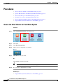
View Network and Endpoint Options in DMM
CHAPTER
12
Register DMPs
11-2
12-1
Concepts 12-1
Overview 12-1
Glossary 12-2
Partial Support for Cisco Medianet 2.1 Features 12-5
DHCP Server Configuration Notes for MSI Service Discovery 12-5
dhcpd Example 12-6
Windows Server Example 12-6
Understand Medianet Autoconfiguration for DMPs 12-7
Information That Medianet and DMPs Exchange 12-8
Medianet Activation Workflow for a DMP 4310G or 4400G 12-9
Restrictions 12-10
Guidelines 12-11
User Guide for Cisco Digital Media Manager 5.4.x
OL-15762-05
vii
Contents
Limit Your Use of Manual Registration 12-11
General Best Practices for Non-Medianet Autoregistration 12-11
Best Practices to Schedule Non-Medianet Autoregistration Events 12-11
Understand the Sequence of Operations for Non-Medianet Autoregistration 12-12
Procedures 12-13
Use DMPDM to Prepare a DMP for Manual Registration 12-13
Use a System Task to Normalize DMP Passwords 12-14
Establish Trust Between Digital Signs and your Centrally Managed DMPs
Add or Edit Address Ranges for Non-Medianet Autoregistration 12-18
Delete Address Ranges for Non-Medianet Autoregistration 12-20
Add or Edit One DMP Manually 12-21
Delete DMPs Manually from Your Device Inventory 12-22
12-17
Reference 12-23
Software UI and Field Reference Tables 12-23
Elements to Autoregister DMPs 12-23
Elements to Add or Edit One DMP Manually 12-24
Elements to Delete One DMP Manually 12-24
Elements to Configure Non-Medianet Autoregistration 12-25
Prevent DHCP Address Assignments to the Wrong VLAN 12-25
FAQs and Troubleshooting 12-30
FAQs 12-30
CHAPTER
13
Organize DMPs in Groups
13-1
Concepts 13-1
Overview 13-1
Understand the Effect of Nesting One DMP Group Inside Another
Procedures 13-3
Add and Edit DMP Groups 13-3
Delete DMP Groups 13-4
Add DMPs Manually to DMP Groups 13-5
Remove DMPs Manually from DMP Groups
Filter the DMP List Table 13-6
13-2
13-5
Reference 13-7
Software UI and Field Reference Tables 13-7
Top-Level Elements to Manage DMPs and DMP Groups
Elements to Add or Edit DMP Groups 13-9
Elements to Delete DMP Groups 13-9
Elements to Remove a DMP from a DMP Group 13-10
FAQs and Troubleshooting 13-10
13-7
User Guide for Cisco Digital Media Manager 5.4.x
viii
OL-15762-05
Contents
FAQs
CHAPTER
14
13-10
Configure DMP Wi-Fi Settings
14-1
Concepts 14-1
Glossary 14-1
ASCII Passphrases and Hexadecimal Keys for WEP
Workflow 14-4
Restrictions 14-5
Procedures 14-5
Establish a Wired Network Connection 14-5
Establish a Wireless Network Connection (802.11)
14-3
14-6
Reference 14-7
DMP Network Interfaces 14-8
FAQs and Troubleshooting 14-8
FAQs 14-8
CHAPTER
15
Touchscreens, Projectors, and Displays
15-1
Concepts 15-1
Overview 15-1
Presentation System Concepts 15-2
Understand Which Displays Work Best with DMPs 15-2
Understand How to Choose Media Signal Cables 15-3
Understand and Prevent Image Retention (Burn-in) 15-5
Procedures 15-6
Connect to a Digital Display or Projector 15-6
Connect to a Touchscreen 15-8
Connect to an Analog Display or Projector 15-9
Use RS-232 Signals to Control Presentation Systems 15-10
Prepare Cisco Displays to Support RS-232 Syntax 15-11
Bootstrap DMTech Displays to Enable Their RS-232 Support 15-14
Bootstrap NEC Displays to Enable Their RS-232 Support 15-16
Use RS-232 Syntax to Control Digital Signs 15-17
Delete Equipment Settings That Use RS-232 Syntax 15-20
DVI 15-21
Prepare a 40- or 52-inch Cisco LCD to Support Centralized Management through DVI
HDMI 15-22
Activate or Deactivate HDMI Autodetection 15-22
Activate or Deactivate Resolution Autodetection 15-23
Use Predefined Tasks to Configure and Manage Equipment 15-23
15-21
User Guide for Cisco Digital Media Manager 5.4.x
OL-15762-05
ix
Contents
Define or Edit DMP Output Settings for A/V 15-23
Delete DMP Output Settings for A/V 15-25
Use Simple Menus to Control A/V Settings 15-26
Reference 15-29
Video and Audio Signal Interfaces 15-30
Supported Touchscreen Drivers in Cisco DMS 5.4 15-33
Software UI and Field Reference Tables 15-34
Elements to Choose A/V Settings from Menus 15-34
Elements to Configure DMP Audio/Video Settings 15-36
Elements to Control HDMI Display Autodetection 15-36
Elements to Control Screen Resolution Autodetection 15-37
Elements to Activate RS-232 for Supported LCD Display Brands (except DMTech)
Elements to Activate RS-232 for LCD Displays by DMTech 15-38
FAQs and Troubleshooting 15-38
FAQs 15-38
Troubleshoot Cisco Professional Series LCD Displays 15-40
CHAPTER
16
DMP User Permissions (Authorization)
16-1
Concepts 16-1
Overview 16-1
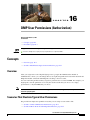
Scenarios That Illustrate Typical User Permissions 16-1
Scenario A: Basic Administrator Permissions 16-2
Scenario B: Basic Network and Endpoint Permissions
Scenario C: Basic Content Permissions 16-2
Scenario D: Basic Reporting Permissions 16-3
Procedures 16-3
Configure User Rights and Permissions
PART
3
CHAPTER
15-37
16-2
16-3
Manage Content for Cisco Digital Signs
17
Media Assets and Embedded Software
17-1
Concepts 17-1
Overview 17-1
Restrictions 17-1
User Permission Restrictions 17-2
Media Restrictions 17-2
File Size and Storage Restrictions 17-5
Local Storage Restrictions 17-5
User Guide for Cisco Digital Media Manager 5.4.x
x
OL-15762-05
Contents
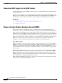
Understand HTTP ‘HEAD’ Request Timeout
17-7
Procedures 17-10
Work with Assets and Categories in Your Media Library 17-10
Add One Asset at a Time to Your Media Library 17-11
Add Multiple Assets Simultaneously to Your Media Library 17-12
Reference 17-14
Software UI and Field Reference Tables 17-14
Elements to Manage Assets and Categories 17-14
Elements to Add Categories and Rename Them 17-16
Elements to Add Assets and Edit Their Attributes 17-17
Elements To Describe and Preview One Asset 17-18
CHAPTER
18
Playlists
18-1
Concepts 18-1
Guidelines 18-1
Best Practices to Optimize DMP Settings for Playlists
Restrictions 18-2
18-1
Procedures 18-2
Create and Organize Playlists 18-2
Change the Sequence of Playback 18-3
Reference 18-3
Software UI and Field Reference Tables 18-3
Elements to Define a Playlist 18-3
CHAPTER
19
Content Distribution and Delivery
19-1
Concepts 19-1
Overview 19-1
Understand DMP Support for the CIFS Protocol 19-2
Choose a Content Delivery System to Use with DMPs 19-2
DMS-CD Concepts 19-4
DMS-CD Overview 19-4
Retry Timeout 19-4
Concurrent Deployments 19-4
DMS-CD Performance Factors 19-5
Understand Shared Scheduling Features for Deployments
Understand DMS-CD Alert Reports 19-7
Guidelines 19-8
DMS-CD Guidelines 19-8
Restrictions 19-12
19-6
User Guide for Cisco Digital Media Manager 5.4.x
OL-15762-05
xi
Contents
DMS-CD Restrictions 19-12
CIFS Restrictions 19-13
ACNS Restrictions 19-13
ECDS Restrictions 19-13
Example Scenario 19-14
Organizational Logic at Acme 19-14
Deployment Scheduling Logic at Acme
19-15
Procedures 19-16
Configure DMM to Use ACNS, WAAS, or ECDS 19-17
Configure DMS-CD 19-18
Configure Deployment Threshold Preferences for DMS-CD
Check Disk Space Capacity for Deployments 19-20
Create a Deployment Package 19-21
Edit a Deployment Package 19-23
Delete a Deployment Package 19-25
Reference 19-26
Software UI and Field Label Reference Tables 19-26
Elements to Define Deployment Thresholds 19-26
Elements to Define a DMS-CD Deployment Package
Elements to Define WAAS, ACNS, or ECDS Settings
FAQs and Troubleshooting 19-31
Troubleshoot DMS-CD 19-31
FAQs for ACNS 19-34
FAQs for WAAS 19-34
Troubleshoot ACNS 19-34
CHAPTER
20
Use Channels to Play Rich Media
19-19
19-29
19-30
20-1
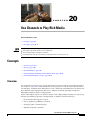
Concepts 20-1
Overview 20-1
Glossary 20-2
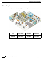
Channel Examples 20-3
Airport Example 20-4
Healthcare Example 20-5
Retail Banking Example 20-6
Retail Shopping Example 20-7
Education Example 20-8
Manufacturing Example 20-9
Understand How Channels Prioritize Their Content
Understand Time Basis Concepts 20-10
20-10
User Guide for Cisco Digital Media Manager 5.4.x
xii
OL-15762-05
Contents
Procedures 20-11
Work with Channels Generally 20-11
View and Filter Channels 20-12
Add a Channel 20-13
Tag a Channel 20-15
Edit a Channel 20-16
Duplicate a Channel 20-17
Delete a Channel 20-18
Work with Channel Details 20-19
Channel Properties 20-19
Default Content 20-21
Time-specific Content 20-23
Play Now Content 20-27
Work with Channel Events 20-33
Add an Event to a Channel 20-33
Duplicate an Event from a Channel 20-33
Delete an Event from a Channel 20-34
Work with Channel Subscriptions 20-35
Subscribe Endpoints to a Channel 20-35
Unsubscribe Endpoints from a Channel 20-36
20-37
CHAPTER
21
Proof of Play
21-1
Concepts 21-1
Overview 21-1
Restrictions 21-1
Implications of Changing the DMM Appliance Hostname 21-2
Implications of Changing the User Authentication Method 21-2
Implications of Changing Which Assets a Playlist Includes 21-3
Glossary 21-3
Campaigns (Formerly, Insertions) 21-3
Workflow 21-4
Procedures 21-4
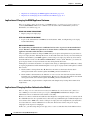
Prepare DMPs to Support Proof of Play 21-4
Enable Syslog and NTP 21-5
Enable Proof of Play Features in DMM 21-6
Create Requestors 21-7
Create Campaigns 21-8
Run a Report 21-9
User Guide for Cisco Digital Media Manager 5.4.x
OL-15762-05
xiii
Contents
Export a Report 21-9
View Previous Reports 21-10
Use the Proof of Play Dashboard
21-10
Reference 21-10
FAQs and Troubleshooting 21-10
FAQs 21-11
Troubleshooting 21-12
CHAPTER
22
Plan for and Manage Emergencies
22-1
Concepts 22-1
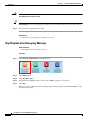
Overview 22-1
Procedures 22-2
Create Deployment Packages for Emergencies 22-2
Provision Emergency Assets to DMP Local Storage 22-4
Start Playback of an Emergency Message 22-5
Stop Playback of an Emergency Message 22-6
PART
4
CHAPTER
Manage IPTV Programming for Cisco Cast
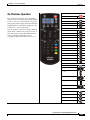
23
Cisco Cast Overview
23-1
Concepts 23-1
Overview 23-1
Restrictions 23-2
User Permissions Restrictions 23-2
Feature License Restrictions 23-2
Centralized Administration 23-2
On-Premises Operation 23-3
Workflow 23-4
Procedures 23-4
Start Cisco Cast
CHAPTER
24
Redistribute Live TV
23-4
24-1
Concepts 24-1
Guidelines 24-1
Site Assessment for Live Video Programming
Restrictions 24-2
User Permissions Restrictions 24-2
Channel Count Restrictions 24-2
24-1
User Guide for Cisco Digital Media Manager 5.4.x
xiv
OL-15762-05
Contents
Codec Restrictions
24-2
Procedures 24-2
Add Channels 24-3
Edit Channels 24-4
Reassign Channel Numbers 24-5
Delete Channels 24-6
List Only the Defined (Active) or Undefined (Inactive) TV Channels
24-7
Reference 24-8
Software UI and Field Reference Tables 24-8
Elements to Manage TV Channels 24-8
Elements to Define Channel Settings 24-10
CHAPTER
25
Video on Demand
25-1
Concepts 25-1
Overview 25-1
Guidelines 25-1
Site Assessment for VoD Programming 25-1
Restrictions 25-2
User Permissions Restrictions 25-2
Channel Count Restrictions 25-2
Workflow to Stage VoD Assets to DMP Local Storage
25-2
Procedures 25-2
Add a New VoD Category 25-3
Add a New VoD Subcategory 25-3
Edit a VoD Category 25-4
Delete a VoD Category 25-5
Map a Video to a VoD Category 25-6
Organize Videos in VoD Categories 25-7
Remove a Video from a Category 25-7
Stage an EPG to DMP Local Storage 25-8
Reference 25-9
Software UI and Field Reference Tables 25-9
Elements to Manage VoD Categories 25-9
CHAPTER
26
Electronic Program Guide
26-1
Concepts 26-1
Overview 26-1
Guidelines 26-2
Restrictions 26-2
User Guide for Cisco Digital Media Manager 5.4.x
OL-15762-05
xv
Contents
User Permissions Restrictions 26-2
Understand EPG Data Formats 26-2
XMLTV 26-2
Tribune Media Services 26-3
Understand Methods to Describe EPG Channels
26-4
Procedures 26-5
Add or Edit Subscriptions to Data from an EPG Provider 26-5
Delete Settings That Define a Subscription 26-6
Synchronize EPG Channel Schedules and Program Descriptions
26-7
Reference 26-8
Software UI and Field Reference Tables 26-8
Elements to Define EPG Provider Settings 26-8
FAQs and Troubleshooting 26-9
Troubleshoot EPG Highlighting 26-9
CHAPTER
27
Look and Feel
27-1
Concepts 27-1
Overview 27-1
Restrictions 27-1
User Permissions Restrictions
27-1
Procedures 27-2
Choose the Color Scheme for Your Menu System 27-2
Specify Which Features Your Menu System Should Include 27-3
Show a Custom Logo in Your Menu System 27-4
Show the Cisco Logo in Your Menu System 27-5
Choose the Date and Time Formats for Your Menu System 27-5
Deploy Menu System Customizations to Your DMPs 27-7
CHAPTER
28
Emulate the DMP Remote Control for Use with Cisco Cast
Concepts 28-1
Overview 28-1
Restrictions 28-2
Audio Muting Restrictions 28-2
Channel-Changing Restrictions 28-2
User Permissions Restrictions 28-2
DMP Model Restrictions 28-2
Workflow to Provision Emulator Service for IP Phones
Procedures 28-4
Activate Services
28-1
28-3
28-4
User Guide for Cisco Digital Media Manager 5.4.x
xvi
OL-15762-05
Contents
Start Services 28-5
Configure URL Parameters 28-5
Enable IP Phone Autoregistration 28-6
Define IP Phone Service Attributes 28-6
Expose the Service to IP Phones 28-7
Configure Emulator Settings in Cast 28-8
Configure an IP Phone to Emulate the Remote Control 28-10
Start the Emulator on an IP Phone 28-10
Start the Emulator on a Mobile Phone 28-11
Use the Emulator on an IP Phone or a Mobile Phone 28-12
User Guide for Cisco Digital Media Manager 5.4.x
OL-15762-05
xvii
Contents
User Guide for Cisco Digital Media Manager 5.4.x
xviii
OL-15762-05
P
A R T
1
Manage Platform Services
C H A P T E R
1
Administration Overview
Revised: September 17, 2012
OL-15762-05
•
Concepts, page 1-1
•
Procedures, page 1-4
•
Reference, page 1-7
We prepared this material with specific expectations of you.
You will administer Cisco DMS.
Audience
Concepts
•
Glossary, page 1-2
•
Logical Ports That Cisco DMS Components Use, page 1-2
User Guide for Cisco Digital Media Manager 5.4.x
OL-15762-05
1-1
Chapter 1
Administration Overview
Concepts
Glossary
Timesaver
Go to terms that start with... [ A | D ].
A
AAI
Appliance Administration Interface. Console application (text-based; menu-driven) and command shell
on all Cisco DMM appliances. Administrators use AAI to set up and connect a new DMM appliance
and maintain it thereafter. Although its scope is far narrower than DMS-Admin, AAI supports
priviliged operations that DMS-Admin does not support.
D
Return to Top
DMS-Admin
Digital Media Suite Administration. Web-based graphical user interface on a DMM appliance.
Administrators use DMS-Admin to:
•
Activate and monitor features throughout the full range of Cisco DMS products.
•
Exchange information with network entities outside Cisco DMS.
•
Centrally manage user accounts for Cisco DMS products.
Compare to AAI.
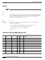
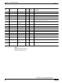
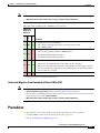
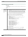
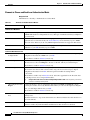
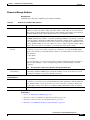
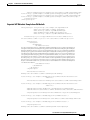
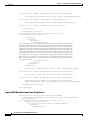
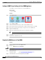
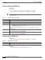
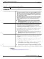
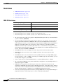
Logical Ports That Cisco DMS Components Use
Make sure to keep these logical ports open to traffic exchanged among Cisco DMS components.
Port
No.
From
To
Bidir? Protocol
Description
20
DMM
DMP
N
FTP
DMM server deploying content to DMP using FTP
20
DMP
FTP server
Y
FTP
transfer of content files
21
DMM
DMP
N
FTP
DMM server deploying content to DMP using FTP
21
DMP
FTP server
Y
FTP
transfer of content files
22
DMM
DMP
N
SFTP
DMM server deploying content to DMP using SFTP
53
DMP
DNS server
N
DNS
DNS services
80
DMP
content server
N
HTTP
123
DMP
NTP server
Y
NTP
NTP services
139
DMP
content server
N
CIFS
CIFS services
161
SNMP client
DMM
N
SNMP
SNMP services
389
DMM
Active Directory N
(LDAP)
LDAP
user database creation or updates
User Guide for Cisco Digital Media Manager 5.4.x
1-2
OL-15762-05
Chapter 1
Administration Overview
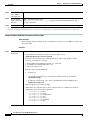
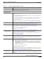
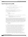
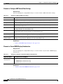
Concepts
Port
No.
From
To
Bidir? Protocol
443
Admin Client
DMP
N
SSL
443
User
DMM
N
HTTPS
445
DMP
content server
N
CIFS
CIFS services
514
DMP
syslog server
N
syslog
syslog services
554
DMP
content server
N
RTSP
DMP requesting WMV streaming from external
Windows Media Streaming Server
636
DMM
Active Directory N
(LDAPS)
LDAPS
user database creation or updates
694
DMM primary
DMM secondary Y
(UDP) Heartbeat for failover health monitoring
843
User
DMM
N
proof of play
7777
Admin Client
DMP
N
SSL
7777
DMM
DMP
Y
SSL
7849
DMM primary
DMM secondary Y
9161
Y
Description
DRBD (failover)
SNMP
SNMP services
9999
DMM
Show and Share
Y
JMX communication
30865
All failover
nodes
All failover
nodes
Y
CSYNC
synchronize config files between nodes in a cluster
(failover).
User
Config
User
deployment
server
N
HTTP
user requesting content from external server
User
Config
DMP
content server
N
HTTP
Legend
DMM=Digital Media Manager
DMP=Digital Media Player
User Guide for Cisco Digital Media Manager 5.4.x
OL-15762-05
1-3
Chapter 1
Administration Overview
Procedures
Procedures
•
Learn Your DMM Appliance Serial Number, page 1-6
•
Start DMS-Admin, page 1-5
Log in to DMM
Procedure
Step 1
Point your browser at your DMM appliance.
•
Use HTTPS and specify port 8443
OR
Use HTTP and specify port 8080 — which redirects immediately to the secured HTTPS connection.
•
Be sure to use the fully qualified appliance DNS name and not merely its IP address. For example,
https://dmm.example.com:8443.
Step 2
When the login page loads, sign in to your account.
Step 3
Click Log In.
The DMM landing page loads in your browser.
Step 4
Stop. You have completed this procedure.
What to Do Next
•
User Guide for Cisco Digital Media Manager 5.4.x
1-4
OL-15762-05
Chapter 1
Administration Overview
Procedures
Start DMS-Admin
Before You Begin
•
Log in to DMM.
Procedure
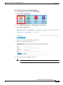
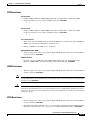
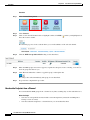
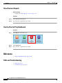
Step 1
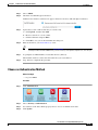
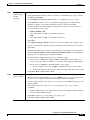
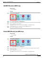
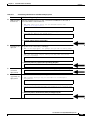
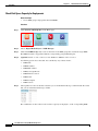
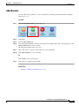
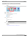
Click Administration on the landing page.
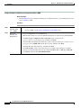
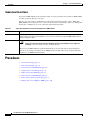
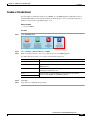
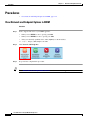
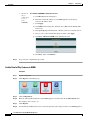
What happens next depends on what happened before.
•
•
Step 2
Is your
appliance
factory-new or
recently
restored?
No licenses are installed.
Have you
activated even
one licensed
feature?
At least one license is installed.
We take you first to the page where you can install a license key.
We take you first to the DMS-Admin Dashboard, whose gauges can inform you
at a glance.
Stop. You have completed this procedure.
Related Topics
•
Log in to DMM, page 1-4
User Guide for Cisco Digital Media Manager 5.4.x
OL-15762-05
1-5
Chapter 1
Administration Overview
Procedures
Learn Your DMM Appliance Serial Number
Caution
You cannot obtain any Cisco DMS software feature licenses until you know your DMM appliance serial number.
Before You Begin
•
Log in to DMM and click Administration.
Procedure
Step 1
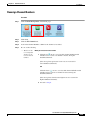
Find the System Information gauge on your Administration dashboard.
Step 2
Make note of your appliance serial number.
Step 3
Stop. You have completed this procedure.
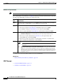
Set a User Session Timeout for Components of Cisco DMS
We log inactive users out of their sessions automatically after an interval, which you control, has
elapsed. This interval applies to all users without exception.
Before You Begin
•
Log in to DMM and click Administration.
Procedure
Step 1
Choose Security > Session.
Step 2
Use the Session Timeout (in minutes) field to enter or edit a session timeout value.
User Guide for Cisco Digital Media Manager 5.4.x
1-6
OL-15762-05
Chapter 1
Administration Overview
Reference
Step 3
Click Update.
Step 4
Stop. You have completed this procedure.
Reference
•
FAQs and Troubleshooting, page 1-7
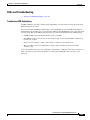
FAQs and Troubleshooting
•
FAQs, page 1-7
FAQs
Q. What might prevent me from logging in?
A. Check the following, and then try again to log in.
•
Is your username wrong or mistyped?
•
Is your password wrong, mistyped, or expired?
•
Is your user account suspended?
•
Is your user account locked after too many failed login attempts?
User Guide for Cisco Digital Media Manager 5.4.x
OL-15762-05
1-7
Chapter 1
Administration Overview
Reference
User Guide for Cisco Digital Media Manager 5.4.x
1-8
OL-15762-05
C H A P T E R
2
Administration Dashboard
Revised: September 17, 2012
OL-15762-05
•
Concepts, page 2-1
•
Procedures, page 2-5
We prepared this material with specific expectations of you.
You will administer Cisco DMS.
Audience
You have already installed at least the license key to activate one Cisco DMS software feature module.
Concepts
•
Dashboard Overview, page 2-1
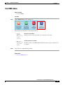
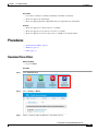
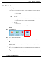
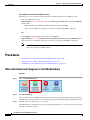
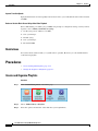
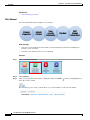
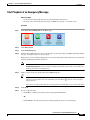
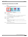
Dashboard Overview
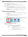
The dashboard for DMS-Admin centralizes many features for system monitoring and log collection.
When problems of any kind interfere with the data-collection processes that populate its gauges, they
show question marks in addition to the best available data. In this case, check that your systems and
network are configured and working correctly.
User Guide for Cisco Digital Media Manager 5.4.x
OL-15762-05
2-1
Chapter 2
Administration Dashboard
Concepts
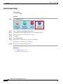
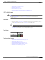
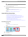
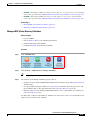
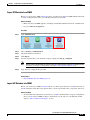
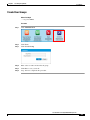
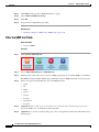
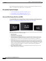
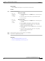
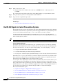
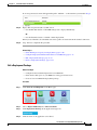
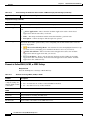
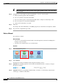
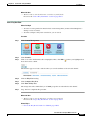
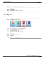
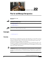
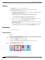
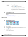
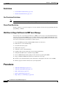
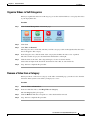
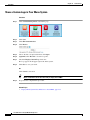
These are the dashboard gauges.
The Failover Cluster gauge monitors your use, if any, of failover.
Note
Sometimes, a monitoring gauge might leave out a value that you expect it to show. When this occurs, we mark any missing
values with a placeholder symbol ( ) to indicate which values we could not show.
Tip
Until you install at least one license key, the DMS-Admin dashboard cannot retrieve data to populate its gauges.
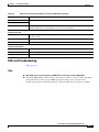
Understand the Alerts Gauge
This gauge shows the total count of notification messages delivered in the past 1 hour.
Timesaver
Click View Alerts to open the Alerts page.
User Guide for Cisco Digital Media Manager 5.4.x
2-2
OL-15762-05
Chapter 2
Administration Dashboard
Concepts
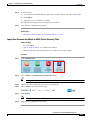
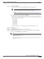
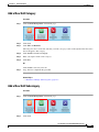
Understand the System Information Gauge
The System Information gauge:
•
Tells you the installed release version of your DMM server software.
•
Tells you the serial number of your DMM appliance.
•
Measures free space and used space for the content partition on your DMM appliance hard drive.
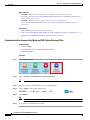
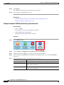
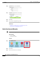
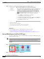
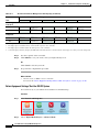
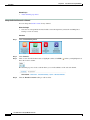
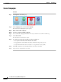
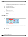
Understand the Status Gauge
Tip
Refresh your browser to update the data that this gauge shows.
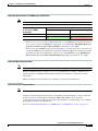
Have you set up the hardware and activated the separately licensed software features for DMM server
failover and your inventory of DMPs?
If so, this gauge summarizes their current state in two summaries, side-by-side.
Digital Media Players
Failover Cluster
Timesaver
•
Counts the total number of registered DMPs.
•
Specifies how many DMPs were reachable or unreachable when this gauge loaded in your browser.
•
Indicates the status of Cisco DMM appliances in your failover cluster.
Click...
• View All DMPs and DMP Groups to open the DMP Manager page.
• View Failover Status to open the Failover Configuration page.
User Guide for Cisco Digital Media Manager 5.4.x
OL-15762-05
2-3
Chapter 2
Administration Dashboard
Concepts
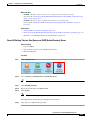
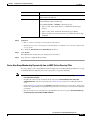
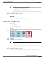
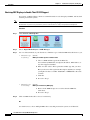
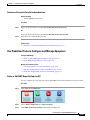
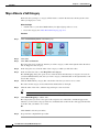
Understand the Licensed Features Gauge
This gauge lists software feature module licenses that are installed on your DMM appliance and
describes constraints that your licenses impose.
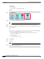
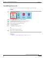
Understand the Users Logged In Gauge
This gauge counts how many users were logged in to your Cisco DMM appliance over the past 1 hour.
Timesaver
Click View All Users to open the Users page.
User Guide for Cisco Digital Media Manager 5.4.x
2-4
OL-15762-05
Chapter 2
Administration Dashboard
Procedures
Procedures
•
View Dashboard Gauges, page 2-5
View Dashboard Gauges
Before You Begin
•
Log in to DMM.
Procedure
Step 1
Click Administration.
Step 2
Click the Dashboard tab.
Step 3
Stop. You have completed this procedure.
User Guide for Cisco Digital Media Manager 5.4.x
OL-15762-05
2-5
Chapter 2
Administration Dashboard
Procedures
User Guide for Cisco Digital Media Manager 5.4.x
2-6
OL-15762-05
C H A P T E R
3
Licenses
Revised: September 17, 2012
OL-15762-05
•
Concepts, page 3-1
•
Procedures, page 3-2
•
Reference, page 3-6
We prepared this material with specific expectations of you.
You will administer Cisco DMS.
Audience
You have already purchased the license key to activate at least one Cisco DMS software feature module.
Concepts
•
Understand Licenses, page 3-1
Understand Licenses
Features of Cisco DMS are licensed and activated separately. Until you obtain and install license keys,
their corresponding features are hidden from all users — including you, the administrator.
Note
Even then, some features remain hidden from users whose privilege levels are low.
What to Do Next
•
OPTIONAL — Would you like to learn which feature licenses we sell?
See http://www.cisco.com/go/dms.
•
MANDATORY— Would you like to obtain license keys?
See the “Request License Keys” section on page 3-2.
•
MANDATORY— Would you like to install feature licenses?
See the “Install License Keys” section on page 3-4.
User Guide for Cisco Digital Media Manager 5.4.x
OL-15762-05
3-1
Chapter 3
Licenses
Procedures
Procedures
•
Request License Keys, page 3-2
•
Install License Keys, page 3-4
•
View Installed Licenses, page 3-5
•
Check the Dashboard Gauge for Licenses, page 3-5
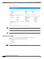
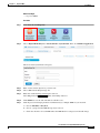
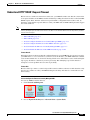
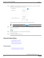
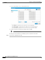
Request License Keys
Features of Cisco DMS are sold and licensed separately. After you purchase the right to use a feature,
you must request and install a unique license key. Your key activates the feature on your server.
Before You Begin
•
Log in to DMM.
Procedure
Step 1
Click Administration.
Step 2
Choose Licenses > Request Licenses.
User Guide for Cisco Digital Media Manager 5.4.x
3-2
OL-15762-05
Chapter 3
Licenses
Procedures
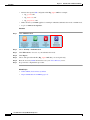
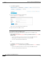
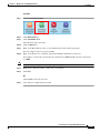
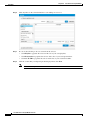
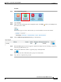
Step 3
Enter all requested values in the Request Licenses form.
Step 4
Choose a method to send your license request as an email message to dms-softwarekeys@cisco.com.
Step 5
•
Export your request to a file that you can email later.
•
Send your request immediately, assuming that your DMM server is configured to enable SMTP.
After you receive a license key file from Cisco, save a local copy of it.
Note
Step 6
Make sure that your local copy does not include any spaces in its filename. (CSCtj60727)
Stop. You have completed this procedure.
What to Do Next
•
MANDATORY— Install License Keys, page 3-4
Related Topics
•
Learn Your DMM Appliance Serial Number, page 1-6
•
View Installed Licenses, page 3-5
User Guide for Cisco Digital Media Manager 5.4.x
OL-15762-05
3-3
Chapter 3
Licenses
Procedures
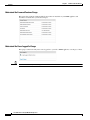
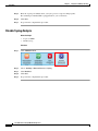
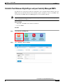
Install License Keys
Before You Begin
•
Log in to DMM.
Procedure
Step 1
Click Administration.
Step 2
Choose Licenses > Install/Upgrade Licenses.
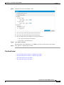
Step 3
Click Browse or Choose File, depending on your installed browser.
Step 4
Find and click the license file where you saved it.
Step 5
Click Open.
Step 6
Click Install License.
Step 7
Repeat these steps until all of your licenses are installed.
Features that you licensed are now activated.
Step 8
Stop. You have completed this procedure.
Related Topics
•
Start DMS-Admin, page 1-5
•
View Installed Licenses, page 3-5
User Guide for Cisco Digital Media Manager 5.4.x
3-4
OL-15762-05
Chapter 3
Licenses
Procedures
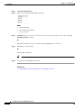
View Installed Licenses
Before You Begin
•
Install at least one license key.
•
Log in to DMM.
Procedure
Step 1
Click Administration.
Step 2
Choose Licenses > View Licenses.
Step 3
Stop. You have completed this procedure.
Tip
The Licensed Features gauge summarizes this information on your DMS-Admin dashboard.
Related Topics
•
Start DMS-Admin, page 1-5
•
Install License Keys, page 3-4
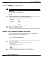
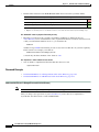
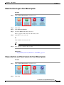
Check the Dashboard Gauge for Licenses
Before You Begin
•
Install at least one license key.
•
Log in to DMM.
Procedure
Step 1
Click Administration.
Step 2
Click Dashboard.
User Guide for Cisco Digital Media Manager 5.4.x
OL-15762-05
3-5
Chapter 3
Licenses
Reference
Step 3
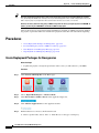
Check the Licensed Features gauge on your dashboard.
It tells you which of your:
Step 4
•
Licensed features are activated.
•
Feature licenses impose restrictions.
Stop. You have completed this procedure.
Reference
•
Automatically Licensed Features on Cisco DMS Appliances and Endpoints, page 3-6
•
Optional Module Licenses, page 3-7
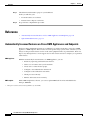
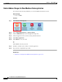
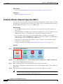
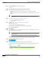
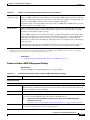
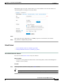
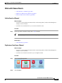
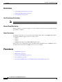
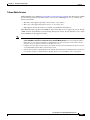
Automatically Licensed Features on Cisco DMS Appliances and Endpoints
We license many fundamental features at no additional cost with your purchase of any Cisco DMM
appliance or DMP endpoint. These licenses are unit-specific and perpetual, in the sense that you can
always use the provided software version on the same equipment where we preinstalled it. We do not
impose any subscription fees or non-support fees for this software and do not obligate you to purchase
other licenses.
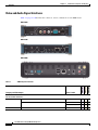
DMM appliance
DMP endpoint
With the automatically licensed features of a DMM appliance, you can:
•
Install any separately purchased feature licenses.
•
Gain access to features after you license them.
•
Create user accounts and user groups.
•
Configure a user authentication framework.
•
Configure event notifications and alarms.
•
Check processes remotely.
•
Monitor and restart servers remotely.
With a DMP endpoint base license, you can set up the DMP itself1 from its embedded device
manager, DMPDM.
1. Managed in isolation, without involving DMM or any other DMPs.
User Guide for Cisco Digital Media Manager 5.4.x
3-6
OL-15762-05
Chapter 3
Licenses
Reference
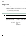
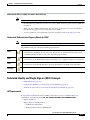
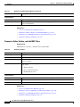
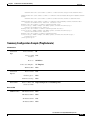
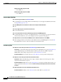
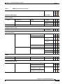
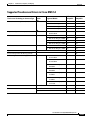
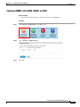
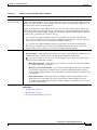
Optional Module Licenses
Note
To obtain and activate any license for any component of Cisco DMS, you must have a DMM appliance.
Part Number1
Module or Pack
DMS-Admin
Features
SNMP
Notifications
•
DMM-SNMP52-K9
•
DMM-SNMP52-K9=
DMM Features
Digital Signs
Module
•
DMM-SIGNSM52-K9
•
DMM-SIGNSM52-K9=
Cast Module
•
DMM-CAST52-K9
•
DMM-CAST52-K9=
•
DMP-FL-1
•
DMP-FL-1=
•
DMP-FL-10
•
DMP-FL-10=
•
DMP-FL-50
•
DMP-FL-50=
•
DMP-FL-500
•
DMP-FL-500=
•
DMP-FL-1000
•
DMP-FL-1000=
Centralized DMP
Management
1 DMP
10 DMPs
50 DMPs
500 DMPs
1,000 DMPs
Description
Activates support for SNMP interaction with network
monitoring applications. Also activates support for event
notifications and alerts.
Activates DMM baseline features to centrally manage and
operate a digital signage network with Cisco DMPs.
Activates DMM abilities to deliver on-demand video and
live broadcast TV channels over IP networks to DMPs and
their attached presentation systems.
To centrally manage DMPs from DMM, you must
combine a Digital Signs Module license with at least one
DMP feature license.
DMP feature licenses are cumulative. If you are already
licensed to manage 500 DMPs before you install an
additional 50-unit license, your DMM installation will
support managing as many as 550 DMPs.
1. During your initial order, use part numbers that omit the = character. Only later, when you want to extend what you ordered initially, should you use part
numbers that end with =.
User Guide for Cisco Digital Media Manager 5.4.x
OL-15762-05
3-7
Chapter 3
Licenses
Reference
User Guide for Cisco Digital Media Manager 5.4.x
3-8
OL-15762-05
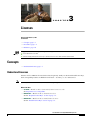
C H A P T E R
4
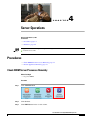
Server Operations
Revised: September 17, 2012
OL-15762-05
•
Procedures, page 4-1
•
Reference, page 4-4
We prepared this material with specific expectations of you.
You administer Cisco DMS.
Audience
Procedures
•
Check DMM Server Processes Remotely, page 4-1
•
Restart Appliances Remotely, page 4-3
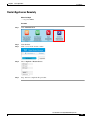
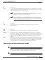
Check DMM Server Processes Remotely
Before You Begin
•
Log in to DMM.
Procedure
Step 1
Click Administration.
Step 2
Click Services.
Step 3
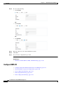
Click DMM Server in the far-left column.
User Guide for Cisco Digital Media Manager 5.4.x
OL-15762-05
4-1
Chapter 4
Server Operations
Procedures
A list tells you which processes are running or stopped.
Note
Any process whose name includes the phrase “Web Application” is actually a child of the Tomcat process.
You can restart the Tomcat process in AAI and simultaneously restart all of its children. The path to do this in AAI is
APPLIANCE_CONTROL > RESTART_OPTIONS > RESTART_WEB_SERVICES.
Similarly, you can restart Postgresql in AAI by choosing APPLIANCE_CONTROL > RESTART_OPTIONS >
RESTART_DATABASE_SERVICES.
Step 4
Stop. You have completed this procedure.
User Guide for Cisco Digital Media Manager 5.4.x
4-2
OL-15762-05
Chapter 4
Server Operations
Procedures
Restart Appliances Remotely
Before You Begin
•
Log in to DMM.
Procedure
Step 1
Click Administration.
Step 2
Click Services.
Step 3
Click a server in the far-left column.
Step 4
Choose Options > Restart Server.
Step 5
Stop. You have completed this procedure.
User Guide for Cisco Digital Media Manager 5.4.x
OL-15762-05
4-3
Chapter 4
Server Operations
Reference
Reference
•
Server Processes, page 4-4
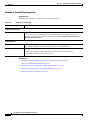
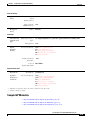
Server Processes
These server processes runs on a DMM appliance.
•
ActiveMQ
•
Event Management System
•
Nginx HTTP Server
•
Postgresql
•
Scheduled Backup Services
•
Soir Advanced Search Core
•
Soir Tagging Service Core
•
Tomcat
– Cast Admin Web Application
– Cast EPG Collector Web Application
– Cast Flash Web Application
– Cast Remote Control Web Application
– DMS-Admin Web Application
– DSM Web Application
– IFMS Web Application
– OpenAM Web Application
User Guide for Cisco Digital Media Manager 5.4.x
4-4
OL-15762-05
C H A P T E R
5
Analyze Cisco DMS System Logs
Revised: September 17, 2012
OL-15762-05
•
Procedures, page 5-1
We prepared this material with specific expectations of you.
You have a working syslog server and you understand its operation.
Audience
Procedures
•
Enable Syslog Analysis, page 5-1
•
Disable Syslog Analysis, page 5-2
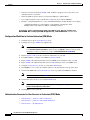
Enable Syslog Analysis
Before You Begin
•
Log in to DMM.
Procedure
Step 1
Click Administration.
Step 2
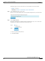
Choose Settings > External Servers > Syslog.
Step 3
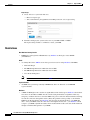
Click Enabled.
Step 4
Enter the routable IP address or DNS-resolvable hostname of your syslog server.
User Guide for Cisco Digital Media Manager 5.4.x
OL-15762-05
5-1
Chapter 5
Analyze Cisco DMS System Logs
Procedures
Step 5
Enter the logical port number where your syslog server accepts incoming logfiles.
The standard port number, 514, is prepopulated for your convenience.
Step 6
Click Save.
Step 7
Stop. You have completed this procedure.
Disable Syslog Analysis
Before You Begin
•
Log in to DMM.
•
Enable syslog.
Procedure
Step 1
Click Administration.
Step 2
Choose Settings > External Servers > Syslog.
Step 3
Click Disabled.
Step 4
Click Save.
Step 5
Stop. You have completed this procedure.
User Guide for Cisco Digital Media Manager 5.4.x
5-2
OL-15762-05
C H A P T E R
6
Configure Failover
Revised: September 17, 2012
OL-15762-05
See Failover Configuration Guide for Cisco Digital Media Suite 5.4.x on Cisco.com.
User Guide for Cisco Digital Media Manager 5.4.x
OL-15762-05
6-1
Chapter 6
Configure Failover
User Guide for Cisco Digital Media Manager 5.4.x
6-2
OL-15762-05
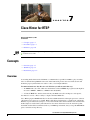
C H A P T E R
7
Cisco Hinter for RTSP
Revised: September 17, 2012
OL-15762-05
•
Concepts, page 7-1
•
Procedures, page 7-3
•
Reference, page 7-6
We prepared this material with specific expectations of you.
You administer Cisco DMS.
Audience
Concepts
•
Overview, page 7-1
•
Workflow, page 7-2
•
Restrictions, page 7-2
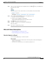
Overview
A streaming media framework called RTP over RTSP makes it possible for DMPs to play streaming
video on demand through RTSP connections. This framework prevents data loss inside streams and
maintains proper synchronization of audio to video, even in high-definition.
You must maintain two data files for each VoD that you will stream in this way.
•
An MPEG2-TS source file, which uses the filename extension MPG. Its program stream might be
encoded as MPEG-1, MPEG-2, or MPEG-4 Part 10 (H.264).
•
A “hinted” MOV file, which is derived from your MPG source file and imposes order upon it.
You must use our Cisco Hinter utility to output each hinted MOV file.
Cisco Hinter prepares MPEG2-TS files for interleaved RTP transmission through open source software
called Darwin Streaming Server (DSS). Hinter adds delivery information to a media track, which tells
DSS how to pack and stream (multiplex, or mux) data from the audio channel and the video channel. This
method improves audiovisual synchronization because these channels traverse the network together.
Your DSS can then deliver such hinted video to your DMPs upon demand, after you stage the MPG-MOV
pair to its media serving directory.
User Guide for Cisco Digital Media Manager 5.4.x
OL-15762-05
7-1
Chapter 7
Cisco Hinter for RTSP
Concepts
Cisco Hinter versions for Windows and Linux users are downloadable from your DMM appliance.
Note
We do not develop, maintain, sell, or support Darwin Streaming Server. Nor do we warrant its suitability for any purpose.
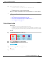
Workflow
1.
Download and set up Cisco Hinter.
2.
Download Darwin Streaming Server (DSS).
Note
The official repository for DSS is http://dss.macforge.org. Alternatively, you can use
http://developer.apple.com/opensource/server/streaming/index.html.
3.
Install and configure DSS on equipment other than any Cisco DMS server appliance.
4.
Process each of your MPG files with Cisco Hinter to output a small, hinted MOV file.
5.
Stage your MPG and MOV files together in the DSS serving directory.
6.
Request streams from rtsp://<DSS_IP_address>:<optional_port_number>/<filename>.mov.
In DMPDM
a. Enter your stream’s address in the URL field at Display Actions > Media URL.
b. Click Start.
In Digital Signs
a. Click the URL (recommended) radio button on the Simple property sheet in the Add Asset
dialog box.
b. Enter your stream’s address in the URL field.
c. Choose RTSP from the File Type list.
d. Click Save.
Restrictions
RTSP Variants
•
There are many variants of RTSP and we support only one of them. You must use RTP over RTSP,
which is also called RTP over TCP or Interleaved TCP. In this variant, RTP, RTCP, and RTSP data
stream together over one logical port — typically, port 554.
•
Our RTSP does not support live streaming (multicast or unicast) in this release.
•
Our RTSP does not support “trick mode.” This means that you cannot pause video during playback,
fast-forward through it, or fast-rewind through it. You can merely start or stop playback.
Darwin Streaming Server
•
DSS cannot read any file whose file size is greater than 2.1 GB. You must split such large files into
smaller ones before you derive hinted MOV output from them. (CSCtb27324)
•
Although DSS is an open source streaming media platform and available for multiple operating
systems, we have tested DSS on Linux exclusively.
User Guide for Cisco Digital Media Manager 5.4.x
7-2
OL-15762-05
Chapter 7
Cisco Hinter for RTSP
Procedures
Cisco Hinter
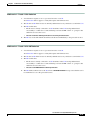
•
Cisco Hinter software is available for Windows and Linux, exclusively.
•
We do not support any other hinter.
•
We do not support playback of hinted files that you output from any other hinter.
Protocols
•
We do not support User Datagram Protocol (UDP).
•
We do not support Session Announcement Protocol (SAP).
•
We do not support Session Description Protocol (SDP) or its announcements.
•
Download Cisco Hinter, page 7-3
•
Windows, page 7-4
•
Linux, page 7-5
Procedures
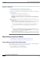
Download Cisco Hinter
Before You Begin
•
Log in to DMM.
Procedure
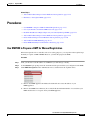
Step 1
Click Administration.
Step 2
Choose Settings > Hinter.
Step 3
Click to download either the Windows or the Linux version.
User Guide for Cisco Digital Media Manager 5.4.x
OL-15762-05
7-3
Chapter 7
Cisco Hinter for RTSP
Procedures
•
Cisco-Hinter-Windows.zip
•
Cisco-Hinter-Linux.tar.gz
Step 4
Decompress the archive.
Step 5
Stop. You have completed this procedure.
Windows
•
Install Cisco Hinter on Windows, page 7-4
•
Run Cisco Hinter on Windows, page 7-4
Install Cisco Hinter on Windows
Procedure
Step 1
Open a command prompt where you decompressed the archive.
Step 2
Type the command cd CiscoHinter, and then press Enter.
Step 3
Type the command install.bat, and then press Enter.
Step 4
Stop. You have completed this procedure.
Run Cisco Hinter on Windows
Procedure
Step 1
Open a command prompt where you decompressed the archive.
Step 2
Type the command runHinter.bat, and then press Enter.
Step 3
Enter the MPEG2-TS filename in the Source MPEG field.
OR
Click Browse or Choose File (depending on which browser you use) to find your MPEG2-TS file.
We populate the Output Name field automatically. It is identical to the name in the Source MPEG field,
except that the filename extension is MOV and not MPG.
Step 4
Click Generate, and then wait for the “Hinting finished successfully” message.
Step 5
Find your hinted MOV output file in the ..\hinted-files subdirectory.
Step 6
Move or copy both the MPG file and its MOV derivative to the DSS root directory.
Step 7
Stop. You have completed this procedure.
User Guide for Cisco Digital Media Manager 5.4.x
7-4
OL-15762-05
Chapter 7
Cisco Hinter for RTSP
Procedures
Linux
•
Install Cisco Hinter on Linux, page 7-5
•
Run Cisco Hinter on Linux, page 7-5
Install Cisco Hinter on Linux
Procedure
Step 1
Open a command prompt where you decompressed the archive.
Step 2
Type the command run Install.sh, and then press Enter.
Step 3
Stop. You have completed this procedure.
Run Cisco Hinter on Linux
Procedure
Step 1
Open a command prompt where you decompressed the archive.
Step 2
Type the command run runHinter.sh, and then press Enter.
Step 3
Enter the MPEG2-TS filename in the Source MPEG field.
OR
Click Browse or Choose File (depending on your browser) to find your MPEG2-TS file.
We populate the Output Name field automatically. It is identical to the name in the Source MPEG field
except that the filename extension is MOV and not MPG.
Step 4
Click Generate, and then wait for the “Hinting finished successfully” message.
Step 5
Find your hinted MOV output file in the ../hinted-files subdirectory.
Step 6
Move or copy both the MPG file and its MOV derivative to the DSS root directory.
Step 7
Stop. You have completed this procedure.
User Guide for Cisco Digital Media Manager 5.4.x
OL-15762-05
7-5
Chapter 7
Cisco Hinter for RTSP
Reference
Reference
•
FAQs and Troubleshooting, page 7-6
FAQs and Troubleshooting
•
Troubleshoot RTP Over RTSP, page 7-6
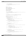
Troubleshoot RTP Over RTSP
These general troubleshooting ideas might help you to diagnose and resolve problems with this feature.
•
Verify that both the MPG source file and its hinted MOV derivative are present together in the media
root directory on your DSS.
•
Use a utility like openRTSP to test both the MPG source file and its hinted MOV derivative. The
correct Linux command line syntax in this case is
openRTSP -V -v -t rtsp://DSS_server_IP_address/filename.mov
•
Use HexEdit, WinHex, or a similar utility to open your hinted MOV file and verify that it contains:
– An explicit reference to the full and literal filename of your MPG source.
– The signature for MOV output from Cisco Hinter:
Hinted MPEG1 Muxed Track
– The signature for interleaved RTP:
m=OTHER 0 RTP/AVP 96
•
Check the system logs on your DSS.
Note
• openRTSP —http://www.live555.com/openRTSP/
• HexEdit —http://hexedit.sourceforge.net/
• WinHex — http://www.winhex.com/winhex/
User Guide for Cisco Digital Media Manager 5.4.x
7-6
OL-15762-05
C H A P T E R
8
Authentication and Federated Identity
Revised: September 17, 2012
OL-15762-05
•
Concepts, page 8-1
•
Procedures, page 8-21
•
Reference, page 8-45
We prepared this material with specific expectations of you.
Embedded Mode — You understand fundamental principles of user authentication.
Audience
LDAP Mode —you are a Microsoft Active Directory expert with real-world experience in its configuration and administration.
Federation Mode —you are a SAML 2.0 expert with real-world experience in its configuration and administration, including
import and export of SAML 2.0-compliant IdP and SP configuration files.
Concepts
•
Overview, page 8-1
•
Glossary, page 8-2
•
Understand the Requirement to Authenticate Users, page 8-9
•
Decide Which Authentication Method to Use, page 8-10
•
LDAP and Active Directory Concepts, page 8-10
•
Federated Identity and Single Sign-on (SSO) Concepts, page 8-17
•
Migration Between Authentication Methods, page 8-20
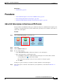
Overview
User authentication features of DMS-Admin help you to:
•
Authenticate all user sessions. (We prevent you from disabling mandatory authentication, even
though we allowed this in Cisco DMS 5.1.x and prior releases.)
•
Choose and configure an authentication method.
•
Import user account settings from an Active Directory server.
User Guide for Cisco Digital Media Manager 5.4.x
OL-15762-05
8-1
Chapter 8
Authentication and Federated Identity
Concepts
Note
•
Synchronize user groups from an Active Directory server. Microsoft Active Directory is the only
LDAP implementation that we support in this release.
•
Use federation services with a SAML 2.0-compliant IdP to support SP-initiated “single sign-on”
login authentication in your network (following an initial synchronization to a Microsoft Active
Directory Server that populates the DMM user database).
We support your use of one — and only one —IdP server with Cisco DMS 5.4.
Glossary
Timesaver
Go to terms that start with... [ A | C | D | F | I | L | O | P | R | S | U | X ].
A
Active Directory
Microsoft implementation of LDAP. A central authentication server and user store. Active Directory is
the only LDAP implementation that we support in this release.
Active Directory
forest
A domain-straddling combination of Active Directory trees within an organization that operates
multiple Internet domains. Thus, the forest at “Amalgamated Examples, LLC” might straddle all trees
across example.com, example.net, and example.org.
Or, to use Cisco as a real-world case-study, one forest could straddle cisco.com and webex.com,
among others.
Note
Active Directory
tree
This Cisco DMS release does not support Active Directory forests.
A subdomain-straddling combination of IdPs throughout one Internet domain. These IdPs operate
collectively on behalf of the Internet domain’s constituent subdomains. Thus, the “tree” at
example.com might encompass all of the IdPs to authenticate user sessions within subdomains such
as these:
•
legal.example.com
•
sales.example.com
•
support.example.com
User Guide for Cisco Digital Media Manager 5.4.x
8-2
OL-15762-05
Chapter 8
Authentication and Federated Identity
Concepts
administrator DN
The DN to authenticate your Active Directory server’s administrator.
This release is more strict than most prior releases in its enforcement of proper LDAP syntax.
Now, when you specify the administrator DN, you must use proper syntax, which conforms
exactly to LDIF grammar.
Note
•
Proper syntax:
CN=admin1,OU=Administrators,DC=example,DC=com
•
Poor syntax:
EXAMPLE\admin1
OTHERWISE
When you use poor syntax here for the first time while your DMM appliance runs DMS 5.3,
we show you, the administrator, this error message: “Invalid username or password.”
But if you used and validated poor syntax here before upgrading to Cisco DMS 5.3, we do not
repeat the validation process. Therefore — even though we do not show an error message
to anyone — LDAP users simply cannot log in.
Note
authentication
C
An LDAP expression must never include a space immediately to either side of a “=” sign. Similarly, it must
never include a space immediately to either side of an “objectClass” attribute. Otherwise, validation fails.
The process to verify if a directory service entity has correctly claimed its own identity.
Return to Top
CA
certification authority. Authority that issues and manages security credentials and public keys, which
any directory service entity relies upon to encrypt and decrypt messages exchanged with any other
directory service entity. As part of a public key infrastructure (PKI), a CA checks with a registration
authority (RA) to verify information that certificate requestors provide. After the RA verifies requestor
information, the CA can then issue a certificate.
CN
common name. An attribute-value pair that names one directory service entity but indicates nothing
about its context or position in a hierarchy. For example, you might see cn=administrator. But
cn=administrator is so commonplace in theory that it might possibly recur many times in an Active
Directory forest, while referring to more than just one directory service entity. An absence of context
means that you cannot know which device, site, realm, user group, or other entity type requires the
implied “administration” or understand why such “administration” should occur.
Therefore, use of a standalone CN is limited in the LDIF grammar. Absent any context, a standalone
CN is only ever useful as an RDN.
Note
CoT
An LDAP expression must never include a space immediately to either side of a “=” sign. Similarly, it must
never include a space immediately to either side of an “objectClass” attribute. Otherwise, validation fails.
circle of trust. The various SP that all authenticate against one IdP in common.
User Guide for Cisco Digital Media Manager 5.4.x
OL-15762-05
8-3
Chapter 8
Authentication and Federated Identity
Concepts
D
Return to Top
domain component. An attribute to designate one constituent part of a fully-qualified domain name
(FQDN). Suppose for example that you manage a server whose FQDN is americas.example.com. In
this case, you would link together three DC attribute-value pairs: DC=Americas,DC=example,dc=com.
DC
Note
digital certificate
An LDAP expression must never include a space immediately to either side of a “=” sign. Similarly, it must
never include a space immediately to either side of an “objectClass” attribute. Otherwise, validation fails.
Uniquely encrypted digital representation of one directory service entity, whether physical or logical.
This trustworthy representation certifies that the entity is not an imposter when it sends or receives data
through a secured channel. The CA normally issues the certificate upon request by the entity or its
representative. The requestor is then held accountable as the “certificate holder.” To establish and retain
credibility, a certificate must conform to requirements set forth in International Organization for
Standardization (ISO) standard X.509. Most commonly, a digital certificate includes the following.
•
One DN to authenticate the directory service entity.
•
One DN to authenticate the CA.
•
A serial number to identify the digital certificate itself.
•
An expiration date, after which any entity that receives the certificate should reject it.
•
A copy of the certificate holder’s public key.
•
The CA’s digital signature, so recipients can verify that the certificate is not forged.
User Guide for Cisco Digital Media Manager 5.4.x
8-4
OL-15762-05
Chapter 8
Authentication and Federated Identity
Concepts
directory service
entity
Any single, named unit at any level within a nested hierarchy of named units, relative to a network. An
entity’s essence depends upon its context. This context, in turn, depends upon interactions between at
least two service providers — one apiece for the naming service and the directory service — in your
network. Theoretically, an entity might represent any tangible thing or logical construct.
•
By “tangible thing,” we mean something that a person could touch, which occupies real space in
the physical world. For example, this entity type might represent one distinct human being, device,
or building.
•
By “logical construct,” we mean a useful abstraction whose existence is assumed or agreed upon
but is not literally physical. For example, this entity type might represent one distinct language,
subnet, protocol, time zone, or ACL.
An entity’s purpose is broad and flexible within the hierarchical context that defines it.
DN
distinguished name. A sequence of attributes that help a CA to distinguish a particular directory service
entity uniquely for authentication. Distinct identity in this case arises from a text string of
comma-delimited attribute-value pairs. Each attribute-value pair conveys one informational detail
about the entity or its context. The comma-delimited string is the actual DN. It consists of the entity’s
own CN, followed by at least one OU, and then concludes with at least one DC. For example:
CN=username,OU=California,OU=west,OU=sales,DC=Americas,DC=example,DC=com
Note
An LDAP expression must never include a space immediately to either side of a “=” sign. Similarly, it must
never include a space immediately to either side of an “objectClass” attribute. Otherwise, validation fails.
Thus, each DN represents more than merely one isolated element. A DN also associates the element to
its specific context within the Active Directory user base that your IdP depends upon.
Tip
F
Any DN might change over the lifespan of its corresponding entity. For example, when you move entries in a tree,
you might introduce new OU attributes or deprecate old ones that are elements of a DN. However, you can assign to any
entity a reliable and unambiguous identity that persists beyond such changes to its context. To accomplish this, merely
include a universally unique identifier (UUID) among the entity’s set of operational attributes.
Return to Top
federation
The whole collection of authentication servers that make SSO possible in a network by synchronizing
their user bases to one IdP in common. This mutualized pooling of user bases bestows each valid user
with a “federated identity” that spans an array of your SPs.
User Guide for Cisco Digital Media Manager 5.4.x
OL-15762-05
8-5
Chapter 8
Authentication and Federated Identity
Concepts
I
Return to Top
IdP
identity provider. One SAML 2.0-compliant server (synchronized to at least one Active Directory
user base), that authenticates user session requests upon demand for SPs in one network subdomain.
Furthermore, an IdP normalizes data from a variety of directory servers (user stores).
Users send their login credentials to an IdP over HTTPS, so the IdP can authenticate them to whichever
SPs they are authorized to use. As an example, consider how an organization could use three IdPs.
•
An IdP in legal.example.com might authenticate user sessions for one SP, by comparing user
session requests to the user base records from one Active Directory server.
•
An IdP in sales.example.com might authenticate user sessions for 15 SPs, by comparing user
session requests to the user base records from three Active Directory servers.
•
An IdP in support.example.com might authenticate user sessions for four SPs, by comparing
user session requests to the user base records from two Active Directory servers.
Caution
Tip
Only a well known CA can issue the digital certificate for your IdP. Otherwise, you cannot use SSL, HTTPS,
or LDAPS in Federation mode and, thus, all user credentials are passed in the clear.
We have tested Cisco DMS federation features successfully against OpenAM, PingFederate, and
Shibboleth. We recommend that you use an IdP that we have tested with Cisco DMS. We explicitly DO NOT support
Novell E-Directory or Kerberos-based custom directories.
If your IdP fails, you can switch your authentication mode to LDAP or Embedded.
L
Return to Top
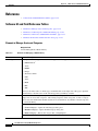
LDAP
Lightweight Directory Access Protocol. A highly complex data model and communications protocol for
user authentication. LDAP provides management and browser applications with access to directories
whose data models and access protocols conform to X.500 series (ISO/IEC 9594) standards.
Note
LDAPS
Secure LDAP. The same as ordinary LDAP, but protected under an added layer of SSL encryption.
Note
Caution
LDIF
Microsoft Active Directory is the only LDAP implementation that we support in this release.
Before you try to configure SSL encryption and before you let anyone log in with SSL, you MUST:
• Activate SSL on your Active Directory server and then export a copy of the server’s digital certificate.
• Import into DMM the SSL certificate that you exported from Active Directory.
• Restart Web Services (Tomcat) in AAI.
Is your DMM appliance one half of a failover pair?
If so, you will trigger immediate failover when you submit the command in AAI to restart Web Services. This occurs
by design, so there is no workaround.
LDAP Data Interchange Format. A strict grammar that SPs and IdPs use to classify and designate
named elements and levels in Active Directory.
User Guide for Cisco Digital Media Manager 5.4.x
8-6
OL-15762-05
Chapter 8
Authentication and Federated Identity
Concepts
O
Return to Top
OpenAM
SAML 2.0-compliant identity and access management server platform written in Java. OpenAM is open
source software available under the Common Development and Distribution (CDDL) license. OpenAM
is derived from and replaces OpenSSO Enterprise, which also used CDDL licensing. See
http://www.forgerock.com/openam.html.
OU
organizational unit. An LDIF classification type for a logical container within a hierarchical system.
In LDIF grammar, the main function of an OU value is to distinguish among superficially identical CNs
that might otherwise be conflated. For example:
• CN=John Doe,OU=sales,DN=example,DN=com
• CN=John Doe,OU=marketing,DN=example,DN=com
Note
P
An LDAP expression must never include a space immediately to either side of a “=” sign. Similarly, it must
never include a space immediately to either side of an “objectClass” attribute. Otherwise, validation fails.
Return to Top
PingFederate
R
SAML 2.0-compliant identity and access management server platform written in Java. PingFederate is
proprietary, commercial software. See http://www.pingidentity.com.
Return to Top
RDN
S
relative distinguished name. The CN for a directory service entity, as used exclusively (and still without
any explicit context) by the one IdP that has synchronized this entity against an Active Directory user
base. When an IdP encounters any RDN attribute in an LDIF reference, the IdP expects implicitly that
its SAML 2.0-synchronized federation is the only possible context for the CN. It expects this because
an IdP cannot authenticate — and logically should never encounter — a directory service entity whose
RDN is meaningful to any other federation.
Return to Top
SAML
Security Assertion Markup Language. XML-based open standard that security domains use to exchange
authentication and authorization data, including assertions and security tokens. We support SAML 2.0.
Shibboleth
A SAML 2.0-compliant architecture for federated identity-based authentication and authorization.
User Guide for Cisco Digital Media Manager 5.4.x
OL-15762-05
8-7
Chapter 8
Authentication and Federated Identity
Concepts
SP
service provider. Server that requests and receives information from an IdP. For example, your DMM
server is an SP for Cisco DMS.
SSO
single sign on. (And sometimes “single sign off.”) The main user-facing benefit of federation mode is
that SPs begin — and end, in some implementations — user sessions on behalf of their entire federation.
SSO is a convenience for users, who can log in only once per day as their work takes them between
multiple servers that are related but independent. Furthermore, SSO is a convenience to IT staff, who
spend less time on user support, password fatigue, compliance audits, and so on.
U
•
We DO NOT support single sign off in Cisco DMS 5.3.
•
We support only SP-initiated SSO in Cisco DMS 5.3.
Return to Top
The location of the user subtree in the LDAP directory tree. For example,
user base
Note
user base DN
An LDAP expression must never include a space immediately to either side of a “=” sign. Similarly, it must
never include a space immediately to either side of an “objectClass” attribute. Otherwise, validation fails.
A user filter limits the scope of an agreement to import filtered records from an Active Directory
user base.
Note
X
An LDAP expression must never include a space immediately to either side of a “=” sign. Similarly, it must
never include a space immediately to either side of an “objectClass” attribute. Otherwise, validation fails.
The DN for an Active Directory user base.
Note
user filter
DC=ad,DC=com.
An LDAP expression must never include a space immediately to either side of a “=” sign. Similarly, it must
never include a space immediately to either side of an “objectClass” attribute. Nor can a group name include any spaces.
Otherwise, validation fails.
Return to Top
X-509
A standard for public key infrastructure. X.509 specifies, among other things, standard formats for
public key certificates and a certification path validation algorithm.
User Guide for Cisco Digital Media Manager 5.4.x
8-8
OL-15762-05
Chapter 8
Authentication and Federated Identity
Concepts
Understand the Requirement to Authenticate Users
Although Cisco DMS always authenticates users, we support three authentication methods.
Note
Tip
•
Embedded authentication is completely native to Cisco DMS. It does not depend on any
external servers.
•
LDAP authentication causes Cisco DMS products to rely on one — and only one — Microsoft
Active Directory server and a Microsoft Internet Information Server (IIS). Thus, setup and
operation with this method are more complex than with embedded authentication.
•
Federation mode — also known as single sign-on (SSO) causes Cisco DMS products to rely on a
SAML 2.0-compliant IdP in combination with a Microsoft Active Directory server and IIS. Thus,
setup and operation with this method are more complex than with LDAP authentication.
You must choose one of these methods. The method that you use determines which login screen your users will see.
•
After a user session times out, we prompt the affected user to log in twice.
•
Migration from one mode to another takes as long as 1 minute to finish (CSCtn22370).
•
An unresponsive Active Directory server can hang a login prompt for 20 minutes without any error message.
EMBEDDED MODE
FEDERATION (SSO) MODE 1
LDAP MODE
IdP-specific login screen
1. When any of your federation servers uses a self-signed certificate, we show your users two SSL warnings during login.
Related Topics
•
LDAP and Active Directory Concepts, page 8-10
•
Federated Identity and Single Sign-on (SSO) Concepts, page 8-17
User Guide for Cisco Digital Media Manager 5.4.x
OL-15762-05
8-9
Chapter 8
Authentication and Federated Identity
Concepts
Decide Which Authentication Method to Use
LDAP and Active Directory Concepts
Note
Microsoft Active Directory is the only LDAP implementation that we support in this release.
•
LDAP is Highly Complex, page 8-11
•
Plan Ahead, page 8-11
•
Restrictions, page 8-11
User Guide for Cisco Digital Media Manager 5.4.x
8-10
OL-15762-05
Chapter 8
Authentication and Federated Identity
Concepts
•
Synchronization Concepts, page 8-11
•
LDAP Concepts, page 8-14
•
Password Concepts, page 8-16
•
Understand Authentication Property Sheets for LDAP, page 8-17
LDAP is Highly Complex
Caution
LDAP-related features of Cisco DMS are meant for use by qualified and experienced administrators of
Microsoft Active Directory. Unless you are an Active Directory and LDAP expert, we recommend that you use
embedded authentication.
Plan Ahead
•
Install and configure Active Directory and Internet Information Services (IIS) before you try to
configure LDAP authentication mode or federation mode in DMS-Admin.
Tip
•
We support IIS 6 on Windows Server 2003.
Make sure that you have generated or imported certificates as necessary and activated SSL on the
Active Directory server before you try to configure SSL encryption.
Restrictions
Support for
Active Directory
Cisco DMS Release
Trees
Forests
5.3.0
Yes
No
Synchronization Concepts
•
Synchronization (Replication) Overview, page 8-12
•
Synchronization Types, page 8-12
•
Understand Manual Synchronization, page 8-13
•
Understand Automatic Synchronization, page 8-13
•
Guidelines for Synchronization, page 8-14
User Guide for Cisco Digital Media Manager 5.4.x
OL-15762-05
8-11
Chapter 8
Authentication and Federated Identity
Concepts
Synchronization (Replication) Overview
Note
Microsoft Active Directory is the only LDAP implementation that we support in this release.
When you choose LDAP authentication or SSO authentication, user account data originates from your
Active Directory server. However, Cisco DMS does not synchronize (replicate) this data automatically,
in real time. Instead, we cache it. Therefore, you must resynchronize user account data when you think
it is appropriate to do so. You can:
•
Resynchronize manually.
•
Schedule synchronizations to recur in the future at set intervals.
DMS-Admin synchronizes all user accounts in the Active Directory “user base” that your filter specifies,
except users whose accounts are disabled on your Active Directory server.
Synchronization Types
Note
Microsoft Active Directory is the only LDAP implementation that we support in this release.
We support four types of Active Directory synchronization in LDAP mode or federation mode.
Initial
Update
Overwrite
Delete
Runs a one-time
synchronization for a
new filter that you never
synchronized
previously.
Runs an incremental,
fast update to find and
make up for any
differences between
user accounts that
match your
Active Directory filter
and your local copy of
those user accounts.
Overwrites your local
copy of user accounts
that correspond to your
Active Directory filter
with new copies of
those user accounts. In
addition, deletes your
local copy of each user
account that has been
deleted from
Active Directory since
the last time that you ran
a synchronization.
Deletes your local copy
of user accounts that
correspond to a defined
Active Directory filter
and deletes the entry for
that filter from
DMS-Admin.
User Guide for Cisco Digital Media Manager 5.4.x
8-12
OL-15762-05
Chapter 8
Authentication and Federated Identity
Concepts
Understand Synchronization of a DMM Group to an LDAP Filter
Note
Microsoft Active Directory is the only LDAP implementation that we support in this release.
Is the Active Directory Filter
Associated to a DMM
User Group?
We Sync All Matching LDAP User Accounts to the
‘All Users’ Group in DMM
Associated User Group in DMM
Yes
Yes
Yes
No
Yes
N.A.
•
In most cases, you can associate one LDAP filter apiece to one DMM user group. Likewise, in most
cases, you can associate one DMM user group apiece to one LDAP filter. The Digital Signs user
group is an exception to both of these principles. It is built-in to Cisco DMS.
•
After you associate a DMM user group to an LDAP filter, you cannot use features on the Users tab
to delete the DMM user group until after you delete the LDAP filter. However, even when you delete
an LDAP filter, there is no requirement to delete its associated DMM user group. Furthermore,
there is no way for you to delete the Digital Signs user group. It is built-in to Cisco DMS.
Understand Manual Synchronization
Note
Microsoft Active Directory is the only LDAP implementation that we support in this release.
Manual synchronization mode requires you to choose Administration > Settings > Authentication >
Synchronize Users > LDAP Bookmarks during all future synchronizations. Afterward, you must
click Update.
Manual synchronization mode deletes your schedule for automatic synchronizations.
Understand Automatic Synchronization
Note
Microsoft Active Directory is the only LDAP implementation that we support in this release.
Automatic synchronization mode automates and schedules incremental updates to user accounts that
match Active Directory filters that you defined in DMS-Admin. When you use automatic
synchronization mode, new fields and elements become available to you. These help you to configure
the settings for automatic synchronization.
See the “Understand Synchronization of a DMM Group to an LDAP Filter” section on page 8-13.
User Guide for Cisco Digital Media Manager 5.4.x
OL-15762-05
8-13
Chapter 8
Authentication and Federated Identity
Concepts
Guidelines for Synchronization
Note
Microsoft Active Directory is the only LDAP implementation that we support in this release.
We recommend that you synchronize your LDAP bookmarks periodically. Synchronization ensures that
user and group membership associations are current and correct.
Sync
Type
Best Practices
Initial
The Initial option is CPU-intensive for your DMM appliance and might lower performance
temporarily. We recommend that you use it during off-peak hours only.
Update
We recommend that you use the Update option whenever:
•
A new user account in Active Directory should have login access to DMM.
•
User attributes1 change in Active Directory for a user account in DMM.
•
A user account is disabled in Active Directory and should be deleted from DMM.
Overwrite Note
The Overwrite option is CPU-intensive for your DMM appliance and might lower its
performance temporarily. We recommend that you use this option during off-peak hours only.
•
After a user account is deleted from Active Directory, this option deletes the
corresponding user account from DMM.
•
After a user account is associated to a new first name, last name, or username, this
option overwrites the outdated user account attributes.
Delete
Caution
Note
The Delete option is destructive by design. We advise that you use it sparingly and with
great caution.
Typically, the deletion process takes about 1 minute to finish. However, when there are more than
50,000 users in the Active Directory database, this process might run in the background and take about
30 minutes to finish. In this case, the user interface in DMS-Admin can show that a bookmark was deleted
even though the actual process has not finished. If you observe this behavior, simply allow 30 minutes for
the operation to finish.
1. Attributes that you entered on the Manage Attributes property sheet in DMS-Admin.
Related Topics
•
Manage LDAP (Active Directory) Attributes, page 8-29
•
Understand LDAP Attributes, page 8-15
•
Guidelines for LDAP Filters, page 8-15
LDAP Concepts
User Guide for Cisco Digital Media Manager 5.4.x
8-14
OL-15762-05
Chapter 8
Authentication and Federated Identity
Concepts
Understand LDAP Attributes
Note
Microsoft Active Directory is the only LDAP implementation that we support in this release.
Ordinarily, DMS-Admin will not import any user account record from your Active Directory server
when the value in it is blank for any of these attributes:
•
Login User Name — This required value always must be unique.
•
First Name — This required value might be identical for multiple users.
•
Last Name — This required value might also be identical for multiple users.
However, you can import and synchronize all of the Active Directory user account records that match
your filters. You can do this even when some of the user account records are incomplete because one or
more of their attributes have blank values.
To prevent these undefined attributes from blocking the import of the user accounts they are meant to
describe, you can enter generic values for most attributes in the Values to Use by Default column.
DMS-Admin takes the generic values that you enter, and then inserts them automatically where they
are needed.
Tip
Nonetheless, you cannot enter a default value for the Login User Name attribute. Usernames are unique.
Guidelines for LDAP Filters
Note
Microsoft Active Directory is the only LDAP implementation that we support in this release.
•
Use “OU” values to impose rough limits on a filter, page 8-15
•
Use “memberOf” values to pinpoint a filter more precisely, page 8-16
•
Use “objectClass” values to match all user records, page 8-16
Use “OU” values to impose rough limits on a filter
•
Never use a filter that defines the user base at the domain level. For example, this filter is
not acceptable.
DC=example,DC=com
•
Instead, use filters that define the user base at a lower level, as this one does.
OU=SanJose,DC=example,DC=com
User Guide for Cisco Digital Media Manager 5.4.x
OL-15762-05
8-15
Chapter 8
Authentication and Federated Identity
Concepts
•
LDAP returns matched records from all levels within the user base that your filter defines.
Would a filter for “OU=SanJose,DC=example,DC=com” ever include any users from...?
OU=RTP,DC=example,DC=com
No 1
OU=Milpitas,OU=SanJose,DC=example,DC=com
Yes2
OU=Sunnyvale,OU=SanJose,DC=example,DC=com
Yes2
1. Research Triangle Park, NC, does not have any physical connection to San José, CA.
2. Milpitas, CA and Sunnyvale, CA, are suburbs of San José, CA, which affects them directly and in multiple ways.
Use “memberOf” values to pinpoint a filter more precisely
•
But what if you did not want to include any members of Milpitas or Sunnyvale? If your
Active Directory server considered these cities (organizational units) to be subsets of San José, how
could you exclude their members? To do so, you would use the
memberOf
attribute. It stops LDAP from matching records at any lower level than the one you name explicitly.
In this scenario for example, you would use
memberOf=OU=SanJose,DC=example,DC=com
to match only the direct members of the “SanJose” OU.
Use “objectClass” values to match all user records
•
You can define a comprehensive filter that matches all user records.
objectClass=user
Password Concepts
•
Understand the Effects of a Changed Password in Active Directory, page 8-16
•
Understand the Effects of a Blank Password in Active Directory, page 8-17
Understand the Effects of a Changed Password in Active Directory
Note
Microsoft Active Directory is the only LDAP implementation that we support in this release.
After you change a user password on your Active Directory server, there is no requirement to
resynchronize the affected user account in DMS-Admin.
User Guide for Cisco Digital Media Manager 5.4.x
8-16
OL-15762-05
Chapter 8
Authentication and Federated Identity
Concepts
Understand the Effects of a Blank Password in Active Directory
Note
Microsoft Active Directory is the only LDAP implementation that we support in this release.
•
Even though it is possible in Active Directory to use a blank value for a password, Cisco DMS does
not allow it.
•
When you choose LDAP authentication, any user whose Active Directory password is blank is
prevented from logging in to any component of Cisco DMS.
•
Access is enabled or restored after the password is populated on the Active Directory server.
Understand Authentication Property Sheets for LDAP
Note
Microsoft Active Directory is the only LDAP implementation that we support in this release.
The Authentication page contains four tabbed property sheets.
Select
Mode1
Embedded, LDAP or SSO
Define
Filter
LDAP or SSO
Synchronize
Users
LDAP or SSO
Manage
Attributes
LDAP or SSO
Select Mode is by default the only active tab. Your choices on the Select Mode property sheet
determine whether you have access to the other three property sheets.
Your choices on the Define Filter property sheet help you to configure and add a new agreement.
Your choices on the Synchronize Users property sheet help you to submit a new agreement.
1. In most production environments, you can expect to use the Select Mode property sheet only one time.
Federated Identity and Single Sign-on (SSO) Concepts
•
IdP Requirements, page 8-17
•
Configuration Workflow to Activate Federation (SSO) Mode, page 8-18
•
Authentication Scenarios for User Sessions in Federation (SSO) Mode, page 8-18
IdP Requirements
To use federation (SSO) mode in Cisco DMS, you must have access to an IdP that meets our
requirements. Your IdP must meet ALL OF THESE CRITERIA IN COMBINATION:
•
Support SAML 2.0.
•
Support these two SAML profiles:
– Web Browser SSO Profile
– Enhanced Client or Proxy (ECP) Profile
User Guide for Cisco Digital Media Manager 5.4.x
OL-15762-05
8-17
Chapter 8
Authentication and Federated Identity
Concepts
•
Generate assertions in which the SAML “UID” attribute is mapped to the local portion of an
authenticated user’s username.
•
Generate SAML responses that are no larger than 16K bytes. (CSCua10799)
•
Use a digital certificate from a well-known CA (but only if you will use HTTPS).
•
Include a “<SingleSignOnService>” entry with SOAP binding in its IdP metadata. For example:
<SingleSignOnService Location=http://idp.example.com/idp/SSO.sml2”
Binding=”urn:oasis:names:tc:SAML:2.0:bindings:SOAP”/>
In practice, these requirements limit your IdP to ones that we certify and
NO OTHER. We certify OpenAM, PingFederate, and Shibboleth. (CSCua29696)
Configuration Workflow to Activate Federation (SSO) Mode
1.
Configure and set up an Active Directory server.
2.
Configure and set up a SAML 2.0-compliant IdP.
Note
When you use a “fresh install” of Cisco DMS 5.3 (as opposed to an upgrade), your DMM appliance is configured
to use embedded authentication mode by default. But when you upgrade a DMM server that was already
configured for an earlier Cisco DMS release, it might use either embedded mode or LDAP mode.
3.
Obtain a digital certificate from a trusted CA and install it on your IdP.
4.
Use DMS-Admin to configure Cisco DMS for federation mode.
5.
Export SAML 2.0-compliant metadata from your DMM server and import it into your IdP.
6.
Export SAML 2.0-compliant metadata from your IdP and import it into your DMM server.
7.
Configure Active Directory exactly as you would in LDAP mode.
8.
Click Update to save your work, and then advance to the Synchronize Users property sheet.
9.
Synchronize DMM with your Active Directory server to populate the DMM user database.
Note
You MUST configure at least one LDAP bookmark.
10. Synchronize users exactly as you would in LDAP mode.
Note
Whenever you change any setting or value on your IdP or any of your SPs, you must reestablish their
pairing to restore mutual trust among them.
11. Click Update to save your work.
Authentication Scenarios for User Sessions in Federation (SSO) Mode
•
SSO Scenario 1 — Trusted + Valid + Authorized
•
SSO Scenario 2 — Trusted + Valid + NOT Authorized
•
SSO Scenario 3 — Nothing Known
User Guide for Cisco Digital Media Manager 5.4.x
8-18
OL-15762-05
Chapter 8
Authentication and Federated Identity
Concepts
SSO Scenario 1—Trusted + Valid + Authorized
1.
A web browser requests access to a protected resource on an SP.
Your federation will not approve or deny this request until it knows more.
2.
The SP asks its IdP if the browser is currently authenticated to any valid user account in the CoT.
3.
The IdP verifies that:
4.
•
The browser is already connected to an SP elsewhere in the CoT, having authenticated
successfully to a valid user account and having received a SAML “token” or “passport” that
authorizes at least some access.
•
The user account has sufficient permissions to access the protected resource.
The IdP acts on the SP’s behalf and redirects the browser immediately to the protected resource.
SSO Scenario 2—Trusted + Valid + NOT Authorized
1.
A web browser requests access to a protected resource on an SP.
Your federation will not approve or deny this request until it knows more.
2.
The SP asks its IdP if the browser is currently authenticated to any valid user account in the CoT.
3.
The IdP verifies that:
4.
•
The browser is already connected to an SP elsewhere in the CoT, having authenticated
successfully to a valid user account and having received a SAML “token” or “passport” that
authorizes at least some access.
•
The user account DOES NOT have sufficient permissions.
The IdP redirects the browser to the SP, where an HTTP 403 Forbidden message states that the user is
not authorized to access the protected resource.
User Guide for Cisco Digital Media Manager 5.4.x
OL-15762-05
8-19
Chapter 8
Authentication and Federated Identity
Concepts
SSO Scenario 3—Nothing Known
1.
A web browser requests access to a protected resource on an SP.
Your federation will not approve or deny this request until it knows more.
2.
The SP asks its IdP if the browser is currently authenticated to any valid user account in the CoT.
3.
The IdP reports that:
4.
•
The browser is not yet connected to any SP in the CoT.
•
The browser is not yet authenticated to any valid user account.
•
We cannot tell if the browser’s human operator is a valid and authorized user, a valid but confused user,
or an intruder.
The SP redirects the browser automatically to an HTTPS login prompt on the IdP, where one of
the following occurs.
•
The browser’s human operator successfully logs in to a valid user account. The IdP attaches a SAML
“token” or “passport” to the browser session, authorizing at least some access. And:
– The user account has permission to access the protected resource. So, the IdP acts on
the SP’s behalf and redirects the browser immediately to the protected resource.
OR
– The user account DOES NOT have permission to access the protected resource. So, the
IdP redirects the browser to the SP, where an HTTP 403 Forbidden message states that the user
is not authorized to access the protected resource.
•
The browser’s human operator fails to log in. So, lacking any proof that this person is authorized,
we block access to every protected resource until the human operator can log in successfully.
Migration Between Authentication Methods
•
Understand Migration (from Either LDAP or SSO) to Embedded, page 8-20
•
Understand Migration (from Embedded) to Either LDAP or SSO, page 8-21
Understand Migration (from Either LDAP or SSO) to Embedded
When you migrate from LDAP (via Active Directory) or federation mode to embedded authentication
mode, you must explicitly choose whether to keep local copies of the:
•
User accounts that were associated to LDAP filters.
•
Groups and policies that were associated to LDAP filters.
User Guide for Cisco Digital Media Manager 5.4.x
8-20
OL-15762-05
Chapter 8
Authentication and Federated Identity
Procedures
Note
•
Unless you choose explicitly to keep the local copy of a user, a group, or a policy, we discard the local copy.
•
Migration from one mode to another takes as long as 1 minute to finish (CSCtn22370).
The result varies according to the combination of your choices.
Policies
Groups
Users
When You
Keep Local
Copies of
Yes Yes Yes
Yes No
No
No
Yes Yes
No
No
No
The Result
•
We preserve all local information.
•
We overwrite all LDAP-derived user account passwords with
CiscoDMMvp99999. 1
•
We preserve all local user accounts. However, we overwrite all LDAP-derived
user account passwords with CiscoDMMvp99999. 1
•
We discard all LDAP-derived groups.
•
We discard all LDAP-derived policies.
•
We discard all LDAP-derived user accounts.
•
We preserve all LDAP-derived groups. However, they are empty.
•
We preserve all LDAP-derived policies. Although they no longer apply to anyone,
you can reuse them and apply them to any remaining user accounts and any future
user accounts as you see fit.
•
We discard all LDAP-derived users, groups, and policies.
1. This security feature protects your network and user data. If anyone gains unauthorized access to the exported file and tries
to use it, Active Directory rejects the invalid passwords.
Understand Migration (from Embedded) to Either LDAP or SSO
Note
•
Before you migrate from embedded authentication mode to federation mode, you must install a digital certificate
from a trusted CA on your IdP server. Otherwise, you cannot migrate to federation mode at all.
•
After you migrate from embedded authentication mode to either LDAP (Active Directory) mode or federation mode, the locked
property sheets become unlocked. You must use them.
•
Migration from one mode to another takes as long as 1 minute to finish (CSCtn22370).
•
Export the Root CA X.509 Certificate from Your Active Directory Server, page 8-22
•
Configure DMM to Trust the Active Directory Root CA, page 8-22
•
Choose an Authentication Method, page 8-23
Procedures
User Guide for Cisco Digital Media Manager 5.4.x
OL-15762-05
8-21
Chapter 8
Authentication and Federated Identity
Procedures
•
Configure LDAP (Active Directory) Settings, page 8-24
•
Configure Federation Services for SSO, page 8-33
Export the Root CA X.509 Certificate from Your Active Directory Server
Procedure
Step 1
Open a web browser on your Active Directory server and connect to http://localhost/certsrv.
Step 2
Click Download a CA certificate.
Step 3
Choose the current CA certificate.
Step 4
Choose DER encoded.
The X.509 certificate that you export must be DER-encoded, and it can be binary or printable (Base64).
However, when you use Base64, the certificate file must include these lines:
-----BEGIN CERTIFICATE---------END CERTIFICATE-----
Step 5
Click Download CA certificate.
Step 6
Save this certificate in a file.
For example, you might call the certificate ADcertificate.cer.
Step 7
Stop. You have completed this procedure.
Configure DMM to Trust the Active Directory Root CA
Before You Begin
•
Log in to DMM.
Procedure
Step 1
Click Administration.
Step 2
Choose Security > Authentication > Select Mode.
User Guide for Cisco Digital Media Manager 5.4.x
8-22
OL-15762-05
Chapter 8
Authentication and Federated Identity
Procedures
Step 3
Choose LDAP.
Step 4
Check the Use SSL Encryption check box.
Additional user interface elements now appear, which are relevant to SSL and digital certificates.
Step 5
Step 6
Upload the root CA certificate file that you saved locally.
a.
Click Upload, and then click Add.
b.
Browse to the file on a local volume.
c.
Click the filename and press Enter.
d.
Click OK to save your work and dismiss the dialog box.
Enter the details for your Active Directory server.
Tip
Step 7
Be sure to use the logical port where your Active Directory server actually listens for SSL connections. The
standard port number for LDAPS is 636. However, your Active Directory server might be configured to use some other port.
As prompted, use DMS-Admin to restart Web Services (Tomcat).
The installed certificate cannot take effect until after you restart Tomcat.
Step 8
Stop. You have completed this procedure.
Choose an Authentication Method
Before You Begin
•
Log in to DMM.
Procedure
Step 1
Click Administration.
Step 2
Choose Security > Authentication.
Step 3
Use elements on the Select Mode property sheet to choose an authentication mode.
Step 4
Click Update.
User Guide for Cisco Digital Media Manager 5.4.x
OL-15762-05
8-23
Chapter 8
Authentication and Federated Identity
Procedures
Note
Migration from one mode to another takes as long as 1 minute to finish (CSCtn22370).
The authentication settings that you changed are now in effect.
Step 5
Stop. You have completed this procedure.
What to Do Next
•
OPTIONAL — Did you choose LDAP (Active Directory) or SSO?
Proceed to the “Define LDAP (Active Directory) Filters” section on page 8-24
Related Topics
•
Elements to Choose and Enable an Authentication Mode, page 8-46
Configure LDAP (Active Directory) Settings
•
Define LDAP (Active Directory) Filters, page 8-24
•
Import User Accounts that Match an LDAP (Active Directory) Filter, page 8-25
•
Resynchronize User Accounts that Match an LDAP (Active Directory) Filter, page 8-26
•
Sever All Existing Ties to a User Base or an LDAP (Active Directory) Server, page 8-27
•
Define the LDAP (Active Directory) Synchronization Schedule, page 8-28
•
Manage LDAP (Active Directory) Attributes, page 8-29
•
Configure Automatic LDAP (Active Directory) Synchronization, page 8-30
•
Derive User Group Membership Dynamically from an LDAP (Active Directory) Filter, page 8-31
Define LDAP (Active Directory) Filters
Before You Begin
•
Log in to DMM.
•
Choose LDAP or federation as your authentication method.
Procedure
Step 1
Click Administration.
Step 2
Choose Security > Authentication.
Step 3
Click Define Filter.
User Guide for Cisco Digital Media Manager 5.4.x
8-24
OL-15762-05
Chapter 8
Authentication and Federated Identity
Procedures
Step 4
Do the following.
a.
Use elements on the Define Filter property sheet to define, validate, and add one LDAP filter.
b.
Click Update.
c.
Repeat this step for each filter to be added.
The authentication settings that you changed are now in effect.
Step 5
Stop. You have completed this procedure.
Related Topics
•
Elements to Define, Validate, and Add LDAP Filters, page 8-48
Import User Accounts that Match an LDAP (Active Directory) Filter
Before You Begin
•
Log in to DMM.
•
Choose LDAP or SSO as your authentication method.
•
Define LDAP filters that will match the user accounts that you want to import.
Procedure
Step 1
Click Administration.
Step 2
Choose Security > Authentication > Synchronize Users.
Tip
Is the Synchronize Users tab disabled (dimmed), so that you cannot click it? If so, refresh your browser.
Step 3
Find the relevant bookmark among all your saved bookmarks.
Step 4
Choose Initial as the synchronization type.
Step 5
Click Submit.
Note
Step 6
Please wait. Your request might take as long as 1 minute to process (CSCtn22370).
Stop. You have completed this procedure.
User Guide for Cisco Digital Media Manager 5.4.x
OL-15762-05
8-25
Chapter 8
Authentication and Federated Identity
Procedures
What to Do Next
•
OPTIONAL — Would you like to associate a set of imported users with a new group?
Proceed to the “Derive User Group Membership Dynamically from an LDAP (Active Directory)
Filter” section on page 8-31.
•
OPTIONAL — Would you like to configure the schedule for synchronization?
Proceed to the “Define the LDAP (Active Directory) Synchronization Schedule” section on
page 8-28.
Related Topics
•
Define LDAP (Active Directory) Filters, page 8-24
•
Derive User Group Membership Dynamically from an LDAP (Active Directory) Filter, page 8-31
•
Elements to Use LDAP Bookmarks for Synchronization, page 8-49
Resynchronize User Accounts that Match an LDAP (Active Directory) Filter
Before You Begin
•
Log in to DMM.
•
Choose LDAP or SSO as your authentication method.
•
Define LDAP filters.
Procedure
Step 1
Click Administration.
Step 2
Choose Security > Authentication > Synchronize Users.
Tip
Is the Synchronize Users tab disabled (dimmed), so that you cannot click it? If so, refresh your browser.
Step 3
Find the relevant bookmark among all your saved bookmarks.
Step 4
Choose Update as the synchronization type.
Step 5
Click Submit.
Note
Step 6
Please wait. Your request might take as long as 1 minute to process (CSCtn22370).
Stop. You have completed this procedure.
User Guide for Cisco Digital Media Manager 5.4.x
8-26
OL-15762-05
Chapter 8
Authentication and Federated Identity
Procedures
What to Do Next
•
OPTIONAL — Would you like to associate a set of imported users with a new group?
Proceed to the “Derive User Group Membership Dynamically from an LDAP (Active Directory)
Filter” section on page 8-31.
•
OPTIONAL — Would you like to configure the schedule for synchronization?
Proceed to the “Define the LDAP (Active Directory) Synchronization Schedule” section on
page 8-28.
Related Topics
•
Define LDAP (Active Directory) Filters, page 8-24
•
Derive User Group Membership Dynamically from an LDAP (Active Directory) Filter, page 8-31
•
Elements to Use LDAP Bookmarks for Synchronization, page 8-49
Sever All Existing Ties to a User Base or an LDAP (Active Directory) Server
Before You Begin
•
Log in to DMM.
•
Choose LDAP or SSO as your authentication method.
•
Define LDAP filters.
Procedure
Step 1
Click Administration.
Step 2
Choose Security > Authentication > Synchronize Users.
Tip
Is the Synchronize Users tab disabled (dimmed), so that you cannot click it? If so, refresh your browser.
Step 3
Click LDAP Bookmarks,
Step 4
Delete all relevant filters from DMS-Admin.
Step 5
Click Update.
Note
Please wait. Your request might take as long as 1 minute to process (CSCtn22370).
The authentication settings that you changed are now in effect.
Step 6
Stop. You have completed this procedure.
User Guide for Cisco Digital Media Manager 5.4.x
OL-15762-05
8-27
Chapter 8
Authentication and Federated Identity
Procedures
What to Do Next
•
OPTIONAL — Would you like to associate a set of imported users with a new group?
Proceed to the “Derive User Group Membership Dynamically from an LDAP (Active Directory)
Filter” section on page 8-31.
•
OPTIONAL — Would you like to configure the schedule for synchronization?
Proceed to the “Define the LDAP (Active Directory) Synchronization Schedule” section on
page 8-28.
Related Topics
•
Define LDAP (Active Directory) Filters, page 8-24
•
Derive User Group Membership Dynamically from an LDAP (Active Directory) Filter, page 8-31
•
Elements to Use LDAP Bookmarks for Synchronization, page 8-49
Define the LDAP (Active Directory) Synchronization Schedule
Before You Begin
•
Log in to DMM.
•
Choose LDAP or SSO as your authentication method.
•
Define LDAP filters and bookmarks.
Procedure
Step 1
Click Administration.
Step 2
Choose Security > Synchronize Users > Scheduling,
Step 3
Choose between manual synchronization and automatic synchronization.
Note
Step 4
You will not see any of the elements that the “Elements for Bookmarks” table describes until after you define
at least one filter on the Define Filter property sheet.
Click Update.
The authentication settings that you changed are now in effect.
Step 5
Stop. You have completed this procedure.
What to Do Next
•
OPTIONAL — Would you like to associate attribute names in DMS-Admin and Active Directory?
If so, proceed to the “Manage LDAP (Active Directory) Attributes” section on page 8-29.
User Guide for Cisco Digital Media Manager 5.4.x
8-28
OL-15762-05
Chapter 8
Authentication and Federated Identity
Procedures
•
OPTIONAL — Should Cisco DMS expect that your Active Directory server uses factory-preset attribute
names? If so, proceed to the “Manage LDAP (Active Directory) Attributes” section on page 8-29.
•
OPTIONAL — Should Cisco DMS expect that your Active Directory server uses custom attribute
names? If so, proceed to the “Manage LDAP (Active Directory) Attributes” section on page 8-29.
Related Topics
•
Define LDAP (Active Directory) Filters, page 8-24
•
Elements to Schedule Synchronization, page 8-50
Manage LDAP (Active Directory) Attributes
Before You Begin
•
Log in to DMM.
•
Choose LDAP or SSO as your authentication method.
•
Define LDAP filters and bookmarks.
•
Configure the LDAP synchronization schedule.
Procedure
Step 1
Click Administration.
Step 2
Click Security > Authentication > Manage Attributes.
Tip
Step 3
Is the Manage Attributes tab disabled (dimmed), so that you cannot click it? If so, refresh your browser.
Use elements on the Manage Attributes property sheet to:
•
Set the associations between DMS-Admin attribute names and their corresponding Active Directory
attribute names.
•
Use the predefined and typical names for Active Directory attributes (shown in grey text) or edit
those attribute names so they match the names that your Active Directory server uses.
•
Enter the values to use by default in DMS-Admin when a user account attribute is not defined on
your Active Directory server.
You must enter a value for each mandatory attribute. You cannot enter a value to use by default for user
names, because each user name is unique.
User Guide for Cisco Digital Media Manager 5.4.x
OL-15762-05
8-29
Chapter 8
Authentication and Federated Identity
Procedures
Step 4
Click Update.
The authentication settings that you changed are now in effect.
Step 5
Stop. You have completed this procedure.
Related Topics
•
Define the LDAP (Active Directory) Synchronization Schedule, page 8-28
•
Elements to Manage Attributes, page 8-51
Configure Automatic LDAP (Active Directory) Synchronization
Before You Begin
•
Log in to DMM.
•
Choose LDAP or SSO as your authentication method.
•
Define LDAP filters and bookmarks.
•
Configure the LDAP synchronization schedule.
Procedure
Step 1
Click Administration.
Step 2
Choose Security > Authentication > Synchronize Users > Scheduling.
Step 3
Click the calendar icon (
Step 4
Choose the hour and minute when synchronization should begin. Then, choose either AM or PM as
the period.
Step 5
From the Repeat Interval list, choose the interval of recurrence:
) to choose the start date for synchronization.
Interval
Description
Never
Synchronization occurs once and does not recur.
Every Day
Synchronization recurs once every 24 hours. You must set the hour and
minute when it should start.
Every Week
Synchronization recurs once every 7 days. You must set the hour and
minute when it should start.
User Guide for Cisco Digital Media Manager 5.4.x
8-30
OL-15762-05
Chapter 8
Authentication and Federated Identity
Procedures
Interval
Description
Every Month
Synchronization recurs once each month. You must set the hour and
minute when it should start.
Custom
Synchronization recurs at an interval of your choosing. You must set the
hour and minute when it should start.
Choose Days, Weeks, or Months as the interval type.
Step 6
•
Choose a day of the month from 1 to 30 when the interval type
is Days.
•
Choose a day of the week when the interval type is Weeks.
•
Choose an interval of recurrence from 1 to 6 when the interval type
is Months.
(Optional)
•
Did you click the Automatic Synchronization radio button?
•
And should a one-time synchronization start immediately, in addition to the start date and time that
you specified?
If so, check the Synchronize users immediately check box.
Step 7
Click Update.
The authentication settings that you changed are now in effect.
Step 8
Stop. You have completed this procedure.
Derive User Group Membership Dynamically from an LDAP (Active Directory) Filter
You can populate a user group with the returned output from a User Base DN query. However, a group
of this kind differs in important ways from a group that you populate manually.
Note
•
Membership of such groups is dynamic — based on shared characteristics among the group of Active Directory
users who match your query.
•
We update and clean these groups automatically during synchronization. Their membership will change after
synchronization runs, when the corresponding records in Active Directory show that a user's membership should start
or stop.
•
An imported Active Directory group is always read-only in DMS-Admin. By protecting it, we ensure that it is always correct,
relative to the original and subject to any delay between synchronizations. For this reason, you cannot edit their memberships
rolls manually.
•
When you try to delete a user from a group of this type, DMS-Admin shows an error message: “You cannot remove any
user from a group associated with an LDAP bookmark.”
User Guide for Cisco Digital Media Manager 5.4.x
OL-15762-05
8-31
Chapter 8
Authentication and Federated Identity
Procedures
Before You Begin
•
Log in to DMM.
•
Choose LDAP as your authentication method.
Procedure
Step 1
Click Administration.
Step 2
Choose Security > Authentication > Define Filter.
Tip
Is the Define Filter tab disabled (dimmed), so that you cannot click it? If so, refresh your browser.
Step 3
Use elements on the Define Filter property sheet to define, validate, and add one LDAP filter.
Step 4
Would you like to add users to a group that exists already? If so, choose that group name from the User
Group (in DMM) list.
OR
Would you like to create and populate an entirely new group? If so, choose Create a New User Group
from the User Group (in DMM) list. Then, give the new user group a name.
•
Group names in DMM can include alphanumeric characters ( 0–9; a–z; A-Z), hyphens (-),
underscores ( _), and periods (.).
•
Spaces are forbidden.
•
Other forbidden characters include:
~‘!@#$%^&*()+={[}]|\:;”"’'<>?/
Step 5
Click Validate.
Step 6
Click Add.
Note
Step 7
Please wait. Your request might take as long as 1 minute to process (CSCtn22370).
Stop. You have completed this procedure.
User Guide for Cisco Digital Media Manager 5.4.x
8-32
OL-15762-05
Chapter 8
Authentication and Federated Identity
Procedures
Configure Federation Services for SSO
•
IdP Configuration Examples, page 8-33
•
Export SP Metadata from DMM, page 8-43
•
Import IdP Metadata into DMM, page 8-43
•
Bypass External Authentication During Superuser Login, as Needed, page 8-45
IdP Configuration Examples
This section includes configuration examples from IdP implementations that have passed internal Cisco
tests for interoperability with Cisco DMS.
Note
•
We provide these rough examples as a courtesy only. We do not endorse any IdP by name, including any whose setup
we mention by name in these examples. Likewise, we do not influence the development of any IdP. We do not know when or
how its configuration workflows, daily operation, or overall quality might change in the future. For these reasons, we cannot
know beforehand when or how the natural course of its ongoing development might invalidate one or more of the examples
in this section. Therefore: Obtain all necessary IdP documentation from your IdP vendor, not Cisco.
•
You are free to choose, configure, and use an IdP at your own discretion — and your own risk. We do not develop,
maintain, or support any IdP. Nor do we warrant that your choice of IdP is free of defects, non-infringing, or fit for any purpose.
•
Example: Configure OpenAM to Interoperate with Cisco DMS, page 8-34
•
Example: Configure Shibboleth to Interoperate with Cisco DMS, page 8-36
•
Example: Configure PingFederate to Interoperate with Cisco DMS, page 8-40
User Guide for Cisco Digital Media Manager 5.4.x
OL-15762-05
8-33
Chapter 8
Authentication and Federated Identity
Procedures
Example: Configure OpenAM to Interoperate with Cisco DMS
Before You Begin
•
Obtain a digital identity certificate from a well-known CA, install it on your IdP host system, and
then enable SSL.
Procedure
Step 1
Note
Configure
OpenAM to use
a datastore from
Active Directory,
unless it already
does so.
In Federation mode, we use a synchronization process to learn which usernames are valid in
your organization. Later and separately, we use an authentication process to verify user-login credentials. And
even though we expect most IdPs will source both of these services from a Microsoft Active Directory server,
your organization might use some other other LDAP system to authenticate user sessions. When this is the case,
you must install and configure an Active Directory server for synchronization use by Cisco DMS.
Otherwise, we cannot learn which usernames are valid. In turn, ordinary users cannot log in to Cisco DMS. To
prevent this outcome, you must replicate and synchronize a datastore between your new Active Directory server
and your existing LDAP server. Afterward, Cisco DMS can synchronize with the Active Directory datastore.
a.
In OpenAM Web, choose Access Control > Top Level Realm > Data Stores.
b.
Enter values to define the attributes of your Active Directory DataStore.
You might enter values for some of the attributes (like these ones, for example)...
LDAP Server: <IP_ADDRESS>:389
LDAP Bind DN: CN=Administrator,CN=Users,DC=win2003esx,DC=example,DC=com
LDAP Bind Password: *********
LDAP Organization DN: OU=SystemTest,DC=win2003esx,DC=example,DC=com
LDAP Users Search Attribute: sAMAccountName
LDAP Users Search Filter: (objectclass=user)
Authentication Naming Attribute: sAMAccountName
... while leaving other attribute values undefined.
Attribute Name Mapping: <Empty>
LDAP Groups Search Attribute: <Empty>
LDAP Groups Search Filter: <Empty>
LDAP Groups container Naming Attribute: <Empty>
LDAP Groups Container Value: <Empty>
Attribute Name of Unqiue Member: <Empty>
LDAP People Container Naming Attribute: <Empty>
LDAP People Container Value: <Empty>
Persistent Search Base DN: <Empty>
Persistent Search Filter: <Empty>
Note
These are merely examples.
c.
Click Federation, and then click your IdP server instance — for example, dmsIdp.
d.
Click Assertion Processing.
e.
Change the IDP Attribute Map value from UID=uid to UID=sAMAccountName.
User Guide for Cisco Digital Media Manager 5.4.x
8-34
OL-15762-05
Chapter 8
Authentication and Federated Identity
Procedures
Step 2
Step 3
Step 4
Step 5
Install Enhanced
Client or Proxy
(ECP), a SAML
profile plugin, if
you will make
API system calls
to OpenAM1.
Export SP
metadata from
Cisco DMS.
Import SP
metadata from
Cisco DMS.
Make sure that
OpenAM is
configured to
issue the
Principal
attribute.
a.
Log in to your Cisco.com user account.
b.
Go to http://cisco.com/cisco/software/release.html?mdfid=280171249&softwareid=
282100271&release=5.3&rellifecycle=&relind=AVAILABLE&reltype=all, navigate to the
download page for our implementation of ECP 2, and then download it.
c.
Use Maven or another method to download release 1.2.14 of the open source logging
framework called log4j.
d.
Copy your downloaded ECP and log4j files to
e.
Restart your servlet container — for example, tomcat.
f.
In OpenAM Web, click Federation, and then click your IdP server instance — for
example, dmsIdp.
g.
Click Advanced.
h.
In the ECP Configuration area, set the IDP Session Mapper value to
com.cisco.dms.core.security.aaa.sso.saml2.ecp.idp.plugin.DmsIDPECPSessionMapper.
i.
Click Save.
/$OPENSSO_HOME/WEB-INF/lib,
.
Export metadata from each SP that will participate in your OpenAM CoT.
For Cisco DMS, see the “Export SP Metadata from DMM” topic.
Tip
a.
Go to the console page and click Register Remote Service Provider.
b.
Check the File check box.
c.
Click Upload, and then navigate to the SP metadata that you exported from DMS-Admin and
saved as dms_sp_config.xml.
d.
Click Configure, and then click Federation.
e.
Make sure that dmsServiceProvider (SAMLv2 SP Remote) has a defined value.
a.
In OpenAM Web, click Federation, and then click your IdP server instance — for
example, dmsIdp.
b.
Click Assertion Processing.
c.
In the Attribute Mapper area, set the Attribute Map value to UID=uid.
d.
Click Back.
e.
Click the SP entity instance for your DMM appliance.
The Assertion Content tab is selected automatically.
f.
In the Request/Response Signing area, check both of these check boxes:
•
Authentication Requests Signed
•
Assertions Signed
g.
Choose Access Control > / (Top Level Realm) > Authentication.
h.
Click All Core Settings.
i.
Make sure that the User Profile value is set to Required.
This will cause OpenAM to pass the user IDs of logged-in users to DMM and your other SPs.
j.
Click Save, and then click Back to Authentication.
k.
Log out of OpenAM Web.
User Guide for Cisco Digital Media Manager 5.4.x
OL-15762-05
8-35
Chapter 8
Authentication and Federated Identity
Procedures
Step 6
Cause
Cisco DMS to
trust OpenAM.
See the “Import IdP Metadata into DMM” topic.
Step 7
Use the Linux
CLI to export IdP
metadata.
wget --no-check-certificate
dms_idp_config.xml
Stop.
You have completed this procedure.
Step 8
https://<IdP_serverip>:<service_port>/opensso/saml2/jsp/exportmetadata.jsp -O
1. Also, DMS-Admin includes a feature to test the configuration of your IdP. In the case of OpenAM, this testing feature uses ECP and fails in its absence.
2. We provide a downloadable ECP implementation as a courtesy to you. Alternatively, you can obtain ECP from another source at your discretion.
Example: Configure Shibboleth to Interoperate with Cisco DMS
Before You Begin
•
Obtain a digital identity certificate from a well-known CA, install it on your IdP host system, and
then enable SSL.
Procedure
Step 1
Obtain and install
Shibboleth.
a.
Go to http://www.shibboleth.net/downloads/identity-provider/latest/.
b.
Download the latest Identity Provider software package, such as
shibboleth-identityprovider-2.3.0-bin.zip.
c.
Extract the downloaded archive, and then make the installer script within it, named
install.sh, executable. For example:
$ unzip shibboleth-identityprovider-2.3.0-bin.zip
$ cd shibboleth-identityprovider-2.3.0
$ chmod u+x install.sh
d.
Run the script to install Shibboleth.
$ ./install.sh
•
The installer will prompt you to specify the installation directory. Its default is
/opt/shibboleth-idp.
•
In addition, it will prompt you to enter your Shibboleth system’s FQDN, such as
shibboleth.example.com.
Respond appropriately to these prompts.
Shibboleth is now installed and you have completed its basic configuration. Your new
Shibboleth system contains these subfolders.
/opt/shibboleth-idp/bin/
/opt/shibboleth-idp/conf/
/opt/shibboleth-idp/credentials/
/opt/shibboleth-idp/lib/
/opt/shibboleth-idp/logs/
/opt/shibboleth-idp/metadata/
/opt/shibboleth-idp/war/
User Guide for Cisco Digital Media Manager 5.4.x
8-36
OL-15762-05
Chapter 8
Authentication and Federated Identity
Procedures
Step 2
Step 3
Export SP
metadata from
Cisco DMS.
Import SP
metadata from
Cisco DMS.
Export metadata from each SP that will participate in your Shibboleth CoT.
Tip
For Cisco DMS, see the “Export SP Metadata from DMM” topic.
Use SFTP or another method to save imported metadata where Shibboleth will access it:
/opt/shibboleth-idp/metadata/.
Step 4
Log in remotely.
Use SSH, remote desktop, VNC, or a direct console connection to log in remotely to the system
where you installed Shibboleth.
Step 5
Edit the attribute
filter file.
a.
Open /opt/shibboleth-idp/conf/attribute-filter.xml for editing.
b.
Change the attributeID value (at or near line 24) to uid.
<afp:AttributeRule attributeID="uid">
Step 6
Edit the attribute
resolver file.
a.
Open /opt/shibboleth-idp/conf/attribute-resolver.xml for editing.
b.
Find this section:
<!- ========================================== ->
<!Attribute Definitions
->
<!- ========================================== ->
c.
Enter these lines after the Attribute Definitions section heading, at or near line 29.
<resolver:AttributeDefinition xsi:type="ad:Simple" id="uid"
sourceAttributeID="sAMAccountName">
<resolver:Dependency ref="myLDAP" />
<resolver:AttributeEncoder xsi:type="enc:SAML2String"
name="urn:oid:0.9.2342.19200300.100.1.1" friendlyName="uid" />
<resolver:AttributeEncoder xsi:type="enc:SAML2StringNameID"
nameFormat="urn:oasis:names:tc:SAML:2.0:nameid-format:transient" />
</resolver:AttributeDefinition>
d.
Find this section:
<!- ========================================== ->
<!Data Connectors
->
<!- ========================================== ->
e.
Enter these lines after the Data Connectors section heading, at or near line 288.
<resolver:DataConnector id="myLDAP" xsi:type="dc:LDAPDirectory"
xmlns="urn:mace:shibboleth:2.0:resolver:dc"
ldapURL="ldap://<YOUR_ACTIVE_DIRECTORY_SERVER_IP>"
baseDN="cn=<USERBASE>, dc=<HOSTNAME>, dc=<EXAMPLE>, dc=<COM>"
principal="cn=<ADMINISTRATOR_CN>, cn=<USERBASE>, dc=<HOSTNAME>,
dc=<EXAMPLE>, dc=<COM>"
principalCredential="<ADMINISTTRATOR_PASSWORD>">
<dc:FilterTemplate>
<![CDATA[
(sAMAccountName=$requestContext.principalName)
]]>
</dc:FilterTemplate>
<LDAPProperty name="java.naming.referral" value="follow"/>
</resolver:DataConnector>
User Guide for Cisco Digital Media Manager 5.4.x
OL-15762-05
8-37
Chapter 8
Authentication and Federated Identity
Procedures
Step 7
Edit the
handler file.
a.
Open /opt/shibboleth-idp/conf/handler.xml for editing.
b.
Uncomment line 109.
<!-- Username/password login handler -->
<ph:LoginHandler xsi:type="ph:UsernamePassword"
jaasConfigurationLocation="file:///opt/shibboleth-idp/conf/login.config">
<ph:AuthenticationMethod>urn:oasis:names:tc:SAML:2.0:ac:classes:PasswordProtect
edTransport</ph:AuthenticationMethod>
</ph:LoginHandler>
Step 8
Edit the login
config file.
a.
Open /opt/shibboleth-idp/conf/login.config for editing.
b.
Find this string, at or near line 45:
};
c.
Enter this material immediately before }; .
edu.vt.middleware.ldap.jaas.LdapLoginModule optional
ldapUrl="ldap://<YOUR_ACTIVE_DIRECTORY_SERVER_IP>:389"
bindDn="cn=<ADMINISTRATOR_CN>, cn=<USERBASE>, dc=<HOSTNAME>, dc=<EXAMPLE>,
dc=<COM>"
bindCredential="<ADMINISTTRATOR_PASSWORD>"
baseDn="cn=<USERBASE>, dc=<HOSTNAME>, dc=<EXAMPLE>, dc=<COM>"
ssl="false"
tls="false"
userFilter="sAMAccountName={0}";
Step 9
Edit the replying
party file.
a.
Open /opt/shibboleth-idp/conf/replying-party.xml for editing.
b.
Find this section:
<!-- ========================================== -->
<!Metadata Configuration
->
<!-- ========================================== -->
c.
Enter these lines after the Metadata Configuration section heading, at or near line 123.
<metadata:MetadataProvider
id="<HOSTNAME_ONLY_FOR_YOUR_SP>"
xsi:type="FilesystemMetadataProvider"
xmlns="urn:mace:shibboleth:2.0:metadata"
metadataFile="/opt/shibboleth-idp/metadata/<EXPORTED_SP_SETTINGS_FILENAME>.xml"
maintainExpiredMetadata="true"
/>
</metadata:MetadataProvider>
User Guide for Cisco Digital Media Manager 5.4.x
8-38
OL-15762-05
Chapter 8
Authentication and Federated Identity
Procedures
Step 10
Prepare your
Shibboleth config
for use by
Cisco DMS.
a.
Open /opt/shibboleth-idp/metadata/opt/shibboleth-idp/metadata/Idp-metadata.xml
for editing.
b.
Delete lines 9 through 11.
<Extensions>
<shibmd:Scope regexp="false"><EXAMPLE>.<COM></shibmd:Scope>
</Extensions>
c.
Delete lines 67 through 69.
<Extensions>
<shibmd:Scope regexp="false"><EXAMPLE>.<COM></shibmd:Scope>
</Extensions>
d.
Find this string:
</IDPSSODescriptor>
e.
Enter this new binding immediately before </IDPSSODescriptor>.
<SingleSignOnService Binding="urn:oasis:names:tc:SAML:2.0:bindings:SOAP"
Location="https://<YOUR_SHIBBOLETH_SERVER_FQDN>:8443/idp/profile/SAML2/SOAP/ECP
" />
f.
Append :8443 to the end of every FQDN in this file.
g.
Save your edited copy of this file to your local system.
Be sure to use your Shibboleth hostname in the local filename. For example, you might name
this local copy idp-shibboleth.xml.
Step 11
Cause
Cisco DMS to
trust Shibboleth.
See the “Import IdP Metadata into DMM” topic.
Step 12
Deploy
Shibboleth.
cp /opt/shibboleth-idp/war/idp.war /usr/local/tomcat/webapps/
Step 13
Test your work.
a.
Restart Tomcat.
b.
Check for the “OK” message at http://<hostname>:8080/idp/profile/Status.
Step 14
Stop.
You have completed this procedure.
User Guide for Cisco Digital Media Manager 5.4.x
OL-15762-05
8-39
Chapter 8
Authentication and Federated Identity
Procedures
Example: Configure PingFederate to Interoperate with Cisco DMS
Before You Begin
•
Install PingFederate and configure it with at least one Adapter instance to your authentication server,
such as LDAP or OAM.
Procedure
Step 1
Step 2
Export SP
metadata from
Cisco DMM.
Import SP
metadata into
PingFederate.
Export metadata from each SP that will participate in your PingFederate CoT.
Tip
For Cisco DMS, see the “Export SP Metadata from DMM” topic.
a.
Log in to PingFederate as its administrator.
b.
Find the SP Connections area in the My IdP Configuration column and click Create New.
c.
Click Do not use a template for this connection on the Configuring SP
Connection/Connection Template page, and then click Next.
d.
Check the Browser SSO Profiles check box on the Configuring SP Connection/Connection
Type page, choose SAML 2.0 from the Protocols list, and then click Next.
e.
Check the Browser SSO check box, and then click Next.
f.
Click Choose File on the Configuring SP Connection/Import Metadata page, and then
navigate to the SP metadata that you exported from DMS-Admin as dms_sp_config.xml.
g.
Click Open, and then click Next THREE TIMES.
User Guide for Cisco Digital Media Manager 5.4.x
8-40
OL-15762-05
Chapter 8
Authentication and Federated Identity
Procedures
Step 3
Configure SAML
profile settings
and IdP
assertions.
a.
Click Configure Browser SSO on the Configuring SP Connection/Browser SSO page.
b.
Check the SP Initiated SSO check box on the Browser SSO/SAML Profiles page, and then
click Next TWO TIMES.
c.
Click Configure Assertion Creation on the Browser SSO/Assertion Creation page.
d.
Click Transient on the Assertion Creation/Identity Mapping page, check the Include
attributes in addition to the transient identifier check box, and then click Next.
e.
Set these attribute-value relationships in the Extend the Contract area on the Assertion
Creation/Attribute Contract page.
•
SAML_AUTHN_CTX
urn:oasis:names:tc:SAML:2.0:attrname-format:uri
•
UID
urn:oasis:names:tc:SAML:2.0:attrname-format:uri
f.
Click Next.
g.
Click Map New Adapter Instance on the Assertion Creation/IdP Adapter Mapping page.
h.
Choose your appropriate authentication type and adapter instance from the next two pages.
i.
Click Next.
The username attribute that you need next is probably part of the adapter contract. Therefore:
Step 4
Configure
protocol settings.
j.
Click Use only the Adapter Contract values in the SAML assertion on the IdP Adapter
Mapping/Assertion Mapping page, and then click Next.
k.
On the IdP Adapter Mapping/Attribute Contract Fulfillment page:
•
Set the source to Text for the SAML_AUTHN_CTX attribute contract. Then, set its
value to urn:oasis:names:tc:SAML:2.0:ac:classes:PasswordProtectedTransport
•
Set the source to Adapter for the UID attribute contract. Then:
–
Locate an adapter value, such as subject or userId, that maps to the username.
–
Set the UID attribute contract value to match the adapter value that you just found.
l.
Click Next > Done > Next > Done > Next.
a.
Click Configure Protocol Settings on the Browser SSO/Protocol Settings page.
b.
Make sure that the default binding value is set to POST on the Protocol Settings/Assertion
Consumer Service URL page, delete all other bindings, and then click Next.
c.
Clear the Artifact check box on the Protocol Settings/Allowable SAML Bindings page, and
then click Next.
d.
Check these check boxes on the Protocol Settings/Signature Policy page, and then
click Next.
•
Require AuthN requests to be signed when received via the POST or Redirect bindings.
•
Always sign the SAML Assertion.
e.
Click None on the Protocol Settings/Encryption Policy page.
f.
Click Next > Done > Next > Done > Next.
User Guide for Cisco Digital Media Manager 5.4.x
OL-15762-05
8-41
Chapter 8
Authentication and Federated Identity
Procedures
Step 5
Configure
credentials and
their digital
signatures.
a.
Click Configure Credentials on the SP Connection/Credentials page.
b.
Click Configure on the Credentials/Back-Channel Authentication page.
c.
Check the Use Digital Signatures to guarantee payload in Browser SSO profile check box on
the Back-Channel Authentication/Inbound SOAP Authentication Type page, and then
click Next.
d.
Click Done on the Back-Channel Authentication/Summary page.
e.
Choose the appropriate certificate on the Credentials/Digital Signature Settings page, check
the Include the certificate in the signature <KeyInfo> Element check box, and then
click Next.
f.
Click Manage Signature Verification Settings... on the Credentials/Signature Verification
Settings page.
g.
Click Unanchored on the Signature Verification/Trust Model page, and then click Next.
h.
Choose your DMM certificate (example: dmm.example.com) from the Primary list on the
Signature Verification/Signature Verification Certificate page, and then click Next.
Note
DO NOT choose any secondary certificate.
OR
If the Primary list does not include your DMM certificate, do the following.
1.
Click Manage Certificates on the Signature Verification/Signature Verification
Certificate page.
2.
Click Choose File on the Import Certificate/Import Certificate page, and then navigate
to the X509 digital certificate file (*.cer) that you output from DMM.
Note
Make sure that your certificate file includes the preamble and postscript that are mandatory for
PEM-formatted certificates. The preamble and postscript look like this.
-----BEGIN CERTIFICATE---------END CERTIFICATE-----
3.
Click Open, and then click Next THREE TIMES.
4.
Check the Make this the active certificate check box on the Import Certificate/Summary
page, and then click Done.
i.
Click Done on the Certificate Management/Manage Digital Verification Certificates page.
j.
Click Next on the Signature Verification/Signature Verification Certificate page.
k.
Click Done on the Signature Verification/Summary page.
l.
Click Next on the Credentials/Signature Verification Settings page.
m.
Click Done on the Credentials/Summary page.
n.
Click Next on the SP Connection page.
Step 6
Activate and save Set the Connection Status to Active on the SP Connection/Activation & Summary page, and then
the new settings. click Save.
Step 7
Stop.
You have completed this procedure.
User Guide for Cisco Digital Media Manager 5.4.x
8-42
OL-15762-05
Chapter 8
Authentication and Federated Identity
Procedures
Export SP Metadata from DMM
Before you can use Cisco DMS in federation mode, you must export data from DMS-Admin in the form
of an SP configuration file. Later, you will import this file into your IdP.
Before You Begin
•
Make sure that your DMM appliance is running in embedded authentication mode or LDAP mode.
•
Log in to DMM as its superuser.
Procedure
Step 1
Click Administration.
Step 2
Choose Security > Authentication.
Step 3
Check the Federation check box.
Step 4
Click Export.
Step 5
Save the exported file to your client PC or laptop computer as dms_sp_config.xml.
Note
Step 6
See the technical documentation or tutorials for your IdP to understand how it imports SP configuration files.
Alternatively, see the topic for your IdP platform in this chapter’s “IdP Configuration Examples” section.
Stop. You have completed this procedure.
Related Topics
•
Import IdP Metadata into DMM, page 8-43
Import IdP Metadata into DMM
Before you can use Cisco DMS in federation mode, you must export data from your IdP in the form of
an IdP configuration file. This topic explains how to use the exported file after you generate and save it.
Before You Begin
•
See the technical documentation or tutorials for your IdP to understand how it exports configuration
files for an SP (such as DMM) to import. Alternatively, see the topic for your IdP platform this
chapter’s “IdP Configuration Examples” section.
User Guide for Cisco Digital Media Manager 5.4.x
OL-15762-05
8-43
Chapter 8
Authentication and Federated Identity
Procedures
•
Rename the exported IdP configuration file idp_<type>.xml. For example:
– idp_openam.xml
– idp_shibboleth.xml
– idp_pingfederate.xml
•
Make sure that your DMM appliance is running in embedded authentication mode or LDAP mode.
•
Log in to DMM as its superuser.
Procedure
Step 1
Click Administration.
Step 2
Choose Security > Authentication.
Step 3
Click Federation to choose it as your authentication mode.
Step 4
Click Import.
Step 5
Choose and upload the IdP file (idp_<type>.xml) that you saved previously.
Step 6
Enter the necessary LDAP information to use your Active Directory server.
Step 7
Stop. You have completed this procedure.
Related Topics
•
Define LDAP (Active Directory) Filters
•
Export SP Metadata from DMM, page 8-43
User Guide for Cisco Digital Media Manager 5.4.x
8-44
OL-15762-05
Chapter 8
Authentication and Federated Identity
Reference
Bypass External Authentication During Superuser Login, as Needed
Your DMM server features a special login form, which rejects every username except superuser. You
use this special form whenever Cisco DMS runs in federation mode or an error has prevented migration
from one authentication mode to another.
Procedure
Step 1
Step 2
Go to http://<FQDN>:8080/dmsadmin/admin/login.
a.
Enter superuser in the Username field.
b.
Enter the corresponding password in the Password field.
c.
Click Log In.
Stop. You have completed this procedure.
Related Topics
•
Federation Mode (SSO) FAQs, page 8-60
•
Software UI and Field Reference Tables, page 8-45
•
Sample SP Configuration File from DMM, page 8-52
•
Sample IdP Metadata, page 8-55
•
FAQs and Troubleshooting, page 8-59
Reference
Software UI and Field Reference Tables
•
Elements to Choose and Enable an Authentication Mode, page 8-46
•
Elements to Define, Validate, and Add LDAP Filters, page 8-48
•
Elements to Use LDAP Bookmarks for Synchronization, page 8-49
•
Elements to Schedule Synchronization, page 8-50
•
Elements to Manage Attributes, page 8-51
User Guide for Cisco Digital Media Manager 5.4.x
OL-15762-05
8-45
Chapter 8
Authentication and Federated Identity
Reference
Elements to Choose and Enable an Authentication Mode
Navigation Path
Administration > Security > Authentication > Select Mode
Table 8-1
Elements for Authentication Modes
Element
Description
Authentication Mode Area
Embedded
Requires users who log in to DMM to authenticate against a user account database that is native
to DMM. This database is independent of every other type of authentication that you might use
in your network.
LDAP
Automatically deletes all user accounts except superuser. Requires future users to authenticate
against the user account data from your Active Directory server when they log in to DMM.
Microsoft Active Directory is the only LDAP implementation that we support in this release.
Federation
Automatically deletes all user accounts except superuser. Requires future users to authenticate
themselves to your IdP when they log in to DMM.
Federation Mode Elements Area
Last Successfully
Configured IdP
This value becomes populated for the first time after you succeed at least once in importing
configuration metadata into DMM from your IdP.
This element is visible in federation mode only.
IdP Configuration File
Provides the means to import configuration metadata that you previously exported from your
IdP and saved to a file. Click Import to browse for the file, which you can then import.
This element is visible in federation mode only.
Last Configured IdP
(CSCtn15472) While it names an IdP explicitly, this value does not necessarily identify the
IdP in current use. Instead, this value describes only your most recent attempt to import
configuration metadata from an IdP, without regard for whether the attempt failed
or succeeded.
This element is visible only in federation mode. It becomes populated for the first time after
you attempt at least once to import IdP metadata.
Tip
Compare this value to the “Last Successfully Configured IdP” value. When they differ, you know that
your latest such attempt actually failed.
(SP Configuration File) Provides the means to export configuration metadata from DMM. Click Export to begin
Export
browsing for a folder on a locally mounted drive where you can save the exported config file.
Later, you will import this file into your IdP.
This element is visible in federation mode only.
Enable Authentication
Test
Helps you to test whether your federation mode settings are correct and will allow SSO for your
ordinary users.
Check this check box to expose UI elements that are otherwise hidden. Clear this check box to
hide such elements.
Test Username
Enter a username that your IdP already knows. Do not use the “superuser” username. This
element is visible only while the Enable Authentication Test check box is checked.
User Guide for Cisco Digital Media Manager 5.4.x
8-46
OL-15762-05
Chapter 8
Authentication and Federated Identity
Reference
Table 8-1
Elements for Authentication Modes (continued)
Element
Test User Password
Description
Enter the password that corresponds to the test username. This element is visible only while
the Enable Authentication Test check box is checked.
LDAP Configuration Area
Anonymous
Enables or disables an anonymous connection between your DMM appliance and your
Active Directory server.
•
An anonymous connection is suitable when you want to see or use public information on
the Active Directory server.
•
In contrast, when you want to see or use privileged information on your Active Directory
server, the server will require you to enter login credentials to prove that you have
sufficient access rights.
In the latter case, your Active Directory server will reject any attempt to log in anonymously.
This check box is available to you only when you choose LDAP mode or federation mode.
Host
Enter the routable IP address or DNS-resolvable hostname for the Active Directory server. This
field is available to you only when you choose LDAP mode or federation mode.
Port
Enter the TCP port number that your Active Directory server uses for communications. This
field is available to you only after you choose LDAP mode or federation mode.
The Active Directory port number by default is:
Administrator DN
•
389 for LDAP communications.
•
636 for LDAPS (Secure LDAP, or LDAP over SSL) and SSO communications.
Enter the distinguished name of the Active Directory server administrator.
This field is available to you only after you choose LDAP mode or federation mode and
uncheck the Anonymous check box.
Tip
Password
See administrator DN, page 8-3.
Enter the password that is associated with the Administrator DN.
This field is available to you only after you choose LDAP mode or federation mode and
uncheck the Anonymous check box.
Use SSL Encryption
The check box to enable or disable encrypted sign-on. This check box is available to you only
when you use LDAP mode or federation mode.
Note
Whenever you enable SSL or install a new SSL certificate for LDAP, you must restart Web Services
(Tomcat) from AAI. Otherwise, LDAP users cannot log in and the new (or newly enabled) SSL certificate
cannot take effect. Also — if your DMM server is one half of a failover pair — the Tomcat restart will trigger
immediate failover. (CSCtl09696)
•
Check the check box to enable encryption.
•
Uncheck it to disable encryption.
Enabling SSL causes the connections between your DMM appliance and your Active Directory
server to use LDAPS. An LDAPS connection is suitable when you want to prevent untrusted
third parties from reading credentials that the servers exchange.
Active Directory
Certificate File
Helps you to upload the digital certificate that your Active Directory server uses for LDAPS
communications. This field is available to you only while the Use SSL Encryption check box
is checked.
User Guide for Cisco Digital Media Manager 5.4.x
OL-15762-05
8-47
Chapter 8
Authentication and Federated Identity
Reference
Table 8-1
Elements for Authentication Modes (continued)
Element
Description
Command Buttons
Update
Saves and applies your work on the Authentication Mode property sheet.
Cancel
Discards your work on the Authentication Mode property sheet and resets all values to their
previous configuration.
Related Topics
•
Choose an Authentication Method, page 8-23
•
Elements to Define, Validate, and Add LDAP Filters, page 8-48
•
Elements to Use LDAP Bookmarks for Synchronization, page 8-49
•
Elements to Manage Attributes, page 8-51
Elements to Define, Validate, and Add LDAP Filters
Navigation Path
Administration > Security > Authentication > Define Filter
Table 8-2
Elements for Filters
Element
Description
Description
Enter a human-readable description for the filter.
User Base DN
Enter the distinguished name of the Active Directory user base that you will search.
User Filter
Enter a user filter to limit the number of matching user accounts to import from the user base
that you specified.
User Group (in DMM)
Choose or create a user group to associate with the filter. At the very least, the list includes
these options.
•
All Users Group
•
Create a New User Group
•
Digital Signage Users
Command Buttons
Add
Adds the filter, exactly as entered, without first validating it.
Validate
Validates the filter to confirm, before you add it, that it will return meaningful results.
Clear
Clears all entries from the Define Filters property sheet.
Related Topics
•
Choose an Authentication Method, page 8-23
•
Elements to Choose and Enable an Authentication Mode, page 8-46
•
Elements to Use LDAP Bookmarks for Synchronization, page 8-49
•
Elements to Manage Attributes, page 8-51
User Guide for Cisco Digital Media Manager 5.4.x
8-48
OL-15762-05
Chapter 8
Authentication and Federated Identity
Reference
Elements to Use LDAP Bookmarks for Synchronization
Navigation Path
Administration > Security > Authentication > Synchronize Users
Table 8-3
Elements for Bookmarks
Element
Description
LDAP Bookmarks property sheet
Synchronization
One of the following types.
•
Initial
•
Update
•
Overwrite
•
Delete
Note
When you click Delete on the LDAP Bookmarks sub-tab, we ask you whether to delete groups and
policies. When you choose Yes, we delete all of the following from Cisco DMS.
• All user accounts that match the filter.
• The particular user group that is associated to the filter.
• All access policies associated to the particular user group.
The deletion process can take as long as 1 minute to finish. (CSCtn22370)
Command Buttons
Update
Submits your selections for the type of synchronization and the scope of access that you chose
and configured. Synchronization of the specified type starts immediately.
Cancel
Resets all entries to their previous values on the LDAP Bookmarks property sheet.
•
Discards all changes to the configuration of behaviors for synchronizations.
•
Discards all changes to the scope of access.
Related Topics
•
Choose an Authentication Method, page 8-23
•
Elements to Choose and Enable an Authentication Mode, page 8-46
•
Elements to Define, Validate, and Add LDAP Filters, page 8-48
•
Elements to Manage Attributes, page 8-51
User Guide for Cisco Digital Media Manager 5.4.x
OL-15762-05
8-49
Chapter 8
Authentication and Federated Identity
Reference
Elements to Schedule Synchronization
Navigation Path
Administration > Security > Authentication > Synchronize Users
Table 8-4
Elements for Scheduling
Element
Description
Scheduling property sheet
Synchronization Mode
Enables one synchronization mode to receive updated user account information from an
Active Directory server. We support two such modes but they are mutually exclusive.
Whenever you enable one, you disable the other. Click either Manual Synchronization or
Automatic Synchronization.
Command Buttons
Update
Submits your selections for the type of synchronization and the scope of access that you chose
and configured. Synchronization of the specified type starts immediately.
Cancel
Resets all entries to their previous values on the Scheduling property sheet.
•
Discards all changes to the configuration of behaviors for synchronizations.
•
Discards all changes to the scope of access.
Related Topics
•
Configure Automatic LDAP (Active Directory) Synchronization, page 8-30
•
Choose an Authentication Method, page 8-23
•
Elements to Choose and Enable an Authentication Mode, page 8-46
•
Elements to Define, Validate, and Add LDAP Filters, page 8-48
•
Elements to Manage Attributes, page 8-51
User Guide for Cisco Digital Media Manager 5.4.x
8-50
OL-15762-05
Chapter 8
Authentication and Federated Identity
Reference
Elements to Manage Attributes
Navigation Path
Administration > Security > Authentication > Manage Attributes
Table 8-5
Elements for Attributes Management
Element
Description
DMM Attribute Name
Values that DMS-Admin uses to describe and identify various attributes that it associates with
each user account. You cannot change the values in this column. They are for your reference
only, to help you enter suitable values (and recognize suitable values when you see them) in
the LDAP Attribute Name column and the Values to Use by Default column.
LDAP Attribute Name
Values that your Active Directory server uses — which correspond one-to-one with values in
the DMM Attribute Row column — to describe and identify attributes of each user account. In
its factory-default configuration, DMS-Admin prepopulates all fields in this column with the
most commonplace values that Active Directory servers use for this purpose. When the values
for these attributes differ on your Active Directory server or when you prefer to import objects
that use other Active Directory attributes, you can edit the values in this column.
Values to Use by
Default
Enter text to insert automatically when the value is blank for the corresponding attribute in an
Active Directory user account that you import or synchronize. To ensure that DMS-Admin
imports each valid user account that matches a filter, we recommend that you enter values for
these attributes:
•
First Name
•
Last Name
For your convenience, you can also enter values to insert automatically when the values are
blank for other attributes — such as Company, Department, or Phone Number — but this
is optional.
Note
Ignore User Account
Control Flags
You cannot enter a value to use by default as the Login User Name value.
Tells DMM to ignore whether your Active Directory server makes use of the User Account
Control Flags attribute. DMM expects to find this attribute on your Active Directory server
and, when the attribute is not present, authentication fails.
Command Buttons
Reset to Factory Default Returns all values in the LDAP Attribute Name column to the most commonplace values that
Active Directory servers use. If you entered different values manually because the labels for
these attributes differ on your Active Directory server or because you prefer to import user
accounts that use other Active Directory attributes, DMS-Admin deletes what you entered.
Update
Saves and applies your work in the Manage Attributes property sheet.
Related Topics
•
Choose an Authentication Method, page 8-23
•
Elements to Choose and Enable an Authentication Mode, page 8-46
•
Elements to Define, Validate, and Add LDAP Filters, page 8-48
•
Elements to Use LDAP Bookmarks for Synchronization, page 8-49
User Guide for Cisco Digital Media Manager 5.4.x
OL-15762-05
8-51
Chapter 8
Authentication and Federated Identity
Reference
Sample SP Configuration File from DMM
<?xml version="1.0" encoding="UTF-8" standalone="yes"?>
<!-!
DMS SAML2 Service Provider Metadata
!
!
Actual Service Provider configuration for the IDP will be instantiated
!
from this template and be deposited onto the IDP.
!
(Auto-generated on/at: Wed May 11 16:58:14 PDT 2011)
!
!
Copyright (c) 2011 Cisco Systems, Inc.
!-->
<EntityDescriptor entityID="http://DMMSP.example.com:8080/opensso"
xmlns="urn:oasis:names:tc:SAML:2.0:metadata">
<SPSSODescriptor AuthnRequestsSigned="true" WantAssertionsSigned="true"
protocolSupportEnumeration="urn:oasis:names:tc:SAML:2.0:protocol"
xmlns:ds="http://www.w3.org/2000/09/xmldsig#">
<KeyDescriptor>
<ds:KeyInfo>
<ds:KeyName>tomcat</ds:KeyName>
<ds:X509Data>
<ds:X509SubjectName>/C=US/ST=CA/L=SJ/O=CISCO/OU=CISCO/CN=DMMSP.example.com</ds:X509Subject
Name>
<ds:X509IssuerSerial>
<ds:X509IssuerName>DMMSP.example.com</ds:X509IssuerName>
<ds:X509SerialNumber>1304558251</ds:X509SerialNumber>
</ds:X509IssuerSerial>
<ds:X509Certificate>Mk6g1VAwAIGUk0QTNwaEzqUECAczVzAMCSDsUIgAQELICqwFQhOABhGJiQwgBBYCkAHAIB
9DGMQE COBEcGAAT0Qg4wBBMMVTzVzC1DEQAM8KlAQVKNDwDMBGF0TxWJACA0YNENgQxCSADEVNlQUwQxDV
BDbAQ0M8pvGTNUFyMtzwTYxTAMVTMMAxx3EMLEcTDDFMvzNEmwcTMNco2LmhgTVw2MTaMAmvx1ALMOQADBkjVwACMB
GNTh0F1BQVJJQAAUM1BSDQwTHAsxAVgMlNMjTCVEQEEgzCwEUCAAQxh8Y0GkMMBZZgTwSVNX0EUBglbgRvgwJrADA5
QYF32B9PNQEBVJANQIBb5K8YwNUQNYo0aQDjDJyMbhjswjcDgAM0IYJIoAGAGBr/qw1adeTiX6wNGwl+Pn2rhopPL7
cCzUI2aNCNyK+D99sLujKL/kjyCBZ9lqKPeCArxWfKycC3/QqgO/SNz33b8JSh6iG35kVwA3OMZplEtLX4CfBkdsXY
TVaKIRPRLMSOH9u9vH6ELFgSzl8dH/tL1o3aJADhnG4gcFA8tGE8QIXZBdBQdNwlDYj1AAAARYsKS6wV2vCZEgTNEI
MAQbvD A87sb03cvDpQUCJ5SQ0O/ 4xQA531HhBHSCDOFbUlq+ PeTKB4dkGsIst9BPaIr43bWO3zfkMbrU2A WNu+
dPcBZpO1raWmP2I8ZErlDYPJSEstzmaC30kkeXg4nfe10KCx1QH8BAQusegy38+ oh8NLYw3N dzQl5vs=
</ds:X509Certificate>
</ds:X509Data>
</ds:KeyInfo>
</KeyDescriptor>
<SingleLogoutService Binding="urn:oasis:names:tc:SAML:2.0:bindings:HTTP-Redirect"
Location="http://DMMSP.example.com:8080/opensso/SPSloRedirect/metaAlias/sp"
ResponseLocation="http://DMMSP.example.com:8080/opensso/SPSloRedirect/metaAlias/sp"/>
<SingleLogoutService Binding="urn:oasis:names:tc:SAML:2.0:bindings:HTTP-POST"
Location="http://DMMSP.example.com:8080/opensso/SPSloPOST/metaAlias/sp"
ResponseLocation="http://DMMSP.example.com:8080/opensso/SPSloPOST/metaAlias/sp"/>
<SingleLogoutService Binding="urn:oasis:names:tc:SAML:2.0:bindings:SOAP"
Location="http://DMMSP.example.com:8080/opensso/SPSloSoap/metaAlias/sp"/>
<ManageNameIDService Binding="urn:oasis:names:tc:SAML:2.0:bindings:HTTP-Redirect"
Location="http://DMMSP.example.com:8080/opensso/SPMniRedirect/metaAlias/sp"
ResponseLocation="http://DMMSP.example.com:8080/opensso/SPMniRedirect/metaAlias/sp"/>
<ManageNameIDService Binding="urn:oasis:names:tc:SAML:2.0:bindings:HTTP-POST"
Location="http://DMMSP.example.com:8080/opensso/SPMniPOST/metaAlias/sp"
ResponseLocation="http://DMMSP.example.com:8080/opensso/SPMniPOST/metaAlias/sp"/>
<ManageNameIDService Binding="urn:oasis:names:tc:SAML:2.0:bindings:SOAP"
Location="http://DMMSP.example.com:8080/opensso/SPMniSoap/metaAlias/sp"
ResponseLocation="http://DMMSP.example.com:8080/opensso/SPMniSoap/metaAlias/sp"/>
<NameIDFormat>urn:oasis:names:tc:SAML:2.0:nameid-format:transient</NameIDFormat>
<NameIDFormat>urn:oasis:names:tc:SAML:1.1:nameid-format:emailAddress</NameIDFormat>
User Guide for Cisco Digital Media Manager 5.4.x
8-52
OL-15762-05
Chapter 8
Authentication and Federated Identity
Reference
<NameIDFormat>urn:oasis:names:tc:SAML:1.1:nameid-format:unspecified</NameIDFormat>
<NameIDFormat>urn:oasis:names:tc:SAML:1.1:nameid-format:WindowsDomainQualifiedName</NameID
Format>
<NameIDFormat>urn:oasis:names:tc:SAML:2.0:nameid-format:kerberos</NameIDFormat>
<NameIDFormat>urn:oasis:names:tc:SAML:1.1:nameid-format:X509SubjectName</NameIDFormat>
<AssertionConsumerService index="0" isDefault="true"
Binding="urn:oasis:names:tc:SAML:2.0:bindings:HTTP-POST"
Location="http://DMMSP.example.com:8080/opensso/Consumer/metaAlias/sp"/>
<AssertionConsumerService index="1"
Binding="urn:oasis:names:tc:SAML:2.0:bindings:HTTP-Artifact"
Location="http://DMMSP.example.com:8080/opensso/Consumer/metaAlias/sp"/>
<AssertionConsumerService index="2"
Binding="urn:oasis:names:tc:SAML:2.0:bindings:PAOS"
Location="http://DMMSP.example.com:8080/opensso/Consumer/ECP/metaAlias/sp"/>
</SPSSODescriptor>
</EntityDescriptor>
Summary Configuration Sample (PingFederate)
SP Connection
Connection
Type
Connection Role:
Browser SSO
Profiles:
Protocol:
Connection Template:
Connection
Options
General Info
SP
true
SAML 2.0
No Template
WS-Trust STS:
false
Browser SSO:
true
Attribute Query:
false
SaaS Provisioning:
false
Partner’s Entity ID
(Connection ID):
http://example.cisco.com:8080/opensso
IdP-Initiated SSO:
false
IdP-Initiated SLO:
false
SP-Initiated SSO:
true
SP-Initiated SLO:
false
Browser SSO
SAML Profiles
User Guide for Cisco Digital Media Manager 5.4.x
OL-15762-05
8-53
Chapter 8
Authentication and Federated Identity
Reference
Assertion
Lifetime
Assertion Minutes
Before:
5
Assertion Minutes
After:
5
Assertion Creation
Identity
Mapping
Attribute
Contract
IdP Adapter
Mapping
Authentication
Type
Enable
Transient Identifier:
true
Include
additional attributes:
true
Attribute:
SAML_AUTHN_CTX
Attribute:
UID
Adapter instance
name:
Authentication Type:
LDAP
1
Single-Factor Authentication
1
Adapter
Instance
Selected
adapter:
LDAP
Assertion
Mapping
Adapter:
LDAP Authentication Service 2.2
Data Store or
Assertion:
Attribute
Contract
Fulfillment
SAML_AUTHN_CTX:
UID:
Use only the Adapter Contract values in the SAML assertion
urn:oasis:names:tc:SAML:2.0:ac:classes:PasswordProtectedTransport
(Text)
subject2 (Adapter)
Protocol Settings
Assertion
Consumer
Service URL
Allowable
SAML
Bindings
Endpoint URL:
https://example.cisco.com:8443/opensso/Consumer/metaAlias/sp (POST)
Artifact:
false
POST:
true
Redirect:
true
SOAP:
true
User Guide for Cisco Digital Media Manager 5.4.x
8-54
OL-15762-05
Chapter 8
Authentication and Federated Identity
Reference
Protocol Settings
Signature
Policy
Require digitally
signed
AuthN requests:
true
Always sign the
SAML Assertion:
true
Encryption
Policy
Status:
Inactive
Credentials
Inbound SOAP
Authentication
Type
SOAP Authentication
Type:
SSL required:
Digital
Signature
Settings
Selected Certificate:
Use Digital Signatures to guarantee payload in Browser SSO profile
true
CN=<your_organization>,
O=<your_department>,
L=<your_city_or_village> ,
ST= <your_state_or_province>,
C=<your_country>
Include Certificate
in KeyInfo:
true
Selected
Signing Algorithm:
RSA SHA1
Signature Verification
Trust Model
Trust Model:
Signature
Verification
Certificate
Selected Certificate:
Unanchored
CN=<FQDN_of_your_DMM_SP>,
OU= <your_organization>,
O=<your_department>,
L= <your_city_or village>,
ST= <your_state_or_province>,
C=<your_country>
1. Although we use this name value in our testbed, you might use some other name.
2. “Sample” is merely an example.
Sample IdP Metadata
•
Exported IdP Metadata Sample from OpenAM, page 8-56
•
Exported IdP Metadata Sample from Shibboleth, page 8-57
•
Exported IdP Metadata Sample from PingFederate, page 8-58
User Guide for Cisco Digital Media Manager 5.4.x
OL-15762-05
8-55
Chapter 8
Authentication and Federated Identity
Reference
Exported IdP Metadata Sample from OpenAM
<?xml version="1.0" encoding="UTF-8" standalone="yes"?>
<EntityDescriptor entityID="dmsIdp" xmlns="urn:oasis:names:tc:SAML:2.0:metadata">
<IDPSSODescriptor WantAuthnRequestsSigned="false"
protocolSupportEnumeration="urn:oasis:names:tc:SAML:2.0:protocol">
<KeyDescriptor use="signing">
<ds:KeyInfo xmlns:ds="http://www.w3.org/2000/09/xmldsig#">
<ds:X509Data>
<ds:X509Certificate>
MJEwVFggTTQ1MUwD9w0kQACIQNICQQWBGBYlAqqAMBGUzAwAEkVsiagAELKkCBkDCADdhAUIQIGE
CYABEMTxwVzNBKQlNQZDMAlNCEQ1ADJzAKC0E4QgQSBExwGGVwzM0AAgQOVDUDT0A8cCNTxMFBVV
BxxjNambbJAQRbThnMxjlMNFYMm8cpT2mDovLMTvENv4pAJIw2yNDRAYDMMTAG0wOyET3MLExgMw
ZEMAAVk80JDVMVT1TSghThEMxBwjAU1zkwFMYEODCAQgH0MGQQGAJCNLEUNBQEBsCCBAwQVMlQAx
DGgwkJ5EAY9vMADP2y0NbJIQo0jV5RaXw8YbsQsTVQDjx5ZNKNZaUgMBByUDjhcYjN2wJBSWQ0bNABmAo2eD4JQ1QA
hEVyPDgAQEMZBUIAtNdgrxA0BcYIB9QuG4aWYHGX/ LcxHcYOES0MIYciud6KmI+/ kq/ YpRbA30QYctD0uax/
0M7BUD/SMT+P1kQhA9dCLiOeu2WB2dKFWWOwcLIhgne7omCI+ozijrImy+4C3fz9zC/VrBA3bQZMcnsE6YbZJDC7Ih
AjNAEAoQNZ5gGAKxBYEABzXjgAQwcDpvFYK1yNqr wArSlA7b3Vkhn42iQVjvj8I3No2ssay4LZyBsffkrm+
gATatC/ HvyyNGoapGS9K4fLZNzBaXDW99/ 728x7bGciRWFdx4VOdPABkis+ a1Had9Blj8uCupvRp/ wkRkP+
6hldOYEWQyVmrwid02g3S5Gtb+ ErQO7KA5G1wKvrw=
</ds:X509Certificate>
</ds:X509Data>
</ds:KeyInfo>
</KeyDescriptor>
<ArtifactResolutionService index="0" isDefault="true"
Binding="urn:oasis:names:tc:SAML:2.0:bindings:SOAP"
Location="http://OpenAM.example.com:8080/opensso/ArtifactResolver/metaAlias/idp"/>
<SingleLogoutService Binding="urn:oasis:names:tc:SAML:2.0:bindings:HTTP-Redirect"
Location="http://OpenAM.example.com:8080/opensso/IDPSloRedirect/metaAlias/idp"
ResponseLocation="http://OpenAM.example.com:8080/opensso/IDPSloRedirect/metaAlias/idp"/>
<SingleLogoutService Binding="urn:oasis:names:tc:SAML:2.0:bindings:HTTP-POST"
Location="http://OpenAM.example.com:8080/opensso/IDPSloPOST/metaAlias/idp"
ResponseLocation="http://OpenAM.example.com:8080/opensso/IDPSloPOST/metaAlias/idp"/>
<SingleLogoutService Binding="urn:oasis:names:tc:SAML:2.0:bindings:SOAP"
Location="http://OpenAM.example.com:8080/opensso/IDPSloSoap/metaAlias/idp"/>
<ManageNameIDService Binding="urn:oasis:names:tc:SAML:2.0:bindings:HTTP-Redirect"
Location="http://OpenAM.example.com:8080/opensso/IDPMniRedirect/metaAlias/idp"
ResponseLocation="http://OpenAM.example.com:8080/opensso/IDPMniRedirect/metaAlias/idp"/>
<ManageNameIDService Binding="urn:oasis:names:tc:SAML:2.0:bindings:HTTP-POST"
Location="http://OpenAM.example.com:8080/opensso/IDPMniPOST/metaAlias/idp"
ResponseLocation="http://OpenAM.example.com:8080/opensso/IDPMniPOST/metaAlias/idp"/>
<ManageNameIDService Binding="urn:oasis:names:tc:SAML:2.0:bindings:SOAP"
Location="http://OpenAM.example.com:8080/opensso/IDPMniSoap/metaAlias/idp"/>
<NameIDFormat>urn:oasis:names:tc:SAML:2.0:nameid-format:persistent</NameIDFormat>
<NameIDFormat>urn:oasis:names:tc:SAML:2.0:nameid-format:transient</NameIDFormat>
<NameIDFormat>urn:oasis:names:tc:SAML:1.1:nameid-format:emailAddress</NameIDFormat>
<NameIDFormat>urn:oasis:names:tc:SAML:1.1:nameid-format:unspecified</NameIDFormat>
<NameIDFormat>urn:oasis:names:tc:SAML:1.1:nameid-format:WindowsDomainQualifiedName</NameID
Format>
<NameIDFormat>urn:oasis:names:tc:SAML:2.0:nameid-format:kerberos</NameIDFormat>
<NameIDFormat>urn:oasis:names:tc:SAML:1.1:nameid-format:X509SubjectName</NameIDFormat>
<SingleSignOnService Binding="urn:oasis:names:tc:SAML:2.0:bindings:HTTP-Redirect"
Location="http://OpenAM.example.com:8080/opensso/SSORedirect/metaAlias/idp"/>
<SingleSignOnService Binding="urn:oasis:names:tc:SAML:2.0:bindings:HTTP-POST"
Location="http://OpenAM.example.com:8080/opensso/SSOPOST/metaAlias/idp"/>
<SingleSignOnService Binding="urn:oasis:names:tc:SAML:2.0:bindings:SOAP"
Location="http://OpenAM.example.com:8080/opensso/SSOSoap/metaAlias/idp"/>
<NameIDMappingService Binding="urn:oasis:names:tc:SAML:2.0:bindings:SOAP"
Location="http://OpenAM.example.com:8080/opensso/NIMSoap/metaAlias/idp"/>
User Guide for Cisco Digital Media Manager 5.4.x
8-56
OL-15762-05
Chapter 8
Authentication and Federated Identity
Reference
<AssertionIDRequestService Binding="urn:oasis:names:tc:SAML:2.0:bindings:SOAP"
Location="http://OpenAM.example.com:8080/opensso/AIDReqSoap/IDPRole/metaAlias/idp"/>
<AssertionIDRequestService Binding="urn:oasis:names:tc:SAML:2.0:bindings:URI"
Location="http://OpenAM.example.com:8080/opensso/AIDReqUri/IDPRole/metaAlias/idp"/>
</IDPSSODescriptor>
</EntityDescriptor>
Exported IdP Metadata Sample from Shibboleth
<EntityDescriptor entityID=”https://sso.example.com/idp/shibboleth”
xmlns=”urn:oasis:names:tc:SAML:2.0:metadata”
xmlns:ds=”http://www.w3.org/2000/09/xmldsig#”
xmlns:shibmd=”urn:mace:shibboleth:metadata:1.0”
xmlns:xsi=”http://www.w3.org/2001/XMLSchema-instance”>
<IDPSSODescriptor protocolSupportEnumeration=”urn:mace:shibboleth:1.0
urn:oasis:names:tc:SAML:1.1:protocol urn:oasis:names:tc:SAML:2.0:protocol”>
<KeyDescriptor>
<ds:KeyInfo>
<ds:X509Data>
<ds:X509Certificate>
MIICRTCCAa6gAwIBAgIETOrk+jANBgkqhkiG9w0BAQUFADBmMQswCQYDVQQGEwJVUzELMAkGA1UE
CBMCQ0ExCzAJBgNVBAcTAlNKMQ4wDAYDVQQKEwVDSVNDTzEOMAwGA1UECxMFQ0lTQ08xHTAbBgNV
BAMTFGZydWl0bG9vcHMuY2lzY28uY29tMCAXDTEwMTEyMjIxNDczOFoYDzIxMTAxMDI5MjE0NzM4
WjBmMQswCQYDVQQGEwJVUzELMAkGA1UECBMCQ0ExCzAJBgNVBAcTAlNKMQ4wDAYDVQQKEwVDSVND
TzEOMAwGA1UECxMFQ0lTQ08xHTAbBgNVBAMTFGZydWl0bG9vcHMuY2lzY28uY29tMIGfMA0GCSqG
SIb3DQEBAQUAA4GNADCBiQKBgQCX0tTliXR7pGh9NNEKbIkChNB0t/H+2ysm4xr1Y60+hFssJGGx
qnNv8UEqH7SIk7Z9eDBW6lJreiH3KtSWIJBvtV1hLGZAlwPTu/b6GzVHGX9uZaj3Jyw0N8rul8k8
BoTsdNag7ZhQ7vIfcQ1HjLw9RT3u+n5ZkD+hbwEKtKePEwIDAQABMA0GCSqGSIb3DQEBBQUAA4GB
AA932Gf5lEY1c3w/ALuEXiDdtLnzRrNZxF7ZneDPfnjygNMOLgYTwCARdjdW40Xurd2RGSJC3MYJ
bhqMIStSTbYPBB6KLuEWkk+AW+/uprX5T49SY6hS918tcErmWdW0CYFlIiRa2hMaJz6AbWAqKR80
+n5IWxwEOlkmOPdWd1B/
</ds:X509Certificate>
</ds:X509Data>
</ds:KeyInfo>
</KeyDescriptor>
<ArtifactResolutionService
Binding=”urn:oasis:names:tc:SAML:1.0:bindings:SOAP-binding”
Location=”http://sso.example.com:8080/idp/profile/SAML1/SOAP/ArtifactResolution”
index=”1”/>
<ArtifactResolutionService Binding=”urn:oasis:names:tc:SAML:2.0:bindings:SOAP”
Location=”http://sso.example.com:8080/idp/profile/SAML2/SOAP/ArtifactResolution”
index=”2”/>
<NameIDFormat>urn:mace:shibboleth:1.0:nameIdentifier</NameIDFormat>
<NameIDFormat>urn:oasis:names:tc:SAML:2.0:nameid-format:transient</NameIDFormat>
<SingleSignOnService Binding=”urn:mace:shibboleth:1.0:profiles:AuthnRequest”
Location=”http://sso.example.com:8080/idp/profile/Shibboleth/SSO” />
<SingleSignOnService Binding=”urn:oasis:names:tc:SAML:2.0:bindings:HTTP-POST”
Location=”http://sso.example.com:8080/idp/profile/SAML2/POST/SSO” />
<SingleSignOnService
Binding=”urn:oasis:names:tc:SAML:2.0:bindings:HTTP-POST-SimpleSign”
User Guide for Cisco Digital Media Manager 5.4.x
OL-15762-05
8-57
Chapter 8
Authentication and Federated Identity
Reference
Location=”http://sso.example.com:8080/idp/profile/SAML2/POST-SimpleSign/SSO” />
<SingleSignOnService Binding=”urn:oasis:names:tc:SAML:2.0:bindings:HTTP-Redirect”
Location=”http://sso.example.com:8080/idp/profile/SAML2/Redirect/SSO” />
<SingleSignOnService Binding=”urn:oasis:names:tc:SAML:2.0:bindings:SOAP”
Location=”http://sso.example.com:8080/idp/profile/SAML2/SOAP/SSO”/>
</IDPSSODescriptor>
<AttributeAuthorityDescriptor
protocolSupportEnumeration=”urn:oasis:names:tc:SAML:1.1:protocol
urn:oasis:names:tc:SAML:2.0:protocol”>
<KeyDescriptor>
<ds:KeyInfo>
<ds:X509Data>
<ds:X509Certificate>
MIICRTCCAa6gAwIBAgIETOrk+jANBgkqhkiG9w0BAQUFADBmMQswCQYDVQQGEwJVUzELMAkGA1UE
CBMCQ0ExCzAJBgNVBAcTAlNKMQ4wDAYDVQQKEwVDSVNDTzEOMAwGA1UECxMFQ0lTQ08xHTAbBgNV
BAMTFGZydWl0bG9vcHMuY2lzY28uY29tMCAXDTEwMTEyMjIxNDczOFoYDzIxMTAxMDI5MjE0NzM4
WjBmMQswCQYDVQQGEwJVUzELMAkGA1UECBMCQ0ExCzAJBgNVBAcTAlNKMQ4wDAYDVQQKEwVDSVND
TzEOMAwGA1UECxMFQ0lTQ08xHTAbBgNVBAMTFGZydWl0bG9vcHMuY2lzY28uY29tMIGfMA0GCSqG
SIb3DQEBAQUAA4GNADCBiQKBgQCX0tTliXR7pGh9NNEKbIkChNB0t/H+2ysm4xr1Y60+hFssJGGx
qnNv8UEqH7SIk7Z9eDBW6lJreiH3KtSWIJBvtV1hLGZAlwPTu/b6GzVHGX9uZaj3Jyw0N8rul8k8
BoTsdNag7ZhQ7vIfcQ1HjLw9RT3u+n5ZkD+hbwEKtKePEwIDAQABMA0GCSqGSIb3DQEBBQUAA4GB
AA932Gf5lEY1c3w/ALuEXiDdtLnzRrNZxF7ZneDPfnjygNMOLgYTwCARdjdW40Xurd2RGSJC3MYJ
bhqMIStSTbYPBB6KLuEWkk+AW+/uprX5T49SY6hS918tcErmWdW0CYFlIiRa2hMaJz6AbWAqKR80
+n5IWxwEOlkmOPdWd1B/
</ds:X509Certificate>
</ds:X509Data>
</ds:KeyInfo>
</KeyDescriptor>
<AttributeService Binding=”urn:oasis:names:tc:SAML:1.0:bindings:SOAP-binding”
Location=”http://sso.example.com:8080/idp/profile/SAML1/SOAP/AttributeQuery” />
<AttributeService Binding=”urn:oasis:names:tc:SAML:2.0:bindings:SOAP”
Location=”http://sso.example.com:8080/idp/profile/SAML2/SOAP/AttributeQuery” />
<NameIDFormat>urn:mace:shibboleth:1.0:nameIdentifier</NameIDFormat>
<NameIDFormat>urn:oasis:names:tc:SAML:2.0:nameid-format:transient</NameIDFormat>
</AttributeAuthorityDescriptor>
</EntityDescriptor>
Exported IdP Metadata Sample from PingFederate
<md:EntityDescriptor entityID="saml2" cacheDuration="PT1440M"
ID="OUEOtB9WV9lj-tGu57Lzdbwmah." xmlns:md="urn:oasis:names:tc:SAML:2.0:metadata">
<md:IDPSSODescriptor
protocolSupportEnumeration="urn:oasis:names:tc:SAML:2.0:protocol">
<md:KeyDescriptor use="signing">
<ds:KeyInfo xmlns:ds="http://www.w3.org/2000/09/xmldsig#">
<ds:X509Data>
<ds:X509Certificate>
User Guide for Cisco Digital Media Manager 5.4.x
8-58
OL-15762-05
Chapter 8
Authentication and Federated Identity
Reference
MIICUzAgI0xCzAJBgNVGATL3DQEBBQUA6reRuMA0GCSqGSIbCCAbygAwIBMGBAYTAl
VTMRMwEQYDVQQIEwpDYWxpZm9ybmlhMREwDwYDVQQHEwhTYW4gSm9zZTEeMBwGA1UE
ChMVRGln0ZW1zMRYwFAYaNZWRpYSBTeXNDVQQXRhbCBDEw1DaXNjbyBTeXN0ZW1zMB
4XDTExMTAxMzAwMjgxMloXDTEyMTAxMjAwMjgxMlowbTELMAkGA1UEBhMCVVMxEzAR
BgNVBAgTCkNhbGlmb3JuaWExETAPBgNVBAcTCFNhbiBKb3NlMR4wHAYDVQQKExVEaW
dpdGFsIE1lZGlhIFN5c3RlbXMxFjAUBgNVBAMTDUNpc2NvIFN5c3RlbXMwgZ8wDQYJ
KoZIhvJAoGBALaYHMXD2DcNAQEBBQADgY0AMIGrFA+B1GubRCQIsqtpv0sHHdmLiJ8
CpuGtIgpHGBYHyKhPPS506YUbpduEViHM4MAqO0c0TKG8JCdhpXgoHI+/suo6zgkm6
x6UOZsW36+FxlUOgO4hsGG3rpNtgkLSd4YrnlwVCdb0FPgsvE58zbptosAQKF5R8iq
NLAgMBAAEwDQYJKoZIhvcNAQEFBQADgYEAedOWz2UZctWwUxSVhTZ1pE39wDTaf40X
0yN9vZiV2O3naP7rwkwles1svozpz5Cw/GJITznvRM2ez3agYaOsnz4FuDARjv3/cz
SED+6uMlv8xsk6gQ1zD3dJmyN2bJL/ENc+6bw8jepPGzyZBv+GwJwLeobKTgcCUI6X
1rIDn1U=
</ds:X509Certificate>
</ds:X509Data>
</ds:KeyInfo>
</md:KeyDescriptor>
<md:NameIDFormat>urn:oasis:names:tc:SAML:2.0:nameid-format:transient</md:NameIDFormat>
<md:SingleSignOnService
Location="https://idp.example.com:9031/idp/SSO.saml2"
Binding="urn:oasis:names:tc:SAML:2.0:bindings:HTTP-POST" />
<md:SingleSignOnService
Location="https://idp.example.com:9031/idp/SSO.saml2"
Binding="urn:oasis:names:tc:SAML:2.0:bindings:HTTP-Redirect" />
<md:SingleSignOnService
Location="https://idp.example.com:9031/idp/SSO.saml2"
Binding="urn:oasis:names:tc:SAML:2.0:bindings:SOAP" />
<saml:Attribute NameFormat="urn:oasis:names:tc:SAML:2.0:attrname-format:uri"
Name="SAML_AUTHN_CTX" xmlns:saml="urn:oasis:names:tc:SAML:2.0:assertion" />
<saml:Attribute NameFormat="urn:oasis:names:tc:SAML:2.0:attrname-format:uri"
Name="UID" xmlns:saml="urn:oasis:names:tc:SAML:2.0:assertion" />
</md:IDPSSODescriptor>
</md:EntityDescriptor>
FAQs and Troubleshooting
•
FAQs, page 8-59
•
LDAP (Active Directory) FAQs, page 8-59
•
Federation Mode (SSO) FAQs, page 8-60
•
Error Message FAQs, page 8-60
•
Network Policy FAQs, page 8-61
•
User Exclusion FAQs, page 8-61
FAQs
LDAP (Active Directory) FAQs
Q. Which Active Directory releases does Cisco DMS support?
A. Our completed tests succeeded as follows.
Windows Active Directory Server 2000
•
Cisco DMS 5.3
User Guide for Cisco Digital Media Manager 5.4.x
OL-15762-05
8-59
Chapter 8
Authentication and Federated Identity
Reference
Windows Active Directory Server 2003
•
Cisco DMS 5.3
Windows Active Directory Server 2008R2
•
Cisco DMS 5.3
Federation Mode (SSO) FAQs
Q. Are there any special APIs to use federation mode?
A. No. We support one set of API calls that work identically across all supported authentication modes.
See http://developer.cisco.com.
Q. Does DMM perform trust validation of certificates that it imports with IdP metadata?
A. Yes.
Q. Do you support any use of certificate revocation lists?
A. No. Not in this release.
Q. Can I use one browser to connect simultaneously to more than one DMM appliance?
A. No. Each time that you connect to an additional instance, you are logged out of any prior instance
in that browser. However, you can use multiple browsers together for this purpose.
Q. Why would user sessions time out for DMM users after a different interval than I set in DMM?
A. This can happen when session timeout values differ between your DMM appliance and your IdP.
Reconfigure these servers to share one identical session timeout value.
Error Message FAQs
Q. Why does an error message state that an Active Directory password is not valid?
Explanation A “User must change password at next login” flag might be set on your Active Directory
server. While this flag is set, the affected user cannot log in to any Cisco DMS component.
DMS-Admin cannot change any password on your Active Directory server.
Recommended Action Use features that your Active Directory server provides for this purpose.
Q. Why does an error message state that filter validation has failed?
Explanation Filters fail when they point to empty containers. They also fail in response to filter
expressions that includes any spaces.
Recommended Action Make sure on your Active Directory server that your filter did not refer to an
empty organizational unit (OU) container. Confirm also that your filter expression does not contain even
one space.
Q. Why would my API calls receive an HTTP 401 Unauthorized error?
Recommended Action When you use federation mode, enable ECP on your IdP server.
User Guide for Cisco Digital Media Manager 5.4.x
8-60
OL-15762-05
Chapter 8
Authentication and Federated Identity
Reference
Network Policy FAQs
Q. When I use LDAP authentication with Cisco DMS, which ports must remain open in my network?
A. Your DMM appliance accepts user authentication requests securely through port 443. DMM then
passes these requests securely to your Active Directory server through port 389. Also, SSL uses
port 636.
User Exclusion FAQs
Q. Can I block Cisco DMS access to one particular Active Directory user account, when it is among the matched
results for an otherwise useful LDAP filter?
A. Yes. Extend your query to include a logical NOT (!) operator for an attribute whose value is unique
to this user. This example uses the LDAP “samAccountName” attribute name, which DMM uses by
default to populate the corresponding login name for DMM. However, if your Active Directory
server uses any other attribute name than “samAccountName ” for this purpose, you must update the
example syntax accordingly when you extend your query.
(&(currentFilter)(samAccountName!=username-to-be-excluded))
Tip
Information on the Manage Attributes property sheet in DMS-Admin confirms whether your Active Directory
server uses the “samAccountName” attribute name.
User Guide for Cisco Digital Media Manager 5.4.x
OL-15762-05
8-61
Chapter 8
Authentication and Federated Identity
Reference
User Guide for Cisco Digital Media Manager 5.4.x
8-62
OL-15762-05
C H A P T E R
9
User Group Assignments
Revised: September 17, 2012
OL-15762-05
•
Concepts, page 9-1
•
Procedures, page 9-2
•
Reference, page 9-10
We prepared this material with specific expectations of you.
You manage user group assignments for Cisco DMS.
Audience
Concepts
•
Understand User Accounts, page 9-1
•
Understand User Roles, page 9-2
Understand User Accounts
You can create user accounts manually or you can import them from an Active Directory server.
Imported accounts and created accounts can coexist.
You cannot create any new user accounts manually while your authentication method is LDAP.
User Guide for Cisco Digital Media Manager 5.4.x
OL-15762-05
9-1
Chapter 9
User Group Assignments
Procedures
Understand User Roles
User roles in DMS-Admin are the automatic result of a logical operation. You cannot use DMS-Admin
to assign a user role directly to any user.
In some cases, users who are authorized to use more than one licensed feature of Cisco DMS. The
DMS-Admin user role that you see for a user account is based on all privileges and access settings that
the user has, combined across all of your licensed and activated features.
Table 9-1
Logic That Determines User Role Designations in DMS-Admin
User Role
Logic
Admin
This user role is assigned automatically to any user who is an administrator in any DMM software
module. These users have full read/write access to all users and user groups in DMS-Admin and can
manage settings for them.
ReadOnly
Caution
Each user account has only the user role “ReadOnly” until you assign additional access rights and
privileges. User accounts with this role have severely limited access.
This user role in DMS-Admin is assigned automatically to any user who has not been granted any
explicit access settings or privileges in any DMM software module. These users are prevented from
logging in to any DMM software module.
Procedures
•
Create User Groups, page 9-3
•
Delete User Groups, page 9-4
•
Create User Accounts Manually, page 9-4
•
Assign Users to User Groups, page 9-6
•
Edit User Accounts Manually, page 9-7
•
Delete User Accounts Manually, page 9-8
•
Remove Users from a User Group, page 9-9
•
Manage User Access Rights to DMPs, page 9-10
User Guide for Cisco Digital Media Manager 5.4.x
9-2
OL-15762-05
Chapter 9
User Group Assignments
Procedures
Create User Groups
Before You Begin
•
Log in to DMM.
Procedure
Step 1
Click Administration.
Step 2
Click Users.
Step 3
Click Create Group.
Step 4
Enter values to name and describe the group.
Step 5
Click Save to save your work.
Step 6
Stop. You have completed this procedure.
User Guide for Cisco Digital Media Manager 5.4.x
OL-15762-05
9-3
Chapter 9
User Group Assignments
Procedures
Delete User Groups
Before You Begin
•
Log in to DMM.
Procedure
Step 1
Click Administration.
Step 2
Click Users.
Step 3
Click a group name to highlight it.
Step 4
Choose Options > Delete Group.
Step 5
Click Yes in the Delete Confirmation dialog box.
Step 6
Stop. You have completed this procedure.
Create User Accounts Manually
Before You Begin
•
Log in to DMM.
Procedure
Step 1
Click Administration.
Step 2
Click Users.
User Guide for Cisco Digital Media Manager 5.4.x
9-4
OL-15762-05
Chapter 9
User Group Assignments
Procedures
Step 3
Click Add New User.
Step 4
Enter required values in the Add New User dialog box.
Step 5
(Optional) Enter contact information.
Step 6
(Optional) Assign the user to a user group.
Step 7
Click Save.
Step 8
Stop. You have completed this procedure.
Related Topics
•
Elements to Configure User Account Settings, page 9-10
•
Delete User Accounts Manually, page 9-8
User Guide for Cisco Digital Media Manager 5.4.x
OL-15762-05
9-5
Chapter 9
User Group Assignments
Procedures
Assign Users to User Groups
When you first create a user account in DMS-Admin, you can associate the account with a user group
immediately or you can do so after you assign access rights and permissions to the user.
Before You Begin
•
Log in to DMM.
Procedure
Step 1
Click Administration.
Step 2
Click Users.
Step 3
Drag a user from the table to the group name.
OR
Use the “Optional group selection” elements in the Edit User dialog box.
User Guide for Cisco Digital Media Manager 5.4.x
9-6
OL-15762-05
Chapter 9
User Group Assignments
Procedures
Step 4
Stop. You have completed this procedure.
Related Topics
•
Edit User Accounts Manually, page 9-7
•
Remove Users from a User Group, page 9-9
Edit User Accounts Manually
You can edit user account settings manually.
Before You Begin
•
Log in to DMM.
•
Create user accounts.
Procedure
Step 1
Click Administration.
Step 2
Click Users.
Step 3
Click an entry in the user accounts table.
Step 4
Choose Options > Edit User.
Step 5
Change values as needed in the Edit User dialog box.
User Guide for Cisco Digital Media Manager 5.4.x
OL-15762-05
9-7
Chapter 9
User Group Assignments
Procedures
Step 6
(Optional) Enter contact information.
Step 7
(Optional) Assign the user to a user group.
Step 8
Click Save.
Step 9
Stop. You have completed this procedure.
Related Topics
•
Elements to Configure User Account Settings, page 9-10
•
Delete User Accounts Manually, page 9-8
Delete User Accounts Manually
Note
You cannot delete the superuser account. However, you can delete any other user account.
Before You Begin
•
Log in to DMM.
•
Create user accounts.
Procedure
Step 1
Click Administration.
Step 2
Click Users.
Step 3
Click an entry in the user accounts table.
User Guide for Cisco Digital Media Manager 5.4.x
9-8
OL-15762-05
Chapter 9
User Group Assignments
Procedures
Tip
Use a modifier key to mark multiple table rows simultaneously.
• Press Shift to mark a range of neighboring table rows.
• Press Ctrl (in Windows only) to mark table rows that don’t touch.
• Press Command (in Mac OS X only) to mark table rows that don’t touch.
Step 4
Choose Options > Delete User.
Step 5
Stop. You have completed this procedure.
Related Topics
•
Create User Accounts Manually, page 9-4
•
Elements to Configure User Account Settings, page 9-10
Remove Users from a User Group
Before You Begin
•
Log in to DMM.
•
Create or import user accounts.
Procedure
Step 1
Click Administration.
Step 2
Click Users.
Step 3
Click an entry in the user accounts table.
Tip
Use a modifier key to mark multiple table rows simultaneously.
• Press Shift to mark a range of neighboring table rows.
• Press Ctrl (in Windows only) to mark table rows that don’t touch.
• Press Command (in Mac OS X only) to mark table rows that don’t touch.
Step 4
Choose Options > Remove User from Group.
Step 5
Stop. You have completed this procedure.
User Guide for Cisco Digital Media Manager 5.4.x
OL-15762-05
9-9
Chapter 9
User Group Assignments
Reference
Related Topics
•
Create User Accounts Manually, page 9-4
•
Elements to Configure User Account Settings, page 9-10
Manage User Access Rights to DMPs
Note
User access settings are DMP-focused.
Procedure
Step 1
See the “DMP User Permissions (Authorization)” chapter, elsewhere in this guide.
Reference
•
Software UI and Field Reference Tables, page 9-10
•
FAQs and Troubleshooting, page 9-11
Software UI and Field Reference Tables
•
Elements to Configure User Account Settings, page 9-10
Elements to Configure User Account Settings
Navigation Path
Administration > Users
Table 9-2
Elements for Creating and Editing User Accounts Manually
Element
Description
First Name
This required value might be identical for multiple users.
Note
Last Name
We do not validate that this value is strictly alphanumeric. Specifically, we support your use of opening
and closing quotation marks, forward slashes, and back slashes.
This required value might also be identical for multiple users.
Note
We do not validate that this value is strictly alphanumeric. Specifically, we support your use of opening
and closing quotation marks, forward slashes, and back slashes.
Email Address
The email address to be associated with this user account.
Username
A unique username. The name is unique in the sense that you have not used it as the name for
any other user account for any component of Cisco DMS. Usernames are case-insensitive. The
minimum length is 2 characters. You must enter the username.
User Guide for Cisco Digital Media Manager 5.4.x
9-10
OL-15762-05
Chapter 9
User Group Assignments
Reference
Table 9-2
Elements for Creating and Editing User Accounts Manually (continued)
Element
Description
Password
The password for the user account. You must enter a password, and then reenter it.
Re-enter password
Active list
Signifies whether the account holder is an active or inactive user of Cisco DMS. Alternatively,
signifies whether the account holder is active in your organization.
Optional Contact Info
Company
The agency, corporation, nonprofit organization, or other such institution to be associated with
this user account.
Department
The department within the institution.
Phone
The telephone number to be associated with this user account.
Optional Group Selection
Unlabeled check box
Marks the groups to which this user should belong.
Groups column
Shows the group name.
Description column
Optional, brief description of the group and its purpose.
FAQs and Troubleshooting
•
FAQs, page 9-11
FAQs
Q. What might prevent a user from logging in to DMM with an account that I created in DMS-Admin?
A. By default, DMS-Admin assigns all newly created user accounts to a user role called “ReadOnly.”
Users with this role cannot log in to DMM. To grant this right to users, you must assign
module-specific rights to them in Digital Signs. Afterward, their user role changes to “Admin.”
User Guide for Cisco Digital Media Manager 5.4.x
OL-15762-05
9-11
Chapter 9
User Group Assignments
Reference
User Guide for Cisco Digital Media Manager 5.4.x
9-12
OL-15762-05
C H A P T E R
10
SNMP, Events, and Notifications
Revised: September 17, 2012
OL-15762-05
•
Concepts, page 10-1
•
Procedures, page 10-4
•
Reference, page 10-9
We prepared this material with specific expectations of you.
You monitor system events for components of Cisco DMS..
Audience
Concepts
•
Overview, page 10-1
•
Restrictions, page 10-2
•
Understand SNMP Concepts, page 10-2
•
Understand MIB and NMS Concepts, page 10-2
•
Understand IP Address Conflict Events, page 10-3
•
Understand Supported Event Types, page 10-3
•
Understand Notification Methods, page 10-4
•
Workflow, page 10-4
Overview
DMS-Admin supports email (SMTP) natively.
In addition, you can purchase and install a license key to activate our SNMP Notifications Module. After
you activate this module, you can start to use:
•
A network management MIB file called CISCO-DIGITAL-MEDIA-SYSTEMS-MIB.my.
•
The agent capabilities file that describes which MIB objects we support in this release.
In this framework, you can define alarms that associate system events with methods to deliver
notification messages.
User Guide for Cisco Digital Media Manager 5.4.x
OL-15762-05
10-1
Chapter 10
SNMP, Events, and Notifications
Concepts
Timesaver
The Alerts gauge at Administration > Dashboard shows the total count of notification messages delivered in the past 1 hour.
Click View Alerts to jump directly to the Alerts page.
Restrictions
•
SNMP features in this release are read-only.
– Your NMS can use SNMP to submit queries to DMS-Admin but cannot use SNMP to edit the
configuration of any Cisco DMS component.
– You cannot edit the (default) community string of your DMM appliance.
•
SNMPv1 and SNMPv2c are not secure protocols. You cannot use a firewall to secure SNMP traffic.
•
In this release, the SNMP Notification Module does not support the SNMPv3 protocol.
Understand SNMP Concepts
Your fully licensed and equipped DMS-Admin software can use SNMPv1 or SNMPv2c to:
•
Respond to Cisco DMS MIB schema-compliant queries from your NMS.
•
Send notification messages automatically to your NMS whenever predefined system event
types occur.
Understand MIB and NMS Concepts
Any dedicated NMS that supports SNMP can load CISCO-DIGITAL-MEDIA-SYSTEMS-MIB.my into its
MIB browser. CiscoWorks is one example. Your NMS can then send SNMP queries to DMS-Admin and
represent its responses correctly to monitor objects from our MIB schema.
•
Cisco DMS server appliances.
•
Cisco DMPs — in the sense that, when your DMPs report their events to your DMM appliance, it
forwards the appropriate SNMP alerts.
•
Cisco Digital Media Manager software.
Our MIB schema models three object groups.
Object Group
Description
DMS Systems Group
Models all distributed component parts of this Cisco DMS installation as a
single, abstract system.
DMS Features Group
Categorizes licensed and unlicensed features.
DMS Inventory Group
Lists the devices that constitute your Cisco DMS installation and describes
their operational status.
User Guide for Cisco Digital Media Manager 5.4.x
10-2
OL-15762-05
Chapter 10
SNMP, Events, and Notifications
Concepts
Understand IP Address Conflict Events
An address conflict occurs when a DHCP server assigns to one registered DMP the exact dynamic
IP address that some other registered DMP used previously.
•
When the DMP that previously used the address is no longer in active use, you should delete the
record of it in Digital Signs.
•
When the DMP that previously used the address is one that should remain active, confirm that it is
still running and still connected to the network. Then, restart it and confirm that its DHCP server
does not assign IP addresses with expiration dates.
Understand Supported Event Types
•
Global Event Categories, page 10-3
•
DMP Event Categories, page 10-3
•
Failover Cluster Event Categories, page 10-4
•
WAAS Event Categories, page 10-4
Global Event Categories
Categories
Notification Messages
All Internal Events
List all signals exchanged between and among the internal components of
Cisco DMS. Most users attribute little or no significance to these events.
All Notifiable Events
List all.
Deployment Failures
Messages list recently failed deployments of content for all components of
Cisco DMS.
Deployment Successes
Messages list recently failed deployments of content for all components of
Cisco DMS.
DMP Event Categories
Categories
Notification Messages
Outages
List all registered but unreachable DMPs.
Restarts
List all registered DMPs that restarted recently.
IP Conflicts
List all registered DMPs with IP address conflicts.
IP Registrations
List all newly registered DMPs.
User Guide for Cisco Digital Media Manager 5.4.x
OL-15762-05
10-3
Chapter 10
SNMP, Events, and Notifications
Procedures
Failover Cluster Event Categories
Categories
Notification Messages
Cluster Node Outages
List instances when either node in any failover pair is not responsive.
Cluster Node Activations
List instances when either node in any failover pair becomes responsive.
WAAS Event Categories
Categories
Notification Messages
WAAS Connections
Lists instances when DMM established a connection to a WAAS share.
WAAS Disconnections
Lists instances when DMM lost its connection to a WAAS share.
WAAS Low Disk Space
Lists instances when the WAAS share was low on disk space.
Understand Notification Methods
Email
Activates automatic delivery of email notification messages for all corresponding event types.
SNMP
Activates automatic delivery of SNMPv2c notification messages to your NMS for all corresponding
event types.
Syslog
Activates automatic delivery of notification messages to your Syslog collector.
All
All of the above.
Workflow
1.
Configure SNMP Server Settings for Your DMM Appliance, page 10-6
2.
Populate the MIB Browser in Your NMS, page 10-6
•
Enable or Disable Email, page 10-5
•
Configure Alert Reports and Notification Settings, page 10-7
Procedures
User Guide for Cisco Digital Media Manager 5.4.x
10-4
OL-15762-05
Chapter 10
SNMP, Events, and Notifications
Procedures
Enable or Disable Email
You can enable or disable the email service (SMTP) on your DMM appliance. When this service is
enabled, DMS-Admin can send email notifications automatically to you or other interested parties
whenever system events of predefined types occur.
Before You Begin
•
Log in to DMM.
Procedure
Step 1
Click Administration.
Step 2
Choose Settings > External Servers > SMTP.
Step 3
Enter the required values to start or stop email service on your DMM appliance.
You must enter these values or you cannot send notification messages:
Value
Description
Notification Operations
Click the radio button to enable or disable the SMTP service.
Hostname or IP address
The globally routable IP address or DNS-resolvable hostname of your
DMM appliance.
Port
The number to identify which TCP port is reserved for SMTP traffic. The
standard port assignment is :25.
From
The email address, root@<FQDN>, where FQDN is the globally
DNS-resolvable FQDN of your DMM appliance.
BCC
Step 4
Click Save.
Step 5
Stop. You have completed this procedure.
User Guide for Cisco Digital Media Manager 5.4.x
OL-15762-05
10-5
Chapter 10
SNMP, Events, and Notifications
Procedures
Configure SNMP Server Settings for Your DMM Appliance
Cisco DMS can convey its notifications to an external SNMP server.
Before You Begin
•
Log in to DMM.
Procedure
Step 1
Click Administration.
Step 2
Choose Settings > SNMP.
Step 3
Click the Server Status radio button to enable or disable SNMP monitoring.
Step 4
Enter in the Host field the routable IP address or DNS-resolvable hostname of your NMS.
Step 5
Enter in the Port field the numeric UDP port assignment reserved for SNMP traffic.
Step 6
Apply the community string.
Step 7
Enter in the Community String field the password to identify that community.
Tip
The default Community String value is public.
Step 8
Click Save.
Step 9
Stop. You have completed this procedure.
Populate the MIB Browser in Your NMS
Procedure
Step 1
Log in to your Cisco.com account on ftp.cisco.com.
Step 2
Navigate to
Timesaver
.
Alternatively, go to http://cisco.com/go/dms/mib.
Step 3
Download these files:
Step 4
Load both files into your network management system (NMS).
User Guide for Cisco Digital Media Manager 5.4.x
10-6
OL-15762-05
Chapter 10
SNMP, Events, and Notifications
Procedures
Tip
Manufacturer documentation for your NMS should tell you how to do this.
Step 5
When your NMS prompts you to enter the SNMP port number for your DMM appliance, use the port
number :161.
Step 6
Stop. You have completed this procedure.
Configure Alert Reports and Notification Settings
•
Define Alert Report Parameters, page 10-7
•
Define Notification Rules, page 10-8
Define Alert Report Parameters
Before You Begin
•
Log in to DMM.
Procedure
Step 1
Click Administration.
Step 2
Click Alerts.
Step 3
Click Alert Reports.
Step 4
Click the radio button to choose a monitoring mode.
•
In Live Monitor Mode, we refresh displayed values in almost-real time.
•
In Snapshot Mode, we do not refresh displayed values.
Step 5
Choose the range of dates.
Step 6
Choose an event type from the Type list, and then click Apply.
Step 7
Click Save.
Step 8
Stop. You have completed this procedure.
User Guide for Cisco Digital Media Manager 5.4.x
OL-15762-05
10-7
Chapter 10
SNMP, Events, and Notifications
Procedures
Define Notification Rules
Before You Begin
•
Log in to DMM.
•
Each target type imposes its own preconditions, as follows, for the delivery of notification messages.
Email
NMS
Syslog
You must:
•
Configure SMTP.
•
Enable notification operations for SMTP.
You must:
•
Purchase and install a license key that activates the SNMP Notification Module.
•
Configure SNMP.
•
Enable notification operations and query operations for SNMP.
You must:
•
Configure Syslog.
•
Enable notification operations for Syslog.
Procedure
Step 1
Click Administration.
Step 2
Choose Alerts > Notification Rules.
Step 3
Check the check boxes to turn On one or more notification methods for each listed event type.
OR
Uncheck every check box for an event type to stop its delivery of notication messages through any
medium or channel.
Step 4
(Optional) Did you check Email?
If so, you activated the Recipent field, which is now editable. Enter the email address that should receive
notification messages.
Note
Enter only one email address in this field. It rejects any entry that contains multiple email addresses (CSCts96411).
User Guide for Cisco Digital Media Manager 5.4.x
10-8
OL-15762-05
Chapter 10
SNMP, Events, and Notifications
Reference
Tip
You can enter a unique recipient address for each notification rule.
Step 5
Click Save.
Step 6
Stop. You have completed this procedure.
Reference
•
FAQs and Troubleshooting, page 10-9
FAQs and Troubleshooting
•
FAQs, page 10-9
•
SMTP FAQs, page 10-9
•
SNMP and MIB FAQs, page 10-9
FAQs
SMTP FAQs
Q. What might interfere with the delivery of configured email notifications for events that the Alert Browser shows?
Explanation This might happen when DMM cannot connect to your SMTP server — due to either a
misconfiguration or a service outage (SMTP error 421). To determine the cause, get copies of your
DMM system logs from AAI and inspect /var/log/dms/EmsService.log file.
Recommended Action Make sure the SMTP server configuration is correct in DMS-Admin. If the
configuration is correct, test with a different mail server.
SNMP and MIB FAQs
Q. Which SNMP versions does the MIB support?
A. The MIB supports SNMPv1 and SNMPv2 in this release.
Note
This release does not support SNMPv3.
Q. If multiple DMPs become unreachable at the same time, will I receive separate SNMP notifications for each?
A. Maybe. This can occur when you configure DMS-Admin to send SNMP notifications for
unreachable DMPs.
Note
This release does not support notification throttling.
User Guide for Cisco Digital Media Manager 5.4.x
OL-15762-05
10-9
Chapter 10
SNMP, Events, and Notifications
Reference
Q. Where can I download the MIB and its agent capabilities file?
A. Log in to your Cisco.com account and go to ftp://ftp.cisco.com/pub/mibs/v2/. Alternatively, go to
http://cisco.com/go/dms/mib.
Q. Which object groups does the MIB support?
A. This release supports:
•
cdmsSystem
•
cdmsFeatures
•
cdmsInventory
To understand these object groups, see the agent capabilities file.
Q. Can I configure the community for my SNMP agent to accept ‘get’ requests?
A. Yes, from the public community.
Q. Can I configure the community for my SNMP agent to accept ‘set’ requests?
A. No, not in this release.
Q. Can I configure the community for my external SNMP server, which receives traps?
A. No, not in this release.
User Guide for Cisco Digital Media Manager 5.4.x
10-10
OL-15762-05
P
A R T
2
Manage Network and Endpoint Settings
C H A P T E R
11
Network and Endpoints Overview
Revised: September 17, 2012
OL-15762-05
•
Concepts, page 11-1
•
Procedures, page 11-2
We prepared this material with specific expectations of you.
You manage the server and endpoint settings that make a digital signage network possible.
Audience
Concepts
•
Overview, page 11-1
Overview
DMM features in the Network and Endpoints section help you to:
•
Discover, control, and monitor the DMPs in your network.
•
Authenticate DMM to DMPs.
•
Limit user access to DMPs.
•
Store and distribute content for digital signs.
•
Declare and manage public emergencies near digital signs.
•
Control low-level device settings.
•
Run digital signage services in Apache Tomcat.
User Guide for Cisco Digital Media Manager 5.4.x
OL-15762-05
11-1
Chapter 11
Network and Endpoints Overview
Procedures
Procedures
•
View Network and Endpoint Options in DMM, page 11-2
View Network and Endpoint Options in DMM
Procedure
Step 1
Point a supported browser at your DMM appliance.
•
When you use HTTP, be sure to specify port 8080.
•
When you use HTTPS, be sure to specify port 8443.
•
Always use the fully qualified device name (FQDN), not the IP address.
For example, https://dmm.example.com:8443
Step 2
Click Network and Endpoints.
Step 3
Stop. You have completed this procedure.
Tip
Check Release Notes for Cisco Digital Media Suite 5.4.x on Cisco.com for a list of supported browsers.
User Guide for Cisco Digital Media Manager 5.4.x
11-2
OL-15762-05
C H A P T E R
12
Register DMPs
Revised: September 17, 2012
OL-15762-05
•
Concepts, page 12-1
•
Procedures, page 12-13
•
Reference, page 12-23
We prepared this material with specific expectations of you.
Everyone — You understand IP addresses, subnets, and other LAN fundamentals.
Audience
Everyone — Your user account permissions allow you to manage DMPs.
Medianet Users —You understand Medianet fundamentals and have hands-on experience in its configuration and use.
Or, because you lack this specialization, you will study technical materials on Cisco.com as needed.
Concepts
•
Overview, page 12-1
•
Glossary, page 12-2
•
Restrictions, page 12-10
•
Guidelines, page 12-11
•
Understand the Sequence of Operations for Non-Medianet Autoregistration, page 12-12
Overview
Before you can start to manage DMPs centrally, you must register them with DMM. You can automate
this process or run it manually for one DMP at a time.
•
Cisco DMS-native autoregistration finds every DMP in the subnets that you specify. Then, it
configures these DMPs to recognize and trust your DMM appliance. It restarts the DMPs and then
registers them in DMM for centralized management.
•
Medianet autoregistration finds any DMP automatically when you attach it to a Medianet-ready
switch in your Enterprise. This method optimizes the switch port for rich media delivery, and then
registers the DMP in DMM for centralized management.
User Guide for Cisco Digital Media Manager 5.4.x
OL-15762-05
12-1
Chapter 12
Register DMPs
Concepts
Glossary
Timesaver
Go to terms that start with... [ A | C | D | L | M ].
A
additional-locationinformation
One of two essential Location Services values that must be configured on your Medianet-enabled
switch. The “civic-location-id” value and the “additional-location-information” value are encapsulated
into a CDP message that endpoints receive.
This value describes any non-default details to inject into the encapsulated CDP message. As this is a
data injection, it depends wholly on the presence of a defined civic-location-id value. Absent that
value, there is no way for this value to reach any endpoint (CSCti85043). Later, when you plug a
Medianet-ready DMP into a properly configured switch, the Location Services feature of MSI
populates the Location URL field automatically in DMPDM.
autoregistration
See MSI registration service.
Auto Smartports1
A collection of interface-level switch commands bundled together as a macro that configures a
switchport without human intervention. Upon detecting a connection to one of its physical interfaces
(or “ports”), a Medianet-ready switch uses CDP packets or a similar mechanism2 — in tandem with a
port-based network access control (PNAC) standard such as 802.1x/MAB — to learn what type of
device has connected to it. Device identification triggers the appropriate Auto Smartports macro to run
automatically on the switch and configure its interface appropriately for the detected device type. This
behavior eases the administrative burden of configuring multiple switchports manually. (Similarly,
when there is a “link-down” event on the port, the switch removes the macro.) In the ITU model and
framework for network management, known as FCAPS, Auto Smartports macros act in support of
what’s called configuration management.
See Auto Smartports Configuration Guide, Release 12.2(58)SE at
http://cisco.com/en/US/docs/switches/lan/auto_smartports/12.2_58_se/configuration/guide/aspcg.html.
1. Infrequently abbreviated as ASP.
2. Such as Link-Level Discovery Protocol (LLDP) packets, packets that include specific MAC addresses or Organizational Unique Identifiers (OUIs), or
attribute-value pairs within a RADIUS response.
User Guide for Cisco Digital Media Manager 5.4.x
12-2
OL-15762-05
Chapter 12
Register DMPs
Concepts
C
CDP
Return to Top
Cisco Discovery Protocol. DMPs and other devices that support CDP can communicate facts about
themselves, amongst themselves, over any physical network medium that supports Subnetwork Access
Protocol (SNAP) encapsulation. CDP uses the data link layer, which connects physical network media
to upper-layer protocols. And because CDP operates at this level, two or more CDP devices that support
different network layer protocols (for example, IP and Novell IPX) can learn about each other.
Specifically, CDP causes devices to advertise not only their existence, but also their platform types,
protocols, IP addresses, and SNMP-agent addresses to neighboring devices on their LAN switch or
WAN. And when their connected switch is Medianet-ready, device identification can also trigger an
Auto Smartports macro to run automatically.
Thus, CDP facilitates discovery — by network management applications — of Cisco devices that are
neighbors of known devices. And this is particularly useful when such previously undiscovered
neighbors use lower-layer, transparent protocols. After they possess information about such devices,
network management applications can send SNMP queries to them.
In addition, CDP detects native VLAN and port duplex mismatches.
civic-location-id
One of two essential Location Services values that must be configured on your Medianet-enabled
switch. The “civic-location-id” value and the “additional-location-information” value are encapsulated
into a CDP message that endpoints receive.
This value describes the physical site — including the municipality, street address, floor designation,
and so on — where a switch and its attached nodes are deployed.
D
Return to Top
DHCP
Dynamic Host Configuration Protocol. A standard method for devices to request, and servers to
allocate, IP addresses in a network without human intervention.
DHCP option 125
An optional DHCP relay class that:
•
Injects “vendor-identifying, vendor-specific information” into the request (within a DHCP
DISCOVER message) to receive a dynamic IP address.
•
Identifies the type of client sending the DHCP DISCOVER message.
In turn, a DHCP server that is configured to support Option 125 can relay the client-generated request
to some other DHCP server. This mechanism allows an organization to designate DHCP servers for
clients that meet particular criteria. For example, you might want all of your DMPs to receive their
IP addresses from a DHCP server that you reserve for this purpose exclusively.
User Guide for Cisco Digital Media Manager 5.4.x
OL-15762-05
12-3
Chapter 12
Register DMPs
Concepts
L
Return to Top
Location Services
Mechanism by which a device can learn its actual physical (“civic”) location through its connection to
a Medianet-ready switch. Upon learning its location, the device can then share this information with
peers, management servers, and other equipment on its network. The physical location of a DMP is
almost always an important factor in which central management server it should trust, which assets it
should play, which commands it should run, and which schedule it should follow.
Someone must configure two essential values on your Medianet-enabled switch: “civic-location-id”
and “additional-location- information.” These values are encapsulated into a CDP message that
endpoints receive.
Note
CDP and LLDP constrain how much location information you can store on a Medianet-enabled switch. Make
sure that this information never exceeds 255 bytes.
Note
A DMP 4400G cannot receive or use Location Services information over Wi-Fi. Its connection type to your
Medianet-enabled switch must be Ethernet.
Tip
Is the Location ID value blank in DMPDM? If so, make sure that a civic-location-id value is defined correctly on your
switch. (CSCti85043).
M
Return to Top
Medianet
End-to-end intelligent architecture for optimized delivery of rich media to a variety of endpoints
throughout an enterprise. Cisco Medianet is media-aware, endpoint-aware, and network-aware.
MSI
Media Services Interface. Announces services to a DMP or any other Medianet-ready device that you
connect to a Medianet-enabled switch. MSI tells devices about their neighbors and their civic location.
MSI registration
service
Medianet feature by which:
MSI service
discovery
•
Devices send encrypted registration requests to management servers.
•
Servers receive such requests, respond to them, and store records in a local database.
Mechanism that applies DHCP option 125 packets to advertise — and poll for — the availability of
particular services in a network. Service discovery also notes which hosts provide these services.
User Guide for Cisco Digital Media Manager 5.4.x
12-4
OL-15762-05
Chapter 12
Register DMPs
Concepts
Partial Support for Cisco Medianet 2.1 Features
Some DMP endpoints support some Cisco Medianet 2.1 features.
Note
Tip
We do not support any Medianet features on DMP 4305G endpoints.
•
To assess your network for Medianet readiness, see http://cisco.com/go/mra.
•
To review solution reference network designs (SRNDs) for Medianet, see
http://www.cisco.com/en/US/solutions/ns340/ns414/ns742/ns819/landing_vid_medianet.html.
DMP 4310G endpoints support discovery via DHCP and can
learn their physical location. In addition, they know and can
broadcast their product type, model, and software version.
DMP 4310G
Through their use of your Medianet, they can receive their IP
address, VLAN assignment, and network configuration settings
automatically. Furthermore, they receive information from
Medianet through DHCP1 that helps them to autoregister
themselves with your DMM server.
Later, after a successful autoregistration, the splash screen on
these DMPs includes key parameters and states explicitly that
setup succeeded.
Medianet 2.1 feature support by DMP 4400G endpoints is
equivalent to support by DMP 4310G endpoints, with just
one exception.
DMP 4400G
Ordinarily, a DMP 4400G can participate in networks via
Ethernet or Wi-Fi. However:
A Wi-Fi connection by a DMP 4400G prevents it from obtaining or using
any Location Services information that Medianet might be configured
to provide.
1. With DHCP option 125 (V-I Vendor-Specific Information) for service discovery, after you configure your
supported DHCP server to support this option. See RFC 3925.
DHCP Server Configuration Notes for MSI Service Discovery
For your MSI service discovery purposes as a DMP administrator, Medianet must know that a DMM
server is available and know exactly which addressable node it is on your network. You must configure
your DHCP server to facilitate this information-sharing model.
Configuration methods vary among platforms and implementations.
•
dhcpd Example, page 12-6
•
Windows Server Example, page 12-6
User Guide for Cisco Digital Media Manager 5.4.x
OL-15762-05
12-5
Chapter 12
Register DMPs
Concepts
dhcpd Example
An example here shows entries in the dhcpd.conf file for a Linux-based DHCP server called dhcpd.
Entries like these advertise the IP address of your authoritative DMM appliance — converted here from
decimal to hex and shown in red — to any DMPs that should trust its directives implicitly.
option domain-name "example.com";
option domain-name-servers 192.168.1.1;
option option-125 code 125 = string;
default-lease-time 600;
max-lease-time 7200;
authoritative;
log-facility local7;
subnet 192.168.1.0 netmask 255.255.255.0 {
range 192.168.1.200 192.168.1.210;
option routers 192.168.1.1;
option subnet-mask 255.255.255.0;
}
class "DMM" {
match if option option-125 = "\x00\x00\x00\x09\x06\x13\x04\x01\x44\x4d\x4d";
option option-125
"\x00\x00\x00\x09\x0b\x14\x09\x01\x80\x6b\xe0\xbc\x1f\x90\x00\x01";
}
Tip
The Linux CLI can easily convert IP address octets from decimal to hexadecimal.
$ echo 'ibase=10;obase=16;
octet
' | bc
(Remember to use a closing quote mark before the pipe.)
And so, in keeping with the previous conversion example, shown in red:
Note
•
128 becomes x80
•
107 becomes x6b
•
224 becomes xe0
•
188 becomes xbc
See the Medianet documentation on Cisco.com for detailed instructions.
Windows Server Example
In contrast, the DHCP offering in Windows Server 2008 (and, likewise, Windows Server 2003) cannot
handle DHCP option 125 queries natively. Therefore, you must install a “callout” DLL that injects this
ability into the server before you can configure it to advertise the availability of any service.
Note
•
For 32-bit Windows Server, the DLL filename is DHCPSDDLLx86.DLL.
•
For 64-bit Windows Server, the DLL filename is DHCPSDDLLx64.DLL.
User Guide for Cisco Digital Media Manager 5.4.x
12-6
OL-15762-05
Chapter 12
Register DMPs
Concepts
Afterward, you must edit \Medianet\msi\apps\dhcpsddll\src\dhcpsdconfig.reg to include a 3-tuple
(IP,port,transport), converted to hexadecimal, that identifies your DMM appliance as a provider of
centralized management for DMPs.
And finally, you must add two keys to the Windows registry, under
\HKEY_LOCAL_MACHINE\SYSTEM\CurrentControlSet\Services\DHCPServer\Paramters
Note
•
CalloutEnabled REG_DWORD 1
•
CalloutDlls REG_MULTI_SZ <full_path_to_DLL>
See the Medianet documentation on Cisco.com for detailed instructions.
Understand Medianet Autoconfiguration for DMPs
DMP 4310G and 4400G endpoints can use CDP to announce and identify themselves on networks. And
you might use Ethernet cables to connect such DMPs to switches where the autoconfiguration (Auto
Smartports) features of Medianet are enabled. When you do, these switches recognize from the CDP
announcements that the newly connected devices are DMPs.
After recognizing that a DMP is attached to one of its Ethernet ports, the switch can apply to this port a
set of built-in configuration macros (Auto Smartports) that are optimized specifically for DMPs. By
configuring so many settings automatically, Medianet can accelerate and simplify DMP mass
deployments, QoS configuration, and asset tracking. In turn, these simplified deployments can lower
your operating costs.
User Guide for Cisco Digital Media Manager 5.4.x
OL-15762-05
12-7
Chapter 12
Register DMPs
Concepts
Information That Medianet and DMPs Exchange
Medianet and a DMP can exchange these types of data.
•
name of the chassis
•
system name
•
system object
•
hardware revision
•
firmware revision
•
software revision
•
serial number
•
manufacturing name
•
model name
•
asset identifier
•
CDP timeout
•
VLAN assignment
•
switch port assignment
•
switch name and model
•
switch IP address
•
location string
If you would like to learn more about Medianet, see http://cisco.com/go/medianet.
User Guide for Cisco Digital Media Manager 5.4.x
12-8
OL-15762-05
Chapter 12
Register DMPs
Concepts
Medianet Activation Workflow for a DMP 4310G or 4400G
Medianet support is enabled by default on DMPs in Cisco DMS release 5.3. However, you can turn this
support Off or back On again at your discretion.
Note
We do not support any Medianet features on DMP 4305G endpoints.
Tip
You can deactivate Medianet support on one or more DMPs. Simply reverse step 3b in this workflow.
1.
Issue the command to enable Medianet 2.1 on a supported network switch that runs
Cisco IOS 12.2(55.0.36)SE).
Switch(config)#macro auto global processing
2.
Enable the Auto Smartports feature globally on the switch.
3.
Use either DMPDM or Digital Signs to enable Medianet features on your DMP 4310G or 4400G.
DMPDM
a. Click Network in the Settings area. ‘
b. Choose On from the Medianet Enabled list in the Medianet Services area.
c. Save this changed setting, and then restart your DMP.
User Guide for Cisco Digital Media Manager 5.4.x
OL-15762-05
12-9
Chapter 12
Register DMPs
Concepts
Digital Signs
a. Create and save a system task that uses:
• Set as its request type.
• init.startService_msi=yes&mib.save=1&mng.reboot=1 as its request string.
b. Schedule and deploy the system task to run on your DMP 4310G or 4400G.
The request string includes a command to restart your DMP.
Restrictions
Non-Medianet Autoregistration
•
DMM-native autoregistration does not use any Medianet technologies. It uses NMAP
(CSCtk02451).
DHCP
•
As of May 2011, these DHCP servers have passed our tests for using Medianet with DMPs.
– Linux ISC dhcpd
– The DHCP implementation in Windows Server 2003
– The DHCP implementation in Windows Server 2008
– Cisco Network Registrar
Note
THIS RELEASE DOES NOT SUPPORT ANY DHCP SERVER THAT RUNS ON A CISCO ROUTER OR SWITCH.
Login Credentials
•
All DMPs that you manage centrally in DMM must share one identical set of DMPDM
login credentials.
Medianet
•
A DMP 4310G might come to use the wrong IP address when it relies upon a Medianet switch where
more than one VLAN uses DHCP. For the switch to bungle IP address assignment in this way,
temporary conditions that do not sever the DMP’s AC power connection must nonetheless interrupt
its network connection through the switch. (Thus, this problem cannot possibly occur while the
DMP uses PoE.) Specifically, the Medianet switch assigns its default VLAN to your DMP. But
then — after your DMP’s network connection is interrupted and restored — your Medianet switch
assigns to your DMP a dynamic IP address from another VLAN on this same switch. The mismatch
disrupts centralized management of your DMP.
User Guide for Cisco Digital Media Manager 5.4.x
12-10
OL-15762-05
Chapter 12
Register DMPs
Concepts
To prevent this problem or to recover from it, you must run a shell script on your switch. See the
“Prevent DHCP Address Assignments to the Wrong VLAN” section on page 12-25.
Guidelines
•
Limit Your Use of Manual Registration, page 12-11
•
General Best Practices for Non-Medianet Autoregistration, page 12-11
•
Best Practices to Schedule Non-Medianet Autoregistration Events, page 12-11
Limit Your Use of Manual Registration
Caution
In addition to our support for Medianet features to autoregister your DMPs, DMM includes an efficient, timesaving
feature of its own to autoregister your DMPs. Despite the presence of two robust and largely automated methods, you
can register a DMP manually for testing purposes.
We recommend that you never use the method to register a DMP manually, except in a lab for testing purposes. Manual registration
is neither suitable for, nor scalable in, a production network.
Eventually, when autoregistration finds and adds a DMP that you registered manually, the device inventory database develops
multiple records for the one device. We see this duplication as an IP address conflict, which interferes with normal operation and
triggers an alarm in DMS-Admin.
General Best Practices for Non-Medianet Autoregistration
Choose Network Ranges Cautiously
When you autoregister DMPs that are new to your DMM appliance, they restart immediately even when
they are known already to another DMM appliance, and even when they are running an event. Therefore,
when your organization uses more than one DMM appliance, be careful to autoregister only those DMPs
that you are not already managing centrally elsewhere. Otherwise, you might temporarily disrupt media
playback for the signs in your network.
Best Practices to Schedule Non-Medianet Autoregistration Events
Stagger Deployment Schedules
DMP autoregistration operations that are native to DMM (as opposed to the superficially similar
operations in a Medianet) occur in a sequence that does not tolerate disruption.
•
You can schedule multiple DMP autoregistration operations to run simultaneously only when they
will all search the same one subnet.
•
However, when you define DMP autoregistration operations to search more than one subnet, you must
not schedule them to run simultaneously, or even to overlap. When they overlap, only the first of them
can run at all. Furthermore, DMM does not show any error message to explain why the similar operations
all failed.
User Guide for Cisco Digital Media Manager 5.4.x
OL-15762-05
12-11
Chapter 12
Register DMPs
Concepts
•
Therefore, you should plan to stagger the start times by at least 35 minutes apiece when you schedule
DMP autoregistration tasks that will search multiple subnets.
Note
•
In a very large network that contains thousands of DMPs, the necessary interval might be longer than
35 minutes.
We recommend that you autoregister DMPs after normal business hours. Autoregistration of 5,000
DMPs takes approximately 4 minutes in a fast network and does not use polling.
Set Events to Recur as Needed
DMM runs any non-Medianet autoregistration job once each time that you schedule it to run.
DMM does not scan the specified network range continuously for DMPs that you might add in the future.
Therefore, when you plan to add DMPs frequently, you should schedule a non-Medianet autoregistration
event to recur accordingly.
•
Your DMPs must all share identical user credentials for their respective accounts. Otherwise,
non-Medianet autoregistration cannot occur. Nor can DMM centrally manage DMPs whose
passwords differ from your universal DMP password.
Note
•
Caution
Special characters, including exclamation points (!), question marks (?), ampersands (&), at signs (@),
and asterisks (*) are forbidden in DMP passwords. (CSCsq41233; CSCsw47873; CSCub67295)
Verify that the routers, switches, and firewalls between your DMM appliance and the NMAP address
range for non-Medianet autoregistration allow TCP port 7777 to send and receive packets
(CSCtk02451). Verify also that ICMP (ping) traffic is allowed to pass from your DMM appliance to
your DMPs on this port. When any of this traffic is blocked anywhere along its route,
non-Medianet autoregistration cannot occur.
You can stop untrusted DMM appliances from seizing control of your DMPs. Simply configure your network firewall to
restrict which devices can send inbound traffic to your DMPs over TCP port 7777.
Understand the Sequence of Operations for Non-Medianet Autoregistration
DMM-native (non-Medianet) autoregistration operations follow this sequence.
1.
DMM scans every device in the specified address range, looking for devices where TCP port 7777
is open.
2.
DMM confirms which such devices are DMPs.
3.
DMPs receive information about your DMM server, and are then instructed to restart.
4.
Upon restarting, DMPs transmit updated information about themselves to DMM and set their own
status to “Up.”
5.
DMM generates new database records for all DMPs that are newly autoregistered.
6.
DMM assigns newly registered DMPs to any DMP groups that match the address range that
you entered.
7.
DMM assigns newly registered DMPs to the “All DMPs” group.
User Guide for Cisco Digital Media Manager 5.4.x
12-12
OL-15762-05
Chapter 12
Register DMPs
Procedures
Related Topics
•
Add or Edit Address Ranges for Non-Medianet Autoregistration, page 12-18
•
Elements to Autoregister DMPs, page 12-23
•
Use DMPDM to Prepare a DMP for Manual Registration, page 12-13
•
Use a System Task to Normalize DMP Passwords, page 12-14
•
Establish Trust Between Digital Signs and your Centrally Managed DMPs, page 12-17
•
Add or Edit Address Ranges for Non-Medianet Autoregistration, page 12-18
•
Delete Address Ranges for Non-Medianet Autoregistration, page 12-20
•
Add or Edit One DMP Manually, page 12-21
•
Delete DMPs Manually from Your Device Inventory, page 12-22
Procedures
Use DMPDM to Prepare a DMP for Manual Registration
When autoregistration is not suitable, such as for testing purposes, you can perform the required steps
manually to register a DMP in DMM. However, you must first prepare the DMP.
Procedure
Step 1
Point your browser to the IP address of a DMP that you will manage centrally.
Step 2
At the DMPDM login prompt, enter the username and the password that you configured for the DMP.
Step 3
Click DMP Management in the Administration area, and then enter the required values.
a.
Enter in the DMM Appliance IP Address field the full and correct IP address of your
DMM appliance.
b.
Enter in the DMM Server Timeout (in seconds) field the maximum number of seconds that your
DMP should wait for a response from your DMM appliance.
User Guide for Cisco Digital Media Manager 5.4.x
OL-15762-05
12-13
Chapter 12
Register DMPs
Procedures
Step 4
Click Apply to confirm your entries.
Step 5
Click Save and Restart DMP in the Administration area, and then click to confirm.
Step 6
Stop. You have completed this procedure.
Related Topics
•
Add or Edit Address Ranges for Non-Medianet Autoregistration, page 12-18
•
Add or Edit One DMP Manually, page 12-21
Use a System Task to Normalize DMP Passwords
Do the management passwords on any of your DMPs differ from your norm for DMPs? Or do any DMP
passwords include forbidden characters?
If so, you must edit these values to normalize them and remove any forbidden characters. Centralized
management of DMPs is possible in DMM only when your DMPs all use one identical username
(admin) and one identical password.
Note
Special characters, including exclamation points (!), question marks (?), ampersands (&), at signs (@), and asterisks
(*) are forbidden in DMP passwords. (CSCsq41233; CSCsw47873; CSCub67295)
User Guide for Cisco Digital Media Manager 5.4.x
12-14
OL-15762-05
Chapter 12
Register DMPs
Procedures
Before You Begin
•
Log in to DMM.
Procedure
Step 1
Click Network and Endpoints.
Step 2
Choose Digital Media Players > Advanced Tasks > System Tasks. Then, click Add New Application.
The Create New System Task form opens.
Step 3
Enter a name and description for your new task.
Step 4
Choose Set from the Request Type list.
Step 5
Enter this command string in the Request text box.
init.WEB_password=
new_password
&mib.save=1&mng.reboot=1
Step 6
Click Submit to save the task and make it available to use.
Step 7
Send the password-changing instruction simultaneously to multiple DMPs in your network.
a.
Choose Schedules > Play Now.
b.
Choose a group from the DMP Groups object selector.
c.
Check the check box for each DMP where the DMP Web Account password should change.
User Guide for Cisco Digital Media Manager 5.4.x
OL-15762-05
12-15
Chapter 12
Register DMPs
Procedures
d.
Choose from the Select an Event Type list the system task that you named in Step 2.
e.
Click Submit.
Note
Step 8
After your targeted DMPs restart, you must update DMM user credential entries at Settings > Server Settings.
Stop. You have completed this procedure.
What to Do Next
•
MANDATORY— Establish Trust Between Digital Signs and your Centrally Managed DMPs,
page 12-17
User Guide for Cisco Digital Media Manager 5.4.x
12-16
OL-15762-05
Chapter 12
Register DMPs
Procedures
Establish Trust Between Digital Signs and your Centrally Managed DMPs
You must tell Cisco Digital Signs what user credentials to use at 5-minute intervals when it polls your
DMPs and at any other time when it sends commands, queries, schedules or assets to your DMPs. Also,
you must tell your DMPs which one DMM appliance to trust with this authority.
Note
This procedure assumes that you manage your DMPs centrally. Furthermore, it assumes that you use Cisco Digital Signs and
not Cisco StadiumVision for this purpose.
Before You Begin
•
Verify that your DMPs all use identical credentials.
•
Log in to DMM.
Procedure
Step 1
Click Network and Endpoints.
Step 2
Choose Settings > Server Settings.
User Guide for Cisco Digital Media Manager 5.4.x
OL-15762-05
12-17
Chapter 12
Register DMPs
Procedures
Step 3
Enter the required values.
•
Servlet Server Address — If you have not already done so, enter the DNS-resolvable hostname and
domain (together, these are the FQDN) for your DMM appliance, such as dmm.example.com.
Note
YOUR ENTRY HERE MUST BE DNS-RESOLVABLE! Otherwise your DMPs cannot load any media assets or other
deployments from DMM. (CSCtx15347)
•
DMP User Name — Enter admin or, when you have changed the DMP Web Account username from
the default value, enter the new username that you assigned.
•
DMP User Password — Enter the password that corresponds to the username.
Step 4
Click Save.
Step 5
Stop. You have completed this procedure.
Caution
DMP credentials must match exactly in DMPDM and Cisco Digital Signs. If you ever use a system task in
Cisco Digital Signs to change DMP credentials, you must then return here and enter matching values. Otherwise, Cisco Digital
Signs will use the wrong credentials when it tries to communicate with your DMPs. Then, after communication fails, it will consider
your DMPs to be unreachable and unmanageable.
Add or Edit Address Ranges for Non-Medianet Autoregistration
Even without access to Cisco Medianet technologies, you can autoregister all of the DMPs in any
NMAP address range that you specify (CSCtk02451). Afterward, the registered DMPs support
centralized management from DMM.
Before You Begin
•
Log in to DMM.
Procedure
Step 1
Click Network and Endpoints.
Step 2
Choose Digital Media Players > Advanced Tasks.
User Guide for Cisco Digital Media Manager 5.4.x
12-18
OL-15762-05
Chapter 12
Register DMPs
Procedures
Step 3
Click the DMP Discovery row in the Application Types list.
Step 4
Do one of the following.
•
Would you like
to define an
NMAP range?
When you will define a new range for autoregistration
a. Click Add New Application.
b. The page is refreshed.
c. Name and describe the deployable event that should use these settings.
•
Would you like
to edit an
NMAP range?
When you will edit a saved range for autoregistration
a. Click the Applications list row whose settings should be edited.
b. Click Edit Application.
c. The page is refreshed.
Step 5
Set the necessary values.
Step 6
Click Submit to save your work.
OR
Click Cancel to discard your work.
Step 7
Schedule a channel event to deliver or run this application.
Step 8
Stop. You have completed this procedure.
Timesaver
Alternatively, you can use DMM-native (non-Medianet) autoregistration to populate a DMP group.
1.
2.
3.
4.
Choose Digital Media Players > DMP Manager.
Click a DMP group to highlight it.
Choose More Actions > Edit Group.
Proceed as you would with any other non-Medianet autoregistration.
Related Topics
•
Understand the Sequence of Operations for Non-Medianet Autoregistration, page 12-12
•
Elements to Autoregister DMPs, page 12-23
•
Elements to Configure Non-Medianet Autoregistration, page 12-25
User Guide for Cisco Digital Media Manager 5.4.x
OL-15762-05
12-19
Chapter 12
Register DMPs
Procedures
Delete Address Ranges for Non-Medianet Autoregistration
You can delete network range definitions you saved for DMP autoregistration events.
Before You Begin
•
Log in to DMM.
Procedure
Step 1
Click Network and Endpoints.
Step 2
Choose Digital Media Players > Advanced Tasks.
Step 3
Click the DMP Discovery row in the Application Types list.
Step 4
Click the Applications list row whose settings should be deleted.
Step 5
Click Delete Application.
Step 6
Click Submit to save your work.
OR
Click Cancel to discard your work.
Step 7
Schedule a calendar event to deliver or run this application.
Step 8
Stop. You have completed this procedure.
Related Topics
•
Elements to Configure Non-Medianet Autoregistration, page 12-25
User Guide for Cisco Digital Media Manager 5.4.x
12-20
OL-15762-05
Chapter 12
Register DMPs
Procedures
Add or Edit One DMP Manually
Before You Begin
•
Log in to DMM.
Procedure
Step 1
Click Network and Endpoints.
Step 2
Choose Digital Media Players > DMP Manager.
Step 3
Do either of the following.
•
Click Add DMP above the DMP List table.
OR
Step 4
•
Click the name of a DMP group to choose it in the object selector, and then click Edit DMP above
the DMP List table.
Tip
Is the Add DMP button missing from your DMP Manager page? If so, something has blocked port 843 on your
switch or router. Open port 843 and try again.
Choose options and enter required values for the DMP.
After you register a DMP manually, its Description value in DMP Manager might be blank, even though
your other DMPs show “registered” as their Description value. This happens only when you have not
entered anything in the Description field. (CSCtr51123)
Step 5
Click Submit to save your work.
OR
Click Clear to discard your work.
Step 6
(Optional) Add the DMP to a DMP group.
Step 7
Schedule a calendar event to deliver or run this application.
Step 8
Stop. You have completed this procedure.
User Guide for Cisco Digital Media Manager 5.4.x
OL-15762-05
12-21
Chapter 12
Register DMPs
Procedures
Related Topics
•
Elements to Add or Edit One DMP Manually, page 12-24
•
Add or Edit Address Ranges for Non-Medianet Autoregistration, page 12-18
Delete DMPs Manually from Your Device Inventory
Before You Begin
•
Log in to DMM.
Procedure
Step 1
Click Network and Endpoints.
Step 2
Choose Digital Media Players > DMP Manager.
Step 3
Do either of the following.
•
Browse the DMP Groups tree until you find the parent group whose member DMP should be deleted.
Then, click the name of this DMP group.
OR
•
Choose an option from the Filter list to restrict which DMPs the DMP List table describes.
Step 4
Click to highlight the DMP to be deleted.
Step 5
Choose More Actions > Delete from System.
DMM shows a warning message and asks that you either confirm or cancel your request.
Step 6
Click OK to save your work.
OR
Click Cancel to discard your work.
Step 7
Schedule a calendar event to deliver or run this application.
Step 8
Stop. You have completed this procedure.
Related Topics
•
Elements to Delete One DMP Manually, page 12-24
User Guide for Cisco Digital Media Manager 5.4.x
12-22
OL-15762-05
Chapter 12
Register DMPs
Reference
Reference
•
Software UI and Field Reference Tables, page 12-23
•
FAQs and Troubleshooting, page 12-30
Software UI and Field Reference Tables
•
Elements to Autoregister DMPs, page 12-23
•
Elements to Add or Edit One DMP Manually, page 12-24
•
Elements to Delete One DMP Manually, page 12-24
•
Elements to Configure Non-Medianet Autoregistration, page 12-25
Elements to Autoregister DMPs
Navigation Path
Either of these.
Table 12-1
•
Network and Endpoints > Digital Media Players > DMP Manager > Create Group
•
Network and Endpoints > Digital Media Players > DMP Manager > More Actions > Edit Group
Elements to Add and Edit DMP Groups
Element
Description
Name
A unique and human-readable name for the group.
Description
A brief description of the group and its purpose.
Add Range
IP address subnet ranges in which to find and autoregister DMPs.
•
The netmask typically is /24.
•
To find every DMP in a subnet, use 0 (zero) as the only digit in the fourth quad, such as
192.0.2.0/24.
•
To find one DMP whose address is already known to you, enter its IP address and the netmask but
use a comma instead of the fourth dot, such as 192.0.2 ,50/24.
•
To find all of the DMPs in a narrow range of addresses, substitute a range for the fourth quad,
such as 192.0.2.1-254.
•
The address range can span one subnet or multiple subnets.
Delete a Range
Deletes the range that you highlighted.
Range (CIDR)
The field where you edit one CIDR address range at a time.
Automatic Grouping Shows a list of all the defined CIDR address ranges. Click a range to edit it.
Range
Related Topics
•
Add or Edit Address Ranges for Non-Medianet Autoregistration, page 12-18
•
Understand the Sequence of Operations for Non-Medianet Autoregistration, page 12-12
User Guide for Cisco Digital Media Manager 5.4.x
OL-15762-05
12-23
Chapter 12
Register DMPs
Reference
Elements to Add or Edit One DMP Manually
Navigation Path
Either of these.
Tip
Table 12-2
•
Network and Endpoints > Digital Media Players > DMP Manager > Add DMP
•
Network and Endpoints > Digital Media Players > DMP Manager > Edit DMP
Is the Add DMP button missing from your DMP Manager page? If so, something has blocked port 843 on your switch or router.
Open port 843 and try again.
Elements to Add and Edit One DMP
Element
Description
Name
A unique and human-readable name for the DMP. Do not use any name that includes the ‘&’ character.
IP Address
The public IP address that receives instructions and data from DMM.
MAC Address
The MAC address that the DMP NIC uses.
Description
Note
After you register a DMP manually, its Description value in DMP Manager might be blank, even though your
other DMPs show “registered” as their Description value. This happens only when you have not entered anything
in the Description field. (CSCtr51123)
Optional, brief description of the DMP, its deployment site, or other details that are relevant or
meaningful to you.
WLAN
The WLAN address of a DMP 4400G.
Note
Serial No.
We do not provide this value for other DMP models.
The serial number of a DMP 4310G.
Note
We do not provide this value for other DMP models.
Elements to Delete One DMP Manually
Navigation Path
•
Table 12-3
Network and Endpoints > Digital Media Players > DMP Manager > Delete DMPs
Elements to Delete One DMP
Element
Description
Delete DMP
Deletes from your inventory database all records of the DMP that you highlighted.
Related Topics
•
Delete DMPs Manually from Your Device Inventory, page 12-22
User Guide for Cisco Digital Media Manager 5.4.x
12-24
OL-15762-05
Chapter 12
Register DMPs
Reference
Elements to Configure Non-Medianet Autoregistration
Navigation Path
•
Table 12-4
Network and Endpoints > Digital Media Players > Advanced Tasks > DMP Discovery
Elements to Configure Autoregistration
Element
Description
Name
A unique and human-readable name for this autoregistration IP address range task. You must enter a
name. The name is unique in the sense that you have not used it previously as the name for anything
that can be scheduled.
Description
A brief description. The description is optional.
Discovery IP Range
The NMAP syntax to describe one or multiple ranges of IP addresses.
WLAN
The WLAN address of a DMP 4400G.
Note
Serial No.
We do not provide this value for other DMP models.
The serial number of a DMP 4310G.
Note
We do not provide this value for other DMP models.
Prevent DHCP Address Assignments to the Wrong VLAN
Note
You can run the following shell script (“mandatory.cdp.sh”) on a Cisco Catalyst 3750 Series switch. This shell script can
prevent a type of DHCP-VLAN misalignment problem that we describe under the “Medianet” heading in the
“Restrictions” section on page 12-10.
Tip
To learn about shell script execution on your switch, see the documentation for your switch on Cisco.com.
\
##::cisco::eem::event_register_neighbor_discovery interface .* cdp update
#-----------------------------------------------------------------#
# February 2009, Cisco EEM team
#
# Copyright (c) 2009-2010 by Cisco Systems, Inc.
# All rights reserved.
#-----------------------------------------------------------------fetch IS_MASTER /oper/platform/stack/manager/all/role
if [[ $IS_MASTER -eq NO ]]; then
return 0
fi
INTERFACE=$_nd_local_intf_name
fetch IS_ASP_ENABLED /config/interface{$INTERFACE}/macro/auto/processing/enabled
if [[ $IS_ASP_ENABLED -eq NO ]]; then
return 0
fi
fetch IS_AUTH_ENABLED /config/interface{$INTERFACE}/macro/auto/processing/auth-enabled
if [[ $IS_AUTH_ENABLED -eq YES ]]; then
User Guide for Cisco Digital Media Manager 5.4.x
OL-15762-05
12-25
Chapter 12
Register DMPs
Reference
fetch CDP_CHECK_ENABLED
/config/interface{$INTERFACE}/macro/auto/processing/cdp-fallback
if [[ $CDP_CHECK_ENABLED -eq NO ]]; then
return 0
fi
fi
DETECTION_CDP=”cdp”
ROUTER=”CISCO_ROUTER_EVENT”
SWITCH=”CISCO_SWITCH_EVENT”
LWAP=”CISCO_WIRELESS_LIGHTWEIGHT_AP_EVENT”
AP=”CISCO_WIRELESS_AP_EVENT”
PHONE=”CISCO_PHONE_EVENT”
IPVSC=”CISCO_IPVSC_EVENT”
LAST_RESORT=”last-resort”
DMP=”CISCO_DMP_EVENT”
fetch IS_CDP_DETECTION_ENABLED
/config/interface{$INTERFACE}/detection_method{$DETECTION_CDP}/macro_auto_detection_cntrl
if [[ $IS_CDP_DETECTION_ENABLED -eq NO ]]; then
return 0
fi
fetch CURRENT_TRIGGER /config/interface{$INTERFACE}/macro/description
fetch CURRENT_AP125X /config/interface{$INTERFACE}/macro/device_descr
# Predefine the trigger in case no capabilities match
DEVICE_TYPE=”Default device”
NEW_TRIGGER=CISCO_CDPDEVICE_EVENT
if [[ $_nd_cdp_capabilities_bit_4 -eq YES ]]; then
DEVICE_TYPE=”Host”
NEW_TRIGGER=CISCO_HOST_EVENT
if [[ $_nd_cdp_platform =~ ^(CIVS-IPC-2[45]|CIVS-IPC-4[35]) ]]; then
DEVICE_TYPE=”Camera”
NEW_TRIGGER=CISCO_IPVSC_EVENT
fetch IS_IPVSC_DETECTION_ENABLED
/config/interface{$INTERFACE}/device_trigger{$IPVSC}/macro_auto_device_cntrl
if [[ $IS_IPVSC_DETECTION_ENABLED -eq NO ]]; then
return 0
fi
fi
if [[ $_nd_cdp_platform =~ ^(CTS[13]000) ]]; then
DEVICE_TYPE=”CTS”
NEW_TRIGGER=CISCO_CTS_EVENT
fi
if [[ $_nd_cdp_platform =~ “((Cisco DMP 4305G)|(Cisco DMP 4400G)|(Cisco DMP 4310G))”
]]; then
NEW_TRIGGER=CISCO_DMP_EVENT
DEVICE_TYPE=”DMP”
fetch IS_DMP_DETECTION_ENABLED
/config/interface{$INTERFACE}/device_trigger{$DMP}/macro_auto_device_cntrl
if [[ $IS_DMP_DETECTION_ENABLED -eq NO ]]; then
return 0
fi
fi
if [[ $_nd_cdp_platform =~ “^((Cisco IP Phone)|(Cisco IP Confe))” ]]; then
DEVICE_TYPE=”Phone”
NEW_TRIGGER=CISCO_PHONE_EVENT
fetch IS_PHONE_DETECTION_ENABLED
/config/interface{$INTERFACE}/device_trigger{$PHONE}/macro_auto_device_cntrl
if [[ $IS_PHONE_DETECTION_ENABLED -eq NO ]]; then
return 0
fi
fi
User Guide for Cisco Digital Media Manager 5.4.x
12-26
OL-15762-05
Chapter 12
Register DMPs
Reference
fi
if [[ $_nd_cdp_capabilities_bit_7 -eq YES ]]; then
DEVICE_TYPE=”Phone”
NEW_TRIGGER=CISCO_PHONE_EVENT
fetch IS_PHONE_DETECTION_ENABLED
/config/interface{$INTERFACE}/device_trigger{$PHONE}/macro_auto_device_cntrl
if [[ $IS_PHONE_DETECTION_ENABLED -eq NO ]]; then
return 0;
fi
fi
if [[ $_nd_cdp_qos_tlv_bandwidth -eq ““ ]]; then
BANDWIDTH_LIMIT=0
else
BANDWIDTH_LIMIT=$_nd_cdp_qos_tlv_bandwidth
fi
IS_AP125X=””
LIMIT=0
if [[ $_nd_cdp_platform =~ “^(cisco AIR-LAP)” ]]; then
if [[ $_nd_cdp_platform =~ “^(cisco AIR-LAP125)” ]]; then
IS_AP125X=AP125X
else
IS_AP125X=””
fi
DEVICE_TYPE=”LightWeight Access Point”
NEW_TRIGGER=CISCO_WIRELESS_LIGHTWEIGHT_AP_EVENT
LIMIT=$BANDWIDTH_LIMIT
fetch IS_LWAP_DETECTION_ENABLED
/config/interface{$INTERFACE}/device_trigger{$LWAP}/macro_auto_device_cntrl
if [[ $IS_LWAP_DETECTION_ENABLED -eq NO ]]; then
return 0
fi
fi
if [[ $_nd_cdp_platform =~ “^(cisco AIR-AP)” ]]; then
if [[ $_nd_cdp_platform =~ “^(cisco AIR-AP125)” ]]; then
IS_AP125X=AP125X
else
IS_AP125X=””
fi
DEVICE_TYPE=”Autonomous Access Point”
NEW_TRIGGER=CISCO_WIRELESS_AP_EVENT
LIMIT=$BANDWIDTH_LIMIT
fetch IS_AP_DETECTION_ENABLED
/config/interface{$INTERFACE}/device_trigger{$AP}/macro_auto_device_cntrl
if [[ $IS_AP_DETECTION_ENABLED -eq NO ]]; then
return 0
fi
fi
if [[ $_nd_cdp_platform =~ “^(cisco AIR-SAP)” ]]; then
DEVICE_TYPE=”Autonomous Access Point”
NEW_TRIGGER=CISCO_WIRELESS_AP_EVENT
LIMIT=$BANDWIDTH_LIMIT
fetch IS_AP_DETECTION_ENABLED
/config/interface{$INTERFACE}/device_trigger{$AP}/macro_auto_device_cntrl
if [[ $IS_AP_DETECTION_ENABLED -eq NO ]]; then
return 0
fi
fi
if [[ $_nd_cdp_capabilities_bit_0 -eq YES ]]; then
DEVICE_TYPE=”Router”
NEW_TRIGGER=CISCO_ROUTER_EVENT
fetch IS_ROUTER_DETECTION_ENABLED
/config/interface{$INTERFACE}/device_trigger{$ROUTER}/macro_auto_device_cntrl
if [[ $IS_ROUTER_DETECTION_ENABLED -eq NO ]]; then
User Guide for Cisco Digital Media Manager 5.4.x
OL-15762-05
12-27
Chapter 12
Register DMPs
Reference
return 0
fi
fi
if [[ $_nd_cdp_capabilities_bit_3 -eq YES ]]; then
DEVICE_TYPE=”Switch”
NEW_TRIGGER=CISCO_SWITCH_EVENT
fetch IS_SWITCH_DETECTION_ENABLED
/config/interface{$INTERFACE}/device_trigger{$SWITCH}/macro_auto_device_cntrl
if [[ $IS_SWITCH_DETECTION_ENABLED -eq NO ]]; then
return 0
fi
fi
if [[ $DEVICE_TYPE =~ “^((Default device)|Host)$” ]]; then
NEW_TRIGGER=CISCO_LAST_RESORT_EVENT
fetch IS_LASTRESORT_TRIGGER_ENABLED
/config/interface{$INTERFACE}/trigger_type{$LAST_RESORT}/macro_auto_trigger_cntrl
if [[ $IS_LASTRESORT_TRIGGER_ENABLED -eq NO ]]; then
return 0
fi
fi
#
#
#
#
#
#
#
#
With config persistency the macro applied interface commands
are not removed on linkdown. But when interface comes up and a
new device has been detected the config should change.
Checks for current_trigger, new_trigger and triggers being null
are required so that the new trigger event is generated
and configs applied without having changing configs when
multiple devices are connected to the same interface.
Configs for only the first device that is detected will be applied.
fetch SW_POE /oper/interface{$INTERFACE}/switch_poe_support
if [[ $NEW_TRIGGER -eq $CURRENT_TRIGGER ]]; then
if [[ $SW_POE -eq YES ]];then
if [[ $CURRENT_AP125X -eq $IS_AP125X ]]; then
set_oper /oper/interface{$INTERFACE}/macro_cfg_reset_pending_state NO
return 0;
else
set_oper /oper/interface{$INTERFACE}/macro_cfg_reset_pending_state YES
fi
else
set_oper /oper/interface{$INTERFACE}/macro_cfg_reset_pending_state NO
return 0;
fi
fi
DEF_TRIGGER=CISCO_CUSTOM_EVENT
# trigger $DEF_TRIGGER TRIGGER=$DEF_TRIGGER INTERFACE=$INTERFACE LINKUP=YES
AUTH_ENABLED=$IS_AUTH_ENABLED
# Apply the new trigger as there is none already applied on interface
if [[ $CURRENT_TRIGGER -eq ““ ]]; then
set_oper /oper/interface{$INTERFACE}/macro_cfg_reset_pending_state NO
fetch ACCESS_VLAN /config/trigger{$NEW_TRIGGER}/vlan_access
fetch VOICE_VLAN /config/trigger{$NEW_TRIGGER}/vlan_voice
fetch NATIVE_VLAN /config/trigger{$NEW_TRIGGER}/vlan_native
if [[ $NEW_TRIGGER -eq CISCO_WIRELESS_AP_EVENT ]]; then
trigger $NEW_TRIGGER TRIGGER=$NEW_TRIGGER INTERFACE=$INTERFACE LINKUP=YES
LIMIT=$LIMIT SW_POE=$SW_POE AP125X=$IS_AP125X NATIVE_VLAN=$NATIVE_VLAN
send log facility AUTOSMARTPORT severity 5 mnemonics INSERT Device $DEVICE_TYPE
detected on interface $INTERFACE, executed $NEW_TRIGGER
return 0;
User Guide for Cisco Digital Media Manager 5.4.x
12-28
OL-15762-05
Chapter 12
Register DMPs
Reference
fi
if [[ $NEW_TRIGGER -eq CISCO_WIRELESS_LIGHTWEIGHT_AP_EVENT ]]; then
trigger $NEW_TRIGGER TRIGGER=$NEW_TRIGGER INTERFACE=$INTERFACE LINKUP=YES
LIMIT=$LIMIT SW_POE=$SW_POE AP125X=$IS_AP125X ACCESS_VLAN=$ACCESS_VLAN
else
trigger $NEW_TRIGGER TRIGGER=$NEW_TRIGGER INTERFACE=$INTERFACE LINKUP=YES
AUTH_ENABLED=$IS_AUTH_ENABLED LIMIT=$LIMIT ACCESS_VLAN=$ACCESS_VLAN VOICE_VLAN=$VOICE_VLAN
NATIVE_VLAN=$NATIVE_VLAN
fi
send log facility AUTOSMARTPORT severity 5 mnemonics INSERT Device $DEVICE_TYPE
detected on interface $INTERFACE, executed $NEW_TRIGGER
trigger $DEF_TRIGGER TRIGGER=$DEF_TRIGGER INTERFACE=$INTERFACE LINKUP=YES
AUTH_ENABLED=$IS_AUTH_ENABLED
return 0;
fi
# Check the reset pending state and only then trigger the new event
# to apply new device configurations.
fetch IS_CFG_RESET_PENDING_STATE /oper/interface{$INTERFACE}/macro_cfg_reset_pending_state
fetch IS_INT_MACRO_CFG_STICKY /config/interface{$INTERFACE}/auto/sticky
STICKY=$IS_INT_MACRO_CFG_STICKY
if [[ $IS_CFG_RESET_PENDING_STATE -eq YES ]]; then
set_oper /oper/interface{$INTERFACE}/macro_cfg_reset_pending_state NO
fetch ACCESS_VLAN /config/trigger{$NEW_TRIGGER}/vlan_access
fetch VOICE_VLAN /config/trigger{$NEW_TRIGGER}/vlan_voice
fetch NATIVE_VLAN /config/trigger{$NEW_TRIGGER}/vlan_native
trigger $CURRENT_TRIGGER TRIGGER=$CURRENT_TRIGGER INTERFACE=$INTERFACE LINKUP=NO
AUTH_ENABLED=$IS_AUTH_ENABLED LIMIT=$LIMIT SW_POE=$SW_POE AP125X=$CURRENT_AP125X
STICKY=$STICKY
send log facility AUTOSMARTPORT severity 5 mnemonics REMOVE Device on interface
$INTERFACE executed $CURRENT_TRIGGER to remove the configuration
if [[ $NEW_TRIGGER -eq CISCO_WIRELESS_AP_EVENT ]]; then
trigger $NEW_TRIGGER TRIGGER=$NEW_TRIGGER INTERFACE=$INTERFACE LINKUP=YES
LIMIT=$LIMIT SW_POE=$SW_POE AP125X=$IS_AP125X NATIVE_VLAN=$NATIVE_VLAN
send log facility AUTOSMARTPORT severity 5 mnemonics INSERT Device $DEVICE_TYPE
detected on interface $INTERFACE, executed $NEW_TRIGGER
return 0;
fi
if [[ $NEW_TRIGGER -eq CISCO_WIRELESS_LIGHTWEIGHT_AP_EVENT ]]; then
trigger $NEW_TRIGGER TRIGGER=$NEW_TRIGGER INTERFACE=$INTERFACE LINKUP=YES
LIMIT=$LIMIT SW_POE=$SW_POE AP125X=$IS_AP125X ACCESS_VLAN=$ACCESS_VLAN
else
trigger $NEW_TRIGGER TRIGGER=$NEW_TRIGGER INTERFACE=$INTERFACE LINKUP=YES
AUTH_ENABLED=$IS_AUTH_ENABLED ACCESS_VLAN=$ACCESS_VLAN VOICE_VLAN=$VOICE_VLAN
NATIVE_VLAN=$NATIVE_VLAN
fi
send log facility AUTOSMARTPORT severity 5 mnemonics INSERT Device $DEVICE_TYPE
detected on interface $INTERFACE, executed $NEW_TRIGGER
fi
User Guide for Cisco Digital Media Manager 5.4.x
OL-15762-05
12-29
Chapter 12
Register DMPs
Reference
FAQs and Troubleshooting
•
FAQs, page 12-30
FAQs
Q. Why does DMM report that a DMP is down within 5 minutes of my registering the DMP successfully in DMM?
A. Make sure that the “Servlet Server Address” value is correct in DMM. See the “Establish Trust
Between Digital Signs and your Centrally Managed DMPs” section on page 12-17.
Q. Can I take advantage of DMM autoregistration without any Medianet-ready switch?
A. Yes. You can use the DMM-native autoregistration that we have always supported or you can
configure your DHCP server to support option 125, and thereby advertise to your DMPs the
IP address of their trusted DMM appliance.
Q. Can I use a Cisco switch or router as my DHCP server?
A. No. Cisco switches and routers do not support DHCP configurations that include option 125.
Q. Can a DMP that uses a static IP address autoregister itself to DMM?
A. It depends. Although a DMP with a static IP address does not communicate with any DHCP
server — and, thus, is blind to information that it might otherwise receive via DHCP option 125 — it
should still be possible to use DMM native-autoregistration, as described elsewhere in this chapter.
Q. Can I obtain the serial number of a DMP?
A. Yes, you can — but only for a DMP 4310G whose installed firmware version is at least 5.2.3. There
are two methods.
•
Use DMM
1. Define an advanced task in DMM.
2. Choose Get as its request type.
3. Enter exactly this request string.
init.serial
4. Name and save your advanced task.
5. Send your advanced task to one or more DMP 4310G endpoints.
•
Use HTTP
Follow exactly this syntax.
https://admin:
password
@ DMP_IP_address
:7777/get_param?p=init.serial
User Guide for Cisco Digital Media Manager 5.4.x
12-30
OL-15762-05
C H A P T E R
13
Organize DMPs in Groups
Revised: September 17, 2012
OL-15762-05
•
Concepts, page 13-1
•
Procedures, page 13-3
•
Reference, page 13-7
We prepared this material with specific expectations of you.
You want to manage and organize your DMPs and presentation systems centrally and effectively.
Audience
Concepts
•
Overview, page 13-1
•
Understand the Effect of Nesting One DMP Group Inside Another, page 13-2
Overview
Features of the DMP Manager page can help you to:
•
Organize your DMPs in groups.
•
Manage DMPs collectively instead of managing only one DMP at a time.
•
Deploy assets or instructions to DMPs immediately.
•
Manage the presentation systems in your network.
When you choose options anywhere on the DMP Manager page, it is updated automatically to show the
options and features that are relevant to your selection.
User Guide for Cisco Digital Media Manager 5.4.x
OL-15762-05
13-1
Chapter 13
Organize DMPs in Groups
Concepts
Table 13-1
Tasks That You Can Perform on the DMP Manager Page
Task
To Learn More
DMP Group Management Tasks
Browse the group hierarchy and
collapse or expand its levels
•
Click a group in the DMP Groups tree to list its member DMPs in the DMP table.
•
Click a closed group to expand its level in the object selector.
•
Click an opened group to collapse its level in the object selector.
Add a new group
•
Add and Edit DMP Groups, page 13-3.
Edit an existing group
•
Understand the Effect of Nesting One DMP Group Inside Another, page 13-2.
Populate a group with DMPs
•
Automatically, in a production network:
Add and Edit DMP Groups, page 13-3.
•
Manually, in a lab:
Add DMPs Manually to DMP Groups, page 13-5.
Delete a group
Delete DMP Groups, page 13-4.
Remove DMPs from groups
Remove DMPs Manually from DMP Groups, page 13-5.
Related Topics
•
Top-Level Elements to Manage DMPs and DMP Groups, page 13-7
Understand the Effect of Nesting One DMP Group Inside Another
We recommend that you create DMP groups to organize your DMPs according to characteristics that
they have in common, such as where or how you will use them, according to whatever logic works best
for you. For example, the logical basis for your DMP groups might be geographic or corporate.
One DMP group can contain another. Each choice that you make for centralized management propagates
from parent (DMP group), to child (DMP subgroup or DMP), to grandchild (DMP). There is no
maximum number of levels that you can add to the hierarchy, but a simpler organization is more scalable
than an unreasonably complex one would be.
We recommend that you do not assign any DMP to the root level in the hierarchy, due to the complexity
of management, but we do not prevent you from doing this.
User Guide for Cisco Digital Media Manager 5.4.x
13-2
OL-15762-05
Chapter 13
Organize DMPs in Groups
Procedures
Procedures
•
Add and Edit DMP Groups, page 13-3
•
Delete DMP Groups, page 13-4
•
Add DMPs Manually to DMP Groups, page 13-5
•
Remove DMPs Manually from DMP Groups, page 13-5
•
Filter the DMP List Table, page 13-6
Add and Edit DMP Groups
Note
DMM uses TCP port 7777 to communicate with DMPs. This port is open on DMPs. You cannot close it.
When you create or edit a DMP group, the least that you must do is name the group. In addition, you can
populate the group automatically with all of the DMPs in any CIDR address range that you specify, or you
can manually add DMPs to a group.
Tip
You can save a named group for use in the future, even if you have not yet assigned any DMPs to it.
Before You Begin
•
Log in to DMM.
Procedure
Step 1
Click Network and Endpoints.
Step 2
Choose Digital Media Players > DMP Manager.
Step 3
Do either of the following.
•
Click Create Group.
•
Click a group to highlight it in the tree, and then choose More Actions > Edit Group.
Step 4
Enter a name and a description for the group.
Step 5
Define the network ranges from which to autoregister DMPs that should join this DMP group.
OR
You can skip this step if you will not autoregister DMPs now.
User Guide for Cisco Digital Media Manager 5.4.x
OL-15762-05
13-3
Chapter 13
Organize DMPs in Groups
Procedures
Tip
DMM runs each autodiscovery job one time. It does not look continually in the specified network range for DMPs
that you might add in the future. When you plan to add DMPs to your network continually, you can schedule an
autodiscovery event to recur as often as necessary.
Step 6
Click OK to save your work.
Step 7
Stop. You have completed this procedure.
Related Topics
•
Elements to Add or Edit DMP Groups, page 13-9
Delete DMP Groups
Before You Begin
•
Log in to DMM.
Procedure
Step 1
Click Network and Endpoints.
Step 2
Choose Digital Media Players > DMP Manager.
Step 3
Navigate in the DMP Groups tree, expanding levels until you find the group.
Step 4
Click the group name in the tree.
Step 5
Choose More Actions > Delete Group.
Step 6
Click OK to delete the group.
OR
Click Cancel to stop this deletion.
Step 7
Stop. You have completed this procedure.
Related Topics
•
Remove DMPs Manually from DMP Groups, page 13-5
User Guide for Cisco Digital Media Manager 5.4.x
13-4
OL-15762-05
Chapter 13
Organize DMPs in Groups
Procedures
Add DMPs Manually to DMP Groups
Before You Begin
•
Log in to DMM.
Procedure
Step 1
Click Network and Endpoints.
Step 2
Choose Digital Media Players > DMP Manager.
Step 3
Navigate in the DMP Groups tree, expanding levels until you find a group that already includes the DMP.
Step 4
Click to highlight this group in the tree.
The DMP List table is refreshed. It now describes DMPs in your highlighted group.
Step 5
Click the DMP and drag it to a different group in the DMP Groups tree.
Step 6
Stop. You have completed this procedure.
Remove DMPs Manually from DMP Groups
Before You Begin
•
Log in to DMM.
Procedure
Step 1
Click Network and Endpoints.
Step 2
Choose Digital Media Players > DMP Manager.
Step 3
Navigate in the object selector tree, expanding its levels until you find a DMP group that should no
longer include a DMP.
Step 4
Click to highlight this group in the tree.
The DMP List table is refreshed. It now describes DMPs in your highlighted group.
User Guide for Cisco Digital Media Manager 5.4.x
OL-15762-05
13-5
Chapter 13
Organize DMPs in Groups
Procedures
Step 5
Click Delete in the row whose DMP should leave a group.
Step 6
Choose Remove DMP from Group.
Step 7
Click OK.
Step 8
Stop. You have completed this procedure.
Related Topics
•
Elements to Remove a DMP from a DMP Group, page 13-10
Filter the DMP List Table
Before You Begin
•
Log in to DMM.
Procedure
Step 1
Click Network and Endpoints.
Step 2
Choose Digital Media Players > DMP Manager.
Step 3
Click the entry in the object selector tree for a DMP group whose list of member DMPs you will filter.
The DMP List table straddles multiple pages when there are more DMPs than there are rows per page.
Step 4
Choose one option from the Filter list, above the DMP List table:
•
Name
•
IP
•
MAC
•
Status
•
Version
•
Product
•
Description
•
Location
Step 5
(Optional) Would you like to specify how many rows of data the table should load per page? If so,
choose the number of rows from the list below the table.
Step 6
(Optional) Does the table straddle multiple pages? If so, use pagination controls above the table to move
between pages.
User Guide for Cisco Digital Media Manager 5.4.x
13-6
OL-15762-05
Chapter 13
Organize DMPs in Groups
Reference
Step 7
Click Go.
Step 8
Stop. You have completed this procedure.
Related Topics
•
Top-Level Elements to Manage DMPs and DMP Groups, page 13-7
•
Software UI and Field Reference Tables, page 13-7
•
FAQs and Troubleshooting, page 13-10
Reference
Software UI and Field Reference Tables
•
Top-Level Elements to Manage DMPs and DMP Groups, page 13-7
•
Elements to Add or Edit DMP Groups, page 13-9
•
Elements to Delete DMP Groups, page 13-9
•
Elements to Remove a DMP from a DMP Group, page 13-10
Top-Level Elements to Manage DMPs and DMP Groups
Navigation Path
•
Table 13-2
Element
Digital Media Players > DMP Manager
Elements for Managing DMPs and DMP Groups
Description
DMP Groups
A hierarchical tree of DMP groups and their subgroups. Here, you can create, edit, and delete groups, as needed, and choose
which DMPs the DMP List table should describe.
Create Group
Shows the Create DMP Group dialog box, where you first define the attributes of a group.
More Actions
Includes these list options:
•
View Group — Shows the View DMP Group dialog box, where you can review group
attributes quickly.
•
Edit Group — Shows the Edit DMP Group dialog box, where you can edit the attributes of
a group.
•
Delete Group — Prompts you to confirm or cancel a group’s deletion. Then, upon
confirmation, deletes the group.
User Guide for Cisco Digital Media Manager 5.4.x
OL-15762-05
13-7
Chapter 13
Organize DMPs in Groups
Reference
Table 13-2
Elements for Managing DMPs and DMP Groups (continued)
Element
Description
DMP List
All DMPs at (or below) a level that you highlight in the DMP Groups tree. Or, the DMPs that match your filtering criteria.
To see every registered DMP in your network, click the group that represents the root level. (By default, its name is “All DMPs”
but this name is editable.) When there are more DMPs than there are rows, the list might straddle multiple pages. In this case,
use pagination controls under the table to move from one page to another.
Control TV
Opens a dialog box where you can adjust standard settings for some flatscreen display models
that you might attach to a centrally managed DMP.
Run Task
Opens a dialog box where you can choose commands or content for delivery to DMPs.
Add DMP
Shows the Add New DMP dialog box.
Edit DMP
Shows the Edit DMP dialog box.
Delete DMP
Deletes the DMP that you highlighted.
Assign DMP to Group
Creates an association between at least one DMP and at least one group.
Remove DMP from Group
Severs the association between at least one DMP and at least one group.
Filter
A method to redraw the DMP List table, including only those DMPs that match your criteria.
N per page
Choose from this list how many rows the table should show. Its options are 10, 20, 50, and 100.
Your choice affects table pagination when the table contains more records than rows. In this
case, you can use pagination controls under the table to load records from a different range.
Name
A unique and human-readable name that you entered or that DMM chose; If DMM chose the
name, it is either the DMP IP address or MAC address.
Status
Says whether a DMP is reachable.
LCD Status
•
A green icon tells you that the DMP is connected to a power source, uses a known IP
address, and is reachable.
•
A red icon tells you that the DMP is unreachable.
One of these:
•
On
•
Off
•
N/A
IP Address
The public IP address at which the DMP receives instructions and data from DMM.
Version
The release number for the installed firmware version on the DMP.
Product
The DMP model number.
Description
The description that you entered.
Internal Storage Free/Total
GB
Measures the available storage capacity of the DMP’s internal solid-state drive, and then
measures the total capacity.
External Storage Free/Total Measures the available storage capacity of the external USB drive, if the DMP is connected to
GB
one, and then measures the total capacity.
WAAS Status
Says that a DMP has mounted a CIFS share, or does not say anything.
User Guide for Cisco Digital Media Manager 5.4.x
13-8
OL-15762-05
Chapter 13
Organize DMPs in Groups
Reference
Related Topics
•
Add and Edit DMP Groups, page 13-3
Elements to Add or Edit DMP Groups
Navigation Path
•
Table 13-3
Element
Digital Media Players > DMP Manager
Elements to Add and Edit DMP Groups
Description
These elements load when you click Create Group or Edit Group under the DMP Groups tree.
Name
A unique and human-readable name for the group.
Description
A brief description of the group and its purpose.
Range
(CIDR)
A valid CIDR range
Automatic
Grouping
Range
Related Topics
•
Top-Level Elements to Manage DMPs and DMP Groups, page 13-7
•
Add and Edit DMP Groups, page 13-3
Elements to Delete DMP Groups
Navigation Path
•
Table 13-4
Element
Digital Media Players > DMP Manager
Element to Delete DMP Groups
Description
This element loads below the DMP Groups object selector. It is an option in the More Actions list.
Delete Group Deletes the group that you highlighted.
Related Topics
•
Top-Level Elements to Manage DMPs and DMP Groups, page 13-7
User Guide for Cisco Digital Media Manager 5.4.x
OL-15762-05
13-9
Chapter 13
Organize DMPs in Groups
Reference
Elements to Remove a DMP from a DMP Group
Navigation Path
•
Table 13-5
Element
Digital Media Players > DMP Manager
Elements to Remove a DMP from a DMP Group
Description
This element loads below the DMP List table. It is an option in the More Actions list.
Remove from Deletes the association between at least one DMP and at least one group.
Group
Related Topics
•
Top-Level Elements to Manage DMPs and DMP Groups, page 13-7
•
Remove DMPs Manually from DMP Groups, page 13-5
FAQs and Troubleshooting
•
FAQs, page 13-10
FAQs
Q. How many DMPs can I centrally manage from one DMM appliance?
A. Approximately 4,000. However, it is not possible to pinpoint an exact count that is correct for every
organization. The ways that you use your DMPs affect their cumulative load on a DMM appliance.
User Guide for Cisco Digital Media Manager 5.4.x
13-10
OL-15762-05
CH A P T E R
14
Configure DMP Wi-Fi Settings
Revised: September 17, 2012
OL-15762-05
•
Concepts, page 14-1
•
Procedures, page 14-5
•
Reference, page 14-7
We prepared this material with specific expectations of you.
You have deployed DMP 4400G endpoints at sites with WLANs.
Audience
Concepts
•
Glossary, page 14-1
•
ASCII Passphrases and Hexadecimal Keys for WEP, page 14-3
Glossary
Timesaver
Go to terms that start with... [ numerals | A | C | E | P | S | T | W ].
numerals
802.11b
A wireless networking standard that specifies a maximum data transfer rate of 11Mbps and an operating
frequency of 2.4GHz.
802.11g
A wireless networking standard that specifies a maximum data transfer rate of 54Mbps, an operating
frequency of 2.4GHz, and backward compatibilitywith 802.11b devices.
User Guide for Cisco Digital Media Manager 5.4.x
OL-15762-05
14-1
Chapter 14
Configure DMP Wi-Fi Settings
Concepts
A
Authentication, Authorization, and Accounting.
AAA
See also EAP-FAST, EAP-MD5 server, LEAP server, and PEAP server.
access point
A device that allows wireless-equipped computers and other devices to communicate with a wired
network. Also used to expand the range of a wireless network.
C
Return to Top
CCMP
Based on the Advanced Encryption Standard (AES) defined in the National Institute of Standards and
Technology's FIPS Publication 197, AES-CCMP is a symmetric block cipher that can encrypt and
decrypt data using keys of 128, 192, and 256 bits. AES-CCMP is superior to WEP encryption and is
defined in the IEEE 802.11i standard.
See also WEP keys.
E
Return to Top
EAP
Extensible Authentication Protocol. A protocol that WPA uses to authorize user access to wireless
networks. Common implementations include EAP-FAST and EAP-MD5.
EAP-FAST
EAP-FAST is a two-phase implementation of the EAP authentication protocol:
•
Phase 0, provisioning. Provision client with a credential called PAC (Protected Access
Credentials).
•
Phase 1, authentication. Use the PAC to establish a tunnel with the server and authenticate the
username and password.
See also AAA and EAP.
EAP-MD5 server
Servers that use EAP to provide dynamic, session-specific wireless encryption keys, central user
administration, and authentication between clients and access points. EAP-MD5 uses MD5 hashing on
client and challenge passwords.
See also AAA and EAP.
P
Return to Top
PEAP server
Protected EAP server, which combines centralized two-way authentication with dynamically generated
wireless equivalent privacy keys or WEP keys.
See also AAA, EAP-MD5 server, and WEP keys.
PSK
Pre-Shared Key.
User Guide for Cisco Digital Media Manager 5.4.x
14-2
OL-15762-05
Chapter 14
Configure DMP Wi-Fi Settings
Concepts
S
Return to Top
SSID
Service Set ID. It is a unique identifier that client devices use to associate with the access point. The
SSID helps client devices distinguish among multiple wireless networks in the same vicinity. The SSID
can be any alphanumeric entry up to 32 characters long.
Caution
The Broadcast SSID setting must be enabled on your wireless access points. Otherwise, your DMPs are
prevented from connecting to your WLAN or obtaining IP addresses.
Caution
When you change SSID settings for your WLAN, your DMPs lose their wireless network connections.
Because they are disconnected, they cannot reconnect automatically. In this case, affected DMPs will appear to
associate to your WLAN access point but will not receive any IP address.
T
Return to Top
TKIP
Temporal Key Integrity Protocol, also known as key hashing, is used as part of server-based
EAP authentication.
W
Return to Top
WEP
Wired Equivalent Privacy is a method to encrypt data transmitted on a wireless network.
WEP keys
Wired equivalent privacy (WEP) keys are the IEEE 802.11b standard that offers a mechanism for
securing wireless LAN data streams. The goals of WEP include access control to prevent unauthorized
users who lack a correct WEP key from gaining access to the network, and privacy to protect wireless
LAN data streams by encrypting them and allowing de-encryption only by users with the correct
WEP keys.
WPA
Wi-Fi Protected Access. WPA is a standards-based, interoperable security enhancement that strongly
increases the level of data protection and access control for existing and future wireless LAN systems.
It is derived from and will be forward-compatible with the upcoming IEEE 802.11i standard. WPA
leverages TKIP for data protection and 802.1X for authenticated key management.
ASCII Passphrases and Hexadecimal Keys for WEP
Tip
You can ignore this topic if your Wi-Fi network uses WPA and not WEP.
Many Wi-Fi access points (wireless routers) accept only a hexadecimal passphrase for WEP-64 and
WEP-128. And yet, DMPs accept only an ASCII passphrase for WEP. For this reason, it might be
necessary at times to translate your WEP passphrase from ASCII to hexadecimal.
Note
Many third-party converters are available. We do not offer any Cisco converter for this purpose.
User Guide for Cisco Digital Media Manager 5.4.x
OL-15762-05
14-3
Chapter 14
Configure DMP Wi-Fi Settings
Concepts
The typical workflow is as follows.
1.
Pick an ASCII passphrase. For example, PassphraseWEP128.
2.
Convert your string of ASCII characters to the hexadecimal key or keys for your network.
•
WEP-64 uses four short hexadecimal keys.
•
WEP-128 uses one long hexadecimal key.
3.
Configure your DMP to use the ASCII from which you derived the hexadecimal.
4.
Configure your wireless router to use the appropriate hexadecimal key or keys.
Related Topics
•
Establish a Wireless Network Connection (802.11), page 14-6
Workflow
It is not necessary, useful, or correct to restart a DMP immediately after you define its Wi-Fi settings.
Instead, the typical workflow is as follows.
1.
Define
Wi-Fi
settings1.
2.
Save
Wi-Fi
settings.
3.
Apply Wi-Fi settings.
a. Use DMPDM to restart DMP.
4.
Get WLAN
IP address.
b. Immediately unplug
DMP Ethernet cable.
OR
a. Unplug DMP power cord.
b. Unplug DMP Ethernet cable.
c. Plug in the DMP power cord.
1. Verify that the Broadcast SSID setting is enabled on your wireless access points. Otherwise, your DMPs are prevented from
obtaining IP addresses.
User Guide for Cisco Digital Media Manager 5.4.x
14-4
OL-15762-05
Chapter 14
Configure DMP Wi-Fi Settings
Procedures
Restrictions
•
Ethernet connections take priority over Wi-Fi connections on DMPs where both are active.
•
The Broadcast SSID setting must be enabled on your wireless access points (also known as wireless
routers or WLAN controllers). Otherwise, your DMPs cannot connect to your WLAN and are
prevented from obtaining IP addresses.
•
We do not support “open” Wi-Fi networks. They are a security risk.
•
We do not support multicast or other streams over Wi-Fi.
•
DMP 4305G endpoints and DMP 4310G endpoints do not support Wi-Fi.
•
When your wireless DMP will not have access to any DHCP server, you must configure its wireless
access point to issue a static IP address. You cannot use DMM or DMPDM for this purpose.
•
Establish a Wired Network Connection, page 14-5
•
Establish a Wireless Network Connection (802.11), page 14-6
Procedures
Establish a Wired Network Connection
Note
See the printed documentation that shipped with your DMP to understand its reliance on DHCP.
A DMP must already be reachable before it can receive Wi-Fi settings. Therefore, you must establish a
wired connection before you can deploy Wi-Fi settings.
Before You Begin
•
Verify that the Broadcast SSID setting is enabled on your wireless access points. Otherwise, your
DMPs cannot connect to your WLAN and are prevented from obtaining IP addresses.
•
Does a security policy in your network restrict DHCP address assignments to known MAC
addresses? If so, locate the MAC address printed on a sticker that is affixed to your DMP. Then,
share this address with your security policy administrator.
Procedure
Step 1
Plug one end of a standard Ethernet cable into the corresponding socket on your DMP.
Step 2
Plug the other end of this cable into a network hub, network switch, or router that participates in an
IP network that uses DHCP for dynamic address allocation.
Step 3
Stop. You have completed this procedure.
User Guide for Cisco Digital Media Manager 5.4.x
OL-15762-05
14-5
Chapter 14
Configure DMP Wi-Fi Settings
Procedures
What to Do Next
•
Go to the “Establish a Wireless Network Connection (802.11)” section on page 14-6.
Related Topics
•
DMP Network Interfaces, page 14-8
Establish a Wireless Network Connection (802.11)
You can create and save applications that describe the important attributes of wireless 802.11 networks
throughout your organization. After you define and save these settings, you can deploy them to centrally
managed DMPs individually or to any of your DMP groups.
Before You Begin
•
Do your DMPs all support wireless connectivity? Some models do not. See their datasheets on
Cisco.com.
•
Verify that the Broadcast SSID setting is enabled on your wireless access points. Otherwise, your
DMPs cannot connect to your WLAN and are prevented from obtaining IP addresses.
•
Does a security policy in your network restrict DHCP address assignments to known MAC
addresses? If so, locate the WLAN address printed on a sticker that is affixed to your DMP. Then,
share this address with your security policy administrator.
•
Verify that your wireless network is working correctly, is available, and you understand how it
authenticates connection requests.
•
Complete all steps in the “Establish a Wired Network Connection” section on page 14-5.
Procedure
Step 1
Click Network and Endpoints.
Step 2
Choose Digital Media Players > Advanced Tasks > Wi-fi Configuration > Add New Application.
The Create New WIFI Application page opens.
Step 3
Enter a meaningful name for the Wi-Fi network that this application describes.
For example, you might use a name that specifies the locale, the building, and the security method for
this network.
Step 4
Enter in the Network SSID field the SSID for the network that this application describes.
Tip
In the future, if you reconfigure SSID settings in your WLAN, your DMPs will lose their network connections.
If this occurs, simply restart your DMPs to restore normal operation.
User Guide for Cisco Digital Media Manager 5.4.x
14-6
OL-15762-05
Chapter 14
Configure DMP Wi-Fi Settings
Reference
Step 5
Choose from the Security list the security method for your network. The options are:
•
WEP-64bit
•
WEP-128bit
•
WPA-PSK
•
WPA-EAP
•
WPA2-PSK
•
WPA2-EAP
The security method that you choose controls, in part, which other fields and options you see.
Step 6
Do the following, as needed.
•
Did you choose a WEP-based security method? And do you see the Passphrase field? If so, enter in
it the key from which your 64-bit or 128-bit passphrase is cryptographically derived.
•
Did you choose a WPA-based or WPA-2-based security method? And do you see the Passphrase
field? If so, enter in it the pre-shared key for your network.
•
Do you see the Encryption list? If so, choose from it either TKIP or CCMP.
•
Do you see the EAP list? If so, choose from it either FAST, MD5, or PEAP (ver.0).
•
Do you see the Username and Password fields? If so, enter in them respectively a valid username
for your wireless network and the password to authenticate that username.
Step 7
Click Submit to save this application.
Step 8
Deploy this application to your DMPs, as appropriate.
•
Immediately — Click the DMP Manager tab, choose which DMPs to reconfigure, choose this
named application from the “W-Fi Configuration” options in the Actions list, and then click Go.
•
In the future — Click the Schedules tab and define deployment parameters for this application.
Step 9
Verify that your DMPs have IP addresses as nodes on the wireless network.
Step 10
After the deployment is successful, unplug the Ethernet cables from your DMPs.
Otherwise, their Ethernet connections will take priority over their Wi-Fi connections.
Step 11
After you unplug their Ethernet cables, restart these DMPs.
Step 12
Stop. You have completed this procedure.
Related Topics
•
Establish a Wired Network Connection, page 5
•
DMP Network Interfaces, page 14-8
•
FAQs and Troubleshooting, page 14-8
Reference
User Guide for Cisco Digital Media Manager 5.4.x
OL-15762-05
14-7
Chapter 14
Configure DMP Wi-Fi Settings
Reference
DMP Network Interfaces
Table 14-1
Network Interfaces
Category
Wired
Subcategory
1
Wireless (WiFi)
Chassis Label
Gigabit Ethernet (10/100/1000)
•
RJ45
802.11b/g Antenna
•
Antenna
1. Category 5 or better. Maximum length: 328 ft (100 m). For any distance greater than 165 ft (50 m), we recommend that you
use Category 5e or Category 6 certified Ethernet cabling. We do not ship any Ethernet cable with any DMP model. You must
obtain this cable separately.
FAQs and Troubleshooting
•
FAQs, page 14-8
FAQs
Q. What configuration errors might cause the following combination of symptoms to occur simultaneously?
•
I cannot ping DMPs on my WLAN.
•
I cannot open any instances of DMPDM for DMPs on my WLAN.
•
Digital Signs software on my DMM appliance shows that DMPs are rea on my WLAN.
•
I can deploy commands and assets from my Digital Signs software to DMPs in my WLAN.
A. It is likely that your DMPs are configured correctly. Please check for errors in the network security
settings for your WLAN.
Q. What might prevent my DMPs from connecting to my WLAN or obtaining IP addresses?
A. The Broadcast SSID setting must be enabled on your wireless access points.
Q. Why did my DMPs lose their wireless network connectivity?
A. This can occur after you change SSID settings for your WLAN. Please restart your DMPs to restore
their connections.
Q. Can I overcome the SSID broadcast requirement if I wait until my DMP is connected before I turn off the
SSID broadcast?
A. No. Your DMP will lose its connection to your WLAN.
Q. What prevents my DMPs from receiving IP addresses even after they have associated to my WLAN access point?
A. This can occur whenever you change SSID settings for your WLAN. Please restart your DMPs to
restore their connections.
Q. How can my wireless DMP use a static IP address?
A. Configure your wireless access point to assign the address.
Q. Why might I see references to TKIP after I configure my DMPs to use WPA2-EAP with AES CCMP?
A. This is a known issue. Although the Digital Signs software user interface might state that you use
TKIP, your DMP uses WPA2-EAP with AES CCMP successfully, just as you configured it to do.
User Guide for Cisco Digital Media Manager 5.4.x
14-8
OL-15762-05
Chapter 14
Configure DMP Wi-Fi Settings
Reference
Q. Why might I see references to DHCP after I configure my DMPs to use static IP addresses on my WLAN?
A. This is a known issue. Although the Digital Signs software user interface might state that you use
DHCP, your DMPs continue to use the static IP addresses that you configured.
User Guide for Cisco Digital Media Manager 5.4.x
OL-15762-05
14-9
Chapter 14
Configure DMP Wi-Fi Settings
Reference
User Guide for Cisco Digital Media Manager 5.4.x
14-10
OL-15762-05
C H A P T E R
15
Touchscreens, Projectors, and Displays
Revised: September 17, 2012
OL-15762-05
•
Concepts, page 15-1
•
Procedures, page 15-6
•
Reference, page 15-29
We prepared this material with specific expectations of you.
You manage and operate presentation systems that are connected to remote DMP endpoints.
Audience
Concepts
•
Overview, page 15-1
•
Presentation System Concepts, page 15-2
Overview
A DMP transmits signals to a public presentation system that you choose, such as a flat-panel display or
projector that is connected to the DMP.
•
This system might use projection or display technologies that are analog or digital.
•
It might support Standard Definition (SD), High Definition (HD), or both.
•
Its output fidelity depends in part upon which signal cables (and adapters) connect it to your DMP.
– With most modern, digital presentation systems, you can use an HDMI cable for both video
and audio. Other such systems — including the 40-inch and 52-inch models in our LCD
Professional Series — might not connect until you combine the HDMI cable with an
HDMI-to-DVI adapter for video. However, DVI does not support the transmission of audio
signals. In this case, you can use the provided audio cable for audio.
– When you use a Cisco-branded LCD display, a feature of Cisco Digital Signs software can
detect automatically when your display is turned On or Off. To connect one of these models to
your DMP, you must use an RS-232 serial cable in addition to the video signal cable.
User Guide for Cisco Digital Media Manager 5.4.x
OL-15762-05
15-1
Chapter 15
Touchscreens, Projectors, and Displays
Concepts
Our centralized management features help you to manage a global IP network of digital signs for any
purpose — in conference rooms, public venues, or executive offices.
Presentation System Concepts
•
Understand Which Displays Work Best with DMPs, page 15-2
•
Understand How to Choose Media Signal Cables, page 15-3
•
Understand and Prevent Image Retention (Burn-in), page 15-5
Understand Which Displays Work Best with DMPs
We certify that DMPs work as designed with Cisco LCD flat-screen displays. All displays in this series
are engineered for intensive use in public settings. See their technical documentation (CSCti35199) at
http://cisco.com/en/US/products/ps10099/tsd_products_support_series_home.html.
In most cases, DMPs can use displays that comply with modern, international standards. We recommend
the following if you must use a third-party display.
•
Digital, not analog.
•
High-definition, not standard-definition.
•
Professional-grade, not consumer-grade. Digital signs and public IPTV installations run many more
hours each day than a consumer-grade display is engineered to run. A consumer-grade system is
likely to fail years sooner than a professional-grade system would under these circumstances.
•
LCD, not plasma. Digital signage uses static images more often than it uses full-motion video. Most
often, content is web-based or animated in Flash. The nature of these media types means that some
pixels are not updated frequently in digital signage. LCDs are less susceptible to burn-in than plasma
displays are. Even though image persistence is sometimes a problem on LCD displays, it is almost
always self-correcting and is unlikely to occur when you follow manufacturer guidelines for
managing your displays correctly.
•
Built-in support for RS-232 signalling. This recommendation is important in direct proportion to the
number of displays that you will manage.
User Guide for Cisco Digital Media Manager 5.4.x
15-2
OL-15762-05
Chapter 15
Touchscreens, Projectors, and Displays
Concepts
Understand How to Choose Media Signal Cables
Caution
Poorly shielded cable can sometimes promote undesired signal leakage (egress ), interference from over-the-air
signals (ingress), or crosstalk between cables that are in close physical proximity.
Special considerations apply when you obtain a signal cable that is longer or of a different type than
cables that we included in your product kit. For DMP models that support the following signal cable
types, the maximum supported lengths are:
Note
•
Composite — 10 ft (approximately 3 m)
•
HDMI 1.1 — 16 ft (approximately 5 m)
•
RCA — 10 ft (approximately 3 m)
•
S-Video — 10 ft (approximately 3 m)
•
SPDIF — 10 ft (approximately 3 m)
•
When image signals are transmitted through a composite cable, image quality suffers. When you use a composite
cable and your DMP shows any web-based media, small text might be difficult to read in TVzilla (the web browser that runs
on some DMP models). To work around this limitation, you can lower the browser resolution setting in DMPDM.
•
Shockwave Flash (SWF) text is blurred during playback when a component video cable connects your DMP to
its presentation system (CSCsx48899). To work around this limitation, avoid the use of component video cable.
Cable Quality
The best signal cables objectively are those with the lowest signal resistance. Factors that affect signal
resistance include wire gauge, cable shielding quality, and cable connector quality. However, the same
materials and engineering designs that reduce signal resistance add to the cost of manufacturing. This
added cost is passed along to a consumer. So, it is useful to understand when signal resistance is not
relevant. Knowing this can help you to manage and reduce expenses without necessarily lowering
your standards. High cost is not inevitable. Nor is it proof of high quality. Sometimes, in fact, high
quality (low signal resistance) is irrelevant.
Even mediocre signal cables are sometimes sufficient, and such cables are often very affordable.
Figure 15-1 illustrates the most important factors to consider when you choose signal cables.
User Guide for Cisco Digital Media Manager 5.4.x
OL-15762-05
15-3
Chapter 15
Touchscreens, Projectors, and Displays
Concepts
Figure 15-1
Signal Cable Purchasing Factors to Consider
Beyond the general guidelines that Figure 15-1 illustrates, two additional factors might constrain which
types of signal cable you can use.
•
The technology, brand, and model of your display — Check its product documentation to
understand its compatibility with various signal cable types.
•
Your DMP model — See its datasheet at http://www.cisco.com/go/dms/dmp/datasheets. Also, your
packing list states which signal cables Cisco planned to ship with your DMP.
Related Topics
•
Connect to an Analog Display or Projector, page 15-9
•
Connect to a Digital Display or Projector, page 15-6
•
Connect to a Touchscreen, page 15-8
User Guide for Cisco Digital Media Manager 5.4.x
15-4
OL-15762-05
Chapter 15
Touchscreens, Projectors, and Displays
Concepts
Understand and Prevent Image Retention (Burn-in)
After any LCD panel shows a fixed pattern for more than 12 hours, slight voltage differences can develop
among electrodes that power the liquid crystals. Therefore, after you show a fixed image for an extended
period of time, it might become blurred or might leave a residual image on an LCD display. This occurs
when charged liquid crystal becomes “stuck” in one position.
Nonetheless, image retention should not occur when you follow our recommended best practices.
Turn off your display at
regular intervals
•
After using your display for 20 hours, turn it off for 4 hours.
•
After using your display for 12 hours, turn it off for 2 hours.
Rotate colors and color Cycle between colors every 30 minutes.
schemes at regular
intervals
Avoid extreme
differences in
luminance
Use built-in features
to prevent image
retention
•
Do not use foreground and background colors that differ greatly in their luminance.
•
Do not use gray.
•
Use bright colors that are identical in their luminance or that differ only slightly in their luminance.
•
Apply motion every 30 minutes to regions that show text.
•
Apply 1 minute of motion to any region that has shown a logo for 4 hours.
Tip
•
Some Cisco LCD models support these features while others do not. Check your Cisco LCD documentation.
Use the Scroll feature to move a solid black bar up and down the display.
– Set its interval in the rage from 1 to 10 hours. We recommend a 1-hour interval.
– Set its duration in the range from 1 to 5 seconds. We recommend a 5-second duration.
•
Use the Pixel Shift feature to move a dotted black rectangle from top to bottom.
– Set its interval in the rage from 1 to 10 hour. We recommend a 1-hour interval.
– Set its duration in the range from 10 to 50 seconds. We recommend a 50-second duration.
•
Use the Bar feature to move a black crosshair around your display.
– Set its interval in the range from 1 to 10 hours. We recommend a 1-hour interval.
– Set its duration in the range from 10 to 50 seconds. We recommend a 50-second duration.
User Guide for Cisco Digital Media Manager 5.4.x
OL-15762-05
15-5
Chapter 15
Touchscreens, Projectors, and Displays
Procedures
Procedures
•
Connect to a Digital Display or Projector, page 15-6
•
Connect to a Touchscreen, page 15-8
•
Connect to an Analog Display or Projector, page 15-9
•
Prepare Cisco Displays to Support RS-232 Syntax, page 15-11
•
Use Predefined Tasks to Configure and Manage Equipment, page 15-23
Connect to a Digital Display or Projector
Timesaver
Is your display a touchscreen? If so, this topic is not for you. Instead, see the “Connect to a Touchscreen” section on
page 15-8.
HDMI and DVI differ in their support for audio signals and use connectors that are shaped differently,
but otherwise are identical. Thus, an adapter can help you to connect to your DMP any presentation
system that supports DVI but not HDMI. When you do this, however, you must also use a separate,
additional signal cable to transmit audio signals, or playback will be silent.
Tip
Is playback silent even though your signal cable type is HDMI? If so, make sure that your DMP has attributed an
authentically HDMI-standard resolution value —such as “HDMI_1080p60” — to your presentation system (CSCsk29797). The
HDMI standard does not support audio playback through any system whose settings ignore or contradict HDMI standards. Thus,
you cannot use HDMI to play audio through a presentation system whose resolution setting is, for example, “VESA_1360x768x60.”
User Guide for Cisco Digital Media Manager 5.4.x
15-6
OL-15762-05
Chapter 15
Touchscreens, Projectors, and Displays
Procedures
Before You Begin
•
Obtain an HDMI-to-DVI adapter if your presentation system uses DVI.
Procedure
Step 1
Do only one of the following.
•
Does your
presentation
system
use HDMI?
When you will use HDMI
a. Connect the HDMI cable to the HDMI interface on the back panel of
your DMP.
b. Connect the other end of the cable to your presentation system.
c. Procced to Step 2.
•
Does your
presentation
system
use DVI?
When you will use DVI
a. Connect the HDMI cable to the HDMI interface on the back panel of
your DMP.
b. Fasten an HDMI-to-‘DVI adapter to the free end of the cable.
c. Connect the free end of the DVI adapter to the corresponding
interface on your presentation system.
d. Plug the 3.5mm audio jack into the Audio interface on the back panel
of your DMP.
e. Connect the other end of the audio cable to the corresponding
interface on your presentation system.
f. Pproceed to Step 2.
Step 2
If the presentation system is not already turned on, turn it On now.
Step 3
Stop. You have completed this procedure.
Related Topics
•
Video and Audio Signal Interfaces, page 15-30
•
Connect to a Digital Display or Projector, page 15-6
User Guide for Cisco Digital Media Manager 5.4.x
OL-15762-05
15-7
Chapter 15
Touchscreens, Projectors, and Displays
Procedures
Connect to a Touchscreen
Tip
Some touchscreens work as designed only after they are calibrated manually. If your touchscreen is one of these, its
calibration occurs during a later stage of DMP setup. The list of related topics for this procedure states where you can learn
about calibration.
DMP connections to a touchscreen are mostly the same as for other digital displays. However,
touchscreens employ a special cable that supports interactivity through touch. This might be either an
RS-232 serial cable or a USB cable, depending on the touchscreen model. Although some models
support both cable types for interactivity, you can use only one type at a time.
Before You Begin
•
Verify that your DMP model supports touchscreen technologies and that we support the touchscreen
brand, model, and device driver that you will use.
•
Check the documentation for your touchscreen to learn whether it requires a serial connection or a
USB connection to your DMP, or if it supports both.
Procedure
Step 1
Do only one of the following.
•
Does your
touchscreen
use HDMI?
When you will use HDMI
a. Connect the HDMI cable to the HDMI interface on the back panel of
your DMP.
b. Connect the other end of the cable to your touchscreen.
c. Proceed to Step 2.
•
Does your
touchscreen
use DVI?
When you will use DVI
a. Connect the HDMI cable to the HDMI interface on the back panel of
your DMP.
b. Fasten an HDMI-to-DVI adapter to the free end of the cable.
c. Connect the free end of the DVI adapter to the corresponding
interface on your touchscreen.
d. Plug the 3.5mm audio jack into the Audio interface on the back panel
of your DMP.
e. Connect the other end of the audio cable to the corresponding
interface on your touchscreen.
f. Proceed to Step 2.
User Guide for Cisco Digital Media Manager 5.4.x
15-8
OL-15762-05
Chapter 15
Touchscreens, Projectors, and Displays
Procedures
Step 2
Do only one of the following.
•
Does your
touchscreen
use USB?
When touchscreen interaction relies on USB
a. Connect a USB cable to the USB interface on the back panel of
your DMP.
b. Connect the other end of the cable to your touchscreen.
c. Proceed to Step 3.
Note
•
Does your
touchscreen
use RS-232?
If your DMP model has only one USB connector, you might prefer to
connect an external hard drive there for added local storage. In this
case, an RS-232 serial cable would be the better choice for connecting
a touchscreen to your DMP.
When touchscreen interaction relies on RS-232
a. Connect an RS-232 serial cable to the RS232 interface on the back
panel of your DMP.
b. Connect the other end of the cable to your touchscreen.
c. Proceed to Step 3.
Step 3
Turn On the touchscreen.
Tip
Step 4
Does a message on the touchscreen say that it must download a “characterization” file? This happens only
when your touchscreen uses technologies from Elo TouchSystems and when you have never turned it On previously (or
after its CF card is reformatted). When you see this message, please disregard it. The touchscreen will obtain its
characterization file automatically during a later stage of DMP setup.
Stop. You have completed this procedure.
Related Topics
•
Video and Audio Signal Interfaces, page 15-30
Connect to an Analog Display or Projector
Tip
DMPs support connections to analog presentation systems. However, we recommend strongly that you use digital
presentation systems whenever possible.
Procedure
Step 1
Make connections for video.
a.
Plug one yellow jack from the RCA video cable into the CVBS interface on the back panel of
your DMP.
b.
Connect the free end of this cable to the corresponding interface on your presentation system.
User Guide for Cisco Digital Media Manager 5.4.x
OL-15762-05
15-9
Chapter 15
Touchscreens, Projectors, and Displays
Procedures
Step 2
Make connections for audio.
a.
Plug the 3mm jack on the RCA audio cable into the AUDIO interface on the back panel of
your DMP.
b.
Connect the free end of this cable to the corresponding interface on your presentation system.
Step 3
If the presentation system is not already turned on, turn it On now.
Step 4
Stop. You have completed this procedure.
Related Topics
•
Video and Audio Signal Interfaces, page 15-30
Use RS-232 Signals to Control Presentation Systems
No international agency exists to tell all of the world’s video equipment manufacturers which commands
and methods (such as RS-232) a presentation system must support. Likewise, no global authority exists
to state exactly which hexadecimal string — if any — must invoke a particular command.
So when manufacturers implement RS-232 commands, they do so as they see fit. Thus, RS-232
command syntax differs among manufacturers and sometimes differs even among equipment models that
share a manufacturer in common.
Tip
Check the manufacturer’s product documentation for your LCD display to learn about its RS-232 support and syntax.
So, how is RS-232 useful to me?
Your digital signs run in the real world because your organization expects to tell someone something.
But when you, the administrator, are half a world away from a sign, or even just a few buildings away,
how can you be absolutely sure that your sign is doing anything — let alone everything — correctly?
•
Is its power turned Off when it should be turned On?
•
Is its audio muted during an exclusive musical performance?
•
Does it ignore a valid video input signal while listening on some other, but disconnected, interface?
Meanwhile, how can you recognize and fix any such misconfiguration from miles away? Situations like
these are perfect for RS-232, whose technology passes properly constructed “command-and-control”
instructions through a DMP and into its attached presentation system.
A case in point: Cisco Digital Signs software can tell you automatically and in real-time which of your
centrally managed Cisco LCD displays are turned On or Off. You can learn at a glance when one (or
more) of these remote units is in the wrong power state, and then issue a simple command to correct the
mistake. But even so, your ability to turn remote equipment On or Off so easily through the Internet is
just one benefit of feeding RS-232 commands through a DMP to its attached LCD display.
This section includes these topics.
•
Prepare Cisco Displays to Support RS-232 Syntax, page 15-11
•
Bootstrap DMTech Displays to Enable Their RS-232 Support, page 15-14
•
Bootstrap NEC Displays to Enable Their RS-232 Support, page 15-16
•
Delete Equipment Settings That Use RS-232 Syntax, page 15-20
User Guide for Cisco Digital Media Manager 5.4.x
15-10
OL-15762-05
Chapter 15
Touchscreens, Projectors, and Displays
Procedures
•
Use RS-232 Signals to Control Presentation Systems, page 15-10
•
Use RS-232 Syntax to Control Digital Signs, page 15-17
Prepare Cisco Displays to Support RS-232 Syntax
Note
This material pertains to multiple Cisco LCD display models.
32-inch
40-inch
42-inch
47-inch
52-inch
55-inch
(LCD-100LPRO-32N)
(LCD-100PRO-40N)
(LCD-110LPRO-42)
(LCD-110LPRO-47)
(LCD-110PRO-52S)
(LCD-110QPRO-55Q)
Individual Cisco LCD display models each support dozens of RS-232 commands, covering the range of
their configurable features.
This topic explains various steps that you must complete before a Cisco LCD display supports RS-232
signaling for centralized management.
Before You Begin
•
Connect your Cisco LCD display to the DMP that will drive it.
•
Plug in your LCD display and turn it On.
Procedure
Step 1
Click Network and Endpoints.
Step 2
Choose Digital Media Players > DMP Manager.
User Guide for Cisco Digital Media Manager 5.4.x
OL-15762-05
15-11
Chapter 15
Touchscreens, Projectors, and Displays
Procedures
Step 3
Use one of these methods, at your discretion, to limit the scope of what the DMP List table shows to you.
•
Limit the scope
by filtering.
(Optional)
When you will filter against an attribute value
a. Choose a DMP attribute type from the Filter list.
You can filter by DMP name, description, IP address, MAC address, or
any other supported attribute.
b. Enter an actual value to filter against the attribute type that you chose.
Had you chosen to filter against the Description attribute, for example,
you might now enter a word like ‘classroom’ or ‘billboard’ as the value
to match.
c. Click Go.
d. Proceed to Step 3.
•
Limit the scope
by browsing.
(Optional)
When you will browse by DMP group
a. Browse in the DMP Groups tree to restrict what the DMP List
table shows.
b. Proceed to Step 3.
Step 4
Click one DMP in the table to choose it exclusively.
OR
Use check boxes to choose multiple DMPs whose attached presentation systems are all identical.
Step 5
Click Run Task, above the DMP List table.
Step 6
Click RS-232: Control supported, non-DMTech displays in the System Tasks drawer.
Step 7
Click OK.
A message confirms that DMM received your submission.
Step 8
Choose Digital Media Players > Advanced Tasks > DMP Polling Status Control.
User Guide for Cisco Digital Media Manager 5.4.x
15-12
OL-15762-05
Chapter 15
Touchscreens, Projectors, and Displays
Procedures
Step 9
Click Add New Application.
a.
Choose your Cisco Professional Series LCD display model from the TV Type list.
Note
This variation of our standard TV Type list includes Cisco models exclusively. These are the only
presentation system models whose electrical power On/Off state this Cisco DMS release can poll in real-time.
ALSO: Is your Cisco LCD display the 32-inch model? If so, see the “Do you use our 32-inch LCD display?“ section,
elsewhere in this procedure. It might be necessary for you to disable a feature that all other users enable.
b.
Choose On from the Polling list, and then click Submit.
We generate a concise name for this application automatically. We are able to do this because your
selections have already defined the purpose and scope of your new polling control application. Its
generated name is always one of these:
•
CISCO_32N=on
•
CISCO_40N=on
•
CISCO_42L=on
•
CISCO_47L=on
•
CISCO_52S=on
•
CISCO_55Q=on
After we show the name to you, your new polling control application is ready for use.
Step 10
Click Run Task, again.
Step 11
Click DMP Polling Status Control in the Advanced Tasks drawer.
Step 12
Click the same “=on” application that you saved for your Cisco LCD model, and then click OK.
A message confirms that DMM received your submission.
Note
As many as 5 minutes might pass before the LCD Status column updates its value to show the real-time
power state of your Cisco LCD display. Ultimately, this value will say either “Display On” or “Display Off.” Until then,
however, it will say “Not Set.”
Please check the next step in this procedure, however, to learn if another step is necessary here to configure your
LCD Professional Series model.
User Guide for Cisco Digital Media Manager 5.4.x
OL-15762-05
15-13
Chapter 15
Touchscreens, Projectors, and Displays
Procedures
Step 13
Compensate, as needed, for model-specific exceptions to basic RS-232 setup.
•
Do you use our
42-inch or
47-inch
LCD display?
When you will poll the On/Off status of a 42- or 47-inch Cisco LCD display
Factory-default settings for this equipment save power by turning Off most of
its support for remote management and polling. Almost any attempt to use
such features can fail while the energy-saving settings remain in effect. 1
So, before you can reliably manage or poll this equipment from Cisco DMS, YOU2
MUST explicitly prepare the RS-232 service for use. Later, at your discretion, you
can either turn Off3 this support or leave it turned On4 continuously.
a. Press Menu on the handheld remote control unit.
Your LCD display shows its OSD menu.
b. Use buttons on the remote control to choose Option > Set > Set ID, and
then change the Set ID value (from “Off”) to 1.
c. Press Exit on the remote control.
1. CSCts44188; CSCtl83984.
2. Or the on-site operator for this equipment.
3. Which decreases power consumption but complicates remote management.
4. Which simplifies remote management but increases power consumption.
Related Topics
•
Bootstrap DMTech Displays to Enable Their RS-232 Support, page 15-14
•
Bootstrap NEC Displays to Enable Their RS-232 Support, page 15-16
•
Elements to Activate RS-232 for Supported LCD Display Brands (except DMTech), page 15-37
Bootstrap DMTech Displays to Enable Their RS-232 Support
You can use our Digital Signs software to transmit instruction codes through your DMPs, and into their
attached presentation systems.
Note
We do not maintain or control the RS-232 commands for any third-party equipment. Please check the manufacturer
documentation for your non-Cisco presentation systems to learn which RS-232 strings are engineered to manage them.
Procedure
Step 1
Click Network and Endpoints.
Step 2
Choose Digital Media Players > DMP Manager.
User Guide for Cisco Digital Media Manager 5.4.x
15-14
OL-15762-05
Chapter 15
Touchscreens, Projectors, and Displays
Procedures
Step 3
Use one of these methods, at your discretion, to limit the scope of what the DMP List table shows to you.
•
Limit the scope
by filtering.
(Optional)
When you will filter against an attribute value
a. Choose a DMP attribute type from the Filter list.
You can filter by DMP name, description, IP address, MAC address, or
any other supported attribute.
b. Enter an actual value to filter against the attribute type that you chose.
Had you chosen to filter against the Description attribute, for example,
you might now enter a word like ‘classroom’ or ‘billboard’ as the value
to match.
c. Click Go.
d. Proceed to Step 3.
•
Limit the scope
by browsing.
(Optional)
When you will browse by DMP group
a. Browse in the DMP Groups tree to restrict what the DMP List
table shows.
b. Proceed to Step 3.
Step 4
Click one DMP in the table to choose it exclusively.
OR
Use check boxes to choose multiple DMPs whose attached presentation systems are all identical.
Step 5
Click Run Task, above the DMP List table.
Step 6
Click RS-232: Control DMTech Displays in the System Tasks drawer.
Step 7
Click OK.
A message loads under the DMP Manager tab, confirming that DMM received your submission.
Step 8
Stop. You have completed this procedure.
Related Topics
•
Elements to Activate RS-232 for LCD Displays by DMTech, page 15-38
User Guide for Cisco Digital Media Manager 5.4.x
OL-15762-05
15-15
Chapter 15
Touchscreens, Projectors, and Displays
Procedures
Bootstrap NEC Displays to Enable Their RS-232 Support
You can use our Digital Signs software to transmit instruction codes through your DMPs, and into their
attached presentation systems.
Note
We do not maintain or control the RS-232 commands for any third-party equipment. Please check the manufacturer
documentation for your non-Cisco presentation systems to learn which RS-232 strings are engineered to manage them.
Procedure
Step 1
Click Network and Endpoints.
Step 2
Choose Digital Media Players > DMP Manager.
Step 3
Use one of these methods, at your discretion, to limit the scope of what the DMP List table shows to you.
•
Limit the scope
by filtering.
(Optional)
When you will filter against an attribute value
a. Choose a DMP attribute type from the Filter list.
You can filter by DMP name, description, IP address, MAC address, or
any other supported attribute.
b. Enter an actual value to filter against the attribute type that you chose.
Had you chosen to filter against the Description attribute, for example,
you might now enter a word like ‘classroom’ or ‘billboard’ as the value
to match.
c. Click Go.
d. Proceed to Step 3.
•
Limit the scope
by browsing.
(Optional)
When you will browse by DMP group
a. Browse in the DMP Groups tree to restrict what the DMP List
table shows.
b. Proceed to Step 3.
Step 4
Click one DMP in the table to choose it exclusively.
OR
Use check boxes to choose multiple DMPs whose attached presentation systems are all identical.
User Guide for Cisco Digital Media Manager 5.4.x
15-16
OL-15762-05
Chapter 15
Touchscreens, Projectors, and Displays
Procedures
Step 5
Click Run Task, above the DMP List table.
Step 6
Click RS-232: Control supported, non-DMTech displays in the System Tasks drawer.
Step 7
Click OK.
A message loads under the DMP Manager tab, confirming that DMM received your submission.
Step 8
Stop. You have completed this procedure.
Related Topics
•
Elements to Activate RS-232 for Supported LCD Display Brands (except DMTech), page 15-37
Use RS-232 Syntax to Control Digital Signs
You can add and edit RS-232 commands that operate LCD displays or other presentation system types.
Before You Begin
•
Prepare your displays for centralized management via RS-232 commands.
•
Activate RS-232 command access for your displays.
Procedure
Step 1
Click Network and Endpoints.
Step 2
Choose Digital Media Players > Advanced Tasks.
Step 3
Click System Tasks in the Application Types list.
Step 4
Do one of the following.
•
Are you adding
(creating) a
command?
When you will define and save a new RS-232 command
a. Click
Add New Application.
The page is refreshed so that you can choose options and enter values.
b. Enter a name.
c. Choose Set from the Request Type list.
d. Enter an RS-232 command string in the Request field.
User Guide for Cisco Digital Media Manager 5.4.x
OL-15762-05
15-17
Chapter 15
Touchscreens, Projectors, and Displays
Procedures
•
Are you editing When you will edit a saved command
a command that
a. Find your editing target in the Applications table.
you saved
b. Click its named row in the Applications table.
previously?
c. Click Edit Application.
The page is refreshed so that you can choose options and enter values.
d. As needed:
• Edit the name.
• Edit the RS-232 command string in the Request field.
For example, the hexadecimal strings in Table 15-1 convey many of the RS-232 commands that you can
send in this way to a Cisco LCD Professional Series display.
Table 15-1
RS-232 Commands to Manage Cisco LCD Displays
Hexadecimal RS-232 Command Strings
Task
32-inch LCD-PRO
40-inch LCD-PRO 42-inch LCD-PRO
47-inch LCD PRO
52-inch LCD-PRO 55-inch LCD-PRO
On
rs232.tx_hex=
6B612030312030310D
rs232.tx_hex=
AA11FF010112
rs232.tx_hex=
6B612030312030310D
rs232.tx_hex=
6B612030312030310D
rs232.tx_hex=
AA11FF010112
rs232.tx_hex=
346230313130303030310D
Off
rs232.tx_hex=
6B612030312030300D
rs232.tx_hex=
AA11FF010011
rs232.tx_hex=
6B612030312030300D
rs232.tx_hex=
6B612030312030300D
rs232.tx_hex=
AA11FF010011
rs232.tx_hex=
346230313130303030300D
HDMI
rs232.tx_hex=
6B622030312030380D
rs232.tx_hex=
AA14FF012135
rs232.tx_hex=
6B622030312030380D
rs232.tx_hex=
6B622030312030380D
rs232.tx_hex=
AA14FF012135
rs232.tx_hex=
346230313130313030300D
DVI
—
rs232.tx_hex=
AA14FF01182C
—
—
rs232.tx_hex=
AA14FF01182C
rs232.tx_hex=
346230313130313030310D
Component
rs232.tx_hex=
6B622030312030340D
—
rs232.tx_hex=
6B622030312030340D
rs232.tx_hex=
6B622030312030340D
rs232.tx_hex=
AA14FF01081C
rs232.tx_hex=
346230313130313030360D
AV
rs232.tx_hex=
6B622030312030320D
rs232.tx_hex=
AA14FF010C20
rs232.tx_hex=
6B622030312030320D
rs232.tx_hex=
6B622030312030320D
rs232.tx_hex=
AA14FF010C20
rs232.tx_hex=
346230313130313030380D
PC
rs232.tx_hex=
6B622030312030370D
rs232.tx_hex=
AA14FF011428
rs232.tx_hex=
6B622030312030370D
rs232.tx_hex=
6B622030312030370D
rs232.tx_hex=
AA14FF011428
rs232.tx_hex=
346230313130313030330D
S-Video
—
—
—
—
—
rs232.tx_hex=
346230313130313030370D
BNC
—
—
—
—
rs232.tx_hex=
AA14FF011E32
—
On
rs232.tx_hex=
6B6520303120300D
rs232.tx_hex=
AA13FF010114
rs232.tx_hex=
6B6520303120300D
rs232.tx_hex=
6B6520303120300D
rs232.tx_hex=
AA13FF010114
rs232.tx_hex=
3462303135353030310D
Off
rs232.tx_hex=
6B6520303120310D
rs232.tx_hex=
AA13FF010013
rs232.tx_hex=
6B6520303120310D
rs232.tx_hex=
6B6520303120310D
rs232.tx_hex=
AA13FF010013
rs232.tx_hex=
3462303135353030300D
0%
rs232.tx_hex=
6B662030312030300D
rs232.tx_hex=
AA12FF010012
rs232.tx_hex=
6B662030312030300D
rs232.tx_hex=
6B662030312030300D
rs232.tx_hex=
AA12FF010012
rs232.tx_hex=
346230313135303030300D
25%
rs232.tx_hex=
6B662030312031390D
rs232.tx_hex=
AA12FF01192B
rs232.tx_hex=
6B662030312031390D
rs232.tx_hex=
6B662030312031390D
rs232.tx_hex=
AA12FF01192B
rs232.tx_hex=
346230313135303032350D
50%
rs232.tx_hex=
6B662030312033320D
rs232.tx_hex=
AA12FF013244
rs232.tx_hex=
6B662030312033320D
rs232.tx_hex=
6B662030312033320D
rs232.tx_hex=
AA12FF013244
rs232.tx_hex=
346230313135303035300D
75%
rs232.tx_hex=
6B662030312034620D
rs232.tx_hex=
AA12FF014b5D
rs232.tx_hex=
6B662030312034620D
rs232.tx_hex=
6B662030312034620D
rs232.tx_hex=
AA12FF014b5D
rs232.tx_hex=
346230313135303037350D
100%
rs232.tx_hex=
6B662030312036340D
rs232.tx_hex=
AA12FF016476
rs232.tx_hex=
6B662030312036340D
rs232.tx_hex=
6B662030312036340D
rs232.tx_hex=
AA12FF016476
rs232.tx_hex=
346230313135303130300D
Power
Input Source
Mute
Volume
User Guide for Cisco Digital Media Manager 5.4.x
15-18
OL-15762-05
Chapter 15
Touchscreens, Projectors, and Displays
Procedures
Table 15-1
RS-232 Commands to Manage Cisco LCD Displays (continued)
Hexadecimal RS-232 Command Strings
Task
32-inch LCD-PRO
40-inch LCD-PRO 42-inch LCD-PRO
47-inch LCD PRO
52-inch LCD-PRO 55-inch LCD-PRO
25%
rs232.tx_hex=
6B6820312031390D
rs232.tx_hex=
AA25FF01193E
rs232.tx_hex=
6B6820312031390D
rs232.tx_hex=
6B6820312031390D
rs232.tx_hex=
AA25FF01193E
rs232.tx_hex=
346230313131303032350D
50%
rs232.tx_hex=
6B6820312033320D
rs232.tx_hex=
AA25FF013257
rs232.tx_hex=
6B6820312033320D
rs232.tx_hex=
6B6820312033320D
rs232.tx_hex=
AA25FF013257
rs232.tx_hex=
346230313131303035300D
75%
rs232.tx_hex=
6B6820312034620D
rs232.tx_hex=
AA25FF014B70
rs232.tx_hex=
6B6820312034620D
rs232.tx_hex=
6B6820312034620D
rs232.tx_hex=
AA25FF014B70
rs232.tx_hex=
346230313131303037350D
100%
rs232.tx_hex=
6B6820312036340D
rs232.tx_hex=
AA25FF016489
rs232.tx_hex=
6B6820312036340D
rs232.tx_hex=
6B6820312036340D
rs232.tx_hex=
AA25FF016489
rs232.tx_hex=
346230313131303130300D
25%
rs232.tx_hex=
6B672030312031390D
rs232.tx_hex=
AA24FF01193D
rs232.tx_hex=
6B672030312031390D
rs232.tx_hex=
6B672030312031390D
rs232.tx_hex=
AA24FF01193D
rs232.tx_hex=
346230313131313032350D
50%
rs232.tx_hex=
6B672030312033320D
rs232.tx_hex=
AA24FF013256
rs232.tx_hex=
6B672030312033320D
rs232.tx_hex=
6B672030312033320D
rs232.tx_hex=
AA24FF013256
rs232.tx_hex=
346230313131313035300D
75%
rs232.tx_hex=
6B672030312034620D
rs232.tx_hex=
AA24FF014B6F
rs232.tx_hex=
6B672030312034620D
rs232.tx_hex=
6B672030312034620D
rs232.tx_hex=
AA24FF014B6F
rs232.tx_hex=
346230313131313037350D
100%
rs232.tx_hex=
6B672030312036340D
rs232.tx_hex=
AA24FF016488
rs232.tx_hex=
6B672030312036340D
rs232.tx_hex=
6B672030312036340D
rs232.tx_hex=
AA24FF016488
rs232.tx_hex=
346230313131313130300D
25%
rs232.tx_hex=
6B6B2030312031390D
rs232.tx_hex=
AA26FF01193F
rs232.tx_hex=
6B6B2030312031390D
rs232.tx_hex=
6B6B2030312031390D
rs232.tx_hex=
AA26FF01193F
rs232.tx_hex=
346230313131323032350D
50%
rs232.tx_hex=
6B6B2030312033320D
rs232.tx_hex=
AA26FF013258
rs232.tx_hex=
6B6B2030312033320D
rs232.tx_hex=
6B6B2030312033320D
rs232.tx_hex=
AA26FF013258
rs232.tx_hex=
346230313131323035300D
75%
rs232.tx_hex=
6B6B2030312034620D
rs232.tx_hex=
AA26FF014b71
rs232.tx_hex=
6B6B2030312034620D
rs232.tx_hex=
6B6B2030312034620D
rs232.tx_hex=
AA26FF014b71
rs232.tx_hex=
346230313131323037350D
100%
rs232.tx_hex=
6B6B2030312036340D
rs232.tx_hex=
AA26FF01648A
rs232.tx_hex=
6B6B2030312036340D
rs232.tx_hex=
6B6B2030312036340D
rs232.tx_hex=
AA26FF01648A
rs232.tx_hex=
346230313131323130300D
Brightness
Contrast
Sharpness
Colorfulness1 (Saturation)
25%
rs232.tx_hex=
6B692030312031390D
rs232.tx_hex=
AA27FF011940
rs232.tx_hex=
6B692030312031390D
rs232.tx_hex=
6B692030312031390D
rs232.tx_hex=
AA27FF011940
rs232.tx_hex=
346230313131363032350D
50%
rs232.tx_hex=
6B692030312033320D
rs232.tx_hex=
AA27FF013259
rs232.tx_hex=
6B692030312033320D
rs232.tx_hex=
6B692030312033320D
rs232.tx_hex=
AA27FF013259
rs232.tx_hex=
346230313131363035300D
75%
rs232.tx_hex=
6B692030312034620D
rs232.tx_hex=
AA27FF014B72
rs232.tx_hex=
6B692030312034620D
rs232.tx_hex=
6B692030312034620D
rs232.tx_hex=
AA27FF014B72
rs232.tx_hex=
346230313131363037350D
100%
rs232.tx_hex=
6B692030312036340D
rs232.tx_hex=
AA27FF01648B
rs232.tx_hex=
6B692030312036340D
rs232.tx_hex=
6B692030312036340D
rs232.tx_hex=
AA27FF01648B
rs232.tx_hex=
346230313131363130300D
25%
rs232.tx_hex=
6B6A2030312031390D
rs232.tx_hex=
AA28FF011941
rs232.tx_hex=
6B6A2030312031390D
rs232.tx_hex=
6B6A2030312031390D
rs232.tx_hex=
AA28FF011941
rs232.tx_hex=
346230313131353032350D
50%
rs232.tx_hex=
6B6A2030312033320D
rs232.tx_hex=
AA28FF01325A
rs232.tx_hex=
6B6A2030312033320D
rs232.tx_hex=
6B6A2030312033320D
rs232.tx_hex=
AA28FF01325A
rs232.tx_hex=
346230313131353035300D
75%
rs232.tx_hex=
6B6A2030312034620D
rs232.tx_hex=
AA28FF014B73
rs232.tx_hex=
6B6A2030312034620D
rs232.tx_hex=
6B6A2030312034620D
rs232.tx_hex=
AA28FF014B73
rs232.tx_hex=
346230313131353037350D
100%
rs232.tx_hex=
6B6A2030312036340D
rs232.tx_hex=
AA28FF01648C
rs232.tx_hex=
6B6A2030312036340D
rs232.tx_hex=
6B6A2030312036340D
rs232.tx_hex=
AA28FF01648C
rs232.tx_hex=
346230313131353130300D
Tint
Remote Control Lock2
On
—
AA36FF010036
—
—
AA36FF010036
—
Off
—
AA36FF010037
—
—
AA36FF010037
—
User Guide for Cisco Digital Media Manager 5.4.x
OL-15762-05
15-19
Chapter 15
Touchscreens, Projectors, and Displays
Procedures
Table 15-1
RS-232 Commands to Manage Cisco LCD Displays (continued)
Hexadecimal RS-232 Command Strings
Task
32-inch LCD-PRO
40-inch LCD-PRO 42-inch LCD-PRO
47-inch LCD PRO
52-inch LCD-PRO 55-inch LCD-PRO
On
—
rs232.tx_hex=
AA5FFF010160
—
—
rs232.tx_hex=
AA5FFF010160
rs232.tx_hex=
346230313130333030310D
Off
—
rs232.tx_hex=
AA5FFF01005F
—
—
rs232.tx_hex=
AA5FFF01005F
rs232.tx_hex=
346230313130333030300D
On
rs232.tx_hex=
6B6D2030312030310D
rs232.tx_hex=
AA5DFF01015E
rs232.tx_hex=
6B6D2030312030310D
rs232.tx_hex=
6B6D2030312030310D
rs232.tx_hex=
AA5DFF01015E
—
Off
rs232.tx_hex=
6B6D2030312030300D
rs232.tx_hex=
AA5DFF01005D
rs232.tx_hex=
6B6D2030312030300D
rs232.tx_hex=
6B6D2030312030300D
rs232.tx_hex=
AA5DFF01005D
—
Panel Lock3
Safety Lock4
1. An image with a colorfulness value of zero percent is grayscale, while the same image with a colorfulness value of 100 percent has vivid colors.
2. The display ignores its handheld remote control but still responds to other commands.
3. The display ignores its built-in buttons but still responds to other commands.
4. Control the display exclusively through your DMP. Neither the handheld remote control nor buttons on the display can override your off-site management.
Step 5
Set other, optional values as needed.
Step 6
Click Submit to save your work, so that you might someday use it.
OR
Click Cancel to discard your work.
Step 7
Stop. You have completed this procedure.
What to Do Next
•
Would you like to delete a saved command?
Proceed to the “Delete Equipment Settings That Use RS-232 Syntax” section on page 15-20.
Delete Equipment Settings That Use RS-232 Syntax
You can delete any of your named and saved RS-232 command strings.
Procedure
Step 1
Click Network and Endpoints.
Step 2
Choose Digital Media Players > Advanced Tasks.
User Guide for Cisco Digital Media Manager 5.4.x
15-20
OL-15762-05
Chapter 15
Touchscreens, Projectors, and Displays
Procedures
Step 3
Click System Tasks in the Application Types list.
Step 4
Find your editing target in the Applications table.
Step 5
Click its named row in the Applications table.
Step 6
Click Delete Application.
Step 7
Click Submit to commit this deletion.
OR
Click Cancel to abandon this deletion.
Step 8
Stop. You have completed this procedure.
Related Topics
•
RS-232 Commands to Manage Cisco LCD Displays
DVI
Support DVI Management
•
Prepare a 40- or 52-inch Cisco LCD to Support Centralized Management through DVI, page 15-21
Prepare a 40- or 52-inch Cisco LCD to Support Centralized Management through DVI
Note
Only our 40-inch and 52-inch LCD display models support DVI connections.
When you use an HDMI cable or a DVI cable to connect your DMP to a 40- or 52-inch Cisco LCD
display, you can use Digital Signs to centrally manage the LCD display.
When unmodified HDMI is the connection type from a DMP to either of these display models,
centralized management from DMM works immediately, without any prerequisites. However, when you
combine HDMI with a DVI adapter, you must complete a simple task at the physical installation site
for your display before you can start to centrally manage it.
Before You Begin
•
Activate RS-232 command access for your 40-inch or 52-inch display.
User Guide for Cisco Digital Media Manager 5.4.x
OL-15762-05
15-21
Chapter 15
Touchscreens, Projectors, and Displays
Procedures
Procedure
Step 1
Press Menu on the remote control for your 40-inch or 52-inch LCD display.
OR
Press Menu on the LCD display front panel.
Step 2
Choose Input > Source List > DVI, and then press Enter.
Step 3
Choose Input > Edit Name > DVI > HD STB, and then press Enter.
Step 4
Stop. You have completed this procedure.
Related Topics
•
Elements to Activate RS-232 for Supported LCD Display Brands (except DMTech), page 15-37
•
RS-232 Commands to Manage Cisco LCD Displays
•
Use Predefined Tasks to Configure and Manage Equipment, page 15-23
HDMI
Support Autodetection
•
Activate or Deactivate HDMI Autodetection, page 15-22
•
Activate or Deactivate Resolution Autodetection, page 15-23
Activate or Deactivate HDMI Autodetection
Procedure
Step 1
Deploy the System Task event called HDMI Display Autotection On.
OR
Deploy the System Task event called HDMI Display Autodetection Off.
Step 2
Stop. You have completed this procedure.
Related Topics
•
Elements to Control HDMI Display Autodetection, page 15-36
User Guide for Cisco Digital Media Manager 5.4.x
15-22
OL-15762-05
Chapter 15
Touchscreens, Projectors, and Displays
Procedures
Activate or Deactivate Resolution Autodetection
Before You Begin
•
Activate HDMI autodetection.
Procedure
Step 1
Deploy the System Task event called Screen Resolution Autotection On.
OR
Deploy the System Task event called Screen Resolution Autodetection Off.
Step 2
Stop. You have completed this procedure.
Related Topics
•
Elements to Control Screen Resolution Autodetection, page 15-37
Use Predefined Tasks to Configure and Manage Equipment
Configure DMP Output
•
Define or Edit DMP Output Settings for A/V, page 15-23
•
Delete DMP Output Settings for A/V, page 15-25
Manage Presentation Systems
•
Use Simple Menus to Control A/V Settings, page 15-26
•
Edit A/V Settings That You Chose from Menus, page 15-28
•
Delete A/V Settings That You Chose from Menus, page 15-29
Define or Edit DMP Output Settings for A/V
You can configure the audio and video signals that DMPs send to their attached presentation systems.
Procedure
Step 1
Click Network and Endpoints.
Step 2
Choose Digital Media Players > Advanced Tasks.
Step 3
Click DMP Audio/Video Settings in the Application Types list.
User Guide for Cisco Digital Media Manager 5.4.x
OL-15762-05
15-23
Chapter 15
Touchscreens, Projectors, and Displays
Procedures
Step 4
Do one of the following.
•
Are these
new settings?
When your A/V settings are new
a. Click Add New Application.
The page is refreshed so that you can choose options and enter values.
b. Enter a name.
For example, the name might identify a locale where the lighting is dim,
for which you must adjust the brightness.
c. Set values for brightness, contrast, and saturation.
d. Set values for the Left and Right audio channels.
e. Set any other, optional values as needed.
f. Proceed to Step 5.
•
Are you editing
saved settings?
When your A/V settings should change
a. Find your editing target in the Applications table.
a. Click its named row in the Applications table.
b. Click Edit Application.
The page is refreshed so that you can choose options and enter values.
c. As
•
•
•
•
needed:
Edit the name.
Edit values for brightness, contrast, or saturation.
Edit values for the Left or Right audio channels.
Edit other, optional values as needed.
d. Proceed to Step 5.
Step 5
Click Submit to save your work, so that you might someday use it.
OR
Click Cancel to discard your work.
Step 6
Stop. You have completed this procedure.
Related Topics
•
Elements to Configure DMP Audio/Video Settings, page 15-36
User Guide for Cisco Digital Media Manager 5.4.x
15-24
OL-15762-05
Chapter 15
Touchscreens, Projectors, and Displays
Procedures
Delete DMP Output Settings for A/V
You can delete any of your named and saved settings for DMP audio and video output.
Procedure
Step 1
Click Network and Endpoints.
Step 2
Choose Digital Media Players > Advanced Tasks.
Step 3
Click DMP Audio/Video Settings in the Application Types list.
Step 4
Find your deletion target in the Applications table.
Step 5
Click its named row in the Applications table.
Step 6
Click Delete Application.
Step 7
Click Submit to commit this deletion.
OR
Click Cancel to abandon this deletion.
Step 8
Stop. You have completed this procedure.
Related Topics
•
Elements to Configure DMP Audio/Video Settings, page 15-36
User Guide for Cisco Digital Media Manager 5.4.x
OL-15762-05
15-25
Chapter 15
Touchscreens, Projectors, and Displays
Procedures
Use Simple Menus to Control A/V Settings
You can define and save a customized bundle of device configuration settings for certain popular
presentation system models. We provide this option for models that pass our tests for DMP compatibility.
Procedure
Step 1
Do one of the following.
•
When you will start from your DMP inventory
Would you
prefer to start
a. Click Network and Endpoints.
from your DMP
inventory?
b. Choose Digital Media Players > DMP Manager.
c. Choose an option from the Filter list to restrict which DMPs the
table describes.
OR
Browse in the DMP Groups tree to restrict which DMPs the
table describes.
d. Click a DMP in the table to choose it.
OR
Use check boxes to choose multiple DMPs whose attached presentation
systems are identical.
e. Click Control TV, above the DMP List table.
f. Proceed to Step 2.
User Guide for Cisco Digital Media Manager 5.4.x
15-26
OL-15762-05
Chapter 15
Touchscreens, Projectors, and Displays
Procedures
•
When you will start from your collection of advanced tasks
Would you
prefer to start
a. Click Network and Endpoints.
from your
collection of
advanced tasks?
b. Choose Digital Media Players > Advanced Tasks.
c. Click DMP Display Controls in the Application Types list.
d. Click Add New Application.
The page is refreshed so that you can choose options and enter values.
e. Proceed to Step 2.
Step 2
Choose your display’s make and model from the TV Type list.
Note
We provide preconfigured tasks for only the presentation system models that pass our tests for
DMP compatibility.
Step 3
Enter a name for the bundle of device configuration settings that you are about to define.
Step 4
Set values for video attributes.
Step 5
Set values for audio attributes.
Step 6
Set other, optional values as needed.
Step 7
Click Submit to save your work, so that you might someday use it.
OR
Click Cancel to discard your work.
Step 8
Stop. You have completed this procedure.
What to Do Next
•
Would you like to edit what you saved?
Proceed to the “Edit A/V Settings That You Chose from Menus” section on page 15-28.
•
Would you like to delete what you saved?
Proceed to the “Delete A/V Settings That You Chose from Menus” section on page 15-29.
User Guide for Cisco Digital Media Manager 5.4.x
OL-15762-05
15-27
Chapter 15
Touchscreens, Projectors, and Displays
Procedures
Related Topics
•
Prepare a 40- or 52-inch Cisco LCD to Support Centralized Management through DVI, page 15-21
•
Elements to Choose A/V Settings from Menus, page 15-34
•
Elements to Activate RS-232 for Supported LCD Display Brands (except DMTech), page 15-37
•
Elements to Activate RS-232 for LCD Displays by DMTech, page 15-38
Edit A/V Settings That You Chose from Menus
You can edit any of your named and saved RS-232 command string bundles.
Procedure
Step 1
Click Network and Endpoints.
Step 2
Choose Digital Media Players > Advanced Tasks.
Step 3
Click DMP Display Controls in the Application Types list.
Step 4
Find your editing target in the Applications table.
Step 5
Click its named row in the Applications table.
Step 6
Click Edit Application.
The page is refreshed so that you can choose options and enter values.
Step 7
Step 8
As needed:
•
Edit the name.
•
Edit values for contrast, brightness, sharpness, color, or tint.
•
Edit values for audio.
•
Edit other, optional values.
Click Submit to save your work, so that you might someday use it.
OR
Click Cancel to discard your work.
Step 9
Stop. You have completed this procedure.
User Guide for Cisco Digital Media Manager 5.4.x
15-28
OL-15762-05
Chapter 15
Touchscreens, Projectors, and Displays
Reference
What to Do Next
•
Would you like to delete what you edited?
Proceed to the “Delete A/V Settings That You Chose from Menus” section on page 15-29.
Related Topics
•
Prepare a 40- or 52-inch Cisco LCD to Support Centralized Management through DVI, page 15-21
•
Elements to Choose A/V Settings from Menus, page 15-34
Delete A/V Settings That You Chose from Menus
You can delete any of your named and saved RS-232 command strings.
Procedure
Step 1
Click Network and Endpoints.
Step 2
Choose Digital Media Players > Advanced Tasks.
Step 3
Click DMP Display Controls in the Application Types list.
Step 4
Find your deletion target in the Applications table.
Step 5
Click its named row in the Applications table.
Step 6
Click Delete Application.
Step 7
Click Submit to commit this deletion.
OR
Click Cancel to abandon this deletion.
Step 8
Stop. You have completed this procedure.
Related Topics
•
Use RS-232 Syntax to Control Digital Signs, page 15-17
•
Video and Audio Signal Interfaces, page 15-30
•
Supported Touchscreen Drivers in Cisco DMS 5.4, page 15-33
•
Software UI and Field Reference Tables, page 15-34
•
FAQs and Troubleshooting, page 15-38
Reference
User Guide for Cisco Digital Media Manager 5.4.x
OL-15762-05
15-29
Chapter 15
Touchscreens, Projectors, and Displays
Reference
Video and Audio Signal Interfaces
Table 2 on page 15-30 describes the connectors, sensors, and buttons on each DMP model.
DMP 4305G
DMP 4310G
DMP 4400G
Chassis Label
DMP 4400G
Category and Subcategory
DMP 4310G
DMP Physical Interfaces
DMP 4305G
Table 2
Electrical Power Connectors
DC
PoE
1
5V
•
POWER 5V DC 1
0
0
12V
•
DC 12V
0
1
0
•
Power DC
0
0
1
•
RJ-45
0
1
0
IEEE 802.3af
User Guide for Cisco Digital Media Manager 5.4.x
15-30
OL-15762-05
Chapter 15
Touchscreens, Projectors, and Displays
Reference
Chassis Label
DMP 4400G
Category and Subcategory
DMP 4310G
DMP Physical Interfaces (continued)
DMP 4305G
Table 2
Network Connectors
Wired2
Fast Ethernet
Gigabit Ethernet
Wireless
4
3
10/100
•
10/100
1
0
0
10/100/1000
•
RJ45
0
1
0
•
RJ-45
0
0
1
•
Antenna
0
0
1
•
CONSOLE
0
1
0
•
HDMI
1
0
1
0
1
0
IEEE 802.11b/g
Debugging (for Cisco use only)
—
Media Signal Connectors
Wired5
Video connectors
HDMI 1.1
HDMI 1.3 6
Component
7
Composite
Audio connectors
3.5mm jack
9
RCA
•
YPbPr/
S-Video
0
1
0
•
S-VIDEO/
YPbPr
1
0
0
•
S-Video
0
0
•
CVBS
•
Audio
10
1
8
1
0
1
0
1
1
0
0
1
•
SPDIF
•
RIGHT
1
0
0
•
LEFT
1
0
0
•
IR Extension
0
1
1
•
—
1
1
1
•
USB
1
0
Infrared
Wired
Wireless
IR receiver extension
IR receiver
3.5 mm jack
Sensor for remote control
11
Serial (Comm Port) Connectors
Wired
Data
USB 1.0
USB 2.0
12
RS-232
(9-pin DB9 to 9-pin DB9)
•
RS232
RS-232
(9-pin DB9 to 3.55mm jack)
0
13
213
0
2
1
0
1
0
1
0
User Guide for Cisco Digital Media Manager 5.4.x
OL-15762-05
15-31
Chapter 15
Touchscreens, Projectors, and Displays
Reference
Chassis Label
DMP 4400G
Category and Subcategory
DMP 4310G
DMP Physical Interfaces (continued)
DMP 4305G
Table 2
Human
Power On/Off
Latching pushbutton switch
•
Power
0
1
0
Device Reset
Recessed pushbutton switch
•
Reset
1
1
1
1. IEEE 802.3af interface with integrated switching regulator.
2. Category 5 or better. Maximum length: 328 ft (100 m). For any distance greater than 165 ft (50 m), we recommend that you use Category 5e or Category 6
certified Ethernet cabling. For installation behind walls, we recommend plenum-rated cabling unless it does not satisfy the requirements set forth in your
regional building code. We do not ship any Ethernet cable with any DMP model. You must obtain this cable separately.
3. Wake-on-LAN.
4. Supporting EAP-FAST, WEP, WPA, and WPA2.
5. For maximum supported media signal cable lengths, see the “Understand How to Choose Media Signal Cables” section on page 15-3. Each video and
audio signal cable that we ship with DMPs is 6 ft (approximately 1.83 m) long.
6. Backward-compatible to HDMI 1.1.
7. Use an S-Video signal cable with a YPbPr-to-S-Video adapter to transmit and receive YPbPr data signals.
8. Although there is no Composite CVBS connector on a DMP 4310G, its YPbPr/S-Video connector supports Composite CVBS when you use an
S-Video-to-Composite adapter.
9. Stereo audio output, irrespective of the cable type for video output.
10. Your DMP remote control (sold separately) cannot mute audio output from the SPDIF interface.
11. Maximum distance from remote control to DMP is 15 ft (5 m). The IR sensor’s signal coverage range extends from 45° left to 45° right.
12. Maximum USB cable length is 15 ft (approximately 5 m).
13. The expected use is one USB connection for a touchscreen and the other for an external data storage device.
User Guide for Cisco Digital Media Manager 5.4.x
15-32
OL-15762-05
Chapter 15
Touchscreens, Projectors, and Displays
Reference
Supported Touchscreen Drivers in Cisco DMS 5.4
Touchscreen Technology or Connector Type
Acoustic Pulse Recognition (APR)
Vendor
ELO
Supported Models
DMP 4400G
Compatible
DMP 4310G
Compatible
•
Touchmonitors
Yes
Yes
•
IDS Touch Display 3200L Yes
Yes
•
IDS Touch Display 4200L Yes
Yes
•
IDS Touch Display 4600L Yes
Yes
Dispersive Signal Technoloy (DST)
3M
•
MicroTouch System
DST2270DX
Yes
Yes
Intellitouch
ELO
•
Touchmonitors
Yes
Yes
•
IDS Touch Display 4200L Yes
Yes
•
IDS Touch Display 4600L Yes
Yes
•
IDS Touch Display 5500L Yes
Yes
•
Touchmonitor 2242L
Yes
Yes
•
Intellitouch Plus
ELO
IDS Touch Display 3200L Yes
Yes
Optical
ELO
No
No
Projected Capacitive Technology (PCT)
3M
No
No
Surface Capacative Technology (SCT)
3M
•
MicroTouch System
SCT3250EX
Yes
Yes
•
MicroTouch System
SCT7650EX
Yes
Yes
•
MicroTouch Display
M1500SS
Yes
Yes
•
MicroTouch Display
M1700SS
Yes
Yes
•
MicroTouch Display
C1500SS
Yes
Yes
•
MicroTouch Display
C1700SS
Yes
Yes
•
MicroTouch Display
C2234SW
Yes
Yes
Serial
General Touch
No
No
USB
General Touch
No
Yes
Zytronics
Yes
No
User Guide for Cisco Digital Media Manager 5.4.x
OL-15762-05
15-33
Chapter 15
Touchscreens, Projectors, and Displays
Reference
Software UI and Field Reference Tables
•
Elements to Choose A/V Settings from Menus, page 15-34
•
Elements to Configure DMP Audio/Video Settings, page 15-36
•
Elements to Control HDMI Display Autodetection, page 15-36
•
Elements to Control Screen Resolution Autodetection, page 15-37
•
Elements to Activate RS-232 for Supported LCD Display Brands (except DMTech), page 15-37
•
Elements to Activate RS-232 for LCD Displays by DMTech, page 15-38
Elements to Choose A/V Settings from Menus
Navigation Path
Either of these:
Table 15-3
•
Network and Endpoints > Digital Media Players > DMP Manager > Control TV
•
Network and Endpoints > Digital Media Players > Advanced Tasks > DMP Audio/Video
Settings
Elements for Menu-driven Settings
Element
Description
TV Type
Choose the manufacturer and the model.
Tip
Other elements on this page:
• Are not available until after you choose an option from this list.
• Vary according to your choice from this list.
Name
A unique and human-readable name for these settings. It is unique in the sense that you have not used
it previously as the name for anything that can be scheduled. You must enter a name.
Description
A brief description. The description is optional.
Contrast
A contrast setting value in the range from 0 to 100. Set the contrast. Then, check Apply.
Brightness
A brightness setting value in the range from 0 to 100. Set the brightness. Then, check Apply.
Sharpness
A sharpness (clarity) setting value in the range from 0 to 100. Set the sharpness. Then, check Apply.
Color
A color setting value in the range from 0 to 100. Set the color. Then, check Apply.
Tint
A tint setting value in the range from 0 to 100. Set the tint. Then, check Apply.
TV Channel
An analog TV signal frequency value in the range from 0 to 99. Set the signal. Then, check Apply.
Audio Volume
An audio volume level setting value in the range from 0 to 100. Set the volume. Then, check Apply.
Mute
Choose whether to mute your presentation system.
Input
Choose the method that corresponds to your video signal cable, such as HDMI or S-Video.
Power
Choose whether to power your presentation system.
User Guide for Cisco Digital Media Manager 5.4.x
15-34
OL-15762-05
Chapter 15
Touchscreens, Projectors, and Displays
Reference
Table 15-3
Elements for Menu-driven Settings (continued)
Element
Description
Cisco Displays Only
Safety Lock
•
Choose On to lock the front panel controls and the remote control buttons for
your LCD Professional Series display. When anyone at its physical location
presses buttons on the remote control or uses controls on the display front panel
while they are locked, an on-screen message explains that the lock is engaged.
There is no effect when anyone at its physical location uses the remote control
unit to enter the safety lock PIN.
•
Choose Off to unlock these controls. It does not matter how you locked them.
When you use Digital Signs to remotely unlock the remote control unit and
controls on the display front panel, it is not necessary to enter the safety
lock PIN.
Note
Remote Control Lock
•
Choose On to lock the remote control unit for your LCD Professional Series
display. When anyone at its physical location presses buttons on the remote
control while it are locked, an on-screen message explains that the lock is
engaged. There is no effect when anyone at its physical location uses the remote
control unit to enter the safety lock PIN.
•
Choose Off to unlock the remote control. It does not matter how you locked it.
When you use Digital Signs to remotely unlock a remote control, it is not
necessary to enter the safety lock PIN.
Note
Panel Lock
Any option that you choose from this list clears your choice, if any, in the Remote
Control Lock and Panel Lock lists. You can choose only one option among all three of these
lists, which are hidden unless you chose CISCO_40N or CISCO_52S from the TV Type list.
Any option that you choose from this list clears your choice, if any, in the Safety Lock
and Panel Lock lists. You can choose only one option among all three of these lists, which are
hidden unless you chose CISCO_40N or CISCO_52S from the TV Type list.
•
Choose On to lock the front panel controls for your LCD Professional Series
display. When anyone at its physical location uses controls on the display front
panel while they are locked, an on-screen message explains that the lock
is engaged.
•
Choose Off to unlock the front panel controls. It does not matter how you locked
them. When you use Digital Signs to remotely unlock these controls, it is not
necessary to enter the safety lock PIN.
Note
Any option that you choose from this list clears your choice, if any, in the Safety Lock
and Remote Control Lock lists. You can choose only one option among all three of these lists,
which are hidden unless you chose CISCO_40N or CISCO_52S from the TV Type list.
Tip
Alternatively, anyone at its physical location can use the remote control unit
to unlock front panel controls on your LCD Professional Series Display, by
entering the safety lock PIN correctly when prompted to enter it.
Related Topics
•
Use Simple Menus to Control A/V Settings, page 15-26
User Guide for Cisco Digital Media Manager 5.4.x
OL-15762-05
15-35
Chapter 15
Touchscreens, Projectors, and Displays
Reference
Elements to Configure DMP Audio/Video Settings
Navigation Path
Network and Endpoints > Digital Media Players > Advanced Tasks > DMP Audio/Video Settings
Table 15-4
Elements to Manage DMP A/V Settings
Element
Description
Name
A unique and human-readable name for these settings. It is unique in the sense that you have not used
it previously as the name for anything that can be scheduled. You must enter a name.
Description
A brief description. The description is optional.
Brightness
The setting to compensates for deficiencies in on-screen brightness. Brightness compensation values
can range from –128 to 127.
Contrast
The setting to compensate for any deficiencies in on-screen contrast. Contrast compensation values
can range from 0 to 255. The default is 128.
Saturation
The setting to compensate for any deficiencies in on-screen color saturation. Saturation
compensation values can range from 0 to 255. The default is 128.
Left Audio
Channel Volume
The setting to control how loudly or softly your DMP outputs sound in the left audio channel.
Volume can range from 0 to 100, where 0 is silent. The default is 50.
Right Audio
Channel Volume
The setting to control how loudly or softly your DMP outputs sound in the left audio channel.
Volume can range from 0 to 100, where 0 is silent. The default is 50.
Related Topics
•
Define or Edit DMP Output Settings for A/V, page 15-23
Elements to Control HDMI Display Autodetection
Navigation Path
Network and Endpoints > Digital Media Players > Advanced Tasks > System Tasks > HDMI Display
Autodetection...
Table 15-5
Elements to Activate or Deactivate Attribute Autodetection
Application Name
Description, Icons, and Options
HDMI Display
Autodetection...
Enable or disable DMP display type autodetection.
•
HDMI Display Autodetection On
•
HDMI Display Autodetection Off
Related Topics
•
Activate or Deactivate HDMI Autodetection, page 15-22
User Guide for Cisco Digital Media Manager 5.4.x
15-36
OL-15762-05
Chapter 15
Touchscreens, Projectors, and Displays
Reference
Elements to Control Screen Resolution Autodetection
Navigation Path
Network and Endpoints > Digital Media Players > Advanced Tasks > System Tasks > Screen Resolution
Autodetection...
Table 15-6
Elements to Activate or Deactivate Screen Resolution Autodetection
Application Name
Description, Icons, and Options
Screen Resolution
Autodetection...
Enable or disable autodetection of the resolutions that your DMP displays support.
•
Screen Resolution Autodetection On
•
Screen Resolution Autodetection Off
Related Topics
•
Activate or Deactivate Resolution Autodetection, page 15-23
Elements to Activate RS-232 for Supported LCD Display Brands (except DMTech)
Tip
Before you pass RS-232 commands through your DMPs and to your DMP displays, first confirm that each DMP is
connected to its display by a signal cable that supports RS-232 signals. Otherwise, your displays will never receive the
commands that you define for them.
Navigation Path
Network and Endpoints > Digital Media Players > Advanced Tasks > System Tasks >
RS-232: Control Supported, Non-DMTech Displays
Table 15-7
Elements to Activate DMP Support for RS-232 for non-DMTech Displays
Element
Description
RS-232: Control
supported,
non-DMTech displays
Cause DMPs to send RS-232 management instructions to an LCD display manufactured by Cisco,
Samsung, LG, NEC, or other supported manufacturers.
Related Topics
•
Prepare Cisco Displays to Support RS-232 Syntax, page 15-11
User Guide for Cisco Digital Media Manager 5.4.x
OL-15762-05
15-37
Chapter 15
Touchscreens, Projectors, and Displays
Reference
Elements to Activate RS-232 for LCD Displays by DMTech
Tip
Before you pass RS-232 commands through your DMPs and to your DMP displays, first confirm that each DMP is
connected to its display by a signal cable that supports RS-232 signals. Otherwise, your displays will never receive
the commands that you define for them.
Navigation Path
Network and Endpoints > Digital Media Players > Advanced Tasks > System Tasks > RS-232: Control
DMTech Displays
Table 15-8
Elements to Activate DMP Support for RS-232 for DMTech Displays
Application Name
Description, Icons, and Options
System Tasks
RS-232: Control
DMTech displays
Cause DMPs to send RS-232 management instructions to an LCD display manufactured by DMTech.
Related Topics
•
Bootstrap DMTech Displays to Enable Their RS-232 Support, page 15-14
FAQs and Troubleshooting
•
FAQs, page 15-38
•
Troubleshoot Cisco Professional Series LCD Displays, page 15-40
•
FAQs About Cleaning and Maintenance, page 15-38
•
FAQs About Daily Operation, page 15-39
•
FAQs About RS-232, page 15-39
•
FAQs About Touchscreens, page 15-39
•
FAQs About Product Quality, page 15-40
FAQs
FAQs About Cleaning and Maintenance
•
How should I clean and maintain a Professional Series display?
Q. How should I clean and maintain a Professional Series display?
A. For cleaning and maintenance guidelines, see the Safety Instructions section called “Cleaning the
Display, Its Plug, and Its Outlet Safely” in User Guide for Cisco LCD Professional Series Displays
on Cisco.com.
User Guide for Cisco Digital Media Manager 5.4.x
15-38
OL-15762-05
Chapter 15
Touchscreens, Projectors, and Displays
Reference
FAQs About Daily Operation
•
How long does display autodetection take?
•
Why might display autodetection fail?
Q. How long does display autodetection take?
A. Autodetection takes less than 8 seconds in most cases and less than 2 seconds in some cases.
Q. Why might display autodetection fail?
A. The display autodetection feature fails unless you use an HDMI signal cable (with or without a DVI
adapter) to connect a presentation system to your DMP.
FAQs About RS-232
•
Why does my DMP 4400G run very slowly while its RS-232 features are enabled?
Q. Why does my DMP 4400G run very slowly while its RS-232 features are enabled?
A. The likeliest explanation is that your signal cable is faulty. Try substituting the equivalent cable from
a DMP that operates as expected when RS-232 features are enabled. If doing this has no effect,
restore your DMP to its factory-default settings and then configure it once more to support RS-232.
FAQs About Touchscreens
•
What should I do when a message states that my touchscreen must download a characterization file?
•
When is it necessary to repeat the calibration of a touchscreen?
•
What can cause a properly calibrated touchscreen to operate as if it is not calibrated?
Q. What should I do when a message states that my touchscreen must download a characterization file?
A. Do not disturb or interrupt the automated process. It occurs only once, and takes approximately
10 minutes to finish. When it is finished, your touchscreen will clear the message automatically.
Q. When is it necessary to repeat the calibration of a touchscreen?
A. You must repeat this calibration whenever you:
•
Rotate a touchscreen or change its resolution.
•
Replace a touchscreen.
Q. What can cause a properly calibrated touchscreen to operate as if it is not calibrated?
A. If this happens to you, unplug the serial cable (or USB cable) that connects this touchscreen to
your DMP. Then, plug that cable back in again.
User Guide for Cisco Digital Media Manager 5.4.x
OL-15762-05
15-39
Chapter 15
Touchscreens, Projectors, and Displays
Reference
FAQs About Product Quality
•
Why are some pixels unexpectedly bright, or black?
Q. Why are some pixels unexpectedly bright, or black?
A. Cisco LCD displays use advanced semiconductor technology with extremely high precision.
Nonetheless, the red, green, blue and white pixels might seem unexpectedly bright sometimes, or
you might notice some black pixels. This is not the result of low quality or a malfunction and you
can continue to use your display without incident.
Troubleshoot Cisco Professional Series LCD Displays
•
Troubleshoot the Power Indicator, page 15-40
•
Troubleshoot Image Quality, page 15-40
•
Troubleshoot Audio Quality, page 15-41
•
Troubleshoot the Handheld Remote Control Unit, page 15-41
•
Run a Diagnostic Self-Test on a 40- or 52-inch Cisco LCD Display, page 15-42
Troubleshoot the Power Indicator
Problem The screen is blank AND the power indicator is off.
Solution Ensure that the power cord is firmly connected and the display is turned on.
Problem The power indicator blinks.
Solution Wait for less than 1 minute. The display is saving changes made to its settings.
Troubleshoot Image Quality
Problem A message states, “Check Signal Cable.”
Solution Make sure that the:
•
Signal cable is firmly connected to the video sources.
•
Video sources are turned on.
Problem The image rolls vertically.
Solution Make sure that the signal cable is securely connected.
User Guide for Cisco Digital Media Manager 5.4.x
15-40
OL-15762-05
Chapter 15
Touchscreens, Projectors, and Displays
Reference
Problem The image is intermittently black (CSCtw78742; CSCts83613).
Solution Avoid incompatible combinations.
•
Have you used a DVI connector while our HDMI resolution autodetect feature was enabled on
your DMP? And then, was the reported resolution called “1920 x 1080?” If so, you must disable
the autodetection feature. Cisco DMP models support DVI connections only in combination
with VESA-standard resolution values — and VESA standards do not include “1920 x 1080.”
Instead, their equivalent is called “VESA_1080p.” You must choose and apply this resolution
value manually.
•
Do not enable HDMI autodetection with a display whose resolution is “DVI_1920p.”
•
Disable our HDMI resolution autodetect feature on your DMP when it reports that any 1080p
presentation system characterizes its resolution as “VESA_1080p.” Then, impose the resolution
value manually that DMPs use: “HDMI_1080p.”
Problem The image is blurred.
Solution Try these possible workarounds.
• Run Frequency Coarse and Fine tuning.
• Turn Off the display, remove its accessories and signal cables, and then turn it On again.
• Set the resolution and frequency to the recommended ranges.
Problem The image is too light OR too dark.
Solution Adjust the brightness and contrast.
Problem Colors are not consistent, OR shadows are too dark, OR white areas are too white.
Solution Adjust the color.
Troubleshoot Audio Quality
Problem Sound is too quiet OR is not audible.
Solution Check the volume level.
Problem Sound frequency is too high OR too low.
Solution Check the levels for treble and bass.
Troubleshoot the Handheld Remote Control Unit
Problem Buttons do not respond.
Solution Check...
•
•
•
•
•
Note
Battery polarities (+/-).
If batteries have lost their charge.
If the power is turned On.
If the power cord is connected securely.
If a fluorescent or neon lamp is turned On nearby.
When you use Digital Signs to lock your remote control and the front panel controls for your display, the
remote control cannot unlock them. Instead, you must switch the Safety Lock, Remote Control Lock, and Panel Lock
toggles all to Off in Digital Signs.
User Guide for Cisco Digital Media Manager 5.4.x
OL-15762-05
15-41
Chapter 15
Touchscreens, Projectors, and Displays
Reference
Note
When you use Digital Signs to lock your remote control, the remote control cannot unlock itself. Instead, you
must switch the Safety Lock and Remote Control Lock toggles both to Off in Digital Signs.
Run a Diagnostic Self-Test on a 40- or 52-inch Cisco LCD Display
Procedure
Step 1
Turn Off your display and turn Off every device connected to it.
Step 2
Disconnect all devices from your display.
Step 3
Turn On your display.
The self-test runs immediately.
Step 4
•
PASS — The LED power indicator remains green.
•
FAIL — An on-screen message moves around on the screen, which says “Check Signal Cable.”
Stop. You have completed this procedure.
User Guide for Cisco Digital Media Manager 5.4.x
15-42
OL-15762-05
C H A P T E R
16
DMP User Permissions (Authorization)
Revised: September 17, 2012
OL-15762-05
•
Concepts, page 16-1
•
Procedures, page 16-3
We prepared this material with specific expectations of you.
You want to manage access rights precisely for particular uses of particular DMPs.
Audience
Concepts
•
Overview, page 16-1
•
Scenarios That Illustrate Typical User Permissions, page 16-1
Overview
After you assign users to the “Digital Signage Users” group in the Administration module at
Administration > Users, you can manage their access rights and permission levels in the Network and
Endpoints module at Network and Endpoints > Settings > User Accounts.
You can restrict the permissions that you grant to particular user accounts in DMM. For example, you
might grant a user the permission to use only the advanced tasks that you choose or to deploy
presentations to only the DMPs that you choose.
Note
Each Cisco Cast user must have at least read-only permission to the “Cast” application, which pertains to the
electronic program guide.
Scenarios That Illustrate Typical User Permissions
We provide four simple user permission sets that you can assign to users with a click.
•
Scenario A: Basic Administrator Permissions, page 16-2
•
Scenario B: Basic Network and Endpoint Permissions, page 16-2
User Guide for Cisco Digital Media Manager 5.4.x
OL-15762-05
16-1
Chapter 16
DMP User Permissions (Authorization)
Concepts
•
Scenario C: Basic Content Permissions, page 16-2
•
Scenario D: Basic Reporting Permissions, page 16-3
Scenario A: Basic Administrator Permissions
Check the Administrator check box at Network and Endpoints > Settings > User Accounts to grant a
selected user the authority to use all four DMM modules.
Scenario B: Basic Network and Endpoint Permissions
Check the Network check box at Network and Endpoints > Settings > User Accounts to grant a selected
user the authority to manage your digital signage network equipment and settings.
Alternatively, you can use the Network toggle (
) to reveal more granular permissions.
Scenario C: Basic Content Permissions
Check the Content check box at Network and Endpoints > Settings > User Accounts to grant a selected
user the authority to manage your content.
Alternatively, you can use the Content toggle (
) to reveal more granular permissions.
User Guide for Cisco Digital Media Manager 5.4.x
16-2
OL-15762-05
Chapter 16
DMP User Permissions (Authorization)
Procedures
Scenario D: Basic Reporting Permissions
Check the Reports check box at Network and Endpoints > Settings > User Accounts to grant a selected
user the authority to manage your proof-of-play reports.
Alternatively, you can use the Reports toggle (
) to reveal more granular permissions.
Procedures
•
Configure User Rights and Permissions, page 16-3
Configure User Rights and Permissions
Before You Begin
•
To see and use the Settings tab, you must be logged in an administrator.
Procedure
Step 1
Click Network and Endpoints on the Home page.
Step 2
Choose Settings > User Accounts.
Step 3
Click a username to highlight it in the Users list.
We then show you this user’s currently assigned permissions.
Step 4
Choose options to increase or reduce any of the user’s permissions.
Step 5
Click Submit.
Step 6
Stop. You have completed this procedure.
User Guide for Cisco Digital Media Manager 5.4.x
OL-15762-05
16-3
Chapter 16
DMP User Permissions (Authorization)
Procedures
User Guide for Cisco Digital Media Manager 5.4.x
16-4
OL-15762-05
P
A R T
3
Manage Content for Cisco Digital Signs
C H A P T E R
17
Media Assets and Embedded Software
Revised: September 17, 2012
OL-15762-05
•
Concepts, page 17-1
•
Procedures, page 17-10
•
Reference, page 17-14
We prepared this material with specific expectations of you.
You will populate and manage a library of DMP-compatible media assets for playback, as well as firmware and kernel files that
expose and expand upon DMP features.
Audience
Concepts
•
Overview, page 17-1
•
Restrictions, page 17-1
•
Understand HTTP ‘HEAD’ Request Timeout, page 17-7
Overview
To simplify management, you can organize your assets for Cisco Digital Signs and Cisco Cast.
We recommend that you create categories for sets of characteristics that your assets have in
common — such as their file type, intended audience, or genre.
Restrictions
•
User Permission Restrictions, page 17-2
•
Media Restrictions, page 17-2
•
File Size and Storage Restrictions, page 17-5
User Guide for Cisco Digital Media Manager 5.4.x
OL-15762-05
17-1
Chapter 17
Media Assets and Embedded Software
Concepts
User Permission Restrictions
•
To see and use the Media Library, you must be logged in with at least read-only permissions for at
least one category.
•
The “ftp” user account on a DMP has limited access to the DMP file directory structure. It cannot
navigate to any higher level than /tmp/ftproot. This is by design (CSCsq49612).
Media Restrictions
•
Audio-Video Sync on a DMP 4305G, page 17-2
•
Misidentified Codecs Can Trigger a Gray Screen, and Then Restart a DMP 4310G, page 17-2
•
Component Signal Cables Prevent DMP 4310G Playback of 1080p60 Video, page 17-3
•
SDP Support and Restrictions, page 17-3
•
Shockwave Flash (SWF) Support and Restrictions, page 17-4
•
MP3 Support and Restrictions, page 17-4
•
MPEG-4 Support and Restrictions, page 17-4
•
Bitmapped/Raster Image (JPG, GIF, PNG) Support and Restrictions, page 17-4
•
URL and Website Support and Restrictions, page 17-5
Audio-Video Sync on a DMP 4305G
Tip
•
In some cases, after a DMP 4305G plays a multicast video stream for 24 hours, audio and video from
the stream are no longer perfectly synchronized. (CSCsy37539; CSCty77956)
•
When a DMP 4305G is restarted, video playback might begin even before the DMP has cleared its
splash screen (CSCtb48195). Although audio plays correctly in this case, the lingering splash
screen hides a video temporarily.
You can use DMPDM to shorten the splash screen duration.
Misidentified Codecs Can Trigger a Gray Screen, and Then Restart a DMP 4310G
A misconfigured or malfunctioning encoder might output video in which the PMT table names a
different codec than was used. When you then try to play this asset through a DMP 4310G, the DMP
might restart suddenly after rendering only a gray screen on your digital sign (CSCth61274).
Tip
You can use free or open source software —such as MediaInfo (see http://mediainfo.sourceforge.net/en) —to check
if the PMT table is wrong. If so, you can use other tools to re-encode or transcode the video properly for playback.
User Guide for Cisco Digital Media Manager 5.4.x
17-2
OL-15762-05
Chapter 17
Media Assets and Embedded Software
Concepts
A DMP 4400G Might Not Output Audio After Finishing the Playback of a WMV File
After a DMP 4400G renders a Windows Media video asset for playback, you might find that subsequent
assets play without any audible sound (CSCtb09480). Our testing suggests that this behavior can occur
only when encoding of the WMV asset’s audio track has combined lossy compression with the
following attributes.
Tip
•
Format: WMA
•
Codec ID: 162
•
Codec Info: Windows Media Audio 3
You can use free or open source software —such as MediaInfo (see http://mediainfo.sourceforge.net/en) —to check
if the audio track is encoded like this. If so, you can use other tools to re-encode or transcode the audio properly for playback.
Component Signal Cables Prevent DMP 4310G Playback of 1080p60 Video
When a Component Video signal cable connects your DMP 4310G to its presentation system, the DMP
cannot render 1080p60 (progressive-scan) video for playback (CSCtf01345). However, the DMP 4310G
in this case can render 1080i60 (interlaced-scan) video correctly.
SDP Support and Restrictions
We support ECDS live streams for digital signage, through the use of SDP files. However, our support
for SDP is limited.
•
We can play MPEG-TS/RTP/UDP multicast streams over Cisco ECDS networks when the multicast
host is a Cisco MDE 1100.
•
Alternatively, we can play other MPEG-TS/RTP/UDP multicast streams whose protocol is HTTP.
•
The SDP file must be generated by Cisco ECDS.
We do not support SDP optional values e, k, p, r, u, or z. Nor do we support SAP.
Note
When you tell DMM the location of an SDP file on an ECDS server, you must enter the ECDS Delivery Service “Service
Routing Domain Name.” Do not enter the real host FQDN or the real host IP address.
Also, you must specify the TCP port.
User Guide for Cisco Digital Media Manager 5.4.x
OL-15762-05
17-3
Chapter 17
Media Assets and Embedded Software
Concepts
Shockwave Flash (SWF) Support and Restrictions
Note
This release does not support audio in Shockwave Flash media. If your media library contains any Shockwave Flash files
that use audio, their playback will be silent.
•
The filename extension must be SWF and you must enter the estimated duration.
•
On a DMP 4305G, avoid playing MP3 audio at the same time as a SWF. Otherwise, the SWF plays
approximately 50 percent slower than it should. The cause is a hardware limitation. (CSCty77918;
CSCtg15314)
•
When a SWF asset has a memory leak that depletes DMP memory, the DMP will not necessarily
reboot automatically, as it is designed to do in some other low-memory scenarios. Instead, if you
have enabled DMP failover (content substitution) and if the alternative content is loadable, your
DMP will load it. But if this attempt fails, your DMP will restart itself automatically, as it does in
those other low-memory scenarios. (CSCty84687; CSCtt29360; CSCtw90991)
MP3 Support and Restrictions
•
This release does not support DMP playback of any MP3 file that contains embedded cover art
(CSCtw78806).
•
This release does not support DMP 4305G playback of any MP3 file with a 24000 sample rate
(CSCtb79824).
•
On a DMP 4305G, avoid playing MP3 audio at the same time as a SWF. Otherwise, the SWF plays
approximately 50 percent slower than it should. The cause is a hardware limitation. (CSCty77918;
CSCtg15314)
MPEG-4 Support and Restrictions
Our support for MPEG-4 requires that you use the MPEG-4 Part 2 or Part 10 (H.264) codec and that you
multiplex audio and video in an MPEG-2 Transport Stream.
•
When your DMP is a 4400G, we support MPEG-4 Part 10/H.264 video in MPEG-2 TS.
•
Neither the 4300G nor the 4305G supports MPEG-4 Part 10/H.264.
The filename extension must be MPG or MPEG and you must enter the estimated duration.
Bitmapped/Raster Image (JPG, GIF, PNG) Support and Restrictions
•
A DMP 4305G in this release does not support use of PNG images.
•
The maximum supported file size per bitmapped image asset is 450 KB on a DMP 4305G and 1 MB
on a DMP 4400G.
•
When your designs for digital signage call for an image with fixed dimensions, such as 640 x 480,
import a bitmap asset of exactly these dimensions. Do not import a larger or smaller version.
Otherwise, your DMP must resize the wrong-sized bitmap on-the-fly for rendering. This work is
computationally expensive, and degrades DMP performance over time. (CSCtx99460;
CSCty83930)
User Guide for Cisco Digital Media Manager 5.4.x
17-4
OL-15762-05
Chapter 17
Media Assets and Embedded Software
Concepts
URL and Website Support and Restrictions
•
The URL for a media asset cannot be any more than 128 characters long. (CSCts62766)
•
To render a Twitter page correctly on your digital sign, do not add the Twitter page URL to your
media library. Instead, use the Go To URL system task. Otherwise, the dynamic center column on
the Twitter page, which is coded to refresh itself every 2 seconds, is blank. (CSCtw78817)
•
DMPs cannot render webpages from servers that use self-signed certificates (CSCtt01371).
•
Some webpages with embedded SWF content use JavaScript code that includes multiple
getElementById() calls or multiple timers, such as setDuration or setInterval. After a
DMP 4305G renders such pages continuously for as little as 12 hours, the DMP can run out of
memory and reboot automatically, or it might render only a white screen instead of the SWF. Such
cases are the combined result of a Flash 7 memory leak and an over-reliance on JavaScript.
(CSCsy01098; CSCty77900)
File Size and Storage Restrictions
•
The media library can store assets for your digital signs temporarily on the same disk partition that
DMM uses for webserver swap space (CSCsi66683; CSCtt27032). If this entire partition becomes
filled before your media library can move its assets to their permanent location:
– LICENSE VERIFICATION MIGHT FAIL, preventing any access to UI pages for
licensed features.
– LICENSE INSTALLATIONS MIGHT FAIL with a spurious message that a license is
not valid.
– UPLOAD OF ADDITIONAL ASSETS MIGHT FAIL.
– CHARTING SERVICES MIGHT FAIL.
– ANY OTHER SERVER OPERATION MIGHT FAIL that requires swap or temp space.
Tip
So, before you bulk-import assets, use the DMS-Admin dashboard to check available space!
•
Before you add any asset, confirm that its file size is not more than 1.9 GB, which is the maximum
stream size for any asset that you include in the layout for a DMD presentation.
•
For purposes of stage-one failover, the combined size of all assets cannot exceed the capacity of the
SD card in a DMP.
Local Storage Restrictions
•
Locally Stored Presentations Should Not Include Remote Assets, page 17-6
•
Local Storage Restrictions for DMP 4310G, page 17-6
User Guide for Cisco Digital Media Manager 5.4.x
OL-15762-05
17-5
Chapter 17
Media Assets and Embedded Software
Concepts
Locally Stored Presentations Should Not Include Remote Assets
We recommend as a best practice that you avoid calling upon any remote assets from a playlist or
presentation to you store locally to a DMP. Otherwise, any network disruptions will interfere with
playback of media that should be impervious to all such disruptions.
Local Storage Restrictions for DMP 4310G
A DMP 4310G that uses an attached USB storage volume might corrupt or erase data on this attached
volume. Likewise, a DMP 4310G might lose its ability to mount this attached volume. After the DMP
reaches this general state, it sometimes reports incorrectly that the attached volume is still mounted
and working.
These problems can occur when you disconnect the external volume from the upper USB interface on a
DMP 4310G and then, without any delay, plug it immediately into the lower USB interface on the same
DMP. However, these problems do not occur in every such case. In our tests, they occurred
approximately 1 percent of the time.
To reduce your possible exposure to these problems, wait no less than 3 seconds after you connect or
disconnect an attached volume, before you do the reverse. In our tests, this best practice eliminated
the risk.
Restart the DMP if it merely unmounts its attached volume.
There is no workaround after the attached volume is erased or its data becomes corrupted. All that you
can do after the fact is reformat the volume and restore its data from a recent backup.
User Guide for Cisco Digital Media Manager 5.4.x
17-6
OL-15762-05
Chapter 17
Media Assets and Embedded Software
Concepts
Understand HTTP ‘HEAD’ Request Timeout
Before it tries to download content from a webserver, your DMP first makes sure that the content exists
at its expected address. Your DMP starts this validation by sending the webserver what’s called an HTTP
HEAD request. Then, when the webserver responds within a configurable interval (10 seconds, by
default) to verify that the expected address is valid, your DMP sends an HTTP GET request that triggers
the actual download.
Note
This configurable interval is based on the “Failover Timeout (ms)” value in DMPDM. Therefore, this value has a powerful
effect on your digital signs even when content failover is disabled. It is the maximum duration that can elapse before your DMP
sends an HTTP GET request.
•
Timeout Benefit, page 17-7
•
Timeout Risk, page 17-7
•
You Can Configure the Timeout on Centrally Managed DMPs, page 17-7
•
You Can Configure the Timeout on One DMP in Isolation, page 17-8
•
You Can Disable the Timeout on Centrally Managed DMPs, page 17-9
•
You Can Disable the Timeout on One DMP in Isolation, page 17-10
Timeout Benefit
When the webserver takes more than the configured interval to respond OR when its response is negative,
your DMP enters a content substitution (“failover”) state. In this state, your DMP substitutes available
assets for unavailable ones. So, instead of showing a black screen, this behavior causes an affected digital
sign to play alternative content that you chose previously. The underlying logic for this behavior
anticipates a serious problem and overcomes it gracefully.
Timeout Risk
However, this logic cannot account for all possible scenarios. When a webserver would otherwise verify
that an asset’s address is valid, your DMP misinterprets the delay and enters its content failover state
unnecessarily.
You Can Configure the Timeout on Centrally Managed DMPs
You can use DMM to edit this timeout.
1.
Click Network and Endpoints.
2.
Choose Digital Media Players > Advanced Tasks > System Tasks.
User Guide for Cisco Digital Media Manager 5.4.x
OL-15762-05
17-7
Chapter 17
Media Assets and Embedded Software
Concepts
3.
Click Add New Application.
4.
Create a “Set” system task with this command string:
failover.timeout=<interval> &mib.save=1
where <interval> is the desired interval in milliseconds.
5.
Deploy the system task to DMPs, as needed.
You Can Configure the Timeout on One DMP in Isolation
Alternatively, you can use either of these methods to edit the timeout on one DMP at a time.
•
Point your desktop browser to
https://admin:<password>@<DMP_FQDN>:7777/set_param?failover.timeout=<interval>&mi
b.save=1, where:
– <password> is whichever password you set most recently for this DMP’s admin user.
– <DMP_FQDN> is the DNS-resolvable hostname for exactly this DMP.
– <interval> is the desired interval in milliseconds.
OR
•
Use DMPDM to point TVzilla (the browser on your DMP) to
https://admin:<password>@localhost:7777/set_param?failover.timeout=<interval>&mib.save
=1, where:
– <password> is whichever password you set most recently for this DMP’s admin user.
– <interval> is the desired interval in milliseconds.
User Guide for Cisco Digital Media Manager 5.4.x
17-8
OL-15762-05
Chapter 17
Media Assets and Embedded Software
Concepts
You Can Disable the Timeout on Centrally Managed DMPs
You can use DMM to disable this timeout (CSCua03897).
1.
Click Network and Endpoints.
2.
Choose Digital Media Players > Advanced Tasks > System Tasks.
3.
Click Add New Application.
4.
Create a “Set” system task with this command string:
video.force_wget_use=0&mib.save=1
5.
Deploy the system task to DMPs, as needed.
Note
To reenable the timeout, use this command string: video.force_wget_use=1&mib.save=1.
User Guide for Cisco Digital Media Manager 5.4.x
OL-15762-05
17-9
Chapter 17
Media Assets and Embedded Software
Procedures
You Can Disable the Timeout on One DMP in Isolation
Alternatively, you can use either of these methods to disable the timeout on one DMP at a time.
•
Point your desktop browser to
https://admin:<password>@<DMP_FQDN>:7777/set_param?video.force_wget_use=0&mib.s
ave=1, where:
– <DMP_FQDN> is the DNS-resolvable hostname for exactly this DMP.
– <password> is whichever password you set most recently for this DMP’s admin user.
OR
•
Use DMPDM to point TVzilla (the browser on your DMP) to
https://admin:<password>@localhost:7777/set_param?video.force_wget_use=0&mib.save=1,
where <password> is whichever password you set most recently for this DMP’s admin user.
Note
To reenable the timeout on one DMP in isolation, change the set_param command string to:
video.force_wget_use=1&mib.save=1.
Procedures
•
Work with Assets and Categories in Your Media Library, page 17-10
•
Add One Asset at a Time to Your Media Library, page 17-11
•
Add Multiple Assets Simultaneously to Your Media Library, page 17-12
Work with Assets and Categories in Your Media Library
Procedure
Step 1
Click Content Management.
Step 2
Click Media Library.
A tree on the left side of the Media Library page names the types of media that are supported and shows
the hierarchy of categories that you have created to organize assets without regard for their media type.
Step 3
Click the name of a media type or of a category.
An untitled table on the right side of the page is updated automatically to describe assets of the relevant
type that your library contains.
User Guide for Cisco Digital Media Manager 5.4.x
17-10
OL-15762-05
Chapter 17
Media Assets and Embedded Software
Procedures
Step 4
Enter the values and choose the options that meet your requirements.
Step 5
Stop. You have completed this procedure.
Related Topics
•
Elements to Manage Assets and Categories, page 17-14
Add One Asset at a Time to Your Media Library
Note
•
After you start to import an asset, do not click any browser button or navigate away from this page until the import
is finished. When you do, the import will not finish successfully.
•
We recommend that you do not use your DMM appliance as if it is a storage server. It has limited capacity to store
files and DMM might not function as designed when space runs low.
Procedure
Step 1
Click Content Management.
Step 2
Click Media Library.
Step 3
Click Add Media Asset.
The Add Asset dialog box opens.
Step 4
Click the Single tab.
Step 5
Do one of the following in the Source area to specify the full local pathname or remote HTTP URL of
the asset.
•
Click URL, enter the URL, and then check or uncheck the Download URL check box to control
whether you download a local copy of the asset or use the version of it that is stored remotely.
Note
•
The URL must be encoded properly (using “%20” instead of spaces, for example), according to the
principles set forth in RFC 2396.
Click Local File, and then click Browse or enter the full local pathname.
Step 6
Choose the option in the Asset Type area that best describes the asset.
Step 7
Enter a title for the asset.
Step 8
Enter the estimated duration for playback.
User Guide for Cisco Digital Media Manager 5.4.x
OL-15762-05
17-11
Chapter 17
Media Assets and Embedded Software
Procedures
Caution
Before a DMP 4305G or 4400G will render any video asset for playback, make sure that the video duration is at least
3 seconds. Otherwise, the extreme brevity triggers DMP failover, which unloads the current playlist or presentation and causes
your DMP to render its failover URL instead.
• To avoid this behavior altogether, use only video clips whose full duration is 3 seconds or more.
• To prevent this behavior temporarily when extremely brief video is somehow essential, disable video failover.
• To recover from this behavior, restart the application.
A DMP 4310G does not exhibit this behavior.
Note
The user interface in Cisco Digital Signs sometimes shows a mistaken estimate of 0 (zero) seconds as the
full duration of a video playlist. Even though the estimate is wrong, the error does not have any practical
consequences. Playback starts and stops as scheduled, without disruption.
This occurs after you set any video asset in the playlist to use 0 seconds as its planned duration. A video asset whose
planned duration is 0 (zero) seconds will play from beginning to end.
When you want to skip a video instead of playing it, you must remove it from the playlist. Any playlist’s constituent
nonvideo assets must have a planned duration of at least 1 second.
Step 9
Choose at least one category.
Step 10
(Optional) Enter a description.
Step 11
(Optional) Enter an owner for the asset.
Step 12
Click Save.
OR
Click Cancel.
Step 13
Stop. You have completed this procedure.
Add Multiple Assets Simultaneously to Your Media Library
The amount of time that a batch download operation requires depends on the speed of your connection,
the number of directory levels that you search for downloadable files, and the total combined file size of
all files that you transfer.
Note
•
After you start to import an asset, do not click any browser button or navigate away from this page until the import
is finished. When you do, the import will not finish successfully.
•
We recommend that you do not use your DMM appliance as if it is a storage server. It has limited capacity to store
files and DMM might not function as designed when space runs low.
Before You Begin
•
Use the DMS-Admin dashboard to check available space. For details, see File Size and Storage
Restrictions, page 17-5.
User Guide for Cisco Digital Media Manager 5.4.x
17-12
OL-15762-05
Chapter 17
Media Assets and Embedded Software
Procedures
Procedure
Step 1
Click Content Management.
Step 2
Click Media Library.
Step 3
Click Add Media Asset.
The Add Asset dialog box opens.
Step 4
Click the Batch tab.
Step 5
Enter, in the Base URL area, the root-level URL for the batch download operation.
We do not support any use of spaces in URLs.
Step 6
Enter, in the Pattern area, a filename pattern that identifies which files to download.
For example, to download every file that uses the three-letter MPG filename extension, the pattern
is *.MPG.
Note
Do not enter the filename pattern to use any unsupported file type.
Step 7
Make choices and enter values to add assets to your library.
Step 8
Click Save.
OR
Click Cancel to discard your work.
Step 9
Stop. You have completed this procedure.
User Guide for Cisco Digital Media Manager 5.4.x
OL-15762-05
17-13
Chapter 17
Media Assets and Embedded Software
Reference
Reference
Software UI and Field Reference Tables, page 17-14
•
Software UI and Field Reference Tables
•
Elements to Manage Assets and Categories, page 17-14
•
Elements to Add Categories and Rename Them, page 17-16
•
Elements to Add Assets and Edit Their Attributes, page 17-17
•
Elements To Describe and Preview One Asset, page 17-18
Elements to Manage Assets and Categories
Navigation Path
Content Management > Media Library
Table 17-1
Elements for Managing a Media Library
Element
Icon and Description
Media Types
A complete list of the types of assets that are supported. The supported assets are:
•
DMP Firmware1
•
Audio
•
HTML
•
Images
•
Shockwave Flash
•
UDP
•
Video
•
RTSP
•
RTP
•
SDP
When you click the name of a media type, an untitled table on the right side of the page is updated
automatically to describe assets of the relevant type that your library contains.
Categories
A hierarchical list of categories in your media library. A category can contain assets or it might be
empty. You can create new categories, edit existing categories, delete categories, or click a category
whose assets the untitled table should describe. You can add almost any number of nested categories
to your media library.
Options — A menu from which you can choose among these options:
•
Create Category — Opens the Add Category dialog box.
•
Rename Category — Opens the Edit Category dialog box.
•
Delete Category — Deletes the category that you highlighted.
Create Category — Opens the Add Category dialog box.
User Guide for Cisco Digital Media Manager 5.4.x
17-14
OL-15762-05
Chapter 17
Media Assets and Embedded Software
Reference
Table 17-1
Elements for Managing a Media Library (continued)
Element
Icon and Description
Filter by
Methods by which you can cause the untitled table to describe only the assets from your media library that match parameters
you have specified. Choose the filtering method, specify the parameters, and then click Go. You can use only one filter per
query. You cannot apply a second filter to results that are already filtered.
Title
Enter at least one word that the title contains.
Filename
Enter a string of characters that the filename contains.
Description
Enter at least one word that the description contains.
File Type
Enter the file type to be matched.
Estimated Duration
Enter in hours, minutes, and seconds, the duration to be matched.
Date Modified
Click the first calendar icon to choose the start date for the range of modification dates to be matched,
and then click the second calendar icon to choose the end date for the range.
Owner
Enter the DMM username for the asset owner to be matched.
Source
Choose whether the asset is stored locally (File) or remotely (URL).
Path
Enter a string of characters that the path contains.
untitled table
Describes all assets contained in the category, or of the media type, that you clicked in the list. The table sorts information
into columns.
Asset Title
A unique and human-readable title that you entered.
Filename
The filename for this asset.
File Type
Identifies the format of the asset that the corresponding row describes.
Size
The file size in bytes.
Estimated Duration
Caution
Before a DMP 4305G or 4400G will render any video asset for playback, make sure that the video
duration is at least 3 seconds. Otherwise, the extreme brevity triggers DMP failover, which unloads the current
playlist or presentation and causes your DMP to render its failover URL instead.
• To avoid this behavior altogether, use only video clips whose full duration is 3 seconds or more.
• To prevent this behavior temporarily when extremely brief video is somehow essential, disable video failover.
• To recover from this behavior, restart the application.
A DMP 4310G does not exhibit this behavior.
The duration value that you entered when you added this asset to your media library, or when you
edited attributes of this asset.
Date Last Modified
Time stamp (in the format DD-MM-YYYY
hh:mm:ss)
that says when the file was last modified.
User Guide for Cisco Digital Media Manager 5.4.x
OL-15762-05
17-15
Chapter 17
Media Assets and Embedded Software
Reference
Table 17-1
Elements for Managing a Media Library (continued)
Element
Icon and Description
pagination controls
Buttons and fields clustered under a table, by which you:
•
Set how many rows a table should show per page before it starts to span multiple pages.
•
Move from one page to another in a table that spans multiple pages.
•
Cause the table to show refreshed data.
Options
Choose the option, if any, that meets your requirements
Add Media Asset
Opens the Add Asset dialog box.
View Media Asset
Opens the View Asset dialog box.
Edit Media Asset
Opens the Edit Asset dialog box.
Remove Media Asset Deletes the asset that you highlighted.
Add Media Asset
Opens the Add Asset dialog box.
Create Playlist
Opens the New Playlist dialog box in a popup window.
1. Or kernel.
Related Topics
•
Elements to Add Categories and Rename Them, page 17-16
•
Elements to Add Assets and Edit Their Attributes, page 17-17
Elements to Add Categories and Rename Them
The Add Category and Rename Category dialog boxes help you to manage the categories for organizing
assets in your media library.
Navigation Path
Table 17-2
•
Content Management > Media Library > Create Category
•
Content Management > Media Library > Options > Create Category
•
Content Management > Media Library > Options > Rename Category
Elements for Managing Media Library Categories
Element
Description
Name
A unique and human-readable name for a category.
Description
A brief description of the category and its purpose.
User Guide for Cisco Digital Media Manager 5.4.x
17-16
OL-15762-05
Chapter 17
Media Assets and Embedded Software
Reference
Elements to Add Assets and Edit Their Attributes
Features of the Add Media Asset and Edit Media Asset dialog boxes help you to populate and manage
your media library. Options are sorted under two tabs, Single and Batch, which help you to manage either
one asset or multiple assets, respectively.
Navigation Path
•
Content Management > Media Library > Add Media Asset
•
Content Management > Media Library > Options > Add Media Asset
•
Content Management > Media Library > Options > Edit Media Asset
.
Table 17-3
Elements for Adding and Editing Assets
Element
Description
Single tab
Elements to add or edit one asset.
Source
The full local pathname or remote HTTP URL of the asset. We do not support any use of spaces in
filenames or URLs.
File Type
Choose the type that best describes the asset:
•
Video — A video file in MPEG-1, MPEG-2, or MPEG-4 format.
•
Shockwave Flash — An Adobe Shockwave Flash 6, or 7 file if your DMP is a 4300G or a 4305G.
Alternatively, if your DMP is a 4400G, and then a file in the format of Shockwave Flash 6, 7, 8,
9, or 10.
•
Images — A standard image file, such as a nonprogressive JPEG image. The filename extension
must be JPG, JPEG, GIF, or PNG.
•
HTML — A web page. The filename extension must be HTM or HTML.
•
Firmware — A firmware or kernel image for the DMP. The filename extension must be FWIMG
or BIN for firmware, or TIVELLA for kernels.
•
UDP — The routable IP address and UDP port for a streaming server.
Title
A unique and human-readable name for the asset.
Estimated Duration
The estimated duration for playback, counted in hours, minutes, and seconds.
Category
Describes each of the categories that should contain this asset. To add a category to the list, click
Select Category.
Description
Optional, brief description of the asset.
Owner
Your name or the name of the person who added the asset.
Batch tab
Elements to add or edit multiple assets simultaneously.
Base URL
An HTTP URL that points to a directory on a server. The directory that you point to serves as the
root-level URL for the batch download operation; every file that you download is retrieved from this
directory or from one of its children at a lower level. We do not support any use of spaces in URLs.
Pattern
The filename pattern that identifies which files to download. We do not support any use of spaces in
filenames.
User Guide for Cisco Digital Media Manager 5.4.x
OL-15762-05
17-17
Chapter 17
Media Assets and Embedded Software
Reference
Table 17-3
Elements for Adding and Editing Assets (continued)
Element
Description
File Type
Choose the type that best describes these assets:
•
Video 1 — A video file in MPEG-1, MPEG-2, or MPEG-4 format.
•
Shockwave Flash2 — Any Adobe Shockwave Flash 6, or 7 file if your DMP is a 4300G or a
4305G. Alternatively, if your DMP is a 4400G, any Adobe Shockwave Flash 6, 7, 8, 9, or 10 file.
•
Images — Any standard image file, such as a nonprogressive JPEG image. The filename
extension must be JPG, JPEG, GIF, or PNG.
•
HTML — Any web page. The filename extension must be HTM or HTML.
•
Firmware — Any firmware image for the DMP. The filename extension must be FWIMG or BIN
for firmware, or TIVELLA for kernels.
•
UDP — The routable IP address and UDP port for a streaming server.
Levels
The number of levels below the specified base URL to search for (and download) files with filenames
that match the specified pattern.
Category
Click the name of the one category that should contain these assets.
1. See the “MPEG-4 Support and Restrictions” section on page 17-4.
2. See the “Shockwave Flash (SWF) Support and Restrictions” section on page 17-4.
Elements To Describe and Preview One Asset
The View Asset dialog box describes the attributes of one asset in your Media Library and, in some cases,
shows a preview. Attribute information is sorted under two tabs, Overview and Usage. Click a tab to see
the asset attributes that it describes. To close the View Asset dialog box, click Close.
Navigation Path
Content Management > Media Library > Options > View Media Asset
Table 17-4
Elements for Viewing Asset Attributes
Element
Description
Overview tab
Attributes that are derived from information in your media library include the elements with these field labels: Title,
Description, File Type, Estimated Duration, Owner, Category Names, and Source. To understand these elements, see Elements
to Add Assets and Edit Their Attributes, page 17-17. Other elements on the Overview tab are as follows.
Preview
Either a generic icon that represents the asset type or a thumbnail that you can click to view this asset,
assuming that its file type is viewable in your browser.
Path
The full HTTP pathname for this asset.
Size
The file size.
Playlist Count
The total count of playlists that contain and are dependent upon this asset. To learn more about these
playlists, click the Usage tab.
Presentation Count
The total count of presentations that contain and are dependent upon this asset. To learn more about
these presentations, click the Usage tab.
Date Modified
Time stamp (in the format
DD-MM-YYYY hh:mm:ss )
that says when the file was last modified.
User Guide for Cisco Digital Media Manager 5.4.x
17-18
OL-15762-05
Chapter 17
Media Assets and Embedded Software
Reference
Table 17-4
Elements for Viewing Asset Attributes (continued)
Element
Description
Usage tab
Shows either the Playlists for Asset table or the Presentations for Asset table, depending on whether you click Playlist or
Presentation, respectively. The table sorts information into the following columns.
Name
The name of the presentation or the playlist that is dependent upon this asset.
Time Referenced
The total count of instances when the described presentation or playlist includes this asset.
Date Modified
Time stamp (in the format DD-MM-YYYY
playlist was last modified.
hh:mm:ss )
that says when the described presentation or
User Guide for Cisco Digital Media Manager 5.4.x
OL-15762-05
17-19
Chapter 17
Media Assets and Embedded Software
Reference
User Guide for Cisco Digital Media Manager 5.4.x
17-20
OL-15762-05
C H A P T E R
18
Playlists
Revised: September 17, 2012
OL-15762-05
•
Concepts, page 18-1
•
Procedures, page 18-2
•
Reference, page 18-3
We prepared this material with specific expectations of you.
You will organize media assets for sequential playback on presentation systems that your DMPs control.
Audience
Concepts
•
Guidelines, page 18-1
•
Restrictions, page 18-2
•
Best Practices to Optimize DMP Settings for Playlists, page 18-1
Guidelines
Best Practices to Optimize DMP Settings for Playlists
•
Improve Transition Speeds, page 18-2
•
Reduce or Resolve Black-Screen Delays After Video Playback, page 18-2
User Guide for Cisco Digital Media Manager 5.4.x
OL-15762-05
18-1
Chapter 18
Playlists
Procedures
Improve Transition Speeds
If playback transitions are unacceptably slow between videos, you can disable the video failover feature
on DMPs.
Reduce or Resolve Black-Screen Delays After Video Playback
We recommend that you enable syslog on DMPs long enough to configure its settings, even if you have
no plans to use it. When you will not use syslog:
1.
Set the syslog server address to 127.0.0.1.
2.
Save your changes.
3.
Disable syslog.
4.
Save your changes.
5.
Restart the DMP.
Restrictions
You cannot add an advanced task (or a system task) to a playlist. However, you can schedule them to
occur between playlists.
Procedures
•
Create and Organize Playlists, page 18-2
•
Change the Sequence of Playback, page 18-3
Create and Organize Playlists
Procedure
Step 1
Click Content Management on the Home page.
Step 2
Choose Media Library > Playlists.
Step 3
Select the options and enter the values that meet your requirements.
User Guide for Cisco Digital Media Manager 5.4.x
18-2
OL-15762-05
Chapter 18
Playlists
Reference
When you choose options anywhere on the Playlists page, it is updated automatically to show the options
and features that are relevant to your selection.
Step 4
Stop. You have completed this procedure.
Related Topics
•
Table 18-1Elements to Define a Playlist, page 18-3
Change the Sequence of Playback
Procedure
Step 1
Click an asset that should be moved.
Step 2
Click either Move Playlist Item Up or Move Playlist Item Down.
Step 3
Stop. You have completed this procedure.
Reference
•
Software UI and Field Reference Tables, page 18-3
Software UI and Field Reference Tables
•
Elements to Define a Playlist, page 18-3
Elements to Define a Playlist
Navigation
•
Table 18-1
Content Management > Media Library > Playlists
Elements to Define a Playlist
Element
Description
Title
The title for this playlist.
Assets
A table in which each row describes one asset. Attributes are sorted into these columns.1
Title
A unique and human-readable name for the asset.
User Guide for Cisco Digital Media Manager 5.4.x
OL-15762-05
18-3
Chapter 18
Playlists
Reference
Table 18-1
Elements to Define a Playlist (continued)
Element
Description
File Type
The type that best describes the asset.
{Estimated | Planned}
•
Video
•
Shockwave Flash
•
Images
•
HTML
•
Firmware
Respectively:
•
An estimate of the actual running time from start to finish of the described asset,
without regard for the amount of time the playlist has reserved to show it.
•
The amount of time that is reserved in the playlist to show this asset.
A planned duration of 0 (zero) seconds in the playlist causes a video to play from beginning
to end. To skip a video instead of playing it, you must remove it from the playlist. Nonvideo
assets must have a duration of 1 second or more for each that you include in a playlist.
Size
The file size.
Delete
Resolution
Choose the resolution of your DMP display from the Select list or enter its width and
height, in pixels.
Options
Randomize
Enables or disables a randomized sequence of playback for assets in this playlist. To turn
randomization on, check the check box. To turn randomization off, uncheck the check box.
Description
A description of this playlist. The description is optional.
Playlist Owner
Your name or the name of the person who manages this playlist.
1. To choose more assets from your media library that this playlist should include, click Add Assets.
User Guide for Cisco Digital Media Manager 5.4.x
18-4
OL-15762-05
C H A P T E R
19
Content Distribution and Delivery
Revised: September 17, 2012
OL-15762-05
•
Concepts, page 19-1
•
Procedures, page 19-16
•
Reference, page 19-26
We prepared this material with specific expectations of you.
You will configure and manage how your digital signage network uses content distribution technologies.
Audience
Concepts
•
Overview, page 19-1
•
Understand DMP Support for the CIFS Protocol, page 19-2
•
Choose a Content Delivery System to Use with DMPs, page 19-2
•
DMS-CD Concepts, page 19-4
•
Guidelines, page 19-8
•
Restrictions, page 19-12
•
Example Scenario, page 19-14
Overview
Commonly, the bandwidth capacity required to deliver an HD video stream ranges from 10 Mbps to
15 Mbps. In contrast, an average SD video stream uses approximately one-third as much capacity.
However, these parameters are highly configurable and will vary from one WAN to another.
Content distribution technologies can make perfect copies of important files from your origin server and
store the duplicates on multiple nodes in your network. Later, anyone who needs one or more of these
cached files can obtain them quickly from a node that is closer to them than the origin server and less
heavily loaded. Such methods improve network scalability and user experience.
Topics in this chapter explain how to use content distribution technologies with Cisco Digital Signs.
Your understanding these important concepts will help you to use content distribution successfully.
User Guide for Cisco Digital Media Manager 5.4.x
OL-15762-05
19-1
Chapter 19
Content Distribution and Delivery
Concepts
Understand DMP Support for the CIFS Protocol
Common Internet File System (CIFS) is a network protocol for sharing files and for obtaining remote
access to those files.
A CIFS share is a mount point on a network attached storage device that supports the CIFS protocol.
When you choose WAAS as your content distribution method, Cisco Digital Signs instructs DMPs to use
the CIFS protocol and mount a network share, such as a Windows shared folder, that uses CIFS.
Related Topics
•
Configure DMM to Use ACNS, WAAS, or ECDS, page 19-17
•
Procedures, page 19-16
Choose a Content Delivery System to Use with DMPs
In media networks, it is sometimes necessary to distribute large files where bandwidth capacity is
moderately or severely constrained. The challenge of doing this successfully is that delivering HD or SD
video streams and deploying large assets often requires an average data transfer rate of greater than
6 million bits per second (Mbps, or megabits). Media networks can compound your need for bandwidth.
There is a practical maximum limit in any WAN for how much bandwidth each of its remote sites can
use, and a content delivery solution can help you to manage multicast file distribution efficiently to the
DMPs that operate at your remote sites. In this way, content delivery solutions can enhance the
scalability of your existing network infrastructure and adapt it for media deployments.
ACNS, WAAS, and ECDS
ACNS and ECDS are designed for efficient delivery of video and other media assets. Both ACNS and
ECDS rely on edge servers to apply their optimizations. Although that edge server is called a CE in
ACNS, the equivalent in ECDS is called an SE. While ACNS can act as an HTTP/HTTPS proxy and can
leverage WCCP for direct or dynamic proxy, ECDS uses DNS to redirect its clients to an appropriate
service engine.
WAAS provide benefits with a much larger variety of content and protocols, including HTTP, HTTPS,
CIFS, NFS, MAPI (Exchange), VDI, live video and even legacy protocols (via TFO, LZ and DRE).
However, WAAS has fewer features than ACNS or ECDS, leaving it less flexible in terms of video.
WAAS requires that accelerators be installed at both the client side and the server side. With WAAS,
traffic optimization is completely transparent at both ends.
While ACNS and ECDS help with traffic-to-client traffic exclusively, WAAS optimizes traffic in both
directions and even among multiple branch offices.
User Guide for Cisco Digital Media Manager 5.4.x
19-2
OL-15762-05
Chapter 19
Content Distribution and Delivery
Concepts
Table 19-1
Comparison of Supported Content-Distribution Methods
Method
Use Cases
DMS-CD
Consider DMS-CD when:
•
Your DMPs do not show live video or high-definition video.
•
Each site in your WAN contains a maximum of three DMPs.
•
Your whole network contains a maximum of 200 DMPs.
•
Each site in your WAN has bandwidth capacity of less than T1/E1.
•
On average, each site in your organization downloads less than 200 MB daily.
•
It takes longer than 5 hours in your WAN to download 300 MB at 128 Kbps.
Note
ECDS
ACNS
WAAS
The file transfer capacity of DMS-CD at any one time is limited to 10 GB (CSCsx45983).
Consider ECDS when:
•
Your DMPs show high-definition video.
•
Each site in your WAN has a minimum of three DMPs.
•
Each site in your WAN has less bandwidth capacity than T2/E2.
•
On average, each site in your organization downloads 200-300 MB of video daily.
•
You need a comprehensive platform for media-delivery, including a Flash streaming server.
Consider ACNS when:
•
Your DMPs show high-definition video.
•
Each site in your WAN has a minimum of three DMPs.
•
Each site in your WAN has less bandwidth capacity than T2/E2.
•
On average, each site in your organization downloads 200-300 MB of video daily.
•
You need a comprehensive platform for media-delivery, excepting a Flash streaming server.
Consider WAAS when:
•
Each site in your WAN has a minimum of three DMPs.
•
Each site in your WAN has less bandwidth capacity than T2/E2.
•
On average, each site in your organization downloads more than 300 Mbps of video daily.
•
You want to use the CIFS protocol when provisioning assets to your DMPs.
Related Topics
•
DMS-CD Overview, page 19-4
•
Understand DMP Support for the CIFS Protocol, page 19-2
•
Configure DMM to Use ACNS, WAAS, or ECDS, page 19-17
User Guide for Cisco Digital Media Manager 5.4.x
OL-15762-05
19-3
Chapter 19
Content Distribution and Delivery
Concepts
DMS-CD Concepts
•
DMS-CD Overview, page 19-4
•
Retry Timeout, page 19-4
•
Concurrent Deployments, page 19-4
•
DMS-CD Performance Factors, page 19-5
•
Understand Shared Scheduling Features for Deployments, page 19-6
DMS-CD Overview
Activation
Anyone who has purchased a valid license to use this release of Cisco Digital Signs also has a perpetual license to
use its built-in implementation of DMS-CD. No additional software is required and there is no recurring cost.
Cisco DMS Content Distribution (DMS-CD) is a file delivery and management mechanism. It conserves
network bandwidth and optimizes playback performance by provisioning creative assets directly to your
DMPs. You can use FTP or SFTP to transfer multiple playlists and presentations to DMP local storage.
Tip
•
Store assets locally on the flash memory card that is preinstalled inside a DMP.
•
Store assets locally on an external USB hard drive or flash drive that you attach to a DMP.
DMPs cannot use the loopback IP address (127.0.0.1) or the loopback hostname (localhost) to find or load assets
stored locally. Instead, the path to local assets must always begin with file://tmp/ftproot/ before it specifies one local volume,
any subdirectories, and the relevant filename.
Retry Timeout
•
The factory default Retry Count value is 5.
•
The factory default Retry Timeout duration is 300 seconds.
Given these values, you can expect that DMS-CD — when it uses default values — takes as long as
1,500 seconds (25 minutes) to detect assets or determine that a DMP is unreachable and give up. In cases
when this duration is too long, you might try changing the Retry Timeout value from 300 to 30.
Concurrent Deployments
Most DMS-CD deployment preference settings that you define take effect during the next scheduled
DMS-CD deployment. However, any time that you change the “Number of concurrent deployments”
value, you must restart your DMM appliance and run a scheduled DMS-CD deployment before the
changed setting takes effect on your DMPs.
User Guide for Cisco Digital Media Manager 5.4.x
19-4
OL-15762-05
Chapter 19
Content Distribution and Delivery
Concepts
DMS-CD Performance Factors
•
Differential Download Intelligence, page 19-5
•
Bandwidth Consumption, page 19-5
•
Resumption of Interrupted and Paused File Transfers, page 19-5
Differential Download Intelligence
Differential download intelligence in DMS-CD prevents the needless provisioning of any asset more
than once to any DMP that uses it and already has downloaded it, even if you have used the asset
repeatedly in multiple playlists or presentations. Your DMPs retain their valid assets and download only
what is new or has changed.
Bandwidth Consumption
A systemwide threshold that you define limits in your WAN how much bandwidth is used per session
when DMS-CD provisions assets to one of your DMPs.
For example, a limit of 1.2 mbits means that file transfer speeds for DMS-CD deployments cannot
exceed the maximum threshold of 1.2 mbits per DMP.
Thus, if your deployment provisions assets to 20 DMPs, the maximum WAN bandwidth that DMS-CD
uses is 24 mbits, because 20 x 1.2 = 24.
Resumption of Interrupted and Paused File Transfers
File transfer resumption in DMS-CD helps to compensate for bandwidth throttling and other constraints
that might limit how many assets you can provision at a time. Such constraints commonly include a
limited number of nighttime hours when deployments are certain not to disrupt the digital signage
messages or Cisco Cast programs that your organization shows to its targeted audiences.
Values that you define at Deployment Manager > Deployment Preferences determine in part how
DMS-CD responds to any incomplete file transfers, but its response also considers the size of individual
files within a deployment package. Finally, a DMP might generate a queue for itself if it is the target of
multiple deployments, because a DMP can receive data from only one deployment package at a time.
Outages and Other Disruptions
When the scheduled delivery of a deployment package is interrupted — by a power failure or a network
outage, for example — while you are provisioning assets, the file transfer process might resume
automatically at a later time.
•
Tip
When sufficient time remains during the same deployment window that was interrupted, your file
transfer resumes after your retry interval has elapsed.
You set this interval in the “Deployment retry time (in seconds)” field.
•
When the interruption extends past the end of the scheduled deployment window and the
deployment is scheduled to recur, file transfer resumes automatically the next time that the
deployment is scheduled to run.
•
When the interruption extends past the end of the scheduled deployment window but you did not
schedule the deployment to recur, file transfer stops without success and does not recur.
User Guide for Cisco Digital Media Manager 5.4.x
OL-15762-05
19-5
Chapter 19
Content Distribution and Delivery
Concepts
Likewise, the maximum number of times that DMS-CD tries to provision assets for an interrupted
deployment package is constrained by the “Deployment retry count” value.
File Size
When your deployment is scheduled to recur, DMS-CD will either pause or stop the transfer of assets
whose transfer did not finish during the deployment window. DMS-CD uses file size to determine
whether an incomplete file is paused or stopped:
Tip
•
Transfer is stopped for any partially transferred file whose size is less than 6 MB, no matter how
much of it was transferred. Transfer of a 100 KB file, for example, must start over again from the
first byte when the deployment recurs.
•
Transfer is paused for any partially transferred file whose size is greater than 6 MB, no matter how
little of it was transferred. A file whose size is 1.6 GB, for example, is paused when none of your
DMPs can download more than 200 MB per day.
•
Calculations of this kind can help you to estimate how far in advance you should schedule the first instance of a
recurring deployment. When you know already, for example, that one-fifth of the data within a deployment package can
transfer to DMP local storage during the deployment window that you reserved, then you know also that the deployment must
recur on at least 5 separate days or your DMPs will not receive their assets in time.
•
We recommend that your deployments recur once each day.
•
When a deployment is scheduled to recur at any other interval than once per day —such as once per week — then this is the
interval after which any paused transfer will resume.
DMP Group Memberships
Each DMP considers its group memberships when it starts to receive provisioned data from DMS-CD.
Tip
•
DMPs that are assigned to only one DMP group apiece accept provisioned data to the best of
their capacity.
•
DMPs that belong to multiple groups, which are scheduled to receive differing deployments
simultaneously, can receive only one of these deployments at a time. When they are the target of
simultaneous deployments, DMPs generate a queue for themselves and receive the various
deployment packages one at a time. Depending on the size and relative importance of one package
over another, such DMPs might sometimes lack assets that you planned for them to have.
You might notice after a DMP joins multiple groups that it runs out of local storage space (on usb_1 or usb_2) faster
than it did before.
•
You can use the Play Now feature to deploy an empty playlist to any DMPs whose local storage has kept copies of obsoleted
assets. This method clears local storage quickly.
•
Alternatively, when local storage contains a combination of assets —some needed, others not — you can create and deploy
a playlist that includes only the useful assets. The DMPs that receive this deployment will keep what they need and delete
everything else.
Understand Shared Scheduling Features for Deployments
Because DMS-CD uses the same scheduling features that are built into Cisco Digital Signs, you can
schedule assets to be provisioned late at night or at other convenient, planned times. Furthermore,
reporting features in Cisco Digital Signs show you which DMS-CD deployments have succeeded or
failed and show you which files were deployed to each DMP.
User Guide for Cisco Digital Media Manager 5.4.x
19-6
OL-15762-05
Chapter 19
Content Distribution and Delivery
Concepts
Understand DMS-CD Alert Reports
•
Monitoring Modes, page 19-7
•
Error Conditions, page 19-7
•
Alert Types, page 19-7
Monitoring Modes
The Alert Reports feature supports modes that you can use when checking for DMS-CD
deployment errors.
•
Live monitor mode describes the most recent 100 instances of an event type that you choose. Its data
is refreshed automatically every 90 seconds.
•
Snapshot mode describes only the events that match the combination of all parameters that
you choose.
Error Conditions
DMS-CD logging captures, detects, and reports these error conditions.
•
DMS-CD cannot retrieve a file.
•
DMS-CD cannot provision a file (DMP out of space or missing USB)
•
DMP is not reachable (is down, or has wrong IP)
•
Deployment was interrupted (network outage, DMM down, etc.)
•
Deployment was not completed during its window
Alert Types
Successes or failures, exclusively
These options from the Type list cause a filtered report to describe only the DMS-CD deployments that
failed or succeeded.
•
Deployment Failures
•
Deployment Successes
DMP-specific
These options from the Type list cause the filtered report to describe only the events that DMPs reported.
Therefore, some of them might pertain to disrupted or failed deployments with DMS-CD.
•
DMP Outages
•
DMP Restarts
•
DMP IP Conflicts
User Guide for Cisco Digital Media Manager 5.4.x
OL-15762-05
19-7
Chapter 19
Content Distribution and Delivery
Concepts
Internal to DMS-CD
When you choose the All Internal Events option from the Type list, these event types also pertain
to DMS-CD deployments.
•
Deployment error
•
Deployment started
•
Deployment ended
Guidelines
Note
You must restart your DMP after you switch it from ACNS mode to ECDS mode. Although we recommend generally that you
restart your DMP after you switch its mode from any content distribution method to another, it is mandatory only when you switch
from ACNS to ECDS. (CSCto35473)
•
DMS-CD Guidelines, page 19-8
DMS-CD Guidelines
•
Gather the Essential Data to Develop a Deployment Strategy, page 19-8
•
Limit DMS-CD Disruptions to DMP Performance, page 19-10
Gather the Essential Data to Develop a Deployment Strategy
DMS-CD deployments and deployment packages are all unique in their own ways. However, a
repeatable process supports your development of the strategy for any such deployment. After you gather
and record the numeric values that describe key factors, simple arithmetic leads you to a deployment
strategy that we expect should be effective in your network.
The worksheet in this section explains and records these numeric values and guides you through the
simple equations to plan a successful deployment.
Note
This worksheet assumes that all targeted DMPs in a deployment have identical network bandwidth capacity
available to them.
User Guide for Cisco Digital Media Manager 5.4.x
19-8
OL-15762-05
Chapter 19
Content Distribution and Delivery
Concepts
Table 19-2
Pre-Planning Worksheet for One DMS-CD Deployment
Factor
A.
Definition and Supporting Data
DMP incoming Either the maximum transfer rate that you defined for DMS-CD or the result of
transfer rate
factors that further constrain this rate.
•
(A1) What value is in effect for the Maximum Transfer Rate
(Table 19-5 on page 19-27)?
•
(A2) If any factors1 reduce bandwidth capacity per DMP to a lower
rate than A1, what is the actual rate?
Q. The lower of these values is exactly what?
B.
Total data to be The product of two values that you multiply.
deployed
• (B1) In this deployment, the package
•
size per DMP is exactly what?
(B2) This deployment targets exactly how many DMPs that should
receive its package?
Q. What is the product (in gigabytes) when you multiply B1 by B2?
C.
Maximum
concurrent
deployments
D.
Duration of
The product of two values that you multiply.
opportunity for • (D1) How many hours per day are available
deployment
deployments?
Q. What value is in effect for the Number of concurrent deployments preference setting?
•
for nondisruptive
(D2) How many days remain until all assets in the deployment package
must be provisioned and available for playback on all targeted DMPs?
Q. What is the product (counted in hours) when you multiply D1 by D2?
User Guide for Cisco Digital Media Manager 5.4.x
OL-15762-05
19-9
Chapter 19
Content Distribution and Delivery
Concepts
Table 19-2
Pre-Planning Worksheet for One DMS-CD Deployment (continued)
Factor
E.
Definition and Supporting Data
Total DMS-CD Gather these values.
throughput
• (E1) What is the
throughput of your DMM appliance? 2
•
(E2) What value is in effect for the Concurrency preference setting?
•
(E3) What DMP Incoming Transfer Rate value did you record in row A?
•
(E4) What is the sum when you add E2 to E3?
Q. Compare the values of E1 and E4. The lower value is exactly what?
F.
Shortest
possible
duration for
a parallel
deployment
The quotient when you divide one value by another.
•
(F1) What Total Data to Be Deployed value did you record in row B?
•
(F2) What Total DMS-CD Throughput value did you record in row E?
Q. What is the quotient (counted in hours) when you divide F1 by F2?
1. Potentially including any QoS policies that limit how much of your total bandwidth capacity DMS-CD is permitted to use.
2. Because your DMM appliance uses a 1 GB network adapter for Ethernet, its throughput is likely to be at least 40 mbits in any modern network that is
not overloaded. If you do not know how to measure server throughput, contact your network administrator.
Limit DMS-CD Disruptions to DMP Performance
Improper scheduling practices and improper WAN bandwidth parameters in your media network might
cause DMS-CD to disrupt playback performance temporarily on DMPs. The disruption affects multicast
video streams, HD videos, Shockwave Flash animations, and image assets that these DMPs show on their
attached presentation systems while simultaneously downloading newly provisioned, large assets. When
this disruption occurs:
•
Videos might become fragmented (contain artifacts), drop frames, or cut out during playback.
•
SWF animations might play slowly.
•
Images might redraw slowly.
•
DMPs might restart unexpectedly, in rare instances.
You can configure bandwidth restrictions in your WAN that should help to alleviate these symptoms or
eliminate them completely, depending on the system load of each DMP.
User Guide for Cisco Digital Media Manager 5.4.x
19-10
OL-15762-05
Chapter 19
Content Distribution and Delivery
Concepts
Best Practices
We recommend that you apply these DMS-CD best practices in your network whenever possible.
•
Create and maintain only one deployment package for any DMP group whose constituent DMPs
should play assets from local storage. Simply configure its deployment to recur nightly (or whatever
other time has the least possible impact on your audience). Then, modify it as necessary, to:
– Include all new or changed assets that member DMPs should obtain or keep for playback.
– Remove obsolete assets that member DMPs should autoclean from local storage.
DMS-CD syncs DMP storage with the current version of the deployment package and applies all
changes automatically.
Note
This method is simpler and more scalable than developing and maintaining a new package and
scheduling a new deployment each time that your needs change. Also, it increases the likelihood that large
deployments will resume and be completed successfully on a slow connection. Furthermore, it prevents deployments
from becoming too numerous to manage.
•
Even if you have not imposed any bandwidth restrictions upon DMS-CD, avoid scheduling
deployments and playback to run in parallel on DMPs. Otherwise, deployments can take longer to
finish than you anticipate. (This delay occurs because the load is doubled on DMPs.) For best
results, schedule DMS-CD deployments to run when no playback is scheduled. During such times,
there is little or no load on DMPs.
•
When playback and deployments must overlap, configure an upper threshold for DMS-CD
bandwidth consumption. The value that you enter should be less than your network’s maximum
transfer rate. Adjust and test values as necessary, until you determine exactly how much bandwidth
DMS-CD can use in your WAN without affecting DMP performance.
Tip
Use the “Enable maximum transfer rate” field (at Digital Media Players > Deployment Manager >
Deployment Preferences) to limit DMS-CD bandwidth consumption.
Note
In our tests, we found that using 5 Mbps as the upper threshold provided adequate bandwidth restriction in
most cases. However, this is not necessarily a value that you should use. Results will vary depending on network
capacity and the load placed on a DMP.
Related Topics
•
Configure Deployment Threshold Preferences for DMS-CD, page 19-19
User Guide for Cisco Digital Media Manager 5.4.x
OL-15762-05
19-11
Chapter 19
Content Distribution and Delivery
Concepts
Restrictions
•
DMS-CD Restrictions, page 19-12
•
CIFS Restrictions, page 19-13
•
ACNS Restrictions, page 19-13
•
ECDS Restrictions, page 19-13
DMS-CD Restrictions
DMS-CD Capacity Category
Maximum Threshold
WAN size
100 sites
DMP count, per site
3 DMPs1
Data transfer per day, per DMP
300 MB2
Concurrent sessions per DMM appliance
75 DMS-CD sessions2, 3
1. This value is approximate and variable from one network to another.
2. This threshold might be lower in your WAN, depending on its total bandwidth capacity.
3. This threshold might be lower in your WAN, depending on your “Enable maximum transfer rate” value.
•
We do not support use of the “Cast” plugin for Digital Media Designer with any content distribution
system or network. (CSCto35473)
•
Even though Microsoft Internet Information Server (IIS) is not case-sensitive, any use of IIS can
trigger case-sensitive behaviors in DMS-CD. This occurs because DMS-CD uses all lowercase
letters during its creation of a local folder whose name matches the FQDN of the external IIS host.
When any asset URL includes even one uppercase letter in reference to the IIS host FQDN,
DMS-CD cannot find any local folder by that name and, so, cannot find its local copy of assets to
render. The error message in this case is “Size = Not Available is not available with the File Access
Service. The status is FAILED.” (CSCtn07580)
•
This DMS-CD release does not support live video. It provisions assets that already exist.
•
This DMS-CD release provisions assets to DMPs exclusively. You cannot target any other
device type.
•
This DMS-CD release does not delete files from any DMP that belongs to multiple DMP groups.
For autocleaning to occur on a DMP, it can belong to one DMP group only. Alternatively, you can
use Play Now to deploy a job to DMPs.
•
You can attach only one external USB flash drive or external USB hard drive to a DMP.
•
We do not support USB hubs or any other method that you might use to attach multiple drives (or
other device types) to a DMP.
•
DMS-CD does not prevent you from using the Actions list or the Play Now feature to start
transferring a DMS-CD deployment package immediately. However, using either of these methods
defeats many of the most important benefits of using DMS-CD. We recommend instead that you use
the Play in Future feature to schedule all of your DMS-CD deployment packages.
•
You cannot use the Deployment Status feature (at Digital Media Players > Deployment Manager >
Deployment Status) to check the progress or status of immediate deployments.
User Guide for Cisco Digital Media Manager 5.4.x
19-12
OL-15762-05
Chapter 19
Content Distribution and Delivery
Concepts
CIFS Restrictions
CIFS Usernames
•
Neither a DMP 4310G nor a DMP 4400G can mount any WAAS share volume whose CIFS
username contains even one of these forbidden characters (CSCtx15486).
%
&
‘
'
(
)
CIFS Passwords
•
Neither a DMP 4310G nor a DMP 4400G can mount any WAAS share volume whose CIFS
password contains even one of these forbidden characters (CSCtx15486).
%
+
Use of CIFS in General
•
There can be only one CIFS mount point, which all DMPs use in common. You cannot set DMPs or
DMP groups to mount any WAAS share except this one.
•
Either your DMPs all use CIFS, or none of them do.
Digital Media Designer (DMD)
•
We do not support use of the “Cast” plugin for Digital Media Designer with any content distribution
system or network. (CSCto35473)
HD Video Playback
•
Playback is choppy for HD video that a DMP 4310G renders from a mounted CIFS volume.
However, a DMP 4400G can render the identical file without difficulty. (CSCtj00686)
ACNS Restrictions
•
We do not support use of the “Cast” plugin for Digital Media Designer with any content distribution
system or network. (CSCto35473)
Note
You must restart your DMP after you switch it from ACNS mode to ECDS mode. Although we recommend generally that you
restart your DMP after you switch its mode from any content distribution method to another, it is mandatory only when you switch
from ACNS to ECDS. (CSCto35473)
Caution
Never delete an ACNS channel that Cisco DMS uses. Otherwise, you cannot see, select, edit, or delete in your schedule any
events that use the deleted channel. In this case, content substitution occurs on your DMPs because scheduled events call upon
missing assets. So, before you delete any ACNS channel, be sure that you have deleted from your schedule all events that will be
disrupted by its absence.
ECDS Restrictions
•
We do not support use of the “Cast” plugin for Digital Media Designer with any content distribution
system or network. (CSCto35473)
•
Intra-playlist transitions take longer (by 1 or 2 seconds apiece) during playback in ECDS mode than
they take in any other mode. Also, a gray screen is visible briefly between videos. ( CSCtl143456)
User Guide for Cisco Digital Media Manager 5.4.x
OL-15762-05
19-13
Chapter 19
Content Distribution and Delivery
Concepts
Note
You must restart your DMP after you switch it from ACNS mode to ECDS mode. Although we recommend generally that you
restart your DMP after you switch its mode from any content distribution method to another, it is mandatory only when you switch
from ACNS to ECDS. (CSCto35473)
Caution
Never delete an ECDS channel that Cisco DMS uses. Otherwise, you cannot see, select, edit, or delete in your schedule any
events that use the deleted channel. In this case, content substitution occurs on your DMPs because scheduled events call upon
missing assets. So, before you delete any ECDS channel, be sure that you have deleted from your schedule all events that will be
disrupted by its absence.
Example Scenario
Acme might be almost any kind of organization that uses digital signs. In this scenario, Acme uses digital
signs at five of its sites. The scenario describes how Acme organizes its DMPs across these sites, and
then optimizes its schedule and settings for efficient delivery of strategic assets to DMPs.
Because the standard floorplan at Acme allows for five signs per site, the Acme signage network
combines 25 DMPs with 25 digital signs. As there are five weeknights per week and coincidentally, five
DMP groups at Acme, its technical staff use a streamlined deployment strategy.
They create and save just five deployment packages in total — merely one per DMP group. They update
the assets in each package according to a schedule for planned changes. They configure each package
deployment to recur once per week, on a weeknight. Then, as needed, they can use the Play Now feature
to deploy urgent or mission-critical changes in real time, if the standard timeslot is not appropriate.
•
Organizational Logic at Acme, page 19-14
•
Deployment Scheduling Logic at Acme, page 19-15
Organizational Logic at Acme
Table 19-3
Organizational Logic for DMPs and Digital Signs at Acme
Item
Description at Acme
Locations
Acme calls its locations with digital signs Site A, Site B, Site C, Site D, and Site E.
DMP Groups
Acme sorts its 25 DMPs into five DMP groups.
•
The five DMPs in Group 1 receive their scheduled deployment every Monday.
•
The five DMPs in Group 2 receive their scheduled deployment every Tuesday.
•
The five DMPs in Group 3 receive their scheduled deployment every Wednesday.
•
The five DMPs in Group 4 receive their scheduled deployment every Thursday.
•
The five DMPs in Group 5 receive their scheduled deployment every Friday.
User Guide for Cisco Digital Media Manager 5.4.x
19-14
OL-15762-05
Chapter 19
Content Distribution and Delivery
Concepts
Table 19-3
Organizational Logic for DMPs and Digital Signs at Acme
Item
Description at Acme
DMPs
There are five DMPs per site, and each DMP belongs to only one group. The names of DMPs are always
derived from a combination of their site (a letter from A to E) and their group (a number from 1 to 5).
Group Assignments
•
DMPs at Site A use the names A1, A2, A3, A4, and A5.
•
DMPs at Site B use the names B1, B2, B3, B4, and B5.
•
DMPs at Site C use the names C1, C2, C3, C4, and C5.
•
DMPs at Site D use the names D1, D2, D3, D4, and D5.
•
DMPs at Site E use the names E1, E2, E3, E4, and E5.
Each DMP group includes one DMP apiece from each site.
•
Group 1 includes A1, B1, C1, D1, and E1.
•
Group 2 includes A2, B2, C2, D2, and E2.
•
Group 3 includes A3, B3, C3, D3, and E3.
•
Group 4 includes A4, B4, C4, D4, and E4.
•
Group 5 includes A5, B5, C5, D5, and E5.
Deployment Scheduling Logic at Acme
Table 19-4 explains how Acme organizes its scheduled deployments.
Table 19-4
DMP Group
DMS-CD Deployment Details for Acme
Locations of
Targeted DMPs
Package Name
and Total Size
Maximum
Bandwidth
per DMP
Aggregate
Bandwidth per
DMP Group
Estimated Length of
a Full Deployment1
In Seconds
In DD:HH:MM
18750
00:05:12
18750
00:05:12
Regularly scheduled deployment for Group 1 recurs overnight each Monday, from 10:00 p.m. to 6:00 a.m.2
Group 1
Site A, DMP = A1
Package 1 = 300 MB
128 Kbit/sec
640 Kbit/sec
Site B, DMP = B1
Site C, DMP = C1
Site D, DMP = D1
Site E, DMP = E1
Regularly scheduled deployment for Group 2 recurs overnight each Tuesday, from 10:00 p.m. to 6:00 a.m.2
Group 2
Site A, DMP = A2
Package 2 = 300 MB
128 Kbit/sec
640 Kbit/sec
Site B, DMP = B2
Site C, DMP = C2
Site D, DMP = D2
Site E, DMP = E2
User Guide for Cisco Digital Media Manager 5.4.x
OL-15762-05
19-15
Chapter 19
Content Distribution and Delivery
Procedures
Table 19-4
DMS-CD Deployment Details for Acme (continued)
Regularly scheduled deployment for Group 3 recurs overnight each Wednesday, from 10:00 p.m. to 6:00 a.m.2
Group 3
Site A, DMP = A3
Package 3 = 300 MB
128 Kbit/sec
640 Kbit/sec
18750
00:05:12
18750
00:05:12
18750
00:05:12
Site B, DMP = B3
Site C, DMP = C3
Site D, DMP = D3
Site E, DMP = E3
Regularly scheduled deployment for Group 4 recurs overnight each Thursday, from 10:00 p.m. to 6:00 a.m.2
Group 4
Site A, DMP = A4
Package 4 = 300 MB
128 Kbit/sec
640 Kbit/sec
Site B, DMP = B4
Site C, DMP = C4
Site D, DMP = D4
Site E, DMP = E4
Regularly scheduled deployment for Group 5 recurs overnight each Friday, from 10:00 p.m. to 6:00 a.m.2
Group 5
Site A, DMP = A5
Package 5 = 300 MB
128 Kbit/sec
640 Kbit/sec
Site B, DMP = B5
Site C, DMP = C5
Site D, DMP = D5
Site E, DMP = E5
1. In a full deployment, where the target DMPs have not stored any assets whatsoever that are part of the latest deployment package. In many cases, packages
will combine new assets with ones that have already been deployed. When this occurs, less time is required because only the new assets, or the changed
ones, are actually deployed.
2. Although a full deployment should take roughly 5 hours, Acme pads its schedule to compensate for any problems that might slow down its deployments.
Procedures
•
Configure DMM to Use ACNS, WAAS, or ECDS, page 19-17
•
Configure DMS-CD, page 19-18
User Guide for Cisco Digital Media Manager 5.4.x
19-16
OL-15762-05
Chapter 19
Content Distribution and Delivery
Procedures
Configure DMM to Use ACNS, WAAS, or ECDS
Before You Begin
•
To see and use the Settings tab, you must be logged in an administrator.
Procedure
Step 1
Click Network and Endpoints on the Home page.
Step 2
Choose Settings > Media Delivery.
Step 3
Click Yes.
User Guide for Cisco Digital Media Manager 5.4.x
OL-15762-05
19-17
Chapter 19
Content Distribution and Delivery
Procedures
Step 4
Do one of the following.
•
Click WAAS.
OR
•
Click ACNS.
OR
•
Click ECDS.
Step 5
Enter the values for your content distribution system.
Step 6
Click Save.
Step 7
Stop. You have completed this procedure.
Related Topics
•
Elements to Define WAAS, ACNS, or ECDS Settings, page 19-30
Configure DMS-CD
•
Configure Deployment Threshold Preferences for DMS-CD, page 19-19
•
Check Disk Space Capacity for Deployments, page 19-20
•
Create a Deployment Package, page 19-21
•
Edit a Deployment Package, page 19-23
•
Delete a Deployment Package, page 19-25
User Guide for Cisco Digital Media Manager 5.4.x
19-18
OL-15762-05
Chapter 19
Content Distribution and Delivery
Procedures
Configure Deployment Threshold Preferences for DMS-CD
Procedure
Step 1
Click Network and Endpoints on the Home page.
Step 2
Choose Digital Media Players > Deployment Manager > Deployment Preferences.
Step 3
Define the DMS-CD thresholds that should be applied by default in the future, when you transfer
deployment packages.
•
Enter or edit the requested values.
•
Choose the deployment file transfer protocol, FTP or SFTP.
•
Enable or disable a maximum transfer rate.
Changes to the maximum transfer rate will have no effect on deployments that are running already. They
are applied to deployments that start after you save your changes.
Step 4
Click Update to save your work and put it into effect.
OR
Click Cancel to discard your work and restore the previous entries.
Step 5
Stop. You have completed this procedure.
Related Topics
•
Elements to Define Deployment Thresholds, page 19-26
•
Create a Deployment Package, page 19-21
•
Troubleshoot DMS-CD, page 19-31
User Guide for Cisco Digital Media Manager 5.4.x
OL-15762-05
19-19
Chapter 19
Content Distribution and Delivery
Procedures
Check Disk Space Capacity for Deployments
Before You Begin
•
Create DMP groups and populate them with DMPs.
Procedure
Step 1
Click Network and Endpoints on the Home page.
Step 2
Choose Digital Media Players > DMP Manager.
Step 3
Click in the DMP Groups object selector the name of the DMP group that contains the target DMP.
The DMP List table is repopulated with the corresponding group membership list.
Step 4
(Optional) Would you like to limit how many DMPs the DMP List table describes?
Use filtering options above the table. You can filter by any of these criteria:
Step 5
•
DMP name
•
DMP IP address
•
DMP MAC address
•
DMP status (Up/Down)
•
DMP firmware version
•
DMP model
•
DMP description
•
DMP location
Add together for each row the first value that you see in the Internal Storage column and the first value
that you see in the External Storage column.
The combination of these values is the total free capacity, in megabytes, on the corresponding DMP.
User Guide for Cisco Digital Media Manager 5.4.x
19-20
OL-15762-05
Chapter 19
Content Distribution and Delivery
Procedures
Step 6
Compare the total free capacity to the expected size of your deployment package.
•
When the total free capacity is sufficient, provision the assets in a deployment package, as planned.
•
When the total free capacity is not sufficient, do one of the following.
– Reduce the size of the deployment package.
– Delete unused or unimportant assets from the DMP.
– Attach one external USB drive to the DMP if you have not attached one already.
– Replace the external USB drive with one that has greater capacity.
Step 7
Stop. You have completed this procedure.
Create a Deployment Package
Before You Begin
•
Configure download threshold preferences for DMS-CD.
•
Check the free disk space on your DMPs for storing provisioned assets.
Procedure
Step 1
Click Network and Endpoints on the Home page.
Step 1
Choose Digital Media Players > Advanced Tasks.
Step 2
Click Deployment Package in the Application Types list.
Step 3
Click Add New Application above the Applications table.
Step 4
Enter a name and description for this deployment package.
User Guide for Cisco Digital Media Manager 5.4.x
OL-15762-05
19-21
Chapter 19
Content Distribution and Delivery
Procedures
Step 5
Choose the mount point for this deployment. You can choose only one.
•
Flash Storage (also known as usb_1) is the SD memory card installed inside a DMP.
•
USB (also known as usb_2) is an external USB hard drive or flash memory drive that is attached to
a DMP.
Tip
Step 6
Step 7
To learn which external USB drives we support and have tested, see Cisco DMS compatibility information
on Cisco.com. http://www.cisco.com/en/US/products/ps6681/products_device_support_tables_list.html.
Does this job consist of assets for an emergency notification?
•
If so, check the Emergency/Alarm check box.
•
If not, uncheck it.
Populate the deployment package.
a.
Click an application type in the Applications list.
b.
Check at least one saved application in the Available Applications table.
c.
Click Select Application.
Step 8
Click Submit.
Step 9
Use the Channels feature to schedule deployment of this package to your DMPs that should receive it.
Then, wait for the file transfer to finish.
Tip
DMS-CD does not prevent you from using the Run Task feature to start transferring a DMS-CD deployment
package immediately. However, its immediacy defeats many of the most important benefits of using DMS-CD. We
recommend instead that you use the Channels feature to schedule all of your DMS-CD deployment packages.
Bandwidth capacity in your WAN determines how long you must wait. After the deployment is finished,
Cisco Digital Signs autogenerates the (Go To) URL action for this deployment package.
Step 10
Choose Digital Media Players > Advanced Task > (Go to) URL.
Step 11
Check that a (Go to) URL application was derived from your deployment task.
User Guide for Cisco Digital Media Manager 5.4.x
19-22
OL-15762-05
Chapter 19
Content Distribution and Delivery
Procedures
If one was generated, its name will append the prefix “LOCAL--” to the name that you entered in Step 4.
Step 12
Deploy this autogenerated (Go to) URL action.
•
Use the Run Task feature on the DMP manager tab to deploy immediately.
OR
•
Use the Channels feature to schedule a future deployment.
When you use Channels, the scheduled start and stop times are derived from the channel’s time zone.
Step 13
Stop. You have completed this procedure.
Related Topics
•
Check Disk Space Capacity for Deployments, page 19-20
•
Configure Deployment Threshold Preferences for DMS-CD, page 19-19
•
Edit a Deployment Package, page 19-23
•
Delete a Deployment Package, page 19-25
Edit a Deployment Package
Before You Begin
•
Configure download threshold preferences for DMS-CD.
•
Check the free disk space on your DMPs for storing provisioned assets.
•
Create at least one DMS-CD deployment package.
Procedure
Step 1
Click Network and Endpoints on the Home page.
Step 2
Choose Digital Media Players > Advanced Tasks.
Step 3
Click Deployment Package in the Application Types list.
Step 4
Click the name of the application to be edited.
User Guide for Cisco Digital Media Manager 5.4.x
OL-15762-05
19-23
Chapter 19
Content Distribution and Delivery
Procedures
Step 5
Click Edit Application above the Applications table.
Step 6
As needed, edit the name or description for this deployment package.
Step 7
Choose the mount point for this deployment. You can choose only one.
•
Flash Storage (also known as usb_1) is the SD memory card installed inside a DMP.
•
USB (also known as usb_2) is an external USB hard drive or flash memory drive that is attached to
a DMP.
Tip
Step 8
Step 9
To learn which external USB drives we support and have tested, see Cisco DMS compatibility information
on Cisco.com. http://www.cisco.com/en/US/products/ps6681/products_device_support_tables_list.html.
Does this job consist of assets for an emergency notification?
•
If so, check the Emergency/Alarm check box.
•
If not, uncheck it.
(Optional) Would you like to repopulate this deployment package?
Repopulate and save it now.
a.
Click an application type in the Applications list.
b.
Check at least one saved application in the Available Applications table.
c.
Click Select Application.
Step 10
Click Submit.
Step 11
Use the Channels feature to schedule deployment of this package to your DMPs that should receive it.
Then, wait for the file transfer to finish.
Tip
DMS-CD does not prevent you from using the Run Task feature to start transferring a DMS-CD deployment
package immediately. However, its immediacy defeats many of the most important benefits of using DMS-CD. We
recommend instead that you use the Channels feature to schedule all of your DMS-CD deployment packages.
Bandwidth capacity in your WAN determines how long you must wait. After the deployment is finished,
Cisco Digital Signs autogenerates the (Go To) URL action for this deployment package.
Step 12
Click (Go to) URL in the Application Types list.
Step 13
Check that a (Go to) URL application was derived from your deployment task.
If one was generated, its name will append the prefix “LOCAL--” to the name that you entered in Step 4.
User Guide for Cisco Digital Media Manager 5.4.x
19-24
OL-15762-05
Chapter 19
Content Distribution and Delivery
Procedures
Step 14
Deploy this autogenerated (Go to) URL action.
•
Use the Run Task feature on the DMP manager tab to deploy immediately.
OR
•
Use the Channels feature to schedule a future deployment.
When you use Channels, the scheduled start and stop times are derived from the channel’s time zone.
Step 15
Stop. You have completed this procedure.
Related Topics
•
Check Disk Space Capacity for Deployments, page 19-20
•
Configure Deployment Threshold Preferences for DMS-CD, page 19-19
•
Create a Deployment Package, page 19-21
•
Delete a Deployment Package, page 19-25
Delete a Deployment Package
Before You Begin
•
You must have saved at least one DMS-CD deployment package.
•
Use the Reports feature (at Schedules > Reports) to search your schedule for any instances of the
deployment package that you will delete. Remove each scheduled instances of it from your schedule.
Procedure
Step 1
Click Network and Endpoints on the Home page.
Step 2
Choose Digital Media Players > Advanced Tasks.
Step 3
Click Deployment Package in the Application Types list.
Step 4
Click the name of the application to be deleted.
Step 5
Click Delete Application above the Applications table.
Step 6
Click Submit.
User Guide for Cisco Digital Media Manager 5.4.x
OL-15762-05
19-25
Chapter 19
Content Distribution and Delivery
Reference
Step 7
Click (Go to) URL in the Application Types list.
Step 8
Click the name of the application to be deleted.
Its name will append the prefix “LOCAL--” to the name that you entered as Step 4 of the “Create a
Deployment Package” procedure.
Step 9
Click Delete Application above the Applications table.
Step 10
Click Submit.
Step 11
Stop. You have completed this procedure.
Related Topics
•
Create a Deployment Package, page 19-21
•
Edit a Deployment Package, page 19-23
•
Software UI and Field Label Reference Tables, page 19-26
•
FAQs and Troubleshooting, page 19-31
Reference
Software UI and Field Label Reference Tables
•
Elements to Define Deployment Thresholds, page 19-26
•
Elements to Define a DMS-CD Deployment Package, page 19-29
•
Elements to Define WAAS, ACNS, or ECDS Settings, page 19-30
Elements to Define Deployment Thresholds
Navigation Path
Network and Endpoints > Digital Media Players > Deployment Manager > Preferences
User Guide for Cisco Digital Media Manager 5.4.x
19-26
OL-15762-05
Chapter 19
Content Distribution and Delivery
Reference
Table 19-5
Elements to Configure DMS-CD Deployment Thresholds
Element
Description
Number of
concurrent
deployments
The maximum allowed number of FTP or SFTP threads, or sessions, that can run concurrently when
DMS-CD provisions assets to DMPs.1 Therefore, the maximum number of DMS-CD deployments that
might possibly run concurrently in your WAN, if each such deployment targets only one DMP. Otherwise,
when any deployments target multiple DMPs, this constraint limits how many DMPs can possibly receive
deployments concurrently in your WAN. 2
Tip
When you use DMS-CD, it is a best practice that none of your DMP groups should contain more than this
number of DMPs. If you ever reduce this value, check that doing so has not caused any of your DMP groups to contain
more DMPs than the new number.
The permitted value is any whole number in the range from 1 to 1000. The factory-default value is
100 threads. We recommend that you avoid using any value greater than 100. Each incrementally higher
value authorizes more concurrent DMS-CD deployments to DMPs and an increased load on your DMM
appliance. You might try reducing this value if you notice that the CPU load is high on your DMM
appliance during DMS-CD deployments.
Note
Deployment time
limit per file (in
minutes)
Any time that you change this value, you must restart your DMM appliance before the changed setting takes
effect on your DMPs.
The count of how many minutes will be allowed to elapse after a DMS-CD deployment package begins
to provision any file. Upon reaching this threshold, the file moves to the back of the queue and its transfer
is deferred.
The next file advances to the front of the queue and the deployment continues. DMS-CD applies this
threshold to a deployment package as many times as necessary until it has cycled through all of its files,
and then the transfer is resumed for a deferred file after it returns to the front of the queue. This threshold
might cause the transfer of any especially large file to be distributed across days. Bottlenecks are
prevented and as many assets are provisioned as can be provisioned.
When you derive this value from the maximum transfer rate, large files in DMS-CD deployment packages
are more likely to transfer quickly.
The permitted value is any whole number in the range from 1 to 10080, where 10,080 minutes is the same
as 168 hours or 7 days.The factory-default value is 1440 minutes, which is exactly 24 hours.
Deployment retry
count
The count of how many times DMS-CD should try again to restart a failed deployment, until DMS-CD
stops trying.
In combination with the deployment retry time, this setting has significant impact on how long it takes
DMS-CD to detect failed deployments. For example, 5 retries x 300 seconds = 1,500 seconds
(25 minutes), while 5 retries x 30 seconds = 150 seconds (2.5 minutes).
The permitted value is any whole number in the range from 1 to 100. The default value is 5 retries. We
recommend that you do not change this value.
User Guide for Cisco Digital Media Manager 5.4.x
OL-15762-05
19-27
Chapter 19
Content Distribution and Delivery
Reference
Table 19-5
Elements to Configure DMS-CD Deployment Thresholds (continued)
Enable maximum
transfer rate
Enforces or ignores a maximum transfer rate that you specify.
This rate is the upper threshold allowed for bandwidth consumption by DMS-CD during its deployments
to any one DMP in your WAN. We measure this rate in kilobits per second (Kbps). The value that you
enter should be less than the maximum transfer rate of your network.
In combination with the Number of concurrent deployments value and the number of DMPs in a group
that you target, this threshold limits how much bandwidth DMS-CD can consume during a deployment.
For example, assume for a moment that QoS policies in your network limit DMS-CD bandwidth
utilization to a maximum of 64 Kbps, and you have enabled the maximum transfer rate setting with a
value of:
•
64 Kbps — Individual DMPs will each consume 64 Kbps per deployment. So, if you then set the
number of concurrent deployments value to 10, you will use 64 Kbps x 10 = 640 Kbps. Furthermore,
you cannot set the Number of concurrent deployments value any higher than 1, because 64 x 1 = 64.
•
32 Kbps — Individual DMPs will each consume 32 Kbps per deployment. So, if you then set the
number of concurrent deployments value to 10, you will use 32 Kbps x 10 = 320 Kbps. Furthermore,
you cannot set the Number of concurrent deployments value any higher than 2, because 32 x 2 = 64.
•
21 Kbps — Individual DMPs will each consume 21 Kbps per deployment. So, if you then set the
number of concurrent deployments value to 10, you will use 21 Kbps x 10 = 210 Kbps. Furthermore,
you cannot set the Number of concurrent deployments value any higher than 3, because 21 x 3 = 64.
The permitted value is any whole number in the range from 28 to 102400, where 102400 Kbps is the same
as 100 Mbps. The factory-default setting ignores this threshold. If you prefer to enforce it, check the
check box.
Deployment
Protocol
FTP or SFTP, according to your security requirements.
Maximum file
size (in MB)
The maximum number of megabytes — per file — that DMS-CD will transport inside a multifile
deployment package to your DMPs, before the file that reached this threshold is moved to the back of the
queue and its transfer is deferred.
When you choose SFTP, connections are encrypted between your DMM server and your DMPs.
Otherwise, these sessions use clear text. Even though the factory-default setting is FTP, we recommend
that you use SFTP.
The next file advances to the front of the queue and the deployment continues. DMS-CD applies this
threshold to a deployment package as many times as necessary until it has cycled through all of its files,
and then the transfer is resumed for the deferred file after it returns to the front of the queue. This
threshold might cause the transfer of any especially large file to be distributed across days. Bottlenecks
are prevented and as many assets are provisioned as can be provisioned.
The permitted value is any whole number in the range from 10 to 1024000, where 1,024,000 MB is the
same as 1 TB. The factory-default maximum size is 600 MB.
Note
Although it is technically feasible to enter a file size as great as 1024000 MB, playback fails for
any file that is larger than 1.9 GB, regardless of the DMP model type. This size is constrained by
the limits of streaming.
User Guide for Cisco Digital Media Manager 5.4.x
19-28
OL-15762-05
Chapter 19
Content Distribution and Delivery
Reference
Table 19-5
Elements to Configure DMS-CD Deployment Thresholds (continued)
Deployment retry
time (in seconds)
The count of how many seconds must elapse before DMS-CD tries again to transfer a deployment
package to a DMP on which the transfer failed or was interrupted. DMS-CD will never try to resume an
interrupted or failed transfer until at least this many seconds have elapsed. When you edit this value, you
change how quickly DMS-CD works around a failed or disrupted deployment.
The permitted value is any whole number in the range from 5 to 10800, where 10800 is equal to 3 hours.
The factory-default value is 300 seconds.
Enable Resume
Enables or disables the option to resume a DMS-CD file transfer that was interrupted. The factory-default
behavior is to resume interrupted transfers. This behavior supports incremental transfer of large files
through slow or unreliable networks over days.
However, DMPs in this release do not have any ability to compare file modification time stamp values
remotely. Our default behavior assumes that any static filename that persists at a static URI identifies a
file that has never changed. So long as we retain a copy of the complete file as it existed while we
transferred it, we will not check its URI again. This design does not consider that some assets might be
dynamic, not static.
You should deselect this check box and disable this feature when your assets are dynamic. After you
disable this feature, DMS-CD will overwrite its copy of every asset whose file size has changed.
1. Each such thread maintains a transfer rate that is equal to or less than the maximum transfer rate in your WAN.
2. Although you can schedule deployments to run concurrently among your various DMP groups, a DMP will serialize in a queue any overlapping
deployments that it is targeted to receive. See DMP Group Memberships, page 19-6.
Related Topics
•
Configure Deployment Threshold Preferences for DMS-CD, page 19-19
Elements to Define a DMS-CD Deployment Package
Navigation Path
Network and Endpoints > Digital Media Players > Advanced Tasks
Table 19-6
Understanding the Advanced Task to Define a DMS-CD Deployment Package
Application Name
Description, Icons, and Options
Deployment Package
Configure a DMS-CD deployment to DMP local storage.
Name
A unique and human-readable name for the deployment task that you are configuring for DMS-CD.
You must enter a name. The name is unique in the sense that you have not used it previously as the
name for anything that can be scheduled.
Description
A brief description. The description is optional.
Mount Point
Choose whether the assets should be provisioned to the flash memory card inside the DMP (usb_1)
or to the one external USB drive that you attached to the DMP (usb_2).
Tip
To learn which external USB drives we support and have tested, see Cisco DMS compatibility
information on Cisco.com.
http://www.cisco.com/en/US/products/ps6681/products_device_support_tables_list.html.
Emergency/Alarm
Check (tick) this box if the transferred files will be used during emergencies. Otherwise, do not check this
box. Assets for emergencies are saved to a special partition
User Guide for Cisco Digital Media Manager 5.4.x
OL-15762-05
19-29
Chapter 19
Content Distribution and Delivery
Reference
Table 19-6
Understanding the Advanced Task to Define a DMS-CD Deployment Package (continued)
Application Name
Description, Icons, and Options
Deployment Package (continued)
Configure a DMS-CD deployment to DMP local storage. (continued)
Application Types
The list of categories for advanced tasks. Click a category to see its tasks.
Available Applications Advanced tasks in the category that you clicked. Click anywhere in a row to select the corresponding
task.
Selected Applications
•
Select Applications — Moves from the Available Applications table to the Selected
Applications table the tasks that you selected.
•
Name — The unique and human-readable name that identifies a particular task.
•
Description — A brief description. The description is optional.
Advanced tasks that you selected from the Available Applications table, so that you could include
them in the file transfer operation that you are configuring. Click a file transfer task to select its
assets for deployment.
•
/
Move Selected Item Up/Down — Reorders the list so that the highlighted item moves up
(or down) one row, exchanging places with the item that was above it (or below it).
•
Delete Selected Item — Moves from the Selected Applications table to the Available
Applications table the applications that you selected.
•
/
Zoom In/Out — Shows only the Selected Applications table, hiding the Available
Applications table. Alternatively, shows the Selected Applications table and the Available
Applications table simultaneously.
Elements to Define WAAS, ACNS, or ECDS Settings
Navigation Path
Network and Endpoints > Settings > Media Delivery
Table 19-7
Elements for Using WAAS, ACNS, or ECDS
Element
Description
Either Yes or No.
Would you like to
configure settings for
• Yes — You will use one of these content distribution methods.
WAAS, ACNS or CDS
• No — You will not use any of these methods.
at this time?
WAAS
User
The username for mounting the CIFS share.
Password
The password for mounting the CIFS share.
Share
The name of the CIFS share.
Hostname/IP
The hostname or IP address of the CIFS share server.
User Guide for Cisco Digital Media Manager 5.4.x
19-30
OL-15762-05
Chapter 19
Content Distribution and Delivery
Reference
Table 19-7
Elements for Using WAAS, ACNS, or ECDS (continued)
Element
Description
ACNS
CDM Address
The routable IP address or resolvable DNS hostname of the appliance or services module (“blade”)
that runs ACNS and Content Distribution Manager software.
Port
The TCP port for login access to CDM. The port number by default is 8443.
User
The username for login access to CDM.
Password
The password that corresponds to the CDM username that you entered.
Default ACNS
Channel
Choose from the list of channels.
ECDS
CDM Address
The routable IP address or resolvable DNS hostname of the appliance or services module (“blade”)
that runs ECDS and Content Distribution Manager software.
Port
The TCP port for login access to CDM. The port number by default is 8443.
User
The username for login access to CDM.
Password
The password that corresponds to the CDM username that you entered.
Default CDS Service
Choose from the list of services.
Related Topics
•
Configure DMM to Use ACNS, WAAS, or ECDS, page 19-17
FAQs and Troubleshooting
•
Troubleshoot DMS-CD, page 19-31
•
FAQs for ACNS, page 19-34
Troubleshoot DMS-CD
•
Check Deployment Status Details, page 19-31
•
Check Appliance System Logs for Deployment Errors, page 19-32
•
Use Snapshot Mode or Live Monitor Mode to Check for Deployment Errors, page 19-33
Check Deployment Status Details
Tip
Values in the Timestamp column always signify one of these:
•
The moment when you clicked Publish All to provision the described deployment package.
•
When the described deployment succeeded.
•
When the described deployment failed.
User Guide for Cisco Digital Media Manager 5.4.x
OL-15762-05
19-31
Chapter 19
Content Distribution and Delivery
Reference
Procedure
Step 1
Click Network and Endpoints.
Step 2
Choose Digital Media Players > Deployment Manager > Deployment Status.
Step 3
(Optional) Would you like to limit how many deployment packages the table describes? If so, use
filtering options above the table.
Step 4
Examine the Status column for any use of the word “Failed.”
a.
Whenever you see that a deployment package has failed, click its
icon in the far right column.
b.
Examine the Deployment Details popup window for any error message that might help you to
troubleshoot the failure.
For example, an error message could state that DMP login credentials were incorrect.
Step 5
Stop. You have completed this procedure.
Related Topics
•
Troubleshoot DMS-CD, page 19-31
Check Appliance System Logs for Deployment Errors
Procedure
Step 1
Log in to AAI on your DMM appliance.
Step 2
Choose DMM_CONTROL > DMM_LOG_LEVEL > DEBUG, and ensure that the logs are verbose.
Step 3
Choose APPLIANCE_CONTROL > GET_SYSLOG,.
Step 4
Choose a method to receive the logfiles.
User Guide for Cisco Digital Media Manager 5.4.x
19-32
OL-15762-05
Chapter 19
Content Distribution and Delivery
Reference
Step 5
Step 6
Search through the DMS-CD.log and catalina.out logfiles for messages about:
•
DMS-CD deployment events
•
DMP deployment events
•
Application deployment events
(in this case, “application” means “deployment package”)
•
File management events
•
Error events
•
Debug logs
Stop. You have completed this procedure.
Related Topics
•
Troubleshoot DMS-CD, page 19-31
Use Snapshot Mode or Live Monitor Mode to Check for Deployment Errors
Procedure
Step 1
Click Administration.
Step 2
Choose Alerts > Alert Reports.
Step 3
Do one of the following.
•
•
Would you like
to review 100
recent errors?
When you will use live mode
a. Click Live Monitor Mode.
b. Choose an option from the Type list.
Would you like When you will use snapshot mode
to review errors
a. Click Snapshot Mode.
between two
b. Set a range of dates and a range of times.
time stamps?
c. Choose an option from the Type list.
Step 4
Click Apply.
Step 5
Stop. You have completed this procedure.
User Guide for Cisco Digital Media Manager 5.4.x
OL-15762-05
19-33
Chapter 19
Content Distribution and Delivery
Reference
Related Topics
•
Troubleshoot DMS-CD, page 19-31
FAQs for ACNS
Q. Soon after I send copies of assets to my Content Engines, what prevents their playback on DMPs?
A. Your network topology and available bandwidth affect how long it takes for content replication to
finish. Before your DMPs can play assets from a Content Engine, these assets must reach the
Content Engine. Delay the playback of replicated assets from your content distribution network,
until you know that ACNS replication is finished.
Q. How can I verify when content replication is finished in CDNFS?
A. You can telnet to a Content Engine to verify this. To learn how, see your Content Engine
product documentation.
FAQs for WAAS
Q. Why would a DMP 4310G in WAAS mode stop playing a video after 1 or 2 seconds?
A. A combination of factors might trigger this behavior. To recover from it one time, restart your DMP.
Or, to prevent this from happening, turn failover Off, set the recovery failover timeout to
1 millisecond, and the number of retries to 1. (CSCtj85446)
https:// DMP_IP_address
:7777/set_param?ciscocraft.mv_failover_timeout=1&ciscocraft.mv_
failover_retries=1&mib.save=1&mng.reboot=1
Troubleshoot ACNS
•
Troubleshoot Choppy Playback of Videos from Your ACNS Network, page 19-34
•
Troubleshoot Unlisted or Missing ACNS Channels in Digital Signs, page 19-37
•
Troubleshoot ACNS Assets That Your DMPs Do Not Play, page 19-38
Troubleshoot Choppy Playback of Videos from Your ACNS Network
•
Is the HTTP bit rate (bandwidth) setting too low on your Content Engine?
•
Are too many DMPs using your Content Engine?
•
Are HTTP requests from DMPs redirected correctly to your Content Engine?
•
Is the HTTP proxy setting wrong in DMPDM to use a Content Engine as the proxy?
User Guide for Cisco Digital Media Manager 5.4.x
19-34
OL-15762-05
Chapter 19
Content Distribution and Delivery
Reference
Is the HTTP bit rate (bandwidth) setting too low on your Content Engine?
The factory-default bandwidth setting for HTTP sessions (up to 1.5Mbps) on a Content Engine
is not sufficient for MPEG-2 video.
•
SD MPEG-2 video requires approximately 5Mbps.
•
HD MPEG-2 video requires approximately 15Mbps.
Use the bitrate command, as follows, to increase the maximum bandwidth on a Content
Engine to 6Mbps per HTTP session.
bitrate http default 6000
Are too many DMPs using your Content Engine?
Two factors affect the upper limit for how many DMPs should use one Content Engine.
•
The resolution of the MPEG-2 files that you use (SD or HD).
•
The designed capacity of the Content Engine model that you use.
For example, the HTTP caching throughput is approximately 40Mbps on a Content
Engine565, which means that this model cannot support any more than:
•
Eight DMPs that play SD MPEG-2 video at 5Mbps.
•
Two or three DMPs that play HD MPEG-2 video at 15Mbps.
Are HTTP requests from DMPs redirected correctly to your Content Engine?
1.
Telnet to your Content Engine and issue this command:
show statistics http savings
2.
Verify that the HTTP savings level is high.
OR
When you see that the HTTP savings level is low, verify that you have correctly
configured your router and — if you use it on your Content Engine — transparent
WCCP mode.
User Guide for Cisco Digital Media Manager 5.4.x
OL-15762-05
19-35
Chapter 19
Content Distribution and Delivery
Reference
Is the HTTP proxy setting wrong in DMPDM to use a Content Engine as the proxy?
Verify that proxy settings are correct for DMPDM, and then correct them as needed.
1.
Click Basic in the Settings list.
2.
Verify in the HTTP Proxy table that each of the following is true.
• You enabled the Use HTTP Proxy option.
• Your proxy server IP address points to the closest Content Engine that you will use.
• You entered the correct port number.
3.
Did you change anything in Step 2?
a. Click Apply.
b. Click Save and Restart DMP in the Administration list.
c. Click Save. Then, click Restart.
Note
Ensure that your proxy server is powerful enough to handle its full load of HTTP sessions.
User Guide for Cisco Digital Media Manager 5.4.x
19-36
OL-15762-05
Chapter 19
Content Distribution and Delivery
Reference
Troubleshoot Unlisted or Missing ACNS Channels in Digital Signs
•
Do time setting differ between Digital Signs and your ACNS server?
•
Did you enter the wrong CDM port number, username, or password in Digital Signs?
•
Did you use a recycled or duplicate ACNS channel name?
Do time setting differ between Digital Signs and your ACNS server?
When time settings are not synchronized between your DMM appliance and your ACNS
server, the differences might cause Digital Signs to reject the digital certificate from your
ACNS server. We recommend that you configure your ACNS server, your DMM appliance,
and each of your Content Engines to synchronize their time settings to an NTP server. 1
CDM Procedure
1.
Log in to Content Distribution Manager.
2.
Choose Devices > Device Groups.
3.
Expand the table of contents so that you see General Settings > Services >
Date/Time > NTP, and then click NTP.
4.
Check the Enable check box in the NTP Settings area.
5.
Enter one ordinary IPv4 IP address In the NTP Server text box, to specify which NTP
server you use.
OR
Enter as many as four such addresses, where each IP address is separated from its
neighbor by one space.
6.
Click Submit.
AAI Procedure
1.
Log in to AAI on your DMM appliance.
2.
Choose DATE_TIME_SETTINGS, and then press Enter.
3.
Choose NTP, and then press Enter.
4.
Enter or choose the NTP settings, and then confirm each individual change.
5.
Press Enter.
User Guide for Cisco Digital Media Manager 5.4.x
OL-15762-05
19-37
Chapter 19
Content Distribution and Delivery
Reference
Did you enter the wrong CDM port number, username, or password in Digital Signs?
Caution
Well-known, factory-default values for Content Distribution Manager (CDM) become wrong in your
network as soon as a CDM administrator overwrites them with secure values. You must use values
that are actually correct in your network.
Be sure in Digital Signs to enter correct CDM values at Settings > ACNS Settings. These are
the factory-default values for CDM.
•
port number — 8443
•
username — admin
•
password — default
Did you use a recycled or duplicate ACNS channel name?
You cannot duplicate or recycle channel names. See "Why do I see an HTTP 500 error when
I use ACNS?"
1. Changing the time settings after you add content to the schedule might affect the availability of that content.
Troubleshoot ACNS Assets That Your DMPs Do Not Play
•
Is the ACNS channel origin server misconfigured?
•
Is the ACNS channel quota misconfigured?
•
Is the ACNS channel fully configured to use an external manifest file?
•
Have you checked if any other content acquisition problems affect the external manifest file?
•
Did anyone change the Time setting for your DMM appliance, but not restart it?
Is the ACNS channel origin server misconfigured?
You must associate each origin server for any ACNS channel with the public IP address that
one of these devices uses:
•
Your DMM appliance.
•
The external publishing server that you use with Digital Signs.
•
The root Content Engine in your content delivery network.
User Guide for Cisco Digital Media Manager 5.4.x
19-38
OL-15762-05
Chapter 19
Content Distribution and Delivery
Reference
Is the ACNS channel quota misconfigured?
Consider the following points when you configure the channel quota for DMS in CDM.
•
On each Content Engine, the total disk space for the channel must not exceed the CDNFS
disk space allocation.
•
The combined size of all content files in a channel must not exceed the amount of disk
space that you allocated for the channel in the Channel Quota field at Contents >
Channels > Definition.
Worksheet
Due to overhead, a file uses more disk space than its own size. You can anticipate how
much space to reserve for a file.
1.
What is the actual file size in kilobytes (KB)?
File size in KB =
2.
Divide the file size in KB by the file system’s fixed block size in bytes — a 4096-byte unit.
File size in KB / 4096 =
3.
Round up the quotient to the nearest integer. The result counts exactly how many 4 KB
blocks the file has filled — or partially filled.
Used file system blocks =
4.
Multiply the total number of used file system blocks by 4096 bytes. The result measures
actual disk space consumption in bytes.
Total disk usage in bytes =
Note
4096 bytes x 4 = 16384.
The integer 4 represents disk space that is reserved for internal system usage.
5.
Add 16384 to the total disk space consumption in bytes.
Minimum disk space to reserve =
Tip
We recommend that you reserve 10 percent more space than you estimate the file will consume. This
cushion ensures that space remains available to other internal system functions.
User Guide for Cisco Digital Media Manager 5.4.x
OL-15762-05
19-39
Chapter 19
Content Distribution and Delivery
Reference
Is the ACNS channel fully configured to use an external manifest file?
1.
Log in to CDM.
2.
Choose Services > Channels.
3.
Click Channel Content in the table of contents.
4.
Click Change Method.
5.
Check Specify external manifest file, and then click Save.
6.
Enter any arbitrary text in the Manifest URL text box.
7.
Enter 0 (zero) in the Check Manifest Every N mins text box.
8.
Click Submit.
Later, each time that you publish content from Digital Signs to ACNS, your ACNS server
automatically fills in the correct manifest location.
Have you checked if any other content acquisition problems affect the external manifest file?
1.
Log in to CDM.
2.
Choose Services > Channels.
3.
Click Channel Content in the table of contents.
4.
Click Validate, and then consider the following while you read the validation report:
• Does any message at the end of the report say that your manifest file is correct?
• Are your Content Engines in sync with the device that hosts your manifest file?
• Does the manifest file refer to files that you use in the affected ACNS channel?
Did anyone change the Time setting for your DMM appliance, but not restart it?
You must restart your DMM appliance after the time setting is changed in AAI or in Digital
Signs. Otherwise, some scheduled deliveries might not occur.
User Guide for Cisco Digital Media Manager 5.4.x
19-40
OL-15762-05
CH A P T E R
20
Use Channels to Play Rich Media
Revised: September 17, 2012
•
Concepts, page 20-1
•
Procedures, page 20-11
We prepared this material with specific expectations of you.
You will define and manage channels for Cisco Digital Signs.
Audience
You will manage endpoint subscriptions to channels.
You understand the mood that your community or organization wants to evoke at a given site.
Concepts
•
Overview, page 20-1
•
Glossary, page 20-2
•
Channel Examples, page 20-3
•
Understand How Channels Prioritize Their Content, page 20-10
•
Understand Time Basis Concepts, page 20-10
Overview
Any organization can tailor its site-specific atmosphere for increased relevance and impact through its
use of what we call channels. Each channel has its own programs, its own broadcast calendar, and its
own time basis. Combined, these differentiators create a framework of flexibility that can extend to the
most ambitious global deployments. But even so, channels are intrinsically simple enough and
lightweight enough for small, local deployments.
Topics in this chapter explain core channel concepts in Cisco Digital Signs and guide you step-by-step
through your planning, preparation, and deployment of channels. You will learn how to:
•
Create channels that support your goals.
•
Choose suitable programming for channels.
•
Assign programs to channel dayparts.
•
Subscribe endpoints to channels.
User Guide for Cisco Digital Media Suite 5.4.x
OL-15762-05
20-1
Chapter 20
Use Channels to Play Rich Media
Concepts
Note
You can trigger an emergency state on any DMP group. When a DMP group is in its emergency state, it plays emeregency
messages instead of the channel events that it is subscribed to play. A declared emergency in progress will always override channel
content on emergency-affected DMPs.
Glossary
Timesaver
Go to terms that start with... [ C | D | P | S | T ].
C
channel
An endpoint-subscribable calendar and package of rich media programming for digital signs. Its central
purpose is to support narrowcast messaging that engages a niche audience — to create experiences in
place.
channel event
A time-limited activity, shared in common among the endpoints that subscribe to a channel. In most
cases, an event tells your subscribed endpoints when to render rich media on your digital signs.
However, you could just as easily create an event that serves some other purpose entirely — for
example, activating endpoint NTP support or deactivating HDMI autodetection. The timing of an event
at any given location is contingent upon its host channel’s time basis.
•
Some events will play just one asset at a time. This kind of daypart might render just a live TV feed
or an animated logo, for example.
•
Other events will overlay multiple assets for simultaneous playback. This kind of daypart might
combine a live video stream with corporate branding, scrolling text, and widgets, for example.
•
A third kind of event will intersperse the other two kinds.In any case, your programming decisions
for a channel and its events will shape the channel’s personality, purpose, and scope.
D
default content
Content that your digital signs should play as needed, without any predefined schedule and without any
manual intervention. In many cases, this playback is partial and fleeting because the only purpose of
default content is to prevent noticeable playback gaps between more strategically significant assets.
Your default content plays in a continuous loop until other content starts to play.
P
play now
Content that your digital signs should start playing instantaneously when you submit the command to
start. Playback of this content continues until, at your discretion, one of the following occurs.
•
You stop playback manually.
•
Playback stops at a date and time that you set.
•
The next scheduled event begins.
User Guide for Cisco Digital Media Suite 5.4.x
20-2
OL-15762-05
Chapter 20
Use Channels to Play Rich Media
Concepts
S
subscriptions
Endpoints subscribe to channels, which supply rich media programming and playback schedules for
digital signs.
T
time basis
Logic that controls how subscribed endpoints understand and implement the start and stop times for
events. A channel’s time basis can be relative (to each endpoint’s own physical time zone) or absolute
to one internationally standard time zone that you choose from a list.
time-specific
content
Content whose playback will start and stop according to a schedule and repeat at set intervals,
controlled by date, time, and repetition rules that you define.
Channel Examples
Topics in this section show you how you might apply the channels concept in various settings.
•
Airport Example, page 20-4
•
Healthcare Example: Figure 20-1 on page 20-5
•
Retail Banking Example: Figure 20-2 on page 20-6
•
Retail Shopping Example: Figure 20-3 on page 20-7
•
Education Example: Figure 20-4 on page 20-8
•
Manufacturing Example: Figure 20-5 on page 20-9
User Guide for Cisco Digital Media Suite 5.4.x
OL-15762-05
20-3
Chapter 20
Use Channels to Play Rich Media
Concepts
Airport Example
Just eight channels might target every typical niche for the public spaces in a major commercial airport.
Arrivals
Local
Weather
Local
Attractions
Services and
Wayfinding
Departures
Remote
Weather
Remote
Attractions
World News
Headlines
Meanwhile, a small regional airport might define even fewer channels.
Arrivals + Departures
Headlines + Weather
Announcements
User Guide for Cisco Digital Media Suite 5.4.x
20-4
OL-15762-05
Chapter 20
Use Channels to Play Rich Media
Concepts
Healthcare Example
Just eight channels might target every typical niche for the public spaces in a hospital or clinic.
Figure 20-1
Healthcare Example
Wayfinding
Health-Positive
Good Neighbor
Advice Nurse
Waiting Room TV
Medication Safety
Translator
Success Stories
User Guide for Cisco Digital Media Suite 5.4.x
OL-15762-05
20-5
Chapter 20
Use Channels to Play Rich Media
Concepts
Retail Banking Example
Just eight channels might target every typical niche for the public spaces in a large, retail bank.
Figure 20-2
Retail Banking Example
Welcome
Account Services
Good Neighbor
Portfolio Management
Online + Mobile
Credit Cards
Small Business
Loans + Mortgages
User Guide for Cisco Digital Media Suite 5.4.x
20-6
OL-15762-05
Chapter 20
Use Channels to Play Rich Media
Concepts
Retail Shopping Example
Just eight channels might target every typical niche for the public spaces in a retail department store.
Figure 20-3
Retail Shopping Example
Store Entrance
Point-of-Purchase
Point-of-Sale
Designer Showcase
Store Exit
Customer Rewards
Wayfinding
In-Store Services
User Guide for Cisco Digital Media Suite 5.4.x
OL-15762-05
20-7
Chapter 20
Use Channels to Play Rich Media
Concepts
Education Example
Just eight channels might target every typical niche for the public spaces at a school or university.
Figure 20-4
Education Example
Events
Menu + Nutrition
Announcements
Course Materials
Remote Experts
Safety + Security
Advice Nurse
Faculty Training
User Guide for Cisco Digital Media Suite 5.4.x
20-8
OL-15762-05
Chapter 20
Use Channels to Play Rich Media
Concepts
Manufacturing Example
Just eight channels might target every typical niche on a factory floor.
Figure 20-5
Manufacturing Example
Shift Rotation
Advice Nurse
Metrics + KPI
Recognition
Tips + Training
Executive
Communications
Industry
Headlines
Safety
User Guide for Cisco Digital Media Suite 5.4.x
OL-15762-05
20-9
Chapter 20
Use Channels to Play Rich Media
Concepts
Understand How Channels Prioritize Their Content
Special event
OVERRIDES SCHEDULED PROGRAMS — Unscheduled content that pre-empts time-specific content. For
example, the special event might be an important political speech or business announcement.
Scheduled program
OVERRIDES FILLER — Predictable, anticipated content that subscribed endpoints play at definite times
and then repeat at definite intervals.
Filler
OVERRIDES NOTHING — Typically, the “default content” for a channel would include only one quick
loop of general assets. For example, it might string together an animation of your logo, a montage of
human faces, and a few very short video clips that each convey something essential about your vision.
Your digital signs can then use this content intelligently, as needed, to prevent noticeable playback
gaps between other assets that play.
Note
When you declare an emergency that affects one or more of your DMP groups, the affected DMPs stop all content
playback from their subscribed channels.
Understand Time Basis Concepts
The time basis that you set for a channel affects when its subscribed DMP endpoints render media for
playback on digital signs. The time basis can be relative to each DMP individually or absolute to one
time zone that you choose from a list. Thus, the time basis flexibility of channels helps to support global
deployments of digital signs. But this same flexibility ensures that channels can be just as relevant and
useful to small deployments as they are to large ones.
The time basis concept can become complicated in practice if you do not understand and plan
appropriately for its possible effects.
Relative to DMP Time Zone
Suppose that you make the time basis for a channel relative to each of its subscribed endpoints.
•
Do these subscribed endpoints all share their local time zone in common?
If so, the effect is no different than choosing this time zone absolutely. An event that runs on the
channel will start and stop at precisely the same time on each subscribed endpoint. Any time of day
occurs simulaneously across them all, without any offset or unexpected complexity.
•
Do these subscribed endpoints operate so remotely from each other that the local time zone will
ever differ among them?
If so, the physical distribution of these endpoints could mean that the relative time of day on any two
endpoints is offset by 1 or more hours. Consider the continental United States, where noon in
New York occurs a full 3 hours before noon the same day in San Francisco.
User Guide for Cisco Digital Media Suite 5.4.x
20-10
OL-15762-05
Chapter 20
Use Channels to Play Rich Media
Procedures
Absolute to <your choice from the Time Zone menu>
Suppose that you choose one absolute time zone as the time basis for a channel to impose on its
subscribed endpoints.
•
Do these subscribed endpoints all share their local time zone in common?
– And is this exactly the same time zone that you chose to enforce absolutely?
If so, the effect is no different than choosing a relative time basis for this channel. An event that
runs on the channel will start and stop at precisely the same time on each subscribed endpoint.
Any time of day occurs simulaneously across them all, without any offset or unexpected
complexity.
Note
Compare and consider the time basis of when you change the subscription of a DMP group from one channel
to another.
Procedures
•
Work with Channels Generally, page 20-11
•
Work with Channel Details, page 20-19
•
Work with Channel Events, page 20-33
•
Work with Channel Subscriptions, page 20-35
Work with Channels Generally
•
View and Filter Channels, page 20-12
•
Add a Channel, page 20-13
•
Tag a Channel, page 20-15
•
Edit a Channel, page 20-16
•
Duplicate a Channel, page 20-17
•
Delete a Channel, page 20-18
User Guide for Cisco Digital Media Suite 5.4.x
OL-15762-05
20-11
Chapter 20
Use Channels to Play Rich Media
Procedures
View and Filter Channels
You can view a list of every channel or you can limit the list to include only a subset of channels.
Before You Begin
•
Your user account permissions must include content management (at Network and Endpoints >
Settings > User Accounts).
•
You must create channels before you can view or filter the channels list.
Procedure
Step 1
Click Content Management.
Step 2
Click Channels.
Your browser loads the All Channels table alongside its filtering controls.
Tip
If you haven’t yet created any channels, the All Channels table is empty. However, you can click
at any time to get started.
Step 3
(Optional) Use standard pagination controls under the All Channels table, as needed, to navigate
through your channels.
Step 4
(Optional) Click the corresponding column heading, as needed, to sort the table by channel name,
content type, or number of subscribers.
Step 5
(Optional) Use standard filtering controls next to the All Channels table, as needed, to limit which
channels the table should include. You can filter by:
•
channel name
User Guide for Cisco Digital Media Suite 5.4.x
20-12
OL-15762-05
Chapter 20
Use Channels to Play Rich Media
Procedures
•
channel tags
•
channel modification date
The All Channels table repopulates itself each time that you submit a new filter.
Tip
Step 6
You can clear these filters at any time. Just click
.
Stop. You have completed this procedure.
Add a Channel
You can create and define new channels at any time.
Before You Begin
•
Your user account permissions must include content management (at Network and Endpoints >
Settings > User Accounts).
Procedure
Step 1
Click Content Management.
Step 2
Click Channels.
Step 3
Click Create Channel.
The New Channel setup assistant opens. It can guide you through all of the phases to create and define
your new channel. Alternatively, you can name and save your channel now, but then define it later.
User Guide for Cisco Digital Media Suite 5.4.x
OL-15762-05
20-13
Chapter 20
Use Channels to Play Rich Media
Procedures
Mandatory
Before You Can
Phase
Configurable Values and Options
Save a
Use a
Channel? Channel?
1
Title
Yes
Yes
Description
No
No
Define Channel Properties
Tags
Yes
Time Basis
2
Select Default Content
3
Add Time-based Events
Select an Application to Add
No
Yes
No
Yes
No
No
Specify Content Settings
4
Step 4
Review
Do one of the following.
•
Would you like to
save the channel
immediately but
define it later?
When you will create and save a channel but not define it
a. Enter a unique name in the Title field.
b. Click Next.
A confirmation message loads briefly and then fades away.
•
Would you like to
define channel
attributes
immediately?
When you will define a channel immediately upon its creation
a. Repeat as needed.
• Enter values and choose options for a phase.
• Click Next when you finish a phase.
b. (Optional) Subscribe DMP groups to the channel.
c. Click Done.
Step 5
Stop. You have completed this procedure.
User Guide for Cisco Digital Media Suite 5.4.x
20-14
OL-15762-05
Chapter 20
Use Channels to Play Rich Media
Procedures
Tag a Channel
You can assign “folksonomy” tags to your channels. The more effectively you tag your channels, the
more efficiently you can filter to the exact channels that matter to you in a given moment.
Before You Begin
•
Your user account permissions must include content management (at Network and Endpoints >
Settings > User Accounts).
Procedure
Step 1
See the procedure, elsewhere in this guide, to add a channel.
Tip
Tagging a new channel is just one part of creating the channel.
User Guide for Cisco Digital Media Suite 5.4.x
OL-15762-05
20-15
Chapter 20
Use Channels to Play Rich Media
Procedures
Related Topics
•
Add a Channel, page 20-13
Edit a Channel
You can edit the fundamental attributes of any channel.
Channel
Properties
Default
Content
Timespecific
Scheduling
Play Now
DMP
Groups
Subscribed
Before You Begin
•
Your user account permissions must include content management (at Network and Endpoints >
Settings > User Accounts).
•
You must create channels before you can edit them.
Procedure
Step 1
Click Content Management.
Step 2
Click Channels.
Step 3
Click a row in the All Channels table to highlight it. Then, click Edit (
meets the Actions column.
) where your highlighted row
The Channels page now loads a sub-tab where you can edit attributes of the selected channel.
User Guide for Cisco Digital Media Suite 5.4.x
20-16
OL-15762-05
Chapter 20
Use Channels to Play Rich Media
Procedures
Step 4
Click a heading to edit its values.
Channel
Properties
The channel title, description, tags, and name basis.
Default
Content
See the “default content”glossary definition.
Time-specific
Scheduling
See the “time-specific content” glossary definition.
Play Now
See the “play now” glossary definition.
DMP Groups
Subscribed
Step 5
Stop. You have completed this procedure.
Duplicate a Channel
To simplify reuse, you can generate an almost exact duplicate of any channel.
Before You Begin
•
Your user account permissions must include content management (at Network and Endpoints >
Settings > User Accounts).
•
You must create channels before you can duplicate them.
Procedure
Step 1
Click Content Management.
Step 2
Click Channels.
Step 3
Click a row in the All Channels table to highlight it. Then, click Duplicate (
row meets the Actions column.
) where your highlighted
User Guide for Cisco Digital Media Suite 5.4.x
OL-15762-05
20-17
Chapter 20
Use Channels to Play Rich Media
Procedures
Tip
Step 4
Step 5
When you first generate a duplicate channel, the only significant difference from its parent is the absence
of any subscribers. However, you can increase the scope of difference.
Configure how else the duplicate channel should differ — if at all — from its parent.
a.
Edit any channel properties that should differ.
b.
Choose any default content that should differ.
c.
Choose any time-specific content that should differ. Then, configure its relationship to time.
d.
Choose any play now content that should differ.
e.
Add or remove subscribers, as needed.
Click Save.
Any changes take effect immediately on all DMP groups that are subscribed to the duplicate channel.
Step 6
Stop. You have completed this procedure.
Delete a Channel
You can delete a channel.
Before You Begin
•
Your user account permissions must include content management (at Network and Endpoints >
Settings > User Accounts).
•
You must create channels before you can delete them.
Procedure
Step 1
Click Content Management.
Step 2
Click Channels.
Your browser loads the All Channels table alongside its filtering controls.
Step 3
(Optional) Use standard pagination controls under the All Channels table, as needed, to navigate
through your channels.
Step 4
(Optional) Click the corresponding column heading, as needed, to sort the table by channel name,
content type, or number of subscribers.
User Guide for Cisco Digital Media Suite 5.4.x
20-18
OL-15762-05
Chapter 20
Use Channels to Play Rich Media
Procedures
Step 5
(Optional) Use standard filtering controls next to the All Channels table, as needed, to limit which
channels the table should include. You can filter by:
•
channel name
•
channel tags
•
channel modification date
The All Channels table repopulates itself each time that you submit a new filter.
Tip
You can clear these filters at any time. Just click
.
Step 6
Click a row in the All Channels table to highlight it. Then, click Delete (
meets the Actions column.
Step 7
Click Yes to confirm that you are deleting the channel deliberately.
) where your highlighted row
The channel is deleted.
Step 8
Stop. You have completed this procedure.
Work with Channel Details
•
Channel Properties, page 20-19
•
Default Content, page 20-21
•
Time-specific Content, page 20-23
•
Play Now Content, page 20-27
Channel Properties
•
Define Channel Properties, page 20-20
•
Change Channel Properties, page 20-20
User Guide for Cisco Digital Media Suite 5.4.x
OL-15762-05
20-19
Chapter 20
Use Channels to Play Rich Media
Procedures
Define Channel Properties
You can define the basic properties of a new channel.
Before You Begin
•
Your user account permissions must include content management (at Network and Endpoints >
Settings > User Accounts).
Procedure
Step 1
See the procedure, elsewhere in this guide, to add a channel.
Tip
Defining the basic properties of a new channel is just one part of creating the channel.
Related Topics
•
Add a Channel, page 20-13
Change Channel Properties
You can redefine the properties of a channel.
Before You Begin
•
Your user account permissions must include content management (at Network and Endpoints >
Settings > User Accounts).
Procedure
Step 1
Click Content Management.
Step 2
Click Channels.
Step 3
Click a row in the All Channels table to highlight it. Then, click Edit (
meets the Actions column.
) where your highlighted row
User Guide for Cisco Digital Media Suite 5.4.x
20-20
OL-15762-05
Chapter 20
Use Channels to Play Rich Media
Procedures
The Channels page now loads a sub-tab where you can edit attributes of the selected channel. Its
“Channel Properties” heading is selected by default.
Step 4
Edit the values, as needed. Then, click Save.
The change takes effect immediately on all DMP groups that are subscribed to this channel.
Step 5
Stop. You have completed this procedure.
Default Content
•
Choose Default Content for a Channel, page 20-21
•
Change the Default Content for a Channel, page 20-22
Choose Default Content for a Channel
You can choose the default content for any new channel.
Before You Begin
•
Your user account permissions must include content management (at Network and Endpoints >
Settings > User Accounts).
Procedure
Step 1
See the procedure, elsewhere in this guide, to add a channel.
Tip
Choosing the default content for a new channel is just one part of creating the channel.
User Guide for Cisco Digital Media Suite 5.4.x
OL-15762-05
20-21
Chapter 20
Use Channels to Play Rich Media
Procedures
Related Topics
•
Add a Channel, page 20-13
Change the Default Content for a Channel
You can change the default content for any channel.
Before You Begin
•
Your user account permissions must include content management (at Network and Endpoints >
Settings > User Accounts).
Procedure
Step 1
Click Content Management.
Step 2
Click Channels.
Step 3
Click a row in the All Channels table to highlight it. Then, click Edit (
meets the Actions column.
) where your highlighted row
The Channels page now loads a sub-tab where you can edit attributes of the selected channel.
Step 4
Click the Default Content heading to edit its values.
User Guide for Cisco Digital Media Suite 5.4.x
20-22
OL-15762-05
Chapter 20
Use Channels to Play Rich Media
Procedures
Step 5
Step 6
Do one of the following to choose content from the default content selector.
•
Click Playlist to populate the selector with a list of your saved playlists.
•
Click Presentation to populate the selector with a list of your saved presentations.
•
Click Go To URL to populate the selector with a list of your saved Go To URLs.
Click the content that your digital signs should play. Then, click OK.
Note
You can choose only one.
The change takes effect immediately on all DMP groups that are subscribed to this channel.
Step 7
Stop. You have completed this procedure.
Time-specific Content
•
Choose Time-specific Content for a Channel, page 20-24
•
Change the Time-specific Content for a Channel, page 20-24
User Guide for Cisco Digital Media Suite 5.4.x
OL-15762-05
20-23
Chapter 20
Use Channels to Play Rich Media
Procedures
Choose Time-specific Content for a Channel
You can choose the time-specific content for a new channel during channel creation. Time-specific
content is what a channel shows routinely. It is the very foundation of a channel’s identity.
Before You Begin
•
Your user account permissions must include content management (at Network and Endpoints >
Settings > User Accounts).
Procedure
Step 1
See the procedure, elsewhere in this guide, to add a channel.
Tip
Choosing the time-specific content for a channel is just one part of creating the channel.
Related Topics
•
Add a Channel, page 20-13
Change the Time-specific Content for a Channel
You can change the time-specific content for a channel. Time-specific content is what a channel shows
routinely. It is the very foundation of a channel’s identity.
Before You Begin
•
Your user account permissions must include content management (at Network and Endpoints >
Settings > User Accounts).
Procedure
Step 1
Click Content Management.
Step 2
Click Channels.
Step 3
Click a row in the All Channels table to highlight it. Then, click Edit (
meets the Actions column.
) where your highlighted row
User Guide for Cisco Digital Media Suite 5.4.x
20-24
OL-15762-05
Chapter 20
Use Channels to Play Rich Media
Procedures
The Channels page now loads a sub-tab where you can edit attributes of the selected channel.
Step 4
Click the Time-specific Scheduling heading to edit its values.
Step 5
When the timeline appears, navigate as needed to a date where you want to add time-specific content.
User Guide for Cisco Digital Media Suite 5.4.x
OL-15762-05
20-25
Chapter 20
Use Channels to Play Rich Media
Procedures
Step 6
Click anywhere on the calendar timeline to start adding an event to it.
Step 7
Do one of the following to choose content from the selector.
Step 8
•
Click Playlist to populate the selector with a list of your saved playlists.
•
Click Presentation to populate the selector with a list of your saved presentations.
•
Click Go To URL to populate the selector with a list of your saved Go To URLs.
Click the content that your digital signs should play. Then, click Next.
Note
You can choose only one.
User Guide for Cisco Digital Media Suite 5.4.x
20-26
OL-15762-05
Chapter 20
Use Channels to Play Rich Media
Procedures
Step 9
Step 10
Configure the event’s relationship to time.
a.
Choose the date and time when playback should start.
b.
Choose the date and time when playback should stop.
c.
Choose whether the event should ever be repeated. And if so:
•
Choose the interval between instances.
•
Set the date of its final instance.
Click Add to Calendar.
The change takes effect immediately on all DMP groups that are subscribed to this channel.
Step 11
Stop. You have completed this procedure.
Play Now Content
•
Choose the Play Now Content for a Channel, page 20-28
•
Change the Play Now Content for a Channel, page 20-28
•
Start a Play Now Event, page 20-31
•
Stop a Play Now Event, page 20-32
User Guide for Cisco Digital Media Suite 5.4.x
OL-15762-05
20-27
Chapter 20
Use Channels to Play Rich Media
Procedures
Choose the Play Now Content for a Channel
You can choose the play now content for a new channel during channel creation.
Before You Begin
•
Your user account permissions must include content management (at Network and Endpoints >
Settings > User Accounts).
Procedure
Step 1
See the procedure, elsewhere in this guide, to add a channel.
Tip
Choosing the play now content for a channel is just one part of creating the channel.
Related Topics
•
Add a Channel, page 20-13
Change the Play Now Content for a Channel
You can change the play now content for a channel.
Before You Begin
•
Your user account permissions must include content management (at Network and Endpoints >
Settings > User Accounts).
Procedure
Step 1
Click Content Management.
Step 2
Click Channels.
Step 3
Click a row in the All Channels table to highlight it. Then, click Edit (
meets the Actions column.
) where your highlighted row
User Guide for Cisco Digital Media Suite 5.4.x
20-28
OL-15762-05
Chapter 20
Use Channels to Play Rich Media
Procedures
The Channels page now loads a sub-tab where you can edit attributes of the selected channel.
Step 4
Click the Play Now heading to edit its values.
When you are not already using Play Now, a message explains the implications of your decisions here.
Step 5
Click Configure Play Now.
We prompt you immediately to configure persistence of the Play Now event, to choose what content
should play, and to trigger the real-time start of the Play Now event.
a.
Choose an option in the Play until area.
b.
Click Select Content.
User Guide for Cisco Digital Media Suite 5.4.x
OL-15762-05
20-29
Chapter 20
Use Channels to Play Rich Media
Procedures
c.
d.
Do one of the following to choose content from the selector.
•
Click Playlist to populate the selector with a list of your saved playlists.
•
Click Presentation to populate the selector with a list of your saved presentations.
•
Click Go To URL to populate the selector with a list of your saved Go To URLs.
Click the content that your digital signs should play. Then, click OK.
Note
You can choose only one.
The change takes effect immediately on all DMP groups that are subscribed to this channel.
Step 6
Stop. You have completed this procedure.
User Guide for Cisco Digital Media Suite 5.4.x
20-30
OL-15762-05
Chapter 20
Use Channels to Play Rich Media
Procedures
What to Do Next
•
Would you like to start the Play Now event that you just defined?
Proceed to the “Start a Play Now Event” section on page 20-31
Start a Play Now Event
Before You Begin
•
Your user account permissions must include content management (at Network and Endpoints >
Settings > User Accounts).
•
You must configure a Play Now event before you can start it.
Procedure
Step 1
Click Content Management.
Step 2
Click Channels.
Step 3
Click a row in the All Channels table to highlight it. Then, click Edit (
meets the Actions column.
) where your highlighted row
The Channels page now loads a sub-tab where you can edit attributes of the selected channel.
Step 4
Click the Play Now heading.
Step 5
Click Configure Play Now.
Step 6
Click Turn on Play Now.
The change takes effect immediately on all DMP groups that are subscribed to this channel.
Step 7
Stop. You have completed this procedure.
What to Do Next
•
Would you like to stop the Play Now event that you just started?
Proceed to the “Stop a Play Now Event” section on page 20-32
Related Topics
•
Choose the Play Now Content for a Channel, page 20-28
User Guide for Cisco Digital Media Suite 5.4.x
OL-15762-05
20-31
Chapter 20
Use Channels to Play Rich Media
Procedures
•
Change the Play Now Content for a Channel, page 20-28
Stop a Play Now Event
Before You Begin
•
Your user account permissions must include content management (at Network and Endpoints >
Settings > User Accounts).
•
You must configure and start a Play Now event before you can stop it.
Procedure
Step 1
Click Content Management.
Step 2
Click Channels.
Step 3
Click a row in the All Channels table to highlight it. Then, click Edit (
meets the Actions column.
) where your highlighted row
The Channels page now loads a sub-tab where you can edit attributes of the selected channel.
Step 4
Click the Play Now heading.
Step 5
Click Stop “Play Now” Content.
The change takes effect immediately on all DMP groups that are subscribed to this channel.
Step 6
Stop. You have completed this procedure.
Related Topics
•
Choose the Play Now Content for a Channel, page 20-28
•
Change the Play Now Content for a Channel, page 20-28
•
Start a Play Now Event, page 20-31
User Guide for Cisco Digital Media Suite 5.4.x
20-32
OL-15762-05
Chapter 20
Use Channels to Play Rich Media
Procedures
Work with Channel Events
•
Add an Event to a Channel, page 20-33
•
Duplicate an Event from a Channel, page 20-33
•
Delete an Event from a Channel, page 20-34
Add an Event to a Channel
Before You Begin
•
Your user account permissions must include content management (at Network and Endpoints >
Settings > User Accounts).
•
You must create channels before you can add or edit their events.
Procedure
Step 1
See the procedure, elsewhere in this guide, to add a channel.
Tip
Choosing the play now content for a channel is just one part of creating the channel.
Related Topics
•
Add a Channel, page 20-13
Duplicate an Event from a Channel
Before You Begin
•
Your user account permissions must include content management (at Network and Endpoints >
Settings > User Accounts).
•
You must create channel events before you can duplicate them.
Procedure
Step 1
Click Content Management.
Step 2
Click Channels.
User Guide for Cisco Digital Media Suite 5.4.x
OL-15762-05
20-33
Chapter 20
Use Channels to Play Rich Media
Procedures
Step 3
Click a row in the All Channels table to highlight it. Then, click Edit (
meets the Actions column.
) where your highlighted row
The Channels page now loads a sub-tab where you can edit attributes of the selected channel.
Step 4
Click the Time-specific Scheduling heading to start duplicating an event.
a.
Navigate to your event on the timeline.
b.
Click your event to highlight it on the timeline.
Details in the Event Information pane now describe your event.
Step 5
Click
(Duplicate) in the Event Information pane.
Essential information about the highlighted event is now copied to your clipboard.
Tip
Step 6
Your computer pointer is changed, temporarily, to
or cancel the duplication job.
. However, it will return to its usual state after you complete
Paste the duplicate event into your channel by clicking any available time slot.
You can repeat this step as often as needed.
Step 7
Press Esc to clear your clipboard.
Step 8
Stop. You have completed this procedure.
Delete an Event from a Channel
Before You Begin
•
Your user account permissions must include content management (at Network and Endpoints >
Settings > User Accounts).
•
You must create channel events before you can delete them.
Procedure
Step 1
Click Content Management.
Step 2
Click Channels.
User Guide for Cisco Digital Media Suite 5.4.x
20-34
OL-15762-05
Chapter 20
Use Channels to Play Rich Media
Procedures
Step 3
Click a row in the All Channels table to highlight it. Then, click Edit (
meets the Actions column.
) where your highlighted row
The Channels page now loads a sub-tab where you can edit attributes of the selected channel.
Step 4
Click the Time-specific Scheduling heading to start duplicating an event.
a.
Navigate to your event on the timeline.
b.
Click your event to highlight it on the timeline.
Details in the Event Information pane now describe your event.
Step 5
Click
(Delete) in the Event Information pane.
Step 6
Click Yes to confirm that you are deleting the event deliberately.
The event is deleted.
Step 7
Stop. You have completed this procedure.
Work with Channel Subscriptions
•
Subscribe Endpoints to a Channel, page 20-35
•
Unsubscribe Endpoints from a Channel, page 20-36
Subscribe Endpoints to a Channel
You can subscribe DMP groups to a channel at any time.
Before You Begin
•
Your user account permissions must include content management (at Network and Endpoints >
Settings > User Accounts).
•
You must create a channel before you can subscribe any endpoints to it.
User Guide for Cisco Digital Media Suite 5.4.x
OL-15762-05
20-35
Chapter 20
Use Channels to Play Rich Media
Procedures
Procedure
Step 1
Click Content Management.
Step 2
Click Channels.
Step 3
Click a row in the All Channels table to highlight it. Then, click Edit (
meets the Actions column.
) where your highlighted row
The Channels page now loads a sub-tab where you can edit attributes of the selected channel.
Step 4
Click the DMP Groups Subscribed heading to edit subscribers.
Step 5
When the DMP groups selection tree appears, expand and collapse its levels of nesting, as needed, to
show the group that interests you.
Step 6
Click Yes in the Subscribe column to toggle this group’s subscription On.
The change takes effect immediately. The group is now subscribed.
Step 7
Stop. You have completed this procedure.
Unsubscribe Endpoints from a Channel
You can unsubscribe DMP groups from a channel at any time, assuming they are first subscribed to it.
Before You Begin
•
Your user account permissions must include content management (at Network and Endpoints >
Settings > User Accounts).
•
You must subscribe endpoints to a channel before you can unsubscribe them.
User Guide for Cisco Digital Media Suite 5.4.x
20-36
OL-15762-05
Chapter 20
Use Channels to Play Rich Media
Procedures
Procedure
Step 1
Click Content Management.
Step 2
Click Channels.
Step 3
Click a row in the All Channels table to highlight it. Then, click Edit (
meets the Actions column.
) where your highlighted row
The Channels page now loads a sub-tab where you can edit attributes of the selected channel.
Step 4
Click the DMP Groups Subscribed heading to edit subscribers.
Step 5
When the DMP groups selection tree appears, expand and collapse its levels of nesting, as needed, to
show the group that interests you.
Step 6
Click No in the Subscribe column to toggle this group’s subscription Off.
The change takes effect immediately. The group is now unsubscribed.
Step 7
Stop. You have completed this procedure.
User Guide for Cisco Digital Media Suite 5.4.x
OL-15762-05
20-37
Chapter 20
Use Channels to Play Rich Media
Procedures
User Guide for Cisco Digital Media Suite 5.4.x
20-38
OL-15762-05
C H A P T E R
21
Proof of Play
Revised: September 17, 2012
OL-15762-05
•
Concepts
•
Procedures
•
Reference
We prepared this material with specific expectations of you.
You will audit and run reports that demonstrate your playback of media assets on your Cisco Digital Signs.
Audience
Concepts
•
Overview, page 21-1
•
Glossary, page 21-3
•
Campaigns (Formerly, Insertions), page 21-3
•
Workflow, page 21-4
Overview
You can audit which assets your DMPs play, and where, and when, and for how long — across any
supported range of dates that you specify.
Proof of play reports are available per DMP, per DMP group, and per campaign. We use a dedicated
proof of play service to collect these records and generate these reports.
Restrictions
Caution
Proof-of-play features fail unless:
• The Syslog Collector IP Address entry in DMPDM points to your DMM appliance.
• The fully qualified domain name of your DMM appliance contains fewer than 30 characters.
User Guide for Cisco Digital Media Manager 5.4.x
OL-15762-05
21-1
Chapter 21
Proof of Play
Concepts
•
Implications of Changing the DMM Appliance Hostname, page 21-2
•
Implications of Changing the User Authentication Method, page 21-2
Implications of Changing the DMM Appliance Hostname
Will you use AAI to change the hostname of a DMM appliance on which proof-of-play features are
enabled (CSCtr00731)? There is no common reason to do this. We recommend that you do not.
Nonetheless, we will not stop you.
BEFORE YOU CHANGE THE HOSTNAME
•
Export your proof-of-play logs.
AFTER YOU CHANGE THE HOSTNAME
•
Log in to the web interface for DMM at its new hostname. Then, reconfigure the proof-of-play
feature immediately.
WHY IS THIS NECESSARY?
We assume that your information is confidential and we strive to protect it from unauthorized
access. Therefore, DMM self-registration of a feature license considers the combination of the
appliance hostname and its hardware serial number.
After its appliance hostname is changed, DMM will reject its prior self-registration of your license to
use proof-of-play features. Although the license is still valid and is still correctly associated with your
hardware serial number, your DMM appliance cannot load proof-of-play logs from any server whose
hostname differs from its own. It cannot read from them or write to them. Likewise, you cannot use
proof-of-play features on any host but the one that self-registered the license.
Although you can return a hostname to its original value, doing so still might not be sufficient to satisfy
an ongoing requirement for full and uninterrupted access to proof-of-play features and logfiles. Consider
this scenario.
1.
The hostname is changed from A to B. Therefore, B cannot use the feature license that A
self-registered and cannot use the logfiles that DMM generated on behalf of A.
2.
The hostname is then returned to A. Therfore, A can access its own data from any time when the
hostname was A, including the original instance. However, it cannot use the feature license that B
self-registered and cannot use the logfiles that DMM generated on behalf of B.
We recommend that you prevent these complications and disruptions by leaving the hostname in its
original state.
Implications of Changing the User Authentication Method
Will you change the user authentication method from LDAP mode to Federation mode (SSO) for a
Cisco DMS deployment that includes proof of play (CSCtq55094)? Fundamental changes to user
authentication are not routine but can be useful occasionally.
However, account records in the new SSO user base might not correspond exactly to account records in
the old LDAP user base. It is possible, in fact, that some long-established login credentials might cease
to be valid for Cisco DMS users. And so, if the proof-of-play user role assignment in your network is
associated with one of these nullified user accounts, the affected user cannot view proof-of-play
campaigns or run reports for campaigns.
In this case, you must assign the proof-of-play role to a user account that exists in the SSO user base.
User Guide for Cisco Digital Media Manager 5.4.x
21-2
OL-15762-05
Chapter 21
Proof of Play
Concepts
Implications of Changing Which Assets a Playlist Includes
In this release, proof-of-play reports for a given playlist during a given time range might not be correct
(CSCtr97593). In some cases, these reports can:
•
Omit playback records retroactively for assets that you trimmed from the playlist at a later time.
(These assets were once correctly part of the playlist and their playback count from that time
is relevant to this report.)
•
Insert playback records retroactively for assets that you added to the playlist at a later time. (These
assets were once correctly excluded from the playlist and their playback count from that time is
not relevant to this report.)
Glossary
Timesaver
Go to terms that start with... [ C | R ].
C
campaign
The campaign or other common goal among any one set of presentations, playlists, and assets that you
consider an affinity group.
Note
In previous releases, we called campaigns “insertions.”
R
Return to Top
requestor
The agency or other entity that requests a campaign or prepares resources for a campaign.
Campaigns (Formerly, Insertions)
Cisco Digital Signs includes methods to identify and assemble an affinity group from any combination
of presentations, playlists, and assets. We call this affinity group package a campaign.
Mingled elements within a campaign all share one clear and unifying purpose. For example, the elements
of your first campaign might all advertise a community celebration, even though they use various
languages or differ in other, key ways. However, you recognize for your own purposes that at least one
significant factor (the community celebration, in this example) unites them as an affinity group.
The benefit of campaigns is that you can audit and verify the scope of playback — individually and
collectively — for all elements that support one goal, initiative, policy, or event. On a DMP-by-DMP
basis, you can discover and demonstrate exactly which assets:
•
Played successfully, and when.
•
Were interrupted or prevented from playing, and when.
User Guide for Cisco Digital Media Manager 5.4.x
OL-15762-05
21-3
Chapter 21
Proof of Play
Procedures
Note
•
Proof of play features in Cisco Digital Signs ignore the playback of assets that Cisco developed — including all
samples and templates that you received with any previous DMM release.
•
Syslog data provides the start and stop time stamps for playback. From time to time, some of these time stamps might
seem wrong even though they are technically correct. In this case, puzzling results will report a playback duration of 0 min
and 0 sec for any campaign element whose start time and stop time were identical— for any reason. The likeliest explanation
is that a stop command interrupted playback coincidentally during the same second in which a campaign element was
scheduled to start playback (CSCtr57386).
A populated campaign audits the playback of:
•
Each asset that you reference directly, as a single element regardless of its context.
•
Each asset that you reference indirectly, as one element within the context of a playlist
or presentation.
1.
Add assets to your media library.
2.
Develop, schedule, and publish presentations and playlists.
3.
Define report collection parameters for proof-of-play.
4.
Run reports.
•
Prepare DMPs to Support Proof of Play, page 21-4
•
Create Requestors, page 21-7
•
Create Campaigns, page 21-8
•
Run a Report, page 21-9
•
Export a Report, page 21-9
•
View Previous Reports, page 21-10
•
Use the Proof of Play Dashboard, page 21-10
Workflow
Procedures
Prepare DMPs to Support Proof of Play
•
Enable Syslog and NTP, page 21-5
•
Enable Proof of Play Features in DMM, page 21-6
User Guide for Cisco Digital Media Manager 5.4.x
21-4
OL-15762-05
Chapter 21
Proof of Play
Procedures
Enable Syslog and NTP
Procedure
Step 1
Do one of the following.
•
Use elements in Digital Signs to enable these services.
Would you
like to
a. Click Network and Endpoints on the Home page.
enable these
services
from Digital
Signs?
b. Choose Digital Media Players > Advanced Tasks.
c. Click System Tasks in the Application Types list.
d. Click Add New Application above the Applications table.
e. Enter a meaningful name in the Name field, such as Enable PoP access
on DMPs.
f. Choose Set from the Request Type list. Then, enter this string:
init.syslog=on&init.syslog_collector=<DMM_routable_IP>&mib.save=1
&mng.reboot=1
g. Click Submit.
h. Click OK.
i. Deploy to all DMPs that should support proof of play.
User Guide for Cisco Digital Media Manager 5.4.x
OL-15762-05
21-5
Chapter 21
Proof of Play
Procedures
•
Use elements in DMPDM to enable these services
Would you
like to
a. Click Browser in the Settings list.
enable these
services
b. Enter the routable IP address of your DMM appliance in the Syslog
from
Collector IP Address field.
DMPDM?
c. Click Apply.
d. Click NTP in the Settings list, and then choose On from the Enable NTP
Service list.
e. Enter pool.ntp.org in the Hostname 1 field, if you have not already done so.
f. Choose your locale from the Time Zone list. Then, click Apply.
g. Click Save and Restart DMP in the Administration list.
h. Click Save. Then, click Restart.
Step 2
Stop. You have completed this procedure.
Enable Proof of Play Features in DMM
Procedure
Step 1
Log in as superuser.
Step 2
Click Reports on the Home page.
Step 3
Click Configuration.
Step 4
Enter the fully qualified, DNS-resolvable DMM appliance domain name in the DMM FQDN field.
For example: dmm.example.com
Step 5
Click Register.
Step 6
Use fields in the Authentication area to enter the superuser name and password for your DMM appliance.
User Guide for Cisco Digital Media Manager 5.4.x
21-6
OL-15762-05
Chapter 21
Proof of Play
Procedures
Step 7
Define settings in the Data Size/Rotation Rules area.
Step 8
Choose an option in the Archiving Rules area to set how many days of playback data to accumulate
before archiving it.
Step 9
Click Update.
Step 10
Stop. You have completed this procedure.
Create Requestors
Procedure
Step 1
Click Reports on the Home page.
Step 2
Click Campaign. Then, click Manage Requestors.
The Manage Requestors dialog box opens.
Step 3
Click Add New Requestors.
The Add New Requestor dialog box opens.
Step 4
Enter a name.
Step 5
(Optional) Enter a description.
Step 6
Click Save.
Step 7
Stop. You have completed this procedure.
User Guide for Cisco Digital Media Manager 5.4.x
OL-15762-05
21-7
Chapter 21
Proof of Play
Procedures
Create Campaigns
Procedure
Step 1
Click Reports on the Home page.
Step 2
Click Campaign. Then, click Create Campaign.
The Create New Campaign dialog box opens.
Step 3
Enter a name for this campaign.
Step 4
Associate a requestor with this campaign.
Step 5
Choose when this campaign should become active, and then choose when it should stop.
Step 6
Click Add Content.
The Select Resources dialog box opens.
Step 7
Use check boxes in the table to mark assets that you might use.
•
Use options on the left to filter what the table shows.
•
Use pagination controls under the table to control how many assets you see.
•
Use the Search function above the table to locate particular assets quickly.
Step 8
Click OK to populate your campaign with the assets that you marked.
Step 9
Stop. You have completed this procedure.
User Guide for Cisco Digital Media Manager 5.4.x
21-8
OL-15762-05
Chapter 21
Proof of Play
Procedures
Run a Report
Procedure
Step 1
Click Reports on the Home page.
Step 2
Click Reports.
Step 3
Choose reporting criteria.
•
Report Type options are Campaign, DMP, or DMP Group.
•
Reporting scope options are Summary and Detailed.
– A summary report counts successes and failures.
– A detailed report counts either successes or failures.
•
You must specify the date range.
Step 4
Click Run.
Step 5
Stop. You have completed this procedure.
Export a Report
Before You Begin
•
Complete the “Run a Report” section on page 21-9.
Procedure
Step 1
Step 2
Choose a format from the Export list.
•
XML
•
CSV
•
Both
Stop. You have completed this procedure.
User Guide for Cisco Digital Media Manager 5.4.x
OL-15762-05
21-9
Chapter 21
Proof of Play
Reference
View Previous Reports
Before You Begin
•
Complete the “Run a Report” section on page 21-9.
Procedure
Step 1
Click View previous reports.
Step 2
Stop. You have completed this procedure.
Use the Proof of Play Dashboard
Procedure
Step 1
Click Reports on the Home page.
Step 2
Click Dashboard.
Step 3
Stop. You have completed this procedure.
Reference
•
FAQs and Troubleshooting, page 21-10
FAQs and Troubleshooting
•
FAQs, page 21-11
•
Troubleshooting, page 21-12
User Guide for Cisco Digital Media Manager 5.4.x
21-10
OL-15762-05
Chapter 21
Proof of Play
Reference
FAQs
Q. What might prevent proof-of-play features from working at all?
A. The fully qualified domain name (FQDN) for your DMM appliance must not exceed 30 characters.
VALID for Proof of Play
dmm.example.com
123456789012345678901234567890
digitalmediamanager.example.com
NOT VALID for Proof of Play
Q. How do campaigns differ from presentations and playlists?
A. They are fundamentally different.
•
Before playback can start for a presentation or playlist, you must target DMP groups and reserve
timeslots for playback.
•
After a reserved timeslot has elapsed, you can verify whether playback occurred as scheduled
for its programming.
Q. Are campaigns required in proof of play?
A. No. Campaigns are just one of three supported report types. You can also obtain proof of play reports
per DMP or per DMP group.
Q. Can I associate one asset with multiple campaigns?
A. Yes.
Q. What triggers universal proof of play auditing for an asset?
A. There are two scenarios in which we validate each instance of playback for an asset.
Scenario
Details
Exceptions
Your campaigns already include
In this case, because you have
all presentations and playlists that not used the asset anywhere
use the asset.
outside of a campaign, we
verify its every instance of
playback.
You added the asset explicitly to
a campaign.
In this case, we audit playback
for this asset no matter how or
when you play it, or in what
context.
This universal verification
becomes conditional when you
use the asset anywhere outside
a campaign.
When you play it as just one
part of a presentation or
playlist that is not — in its own
right — part of any campaign:
•
We do not verify playback
for the playlist as a whole.
•
We do not verify playback
for any other assets than
the one that you audit
explicitly.
Q. What triggers conditional proof of play auditing for an asset?
A. We might validate some instances of playback but not others. We cannot audit playback consistently
for an asset whose instances of playback occur sometimes outside any campaign.
User Guide for Cisco Digital Media Manager 5.4.x
OL-15762-05
21-11
Chapter 21
Proof of Play
Reference
Q. What prevents proof of play auditing for an asset?
A. We cannot validate instances of playback for an asset whose every instance of playback occurs
outside any campaign.
Q. What are the implications for emergency events?
A. See CSCtd23249
Troubleshooting
The log file location for proof of play features is:
/var/apache-tomcat/proofofplay-core.log
User Guide for Cisco Digital Media Manager 5.4.x
21-12
OL-15762-05
C H A P T E R
22
Plan for and Manage Emergencies
Revised: September 17, 2012
OL-15762-05
Warning
Severe conditions that disrupt equipment during and after an emergency might prevent messages
from playing on your digital signs.
•
Concepts, page 22-1
•
Procedures, page 22-2
We prepared this material with specific expectations of you.
You will use Cisco Digital Signs for public safety messaging.
Audience
Concepts
•
Overview, page 22-1
Overview
When emergencies of any kind affect sites where you have digital signs, you can use them to alert your
viewers, warn them about dangers that might affect them, and direct them to safety. Or you can provide
other kinds of information to them as you see fit. Until you stop playing emergency messages, they
override all events that were scheduled to run automatically.
It is important to remember that emergency message insertions in your schedule will override only the
events that are scheduled to run automatically. Furthermore, such insertions will override these events
on only the DMPs that the emergency message insertion affected. All other DMPs in your network will
abide by their schedule, without disruption.
Note
Consider very carefully which DMM users should have permission to work with your Channels and manage
your DMP groups. Although all of the future scheduling features are suspended (for affected DMPs only) while an emergency
is in progress, none of the Run Task features or other DMP Manager features are suspended. Therefore, it is possible for a careless
user or malicious user with sufficient permissions to start another event manually on the DMPs where an emergency message
should play.
User Guide for Cisco Digital Media Manager 5.4.x
OL-15762-05
22-1
Chapter 22
Plan for and Manage Emergencies
Procedures
Tip
Does your organization prefer that one or more screen zones show assets that are centrally editable in real time?
If so, you can stage the editable assets remotely on one of your external deployment servers instead of staging them locally on your
DMPs. Then, the people in your organization who are entrusted to edit these assets can do so in real time.
However, our factory-default security policy on DMPs will prevent this unless you explicitly allow it in DMPDM. To
allow it, you must log in to DMPDM 5.4 and disable its Web Security option.
After an emergency has stopped and normal scheduling has resumed on a DMP group and its children,
any playlist or presentation that was scheduled for playback at that time will start from the beginning.
Procedures
•
Create Deployment Packages for Emergencies, page 22-2
•
Provision Emergency Assets to DMP Local Storage, page 22-4
•
Start Playback of an Emergency Message, page 22-5
•
Stop Playback of an Emergency Message, page 22-6
Create Deployment Packages for Emergencies
Before You Begin
•
Populate the playlist or design the presentation whose assets you will transfer to your DMPs.
Procedure
Step 1
Click Network and Endpoints on the Home page.
Step 2
Choose Digital Media Players > Advanced Tasks.
Step 3
Click File Transfer to DMP or Server in the Application Types list.
Step 4
Click Add New Application above the Applications table.
Step 5
Define behaviors for, and save, the file transfer task.
a.
Enter a specific name, such as “Fire” or “Flash Flood,” for the type of emergency.
User Guide for Cisco Digital Media Manager 5.4.x
22-2
OL-15762-05
Chapter 22
Plan for and Manage Emergencies
Procedures
You might want to use a less specific name, such as “Emergencies,” if this task will transfer the
assets for multiple presentations or playlists, or if your organization uses one playlist or presentation
for emergencies of all kinds.
b.
Choose FTP or HTTP from the DMP Publishing Protocol list.
c.
Check the Emergency/Alarm check box.
d.
Do one of the following.
•
Are the assets part of a saved presentation? If so, click Presentations in the Applications list.
OR
•
Are the assets part of a saved playlist? If so, click Playlists.
The page is refreshed.
Step 6
Click the presentation or playlist (in the Available Applications list) whose assets should be transferred.
Step 7
Click
Select Applications.
AND
(Optional) Repeat as needed to transfer the assets for multiple playlists and presentations.
Step 8
Click Submit.
The task is now saved and available for deployments.
Note
Even though you created and saved a file transfer task, you have not used it yet. Your DMPs will not have local
copies of the emergency assets until after you run this task successfully.
Step 9
Provision the emergency assets to your DMPs.
Step 10
Stop. You have completed this procedure.
Related Topics
•
Provision Emergency Assets to DMP Local Storage, page 22-4
User Guide for Cisco Digital Media Manager 5.4.x
OL-15762-05
22-3
Chapter 22
Plan for and Manage Emergencies
Procedures
Provision Emergency Assets to DMP Local Storage
Before You Begin
•
Create and save deployable messages for playback during emergencies.
Procedure
Step 1
Click Network and Endpoints on the Home page.
Step 2
Click DMP Manager.
Step 3
Click the group (in the DMP Groups list) that should receive these assets.
Step 4
Click Run Task.
The Run Task dialog box opens.
•
Use options in the top pane to add DMPs to, or remove them from, your emergency deployment.
•
Use options in the Select Task pane to filter which advanced tasks the table shows.
•
Use pagination controls under the table to control how many advanced tasks you see.
•
Use the Search function above the table to locate particular tasks quickly.
Step 5
Click to highlight the best system tasks for the type of emergency.
Step 6
Click OK.
The Run Task dialog box closes and a message tells you that your selected task was deployed.
Step 7
•
DMM transfers assets to your DMPs.
•
DMM creates as many Go-to URL entries as the number of presentations and playlists that are part
of the deployment.
•
DMM applies the prefix “Alarm” to each of these Go-to URL entries.
Stop. You have completed this procedure.
Related Topics
•
Start Playback of an Emergency Message, page 22-5
•
Stop Playback of an Emergency Message, page 22-6
User Guide for Cisco Digital Media Manager 5.4.x
22-4
OL-15762-05
Chapter 22
Plan for and Manage Emergencies
Procedures
Start Playback of an Emergency Message
Before You Begin
•
Create and save deployable messages for playback during emergencies.
•
Provision assets for the emergency message to DMP local storage or a network server.
Procedure
Step 1
Click Network and Endpoints on the Home page.
Step 2
Click Emergencies.
Step 3
Click Start Emergency.
Step 4
From the Select Emergency list, choose the playlist or presentation that your DMPs should play during
the type of emergency that is now in progress.
Entries that you see in the Select Emergency list are derived from file transfer tasks that you saved after
checking the Emergency/Alarm check box.
Note
Step 5
You cannot add the “ALARM” prefix manually to the name of a (Go to) URL task to make the task appear in
the Select Emergency list. Nor can you delete the “ALARM” prefix manually from the name of a (Go to) URL task to
exclude the task from the Select Emergency list.
Click to select at least one group in the Select DMP Group tree.
Tip
You can select more than one group at a time. Depending on which operating system you use, hold down either the
Control key (sometimes labled “Ctrl”) or the Command key (sometimes labeled “ ”) while you click any subsequent
groups after the first.
When you choose a group that has child groups, the child groups and their member DMPs are also selected automatically.
Step 6
Click Start.
Step 7
Do one of the following.
•
Click OK to confirm your selections and start playback immediately.
OR
•
Click Cancel to discard your selections without playing the assets for any emergency.
User Guide for Cisco Digital Media Manager 5.4.x
OL-15762-05
22-5
Chapter 22
Plan for and Manage Emergencies
Procedures
Warning
Tip
Step 8
Severe conditions that disrupt equipment during and after an emergency might prevent messages
from playing on your digital signs.
You can submit an emergency to a DMP group while it is showing a playlist or presentation that describes some
other emergency. There is no need to explicitly stop playback of the current emergency message before you start another one.
Stop. You have completed this procedure.
Related Topics
•
Stop Playback of an Emergency Message, page 22-6
Stop Playback of an Emergency Message
Before You Begin
•
Start playback of an emergency message.
Procedure
Step 1
Click Network and Endpoints on the Home page.
Step 2
Click Emergencies.
Step 3
Click Stop Emergency.
Step 4
Expand the Select DMP Group tree. Then, click a DMP group that is colored red.
Step 5
Click Stop.
When you choose a DMP group that has child groups, the child groups and their member DMPs are also
selected automatically.
User Guide for Cisco Digital Media Manager 5.4.x
22-6
OL-15762-05
Chapter 22
Plan for and Manage Emergencies
Procedures
Step 6
Do one of the following.
•
Click OK to stop playback of your emergency message. This action restores normal scheduling for
the DMP group (and children) that you chose.
OR
•
Step 7
Click Cancel to discard your selections without stopping the emergency, click Cancel.
Stop. You have completed this procedure.
Related Topics
•
Start Playback of an Emergency Message, page 22-5
User Guide for Cisco Digital Media Manager 5.4.x
OL-15762-05
22-7
Chapter 22
Plan for and Manage Emergencies
Procedures
User Guide for Cisco Digital Media Manager 5.4.x
22-8
OL-15762-05
P
A R T
4
Manage IPTV Programming for Cisco Cast
C H A P T E R
23
Cisco Cast Overview
Revised: September 17, 2012
OL-15762-05
•
Concepts, page 23-1
•
Procedures, page 23-4
We prepared this material with specific expectations of you.
You will manage the delivery of IPTV services to presentation systems connected to your DMP endpoints.
Audience
Concepts
•
Overview, page 23-1
•
Restrictions, page 23-2
•
Centralized Administration, page 23-2
•
On-Premises Operation, page 23-3
•
Workflow, page 23-4
Overview
Features of Cisco Cast help your organization to deliver video-on-demand and live broadcast TV
channels over IP networks to presentation systems that you connect to DMPs.
These DMPs might be in your conference rooms, public venues, executive offices, or other settings.
User Guide for Cisco Digital Media Manager 5.4.x
OL-15762-05
23-1
Chapter 23
Cisco Cast Overview
Concepts
Restrictions
•
Feature License Restrictions, page 23-2
•
User Permissions Restrictions, page 23-2
User Permissions Restrictions
Note
Features of Cisco Cast are hidden from you until your user role assignment is APPLICATION MANAGER and you have
explicit WRITE permissions (CSCtr05337).
Feature License Restrictions
Activation
See the “Understand Licenses” section in Part 1, Chapter 3, “Licenses.”
Centralized Administration
Cisco Cast includes powerful features for administrators.
•
Customize on-screen menus with a logo and a skin.
•
Configure video channel assignments.
•
Specify what channels and programs should be available to the DMP displays where your
organization will deploy Cisco Cast, and when they should be available.
You can make programming available that suits your purpose at a particular location, for a particular
audience, at a particular time of day.
Live news and financial
information
Sales and marketing messages
Educational or training content
for classrooms
Corporate communications
Entertainment
Any other programming that
suits your purpose.
Hospitality and healthcare providers might even use Cisco Cast in support of in-room IPTV.
Related Topics
•
Start Cisco Cast, page 23-4
User Guide for Cisco Digital Media Manager 5.4.x
23-2
OL-15762-05
Chapter 23
Cisco Cast Overview
Concepts
On-Premises Operation
System Controls
power
Easy navigation logic helps your on-premises
operator to choose among your program offerings
for Cisco Cast. Its on-screen menus, categories,
and program guides support interaction through
handheld remote control units, telephones, and
touchscreens — all sold separately.
Your on-premises operator can change channels,
adjust audio volume levels, play live streams, or
play VoD streams. Using our handheld remote
control, all buttons named here support
on-premises interaction with Cisco Cast 5.3.x.
Audio Controls
volume up
volume down
mute
Channel Controls
channel down
channel up
return to previous
1
2
3
4
5
6
7
8
9
0
Menu Controls
menu
up
left
OK
right
down
Guide Controls
guide
page up
page down
exit
User Guide for Cisco Digital Media Manager 5.4.x
OL-15762-05
23-3
Chapter 23
Cisco Cast Overview
Procedures
Workflow
1.
Install the license for Cisco Cast on your DMM appliance.
2.
Deploy DMPs and presentation systems to sites where you will show IPTV programming.
3.
When your IPTV programming will include live TV.
•
Negotiate with a cable or satellite TV service in your region for the right to redistribute their package
of TV channel signals, in whole or in part.
•
Configure one encoder apiece for each TV channel signal that you will stream in real time.
- Use a Scientific Atlanta 9032SD encoder for standard definition signals.
- Use a Scientific Atlanta 9050HD encoder for high definition signals.
4.
Use Skin Customization options to enable or disable the electronic program guide (EPG) for Cisco Cast.
a. When you will use an EPG, choose a population method for each channel.
b. When you will use an EPG and populate its channel descriptions from an EPG data subscription,
define the subscription settings.
c. When your DMM appliance does not have direct Internet access and should use a proxy server
to obtain EPG data from your data service provider, configure a SOCKS proxy for Cisco Cast.
Procedures
•
Start Cisco Cast, page 23-4
Start Cisco Cast
Procedure
Step 1
Point your browser at your DMM appliance.
•
When you use HTTP, be sure to specify port 8080.
•
When you use HTTPS, be sure to specify port 8443.
•
Be sure to use the fully qualified appliance DNS name and not merely its IP address.
For example, https://dmm.example.com:8443
Step 2
Click Content Management on the Home page.
User Guide for Cisco Digital Media Manager 5.4.x
23-4
OL-15762-05
Chapter 23
Cisco Cast Overview
Procedures
Step 3
Click Cast.
The TV Channels tab is preselected by default.
Step 4
Stop. You have completed this procedure.
User Guide for Cisco Digital Media Manager 5.4.x
OL-15762-05
23-5
Chapter 23
Cisco Cast Overview
Procedures
User Guide for Cisco Digital Media Manager 5.4.x
23-6
OL-15762-05
C H A P T E R
24
Redistribute Live TV
Revised: September 17, 2012
OL-15762-05
•
Concepts, page 24-1
•
Procedures, page 24-2
•
Reference, page 24-8
We prepared this material with specific expectations of you.
You will use Cisco Cast to deliver live television feeds to presentation systems at high-bandwidth sites.
Audience
Concepts
•
Guidelines, page 24-1
•
Restrictions, page 24-2
•
Site Assessment for Live Video Programming, page 24-1
Guidelines
Site Assessment for Live Video Programming
Organizations that use Cisco Cast tend to show live video programming at their sites with the greatest
bandwidth capacity, such as their main site. Live video programming is not suitable for remote branch
offices with low bandwidth capacity.
When you plan how many TV channels to configure, consider the actual bandwidth capacity in your
WAN and at each remote site where you will use Cisco Cast. The typical rate of bandwidth consumption
will be in the range from 2 Mbps to 16 Mbps per channel, per site.
User Guide for Cisco Digital Media Manager 5.4.x
OL-15762-05
24-1
Chapter 24
Redistribute Live TV
Procedures
Restrictions
•
User Permissions Restrictions, page 24-2
•
Channel Count Restrictions, page 24-2
•
Codec Restrictions, page 24-2
User Permissions Restrictions
Note
Features of Cisco Cast are hidden from you until you are logged in as a user with content permissions.
Channel Count Restrictions
Features of this Cisco Cast release support 99 or fewer channels of live broadcast programming and VoD
programming, combined.
Codec Restrictions
Any digital encoders that you use for live broadcast channels must adhere to the MPEG2-TS standard
for streaming and must support at least one of these codecs:
•
MPEG1
•
MPEG2
•
MPEG4/h.264 (supported on DMP 4400G endpoints only)
For this reason, we recommend that you use a Scientific Atlanta 9032SD encoder or 9050HD encoder to
encode the video streams that your DMPs use for Cisco Cast channels.
Procedures
•
Add Channels, page 24-3
•
Edit Channels, page 24-4
•
Reassign Channel Numbers, page 24-5
•
Delete Channels, page 24-6
•
List Only the Defined (Active) or Undefined (Inactive) TV Channels, page 24-7
User Guide for Cisco Digital Media Manager 5.4.x
24-2
OL-15762-05
Chapter 24
Redistribute Live TV
Procedures
Add Channels
You can define many attributes for a new TV channel in your lineup. Permitted channel assignments
range from 1 to 99.
Procedure
Step 1
Click Content Management on the Home page.
Step 2
Click Cast.
Step 3
Click the TV Channels tab.
Step 4
Look in the Channel Number column for the channel to be defined. Then, in the corresponding row, click
Set Up Channel in the Actions column.
The Add a New Channel dialog box opens.
Step 5
Choose the options or enter the values that meet your requirements.
Step 6
Click Add a Channel to save your entries.
OR
Click Cancel to discard your entries.
Step 7
Stop. You have completed this procedure.
Related Topics
•
Elements to Manage TV Channels, page 24-8
User Guide for Cisco Digital Media Manager 5.4.x
OL-15762-05
24-3
Chapter 24
Redistribute Live TV
Procedures
Edit Channels
Procedure
Step 1
Click Content Management on the Home page.
Step 2
Click Cast.
Step 3
Click the TV Channels tab.
Step 4
Notice where the Channel Number column intersects a row that describes the targeted channel
Step 5
Click the arrow (
) in that row’s Actions column
The Actions menu expands so that you can see and choose among its options.
Step 6
Click Edit Channel Settings.
The Edit an Existing Channel dialog box opens.
Step 7
Choose the options or enter the values that meet your requirements.
Step 8
Click Update Channel to save your entries.
OR
Click Cancel to discard your entries.
Step 9
Stop. You have completed this procedure.
Related Topics
•
Elements to Manage TV Channels, page 24-8
User Guide for Cisco Digital Media Manager 5.4.x
24-4
OL-15762-05
Chapter 24
Redistribute Live TV
Procedures
Reassign Channel Numbers
Procedure
Step 1
Click Content Management on the Home page.
Step 2
Click Cast.
Step 3
Click the TV Channels tab.
Step 4
Look in the Channel Number column for the channel to be edited.
Step 5
Do one of the following.
•
Would you like
to reassign this
channel to the
nearest unused
number?
When you will use the nearest number
a. Click the up ( ) arrow to associate this channel definition with
whichever lower-numbered channel is nearest among the
undefined channels.
(The arrow points up because lower rows are reserved for
lower-numbered channels.)
OR
Click the down ( ) arrow to associate this channel definition with
whichever higher-numbered channel is nearest among the
undefined channels.
(The arrow points down because higher rows are reserved for
higher-numbered channels).
b. Proceed to Step 6.
User Guide for Cisco Digital Media Manager 5.4.x
OL-15762-05
24-5
Chapter 24
Redistribute Live TV
Procedures
•
Would you like
to specify the
number for
this channel?
When you will choose a specific number
a. Notice where the Channel Number column intersects a row that
describes the targeted channel.
b. Click the arrow (
) in that row’s Actions column.
The Actions menu expands so that you can see and choose among
its options.
c. Click Reassign to Any Unused Channel.
d. Choose from the list in the Actions column which channel number to
assign to the targeted channel.
e. Proceed to Step 6.
Step 6
Stop. You have completed this procedure.
Related Topics
•
Elements to Manage TV Channels, page 24-8
•
“Reassign to Nearest Unused Channel” (in Table 24-1 on page 24-9)
Delete Channels
Procedure
Step 1
Click Content Management on the Home page.
Step 2
Click Cast.
Step 3
Click the TV Channels tab.
Step 4
Look in the Channel Number column for the channel to be deleted. Then, in the corresponding row, click
the arrow ( ) in the Actions column.
The Actions menu expands so that you can see and choose among its options.
Step 5
Click Delete This Channel.
The Delete Confirmation dialog box opens.
User Guide for Cisco Digital Media Manager 5.4.x
24-6
OL-15762-05
Chapter 24
Redistribute Live TV
Procedures
Step 6
Click Yes to delete the channel.
OR
Click No to retain the channel.
Step 7
Stop. You have completed this procedure.
Related Topics
•
Elements to Manage TV Channels, page 24-8
List Only the Defined (Active) or Undefined (Inactive) TV Channels
You can filter the TV Channels table so that it describes defined channels only or undefined channels
only. By default, the table describes all channels.
Procedure
Step 1
Click Content Management on the Home page.
Step 2
Click Cast.
Step 3
Click the TV Channels tab.
Step 4
Choose and option from the Channel View list above the column headings.
Step 5
•
All Channels (default) — Shows the combination of all defined and undefined channels.
•
Active Channels — Shows only the defined channels.
•
Inactive Channels — Shows only the channels that are not yet defined.
Stop. You have completed this procedure.
Related Topics
•
Elements to Manage TV Channels, page 24-8
User Guide for Cisco Digital Media Manager 5.4.x
OL-15762-05
24-7
Chapter 24
Redistribute Live TV
Reference
Reference
•
Software UI and Field Reference Tables, page 24-8
Software UI and Field Reference Tables
•
Elements to Manage TV Channels, page 24-8
Elements to Manage TV Channels
Navigation Path
•
Content Management > Cast > TV Channels
The TV Channels table describes the defined and undefined TV channels for your network and includes
features that help you to manage these channels.
Table 24-1
Elements of the TV Channels Table
Element
Description
Channel View list
Enables or disables a filtered view of which channels this table describes, based on which option you
choose:
Channel Number
•
All Channels — Shows the combination of all defined and undefined channels.
•
Active Channels — Shows only the defined channels.
•
Inactive Channels — Shows only the channels that are not yet defined.
One numeral per row, in the range from 1 to 99, where any numeral can be the TV channel number that
you associate with a particular multicast stream. The default behavior for this table is that it shows all
99 possible channel numbers, one per row.
Your choice from the Channel View list might limit how many rows the table contains, and this can
affect indirectly how many channel numbers you see.
When you sort the table by clicking a column heading, channel numbers might be rearranged
temporarily into an unrecognizable sequence. To sort channels back into the expected sequence if their
sequence has become unrecognizable, click the Channel Number column heading.
Channel Name
Description
Multicast Address:
Port
Blank when the corresponding row describes an undefined TV channel. Otherwise, shows a value that
you entered or an option that you chose from a list when you defined the channel. To understand these
values, see Table 24-2 on page 24-10.
Call Letters for
Channel
User Guide for Cisco Digital Media Manager 5.4.x
24-8
OL-15762-05
Chapter 24
Redistribute Live TV
Reference
Table 24-1
Elements of the TV Channels Table (continued)
Element
Description
Reassign to Nearest
Unused Channel
Two buttons, either of which can change the association between a channel definition and a channel
number. The channel definition in the corresponding row becomes associated instead with the closest
channel (of a higher number or a lower number, respectively) that is undefined. These buttons have no
effect when every channel is already defined.
The first row and last row of this table will only ever show one of these buttons apiece. These rows
differ from all other rows in the table because you cannot use any channel number that is lower than
the lowest supported channel number or higher than the highest supported channel number. The first
row shows only , while the last row shows only .
Actions
•
— Associates the channel definition that the corresponding row describes with whichever
lower-numbered channel is nearest among the undefined channels. The arrow points up because
table rows above this row are reserved for lower-numbered channels.
•
— Associates the channel definition that the corresponding row describes with whichever
higher-numbered channel is nearest among the undefined channels. The arrow points down
because table rows above this row are reserved for higher-numbered channels.
One of these:
•
Set Up Channel — Opens the dialog box where you can enter values and define attributes for a TV
channel. This button is visible only in rows that describe undefined TV channels.
•
— A list from which you can choose one of the following options. This list is visible only in
rows that describe defined TV channels.
– Edit Channel Settings — Opens the dialog box where you can edit the values and attributes
of a channel that is already defined.
– Reassign to Any Unused Channel — Associates the channel definition that the corresponding
row describes with whichever channel is nearest among the undefined channels. The new
channel number might be higher or lower than whichever channel number was in effect until
you changed it.
– Delete This Channel — Deletes all entries and attribute values from the definition of the
channel that the corresponding row describes. The relevant channel number will not be
associated with any defined channel unless or until you define a new channel for it or associate
an existing channel with it.
Related Topics
•
Add Channels, page 24-3
•
Edit Channels, page 24-4
•
Reassign Channel Numbers, page 24-5
User Guide for Cisco Digital Media Manager 5.4.x
OL-15762-05
24-9
Chapter 24
Redistribute Live TV
Reference
Elements to Define Channel Settings
Navigation Path
Table 24-2
•
Cast > TV Channels > Set Up Channel
•
Cast > TV Channels >
> Edit Channel Settings
Elements for Channel Definition
Element
Description
Your Name for
This Channel
A meaningful, brief, and unique description of the channel that the corresponding row describes, such
as China Central Television, Univision, Al-Jazeera, BBC-1, Star Cricket, HBO, or CNN.
Address Type
The method (multicast or HTTP) that your DMPs will use to receive the video stream for this channel.
Choose an option from the list to enter the correct kind of address. Your choice determines which other
fields appear on this page. The options are:
•
Multicast Address — The routable IP address and UDP port for a streaming server, as described in
the “Multicast Address: Port” row elsewhere in this table.
•
HTTP URL — The full HTTP URL for one video file of a supported type, as described in the
“HTTP URL” row elsewhere in this table.
Multicast Address:
Port
The IP address and port number of the streaming server from which your DMPs will receive the
multicast stream for this channel. You must specify the port number. This field is visible only after you
choose Multicast Address from the Address Type list. Later, if you choose any other option from the
Address Type list, Cisco Cast will ignore the values in this field.
HTTP URL
The exact URL and path that points to one MPEG video file on an HTTP server. You must use HTTP
as the protocol and the filename extension must be MPG. This field is visible only after you choose
HTTP URL from the Address Type list.
Text to Show if
Program Guide is
Not Available
Text that describes this channel. The electronic program guide (EPG) shows this text when no other
information is available. When the EPG uses this text, it does not describe individual programs for this
channel.
EPG Provider
Associates or disassociates this channel with one EPG data source and specifies the nature of that
source if you associate one with this channel. You can choose whether to use any data source. The
options are similar to these:
•
TMS — Your EPG will use data from Tribune Media Services to describe this channel and
its programs.
•
<XMLTV> — Your EPG will use data in the XMLTV format to describe this channel and
its programs.
•
Upload CSV — Your EPG will use data from a CSV file to describe this channel and its programs.
•
None — Your EPG will use a brief, generic statement to describe this channel and its programs.
Note
EPG data is not required for Cisco Cast to work. You can use options at Cast > Skins Customization to enable or
disable the EPG. You are not required to subscribe to any EPG data service.
CSV File (Browse)
The method to find and select a CSV file that you have stored locally and will upload to your
DMM appliance.
Download the
CSV Template
A downloadable template file in Microsoft Excel format that you can use to define the EPG attributes
for programs on one channel. This link is visible only when you have chosen Upload CSV from the
EPG Provider list.
User Guide for Cisco Digital Media Manager 5.4.x
24-10
OL-15762-05
Chapter 24
Redistribute Live TV
Reference
Table 24-2
Elements for Channel Definition (continued)
Element
Description
Call Letters
for Channel
A list of call letters for TV channels that your EPG subscription includes. The list is variable according
to your location in the United States, the package of channels that you receive from your cable or
satellite TV provider, the nature of your contract with TMS, and possibly other factors. Your list might
include some or all of these call letters, possibly among others:
•
ABC — American Broadcasting Company
•
AZA — Azteca América
•
CBC — Canadian Broadcasting Corporation
•
CBS — CBS Broadcasting
•
CW — The CW Television Network
•
FOX — Fox Broadcasting Company
•
MNT — MyNetworkTV
•
NBC — National Broadcasting Company
•
PAX — ION Television
•
PBS — Public Broadcasting Service
•
SRC — SRC
•
TEL — Telemundo
•
TLF — TeleFutura
•
TQS — Télévision Quatre Saisons
•
TVA — Tele Vida Abundante
•
UNI — Univision
This list is visible only after you choose Tribune Media Services from the EPG Provider list.
Related Topics
•
Generic Channel Descriptions, page 26-4
•
Channel Descriptions from a CSV File, page 26-4
•
Channel Descriptions from a Data Subscription, page 26-4
•
Add or Edit Subscriptions to Data from an EPG Provider, page 26-5
User Guide for Cisco Digital Media Manager 5.4.x
OL-15762-05
24-11
Chapter 24
Redistribute Live TV
Reference
User Guide for Cisco Digital Media Manager 5.4.x
24-12
OL-15762-05
C H A P T E R
25
Video on Demand
Revised: September 17, 2012
OL-15762-05
•
Concepts, page 25-1
•
Procedures, page 25-2
•
Reference, page 25-9
We prepared this material with specific expectations of you.
You will make prerecorded video assets available for playback on demand through IPTV services to your digital signs.
Audience
Concepts
•
Overview, page 25-1
•
Guidelines, page 25-1
•
Restrictions, page 25-2
Overview
Categories help you to manage how VoDs are organized within the interactive menu system at sites
where you deploy Cisco Cast.
Guidelines
•
Site Assessment for VoD Programming, page 25-1
Site Assessment for VoD Programming
Remote branch offices are better suited to VoD programming than they are to live video programming.
Common use cases for VoD programming include training and executive communications.
We recommend that you use a content delivery system to provision the assets for your VoD
programming, particularly if your remote sites have low bandwidth capacity.
User Guide for Cisco Digital Media Manager 5.4.x
OL-15762-05
25-1
Chapter 25
Video on Demand
Procedures
Restrictions
•
User Permissions Restrictions, page 25-2
•
Channel Count Restrictions, page 25-2
User Permissions Restrictions
Note
Features of Cisco Cast are hidden from you until you are logged in as a user with content permissions.
Channel Count Restrictions
Features of this Cisco Cast release support 99 or fewer channels of live broadcast programming and VoD
programming, combined.
Workflow to Stage VoD Assets to DMP Local Storage
You can stage Cisco Cast VoD assets directly to a DMP, for local storage on its internal flash memory
card (usb_1) or its external USB drive (usb_2). This technique conserves WAN bandwidth and avoids
latency that might detract from the quality of your Cisco Cast VoD programming. It is useful also if you
do not have any dedicated content delivery solution in place.
1.
Create the DMP group whose member DMPs should store VoD assets.
2.
Define the Cisco Cast channel lineup.
3.
Customize the menu system.
4.
Define VoD categories.
5.
Add video assets to the media library.
6.
Populate VoD categories with video assets from the media library.
7.
Verify that the FTP service is enabled on target DMPs.
8.
Create a DMS-CD deployment package for the electronic program guide (EPG).
9.
Stage your EPG to DMPs that should serve VoDs from local storage.
10. Transfer your customized menu system, channels list, VoD playlist, and video assets to DMPs.
11. Monitor progress and the current status of your deployment.
Procedures
•
Add a New VoD Category, page 25-3
•
Add a New VoD Subcategory, page 25-3
•
Edit a VoD Category, page 25-4
•
Delete a VoD Category, page 25-5
•
Map a Video to a VoD Category, page 25-6
User Guide for Cisco Digital Media Manager 5.4.x
25-2
OL-15762-05
Chapter 25
Video on Demand
Procedures
Add a New VoD Category
Procedure
Step 1
Click Content Management on the Home page.
Step 2
Click Cast.
Step 3
Click Video on Demand.
The Categories area is on the left, and after you click a category, a table on the right describes the videos
that are mapped to that category.
Step 4
Click Actions > Create a Category.
Step 5
Enter a descriptive name for the category.
Step 6
Click Save.
OR
Click Cancel to discard your work.
Step 7
Stop. You have completed this procedure.
Related Topics
•
Elements to Manage VoD Categories, page 25-9
Add a New VoD Subcategory
Procedure
Step 1
Click Content Management on the Home page.
Step 2
Click Cast.
User Guide for Cisco Digital Media Manager 5.4.x
OL-15762-05
25-3
Chapter 25
Video on Demand
Procedures
Step 3
Click Video on Demand.
The Categories area is on the left, and after you click a category, a table on the right describes the videos
that are mapped to that category.
Step 4
Click the category that should contain the subcategory.
Step 5
Choose Actions > Create a Category.
Step 6
Enter a descriptive name for the subcategory.
Step 7
Click Save.
OR
Click Cancel to discard your work.
Step 8
Stop. You have completed this procedure.
Related Topics
•
Elements to Manage VoD Categories, page 25-9
Edit a VoD Category
Procedure
Step 1
Click Content Management on the Home page.
Step 2
Click Cast.
Step 3
Click Video on Demand.
The Categories area is on the left, and after you click a category, a table on the right describes the videos
that are mapped to that category.
Step 4
Click the name of the category to be edited.
Step 5
Choose Actions > Modify Category.
Step 6
Edit the values.
User Guide for Cisco Digital Media Manager 5.4.x
25-4
OL-15762-05
Chapter 25
Video on Demand
Procedures
Step 7
Click Save.
OR
Click Cancel to discard your work.
Step 8
Stop. You have completed this procedure.
Related Topics
•
Elements to Manage VoD Categories, page 25-9
Delete a VoD Category
Procedure
Step 1
Click Content Management on the Home page.
Step 2
Click Cast.
Step 3
Click Video on Demand.
The Categories area is on the left, and after you click a category, a table on the right describes the videos
that are mapped to that category.
Step 4
Click the name of the category that you want to delete.
Step 5
Click Actions > Delete Category.
The Delete Confirmation dialog box opens.
Step 6
Click Yes to delete the category.
OR
Click No to retain it.
Step 7
Stop. You have completed this procedure.
Related Topics
•
Elements to Manage VoD Categories, page 25-9
User Guide for Cisco Digital Media Manager 5.4.x
OL-15762-05
25-5
Chapter 25
Video on Demand
Procedures
Map a Video to a VoD Category
Each video that you map to a category will be listed as a VoD in the interactive menu system at sites
where you deploy Cisco Cast.
Before You Begin
•
Add the video to your shared Media Library for digital signage and Cisco Cast.
•
Create the category. See Add a New VoD Category, page 25-3.
Procedure
Step 1
Click Content Management on the Home page.
Step 2
Click Cast.
Step 3
Click Video on Demand.
The Categories area is on the left, and after you click a category, a table on the right describes the videos
that are mapped to that category.
Step 4
In the Categories area, click the name of the category to which you will add a video.
Step 5
In the area that lists videos, click Map Videos to Category.
The VoD Mapping dialog box opens. A tree on the left shows the hierarchy of categories for assets in
your shared Media Library and, after you click a category, an untitled table on the right describes each
asset in that category.
Step 6
Click the Media Library category that contains the video that you want to use as a VoD.
The videos in this category are described in the untitled table on the right.
Step 7
Click the name of the video, and then drag and drop it to the area below.
Tip
Step 8
To choose more than one video, hold down the Shift key while you click each name.
Click Submit Mapping to add the video.
The category that you chose is now part of the categories tree on the Video on Demand page. Later,
whenever you choose this category in the tree, an untitled table on the left side of the page will describe
each video that you added to it as a VoD.
OR
Click Cancel to discard your entries.
Step 9
Stop. You have completed this procedure.
User Guide for Cisco Digital Media Manager 5.4.x
25-6
OL-15762-05
Chapter 25
Video on Demand
Procedures
Organize Videos in VoD Categories
When you organize the videos in a VoD category, you set the order in which Cisco Cast plays the videos
at your deployment sites.
Procedure
Step 1
Click Content Management on the Home page.
Step 2
Click Cast.
Step 3
Click Video on Demand.
The Categories area is on the left, and after you click a category, a table on the right describes the videos
that are mapped to that category.
Step 4
In the Categories area, click the name of the category that includes the videos to be organized.
The videos in this category are described in the untitled table on the right.
Step 5
Click the name of the video; then, drag and drop it to its new location in the list.
Videos that are higher in the list will be shown before videos that are lower in the list.
Step 6
Stop. You have completed this procedure.
Remove a Video from a Category
When you remove a video from a category on the Video on Demand page, you remove it also from the
interactive menu system at sites where you deploy Cisco Cast.
Procedure
Step 1
Click the Video on Demand tab.
Step 2
In the area that lists videos, click Map Videos to Category.
The VoD Mapping dialog box opens.
Step 3
Click the Remove link that corresponds to a video that should be removed.
Step 4
Stop. You have completed this procedure.
User Guide for Cisco Digital Media Manager 5.4.x
OL-15762-05
25-7
Chapter 25
Video on Demand
Procedures
Stage an EPG to DMP Local Storage
Procedure
Step 1
Click Network and Endpoints on the Home page.
Step 2
Choose Digital Media Players > Advanced Tasks.
Step 3
Click Deployment Package in the Application Types list.
Step 4
Click Add New Application above the Applications table.
Step 5
Click Cast in the Applications list.
Step 6
Enter Deploy-Local-Cast in the Name field.
Step 7
Choose an option from the Mount Point list.
•
•
Should “usb_1”1
be the local
mount point?
When you will use usb_1
Should “usb_2”2
be the local
mount point?
When you will use usb_2
a. Choose Flash Storage (default).
a. Choose USB.
1. “usb_1” is the CF, SD, or SSD memory card inside your DMP.
2. “usb_2” is an external hard drive or flash drive that you have attached to your DMP.
Step 8
Click the name of your Cisco Cast program guide. Then, click Select Application.
Step 9
Click Submit.
Step 10
Stop. You have completed this procedure.
User Guide for Cisco Digital Media Manager 5.4.x
25-8
OL-15762-05
Chapter 25
Video on Demand
Reference
Reference
•
Software UI and Field Reference Tables, page 25-9
Software UI and Field Reference Tables
•
Elements to Manage VoD Categories, page 25-9
Elements to Manage VoD Categories
Navigation Path
Cast > Video on Demand > Categories
Table 25-1
Elements for Managing VoD Categories
Element
Description
Categories selector
A hierarchical tree (an object selector) of VoD categories. Highlight the name of a
category to designate it as the one that should contain a VoD that you will map to it.
Actions
Options that you can choose, whose effect is relative to the category that you chose.
untitled table
Map Videos to Category
•
Create a Category
•
Modify Category
•
Delete Category
Each row describes one VoD asset that is mapped to a category for Cisco Cast. Asset
attributes that these columns describe are derived from records in your media library:
•
Title
•
Description
•
Duration
•
Source
Opens a dialog box in which you can choose the videos to be mapped.
User Guide for Cisco Digital Media Manager 5.4.x
OL-15762-05
25-9
Chapter 25
Video on Demand
Reference
User Guide for Cisco Digital Media Manager 5.4.x
25-10
OL-15762-05
C H A P T E R
26
Electronic Program Guide
Revised: September 17, 2012
OL-15762-05
•
Concepts, page 26-1
•
Procedures, page 26-5
•
Reference, page 26-8
We prepared this material with specific expectations of you.
You will configure and populate the channel and program listings for IPTV services to your presentation systems.
Audience
Concepts
•
Overview, page 26-1
•
Guidelines, page 26-2
•
Restrictions, page 26-2
•
Understand EPG Data Formats, page 26-2
•
Understand Methods to Describe EPG Channels, page 26-4
Overview
Electronic program guide (EPG) data is not required for Cisco Cast to work. You can enable or disable
the EPG for Cisco DMS. You are not required to subscribe to any EPG data service.
Tip
To have and use an EPG without entering into a subscription contract, you can create and upload a CSV file that
contains program descriptions that you have entered.
User Guide for Cisco Digital Media Manager 5.4.x
OL-15762-05
26-1
Chapter 26
Electronic Program Guide
Concepts
Guidelines
Note
When you negotiate a subscription contract to receive EPG data in any format, tell your data provider that you will use
its EPG data with Cisco Cast. Knowing this, your provider can ensure that your license grants you sufficient permissions so that
you are not in violation of its terms.
Restrictions
•
User Permissions Restrictions, page 26-2
User Permissions Restrictions
Note
Features of Cisco Cast are hidden from you until you are logged in as a user with content permissions.
Understand EPG Data Formats
We support the XMLTV and TMS data formats for subscriptions to electronic program guide (EPG) data.
•
XMLTV, page 26-2
•
Tribune Media Services, page 26-3
XMLTV
XMLTV is an emerging, open-source format for EPG data, based in part on RFC 2838 and maintained
by the XMLTV Project. An EPG data file that complies with this format contains structured records that
describe the attributes of episodes and channels individually.
Cisco DMS supports EPG data subscriptions that retrieve a single GZIP-compressed XMLTV file from
an ftp server. Many subscription providers compile and deliver EPG data in this way, including these
providers based in the United States:
•
FYI Television, Inc. (http://www.fyitelevision.com/)
1901 N State Hwy 360 3rd Floor
Grand Prairie, TX 75050
•
Schedules Direct (http://www.schedulesdirect.org/)
8613 42nd Ave S
Seattle, WA 98118
User Guide for Cisco Digital Media Manager 5.4.x
26-2
OL-15762-05
Chapter 26
Electronic Program Guide
Concepts
Tribune Media Services
Tribune Media Services (TMS; http://tms.tribune.com/products/k-epgs.html) sells subscriptions to EPG
data in several proprietary data formats that it controls. Cisco DMS supports only one of these data
formats. Specifically:
•
The name of the supported product is TV Schedules, United States.
•
The scope of the supported product is Fourteen (14) rolling days.
•
Subscriptions that use this format are available only within the United States.
Other EPG subscription products from TMS use data formats that we do not support. If you are already
a TMS customer, check whether your preexisting subscription contract already authorizes you to obtain
and use EPG data in the supported format.
Note
•
To learn more about the supported TMS data format or to negotiate the commercial contract for a subscription,
contact Amy Mann, the director of new media sales at Tribune Media Services. Her toll-free telephone number is
800 833-9581, ext. 2333, and her email address is aamann@tribune.com. To ensure that your contract includes sufficient
permissions, be sure to say that you intend to use TMS data for Cisco Cast.
•
It might be necessary to adjust security settings in your network so that you can receive EPG data from TMS. The ftp server
on your DMM appliance must be able to reach the TMS ftp server.
•
Data from TMS is proprietary, copyrighted, and licensed. Although TMS compiles this licensed data in good faith, neither Cisco
nor TMS makes any express or implied warranties regarding the data or its merchantability or fitness for any purpose.
User Guide for Cisco Digital Media Manager 5.4.x
OL-15762-05
26-3
Chapter 26
Electronic Program Guide
Concepts
Understand Methods to Describe EPG Channels
Generic Channel
Descriptions
You can disassociate a channel from all EPG data sources.
Channel Descriptions
from a CSV File
You can enter descriptions into a CSV file for each program that a channel will show.
In this case, the only information that an EPG will show about the channel is exactly the text that you
enter in the Text to Show if Program Guide is Not Available field. This brief message, which you enter
one time, describes the channel in a broad and general sense, and straddles all time slots.
With this method, you can have and use an EPG without entering into a subscription contract. To
populate an EPG completely, you must create and upload a separate CSV file for every channel that
your EPG should include. EPG provider-related prerequisites do not apply if your channel will use
programming data from a CSV file.
There are strict requirements for what constitutes a valid CSV file. It must use syntax and formatting
that are perfectly consistent with output from a downloadable Microsoft Excel format template that we
provide for your use. We strongly recommend that you derive your CSV files from the free template.
Click Download the CSV Template to obtain a copy of the template, and start using it to define the
EPG attributes for programs on one channel. You can define the attributes for only a few programs or
for as many as 14 days of programs.
Populate fields in the template as follows, where each table row contains the attributes for one program
in the EPG for the corresponding TV channel.
•
Date — The date and time of day when one described program will start. Start times for programs
in your CSV file must use the format MM/DD/YY HH:mm.
•
Duration — The total running time for the described program. Duration values for programs must
use numerals, which indicate the total duration in minutes.
•
Title — The title that the program guide should show for the described program. Program titles are
limited to a maximum of 23 characters. When the text to be displayed in a program title should
show any visible quotation marks, you must enter exactly \" for each quotation mark that should
be visible.
•
Description — The actual description that the program guide should show for the program.
Descriptions are limited to a maximum of 50 characters. When the text to be displayed in your
program guide should show any visible quotation marks, you must enter exactly \" for each
quotation mark that should be visible.
Define the attributes for programs on one channel, and then save and upload your CSV file.
Channel Descriptions
from a Data
Subscription
You can negotiate with a vendor of programming data to establish a paid subscription, by which you
will gain automatic access to current program schedules and descriptions for multiple channels. Before
your channel can use any EPG data from a subscription provider, you must enter your subscription
details and synchronize data on the EPG Providers tab. Then, you must configure the channel on the
TV Channels tab. The supported data formats are:
•
TMS — Your EPG will use Tribune Media Services data to describe the channel and its programs.
•
<XMLTV> — Your EPG will use data in the XMLTV format to describe the channel and its
programs. The provider name here is not necessarily “XMLTV.” Instead, it matches exactly what
you entered for the provider name when you configured your subscription settings, assuming that
you have an XMLTV data subscription.
User Guide for Cisco Digital Media Manager 5.4.x
26-4
OL-15762-05
Chapter 26
Electronic Program Guide
Procedures
Related Topics
•
Add Channels, page 24-3
•
Add or Edit Subscriptions to Data from an EPG Provider, page 26-5
•
Delete Settings That Define a Subscription, page 26-6
•
Synchronize EPG Channel Schedules and Program Descriptions, page 26-7
Procedures
Add or Edit Subscriptions to Data from an EPG Provider
You use elements on the EPG Providers page to define the settings for your EPG data subscriptions, view
a summary of all subscriptions that you have defined and, optionally, choose whether to edit, delete, or
synchronize a subscription.
Procedure
Step 1
Click Content Management on the Home page.
Step 2
Click Cast.
Step 3
Click the EPG Providers tab.
Step 4
Do one of the following.
•
Click Add an EPG Provider to define the settings for a new subscription.
•
Edit a subscription that you defined previously.
a. In the EPG Provider Name column, identify the subscription to be edited. Then, click the
corresponding arrow (
) in the Actions column.
The Actions menu expands so that you can see and choose among its options.
b. Click Edit.
A dialog box opens, in which you can define or edit the attributes for this subscription.
Step 5
Choose the options or enter the values that meet your requirements, as described in Table 26-1 on
page 26-8.
User Guide for Cisco Digital Media Manager 5.4.x
OL-15762-05
26-5
Chapter 26
Electronic Program Guide
Procedures
Step 6
Do one of the following.
•
Click the button that saves your entries.
– Click Add Provider if you are defining a new subscription.
OR
– Click Update Provider if you are editing a subscription that you defined previously.
•
Step 7
Click Cancel to discard your entries.
Stop. You have completed this procedure.
What to Do Next
•
Would you like to associate a subscription with a channel?
Proceed to the “Add Channels” section on page 24-3.
Delete Settings That Define a Subscription
Procedure
Step 1
Click Content Management on the Home page.
Step 2
Click Cast.
Step 3
Click the EPG Providers tab.
Step 4
In the EPG Provider Name column, identify the subscription to be deleted; then, click the corresponding
arrow ( ) in the Actions column.
The Actions menu expands so that you can see and choose among its options.
Step 5
Click Delete.
Step 6
Click Yes to delete the subscription.
OR
Click No to retain the subscription.
Step 7
Stop. You have completed this procedure.
User Guide for Cisco Digital Media Manager 5.4.x
26-6
OL-15762-05
Chapter 26
Electronic Program Guide
Procedures
Synchronize EPG Channel Schedules and Program Descriptions
Procedure
Step 1
Click Content Management on the Home page.
Step 2
Click Cast.
Step 3
Click the EPG Providers tab.
Step 4
Examine entries in the EPG Provider Name column.
a.
Identify the subscription whose TV channel schedules and program descriptions should be
synchronized to your EPG.
b.
Click the corresponding arrow (
) in the Actions column.
The Actions menu expands so that you can see and choose among its options.
Step 5
Click Synchronize.
The Performing EPG Synchronization dialog box opens. It shows a progress indicator ( ) that spins
until synchronization has finished. This dialog box closes itself automatically upon completion, unless
you dismiss it manually before that.
Step 6
(Optional) Would you like to dismiss the dialog box? If so, click Run in Background.
Synchronization finishes in the background so that you can continue your work.
Step 7
Stop. You have completed this procedure.
User Guide for Cisco Digital Media Manager 5.4.x
OL-15762-05
26-7
Chapter 26
Electronic Program Guide
Reference
Reference
•
Software UI and Field Reference Tables, page 26-8
•
FAQs and Troubleshooting, page 26-9
Software UI and Field Reference Tables
•
Elements to Define EPG Provider Settings, page 26-8
Elements to Define EPG Provider Settings
Table 26-1
Elements for Defining EPG Subscription Settings
Element
Description
Provider Name
The name that you use to distinguish this provider from all other providers.
Data Format
The file format for your subscription data, after you download and decompress it. One
of these:
•
Tribune Media Services - TV Schedules
•
XMLTV
Host or IP Address
The routable IP address or DMS-resolvable hostname of the ftp server where you obtain
EPG data from your subscription provider.
Username
Your username to log in to the specified ftp server.
Password
The password to authenticate your username to the specified ftp server.
Remote Path
The ftp server subdirectory path where EPG data files are stored for your subscription.
Enter the full pathname, including the actual filename for the .gz (gzipped) archive, if the
data format is XMLTV. For example, you might enter pub/xmltv.xml.gz.
Proxy Settings (Optional)
Proxy Hostname
Proxy Port
The routable IP address or DNS-resolvable hostname and port number of the proxy server
that your DMM appliance should use if it does not have direct Internet access.
Note
Do not enter a colon before the port number.
Note
Do not configure proxy settings for DMM appliances that have direct access to the Internet.
Automatic Synchronization Time
Hour
Minute
The exact time of day when your DMM appliance should synchronize its program guides
for Cisco Cast with the latest available EPG data from your service provider.
User Guide for Cisco Digital Media Manager 5.4.x
26-8
OL-15762-05
Chapter 26
Electronic Program Guide
Reference
FAQs and Troubleshooting
•
Troubleshoot EPG Highlighting, page 26-9
Troubleshoot EPG Highlighting
A DMP 4310G does not always render yellow highlighting correctly in the electronic program guide
(EPG) listings for Cisco Cast.
As you navigate through EPG program listings, yellow highlights on screen should always indicate
which listing is the current focus of your navigation. However, this highlighting can become offset from
your true focus. Before the EPG reaches this state, all of the following must be true simultaneously.
•
A DMP 4310G controls the digital sign that shows your EPG.
•
Your EPG navigation focus reaches to the outermost edge of your navigable EPG — whether top,
bottom, left, or right.
•
You use an arrow button or other control that is not valid for your current focus.
•
The reason this control is not valid in this context is that it would move focus beyond the
outermost edge.
To recover from this state, press any valid button. Alternatively, double-press the same arrow button or
other control that you previously invoked in error. The yellow highlight is then restored to your
true focus.
User Guide for Cisco Digital Media Manager 5.4.x
OL-15762-05
26-9
Chapter 26
Electronic Program Guide
Reference
User Guide for Cisco Digital Media Manager 5.4.x
26-10
OL-15762-05
C H A P T E R
27
Look and Feel
Revised: September 17, 2012
OL-15762-05
•
Concepts, page 27-1
•
Procedures, page 27-2
We prepared this material with specific expectations of you.
You will define and apply a “skin” to your IPTV menus.
Audience
Concepts
•
Overview, page 27-1
•
Restrictions, page 27-1
Overview
You can customize the interactive menu system that is presented to viewers at your deployment sites and
choose which features this menu should include.
Restrictions
•
User Permissions Restrictions, page 27-1
User Permissions Restrictions
Note
Features of Cisco Cast are hidden from you until you are logged in as a user with content permissions.
User Guide for Cisco Digital Media Manager 5.4.x
OL-15762-05
27-1
Chapter 27
Look and Feel
Procedures
Procedures
•
Choose the Color Scheme for Your Menu System, page 27-2
•
Specify Which Features Your Menu System Should Include, page 27-3
•
Show a Custom Logo in Your Menu System, page 27-4
•
Show the Cisco Logo in Your Menu System, page 27-5
•
Choose the Date and Time Formats for Your Menu System, page 27-5
•
Deploy Menu System Customizations to Your DMPs, page 27-7
Choose the Color Scheme for Your Menu System
Procedure
Step 1
Click Content Management on the Home page.
Step 2
Click Cast.
Step 3
Click Skin Customization.
Step 4
Click to choose a supported color scheme.
Step 5
Click Save to save your work.
OR
Click Cancel to discard your work.
Tip
Step 6
Menu customizations do not take effect until you deploy them to DMPs.
Stop. You have completed this procedure.
Related Topics
•
Deploy Menu System Customizations to Your DMPs, page 27-7
User Guide for Cisco Digital Media Manager 5.4.x
27-2
OL-15762-05
Chapter 27
Look and Feel
Procedures
Specify Which Features Your Menu System Should Include
Procedure
Step 1
Click Content Management on the Home page.
Step 2
Click Cast.
Step 3
Click Skin Customization.
Step 4
Use check boxes to choose features for the main menu.
Step 5
Click Save to save your work.
OR
Click Cancel to discard it
Tip
Step 6
Menu customizations do not take effect until you deploy them to DMPs.
Stop. You have completed this procedure.
Related Topics
•
Deploy Menu System Customizations to Your DMPs, page 27-7
User Guide for Cisco Digital Media Manager 5.4.x
OL-15762-05
27-3
Chapter 27
Look and Feel
Procedures
Show a Custom Logo in Your Menu System
Procedure
Step 1
Click Content Management on the Home page.
Step 2
Click Cast.
Step 3
Click Skin Customization.
Step 4
Click Browse.
Step 5
Choose the file to be uploaded. Then, click Open.
Step 6
(Optional) Click Preview to view the logo file.
Step 7
Check the Display Custom Logo check box.
The logo appears in the upper right of the menu system.
Step 8
Click Save to save your work.
OR
Click Cancel to discard it
Tip
Step 9
Menu customizations do not take effect until you deploy them to DMPs.
Stop. You have completed this procedure.
Related Topics
•
Deploy Menu System Customizations to Your DMPs, page 27-7
User Guide for Cisco Digital Media Manager 5.4.x
27-4
OL-15762-05
Chapter 27
Look and Feel
Procedures
Show the Cisco Logo in Your Menu System
Procedure
Step 1
Click Content Management on the Home page.
Step 2
Click Cast.
Step 3
Click Skin Customization.
Step 4
Check the Display Cisco Logo check box.
The logo appears in the lower left of the menu system.
Step 5
Click Save to save your work.
OR
Click Cancel to discard your work.
Tip
Step 6
Menu customizations do not take effect until you deploy them to DMPs.
Stop. You have completed this procedure.
Related Topics
•
Deploy Menu System Customizations to Your DMPs, page 27-7
Choose the Date and Time Formats for Your Menu System
Procedure
Step 1
Click Content Management on the Home page.
Step 2
Click Cast.
User Guide for Cisco Digital Media Manager 5.4.x
OL-15762-05
27-5
Chapter 27
Look and Feel
Procedures
Step 3
Click Skin Customization.
Step 4
Choose an option from from the Date Format list.
WHERE
Step 5
•
mm is the month
•
dd is the date in the month
•
yyyy is the year
(Optional) Should your menu use a 24-hour clock that counts from 00:00 to 23:59? If so, check the
Use Military Time check box.
OR
Uncheck this check box to use a 12-hour clock that distinguishes a.m. from p.m.
Step 6
Click Save to save your work.
OR
Click Cancel to discard it
Tip
Step 7
Menu customizations do not take effect until you deploy them to DMPs.
Stop. You have completed this procedure.
Related Topics
•
Deploy Menu System Customizations to Your DMPs, page 27-7
User Guide for Cisco Digital Media Manager 5.4.x
27-6
OL-15762-05
Chapter 27
Look and Feel
Procedures
Deploy Menu System Customizations to Your DMPs
Procedure
Step 1
Click Network and Endpoints on the Home page.
Step 2
Choose Digital Media Players > DMP Manager.
Step 3
Use check boxes in the table to mark DMPs that should use this menu skin.
Step 4
Click Run Task.
The Run Task dialog box opens.
•
Use options in the top pane to add DMPs to, or remove them from, your menu skin deployment.
•
Use the Search function above the table to locate your Cast-PG task in particular.
Step 5
Toggle open the Advanced Tasks drawer in the Select Task area.
Step 6
Click to highlight your Cast-PG task.
Step 7
Click OK.
The Run Task dialog box closes and a message tells you that your selected task was deployed.
Step 8
•
DMM transfers assets to your DMPs.
•
DMM creates as many Go-to URL entries as the number of presentations and playlists that are part
of the deployment.
Stop. You have completed this procedure.
User Guide for Cisco Digital Media Manager 5.4.x
OL-15762-05
27-7
Chapter 27
Look and Feel
Procedures
User Guide for Cisco Digital Media Manager 5.4.x
27-8
OL-15762-05
C H A P T E R
28
Emulate the DMP Remote Control
for Use with Cisco Cast
Revised: September 17, 2012
OL-15762-05
•
Concepts, page 28-1
•
Procedures, page 28-4
We prepared this material with specific expectations of you.
You want to emulate the DMP remote control on mobile phones or Cisco IP phones.
Audience
Note
We do not support remote control emulation on a DMP 4310G.
Concepts
•
Overview, page 28-1
•
Restrictions, page 28-2
•
Workflow to Provision Emulator Service for IP Phones, page 28-3
Overview
Topics in this section describe a software-based emulator that you can use in place of, or in addition to,
the remote control unit for a DMP.
Note
•
Although Cisco sells a physical remote control device for use with DMPs that deliver Cisco Cast programming to
their attached displays, the remote control unit is an optional accessory for a DMP.
•
To learn about the remote control unit, see its documentation on Cisco.com.
•
The emulated remote control supports changing channels for Cisco Cast, navigating in the Cisco Cast menu system, and
adjusting audio volume settings for a DMP.
User Guide for Cisco Digital Media Manager 5.4.x
OL-15762-05
28-1
Chapter 28
Emulate the DMP Remote Control for Use with Cisco Cast
Concepts
Restrictions
•
Audio Muting Restrictions, page 28-2
•
Channel-Changing Restrictions, page 28-2
•
User Permissions Restrictions, page 28-2
•
DMP Model Restrictions, page 28-2
Audio Muting Restrictions
When your DMP 4400G connects from its SPDIF audio interface to an external display or receiver, your
DMP remote control cannot mute the audio. (CSCty77943; CSCth12215)
Channel-Changing Restrictions
•
When you use a handheld or emulated remote control to operate the Cisco Cast EPG for a
DMP 4400G, avoid changing channels more than once in 3 seconds. Otherwise, the DMP must
queue your repeated commands to a buffer and then call them sequentially for processing. This
operation can cause a visible lag, during which your display goes black for a split-second
(CSCtn04167).
•
Remote control keymapping falls out of sync when you change a button’s “keypress” MIB value
more than 208 times without restarting your DMP (CSCsr61876). Until you have restarted your
DMP, any subsequent attempts to change the “keypress” MIB of the affected button will not have
any effect.
User Permissions Restrictions
Note
Features of Cisco Cast are hidden from you until your user role assignment is APPLICATION MANAGER and you have
explicit WRITE permissions (CSCtr05337).
DMP Model Restrictions
Note
We do not support remote control emulation on a DMP 4310G.
User Guide for Cisco Digital Media Manager 5.4.x
28-2
OL-15762-05
Chapter 28
Emulate the DMP Remote Control for Use with Cisco Cast
Concepts
Workflow to Provision Emulator Service for IP Phones
You can provision a service from Cisco Unified Communications Manager that emulates the handheld
DMP remote control unit on Cisco IP phones. This workflow assumes that you are experienced as an
administrator in Cisco Unified Communications Manager and that you use it already to manage a
network of IP phones.
Tip
1.
Skip this workflow if you will not use any IP phones to emulate the remote control.
Complete these tasks in CUCM.
a. Activate Services, page 28-4
b. Start Services, page 28-5
c. Configure URL Parameters, page 28-5
d. Enable IP Phone Autoregistration, page 28-6
e. Define IP Phone Service Attributes, page 28-6
f. Expose the Service to IP Phones, page 28-7
Note
2.
Complete these tasks in Cisco Cast.
•
3.
Emulator-related configuration changes that you make on your Cisco Unified Communications
Manager server do not become useful until after you also configure Cisco Cast to serve the
emulator, and configure at least one IP phone to run the emulator.
Configure Emulator Settings in Cast, page 28-8
Complete these tasks on phones, as needed.
a. Configure an IP Phone to Emulate the Remote Control, page 28-10
b. Start the Emulator on an IP Phone, page 28-10
c. Start the Emulator on a Mobile Phone, page 28-11
d. Use the Emulator on an IP Phone or a Mobile Phone, page 28-12
Note
This workflow is based on Cisco Unified Communications Manager release 6.1. When you use any other release, the
workflow might differ slightly in your network. We recommend that you read on Cisco.com the particular revisions of these guides
that apply to your network.
•
Cisco Unified Communications Manager Administration Guide
•
Cisco Unified Serviceability Administration Guide
User Guide for Cisco Digital Media Manager 5.4.x
OL-15762-05
28-3
Chapter 28
Emulate the DMP Remote Control for Use with Cisco Cast
Procedures
Procedures
In Cisco Unified Communications Manager
•
Activate Services, page 28-4
•
Start Services, page 28-5
•
Configure URL Parameters, page 28-5
•
Enable IP Phone Autoregistration, page 28-6
•
Define IP Phone Service Attributes, page 28-6
•
Expose the Service to IP Phones, page 28-7
In Cisco Cast
•
Configure Emulator Settings in Cast, page 28-8
On Phones
•
Configure an IP Phone to Emulate the Remote Control, page 28-10
•
Start the Emulator on an IP Phone, page 28-10
•
Start the Emulator on a Mobile Phone, page 28-11
•
Use the Emulator on an IP Phone or a Mobile Phone, page 28-12
Activate Services
Procedure
Step 1
Log in to Cisco Unified Communications Manager Administration.
Step 2
Choose Cisco Unified Serviceability from the Navigation list. Then, click Go.
Step 3
Choose Tools > Service Activation.
Step 4
Examine the Server list.
Step 5
Choose from it a server that should support remote control emulation.
Step 6
Click Go.
Step 7
Check the Check All Services check box.
Step 8
Click Save. Then, click OK.
Step 9
Stop. You have completed this procedure.
What to Do Next
•
Proceed to the “Start Services” section on page 28-5.
User Guide for Cisco Digital Media Manager 5.4.x
28-4
OL-15762-05
Chapter 28
Emulate the DMP Remote Control for Use with Cisco Cast
Procedures
Start Services
Before You Begin
•
Activate services.
Procedure
Step 1
Choose Tools > Control Center - Feature Services.
Step 2
Click the Server list and choose from among its options the server where the remote control emulation
service should be started for Cisco Cast.
Step 3
Click Go.
Step 4
Repeat as many times as necessary until every service is running:
Click the radio button for any service that is not yet running. Then, click Start.
Step 5
Stop. You have completed this procedure.
What to Do Next
•
Proceed to the “Configure URL Parameters” section on page 28-5.
Related Topics
•
Activate Services, page 28-4
Configure URL Parameters
Before You Begin
•
Start services.
Procedure
Step 1
Choose Cisco Unified CM Administration from the Navigation list. Then, click Go.
Step 2
Choose System > Enterprise Parameters. Then, scroll to the Phone URL Parameters area.
Step 3
Verify that you have not changed the factory-default values for these parameters.
•
URL Authentication
•
URL Directories
•
URL Information
•
URL Services
Step 4
Click Save.
Step 5
Stop. You have completed this procedure.
User Guide for Cisco Digital Media Manager 5.4.x
OL-15762-05
28-5
Chapter 28
Emulate the DMP Remote Control for Use with Cisco Cast
Procedures
What to Do Next
•
Proceed to the “Enable IP Phone Autoregistration” section on page 28-6.
Related Topics
•
Start Services, page 28-5
Enable IP Phone Autoregistration
Before You Begin
•
Configure URL parameters.
Procedure
Step 1
Choose System > Cisco Unified CM. Then, click Find.
Step 2
Click the name of the server whose managed IP phones should be autoregistered.
Step 3
Uncheck the Auto-registration disabled on this Cisco Unified Communications Manager check box.
Step 4
Edit the range of values that starts in the Starting Directory Number field and ends in the Ending
Directory Number field.
Step 5
Click Save.
Step 6
Stop. You have completed this procedure.
What to Do Next
•
Proceed to the “Define IP Phone Service Attributes” section on page 28-6.
Related Topics
•
Configure URL Parameters, page 28-5
Define IP Phone Service Attributes
Before You Begin
•
Enable IP phone autoregistration.
Procedure
Step 1
Choose Cisco Unified CM Administration from the Navigation list. Then, click Go.
Step 2
Choose Device > Device Settings > Phone Services.
Step 3
Click Add New.
Step 4
Enter Cast in these fields.
•
Service Name
•
ASCII Service Name
User Guide for Cisco Digital Media Manager 5.4.x
28-6
OL-15762-05
Chapter 28
Emulate the DMP Remote Control for Use with Cisco Cast
Procedures
Step 5
Enter this URL in the Service URL field:
http://<DMM_hostname>:8080/etv-remotecontrol-webapp/app/getpin
Step 6
Click Save.
Step 7
Stop. You have completed this procedure.
What to Do Next
•
Proceed to the “Expose the Service to IP Phones” section on page 28-7.
Related Topics
•
Enable IP Phone Autoregistration, page 28-6
Expose the Service to IP Phones
Before You Begin
•
Define IP phone service attributes.
Procedure
Step 1
Choose Cisco Unified CM Administration from the Navigation list. Then, click Go.
Step 2
Choose Device > Phone.
Step 3
Click Find.
Step 4
Repeat this sequence of actions for each phone that should subscribe to the emulator:
a.
Click the name — in the Device Name (Line) column — of the managed IP phone that you
will configure.
By default, this name is just SEP prefixed to the MAC address of the phone. However, your server
might be configured to use some other naming format.
b.
When the page refreshes, choose Subscribe/Unsubscribe Services from the Related Links list.
A popup window opens.
c.
Choose Cast from the Select a Service list. Then, click Next.
d.
Choose Cast from the ASCII Service Name list. Then, click Subscribe.
e.
Verify that the message in the Status area says, “Add successful,” and that the Subscribed Services
area includes “Cast.”
f.
Close the popup window.
Step 5
Click Go.
Step 6
Stop. You have completed this procedure.
User Guide for Cisco Digital Media Manager 5.4.x
OL-15762-05
28-7
Chapter 28
Emulate the DMP Remote Control for Use with Cisco Cast
Procedures
What to Do Next
•
Proceed to the “Configure Emulator Settings in Cast” section on page 28-8.
Related Topics
•
Enable IP Phone Autoregistration, page 28-6
Configure Emulator Settings in Cast
Note
Options on the Remote Control page might sometimes be dimmed and not available to you.
•
Click Save to activate dimmed options if this occurs during Step 1.
•
This occurs during Step 2 only when your choice is None. Choose either All DMPs or Selected DMPs to reactivate options
that your choice dimmed.
Before You Begin
•
Complete the workflow in Cisco Unified Communications Manager to provision the emulator to
your IP phones.
Procedure
Step 1
Click Content Management.
Step 2
Choose Cast > Remote Control.
Step 3
Choose an option from the Display Security PIN on screen list, to set how many of your DMPs should
support the emulator.
•
All DMPs
•
Selected DMPs
•
None
Note
Step 4
We do not support remote control emulation on a DMP 4310G.
(As Needed) Did you choose Selected DMPs in Step 3?
If so, click Display DMP Selections to refine your list of which DMPs should support the emulator.
a.
Use check boxes to select and deselect DMPs.
b.
Click Save Selection Changes to save your work.
c.
Click Close to dismiss the dialog box.
User Guide for Cisco Digital Media Manager 5.4.x
28-8
OL-15762-05
Chapter 28
Emulate the DMP Remote Control for Use with Cisco Cast
Procedures
Step 5
Choose an option from the Security PIN behavior list.
Although Cisco Cast randomly generates all of its emulator PINs, the fixed and dynamic types differ in
their persistence.
•
Fixed — These PINs persist until the PIN management type is changed.
•
Dynamic — These PINs expire and are then regenerated after an update interval that you define.
No two DMPs in your network will use the same PIN at any one time.
Step 6
(As Needed) Did you choose the dynamic PIN type in Step 5?
If so, enter at least one digit in the Security PIN update interval (minutes) field.
The interval cannot be any less than 2 min. When you do not enter any value, Cisco Cast uses its
factory-default interval of 5 min.
Step 7
Enter a shortened URL in the Access URL field for a page that will redirect ultimately to
http://<DMM_hostname>:8080/etv-remotecontrol-webapp/app/index.htm.
Note
Step 8
The shortened URL must not be more than 24 characters long.
Click Save.
OR
Click Cancel to discard your selections and start over again.
Step 9
Step 10
Deploy the new emulator settings to your DMPs.
a.
Click Content Management on the Home page.
b.
Choose Digital Media Players > DMP Manager.
c.
Choose the DMP or DMP group that should use these settings.
d.
Choose Cast from the Actions list. Then, click Go.
Stop. You have completed this procedure.
Related Topics
•
Workflow to Provision Emulator Service for IP Phones, page 28-3
•
Configure an IP Phone to Emulate the Remote Control, page 28-10
•
Start the Emulator on an IP Phone, page 28-10
•
Start the Emulator on a Mobile Phone, page 28-11
•
Use the Emulator on an IP Phone or a Mobile Phone, page 28-12
User Guide for Cisco Digital Media Manager 5.4.x
OL-15762-05
28-9
Chapter 28
Emulate the DMP Remote Control for Use with Cisco Cast
Procedures
Configure an IP Phone to Emulate the Remote Control
You can configure a Cisco IP Phone from the 7960 series or the 7970 series to emulate the remote control
for Cisco Cast, and then use keys drawn on its touchscreen to choose options from the electronic
program guide, change channels, and adjust audio volume levels.
Before You Begin
Complete the workflow in Cisco Unified Communications Manager to provision the emulator to your
IP phones.
Procedure
Step 1
Press Settings on your Cisco IP phone.
Step 2
Press * * #.
A confirmation message at the bottom of the touchscreen says, “Settings Unlocked!”
Step 3
Go to Network Configuration. Then, press Select.
Step 4
Go to Alternate TFTP. Then, press Yes.
Tip
Step 5
If Alternate TFTP is not an option in the Network Configuration menu, contact the administrator for Cisco
Unified Communications Manager.
Click Save.
The IP phone is restarted automatically, so that its configuration changes can take effect.
Step 6
Stop. You have completed this procedure.
Related Topics
•
Workflow to Provision Emulator Service for IP Phones, page 28-3
•
Use the Emulator on an IP Phone or a Mobile Phone, page 28-12
Start the Emulator on an IP Phone
Before You Begin
•
Provision the emulator for use on Cisco IP phones.
•
Configure emulator settings in Cisco Cast.
•
Configure your IP phone to emulate the remote control.
•
Make note of the generated PIN code in the top-right corner of a DMP display that is showing
Cisco Cast. The emulator cannot control the corresponding DMP without this PIN.
User Guide for Cisco Digital Media Manager 5.4.x
28-10
OL-15762-05
Chapter 28
Emulate the DMP Remote Control for Use with Cisco Cast
Procedures
Procedure
Step 1
Press Services on your Cisco IP phone.
Step 2
Highlight the remote control option in the services list. Then, press Select.
Step 3
Tap the PIN field on your touchscreen.
Step 4
Use the keypad to enter the PIN code.
Step 5
Tap Submit on the touchscreen.
The touchscreen is refreshed and the emulator starts.
Step 6
Stop. You have completed this procedure.
Related Topics
•
Workflow to Provision Emulator Service for IP Phones, page 28-3
•
Configure Emulator Settings in Cast, page 28-8
•
Use the Emulator on an IP Phone or a Mobile Phone, page 28-12
Start the Emulator on a Mobile Phone
Before You Begin
•
Configure emulator settings in Cisco Cast.
•
Make note of the generated PIN code in the top-right corner of a DMP display that is showing
Cisco Cast. The emulator cannot control the corresponding DMP without this PIN.
•
This procedure assumes that you are using a supported platform. To learn which mobile phone
platforms we support in this release, see our release notes on Cisco.com. An unsupported platform
might not be capable of running the emulator.
Procedure
Step 1
Start the Internet browser on your mobile phone.
Step 2
Go to the URL that you see on the DMP display that is showing Cisco Cast.
You are prompted to enter the PIN.
Step 3
Enter the PIN. Then, click Go.
The emulator starts.
Step 4
Stop. You have completed this procedure.
Related Topics
•
Configure Emulator Settings in Cast, page 28-8
•
Use the Emulator on an IP Phone or a Mobile Phone, page 28-12
User Guide for Cisco Digital Media Manager 5.4.x
OL-15762-05
28-11
Chapter 28
Emulate the DMP Remote Control for Use with Cisco Cast
Procedures
Use the Emulator on an IP Phone or a Mobile Phone
Before You Begin
•
(When you will use the emulator on an IP phone) Complete the workflow in Cisco Unified
Communications Manager to provision the emulator to your IP phones.
•
Configure emulator settings in Cisco Cast.
•
Start the emulator on your phone.
Procedure
Step 1
Consult DMP remote control documentation on Cisco.com and pay particular attention to sections that
describe button behaviors. These descriptions apply equally to the physical unit and its emulator.
Note
Step 2
The emulator has fewer buttons than the physical remote control has. You cannot invoke behaviors from the
emulator which correspond to any buttons that it does not have.
Stop. You have completed this procedure.
Related Topics
•
Workflow to Provision Emulator Service for IP Phones, page 28-3
•
Configure Emulator Settings in Cast, page 28-8
•
Start the Emulator on an IP Phone, page 28-10
•
Start the Emulator on a Mobile Phone, page 28-11
User Guide for Cisco Digital Media Manager 5.4.x
28-12
OL-15762-05