1
MITSUBISHI ELECTRIC
AIR CONDITIONERS CITY MULTI
DATA BOOK
2001
MITSUBISHI ELECTRIC EUROPE B.V.
AIR CONDITIONING
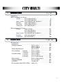
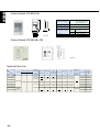
1 Outdoor Unit
P. 4 - 194
··············································································
Introduction
R407C refrigerant & CE unit
Y series
PUHY-P200·250YMF-C ··································
PUHY-P400·500YMF-B ··································
Super Y series PUHY-P600·650·700·750YSMF-B ····················
R2 series
PURY-P200·250YMF-C ··································
WR2 series
PQRY-P200·250YMF-B ··································
Cooling only
PUY-P200·250YMF-C ··································
4
5
19
33
55
69
95
R22 refrigerant & CE unit
··································
PUMY-125YMA
PUHY-200·250YMF-C ··································
PUHY-400·500YMF-B ··································
Super Y series PUHY-600·650·700·750YSMF-B ······················
R2 series
PURY-200·250YMF-C ··································
··································
Cooling only
PUY-200·250YMF-C
Y series
2 Indoor Unit
107
119
133
147
169
183
P. 196 - 394
CE indoor unit
·············································································· 196
Introduction
Ceiling concealed
PEFY-P-VML-A ······················· 199
Ceiling mounted built-in
Floor standing
Exposed
Cassette ceiling
Concealed
1-way flow
2-way flow
4-way flow
Wall mounted
Ceiling suspended
LOSSNAY
BC controller (with PURY, PQRY)
PEFY-P-VMH-A
PEFY-P-VMM-A ·······················
·······················
PDFY-P-VM-A
PFFY-P-VLEM-A ·····················
PFFY-P-VLRM-A
PMFY-P-VBM-A ·····················
PLFY-P-VLMD-A ·····················
PLFY-P-VKM-A/VAM-A ············
PKFY-P-VAM-A/VGM-A ············
PCFY-P-VGM-A ·····················
LGH-RS2-E2
CMB-P-V-E
·····················
·····················
229
257
281
295
307
327
343
359
371
383
1
Introduction
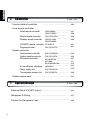
3 Controller
P. 396 - 442
Function table of controller
······················································ 396
Local remote controller
Wired remote controller
Simple remote controller
Wireless remote controller
PAR-20MAA ·························· 397
PAR-F27MEA ·························· 398
PAC-SE51CRA ······················ 399
PAR-FL31MA ························· 400
PAR-FA30MA
······················· 401
LOSSNAY remote controller PZ-52SF-E
Programme timer
PAC-SC32PTA ······················· 402
System controller
Group remote controller
System remote controller
Centralized controller
PAC-SC30GRA ······················
PAC-SF41SCA ·······················
MJ-103MTRA ·························
MJ-180A ································
MJ-310E/MB-300 ···················
403
405
407
411
424
Power supply unit
LMAP02-E ······························ 433
PAC-SC34KUA ······················· 435
Transmission booster unit
PAC-SF46EPA ······················ 436
Air conditioner interface
System compornent
4 System Design
····································································· 437
P. 442 - 496
Electrical Work & M-NET control ····················································· 442
Refrigerant & Piping ··········································································· 457
Caution For Refrigerant Leak ··························································· 495
2
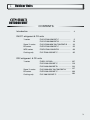
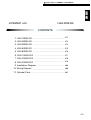
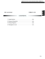
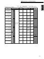
1 Outdoor Units
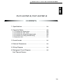
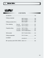
OUTDOOR UNIT
CONTENTS
Introduction ···················································································
4
R407C refrigerant & CE units
Y series
Super Y series
R2 series
WR2 series
Cooling only
PUHY-P200·250YMF-C ······················
PUHY-P400·500YMF-B ······················
PUHY-P600·650·700·750YSMF-B ······
PURY-P200·250YMF-C ······················
PQRY-P200·250YMF-B ······················
PUY-P200·250YMF-C ·························
5
19
33
55
69
95
R22 refrigerant & CE units
Y series
Super Y series
R2 series
Cooling only
107
119
133
147
PURY-200·250YMF-C ························· 169
PUY-200·250YMF-C ························· 183
PUMY-125YMA ····································
PUHY-200·250YMF-C ························
PUHY-400·500YMF-B ························
PUHY-600·650·700·750YSMF-B ··········
3
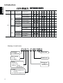
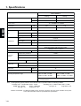
Introduction
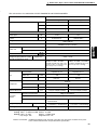
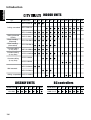
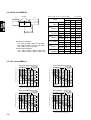
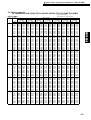
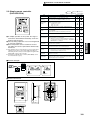
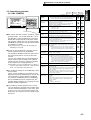
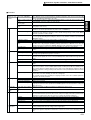
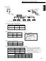
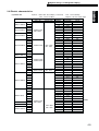
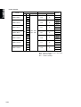
Introduction
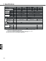
OUTDOOR UNITS
Standard Refrigerant
Series
Y series
Model Name
125 200
250 315
●
PUHY-P-YMF-C
600
●
R2 series
PURY-P-YMF-C
●
●
WR2 series
PQRY-P-YMF-B
●
●
Cooling Only
PUY-P-YMF-C
●
●
●
●
Y series
PUMY-YMA
PUHY-YMF-C
●
Cooling Only
PURY-YMF-C
PUY-YMF-C
●
●
●
●
●
●
●
●
Super Y series PUHY-YSMF-B
R2 series
●
●
PUHY-YMF-B
R22
●
●
●
●
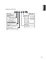
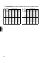
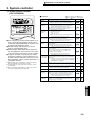
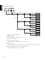
Meaning of model name
P U H Y - P 200 YMF-C
Packaged
Air conditioner
Heat source
·U : Air
·Q : Water
Series
·R : R2 unit
·H, M : Y unit
·Nothing : Cooling
only unit (Y)
Invertor
·Y : Variable capacity unit
(Invertor)
·N : Constant capacity unit
4
750
●
Super Y series PUHY-P-YSMF-B
CE
650 700
●
PUHY-P-YMF-B
R407C
400 500
(5HP) (8HP) (10HP) (13HP) (16HP) (20HP) (24HP) (26HP) (28HP) (30HP)
Sub name
Model size
Refrigerant
·P : R407C
·Nothing : R22
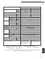
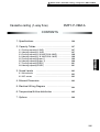
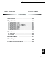
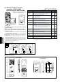
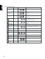
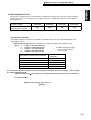
1 Outdoor units / Y series / R407C / PUHY-P200·250YMF-C
PUHY-P200YMF-C, PUHY-P250YMF-C
Y-8,10(R407C)
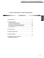
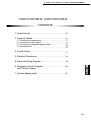
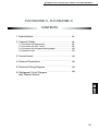
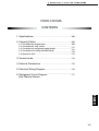
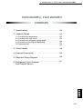
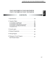
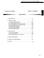
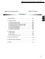
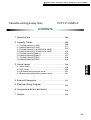
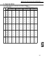
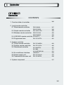
CONTENTS
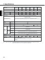
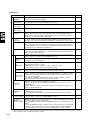
1. Specifications ································································· 6
2. Capacity Tables ······························································ 8
2-1 Correction by temperature ············································
2-2 Correction by total indoor ·············································
2-3 Correction by refrigerant piping length ···························
2-4 Correction at frosting and defrosting ····························
2-5 Operation limit ·······························································
8
10
12
13
13
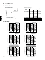
3. Sound Levels ·································································· 14
4. External Dimensions ···················································· 15
5. Electrical Wiring Diagram ············································· 16
6. Refrigerant Circuit Diagram ········································· 17
And Thermal Sensor
5
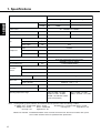
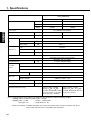
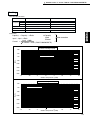
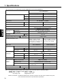
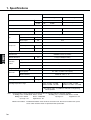
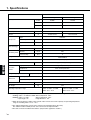
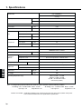
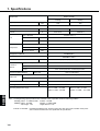
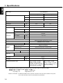
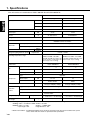
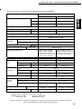
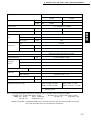
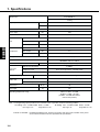
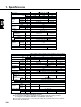
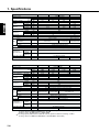
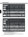
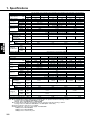
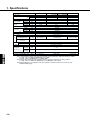
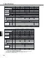
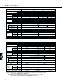
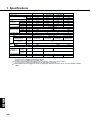
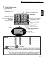
1. Specifications
Model name
PUHY-P200YMF-C
Heating
kW
✻1
22.4
25.0
kcal/h
✻2
20,000
-
Capacity
Y-8,10(R407C)
Cooling
Power source
3N ~ 380/400/415V 50/60Hz
Power input
Current
kW
8.64
7.98
A
14.5/13.8/13.3
13.4/12.7/12.3
Type ✕ Quantity
Fan
Airflow rate
Propeller fan ✕ 1
m3/min
185
kW
0.38
Motor output
Type
Compressor
Hermetic
Motor output
kW
5.5
Crankcase heater
kW
0.062(240V)
Refrigerant / Lubricant
R407C/MEL32
Steel plate painting with polyester powder
<MUNSELL 5Y8/1 or similar>
External finish
External dimension
mm
High pressure protection
Protection
devices
2.94MPa
Compressor / Fan
Over current protection / Thermal switch
Inverter
Refrigerant piping diameter
1715(H)✕990(W)✕840(L)
DC bus current protection, thermal switch
Liquid / Gas
ø12.7 flare /ø25.4 Flange
Total capacity
50 ~ 130% of outdoor unit capacity
Indoor unit
Model / Quantity
Model 20 ~ 250 / 1 ~ 13
Noise level
dB<A>
56
Net weight
kg
225
Operating temperature range
Indoor:15˚CWB ~ 24˚CWB
Outdoor:-5˚CDB ~ 43˚CDB
(0˚CDB ~ 43˚CDB with outdoor
unit at lower position)
Indoor:15˚CDB ~ 27˚CDB
Outdoor:-15˚CWB ~ 15.5˚CWB
Note: 1.Cooling/heating capacity indicates the maximum value at operation under the following condition.
✻1 Cooling Indoor : 27˚CDB/19˚CWB Outdoor : 35˚CDB
✻2 Cooling Indoor : 27˚CDB/19.5˚CWB Outdoor : 35˚CDB
Heating Indoor : 20˚CDB
Outdoor : 7˚CDB/6˚CWB
Pipe length : 5m
Height difference : 0m
Pipe length : 7.5m
Height difference : 0m
2.Works not included : Installation/foundation work, electrical connection work, duct work, insulation work, power
source switch and other items not specified in this specification.
6
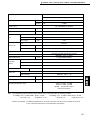
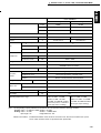
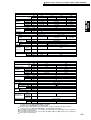
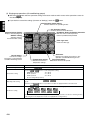
1 Outdoor units / Y series / R407C / PUHY-P200·250YMF-C
Model name
PUHY-P250YMF-C
Capacity
28.0
31.5
kcal/h
✻2
25,000
-
3N ~ 380/400/415V 50/60Hz
kW
A
Current
Airflow rate
10.89
10.15
18.3/17.4/16.8
17.1/16.2/15.6
Propeller fan ✕ 1
Type ✕ Quantity
m3/min
185
kW
0.38
Motor output
Hermetic
Type
Motor output
kW
Crankcase heater
kW
7.5
0.062(240V)
R407C/Polyol ester oil (POE)
Refrigerant / Lubricant
Steel plate painting with polyester powder
<MUNSELL 5Y8/1 or similar>
External finish
External dimension
mm
Over current protection / Thermal switch
Compressor / Fan
DC bus current protection, thermal switch
Inverter
Refrigerant piping diameter
1715(H)✕990(W)✕840(L)
2.94MPa
High pressure protection
Protection
devices
Y-8,10(R407C)
✻1
Power input
Compressor
Heating
kW
Power source
Fan
Cooling
ø12.7 flare /ø28.58 Flange
Liquid / Gas
50 ~ 130% of outdoor unit capacity
Total capacity
Indoor unit
Model 20 ~ 250 / 1 ~ 16
Model / Quantity
Noise level
dB<A>
57
Net weight
kg
231
Operating temperature range
Indoor:15˚CWB ~ 24˚CWB
Outdoor:-5˚CDB ~ 43˚CDB
(0˚CDB ~ 43˚CDB with outdoor
unit at lower position)
Indoor:15˚CDB ~ 27˚CDB
Outdoor:-15˚CWB~15.5˚CWB
Note: 1.Cooling/heating capacity indicates the maximum value at operation under the following condition.
✻1 Cooling Indoor : 27˚CDB/19˚CWB Outdoor : 35˚CDB
✻2 Cooling Indoor : 27˚CDB/19.5˚CWB Outdoor : 35˚CDB
Heating Indoor : 20˚CDB
Outdoor : 7˚CDB/6˚CWB
Pipe length : 5m
Height difference : 0m
Pipe length : 7.5m
Height difference : 0m
2.Works not included : Installation/foundation work, electrical connection work, duct work, insulation work, power
source switch and other items not specified in this specification.
7
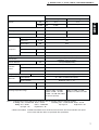
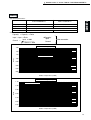
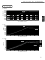
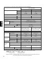
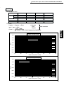
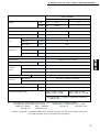
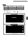
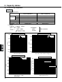
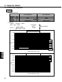
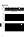
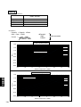
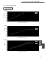
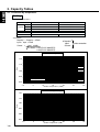
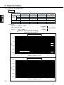
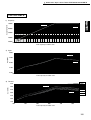
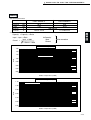
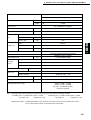
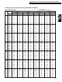
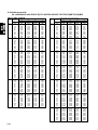
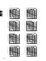
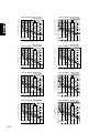
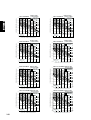
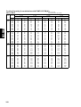
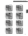
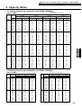
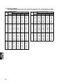
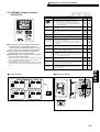
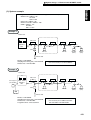
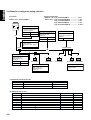
2. Capacity tables
2-1. Correction by temperature
Cooling
Y-8,10(R407C)
• Standard Specifications
PUHY-P200YMF-C
PUHY-P250YMF-C
22.4
8.64
28.0
10.89
kW
kW
V
A
Capacity
Input
Source
Current
380/400/415
14.5/13.8/13.3
18.3/17.4/16.8
• Calculation
Capacity' = Capacity ✕ Ratio
❇ Capacity'
Input'
Current'
Input ' = Input ✕ Ratio
Input' ✕ 1000
Current' =
3 ✕ Source ✕ 0.90
After correction
The Ratio of Cooling Capacity
1.30
1.20
24˚CWB
Ratio
1.10
22˚CWB
20˚CWB
1.00
19˚CWB
18˚CWB
16˚CWB
0.90
15˚CWB
Indoor Temperature(˚CWB)
0.80
-5
0
5
10
15
20
25
30
35
40
45
Outdoor Temperature (˚CDB)
The Ratio of Cooling Power Input
1.30
24˚CWB
22˚CWB
1.20
20˚CWB
1.10
19˚CWB
18˚CWB
1.00
Ratio
16˚CWB
0.90
15˚CWB
0.80
0.70
0.60
0.50
0.40
-5
0
5
10
15
20
25
30
Outdoor Temperature (˚CDB)
8
35
40
45
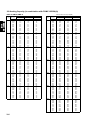
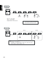
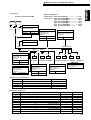
1 Outdoor units / Y series / R407C / PUHY-P200·250YMF-C
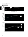
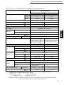
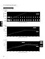
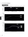
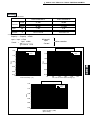
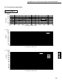
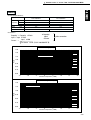
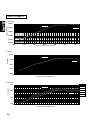
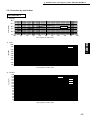
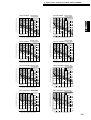
Heating
• Standard Specifications
PUHY-P250YMF-C
25.0
7.89
31.5
10.15
kW
kW
V
A
Y-8,10(R407C)
Capacity
Input
Source
Current
PUHY-P200YMF-C
380/400/415
13.4/12.7/12.3
17.1/16.2/15.6
• Calculation
Capacity' = Capacity ✕ Ratio
❇Capacity'
Input'
Current'
Input ' = Input ✕ Ratio
Input' ✕ 1000
Current' =
3 ✕ Source ✕ 0.90
After correction
The Ratio of Heating Capacity
1.30
15˚CDB
1.20
1.10
Indoor Temperature(˚CDB)
Ratio
20˚CDB
1.00
0.90
0.80
25˚CDB
0.70
27˚CDB
0.60
-15
-10
-5
0
5
10
15
20
Outdoor Temperature (˚CWB)
The Ratio of Heating Power Input
1.10
Indoor Temperature(˚CDB)
1.00
15˚CDB
Ratio
0.90
20˚CDB
0.80
0.70
25˚CDB
0.60
0.50
-15
27˚CDB
-10
-5
0
5
10
15
20
Outdoor Temperature (˚CWB)
9
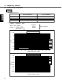
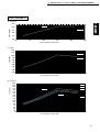
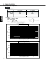
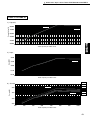
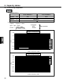
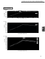
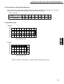
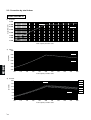
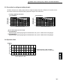
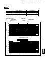
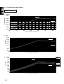
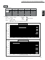
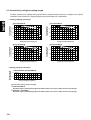
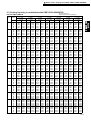
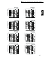
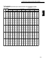
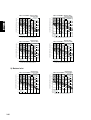
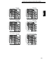
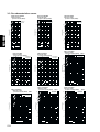
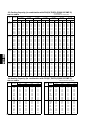
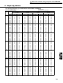
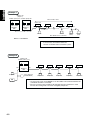
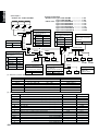
2-2. Correction by total indoor
PUHY-P200YMF-C
30.0
Heating
Capacity(kW)
25.0
20.0
Cooling
15.0
10.0
5.0
100
150
200
Total capacity of indoor units
250
300
2) Input
10.00
9.00
Cooling
Input(kW)
8.00
7.00
Heating
6.00
5.00
4.00
3.00
2.00
1.00
100
150
200
250
300
Total capacity of indoor units
3) Current
Current(A)
Y-8,10(R407C)
1) Capacity
18.0
17.0
16.0
15.0
14.0
13.0
12.0
11.0
10.0
9.0
8.0
7.0
6.0
5.0
4.0
3.0
2.0
100
Cooling
415V
380V
400V
Heating
150
200
Total capacity of indoor units
10
380V
400V
250
415V
300
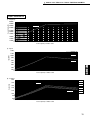
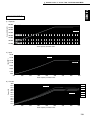
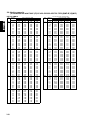
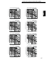
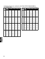
1 Outdoor units / Y series / R407C / PUHY-P200·250YMF-C
PUHY-P250YMF-C
1) Capacity
Y-8,10(R407C)
35.0
Heating
Capacity(kW)
30.0
Cooling
25.0
20.0
15.0
10.0
100
150
200
250
Total capacity of indoor units
300
350
2) Input
12.00
11.00
Cooling
Input(kW)
10.00
9.00
Heating
8.00
7.00
6.00
5.00
4.00
3.00
100
150
200
250
300
350
Total capacity of indoor units
Current(A)
3) Current
20.0
19.0
18.0
17.0
16.0
15.0
14.0
13.0
12.0
11.0
10.0
9.0
8.0
7.0
6.0
5.0
4.0
100
380V
400V
Cooling
415V
380V
400V
Heating
415V
150
200
250
300
350
Total capacity of indoor units
11
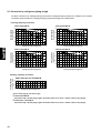
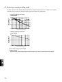
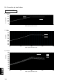
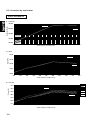
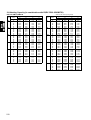
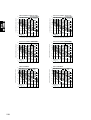
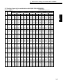
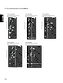
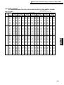
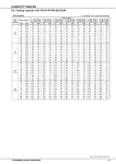
2-3 Correction by refrigerant piping length
To obtain a decrease in cooling/heating capacity due to refrigerant piping extension, multiply by the capacity
correction factor based on the refrigerant piping equivalent length in the table below.
Y-8,10(R407C)
• Cooling capacity correction
PUHY-P200YMF-C
Total ca
PUHY-P250YMF-C
1.0
pacity
of indo
or unit
0.9
100
150
200
0.8
260
0.7
0
20
40
80
100
60
Piping equivalent length (m)
Cooling capacity
correction factor
Cooling capacity
correction factor
1.0
pacity
of indo
or unit
0.9
125
188
250
0.8
325
0.7
0
120
Total ca
20
40
80
100
60
Piping equivalent length (m)
120
• Heating capacity correction
PUHY-P250YMF-C
PUHY-P200YMF-C
1.0
Heating capacity
correction factor
Heating capacity
correction factor
1.0
0.9
0.8
0.7
0
20
40
80
100
60
Piping equivalent length (m)
120
0.9
0.8
0.7
0
20
40
80
100
60
Piping equivalent length (m)
120
• How to obtain piping equivalent length
➀ PUHY-P200YMF-C
Equivalent length = (Actual piping length to the farthest indoor unit) + (0.47 ✕ number of bent on the piping)m
➁ PUHY-P250YMF-C
Equivalent length = (Actual piping length to the farthest indoor unit) + (0.50 ✕ number of bent on the piping)m
12
1 Outdoor units / Y series / R407C / PUHY-P200·250YMF-C
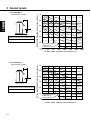
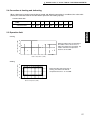
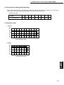
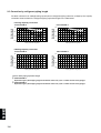
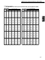
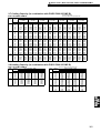
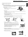
2-4 Correction at frosting and defrosting
When a decrease in heating capacity due to frosted and defrosting operations is considered, the value multiplied by the correction factor in the table below represents the heating capacity.
Correction factor table
Correction factor
6
4
2
0
-2
-4
-6
-8
-10
1.0
0.95
0.84
0.83
0.87
0.9
0.95
0.95
0.95
Y-8,10(R407C)
Outdoor inlet air temp
(˚CWB)
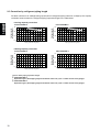
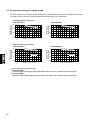
2-5 Operation limit
Indoor temperature (˚CWB)
• Cooling
30
25
(Outdoor door temperature :0˚CDB~43˚CDB with
outdoor unit at lower position in cooling mode.)
20
15
10
-5
0
5
10
15
20
25
30
35
40
45
Outdoor temperature (˚CDB)
Indoor temperature (˚CDB)
• Heating
30
25
20
15
10
-15
-10
-5
0
5
10
15
20
Outdoor temperature (˚CDB)
13
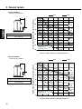
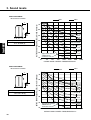
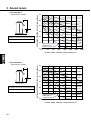
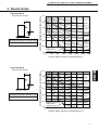
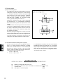
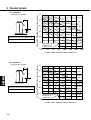
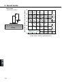
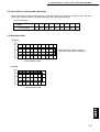
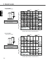
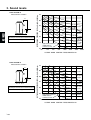
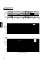
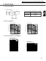
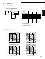
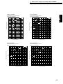
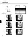
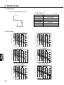
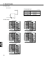
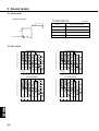
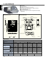
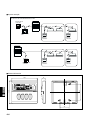
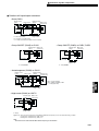
PUHY-P200YMF-C
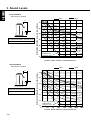
Measurement condition
Y-8,10(R407C)
1m
1m
A
B
Sound pressure level in anechoic room
56 dB (A)
OCTAVE BAND PRESSURE LEVEL< dB> 0dB = 0.0002µbar
3. Sound levels
70
60
NC60
50
NC50
40
NC40
30
NC30
20
NC20
Approximate minimum
audible limit on
continuous noise
10
63
125
250
500
1000
2000
4000
8000
OCTAVE BAND CENTER FREQUENCIES<Hz>
PUHY-P250YMF-C
1m
1m
A
B
Sound pressure level in anechoic room
57 dB (A)
OCTAVE BAND PRESSURE LEVEL< dB> 0dB = 0.0002µbar
Measurement condition
70
60
NC60
50
NC50
40
NC40
30
NC30
20
10
NC20
Approximate minimum
audible limit on
continuous noise
63
125
250
500
1000
2000
4000
OCTAVE BAND CENTER FREQUENCIES<Hz>
14
8000
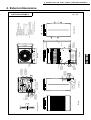
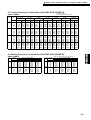
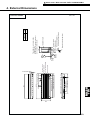
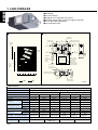
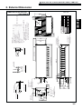
Crosss section Y-Y
50
251
25
Conn. pipe
200:ø25.4<brazed>
250:ø28.58<brazed>
100
Rear view
Knockout hole
234
237
198
Note1
Knockout hole
Bottom piping hole
<Bottom wiring hole>
Cross section X-X
778
60
75
Left side view
ø27 Knockout hole
<Left side hole for
80
the control wiring> Knockout hole
Left piping hole
160
Y
40
75
ø40 Knockout hole
<Left side hole for
the power supply>
Knockout hole
Front piping hole
<Front wiring hole>
813
590
Plane view
990
560(bolt hole)
55
215
31
79
165
Front view
910
Service panel
1490
Knockout hole
<Front side hole for
the power supply>
X
80
215
X
Refrig. service
valve (liquid)
ø12.7<flare>
Knockout hole
4X2-14X20
Oval hole
Refrig. service
valve(gas)
<flange>
ø27 Knockout hole
<Bottom side hole for
the control wiring>
194
73 80
ø40 Knockout hole
<Bottom side hole for
the power supply>
40
Y
70
121
100
48
840
78
5
149
15
880(bolt hole)
15
12
Air
inlet
Right side view
Air outlet
Air
inlet
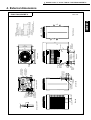
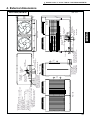
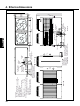
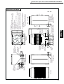
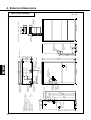
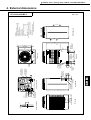
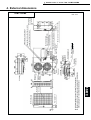
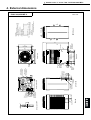
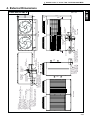
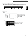
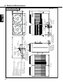
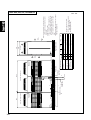
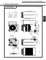
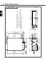
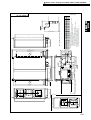
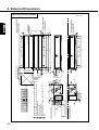
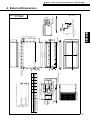
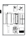
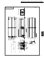
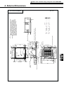
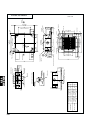
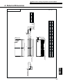
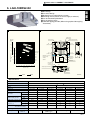
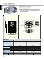
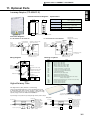
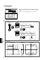
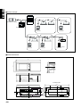
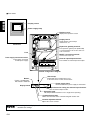
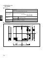
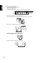
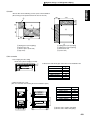
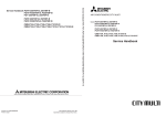
PUHY-P200,250YMF-C
Y-8,10(R407C)
99
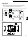
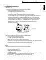
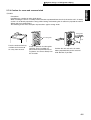
< Accessory >
• Refrigerant (gas) conn. pipe ··········· 1 pc.
(The connecting pipe is fixed with the unit)
• Packing for conn. pipe ·················· 1 pc.
(Attached near the ball valve)
• Wiring mounting board
• Conduit mounting plate
(Painted the same color as the unit body)
ø40································· 1 pc.
ø33································· 1 pc.
ø27································· 1 pc.
• Tapping screw 4 ✕ 10 ················ 6 pcs.
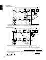
Note.1 Please leave a space under the outdoor unit
for the piping When, you connect the piping
from the bottom.
(Please be careful not to close the hole
of the bottom plate by the basement)
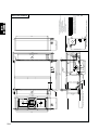
1 Outdoor units / Y series / R407C / PUHY-P200·250YMF-C
4. External dimensions
Unit : mm
15
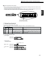
1715
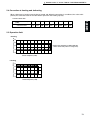
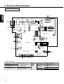
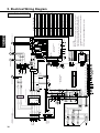
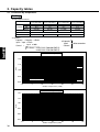
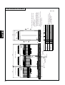
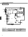
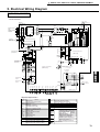
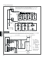
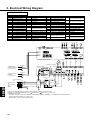
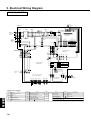
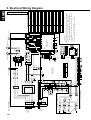
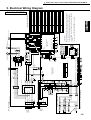
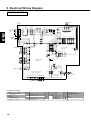
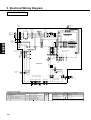
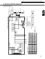
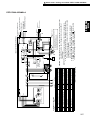
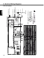
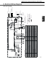
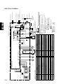
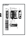
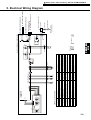
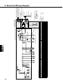
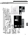
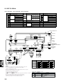
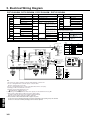
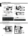
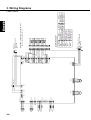
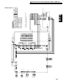
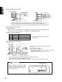
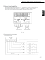
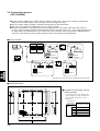
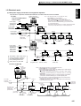
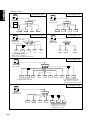
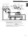
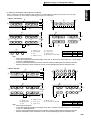
5. Electrical Wiring Diagram
Y-8,10(R407C)
PUHY-P200, 250YMF-C
MC1
Inverter
Controller Box
Red
Terminal
Block
TB1A
L1
Red
L1
Power source
3N380/400/415V
50/60Hz
Noise
Filter
NF
L1
Terminal
Block
L1
L1
TB1B
L1
Red
Red
L2
White
L2
L2
White
L2
White
-
L3
L3
Black
L3
L3
Black
L3
Black
- -
N
N
Blue
N
N
Blue
N
Blue
Black
IPM
R5
ZNR4
C1
L2
PE
R1
DS
- +
White
ACCT
-W
ACCT
-U
Diode
stack
N
L3
L2
52C
DCL
U
+
C2
R2
+
C3
R3
V
W
P
Gate amp board
(G/A board)
N
Green/
Yellow
PE
Connect to
Indoor and
remote
controller
Motor
U V W (Compressor)
BOX BODY
TB3
M1
F3
250VAC
1A F
BOX BODY
CNE
(2P)
CNDC1
(4P)
1 2
1 2 3 4
CNDR1
(9P)
CN15V1
(14P)
1 2 3 4 5 6 7 8 9
1 2 3 4 5 6 7 8 9 1011121314
M2
CNTR1
FB2
FB1
S
TB7
CH1
Crank case heater
(Compressor)
SV1
SV2
21S4
123
12
CNS2
(3P)
CNS1
(2P)
3
2 CN32
1 (3P)
1 2
3
CN20
(3P)
1
2
X01
3
2 CN33
1 (3P)
X02
6
5
4 CN34
3 (6P)
2
1
X04
7
1
2 5 4 3
3
4 CNRS2
5 (7P)
6
7
CNVCC41
(2P)
2
1 CNVCC4
2 (2P)
1
2
CNVCC3 3
(6P)
4
5
6
1
2
3 CNVCC2
4 (6P)
5
6
1
2
CNRS3 3
(7P) 4
5
6
3
CNTR
(3P)
F1
250VAC
2A F
X10
SV4
SV3
1 2 3 4 5 6 7 8 9
CNVDC
(4P)
Gray
White
Orange
Yellow
Black
Purple
Brown
Red
Black
Red
1 2 3 4
1 2 3 4 5 6 7 8 9 1011121314
CNDR2
(9P)
CN15V2
(14P)
F01
250VAC
2A F
Power circuit board
(INV board)
1
CNACCT 2
(4P)
3
4
2 X01
52C
3
CN52C
(3P)
CNTH
X02 (2P)
1
X05
1
2
3
4 4:Compressor ON/OFF
5
12V
CNAC2
2 1 (5P)
1
1
2
3
CNX10
(3P)
CN51
(5P)
6
5
4 CN36
3 (6P)
2
1
Blue
M2
White
Green
BOX BODY
T01
Brown
Orange
BOX BODY
M1
5:Trouble
2 3
12
CNFAN
(3P)
CNR
(3P)
1 2 3
CNL2
(2P)
CN30V
(2P)
12
12
L2
R6
MF1
THHS R7
BOX BODY
X06
X07
CN3D 3
2
(3P) 1
Control circuit board
(MAIN board)
CN3S 3
(3P) 2
1
DEMAND
CN3N 3
(3P) 2
1
NIGHT MODE
CN3D
1-2 1-3
ON ON
OFF
ON OFF
OFF
Mode
HEAT
COOL
Auto
changeover
Normal
L1 L2 L3
63H
High pressure
switch
CN38
(3P)
1
2
3
CNPOW
(5P)
X10
1 23 4 5
F03 250VAC 6.3A F
F02 250VAC 6.3A F
F01 250VAC 6.3A F
detection
circuit
6
5
CNFC1 4
(6P) 3
2
Refer to the service handbook
about the switch operations.
1
6
5
4 CNFC2
3 (6P)
2
1
FB3
1
CNFAN 23
(5P) 4
1
2
3
4
5
CN04
FB4
12
1234
CN02
(8P)
TH10 TH9
LD
CNL
(3P)
CNLV1
(5P)
CNLV2
(5P)
1 2 3
12345
1234 5
SLEV
LEV1
CN01 CNH
(2P) (3P)
123
12345678
12
TH6
TH5 TH8 TH7 TH2
TH1
1 2 3
Black
White
Red
Black
White
Red
12
CN03
(3P)
Fan control board
(Fancon board)
Fan motor
(Heat exchanger)
N
Black
White
Red
CN09 CN06 CN05
(2P) (2P)
(4P)
U
V
W MF
N
3 2 1
3 2 1
63HS
63LS
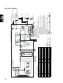
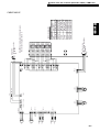
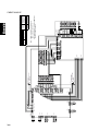
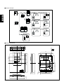
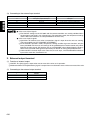
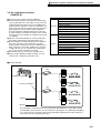
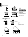
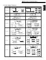
<SYMBOL EXPLANATION>
Symbol
DCL
ACCT-U,W
ZNR4
52C
MF1
21S4
SV1,SV2
SV3
16
Name
DC reactor (Power factor improvement)
Current Sensor
Varistor
Magnetic contactor (Inverter main circuit)
Fan motor (Radiator panel)
4--way valve
Solenoid valve (Discharge--suction bypass)
Solenoid valve
(Heat exchanger capacity control)
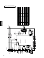
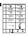
Symbol
SV4
Name
Solenoid valve
(Heat exchanger capacity control)
LEV1
Electronic expansion valve
(Sub-cool coil bypass)
SLEV
63HS
63LS
L2
IPM
Electronic expansion valve(Oil return)
High pressure sensor
Low pressure sensor
Choke coil (Transmission)
Intelligent power module
Symbol
TH1
Name
Thermistor Discharge pipe temp. detect
TH2
TH5
TH6
Saturation evapo. temp. detect
Pipe temp. detect
OA temp. detect
TH7
liquid outlet temp. detect
at Sub--cool coil
TH8
TH9
bypass outlet temp. detect
at Sub--cool coil
High pressure liquid. temp.
Symbol
TH10
Name
Compressor shell temp.
THHS
LD
X1~10
FB1~4
Radiator panel temp. detect
Accumlator liquid level detect
Aux. relay
Ferrite core
Earth terminal
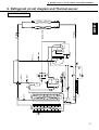
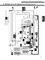
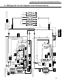
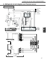
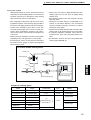
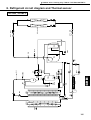
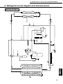
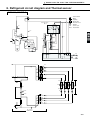
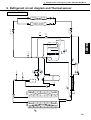
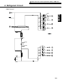
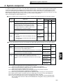
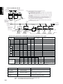
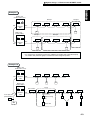
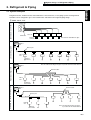
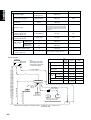
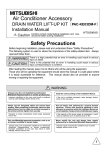
TH6
HEX 1
TH5
ST9
SV4
HEX 2
SV3
ST3
SV2
SV1
CP1
63HS
LEV1
TH8
TH2 CP4
Drier TH9
TH10
Comp
TH1
O/S
SCC
CP3
63H
CV1
ST5
ST4
TH7
MA
SLEV
63LS
CJ2
SA
ST2 BV2
Indoor units
Y-8,10(R407C)
CJ1
ST1 BV1
1 Outdoor units / Y series / R407C / PUHY-P200·250YMF-C
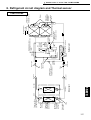
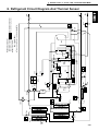
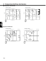
6. Refrigerant circuit diagram and Thermal sensor
PUHY-P200, 250YMF-C
17
18
Y-8,10(R407C)
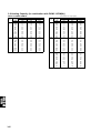
1 Outdoor units / Y series / R407C / PUHY-P400·500YMF-B
PUHY-P400YMF-B, PUHY-P500YMF-B
Y-16,20(R407C)
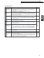
CONTENTS
1. Specifications ································································· 20
2. Capacity Tables ······························································ 22
2-1 Correction by temperature ············································
2-2 Correction by total indoor ·············································
2-3 Correction by refrigerant piping length ···························
2-4 Correction at frosting and defrosting ····························
2-5 Operation limit ·······························································
22
24
26
27
27
3. Sound Levels ·································································· 28
4. External Dimensions ···················································· 29
5. Wiring Diagram ····························································· 30
6. Refrigerant Circuit Diagram ········································· 31
And Thermal Sensor
19
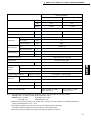
1. Specifications
Model name
PUHY-P400YMF-B
Capacity
Cooling
Heating
kcal/h
40,000
45,000
kW
46.5
52.3
BTU/h
158,800
178,600
3N ~ 380/400/415V 50/60Hz
Y-16,20(R407C)
Power source
Power input
Current
kW
16.9
15.9
A
28.2/26.8/25.8
26.5/25.2/24.3
Propeller fan ✕2
Type✕ Quantity
Fan
Airflow rate
m3/min
370
kW
0.35 ✕ 2
Motor output
Hermetic
Type
Compressor
Motor output
kW
4.5 + 7.5
Crankcase heater
kW
0.045 + 0.056
Refrigerant / Lubricant
R407C / MEL32
Steel plate painting with polyester powder
<MUNSELL 5Y8/1 or similar>
External finish
External dimension
mm
High pressure protection
Protection
devices
30kg/cm2G(2.94MPa)
Compressor / Fan
Overcurrent protection / Thermal switch
Inverter
Refrigerant piping diameter
1715(H)✕ 1990(W) ✕ 840(L)
DC bus current protection, thermal switch
Liquid / Gas
ø 15.88 flare / ø 34.93 Flange
50 ~ 130% of outdoor unit capacity
Total capacity
Indoor unit
Model 25 ~ 250 / 1 ~ 20
Model / Quantity
Noise level
dB<A>
60 / 61
Net weight
kg
455
Operating temperature range
Indoor:15˚CWB ~ 24˚CWB
Outdoor:-5˚CDB ~ 43˚CDB
(10˚CDB ~43˚CDB with outdoor
unit at lower position, or with indoor
unit 25 type only is working.)
Indoor:15˚CDB ~ 27˚CDB
Outdoor:-12˚CWB ~ 15.5˚CWB
(-12˚CWB~10˚CWB with indoor unit
25 type only is working)
Note: 1.Cooling/heating capacity indicates the maximum value at operation under the following condition.
Cooling Indoor : 27˚CDB/19.5˚CWB Outdoor : 35˚CDB
Heating Indoor : 21˚CDB
Outdoor : 7˚CDB/6˚CWB
Pipe length : 5m
Height difference : 0m
2.Works not included : Installation/foundation work, electrical connection work, duct work, insulation work, power
source switch and other items not specified in this specification.
20
1 Outdoor units / Y series / R407C / PUHY-P400·500YMF-B
Model name
PUHY-P500YMF-B
Capacity
Cooling
Heating
kcal/h
50,000
56,000
kW
58.2
65.1
BTU/h
198,500
222,300
Power source
3N ~ 380/400/415V 50/60Hz
Current
kW
21.3
19.65
A
35.1/33.4/32.2
32.8/31.1/30.0
Type✕ Quantity
Fan
Propeller fan✕ 2
Airflow rate
m3/min
370
kW
0.35 ✕ 2
Motor output
Type
Compressor
Hermetic
Motor output
kW
Crankcase heater
kW
Refrigerant / Lubricant
External dimension
mm
High pressure protection
0.045 + 0.056
Steel plate painting with polyester powder
<MUNSELL 5Y8/1 or similar>
1715(H)✕ 1990(W) ✕ 840(L)
30kg/cm2G(2.94MPa)
Compressor / Fan
Overcurrent protection / Thermal switch
Inverter
Refrigerant piping diameter
7.5 + 7.5
R407C / Polyester oil (POE)
External finish
Protection
devices
Y-16,20(R407C)
Power input
DC bus current protection, thermal switch
Liquid / Gas
ø 15.88 flare / ø 34.93 Flange
Total capacity
50 ~ 130% of outdoor unit capacity
Indoor unit
Model / Quantity
Model 25 ~ 250 / 1 ~ 20
Noise level
dB<A>
60 / 61
Net weight
kg
475
Operating temperature range
Indoor:15˚CWB ~ 24˚CWB
Outdoor:-5˚CDB ~ 43˚CDB
(10˚CDB ~43˚CDB with outdoor
unit at lower position, or with indoor
unit 25 type only is working.)
Indoor:15˚CDB ~ 27˚CDB
Outdoor:-12˚CWB ~ 15.5˚CWB
(-12˚CWB~10˚CWB with indoor
unit 25 type only is working)
Note: 1.Cooling/heating capacity indicates the maximum value at operation under the following condition.
Cooling Indoor : 27˚CDB/19.5˚CWB Outdoor : 35˚CDB
Heating Indoor : 21˚CDB
Outdoor : 7˚CDB/6˚CWB
Pipe length : 5m
Height difference : 0m
2.Works not included : Installation/foundation work, electrical connection work, duct work, insulation work, power
source switch and other items not specified in this specification.
21
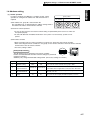
2. Capacity tables
2-1. Correction by temperature
Cooling
•Standard Specifications
Capacity
Y-16,20(R407C)
Input
Source
Current
kcal/h
kW
BTU/h
kW
V
A
PUHY-P400YMF-B
PUHY-P500YMF-B
40,000
46.5
50,000
58.2
158,800
198,500
16.9
21.3
380/400/415
28.2/26.8/25.8
35.1/33.4/32.2
•Calculation
Capacity' = Capacity ✕ Ratio
Input ' = Input ✕ Ratio
Input' ✕1000
Current' =
3 ✕ Source ✕ 0.91(:PUHY-P400YMF-B)
✕ 0.92(:PUHY-P500YMF-B)
❈Capacity'
Input'
Current'
After correction
The Ratio of Cooling Capacity
1.20
1.10
Ratio
24˚CWB
22˚CWB
1.00
20˚CWB
19.5˚CWB
18˚CWB
0.90
16˚CWB
15˚CWB
Indoor Temperature(˚CWB)
0.80
-10
0
10
20
30
Outdoor Temperature (˚CDB)
40
50
The Ratio of Cooling Power Input
1.20
24˚CWB
22˚CWB
20˚CWB
19.5˚CWB
1.10
18˚CWB
16˚CWB
15˚CWB
Ratio
1.00
0.90
0.80
0.70
-10
22
0
10
20
30
Outdoor Temperature (˚CDB)
40
50
1 Outdoor units / Y series / R407C / PUHY-P400·500YMF-B
Heating
•Standard Specifications
Capacity
Input
Source
Current
kcal/h
kW
BTU/h
kW
V
A
PUHY-P400YMF-B
PUHY-P500YMF-B
45,000
52.3
56,000
65.1
178,600
222,300
15.9
19.65
380/400/415
26.5/25.2/24.3
32.8/31.1/30.0
Y-16,20(R407C)
•Calculation
❈Capacity'
Input'
Current'
Capacity' = Capacity ✕ Ratio
Input ' = Input ✕ Ratio
Input' ✕1000
Current' =
3 ✕ Source ✕ 0.91 (:PUHY-P400·500YMF-B)
After correction
The Ratio of Heating Capacity
1.30
1.20
15˚CDB
Indoor Temperature(˚CDB)
1.10
Ratio
20˚CDB
1.00
21˚CDB
0.90
25˚CDB
0.80
27˚CDB
0.70
0.60
-15
-10
-5
0
5
Outdoor Temperature (˚CWB)
10
15
20
The Ratio of Heating Power Input
1.20
Indoor Temperature(˚CDB)
1.10
15˚CDB
Ratio
1.00
0.90
20˚CDB
21˚CDB
0.80
0.70
25˚CDB
27˚CDB
0.60
-15
-10
-5
0
5
Outdoor Temperature (˚CWB)
10
15
20
23
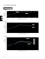
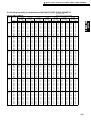
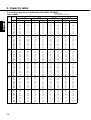
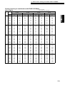
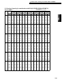
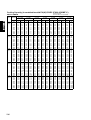
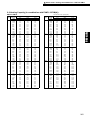
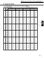
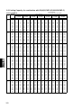
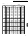
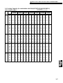
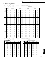
2-2. Correction by total indoor
PUHY-P400YMF-B
1) Capacity
50,000
Capacity(kcal/h)
Cooling
40,000
35,000
30,000
25,000
20,000
200
250
300
350
400
Total capacity of indoor units
450
500
2) Input
20.00
Cooling
Input(kW)
18.00
16.00
14.00
Heating
12.00
10.00
8.00
200
250
300
350
400
450
500
Total capacity of indoor units
3) Current
30.0
380V
Cooling
28.0
Current(A)
Y-16,20(R407C)
Heating
45,000
400V
26.0
415V
24.0
380V
22.0
400V
Heating
20.0
415V
18.0
16.0
14.0
12.0
200
250
300
350
400
Total capacity of indoor units
24
450
500
1 Outdoor units / Y series / R407C / PUHY-P400·500YMF-B
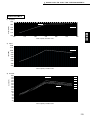
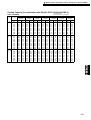
PUHY-P500YMF-B
1) Capacity
Heating
55,000
50,000
Cooling
45,000
40,000
Y-16,20(R407C)
Capacity(kcal/h)
60,000
35,000
30,000
25,000
250
300
350
400
450
500
Total capacity of indoor units
550
600
650
2) Input
23.00
Cooling
Input(kW)
21.00
19.00
Heating
17.00
15.00
13.00
11.00
9.00
250
300
350
400
450
500
550
600
650
Total capacity of indoor units
Current(A)
3) Current
36.0
34.0
32.0
30.0
28.0
26.0
24.0
22.0
20.0
18.0
16.0
14.0
250
380V
Cooling
400V
415V
380V
400V
Heating
415V
300
350
400
450
500
550
600
650
Total capacity of indoor units
25
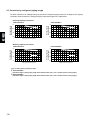
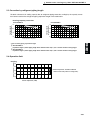
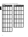
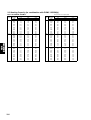
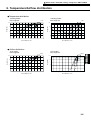
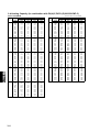
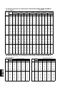
2-3 Correction by refrigerant piping length
To obtain a decrease in cooling/heating capacity due to refrigerant piping extension, multiply by the capacity
correction factor based on the refrigerant piping equivalent length in the table below.
• Cooling capacity correction
PUHY-P500YMF-B
Y-16,20(R407C)
Cooling capacity
correction factor
Total ca
pacity
of indo
or unit
0.9
200
300
0.8
400
520
0.7
Cooling capacity
correction factor
PUHY-P400YMF-B
1.0
1.0
Total ca
pacit
y of ind
oor unit
0.9
250
375
500
0.8
650
0
20
40
60
80
100
120
Piping equivalent length (m)
0
20
40
60
80
100
120
Piping equivalent length (m)
Cooling capacity
correction factor
•Heating capacity correction
PUHY-P400·500YMF-B
1.0
0.9
0
20
40
60
80
100
120
Piping equivqlent length (m)
• How to obtain piping equivalent length
➀ PUHY-P400YMF-B
Equivalent length = (Actual piping length to the farthest indoor unit) + (0.70 ✕ number of bent on the piping)m
➁ PUHY-P500YMF-B
Equivalent length = (Actual piping length to the farthest indoor unit) + (0.80 ✕ number of bent on the piping)m
26
1 Outdoor units / Y series / R407C / PUHY-P400·500YMF-B
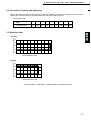
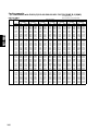
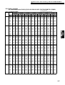
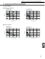
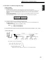
2-4 Correction at frosting and defrosting
When a decrease in heating capacity due to frosted and defrosting operations is considered, the value multiplied by the correction factor in the table below represents the heating capacity.
Correction factor table
Outdoor inlet air temp
(˚CWB)
Correction factor
6
4
2
0
-2
-4
-6
-8
-10
1.0
0.98
0.89
0.89
0.90
0.92
0.95
0.95
0.95
Y-16,20(R407C)
2-5 Operation limit
Indoor temperature (˚CDB)
• Cooling
30
When the indoor unit is located above
the outdoor unit for 4m or more, or
indoor unit 25type only is working, the
outdoor unit inlet air temperature
becomes 10~43˚CDB.
25
20
15
10
-5
0
5
10
15
20
25
30
Outdoor temperature (˚CWB)
35
40
45
Indoor temperature (˚CDB)
• Heating
30
25
When the indoor unit 25type only is
working, the outdoor unit inlet air
temperature becomes -12~10˚CWB.
20
15
10
-15
-10
-5
0
5
10
Outdoor temperature (˚CWB)
15
20
27
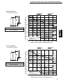
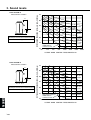
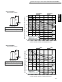
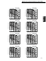
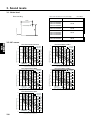
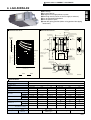
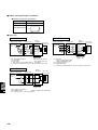
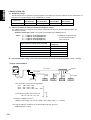
3. Sound levels
PUHY-P400YMF-B
Measurement condition
60Hz
50Hz
1m
B
Sound pressure level in anechoic room
60 / 61 dB (A)
70
60
NC60
50
NC50
40
NC40
30
NC30
20
10
NC20
Approximate minimum
audible limit on
continuous noise
63
125
250
500
1000
2000
4000
8000
OCTAVE BAND CENTER FREQUENCIES<Hz>
PUHY-P500YMF-B
Measurement condition
60Hz
50Hz
A
B
Sound pressure level in anechoic room
60 / 61 dB (A)
OCTAVE BAND PRESSURE LEVEL< dB> 0dB = 0.0002µbar
1m
1m
Y-16,20(R407C)
A
OCTAVE BAND PRESSURE LEVEL< dB> 0dB = 0.0002µbar
1m
70
60
NC60
50
NC50
40
NC40
30
NC30
20
NC20
Approximate minimum
audible limit on
continuous noise
10
63
125
250
500
1000
2000
4000
OCTAVE BAND CENTER FREQUENCIES<Hz>
28
8000
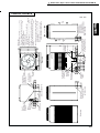
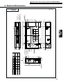
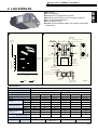
Rear view
694
150
208
203
152
111
80 82 78
Air
inlet
Left side view
Knockout hole
Left side hole for
the control wiring,
the power supply, the
oil balance pipe to the
constant capacity unit
40
Air
inlet
Service panel
X
7X2-14X20oval hole
Front hole for the power supply
Changeable to 400:ø46,ø53,ø62
500:ø53,ø62 by using attached
conduit mounting plate (accessory)
80
X–X
Note.1
Knockout hole
Bottom piping hole
Bottom hole for the power supply
Changeable to 400:ø46,ø53,ø62
Cross section
500:ø53,ø62 by using attached
conduit mounting plate (accessory)
Air outlet
230
73
90 80
Conn. pipe
ø34.93 <brazed>
126
86
ø27 Knockout hole
<bottom hole for the
control wiring>
218
215
725
745
Service valve
(oil balance)
780
45
115
25 90 75
780
Refrig. service
valve(gas)
Knockout hole
Plane view
1990
Front view
Knockout hole
Front piping hole
Refrig.service
valve (liquid)
215
X
1715
Refrig. service
valve(gas)
<flange>
100
48
24
70
149 70
15
840
880
910
15
225
1490
Refrig.service
valve (liquid)
ø15.88<flare>
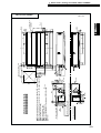
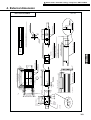
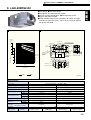
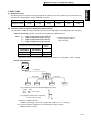
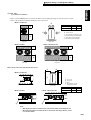
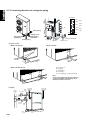
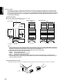
PUHY-P400,500YMF-B
Y-16,20(R407C)
<Accessorys>
• Refrigerant (gas) conn. pipe ················· 1pc.
(The connecting pipe has been fixed with the unit)
• Packing for conn. pipe ·························· 1pc.
(Attached near the ball valve)
• Conduit mouting plate
(Painted the same color as the unit body)
ø62,ø53,ø46 ·································· Each 1pc.
• Tapping screw 4X10 ····························· 6pcs.
• Wiring partition plate ····························· 1pc.
Note1. Please leave a space under the outdoor unit
for the piping when you connect the piping
from the bottom.
(Please be careful not to close the hole
of the bottom plate by the basement)
1 Outdoor units / Y series / R407C / PUHY-P400·500YMF-B
4. External dimensions
Unit : mm
29
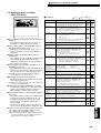
52F
CH12
A2
A1
13
52C2
14
A2
A1
52C2
96
51C2
95
CN51C2
(3P)
3
2
1
CNCH
(3P)
3
2
1
CN52F
(3P)
5
4
1
2
3
CN52C2
(5P)
3
2
1
PE
BOX BODY
X03
X02
X01
CNOUT2
(4P)
CNRT2
(5P)
RELAY board
BOX BODY
S
M2
M1
TB7
M2
M1
TB3
Green/
Yellow
PE
Blue
N
N
Black
L3
L3
White
L2
L2
Connect to
Indoor and
remote
controller
Power source
3N~
380/400/415V
50/60Hz
L1
TB1
L1
Red
SV5b
21S4b
6
5
4 CN37
3 (6P)
2
1
6
5
4 CN36
3 (6P)
2
1
3
2 CN35
1 (3P)
6
5
4 CN34
3 (6P)
2
1
1
2
1
X10
X09
X08
X07
X06
4 3
1 2
SSR
X05
X04
X02
X01
N
L3
L2
CN05
(4P)
12
1234
12
2
3
CNTR
(3P)
OFF
ON
SW4-6
F3
250VAC
1A F
VK2
VG2
VK1
VG1
~-
~
~+
DS
F2
600VAC
12A F
White
L3 Black
L2
L1
Red
CN03
(3P)
TH6
123
CN02
(8P)
TH5 TH8 TH2
TH7
12345678
3 2 1
63LS
3 2 1
63HS
TH11
SLEV
CNLV1
(5P)
12345
CNL
(3P)
W
V
LEV1
12345
CNLV2
(5P)
4
5
6
1
CNFC1 2
(6P) 3
CN3S 3
(3P) 12
CN3D 3
(3P) 12
CN51
(5P)
1
2
3
4
5
1 2 3 4
3
2
1
1
2
3
4
5
6
6
1234
F01
250VAC
2A F
CNV
(5P)
5
2
CNU 3
(5P) 4
5 4 3 2 1
CNW
(5P)
CNFC2
(6P)
5 4 3 2 1
1
2
3
4
5
6
R6
L2
UK2
UG2
BOX BODY
FG
CN3
(6P)
1 2 3 4 5 6
C25
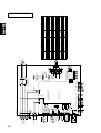
Thermistor
TH2~12, THHS
Cord heater
Solenoid valve
Earth terminal
Ferrite core
Power transistor module
TRM1~3
FB1
Choke coil(Transmission)
High pressure sensor
Electronic expansion valve
L2
63HS,63LS
LEV1,SLEV
SV1,22,32,4,5b,6
4-way valve
Solid state relay
SSR
21S4a,b
Magnetic contactor
Fan (Radiator panel)
MF1
Overload Relay
52F
Magnetic contactor
51C2
Magnetic contactor (Inverter main circuit)
52C2
52C1
Current Sensor
Varistor
ZNR4
DC reactor (Power factor improvement)
DCL
High pressure switch
DCCT
63H1,2
CH2,CH3
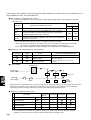
Name
Crank case heater(Compressor)
Noise Filter
NF
CH11,12
Diode stack
DS
TB1, 1A, 3,7
Terminal block
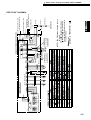
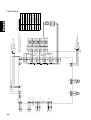
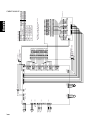
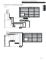
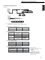
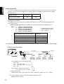
<SYMBOL EXPLANATION>
Symbol
<CAUTION>
·When checking for the inside control box, be sure to turn the
power source off, and confirm that the voltage at the both
ends of main capacitor(C2,C3) is being sufficientry low by
opening MAIN board mounting plate after leaving 10minutes
or more.
·Please read the INSTALLATION MANUAL carefully.
12
12
1 2 3
UK1
UG1
2 1
CN30V
(2P)
CNL2
(2P)
HEAT
COOL
C24 C22
TRM3 C2E1
C1
Black
Motor (Compressor)
White
C16
CN2-3
(2P)
CNR
(3P)
Mode
Comp ON/OFF
Fan control board
(FANCON board) 1
1-2
2 1
CN2-2
(2P)
Power circuit board
(INV board)
CN2-1
(2P)
2 1
CNVDC
(4P)
C1
Red
MC1
U V W
TRM2 C2E1
C23 C21
1 2 3 4
THHS R7
CN3D
Mode
1-2 1-3
ON ON Auto
changeover
OFF
ON OFF
Normal
OFF
CN3S
C20
C1
TRM1 C2E1
CN05
C15
Fan motor
CNMF3
C14
CNTH
X02 (2P)
1 2 3 CNFAN 1 2
(3P)
MF1
X01
CNVCC1
(6P)
A
2
4
MF3
U V W (Heat exchanger)
CNAC2 CNCT
(3P)
(4P)
3 2 1
CNRS2
(7P)
1 CNVCC2
2 (2P)
1
2
3
4
5
6
7
R2
52F
R3 DCCT
CN52C
(3P)
+
C3
+
C2
5
3
1
4:Compressor ON/OFF
5:Trouble
52C1
1 2
3 4
5
6
52C1
DCL
R1
R5
Black
White
WK1
WG2
CNX10
(3P)
1
2
3
5
6
1
2
CNVCC3 3
(6P)
4
12V
1 2 3
6
7
CNVCC41
(2P)
2
X10
1 2 3
1
2
CNRS3 34
(7P) 5
C1
K G
G K
K G
G K
ZNR4
WG1
WK2
L3
L2
CN01 CNH
(2P) (3P)
12
K G
UK1
SCRM
UG1
UK2
UG2
F1
600VAC
12A F
Red
G K
U
L1
Refer to the Service handbook about the switch operation.
12
12
1
as connection with
PUHN-P200/250YMF-B
TH10a
TH9b TH10c TH12 TH9a TH4 TH3
TH10b
4
3 CN13
2 (4P)
1 1234
CN20
(3P)
F1
250VAC
2A F
T01
CNTR1
Black
White
Red
Control circuit board
(MAIN board)
1 2 3
CN12 CN09 CN07 CN06
(2P) (2P) (2P) (2P)
detection
circuit
CNS1
2 1 (2P)
BOX BODY
Green/
Yellow
Blue
Black
White
TB1A
L1
Red
detection
circuit
CNRT1
(5P)
6 CNOUT1
5 (6P)
1
1
5
4
3
3
2
4
3
2
1
(3P)
(3P)
3
2 CN33
1
3
2 CN32
CNS2
(3P) 3 2 1
CN38
(3P)
Green/
Yellow
Blue
Black
White
Red
2
5
4
3
SV6
SV4
CH3
CH2
21S4a
SV1
CH11
N
L3
L2
L1
63H2 63H1
SV32 SV22
N
L3
L2
L1
NF
A
5
5 6
6
Black
*3:NF is in the back of the Inverter Controller Box.
3
3 4
1
4
52C2
White
1 2
2
51C2
51C2 : 27A
Red
FB1
CN04
Red
White
Black
Inverter Controller Box
CNMF2
MF2
Fan motor
(Heat exchanger) U V W
Blue
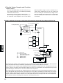
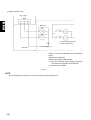
<WIRING DIAGRAM>
Black
White
Red
White
WG1
WK1
WG2
WK2
Red
B1
E1
E2
E2
B2
Black
Motor (Compressor) UMC2
V W
Black
White
Red
Red
White
Black
VG1
VK1
Yellow
Orange
B1
E1
E2
E2
B2
Purple
Black
B1
E1
E2
E2
B2
Brown
Red
Orange
Yellow
Black
Purple
30
Red
Brown
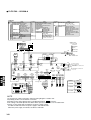
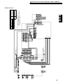
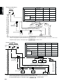
PUHY-P400·500YMF-B
VG2
VK2
Y-16,20(R407C)
5. Electrical Wiring Diagram
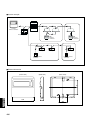
TH6
HEX1b
42 -3
42 -1
TH10a
10
11
HEX2a
TH5
HEX2b
TH10b
HEX1a
SV5b
-6
-7
16
16
SCC
TH8
O/S
TH10c
TH2
2
3
CP4
TH9b CP2
5
5
LEV1
TH9a
ST7
SLEV
SV6
SV4
27
27
ST4
CJ3
TH12
CP3a SV22
102 93
102 93
TH7
30 30
30 30
TH4
63H2
CV2
21.5
(2.11)
21.5
(2.11)
ST5
21.5
(2.11)
21.5
(2.11)
1 -10
1 -10
CP1
SV1
92 88
97 88
ST6
CJ1
63HS
Comp1
TH11
60 43
65 40
CS-circuit
Drier
63H1
CV1
-6
-7
21S4a
Comp2
ST8
SV32
SA
1
1
-6
-6
TH3 ST3
ST9
CP3b
CV3
CP5
MA
63LS
CJ2
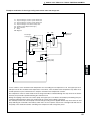
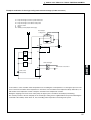
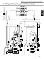
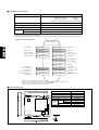
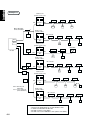
Model 400 in heating mode
Model 500 in heating mode
Y-16,20(R407C)
21S4b
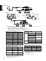
❇ Value : TH1~TH10c : ˚C
63HS,63LS : kg/cm2G(MPa)
Model 400 in cooling mode➞
Model 500 in cooling mode➞
➞
➞
❇ Standard operation data
BV2
3.6
(0.35)
3.2
(0.31)
ST2
BV3
4.4
(0.43)
4.3
(0.42)
ST1
BV1
1 Outdoor units / Y series / R407C / PUHY-P400·500YMF-B
6. Refrigerant circuit diagram and Thermal sensor
31
32
Y-16,20(R407C)
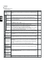
1 Outdoor units / Super Y series / R407C / PUHY-P600·650·700·750YSMF-B
PUHY-P600YSMF-B, PUHY-P650YSMF-B
PUHY-P700YSMF-B, PUHY-P750YSMF-B
CONTENTS
1. Specifications ································································· 34
Super Y(R407C)
2. Capacity Tables ······························································ 38
2-1 Correction by temperature ············································
2-2 Correction by total indoor ·············································
2-3 Correction by refrigerant piping length ···························
2-4 Correction at frosting and defrosting ····························
2-5 Operation limit ·······························································
38
40
44
45
45
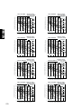
3. Sound Levels ·································································· 46
4. External Dimensions ···················································· 48
5. Wiring Diagram ····························································· 51
6. Refrigerant Circuit Diagram ········································· 53
And Thermal Sensor
33
1. Specifications
This unit consists of a conbination of PUHY-P400YMF-B and PUHN-P200YMF-B.
Model name
PUHY-P600YSMF-B
Capacity
Cooling
Heating
kcal/h
60,000
67,400
kW
69.8
78.3
BTU/h
238,200
267,500
Power source
3N ~ 380/400/415V 50/60Hz
Power input
Current
kW
25.5
22.95
A
42.5/40.4/38.9
38.3/36.4/35.0
Refrigerant / Lubricant
R407C/MEL32
Steel plate painting with polyester powder
<MUNSELL 5Y8/1 or similar>
Super Y(R407C)
External finish
Total capacity
50 ~ 130% of outdoor unit capacity
Indoor unit
Model / Quantity
Model 20 ~ 250 / 2 ~ 32
dB<A>
Noise level
Refrigerant piping diameter (main)
Liquid / Gas
Operating temperature range
Model name
ø19.05 / ø34.93
Indoor:15˚CWB ~ 24˚CWB
Outdoor:-5˚CDB ~ 43˚CDB
Indoor:15˚CDB ~ 27˚CDB
Outdoor:-15˚CWB ~ 15.5˚CWB
(10˚CDB~43˚CDB with outdoor unit
at lower position, or with indoor unit
20 or 25 type only is working)
(-12˚CWB~10˚CWB with indoor unit
20 or 25 type only is working)
PUHY-P400YMF-B
Type✕ Quantity
Fan
61.5 / 62
(50/60Hz)
Propeller fan ✕ 2
m3/min
Airflow rate
Motor output
kW
185
0.35 ✕ 1
0.35 ✕ 2
Hermetic
Motor output
kW
4.5 + 7.5
5.5
Crankcase heater
kW
0.045 + 0.056
0.056
mm
1715(H)✕ 1990(W) ✕ 840(L)
1715(H)✕ 990(W)✕ 840(L)
External dimension
High pressure protection
Protection
devices
30kg/cm2G(2.94MPa)
Compressor / Fan
Overcurrent protection / Thermal switch
Inverter
Refrigerant piping diameter
Net weight
Propeller fan ✕ 1
370
Type
Compressor
PUHN-P200YMF-B
Liquid / Gas
kg
DC bus current protection,
thermal switch
—
ø 15.88 flare / ø 34.93 Flange
ø 12.7 flare / ø 28.58 Flange
455
240
Note: 1.Cooling/heating capacity indicates the maximum value at operation under the following condition.
Cooling Indoor : 27˚CDB/19.5˚CWB Outdoor : 35˚CDB
Heating Indoor : 21˚CDB
Outdoor : 7˚CDB/6˚CWB
Pipe length : 10m
Height difference : 0m
2.Works not included : Installation/foundation work, electrical connection work, duct work, insulation work, power
source switch and other items not specified in this specification.
34
1 Outdoor units / Super Y series / R407C / PUHY-P600·650·700·750YSMF-B
This unit consists of a conbination of PUHY-P400YMF-B and PUHN-P250YMF-B.
Model name
PUHY-P650YSMF-B
Capacity
Cooling
Heating
kcal/h
65,000
73,000
kW
75.6
84.9
BTU/h
258,100
289,800
Power source
3N ~ 380/400/415V 50/60Hz
Power input
Current
kW
27.45
25.2
A
45.8/43.5/41.9
42.0/39.9/38.5
Refrigerant / Lubricant
R407C/MEL32
Steel plate painting with polyester powder
<MUNSELL 5Y8/1 or similar>
External finish
Super Y(R407C)
Total capacity
50 ~ 130% of outdoor unit capacity
Indoor unit
Model / Quantity
Model 20 ~ 250 / 2 ~ 32
dB<A>
Noise level
Refrigerant piping diameter (main)
Liquid / Gas
Operating temperature range
Model name
ø 19.05 / ø41.28
Indoor:15˚CWB ~ 24˚CWB
Outdoor:-5˚CDB ~ 43˚CDB
Indoor:15˚CDB ~ 27˚CDB
Outdoor:-15˚CWB ~ 15.5˚CWB
(10˚CDB~43˚CDB with outdoor unit
at lower position, or with indoor unit
20 or 25 type only is working)
(-12˚CWB~10˚CWB with indoor unit
20 or 25 type only is working)
PUHY-P400YMF-B
Type✕ Quantity
Fan
62.0 / 62.5
(50/60Hz)
Propeller fan ✕ 2
Airflow rate
m3/min
Motor output
kW
185
0.35 ✕ 1
0.35 ✕ 2
Hermetic
Motor output
kW
4.5 + 7.5
7.5
Crankcase heater
kW
0.045 + 0.056
0.056
mm
1715(H)✕ 1990(W) ✕ 840(L)
External dimension
High pressure protection
Protection
devices
30kg/cm G(2.94MPa)
Compressor / Fan
Refrigerant piping diameter
1715(H)✕ 990(W)✕ 840(L)
2
Overcurrent protection / Thermal switch
Inverter
Net weight
Propeller fan ✕ 1
370
Type
Compressor
PUHN-P250YMF-B
DC bus current protection,
thermal switch
Liquid / Gas
kg
ø 15.88 flare / ø 34.93 Flange
—
ø 12.7 flare / ø 28.58 Flange
455
255
Note: 1.Cooling/heating capacity indicates the maximum value at operation under the following condition.
Cooling Indoor : 27˚CDB/19.5˚CWB Outdoor : 35˚CDB
Heating Indoor : 21˚CDB
Outdoor : 7˚CDB/6˚CWB
Pipe length : 10m
Height difference : 0m
2.Works not included : Installation/foundation work, electrical connection work, duct work, insulation work, power
source switch and other items not specified in this specification.
35
This unit consists of a conbination of PUHY-P500YMF-B and PUHN-P200YMF-B.
Model name
PUHY-P700YSMF-B
Capacity
Cooling
Heating
kcal/h
70,000
78,400
kW
81.5
91.1
BTU/h
277,900
311,200
Power source
3N ~ 380/400/415V 50/60Hz
Power input
Current
kW
30.5
26.95
A
50.3/47.8/46.1
44.9/42.7/41.2
Refrigerant / Lubricant
R407C/MEL32
Steel plate painting with polyester powder
<MUNSELL 5Y8/1 or similar>
Super Y(R407C)
External finish
Total capacity
50 ~ 130% of outdoor unit capacity
Indoor unit
Model / Quantity
Model 20 ~ 250 / 2 ~ 32
dB<A>
Noise level
Refrigerant piping diameter (main)
Liquid / Gas
Operating temperature range
Model name
ø19.05 / ø41.28
Indoor:15˚CWB ~ 24˚CWB
Outdoor:-5˚CDB ~ 43˚CDB
Indoor:15˚CDB ~ 27˚CDB
Outdoor:-15˚CWB ~ 15.5˚CWB
(10˚CDB~43˚CDB with outdoor unit
at lower position, or with indoor unit
20 or 25 type only is working)
(-12˚CWB~10˚CWB with indoor unit
20 or 25 type only is working)
PUHY-P500YMF-B
Airflow rate
m3/min
Motor output
kW
185
0.35 ✕ 1
0.35 ✕ 2
Hermetic
Motor output
kW
7.5 + 7.5
5.5
Crankcase heater
kW
0.045 + 0.056
0.056
mm
1715(H)✕ 1990(W) ✕ 840(L)
1715(H)✕ 990(W)✕ 840(L)
External dimension
High pressure protection
Protection
devices
30kg/cm2G(2.94MPa)
Compressor / Fan
Overcurrent protection / Thermal switch
Inverter
Refrigerant piping diameter
Net weight
Propeller fan ✕ 1
370
Type
Compressor
PUHN-P200YMF-B
Propeller fan ✕ 2
Type✕ Quantity
Fan
61.5 / 62.0
(50/60Hz)
DC bus current protection,
thermal switch
Liquid / Gas
kg
ø 15.88 flare / ø 34.93 Flange
—
ø 12.7 flare / ø 28.58 Flange
475
240
Note: 1.Cooling/heating capacity indicates the maximum value at operation under the following condition.
Cooling Indoor : 27˚CDB/19.5˚CWB Outdoor : 35˚CDB
Heating Indoor : 21˚CDB
Outdoor : 7˚CDB/6˚CWB
Pipe length : 10m
Height difference : 0m
2.Works not included : Installation/foundation work, electrical connection work, duct work, insulation work, power
source switch and other items not specified in this specification.
36
1 Outdoor units / Super Y series / R407C / PUHY-P600·650·700·750YSMF-B
This unit consists of a conbination of PUHY-P500YMF-B and PUHN-P250YMF-B.
Model name
PUHY-P750YSMF-B
Capacity
Cooling
Heating
kcal/h
75,000
84,000
kW
87.3
97.7
BTU/h
297,800
333,500
Power source
3N ~ 380/400/415V 50/60Hz
Power input
Current
kW
32.4
28.95
A
53.5/50.8/48.9
48.3/45.9/44.2
Refrigerant / Lubricant
R407C/MEL32
Steel plate painting with polyester powder
<MUNSELL 5Y8/1 or similar>
External finish
50 ~ 130% of outdoor unit capacity
Super Y(R407C)
Total capacity
Indoor unit
Model / Quantity
Model 20 ~ 250 / 2 ~ 32
dB<A>
Noise level
62.0 / 62.5
(50/60Hz)
Refrigerant piping diameter (main)
Liquid / Gas
Operating temperature range
ø19.05 / ø41.28
Indoor:15˚CWB ~ 24˚CWB
Outdoor:-5˚CDB ~ 43˚CDB
Indoor:15˚CDB ~ 27˚CDB
Outdoor:-15˚CWB ~ 15.5˚CWB
(10˚CDB~43˚CDB with outdoor unit
at lower position, or with indoor unit
20 or 25 type only is working)
(-12˚CWB~10˚CWB with indoor unit
20 or 25 type only is working)
PUHY-P500YMF-B
Propeller fan ✕ 2
Type✕ Quantity
m3/min
Airflow rate
Fan
Motor output
kW
185
0.35 ✕ 1
0.35 ✕ 2
Hermetic
Motor output
kW
7.5 + 7.5
7.5
Crankcase heater
kW
0.045 + 0.056
0.056
mm
1715(H)✕ 1990(W) ✕ 840(L)
External dimension
High pressure protection
Protection
devices
30kg/cm G(2.94MPa)
Compressor / Fan
Refrigerant piping diameter
1715(H)✕ 990(W)✕ 840(L)
2
Overcurrent protection / Thermal switch
Inverter
Net weight
Propeller fan ✕ 1
370
Type
Compressor
PUHN-P250YMF-B
DC bus current protection,
thermal switch
Liquid / Gas
kg
ø 15.88 flare / ø 34.93 Flange
—
ø 12.7 flare / ø 28.58 Flange
475
255
Note: 1.Cooling/heating capacity indicates the maximum value at operation under the following condition.
Cooling Indoor : 27˚CDB/19.5˚CWB Outdoor : 35˚CDB
Heating Indoor : 21˚CDB
Outdoor : 7˚CDB/6˚CWB
Pipe length : 10m
Height difference : 0m
2.Works not included : Installation/foundation work, electrical connection work, duct work, insulation work, power
source switch and other items not specified in this specification.
37
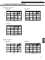
2. Capacity tables
2-1. Correction by temperature
Cooling
•Standard Specifications
Capacity
Input
Source
Current
kcal/h
kW
BTU/h
kW
V
A
PUHY-P600YSMF-B
PUHY-P650YSMF-B
PUHY-P700YSMF-B
PUHY-P750YSMF-B
60,000
69.8
65,000
75.6
70,000
81.5
75,000
87.3
238,200
258,100
277,900
297,800
25.5
27.45
30.5
32.4
50.3/47.8/46.1
53.5/50.8/48.9
380/400/415
42.5/40.4/38.9
45.8/43.5/41.9
•Calculation
Capacity' = Capacity ✕ Ratio
Super Y(R407C)
Input ' = Input ✕ Ratio
Input' ✕1000
Current' =
3 ✕ Source ✕ 0.91(:PUHY-P600·650YSMF-B)
✕ 0.92(:PUHY-P700·750YSMF-B)
❈Capacity'
Input'
Current'
After correction
The Ratio of Cooling Capacity
1.20
1.10
Ratio
24˚CWB
22˚CWB
1.00
20˚CWB
19.5˚CWB
18˚CWB
0.90
16˚CWB
15˚CWB
Indoor Temperature(˚CWB)
0.80
-10
0
10
20
30
Outdoor Temperature (˚CDB)
40
50
The Ratio of Cooling Power Input
1.20
24˚CWB
22˚CWB
20˚CWB
19.5˚CWB
1.10
18˚CWB
16˚CWB
15˚CWB
Ratio
1.00
0.90
0.80
0.70
-10
38
0
10
20
30
Outdoor Temperature (˚CDB)
40
50
1 Outdoor units / Super Y series / R407C / PUHY-P600·650·700·750YSMF-B
Heating
•Standard Specifications
Capacity
Input
Source
Current
kcal/h
kW
BTU/h
kW
V
A
PUHY-P600YSMF-B
PUHY-P650YSMF-B
PUHY-P700YSMF-B
PUHY-P750YSMF-B
67,400
78.3
73,000
84.9
78,400
91.1
84,000
97.7
267,500
289,800
311,200
333,500
22.95
25.2
38.3/36.4/35.0
42.0/39.9/38.5
26.95
380/400/415
28.95
44.9/42.7/41.2
48.3/45.9/44.2
•Calculation
❈Capacity'
Input'
Current'
Capacity' = Capacity ✕ Ratio
Super Y(R407C)
After correction
Input ' = Input ✕ Ratio
Input' ✕1000
Current' =
3 ✕ Source ✕ 0.91 (:PUHY-P600·650·700·750YSMF-B)
The Ratio of Heating Capacity
1.30
1.20
15˚CDB
Indoor Temperature(˚CDB)
1.10
Ratio
20˚CDB
1.00
21˚CDB
0.90
25˚CDB
0.80
27˚CDB
0.70
0.60
-15
-10
-5
0
5
Outdoor Temperature (˚CWB)
10
15
20
The Ratio of Heating Power Input
1.20
Indoor Temperature(˚CDB)
1.10
15˚CDB
Ratio
1.00
0.90
20˚CDB
21˚CDB
0.80
0.70
25˚CDB
27˚CDB
0.60
-15
-10
-5
0
5
Outdoor Temperature (˚CWB)
10
15
20
39
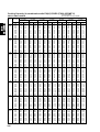
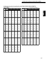
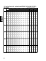
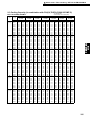
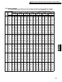
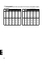
2-2. Correction by total indoor
PUHY-P600YSMF-B
1) Capacity
Capacity(kcal/h)
70,000
Heating
Cooling
60,000
50,000
30,000
300
350
400
450
500
550
600
Total capacity of indoor units
650
700
750
800
2) Input
30.00
Input(kW)
Cooling
25.00
20.00
Heating
15.00
10.00
300
350
400
450
500
550
600
650
700
750
800
Total capacity of indoor units
3) Current
380V
400V
45.0
Cooling
Current(A)
Super Y(R407C)
40,000
40.0
415V
35.0
380V
400V
30.0
Heating
415V
25.0
20.0
15.0
300
350
400
450
500
550
600
Total capacity of indoor units
40
650
700
750
800
1 Outdoor units / Super Y series / R407C / PUHY-P600·650·700·750YSMF-B
PUHY-P650YSMF-B
1) Capacity
Capacity(kcal/h)
70,000
Heating
Cooling
60,000
50,000
40,000
300
400
500
600
Total capacity of indoor units
700
Super Y(R407C)
30,000
800
2) Input
30.00
Input(kW)
Cooling
25.00
Heating
20.00
15.00
10.00
300
400
500
600
700
800
Total capacity of indoor units
3) Current
380V
45.0
400V
Current(A)
Cooling
40.0
415V
380V
35.0
Heating
30.0
400V
415V
25.0
20.0
15.0
300
400
500
600
700
800
Total capacity of indoor units
41
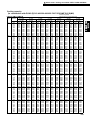
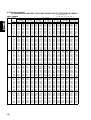
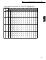
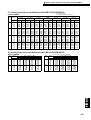
PUHY-P700YSMF-B
1) Capacity
Capacity(kcal/h)
80,000
Heating
Cooling
70,000
60,000
50,000
30,000
300
400
500
600
700
Total capacity of indoor units
800
900
2) Input
30.00
Input(kW)
Cooling
25.00
Heating
20.00
15.00
10.00
300
400
500
600
700
800
900
Total capacity of indoor units
3) Current
380V
50.0
400V
Cooling
Current(A)
Super Y(R407C)
40,000
415V
380V
40.0
400V
Heating
415V
30.0
20.0
300
400
500
600
700
Total capacity of indoor units
42
800
900
1 Outdoor units / Super Y series / R407C / PUHY-P600·650·700·750YSMF-B
PUHY-P750YSMF-B
Capacity(kcal/h)
1) Capacity
Heating
80,000
Cooling
70,000
60,000
50,000
40,000
300
400
500
600
700
Total capacity of indoor units
800
900
Super Y(R407C)
30,000
1000
2) Input
Cooling
Input(kW)
30.00
Heating
25.00
20.00
15.00
10.00
300
400
500
600
700
800
900
1000
Total capacity of indoor units
380V
3) Current
400V
Cooling
Current(A)
50.0
415V
380V
400V
Heating
40.0
415V
30.0
20.0
300
400
500
600
700
800
900
1000
Total capacity of indoor units
43
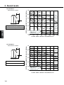
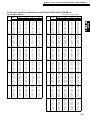
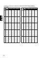
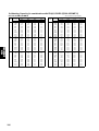
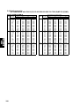
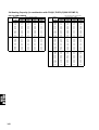
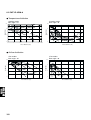
2-3 Correction by refrigerant piping length
To obtain a decrease in cooling/heating capacity due to refrigerant piping extension, multiply by the capacity
correction factor based on the refrigerant piping equivalent length in the table below.
• Cooling capacity correction
PUHY-P600YSMF-B
PUHY-P650YSMF-B
Total ca
1.0
pacity
of indo
or unit
300
0.9
450
8.0
600
780
Cooling capacity
correction factor
Cooling capacity
correction factor
1.0
7.0
Total capa
city
0.9
325
488
650
845
8.0
20
40
80
60
100
120
0
20
Piping equivqlent length (m)
40
60
80
100
120
Piping equivqlent length (m)
PUHY-P700YSMF-B
PUHY-P750YSMF-B
Total ca
1.0
pacity o
f indoor
unit
0.9
350
525
700
910
8.0
7.0
Cooling capacity
correction factor
1.0
Cooling capacity
correction factor
unit
7.0
0
Super Y(R407C)
of indoor
Total ca
pacity
of indo
or unit
0.9
375
563
750
8.0
975
7.0
0
20
40
60
80
100
120
Piping equivqlent length (m)
0
20
40
60
80
100
120
Piping equivqlent length (m)
Cooling capacity
correction factor
•Heating capacity correction
PUHY-P600·650·700·750YSMF-B
1.0
0.9
0
20
40
60
80
100
120
Piping equivqlent length (m)
• How to obtain piping equivalent length
➀ PUHY-P600YSMF-B
Equivalent length = (Actual piping length to the farthest indoor unit) + (0.80 ✕ number of bent on the piping)m
➁ PUHY-P650 ~ 750YSMF-B
Equivalent length = (Actual piping length to the farthest indoor unit) + (0.95 ✕ number of bent on the piping)m
44
1 Outdoor units / Super Y series / R407C / PUHY-P600·650·700·750YSMF-B
2-4 Correction at frosting and defrosting
When a decrease in heating capacity due to frosted and defrosting operations is considered, the value multiplied by the correction factor in the table below represents the heating capacity.
Outdoor inlet air temp
(˚CWB)
Correction factor
6
4
2
0
-2
-4
-6
-8
-10
1.0
0.98
0.89
0.89
0.90
0.92
0.95
0.95
0.95
2-5 Operation limit
30
When the indoor unit is located above
the outdoor unit for 4m or more, or
indoor unit 20 or 25type only is working,
the outdoor unit inlet air temperature
becomes 10~43˚CDB.
25
20
15
10
-5
0
5
10
15
20
25
30
Outdoor temperature (˚CWB)
35
40
45
Indoor temperature (˚CDB)
• Heating
30
25
When the indoor unit 20 or 25type only is
working, the outdoor unit inlet air
temperature becomes -15~10˚CWB.
20
15
10
-15
-10
-5
0
5
10
Outdoor temperature (˚CWB)
15
20
45
Super Y(R407C)
Indoor temperature (˚CDB)
• Cooling
3. Sound levels
PUHY-P600YSMF-B
Measurement condition
60Hz
50Hz
1m
A
B
Super Y(R407C)
Sound pressure level in anechoic room
61.5 / 62.0 dB (A)
OCTAVE BAND PRESSURE LEVEL< dB> 0dB = 0.0002µbar
1m
70
60
NC60
50
NC50
40
NC40
30
NC30
20
10
NC20
Approximate minimum
audible limit on
continuous noise
63
125
250
500
1000
2000
4000
8000
OCTAVE BAND CENTER FREQUENCIES<Hz>
PUHY-P650YSMF-B
Measurement condition
60Hz
50Hz
1m
A
B
Sound pressure level in anechoic room
62.0 / 62.5 dB (A)
OCTAVE BAND PRESSURE LEVEL< dB> 0dB = 0.0002µbar
1m
70
60
NC60
50
NC50
40
NC40
30
NC30
20
NC20
Approximate minimum
audible limit on
continuous noise
10
63
125
250
500
1000
2000
4000
OCTAVE BAND CENTER FREQUENCIES<Hz>
46
8000
1 Outdoor units / Super Y series / R407C / PUHY-P600·650·700·750YSMF-B
PUHY-P700YSMF-B
Measurement condition
60Hz
50Hz
1m
A
B
Sound pressure level in anechoic room
70
60
NC60
50
NC50
40
NC40
30
NC30
20
10
Super Y(R407C)
61.5 / 62.0 dB (A)
OCTAVE BAND PRESSURE LEVEL< dB> 0dB = 0.0002µbar
1m
NC20
Approximate minimum
audible limit on
continuous noise
63
125
250
500
1000
2000
4000
8000
OCTAVE BAND CENTER FREQUENCIES<Hz>
PUHY-P750YSMF-B
Measurement condition
60Hz
50Hz
1m
A
B
Sound pressure level in anechoic room
62.0 / 62.5 dB (A)
OCTAVE BAND PRESSURE LEVEL< dB> 0dB = 0.0002µbar
1m
70
60
NC60
50
NC50
40
NC40
30
NC30
20
NC20
Approximate minimum
audible limit on
continuous noise
10
63
125
250
500
1000
2000
4000
8000
OCTAVE BAND CENTER FREQUENCIES<Hz>
47
694
150
80 82 78
Air
inlet
Left side view
Knockout hole
Left side hole for
the control wiring,
the power supply, the
oil balance pipe to the
constant capacity unit
40
Air
inlet
Service panel
X
7X2-14X20oval hole
Front hole for the power supply
Changeable to 400:ø46,ø53,ø62
500:ø53,ø62 by using attached
conduit mounting plate (accessory)
80
X–X
Note.1
Knockout hole
Bottom piping hole
218
215
725
745
Service valve
(oil balance)
780
45
115
25 90 75
780
Refrig. service
valve(gas)
Knockout hole
Plane view
1990
Front view
Knockout hole
Front piping hole
Refrig.service
valve (liquid)
215
X
PUHY-P400,500YMF-B
Rear view
111
Bottom hole for the power supply
Changeable to 400:ø46,ø53,ø62
Cross section
500:ø53,ø62 by using attached
conduit mounting plate (accessory)
Air outlet
230
Conn. pipe
ø34.93
90 80
73
ø27 Knockout hole
<bottom hole for the
control wiring>
208
203
152
Refrig. service
valve(gas)
<flange>
15
225
Refrig.service
valve (liquid)
ø15.88<flare>
126
86
<Accessorys>
• Refrigerant (gas) conn. pipe ················· 1pc.
(The connecting pipe has been fixed with the unit)
• Packing for conn. pipe ·························· 1pc.
(Attached near the ball valve)
• Conduit mouting plate
(Painted the same color as the unit body)
ø62,ø53,ø46 ·································· Each 1pc.
• Tapping screw 4X10 ····························· 6pcs.
• Wiring partition plate ····························· 1pc.
Note1. Please leave a space under the outdoor unit
for the piping when you connect the piping
from the bottom.
(Please be careful not to close the hole
of the bottom plate by the basement)
100
48
24
70
149 70
15
840
880
910
1715
48
1490
Super Y(R407C)
4. External dimensions
Unit : mm
168
237
Rear view
Conn. pipe
ø28.58<brazed>
73 80
25
75 135
Left side view
80
Cross section X–X
778
584
Knockout hole
Left side hole for refrig.
(liquid,gas) conn. pipe
160
40
Knockout hole
Front piping hole
Refrig. service
valve(gas)
<flange>
31
79
X
Refrig.service
valve (liquid)
ø12.7<flare>
ø27 Knockout hole
Front piping hole
(oil balance)
4 ✕ 2 – 14 ✕ 20
Oval hole
ø27 Knockout hole
<bottom hole for the
control wiring>
130
Note.1
121
48 100
Knockout hole
Bottom piping hole
40
165
80
215
190
425
Front view
813
55
345
Plane view
560
990
55
215
15
840
880
910
Knockout hole
X
Service panel
Front hole for the power supply
Changeable to ø27,ø33,ø40
by using attached conduit
mounting plate (accessory)
40 80
Air
inlet
Air
inlet
Right side view
Knockout hole
Right side hole for
the control wiring,
the power supply,
the oil balance pipe to
the variable capacity unit
Air outlet
Note1. Please leave a space under the outdoor unit
for the piping when you connect the piping
from the bottom.
(Please be careful not to close the hole
of the bottom plate by the basement)
Service valve
(oil balance)
ø12.7<flare>
78
ø40 Knockout hole
Changeable to ø27,ø33 by
using attached conduit mounting
plate (accessory)
149
225
1490
Note.1
1715
ø27 Knockout hole
Bottom piping hole
(oil balance)
115
48
15
99
142
Super Y(R407C)
70
<Accessorys>
• Refrigerant (gas) conn. pipe···························1pc.
(The connecting pipe has been fixed with the unit)
• Packing for conn. pipe····································1pc.
(Attached near the ball valve)
• Conduit mouting plate
(Painted the same color as the unit body)
ø40,ø33,ø27····················································Each 1pc.
• Tapping screw 4✕12·······································4pcs.
• Oil balance conn. pipe (to the variable capacity unit
through the right side panel knockout hole)·········1pc.
• Sealing···························································2pcs.
1 Outdoor units / Super Y series / R407C / PUHY-P600·650·700·750YSMF-B
PUHN-P200, 250YMF-B
Unit : mm
49
50
10
e
g
f
Oil balance pipe
Distributer
❇3
(liquid) ❇3
Constant capacity unit
990
b
Air
inlet
gas d
liquid e
Distributer ~
Constant capacity unit gas f
g
Oil balance pipe
liquid a
gas b
liquid c
Note.1
Distributer ~
Variable capacity unit
Indoor units ~
Distributer
Front view
Distributer
(gas) ❇3
Indoor units
a
c
d
Variable capacity unit
1990
ø34.93
600
700
ø12.7
ø28.58
ø12.7
ø34.93
ø15.88
❇2
❇1
ø41.28
ø19.05
650
Right side view
Air outlet
840
910
Super Y(R407C)
750
❇1 This pipe has been fixed.
❇2 The oil balance pipe is usually
fixed inside of the unit.
❇3 Option (CMC-30A)
Note 1.Please install the constant capacity unit
and the variable capacity unit on a same
level stand.
2.Pipe size is as follws.
3.Please install the constant capacity unit
and the variable capacity unit side by side,
the constant capacity unit on the left side
and the variable capacity unit on the right
side.
4.Optional kits(CMC-30A) is needed to compose
PUHY-P600~750YSMF-B.
Air
inlet
PUHY-P600,650,700,750YSMF-B
Unit : mm
52F
CH12
A2
A1
13
52C2
14
A2
A1
52C2
96
95
51C2
CN51C2
(3P)
3
2
1
CNCH
(3P)
3
2
1
CN52F
(3P)
5
4
1
2
3
CN52C2
(5P)
3
2
1
BOX BODY
X03
X02
X01
CNOUT2
(4P)
CNRT2
(5P)
RELAY board
BOX BODY
S
M2
M1
TB7
M2
M1
TB3
PE
PE
Blue
Green/
Yellow
N
N
Black
L3
L3
White
L2
L2
Connect to
Indoor and
remote
controller
Power source
3N~
380/400/415V
50/60Hz
L1
TB1
L1
Red
SV5b
21S4b
6
5
4 CN37
3 (6P)
2
1
6
5
4 CN36
3 (6P)
2
1
3
2 CN35
1 (3P)
6
5
4 CN34
3 (6P)
2
1
1
2
1
1
X10
X09
X08
X07
X06
4 3
1 2
SSR
X05
X04
X02
X01
N
L3
L2
CN05
(4P)
12
1234
12
2
3
CNTR
(3P)
OFF
ON
SW4-6
F3
250VAC
1A F
VK2
VG2
VK1
VG1
~-
~
~+
DS
F2
600VAC
12A F
White
L3 Black
L2
L1
Red
CN03
(3P)
TH6
123
CN02
(8P)
TH5 TH8 TH2
TH7
12345678
3 2 1
63LS
3 2 1
63HS
TH11
SLEV
CNLV1
(5P)
12345
CNL
(3P)
W
V
LEV1
12345
CNLV2
(5P)
1
CNFC1 2
(6P) 3
4
5
6
CN3S 3
(3P) 12
CN3D 3
(3P) 12
CN51
(5P)
1
2
3
4
5
+
C2
1 2 3 4
3
2
1
1
2
3
4
5
6
6
1234
F01
250VAC
2A F
1-2
5
5 4 3 2 1
CNV
(5P)
2
CNU 3
(5P) 4
5 4 3 2 1
CNW
(5P)
CNFC2
(6P)
2 1
CN2-2
(2P)
R6
L2
UK2
UG2
BOX BODY
FG
CN3
(6P)
1 2 3 4 5 6
C25
Thermistor
TH2~12, THHS
Cord heater
Solenoid valve
Earth terminal
Ferrite core
Power transistor module
TRM1~3
FB1
Choke coil(Transmission)
High pressure sensor
Electronic expansion valve
L2
63HS,63LS
LEV1,SLEV
SV1,22,32,4,5b,6
4-way valve
Solid state relay
SSR
21S4a,b
Magnetic contactor
Fan (Radiator panel)
MF1
Overload Relay
52F
Magnetic contactor
51C2
Magnetic contactor (Inverter main circuit)
52C2
52C1
Current Sensor
Varistor
ZNR4
DC reactor (Power factor improvement)
DCL
High pressure switch
DCCT
63H1,2
CH2,CH3
Name
Crank case heater(Compressor)
Noise Filter
NF
CH11,12
Diode stack
DS
TB1, 1A, 3,7
Terminal block
<SYMBOL EXPLANATION>
Symbol
<CAUTION>
·When checking for the inside control box, be sure to turn the
power source off, and confirm that the voltage at the both
ends of main capacitor(C2,C3) is being sufficientry low by
opening MAIN board mounting plate after leaving 10minutes
or more.
·Please read the INSTALLATION MANUAL carefully.
12
12
1 2 3
UK1
UG1
2 1
CN30V
(2P)
CNL2
(2P)
CNR
(3P)
HEAT
COOL
C24 C22
TRM3 C2E1
C1
Black
Motor (Compressor)
White
C16
CN2-3
(2P)
Power circuit board
(INV board)
CN2-1
(2P)
2 1
CNVDC
(4P)
C1
Red
MC1
U V W
TRM2 C2E1
C23 C21
C15
1 2 3 4
Mode
Comp ON/OFF
Fan control board
(FANCON board) 1
1
2
3
4
5
6
C20
C1
TRM1 C2E1
CN05
THHS R7
CN3D
Mode
1-2 1-3
ON ON Auto
changeover
OFF
ON OFF
Normal
OFF
CN3S
Fan motor
CNMF3
C14
CNTH
X02 (2P)
1 2 3 CNFAN 1 2
(3P)
MF1
X01
CNVCC1
(6P)
A
2
4
MF3
U V W (Heat exchanger)
CNAC2 CNCT
(3P)
(4P)
3 2 1
CNRS2
(7P)
1 CNVCC2
2 (2P)
1
2
3
4
5
6
7
R2
52F
R3 DCCT
CN52C
(3P)
+
C3
5
3
1
4:Compressor ON/OFF
5:Trouble
52C1
1 2
3 4
5
6
52C1
DCL
R1
R5
Black
White
WK1
WG2
CNX10
(3P)
1
2
3
5
6
1
2
CNVCC3 3
(6P)
4
12V
1 2 3
6
7
CNVCC41
(2P)
2
X10
1 2 3
1
2
CNRS3 34
(7P) 5
C1
K G
G K
K G
G K
ZNR4
WG1
WK2
L3
L2
CN01 CNH
(2P) (3P)
12
K G
UK1
SCRM
UG1
UK2
UG2
F1
600VAC
12A F
Red
G K
U
L1
Refer to the Service handbook about the switch operation.
12
12
1
as connection with
PUHN-P200/250YMF-B
TH10a
TH9b TH10c TH12 TH9a TH4 TH3
TH10b
4
3 CN13
2 (4P)
1 1234
CN20
(3P)
F1
250VAC
2A F
T01
CNTR1
Black
White
Red
Control circuit board
(MAIN board)
1 2 3
CN12 CN09 CN07 CN06
(2P) (2P) (2P) (2P)
detection
circuit
CNS1
2 1 (2P)
BOX BODY
Green/
Yellow
Blue
Black
White
TB1A
L1
Red
detection
circuit
CNRT1
(5P)
6 CNOUT1
5 (6P)
1
5
4
3
3
2
4
3
2
1
(3P)
(3P)
3
2 CN33
1
3
2 CN32
CNS2
(3P) 3 2 1
CN38
(3P)
Green/
Yellow
Blue
Black
White
Red
2
5
4
3
SV6
SV4
CH3
CH2
21S4a
SV1
CH11
N
L3
L2
L1
63H2 63H1
SV32 SV22
N
L3
L2
L1
NF
A
5
5 6
6
Black
*3:NF is in the back of the Inverter Controller Box.
3
3 4
1
4
52C2
White
1 2
2
Red
51C2
51C2 : 27A
Red
White
Black
WG2
WK2
FB1
CN04
CNMF2
MF2
Fan motor
(Heat exchanger) U V W
Blue
WG1
WK1
Inverter Controller Box
Black
White
Red
White
VG2
VK2
Red
Black
Motor (Compressor) UMC2
V W
Black
White
Red
Red
White
Black
VG1
VK1
Yellow
Orange
B1
E1
E2
E2
B2
Purple
Black
B1
E1
E2
E2
B2
Brown
Red
Orange
Yellow
Black
Purple
B1
E1
E2
E2
B2
Red
Brown
PUHY-P400·500YMF-B
Super Y(R407C)
<WIRING DIAGRAM>
1 Outdoor units / Super Y series / R407C / PUHY-P600·650·700·750YSMF-B
5. Electrical Wiring Diagram
51
A1
A2
SV4
SV2
52
C113 52C1
CH11
51C
63H
CH3
CH2
SV
5b
SV3
21
SV1 S4
14
Green/
Yellow
PE
S
1
2 CN35
3 (3P)
6
5
4 CN34
3 (6P)
2
1
3
2 CN39
1 (3P)
6
5
4
3
2 CN33
1 (6P)
TH10b TH10a
CN12 CN09
(2P) (2P)
12 12
5
4 CN52C1
3 (5P)
2 X07
1
3
2 CNCH11
1 (3P)
CN46
(3P)
1
2
3
CN38
(3P)
1
2
3
M2
M1
TB3
Blue
N
Invreter
unit
Black
L3
N
Unit body
White
L2
Red
Power sourceL2
3N~
380/400/415V
50/60Hz
L3
PE
TB1
SSR01
4 3
1 2
X05
X04
X03
X02
X01
TH9
CN03
(3P)
123
1 2
CNS1
(2P)
TH4 TH3 TH6
CN06 CN05
(4P)
(2P)
12
1234
X06
Detection
circuit
Detection
circuit
A
2
ZNR01
F1
250VAC
6.3A F
CN20
3 (3P)
1
2
CNTR
(2P)
TH5 TH8 TH7
CN02
(8P)
12345678
TH11
CN01
(2P)
12
63LS
3 2 1
6
5
6
LEV1
CNLV1
(5P)
12345
F3
250VAC
1A F
CNL
(3P)
1 2 3
SW3-10 are OFF for Model 200.
and ON for Model 250.
Control circuit board
(CONT board)
1
T01
4
3
4
LEV2
CNLV2
(6P)
123456
1
CNFC1 2
(6P) 3
4
5
6
F2
600VAC
8A F
Model 200:24A
Model 250:27A
2
1
51C1
2
5
3
1
L3 L2 L1
L3 L2 L1
L3 L2 L1
52C1
Black
L1
VK2
VG2
VK1
VG1
WG1
WK2
L3
L2
L1
1
2 CNFC2
3 (6P)
4
5
CNW
6
(5P)
5 4 3 2 1
2
CNU 3
(5P) 4
5
CNV
(5P)
5 4 3 2 1
K G
G K
K G
G K
K G
G K
CN04
Black
UK2
UG2
UK1
UG1
WK1
WG2
W
V
U
Red
UK1
UG2
SCRM
UG1
UK2
A
NF
Noise
Filter
F1
600VAC
8A F
Black
White
Red
Fan control board
(Fancon board) 1
White
WG2
WK2
L1
Black
White
Red
Red
WG1
WK1
Controller Box
VG2
VK2
52
VG1
VK1
MF
U
V
W
Fan motor
CNMF
U
V MC1
W
FUSE(8A)
F1,F2
SORENOID VALVE
SORENOID VALVE
SORENOID VALVE
HIGH PRESSURE CUT OUT SWITCH
LOW SIDE PRESSURE SENSOR
THERMISTER
SV5b
SV2,SV3
63H
63LS
TH11
4-WAY VALVE
CORD HEATER
SV1,SV4
21S4
CH2,CH3
CRANK CASE HEATER(COMPRESSOR)
FAN MOTOR(HEAT EXCHANGER)
MF
CH11
ELECTRIC MOTOR OF COMPRESSOR
OVER CURRENT RELAY
51C1
MC1
MAGNET CNTACTOR
52C1
FUSE(1A)
FUSE(6.3A)
F1
F3
SOLID STATE RELAY
SSR
NAME
VARISTOR
SYMBOL
ZNR01
Motor (Compressor)
Super Y(R407C)
SYMBOL
NAME
EARTH TERMINAL
POWER SOURCE TERMINAL BLOCK
SWITCH
TB1
SWITCH
SWU1,2
RELAY
ELECTRONIC EXPANSION VALVE
ELECTRONIC EXPANSION VALVE
THERMISTER
THERMISTER
THERMISTER
THERMISTER
THERMISTER
THERMISTER
THERMISTER
THERMISTER
THERMISTER
SW2,SW3
X01~X07
LEV2
LEV1
TH10b
TH10a
TH9
TH8
TH7
TH6
TH5
TH4
TH3
PUHN-P200·250YMF-B
53
SV5b
42
42
HEX1a
-3
-1
TH6
HEX1
11
10
42
42
-3
-1
TH5
HEX2
TH10a
-1
-2
CV1
-5
-6
SCC
TH8
13
12
TH11
3
2
5
4
SV3
LEV1
TH9
ST10
CP4
Comp1
SV2
4
3
27
27
TH7
ST3
-5
-6
SV4
TH7
TH4
TH3
ST7
ST7
ST5
LEV1
TH9a
30 30
30 30
TH4
27
27
ST9
ST4
30 30
30 30
ST4
CJ3
TH12
CP3a SV22
102 93
102 93
SV6
SV4
63H2
CV2
21.5
(2.11)
21.5
(2.11)
SLEV
ST5
21.5
(2.11)
21.5
(2.11)
2 -9
1 -10
CP1
SV1
CJ1
CV1
ST6
O/S
102 93
102 93
21S4
SCC
TH8
CP4
TH10c
Comp1
TH2
SV1
92 88
97 88
ST6
CP1
CJ1
63HS
TH9b CP2
5
5
60 43
65 40
16
16
O/S
TH11
21S4a
CS-circuit
Drier
63H1
63H
TH10a
HEX2a
TH5
HEX2b
PUHN-P200,250YMF-B
TH6
HEX1b
TH10b
ST8
ST8
Comp2
SV32
SA
2
1
SA
-5
-6
TH3 ST3
ST9
CP3b
CP3
MA
CV3
CP5
MA
LEV2
BV2
3.5
(0.34)
3.5
(0.34)
BV2
BV1
BV3
ST2
ST1
ST2
BV3
4.6
(0.45)
4.5
(0.44)
TH10b
SV5b CP5
CV2
63LS
CJ2
63LS
CJ2
ST1
BV1
Model 500 (250) in heating mode
Distributer(Liquid)
pipe
Oil balance
Indoor unit
Distributer(Gas)
❇ Value : TH1~TH10c : ˚C
63HS,63LS : kg/cm2G(MPa)
Model 500 (250) in cooling mode ➞
Super Y(R407C)
-5
-6
Model 400 (200) in heating mode
Model 400 (200) in cooling mode ➞
❇ Standard operation data
➞
21S4b
➞
PUHY-P400,500YMF-B
1 Outdoor units / Super Y series / R407C / PUHY-P600·650·700·750YSMF-B
6. Refrigerant circuit diagram and Thermal sensor
54
Super Y(R407C)
1 Outdoor units / R2 series / R407C / PURY-P200·250YMF-C
PURY-P200YMF-C, PURY-P250YMF-C
CONTENTS
1. Specifications ································································· 56
2. Capacity Tables ······························································ 58
2-1 Correction by temperature ············································
2-2 Correction by total indoor ·············································
2-3 Correction by refrigerant piping length ···························
2-4 Correction at frosting and defrosting ····························
2-5 Operation limit ·······························································
58
60
62
63
63
R2(R407C)
3. Sound Levels ·································································· 64
4. External Dimensions ···················································· 65
5. Electrical Wiring Diagram ·············································· 66
6. Refrigerant Circuit Diagram ········································· 67
And Thermal Sensor
55
1. Specifications
Model name
PURY-P200YMF-C
Capacity
Cooling
Heating
kW
✻1
22.4
25.0
kcal/h
✻2
20,000
3N ~ 380/400/415V 50/60Hz
Power source
Power input
Current
kW
8.64
7.98
A
14.5/13.8/13.3
13.4/12.7/12.3
Propeller fan✕ 1
Type✕ Quantity
Fan
Airflow rate
Motor output
m3/min
185
kW
0.38
Hermetic
Type
Compressor
Motor output
kW
5.5
Crankcase heater
kW
0.062(240V)
R2(R407C)
Refrigerant / Lubricant
R407C/MEL32
Steel plate painting with polyester powder
<MUNSELL 5Y8/1 or similar>
External finish
External dimension
mm
1715(H)✕ 990(W)✕ 840(L)
2.94MPa
High pressure protection
Protection
devices
Over current protection / Thermal switch
Compressor / Fan
DC bus current protection, thermal switch
Inverter
Refrigerant piping diameter
High press. / Low press.
ø 19.05 flare / ø 25.4 Flange
50 ~ 150% of outdoor unit capacity
Total capacity
Indoor unit
Model 20~ 250 / 1~ 15
Model / Quantity
Noise level
dB<A>
56
Net weight
kg
241
Operating temperature range
Indoor:15˚CWB ~ 24˚CWB
Outdoor:-5˚CDB ~ 43˚CDB
Indoor:15˚CDB ~ 27˚CDB
Outdoor:-15˚CWB ~ 15.5˚CWB
❇-5˚CDB/-6˚CWB ~ 21˚CDB/15.5˚CWB with cooling/heating
mixed operation.
Note: 1.Cooling/heating capacity indicates the maximum value at operation under the following condition.
✻1 Cooling Indoor : 27˚CDB/19˚CWB Outdoor : 35˚CDB
✻2 Cooling Indoor : 27˚CDB/19.5˚CWB Outdoor : 35˚CDB
Heating Indoor : 20˚CDB
Outdoor : 7˚CDB/6˚CWB
Pipe length : 5m
Height difference : 0m
Pipe length : 7.5m
Height difference : 0m
2.Works not included : Installation/foundation work, electrical connection work, duct work, insulation work, power
source switch and other items not specified in this specification.
56
1 Outdoor units / R2 series / R407C / PURY-P200·250YMF-C
Model name
PURY-P250YMF-C
Capacity
Cooling
Heating
kW
✻1
28.0
31.5
kcal/h
✻2
25,000
3N ~ 380/400/415V 50/60Hz
Power source
Power input
Current
kW
10.89
10.15
A
18.3/17.4/16.8
17.1/16.2/15.6
Propeller fan✕ 1
Type✕ Quantity
Fan
Airflow rate
Motor output
m3/min
185
kW
0.38
Hermetic
Type
Compressor
Motor output
kW
7.5
Crankcase heater
kW
0.062(240V)
Refrigerant / Lubricant
R407C/MEL32
External dimension
mm
1715(H)✕ 990(W)✕ 840(L)
2.94MPa
High pressure protection
Protection
devices
Over current protection / Thermal switch
Compressor / Fan
DC bus current protection, thermal switch
Inverter
Refrigerant piping diameter
R2(R407C)
Steel plate painting with polyester powder
<MUNSELL 5Y8/1 or similar>
External finish
High press. / Low press.
ø 19.05 flare / ø 28.58 Flange
50 ~ 150% of outdoor unit capacity
Total capacity
Indoor unit
Model 20 ~ 250 / 1 ~ 16
Model / Quantity
Noise level
dB<A>
57
Net weight
kg
247
Operating temperature range
Indoor:15˚CWB ~ 24˚CWB
Outdoor:-5˚CDB ~ 43˚CDB
Indoor:15˚CDB ~ 27˚CDB
Outdoor:-15˚CWB ~ 15.5˚CWB
❇-5˚CDB/-6˚CWB ~ 21˚CDB/15.5˚CWB with cooling/heating
mixed operation.
Note: 1.Cooling/heating capacity indicates the maximum value at operation under the following condition.
✻1 Cooling Indoor : 27˚CDB/19˚CWB Outdoor : 35˚CDB
✻2 Cooling Indoor : 27˚CDB/19.5˚CWB Outdoor : 35˚CDB
Heating Indoor : 20˚CDB
Outdoor : 7˚CDB/6˚CWB
Pipe length : 5m
Height difference : 0m
Pipe length : 7.5m
Height difference : 0m
2.Works not included : Installation/foundation work, electrical connection work, duct work, insulation work, power
source switch and other items not specified in this specification.
57
2. Capacity tables
2-1. Correction by temperature
Cooling
• Standard Specifications
PURY-P200YMF-C
PURY-P250YMF-C
22.4
8.64
28.0
10.89
kW
kW
V
A
Capacity
Input
Source
Current
380/400/415
14.5/13.8/13.3
18.3/17.4/16.8
• Calculation
Capacity' = Capacity ✕ Ratio
❇ Capacity'
Input'
Current'
Input ' = Input ✕ Ratio
Input' ✕ 1000
Current' =
3 ✕ Source ✕ 0.90
After correction
The Ratio of Cooling Capacity
1.30
R2(R407C)
1.20
24˚CWB
Ratio
1.10
22˚CWB
20˚CWB
1.00
19˚CWB
18˚CWB
16˚CWB
0.90
15˚CWB
Indoor Temperature(˚CWB)
0.80
-5
0
5
10
15
20
25
30
35
40
45
Outdoor Temperature (˚CDB)
The Ratio of Cooling Power Input
1.30
24˚CWB
22˚CWB
1.20
20˚CWB
1.10
19˚CWB
18˚CWB
1.00
Ratio
16˚CWB
0.90
15˚CWB
0.80
0.70
0.60
0.50
0.40
-5
0
5
10
15
20
25
30
Outdoor Temperature (˚CDB)
58
35
40
45
1 Outdoor units / R2 series / R407C / PURY-P200·250YMF-C
Heating
• Standard Specifications
Capacity
Input
Source
Current
PURY-P200YMF-C
PURY-P250YMF-C
25.0
7.98
31.5
10.15
kW
kW
V
A
380/400/415
13.4/12.7/12.3
17.1/16.2/15.6
• Calculation
Capacity' = Capacity ✕ Ratio
❇Capacity'
Input'
Current'
Input ' = Input ✕ Ratio
Input' ✕ 1000
Current' =
3 ✕ Source ✕ 0.90
After correction
The Ratio of Heating Capacity
1.30
15˚CDB
1.20
R2(R407C)
1.10
Indoor Temperature(˚CDB)
Ratio
20˚CDB
1.00
0.90
0.80
25˚CDB
0.70
27˚CDB
0.60
-15
-10
-5
0
5
10
15
20
Outdoor Temperature (˚CWB)
The Ratio of Heating Power Input
1.10
Indoor Temperature(˚CDB)
1.00
15˚CDB
Ratio
0.90
20˚CDB
0.80
0.70
25˚CDB
0.60
0.50
-15
27˚CDB
-10
-5
0
5
10
15
20
Outdoor Temperature (˚CWB)
59
2-2. Correction by total indoor
PURY-P200YMF-C
1) Capacity
30.0
Heating
Capacity(kW)
25.0
Cooling
20.0
15.0
10.0
5.0
100
150
200
250
Total capacity of indoor units
300
350
2) Input
10.00
9.00
Cooling
Input(kW)
7.00
6.00
Heating
5.00
4.00
3.00
2.00
1.00
100
150
200
250
300
350
Total capacity of indoor units
3) Current
Current(A)
R2(R407C)
8.00
18.0
17.0
16.0
15.0
14.0
13.0
12.0
11.0
10.0
9.0
8.0
7.0
6.0
5.0
4.0
3.0
2.0
100
Cooling
415V
380V
400V
Heating
150
200
250
Total capacity of indoor units
60
380V
400V
415V
300
350
1 Outdoor units / R2 series / R407C / PURY-P200·250YMF-C
PURY-P250YMF-C
1) Capacity
35.0
Heating
Capacity(kW)
30.0
Cooling
25.0
20.0
15.0
10.0
100
150
200
250
Total capacity of indoor units
300
350
400
2) Input
12.00
11.00
Cooling
9.00
R2(R407C)
Input(kW)
10.00
8.00
Heating
7.00
6.00
5.00
4.00
3.00
100
150
200
250
300
350
400
Total capacity of indoor units
Current(A)
3) Current
20.0
19.0
18.0
17.0
16.0
15.0
14.0
13.0
12.0
11.0
10.0
9.0
8.0
7.0
6.0
5.0
4.0
100
Cooling
380V
400V
415V
380V
Heating
400V
415V
150
200
250
300
350
400
Total capacity of indoor units
61
2-3 Correction by refrigerant piping length
To obtain a decrease in cooling/heating capacity due to refrigerant piping extension, multiply by the capacity
correction factor based on the refrigerant piping equivalent length in the table below.
• Cooling capacity correction
PURY-P200YMF-C
Total ca
1.0
pacity
of indo
or unit
100
0.9
150
200
0.8
300
0.7
0
20
40
80
100
60
Piping equivalent length (m)
Cooling capacity
correction factor
Cooling capacity
correction factor
1.0
PURY-P250YMF-C
pacity
of indo
or unit
125
0.9
188
250
0.8
375
0.7
0
120
Total ca
20
40
80
100
60
Piping equivalent length (m)
120
• Heating capacity correction
PURY-P250YMF-C
PURY-P200YMF-C
Total capacity
of
indoor unit
1.0
100
150
0.9
200 or more
0.8
0.7
0
20
40
80
100
60
Piping equivalent length (m)
120
Heating capacity
correction factor
R2(R407C)
Heating capacity
correction factor
1.0
Total capacity
of
indoor unit
125
188
0.9
250 or more
0.8
0.7
0
20
40
80
100
60
Piping equivalent length (m)
120
• How to obtain piping equivalent length
➀ PURY-P200YMF-C
Equivalent length = (Actual piping length to the farthest indoor unit) + (0.47 ✕ number of bent on the piping)m
➁ PURY-P250YMF-C
Equivalent length = (Actual piping length to the farthest indoor unit) + (0.50 ✕ number of bent on the piping)m
62
1 Outdoor units / R2 series / R407C / PURY-P200·250YMF-C
2-4 Correction at frosting and defrosting
When a decrease in heating capacity due to frosted and defrosting operations is considered, the value multiplied by the correction factor in the table below represents the heating capacity.
Correction factor table
Outdoor inlet air temp
(˚CWB)
Correction factor
6
4
2
0
-2
-4
-6
-8
-10
1.0
0.95
0.84
0.83
0.87
0.9
0.95
0.95
0.95
2-5 Operation limit
Indoor temperature (˚CWB)
• Cooling
30
25
20
15
0
5
10
15
20
25
30
35
40
45
R2(R407C)
10
-5
Outdoor temperature (˚CDB)
Indoor temperature (˚CDB)
• Heating
30
25
20
15
10
-15
-10
-5
0
5
10
15
20
Outdoor temperature (˚CDB)
❇ Outdoor temperature : -5˚CDB/-6˚CWB ~ 21˚CDB/15.5˚CWB in cooling/heating mixed mode.
63
PURY-P200YMF-C
Measurement condition
1m
1m
A
B
Sound pressure level in anechoic room
56 dB (A)
OCTAVE BAND PRESSURE LEVEL< dB> 0dB = 0.0002µbar
3. Sound levels
70
60
NC60
50
NC50
40
NC40
30
NC30
20
NC20
Approximate minimum
audible limit on
continuous noise
10
63
125
250
500
1000
2000
4000
8000
R2(R407C)
OCTAVE BAND CENTER FREQUENCIES<Hz>
PURY-P250YMF-C
1m
1m
A
B
Sound pressure level in anechoic room
57 dB (A)
OCTAVE BAND PRESSURE LEVEL< dB> 0dB = 0.0002µbar
Measurement condition
70
60
NC60
50
NC50
40
NC40
30
NC30
20
10
NC20
Approximate minimum
audible limit on
continuous noise
63
125
250
500
1000
2000
4000
OCTAVE BAND CENTER FREQUENCIES<Hz>
64
8000
50
Rear view
Crosss section Y-Y
262
237
Conn. pipe
200:ø25.4<brazed>
250:ø28.58<brazed>
73 80
Note1
Knockout hole
Bottom piping hole
<Bottom wiring hole>
25
778
80
60
75
Knockout hole
Left piping hole
Left side view
ø27 Knockout hole
<Left side hole for
the control wiring>
Cross section X-X
160
Y
40
83
215
Knockout hole
Front piping hole
<Front wiring hole>
813
590
Plane view
990
560(bolt hole)
55
215
79
Refrig. service
valve(low pressure)
<flange>
31
165
Front view
910
Service panel
Knockout hole
<Front side hole for
the power supply>
X
Knockout hole
4X2-14X20
Oval hole
Refrig. service
valve (high pressure)
ø19.05<flare>
X
ø27 Knockout hole
<Bottom side hole for
the control wiring>
ø40 Knockout hole
<Bottom side hole for
the power supply>
ø40 Knockout hole
<Left side hole for
the power supply>
75
121
100
Y
194
14
5
110
12
Air
inlet
Right side view
Air outlet
Air
inlet
PURY-P200,250YMF-C
R2(R407C)
48
78
149
15
840
880(bolt hole)
15
99
225
1490
< Accessory >
• Refrigerant (gas) conn. pipe ··········· 1 pc.
(The connecting pipe is fixed with the unit)
• Packing for conn. pipe ·················· 1 pc.
(Attached near the ball valve)
• Wiring mounting plate
• Conduit mounting plate
(Painted the same color as the unit body)
ø40································· 1 pc.
ø33································· 1 pc.
• ø27································· 1 pc.
Tapping screw 4 ✕ 10 ················ 6 pcs.
Note.1 Please leave a space under the outdoor unit
for the piping When, you connect the piping
from the bottom.
(Please be careful not to close the hole
of the bottom plate by the basement)
1 Outdoor units / R2 series / R407C / PURY-P200·250YMF-C
4. External dimensions
Unit : mm
65
1715
5. Electrical Wiring Diagram
PURY-P200, 250YMF-C
MC1 Motor
(Compressor)
Inverter
Controller Box
U V W
Red White
Black
ACCT
-W
Terminal
Block
TB1A
Red
L1
L1
Power source
3N380/400/415V
50/60Hz
White
L2
L2
Noise
Filter
NF
Terminal
Block
L1
TB1B
Red
L1
L1
L1
Red
L2
L2
White
L2
L3
Diode
stack
N
White
L3
Black
L3
L3
Black
L3
Black
N
N
Blue
N
N
Blue
N
Blue
PE
Green/
Yellow
R1
DS
~+
L3
IPM
R5
ZNR4
C1
~
52C
DCL
U
+
C2
R2
+
C3
R3
TB3
M1
W
Gate amp board
(G/A board)
~-
N
BOX BODY
V
P
BOX BODY
PE
Connect to
Indoor and
remote
controller
L2
ACCT
-U
CNE CNDC1
(2P) (4P)
F3
250VAC
1A F
1 2
CNDR1
(9P)
1 2 3 4
CN15V1
(14P)
1 2 3 4 5 6 7 8 9
1 2 3 4 5 6 7 8 9 101112 1314
M2
CNTR1
FB2
FB1
S
12 3
CH1
Crank case heater
(Compressor)
SV1
SV2 21S4
R2(R407C)
12
CNS2
(3P)
TB7
3
2 CN32
1 (3P)
3
2 CN33
1 (3P)
6
5
4 CN34
3 (6P)
2
1
1
CNS1
(2P)
2
3
CN20
(3P)
1
2
F1
250VAC
2A F
6
7
1
2 5 4 3
3
4 CNRS2
5 (7P)
6
7
CNVCC41
(2P) 2
CNVCC4
1 (2P)
2
1
2
3
CNRS3 34
(7P) 5
CNTR
(3P)
5
6
X10
X02
SV6
SV3
SV5
X06
6
5
4 CN37
3 (6P)
2
1
X08
Gray
White
Black
Purple
Orange
Yellow
Black
Red
Brown
Red
CN15V2
(14P)
Power circuit board
(INV board)
1
CNACCT 2
(4P) 3
4
3
CNTH CNR
X02 (2P)
(3P)
CN52C
(3P)
12V
1
2
3
4 4:Compressor ON/OFF
5
5:Trouble
SV4
1 2 3 4 5 6 7 8 9 101112 1314
CNDR2
(9P)
2 X01
52C
CN51
(5P)
6
5
4 CN36
3 (6P)
2
1
1 2 3 4 5 6 7 8 9
CNVDC
(4P)
F01
250VAC
2A F
1 2
X05
1 2 3 4
1
1
2
3
CNX10
(3P)
X04
CNAC2
2 1 (5P)
1
2
3 CNVCC2
4 (6P)
5
6
1
CNVCC3 23
(6P) 4
X01
White
Green
M2
Blue
T01
Brown
Orange
BOX BODY
BOX BODY
M1
3
CNFAN
(3P)
12
1 2 3
CNL2
(2P)
CN30V
(2P)
12
12
L2
R6
MF1
THHS R7
BOX BODY
CN3D
(3P)
X07
3
2
1
Control circuit board
(MAIN board)
DEMAND
NIGHT MODE
X09
L1 L2 L3
CNPOW
(5P)
1 23 4 5
X10
63H
High pressure
switch
CN38
(3P)
1
2
3
F03 250VAC 6.3A F
F02 250VAC 6.3A F
F01 250VAC 6.3A F
detection
circuit
FB3
6
5
Refer to the service handbook
about the switch operations.
CNFC1 4
(6P) 3
2
1
6
5
4 CNFC2
3 (6P)
2
1
1
1
2
3
4
CNFAN 2
(5P) 3
4
5
FB4
1234
CN03
(3P)
CN02
(8P)
123
12345678
CN01 CNH
(2P) (3P)
12
TH10 TH9
TH6
LD
TH5
TH7 TH2
TH1
CNL
(3P)
CNLV1
(5P)
123
123
12345
Black
White
Red
12
Black
White
Red
12
Black
White
Red
CN09 CN06 CN05
(2P) (2P) (4P)
3 2 1
3 2 1
63HS
63LS
Fan control board
(Fancon board)
U
V
WMF
N
CNO 4
Fan motor
(Heat exchanger)
N
SLEV
<SYMBOL EXPLANATION>
Symbol
DCL
Name
DC reactor
(Power factor improvement)
ACCT-U,W Current Sensor
ZNR4
Varistor
52C
Magnetic contactor
(Inverter main circuit)
MF1
21S4
Fan motor (Radiator panel)
4--way valve
66
Symbol
Name
SV1,SV2 Solenoid valve (Discharge--suction bypass)
Solenoid valve
SV3~SV6
(Heat exchanger capacity control)
Electronic expansion valve(Oil return)
SLEV
63HS
High pressure sensor
63LS
Low pressure sensor
L2
Choke coil(Transmission)
IPM
Intelligent power module
Symbol
TH1
TH2
TH5
TH6
Name
Thermistor Discharge pipe temp. detect
Saturation evapo. temp. detect
Pipe temp. detect
OA temp. detect
TH7
liquid outlet temp. detect
at Sub--cool coil
TH9
TH10
High pressure liquid temp.
Compressor shell temp.
Symbol
THHS
LD
X1~10
FB1~4
Name
Thermistor Radiator panel temp. detect
Accumlator liquid level detect
Aux. relay
Ferrite core
Earth terminal
1 Outdoor units / R2 series / R407C / PURY-P200·250YMF-C
6. Refrigerant circuit diagram and Thermal sensor
PURY-P200, 250YMF-C
:
:
:
:
:
:
SP :
ACC :
Solenoid Valves
Block
ST5
Distributor
SJ1
SV4
63HS
SV3
CJ2
O/S
SV5
SV6
HEXb
CP1
TH7
ST6
HEXf3
SV1 SV2
TH1
CV1
Solenoid valve
Orifice
Capillary
Check valve
Thermal sensor
Strainer
Service port
Accumulator
CV7
TH6
63LS
ACC
63H
HEXf2
SA
Comp
HEXf1
MA
TH10
SLEV
CP2
CV10
CV5 CV2 CV3
CV4
Drier
TH9
BV1
R2(R407C)
ST1
CV8 CV9
TH2
CV6
TH5
BV2
CS(Composition Sensing) circuit
Check Valves Block
SVC
SVA
SVB
Gas/liquid separator
TH23
TH12
TH21
Indoor
units
TH11
TH22
63HS1
LEV
LEV1
63HS3
TH15
LEV3
TH16
BC controller
CMB-P104V-E
67
68
R2(R407C)
1 Outdoor units / WR2 series / R407C / PQRY-P200·250YMF-B
PQRY-P200YMF-B, PQRY-P250YMF-B
CONTENTS
1. Specifications ································································· 70
2. Capacity Tables ······························································ 72
2-1 Correction by temperature ············································
2-2 Correction by total indoor ·············································
2-3 Correction by refrigerant piping length ···························
2-4 Operation limit ······························································
72
74
76
76
3. Sound Levels ·································································· 77
4. External Dimensions ···················································· 78
5. Electrical Wiring Diagram ·············································· 79
WR2(R407C)
6. Refrigerant Circuit Diagram ········································· 80
And Thermal Sensor
7. System design guide ······················································ 81
69
1. Specifications
Model name
PQRY-P200YMF-B
Capacity
Cooling
Heating
kcal/h
20,000
22,400
kW
23.3
26.0
BTU/h
79,400
88,900
Power source
3N ~ 380/400/415V 50Hz
Power input
Current
kW
8.40
7.90
A
14.0/13.3/12.8
13.1/12.5/12.0
Type
Compressor
Hermetic
Motor output
kW
5.5
Crankcase heater
kW
0.045
Double coil
Type
Heat exchanger
Water volume in the coil
Volume
Circulating water
Pressure drop
l
10.5
m3/ h
3.88
kPa
8
Refrigerant / Lubricant
R407C/MEL32
External finish
Steel plate acrylic paint
WR2(R407C)
External dimension
mm
30kg/cm2G(2.94MPa)
High pressure protection
Protection
devices
Over current protection
Compressor
DC bus current protection, thermal switch
Inverter
Refrigerant piping diameter
1670(H)✕ 1150(W) ✕ 500(L)
High press. / Low press.
ø 19.05 flare / ø 25.4 Flange
50 ~ 150% of heat source unit capacity
Total capacity
Indoor unit
Model 20~ 140 / 1~ 15
Model / Quantity
Noise level
dB<A>
53
Net weight
kg
270
Operating temperature range
Indoor:15˚CWB ~ 24˚CWB
Water :10˚C ~ 45˚C
Indoor:15˚CDB ~ 27˚CDB
Water :10˚C ~ 45˚C
Note: 1.Cooling/heating capacity indicates the maximum value at operation under the following condition.
Cooling Indoor : 27˚CDB/19.5˚CWB Water temperature : 30˚C
Heating Indoor : 21˚CDB
Water temperature : 20˚C
Pipe length : 5m
Height difference : 0m
2.When the total capacity of indoor units exceeds 130% of heat source units capacity, the operating temperature
range of circulating water is 15˚C ~ 45˚C.
3.The ambient temperature of heat source unit has to be kept below 40˚C (dry valve).
The ambient relative humidity of heat source unit has to be kept below 80%.
4.This unit can not be installed in the outdoor. (No protection against the weather.)
70
1 Outdoor units / WR2 series / R407C / PQRY-P200·250YMF-B
Model name
PQRY-P250YMF-B
Capacity
Cooling
Heating
kcal/h
25,000
28,000
kW
29.1
32.6
BTU/h
99,300
111,200
3N ~ 380/400/415V 50Hz
Power source
Power input
Current
kW
11.3
9.70
A
18.8/17.9/17.2
16.1/15.3/14.8
Hermetic
Type
Compressor
Motor output
kW
7.5
Crankcase heater
kW
0.045
Double coil
Type
Heat exchanger
Water volume in the coil
Volume
Circulating water
Pressure drop
m3/ h
4.93
kPa
10
Refrigerant / Lubricant
R407C/Polyol ester oil (POE)
External finish
Steel plate acrylic paint
External dimension
mm
WR2(R407C)
Compressor
Over current protection
Inverter
Refrigerant piping diameter
1670(H)✕ 1150(W) ✕ 500(L)
30kg/cm2G(2.94MPa)
High pressure protection
Protection
devices
13
l
DC bus current protection, thermal switch
High press. / Low press.
ø 19.05 flare / ø 28.58 Flange
50 ~ 150% of heat source unit capacity
Total capacity
Indoor unit
Model 20~ 140 / 1~ 16
Model / Quantity
Noise level
dB<A>
54
Net weight
kg
280
Operating temperature range
Indoor:15˚CWB ~ 24˚CWB
Water :10˚C ~ 45˚C
Indoor:15˚CDB ~ 27˚CDB
Water :10˚C ~ 45˚C
Note: 1.Cooling/heating capacity indicates the maximum value at operation under the following condition.
Cooling Indoor : 27˚CDB/19.5˚CWB Water temperature : 30˚C
Heating Indoor : 21˚CDB
Water temperature : 20˚C
Pipe length : 5m
Height difference : 0m
2.When the total capacity of indoor units exceeds 130% of heat source units capacity, the operating temperature
range of circulating water is 15˚C ~ 45˚C.
3.The ambient temperature of heat source unit has to be kept below 40˚C (dry valve).
The ambient relative humidity of heat source unit has to be kept below 80%.
4.This unit can not be installed in the outdoor. (No protection against the weather.)
71
2. Capacity tables
2-1. Correction by temperature
Cooling
• Standard Specifications
PQRY-P200YMF-B
PQRY-P250YMF-B
20,000
23.3
79,400
8.40
25,000
29.1
99,300
11.3
kcal/h
kW
BTU/h
kW
V
A
Capacity
Input
Source
Current
380/400/415
14.0/13.3/12.8
18.8/17.9/17.2
• Calculation
Capacity' = Capacity ✕ Ratio
❇ Capacity'
Input'
Current'
Input ' = Input ✕ Ratio
Input' ✕1000
Current' =
3 ✕ Source ✕ 0.91
After correction
Inlet-water temp.
Water volume
1.20
: Capacity
: Input
: Capacity
: Input
1.10
1.10
WR2(R407C)
1.00
Ratio
Ratio
1.00
0.90
0.90
0.80
0.80
0.75
10
20
30
40
50
0.70
70
90
110
130
150
170
The ratio of water volume change (%)
Inlet-water temp. (˚C)
Intake air temp.
1.20
Water-pressure drop
: Capacity
: Input
30
Water-pressure drop (kPa)
1.10
Ratio
1.00
0.90
0.80
0.70
15
72
25
20
15
25
PQRY-P250YMF-B
10
5
0
20
Intake air temp. (˚CWB)
(Room temp.)
PQRY-P200YMF-B
2
3
4
5
6
Water-volume (m
7
3/h)
8
9
1 Outdoor units / WR2 series / R407C / PQRY-P200·250YMF-B
Heating
• Standard Specifications
Capacity
Input
Source
Current
PQRY-P200YMF-B
PQRY-P250YMF-B
22,400
26.0
88,900
7.90
28,000
32.6
111,200
9.70
kcal/h
kW
BTU/h
kW
V
A
380/400/415
16.1/15.3/14.8
13.1/12.5/12.0
• Calculation
Capacity' = Capacity ✕ Ratio
❇Capacity'
Input'
Current'
Input ' = Input ✕ Ratio
Input' ✕1000
Current' =
3 ✕ Source ✕ 0.91
After correction
Inlet-water temp.
Water volume
1.20
: Capacity
: Input
: Capacity
: Input
1.10
1.10
Ratio
1.00
0.90
WR2(R407C)
0.90
0.80
0.80
0.75
10
20
30
40
Inlet-water temp. (˚C)
50
0.70
70
90
110
130
150
170
The ratio of water volume change (%)
Intake air temp.
1.20
: Capacity
: Input
1.10
1.00
Ratio
Ratio
1.00
0.90
0.80
0.70
15
20
Intake air temp. (˚CDB)
(Room temp.)
25
73
2-2. Correction by total indoor
PQRY-P200YMF-B
1) Capacity
Capacity(kcal/h)
24,000
Heating
22,000
Cooling
20,000
18,000
16,000
14,000
12,000
10,000
100
120
140
160
180
200
220
Total capacity of indoor units
240
260
280
300
2) Input
9.00
Cooling
Input(kW)
8.00
7.00
Heating
6.00
WR2(R407C)
5.00
4.00
3.00
100
120
140
160
180
200
220
240
260
280
300
Total capacity of indoor units
3) Current
16.0
380V
Cooling
400V
Current(A)
14.0
415V
12.0
380V
10.0
400V
Heating
8.0
415V
6.0
4.0
100
120
140
160
180
200
220
Total capacity of indoor units
74
240
260
280
300
1 Outdoor units / WR2 series / R407C / PQRY-P200·250YMF-B
PQRY-P250YMF-B
1) Capacity
Capacity(kcal/h)
30,000
28,000
Heating
26,000
Cooling
24,000
22,000
20,000
18,000
16,000
14,000
12,000
125
150
175
200
225
250
275
Total capacity of indoor units
300
325
350
375
2) Input
12.00
Input(kW)
11.00
Cooling
10.00
9.00
8.00
Heating
7.00
WR2(R407C)
6.00
5.00
4.00
125
150
175
200
225
250
275
300
325
350
375
Total capacity of indoor units
3) Current
20.0
380V
Cooling
Current(A)
18.0
400V
415V
16.0
380V
14.0
400V
12.0
Heating
415V
10.0
8.0
6.0
125
150
175
200
225
250
275
300
325
350
375
Total capacity of indoor units
75
2-3 Correction by refrigerant piping length
To obtain a decrease in cooling/heating capacity due to refrigerant piping extension, multiply by the capacity
correction factor based on the refrigerant piping equivalent length in the table below.
• Cooling capacity correction
PQRY-P200YMF-B
PQRY-P250YMF-B
Total ca
1.0
pacity
of indo
or unit
100
0.9
150
200
0.8
300
0.7
0
20
40
80
100
60
Piping equivalent length (m)
Cooling capacity
correction factor
Cooling capacity
correction factor
1.0
Total ca
of indo
or unit
125
0.9
188
250
0.8
375
0.7
0
120
pacity
20
40
80
100
60
Piping equivalent length (m)
120
• Heating capacity correction
PQRY-P250YMF-B
PQRY-P200YMF-B
Total capacity
of
1.0
100
150
0.9
200 or more
0.8
0.7
0
WR2(R407C)
indoor unit
20
40
80
100
60
Piping equivalent length (m)
120
Heating capacity
correction factor
Heating capacity
correction factor
1.0
Total capacity
of
indoor unit
125
188
0.9
250 or more
0.8
0.7
0
20
40
80
100
60
Piping equivalent length (m)
120
• How to obtain piping equivalent length
➀ PQRY-P200YMF-B
Equivalent length = (Actual piping length to the farthest indoor unit) + (0.47 ✕ number of bent on the piping)m
➁ PQRY-P250YMF-B
Equivalent length = (Actual piping length to the farthest indoor unit) + (0.50 ✕ number of bent on the piping)m
2-4 Operation limit
•Heating
Indoor temperature (˚CDB)
Indoor temperature (˚CWB)
• Cooling
30
25
20
15
10
10
15
20
25
30
35
40
45
Water temperature (˚C)
(Indoor capacity
76
130% : Water temp. 15~45˚C)
30
25
20
15
10
10
15
20
25
30
35
40
45
Water temperature (˚C)
(Indoor capacity
130% : Water temp. 15~45˚C)
1 Outdoor units / WR2 series / R407C / PQRY-P200·250YMF-B
PQRY-P200YMF-B
Measurement condition
1m
1m
A
B
Sound pressure level in anechoic room
53 dB (A)
OCTAVE BAND PRESSURE LEVEL< dB> 0dB = 0.0002µbar
3. Sound levels
70
60
NC60
50
NC50
40
NC40
30
NC30
20
NC20
Approximate minimum
audible limit on
continuous noise
10
63
125
250
500
1000
2000
4000
8000
OCTAVE BAND CENTER FREQUENCIES<Hz>
PQRY-P250YMF-B
1m
A
B
Sound pressure level in anechoic room
54 dB (A)
OCTAVE BAND PRESSURE LEVEL< dB> 0dB = 0.0002µbar
1m
70
WR2(R407C)
Measurement condition
60
NC60
50
NC50
40
NC40
30
NC30
20
10
NC20
Approximate minimum
audible limit on
continuous noise
63
125
250
500
1000
2000
4000
8000
OCTAVE BAND CENTER FREQUENCIES<Hz>
77
863
122
Left side view
Water inlet
(PT1 1/2 screw)
373
ø40 piping hole
78
122
78
ø70 piping hole
ø28 Knockout hole
<Hole for the control
wiring>
1260
1076
Refrig. service
valve
(high pressure)
ø19.05<flare>
Conn. pipe
200:ø25.4<brazed>
250:ø28.58<brazed>
ø39 Knockout hole
<Hole for the power supply>
1161
226
107
1531
Water outlet
(PT1 1/2 screw)
<Accessory>
.Refrigerant (gas) conn. pipe . . . . 1pc.
(The connecting pipe is fixed with the unit)
.Packing for conn. pipe . . . . . . . . .1pc.
ø39 Knockout hole
(Attached near the ball valve)
<piping hole>
.Wiring mounting board . . . . . . . . 1pc.
.Tapping screw M4 . . . . . . . . . . . . 2pcs.
.Hanger bolt M12 . . . . . . . . . . . . . 4pcs.
ø60 Knockout hole
<piping hole>
163
130
373
226
353
225
100
64
1150
Plane view
ø28 Knockout hole
<Hole for the control
wiring>
ø39 Knockout hole
<Hole for the power supply>
257
Drain(PT1 screw)
ø39 Knockout hole
<Hole for the power
supply>
Right side view
78
108
ø28 Knockout hole
<Hole for the control
wiring>
Piping space
(left side pipe)
400
Rear view
Front view
Service space
(front side)
Plane view
Piping space
(upside pipe)
Note1.Take notice of service space as follows.
PQRY-(P)200,250YMF-B
Front view
Knockout hole
Refrig. service
valve(low pressure)
<flange>
693
112
Water outlet
(PT1 1/2 screw)
Water inlet
(PT1 1/2 screw)
80
49
4-ø14 Mounting hole
837
1227
1177
1120
777
4-M12 Female screw
(for lifting bolt)
1345
392
437
500
61
31
1590
1670
600
78
400
WR2(R407C)
4. External dimensions
Unit : mm
1 Outdoor units / WR2 series / R407C / PQRY-P200·250YMF-B
5. Electrical Wiring Diagram
PQRY-P200, 250YMF-B
<WIRING DIAGRAM>
L2
L3
N
L1
L1
Diode
stack
Red
R5
Red
L2
L2
White
L2
White
L3
Black
L3
L3
Black
L3
Black
N
Blue
N
N
Blue
N
Blue
PE
Green/
Yellow
C1
~
52C
DCL
~ -
+
C2
R2
+
C3
R3 DCCT
C1
C14
Connect to
Indoor and
remote controller
C1
TRM1 C2E1
C15
C1
TRM2 C2E1
C23 C21
C20
PE
Black
White
ZNR4
~+
White
L2
R1
DS
TB1B
L1
Red
TRM3 C2E1
C16
B1
E1
E2
E2
B2
L1
C25
C24 C22
1 2 3 4
BOX BODY
TB3
M1
BOX BODY
F3
250VAC
1A F
M2
CNAC3
(4P)
TB7
AC4
(to CNAC4)
AC1
CH1
4
3
2
1
123
12
CNS2
(3P)
CNS1
(2P)
3
2
1
CN32
(3P)
X01
SV1
3
2
1
CN33
(3P)
X02
SV2 21S4
6
5
4
3
2
1
CN34
(6P)
3
2
1
CN35
(3P)
Crank case heater
(Compressor)
1 2
3
CN20
(3P)
1
2
1
2
6
7
1
2
3
4
5
6
7
CNRS2
(7P)
CNVCC4 1
2
(2P)
1
2
CNVCC2
(6P)
1
2
CNVCC3 3
4
(6P)
5
6
1
2
3
4
5
6
CNVCC1
(6P)
3
CNRS3 34
(7P) 5
CNTR
(3P)
F1
250VAC
2A F
X10
1
2
3
2 1
1234
1 2 3 4
2 1
2 1
Brown
Red
Orange
Yellow
Black
Purple
Purple
Black
Yellow
Orange
2 1
1 2 3 4 5 6
CNAC2 CNCT CNVDC CN2-1 CN2-2 CN2-3
(3P)
(4P)
(4P)
(2P) (2P)
(2P)
CN3
(6P)
F01
250VAC
2A F
Power circuit board
(INV board)
1
2
52C
CNX10
(3P)
X04
3
Red
Brown
Blue
S
Red
T01
M2
Black
CNTR1
M1
White
Power source
3N~
380/400/415V
50/60Hz
FB1
Terminal
Block
Noise
Filter
NF
B1
E1
E2
E2
B2
TB1A
L1
Red
Motor
MC1
U V W (Compressor)
B1
E1
E2
E2
B2
Inverter
Controller Box
Terminal
Block
X01
3
CN52C
(3P)
CNTH CNR
X02 (2P)
(3P)
1
2 3 CNFAN 1 2
CNL2
(2P)
1 2 3
CN30V
(2P)
12
12
L2
R6
FG
(3P)
X05
SSR
Code heater
(Accumulator liquid
level detect)
CH2
CH3
4 3
1 2
CN3D 3
(3P) 21
MF1
Comp ON/OFF input
SV4 SV3
SV6 SV5
6
5
4
3
2
1
X07
CN37
(6P)
1
2
3
4
5
12V
X06
Control circuit board
(MAIN board)
CN51
(5P)
4 : Compressor ON/OFF
5 : DIP SW3-3 OFF : water freeze signal
ON : trouble signal
X08
(to CNAC3)
AC4 AC1
X09
CN81
X21 (9P)
CNAC4
(4P) 4 3 2 1
63H
High pressure
switch
Freeze protect
switch
26W
9
X22 8
7
X10
CN38
(3P)
1
2
3
X23 6
5
4
3
2
1
detection
circuit
5
4
3
2
1
detection
circuit
CN63PW
(4P) 4
3
2
1
CNRT1
(5P)
CNOUT1
(6P) 6
12
1234
CN03
(3P)
123
THINV TH10 TH9 TH4 TH3 TH6
CN02
(8P)
12345678
CN01 CNH
(2P) (3P)
12
1 2 3
CNL
(3P)
CNLV1
(5P)
CNLV2
(5P)
1 2 3
12345
1234 5
Black
White
Red
12
CN05
(4P)
Black
White
Red
CN12 CN09 CN06
(2P) (2P) (2P)
12
WR2(R407C)
6
5
4
3
2
1
CN36
(6P)
BOX BODY
THHS R7
BOX BODY
3 2 1
3 2 1
63HS
63LS
TH2 TH1
SLEV
5
4
3
2
1
CN83
(7P)
CNPW
(4P)
4
3
2
1
6
5
4
3
2
1
SV73 SV72 SV71
7
5
3
1
detection
circuit
CNOUT2
(6P)
TB8
4
3
2
1
63PW
Pump
interlock
Unit ON/OFF
X25
RELAY board
LEV2
<Symbol explanation>
Symbol
Name
DC reactor
(Power factor improvement)
DCCT
Current Sensor
Varistor
ZNR4
Magnetic contactor
52C
(Inverter main circuit)
MF1
Fan motor (Radiator panel)
Choke coil (Transmission)
L2
Diode stack
DS
TRM1~3 Power transistor module
NF
Niose Filter
FB1
Ferrite core
SSR
Solid state relay
21S4
4-way valve
SV1, SV2 Solenoid valve (Discharge-suction bypass)
valve
SV3~6 Solenoid
(Heat exchanger capacity control)
Solenoid valve
SV71~73 (Heat exchanger capacity control)
DCL
Electronic expansion valve
(Heat exchanger for inverter)
Electronic expansion valve (Oil return)
SLEV
63HS
High pressure sensor
63LS
Low pressure sensor
X1,2,4~10 Aux. relay
X21~23,25
TH1
Thermistor Discharge pipe temp. detect
Saturation evapo. temp. detect
TH2
Upper
Accumulator liquid
TH3
temp. detect
Lower
TH4
OA temp. detect
TH6
High pressure liquid temp.
TH9
Compressor shell temp.
TH10
Radiator panel temp. detect
THHS
Outlet temp. detect of
THINV
heat exchanger for inverter
LEV2
Earth terminal
79
6. Refrigerant circuit diagram and Thermal sensor
PQRY-P200, 250YMF-B
4way valve
ST2
SP1
Solenoid Valves
Block
High pressure
sensor
ST5
SV2
Distributor
SV3
SV4
ST8
SV6
SV5
SV73
:
:
:
:
:
:
SP :
ACC :
CV11
Oil
separator
Solenoid valve
Orifice
Capillary
Check valve
Thermal sensor
Strainer
Service port
Accumulator
CP1
ST6
CP3
SV1
CV1
TH1
Accumulator
High pressure
switch
CV7
SV72
Water heat exchanger
(Double coil type)
SLEV
Compressor
TH3
TH6
ST3
SP2
TH10
Water
circulating
CP2 TH4 ST4
SV71
CP4
ST7a
Air heat exchanger
ST7b ST7c ST7d
TH INV
LEV3 TH2
Low presser sensor
CV8
CV9
CV10
CV4
TH9
CV5
CV2
CV3
ST1
BV1
CV6
Drier
BV2
Orifice
Check Valves Block
WR2(R407C)
SVC
SVA
SVB
Gas/liquid separator
TH23
TH12
TH21
Indoor
units
TH11
TH22
63HS1
LEV
LEV1
63HS3
TH15
LEV3
TH16
BC controller
CMB-P104V-E
80
1 Outdoor units / WR2 series / R407C / PQRY-P200·250YMF-B
7. System design guide
7-1 Designing of water circuit system
1) Example of basic water circuit
The water circuit of the water heat source CITY MULTI
connects the heat source unit with the cooling
tower/auxiarily heat source/heat storage tank/circulation
pump with a single system water piping as shown in the
figure below. The selector valve automatically controls to
circulate water toward the cooling tower in the cooling
season, while toward the heat storage tank in the heating season. If the circulation water temperature is kept in
a range of 10~45˚C* regardless of the building load, the
water heat source CITY MULTI can be operated for
either cooling or heating. Therefore in the summer when
only cooling load exists, the temperature rise of circulation water will be suppressed by operating the cooling
tower. While in the winter when heating load increases,
the temperature of circulation water may be dropped
below 10˚C. Under such situation, the circulation water
will be heated with the auxiliary heat source if it drops
below a certain temperature.
When the thermal balance between cooling and heating
operation is in a correct proportion, the operation of the
auxiliary heat source and cooling tower is not required.
In order to control the above thermal balance properly
and use thermal energy effectively, utilizing of heat storage tanks, and night-time discounted electric power as a
auxiliary heat source will be economical.
Meantime as this system uses plural sets of heat source
unit equipped with water heat exchangers, water quality
control is important. Therefore it is recommended to use
closed type cooling towers as much as possible to prevent the circulation water from being contaminated.
When open type cooling towers are used, it is essential
to provide proper maintenance control such as that to
install water treatment system to prevent troubles
caused by contaminated circulation water.
*15~45˚C : 50%~150% of indoor units can be connected
*10~40˚C : 50%~130% of indoor units can be connected
Example of basic water circuit for water heat source CITY MULTI
WR2(R407C)
C.T
E.H
C.T.P
S.T
P T
T
3-way valve
S.T
C.T
C.T.P
P
T
E.H
: Heating tank
(Heat storage tank)
: Cooling tower
: Cooling water pump
: Circulation water pump
: Thermostat for water
: Electric heater
: Heat source unit for cooling
operation
: Heat source unit for heatin
operation
The indoor unit and refrigerant piping system are excluded in this figure.
81
2) Cooling tower
a) Types of cooling tower
The cooling towers presently used include the open type
cooling tower, open type cooling tower + heat exchanger, closed type cooling tower, and air-cooled type cooling
tower. However, as the quality control of circulation
water is essential when units are installed in decentralized state inside a building, the closed type cooling
tower is generally employed in such case.
Although the circulation water will not be contaminated
by atmospheric air, it is recommended to periodically
blow water inside the system and replenish fresh water
instead.
In a district where the coil may be frozen in the winter, it
is necessary to apply antifreeze solution to the circulation water, or take freeze protection measures such as to
automatically discharge water inside the cooling coil at
the stopping of the pump.
When the open type cooling tower is used, be sure to
install a water quality control device in addition to the
freeze protection measures, as the water may be deteriorated by atmospheric contaminants entered into the
cooling tower and dissolved into the circulation water.
Types of cooling towers
Closed type
Air-cooled type
b) Calculation method of cooling tower capacity
WR2(R407C)
All units of the water heat source CITY MULTI may possibly be in cooling operation temporarily (at pulling
down) in the summer, however, it is not necessary to
determine the capacity according to the total cooling
capacity of all CITY MULTI units as this system has a
wide operating water temperature range
15~45˚C : 130% over
).
( 10~45˚C : 130% or less
Cooling tower capacity =
It is determined in accordance with the value obtained
by adding the maximum cooling load of an actual building, the input heat equivalent value of all CITY MULTI
units, and the cooling load of the circulating pumps.
Please check for the values of the cooling water volume
and circulation water volume.
Qc + 860 x (∑Qw + Rw)
3,900
(Refrigeration ton)
Qc : Maximum cooling load under actual state
(kcal/h)
Qw : Total input of water heat source CITY MULTI at simultaneous operation under
maximum state
(kW)
Pw : Shaft power of circulation pumps
(kW)
82
1 Outdoor units / WR2 series / R407C / PQRY-P200·250YMF-B
3) Auxiliary heat source and heat storage tank
When the heating load is larger than the cooling load,
the circulation water temperature lowers in accordance
with the heat balance of the system. It should be heated
by the auxiliary heat source in order to keep the inlet
water temperature within the operating range
15˚C or more : 130% over
)
( 10˚C or more : 130% or less
of the water heat source CITY MULTI.
Further in order to operate the water heat source CITY
MULTI effectively, it is recommended to utilize the heat
storage tank to cover the warming up load in the morning and the insufficient heat amount.
Effective heat utilization can be expected to cover insufficient heat at the warming up in the next morning or
peak load time by storing heat by installing a heat storage tank or operating a low load auxiliary heat source at
the stopping of the water heat source CITY MULTI. As it
can also be possible to reduce the running cost through
the heat storage by using the discounted night-time electric power, using both auxiliary heat source and heat
storage tank together is recommended.
The effective temperature difference of an ordinary heat
storage tank shows about 5deg. even with the storing
temperature at 45˚C.
However with the water heat source CITY MULTI, it can
be utilized as heating heat source up to 15˚C with an
effective temperature of a high 30deg. approximately,
thus the capacity of the heat storage tank can be minimized.
a)Auxiliary heat source
The following can be used as the auxiliary heat source.
• Boiler (Heavy oil, kerosine, gas, electricity)
• Electric heat (Insertion of electric heater into heat storage tank)
• Outdoor air (Air-heat source heat pump chiller)
• Warm discharge water (Exhaust water heat from
machines inside building and hot water supply)
• Utilization of night-time lighting
•Solar heat
Please note that the auxiliary heat source should be
selected after studying your operating environment and
economical feasibility.
Determining the auxiliary heat source capacity
However the auxiliary heat source capacity should be
determined by the daily heating load including warming
up load on the week day.
For the load at the next morning of the holiday, heat storage is required by operating the auxiliary heat source
even outside of the ordinary working hour.
When heat storage tank is not used
QH = HCT
QH
HCT
COPH
VW
∆T
TWH
TWL
PW
(1-
1
COPh
)
- 1000 x Vw x ∆T - 860 x Pw
: Auxiliary heat source capacity
: Total heating capacity of each water heat source CITY MULTI
: COP of water heat source CITY MULTI at heating
: Holding water volume inside piping
: Allowable water temperature drop = TWH - TWL
: Heat source water temperature at high temperature side
: Heat source water temperature at low temperature side
: Heat source water pump shaft power
(kcal/h)
(kcal/h)
(m3)
(˚C)
(˚C)
(˚C)
(kW)
83
WR2(R407C)
For the CITY MULTI water heat source system, a heat
storage tank is recommended to use. When employment
of the heat storage tank is difficult, the warming up operation should be arranged to cover the starting up heating load. Since the holding water inside the piping circuit
owns heat capacity and the warming up operation can
be assumed for about one hour except that in a cold
region, the heat storage tank capacity is required to be
that at the maximum daily heating load including the
warming up load at the next morning of the holiday.
When heat storage tank is used;
HQ1T =
(1-
QH =
1
COPh
)
- 860 x Pw x T2
xK
(Kcal)
T1
QH1T
T1
T2
K
:
:
:
:
Total of heating load on weekday including warming up
Operating hour of auxiliary heat source
Operating hour of heat source water pump
Allowance factor (Heat storage tank, piping loss, etc.)
(kcal/day)
(h)
(h)
1.05~1.10
HQ1T is calculated from the result of steady state load calculation similarly by using the equation below.
HQ1T = 1.15 x (∑Q'a + ∑Q'b + ∑Q'c + ∑Q'd + ∑Q'f) T2 - ψ (∑Qe1 + ∑Qe2 + ∑Qe3) (T2 - 1)
Q'a
Q'b
Q'c
Q'd
Q'f
Q'e1
Q'e2
Q'e3
ψ
T2
:
:
:
:
:
:
:
:
:
:
Thermal load from external wall/roof in each zone
Thermal load from glass window in each zone
Thermal load from partition/ceiling/floor in each zone
Thermal load by infiltration in each zone
Fresh outdoor air load in each zone
Thermal load from human body in each zone
Thermal load from lighting fixture in each zone
Thermal load from equipment in each zone
Radiation load rate
Air conditioning hour
(kcal/h)
(kcal/h)
(kcal/h)
(kcal/h)
(kcal/h)
(kcal/h)
(kcal/h)
(kcal/h)
0.6~0.8
WR2(R407C)
b) Heat storage tank
Heat storage tank can be classified by types into the
open type heat storage tank exposed to atmosphere,
and the closed type heat storage tank with structure separated from atmosphere. Although the size of the tank
and its installation place should be taken into account,
the closed type tank is being usually employed by con-
sidering corrosion problems.
The capacity of heat storage tanks is determined in
accordance with the daily maximum heating load that
includes warming up load to be applied for the day after
the holiday.
When auxiliary heat source is operated during operation and even after stopping of water heat source CITY MULTI unit
HQ2T
(1-
V=
1
COPh
)
- 860 x Pw x T2 - QH x T2
∆T x 1000 x ηV
(ton)
When auxiliary heat source is operated after stopping of water heat source CITY MULTI unit
HQ2T
V=
84
(1-
1
COPh
)
- 860 x Pw x T2
∆T x 1000 x ηV
(ton)
HQ2T
∆T
ηV
: Maximum heating load including load required for the day after the holiday (kcal/day)
: Temperature difference utilized by heat storage tank
(deg)
: Heat storage tank efficiency
HQ2T
: 1.3 x (∑Q'a + ∑Q'c + ∑Q'd + ∑Q'f) T2 - ψ(∑Qe2 + ∑Qe3) (T2 - 1)
1 Outdoor units / WR2 series / R407C / PQRY-P200·250YMF-B
4) Piping system
tank to absorb the expansion/contraction of water
caused by temperature fluctuation.
The following items should be kept in your mind in planning / designing water circuits.
a) All units should be constituted in a single circuit in
principle.
b) When plural numbers of the water heat source CITY
MULTI unit are installed, the rated circulating water flow
rate should be kept by making the piping resistance to
each unit almost same value. As an example, the
reverse return system as shown below may be
employed.
e) If the operating temperature range of circulation water
stays within the temperature near the normal temperature (summer : 30˚C, winter : 20˚C), thermal insulation or
anti-sweating work is not required for the piping inside
buildings.
c) Depending on the structure of a building, the water circuit
may be prefabricated by making the layout uniform.
d) When a closed type piping circuit is constructed, install an
expansion tank usable commonly for a make-up water
In case of the conditions below, however, thermal insulation is required.
• When well water is used for heat source water.
• When piped to outdoor or a place where freezing may be
caused.
• When vapor condensation may be generated on piping
due to an increase in dry bulb temperature caused by
the entry of fresh outdoor air.
System example of water circuit
Cooling tower
Backflow prevention valve
Pump
Strainer
Heating tank
3-way valve
WR2(R407C)
Flexible joint
Refregerant piping
3-way valve
To indoor unit
BC controller
BC controller
BC controller
BC controller
Heat
source
unit
Heat
source
unit
Refregerant piping
Joint
Valve
Heat
source
unit
Heat
source
unit
Y-shape strainer
Drain
85
5) Cleaning of water heat exchanger
For the water heat exchanger, scale adheres in less
amount generally in the case of closed type cooling towers. However in a long period of use, scale will adhere
that may lower the heat exchange capacity and increase
the water resistance.
In such case, conduct cleaning work under the proce-
Acid washing
Water washing
dure given below.
The cleaning work procedure generally used is as follows. However as the cleaning agents have various differences in their cleaning effect, corrosion characteristics, processing time, and condensation for use, conduct
the work after consulting the relating maker.
Water washing
Neutralization
Applying inhibitor
a)Still standing method
This method feeds the raw liquid or diluted solution of
cleaning agent into the water circuit and leave it for a
while, and requires only a simple device.
• Since the cleaning time required differs by the agent of
each maker, be sufficiently careful for the time and not
to exceed the time specified.
• Fully recover the cleaning liquid through the water discharge plug of the heat exchanger, and then fully clean
the water circuit with clean water. If the water washing
can not be made sufficiently, neutralization processing
will be effective.
Still standing cleaning device
WR2(R407C)
Cleaning agent
Hose
To be closed
Water discharge plug
T-joint : When no exclusive T-joint is
available, use the connection
of the thermometer or the like.
86
1 Outdoor units / WR2 series / R407C / PQRY-P200·250YMF-B
b)Circulation method
Although this method can clean in shorter time than that
required by the still standing method, be careful that the
circulation pump may be damaged if using cleaning
agent with strong corrosive characteristics.
• Check for the connections of piping beforehand so that
cleaning agent will not leak from the piping during
cleaning work.
• Start cleaning operation after fully mixing the cleaning
agent with water.
• Cleaning at the earlier timing is recommended as the
removal of scale will be difficult if it has accumulated
seriously. Periodical cleaning is necessary in a district
with inferior water quality.
• Conduct water washing sufficiently with clear water after
cleaning work as all cleaning agents own strong acidity.
• To verify the completion of cleaning, remove the hose
and observe the inner wall of the piping whether it is
clean.
• Be sufficiently careful for fire when using inflammable
cleaning agent (GOSPEL R).
• After completing washing work, fully recover the washing liquid through the water discharge plug installed at
the bottom of the piping and that at the heat exchanger.
• Conduct water washing for three times or more after
removing cleaning agent. If this can not be made satisfactorily, apply neutralization treatment. Full replacement of water can be ascertained by measuring the PH
of the water.
• Note that it may be required to control the cleaning time
depending on the scale generation or water quality.
• At cleaning work, remove or shut down the instruments
like water pressure gauges so that the cleaning liquid
will not enter into them.
Circulation method cleaning device
Hose
Filtration net
Cleaning agent
Tank
To be closed
WR2(R407C)
Hose
T-joint
To be closed
T-joint
Pump
Water discharge plug
Water discharge plug
Example of cleaning agents
Name
Shape
Condensation
Time
CLEARLITE RK
Powder/Liquid
10~20%
2~3Hr.
Koei Kagaku
CLEARLITE ACE
Powder/Liquid
3~5%
1~3Hr.
Koei Kagaku
GOSPEL R
Liquid
GOSPEL SR
Powder
7%
ADDITION DR
Powder
SS-100
Liquid
limit 10%,
( Upper
)
lower limit 5%
NEOLUX F
Powder
DISCALER
Powder
Makers
Gospel Kako
1~4Hr.
Marusan
Seiwa kogyo
4~7%
Saver Kagaku
87
6) Practical System Examples and Circulation
Water Control
WR2 stays within a range of 15~45˚C. However, the circulation water temperature near 32˚C for cooling and
20˚C for heating is recommended by taking the life,
power consumption and capacity of the air conditioning
units into consideration. The detail of the control is also
shown below.
Since the CITY MULTI WR2 is of water heat source system, versatile systems can be constituted by combining
it with various heat sources.
The practical system examples are given below.
Either cooling or heating operation can be performed if
the circulation water temperature of the CITY MULTI
Example-1 Combination of closed type cooling tower and hot water heat storage tank (using underground hollow slab)
Cooling water pump
Expansion tank
Closed type
cooling tower
Circulation
water pump
V1
XS
T1
Heat
source
unit
WR2(R407C)
T2
V2
EH
MG
Heat exchanger
T1~T4 : Thermostat
V1~V2: Proportional type
motor-driven 3-way valve
V3
: Motor-driven 3-way valve
XS
: Auxiliary switch
MG : Magnetic switch
EH
: Electric heater
Heat storage
tank pump
Heat storage tank
T4
V3 Auxiliary
heat source
T3
By detecting the circulation water temperature of the CITY MULTI WR2 system with T1 (around 32˚C) and T2 (around
20˚C), the temperature will be controlled by opening/closing V1 in the summer and V2 in the winter.
In the summer, as the circulation water temperature rises exceeding the set temperature of T1, the bypass port of V1 will
open to lower the circulation water temperature. While in the winter, as the circulation water temperature drops, V2 will
open following the command of T2 to rise the circulation water temperature.
The water inside the heat storage tank will be heated by the auxiliary heat source by V3 being opened with timer operation in the night-time. The electric heater of the auxiliary heat source will be controlled by T3 and the timer. The start/stop
control of the fan and pump of the closed type cooling tower is applied with the step control of the fan and pump following the command of the auxiliary switch XS of V1, that operates only the fan at the light load while the fan and pump at
the maximum load thus controlling water temperature and saving motor power.
88
1 Outdoor units / WR2 series / R407C / PQRY-P200·250YMF-B
Example-2 Combination of closed type cooling tower and hot water heat storage tank
T1 : Proportional type, insertion system thermostat
T2 : Proportional type, insertion system thermostat
T3 : Proportional type, insertion system thermostat
V1 : Proportional type, motor-driven 3-way valve
V2 : Proportional type, motor-driven 3-way valve
XS : Auxiliary switch (Duplex switch type)
SC : Step controller
R : Relay
MG : Magnetic
SC
MG
Hot water heat
storage tank
Closed type
cooling tower
T3
CV
V1
XS
V2
R
Heat
source
unit
Pump interlock
T2
Heat source
water pump
WR2(R407C)
=In the summer, as the circulation water temperature rises exceeding the set temperature of T1, the bypass port of V1
will open to lower the circulation water temperature. In the winter, if the circulation water temperature stays below 25˚C,
V2 will open/close by the command of T2 to keep the circulation water temperature constant.
The temperature of the hot water inside the heat storage tank will be controlled through the step control of the electric
heater by step controller operation following the command of T3.
During the stopping of the heat source water pump, the bypass port of V2 will be closed fully by interlocking thus preventing the high temperature water from entering into the system at the starting of the pump.
The start/stop control of the fan and pump of the closed type cooling tower is applied with the step control of the fan and
pump following the command of the auxiliary switch XS of V1, that operates only the fan at the light load while the fan
and pump at the maximum load thus controlling water temperature and saving motor power.
89
Example-3 Combination of closed type cooling tower and boiler
T1
T2
T3
V1
S
R
XS
: Proportional type, insertion system thermostat
: Proportional type, insertion system thermostat
: Proportional type, insertion system thermostat
: Proportional type, motor-driven 3-way valve
: Selector switch
: Relay
: Auxiliary switch (Duplex switch type)
Closed type
cooling tower
XS
V1
Relay board
WR2(R407C)
Heat
source
unit
T1
Pump interlock
Boiler
Heat source
water pump
V2
T2
R
In the summer, as the circulation water temperature rises exceeding the set temperature of T1, the bypass port of V1 will
close to lower the circulation water temperature. In the winter, if the circulation water temperature drops below 25˚C, V2 will
conduct water temperature control to keep the circulation water temperature constant.
During the stopping of the heat source water pump, the bypass port of V2 will be closed fully by interlocking.
The start/stop control of the fan and pump of the closed type cooling tower is applied with the step control following the command of the auxiliary switch XS of V1, thus controlling water temperature and saving motor power.
90
1 Outdoor units / WR2 series / R407C / PQRY-P200·250YMF-B
Example-4 Combination of closed type cooling tower and heat exchanger (of other heat source)
T1
T2
V1
V2
S
R
XS
: Proportional type, insertion system thermostat
: Proportional type, insertion system thermostat
: Proportional type, motor-driven 3-way valve
: Proportional type, motor-driven 3-way valve
: Selector switch
: Relay
: Auxiliary switch (Duplex switch type)
Closed type
cooling tower
XS
V1
Relay board
Heat
source
unit
T1
Heat exchanger
WR2(R407C)
Other heat source water
V2
Heat source
water pump
T2
In the summer, as the circulation water temperature rises exceeding the set temperature of T1, the bypass port of V1 will
close to lower the circulation water temperature. In the winter, if the circulation water temperature drops below 26˚C, V2
will conduct water temperature control to keep the circulation water temperature constant.
During the stopping of the heat source water pump, the bypass port of V2 will be closed fully by interlocking.
The start/stop control of the fan and pump of the closed type cooling tower is applied with the step control following the
command of the auxiliary switch XS of V1, thus controlling water temperature and saving motor power.
91
7) Pump interlock circuit
Heat source
equipment
• Plural indoor units (8HP:15sets, 16HP:16sets maximum) being connected to
a single refrigerant system can be controlled individually.
• The transmission line is of a jumper wiring system using non-polar 2 wires.
Refrigerant piping
BC controller
Transmisson line
Water
circuit
Indooor
unit
Indooor
unit
Indooor
unit
Indooor
unit
Remote controller
Room-A
Room-B
Room-C
Room-D
Heat source
water pump
(MP)
Site control panel
WR2(R407C)
Room-E
(Remote controller
operation at two spot)
Room-G
Room-F
Wiring diagram
This circuit uses the “Terminal block for pump interlock (TB8)“ inside the electrical parts box of the heat source equipment.
This circuit is for interlocking of the heat source equipment operation and the heat source water pump.
L
Site control panel
N
Heat source equipment
~ / N 240/230/220V
MCB
TB8
1
2
3
4
TM1
Heat source equipment
52P
TM1
TM2
TB8
52P
1
2
3
*Remove the short circuit
wire between 3 and 4
when wiring to TB8.
4
TM2
MP
To next equipment
92
X
: Relay
TM1, 2 : Timer relay
(closes after elapsing
the set time when it is
powered, while opens
promptly when it is not
powered)
52P
: Magnetic contactor
for heat source
water pump
MP
: Heat source
water pump
MCB : Circuit breaker
1 Outdoor units / WR2 series / R407C / PQRY-P200·250YMF-B
Operation ON signal
Terminal No.
Output
Operation
TB8-1, 2
Relay contacts output
Rated voltage : L1 - N : 220 ~ 240V
Rated load : 1A
• When Dip switch 2-7 is OFF
The relay closes during compressor operation.
• When DIP switch 2-7 is ON.
The relay closes during reception of cooling or the heating operation signal from the controller.
(Note : It is output even if the thermostat is OFF (when the compressor is stopped).)
Pump Interlock
Terminal No.
Input
Operation
TB8-3, 4
Level signal
If the circuit between TB8-3 and TB8-4 is open, compressor operation is prohibited.
WR2(R407C)
93
7-2.WATER PIPING WORK
Although the water piping for the CITY MULTI WR2 system does not differ from that for ordinary air conditioning systems, pay special attention to the items below in conducting the piping work.
WR2(R407C)
1) Items to be observed on installation work
• In order to equalize piping resistance for each unit, adapt
the reverse return system.
• Mount a joint and a valve onto the water outlet/inlet of the
unit to allow for maintenance, inspection and replacement work. Be sure to mount a strainer at the water inlet
piping of the unit. (The strainer is required at the circulation water inlet to protect the heat source unit.)
* The installation example of the heat source unit is shown
right.
• Be sure to provide an air relief opening on the water piping properly, and purge air after feeding water to the piping system.
• Condensate will generate at the low temperature part
inside the heat source equipment. Connect drain piping
to the drain piping connection located at the bottom of
the heat source equipment to discharge it outside the
equipment.
• At the center of the header of the heat exchanger water
inlet inside the unit, a plug for water discharge is being
provided.
Use it for maintenance work or the like.
• Mount a backflow prevention valve and a flexible joint for
vibration control onto the pump.
• Provide a sleeve to the penetrating parts of the wall to
prevent the piping.
• Fasten the piping with metal fitting, arrange the piping
not to expose to cutting or bending force, and pay sufficient care for possible vibration.
• Be careful not to erroneously judge the position of the
inlet and outlet of water.
(Lower position : Inlet, Upper position : Outlet)
2) Thermal insulation work
Thermal insulation or antisweating work is not required
for the piping inside buildings in the case of the CITY
MULTI WR2 system if the operating temperature range
of circulation water stays within the temperature near the
normal (summer : 30˚C, winter : 20˚C).
In case of the conditions below, however, thermal insulation is required.
• Use of well water for heat source water
• Outdoor piping portions
• Indoor piping portions where freezing may be caused in
winter
• A place where vapor condensation may be generated on
piping due to an increase in dry bulb temperature inside
the ceiling caused by the entry of fresh outdoor air
• Drain piping portions
94
Installation example of heat source unit
Water
outlet
Circulation
water main
Refrigerant
piping
Stop valve
Stop valve
Y-shape
strainer
Water
inlet
Drain
pipe
3) Water treatment and water quality control
For the circulation water cooling tower of the CITY
MULTI WR2 system, employment of the closed type is
recommended to keep water quality. However, in the
case that an open type cooling tower is employed or the
circulating water quality is inferior, scale will adhere onto
the water heat exchanger leading to the decreased heat
exchange capacity or the corrosion of the heat exchanger. Be sufficiently careful for water quality control and
water treatment at the installation of the circulation water
system.
• Removal of impurities inside piping
Be careful not to allow impurities such as welding fragment, remaining sealing material and rust from mixing
into the piping during installation work.
• Water treatment
The water quality standards have been established by
the industry (Japan Refrigeration, Air Conditioning
Industry Association, in case of Japan) for water treatment to be applied.
In order to keep the water quality within such standards,
you are kindly requested to conduct bleeding-off by
overflow and periodical water quality tests, and use
inhibitors to suppress condensation or corrosion. Since
piping may be corroded by some kinds of inhibitor, consult an appropriate water treatment expert for proper
water treatment.
(4) Pump interlock
Operating the heat source unit without circulation water
inside the water piping can cause a trouble. Be sure to
provide interlocking for the unit operation and water circuit. Since the terminal block is being provided inside the
unit, use it as required.
1 Outdoor units / Cooling only / R407C / PUY-P200·250YMF-C
PUY-P200YMF-C, PUY-P250YMF-C
CONTENTS
1. Specifications ································································· 96
2. Capacity Tables ······························································ 98
2-1 Correction by temperature ············································
2-2 Correction by total indoor ·············································
2-3 Correction by refrigerant piping length ···························
2-4 Operation limit ·······························································
98
99
101
101
3. Sound Levels ·································································· 102
4. External Dimensions ···················································· 103
5. Electrical Wiring Diagram ·············································· 104
6. Refrigerant Circuit Diagram ········································· 105
And Thermal Sensor
C/O(R407C)
95
1. Specifications
Model name
PUY-P200YMF-C
Cooling
Capacity
kW
✻1
22.4
kcal/h
✻2
20,000
Power source
3N ~ 380/400/415V 50/60Hz
Power input
Current
kW
8.64
A
14.5/13.8/13.3
Type ✕ Quantity
Fan
Airflow rate
Propeller fan ✕ 1
m3/min
185
kW
0.38
Motor output
Type
Compressor
Hermetic
Motor output
kW
5.5
Crankcase heater
kW
0.062(240V)
Refrigerant / Lubricant
R407C/MEL32
Steel plate painting with polyester powder
<MUNSELL 5Y8/1 or similar>
External finish
External dimension
mm
High pressure protection
Protection
devices
1715(H)✕990(W)✕840(L)
2.94MPa
Compressor / Fan
Over current protection / Thermal switch
Inverter
DC bus current protection, thermal switch
Refrigerant piping diameter
Liquid / Gas
ø12.7 flare /ø25.4 Flange
Total capacity
50 ~ 130% of outdoor unit capacity
Indoor unit
C/0(R407C)
Model / Quantity
Model 20 ~ 250 / 1 ~ 13
Noise level
dB<A>
56
Net weight
kg
223
Operating temperature range
Indoor:15˚CWB ~ 24˚CWB
Outdoor:-5˚CDB ~ 43˚CDB
(0˚CDB ~ 43˚CDB with outdoor
unit at lower position)
Note: 1.Cooling/heating capacity indicates the maximum value at operation under the following condition.
✻1 Cooling Indoor : 27˚CDB/19˚CWB Outdoor : 35˚CDB
✻2 Cooling Indoor : 27˚CDB/19.5˚CWB Outdoor : 35˚CDB
Pipe length : 7.5m
Height difference : 0m
Pipe length : 5m
Height difference : 0m
2.Works not included : Installation/foundation work, electrical connection work, duct work, insulation work, power
source switch and other items not specified in this specification.
96
1 Outdoor units / Cooling only / R407C / PUY-P200·250YMF-C
Model name
PUY-P250YMF-C
Cooling
Capacity
kW
✻1
28.0
kcal/h
✻2
25,000
3N ~ 380/400/415V 50/60Hz
Power source
Power input
Current
kW
10.89
A
18.3/17.4/16.8
Propeller fan ✕ 1
Type ✕ Quantity
Fan
Airflow rate
m3/min
185
kW
0.38
Motor output
Hermetic
Type
Compressor
Motor output
kW
7.5
Crankcase heater
kW
0.062(240V)
R407C/Polyol ester oil (POE)
Refrigerant / Lubricant
Steel plate painting with polyester powder
<MUNSELL 5Y8/1 or similar>
External finish
External dimension
mm
2.94MPa
High pressure protection
Protection
devices
1715(H)✕990(W)✕840(L)
Compressor / Fan
Over current protection / Thermal switch
Inverter
DC bus current protection, thermal switch
Refrigerant piping diameter
ø12.7 flare /ø28.58 Flange
Liquid / Gas
50 ~ 130% of outdoor unit capacity
Total capacity
Indoor unit
Model 20 ~ 250 / 1 ~ 16
Model / Quantity
dB<A>
57
Net weight
kg
230
C/O(R407C)
Noise level
Indoor:15˚CWB ~ 24˚CWB
Outdoor:-5˚CDB ~ 43˚CDB
(0˚CDB ~ 43˚CDB with outdoor
unit at lower position)
Operating temperature range
Note: 1.Cooling/heating capacity indicates the maximum value at operation under the following condition.
✻1 Cooling Indoor : 27˚CDB/19˚CWB Outdoor : 35˚CDB
✻2 Cooling Indoor : 27˚CDB/19.5˚CWB Outdoor : 35˚CDB
Pipe length : 7.5m
Height difference : 0m
Pipe length : 5m
Height difference : 0m
2.Works not included : Installation/foundation work, electrical connection work, duct work, insulation work, power
source switch and other items not specified in this specification.
97
2. Capacity tables
2-1. Correction by temperature
Cooling
• Standard Specifications
PUY-P200YMF-C
PUY-P250YMF-C
22.4
8.64
28.0
10.89
kW
kW
V
A
Capacity
Input
Source
Current
380/400/415
14.5/13.8/13.3
13.4/12.7/12.3
• Calculation
Capacity' = Capacity ✕ Ratio
❇ Capacity'
Input'
Current'
Input ' = Input ✕ Ratio
Input' ✕ 1000
Current' =
3 ✕ Source ✕ 0.90
After correction
The Ratio of Cooling Capacity
1.30
1.20
1.10
24˚CDB
Ratio
22˚CDB
1.00
20˚CDB
19˚CDB
18˚CDB
0.90
16˚CDB
Indoor Temperature(˚CDB)
0.80
15˚CDB
-5
0
5
10
15
20
25
30
35
40
45
C/0(R407C)
Outdoor Temperature (˚CDB
The Ratio of Cooling Power Input
1.20
24˚CDB
1.10
20˚CDB
22˚CDB
19˚CDB
18˚CDB
16˚CDB
15˚CDB
1.00
Ratio
0.90
0.80
0.70
0.60
0.50
0.40
0.30
-5
0
5
10
15
20
25
30
Outdoor Temperature (˚CDB)
98
35
40
45
1 Outdoor units / Cooling only / R407C / PUY-P200·250YMF-C
2-2. Correction by total indoor
PUY-P200YMF-C
1) Capacity
30.0
Capacity(kW)
25.0
20.0
Cooling
15.0
10.0
5.0
100
120
140
160
180
200
220
Total capacity of indoor units
240
260
280
300
2) Input
10.00
Cooling
9.00
Input(kW)
8.00
7.00
6.00
5.00
4.00
3.00
2.00
1.00
100
120
140
160
180
200
220
240
260
280
300
Total capacity of indoor units
18.0
17.0
16.0
15.0
14.0
13.0
12.0
11.0
10.0
9.0
8.0
7.0
6.0
5.0
4.0
3.0
2.0
100
C/O(R407C)
Current(A)
3) Current
Cooling
380V
400V
415V
120
140
160
180
200
220
240
260
280
300
Total capacity of indoor units
99
PUY-P250YMF-C
1) Capacity
35.0
Capacity(kW)
30.0
Cooling
25.0
20.0
15.0
10.0
100
150
200
250
Total capacity of indoor units
300
350
400
2) Input
12.00
Cooling
11.00
Input(kW)
10.00
9.00
8.00
7.00
6.00
5.00
4.00
3.00
100
150
200
250
300
350
400
Total capacity of indoor units
Current(A)
C/0(R407C)
3) Current
20.0
19.0
18.0
17.0
16.0
15.0
14.0
13.0
12.0
11.0
10.0
9.0
8.0
7.0
6.0
5.0
4.0
100
380V
400V
Cooling
415V
150
200
250
Total capacity of indoor units
100
300
350
400
1 Outdoor units / Cooling only / R407C / PUY-P200·250YMF-C
2-3 Correction by refrigerant piping length
To obtain a decrease in cooling capacity due to refrigerant piping extension, multiply by the capacity correction factor based on the refrigerant piping equivalent length in the table below.
• Cooling capacity correction
PUY-P200YMF-C
PUY-P250YMF-C
Total ca
1.0
pacity
of indo
or unit
0.9
Cooling capacity
correction factor
Cooling capacity
correction factor
1.0
100
150
200
0.8
260
0.7
0
20
40
80
100
60
Piping equivalent length (m)
pacity
of indo
or unit
0.9
125
188
250
0.8
325
0.7
0
120
Total ca
20
40
80
100
60
Piping equivalent length (m)
120
• How to obtain piping equivalent length
➀ PUY-P200YMF-C
Equivalent length = (Actual piping length to the farthest indoor unit) + (0.47 ✕ number of bent on the piping)m
➁ PUY-P250YMF-C
Equivalent length = (Actual piping length to the farthest indoor unit) + (0.50 ✕ number of bent on the piping)m
2-4 Operation limit
30
25
(Outdoor temperature :0˚CDB~ 43˚CDB with
outdoor unit at lower position in cooling mode.)
20
15
10
-5
0
5
10
15
20
25
30
35
40
C/O(R407C)
Indoor temperature (˚nCWB)
• Cooling
45
Outdoor temperature (˚CDB)
101
PUY-P200YMF-C
Measurement condition
1m
1m
A
B
Sound pressure level in anechoic room
56 dB (A)
OCTAVE BAND PRESSURE LEVEL< dB> 0dB = 0.0002µbar
3. Sound levels
70
60
NC60
50
NC50
40
NC40
30
NC30
20
NC20
Approximate minimum
audible limit on
continuous noise
10
63
125
250
500
1000
2000
4000
8000
OCTAVE BAND CENTER FREQUENCIES<Hz>
PUY-P250YMF-C
1m
1m
C/0(R407C)
A
B
Sound pressure level in anechoic room
57 dB (A)
OCTAVE BAND PRESSURE LEVEL< dB> 0dB = 0.0002µbar
Measurement condition
70
60
NC60
50
NC50
40
NC40
30
NC30
20
10
NC20
Approximate minimum
audible limit on
continuous noise
63
125
250
500
1000
2000
4000
OCTAVE BAND CENTER FREQUENCIES<Hz>
102
8000
Crosss section Y-Y
50
251
25
Conn. pipe
200:ø25.4<brazed>
250:ø28.58<brazed>
100
Rear view
Knockout hole
234
237
198
Note1
Knockout hole
Bottom piping hole
<Bottom wiring hole>
Cross section X-X
778
60
75
Left side view
ø27 Knockout hole
<Left side hole for
80
the control wiring> Knockout hole
Left piping hole
160
Y
40
75
ø40 Knockout hole
<Left side hole for
the power supply>
Knockout hole
Front piping hole
<Front wiring hole>
813
590
Plane view
990
560(bolt hole)
55
215
31
79
165
Front view
910
Service panel
1490
Knockout hole
<Front side hole for
the power supply>
X
80
215
X
Refrig. service
valve (liquid)
ø12.7<flare>
Knockout hole
4X2-14X20
Oval hole
Refrig. service
valve(gas)
<flange>
ø27 Knockout hole
<Bottom side hole for
the control wiring>
194
73 80
ø40 Knockout hole
<Bottom side hole for
the power supply>
40
Y
70
121
100
48
840
78
5
Air
inlet
Right side view
Air outlet
Air
inlet
PUY-P200,250YMF-C
C/O(R407C)
12
149
15
880(bolt hole)
15
99
< Accessory >
• Refrigerant (gas) conn. pipe ··········· 1 pc.
(The connecting pipe is fixed with the unit)
• Packing for conn. pipe ·················· 1 pc.
(Attached near the ball valve)
• Wiring mounting board
• Conduit mounting plate
(Painted the same color as the unit body)
ø40································· 1 pc.
ø33································· 1 pc.
ø27································· 1 pc.
• Tapping screw 4 ✕ 10 ················ 6 pcs.
Note.1 Please leave a space under the outdoor unit
for the piping When, you connect the piping
from the bottom.
(Please be careful not to close the hole
of the bottom plate by the basement)
1 Outdoor units / Cooling only / R407C / PUY-P200·250YMF-C
4. External dimensions
Unit : mm
103
1715
5. Electrical Wiring Diagram
PUY-P200 , 250YMF-C
MC1
Inverter
Controller Box
Red
Terminal
Block
TB1A
L1
Red
L1
Power source
3N380/400/415V
50/60Hz
L2
L2
White
L1
Terminal
Block
L1
L2
L2
L1
TB1B
L1
Red
Red
L2
White
L2
L3
Black
L3
L3
Black
L3
Black
N
Blue
N
N
Blue
N
Blue
R1
DS
White
White
ACCT
-W
Black
ACCT
-U
Diode
stack
N
L3
- +
N
IPM
R5
ZNR4
C1
-
52C
DCL
- -
U
+
C2
R2
+
C3
R3
V
W
P
Gate amp board
(G/A board)
N
Green/
Yellow
PE
Connect to
Indoor and
remote
controller
Noise
Filter
NF
L3
PE
Motor
U V W (Compressor)
BOX BODY
TB3
M1
F3
250VAC
1A F
BOX BODY
CNE
(2P)
CNDC1
(4P)
1 2
1 2 3 4
CNDR1
(9P)
CN15V1
(14P)
1 2 3 4 5 6 7 8 9
1 2 3 4 5 6 7 8 9 1011121314
M2
CNTR1
FB2
TB7
CH1
Crank case heater
(Compressor)
SV1
123
12
CNS2
(3P)
CNS1
(2P)
3
2 CN32
1 (3P)
3
2 CN33
1 (3P)
6
5
4 CN34
3 (6P)
2
1
SV2
1 2
3
CN20
(3P)
1
2
3
CNTR
(3P)
F1
250VAC
2A F
X01
1
2
CNRS3 3
(7P) 4
5
6
7
1
2 5 4 3
3
4 CNRS2
5 (7P)
6
7
CNVCC41
(2P)
2
1 CNVCC4
2 (2P)
1
2
CNVCC3 3
(6P)
4
5
6
1
2
3 CNVCC2
4 (6P)
5
6
X10
X02
SV3
1 2 3 4 5 6 7 8 9
CNVDC
(4P)
Gray
White
Orange
Yellow
Black
Purple
Brown
Red
Black
Red
1 2 3 4
1 2 3 4 5 6 7 8 9 1011121314
CNDR2
(9P)
CN15V2
(14P)
F01
250VAC
2A F
Power circuit board
(INV board)
1
CNACCT 2
(4P)
3
4
2 X01
52C
3
CN52C
(3P)
CNTH
X02 (2P)
1
X05
1
2
3
4 4:Compressor ON/OFF
5
12V
CNAC2
2 1 (5P)
1
1
2
3
CNX10
(3P)
CN51
(5P)
6
5
4 CN36
3 (6P)
2
1
Blue
FB1
S
White
Green
BOX BODY
T01
M2
Brown
Orange
BOX BODY
M1
5:Trouble
2 3
12
CNFAN
(3P)
CNR
(3P)
1 2 3
CNL2
(2P)
CN30V
(2P)
12
12
L2
R6
MF1
THHS R7
BOX BODY
X06
Control circuit board
(MAIN board)
CN3S 3
(3P) 2
1
DEMAND
CN3N 3
(3P) 2
1
NIGHT MODE
L1 L2 L3
63H
High pressure
switch
CN38
(3P)
1
2
3
CNPOW
(5P)
X10
F03 250VAC 6.3A F
F02 250VAC 6.3A F
F01 250VAC 6.3A F
detection
circuit
6
5
CNFC1 4
(6P) 3
2
1
Refer to the service handbook
about the switch operations.
C/0(R407C)
1 23 4 5
6
5
4 CNFC2
3 (6P)
2
1
FB3
1
CNFAN 23
(5P) 4
1
2
3
4
5
CN04
FB4
12
1234
CN03
(3P)
CN02
(8P)
CN01 CNH
(2P) (3P)
123
12345678
12
TH6
TH5 TH8 TH7 TH2
TH1
TH10 TH9
LD
1 2 3
Black
White
Red
Black
White
Red
12
CNL
(3P)
CNLV1
(5P)
CNLV2
(5P)
1 2 3
12345
1234 5
SLEV
LEV1
Fan control board
(Fancon board)
Fan motor
(Heat exchanger)
N
Black
White
Red
CN09 CN06 CN05
(2P) (2P)
(4P)
U
V
W MF
N
3 2 1
3 2 1
63HS
63LS
<SYMBOL EXPLANATION>
Name
Symbol
DC reactor (Power factor improvement)
DCL
ACCT-U,W Current Sensor
ZNR4
Varistor
52C
MF1
SV1,SV2
SV3
104
Magnetic contactor (Inverter main circuit)
Fan motor (Radiator panel)
Solenoid valve (Discharge--suction bypass)
Solenoid valve
(Heat exchanger capacity control)
Symbol
LEV1
Name
Electronic expansion valve
(Sub-cool coil bypass)
SLEV
Electronic expansion valve(Oil return)
63HS
63LS
L2
IPM
TH1
High pressure sensor
Low pressure sensor
Choke coil(Transmission)
Intelligent power module
Thermistor Discharge pipe temp. detect
Symbol
TH2
TH5
TH6
TH7
TH8
TH9
Name
Thermistor Saturation evapo. temp. detect
Pipe temp. detect
OA temp. detect
liquid outlet temp. detect
at Sub--cool coil
bypass outlet temp. detect
at Sub--cool coil
High pressure liquid. temp.
Symbol
TH10
THHS
X1~10
FB1~4
Name
Compressor shell temp.
Radiator panel temp. detect
Aux. relay
Ferrite core
Earth terminal
TH6
HEX1
TH5
CV2
HEX2
SCC
CP3
63H
CV1
ST5
ST3
SV2
SV1
CP
63HS
LEV1
TH8
TH2
Drier TH9
TH10
Comp
TH1
O/S
C/O(R407C)
SV3
CJ1
ST4
TH7
MA
SLEV
63LS
CJ2
SA
Indoor units
BV1
ST2 BV2
ST1
1 Outdoor units / Cooling only / R407C / PUY-P200·250YMF-C
6. Refrigerant circuit diagram and Thermal sensor
PUY-P200 , 250YMF-C
105
106
C/0(R407C)
1 Outdoor units / Y series / R22 / PUMY-125YMA
PUMY-125YMA
CONTENTS
1. Specifications ································································· 108
2. Capacity Tables ······························································ 109
2-1 Correction by temperature ············································ 109
2-2 Correction by total indoor ············································· 111
2-3 Correction by refrigerant piping length ··························· 112
2-4 Correction at frosting and defrosting ···························· 113
2-5 Operation limit ······························································· 113
3. Sound Levels ·································································· 114
4. External Dimensions ···················································· 115
5. Electrical Wiring Diagram ·············································· 116
6. Refrigerant Circuit Diagram ········································· 117
And Thermal Sensor
Y-5(R22)
107
1. Specifications
Model name
PUMY-125YMA
Capacity
kW
Cooling
Heating
14.0
16.0
3N ~ 380/400/415V 50Hz
Power source
Power input
Current
kW
5.95
5.58
A
9.6/9.1/8.8
9.0/8.6/8.3
Propeller fan ✕ 2
Type ✕ Quantity
Fan
Airflow rate
m3/min
90
kW
0.06 ✕ 2
Motor output
Hermetic
Type
Compressor
Motor output
kW
3.5
Crankcase heater
kW
R22/MS32(N-1)
Refrigerant / Lubricant
Steel plate painting with polyester powder
<MUNSELL 5Y8/1>
External finish
External dimension
mm
1280(H)✕1020(W)✕350+30(D)
3.0MPa
High pressure protection
Protection
devices
Compressor / Fan
Internal thermal switch / Internal thermal switch
Inverter
Over current protection , Overheat protection
Refrigerant piping diameter
ø9.52 /ø19.05 (Flare)
Liquid / Gas
50 ~ 130% of outdoor unit capacity
Total capacity
Indoor unit
Model 20 ~ 125 / 1 ~ 8
Model / Quantity
Noise level
dB<A>
54
Net weight
kg
127
Y-5(R22)
Operating temperature range
Indoor:15˚CWB ~ 24˚CWB
Outdoor:-5˚CDB ~ 46˚CDB
Indoor:15˚CDB ~ 27˚CDB
Outdoor:-15˚CWB ~ 15.5˚CWB
Note: 1.Cooling/heating capacity indicates the maximum value at operation under the following condition.
Cooling Indoor : 27˚CDB/19˚CWB Outdoor : 35˚CDB
Heating Indoor : 20˚CDB
Outdoor : 7˚CDB/6˚CWB
Pipe length : 7.5m
Height difference : 0m
2.Works not included : Installation/foundation work, electrical connection work, duct work, insulation work, power
source switch and other items not specified in this specification.
108
1 Outdoor units / Y series / R22 / PUMY-125YMA
2. Capacity table
2-1. Correction by temperature
Cooling
• Standard Specifications
PUMY-125YMA
Capacity
Input
Source
Current
14.0
5.95
380/400/415
9.6/9.1/8.8
kW
kW
V
A
• Calculation
Capacity' = Capacity ✕ Ratio
❇ Capacity'
Input'
Current'
Input ' = Input ✕ Ratio
Input' ✕1000
Current' =
3 ✕ Source ✕ 0.94
After correction
The Ratio of Cooling Capacity
1.30
Ratio
1.20
1.10
22˚CWB
20˚CWB
1.00
Indoor Temperature(˚CWB)
18˚CWB
0.90
16˚CWB
-10
0
10
20
30
Outdoor Temperature (˚CDB)
40
50
The Ratio of Cooling Power Input
1.40
Y-5(R22)
1.20
22˚CWB
20˚CWB
18˚CWB
16˚CWB
Ratio
1.00
0.80
0.60
0.40
-10
0
10
20
30
Outdoor Temperature (˚CDB)
40
50
109
Heating
• Standard Specifications
PUMY-125YMA
Capacity
Input
Source
Current
kW
kW
V
A
16.0
5.58
380/400/415
9.0/8.6/8.3
• Calculation
Capacity' = Capacity ✕ Ratio
❇Capacity'
Input'
Current'
Input ' = Input ✕ Ratio
Input' ✕1000
Current' =
3 ✕ Source ✕ 0.94
After correction
The Ratio of Heating Capacity
1.30
15˚CDB
1.20
20˚CDB
Ratio
1.10
Indoor Temperature(˚CDB)
1.00
25˚CDB
0.90
0.80
0.70
0.60
-15
-10
-5
0
5
Outdoor Temperature (˚CWB)
10
15
20
The Ratio of Heating Power Input
1.20
Indoor Temperature(˚CDB)
Y-5(R22)
1.10
20˚CDB
15˚CDB
Ratio
1.00
25˚CDB
0.90
0.80
0.70
0.60
-15
110
-10
-5
0
5
Outdoor Temperature (˚CWB)
10
15
20
1 Outdoor units / Y series / R22 / PUMY-125YMA
2-2. Correction by total indoor
PUMY-125YMA
1) Capacity
17.00
Heating
Cooling
Capacity(kW)
15.00
13.00
11.00
9.00
7.00
60
80
100
120
Total capacity of indoor units
140
160
180
2) Input
Input(kW)
7.00
Cooling
6.00
Heating
5.00
4.00
3.00
2.00
60
80
100
120
140
160
180
Total capacity of indoor units
3) Current
10.0
380V
Cooling
8.0
415V
380V
Heating
415V
7.0
6.0
5.0
4.0
3.0
60
80
100
120
140
160
180
Total capacity of indoor units
111
Y-5(R22)
Current(A)
9.0
2-3 Correction by refrigerant piping length
To obtain a decrease in cooling/heating capacity due to refrigerant piping extension, multiply by the capacity
correction factor based on the refrigerant piping equivalent length in the table below.
• Cooling capacity correction
PUMY-125YMA
Cooling capacity
correction factor
1.0
Total ca
pacity
of indo
or unit
63
0.9
94
0.8
125
163
0.7
5 10
20
30
40
50
60
Piping equivalent length (m)
70 75
• Heating capacity correction
PUMY-125YMA
Heating capacity
correction factor
1.0
0.95
0.9
5 10
20
30
40
50
60
Piping equivalent length (m)
70 75
• How to obtain piping equivalent length
➀ PUMY-125YMA
Y-5(R22)
Equivalent length = (Actual piping length to the farthest indoor unit) + (0.35 ✕ number of bent on the piping)m
112
1 Outdoor units / Y series / R22 / PUMY-125YMA
2-4 Correction at frosting and defrosting
When a decrease in heating capacity due to frosted and defrosting operations is considered, the value multiplied by the correction factor in the table below represents the heating capacity.
Correction factor table
Outdoor inlet air temp
(˚CWB)
Correction factor
6
4
2
0
-2
-4
-6
-8
-10
1.0
0.98
0.89
0.88
0.89
0.9
0.95
0.95
0.95
2-5 Operation limit
Indoor temperature (˚CWB)
• Cooling
30
25
20
15
10
-5
0
5
10
15
20
25
30
35
40
45
50
Outdoor temperature (˚CDB)
Indoor temperature (˚CDB)
• Heating
30
25
20
15
10
-15
-10
-5
0
5
10
15
20
Outdoor temperature (˚CDB)
Y-5(R22)
113
PUMY-125YMA
Measurement condition
1m
1m
A
B
Sound pressure level in anechoic room
57 dB (A)
OCTAVE BAND PRESSURE LEVEL< dB> 0dB = 0.0002µbar
3. Sound levels
70
60
NC60
50
NC50
40
NC40
30
NC30
20
NC20
Approximate minimum
audible limit on
continuous noise
10
63
125
250
500
1000
2000
4000
Y-5(R22)
OCTAVE BAND CENTER FREQUENCIES<Hz>
114
8000
Rear air intake
Side air intake
Drain hole
(3-ø 33 hole)
shaped dotched holes
(standard bolt M10)
Optional parts
(base branching
pipe) installation
hole
Knock out holes for power line 2-ø 29
Knock out hole for right piping
Liquid refrigerant pipe
connection ø 9.52 (3/8F)
Gos refrigerant-pipe
connection ø 19.05 (3/4F)
Terminal block for power source
Teminal block for central remote control
Teminal block for transmission
Knock out holes for
power line 2-ø 27
Bottom piping hole
Knock out hole for
front piping
Oval holes
(standard bolt M10)
Piping cover
Handle for
moving
Optional parts
installation hole
Air outlet
PUMY-125YMA
Y-5(R22)
✻1...Indicates the dimensions of the cutoff valve connector.
✻2...Make sure that the panel can be easily removed for maintenance
when a piping cover is used for aesthetic reasons.
Rear piping hole
Handle for moving
Air intake
1 Outdoor units / Y series / R22 / PUMY-125YMA
4. External dimensions
Unit : mm
115
5. Electrical Wiring Diagram
PUMY-125YMA
SYMBOL
ACCT
CB1,CB2
CNA
CNR
CNS1
CNS2
CN1
CN2
CN3
CN4
CN40
CN41
CN51
CN3D
C01,C02
C03
NAME
NAME
SYMBOL
CONNECTOR<CURRENT DETECTION> C1,C2
FAN MOTOR CAPACITOR
DM
DIODE MODULE
SMOOTHING CAPACITOR
REACTOR
CONNECTOR <POWER SUPPLY> DCL
CONNECTOR <DISCHARGE CIRCUIT,POWER SUPPLY> F.C
FAN CONTROL
CONNECTOR <MULTI SYSTEM> FUSE1 FUSE(6.3A)
CONNECTOR <CENTRALIZED CONTROL> FUSE2
FUSE(2A)
CONNECTOR <CONTROLLER DRIVE CONTROL> IPM
INTELLIGENT POWER MODULE
SYMBOL
NAME
SV1
SW1
SW2
SW3
SW4
SW5
SWU1
CONNECTOR <POWER SYNC SIGNAL,PROTECTION> LD1
SWU2
DIGITAL INDICATION LED
<OPERATION INSPECTION INDICATION> SWU3
CONNECTOR <POWER SUPPLY 30V,12V,5V>
CONNECTOR <INVERTER SIGNAL 5V> MC
COMPRESSOR(INNER THERMOSTAT) TB1
CONNECTOR <CENTRALIZED CONTROL POWER SUPPLY> MF1,MF2 FAN MOTOR(INNER THERMOSTAT) TB3
CONNECTOR <FOR STORING JUMPER CONNECTOR> NF
NOISE FILTER
TB7
CONNECTOR <COMPRESSOR DRIVE SIGNAL OUTPUT> RS1
RESISTOR <RUSH CURRENT PROTECT> THHS
CONNECTOR <DEMAND SIGNAL/SILENT MODE INPUT> RB1,RB2 RESISTOR <VOLTAGE BALANCE ADJUSTMENT>
RD1,RD2 RESISTOR <DISCHARGE>
TH1
SMOOTHING CAPACITOR
SLEV
CAPACITOR <FILTER>
EXPANSION VALVE
NAME
SYMBOL
SOLENOID VALVE <HOT GAS BYPASS> TH2
THERMISTOR
SWITCH <DISPLAY SELECTION>
SWITCH <FUNCTION SELECTION> TH5
SWITCH <TEST RUN>
SWITCH <MODEL SELECTION>
TH6
SWITCH <FUNCTION SELECTION> X
SWITCH <UNIT ADDRESS SELECTION,1ST DIGIT> X71
SWITCH <UNIT ADDRESS SELECTION,2ND DIGIT> X72
SWITCH <UNIT ADDRESS SELECTION,3RD DIGIT> X73
TERMINAL BLOCK <POWER SUPPLY> ZNR
TERMINAL BLOCK <TRANSMISSION> 21S4
TERMINAL BLOCK <CENTRALIZED CONTROL> 49C
52C
THERMISTOR
<IPM RADIATOR PANEL TEMP. DETECTION> 63HS
<LOW PRESSURE SATURATED TEMP. DETECTION>
THERMISTOR
<PIPE TEMP. DETECTION:JUDGING DEFROST>
THERMISTOR <OUTDOOR TEMP. DETECTION>
RELAY
RELAY <MAGNETIC CONTACTOR>
RELAY <4-WAY VALVE>
RELAY <SOLENOID VALVE>
VARISTOR
4-WAY VALVE
THERMAL SWITCH <COMPRESSOR>
MAGNETIC CONTACTOR
HIGH PRESSURE SENSOR
<DISCHARGE PRESSURE DETECTION>
THERMISTOR <DISCHARGE TEMP. DETECTION>
THHS TH6 TH5
TH2 TH1 63HS
SLEV
3
1234
CN40
(WHT)
1234
12345
CN41
CN51
(WHT)
(WHT)
LD1
1 CNS2
2 (YLW)
78
78
45 6
78
901
45 6
901
23
23
901
23
1 CNS1
2 (RED)
6
13 12 123 123456
12 13 12
THHS TH6 TH5
SLEV
TH2 TH1 63HS
(BLK) (WHT) (GRN)
(WHT)
(GRN) (WHT) (WHT)
SW1
SW2
ON
ON
OFF
OFF
12345678
1 2 3 4 5 6 7 8 9 10
SW4
SW3
SW5
ON
ON
ON
ACCT 2
OFF
OFF
OFF
(YLW) 1
12
1234
12345678
(YLW)
(WHT)
(YLW)
(RED)
CN1
CN2
CN3
CN4
6321 654321 76321 7654321
123
CN3D
(WHT)
45 6
SWU3 SWU2 SWU1
(3rd digit) (2rd digit) (1rd digit)
<MULTI CONTROLLER BOARD>
49C
MC
U
Y-5(R22)
L2
L2
WHT
L3
L3
BLK
N
N
BLU
GRN/YLW
GROUND
N
~
YLW
YLW
BLU
+
-
-
N
31 6321
49C
CN1
(YLW) (RED)
654321
CN2
(YLW)
FUSE2 FUSE1
(2A)
(6.3A) X71
ZNR
WHT
BLU
X73
+
CB2
-
52C
BLU
WHT
WHT
31
BLU
WHT
GRN
BLU
WHT
RED
RED
SV1
BLU
21S4
MF1
CB1
1.Refer to the wiring diagrams of the indoor units for details on wiring of each indoor unit.
2.Symbols used in wiring diagram above are. :Terminal block,
:Connector, :Insertion tab.
3.Self-diagnosis function
The indoor and outdoor units can be diagnosed automatically using the self-diagnosis switch(SW1) and LD1(LED indication)
found on the multi-controller of the outdoor unit.
LED indication : Set all contacts of SW1 to OFF .
116
F.C
X72
31
+
~
7654321
CN4
(YLW)
(BLU) (GRN) (BLK) (WHT) (WHT)
3 1 52C 3 1 21S4 3 1 SV1 3 1 MF1 3 1 MF2
BLU
BLU
E
YLW
YLW
N
52C
-
76321
CN3
(WHT)
C02
P1
BLK
+
~
E
DCL
7
WHT
31
CNA NF
(RED)
RED
LI1 LO1
WHT
LI2 LO2
BLK
LI3 LO3
BLK
P
5
MF2
RED
ORN
POWER SUPPLY
3N~
380/220-415/240V
50Hz
380/220V
60Hz
RED
N1
6
DM
C01
6
RED
ORN
NO FUSE BREAKER TB1
25A
L1
L1
WHT
RED
YLW
YLW
S
W
IPM
C03
10
(RED)
(WHT)
3 1 CNA10 8 6 5 3 1 CNR
ORN
GRN
M2
RB2 RB1
RS1
TB7
M1
ORN
FOR CENTRALIZED
CONTROL
DC 30V (Non-polar)
(WHT)
CNR
1
3
5
6
8
+
X
V
BLU
S
U
P
RD1
RED
BRN
BLK
M2
<POWER SUPPLY BOARD>
<RESISTOR BOARD>
RD2
X
BLU
TB3
BRN
M1
TO INDOOR UNIT
CONNECTING WIRES
DC 30V (Non-polar)
4
W
V
C1
C2
Flare
Linear expansion
valve (LEV)
Thermistor
TH22 (piping
temperature
detection)
Thermistor
TH21 (intake
temperature
detection)
Indoor heat
exchanger
Thermistor TH23
for monitoring gas
pipe temperature
Indoor unit
Liquid pipe
Gas pipe
Y-5(R22)
Flare
Check valve
(low pressure)
Flare
Service port
Connector
Compressor
(MC)
Thermistor
TH1 (discharge
temperature
sensor)
Check valve
(High prssure)
Oil
separator
Outdoor unit
Outdoor heat exchanger
Thermistor THHS
(Radiator panel
temperature sensor)
Electromagnetic valve
(SV1)
Overcooling heat exchanger
Strainer
Electronic expansion valve (SLEV)
Strainer
Service port
Flare
Strainer
Capillary
tube 1
Strainer
4-way
valve
Accumulator
Strainer
Thermistor TH2
(Saturation temperature
of suction pressure)
Capillary
tube 2
Connector
High-pressure sensor
discharge pressure sensor
(63HS)
(Refrigerant flow)
Cooling
Heating
Capillary
tube 3
Thermistor TH5
(pipng temperature
monitoring and
determination)
Strainer
Thermistor TH6
(outdoor air
temperature sensor)
1 Outdoor units / Y series / R22 / PUMY-125YMA
6. Refrigerant circuit diagram and Thermal sensor
PUMY-125YMA
117
118
Y-5(R22)
1 Outdoor units / Y series / R22 / PUHY-200·250YMF-C
PUHY-200YMF-C, PUHY-250YMF-C
CONTENTS
1. Specifications ································································· 120
2. Capacity Tables ······························································ 122
2-1 Correction by temperature ············································ 122
2-2 Correction by total indoor ············································· 124
2-3 Correction by refrigerant piping length ··························· 126
2-4 Correction at frosting and defrosting ···························· 127
2-5 Operation limit ······························································· 127
3. Sound Levels ·································································· 128
4. External Dimensions ···················································· 129
5. Electrical Wiring Diagram ·············································· 130
6. Refrigerant Circuit Diagram ········································· 131
And Thermal Sensor
Y-8,10(R22)
119
1. Specifications
Model name
PUHY-200YMF-C
Cooling
Heating
kW
✻1
22.4
25.0
kcal/h
✻2
20,000
-
Capacity
3N ~ 380/400/415V 50/60Hz
Power source
Power input
Current
kW
8.64
7.98
A
14.5/13.8/13.3
13.4/12.7/12.3
Propeller fan ✕ 1
Type ✕ Quantity
Fan
Airflow rate
m3/min
185
kW
0.38
Motor output
Type
Compressor
Hermetic
Motor output
kW
5.5
Crankcase heater
kW
0.062(240V)
Refrigerant / Lubricant
R22/MS32(N-1)
Steel plate painting with polyester powder
<MUNSELL 5Y8/1 or similar>
External finish
External dimension
mm
High pressure protection
Protection
devices
2.94MPa
Compressor / Fan
Over current protection / Thermal switch
Inverter
Refrigerant piping diameter
1715(H)✕990(W)✕840(L)
DC bus current protection, thermal switch
Liquid / Gas
ø12.7 flare /ø25.4 Flange
Total capacity
50 ~ 130% of outdoor unit capacity
Indoor unit
Model / Quantity
Noise level
dB<A>
56
Net weight
kg
219
Operating temperature range
Y-8,10(R22)
Model 20 ~ 250 / 1 ~ 13
Indoor:15˚CDB ~ 27˚CDB
Indoor:15˚CWB ~ 24˚CWB
Outdoor:-15˚CWB ~ 15.5˚CWB
Outdoor:-5˚CDB ~ 43˚CDB
(10˚CDB ~ 43˚CDB with outdoor
unit at lower position)
Note: 1.Cooling/heating capacity indicates the maximum value at operation under the following condition.
✻1 Cooling Indoor : 27˚CDB/19˚CWB Outdoor : 35˚CDB
✻2 Cooling Indoor : 27˚CDB/19.5˚CWB Outdoor : 35˚CDB
Heating Indoor : 20˚CDB
Outdoor : 7˚CDB/6˚CWB
Pipe length : 5m
Height difference : 0m
Pipe length : 7.5m
Height difference : 0m
2.Works not included : Installation/foundation work, electrical connection work, duct work, insulation work, power
source switch and other items not specified in this specification.
120
1 Outdoor units / Y series / R22 / PUHY-200·250YMF-C
Model name
PUHY-250YMF-C
Capacity
✻1
28.0
31.5
kcal/h
✻2
25,000
-
3N ~ 380/400/415V 50/60Hz
Power input
kW
Current
A
Type ✕ Quantity
Airflow rate
10.15
18.3/17.4/16.8
17.1/16.2/15.6
m3/min
185
kW
0.38
Hermetic
Type
Motor output
kW
Crankcase heater
kW
7.5
0.062(240V)
R22/MS32(N-1)
Refrigerant / Lubricant
Steel plate painting with polyester powder
<MUNSELL 5Y8/1 or similar>
External finish
External dimension
mm
High pressure protection
Protection
devices
10.89
Propeller fan ✕ 1
Motor output
Compressor
Heating
kW
Power source
Fan
Cooling
2.94MPa
Compressor / Fan
Over current protection / Thermal switch
Inverter
Refrigerant piping diameter
1715(H)✕990(W)✕840(L)
DC bus current protection, thermal switch
Liquid / Gas
ø12.7 flare /ø28.58 Flange
Total capacity
50 ~ 130% of outdoor unit capacity
Indoor unit
Model / Quantity
Model 20 ~ 250 / 1 ~ 16
Noise level
dB<A>
57
Net weight
kg
221
Operating temperature range
Indoor:15˚CDB ~ 27˚CDB
Indoor:15˚CWB ~ 24˚CWB
Outdoor:-15˚CWB~15.5˚CWB
Outdoor:-5˚CDB ~ 43˚CDB
(10˚CDB ~ 43˚CDB with outdoor
unit at lower position)
Y-8,10(R22)
Note: 1.Cooling/heating capacity indicates the maximum value at operation under the following condition.
✻1 Cooling Indoor : 27˚CDB/19˚CWB Outdoor : 35˚CDB
✻2 Cooling Indoor : 27˚CDB/19.5˚CWB Outdoor : 35˚CDB
Heating Indoor : 20˚CDB
Outdoor : 7˚CDB/6˚CWB
Pipe length : 5m
Height difference : 0m
Pipe length : 7.5m
Height difference : 0m
2.Works not included : Installation/foundation work, electrical connection work, duct work, insulation work, power
source switch and other items not specified in this specification.
121
2. Capacity tables
2-1. Correction by temperature
Cooling
• Standard Specifications
PUHY-200YMF-C
PUHY-250YMF-C
22.4
8.64
28.0
10.89
kW
kW
V
A
Capacity
Input
Source
Current
380/400/415
14.5/13.8/13.3
18.3/17.4/16.8
• Calculation
Capacity' = Capacity ✕ Ratio
❇ Capacity'
Input'
Current'
Input ' = Input ✕ Ratio
Input' ✕ 1000
Current' =
3 ✕ Source ✕ 0.90
After correction
The Ratio of Cooling Capacity
1.30
1.20
24˚CWB
Ratio
1.10
22˚CWB
20˚CWB
1.00
19˚CWB
18˚CWB
16˚CWB
0.90
15˚CWB
Indoor Temperature(˚CWB)
0.80
-5
0
5
10
15
20
25
30
35
40
45
Outdoor Temperature (˚CDB)
The Ratio of Cooling Power Input
1.30
24˚CWB
22˚CWB
1.20
20˚CWB
1.10
19˚CWB
18˚CWB
1.00
Ratio
16˚CWB
0.90
15˚CWB
0.80
Y-8,10(R22)
0.70
0.60
0.50
0.40
-5
0
5
10
15
20
25
30
Outdoor Temperature (˚CDB)
122
35
40
45
1 Outdoor units / Y series / R22 / PUHY-200·250YMF-C
Heating
• Standard Specifications
Capacity
Input
Source
Current
PUHY-200YMF-C
PUHY-250YMF-C
25.0
7.98
31.5
10.15
kW
kW
V
A
380/400/415
13.4/12.7/12.3
17.1/16.2/15.6
• Calculation
Capacity' = Capacity ✕ Ratio
❇Capacity'
Input'
Current'
Input ' = Input ✕ Ratio
Input' ✕ 1000
Current' =
3 ✕ Source ✕ 0.91
After correction
The Ratio of Heating Capacity
1.30
15˚CDB
1.20
1.10
Indoor Temperature(˚CDB)
Ratio
20˚CDB
1.00
0.90
0.80
25˚CDB
0.70
27˚CDB
0.60
-15
-10
-5
0
5
10
15
20
Outdoor Temperature (˚CDB)
The Ratio of Heating Power Input
1.10
Indoor Temperature(˚CDB)
1.00
15˚CDB
Ratio
0.90
20˚CDB
0.80
Y-8,10(R22)
0.70
25˚CDB
0.60
0.50
-15
27˚CDB
-10
-5
0
5
10
15
20
Outdoor Temperature (˚CDB)
123
2-2. Correction by total indoor
PUHY-200YMF-C
1) Capacity
30.0
Heating
Capacity(kW)
25.0
20.0
Cooling
15.0
10.0
5.0
100
150
200
Total capacity of indoor units
250
300
2) Input
10.00
9.00
Cooling
Input(kW)
8.00
7.00
Heating
6.00
5.00
4.00
3.00
2.00
1.00
100
150
200
250
300
Total capacity of indoor units
Y-8,10(R22)
Current(A)
3) Current
18.0
17.0
16.0
15.0
14.0
13.0
12.0
11.0
10.0
9.0
8.0
7.0
6.0
5.0
4.0
3.0
2.0
100
Cooling
415V
380V
400V
Heating
150
200
Total capacity of indoor units
124
380V
400V
250
415V
300
1 Outdoor units / Y series / R22 / PUHY-200·250YMF-C
PUHY-250YMF-C
1) Capacity
35.0
Heating
Capacity(kW)
30.0
Cooling
25.0
20.0
15.0
10.0
100
150
200
250
Total capacity of indoor units
300
350
2) Input
12.00
11.00
Cooling
Input(kW)
10.00
9.00
Heating
8.00
7.00
6.00
5.00
4.00
3.00
100
150
200
250
300
350
Total capacity of indoor units
Current(A)
3) Current
380V
400V
Cooling
415V
380V
400V
Heating
415V
150
200
250
300
Y-8,10(R22)
20.0
19.0
18.0
17.0
16.0
15.0
14.0
13.0
12.0
11.0
10.0
9.0
8.0
7.0
6.0
5.0
4.0
100
350
Total capacity of indoor units
125
2-3 Correction by refrigerant piping length
To obtain a decrease in cooling/heating capacity due to refrigerant piping extension, multiply by the capacity
correction factor based on the refrigerant piping equivalent length in the table below.
• Cooling capacity correction
PUHY-200YMF-C
PUHY-250YMF-C
Total ca
1.0
pacity
of indo
or unit
0.9
100
150
200
0.8
260
0.7
0
20
40
80
100
60
Piping equivalent length (m)
Cooling capacity
correction factor
Cooling capacity
correction factor
1.0
pacity
of indo
or unit
0.9
125
188
250
0.8
325
0.7
0
120
Total ca
20
40
80
100
60
Piping equivalent length (m)
120
• Heating capacity correction
PUHY-250YMF-C
PUHY-200YMF-C
1.0
Heating capacity
correction factor
Heating capacity
correction factor
1.0
0.9
0.8
0.7
0
20
40
80
100
60
Piping equivalent length (m)
120
0.9
0.8
0.7
0
20
40
80
100
60
Piping equivalent length (m)
120
• How to obtain piping equivalent length
➀ PUHY-200YMF-C
Equivalent length = (Actual piping length to the farthest indoor unit) + (0.47 ✕ number of bent on the piping)m
➁ PUHY-250YMF-C
Y-8,10(R22)
Equivalent length = (Actual piping length to the farthest indoor unit) + (0.50 ✕ number of bent on the piping)m
126
1 Outdoor units / Y series / R22 / PUHY-200·250YMF-C
2-4 Correction at frosting and defrosting
When a decrease in heating capacity due to frosted and defrosting operations is considered, the value multiplied by the correction factor in the table below represents the heating capacity.
Correction factor table
Outdoor inlet air temp
(˚CWB)
Correction factor
6
4
2
0
-2
-4
-6
-8
-10
1.0
0.95
0.84
0.83
0.87
0.9
0.95
0.95
0.95
2-5 Operation limit
Indoor temperature (˚CWB)
• Cooling
30
25
(Outdoor temperature :10˚CDB ~ 43˚CDB with
outdoor unit at lower position in cooling mode.)
20
15
10
-5
0
5
10
15
20
25
30
35
40
45
Outdoor temperature (˚CDB)
Indoor temperature (˚CDB)
• Heating
30
25
20
15
10
-15
-10
-5
0
5
10
15
20
Outdoor temperature (˚CDB)
Y-8,10(R22)
127
PUHY-200YMF-C
Measurement condition
1m
1m
A
B
Sound pressure level in anechoic room
56 dB (A)
OCTAVE BAND PRESSURE LEVEL< dB> 0dB = 0.0002µbar
3. Sound levels
70
60
NC60
50
NC50
40
NC40
30
NC30
20
NC20
Approximate minimum
audible limit on
continuous noise
10
63
125
250
500
1000
2000
4000
8000
OCTAVE BAND CENTER FREQUENCIES<Hz>
PUHY-250YMF-C
1m
1m
A
B
Sound pressure level in anechoic room
Y-8,10(R22)
57 dB (A)
OCTAVE BAND PRESSURE LEVEL< dB> 0dB = 0.0002µbar
Measurement condition
70
60
NC60
50
NC50
40
NC40
30
NC30
20
10
NC20
Approximate minimum
audible limit on
continuous noise
63
125
250
500
1000
2000
4000
OCTAVE BAND CENTER FREQUENCIES<Hz>
128
8000
Crosss section Y-Y
100
251
25
Conn. pipe
200:ø25.4<brazed>
250:ø28.58<brazed>
Cross section X-X
778
60
75
Left side view
ø27 Knockout hole
<Left side hole for
80
the control wiring> Knockout hole
Left piping hole
160
Y
Y
40
75
ø40 Knockout hole
<Left side hole for
the power supply>
X
31
79
Refrig. service
valve (liquid)
ø12.7<flare>
Knockout hole
4X2-14X20
Oval hole
Refrig. service
valve(gas)
<flange>
ø27 Knockout hole
<Bottom side hole for
the control wiring>
ø40 Knockout hole
<Bottom side hole for
the power supply>
165
80
215
Front view
Knockout hole
Front piping hole
<Front wiring hole>
813
590
Plane view
990
560(bolt hole)
55
215
910
X
Service panel
1490
Knockout hole
<Front side hole for
the power supply>
Air
inlet
Right side view
Air outlet
Air
inlet
PUHY-200,250YMF-C
Y-8,10(R22)
Rear view
Knockout hole
Note1
Knockout hole
Bottom piping hole
<Bottom wiring hole>
237
198
50
234
73 80
5
194
12
149
840
78
121
100
48
40
70
15
880(bolt hole)
15
99
< Accessory >
• Refrigerant (gas) conn. pipe ··········· 1 pc.
(The connecting pipe is fixed with the unit)
• Packing for conn. pipe ·················· 1 pc.
(Attached near the ball valve)
• Wiring mounting board
• Conduit mounting plate
(Painted the same color as the unit body)
ø40································· 1 pc.
ø33································· 1 pc.
ø27································· 1 pc.
• Tapping screw 4 ✕ 10 ················ 6 pcs.
Note.1 Please leave a space under the outdoor unit
for the piping When, you connect the piping
from the bottom.
(Please be careful not to close the hole
of the bottom plate by the basement)
1 Outdoor units / Y series / R22 / PUHY-200·250YMF-C
4. External dimensions
Unit : mm
129
1715
5. Electrical Wiring Diagram
PUHY-200, 250YMF-C
MC1
Inverter
Controller Box
Red
Terminal
Block
TB1A
L1
Red
L1
Power source
3N380/400/415V
50/60Hz
L2
L2
White
Noise
Filter
NF
L1
L1
L2
L2
Terminal
Block
L1
TB1B
L1
Red
Red
L2
White
L3
Black
L3
L3
Black
L3
Black
N
Blue
N
N
Blue
N
Blue
White
ACCT
-W
Black
ACCT
-U
Diode
stack
N
L3
R1
DS
White
N
IPM
R5
ZNR4
C1
-
52C
DCL
- -
U
+
C2
R2
+
C3
R3
V
W
P
Gate amp board
(G/A board)
N
Green/
Yellow
PE
Connect to
Indoor and
remote
controller
L2
- +
L3
PE
Motor
U V W (Compressor)
BOX BODY
TB3
M1
F3
250VAC
1A F
BOX BODY
CNE
(2P)
CNDC1
(4P)
1 2
1 2 3 4
CNDR1
(9P)
CN15V1
(14P)
1 2 3 4 5 6 7 8 9
1 2 3 4 5 6 7 8 9 1011121314
M2
CNTR1
FB2
TB7
CH1
Crank case heater
(Compressor)
SV1
SV2
21S4
123
12
CNS2
(3P)
CNS1
(2P)
3
2 CN32
1 (3P)
1 2
3
CN20
(3P)
1
2
X01
3
2 CN33
1 (3P)
X02
6
5
4 CN34
3 (6P)
2
1
X04
7
1
2 5 4 3
3
4 CNRS2
5 (7P)
6
7
CNVCC41
(2P)
2
1 CNVCC4
2 (2P)
1
2
CNVCC3 3
(6P)
4
5
6
1
2
3 CNVCC2
4 (6P)
5
6
1
2
CNRS3 3
(7P) 4
5
6
3
CNTR
(3P)
F1
250VAC
2A F
X10
1 2 3 4 5 6 7 8 9
CNVDC
(4P)
Gray
White
Black
Purple
Orange
Yellow
Brown
Red
Black
1 2 3 4
1 2 3 4 5 6 7 8 9 1011121314
CNDR2
(9P)
CN15V2
(14P)
F01
250VAC
2A F
Power circuit board
(INV board)
1
CNACCT 2
(4P)
3
4
2 X01
52C
3
CN52C
(3P)
CNTH
X02 (2P)
1
X05
1
2
3
4 4:Compressor ON/OFF
5
CN51
(5P)
5:Trouble
2 3
12
CNFAN
(3P)
CNR
(3P)
CN3S 3
(3P) 2
1
DEMAND
CN3N 3
(3P) 2
1
NIGHT MODE
CNL2
(2P)
1 2 3
CN30V
(2P)
12
12
L2
R6
MF1
THHS R7
BOX BODY
CN3D 3
2
(3P) 1
Control circuit board
(MAIN board)
CNAC2
2 1 (5P)
1
1
2
3
CNX10
(3P)
12V
Red
Blue
FB1
S
White
Green
BOX BODY
T01
M2
Brown
Orange
BOX BODY
M1
CN3D
1-2 1-3
ON ON
OFF
ON OFF
OFF
Mode
HEAT
COOL
Auto
changeover
Normal
L1 L2 L3
63H
High pressure
switch
CN38
(3P)
1
2
3
CNPOW
(5P)
X10
1 23 4 5
F03 250VAC 6.3A F
F02 250VAC 6.3A F
F01 250VAC 6.3A F
detection
circuit
6
5
CNFC1 4
(6P) 3
2
1
Refer to the service handbook
about the switch operations.
6
5
4 CNFC2
3 (6P)
2
1
FB3
1
CNFAN 23
(5P) 4
1
2
3
4
5
CN04
FB4
CN05
(4P)
CN03
(3P)
CN02
(8P)
CN01 CNH
(2P) (3P)
123
12345678
12
TH6
TH5 TH8 TH7 TH2
TH1
LD
1 2 3
CNLV1
(5P)
CNLV2
(5P)
12345
1234 5
SLEV
LEV1
Fan control board
(Fancon board)
Fan motor
(Heat exchanger)
N
Black
White
Red
Black
White
Red
1234
U
V
W MF
N
3 2 1
63HS
<SYMBOL EXPLANATION>
Symbol
DCL
Name
DC reactor
(Power factor improvement)
Y-8,10(R22)
ACCT-U,W Current Sensor
ZNR4
Varistor
52C
Magnetic contactor
(Inverter main circuit)
MF1
21S4
Fan motor (Radiator panel)
4--way valve
130
Name
Symbol
SV1,SV2 Solenoid valve (Discharge--suction bypass)
LEV1
SLEV
63HS
L2
IPM
TH1
Electronic expansion valve
(Sub-cool coil bypass)
Electronic expansion valve(Oil return)
High pressure sensor
Choke coil(Transmission)
Intelligent power module
Thermistor Discharge pipe temp. detect
Symbol
TH2
TH5
TH6
Name
Thermistor Saturation evapo. temp. detect
Pipe temp. detect
OA temp. detect
TH7
liquid outlet temp. detect
at Sub--cool coil
TH8
bypass outlet temp. detect
at Sub--cool coil
THHS
Radiator panel temp. detect
Symbol
LD
X1~10
FB1~4
Name
Accumlator liquid level detect
Aux. relay
Ferrite core
Earth terminal
1 Outdoor units / Y series / R22 / PUHY-200·250YMF-C
6. Refrigerant circuit diagram and Thermal sensor
BV2
ST2
LEV1
SV2
SCC
TH5
HEX2
TH8
63H
CV1
O/S
TH1
Comp
ST3
SV1
CP1
63HS
Y-8,10(R22)
TH6
HEX1
CJ1
ST4
TH7
MA
CJ2
SLEV
SA
CP2
ST1
TH2
BV1
Indoor unit
PUHY-200, 250YMF-C
131
132
Y-8,10(R22)
1 Outdoor units / Y series / R22 / PUHY-400·500YMF-B
Y-16,20(R22)
PUHY-400YMF-B, PUHY-500YMF-B
CONTENTS
1. Specifications ································································· 134
2. Capacity Tables ······························································ 136
2-1 Correction by temperature ············································
2-2 Correction by total indoor ·············································
2-3 Correction by refrigerant piping length ···························
2-4 Correction at frosting and defrosting ····························
2-5 Operation limit ·······························································
136
138
140
141
141
3. Sound Levels ·································································· 142
4. External Dimensions ···················································· 143
5. Wiring Diagram ····························································· 144
6. Refrigerant Circuit Diagram ········································· 145
And Thermal Sensor
133
Y-16,20(R22)
1. Specifications
Model name
PUHY-400YMF-B
Capacity
Cooling
Heating
kcal/h
40,000
45,000
kW
46.5
52.3
BTU/h
158,800
178,600
3N ~ 380/400/415V 50/60Hz
Power source
Power input
Current
kW
16.9
15.6
A
28.2/26.8/25.8
26.0/24.7/23.8
Propeller fan ✕2
Type✕ Quantity
Fan
Airflow rate
m3/min
370
kW
0.35 ✕ 2
Motor output
Hermetic
Type
Compressor
Motor output
kW
7.5 + 4.5
Crankcase heater
kW
0.045 + 0.045
R22/MS32(N-1)
Refrigerant / Lubricant
Steel plate painting with polyester powder
<MUNSELL 5Y8/1 or similar>
External finish
External dimension
mm
30kg/cm2G(2.94MPa)
High pressure protection
Protection
devices
Overcurrent protection / Thermal switch
Compressor / Fan
DC bus current protection, thermal switch
Inverter
Refrigerant piping diameter
1715(H)✕ 1990(W) ✕ 840(L)
ø 15.88 flare / ø 34.93 Flange
Liquid / Gas
50 ~ 130% of outdoor unit capacity
Total capacity
Indoor unit
Model 25 ~ 250 / 1 ~ 20
Model / Quantity
Noise level
dB<A>
60 / 61
Net weight
kg
432
Operating temperature range
Indoor:15˚CWB ~ 24˚CWB
Outdoor:-5˚CDB ~ 43˚CDB
(10˚CDB ~43˚CDB with outdoor
unit at lower position, or with indoor
unit 25 type only is working.)
Indoor:15˚CDB ~ 27˚CDB
Outdoor:-12˚CWB ~ 15.5˚CWB
(-12˚CWB~10˚CWB with indoor unit
25 type only is working)
Note: 1.Cooling/heating capacity indicates the maximum value at operation under the following condition.
Cooling Indoor : 27˚CDB/19.5˚CWB Outdoor : 35˚CDB
Heating Indoor : 21˚CDB
Outdoor : 7˚CDB/6˚CWB
Pipe length : 5m
Height difference : 0m
2.Works not included : Installation/foundation work, electrical connection work, duct work, insulation work, power
source switch and other items not specified in this specification.
134
1 Outdoor units / Y series / R22 / PUHY-400·500YMF-B
PUHY-500YMF-B
Capacity
Cooling
Heating
kcal/h
50,000
56,000
kW
58.2
65.1
BTU/h
198,500
222,300
Power source
3N ~ 380/400/415V 50/60Hz
Power input
Current
kW
20.75
19.3
A
34.2/32.5/31.3
32.2/30.6/29.5
Type✕ Quantity
Fan
Propeller fan✕ 2
Airflow rate
m3/min
370
kW
0.35 ✕ 2
Motor output
Type
Compressor
Hermetic
Motor output
kW
Crankcase heater
kW
Refrigerant / Lubricant
External dimension
mm
High pressure protection
0.045 + 0.056
Steel plate painting with polyester powder
<MUNSELL 5Y8/1 or similar>
1715(H)✕ 1990(W) ✕ 840(L)
30kg/cm2G(2.94MPa)
Compressor / Fan
Overcurrent protection / Thermal switch
Inverter
Refrigerant piping diameter
7.5 + 7.5
R22/MS32(N-1)
External finish
Protection
devices
Y-16,20(R22)
Model name
DC bus current protection, thermal switch
Liquid / Gas
ø 15.88 flare / ø 34.93 Flange
Total capacity
50 ~ 130% of outdoor unit capacity
Indoor unit
Model / Quantity
Model 25 ~ 250 / 1 ~ 20
Noise level
dB<A>
60 / 61
Net weight
kg
472
Operating temperature range
Indoor:15˚CWB ~ 24˚CWB
Outdoor:-5˚CDB ~ 43˚CDB
(10˚CDB ~43˚CDB with outdoor
unit at lower position, or with indoor
unit 25 type only is working.)
Indoor:15˚CDB ~ 27˚CDB
Outdoor:-12˚CWB ~ 15.5˚CWB
(-12˚CWB~10˚CWB with indoor
unit 25 type only is working)
Note: 1.Cooling/heating capacity indicates the maximum value at operation under the following condition.
Cooling Indoor : 27˚CDB/19.5˚CWB Outdoor : 35˚CDB
Heating Indoor : 21˚CDB
Outdoor : 7˚CDB/6˚CWB
Pipe length : 5m
Height difference : 0m
2.Works not included : Installation/foundation work, electrical connection work, duct work, insulation work, power
source switch and other items not specified in this specification.
135
2-1. Correction by temperature
Cooling
•Standard Specifications
Capacity
Input
Source
Current
kcal/h
kW
BTU/h
kW
V
A
PUHY-400YMF-B
PUHY-500YMF-B
40,000
46.5
50,000
58.2
158,800
198,500
16.9
20.75
380/400/415
28.2/26.8/25.8
34.2/32.5/31.3
•Calculation
Capacity' = Capacity ✕ Ratio
Input ' = Input ✕ Ratio
Input' ✕1000
Current' =
3 ✕ Source ✕ 0.91(:PUHY-400YMF-B)
✕ 0.92(:PUHY-500YMF-B)
❈Capacity'
Input'
Current'
After correction
The Ratio of Cooling Capacity
1.20
1.10
Ratio
24˚CWB
22˚CWB
1.00
20˚CWB
19.5˚CWB
18˚CWB
0.90
16˚CWB
15˚CWB
Indoor Temperature(˚CWB)
0.80
-10
0
10
20
30
Outdoor Temperature (˚CDB)
40
50
The Ratio of Cooling Power Input
1.20
24˚CWB
22˚CWB
20˚CWB
19.5˚CWB
1.10
18˚CWB
16˚CWB
15˚CWB
1.00
Ratio
Y-16,20(R22)
2. Capacity Tables
0.90
0.80
0.70
-10
136
0
10
20
30
Outdoor Temperature (˚CDB)
40
50
1 Outdoor units / Y series / R22 / PUHY-400·500YMF-B
Y-16,20(R22)
Heating
•Standard Specifications
Capacity
Input
Source
Current
kcal/h
kW
BTU/h
kW
V
A
PUHY-400YMF-B
PUHY-500YMF-B
45,000
52.3
56,000
65.1
178,600
222,300
15.6
19.3
380/400/415
26.0/24.7/23.8
32.2/30.6/29.5
•Calculation
❈Capacity'
Input'
Current'
Capacity' = Capacity ✕ Ratio
Input ' = Input ✕ Ratio
Input' ✕1000
Current' =
3 ✕ Source ✕ 0.91 (:PUHY-400·500YMF-B)
After correction
The Ratio of Heating Capacity
1.30
1.20
15˚CDB
Indoor Temperature(˚CDB)
1.10
Ratio
20˚CDB
1.00
21˚CDB
0.90
25˚CDB
0.80
27˚CDB
0.70
0.60
-15
-10
-5
0
5
Outdoor Temperature (˚CWB)
10
15
20
The Ratio of Heating Power Input
1.20
Indoor Temperature(˚CDB)
1.10
15˚CDB
Ratio
1.00
0.90
20˚CDB
21˚CDB
0.80
0.70
25˚CDB
27˚CDB
0.60
-15
-10
-5
0
5
Outdoor Temperature (˚CWB)
10
15
20
137
PUHY-400YMF-B
1) Capacity
50,000
Capacity(kcal/h)
Heating
45,000
Cooling
40,000
35,000
30,000
25,000
20,000
200
250
300
350
400
Total capacity of indoor units
450
500
2) Input
18.00
Cooling
Input(kW)
16.00
14.00
12.00
Heating
10.00
8.00
6.00
200
250
300
350
400
450
500
Total capacity of indoor units
3) Current
30.0
380V
Cooling
28.0
Current(A)
Y-16,20(R22)
2-2. Correction by total indoor
400V
26.0
415V
24.0
380V
22.0
400V
Heating
20.0
415V
18.0
16.0
14.0
12.0
200
250
300
350
400
Total capacity of indoor units
138
450
500
1 Outdoor units / Y series / R22 / PUHY-400·500YMF-B
Y-16,20(R22)
PUHY-500YMF-B
1) Capacity
Capacity(kcal/h)
60,000
Heating
55,000
50,000
Cooling
45,000
40,000
35,000
30,000
25,000
250
300
350
400
450
500
Total capacity of indoor units
550
600
650
2) Input
23.00
Cooling
Input(kW)
21.00
19.00
Heating
17.00
15.00
13.00
11.00
9.00
250
300
350
400
450
500
550
600
650
Total capacity of indoor units
Current(A)
3) Current
36.0
34.0
32.0
30.0
28.0
26.0
24.0
22.0
20.0
18.0
16.0
14.0
250
380V
Cooling
400V
415V
380V
Heating
400V
415V
300
350
400
450
500
550
600
650
Total capacity of indoor units
139
To obtain a decrease in cooling/heating capacity due to refrigerant piping extension, multiply by the capacity
correction factor based on the refrigerant piping equivalent length in the table below.
• Cooling capacity correction
Cooling capacity
correction factor
Total ca
pacity
of indo
or unit
0.9
200
300
0.8
400
520
0.7
Cooling capacity
correction factor
PUHY-500YMF-B
PUHY-400YMF-B
1.0
1.0
Total ca
pacit
y of ind
oor unit
0.9
20
40
80
60
100
500
0.8
650
0
20
40
60
80
100
120
Piping equivalent length (m)
• Heating capacity correction
PUHY-400·500YMF-B
1.0
0.9
0
20
40
60
80
100
120
Piping equivqlent length (m)
• How to obtain piping equivalent length
➀ PUHY-400YMF-B
Equivalent length = (Actual piping length to the farthest indoor unit) + (0.70 ✕ number of bent on the piping)m
➁ PUHY-500YMF-B
Equivalent length = (Actual piping length to the farthest indoor unit) + (0.80 ✕ number of bent on the piping)m
140
250
375
Piping equivalent length (m)
0
Cooling capacity
correction factor
Y-16,20(R22)
2-3 Correction by refrigerant piping length
120
1 Outdoor units / Y series / R22 / PUHY-400·500YMF-B
When a decrease in heating capacity due to frosted and defrosting operations is considered, the value multiplied by the correction factor in the table below represents the heating capacity.
Correction factor table
Outdoor inlet air temp
(˚CWB)
Correction factor
6
4
2
0
-2
-4
-6
-8
-10
1.0
0.98
0.89
0.89
0.90
0.92
0.95
0.95
0.95
2-5 Operation limit
Indoor temperature (˚CDB)
• Cooling
30
When the indoor unit is located above
the outdoor unit for 4m or more, or
indoor unit 25type only is working, the
outdoor unit inlet air temperature
becomes 10~43˚CDB.
25
20
15
10
-5
0
5
10
15
20
25
30
Outdoor temperature (˚CWB)
35
40
45
Indoor temperature (˚CDB)
• Heating
30
25
When the indoor unit 25type only is
working, the outdoor unit inlet air
temperature becomes -12~10˚CWB.
20
15
10
-15
-10
-5
0
5
10
Outdoor temperature (˚CWB)
15
20
141
Y-16,20(R22)
2-4 Correction at frosting and defrosting
PUHY-400YMF-B
Measurement condition
60Hz
50Hz
1m
A
B
Sound pressure level in anechoic room
60 / 61 dB (A)
OCTAVE BAND PRESSURE LEVEL< dB> 0dB = 0.0002µbar
1m
70
60
NC60
50
NC50
40
NC40
30
NC30
20
10
NC20
Approximate minimum
audible limit on
continuous noise
63
125
250
500
1000
2000
4000
8000
OCTAVE BAND CENTER FREQUENCIES<Hz>
PUHY-500YMF-B
Measurement condition
60Hz
50Hz
A
B
Sound pressure level in anechoic room
60 / 61 dB (A)
OCTAVE BAND PRESSURE LEVEL< dB> 0dB = 0.0002µbar
1m
1m
Y-16,20(R22)
3. Sound Levels
70
60
NC60
50
NC50
40
NC40
30
NC30
20
NC20
Approximate minimum
audible limit on
continuous noise
10
63
125
250
500
1000
2000
4000
OCTAVE BAND CENTER FREQUENCIES<Hz>
142
8000
Rear view
694
150
208
203
152
111
80 82 78
Air
inlet
Left side view
Knockout hole
Left side hole for
the control wiring,
the power supply, the
oil balance pipe to the
constant capacity unit
40
Air
inlet
Service panel
X
7X2-14X20oval hole
Front hole for the power supply
Changeable to 400:ø46,ø53,ø62
500:ø53,ø62 by using attached
conduit mounting plate (accessory)
80
X–X
Note.1
Knockout hole
Bottom piping hole
Bottom hole for the power supply
Changeable to 400:ø46,ø53,ø62
Cross section
500:ø53,ø62 by using attached
conduit mounting plate (accessory)
Air outlet
230
73
90 80
Conn. pipe
ø34.93 <brazed>
126
86
ø27 Knockout hole
<bottom hole for the
control wiring>
218
215
725
745
Service valve
(oil balance)
780
45
115
25 90 75
780
Refrig. service
valve(gas)
Knockout hole
Plane view
1990
Front view
Knockout hole
Front piping hole
Refrig.service
valve (liquid)
215
X
1715
Refrig. service
valve(gas)
<flange>
149 70
15
840
880
910
15
225
1490
Refrig.service
valve (liquid)
ø15.88<flare>
100
48
24
70
PUHY-400,500YMF-B
Unit : mm
Y-16,20(R22)
<Accessorys>
• Refrigerant (gas) conn. pipe ················· 1pc.
(The connecting pipe has been fixed with the unit)
• Packing for conn. pipe ·························· 1pc.
(Attached near the ball valve)
• Conduit mouting plate
(Painted the same color as the unit body)
ø62,ø53,ø46 ·································· Each 1pc.
• Tapping screw 4X10 ····························· 6pcs.
• Wiring partition plate ····························· 1pc.
Note1. Please leave a space under the outdoor unit
for the piping when you connect the piping
from the bottom.
(Please be careful not to close the hole
of the bottom plate by the basement)
1 Outdoor units / Y series / R22 / PUHY-400·500YMF-B
4. External Dimensions
143
52F
CH12
A2
3
2
1
CNCH
(3P)
3
2
1
CN52F
(3P)
5
4
1
2
3
CN52C2
(5P)
3
2
1
X03
X02
X01
CNOUT2
(4P)
CNRT2
(5P)
RELAY board
SV5b
21S4b
(3P)
6
5
4 CN37
3 (6P)
2
1
6
5
4 CN36
3 (6P)
2
1
3
2 CN35
1 (3P)
6
5
4 CN34
3 (6P)
2
1
1
2 CN33
3
1
X10
X09
X08
X07
X06
4 3
1 2
SSR
X05
X04
X02
X01
N
L3
L2
TH12 TH9a TH4 TH3
12
CN05
(4P)
12
1
2
3
CNTR
(3P)
OFF
ON
SW4-6
F3
250VAC
1A F
VK2
VG2
~-
~
~+
DS
F2
VK1
VG1
F1
600VAC
12A F
600VAC
12A F
White
Red
L3 Black
L2
L1
TH6
TH5 TH8 TH2
TH7
CN02
(8P)
12345678
CN03
(3P)
123
CNL
(3P)
1 2 3
1 2 3
TH11
12
CN01 CNH
(2P) (3P)
63HS
3 2 1
SLEV
W
V
U
1
2
3
4
5
LEV1
12345
CNLV2
(5P)
4
5
6
1
CNFC1 2
(6P) 3
CN3S 3
(3P) 21
1 2 3 4
3
2
1
1
2
3
4
5
6
6
1234
(3P)
5
2
CNU 3
(5P) 4
CNV
(5P)
5 4 3 2 1
CNW
(5P)
CNFC2
(6P)
CNR
(3P)
1 2 3
HEAT
COOL
THHS R7
5 4 3 2 1
1
2
3
4
5
6
2 1
CN2-2
(2P)
UK2
UG2
UK1
UG1
2 1
R6
L2
BOX BODY
FG
CN3
(6P)
1 2 3 4 5 6
C25
Magnetic contactor
Fan (Radiator panel)
Solid state relay
52F
MF1
SSR
Solenoid valve
FB1
Earth terminal
Ferrite core
Choke coil(Transmission)
Power transistor module
TRM1~3
High pressure sensor
Electronic expansion valve
L2
63HS
LEV1,SLEV
SV1,22,32,4,5b,6
4-way valve
Overload Relay
51C2
21S4a,b
Magnetic contactor (Inverter main circuit)
Magnetic contactor
52C2
Varistor
52C1
Current Sensor
ZNR4
DC reactor (Power factor improvement)
DCCT
DCL
High pressure switch
Cord heater
63H1,2
Crank case heater(Compressor)
Thermistor
TH2~12, THHS
CH2,CH3
Noise Filter
NF
Name
CH11,12
Diode stack
DS
TB1, 1A, 3,7
Terminal block
<SYMBOL EXPLANATION>
Symbol
<CAUTION>
·When checking for the inside control box, be sure to turn the
power source off, and confirm that the voltage at the both
ends of main capacitor(C2,C3) is being sufficientry low by
opening MAIN board mounting plate after leaving 10minutes
or more.
·Please read the INSTALLATION MANUAL carefully.
12
CN30V
(2P)
12
CNL2
(2P)
C24 C22
TRM3 C2E1
C1
Black
Motor (Compressor)
White
C16
CN2-3
(2P)
Power circuit board
(INV board)
CN2-1
(2P)
2 1
CNVDC
(4P)
C1
Red
MC1
U V W
TRM2 C2E1
C23 C21
C15
1 2 3 4
Mode
Comp ON/OFF
Fan control board
(FANCON board) 1
1-2
C1
TRM1 C2E1
CN05
C20
CNTH
X02 (2P)
F01
250VAC
2A F
CN3D
Mode
1-2 1-3
ON ON Auto
changeover
OFF
ON OFF
Normal
OFF
CN3S
Fan motor
CNMF3
C14
1 2 3 CNFAN 1 2
MF1
X01
CNVCC1
(6P)
A
2
4
MF3
U V W (Heat exchanger)
CNAC2 CNCT
(3P)
(4P)
3 2 1
CNRS2
(7P)
1 CNVCC2
2 (2P)
1
2
3
4
5
6
7
R2
52F
R3 DCCT
CN52C
(3P)
+
C3
+
C2
5
3
1
4:Compressor ON/OFF
5:Trouble
52C1
1 2
3 4
5
6
52C1
DCL
R5
Black
R1
CN51
(5P)
CN3D 3
(3P) 12
CN04
White
Red
WK1
WG2
CNX10
(3P)
1
2
3
1
2
CNVCC3 3
(6P)
4
5
6
12V
CNLV1
(5P)
6
7
CNVCC41
(2P)
2
X10
12345
1
2
CNRS3 34
(7P) 5
C1
K G
G K
K G
G K
K G
G K
ZNR4
WG1
WK2
L3
L2
L1
UK1
UG2
SCRM
UG1
UK2
Refer to the Service handbook about the switch operation.
as connection with
PUHN-200/250YMF-B
1234
12
CN20
(3P)
F1
250VAC
2A F
T01
CNTR1
Black
White
Red
Control circuit board
(MAIN board)
1 2 3
12
TH10a TH10b
4
3 CN13
2 (4P)
1 1234
CNS1
(2P)
A
CN12 CN09 CN07 CN06
(2P) (2P) (2P) (2P)
detection
circuit
21
BOX BODY
Green/
Yellow
Blue
Black
White
TB1A
L1
Red
detection
circuit
CNRT1
(5P)
6 CNOUT1
5 (6P)
1
5
4
3
3
2
1
1
4
3
2
1
(3P)
2 CN32
3
CNS2
(3P) 3 2 1
CN38
(3P)
Green/
Yellow
Blue
Black
White
Red
2
63H2 63H1
SV6
SV4
CH3
CH2
21S4a
SV1
CH11
N
L3
L2
L1
2
5
4
3
*1
SV32 SV22
N
L3
L2
L1
NF
*3:NF is in the back of the Inverter Controller Box.
5
5 6
6
Black
1
3
52C2
3 4
1 2
2
4
51C2
51C2/Model 500 : 27A
Model 400 : 17.5A
White
FB1
Red
There are not "*1" on "PUHY-400YMF-B".
A1
13
52C2
14
A2
A1
52C2
96
95
51C2
CN51C2
(3P)
BOX BODY
BOX BODY
S
M2
M1
TB7
M2
M1
TB3
Green/
Yellow
PE
PE
Blue
N
N
Black
L3
White
L2
L2
L3
Connect to
Indoor and
remote
controller
Power source
3N~
380/400/415V
50/60Hz
L1
TB1
L1
Red
Inverter Controller Box
CNMF2
Red
White
Black
WG2
WK2
<WIRING DIAGRAM>
Blue
MF2
Fan motor
(Heat exchanger) U V W
White
WG1
WK1
Yellow
Orange
Motor (Compressor) UMC2
V W
Black
White
Red
Red
White
Black
VG1
VK1
VG2
VK2
Red
B1
E1
E2
E2
B2
Black
PUHY-400·500YMF-B
Red
Brown
B1
E1
E2
E2
B2
Purple
Black
B1
E1
E2
E2
B2
144
Brown
Red
Orange
Yellow
Black
Purple
Y-16,20(R22)
5. Electrical Wiring Diagram
TH6
SV5b
HEX1a
HEX1b
-4
-5
T10b
42
42
7
9
TH5
T10a
HEX2b
HEX2a
21S4b
SCC
TH8
8
9
63H1
CV1
-4
-5
O/S
4
5
CP4
No.1
Comp.
LEV1
TH9
90 85
95 85
SV1
CP1
27
ST4
TH7 27
TH4
CJ3
95 90
100 90
ST8
3
3
No.2
Comp.
CP3b
-4
-4 TH3
SV22 SV32
TH12
CP3a
SV6
SV4
63H2
CV2
ST7
30 30
30 30
SLEV
ST5
20.0 18.0
(1.96) (1.77)
CJ1
20.0 18.0
63HS (1.96) (1.77)
ST6
TH11
21S4a
ST3
ST9
SA
MA
CP2
TH2
CV3
CP5
3 -4
3 -4
CJ2
ST2
ST1
Model 400 in heating mode
Model 500 in heating mode
❇ There are SV22,SV32 only for PUHY-500YMF-B.
❇ Value : TH1~TH9 : ˚C
HPS : kg/cm2G(MPa)
Model 400 in cooling mode➞
Model 500 in cooling mode➞
BV3
BV2
BV1
Y-16,20(R22)
➞
➞
❇ Standard operation data
1 Outdoor units / Y series / R22 / PUHY-400·500YMF-B
6. Refrigerant Circuit Diagram And Thermal Sensor
145
146
Y-16,20(R22)
1 Outdoor units / Super Y series / R407C / PUHY-600·650·700·750YSMF-B
Super Y(R22)
PUHY-600YSMF-B, PUHY-650YSMF-B
PUHY-700YSMF-B, PUHY-750YSMF-B
CONTENTS
1. Specifications ································································· 148
2. Capacity Tables ······························································ 152
2-1 Correction by temperature ············································
2-2 Correction by total indoor ·············································
2-3 Correction by refrigerant piping length ···························
2-4 Correction at frosting and defrosting ····························
2-5 Operation limit ·······························································
152
154
158
159
159
3. Sound Levels ·································································· 160
4. External Dimensions ···················································· 162
5. Wiring Diagram ····························································· 165
6. Refrigerant Circuit Diagram ········································· 167
And Thermal Sensor
147
1. Specifications
This unit consists of a conbination of PUHY-400YMF-B and PUHN-200YMF-B.
Super Y(R22)
Model name
PUHY-600YSMF-B
Capacity
Cooling
Heating
kcal/h
60,000
67,400
kW
69.8
78.3
BTU/h
238,200
267,500
Power source
3N ~ 380/400/415V 50/60Hz
Power input
Current
kW
24.85
22.70
A
41.4/39.4/37.9
37.9/36.0/34.7
Refrigerant / Lubricant
R22/MS32(N-1)
Steel plate painting with polyester powder
<MUNSELL 5Y8/1 or similar>
External finish
Total capacity
50 ~ 130% of outdoor unit capacity
Indoor unit
Model / Quantity
Model 20 ~ 250 / 2 ~ 32
dB<A>
Noise level
Refrigerant piping diameter (main)
Liquid / Gas
Operating temperature range
Model name
ø 19.05 / ø 34.93
Indoor:15˚CWB ~ 24˚CWB
Outdoor:-5˚CDB ~ 43˚CDB
Indoor:15˚CDB ~ 27˚CDB
Outdoor:-15˚CWB ~ 15.5˚CWB
(10˚CDB~43˚CDB with outdoor unit
at lower position, or with indoor unit
20 or 25 type only is working)
(-12˚CWB~10˚CWB with indoor unit
20 or 25 type only is working)
PUHY-400YMF-B
Type✕ Quantity
Fan
61.5 / 62
(50/60Hz)
Propeller fan ✕ 2
m3/min
Airflow rate
Motor output
kW
185
0.35 ✕ 1
0.35 ✕ 2
Hermetic
Motor output
kW
7.5 + 4.5
5.5
Crankcase heater
kW
0.045 + 0.045
0.056
mm
1715(H)✕ 1990(W) ✕ 840(L)
External dimension
High pressure protection
Protection
devices
30kg/cm G(2.94MPa)
Compressor / Fan
Refrigerant piping diameter
1715(H)✕ 990(W)✕ 840(L)
2
Overcurrent protection / Thermal switch
Inverter
Net weight
Propeller fan ✕ 1
370
Type
Compressor
PUHN-200YMF-B
Liquid / Gas
kg
DC bus current protection,
thermal switch
—
ø 15.88 flare / ø 34.93 Flange
ø 12.7 flare / ø 28.58 Flange
432
240
Note: 1.Cooling/heating capacity indicates the maximum value at operation under the following condition.
Cooling Indoor : 27˚CDB/19.5˚CWB Outdoor : 35˚CDB
Heating Indoor : 21˚CDB
Outdoor : 7˚CDB/6˚CWB
Pipe length : 10m
Height difference : 0m
2.Works not included : Installation/foundation work, electrical connection work, duct work, insulation work, power
source switch and other items not specified in this specification.
148
1 Outdoor units / Super Y series / R407C / PUHY-600·650·700·750YSMF-B
This unit consists of a conbination of PUHY-400YMF-B and PUHN-250YMF-B.
Model name
PUHY-650YSMF-B
Heating
kcal/h
65,000
73,000
kW
75.6
84.9
BTU/h
258,100
289,800
Power source
Super Y(R22)
Capacity
Cooling
3N ~ 380/400/415V 50/60Hz
Power input
Current
kW
26.75
24.70
A
44.6/42.4/40.8
41.2/39.1/37.7
Refrigerant / Lubricant
R22/MS32(N-1)
Steel plate painting with polyester powder
<MUNSELL 5Y8/1 or similar>
External finish
Total capacity
50 ~ 130% of outdoor unit capacity
Indoor unit
Model / Quantity
Model 20 ~ 250 / 2 ~ 32
dB<A>
Noise level
Refrigerant piping diameter (main)
Liquid / Gas
Operating temperature range
Model name
ø 19.05 / ø 41.28
Indoor:15˚CWB ~ 24˚CWB
Outdoor:-5˚CDB ~ 43˚CDB
Indoor:15˚CDB ~ 27˚CDB
Outdoor:-15˚CWB ~ 15.5˚CWB
(10˚CDB~43˚CDB with outdoor unit
at lower position, or with indoor unit
20 or 25 type only is working)
(-12˚CWB~10˚CWB with indoor unit
20 or 25 type only is working)
PUHY-400YMF-B
Type✕ Quantity
Fan
62.0 / 62.5
(50/60Hz)
Propeller fan ✕ 2
Airflow rate
m3/min
Motor output
kW
185
0.35 ✕ 1
0.35 ✕ 2
Hermetic
Motor output
kW
7.5 + 4.5
7.5
Crankcase heater
kW
0.045 + 0.045
0.056
mm
1715(H)✕ 1990(W) ✕ 840(L)
1715(H)✕ 990(W)✕ 840(L)
External dimension
30kg/cm2G(2.94MPa)
High pressure protection
Protection
devices
Compressor / Fan
Overcurrent protection / Thermal switch
Inverter
Refrigerant piping diameter
Net weight
Propeller fan ✕ 1
370
Type
Compressor
PUHN-250YMF-B
DC bus current protection,
thermal switch
Liquid / Gas
kg
ø 15.88 flare / ø 34.93 Flange
—
ø 12.7 flare / ø 28.58 Flange
432
255
Note: 1.Cooling/heating capacity indicates the maximum value at operation under the following condition.
Cooling Indoor : 27˚CDB/19.5˚CWB Outdoor : 35˚CDB
Heating Indoor : 21˚CDB
Outdoor : 7˚CDB/6˚CWB
Pipe length : 10m
Height difference : 0m
2.Works not included : Installation/foundation work, electrical connection work, duct work, insulation work, power
source switch and other items not specified in this specification.
149
This unit consists of a conbination of PUHY-500YMF-B and PUHN-200YMF-B.
Super Y(R22)
Model name
PUHY-700YSMF-B
Capacity
Cooling
Heating
kcal/h
70,000
78,400
kW
81.5
91.1
BTU/h
277,900
311,200
Power source
3N ~ 380/400/415V 50/60Hz
Power input
Current
kW
29.25
26.60
A
48.3/45.8/44.2
44.4/42.1/40.6
Refrigerant / Lubricant
R22/MS32(N-1)
Steel plate painting with polyester powder
<MUNSELL 5Y8/1 or similar>
External finish
Total capacity
50 ~ 130% of outdoor unit capacity
Indoor unit
Model / Quantity
Model 20 ~ 250 / 2 ~ 32
dB<A>
Noise level
Refrigerant piping diameter (main)
Liquid / Gas
Operating temperature range
Model name
ø 19.05 / ø 41.28
Indoor:15˚CWB ~ 24˚CWB
Outdoor:-5˚CDB ~ 43˚CDB
Indoor:15˚CDB ~ 27˚CDB
Outdoor:-15˚CWB ~ 15.5˚CWB
(10˚CDB~43˚CDB with outdoor unit
at lower position, or with indoor unit
20 or 25 type only is working)
(-12˚CWB~10˚CWB with indoor unit
20 or 25 type only is working)
PUHY-500YMF-B
Airflow rate
m3/min
Motor output
kW
185
0.35 ✕ 1
0.35 ✕ 2
Hermetic
Motor output
kW
7.5 + 7.5
5.5
Crankcase heater
kW
0.045 + 0.056
0.056
mm
1715(H)✕ 1990(W) ✕ 840(L)
1715(H)✕ 990(W)✕ 840(L)
External dimension
High pressure protection
Protection
devices
30kg/cm2G(2.94MPa)
Compressor / Fan
Overcurrent protection / Thermal switch
Inverter
Refrigerant piping diameter
Net weight
Propeller fan ✕ 1
370
Type
Compressor
PUHN-200YMF-B
Propeller fan ✕ 2
Type✕ Quantity
Fan
61.5 / 62.0
(50/60Hz)
DC bus current protection,
thermal switch
Liquid / Gas
kg
—
ø 15.88 flare / ø 34.93 Flange
ø 12.7 flare / ø 25.4 Flange
472
240
Note: 1.Cooling/heating capacity indicates the maximum value at operation under the following condition.
Cooling Indoor : 27˚CDB/19.5˚CWB Outdoor : 35˚CDB
Heating Indoor : 21˚CDB
Outdoor : 7˚CDB/6˚CWB
Pipe length : 10m
Height difference : 0m
2.Works not included : Installation/foundation work, electrical connection work, duct work, insulation work, power
source switch and other items not specified in this specification.
150
1 Outdoor units / Super Y series / R407C / PUHY-600·650·700·750YSMF-B
This unit consists of a conbination of PUHY-500YMF-B and PUHN-250YMF-B.
Model name
PUHY-750YSMF-B
Heating
kcal/h
75,000
84,000
kW
87.3
97.7
BTU/h
297,800
333,500
Power source
Super Y(R22)
Capacity
Cooling
3N ~ 380/400/415V 50/60Hz
Power input
Current
kW
31.15
28.60
A
51.4/48.8/47.1
47.7/45.3/43.7
Refrigerant / Lubricant
R22/MS32(N-1)
Steel plate painting with polyester powder
<MUNSELL 5Y8/1 or similar>
External finish
Total capacity
50 ~ 130% of outdoor unit capacity
Indoor unit
Model / Quantity
Model 20 ~ 250 / 2 ~ 32
dB<A>
Noise level
62.0 / 62.5
(50/60Hz)
Refrigerant piping diameter (main)
Liquid / Gas
Operating temperature range
ø 19.05 / ø 41.28
Indoor:15˚CWB ~ 24˚CWB
Outdoor:-5˚CDB ~ 43˚CDB
Indoor:15˚CDB ~ 27˚CDB
Outdoor:-15˚CWB ~ 15.5˚CWB
(10˚CDB~43˚CDB with outdoor unit
at lower position, or with indoor unit
20 or 25 type only is working)
(-12˚CWB~10˚CWB with indoor unit
20 or 25 type only is working)
PUHY-500YMF-B
Propeller fan ✕ 2
Type✕ Quantity
m3/min
Airflow rate
Fan
Motor output
kW
185
0.35 ✕ 1
0.35 ✕ 2
Hermetic
Motor output
kW
7.5 + 7.5
7.5
Crankcase heater
kW
0.045 + 0.056
0.056
mm
1715(H)✕ 1990(W) ✕ 840(L)
1715(H)✕ 990(W)✕ 840(L)
External dimension
High pressure protection
Protection
devices
30kg/cm2G(2.94MPa)
Compressor / Fan
Overcurrent protection / Thermal switch
Inverter
Refrigerant piping diameter
Net weight
Propeller fan ✕ 1
370
Type
Compressor
PUHN-250YMF-B
DC bus current protection,
thermal switch
Liquid / Gas
kg
ø 15.88 flare / ø 34.93 Flange
—
ø 12.7 flare / ø 28.58 Flange
472
255
Note: 1.Cooling/heating capacity indicates the maximum value at operation under the following condition.
Cooling Indoor : 27˚CDB/19.5˚CWB Outdoor : 35˚CDB
Heating Indoor : 21˚CDB
Outdoor : 7˚CDB/6˚CWB
Pipe length : 10m
Height difference : 0m
2.Works not included : Installation/foundation work, electrical connection work, duct work, insulation work, power
source switch and other items not specified in this specification.
151
2. Capacity Tables
2-1. Correction by temperature
Cooling
Super Y(R22)
•Standard Specifications
Capacity
Input
Source
Current
kcal/h
kW
BTU/h
kW
V
A
PUHY-600YSMF-B
PUHY-650YSMF-B
PUHY-700YSMF-B
PUHY-750YSMF-B
60,000
69.8
65,000
75.6
70,000
81.5
75,000
87.3
238,200
258,100
277,900
297,800
24.85
26.75
29.25
31.15
48.3/45.8/44.2
51.4/48.8/47.1
380/400/415
41.4/39.4/37.9
44.6/42.4/40.8
•Calculation
Capacity' = Capacity ✕ Ratio
Input ' = Input ✕ Ratio
Input' ✕1000
Current' =
3 ✕ Source ✕ 0.91(:PUHY-600·650YSMF-B)
✕ 0.92(:PUHY-700·750YSMF-B)
❈Capacity'
Input'
Current'
After correction
The Ratio of Cooling Capacity
1.20
1.10
Ratio
24˚CWB
22˚CWB
1.00
20˚CWB
19.5˚CWB
18˚CWB
0.90
16˚CWB
15˚CWB
Indoor Temperature(˚CWB)
0.80
-10
0
10
20
30
Outdoor Temperature (˚CDB)
40
50
The Ratio of Cooling Power Input
1.20
24˚CWB
22˚CWB
20˚CWB
19.5˚CWB
1.10
18˚CWB
16˚CWB
15˚CWB
Ratio
1.00
0.90
0.80
0.70
-10
152
0
10
20
30
Outdoor Temperature (˚CDB)
40
50
1 Outdoor units / Super Y series / R407C / PUHY-600·650·700·750YSMF-B
Heating
•Standard Specifications
Input
Source
Current
kcal/h
kW
BTU/h
kW
V
A
PUHY-650YSMF-B
PUHY-700YSMF-B
PUHY-750YSMF-B
67,400
78.3
73,000
84.9
78,400
91.1
84,000
97.7
267,500
289,800
311,200
333,500
22.70
24.70
37.9/36.0/34.7
41.2/39.1/37.7
26.60
380/400/415
Super Y(R22)
Capacity
PUHY-600YSMF-B
28.60
44.4/42.1/40.6
47.7/45.3/43.7
•Calculation
❈Capacity'
Input'
Current'
Capacity' = Capacity ✕ Ratio
After correction
Input ' = Input ✕ Ratio
Input' ✕1000
Current' =
3 ✕ Source ✕ 0.91 (:PUHY-600·650·700·750YSMF-B)
The Ratio of Heating Capacity
1.30
1.20
15˚CDB
Indoor Temperature(˚CDB)
1.10
Ratio
20˚CDB
1.00
21˚CDB
0.90
25˚CDB
0.80
27˚CDB
0.70
0.60
-15
-10
-5
0
5
Outdoor Temperature (˚CWB)
10
15
20
The Ratio of Heating Power Input
1.20
Indoor Temperature(˚CDB)
1.10
15˚CDB
Ratio
1.00
0.90
20˚CDB
21˚CDB
0.80
0.70
25˚CDB
27˚CDB
0.60
-15
-10
-5
0
5
Outdoor Temperature (˚CWB)
10
15
20
153
2-2. Correction by total indoor
1) Capacity
Capacity(kcal/h)
70,000
Heating
Cooling
60,000
50,000
40,000
30,000
300
350
400
450
500
550
600
Total capacity of indoor units
650
700
750
800
2) Input
30.00
Input(kW)
Cooling
25.00
20.00
Heating
15.00
10.00
300
350
400
450
500
550
600
650
700
750
800
Total capacity of indoor units
3) Current
380V
400V
45.0
Current(A)
Super Y(R22)
PUHY-600YSMF-B
Cooling
40.0
415V
380V
35.0
400V
Heating
30.0
415V
25.0
20.0
15.0
300
350
400
450
500
550
600
Total capacity of indoor units
154
650
700
750
800
1 Outdoor units / Super Y series / R407C / PUHY-600·650·700·750YSMF-B
PUHY-650YSMF-B
1) Capacity
Capacity(kcal/h)
Super Y(R22)
70,000
Heating
Cooling
60,000
50,000
40,000
30,000
300
400
500
600
Total capacity of indoor units
700
800
2) Input
30.00
Input(kW)
Cooling
25.00
Heating
20.00
15.00
10.00
300
400
500
600
700
800
Total capacity of indoor units
3) Current
380V
Current(A)
45.0
400V
Cooling
40.0
415V
380V
35.0
Heating
30.0
400V
415V
25.0
20.0
15.0
300
400
500
600
700
800
Total capacity of indoor units
155
1) Capacity
Capacity(kcal/h)
80,000
Heating
Cooling
70,000
60,000
50,000
40,000
30,000
300
400
500
600
700
Total capacity of indoor units
800
900
2) Input
30.00
Input(kW)
Cooling
25.00
Heating
20.00
15.00
10.00
300
400
500
600
700
800
900
Total capacity of indoor units
3) Current
50.0
380V
400V
Cooling
Current(A)
Super Y(R22)
PUHY-700YSMF-B
415V
380V
40.0
Heating
400V
415V
30.0
20.0
300
400
500
600
700
Total capacity of indoor units
156
800
900
1 Outdoor units / Super Y series / R407C / PUHY-600·650·700·750YSMF-B
PUHY-750YSMF-B
Super Y(R22)
Capacity(kcal/h)
1) Capacity
Heating
80,000
Cooling
70,000
60,000
50,000
40,000
30,000
300
400
500
600
700
Total capacity of indoor units
800
900
1000
2) Input
Input(kW)
30.00
Cooling
Heating
25.00
20.00
15.00
10.00
300
400
500
600
700
800
900
1000
Total capacity of indoor units
3) Current
380V
Current(A)
50.0
400V
Cooling
415V
380V
40.0
Heating
400V
415V
30.0
20.0
300
400
500
600
700
800
900
1000
Total capacity of indoor units
157
2-3 Correction by refrigerant piping length
To obtain a decrease in cooling/heating capacity due to refrigerant piping extension, multiply by the capacity
correction factor based on the refrigerant piping equivalent length in the table below.
PUHY-600YSMF-B
PUHY-650YSMF-B
Total ca
1.0
pacity
of indo
or unit
300
0.9
450
8.0
600
780
Cooling capacity
correction factor
Cooling capacity
correction factor
1.0
7.0
Total capa
city
unit
0.9
325
488
650
845
8.0
20
40
80
60
100
0
120
20
Piping equivqlent length (m)
40
60
80
100
120
Piping equivqlent length (m)
PUHY-700YSMF-B
PUHY-750YSMF-B
Total ca
1.0
pacity o
f indoor
unit
0.9
350
525
700
910
8.0
7.0
Cooling capacity
correction factor
1.0
Cooling capacity
correction factor
of indoor
7.0
0
Total ca
pacity
of indo
or unit
0.9
375
563
750
8.0
975
7.0
0
20
40
80
60
100
120
Piping equivqlent length (m)
0
20
40
60
80
100
120
Piping equivqlent length (m)
• Heating capacity correction
Cooling capacity
correction factor
Super Y(R22)
• Cooling capacity correction
PUHY-600·650·700·750YSMF-B
1.0
0.9
0
20
40
60
80
100
120
Piping equivqlent length (m)
• How to obtain piping equivalent length
➀ PUHY-600YSMF-B
Equivalent length = (Actual piping length to the farthest indoor unit) + (0.80 ✕ number of bent on the piping)m
➁ PUHY-650 ~ 750YSMF-B
Equivalent length = (Actual piping length to the farthest indoor unit) + (0.95 ✕ number of bent on the piping)m
158
1 Outdoor units / Super Y series / R407C / PUHY-600·650·700·750YSMF-B
2-4 Correction at frosting and defrosting
When a decrease in heating capacity due to frosted and defrosting operations is considered, the value multiplied by the correction factor in the table below represents the heating capacity.
Correction factor
6
4
2
0
-2
-4
-6
-8
-10
1.0
0.98
0.89
0.89
0.90
0.92
0.95
0.95
0.95
Super Y(R22)
Outdoor inlet air temp
(˚CWB)
2-5 Operation limit
Indoor temperature (˚CDB)
• Cooling
30
When the indoor unit is located above
the outdoor unit for 4m or more, or
indoor unit 20 or 25type only is working,
the outdoor unit inlet air temperature
becomes 10~43˚CDB.
25
20
15
10
-5
0
5
10
15
20
25
30
Outdoor temperature (˚CWB)
35
40
45
Indoor temperature (˚CDB)
• Heating
30
25
When the indoor unit 20 or 25type only is
working, the outdoor unit inlet air
temperature becomes -15~10˚CWB.
20
15
10
-15
-10
-5
0
5
10
Outdoor temperature (˚CWB)
15
20
159
3. Sound Levels
PUHY-600YSMF-B
Measurement condition
60Hz
Super Y(R22)
50Hz
1m
A
B
Sound pressure level in anechoic room
61.5 / 62.0 dB (A)
OCTAVE BAND PRESSURE LEVEL< dB> 0dB = 0.0002µbar
1m
70
60
NC60
50
NC50
40
NC40
30
NC30
20
10
NC20
Approximate minimum
audible limit on
continuous noise
63
125
250
500
1000
2000
4000
8000
OCTAVE BAND CENTER FREQUENCIES<Hz>
PUHY-650YSMF-B
Measurement condition
60Hz
50Hz
1m
A
B
Sound pressure level in anechoic room
62.0 / 62.5 dB (A)
OCTAVE BAND PRESSURE LEVEL< dB> 0dB = 0.0002µbar
1m
70
60
NC60
50
NC50
40
NC40
30
NC30
20
NC20
Approximate minimum
audible limit on
continuous noise
10
63
125
250
500
1000
2000
4000
OCTAVE BAND CENTER FREQUENCIES<Hz>
160
8000
1 Outdoor units / Super Y series / R407C / PUHY-600·650·700·750YSMF-B
PUHY-700YSMF-B
Measurement condition
60Hz
50Hz
Super Y(R22)
1m
A
B
Sound pressure level in anechoic room
61.5 / 62.0 dB (A)
OCTAVE BAND PRESSURE LEVEL< dB> 0dB = 0.0002µbar
1m
70
60
NC60
50
NC50
40
NC40
30
NC30
20
10
NC20
Approximate minimum
audible limit on
continuous noise
63
125
250
500
1000
2000
4000
8000
OCTAVE BAND CENTER FREQUENCIES<Hz>
PUHY-750YSMF-B
Measurement condition
60Hz
50Hz
1m
A
B
Sound pressure level in anechoic room
62.0 / 62.5 dB (A)
OCTAVE BAND PRESSURE LEVEL< dB> 0dB = 0.0002µbar
1m
70
60
NC60
50
NC50
40
NC40
30
NC30
20
NC20
Approximate minimum
audible limit on
continuous noise
10
63
125
250
500
1000
2000
4000
8000
OCTAVE BAND CENTER FREQUENCIES<Hz>
161
Rear view
111
694
150
80 82 78
Air
inlet
Left side view
Knockout hole
Left side hole for
the control wiring,
the power supply, the
oil balance pipe to the
constant capacity unit
40
Air
inlet
Service panel
X
7X2-14X20oval hole
Front hole for the power supply
Changeable to 400:ø46,ø53,ø62
500:ø53,ø62 by using attached
conduit mounting plate (accessory)
80
X–X
Note.1
Knockout hole
Bottom piping hole
Bottom hole for the power supply
Changeable to 400:ø46,ø53,ø62
Cross section
500:ø53,ø62 by using attached
conduit mounting plate (accessory)
Air outlet
230
Conn. pipe
ø34.93 <brazed>
90 80
73
ø27 Knockout hole
<bottom hole for the
control wiring>
208
203
152
Refrig. service
valve(gas)
<flange>
126
86
218
215
725
745
Service valve
(oil balance)
780
45
115
25 90 75
780
Refrig. service
valve(gas)
Knockout hole
Plane view
1990
Front view
Knockout hole
Front piping hole
Refrig.service
valve (liquid)
215
15
225
Refrig.service
valve (liquid)
ø15.88<flare>
24
<Accessorys>
• Refrigerant (gas) conn. pipe ················· 1pc.
(The connecting pipe has been fixed with the unit)
• Packing for conn. pipe ·························· 1pc.
(Attached near the ball valve)
• Conduit mouting plate
(Painted the same color as the unit body)
ø62,ø53,ø46 ·································· Each 1pc.
• Tapping screw 4X10 ····························· 6pcs.
• Wiring partition plate ····························· 1pc.
Note1. Please leave a space under the outdoor unit
for the piping when you connect the piping
from the bottom.
(Please be careful not to close the hole
of the bottom plate by the basement)
100
48
X
PUHY-400,500YMF-B
70
149 70
15
840
880
910
1715
162
1490
Super Y(R22)
4. External Dimensions
Unit : mm
73 80
168
237
Rear view
Conn. pipe
ø28.58<brazed>
25
75 135
Left side view
80
Cross section X–X
778
584
Knockout hole
Left side hole for refrig.
(liquid,gas) conn. pipe
160
40
121
130
Knockout hole
Front piping hole
Refrig. service
valve(gas)
<flange>
31
79
X
Refrig.service
valve (liquid)
ø12.7<flare>
ø27 Knockout hole
Front piping hole
(oil balance)
4 ✕ 2 – 14 ✕ 20
Oval hole
ø27 Knockout hole
<bottom hole for the
control wiring>
48 100
Note.1
40
165
80
215
190
425
Front view
813
55
345
Plane view
560
990
55
215
15
840
880
910
Knockout hole
X
Service panel
Front hole for the power supply
Changeable to ø27,ø33,ø40
by using attached conduit
mounting plate (accessory)
40 80
Air
inlet
Air
inlet
Right side view
Knockout hole
Right side hole for
the control wiring,
the power supply,
the oil balance pipe to
the variable capacity unit
Air outlet
Note1. Please leave a space under the outdoor unit
for the piping when you connect the piping
from the bottom.
(Please be careful not to close the hole
of the bottom plate by the basement)
Service valve
(oil balance)
ø12.7<flare>
78
Knockout hole
Bottom piping hole
149
225
1490
15
99
142
ø40 Knockout hole
Changeable to ø27,ø33 by
using attached conduit mounting
plate (accessory)
1715
Note.1
115
48
ø27 Knockout hole
Bottom piping hole
(oil balance)
Super Y(R22)
70
<Accessorys>
• Refrigerant (gas) conn. pipe···························1pc.
(The connecting pipe has been fixed with the unit)
• Packing for conn. pipe····································1pc.
(Attached near the ball valve)
• Conduit mouting plate
(Painted the same color as the unit body)
ø40,ø33,ø27····················································Each 1pc.
• Tapping screw 4✕12·······································4pcs.
• Oil balance conn. pipe (to the variable capacity unit
through the right side panel knockout hole)·········1pc.
• Sealing···························································2pcs.
1 Outdoor units / Super Y series / R407C / PUHY-600·650·700·750YSMF-B
PUHN-200, 250YMF-B
Unit : mm
163
164
10
e
g
f
Oil balance pipe
Distributer
❇3
(liquid) ❇3
Constant capacity unit
990
b
Air
inlet
gas d
liquid e
Distributer ~
Constant capacity unit gas f
g
Oil balance pipe
liquid a
gas b
liquid c
Note.1
Distributer ~
Variable capacity unit
Indoor units ~
Distributer
Front view
Distributer
(gas) ❇3
Indoor units
a
c
d
Variable capacity unit
1990
910
ø34.93
600
700
ø12.7
ø28.58
ø12.7
ø34.93
ø15.88
❇2
❇1
ø41.28
ø19.05
650
Right side view
Air outlet
840
750
❇1 This pipe has been fixed.
❇2 The oil balance pipe is usually
fixed inside of the unit.
❇3 Option (CMC-30A)
Note 1.Please install the constant capacity unit
and the variable capacity unit on a same
level stand.
2.Pipe size is as follws.
3.Please install the constant capacity unit
and the variable capacity unit side by side,
the constant capacity unit on the left side
and the variable capacity unit on the right
side.
4.Optional kits(CMC-30A) is needed to compose
PUHY-600~750YSMF-B.
Air
inlet
Super Y(R22)
PUHY-600,650,700,750YSMF-B
Unit : mm
52F
CH12
A2
CN51C2
(3P)
3
2
1
CNCH
(3P)
3
2
1
CN52F
(3P)
5
4
1
2
3
CN52C2
(5P)
3
2
1
X03
X02
X01
CNOUT2
(4P)
CNRT2
(5P)
RELAY board
SV5b
21S4b
(3P)
6
5
4 CN37
3 (6P)
2
1
6
5
4 CN36
3 (6P)
2
1
3
2 CN35
1 (3P)
6
5
4 CN34
3 (6P)
2
1
1
2 CN33
3
1
X10
X09
X08
X07
X06
4 3
1 2
SSR
X05
X04
X02
X01
N
L3
L2
TH12 TH9a TH4 TH3
12
CN05
(4P)
12
1
2
3
CNTR
(3P)
OFF
ON
SW4-6
F3
250VAC
1A F
VK2
VG2
VK1
VG1
~-
~
~+
DS
F2
600VAC
12A F
White
Red
L3 Black
L2
L1
CN03
(3P)
TH6
123
CN02
(8P)
TH5 TH8 TH2
TH7
12345678
CNL
(3P)
1 2 3
CN01 CNH
(2P) (3P)
1 2 3
TH11
12
63HS
3 2 1
K G
UK1
SCRM
UG1
SLEV
W
V
1
2
3
4
5
LEV1
12345
CNLV2
(5P)
4
5
6
1
CNFC1 2
(6P) 3
CN3S 3
(3P) 21
1 2 3 4
3
2
1
1
2
3
4
5
6
6
1234
F01
250VAC
2A F
1-2
5 4 3 2 1
5
2
CNU 3
(5P) 4
CNV
(5P)
5 4 3 2 1
CNW
(5P)
CNFC2
(6P)
2 1
CN2-2
(2P)
R6
L2
UK2
UG2
BOX BODY
FG
CN3
(6P)
1 2 3 4 5 6
C25
Magnetic contactor
Fan (Radiator panel)
Solid state relay
52F
MF1
SSR
Solenoid valve
FB1
Earth terminal
Ferrite core
Choke coil(Transmission)
Power transistor module
TRM1~3
High pressure sensor
Electronic expansion valve
L2
63HS
LEV1,SLEV
SV1,22,32,4,5b,6
4-way valve
Overload Relay
51C2
21S4a,b
Magnetic contactor (Inverter main circuit)
Magnetic contactor
52C2
Varistor
52C1
Current Sensor
ZNR4
DC reactor (Power factor improvement)
DCCT
DCL
High pressure switch
Cord heater
63H1,2
Crank case heater(Compressor)
Thermistor
TH2~12, THHS
CH2,CH3
Noise Filter
NF
Name
CH11,12
Diode stack
DS
TB1, 1A, 3,7
Terminal block
<SYMBOL EXPLANATION>
Symbol
<CAUTION>
·When checking for the inside control box, be sure to turn the
power source off, and confirm that the voltage at the both
ends of main capacitor(C2,C3) is being sufficientry low by
opening MAIN board mounting plate after leaving 10minutes
or more.
·Please read the INSTALLATION MANUAL carefully.
12
12
1 2 3
UK1
UG1
2 1
CN30V
(2P)
CNL2
(2P)
CNR
(3P)
HEAT
COOL
C24 C22
TRM3 C2E1
C1
Black
Motor (Compressor)
White
C16
CN2-3
(2P)
Power circuit board
(INV board)
CN2-1
(2P)
2 1
CNVDC
(4P)
C1
Red
MC1
U V W
TRM2 C2E1
C23 C21
C15
1 2 3 4
Mode
Comp ON/OFF
Fan control board
(FANCON board) 1
1
2
3
4
5
6
C20
C1
TRM1 C2E1
CN05
THHS R7
CN3D
Mode
1-2 1-3
ON ON Auto
changeover
OFF
ON OFF
Normal
OFF
CN3S
Fan motor
CNMF3
C14
CNTH
X02 (2P)
1 2 3 CNFAN 1 2
(3P)
MF1
X01
CNVCC1
(6P)
A
2
4
MF3
U V W (Heat exchanger)
CNAC2 CNCT
(3P)
(4P)
3 2 1
CNRS2
(7P)
1 CNVCC2
2 (2P)
1
2
3
4
5
6
7
R2
52F
R3 DCCT
CN52C
(3P)
+
C3
+
C2
5
3
1
4:Compressor ON/OFF
5:Trouble
52C1
1 2
3 4
5
6
52C1
DCL
R5
Black
R1
CN51
(5P)
CN3D 3
(3P) 12
CN04
White
WK1
WG2
CNX10
(3P)
1
2
3
5
6
1
2
CNVCC3 3
(6P)
4
12V
CNLV1
(5P)
6
7
CNVCC41
(2P)
2
X10
12345
1
2
CNRS3 43
(7P) 5
C1
K G
G K
K G
ZNR4
WG1
WK2
L3
L2
G K
UK2
UG2
F1
600VAC
12A F
Red
G K
U
L1
Refer to the Service handbook about the switch operation.
as connection with
PUHN-200/250YMF-B
1234
12
CN20
(3P)
F1
250VAC
2A F
T01
CNTR1
Black
White
Red
Control circuit board
(MAIN board)
1 2 3
12
TH10a TH10b
4
3 CN13
2 (4P)
1 1234
CNS1
(2P)
CN12 CN09 CN07 CN06
(2P) (2P) (2P) (2P)
detection
circuit
21
BOX BODY
Green/
Yellow
Blue
Black
White
TB1A
L1
Red
detection
circuit
CNRT1
(5P)
6 CNOUT1
5 (6P)
1
5
4
3
3
2
1
1
4
3
2
1
(3P)
2 CN32
3
CNS2
(3P) 3 2 1
CN38
(3P)
Green/
Yellow
Blue
Black
White
Red
2
63H2 63H1
SV6
SV4
CH3
CH2
21S4a
SV1
CH11
N
L3
L2
L1
2
5
4
3
*1
SV32 SV22
N
L3
L2
L1
NF
A
5
5 6
6
Black
*3:NF is in the back of the Inverter Controller Box.
3
1
3 4
52C2
4
1 2
White
51C2
2
FB1
51C2/Model 500 : 27A
Model 400 : 17.5A
Red
There are not "*1" on "PUHY-400YMF-B".
A1
13
52C2
14
A2
A1
52C2
96
95
51C2
BOX BODY
BOX BODY
S
M2
M1
TB7
M2
M1
TB3
Green/
Yellow
PE
PE
Blue
N
N
Black
L3
L3
White
L2
L2
Connect to
Indoor and
remote
controller
Power source
3N~
380/400/415V
50/60Hz
L1
TB1
L1
Red
Inverter Controller Box
CNMF2
Red
White
Black
WG2
WK2
Motor (Compressor) U
V W
Blue
MF2
Fan motor
(Heat exchanger) U V W
White
WG1
WK1
VG2
VK2
Red
Black
<WIRING DIAGRAM>
Black
White
Red
Red
White
Black
VG1
VK1
Yellow
Orange
B1
E1
E2
E2
B2
Purple
Black
B1
E1
E2
E2
B2
Brown
Red
Orange
Yellow
Black
Purple
B1
E1
E2
E2
B2
Red
Brown
PUHY-400·500YMF-B
Super Y(R22)
MC2
1 Outdoor units / Super Y series / R407C / PUHY-600·650·700·750YSMF-B
5. Electrical Wiring Diagram
165
A1
A2
SV4
52
C113 52C1
CH11
51C
63H
CH3
CH2
SV
5b
21
SV1 S4
14
Green/
Yellow
PE
S
1
2 CN35
3 (3P)
6
5
4 CN34
3 (6P)
2
1
3
2 CN39
1 (3P)
6
5
4
3
2 CN33
1 (6P)
TH10b TH10a
CN12 CN09
(2P) (2P)
12 12
5
4 CN52C1
3 (5P)
2 X07
1
3
2 CNCH11
1 (3P)
CN46
(3P)
1
2
3
CN38
(3P)
1
2
3
M2
M1
Unit body
Blue
N
N
TB3
Black
L3
Invreter
unit
White
L2
Red
Power sourceL2
3N~
380/400/415V
50/60Hz
L3
PE
TB1
SSR01
4 3
1 2
X05
X04
X03
X02
X01
TH9
CN03
(3P)
123
1 2
CNS1
(2P)
TH4 TH3 TH6
CN06 CN05
(4P)
(2P)
12
1234
X06
Detection
circuit
Detection
circuit
A
2
ZNR01
F1
250VAC
6.3A F
CN20
3 (3P)
1
2
CNTR
(2P)
TH5 TH8 TH7
CN02
(8P)
12345678
TH11
CN01
(2P)
12
63LS
3 2 1
6
5
6
LEV1
CNLV1
(5P)
12345
F3
250VAC
1A F
CNL
(3P)
1 2 3
SW3-10 are OFF for Model 200.
and ON for Model 250.
Control circuit board
(CONT board)
1
T01
4
3
4
LEV2
CNLV2
(6P)
123456
1
CNFC1 2
(6P) 3
4
5
6
F2
600VAC
8A F
Model 200:24A
Model 250:27A
2
1
51C1
2
5
3
1
L3 L2 L1
L3 L2 L1
L3 L2 L1
52C1
Black
L1
Red
VK2
VG2
VK1
VG1
WG1
WK2
L3
L2
L1
1
2 CNFC2
3 (6P)
4
5
CNW
6
(5P)
5 4 3 2 1
2
CNU 3
(5P) 4
5
CNV
(5P)
5 4 3 2 1
K G
G K
K G
G K
K G
G K
CN04
Black
Red
UK2
UG2
UK1
UG1
WK1
WG2
W
V
U
UK1
UG2
SCRM
UG1
UK2
A
NF
Noise
Filter
F1
600VAC
8A F
Black
White
Fan control board
(Fancon board) 1
White
WG2
WK2
L1
Black
White
Red
Red
WG1
WK1
Controller Box
VG2
VK2
166
VG1
VK1
MF
U
V
W
Fan motor
CNMF
U
V MC1
W
FUSE(8A)
F1,F2
TH4
HIGH PRESSURE CUT OUT SWITCH TB1
LOW SIDE PRESSURE SENSOR
THERMISTER
63H
63LS
TH11
SWU1,2
SORENOID VALVE
SORENOID VALVE
SW2,SW3
X01~X07
LEV2
LEV1
TH10b
TH10a
TH9
TH8
TH7
TH6
TH5
SV5b
4-WAY VALVE
CORD HEATER
SYMBOL
TH3
SV1,SV4
21S4
CH2,CH3
CRANK CASE HEATER(COMPRESSOR)
FAN MOTOR(HEAT EXCHANGER)
MF
CH11
ELECTRIC MOTOR OF COMPRESSOR
OVER CURRENT RELAY
51C1
MC1
MAGNET CNTACTOR
52C1
FUSE(1A)
FUSE(6.3A)
F1
F3
SOLID STATE RELAY
SSR
NAME
VARISTOR
SYMBOL
ZNR01
Motor (Compressor)
EARTH TERMINAL
POWER SOURCE TERMINAL BLOCK
SWITCH
SWITCH
RELAY
ELECTRONIC EXPANSION VALVE
ELECTRONIC EXPANSION VALVE
THERMISTER
THERMISTER
THERMISTER
THERMISTER
THERMISTER
THERMISTER
THERMISTER
THERMISTER
THERMISTER
NAME
Super Y(R22)
PUHN-200·250YMF-B
SV5b
HEX1a
42
42
7
9
TH5
HEX2b
TH10b
TH6
HEX1
42
42
7
9
TH5
TH10a
-3
-4
-3
-4
HEX2
11
10
21S4
SCC
TH8
63H
9
8
SCC
TH8
7
6
CJ1
ST9
-3
-4
27
27
ST4
TH7
ST3
TH3
6
5
SV4
30 30
30 30
TH7
ST4
27
27
TH12
❇1
30 30
30 30
ST8
4
3
SA
-3
-4
SA
ST3
ST9
CP3b
ST8
TH3
SV32
Comp2
SV22
95 90
100 90
CP3a
SV6
SV4
63H2
CJ3
CV2
18.0
(1.77)
18.0
(1.77)
TH4
-3
-4 LEV1 ST7
ST10
CP4
Comp1
ST5
TH9
SV1
CP1
CV1
TH11
100 90
100 90
TH9
ST7
TH4
SLEV
LEV1
ST10
CP4
ST6
O/S
5
4
CP1
90 85
95 85
Comp1
TH11
20
(1.96)
20
(1.96)
ST5
CJ1
63HS
SV1
ST6
O/S
21S4a
63H1
CV1
TH10a
HEX2a
PUHN-200,250YMF-B
TH6
HEX1b
-3
-4
21S4b
CP3
MA
MA
CP5
CV3
There are not "❇1"
on "PUHY-400YMF-B".
LEV2
SV5b CP5
CV2
BV2
BV1
TH10b
ST2
BV3
BV2
BV3
ST2
ST1
CJ2
63LS
TH2
CP2
4 -3
3 -4
CJ2
ST1
BV1
Model 400 (200) in heating mode
Model 500 (250) in heating mode
Distributer (Liquid)
Oil balance
pipe
Distributer (Gas)
Indoor unit
❇ There are SV22,SV32 only for PUHY-500YMF-B.
❇ Value : TH1~TH9: ˚C
63HS,63LS : kg/cm2G(MPa)
Model 400 (200) in cooling mode ➞
Model 500 (250) in cooling mode ➞
Super Y(R22)
PUHY-400,500YMF-B
➞
➞
❇ Standard operation data
1 Outdoor units / Super Y series / R407C / PUHY-600·650·700·750YSMF-B
6. Refrigerant Circuit Diagram And Thermal Sensor
167
168
Super Y(R22)
1 Outdoor units / R2 series / R22 / PURY-200·250YMF-C
PURY-200YMF-C, PURY-250YMF-C
CONTENTS
R2(R22)
1. Specifications ································································· 170
2. Capacity Tables ······························································ 172
2-1 Correction by temperature ············································ 172
2-2 Correction by total indoor ············································· 174
2-3 Correction by refrigerant piping length ··························· 176
2-4 Correction at frosting and defrosting ···························· 177
2-5 Operation limit ······························································· 177
3. Sound Levels ·································································· 178
4. External Dimensions ···················································· 179
5. Electrical Wiring Diagram ·············································· 180
6. Refrigerant Circuit Diagram ········································· 181
And Thermal Sensor
169
1. Specifications
Model name
PURY-200YMF-C
Capacity
Cooling
Heating
kW
✻1
22.4
25.0
kcal/h
✻2
20,000
-
Power source
3N ~ 380/400/415V 50/60Hz
Power input
R2(R22)
Current
kW
8.64
7.98
A
14.5/13.8/13.3
13.4/12.7/12.3
Type ✕Quantity
Fan
Propeller fan ✕1
Airflow rate
Motor output
m3/min
185
kW
0.38
Type
Compressor
Hermetic
Motor output
kW
5.5
Crankcase heater
kW
0.062(240V)
Refrigerant / Lubricant
R22/MS32(N-1)
Steel plate painting with polyester powder
<MUNSELL 5Y8/1 or similar>
External finish
External dimension
mm
1715(H) ✕990(W) ✕840(L)
High pressure protection
Protection
devices
2.94MPa
Compressor / Fan
Over current protection / Thermal switch
Inverter
Refrigerant piping diameter
DC bus current protection, thermal switch
High press. / Low press.
Total capacity
ø 19.05 flare / ø 25.4 Flange
50 ~ 150% of outdoor unit capacity
Indoor unit
Model / Quantity
Model 20 ~ 250 / 1 ~ 15
Noise level
dB<A>
56
Net weight
kg
238
Operating temperature range
Indoor:15˚CWB ~ 24˚CWB
Outdoor:-5˚CDB ~ 43˚CDB
Indoor:15˚CDB ~ 27˚CDB
Outdoor:-15˚CWB ~ 15.5˚CWB
❇-5˚CDB/-6˚CWB ~ 21˚CDB/15.5˚CWB with cooling/heating
mixed operation.
Note: 1.Cooling/heating capacity indicates the maximum value at operation under the following condition.
✻1 Cooling Indoor : 27˚CDB/19˚CWB Outdoor : 35˚CDB
✻2 Cooling Indoor : 27˚CDB/19.5˚CWB Outdoor : 35˚CDB
Heating Indoor : 20˚CDB
Outdoor : 7˚CDB/6˚CWB
Pipe length : 5m
Height difference : 0m
Pipe length : 7.5m
Height difference : 0m
2.Works not included : Installation/foundation work, electrical connection work, duct work, insulation work, power
source switch and other items not specified in this specification.
170
1 Outdoor units / R2 series / R22 / PURY-200·250YMF-C
Model name
PURY-250YMF-C
Capacity
Cooling
Heating
kW
✻1
28.0
31.5
kcal/h
✻2
25,000
3N ~ 380/400/415V 50/60Hz
Power source
Power input
Current
kW
10.89
10.15
A
18.3/17.4/16.8
17.1/16.2/15.6
Fan
Airflow rate
Motor output
m3/min
185
kW
0.38
Hermetic
Type
Compressor
Motor output
kW
7.5
Crankcase heater
kW
0.062(240V)
R22/MS32(N-1)
Refrigerant / Lubricant
Steel plate painting with polyester powder
<MUNSELL 5Y8/1 or similar>
External finish
External dimension
mm
1715(H)✕ 990(W)✕ 840(L)
2.94MPa
High pressure protection
Protection
devices
R2(R22)
Propeller fan✕ 1
Type✕ Quantity
Over current protection / Thermal switch
Compressor / Fan
DC bus current protection, thermal switch
Inverter
Refrigerant piping diameter
High press. / Low press.
ø 19.05 flare / ø 28.58 Flange
50 ~ 150% of outdoor unit capacity
Total capacity
Indoor unit
Model 20 ~ 250 / 1 ~ 16
Model / Quantity
Noise level
dB<A>
57
Net weight
kg
240
Operating temperature range
Indoor:15˚CWB ~ 24˚CWB
Outdoor:-5˚CDB ~ 43˚CDB
Indoor:15˚CDB ~ 27˚CDB
Outdoor:-15˚CWB ~ 15.5˚CWB
❇-5˚CDB/-6˚CWB ~ 21˚CDB/15.5˚CWB with cooling/heating
mixed operation.
Note: 1.Cooling/heating capacity indicates the maximum value at operation under the following condition.
✻1 Cooling Indoor : 27˚CDB/19˚CWB Outdoor : 35˚CDB
✻2 Cooling Indoor : 27˚CDB/19.5˚CWB Outdoor : 35˚CDB
Heating Indoor : 20˚CDB
Outdoor : 7˚CDB/6˚CWB
Pipe length : 5m
Height difference : 0m
Pipe length : 7.5m
Height difference : 0m
2.Works not included : Installation/foundation work, electrical connection work, duct work, insulation work, power
source switch and other items not specified in this specification.
171
2. Capacity tables
2-1. Correction by temperature
Cooling
• Standard Specifications
PURY-200YMF-C
PURY-250YMF-C
22.4
8.64
28.0
10.89
kW
kW
V
A
Capacity
Input
Source
Current
380/400/415
14.5/13.8/13.3
18.3/17.4/16.8
R2(R22)
• Calculation
Capacity' = Capacity ✕ Ratio
❇ Capacity'
Input'
Current'
Input ' = Input ✕ Ratio
Input' ✕ 1000
Current' =
3 ✕ Source ✕ 0.90
After correction
The Ratio of Cooling Capacity
1.30
1.20
24˚CWB
Ratio
1.10
22˚CWB
20˚CWB
1.00
19˚CWB
18˚CWB
16˚CWB
0.90
15˚CWB
Indoor Temperature(˚CWB)
0.80
-5
0
5
10
15
20
25
30
35
40
45
Outdoor Temperature (˚CDB)
The Ratio of Cooling Power Input
1.30
24˚CWB
22˚CWB
1.20
20˚CWB
1.10
19˚CWB
18˚CWB
1.00
Ratio
16˚CWB
0.90
15˚CWB
0.80
0.70
0.60
0.50
0.40
-5
0
5
10
15
20
25
30
Outdoor Temperature (˚CDB)
172
35
40
45
1 Outdoor units / R2 series / R22 / PURY-200·250YMF-C
Heating
• Standard Specifications
Capacity
Input
Source
Current
PURY-200YMF-C
PURY-250YMF-C
26.0
7.98
32.6
10.15
kW
kW
V
A
380/400/415
13.4/12.7/12.3
17.1/16.2/15.6
R2(R22)
• Calculation
Capacity' = Capacity ✕ Ratio
❇Capacity'
Input'
Current'
Input ' = Input ✕ Ratio
Input' ✕ 1000
Current' =
3 ✕ Source ✕ 0.90
After correction
The Ratio of Heating Capacity
1.30
15˚CDB
1.20
1.10
Indoor Temperature(˚CDB)
Ratio
20˚CDB
1.00
0.90
0.80
25˚CDB
0.70
27˚CDB
0.60
-15
-10
-5
0
5
10
15
20
Outdoor Temperature (˚CWB)
The Ratio of Heating Power Input
1.10
Indoor Temperature(˚CDB)
1.00
15˚CDB
Ratio
0.90
20˚CDB
0.80
0.70
25˚CDB
0.60
0.50
-15
27˚CDB
-10
-5
0
5
10
15
20
Outdoor Temperature (˚CWB)
173
2-2. Correction by total indoor
PURY-200YMF-C
1) Capacity
30.0
Heating
Capacity(kW)
Cooling
20.0
15.0
10.0
5.0
100
150
200
250
Total capacity of indoor units
300
350
2) Input
10.00
9.00
Cooling
Input(kW)
8.00
7.00
6.00
Heating
5.00
4.00
3.00
2.00
1.00
100
150
200
250
300
350
Total capacity of indoor units
3) Current
Current(A)
R2(R22)
25.0
18.0
17.0
16.0
15.0
14.0
13.0
12.0
11.0
10.0
9.0
8.0
7.0
6.0
5.0
4.0
3.0
2.0
100
Cooling
415V
380V
400V
Heating
150
200
250
Total capacity of indoor units
174
380V
400V
415V
300
350
1 Outdoor units / R2 series / R22 / PURY-200·250YMF-C
PURY-250YMF-C
1) Capacity
35.0
Heating
Cooling
25.0
20.0
15.0
R2(R22)
Capacity(kW)
30.0
10.0
100
150
200
250
Total capacity of indoor units
300
350
400
2) Input
12.00
11.00
Cooling
Input(kW)
10.00
9.00
8.00
Heating
7.00
6.00
5.00
4.00
3.00
100
150
200
250
300
350
400
Total capacity of indoor units
Current(A)
3) Current
20.0
19.0
18.0
17.0
16.0
15.0
14.0
13.0
12.0
11.0
10.0
9.0
8.0
7.0
6.0
5.0
4.0
100
Cooling
380V
400V
415V
380V
Heating
400V
415V
150
200
250
300
350
400
Total capacity of indoor units
175
2-3 Correction by refrigerant piping length
To obtain a decrease in cooling/heating capacity due to refrigerant piping extension, multiply by the capacity
correction factor based on the refrigerant piping equivalent length in the table below.
• Cooling capacity correction
PURY-200YMF-C
Total ca
pacity
of indo
or unit
100
150
200
0.8
300
20
40
80
100
60
Piping equivalent length (m)
Cooling capacity
correction factor
Cooling capacity
correction factor
PURY-250YMF-C
1.0
0.9
0.7
0
pacity
of indo
or unit
125
0.9
188
250
0.8
375
0.7
0
120
Total ca
20
40
80
100
60
Piping equivalent length (m)
120
• Heating capacity correction
PURY-250YMF-C
PURY-200YMF-C
Total capacity
of
indoor unit
1.0
100
150
0.9
200 or more
0.8
0.7
0
20
40
80
100
60
Piping equivalent length (m)
120
Heating capacity
correction factor
1.0
Heating capacity
correction factor
R2(R22)
1.0
Total capacity
of
indoor unit
125
188
0.9
250 or more
0.8
0.7
0
20
40
80
100
60
Piping equivalent length (m)
120
• How to obtain piping equivalent length
➀ PURY-200YMF-C
Equivalent length = (Actual piping length to the farthest indoor unit) + (0.47 ✕ number of bent on the piping)m
➁ PURY-250YMF-C
Equivalent length = (Actual piping length to the farthest indoor unit) + (0.50 ✕ number of bent on the piping)m
176
1 Outdoor units / R2 series / R22 / PURY-200·250YMF-C
2-4 Correction at frosting and defrosting
When a decrease in heating capacity due to frosted and defrosting operations is considered, the value multiplied by the correction factor in the table below represents the heating capacity.
Correction factor table
Outdoor inlet air temp
(˚CWB)
Correction factor
6
4
2
0
-2
-4
-6
-8
-10
1.0
0.95
0.84
0.83
0.87
0.9
0.95
0.95
0.95
R2(R22)
2-5 Operation limit
Indoor temperature (˚CWB)
• Cooling
30
25
20
15
10
-5
0
5
10
15
20
25
30
35
40
45
Outdoor temperature (˚CDB)
Indoor temperature (˚CDB)
• Heating
30
25
20
15
10
-15
-10
-5
0
5
10
15
20
Outdoor temperature (˚CDB)
❇ Outdoor temperature : -5˚CDB/-6˚CWB ~ 21˚CDB/15.5˚CWB in cooling/heating mixed mode.
177
PURY-200YMF-C
Measurement condition
1m
B
Sound pressure level in anechoic room
56 dB (A)
70
60
NC60
50
NC50
40
NC40
30
NC30
20
NC20
Approximate minimum
audible limit on
continuous noise
10
63
125
250
500
1000
2000
4000
8000
OCTAVE BAND CENTER FREQUENCIES<Hz>
PURY-250YMF-C
1m
A
B
Sound pressure level in anechoic room
57 dB (A)
OCTAVE BAND PRESSURE LEVEL< dB> 0dB = 0.0002µbar
Measurement condition
1m
R2(R22)
1m
A
OCTAVE BAND PRESSURE LEVEL< dB> 0dB = 0.0002µbar
3. Sound levels
70
60
NC60
50
NC50
40
NC40
30
NC30
20
10
NC20
Approximate minimum
audible limit on
continuous noise
63
125
250
500
1000
2000
4000
OCTAVE BAND CENTER FREQUENCIES<Hz>
178
8000
50
Rear view
Crosss section Y-Y
262
237
Conn. pipe
200:ø25.4<brazed>
250:ø28.58<brazed>
73 80
25
778
80
60
75
Knockout hole
Left piping hole
Left side view
ø27 Knockout hole
<Left side hole for
the control wiring>
Cross section X-X
160
Y
75
40
ø40 Knockout hole
<Left side hole for
the power supply>
Knockout hole
4X2-14X20
Oval hole
Refrig. service
valve (high pressure)
ø19.05<flare>
X
ø27 Knockout hole
<Bottom side hole for
the control wiring>
ø40 Knockout hole
<Bottom side hole for
the power supply>
194
Note1
Knockout hole
Bottom piping hole
<Bottom wiring hole>
121
100
48
Y
79
Refrig. service
valve(low pressure)
<flange>
31
165
83
215
Front view
Knockout hole
Front piping hole
<Front wiring hole>
813
590
Plane view
990
560(bolt hole)
55
215
910
X
Service panel
Knockout hole
<Front side hole for
the power supply>
78
5
149
14
110
15
840
880(bolt hole)
15
99
12
Air
inlet
Right side view
Air outlet
Air
inlet
PURY-200,250YMF-C
1715
R2(R22)
225
1490
< Accessory >
• Refrigerant (gas) conn. pipe ··········· 1 pc.
(The connecting pipe is fixed with the unit)
• Packing for conn. pipe ·················· 1 pc.
(Attached near the ball valve)
• Wiring mounting plate
• Conduit mounting plate
(Painted the same color as the unit body)
ø40································· 1 pc.
ø33································· 1 pc.
• ø27································· 1 pc.
Tapping screw 4 ✕ 10 ················ 6 pcs.
Note.1 Please leave a space under the outdoor unit
for the piping When, you connect the piping
from the bottom.
(Please be careful not to close the hole
of the bottom plate by the basement)
1 Outdoor units / R2 series / R22 / PURY-200·250YMF-C
4. External dimensions
Unit : mm
179
5. Electrical Wiring Diagram
PURY-200, 250YMF-C
MC1 Motor
(Compressor)
Inverter
Controller Box
U V W
Red White
Black
ACCT
-W
Terminal
Block
TB1A
Red
L1
L1
R2(R22)
Power source
3N380/400/415V
50/60Hz
White
L2
L2
Noise
Filter
NF
Terminal
Block
L1
TB1B
Red
L1
L1
L1
Red
L2
L2
White
L2
L3
Diode
stack
N
White
L3
Black
L3
L3
Black
L3
Black
N
N
Blue
N
N
Blue
N
Blue
PE
Green/
Yellow
R1
DS
~+
L3
IPM
R5
ZNR4
C1
~
52C
DCL
U
+
C2
R2
+
C3
R3
TB3
M1
W
Gate amp board
(G/A board)
~-
N
BOX BODY
V
P
BOX BODY
PE
Connect to
Indoor and
remote
controller
L2
ACCT
-U
CNE CNDC1
(2P) (4P)
F3
250VAC
1A F
1 2
1 2 3 4
CNDR1
(9P)
CN15V1
(14P)
1 2 3 4 5 6 7 8 9
1 2 3 4 5 6 7 8 9 101112 1314
M2
CNTR1
FB2
FB1
S
12 3
12
CH1
Crank case heater
(Compressor)
SV1
SV2 21S4
3
2 CN32
1 (3P)
3
2 CN33
1 (3P)
6
5
4 CN34
3 (6P)
2
1
1
CNS1
(2P)
CNS2
(3P)
TB7
2
3
CN20
(3P)
1
2
F1
250VAC
2A F
6
7
1
2 5 4 3
3
4 CNRS2
5 (7P)
6
7
CNVCC41
(2P) 2
CNVCC4
1 (2P)
2
1
2
3
CNRS3 34
(7P) 5
CNTR
(3P)
5
6
X10
X02
SV6
SV3
SV5
X06
6
5
4 CN37
3 (6P)
2
1
X08
Gray
White
Black
Purple
Orange
Yellow
Black
Red
Brown
Red
CN15V2
(14P)
1
CNACCT 2
(4P) 3
4
3
CNTH CNR
X02 (2P)
(3P)
1
2
3
4 4:Compressor ON/OFF
5
5:Trouble
SV4
1 2 3 4 5 6 7 8 9 101112 1314
CNDR2
(9P)
2 X01
52C
CN51
(5P)
6
5
4 CN36
3 (6P)
2
1
1 2 3 4 5 6 7 8 9
Power circuit board
(INV board)
CN52C
(3P)
12V
CNVDC
(4P)
F01
250VAC
2A F
1 2
X05
1 2 3 4
1
1
2
3
CNX10
(3P)
X04
CNAC2
2 1 (5P)
1
2
3 CNVCC2
4 (6P)
5
6
1
CNVCC3 23
(6P) 4
X01
White
Green
M2
Blue
T01
Brown
Orange
BOX BODY
BOX BODY
M1
3
CNFAN
(3P)
12
1 2 3
CNL2
(2P)
CN30V
(2P)
12
12
L2
R6
MF1
THHS R7
BOX BODY
CN3D
(3P)
X07
3
2
1
Control circuit board
(MAIN board)
DEMAND
NIGHT MODE
X09
L1 L2 L3
CNPOW
(5P)
1 23 4 5
X10
63H
High pressure
switch
CN38
(3P)
1
2
3
F03 250VAC 6.3A F
F02 250VAC 6.3A F
F01 250VAC 6.3A F
detection
circuit
FB3
6
5
Refer to the service handbook
about the switch operations.
CNFC1 4
(6P) 3
2
1
6
5
4 CNFC2
3 (6P)
2
1
1
1
2
3
4
CNFAN 2
(5P) 3
4
5
FB4
1234
CN03
(3P)
CN02
(8P)
123
12345678
CN01 CNH
(2P) (3P)
12
TH6
LD
TH5
TH7
TH1
CNL
(3P)
CNLV1
(5P)
123
123
12345
Black
White
Red
12
Black
White
Red
12
Black
White
Red
CN09 CN06 CN05
(2P) (2P) (4P)
3 2 1
3 2 1
63HS
63LS
Fan control board
(Fancon board)
U
V
WMF
N
CNO 4
Fan motor
(Heat exchanger)
N
SLEV
<SYMBOL EXPLANATION>
Symbol
DCL
Name
DC reactor
(Power factor improvement)
ACCT-U,W Current Sensor
ZNR4
Varistor
52C
Magnetic contactor
(Inverter main circuit)
MF1
Fan motor (Radiator panel)
180
Symbol
Name
21S4
4--way valve
SV1,SV2 Solenoid valve (Discharge--suction bypass)
SV3~SV6
SLEV
63HS
63LS
Solenoid valve
(Heat exchanger capacity control)
Electronic expansion valve(Oil return)
High pressure sensor
Low pressure sensor
Symbol
L2
IPM
TH1
TH5
TH6
TH7
Name
Choke coil(Transmission)
Intelligent power module
Thermistor Discharge pipe temp. detect
Pipe temp. detect
OA temp. detect
liquid outlet temp. detect
at Sub--cool coil
Symbol
THHS
LD
X1~10
FB1~4
Name
Thermistor Radiator panel temp. detect
Accumlator liquid level detect
Aux. relay
Ferrite core
Earth terminal
1 Outdoor units / R2 series / R22 / PURY-200·250YMF-C
6. Refrigerant circuit diagram and Thermal sensor
PURY-200, 250YMF-C
:
:
:
:
:
:
SP :
ACC :
Solenoid Valves
Block
Distributor
CJ1
63HS
SV3
CJ2
SV6
SV5
R2(R22)
O/S
SV4
Solenoid valve
Orifice
Capillary
Check valve
Thermal sensor
Strainer
Service port
Accumulator
HEXb
CP1
TH7
ST6
SV1 SV2
CV1
CV7
HEXf3
TH1
TH6
63LS
ACC
63H
HEXf2
SA
Comp
MA
HEXf1
TH10
SLEV
CV2 CV3
CV8 CV9
CV10
ST1
CV4
BV1
CV5
CV6
TH5
BV2
Check Valves Block
SVC
SVA
SVB
Gas/liquid separator
TH23
TH12
TH21
Indoor
units
TH11
TH22
63HS1
LEV
LEV1
63HS3
TH15
LEV3
TH16
BC controller
CMB-P104V-E
181
182
R2(R22)
1 Outdoor units / Cooling only / R22 / PUY-200·250YMF-C
PUY-200YMF-C, PUY-250YMF-C
CONTENTS
1. Specifications ································································· 184
2. Capacity Tables ······························································ 186
C/O(R22)
2-1 Correction by temperature ············································ 186
2-2 Correction by total indoor ············································· 187
2-3 Correction by refrigerant piping length ··························· 189
2-4 Operation limit ······························································· 189
3. Sound Levels ·································································· 190
4. External Dimensions ···················································· 191
5. Electrical Wiring Diagram ·············································· 192
6. Refrigerant Circuit Diagram ········································· 193
And Thermal Sensor
183
1. Specifications
Model name
PUY-200YMF-C
Cooling
Capacity
kW
✻1
22.4
kcal/h
✻2
20,000
3N ~ 380/400/415V 50/60Hz
Power source
Power input
Current
kW
8.64
A
14.5/13.8/13.3
Propeller fan ✕ 1
Type ✕ Quantity
Fan
Airflow rate
m3/min
185
kW
0.38
C/O(R22)
Motor output
Type
Compressor
Hermetic
Motor output
kW
5.5
Crankcase heater
kW
0.062(240V)
Refrigerant / Lubricant
R22/MS32(N-1)
Steel plate painting with polyester powder
<MUNSELL 5Y8/1 or similar>
External finish
External dimension
mm
High pressure protection
Protection
devices
1715(H)✕990(W)✕840(L)
2.94MPa
Compressor / Fan
Over current protection / Thermal switch
Inverter
DC bus current protection, thermal switch
Refrigerant piping diameter
Liquid / Gas
ø12.7 flare /ø25.4 Flange
Total capacity
50 ~ 130% of outdoor unit capacity
Indoor unit
Model / Quantity
Model 20 ~ 250 / 1 ~ 13
Noise level
dB<A>
56
Net weight
kg
218
Operating temperature range
Indoor:15˚CWB ~ 24˚CWB
Outdoor:-5˚CDB ~ 43˚CDB
(10˚CDB ~ 43˚CDB with outdoor
unit at lower position)
Note: 1.Cooling/heating capacity indicates the maximum value at operation under the following condition.
✻1 Cooling Indoor : 27˚CDB/19˚CWB Outdoor : 35˚CDB
✻2 Cooling Indoor : 27˚CDB/19.5˚CWB Outdoor : 35˚CDB
Pipe length : 7.5m
Height difference : 0m
Pipe length : 5m
Height difference : 0m
2.Works not included : Installation/foundation work, electrical connection work, duct work, insulation work, power
source switch and other items not specified in this specification.
184
1 Outdoor units / Cooling only / R22 / PUY-200·250YMF-C
Model name
PUY-250YMF-C
Cooling
Capacity
kW
✻1
28.0
kcal/h
✻2
25,000
3N ~ 380/400/415V 50/60Hz
Power source
Power input
Current
kW
10.89
A
18.3/17.4/16.8
Propeller fan ✕ 1
Type ✕ Quantity
Fan
Airflow rate
m3/min
185
kW
0.38
Motor output
Compressor
Motor output
kW
7.5
Crankcase heater
kW
0.062(240V)
R22/MS32(N-1)
Refrigerant / Lubricant
Steel plate painting with polyester powder
<MUNSELL 5Y8/1 or similar>
External finish
External dimension
mm
1715(H)✕990(W)✕840(L)
2.94MPa
High pressure protection
Protection
devices
C/O(R22)
Hermetic
Type
Compressor / Fan
Over current protection / Thermal switch
Inverter
DC bus current protection, thermal switch
Refrigerant piping diameter
ø12.7 flare /ø28.58 Flange
Liquid / Gas
50 ~ 130% of outdoor unit capacity
Total capacity
Indoor unit
Model 20 ~ 250 / ~ 16
Model / Quantity
Noise level
dB<A>
57
Net weight
kg
220
Indoor:15˚CWB ~ 24˚CWB
Outdoor:-5˚CDB ~ 43˚CDB
(10˚CDB ~ 43˚CDB with outdoor
unit at lower position)
Operating temperature range
Note: 1.Cooling/heating capacity indicates the maximum value at operation under the following condition.
✻1 Cooling Indoor : 27˚CDB/19˚CWB Outdoor : 35˚CDB
✻2 Cooling Indoor : 27˚CDB/19.5˚CWB Outdoor : 35˚CDB
Pipe length : 7.5m
Height difference : 0m
Pipe length : 5m
Height difference : 0m
2.Works not included : Installation/foundation work, electrical connection work, duct work, insulation work, power
source switch and other items not specified in this specification.
185
2. Capacity table
2-1. Correction by temperature
Cooling
• Standard Specifications
PUY-200YMF-C
PUY-250YMF-C
22.4
8.64
28.0
10.89
kW
kW
V
A
Capacity
Input
Source
Current
380/400/415
14.5/13.8/13.3
18.3/17.4/16.8
• Calculation
Capacity' = Capacity ✕ Ratio
❇ Capacity'
Input'
Current'
C/O(R22)
Input ' = Input ✕ Ratio
Input' ✕ 1000
Current' =
3 ✕ Source ✕ 0.90
After correction
The Ratio of Cooling Capacity
1.30
1.20
1.10
24˚CDB
Ratio
22˚CDB
1.00
20˚CDB
19˚CDB
18˚CDB
0.90
16˚CDB
Indoor Temperature(˚CDB)
0.80
15˚CDB
-5
0
5
10
15
20
25
30
35
40
45
Outdoor Temperature (˚CDB)
The Ratio of Cooling Power Input
1.20
24˚CDB
1.10
20˚CDB
22˚CDB
19˚CDB
18˚CDB
16˚CDB
15˚CDB
1.00
Ratio
0.90
0.80
0.70
0.60
0.50
0.40
0.30
-5
0
5
10
15
20
25
30
Outdoor Temperature (˚CDB)
186
35
40
45
1 Outdoor units / Cooling only / R22 / PUY-200·250YMF-C
2-2. Correction by total indoor
PUY-200YMF-C
1) Capacity
30.0
Capacity(kW)
25.0
20.0
Cooling
15.0
10.0
5.0
100
120
140
160
180
200
220
Total capacity of indoor units
240
260
280
300
C/O(R22)
2) Input
10.00
Cooling
9.00
Input(kW)
8.00
7.00
6.00
5.00
4.00
3.00
2.00
1.00
100
120
140
160
180
200
220
240
260
280
300
Total capacity of indoor units
Current(A)
3) Current
18.0
17.0
16.0
15.0
14.0
13.0
12.0
11.0
10.0
9.0
8.0
7.0
6.0
5.0
4.0
3.0
2.0
100
Cooling
380V
400V
415V
120
140
160
180
200
220
240
260
280
300
Total capacity of indoor units
187
PUY-250YMF-C
1) Capacity
35.0
Capacity(kW)
30.0
Cooling
25.0
20.0
15.0
10.0
150
200
250
Total capacity of indoor units
300
350
400
2) Input
12.00
Cooling
11.00
Input(kW)
10.00
9.00
8.00
7.00
6.00
5.00
4.00
3.00
100
150
200
250
300
350
400
Total capacity of indoor units
3) Current
Current(A)
C/O(R22)
100
20.0
19.0
18.0
17.0
16.0
15.0
14.0
13.0
12.0
11.0
10.0
9.0
8.0
7.0
6.0
5.0
4.0
100
380V
400V
Cooling
415V
150
200
250
Total capacity of indoor units
188
300
350
400
1 Outdoor units / Cooling only / R22 / PUY-200·250YMF-C
2-3 Correction by refrigerant piping length
To obtain a decrease in cooling capacity due to refrigerant piping extension, multiply by the capacity correction factor based on the refrigerant piping equivalent length in the table below.
• Cooling capacity correction
PUY-200YMF-C
PUY-250YMF-C
Total ca
1.0
pacity
of indo
or unit
Cooling capacity
correction factor
Cooling capacity
correction factor
1.0
100
0.9
150
200
0.8
260
0.7
0
20
40
80
100
60
Piping equivalent length (m)
pacity
of indo
or unit
0.9
125
188
250
0.8
325
0.7
0
120
Total ca
20
40
80
100
60
Piping equivalent length (m)
120
C/O(R22)
• How to obtain piping equivalent length
➀ PUY-200YMF-C
Equivalent length = (Actual piping length to the farthest indoor unit) + (0.47 ✕ number of bent on the piping)m
➁ PUY-250YMF-C
Equivalent length = (Actual piping length to the farthest indoor unit) + (0.50 ✕ number of bent on the piping)m
2-4 Operation limit
Indoor temperature (˚CWB)
• Cooling
30
25
(Outdoor temperature :10˚CDB~ 43˚CDB with
outdoor unit at lower position in cooling mode.)
20
15
10
-5
0
5
10
15
20
25
30
35
40
45
Outdoor temperature (˚CDB)
189
PUY-200YMF-C
Measurement condition
1m
1m
A
B
Sound pressure level in anechoic room
C/O(R22)
56 dB (A)
OCTAVE BAND PRESSURE LEVEL< dB> 0dB = 0.0002µbar
3. Sound levels
70
60
NC60
50
NC50
40
NC40
30
NC30
20
NC20
Approximate minimum
audible limit on
continuous noise
10
63
125
250
500
1000
2000
4000
8000
OCTAVE BAND CENTER FREQUENCIES<Hz>
PUY-250YMF-C
1m
1m
A
B
Sound pressure level in anechoic room
57 dB (A)
OCTAVE BAND PRESSURE LEVEL< dB> 0dB = 0.0002µbar
Measurement condition
70
60
NC60
50
NC50
40
NC40
30
NC30
20
10
NC20
Approximate minimum
audible limit on
continuous noise
63
125
250
500
1000
2000
4000
OCTAVE BAND CENTER FREQUENCIES<Hz>
190
8000
Crosss section Y-Y
100
Rear view
Knockout hole
251
25
Conn. pipe
200:ø25.4<brazed>
250:ø28.58<brazed>
237
198
Note1
Knockout hole
Bottom piping hole
<Bottom wiring hole>
73 80
Cross section X-X
778
60
75
Left side view
ø27 Knockout hole
<Left side hole for
80
the control wiring> Knockout hole
Left piping hole
160
Y
Y
40
75
ø40 Knockout hole
<Left side hole for
the power supply>
X
31
79
Refrig. service
valve (liquid)
ø12.7<flare>
Knockout hole
4X2-14X20
Oval hole
Refrig. service
valve(gas)
<flange>
ø27 Knockout hole
<Bottom side hole for
the control wiring>
ø40 Knockout hole
<Bottom side hole for
the power supply>
194
50
234
121
100
48
40
5
149
165
80
215
Front view
Knockout hole
Front piping hole
<Front wiring hole>
813
590
Plane view
990
560(bolt hole)
55
215
910
X
Service panel
840
1490
Knockout hole
<Front side hole for
the power supply>
78
12
Air
inlet
Right side view
Air outlet
Air
inlet
PUY-200,250YMF-C
C/O(R22)
70
15
880(bolt hole)
15
99
< Accessory >
• Refrigerant (gas) conn. pipe ··········· 1 pc.
(The connecting pipe is fixed with the unit)
• Packing for conn. pipe ·················· 1 pc.
(Attached near the ball valve)
• Wiring mounting board
• Conduit mounting plate
(Painted the same color as the unit body)
ø40································· 1 pc.
ø33································· 1 pc.
ø27································· 1 pc.
• Tapping screw 4 ✕ 10 ················ 6 pcs.
Note.1 Please leave a space under the outdoor unit
for the piping When, you connect the piping
from the bottom.
(Please be careful not to close the hole
of the bottom plate by the basement)
1 Outdoor units / Cooling only / R22 / PUY-200·250YMF-C
4. External dimensions
Unit : mm
191
1715
5. Electrical Wiring Diagram
PUY-200, 250YMF-C
MC1
Inverter
Controller Box
Red
Terminal
Block
TB1A
L1
Red
L1
Power source
3N380/400/415V
50/60Hz
L2
L2
White
C/O(R22)
L1
L1
L2
L2
Terminal
Block
L1
TB1B
L1
Red
Red
L2
White
L2
L3
Black
L3
L3
Black
L3
Black
N
Blue
N
N
Blue
N
Blue
R1
DS
White
White
ACCT
-W
Black
ACCT
-U
Diode
stack
N
L3
- +
N
IPM
R5
ZNR4
C1
-
52C
DCL
- -
U
+
C2
R2
+
C3
R3
V
W
P
Gate amp board
(G/A board)
N
Green/
Yellow
PE
Connect to
Indoor and
remote
controller
Noise
Filter
NF
L3
PE
Motor
U V W (Compressor)
BOX BODY
TB3
M1
F3
250VAC
1A F
BOX BODY
CNE
(2P)
CNDC1
(4P)
1 2
1 2 3 4
CNDR1
(9P)
CN15V1
(14P)
1 2 3 4 5 6 7 8 9
1 2 3 4 5 6 7 8 9 1011121314
M2
CNTR1
FB2
TB7
CH1
123
12
CNS2
(3P)
CNS1
(2P)
3
2 CN32
1 (3P)
Crank case heater
(Compressor)
3
2 CN33
1 (3P)
SV1
6
5
4 CN34
3 (6P)
2
1
SV2
1 2
3
CN20
(3P)
1
2
F1
250VAC
2A F
7
1
2 5 4 3
3
4 CNRS2
5 (7P)
6
7
CNVCC41
(2P)
2
1 CNVCC4
2 (2P)
1
2
CNVCC3 3
(6P)
4
5
6
1
2
3 CNVCC2
4 (6P)
5
6
1
2
CNRS3 3
(7P) 4
5
6
3
CNTR
(3P)
X01
X10
X02
1 2 3 4 5 6 7 8 9
CNVDC
(4P)
Gray
White
Orange
Yellow
Black
Purple
Brown
Red
Black
1 2 3 4
1 2 3 4 5 6 7 8 9 1011121314
CNDR2
(9P)
CN15V2
(14P)
F01
250VAC
2A F
Power circuit board
(INV board)
1
CNACCT 2
(4P)
3
4
2 X01
52C
3
CN52C
(3P)
CNTH
X02 (2P)
1
X05
1
2
3
4 4:Compressor ON/OFF
5
CN51
(5P)
Control circuit board
(MAIN board)
CNAC2
2 1 (5P)
1
1
2
3
CNX10
(3P)
12V
Red
Blue
FB1
S
White
Green
BOX BODY
T01
M2
Brown
Orange
BOX BODY
M1
5:Trouble
2 3
12
CNFAN
(3P)
CNR
(3P)
1 2 3
DEMAND
CN3N 3
(3P) 2
1
NIGHT MODE
CN30V
(2P)
12
12
L2
R6
MF1
THHS R7
BOX BODY
CN3S 3
(3P) 2
1
CNL2
(2P)
L1 L2 L3
63H
High pressure
switch
CN38
(3P)
1
2
3
CNPOW
(5P)
X10
1 23 4 5
F03 250VAC 6.3A F
F02 250VAC 6.3A F
F01 250VAC 6.3A F
detection
circuit
6
5
CNFC1 4
(6P) 3
2
1
Refer to the service handbook
about the switch operations.
6
5
4 CNFC2
3 (6P)
2
1
FB3
1
CNFAN 23
(5P) 4
1
2
3
4
5
CN04
FB4
CN05
(4P)
CN02
(8P)
CN01 CNH
(2P) (3P)
123
12345678
12
TH6
TH5 TH8 TH7 TH2
TH1
LD
1 2 3
CNLV1
(5P)
CNLV2
(5P)
12345
1234 5
SLEV
LEV1
Fan control board
(Fancon board)
Fan motor
(Heat exchanger)
N
Black
White
Red
Black
White
Red
1234
CN03
(3P)
U
V
W MF
N
3 2 1
63HS
<SYMBOL EXPLANATION>
Name
Symbol
DC reactor (Power factor improvement)
DCL
ACCT-U,W Current Sensor
ZNR4
Varistor
52C
MF1
SV1,SV2
192
Magnetic contactor (Inverter main circuit)
Fan motor (Radiator panel)
Solenoid valve (Discharge--suction bypass)
Symbol
LEV1
Name
Electronic expansion valve
(Sub-cool coil bypass)
SLEV
Electronic expansion valve(Oil return)
63HS
L2
IPM
TH1
High pressure sensor
Choke coil(Transmission)
Intelligent power module
Thermistor Discharge pipe temp. detect
Symbol
TH2
TH5
TH6
Name
Thermistor Saturation evapo. temp. detect
Pipe temp. detect
OA temp. detect
TH7
liquid outlet temp. detect
at Sub--cool coil
TH8
bypass outlet temp. detect
at Sub--cool coil
Symbol
THHS
X1~10
FB1~4
Name
Radiator panel temp. detect
Aux. relay
Ferrite core
Earth terminal
1 Outdoor units / Cooling only / R22 / PUY-200·250YMF-C
6. Refrigerant circuit diagram and Thermal sensor
ST2
C/O(R22)
LEV1
SCC
Comp
SV2
TH6
HEX1
TH5
HEX2
TH8
63H
O/S
ST3
SV1
CP1
63HS
CJ1
ST4
TH7
MA
CJ2
SLEV
SA
CP2
ST1
TH2
BV1
BV2
PUY-200, 250YMF-C
193
194
C/O(R22)
2 Indoor Units
INDOOR UNIT
CONTENTS
Introduction ··························································································· 196
Ceiling concealed
PEFY-P-VML-A ·························
PEFY-P-VMH-A·························
PEFY-P-VMM-A························
PDFY-P-VM-A ··························
Ceiling mounted uilt-in
199
199
229
257
Floor standing
Exposed
Concealed
PFFY-P-VLEM-A ······················· 281
PFFY-P-VLRM-A ······················ 281
Cassette ceiling
1-way flow
2-way flow
4-way flow
PMFY-P-VBM-A ······················· 295
PLFY-P-VLMD-A······················· 307
PLFY-P-VKM-A/VAM-A ············ 327
Wall monted
PKFY-P-VAM-A/VGM-A············ 343
Ceiling suspended
PCFY-P-VGM-A ························ 359
LOSSNAY
LGH-RS2-E2 ···························· 371
BC controller (with PURY, PQRY) CMB-P-V-E ······························ 383
195
Introduction
Introduction
INDOOR UNITS
Type
Model Name
20
25
32
PEFY-P-VML-A
●
●
●
Ceiling concealed PEFY-PVMH-A
40
50
63
71
80
100
125
140 200
250
●
●
●
●
●
●
●
●
●
●
●
PEFY-P-VMM-A
●
●
●
●
●
●
●
●
●
●
PDFY-P-VM-A
●
●
●
●
●
●
●
●
●
●
PFFY-PVLEM-A
●
●
●
●
●
●
Floor standing
(Concealed)
PFFY-PVLRM-A ●
●
●
●
●
●
Cassette ceiling
(1-way flow)
PMFY-P-VBM-A
●
●
●
●
Cassette ceiling
(2-way flow)
PLFY-P-VLMD-A ●
●
●
●
●
●
●
●
●
●
●
●
●
●
●
●
●
●
Ceiling mounted
built-in
Floor standing
(Exposed)
PLFY-P-VKM-A
Cassette ceiling
(4-way flow)
PLFY-P-VAM-A
PKFY-P-VAM-A
●
●
Wall mounted
PKFY-P-VGM-A
●
Ceiling suspended PCFY-P-VGM-A
●
●
LOSSNAY UNITS
●
●
BC controllers
Model Name 20
35
50
80
100
150 200
Model Name 104
105
106 108 1010 1013 1016
●
●
●
●
●
●
CMB-P-V-E
●
●
●
LGH-RS2
196
●
●
●
●
●
Introduction
Meaning of model name
P E F Y - P 20 VML
Packaged
Air conditioner
Series
·L : Ceiling cassette
·E : Ceiling concealed
·C : Ceiling suspended
·K : Wall mounted
·D : Ceiling mounted bulit-in
·F : Floor standing
Inverter outdoor units
It is connected with inverter
outdoor units
VRF
It can be connected with all
outdoor unit type.
Sub name
Model size
·20 : 0.8HP
·25 : 1.0HP
·32 : 1.25HP
·40 : 1.6HP
·50 : 2.0HP
·63 : 2.5HP
·71 : 2.8HP
·80 : 3.2HP
·100 : 4.0HP
·125 : 5.0HP
·140 : 6.0HP
·200 : 8.0HP
·250 : 10HP
Refrigerant
·P : R407C/R22 commonness
·Nothing : R22
Y series, R2 series, Super Y series,
Cooling only, Heat pump, Heat recovery
197
198
Introduction
2 Indoor units / Ceiling concealed / PEFY-P-VML/VMH-A
PEFY-PVML-A/VMH-A
Ceiling concealed
PEFY-P-VML-A
PEFY-P-VMH-A
CONTENTS
1. Specifications ································································· 200
2. Capacity Tables ······························································ 202
2-1 Cooling capacity(Y-5HP) ················································ 202
2-2 Heating capacity(Y-5HP) ················································ 204
2-3 Cooling capacity(Y-8·10HP,R2-8·10HP) ························· 205
2-4 Heating capacity(Y-8·10HP,R2-8·10HP) ························· 207
2-5 Cooling capacity(Super Y) ·············································· 208
2-6 Heating capacity(Super Y) ·············································· 210
2-7 Cooling capacity(PQRY) ················································ 211
2-8 Heating capacity(PQRY) ················································ 212
3. Sound Levels
······························································· 213
3-1 Noise levels(VML-A) ······················································ 213
3-2 N/C curves(VML-A) ······················································ 213
3-3 Fan characteristics curves(VML-A) ································ 213
3-4 Noise levels(VMH-A) ······················································ 214
3-5 N/C curves(VMH-A) ······················································ 214
3-6 Fan characteristics curves(VMH-A) ································ 219
4. External Dimensions ···················································· 222
5. Electrical Wiring Diagrams ··········································· 225
6. Options
··········································································· 228
199
1. Specifications
PEFY-P20VML-A PEFY-P25VML-A PEFY-P32VML-A
Power source
Cooling capacity
PEFY-PVML-A/VMH-A
Heating capacity
Power consumption
(50/60Hz)
Current
❇1
❇2
❇1
Cooling
Heating
Cooling
Heating
kW
kcal/h
kW
kW
kW
A
A
External finish
Dimension
Height
Width
Depth
Net weight
Heat exchanger
Type
Airflow rate
Fan (Lo-Mid-Hi)
m3/min
External static
pressure
Type
Motor
Output
Air filter
Gas
Refrigerant
pipe dimension
mm
mm
mm
kg
~220-240V 50Hz / 60Hz
2.8
3.6
2,500
3,150
3.2
4.0
0.05/0.06
0.07/0.09
0.05/0.06
0.07/0.09
0.24/0.28
0.32/0.42
0.24/0.28
0.32/0.42
Galvanized steel plate
225
720
550
18
Cross fin (Aluminum plate fin and copper tube)
Sirocco fan✕ 1
2.2
2,000
2.5
(Brazing)
Liquid
(Brazing)
Drain pipe dimension
Noise level (Lo-Mid-Hi)
5.4-6.5-7.9
Pa
6.0-7.5-9.5
5
Single phase induction motor
0.023
0.032
PP Honeycomb fabric (washable)
kW
mm
ø 12.7
mm
ø 6.35
R1 (External thread)
29-33-36
dB(A)
30-35-40
PEFY-P40VMH-A PEFY-P50VMH-A PEFY-P63VMH-A PEFY-P71VMH-A
Power source
Cooling capacity
Heating capacity
Power consumption
(50/60Hz)
Current
❇1
❇2
❇1
Cooling
Heating
Cooling
Heating
kW
kcal/h
kW
kW
kW
A
A
4.5
4,000
5.0
External finish
Dimension
Height
Width
Depth
Net weight
Heat exchanger
Type
Airflow rate
Fan (Lo-Hi)
44
m3/min
External static 220V
pressure ❇3 230, 240V
Type
Motor
Output ❇ 4
Air filter (option)
Gas
Refrigerant
pipe dimension
mm
mm
mm
kg
(Flare)
Liquid
(Flare)
Drain pipe dimension
Noise level (Lo-Hi)
220V
230, 240V
~ 220-240V 50Hz /60Hz
8.0
5.6
7.1
7,100
5,000
6,300
9.0
6.3
8.0
0.19/0.23
0.24/0.30
0.26/0.33
0.26/0.33
0.19/0.23
0.24/0.30
0.88/1.06
1.12/1.38
1.20/1.51
0.88/1.06
1.12/1.38
1.20/1.51
Galvanizing
380
750
1000
900
45
50
Cross fin (Aluminum plate fin and copper tube)
Sirocco fan✕ 1
10.0-14.0
Pa
Pa
13.5-19.0
50/100/200
100/150/200
Single phase induction motor
0.12
0.08
Synthethic fiber unwoven cloth filter(long life)
kW
mm
ø 12.7
ø 15.88
mm
ø 6.35
ø 9.52
dB(A)
dB(A)
27-34
31-37
32 (1-1/4 inch)
32-38
36-41
15.5-22.0
0.14
32-39
35-41
Note: ❇ 1 Cooling/Heating capacity indicates the maximum value at operation under the following condition.
Cooling : Indoor 27˚CDB/19˚CWB,Outdoor 35˚CDB
Heating : Indoor 20˚CDB,Outdoor 7˚CDB/6˚CWB
❇ 2 Cooling capacity indicates the maximum value at operation under the following condition.
Cooling : Indoor 27˚CDB/19.5˚CWB,Outdoor 35˚CDB (WR2: water 30˚C)
❇ 3 The external static pressure is set to 100Pa (at 220V) /150Pa (at 230, 240V) at factory shipment.
❇ 4 The value are that at 240V.
200
2 Indoor units / Ceiling concealed / PEFY-P-VML-A/VMH-A
PEFY-P80VMH-A PEFY-P100VMH-A PEFY-P125VMH-A PEFY-P140VMH-A
~ 220-240V 50Hz /60Hz
11.2
14.0
10,000
12,500
Power source
Cooling capacity
Current
kW
kcal/h
9.0
8,000
kW
kW
kW
A
A
10.0
0.32/0.40
0.32/0.40
1.47/1.83
1.47/1.83
12.5
Height
Width
Depth
Net weight
Heat exchanger
Type
Airflow rate
Fan (Lo-Hi)
m3/min
External static 220V
pressure ❇3 230, 240V
Type
Motor
Output ❇ 4
Air filter (option)
Gas
Refrigerant
pipe dimension
mm
mm
mm
kg
(Flare)
Liquid
(Flare)
Drain pipe dimension
Noise level (Lo-Hi)
220V
230, 240V
1000
1200
900
50
70
Cross fin (Aluminum plate fin and copper tube)
Sirocco fan✕ 2
Sirocco fan✕ 1
18.0-25.0
Pa
Pa
kW
0.18
mm
ø 15.88
26.5-38.0
28.0-40.0
50/100/200
100/150/200
Single phase induction motor
0.26
Synthethic fiber unwoven cloth filter(long life)
ø 19.05
ø 9.52
mm
dB(A)
dB(A)
32 (1-1/4 inch)
34-42
38-44
35-41
38-43
PEFY-P200VMH-A
Heating capacity
Power consumption
(50/60Hz)
Current
❇1
❇2
❇1
Cooling
Heating
Cooling
Heating
kW
kcal/h
kW
kW
kW
A
A
External finish
Dimension
Height
Width
Depth
Net weight
Heat exchanger
Type
Fan Airflow rate
External static 380V
pressure ❇ 5 400, 415V
Type
Motor
Output ❇6
Air filter (option)
Gas
Refrigerant
pipe dimension
PEFY-P250VMH-A
3N ~ 380-415V 50Hz / 60Hz
Power source
Cooling capacity
18.0
0.48/0.59
0.48/0.59
2.35/2.70
2.35/2.70
16.0
0.48/0.58
0.48/0.58
2.34/2.66
2.34/2.66
Galvanizing
380
External finish
Dimension
16.0
14,000
PEFY-PVML-A/VMH-A
Heating capacity
Power consumption
(50/60Hz)
❇1
❇2
❇1
Cooling
Heating
Cooling
Heating
(Brazing)
Liquid
(Brazing)
Drain pipe dimension
380V
Noise level
400, 415V
mm
mm
mm
kg
3
m /min
Pa
Pa
22.4
20,000
25.0
28.0
25,000
31.5
0.99/1.14
0.99/1.14
1.62/1.86
1.62/1.86
1.23/1.41
1.23/1.41
2.0/2.3
2.0/2.3
Galvanizing
470
1250
1120
100
Cross fin (Aluminum plate fin and copper tube)
Sirocco fan✕ 2
58.0
72.0
110/220
130/260
3-phase induction motor
kW
0.76
1.08
Synthethic fiber unwoven cloth filter(long life)
mm
ø 25.4
mm
ø 28.58
ø 12.7
32 (1-1/4 inch)
dB(A)
dB(A)
42(110Pa)/45(220Pa)
44(130Pa)/47(260Pa)
50(110Pa)/52(220Pa)
52(130Pa)/54(260Pa)
Note: ❇ 1 Cooling/Heating capacity indicates the maximum value at operation under the following condition.
Cooling : Indoor 27˚CDB/19˚CWB,Outdoor 35˚CDB
Heating : Indoor 20˚CDB,Outdoor 7˚CDB/6˚CWB
❇ 2 Cooling capacity indicates the maximum value at operation under the following condition.
Cooling : Indoor 27˚CDB/19.5˚CWB,Outdoor 35˚CDB (WR2: water 30˚C)
❇ 3 The external static pressure is set to 100Pa (at 220V) /150Pa (at 230, 240V) at factory shipment.
❇ 4 The value are that at 240V.
❇ 5 The external static pressure is set to 110Pa (at 380V) /130Pa (at 400, 415V) at factory shipment.
❇ 6 The value are that at 415V.
201
2. Capacity tables
2-1.Cooling Capacity (In combination with PUMY-125YM(A))
CA:Capacity(kW)
SHC:Sensible heat Capacity(kW)
PEFY-P-VML-A,VMH-A
PEFY-PVML-A/VMH-A
Unit
size
20
(2.2)
25
(2.8)
32
(3.6)
40
(4.5)
50
(5.6)
63
(7.1)
202
Outdoor
air temp.
˚CDB
20.0
22.5
25.0
27.5
30.0
32.5
35.0
37.5
40.0
46.0
20.0
22.5
25.0
27.5
30.0
32.5
35.0
37.5
40.0
46.0
20.0
22.5
25.0
27.5
30.0
32.5
35.0
37.5
40.0
46.0
20.0
22.5
25.0
27.5
30.0
32.5
35.0
37.5
40.0
46.0
20.0
22.5
25.0
27.5
30.0
32.5
35.0
37.5
40.0
46.0
20.0
22.5
25.0
27.5
30.0
32.5
35.0
37.5
40.0
46.0
Indoor air temp.
23˚CDB
16˚CWB
CA
2.2
2.1
2.1
2.1
2.1
2.0
2.0
2.0
2.0
1.9
2.8
2.7
2.7
2.7
2.6
2.6
2.6
2.5
2.5
2.4
3.6
3.5
3.5
3.4
3.4
3.3
3.3
3.2
3.2
3.1
4.5
4.4
4.3
4.3
4.2
4.2
4.1
4.1
4.0
3.8
5.5
5.5
5.4
5.3
5.3
5.2
5.1
5.0
5.0
4.8
7.0
6.9
6.9
6.8
6.7
6.6
6.5
6.4
6.3
6.1
25˚CDB
18˚CWB
SHC
1.8
1.8
1.8
1.8
1.8
1.8
1.8
1.8
1.7
1.7
2.2
2.2
2.1
2.1
2.1
2.1
2.1
2.1
2.0
2.0
2.7
2.7
2.7
2.7
2.6
2.6
2.6
2.6
2.5
2.5
3.3
3.3
3.3
3.3
3.2
3.2
3.2
3.1
3.1
3.0
3.9
3.9
3.9
3.8
3.8
3.7
3.7
3.7
3.6
3.5
5.2
5.1
5.1
5.0
5.0
4.9
4.9
4.8
4.8
4.7
CA
2.3
2.3
2.3
2.2
2.2
2.2
2.1
2.1
2.1
2.0
2.9
2.9
2.9
2.8
2.8
2.8
2.7
2.7
2.7
2.6
3.7
3.7
3.7
3.6
3.6
3.6
3.5
3.5
3.4
3.3
4.7
4.6
4.6
4.6
4.5
4.4
4.4
4.3
4.3
4.1
5.8
5.8
5.7
5.7
5.6
5.5
5.5
5.4
5.3
5.1
7.4
7.3
7.3
7.2
7.1
7.0
6.9
6.8
6.7
6.5
28˚CDB
20˚CWB
SHC
1.9
1.9
1.9
1.9
1.9
1.9
1.9
1.9
1.8
1.8
2.3
2.3
2.3
2.2
2.2
2.2
2.2
2.2
2.2
2.1
2.8
2.8
2.8
2.8
2.8
2.7
2.7
2.7
2.7
2.6
3.5
3.5
3.4
3.4
3.4
3.4
3.3
3.3
3.3
3.2
4.1
4.1
4.0
4.0
4.0
3.9
3.9
3.9
3.8
3.7
5.4
5.3
5.3
5.3
5.2
5.2
5.1
5.1
5.1
4.9
CA
2.4
2.4
2.4
2.4
2.3
2.3
2.3
2.2
2.2
2.1
3.1
3.1
3.1
3.0
3.0
2.9
2.9
2.9
2.8
2.7
4.0
4.0
3.9
3.9
3.8
3.8
3.7
3.7
3.6
3.5
5.0
5.0
4.9
4.9
4.8
4.7
4.7
4.6
4.5
4.3
6.2
6.2
6.1
6.0
5.9
5.9
5.8
5.7
5.6
5.4
7.9
7.8
7.7
7.7
7.5
7.5
7.3
7.2
7.2
6.9
30˚CDB
22˚CWB
SHC
1.9
1.9
1.9
1.9
1.9
1.9
1.8
1.8
1.8
1.8
2.3
2.2
2.2
2.2
2.2
2.2
2.2
2.2
2.1
2.1
2.8
2.8
2.8
2.8
2.7
2.7
2.7
2.7
2.7
2.6
3.5
3.4
3.4
3.4
3.4
3.3
3.3
3.3
3.3
3.2
4.1
4.0
4.0
4.0
3.9
3.9
3.9
3.8
3.8
3.7
5.3
5.3
5.3
5.2
5.2
5.1
5.1
5.0
5.0
4.9
CA
2.6
2.6
2.5
2.5
2.5
2.5
2.4
2.4
2.4
2.3
3.3
3.2
3.2
3.2
3.2
3.1
3.1
3.0
3.0
2.9
4.2
4.2
4.1
4.1
4.1
4.0
4.0
3.9
3.9
3.7
5.3
5.2
5.2
5.1
5.1
5.0
5.0
4.9
4.8
4.6
6.6
6.5
6.4
6.4
6.3
6.2
6.2
6.1
6.0
5.8
8.3
8.2
8.2
8.1
8.0
7.9
7.8
7.7
7.6
7.3
SHC
2.0
2.0
2.0
2.0
1.9
1.9
1.9
1.9
1.9
1.9
2.3
2.3
2.3
2.3
2.3
2.3
2.3
2.2
2.2
2.2
2.9
2.9
2.9
2.8
2.8
2.8
2.8
2.8
2.7
2.7
3.6
3.5
3.5
3.5
3.5
3.5
3.4
3.4
3.4
3.3
4.2
4.1
4.1
4.1
4.1
4.0
4.0
4.0
3.9
3.8
5.5
5.4
5.4
5.4
5.3
5.3
5.3
5.2
5.2
5.1
2 Indoor units / Ceiling concealed / PEFY-P-VML-A/VMH-A
2-1.Cooling
Capacity
(In combination
PUMY-125YM(A))
Cooling Capacity
(In combination
withwith
PUMY-125YM(A))
CA:Capacity(kW)
SHC:Sensible heat Capacity(kW)
PEFY-P-VML-A,VMH-A
Unit
size
80
(9.0)
100
(11.2)
125
(14.0)
140
(16.0)
200
(22.4)
250
(28.0)
Indoor air temp.
23˚CDB
16˚CWB
25˚CDB
18˚CWB
28˚CDB
20˚CWB
30˚CDB
22˚CWB
˚CDB
CA
SHC
CA
SHC
CA
SHC
CA
SHC
20.0
22.5
25.0
27.5
30.0
32.5
35.0
37.5
40.0
46.0
20.0
22.5
25.0
27.5
30.0
32.5
35.0
37.5
40.0
46.0
20.0
22.5
25.0
27.5
30.0
32.5
35.0
37.5
40.0
46.0
20.0
22.5
25.0
27.5
30.0
32.5
35.0
37.5
40.0
46.0
20.0
22.5
25.0
27.5
30.0
32.5
35.0
37.5
40.0
46.0
20.0
22.5
25.0
27.5
30.0
32.5
35.0
37.5
40.0
46.0
20.0
22.5
25.0
27.5
30.0
32.5
35.0
37.5
40.0
46.0
7.9
7.8
7.7
7.6
7.5
7.4
7.3
7.2
7.1
6.8
8.9
8.8
8.7
8.6
8.5
8.3
8.2
8.1
8.0
7.7
11.1
10.9
10.8
10.7
10.5
10.4
10.2
10.1
10.0
9.6
13.9
13.7
13.5
13.4
13.2
13.0
12.8
12.6
12.5
12.0
15.8
15.6
15.5
15.3
15.0
14.8
14.6
14.4
14.2
13.7
22.2
21.9
21.6
21.4
21.1
20.7
20.4
20.2
19.9
19.2
27.7
27.4
27.0
26.7
26.3
25.9
25.5
25.2
24.9
23.9
5.8
5.7
5.7
5.6
5.6
5.5
5.4
5.4
5.4
5.2
6.5
6.5
6.4
6.4
6.3
6.2
6.2
6.1
6.1
5.9
8.7
8.7
8.6
8.5
8.5
8.4
8.3
8.3
8.2
8.0
10.1
10.0
9.9
9.9
9.8
9.6
9.6
9.5
9.4
9.2
11.6
11.4
11.4
11.3
11.1
11.0
10.9
10.8
10.8
10.5
16.5
16.4
16.3
16.1
16.0
15.8
15.7
15.5
15.4
15.1
20.6
20.4
20.2
20.1
19.9
19.7
19.5
19.3
19.2
18.7
8.3
8.2
8.2
8.1
8.0
7.9
7.8
7.7
7.6
7.3
9.4
9.3
9.2
9.1
9.0
8.9
8.8
8.6
8.6
8.2
11.6
11.5
11.5
11.3
11.2
11.1
10.9
10.8
10.6
10.2
14.6
14.4
14.3
14.2
14.0
13.8
13.7
13.4
13.3
12.8
16.6
16.5
16.4
16.2
16.0
15.8
15.6
15.4
15.2
14.6
23.3
23.1
22.9
22.7
22.4
22.1
21.8
21.5
21.3
20.5
29.1
28.8
28.6
28.3
28.0
27.7
27.3
26.9
26.6
25.6
6.0
6.0
5.9
5.9
5.8
5.8
5.7
5.7
5.6
5.5
6.8
6.7
6.7
6.7
6.6
6.6
6.5
6.4
6.4
6.2
9.1
9.1
9.0
9.0
8.9
8.8
8.8
8.7
8.6
8.5
10.5
10.4
10.4
10.3
10.2
10.2
10.1
10.0
9.9
9.7
12.0
11.9
11.9
11.8
11.7
11.6
11.5
11.4
11.3
11.1
17.2
17.1
17.0
16.9
16.8
16.7
16.5
16.4
16.3
15.9
21.4
21.3
21.2
21.0
20.9
20.7
20.5
20.3
20.2
19.7
8.9
8.8
8.7
8.6
8.5
8.4
8.3
8.2
8.1
7.7
10.0
9.9
9.8
9.7
9.5
9.5
9.3
9.2
9.1
8.7
12.5
12.3
12.2
12.1
11.9
11.8
11.6
11.4
11.3
10.8
15.6
15.4
15.3
15.1
14.9
14.7
14.5
14.3
14.1
13.5
17.8
17.6
17.4
17.2
17.0
16.8
16.5
16.3
16.1
15.4
24.9
24.6
24.4
24.1
23.8
23.5
23.2
22.8
22.6
21.6
31.2
30.8
30.5
30.2
29.7
29.4
29.0
28.6
28.2
27.0
6.0
5.9
5.9
5.8
5.8
5.7
5.7
5.6
5.6
5.4
6.8
6.7
6.7
6.6
6.5
6.5
6.4
6.4
6.3
6.1
9.1
9.0
9.0
8.9
8.8
8.8
8.7
8.6
8.6
8.4
10.5
10.4
10.3
10.2
10.1
10.1
10.0
9.9
9.8
9.5
12.0
11.9
11.8
11.7
11.6
11.5
11.4
11.3
11.2
10.9
17.1
17.0
16.9
16.8
16.6
16.5
16.3
16.2
16.1
15.7
21.3
21.2
21.0
20.9
20.7
20.5
20.3
20.1
20.0
19.5
9.4
9.3
9.2
9.1
9.0
8.9
8.8
8.7
8.6
8.2
10.6
10.4
10.4
10.3
10.2
10.0
9.9
9.8
9.6
9.3
13.1
13.0
12.9
12.8
12.6
12.5
12.3
12.2
12.0
11.5
16.4
16.2
16.1
16.0
15.8
15.6
15.4
15.2
15.0
14.4
18.8
18.6
18.4
18.2
18.0
17.9
17.6
17.4
17.2
16.5
26.3
26.0
25.8
25.5
25.3
25.0
24.6
24.4
24.0
23.1
32.8
32.5
32.2
31.9
31.6
31.2
30.8
30.5
30.0
28.8
6.1
6.1
6.1
6.0
6.0
5.9
5.9
5.8
5.8
5.6
6.9
6.9
6.8
6.8
6.8
6.7
6.6
6.6
6.5
6.4
9.3
9.3
9.2
9.2
9.1
9.1
9.0
9.0
8.9
8.7
10.8
10.7
10.6
10.6
10.5
10.4
10.3
10.2
10.1
9.9
12.3
12.2
12.1
12.1
12.0
11.9
11.8
11.7
11.6
11.3
17.6
17.5
17.4
17.3
17.2
17.1
16.9
16.8
16.7
16.3
21.9
21.8
21.6
21.5
21.4
21.2
21.0
20.9
20.7
20.2
PEFY-PVML-A/VMH-A
71
(8.0)
Outdoor
air temp.
203
2-2.Heating Capacity (In combination with PUMY-125YM(A))
PEFY-P-VML-A,VMH-A
Unit
size
PEFY-PVML-A/VMH-A
20
25
32
40
50
63
Outdoor
air temp.
˚CWB
-12.0
-10.0
-5.0
0.0
2.5
6.0
7.5
10.0
12.5
15.5
-12.0
-10.0
-5.0
0.0
2.5
6.0
7.5
10.0
12.5
15.5
-12.0
-10.0
-5.0
0.0
2.5
6.0
7.5
10.0
12.5
15.5
-12.0
-10.0
-5.0
0.0
2.5
6.0
7.5
10.0
12.5
15.5
-12.0
-10.0
-5.0
0.0
2.5
6.0
7.5
10.0
12.5
15.5
-12.0
-10.0
-5.0
0.0
2.5
6.0
7.5
10.0
12.5
15.5
Indoor air temp.:˚CDB
15.0
20.0
SHC
SHC
1.6
1.6
1.7
1.6
1.9
1.9
2.2
2.1
2.3
2.3
2.5
2.5
2.6
2.6
2.8
2.7
2.9
2.8
3.1
2.8
2.0
2.0
2.1
2.1
2.4
2.4
2.8
2.8
3.0
2.9
3.2
3.2
3.3
3.3
3.5
3.5
3.7
3.5
3.9
3.5
2.5
2.5
2.7
2.6
3.1
3.0
3.5
3.4
3.7
3.7
4.0
4.0
4.2
4.1
4.4
4.4
4.7
4.4
4.9
4.4
3.2
3.1
3.4
3.3
3.8
3.8
4.3
4.3
4.6
4.6
5.0
5.0
5.2
5.2
5.5
5.5
5.9
5.5
6.2
5.5
4.0
3.9
4.2
4.2
4.8
4.8
5.5
5.4
5.8
5.8
6.3
6.3
6.6
6.5
7.0
6.9
7.4
7.0
7.7
7.0
5.1
5.0
5.4
5.3
6.1
6.0
6.9
6.9
7.4
7.3
8.0
8.0
8.3
8.3
8.8
8.8
9.4
8.8
9.8
8.8
25.0
SHC
1.5
1.6
1.9
2.1
2.3
2.5
2.5
2.5
2.5
2.5
2.0
2.1
2.4
2.7
2.9
3.2
3.2
3.2
3.2
3.2
2.5
2.6
3.0
3.4
3.6
3.9
4.0
4.0
4.0
4.0
3.1
3.2
3.7
4.2
4.5
4.9
5.0
5.0
5.0
5.0
3.9
4.1
4.7
5.3
5.7
6.2
6.2
6.2
6.2
6.2
4.9
5.2
5.9
6.8
7.2
7.9
7.9
7.9
7.9
7.9
Unit
size
71
80
100
125
140
200
250
204
Outdoor
air temp.
˚CWB
-12.0
-10.0
-5.0
0.0
2.5
6.0
7.5
10.0
12.5
15.5
-12.0
-10.0
-5.0
0.0
2.5
6.0
7.5
10.0
12.5
15.5
-12.0
-10.0
-5.0
0.0
2.5
6.0
7.5
10.0
12.5
15.5
-12.0
-10.0
-5.0
0.0
2.5
6.0
7.5
10.0
12.5
15.5
-12.0
-10.0
-5.0
0.0
2.5
6.0
7.5
10.0
12.5
15.5
-12.0
-10.0
-5.0
0.0
2.5
6.0
7.5
10.0
12.5
15.5
-12.0
-10.0
-5.0
0.0
2.5
6.0
7.5
10.0
12.5
15.5
SHC:Sensible heat Capacity(kW)
Indoor air temp.:˚CDB
15.0
20.0
SHC
SHC
5.7
5.6
6.0
5.9
6.9
6.8
7.8
7.7
8.3
8.2
9.1
9.0
9.4
9.3
9.9
9.9
10.5
9.9
11.1
9.9
6.4
6.2
6.7
6.6
7.6
7.5
8.7
8.6
9.2
9.2
10.1
10.0
10.4
10.4
11.1
11.0
11.7
11.0
12.3
11.0
8.0
7.8
8.4
8.2
9.6
9.4
10.9
10.7
11.5
11.4
12.6
12.5
13.0
12.9
13.8
13.7
14.6
13.8
15.4
13.8
10.2
10.0
10.7
10.6
12.2
12.1
13.9
13.8
14.8
14.7
16.1
16.0
16.7
16.6
17.7
17.6
18.7
17.7
19.7
17.7
11.5
11.2
12.1
11.9
13.8
13.6
15.6
15.5
16.6
16.5
18.1
18.0
18.8
18.6
19.9
19.8
21.1
19.9
22.1
19.9
15.9
15.6
16.8
16.5
19.1
18.9
21.7
21.5
23.1
22.9
25.1
25.0
26.1
25.9
27.6
27.5
29.3
27.6
30.8
27.6
20.1
19.7
21.1
20.8
24.1
23.8
27.3
27.1
29.1
28.8
31.7
31.5
32.8
32.6
34.8
34.6
36.9
34.8
38.7
34.8
25.0
SHC
5.5
5.8
6.7
7.6
8.1
8.9
8.9
8.9
8.9
8.9
6.1
6.5
7.4
8.5
9.0
9.9
9.9
9.9
9.9
9.9
7.7
8.1
9.3
10.6
11.3
12.3
12.4
12.4
12.4
12.4
9.8
10.4
11.9
13.6
14.5
15.8
15.8
15.8
15.8
15.8
11.0
11.7
13.4
15.3
16.3
17.8
17.8
17.8
17.8
17.8
15.3
16.2
18.6
21.2
22.6
24.7
24.8
24.8
24.8
24.8
19.3
20.4
23.4
26.7
28.5
31.1
31.2
31.2
31.2
31.2
2 Indoor units / Ceiling concealed / PEFY-P-VML-A/VMH-A
2-3.Cooling Capacity (In combination with PU(H)Y,PURY-(P)200·250YMF-C)
CA:Capacity(kW)
SH:FSensible heat Capacity(kW)
PEFY-P-VML-A,VMH-A
Unit
size
25
(2.8)
32
(3.6)
40
(4.5)
50
(5.6)
63
(7.1)
˚CDB
20.0
22.5
25.0
27.5
30.0
32.5
35.0
37.5
40.0
43.0
20.0
22.5
25.0
27.5
30.0
32.5
35.0
37.5
40.0
43.0
20.0
22.5
25.0
27.5
30.0
32.5
35.0
37.5
40.0
43.0
20.0
22.5
25.0
27.5
30.0
32.5
35.0
37.5
40.0
43.0
20.0
22.5
25.0
27.5
30.0
32.5
35.0
37.5
40.0
43.0
20.0
22.5
25.0
27.5
30.0
32.5
35.0
37.5
40.0
43.0
21.5˚CDB
15˚CWB
CA
SHC
2.2
1.8
2.1
1.8
2.1
1.8
2.1
1.8
2.1
1.8
2.0
1.8
2.0
1.8
2.0
1.8
2.0
1.8
2.0
1.7
2.7
2.2
2.7
2.2
2.7
2.1
2.7
2.1
2.6
2.1
2.6
2.1
2.6
2.1
2.5
2.1
2.5
2.1
2.5
2.0
3.5
2.7
3.5
2.7
3.5
2.7
3.4
2.6
3.4
2.6
3.3
2.6
3.3
2.6
3.3
2.6
3.2
2.6
3.2
2.5
4.4
3.3
4.4
3.3
4.3
3.3
4.3
3.3
4.2
3.2
4.2
3.2
4.1
3.2
4.1
3.2
4.1
3.1
4.0
3.1
5.5
3.9
5.4
3.9
5.4
3.8
5.3
3.8
5.3
3.8
5.2
3.8
5.2
3.7
5.1
3.7
5.0
3.7
5.0
3.6
7.0
5.1
6.9
5.1
6.8
5.0
6.7
5.0
6.7
5.0
6.6
4.9
6.5
4.9
6.5
4.9
6.4
4.8
6.3
4.8
23˚CDB
16˚CWB
CA
SHC
2.2
1.9
2.2
1.9
2.2
1.9
2.1
1.9
2.1
1.9
2.1
1.8
2.1
1.8
2.0
1.8
2.0
1.8
2.0
1.8
2.8
2.2
2.8
2.2
2.7
2.2
2.7
2.2
2.7
2.2
2.7
2.2
2.6
2.1
2.6
2.1
2.6
2.1
2.5
2.1
3.6
2.8
3.6
2.7
3.5
2.7
3.5
2.7
3.5
2.7
3.4
2.7
3.4
2.7
3.3
2.6
3.3
2.6
3.3
2.6
4.5
3.4
4.5
3.4
4.4
3.4
4.4
3.3
4.3
3.3
4.3
3.3
4.2
3.3
4.2
3.2
4.1
3.2
4.1
3.2
5.6
4.0
5.5
3.9
5.5
3.9
5.4
3.9
5.4
3.9
5.3
3.8
5.3
3.8
5.2
3.8
5.2
3.8
5.1
3.7
7.1
5.2
7.0
5.2
7.0
5.2
6.9
5.1
6.8
5.1
6.7
5.1
6.7
5.0
6.6
5.0
6.5
5.0
6.4
4.9
Indoor air temp.
25˚CDB
27˚CDB
18˚CWB
19˚CWB
CA
SHC
CA
SHC
2.3
1.9
2.3
1.9
2.3
1.8
2.3
1.9
2.2
1.8
2.3
1.9
2.2
1.8
2.3
1.9
2.2
1.8
2.2
1.9
2.2
1.8
2.2
1.8
2.2
1.8
2.2
1.8
2.1
1.8
2.2
1.8
2.1
1.8
2.2
1.8
2.1
1.8
2.1
1.8
2.9
2.2
3.0
2.2
2.9
2.2
2.9
2.2
2.9
2.2
2.9
2.2
2.8
2.1
2.9
2.2
2.8
2.1
2.9
2.2
2.8
2.1
2.8
2.1
2.7
2.1
2.8
2.1
2.7
2.1
2.8
2.1
2.7
2.1
2.7
2.1
2.7
2.1
2.7
2.1
3.7
2.7
3.8
2.7
3.7
2.7
3.8
2.7
3.7
2.7
3.7
2.7
3.6
2.7
3.7
2.7
3.6
2.6
3.7
2.7
3.6
2.6
3.6
2.7
3.5
2.6
3.6
2.6
3.5
2.6
3.6
2.6
3.5
2.6
3.5
2.6
3.4
2.6
3.5
2.6
4.7
3.3
4.8
3.4
4.6
3.3
4.7
3.3
4.6
3.3
4.7
3.3
4.5
3.3
4.6
3.3
4.5
3.2
4.6
3.3
4.5
3.2
4.5
3.3
4.4
3.2
4.5
3.2
4.4
3.2
4.5
3.2
4.3
3.2
4.4
3.2
4.3
3.1
4.4
3.2
5.8
3.9
5.9
3.9
5.8
3.9
5.9
3.9
5.7
3.8
5.8
3.8
5.7
3.8
5.8
3.8
5.6
3.8
5.7
3.8
5.5
3.7
5.7
3.8
5.5
3.7
5.6
3.7
5.4
3.7
5.5
3.7
5.4
3.7
5.5
3.7
5.3
3.6
5.4
3.7
7.4
5.1
7.5
5.1
7.3
5.1
7.5
5.1
7.2
5.0
7.4
5.1
7.2
5.0
7.3
5.1
7.1
5.0
7.2
5.0
7.0
4.9
7.2
5.0
7.0
4.9
7.1
5.0
6.9
4.9
7.0
4.9
6.8
4.9
7.0
4.9
6.7
4.8
6.9
4.9
28˚CDB
20˚CWB
CA
SHC
2.4
2.0
2.4
1.9
2.3
1.9
2.3
1.9
2.3
1.9
2.3
1.9
2.2
1.9
2.2
1.9
2.2
1.9
2.2
1.9
3.0
2.3
3.0
2.3
3.0
2.3
2.9
2.2
2.9
2.2
2.9
2.2
2.9
2.2
2.8
2.2
2.8
2.2
2.8
2.2
3.9
2.8
3.9
2.8
3.8
2.8
3.8
2.8
3.7
2.8
3.7
2.7
3.7
2.7
3.6
2.7
3.6
2.7
3.6
2.7
4.9
3.5
4.8
3.4
4.8
3.4
4.7
3.4
4.7
3.4
4.6
3.4
4.6
3.3
4.5
3.3
4.5
3.3
4.4
3.3
6.0
4.0
6.0
4.0
5.9
4.0
5.9
3.9
5.8
3.9
5.8
3.9
5.7
3.9
5.7
3.8
5.6
3.8
5.5
3.8
7.7
5.3
7.6
5.3
7.5
5.2
7.5
5.2
7.4
5.2
7.3
5.2
7.2
5.1
7.2
5.1
7.1
5.1
7.0
5.0
30˚CDB
22˚CWB
CA
SHC
2.5
1.9
2.4
1.9
2.4
1.9
2.4
1.9
2.4
1.9
2.4
1.9
2.3
1.9
2.3
1.9
2.3
1.8
2.3
1.8
3.1
2.2
3.1
2.2
3.1
2.2
3.1
2.2
3.0
2.2
3.0
2.2
3.0
2.2
2.9
2.2
2.9
2.1
2.9
2.1
4.0
2.7
4.0
2.7
4.0
2.7
3.9
2.7
3.9
2.7
3.9
2.7
3.8
2.7
3.8
2.7
3.7
2.6
3.7
2.6
5.0
3.4
5.0
3.4
5.0
3.3
4.9
3.3
4.9
3.3
4.8
3.3
4.8
3.3
4.7
3.3
4.7
3.2
4.6
3.2
6.3
3.9
6.2
3.9
6.2
3.8
6.1
3.8
6.0
3.8
6.0
3.8
5.9
3.8
5.9
3.7
5.8
3.7
5.8
3.7
8.0
5.2
7.9
5.1
7.8
5.1
7.7
5.1
7.7
5.0
7.6
5.0
7.5
5.0
7.5
5.0
7.4
4.9
7.3
4.9
32˚CDB
24˚CWB
CA
SHC
2.6
1.9
2.5
1.9
2.5
1.9
2.5
1.8
2.5
1.8
2.4
1.8
2.4
1.8
2.4
1.8
2.4
1.8
2.3
1.8
3.2
2.2
3.2
2.2
3.2
2.1
3.2
2.1
3.1
2.1
3.1
2.1
3.1
2.1
3.1
2.1
3.0
2.1
3.0
2.1
4.2
2.7
4.1
2.7
4.1
2.6
4.1
2.6
4.0
2.6
4.0
2.6
4.0
2.6
3.9
2.6
3.9
2.6
3.8
2.6
5.2
3.3
5.2
3.3
5.1
3.2
5.1
3.2
5.0
3.2
5.0
3.2
5.0
3.2
4.9
3.2
4.9
3.2
4.8
3.1
6.5
3.8
6.4
3.8
6.4
3.7
6.3
3.7
6.3
3.7
6.2
3.7
6.2
3.7
6.1
3.6
6.0
3.6
6.0
3.6
8.2
5.0
8.2
5.0
8.1
5.0
8.0
4.9
8.0
4.9
7.9
4.9
7.8
4.9
7.7
4.8
7.7
4.8
7.6
4.8
PEFY-PVML-A/VMH-A
20
(2.2)
Outdoor
air temp.
205
Cooling Capacity (In combination with PU(H)Y,PURY-(P)200·250YMF-C)
CA:Capacity(kW)
SHC:Sensible heat Capacity(kW)
PEFY-P-VML-A,VMH-A
PEFY-PVML-A/VMH-A
Unit
size
71
(8.0)
80
(9.0)
100
(11.2)
125
(14.0)
140
(16.0)
200
(22.4)
250
(28.0)
206
Outdoor
air temp.
˚CDB
20.0
22.5
25.0
27.5
30.0
32.5
35.0
37.5
40.0
43.0
20.0
22.5
25.0
27.5
30.0
32.5
35.0
37.5
40.0
43.0
20.0
22.5
25.0
27.5
30.0
32.5
35.0
37.5
40.0
43.0
20.0
22.5
25.0
27.5
30.0
32.5
35.0
37.5
40.0
43.0
20.0
22.5
25.0
27.5
30.0
32.5
35.0
37.5
40.0
43.0
20.0
22.5
25.0
27.5
30.0
32.5
35.0
37.5
40.0
43.0
20.0
22.5
25.0
27.5
30.0
32.5
35.0
37.5
40.0
43.0
21.5˚CDB
15˚CWB
CA
SHC
7.8
5.7
7.8
5.7
7.7
5.6
7.6
5.6
7.5
5.6
7.4
5.5
7.4
5.5
7.3
5.4
7.2
5.4
7.1
5.4
8.8
6.5
8.7
6.4
8.6
6.4
8.6
6.3
8.5
6.3
8.4
6.2
8.3
6.2
8.2
6.2
8.1
6.1
8.0
6.1
11.0
8.7
10.9
8.6
10.8
8.6
10.6
8.5
10.5
8.5
10.4
8.4
10.3
8.4
10.2
8.3
10.1
8.3
9.9
8.2
13.7
10.0
13.6
10.0
13.4
9.9
13.3
9.8
13.2
9.8
13.0
9.7
12.9
9.6
12.7
9.5
12.6
9.5
12.4
9.4
15.7
11.5
15.5
11.4
15.4
11.3
15.2
11.2
15.0
11.1
14.9
11.1
14.7
11.0
14.6
10.9
14.4
10.8
14.2
10.7
22.0
16.4
21.7
16.3
21.5
16.2
21.3
16.1
21.1
16.0
20.8
15.9
20.6
15.8
20.4
15.6
20.2
15.5
19.9
15.4
27.4
20.4
27.2
20.3
26.9
20.1
26.6
20.0
26.3
19.9
26.0
19.7
25.8
19.6
25.5
19.4
25.2
19.3
24.9
19.2
23˚CDB
16˚CWB
CA
SHC
8.0
5.8
7.9
5.8
7.8
5.8
7.8
5.7
7.7
5.7
7.6
5.6
7.5
5.6
7.4
5.6
7.4
5.5
7.3
5.5
9.0
6.6
8.9
6.6
8.8
6.5
8.7
6.5
8.6
6.4
8.6
6.4
8.5
6.3
8.4
6.3
8.3
6.3
8.2
6.2
11.2
8.9
11.1
8.9
11.0
8.8
10.9
8.8
10.8
8.7
10.6
8.6
10.5
8.6
10.4
8.5
10.3
8.5
10.2
8.4
14.0
10.2
13.9
10.2
13.7
10.1
13.6
10.0
13.4
10.0
13.3
9.9
13.2
9.8
13.0
9.8
12.9
9.7
12.7
9.6
16.0
11.7
15.8
11.6
15.7
11.6
15.5
11.5
15.4
11.4
15.2
11.3
15.0
11.2
14.9
11.2
14.7
11.1
14.5
11.0
22.4
16.8
22.2
16.7
22.0
16.6
21.7
16.5
21.5
16.4
21.3
16.3
21.1
16.1
20.8
16.0
20.6
15.9
20.3
15.8
28.0
20.9
27.7
20.7
27.4
20.6
27.2
20.5
26.9
20.3
26.6
20.2
26.3
20.1
26.0
19.9
25.8
19.8
25.4
19.6
Indoor air temp.
25˚CDB
27˚CDB
18˚CWB
19˚CWB
CA
SHC
CA
SHC
8.3
5.7
8.5
5.7
8.2
5.7
8.4
5.7
8.2
5.6
8.3
5.7
8.1
5.6
8.2
5.6
8.0
5.6
8.2
5.6
7.9
5.5
8.1
5.6
7.8
5.5
8.0
5.5
7.8
5.5
7.9
5.5
7.7
5.4
7.8
5.5
7.6
5.4
7.7
5.4
9.4
6.5
9.5
6.5
9.3
6.4
9.5
6.5
9.2
6.4
9.4
6.4
9.1
6.3
9.3
6.4
9.0
6.3
9.2
6.3
8.9
6.2
9.1
6.3
8.8
6.2
9.0
6.3
8.7
6.2
8.9
6.2
8.6
6.1
8.8
6.2
8.5
6.1
8.7
6.1
11.6
8.7
11.9
8.8
11.5
8.7
11.8
8.8
11.4
8.6
11.6
8.7
11.3
8.6
11.5
8.7
11.2
8.5
11.4
8.6
11.1
8.5
11.3
8.6
11.0
8.4
11.2
8.6
10.9
8.4
11.1
8.5
10.8
8.3
11.0
8.5
10.6
8.3
10.8
8.4
14.6
10.0
14.8
10.1
14.4
9.9
14.7
10.0
14.3
9.9
14.6
10.0
14.1
9.8
14.4
9.9
14.0
9.8
14.3
9.8
13.9
9.7
14.1
9.8
13.7
9.6
14.0
9.7
13.6
9.6
13.9
9.7
13.4
9.5
13.7
9.6
13.3
9.4
13.6
9.5
16.6
11.4
17.0
11.5
16.5
11.4
16.8
11.4
16.3
11.3
16.6
11.4
16.2
11.2
16.5
11.3
16.0
11.2
16.3
11.2
15.8
11.1
16.2
11.2
15.7
11.0
16.0
11.1
15.5
10.9
15.8
11.0
15.4
10.9
15.7
11.0
15.2
10.8
15.5
10.9
23.3
16.4
23.7
16.5
23.1
16.3
23.5
16.5
22.8
16.2
23.3
16.4
22.6
16.1
23.1
16.3
22.4
16.0
22.8
16.2
22.2
15.9
22.6
16.1
22.0
15.8
22.4
16.0
21.7
15.7
22.2
15.9
21.5
15.6
22.0
15.8
21.2
15.5
21.7
15.7
29.1
20.4
29.7
20.6
28.8
20.3
29.4
20.4
28.6
20.1
29.1
20.3
28.3
20.0
28.8
20.2
28.0
19.9
28.6
20.1
27.7
19.8
28.3
20.0
27.4
19.6
28.0
19.9
27.2
19.5
27.7
19.7
26.9
19.4
27.4
19.6
26.5
19.3
27.1
19.5
28˚CDB
20˚CWB
CA
SHC
8.6
5.9
8.6
5.9
8.5
5.8
8.4
5.8
8.3
5.8
8.2
5.7
8.2
5.7
8.1
5.7
8.0
5.6
7.9
5.6
9.7
6.7
9.6
6.7
9.5
6.6
9.5
6.6
9.4
6.5
9.3
6.5
9.2
6.5
9.1
6.4
9.0
6.4
8.9
6.3
12.1
9.1
12.0
9.1
11.9
9.0
11.8
9.0
11.6
9.0
11.5
8.9
11.4
8.9
11.3
8.8
11.2
8.8
11.1
8.7
15.1
10.4
15.0
10.3
14.8
10.3
14.7
10.2
14.6
10.1
14.4
10.1
14.3
10.0
14.1
10.0
14.0
9.9
13.8
9.8
17.3
11.9
17.1
11.8
17.0
11.7
16.8
11.7
16.6
11.6
16.5
11.5
16.3
11.5
16.2
11.4
16.0
11.3
15.8
11.3
24.2
17.1
24.0
17.0
23.7
16.9
23.5
16.8
23.3
16.7
23.1
16.6
22.8
16.5
22.6
16.4
22.4
16.3
22.1
16.2
30.2
21.2
30.0
21.1
29.7
21.0
29.4
20.9
29.1
20.7
28.8
20.6
28.6
20.5
28.3
20.4
28.0
20.3
27.7
20.1
30˚CDB
22˚CWB
CA
SHC
9.0
5.8
8.9
5.7
8.8
5.7
8.7
5.7
8.6
5.6
8.6
5.6
8.5
5.6
8.4
5.5
8.3
5.5
8.2
5.5
10.1
6.5
10.0
6.5
9.9
6.4
9.8
6.4
9.7
6.4
9.6
6.3
9.5
6.3
9.5
6.3
9.4
6.2
9.3
6.2
12.5
8.9
12.4
8.9
12.3
8.8
12.2
8.8
12.1
8.7
12.0
8.7
11.9
8.7
11.8
8.6
11.6
8.6
11.5
8.5
15.7
10.1
15.5
10.0
15.4
10.0
15.3
9.9
15.1
9.9
15.0
9.8
14.8
9.8
14.7
9.7
14.6
9.7
14.4
9.6
17.9
11.5
17.8
11.5
17.6
11.4
17.4
11.4
17.3
11.3
17.1
11.2
17.0
11.2
16.8
11.1
16.6
11.1
16.4
11.0
25.1
16.6
24.9
16.5
24.6
16.5
24.4
16.4
24.2
16.3
24.0
16.2
23.7
16.1
23.5
16.0
23.3
16.0
23.0
15.9
31.4
20.7
31.1
20.5
30.8
20.4
30.5
20.3
30.2
20.2
30.0
20.1
29.7
20.0
29.4
19.9
29.1
19.8
28.8
19.7
32˚CDB
24˚CWB
CA
SHC
9.3
5.6
9.2
5.6
9.1
5.5
9.0
5.5
9.0
5.5
8.9
5.4
8.8
5.4
8.7
5.4
8.6
5.4
8.5
5.3
10.4
6.3
10.4
6.3
10.3
6.3
10.2
6.2
10.1
6.2
10.0
6.2
9.9
6.1
9.8
6.1
9.7
6.1
9.6
6.0
13.0
8.7
12.9
8.6
12.8
8.6
12.7
8.6
12.5
8.5
12.4
8.5
12.3
8.5
12.2
8.4
12.1
8.4
12.0
8.3
16.2
9.8
16.1
9.8
16.0
9.7
15.8
9.7
15.7
9.6
15.5
9.6
15.4
9.5
15.3
9.5
15.1
9.4
15.0
9.4
18.6
11.2
18.4
11.2
18.2
11.1
18.1
11.0
17.9
11.0
17.8
10.9
17.6
10.9
17.4
10.8
17.3
10.8
17.1
10.7
26.0
16.2
25.8
16.1
25.5
16.0
25.3
15.9
25.1
15.9
24.9
15.8
24.6
15.7
24.4
15.6
24.2
15.5
23.9
15.5
32.5
20.1
32.2
20.0
31.9
19.9
31.6
19.8
31.4
19.7
31.1
19.6
30.8
19.5
30.5
19.4
30.2
19.3
29.9
19.2
2 Indoor units / Ceiling concealed / PEFY-P-VML-A/VMH-A
2-4.Heating Capacity (In combination with PU(H)Y,PURY-(P)200·250YMF-C)
PEFY-P-VML-A,VMH-A
Unit
size
25
32
40
50
63
15.0
SHC
1.7
1.9
2.1
2.4
2.5
2.5
2.6
2.8
3.0
3.0
2.1
2.4
2.7
3.1
3.2
3.2
3.4
3.6
3.8
3.9
2.7
3.1
3.4
3.8
4.0
4.0
4.2
4.5
4.8
4.8
3.3
3.8
4.3
4.8
5.0
5.1
5.3
5.6
6.0
6.1
4.2
4.8
5.4
6.0
6.3
6.4
6.6
7.1
7.5
7.6
5.4
6.1
6.9
7.6
8.0
8.1
8.4
9.0
9.6
9.7
Indoor air temp.:˚CDB
20.0
25.0
SHC
SHC
1.6
1.6
1.9
1.9
2.1
2.0
2.4
2.0
2.5
2.0
2.5
2.0
2.5
2.0
2.5
2.0
2.5
2.0
2.5
2.0
2.1
2.1
2.4
2.4
2.7
2.5
3.0
2.5
3.2
2.5
3.2
2.5
3.2
2.5
3.2
2.5
3.2
2.5
3.2
2.5
2.6
2.6
3.0
3.0
3.4
3.1
3.8
3.1
4.0
3.1
4.0
3.1
4.0
3.1
4.0
3.1
4.0
3.1
4.0
3.1
3.3
3.3
3.8
3.7
4.2
3.9
4.7
3.9
5.0
3.9
5.0
3.9
5.0
3.9
5.0
3.9
5.0
3.9
5.0
3.9
4.2
4.1
4.8
4.7
5.3
4.9
5.9
4.9
6.2
4.9
6.3
4.9
6.3
4.9
6.3
4.9
6.3
4.9
6.3
4.9
5.3
5.2
6.0
6.0
6.8
6.2
7.5
6.2
7.9
6.2
8.0
6.2
8.0
6.2
8.0
6.2
8.0
6.2
8.0
6.2
27.0
SHC
1.6
1.7
1.7
1.7
1.7
1.7
1.7
1.7
1.7
1.7
2.1
2.2
2.2
2.2
2.2
2.2
2.2
2.2
2.2
2.2
2.6
2.8
2.8
2.8
2.8
2.8
2.8
2.8
2.8
2.8
3.3
3.5
3.5
3.5
3.5
3.5
3.5
3.5
3.5
3.5
4.1
4.3
4.3
4.3
4.3
4.3
4.3
4.3
4.3
4.3
5.2
5.5
5.5
5.5
5.5
5.5
5.5
5.5
5.5
5.5
Unit
size
71
80
100
125
140
200
250
Outdoor
air temp.
˚CWB
-15.0
-10.0
-5.0
0.0
2.5
6.0
7.5
10.0
12.5
15.5
-15.0
-10.0
-5.0
0.0
2.5
6.0
7.5
10.0
12.5
15.5
-15.0
-10.0
-5.0
0.0
2.5
6.0
7.5
10.0
12.5
15.5
-15.0
-10.0
-5.0
0.0
2.5
6.0
7.5
10.0
12.5
15.5
-15.0
-10.0
-5.0
0.0
2.5
6.0
7.5
10.0
12.5
15.5
-15.0
-10.0
-5.0
0.0
2.5
6.0
7.5
10.0
12.5
15.5
-15.0
-10.0
-5.0
0.0
2.5
6.0
7.5
10.0
12.5
15.5
15.0
SHC
6.0
6.9
7.7
8.6
9.0
9.1
9.5
10.1
10.8
10.9
6.7
7.6
8.6
9.5
10.0
10.1
10.5
11.2
12.0
12.1
8.4
9.6
10.7
11.9
12.5
12.6
13.2
14.1
15.0
15.1
10.7
12.2
13.7
15.3
16.0
16.2
16.8
18.0
19.1
19.4
12.1
13.8
15.5
17.2
18.0
18.2
19.0
20.2
21.5
21.8
16.7
19.1
21.5
23.8
25.0
25.3
26.3
28.1
29.9
30.3
21.1
24.1
27.1
30.0
31.5
31.8
33.2
35.4
37.7
38.1
SHC:Sensible heat Capacity(kW)
Indoor air temp.:˚CDB
20.0
25.0
27.0
SHC
SHC
SHC
5.9
5.9
5.9
6.8
6.7
6.2
7.6
7.0
6.2
8.5
7.0
6.2
8.9
7.0
6.2
9.0
7.0
6.2
9.0
7.0
6.2
9.0
7.0
6.2
9.0
7.0
6.2
9.0
7.0
6.2
6.6
6.5
6.5
7.5
7.4
6.9
8.5
7.8
6.9
9.4
7.8
6.9
9.9
7.8
6.9
10.0
7.8
6.9
10.0
7.8
6.9
10.0
7.8
6.9
10.0
7.8
6.9
10.0
7.8
6.9
8.2
8.2
8.1
9.4
9.3
8.6
10.6
9.8
8.6
11.8
9.8
8.6
12.4
9.8
8.6
12.5
9.8
8.6
12.5
9.8
8.6
12.5
9.8
8.6
12.5
9.8
8.6
12.5
9.8
8.6
10.6
10.5
10.4
12.1
11.9
11.0
13.6
12.5
11.0
15.1
12.5
11.0
15.8
12.5
11.0
16.0
12.5
11.0
16.0
12.5
11.0
16.0
12.5
11.0
16.0
12.5
11.0
16.0
12.5
11.0
11.9
11.8
11.7
13.6
13.4
12.4
15.3
14.0
12.4
17.0
14.0
12.4
17.8
14.0
12.4
18.0
14.0
12.4
18.0
14.0
12.4
18.0
14.0
12.4
18.0
14.0
12.4
18.0
14.0
12.4
16.5
16.4
16.3
18.9
18.6
17.3
21.2
19.5
17.3
23.6
19.5
17.3
24.8
19.5
17.3
25.0
19.5
17.3
25.0
19.5
17.3
25.0
19.5
17.3
25.0
19.5
17.3
25.0
19.5
17.3
20.8
20.6
20.5
23.8
23.4
21.7
26.7
24.6
21.7
29.7
24.6
21.7
31.2
24.6
21.7
31.5
24.6
21.7
31.5
24.6
21.7
31.5
24.6
21.7
31.5
24.6
21.7
31.5
24.6
21.7
PEFY-PVML-A/VMH-A
20
Outdoor
air temp.
˚CWB
-15.0
-10.0
-5.0
0.0
2.5
6.0
7.5
10.0
12.5
15.5
-15.0
-10.0
-5.0
0.0
2.5
6.0
7.5
10.0
12.5
15.5
-15.0
-10.0
-5.0
0.0
2.5
6.0
7.5
10.0
12.5
15.5
-15.0
-10.0
-5.0
0.0
2.5
6.0
7.5
10.0
12.5
15.5
-15.0
-10.0
-5.0
0.0
2.5
6.0
7.5
10.0
12.5
15.5
-15.0
-10.0
-5.0
0.0
2.5
6.0
7.5
10.0
12.5
15.5
207
2-5.Cooling capacity
(In combination with PUHY-(P)315·400·500·600·650·700·750Y(S)MF-B,Y(S)MC)
CA:Capacity(kcal/h)
SHC:Sensible heat Capacity(kcal/h)
PEFY-P-VML-A,VMH-A
PEFY-PVML-A/VMH-A
Unit
size
20
25
32
40
50
63
208
Outdoor
air temp.
˚CDB
20.0
22.5
25.0
27.5
30.0
32.5
35.0
37.5
40.0
43.0
20.0
22.5
25.0
27.5
30.0
32.5
35.0
37.5
40.0
43.0
20.0
22.5
25.0
27.5
30.0
32.5
35.0
37.5
40.0
43.0
20.0
22.5
25.0
27.5
30.0
32.5
35.0
37.5
40.0
43.0
20.0
22.5
25.0
27.5
30.0
32.5
35.0
37.5
40.0
43.0
20.0
22.5
25.0
27.5
30.0
32.5
35.0
37.5
40.0
43.0
21.5˚CDB
15˚CWB
CA
SHC
1813
1558
1813
1558
1799
1551
1784
1545
1770
1538
1755
1532
1741
1525
1726
1519
1712
1512
1695
1504
2266
1820
2266
1820
2248
1812
2230
1803
2212
1795
2194
1786
2176
1778
2158
1769
2140
1761
2118
1751
2855
2233
2855
2233
2833
2222
2810
2211
2787
2201
2765
2190
2742
2179
2719
2168
2696
2157
2669
2145
3625
2773
3625
2773
3597
2760
3568
2746
3539
2732
3511
2718
3482
2704
3453
2690
3424
2676
3389
2660
4532
3258
4532
3258
4496
3240
4460
3222
4424
3203
4388
3185
4352
3166
4316
3148
4280
3130
4237
3108
5710
4263
5710
4263
5665
4241
5620
4219
5574
4196
5529
4174
5484
4151
5438
4129
5393
4107
5338
4080
23˚CDB
16˚CWB
CA
SHC
1901
1629
1894
1625
1876
1617
1857
1609
1839
1601
1821
1593
1802
1585
1784
1577
1766
1569
1744
1559
2377
1899
2367
1895
2345
1884
2322
1874
2299
1863
2276
1853
2253
1842
2230
1832
2207
1822
2180
1809
2995
2328
2983
2322
2954
2309
2925
2295
2896
2282
2868
2269
2839
2255
2810
2242
2781
2229
2746
2213
3803
2889
3788
2882
3751
2864
3715
2847
3678
2830
3641
2813
3605
2796
3568
2779
3531
2761
3487
2741
4753
3386
4735
3377
4689
3354
4643
3331
4597
3308
4552
3286
4506
3263
4460
3240
4414
3218
4359
3191
5989
4437
5966
4425
5908
4398
5851
4370
5793
4342
5735
4315
5677
4287
5620
4260
5562
4232
5493
4200
Indoor air temp.
25˚CDB
27˚CDB
18˚CWB
19.5˚CWB
CA
SHC
CA
SHC
2049
1626
2157
1680
2031
1618
2131
1670
2008
1609
2105
1659
1985
1599
2079
1649
1962
1590
2052
1639
1939
1580
2026
1629
1916
1571
2000
1619
1893
1562
1974
1609
1870
1552
1948
1598
1843
1541
1916
1586
2561
1897
2697
1955
2539
1887
2664
1942
2510
1875
2631
1928
2482
1863
2598
1915
2453
1850
2566
1902
2424
1838
2533
1889
2395
1826
2500
1876
2367
1814
2467
1862
2338
1802
2434
1849
2304
1787
2395
1834
3227
2326
3398
2395
3199
2314
3357
2378
3163
2298
3315
2361
3127
2282
3274
2344
3091
2267
3233
2327
3055
2251
3191
2310
3018
2235
3150
2293
2982
2220
3109
2276
2946
2204
3067
2260
2902
2186
3018
2239
4098
2888
4315
2971
4063
2872
4262
2948
4017
2852
4210
2926
3971
2832
4157
2904
3925
2811
4105
2883
3879
2791
4052
2861
3833
2771
4000
2839
3787
2751
3948
2817
3741
2731
3895
2796
3686
2707
3832
2770
5123
3391
5393
3477
5078
3370
5328
3447
5021
3343
5262
3418
4963
3316
5197
3389
4906
3289
5131
3360
4848
3262
5066
3331
4791
3235
5000
3302
4734
3209
4934
3273
4676
3183
4869
3244
4607
3151
4790
3210
6455
4438
6796
4559
6399
4412
6713
4524
6326
4380
6630
4488
6254
4347
6548
4453
6181
4315
6465
4418
6109
4282
6383
4383
6037
4250
6300
4348
5964
4218
6217
4313
5892
4186
6135
4278
5805
4147
6036
4237
28˚CDB
20˚CWB
CA
SHC
2192
1738
2164
1727
2137
1717
2110
1706
2083
1696
2055
1686
2028
1675
2001
1665
1974
1655
1941
1642
2740
2017
2705
2004
2671
1990
2637
1976
2603
1963
2569
1949
2535
1936
2501
1923
2467
1909
2426
1893
3452
2468
3409
2450
3366
2433
3323
2416
3280
2398
3237
2381
3194
2364
3151
2347
3109
2330
3057
2309
4383
3057
4329
3035
4274
3012
4220
2990
4165
2967
4111
2945
4056
2923
4002
2901
3947
2879
3882
2853
5479
3566
5411
3536
5343
3506
5275
3476
5207
3446
5139
3417
5070
3387
5002
3358
4934
3329
4852
3294
6904
4687
6818
4651
6732
4614
6646
4578
6560
4542
6475
4506
6389
4471
6303
4435
6217
4400
6114
4358
30˚CDB
22˚CWB
CA
SHC
2320
1715
2290
1704
2259
1693
2229
1682
2198
1671
2167
1660
2137
1650
2106
1639
2076
1628
2039
1616
2900
1989
2862
1975
2824
1961
2786
1947
2748
1933
2709
1919
2671
1905
2633
1891
2595
1877
2549
1861
3654
2433
3606
2415
3558
2397
3510
2379
3462
2361
3414
2343
3366
2325
3318
2307
3270
2290
3212
2268
4640
3014
4579
2991
4518
2967
4457
2944
4396
2921
4335
2898
4274
2875
4213
2852
4152
2829
4078
2802
5800
3514
5724
3483
5648
3452
5571
3421
5495
3390
5419
3359
5342
3328
5266
3298
5190
3268
5098
3232
7309
4620
7212
4582
7116
4544
7020
4507
6924
4469
6828
4432
6731
4395
6635
4358
6539
4322
6424
4278
˚32˚CDB
24˚CWB
CA
SHC
2459
1690
2424
1679
2389
1667
2354
1656
2319
1644
2285
1633
2250
1622
2215
1611
2180
1600
2139
1586
3073
1959
3030
1944
2986
1929
2943
1915
2899
1900
2856
1885
2812
1871
2769
1856
2725
1842
2673
1824
3872
2396
3817
2377
3763
2358
3708
2339
3653
2320
3598
2301
3544
2282
3489
2264
3434
2245
3368
2223
4917
2968
4848
2943
4778
2919
4708
2894
4639
2870
4569
2846
4500
2821
4430
2797
4361
2774
4277
2745
6146
3459
6059
3425
5972
3393
5886
3360
5799
3327
5712
3295
5625
3263
5538
3231
5451
3199
5347
3161
7744
4548
7635
4508
7525
4468
7416
4429
7306
4390
7197
4350
7087
4312
6978
4273
6868
4234
6737
4189
2 Indoor units / Ceiling concealed / PEFY-P-VML-A/VMH-A
Cooling capacity
(In combination with PUHY-(P)315·400·500·600·650·700·750Y(S)MF-B,Y(S)MC)
CA:Capacity(kcal/h)
SHC:Sensible heat Capacity(kcal/h)
PEFY-P-VML-A,VMH-A
Unit
size
80
100
125
140
200
250
˚CDB
20.0
22.5
25.0
27.5
30.0
32.5
35.0
37.5
40.0
43.0
20.0
22.5
25.0
27.5
30.0
32.5
35.0
37.5
40.0
43.0
20.0
22.5
25.0
27.5
30.0
32.5
35.0
37.5
40.0
43.0
20.0
22.5
25.0
27.5
30.0
32.5
35.0
37.5
40.0
43.0
20.0
22.5
25.0
27.5
30.0
32.5
35.0
37.5
40.0
43.0
20.0
22.5
25.0
27.5
30.0
32.5
35.0
37.5
40.0
43.0
20.0
22.5
25.0
27.5
30.0
32.5
35.0
37.5
40.0
43.0
21.5˚CDB
15˚CWB
CA
SHC
6435
4764
6435
4764
6385
4739
6334
4714
6282
4688
6231
4663
6180
4637
6129
4612
6078
4587
6016
4557
7251
5395
7251
5395
7194
5366
7136
5338
7079
5309
7021
5281
6963
5252
6906
5224
6848
5196
6779
5162
9063
7285
9063
7285
8993
7252
8920
7218
8848
7184
8776
7151
8704
7117
8632
7083
8560
7050
8474
7010
11329
8392
11329
8392
11241
8348
11151
8303
11060
8258
10970
8214
10880
8169
10790
8125
10700
8080
10592
8027
12689
9465
12689
9465
12590
9416
12489
9366
12388
9316
12287
9266
12186
9217
12085
9167
11984
9118
11863
9059
18126
13746
18126
13746
17985
13677
17841
13606
17697
13536
17553
13466
17408
13396
17264
13326
17120
13256
16947
13173
22658
17092
22658
17092
22481
17005
22301
16916
22121
16828
21941
16740
21761
16652
21580
16565
21400
16477
21184
16373
23˚CDB
16˚CWB
CA
SHC
6750
4956
6724
4944
6659
4912
6593
4880
6528
4849
6463
4818
6398
4786
6333
4755
6268
4724
6190
4687
7605
5613
7576
5599
7503
5564
7429
5528
7356
5493
7283
5458
7209
5423
7136
5388
7063
5353
6975
5311
9507
7601
9470
7584
9378
7542
9287
7500
9195
7458
9103
7417
9012
7375
8920
7334
8828
7293
8718
7243
11883
8731
11837
8709
11723
8653
11608
8598
11494
8542
11379
8487
11265
8432
11150
8378
11035
8323
10898
8258
13309
9850
13258
9825
13130
9763
13001
9702
12873
9640
12745
9579
12616
9518
12488
9457
12360
9396
12206
9323
19013
14314
18940
14279
18756
14192
18573
14105
18390
14018
18207
13931
18023
13845
17840
13759
17657
13673
17437
13570
23766
17795
23675
17751
23446
17641
23216
17532
22987
17423
22758
17314
22529
17206
22300
17098
22071
16990
21796
16862
Indoor air temp.
25˚CDB
27˚CDB
18˚CWB
19.5˚CWB
CA
SHC
CA
SHC
7274
4959
7659
5093
7211
4930
7566
5052
7130
4893
7472
5012
7048
4856
7379
4972
6966
4819
7286
4932
6885
4782
7193
4892
6803
4745
7100
4852
6722
4709
7007
4813
6640
4672
6914
4773
6542
4629
6802
4726
8196
5615
8629
5768
8125
5583
8525
5723
8033
5541
8420
5678
7941
5500
8315
5633
7849
5458
8210
5588
7758
5417
8105
5543
7666
5376
8000
5498
7574
5335
7895
5454
7482
5294
7790
5410
7371
5245
7664
5357
10245
7593
10787
7826
10157
7555
10656
7773
10042
7505
10525
7720
9927
7456
10393
7667
9812
7408
10262
7614
9697
7359
10131
7561
9582
7310
10000
7509
9467
7262
9869
7456
9352
7214
9738
7404
9214
7156
9580
7342
12807
8735
13484
8971
12696
8684
13320
8900
12552
8619
13156
8829
12408
8554
12992
8758
12265
8489
12828
8688
12121
8424
12664
8618
11977
8360
12500
8548
11834
8296
12336
8478
11690
8232
12172
8409
11518
8155
11975
8326
14344
9852
15102
10122
14219
9796
14918
10043
14058
9723
14734
9964
13897
9651
14551
9886
13737
9579
14367
9807
13576
9507
14184
9729
13415
9435
14000
9652
13254
9363
13816
9574
13093
9292
13633
9497
12900
9207
13412
9405
20491
14312
21574
14715
20313
14232
21311
14604
20083
14130
21049
14493
19854
14028
20787
14382
19624
13926
20525
14272
19394
13825
20262
14162
19164
13723
20000
14053
18934
13623
19738
13944
18704
13522
19475
13835
18428
13402
19161
13705
25613
17794
26967
18291
25392
17694
26639
18151
25104
17566
26311
18012
24817
17437
25984
17873
24530
17310
25656
17734
24242
17182
25328
17597
23955
17055
25000
17459
23668
16929
24672
17322
23380
16803
24344
17186
23035
16652
23951
17023
28˚CDB
20˚CWB
CA
SHC
7780
5233
7684
5191
7587
5150
7490
5109
7393
5068
7297
5027
7200
4987
7103
4946
7006
4906
6890
4858
8767
5928
8658
5882
8549
5836
8440
5790
8331
5744
8222
5698
8113
5653
8004
5608
7895
5563
7764
5509
10958
8074
10822
8019
10686
7965
10550
7911
10413
7857
10277
7803
10141
7749
10005
7696
9868
7643
9705
7579
13698
9218
13527
9145
13357
9073
13187
9001
13017
8929
12846
8857
12676
8786
12506
8715
12335
8644
12131
8560
15342
10406
15151
10325
14960
10244
14769
10164
14579
10084
14388
10004
14197
9925
14006
9846
13816
9767
13587
9673
21916
15141
21644
15027
21372
14913
21099
14800
20827
14688
20554
14575
20282
14464
20009
14352
19737
14241
19410
14109
27396
18815
27055
18672
26714
18529
26374
18387
26033
18246
25693
18105
25352
17965
25011
17825
24671
17686
24262
17519
30˚CDB
22˚CWB
CA
SHC
8237
5157
8128
5114
8020
5071
7911
5029
7803
4986
7695
4944
7586
4902
7478
4860
7369
4818
7239
4769
9281
5843
9159
5795
9036
5747
8914
5699
8792
5652
8670
5604
8548
5557
8426
5510
8304
5463
8157
5408
11601
7962
11448
7905
11296
7849
11143
7793
10990
7737
10837
7681
10685
7626
10532
7570
10379
7515
10196
7449
14501
9086
14310
9010
14119
8934
13929
8859
13738
8785
13547
8710
13356
8636
13165
8563
12974
8489
12745
8402
16241
10256
16028
10171
15814
10088
15600
10004
15386
9921
15172
9838
14959
9756
14745
9674
14531
9593
14275
9495
23202
14924
22896
14805
22591
14687
22286
14570
21980
14453
21675
14337
21370
14221
21064
14105
20759
13990
20392
13853
29002
18544
28621
18396
28239
18248
27857
18100
27475
17954
27094
17807
26712
17662
26330
17517
25948
17373
25490
17200
32˚CDB
24˚CWB
CA
SHC
8728
5077
8604
5031
8481
4986
8358
4942
8234
4897
8111
4853
7987
4808
7864
4764
7740
4721
7592
4669
9834
5752
9695
5701
9556
5651
9417
5601
9278
5551
9139
5501
9000
5451
8861
5402
8722
5353
8555
5295
12293
7844
12119
7784
11945
7725
11771
7666
11597
7607
11423
7549
11250
7490
11076
7432
10902
7374
10693
7305
15366
8943
15149
8864
14931
8784
14714
8706
14497
8627
14279
8549
14062
8471
13845
8394
13627
8317
13367
8225
17210
10095
16966
10006
16723
9918
16480
9831
16236
9743
15993
9657
15749
9570
15506
9484
15263
9399
14971
9296
24585
14692
24238
14567
23890
14443
23542
14320
23195
14197
22847
14075
22499
13954
22151
13832
21804
13712
21387
13568
30732
18256
30297
18099
29862
17944
29428
17789
28993
17635
28559
17481
28124
17328
27689
17176
27255
17025
26733
16844
209
PEFY-PVML-A/VMH-A
71
Outdoor
air temp.
2-6.Heating capacity
(In combination with PUHY-(P)315·400·500·600·650·700·750Y(S)MF-B,Y(S)MC)
PEFY-P-VML-A,VMH-A
PEFY-PVML-A/VMH-A
Unit
size
20
25
32
40
50
63
Outdoor
air temp.
15
˚CWB
-15.0
-10.0
-5.0
0.0
2.5
6.0
7.5
10.0
12.5
15.5
-15.0
-10.0
-5.0
0.0
2.5
6.0
7.5
10.0
12.5
15.5
-15.0
-10.0
-5.0
0.0
2.5
6.0
7.5
10.0
12.5
15.5
-15.0
-10.0
-5.0
0.0
2.5
6.0
7.5
10.0
12.5
15.5
-15.0
-10.0
-5.0
0.0
2.5
6.0
7.5
10.0
12.5
15.5
-15.0
-10.0
-5.0
0.0
2.5
6.0
7.5
10.0
12.5
15.5
SHC
1555
1774
1994
2213
2322
2343
2441
2605
2769
2807
1935
2208
2481
2754
2890
2915
3038
3242
3446
3493
2454
2800
3146
3491
3664
3696
3852
4111
4370
4428
3111
3549
3987
4426
4645
4686
4883
5211
5539
5613
3871
4416
4962
5508
5780
5831
6076
6484
6893
6986
4908
5599
6291
6983
7329
7393
7704
8221
8739
8857
Indoor air temp.:˚CDB
21
25
SHC
1532
1751
1970
2190
2250
2250
2250
2250
2250
2250
1907
2179
2452
2725
2800
2800
2800
2800
2800
2800
2417
2763
3109
3455
3550
3550
3550
3550
3550
3550
3064
3503
3941
4379
4500
4500
4500
4500
4500
4500
3813
4359
4904
5450
5600
5600
5600
5600
5600
5600
4835
5526
6218
6910
7100
7100
7100
7100
7100
7100
SHC
1509
1728
1809
1809
1809
1809
1809
1809
1809
1809
1878
2151
2252
2252
2252
2252
2252
2252
2252
2252
2381
2727
2855
2855
2855
2855
2855
2855
2855
2855
3018
3456
3619
3619
3619
3619
3619
3619
3619
3619
3755
4301
4503
4503
4503
4503
4503
4503
4503
4503
4761
5453
5709
5709
5709
5709
5709
5709
5709
5709
27
SHC
1500
1601
1601
1601
1601
1601
1601
1601
1601
1601
1866
1992
1992
1992
1992
1992
1992
1992
1992
1992
2366
2525
2525
2525
2525
2525
2525
2525
2525
2525
2999
3201
3201
3201
3201
3201
3201
3201
3201
3201
3732
3984
3984
3984
3984
3984
3984
3984
3984
3984
4732
5051
5051
5051
5051
5051
5051
5051
5051
5051
Unit
size
71
80
100
125
140
200
250
210
Outdoor
air temp.
˚CWB
-15.0
-10.0
-5.0
0.0
2.5
6.0
7.5
10.0
12.5
15.5
-15.0
-10.0
-5.0
0.0
2.5
6.0
7.5
10.0
12.5
15.5
-15.0
-10.0
-5.0
0.0
2.5
6.0
7.5
10.0
12.5
15.5
-15.0
-10.0
-5.0
0.0
2.5
6.0
7.5
10.0
12.5
15.5
-15.0
-10.0
-5.0
0.0
2.5
6.0
7.5
10.0
12.5
15.5
-15.0
-10.0
-5.0
0.0
2.5
6.0
7.5
10.0
12.5
15.5
-15.0
-10.0
-5.0
0.0
2.5
6.0
7.5
10.0
12.5
15.5
SHC:Sensible heat Capacity(kcal/h)
Indoor air temp.:˚CDB
15
21
25
SHC
5530
6309
7089
7868
8258
8330
8680
9264
9847
9979
6221
7098
7975
8852
9290
9371
9765
10421
11078
11227
7742
8833
9924
11015
11561
11662
12152
12969
13786
13971
9677
11041
12405
13769
14451
14577
15190
16211
17232
17464
11060
12619
14177
15736
16515
16660
17360
18527
19694
19959
15484
17666
19848
22031
23122
23324
24304
25938
27572
27942
19355
22082
24810
27538
28902
29155
30380
32422
34465
34928
SHC
5447
6227
7006
7786
8000
8000
8000
8000
8000
8000
6128
7005
7882
8759
9000
9000
9000
9000
9000
9000
7626
8718
9809
10900
11200
11200
11200
11200
11200
11200
9533
10897
12261
13625
14000
14000
14000
14000
14000
14000
10895
12454
14012
15571
16000
16000
16000
16000
16000
16000
15253
17435
19617
21800
22400
22400
22400
22400
22400
22400
19066
21794
24522
27249
28000
28000
28000
28000
28000
28000
SHC
5365
6144
6433
6433
6433
6433
6433
6433
6433
6433
6036
6912
7237
7237
7237
7237
7237
7237
7237
7237
7511
8602
9006
9006
9006
9006
9006
9006
9006
9006
9389
10753
11258
11258
11258
11258
11258
11258
11258
11258
10730
12289
12866
12866
12866
12866
12866
12866
12866
12866
15022
17204
18012
18012
18012
18012
18012
18012
18012
18012
18777
21505
22515
22515
22515
22515
22515
22515
22515
22515
27
SHC
5332
5691
5691
5691
5691
5691
5691
5691
5691
5691
5998
6402
6402
6402
6402
6402
6402
6402
6402
6402
7465
7967
7967
7967
7967
7967
7967
7967
7967
7967
9331
9959
9959
9959
9959
9959
9959
9959
9959
9959
10664
11381
11381
11381
11381
11381
11381
11381
11381
11381
14929
15934
15934
15934
15934
15934
15934
15934
15934
15934
18662
19918
19918
19918
19918
19918
19918
19918
19918
19918
2 Indoor units / Ceiling concealed / PEFY-P-VML-A/VMH-A
2-7.Cooling Capacity (In combination with PQRY-P200·250YMF-B)
CA:Capacity(kcal/h)
SHC:Sensible heat Capacity(kcal/h)
PEFY-P-VML-A,VMH-A
Unit
size
Water
temp.
˚C
25
32
40
50
63
71
80
100
125
140
200
250
10
20
30
40
45
10
20
30
40
45
10
20
30
40
45
10
20
30
40
45
10
20
30
40
45
10
20
30
40
45
10
20
30
40
45
10
20
30
40
45
10
20
30
40
45
10
20
30
40
45
10
20
30
40
45
10
20
30
40
45
10
20
30
40
45
1914
1844
1740
1514
1427
2393
2306
2175
1892
1784
3015
2905
2741
2384
2247
3828
3689
3480
3028
2854
4785
4611
4350
3785
3567
6029
5810
5481
4768
4494
6795
6548
6177
5374
5065
7656
7378
6960
6055
5707
9570
9222
8700
7569
7134
11963
11528
10875
9461
8918
13398
12911
12180
10597
9988
19140
18444
17400
15138
14268
23925
23055
21750
18923
17835
1604
1572
1525
1424
1386
1880
1839
1777
1647
1598
2310
2257
2178
2012
1949
2873
2804
2703
2489
2409
3390
3300
3165
2884
2778
4423
4313
4150
3807
3678
4946
4821
4636
4247
4101
5598
5458
5251
4814
4650
7526
7360
7115
6595
6399
8712
8492
8167
7482
7225
9820
9576
9214
8450
8164
14246
13902
13392
12314
11909
17720
17288
16647
15295
14788
23˚CDB
16˚CWB
CA
SHC
1980
1908
1800
1566
1476
2475
2385
2250
1958
1845
3119
3005
2835
2466
2325
3960
3816
3600
3132
2952
4950
4770
4500
3915
3690
6237
6010
5670
4933
4649
7029
6773
6390
5559
5240
7920
7632
7200
6264
5904
9900
9540
9000
7830
7380
12375
11925
11250
9788
9225
13860
13356
12600
10962
10332
19800
19080
18000
15660
14760
24750
23850
22500
19575
18450
1664
1632
1584
1483
1445
1944
1903
1841
1711
1661
2386
2333
2254
2087
2024
2964
2895
2793
2579
2498
3486
3395
3260
2977
2872
4557
4447
4284
3939
3810
5093
4968
4783
4392
4246
5767
5626
5418
4980
4816
7782
7616
7370
6849
6653
8972
8752
8425
7738
7481
10118
9873
9510
8744
8457
14692
14346
13834
12753
12348
18269
17835
17192
15836
15328
Indoor air temp.
25˚CDB
27˚CDB
18˚CWB
19.5˚CWB
CA
SHC
CA
SHC
2105
2029
1914
1665
1569
2632
2536
2393
2081
1962
3316
3195
3015
2623
2472
4211
4058
3828
3330
3139
5264
5072
4785
4163
3924
6632
6391
6029
5245
4944
7474
7202
6795
5911
5572
8422
8115
7656
6661
6278
10527
10144
9570
8326
7847
13159
12680
11963
10407
9809
14738
14202
13398
11656
10986
21054
20288
19140
16652
15695
26318
25361
23925
20815
19619
1649
1617
1570
1470
1432
1927
1886
1825
1695
1647
2365
2312
2234
2068
2006
2938
2870
2769
2556
2476
3458
3367
3233
2951
2847
4519
4409
4247
3905
3777
5051
4926
4742
4354
4208
5718
5578
5372
4936
4774
7714
7549
7305
6789
6594
8897
8677
8353
7670
7415
10032
9788
9427
8667
8382
14565
14221
13713
12640
12238
18112
17680
17042
15696
15192
2200
2120
2000
1740
1640
2750
2650
2500
2175
2050
3465
3339
3150
2741
2583
4400
4240
4000
3480
3280
5500
5300
5000
4350
4100
6930
6678
6300
5481
5166
7810
7526
7100
6177
5822
8800
8480
8000
6960
6560
11000
10600
10000
8700
8200
13750
13250
12500
10875
10250
15400
14840
14000
12180
11480
22000
21200
20000
17400
16400
27500
26500
25000
21750
20500
1697
1665
1619
1519
1482
1977
1936
1876
1747
1699
2423
2371
2293
2129
2067
3007
2939
2839
2628
2549
3525
3435
3302
3023
2919
4618
4509
4348
4009
3882
5159
5035
4852
4467
4324
5842
5704
5499
5067
4905
7913
7750
7509
6997
6805
9088
8870
8548
7871
7618
10252
10010
9652
8898
8616
14898
14557
14053
12990
12591
18520
18092
17459
16125
15625
28˚CDB
20˚CWB
CA
SHC
2229
2148
2026
1763
1661
2786
2684
2533
2203
2077
3510
3382
3191
2776
2617
4457
4295
4052
3525
3323
5572
5369
5065
4407
4153
7020
6765
6382
5552
5233
7912
7624
7192
6257
5898
8914
8590
8104
7050
6645
11143
10738
10130
8813
8307
13929
13422
12663
11016
10383
15600
15033
14182
12338
11629
22286
21476
20260
17626
16613
27858
26845
25325
22033
20767
1752
1721
1674
1576
1538
2036
1995
1935
1807
1759
2492
2440
2362
2199
2138
3088
3021
2921
2711
2632
3607
3518
3385
3107
3004
4737
4628
4468
4131
4004
5289
5166
4984
4601
4458
5992
5853
5649
5220
5059
8148
7986
7745
7236
7044
9317
9101
8780
8106
7854
10516
10275
9918
9168
8887
15296
14957
14455
13397
13000
19010
18584
17954
16626
16128
30˚CDB
22˚CWB
CA
SHC
2354
2268
2140
1862
1755
2943
2836
2675
2327
2194
3708
3573
3371
2932
2764
4708
4537
4280
3724
3510
5885
5671
5350
4655
4387
7415
7145
6741
5865
5528
8357
8053
7597
6609
6230
9416
9074
8560
7447
7019
11770
11342
10700
9309
8774
14713
14178
13375
11636
10968
16478
15879
14980
13033
12284
23540
22684
21400
18618
17548
29425
28355
26750
23273
21935
1727
1696
1651
1554
1518
2005
1965
1906
1782
1735
2453
2402
2327
2167
2107
3040
2974
2877
2672
2595
3549
3461
3331
3060
2958
4662
4556
4399
4069
3945
5205
5084
4906
4532
4392
5897
5762
5562
5142
4985
8025
7866
7631
7134
6947
9170
8957
8644
7985
7738
10349
10113
9764
9031
8756
15055
14723
14232
13198
12810
18710
18293
17676
16378
15892
32˚CDB
24˚CWB
CA
SHC
2486
2396
2260
1966
1853
3108
2995
2825
2458
2317
3915
3773
3560
3097
2919
4972
4791
4520
3932
3706
6215
5989
5650
4916
4633
7831
7546
7119
6194
5838
8825
8504
8023
6980
6579
9944
9582
9040
7865
7413
12430
11978
11300
9831
9266
15538
14973
14125
12289
11583
17402
16769
15820
13763
12972
24860
23956
22600
19662
18532
31075
29945
28250
24578
23165
1699
1669
1625
1531
1496
1971
1932
1875
1754
1708
2411
2361
2288
2133
2074
2988
2923
2828
2628
2554
3485
3399
3272
3007
2908
4579
4476
4323
4002
3881
5113
4995
4821
4456
4320
5792
5660
5466
5056
4903
7891
7736
7507
7023
6841
9007
8799
8494
7852
7612
10165
9935
9595
8881
8613
14791
14467
13989
12982
12604
18380
17973
17373
16108
15635
211
PEFY-PVML-A/VMH-A
20
21.5˚CDB
15˚CWB
CA
SHC
2-8.Heating Capacity (In combination with PQRY-P200·250YMF-B)
PEFY-P-VML-A,VMH-A
PEFY-PVML-A/VMH-A
Unit
size
20
25
32
40
50
63
Water
temp.
15
˚C
10
20
30
40
45
10
20
30
40
45
10
20
30
40
45
10
20
30
40
45
10
20
30
40
45
10
20
30
40
45
SHC
1951
2295
2295
2387
2616
2428
2856
2856
2970
3256
3078
3621
3621
3766
4128
3902
4590
4590
4774
5233
4855
5712
5712
5940
6512
6156
7242
7242
7532
8256
Indoor air temp.:˚CDB
21
25
SHC
1913
2250
2250
2340
2565
2380
2800
2800
2912
3192
3018
3550
3550
3692
4047
3825
4500
4500
4680
5130
4760
5600
5600
5824
6384
6035
7100
7100
7384
8094
SHC
1549
1823
1823
1895
2078
1928
2268
2268
2359
2586
2444
2876
2876
2991
3278
3098
3645
3645
3791
4155
3856
4536
4536
4717
5171
4888
5751
5751
5981
6556
27
SHC
1377
1620
1620
1685
1847
1714
2016
2016
2097
2298
2173
2556
2556
2658
2914
2754
3240
3240
3370
3694
3427
4032
4032
4193
4596
4345
5112
5112
5316
5828
Unit
size
71
80
100
125
140
200
250
212
Water
temp.
˚C
10
20
30
40
45
10
20
30
40
45
10
20
30
40
45
10
20
30
40
45
10
20
30
40
45
10
20
30
40
45
10
20
30
40
45
SHC:Sensible heat Capacity(kcal/h)
Indoor air temp.:˚CDB
15
21
25
SHC
6936
8160
8160
8486
9302
7803
9180
9180
9547
10465
9710
11424
11424
11881
13023
12138
14280
14280
14851
16279
13872
16320
16320
16973
18605
19421
22848
22848
23762
26047
24276
28560
28560
29702
32558
SHC
6800
8000
8000
8320
9120
7650
9000
9000
9360
10260
9520
11200
11200
11648
12768
11900
14000
14000
14560
15960
13600
16000
16000
16640
18240
19040
22400
22400
23296
25536
23800
28000
28000
29120
31920
SHC
5508
6480
6480
6739
7387
6197
7290
7290
7582
8311
7711
9072
9072
9435
10342
9639
11340
11340
11794
12928
11016
12960
12960
13478
14774
15422
18144
18144
18870
20684
19278
22680
22680
23587
25855
27
SHC
4896
5760
5760
5990
6566
5508
6480
6480
6739
7387
6854
8064
8064
8387
9193
8568
10080
10080
10483
11491
9792
11520
11520
11981
13133
13709
16128
16128
16773
18386
17136
20160
20160
20966
22982
2 Indoor units / Ceiling concealed / PEFY-P-VML-A/VMH-A
3. Sound levels
3-1. Noise level(VML-A)
➀ Rear inlet model1
Noise level at anechoic room (Low-Mid-High)
2m
Unit : dB(A)
Noise level (A weighted)
Model
29-33-36
PEFY-P32VML-A
30-35-40
1.5m
PEFY-P20VML-A
PEFY-P25VML-A
Measured point
3-2. NC curves(VML-A)
PEFY-P20,25VML-A
PEFY-P32VML-A
High speed
Middle speed
Low speed
60
NC60
50
NC50
40
NC40
30
NC30
20
NC20
70
OCTAVE BAND PRESSURE LEVEL< dB> 0dB = 20µPa
OCTAVE BAND PRESSURE LEVEL< dB> 0dB = 20µPa
70
10
High speed
Middle speed
Low speed
60
NC60
50
NC50
40
NC40
30
NC30
20
NC20
10
Approximate minimum
audible limit on
continuous noise
0
63
125
250
Approximate minimum
audible limit on
continuous noise
0
500
1000
2000
4000
8000
63
125
OCTAVE BAND CENTER FREQUENCIES<Hz>
250
500
1000
2000
4000
8000
OCTAVE BAND CENTER FREQUENCIES<Hz>
3-3. Fan characteristics curves(VML-A)
PEFY-P20,25VML-A
External static pressure : 5Pa
Power source : 220·230·240(V)
18
50Hz
60Hz
16
PEFY-P32VML-A
External static pressure : 5Pa
Power source : 220·230·240(V)
High
12
12
10
10
50Hz
60Hz
High
Static pressure (Pa)
Static pressure (Pa)
14
Middle
8
Low
6
8
6
Middle
4
4
2
2
Low
0
0
5
6
7
Airflow rate (m3/min)
8
9
6
7
8
9
10
11
Airflow rate (m3/min)
213
PEFY-PVML-A/VMH-A
Aux.duct
1m
3-4. Noise level(VMH-A)
Noise level at anechoic room (Low-High)
Aux.duct
1m
2m
External static pressure❇
Low
Mid
High
Model
PEFY-PVML-A/VMH-A
Unit : dB(A)
1.5m
220V
25-30
PEFY-P40, 50
VMH-A 230, 240V 30-34
❇ PEFY-P200, 250VMH-A
Low : 110Pa (at 380V) / 130Pa (at 400, 415V)
High : 220Pa (at 380V) / 260Pa (at 400, 415V)
31-37
31-41
36-43
31-36
PEFYP63VMH-A 230, 240V 35-39
32-38
36-41
38-44
220V
30-36
32-39
35-43
230, 240V 34-39
35-41
37-44
32-39
35-41
37-43
230, 240V 37-41
PEFYP80VMH-A
❇ PEFY-P40~140VMH-A
Low : 50Pa (at 220V) / 100Pa (at 230, 240V)
Mid : 100Pa (at 220V) / 150Pa (at 230, 240V)
High : 200Pa (at 220, 230, 240V)
30-40
220V
PEFYP71VMH-A
Measured point
27-34
PEFY-P100,
125, 140VMH-A
220V
38-43
39-45
32-40
34-42
36-46
230, 240V 36-42
220V
38-44
38-47
380V
PEFYP200VMH-A 400, 415V
42
–
45
44
–
47
380V
PEFYP250VMH-A 400, 415V
50
–
52
52
–
54
3-5. NC curves(VMH-A)
static
PEFY-P40,50VMH-A (External
pressure 50Pa)
static
PEFY-P40,50VMH-A (External
pressure 100Pa)
70
High speed
Low speed
220V-50/60Hz
60
NC60
50
NC50
40
NC40
30
NC30
20
NC20
OCTAVE BAND PRESSURE LEVEL< dB> 0dB = 20µPa
OCTAVE BAND PRESSURE LEVEL< dB> 0dB = 20µPa
70
10
63
125
250
NC60
50
NC50
40
NC40
30
NC30
20
NC20
10
Approximate minimum
audible limit on
continuous noise
0
Approximate minimum
audible limit on
continuous noise
0
500
1000
2000
4000
8000
63
OCTAVE BAND CENTER FREQUENCIES<Hz>
static
PEFY-P40,50VMH-A (External
pressure 200Pa)
250
500
1000
2000
4000
8000
PEFY-P63VMH-A
(External static
pressure 50Pa)
70
High speed
Low speed
220V-50/60Hz
60
NC60
50
NC50
40
NC40
30
NC30
20
NC20
10
OCTAVE BAND PRESSURE LEVEL< dB> 0dB = 20µPa
OCTAVE BAND PRESSURE LEVEL< dB> 0dB = 20µPa
125
OCTAVE BAND CENTER FREQUENCIES<Hz>
70
High speed
Low speed
220V-50/60Hz
60
NC60
50
NC50
40
NC40
30
NC30
20
NC20
10
Approximate minimum
audible limit on
continuous noise
0
63
125
250
Approximate minimum
audible limit on
continuous noise
0
500
1000
2000
4000
OCTAVE BAND CENTER FREQUENCIES<Hz>
214
High speed
Low speed
220V-50/60Hz
60
8000
63
125
250
500
1000
2000
4000
OCTAVE BAND CENTER FREQUENCIES<Hz>
8000
2 Indoor units / Ceiling concealed / PEFY-P-VML-A/VMH-A
static
PEFY-P63VMH-A (External
pressure 100Pa)
static
PEFY-P63VMH-A (External
pressure 200Pa)
High speed
Low speed
220V-50/60Hz
60
NC60
50
NC50
40
NC40
30
NC30
20
NC20
OCTAVE BAND PRESSURE LEVEL< dB> 0dB = 20µPa
70
10
60
NC60
50
NC50
40
NC40
30
NC30
20
NC20
10
Approximate minimum
audible limit on
continuous noise
0
63
125
250
Approximate minimum
audible limit on
continuous noise
0
500
1000
2000
4000
8000
63
OCTAVE BAND CENTER FREQUENCIES<Hz>
static
PEFY-P71VMH-A (External
pressure 50Pa)
500
1000
2000
4000
8000
static
PEFY-P71VMH-A (External
pressure 100Pa)
High speed
Low speed
220V-50/60Hz
60
NC60
50
NC50
40
NC40
30
NC30
20
NC20
OCTAVE BAND PRESSURE LEVEL< dB> 0dB = 20µPa
OCTAVE BAND PRESSURE LEVEL< dB> 0dB = 20µPa
250
70
10
High speed
Low speed
220V-50/60Hz
60
NC60
50
NC50
40
NC40
30
NC30
NC20
20
10
Approximate minimum
audible limit on
continuous noise
0
63
125
250
Approximate minimum
audible limit on
continuous noise
0
500
1000
2000
4000
8000
63
OCTAVE BAND CENTER FREQUENCIES<Hz>
125
250
500
1000
2000
4000
8000
OCTAVE BAND CENTER FREQUENCIES<Hz>
static
PEFY-P71VMH-A (External
pressure 200Pa)
static
PEFY-P80VMH-A (External
pressure 50Pa)
70
70
High speed
Low speed
220V-50/60Hz
60
NC60
50
NC50
40
NC40
30
High speed
Low speed
220V-50/60Hz
NC30
NC20
20
OCTAVE BAND PRESSURE LEVEL< dB> 0dB =20µPa
OCTAVE BAND PRESSURE LEVEL< dB> 0dB =20µPa
125
OCTAVE BAND CENTER FREQUENCIES<Hz>
70
10
60
NC60
50
NC50
40
NC40
30
NC30
20
NC20
10
Approximate minimum
audible limit on
continuous noise
0
63
125
250
Approximate minimum
audible limit on
continuous noise
0
500
1000
2000
4000
8000
63
OCTAVE BAND CENTER FREQUENCIES<Hz>
125
250
500
1000
2000
4000
8000
OCTAVE BAND CENTER FREQUENCIES<Hz>
static
PEFY-P80VMH-A (External
pressure 100Pa)
static
PEFY-P80VMH-A (External
pressure 200Pa)
70
High speed
Low speed
220V-50/60Hz
60
NC60
50
NC50
40
NC40
30
NC30
NC20
20
10
OCTAVE BAND PRESSURE LEVEL< dB> 0dB = 20µPa
70
OCTAVE BAND PRESSURE LEVEL< dB> 0dB = 20µPa
High speed
Low speed
220V-50/60Hz
PEFY-PVML-A/VMH-A
OCTAVE BAND PRESSURE LEVEL< dB> 0dB = 20µPa
70
High speed
Low speed
220V-50/60Hz
60
NC60
50
NC50
40
NC40
30
NC30
20
NC20
10
Approximate minimum
audible limit on
continuous noise
0
63
125
250
Approximate minimum
audible limit on
continuous noise
0
500
1000
2000
4000
OCTAVE BAND CENTER FREQUENCIES<Hz>
8000
63
125
250
500
1000
2000
4000
8000
OCTAVE BAND CENTER FREQUENCIES<Hz>
215
static
PEFY-P100,125,140VMH-A (External
pressure 50Pa)
static
PEFY-P100,125,140VMH-A (External
pressure 100Pa)
70
High speed
Low speed
220V-50/60Hz
60
NC60
50
NC50
40
NC40
30
NC30
20
NC20
OCTAVE BAND PRESSURE LEVEL< dB> 0dB = 20µPa
PEFY-PVML-A/VMH-A
OCTAVE BAND PRESSURE LEVEL< dB> 0dB = 20µPa
70
10
60
NC60
50
NC50
40
NC40
30
NC30
20
NC20
10
Approximate minimum
audible limit on
continuous noise
0
63
125
250
Approximate minimum
audible limit on
continuous noise
0
500
1000
2000
4000
8000
63
OCTAVE BAND CENTER FREQUENCIES<Hz>
static
PEFY-P100,125,140VMH-A (External
pressure 200Pa)
500
1000
2000
4000
8000
static
PEFY-P200VMH-A (External
pressure 100Pa)
NC60
50
NC50
40
NC40
30
NC30
20
NC20
OCTAVE BAND PRESSURE LEVEL< dB> 0dB = 20µPa
OCTAVE BAND PRESSURE LEVEL< dB> 0dB =20µPa
High speed
Low speed
220V-50/60Hz
60
220Pa
110Pa
380V-50/60Hz
60
NC60
50
NC50
40
NC40
30
NC30
20
NC20
10
Approximate minimum
audible limit on
continuous noise
0
63
125
250
Approximate minimum
audible limit on
continuous noise
0
500
1000
2000
4000
8000
63
OCTAVE BAND CENTER FREQUENCIES<Hz>
125
250
500
1000
2000
4000
8000
OCTAVE BAND CENTER FREQUENCIES<Hz>
static
PEFY-P250VMH-A (External
pressure 150Pa)
static
PEFY-P40,50VMH-A (External
pressure 100Pa)
70
70
220Pa
110Pa
380V-50/60Hz
60
NC60
50
NC50
40
NC40
30
NC30
20
NC20
OCTAVE BAND PRESSURE LEVEL< dB> 0dB =20µPa
OCTAVE BAND PRESSURE LEVEL< dB> 0dB =20µPa
250
70
10
10
High speed
Low speed
230·240V-50/60Hz
60
NC60
50
NC50
40
NC40
30
NC30
NC20
20
10
Approximate minimum
audible limit on
continuous noise
0
63
125
250
Approximate minimum
audible limit on
continuous noise
0
500
1000
2000
4000
8000
63
OCTAVE BAND CENTER FREQUENCIES<Hz>
125
250
500
1000
2000
4000
8000
OCTAVE BAND CENTER FREQUENCIES<Hz>
static
PEFY-P40,50VMH-A (External
pressure 150Pa)
static
PEFY-P40,50VMH-A (External
pressure 200Pa)
70
High speed
Low speed
230·240V-50/60Hz
60
NC60
50
NC50
40
NC40
30
NC30
NC20
20
10
OCTAVE BAND PRESSURE LEVEL< dB> 0dB = 20µPa
70
OCTAVE BAND PRESSURE LEVEL< dB> 0dB =20µPa
125
OCTAVE BAND CENTER FREQUENCIES<Hz>
70
High speed
Low speed
230·240V-50/60Hz
60
NC60
50
NC50
40
NC40
30
NC30
20
NC20
10
Approximate minimum
audible limit on
continuous noise
0
63
125
250
Approximate minimum
audible limit on
continuous noise
0
500
1000
2000
4000
OCTAVE BAND CENTER FREQUENCIES<Hz>
216
High speed
Low speed
220V-50/60Hz
8000
63
125
250
500
1000
2000
4000
OCTAVE BAND CENTER FREQUENCIES<Hz>
8000
2 Indoor units / Ceiling concealed / PEFY-P-VML-A/VMH-A
static
PEFY-P63VMH-A (External
pressure 100Pa)
static
PEFY-P63VMH-A (External
pressure 150Pa)
70
70
High speed
Low speed
50
NC50
40
NC40
NC30
NC20
20
OCTAVE BAND PRESSURE LEVEL< dB> 0dB = 20µPa
NC60
30
10
NC60
50
NC50
40
NC40
30
NC30
20
NC20
10
Approximate minimum
audible limit on
continuous noise
0
63
125
250
Approximate minimum
audible limit on
continuous noise
0
500
1000
2000
4000
8000
63
125
OCTAVE BAND CENTER FREQUENCIES<Hz>
static
PEFY-P63VMH-A (External
pressure 200Pa)
1000
2000
4000
8000
static
PEFY-P71VMH-A (External
pressure 100Pa)
High speed
Low speed
230·240V-50/60Hz
60
NC60
50
NC50
40
NC40
30
NC30
20
NC20
OCTAVE BAND PRESSURE LEVEL< dB> 0dB = 20µPa
OCTAVE BAND PRESSURE LEVEL< dB> 0dB = 20µPa
500
70
10
High speed
Low speed
230·240V-50/60Hz
60
NC60
50
NC50
40
NC40
30
NC30
20
NC20
10
Approximate minimum
audible limit on
continuous noise
0
63
125
250
Approximate minimum
audible limit on
continuous noise
0
500
1000
2000
4000
8000
63
OCTAVE BAND CENTER FREQUENCIES<Hz>
125
250
500
1000
2000
4000
8000
OCTAVE BAND CENTER FREQUENCIES<Hz>
static
PEFY-P71VMH-A (External
pressure 150Pa)
static
PEFY-P71VMH-A (External
pressure 200Pa)
70
High speed
Low speed
230·240V-50/60Hz
60
NC60
50
NC50
40
NC40
30
NC30
20
NC20
OCTAVE BAND PRESSURE LEVEL< dB> 0dB = 20µPa
70
OCTAVE BAND PRESSURE LEVEL< dB> 0dB = 20µPa
250
OCTAVE BAND CENTER FREQUENCIES<Hz>
70
10
High speed
Low speed
230·240V-50/60Hz
60
NC60
50
NC50
40
NC40
30
NC30
NC20
20
10
Approximate minimum
audible limit on
continuous noise
0
63
125
250
Approximate minimum
audible limit on
continuous noise
0
500
1000
2000
4000
8000
63
OCTAVE BAND CENTER FREQUENCIES<Hz>
125
250
500
1000
2000
4000
8000
OCTAVE BAND CENTER FREQUENCIES<Hz>
static
PEFY-P80VMH-A (External
pressure 100Pa)
static
PEFY-P80VMH-A (External
pressure 150Pa)
70
High speed
Low speed
230·240V-50/60Hz
60
NC60
50
NC50
40
NC40
30
NC30
NC20
20
10
OCTAVE BAND PRESSURE LEVEL< dB> 0dB = 20µPa
70
OCTAVE BAND PRESSURE LEVEL< dB> 0dB = 20µPa
High speed
Low speed
230·240V-50/60Hz
60
PEFY-PVML-A/VMH-A
OCTAVE BAND PRESSURE LEVEL< dB> 0dB = 20µPa
230·240V-50/60Hz
60
High speed
Low speed
230·240V-50/60Hz
60
NC60
50
NC50
40
NC40
30
NC30
20
NC20
10
Approximate minimum
audible limit on
continuous noise
0
63
125
250
Approximate minimum
audible limit on
continuous noise
0
500
1000
2000
4000
OCTAVE BAND CENTER FREQUENCIES<Hz>
8000
63
125
250
500
1000
2000
4000
8000
OCTAVE BAND CENTER FREQUENCIES<Hz>
217
static
PEFY-P100,125,140VMH-A (External
pressure 100Pa)
static
PEFY-P80VMH-A (External
pressure 200Pa)
70
70
High speed
Low speed
60
NC60
50
NC50
40
NC40
30
NC30
20
NC20
10
60
NC60
50
NC50
40
NC40
30
NC30
20
NC20
10
Approximate minimum
audible limit on
continuous noise
0
63
125
250
Approximate minimum
audible limit on
continuous noise
0
500
1000
2000
4000
8000
63
OCTAVE BAND CENTER FREQUENCIES<Hz>
static
PEFY-P100,125,140VMH-A (External
pressure 150Pa)
500
1000
2000
4000
8000
static
PEFY-P100,125,140VMH-A (External
pressure 200Pa)
High speed
Low speed
230·240V-50/60Hz
60
NC60
50
NC50
40
NC40
30
NC30
20
NC20
OCTAVE BAND PRESSURE LEVEL< dB> 0dB = 20µPa
OCTAVE BAND PRESSURE LEVEL< dB> 0dB = 20µPa
250
70
10
High speed
Low speed
230·240V-50/60Hz
60
NC60
50
NC50
40
NC40
30
NC30
20
NC20
10
Approximate minimum
audible limit on
continuous noise
0
63
125
250
Approximate minimum
audible limit on
continuous noise
0
500
1000
2000
4000
8000
63
OCTAVE BAND CENTER FREQUENCIES<Hz>
125
250
500
1000
2000
4000
8000
OCTAVE BAND CENTER FREQUENCIES<Hz>
static
PEFY-P200VMH-A (External
pressure 150Pa)
static
PEFY-P250VMH-A (External
pressure 200Pa)
70
70
260Pa
130Pa
400·415V-50/60Hz
60
260Pa
130Pa
400·415V-50/60Hz
NC60
50
NC50
40
NC40
30
NC30
20
NC20
10
OCTAVE BAND PRESSURE LEVEL< dB> 0dB =20µPa
OCTAVE BAND PRESSURE LEVEL< dB> 0dB =20µPa
125
OCTAVE BAND CENTER FREQUENCIES<Hz>
70
60
NC60
50
NC50
40
NC40
30
NC30
NC20
20
10
Approximate minimum
audible limit on
continuous noise
0
63
125
250
Approximate minimum
audible limit on
continuous noise
0
500
1000
2000
4000
OCTAVE BAND CENTER FREQUENCIES<Hz>
218
High speed
Low speed
230·240V-50/60Hz
OCTAVE BAND PRESSURE LEVEL< dB> 0dB = 20µPa
PEFY-PVML-A/VMH-A
OCTAVE BAND PRESSURE LEVEL< dB> 0dB = 20µPa
230·240V-50/60Hz
8000
63
125
250
500
1000
2000
4000
OCTAVE BAND CENTER FREQUENCIES<Hz>
8000
2 Indoor units / Ceiling concealed / PEFY-P-VML-A/VMH-A
3-6. Fan characteristics curves(VMH-A)
PEFY-P40,50VMH-A
PEFY-P40,50VMH-A
Suction : Back inlet
External static pressure : 50,100,200Pa
Power source : 220(V)
Suction : Back inlet
External static pressure : 100,150,200Pa
Power source : 230,240(V)
250
250
50Hz
60Hz
50Hz
60Hz
PEFY-PVML-A/VMH-A
High(200)
High(200)
200
200
High(150)
High(100)
150
Static pressure (Pa)
Static pressure (Pa)
150
High(50)
Low
100
High(100)
Low
100
High
efficiency
filter
50
High
efficiency
filter
50
Long-life
filter
Long-life
0
filter
0
15
10
Airflow rate (m3/min)
10
15
Airflow rate (m3/min)
PEFY-P63VMH-A
PEFY-P63VMH-A
Suction : Back inlet
External static pressure : 50,100,200Pa
Power source : 220(V)
Suction : Back inlet
External static pressure : 100,150,200Pa
Power source : 230·240(V)
250
250
50Hz
60Hz
High(200)
High(150)
High(100)
200
50Hz
60Hz
High(200)
200
Static pressure (Pa)
150
Low
100
High
efficiency
filter
50
150
Low
100
High
efficiency
filter
50
Long-life
Long-life
filter
0
filter
0
20
15
20
15
Airflow rate
Airflow rate (m3/min)
(m3/min)
PEFY-P71VMH-A
PEFY-P71VMH-A
Suction : Back inlet
External static pressure : 100,150,200Pa
Power source : 230·240(V)
Suction : Back inlet
External static pressure : 50,100,200Pa
Power source : 220(V)
250
250
50Hz
60Hz
High(200)
High(150)
50Hz
60Hz
High(200)
High(100)
200
200
High(100)
High(50)
150
Static pressure (Pa)
150
Static pressure (Pa)
Static pressure (Pa)
High(100)
High(50)
Low
100
Low
100
High
High
50
efficiency
50
efficiency
filter
filter
Long-life
Long-life
filter
0
15
20
Airflow rate (m3/min)
25
filter
0
15
20
25
Airflow rate (m3/min)
219
PEFY-P80VMH-A
PEFY-P80VMH-A
250
Suction : Back inlet
External static pressure : 100,150,200Pa
Power source : 230·240(V)
Suction : Back inlet
External static pressure : 50,100,200Pa
Power source : 220(V)
250
50Hz
60Hz
50Hz
60Hz
High(200)
PEFY-PVML-A/VMH-A
High(200)
High(150)
200
200
High(100)
High(100)
High(50)
150
Static pressure (Pa)
Static pressure (Pa)
150
Low
100
Low
100
High
High
50
50
efficiency
efficiency
filter
filter
Long-life
Long-life
filter
0
15
20
15
25
Airflow rate
filter
0
20
(m3/min)
25
Airflow rate
(m3/min)
PEFY-P100·125VMH-A
PEFY-P100·125VMH-A
Suction : Back inlet
External static pressure : 100,150,200Pa
Power source : 230·240(V)
Suction : Back inlet
External static pressure : 50,100,200Pa
Power source : 220(V)
250
250
50Hz
60Hz
High(200)
50Hz
60Hz
High(200)
High(150)
200
200
High(100)
High(50)
Static pressure (Pa)
Static pressure (Pa)
High(100)
150
150
Low
100
High
efficiency
filter
50
Low
100
Long-life
filter
0
25
30
35
Airflow rate (m3/min)
40
High
efficiency
filter
50
Long-life
filter
0
25
45
PEFY-P140VMH-A
30
35
Airflow rate (m3/min)
45
PEFY-P140VMH-A
Suction : Back inlet
External static pressure : 50,100,200Pa
Power source : 220(V)
250
250
50Hz
60Hz
Suction : Back inlet
External static pressure : 100,150,200Pa
Power source : 230·240(V)
50Hz
60Hz
High(200)
High(200)
High(150)
200
200
High(100)
Static pressure (Pa)
Static pressure (Pa)
40
150
High(50)
100
150
High(100)
100
Low
Low
High
High
efficiency
filter
efficiency
filter
50
50
Long-life
filter
0
25
30
35
Airflow rate (m3/min)
220
Long-life
filter
0
40
45
50
25
30
35
40
Airflow rate (m3/min)
45
50
2 Indoor units / Ceiling concealed / PEFY-P-VML-A/VMH-A
PEFY-P200VMH-A
PEFY-P200VMH-A
Suction : Back inlet
External static pressure : 110,220Pa
Power source : 380(V)
Suction : Back inlet
External static pressure : 130,260Pa
Power source : 400·415(V)
350
350
300
300
(220)
250
250
Static pressure (Pa)
Static pressure (Pa)
50Hz
60Hz
(260)
PEFY-PVML-A/VMH-A
50Hz
60Hz
(110)
200
150
(130)
200
150
100
100
High
efficiency
filter
High
efficiency
filter
50
50
Long-life
filter
0
40
45
55
55
60
65
70
0
40
75
Long-life
filter
45
50
Airflow rate (m3/min)
55
60
Airflow rate (m3/min)
65
70
75
PEFY-P250VMH-A
PEFY-P250VMH-A
Suction : Back inlet
External static pressure : 130,260Pa
Power source : 400·415(V)
Suction : Back inlet
External static pressure : 110,220Pa
Power source : 380(V)
350
350
50Hz
60Hz
50Hz
60Hz
(260)
300
300
(220)
250
250
Static pressure (Pa)
Static pressure (Pa)
(130)
(110)
200
150
200
150
100
100
High
efficiency
filter
50
Long-life
filter
0
55
60
65
70
75
Airflow rate (m3/min)
80
85
90
High
efficiency
filter
50
Long-life
filter
0
55
60
65
70
75
Airflow rate (m3/min)
80
85
90
221
610
Air filter
2
510
3
459 (Lifting bolt pitch)
Control box
Terminal bed
(Power source)
Terminal bed
(Transmission)
Lifting bolt
Air inlet
80
1
113
148
55
30
15
15
Air outlet
14
13.5
50 50
80
50
16
14
127
664 (Lifting bolt pitch)
23
12-¿3
Note1. Use M10 screw for the lifting bolt (field supply).
2. Keep the service space for the maintenance from the bottom
when the heat exchanger is cleaned.
582
Refrigerant piping brazing connection (gas ø12.7 copper tube): HP ······ ➀
Refrigerant piping brazing connection (liquid ø6.35 copper tube): LP ···· ➁
Drain piping connection R1 (External thread)
······· ➂
42.5
204.5
65.5
222
50X11=550
225
PEFY-PVML-A/VMH-A
4. External Dimensions
PEFY-P20,25,32VML-A
Unit : mm
710
D
Model:40~80 (Note3)
50x(G-1)=H
41 F
3
92
1
Drain hole
(option)
Drain hole
Terminal bed
(Transmission)
Terminal box
Control box
847
900
814 (Lifting bolt pitch)
904
383
Terminal bed
(Power source)
Keep duct-work length 850mm or more.
24
10
10
343
387
2
200
29
60
15
15
Air outlet
50
C
70
Lifting bolt
340
17
340
50
J-ø3
130
50x5=250
45
50
80
94
50 50 50 50
41 25
50x(J-1)=K
B (Lifting bolt pitch)
23
77
328
250
380
Air inlet
30
Less than 550 mm
E
A
800
800
1050
1250
B
754
754
1004
1204
C
680
680
930
1130
D
600
600
850
1050
E
550
550
800
1000
F
50
50
25
25
G
11
11
17
21
H
500
500
800
1000
J
10
10
15
19
K
450
450
700
900
M
ø12.7
ø15.88
ø15.88
ø19.05
Refrigerant piping flare connection (gas M copper tube): HP ··· ➀
Refrigerant piping flare connection (liquid N copper tube): LP ··· ➁
Drain hose 32mm(1-1/4inch) <flexible joint 200mm> (accessory) ··· ➂
Note1. Use M10 screw for the lifting bolt (field supply).
2. Keep the service space for the maintenance from the bottom when the heat exchanger is cleaned.
3. This chart indicates for PEFY-P100·125·140VMH-A models, which has 2 fans.
PEFY-P40·50·63·71·80 models have 1 fan.
4. Make sure to install the air filter(field supply) on the air intake side.
In case field supplied air filter is used, attach it where the filter service is easily done.
Model
PEFY-P40VMH-A
PEFY-P50·63VMH-A
PEFY-P71·80VMH-A
PEFY-P100·125·140VMH-A
When installing the drain water lifting-up mech(option).
250
3
Less than 300mm
N
ø6.35
ø9.52
ø9.52
ø9.52
PEFY-P40,50,63,71,80,
100,125,140VMH-A
PEFY-PVML-A/VMH-A
G-ø3
2 Indoor units / Ceiling concealed / PEFY-P-VML-A/VMH-A
Unit : mm
223
A
Lifting bolt
1250
Keep duct-work length 850mm or more.
420
50x21=1050
102 25
24
10
10
Air inlet
35
Terminal bed
(Transmission)
Terminal bed
(Power source)
Control box
1120
1067
1034 (Lifting bolt pitch)
1124
Drain hole
95
1
422
489
2
Drain hole
(option)
3
249
29
60
15
15
Air outlet
21-ø3
41
164
420
50x7= 350
20
50x20=1000
50
100
22-ø3
30
1326 (Lifting bolt pitch)
1372
23
44
327
50x6= 300
340
470
224
20
105
1100
A
ø25.4
ø28.58
B
ø12.7
ø12.7
Refrigerant piping brazing connection (gas A copper tube): HP ····➀
Refrigerant piping brazing connection (liquid B copper tube): LP ····➁
Drain hose 32mm(1-1/4inch) <flexible joint 200mm> (accessory) ····➂
Model
PEFY-P200VMH-A
PEFY-P250VMH-A
Note1. Use M10 screw for the lifting bolt (field supply).
2. Keep the service space for the maintenance from the bottom
when the heat exchanger is cleaned.
3. Make sure to install the air filter(field supply)
on the air intake side.
In case field supplied air filter is used, attach it where
the filter service is easily done.
When installing the drain water lifting-up mech(option).
3
Less than 300mm
340
PEFY-PVML-A/VMH-A
PEFY-P200, 250VMH-A
Unit : mm
Less than 550mm
1100
12 3 4 5 6
6 5 4
9 0 1
2
3
TH23
21
CN29
21
CN31
LEV
654321
CN60
3
31
CNT
AC250V
6.3A F
F1
CND
ZNR
C
1357
31
986
(Blue)
4 31
*insert
DSA1
1.5µF
2.0µF
PEFY-P20~32VML-A
PE
3
S.B
CN1 1
TB2
TO DUCT
L
N
PE
POWER SUPPLY
220,230,240V
50,60Hz
~
BREAKER(16A)
FUSE(16A)
PULL BOX
TO NEXT INDOOR UNIT
TB5 (TRANSMISSION TERMINAL BED)
S(SHIELD)
TO OUTDOOR UNIT
M2
BC CONTROLLER
M1
M-NET REMOTE CONTROLLER
TB15 (TRANSMISSION TERMINAL BED)
2
TO MA REMOTE CONTROLLER
1
The motor connector is connected
with 230V,240V power at factory shipment.
If 220V power is used,
insert the attachment.
Color/Power source
White/230V,240V
Blue/220V
MF
CN2M
ZNR1
2
1
98
X04
FAN3
X06 X05
98 5 4 31
(White) 9 8 6 5 4 3 1
*A
31
CNP
X01
3
1
I.B
CN3A
NOTE;1.The wirings to TB2,TB5 shown in dotted line are field work.
2.Mark
indicates terminal bed,
connector,
board
insertion connector or fastening connector of control board.
13
*A Capacitor
MODELS 20/25
MODEL 32
1
T
CN3T
NAME
Thermistor (inlet temp.detection)
Thermistor (piping temp.detection/liquid)
Thermistor (piping temp.detection/gas)
Switch (1st digit address set)
Switch (2nd digit address set)
Switch (connection No.set)
Switch(for mode selection)
Switch(for capacity code)
Switch(for mode selection)
Switch(for model selection)
Switch(for voltage selection)
TH22
21
21
TH21
CN21
CN20
SYMBOL
TH21
TH22
TH23
SW11(A.B)
SW12(A.B)
SW14(A.B)
SW1(A.B)
SW2(I.B)
SW3(I.B)
SW4(I.B)
SW5(A.B)
SW11
(1st digit)
8
7
SYMBOL
NAME
MF
Fan motor
C
*A Capacitor (for MF)
I.B
Indoor controller board
A.B
Address board
TB2
Power source terminal bed
TB5
Transmission terminal bed
TB15
Transmission terminal bed
F1
Fuse AC250V 6.3A F
T
Transformer
LEV
Electronic linear expan. valve
S.B
Surge absorber board
X04~X06 Aux.relay
SYMBOL EXPLANATION
CN82
CN62
8
SW5
SW1
7
6
F0 12
9 0 1
E
5
D
3
2
8
C
4
4
3
7
B
5
A
6 5 4
3
98 76
2
SW14
SW12
1 (Connection No.) (2nd digit)
A.B
CN81
CN42
SW4 SW3 SW2
PEFY-PVML-A/VMH-A
1
2
3
4
1
2
3
4
5
6
7
8
INSIDE SECTION OF CONTROL BOX
2 Indoor units / Ceiling concealed / PEFY-P-VML-A/VMH-A
5. Electrical Wiring Diagrams
225
226
SYMBOL
MF
C
I.B
A.B
TB2
TB5
TB15
F1
<F2>
T
<DP>
LEV
<DS>
9 0 1
2
3
6 5 4
SW11
(1st digit)
8
7
NAME
Fan motor
*B Capacitor (for MF)
Indoor controller board
Address board
Power source terminal bed
Transmission terminal bed
Transmission terminal bed
Fuse AC250V 6.3A F
Fuse AC250V 5A F
Transformer
Drain Pump
Electronic linear expan. valve
Drain sensor
SYMBOL EXPLANATION
12 3 4 5 6
A.B
CN82
CN62
8
SW1
SW5
7
6
9 0 1
EF012
5
D
3
2
8
C
4
4
3
7
BA
5
3
6 5 4
9876
2
SW14
SW12
1
(Connection No.) (2nd digit)
*NOTE 1
DS
3 1
CN31
CN60
LEV
654321
1 1
2 2
1
2
*NOTE 1,2
X01
98
C
431
13 7
I.B
(Blue)
TB15 (TRANSMISSION TERMINAL BED)
2
TO MA REMOTE CONTROLLER
1
4 31
3
S.B
CN1 1
PE
(Red)
TB2
TO DUCT
L
N
PE
POWER SUPPLY
~ 220,230,240V
50,60Hz
BREAKER(16A)
FUSE(16A)
PULL BOX
TO NEXT INDOOR UNIT
TB5 (TRANSMISSION TERMINAL BED)
S(SHIELD)
TO OUTDOOR UNIT
M2
2
BC CONTROLLER
1
M1
M-NET REMOTE CONTROLLER
3
1
31 9 8 5 31
4 31 9 8
*insert
DSA1
ZNR1
CN2M
CN3A
attachment to alter the external static pressure on the fan
Color/External Static Pressure
Red/200Pa (at 220,230,240V)
Blue/50Pa (at 220V),100Pa(at 230,240V)
White/100Pa (at 220V),150Pa(at 230,240V)
MF
986
98
X04
FAN3
X06 X05
(White) 9 8 6 5 4 3 1
*B
AC250V
F2 5A F
*NOTE 1
DP
31
CND CNP
ZNR
13
*A connector is
attached to the
drain lift up
mechanism,
which is an
optional part.
*A
CNT
1 13
T
CN3T
3
AC250V
6.3A F
F1
INSIDE SECTION OF CONTROL BOX
NAME
NOTE;1.The part of the broken line indicates the circuit
Surge absorber board
for optional parts.
Thermistor (inlet temp.detection)
2.*A in the chart is the connector for a drain pump
Thermistor (piping temp.detection/liquid)
test run operation.
Thermistor (piping temp.detection/gas)
(The Drain Pump operates continuously if the
Switch (1st digit address set)
connector is inserted and the power is supplied.)
Switch (2nd digit address set)
Switch (connection No.set)
After the test run, make sure to remove the
Switch(for mode selection)
*A connector.
*B Capacitor
Switch(for capacity code)
3.The
wirings to TB2,TB5 (shown in dotted line) are
MODELS 40/50
3.0µF
Switch(for mode selection)
field work.
MODEL 63
4.0µF
Switch(for model selection)
4.Mark
indicates terminal bed,
connector,
board
Switch(for voltage selection)
MODELS 71/80
5.0µF
Aux.relay
insertion connector or fastening connector of control
MODELS 100/125/140 7.0µF
board.
inside < > is the optional parts
TH22
SYMBOL
S.B
TH21
TH22
TH23
SW11(A.B)
SW12(A.B)
SW14(A.B)
SW1(A.B)
SW2(I.B)
SW3(I.B)
SW4(I.B)
SW5(A.B)
X04~X06
TH21
TH23
21
Drain sensor
CN31
21
21
21
1
SW4 SW3 SW2
2
3 CN42
4
1
2
3
4
5 CN81
6
7
8
CN20 CN21 CN29
PEFY-PVML-A/VMH-A
PEFY-P40~140VMH-A
CN62
SW14
(Connection No.)
EF0 12
D
3
C
4
B
A9 65
87
SW1
CN82
123456
8
7
901
2
3
654
SW12
(2nd digit)
SW5
CN81
CN42
TH22
21
21
TH21
CN21
CN20
TH23
21
CN29
*NOTE 1
DS
3 1
CN31
Drain sensor
21
CN31
CN60
3
*A
T
1
CN3T
2
1
CNT
2
1
31
2
1
13
CND
ZNR
654321
LEV2
LEV1
654321
654321
654321
6 5 4 3 2 1LEV adapter board
*NOTE 1
DP
MF
49F
( 5A )
51F
(Blue)
100Pa
3
S.B
CN1 1
6 54 89
52F
ZNR1
DSA1
CN2M
TB15 (TRANSMISSION TERMINAL BED)
2
TO MA REMOTE CONTROLLER
1
L1
L2
L3
N
PE
PE
TB2
TO DUCT
BREAKER
POWER SUPPLY
3N~
380/400/415V 50/60Hz
TB5 (TRANSMISSION TERMINAL BED)
S(SHIELD)
TO OUTDOOR UNIT
M2
2
BC CONTROLLER
1
M1
M-NET REMOTE CONTROLLER
3
1
connector to alter the external static pressure on the fan
Colour/External Static Pressure
Blue/110Pa(at 380V),130Pa(at 400,415V)
White/220Pa(at 380V),260Pa(at 400,415V)
89
52F
89
CR
1357
FAN3
X06 X05 X04
200Pa 3 2 1 6 5 4
31
CNP
X01
(White) 3 2 1
F2
*A connector is attached
AC250V
to the drain lift up
5A
F
mechanism,
which is an optional part.
*NOTE 1,2
654321
AC250V
6.3A F
F1
I.B
CN3A
SYMBOL
NAME
51F
Over current relay (fan motor)
TH21 Thermistor (inlet temp.detection)
TH22 Thermistor (piping temp.detection/liquid) CAUTION;1.To protect Fan motor from abnormal current, Over current relays<51F>
TH23 Thermistor (piping temp.detection/gas)
is installed. Therefore, do not change factory set value of Over
SW11(A.B) Switch (1st digit address set)
current
relays.
SW12(A.B) Switch (2nd digit address set)
NOTE;1.The part of the broken line indicates the circuit for optional parts.
SW14(A.B) Switch (connection No.set)
2. *A in the chart is the connector for a drain pump test run operation.
SW1(A.B) Switch(for mode selection)
(The Drain Pump operates continuously if the connector is inserted
SW2(I.B) Switch(for capacity code)
SW3(I.B) Switch(for mode selection)
and the power is supplied.)
SW4(I.B) Switch(for model selection)
After the test run, make sure to remove the *A connector.
SW5(A.B) Switch(for voltage selection)
3.The wirings to TB2,TB5 shown in dotted line are field work.
X04~X06 Aux.relay
4.Mark
indicates terminal bed,
connector,
board insertion
49F
Inner thermostat
connector or fastening connector of control board.
inside < > is the optional parts
901
2
3
654
SW11
(1st digit)
8
7
SYMBOL EXPLANATION
NAME
SYMBOL
Fan motor
MF
I.B
Indoor controller board
A.B
Address board
TB2
Power source terminal bed
TB5
Transmission terminal bed
TB15 Transmission terminal bed
F1
Fuse AC250V 6.3A F
<F2>
Fuse AC250V 5A F
T
Transformer
<DP> Drain Pump
LEV1,LEV2 Electronic linear expan. valve
<DS> Drain sensor
S.B
Surge absorber board
52F
Contactor (fan motor)
8
7
6
5
4
3
2
1
A.B
1
2
3
4
5
6
7
8
SW4 SW3 SW2
PEFY-PVML-A/VMH-A
1
2
3
4
INSIDE SECTION OF CONTROL BOX
2 Indoor units / Ceiling concealed / PEFY-P-VML-A/VMH-A
PEFY-P200•250VMH-A
227
6. Options
Description
PEFY-PVML-A/VMH-A
Long life filter
Filter box
Drain water lift-up kit
228
Model
Applicable capacity
PAC-KE32LAF-F
P20/P25/P32
PAC-KE86LAF
P40/P50/P63
PAC-KE88LAF
P71/P80
PAC-KE89LAF
P100/P125/P140
PAC-KE85LAF
P200/P250
PAC-KE63TB-F
P40/P50/P63
PAC-KE80TB-F
P71/P80
PAC-KE140TB-F
P100/P125/P140
PAC-KE250TB-F
P200/P250
PAC-KE04DM-F
P40/P50/P63/P71/P80/P100
P125/P140/P200/P250
1 Indoor units / Ceiling concealed / PEFY-P-VMM-A
PEFY-P-VMM-A
Ceiling concealed
PEFY-P-VMM-A
CONTENTS
1. Specifications ································································· 230
2. Capacity Tables ······························································ 232
2-1 Cooling capacity(Y-5HP) ················································ 232
2-2 Heating capacity(Y-5HP) ················································ 234
2-3 Cooling capacity(Y-8·10HP,R2-8·10HP)························· 235
2-4 Heating capacity(Y-8·10HP,R2-8·10HP)························· 237
2-5 Cooling capacity(Super Y) ·············································· 238
2-6 Heating capacity(Super Y) ·············································· 240
2-7 Cooling capacity(PQRY) ················································ 241
2-8 Heating capacity(PQRY) ················································ 242
3. Sound Levels
······························································· 243
3-1 Sound levels(VMM-A) ···················································· 243
3-2 N/C curves(VMM-A) ······················································ 243
3-3 Fan characteristics curves(VMM-A) ······························· 250
4. External Dimensions ···················································· 252
5. Electrical Wiring Diagrams ··········································· 254
6. Options
··········································································· 256
229
1. Specifications
PEFY-P20VMM-A PEFY-P25VMM-A PEFY-P32VMM-A PEFY-P40VMM-A
Power source
Cooling capacity
PEFY-P-VMM-A
Heating capacity
Power consumption
(50Hz)
Current
❇1
❇2
❇1
Cooling
Heating
Cooling
Heating
kW
kcal/h
kW
kW
kW
A
A
2.2
2,000
2.5
Height
Width
Depth
Net weight
Heat exchanger
Type
Airflow rate
Fan
(Lo-Mid-Hi)
Gas
Refrigerant
pipe dimension
(Brazing)
Liquid
(Brazing)
Drain pipe dimension
Noise level (Lo-Mid-Hi)
4.5
4,000
5.0
0.19
0.19
0.92
0.92
0.17
0.17
0.81
0.81
Galvanized steel plate
295
815
935
700
27
33
Cross fin (Aluminum plate fin and copper tube)
Sirocco fan✕ 1
Sirocco fan✕ 2
mm
mm
mm
kg
m3/min
External static pressure
Type
Motor
Output
Air filter
~220-240V 50Hz
3.6
3,150
4.0
0.15
0.15
0.73
0.73
External finish
Dimension
2.8
2,500
3.2
7.5-9.0-10.5
6.0-7.2-8.5
10.0-12.0-14.0
30/50/100
Single phase induction motor
0.17
0.15
PP Honeycomb fabric (washable)
Pa
kW
mm
ø 12.7
mm
ø 6.35
dB(A)
27-30-32
R1 (External thread)
28-32-35
0.19
31-34-37
PEFY-P50VMM-A PEFY-P63VMM-A PEFY-P71VMM-A PEFY-P80VMM-A
Power source
Cooling capacity
Heating capacity
Power consumption
(50Hz)
Current
❇1
❇2
❇1
Cooling
Heating
Cooling
Heating
5.6
5,000
6.3
0.20
0.20
0.98
0.98
mm
mm
mm
kg
935
m3/min
12.0-14.5-17.0
External finish
Dimension
Height
Width
Depth
Net weight
Heat exchanger
Type
Airflow rate
Fan (Lo-Hi)
External static pressure
Type
Motor
Output
Air filter
Gas
Refrigerant
pipe dimension
(Flare)
Liquid
(Flare)
Drain pipe dimension
Noise level (Lo-Mid-Hi)
~220-240V 50Hz
8.0
7.1
7,100
6,300
9.0
8.0
0.25
0.22
0.25
0.22
1.15
1.07
1.15
1.07
Galvanized steel plate
295
1175
700
42
Cross fin (Aluminum plate fin and copper tube)
Sirocco fan✕ 2
kW
kcal/h
kW
kW
kW
A
A
33
Pa
kW
0.20
13.5-16.2-19.0
9.0
8,000
10.0
14.5-18.0-21.0
30/50/100
Single phase induction motor
0.22
0.25
PP Honeycomb fabric (washable)
mm
ø 15.88
mm
ø 9.52
R1 (External thread)
dB(A)
31-35-38
32-36-39
Note: ❇ 1 Cooling/Heating capacity indicates the maximum value at operation under the following condition.
Cooling : Indoor 27˚CDB/19˚CWB,Outdoor 35˚CDB
Heating : Indoor 20˚CDB,Outdoor 7˚CDB/6˚CWB
❇ 2 Cooling capacity indicates the maximum value at operation under the following condition.
Cooling : Indoor 27˚CDB/19.5˚CWB,Outdoor 35˚CDB (WR2: water 30˚C)
230
1 Indoor units / Ceiling concealed / PEFY-P-VMM-A
PEFY-P100VMM-A PEFY-P125VMM-A PEFY-P140VMM-A
Power source
Cooling capacity
Current
kW
kcal/h
kW
kW
kW
A
A
External finish
Dimension
Height
Width
Depth
Net weight
Heat exchanger
Type
Airflow rate
Fan (Lo-Hi)
m3/min
External static pressure
Type
Output
Air filter
Motor
Gas
Refrigerant
pipe dimension
mm
mm
mm
kg
(Flare)
Liquid
(Flare)
Drain pipe dimension
Noise level (Lo-Mid-Hi)
Pa
kW
~ 220-240V 50Hz
16.0
14.0
14,000
12,500
18.0
16.0
0.40
0.42
0.40
0.42
1.90
1.95
1.90
1.95
Galvanized steel plate
325
1415
1715
740
62
65
70
Cross fin (Aluminum plate fin and copper tube)
Sirocco fan✕ 2
11.2
10,000
12.5
0.29
0.29
1.34
1.34
23.0-33.0
28.0-40.0
29.5-42.0
50/130
Single phase induction motor
0.40
0.29
0.42
PP Honeycomb fabric (washable)
mm
ø 19.05
mm
ø 9.52
dB(A)
PEFY-P-VMM-A
Heating capacity
Power consumption
(50/60Hz)
❇1
❇2
❇1
Cooling
Heating
Cooling
Heating
40-44
R1 (External thread)
42-45
42-45
Note: ❇ 1 Cooling/Heating capacity indicates the maximum value at operation under the following condition.
Cooling : Indoor 27˚CDB/19˚CWB,Outdoor 35˚CDB
Heating : Indoor 20˚CDB,Outdoor 7˚CDB/6˚CWB
❇ 2 Cooling capacity indicates the maximum value at operation under the following condition.
Cooling : Indoor 27˚CDB/19.5˚CWB,Outdoor 35˚CDB (WR2: water 30˚C)
231
2. Capacity table
2-1.Cooling Capacity (In combination with PUMY-125YM(A))
CA:Capacity(kW)
SHC:Sensible heat Capacity(kW)
PEFY-P-VMM-A
PEFY-P-VMM-A
Unit
size
20
(2.2)
25
(2.8)
32
(3.6)
40
(4.5)
50
(5.6)
63
(7.1)
232
Outdoor
air temp.
˚CDB
20.0
22.5
25.0
27.5
30.0
32.5
35.0
37.5
40.0
46.0
20.0
22.5
25.0
27.5
30.0
32.5
35.0
37.5
40.0
46.0
20.0
22.5
25.0
27.5
30.0
32.5
35.0
37.5
40.0
46.0
20.0
22.5
25.0
27.5
30.0
32.5
35.0
37.5
40.0
46.0
20.0
22.5
25.0
27.5
30.0
32.5
35.0
37.5
40.0
46.0
20.0
22.5
25.0
27.5
30.0
32.5
35.0
37.5
40.0
46.0
Indoor air temp.
23˚CDB
16˚CWB
CA
2.2
2.1
2.1
2.1
2.1
2.0
2.0
2.0
2.0
1.9
2.8
2.7
2.7
2.7
2.6
2.6
2.6
2.5
2.5
2.4
3.6
3.5
3.5
3.4
3.4
3.3
3.3
3.2
3.2
3.1
4.5
4.4
4.3
4.3
4.2
4.2
4.1
4.1
4.0
3.8
5.5
5.5
5.4
5.3
5.3
5.2
5.1
5.0
5.0
4.8
7.0
6.9
6.9
6.8
6.7
6.6
6.5
6.4
6.3
6.1
25˚CDB
18˚CWB
SHC
1.8
1.8
1.8
1.8
1.7
1.7
1.7
1.7
1.7
1.7
2.1
2.1
2.1
2.0
2.0
2.0
2.0
2.0
1.9
1.9
2.6
2.6
2.6
2.6
2.5
2.5
2.5
2.5
2.5
2.4
3.4
3.3
3.3
3.3
3.3
3.2
3.2
3.2
3.2
3.1
4.1
4.1
4.0
4.0
4.0
3.9
3.9
3.9
3.8
3.7
5.2
5.1
5.1
5.0
5.0
4.9
4.9
4.8
4.8
4.7
CA
2.3
2.3
2.3
2.2
2.2
2.2
2.1
2.1
2.1
2.0
2.9
2.9
2.9
2.8
2.8
2.8
2.7
2.7
2.7
2.6
3.7
3.7
3.7
3.6
3.6
3.6
3.5
3.5
3.4
3.3
4.7
4.6
4.6
4.6
4.5
4.4
4.4
4.3
4.3
4.1
5.8
5.8
5.7
5.7
5.6
5.5
5.5
5.4
5.3
5.1
7.4
7.3
7.3
7.2
7.1
7.0
6.9
6.8
6.7
6.5
28˚CDB
20˚CWB
SHC
1.9
1.9
1.9
1.9
1.8
1.8
1.8
1.8
1.8
1.8
2.2
2.2
2.1
2.1
2.1
2.1
2.1
2.1
2.1
2.0
2.7
2.7
2.7
2.7
2.7
2.7
2.6
2.6
2.6
2.5
3.5
3.5
3.5
3.5
3.4
3.4
3.4
3.4
3.3
3.3
4.3
4.3
4.2
4.2
4.2
4.1
4.1
4.1
4.0
3.9
5.4
5.3
5.3
5.3
5.2
5.2
5.1
5.1
5.1
4.9
CA
2.4
2.4
2.4
2.4
2.3
2.3
2.3
2.2
2.2
2.1
3.1
3.1
3.1
3.0
3.0
2.9
2.9
2.9
2.8
2.7
4.0
4.0
3.9
3.9
3.8
3.8
3.7
3.7
3.6
3.5
5.0
5.0
4.9
4.9
4.8
4.7
4.7
4.6
4.5
4.3
6.2
6.2
6.1
6.0
5.9
5.9
5.8
5.7
5.6
5.4
7.9
7.8
7.7
7.7
7.5
7.5
7.3
7.2
7.2
6.9
30˚CDB
22˚CWB
SHC
1.9
1.9
1.8
1.8
1.8
1.8
1.8
1.8
1.8
1.7
2.2
2.1
2.1
2.1
2.1
2.1
2.1
2.0
2.0
2.0
2.7
2.7
2.7
2.7
2.6
2.6
2.6
2.6
2.6
2.5
3.5
3.5
3.5
3.4
3.4
3.4
3.3
3.3
3.3
3.2
4.3
4.2
4.2
4.2
4.1
4.1
4.1
4.0
4.0
3.9
5.3
5.3
5.3
5.2
5.2
5.1
5.1
5.0
5.0
4.9
CA
2.6
2.6
2.5
2.5
2.5
2.5
2.4
2.4
2.4
2.3
3.3
3.2
3.2
3.2
3.2
3.1
3.1
3.0
3.0
2.9
4.2
4.2
4.1
4.1
4.1
4.0
4.0
3.9
3.9
3.7
5.3
5.2
5.2
5.1
5.1
5.0
5.0
4.9
4.8
4.6
6.6
6.5
6.4
6.4
6.3
6.2
6.2
6.1
6.0
5.8
8.3
8.2
8.2
8.1
8.0
7.9
7.8
7.7
7.6
7.3
SHC
1.9
1.9
1.9
1.9
1.9
1.9
1.9
1.9
1.8
1.8
2.2
2.2
2.2
2.2
2.2
2.2
2.1
2.1
2.1
2.1
2.8
2.8
2.8
2.8
2.7
2.7
2.7
2.7
2.6
2.6
3.6
3.6
3.6
3.5
3.5
3.5
3.5
3.4
3.4
3.3
4.4
4.4
4.3
4.3
4.3
4.2
4.2
4.2
4.1
4.0
5.5
5.5
5.4
5.4
5.4
5.3
5.3
5.2
5.2
5.1
1 Indoor units / Ceiling concealed / PEFY-P-VMM-A
Cooling Capacity (In combination with PUMY-125YM(A))
CA:Capacity(kW)
SHC:Sensible heat Capacity(kW)
PEFY-P-VMM-A
Unit
size
80
(9.0)
100
(11.2)
125
(14.0)
140
(16.0)
˚CDB
20.0
22.5
25.0
27.5
30.0
32.5
35.0
37.5
40.0
46.0
20.0
22.5
25.0
27.5
30.0
32.5
35.0
37.5
40.0
46.0
20.0
22.5
25.0
27.5
30.0
32.5
35.0
37.5
40.0
46.0
20.0
22.5
25.0
27.5
30.0
32.5
35.0
37.5
40.0
46.0
20.0
22.5
25.0
27.5
30.0
32.5
35.0
37.5
40.0
46.0
Indoor air temp.
23˚CDB
16˚CWB
CA
7.9
7.8
7.7
7.6
7.5
7.4
7.3
7.2
7.1
6.8
8.9
8.8
8.7
8.6
8.5
8.3
8.2
8.1
8.0
7.7
11.1
10.9
10.8
10.7
10.5
10.4
10.2
10.1
10.0
9.6
13.9
13.7
13.5
13.4
13.2
13.0
12.8
12.6
12.5
12.0
15.8
15.6
15.5
15.3
15.0
14.8
14.6
14.4
14.2
13.7
25˚CDB
18˚CWB
SHC
5.8
5.7
5.7
5.6
5.6
5.5
5.5
5.4
5.4
5.2
6.3
6.2
6.2
6.1
6.1
6.0
5.9
5.9
5.8
5.7
8.5
8.4
8.4
8.3
8.2
8.2
8.1
8.0
8.0
7.8
10.4
10.3
10.3
10.2
10.1
10.0
9.9
9.8
9.8
9.5
11.6
11.5
11.4
11.3
11.2
11.1
11.0
10.9
10.8
10.5
CA
8.3
8.2
8.2
8.1
8.0
7.9
7.8
7.7
7.6
7.3
9.4
9.3
9.2
9.1
9.0
8.9
8.8
8.6
8.6
8.2
11.6
11.5
11.5
11.3
11.2
11.1
10.9
10.8
10.6
10.2
14.6
14.4
14.3
14.2
14.0
13.8
13.7
13.4
13.3
12.8
16.6
16.5
16.4
16.2
16.0
15.8
15.6
15.4
15.2
14.6
28˚CDB
20˚CWB
SHC
6.0
6.0
5.9
5.9
5.9
5.8
5.8
5.7
5.7
5.5
6.5
6.5
6.5
6.4
6.4
6.3
6.2
6.2
6.1
6.0
8.9
8.8
8.8
8.7
8.7
8.6
8.5
8.5
8.4
8.2
10.9
10.8
10.8
10.7
10.6
10.5
10.4
10.3
10.3
10.0
12.1
12.0
11.9
11.9
11.8
11.7
11.6
11.4
11.4
11.1
CA
8.9
8.8
8.7
8.6
8.5
8.4
8.3
8.2
8.1
7.7
10.0
9.9
9.8
9.7
9.5
9.5
9.3
9.2
9.1
8.7
12.5
12.3
12.2
12.1
11.9
11.8
11.6
11.4
11.3
10.8
15.6
15.4
15.3
15.1
14.9
14.7
14.5
14.3
14.1
13.5
17.8
17.6
17.4
17.2
17.0
16.8
16.5
16.3
16.1
15.4
30˚CDB
22˚CWB
SHC
6.0
5.9
5.9
5.9
5.8
5.8
5.7
5.6
5.6
5.4
6.5
6.5
6.4
6.4
6.3
6.2
6.2
6.1
6.1
5.9
8.8
8.8
8.7
8.7
8.6
8.5
8.4
8.4
8.3
8.1
10.8
10.7
10.7
10.6
10.5
10.4
10.3
10.2
10.2
9.9
12.0
11.9
11.9
11.8
11.6
11.6
11.4
11.3
11.3
11.0
CA
9.4
9.3
9.2
9.1
9.0
8.9
8.8
8.7
8.6
8.2
10.6
10.4
10.4
10.3
10.2
10.0
9.9
9.8
9.6
9.3
13.1
13.0
12.9
12.8
12.6
12.5
12.3
12.2
12.0
11.5
16.4
16.2
16.1
16.0
15.8
15.6
15.4
15.2
15.0
14.4
18.8
18.6
18.4
18.2
18.0
17.9
17.6
17.4
17.2
16.5
SHC
6.1
6.1
6.1
6.0
6.0
5.9
5.9
5.9
5.8
5.7
6.7
6.6
6.6
6.5
6.5
6.4
6.4
6.3
6.3
6.1
9.1
9.0
9.0
8.9
8.9
8.8
8.8
8.7
8.6
8.4
11.1
11.1
11.0
10.9
10.9
10.8
10.7
10.6
10.5
10.3
12.3
12.3
12.2
12.1
12.0
12.0
11.8
11.8
11.6
11.4
PEFY-P-VMM-A
71
(8.0)
Outdoor
air temp.
233
2-2.Heating Capacity (In combination with PUMY-125YM(A))
PEFY-P-VMM-A
Unit
size
PEFY-P-VMM-A
20
25
32
40
50
63
234
Outdoor
air temp.
˚CWB
-12.0
-10.0
-5.0
0.0
2.5
6.0
7.5
10.0
12.5
15.5
-12.0
-10.0
-5.0
0.0
2.5
6.0
7.5
10.0
12.5
15.5
-12.0
-10.0
-5.0
0.0
2.5
6.0
7.5
10.0
12.5
15.5
-12.0
-10.0
-5.0
0.0
2.5
6.0
7.5
10.0
12.5
15.5
-12.0
-10.0
-5.0
0.0
2.5
6.0
7.5
10.0
12.5
15.5
-12.0
-10.0
-5.0
0.0
2.5
6.0
7.5
10.0
12.5
15.5
SHC:Sensible heat Capacity(kW)
Indoor air temp.:˚CDB
15.0
20.0
SHC
SHC
1.6
1.6
1.7
1.6
1.9
1.9
2.2
2.1
2.3
2.3
2.5
2.5
2.6
2.6
2.8
2.7
2.9
2.8
3.1
2.8
2.0
2.0
2.1
2.1
2.4
2.4
2.8
2.8
3.0
2.9
3.2
3.2
3.3
3.3
3.5
3.5
3.7
3.5
3.9
3.5
2.5
2.5
2.7
2.6
3.1
3.0
3.5
3.4
3.7
3.7
4.0
4.0
4.2
4.1
4.4
4.4
4.7
4.4
4.9
4.4
3.2
3.1
3.4
3.3
3.8
3.8
4.3
4.3
4.6
4.6
5.0
5.0
5.2
5.2
5.5
5.5
5.9
5.5
6.2
5.5
4.0
3.9
4.2
4.2
4.8
4.8
5.5
5.4
5.8
5.8
6.3
6.3
6.6
6.5
7.0
6.9
7.4
7.0
7.7
7.0
5.1
5.0
5.4
5.3
6.1
6.0
6.9
6.9
7.4
7.3
8.0
8.0
8.3
8.3
8.8
8.8
9.4
8.8
9.8
8.8
25.0
SHC
1.5
1.6
1.9
2.1
2.3
2.5
2.5
2.5
2.5
2.5
2.0
2.1
2.4
2.7
2.9
3.2
3.2
3.2
3.2
3.2
2.5
2.6
3.0
3.4
3.6
3.9
4.0
4.0
4.0
4.0
3.1
3.2
3.7
4.2
4.5
4.9
5.0
5.0
5.0
5.0
3.9
4.1
4.7
5.3
5.7
6.2
6.2
6.2
6.2
6.2
4.9
5.2
5.9
6.8
7.2
7.9
7.9
7.9
7.9
7.9
Unit
size
71
80
100
125
140
Outdoor
air temp.
˚CWB
-12.0
-10.0
-5.0
0.0
2.5
6.0
7.5
10.0
12.5
15.5
-12.0
-10.0
-5.0
0.0
2.5
6.0
7.5
10.0
12.5
15.5
-12.0
-10.0
-5.0
0.0
2.5
6.0
7.5
10.0
12.5
15.5
-12.0
-10.0
-5.0
0.0
2.5
6.0
7.5
10.0
12.5
15.5
-12.0
-10.0
-5.0
0.0
2.5
6.0
7.5
10.0
12.5
15.5
15.0
SHC
5.7
6.0
6.9
7.8
8.3
9.1
9.4
9.9
10.5
11.1
6.4
6.7
7.6
8.7
9.2
10.1
10.4
11.1
11.7
12.3
8.0
8.4
9.6
10.9
11.5
12.6
13.0
13.8
14.6
15.4
10.2
10.7
12.2
13.9
14.8
16.1
16.7
17.7
18.7
19.7
11.5
12.1
13.8
15.6
16.6
18.1
18.8
19.9
21.1
22.1
Indoor air temp.:˚CDB
20.0
SHC
5.6
5.9
6.8
7.7
8.2
9.0
9.3
9.9
9.9
9.9
6.2
6.6
7.5
8.6
9.2
10.0
10.4
11.0
11.0
11.0
7.8
8.2
9.4
10.7
11.4
12.5
12.9
13.7
13.8
13.8
10.0
10.6
12.1
13.8
14.7
16.0
16.6
17.6
17.7
17.7
11.2
11.9
13.6
15.5
16.5
18.0
18.6
19.8
19.9
19.9
25.0
SHC
5.5
5.8
6.7
7.6
8.1
8.9
8.9
8.9
8.9
8.9
6.1
6.5
7.4
8.5
9.0
9.9
9.9
9.9
9.9
9.9
7.7
8.1
9.3
10.6
11.3
12.3
12.4
12.4
12.4
12.4
9.8
10.4
11.9
13.6
14.5
15.8
15.8
15.8
15.8
15.8
11.0
11.7
13.4
15.3
16.3
17.8
17.8
17.8
17.8
17.8
1 Indoor units / Ceiling concealed / PEFY-P-VMM-A
2-3.Cooling Capacity (In combination with PU(H)Y,PURY-(P)200•250YMF-C)
CA:Capacity(kW)
SHC:Sensible heat Capacity(kW)
PEFY-P-VMM-A
Unit
size
25
(2.8)
32
(3.6)
40
(4.5)
50
(5.6)
63
(7.1)
˚CDB
20.0
22.5
25.0
27.5
30.0
32.5
35.0
37.5
40.0
43.0
20.0
22.5
25.0
27.5
30.0
32.5
35.0
37.5
40.0
43.0
20.0
22.5
25.0
27.5
30.0
32.5
35.0
37.5
40.0
43.0
20.0
22.5
25.0
27.5
30.0
32.5
35.0
37.5
40.0
43.0
20.0
22.5
25.0
27.5
30.0
32.5
35.0
37.5
40.0
43.0
20.0
22.5
25.0
27.5
30.0
32.5
35.0
37.5
40.0
43.0
21.5˚CDB
15˚CWB
CA
SHC
2.2
1.8
2.1
1.8
2.1
1.8
2.1
1.8
2.1
1.7
2.0
1.7
2.0
1.7
2.0
1.7
2.0
1.7
2.0
1.7
2.7
2.1
2.7
2.1
2.7
2.0
2.7
2.0
2.6
2.0
2.6
2.0
2.6
2.0
2.5
2.0
2.5
2.0
2.5
1.9
3.5
2.6
3.5
2.6
3.5
2.6
3.4
2.6
3.4
2.5
3.3
2.5
3.3
2.5
3.3
2.5
3.2
2.5
3.2
2.5
4.4
3.4
4.4
3.3
4.3
3.3
4.3
3.3
4.2
3.3
4.2
3.2
4.1
3.2
4.1
3.2
4.1
3.2
4.0
3.2
5.5
4.1
5.4
4.1
5.4
4.0
5.3
4.0
5.3
4.0
5.2
3.9
5.2
3.9
5.1
3.9
5.0
3.9
5.0
3.8
7.0
5.1
6.9
5.1
6.8
5.0
6.7
5.0
6.7
5.0
6.6
4.9
6.5
4.9
6.5
4.9
6.4
4.8
6.3
4.8
23˚CDB
16˚CWB
CA
SHC
2.2
1.8
2.2
1.8
2.2
1.8
2.1
1.8
2.1
1.8
2.1
1.8
2.1
1.8
2.0
1.8
2.0
1.8
2.0
1.8
2.8
2.1
2.8
2.1
2.7
2.1
2.7
2.1
2.7
2.1
2.7
2.1
2.6
2.0
2.6
2.0
2.6
2.0
2.5
2.0
3.6
2.7
3.6
2.7
3.5
2.6
3.5
2.6
3.5
2.6
3.4
2.6
3.4
2.6
3.3
2.6
3.3
2.5
3.3
2.5
4.5
3.4
4.5
3.4
4.4
3.4
4.4
3.4
4.3
3.4
4.3
3.3
4.2
3.3
4.2
3.3
4.1
3.3
4.1
3.2
5.6
4.2
5.5
4.1
5.5
4.1
5.4
4.1
5.4
4.1
5.3
4.0
5.3
4.0
5.2
4.0
5.2
4.0
5.1
3.9
7.1
5.2
7.0
5.2
7.0
5.2
6.9
5.1
6.8
5.1
6.7
5.1
6.7
5.0
6.6
5.0
6.5
5.0
6.4
4.9
Indoor air temp.
25˚CDB
27˚CDB
18˚CWB
19˚CWB
CA
SHC
CA
SHC
2.3
1.8
2.3
1.8
2.3
1.8
2.3
1.8
2.2
1.8
2.3
1.8
2.2
1.8
2.3
1.8
2.2
1.8
2.2
1.8
2.2
1.8
2.2
1.8
2.2
1.7
2.2
1.8
2.1
1.7
2.2
1.8
2.1
1.7
2.2
1.8
2.1
1.7
2.1
1.8
2.9
2.1
3.0
2.1
2.9
2.1
2.9
2.1
2.9
2.0
2.9
2.1
2.8
2.0
2.9
2.1
2.8
2.0
2.9
2.0
2.8
2.0
2.8
2.0
2.7
2.0
2.8
2.0
2.7
2.0
2.8
2.0
2.7
2.0
2.7
2.0
2.7
2.0
2.7
2.0
3.7
2.6
3.8
2.6
3.7
2.6
3.8
2.6
3.7
2.6
3.7
2.6
3.6
2.6
3.7
2.6
3.6
2.5
3.7
2.6
3.6
2.5
3.6
2.6
3.5
2.5
3.6
2.5
3.5
2.5
3.6
2.5
3.5
2.5
3.5
2.5
3.4
2.5
3.5
2.5
4.7
3.4
4.8
3.4
4.6
3.3
4.7
3.4
4.6
3.3
4.7
3.4
4.5
3.3
4.6
3.3
4.5
3.3
4.6
3.3
4.5
3.3
4.5
3.3
4.4
3.2
4.5
3.3
4.4
3.2
4.5
3.3
4.3
3.2
4.4
3.2
4.3
3.2
4.4
3.2
5.8
4.1
5.9
4.1
5.8
4.1
5.9
4.1
5.7
4.0
5.8
4.1
5.7
4.0
5.8
4.0
5.6
4.0
5.7
4.0
5.5
4.0
5.7
4.0
5.5
3.9
5.6
4.0
5.4
3.9
5.5
3.9
5.4
3.9
5.5
3.9
5.3
3.9
5.4
3.9
7.4
5.1
7.5
5.1
7.3
5.1
7.5
5.1
7.2
5.0
7.4
5.1
7.2
5.0
7.3
5.1
7.1
5.0
7.2
5.0
7.0
5.0
7.2
5.0
7.0
4.9
7.1
5.0
6.9
4.9
7.0
4.9
6.8
4.9
7.0
4.9
6.7
4.8
6.9
4.9
28˚CDB
20˚CWB
CA
SHC
2.4
1.9
2.4
1.9
2.3
1.9
2.3
1.9
2.3
1.9
2.3
1.9
2.2
1.8
2.2
1.8
2.2
1.8
2.2
1.8
3.0
2.2
3.0
2.1
3.0
2.1
2.9
2.1
2.9
2.1
2.9
2.1
2.9
2.1
2.8
2.1
2.8
2.1
2.8
2.1
3.9
2.7
3.9
2.7
3.8
2.7
3.8
2.7
3.7
2.7
3.7
2.6
3.7
2.6
3.6
2.6
3.6
2.6
3.6
2.6
4.9
3.5
4.8
3.5
4.8
3.5
4.7
3.4
4.7
3.4
4.6
3.4
4.6
3.4
4.5
3.4
4.5
3.4
4.4
3.3
6.0
4.2
6.0
4.2
5.9
4.2
5.9
4.2
5.8
4.1
5.8
4.1
5.7
4.1
5.7
4.1
5.6
4.1
5.5
4.0
7.7
5.3
7.6
5.3
7.5
5.2
7.5
5.2
7.4
5.2
7.3
5.2
7.2
5.1
7.2
5.1
7.1
5.1
7.0
5.0
30˚CDB
22˚CWB
CA
SHC
2.5
1.9
2.4
1.8
2.4
1.8
2.4
1.8
2.4
1.8
2.4
1.8
2.3
1.8
2.3
1.8
2.3
1.8
2.3
1.8
3.1
2.1
3.1
2.1
3.1
2.1
3.1
2.1
3.0
2.1
3.0
2.0
3.0
2.0
2.9
2.0
2.9
2.0
2.9
2.0
4.0
2.6
4.0
2.6
4.0
2.6
3.9
2.6
3.9
2.6
3.9
2.6
3.8
2.6
3.8
2.5
3.7
2.5
3.7
2.5
5.0
3.4
5.0
3.4
5.0
3.4
4.9
3.4
4.9
3.3
4.8
3.3
4.8
3.3
4.7
3.3
4.7
3.3
4.6
3.3
6.3
4.1
6.2
4.1
6.2
4.1
6.1
4.1
6.0
4.0
6.0
4.0
5.9
4.0
5.9
4.0
5.8
4.0
5.8
3.9
8.0
5.2
7.9
5.1
7.8
5.1
7.7
5.1
7.7
5.1
7.6
5.0
7.5
5.0
7.5
5.0
7.4
4.9
7.3
4.9
32˚CDB
24˚CWB
CA
SHC
2.6
1.8
2.5
1.8
2.5
1.8
2.5
1.8
2.5
1.8
2.4
1.8
2.4
1.8
2.4
1.8
2.4
1.8
2.3
1.7
3.2
2.0
3.2
2.0
3.2
2.0
3.2
2.0
3.1
2.0
3.1
2.0
3.1
2.0
3.1
2.0
3.0
2.0
3.0
2.0
4.2
2.6
4.1
2.6
4.1
2.5
4.1
2.5
4.0
2.5
4.0
2.5
4.0
2.5
3.9
2.5
3.9
2.5
3.8
2.5
5.2
3.3
5.2
3.3
5.1
3.3
5.1
3.3
5.0
3.3
5.0
3.2
5.0
3.2
4.9
3.2
4.9
3.2
4.8
3.2
6.5
4.0
6.4
4.0
6.4
4.0
6.3
4.0
6.3
3.9
6.2
3.9
6.2
3.9
6.1
3.9
6.0
3.9
6.0
3.8
8.2
5.0
8.2
5.0
8.1
5.0
8.0
4.9
8.0
4.9
7.9
4.9
7.8
4.9
7.7
4.8
7.7
4.8
7.6
4.8
PEFY-P-VMM-A
20
(2.2)
Outdoor
air temp.
235
Cooling Capacity (In combination with PU(H)Y,PURY-(P)200·250YMF-C)
CA:Capacity(kW)
SHC:Sensible heat Capacity(kW)
PEFY-P-VMM-A
PEFY-P-VMM-A
Unit
size
71
(8.0)
80
(9.0)
100
(11.2)
125
(14.0)
140
(16.0)
236
Outdoor
air temp.
˚CDB
20.0
22.5
25.0
27.5
30.0
32.5
35.0
37.5
40.0
43.0
20.0
22.5
25.0
27.5
30.0
32.5
35.0
37.5
40.0
43.0
20.0
22.5
25.0
27.5
30.0
32.5
35.0
37.5
40.0
43.0
20.0
22.5
25.0
27.5
30.0
32.5
35.0
37.5
40.0
43.0
20.0
22.5
25.0
27.5
30.0
32.5
35.0
37.5
40.0
43.0
21.5˚CDB
15˚CWB
CA
SHC
7.8
5.7
7.8
5.7
7.7
5.7
7.6
5.6
7.5
5.6
7.4
5.5
7.4
5.5
7.3
5.5
7.2
5.4
7.1
5.4
8.8
6.2
8.7
6.2
8.6
6.1
8.6
6.1
8.5
6.1
8.4
6.0
8.3
6.0
8.2
5.9
8.1
5.9
8.0
5.8
11.0
8.5
10.9
8.4
10.8
8.3
10.6
8.3
10.5
8.2
10.4
8.2
10.3
8.1
10.2
8.1
10.1
8.0
9.9
8.0
13.7
10.4
13.6
10.3
13.4
10.2
13.3
10.2
13.2
10.1
13.0
10.0
12.9
10.0
12.7
9.9
12.6
9.8
12.4
9.7
15.7
11.5
15.5
11.4
15.4
11.4
15.2
11.3
15.0
11.2
14.9
11.1
14.7
11.0
14.6
11.0
14.4
10.9
14.2
10.8
23˚CDB
16˚CWB
CA
SHC
8.0
5.9
7.9
5.8
7.8
5.8
7.8
5.7
7.7
5.7
7.6
5.7
7.5
5.6
7.4
5.6
7.4
5.5
7.3
5.5
9.0
6.4
8.9
6.3
8.8
6.3
8.7
6.2
8.6
6.2
8.6
6.1
8.5
6.1
8.4
6.0
8.3
6.0
8.2
5.9
11.2
8.7
11.1
8.6
11.0
8.6
10.9
8.5
10.8
8.5
10.6
8.4
10.5
8.4
10.4
8.3
10.3
8.2
10.2
8.2
14.0
10.6
13.9
10.5
13.7
10.5
13.6
10.4
13.4
10.3
13.3
10.3
13.2
10.2
13.0
10.1
12.9
10.1
12.7
10.0
16.0
11.8
15.8
11.7
15.7
11.6
15.5
11.5
15.4
11.4
15.2
11.4
15.0
11.3
14.9
11.2
14.7
11.1
14.5
11.1
Indoor air temp.
25˚CDB
27˚CDB
18˚CWB
19˚CWB
CA
SHC
CA
SHC
8.3
5.7
8.5
5.8
8.2
5.7
8.4
5.7
8.2
5.6
8.3
5.7
8.1
5.6
8.2
5.7
8.0
5.6
8.2
5.6
7.9
5.5
8.1
5.6
7.8
5.5
8.0
5.6
7.8
5.5
7.9
5.5
7.7
5.4
7.8
5.5
7.6
5.4
7.7
5.4
9.4
6.2
9.5
6.2
9.3
6.2
9.5
6.2
9.2
6.1
9.4
6.1
9.1
6.1
9.3
6.1
9.0
6.0
9.2
6.1
8.9
6.0
9.1
6.0
8.8
5.9
9.0
6.0
8.7
5.9
8.9
5.9
8.6
5.9
8.8
5.9
8.5
5.8
8.7
5.9
11.6
8.5
11.9
8.6
11.5
8.4
11.8
8.5
11.4
8.4
11.6
8.5
11.3
8.3
11.5
8.4
11.2
8.3
11.4
8.4
11.1
8.2
11.3
8.3
11.0
8.2
11.2
8.3
10.9
8.1
11.1
8.2
10.8
8.1
11.0
8.2
10.6
8.0
10.8
8.2
14.6
10.4
14.8
10.5
14.4
10.3
14.7
10.4
14.3
10.2
14.6
10.3
14.1
10.2
14.4
10.3
14.0
10.1
14.3
10.2
13.9
10.1
14.1
10.2
13.7
10.0
14.0
10.1
13.6
9.9
13.9
10.1
13.4
9.9
13.7
10.0
13.3
9.8
13.6
9.9
16.6
11.5
17.0
11.6
16.5
11.4
16.8
11.5
16.3
11.3
16.6
11.4
16.2
11.3
16.5
11.4
16.0
11.2
16.3
11.3
15.8
11.1
16.2
11.2
15.7
11.1
16.0
11.2
15.5
11.0
15.8
11.1
15.4
10.9
15.7
11.0
15.2
10.8
15.5
10.9
28˚CDB
20˚CWB
CA
SHC
8.6
5.9
8.6
5.9
8.5
5.9
8.4
5.8
8.3
5.8
8.2
5.8
8.2
5.7
8.1
5.7
8.0
5.7
7.9
5.6
9.7
6.4
9.6
6.4
9.5
6.3
9.5
6.3
9.4
6.2
9.3
6.2
9.2
6.2
9.1
6.1
9.0
6.1
8.9
6.0
12.1
8.9
12.0
8.8
11.9
8.8
11.8
8.7
11.6
8.7
11.5
8.6
11.4
8.6
11.3
8.5
11.2
8.5
11.1
8.4
15.1
10.8
15.0
10.7
14.8
10.7
14.7
10.6
14.6
10.6
14.4
10.5
14.3
10.5
14.1
10.4
14.0
10.3
13.8
10.3
17.3
11.9
17.1
11.9
17.0
11.8
16.8
11.7
16.6
11.7
16.5
11.6
16.3
11.5
16.2
11.5
16.0
11.4
15.8
11.3
30˚CDB
22˚CWB
CA
SHC
9.0
5.8
8.9
5.7
8.8
5.7
8.7
5.7
8.6
5.7
8.6
5.6
8.5
5.6
8.4
5.6
8.3
5.5
8.2
5.5
10.1
6.2
10.0
6.2
9.9
6.1
9.8
6.1
9.7
6.1
9.6
6.0
9.5
6.0
9.5
6.0
9.4
5.9
9.3
5.9
12.5
8.6
12.4
8.6
12.3
8.5
12.2
8.5
12.1
8.5
12.0
8.4
11.9
8.4
11.8
8.3
11.6
8.3
11.5
8.3
15.7
10.5
15.5
10.5
15.4
10.4
15.3
10.4
15.1
10.3
15.0
10.3
14.8
10.2
14.7
10.2
14.6
10.1
14.4
10.0
17.9
11.6
17.8
11.5
17.6
11.5
17.4
11.4
17.3
11.4
17.1
11.3
17.0
11.2
16.8
11.2
16.6
11.1
16.4
11.0
32˚CDB
24˚CWB
CA
SHC
9.3
5.6
9.2
5.6
9.1
5.6
9.0
5.5
9.0
5.5
8.9
5.5
8.8
5.4
8.7
5.4
8.6
5.4
8.5
5.3
10.4
6.0
10.4
6.0
10.3
6.0
10.2
5.9
10.1
5.9
10.0
5.9
9.9
5.8
9.8
5.8
9.7
5.8
9.6
5.7
13.0
8.4
12.9
8.4
12.8
8.3
12.7
8.3
12.5
8.2
12.4
8.2
12.3
8.2
12.2
8.1
12.1
8.1
12.0
8.1
16.2
10.2
16.1
10.2
16.0
10.1
15.8
10.1
15.7
10.0
15.5
10.0
15.4
9.9
15.3
9.9
15.1
9.9
15.0
9.8
18.6
11.3
18.4
11.2
18.2
11.2
18.1
11.1
17.9
11.0
17.8
11.0
17.6
10.9
17.4
10.9
17.3
10.8
17.1
10.8
1 Indoor units / Ceiling concealed / PEFY-P-VMM-A
2-4.Heating Capacity (In combination with PU(H)Y,PURY-(P)200·250YMF-C)
PEFY-P-VMM-A
Unit
size
20
32
40
50
63
15.0
SHC
1.7
1.9
2.1
2.4
2.5
2.5
2.6
2.8
3.0
3.0
2.1
2.4
2.7
3.1
3.2
3.2
3.4
3.6
3.8
3.9
2.7
3.1
3.4
3.8
4.0
4.0
4.2
4.5
4.8
4.8
3.3
3.8
4.3
4.8
5.0
5.1
5.3
5.6
6.0
6.1
4.2
4.8
5.4
6.0
6.3
6.4
6.6
7.1
7.5
7.6
5.4
6.1
6.9
7.6
8.0
8.1
8.4
9.0
9.6
9.7
SHC:Sensible heat Capacity(kW)
Indoor air temp.:˚CDB
20.0
25.0
SHC
SHC
1.6
1.6
1.9
1.9
2.1
2.0
2.4
2.0
2.5
2.0
2.5
2.0
2.5
2.0
2.5
2.0
2.5
2.0
2.5
2.0
2.1
2.1
2.4
2.4
2.7
2.5
3.0
2.5
3.2
2.5
3.2
2.5
3.2
2.5
3.2
2.5
3.2
2.5
3.2
2.5
2.6
2.6
3.0
3.0
3.4
3.1
3.8
3.1
4.0
3.1
4.0
3.1
4.0
3.1
4.0
3.1
4.0
3.1
4.0
3.1
3.3
3.3
3.8
3.7
4.2
3.9
4.7
3.9
5.0
3.9
5.0
3.9
5.0
3.9
5.0
3.9
5.0
3.9
5.0
3.9
4.2
4.1
4.8
4.7
5.3
4.9
5.9
4.9
6.2
4.9
6.3
4.9
6.3
4.9
6.3
4.9
6.3
4.9
6.3
4.9
5.3
5.2
6.0
6.0
6.8
6.2
7.5
6.2
7.9
6.2
8.0
6.2
8.0
6.2
8.0
6.2
8.0
6.2
8.0
6.2
27.0
SHC
1.6
1.7
1.7
1.7
1.7
1.7
1.7
1.7
1.7
1.7
2.1
2.2
2.2
2.2
2.2
2.2
2.2
2.2
2.2
2.2
2.6
2.8
2.8
2.8
2.8
2.8
2.8
2.8
2.8
2.8
3.3
3.5
3.5
3.5
3.5
3.5
3.5
3.5
3.5
3.5
4.1
4.3
4.3
4.3
4.3
4.3
4.3
4.3
4.3
4.3
5.2
5.5
5.5
5.5
5.5
5.5
5.5
5.5
5.5
5.5
Unit
size
71
80
100
125
140
Outdoor
air temp.
˚CWB
-15.0
-10.0
-5.0
0.0
2.5
6.0
7.5
10.0
12.5
15.5
-15.0
-10.0
-5.0
0.0
2.5
6.0
7.5
10.0
12.5
15.5
-15.0
-10.0
-5.0
0.0
2.5
6.0
7.5
10.0
12.5
15.5
-15.0
-10.0
-5.0
0.0
2.5
6.0
7.5
10.0
12.5
15.5
-15.0
-10.0
-5.0
0.0
2.5
6.0
7.5
10.0
12.5
15.5
15.0
SHC
6.0
6.9
7.7
8.6
9.0
9.1
9.5
10.1
10.8
10.9
6.7
7.6
8.6
9.5
10.0
10.1
10.5
11.2
12.0
12.1
8.4
9.6
10.7
11.9
12.5
12.6
13.2
14.1
15.0
15.1
10.7
12.2
13.7
15.3
16.0
16.2
16.8
18.0
19.1
19.4
12.1
13.8
15.5
17.2
18.0
18.2
19.0
20.2
21.5
21.8
Indoor air temp.:˚CDB
20.0
25.0
SHC
SHC
5.9
5.9
6.8
6.7
7.6
7.0
8.5
7.0
8.9
7.0
9.0
7.0
9.0
7.0
9.0
7.0
9.0
7.0
9.0
7.0
6.6
6.5
7.5
7.4
8.5
7.8
9.4
7.8
9.9
7.8
10.0
7.8
10.0
7.8
10.0
7.8
10.0
7.8
10.0
7.8
8.2
8.2
9.4
9.3
10.6
9.8
11.8
9.8
12.4
9.8
12.5
9.8
12.5
9.8
12.5
9.8
12.5
9.8
12.5
9.8
10.6
10.5
12.1
11.9
13.6
12.5
15.1
12.5
15.8
12.5
16.0
12.5
16.0
12.5
16.0
12.5
16.0
12.5
16.0
12.5
11.9
11.8
13.6
13.4
15.3
14.0
17.0
14.0
17.8
14.0
18.0
14.0
18.0
14.0
18.0
14.0
18.0
14.0
18.0
14.0
27.0
SHC
5.9
6.2
6.2
6.2
6.2
6.2
6.2
6.2
6.2
6.2
6.5
6.9
6.9
6.9
6.9
6.9
6.9
6.9
6.9
6.9
8.1
8.6
8.6
8.6
8.6
8.6
8.6
8.6
8.6
8.6
10.4
11.0
11.0
11.0
11.0
11.0
11.0
11.0
11.0
11.0
11.7
12.4
12.4
12.4
12.4
12.4
12.4
12.4
12.4
12.4
PEFY-P-VMM-A
25
Outdoor
air temp.
˚CWB
-15.0
-10.0
-5.0
0.0
2.5
6.0
7.5
10.0
12.5
15.5
-15.0
-10.0
-5.0
0.0
2.5
6.0
7.5
10.0
12.5
15.5
-15.0
-10.0
-5.0
0.0
2.5
6.0
7.5
10.0
12.5
15.5
-15.0
-10.0
-5.0
0.0
2.5
6.0
7.5
10.0
12.5
15.5
-15.0
-10.0
-5.0
0.0
2.5
6.0
7.5
10.0
12.5
15.5
-15.0
-10.0
-5.0
0.0
2.5
6.0
7.5
10.0
12.5
15.5
237
2-5.Cooling capacity
(In combination with PUHY-(P)315·400·500·600·650·700·750Y(S)MF-B,Y(S)MC)
CA:Capacity(kcal/h)
SHC:Sensible heat Capacity(kcal/h)
PEFY-P-VMM-A
PEFY-P-VMM-A
Unit
size
20
25
32
40
50
63
238
Outdoor
air temp.
˚CDB
20.0
22.5
25.0
27.5
30.0
32.5
35.0
37.5
40.0
43.0
20.0
22.5
25.0
27.5
30.0
32.5
35.0
37.5
40.0
43.0
20.0
22.5
25.0
27.5
30.0
32.5
35.0
37.5
40.0
43.0
20.0
22.5
25.0
27.5
30.0
32.5
35.0
37.5
40.0
43.0
20.0
22.5
25.0
27.5
30.0
32.5
35.0
37.5
40.0
43.0
20.0
22.5
25.0
27.5
30.0
32.5
35.0
37.5
40.0
43.0
21.5˚CDB
15˚CWB
CA
SHC
1813
1520
1813
1520
1799
1513
1784
1507
1770
1500
1755
1494
1741
1487
1726
1480
1712
1474
1695
1466
2266
1734
2266
1734
2248
1726
2230
1717
2212
1708
2194
1700
2176
1691
2158
1682
2140
1674
2118
1663
2855
2160
2855
2160
2833
2149
2810
2138
2787
2127
2765
2116
2742
2104
2719
2093
2696
2083
2669
2069
3625
2805
3625
2805
3597
2791
3568
2778
3539
2764
3511
2750
3482
2736
3453
2722
3424
2709
3389
2692
4532
3420
4532
3420
4496
3402
4460
3385
4424
3367
4388
3349
4352
3332
4316
3314
4280
3297
4237
3276
5710
4267
5710
4267
5665
4245
5620
4222
5574
4200
5529
4177
5484
4155
5438
4133
5393
4111
5338
4084
23˚CDB
16˚CWB
CA
SHC
1901
1588
1894
1584
1876
1576
1857
1568
1839
1560
1821
1552
1802
1544
1784
1536
1766
1527
1744
1518
2377
1807
2367
1802
2345
1791
2322
1781
2299
1770
2276
1759
2253
1748
2230
1738
2207
1727
2180
1714
2995
2249
2983
2243
2954
2229
2925
2216
2896
2202
2868
2188
2839
2175
2810
2161
2781
2148
2746
2131
3803
2923
3788
2916
3751
2899
3715
2882
3678
2864
3641
2847
3605
2830
3568
2813
3531
2797
3487
2776
4753
3560
4735
3551
4689
3529
4643
3507
4597
3486
4552
3464
4506
3442
4460
3421
4414
3399
4359
3374
5989
4440
5966
4429
5908
4401
5851
4374
5793
4346
5735
4319
5677
4291
5620
4264
5562
4236
5493
4204
Indoor air temp.
25˚CDB
27˚CDB
18˚CWB
19.5˚CWB
CA
SHC
CA
SHC
2049
1585
2157
1637
2031
1578
2131
1626
2008
1568
2105
1616
1985
1559
2079
1606
1962
1549
2052
1595
1939
1540
2026
1585
1916
1530
2000
1575
1893
1521
1974
1564
1870
1511
1948
1554
1843
1500
1916
1542
2561
1806
2697
1858
2539
1796
2664
1844
2510
1784
2631
1830
2482
1771
2598
1816
2453
1758
2566
1803
2424
1746
2533
1789
2395
1733
2500
1776
2367
1721
2467
1762
2338
1708
2434
1749
2304
1693
2395
1732
3227
2249
3398
2312
3199
2236
3357
2294
3163
2220
3315
2277
3127
2204
3274
2259
3091
2188
3233
2242
3055
2172
3191
2224
3018
2156
3150
2207
2982
2140
3109
2190
2946
2124
3067
2173
2902
2105
3018
2152
4098
2921
4315
3006
4063
2906
4262
2985
4017
2886
4210
2963
3971
2866
4157
2941
3925
2846
4105
2919
3879
2826
4052
2898
3833
2806
4000
2876
3787
2786
3948
2855
3741
2766
3895
2833
3686
2742
3832
2808
5123
3560
5393
3660
5078
3540
5328
3632
5021
3515
5262
3604
4963
3489
5197
3576
4906
3463
5131
3548
4848
3438
5066
3521
4791
3413
5000
3493
4734
3387
4934
3466
4676
3362
4869
3439
4607
3332
4790
3406
6455
4441
6796
4563
6399
4416
6713
4528
6326
4383
6630
4492
6254
4351
6548
4457
6181
4318
6465
4422
6109
4286
6383
4387
6037
4254
6300
4352
5964
4222
6217
4317
5892
4190
6135
4283
5805
4151
6036
4241
28˚CDB
20˚CWB
CA
SHC
2192
1691
2164
1681
2137
1670
2110
1660
2083
1649
2055
1638
2028
1628
2001
1618
1974
1607
1941
1595
2740
1912
2705
1898
2671
1884
2637
1870
2603
1856
2569
1842
2535
1828
2501
1814
2467
1801
2426
1784
3452
2378
3409
2360
3366
2342
3323
2324
3280
2306
3237
2289
3194
2271
3151
2253
3109
2236
3057
2215
4383
3096
4329
3074
4274
3051
4220
3029
4165
3007
4111
2985
4056
2963
4002
2941
3947
2919
3882
2893
5479
3764
5411
3735
5343
3707
5275
3678
5207
3650
5139
3622
5070
3594
5002
3566
4934
3538
4852
3505
6904
4691
6818
4655
6732
4619
6646
4583
6560
4547
6475
4511
6389
4475
6303
4440
6217
4405
6114
4362
30˚CDB
22˚CWB
CA
SHC
2320
1668
2290
1657
2259
1646
2229
1635
2198
1625
2167
1614
2137
1603
2106
1592
2076
1581
2039
1568
2900
1885
2862
1870
2824
1856
2786
1841
2748
1827
2709
1812
2671
1798
2633
1784
2595
1769
2549
1752
3654
2344
3606
2325
3558
2307
3510
2288
3462
2270
3414
2251
3366
2233
3318
2215
3270
2197
3212
2175
4640
3052
4579
3029
4518
3006
4457
2983
4396
2960
4335
2937
4274
2914
4213
2892
4152
2869
4078
2842
5800
3710
5724
3681
5648
3651
5571
3622
5495
3592
5419
3563
5342
3534
5266
3505
5190
3476
5098
3442
7309
4624
7212
4586
7116
4549
7020
4511
6924
4474
6828
4437
6731
4400
6635
4363
6539
4326
6424
4282
32˚CDB
24˚CWB
CA
SHC
2459
1644
2424
1633
2389
1621
2354
1610
2319
1598
2285
1587
2250
1575
2215
1564
2180
1553
2139
1539
3073
1856
3030
1841
2986
1825
2943
1810
2899
1795
2856
1780
2812
1765
2769
1750
2725
1735
2673
1717
3872
2308
3817
2288
3763
2269
3708
2249
3653
2230
3598
2211
3544
2191
3489
2172
3434
2153
3368
2131
4917
3006
4848
2982
4778
2957
4708
2933
4639
2909
4569
2885
4500
2861
4430
2837
4361
2813
4277
2785
6146
3653
6059
3622
5972
3591
5886
3560
5799
3529
5712
3498
5625
3468
5538
3437
5451
3407
5347
3371
7744
4552
7635
4512
7525
4473
7416
4433
7306
4394
7197
4355
7087
4316
6978
4278
6868
4239
6737
4193
1 Indoor units / Ceiling concealed / PEFY-P-VMM-A
Cooling capacity
(In combination with PUHY-(P)315·400·500·600·650·700·750Y(S)MF-B,Y(S)MC)
CA:Capacity(kcal/h)
SHC:Sensible heat Capacity(kcal/h)
PEFY-P-VMM-A
Unit
size
80
100
125
140
˚CDB
20.0
22.5
25.0
27.5
30.0
32.5
35.0
37.5
40.0
43.0
20.0
22.5
25.0
27.5
30.0
32.5
35.0
37.5
40.0
43.0
20.0
22.5
25.0
27.5
30.0
32.5
35.0
37.5
40.0
43.0
20.0
22.5
25.0
27.5
30.0
32.5
35.0
37.5
40.0
43.0
20.0
22.5
25.0
27.5
30.0
32.5
35.0
37.5
40.0
43.0
21.5˚CDB
15˚CWB
CA
SHC
6435
4778
6435
4778
6385
4752
6334
4727
6282
4702
6231
4676
6180
4651
6129
4626
6078
4601
6016
4571
7251
5192
7251
5192
7194
5163
7136
5133
7079
5104
7021
5074
6963
5044
6906
5015
6848
4986
6779
4950
9063
7091
9063
7091
8993
7057
8920
7023
8848
6988
8776
6954
8704
6920
8632
6886
8560
6852
8474
6811
11329 8681
11329 8681
11241 8639
11151 8595
11060 8551
10970 8508
10880 8464
10790 8421
10700 8378
10592 8326
12689 9504
12689 9504
12590 9456
12489 9406
12388 9356
12287 9307
12186 9257
12085 9208
11984 9159
11863 9100
23˚CDB
16˚CWB
CA
SHC
6750
4971
6724
4958
6659
4927
6593
4895
6528
4864
6463
4833
6398
4802
6333
4770
6268
4739
6190
4702
7605
5395
7576
5380
7503
5343
7429
5306
7356
5270
7283
5233
7209
5197
7136
5160
7063
5124
6975
5081
9507
7392
9470
7375
9378
7332
9287
7290
9195
7247
9103
7205
9012
7163
8920
7121
8828
7079
8718
7028
11883 9043
11837 9021
11723 8967
11608 8913
11494 8860
11379 8806
11265 8752
11150 8699
11035 8646
10898 8582
13309 9893
13258 9868
13130 9806
13001 9745
12873 9683
12745 9622
12616 9561
12488 9500
12360 9440
12206 9367
Indoor air temp.
25˚CDB
27˚CDB
18˚CWB
19.5˚CWB
CA
SHC
CA
SHC
7274
4973
7659
5108
7211
4944
7566
5067
7130
4907
7472
5027
7048
4870
7379
4987
6966
4833
7286
4947
6885
4797
7193
4908
6803
4760
7100
4868
6722
4724
7007
4829
6640
4687
6914
4789
6542
4644
6802
4742
8196
5402
8629
5539
8125
5369
8525
5491
8033
5325
8420
5444
7941
5282
8315
5397
7849
5239
8210
5350
7758
5196
8105
5304
7666
5153
8000
5257
7574
5110
7895
5211
7482
5068
7790
5165
7371
5017
7664
5110
10245 7387
10787 7606
10157 7348
10656 7551
10042 7298
10525 7497
9927
7248
10393 7443
9812
7198
10262 7389
9697
7149
10131 7336
9582
7099
10000 7282
9467
7050
9869
7229
9352
7001
9738
7176
9214
6942
9580
7112
12807 9040
13484 9300
12696 8991
13320 9231
12552 8928
13156 9162
12408 8864
12992 9093
12265 8801
12828 9025
12121 8738
12664 8957
11977 8676
12500 8889
11834 8613
12336 8821
11690 8551
12172 8754
11518 8477
11975 8674
14344 9894
15102 10167
14219 9838
14918 10088
14058 9765
14734 10010
13897 9693
14551 9931
13737 9621
14367 9853
13576 9549
14184 9776
13415 9478
14000 9698
13254 9407
13816 9621
13093 9336
13633 9544
12900 9251
13412 9453
28˚CDB
20˚CWB
CA
SHC
7780
5249
7684
5208
7587
5167
7490
5126
7393
5085
7297
5045
7200
5004
7103
4964
7006
4924
6890
4876
8767
5680
8658
5631
8549
5583
8440
5535
8331
5487
8222
5440
8113
5392
8004
5345
7895
5298
7764
5242
10958 7837
10822 7781
10686 7726
10550 7671
10413 7616
10277 7561
10141 7507
10005 7452
9868
7398
9705
7333
13698 9573
13527 9502
13357 9432
13187 9362
13017 9292
12846 9223
12676 9153
12506 9084
12335 9016
12131 8934
15342 10454
15151 10373
14960 10293
14769 10213
14579 10133
14388 10054
14197 9975
14006 9896
13816 9817
13587 9724
30˚CDB
22˚CWB
CA
SHC
8237
5174
8128
5131
8020
5088
7911
5045
7803
5003
7695
4961
7586
4919
7478
4877
7369
4836
7239
4786
9281
5597
9159
5546
9036
5496
8914
5446
8792
5396
8670
5347
8548
5298
8426
5249
8304
5200
8157
5142
11601 7727
11448 7669
11296 7612
11143 7554
10990 7497
10837 7440
10685 7384
10532 7328
10379 7271
10196 7204
14501 9437
14310 9364
14119 9291
13929 9218
13738 9145
13547 9073
13356 9002
13165 8930
12974 8859
12745 8774
16241 10304
16028 10220
15814 10136
15600 10053
15386 9970
15172 9888
14959 9806
14745 9724
14531 9643
14275 9546
32˚CDB
24˚CWB
CA
SHC
8728
5093
8604
5047
8481
5003
8358
4958
8234
4913
8111
4869
7987
4825
7864
4781
7740
4738
7592
4686
9834
5507
9695
5454
9556
5401
9417
5349
9278
5296
9139
5244
9000
5193
8861
5141
8722
5090
8555
5029
12293 7609
12119 7549
11945 7488
11771 7428
11597 7368
11423 7309
11250 7249
11076 7190
10902 7131
10693 7061
15366 9292
15149 9215
14931 9138
14714 9062
14497 8986
14279 8910
14062 8835
13845 8760
13627 8685
13367 8596
17210 10143
16966 10055
16723 9967
16480 9880
16236 9793
15993 9706
15749 9620
15506 9535
15263 9449
14971 9348
PEFY-P-VMM-A
71
Outdoor
air temp.
239
2-6.Heating capacity
(In combination with PUHY-(P)315·400·500·600·650·700·750Y(S)MF-B,Y(S)MC)
PEFY-P-VMM-A
PEFY-P-VMM-A
Unit
size
20
25
32
40
50
63
240
Outdoor
air temp.
˚CWB
-15.0
-10.0
-5.0
0.0
2.5
6.0
7.5
10.0
12.5
15.5
-15.0
-10.0
-5.0
0.0
2.5
6.0
7.5
10.0
12.5
15.5
-15.0
-10.0
-5.0
0.0
2.5
6.0
7.5
10.0
12.5
15.5
-15.0
-10.0
-5.0
0.0
2.5
6.0
7.5
10.0
12.5
15.5
-15.0
-10.0
-5.0
0.0
2.5
6.0
7.5
10.0
12.5
15.5
-15.0
-10.0
-5.0
0.0
2.5
6.0
7.5
10.0
12.5
15.5
15
SHC
1555
1774
1994
2213
2322
2343
2441
2605
2769
2807
1935
2208
2481
2754
2890
2915
3038
3242
3446
3493
2454
2800
3146
3491
3664
3696
3852
4111
4370
4428
3111
3549
3987
4426
4645
4686
4883
5211
5539
5613
3871
4416
4962
5508
5780
5831
6076
6484
6893
6986
4908
5599
6291
6983
7329
7393
7704
8221
8739
8857
SHC:Sensible heat Capacity(kcal/h)
Indoor air temp.:˚CDB
21
25
SHC
SHC
1532
1509
1751
1728
1970
1809
2190
1809
2250
1809
2250
1809
2250
1809
2250
1809
2250
1809
2250
1809
1907
1878
2179
2151
2452
2252
2725
2252
2800
2252
2800
2252
2800
2252
2800
2252
2800
2252
2800
2252
2417
2381
2763
2727
3109
2855
3455
2855
3550
2855
3550
2855
3550
2855
3550
2855
3550
2855
3550
2855
3064
3018
3503
3456
3941
3619
4379
3619
4500
3619
4500
3619
4500
3619
4500
3619
4500
3619
4500
3619
3813
3755
4359
4301
4904
4503
5450
4503
5600
4503
5600
4503
5600
4503
5600
4503
5600
4503
5600
4503
4835
4761
5526
5453
6218
5709
6910
5709
7100
5709
7100
5709
7100
5709
7100
5709
7100
5709
7100
5709
27
SHC
1500
1601
1601
1601
1601
1601
1601
1601
1601
1601
1866
1992
1992
1992
1992
1992
1992
1992
1992
1992
2366
2525
2525
2525
2525
2525
2525
2525
2525
2525
2999
3201
3201
3201
3201
3201
3201
3201
3201
3201
3732
3984
3984
3984
3984
3984
3984
3984
3984
3984
4732
5051
5051
5051
5051
5051
5051
5051
5051
5051
Unit
size
71
80
100
125
140
Outdoor
air temp.
˚CWB
-15.0
-10.0
-5.0
0.0
2.5
6.0
7.5
10.0
12.5
15.5
-15.0
-10.0
-5.0
0.0
2.5
6.0
7.5
10.0
12.5
15.5
-15.0
-10.0
-5.0
0.0
2.5
6.0
7.5
10.0
12.5
15.5
-15.0
-10.0
-5.0
0.0
2.5
6.0
7.5
10.0
12.5
15.5
-15.0
-10.0
-5.0
0.0
2.5
6.0
7.5
10.0
12.5
15.5
15
SHC
5530
6309
7089
7868
8258
8330
8680
9264
9847
9979
6221
7098
7975
8852
9290
9371
9765
10421
11078
11227
7742
8833
9924
11015
11561
11662
12152
12969
13786
13971
9677
11041
12405
13769
14451
14577
15190
16211
17232
17464
11060
12619
14177
15736
16515
16660
17360
18527
19694
19959
Indoor air temp.:˚CDB
21
25
SHC
SHC
5447
5365
6227
6144
7006
6433
7786
6433
8000
6433
8000
6433
8000
6433
8000
6433
8000
6433
8000
6433
6128
6036
7005
6912
7882
7237
8759
7237
9000
7237
9000
7237
9000
7237
9000
7237
9000
7237
9000
7237
7626
7511
8718
8602
9809
9006
10900
9006
11200
9006
11200
9006
11200
9006
11200
9006
11200
9006
11200
9006
9533
9389
10897
10753
12261
11258
13625
11258
14000
11258
14000
11258
14000
11258
14000
11258
14000
11258
14000
11258
10895
10730
12454
12289
14012
12866
15571
12866
16000
12866
16000
12866
16000
12866
16000
12866
16000
12866
16000
12866
27
SHC
5332
5691
5691
5691
5691
5691
5691
5691
5691
5691
5998
6402
6402
6402
6402
6402
6402
6402
6402
6402
7465
7967
7967
7967
7967
7967
7967
7967
7967
7967
9331
9959
9959
9959
9959
9959
9959
9959
9959
9959
10664
11381
11381
11381
11381
11381
11381
11381
11381
11381
1 Indoor units / Ceiling concealed / PEFY-P-VMM-A
2-7.Cooling Capacity (In combination with PQRY-P200·250YMF-B)
CA:Capacity(kcal/h)
SHC:Sensible heat Capacity(kcal/h)
PEFY-P-VMM-A
Unit
size
25
32
40
50
63
71
80
100
125
140
˚C
10
20
30
40
45
10
20
30
40
45
10
20
30
40
45
10
20
30
40
45
10
20
30
40
45
10
20
30
40
45
10
20
30
40
45
10
20
30
40
45
10
20
30
40
45
10
20
30
40
45
10
20
30
40
45
21.5˚CDB
15˚CWB
CA
SHC
1914
1567
1844
1535
1740
1487
1514
1385
1427
1346
2393
1796
2306
1754
2175
1690
1892
1557
1784
1507
3015
2239
2905
2184
2741
2104
2384
1934
2247
1870
3828
2904
3689
2836
3480
2735
3028
2523
2854
2443
4785
3545
4611
3459
4350
3331
3785
3061
3567
2959
6029
4426
5810
4316
5481
4154
4768
3811
4494
3682
6795
4958
6548
4834
6177
4650
5374
4261
5065
4115
7656
5404
7378
5258
6960
5043
6055
4590
5707
4421
9570
7336
9222
7167
8700
6918
7569
6390
7134
6191
11963 8992
11528 8778
10875 8462
9461
7794
8918
7542
13398 9858
12911 9615
12180 9254
10597 8493
9988
8208
23˚CDB
16˚CWB
CA
SHC
1980
1623
1908
1591
1800
1543
1566
1441
1476
1402
2475
1853
2385
1810
2250
1747
1958
1613
1845
1563
3119
2308
3005
2254
2835
2173
2466
2003
2325
1939
3960
2997
3816
2929
3600
2828
3132
2615
2952
2535
4950
3655
4770
3568
4500
3440
3915
3169
3690
3067
6237
4561
6010
4451
5670
4288
4933
3944
4649
3815
7029
5108
6773
4982
6390
4798
5559
4408
5240
4262
7920
5555
7632
5409
7200
5192
6264
4737
5904
4568
9900
7576
9540
7407
9000
7157
7830
6628
7380
6429
12375 9277
11925 9063
11250 8746
9788
8076
9225
7824
13860 10160
13356 9915
12600 9553
10962 8790
10332 8504
Indoor air temp.
25˚CDB
27˚CDB
18˚CWB
19.5˚CWB
CA
SHC
CA
SHC
2105
1609
2200
1654
2029
1577
2120
1622
1914
1529
2000
1575
1665
1428
1740
1475
1569
1390
1640
1437
2632
1837
2750
1880
2536
1795
2650
1838
2393
1732
2500
1776
2081
1599
2175
1644
1962
1549
2050
1594
3316
2289
3465
2340
3195
2234
3339
2287
3015
2154
3150
2207
2623
1985
2741
2039
2472
1922
2583
1977
4211
2971
4400
3042
4058
2904
4240
2975
3828
2804
4000
2876
3330
2592
3480
2667
3139
2513
3280
2588
5264
3624
5500
3705
5072
3538
5300
3620
4785
3410
5000
3493
4163
3141
4350
3227
3924
3040
4100
3127
6632
4522
6930
4622
6391
4413
6678
4513
6029
4250
6300
4352
5245
3909
5481
4013
4944
3781
5166
3887
7474
5064
7810
5174
7202
4940
7526
5050
6795
4756
7100
4868
5911
4369
6177
4484
5572
4224
5822
4341
8422
5510
8800
5616
8115
5364
8480
5471
7656
5149
8000
5257
6661
4697
6960
4809
6278
4528
6560
4642
10527 7510
11000 7694
10144 7343
10600 7528
9570
7094
10000 7282
8326
6569
8700
6762
7847
6372
8200
6567
13159 9197
13750 9412
12680 8984
13250 9201
11963 8669
12500 8889
10407 8004
10875 8230
9809
7755
10250 7983
14738 10073 15400 10296
14202 9830
14840 10055
13398 9471
14000 9698
11656 8713
12180 8947
10986 8429
11480 8666
28˚CDB
20˚CWB
CA
SHC
2229
1706
2148
1674
2026
1627
1763
1528
1661
1490
2786
1931
2684
1889
2533
1827
2203
1696
2077
1647
3510
2402
3382
2349
3191
2270
2776
2103
2617
2040
4457
3127
4295
3060
4052
2961
3525
2753
3323
2675
5572
3803
5369
3718
5065
3592
4407
3327
4153
3227
7020
4741
6765
4633
6382
4473
5552
4136
5233
4009
7912
5305
7624
5183
7192
5001
6257
4619
5898
4476
8914
5746
8590
5602
8104
5389
7050
4942
6645
4776
11143 7913
10738 7747
10130 7502
8813
6985
8307
6790
13929 9669
13422 9459
12663 9148
11016 8492
10383 8246
15600 10564
15033 10323
14182 9968
12338 9221
11629 8941
30˚CDB
22˚CWB
CA
SHC
2354
1681
2268
1650
2140
1604
1862
1507
1755
1470
2943
1901
2836
1860
2675
1799
2327
1671
2194
1623
3708
2365
3573
2312
3371
2235
2932
2072
2764
2011
4708
3078
4537
3013
4280
2917
3724
2713
3510
2636
5885
3743
5671
3660
5350
3537
4655
3277
4387
3180
7415
4666
7145
4560
6741
4403
5865
4074
5528
3950
8357
5221
8053
5101
7597
4923
6609
4550
6230
4410
9416
5653
9074
5511
8560
5303
7447
4866
7019
4703
11770 7791
11342 7629
10700 7390
9309
6884
8774
6694
14713 9518
14178 9313
13375 9009
11636 8367
10968 8127
16478 10397
15879 10162
14980 9814
13033 9083
12284 8810
32˚CDB
24˚CWB
CA
SHC
2486
1653
2396
1623
2260
1579
1966
1484
1853
1448
3108
1868
2995
1828
2825
1769
2458
1644
2317
1597
3915
2323
3773
2272
3560
2197
3097
2038
2919
1979
4972
3025
4791
2962
4520
2868
3932
2669
3706
2595
6215
3678
5989
3597
5650
3477
4916
3224
4633
3129
7831
4584
7546
4480
7119
4327
6194
4006
5838
3886
8825
5128
8504
5011
8023
4838
6980
4474
6579
4338
9944
5550
9582
5411
9040
5208
7865
4782
7413
4623
12430 7657
11978 7500
11300 7267
9831
6774
9266
6589
15538 9353
14973 9153
14125 8856
12289 8232
11583 7998
17402 10213
16769 9984
15820 9645
13763 8933
12972 8667
PEFY-P-VMM-A
20
Water
temp.
241
2-8.Heating Capacity (In combination with PQRY-P200·250YMF-B)
PEFY-P-VMM-A
Unit
size
PEFY-P-VMM-A
20
25
32
40
50
63
242
Water
temp.
˚C
10
20
30
40
45
10
20
30
40
45
10
20
30
40
45
10
20
30
40
45
10
20
30
40
45
10
20
30
40
45
15
SHC
1951
2295
2295
2387
2616
2428
2856
2856
2970
3256
3078
3621
3621
3766
4128
3902
4590
4590
4774
5233
4855
5712
5712
5940
6512
6156
7242
7242
7532
8256
SHC:Sensible heat Capacity(kcal/h)
Indoor air temp.:˚CDB
21
25
SHC
SHC
1913
1549
2250
1823
2250
1823
2340
1895
2565
2078
2380
1928
2800
2268
2800
2268
2912
2359
3192
2586
3018
2444
3550
2876
3550
2876
3692
2991
4047
3278
3825
3098
4500
3645
4500
3645
4680
3791
5130
4155
4760
3856
5600
4536
5600
4536
5824
4717
6384
5171
6035
4888
7100
5751
7100
5751
7384
5981
8094
6556
27
SHC
1377
1620
1620
1685
1847
1714
2016
2016
2097
2298
2173
2556
2556
2658
2914
2754
3240
3240
3370
3694
3427
4032
4032
4193
4596
4345
5112
5112
5316
5828
Unit
size
71
80
100
125
140
Water
temp.
˚C
10
20
30
40
45
10
20
30
40
45
10
20
30
40
45
10
20
30
40
45
10
20
30
40
45
15
SHC
6936
8160
8160
8486
9302
7803
9180
9180
9547
10465
9710
11424
11424
11881
13023
12138
14280
14280
14851
16279
13872
16320
16320
16973
18605
Indoor air temp.:˚CDB
21
25
SHC
SHC
6800
5508
8000
6480
8000
6480
8320
6739
9120
7387
7650
6197
9000
7290
9000
7290
9360
7582
10260
8311
9520
7711
11200
9072
11200
9072
11648
9435
12768
10342
11900
9639
14000
11340
14000
11340
14560
11794
15960
12928
13600
11016
16000
12960
16000
12960
16640
13478
18240
14774
27
SHC
4896
5760
5760
5990
6566
5508
6480
6480
6739
7387
6854
8064
8064
8387
9193
8568
10080
10080
10483
11491
9792
11520
11520
11981
13133
1 Indoor units / Ceiling concealed / PEFY-P-VMM-A
3. Sound levels
3-1. Noise level(VMM-A)
Ceiling concealed (VMM-A series)
2m
1.5m
Model
Measured point
Unit : dB(A)
External static pressure❇
High
Low
Mid
PEFY-P20VMM-A
PEFY-P25VMM-A
23-28-31
27-30-32
29-34-39
PEFY-P32VMM-A
PEFY-P40VMM-A
PEFY-P50VMM-A
PEFY-P63VMM-A
PEFY-P71VMM-A
PEFY-P80VMM-A
26-30-33
29-32-35
29-34-37
30-34-37
28-32-35
31-34-37
31-35-38
31-35-38
32-36-39
33-37-41
34-38-41
34-38-41
31-34-37
32-36-39
35-39-42
PEFY-P100VMM-A
PEFY-P125VMM-A
PEFY-P140VMM-A
40-44
42-45
42-45
-
43-47
44-47
44-47
❇ PEFY-P20~80VMM-A
Low : 30Pa Mid : 50Pa High : 100Pa
❇ PEFY-P100~140VMM-A
Low : 50Pa High : 130Pa
3-2. NC curves(VMM-A)
1) Back inlet
static
PEFY-P20,25VMM-A (External
pressure 30Pa)
High speed
Middle speed
Low speed
60
NC60
50
NC50
40
NC40
30
NC30
20
NC20
static
PEFY-P20,25VMM-A (External
pressure 50Pa)
70
OCTAVE BAND PRESSURE LEVEL< dB> (0dB = 20µPa)
OCTAVE BAND PRESSURE LEVEL< dB> (0dB = 20µPa)
70
10
High speed
Middle speed
Low speed
60
NC60
50
NC50
40
NC40
30
NC30
20
NC20
10
Approximate minimum
audible limit on
continuous noise
0
63
125
250
Approximate minimum
audible limit on
continuous noise
0
500
1000
2000
4000
8000
63
OCTAVE BAND CENTER FREQUENCIES<Hz>
static
PEFY-P20,25VMM-A (External
pressure 100Pa)
High speed
Middle speed
Low speed
60
NC60
50
NC50
40
NC40
30
NC30
20
NC20
10
63
125
250
500
1000
2000
4000
8000
static
PEFY-P32VMM-A (External
pressure 30Pa)
High speed
Middle speed
Low speed
60
NC60
50
NC50
40
NC40
30
NC30
20
NC20
10
Approximate minimum
audible limit on
continuous noise
0
250
70
OCTAVE BAND PRESSURE LEVEL< dB> (0dB = 20µPa)
OCTAVE BAND PRESSURE LEVEL< dB> (0dB = 20µPa)
70
125
OCTAVE BAND CENTER FREQUENCIES<Hz>
Approximate minimum
audible limit on
continuous noise
0
500
1000
2000
4000
OCTAVE BAND CENTER FREQUENCIES<Hz>
8000
63
125
250
500
1000
2000
4000
8000
OCTAVE BAND CENTER FREQUENCIES<Hz>
243
PEFY-P-VMM-A
Noise level at anechoic room (Low-Middle-High)
Aux.duct
1m
static
PEFY-P32VMM-A (External
pressure 50Pa)
High speed
Middle speed
Low speed
60
NC60
50
NC50
40
NC40
30
NC30
20
NC20
static
PEFY-P32VMM-A (External
pressure 100Pa)
70
OCTAVE BAND PRESSURE LEVEL< dB> (0dB = 20µPa)
PEFY-P-VMM-A
OCTAVE BAND PRESSURE LEVEL< dB> (0dB = 20µPa)
70
10
63
125
250
60
NC60
50
NC50
40
NC40
30
NC30
20
NC20
10
Approximate minimum
audible limit on
continuous noise
0
High speed
Middle speed
Low speed
Approximate minimum
audible limit on
continuous noise
0
500
1000
2000
4000
8000
63
OCTAVE BAND CENTER FREQUENCIES<Hz>
static
PEFY-P40VMM-A (External
pressure 30Pa)
High speed
Middle speed
Low speed
60
NC60
50
NC50
40
NC40
30
NC30
20
NC20
125
250
60
8000
50
NC50
40
NC40
30
NC30
20
NC20
Approximate minimum
audible limit on
continuous noise
1000
2000
4000
8000
63
NC60
50
NC50
40
NC40
30
250
500
1000
NC30
NC20
20
PEFY-P50VMM-A
2000
4000
8000
(External static
pressure 30Pa)
70
OCTAVE BAND PRESSURE LEVEL< dB> (0dB = 20µPa)
High speed
Middle speed
Low speed
60
125
OCTAVE BAND CENTER FREQUENCIES<Hz>
static
PEFY-P40VMM-A (External
pressure 100Pa)
OCTAVE BAND PRESSURE LEVEL< dB> (0dB = 20µPa)
4000
NC60
0
500
70
10
High speed
Middle speed
Low speed
60
NC60
50
NC50
40
NC40
30
NC30
20
NC20
10
Approximate minimum
audible limit on
continuous noise
0
63
125
250
Approximate minimum
audible limit on
continuous noise
0
500
1000
2000
4000
8000
63
OCTAVE BAND CENTER FREQUENCIES<Hz>
(External static
pressure 50Pa)
High speed
Middle speed
Low speed
60
NC60
50
NC50
40
NC40
30
NC30
20
NC20
10
63
125
250
250
500
1000
2000
4000
8000
PEFY-P50VMM-A
(External static
pressure 100Pa)
70
High speed
Middle speed
Low speed
60
NC60
50
NC50
40
NC40
30
NC30
20
NC20
10
Approximate minimum
audible limit on
continuous noise
0
125
OCTAVE BAND CENTER FREQUENCIES<Hz>
OCTAVE BAND PRESSURE LEVEL< dB> (0dB = 20µPa)
PEFY-P50VMM-A
70
OCTAVE BAND PRESSURE LEVEL< dB> (0dB = 20µPa)
2000
High speed
Middle speed
Low speed
OCTAVE BAND CENTER FREQUENCIES<Hz>
Approximate minimum
audible limit on
continuous noise
0
500
1000
2000
4000
OCTAVE BAND CENTER FREQUENCIES<Hz>
244
1000
10
Approximate minimum
audible limit on
continuous noise
63
500
static
PEFY-P40VMM-A (External
pressure 50Pa)
10
0
250
70
OCTAVE BAND PRESSURE LEVEL< dB> (0dB = 20µPa)
OCTAVE BAND PRESSURE LEVEL< dB> (0dB = 20µPa)
70
125
OCTAVE BAND CENTER FREQUENCIES<Hz>
8000
63
125
250
500
1000
2000
4000
OCTAVE BAND CENTER FREQUENCIES<Hz>
8000
1 Indoor units / Ceiling concealed / PEFY-P-VMM-A
(External static
pressure 30Pa)
60
NC60
50
NC50
40
NC40
30
NC30
20
NC20
10
63
125
250
High speed
Middle speed
Low speed
60
NC60
50
NC50
40
NC40
30
NC30
NC20
20
10
Approximate minimum
audible limit on
continuous noise
0
Approximate minimum
audible limit on
continuous noise
0
500
1000
2000
4000
8000
63
OCTAVE BAND CENTER FREQUENCIES<Hz>
NC60
50
NC50
40
NC40
30
NC30
NC20
20
250
4000
60
8000
NC60
50
NC50
40
NC40
30
NC30
20
NC20
Approximate minimum
audible limit on
continuous noise
0
500
1000
2000
4000
8000
63
NC60
50
NC50
40
NC40
30
NC30
20
250
500
1000
2000
4000
8000
NC20
static
PEFY-P71,80VMM-A (External
pressure 100Pa)
70
OCTAVE BAND PRESSURE LEVEL< dB> (0dB = 20µPa)
High speed
Middle speed
Low speed
60
125
OCTAVE BAND CENTER FREQUENCIES<Hz>
static
PEFY-P71,80VMM-A (External
pressure 50Pa)
70
OCTAVE BAND PRESSURE LEVEL< dB> (0dB = 20µPa)
2000
High speed
Middle speed
Low speed
OCTAVE BAND CENTER FREQUENCIES<Hz>
10
High speed
Middle speed
Low speed
60
NC60
50
NC50
40
NC40
30
NC30
NC20
20
10
Approximate minimum
audible limit on
continuous noise
0
63
125
250
Approximate minimum
audible limit on
continuous noise
0
500
1000
2000
4000
8000
63
OCTAVE BAND CENTER FREQUENCIES<Hz>
50
NC50
40
NC40
NC30
20
NC20
10
125
250
1000
2000
4000
8000
High speed
Low speed
60
NC60
50
NC50
40
NC40
30
NC30
20
NC20
10
Approximate minimum
audible limit on
continuous noise
63
OCTAVE BAND PRESSURE LEVEL< dB> (0dB = 20µPa)
NC60
0
500
70
Low speed
30
250
static
PEFY-P100VMM-A (External
pressure 130Pa)
High speed
60
125
OCTAVE BAND CENTER FREQUENCIES<Hz>
static
PEFY-P100VMM-A (External
pressure 50Pa)
70
OCTAVE BAND PRESSURE LEVEL< dB> (0dB = 20µPa)
1000
10
Approximate minimum
audible limit on
continuous noise
125
500
static
PEFY-P71,80VMM-A (External
pressure 30Pa)
10
63
250
70
OCTAVE BAND PRESSURE LEVEL< dB> (0dB = 20µPa)
OCTAVE BAND PRESSURE LEVEL< dB> (0dB = 20µPa)
High speed
Middle speed
Low speed
60
125
OCTAVE BAND CENTER FREQUENCIES<Hz>
(External static
pressure 100Pa)
PEFY-P63VMM-A
70
0
(External static
pressure 50Pa)
PEFY-P-VMM-A
OCTAVE BAND PRESSURE LEVEL< dB> (0dB = 20µPa)
High speed
Middle speed
Low speed
PEFY-P63VMM-A
70
OCTAVE BAND PRESSURE LEVEL< dB> (0dB = 20µPa)
PEFY-P63VMM-A
70
Approximate minimum
audible limit on
continuous noise
0
500
1000
2000
4000
OCTAVE BAND CENTER FREQUENCIES<Hz>
8000
63
125
250
500
1000
2000
4000
8000
OCTAVE BAND CENTER FREQUENCIES<Hz>
245
static
PEFY-P125VMM-A (External
pressure 50Pa)
static
PEFY-P125VMM-A (External
pressure 130Pa)
70
High speed
Low speed
60
NC60
50
NC50
40
NC40
30
NC30
20
NC20
OCTAVE BAND PRESSURE LEVEL< dB> (0dB = 20µPa)
PEFY-P-VMM-A
OCTAVE BAND PRESSURE LEVEL< dB> (0dB = 20µPa)
70
10
63
125
250
NC60
50
NC50
40
NC40
30
NC30
20
NC20
10
Approximate minimum
audible limit on
continuous noise
0
High speed
Low speed
60
Approximate minimum
audible limit on
continuous noise
0
500
1000
2000
4000
8000
63
OCTAVE BAND CENTER FREQUENCIES<Hz>
static
PEFY-P140VMM-A (External
pressure 50Pa)
250
500
1000
2000
4000
8000
static
PEFY-P140VMM-A (External
pressure 130Pa)
70
70
High speed
Low speed
60
NC60
50
NC50
40
NC40
30
NC30
20
NC20
OCTAVE BAND PRESSURE LEVEL< dB> (0dB = 20µPa)
OCTAVE BAND PRESSURE LEVEL< dB> (0dB = 20µPa)
125
OCTAVE BAND CENTER FREQUENCIES<Hz>
10
63
125
250
NC60
50
NC50
40
NC40
30
NC30
20
NC20
10
Approximate minimum
audible limit on
continuous noise
0
High speed
Low speed
60
Approximate minimum
audible limit on
continuous noise
0
500
1000
2000
4000
8000
63
OCTAVE BAND CENTER FREQUENCIES<Hz>
125
250
500
1000
2000
4000
8000
OCTAVE BAND CENTER FREQUENCIES<Hz>
2) Bottom inlet
static
PEFY-P20,25VMM-A (External
pressure 30Pa)
High speed
Middle speed
Low speed
60
NC60
50
NC50
40
NC40
30
NC30
20
NC20
10
High speed
Middle speed
Low speed
60
NC60
50
NC50
40
NC40
30
NC30
NC20
20
10
Approximate minimum
audible limit on
continuous noise
0
63
125
250
Approximate minimum
audible limit on
continuous noise
0
500
1000
2000
4000
OCTAVE BAND CENTER FREQUENCIES<Hz>
246
static
PEFY-P20,25VMM-A (External
pressure 50Pa)
70
OCTAVE BAND PRESSURE LEVEL< dB> (0dB = 20µPa)
OCTAVE BAND PRESSURE LEVEL< dB> (0dB = 20µPa)
70
8000
63
125
250
500
1000
2000
4000
OCTAVE BAND CENTER FREQUENCIES<Hz>
8000
1 Indoor units / Ceiling concealed / PEFY-P-VMM-A
static
PEFY-P20,25VMM-A (External
pressure 100Pa)
60
NC60
50
NC50
40
NC40
30
NC30
NC20
20
OCTAVE BAND PRESSURE LEVEL< dB> (0dB = 20µPa)
High speed
Middle speed
Low speed
static
PEFY-P32VMM-A (External
pressure 30Pa)
70
10
63
125
250
60
NC60
50
NC50
40
NC40
30
NC30
20
NC20
10
Approximate minimum
audible limit on
continuous noise
0
High speed
Middle speed
Low speed
Approximate minimum
audible limit on
continuous noise
0
500
1000
2000
4000
8000
63
125
OCTAVE BAND CENTER FREQUENCIES<Hz>
NC60
50
NC50
40
NC40
30
NC30
20
NC20
250
NC60
50
NC50
40
NC40
30
NC30
20
NC20
Approximate minimum
audible limit on
continuous noise
1000
2000
4000
8000
63
125
NC60
50
NC50
40
NC40
30
NC30
NC20
20
2000
4000
8000
High speed
Middle speed
Low speed
60
NC60
50
NC50
40
NC40
30
NC30
20
NC20
10
Approximate minimum
audible limit on
continuous noise
Approximate minimum
audible limit on
continuous noise
0
500
1000
2000
4000
8000
63
OCTAVE BAND CENTER FREQUENCIES<Hz>
NC60
50
NC50
40
NC40
30
250
500
1000
2000
4000
8000
NC30
20
NC20
10
(External static
pressure 30Pa)
PEFY-P50VMM-A
70
OCTAVE BAND PRESSURE LEVEL< dB> (0dB = 20µPa)
High speed
Middle speed
Low speed
60
125
OCTAVE BAND CENTER FREQUENCIES<Hz>
static
PEFY-P40VMM-A (External
pressure 100Pa)
70
OCTAVE BAND PRESSURE LEVEL< dB> (0dB = 20µPa)
1000
static
PEFY-P40VMM-A (External
pressure 50Pa)
10
250
500
70
OCTAVE BAND PRESSURE LEVEL< dB> (0dB = 20µPa)
OCTAVE BAND PRESSURE LEVEL< dB> (0dB = 20µPa)
High speed
Middle speed
Low speed
60
250
OCTAVE BAND CENTER FREQUENCIES<Hz>
static
PEFY-P40VMM-A (External
pressure 30Pa)
125
8000
High speed
Middle speed
Low speed
0
500
70
63
4000
60
OCTAVE BAND CENTER FREQUENCIES<Hz>
0
2000
10
Approximate minimum
audible limit on
continuous noise
125
1000
static
PEFY-P32VMM-A (External
pressure 100Pa)
10
63
500
70
OCTAVE BAND PRESSURE LEVEL< dB> (0dB = 20µPa)
OCTAVE BAND PRESSURE LEVEL< dB> (0dB = 20µPa)
High speed
Middle speed
Low speed
60
250
OCTAVE BAND CENTER FREQUENCIES<Hz>
static
PEFY-P32VMM-A (External
pressure 50Pa)
70
0
PEFY-P-VMM-A
OCTAVE BAND PRESSURE LEVEL< dB> (0dB = 20µPa)
70
High speed
Middle speed
Low speed
60
NC60
50
NC50
40
NC40
30
NC30
NC20
20
10
Approximate minimum
audible limit on
continuous noise
0
63
125
250
Approximate minimum
audible limit on
continuous noise
0
500
1000
2000
4000
OCTAVE BAND CENTER FREQUENCIES<Hz>
8000
63
125
250
500
1000
2000
4000
8000
OCTAVE BAND CENTER FREQUENCIES<Hz>
247
(External static
pressure 50Pa)
OCTAVE BAND PRESSURE LEVEL< dB> (0dB = 20µPa)
PEFY-P-VMM-A
High speed
Middle speed
Low speed
60
NC60
50
NC50
40
NC40
30
NC30
20
NC20
PEFY-P50VMM-A
10
63
125
250
High speed
Middle speed
Low speed
60
NC60
50
NC50
40
NC40
30
NC30
20
NC20
10
Approximate minimum
audible limit on
continuous noise
0
Approximate minimum
audible limit on
continuous noise
0
500
1000
2000
4000
8000
63
OCTAVE BAND CENTER FREQUENCIES<Hz>
(External static
pressure 30Pa)
OCTAVE BAND PRESSURE LEVEL< dB> (0dB = 20µPa)
High speed
Middle speed
Low speed
60
NC60
50
NC50
40
NC40
30
NC30
20
NC20
250
500
1000
2000
4000
NC50
40
NC40
30
NC30
20
NC20
Approximate minimum
audible limit on
continuous noise
(External static
pressure 100Pa)
NC60
50
NC50
40
NC40
30
NC30
20
250
500
1000
2000
4000
8000
NC20
static
PEFY-P71,80VMM-A (External
pressure 30Pa)
70
OCTAVE BAND PRESSURE LEVEL< dB> (0dB = 20µPa)
OCTAVE BAND PRESSURE LEVEL< dB> (0dB = 20µPa)
60
125
OCTAVE BAND CENTER FREQUENCIES<Hz>
High speed
Middle speed
Low speed
60
NC60
50
NC50
40
NC40
30
NC30
20
NC20
10
Approximate minimum
audible limit on
continuous noise
Approximate minimum
audible limit on
continuous noise
0
500
1000
2000
4000
8000
63
OCTAVE BAND CENTER FREQUENCIES<Hz>
NC60
50
NC50
40
NC40
30
NC30
20
250
500
1000
2000
4000
8000
NC20
10
static
PEFY-P71,80VMM-A (External
pressure 100Pa)
70
OCTAVE BAND PRESSURE LEVEL< dB> (0dB = 20µPa)
High speed
Middle speed
Low speed
60
125
OCTAVE BAND CENTER FREQUENCIES<Hz>
static
PEFY-P71,80VMM-A (External
pressure 50Pa)
70
OCTAVE BAND PRESSURE LEVEL< dB> (0dB = 20µPa)
(External static
pressure 50Pa)
NC60
63
10
High speed
Middle speed
Low speed
60
NC60
50
NC50
40
NC40
30
NC30
20
NC20
10
Approximate minimum
audible limit on
continuous noise
0
63
125
250
Approximate minimum
audible limit on
continuous noise
0
500
1000
2000
4000
OCTAVE BAND CENTER FREQUENCIES<Hz>
248
8000
50
8000
High speed
Middle speed
Low speed
250
4000
60
0
PEFY-P63VMM-A
125
2000
10
70
63
1000
High speed
Middle speed
Low speed
OCTAVE BAND CENTER FREQUENCIES<Hz>
0
500
PEFY-P63VMM-A
Approximate minimum
audible limit on
continuous noise
125
250
70
10
63
125
OCTAVE BAND CENTER FREQUENCIES<Hz>
OCTAVE BAND PRESSURE LEVEL< dB> (0dB = 20µPa)
PEFY-P63VMM-A
70
0
(External static
pressure 100Pa)
70
OCTAVE BAND PRESSURE LEVEL< dB> (0dB = 20µPa)
PEFY-P50VMM-A
70
8000
63
125
250
500
1000
2000
4000
OCTAVE BAND CENTER FREQUENCIES<Hz>
8000
1 Indoor units / Ceiling concealed / PEFY-P-VMM-A
static
PEFY-P100VMM-A (External
pressure 50Pa)
static
PEFY-P100VMM-A (External
pressure 130Pa)
70
Low speed
NC60
50
NC50
40
NC40
30
NC30
20
NC20
OCTAVE BAND PRESSURE LEVEL< dB> (0dB = 20µPa)
High speed
60
10
63
125
250
60
NC60
50
NC50
40
NC40
30
NC30
20
NC20
10
Approximate minimum
audible limit on
continuous noise
0
High speed
Low speed
Approximate minimum
audible limit on
continuous noise
0
500
1000
2000
4000
8000
63
OCTAVE BAND CENTER FREQUENCIES<Hz>
static
PEFY-P125VMM-A (External
pressure 50Pa)
250
500
1000
2000
4000
8000
static
PEFY-P125VMM-A (External
pressure 130Pa)
70
High speed
Low speed
60
NC60
50
NC50
40
NC40
30
NC30
20
NC20
OCTAVE BAND PRESSURE LEVEL< dB> (0dB = 20µPa)
OCTAVE BAND PRESSURE LEVEL< dB> (0dB = 20µPa)
125
OCTAVE BAND CENTER FREQUENCIES<Hz>
70
10
63
125
250
High speed
Low speed
60
NC60
50
NC50
40
NC40
30
NC30
20
NC20
10
Approximate minimum
audible limit on
continuous noise
0
Approximate minimum
audible limit on
continuous noise
0
500
1000
2000
4000
8000
63
OCTAVE BAND CENTER FREQUENCIES<Hz>
125
250
500
1000
2000
4000
8000
OCTAVE BAND CENTER FREQUENCIES<Hz>
static
PEFY-P140VMM-A (External
pressure 50Pa)
static
PEFY-P140VMM-A (External
pressure 130Pa)
70
70
High speed
Low speed
60
NC60
50
NC50
40
NC40
30
NC30
20
NC20
10
63
125
250
High speed
Low speed
60
NC60
50
NC50
40
NC40
30
NC30
20
NC20
10
Approximate minimum
audible limit on
continuous noise
0
OCTAVE BAND PRESSURE LEVEL< dB> (0dB = 20µPa)
OCTAVE BAND PRESSURE LEVEL< dB> (0dB = 20µPa)
PEFY-P-VMM-A
OCTAVE BAND PRESSURE LEVEL< dB> (0dB = 20µPa)
70
Approximate minimum
audible limit on
continuous noise
0
500
1000
2000
4000
OCTAVE BAND CENTER FREQUENCIES<Hz>
8000
63
125
250
500
1000
2000
4000
8000
OCTAVE BAND CENTER FREQUENCIES<Hz>
249
PEFY-P20,25VMM-A
PEFY-P32VMM-A
PEFY-P40VMM-A
External static pressure : 30,50,100Pa
Power source : 220·240(V)
External static pressure : 30,50,100Pa
Power source : 220·240(V)
External static pressure : 30,50,100Pa
Power source : 220·240(V)
150
150
150
30Pa
30Pa
Pa
L
50
100Pa
50Pa
30Pa
100Pa
50
im
it
100Pa
100
Lim
it
External static pressure (Pa)
imit
Pa
L
50
imit
50Pa
Pa
L
30
External static pressure (Pa)
Pa
L
imit
50Pa
100Pa
100
High
Low
100
Pa
Lim
it
100
Pa L
imit
100
Pa L
im
50
Pa
L
imit
100
30
External static pressure (Pa)
100Pa
100Pa
High
Low
30
Pa
High
Low
it
PEFY-P-VMM-A
3-3. Fan characteristics curves(VMM-A)
50Pa
50
50
50Pa
50Pa
30Pa
30Pa
30Pa
6
8
10
8
Air volume (m3/min)
10
PEFY-P50VMM-A
PEFY-P63VMM-A
External static pressure : 30,50,100Pa
Power source : 220·240(V)
External static pressure : 30,50,100Pa
Power source : 220·240(V)
150
150
High
Low
im
10
0P
aL
100
Pa
L
100Pa
50
it
Lim
Pa
it
L im
50
50
30Pa
50Pa
30Pa
12
14
16
Air volume (m3/min)
250
100Pa
50Pa
30Pa
50Pa
Pa
Lim
it
30Pa
100Pa
100
30
External static pressure (Pa)
it
im
Pa
L
50
30
Pa
External static pressure (Pa)
50Pa
18
15
Air volume (m3/min)
12
14
Air volume (m3/min)
it
imit
High
Low
100Pa
100
10
12
Air volume (m3/min)
20
16
1 Indoor units / Ceiling concealed / PEFY-P-VMM-A
PEFY-P100VMM-A
External static pressure : 50,130Pa
Power source : 220·240(V)
150
200
High
Low
30Pa
100Pa
50
130Pa
Lim
External static pressure (Pa)
it
L im
50Pa
Pa
50
Pa
Lim
it
100
100Pa
30
External static pressure (Pa)
10
it
0P
aL
im
it
High
Low
50Pa
150
100
PEFY-P-VMM-A
PEFY-P71,80VMM-A
External static pressure : 30,50,100Pa
Power source : 220·240(V)
50Pa
50,130Pa
50
30Pa
15
25
20
Air volume (m3/min)
30
Air volume (m3/min)
PEFY-P125VMM-A
PEFY-P140VMM-A
External static pressure : 50,130Pa
Power source : 220·240(V)
External static pressure : 50,130Pa
Power source : 220·240(V)
200
200
High
Low
High
Low
130Pa
Li
Li
m
m
it
it
130Pa
150
150
External static pressure (Pa)
External static pressure (Pa)
35
50Pa
100
50,130Pa
50Pa
100
50,130Pa
50
50
25
30
35
Air volume (m3/min)
40
30
35
40
45
Air volume (m3/min)
251
B C D E F
G
245
710 684 6.35 12.7
305
830 804 6.35 12.7
305
830 804 9.52 15.88
280 290 1070 1044 9.52 15.88
450
7
4
1
61
640
2
227
In case of bottom inlet
7
15
40
176
256
Air inlet
10
30
Air outlet
365˜465
159
5
81
B
B
B
81
81
81
10-ø3(P20/25/32/40/50)
12-ø3(P63/71/80)
30
13
10-ø3(P20/25/32/40/50)
12-ø3(P63/71/80)
(14X22)
Lifting bolt hole
10-ø3(P20/25/32/40/50)
12-ø3(P63/71/80)
PEFY-P20,25,32,40,50,63,71,80VMM-A
A
C
D
243
3
6
E
44 75
C
C
A
81
81
A
13
55
50˜150 29
Service space:500 or more
Access door
Air outlet
Be sure to apply the air filter (field supply) near the air inlet grille.
Keep duct-work length 850mm or more.
Air inlet
10
30
282
450
35
109
In case of rear inlet
3.5
21
Refrigerant piping flare connection (liquid øF copper tube):HP
Refrigerant piping flare connection (gas øG copper tube) :LP
Drain R1(External thread)
Electrical parts box
Drain Pump (Option)
Set
Drain Pipe (Option)···Flexible joint VP-25(I.D.ø32)
Filter
A
652
772
772
1012
40
288
256
176
3.5
24
179
1
2
3
4
5
6
7
Model
P20,25,32
P40
P50
P63,71,80
10
18
277
45 80
85
355
56
10
10
10
252
197
PEFY-P-VMM-A
4. External Dimensions
Unit : mm
7
3
25
In case of bottom inlet
7
15
30
40
4
680
Air inlet
181
279
282
53
1
Air outlet
6
5
243
3
44
13
75
81
81
50˜150 29
55 81
Service space:500 or more
Access door
Air outlet
169
2
30
10
Be sure to apply the air filter (field supply) near the air inlet grille.
Keep duct-work length 850mm or more.
Air inlet
In case of rear inlet
30
282
Refrigerant piping flare connection (liquid ø9.52 copper tube):HP
Refrigerant piping flare connection (gas ø19.05 copper tube) :LP
Drain 25A (male screw)
Electrical parts box
Drain Pump (Option)
Set
Drain Pipe (Option)···Flexible joint VP25(I.D.ø32)
Filter
40
319
279
181
3
35
140
1
2
3
4
5
6
7
450
20
210
197
Model
A
B
C
D
E
P100·125 1252 360 370 1310 1284
P140
1552 460 470 1610 1584
10
365˜465
323
308
307
45 122
113
A
C
D
E
C
A
C
A
B
B
B
81
81
81
12-ø3
30
13
12-ø3
Lifting bolt hole
(14X22)
12-ø3
375
80
10
10
10
PEFY-P100,125,140VMM-A
PEFY-P-VMM-A
450
1 Indoor units / Ceiling concealed / PEFY-P-VMM-A
Unit : mm
253
254
SW14
(Connection No.)
SW11
SW12
(2nd digit) (1st digit)
TH21
TH22
TH23
(Red) (White) (Black)
OPTION
DS
LEV
(White)
OP
X1
(White)
BREAKER(16A)
POWER SUPPLY
˜/N 220-240V 50Hz
TO DUCT
FUSE(16A)
PULL BOX
TO NEXT INDOOR UNIT
TB5 (TRANSMISSION TERMINAL BED)
S(SHIELD)
M2
TO OUTDOOR UNIT
M1
BC CONTROLLER
M-NET REMOTE CONTROLLER
NOTE;1.TB2,TB5 shown in dotted line are
field work.
2.Mark
indicates terminal bed,
connector, board insertion
connector or fastening connector
of control board.
MF
X4
FAN CON
TO MA REMOTE CONTROLLER
TB15 (TRANSMISSION TERMINAL BED)
INSIDE SECTION OF CONTROL BOX
PEFY-P-VMM-A
5. Electrical Wiring Diagrams
PEFY-P20~80VMM-A
SW11
SW14
SW12
(Connection No.) (2nd digit) (1st digit)
TH21
FB
TH22
TH23
(Red) (White) (Black)
DS
LEV
OP
Red Connector
for External static
pressure 130Pa
(White)
T
C
MF
X06X05 X04
POWER SUPPLY
˜/N 220-240V 50Hz
BREAKER(16A)
FUSE(16A)
NOTE;1.TB2,TB5 shown in dotted line are
field work.
2.Mark
indicates terminal bed,
connector, board insertion
connector or fastening connector
of control board.
White Connector
for External static
pressure 50Pa
TO DUCT
PULL BOX
TO NEXT INDOOR UNIT
TO OUTDOOR UNIT
BC CONTROLLER
M-NET REMOTE CONTROLLER
TB5 (TRANSMISSION TERMINAL BED)
S(SHIELD)
TO MA REMOTE CONTROLLER
TB15 (TRANSMISSION TERMINAL BED)
PEFY-P-VMM-A
OPTION
INSIDE SECTION OF CONTROL BOX
1 Indoor units / Ceiling concealed / PEFY-P-VMM-A
PEFY-P100~140VMM-A
255
6. Options
PEFY-P-VMM-A
Description
Circular duct flange
Drain water lift-up kit
256
Model
Applicable capacity
PAC-KE32EDF-F
PEFY-P20,25,32VMM-A
PAC-KE50EDF-F
PEFY-P40,50VMM-A
PAC-KE80EDF-F
PEFY-P63,71,80VMM-A
PAC-KE125EDF-F
PEFY-P100,125VMM-A
PAC-KE140EDF-F
PEFY-P140VMM-A
PAC-KE03DM-F
PEFY-P20,25,32,40,50,63,71
80,100,125,140VMM-A
2 Indoor units / Ceiling mounted built-in / PDFY-P-VM-A
Ceiling mounted built-in
PDFY-P-VM-A
CONTENTS
PDFY-P-VM-A
1. Specifications ································································· 258
2. Capacity Tables ······························································ 259
2-1 Cooling capacity(Y-5HP) ················································ 259
2-2 Heating capacity(Y-5HP) ················································ 261
2-3 Cooling capacity(Y-8·10HP,R2-8·10HP) ························ 262
2-4 Heating capacity(Y-8·10HP,R2-8·10HP) ························ 264
2-5 Cooling capacity(Super Y) ·············································· 265
2-6 Heating capacity(Super Y) ················································267
2-7 Cooling capacity(PQRY) ················································ 268
2-8 Heating capacity(PQRY) ················································ 269
3. Sound Levels
······························································· 270
3-1 Noise levels ································································· 270
3-2 N/C curves ·································································· 270
3-3 Fan characteristics curves ············································· 274
4. External Dimensions ···················································· 275
5. Electrical Wiring Diagrams ··········································· 277
6. Option
············································································· 279
257
1. Specifications
PDFY-P20VM-A
PDFY-P25VM-A
Power source
❇1
❇2
Cooling capacity
Heating capacity
Power consumption
(50/60Hz)
Current
Cooling
Heating
Cooling
Heating
kW
kcal/h
kW
kW
kW
A
A
2.2
2,000
2.5
2.8
2,500
3.2
0.11/0.12
0.11/0.12
0.53/0.58
0.53/0.58
PDFY-P32VM-A
PDFY-P-VM-A
Dimension
Net weight
Heat exchanger
Type
Airflow rate
Fan (Lo-Mid2-Mid1-Hi)
External static
pressure ❇ 3
Type
Motor
Output ❇ 4
Air filter ❇ 5
Gas
Refrigerant
pipe dimension
(Flare)
Liqud
(Flare)
Drain pipe dimension
Noise level (Lo-Mid2-Mid1-Hi)
710
960
735
25.5
32
34
27
Cross fin (Aluminum plate fin and copper tube)
Sirocco fan✕ 1
Sirocco fan✕ 2
m3/min
6.0-6.5-7.5-8.5
Current
30/50/100
Single phase induction motor
0.075(at 240V)
Synthethic fiber unwoven cloth filter(long life)
kW
mm
ø 12.7
ø 15.88
mm
ø 6.35
ø 9.52
Outer diameter 32(VP-25)
28-30-33-36
dB(A)
❇1
❇2
❇1
Cooling
Heating
Cooling
Heating
kW
kcal/h
kW
kW
kW
A
A
Height
Width
Depth
mm
mm
mm
kg
7.1
6,300
8.0
0.14/0.17
0.14/0.17
0.68/0.82
0.68/0.82
External finish
Dimension
Net weight
Heat exchanger
Type
Airflow rate
Fan (Lo-Mid2-Mid1-Hi)
External static
pressure ❇ 3
Type
Motor
Output ❇ 4
Air filter ❇ 5
Gas
Refrigerant
pipe dimension
(Flare)
Liquid
(Flare)
Drain pipe dimension
Noise level (Lo-Mid2-Mid1-Hi)
10.0-11.0-12.5-14.0
Pa
PDFY-P63VM-A
Heating capacity
Power
consumption
5.6
5,000
6.3
Galvanizing
295
mm
mm
mm
kg
Power source
Cooling capacity
PDFY-P50VM-A
0.13/0.15
0.13/0.15
0.60/0.71
0.60/0.71
External finish
Height
Width
Depth
PDFY-P40VM-A
~ 220-240V 50Hz / ~ 220V 60Hz
3.6
4.5
3,150
4,000
4.0
5.0
34-36-37-39
PDFY-P71VM-A PDFY-P80VM-A PDFY-P100VM-A PDFY-P125VM-A
~ 220-240V 50Hz / ~ 220V 60Hz
9.0
11.2
14.0
8,000
10,000
12,500
10.0
12.5
16.0
0.17/0.21
0.27-0.31/0.29
0.33-0.38/0.39
0.17/0.21
0.27-0.31/0.29
0.33-0.38/0.39
0.82/1.01
1.28-1.34/1.36
1.55-1.63/1.84
0.82/1.01
1.28-1.34/1.36
1.55-1.63/1.84
Galvanizing
335
295
1510
1160
735
775
39
52
Cross fin (Aluminum plate fin and copper tube)
Sirocco fan✕ 2
8.0
7,100
9.0
0.15/0.18
0.15/0.18
0.72/0.88
0.72/0.88
m3/min
12.5-14.0-16.0-18.0 13.5-15.5-17.5-19.5 14.5-16.5-18.5-21.0
Pa
30/50/100
24.0-34.0
(Lo-Hi)
50/100/130
Single phase induction motor
0.078(at 240V)
0.140(at 240V)
Synthethic fiber unwoven cloth filter(long life)
kW
mm
0.190(at 240V)
ø 19.05
ø 15.88
ø 9.52
mm
dB(A)
19.5-28.0
(Lo-Hi)
30-34-36-39
Outer diameter 32(VP-25)
32-35-37-40
34-37-40-42
34-42(37-44)❇6
40-45(42-46)❇6
Note: ❇ 1 Cooling/Heating capacity indicates the maximum value at operation under the following condition.
Cooling : Indoor 27˚CDB/19˚CWB,Outdoor 35˚CDB
Heating : Indoor 20˚CDB,Outdoor 7˚CDB/6˚CWB
❇ 2 Cooling capacity indicates the maximum value at operation under the following condition.
Cooling : Indoor 27˚CDB/19.5˚CWB,Outdoor 35˚CDB (WR2: water 30˚C)
❇ 3 The external static pressure is set to 50Pa at factory shipment.
❇ 4 The value for Models 20-80 are that at the external static pressure of 100Pa, while the value for Models 100125 are that at the external static pressure of 130Pa.
❇ 5 Be sure to apply the air filter near the air inlet grille, and make the air inlet ductwork length 850mm or more.
❇ 6 The figure in ( ) indicates noise level at 240V/50Hz.
258
2 Indoor units / Ceiling mounted built-in / PDFY-P-VM-A
2. Capacity tables
2-1.Cooling Capacity (In combination with PUMY-125YM(A))
CA:Capacity(kW)
SHC:Sensible heat Capacity(kW)
PDFY-P-VM-A
Unit
size
20
(2.2)
32
(3.6)
40
(4.5)
50
(5.6)
63
(7.1)
˚CDB
20.0
22.5
25.0
27.5
30.0
32.5
35.0
37.5
40.0
46.0
20.0
22.5
25.0
27.5
30.0
32.5
35.0
37.5
40.0
46.0
20.0
22.5
25.0
27.5
30.0
32.5
35.0
37.5
40.0
46.0
20.0
22.5
25.0
27.5
30.0
32.5
35.0
37.5
40.0
46.0
20.0
22.5
25.0
27.5
30.0
32.5
35.0
37.5
40.0
46.0
20.0
22.5
25.0
27.5
30.0
32.5
35.0
37.5
40.0
46.0
Indoor air temp.
23˚CDB
16˚CWB
CA
2.2
2.1
2.1
2.1
2.1
2.0
2.0
2.0
2.0
1.9
2.8
2.7
2.7
2.7
2.6
2.6
2.6
2.5
2.5
2.4
3.6
3.5
3.5
3.4
3.4
3.3
3.3
3.2
3.2
3.1
4.5
4.4
4.3
4.3
4.2
4.2
4.1
4.1
4.0
3.8
5.5
5.5
5.4
5.3
5.3
5.2
5.1
5.0
5.0
4.8
7.0
6.9
6.9
6.8
6.7
6.6
6.5
6.4
6.3
6.1
25˚CDB
18˚CWB
SHC
1.8
1.8
1.8
1.8
1.7
1.7
1.7
1.7
1.7
1.7
2.1
2.1
2.1
2.0
2.0
2.0
2.0
2.0
1.9
1.9
2.5
2.5
2.5
2.5
2.4
2.4
2.4
2.4
2.4
2.3
3.3
3.3
3.2
3.2
3.2
3.1
3.1
3.1
3.1
3.0
4.1
4.0
4.0
4.0
3.9
3.9
3.8
3.8
3.8
3.7
5.1
5.0
5.0
5.0
4.9
4.9
4.8
4.8
4.7
4.6
CA
2.3
2.3
2.3
2.2
2.2
2.2
2.1
2.1
2.1
2.0
2.9
2.9
2.9
2.8
2.8
2.8
2.7
2.7
2.7
2.6
3.7
3.7
3.7
3.6
3.6
3.6
3.5
3.5
3.4
3.3
4.7
4.6
4.6
4.6
4.5
4.4
4.4
4.3
4.3
4.1
5.8
5.8
5.7
5.7
5.6
5.5
5.5
5.4
5.3
5.1
7.4
7.3
7.3
7.2
7.1
7.0
6.9
6.8
6.7
6.5
28˚CDB
20˚CWB
SHC
1.9
1.9
1.9
1.9
1.8
1.8
1.8
1.8
1.8
1.8
2.2
2.2
2.1
2.1
2.1
2.1
2.1
2.1
2.1
2.0
2.6
2.6
2.6
2.6
2.6
2.5
2.5
2.5
2.5
2.4
3.4
3.4
3.4
3.4
3.3
3.3
3.3
3.2
3.2
3.2
4.2
4.2
4.2
4.1
4.1
4.1
4.0
4.0
4.0
3.9
5.3
5.3
5.2
5.2
5.2
5.1
5.1
5.0
5.0
4.9
CA
2.4
2.4
2.4
2.4
2.3
2.3
2.3
2.2
2.2
2.1
3.1
3.1
3.1
3.0
3.0
2.9
2.9
2.9
2.8
2.7
4.0
4.0
3.9
3.9
3.8
3.8
3.7
3.7
3.6
3.5
5.0
5.0
4.9
4.9
4.8
4.7
4.7
4.6
4.5
4.3
6.2
6.2
6.1
6.0
5.9
5.9
5.8
5.7
5.6
5.4
7.9
7.8
7.7
7.7
7.5
7.5
7.3
7.2
7.2
6.9
30˚CDB
22˚CWB
SHC
1.9
1.9
1.8
1.8
1.8
1.8
1.8
1.8
1.8
1.7
2.2
2.1
2.1
2.1
2.1
2.1
2.1
2.0
2.0
2.0
2.6
2.6
2.6
2.6
2.5
2.5
2.5
2.5
2.5
2.4
3.4
3.4
3.4
3.3
3.3
3.3
3.2
3.2
3.2
3.1
4.2
4.2
4.1
4.1
4.1
4.0
4.0
4.0
3.9
3.8
5.3
5.2
5.2
5.2
5.1
5.1
5.0
5.0
4.9
4.8
CA
2.6
2.6
2.5
2.5
2.5
2.5
2.4
2.4
2.4
2.3
3.3
3.2
3.2
3.2
3.2
3.1
3.1
3.0
3.0
2.9
4.2
4.2
4.1
4.1
4.1
4.0
4.0
3.9
3.9
3.7
5.3
5.2
5.2
5.1
5.1
5.0
5.0
4.9
4.8
4.6
6.6
6.5
6.4
6.4
6.3
6.2
6.2
6.1
6.0
5.8
8.3
8.2
8.2
8.1
8.0
7.9
7.8
7.7
7.6
7.3
SHC
1.9
1.9
1.9
1.9
1.9
1.9
1.9
1.9
1.8
1.8
2.2
2.2
2.2
2.2
2.2
2.2
2.1
2.1
2.1
2.1
2.7
2.7
2.7
2.6
2.6
2.6
2.6
2.6
2.5
2.5
3.5
3.5
3.5
3.4
3.4
3.4
3.4
3.3
3.3
3.2
4.3
4.3
4.3
4.2
4.2
4.2
4.1
4.1
4.1
4.0
5.4
5.4
5.3
5.3
5.3
5.2
5.2
5.2
5.1
5.0
PDFY-P-VM-A
25
(2.8)
Outdoor
air temp.
259
Cooling Capacity (In combination with PUMY-125YM(A))
CA:Capacity(kW)
SHC:Sensible heat Capacity(kW)
PDFY-P-VM-A
Unit
size
PDFY-P-VM-A
71
(8.0)
80
(9.0)
100
(11.2)
125
(14.0)
260
Outdoor
air temp.
˚CDB
20.0
22.5
25.0
27.5
30.0
32.5
35.0
37.5
40.0
46.0
20.0
22.5
25.0
27.5
30.0
32.5
35.0
37.5
40.0
46.0
20.0
22.5
25.0
27.5
30.0
32.5
35.0
37.5
40.0
46.0
20.0
22.5
25.0
27.5
30.0
32.5
35.0
37.5
40.0
46.0
Indoor air temp.
23˚CDB
16˚CWB
CA
7.9
7.8
7.7
7.6
7.5
7.4
7.3
7.2
7.1
6.8
8.9
8.8
8.7
8.6
8.5
8.3
8.2
8.1
8.0
7.7
11.1
10.9
10.8
10.7
10.5
10.4
10.2
10.1
10.0
9.6
13.9
13.7
13.5
13.4
13.2
13.0
12.8
12.6
12.5
12.0
25˚CDB
18˚CWB
SHC
5.8
5.7
5.7
5.6
5.6
5.5
5.4
5.4
5.4
5.2
6.3
6.2
6.2
6.1
6.1
6.0
5.9
5.9
5.8
5.7
7.9
7.8
7.8
7.7
7.6
7.5
7.5
7.4
7.3
7.1
10.0
9.9
9.8
9.8
9.7
9.6
9.5
9.4
9.3
9.1
CA
8.3
8.2
8.2
8.1
8.0
7.9
7.8
7.7
7.6
7.3
9.4
9.3
9.2
9.1
9.0
8.9
8.8
8.6
8.6
8.2
11.6
11.5
11.5
11.3
11.2
11.1
10.9
10.8
10.6
10.2
14.6
14.4
14.3
14.2
14.0
13.8
13.7
13.4
13.3
12.8
28˚CDB
20˚CWB
SHC
6.0
5.9
5.9
5.9
5.8
5.8
5.7
5.7
5.6
5.5
6.6
6.5
6.5
6.4
6.4
6.3
6.3
6.2
6.1
6.0
8.2
8.2
8.1
8.1
8.0
7.9
7.9
7.8
7.7
7.5
10.4
10.4
10.3
10.2
10.1
10.1
10.0
9.9
9.8
9.6
CA
8.9
8.8
8.7
8.6
8.5
8.4
8.3
8.2
8.1
7.7
10.0
9.9
9.8
9.7
9.5
9.5
9.3
9.2
9.1
8.7
12.5
12.3
12.2
12.1
11.9
11.8
11.6
11.4
11.3
10.8
15.6
15.4
15.3
15.1
14.9
14.7
14.5
14.3
14.1
13.5
30˚CDB
22˚CWB
SHC
6.0
5.9
5.9
5.8
5.8
5.7
5.7
5.6
5.6
5.4
6.5
6.5
6.4
6.4
6.3
6.3
6.2
6.1
6.1
5.9
8.2
8.1
8.1
8.0
7.9
7.9
7.8
7.7
7.7
7.4
10.4
10.3
10.2
10.2
10.0
10.0
9.9
9.8
9.7
9.4
CA
9.4
9.3
9.2
9.1
9.0
8.9
8.8
8.7
8.6
8.2
10.6
10.4
10.4
10.3
10.2
10.0
9.9
9.8
9.6
9.3
13.1
13.0
12.9
12.8
12.6
12.5
12.3
12.2
12.0
11.5
16.4
16.2
16.1
16.0
15.8
15.6
15.4
15.2
15.0
14.4
SHC
6.1
6.1
6.0
6.0
6.0
5.9
5.9
5.8
5.8
5.6
6.7
6.6
6.6
6.6
6.5
6.5
6.4
6.4
6.3
6.1
8.4
8.3
8.3
8.2
8.2
8.1
8.0
8.0
7.9
7.7
10.7
10.6
10.5
10.5
10.4
10.3
10.2
10.1
10.0
9.8
2 Indoor units / Ceiling mounted built-in / PDFY-P-VM-A
2-2.Heating Capacity (In combination with PUMY-125YM(A))
PDFY-P-VM-A
Unit
size
20
32
40
50
SHC:Sensible heat Capacity(kW)
Indoor air temp.:˚CDB
15.0
20.0
SHC
SHC
1.6
1.6
1.7
1.6
1.9
1.9
2.2
2.1
2.3
2.3
2.5
2.5
2.6
2.6
2.8
2.7
2.9
2.8
3.1
2.8
2.0
2.0
2.1
2.1
2.4
2.4
2.8
2.8
3.0
2.9
3.2
3.2
3.3
3.3
3.5
3.5
3.7
3.5
3.9
3.5
2.5
2.5
2.7
2.6
3.1
3.0
3.5
3.4
3.7
3.7
4.0
4.0
4.2
4.1
4.4
4.4
4.7
4.4
4.9
4.4
3.2
3.1
3.4
3.3
3.8
3.8
4.3
4.3
4.6
4.6
5.0
5.0
5.2
5.2
5.5
5.5
5.9
5.5
6.2
5.5
4.0
3.9
4.2
4.2
4.8
4.8
5.5
5.4
5.8
5.8
6.3
6.3
6.6
6.5
7.0
6.9
7.4
7.0
7.7
7.0
25.0
SHC
1.5
1.6
1.9
2.1
2.3
2.5
2.5
2.5
2.5
2.5
2.0
2.1
2.4
2.7
2.9
3.2
3.2
3.2
3.2
3.2
2.5
2.6
3.0
3.4
3.6
3.9
4.0
4.0
4.0
4.0
3.1
3.2
3.7
4.2
4.5
4.9
5.0
5.0
5.0
5.0
3.9
4.1
4.7
5.3
5.7
6.2
6.2
6.2
6.2
6.2
Unit
size
63
71
80
100
125
Outdoor
air temp.
˚CWB
-12.0
-10.0
-5.0
0.0
2.5
6.0
7.5
10.0
12.5
15.5
-12.0
-10.0
-5.0
0.0
2.5
6.0
7.5
10.0
12.5
15.5
-12.0
-10.0
-5.0
0.0
2.5
6.0
7.5
10.0
12.5
15.5
-12.0
-10.0
-5.0
0.0
2.5
6.0
7.5
10.0
12.5
15.5
-12.0
-10.0
-5.0
0.0
2.5
6.0
7.5
10.0
12.5
15.5
15.0
SHC
5.1
5.4
6.1
6.9
7.4
8.0
8.3
8.8
9.4
9.8
5.7
6.0
6.9
7.8
8.3
9.1
9.4
9.9
10.5
11.1
6.4
6.7
7.6
8.7
9.2
10.1
10.4
11.1
11.7
12.3
8.0
8.4
9.6
10.9
11.5
12.6
13.0
13.8
14.6
15.4
10.2
10.7
12.2
13.9
14.8
16.1
16.7
17.7
18.7
19.7
Indoor air temp.:˚CDB
20.0
SHC
5.0
5.3
6.0
6.9
7.3
8.0
8.3
8.8
8.8
8.8
5.6
5.9
6.8
7.7
8.2
9.0
9.3
9.9
9.9
9.9
6.2
6.6
7.5
8.6
9.2
10.0
10.4
11.0
11.0
11.0
7.8
8.2
9.4
10.7
11.4
12.5
12.9
13.7
13.8
13.8
10.0
10.6
12.1
13.8
14.7
16.0
16.6
17.6
17.7
17.7
25.0
SHC
4.9
5.2
5.9
6.8
7.2
7.9
7.9
7.9
7.9
7.9
5.5
5.8
6.7
7.6
8.1
8.9
8.9
8.9
8.9
8.9
6.1
6.5
7.4
8.5
9.0
9.9
9.9
9.9
9.9
9.9
7.7
8.1
9.3
10.6
11.3
12.3
12.4
12.4
12.4
12.4
9.8
10.4
11.9
13.6
14.5
15.8
15.8
15.8
15.8
15.8
PDFY-P-VM-A
25
Outdoor
air temp.
˚CWB
-12.0
-10.0
-5.0
0.0
2.5
6.0
7.5
10.0
12.5
15.5
-12.0
-10.0
-5.0
0.0
2.5
6.0
7.5
10.0
12.5
15.5
-12.0
-10.0
-5.0
0.0
2.5
6.0
7.5
10.0
12.5
15.5
-12.0
-10.0
-5.0
0.0
2.5
6.0
7.5
10.0
12.5
15.5
-12.0
-10.0
-5.0
0.0
2.5
6.0
7.5
10.0
12.5
15.5
261
2-3.Cooling Capacity (In combination with PU(H)Y,PURY-(P)200·250YMF-C)
CA:Capacity(kW)
SHC:Sensible heat Capacity(kW)
PDFY-P-VM-A
Unit
size
PDFY-P-VM-A
20
(2.2)
25
(2.8)
32
(3.6)
40
(4.5)
50
(5.6)
63
(7.1)
262
Outdoor
air temp.
˚CDB
20.0
22.5
25.0
27.5
30.0
32.5
35.0
37.5
40.0
43.0
20.0
22.5
25.0
27.5
30.0
32.5
35.0
37.5
40.0
43.0
20.0
22.5
25.0
27.5
30.0
32.5
35.0
37.5
40.0
43.0
20.0
22.5
25.0
27.5
30.0
32.5
35.0
37.5
40.0
43.0
20.0
22.5
25.0
27.5
30.0
32.5
35.0
37.5
40.0
43.0
20.0
22.5
25.0
27.5
30.0
32.5
35.0
37.5
40.0
43.0
21.5˚CDB
15˚CWB
CA
SHC
2.2
1.8
2.1
1.8
2.1
1.8
2.1
1.8
2.1
1.7
2.0
1.7
2.0
1.7
2.0
1.7
2.0
1.7
2.0
1.7
2.7
2.1
2.7
2.1
2.7
2.0
2.7
2.0
2.6
2.0
2.6
2.0
2.6
2.0
2.5
2.0
2.5
2.0
2.5
1.9
3.5
2.5
3.5
2.5
3.5
2.5
3.4
2.5
3.4
2.4
3.3
2.4
3.3
2.4
3.3
2.4
3.2
2.4
3.2
2.4
4.4
3.3
4.4
3.2
4.3
3.2
4.3
3.2
4.2
3.2
4.2
3.2
4.1
3.1
4.1
3.1
4.1
3.1
4.0
3.1
5.5
4.0
5.4
4.0
5.4
4.0
5.3
3.9
5.3
3.9
5.2
3.9
5.2
3.9
5.1
3.8
5.0
3.8
5.0
3.8
7.0
5.1
6.9
5.0
6.8
5.0
6.7
4.9
6.7
4.9
6.6
4.9
6.5
4.8
6.5
4.8
6.4
4.8
6.3
4.7
23˚CDB
16˚CWB
CA
SHC
2.2
1.8
2.2
1.8
2.2
1.8
2.1
1.8
2.1
1.8
2.1
1.8
2.1
1.8
2.0
1.8
2.0
1.8
2.0
1.8
2.8
2.1
2.8
2.1
2.7
2.1
2.7
2.1
2.7
2.1
2.7
2.1
2.6
2.0
2.6
2.0
2.6
2.0
2.5
2.0
3.6
2.6
3.6
2.5
3.5
2.5
3.5
2.5
3.5
2.5
3.4
2.5
3.4
2.5
3.3
2.4
3.3
2.4
3.3
2.4
4.5
3.3
4.5
3.3
4.4
3.3
4.4
3.3
4.3
3.2
4.3
3.2
4.2
3.2
4.2
3.2
4.1
3.2
4.1
3.1
5.6
4.1
5.5
4.1
5.5
4.1
5.4
4.0
5.4
4.0
5.3
4.0
5.3
4.0
5.2
3.9
5.2
3.9
5.1
3.9
7.1
5.2
7.0
5.1
7.0
5.1
6.9
5.1
6.8
5.0
6.7
5.0
6.7
4.9
6.6
4.9
6.5
4.9
6.4
4.8
Indoor air temp.
25˚CDB
27˚CDB
18˚CWB
19˚CWB
CA
SHC
CA
SHC
2.3
1.8
2.3
1.8
2.3
1.8
2.3
1.8
2.2
1.8
2.3
1.8
2.2
1.8
2.3
1.8
2.2
1.8
2.2
1.8
2.2
1.8
2.2
1.8
2.2
1.7
2.2
1.8
2.1
1.7
2.2
1.8
2.1
1.7
2.2
1.8
2.1
1.7
2.1
1.8
2.9
2.1
3.0
2.1
2.9
2.1
2.9
2.1
2.9
2.0
2.9
2.1
2.8
2.0
2.9
2.1
2.8
2.0
2.9
2.0
2.8
2.0
2.8
2.0
2.7
2.0
2.8
2.0
2.7
2.0
2.8
2.0
2.7
2.0
2.7
2.0
2.7
2.0
2.7
2.0
3.7
2.5
3.8
2.5
3.7
2.5
3.8
2.5
3.7
2.5
3.7
2.5
3.6
2.5
3.7
2.5
3.6
2.4
3.7
2.5
3.6
2.4
3.6
2.4
3.5
2.4
3.6
2.4
3.5
2.4
3.6
2.4
3.5
2.4
3.5
2.4
3.4
2.4
3.5
2.4
4.7
3.3
4.8
3.3
4.6
3.2
4.7
3.3
4.6
3.2
4.7
3.2
4.5
3.2
4.6
3.2
4.5
3.2
4.6
3.2
4.5
3.2
4.5
3.2
4.4
3.1
4.5
3.2
4.4
3.1
4.5
3.2
4.3
3.1
4.4
3.1
4.3
3.1
4.4
3.1
5.8
4.0
5.9
4.0
5.8
4.0
5.9
4.0
5.7
4.0
5.8
4.0
5.7
3.9
5.8
4.0
5.6
3.9
5.7
4.0
5.5
3.9
5.7
3.9
5.5
3.9
5.6
3.9
5.4
3.8
5.5
3.9
5.4
3.8
5.5
3.9
5.3
3.8
5.4
3.8
7.4
5.0
7.5
5.1
7.3
5.0
7.5
5.0
7.2
5.0
7.4
5.0
7.2
4.9
7.3
5.0
7.1
4.9
7.2
4.9
7.0
4.9
7.2
4.9
7.0
4.8
7.1
4.9
6.9
4.8
7.0
4.9
6.8
4.8
7.0
4.8
6.7
4.7
6.9
4.8
28˚CDB
20˚CWB
CA
SHC
2.4
1.9
2.4
1.9
2.3
1.9
2.3
1.9
2.3
1.9
2.3
1.9
2.2
1.8
2.2
1.8
2.2
1.8
2.2
1.8
3.0
2.2
3.0
2.1
3.0
2.1
2.9
2.1
2.9
2.1
2.9
2.1
2.9
2.1
2.8
2.1
2.8
2.1
2.8
2.1
3.9
2.6
3.9
2.6
3.8
2.6
3.8
2.5
3.7
2.5
3.7
2.5
3.7
2.5
3.6
2.5
3.6
2.5
3.6
2.4
4.9
3.4
4.8
3.4
4.8
3.3
4.7
3.3
4.7
3.3
4.6
3.3
4.6
3.3
4.5
3.3
4.5
3.2
4.4
3.2
6.0
4.2
6.0
4.1
5.9
4.1
5.9
4.1
5.8
4.1
5.8
4.1
5.7
4.0
5.7
4.0
5.6
4.0
5.5
4.0
7.7
5.2
7.6
5.2
7.5
5.2
7.5
5.1
7.4
5.1
7.3
5.1
7.2
5.0
7.2
5.0
7.1
5.0
7.0
4.9
30˚CDB
22˚CWB
CA
SHC
2.5
1.9
2.4
1.8
2.4
1.8
2.4
1.8
2.4
1.8
2.4
1.8
2.3
1.8
2.3
1.8
2.3
1.8
2.3
1.8
3.1
2.1
3.1
2.1
3.1
2.1
3.1
2.1
3.0
2.1
3.0
2.0
3.0
2.0
2.9
2.0
2.9
2.0
2.9
2.0
4.0
2.5
4.0
2.5
4.0
2.5
3.9
2.5
3.9
2.5
3.9
2.4
3.8
2.4
3.8
2.4
3.7
2.4
3.7
2.4
5.0
3.3
5.0
3.3
5.0
3.3
4.9
3.2
4.9
3.2
4.8
3.2
4.8
3.2
4.7
3.2
4.7
3.2
4.6
3.1
6.3
4.1
6.2
4.0
6.2
4.0
6.1
4.0
6.0
4.0
6.0
4.0
5.9
3.9
5.9
3.9
5.8
3.9
5.8
3.9
8.0
5.1
7.9
5.1
7.8
5.0
7.7
5.0
7.7
5.0
7.6
4.9
7.5
4.9
7.5
4.9
7.4
4.9
7.3
4.8
32˚CDB
24˚CWB
CA
SHC
2.6
1.8
2.5
1.8
2.5
1.8
2.5
1.8
2.5
1.8
2.4
1.8
2.4
1.8
2.4
1.8
2.4
1.8
2.3
1.7
3.2
2.0
3.2
2.0
3.2
2.0
3.2
2.0
3.1
2.0
3.1
2.0
3.1
2.0
3.1
2.0
3.0
2.0
3.0
2.0
4.2
2.4
4.1
2.4
4.1
2.4
4.1
2.4
4.0
2.4
4.0
2.4
4.0
2.4
3.9
2.4
3.9
2.3
3.8
2.3
5.2
3.2
5.2
3.2
5.1
3.2
5.1
3.2
5.0
3.1
5.0
3.1
5.0
3.1
4.9
3.1
4.9
3.1
4.8
3.1
6.5
3.9
6.4
3.9
6.4
3.9
6.3
3.9
6.3
3.9
6.2
3.8
6.2
3.8
6.1
3.8
6.0
3.8
6.0
3.8
8.2
4.9
8.2
4.9
8.1
4.9
8.0
4.9
8.0
4.8
7.9
4.8
7.8
4.8
7.7
4.8
7.7
4.7
7.6
4.7
2 Indoor units / Ceiling mounted built-in / PDFY-P-VM-A
Cooling Capacity (In combination with PU(H)Y,PURY-(P)200·250YMF-C)
CA:Capacity(kW)
SHC:Sensible heat Capacity(kW)
PDFY-P-VM-A
Unit
size
71
(8.0)
100
(11.2)
125
(14.0)
˚CDB
20.0
22.5
25.0
27.5
30.0
32.5
35.0
37.5
40.0
43.0
20.0
22.5
25.0
27.5
30.0
32.5
35.0
37.5
40.0
43.0
20.0
22.5
25.0
27.5
30.0
32.5
35.0
37.5
40.0
43.0
20.0
22.5
25.0
27.5
30.0
32.5
35.0
37.5
40.0
43.0
21.5˚CDB
15˚CWB
CA
SHC
7.8
5.7
7.8
5.7
7.7
5.6
7.6
5.6
7.5
5.6
7.4
5.5
7.4
5.5
7.3
5.4
7.2
5.4
7.1
5.3
8.8
6.3
8.7
6.2
8.6
6.2
8.6
6.1
8.5
6.1
8.4
6.0
8.3
6.0
8.2
5.9
8.1
5.9
8.0
5.8
11.0
7.9
10.9
7.8
10.8
7.7
10.6
7.7
10.5
7.6
10.4
7.6
10.3
7.5
10.2
7.5
10.1
7.4
9.9
7.3
13.7
9.9
13.6
9.9
13.4
9.8
13.3
9.7
13.2
9.7
13.0
9.6
12.9
9.5
12.7
9.5
12.6
9.4
12.4
9.3
23˚CDB
16˚CWB
CA
SHC
8.0
5.8
7.9
5.8
7.8
5.8
7.8
5.7
7.7
5.7
7.6
5.6
7.5
5.6
7.4
5.6
7.4
5.5
7.3
5.5
9.0
6.4
8.9
6.3
8.8
6.3
8.7
6.2
8.6
6.2
8.6
6.1
8.5
6.1
8.4
6.1
8.3
6.0
8.2
6.0
11.2
8.0
11.1
8.0
11.0
7.9
10.9
7.8
10.8
7.8
10.6
7.7
10.5
7.7
10.4
7.6
10.3
7.6
10.2
7.5
14.0
10.1
13.9
10.1
13.7
10.0
13.6
9.9
13.4
9.9
13.3
9.8
13.2
9.7
13.0
9.7
12.9
9.6
12.7
9.5
Indoor air temp.
25˚CDB
27˚CDB
18˚CWB
19˚CWB
CA
SHC
CA
SHC
8.3
5.7
8.5
5.7
8.2
5.7
8.4
5.7
8.2
5.6
8.3
5.7
8.1
5.6
8.2
5.6
8.0
5.5
8.2
5.6
7.9
5.5
8.1
5.6
7.8
5.5
8.0
5.5
7.8
5.4
7.9
5.5
7.7
5.4
7.8
5.5
7.6
5.4
7.7
5.4
9.4
6.2
9.5
6.2
9.3
6.2
9.5
6.2
9.2
6.1
9.4
6.2
9.1
6.1
9.3
6.1
9.0
6.1
9.2
6.1
8.9
6.0
9.1
6.0
8.8
6.0
9.0
6.0
8.7
5.9
8.9
6.0
8.6
5.9
8.8
5.9
8.5
5.8
8.7
5.9
11.6
7.8
11.9
7.8
11.5
7.8
11.8
7.8
11.4
7.7
11.6
7.8
11.3
7.7
11.5
7.7
11.2
7.6
11.4
7.7
11.1
7.6
11.3
7.6
11.0
7.5
11.2
7.6
10.9
7.5
11.1
7.5
10.8
7.4
11.0
7.5
10.6
7.3
10.8
7.4
14.6
9.9
14.8
10.0
14.4
9.8
14.7
9.9
14.3
9.8
14.6
9.8
14.1
9.7
14.4
9.8
14.0
9.7
14.3
9.7
13.9
9.6
14.1
9.7
13.7
9.5
14.0
9.6
13.6
9.5
13.9
9.5
13.4
9.4
13.7
9.5
13.3
9.3
13.6
9.4
28˚CDB
20˚CWB
CA
SHC
8.6
5.9
8.6
5.9
8.5
5.8
8.4
5.8
8.3
5.8
8.2
5.7
8.2
5.7
8.1
5.7
8.0
5.6
7.9
5.6
9.7
6.4
9.6
6.4
9.5
6.3
9.5
6.3
9.4
6.3
9.3
6.2
9.2
6.2
9.1
6.2
9.0
6.1
8.9
6.1
12.1
8.1
12.0
8.0
11.9
8.0
11.8
7.9
11.6
7.9
11.5
7.8
11.4
7.8
11.3
7.7
11.2
7.7
11.1
7.6
15.1
10.3
15.0
10.2
14.8
10.1
14.7
10.1
14.6
10.0
14.4
10.0
14.3
9.9
14.1
9.9
14.0
9.8
13.8
9.7
30˚CDB
22˚CWB
CA
SHC
9.0
5.7
8.9
5.7
8.8
5.7
8.7
5.7
8.6
5.6
8.6
5.6
8.5
5.6
8.4
5.5
8.3
5.5
8.2
5.5
10.1
6.2
10.0
6.2
9.9
6.2
9.8
6.1
9.7
6.1
9.6
6.1
9.5
6.0
9.5
6.0
9.4
6.0
9.3
5.9
12.5
7.9
12.4
7.8
12.3
7.8
12.2
7.7
12.1
7.7
12.0
7.6
11.9
7.6
11.8
7.5
11.6
7.5
11.5
7.5
15.7
10.0
15.5
9.9
15.4
9.9
15.3
9.8
15.1
9.8
15.0
9.7
14.8
9.7
14.7
9.6
14.6
9.6
14.4
9.5
32˚CDB
24˚CWB
CA
SHC
9.3
5.6
9.2
5.5
9.1
5.5
9.0
5.5
9.0
5.5
8.9
5.4
8.8
5.4
8.7
5.4
8.6
5.4
8.5
5.3
10.4
6.1
10.4
6.0
10.3
6.0
10.2
6.0
10.1
5.9
10.0
5.9
9.9
5.9
9.8
5.8
9.7
5.8
9.6
5.8
13.0
7.6
12.9
7.6
12.8
7.5
12.7
7.5
12.5
7.5
12.4
7.4
12.3
7.4
12.2
7.3
12.1
7.3
12.0
7.3
16.2
9.7
16.1
9.6
16.0
9.6
15.8
9.5
15.7
9.5
15.5
9.4
15.4
9.4
15.3
9.4
15.1
9.3
15.0
9.2
PDFY-P-VM-A
80
(9.0)
Outdoor
air temp.
263
2-4.Heating Capacity (In combination with PU(H)Y,PURY-(P)200·250YMF-C)
PDFY-P-VM-A
Unit
size
PDFY-P-VM-A
20
25
32
40
50
264
Outdoor
air temp.
˚CWB
-15.0
-10.0
-5.0
0.0
2.5
6.0
7.5
10.0
12.5
15.5
-15.0
-10.0
-5.0
0.0
2.5
6.0
7.5
10.0
12.5
15.5
-15.0
-10.0
-5.0
0.0
2.5
6.0
7.5
10.0
12.5
15.5
-15.0
-10.0
-5.0
0.0
2.5
6.0
7.5
10.0
12.5
15.5
-15.0
-10.0
-5.0
0.0
2.5
6.0
7.5
10.0
12.5
15.5
SHC:Sensible heat Capacity(kW)
15.0
SHC
1.7
1.9
2.1
2.4
2.5
2.5
2.6
2.8
3.0
3.0
2.1
2.4
2.7
3.1
3.2
3.2
3.4
3.6
3.8
3.9
2.7
3.1
3.4
3.8
4.0
4.0
4.2
4.5
4.8
4.8
3.3
3.8
4.3
4.8
5.0
5.1
5.3
5.6
6.0
6.1
4.2
4.8
5.4
6.0
6.3
6.4
6.6
7.1
7.5
7.6
Indoor air temp.:˚CDB
20.0
25.0
SHC
SHC
1.6
1.6
1.9
1.9
2.1
2.0
2.4
2.0
2.5
2.0
2.5
2.0
2.5
2.0
2.5
2.0
2.5
2.0
2.5
2.0
2.1
2.1
2.4
2.4
2.7
2.5
3.0
2.5
3.2
2.5
3.2
2.5
3.2
2.5
3.2
2.5
3.2
2.5
3.2
2.5
2.6
2.6
3.0
3.0
3.4
3.1
3.8
3.1
4.0
3.1
4.0
3.1
4.0
3.1
4.0
3.1
4.0
3.1
4.0
3.1
3.3
3.3
3.8
3.7
4.2
3.9
4.7
3.9
5.0
3.9
5.0
3.9
5.0
3.9
5.0
3.9
5.0
3.9
5.0
3.9
4.2
4.1
4.8
4.7
5.3
4.9
5.9
4.9
6.2
4.9
6.3
4.9
6.3
4.9
6.3
4.9
6.3
4.9
6.3
4.9
27.0
SHC
1.6
1.7
1.7
1.7
1.7
1.7
1.7
1.7
1.7
1.7
2.1
2.2
2.2
2.2
2.2
2.2
2.2
2.2
2.2
2.2
2.6
2.8
2.8
2.8
2.8
2.8
2.8
2.8
2.8
2.8
3.3
3.5
3.5
3.5
3.5
3.5
3.5
3.5
3.5
3.5
4.1
4.3
4.3
4.3
4.3
4.3
4.3
4.3
4.3
4.3
Unit
size
63
71
80
100
125
Outdoor
air temp.
˚CWB
-15.0
-10.0
-5.0
0.0
2.5
6.0
7.5
10.0
12.5
15.5
-15.0
-10.0
-5.0
0.0
2.5
6.0
7.5
10.0
12.5
15.5
-15.0
-10.0
-5.0
0.0
2.5
6.0
7.5
10.0
12.5
15.5
-15.0
-10.0
-5.0
0.0
2.5
6.0
7.5
10.0
12.5
15.5
-15.0
-10.0
-5.0
0.0
2.5
6.0
7.5
10.0
12.5
15.5
15.0
SHC
5.4
6.1
6.9
7.6
8.0
8.1
8.4
9.0
9.6
9.7
6.0
6.9
7.7
8.6
9.0
9.1
9.5
10.1
10.8
10.9
6.7
7.6
8.6
9.5
10.0
10.1
10.5
11.2
12.0
12.1
8.4
9.6
10.7
11.9
12.5
12.6
13.2
14.1
15.0
15.1
10.7
12.2
13.7
15.3
16.0
16.2
16.8
18.0
19.1
19.4
Indoor air temp.:˚CDB
20.0
25.0
SHC
SHC
5.3
5.2
6.0
6.0
6.8
6.2
7.5
6.2
7.9
6.2
8.0
6.2
8.0
6.2
8.0
6.2
8.0
6.2
8.0
6.2
5.9
5.9
6.8
6.7
7.6
7.0
8.5
7.0
8.9
7.0
9.0
7.0
9.0
7.0
9.0
7.0
9.0
7.0
9.0
7.0
6.6
6.5
7.5
7.4
8.5
7.8
9.4
7.8
9.9
7.8
10.0
7.8
10.0
7.8
10.0
7.8
10.0
7.8
10.0
7.8
8.2
8.2
9.4
9.3
10.6
9.8
11.8
9.8
12.4
9.8
12.5
9.8
12.5
9.8
12.5
9.8
12.5
9.8
12.5
9.8
10.6
10.5
12.1
11.9
13.6
12.5
15.1
12.5
15.8
12.5
16.0
12.5
16.0
12.5
16.0
12.5
16.0
12.5
16.0
12.5
27.0
SHC
5.2
5.5
5.5
5.5
5.5
5.5
5.5
5.5
5.5
5.5
5.9
6.2
6.2
6.2
6.2
6.2
6.2
6.2
6.2
6.2
6.5
6.9
6.9
6.9
6.9
6.9
6.9
6.9
6.9
6.9
8.1
8.6
8.6
8.6
8.6
8.6
8.6
8.6
8.6
8.6
10.4
11.0
11.0
11.0
11.0
11.0
11.0
11.0
11.0
11.0
2 Indoor units / Ceiling mounted built-in / PDFY-P-VM-A
2-5.Cooling capacity
(In combination with PUHY-(P)315·400·500·600·650·700·750Y(S)MF-B,Y(S)MC)
CA:Capacity(kcal/h)
SHC:Sensible heat Capacity(kcal/h)
PDFY-P-VM-A
Unit
size
20
32
40
50
63
˚CDB
20.0
22.5
25.0
27.5
30.0
32.5
35.0
37.5
40.0
43.0
20.0
22.5
25.0
27.5
30.0
32.5
35.0
37.5
40.0
43.0
20.0
22.5
25.0
27.5
30.0
32.5
35.0
37.5
40.0
43.0
20.0
22.5
25.0
27.5
30.0
32.5
35.0
37.5
40.0
43.0
20.0
22.5
25.0
27.5
30.0
32.5
35.0
37.5
40.0
43.0
20.0
22.5
25.0
27.5
30.0
32.5
35.0
37.5
40.0
43.0
21.5˚CDB
15˚CWB
CA
SHC
1813
1520
1813
1520
1799
1513
1784
1507
1770
1500
1755
1494
1741
1487
1726
1480
1712
1474
1695
1466
2266
1734
2266
1734
2248
1726
2230
1717
2212
1708
2194
1700
2176
1691
2158
1682
2140
1674
2118
1663
2855
2075
2855
2075
2833
2064
2810
2053
2787
2041
2765
2030
2742
2018
2719
2007
2696
1995
2669
1982
3625
2724
3625
2724
3597
2710
3568
2696
3539
2681
3511
2667
3482
2653
3453
2639
3424
2625
3389
2608
4532
3371
4532
3371
4496
3353
4460
3336
4424
3318
4388
3300
4352
3282
4316
3264
4280
3247
4237
3226
5710
4209
5710
4209
5665
4187
5620
4164
5574
4141
5529
4119
5484
4096
5438
4073
5393
4051
5338
4024
23˚CDB
16˚CWB
CA
SHC
1901
1588
1894
1584
1876
1576
1857
1568
1839
1560
1821
1552
1802
1544
1784
1536
1766
1527
1744
1518
2377
1807
2367
1802
2345
1791
2322
1781
2299
1770
2276
1759
2253
1748
2230
1738
2207
1727
2180
1714
2995
2158
2983
2152
2954
2138
2925
2124
2896
2109
2868
2095
2839
2081
2810
2067
2781
2053
2746
2036
3803
2835
3788
2828
3751
2810
3715
2793
3678
2775
3641
2758
3605
2741
3568
2723
3531
2706
3487
2685
4753
3508
4735
3499
4689
3477
4643
3455
4597
3433
4552
3411
4506
3389
4460
3367
4414
3345
4359
3319
5989
4378
5966
4367
5908
4339
5851
4311
5793
4283
5735
4255
5677
4227
5620
4199
5562
4171
5493
4138
Indoor air temp.
25˚CDB
27˚CDB
18˚CWB
19.5˚CWB
CA
SHC
CA
SHC
2049
1585
2157
1637
2031
1578
2131
1626
2008
1568
2105
1616
1985
1559
2079
1606
1962
1549
2052
1595
1939
1540
2026
1585
1916
1530
2000
1575
1893
1521
1974
1564
1870
1511
1948
1554
1843
1500
1916
1542
2561
1806
2697
1858
2539
1796
2664
1844
2510
1784
2631
1830
2482
1771
2598
1816
2453
1758
2566
1803
2424
1746
2533
1789
2395
1733
2500
1776
2367
1721
2467
1762
2338
1708
2434
1749
2304
1693
2395
1732
3227
2160
3398
2216
3199
2147
3357
2198
3163
2130
3315
2179
3127
2113
3274
2161
3091
2096
3233
2143
3055
2080
3191
2125
3018
2063
3150
2107
2982
2047
3109
2089
2946
2030
3067
2072
2902
2011
3018
2050
4098
2836
4315
2914
4063
2820
4262
2892
4017
2799
4210
2869
3971
2778
4157
2847
3925
2758
4105
2825
3879
2737
4052
2803
3833
2717
4000
2781
3787
2697
3948
2759
3741
2677
3895
2737
3686
2652
3832
2711
5123
3509
5393
3605
5078
3489
5328
3576
5021
3463
5262
3548
4963
3437
5197
3520
4906
3411
5131
3492
4848
3385
5066
3464
4791
3359
5000
3436
4734
3334
4934
3408
4676
3308
4869
3381
4607
3278
4790
3348
6455
4381
6796
4498
6399
4355
6713
4462
6326
4322
6630
4426
6254
4289
6548
4390
6181
4256
6465
4354
6109
4223
6383
4319
6037
4190
6300
4284
5964
4158
6217
4248
5892
4125
6135
4213
5805
4087
6036
4171
28˚CDB
20˚CWB
CA
SHC
2192
1691
2164
1681
2137
1670
2110
1660
2083
1649
2055
1638
2028
1628
2001
1618
1974
1607
1941
1595
2740
1912
2705
1898
2671
1884
2637
1870
2603
1856
2569
1842
2535
1828
2501
1814
2467
1801
2426
1784
3452
2275
3409
2256
3366
2237
3323
2219
3280
2200
3237
2182
3194
2164
3151
2145
3109
2127
3057
2105
4383
2996
4329
2974
4274
2951
4220
2928
4165
2905
4111
2883
4056
2860
4002
2838
3947
2815
3882
2789
5479
3705
5411
3676
5343
3647
5275
3618
5207
3590
5139
3561
5070
3533
5002
3504
4934
3476
4852
3443
6904
4621
6818
4584
6732
4547
6646
4510
6560
4474
6475
4438
6389
4402
6303
4366
6217
4330
6114
4287
30˚CDB
22˚CWB
CA
SHC
2320
1668
2290
1657
2259
1646
2229
1635
2198
1625
2167
1614
2137
1603
2106
1592
2076
1581
2039
1568
2900
1885
2862
1870
2824
1856
2786
1841
2748
1827
2709
1812
2671
1798
2633
1784
2595
1769
2549
1752
3654
2242
3606
2222
3558
2203
3510
2183
3462
2164
3414
2145
3366
2126
3318
2107
3270
2088
3212
2066
4640
2954
4579
2930
4518
2906
4457
2883
4396
2859
4335
2835
4274
2812
4213
2789
4152
2766
4078
2738
5800
3651
5724
3621
5648
3591
5571
3561
5495
3532
5419
3502
5342
3472
5266
3443
5190
3414
5098
3379
7309
4554
7212
4515
7116
4477
7020
4439
6924
4401
6828
4364
6731
4326
6635
4289
6539
4252
6424
4207
32˚CDB
24˚CWB
CA
SHC
2459
1644
2424
1633
2389
1621
2354
1610
2319
1598
2285
1587
2250
1575
2215
1564
2180
1553
2139
1539
3073
1856
3030
1841
2986
1825
2943
1810
2899
1795
2856
1780
2812
1765
2769
1750
2725
1735
2673
1717
3872
2206
3817
2185
3763
2165
3708
2145
3653
2125
3598
2104
3544
2085
3489
2065
3434
2045
3368
2021
4917
2908
4848
2883
4778
2858
4708
2833
4639
2808
4569
2784
4500
2759
4430
2735
4361
2711
4277
2682
6146
3594
6059
3562
5972
3531
5886
3499
5799
3468
5712
3437
5625
3406
5538
3375
5451
3345
5347
3308
7744
4482
7635
4442
7525
4402
7416
4362
7306
4322
7197
4282
7087
4243
6978
4204
6868
4165
6737
4118
PDFY-P-VM-A
25
Outdoor
air temp.
265
Cooling capacity
(In combination with PUHY-(P)315·400·500·600·650·700·750Y(S)MF-B,Y(S)MC)
CA:Capacity(kcal/h)
SHC:Sensible heat Capacity(kcal/h)
PDFY-P-VM-A
Unit
size
PDFY-P-VM-A
71
80
100
125
266
Outdoor
air temp.
˚CDB
20.0
22.5
25.0
27.5
30.0
32.5
35.0
37.5
40.0
43.0
20.0
22.5
25.0
27.5
30.0
32.5
35.0
37.5
40.0
43.0
20.0
22.5
25.0
27.5
30.0
32.5
35.0
37.5
40.0
43.0
20.0
22.5
25.0
27.5
30.0
32.5
35.0
37.5
40.0
43.0
21.5˚CDB
15˚CWB
CA
SHC
6435
4757
6435
4757
6385
4732
6334
4706
6282
4681
6231
4655
6180
4630
6129
4605
6078
4579
6016
4549
7251
5210
7251
5210
7194
5181
7136
5151
7079
5122
7021
5092
6963
5063
6906
5034
6848
5004
6779
4969
9063
6563
9063
6563
8993
6527
8920
6490
8848
6454
8776
6417
8704
6381
8632
6344
8560
6308
8474
6265
11329 8317
11329 8317
11241 8273
11151 8228
11060 8183
10970 8137
10880 8093
10790 8048
10700 8003
10592 7950
23˚CDB
16˚CWB
CA
SHC
6750
4949
6724
4936
6659
4904
6593
4873
6528
4841
6463
4810
6398
4779
6333
4747
6268
4716
6190
4679
7605
5415
7576
5400
7503
5363
7429
5326
7356
5290
7283
5253
7209
5217
7136
5181
7063
5145
6975
5102
9507
6823
9470
6804
9378
6759
9287
6713
9195
6668
9103
6623
9012
6578
8920
6533
8828
6488
8718
6435
11883 8651
11837 8628
11723 8572
11608 8516
11494 8460
11379 8405
11265 8349
11150 8294
11035 8239
10898 8173
Indoor air temp.
25˚CDB
27˚CDB
18˚CWB
19.5˚CWB
CA
SHC
CA
SHC
7274
4951
7659
5084
7211
4922
7566
5044
7130
4885
7472
5003
7048
4848
7379
4963
6966
4811
7286
4923
6885
4774
7193
4883
6803
4737
7100
4843
6722
4701
7007
4804
6640
4664
6914
4764
6542
4621
6802
4717
8196
5421
8629
5559
8125
5388
8525
5512
8033
5344
8420
5465
7941
5301
8315
5418
7849
5258
8210
5372
7758
5216
8105
5325
7666
5173
8000
5279
7574
5131
7895
5233
7482
5088
7790
5187
7371
5038
7664
5133
10245 6830
10787 7006
10157 6788
10656 6948
10042 6735
10525 6890
9927
6681
10393 6832
9812
6628
10262 6774
9697
6575
10131 6716
9582
6522
10000 6659
9467
6470
9869
6602
9352
6417
9738
6546
9214
6355
9580
6478
12807 8656
13484 8886
12696 8605
13320 8814
12552 8539
13156 8743
12408 8473
12992 8671
12265 8408
12828 8600
12121 8342
12664 8530
11977 8277
12500 8459
11834 8213
12336 8389
11690 8148
12172 8319
11518 8071
11975 8236
28˚CDB
20˚CWB
CA
SHC
7780
5224
7684
5183
7587
5141
7490
5100
7393
5059
7297
5019
7200
4978
7103
4938
7006
4897
6890
4849
8767
5702
8658
5654
8549
5606
8440
5558
8331
5510
8222
5463
8113
5416
8004
5369
7895
5322
7764
5266
10958 7190
10822 7130
10686 7070
10550 7011
10413 6952
10277 6894
10141 6835
10005 6777
9868
6719
9705
6650
13698 9127
13527 9053
13357 8980
13187 8907
13017 8835
12846 8763
12676 8691
12506 8619
12335 8548
12131 8462
30˚CDB
22˚CWB
CA
SHC
8237
5148
8128
5105
8020
5062
7911
5020
7803
4977
7695
4935
7586
4893
7478
4851
7369
4809
7239
4759
9281
5619
9159
5569
9036
5519
8914
5469
8792
5419
8670
5370
8548
5321
8426
5272
8304
5224
8157
5166
11601 7085
11448 7023
11296 6961
11143 6900
10990 6838
10837 6777
10685 6717
10532 6656
10379 6596
10196 6524
14501 8994
14310 8918
14119 8842
13929 8766
13738 8691
13547 8616
13356 8541
13165 8467
12974 8393
12745 8304
32˚CDB
24˚CWB
CA
SHC
8728
5067
8604
5022
8481
4977
8358
4932
8234
4887
8111
4843
7987
4799
7864
4755
7740
4711
7592
4659
9834
5529
9695
5476
9556
5424
9417
5371
9278
5319
9139
5267
9000
5216
8861
5165
8722
5114
8555
5053
12293 6973
12119 6907
11945 6842
11771 6777
11597 6713
11423 6649
11250 6585
11076 6522
10902 6459
10693 6384
15366 8852
15149 8772
14931 8692
14714 8612
14497 8533
14279 8454
14062 8376
13845 8298
13627 8220
13367 8127
2 Indoor units / Ceiling mounted built-in / PDFY-P-VM-A
2-6.Heating capacity
(In combination with PUHY-(P)315·400·500·600·650·700·750Y(S)MF-B,Y(S)MC)
PDFY-P-VM-A
Unit
size
20
32
40
50
SHC:Sensible heat Capacity(kcal/h)
15
SHC
1555
1774
1994
2213
2322
2343
2441
2605
2769
2807
1935
2208
2481
2754
2890
2915
3038
3242
3446
3493
2454
2800
3146
3491
3664
3696
3852
4111
4370
4428
3111
3549
3987
4426
4645
4686
4883
5211
5539
5613
3871
4416
4962
5508
5780
5831
6076
6484
6893
6986
Indoor air temp.:˚CDB
21
25
SHC
SHC
1532
1509
1751
1728
1970
1809
2190
1809
2250
1809
2250
1809
2250
1809
2250
1809
2250
1809
2250
1809
1907
1878
2179
2151
2452
2252
2725
2252
2800
2252
2800
2252
2800
2252
2800
2252
2800
2252
2800
2252
2417
2381
2763
2727
3109
2855
3455
2855
3550
2855
3550
2855
3550
2855
3550
2855
3550
2855
3550
2855
3064
3018
3503
3456
3941
3619
4379
3619
4500
3619
4500
3619
4500
3619
4500
3619
4500
3619
4500
3619
3813
3755
4359
4301
4904
4503
5450
4503
5600
4503
5600
4503
5600
4503
5600
4503
5600
4503
5600
4503
27
SHC
1500
1601
1601
1601
1601
1601
1601
1601
1601
1601
1866
1992
1992
1992
1992
1992
1992
1992
1992
1992
2366
2525
2525
2525
2525
2525
2525
2525
2525
2525
2999
3201
3201
3201
3201
3201
3201
3201
3201
3201
3732
3984
3984
3984
3984
3984
3984
3984
3984
3984
Unit
size
63
71
80
100
125
Outdoor
air temp.
˚CWB
-15.0
-10.0
-5.0
0.0
2.5
6.0
7.5
10.0
12.5
15.5
-15.0
-10.0
-5.0
0.0
2.5
6.0
7.5
10.0
12.5
15.5
-15.0
-10.0
-5.0
0.0
2.5
6.0
7.5
10.0
12.5
15.5
-15.0
-10.0
-5.0
0.0
2.5
6.0
7.5
10.0
12.5
15.5
-15.0
-10.0
-5.0
0.0
2.5
6.0
7.5
10.0
12.5
15.5
15
SHC
4908
5599
6291
6983
7329
7393
7704
8221
8739
8857
5530
6309
7089
7868
8258
8330
8680
9264
9847
9979
6221
7098
7975
8852
9290
9371
9765
10421
11078
11227
7742
8833
9924
11015
11561
11662
12152
12969
13786
13971
9677
11041
12405
13769
14451
14577
15190
16211
17232
17464
Indoor air temp.:˚CDB
21
25
SHC
SHC
4835
4761
5526
5453
6218
5709
6910
5709
7100
5709
7100
5709
7100
5709
7100
5709
7100
5709
7100
5709
5447
5365
6227
6144
7006
6433
7786
6433
8000
6433
8000
6433
8000
6433
8000
6433
8000
6433
8000
6433
6128
6036
7005
6912
7882
7237
8759
7237
9000
7237
9000
7237
9000
7237
9000
7237
9000
7237
9000
7237
7626
7511
8718
8602
9809
9006
10900
9006
11200
9006
11200
9006
11200
9006
11200
9006
11200
9006
11200
9006
9533
9389
10897
10753
12261
11258
13625
11258
14000
11258
14000
11258
14000
11258
14000
11258
14000
11258
14000
11258
27
SHC
4732
5051
5051
5051
5051
5051
5051
5051
5051
5051
5332
5691
5691
5691
5691
5691
5691
5691
5691
5691
5998
6402
6402
6402
6402
6402
6402
6402
6402
6402
7465
7967
7967
7967
7967
7967
7967
7967
7967
7967
9331
9959
9959
9959
9959
9959
9959
9959
9959
9959
PDFY-P-VM-A
25
Outdoor
air temp.
˚CWB
-15.0
-10.0
-5.0
0.0
2.5
6.0
7.5
10.0
12.5
15.5
-15.0
-10.0
-5.0
0.0
2.5
6.0
7.5
10.0
12.5
15.5
-15.0
-10.0
-5.0
0.0
2.5
6.0
7.5
10.0
12.5
15.5
-15.0
-10.0
-5.0
0.0
2.5
6.0
7.5
10.0
12.5
15.5
-15.0
-10.0
-5.0
0.0
2.5
6.0
7.5
10.0
12.5
15.5
267
2-7.Cooling Capacity (In combination with PQRY-P200·250YMF-B)
CA:Capacity(kcal/h)
SHC:Sensible heat Capacity(kcal/h)
PDFY-P-VM-A
Unit
size
20
PDFY-P-VM-A
25
32
40
50
63
71
80
100
125
268
Water
temp.
˚C
10
20
30
40
45
10
20
30
40
45
10
20
30
40
45
10
20
30
40
45
10
20
30
40
45
10
20
30
40
45
10
20
30
40
45
10
20
30
40
45
10
20
30
40
45
10
20
30
40
45
21.5˚CDB
15˚CWB
CA
SHC
1914
1567
1844
1535
1740
1487
1514
1385
1427
1346
2393
1796
2306
1754
2175
1690
1892
1557
1784
1507
3015
2157
2905
2101
2741
2018
2384
1842
2247
1776
3828
2825
3689
2755
3480
2652
3028
2436
2854
2354
4785
3498
4611
3411
4350
3281
3785
3008
3567
2905
6029
4371
5810
4259
5481
4095
4768
3748
4494
3618
6795
4939
6548
4813
6177
4628
5374
4238
5065
4092
7656
5421
7378
5276
6960
5061
6055
4610
5707
4441
9570
6825
9222
6645
8700
6379
7569
5819
7134
5610
11963 8640
11528 8418
10875 8090
9461
7399
8918
7141
23˚CDB
16˚CWB
CA
SHC
1980
1623
1908
1591
1800
1543
1566
1441
1476
1402
2475
1853
2385
1810
2250
1747
1958
1613
1845
1563
3119
2220
3005
2163
2835
2079
2466
1903
2325
1837
3960
2911
3816
2841
3600
2738
3132
2521
2952
2440
4950
3604
4770
3516
4500
3386
3915
3112
3690
3009
6237
4500
6010
4388
5670
4223
4933
3875
4649
3745
7029
5086
6773
4960
6390
4775
5559
4383
5240
4237
7920
5574
7632
5428
7200
5212
6264
4760
5904
4590
9900
7020
9540
6839
9000
6572
7830
6011
7380
5801
12375 8894
11925 8671
11250 8342
9788
7649
9225
7390
Indoor air temp.
25˚CDB
27˚CDB
18˚CWB
19.5˚CWB
CA
SHC
CA
SHC
2105
1609
2200
1654
2029
1577
2120
1622
1914
1529
2000
1575
1665
1428
1740
1475
1569
1390
1640
1437
2632
1837
2750
1880
2536
1795
2650
1838
2393
1732
2500
1776
2081
1599
2175
1644
1962
1549
2050
1594
3316
2201
3465
2246
3195
2145
3339
2190
3015
2062
3150
2107
2623
1886
2741
1934
2472
1821
2583
1869
4211
2887
4400
2951
4058
2817
4240
2882
3828
2715
4000
2781
3330
2499
3480
2567
3139
2418
3280
2487
5264
3573
5500
3651
5072
3486
5300
3564
4785
3357
5000
3436
4163
3084
4350
3166
3924
2983
4100
3065
6632
4462
6930
4557
6391
4351
6678
4446
6029
4187
6300
4284
5245
3841
5481
3941
4944
3712
5166
3813
7474
5043
7810
5151
7202
4918
7526
5027
6795
4733
7100
4843
5911
4345
6177
4458
5572
4199
5822
4314
8422
5529
8800
5636
8115
5383
8480
5492
7656
5169
8000
5279
6661
4718
6960
4832
6278
4550
6560
4666
10527 6962
11000 7102
10144 6782
10600 6923
9570
6517
10000 6659
8326
5959
8700
6106
7847
5750
8200
5899
13159 8819
13750 9004
12680 8598
13250 8784
11963 8271
12500 8459
10407 7582
10875 7777
9809
7325
10250 7521
28˚CDB
20˚CWB
CA
SHC
2229
1706
2148
1674
2026
1627
1763
1528
1661
1490
2786
1931
2684
1889
2533
1827
2203
1696
2077
1647
3510
2300
3382
2244
3191
2162
2776
1989
2617
1925
4457
3028
4295
2959
4052
2858
3525
2645
3323
2566
5572
3744
5369
3658
5065
3530
4407
3262
4153
3161
7020
4671
6765
4561
6382
4399
5552
4058
5233
3930
7912
5281
7624
5157
7192
4975
6257
4591
5898
4448
8914
5768
8590
5624
8104
5412
7050
4967
6645
4802
11143 7271
10738 7093
10130 6831
8813
6279
8307
6074
13929 9227
13422 9008
12663 8685
11016 8005
10383 7751
30˚CDB
22˚CWB
CA
SHC
2354
1681
2268
1650
2140
1604
1862
1507
1755
1470
2943
1901
2836
1860
2675
1799
2327
1671
2194
1623
3708
2263
3573
2209
3371
2128
2932
1959
2764
1896
4708
2980
4537
2913
4280
2814
3724
2606
3510
2528
5885
3685
5671
3600
5350
3475
4655
3213
4387
3114
7415
4596
7145
4489
6741
4330
5865
3996
5528
3872
8357
5196
8053
5075
7597
4897
6609
4522
6230
4382
9416
5675
9074
5534
8560
5326
7447
4891
7019
4729
11770 7154
11342 6980
10700 6723
9309
6183
8774
5982
14713 9079
14178 8865
13375 8548
11636 7884
10968 7635
32˚CDB
24˚CWB
CA
SHC
2486
1653
2396
1623
2260
1579
1966
1484
1853
1448
3108
1868
2995
1828
2825
1769
2458
1644
2317
1597
3915
2222
3773
2169
3560
2090
3097
1925
2919
1864
4972
2928
4791
2863
4520
2766
3932
2563
3706
2487
6215
3619
5989
3537
5650
3415
4916
3159
4633
3064
7831
4514
7546
4409
7119
4254
6194
3929
5838
3808
8825
5103
8504
4985
8023
4811
6980
4446
6579
4309
9944
5571
9582
5434
9040
5231
7865
4807
7413
4649
12430 7025
11978 6855
11300 6604
9831
6078
9266
5882
15538 8916
14973 8707
14125 8398
12289 7751
11583 7509
2 Indoor units / Ceiling mounted built-in / PDFY-P-VM-A
2-8.Heatling Capacity (In combination with PQRY-P200·250YMF-B)
PDFY-P-VM-A
Unit
size
20
25
40
50
SHC:Sensible heat Capacity(kcal/h)
15
SHC
1951
2295
2295
2387
2616
2428
2856
2856
2970
3256
3078
3621
3621
3766
4128
3902
4590
4590
4774
5233
4855
5712
5712
5940
6512
Indoor air temp.:˚CDB
21
25
SHC
SHC
1913
1549
2250
1823
2250
1823
2340
1895
2565
2078
2380
1928
2800
2268
2800
2268
2912
2359
3192
2586
3018
2444
3550
2876
3550
2876
3692
2991
4047
3278
3825
3098
4500
3645
4500
3645
4680
3791
5130
4155
4760
3856
5600
4536
5600
4536
5824
4717
6384
5171
27
SHC
1377
1620
1620
1685
1847
1714
2016
2016
2097
2298
2173
2556
2556
2658
2914
2754
3240
3240
3370
3694
3427
4032
4032
4193
4596
Unit
size
63
71
80
100
125
Water
temp.
˚C
10
20
30
40
45
10
20
30
40
45
10
20
30
40
45
10
20
30
40
45
10
20
30
40
45
15
SHC
6156
7242
7242
7532
8256
6936
8160
8160
8486
9302
7803
9180
9180
9547
10465
9710
11424
11424
11881
13023
12138
14280
14280
14851
16279
Indoor air temp.:˚CDB
21
25
SHC
SHC
6035
4888
7100
5751
7100
5751
7384
5981
8094
6556
6800
5508
8000
6480
8000
6480
8320
6739
9120
7387
7650
6197
9000
7290
9000
7290
9360
7582
10260
8311
9520
7711
11200
9072
11200
9072
11648
9435
12768
10342
11900
9639
14000
11340
14000
11340
14560
11794
15960
12928
27
SHC
4345
5112
5112
5316
5828
4896
5760
5760
5990
6566
5508
6480
6480
6739
7387
6854
8064
8064
8387
9193
8568
10080
10080
10483
11491
PDFY-P-VM-A
32
Water
temp.
˚C
10
20
30
40
45
10
20
30
40
45
10
20
30
40
45
10
20
30
40
45
10
20
30
40
45
269
3. Sound levels
3-1. Noise level
Ceiling mounted built - in
Noise level at anechoic room
(Low-Middle2-Middle1-High)
2.0m
0.27m
Model
Aux. duct
PDFY-P20VM-A
PDFY-P25VM-A
PDFY-P32VM-A
1.5m
PDFY-P-VM-A
❇ PDFY-P20~80VM-A
Low : 30Pa Mid : 50Pa High : 100Pa
PDFY-P100, 125VM-A
Low : 50Pa Mid : 100Pa High : 130Pa
28-30-33-36
31-35-39-41
35-35.5-36-37 34-36-37-39
37-39-40-41
26-28-31-33
PDFY-P40VM-A
PDFY-P50VM-A
measured point
Unit : dB(A)
External static pressure❇
High
Low
Mid
PDFY-P63VM-A
28-31-34-37
30-34-36-39
33-37-40-42
PDFY-P71VM-A
30-33-35-38
32-35-37-40
35-38-41-43
PDFY-P80VM-A
31-34-37-39
34-37-40-42
35-39-42-44
PDFY-P100VM-A 34-42(37-44) 36-44(38-45)
38-45(39-46)
PDFY-P125VM-A 40-45(42-46) 42-46(43-47)
42-46(44-47)
3-2. NC curves
static
PDFY-P20,25,32VM-A (External
pressure 30Pa)
static
PDFY-P20,25,32VM-A (External
pressure 50Pa)
70
High speed
Low speed
60
NC60
50
NC50
40
NC40
30
NC30
20
NC20
OCTAVE BAND PRESSURE LEVEL< dB> 0dB = 20µPa
OCTAVE BAND PRESSURE LEVEL< dB> 0dB =20µPa
70
10
High speed
Low speed
60
NC60
50
NC50
40
NC40
30
NC30
20
NC20
10
Approximate minimum
audible limit on
continuous noise
0
63
125
250
Approximate minimum
audible limit on
continuous noise
0
500
1000
2000
4000
8000
63
OCTAVE BAND CENTER FREQUENCIES<Hz>
static
PDFY-P20,25,32VM-A (External
pressure 100Pa)
50
NC50
40
NC40
NC30
NC20
OCTAVE BAND PRESSURE LEVEL< dB> 0dB =20µPa
OCTAVE BAND PRESSURE LEVEL< dB> 0dB = 20µPa
NC60
20
10
63
125
250
1000
2000
PDFY-P40VM-A
4000
8000
(External static
pressure 30Pa)
60
NC60
50
NC50
40
NC40
30
NC30
20
NC20
Approximate minimum
audible limit on
continuous noise
0
500
4000
8000
63
125
250
500
1000
2000
4000
8000
OCTAVE BAND CENTER FREQUENCIES<Hz>
(External static
pressure 50Pa)
PDFY-P40VM-A
(External static
pressure 100Pa)
70
High speed
Low speed
60
NC60
50
NC50
40
NC40
30
NC30
20
NC20
10
OCTAVE BAND PRESSURE LEVEL< dB> 0dB = 20µPa
70
OCTAVE BAND PRESSURE LEVEL< dB> 0dB = 20µPa
2000
High speed
Low speed
OCTAVE BAND CENTER FREQUENCIES<Hz>
High speed
Low speed
60
NC60
50
NC50
40
NC40
30
NC30
20
NC20
10
Approximate minimum
audible limit on
continuous noise
0
63
270
1000
10
Approximate minimum
audible limit on
continuous noise
0
500
70
High speed
Low speed
30
250
PDFY-P40VM-A
70
60
125
OCTAVE BAND CENTER FREQUENCIES<Hz>
125
250
Approximate minimum
audible limit on
continuous noise
0
500
1000
2000
4000
OCTAVE BAND CENTER FREQUENCIES<Hz>
8000
63
125
250
500
1000
2000
4000
OCTAVE BAND CENTER FREQUENCIES<Hz>
8000
2 Indoor units / Ceiling mounted built-in / PDFY-P-VM-A
(External static
pressure 30Pa)
PDFY-P50VM-A
PDFY-P50VM-A
NC60
50
NC50
40
NC40
30
NC30
20
NC20
OCTAVE BAND PRESSURE LEVEL< dB> 0dB = 20µPa
High speed
Low speed
60
10
High speed
Low speed
60
NC60
50
NC50
40
NC40
30
NC30
20
NC20
10
Approximate minimum
audible limit on
continuous noise
0
63
125
250
Approximate minimum
audible limit on
continuous noise
0
500
1000
2000
4000
8000
63
OCTAVE BAND CENTER FREQUENCIES<Hz>
(External static
pressure 100Pa)
PDFY-P50VM-A
500
PDFY-P63VM-A
High speed
Low speed
60
NC60
50
NC50
40
NC40
30
NC30
20
NC20
OCTAVE BAND PRESSURE LEVEL< dB> 0dB = 20µPa
OCTAVE BAND PRESSURE LEVEL< dB> 0dB =20µPa
250
1000
2000
4000
8000
(External static
pressure 30Pa)
70
10
High speed
Low speed
60
NC60
50
NC50
40
NC40
30
NC30
NC20
20
10
Approximate minimum
audible limit on
continuous noise
0
63
125
250
Approximate minimum
audible limit on
continuous noise
0
500
1000
2000
4000
8000
63
OCTAVE BAND CENTER FREQUENCIES<Hz>
(External static
pressure 50Pa)
PDFY-P63VM-A
125
250
500
1000
2000
4000
8000
OCTAVE BAND CENTER FREQUENCIES<Hz>
PDFY-P63VM-A
(External static
pressure 100Pa)
70
High speed
Low speed
60
NC60
50
NC50
40
NC40
30
NC30
NC20
20
OCTAVE BAND PRESSURE LEVEL< dB> 0dB =20µPa
70
OCTAVE BAND PRESSURE LEVEL< dB> 0dB =20µPa
125
OCTAVE BAND CENTER FREQUENCIES<Hz>
70
10
High speed
Low speed
60
NC60
50
NC50
40
NC40
30
NC30
20
NC20
10
Approximate minimum
audible limit on
continuous noise
0
63
125
250
Approximate minimum
audible limit on
continuous noise
0
500
1000
2000
4000
8000
63
OCTAVE BAND CENTER FREQUENCIES<Hz>
PDFY-P71VM-A
125
250
500
1000
2000
4000
8000
OCTAVE BAND CENTER FREQUENCIES<Hz>
(External static
pressure 30Pa)
PDFY-P71VM-A
(External static
pressure 50Pa)
70
High speed
Low speed
60
NC60
50
NC50
40
NC40
30
NC30
20
NC20
10
OCTAVE BAND PRESSURE LEVEL< dB> 0dB = 20µPa
70
OCTAVE BAND PRESSURE LEVEL< dB> 0dB = 20µPa
(External static
pressure 50Pa)
70
PDFY-P-VM-A
OCTAVE BAND PRESSURE LEVEL< dB> 0dB = 20µPa
70
High speed
Low speed
60
NC60
50
NC50
40
NC40
30
NC30
20
NC20
10
Approximate minimum
audible limit on
continuous noise
0
63
125
250
Approximate minimum
audible limit on
continuous noise
0
500
1000
2000
4000
OCTAVE BAND CENTER FREQUENCIES<Hz>
8000
63
125
250
500
1000
2000
4000
8000
OCTAVE BAND CENTER FREQUENCIES<Hz>
271
PDFY-P71VM-A
(External static
pressure 100Pa)
PDFY-P80VM-A
60
NC60
50
NC50
40
NC40
30
NC30
20
NC20
OCTAVE BAND PRESSURE LEVEL< dB> 0dB =20µPa
OCTAVE BAND PRESSURE LEVEL< dB> 0dB =20µPa
PDFY-P-VM-A
High speed
Low speed
High speed
Low speed
60
NC60
50
NC50
40
NC40
30
NC30
20
NC20
10
10
Approximate minimum
audible limit on
continuous noise
0
63
125
250
Approximate minimum
audible limit on
continuous noise
0
500
1000
2000
4000
63
8000
PDFY-P80VM-A
(External static
pressure 50Pa)
High speed
Low speed
60
NC60
50
NC50
40
NC40
30
NC30
20
NC20
OCTAVE BAND PRESSURE LEVEL< dB> 0dB =20µPa
OCTAVE BAND PRESSURE LEVEL< dB> 0dB = 20µPa
500
1000
2000
4000
8000
(External static
pressure 100Pa)
70
10
High speed
Low speed
60
NC60
50
NC50
40
NC40
30
NC30
20
NC20
10
Approximate minimum
audible limit on
continuous noise
0
63
125
250
Approximate minimum
audible limit on
continuous noise
0
500
1000
2000
4000
8000
63
OCTAVE BAND CENTER FREQUENCIES<Hz>
125
250
500
1000
2000
4000
8000
OCTAVE BAND CENTER FREQUENCIES<Hz>
static
PDFY-P100VM-A (External
pressure 50Pa)
static
PDFY-P100VM-A (External
pressure 100Pa)
70
70
High speed
Low speed
60
NC60
50
NC50
40
NC40
30
High speed
Low speed
220V-50/60Hz
NC30
20
NC20
OCTAVE BAND PRESSURE LEVEL< dB> 0dB = 20µPa
220V-50/60Hz
OCTAVE BAND PRESSURE LEVEL< dB> 0dB =20µPa
250
PDFY-P80VM-A
70
10
60
NC60
50
NC50
40
NC40
30
NC30
20
NC20
10
Approximate minimum
audible limit on
continuous noise
0
63
125
250
Approximate minimum
audible limit on
continuous noise
0
500
1000
2000
4000
8000
63
OCTAVE BAND CENTER FREQUENCIES<Hz>
125
250
500
1000
2000
4000
8000
OCTAVE BAND CENTER FREQUENCIES<Hz>
static
PDFY-P100VM-A (External
pressure 130Pa)
static
PDFY-P125VM-A (External
pressure 50Pa)
70
High speed
Low speed
220V-50/60Hz
60
NC60
50
NC50
40
NC40
30
NC30
20
NC20
10
OCTAVE BAND PRESSURE LEVEL< dB> 0dB = 20µPa
70
OCTAVE BAND PRESSURE LEVEL< dB> 0dB =20µPa
125
OCTAVE BAND CENTER FREQUENCIES<Hz>
OCTAVE BAND CENTER FREQUENCIES<Hz>
High speed
Low speed
220V-50/60Hz
60
NC60
50
NC50
40
NC40
30
NC30
20
NC20
10
Approximate minimum
audible limit on
continuous noise
0
63
125
250
Approximate minimum
audible limit on
continuous noise
0
500
1000
2000
4000
OCTAVE BAND CENTER FREQUENCIES<Hz>
272
(External static
pressure 30Pa)
70
70
8000
63
125
250
500
1000
2000
4000
OCTAVE BAND CENTER FREQUENCIES<Hz>
8000
2 Indoor units / Ceiling mounted built-in / PDFY-P-VM-A
static
PDFY-P125VM-A (External
pressure 100Pa)
static
PDFY-P125VM-A (External
pressure 130Pa)
High speed
Low speed
220V-50/60Hz
60
NC60
50
NC50
40
NC40
30
NC30
20
NC20
OCTAVE BAND PRESSURE LEVEL< dB> 0dB = 20µPa
70
10
NC60
50
NC50
40
NC40
30
NC30
20
NC20
10
Approximate minimum
audible limit on
continuous noise
0
63
125
250
Approximate minimum
audible limit on
continuous noise
0
500
1000
2000
4000
8000
63
125
OCTAVE BAND CENTER FREQUENCIES<Hz>
static
PDFY-P100VM-A (External
pressure 50Pa)
1000
2000
4000
8000
static
PDFY-P100VM-A (External
pressure 100Pa)
High speed
Low speed
60
NC60
50
NC50
40
NC40
30
High speed
Low speed
240V-50Hz
NC30
20
NC20
OCTAVE BAND PRESSURE LEVEL< dB> 0dB =20µPa
OCTAVE BAND PRESSURE LEVEL< dB> 0dB =20µPa
500
70
240V-50Hz
10
60
NC60
50
NC50
40
NC40
30
NC30
20
NC20
10
Approximate minimum
audible limit on
continuous noise
0
63
125
250
Approximate minimum
audible limit on
continuous noise
0
500
1000
2000
4000
8000
63
OCTAVE BAND CENTER FREQUENCIES<Hz>
125
250
500
1000
2000
4000
8000
OCTAVE BAND CENTER FREQUENCIES<Hz>
static
PDFY-P100VM-A (External
pressure 130Pa)
static
PDFY-P125VM-A (External
pressure 50Pa)
70
70
High speed
Low speed
240V-50Hz
60
NC60
50
NC50
40
NC40
30
High speed
Low speed
240V-50Hz
NC30
20
NC20
OCTAVE BAND PRESSURE LEVEL< dB> 0dB =20µPa
OCTAVE BAND PRESSURE LEVEL< dB> 0dB = 20µPa
250
OCTAVE BAND CENTER FREQUENCIES<Hz>
70
10
60
NC60
50
NC50
40
NC40
30
NC30
20
NC20
10
Approximate minimum
audible limit on
continuous noise
0
63
125
250
Approximate minimum
audible limit on
continuous noise
0
500
1000
2000
4000
8000
63
OCTAVE BAND CENTER FREQUENCIES<Hz>
125
250
500
1000
2000
4000
8000
OCTAVE BAND CENTER FREQUENCIES<Hz>
static
PDFY-P125VM-A (External
pressure 100Pa)
static
PDFY-P125VM-A (External
pressure 130Pa)
70
70
High speed
Low speed
60
NC60
50
NC50
40
NC40
30
NC30
20
High speed
Low speed
240V-50Hz
NC20
10
OCTAVE BAND PRESSURE LEVEL< dB> 0dB =20µPa
240V-50Hz
OCTAVE BAND PRESSURE LEVEL< dB> 0dB =20µPa
High speed
Low speed
220V-50/60Hz
60
PDFY-P-VM-A
OCTAVE BAND PRESSURE LEVEL< dB> 0dB = 20µPa
70
60
NC60
50
NC50
40
NC40
30
NC30
20
NC20
10
Approximate minimum
audible limit on
continuous noise
0
63
125
250
Approximate minimum
audible limit on
continuous noise
0
500
1000
2000
4000
OCTAVE BAND CENTER FREQUENCIES<Hz>
8000
63
125
250
500
1000
2000
4000
8000
OCTAVE BAND CENTER FREQUENCIES<Hz>
273
3-3. Fan characteristics curves
PDFY-P40,50VM-A
(External static
pressure 30,50,100Pa)
PDFY-P63VM-A
(External static
pressure 30,50,100Pa)
100P
a lim
Pa
li
Pa
li
50
100
mit
Static pressure (Pa)
Pa
lim
it
100
100Pa
30
100Pa
30
Static pressure (Pa)
limit
30Pa
Static pressure (Pa)
100
50
50
100Pa
50
50Pa
50Pa
100Pa
100Pa
50Pa
100Pa
50Pa
30Pa
30Pa
50Pa
0
0
6
10
8
Airflow rate (m3/min)
10
20
50Hz
High speed
Low speed
50
Pa
lim
it
10
0P
a li
mit
100
Pa
limit
50P
a li
mit
Pa
li
mit
Static pressure (Pa)
150
30
Static pressure (Pa)
Pa
li
30
100Pa
14
16
18
Airflow rate (m3/min)
PDFY-P100VM-A
(External static
pressure 50,100,130Pa)
200
150
mit
Static pressure (Pa)
100
12
16
High speed
Low speed
100
Pa
lim
it
High speed
Low speed
50
Pa
lim
it
150
12
14
Airflow rate (m3/min)
PDFY-P80VM-A
(External static
pressure 30,50,100Pa)
PDFY-P71VM-A
(External static
pressure 30,50,100Pa)
30Pa
130
Pa
limit
0
30Pa
50Pa
30Pa
30Pa
100
100Pa
130Pa
100
100Pa
50
50
50
100Pa
50Pa
50Pa
50Pa
100Pa
30Pa
30Pa
14
16
20
18
Airflow rate (m3/min)
PDFY-P125VM-A
(External static
pressure 50,100,130Pa)
mit
250
22
24
26
Airflow rate (m3/min)
28
30
60Hz
High speed
Low speed
130
mit
0P
a li
10
mit
0P
a li
10
0P
a li
200
150
150
130Pa
100
Static pressure (Pa)
Static pressure (Pa)
50P
a lim
it
10
200
50
Pa
lim
it
150
20
PDFY-P125VM-A
(External static
pressure 50,100,130Pa)
130
130
Pa
limit
mit
High speed
Low speed
18
16
50Hz
High speed
Low speed
Pa
li
60Hz
250
24
22
mit
12
22
Pa
li
16
18
20
Airflow rate (m3/min)
PDFY-P100VM-A
(External static
pressure 50,100,130Pa)
200
130Pa
0
0
14
12
100Pa
50
Pa
lim
it
50Pa
50Pa
50Pa
30Pa
30Pa
0
Static pressure (Pa)
PDFY-P-VM-A
mit
50P
a lim
it
High speed
Low speed
mit
150
50P
a li
mit
150
150
High speed
Low speed
Pa
li
100Pa
High speed
Low speed
1 00
limit
it
PDFY-P20,25,32VM-A
(External static
pressure 30,50,100Pa)
130Pa
130Pa
100
100
100Pa
100Pa
100Pa
50
50
50
50Pa
50Pa
50Pa
0
274
50Pa
50Pa 100Pa
100Pa 130Pa
50Pa
130Pa
130Pa
0
16
18
20
22
24
26
Airflow rate (m3/min)
28
30
100Pa
0
22
24
26
28
30
32
Airflow rate (m3/min)
34
36
22
24
26
28
30
32
Airflow rate (m3/min)
34
36
1
2
17
Air filter
Transmission
entry
Power source
entry
Control box
C
710
960
1160
735
D
686
936
1136
(❇1) 3
670(Lifting bolt pitch)
B
750
1000
1200
280
Drain hole
Water filling port
111
2
17
64
1
G
200
200
200
H
6
8
10
J
650
900
1100
1
2
(❇1) 3
1
2
20
(❇1) 3
Lifting bolt hole
4-14✕22 hole
(❇2) When fixing the panel to indoor unit,
this dimensinon may be 50~65.
34
F
155
180
180
126
190
E
620
870
1070
172
28
MODEL
A
PDFY-P20·25·32VM-A 790
PDFY-P40·50VM-A
1040
PDFY-P63·71·80VM-A 1240
J
295
140~300
1
2
265
(❇2)
64
Drain hose VP-25 <flexible joint 200mm> (accessory)··· 3
47
8
20
12
12
20
G
J
G
A
E
D(Lifting bolt pitch)
C
D(Lifting bolt pitch)
G
Panel (option)
G
H-ø3 hole
F
566(Ceiling opening)
20
Fresh air intake ø150 knock out hole
3
300mm or less
4-ø3 Mounting hole
126
(❇1)When installing the drain water lifting-up
mech(option).
4-ø3.4 burring
50
20
12
12
20
123
263
36
B(Ceiling opening)
600mmMAX
Model
20~40
Gas pipe : LP ø12.7 ················································
Liquid pipe : HP ø6.35 ················································
Model
50~60
Gas pipe : LP ø15.88 ················································
Liquid pipe : HP ø9.5 ················································
ø1
72
31 58
21
198
670(Lifting bolt pitch)
168
600
PDFY-P20,25,32,40,50,
63,71,80VM-A
PDFY-P-VM-A
Note:1. Use M10 screw for the lifting bolt (field supply).
2 Indoor units / Ceiling mounted built-in / PDFY-P-VM-A
4. External Dimensions
Unit : mm
275
17
Air filter
Transmission
entry
Power source
entry
Control box
775
(❇1) 3
151
320
Water filling port
Drain hole
2
1
1
2
(❇1) 3
1
2
(❇1) 3
20
12
12
20<270>
(❇2) When fixing the panel to indoor unit,
this dimensinon may be 50~65.
17
121
190
274
64
34
28
710(Lifting bolt pitch)
206
Drain hose VP-25 <flexible joint 200mm> (accessory)·· 3
1450
335
140~300
Gas pipe : LP ø19.05 ············································ 1
Liquid pipe : HP ø9.52 ············································ 2
305
(❇2)
64
Note:1. Use M10 screw for the lifting bolt (field supply).
47
20
200
200
200
1590
200
1486(Lifting bolt pitch)
1420
1510
1486(Lifting bolt pitch)
200
Panel (option)
200
566(Ceiling opening)
300
20
14-ø3 hole 4-ø3.4 burring
155
12
50
20
12
20
36
216
600
8
21
31 58
710(Lifting bolt pitch)
Lifting bolt hole
4-14✕22 hole
Fresh air intake ø150 knock out hole
300mm or less
3
139
4-ø3 Mounting hole
156
(❇1)When installing the drain water lifting-up
mech(option).
600mmMAX
1450
72
1550(Ceiling opening)
ø1
276
238
PDFY-P-VM-A
PDFY-P100, 125VM-A
Unit : mm
F 0 12
9
SW5
0 1
CN62
345
0 1
CN82
CN42
Indoor controller board
I.B
NAME
Transmission terminal bed
TH21
LEV
Thermistor (inlet temp.detection)
Electronic linear expan. valve
Drain sensor
<DS>
S.B
X1,X4
SW5(A.B)
Surge absorber board
Inside < > is the optional parts.
Aux.relay
Switch(for voltage selection)
Switch(for model selection)
Switch(for mode selection)
Drain pump
<DP>
SW4(I.B)
Switch(for capacity code)
SW3(I.B)
Transformer
T
Switch(for mode selection)
SW2(I.B)
SW1(A.B)
Fuse AC250V 5A F
<F2>
S W 1 4 ( A . B ) Switch (connection No.set)
S W 1 2 ( A . B ) Switch (2nd digit address set)
Transmission terminal bed
TB5
TB15
Switch (option parts)
SWC(A.B)
Switch (option parts)
Thermistor (piping temp.detection/gas)
TH23
✻NOTE 3
DP
Thermistor (piping temp.detection/liquid)
S W 1 1 ( A . B ) Switch (1st digit address set)
Fuse AC250V 6.3A F
1
TH22
SYMBOL
✻NOTE 3
DS
3 1
Address board
F
3
FAN1
C
5 3 1
X4
MF
(Red)
DSA1
ZNR1
CND
3 1
F2
)
PE
3
S.B
CN1 1
PE
M-NET REMOTE CONTROLLER
POWER SUPPLY
~ 220-240V 50Hz
220V 60Hz
BREAKER(16A)
FUSE(16A)
PULL BOX
TO NEXT INDOOR UNIT
TO DUCT
TB2
For test of pumpout
(after confirm drain pump out,
take this connector off.)
(Red)
(5A)
TO MA REMOTE CONTROLLER
TB15 (TRANSMISSION TERMINAL BED)
TB5 (TRANSMISSION TERMINAL BED)
S(SHIELD)
TO OUTDOOR UNIT
M2
BC CONTROLLER
M1
1
2
NOTE;1.TB2,TB5 shown in dotted line are
field work.
2.Mark
indicates terminal bed,
connector,
board insertion
connector or fastening connector
of control board.
3.
:optional parts
(White) 3 2 1 (White) 4 2 1
3 1
CNP
(
CN2M
F
AC250V
6.3A F
2
1
3
1
N
T
1
CNT
ZNR
CN3A
I.B
CN31
LEV
6 5 4 3 2 1 3
CN3T
1
FAN CON
3
L
1
CN60
X1
FAN2
5
Drain sensor
2
CN31
S WA ( A . B )
TH23
2 1
CN29
(Black)
Power source terminal bed
TH22
2 1
CN21
(White)
A.B
TH21
2 1
CN20
(Red)
TB2
C
CN81
SW2
8 7 6 5 4 3 2 1
SW3
Fan motor
✻ Capacitor (for MF)
NAME
SW11
(1st digit)
8
7
6
5
4
3
2
1
SW4
MF
SYMBOL
SYMBOL EXPLANATION
SW12
(2nd digit)
9
1 2 3 4 5 6
2 3
SW14
(Connection No.)
7 8 9A
E
SW1
SWA SWC
6
B CD
A.B
4 5 6
7 8
1
2
3
4
2 3
PDFY-P-VM-A
4 5 6
7 8
INSIDE SECTION OF CONTROL BOX
2 Indoor units / Ceiling mounted built-in / PDFY-P-VM-A
5. Electrical Wiring Diagrams
PDFY-P20~P80VM-A
277
F 0 12
9
SW5
0 1
CN62
2 3
345
0 1
CN82
NAME
3 1
S W 1 2 ( A . B ) Switch (2nd digit address set)
S W 1 4 ( A . B ) Switch (connection No.set)
SW1(A.B)
Transmission terminal bed
Transmission terminal bed
Fuse AC250V 6.3A F
TB5
TB15
X01,X04
Drain sensor
Electronic linear expan. valve
<DS>
TH21
Thermistor (inlet temp.detection)
SW5(A.B)
Drain pump
<DP>
˜
S.B
Surge absorber board
Inside < > is the optional parts.
X 0 6 Aux.relay
Switch(for voltage selection)
Switch(for model selection)
Switch(for mode selection)
SW3(I.B)
SW4(I.B)
Switch(for capacity code)
SW2(I.B)
Fuse AC250V 5A F
Transformer
T
Switch(for mode selection)
Switch (option parts)
SWC(A.B)
S W 1 1 ( A . B ) Switch (1st digit address set)
Thermistor (piping temp.detection/gas)
Power source terminal bed
Thermistor (piping temp.detection/liquid)
TH23
Address board
LEV
DP
✻NOTE 3
A.B
<F2>
C
1 3 5 7
FAN3
(
(Red)
3 1
DSA1
ZNR1
CND
F2
)
M2
M1
PE
3
4 2 1
4 2 1
(Blue)
indicate using fore-sided duct flange.
✻The following external static pressure
take this connector off.)
BREAKER(16A)
POWER SUPPLY
~ 220-240V 50Hz
220V 60Hz
TO DUCT
FUSE(16A)
PULL BOX
TO NEXT INDOOR UNIT
(after confirm drain pump out,
For test of pumpout
(Red)
(5A)
PE
TB2
TO OUTDOOR UNIT
BC CONTROLLER
M-NET REMOTE CONTROLLER
TB5(TRANSMISSION TERMINAL BED)
S(SHIELD)
S.B
CN1 1
2
1
TO MA REMOTE CONTROLLER
TB15 (TRANSMISSION TERMINAL BED)
MODELS 100
MODELS 125
✻Capacitor
5.0µF
8.0µF
NOTE;1.TB2,TB5 shown in dotted line are
field work.
2.Mark
indicates terminal bed,
connector,
board insertion
connector or fastening connector
of control board.
3.
:optional parts
Connector color
White··· In case of used 50Pa.
Red ··· In case of used 100Pa or 70Pa included <h.e.f>.
Blue ··· In case of used 130Pa or 100Pa included <h.e.f>.
(<h.e.f>:high efficiency filter)
(Red)
C
MF
(White) 3 2 1 (White) 4 2 1
TB2
F
1
TH22
SYMBOL
✻NOTE 3
DS
3 1
Switch (option parts)
C
3
CNP
F
AC250V
6.3A F
CN2M
N
T
1
CNT
ZNR
1
2
CN31
LEV
6 5 4 3 2 1 3
CN3T
X06 X05 X04
1
3
L
1
CN60
X01
CN3A
I.B
INSIDE SECTION OF CONTROL BOX
Drain sensor
2
CN31
S WA ( A . B )
TH23
2 1
CN29
(Black)
Indoor controller board
TH22
2 1
CN21
(White)
I.B
TH21
2 1
CN20
(Red)
Fan motor
✻ Capacitor (for MF)
NAME
SW11
(1st digit)
8
7
6
5
4
3
2
1
CN81
SW2
8 7 6 5 4 3 2 1
SW3
MF
SYMBOL
SYMBOL EXPLANATION
SW12
(2nd digit)
9
1 2 3 4 5 6
SW4
CN42
2 3
SW14
(Connection No.)
7 8 9A
E
SW1
6
B CD
A.B
4 5 6
7 8
1
2
3
4
4 5 6
278
7 8
PDFY-P-VM-A
PDFY-P100·P125VM-A
2 Indoor units / Ceiling mounted built-in / PDFY-P-VM-A
6. Option
Description
Model
Applicable capacity
PAC-KD02DM-F
P20/P25/P32/P40/P50
P63/P71/P80/P100/P125
Square duct flange
PAC-KD32KDF-F
P20/P25/P32
PAC-KD50KDF-F
P40/P50
PAC-KD80KDF-F
P63/P71/P80
PAC-KD125KDF-F
P100/P125
PAC-KD32EDF-F
P20/P25/P32
PAC-KD50EDF-F
P40/P50
PAC-KD80EDF-F
P63/P71/P80
PAC-KD125EDF-F
P100/P125
PAC-KD80RTB
P20/P25/P32
PAC-KD81RTB
P40/P50
PAC-KD83RTB
P63/P71/P80
PAC-KD84RTB
P100/P125
PAC-KD90DF
P20/P25/P32
PAC-KD91DF
P40/P50
PAC-KD93DF
P63/P71/P80
PAC-KD94DF
P100/P125
PAC-KD70TB
P20/P25/P32
PAC-KD71TB
P40/P50
PAC-KD73TB
P63/P71/P80
PAC-KD74TB
P100/P125
PAC-KD30AF
P20/P25/P32
PAC-KD31AF
P40/P50
PAC-KD33AF
P63/P71/P80
PAC-KD34AF
P100/P125
PAC-KD40AF
P20/P25/P32
PAC-KD41AF
P40/P50
PAC-KD43AF
P63/P71/P80
PAC-KD44AF
P100/P125
CMP-J36DSW
P20/P25/P32
CMP-J56DSW
P40/P50
CMP-J90DSW
P63/P71/P80
CMP-J160DSW
P100/P125
Circular duct flange
Filter box for rear
suction
Canvas duct for bottom
suction
Filter box for bottom
suction
High efficiency filter
65%
High efficiency filter
90%
Maintenance panel
with air intake
PDFY-P-VM-A
Drain water lift-up kit
279
280
PDFY-P-VM-A
2 Indoor units / Floor standing / PFFY-P-VLEM-A/VLRM-A
Floor standing(Exposed)
Floor standing(Concealed)
CONTENTS
PFFY-P-VLEM-A
PFFY-P-VLRM-A
1. Specifications ································································· 282
PFFY-PVLEM-A/VLRM-A
2. Capacity Tables ······························································ 283
2-1 Cooling capacity(Y-5HP) ················································ 283
2-2 Heating capacity(Y-5HP) ················································ 284
2-3 Cooling capacity(Y-8·10HP,R2-8·10HP) ························ 285
2-4 Heating capacity(Y-8·10HP,R2-8·10HP) ························ 286
2-5 Cooling capacity(Super Y) ·············································· 287
2-6 Heating capacity(Super Y) ·············································· 288
2-7 Cooling capacity(PQRY) ················································ 289
2-8 Heating capacity(PQRY) ················································ 289
3. Sound Levels
······························································· 290
3-1 Noise levels
3-2 N/C curves
······························································ 290
······························································ 290
4. External Dimensions ···················································· 291
5. Electrical Wiring Diagram ············································ 293
6. Temperature/Airflow distribution
···························· 294
281
1. Specifications
PFFY-P20VLEM-A PFFY-P25VLEM-A PFFY-P32VLEM-A PFFY-P40VLEM-A PFFY-P50VLEM-A PFFY-P63VLEM-A
Power source
❇1
❇2
Cooling capacity
❇1
Cooling
Heating
Cooling
Current
Heating
External finish(Munsel No.)
Height
Dimension
Width
Depth
Net weight
Heat exchanger
Type
Airflow rate ❇ 3
Fan (Low-High)
External static
pressure
Type
Motor
Output
Air filter
PFFY-PVLEM-A/VLRM-A
Heating capacity
Power
consumption
Gas
Refrigerant
pipe dimension
(Flare)
Liquid
(Flare)
Drain pipe dimension
Noise level (Low-High) ❇ 3 ❇ 4
kW
kcal/h
kW
kW
kW
A
A
2.2
2.8
2,000
2,500
2.5
3.2
0.04 / 0.06
0.04 / 0.06
0.19 / 0.25
0.19 / 0.25
mm
mm
mm
kg
1,050
23
Sirocco fan✕ 1
~ 220-240V 50Hz / ~ 208-230V 60Hz
3.6
4.5
5.6
3,150
4,000
5,000
4.0
5.0
6.3
0.065 / 0.075
0.06 / 0.07
0.085 / 0.09
0.065 / 0.075
0.06 / 0.07
0.085 / 0.09
0.32 / 0.33
0.29 / 0.30
0.40 / 0.41
0.32 / 0.33
0.29 / 0.30
0.40 / 0.41
Acrylic paint (5Y 8/1)
630
1,170
1,410
220
30
25
26
Cross fin (Aluminum plate fin and copper tube)
Sirocco fan✕ 2
5.5-6.5
m3/min
9.0-11.0
7.0-9.0
12.0-14.0
7.1
6,300
8.0
0.1 / 0.11
0.1 / 0.11
0.46 / 0.47
0.46 / 0.47
32
12.0-15.5
0
Pa
kW
Single phase induction motor
0.035
0.03
PP Honeycomb fabric (washable)
0.02
0.045
mm
ø 12.7
ø 15.88
mm
ø 6.35
ø 9.52
dB(A)
Accessary hose ø 27 (top end : ø 20)
38-43
35-40
34-40
40-46
PFFY-P20VLRM-A PFFY-P25VLRM-A PFFY-P32VLRM-A PFFY-P40VLRM-A PFFY-P50VLRM-A PFFY-P63VLRM-A
Power source
❇1
❇2
Cooling capacity
❇1
Cooling
Heating
Cooling
Current
Heating
External finish(Munsel No.)
Height
Dimension
Width
Depth
Net weight
Heat exchanger
Type
Airflow rate ❇ 3
(Low-High)
Fan
External static
pressure
Type
Motor
Output
Air filter
Heating capacity
Power
consumption
Gas
Refrigerant
pipe dimension
(Flare)
Liquid
(Flare)
Drain pipe dimension
Noise level (Low-High) ❇ 3 ❇ 4
kW
kcal/h
2.2
2,000
kW
kW
kW
A
A
2.5
mm
mm
mm
kg
m3/min
2.8
2,500
~ 220-240V 50Hz / ~ 208-230V 60Hz
3.6
4.5
3,150
4,000
3.2
4.0
5.0
6.3
0.06 / 0.07
0.065 / 0.075
0.085 / 0.09
0.06 / 0.07
0.065 / 0.075
0.085 / 0.09
0.29 / 0.30
0.32 / 0.33
0.40 / 0.41
0.29 / 0.30
0.32 / 0.33
0.40 / 0.41
Acrylic paint (3.4Y 7.7/0.8)
639
886
1,246
1,006
220
25
20
18.5
21
Cross fin (Aluminum plate fin and copper tube)
Sirocco fan✕ 2
Sirocco fan✕ 1
5.5-6.5
9.0-11.0
7.0-9.0
12.0-14.0
Single phase induction motor
0.035
0.03
PP Honeycomb fabric (washable)
0.02
27
12.0-15.5
0.045
mm
ø 12.7
ø 15.88
mm
ø 6.35
ø 9.52
dB(A)
8.0
0.1 / 0.11
0.1 / 0.11
0.46 / 0.47
0.46 / 0.47
0
34-40
Accessary hose ø 27 (top end : ø 20)
38-43
35-40
Note: ❇ 1 Cooling/Heating capacity indicates the maximum value at operation under the following condition.
Cooling : Indoor 27˚CDB/19˚CWB,Outdoor 35˚CDB
Heating : Indoor 20˚CDB,Outdoor 7˚CDB/6˚CWB
❇ 2 Cooling capacity indicates the maximum value at operation under the following condition.
Cooling : Indoor 27˚CDB/19.5˚CWB,Outdoor 35˚CDB (WR2: water 30˚C)
❇ 3 Air flow rate/noise level are in ( Low-High)
❇ 4 Measured point : 1m✕1m, Power supply : AC240V/50Hz
·1dB(A) lower at AC230V/50Hz
·2dB(A) lower at AC220V/50Hz
·3dB(A) lower at 1.5m✕1.5m point
282
7.1
6,300
0.04 / 0.06
0.04 / 0.06
0.19 / 0.25
0.19 / 0.25
Pa
kW
5.6
5,000
40-46
2 Indoor units / Floor standing / PFFY-P-VLEM-A/VLRM-A
2. Capacity tables
2-1.Cooling Capacity (In combination with PUMY-125YM(A))
CA:Capacity(kW)
SHC:Sensible heat Capacity(kW)
PFFY-P-VLEM-AVLRM-A
Unit
size
20
(2.2)
25
(2.8)
40
(4.5)
50
(5.6)
63
(7.1)
˚CDB
20.0
22.5
25.0
27.5
30.0
32.5
35.0
37.5
40.0
46.0
20.0
22.5
25.0
27.5
30.0
32.5
35.0
37.5
40.0
46.0
20.0
22.5
25.0
27.5
30.0
32.5
35.0
37.5
40.0
46.0
20.0
22.5
25.0
27.5
30.0
32.5
35.0
37.5
40.0
46.0
20.0
22.5
25.0
27.5
30.0
32.5
35.0
37.5
40.0
46.0
20.0
22.5
25.0
27.5
30.0
32.5
35.0
37.5
40.0
46.0
Indoor air temp.
23˚CDB
16˚CWB
CA
2.2
2.1
2.1
2.1
2.1
2.0
2.0
2.0
2.0
1.9
2.8
2.7
2.7
2.7
2.6
2.6
2.6
2.5
2.5
2.4
3.6
3.5
3.5
3.4
3.4
3.3
3.3
3.2
3.2
3.1
4.5
4.4
4.3
4.3
4.2
4.2
4.1
4.1
4.0
3.8
5.5
5.5
5.4
5.3
5.3
5.2
5.1
5.0
5.0
4.8
7.0
6.9
6.9
6.8
6.7
6.6
6.5
6.4
6.3
6.1
25˚CDB
18˚CWB
SHC
1.9
1.9
1.9
1.9
1.9
1.9
1.8
1.8
1.8
1.8
2.2
2.2
2.2
2.1
2.1
2.1
2.1
2.1
2.1
2.0
2.6
2.5
2.5
2.5
2.5
2.4
2.4
2.4
2.4
2.3
3.2
3.2
3.1
3.1
3.1
3.1
3.0
3.0
3.0
2.9
4.0
4.0
4.0
3.9
3.9
3.9
3.8
3.8
3.8
3.7
5.0
5.0
4.9
4.9
4.8
4.8
4.7
4.7
4.6
4.5
CA
2.3
2.3
2.3
2.2
2.2
2.2
2.1
2.1
2.1
2.0
2.9
2.9
2.9
2.8
2.8
2.8
2.7
2.7
2.7
2.6
3.7
3.7
3.7
3.6
3.6
3.6
3.5
3.5
3.4
3.3
4.7
4.6
4.6
4.6
4.5
4.4
4.4
4.3
4.3
4.1
5.8
5.8
5.7
5.7
5.6
5.5
5.5
5.4
5.3
5.1
7.4
7.3
7.3
7.2
7.1
7.0
6.9
6.8
6.7
6.5
28˚CDB
20˚CWB
SHC
2.0
2.0
2.0
2.0
2.0
2.0
1.9
1.9
1.9
1.9
2.3
2.3
2.3
2.3
2.2
2.2
2.2
2.2
2.2
2.1
2.7
2.6
2.6
2.6
2.6
2.6
2.5
2.5
2.5
2.4
3.3
3.3
3.3
3.3
3.2
3.2
3.2
3.2
3.1
3.1
4.2
4.2
4.2
4.1
4.1
4.1
4.0
4.0
4.0
3.9
5.2
5.2
5.2
5.1
5.1
5.0
5.0
4.9
4.9
4.8
CA
2.4
2.4
2.4
2.4
2.3
2.3
2.3
2.2
2.2
2.1
3.1
3.1
3.1
3.0
3.0
2.9
2.9
2.9
2.8
2.7
4.0
4.0
3.9
3.9
3.8
3.8
3.7
3.7
3.6
3.5
5.0
5.0
4.9
4.9
4.8
4.7
4.7
4.6
4.5
4.3
6.2
6.2
6.1
6.0
5.9
5.9
5.8
5.7
5.6
5.4
7.9
7.8
7.7
7.7
7.5
7.5
7.3
7.2
7.2
6.9
30˚CDB
22˚CWB
SHC
2.0
2.0
2.0
2.0
1.9
1.9
1.9
1.9
1.9
1.9
2.3
2.3
2.2
2.2
2.2
2.2
2.2
2.2
2.1
2.1
2.6
2.6
2.6
2.6
2.6
2.5
2.5
2.5
2.5
2.4
3.3
3.3
3.3
3.2
3.2
3.2
3.2
3.1
3.1
3.0
4.2
4.2
4.1
4.1
4.1
4.0
4.0
4.0
3.9
3.8
5.2
5.2
5.1
5.1
5.0
5.0
4.9
4.9
4.8
4.7
CA
2.6
2.6
2.5
2.5
2.5
2.5
2.4
2.4
2.4
2.3
3.3
3.2
3.2
3.2
3.2
3.1
3.1
3.0
3.0
2.9
4.2
4.2
4.1
4.1
4.1
4.0
4.0
3.9
3.9
3.7
5.3
5.2
5.2
5.1
5.1
5.0
5.0
4.9
4.8
4.6
6.6
6.5
6.4
6.4
6.3
6.2
6.2
6.1
6.0
5.8
8.3
8.2
8.2
8.1
8.0
7.9
7.8
7.7
7.6
7.3
SHC
2.1
2.1
2.0
2.0
2.0
2.0
2.0
2.0
2.0
1.9
2.3
2.3
2.3
2.3
2.3
2.3
2.3
2.2
2.2
2.2
2.7
2.7
2.7
2.7
2.6
2.6
2.6
2.6
2.6
2.5
3.4
3.4
3.4
3.3
3.3
3.3
3.3
3.2
3.2
3.1
4.3
4.3
4.2
4.2
4.2
4.2
4.1
4.1
4.1
4.0
5.3
5.3
5.3
5.2
5.2
5.1
5.1
5.1
5.0
4.9
PFFY-PVLEM-A/VLRM-A
32
(3.6)
Outdoor
air temp.
283
2-2.Heating Capacity (In combination with PUMY-125YM(A))
PFFY-P-VLEM-A,VLRM-A
Unit
size
20
PFFY-PVLEM-A/VLRM-A
25
32
284
Outdoor
air temp.
˚CWB
-12.0
-10.0
-5.0
0.0
2.5
6.0
7.5
10.0
12.5
15.5
-12.0
-10.0
-5.0
0.0
2.5
6.0
7.5
10.0
12.5
15.5
-12.0
-10.0
-5.0
0.0
2.5
6.0
7.5
10.0
12.5
15.5
Indoor air temp.:˚CDB
15.0
20.0
SHC
SHC
1.6
1.6
1.7
1.6
1.9
1.9
2.2
2.1
2.3
2.3
2.5
2.5
2.6
2.6
2.8
2.7
2.9
2.8
3.1
2.8
2.0
2.0
2.1
2.1
2.4
2.4
2.8
2.8
3.0
2.9
3.2
3.2
3.3
3.3
3.5
3.5
3.7
3.5
3.9
3.5
2.5
2.5
2.7
2.6
3.1
3.0
3.5
3.4
3.7
3.7
4.0
4.0
4.2
4.1
4.4
4.4
4.7
4.4
4.9
4.4
SHC:Sensible heat Capacity(kW)
25.0
SHC
1.5
1.6
1.9
2.1
2.3
2.5
2.5
2.5
2.5
2.5
2.0
2.1
2.4
2.7
2.9
3.2
3.2
3.2
3.2
3.2
2.5
2.6
3.0
3.4
3.6
3.9
4.0
4.0
4.0
4.0
Unit
size
40
50
63
Outdoor
air temp.
˚CWB
-12.0
-10.0
-5.0
0.0
2.5
6.0
7.5
10.0
12.5
15.5
-12.0
-10.0
-5.0
0.0
2.5
6.0
7.5
10.0
12.5
15.5
-12.0
-10.0
-5.0
0.0
2.5
6.0
7.5
10.0
12.5
15.5
15.0
SHC
3.2
3.4
3.8
4.3
4.6
5.0
5.2
5.5
5.9
6.2
4.0
4.2
4.8
5.5
5.8
6.3
6.6
7.0
7.4
7.7
5.1
5.4
6.1
6.9
7.4
8.0
8.3
8.8
9.4
9.8
Indoor air temp.:˚CDB
20.0
SHC
3.1
3.3
3.8
4.3
4.6
5.0
5.2
5.5
5.5
5.5
3.9
4.2
4.8
5.4
5.8
6.3
6.5
6.9
7.0
7.0
5.0
5.3
6.0
6.9
7.3
8.0
8.3
8.8
8.8
8.8
25.0
SHC
3.1
3.2
3.7
4.2
4.5
4.9
5.0
5.0
5.0
5.0
3.9
4.1
4.7
5.3
5.7
6.2
6.2
6.2
6.2
6.2
4.9
5.2
5.9
6.8
7.2
7.9
7.9
7.9
7.9
7.9
2 Indoor units / Floor standing / PFFY-P-VLEM-A/VLRM-A
2-3.Cooling Capacity (In combination with PU(H)Y,PURY-(P)200·250YMF-C)
CA:Capacity(kW)
SHC:Sensible heat Capacity(kW)
PFFY-P-VLEM-A,VLRM-A
Unit
size
20
(2.2)
25
(2.8)
40
(4.5)
50
(5.6)
63
(7.1)
˚CDB
20.0
22.5
25.0
27.5
30.0
32.5
35.0
37.5
40.0
43.0
20.0
22.5
25.0
27.5
30.0
32.5
35.0
37.5
40.0
43.0
20.0
22.5
25.0
27.5
30.0
32.5
35.0
37.5
40.0
43.0
20.0
22.5
25.0
27.5
30.0
32.5
35.0
37.5
40.0
43.0
20.0
22.5
25.0
27.5
30.0
32.5
35.0
37.5
40.0
43.0
20.0
22.5
25.0
27.5
30.0
32.5
35.0
37.5
40.0
43.0
21.5˚CDB
15˚CWB
CA
SHC
2.2
1.9
2.1
1.9
2.1
1.9
2.1
1.9
2.1
1.9
2.0
1.9
2.0
1.8
2.0
1.8
2.0
1.8
2.0
1.8
2.7
2.2
2.7
2.2
2.7
2.2
2.7
2.1
2.6
2.1
2.6
2.1
2.6
2.1
2.5
2.1
2.5
2.1
2.5
2.1
3.5
2.5
3.5
2.5
3.5
2.5
3.4
2.5
3.4
2.5
3.3
2.4
3.3
2.4
3.3
2.4
3.2
2.4
3.2
2.4
4.4
3.2
4.4
3.2
4.3
3.1
4.3
3.1
4.2
3.1
4.2
3.1
4.1
3.0
4.1
3.0
4.1
3.0
4.0
3.0
5.5
4.0
5.4
4.0
5.4
4.0
5.3
3.9
5.3
3.9
5.2
3.9
5.2
3.8
5.1
3.8
5.0
3.8
5.0
3.8
7.0
5.0
6.9
4.9
6.8
4.9
6.7
4.9
6.7
4.8
6.6
4.8
6.5
4.8
6.5
4.7
6.4
4.7
6.3
4.6
23˚CDB
16˚CWB
CA
SHC
2.2
2.0
2.2
2.0
2.2
1.9
2.1
1.9
2.1
1.9
2.1
1.9
2.1
1.9
2.0
1.9
2.0
1.9
2.0
1.9
2.8
2.2
2.8
2.2
2.7
2.2
2.7
2.2
2.7
2.2
2.7
2.2
2.6
2.2
2.6
2.1
2.6
2.1
2.5
2.1
3.6
2.6
3.6
2.6
3.5
2.5
3.5
2.5
3.5
2.5
3.4
2.5
3.4
2.5
3.3
2.5
3.3
2.4
3.3
2.4
4.5
3.2
4.5
3.2
4.4
3.2
4.4
3.2
4.3
3.2
4.3
3.1
4.2
3.1
4.2
3.1
4.1
3.1
4.1
3.0
5.6
4.1
5.5
4.1
5.5
4.0
5.4
4.0
5.4
4.0
5.3
4.0
5.3
3.9
5.2
3.9
5.2
3.9
5.1
3.8
7.1
5.1
7.0
5.0
7.0
5.0
6.9
5.0
6.8
4.9
6.7
4.9
6.7
4.9
6.6
4.8
6.5
4.8
6.4
4.7
Indoor air temp.
25˚CDB
27˚CDB
18˚CWB
19˚CWB
CA
SHC
CA
SHC
2.3
1.9
2.3
2.0
2.3
1.9
2.3
2.0
2.2
1.9
2.3
2.0
2.2
1.9
2.3
1.9
2.2
1.9
2.2
1.9
2.2
1.9
2.2
1.9
2.2
1.9
2.2
1.9
2.1
1.9
2.2
1.9
2.1
1.9
2.2
1.9
2.1
1.8
2.1
1.9
2.9
2.2
3.0
2.2
2.9
2.2
2.9
2.2
2.9
2.2
2.9
2.2
2.8
2.2
2.9
2.2
2.8
2.1
2.9
2.2
2.8
2.1
2.8
2.2
2.7
2.1
2.8
2.2
2.7
2.1
2.8
2.1
2.7
2.1
2.7
2.1
2.7
2.1
2.7
2.1
3.7
2.5
3.8
2.5
3.7
2.5
3.8
2.5
3.7
2.5
3.7
2.5
3.6
2.5
3.7
2.5
3.6
2.5
3.7
2.5
3.6
2.4
3.6
2.5
3.5
2.4
3.6
2.4
3.5
2.4
3.6
2.4
3.5
2.4
3.5
2.4
3.4
2.4
3.5
2.4
4.7
3.2
4.8
3.2
4.6
3.1
4.7
3.2
4.6
3.1
4.7
3.1
4.5
3.1
4.6
3.1
4.5
3.1
4.6
3.1
4.5
3.1
4.5
3.1
4.4
3.0
4.5
3.1
4.4
3.0
4.5
3.0
4.3
3.0
4.4
3.0
4.3
3.0
4.4
3.0
5.8
4.0
5.9
4.0
5.8
4.0
5.9
4.0
5.7
4.0
5.8
4.0
5.7
3.9
5.8
4.0
5.6
3.9
5.7
3.9
5.5
3.9
5.7
3.9
5.5
3.9
5.6
3.9
5.4
3.8
5.5
3.9
5.4
3.8
5.5
3.8
5.3
3.8
5.4
3.8
7.4
5.0
7.5
5.0
7.3
4.9
7.5
4.9
7.2
4.9
7.4
4.9
7.2
4.9
7.3
4.9
7.1
4.8
7.2
4.8
7.0
4.8
7.2
4.8
7.0
4.8
7.1
4.8
6.9
4.7
7.0
4.8
6.8
4.7
7.0
4.7
6.7
4.7
6.9
4.7
28˚CDB
20˚CWB
CA
SHC
2.4
2.0
2.4
2.0
2.3
2.0
2.3
2.0
2.3
2.0
2.3
2.0
2.2
2.0
2.2
2.0
2.2
2.0
2.2
2.0
3.0
2.3
3.0
2.3
3.0
2.3
2.9
2.3
2.9
2.2
2.9
2.2
2.9
2.2
2.8
2.2
2.8
2.2
2.8
2.2
3.9
2.6
3.9
2.6
3.8
2.6
3.8
2.6
3.7
2.5
3.7
2.5
3.7
2.5
3.6
2.5
3.6
2.5
3.6
2.5
4.9
3.3
4.8
3.3
4.8
3.2
4.7
3.2
4.7
3.2
4.6
3.2
4.6
3.2
4.5
3.1
4.5
3.1
4.4
3.1
6.0
4.2
6.0
4.1
5.9
4.1
5.9
4.1
5.8
4.1
5.8
4.0
5.7
4.0
5.7
4.0
5.6
4.0
5.5
3.9
7.7
5.1
7.6
5.1
7.5
5.1
7.5
5.0
7.4
5.0
7.3
5.0
7.2
4.9
7.2
4.9
7.1
4.9
7.0
4.8
30˚CDB
22˚CWB
CA
SHC
2.5
2.0
2.4
2.0
2.4
2.0
2.4
2.0
2.4
2.0
2.4
2.0
2.3
2.0
2.3
1.9
2.3
1.9
2.3
1.9
3.1
2.2
3.1
2.2
3.1
2.2
3.1
2.2
3.0
2.2
3.0
2.2
3.0
2.2
2.9
2.2
2.9
2.2
2.9
2.1
4.0
2.5
4.0
2.5
4.0
2.5
3.9
2.5
3.9
2.5
3.9
2.5
3.8
2.5
3.8
2.4
3.7
2.4
3.7
2.4
5.0
3.2
5.0
3.2
5.0
3.2
4.9
3.1
4.9
3.1
4.8
3.1
4.8
3.1
4.7
3.1
4.7
3.0
4.6
3.0
6.3
4.0
6.2
4.0
6.2
4.0
6.1
4.0
6.0
4.0
6.0
3.9
5.9
3.9
5.9
3.9
5.8
3.9
5.8
3.8
8.0
5.0
7.9
4.9
7.8
4.9
7.7
4.9
7.7
4.9
7.6
4.8
7.5
4.8
7.5
4.8
7.4
4.8
7.3
4.7
32˚CDB
24˚CWB
CA
SHC
2.6
2.0
2.5
1.9
2.5
1.9
2.5
1.9
2.5
1.9
2.4
1.9
2.4
1.9
2.4
1.9
2.4
1.9
2.3
1.9
3.2
2.2
3.2
2.2
3.2
2.2
3.2
2.2
3.1
2.1
3.1
2.1
3.1
2.1
3.1
2.1
3.0
2.1
3.0
2.1
4.2
2.5
4.1
2.4
4.1
2.4
4.1
2.4
4.0
2.4
4.0
2.4
4.0
2.4
3.9
2.4
3.9
2.4
3.8
2.3
5.2
3.1
5.2
3.1
5.1
3.1
5.1
3.0
5.0
3.0
5.0
3.0
5.0
3.0
4.9
3.0
4.9
3.0
4.8
2.9
6.5
3.9
6.4
3.9
6.4
3.9
6.3
3.9
6.3
3.8
6.2
3.8
6.2
3.8
6.1
3.8
6.0
3.8
6.0
3.7
8.2
4.8
8.2
4.8
8.1
4.8
8.0
4.7
8.0
4.7
7.9
4.7
7.8
4.7
7.7
4.6
7.7
4.6
7.6
4.6
PFFY-PVLEM-A/VLRM-A
32
(3.6)
Outdoor
air temp.
285
2-4.Heating Capacity (In combination with PU(H)Y,PURY-(P)200·250YMF-C)
PFFY-P-VLEM-A,VLRM-A
Unit
size
20
PFFY-PVLEM-A/VLRM-A
25
32
286
Outdoor
air temp.
˚CWB
-15.0
-10.0
-5.0
0.0
2.5
6.0
7.5
10.0
12.5
15.5
-15.0
-10.0
-5.0
0.0
2.5
6.0
7.5
10.0
12.5
15.5
-15.0
-10.0
-5.0
0.0
2.5
6.0
7.5
10.0
12.5
15.5
15.0
SHC
1.7
1.9
2.1
2.4
2.5
2.5
2.6
2.8
3.0
3.0
2.1
2.4
2.7
3.1
3.2
3.2
3.4
3.6
3.8
3.9
2.7
3.1
3.4
3.8
4.0
4.0
4.2
4.5
4.8
4.8
Indoor air temp.:˚CDB
20.0
25.0
SHC
SHC
1.6
1.6
1.9
1.9
2.1
2.0
2.4
2.0
2.5
2.0
2.5
2.0
2.5
2.0
2.5
2.0
2.5
2.0
2.5
2.0
2.1
2.1
2.4
2.4
2.7
2.5
3.0
2.5
3.2
2.5
3.2
2.5
3.2
2.5
3.2
2.5
3.2
2.5
3.2
2.5
2.6
2.6
3.0
3.0
3.4
3.1
3.8
3.1
4.0
3.1
4.0
3.1
4.0
3.1
4.0
3.1
4.0
3.1
4.0
3.1
SHC:Sensible heat Capacity(kW)
27.0
SHC
1.6
1.7
1.7
1.7
1.7
1.7
1.7
1.7
1.7
1.7
2.1
2.2
2.2
2.2
2.2
2.2
2.2
2.2
2.2
2.2
2.6
2.8
2.8
2.8
2.8
2.8
2.8
2.8
2.8
2.8
Unit
size
40
50
63
Outdoor
air temp.
˚CWB
-15.0
-10.0
-5.0
0.0
2.5
6.0
7.5
10.0
12.5
15.5
-15.0
-10.0
-5.0
0.0
2.5
6.0
7.5
10.0
12.5
15.5
-15.0
-10.0
-5.0
0.0
2.5
6.0
7.5
10.0
12.5
15.5
15.0
SHC
3.3
3.8
4.3
4.8
5.0
5.1
5.3
5.6
6.0
6.1
4.2
4.8
5.4
6.0
6.3
6.4
6.6
7.1
7.5
7.6
5.4
6.1
6.9
7.6
8.0
8.1
8.4
9.0
9.6
9.7
Indoor air temp.:˚CDB
20.0
25.0
SHC
SHC
3.3
3.3
3.8
3.7
4.2
3.9
4.7
3.9
5.0
3.9
5.0
3.9
5.0
3.9
5.0
3.9
5.0
3.9
5.0
3.9
4.2
4.1
4.8
4.7
5.3
4.9
5.9
4.9
6.2
4.9
6.3
4.9
6.3
4.9
6.3
4.9
6.3
4.9
6.3
4.9
5.3
5.2
6.0
6.0
6.8
6.2
7.5
6.2
7.9
6.2
8.0
6.2
8.0
6.2
8.0
6.2
8.0
6.2
8.0
6.2
27.0
SHC
3.3
3.5
3.5
3.5
3.5
3.5
3.5
3.5
3.5
3.5
4.1
4.3
4.3
4.3
4.3
4.3
4.3
4.3
4.3
4.3
5.2
5.5
5.5
5.5
5.5
5.5
5.5
5.5
5.5
5.5
2 Indoor units / Floor standing / PFFY-P-VLEM-A/VLRM-A
2-5.Cooling capacity
(In combination with PUHY-(P)315·400·500·600·650·700·750Y(S)MF-B,Y(S)MC)
CA:Capacity(kcal/h)
SHC:Sensible heat Capacity(kcal/h)
PFFY-P-VLEM-A,VLRM-A
Unit
size
20
25
40
50
63
˚CDB
20.0
22.5
25.0
27.5
30.0
32.5
35.0
37.5
40.0
43.0
20.0
22.5
25.0
27.5
30.0
32.5
35.0
37.5
40.0
43.0
20.0
22.5
25.0
27.5
30.0
32.5
35.0
37.5
40.0
43.0
20.0
22.5
25.0
27.5
30.0
32.5
35.0
37.5
40.0
43.0
20.0
22.5
25.0
27.5
30.0
32.5
35.0
37.5
40.0
43.0
20.0
22.5
25.0
27.5
30.0
32.5
35.0
37.5
40.0
43.0
21.5˚CDB
15˚CWB
CA
SHC
1813
1620
1813
1620
1799
1614
1784
1608
1770
1601
1755
1595
1741
1588
1726
1582
1712
1575
1695
1568
2266
1829
2266
1829
2248
1820
2230
1812
2212
1803
2194
1795
2176
1787
2158
1778
2140
1770
2118
1760
2855
2088
2855
2088
2833
2077
2810
2065
2787
2054
2765
2043
2742
2031
2719
2020
2696
2008
2669
1995
3625
2651
3625
2651
3597
2636
3568
2622
3539
2607
3511
2593
3482
2578
3453
2564
3424
2550
3389
2532
4532
3358
4532
3358
4496
3340
4460
3322
4424
3304
4388
3287
4352
3269
4316
3251
4280
3233
4237
3212
5710
4139
5710
4139
5665
4116
5620
4093
5574
4070
5529
4047
5484
4024
5438
4001
5393
3978
5338
3951
23˚CDB
16˚CWB
CA
SHC
1901
1696
1894
1693
1876
1685
1857
1677
1839
1669
1821
1661
1802
1653
1784
1645
1766
1637
1744
1628
2377
1908
2367
1904
2345
1893
2322
1883
2299
1873
2276
1862
2253
1852
2230
1842
2207
1831
2180
1819
2995
2171
2983
2166
2954
2151
2925
2137
2896
2123
2868
2109
2839
2095
2810
2081
2781
2067
2746
2050
3803
2756
3788
2749
3751
2731
3715
2713
3678
2695
3641
2677
3605
2660
3568
2642
3531
2624
3487
2603
4753
3494
4735
3485
4689
3463
4643
3440
4597
3418
4552
3396
4506
3374
4460
3352
4414
3330
4359
3304
5989
4302
5966
4291
5908
4262
5851
4234
5793
4205
5735
4177
5677
4148
5620
4120
5562
4092
5493
4058
Indoor air temp.
25˚CDB
27˚CDB
18˚CWB
19.5˚CWB
CA
SHC
CA
SHC
2049
1692
2157
1751
2031
1685
2131
1741
2008
1675
2105
1731
1985
1666
2079
1721
1962
1657
2052
1711
1939
1648
2026
1701
1916
1638
2000
1691
1893
1629
1974
1681
1870
1620
1948
1671
1843
1609
1916
1659
2561
1906
2697
1965
2539
1896
2664
1952
2510
1884
2631
1938
2482
1872
2598
1925
2453
1860
2566
1912
2424
1848
2533
1899
2395
1835
2500
1886
2367
1823
2467
1873
2338
1811
2434
1860
2304
1797
2395
1844
3227
2173
3398
2230
3199
2160
3357
2212
3163
2143
3315
2194
3127
2127
3274
2176
3091
2110
3233
2158
3055
2094
3191
2140
3018
2077
3150
2122
2982
2061
3109
2104
2946
2044
3067
2087
2902
2025
3018
2066
4098
2759
4315
2831
4063
2742
4262
2808
4017
2721
4210
2785
3971
2700
4157
2762
3925
2679
4105
2739
3879
2658
4052
2717
3833
2637
4000
2694
3787
2616
3948
2671
3741
2595
3895
2649
3686
2570
3832
2622
5123
3495
5393
3590
5078
3475
5328
3561
5021
3449
5262
3533
4963
3423
5197
3505
4906
3397
5131
3476
4848
3371
5066
3448
4791
3345
5000
3420
4734
3319
4934
3393
4676
3294
4869
3365
4607
3263
4790
3332
6455
4306
6796
4418
6399
4280
6713
4381
6326
4246
6630
4345
6254
4213
6548
4308
6181
4179
6465
4272
6109
4146
6383
4236
6037
4113
6300
4200
5964
4080
6217
4164
5892
4047
6135
4128
5805
4007
6036
4086
28˚CDB
20˚CWB
CA
SHC
2192
1814
2164
1804
2137
1793
2110
1783
2083
1773
2055
1763
2028
1752
2001
1742
1974
1732
1941
1720
2740
2028
2705
2014
2671
2000
2637
1987
2603
1973
2569
1960
2535
1947
2501
1933
2467
1920
2426
1904
3452
2290
3409
2271
3366
2253
3323
2235
3280
2216
3237
2198
3194
2180
3151
2162
3109
2143
3057
2122
4383
2907
4329
2884
4274
2860
4220
2837
4165
2813
4111
2790
4056
2767
4002
2744
3947
2721
3882
2694
5479
3689
5411
3660
5343
3631
5275
3602
5207
3573
5139
3544
5070
3516
5002
3487
4934
3459
4852
3425
6904
4534
6818
4497
6732
4459
6646
4422
6560
4385
6475
4348
6389
4311
6303
4275
6217
4238
6114
4195
30˚CDB
22˚CWB
CA
SHC
2320
1790
2290
1780
2259
1769
2229
1758
2198
1748
2167
1737
2137
1726
2106
1716
2076
1705
2039
1693
2900
1999
2862
1985
2824
1971
2786
1957
2748
1943
2709
1929
2671
1916
2633
1902
2595
1888
2549
1871
3654
2257
3606
2238
3558
2218
3510
2199
3462
2180
3414
2161
3366
2142
3318
2123
3270
2105
3212
2082
4640
2865
4579
2840
4518
2816
4457
2792
4396
2767
4335
2743
4274
2719
4213
2695
4152
2672
4078
2643
5800
3635
5724
3605
5648
3575
5571
3545
5495
3515
5419
3485
5342
3456
5266
3426
5190
3397
5098
3362
7309
4468
7212
4429
7116
4390
7020
4351
6924
4313
6828
4274
6731
4236
6635
4198
6539
4160
6424
4115
32˚CDB
24˚CWB
CA
SHC
2459
1765
2424
1754
2389
1743
2354
1732
2319
1720
2285
1709
2250
1698
2215
1687
2180
1676
2139
1663
3073
1970
3030
1955
2986
1940
2943
1925
2899
1911
2856
1896
2812
1881
2769
1867
2725
1853
2673
1835
3872
2221
3817
2201
3763
2181
3708
2160
3653
2140
3598
2120
3544
2101
3489
2081
3434
2061
3368
2038
4917
2820
4848
2794
4778
2768
4708
2742
4639
2717
4569
2692
4500
2666
4430
2641
4361
2616
4277
2587
6146
3578
6059
3546
5972
3515
5886
3483
5799
3452
5712
3421
5625
3390
5538
3359
5451
3328
5347
3291
7744
4396
7635
4355
7525
4314
7416
4274
7306
4233
7197
4193
7087
4153
6978
4113
6868
4073
6737
4026
PFFY-PVLEM-A/VLRM-A
32
Outdoor
air temp.
287
2-6.Heating capacity
(In combination with PUHY-(P)315·400·500·600·650·700·750Y(S)MF-B,Y(S)MC)
PFFY-P-VLEM-A,VLRM-A
Unit
size
20
PFFY-PVLEM-A/VLRM-A
25
32
288
Outdoor
air temp.
˚CWB
-15.0
-10.0
-5.0
0.0
2.5
6.0
7.5
10.0
12.5
15.5
-15.0
-10.0
-5.0
0.0
2.5
6.0
7.5
10.0
12.5
15.5
-15.0
-10.0
-5.0
0.0
2.5
6.0
7.5
10.0
12.5
15.5
15
SHC
1555
1774
1994
2213
2322
2343
2441
2605
2769
2807
1935
2208
2481
2754
2890
2915
3038
3242
3446
3493
2454
2800
3146
3491
3664
3696
3852
4111
4370
4428
Indoor air temp.:˚CDB
21
25
SHC
SHC
1532
1509
1751
1728
1970
1809
2190
1809
2250
1809
2250
1809
2250
1809
2250
1809
2250
1809
2250
1809
1907
1878
2179
2151
2452
2252
2725
2252
2800
2252
2800
2252
2800
2252
2800
2252
2800
2252
2800
2252
2417
2381
2763
2727
3109
2855
3455
2855
3550
2855
3550
2855
3550
2855
3550
2855
3550
2855
3550
2855
SHC:Sensible heat Capacity(kcal/h)
27
SHC
1500
1601
1601
1601
1601
1601
1601
1601
1601
1601
1866
1992
1992
1992
1992
1992
1992
1992
1992
1992
2366
2525
2525
2525
2525
2525
2525
2525
2525
2525
Unit
size
40
50
63
Outdoor
air temp.
˚CWB
-15.0
-10.0
-5.0
0.0
2.5
6.0
7.5
10.0
12.5
15.5
-15.0
-10.0
-5.0
0.0
2.5
6.0
7.5
10.0
12.5
15.5
-15.0
-10.0
-5.0
0.0
2.5
6.0
7.5
10.0
12.5
15.5
15
SHC
3111
3549
3987
4426
4645
4686
4883
5211
5539
5613
3871
4416
4962
5508
5780
5831
6076
6484
6893
6986
4908
5599
6291
6983
7329
7393
7704
8221
8739
8857
Indoor air temp.:˚CDB
21
25
SHC
SHC
3064
3018
3503
3456
3941
3619
4379
3619
4500
3619
4500
3619
4500
3619
4500
3619
4500
3619
4500
3619
3813
3755
4359
4301
4904
4503
5450
4503
5600
4503
5600
4503
5600
4503
5600
4503
5600
4503
5600
4503
4835
4761
5526
5453
6218
5709
6910
5709
7100
5709
7100
5709
7100
5709
7100
5709
7100
5709
7100
5709
27
SHC
2999
3201
3201
3201
3201
3201
3201
3201
3201
3201
3732
3984
3984
3984
3984
3984
3984
3984
3984
3984
4732
5051
5051
5051
5051
5051
5051
5051
5051
5051
2 Indoor units / Floor standing / PFFY-P-VLEM-A/VLRM-A
2-7.Cooling Capacity (In combination with PQRY-P200·250YMF-B)
CA:Capacity(kcal/h)
SHC:Sensible heat Capacity(kcal/h)
PFFY-P-VLEM-A,VLRM-A
Unit
size
20
25
32
40
63
˚C
10
20
30
40
45
10
20
30
40
45
10
20
30
40
45
10
20
30
40
45
10
20
30
40
45
10
20
30
40
45
21.5˚CDB
15˚CWB
CA
SHC
1914
1666
1844
1635
1740
1588
1514
1488
1427
1451
2393
1889
2306
1847
2175
1786
1892
1656
1784
1607
3015
2170
2905
2113
2741
2030
2384
1856
2247
1791
3828
2754
3689
2683
3480
2578
3028
2356
2854
2273
4785
3486
4611
3398
4350
3268
3785
2994
3567
2891
6029
4303
5810
4190
5481
4022
4768
3670
4494
3538
23˚CDB
16˚CWB
CA
SHC
1980
1730
1908
1699
1800
1652
1566
1552
1476
1514
2475
1953
2385
1912
2250
1851
1958
1720
1845
1671
3119
2233
3005
2177
2835
2093
2466
1918
2325
1853
3960
2835
3816
2763
3600
2657
3132
2435
2952
2352
4950
3590
4770
3502
4500
3371
3915
3096
3690
2993
6237
4427
6010
4313
5670
4145
4933
3791
4649
3659
Indoor air temp.
25˚CDB
27˚CDB
18˚CWB
19.5˚CWB
CA
SHC
CA
SHC
2105
1715
2200
1768
2029
1684
2120
1737
1914
1637
2000
1691
1665
1539
1740
1593
1569
1501
1640
1556
2632
1936
2750
1987
2536
1895
2650
1946
2393
1834
2500
1886
2081
1705
2175
1758
1962
1657
2050
1710
3316
2214
3465
2260
3195
2158
3339
2204
3015
2075
3150
2122
2623
1901
2741
1950
2472
1836
2583
1885
4211
2811
4400
2869
4058
2740
4240
2798
3828
2635
4000
2694
3330
2414
3480
2475
3139
2331
3280
2393
5264
3560
5500
3636
5072
3472
5300
3549
4785
3342
5000
3420
4163
3069
4350
3150
3924
2967
4100
3048
6632
4390
6930
4478
6391
4277
6678
4366
6029
4109
6300
4200
5245
3758
5481
3851
4944
3627
5166
3721
28˚CDB
20˚CWB
CA
SHC
2229
1828
2148
1797
2026
1752
1763
1654
1661
1618
2786
2046
2684
2006
2533
1946
2203
1818
2077
1771
3510
2315
3382
2260
3191
2178
2776
2006
2617
1942
4457
2939
4295
2869
4052
2765
3525
2547
3323
2465
5572
3728
5369
3642
5065
3514
4407
3244
4153
3143
7020
4586
6765
4474
6382
4308
5552
3961
5233
3832
30˚CDB
22˚CWB
CA
SHC
2354
1802
2268
1772
2140
1727
1862
1633
1755
1597
2943
2015
2836
1976
2675
1917
2327
1793
2194
1746
3708
2278
3573
2224
3371
2144
2932
1976
2764
1913
4708
2892
4537
2823
4280
2722
3724
2508
3510
2428
5885
3669
5671
3584
5350
3459
4655
3195
4387
3097
7415
4511
7145
4402
6741
4240
5865
3900
5528
3774
32˚CDB
24˚CWB
CA
SHC
2486
1774
2396
1745
2260
1701
1966
1609
1853
1574
3108
1981
2995
1943
2825
1886
2458
1765
2317
1719
3915
2237
3773
2184
3560
2106
3097
1943
2919
1881
4972
2840
4791
2773
4520
2674
3932
2466
3706
2388
6215
3604
5989
3521
5650
3399
4916
3142
4633
3046
7831
4429
7546
4322
7119
4164
6194
3834
5838
3710
PFFY-PVLEM-A/VLRM-A
50
Water
temp.
2-8.Heatling Capacity (In combination with PQRY-P200·250YMF-B)
PFFY-P-VLEM-A,VLRM-A
Unit
size
20
25
32
Water
temp.
˚C
10
20
30
40
45
10
20
30
40
45
10
20
30
40
45
15
SHC
1951
2295
2295
2387
2616
2428
2856
2856
2970
3256
3078
3621
3621
3766
4128
SHC:Sensible heat Capacity(kcal/h)
Indoor air temp.:˚CDB
21
25
SHC
SHC
1913
1549
2250
1823
2250
1823
2340
1895
2565
2078
2380
1928
2800
2268
2800
2268
2912
2359
3192
2586
3018
2444
3550
2876
3550
2876
3692
2991
4047
3278
27
SHC
1377
1620
1620
1685
1847
1714
2016
2016
2097
2298
2173
2556
2556
2658
2914
Unit
size
40
50
63
Water
temp.
˚C
10
20
30
40
45
10
20
30
40
45
10
20
30
40
45
15
SHC
3902
4590
4590
4774
5233
4855
5712
5712
5940
6512
6156
7242
7242
7532
8256
Indoor air temp.:˚CDB
21
25
SHC
SHC
3825
3098
4500
3645
4500
3645
4680
3791
5130
4155
4760
3856
5600
4536
5600
4536
5824
4717
6384
5171
6035
4888
7100
5751
7100
5751
7384
5981
8094
6556
27
SHC
2754
3240
3240
3370
3694
3427
4032
4032
4193
4596
4345
5112
5112
5316
5828
289
3. Sound levels
3-1. Noise level
Noise level at anechoic room (Low-High)
Floor standing
Model
1.0m
Noise level (A weighted)
PFFY-P20VLEM-A
PFFY-P20VLRM-A
PFFY-P25VLEM-A
PFFY-P25VLRM-A
34-40
PFFY-P32VLEM-A
PFFY-P32VLRM-A
35-40
PFFY-P40VLEM-A
PFFY-P40VLRM-A
PFFY-P50VLEM-A
PFFY-P50VLRM-A
38-43
PFFY-P63VLEM-A
PFFY-P63VLRM-A
40-46
3-2. NC curves
70
PFFY-P20,25VLEM-A,VLRM-A
70
PFFY-P32VLEM-A,VLRM-A
High speed
Low speed
High speed
Low speed
50
NC50
40
NC40
30
20
10
60
NC60
NC30
NC20
Approximate minimum
audible limit on
continuous noise
63
125
250
500
1000
2000
4000
OCTAVE BAND PRESSURE LEVEL< dB> 0dB = 20µPa
OCTAVE BAND PRESSURE LEVEL< dB> 0dB = 20µPa
60
50
NC50
40
NC40
30
20
10
8000
NC60
NC30
NC20
Approximate minimum
audible limit on
continuous noise
63
OCTAVE BAND CENTER FREQUENCIES<Hz>
125
250
500
1000
PFFY-P40VLEM-A,VLRM-A
High speed
Low speed
NC50
40
NC40
30
NC30
NC20
Approximate minimum
audible limit on
continuous noise
63
125
250
500
1000
2000
4000
8000
PFFY-P63VLEM-A,VLRM-A
70
High speed
Low speed
60
290
NC60
50
NC50
40
NC40
30
NC30
NC20
Approximate minimum
audible limit on
continuous noise
63
125
250
500
1000
2000
OCTAVE BAND CENTER FREQUENCIES<Hz>
NC60
50
NC50
40
NC40
30
20
10
NC30
NC20
Approximate minimum
audible limit on
continuous noise
63
125
250
500
1000
2000
OCTAVE BAND CENTER FREQUENCIES<Hz>
OCTAVE BAND CENTER FREQUENCIES<Hz>
10
60
NC60
50
20
8000
PFFY-P50VLEM-A,VLRM-A
OCTAVE BAND PRESSURE LEVEL< dB> 0dB = 20µPa
OCTAVE BAND PRESSURE LEVEL< dB> 0dB = 20µPa
60
10
4000
70
High speed
Low speed
20
2000
OCTAVE BAND CENTER FREQUENCIES<Hz>
70
OCTAVE BAND PRESSURE LEVEL< dB> 0dB = 20µPa
PFFY-PVLEM-A/VLRM-A
1.0m
measured point
Unit : dB(A)
4000
8000
4000
8000
Model
PFFY -P20VLEM-A
PFFY -P25VLEM-A
PFFY -P32VLEM-A
PFFY -P40VLEM-A
PFFY -P50VLEM-A
PFFY -P63VLEM-A
Level adjusting screw
4 pcs.(attached)
630
B
640
640
760
760
1000
1000
50
430
Air
inlet
220
90
35
6
D
E(Gas)
610 ø12.7
610 ø12.7
730 ø12.7
730 ø12.7
970 ø15.88
970 ø15.88
Air outlet
100
C
600
600
720
720
960
960
35
500
( 75 )
(60)
120
Hose(accessory)
OD ø 27(TOP ø 20)
Strainer
Drain pan
Refrigeant piping flare
connection(Liquid) F : HP
Refrigerant piping flare
connection(Gas) E : LP
F(Liquid)
ø6.35
ø6.35
ø6.35
ø6.35
ø9.52
ø9.52
10
25
Piping
space
170
220
78
80
45
15
Air filter
B
D
B
A
C
15
Air supply grille
220
170
2-12 ✕16
Floor mounting hole
10
2 ✕ 2-12 ✕16
Wall mounting hole
Remote controller
(PAR-F25MA)can be built-in.
(Program timer can not be
built-in together)
108
310
40
21
183.5
160
300
170
106
A
1050
1050
1170
1170
1410
1410
PFFY-PVLEM-A/VLRM-A
Dimensions
2 Indoor units / Floor standing / PFFY-P-VLEM-A/VLRM-A
4. External Dimensions
PFFY-P20,25,32,40,50,
63VLEM-A
Unit : mm
291
20
2- ø 4.7
Duct mounting hole
Level adjusting screw
4 pcs.(attached)
220
98
Air
inlet
100
84
Air outlet
A
B
C
886 640 572
886 640 572
1006 760 692
1006 760 692
1246 1000 932
1246 1000 932
90
35
49
30 8
D
610
610
730
730
970
970
E
360
360
480
480
720
720
9
639
Model
PFFY -P20VLRM-A
PFFY -P25VLRM-A
PFFY -P32VLRM-A
PFFY -P40VLRM-A
PFFY -P50VLRM-A
PFFY -P63VLRM-A
50
430
10
29
400
( 75 )
F
4
4
5
5
7
7
Hose(accessory)
OD ø 27(TOP ø 20)
Strainer
Drain pan
Refrigeant piping flare
connection(Liquid) H : HP
Refrigerant piping flare
connection(Gas) G : LP
80
45
76
2 ✕ F - ø 4.7
Duct mounting hole
G(Gas) H(Liquid)
ø12.7
ø6.35
ø12.7
ø6.35
ø12.7
ø6.35
ø12.7
ø6.35
ø15.88
ø9.52
ø15.88
ø9.52
15
Air filter
120
D
B
E
C
B
A
15
2 ✕ 2 - 12 ✕ 16
Wall mounting hole
2-12 ✕ 16
Floor mounting hole
167
90
310
Dimensions
106
15
132
300
292
170
PFFY-PVLEM-A/VLRM-A
PFFY-P20,25,32,40,50,
63VLRM-A
Unit : mm
9 0 1
CN62
123456
2 3
345
9 0 1
CN82
SYMBOL
MF
C
I.B
A.B
TB2
TB5
TB15
F
T
LEV
S.B
TH21
8 7 6 5 4 3 2 1
CN81
TH21
3 1
21
(Black)
21
CN31
SYMBOL
TH22
TH23
SW11(A.B)
SW12(A.B)
SW14(A.B)
SW1(A.B)
SW2(I.B)
SW3(I.B)
SW4(I.B)
SW5(A.B)
X04~06
TH23
3 1
21
21
21
CN21 CN29
TH22
(White)
2 1
CN20
(Red) (White) (Black)
NAME
Fan motor
✻Capacitor (for MF)
Indoor controller board
Address board
Power source terminal bed
Transmission terminal bed
Transmission terminal bed
Fuse AC250V 6.3A F
Transformer
Electronic linear expan. valve
Surge absorber board
Thermistor (inlet temp.detection)
SYMBOL EXPLANATION
8
7
6
5
4
3
2
1
SW4SW3 SW2
SW11
SW12
SW14
(Connection No.) (2nd digit) (1st digit)
89A
0 12
67
EF
SW5
7 8
A.B
SW1
4 5 6
B CD
CN42
5 6
1
2
3
4
2 3
(White)
3
1
T
CN3T
3 1
CNT
F
)
AC250V
6.3A F
NAME
Thermistor (piping temp.detection/liquid)
Thermistor (piping temp.detection/gas)
Switch (1st digit address set)
Switch (2nd digit address set)
Switch (connection No.set)
Switch(for mode selection)
Switch(for capacity code)
Switch(for mode selection)
Switch(for model selection)
Switch(for voltage selection)
Aux.relay
LEV
6 5 4 3 2 1
6 5 4 3 2 1
6 5 4 3 2 1
CN60
(
13
C
MF
4 3 2 1
4 3 2 1
135 7
MODELS
MODEL
MODEL
DSA1
ZNR1
CN2M
CN3A
I.B
2
1
3
1
TB2
N
PE
1.5µF
2.0µF
2.5µF
3
L
M2
M1
S.B
TO MA REMOTE CONTROLLER
POWER SUPPLY
~ 220-240V 50Hz
BREAKER(16A)
FUSE(16A)
PULL BOX
TO NEXT INDOOR UNIT
TO OUTDOOR UNIT
BC CONTROLLER
M-NET REMOTE CONTROLLER
TB5 (TRANSMISSION TERMINAL BED)
2
1
TB15 (TRANSMISSION TERMINAL BED)
S(SHIELD)
CN1 1
20/25/32/40
50
63
FAN3
X06 X05 X04
✻Capacitor
(White)
CND
ZNR
PFFY-PVLEM-A/VLRM-A
4
7 8
INSIDE SECTION OF CONTROL BOX
2 Indoor units / Floor standing / PFFY-P-VLEM-A/VLRM-A
5. Electrical Wiring Diagram
293
6. Temperature/Airflow distribution
● Temperature distribution
<Cooling mode>
<Heating mode>
Room temp. : 27˚C
Room temp. : 20˚C
3
3
25
24
25
23
29
24
Height (m)
Height (m)
26
2
22
2
30
33
20
1
1
1
2
3
4
1
2
3
4
Floor distance (m)
● Airlow distribution
<Cooling mode>
<Heating mode>
Room temp. : 27˚C
0.5
1.0
1.5
2.0
Room temp. : 20˚C
Distance (m)
2.5
3.0
3.5
4.0
0.5
3.0
Distance (m)
2.5
3.0
3.5
0 .9
1.
0.
Height (m)
0.
4
0.
3
2.0
0.
9
4
1.
9
1.5
0.
4
1.0
8
0.
4
1.
0.
3
0.5
0.5
0
0
0.7
8
5
0.6
1.
1.
8
7
0.
75
4
1.5
1.0
1.
0.
0.8
6
2.5
1 .7
65
0.
0.6
5
2.0
294
2.0
1.5
1.3
1.4
0.7
0.
1.0
1.0
3.0
2.5
Height (m)
PFFY-PVLEM-A/VLRM-A
Floor distance (m)
9
0.
3
4.0
2 Indoor units / Cassette ceiling / 1-way flow / PMFY-P-VBM-A
Cassette ceiling (1-way flow)
PMFY-P-VBM-A
CONTENTS
1. Specifications ································································· 296
2. Capacity Tables ······························································ 297
3. Sound Levels
PMFY-P-VBM-A
2-1 Cooling capacity(Y-5HP) ················································ 297
2-2 Heating capacity(Y-5HP) ················································ 297
2-3 Cooling capacity(Y-8·10HP,R2-8·10HP) ························ 298
2-4 Heating capacity(Y-8·10HP,R2-8·10HP) ························ 298
2-5 Cooling capacity(Super Y) ·············································· 299
2-6 Heating capacity(Super Y) ·············································· 300
2-7 Cooling capacity(PQRY) ················································ 301
2-8 Heating capacity(PQRY) ················································ 301
······························································· 302
3-1 Noise levels
······························································· 302
3-2 N/C curves ·································································· 302
4. External Dimension
···················································· 303
5. Electrical Wiring Diagram
··········································· 304
6. Temperature/Airflow distribution ································· 305
7. Options ············································································ 306
295
1. Specifications
PMFY-P20VBM-A PMFY-P25VBM-A
Power source
Cooling capacity
Heating capacity
Power consumption
Current
❇1
❇2
❇1
Cooling
Heating
Cooling
Heating
kW
kcal/h
kW
kW
kW
A
A
2.2
2,000
2.5
Height
Width
Depth
Net weight ❇3
Heat exchanger
Type
Airflow rate ❇3
Fan (Low-Mid2-Mid1-High)
External static
pressure
Type
Motor
Output
Air filter
Gas
Refrigerant
pipe dimension
(Brazing)
Liquid
(Brazing)
Drain pipe dimension
PMFY-P-VBM-A
Noise level (Low-Mid2-Mid1-High)
4.5
4,000
5.0
0.044
0.044
0.21
0.21
Panel : 0.98Y8.99/0.63
230 (30)
854 (1000)
395 (470)
14 (3.0)
Cross fin (Aluminum plate fin and copper tube)
Line flow fan ✕ 1
6.5-7.2-8.0-8.7
7.3-8.0-8.6-9.3
mm
mm
mm
kg
m3/min
PMFY-P40VBM-A
0.042
0.042
0.20
0.20
External finish
Dimension ❇3
PMFY-P32VBM-A
~220-240V 50Hz / ~ 200V 60Hz
2.8
3.6
2,500
3,150
3.2
4.0
Pa
0.054
0.054
0.26
0.26
7.7-8.7-9.7-10.7
0
Single phase induction motor
0.028
PP Honeycomb fabric
kW
mm
ø 12.7
mm
ø 6.35
VP-20
dB(A)
27-30-33-35
32-34-36-37
33-35-37-39
Note: ❇ 1 Cooling/Heating capacity indicates the maximum value at operation under the following condition.
Cooling : Indoor 27˚CDB/19˚CWB,Outdoor 35˚CDB
Heating : Indoor 20˚CDB,Outdoor 7˚CDB/6˚CWB
❇ 2 Cooling capacity indicates the maximum value at operation under the following condition.
Cooling : Indoor 27˚CDB/19.5˚CWB,Outdoor 35˚CDB (WR2: water 30˚C)
❇3 External dimension / net weight are shown in (panel), and airflow rate/noise level are in (lowmiddle2-middle1-high).
296
2 Indoor units / Cassette ceiling / 1-way flow / PMFY-P-VBM-A
2. Capacity tables
2-1.Cooling Capacity (In combination with PUMY-125YM(A))
CA:Capacity(kW)
SHC:Sensible heat Capacity(kW)
PMFY-P-VBM-A
Unit
size
20
(2.2)
25
(2.8)
32
(3.6)
˚CDB
20.0
22.5
25.0
27.5
30.0
32.5
35.0
37.5
40.0
46.0
20.0
22.5
25.0
27.5
30.0
32.5
35.0
37.5
40.0
46.0
20.0
22.5
25.0
27.5
30.0
32.5
35.0
37.5
40.0
46.0
20.0
22.5
25.0
27.5
30.0
32.5
35.0
37.5
40.0
46.0
Indoor air temp.
23˚CDB
16˚CWB
CA
2.2
2.1
2.1
2.1
2.1
2.0
2.0
2.0
2.0
1.9
2.8
2.7
2.7
2.7
2.6
2.6
2.6
2.5
2.5
2.4
3.6
3.5
3.5
3.4
3.4
3.3
3.3
3.2
3.2
3.1
4.5
4.4
4.3
4.3
4.2
4.2
4.1
4.1
4.0
3.8
25˚CDB
18˚CWB
SHC
1.9
1.8
1.8
1.8
1.8
1.8
1.8
1.8
1.8
1.7
2.3
2.3
2.2
2.2
2.2
2.2
2.2
2.2
2.1
2.1
2.6
2.6
2.6
2.6
2.5
2.5
2.5
2.5
2.5
2.4
3.2
3.2
3.2
3.2
3.1
3.1
3.1
3.0
3.0
2.9
CA
2.3
2.3
2.3
2.2
2.2
2.2
2.1
2.1
2.1
2.0
2.9
2.9
2.9
2.8
2.8
2.8
2.7
2.7
2.7
2.6
3.7
3.7
3.7
3.6
3.6
3.6
3.5
3.5
3.4
3.3
4.7
4.6
4.6
4.6
4.5
4.4
4.4
4.3
4.3
4.1
28˚CDB
20˚CWB
SHC
1.9
1.9
1.9
1.9
1.9
1.9
1.9
1.9
1.8
1.8
2.4
2.4
2.4
2.3
2.3
2.3
2.3
2.3
2.3
2.2
2.7
2.7
2.7
2.7
2.7
2.7
2.6
2.6
2.6
2.5
3.4
3.3
3.3
3.3
3.3
3.3
3.2
3.2
3.2
3.1
CA
2.4
2.4
2.4
2.4
2.3
2.3
2.3
2.2
2.2
2.1
3.1
3.1
3.1
3.0
3.0
2.9
2.9
2.9
2.8
2.7
4.0
4.0
3.9
3.9
3.8
3.8
3.7
3.7
3.6
3.5
5.0
5.0
4.9
4.9
4.8
4.7
4.7
4.6
4.5
4.3
30˚CDB
22˚CWB
SHC
1.9
1.9
1.9
1.9
1.9
1.9
1.9
1.8
1.8
1.8
2.4
2.3
2.3
2.3
2.3
2.3
2.3
2.3
2.2
2.2
2.7
2.7
2.7
2.7
2.6
2.6
2.6
2.6
2.6
2.5
3.4
3.3
3.3
3.3
3.2
3.2
3.2
3.2
3.1
3.0
CA
2.6
2.6
2.5
2.5
2.5
2.5
2.4
2.4
2.4
2.3
3.3
3.2
3.2
3.2
3.2
3.1
3.1
3.0
3.0
2.9
4.2
4.2
4.1
4.1
4.1
4.0
4.0
3.9
3.9
3.7
5.3
5.2
5.2
5.1
5.1
5.0
5.0
4.9
4.8
4.6
SHC
2.0
2.0
2.0
2.0
2.0
1.9
1.9
1.9
1.9
1.9
2.4
2.4
2.4
2.4
2.4
2.4
2.4
2.3
2.3
2.3
2.8
2.8
2.8
2.8
2.7
2.7
2.7
2.7
2.7
2.6
3.4
3.4
3.4
3.4
3.4
3.3
3.3
3.3
3.2
3.2
PMFY-P-VBM-A
40
(4.5)
Outdoor
air temp.
2-2.Heating Capacity (In combination with PUMY-125YM(A))
PMFY-P-VBM-A
Unit
size
20
25
Outdoor
air temp.
˚CWB
-12.0
-10.0
-5.0
0.0
2.5
6.0
7.5
10.0
12.5
15.5
-12.0
-10.0
-5.0
0.0
2.5
6.0
7.5
10.0
12.5
15.5
SHC:Sensible heat Capacity(kW)
Indoor air temp.:˚CDB
15.0
20.0
SHC
SHC
1.6
1.6
1.7
1.6
1.9
1.9
2.2
2.1
2.3
2.3
2.5
2.5
2.6
2.6
2.8
2.7
2.9
2.8
3.1
2.8
2.0
2.0
2.1
2.1
2.4
2.4
2.8
2.8
3.0
2.9
3.2
3.2
3.3
3.3
3.5
3.5
3.7
3.5
3.9
3.5
25.0
SHC
1.5
1.6
1.9
2.1
2.3
2.5
2.5
2.5
2.5
2.5
2.0
2.1
2.4
2.7
2.9
3.2
3.2
3.2
3.2
3.2
Unit
size
32
40
Outdoor
air temp.
˚CWB
-12.0
-10.0
-5.0
0.0
2.5
6.0
7.5
10.0
12.5
15.5
-12.0
-10.0
-5.0
0.0
2.5
6.0
7.5
10.0
12.5
15.5
15.0
SHC
2.5
2.7
3.1
3.5
3.7
4.0
4.2
4.4
4.7
4.9
3.2
3.4
3.8
4.3
4.6
5.0
5.2
5.5
5.9
6.2
Indoor air temp.:˚CDB
20.0
SHC
2.5
2.6
3.0
3.4
3.7
4.0
4.1
4.4
4.4
4.4
3.1
3.3
3.8
4.3
4.6
5.0
5.2
5.5
5.5
5.5
25.0
SHC
2.5
2.6
3.0
3.4
3.6
3.9
4.0
4.0
4.0
4.0
3.1
3.2
3.7
4.2
4.5
4.9
5.0
5.0
5.0
5.0
297
2-3.Cooling Capacity (In combination with PU(H)Y,PURY-(P)200·250YMF-C)
CA:Capacity(kW)
SHC:Sensible heat Capacity(kW)
PMFY-P-VBM-A
Unit
size
20
(2.2)
25
(2.8)
PMFY-P-VBM-A
32
(3.6)
40
(4.5)
Outdoor
air temp.
˚CDB
20.0
22.5
25.0
27.5
30.0
32.5
35.0
37.5
40.0
43.0
20.0
22.5
25.0
27.5
30.0
32.5
35.0
37.5
40.0
43.0
20.0
22.5
25.0
27.5
30.0
32.5
35.0
37.5
40.0
43.0
20.0
22.5
25.0
27.5
30.0
32.5
35.0
37.5
40.0
43.0
21.5˚CDB
15˚CWB
CA
SHC
2.2
1.8
2.1
1.8
2.1
1.8
2.1
1.8
2.1
1.8
2.0
1.8
2.0
1.8
2.0
1.8
2.0
1.8
2.0
1.7
2.7
2.3
2.7
2.2
2.7
2.2
2.7
2.2
2.6
2.2
2.6
2.2
2.6
2.2
2.5
2.2
2.5
2.2
2.5
2.1
3.5
2.6
3.5
2.6
3.5
2.6
3.4
2.6
3.4
2.5
3.3
2.5
3.3
2.5
3.3
2.5
3.2
2.5
3.2
2.5
4.4
3.2
4.4
3.2
4.3
3.2
4.3
3.1
4.2
3.1
4.2
3.1
4.1
3.1
4.1
3.1
4.1
3.0
4.0
3.0
23˚CDB
16˚CWB
CA
SHC
2.2
1.9
2.2
1.9
2.2
1.9
2.1
1.9
2.1
1.9
2.1
1.8
2.1
1.8
2.0
1.8
2.0
1.8
2.0
1.8
2.8
2.3
2.8
2.3
2.7
2.3
2.7
2.3
2.7
2.3
2.7
2.3
2.6
2.3
2.6
2.2
2.6
2.2
2.5
2.2
3.6
2.7
3.6
2.7
3.5
2.6
3.5
2.6
3.5
2.6
3.4
2.6
3.4
2.6
3.3
2.6
3.3
2.5
3.3
2.5
4.5
3.3
4.5
3.3
4.4
3.2
4.4
3.2
4.3
3.2
4.3
3.2
4.2
3.1
4.2
3.1
4.1
3.1
4.1
3.1
Indoor air temp.
25˚CDB
27˚CDB
18˚CWB
19˚CWB
CA
SHC
CA
SHC
2.3
1.9
2.3
1.9
2.3
1.8
2.3
1.9
2.2
1.8
2.3
1.9
2.2
1.8
2.3
1.9
2.2
1.8
2.2
1.9
2.2
1.8
2.2
1.9
2.2
1.8
2.2
1.8
2.1
1.8
2.2
1.8
2.1
1.8
2.2
1.8
2.1
1.8
2.1
1.8
2.9
2.3
3.0
2.3
2.9
2.3
2.9
2.3
2.9
2.3
2.9
2.3
2.8
2.2
2.9
2.3
2.8
2.2
2.9
2.3
2.8
2.2
2.8
2.3
2.7
2.2
2.8
2.2
2.7
2.2
2.8
2.2
2.7
2.2
2.7
2.2
2.7
2.2
2.7
2.2
3.7
2.6
3.8
2.6
3.7
2.6
3.8
2.6
3.7
2.6
3.7
2.6
3.6
2.6
3.7
2.6
3.6
2.6
3.7
2.6
3.6
2.5
3.6
2.6
3.5
2.5
3.6
2.5
3.5
2.5
3.6
2.5
3.5
2.5
3.5
2.5
3.4
2.5
3.5
2.5
4.7
3.2
4.8
3.2
4.6
3.2
4.7
3.2
4.6
3.2
4.7
3.2
4.5
3.1
4.6
3.2
4.5
3.1
4.6
3.1
4.5
3.1
4.5
3.1
4.4
3.1
4.5
3.1
4.4
3.1
4.5
3.1
4.3
3.0
4.4
3.1
4.3
3.0
4.4
3.0
28˚CDB
20˚CWB
CA
SHC
2.4
2.0
2.4
2.0
2.3
1.9
2.3
1.9
2.3
1.9
2.3
1.9
2.2
1.9
2.2
1.9
2.2
1.9
2.2
1.9
3.0
2.4
3.0
2.4
3.0
2.4
2.9
2.4
2.9
2.4
2.9
2.3
2.9
2.3
2.8
2.3
2.8
2.3
2.8
2.3
3.9
2.7
3.9
2.7
3.8
2.7
3.8
2.7
3.7
2.7
3.7
2.6
3.7
2.6
3.6
2.6
3.6
2.6
3.6
2.6
4.9
3.3
4.8
3.3
4.8
3.3
4.7
3.3
4.7
3.2
4.6
3.2
4.6
3.2
4.5
3.2
4.5
3.2
4.4
3.1
30˚CDB
22˚CWB
CA
SHC
2.5
1.9
2.4
1.9
2.4
1.9
2.4
1.9
2.4
1.9
2.4
1.9
2.3
1.9
2.3
1.9
2.3
1.9
2.3
1.8
3.1
2.3
3.1
2.3
3.1
2.3
3.1
2.3
3.0
2.3
3.0
2.3
3.0
2.3
2.9
2.3
2.9
2.3
2.9
2.3
4.0
2.6
4.0
2.6
4.0
2.6
3.9
2.6
3.9
2.6
3.9
2.6
3.8
2.6
3.8
2.6
3.7
2.5
3.7
2.5
5.0
3.2
5.0
3.2
5.0
3.2
4.9
3.2
4.9
3.2
4.8
3.1
4.8
3.1
4.7
3.1
4.7
3.1
4.6
3.1
32˚CDB
24˚CWB
CA
SHC
2.6
1.9
2.5
1.9
2.5
1.9
2.5
1.9
2.5
1.8
2.4
1.8
2.4
1.8
2.4
1.8
2.4
1.8
2.3
1.8
3.2
2.3
3.2
2.3
3.2
2.3
3.2
2.3
3.1
2.2
3.1
2.2
3.1
2.2
3.1
2.2
3.0
2.2
3.0
2.2
4.2
2.6
4.1
2.6
4.1
2.5
4.1
2.5
4.0
2.5
4.0
2.5
4.0
2.5
3.9
2.5
3.9
2.5
3.8
2.5
5.2
3.1
5.2
3.1
5.1
3.1
5.1
3.1
5.0
3.1
5.0
3.1
5.0
3.0
4.9
3.0
4.9
3.0
4.8
3.0
2-4.Heating Capacity (In combination with PU(H)Y,PURY-(P)200·250YMF-C)
PMFY-P-VBM-A
Unit
size
20
25
298
Outdoor
air temp.
˚CWB
-15.0
-10.0
-5.0
0.0
2.5
6.0
7.5
10.0
12.5
15.5
-15.0
-10.0
-5.0
0.0
2.5
6.0
7.5
10.0
12.5
15.5
15.0
SHC
1.7
1.9
2.1
2.4
2.5
2.5
2.6
2.8
3.0
3.0
2.1
2.4
2.7
3.1
3.2
3.2
3.4
3.6
3.8
3.9
SHC:Sensible heat Capacity(kW)
Indoor air temp.:˚CDB
20.0
25.0
SHC
SHC
1.6
1.6
1.9
1.9
2.1
2.0
2.4
2.0
2.5
2.0
2.5
2.0
2.5
2.0
2.5
2.0
2.5
2.0
2.5
2.0
2.1
2.1
2.4
2.4
2.7
2.5
3.0
2.5
3.2
2.5
3.2
2.5
3.2
2.5
3.2
2.5
3.2
2.5
3.2
2.5
27.0
SHC
1.6
1.7
1.7
1.7
1.7
1.7
1.7
1.7
1.7
1.7
2.1
2.2
2.2
2.2
2.2
2.2
2.2
2.2
2.2
2.2
Unit
size
32
40
Outdoor
air temp.
˚CWB
-15.0
-10.0
-5.0
0.0
2.5
6.0
7.5
10.0
12.5
15.5
-15.0
-10.0
-5.0
0.0
2.5
6.0
7.5
10.0
12.5
15.5
15.0
SHC
2.7
3.1
3.4
3.8
4.0
4.0
4.2
4.5
4.8
4.8
3.3
3.8
4.3
4.8
5.0
5.1
5.3
5.6
6.0
6.1
Indoor air temp.:˚CDB
20.0
25.0
SHC
SHC
2.6
2.6
3.0
3.0
3.4
3.1
3.8
3.1
4.0
3.1
4.0
3.1
4.0
3.1
4.0
3.1
4.0
3.1
4.0
3.1
3.3
3.3
3.8
3.7
4.2
3.9
4.7
3.9
5.0
3.9
5.0
3.9
5.0
3.9
5.0
3.9
5.0
3.9
5.0
3.9
27.0
SHC
2.6
2.8
2.8
2.8
2.8
2.8
2.8
2.8
2.8
2.8
3.3
3.5
3.5
3.5
3.5
3.5
3.5
3.5
3.5
3.5
2 Indoor units / Cassette ceiling / 1-way flow / PMFY-P-VBM-A
2-5.Cooling capacity
(In combination with PUHY-(P)315·400·500·600·650·700·750Y(S)MF-B,Y(S)MC)
CA:Capacity(kcal/h)
SHC:Sensible heat Capacity(kcal/h)
PMFY-P-VBM-A
Unit
size
20
25
32
˚CDB
20.0
22.5
25.0
27.5
30.0
32.5
35.0
37.5
40.0
43.0
20.0
22.5
25.0
27.5
30.0
32.5
35.0
37.5
40.0
43.0
20.0
22.5
25.0
27.5
30.0
32.5
35.0
37.5
40.0
43.0
20.0
22.5
25.0
27.5
30.0
32.5
35.0
37.5
40.0
43.0
21.5˚CDB
15˚CWB
CA
SHC
1813
1564
1813
1564
1799
1557
1784
1551
1770
1544
1755
1538
1741
1531
1726
1525
1712
1518
1695
1511
2266
1901
2266
1901
2248
1893
2230
1885
2212
1877
2194
1868
2176
1860
2158
1852
2140
1844
2118
1834
2855
2163
2855
2163
2833
2152
2810
2141
2787
2129
2765
2118
2742
2107
2719
2096
2696
2085
2669
2072
3625
2677
3625
2677
3597
2663
3568
2649
3539
2634
3511
2620
3482
2606
3453
2591
3424
2577
3389
2560
23˚CDB
16˚CWB
CA
SHC
1901
1635
1894
1632
1876
1624
1857
1616
1839
1608
1821
1600
1802
1592
1784
1584
1766
1576
1744
1566
2377
1986
2367
1982
2345
1972
2322
1962
2299
1952
2276
1942
2253
1931
2230
1921
2207
1911
2180
1899
2995
2252
2983
2246
2954
2233
2925
2219
2896
2205
2868
2191
2839
2178
2810
2164
2781
2151
2746
2135
3803
2785
3788
2778
3751
2760
3715
2742
3678
2725
3641
2707
3605
2689
3568
2672
3531
2654
3487
2633
Indoor air temp.
25˚CDB
27˚CDB
18˚CWB
19.5˚CWB
CA
SHC
CA
SHC
2049
1632
2157
1687
2031
1625
2131
1676
2008
1615
2105
1666
1985
1606
2079
1656
1962
1596
2052
1646
1939
1587
2026
1636
1916
1577
2000
1626
1893
1568
1974
1615
1870
1559
1948
1605
1843
1548
1916
1593
2561
1983
2697
2048
2539
1974
2664
2035
2510
1962
2631
2022
2482
1950
2598
2009
2453
1938
2566
1996
2424
1926
2533
1983
2395
1914
2500
1970
2367
1902
2467
1957
2338
1891
2434
1945
2304
1876
2395
1929
3227
2252
3398
2315
3199
2239
3357
2297
3163
2223
3315
2280
3127
2207
3274
2262
3091
2191
3233
2245
3055
2175
3191
2228
3018
2159
3150
2210
2982
2143
3109
2193
2946
2127
3067
2176
2902
2108
3018
2156
4098
2787
4315
2861
4063
2770
4262
2839
4017
2749
4210
2816
3971
2728
4157
2793
3925
2707
4105
2771
3879
2687
4052
2748
3833
2666
4000
2726
3787
2645
3948
2703
3741
2625
3895
2681
3686
2600
3832
2655
28˚CDB
20˚CWB
CA
SHC
2192
1745
2164
1735
2137
1724
2110
1714
2083
1703
2055
1693
2028
1683
2001
1672
1974
1662
1941
1650
2740
2116
2705
2103
2671
2090
2637
2077
2603
2063
2569
2050
2535
2037
2501
2024
2467
2011
2426
1996
3452
2382
3409
2364
3366
2346
3323
2328
3280
2310
3237
2293
3194
2275
3151
2257
3109
2240
3057
2219
4383
2940
4329
2917
4274
2893
4220
2870
4165
2847
4111
2824
4056
2801
4002
2778
3947
2756
3882
2729
30˚CDB
22˚CWB
CA
SHC
2320
1722
2290
1711
2259
1700
2229
1689
2198
1678
2167
1668
2137
1657
2106
1646
2076
1636
2039
1623
2900
2088
2862
2074
2824
2060
2786
2046
2748
2033
2709
2019
2671
2006
2633
1992
2595
1979
2549
1962
3654
2348
3606
2329
3558
2310
3510
2292
3462
2273
3414
2255
3366
2237
3318
2219
3270
2200
3212
2179
4640
2897
4579
2873
4518
2849
4457
2825
4396
2801
4335
2777
4274
2753
4213
2730
4152
2706
4078
2678
32˚CDB
24˚CWB
CA
SHC
2459
1697
2424
1686
2389
1674
2354
1663
2319
1652
2285
1640
2250
1629
2215
1618
2180
1607
2139
1594
3073
2057
3030
2043
2986
2028
2943
2014
2899
2000
2856
1985
2812
1971
2769
1957
2725
1943
2673
1926
3872
2311
3817
2291
3763
2272
3708
2252
3653
2233
3598
2214
3544
2195
3489
2176
3434
2157
3368
2134
4917
2852
4848
2826
4778
2801
4708
2775
4639
2750
4569
2725
4500
2700
4430
2675
4361
2651
4277
2621
PMFY-P-VBM-A
40
Outdoor
air temp.
299
2-6.Heating capacity
(In combination with PUHY-(P)315·400·500·600·650·700·750Y(S)MF-B,Y(S)MC)
PMFY-P-VBM-A
Unit
size
20
PMFY-P-VBM-A
25
300
Outdoor
air temp.
˚CWB
-15.0
-10.0
-5.0
0.0
2.5
6.0
7.5
10.0
12.5
15.5
-15.0
-10.0
-5.0
0.0
2.5
6.0
7.5
10.0
12.5
15.5
15
SHC
1555
1774
1994
2213
2322
2343
2441
2605
2769
2807
1935
2208
2481
2754
2890
2915
3038
3242
3446
3493
SHC:Sensible heat Capacity(kcal/h)
Indoor air temp.:˚CDB
21
25
SHC
SHC
1532
1509
1751
1728
1970
1809
2190
1809
2250
1809
2250
1809
2250
1809
2250
1809
2250
1809
2250
1809
1907
1878
2179
2151
2452
2252
2725
2252
2800
2252
2800
2252
2800
2252
2800
2252
2800
2252
2800
2252
27
SHC
1500
1601
1601
1601
1601
1601
1601
1601
1601
1601
1866
1992
1992
1992
1992
1992
1992
1992
1992
1992
Unit
size
32
40
Outdoor
air temp.
˚CWB
-15.0
-10.0
-5.0
0.0
2.5
6.0
7.5
10.0
12.5
15.5
-15.0
-10.0
-5.0
0.0
2.5
6.0
7.5
10.0
12.5
15.5
15
SHC
2454
2800
3146
3491
3664
3696
3852
4111
4370
4428
3111
3549
3987
4426
4645
4686
4883
5211
5539
5613
Indoor air temp.:˚CDB
21
25
SHC
SHC
2417
2381
2763
2727
3109
2855
3455
2855
3550
2855
3550
2855
3550
2855
3550
2855
3550
2855
3550
2855
3064
3018
3503
3456
3941
3619
4379
3619
4500
3619
4500
3619
4500
3619
4500
3619
4500
3619
4500
3619
27
SHC
2366
2525
2525
2525
2525
2525
2525
2525
2525
2525
2999
3201
3201
3201
3201
3201
3201
3201
3201
3201
2 Indoor units / Cassette ceiling / 1-way flow / PMFY-P-VBM-A
2-7.Cooling Capacity (In combination with PQRY-P200·250YMF-B)
CA:Capacity(kcal/h)
SHC:Sensible heat Capacity(kcal/h)
PMFY-P-VBM-A
Unit
size
20
25
32
40
Water
temp.
˚C
10
20
30
40
45
10
20
30
40
45
10
20
30
40
45
10
20
30
40
45
21.5˚CDB
15˚CWB
CA
SHC
1914
1610
1844
1578
1740
1531
1514
1430
1427
1392
2393
1960
2306
1920
2175
1860
1892
1732
1784
1684
3015
2241
2905
2187
2741
2107
2384
1937
2247
1873
3828
2780
3689
2709
3480
2605
3028
2385
2854
2303
23˚CDB
16˚CWB
CA
SHC
1980
1670
1908
1638
1800
1591
1566
1490
1476
1451
2475
2031
2385
1990
2250
1930
1958
1802
1845
1754
3119
2311
3005
2257
2835
2176
2466
2006
2325
1942
3960
2863
3816
2792
3600
2687
3132
2466
2952
2384
Indoor air temp.
25˚CDB
27˚CDB
18˚CWB
19.5˚CWB
CA
SHC
CA
SHC
2105
1655
2200
1703
2029
1624
2120
1672
1914
1577
2000
1626
1665
1477
1740
1527
1569
1439
1640
1489
2632
2013
2750
2069
2536
1973
2650
2029
2393
1913
2500
1970
2081
1786
2175
1845
1962
1739
2050
1798
3316
2291
3465
2344
3195
2237
3339
2290
3015
2157
3150
2210
2623
1988
2741
2043
2472
1925
2583
1980
4211
2838
4400
2899
4058
2768
4240
2829
3828
2664
4000
2726
3330
2445
3480
2508
3139
2363
3280
2427
28˚CDB
20˚CWB
CA
SHC
2229
1759
2148
1728
2026
1682
1763
1583
1661
1546
2786
2135
2684
2095
2533
2036
2203
1911
2077
1864
3510
2406
3382
2353
3191
2274
2776
2107
2617
2044
4457
2972
4295
2902
4052
2799
3525
2583
3323
2502
30˚CDB
22˚CWB
CA
SHC
2354
1734
2268
1703
2140
1658
1862
1562
1755
1526
2943
2103
2836
2064
2675
2007
2327
1885
2194
1839
3708
2368
3573
2316
3371
2239
2932
2076
2764
2014
4708
2924
4537
2856
4280
2756
3724
2544
3510
2465
32˚CDB
24˚CWB
CA
SHC
2486
1706
2396
1677
2260
1633
1966
1539
1853
1503
3108
2069
2995
2031
2825
1975
2458
1857
2317
1812
3915
2327
3773
2276
3560
2200
3097
2041
2919
1982
4972
2872
4791
2805
4520
2707
3932
2501
3706
2424
PMFY-P-VBM-A
Unit
size
20
25
Water
temp.
˚C
10
20
30
40
45
10
20
30
40
45
15
SHC
1951
2295
2295
2387
2616
2428
2856
2856
2970
3256
PMFY-P-VBM-A
2-8.Heating Capacity (In combination with PQRY-P200·250YMF-B)
SHC:Sensible heat Capacity(kcal/h)
Indoor air temp.:˚CDB
21
25
SHC
SHC
1913
1549
2250
1823
2250
1823
2340
1895
2565
2078
2380
1928
2800
2268
2800
2268
2912
2359
3192
2586
27
SHC
1377
1620
1620
1685
1847
1714
2016
2016
2097
2298
Unit
size
32
40
Water
temp.
˚C
10
20
30
40
45
10
20
30
40
45
15
SHC
3078
3621
3621
3766
4128
3902
4590
4590
4774
5233
Indoor air temp.:˚CDB
21
25
SHC
SHC
3018
2444
3550
2876
3550
2876
3692
2991
4047
3278
3825
3098
4500
3645
4500
3645
4680
3791
5130
4155
27
SHC
2173
2556
2556
2658
2914
2754
3240
3240
3370
3694
301
3. Sound levels
3-1. Noise level
Casette ceiling (VBM-A series)
Noise level at anechoic room
(Low-Middle2-Middle1-High)
Model
Unit : dB(A)
Noise level (A weighted)
27-30-33-35
PMFY-P25VBM-A
PMFY-P32VBM-A
32-34-36-37
PMFY-P40VBM-A
33-35-37-39
1.5m
PMFY-P20VBM-A
Measured point
3-2. NC curves
PMFY-P20VBM-A
PMFY-P25,32VBM-A
High speed
Middle1 speed
Middle2 speed
Low speed
60
NC60
50
NC50
40
NC40
30
NC30
20
NC20
10
63
125
250
60
NC60
50
NC50
40
NC40
30
NC30
20
NC20
1000
2000
4000
8000
High speed
Middle1 speed
Middle2 speed
Low speed
60
NC60
50
NC50
40
NC40
30
NC30
20
NC20
10
Approximate minimum
audible limit on
continuous noise
63
125
250
500
1000
2000
4000
OCTAVE BAND CENTER FREQUENCIES<Hz>
63
125
250
500
1000
2000
4000
OCTAVE BAND CENTER FREQUENCIES<Hz>
PMFY-P40VBM-A
70
0
Approximate minimum
audible limit on
continuous noise
0
500
OCTAVE BAND CENTER FREQUENCIES<Hz>
OCTAVE BAND PRESSURE LEVEL< dB> 0dB = 20µPa
High speed
Middle1 speed
Middle2 speed
Low speed
10
Approximate minimum
audible limit on
continuous noise
0
302
70
OCTAVE BAND PRESSURE LEVEL< dB> 0dB = 20µPa
PMFY-P-VBM-A
OCTAVE BAND PRESSURE LEVEL< dB> 0dB = 20µPa
70
8000
8000
Refrigirant
pipe(liquid)
ODø6.35
drain pan
same line
Left side
ceiling panel
176
ceiling
panel
(96)
141
Refrigirant pipe(gas)
ODø12.7
395
302
254
96
ceiling opening
340 suspension bolt pitch
43
46
Lower view
200
ø50
200
Panel(grille):PMP-40BM
600
759
812
drain pan
Air outlet(lower)
1000 outer side of grille
Front
( 56)
Drainage pipe
PVC pipe:VP-20[ODø25]
430
outer side of grille
470
20
20
198
(10)
17.5
17.5
28
28
45
45
230
(20)
outer line of grille
53
30
elect box
center of unit
20
outer side of grille
247
69
Terminal block for power supply
Panel(grille):PMP-40BM
suspension bolt(M10 or W3/8)
around indoor unit
Installation space required
Terminal biock for transmission
Right side
Gas pipe
Liquid pipe
pipe cover
Knock out
250
Fresh air intake hole
288.5
ø100
4-ø2.8 Burring hole
PVC pipe:VP-20[ODø25(1')]
ODø12.7(1/2")
ODø6.35(1/4")
ODø43
Details of fresh air intake hole
Drainage piping
Refrigerant
piping
230
20
74.5
26
110
74.5
26
235 or more
1000 outer side of grille
960 seiling opening
811 suspension bolt pitch
759
20
40
60
22
108
mounting plate
110
20
PMFY-P20,25,32,40VBM-A
470
ø1
PMFY-P-VBM-A
Top
2 Indoor units / Cassette ceiling / 1-way flow / PMFY-P-VBM-A
4. External dimension
Unit : mm
303
5. Electrical Wiring Diagram
FUSE BREAKER
PULL BOX (15A) (15A)
POWER SUPPLY
TO NEXT
~/N 220-240V 50Hz
INDOOR UNIT
220V 60Hz
TO OUTDOOR UNIT
BC CONTROLLER
M-NET REMOTE CONTROLLER
DC24-30V
TB5 M1 M2 (SHIELD)
TO MA-REMOTE CONTROLLER
MF
PE
I.B
CN2M
CN3A
(BLU) 1 2 (BLU) 3 1
M-NET
REMOCON CN31
(WHT)
DRAIN
LED2
CN29
(BLK)
GAS
CN21
(WHT)
LIQUID
CN20
(RED)
INTAKE
LED1
FAN 1 2 3 4 5 6
(WHT)
RED
BLU
FUSE
3
1
PMFY-P-VBM-A
SW2
P25VBM
P32VBM
0N
0FF
BLU
0N
0FF
123456 7 8 9 10
123456
1
3
CNP
(YLW)
D.U.M
X1
X1
0N
0FF
123456 7 8 9 10
123456
0N
0FF
0N
0FF
P40VBM
DP
123456 7 8 9 10
123456
0N
0FF
BLU
0N
0FF
0N
0FF
P20VBM
T
SW2
SW2
*See fig:W1
1 2 3 4 5 6 7 8 9 10
123456
SW3
(RED)
ADDRESS
CN43
SW1
1 2 3 4 5 6 7 8 9 10
SW12 SW11
O
0
0
3RD. 2ND. 1ST.
DIGIT DIGIT DIGIT
4
3
2
1
(RED)
ADDRESS
SWC
SW14 CN82
0
CONNECTION
No.
(WHT)
REMOTE
SWITCH
CN32
1
3
8
7
6
5
4
3
2
1
(RED)
ADDRESS
CN42
1 2 3 4
TH22
2
1
6
5
2
1
TH21
BLU
BRN
ORN
YLW
RED
WHT
BRN
RED
ORN
YLW
GRN
6
LEV
1
2
3 MV
4
5
2
1
CN25
A.B
SW5
220V
240V
2
1
CN6V 4
(GRN)
VANE 3
12345
1 2 3 4 5 6 1 2 3 4 5 6 7 8 9 10
TH23
2
1
0N
0FF
DS
2
1
CN60 4
(WHT)
LEV 3
SW4
0N
0FF
3
2
1
6
5
4
CN41
(WHT)
HA
1
5
CN51
(WHT)
CENTRALLY
CONTROL
1
CN52 5
(GRN)
REMOTE
INDICATION
1
ZNR
CND
(RED)
POWER
<W1>
MODELS
TB15
ORN
ORN
1 2
5
BLU
BLU
RED
BLU
GRN/YLW
TB2 L N
2
1
(RED)
ADDRESS
CN81
CN27
1 2 3 4 5 6 7 8
4
8
NOTES:
1.At servicing for outdoor unit,always
follow the wiring diagram of outdoor unit.
2.In case of using MA-Remote controller,
please connect to TB15.
(Remote controller wire is non-polar.)
3.In case of using M-NET, please connect
to TB5.(Transmission line is non-polar.)
4.Symbol[S] of TB5 is the shield wire
connection.
5.Symbols used in wiring diagram above
are,
:terminal block,
:connector.
6.The setting of the SW2 dip switches
differs in the capacity. For the detail,see
the table below.
7.Please set the switch SW5 according to
the power supply voltage.
Set SW5 to 240V side when the power
supply is 230 and 240 volts.
When the power supply is 220 volts,set
SW5 to 220V side.
304
[ LEGEND ]
NAME
SYMBOL
I.B
INDOOR CONTROLLER BOARD
CN25 CONNECTOR HUMIDIFIER
DAMPER
CN27
REMOTE SWITCH
CN32
HA TERMINAL-A
CN41
CENTRALLY CONTROL
CN51
REMOTE INDICATION
CN52
CAPACITY CODE
SW2 SWITCH
MODE SELECTION
SW3
MODEL SELECTION
SW4
ZNR VARISTOR
FUSE FUSE(6.3A/250V)
AUX.RELAY DRAIN PUMP
X1
TRANSFORMER
T
LED1 POWER SUPPLY(I.B)
LED2 POWER SUPPLY(R.B)
A.B
CIRCUIT BOARD
MODE SELECTION
SW1 SWITCH
VOLTAGE SELECTION
SW5
ADDRESS SETTING 1ST DIGIT
SW11
ADDRESS SETTING 2ND DIGIT
SW12
CONNECTION NO.
SW14
SYMBOL
MF
MV
DP
DS
TB2
TB5
TB15
TH21
TH22
TH23
LEV
NAME
FAN MOTOR
VANE MOTOR
DRAIN WATER LIFTING-UP MACH.
DRAIN SENSOR
TERMINAL POWER SUPPLY
BLOCK
TRANSMISSION
MA-REMOTE CONTROLLER
THERMISTOR ROOM TEMP.DETECTION
(0˚C/15kΩ ,25˚C/5.4kΩ)
PIPE TEMP.DETECTION/LIQUID
(0˚C/15kΩ ,25˚C/5.4kΩ)
PIPE TEMP.DETECTION/GAS
(0˚C/15kΩ ,25˚C/5.4kΩ)
LINEAR EXPANSION VALVE
2 Indoor units / Cassette ceiling / 1-way flow / PMFY-P-VBM-A
6. Temperature/Airflow distribution
● Temperature distribution
<Cooling mode>
Flow angle 30˚
<Heating mode>
Flow angle 70˚
<˚C>
19
2
Height <m>
Height <m>
<˚C>
2.7
2.7
21
23
23
25
1
33
2
27
24
24
30
1
21
25
25
5
4
3
2
1
5
0
4
Floor distance <m>
3
2
1
0
Floor distance <m>
● Airflow distribution
<Fan mode>
Flow angle 70˚
<m/s>
3.0
2
1.0
Height <m>
Height <m>
<m/s>
2.7
2.7
2.0
0.5
1
3.0
2
2.0
1.0
1
0.5
0.5
5
4
3
2
Floor distance <m>
1
0
5
4
3
2
1
0
Floor distance <m>
305
PMFY-P-VBM-A
<Fan mode>
Flow angle 30˚
PMFY-P-VBM-A
7. Options
306
Description
Model
Applicable capacity
Decoration panel
PMP-40BM
P20/P25/P32/P40
2 Indoor units / Cassette ceiling / 2-way flow / PLFY-P-VLMD-A
Cassette ceiling(2-way flow)
PLFY-P-VLMD-A
CONTENTS
1. Specifications ································································· 308
2. Capacity Tables ······························································ 309
2-1 Cooling capacity(Y-5HP) ················································ 309
2-2 Heating capacity(Y-5HP) ················································ 311
2-3 Cooling capacity(Y-8·10HP,R2-8·10HP) ························ 312
2-4 Heating capacity(Y-8·10HP,R2-8·10HP) ························ 314
2-5 Cooling capacity(Super Y) ·············································· 315
2-6 Heating capacity(Super Y) ·············································· 317
2-7 Cooling capacity(PQRY) ················································ 318
2-8 Heating capacity(PQRY) ················································ 319
······························································· 320
PLFY-P-VLMD-A
3. Sound Levels
3-1 Noise levels
································································ 320
3-2 N/C curves
································································ 320
3-3 OA Intake-static pressure curve ···································· 321
3-4 Branch duct Intake-static pressure curve ···················· 321
4. External Dimensions ···················································· 322
5. Electrical Wiring Diagram ············································ 324
6. Temperature/Airflow distribution ·································· 325
7. Options ············································································· 326
307
1. Specifications
PLFY-P20VLMD-A PLFY-P25VLMD-A PLFY-P32VLMD-A PLFY-P40VLMD-A PLFY-P50VLMD-A
Power source
❇1
Cooling capacity
❇2
Heating capacity
❇1
Cooling
Power
consumption
Heating
Cooling
Current
Heating
External finish(Munsel No.)
Height
Dimension ❇ 3
Width
Depth
Net weight ❇ 3
Heat exchanger
Type
Airflow rate
Fan (Lo-Mid2-Mid1-Hi)
External static
pressure
Type
Motor
Output
Air filter
Gas
Refrigerant
pipe dimension
(Flare)
Liqud
(Flare)
Drain pipe dimension
Noise level (Lo-Mid2-Mid1-Hi)
kW
kcal/h
kW
kW
kW
A
A
~ 220-240V 50Hz
3.6
4.5
5.6
3,150
4,000
5,000
4.0
5.0
6.3
0.09
0.16
0.10
0.08
0.09
0.15
0.48
0.43
0.77
0.43
0.71
0.38
Unit : Galvanized steel plate Panel : 0.70Y8.59/0.97
338 <8>
768 <1,060>
1,008 <1,300>
606 <670>
24 <7>
35 <8>
25 <7>
33.5 <8>
Cross fin (Aluminum plate fin and copper tube)
Sirocco fan✕ 1
Sirocco fan✕ 2
2.2
2,000
2.5
2.8
2,500
3.2
mm
mm
mm
kg
m3/min
6.0-6.5-7.3-8.0
6.5-7.0-7.8-8.5
9.0-10.5-11.5-12.5
Pa
0
kW
Single phase induction motor
0.033
Synthetic fiber unwoven cloth filter (long life)
0.075
mm
ø 12.7
ø 15.88
mm
ø 6.35
ø 9.52
dB(A)
VP-25
29-31-34-36
28-30-33-35
29-32-34-36
PLFY-P63VLMD-A PLFY-P80VLMD-A PLFY-P100VLMD-A PLFY-P125VLMD-A
PLFY-P-VLMD-A
Power source
❇1
Cooling capacity
❇2
❇1
Heating capacity
Cooling
Power
consumption
Heating
Cooling
Current
Heating
External finish(Munsel No.)
Height
Width
Dimension ❇ 3
Depth
Net weight ❇ 3
Heat exchanger
Type
Airflow rate
Fan (Lo-Mid2-Mid1-Hi)
External static
pressure
Type
Motor
Output
Air filter
Gas
Refrigerant
pipe dimension
(Flare)
Liqud
(Flare)
Drain pipe dimension
Noise level (Lo-Mid2-Mid1-Hi)
kW
kcal/h
kW
kW
kW
A
A
mm
mm
mm
kg
m3/min
~ 220-240V 50Hz
7.1
9.0
11.2
14.0
6,300
8,000
10,000
12,500
8.0
10.0
12.5
16.0
0.28
0.25
0.23
0.22
0.27
0.24
0.22
0.21
1.35
1.20
1.10
1.05
1.33
1.15
1.05
1.00
Unit : Galvanized steel plate Panel : 0.70V8.59/0.97
338 <8>
1,358 <1,650>
1,708 <2,000>
606 <670>
39 <10>
56 <11.5>
Cross fin (Aluminum plate fin and copper tube)
Sirocco fan✕ 2
Sirocco fan✕ 4
13.0-14.0-16.0-18.0
21.0-23.0-26.0-29.0
15.0-17.0-19.0-21.0
24.0-27.0-30.0-33.0
0
Pa
Single phase induction motor
kW
0.078
mm
0.078✕ 2
Synthetic fiber unwoven cloth filter (long life)
ø 9.52
mm
dB(A)
ø 19.05
15.88
32-34-37-39
36-38-41-43
VP-25
37-39-41-43
40-42-44-46
Note: ❇ 1 Cooling/Heating capacity indicates the maximum value at operation under the following condition.
Cooling : Indoor 27˚CDB/19˚CWB,Outdoor 35˚CDB
Heating : Indoor 20˚CDB,Outdoor 7˚CDB/6˚CWB
❇ 2 Cooling capacity indicates the maximum value at operation under the following condition.
Cooling : Indoor 27˚CDB/19.5˚CWB,Outdoor 35˚CDB (WR2: water 30˚C)
❇ 3 The figure in < > indicates panel's
308
10.0-11.0-12.0-13.0
32-34-36-38
2 Indoor units / Cassette ceiling / 2-way flow / PLFY-P-VLMD-A
2. Capacity tables
2-1.Cooling Capacity (In combination with PUMY-125YM(A))
CA:Capacity(kW)
SHC:Sensible heat Capacity(kW)
PLFY-P-VLMD-A
Unit
size
20
(2.2)
25
(2.8)
32
(3.6)
40
(4.5)
63
(7.1)
˚CDB
20.0
22.5
25.0
27.5
30.0
32.5
35.0
37.5
40.0
46.0
20.0
22.5
25.0
27.5
30.0
32.5
35.0
37.5
40.0
46.0
20.0
22.5
25.0
27.5
30.0
32.5
35.0
37.5
40.0
46.0
20.0
22.5
25.0
27.5
30.0
32.5
35.0
37.5
40.0
46.0
20.0
22.5
25.0
27.5
30.0
32.5
35.0
37.5
40.0
46.0
20.0
22.5
25.0
27.5
30.0
32.5
35.0
37.5
40.0
46.0
Indoor air temp.
23˚CDB
16˚CWB
CA
2.2
2.1
2.1
2.1
2.1
2.0
2.0
2.0
2.0
1.9
2.8
2.7
2.7
2.7
2.6
2.6
2.6
2.5
2.5
2.4
3.6
3.5
3.5
3.4
3.4
3.3
3.3
3.2
3.2
3.1
4.5
4.4
4.3
4.3
4.2
4.2
4.1
4.1
4.0
3.8
5.5
5.5
5.4
5.3
5.3
5.2
5.1
5.0
5.0
4.8
7.0
6.9
6.9
6.8
6.7
6.6
6.5
6.4
6.3
6.1
25˚CDB
18˚CWB
SHC
1.8
1.7
1.7
1.7
1.7
1.7
1.7
1.7
1.7
1.6
2.1
2.0
2.0
2.0
2.0
2.0
1.9
1.9
1.9
1.9
2.5
2.5
2.5
2.5
2.4
2.4
2.4
2.4
2.4
2.3
3.2
3.2
3.2
3.1
3.1
3.1
3.1
3.0
3.0
2.9
4.0
3.9
3.9
3.9
3.8
3.8
3.7
3.7
3.7
3.6
5.1
5.0
5.0
4.9
4.9
4.8
4.8
4.7
4.7
4.6
CA
2.3
2.3
2.3
2.2
2.2
2.2
2.1
2.1
2.1
2.0
2.9
2.9
2.9
2.8
2.8
2.8
2.7
2.7
2.7
2.6
3.7
3.7
3.7
3.6
3.6
3.6
3.5
3.5
3.4
3.3
4.7
4.6
4.6
4.6
4.5
4.4
4.4
4.3
4.3
4.1
5.8
5.8
5.7
5.7
5.6
5.5
5.5
5.4
5.3
5.1
7.4
7.3
7.3
7.2
7.1
7.0
6.9
6.8
6.7
6.5
28˚CDB
20˚CWB
SHC
1.8
1.8
1.8
1.8
1.8
1.8
1.8
1.8
1.8
1.7
2.1
2.1
2.1
2.1
2.1
2.1
2.0
2.0
2.0
2.0
2.6
2.6
2.6
2.6
2.6
2.5
2.5
2.5
2.5
2.4
3.4
3.3
3.3
3.3
3.3
3.2
3.2
3.2
3.2
3.1
4.1
4.1
4.1
4.1
4.0
4.0
3.9
3.9
3.9
3.8
5.3
5.2
5.2
5.2
5.1
5.1
5.0
5.0
5.0
4.8
CA
2.4
2.4
2.4
2.4
2.3
2.3
2.3
2.2
2.2
2.1
3.1
3.1
3.1
3.0
3.0
2.9
2.9
2.9
2.8
2.7
4.0
4.0
3.9
3.9
3.8
3.8
3.7
3.7
3.6
3.5
5.0
5.0
4.9
4.9
4.8
4.7
4.7
4.6
4.5
4.3
6.2
6.2
6.1
6.0
5.9
5.9
5.8
5.7
5.6
5.4
7.9
7.8
7.7
7.7
7.5
7.5
7.3
7.2
7.2
6.9
30˚CDB
22˚CWB
SHC
1.8
1.8
1.8
1.8
1.8
1.8
1.8
1.7
1.7
1.7
2.1
2.1
2.1
2.1
2.1
2.0
2.0
2.0
2.0
1.9
2.6
2.6
2.6
2.6
2.5
2.5
2.5
2.5
2.5
2.4
3.3
3.3
3.3
3.3
3.2
3.2
3.2
3.2
3.1
3.0
4.1
4.1
4.1
4.0
4.0
3.9
3.9
3.9
3.8
3.7
5.3
5.2
5.2
5.1
5.1
5.1
5.0
5.0
4.9
4.8
CA
2.6
2.6
2.5
2.5
2.5
2.5
2.4
2.4
2.4
2.3
3.3
3.2
3.2
3.2
3.2
3.1
3.1
3.0
3.0
2.9
4.2
4.2
4.1
4.1
4.1
4.0
4.0
3.9
3.9
3.7
5.3
5.2
5.2
5.1
5.1
5.0
5.0
4.9
4.8
4.6
6.6
6.5
6.4
6.4
6.3
6.2
6.2
6.1
6.0
5.8
8.3
8.2
8.2
8.1
8.0
7.9
7.8
7.7
7.6
7.3
SHC
1.9
1.9
1.9
1.9
1.9
1.8
1.8
1.8
1.8
1.8
2.2
2.2
2.2
2.1
2.1
2.1
2.1
2.1
2.1
2.0
2.7
2.7
2.7
2.6
2.6
2.6
2.6
2.6
2.5
2.5
3.4
3.4
3.4
3.4
3.3
3.3
3.3
3.3
3.2
3.2
4.2
4.2
4.2
4.1
4.1
4.1
4.0
4.0
4.0
3.9
5.4
5.4
5.3
5.3
5.3
5.2
5.2
5.1
5.1
5.0
PLFY-P-VLMD-A
50
(5.6)
Outdoor
air temp.
309
Cooling Capacity (In combination with PUMY-125YM(A))
CA:Capacity(kW)
SHC:Sensible heat Capacity(kW)
PLFY-P-VLMD-A
Unit
size
80
(9.0)
100
(11.2)
PLFY-P-VLMD-A
125
(14.0)
310
Outdoor
air temp.
˚CDB
20.0
22.5
25.0
27.5
30.0
32.5
35.0
37.5
40.0
46.0
20.0
22.5
25.0
27.5
30.0
32.5
35.0
37.5
40.0
46.0
20.0
22.5
25.0
27.5
30.0
32.5
35.0
37.5
40.0
46.0
23˚CDB
16˚CWB
CA
8.9
8.8
8.7
8.6
8.5
8.3
8.2
8.1
8.0
7.7
11.1
10.9
10.8
10.7
10.5
10.4
10.2
10.1
10.0
9.6
13.9
13.7
13.5
13.4
13.2
13.0
12.8
12.6
12.5
12.0
25˚CDB
18˚CWB
SHC
6.3
6.3
6.2
6.2
6.1
6.0
6.0
5.9
5.9
5.7
8.3
8.2
8.1
8.1
8.0
7.9
7.8
7.8
7.7
7.5
10.1
10.0
10.0
9.9
9.8
9.7
9.6
9.5
9.4
9.2
CA
9.4
9.3
9.2
9.1
9.0
8.9
8.8
8.6
8.6
8.2
11.6
11.5
11.5
11.3
11.2
11.1
10.9
10.8
10.6
10.2
14.6
14.4
14.3
14.2
14.0
13.8
13.7
13.4
13.3
12.8
SHC
6.6
6.6
6.5
6.5
6.4
6.4
6.3
6.2
6.2
6.0
8.6
8.6
8.5
8.5
8.4
8.3
8.3
8.2
8.1
7.9
10.5
10.5
10.4
10.3
10.3
10.2
10.1
10.0
9.9
9.7
Indoor air temp.
28˚CDB
20˚CWB
CA
10.0
9.9
9.8
9.7
9.5
9.5
9.3
9.2
9.1
8.7
12.5
12.3
12.2
12.1
11.9
11.8
11.6
11.4
11.3
10.8
15.6
15.4
15.3
15.1
14.9
14.7
14.5
14.3
14.1
13.5
30˚CDB
22˚CWB
SHC
6.6
6.5
6.5
6.4
6.4
6.3
6.2
6.2
6.1
6.0
8.6
8.5
8.5
8.4
8.3
8.3
8.2
8.1
8.1
7.8
10.5
10.4
10.3
10.3
10.2
10.1
10.0
9.9
9.8
9.6
CA
10.6
10.4
10.4
10.3
10.2
10.0
9.9
9.8
9.6
9.3
13.1
13.0
12.9
12.8
12.6
12.5
12.3
12.2
12.0
11.5
16.4
16.2
16.1
16.0
15.8
15.6
15.4
15.2
15.0
14.4
SHC
6.7
6.7
6.7
6.6
6.6
6.5
6.5
6.4
6.3
6.2
8.8
8.8
8.7
8.7
8.6
8.5
8.5
8.4
8.3
8.1
10.8
10.7
10.6
10.6
10.5
10.4
10.3
10.3
10.2
9.9
2 Indoor units / Cassette ceiling / 2-way flow / PLFY-P-VLMD-A
2-2.Heating Capacity (In combination with PUMY-125YM(A))
PLFY-P-VLMD-A
Unit
size
20
25
32
40
SHC:Sensible heat Capacity(kW)
Indoor air temp.:˚CDB
15.0
20.0
SHC
SHC
1.6
1.6
1.7
1.6
1.9
1.9
2.2
2.1
2.3
2.3
2.5
2.5
2.6
2.6
2.8
2.7
2.9
2.8
3.1
2.8
2.0
2.0
2.1
2.1
2.4
2.4
2.8
2.8
3.0
2.9
3.2
3.2
3.3
3.3
3.5
3.5
3.7
3.5
3.9
3.5
2.5
2.5
2.7
2.6
3.1
3.0
3.5
3.4
3.7
3.7
4.0
4.0
4.2
4.1
4.4
4.4
4.7
4.4
4.9
4.4
3.2
3.1
3.4
3.3
3.8
3.8
4.3
4.3
4.6
4.6
5.0
5.0
5.2
5.2
5.5
5.5
5.9
5.5
6.2
5.5
4.0
3.9
4.2
4.2
4.8
4.8
5.5
5.4
5.8
5.8
6.3
6.3
6.6
6.5
7.0
6.9
7.4
7.0
7.7
7.0
25.0
SHC
1.5
1.6
1.9
2.1
2.3
2.5
2.5
2.5
2.5
2.5
2.0
2.1
2.4
2.7
2.9
3.2
3.2
3.2
3.2
3.2
2.5
2.6
3.0
3.4
3.6
3.9
4.0
4.0
4.0
4.0
3.1
3.2
3.7
4.2
4.5
4.9
5.0
5.0
5.0
5.0
3.9
4.1
4.7
5.3
5.7
6.2
6.2
6.2
6.2
6.2
Unit
size
63
80
100
125
Outdoor
air temp.
˚CWB
-12.0
-10.0
-5.0
0.0
2.5
6.0
7.5
10.0
12.5
15.5
-12.0
-10.0
-5.0
0.0
2.5
6.0
7.5
10.0
12.5
15.5
-12.0
-10.0
-5.0
0.0
2.5
6.0
7.5
10.0
12.5
15.5
-12.0
-10.0
-5.0
0.0
2.5
6.0
7.5
10.0
12.5
15.5
15.0
SHC
5.1
5.4
6.1
6.9
7.4
8.0
8.3
8.8
9.4
9.8
6.4
6.7
7.6
8.7
9.2
10.1
10.4
11.1
11.7
12.3
8.0
8.4
9.6
10.9
11.5
12.6
13.0
13.8
14.6
15.4
10.2
10.7
12.2
13.9
14.8
16.1
16.7
17.7
18.7
19.7
Indoor air temp.:˚CDB
20.0
SHC
5.0
5.3
6.0
6.9
7.3
8.0
8.3
8.8
8.8
8.8
6.2
6.6
7.5
8.6
9.2
10.0
10.4
11.0
11.0
11.0
7.8
8.2
9.4
10.7
11.4
12.5
12.9
13.7
13.8
13.8
10.0
10.6
12.1
13.8
14.7
16.0
16.6
17.6
17.7
17.7
25.0
SHC
4.9
5.2
5.9
6.8
7.2
7.9
7.9
7.9
7.9
7.9
6.1
6.5
7.4
8.5
9.0
9.9
9.9
9.9
9.9
9.9
7.7
8.1
9.3
10.6
11.3
12.3
12.4
12.4
12.4
12.4
9.8
10.4
11.9
13.6
14.5
15.8
15.8
15.8
15.8
15.8
PLFY-P-VLMD-A
50
Outdoor
air temp.
˚CWB
-12.0
-10.0
-5.0
0.0
2.5
6.0
7.5
10.0
12.5
15.5
-12.0
-10.0
-5.0
0.0
2.5
6.0
7.5
10.0
12.5
15.5
-12.0
-10.0
-5.0
0.0
2.5
6.0
7.5
10.0
12.5
15.5
-12.0
-10.0
-5.0
0.0
2.5
6.0
7.5
10.0
12.5
15.5
-12.0
-10.0
-5.0
0.0
2.5
6.0
7.5
10.0
12.5
15.5
311
2-3.Cooling Capacity (In combination with PU(H)Y,PURY-(P)200·250YMF-C)
CA:Capacity(kW)
SHC:Sensible heat Capacity(kW)
PLFY-P-VLMD-A
Unit
size
20
(2.2)
25
(2.8)
32
(3.6)
PLFY-P-VLMD-A
40
(4.5)
50
(5.6)
63
(7.1)
312
Outdoor
air temp.
˚CDB
20.0
22.5
25.0
27.5
30.0
32.5
35.0
37.5
40.0
43.0
20.0
22.5
25.0
27.5
30.0
32.5
35.0
37.5
40.0
43.0
20.0
22.5
25.0
27.5
30.0
32.5
35.0
37.5
40.0
43.0
20.0
22.5
25.0
27.5
30.0
32.5
35.0
37.5
40.0
43.0
20.0
22.5
25.0
27.5
30.0
32.5
35.0
37.5
40.0
43.0
20.0
22.5
25.0
27.5
30.0
32.5
35.0
37.5
40.0
43.0
21.5˚CDB
15˚CWB
CA
SHC
2.2
1.8
2.1
1.7
2.1
1.7
2.1
1.7
2.1
1.7
2.0
1.7
2.0
1.7
2.0
1.7
2.0
1.7
2.0
1.7
2.7
2.0
2.7
2.0
2.7
2.0
2.7
2.0
2.6
2.0
2.6
2.0
2.6
2.0
2.5
1.9
2.5
1.9
2.5
1.9
3.5
2.5
3.5
2.5
3.5
2.5
3.4
2.5
3.4
2.4
3.3
2.4
3.3
2.4
3.3
2.4
3.2
2.4
3.2
2.4
4.4
3.2
4.4
3.2
4.3
3.2
4.3
3.1
4.2
3.1
4.2
3.1
4.1
3.1
4.1
3.0
4.1
3.0
4.0
3.0
5.5
3.9
5.4
3.9
5.4
3.9
5.3
3.9
5.3
3.8
5.2
3.8
5.2
3.8
5.1
3.7
5.0
3.7
5.0
3.7
7.0
5.0
6.9
5.0
6.8
5.0
6.7
4.9
6.7
4.9
6.6
4.9
6.5
4.8
6.5
4.8
6.4
4.7
6.3
4.7
23˚CDB
16˚CWB
CA
SHC
2.2
1.8
2.2
1.8
2.2
1.8
2.1
1.8
2.1
1.8
2.1
1.8
2.1
1.7
2.0
1.7
2.0
1.7
2.0
1.7
2.8
2.1
2.8
2.1
2.7
2.1
2.7
2.0
2.7
2.0
2.7
2.0
2.6
2.0
2.6
2.0
2.6
2.0
2.5
2.0
3.6
2.6
3.6
2.5
3.5
2.5
3.5
2.5
3.5
2.5
3.4
2.5
3.4
2.5
3.3
2.4
3.3
2.4
3.3
2.4
4.5
3.3
4.5
3.2
4.4
3.2
4.4
3.2
4.3
3.2
4.3
3.2
4.2
3.1
4.2
3.1
4.1
3.1
4.1
3.1
5.6
4.0
5.5
4.0
5.5
4.0
5.4
3.9
5.4
3.9
5.3
3.9
5.3
3.9
5.2
3.8
5.2
3.8
5.1
3.8
7.1
5.1
7.0
5.1
7.0
5.1
6.9
5.0
6.8
5.0
6.7
5.0
6.7
4.9
6.6
4.9
6.5
4.9
6.4
4.8
Indoor air temp.
25˚CDB
27˚CDB
18˚CWB
19˚CWB
CA
SHC
CA
SHC
2.3
1.8
2.3
1.8
2.3
1.8
2.3
1.8
2.2
1.7
2.3
1.8
2.2
1.7
2.3
1.8
2.2
1.7
2.2
1.8
2.2
1.7
2.2
1.7
2.2
1.7
2.2
1.7
2.1
1.7
2.2
1.7
2.1
1.7
2.2
1.7
2.1
1.7
2.1
1.7
2.9
2.0
3.0
2.1
2.9
2.0
2.9
2.0
2.9
2.0
2.9
2.0
2.8
2.0
2.9
2.0
2.8
2.0
2.9
2.0
2.8
2.0
2.8
2.0
2.7
2.0
2.8
2.0
2.7
1.9
2.8
2.0
2.7
1.9
2.7
2.0
2.7
1.9
2.7
1.9
3.7
2.5
3.8
2.5
3.7
2.5
3.8
2.5
3.7
2.5
3.7
2.5
3.6
2.5
3.7
2.5
3.6
2.4
3.7
2.5
3.6
2.4
3.6
2.4
3.5
2.4
3.6
2.4
3.5
2.4
3.6
2.4
3.5
2.4
3.5
2.4
3.4
2.4
3.5
2.4
4.7
3.2
4.8
3.2
4.6
3.2
4.7
3.2
4.6
3.2
4.7
3.2
4.5
3.1
4.6
3.2
4.5
3.1
4.6
3.1
4.5
3.1
4.5
3.1
4.4
3.1
4.5
3.1
4.4
3.1
4.5
3.1
4.3
3.0
4.4
3.1
4.3
3.0
4.4
3.0
5.8
3.9
5.9
3.9
5.8
3.9
5.9
3.9
5.7
3.9
5.8
3.9
5.7
3.8
5.8
3.9
5.6
3.8
5.7
3.8
5.5
3.8
5.7
3.8
5.5
3.8
5.6
3.8
5.4
3.7
5.5
3.8
5.4
3.7
5.5
3.7
5.3
3.7
5.4
3.7
7.4
5.0
7.5
5.0
7.3
5.0
7.5
5.0
7.2
5.0
7.4
5.0
7.2
4.9
7.3
5.0
7.1
4.9
7.2
4.9
7.0
4.9
7.2
4.9
7.0
4.8
7.1
4.9
6.9
4.8
7.0
4.8
6.8
4.8
7.0
4.8
6.7
4.7
6.9
4.8
28˚CDB
20˚CWB
CA
SHC
2.4
1.9
2.4
1.8
2.3
1.8
2.3
1.8
2.3
1.8
2.3
1.8
2.2
1.8
2.2
1.8
2.2
1.8
2.2
1.8
3.0
2.1
3.0
2.1
3.0
2.1
2.9
2.1
2.9
2.1
2.9
2.1
2.9
2.0
2.8
2.0
2.8
2.0
2.8
2.0
3.9
2.6
3.9
2.6
3.8
2.6
3.8
2.5
3.7
2.5
3.7
2.5
3.7
2.5
3.6
2.5
3.6
2.5
3.6
2.4
4.9
3.3
4.8
3.3
4.8
3.3
4.7
3.3
4.7
3.2
4.6
3.2
4.6
3.2
4.5
3.2
4.5
3.2
4.4
3.1
6.0
4.1
6.0
4.0
5.9
4.0
5.9
4.0
5.8
4.0
5.8
3.9
5.7
3.9
5.7
3.9
5.6
3.9
5.5
3.8
7.7
5.2
7.6
5.2
7.5
5.1
7.5
5.1
7.4
5.1
7.3
5.0
7.2
5.0
7.2
5.0
7.1
5.0
7.0
4.9
30˚CDB
22˚CWB
CA
SHC
2.5
1.8
2.4
1.8
2.4
1.8
2.4
1.8
2.4
1.8
2.4
1.8
2.3
1.8
2.3
1.8
2.3
1.7
2.3
1.7
3.1
2.1
3.1
2.0
3.1
2.0
3.1
2.0
3.0
2.0
3.0
2.0
3.0
2.0
2.9
2.0
2.9
2.0
2.9
2.0
4.0
2.5
4.0
2.5
4.0
2.5
3.9
2.5
3.9
2.5
3.9
2.4
3.8
2.4
3.8
2.4
3.7
2.4
3.7
2.4
5.0
3.2
5.0
3.2
5.0
3.2
4.9
3.2
4.9
3.2
4.8
3.1
4.8
3.1
4.7
3.1
4.7
3.1
4.6
3.1
6.3
3.9
6.2
3.9
6.2
3.9
6.1
3.9
6.0
3.9
6.0
3.8
5.9
3.8
5.9
3.8
5.8
3.8
5.8
3.7
8.0
5.1
7.9
5.0
7.8
5.0
7.7
5.0
7.7
4.9
7.6
4.9
7.5
4.9
7.5
4.9
7.4
4.8
7.3
4.8
32˚CDB
24˚CWB
CA
SHC
2.6
1.8
2.5
1.8
2.5
1.8
2.5
1.7
2.5
1.7
2.4
1.7
2.4
1.7
2.4
1.7
2.4
1.7
2.3
1.7
3.2
2.0
3.2
2.0
3.2
2.0
3.2
2.0
3.1
2.0
3.1
2.0
3.1
1.9
3.1
1.9
3.0
1.9
3.0
1.9
4.2
2.4
4.1
2.4
4.1
2.4
4.1
2.4
4.0
2.4
4.0
2.4
4.0
2.4
3.9
2.4
3.9
2.3
3.8
2.3
5.2
3.1
5.2
3.1
5.1
3.1
5.1
3.1
5.0
3.1
5.0
3.0
5.0
3.0
4.9
3.0
4.9
3.0
4.8
3.0
6.5
3.8
6.4
3.8
6.4
3.8
6.3
3.8
6.3
3.7
6.2
3.7
6.2
3.7
6.1
3.7
6.0
3.7
6.0
3.6
8.2
4.9
8.2
4.9
8.1
4.9
8.0
4.8
8.0
4.8
7.9
4.8
7.8
4.8
7.7
4.7
7.7
4.7
7.6
4.7
2 Indoor units / Cassette ceiling / 2-way flow / PLFY-P-VLMD-A
Cooling Capacity (In combination with PU(H)Y,PURY-(P)200·250YMF-C)
CA:Capacity(kW)
SHC:Sensible heat Capacity(kW)
PLFY-P-VLMD-A
Unit
size
80
(9.0)
100
(11.2)
125
(14.0)
Outdoor
air temp.
˚CDB
20.0
22.5
25.0
27.5
30.0
32.5
35.0
37.5
40.0
43.0
20.0
22.5
25.0
27.5
30.0
32.5
35.0
37.5
40.0
43.0
20.0
22.5
25.0
27.5
30.0
32.5
35.0
37.5
40.0
43.0
21.5˚CDB
15˚CWB
CA
SHC
8.8
6.3
8.7
6.3
8.6
6.2
8.6
6.2
8.5
6.1
8.4
6.1
8.3
6.0
8.2
6.0
8.1
5.9
8.0
5.9
11.0
8.2
10.9
8.2
10.8
8.1
10.6
8.0
10.5
8.0
10.4
7.9
10.3
7.9
10.2
7.8
10.1
7.8
9.9
7.7
13.7
10.1
13.6
10.0
13.4
9.9
13.3
9.8
13.2
9.8
13.0
9.7
12.9
9.6
12.7
9.6
12.6
9.5
12.4
9.4
23˚CDB
16˚CWB
CA
SHC
9.0
6.4
8.9
6.4
8.8
6.3
8.7
6.3
8.6
6.2
8.6
6.2
8.5
6.2
8.4
6.1
8.3
6.1
8.2
6.0
11.2
8.4
11.1
8.3
11.0
8.3
10.9
8.2
10.8
8.2
10.6
8.1
10.5
8.1
10.4
8.0
10.3
8.0
10.2
7.9
14.0
10.3
13.9
10.2
13.7
10.1
13.6
10.1
13.4
10.0
13.3
9.9
13.2
9.9
13.0
9.8
12.9
9.7
12.7
9.6
Indoor air temp.
25˚CDB
27˚CDB
18˚CWB
19˚CWB
CA
SHC
CA
SHC
9.4
6.3
9.5
6.3
9.3
6.2
9.5
6.3
9.2
6.2
9.4
6.2
9.1
6.1
9.3
6.2
9.0
6.1
9.2
6.1
8.9
6.1
9.1
6.1
8.8
6.0
9.0
6.1
8.7
6.0
8.9
6.0
8.6
5.9
8.8
6.0
8.5
5.9
8.7
5.9
11.6
8.2
11.9
8.3
11.5
8.2
11.8
8.2
11.4
8.1
11.6
8.2
11.3
8.1
11.5
8.1
11.2
8.0
11.4
8.1
11.1
8.0
11.3
8.0
11.0
7.9
11.2
8.0
10.9
7.9
11.1
8.0
10.8
7.8
11.0
7.9
10.6
7.8
10.8
7.9
14.6
10.0
14.8
10.1
14.4
10.0
14.7
10.0
14.3
9.9
14.6
10.0
14.1
9.8
14.4
9.9
14.0
9.8
14.3
9.9
13.9
9.7
14.1
9.8
13.7
9.7
14.0
9.7
13.6
9.6
13.9
9.7
13.4
9.5
13.7
9.6
13.3
9.5
13.6
9.6
28˚CDB
20˚CWB
CA
SHC
9.7
6.5
9.6
6.4
9.5
6.4
9.5
6.4
9.4
6.3
9.3
6.3
9.2
6.2
9.1
6.2
9.0
6.2
8.9
6.1
12.1
8.5
12.0
8.5
11.9
8.5
11.8
8.4
11.6
8.4
11.5
8.3
11.4
8.3
11.3
8.2
11.2
8.2
11.1
8.1
15.1
10.4
15.0
10.3
14.8
10.3
14.7
10.2
14.6
10.2
14.4
10.1
14.3
10.1
14.1
10.0
14.0
9.9
13.8
9.9
30˚CDB
22˚CWB
CA
SHC
10.1
6.3
10.0
6.3
9.9
6.2
9.8
6.2
9.7
6.2
9.6
6.1
9.5
6.1
9.5
6.1
9.4
6.0
9.3
6.0
12.5
8.3
12.4
8.3
12.3
8.2
12.2
8.2
12.1
8.2
12.0
8.1
11.9
8.1
11.8
8.0
11.6
8.0
11.5
7.9
15.7
10.1
15.5
10.1
15.4
10.0
15.3
10.0
15.1
9.9
15.0
9.9
14.8
9.8
14.7
9.8
14.6
9.7
14.4
9.6
32˚CDB
24˚CWB
CA
SHC
10.4
6.1
10.4
6.1
10.3
6.0
10.2
6.0
10.1
6.0
10.0
5.9
9.9
5.9
9.8
5.9
9.7
5.9
9.6
5.8
13.0
8.1
12.9
8.1
12.8
8.0
12.7
8.0
12.5
7.9
12.4
7.9
12.3
7.9
12.2
7.8
12.1
7.8
12.0
7.7
16.2
9.8
16.1
9.8
16.0
9.7
15.8
9.7
15.7
9.6
15.5
9.6
15.4
9.5
15.3
9.5
15.1
9.4
15.0
9.4
PLFY-P-VLMD-A
313
2-4.Heating Capacity (In combination with PU(H)Y,PURY-(P)200·250YMF-C)
PLFY-P-VLMD-A
Unit
size
20
25
32
PLFY-P-VLMD-A
40
50
314
Outdoor
air temp.
˚CWB
-15.0
-10.0
-5.0
0.0
2.5
6.0
7.5
10.0
12.5
15.5
-15.0
-10.0
-5.0
0.0
2.5
6.0
7.5
10.0
12.5
15.5
-15.0
-10.0
-5.0
0.0
2.5
6.0
7.5
10.0
12.5
15.5
-15.0
-10.0
-5.0
0.0
2.5
6.0
7.5
10.0
12.5
15.5
-15.0
-10.0
-5.0
0.0
2.5
6.0
7.5
10.0
12.5
15.5
15.0
SHC
1.7
1.9
2.1
2.4
2.5
2.5
2.6
2.8
3.0
3.0
2.1
2.4
2.7
3.1
3.2
3.2
3.4
3.6
3.8
3.9
2.7
3.1
3.4
3.8
4.0
4.0
4.2
4.5
4.8
4.8
3.3
3.8
4.3
4.8
5.0
5.1
5.3
5.6
6.0
6.1
4.2
4.8
5.4
6.0
6.3
6.4
6.6
7.1
7.5
7.6
SHC:Sensible heat Capacity(kW)
Indoor air temp.:˚CDB
20.0
25.0
SHC
SHC
1.6
1.6
1.9
1.9
2.1
2.0
2.4
2.0
2.5
2.0
2.5
2.0
2.5
2.0
2.5
2.0
2.5
2.0
2.5
2.0
2.1
2.1
2.4
2.4
2.7
2.5
3.0
2.5
3.2
2.5
3.2
2.5
3.2
2.5
3.2
2.5
3.2
2.5
3.2
2.5
2.6
2.6
3.0
3.0
3.4
3.1
3.8
3.1
4.0
3.1
4.0
3.1
4.0
3.1
4.0
3.1
4.0
3.1
4.0
3.1
3.3
3.3
3.8
3.7
4.2
3.9
4.7
3.9
5.0
3.9
5.0
3.9
5.0
3.9
5.0
3.9
5.0
3.9
5.0
3.9
4.2
4.1
4.8
4.7
5.3
4.9
5.9
4.9
6.2
4.9
6.3
4.9
6.3
4.9
6.3
4.9
6.3
4.9
6.3
4.9
27.0
SHC
1.6
1.7
1.7
1.7
1.7
1.7
1.7
1.7
1.7
1.7
2.1
2.2
2.2
2.2
2.2
2.2
2.2
2.2
2.2
2.2
2.6
2.8
2.8
2.8
2.8
2.8
2.8
2.8
2.8
2.8
3.3
3.5
3.5
3.5
3.5
3.5
3.5
3.5
3.5
3.5
4.1
4.3
4.3
4.3
4.3
4.3
4.3
4.3
4.3
4.3
Unit
size
63
80
100
125
Outdoor
air temp.
˚CWB
-15.0
-10.0
-5.0
0.0
2.5
6.0
7.5
10.0
12.5
15.5
-15.0
-10.0
-5.0
0.0
2.5
6.0
7.5
10.0
12.5
15.5
-15.0
-10.0
-5.0
0.0
2.5
6.0
7.5
10.0
12.5
15.5
-15.0
-10.0
-5.0
0.0
2.5
6.0
7.5
10.0
12.5
15.5
15.0
SHC
5.4
6.1
6.9
7.6
8.0
8.1
8.4
9.0
9.6
9.7
6.7
7.6
8.6
9.5
10.0
10.1
10.5
11.2
12.0
12.1
8.4
9.6
10.7
11.9
12.5
12.6
13.2
14.1
15.0
15.1
10.7
12.2
13.7
15.3
16.0
16.2
16.8
18.0
19.1
19.4
Indoor air temp.:˚CDB
20.0
25.0
SHC
SHC
5.3
5.2
6.0
6.0
6.8
6.2
7.5
6.2
7.9
6.2
8.0
6.2
8.0
6.2
8.0
6.2
8.0
6.2
8.0
6.2
6.6
6.5
7.5
7.4
8.5
7.8
9.4
7.8
9.9
7.8
10.0
7.8
10.0
7.8
10.0
7.8
10.0
7.8
10.0
7.8
8.2
8.2
9.4
9.3
10.6
9.8
11.8
9.8
12.4
9.8
12.5
9.8
12.5
9.8
12.5
9.8
12.5
9.8
12.5
9.8
10.6
10.5
12.1
11.9
13.6
12.5
15.1
12.5
15.8
12.5
16.0
12.5
16.0
12.5
16.0
12.5
16.0
12.5
16.0
12.5
27.0
SHC
5.2
5.5
5.5
5.5
5.5
5.5
5.5
5.5
5.5
5.5
6.5
6.9
6.9
6.9
6.9
6.9
6.9
6.9
6.9
6.9
8.1
8.6
8.6
8.6
8.6
8.6
8.6
8.6
8.6
8.6
10.4
11.0
11.0
11.0
11.0
11.0
11.0
11.0
11.0
11.0
2 Indoor units / Cassette ceiling / 2-way flow / PLFY-P-VLMD-A
2-5.Cooling capacity
(In combination with PUHY-(P)315·400·500·600·650·700·750Y(S)MF-B,Y(S)MC)
CA:Capacity(kcal/h)
SHC:Sensible heat Capacity(kcal/h)
PLFY-P-VLMD-A
Unit
size
20
25
32
40
63
˚CDB
20.0
22.5
25.0
27.5
30.0
32.5
35.0
37.5
40.0
43.0
20.0
22.5
25.0
27.5
30.0
32.5
35.0
37.5
40.0
43.0
20.0
22.5
25.0
27.5
30.0
32.5
35.0
37.5
40.0
43.0
20.0
22.5
25.0
27.5
30.0
32.5
35.0
37.5
40.0
43.0
20.0
22.5
25.0
27.5
30.0
32.5
35.0
37.5
40.0
43.0
20.0
22.5
25.0
27.5
30.0
32.5
35.0
37.5
40.0
43.0
21.5˚CDB
15˚CWB
CA
SHC
1813
1488
1813
1488
1799
1482
1784
1475
1770
1468
1755
1462
1741
1455
1726
1448
1712
1442
1695
1434
2266
1705
2266
1705
2248
1697
2230
1688
2212
1679
2194
1670
2176
1661
2158
1653
2140
1644
2118
1633
2855
2075
2855
2075
2833
2064
2810
2053
2787
2041
2765
2030
2742
2018
2719
2007
2696
1995
2669
1982
3625
2672
3625
2672
3597
2658
3568
2643
3539
2629
3511
2614
3482
2600
3453
2586
3424
2572
3389
2555
4532
3293
4532
3293
4496
3275
4460
3257
4424
3239
4388
3221
4352
3202
4316
3184
4280
3166
4237
3145
5710
4192
5710
4192
5665
4170
5620
4147
5574
4124
5529
4102
5484
4079
5438
4056
5393
4034
5338
4007
23˚CDB
16˚CWB
CA
SHC
1901
1554
1894
1550
1876
1542
1857
1534
1839
1526
1821
1517
1802
1509
1784
1501
1766
1493
1744
1483
2377
1775
2367
1771
2345
1760
2322
1749
2299
1738
2276
1727
2253
1716
2230
1705
2207
1695
2180
1682
2995
2158
2983
2152
2954
2138
2925
2124
2896
2109
2868
2095
2839
2081
2810
2067
2781
2053
2746
2036
3803
2779
3788
2772
3751
2754
3715
2736
3678
2718
3641
2701
3605
2683
3568
2665
3531
2648
3487
2627
4753
3424
4735
3415
4689
3392
4643
3370
4597
3347
4552
3325
4506
3302
4460
3280
4414
3258
4359
3231
5989
4360
5966
4349
5908
4321
5851
4293
5793
4264
5735
4236
5677
4208
5620
4181
5562
4153
5493
4120
Indoor air temp.
25˚CDB
27˚CDB
18˚CWB
19.5˚CWB
CA
SHC
CA
SHC
2049
1552
2157
1601
2031
1544
2131
1590
2008
1534
2105
1580
1985
1525
2079
1569
1962
1515
2052
1559
1939
1505
2026
1548
1916
1496
2000
1538
1893
1486
1974
1528
1870
1477
1948
1517
1843
1465
1916
1505
2561
1775
2697
1825
2539
1765
2664
1811
2510
1753
2631
1797
2482
1740
2598
1783
2453
1727
2566
1769
2424
1714
2533
1755
2395
1701
2500
1741
2367
1689
2467
1728
2338
1676
2434
1714
2304
1661
2395
1698
3227
2160
3398
2216
3199
2147
3357
2198
3163
2130
3315
2179
3127
2113
3274
2161
3091
2096
3233
2143
3055
2080
3191
2125
3018
2063
3150
2107
2982
2047
3109
2089
2946
2030
3067
2072
2902
2011
3018
2050
4098
2781
4315
2855
4063
2765
4262
2832
4017
2744
4210
2809
3971
2723
4157
2787
3925
2702
4105
2764
3879
2681
4052
2742
3833
2660
4000
2719
3787
2639
3948
2697
3741
2619
3895
2674
3686
2594
3832
2648
5123
3427
5393
3516
5078
3406
5328
3487
5021
3380
5262
3458
4963
3353
5197
3429
4906
3327
5131
3401
4848
3300
5066
3372
4791
3274
5000
3344
4734
3248
4934
3315
4676
3222
4869
3287
4607
3190
4790
3253
6455
4363
6796
4479
6399
4337
6713
4443
6326
4304
6630
4407
6254
4271
6548
4371
6181
4238
6465
4335
6109
4205
6383
4299
6037
4172
6300
4264
5964
4140
6217
4229
5892
4107
6135
4193
5805
4068
6036
4151
28˚CDB
20˚CWB
CA
SHC
2192
1653
2164
1642
2137
1631
2110
1621
2083
1610
2055
1599
2028
1589
2001
1578
1974
1568
1941
1555
2740
1877
2705
1862
2671
1848
2637
1834
2603
1820
2569
1805
2535
1791
2501
1777
2467
1763
2426
1747
3452
2275
3409
2256
3366
2237
3323
2219
3280
2200
3237
2182
3194
2164
3151
2145
3109
2127
3057
2105
4383
2933
4329
2910
4274
2886
4220
2863
4165
2840
4111
2817
4056
2794
4002
2771
3947
2748
3882
2721
5479
3609
5411
3580
5343
3550
5275
3521
5207
3491
5139
3462
5070
3433
5002
3404
4934
3375
4852
3341
6904
4600
6818
4563
6732
4526
6646
4490
6560
4453
6475
4417
6389
4380
6303
4344
6217
4308
6114
4265
30˚CDB
22˚CWB
CA
SHC
2320
1630
2290
1619
2259
1608
2229
1597
2198
1586
2167
1575
2137
1564
2106
1553
2076
1542
2039
1529
2900
1850
2862
1835
2824
1820
2786
1805
2748
1791
2709
1776
2671
1761
2633
1747
2595
1732
2549
1715
3654
2242
3606
2222
3558
2203
3510
2183
3462
2164
3414
2145
3366
2126
3318
2107
3270
2088
3212
2066
4640
2891
4579
2866
4518
2842
4457
2818
4396
2794
4335
2770
4274
2746
4213
2723
4152
2699
4078
2671
5800
3557
5724
3526
5648
3495
5571
3464
5495
3434
5419
3403
5342
3373
5266
3343
5190
3313
5098
3278
7309
4534
7212
4495
7116
4457
7020
4419
6924
4381
6828
4343
6731
4305
6635
4268
6539
4230
6424
4186
32˚CDB
24˚CWB
CA
SHC
2459
1606
2424
1595
2389
1583
2354
1571
2319
1560
2285
1548
2250
1537
2215
1525
2180
1514
2139
1500
3073
1821
3030
1805
2986
1790
2943
1774
2899
1759
2856
1744
2812
1728
2769
1713
2725
1698
2673
1680
3872
2206
3817
2185
3763
2165
3708
2145
3653
2125
3598
2104
3544
2085
3489
2065
3434
2045
3368
2021
4917
2846
4848
2820
4778
2794
4708
2769
4639
2744
4569
2719
4500
2694
4430
2669
4361
2644
4277
2614
6146
3500
6059
3467
5972
3435
5886
3403
5799
3371
5712
3339
5625
3307
5538
3276
5451
3244
5347
3207
7744
4462
7635
4422
7525
4381
7416
4341
7306
4301
7197
4262
7087
4222
6978
4183
6868
4144
6737
4097
PLFY-P-VLMD-A
50
Outdoor
air temp.
315
Cooling capacity
(In combination with PUHY-(P)315·400·500·600·650·700·750Y(S)MF-B,Y(S)MC)
CA:Capacity(kcal/h)
SHC:Sensible heat Capacity(kcal/h)
PLFY-P-VLMD-A
Unit
size
80
100
PLFY-P-VLMD-A
125
316
Outdoor
air temp.
˚CDB
20.0
22.5
25.0
27.5
30.0
32.5
35.0
37.5
40.0
43.0
20.0
22.5
25.0
27.5
30.0
32.5
35.0
37.5
40.0
43.0
20.0
22.5
25.0
27.5
30.0
32.5
35.0
37.5
40.0
43.0
21.5˚CDB
15˚CWB
CA
SHC
7251
5247
7251
5247
7194
5218
7136
5189
7079
5159
7021
5130
6963
5101
6906
5072
6848
5043
6779
5008
9063
6879
9063
6879
8993
6844
8920
6809
8848
6774
8776
6739
8704
6704
8632
6669
8560
6634
8474
6592
11329 8412
11329 8412
11241 8368
11151 8323
11060 8279
10970 8234
10880 8189
10790 8145
10700 8101
10592 8048
23˚CDB
16˚CWB
CA
SHC
7605
5454
7576
5440
7503
5403
7429
5367
7356
5331
7283
5294
7209
5258
7136
5222
7063
5187
6975
5144
9507
7163
9470
7146
9378
7102
9287
7058
9195
7015
9103
6972
9012
6929
8920
6886
8828
6843
8718
6792
11883 8753
11837 8731
11723 8675
11608 8620
11494 8565
11379 8510
11265 8455
11150 8400
11035 8346
10898 8280
Indoor air temp.
25˚CDB
27˚CDB
18˚CWB
19.5˚CWB
CA
SHC
CA
SHC
8196
5460
8629
5601
8125
5427
8525
5554
8033
5384
8420
5507
7941
5341
8315
5461
7849
5298
8210
5415
7758
5256
8105
5369
7666
5214
8000
5323
7574
5171
7895
5277
7482
5130
7790
5232
7371
5079
7664
5178
10245 7162
10787 7364
10157 7122
10656 7308
10042 7071
10525 7253
9927
7020
10393 7198
9812
6969
10262 7143
9697
6918
10131 7088
9582
6868
10000 7033
9467
6818
9869
6978
9352
6767
9738
6924
9214
6707
9580
6859
12807 8756
13484 8994
12696 8705
13320 8923
12552 8640
13156 8852
12408 8575
12992 8781
12265 8510
12828 8711
12121 8446
12664 8641
11977 8381
12500 8572
11834 8317
12336 8502
11690 8253
12172 8433
11518 8177
11975 8350
28˚CDB
20˚CWB
CA
SHC
8767
5748
8658
5700
8549
5652
8440
5605
8331
5557
8222
5510
8113
5464
8004
5417
7895
5371
7764
5315
10958 7577
10822 7520
10686 7464
10550 7407
10413 7351
10277 7295
10141 7239
10005 7183
9868
7128
9705
7062
13698 9243
13527 9171
13357 9098
13187 9026
13017 8955
12846 8883
12676 8812
12506 8741
12335 8671
12131 8586
30˚CDB
22˚CWB
CA
SHC
9281
5664
9159
5614
9036
5564
8914
5515
8792
5466
8670
5417
8548
5369
8426
5320
8304
5272
8157
5215
11601 7469
11448 7410
11296 7351
11143 7292
10990 7234
10837 7175
10685 7117
10532 7060
10379 7002
10196 6934
14501 9109
14310 9034
14119 8959
13929 8884
13738 8809
13547 8735
13356 8661
13165 8588
12974 8515
12745 8427
32˚CDB
24˚CWB
CA
SHC
9834
5573
9695
5521
9556
5469
9417
5417
9278
5365
9139
5314
9000
5263
8861
5212
8722
5162
8555
5102
12293 7353
12119 7291
11945 7229
11771 7167
11597 7106
11423 7045
11250 6984
11076 6923
10902 6863
10693 6791
15366 8966
15149 8887
14931 8808
14714 8729
14497 8651
14279 8573
14062 8495
13845 8418
13627 8342
13367 8250
2 Indoor units / Cassette ceiling / 2-way flow / PLFY-P-VLMD-A
2-6.Heating capacity
(In combination with PUHY-(P)315·400·500·600·650·700·750Y(S)MF-B,Y(S)MC)
PLFY-P-VLMD-A
Unit
size
20
25
32
40
15
SHC
1555
1774
1994
2213
2322
2343
2441
2605
2769
2807
1935
2208
2481
2754
2890
2915
3038
3242
3446
3493
2454
2800
3146
3491
3664
3696
3852
4111
4370
4428
3111
3549
3987
4426
4645
4686
4883
5211
5539
5613
3871
4416
4962
5508
5780
5831
6076
6484
6893
6986
SHC:Sensible heat Capacity(kcal/h)
Indoor air temp.:˚CDB
21
25
SHC
SHC
1532
1509
1751
1728
1970
1809
2190
1809
2250
1809
2250
1809
2250
1809
2250
1809
2250
1809
2250
1809
1907
1878
2179
2151
2452
2252
2725
2252
2800
2252
2800
2252
2800
2252
2800
2252
2800
2252
2800
2252
2417
2381
2763
2727
3109
2855
3455
2855
3550
2855
3550
2855
3550
2855
3550
2855
3550
2855
3550
2855
3064
3018
3503
3456
3941
3619
4379
3619
4500
3619
4500
3619
4500
3619
4500
3619
4500
3619
4500
3619
3813
3755
4359
4301
4904
4503
5450
4503
5600
4503
5600
4503
5600
4503
5600
4503
5600
4503
5600
4503
27
SHC
1500
1601
1601
1601
1601
1601
1601
1601
1601
1601
1866
1992
1992
1992
1992
1992
1992
1992
1992
1992
2366
2525
2525
2525
2525
2525
2525
2525
2525
2525
2999
3201
3201
3201
3201
3201
3201
3201
3201
3201
3732
3984
3984
3984
3984
3984
3984
3984
3984
3984
Unit
size
63
80
100
125
Outdoor
air temp.
˚CWB
-15.0
-10.0
-5.0
0.0
2.5
6.0
7.5
10.0
12.5
15.5
-15.0
-10.0
-5.0
0.0
2.5
6.0
7.5
10.0
12.5
15.5
-15.0
-10.0
-5.0
0.0
2.5
6.0
7.5
10.0
12.5
15.5
-15.0
-10.0
-5.0
0.0
2.5
6.0
7.5
10.0
12.5
15.5
15
SHC
4908
5599
6291
6983
7329
7393
7704
8221
8739
8857
6221
7098
7975
8852
9290
9371
9765
10421
11078
11227
7742
8833
9924
11015
11561
11662
12152
12969
13786
13971
9677
11041
12405
13769
14451
14577
15190
16211
17232
17464
Indoor air temp.:˚CDB
21
25
SHC
SHC
4835
4761
5526
5453
6218
5709
6910
5709
7100
5709
7100
5709
7100
5709
7100
5709
7100
5709
7100
5709
6128
6036
7005
6912
7882
7237
8759
7237
9000
7237
9000
7237
9000
7237
9000
7237
9000
7237
9000
7237
7626
7511
8718
8602
9809
9006
10900
9006
11200
9006
11200
9006
11200
9006
11200
9006
11200
9006
11200
9006
9533
9389
10897
10753
12261
11258
13625
11258
14000
11258
14000
11258
14000
11258
14000
11258
14000
11258
14000
11258
27
SHC
4732
5051
5051
5051
5051
5051
5051
5051
5051
5051
5998
6402
6402
6402
6402
6402
6402
6402
6402
6402
7465
7967
7967
7967
7967
7967
7967
7967
7967
7967
9331
9959
9959
9959
9959
9959
9959
9959
9959
9959
PLFY-P-VLMD-A
50
Outdoor
air temp.
˚CWB
-15.0
-10.0
-5.0
0.0
2.5
6.0
7.5
10.0
12.5
15.5
-15.0
-10.0
-5.0
0.0
2.5
6.0
7.5
10.0
12.5
15.5
-15.0
-10.0
-5.0
0.0
2.5
6.0
7.5
10.0
12.5
15.5
-15.0
-10.0
-5.0
0.0
2.5
6.0
7.5
10.0
12.5
15.5
-15.0
-10.0
-5.0
0.0
2.5
6.0
7.5
10.0
12.5
15.5
317
2-7.Cooling Capacity (In combination with PQRY-P200·250YMF-B)
CA:Capacity(kcal/h)
SHC:Sensible heat Capacity(kcal/h)
PLFY-P-VLMD-A
Unit
size
20
25
32
40
50
63
PLFY-P-VLMD-A
80
100
125
318
Water
temp.
˚C
10
20
30
40
45
10
20
30
40
45
10
20
30
40
45
10
20
30
40
45
10
20
30
40
45
10
20
30
40
45
10
20
30
40
45
10
20
30
40
45
10
20
30
40
45
21.5˚CDB
15˚CWB
CA
SHC
1914
1536
1844
1503
1740
1455
1514
1352
1427
1313
2393
1768
2306
1725
2175
1661
1892
1526
1784
1475
3015
2157
2905
2101
2741
2018
2384
1842
2247
1776
3828
2775
3689
2704
3480
2599
3028
2379
2854
2297
4785
3424
4611
3334
4350
3201
3785
2922
3567
2818
6029
4355
5810
4243
5481
4078
4768
3730
4494
3599
7656
5456
7378
5312
6960
5099
6055
4651
5707
4484
9570
7129
9222
6956
8700
6702
7569
6163
7134
5961
11963 8731
11528 8511
10875 8187
9461
7503
8918
7246
23˚CDB
16˚CWB
CA
SHC
1980
1589
1908
1557
1800
1508
1566
1405
1476
1366
2475
1823
2385
1779
2250
1715
1958
1579
1845
1528
3119
2220
3005
2163
2835
2079
2466
1903
2325
1837
3960
2857
3816
2786
3600
2681
3132
2460
2952
2377
4950
3522
4770
3432
4500
3299
3915
3019
3690
2915
6237
4483
6010
4371
5670
4205
4933
3856
4649
3725
7920
5613
7632
5468
7200
5254
6264
4804
5904
4636
9900
7352
9540
7179
9000
6923
7830
6383
7380
6181
12375 8994
11925 8773
11250 8448
9788
7761
9225
7504
Indoor air temp.
25˚CDB
27˚CDB
18˚CWB
19.5˚CWB
CA
SHC
CA
SHC
2105
1576
2200
1618
2029
1543
2120
1586
1914
1495
2000
1538
1665
1393
1740
1437
1569
1354
1640
1399
2632
1807
2750
1848
2536
1764
2650
1805
2393
1700
2500
1741
2081
1565
2175
1608
1962
1515
2050
1558
3316
2201
3465
2246
3195
2145
3339
2190
3015
2062
3150
2107
2623
1886
2741
1934
2472
1821
2583
1869
4211
2833
4400
2893
4058
2762
4240
2823
3828
2658
4000
2719
3330
2439
3480
2502
3139
2356
3280
2420
5264
3493
5500
3564
5072
3403
5300
3475
4785
3271
5000
3344
4163
2993
4350
3068
3924
2889
4100
2965
6632
4445
6930
4538
6391
4334
6678
4428
6029
4169
6300
4264
5245
3822
5481
3920
4944
3692
5166
3791
8422
5566
8800
5677
8115
5422
8480
5534
7656
5209
8000
5323
6661
4762
6960
4880
6278
4595
6560
4714
10527 7288
11000 7455
10144 7117
10600 7285
9570
6863
10000 7033
8326
6327
8700
6502
7847
6126
8200
6303
13159 8917
13750 9110
12680 8698
13250 8893
11963 8375
12500 8572
10407 7693
10875 7896
9809
7438
10250 7643
28˚CDB
20˚CWB
CA
SHC
2229
1667
2148
1635
2026
1588
1763
1487
1661
1449
2786
1896
2684
1853
2533
1790
2203
1657
2077
1608
3510
2300
3382
2244
3191
2162
2776
1989
2617
1925
4457
2965
4295
2895
4052
2792
3525
2575
3323
2495
5572
3650
5369
3561
5065
3431
4407
3156
4153
3053
7020
4651
6765
4540
6382
4378
5552
4035
5233
3907
8914
5813
8590
5670
8104
5460
7050
5019
6645
4854
11143 7655
10738 7485
10130 7235
8813
6706
8307
6508
13929 9342
13422 9126
12663 8806
11016 8134
10383 7882
30˚CDB
22˚CWB
CA
SHC
2354
1643
2268
1611
2140
1565
1862
1467
1755
1429
2943
1866
2836
1825
2675
1763
2327
1633
2194
1584
3708
2263
3573
2209
3371
2128
2932
1959
2764
1896
4708
2918
4537
2849
4280
2749
3724
2537
3510
2458
5885
3591
5671
3504
5350
3376
4655
3108
4387
3007
7415
4577
7145
4468
6741
4309
5865
3974
5528
3849
9416
5719
9074
5579
8560
5373
7447
4942
7019
4781
11770 7534
11342 7369
10700 7123
9309
6606
8774
6413
14713 9193
14178 8982
13375 8669
11636 8011
10968 7765
32˚CDB
24˚CWB
CA
SHC
2486
1616
2396
1585
2260
1540
1966
1444
1853
1408
3108
1834
2995
1793
2825
1733
2458
1606
2317
1559
3915
2222
3773
2169
3560
2090
3097
1925
2919
1864
4972
2866
4791
2799
4520
2701
3932
2494
3706
2417
6215
3526
5989
3441
5650
3316
4916
3055
4633
2957
7831
4494
7546
4389
7119
4233
6194
3907
5838
3785
9944
5615
9582
5479
9040
5278
7865
4857
7413
4700
12430 7402
11978 7240
11300 7001
9831
6498
9266
6310
15538 9029
14973 8823
14125 8518
12289 7877
11583 7638
2 Indoor units / Cassette ceiling / 2-way flow / PLFY-P-VLMD-A
2-8.Heating Capacity (In combination with PQRY-P200·250YMF-B)
PLFY-P-VLMD-A
Unit
size
20
25
32
40
50
Water
temp.
˚C
10
20
30
40
45
10
20
30
40
45
10
20
30
40
45
10
20
30
40
45
10
20
30
40
45
15
SHC
1951
2295
2295
2387
2616
2428
2856
2856
2970
3256
3078
3621
3621
3766
4128
3902
4590
4590
4774
5233
4855
5712
5712
5940
6512
SHC:Sensible heat Capacity(kcal/h)
Indoor air temp.:˚CDB
21
25
SHC
SHC
1913
1549
2250
1823
2250
1823
2340
1895
2565
2078
2380
1928
2800
2268
2800
2268
2912
2359
3192
2586
3018
2444
3550
2876
3550
2876
3692
2991
4047
3278
3825
3098
4500
3645
4500
3645
4680
3791
5130
4155
4760
3856
5600
4536
5600
4536
5824
4717
6384
5171
27
SHC
1377
1620
1620
1685
1847
1714
2016
2016
2097
2298
2173
2556
2556
2658
2914
2754
3240
3240
3370
3694
3427
4032
4032
4193
4596
Unit
size
63
80
100
125
Water
temp.
˚C
10
20
30
40
45
10
20
30
40
45
10
20
30
40
45
10
20
30
40
45
15
SHC
6156
7242
7242
7532
8256
7803
9180
9180
9547
10465
9710
11424
11424
11881
13023
12138
14280
14280
14851
16279
Indoor air temp.:˚CDB
21
25
SHC
SHC
6035
4888
7100
5751
7100
5751
7384
5981
8094
6556
7650
6197
9000
7290
9000
7290
9360
7582
10260
8311
9520
7711
11200
9072
11200
9072
11648
9435
12768
10342
11900
9639
14000
11340
14000
11340
14560
11794
15960
12928
27
SHC
4345
5112
5112
5316
5828
5508
6480
6480
6739
7387
6854
8064
8064
8387
9193
8568
10080
10080
10483
11491
PLFY-P-VLMD-A
319
3. Sound levels
3-1. Noise level
Noise level at anechoic room
(Low-Middle2-Middle1-High)
1.5m
Casette ceiling (VLMD-A series)
Measured point
Unit : dB(A)
Model
Noise level (A weighted)
PLFY-P20VLMD-A
PLFY-P25VLMD-A
28-30-33-35
PLFY-P32VLMD-A
29-31-34-36
PLFY-P40VLMD-A
29-32-34-36
PLFY-P50VLMD-A
32-34-36-38
PLFY-P63VLMD-A
32-34-37-39
PLFY-P80VLMD-A
36-38-41-43
PLFY-P100VLMD-A
37-39-41-43
PLFY-P125VLMD-A
40-42-44-46
3-2. NC curves
PLFY-P20,25VLMD-A
60
NC60
50
NC50
40
NC40
30
NC30
20
NC20
10
PLFY-P-VLMD-A
PLFY-P32VLMD-A
70
High speed
Low speed
OCTAVE BAND PRESSURE LEVEL< dB> 0dB =20µPa
OCTAVE BAND PRESSURE LEVEL< dB> 0dB = 20µPa
70
High speed
Low speed
60
NC60
50
NC50
40
NC40
30
NC30
20
NC20
10
Approximate minimum
audible limit on
continuous noise
0
63
125
250
Approximate minimum
audible limit on
continuous noise
0
500
1000
2000
4000
8000
63
OCTAVE BAND CENTER FREQUENCIES<Hz>
PLFY-P40VLMD-A
60
NC60
50
NC50
40
NC40
30
NC30
20
NC20
10
Approximate minimum
audible limit on
continuous noise
63
1000
2000
4000
8000
High speed
Low speed
60
NC60
50
NC50
40
NC40
30
NC30
20
NC20
125
250
Approximate minimum
audible limit on
continuous noise
0
500
1000
2000
4000
8000
63
OCTAVE BAND CENTER FREQUENCIES<Hz>
50
NC50
40
NC40
NC30
20
NC20
10
OCTAVE BAND PRESSURE LEVEL< dB> 0dB =20µPa
NC60
30
250
500
1000
2000
4000
8000
PLFY-P80VLMD-A
70
High speed
Low speed
60
125
OCTAVE BAND CENTER FREQUENCIES<Hz>
PLFY-P63VLMD-A
70
OCTAVE BAND PRESSURE LEVEL< dB> 0dB = 20µPa
500
10
0
High speed
Low speed
60
NC60
50
NC50
40
NC40
30
NC30
20
NC20
10
Approximate minimum
audible limit on
continuous noise
0
63
125
250
Approximate minimum
audible limit on
continuous noise
0
500
1000
2000
4000
OCTAVE BAND CENTER FREQUENCIES<Hz>
320
250
PLFY-P50VLMD-A
70
High speed
Low speed
OCTAVE BAND PRESSURE LEVEL< dB> 0dB = 20µPa
OCTAVE BAND PRESSURE LEVEL< dB> 0dB = 20µPa
70
125
OCTAVE BAND CENTER FREQUENCIES<Hz>
8000
63
125
250
500
1000
2000
4000
OCTAVE BAND CENTER FREQUENCIES<Hz>
8000
2 Indoor units / Cassette ceiling / 2-way flow / PLFY-P-VLMD-A
PLFY-P100VLMD-A
PLFY-P125VLMD-A
70
High speed
Low speed
60
OCTAVE BAND PRESSURE LEVEL< dB> 0dB = 20µPa
OCTAVE BAND PRESSURE LEVEL< dB> 0dB =20µPa
70
NC60
50
NC50
40
NC40
30
NC30
20
NC20
10
High speed
Low speed
60
NC60
50
NC50
40
NC40
30
NC30
20
NC20
10
Approximate minimum
audible limit on
continuous noise
0
63
125
250
Approximate minimum
audible limit on
continuous noise
0
500
1000
2000
4000
8000
63
OCTAVE BAND CENTER FREQUENCIES<Hz>
125
250
500
1000
2000
4000
8000
OCTAVE BAND CENTER FREQUENCIES<Hz>
3-3. OA Intake-static pressure curve
10
Static pressure (Pa)
5
A
B
C
D
0
F
-5
0
1
2
3
4
5
6
7
8
A:
B:
C:
D:
E:
F:
20,25,32
40,50
63
80
100
125
A:
B:
C:
D:
E:
F:
20,25,32
40,50
63
80
100
125
PLFY-P-VLMD-A
E
Airflow rate (m3/min)
3-4. Branch duct Intake-static pressure curve
20
Branch Static pressure (Pa)
15
10
F
E
5
D
C
B
A
0
1
2
Branch duct airflow rate (m3/min)
3
4
321
Terminal bed(Transmission)
20
Terminal box
3
Air filter
60
350
222
630 (Ceiling opening)
70
550 (Lifting bolt pitch)
60
606
476
70
178
106
1
2
3
300mm or less
20
Drain hole
606
102
4- ø2.9Mounting hole
Control box
E
ø224
122
D(Lifting bolt pitch)
C
A
B (Ceiling opening)
45
˚
102
D
B
20
A
181
B
90
˚
˚
72
ø1
C
D
E
P63
P80
1650 1610 1358 1406 681
PLFY-P20VLMD-A
P25
1060 1020 768 816 386
P32
P40
300 1260 1008 1056 506
P50
Model
90
4- ø2.9Mounting hole
303
Fresh air intake ø150 knock out hole
290
338~353
F
G
Standard
Standard
center panel center panel
PLFY-P20, 25, 32, 40, 50,
63, 80VLMD-A
Standard center panel
20
122
Branch duct ø 200 knock out hole (both side)
2
1
630
Water filling port
3
(accessory) ·······
1
2
VP-25<flexible joint>
Terminal bed(Power source)
Drain hose
38
2
: LP ø 15.88 ····················
: HP ø 9.52 ······················
52
Gas pipe
Liquid pipe
135
Model
50· 63· 80
235
1
F
Note:1.Use M10 screw for the lifing bolt (field supply).
< flare >
Model
Gas pipe
: LP ø 12.7 ······················
20· 25· 32· 40 Liquid pipe
: HP ø 6.35 ······················
192
35
70
178
3
˚
600mmMAX
G
8
90
45 3~ 18
476
670
40
550
40
322
145
PLFY-P-VLMD-A
4. External Dimensions
Unit : mm
38
20
Terminal box
235
Terminal bed(Transmission)
Air filter
3
353
222
630 (Ceiling opening)
70
2
Drain hole
20
3
2
630
606
Water filling port
300mm or less
550 (Lifting bolt pitch)
60
606
476
70
178
106
1
52
Terminal bed(Power source)
60
(accessory) ······· 3
VP-25<flexible joint>
135
Drain hose
192
35
290
45 3~ 18
< flare >
ø19.05 ············· 1
ø 9.52 ············· 2
338~ 353
8
Gas pipe : LP
Liquid pipe : HP
600mmMAX
476
670
70
178
20
Control box
4- ø 2.9Mounting hole
856
Branch duct ø 200 knock out hole (both side)
Standard center panel
122
102
122
1756(Lifting bolt pitch)
1708
2000
1960 (Ceiling opening)
ø2
24
45˚
102
1756
1960
90˚
1
145
40
550
20
40
Note:1.Use M10 screw for the lifing bolt (field supply).
90
90
˚
˚
72
ø1
4- ø 2.9Mounting hole
303
Fresh air intake ø 150 knock out hole
PLFY-P100, 125VLMD-A
PLFY-P-VLMD-A
3
2 Indoor units / Cassette ceiling / 2-way flow / PLFY-P-VLMD-A
Unit : mm
323
181
SW5
9
0 1
9
0 1
CN82
CN42
2 3
2 3
345
7 8
8
7
6
5
4
3
2
1
21
TH21
CN20
CN81
TH22
21
CN21
DS
3
1
CN31
21
CN23
CN60
MV
LEV
3 2 1 (White) 6 5 4 3 2 1 (White)
654321
NAME
Electronic linear expan.valve
Surge absorber board
Limit switch (MV built in)
Motor for vane (with limit switch)
Drain sensor
Thermistor (inlet temp.detection)
Thermistor (pipe temp.detection / liquid)
Thermistor (pipe temp.detection / gas)
Switch (1st digit address set)
Switch (2nd digit address set)
LS
(Green) 2 1
SYMBOL
LEV
S.B
LS
MV
DS
TH21
TH22
TH23
SW11(A.B)
SW12(A.B)
TH23
21
CN29
(Red) (White) (Black)
87654321
SYMBOL EXPLANATION
SYMBOL
NAME
MF,MF1,MF2 Fan motor
* Capacitor(for MF,MF1·MF2)
C,C1,C2
Indoor controller board
I.B
Address board
A.B
Power source terminal bed
TB2
Transmission terminal bed
TB5
TB15
Transmission terminal bed
F
Fuse AC250V 6.3A F
T
Transformer
DP
Dorain pump
SW12
SW11
SW14
(Connection No.) (2nd digit) (1st digit)
89A
F0 12
67
E
SW1
CN62
1234 5 6
5 6
SWA SWC
4
A.B
1
2
3
4
5 6
B CD
SW4 SW3 SW2
4
324
7 8
PLFY-P-VLMD-A
CN3T
T
1
32 1
31
MF
C
531
F
AC250V
6.3A F
CN2M
CND
31
ZNR
X4 FAN1
FAN CON
(White)
CNV
31
DP
CNP
X3
CN3A
SYMBOL
SW14(A.B)
SW1(A.B)
SW2(I.B)
SW3(I.B)
SW4(I.B)
SW5(A.B)
SWA(A.B)
SWC(A.B)
X1,X3,X4
1
2
3
(White)
2
1
3
1
NAME
Switch (connection No.set)
Switch (for mode selection)
Switch (for capacity code)
Switch (for mode selection)
Switch (for model selection)
Switch (for voltage selection)
Switch (option parts)
Switch (option parts)
Aux.relay
For test of pump out
(After confirm drain pump out,take this connector off.)
(Red)
31
CNT
(Red) 2 1
3
X1
FAN2
5 3 1
I.B
INSIDE SECTION OF CONTROL BOX
C1
C2
PLFY-P100·125VLMD
L
N
PE
3
1
MF1 MF2
DSA1
ZNR1
CN1 S.B
M1
M2
POWER SUPPLY
~ 220-240V 50Hz
BREAKER(16A)
FUSE(16A)
PULL BOX
TO NEXT INDOOR UNIT
*Capacitor
MODELS 20/25/32
MODELS 40/80
MODELS 50
MODELS 63
MODELS 100/125
2.5µF
5.0µF
4.0µF
6.0µF
5.0µF ✕ 2
NOTE;1.TB2,TB5 shown in dotted line
are field work.
2.Mark
indicates terminal bed,
connector,
board insertion
connector or fastening connector
of control board.
TB2
TO OUTDOOR UNIT
BC CONTROLLER
M-NET REMOTE CONTROLLER
TB5(TRANSMISSION TERMINAL BED)
TO MA REMOTE CONTROLLER
TB15 (TRANSMISSION TERMINAL BED)
S(SHIELD)
1
2
INSIDE SECTION OF
TERMINAL BED BOX
5. Electrical Wiring Diagram
2 Indoor units / Cassette ceiling / 2-way flow / PLFY-P-VLMD-A
6. Temperature/Airflow distribution
●Temperature distribution
<Cooling mode>
Room temp. : 27˚C
3
22
24
Height (m)
20
˚C
20
Flow angle : 70˚
Room temp. : 20˚C
3
22
˚C
24
Height (m)
Flow angle : 20˚
<Heating mode>
2
26
26
1
33
33
2
30
24
30
24
1
27
27
20
20
0
0
4
3
2
1
0
1
2
3
4
4
3
2
Floor distance (m)
1
0
1
2
3
4
Floor distance (m)
Airflow rate : Low
Flow angle : 70˚
Room temp. : 21˚C
˚C
Height (m)
3
2
30
28
24
1
20
20
0
4
3
2
1
0
1
2
3
4
Floor distance (m)
PLFY-P-VLMD-A
● Airflow distribution
<Cooling mode>
Flow angle : 20˚
3
0.3
2.0
m/s
2.0
Flow angle : 70˚
0.5
Room temp. : 20˚C
3
0.3
0.1
m/s
Height (m)
Height (m)
0.1
0.5
<Heating mode>
Room temp. : 27˚C
2
1
2
1.0
0.5 0.25
0.5
0.25
1
0.1
0
1.0
0.1
0
4
3
2
1
0
1
Floor distance (m)
2
3
4
4
3
2
1
0
1
2
3
4
Floor distance (m)
325
7. Options
Description
PLFY-P-VLMD-A
Decoration panel
326
Model
Applicable capacity
CMP-32LW-F
P20/P25/P32
CMP-40LW-F
P40/P50
CMP-63LW-F
P63/P80
CMP-125LW-F
P100/P125
2 Indoor units / Cassette ceiling / 4-way flow / PLFY-P-VKM-A/VAM-A
Cassette ceiling(4-way flow)
PLFY-P-VKM-A
PLFY-P-VAM-A
CONTENTS
1. Specifications ································································· 328
2. Capacity Tables ······························································ 329
2-1 Cooling capacity(Y-5HP) ················································ 329
2-2 Heating capacity(Y-5HP) ················································ 330
2-3 Cooling capacity(Y-8·10HP,R2-8·10HP) ························ 331
2-4 Heating capacity(Y-8·10HP,R2-8·10HP) ························ 332
2-5 Cooling capacity(Super Y) ·············································· 333
2-6 Heating capacity(Super Y) ·············································· 334
2-7 Cooling capacity(PQRY) ················································ 335
2-8 Heating capacity(PQRY) ················································ 335
3. Sound Levels
······························································· 336
3-1 Noise levels ································································ 336
3-2 N/C curves ·································································· 336
4. External Dimensions ···················································· 337
PLFY-PVKM-A/VAM-A
5. Electrical Wiring Diagrams ············································ 339
6. Temperature/Airflow distribution ·································· 341
7. Options ············································································· 342
327
1. Specifications
PLFY-P32VKM-A
PLFY-P40VKM-A
Power source
❇1
❇2
Heating capacity
❇1
Cooling
Power
consumption
Heating
Cooling
Current
Heating
External finish(Munsel No.)
Height
Dimension ❇ 3
Width
Depth
Net weight ❇ 3
Heat exchanger
Type
Airflow rate ❇ 3
Fan (Low-Mid2-Mid1-High)
External static
pressure
Type
Motor
Output
Air filter
Cooling capacity
Gas
Refrigerant
pipe dimension
(Flare)
Liquid
(Flare)
Drain pipe dimension
Noise level (Lo-Mid2-Mid1-Hi) ❇ 3
kW
kcal/h
kW
kW
kW
A
A
3.6
3,150
4.0
0.13
0.13
0.60
0.60
mm
mm
mm
kg
m3/min
Gas
Refrigerant
pipe dimension
(Flare)
Liquid
(Flare)
Drain pipe dimension
Noise level (Lo-Mid2-Mid1-Hi) ❇3
PLFY-PVKM-A/VAM-A
7.1
6,300
8.0
0.15
0.15
0.68
0.68
20(3.7)
14-15-16-17
0
Pa
Single phase induction motor
0.030
PP Honeycomb
kW
mm
ø 12.7
ø 15.88
mm
ø 6.35
ø 9.52
VP-25
dB(A)
kW
kcal/h
kW
kW
kW
A
A
9.0
8,000
10.0
0.18
0.18
0.86
0.86
mm
mm
mm
kg
258(30)
m3/min
24(5)
16-18-20-22
Pa
PLFY-P100VAM-A
PLFY-P125VAM-A
~ 220-240V 50Hz / ~ 220V 60Hz
11.2
10,000
12.5
0.30
0.30
1.43
1.43
Panel : 0.70Y 8.59/0.97
298(30)
840(950)
840(950)
30(5)
Cross fin (Aluminum plate fin and copper tube)
Turbo fan
20-23-26-28
14.0
12,500
16.0
0.34
0.34
1.64
1.64
30(5)
22-25-28-30
0
kW
0.070
Single phase induction motor
0.120
PP Honeycomb
mm
ø 15.88
ø 19.05
mm
dB(A)
35-36.5-38-39
32-34-35.5-37
31-32.5-34-35
PLFY-P80VAM-A
❇1
❇2
Heating capacity
❇1
Cooling
Power
consumption
Heating
Cooling
Current
Heating
External finish(Munsel No.)
Height
Dimension ❇ 3
Width
Depth
Net weight ❇ 3
Heat exchanger
Type
Airflow rate ❇ 3
Fan (Low-Mid2-Mid1-High)
External static
pressure
Type
Motor
Output
Air filter
PLFY-P63VKM-A
13-14-15-16
13-14-14.5-15
Power source
Cooling capacity
PLFY-P50VKM-A
~ 220-240V 50Hz / ~ 220V 60Hz
4.5
5.6
4,000
5,000
5.0
6.3
0.14
0.14
0.64
0.64
Panel : 0.70Y 8.59/0.97
298(30)
660(760)
660(760)
19(3.7)
Cross fin (Aluminum plate fin and copper tube)
Turbo fan
ø 9.52
30-32-35-37
VP-25
33-36-39-41
35-38-41-43
Note: ❇ 1 Cooling/Heating capacity indicates the maximum value at operation under the following condition.
Cooling : Indoor 27˚CDB/19˚CWB,Outdoor 35˚CDB
Heating : Indoor 20˚CDB,Outdoor 7˚CDB/6˚CWB
❇ 2 Cooling capacity indicates the maximum value at operation under the following condition.
Cooling : Indoor 27˚CDB/19.5˚CWB,Outdoor 35˚CDB (WR2: water 30˚C)
❇ 3 External dimension/ net weight are shown in (unit/panel) , and airflow rate/noise level are in (low-middle2-middle1-high).
328
2 Indoor units / Cassette ceiling / 4-way flow / PLFY-P-VKM-A/VAM-A
2. Capacity tables
2-1.Cooling Capacity (In combination with PUMY-125YM(A))
CA:Capacity(kW)
SHC:Sensible heat Capacity(kW)
PLFY-P-VKM-AVAM-A
Unit
size
32
(3.6)
40
(4.5)
50
(5.6)
63
(7.1)
80
(9.0)
125
(14.0)
˚CDB
20.0
22.5
25.0
27.5
30.0
32.5
35.0
37.5
40.0
46.0
20.0
22.5
25.0
27.5
30.0
32.5
35.0
37.5
40.0
46.0
20.0
22.5
25.0
27.5
30.0
32.5
35.0
37.5
40.0
46.0
20.0
22.5
25.0
27.5
30.0
32.5
35.0
37.5
40.0
46.0
20.0
22.5
25.0
27.5
30.0
32.5
35.0
37.5
40.0
46.0
20.0
22.5
25.0
27.5
30.0
32.5
35.0
37.5
40.0
46.0
20.0
22.5
25.0
27.5
30.0
32.5
35.0
37.5
40.0
46.0
Indoor air temp.
23˚CDB
16˚CWB
CA
3.6
3.5
3.5
3.4
3.4
3.3
3.3
3.2
3.2
3.1
4.5
4.4
4.3
4.3
4.2
4.2
4.1
4.1
4.0
3.8
5.5
5.5
5.4
5.3
5.3
5.2
5.1
5.0
5.0
4.8
7.0
6.9
6.9
6.8
6.7
6.6
6.5
6.4
6.3
6.1
8.9
8.8
8.7
8.6
8.5
8.3
8.2
8.1
8.0
7.7
11.1
10.9
10.8
10.7
10.5
10.4
10.2
10.1
10.0
9.6
13.9
13.7
13.5
13.4
13.2
13.0
12.8
12.6
12.5
12.0
25˚CDB
18˚CWB
SHC
2.7
2.7
2.7
2.6
2.6
2.6
2.6
2.5
2.5
2.5
3.4
3.4
3.3
3.3
3.3
3.3
3.2
3.2
3.2
3.1
4.0
4.0
3.9
3.9
3.9
3.8
3.8
3.7
3.7
3.6
4.9
4.9
4.8
4.8
4.7
4.7
4.6
4.6
4.6
4.4
6.4
6.4
6.3
6.3
6.2
6.1
6.1
6.0
6.0
5.8
8.1
8.0
8.0
7.9
7.8
7.7
7.7
7.6
7.5
7.4
9.7
9.6
9.5
9.4
9.3
9.2
9.1
9.0
9.0
8.7
CA
3.7
3.7
3.7
3.6
3.6
3.6
3.5
3.5
3.4
3.3
4.7
4.6
4.6
4.6
4.5
4.4
4.4
4.3
4.3
4.1
5.8
5.8
5.7
5.7
5.6
5.5
5.5
5.4
5.3
5.1
7.4
7.3
7.3
7.2
7.1
7.0
6.9
6.8
6.7
6.5
9.4
9.3
9.2
9.1
9.0
8.9
8.8
8.6
8.6
8.2
11.6
11.5
11.5
11.3
11.2
11.1
10.9
10.8
10.6
10.2
14.6
14.4
14.3
14.2
14.0
13.8
13.7
13.4
13.3
12.8
28˚CDB
20˚CWB
SHC
2.8
2.8
2.8
2.8
2.7
2.7
2.7
2.7
2.7
2.6
3.5
3.5
3.5
3.5
3.5
3.4
3.4
3.4
3.4
3.3
4.2
4.1
4.1
4.1
4.1
4.0
4.0
3.9
3.9
3.8
5.1
5.1
5.1
5.0
5.0
4.9
4.9
4.8
4.8
4.7
6.7
6.7
6.6
6.6
6.5
6.5
6.4
6.4
6.3
6.2
8.4
8.4
8.3
8.3
8.2
8.2
8.1
8.0
7.9
7.8
10.1
10.0
10.0
9.9
9.8
9.7
9.6
9.5
9.4
9.2
CA
4.0
4.0
3.9
3.9
3.8
3.8
3.7
3.7
3.6
3.5
5.0
5.0
4.9
4.9
4.8
4.7
4.7
4.6
4.5
4.3
6.2
6.2
6.1
6.0
5.9
5.9
5.8
5.7
5.6
5.4
7.9
7.8
7.7
7.7
7.5
7.5
7.3
7.2
7.2
6.9
10.0
9.9
9.8
9.7
9.5
9.5
9.3
9.2
9.1
8.7
12.5
12.3
12.2
12.1
11.9
11.8
11.6
11.4
11.3
10.8
15.6
15.4
15.3
15.1
14.9
14.7
14.5
14.3
14.1
13.5
30˚CDB
22˚CWB
SHC
2.8
2.8
2.8
2.7
2.7
2.7
2.7
2.6
2.6
2.6
3.5
3.5
3.5
3.5
3.4
3.4
3.4
3.3
3.3
3.2
4.1
4.1
4.1
4.1
4.0
4.0
3.9
3.9
3.9
3.8
5.1
5.1
5.0
5.0
4.9
4.9
4.8
4.8
4.7
4.6
6.7
6.6
6.6
6.5
6.5
6.4
6.4
6.3
6.2
6.1
8.4
8.3
8.3
8.2
8.1
8.1
8.0
7.9
7.9
7.7
10.1
10.0
9.9
9.8
9.7
9.6
9.5
9.4
9.4
9.1
CA
4.2
4.2
4.1
4.1
4.1
4.0
4.0
3.9
3.9
3.7
5.3
5.2
5.2
5.1
5.1
5.0
5.0
4.9
4.8
4.6
6.6
6.5
6.4
6.4
6.3
6.2
6.2
6.1
6.0
5.8
8.3
8.2
8.2
8.1
8.0
7.9
7.8
7.7
7.6
7.3
10.6
10.4
10.4
10.3
10.2
10.0
9.9
9.8
9.6
9.3
13.1
13.0
12.9
12.8
12.6
12.5
12.3
12.2
12.0
11.5
16.4
16.2
16.1
16.0
15.8
15.6
15.4
15.2
15.0
14.4
SHC
2.9
2.9
2.8
2.8
2.8
2.8
2.8
2.7
2.7
2.7
3.6
3.6
3.6
3.6
3.5
3.5
3.5
3.5
3.4
3.4
4.3
4.2
4.2
4.2
4.1
4.1
4.1
4.0
4.0
3.9
5.2
5.2
5.2
5.1
5.1
5.0
5.0
5.0
4.9
4.8
6.9
6.8
6.8
6.7
6.7
6.6
6.6
6.5
6.5
6.3
8.6
8.6
8.5
8.5
8.4
8.4
8.3
8.2
8.1
7.9
10.3
10.2
10.2
10.1
10.0
9.9
9.8
9.8
9.7
9.4
PLFY-PVKM-A/VAM-A
100
(11.2)
Outdoor
air temp.
329
2-2.Heating Capacity (In combination with PUMY-125YM(A))
PLFY-P-VKM-A,VAM-A
Unit
size
32
40
50
PLFY-PVKM-A/VAM-A
63
330
Outdoor
air temp.
˚CWB
-12.0
-10.0
-5.0
0.0
2.5
6.0
7.5
10.0
12.5
15.5
-12.0
-10.0
-5.0
0.0
2.5
6.0
7.5
10.0
12.5
15.5
-12.0
-10.0
-5.0
0.0
2.5
6.0
7.5
10.0
12.5
15.5
-12.0
-10.0
-5.0
0.0
2.5
6.0
7.5
10.0
12.5
15.5
Indoor air temp.:˚CDB
15.0
20.0
SHC
SHC
2.5
2.5
2.7
2.6
3.1
3.0
3.5
3.4
3.7
3.7
4.0
4.0
4.2
4.1
4.4
4.4
4.7
4.4
4.9
4.4
3.2
3.1
3.4
3.3
3.8
3.8
4.3
4.3
4.6
4.6
5.0
5.0
5.2
5.2
5.5
5.5
5.9
5.5
6.2
5.5
4.0
3.9
4.2
4.2
4.8
4.8
5.5
5.4
5.8
5.8
6.3
6.3
6.6
6.5
7.0
6.9
7.4
7.0
7.7
7.0
5.1
5.0
5.4
5.3
6.1
6.0
6.9
6.9
7.4
7.3
8.0
8.0
8.3
8.3
8.8
8.8
9.4
8.8
9.8
8.8
SHC:Sensible heat Capacity(kW)
25.0
SHC
2.5
2.6
3.0
3.4
3.6
3.9
4.0
4.0
4.0
4.0
3.1
3.2
3.7
4.2
4.5
4.9
5.0
5.0
5.0
5.0
3.9
4.1
4.7
5.3
5.7
6.2
6.2
6.2
6.2
6.2
4.9
5.2
5.9
6.8
7.2
7.9
7.9
7.9
7.9
7.9
Unit
size
80
100
125
Outdoor
air temp.
˚CWB
-12.0
-10.0
-5.0
0.0
2.5
6.0
7.5
10.0
12.5
15.5
-12.0
-10.0
-5.0
0.0
2.5
6.0
7.5
10.0
12.5
15.5
-12.0
-10.0
-5.0
0.0
2.5
6.0
7.5
10.0
12.5
15.5
15.0
SHC
6.4
6.7
7.6
8.7
9.2
10.1
10.4
11.1
11.7
12.3
8.0
8.4
9.6
10.9
11.5
12.6
13.0
13.8
14.6
15.4
10.2
10.7
12.2
13.9
14.8
16.1
16.7
17.7
18.7
19.7
Indoor air temp.:˚CDB
20.0
SHC
6.2
6.6
7.5
8.6
9.2
10.0
10.4
11.0
11.0
11.0
7.8
8.2
9.4
10.7
11.4
12.5
12.9
13.7
13.8
13.8
10.0
10.6
12.1
13.8
14.7
16.0
16.6
17.6
17.7
17.7
25.0
SHC
6.1
6.5
7.4
8.5
9.0
9.9
9.9
9.9
9.9
9.9
7.7
8.1
9.3
10.6
11.3
12.3
12.4
12.4
12.4
12.4
9.8
10.4
11.9
13.6
14.5
15.8
15.8
15.8
15.8
15.8
2 Indoor units / Cassette ceiling / 4-way flow / PLFY-P-VKM-A/VAM-A
2-3.Cooling Capacity (In combination with PU(H)Y,PURY-(P)200·250YMF-C)
CA:Capacity(kW)
SHC:Sensible heat Capacity(kW)
PLFY-P-VKM-A,VAM-A
Unit
size
32
(3.6)
40
(4.5)
50
(5.6)
63
(7.1)
80
(9.0)
125
(14.0)
˚CDB
20.0
22.5
25.0
27.5
30.0
32.5
35.0
37.5
40.0
43.0
20.0
22.5
25.0
27.5
30.0
32.5
35.0
37.5
40.0
43.0
20.0
22.5
25.0
27.5
30.0
32.5
35.0
37.5
40.0
43.0
20.0
22.5
25.0
27.5
30.0
32.5
35.0
37.5
40.0
43.0
20.0
22.5
25.0
27.5
30.0
32.5
35.0
37.5
40.0
43.0
20.0
22.5
25.0
27.5
30.0
32.5
35.0
37.5
40.0
43.0
20.0
22.5
25.0
27.5
30.0
32.5
35.0
37.5
40.0
43.0
21.5˚CDB
15˚CWB
CA
SHC
3.5
2.7
3.5
2.7
3.5
2.6
3.4
2.6
3.4
2.6
3.3
2.6
3.3
2.6
3.3
2.6
3.2
2.5
3.2
2.5
4.4
3.4
4.4
3.4
4.3
3.3
4.3
3.3
4.2
3.3
4.2
3.3
4.1
3.2
4.1
3.2
4.1
3.2
4.0
3.2
5.5
4.0
5.4
3.9
5.4
3.9
5.3
3.9
5.3
3.9
5.2
3.8
5.2
3.8
5.1
3.8
5.0
3.7
5.0
3.7
7.0
4.9
6.9
4.9
6.8
4.8
6.7
4.8
6.7
4.7
6.6
4.7
6.5
4.7
6.5
4.6
6.4
4.6
6.3
4.6
8.8
6.4
8.7
6.4
8.6
6.3
8.6
6.3
8.5
6.2
8.4
6.2
8.3
6.1
8.2
6.1
8.1
6.0
8.0
6.0
11.0
8.0
10.9
8.0
10.8
7.9
10.6
7.9
10.5
7.8
10.4
7.8
10.3
7.7
10.2
7.7
10.1
7.6
9.9
7.5
13.7
9.6
13.6
9.6
13.4
9.5
13.3
9.4
13.2
9.3
13.0
9.3
12.9
9.2
12.7
9.1
12.6
9.0
12.4
9.0
23˚CDB
16˚CWB
CA
SHC
3.6
2.7
3.6
2.7
3.5
2.7
3.5
2.7
3.5
2.7
3.4
2.7
3.4
2.6
3.3
2.6
3.3
2.6
3.3
2.6
4.5
3.5
4.5
3.4
4.4
3.4
4.4
3.4
4.3
3.4
4.3
3.4
4.2
3.3
4.2
3.3
4.1
3.3
4.1
3.3
5.6
4.1
5.5
4.0
5.5
4.0
5.4
4.0
5.4
3.9
5.3
3.9
5.3
3.9
5.2
3.9
5.2
3.8
5.1
3.8
7.1
5.0
7.0
4.9
7.0
4.9
6.9
4.9
6.8
4.8
6.7
4.8
6.7
4.8
6.6
4.7
6.5
4.7
6.4
4.6
9.0
6.5
8.9
6.5
8.8
6.4
8.7
6.4
8.6
6.4
8.6
6.3
8.5
6.3
8.4
6.2
8.3
6.2
8.2
6.1
11.2
8.2
11.1
8.2
11.0
8.1
10.9
8.1
10.8
8.0
10.6
7.9
10.5
7.9
10.4
7.8
10.3
7.8
10.2
7.7
14.0
9.8
13.9
9.7
13.7
9.7
13.6
9.6
13.4
9.5
13.3
9.4
13.2
9.4
13.0
9.3
12.9
9.2
12.7
9.1
Indoor air temp.
25˚CDB
27˚CDB
18˚CWB
19˚CWB
CA
SHC
CA
SHC
3.7
2.7
3.8
2.7
3.7
2.7
3.8
2.7
3.7
2.6
3.7
2.7
3.6
2.6
3.7
2.7
3.6
2.6
3.7
2.6
3.6
2.6
3.6
2.6
3.5
2.6
3.6
2.6
3.5
2.6
3.6
2.6
3.5
2.6
3.5
2.6
3.4
2.5
3.5
2.6
4.7
3.4
4.8
3.4
4.6
3.4
4.7
3.4
4.6
3.3
4.7
3.4
4.5
3.3
4.6
3.4
4.5
3.3
4.6
3.3
4.5
3.3
4.5
3.3
4.4
3.3
4.5
3.3
4.4
3.2
4.5
3.3
4.3
3.2
4.4
3.3
4.3
3.2
4.4
3.2
5.8
4.0
5.9
4.0
5.8
3.9
5.9
4.0
5.7
3.9
5.8
3.9
5.7
3.9
5.8
3.9
5.6
3.9
5.7
3.9
5.5
3.8
5.7
3.9
5.5
3.8
5.6
3.8
5.4
3.8
5.5
3.8
5.4
3.8
5.5
3.8
5.3
3.7
5.4
3.8
7.4
4.9
7.5
4.9
7.3
4.8
7.5
4.8
7.2
4.8
7.4
4.8
7.2
4.8
7.3
4.8
7.1
4.7
7.2
4.7
7.0
4.7
7.2
4.7
7.0
4.7
7.1
4.7
6.9
4.6
7.0
4.6
6.8
4.6
7.0
4.6
6.7
4.6
6.9
4.6
9.4
6.4
9.5
6.4
9.3
6.3
9.5
6.4
9.2
6.3
9.4
6.3
9.1
6.3
9.3
6.3
9.0
6.2
9.2
6.3
8.9
6.2
9.1
6.2
8.8
6.1
9.0
6.2
8.7
6.1
8.9
6.1
8.6
6.1
8.8
6.1
8.5
6.0
8.7
6.1
11.6
8.0
11.9
8.1
11.5
8.0
11.8
8.0
11.4
7.9
11.6
8.0
11.3
7.9
11.5
7.9
11.2
7.8
11.4
7.9
11.1
7.8
11.3
7.8
11.0
7.7
11.2
7.8
10.9
7.7
11.1
7.8
10.8
7.6
11.0
7.7
10.6
7.6
10.8
7.6
14.6
9.6
14.8
9.6
14.4
9.5
14.7
9.5
14.3
9.4
14.6
9.5
14.1
9.4
14.4
9.4
14.0
9.3
14.3
9.3
13.9
9.2
14.1
9.3
13.7
9.2
14.0
9.2
13.6
9.1
13.9
9.1
13.4
9.0
13.7
9.1
13.3
9.0
13.6
9.0
28˚CDB
20˚CWB
CA
SHC
3.9
2.8
3.9
2.8
3.8
2.8
3.8
2.7
3.7
2.7
3.7
2.7
3.7
2.7
3.6
2.7
3.6
2.7
3.6
2.7
4.9
3.5
4.8
3.5
4.8
3.5
4.7
3.5
4.7
3.5
4.6
3.4
4.6
3.4
4.5
3.4
4.5
3.4
4.4
3.4
6.0
4.1
6.0
4.1
5.9
4.1
5.9
4.0
5.8
4.0
5.8
4.0
5.7
4.0
5.7
3.9
5.6
3.9
5.5
3.9
7.7
5.0
7.6
5.0
7.5
4.9
7.5
4.9
7.4
4.9
7.3
4.8
7.2
4.8
7.2
4.8
7.1
4.8
7.0
4.7
9.7
6.6
9.6
6.6
9.5
6.5
9.5
6.5
9.4
6.5
9.3
6.4
9.2
6.4
9.1
6.3
9.0
6.3
8.9
6.3
12.1
8.3
12.0
8.3
11.9
8.2
11.8
8.2
11.6
8.1
11.5
8.1
11.4
8.1
11.3
8.0
11.2
8.0
11.1
7.9
15.1
9.9
15.0
9.8
14.8
9.7
14.7
9.7
14.6
9.6
14.4
9.5
14.3
9.5
14.1
9.4
14.0
9.4
13.8
9.3
30˚CDB
22˚CWB
CA
SHC
4.0
2.7
4.0
2.7
4.0
2.7
3.9
2.7
3.9
2.7
3.9
2.7
3.8
2.6
3.8
2.6
3.7
2.6
3.7
2.6
5.0
3.4
5.0
3.4
5.0
3.4
4.9
3.4
4.9
3.4
4.8
3.4
4.8
3.3
4.7
3.3
4.7
3.3
4.6
3.3
6.3
4.0
6.2
4.0
6.2
3.9
6.1
3.9
6.0
3.9
6.0
3.9
5.9
3.9
5.9
3.8
5.8
3.8
5.8
3.8
8.0
4.9
7.9
4.8
7.8
4.8
7.7
4.8
7.7
4.7
7.6
4.7
7.5
4.7
7.5
4.7
7.4
4.6
7.3
4.6
10.1
6.4
10.0
6.4
9.9
6.4
9.8
6.3
9.7
6.3
9.6
6.3
9.5
6.2
9.5
6.2
9.4
6.1
9.3
6.1
12.5
8.1
12.4
8.1
12.3
8.0
12.2
8.0
12.1
7.9
12.0
7.9
11.9
7.9
11.8
7.8
11.6
7.8
11.5
7.7
15.7
9.6
15.5
9.5
15.4
9.5
15.3
9.4
15.1
9.3
15.0
9.3
14.8
9.2
14.7
9.2
14.6
9.1
14.4
9.1
32˚CDB
24˚CWB
CA
SHC
4.2
2.6
4.1
2.6
4.1
2.6
4.1
2.6
4.0
2.6
4.0
2.6
4.0
2.6
3.9
2.6
3.9
2.5
3.8
2.5
5.2
3.3
5.2
3.3
5.1
3.3
5.1
3.3
5.0
3.3
5.0
3.3
5.0
3.3
4.9
3.2
4.9
3.2
4.8
3.2
6.5
3.9
6.4
3.9
6.4
3.8
6.3
3.8
6.3
3.8
6.2
3.8
6.2
3.8
6.1
3.7
6.0
3.7
6.0
3.7
8.2
4.7
8.2
4.7
8.1
4.7
8.0
4.6
8.0
4.6
7.9
4.6
7.8
4.6
7.7
4.5
7.7
4.5
7.6
4.5
10.4
6.2
10.4
6.2
10.3
6.2
10.2
6.1
10.1
6.1
10.0
6.1
9.9
6.0
9.8
6.0
9.7
6.0
9.6
5.9
13.0
7.9
12.9
7.8
12.8
7.8
12.7
7.8
12.5
7.7
12.4
7.7
12.3
7.6
12.2
7.6
12.1
7.6
12.0
7.5
16.2
9.3
16.1
9.2
16.0
9.2
15.8
9.1
15.7
9.1
15.5
9.0
15.4
9.0
15.3
8.9
15.1
8.9
15.0
8.8
PLFY-PVKM-A/VAM-A
100
(11.2)
Outdoor
air temp.
331
2-4.Heating Capacity (In combination with PU(H)Y,PURY-(P)200·250YMF-C)
PLFY-P-VKM-A,VAM-A
Unit
size
32
40
50
PLFY-PVKM-A/VAM-A
63
332
Outdoor
air temp.
˚CWB
-15.0
-10.0
-5.0
0.0
2.5
6.0
7.5
10.0
12.5
15.5
-15.0
-10.0
-5.0
0.0
2.5
6.0
7.5
10.0
12.5
15.5
-15.0
-10.0
-5.0
0.0
2.5
6.0
7.5
10.0
12.5
15.5
-15.0
-10.0
-5.0
0.0
2.5
6.0
7.5
10.0
12.5
15.5
15.0
SHC
2.7
3.1
3.4
3.8
4.0
4.0
4.2
4.5
4.8
4.8
3.3
3.8
4.3
4.8
5.0
5.1
5.3
5.6
6.0
6.1
4.2
4.8
5.4
6.0
6.3
6.4
6.6
7.1
7.5
7.6
5.4
6.1
6.9
7.6
8.0
8.1
8.4
9.0
9.6
9.7
Indoor air temp.:˚CDB
20.0
25.0
SHC
SHC
2.6
2.6
3.0
3.0
3.4
3.1
3.8
3.1
4.0
3.1
4.0
3.1
4.0
3.1
4.0
3.1
4.0
3.1
4.0
3.1
3.3
3.3
3.8
3.7
4.2
3.9
4.7
3.9
5.0
3.9
5.0
3.9
5.0
3.9
5.0
3.9
5.0
3.9
5.0
3.9
4.2
4.1
4.8
4.7
5.3
4.9
5.9
4.9
6.2
4.9
6.3
4.9
6.3
4.9
6.3
4.9
6.3
4.9
6.3
4.9
5.3
5.2
6.0
6.0
6.8
6.2
7.5
6.2
7.9
6.2
8.0
6.2
8.0
6.2
8.0
6.2
8.0
6.2
8.0
6.2
SHC:Sensible heat Capacity(kW)
27.0
SHC
2.6
2.8
2.8
2.8
2.8
2.8
2.8
2.8
2.8
2.8
3.3
3.5
3.5
3.5
3.5
3.5
3.5
3.5
3.5
3.5
4.1
4.3
4.3
4.3
4.3
4.3
4.3
4.3
4.3
4.3
5.2
5.5
5.5
5.5
5.5
5.5
5.5
5.5
5.5
5.5
Unit
size
80
100
125
Outdoor
air temp.
˚CWB
-15.0
-10.0
-5.0
0.0
2.5
6.0
7.5
10.0
12.5
15.5
-15.0
-10.0
-5.0
0.0
2.5
6.0
7.5
10.0
12.5
15.5
-15.0
-10.0
-5.0
0.0
2.5
6.0
7.5
10.0
12.5
15.5
15.0
SHC
6.7
7.6
8.6
9.5
10.0
10.1
10.5
11.2
12.0
12.1
8.4
9.6
10.7
11.9
12.5
12.6
13.2
14.1
15.0
15.1
10.7
12.2
13.7
15.3
16.0
16.2
16.8
18.0
19.1
19.4
Indoor air temp.:˚CDB
20.0
25.0
SHC
SHC
6.6
6.5
7.5
7.4
8.5
7.8
9.4
7.8
9.9
7.8
10.0
7.8
10.0
7.8
10.0
7.8
10.0
7.8
10.0
7.8
8.2
8.2
9.4
9.3
10.6
9.8
11.8
9.8
12.4
9.8
12.5
9.8
12.5
9.8
12.5
9.8
12.5
9.8
12.5
9.8
10.6
10.5
12.1
11.9
13.6
12.5
15.1
12.5
15.8
12.5
16.0
12.5
16.0
12.5
16.0
12.5
16.0
12.5
16.0
12.5
27.0
SHC
6.5
6.9
6.9
6.9
6.9
6.9
6.9
6.9
6.9
6.9
8.1
8.6
8.6
8.6
8.6
8.6
8.6
8.6
8.6
8.6
10.4
11.0
11.0
11.0
11.0
11.0
11.0
11.0
11.0
11.0
2 Indoor units / Cassette ceiling / 4-way flow / PLFY-P-VKM-A/VAM-A
2-5.Cooling capacity
(In combination with PUHY-(P)315·400·500·600·650·700·750Y(S)MF-B,Y(S)MC)
CA:Capacity(kcal/h)
SHC:Sensible heat Capacity(kcal/h)
PLFY-P-VKM-A,VAM-A
Unit
size
32
40
50
63
80
125
˚CDB
20.0
22.5
25.0
27.5
30.0
32.5
35.0
37.5
40.0
43.0
20.0
22.5
25.0
27.5
30.0
32.5
35.0
37.5
40.0
43.0
20.0
22.5
25.0
27.5
30.0
32.5
35.0
37.5
40.0
43.0
20.0
22.5
25.0
27.5
30.0
32.5
35.0
37.5
40.0
43.0
20.0
22.5
25.0
27.5
30.0
32.5
35.0
37.5
40.0
43.0
20.0
22.5
25.0
27.5
30.0
32.5
35.0
37.5
40.0
43.0
20.0
22.5
25.0
27.5
30.0
32.5
35.0
37.5
40.0
43.0
21.5˚CDB
15˚CWB
CA
SHC
2855
2215
2855
2215
2833
2204
2810
2193
2787
2182
2765
2172
2742
2161
2719
2150
2696
2139
2669
2126
3625
2821
3625
2821
3597
2808
3568
2794
3539
2780
3511
2766
3482
2753
3453
2739
3424
2725
3389
2709
4532
3322
4532
3322
4496
3304
4460
3286
4424
3268
4388
3249
4352
3231
4316
3214
4280
3196
4237
3174
5710
4063
5710
4063
5665
4040
5620
4016
5574
3992
5529
3969
5484
3945
5438
3922
5393
3899
5338
3871
7251
5334
7251
5334
7194
5305
7136
5276
7079
5247
7021
5219
6963
5190
6906
5161
6848
5133
6779
5098
9063
6734
9063
6734
8993
6699
8920
6663
8848
6627
8776
6592
8704
6556
8632
6521
8560
6485
8474
6443
11329 8037
11329 8037
11241 7991
11151 7944
11060 7897
10970 7850
10880 7804
10790 7757
10700 7711
10592 7655
23˚CDB
16˚CWB
CA
SHC
2995
2308
2983
2302
2954
2289
2925
2275
2896
2262
2868
2249
2839
2235
2810
2222
2781
2209
2746
2193
3803
2940
3788
2933
3751
2916
3715
2899
3678
2882
3641
2865
3605
2848
3568
2831
3531
2815
3487
2794
4753
3454
4735
3445
4689
3423
4643
3400
4597
3378
4552
3356
4506
3333
4460
3311
4414
3289
4359
3263
5989
4220
5966
4209
5908
4179
5851
4150
5793
4121
5735
4092
5677
4063
5620
4034
5562
4005
5493
3971
7605
5548
7576
5533
7503
5497
7429
5462
7356
5426
7283
5391
7209
5355
7136
5320
7063
5285
6975
5243
9507
7007
9470
6989
9378
6945
9287
6901
9195
6857
9103
6813
9012
6769
8920
6725
8828
6681
8718
6629
11883 8348
11837 8325
11723 8267
11608 8208
11494 8150
11379 8092
11265 8035
11150 7977
11035 7920
10898 7852
Indoor air temp.
25˚CDB
27˚CDB
18˚CWB
19.5˚CWB
CA
SHC
CA
SHC
3227
2307
3398
2374
3199
2295
3357
2357
3163
2279
3315
2340
3127
2263
3274
2323
3091
2247
3233
2306
3055
2232
3191
2289
3018
2216
3150
2272
2982
2201
3109
2255
2946
2185
3067
2238
2902
2166
3018
2218
4098
2939
4315
3025
4063
2923
4262
3003
4017
2903
4210
2981
3971
2883
4157
2960
3925
2863
4105
2938
3879
2843
4052
2917
3833
2823
4000
2895
3787
2804
3948
2874
3741
2784
3895
2852
3686
2760
3832
2827
5123
3457
5393
3548
5078
3436
5328
3520
5021
3410
5262
3491
4963
3384
5197
3462
4906
3357
5131
3434
4848
3331
5066
3405
4791
3305
5000
3377
4734
3279
4934
3349
4676
3253
4869
3321
4607
3222
4790
3288
6455
4227
6796
4332
6399
4200
6713
4295
6326
4166
6630
4257
6254
4131
6548
4220
6181
4097
6465
4182
6109
4063
6383
4145
6037
4029
6300
4109
5964
3995
6217
4072
5892
3961
6135
4035
5805
3921
6036
3992
8196
5551
8629
5699
8125
5518
8525
5653
8033
5476
8420
5607
7941
5434
8315
5562
7849
5392
8210
5516
7758
5350
8105
5471
7666
5309
8000
5426
7574
5268
7895
5381
7482
5226
7790
5337
7371
5177
7664
5283
10245 7009
10787 7200
10157 6969
10656 7143
10042 6917
10525 7087
9927
6865
10393 7030
9812
6813
10262 6974
9697
6761
10131 6918
9582
6710
10000 6863
9467
6659
9869
6807
9352
6608
9738
6752
9214
6547
9580
6686
12807 8362
13484 8569
12696 8309
13320 8494
12552 8240
13156 8419
12408 8171
12992 8344
12265 8103
12828 8270
12121 8035
12664 8197
11977 7967
12500 8123
11834 7900
12336 8050
11690 7833
12172 7978
11518 7753
11975 7891
28˚CDB
20˚CWB
CA
SHC
3452
2445
3409
2427
3366
2410
3323
2392
3280
2375
3237
2358
3194
2340
3151
2323
3109
2306
3057
2285
4383
3116
4329
3094
4274
3071
4220
3049
4165
3027
4111
3005
4056
2983
4002
2961
3947
2940
3882
2914
5479
3644
5411
3614
5343
3585
5275
3556
5207
3527
5139
3498
5070
3469
5002
3440
4934
3412
4852
3377
6904
4441
6818
4402
6732
4364
6646
4326
6560
4288
6475
4250
6389
4212
6303
4175
6217
4137
6114
4093
8767
5854
8658
5807
8549
5760
8440
5714
8331
5667
8222
5621
8113
5575
8004
5529
7895
5484
7764
5429
10958 7400
10822 7342
10686 7284
10550 7227
10413 7169
10277 7112
10141 7055
10005 6999
9868
6942
9705
6875
13698 8782
13527 8705
13357 8629
13187 8553
13017 8477
12846 8402
12676 8327
12506 8252
12335 8178
12131 8089
30˚CDB
22˚CWB
CA
SHC
3654
2411
3606
2393
3558
2374
3510
2356
3462
2338
3414
2320
3366
2302
3318
2285
3270
2267
3212
2246
4640
3072
4579
3049
4518
3026
4457
3003
4396
2980
4335
2957
4274
2935
4213
2912
4152
2889
4078
2863
5800
3591
5724
3561
5648
3530
5571
3500
5495
3470
5419
3439
5342
3410
5266
3380
5190
3350
5098
3315
7309
4376
7212
4336
7116
4296
7020
4256
6924
4217
6828
4177
6731
4138
6635
4099
6539
4060
6424
4014
9281
5769
9159
5720
9036
5672
8914
5623
8792
5575
8670
5527
8548
5479
8426
5432
8304
5385
8157
5328
11601 7293
11448 7233
11296 7173
11143 7113
10990 7053
10837 6994
10685 6935
10532 6876
10379 6818
10196 6748
14501 8653
14310 8573
14119 8493
13929 8414
13738 8335
13547 8257
13356 8179
13165 8102
12974 8025
12745 7933
32˚CDB
24˚CWB
CA
SHC
3872
2374
3817
2355
3763
2336
3708
2317
3653
2298
3598
2279
3544
2260
3489
2242
3434
2223
3368
2201
4917
3026
4848
3001
4778
2977
4708
2953
4639
2929
4569
2905
4500
2881
4430
2857
4361
2834
4277
2806
6146
3535
6059
3503
5972
3471
5886
3439
5799
3407
5712
3375
5625
3344
5538
3313
5451
3282
5347
3244
7744
4306
7635
4264
7525
4222
7416
4180
7306
4138
7197
4097
7087
4056
6978
4015
6868
3974
6737
3926
9834
5678
9695
5627
9556
5575
9417
5525
9278
5474
9139
5424
9000
5374
8861
5324
8722
5274
8555
5215
12293 7179
12119 7115
11945 7052
11771 6989
11597 6926
11423 6864
11250 6802
11076 6741
10902 6679
10693 6606
15366 8513
15149 8429
14931 8345
14714 8262
14497 8179
14279 8097
14062 8015
13845 7934
13627 7853
13367 7757
PLFY-PVKM-A/VAM-A
100
Outdoor
air temp.
333
2-6.Heating capacity
(In combination with PUHY-(P)315·400·500·600·650·700·750Y(S)MF-B,Y(S)MC)
PLFY-P-VKM-A,VAM-A
Unit
size
32
40
50
PLFY-PVKM-A/VAM-A
63
334
Outdoor
air temp.
˚CWB
-15.0
-10.0
-5.0
0.0
2.5
6.0
7.5
10.0
12.5
15.5
-15.0
-10.0
-5.0
0.0
2.5
6.0
7.5
10.0
12.5
15.5
-15.0
-10.0
-5.0
0.0
2.5
6.0
7.5
10.0
12.5
15.5
-15.0
-10.0
-5.0
0.0
2.5
6.0
7.5
10.0
12.5
15.5
15
SHC
2454
2800
3146
3491
3664
3696
3852
4111
4370
4428
3111
3549
3987
4426
4645
4686
4883
5211
5539
5613
3871
4416
4962
5508
5780
5831
6076
6484
6893
6986
4908
5599
6291
6983
7329
7393
7704
8221
8739
8857
Indoor air temp.:˚CDB
21
25
SHC
SHC
2417
2381
2763
2727
3109
2855
3455
2855
3550
2855
3550
2855
3550
2855
3550
2855
3550
2855
3550
2855
3064
3018
3503
3456
3941
3619
4379
3619
4500
3619
4500
3619
4500
3619
4500
3619
4500
3619
4500
3619
3813
3755
4359
4301
4904
4503
5450
4503
5600
4503
5600
4503
5600
4503
5600
4503
5600
4503
5600
4503
4835
4761
5526
5453
6218
5709
6910
5709
7100
5709
7100
5709
7100
5709
7100
5709
7100
5709
7100
5709
SHC:Sensible heat Capacity(kcal/h)
27
SHC
2366
2525
2525
2525
2525
2525
2525
2525
2525
2525
2999
3201
3201
3201
3201
3201
3201
3201
3201
3201
3732
3984
3984
3984
3984
3984
3984
3984
3984
3984
4732
5051
5051
5051
5051
5051
5051
5051
5051
5051
Unit
size
80
100
125
Outdoor
air temp.
˚CWB
-15.0
-10.0
-5.0
0.0
2.5
6.0
7.5
10.0
12.5
15.5
-15.0
-10.0
-5.0
0.0
2.5
6.0
7.5
10.0
12.5
15.5
-15.0
-10.0
-5.0
0.0
2.5
6.0
7.5
10.0
12.5
15.5
15
SHC
6221
7098
7975
8852
9290
9371
9765
10421
11078
11227
7742
8833
9924
11015
11561
11662
12152
12969
13786
13971
9677
11041
12405
13769
14451
14577
15190
16211
17232
17464
Indoor air temp.:˚CDB
21
25
SHC
SHC
6128
6036
7005
6912
7882
7237
8759
7237
9000
7237
9000
7237
9000
7237
9000
7237
9000
7237
9000
7237
7626
7511
8718
8602
9809
9006
10900
9006
11200
9006
11200
9006
11200
9006
11200
9006
11200
9006
11200
9006
9533
9389
10897
10753
12261
11258
13625
11258
14000
11258
14000
11258
14000
11258
14000
11258
14000
11258
14000
11258
27
SHC
5998
6402
6402
6402
6402
6402
6402
6402
6402
6402
7465
7967
7967
7967
7967
7967
7967
7967
7967
7967
9331
9959
9959
9959
9959
9959
9959
9959
9959
9959
2 Indoor units / Cassette ceiling / 4-way flow / PLFY-P-VKM-A/VAM-A
2-7.Cooling Capacity (In combination with PQRY-P200·250YMF-B)
CA:Capacity(kcal/h)
SHC:Sensible heat Capacity(kcal/h)
PLFY-P-VKM-A,VAM-A
Unit
size
32
40
50
63
80
100
125
Water
temp.
˚C
10
20
30
40
45
10
20
30
40
45
10
20
30
40
45
10
20
30
40
45
10
20
30
40
45
10
20
30
40
45
10
20
30
40
45
21.5˚CDB
15˚CWB
CA
SHC
3015
2292
2905
2239
2741
2160
2384
1993
2247
1931
3828
2919
3689
2852
3480
2752
3028
2540
2854
2461
4785
3451
4611
3362
4350
3230
3785
2954
3567
2850
6029
4231
5810
4115
5481
3944
4768
3585
4494
3451
7656
5539
7378
5398
6960
5188
6055
4747
5707
4582
9570
6989
9222
6814
8700
6554
7569
6007
7134
5802
11963 8373
11528 8142
10875 7801
9461
7086
8918
6819
23˚CDB
16˚CWB
CA
SHC
3119
2366
3005
2313
2835
2234
2466
2066
2325
2004
3960
3014
3816
2946
3600
2846
3132
2634
2952
2554
4950
3552
4770
3462
4500
3331
3915
3053
3690
2949
6237
4348
6010
4231
5670
4059
4933
3699
4649
3564
7920
5703
7632
5561
7200
5351
6264
4908
5904
4742
9900
7200
9540
7024
9000
6763
7830
6215
7380
6009
12375 8602
11925 8370
11250 8028
9788
7309
9225
7042
Indoor air temp.
25˚CDB
27˚CDB
18˚CWB
19.5˚CWB
CA
SHC
CA
SHC
3316
2346
3465
2402
3195
2293
3339
2350
3015
2214
3150
2272
2623
2049
2741
2107
2472
1986
2583
2046
4211
2988
4400
3061
4058
2921
4240
2994
3828
2821
4000
2895
3330
2611
3480
2687
3139
2532
3280
2608
5264
3522
5500
3596
5072
3434
5300
3507
4785
3302
5000
3377
4163
3027
4350
3104
3924
2924
4100
3002
6632
4313
6930
4394
6391
4197
6678
4279
6029
4026
6300
4109
5245
3667
5481
3753
4944
3533
5166
3620
8422
5655
8800
5774
8115
5514
8480
5634
7656
5305
8000
5426
6661
4865
6960
4990
6278
4700
6560
4827
10527 7138
11000 7293
10144 6963
10600 7119
9570
6705
10000 6863
8326
6160
8700
6322
7847
5956
8200
6120
13159 8533
13750 8692
12680 8301
13250 8462
11963 7960
12500 8123
10407 7246
10875 7414
9809
6980
10250 7150
28˚CDB
20˚CWB
CA
SHC
3510
2469
3382
2416
3191
2339
2776
2175
2617
2114
4457
3146
4295
3080
4052
2982
3525
2774
3323
2696
5572
3684
5369
3596
5065
3467
4407
3194
4153
3093
7020
4493
6765
4378
6382
4209
5552
3855
5233
3723
8914
5918
8590
5778
8104
5572
7050
5138
6645
4975
11143 7479
10738 7306
10130 7051
8813
6513
8307
6312
13929 8887
13422 8658
12663 8321
11016 7615
10383 7352
30˚CDB
22˚CWB
CA
SHC
3708
2431
3573
2380
3371
2304
2932
2144
2764
2084
4708
3098
4537
3033
4280
2937
3724
2734
3510
2658
5885
3625
5671
3539
5350
3413
4655
3146
4387
3047
7415
4421
7145
4308
6741
4142
5865
3795
5528
3666
9416
5823
9074
5686
8560
5484
7447
5060
7019
4901
11770 7360
11342 7191
10700 6941
9309
6415
8774
6218
14713 8742
14178 8517
13375 8187
11636 7496
10968 7239
32˚CDB
24˚CWB
CA
SHC
3915
2390
3773
2340
3560
2266
3097
2110
2919
2051
4972
3045
4791
2982
4520
2888
3932
2690
3706
2616
6215
3561
5989
3477
5650
3353
4916
3093
4633
2997
7831
4340
7546
4230
7119
4068
6194
3729
5838
3603
9944
5719
9582
5585
9040
5388
7865
4974
7413
4820
12430 7229
11978 7064
11300 6820
9831
6308
9266
6116
15538 8580
14973 8361
14125 8039
12289 7365
11583 7115
2-8.Heatling Capacity (In combination with PQRY-P200·250YMF-B)
PLFY-P-VKM-A,VAM-A
32
40
50
63
Water
temp.
˚C
10
20
30
40
45
10
20
30
40
45
10
20
30
40
45
10
20
30
40
45
15
SHC
3078
3621
3621
3766
4128
3902
4590
4590
4774
5233
4855
5712
5712
5940
6512
6156
7242
7242
7532
8256
Indoor air temp.:˚CDB
21
25
SHC
SHC
3018
2444
3550
2876
3550
2876
3692
2991
4047
3278
3825
3098
4500
3645
4500
3645
4680
3791
5130
4155
4760
3856
5600
4536
5600
4536
5824
4717
6384
5171
6035
4888
7100
5751
7100
5751
7384
5981
8094
6556
SHC:Sensible heat Capacity(kcal/h)
27
SHC
2173
2556
2556
2658
2914
2754
3240
3240
3370
3694
3427
4032
4032
4193
4596
4345
5112
5112
5316
5828
Unit
size
80
100
125
Water
temp.
˚C
10
20
30
40
45
10
20
30
40
45
10
20
30
40
45
15
SHC
7803
9180
9180
9547
10465
9710
11424
11424
11881
13023
12138
14280
14280
14851
16279
Indoor air temp.:˚CDB
21
25
SHC
SHC
7650
6197
9000
7290
9000
7290
9360
7582
10260
8311
9520
7711
11200
9072
11200
9072
11648
9435
12768
10342
11900
9639
14000
11340
14000
11340
14560
11794
15960
12928
PLFY-PVKM-A/VAM-A
Unit
size
27
SHC
5508
6480
6480
6739
7387
6854
8064
8064
8387
9193
8568
10080
10080
10483
11491
335
3. Sound levels
3-1. Noise level
1.5m
Casette ceiling (VKM-A/VAM-A series)
Noise level at anechoic room
(Low-Middle2-Middle1-High)
Unit : dB(A)
Model
Noise level (A weighted)
PLFY-P32VKM-A
PLFY-P40VKM-A
31-32.5-34-35
PLFY-P50VKM-A
32-34-35.5-37
PLFY-P63VKM-A
35-36.5-38-39
PLFY-P80VAM-A
30-32-35-37
PLFY-P100VAM-A
33-36-39-41
PLFY-P125VAM-A
35-38-41-43
Measured point
3-2. NC curves
PLFY-P32,40VKM-A
PLFY-P50VLMD-A
70
High speed
Low speed
60
NC60
50
NC50
40
NC40
30
NC30
20
NC20
OCTAVE BAND PRESSURE LEVEL< dB> 0dB = 20µPa
OCTAVE BAND PRESSURE LEVEL< dB> 0dB = 20µPa
70
60
50
NC50
40
NC40
30
NC30
20
NC20
10
10
Approximate minimum
audible limit on
continuous noise
0
63
125
250
Approximate minimum
audible limit on
continuous noise
0
500
1000
2000
4000
63
8000
PLFY-P63VKM-A
60
50
NC50
40
NC40
30
NC30
20
NC20
500
1000
2000
4000
8000
High speed
Middle1 speed
Middle2 speed
Low speed
60
NC60
50
NC50
40
NC40
30
NC30
20
NC20
10
10
Approximate minimum
audible limit on
continuous noise
0
63
125
250
Approximate minimum
audible limit on
continuous noise
0
500
1000
2000
4000
63
8000
PLFY-P100VAM-A
High speed
Middle1 speed
Middle2 speed
Low speed
NC60
60
50
NC50
40
NC40
30
NC30
20
250
500
1000
2000
4000
8000
NC20
PLFY-P125VAM-A
70
High speed
Middle1 speed
Middle2 speed
Low speed
NC60
OCTAVE BAND PRESSURE LEVEL< dB> 0dB =20µPa
70
125
OCTAVE BAND CENTER FREQUENCIES<Hz>
OCTAVE BAND CENTER FREQUENCIES<Hz>
OCTAVE BAND PRESSURE LEVEL< dB> 0dB =20µPa
250
PLFY-P80VAM-A
70
High speed
Low speed
NC60
OCTAVE BAND PRESSURE LEVEL< dB> 0dB = 20µPa
OCTAVE BAND PRESSURE LEVEL< dB> 0dB = 20µPa
70
PLFY-PVKM-A/VAM-A
125
OCTAVE BAND CENTER FREQUENCIES<Hz>
OCTAVE BAND CENTER FREQUENCIES<Hz>
60
50
NC50
40
NC40
30
NC30
NC20
20
10
10
Approximate minimum
audible limit on
continuous noise
0
63
125
250
Approximate minimum
audible limit on
continuous noise
0
500
1000
2000
4000
OCTAVE BAND CENTER FREQUENCIES<Hz>
336
High speed
Low speed
NC60
8000
63
125
250
500
1000
2000
4000
OCTAVE BAND CENTER FREQUENCIES<Hz>
8000
Suspension bolt pitch
64
507
75
65
186
2
1
660
Drain hole
A
337
460
Air outlet hole
760
PLFY-PVKM-A/VAM-A
Air intake grill
66
NOTE 1.The electrical parts box may be removed during servicing.When connecting the power line and the control
wire,provide enough length to the electric wires.
NOTE 2.When installing the optional high-efficiency filter,the
dimension between the transom and ceiling shall be
more than 440mm. Also,when installing the optional
fresh air intake casement or the multi-functional casement,the dimension between the transom and ceiling
shall be more than 440mm. (The optional highefficiency filter can also be installed.)
Feeding hole
(Drain pump)
4-Auto vanes
Vane motor
Grill
35
Intake grill opening/closing side
< flare >
ø12.7 ···················
ø 6.35 ···················
ø15.88 ··················
ø9.52 ··················
Gas pipe : LP
Liquid pipe : HP
Gas pipe : LP
Liquid pipe : HP
Model
32• 40
Model
50• 63
Leave space of 10~15mm between the
top surface of the unit and the ceiling slab
Optional high-efficiency filter
Drain pipe
VP-25 connection
Ceiling surface
42
117
117
25~35
Terminal block for control
Terminal block for
power supply
Ceiling hole
690~710
640
Suspension bolt pitch
Control wire entry
Power line entry
466
Refrigerant piping side
electric wire entry side
Air intake hole
Suspension bolt lower edge
166
68
117
117
13
25~35
25~35
Suspension bolt M10
or W3/8
156
760
253
Ceiling hole
690~710
65~80
66
435
1
2
1
2
PLFY-P32,40,50,63VKM-A
35
660
115
466
Air intake hole
77
460
Air outlet hole
298
30
243
+3
54 -2
135
54 +3
-2
25~35
2 Indoor units / Cassette ceiling / 4-way flow / PLFY-P-VKM-A/VAM-A
4. External Dimensions
Unit : mm
PLFY-P100, 125VAM-A
PLFY-P80VAM-A
Models
➀
➁
Refrigerant pipe Refrigerant pipe
(9.52mm dia.)
(15.88mm dia.)
flared connection flared connection
3/8F
5/8F
Refrigerant pipe Refrigerant pipe
(9.52mm dia.)
(19.05mm dia.)
flared connection flared connection
3/8F
3/4F
258
298
281
B
ø 150
Branch duct hole
(Cut out hole)
Ceiling surface
ø 100
(Cut out hole)
14 - ø 2.8
Burring hole
84
80
C
High efficiency filter
& Fresh air intake casement (option)
ø125
120˚
Deteil drawing of fresh air intake
350
90 100 100 90
3 - ø2.8
Burring hole
241
A
70˚
ø 175
158
100
PLFY-PVKM-A/VAM-A
120˚
130
135
17 +50
Branch duct hole
840
167
Susppension bolt lower edge
2
1
Suspension bolt M10
or W3/8
60
M
Air intake grille
810
Suspension bolt pitch
Ceiling hole
860~910
M
411
Air outlet hole
950
577
Air intake hole
Control wire entry
Feeding hole
(Drain pump)
286
374
840
Terminal block
197
159
Power line entry
20~45
Fresh air intake
159
192
950
M
Drain pipe
VP-25connection
(O.D.ø 32)
77
Auto vane
Drain hole
51
Vane motor
Grille
Ceiling surface
M
159
20~45
16
105
98
170
77
A
89
51
159
190
17 +50
140
Suspension bolt pitch
605
B
30
C
50~70
411
Air outlet hole
20~45
860~910
Ceiling hole
20~45
338
577
Air intake hole
Branch
duct hole
PLFY-P80,100,125VAM-A
Unit : mm
155
Main power supply
Power supply for
MA-Remote controller
LED2
Meaning
Function
SYMBOL
NAME
A.B
CIRCUIT BOARD (ADDRESS)
SW1 SWITCH MODE SELECTION
SW5
VOLTAGE SELECTION
SW11
ADDRESS SETTING 1ST DIGIT
SW12
ADDRESS SETTING 2ND DIGIT
SW14
CONNECTION NO.
SWA
CEILING HEIGHT SELECTOR
SWB
DISCHARGE OUTLET NUMBER
SELECTOR
SWC
OPTION SELECTOR
TH21 THERMISTOR ROOM TEMP.DETECTION
(0˚C/15k ,25˚C/5.4k )
TH22
PIPE TEMP.DETECTION/LIQUID
(0˚C/15k ,25˚C/5.4k )
TH23
PIPE TEMP.DETECTION/GAS
(0˚C/15k ,25˚C/5.4k )
LEV
LINEAR EXPANSION VALVE
P.B
INDOOR POWER BOARD
C
CAPACITOR(FAN MOTOR)
LS
LIMIT SWITCH
H2
DEW PREVENTION HEATER
DP
DRAIN WATER LIFTING-UP MACH.
DS
DRAIN SENSOR
Main power supply (indoor unit:220-240V)
power on
lamp is lit
Power supply for MA-Remote controller
on
lamp is lit
PLFY-PVKM-A/VAM-A
LED1
Mark
Led on indoor board for sevice
SYMBOL
NAME
I.B
INDOOR CONTROLLER BOARD
CN25 CONNECTOR HUMIDIFIER
DAMPER
CN27
REMOTE SWITCH
CN32
HA TERMINAL-A
CN41
CENTRALLY CONTROL
CN51
REMOTE INDICATION
CN52
CAPACITY CODE
SW2 SWITCH
MODE SELECTION
SW3
MODEL SELECTION
SW4
ZNR VARISTOR
FUSE FUSE(6.3A)
F.C FAN PHASE CONTROL
AUX.RELAY DRAIN PUMP
X1
VANE
X3
FANMOTOR
X4
LED1 POWER SUPPLY(I.B)
LED2 POWER SUPPLY(I.B)
FAN MOTOR(WITH INNER THERMO.)
MF
VANE MOTOR
MV
TERMINAL POWER SUPPLY
TB2
BLOCK
TRANSMISSION
TB5
MA-REMOTE CONTROLLER
TB15
[ LEGEND ]
NOTE
ON
OFF
ON
OFF
P32
P40
MODELS
P50,P63
P32,P40
MODELS
1 2 3 4 5 6
1 2 3 4 5 6
SW2
ON
OFF
ON
OFF
P63
P50
SW3
ON
OFF
ON
OFF
<fig:❇1>
<fig:❇2>
1 2 3 4 5 6
1 2 3 4 5 6
SW2
1 2 3 4 5 6 7 8 9 10
1 2 3 4 5 6 7 8 9 10
MODELS
1.At servicing for outdoor unit,always follow the wiring
diagram of outdoor unit.
2.In case of using MA-Remote controller, please connect
to TB15.
(Remote controller wire is non-polar.)
3.In case of using M-NET, please connect to
TB5.(Transmission line is non-polar.)
4.Symbol[S] of TB5 is the shield wire connection.
5.Symbols used in wiring diagram above are,
:Terminal block,
:Connector.
6.The setting of the SW2 dip switches differs in the
capacity. For the detail,refer to the fig: ❇1.
7.Please set the switch SW5 according to the power
supply voltage.
Set SW5 to 240V side when the power supply is 230
and 240 volts.
When the power supply is 220 volts,set SW5 to 220V
side.
M-NET
2 Indoor units / Cassette ceiling / 4-way flow / PLFY-P-VKM-A/VAM-A
5. Electrical Wiring Diagrams
● PLFY-P32 ~ 63VKM-A
339
● PLFY-P80 ~ 125VAM-A
[LEGEND]
SYMBOL
P.B
I.B
CN25
CN32
CN41
CN51
CN52
SW2
SW3
SW4
ZNR
FUSE
F.C
X1
X4
LED1
LED2
NAME
INDOOR POWER BOARD
INDOOR CONTROLLER BOARD
CONNECTOR HUMIDIFIER
REMOTE SWITCH
HA TERMINAL-A
CENTRALLY CONTROL
REMOTE INDICATION
CAPACITY CODE
SWITCH
MODE SELECTION
MODEL SELECTION
VARISTOR
FUSE (6.3A/250V)
FAN PHASE CONTROL
DRAIN PUMP
AUX.RELAY
FAN MOTOR
POWER SUPPLY(I.B)
POWER SUPPLY(I.B)
SYMBOL
C
MF
MV
DP
DS
H2
TB2
TB5
TB15
LEV
TH21
TH22
NAME
SYMBOL
TH23
THERMISTOR PIPE TEMPERATURE
DETECTION / GAS
(0˚C/15kΩ, 25˚C/5.4kΩ)
A.B
CIRCUIT BOARD
SW1 SWITCH
MODE SELECTION
SW5
VOLTAGE SELECTION
SW11
ADDRESS SETTING 1ST DIGIT
SW12
ADDRESS SETTING 2ND DIGIT
SW14
CONNECTION No.
SWA
CEILING HEIGHT SELECTOR
SWB
DISCHARGE OUTLET NUMBER
SELECTOR
SWC
OPTION SELECTOR
NAME
CAPACITOR(FAN MOTOR)
FAN MOTOR(WITH INNER THERMO)
VANE MOTOR
DRAIN WATER LIFTING-UP MACH
DRAIN SENSOR
DEW PREVENTION HEATER
TERMINAL
POWER SUPPLY
BLOCK
TRANSMISSION
TRANSMISSION
LINEAR EXPANSION VALVE
THERMISTOR ROOM TEMPERATURE
DETECTION
(0˚C/15kΩ, 25˚C/5.4kΩ)
PIPE TEMPERATURE
DETECTION / LIQUID
(0˚C/15kΩ, 25˚C/5.4kΩ)
GRILLE
MV MV MV MV
5
5
5
POWER SUPPL
Y
~ 220-240V 50Hz
220V 60Hz
H2
5
5
BREAKER
(15A)
1 2 3 6 7 4 8 9 5 10
YLW
YLW
FUSE(15A)
1 2
3
2
1
X4
1 3 D.U.M
CNP
(BLU)
POWER 1 3
CND
(RED)
FUSE
1 2
CN2D
(WHT)
LED1
X1
X1
(WHT)
REMOTE
SWITCH
CN32
(WHT)
4
LEV
CN60
(GRN)
(WHT)
REMOTE CENTRALLY 6 5 4 3 2 1
(WHT)
HUMIDIFIER
CN25
2 1
INDICATION CONTROL
1
(RED)
(RED)
CN52
CN51
ADDRESS
ADDRESS 5
1 5
1
CN81
CN42
SW4
SW3
SW2
ON
ON
8 7 6 5 4 3 2 1 4 3 2 1
OFF
OFF
123456 12345678910 12345
6
4
8
5
1
3
CN2M 1
(BLU) 2
M-NET
BLU
BLU
TB5
M1
M2
}
CN3A 1
(BLU) 3
REMOCON
ORN
ORN
TB15
1
2
MA-REMOTE CONTROLLER
}TODC8.7-13V
TO OUTDOOR UNIT
BC CONTROLLER
M-NET REMOTE CONTROLLER
S (SHIELD) DC24-30V
LED2
(WHT) (BLK) (WHT) (RED)
DRAN GAS LIQUID INTAKE
CN31 CN29 CN21 CN20
3 2 1 2 1 2 1 2 1
BLK
PLFY-PVKM-A/VAM-A
(GRN)
VANE
(RED)
CN6N
DAMPER 6 5 4 3 2 1
CN27
2 1
CN41
(WHT)
BLK
ZNR
TO NEXT
INDOOR UNIT
BLK
WHT
1 3 POWER
CND
(RED)
HA
X4
F.C
PE
PULL BOX
2
1
BLK
WHT
BRN
BRN
BLU
RED
RED
WHT
BLK
FAN 1 3 5
(WHT)
P.B
BLK
BLK
1 2 3
(AC220-240V)
(DC13.1V)
CNSK (RED)
CN2S (WHT)
TRANS
GRN/YLW
BLK
BLK
DP
YLW
YLW
MF
1 2 3
C
I.B
RED L TB2
BLU N
See fig : ❇ 1
(❇ 1)
MODELS
12345678910
SW14
SW12 SW11 SWC
0
0
0
3RD.DIGIT 2ND.DIGIT 1ST.DIGIT
CONNECTION
No.
BRN
RED
BLU
ORN
YLW
WHT
4
3
2
1
(RED)
ADDRESS
CN82
ON
OFF
(RED)
ADDRESS
CN43
A.B
SW5
SWA SWB
220V
240V 3
2
2
3
SW1
1
4
8
7
6
5
4
3
2
1
DS
TH23 TH22 TH21
P80VAM
ON
OFF
P100VAM
ON
OFF
P125VAM
ON
OFF
LEV
NOTE
1.At servicing for outdoor unit,always follow the wiring diagram of outdoor unit.
2.Symbol(S) of TB5 is the shield wire connection.
3.Symbols used in wiring diagram above are, :Terminal block,
:Connector.
4.The setting of the SW2 dip switches differs in the capacity for the detail, see the table below.
5.Please set the switch SW5 according to the power supply voltage.
Set SW5 to 240V side when the power supply is 230 and 240 volts.
When the power supply is 220 volts,set SW5 to 220V side.
340
SW2
123456
123456
123456
2 Indoor units / Cassette ceiling / 4-way flow / PLFY-P-VKM-A/VAM-A
6. Temperature/Airflow distribution
● Temperature distribution
<Cooling mode>
Flow angle 30˚
<Heating mode>
Flow angle 70˚
<˚C>
2.7
21
1
23
25
35
2
27
Height <m>
Height <m>
2
<˚C>
2.7
23
31
1
27
25
23
4
3
2
1
4
0
19
19
0
0
3
2
1
0
Floor distance <m>
Floor distance <m>
<Cooling mode>
Flow angle 70˚
<˚C>
2.7
21
Height <m>
2
25
23
1
25
0
4
3
2
1
0
Floor distance <m>
<Fan mode>
Flow angle 70˚
<Fan mode>
Flow angle 30˚
<m/s>
2.7
<m/s>
2.7
4.0
3.0
1.0
1
4.0
1.0
2
2.0
Height <m>
Height <m>
2
3.0
2.0
0.5
1
0.5
0
0
4
3
2
1
Floor distance <m>
0
4
3
2
1
0
Floor distance <m>
341
PLFY-PVKM-A/VAM-A
● Airflow distribution
7. Options
● PLFY-P32/P40/P50/P63VKM-A
Description
Model
Decoration panel
PLP-25KB
Space panel
PAC-SE01AS-E
Wide panel
PAC-SE06WP-E
Air outlet shutter plate
PAC-SE14SP-E
High efficiency filter element
PAC-SE13KF-E
(PAC-SE21TM-E is necessary to use this filter)
Multi-function casement
High efficiency filter casement
Flesh air intake casement
PAC-SE21TM-E
● PLFY-P80/P100/P125VAM-A
PLFY-PVKM-A/VAM-A
Description
342
Model
Air outlet shutter plate
PAC-SG06SP-E
High efficiency filter casement
PAC-SG01KF
Multi-function casement
PAC-SG03TM-E
2 Indoor units / Wall mounted / PKFY-P-VAM-A/VGM-A
Wall mounted
PKFY-P-VAM-A
PKFY-P-VGM-A
CONTENTS
1. Specifications ································································· 344
2. Capacity Tables ······························································ 345
2-1 Cooling capacity(Y-5HP) ················································ 345
2-2 Heating capacity(Y-5HP) ················································ 346
2-3 Cooling capacity(Y-8·10HP,R2-8·10HP) ························ 347
2-4 Heating capacity(Y-8·10HP,R2-8·10HP) ························ 348
2-5 Cooling capacity(Super Y) ·············································· 349
2-6 Heating capacity(Super Y) ·············································· 350
2-7 Cooling capacity(PQRY) ················································ 351
2-8 Heating capacity(PQRY) ················································ 351
3. Sound Levels
······························································· 352
3-1 Noise levels
3-2 N/C curves
································································· 352
································································ 352
4. External Dimensions ···················································· 353
5. Electrical Wiring Diagrams ··········································· 355
6. Temperature/Airflow distribution ·································· 357
PKFY-PVAM-A/VGM-A
343
1. Specifications
PKFY-P20VAM-A PKFY-P25VAM-A PKFY-P32VGM-A PKFY-P40VGM-A PKFY-P50VGM-A
Power source
❇1
Cooling capacity
❇2
Heating capacity
❇1
Cooling
Power
consumption
Heating
Cooling
Current
Heating
External finish(Munsel No.)
Height
Dimension
Width
Depth
Net weight
Heat exchanger
Type
Airflow rate ❇ 3
Fan (Lo-Mid2-Mid1-Hi)
External static
pressure
Type
Motor
Output
Air filter
Gas
Refrigerant
pipe dimension
(Flare)
Liquid
(Flare)
Drain pipe dimension
Noise level (Lo-Mid2-Mid1-Hi) ❇ 3
kW
kcal/h
kW
kW
kW
A
A
mm
mm
mm
kg
m3/min
~ 220-240V 50Hz ~ 220V 60Hz
5.6
3.6
4.5
5,000
3,150
4,000
6.3
4.0
5.0
0.04
0.07
0.04
0.07
0.20
0.32
0.20
0.32
Plastic 2.60Y 8.66/0.69
Plastic <PS,ABS> white 0.70Y 8.59/0.97
295
340
815
990
158
235
8.5
16
Cross fin (Aluminum plate fin and copper tube)
Line flow fan ✕ 1
2.2
2,000
2.5
2.8
2,500
3.2
4.9-5.2-5.6-5.9
8-9.5-10.5-11.5
0
Pa
Single phase induction motor
kW
0.017
0.030
PP Honeycomb (long life)
mm
ø 12.7
ø 15.88
mm
ø 6.35
ø 9.52
dB(A)
ø 28,VP-16
32-33-35-36
VP-20
33-36-38-41
PKFY-PVAM-A/VGM-A
Note: ❇ 1 Cooling/Heating capacity indicates the maximum value at operation under the following condition.
Cooling : Indoor 27˚CDB/19˚CWB,Outdoor 35˚CDB
Heating : Indoor 20˚CDB,Outdoor 7˚CDB/6˚CWB
❇ 2 Cooling capacity indicates the maximum value at operation under the following condition.
Cooling : Indoor 27˚CDB/19.5˚CWB,Outdoor 35˚CDB (WR2: water 30˚C)
❇ 3 Airflow rate/noise level are in (low-middle2-middle1-high).
344
9-10-11-12
34-37-40-43
2 Indoor units / Wall mounted / PKFY-P-VAM-A/VGM-A
2. Capacity tables
2-1.Cooling Capacity (In combination with PUMY-125YM(A))
CA:Capacity(kW)
SHC:Sensible heat Capacity(kW)
PKFY-P-VAM-AVGM-A
Unit
size
20
(2.2)
25
(2.8)
32
(3.6)
40
(4.5)
50
(5.6)
Outdoor
air temp.
CA
2.2
2.1
2.1
2.1
2.1
2.0
2.0
2.0
2.0
1.9
2.8
2.7
2.7
2.7
2.6
2.6
2.6
2.5
2.5
2.4
3.6
3.5
3.5
3.4
3.4
3.3
3.3
3.2
3.2
3.1
4.5
4.4
4.3
4.3
4.2
4.2
4.1
4.1
4.0
3.8
5.5
5.5
5.4
5.3
5.3
5.2
5.1
5.0
5.0
4.8
25˚CDB
18˚CWB
SHC
1.5
1.5
1.5
1.5
1.5
1.5
1.4
1.4
1.4
1.4
1.9
1.9
1.9
1.9
1.8
1.8
1.8
1.8
1.8
1.7
2.8
2.8
2.8
2.8
2.8
2.7
2.7
2.7
2.7
2.6
3.3
3.2
3.2
3.2
3.1
3.1
3.1
3.1
3.0
3.0
3.8
3.8
3.8
3.7
3.7
3.6
3.6
3.6
3.5
3.4
CA
2.3
2.3
2.3
2.2
2.2
2.2
2.1
2.1
2.1
2.0
2.9
2.9
2.9
2.8
2.8
2.8
2.7
2.7
2.7
2.6
3.7
3.7
3.7
3.6
3.6
3.6
3.5
3.5
3.4
3.3
4.7
4.6
4.6
4.6
4.5
4.4
4.4
4.3
4.3
4.1
5.8
5.8
5.7
5.7
5.6
5.5
5.5
5.4
5.3
5.1
28˚CDB
20˚CWB
SHC
1.6
1.6
1.6
1.6
1.5
1.5
1.5
1.5
1.5
1.5
2.0
2.0
2.0
2.0
1.9
1.9
1.9
1.9
1.9
1.8
3.0
3.0
2.9
2.9
2.9
2.9
2.9
2.8
2.8
2.8
3.4
3.4
3.4
3.3
3.3
3.3
3.2
3.2
3.2
3.1
4.0
3.9
3.9
3.9
3.9
3.8
3.8
3.7
3.7
3.6
CA
2.4
2.4
2.4
2.4
2.3
2.3
2.3
2.2
2.2
2.1
3.1
3.1
3.1
3.0
3.0
2.9
2.9
2.9
2.8
2.7
4.0
4.0
3.9
3.9
3.8
3.8
3.7
3.7
3.6
3.5
5.0
5.0
4.9
4.9
4.8
4.7
4.7
4.6
4.5
4.3
6.2
6.2
6.1
6.0
5.9
5.9
5.8
5.7
5.6
5.4
30˚CDB
22˚CWB
SHC
1.6
1.6
1.6
1.6
1.5
1.5
1.5
1.5
1.5
1.4
2.0
2.0
2.0
1.9
1.9
1.9
1.9
1.9
1.8
1.8
3.0
2.9
2.9
2.9
2.9
2.9
2.8
2.8
2.8
2.7
3.4
3.4
3.3
3.3
3.3
3.2
3.2
3.2
3.2
3.1
4.0
3.9
3.9
3.9
3.8
3.8
3.7
3.7
3.7
3.6
CA
2.6
2.6
2.5
2.5
2.5
2.5
2.4
2.4
2.4
2.3
3.3
3.2
3.2
3.2
3.2
3.1
3.1
3.0
3.0
2.9
4.2
4.2
4.1
4.1
4.1
4.0
4.0
3.9
3.9
3.7
5.3
5.2
5.2
5.1
5.1
5.0
5.0
4.9
4.8
4.6
6.6
6.5
6.4
6.4
6.3
6.2
6.2
6.1
6.0
5.8
SHC
1.6
1.6
1.6
1.6
1.6
1.6
1.6
1.5
1.5
1.5
2.0
2.0
2.0
2.0
2.0
2.0
1.9
1.9
1.9
1.9
3.1
3.0
3.0
3.0
3.0
3.0
2.9
2.9
2.9
2.8
3.5
3.4
3.4
3.4
3.4
3.4
3.3
3.3
3.3
3.2
4.1
4.0
4.0
4.0
3.9
3.9
3.9
3.8
3.8
3.7
PKFY-PVAM-A/VGM-A
˚CDB
20.0
22.5
25.0
27.5
30.0
32.5
35.0
37.5
40.0
46.0
20.0
22.5
25.0
27.5
30.0
32.5
35.0
37.5
40.0
46.0
20.0
22.5
25.0
27.5
30.0
32.5
35.0
37.5
40.0
46.0
20.0
22.5
25.0
27.5
30.0
32.5
35.0
37.5
40.0
46.0
20.0
22.5
25.0
27.5
30.0
32.5
35.0
37.5
40.0
46.0
Indoor air temp.
23˚CDB
16˚CWB
345
2-2.Heating Capacity (In combination with PUMY-125YM(A))
PKFY-P-VAM-A,VGM-A
Unit
size
20
25
Outdoor
air temp.
˚CWB
-12.0
-10.0
-5.0
0.0
2.5
6.0
7.5
10.0
12.5
15.5
-12.0
-10.0
-5.0
0.0
2.5
6.0
7.5
10.0
12.5
15.5
Indoor air temp.:˚CDB
15.0
20.0
SHC
SHC
1.6
1.6
1.7
1.6
1.9
1.9
2.2
2.1
2.3
2.3
2.5
2.5
2.6
2.6
2.8
2.7
2.9
2.8
3.1
2.8
2.0
2.0
2.1
2.1
2.4
2.4
2.8
2.8
3.0
2.9
3.2
3.2
3.3
3.3
3.5
3.5
3.7
3.5
3.9
3.5
SHC:Sensible heat Capacity(kW)
25.0
SHC
1.5
1.6
1.9
2.1
2.3
2.5
2.5
2.5
2.5
2.5
2.0
2.1
2.4
2.7
2.9
3.2
3.2
3.2
3.2
3.2
Unit
size
32
40
PKFY-PVAM-A/VGM-A
50
346
Outdoor
air temp.
˚CWB
-12.0
-10.0
-5.0
0.0
2.5
6.0
7.5
10.0
12.5
15.5
-12.0
-10.0
-5.0
0.0
2.5
6.0
7.5
10.0
12.5
15.5
-12.0
-10.0
-5.0
0.0
2.5
6.0
7.5
10.0
12.5
15.5
15.0
SHC
2.5
2.7
3.1
3.5
3.7
4.0
4.2
4.4
4.7
4.9
3.2
3.4
3.8
4.3
4.6
5.0
5.2
5.5
5.9
6.2
4.0
4.2
4.8
5.5
5.8
6.3
6.6
7.0
7.4
7.7
Indoor air temp.:˚CDB
20.0
SHC
2.5
2.6
3.0
3.4
3.7
4.0
4.1
4.4
4.4
4.4
3.1
3.3
3.8
4.3
4.6
5.0
5.2
5.5
5.5
5.5
3.9
4.2
4.8
5.4
5.8
6.3
6.5
6.9
7.0
7.0
25.0
SHC
2.5
2.6
3.0
3.4
3.6
3.9
4.0
4.0
4.0
4.0
3.1
3.2
3.7
4.2
4.5
4.9
5.0
5.0
5.0
5.0
3.9
4.1
4.7
5.3
5.7
6.2
6.2
6.2
6.2
6.2
2 Indoor units / Wall mounted / PKFY-P-VAM-A/VGM-A
2-3.Cooling Capacity (In combination with PU(H)Y,PURY-(P)200·250YMF-C)
CA:Capacity(kW)
SHC:Sensible heat Capacity(kW)
PKFY-P-VAM-A,VGM-A
Unit
size
20
(2.2)
25
(2.8)
32
(3.6)
40
(4.5)
50
(5.6)
Outdoor
air temp.
23˚CDB
16˚CWB
CA
SHC
2.2
1.5
2.2
1.5
2.2
1.5
2.1
1.5
2.1
1.5
2.1
1.5
2.1
1.5
2.0
1.5
2.0
1.5
2.0
1.4
2.8
1.9
2.8
1.9
2.7
1.9
2.7
1.9
2.7
1.9
2.7
1.9
2.6
1.9
2.6
1.8
2.6
1.8
2.5
1.8
3.6
2.9
3.6
2.9
3.5
2.9
3.5
2.9
3.5
2.8
3.4
2.8
3.4
2.8
3.3
2.8
3.3
2.8
3.3
2.8
4.5
3.3
4.5
3.3
4.4
3.3
4.4
3.2
4.3
3.2
4.3
3.2
4.2
3.2
4.2
3.2
4.1
3.1
4.1
3.1
5.6
3.9
5.5
3.8
5.5
3.8
5.4
3.8
5.4
3.7
5.3
3.7
5.3
3.7
5.2
3.7
5.2
3.6
5.1
3.6
Indoor air temp.
25˚CDB
27˚CDB
18˚CWB
19˚CWB
CA
SHC
CA
SHC
2.3
1.5
2.3
1.5
2.3
1.5
2.3
1.5
2.2
1.5
2.3
1.5
2.2
1.5
2.3
1.5
2.2
1.5
2.2
1.5
2.2
1.5
2.2
1.5
2.2
1.5
2.2
1.5
2.1
1.4
2.2
1.4
2.1
1.4
2.2
1.4
2.1
1.4
2.1
1.4
2.9
1.9
3.0
1.9
2.9
1.9
2.9
1.9
2.9
1.9
2.9
1.9
2.8
1.8
2.9
1.9
2.8
1.8
2.9
1.8
2.8
1.8
2.8
1.8
2.7
1.8
2.8
1.8
2.7
1.8
2.8
1.8
2.7
1.8
2.7
1.8
2.7
1.8
2.7
1.8
3.7
2.8
3.8
2.9
3.7
2.8
3.8
2.9
3.7
2.8
3.7
2.9
3.6
2.8
3.7
2.8
3.6
2.8
3.7
2.8
3.6
2.8
3.6
2.8
3.5
2.8
3.6
2.8
3.5
2.7
3.6
2.8
3.5
2.7
3.5
2.8
3.4
2.7
3.5
2.8
4.7
3.2
4.8
3.2
4.6
3.2
4.7
3.2
4.6
3.2
4.7
3.2
4.5
3.2
4.6
3.2
4.5
3.1
4.6
3.2
4.5
3.1
4.5
3.2
4.4
3.1
4.5
3.1
4.4
3.1
4.5
3.1
4.3
3.1
4.4
3.1
4.3
3.0
4.4
3.1
5.8
3.8
5.9
3.8
5.8
3.7
5.9
3.7
5.7
3.7
5.8
3.7
5.7
3.7
5.8
3.7
5.6
3.7
5.7
3.7
5.5
3.6
5.7
3.6
5.5
3.6
5.6
3.6
5.4
3.6
5.5
3.6
5.4
3.5
5.5
3.6
5.3
3.5
5.4
3.5
28˚CDB
20˚CWB
CA
SHC
2.4
1.6
2.4
1.5
2.3
1.5
2.3
1.5
2.3
1.5
2.3
1.5
2.2
1.5
2.2
1.5
2.2
1.5
2.2
1.5
3.0
1.9
3.0
1.9
3.0
1.9
2.9
1.9
2.9
1.9
2.9
1.9
2.9
1.9
2.8
1.9
2.8
1.8
2.8
1.8
3.9
3.0
3.9
3.0
3.8
3.0
3.8
2.9
3.7
2.9
3.7
2.9
3.7
2.9
3.6
2.9
3.6
2.9
3.6
2.9
4.9
3.3
4.8
3.3
4.8
3.3
4.7
3.3
4.7
3.3
4.6
3.3
4.6
3.2
4.5
3.2
4.5
3.2
4.4
3.2
6.0
3.9
6.0
3.8
5.9
3.8
5.9
3.8
5.8
3.8
5.8
3.7
5.7
3.7
5.7
3.7
5.6
3.7
5.5
3.6
30˚CDB
22˚CWB
CA
SHC
2.5
1.5
2.4
1.5
2.4
1.5
2.4
1.5
2.4
1.5
2.4
1.5
2.3
1.5
2.3
1.5
2.3
1.4
2.3
1.4
3.1
1.9
3.1
1.9
3.1
1.9
3.1
1.9
3.0
1.8
3.0
1.8
3.0
1.8
2.9
1.8
2.9
1.8
2.9
1.8
4.0
2.9
4.0
2.9
4.0
2.9
3.9
2.9
3.9
2.9
3.9
2.9
3.8
2.8
3.8
2.8
3.7
2.8
3.7
2.8
5.0
3.3
5.0
3.2
5.0
3.2
4.9
3.2
4.9
3.2
4.8
3.2
4.8
3.2
4.7
3.1
4.7
3.1
4.6
3.1
6.3
3.7
6.2
3.7
6.2
3.7
6.1
3.7
6.0
3.7
6.0
3.6
5.9
3.6
5.9
3.6
5.8
3.6
5.8
3.5
32˚CDB
24˚CWB
CA
SHC
2.6
1.5
2.5
1.5
2.5
1.5
2.5
1.4
2.5
1.4
2.4
1.4
2.4
1.4
2.4
1.4
2.4
1.4
2.3
1.4
3.2
1.8
3.2
1.8
3.2
1.8
3.2
1.8
3.1
1.8
3.1
1.8
3.1
1.8
3.1
1.8
3.0
1.7
3.0
1.7
4.2
2.8
4.1
2.8
4.1
2.8
4.1
2.8
4.0
2.8
4.0
2.8
4.0
2.8
3.9
2.8
3.9
2.7
3.8
2.7
5.2
3.2
5.2
3.2
5.1
3.1
5.1
3.1
5.0
3.1
5.0
3.1
5.0
3.1
4.9
3.1
4.9
3.0
4.8
3.0
6.5
3.6
6.4
3.6
6.4
3.6
6.3
3.6
6.3
3.5
6.2
3.5
6.2
3.5
6.1
3.5
6.0
3.5
6.0
3.4
PKFY-PVAM-A/VGM-A
˚CDB
20.0
22.5
25.0
27.5
30.0
32.5
35.0
37.5
40.0
43.0
20.0
22.5
25.0
27.5
30.0
32.5
35.0
37.5
40.0
43.0
20.0
22.5
25.0
27.5
30.0
32.5
35.0
37.5
40.0
43.0
20.0
22.5
25.0
27.5
30.0
32.5
35.0
37.5
40.0
43.0
20.0
22.5
25.0
27.5
30.0
32.5
35.0
37.5
40.0
43.0
21.5˚CDB
15˚CWB
CA
SHC
2.2
1.5
2.1
1.5
2.1
1.5
2.1
1.5
2.1
1.5
2.0
1.5
2.0
1.5
2.0
1.4
2.0
1.4
2.0
1.4
2.7
1.9
2.7
1.9
2.7
1.9
2.7
1.9
2.6
1.8
2.6
1.8
2.6
1.8
2.5
1.8
2.5
1.8
2.5
1.8
3.5
2.8
3.5
2.8
3.5
2.8
3.4
2.8
3.4
2.8
3.3
2.7
3.3
2.7
3.3
2.7
3.2
2.7
3.2
2.7
4.4
3.2
4.4
3.2
4.3
3.2
4.3
3.2
4.2
3.1
4.2
3.1
4.1
3.1
4.1
3.1
4.1
3.1
4.0
3.0
5.5
3.8
5.4
3.8
5.4
3.7
5.3
3.7
5.3
3.7
5.2
3.6
5.2
3.6
5.1
3.6
5.0
3.6
5.0
3.5
347
2-4.Heating Capacity (In combination with PU(H)Y,PURY-(P)200·250YMF-C)
PKFY-P-VAM-A,VGM-A
Unit
size
20
25
Outdoor
air temp.
˚CWB
-15.0
-10.0
-5.0
0.0
2.5
6.0
7.5
10.0
12.5
15.5
-15.0
-10.0
-5.0
0.0
2.5
6.0
7.5
10.0
12.5
15.5
15.0
SHC
1.7
1.9
2.1
2.4
2.5
2.5
2.6
2.8
3.0
3.0
2.1
2.4
2.7
3.1
3.2
3.2
3.4
3.6
3.8
3.9
Indoor air temp.:˚CDB
20.0
25.0
SHC
SHC
1.6
1.6
1.9
1.9
2.1
2.0
2.4
2.0
2.5
2.0
2.5
2.0
2.5
2.0
2.5
2.0
2.5
2.0
2.5
2.0
2.1
2.1
2.4
2.4
2.7
2.5
3.0
2.5
3.2
2.5
3.2
2.5
3.2
2.5
3.2
2.5
3.2
2.5
3.2
2.5
SHC:Sensible heat Capacity(kW)
27.0
SHC
1.6
1.7
1.7
1.7
1.7
1.7
1.7
1.7
1.7
1.7
2.1
2.2
2.2
2.2
2.2
2.2
2.2
2.2
2.2
2.2
Unit
size
32
40
PKFY-PVAM-A/VGM-A
50
348
Outdoor
air temp.
˚CWB
-15.0
-10.0
-5.0
0.0
2.5
6.0
7.5
10.0
12.5
15.5
-15.0
-10.0
-5.0
0.0
2.5
6.0
7.5
10.0
12.5
15.5
-15.0
-10.0
-5.0
0.0
2.5
6.0
7.5
10.0
12.5
15.5
15.0
SHC
2.7
3.1
3.4
3.8
4.0
4.0
4.2
4.5
4.8
4.8
3.3
3.8
4.3
4.8
5.0
5.1
5.3
5.6
6.0
6.1
4.2
4.8
5.4
6.0
6.3
6.4
6.6
7.1
7.5
7.6
Indoor air temp.:˚CDB
20.0
25.0
SHC
SHC
2.6
2.6
3.0
3.0
3.4
3.1
3.8
3.1
4.0
3.1
4.0
3.1
4.0
3.1
4.0
3.1
4.0
3.1
4.0
3.1
3.3
3.3
3.8
3.7
4.2
3.9
4.7
3.9
5.0
3.9
5.0
3.9
5.0
3.9
5.0
3.9
5.0
3.9
5.0
3.9
4.2
4.1
4.8
4.7
5.3
4.9
5.9
4.9
6.2
4.9
6.3
4.9
6.3
4.9
6.3
4.9
6.3
4.9
6.3
4.9
27.0
SHC
2.6
2.8
2.8
2.8
2.8
2.8
2.8
2.8
2.8
2.8
3.3
3.5
3.5
3.5
3.5
3.5
3.5
3.5
3.5
3.5
4.1
4.3
4.3
4.3
4.3
4.3
4.3
4.3
4.3
4.3
2 Indoor units / Wall mounted / PKFY-P-VAM-A/VGM-A
2-5.Cooling capacity
(In combination with PUHY-(P)315·400·500·600·650·700·750Y(S)MF-B,Y(S)MC)
CA:Capacity(kcal/h)
SHC:Sensible heat Capacity(kcal/h)
PKFY-P-VAM-A,VGM-A
Unit
size
20
25
32
40
50
Outdoor
air temp.
23˚CDB
16˚CWB
CA
SHC
1901
1337
1894
1334
1876
1324
1857
1315
1839
1306
1821
1296
1802
1287
1784
1278
1766
1269
1744
1258
2377
1649
2367
1645
2345
1633
2322
1621
2299
1609
2276
1597
2253
1586
2230
1574
2207
1562
2180
1548
2995
2455
2983
2450
2954
2437
2925
2424
2896
2411
2868
2398
2839
2385
2810
2372
2781
2360
2746
2344
3803
2809
3788
2802
3751
2784
3715
2766
3678
2749
3641
2731
3605
2714
3568
2696
3531
2679
3487
2658
4753
3282
4735
3273
4689
3249
4643
3225
4597
3201
4552
3177
4506
3154
4460
3130
4414
3107
4359
3079
Indoor air temp.
25˚CDB
27˚CDB
18˚CWB
19.5˚CWB
CA
SHC
CA
SHC
2049
1340
2157
1373
2031
1331
2131
1361
2008
1320
2105
1349
1985
1309
2079
1337
1962
1298
2052
1325
1939
1287
2026
1313
1916
1277
2000
1302
1893
1266
1974
1290
1870
1255
1948
1278
1843
1242
1916
1264
2561
1653
2697
1693
2539
1642
2664
1677
2510
1628
2631
1662
2482
1614
2598
1647
2453
1600
2566
1632
2424
1586
2533
1617
2395
1573
2500
1602
2367
1559
2467
1587
2338
1545
2434
1572
2304
1529
2395
1555
3227
2452
3398
2530
3199
2440
3357
2513
3163
2425
3315
2497
3127
2409
3274
2480
3091
2394
3233
2464
3055
2379
3191
2447
3018
2364
3150
2431
2982
2349
3109
2415
2946
2334
3067
2399
2902
2316
3018
2379
4098
2810
4315
2886
4063
2793
4262
2864
4017
2773
4210
2841
3971
2752
4157
2818
3925
2731
4105
2796
3879
2710
4052
2774
3833
2690
4000
2751
3787
2669
3948
2729
3741
2649
3895
2707
3686
2625
3832
2681
5123
3290
5393
3368
5078
3268
5328
3337
5021
3240
5262
3306
4963
3212
5197
3276
4906
3184
5131
3245
4848
3156
5066
3215
4791
3128
5000
3185
4734
3100
4934
3155
4676
3073
4869
3125
4607
3040
4790
3090
28˚CDB
20˚CWB
CA
SHC
2192
1407
2164
1395
2137
1382
2110
1370
2083
1358
2055
1346
2028
1334
2001
1322
1974
1310
1941
1296
2740
1733
2705
1718
2671
1702
2637
1687
2603
1671
2569
1656
2535
1640
2501
1625
2467
1610
2426
1592
3452
2613
3409
2596
3366
2579
3323
2562
3280
2545
3237
2529
3194
2512
3151
2495
3109
2479
3057
2459
4383
2967
4329
2943
4274
2920
4220
2897
4165
2874
4111
2852
4056
2829
4002
2806
3947
2784
3882
2757
5479
3448
5411
3416
5343
3385
5275
3353
5207
3322
5139
3291
5070
3261
5002
3230
4934
3199
4852
3163
30˚CDB
22˚CWB
CA
SHC
2320
1386
2290
1374
2259
1361
2229
1348
2198
1336
2167
1323
2137
1311
2106
1298
2076
1286
2039
1271
2900
1708
2862
1691
2824
1675
2786
1659
2748
1643
2709
1627
2671
1611
2633
1595
2595
1580
2549
1561
3654
2577
3606
2559
3558
2542
3510
2524
3462
2507
3414
2490
3366
2472
3318
2455
3270
2438
3212
2417
4640
2924
4579
2900
4518
2876
4457
2852
4396
2828
4335
2804
4274
2781
4213
2757
4152
2734
4078
2706
5800
3397
5724
3364
5648
3331
5571
3299
5495
3266
5419
3234
5342
3202
5266
3170
5190
3139
5098
3101
32˚CDB
24˚CWB
CA
SHC
2459
1364
2424
1351
2389
1338
2354
1324
2319
1311
2285
1298
2250
1285
2215
1272
2180
1259
2139
1243
3073
1680
3030
1663
2986
1646
2943
1629
2899
1612
2856
1595
2812
1578
2769
1562
2725
1545
2673
1526
3872
2539
3817
2520
3763
2502
3708
2484
3653
2465
3598
2447
3544
2429
3489
2411
3434
2393
3368
2372
4917
2878
4848
2853
4778
2827
4708
2802
4639
2777
4569
2753
4500
2728
4430
2703
4361
2679
4277
2649
6146
3342
6059
3307
5972
3273
5886
3238
5799
3204
5712
3171
5625
3137
5538
3103
5451
3070
5347
3031
PKFY-PVAM-A/VGM-A
˚CDB
20.0
22.5
25.0
27.5
30.0
32.5
35.0
37.5
40.0
43.0
20.0
22.5
25.0
27.5
30.0
32.5
35.0
37.5
40.0
43.0
20.0
22.5
25.0
27.5
30.0
32.5
35.0
37.5
40.0
43.0
20.0
22.5
25.0
27.5
30.0
32.5
35.0
37.5
40.0
43.0
20.0
22.5
25.0
27.5
30.0
32.5
35.0
37.5
40.0
43.0
21.5˚CDB
15˚CWB
CA
SHC
1813
1287
1813
1287
1799
1280
1784
1273
1770
1265
1755
1258
1741
1250
1726
1243
1712
1235
1695
1226
2266
1589
2266
1589
2248
1579
2230
1570
2212
1560
2194
1551
2176
1541
2158
1532
2140
1522
2118
1511
2855
2352
2855
2352
2833
2341
2810
2331
2787
2320
2765
2310
2742
2299
2719
2289
2696
2278
2669
2266
3625
2699
3625
2699
3597
2685
3568
2671
3539
2656
3511
2642
3482
2628
3453
2614
3424
2600
3389
2583
4532
3162
4532
3162
4496
3143
4460
3124
4424
3105
4388
3086
4352
3066
4316
3047
4280
3028
4237
3006
349
2-6.Heating capacity
(In combination with PUHY-(P)315·400·500·600·650·700·750Y(S)MF-B,Y(S)MC)
PKFY-P-VAM-A,VGM-A
Unit
size
20
25
Outdoor
air temp.
˚CWB
-15.0
-10.0
-5.0
0.0
2.5
6.0
7.5
10.0
12.5
15.5
-15.0
-10.0
-5.0
0.0
2.5
6.0
7.5
10.0
12.5
15.5
15
SHC
1555
1774
1994
2213
2322
2343
2441
2605
2769
2807
1935
2208
2481
2754
2890
2915
3038
3242
3446
3493
Indoor air temp.:˚CDB
21
25
SHC
SHC
1532
1509
1751
1728
1970
1809
2190
1809
2250
1809
2250
1809
2250
1809
2250
1809
2250
1809
2250
1809
1907
1878
2179
2151
2452
2252
2725
2252
2800
2252
2800
2252
2800
2252
2800
2252
2800
2252
2800
2252
SHC:Sensible heat Capacity(kcal/h)
27
SHC
1500
1601
1601
1601
1601
1601
1601
1601
1601
1601
1866
1992
1992
1992
1992
1992
1992
1992
1992
1992
Unit
size
32
40
PKFY-PVAM-A/VGM-A
50
350
Outdoor
air temp.
˚CWB
-15.0
-10.0
-5.0
0.0
2.5
6.0
7.5
10.0
12.5
15.5
-15.0
-10.0
-5.0
0.0
2.5
6.0
7.5
10.0
12.5
15.5
-15.0
-10.0
-5.0
0.0
2.5
6.0
7.5
10.0
12.5
15.5
15
SHC
2454
2800
3146
3491
3664
3696
3852
4111
4370
4428
3111
3549
3987
4426
4645
4686
4883
5211
5539
5613
3871
4416
4962
5508
5780
5831
6076
6484
6893
6986
Indoor air temp.:˚CDB
21
25
SHC
SHC
2417
2381
2763
2727
3109
2855
3455
2855
3550
2855
3550
2855
3550
2855
3550
2855
3550
2855
3550
2855
3064
3018
3503
3456
3941
3619
4379
3619
4500
3619
4500
3619
4500
3619
4500
3619
4500
3619
4500
3619
3813
3755
4359
4301
4904
4503
5450
4503
5600
4503
5600
4503
5600
4503
5600
4503
5600
4503
5600
4503
27
SHC
2366
2525
2525
2525
2525
2525
2525
2525
2525
2525
2999
3201
3201
3201
3201
3201
3201
3201
3201
3201
3732
3984
3984
3984
3984
3984
3984
3984
3984
3984
2 Indoor units / Wall mounted / PKFY-P-VAM-A/VGM-A
2-7.Cooling Capacity (In combination with PQRY-P200·250YMF-B)
CA:Capacity(kcal/h)
SHC:Sensible heat Capacity(kcal/h)
PKFY-P-VAM-A,VGM-A
Unit
size
20
25
32
40
50
Water
temp.
˚C
10
20
30
40
45
10
20
30
40
45
10
20
30
40
45
10
20
30
40
45
10
20
30
40
45
21.5˚CDB
15˚CWB
CA
SHC
1914
1341
1844
1304
1740
1250
1514
1135
1427
1093
2393
1657
2306
1610
2175
1541
1892
1395
1784
1341
3015
2426
2905
2375
2741
2299
2384
2137
2247
2075
3828
2801
3689
2731
3480
2627
3028
2409
2854
2327
4785
3300
4611
3205
4350
3065
3785
2773
3567
2664
23˚CDB
16˚CWB
CA
SHC
1980
1378
1908
1341
1800
1286
1566
1171
1476
1128
2475
1701
2385
1654
2250
1584
1958
1438
1845
1384
3119
2512
3005
2460
2835
2384
2466
2221
2325
2160
3960
2886
3816
2815
3600
2711
3132
2492
2952
2410
4950
3386
4770
3291
4500
3151
3915
2857
3690
2748
Indoor air temp.
25˚CDB
27˚CDB
18˚CWB
19.5˚CWB
CA
SHC
CA
SHC
2105
1367
2200
1392
2029
1330
2120
1356
1914
1275
2000
1302
1665
1161
1740
1188
1569
1119
1640
1146
2632
1688
2750
1718
2536
1641
2650
1671
2393
1571
2500
1602
2081
1426
2175
1458
1962
1372
2050
1404
3316
2489
3465
2557
3195
2438
3339
2506
3015
2362
3150
2431
2623
2202
2741
2272
2472
2141
2583
2212
4211
2861
4400
2923
4058
2791
4240
2854
3828
2688
4000
2751
3330
2470
3480
2536
3139
2389
3280
2455
5264
3360
5500
3419
5072
3265
5300
3324
4785
3125
5000
3185
4163
2833
4350
2895
3924
2724
4100
2787
28˚CDB
20˚CWB
CA
SHC
2229
1424
2148
1387
2026
1333
1763
1220
1661
1178
2786
1755
2684
1708
2533
1639
2203
1496
2077
1442
3510
2636
3382
2585
3191
2511
2776
2352
2617
2292
4457
2998
4295
2929
4052
2827
3525
2612
3323
2532
5572
3491
5369
3397
5065
3258
4407
2969
4153
2862
30˚CDB
22˚CWB
CA
SHC
2354
1401
2268
1365
2140
1312
1862
1201
1755
1160
2943
1726
2836
1680
2675
1613
2327
1472
2194
1420
3708
2596
3573
2547
3371
2474
2932
2319
2764
2261
4708
2951
4537
2883
4280
2783
3724
2573
3510
2495
5885
3434
5671
3341
5350
3205
4655
2922
4387
2817
32˚CDB
24˚CWB
CA
SHC
2486
1375
2396
1340
2260
1288
1966
1181
1853
1141
3108
1694
2995
1649
2825
1583
2458
1446
2317
1395
3915
2553
3773
2506
3560
2434
3097
2284
2919
2227
4972
2898
4791
2832
4520
2735
3932
2530
3706
2454
6215
3370
5989
3279
5650
3147
4916
2870
4633
2768
2-8.Heating Capacity (In combination with PQRY-P200·250YMF-B)
PKFY-P-VAM-A,VGM-A
Unit
size
20
25
Water
temp.
˚C
10
20
30
40
45
10
20
30
40
45
15
SHC
1951
2295
2295
2387
2616
2428
2856
2856
2970
3256
Indoor air temp.:˚CDB
21
25
SHC
SHC
1913
1549
2250
1823
2250
1823
2340
1895
2565
2078
2380
1928
2800
2268
2800
2268
2912
2359
3192
2586
SHC:Sensible heat Capacity(kcal/h)
27
SHC
1377
1620
1620
1685
1847
1714
2016
2016
2097
2298
Unit
size
32
40
50
Water
temp.
˚C
10
20
30
40
45
10
20
30
40
45
10
20
30
40
45
15
SHC
3078
3621
3621
3766
4128
3902
4590
4590
4774
5233
4855
5712
5712
5940
6512
Indoor air temp.:˚CDB
21
25
SHC
SHC
3018
2444
3550
2876
3550
2876
3692
2991
4047
3278
3825
3098
4500
3645
4500
3645
4680
3791
5130
4155
4760
3856
5600
4536
5600
4536
5824
4717
6384
5171
27
SHC
2173
2556
2556
2658
2914
2754
3240
3240
3370
3694
3427
4032
4032
4193
4596
PKFY-PVAM-A/VGM-A
351
3. Sound levels
3-1. Noise level
Wall mounted
Noise level at anechoic room
(Low-Middle2-Middle1-High)
Model
Unit : dB(A)
Noise level (A weighted)
PKFY-P20VAM-A
PKFY-P25VAM-A
32-33-35-36
1.0m
PKFY-P32VGM-A
PKFY-P40VGM-A
PKFY-P50VGM-A
33-36-38-41
34-37-40-43
1.0m
Measured point
3-2. NC curves
PKFY-P20VAM-A
PKFY-P25VAM-A
70
70
High speed
Low speed
50
NC50
40
NC40
30
NC30
20
10
60
NC60
NC20
Approximate minimum
audible limit on
continuous noise
63
125
250
500
1000
2000
4000
OCTAVE BAND PRESSURE LEVEL< dB> 0dB =20µPa
OCTAVE BAND PRESSURE LEVEL< dB> 0dB = 20µPa
60
High speed
Low speed
50
NC50
40
NC40
30
20
10
8000
NC60
NC30
NC20
Approximate minimum
audible limit on
continuous noise
63
OCTAVE BAND CENTER FREQUENCIES<Hz>
125
250
500
1000
PKFY-P32VGM-A
PKFY-PVAM-A/VGM-A
High speed
Low speed
50
NC50
40
NC40
30
NC30
NC20
Approximate minimum
audible limit on
continuous noise
63
125
250
500
1000
2000
4000
8000
OCTAVE BAND CENTER FREQUENCIES<Hz>
PKFY-P50VGM-A
High speed
Low speed
OCTAVE BAND PRESSURE LEVEL< dB> 0dB = 20µPa
60
NC60
50
NC50
40
NC40
30
NC30
NC20
Approximate minimum
audible limit on
continuous noise
63
125
250
500
1000
2000
OCTAVE BAND CENTER FREQUENCIES<Hz>
352
NC60
50
NC50
40
NC40
30
20
10
NC30
NC20
Approximate minimum
audible limit on
continuous noise
63
125
250
500
1000
2000
OCTAVE BAND CENTER FREQUENCIES<Hz>
70
10
60
NC60
OCTAVE BAND PRESSURE LEVEL< dB> 0dB =20µPa
OCTAVE BAND PRESSURE LEVEL< dB> 0dB =20µPa
60
20
8000
70
High speed
Low speed
10
4000
PKFY-P40VGM-A
70
20
2000
OCTAVE BAND CENTER FREQUENCIES<Hz>
4000
8000
4000
8000
13
60
450 Gas pipe
520 Liquid pipe
116
660 Total length of drain piping 760 110
146
Adress board
Remote control
terminal plate
Power terminal plate
Outlet
angle
Intake
direction
158
5
Installation board
The address board is protected by
a plastic cover.
Remove the cover with a screwdriver
(one screw) to set the board.
Dip switch (switches functions)
70.3
Address board
Outlet
Outlet
dimensions Terminal plate
direction
Rotary switch (pair No.)
Rotary switch (own address)
17˚
695 Outlet dimensions
MITSUBISHI PKFY-VAM
247.5 Intake dimensions
2.5 60 150
25.5
Intake dimensions
13
Liquid pipe
Gas pipe
ø6.35
ø12.7
PKFY-P20, 25VAM-A
PKFY-PVAM-A/VGM-A
295
815
630 Intake dimensions
21.5
37.4
783
2 Indoor units / Wall mounted / PKFY-P-VAM-A/VGM-A
4. External Dimensions
Unit : mm
353
340
245
70 21
(Left side piping
installation)
Drain pipe (VP-20)
35
50
Lower side
Liquid pipe
Gas pipe
990
705 Air outlet
80
715 Air intake
549
481
395
Auto vane
280 Air intake
700 (Flexible hose total length 800)
400
12-Louvers (manual)
340 Air intake
Front view(to open the grille)
Filter grip
Knock out hole for left piping
Refrigerant pipe.Drain pipe.Wiring hole.
53
79
60
Front view
80
Left side
225
70
190
160
235
MITSUBISHI ELECTRIC
233
86
54
35
40
198 Air intake
60
280
153
31
60
Address board
(Right side piping
installation)
Model
32,40
50
Terminal block for
power supply
Terminal block for
remote control
Liquid pipe
ø6.35
ø9.52
Service panel
(Power supply access)
Gas pipe
ø12.7
ø15.88
Knock out hole for right piping
Refrigerant pipe.Drain pipe.
Wiring hole
Less than 15
Knock out hole for under piping
Refrigerant piping.Drain pipe.
Wiring hole
235
Right side
245
354
70 21
PKFY-PVAM-A/VGM-A
PKFY-P32,40,50VGM-A
Unit : mm
2 Indoor units / Wall mounted / PKFY-P-VAM-A/VGM-A
5. Electrical Wiring Diagrams
5-1 PKFY-P-VAM-A
Legend
Symbol
Name
M.B
Indoor controller board
CN32
Connector
Symbol
Remote switch
Name
TH23
Thermistor
Symbol
Name
TB2
Pipe temp. detection/Gas
(0˚C / 15kΩ, 25˚C / 5.4kΩ)
Terminal block
Power supply
Circuit board
Address
TB15
MA-Remote controller
CN41
HA terminal - A
P.B
Indoor power board
A.B
CN51
Centrally control
ZNR
Varistor
SW1 <A.B> Switch
Mode selection
CN52
Remote indication
FUSE
Fuse (6.3A)
SW5 <A.B>
Voltage selection
Capacity code
F.C
Fan phase control
SW11 <A.B>
Address setting 1st digit
Mode selection
MF
Fan motor
SW12 <A.B>
Address setting 2nd digit
Room temp. detection
(0˚C / 15kΩ, 25˚C / 5.4kΩ)
C1
Capacity (fan motor)
SW14 <A.B>
Connection No.
MV
Vane motor
Pipe temp. detection/liquid
(0˚C / 15kΩ, 25˚C / 5.4kΩ)
LEV
Linear expansion valve
Switch
SW2
SW3
Thermistor
TH21
TH22
TB5
S(SHIELD)
RED
PNK
BLU
ORN
YLW
MV
TH22
M2
M1
TH21
{
TH23
T O OUTDOOR UNIT
BC CONTROLLER
REMOTE CONTROLLER
DC24-30V
5
6
4
2ND
DIGIT
1ST
DIGIT
0
CONNECTION
NO.
1
See fig:❈1
SW2
3RD
DIGIT
SW14
SW3
0
0
(WHT)
1234
SW12 SW11
(RED)
ADDRESS
CN82
8
1 2 3 4 5 6 7 8 9 10
1 2 3 4 5 6 7 8 9 10
8
2
CN29 CN21
REMOTE REVOLUTION GAS
LIQUID
SWITCH (GRN)
(WHT)
(BLK)
5
8 1
4 1
1
(WHT)
3 1
2
CN52
REMOTE
INDICATION
(WHT)
CN42
ADDRESS
(RED)
CN3A CN20
(BLU) INTAKE
(RED)
CN81
ADDRESS
(RED)
1
CN53-M 1
POWER BOARD
(RED)
CN35-M 1
POWER BOARD
(BLU)
5
3
F AN1 1 4
(GRN)
MICON
5 BOARD
(BLU)
1
6 CND 1
(RED)
3
C1
CN35-P
CN53-P
LED2
2
CN2M
M-NET
3 (BLU)
FUSE
(15A)
RED
BLU
2 1
WHT
RED
BLK
1 2 31
CN33
BLU
BLU
HA
CN41
(WHT)
CN32
1
CENTRALLY
CONTROL
0N
0FF
ON
OFF
1 2 3
5 1
CN51
1
5 1 2 3 4
CN5V
(BLU)
1
4
(RED)
ADDRESS
CN43
240V
SW1
61
CN60
LEV
(WHT)
ORN
1
ORN
220V
PULL
BOX
GRN/YLW
A.B
SW5
TB2
L
N
MF
BRN
RED
BLU
ORN
YLW
WHT
LEV
T O NEXT
INDOOR UNIT
LED5
F.C
FUSE
ZNR 250V
6.3A
BREAKER
(15A)
POWER SUPPLY
~/N 220-240V50Hz
~/N 220V 60Hz
MICON
BOARD
(RED)
LED1
P.B
M.B
Led on indoor board for sevice
Mark
Meaning
LED1
Main power supply
LED2
Power supply for
MA-Remote controller
PKFY-PVAM-A/VGM-A
Note
1. At servicing for outdoor unit, always follow the wiring diagram of outdoor unit.
2. In case of using MA-Remote controller, please connect to TB15.(Remote controller wire is non-polar.)
3. In case of using M-NET, please connect to the wire.(BLU, two wire) <M1, M2>of CN2M
(Transmission line is non-polar.)
4. Symbols used in wiring diagram above are, : terminal block, : connector, : direct wire connection.
5. The setting of the SW2 dip switches differs in the capacity for the detail, refer to the fig: ❈1.
6. Please set the switch SW5 accordng to the power supply voltage.
SW5 to 240V side when the power supply is 230 and 240 volts.
When the power supply is 220 volts, set SW5 to 220V side.
Function
Main power supply (indoor unit:220-240V)
power on
lamp is lit
Power supply for MA-Remote controller
on
lamp is lit
<❈ 1>
MODELS
PKFY-P20VAM
SW2
ON
OFF
MODELS
PKFY-P25VAM
1 2 3 4
SW2
ON
OFF
1 2 3 4
355
5-2 PKFY-P-VGM-A
PKFY-P32VGM , PKFY-P40VGM , PKFY-P50VGM
Symbol
Name
Indoor controller board
Connector
Remote switch
HA terminal-A
Centrally control
Remote indication
Capacity code
Switch
Mode selection
Model selection
Varistor
Aux.Relay (Fan motor)
Fuse (6.3A)
Fan phase control
I.B
CN32
CN41
CN51
CN52
SW2
SW3
SW4
ZNR
X4
FUSE
F.C
Symbol
Name
Symbol
Name
Room temp. detection
Circuit board
A.B
(0ßC/15k‰,25ßC/5.4k‰)
SW1 Switch
Mode selection
Pipe temp. detection/liquid
SW5
Voltage selection
(0ßC/15k‰,25ßC/5.4k‰)
SW11
Address setting 1st digit
Pipe temp. detection/Gas
SW12
Address setting 2nd digit
(0ßC/15k‰,25ßC/5.4k‰)
SW14
Connection No.
SWC
Option selector
Fan motor (with inner thermostat)
Indoor power board
Capacitor (fan motor)
P.B
Vane motor
Power supply
Terminal
Transmission
block
MA-Remote controller
Linear expansion valve
Thermistor
TH21
TH22
TH23
MF
C1
MV
TB2
TB5
TB15
LEV
TO NEXT INDOOR UNIT
TB2
RED
L
BLU
N
GRN/YLW
MF
3 2 1
AC220-240V
(RED)
TRANS
CNSK
3
2
1
FAN 1
(WHT)
3 5
CND 1
(RED)
BLK
WHT
BLU
RED
RED
WHT
BLK
C1
I.B
LED1
(WHT)
HA
CN41
X4
(GRN)
VANE
(RED)
ADDRESS
CN81
(RED)
ADDRESS
CN6V
6 5 4 3 2 1
8 7 6 5 4 3 2 1
4 3 2 1
CN42
SW2
SW3
SW4
0N
0FF
PKFY-PVAM-A/VGM-A
240V
SW1
ON
OFF
1 2 3 4 5 6 7 8 910
SW12 SW11
0
0
3RD
2ND
DIGIT DIGIT
0
1ST
DIGIT
TB15
1
2
ORN
TO OUTDOOR UNIT
BC CONTROLLER
M-NET REMOTE CONTROLLER
DC24-30V
TO MA-REMOTE
CONTROLLER
DC8.7-13V
(RED) (WHT) (BLK)
0N INTAKE LIQUID GAS
CN20 CN21 CN29
0FF
12345
1 2 3 4 5 6 1 2 3 4 5 6 7 8 9 10
M2
M1
ORN
3
BRN
RED
ORN
YLW
PIN
BLU
MV
2 1
2 1
LED2
2 1
BRN
RED
BLU
ORN
YLW
WHT
4
See fig:❇1
A.B
SW5
TB5 S(SHIELD)
BLU
BLU
6
8
220V
(WHT)
DRAIN
CN31
POWER SUPPLY
~220-240V 50Hz
60Hz
~220V
BLK
WHT
CN2D 1
(WHT) 2
(BLU) 1
4
1 3 2 1 (M-NET)
2
CN2M
(WHT)
(WHT)
(GRN)
(WHT)
REMOTE
REMOTE CENTRALLY
LEV
SWITCH
INDICATIONCONTROL
CN60
CN3A 1
CN32
CN52
CN51
(BLU) 2
5
15
1 6 5 4 3 2 1 1
3
ZNR
F.C
BREAKER
(15A)
(RED)
FUSE
250V
6.3A
X4
FUSE(15A)
2
1
1 3 CNDK
3
PULL BOX
DC13.1V
(WHT)
CN2S
{
{
P.B
(RED)
ADDRESS
CN43
4
3
2
1
LEV
(RED)
ADDRESS
CN82
SWC SW14
0
CONNECTION
NO.
8
7
6
5
4
3
2
1
NOTE
TH21 TH22 TH23
<❇1>
Models
P32
SW2
ON
OFF
P40
ON
OFF
P50
ON
OFF
1.At servicing for outdoor unit,always follow the wiring diagram of outdoor unit.
123456
123456
123456
SW4
SW3
ON
OFF
ON
OFF
ON
OFF
ON
OFF
1 2 3 4 5 6 7 8 9 10
1 2 3 4 5 6 7 8 9 10
ON
OFF
ON
OFF
1 2 3 4 5 6 7 8 910
1 234 5
1 234 5
1 234 5
2.In case of using MA-Remote controller, please connect to TB15.
(Remote controller wire is non-polar.)
3.In case of using M-NET, please connect to TB5.(Transmission line is non-polar.)
4.Symbol[S] of TB5 is the shield wire connection.
5.Symbols used in wiring diagram above are,
:Terminal block,
:Connector.
6.The setting of the SW2 dip switches differs in the capacity. For the detail,refer to the fig: ❇1.
7.Please set the switch SW5 according to the power supply voltage.
Set SW5 to 240V side when the power supply is 230 and 240 volts.
When the power supply is 220 volts,set SW5 to 220V side.
356
Led on indoor board for sevice
Mark
Meaning
LED1
Main power supply
LED2
Power supply for
MA-Remote controller
Function
Main power supply (indoor unit:220-240V)
power on
lamp is lit
Power supply for MA-Remote controller
on
lamp is lit
2 Indoor units / Wall mounted / PKFY-P-VAM-A/VGM-A
6. Temperature/Airflow distribution
6-1 PKFY-P-VAM-A
● Temperature distribution
<Cooling mode>
Horizontal air flow
2.7
2.7
2
2
27
Height (m)
Height (m)
<Heating mode>
Downward air flow
25
1
21
33
1
23
23
23
25
0
31
27 29
0
0
1
2
3
4
31
0
29
27
1
25
2
Floor distance (m)
3
4
Floor distance (m)
● Airflow distribution
<Fan mode>
Downward air flow
<Fan mode>
Horizontal air flow
2.7
2.7
2
3.0
2.0
1.0
1
Height (m)
Height (m)
2
0.5
3.0
2.0
1
0.5
1.0
1.0
0.5
0
0
0
1
2
Floor distance (m)
3
4
0
1
2
3
4
Floor distance (m)
PKFY-PVAM-A/VGM-A
357
6-2 PKFY-P-VGM-A
● Temperature distribution
<Cooling mode>
Flow angle : 10˚
2.7
<Heating mode>
Flow angle : 70˚
2.7
27
25
2
21
Height (m)
Height (m)
2
23
23
1
35
23
0
2
3
4
5
5.5
27
25
0
1
25
33
25
0
23
1
0
27
29 31
1
29
31
2
Floor distance (m)
3
4
5
5.5
4
5
5.5
Floor distance (m)
● Airflow distribution
<Fan mode>
Flow angle : 70˚
<Fan mode>
Flow angle : 10˚
2.7
2.7
4.0
2
Height (m)
Height (m)
2
0.5
3.0
2.0
1
4.0
3.0
1
1.0
0.5
0.5
0.5
2.0
1.0
1.0
0
0
0
1
2
3
PKFY-PVAM-A/VGM-A
Floor distance (m)
358
4
5
5.5
0
1
2
3
Floor distance (m)
2 Indoor units / Ceiling suspended / PCFY-P-VGM-A
Ceiling suspended
PCFY-P-VGM-A
CONTENTS
1. Specifications ································································· 360
2. Capacity Tables ······························································ 361
2-1 Cooling capacity(Y-5HP) ················································ 361
2-2 Heating capacity(Y-5HP) ················································ 361
2-3 Cooling capacity(Y-8·10HP,R2-8·10HP) ······················· 362
2-4 Heating capacity(Y-8·10HP,R2-8·10HP) ······················· 362
2-5 Cooling capacity(Super Y) ···············································363
2-6 Heating capacity(Super Y)··············································· 364
2-7 Cooling capacity(PQRY) ················································ 365
2-8 Heating capacity(PQRY) ················································ 365
3. Sound Levels
······························································· 366
3-1 Sound levels ································································· 366
3-2 N/C curves ·································································· 366
4. External Dimension
···················································· 367
5. Wiring Diagram ····························································· 368
6. Temperature/Airflow distribution ································· 369
PCFY-P-VGM-A
359
1. Specifications
PCFY-P40VGM-A PCFY-P63VGM-A PCFY-P100VGM-A PCFY-P125VGM-A
Power source
❇1
Cooling capacity
❇2
Heating capacity
❇1
Cooling
Power
consumption
Heating
Cooling
Current
Heating
External finish(Munsel No.)
Height
Dimension ❇ 3
Width
Depth
Net weight ❇ 3
Heat exchanger
Type
Airflow rate ❇ 3
Fan (Lo-Mid2-Mid1-Hi)
External static
pressure
Type
Motor
Output
Air filter
Gas
Refrigerant
pipe dimension
(Flare)
Liquid
(Flare)
Drain pipe dimension
Noise level (Lo-Mid2-Mid1-Hi) ❇ 3
kW
kcal/h
kW
kW
kW
A
A
mm
mm
mm
kg
m3/min
~ 220-240V 50Hz / ~220V 60Hz
14.0
7.1
11.2
10,000
6,300
12,500
16.0
12.5
8.0
0.24
0.16
0.13
0.24
0.16
0.13
1.10
0.73
0.60
1.10
0.73
0.60
0.70Y 8.59/0.97
210
270
1,000
1,620
1,310
680
27
43
37
34
Cross fin (Aluminum plate fin and copper tube)
Sirocco fan✕ 2
Sirocco fan✕ 4
Sirocco fan✕ 3
4.5
4,000
5.0
0.10
0.10
0.46
0.46
8-10-11-12
18-20-23-25
12-14-16-18
Pa
26-28-32-35
0
kW
0.054
mm
ø 12.7
mm
ø 6.35
dB(A)
29-33-36-38
Single phase induction motor
0.090
0.070
PP Honeycomb (long life)
0.150
ø 19.05
ø 15.88
ø 9.52
VP-25
32-34-37-39
36-38-41-43
37-39-42-44
PCFY-P-VGM-A
Note: ❇ 1 Cooling/Heating capacity indicates the maximum value at operation under the following condition.
Cooling : Indoor 27˚CDB/19˚CWB,Outdoor 35˚CDB
Heating : Indoor 20˚CDB,Outdoor 7˚CDB/6˚CWB
❇ 2 Cooling capacity indicates the maximum value at operation under the following condition.
Cooling : Indoor 27˚CDB/19.5˚CWB,Outdoor 35˚CDB (WR2: water 30˚C)
❇ 3 External dimension/net weight are shown in (unit/panel),and airflw rate/noise level are in (low-middle 2-middle
1-high).
360
2 Indoor units / Ceiling suspended / PCFY-P-VGM-A
2. Capacity tables
2-1.Cooling Capacity (In combination with PUMY-125YM(A))
CA:Capacity(kW)
SHC:Sensible heat Capacity(kW)
PCFY-P-VGM-A
Unit
size
40
(4.5)
63
(7.1)
100
(11.2)
125
(14.0)
Outdoor
air temp.
˚CDB
20.0
22.5
25.0
27.5
30.0
32.5
35.0
37.5
40.0
46.0
20.0
22.5
25.0
27.5
30.0
32.5
35.0
37.5
40.0
46.0
20.0
22.5
25.0
27.5
30.0
32.5
35.0
37.5
40.0
46.0
20.0
22.5
25.0
27.5
30.0
32.5
35.0
37.5
40.0
46.0
Indoor air temp.
23˚CDB
16˚CWB
CA
4.5
4.4
4.3
4.3
4.2
4.2
4.1
4.1
4.0
3.8
7.0
6.9
6.9
6.8
6.7
6.6
6.5
6.4
6.3
6.1
11.1
10.9
10.8
10.7
10.5
10.4
10.2
10.1
10.0
9.6
13.9
13.7
13.5
13.4
13.2
13.0
12.8
12.6
12.5
12.0
25˚CDB
18˚CWB
SHC
3.1
3.1
3.1
3.0
3.0
3.0
2.9
2.9
2.9
2.8
5.0
4.9
4.9
4.8
4.8
4.7
4.7
4.6
4.6
4.5
7.8
7.8
7.7
7.6
7.5
7.5
7.4
7.3
7.3
7.1
9.9
9.8
9.7
9.6
9.5
9.4
9.3
9.2
9.1
8.9
CA
4.7
4.6
4.6
4.6
4.5
4.4
4.4
4.3
4.3
4.1
7.4
7.3
7.3
7.2
7.1
7.0
6.9
6.8
6.7
6.5
11.6
11.5
11.5
11.3
11.2
11.1
10.9
10.8
10.6
10.2
14.6
14.4
14.3
14.2
14.0
13.8
13.7
13.4
13.3
12.8
28˚CDB
20˚CWB
SHC
3.2
3.2
3.2
3.2
3.2
3.1
3.1
3.1
3.0
3.0
5.1
5.1
5.1
5.0
5.0
5.0
4.9
4.9
4.8
4.7
8.1
8.1
8.0
8.0
7.9
7.8
7.8
7.7
7.6
7.4
10.3
10.2
10.1
10.1
10.0
9.9
9.8
9.7
9.6
9.4
CA
5.0
5.0
4.9
4.9
4.8
4.7
4.7
4.6
4.5
4.3
7.9
7.8
7.7
7.7
7.5
7.5
7.3
7.2
7.2
6.9
12.5
12.3
12.2
12.1
11.9
11.8
11.6
11.4
11.3
10.8
15.6
15.4
15.3
15.1
14.9
14.7
14.5
14.3
14.1
13.5
30˚CDB
22˚CWB
SHC
3.2
3.2
3.2
3.2
3.1
3.1
3.1
3.0
3.0
2.9
5.1
5.1
5.1
5.0
5.0
4.9
4.9
4.8
4.8
4.6
8.1
8.0
8.0
7.9
7.8
7.8
7.7
7.6
7.6
7.3
10.2
10.1
10.1
10.0
9.9
9.8
9.7
9.6
9.5
9.2
CA
5.3
5.2
5.2
5.1
5.1
5.0
5.0
4.9
4.8
4.6
8.3
8.2
8.2
8.1
8.0
7.9
7.8
7.7
7.6
7.3
13.1
13.0
12.9
12.8
12.6
12.5
12.3
12.2
12.0
11.5
16.4
16.2
16.1
16.0
15.8
15.6
15.4
15.2
15.0
14.4
SHC
3.3
3.3
3.3
3.2
3.2
3.2
3.2
3.1
3.1
3.0
5.3
5.2
5.2
5.2
5.1
5.1
5.0
5.0
4.9
4.8
8.3
8.3
8.2
8.2
8.1
8.0
7.9
7.9
7.8
7.6
10.5
10.4
10.3
10.3
10.2
10.1
10.0
9.9
9.8
9.6
2-2.Heating Capacity (In combination with PUMY-125YM(A))
PCFY-P-VGM-A
Unit
size
40
SHC:Sensible heat Capacity(kW)
Indoor air temp.:˚CDB
15.0
20.0
SHC
SHC
3.2
3.1
3.4
3.3
3.8
3.8
4.3
4.3
4.6
4.6
5.0
5.0
5.2
5.2
5.5
5.5
5.9
5.5
6.2
5.5
5.1
5.0
5.4
5.3
6.1
6.0
6.9
6.9
7.4
7.3
8.0
8.0
8.3
8.3
8.8
8.8
9.4
8.8
9.8
8.8
25.0
SHC
3.1
3.2
3.7
4.2
4.5
4.9
5.0
5.0
5.0
5.0
4.9
5.2
5.9
6.8
7.2
7.9
7.9
7.9
7.9
7.9
Unit
size
100
125
Outdoor
air temp.
˚CWB
-12.0
-10.0
-5.0
0.0
2.5
6.0
7.5
10.0
12.5
15.5
-12.0
-10.0
-5.0
0.0
2.5
6.0
7.5
10.0
12.5
15.5
15.0
SHC
8.0
8.4
9.6
10.9
11.5
12.6
13.0
13.8
14.6
15.4
10.2
10.7
12.2
13.9
14.8
16.1
16.7
17.7
18.7
19.7
Indoor air temp.:˚CDB
20.0
SHC
7.8
8.2
9.4
10.7
11.4
12.5
12.9
13.7
13.8
13.8
10.0
10.6
12.1
13.8
14.7
16.0
16.6
17.6
17.7
17.7
25.0
SHC
7.7
8.1
9.3
10.6
11.3
12.3
12.4
12.4
12.4
12.4
9.8
10.4
11.9
13.6
14.5
15.8
15.8
15.8
15.8
15.8
PCFY-P-VGM-A
63
Outdoor
air temp.
˚CWB
-12.0
-10.0
-5.0
0.0
2.5
6.0
7.5
10.0
12.5
15.5
-12.0
-10.0
-5.0
0.0
2.5
6.0
7.5
10.0
12.5
15.5
361
2-3.Cooling Capacity (In combination with PU(H)Y,PURY-(P)200·250YMF-C)
CA:Capacity(kW)
SHC:Sensible heat Capacity(kW)
PCFY-P-VGM-A
Unit
size
40
(4.5)
63
(7.1)
100
(11.2)
125
(14.0)
Outdoor
air temp.
˚CDB
20.0
22.5
25.0
27.5
30.0
32.5
35.0
37.5
40.0
43.0
20.0
22.5
25.0
27.5
30.0
32.5
35.0
37.5
40.0
43.0
20.0
22.5
25.0
27.5
30.0
32.5
35.0
37.5
40.0
43.0
20.0
22.5
25.0
27.5
30.0
32.5
35.0
37.5
40.0
43.0
21.5˚CDB
15˚CWB
CA
SHC
4.4
3.1
4.4
3.1
4.3
3.1
4.3
3.0
4.2
3.0
4.2
3.0
4.1
3.0
4.1
2.9
4.1
2.9
4.0
2.9
7.0
4.9
6.9
4.9
6.8
4.8
6.7
4.8
6.7
4.8
6.6
4.7
6.5
4.7
6.5
4.7
6.4
4.6
6.3
4.6
11.0
7.8
10.9
7.7
10.8
7.7
10.6
7.6
10.5
7.5
10.4
7.5
10.3
7.4
10.2
7.4
10.1
7.3
9.9
7.2
13.7
9.8
13.6
9.7
13.4
9.6
13.3
9.6
13.2
9.5
13.0
9.4
12.9
9.4
12.7
9.3
12.6
9.2
12.4
9.1
23˚CDB
16˚CWB
CA
SHC
4.5
3.2
4.5
3.1
4.4
3.1
4.4
3.1
4.3
3.1
4.3
3.0
4.2
3.0
4.2
3.0
4.1
3.0
4.1
2.9
7.1
5.0
7.0
5.0
7.0
4.9
6.9
4.9
6.8
4.9
6.7
4.8
6.7
4.8
6.6
4.7
6.5
4.7
6.4
4.7
11.2
7.9
11.1
7.9
11.0
7.8
10.9
7.7
10.8
7.7
10.6
7.6
10.5
7.6
10.4
7.5
10.3
7.5
10.2
7.4
14.0
10.0
13.9
9.9
13.7
9.8
13.6
9.8
13.4
9.7
13.3
9.6
13.2
9.6
13.0
9.5
12.9
9.4
12.7
9.3
Indoor air temp.
25˚CDB
27˚CDB
18˚CWB
19˚CWB
CA
SHC
CA
SHC
4.7
3.1
4.8
3.1
4.6
3.1
4.7
3.1
4.6
3.0
4.7
3.0
4.5
3.0
4.6
3.0
4.5
3.0
4.6
3.0
4.5
3.0
4.5
3.0
4.4
2.9
4.5
3.0
4.4
2.9
4.5
2.9
4.3
2.9
4.4
2.9
4.3
2.9
4.4
2.9
7.4
4.9
7.5
4.9
7.3
4.8
7.5
4.9
7.2
4.8
7.4
4.8
7.2
4.8
7.3
4.8
7.1
4.7
7.2
4.8
7.0
4.7
7.2
4.7
7.0
4.7
7.1
4.7
6.9
4.6
7.0
4.7
6.8
4.6
7.0
4.6
6.7
4.6
6.9
4.6
11.6
7.7
11.9
7.7
11.5
7.7
11.8
7.7
11.4
7.6
11.6
7.7
11.3
7.6
11.5
7.6
11.2
7.5
11.4
7.6
11.1
7.5
11.3
7.5
11.0
7.4
11.2
7.5
10.9
7.4
11.1
7.4
10.8
7.3
11.0
7.4
10.6
7.2
10.8
7.3
14.6
9.7
14.8
9.8
14.4
9.7
14.7
9.7
14.3
9.6
14.6
9.6
14.1
9.5
14.4
9.6
14.0
9.5
14.3
9.5
13.9
9.4
14.1
9.5
13.7
9.3
14.0
9.4
13.6
9.3
13.9
9.3
13.4
9.2
13.7
9.3
13.3
9.1
13.6
9.2
28˚CDB
20˚CWB
CA
SHC
4.9
3.2
4.8
3.1
4.8
3.1
4.7
3.1
4.7
3.1
4.6
3.1
4.6
3.0
4.5
3.0
4.5
3.0
4.4
3.0
7.7
5.0
7.6
5.0
7.5
5.0
7.5
4.9
7.4
4.9
7.3
4.9
7.2
4.8
7.2
4.8
7.1
4.8
7.0
4.7
12.1
8.0
12.0
7.9
11.9
7.9
11.8
7.8
11.6
7.8
11.5
7.7
11.4
7.7
11.3
7.6
11.2
7.6
11.1
7.5
15.1
10.1
15.0
10.0
14.8
9.9
14.7
9.9
14.6
9.8
14.4
9.8
14.3
9.7
14.1
9.6
14.0
9.6
13.8
9.5
30˚CDB
22˚CWB
CA
SHC
5.0
3.1
5.0
3.1
5.0
3.0
4.9
3.0
4.9
3.0
4.8
3.0
4.8
3.0
4.7
3.0
4.7
2.9
4.6
2.9
8.0
4.9
7.9
4.9
7.8
4.8
7.7
4.8
7.7
4.8
7.6
4.7
7.5
4.7
7.5
4.7
7.4
4.7
7.3
4.6
12.5
7.7
12.4
7.7
12.3
7.7
12.2
7.6
12.1
7.6
12.0
7.5
11.9
7.5
11.8
7.4
11.6
7.4
11.5
7.3
15.7
9.8
15.5
9.7
15.4
9.7
15.3
9.6
15.1
9.6
15.0
9.5
14.8
9.4
14.7
9.4
14.6
9.3
14.4
9.3
32˚CDB
24˚CWB
CA
SHC
5.2
3.0
5.2
3.0
5.1
3.0
5.1
2.9
5.0
2.9
5.0
2.9
5.0
2.9
4.9
2.9
4.9
2.9
4.8
2.8
8.2
4.7
8.2
4.7
8.1
4.7
8.0
4.7
8.0
4.6
7.9
4.6
7.8
4.6
7.7
4.6
7.7
4.5
7.6
4.5
13.0
7.5
12.9
7.5
12.8
7.4
12.7
7.4
12.5
7.3
12.4
7.3
12.3
7.3
12.2
7.2
12.1
7.2
12.0
7.1
16.2
9.5
16.1
9.4
16.0
9.4
15.8
9.3
15.7
9.3
15.5
9.2
15.4
9.2
15.3
9.1
15.1
9.1
15.0
9.0
2-4.Heating Capacity (In combination with PU(H)Y,PURY-(P)200·250YMF-C)
PCFY-P-VGM-A
Unit
size
PCFY-P-VGM-A
40
63
362
Outdoor
air temp.
˚CWB
-15.0
-10.0
-5.0
0.0
2.5
6.0
7.5
10.0
12.5
15.5
-15.0
-10.0
-5.0
0.0
2.5
6.0
7.5
10.0
12.5
15.5
15.0
SHC
3.3
3.8
4.3
4.8
5.0
5.1
5.3
5.6
6.0
6.1
5.4
6.1
6.9
7.6
8.0
8.1
8.4
9.0
9.6
9.7
SHC:Sensible heat Capacity(kW)
Indoor air temp.:˚CDB
20.0
25.0
SHC
SHC
3.3
3.3
3.8
3.7
4.2
3.9
4.7
3.9
5.0
3.9
5.0
3.9
5.0
3.9
5.0
3.9
5.0
3.9
5.0
3.9
5.3
5.2
6.0
6.0
6.8
6.2
7.5
6.2
7.9
6.2
8.0
6.2
8.0
6.2
8.0
6.2
8.0
6.2
8.0
6.2
27.0
SHC
3.3
3.5
3.5
3.5
3.5
3.5
3.5
3.5
3.5
3.5
5.2
5.5
5.5
5.5
5.5
5.5
5.5
5.5
5.5
5.5
Unit
size
100
125
Outdoor
air temp.
˚CWB
-15.0
-10.0
-5.0
0.0
2.5
6.0
7.5
10.0
12.5
15.5
-15.0
-10.0
-5.0
0.0
2.5
6.0
7.5
10.0
12.5
15.5
15.0
SHC
8.4
9.6
10.7
11.9
12.5
12.6
13.2
14.1
15.0
15.1
10.7
12.2
13.7
15.3
16.0
16.2
16.8
18.0
19.1
19.4
Indoor air temp.:˚CDB
20.0
25.0
SHC
SHC
8.2
8.2
9.4
9.3
10.6
9.8
11.8
9.8
12.4
9.8
12.5
9.8
12.5
9.8
12.5
9.8
12.5
9.8
12.5
9.8
10.6
10.5
12.1
11.9
13.6
12.5
15.1
12.5
15.8
12.5
16.0
12.5
16.0
12.5
16.0
12.5
16.0
12.5
16.0
12.5
27.0
SHC
8.1
8.6
8.6
8.6
8.6
8.6
8.6
8.6
8.6
8.6
10.4
11.0
11.0
11.0
11.0
11.0
11.0
11.0
11.0
11.0
2 Indoor units / Ceiling suspended / PCFY-P-VGM-A
2-5.Cooling capacity
(In combination with PUHY-(P)315·400·500·600·650·700·750Y(S)MF-B,Y(S)MC)
CA:Capacity(kcal/h)
SHC:Sensible heat Capacity(kcal/h)
PCFY-P-VGM-A
Unit
size
40
63
100
125
Outdoor
air temp.
˚CDB
20.0
22.5
25.0
27.5
30.0
32.5
35.0
37.5
40.0
43.0
20.0
22.5
25.0
27.5
30.0
32.5
35.0
37.5
40.0
43.0
20.0
22.5
25.0
27.5
30.0
32.5
35.0
37.5
40.0
43.0
20.0
22.5
25.0
27.5
30.0
32.5
35.0
37.5
40.0
43.0
21.5˚CDB
15˚CWB
CA
SHC
3625
2577
3625
2577
3597
2562
3568
2547
3539
2532
3511
2517
3482
2502
3453
2487
3424
2472
3389
2454
5710
4082
5710
4082
5665
4058
5620
4035
5574
4012
5529
3988
5484
3965
5438
3942
5393
3918
5338
3891
9063
6490
9063
6490
8993
6454
8920
6417
8848
6380
8776
6343
8704
6306
8632
6269
8560
6232
8474
6188
11329 8173
11329 8173
11241 8128
11151 8082
11060 8036
10970 7990
10880 7944
10790 7899
10700 7853
10592 7799
23˚CDB
16˚CWB
CA
SHC
3803
2676
3788
2669
3751
2650
3715
2631
3678
2613
3641
2594
3605
2576
3568
2558
3531
2539
3487
2518
5989
4241
5966
4229
5908
4200
5851
4171
5793
4142
5735
4113
5677
4084
5620
4055
5562
4027
5493
3993
9507
6744
9470
6726
9378
6679
9287
6633
9195
6588
9103
6542
9012
6496
8920
6451
8828
6406
8718
6351
11883 8495
11837 8472
11723 8415
11608 8358
11494 8301
11379 8244
11265 8188
11150 8132
11035 8076
10898 8008
Indoor air temp.
25˚CDB
27˚CDB
18˚CWB
19.5˚CWB
CA
SHC
CA
SHC
4098
2681
4315
2747
4063
2664
4262
2723
4017
2642
4210
2699
3971
2620
4157
2676
3925
2598
4105
2652
3879
2576
4052
2628
3833
2555
4000
2605
3787
2533
3948
2582
3741
2512
3895
2558
3686
2486
3832
2531
6455
4247
6796
4354
6399
4220
6713
4316
6326
4186
6630
4279
6254
4152
6548
4242
6181
4118
6465
4205
6109
4084
6383
4168
6037
4050
6300
4131
5964
4016
6217
4095
5892
3983
6135
4059
5805
3943
6036
4015
10245 6753
10787 6924
10157 6711
10656 6864
10042 6657
10525 6805
9927
6602
10393 6746
9812
6549
10262 6688
9697
6495
10131 6630
9582
6441
10000 6572
9467
6388
9869
6514
9352
6335
9738
6457
9214
6272
9580
6388
12807 8505
13484 8723
12696 8453
13320 8650
12552 8385
13156 8576
12408 8318
12992 8504
12265 8252
12828 8431
12121 8185
12664 8359
11977 8119
12500 8287
11834 8053
12336 8216
11690 7987
12172 8145
11518 7908
11975 8060
28˚CDB
20˚CWB
CA
SHC
4383
2816
4329
2791
4274
2767
4220
2742
4165
2718
4111
2694
4056
2670
4002
2646
3947
2623
3882
2594
6904
4464
6818
4426
6732
4387
6646
4349
6560
4312
6475
4274
6389
4237
6303
4199
6217
4162
6114
4118
10958 7100
10822 7040
10686 6979
10550 6919
10413 6860
10277 6800
10141 6741
10005 6682
9868
6623
9705
6553
13698 8949
13527 8874
13357 8800
13187 8725
13017 8651
12846 8577
12676 8504
12506 8431
12335 8358
12131 8272
30˚CDB
22˚CWB
CA
SHC
4640
2775
4579
2749
4518
2724
4457
2699
4396
2673
4335
2648
4274
2624
4213
2599
4152
2574
4078
2545
7309
4399
7212
4359
7116
4319
7020
4280
6924
4241
6828
4201
6731
4163
6635
4124
6539
4085
6424
4040
11601 6996
11448 6933
11296 6870
11143 6808
10990 6746
10837 6684
10685 6622
10532 6561
10379 6500
10196 6428
14501 8819
14310 8741
14119 8663
13929 8586
13738 8509
13547 8432
13356 8356
13165 8280
12974 8205
12745 8115
32˚CDB
24˚CWB
CA
SHC
4917
2731
4848
2704
4778
2677
4708
2650
4639
2624
4569
2598
4500
2572
4430
2546
4361
2520
4277
2489
7744
4329
7635
4287
7525
4245
7416
4204
7306
4162
7197
4121
7087
4080
6978
4040
6868
3999
6737
3951
12293 6884
12119 6817
11945 6751
11771 6686
11597 6620
11423 6555
11250 6491
11076 6427
10902 6363
10693 6286
15366 8679
15149 8597
14931 8515
14714 8434
14497 8353
14279 8272
14062 8192
13845 8113
13627 8034
13367 7939
PCFY-P-VGM-A
363
2-6.Heating capacity
(In combination with PUHY-(P)315·400·500·600·650·700·750Y(S)MF-B,Y(S)MC)
PCFY-P-VGM-A
Unit
size
40
PCFY-P-VGM-A
63
364
Outdoor
air temp.
˚CWB
-15.0
-10.0
-5.0
0.0
2.5
6.0
7.5
10.0
12.5
15.5
-15.0
-10.0
-5.0
0.0
2.5
6.0
7.5
10.0
12.5
15.5
15
SHC
3111
3549
3987
4426
4645
4686
4883
5211
5539
5613
4908
5599
6291
6983
7329
7393
7704
8221
8739
8857
SHC:Sensible heat Capacity(kcal/h)
Indoor air temp.:˚CDB
21
25
SHC
SHC
3064
3018
3503
3456
3941
3619
4379
3619
4500
3619
4500
3619
4500
3619
4500
3619
4500
3619
4500
3619
4835
4761
5526
5453
6218
5709
6910
5709
7100
5709
7100
5709
7100
5709
7100
5709
7100
5709
7100
5709
27
SHC
2999
3201
3201
3201
3201
3201
3201
3201
3201
3201
4732
5051
5051
5051
5051
5051
5051
5051
5051
5051
Unit
size
100
125
Outdoor
air temp.
˚CWB
-15.0
-10.0
-5.0
0.0
2.5
6.0
7.5
10.0
12.5
15.5
-15.0
-10.0
-5.0
0.0
2.5
6.0
7.5
10.0
12.5
15.5
15
SHC
7742
8833
9924
11015
11561
11662
12152
12969
13786
13971
9677
11041
12405
13769
14451
14577
15190
16211
17232
17464
Indoor air temp.:˚CDB
21
25
SHC
SHC
7626
7511
8718
8602
9809
9006
10900
9006
11200
9006
11200
9006
11200
9006
11200
9006
11200
9006
11200
9006
9533
9389
10897
10753
12261
11258
13625
11258
14000
11258
14000
11258
14000
11258
14000
11258
14000
11258
14000
11258
27
SHC
7465
7967
7967
7967
7967
7967
7967
7967
7967
7967
9331
9959
9959
9959
9959
9959
9959
9959
9959
9959
2 Indoor units / Ceiling suspended / PCFY-P-VGM-A
2-7.Cooling Capacity (In combination with PQRY-P200·250YMF-B)
CA:Capacity(kcal/h)
SHC:Sensible heat Capacity(kcal/h)
PCFY-P-VGM-A
Unit
size
40
63
100
125
Water
temp.
˚C
10
20
30
40
45
10
20
30
40
45
10
20
30
40
45
10
20
30
40
45
21.5˚CDB
15˚CWB
CA
SHC
3828
2684
3689
2610
3480
2501
3028
2273
2854
2187
6029
4249
5810
4134
5481
3963
4768
3606
4494
3473
9570
6755
9222
6573
8700
6304
7569
5737
7134
5526
11963 8502
11528 8276
10875 7942
9461
7240
8918
6977
23˚CDB
16˚CWB
CA
SHC
3960
2757
3816
2683
3600
2574
3132
2344
2952
2259
6237
4367
6010
4251
5670
4080
4933
3722
4649
3588
9900
6945
9540
6761
9000
6490
7830
5922
7380
5710
12375 8743
11925 8516
11250 8181
9788
7476
9225
7213
Indoor air temp.
25˚CDB
27˚CDB
18˚CWB
19.5˚CWB
CA
SHC
CA
SHC
4211
2735
4400
2787
4058
2662
4240
2713
3828
2553
4000
2605
3330
2324
3480
2379
3139
2240
3280
2294
6632
4332
6930
4415
6391
4217
6678
4300
6029
4046
6300
4131
5245
3690
5481
3777
4944
3557
5166
3645
10527 6888
11000 7021
10144 6705
10600 6839
9570
6436
10000 6572
8326
5871
8700
6011
7847
5660
8200
5802
13159 8672
13750 8843
12680 8446
13250 8618
11963 8112
12500 8287
10407 7411
10875 7592
9809
7150
10250 7333
28˚CDB
20˚CWB
CA
SHC
4457
2849
4295
2776
4052
2668
3525
2443
3323
2359
7020
4516
6765
4402
6382
4234
5552
3881
5233
3750
11143 7183
10738 7002
10130 6736
8813
6178
8307
5970
13929 9052
13422 8828
12663 8498
11016 7807
10383 7549
30˚CDB
22˚CWB
CA
SHC
4708
2803
4537
2732
4280
2626
3724
2405
3510
2323
7415
4443
7145
4331
6741
4166
5865
3821
5528
3693
11770 7066
11342 6889
10700 6628
9309
6082
8774
5879
14713 8906
14178 8687
13375 8364
11636 7687
10968 7434
32˚CDB
24˚CWB
CA
SHC
4972
2752
4791
2682
4520
2579
3932
2364
3706
2284
7831
4362
7546
4253
7119
4092
6194
3756
5838
3630
12430 6937
11978 6764
11300 6509
9831
5977
9266
5779
15538 8744
14973 8531
14125 8215
12289 7555
11583 7310
2-8.Heating Capacity (In combination with PQRY-P200·250YMF-B)
PCFY-P-VGM-A
Unit
size
40
63
Water
temp.
˚C
10
20
30
40
45
10
20
30
40
45
15
SHC
3902
4590
4590
4774
5233
6156
7242
7242
7532
8256
SHC:Sensible heat Capacity(kcal/h)
Indoor air temp.:˚CDB
21
25
SHC
SHC
3825
3098
4500
3645
4500
3645
4680
3791
5130
4155
6035
4888
7100
5751
7100
5751
7384
5981
8094
6556
27
SHC
2754
3240
3240
3370
3694
4345
5112
5112
5316
5828
Unit
size
100
125
Water
temp.
˚C
10
20
30
40
45
10
20
30
40
45
15
SHC
9710
11424
11424
11881
13023
12138
14280
14280
14851
16279
Indoor air temp.:˚CDB
21
25
SHC
SHC
9520
7711
11200
9072
11200
9072
11648
9435
12768
10342
11900
9639
14000
11340
14000
11340
14560
11794
15960
12928
27
SHC
6854
8064
8064
8387
9193
8568
10080
10080
10483
11491
PCFY-P-VGM-A
365
3. Sound levels
3-1. Noise level
Ceiling suspended
Noise level at anechoic room
(Low-Middle2-Middle1-High)
1.0m
Model
1.0m
Measured point
Unit : dB(A)
Noise level (A weighted)
PCFY-P40VGM-A
29-33-36-38
PCFY-P63VGM-A
32-34-37-39
PCFY-P100VGM-A
36-38-41-43
PCFY-P125VGM-A
37-39-42-44
3-2. NC curves
PCFY-P40VGM-A
PCFY-P63VGM-A
60
NC60
50
NC50
40
NC40
30
NC30
20
NC20
OCTAVE BAND PRESSURE LEVEL< dB> 0dB = 20µPa
70
High speed
Low speed
20µPa
OCTAVE BAND PRESSURE LEVEL< dB> 0dB = 20µPa
70
10
High speed
Low speed
60
NC60
50
NC50
40
NC40
30
NC30
20
NC20
10
Approximate minimum
audible limit on
continuous noise
0
63
125
250
Approximate minimum
audible limit on
continuous noise
0
500
1000
2000
4000
8000
63
OCTAVE BAND CENTER FREQUENCIES<Hz>
PCFY-P100VGM-A
60
NC60
50
NC50
40
NC40
30
NC30
20
NC20
10
63
125
250
1000
2000
4000
8000
High speed
Low speed
60
NC60
50
NC50
40
NC40
30
NC30
20
NC20
Approximate minimum
audible limit on
continuous noise
0
500
1000
2000
4000
OCTAVE BAND CENTER FREQUENCIES<Hz>
PCFY-P-VGM-A
500
10
Approximate minimum
audible limit on
continuous noise
0
366
250
PCFY-P125VGM-A
70
High speed
Low speed
OCTAVE BAND PRESSURE LEVEL< dB> 0dB = 20µPa
OCTAVE BAND PRESSURE LEVEL< dB> 0dB = 20µPa
70
125
OCTAVE BAND CENTER FREQUENCIES<Hz>
8000
63
125
250
500
1000
2000
4000
OCTAVE BAND CENTER FREQUENCIES<Hz>
8000
Electrical box
229
Air intake
Air outlet
Model
PCFY -P40VGM-A
PCFY -P63VGM-A
PCFY -P100VGM-A
PCFY -P125VGM-A
A
1,000
1,310
1,310
1,620
C
B
A
D
B
904
1,214
1,214
1,524
150 18
C
918
1,228
1,228
1,535
90
D
983
1,290
1,290
1,600
161
E
933
1,240
1,240
1,547
87
F
210
210
270
270
16
G
180
180
207
207
H
157
157
217
217
182
I
J
I
201
201
198
198
J
241
241
245
245
Model
40
High press. 63
Low press. 100,125
(Drainage)
Liquid
ø6.35
ø9.52
ø9.52
Gas
ø12.7
ø15.88
ø19.05
PCFY-P40,63,100,125VGM-A
PCFY-P-VGM-A
70
80
56
E
(Suspension bolt pitch)
70
81 96
254
320
G
F
506
680
140
2 Indoor units / Ceiling suspended / PCFY-P-VGM-A
4. External Dimension
Unit : mm
367
H
5. Electrical Wiring Diagram
PCFY-P40VGM , PCFY-P63VGM , PCFY-P100VGM , PCFY-P125VGM
Symbol
Name
Symbol
Indoor controller board
I.B
Name
C1
Capacitor(fan motor)
Symbol
A.B
Name
Address
Circuit board
CN32 Connector
Remote switch
LEV
Linear expansion valve
SW1 Switch
Mode selection
CN51
Centrally control
MF
Fan motor(with inner thermo)
SW5
Voltage selection
CN52
Remote indication
MV
Vane motor
SW11
Address setting 1st digit
CNP
Drain-up machine
TH21
Thermistor
SW12
Address setting 2nd digit
SW14
Connection No.
Room temp. detection
(0ßC/15k‰,25ßC/5.4k‰)
Fan phase control
F.C
FUSE Fuse (6.3A)
SW2 Switch
Capacity code
SW3
Mode selection
SW4
Model selection
Aux.Relay
X1
X4
ZNR
P.B
TH22
Pipe temp. detection / Liquid
TH23
Pipe temp. detection / Gas
SWA Ceiling heigh selector
SWC Option selector
(0ßC/15k‰,25ßC/5.4k‰)
Led on indoor board for sevice
(0ßC/15k‰,25ßC/5.4k‰)
Mark
Meaning
Function
Drain-up machine
TB2
Terminal
Power supply
Fan motor
TB5
block
Transmission
LED1 Main power supply
MA-remote controller
Power supply for
Power supply for MA-Remote controller
LED2 MA-Remote controller on lamp is lit
Varistor
TB15
Indoor power board
DP
Drain-up machine (OPTION)
DS
Drain sensor (OPTION)
Main power supply (indoor unit:220-240V)
power on lamp is lit
TO NEXT INDOOR UNIT
TB2
TO NEXT INDOOR UNIT
❇1
Models
RED
BLU
RED
WHT
BLK
FAN
(WHT)
1 3 5
CND 1
(RED)
X4
BLK
WHT
RED
BLU
C1
3
1 3
CNP
FUSE
250V
6.3A
X1
1
5
6 5 4 3 2 1
(RED)
ADDRESS
CN81
8 7 6 5 4 3 2 1
1 5
(RED)
ADDRESS
0N
CN42
4 3 2 1
SW2
6 5 4 3 2 1
1
SW3
1
12345
1 2 3 4 5 6 1 2 3 4 5 6 7 8 9 10
3 2 1
4
SW4
0FF
DRAIN
CN31
(WHT)
REMOTO
SWITCH
CN32
(WHT)
LEV
CN60
ON
PCFY-P100VGM OFF
1
2
BLK
WHT
~/N 220-240V 50Hz
~/N 220V 60Hz
ON
PCFY-P125VGM OFF
CN2M
(BLU)
M-NET
1
2
CN3A
(BLU)
3
1
2
3
ORN
ORN
TB5 S(SHIELD)
TO OUTDOOR UNIT
M2
BC CONTROLLER
M1
REMOTE CONTROLLER
DC24-30V
TB15
1
TO MA-REMOTE
CONTROLLER
2
DC8.7-13V
(RED) (WHT) (BLK)
0N INTAKE LIQUID GAS
CN20 CN21 CN29
0FF
2 1
2 1
2 1
2 1
2 1
LED2
MV
ON
OFF
1 2 3 4 5 6 7 8 910
SW12 SW11
0
0
CN6V
(WHT)
DRAIN
CN31
6
TH21 TH22 TH23
3 2 1
I.B
6 5 4 3 2 1
LEV
DS
MV
DS(OPTION)
PCFY-P-VGM-A
Note
1.At servicing for outdoor unit,always follow the wiring diagram of outdoor unit.
2.In case of using MA-Remote controller, please connect to TB15.
(Remote controller wire is non-polar.)
3.In case of using M-NET, please connect to TB5.(Transmission line is non-polar.)
4.Symbol[S] of TB5 is the shield wire connection.
5.Symbols used in wiring diagram above are,
:Terminal block,
:Connector.
6. The setting of the SW2 dip switches differs in the capacity. For the detail,refer to the fig: ❇1.
7. Please set the switch SW5 according to the power supply voltage.
Set SW5 to 240V side when the power supply is 230 and 240 volts.
When the power supply is 220 volts,set SW5 to 220V side.
8. Fasten terminal of the terminal board "TB5" equips lock system.
To remove the fasten terminal,pull it while pressing the protrudingn portion (locking lever)of the terminal.
Connection of the fasten terminal,protruding portion shouid face upward.
368
0
3RD 2ND 1ST
DIGIT DIGIT DIGIT
VANE
6 5 4 3 2 1
BRN
RED
ORN
YLW
WHT
BLU
See fig: ❇1
BRN
RED
BLU
ORN
YLW
WHT
BRN
RED
ORN
YLW
WHT
BLU
6 5 4 3 2 1
4
6 5 4 3 2 1
ON
OFF
1 2 3 4 5 6 7 8 9 10
123456
240V
(GRN)
8
123456
SW1
MODELS
PCFY-P100,P125VGM
6
6
1 2 3 4 5 6 7 8 9 10
123456
SW5
220V
BLU
BLU
123456
ON
OFF
A.B
(WHT)
HA
CN41
(WHT)
(GRN)
REMOTE
CENTRALLY
INDICATION CONTROL
CN52
CN51
BREAKER
(15A)
CN2D
(WHT)
LED1
X1
X4
(GRN)
VANE
CN6V
2
1
CNDK
(RED)
ON
PCFY-P63VGM OFF
CN2S
(WHT)
ZNR
F.C
1 3
(BLU)
FUSE(15A)
(WHT)
3
2
1
DP
I.B
DC13.1V
AC220~240V
(RED)
TRANS
CNSK
{
(OPTION)
1 3 5
PULL BOX
SW3
SW2
ON
PCFY-P40VGM OFF
{
P.B
MF
TB2
L
N
GRN/YLW
3
2
1
SWA (RED) 4
ADDRESS
SWC
3
CN43 2
1
8
(RED) 7
ADDRESS
CN82 6
SW14
5
0
4
3
CONNECTION 2
1
NO.
2 Indoor units / Ceiling suspended / PCFY-P-VGM-A
6. Temperature/Airflow distribution
● Temperature distribution
<Cooling mode>
Flow angle : 0˚
3
20
22
24
2
Height (m)
Height (m)
3
<Heating mode>
Flow angle : 60˚
24
1
2
33
24
24
1
21
30
27
21
27
0
0
0
1
2
3
4
5
6
7
0
8
1
2
3
4
5
6
7
8
6
7
8
Floor distance (m)
Floor distance (m)
● Airflow distribution
<Fan mode>
Flow angle : 60˚
<Fan mode>
Flow angle : 0˚
3
3
4.0
3.0
2.0
0.5
Height (m)
Height (m)
4.0
2
1.0
1
0.5
3.0
2
0.5
2.0
1
1.0
0
0
0
1
2
3
4
5
Floor distance (m)
6
7
8
0
1
2
3
4
5
Floor distance (m)
PCFY-P-VGM-A
369
370
PCFY-P-VGM-A
2 Indoor units / LOSSNAY / LGH-RS2-E2
LOSSNAY
LOSSNAY unit
LGH-RS2-E2
CONTENTS
1. LGH-15RS2-E2 ······························································· 372
2. LGH-25RS2-E2 ······························································· 373
3. LGH-35RS2-E2 ······························································· 374
4. LGH-50RS2-E2 ······························································· 375
5. LGH-80RS2-E2 ······························································· 376
6. LGH-100RS2-E2 ···························································· 377
7. LGH-150RS2-E2 ···························································· 378
8. LGH-200RS2-E2 ···························································· 379
9. Installation Diagram ························································ 380
10. Wiring Diagram ······························································ 380
11. Optional Parts ································································ 381
371
LOSSNAY
1. LGH-15RS2-E2
● Slim design
● Low noise design
● Straight-line air supply/exhaust system
● Extra-high notch (can be set for air supply or exhaust)
● Can be mounted upside down
● One inspection space
External Dimensions
Characteristic Curve
Damper plate
700
Air exhaust fan
Exchange
efficiency
(%)
90
200
20
Maintenance
space for
15m
heat exchanger,
air filters,
15
(mmH2O)
High
275
Air supply fan
Inspection
opening
Control box
and fans
10m
Maintenance cover
10
Heat exchanger
Low
5m
(Lossnay core)
5
50
780
84
0
0
50
100
150
200
Ceiling suspension fixture
(m3/h)
10
20
30
40
50
60
70
97.5
0
84
250
Air volume (L/s)
110
100
641
20m
Ent
h
effic alpyien exch
cy(
Co ange
olin
g)
Extra High
150
(supply air)
22
50
SA
OA
(outside air)
250
25
100mm dia
pipe length
150
250
ge
80
Enth
a
effic lpy-exc
h
ienc
y(He ange
ating
)
30
600 or more
300
610
450
Tem
p
effic eratur
e-ex
ienc
cha
y
n
60
External static
pressure
(Pa)
RA
(return air)
EA
(exhaust air)
80
70
Ceiling suspension fixture
Air filters
Terminal block
50Hz
60Hz
Unit:mm
Specifications
LGH-15RS2-E2
Model
Power source
Single phase 220-240V
Ventilation mode
Notch
Low
Extra high
High
Low
0.43-0.45/0.49
0.35-0.36/0.39
0.27-0.28/0.29
0.45-0.47/0.53
0.37-0.38/0.42
0.29-0.30/0.32
93-107/106
75-86/85
58-66/63
97-111/109
79-90/90
62-69/69
(m3/h)
150/150
150/150
130/130
150/150
150/150
130/130
(L/s)
42/42
42/42
36/36
42/42
42/42
36/36
(mmH2O)
6.7/6.7
5.5/5.5
4.0/4.0
6.7/6.7
5.5/5.5
4.0/4.0
(Pa)
65.7/65.7
53.9/53.9
39.2/39.2
65.7/65.7
53.9/53.9
39.2/39.2
74/74
74/74
76/76
29-30/29.5
27-28/27.5
25-26/24.5
Temperature exchange efficiency (%)
Enthalpy exchange
efficiency (%)
Noise (dB)
Bypass ventilation
High
Input (W)
External static pressure
Heating
64/64
64/64
65/65
Cooling
58/58
58/58
60/60
28.5-29.5/29
26.5-27.5/27
24.5-25.5/24
(measured at 1.5m under
the center of Lossnay)
19kg
Weight (kg)
Starting current
372
60Hz
Extra high
Current (A)
Air volume
50Hz/220V
Lossnay ventilation
Under 0.7A
Insulation resistance
10M or more
(500V megger)
Withstand voltage
1500V AC, 1 minute
2 Indoor units / LOSSNAY / LGH-RS2-E2
2. LGH-25RS2-E2
External Dimensions
Characteristic Curve
Damper plate
Air exhaust fan
Tem
p
effic erature
ienc
exc
y
han
RA
(return air)
60
25
200
20
OA
SA
(outside air)
(supply air)
100
heat exchanger,
air filters,
15
40m
High
and fans
250
Maintenance space for
150mm dia
pipe length
600ormore
Extra High
Inspection
opening
Control box
30m
10
275
Air supply fan
150
150
(mmH2O)
External static pressure
(Pa)
22
250
735
530
ge
Entha
lpy ex
ch
efficie
ncy(H ange
En
eating
t
)
effic halpy
ien exc
cy(
h
Co ange
olin
g)
70
50
EA
(exhaust air)
765
80
Ceiling suspension fixture
700
80
Exchange
efficiency
(%)
90
Maintenance cover
20m
50
5
Heat exchanger
Low
0
0
50
100
10m
150
200
(m3/h)
250
300
(Lossnay core)
350
63
780
63
Ceiling suspension fixture
0
10
20
30
40
50
60
70
80
90 100
160
142
Air volume (L/s)
Air filters
50Hz
60Hz
Terminal block
Unit:mm
Specifications
LGH-25RS2-E2
Model
Power source
Single phase 220-240V
Ventilation mode
Notch
Current (A)
Input (W)
Air volume
External static pressure
Noise (dB)
Bypass ventilation
Extra high
High
Low
Extra high
High
Low
0.47-0.49/0.54
0.42-0.44/0.48
0.28-0.30/0.32
0.50-0.52/0.58
0.45-0.47/0.51
0.31-0.33/0.35
101-117/118
92-105/105
61-72/70
105-121/123
96-109/110
66-76/74
250/250
250/250
195/195
250/250
250/250
195/195
(L/s)
69/69
69/69
54/54
69/69
69/69
54/54
(mmH2O)
6.0/6.0
4.5/4.5
2.6/2.6
6.0/6.0
4.5/4.5
2.6/2.6
(Pa)
58.8/58.8
44.1/44.1
25.5/25.5
58.8/58.8
44.1/44.1
25.5/25.5
74/74
29.5-30.5/30
27.5-28.5/28
25-26/25
72/72
72/72
Heating
64/64
64/64
66/66
Cooling
58/58
58/58
60/60
29-30/29.5
27-28/27.5
24.5-25.5/24.5
(measured at 1.5m under
the center of Lossnay)
23kg
Weight (kg)
Starting current
60Hz
(m3/h)
Temperature exchange efficiency (%)
Enthalpy exchange
efficiency (%)
50Hz/220V
Lossnay ventilation
Under 0.8A
Insulation resistance
10M or more
(500V megger)
Withstand voltage
1500V AC, 1 minute
373
LOSSNAY
● Slim design
● Low noise design
● Straight-line air supply/exhaust system
● Extra-high notch (can be set for air supply or exhaust)
● Can be mounted upside down
● One inspection space
●φ 100 duct piping possible (When using optional duct piping
attachment)
3. LGH-35RS2-E2
LOSSNAY
● Slim design
● Low noise design
● Straight-line air supply/exhaust system
● Extra-high notch (can be set for air supply or exhaust)
● Can be mounted upside down
● One inspection space
●φ 100 duct piping possible (When using optional duct piping
attachment)
External Dimensions
Characteristic Curve
Damper plate
Air exhaust fan
760
Ceiling suspension fixture
Exchange
efficiency
(%)
RA
(return air)
50
250
25
200
20
150mm dia
pipe length
High
OA
SA
(outside air)
(supply air)
Maintenance space for
30m
heat exchanger,
100
air filters,
15
(mmH2O)
External static pressure
(Pa)
150
20m
and fans
Low
80
30
22
300
317
250
60
600ormore
70
Air supply fan
Inspection
150
80
874
650
Tem
effic peratur
e ex
ienc
chan
y
ge
Enth
alpy
effic
e
x
cha
ienc
n
ge
y ( He
atin
g)
Enth
a
effic lpy ex
ienc
c
y( C hange
ooli
ng)
Extra High
906
EA
(exhaust air)
90
opening
10
Control box
Maintenance cover
10m
50
5
Heat exchanger
(Lossnay core)
0
100
0
200
300
400
63
856
63
500
(m3/h)
0
20
40
60
80
100
120
Ceiling suspension fixture
140
Air filters
50Hz
60Hz
160
142
Air volume (L/s)
Terminal block
Unit:mm
Specifications
LGH-35RS2-E2
Model
Power source
Single phase 220-240V
Ventilation mode
Notch
Current (A)
Input (W)
Air volume
External static pressure
Noise (dB)
Bypass ventilation
Extra high
High
Low
Extra high
High
Low
0.60-0.60/0.77
0.57-0.57/0.68
0.40-0.42/0.42
0.63-0.63/0.80
0.60-0.60/0.70
0.43-0.45/0.44
132-142/168
125-134/148
87-99/90
137-147/173
130-139/153
92-104/93
350/350
350/320
250/210
350/350
350/320
250/210
(L/s)
97/97
97/89
69/58
97/97
97/89
69/58
(mmH2O)
8.9/8.9
6.0/4.5
3.1/1.9
8.9/8.9
6.0/4.5
3.1/1.9
(Pa)
87.2/87.2
58.8/44.1
30.4/18.6
87.2/87.2
58.8/44.1
30.4/18.6
32-34/30.5
30-32/27.5
24-26/22.5
75/75
75/76
79/81
Heating
65/65
65/66
69/71
Cooling
61/61
61/62
65/68
31-33/30
29-31/27
24-26/22
(measured at 1.5m under
the center of Lossnay)
33kg
Weight (kg)
Starting current
374
60Hz
(m3/h)
Temperature exchange efficiency (%)
Enthalpy exchange
efficiency (%)
50Hz/220V
Lossnay ventilation
Under 1.6A
Insulation resistance
10M or more
(500V megger)
Withstand voltage
1500V AC, 1 minute
2 Indoor units / LOSSNAY / LGH-RS2-E2
4. LGH-50RS2-E2
External Dimensions
Characteristic Curve
LOSSNAY
● Slim design
● Low noise design
● Straight-line air supply/exhaust system
● Extra-high notch (can be set for air supply or exhaust)
● Can be mounted upside down
● One inspection space
●φ 150 duct piping possible (When using optional duct piping
attachment)
Damper plate
Ceiling suspension fixture
790
Air exhaust fan
25
200
20
150
100
60m
15
Low
10
heat exchanger,
50m
air filters,
40m
and fans
1048
745
317
Inspection
Control box
opening
Maintenance cover
30m
Heat exchanger
5
(Lossnay core)
10m
0
(supply air)
Maintenance space for
High
20m
50
SA
OA
(outside air)
200mm dia
pipe length
Extra High
22
250
250
50
150
30
(mmH2O)
300
1016
Tem
per
atu
En
re e
th
xcha
al
nge ef
py
En
ficiency
exc
th
al
ha
py
ng
e
ex
effic
ch
ienc
an
y (H
ge
eatin
g)
effic
ien
cy
(Co
oling
)
35
(return air)
(exhaust air)
600 or more
350
60
External static pressure
(Pa)
RA
EA
80
70
Air supply fan
100
0
0
20
200
40
60
300
400
(m3/h)
500
600
80
Exchange
efficiency
(%)
90
80 100 120 140 160 180 200
79
888
79
700
Ceiling suspension fixture
Air filters
50Hz
208
192
Air volume (L/s)
Terminal block
60Hz
Unit:mm
Specifications
LGH-50RS2-E2
Model
Power source
Single phase 220-240V
Ventilation mode
Notch
Current (A)
Input (W)
Air volume
External static pressure
Noise (dB)
Bypass ventilation
Extra high
High
Low
Extra high
High
Low
0.84-0.84/1.10
0.78-0.78/0.96
0.51-0.53/0.50
0.87-0.87/1.12
0.81-0.81/0.97
0.54-0.56/0.54
184-201/250
170-183/209
107-123/109
190-207/253
175-188/211
112-128/113
500/500
500/480
360/280
500/500
500/480
360/280
(L/s)
139/139
139/133
100/78
139/139
139/133
100/78
(mmH2O)
9.5/12.0
4.7/4.0
2.4/1.4
9.5/12.0
4.7/4.0
2.4/1.4
(Pa)
93.1/117.6
46.1/39.2
23.5/13.7
93.1/117.6
46.1/39.2
23.5/13.7
35-36/37
33-34/33
26.5-27.5/25
74/74
74/74
76/79
Heating
62/62
62/62
66/69
Cooling
58/58
58/58
62/66
34-35/36
32-33/32
25.5-26.5/24
(measured at 1.5m under
the center of Lossnay)
38kg
Weight (kg)
Starting current
60Hz
(m3/h)
Temperature exchange efficiency (%)
Enthalpy exchange
efficiency (%)
50Hz/220V
Lossnay ventilation
Under
2.2A/1.9A
Insulation resistance
10M or more
(500V megger)
Withstand voltage
1500V AC, 1 minute
375
5. LGH-80RS2-E2
LOSSNAY
● Slim design
● Low noise design
● Straight-line air supply/exhaust system
● Extra-high notch (can be set for air supply or exhaust)
● Can be mounted upside down
● One inspection space
● φ 200 duct piping possible (When using optional duct piping
attachment)
External Dimensions
Characteristic Curve
Damper plate
Exchange
efficiency
(%)
90
Air exhaust fan
30
200
Maintenance space for
heat exchanger,
250mm dia
pipe length
High
air filters,
and fans
100m
20
Control box
80m
Low
398
Air supply fan
Inspection
opening
80
300
1036
50
SA
(supply air)
OA
(outside air)
22
40
1004
690
400
250
60
Ent
h
effic alpy
ien exch
cy(
He ange
atin
g)
En
tha
effic lpy
ien exc
h
c y(
C o ange
olin
g)
Extra High
600ormore
50
(mmH2O)
500
Maintenance cover
60m
100
10
Heat exchanger
(Lossnay core)
40m
20m
0
0
0
200
50
400
100
600
(m3/h)
150
800
1000
1164
79
200
250
300
350
Air volume (L/s)
50Hz
79
Ceiling suspension fixture
1200
242
258
External static pressure
(Pa)
70
RA
(return air)
EA
(exhaust air)
nge
150
Tem
effic peratu
re e
ienc
xch
y
a
80
Ceiling suspension fixture
1030
Air filters
Terminal block
60Hz
Unit:mm
Specifications
LGH-80RS2-E2
Model
Power source
Single phase 220-240V
Ventilation mode
50Hz/220V
Lossnay ventilation
60Hz
Bypass ventilation
Notch
Extra high
High
Low
Extra high
High
Low
Current (A)
2.0-2.0/2.5
1.9-1.9/2.3
1.6-1.6/1.8
2.1-2.1/2.6
2.0-2.0/2.4
1.7-1.7/1.8
Input (W)
Air volume
External static pressure
440-460/550
415-445/505
345-375/385
453-473/560
438-458/510
358-388/390
(m3/h)
800/800
800/800
700/700
800/800
800/800
700/700
(L/s)
222/222
222/222
194/194
222/222
222/222
194/194
(mmH2O)
13.2/13.2
10/10
7.7/7.7
13.2/13.2
10/10
7.7/7.7
(Pa)
129.4/129.4
98/98
75.5/75.5
129.4/129.4
98/98
75.5/75.5
37-38/37.5
35.5-36.5/36
33-34/31.5
Temperature exchange efficiency (%)
Enthalpy exchange
efficiency (%)
Noise (dB)
74/74
74/74
75/75
Heating
65/65
65/65
67/67
Cooling
60/60
60/60
62/62
36.5-37.5/37
35-36/35.5
32.5-33.5/31
(measured at 1.5m under
the center of Lossnay)
73kg
Weight (kg)
Starting current
376
Under
4.8A/4.1A
Insulation resistance
10M or more
(500V megger)
Withstand voltage
1500V AC, 1 minute
2 Indoor units / LOSSNAY / LGH-RS2-E2
6. LGH-100RS2-E2
External Dimensions
Characteristic Curve
Damper plate
Air exhaust fan
Exchange
efficiency
(%)
90
Tem
p
efficie erature e
xcha
ncy
nge
30
100
250mm dia
pipe lengtr
High
100m
Maintenance space for
80m
Low
20
SA
(supply air)
OA
(outside air)
10
heat exchanger,
60m
air filters,
40m
and fans
Air supply fan
Control box
opening
200
400
600
800
(m3/h)
1000
Maintenance cover
Heat exchanger
1200
(Lossnay core)
50
100
150
200
250
300
79
1164
79
0
350
Ceiling suspension fixture
242
Air volume (L/s)
Air filters
50Hz
258
0
398
Inspection
20m
0
80
300
1263
50
22
40
1231
920
400
250
60
Enth
effic alpy ex
ienc
c
y(H hange
eati
ng)
Ent
effic halpy e
ienc xch
y(C ang
ooli e
ng)
Extra High
RA
(return air)
600 or more
50
(mmH2O)
500
External static pressure
(Pa)
70
EA
(exhaust air)
150
80
200
Ceiling suspension fixture
1030
Terminal block
60Hz
Unit:mm
Specifications
LGH-100RS2-E2
Model
Power source
Single phase 220-240V
Ventilation mode
50Hz/220V
Lossnay ventilation
60Hz
Bypass ventilation
Notch
Extra high
High
Low
Extra high
High
Low
Current (A)
2.3-2.3/2.8
2.2-2.2/2.6
1.9-1.9/1.7
2.2-2.2/2.8
2.1-2.1/2.6
1.8-1.8/1.7
Input (W)
Air volume
External static pressure
500-535/605
475-525/555
405-445/355
498-508/600
463-503/560
398-448/360
3
(m /h)
1,000/1,000
1,000/1,000
845/750
1,000/1,000
1,000/1,000
845/750
(L/s)
278/278
278/278
235/208
278/278
278/278
235/208
(mmH2O)
12.5/12.5
7.4/7.4
5.3/4.2
12.5/12.5
7.4/7.4
5.3/4.2
(Pa)
122.5/122.5
72.5/72.5
51.9/41.2
122.5/122.5
72.5/72.5
51.9/41.2
75/75
75/75
76.5/78
Heating
66/66
66/66
68/70
Cooling
61/61
61/61
63/65
37-38/38
35.5-36.5/37
33-34/31
37.5-38.5/39
36-37/38
33.5-34.5/32
Temperature exchange efficiency (%)
Enthalpy exchange
efficiency (%)
Noise (dB)
(measured at 1.5m under
the center of Lossnay)
83kg
Weight (kg)
Starting current
Under
4.5A/4.7A
Insulation resistance
10M or more
(500V megger)
Withstand voltage
1500V AC, 1 minute
377
LOSSNAY
● Slim design
● Low noise design
● Straight-line air supply/exhaust system
● Extra-high notch (can be set for air supply or exhaust)
● Can be mounted upside down
● One inspection space
● φ 200 duct piping possible (When using optional duct piping
attachment)
LOSSNAY
7. LGH-150RS2-E2
● Slim design ●Low noise design
● Straight-line air supply/exhaust system
● Can be mounted upside down
●One inspection space ●Bypass operation included
● Switch possible between two φ 250 ducts for indoor air supply
and exhaust (total of 4 ducts). This is when using two optional flange sets PZ-25FR.
External Dimensions
Exchange
efficiency
(%)
90
Damper plate
Air exhaust fan
Te
efficmper
ien ature
cy
exc
80
300
964
1046
Air supply fan
Inspection
opening
800
Control box
30
(mmH2O)
200
Maintenance space for
heat exchanger,
air filters,
and fans
SA
(supply air)
26
40
1004
510
400
OA
(outside air)
250
60
En
efficthalp
ien y ex
cy( cha
He ng
atin e
En
g)
eff thal
icie py
e
nc xc
y(C ha
oo nge
ling
)
50
600 or more
500
150
70
Heat exchanger
(Lossnay core)
350mm dia
pipe length
20
130
1662
1164
249
249
130
100m
80m
100
10
60m
Maintenance covers
40m
20m
0
0
0
500
100
1000
1500
(m3/h)
200
300
400
2000
350
705
External static pressure
(Pa)
RA
(return air)
EA
(exhaust air)
han
ge
50
Ceiling suspension fixture
1030
100
Characteristic Curve
2500
Air filters
500
600
700
Air volume (L/s)
50Hz
60Hz
Unit:mm
Specifications
LGH-150RS2-E2
Model
Power source
Three phase 380-415V
Ventilation mode
Lossnay ventilation
1.65-1.65/1.9
870-925/1,126
(m3/h)
1,500/1,500
1,500/1,500
(L/s)
417/417
417/417
(mmH2O)
13/13
13/13
(Pa)
127.4/127.4
127.4/127.4
Temperature exchange efficiency (%)
Enthalpy exchange
efficiency (%)
Noise (dB)
75/75
Heating
66/66
Cooling
61/61
(measured at 1.5m under
the center of Lossnay)
39.5-40.5/41.5
38-39/40
175kg
Weight (kg)
Starting current
378
Bypass ventilation
1.6-1.6/1.9
Input (W)
External static pressure
60Hz
840-885/1,120
Current (A)
Air volume
50Hz/380V
Under
7.1A/6.7A
Insulation resistance
10M or more
(500V megger)
Withstand voltage
1500V AC, 1 minute
2 Indoor units / LOSSNAY / LGH-RS2-E2
8. LGH-200RS2-E2
External Dimensions
Characteristic Curve
Exchange
efficiency
(%)
90
Damper plate
Air exhaust fan
200
Maintenance space for
heat exchanger,
air filters,
and fans
350mm dia
pipe length
20
100m
60m
40m
20m
10
0
400
0
0
100
800
200
1200 1600
(m3/h)
300
400
2000
500
1662
1164
249
130
Maintenance covers
600
800
130
249
2400
700
Air volume (L/s)
50Hz
Air supply fan
Control box
Heat exchanger
(Lossnay core)
80m
100
Inspection
opening
100
30
1194
1273
300
SA
(supply air)
26
50
OA
(outside air)
350
705
40
RA
(return air)
1231
740
400
EA
(exhaust air)
y ex
250
60
(mmH2O)
50
External static pressure
(Pa)
500
halp
600ormore
E nt
70
eratu
re ex
chan
ge e
fficien
cy
ch a
Ent
nge
halp
effic
ye
ie
xch
ncy(
ang
Hea
ee
ting
fficie
)
ncy
(Co
olin
g)
80
Ceiling suspension fixture
1030
150
Temp
Air filters
60Hz
Unit:mm
Specifications
LGH-200RS2-E2
Model
Power source
Three phase 380-415V
Ventilation mode
Lossnay ventilation
1.8-1.8/2.9
960-990/1,515
(m3/h)
2,000/2,000
2,000/2,000
(L/s)
556/556
556/556
(mmH2O)
15/15
15/15
(Pa)
147/147
147/147
Temperature exchange efficiency (%)
Enthalpy exchange
efficiency (%)
Noise (dB)
75/75
Heating
66/66
Cooling
61/61
(measured at 1.5m under
the center of Lossnay)
40.5-41.5/43
39.5-40.5/42
194kg
Weight (kg)
Starting current
Bypass ventilation
1.9-1.9/2.7
Input (W)
External static pressure
60Hz
1,020-1,050/1,640
Current (A)
Air volume
50Hz/380V
Under
10A/8.9A
Insulation resistance
10M or more
(500V megger)
Withstand voltage
1500V AC, 1 minute
379
LOSSNAY
● Slim design ●Low noise design
● Straight-line air supply/exhaust system
● Can be mounted upside down ●One inspection space
●Bypass operation included
●Switch possible between two φ 250 ducts for indoor air supply
and exhaust (total of 4 ducts). This is when using two optional
flange sets PZ-25FR.
LGH-15RS2-E2~100RS2-E2
LGH-150RS2-E2, 200RS2-E2
Ceiling
suspension
bolt position
Ceiling
suspension
bolt position
Air exhaust grille
PZ-“F ” FG3
A
Air-supply grille
PZ-20FG3 or PZ-25FG3
Exhaust grille
(user supplied)
A
Ceiling suspension
bolt position
C
EA
Ceiling
suspension
bolt position
Exhaust grille
(user supplied)
(Exhaust-air outlet)
C
B
EA
B
(Exhaust-air outlet)
Duct normal diameter
øE (user-supplied)
Heat exchanger/filter
maintenance space
450 ( 600)
Inspection port
Air-supply grille
(user supplied)
Air-supply grille
PZ-“F ” FG3
Y piping, Dwindle pipe
(user-supplied)
OA
(Fresh-air intake)
450 ( 600)
Inspection port
D
Duct diameter
ø350 (user-supplied)
Ceiling suspension bolt
position (user-supplied)
Duct diameter
ø350 (user-supplied)
150~250
Heat exchanger/filter
maintenance space
D
150~250
(Fresh-air intake)
Min. 600
Ceiling
suspension
bolt position
OA
Min. 600
Ceiling suspension
bolt position
Weather cover
Duct incline
Over 1/30 (toward the wall)
(Moisture condensation prevention)
Air-supply grille
PZ-20FG3 or PZ-25FG3
Ceiling suspension
bolt position
EA
(Exhaust-air outlet)
EA
450 ( 600)
(Fresh-air intake)
Inspection port
Duct incline
Over 1/30 (toward the wall)
(Moisture condensation prevention)
RA SA
(Return air)
Air-supply
exhaust grille
(Supply air)
EA
(Exhaust-air outlet)
OA
(Fresh-air intake)
450 ( 600)
Inspection port
• An inspection port ( 450 or 600) must be installed on the filter and Lossnay core
removing side.
• Provide heat insulation to prevent moisture condensation along the two outside ducts
(fresh-air intake and exhaust-air outlet).
• Ceiling installation hardware can be attached to the top of the unit.
not use vent caps or round hoods in places directly exposed to rain.
• Do
• Humidifier and high-performance filter units can be installed in the middle of the air-
RA
Air exhaust grille
SA
(Return air)
SA
Air-supply grille
(Supply air)
(Supply air)
supply duct.
A
700
700
760
790
1,030
1,030
LGH-15RS2-E2
LGH-25RS2-E2
LGH-35RS2-E2
LGH-50RS2-E2
LGH-80RS2-E2
LGH-100RS2-E2
B
641
765
906
1,048
1,036
1,263
C
334
334
334
414
414
414
D
334
334
334
414
414
414
E
100
150
150
200
250
250
F
10
15
15
20
25
25
• An inspection port ( 450 or 600) must be installed on the filter and Lossnay
core removing side.
• Provide heat insulation to prevent moisture condensation along the two outside ducts
(fresh-air intake and exhaust-air outlet).
• Where rain falls directly on the machinery, use the weather cover to prevent entry
of rainwater.
A
1,030
1,030
LGH-150RS2-E2
LGH-200RS2-E2
B
1,046
1,273
C
414
414
D
414
414
10. Wiring Diagram
LGH-15RS2-E2 ~ 100RS2-E2
LGH-150RS2-E2, 200RS2-E2
● Connect the wires indicated by the bold
● Be sure to connect the grounding wire.
● 60Hz: Invalid in EU.
Power source
3 380-415V 50Hz
3 380V
60Hz
lines.
R
Control box of Lossnay unit
Power
source
Breaker
1
High
2
N
50Hz
60Hz
High
1
Extra
high
4
ON/OFF
L
220-240V
220V
3
High/
Low
Lossnay/Bypass
N
3
Low
4
Damper
6
Red
2
White
Green
High
Extra
high
8
X
Breaker
Black
Pink
Orange
5
Blue
White
Red
White
Black
Pink
F
100V
Yellow
X1
Red
Brown
52F
52F
Blue
White
R Y B
(Exhaust fan)
M1
X2
Yellow
Blue
Blue
Grey
Grey
Damper
3
U
V
W
Black
White
Red
7
220-240V
2
Yellow
51F
(Supply
fan)
Limit
MG GM switch
Transforrmer
ON / OFF
1
X2
51F
M2
Red
White
Blue
M1
M2
100V
RA
thermistor
OA
thermistor
Black
White
Red
M1
M2
Blue
Terminal for external
control options
Limit
switch
MG
GM
Limit
switch
MG
GM
RA OA
thermistor thermistor
Breakers and control switches should be provided by the customer.
the thermistor when a Lossnay adaptor is used. For details,
please refer to the instllation instruction manual of the Lossnay adaptor.
●Connect
380
lines.
B
Lossnay unit
Relay X
Green/
Yellow
Y
● Connect the wires indicated by the bold
● Be sure to connect the grounding wire.
● 60Hz: Invalid in EU.
Blue
Blue
Gray
Gray
LOSSNAY
9.Installation Diagram
52F: Contactor 51F: Overcurrent relay M1, M2: Fan motor
X: Auxiliary relay Y: Transformer F: Themal fuse for fan
Stop
indication
contact
Run
indication
contact
Error
indication
contact
5
7
9
52SF
6
52SF
8
MG: Magnet
11
X1
10
X2
12
GM: Damper motor
2 Indoor units / LOSSNAY / LGH-RS2-E2
11. Optional Parts
LOSSNAY
Lossnay Adaptor (PZ-53ADF-E)
External Dimensional Diagrams
160
Specifications
70
Single phase 220V-240V / 50Hz
220V / 60Hz (Not used in EU)
Power supply
80
Electricity consumption
3W
Temperature: 0 - 40°C / Humidity:
80%RH or less (no condensation)
250
240
Operating conditions
Weight
1.1 kg
Fan control capacity
84.3
5 A or less
Unit: mm
4-ø4.8 (mounting holes)
Connection Diagrams
For LGH-15RS2-E2 to LGH-100RS2-E2
Lossnay adaptor
Power
supply
Circuit
breaker
Thermistor connection cable
(Enclosed accessory)
TM1
220-240V/50Hz L
N
220V/60Hz
(60Hz: Not used in EU)
Lossnay
unit
L
N CN3
1
C
2
D
3
E
4
F
1 High
Power
supply
Circuit
breaker
220-240V/50Hz L
N
220V/60Hz
(60Hz: Not used in EU)
TM1
L
N
TM2
3 Low
K
L
4 Damper
A
B
S
2
3
9
10
Customer’s
preparation
cable*
Lossnay
unit
Defect sign
Connector
*Sheathed PVC cable
0.5 to 1.0 mm.
Thermistor
Meaning of symbols
White
White Brown
TM1 CN1
Brown
CN2
16
L
L
TM4 15
N
N
14
220-240V/50Hz
220V/60Hz (Not used in EU) CN3
13
12
C
E
D
F
G
Lossnay
Malfunction input
1
Thermistor connection cable
(Enclosed accessory)
TR
Power
supply
1
2
3
4
CN5
Thermistor connection cable
(Enclosed accessory)
Circuit
breaker
Circuit
breaker
R Y B
1
2
3
4
A
B
S
Thermistor
Wiring Diagrams
16
15
14
TM4
13
12
11
TB5
Connector
CN5
R Y B
Thermistor
connection
Lossnay adaptor cable
(Enclosed
accessory)
2 N
TB5
G
380-415V/50Hz
380V/60Hz (Not used in EU)
For LGH-150RS2-E2 to LGH-200RS2-E2
11
LED4
TB5
A
TM2
K
LED2
B
L
LED1
S
CN6
TM3
3
SW5
SW2 CN5
SA1 SA2 SW6
2
1
Not used
Operation monitor output
Malfunction monitor output
(damper control output)
M-NET transmission line
Shield wire
External control input
12V or
24V DC
Mr.Slim
3
Symbol
SW2
SW5
SW6
SA1
SA2
CN1
CN2
CN3
CN5
TR
TM1
TM2
TM3
TM4
Uncharged
a-contact
1
(non-polar)
Thermistor
High-efficiency Filter
TB5
LED1
LED2
LED4
Name
Function selector dip switch
Function selector dip switch
Function selector dip switch
Address setting rotary switch (10 digit)
Address setting rotary switch (1 digit)
Connector (transformer, primary side)
Connector (transformer, secondary side)
Connector (for connection with Lossnay)
Connector (for connection with thermistor)
Control circuit transformer
Terminal block (power supply input)
Terminal block (malfunction input)
Terminal block (external control input)
Terminal block (monitor output, malfunction monitor output,
damper control output)
Terminal block (transmission line connection: 2 non-polar lines)
Inspection display lamp (green)
Inspection display lamp (red)
Inspection display lamp (red)
This high-efficiency filter (with 65% colorimetricity)
can be incorporated inside the Lossnay unit without the need
to attach parts from other systems, as done to date. The main
unit external dimensions are unchanged, and processing
capacity ranges between 150m3/h and 2,000m3/h.
Incorporation into the main unit is simple, and filter
changes can be performed via the main unit inspection opening.
System design and operation incorporating the high-efficiency filter is simple
New system
Exhaust grille
EA (exhaust)
Main unit
OA
(outside air)
High-efficiency filter unit
Inspection opening (❏450)
Air supply
grille
●Systems to date
which employed highefficiency filters
required installation of
separately sold system
materials during ducting. This requires
installation space and
a special inspection
opening.
Exhaust grille
EA (exhaust)
Main unit
OA
(outside air)
High-efficiency filter
Inspection opening
●Simply incorporating
the separately sold
high-efficiency filter
inside the main unit
negates the need for
filter unit installation
space and special
inspection opening.
Air supply grille
381
LOSSNAY
Control Switch (PZ-52SF-E)
120
Source power requirement
70
8
33
Interface condition for transmission line
M-NET transmission line: 30VDC+AMI signal (±5VDC)
Number of M-NET controlled Lossnay
unit controlled by PZ-52SF-E
1 - 16
Environmental condition
Unit: mm
0 - 40 °C
0 - 70 °C
Temperature
Operating
Non operating
Humidity
30 - 90%RH (No condensation)
Dimensions
120 (High) × 70 (Width) × 8 (Depth) mm
Weight
0.12 kg
Unit: mm
48
Input voltage 17VDC - 30VDC, 0.02A
Power received from an outdoor
unit or a power supply unit via
M-NET transmission line.
Control Switch (PZ-05SLB2-CE)
12.2
20.4
116
117
120
6.5
Unit: mm
Optional Parts List
Parts
Interlocking system
Switch
Adaptor
Model
Switch
LGH-15RS2-E2
Air supply
Duct
Sound
Branching
exhaust grille
conversion
muffler box
duct
(sound
attachment
muffler type)
PZ-10FG3
LGH-25RS2-E2
PZ-15FG3
PZ-15Y
PZ-15A
Vent cap
Weather
cover
Round
hood
Flange set
High
(duct
Spare filter efficiency
connection
filter
for o250
PZ-10BCA4
PZ-10CV
PZ-10FA3
PZ-15RF5
PZ-15RFM
PZ-15BCA4
PZ-15CV
PZ-15FA3
PZ-25RF5
PZ-25RFM
PZ-35RF5
PZ-35RFM
PZ-50RF5
PZ-50RFM
PZ-80RF5
PZ-80RFM
LGH-35RS2-E2
PZ-05SLB2-CE
LGH-50RS2-E2
PZ-53ADF-E PZ-52SF-E
PZ-20FG3
LGH-80RS2-E2
PZ-25SB2
LGH-100RS2-E2
LGH-150RS2-E2
LGH-200RS2-E2
PZ-20SB2
PZ-20Y
PZ-25Y
PZ-20A2
PZ-25A
PZ-20BCA4
PZ-25BCD
PZ-20CV
PZ-25VS
PZ-20FA3
PZ-25FS4
PZ-100RF5 PZ-100RFM
PZ-25FG3
Custmor
preparation
PZ-80RF5✽ PZ-80RFM✽
PZ-25FR
PZ-100RF5✽ PZ-100RFM✽
✽
382
2 sets are necessary.
2 Indoor units / BC controller (with PURY, PQRY) / CMB-P-V-E
BC controller
BC controller
CMB-P-V-E
CONTENTS
1. Specifications ··································································· 384
3. External Dimension ······················································ 385
4. Wiring Diagrams ····························································· 386
4. Refrigerant circuit ·························································· 393
383
1. Specifications
Model name
CMB-P104V-E CMB-P105V-E CMB-P106V-E CMB-P108V-E CMB-P1010V-E CMB-P1013V-E CMB-P1016V-E
BC controller
Number of branch
4
5
6
8
10
13
16
0.203
0.248
~ 220/230/240V 50Hz
Power source
Power input
kW
Current
A
0.068
0.083
0.098
0.31/0.30/0.29 0.38/0.36/0.35 0.45/0.43/0.41
External finish
0.128
0.158
0.58/0.56/0.54 0.72/0.69/0.66 0.93/0.89/0.85 1.13/1.08/1.04
Galvanized steel plate (Lower part drain pan painting N1.5)
Model 80 or smaller
Indoor unit capacity
connectable to 1 branch
•Use optional joint pipe combining 2-branch when the total unit capacity exceeds 81.
•Use the reducer (standard accessory) when the indoor unit Model 40 or smaller is connected.
Height
mm
290
Width
mm
360
Depth
mm
676
High pressure
To
pipe
outdoor
Low pressure
unit
pipe
Refrigerant
piping
Liquid pipe
diameter
To
indoor
unit
ø19.05 Flare
ø25.4 Flange
ø28.58 Brazed
ø9.52 Flare
(ø6.35 with attached reducer used, ø12.7 with optional joint pipe used)
ø15.88 Flare
(ø12.7 with attached reducer used, ø19.05 with optional joint pipe used)
Gas pipe
Drain pipe
Net weight
Accessories
1126
VP-20
kg
29
32
34
39
44
54
61
•Flange (with insulation)
•Drain connection pipe (with flexible hose and insulation)
•Reducer
Note: 1.Works not included : Installation/foundation work, electrical connection work, duct work, insulation work, power
source switch and other items not specified in this specification.
384
240
180
85
ø31
<Flange>
289
Connection pipe of
outdoor unit
(Low pressure)
Drain piping
VP-25 connection
X
Y
ø19.05 <Flare>
145
Z
185
Connection pipe of
outdoor unit
(High pressure)
260
180
46
1
46
65
2
OD25.4
OD28.58
3
4
5
6
Detail of Y section
A
7
8
9
65XC=D
10
B(Lifting bolt pitch)
12
30
11
12
13
Control box
14
15
16
Detail of Z section
ø15.88 <Flare>
Connection pipe of
indoor unit(Gas)
ø9.52 <Flare>
Connection pipe of
indoor unit(Liquid)
200
Model
CMB-P104V-E
CMB-P105V-E
CMB-P106V-E
CMB-P108V-E
CMB-P1010V-E
CMB-P1013V-E
CMB-P1016V-E
Service
Space
A
B
C
676 702 3
676 702 4
676 702 5
676 702 7
676 702 9
1126 1152 12
1126 1152 15
Access
door
450■
Note1.Suspension bolt(ø10),washer(M10),and nut(M10)
prepare in the field.
2.Take notice of service space as follows.
(Please give attention not to occupy service
space by letting ducts and pipes through.)
298
14
70
360
100
(Lifting bolt pitch)
Detail of X section
27
D
195
260
325
455
585
780
975
200
<Accessories>
•Refrigerant<Low pressure> conn. pipe ···· 1pc.
•Packing for conn. pipe ······························ 1pc.
•Cover for conn. pipe ································· 1pc.
•Reducer(Large,Small) ······························ Quantity for all connections
•Drain hose(VP-25 connection) ················· 1pc.
•Pipe cover for drain hose ························· 1pc.
•Hose band ················································ 1pc.
•Tie band ··················································· 4pcs.
700
Accessory
250
Drain hose (Accessory)
78
82
112
CMB-P104,105,106,108,1010,
1013,1016V-E
BC controller
Band (Accessory)
2 Indoor units / BC controller (with PURY, PQRY) / CMB-P-V-E
2. External Dimension
Unit : mm
385
386
TH16
TH15
TH12
TH11
PS3
PS1
1
2
3
1
2
3
1 3
X32
X5
X6
X31
X3
X4
X30
X1
X2
4
3
2
1
CN05
1 2 3 4 5 6
LEV1
CN07
1 2 3 4 5 6
LEV3
1 3 5
X33
CN12
CN38
3
1
7
5
3
1
CN29
7
5
3
1
CN28
7
5
3
1
CN27
7
5
3
1
CN26
CNTR
8
CN11
2 1
CN02
240V
X7
CN03
220
7
3 2 1
3 2 1
CNVCC1
TR
X8
CN10
CN13
CNP3
CNP1
22V
6
5
4
3
2
1
1
2
3
1
2
3
1
2
BC Board
20
M2
M1
TB02
9
Name
Transformer
Thermister sensor
Expansion valve
Pressure sensor
Terminal block
(for power source)
Terminal block
(for Transmission)
Power source
220V 240V 50Hz
EARTH
TB02
TB01
Symbol
TR
TH11 16
LEV1, 3
PS1,3
}
PE
TB01
L
N
SV1B
SV1A
SV1C
SV2B
SV2A
SV2C
SV3B
SV3A
SV3C
SV4B
SV4A
SV4C
Symbol explanation
16 16
15 15
14 14
13 13
12 12
11 11
10 10
9
8
7
8
6
7
5
4
3
2
1
6
5
4
3
2
1
Symbol
Name
SV1 4A Solenoid valve
SV1 4B Solenoid valve
SV1 4C Solenoid valve
Note:TB02 is terminal block for transmission.
Never connect power line to it.
}
Shield wire
Transmission line
DC 30V
BC controller
3. Wiring Diagrams
CMB-P104V-E
TH16
TH15
TH12
TH11
PS3
PS1
1
2
3
1
2
3
CN12
X32
X5
X6
X31
X3
X4
X30
X1
X2
4
3
2
1
CN05
1 2 3 4 5 6
LEV1
CN07
1 2 3 4 5 6
LEV3
1 3 5
X34
X9
X10
X33
CN11
CN38
3
1
7
5
3
1
CN30
7
5
3
1
CN29
7
5
3
1
CN28
7
5
3
1
CN27
7
5
3
1
CN26
CNTR
8
CN02
1 3
X7
CN03
CNVCC1
2 1
240V
X8
3 2 1
3 2 1
220
7
CN10
CN13
CNP3
CNP1
TR
6
5
4
3
2
1
1
2
3
1
2
3
1
2
BC Board
22V
M2
M1
TB02
9
PE
}
2
2
TB01
L
N
1
1
16 16
15 15
14 14
13 13
12 12
11 11
10 10
9
8
7
8
6
7
5
4
3
2
1
6
5
4
3
2
1
Name
Transformer
Thermister sensor
Expansion valve
Pressure sensor
Terminal block
TB01
(for power source)
Terminal block
TB02
(for Transmission)
SV1 5A Solenoid valve
SV1 5B Solenoid valve
SV1 5C Solenoid valve
Symbol
TR
TH11 16
LEV1, 3
PS1,3
Symbol explanation
Power source
220V 240V 50Hz
EARTH
SV1B
SV1A
SV1C
SV2B
SV2A
SV2C
SV3B
SV3A
SV3C
SV4B
SV4A
SV4C
SV5B
SV5A
SV5C
Note:TB02 is terminal block for transmission.
Never connect power line to it.
}
Shield wire
Transmission line
DC 30V
BC controller
20
2 Indoor units / BC controller (with PURY, PQRY) / CMB-P-V-E
CMB-P105V-E
387
388
TH16
TH15
TH12
TH11
PS3
PS1
1
2
3
1
2
3
1 3
X32
X5
X6
X31
X3
X4
X30
X1
X2
4
3
2
1
CN05
1 2 3 4 5 6
LEV1
CN07
1 2 3 4 5 6
LEV3
1 3 5
X35
X11
X12
X34
X9
X10
X33
CN12
CN38
8
CN11
2 1
CN02
3
1
7
5
3
1
CN31
7
5
3
1
CN30
7
5
3
1
CN29
7
5
3
1
CN28
7
5
3
1
CN27
7
5
3
1
CN26
CNTR
X7
CN03
240V
7
3 2 1
3 2 1
CNVCC1
220
X8
CN10
CN13
CNP3
CNP1
TR
6
5
4
3
2
1
1
2
3
1
2
3
1
2
BC Board
22V
}
Shield wire
Transmission line
DC 30V
9
}
PE
TB01
L
N
16 16
15 15
14 14
13 13
12 12
11 11
10 10
9
8
7
8
6
7
5
4
3
2
1
6
5
4
3
2
1
Power source
220V 240V 50Hz
EARTH
SV1B
SV1A
SV1C
SV2B
SV2A
SV2C
SV3B
SV3A
SV3C
SV4B
SV4A
SV4C
SV5B
SV5A
SV5C
Note:TB02 is terminal block for transmission.
Never connect power line to it.
M2
M1
TB02
4
4
Name
Transformer
Thermister sensor
Expansion valve
Pressure sensor
Terminal block
TB01
(for power source)
Terminal block
TB02
(for Transmission)
SV1 6A Solenoid valve
SV1 6B Solenoid valve
SV1 6C Solenoid valve
Symbol
TR
TH11 16
LEV1,3
PS1,3
Symbol explanation
3
3
2
2
1
1
SV6C
SV6A
SV6B
20
BC controller
CMB-P106V-E
TH16
TH15
TH12
TH11
PS3
1
2
3
1 3
CN38
CN12
CN50
X1
X2
X31
X3
X4
X30
4
3
2
CN05
1 2 3 4 5 6
LEV1
CN07
1 2 3 4 5 6
LEV3
1 3 5
X35
X11
X12
X34
X9
X10
X33
8
CN11
X7
7
1
X8
6
5
3
1
3 1
CN36
7
5
3
1
CN31
7
5
3
}
PE
TB01
L
N
16 16
1
CN30
15 15
7
14 14
13 13
5
3
12 12
11 11
1
CN29
10 10
9
7
9
5
3
8
7
1
8
6
7
CN28
6
5
4
5
4
3
2
2
3
1
1
7
}
Power source
220V 240V 50Hz
EARTH
SV1B
SV1A
SV1C
SV2B
SV2A
SV2C
SV3B
SV3A
SV3C
SV4B
SV4A
SV4C
SV5B
SV5A
SV5C
Shield wire
Transmission line
DC 30V
5
3
1
CN27
7
5
3
1
CN26
CNTR
X32
4
CN10
CN51
3
CN02
2 1
X5
CN03
3 2 1
2
CNVCC1
3 2 1
X6
CN13
CNP3
CNP1
1
1
2
3
1
2
1
2
3
7 6 5 4 3 2 1
X21
PS1
6 5 4 3 2 1
M2
M1
Name
Transformer
Thermister sensor
Expansion valve
Pressure sensor
Terminal block
(for power source)
Terminal block
(for Transmission)
Symbol
SV1 8A
SV1 8B
SV1 8C
3
1
CN39
16 15 14 13 12 11 10
16 15 14 13 12 11 10
7
6
6
7 6 5 4 3 2 1
5
7
7
3
8
8
1
9
9
5
5
5
2
2
3
3
3
1
CN52
4
4
7
1
1
RELAY4 Board
Name
Solenoid valve
Solenoid valve
Solenoid valve
Note:TB02 is terminal block for transmission.
Never connect power line to it.
TB02
TB01
Symbol
TR
TH11 16
LEV1, 3
PS1,3
Symbol explanation
X16
TB02
X15
240V
CN32
BC Board
220
X37
TR
X14
1
2
3
22V
CN33
SV8C
SV8A
SV8B
SV7C
SV7A
SV7B
SV6C
SV6A
SV6B
X36
X13
CMB-P108V-E
BC controller
20
2 Indoor units / BC controller (with PURY, PQRY) / CMB-P-V-E
389
TH16
TH15
TH12
TH11
PS3
1
2
3
CN12
1 3
CN38
X1
X2
X31
X3
X4
X30
4
3
2
CN05
1 2 3 4 5 6
LEV1
CN07
1 2 3 4 5 6
LEV3
1 3 5
X35
X11
X12
X34
X9
X10
X33
8
CN11
X7
7
1
X8
6
3
9
7
5
3
1
CN31
7
5
3
}
PE
TB01
L
N
16 16
1
CN30
15 15
7
14 14
13 13
12 12
11 11
10 10
9
5
3
1
CN29
7
5
3
1
8
7
7
8
6
6
CN28
5
5
4
3
2
1
7
4
3
2
1
5
3
1
CN27
7
5
3
1
CN26
CNTR
X32
5
4
CN10
CN50
3
CN51
X5
CN02
2 1
2
CN03
3 2 1
X6
CN13
CNP3
3 2 1
CNVCC1
1
1
2
3
1
2
CNP1
Power source
220V 240V 50Hz
EARTH
SV1B
SV1A
SV1C
SV2B
SV2A
SV2C
SV3B
SV3A
SV3C
SV4B
SV4A
SV4C
SV5B
SV5A
SV5C
Name
Transformer
Thermister sensor
Expansion valve
Pressure sensor
Terminal block
(for power source)
Terminal block
(for Transmission)
3
1
7
CN53
CN39
5
3
1
6 5 4 3 2 1
5
3
1
7
16 15 14 13 12 11 10
16 15 14 13 12 11 10
7
6
6
7 6 5 4 3 2 1
5
7
7
3
8
8
1
9
9
5
5
5
2
2
3
3
3
1
CN52
4
4
7
1
1
RELAY4 Board
Symbol
Name
SV1 10A Solenoid valve
SV1 10B Solenoid valve
SV1 10C Solenoid valve
Note:TB02 is terminal block for transmission.
Never connect power line to it.
TB02
TB01
CN35
3
Symbol
TR
TH11 16
LEV1, 3
PS1,3
X20
1
X19
7 6 5 4 3 2 1
CN34
PS1
6 5 4 3 2 1
}
Symbol explanation
X18
Shield wire
Transmission line
DC 30V
X17
1
2
M2
M1
CN33
TB02
X16
240V
X15
1
2
3
220
CN32
TR
X37
BC Board
22V
BC controller
X14
20
X39
SV10C
SV10A
SV10B
SV9C
SV9A
SV9B
SV8C
SV8A
SV8B
SV7C
SV7A
SV7B
SV6C
SV6A
SV6B
X36
X13
390
X38
CMB-P1010V-E
TH16
TH15
TH12
TH11
PS3
1
2
3
CN03
CNVCC1
CN05
CN51
CN50
4
3
2
1
8
1 2 3 4 5 6
LEV1
1 2 3 4 5 6
LEV3
3
1
3
5
X1
X30
8
7
6
5
4
3
1 3 5
CN12
CNOUT3
4
5
3
5
X11
X35
7
1
X12
CN31
7
3
X9
1
CN30
7
5
3
1
CN29
7
5
3
1
CN28
X34
X10
X33
X7
X8
X32
X5
X6
5
X31
2
7
3
X3
1
3
1
CN27
7
1
X2
CN26
CNTR
X4
CN38
1 3
CNOUT1
2
CN02
2 1
7
CN07
3 2 1
3 2 1
1
CN11
CN10
CN13
CNP3
CNP1
6
5
4
3
2
1
1
2
1
2
3
1
2
3
SV1B
SV1A
SV1C
SV2B
SV2A
SV2C
SV3B
SV3A
SV3C
SV4B
SV4A
SV4C
SV5B
SV5A
SV5C
EARTH
source
} Power
~ 220V~240V 50Hz
PE
TB01
L
N
16 16
15 15
14 14
13 13
12 12
11 11
10 10
9 9
8 8
7 7
6 6
5 5
4 4
3 3
2 2
1 1
1
3
8
8
5
7
7
CNOUT2
CNOUT4
1
2
3
4
7
6
6
1
2
3
4
5
6
7
8
16 15 14 13 12 11 10 9
16 15 14 13 12 11 10 9
X20
PS1
}
X19
7 6 5 4 3 2 1
CN35
6 5 4 3 2 1
X39
1
2
3
5
5
CN34
Shield wire
Transmission line
DC 30V
1
4
4
X18
M2
M1
5
2
2
3
3
3
X17
BC Board
7
1
1
CN33
TB02
SV10C
SV10A
SV10B
SV9C
SV9A
SV9B
SV8C
SV8A
SV8B
SV7C
SV7A
SV7B
SV6C
SV6A
SV6B
X38
240V
5
3
1
X16
220
7
CN32
Name
Terminal block
(for power source)
Terminal block
TB02
(for Transmission)
SV1~13A Solenoid valve
SV1~13B Solenoid valve
SV1~13C Solenoid valve
Symbol
TB01
5
3
1
7
3 2 1
CN39 CNVCC2
1 3
X48
X46
X47
CN42
X45
X43
X44
CN41
X42
X40
X41
CN40
7
5
3
1
7
5
3
1
7
5
3
1
RELAY10
Board
16 16
15 15
14 14
13 13
12 12
11 11
10 10
9 9
8 8
7 7
6 6
5 5
4 4
3 3
2 2
1 1
SV11B
SV11A
SV11C
SV12B
SV12A
SV12C
SV13B
SV13A
SV13C
Note : 1. TB02 is transmission terminal block.
Never connect power line to it.
2. The initial set values of switch on CONT.B are
as follows : SW1 : 0, SW2:0.
X14
TR
X13
22V
X36
20
X15
Name
Transformer
Thermister sensor
Expansion valve
Pressure sensor
BC controller
X37
Symbol
TR
TH11~16
LEV1,3
PS1,3
2 Indoor units / BC controller (with PURY, PQRY) / CMB-P-V-E
CMB-P1013V-E
391
TH16
TH15
TH12
TH11
PS3
PS1
1
2
3
CN03
CNVCC1
CN05
CN51
CN50
4
3
2
1
8
1 2 3 4 5 6
LEV1
1 2 3 4 5 6
LEV3
3
3
5
X1
X30
8
7
6
5
4
3
1 3 5
CN12
CNOUT3
4
5
3
5
X11
X35
7
1
X12
CN31
7
3
X9
1
CN30
7
5
3
1
CN29
7
5
3
1
CN28
X34
X10
X33
X7
X8
X32
X5
X6
5
X31
2
7
3
X3
1
3
1
CN27
7
1
X2
CN26
CNTR
X4
CN38
1 3
CNOUT1
2
CN02
2 1
7
CN07
3 2 1
3 2 1
1
CN11
CN10
CN13
CNP3
CNP1
6
5
4
3
2
1
1
2
1
2
3
1
2
3
1
SV1B
SV1A
SV1C
SV2B
SV2A
SV2C
SV3B
SV3A
SV3C
SV4B
SV4A
SV4C
SV5B
SV5A
SV5C
EARTH
source
} Power
~ 220V~240V 50Hz
PE
TB01
L
N
16 16
15 15
14 14
13 13
12 12
11 11
10 10
9 9
8 8
7 7
6 6
5 5
4 4
3 3
2 2
1 1
}
1
3
8
8
5
7
7
CNOUT2
CNOUT4
1
2
3
4
7
6
6
1
2
3
4
5
6
7
8
16 15 14 13 12 11 10 9
16 15 14 13 12 11 10 9
X20
7 6 5 4 3 2 1
X19
6 5 4 3 2 1
CN35
1
2
3
X39
Shield wire
Transmission line
DC 30V
5
5
1
4
4
X18
M2
M1
CN34
BC Board
5
2
2
3
3
3
X17
TB02
7
1
1
CN33
240V
SV10C
SV10A
SV10B
SV9C
SV9A
SV9B
SV8C
SV8A
SV8B
SV7C
SV7A
SV7B
SV6C
SV6A
SV6B
X38
220
5
3
1
X16
TR
7
Name
Transformer
Thermister sensor
Expansion valve
Pressure sensor
Name
Terminal block
(for power source)
Terminal block
TB02
(for Transmission)
SV1~16A Solenoid valve
SV1~16B Solenoid valve
SV1~16C Solenoid valve
Symbol
TB01
5
3
1
7
3 2 1
CN39 CNVCC2
1 3
X57
X55
X56
CN45
X54
X52
X53
CN44
X51
X49
X50
CN43
X48
X46
X47
CN42
X45
X43
X44
CN41
X42
X40
X41
CN40
7
5
3
1
7
5
3
1
7
5
3
1
7
5
3
1
7
5
3
1
7
5
3
1
RELAY10
Board
22
11
16 16
15 15
14 14
13 13
12 12
11 11
10 10
9 9
8 8
7 7
6 6
5 5
4 4
3 3
2 2
1 1
SV16A
SV16C
SV11B
SV11A
SV11C
SV12B
SV12A
SV12C
SV13B
SV13A
SV13C
SV14B
SV14A
SV14C
SV15B
SV15A
SV15C
SV16B
Note : 1. TB02 is transmission terminal block.
Never connect power line to it.
2. The initial set values of switch on CONT.B are
as follows : SW1 : 0, SW2:0.
X14
22V
X13
20
X15
Symbol
TR
TH11~16
LEV1,3
PS1,3
X36
392
X37
BC controller
CMB-P1016V-E
CN32
2 Indoor units / BC controller (with PURY, PQRY) / CMB-P-V-E
4. Refrigerant Circuit
CMB-P104V-E
SVC
BC controller
SVA
Outdoor unit
SVB
Gas/liquid separator
TH12
Indoor units
TH11
63HS1
LEV1
63HS3
TH15
LEV3
TH16
393
394
BC controller
3 Controller
Controller
CONTENTS
1. Function table of controller···························································· 396
2. Local remote controller
2-1 Wired remote controller
2-2
2-3
2-4
2-5
PAR-20MAA ····························· 397
PAR-F27MEA ··························· 398
Simple remote controller
PAC-SE51CRA ························· 399
Wireless remote controller PAR-FL31MA···························· 400
PAR-FA30MA···························· 400
LOSSNAY remote controller PZ-52SF-E ······························· 401
Programme timer
PAC-SC32PTA·························· 402
3. System controller
3-1 Group remote controller
3-2 System remote controller
3-3 Centralized controller
3-4 Air conditioner interface
3-5 Power supply unit
3-6 Transmission booster unit
PAC-SC30GRA ························· 403
PAC-SF41SCA ························· 405
MJ-103MTRA ··························· 407
MJ-180A ··································· 411
MJ-310E7MB-300····················· 424
LMAP02-E ································ 433
PAC-SC34KUA························· 435
PAC-SF46EPA·························· 436
4. System component ········································································ 437
395
Introduction
1. Function table of controllers
PAR-20MAA
MELANS series (Man-machine type)
Interface type
Local remote controller
Air conditioner
Simple remote Wireless remote Programme Group remote System remote
Centralized
controller
controller
controller
interface
timer
controller
controller
PAR-F27MEA PAC-SE51CRA PAR-FL31MA PAC-SC32PTA PAC-SC30GRA PAC-SF41SCA MJ-103MTRA MJ-180A MJ-310E LMAP02-E
1G/16units
1G/16units 1G/16units 1G/16units
Remote controller
Model
No. of units controllable
(Groups (G) / units)
Operation
✕
Temperature setting
✕
Permit / Prohibit direction
✕
✕
✕
Fan speed
✕
Air flow direction
Monitoring
✕
✕
✕
✕
✕
✕
✕
✕
✕
✕
✕
Setting temperature
✕
✕
Scheduling
✕
✕
Fan speed
✕
✕/
Annual (Designated day setting)
✕
One day
✕
✕/
*1
✕
✕
*1
*2
*1
✕
✕
✕
✕
✕
✕
✕
✕
✕
*1
✕
✕
✕
Permit / Prohibit for receiving
✕
✕
✕
✕
✕
✕
✕
✕
✕
✕
✕
✕
✕/
*1
✕/
*1
✕
✕
✕
*1
✕
*1
✕
Times of stops / Starts per day
1/1 / 48
1/1 / 48
✕
1/1
48
✕ /48
3/3
6
10
Times of stops / Starts per week
✕
✕
✕
✕
336
✕ /336*
✕ /336*
21/21
42
70
Auto off timer
✕
✕
✕
✕
✕
✕
✕
✕
✕
10
1
1
Minimum setting unit (minutes)
*1
*1
1
✕ /30
✕ /48
*1
1
✕ /30
*1
10/30
10/30
✕
10
30
Error history
✕
✕
✕
✕
✕
Daily / Monthly reports
✕
✕
✕
✕
✕
✕
✕
✕
✕
Electricity charges
✕
✕
✕
✕
✕
✕
✕
✕
✕
Set temperature range limite
✕
✕
✕
✕
✕
✕
✕
✕
✕
Auto lock
✕
✕
✕
✕
✕
✕
✕
✕
✕
✕
✕
✕
/✕
/
✕
✕
Ventilation (group / interlocked)
✕/
✕/
*3
✕
✕/
/
Group setting
✕
Block setting
✕
✕
✕
✕
✕
✕
✕
✕
✕
Revision of electricity charges
✕
✕
✕
✕
✕
✕
✕
✕
✕
Ventilation
Ventilation
(group / interlocked) (group / interlocked)
Recording
✕
Operation mode
Air flow direction
Others
✕
✕
Indoor temperature (intake)
Control and
management
✕
Error flashing
Operating hour
✕
✕
✕
Filter sign
Operation
✕
Status
Error content
Monitoring
100G/100units
1000G/1000units 50G/50units
200G/200units
✕
✕
Operation mode
Weekly
8G/16units 32G/50units 50G/50units
✕
Start / Stop
Start / Stop
–/
–/
–/
–/
✕
–/
/
/
/
/
Fan speed
–/
–/
–/✕
–/✕
✕
–/
–/✕
/
/✕
/
Ventilation mode
–/✕
–/✕
–/✕
–/✕
✕
–/✕
/✕
/✕
/✕
/✕
Status
–/
–/
–/✕
–/✕
✕
–/
/✕
/
/✕
/
–/
–/✕
/
/✕
/
–/✕
/✕
/✕
/✕
Fan speed
–/
–/
–/✕
–/✕
✕
Ventilation mode
–/✕
–/✕
–/✕
–/✕
✕
: Each group / Batched
: Each group
: Set up by a local remote controller
*1: When PAC-SC32PTA is connected.
396
1units
: Depend on the Building management system
: Please inquire
✕ : Not available
*2: daily timer availability
/✕
: Block (City Multi indoor unit only)
– : Not used
*3: For group operation, cross-over wring is required between indoor unit.
3 Controller / Local remote controller
2. Local remote controller
2-1 Wired remote controller
(PAR-20MAA)
■ Functions
:Each floor
Item
OFF
Operation mode
switching
Switches between Cool / Dry / Auto / Fan / Heat.
Operation modes vary depending on the air conditioner unit.
Auto mode is the City Multi R2 and WR2 series only.
TEMP.
˚C
CLOCK
CHECK
˚C
STAND BY
DEFROST
ERROR CODE
NOT AVAILABLE
TEMP.
FILTER
CHECK MODE
TEST RUN
FUNCTION
ON/OFF
FILTER
CHECK TEST
PAR-20MAA
Description
Run and stop operation for a single group
Temperature
setting
Sets the temperature for a single group
Range of temperature setting
Cool/Dry : 19˚C - 30˚C
Heat : 17˚C - 28˚C
Auto : 19˚C - 28˚C
Fan speed
setting
Models with 4 air flow speed settings: Hi/Mid-2/Mid-1/Low
Models with 3 air flow speed settings: Hi/Mid/Low
Models with 2 air flow speed settings: Hi/Low
Air flow
direction
setting
Air flow direction angles 100% - 80% - 60% - 40%, Swing,
Louver ON/OFF
Air flow direction settings vary depending on the model.
Timer
operation
One ON/OFF setting can be set for one day.
By connecting the Programme timer, set 48 ON/OFF
settings every 30 minutes. By loading only one pattern, it
can operate as a weekly schedule.
Operations Display
PAR-20MAA
ON
:Each group ● :Each block
:Collective ✕ :Not available
ON/OFF
1Hr.
CENTRALLY CONTROLLED
:Each unit
TIMER SET
TIMER SET
● Group operation is possible without requiring
address setting.
● Usable as the local remote controller for System
Controller (MELANS).
● Remote controller automatically judges the function required for indoor unit such as vane/louver
selection.
(*) For group operation, cross-over wiring is required
between indoor units.
(*) Combined use with M-NET remote controller
(F27MEA, Simple R/C, LOSSNAY R/C) can not be
conducted inside a group.
Individually prohibit operation of each local remote control
function (Start/Stop, Change operation mode, Set
temperature, Reset filter).
*1: When the local remote controller inactivation command
is received from the master system controller,
"- CENTRALLY CONTROLLED -" is displayed.
✕
Prohibition/permission
of specified mode
(Cooling prohibited
/heating prohibited
/cooling-heating prohibited)
By the setting from System Controller, the operation for the
following modes is prohibited.
At cooling prohibited
: Cool, Dry, Auto,
At heating prohibited
: Heat, Auto,
At cooling-heating prohibited : Cool, Heat, Dry, Auto
✕
Indoor unit intake
temperature
Measures the intake temperature of the indoor unit when
the indoor unit is operating.
✕
Error
When an error is currently occurring on an air conditioner
unit, the afflicted unit and the error code are displayed.
✕
Test run
This operates air conditioner units in test run mode.
Permit / Prohibit
local operation
Ventilation
equipment
■ System example
External
input/output
*1
Up to 16 indoor units can be connected to an interlocked
system that has one Lossnay. Lossnay items that can be
set are "Hi" "Low" "Stop". Ventilation mode switching is not
available.
By connecting the Programme timer "PAC SC32PTA", a
weekly schedule can be controlled. External start/stop
control and emergency stop is not supported.
Non-polarized
2-wire
Non-polarized
2-wire
MA
Remote
controller
MA
Remote
controller
■ External dimension
(Side view)
(Rear view)
130
19
46
83.5
120
(Front view)
397
■ Functions
(PAR-F27MEA)
:Each floor
Item
CENTRALLY CONTROLLED
ON OFF
DAILY
AUTO OFF
CLOCK
˚C
˚C
ERROR CODE
NOT AVAILABLE
TEMP.
Operations Display
Description
Run and stop operation for a single group
Operation mode
switching
Switches between Cool / Dry / Auto / Fan / Heat.
Operation modes vary depending on the air conditioner unit.
Auto mode is the City Multi R2 and WR2 series only.
TEMP.
FILTER
CHECK MODE
TEST RUN
:Each group ● :Each block
:Collective ✕ :Not available
ON/OFF
1Hr.
REMAINDER
STAND BY
DEFROST
:Each unit
Temperature
setting
Sets the temperature for a single group
Range of temperature setting
Cool/Dry : 19˚C - 30˚C
Heat : 17˚C - 28˚C
Auto : 19˚C - 28˚C
Fan speed
setting
Models with 4 air flow speed settings: Hi/Mid-2/Mid-1/Low
Models with 3 air flow speed settings: Hi/Mid/Low
Models with 2 air flow speed settings: Hi/Low
Air flow
direction
setting
Air flow direction angles 100% - 80% - 60% - 40%, Swing,
Louver ON/OFF
Air flow direction settings vary depending on the model.
LIMIT TEMP.
ON/OFF
CLOCK→ON→OFF
CHECK TEST
PAR-F27MEA
TIMER SET
Individually prohibit operation of each local remote control
function (Start/Stop, Change operation mode, Set
temperature, Reset filter).
*1: When the local remote controller inactivation command
is received from the master system controller, "CENTRALLY CONTROLLED -" is displayed.
✕
By the setting from System Controller, the operation for the
following modes is prohibited.
At cooling prohibited
: Cool, Dry, Auto,
At heating prohibited
: Heat, Auto,
At cooling-heating prohibited : Cool, Heat, Dry, Auto
✕
Indoor unit intake
temperature
Measures the intake temperature of the indoor unit when
the indoor unit is operating.
✕
Error
When an error is currently occurring on an air conditioner
unit, the afflicted unit and the error code are displayed.
✕
Permit / Prohibit
local operation
● Three timer modes are prepared by enriching the
timer function.The timer mode can selectively be
used depending on the application configuration.
● The range of room temperature setting can be
limited by the initial setting.By setting the room
temperature range narrower than usual setting,
cooling/heating operation with excessive temperature can be prevented thus saving energy easily.
● Equipped with simplified button locking function.
Prohibition/permission
of specified mode
(Cooling prohibited
/heating prohibited
/cooling-heating prohibited)
Timer operation
Thanks to the three timer modes equipped, a proper mode
can be selected to meet the usage.
One day timer : ON/OFF setting of one time on one day can be applied.
Daily timer
: ON/OFF setting by the One day timer can be repeated for
everyday.
Auto OFF timer : OFF timer can be set in a range from 30 minutes to 4 hours.
*Setting of Auto OFF timer automatically activates OFF timer at the next operation.
This function can be utilized to prevent the negligence of OFF setting.
*Weekly schedule in only one patterns can be employed by connecting Program timer. 2
*
■ System example
Test run
Ventilation
equipment
Remote
controller
Remote
controller
■ External dimension
This operates air conditioner units in test run mode.
Up to 16 indoor units can be connected to an interlocked
system that has one Lossnay. Lossnay items that can be
set are "Hi" "Low" "Stop". Ventilation mode switching is not
available.
Function to limit
the setting range
of room
temperature
(Set temperature
range limit)
The range of room temperature setting can be limited by the
initial setting.The lowest limit temperature can be made higher
than the usual (19˚C) at cooling/drying, while the upper limit
temperature lower than the usual (28˚C) at heating.
Easy-to-operate
simplified locking
function
(Auto lock function)
Setting/releasing of simplified locking for remote control
switch can be performed.
· Locking of all switches
· Locking of all switches except Start/Stop switch
External
input/output
By connecting the Programme timer "PAC SC32PTA", a
weekly schedule can be controlled. External start/stop
control and emergency stop is not supported.
*When making the function to limit room temperature setting range
effective, the operation mode can not be set to the auto mode.
(Front view)
(Side view)
(Rear view)
130
19
46
398
83.5
120
PAR-F27MEA
FILTER
*1
3 Controller / Local remote controller
2-2 Simple remote controller
(PAC-SE51CRA)
:Each unit
:Each floor
Description
Item
CENTRAL TEMP.CHECK
Operations Display
ON/OFF
Run and stop operation for a single group
Operation mode
switching
Switches between Cool / Dry / Auto / Fan / Heat.
Operation modes vary depending on the air conditioner unit.
Auto mode is the City Multi R2 and WR2 series only.
Temperature
setting
Sets the temperature for a single group
Range of temperature setting
Cool/Dry : 19˚C - 30˚C
Heat : 17˚C - 28˚C
Auto : 19˚C - 28˚C
Fan speed setting
Models with 4 air flow speed settings: Hi/Mid-2/Mid-1/Low
Models with 2 air flow speed settings: Hi/Low
Air flow direction
setting
Air flow direction angles 100% - 80% - 60% - 40%, Swing,
Louver ON/OFF
Air flow direction settings vary depending on the model.
✕
✕
Timer operation
Not available
✕
✕
˚C
ON/OFF
:Each group ● :Each block
:Collective ✕ :Not available
TEMP.
✕
PAC-SE51CRA
❇: This equipment does not have functions such as operation mode
switching, test run mode, self checking ability and settings for
interlocking. Therefore, always use this equipment together with a
PAR-F27ME or other system controller.
❇: Combined use with MA remote controller (PAR-20MAA) can not
be conducted inside a group.
Individually prohibit operation of each local remote control
function (Start/Stop, Set temperature).
*1: When the local remote controller inactivation command is
received from the master system controller, "- CENTRALLY
CONTROLLED -" is displayed.
Permit / Prohibit
local operation
✕
Indoor unit intake
temperature
Measures the intake temperature of the indoor unit only when
the indoor unit is operating.
✕
Error
When an error is currently occurring on an air conditioner unit,
the afflicted unit and the error code are displayed.
✕
This operates air conditioner units in test run mode.
Test run
*2: The display for test run mode will be the same as for
normal start/stop (no display "test run").
✕
*1
✕
*2
Ventilation
equipment
Up to 16 indoor units can be connected to an interlocked system
that has one Lossnay.
✕
✕
External
input/output
By connecting the Programme timer, allocate A/B2 mode for a
week and control a week's schedule. External start/stop control
and emergency stop is not supported.
✕
✕
■ System example
Centralized controller
UP
Power supply unit
Simple remote
controller
Simple remote
controller
■ External dimension
ABS
REMOTE CONTROLLER
PAC-SE51CRA
120
78
INPUT VOLTAGE
WEIGHT
SERIAL No.
MADE IN JAPAN
DC30V
0.02A
0.15kg
KT79C117H01
83.5
MODEL
ON/OFF
TEMP.
PAC-SE51CRA
70
8
33
(41)
48
399
PAC-SE51CRA
● To simplify operation of the system, the range of
controls has been limited to Start/Stop, room temperature and fan speed.
● The only wiring required is cross-over wiring based
on two-wire signal lines.
● Room temperature sensor is built-in to the unit.
The indoor unit can be replaced this with the body
thermostat.
2-3 Wireless remote controller
Controller :PAR-FL31MA
Signal receiving unit :PAR-FA31MA
:Each floor
TEST RUN
˚C
ON/OFF
Run and stop operation for a single group
Operation mode
switching
Switches between Cool / Dry / Fan / Heat / Auto.
Operation modes vary depending on the air conditioner unit.
Auto mode is the City Multi R2 and WR2 series only.
Temperature
setting
Sets the temperature for a single group
Range of temperature setting
Cool/Dry : 19˚C - 30˚C
Heat : 17˚C - 28˚C
Auto : 19˚C - 28˚C
Fan speed setting
Models with 4 air flow speed settings: Hi/Mid-2/Mid-1/Low
Models with 2 air flow speed settings: Hi/Low
❇
❇
Air flow direction
setting
Air flow direction angles 100% - 80% - 60% - 40%, Swing.
Air flow direction settings vary depending on the model.
❇
❇
Timer operation
One ON/OFF setting can be set for one day.
AM
PM
AM
PM
ON/OFF
NOT AVAILABLE
ON/OFF
MODE
CLOCK
FAN
HEAT
VANE
STOP
START
HR.
MIN.
COOL
PAR-FA31MA
PAR-FL31MA
❇: If an indoor unit with different functionality is operating inside the
same group, please note there may be cases when functionality
is partially disabled for batch control.
❇: Wireless remote controllers can only be used for a single refrigerant system.
❇: If you use a system controller to centrally control a group, you
will need cross-wiring between indoor units when using a wireless remote controller.
Also ensure there is no difference between the group setting of
the master system controller and the cross wiring across indoor
units when wiring and setting cross wires.
✕
Indoor unit intake
temperature
Measures the intake temperature of the indoor unit when the
indoor unit is operating.
✕
Error
When an error occurs on the air conditioner unit, the operation
lamp on the signal receiving unit will flash.
✕
Test run
This operates air conditioner units in test run mode.
Ventilation
equipment
Up to 16 indoor units can be connected to an interlocked system
that has one Lossnay.
✕
✕
External
input/output
By connecting the Programme timer, allocate A/B2 mode for a
week and control a week's schedule.
✕
✕
*1
✕
❇ Some models will have differnt display for the air flowdirection and fan speed.
Set the air flow direction and fan speed when performing initial setting.
■ System example
Non-polarized
2-wire
Signal
receiving
unit
Wireless
remote
controller
Nonpolarized
2-wire
Signal
receiving
unit
Nonpolarized
2-wire
Signal
receiving
unit
Wireless
remote
controller
Wireless
remote
controller
■ External dimension
57
PAR-FL31MA
PAR-FA31MA
CHECK
TEST RUN
70
˚C
9.9
22.5
4.8
AM
PM
19
AM
PM
NOT AVAILABLE
ON/OFF
153
ON/OFF
83.5
•Use two 24A size alkaline
batteries. Make sure you align
the battery polarities correctly.
Reset
HEAT
COOL
Set
4.6
Nrm
35.2
After refilling batteries,
press the reset button.
120
•Remove the batteries if you do
not expect to use the controller
for a long time.
TEMP.
9.2
18
55
3
PAR-FL31MA
Individually prohibit operation of each local remote control
function (Start/Stop, Change operation mode, Set temperature,
Reset filter).
*1: If operation is performed when the local remote controller
inactivation command is received from the master system
controller, a buzzer will ring and an LED will flash.
Permit / Prohibit
local operation
● It can operate in a group system without requiring
address settings.
● When operating, it displays LED lamps. When
errors occur, the error code can be shown by the
LED flash count.
Operations Display
Description
Item
❇ : There are some indoor unit models
which do not attach this unit.
CHECK
:Each group ● :Each block
:Collective ✕ :Not available
:Each unit
400
OPEN
3 Controller / Local remote controller
2-4 LOSSNAY remote controller
(PZ-52SF-E)
:Each unit
:Each floor
CENTRAL INTERLOCKED
Operation mode
switching
HEAT EX.
BY-PASS
AUTO
CHECK
NOT AVAILABLE FILTER
Switches between automatic ventilation/ vent - heat
interchange/ normal ventilation
Note: Operation modes vary depending on the model.
When connecting to only models without a damper,
these models cannot be used.("NOT AVAILABLE" will
appear in the display.)
Not available
Fan speed setting
Models with 2 air flow speed settings: Hi/Low
When only connected to single notch models, this function is
disabled.
Air flow direction
setting
Timer operation
✕
✕
Not available
✕
✕
Not available
✕
✕
Individually prohibit operation of each local remote control
function (Start/Stop, Reset filter).
*1: When the local remote controller inactivation command is
received from a master system controller, " CENTRAL " is
displayed.
✕
Indoor unit intake
temperature
Not available
✕
Error
When an error occurs on the air conditioner unit, the operation
lamp on the signal receiving unit will flash.
✕
Test run
There is no test run switch for Lossnay remote controllers.
Set test run on a Lossnay by using the test run switch on the
Lossnay unit.
*2: Cancel by operating the start/stop switch after switching off
the Lossnay unit test run switch.
Ventilation
equipment
Up to 16 indoor units can be connected to an interlocked system
that has one Lossnay.
Interlocked
operation
This is displayed to indicate it is being operated by an operation
control unit's external control terminal for an interlocked system
that contains Lossnay units and indoor units.
✕
External
input/output
The programme timer (PAC-YT30ST) cannot be connected.
When external ON/OFF is required, use the Lossnay unit's
external control input.
✕
FILTER
Permit / Prohibit
local operation
❇ : When setting up a Lossnay stand-alone system or when setting
up a Lossnay and centralized controller system, connect a
power supply unit for the signal cables.
❇ : It is impossible to use a Lossnay remote controller for Lossnay
unit that is interlocked other indoor unit (except for some models).
Run and stop operation for a Lossnay unit
Temperature
setting
ON/OFF
● Stand-alone Lossnay operation is possible by
commands from a centralized controller or
Lossnay remote controller. (MJ-103 is a centralized controller that supports Lossnay operation.)
● The Lossnay remote controller is capable of
changing the air flow and vent modes.
● All the wiring is cross-wiring that uses non-polar
two wire system signal cables.
Operations Display
Description
Item
ON/OFF
:Each group ● :Each block
:Collective ✕ :Not available
*1
✕
*2✕
✕
PZ-52SF-E
■ External dimension
■ System example
ABS
Lossnay
unit
Lossnay
unit
Lossnay
unit
Lossnay
unit
REMOTE CONTROLLER
PZ-52S F-E
120
78
INPUT VOLTAGE
Lossnay remote
controller
WEIGHT
SERIAL No.
MADE IN JAPAN
DC30V
0.02A
0.15kg
KT79C117H01
83.5
MODEL
Lossnay remote
controller
ON/OFF
FILTER
UP
Lossnay
unit
Lossnay remote
controller
Lossnay
unit
Lossnay
unit
Lossnay remote
controller
Lossnay
unit
Power supply unit
70
8
33
(41)
48
401
2-5 Programme timer
(PAC-SC32PTA)
SET
SET
SET/MONITOR
● To be set the ON/OFF schedule each 30 minutes. (1 pattern)
● To be set the effective/ineffective of schedule in each individual
days.
● To be set the set-buck temperature. (0, 1, 2, 6, 8 deg.)
BACK
S M T W T F S
TODAY
WEEKLY
SETTING
0
3
6
9
12
12
15
18
21
24
SET BACK
PROGRAM TIMER
PAC-SC32PTA
DAILY
SETTING
SET BACK
ON
CLOCK
ON
DAILY TIMER
OFF
OFF
■ System example
Group remote
controller
UP
Lossnay unit
Power supply
unit
Remote
Programme
controller timer
Remote
Programme
controller timer
Simple remote
controller
■ External dimension
83.5
(Rear view)
130
18
46
Mounting pitch
402
Mounting pitch
(Side view)
120
(Front view)
64
PAC-SC32PTA
Programme
timer
3 Controller / Local remote controller
3. System controller
3-1 Group remote controller
(PAC-SC30GRA)
■ Functions
:Each unit
:Each floor
ON/OFF
CENTRALLY CONTROLLED
CHECK ADDRESS
ON
˚C
OFF
˚C
COLLECTIVE
GROUP
Item
FILTER
CHECK MODE
TEST RUN
ON/OFF
FILTER
GROUP
Switches between Cool / Dry / Auto / Fan / Heat.
*2:When collective operation is set, the display will show
"COLLECTIVE" in the bottom left of the LCD screen.
Operation modes vary depending on the air conditioner unit.
Auto mode is the City Multi R2 and WR2 series only.
*2
Sets the temperature for a single group
Range of temperature setting
Cool/Dry : 19˚C - 30˚C
Heat : 17˚C - 28˚C
Auto : 19˚C - 28˚C
*3:When collective operation is set, the display will show
"COLLECTIVE" in the bottom left of the LCD screen.
*3
Temperature
setting
Fan speed setting
❇: With the group remote controller, you cannot control groups
that only contain the Lossnay remote controller.
❇: It is impossible to use the group remote controller to control
K control units.
❇: When connecting to signal cables for central control, it must
use a power supply unit for the signal cables.
*1
Operation mode
switching
TEST RUN
● Up to 8 groups can be operated (maximum of 16
units). Just by pressing switches, groups can be
started and stopped individually, or all groups can
be started and stopped as a batch.
● Detailed settings and operations can also be
made for each individual group.
● All the wiring is simply done with non-polarized
two wire signal lines. The connection is the same
as the connection to the master system controller.
● It supports operation of groups that can extend
beyond one refrigerant system. Furthermore, it is
possible to drive interlocked systems that use ventilator equipment or drive ventilator equipment in a
stand-alone situation.
Operations Display
Run and stop operation for the air conditionaer units
*1: Even when only a single indoor unit connected to the group remote
controller is operated, the collective ON/OFF lamp will light up.
CHECK
GROUP
REMOTE CONTROLLER
PAC-SC30GRA
Description
ON/OFF
NOT AVAILABLE
TEMP.
:Each group ● :Each block
:Collective ✕ :Not available
*4
Models with 4 air flow speed settings: Hi/Mid-2/Mid-1/Low
Models with 2 air flow speed settings: Hi/Low
*4:When collective operation is set, the display will show
"COLLECTIVE" in the bottom left of the LCD screen.
Air flow direction
setting
Air flow direction angles 100% - 80% - 60% - 40%, Swing,
Louver ON/OFF
Air flow direction settings vary depending on the model.
*5:When collective operation is set, the display will show
"COLLECTIVE" in the bottom left of the LCD screen.
Timer operation
It is impossible to set schedules by only using this group
remote controller.
By connecting a program timer, set 48 ON/OFF settings
every 30 minutes. By loading only one pattern, it can
operate as a weekly schedule.
*6: If the Programme timer is connected, you can
enable/disable timer operation for each group.
*5
*6
Individually prohibit operation of each local remote control
function (Start/Stop, Change operation mode, Set temperature,
Reset filter).
*7: When the local remote controller inactivation command is
received from a master system controller, "- CENTRALLY
CONTROLLED -" is displayed.
✕
Indoor unit intake
temperature
Measures the intake temperature of the indoor unit only when
the indoor unit is operating.
✕
Error
When an error is currently occurring on an air conditioner unit,
the afflicted unit and the error code are displayed.
*8:This is indicated by the batch operation lamp.
✕
Test run
This operates air conditioner units in test run mode.
Permit / Prohibit
local operation
Ventilation
equipment
External
input/output
Up to 16 indoor units can be connected to an interlocked system
that has one Lossnay. Lossnay items that can be set are "Hi"
"Low" "Stop". Ventilation mode switching is not possible.
*9:When collective operation is set, the display will show
"COLLECTIVE" in the bottom left of the LCD screen.
*7
*8
*9
By connecting the Programme timer "PAC-SC32PTA", a weekly
schedule can be controlled. External start/stop control and
emergency stop is not supported.
PAC-SC30GRA
403
■ System example
Connect to the centralized transmission line
Group remote
controller
UP
Power supply
unit
Remote
controller
Remote
controller
Remote
controller
Remote
controller
Connect to the indoor/outdoor transmission line
Group remote
controller
■ External dimension
130
18
ON/OFF
CHECK ADDRESS
ON
OFF
˚C
GROUP
˚C
COLLECTIVE
GROUP
FILTER
CHECK MODE
TEST RUN
NOT AVAILABLE
83.5
120
PAC-SC30GRA
CENTRALLY CONTROLLED
46
404
3 Controller / Local remote controller
3-2 System remote controller
(PAC-SF41SCA)
■ Functions
:Each unit
:Each floor
ON/OFF
CENTRALIZED
COLLECTIVE
GROUP
ON
OFF
CHECK
PROHIBIT
ON/OFF MODE
FILTER TEMP.
AUTO
BY-PASS
HEAT EX
MODE LOCK
˚C
● Scheduled operation can be employed.
· Scheduled operation can be performed per group by
connecting Programme timer.
Operation mode
switching
Switches between Cool / Dry / Auto / Fan / Heat.
*2:When collective operation is set, the display will show
"COLLECTIVE" in the bottom left of the LCD screen.
Operation modes vary depending on the air conditioner unit.
Auto mode is the City Multi R2 and WR2 series only.
*2
Sets the temperature for a single group
Range of temperature setting
Cool/Dry : 19˚C - 30˚C
Heat : 17˚C - 28˚C
Auto : 19˚C - 28˚C
*3:When collective operation is set, the display will show
"COLLECTIVE" in the bottom left of the LCD screen.
*3
*1
*1
Fan speed setting
Not available
✕
✕
Air flow direction
setting
Not available
✕
✕
Timer operation
Permit / Prohibit
local operation
It is impossible to set schedules by only using this group
remote controller.
By connecting a program timer, set 48 ON/OFF settings
every 30 minutes. By loading only one pattern, it can
operate as a weekly schedule.
*4: If the Programme timer is connected, you can
enable/disable timer operation for each group.
*4
It can set individually prohibit operation of each local remote
control function when it is set the master controller (Start/Stop,
Change operation mode, Set temperature, Reset filter).
*5: When the local remote controller inactivation command is
received from the master system controller, "CENTRALLY CONTROLLED -" is displayed.
*5
Prohibition/permission
of specified mode
(Cooling prohibited
/heating prohibited
/cooling-heating prohibited)
It can prohibit the operation for the following modes is prohibited.
At cooling prohibited
: Cool, Dry, Auto,
At heating prohibited
: Heat, Auto,
At cooling-heating prohibited : Cool, Heat, Dry, Auto
Indoor unit intake
temperature
Not available
✕
Error
When an error is currently occurring on an air conditioner
unit, the afflicted unit and the error code are displayed.
✕
Timer operation
(❇) Emergency stopping function can not be applied at
the use of Programme timer.
It is impossible to set schedules by only using this group
remote controller.
By connecting a program timer, set 48 ON/OFF settings
every 30 minutes. By loading only one pattern, it can
operate as a weekly schedule.
*6: If the Programme timer is connected, you can
enable/disable timer operation for each group.
Test run
This operates air conditioner units in test run mode.
Ventilation
equipment operation
(individual)
The grouping of LOSSNAY only can be performed.
*The operation mode includes [Auto ventilation],
[By-pass ventilation] and [Heat exchanger ventilation] .
Ventilation
equipment operation
(interlocking)
LOSSNAY operates interlocked with the operation of indoor unit.
*Can not operate for the air volume/mode. LED only lights at
the individual operation of interlocked unit.
External
input/output
Emergency stopping function / Programme timer.
Position to allow
connection
Indoor/outdoor transmission line : Allowed
Centralized system (indoor/outdoor, etc.) transmission line :
Allowed (requiring Power supply unit)
✕
*6
✕
PAC-SF41SCA
● Independent operation of LOSSNAY is possible.
· The grouping of LOSSNAY only can be performed. In
addition, [Auto ventilation], [By-pass ventilation] or
[Heat exchanger ventilation] can be selected.
● The operation modes can be limited depending on
the season.
· The operation modes for which the manipulation from
local remote controller is not desired can be controlled and managed collectively from the system
remote controller side.(Prohibition/permission of
specified mode)
· The selection of operation modes of Unit and local
remote controller will be limited by setting from Unit.
● Can be connected with the indoor/outdoor transmission
line of indoor units without Power supply unit. This
saves writing work and installation work.
Operations Display
Run and stop operation for the air conditionaer units
*1: Even when only a single indoor unit connected to the group remote
controller is operated, the collective ON/OFF lamp will light up.
Temperature
setting
(❇) When emergency stopping function is applied,
Programme timer can not be used.
Description
Item
ON/OFF
NO COOL HEAT
FILTER
● Air conditioners of 32 groups / 50 sets can be controlled.
· Air conditioners of 32 groups / 50 sets can be controlled with one remotecontroller successfully.
● The operating status can be judged at a glance
through the liquid crystal screen.
· Which group is currently running can be seen in a
glance by viewing the operation status display for
each group.
● Simple remote controller that limits the basic
manipulation.
· The manipulation for air conditioning equipment is limited to [Start/Stop], [Operating mode selection],
[Temperature setting] and [Local control prohibition]
thus assuring easy handling.
● The operation of local remote controller can be
prohibited as required.
· Using [Emergency stop input cable] provided with the
controller in a same package enables the interlocking
with a fire detector or to conduct emergency stop.
:Each group ● :Each block
:Collective ✕ :Not available
(❇) For the connection with the indoor/outdoor transmission line, the number of connectable set of indoor
units and remote controllers is limited.
405
■ System example
system
remote controller
UP
Power supply unit
MA
Remote
controller
Lossnay unit
MA
Remote
controller
Lossnay unit
Lossnay unit
Lossnay remote
controller
Lossnay remote
controller
■ External dimension
(Side view)
102
18
(Rear view)
PAC-SF41SCA
83.5
(Front view)
46
406
3 Controller / Local remote controller
:Each unit
:Each floor
Item
ON/OFF
ON/OFF
TEST RUN
ON/OFF
MODE
1
2
4
5
GROUP
SELECT
7
CENTRAL CONTROLLER
MJ-103MTRA
REMOTE
PROHIBITION
0
6
CLOCK/
PATTERN
TIMER
MODE
BACK
SCREEN
VENTILATION
9
8
Description
Operations Display
*1
Run and stop operation for the air conditioner units
*1: Even when only a single indoor unit connected to the group remote
controller is operated, the collective ON/OFF lamp will light up.
FAN SPEED
3
AIR
DIRECTION
TEMP.
:Each group ● :Each block
:Collective ✕ :Not available
INS.
Operation mode
switching
Switches between Cool / Dry / Auto / Fan / Heat.
(Group of Lossnay unit : automatic ventilation/ vent - heat
interchange/ normal ventilation)
Operation modes vary depending on the air conditioner unit.
Auto mode is the City Multi R2 and WR2 series only.
Temperature
setting
Range of temperature setting
Cool/Dry : 19˚C - 30˚C
Heat : 17˚C - 28˚C
Auto : 19˚C - 28˚C
Fan speed setting
Models with 4 air flow speed settings: Hi/Mid-2/Mid-1/Low
Models with 2 air flow speed settings: Hi/Low
Air flow direction
setting
Air flow direction angles 100% - 80% - 60% - 40%, Swing,
*2: Louver cannot be set.
Air flow direction settings vary depending on the model.
Timer operation
For one day, you can set start/stop three times and you can set
enable/disable three times.
For a week's schedule, you can store three start/stop patterns
and one enable/disable pattern.
*3: When the timer is set, "Timer enabled" is shown on the
operation setting screen of the LCD.
RESET
DEL.
ENTER
●This unit has five basic controls; "start/stop", "switch
operation mode", "set air flow speed (❇)", "set air
flow direction", and "set temperature". The unit is
built-in with an exposed part of only about 22mm.
The operation settings not only can be performed
individually for groups, they can also be performed
for all groups in a batch.
(❇) The setting values for air flow speed settings vary
depending on the model.
●To cater for the circumstances, operation of local
remote control by tenant can be disabled.
It is possible to disable local remote control operation of the tenant side for each of the five basic
controls.
You can also nominate times for inactivating local
remote control on the schedule screen. (❇) This
function prevents excessive cooling over summer
and is useful for low energy operation etc.
(❇) Inactivation set in the schedule will be for a batch of
operations that includes "start/stop", "switch operation
mode", "set temperature" and "filter reset".
● It is possible to manage an air conditioning schedule for tenants.
Create a week schedule for your tenants by compiling their work start and finish times. You can also
set an OFF time to prevent tenants forgetting to
turn off the air conditioning when air conditioning
time is extended because of overtime work. The
schedule allows 3 patterns for each group to meet
different weekday requirements.
Permit / Prohibit
local operation
Indoor unit intake
temperature
Error
Test run
Ventilation
equipment
External
input/output
*2
*3
Individually prohibit operation of each local remote control
function (Start/Stop, Change operation mode, Set temperature,
Reset filter).
*4: When the local remote controller inactivation command is
received from the master system controller, "Disabled"
appears in inverted display on the operation setting screen.
Measures the intake temperature of the indoor unit only when
the indoor unit is operating.
When an error is currently occurring on an air conditioner unit,
the afflicted unit and the error code are displayed.
*5: When an error occurs, the LED flashes. The operation
monitor screen shows the abnormal unit by flashing it. The
error monitor screen shows the abnormal unit address,
error code and source of detection. The error log monitor
screen shows the time and date, the abnormal unit
address, error code and source of detection.
*
4
✕
✕
*5
This operates air conditioner units in test run mode.
The interlocked system settings can be performed by the master
system controller.
When setting the interlocked system, you can use the ventilation
switch to switch the free plan Losnay settings between "Hi",
"Low" and "Stop".
When setting a group of only free plan Losnay units, you can
switch between "Normal ventilation", "Interchange ventilation"
and "Automatic ventilation".
By using accessory cables you can set and monitor the
following.
Input
By level signal: "Batch start/stop", "Batch emergency stop"
By pulse signal: "Batch start/stop", "Enable/disable local
remote controller"
Output
"Start/stop", "Error/Normal"
● It is possible to monitor operation from a screen
You can monitor the operation state of indoor units
from the centralized controller's screen. Also, when
an error occurs, you can find out the location and
detail of the error and you can even call up a log of
past errors.
407
MJ-103MTRA
3-3 Centralized controller
3-3-1 MJ-103MTRA
Centralized controller
UP
Power supply unit
Remote
controller
Remote
controller
Lossnay unit
Remote
controller
Lossnay remote
controller
Remote
controller
■ External dimension
25
300
70
120
ON/OFF
CENTRAL CONTROLLER
MJ-103MTRA
3
46
104
116
19
57
34
Installation plate
288
280
138
47
83.6
1
CN3
5
1 CN1 3
1 CN5 3
1
CN4
5
1
CN2
5
28
106
S
408
47
13
B
91
83.5
A
M-NET
MJ-103MTRA
■ System example
3 Controller / System controller / Centralized controller
MJ-103MTRA
■ External input/output usaque method
1 .External signal input function
(1) External input
Emergency stop/normal, run/stop and prohibit/enable of local remote controller operation can be
controlled for all air conditioners being control by using the no-voltage contact signal from an
external source. (Select with the DIP switch settings)
No.
DIP switch
External signal input function
No.6
No.7
Remarks
1
Do not use external input signal
(factory setting)
OFF
OFF
2
Execute emergency stop/normal with
level signal
OFF
ON
The local remote controller ON/OFF operations, and the
controller ON/OFF operation and prohibit / enable change
operations will be prohibited during emergency stop.
3
Perform ON/OFF with level signal
ON
OFF
The local remote controller ON/OFF operations, and the
controller ON/OFF operations and prohibit/enable
change operations will be prohibited.
4
Perform ON/OFF, prohibit/enable with
pulse signals.
ON
ON
Set the pulse width while the contact is ON to 0.5 to 1sec.
(2) Level signal and pulse signal
(A) Level signal
(B) Pulse signal
(Example) for ON/OFF
Contact ON
0.5 to 1 sec
Contact OFF
Contact ON
Stop
Run
Stop
Signal 1 (run)
Contact OFF
0.5 to 1 sec
Contact ON
Contact OFF
Normal Emergency stop Normal
Contact ON
Signal 2 (stop)
Contact OFF
OFF
ON
OFF
* The prohibit/enable input is the same.
(3)External input specifications
CN3 Lead wire Emergency stop/normal level signal
ON/OFF level signal
No.1
Orange
Emergency stop/normal input
ON/OFF input
No.2
Yellow
Not used
Not used
No.3
Blue
Not used
Not used
No.4
Violet
Not used
Not used
No.5
Green
Common (0V)
ON/OFF, prohibit/enable pulse signal
ON input
OFF input
Local remote controller operation
prohibit input
Local remote controller operation
enable input
(A) For level signal
➀ When the emergency stop/normal signal is selected, the status will change from normal to emergency stop
when the external input signal contact changes from OFF to ON, and will change from emergency stop to
normal when the contact changes from ON to OFF.
➁ When the ON/OFF signal is selected, the status will change from OFF to ON when the external input signal
contact changes from OFF to ON, and will change from ON to OFF when the contact changes from ON to
OFF.
(B) For pulse signal
➀ Even if the ON signal is input during ON, the status will remain at ON state.
➁ If the local remote controller is prohibited, the ON/OFF operation mode and temperature setting operations
by the local remote controller will be prohibited.
➂ Set the pulse width (contact ON time) to 0.5 to 1 sec.
409
MJ-103MTRA
(4)Recommended circuit example
(A) For level signal
CN3
1
CN3
X1
Orange
X1
Run/stop or
emergency stop
2
3
4
5
Main unit
1
2
3
4
Green
5
Max. 10m
Main unit
Orange
X1
Yellow
Blue
X2
Y1
Y2
Purple
Green
X1
Run
X2
Y1
Y2
Stop
Prohibit
enable
Max. 10m
➀ The no-voltage contact and extension cable, etc., must be prepared separately at the site.
➁ The connection cable can be extended up to 10m. (Use a 0.3mm2 or lager wire.)
➂ Cut the extra cable near the connector, and securely insulate the cut section with tape, etc.
2. External signal output function
(1) External output
When one or more air conditioners are running, the " ON" signal will be output, and if an malfunction
occurs in one or more air conditioners, the " Malfunction" signal will be output.
(2)External output specifications
CN1
No.1
Lead wire
Red
Details of each terminal
Common (DC5V)
No.2
Black
ON/OFF
No.3
Brown
Malfunction/normal
➀ " ON" signal and " Malfunction" signal will
both be output.
(3)Recommended circuit example
To drive a relay
CN1
Diode(*2)
1
2
3
Black
Brown
Z1
Z1
Z2
Z1
Z1
Z1
(*1)
CN3
5
Main unit
Green
Power
supply
Max.10m
Use Z1 and Z2 relays having the following specifications.
Operation coil
Rated voltage :DC 12V,DC24V
Power Consumption : 0.9W or less
(*1)Prepare a power supply separately according to the relay being
used.(DC 12V or DC24V)
(*2)Always insert a diode on both ends of the relay coil.
L1 : Run display lamp
L2 : Malfunction display lamp
➀ Each element will turn on while ON operation and when a malfunction.
➁ The connection cable can be extended up to 10m.
➂ The relays, lamps, diodes and extension cables, etc., must be prepared separately at the site.
CAUTION
Peel off the label
When connecting the external input/output
cables to connector CN3 and CN1 on the
controller, Peel off the label on the controller connector section.
A B S
410
CN3 CN1
3 Controller / Local remote controller
3-3-2 MJ-180A
● It is possible to operate simply and clear display by graphic user interface (GUI).
MJ-180A
U AR
T
BA
MJ-180A POWER
T
G
REWTUV
P RUF
Central controller
MODEL
MJ-180
SERVICE REF. MJ-180A-E
POWER RATING 220-240V;0.3A ~/N
50m
9.0t
WEIGHT
SERIAL No.
MADE IN JAPAN
KT79C068H14
● It is possible to set a schedule for each tenant.
You can set 6 ON/OFF cycles to a precision of one minute and you can have different settings for different weekdays, thus
giving you the ability to manage a schedule for one week. After a schedule is set, this setting can be used to automatically
start/stop the air conditioner units by commands sent from a man-machine interface control (❇). A schedule setting that
specifies 50 holidays is also possible. (❇: Control table display part)
Weekly schedule
setting display
Exception-day
schedule display
● Quick notification of errors by an easy to understand screen display
Because all the screen commands for air conditioner unit control are
included in the graphic user interface, the operations are simple and
there will be no confusing moments. Furthermore, a smooth maintenance service can be achieved from support such as a simple icon
mark being displayed when faults occur in the air conditioner units and
the ability to display the currently occurring error and a log of past
errors.
411
■ System example
MJ-180A
MJ-180A POWER
MJ-180A
UP
Lossnay unit
Power supply
unit
Remote
controller
Lossnay remote
controller
Remote
controller
Simple remote
controller
Remote
controller
Simple remote
controller
UP
Power supply
unit
Lossnay unit
Lossnay remote
controller
■ External dimension
95
ø32
55
40
130
9
ø1
8
R5
204
144
116
243
105
115
87
135
50
250
U AR
T
BA
218.8
410
480
MJ-180A POWER
T
G
REWTUV
P RUF
Central controller
MODEL
MJ-180
22
SERVICE REF. MJ-180A-E
POWER RATING 220-240V;0.3A ~/N
50m
WEIGHT
9.0t
SERIAL No.
KT79C068H14
100
70
200
412
0
20
360
2ø1
MADE IN JAPAN
222
270
3 Controller / System controller / Centralized controller
■ Functions
Temperature setting
Operation modes
Normal functions
Air direction setting
Fan speed
Prohibit local remote controller
Monitoring
Filter sign reset
External signal input interface
ON/OFF (bulk)
Operating status (by floor)
Operating status (by group)
Schedule
Error (bulk)
Filter sign (bulk)
OFF timer
Weekly schedule
Exception-day schedule
Others
Maintenance functions
Settings
Monitoring
Current time setting
Display layout setting
Touch panel adjustment
Prohibit items setting
Details
Up to 100 units can be connected with the standard configuration. This can be increased to 200
units by expanding the GWU-50A to two units.
1 to 16 (The same applies for independent LOSSNAY (OA processing unit). However, indoor units
and LOSSNAY cannot be used in the same group.)
0 to 2
0 to 4. (However, ensure that the total number of remote controllers and system controllers in
each group is four or less.)
The system can be operated and stopped for the whole building, an entire floor or by group. (Bulk
operations can also be performed for only indoor units or LOSSNAYs)
Room temperature can be set for the whole building, and entire floor or by group. Permissible
temperature range. During cooling (dry) 19 °C to 30 °C. During heating 17 °C to 28 °C. During
automatic operations 19 °C to 28 °C.
Mode switching is possible between Cool, Dry, fan, Heat and Auto for the whole building, an entire
floor or by group. (Switching between Bypass, Heat recovery and Auto ventilation is possible with
LOSSNAY groups.)
Possible to switch between four vertical stages or swing by group.
Possible to switch between four levels by group. (Two levels depending on the type)
It is possible to prohibit and permit the specific functions of remote controllers for the whole building,
an entire floor or by group (The prohibiting setting is performed on a different screen. The only
operations that can be prohibited are ON/OFF, Operation mode, Temperature, Filter sign reset.)
The filter sign display can be reset for the whole building, an entire floor or by group.”
It is possible set the emergency stop, ON/OFF and prohibit/permit all together from an external
source.
It is possible to display the ON/OFF status for an entire floor (all on, all off, some on/some off)
It is possible to display the ON/OFF status, the schedule valid/invalid status and the malfunction/
filter sign status graphically by group for each floor.
It is possible to display the ON/OFF status, the temperature settings, the operation mode, the air
direction, the fan speed, the remote control prohibited/permits status and the filter sign status by
group.
It is possible to display the unit for which an error has been triggered from amongst all units.
It is possible to display the unit for which a filter sign has been triggered from amongst all units.
Switches the units off at the time preset for that day for the whole building, an entire floor or by
group.
It is possible to set the weekly operating schedule for the whole building, an entire floor or by
group. It is possible to set the schedule pattern (daily schedule) allocated every Sunday as follows: #Twelve different schedule patterns for the entire system. #Six different settings per day for
ON/OFF, temperature setting, operating mode and remote control prohibit/permit with each schedule pattern.
It is possible to set fifty days of exceptional schedule operations (national holidays, etc.) for one
year in units of the whole building, an entire floor and groups.
The schedule pattern (day schedule) for assigning each date is the same schedule pattern as
assigned to the weekly schedule.
It is possible to set the current date and time.
It is possible to set the display layout and group name for the group button on each floor.
Adjusts the touch panel.
It is possible to prohibit operations from remote controllers for the whole building, an entire floor or
by group (the items that can be prohibited are ON/OFF, Operation mode, Temperature setting and
Filter sign reset.)
Displays a maximum of 200 past malfunctions (200 from the most recent)
Monitoring past malfunctions
System set- Connection information set- Registers indoor units, LOSSNAYs, remote controllers and slave system controllers.
tings
ting
The current date and time is backed up in the internal condenser for a period of approximately
Data backup Current time back up
one week after the mains power has been cut off. (The power supply to the main system must be
switched on continuously for 24 hours or more to recharge the internal condenser)
Saves the contents of the pre-set schedule even when the mains power is switched off.
Schedule
Saves the contents of the pre-set display layout even when the mains power is switched off.
Display layout
Saves the contents of the operations prohibited item even when the mains power is switched off.
Operations prohibited
Saves the contents of the Malfunction log even when the mains power is switched off.
Malfunction log
Saves the contents of the pre-set connection information even when the mains power is switched
Connection information
off.
Exter nal in- External input
It is possible to set the emergency stop/normal operations mode, the ON/OFF and the remote
put/output
control prohibit/permit with a no-voltage contact signal input.
External output
The “ON” signal is output when one or more of the units being controlled are operating. The
“Malfunction” signal is output when a malfunction occurs in one or more of the units being controlled.
413
MJ-180A
Function
Number of con- Indoor units, LOSSNAY”
trol units
Number of indoor units per
group
Number of remote-controllers per group
System controllers per
group
Operations
ON/OFF
MJ-180A
■ Part names
Display screen
Power supply lamp
Display screen.
Displays the operations screen
Display board.
Fitted with the various lamps
and buzzers, etc.
Front view
Expansion gateway terminal.
The expansion gateway unit (GWU-50A)
is connected when 101 or more units are
to be connected.
Fuse
M-NET connection terminal.
T2.0A 250V
Connected to each unit
Power supply connection terminal.
Connected to an AC220
to 240V power supply
External input/output terminal.
A1 B1 S
B1 B2 S
A2 B2 S
11 12 13 14 15 01 02 03
The terminal for external input and output
L N
TB4
TB1
220-240V ~/N
TB2-1
MAIN-BUS
TRANSMISSION LINE
B1,B2:DATA LINE
S:SHIELD WIRE
TB2-2
TB7
EXTERNAL INPUT
LINE
LINE
M-NET TRANSMISSION
LINE
A1,B1:DATA LINE
10W S:SHILD WIRE
A2,B2:DATA LINE
30V S:SHILD WIRE
TB8
30V
5V
12~24V
Internal configuration diagram
Alarm lamp.
Buzzer.
Issues a sound when
the screen is touched
Illuminated when a malfunction occurs
in the main unit or in units connected to it.
Power supply lamp.
Illuminated when the power supply is switched on.
Display board
Dip-switches for setting the external input function.
Sets the external input function.
Operating lamp
This lamp is illuminated when even a single unit is operating.
Communicating lamp.
Blinks when the main unit is communicating with another unit.
Contrast adjustment knob.
Adjusts the screen contrast.
settings for the display board have already been made by a specialist. The customer must not
NOTE: ● The
amend these settings.
414
3 Controller / System controller / Centralized controller
■ External input/output function settings
● It is possible to operate the ON/OFF settings, the monitoring and error monitoring functions from another system
by the use of the external input/output terminals.
● Set the dip-switches on the main unit’s display board in order to use the external input/output terminals. The
function will be activated approximately five seconds after the settings have been made.
MJ-180A
SW801
ON
Display board
1
2
3
4
5
6
7
8
Dip-switches for setting
the external Input function
1. External input terminal
(1) The external input function and its set-up
● The external input function is activated by setting the number 1 and 2 dip-switches on or off.
No.
1
Dip-switch
No.1
No.2
OFF
OFF
ON
OFF
2
OFF
ON
3
ON
ON
Function of external input signal
NOTE
External input signal not used (factory Prohibits the external input function. (No operations performed when
setting)
a signal arrives.)
Stops all units and prohibits the remote control when the level signal
Perform emergency stop with level sigis input. (Used to stop the air-conditioning with a signal from the fire
nal
alarm.)
Perform ON/OFF operation, prohibit/per- Switches all units ON/OFF and prohibits or permits remote control
mit operation with pulse signal
with the pulse signal.
(2) Level signals and pulse signals
1 Level signals
CONTACT ON
During emergency stops
CONTACT OFF
Normal
Emergency
stop
Normal
2 Pulse signals
Example: ON/OFF
Pulse width 500ms or more
Signal 1 (ON):
CONTACT ON
CONTACT OFF
Signal 2 (OFF):
CONTACT ON
CONTACT OFF
OFF
ON
OFF
415
(3) Connecting to the external input terminal
MJ-180A
TB7 terminal number
11
12
13
14
15
Emergency stop/normal level signal
Emergency stop/normal input
Not used
Not used
Not used
ON/OFF prohibit/permit
ON input
OFF input
Local remote controller prohibit input
Local remote controller permit input
Common (OV)
NOTE: ● In the case of level signals
1 The ON/OFF settings for the MJ-180A and the remote controllers are usually prohibited when
the emergency stop level is set at [contact on]. (The operations mode, the temperature settings
and the filter reset functions are also prohibited for the main unit.)
● In the case of pulse signals
1 Operations will continue even when an operations signal is input when the units are running.
(The same applies for OFF, PROHIBIT and PERMIT.)
2 Of the ON/OFF, operations mode, temperature settings and filter sign reset functions, only the
items prohibited with the main unit settings will be prohibited when remote controls are prohibited with the pulse signal. (All functions are set at [PROHIBIT] when shipped from the factory.)
Refer to the instruction book (general operations) for details on setting the prohibited items.
3 If ON and OFF have been input at the same time, the unit stops, and if Prohibited/Permitted are
input at the same time, Permitted is set.
2. External output terminal
(1) Function of external output
1 ON/OFF: The [ON] signal is output when one or more of the units are in operation.
2 Malfunction/Normal: The [Malfunction] signal is output when an malfunction occurs with one or more of the units.
(2) Connecting to the external output terminal
TB8 terminal number
1
2
3
416
Details of each terminal
ON/OFF
Malfunction/Normal
Common (OV)
3 Controller / System controller / Centralized controller
3. External input/output line
Wire the external input cables to terminals 11, 12, 13, 14, and 15 on the TB7 (as shown in Fig. 5.5).
Wire the external output cables to terminals 01, 02 and 03 on the TB8 (as shown in Fig. 5-5).
Refer to the 6. External input/output functions for the specification of each terminal.
MJ-180A
External input cable
External output cable
Fig. 5-5
(1) Recommended circuitry examples
1 External input circuit
Max. 10 m
417
MJ-180A
2 External output circuit
Diode (*2)
L1: Operation display lamp
L2: Error display lamp
Power supply (*1)
Max.10m
Relays Y1 and Y2 should follow the specifications
below:
Voltage: DC12V/DC24V
Power consumption: 0.9W or below
(*1) Prepare a separate power supply according to
the relay being used (DC12V or DC24V).
(*2) Always insert a diode.
Fig. 5-7
NOTE
After connecting each cable, be sure to secure them with the cable fixture.
418
3 Controller / System controller / Centralized controller
■ Functions usually used
1. Operation condition monitor
(1) Monitoring by group
Displays the groups installed on the floor.
The Operation Condition Monitoring Screen.
Scroll buttons.
Scrolls the screen up, down,
left and right.
UP button.
Displays the next upper floor.
Displayed floor.
Enlarge/Shrink button.
The floor number is being displayed.
Switches between the normal display,
a shrunken display and a display
of the whole building.
Down button.
Displays the next lower floor.
Filter button.
Displayed when a filter sign has been
triggered for one or more units.
+α button.
Error button.
Moves to all kinds of setting
and record screens.
Displayed when a malfunction occurs for one
or more units.
Group button
Picture of the operation status.
Displays a picture of the operation status
for the set-up type
Group name.
Displays the group name.
NOTE: ● The pictures for the operation status are displayed as follows.
Air-conditioner
LOSSNAY
ON
ON (schedule available)
ON (OFF timer available)
OFF
OFF (schedule available)
OFF (OFF timer available)
ON
ON (schedule available)
ON (OFF timer available)
OFF
OFF (schedule available)
OFF (OFF timer available)
● An X mark or F mark lights up on the group button if a malfunction or filter sign occurs.
Malfunction triggered
Filter sign triggered
backlight will be extinguished and the screen will return to the operation condition monitoring
NOTE: ● The
screen when no operation is made on normal operation screens for a period of ten minutes. (During
a malfunction, the backlight does not go off.) Touch the screen once to re-illuminate the backlight in
this case.
● If the external input function is used, and ON/OFF operation or manual operation Prohibited/Permitted is input from an external system, the ON/OFF operation or Prohibited/Permitted setting applies to
all units. (Please refer to p. 5 of the Instruction Book, “Initial Settings and Amending Settings”.)
419
MJ-180A
● The condition of air conditioner (indoor unit) or Lossnay (OA processing unit) can be monitored by group to
provide any display during ON/OFF/Malfunction Status/Filter sign occurrence.
● A schedule mark will be attached to the group button when weekly schedule, exception-day schedule or OFF
Timer has been set up.
Group button display area.
(2) Single group operations (Air-conditioning groups)
● Touch the
button after the operation settings have been made to switch across to the operations status for
the selected group.
MJ-180A
● If you desire to cancel the settings (Contents of Settings), touch the
button.
Operating mode setting.
Switches between the operating modes.
Air direction setting.
Switches between the air directions.
Selected group display.
Prohibition Setting for Remote Controller.
Displays the selected group.
Switches remote control operations
between prohibited and permitted.
ON/OFF setting.
Switches between
the ON and OFF setting.
Filter sign reset.
Resets the filter sign.
OK button.
Cancel button.
Registers the settings and returns to The
Operation Condition Monitoring Screen.
Cancels the settings
and returns to The Operation
Condition Monitoring Screen.
Temperature setting.
Fan speed setting.
Switches between the
temperature settings.
Switches between fan speeds.
Function
ON/OFF setting
Operations
Touch either the
Touch the
Temperature setting
and
or
buttons to switch the groups ON and OFF.
buttons to set the temperature setting.
COOL/DRY operations
: 19 to 30 °C
HEAT operations
: 17 to 28 °C
AUTO operations
: 19 to 28 °C
(Not set during FAN operations)
Touch any of the buttons between
Operating mode setting
Selection of the
Touch the
Air direction setting
and
to switch between operating modes for the selected
group.
→
and
↔
button is not possible for models not equipped with the automatic mode.
buttons to set the air direction for the selected group.
↔
↔
↔
←
Vertical
Horizontal
Swing
(The air direction area will not be displayed for models not equipped with an air direction switching function.
The swing will not be displayed for models not equipped with a swing function.)
420
3 Controller / System controller / Centralized controller
Function
Operations
Touch the
and
buttons to set the fan speed for the selected group.
Four-level fan speed types:
→
↔
Two-level fan speed types:
↔
←
High
↔
The fan speed setting area will not be displayed for models not equipped with a fan speed switching
function.
Touch the
Prohibition Setting For Remote
Controller
or
buttons to prohibit or permit specific function of the remote controller for the
selected group. The items that can be prohibited when
has been selected (ON/OFF, Operating
mode, Temperature and Filter sign reset) are set on the screen for selecting the required units.
Touch the
button to reset the filter sign for the selected group. (This field will be displayed darkly
Filter sign reset
when a filter sign has not been triggered, and it will not be possible to select the
button.)
NOTE: ● The items that cannot be operated will be displayed in a darker color, and it will not be possible to
operate the operation buttons.
button on the ON/OFF settings, the [Temperature Settings], [Operation Mode
1 If touch the
Settings], [Air Direction Settings], [Fan speed Settings] and [Filter sign reset] cannot be set.
2 If touch the
set.
3
button on the operation mode settings, the [Temperature Settings] cannot be
button cannot be selected with indoor unit models without the automatic mode.
button cannot be selected.
4 If no Prohibited item is set, the
● The air direction switching area will not be displayed for indoor unit models not equipped with an air
direction switching function.
● The fan speed switching area will not be displayed for indoor unit models not equipped with a fan
speed switching function.
● [Swing] settings are not possible with indoor unit models not equipped with a swing function.
421
MJ-180A
Low
Fan speed setting
↔
2. Layout modifications
● This screen is used to amend the position, size and names of the group buttons, marks and lines.
● It is possible to create an operation screen similar to the one shown below by setting up a layout.
Mark
Line
MJ-180A
Group button
NOTE: ● If you have added a new group, deleted a group or changed floors, the layout is initialized, so
please set this screen once more.
(1) Moving across to the layout setting screen
The Operation Condition Monitoring Screen.
1 Touch the
button at the bottom right-hand corner of The Operation Condition Monitoring Screen to move across to The All Kinds
Of Setting / Previous Record Screen.
The All Kinds Of Setting / Previous Record Screen.
2 Touch the
Setting Screen.
The Layout Setting Screen.
422
button to move across to The Layout
3 Controller / System controller / Centralized controller
(2) Setting up the operation time of the day-schedule
● Set the time that the schedule is to be operated.
● Schedules can be operated a maximum of six timers per day.
The Day-schedule Setting Screen.
, for example) for which
button to move across to The Schedule
2 Touch the
Pattern Setting Screen.
The Schedule Pattern Setting Screen.
) that is to be set up or amended to
3 Touch the time button (
move across to The Time Setting Screen.
The Time Setting Screen.
4 Use the
and
buttons to set the time of schedule execution.
button once the time has been set to return to The
5 Touch the
Schedule Pattern Setting Screen.
If the schedule pattern is to be deleted, touch the
ton and then touch the
but-
button.
The Schedule Pattern Setting Screen.
NOTE: ● Touch the
button after selecting
on The Time Setting Screen to delete the previously set time and the contents of the schedule.
423
MJ-180A
1 Touch the day-schedule button (
the schedule contents are to be set.
3-3-3
MJ-310E/MB-300
Example
10V
Gate way
unit
B1, B2:DATA LINE
S: SHELD WIRE
TB1
L N
220-240V ~/N
TB2
30V
A,B: DATA LINE
10V S: SHILD WIRE
A B S
S
TB4
B1 B2
MAIN-BUS M-NET TRANSMISSION
TRANSMISSION LINE LINE
RS-232C-1
TB1
B1,B2:DATA LINE
S: SHILD WIRE
S
TB4
UP
RS-232C-2
B1 B2
220V-240V ~/N
UP
L N
MAIN-BUS
TRANSMISSION LINE
Serial
interface unit
SERIAL INTERFACE UNIT
MODEL
IFU-1000SA
INPUT VOLTAGE 220-240V ~/N50Hz
MAX 6W
POWER CONSUMPTION
MASS
6
MJ-310E
MB-300
UP
Remote
controller
Power
supply
unit
Remote
controller
MJ-310E
RS-232C
Remote
controller
BOX
Simple remote
controller
Gate way
unit
TB1
220V-240V ~/N
L N
UP
TB2
30V
A,B: DATA LINE
10V S: SHILD WIRE
A B S
S
TB4
B1,B2:DATA LINE
S: SHILD WIRE
B1 B2
MAIN-BUS M-NET TRANSMISSION
TRANSMISSION LINE LINE
INPUT
OUTPUT
(Digita I/O)
UP
Converter
Remote
controller
Power supply
unit
RS-485
WHM for
outdoor unit
WHM for
indoor unit
Remote
controller
Remote
controller
Remote
controller
WHM for
general
unit etc.
● The air conditioning equipment of a large scale building is operated / set / monitored through the floor indication on
the displays and and the manipulation of the mouse.
● The air conditioning charge can be calculated and the maintenance timing can be estimated.
● The ON/OFF setting in a unit of one minute can be performed and a different setting can be adapted to each calendar day, thus allowing to set weekly schedules. In addition, as an individual holiday and any specific day can be set,
the annual schedule control per tenant can be prepared.
● As the prohibited items of Local remote controller operation for each air conditioning unit can be divided by the most
significant man-machine, the integrated control of each room can be performed from the building administration room
or the like.
424
3 Controller / System controller / Centralized controller / MJ-310E/MB-300
1. MJ-310E
(1)Recommended equipment for use
PC
Specifications
Pentium 500Mhz or more
128MB or more
6GB or more
PCI 1slot or more
2ports or more
OS
WindowsNT4.0 Workstation
Service Pack6A English Version
1024 X 768 or more
65536 colors display possible
Resolution
Color display
Remarks
Recommended
Designated
Recommended
At use of input/output
At connection with WHM
(At no connection with
WHM : 1port or more)
Designated
MJ-310E
MB-300
Monitor
Item
CPU
Memory
HDD capacity
Extended board
Serial port
Designated
Designated
(2)Screen composition
Control screen
Display in a unit of group, floor, block and building can
be provided. Operation manipulation, schedule setting,
operating hour display, filter sign display, and air
conditioning charge display are also possible.
Remote controller operation screen
Air conditioning charge display screen
Initial screen
With this screen, the function to be used or not to be used
can be determined and systems can be set. This includes
the setting of system composition, charging system, time
setting, and maintenance of charge data for example.
Screen to set system composition
425
(3)Function
MJ-310E
Indoor unit,
LOSSNAY
Max 1000 sets including indoor unit, LOSSNAN, OA Processing unit.
Max. 20 sets for connection with G/W.
Number of indoor
unit in a group
1 ~ 16 sets (not including interlocked equipment). However, indoor unit, LOSSNAY,
K-control indoor unit can not be contained in a same group.
Number of remote
unit in a group
0 ~ 2 sets
Number of system
unit in a group
0 ~ 4 sets( including the number of remote controller)
Connectable
equipment
Free Plan direct expansion type air conditioning unit, LOSSNAY (connectable with
adapter), OA Processing Unit A-control Mr.SLIM (connectable with M-NET adapter or
M-NET outdoor unit), K-control air conditioning unit (Connectable with K-transmission
converter, not connectable if upper class exists).
Screen
composition
For easier operation, there are separate windows provided for normal operation and for
maintenance. For operational reliability password input is needed to prevent mis-operation.
Control screen
Freely operable without password.
This screen is used for normal operation : monitoring, and control of calendar function,
scheduled ON/OFF control, operating time accumulation, abnormality history, daily and
monthly reports, air-conditioning energy monitor.
Initial screen
Requiring a fixed password.
This screen is used for maintenance to control plane image setting, group/block, printer
setting, energy monitor setting, etc.
Control
Monitoring
Operation & setting
Display screen
MJ-310E
MB-300
Number of set to control
Function
Remarks
ON/OFF
Displays some floors in the window to monitor operation status by group on each floor.
Displays each floor to monitor and turn ON/OFF by group.
Operation
mode
Displays each floor to select operation mode (AUTO, COOL, HEAT, FAN, and DRY)
and monitor the set status by group.
*1
Set
temperature
Displays each floor to set desired temperature and monitor the set status by group.
Set temperature range (in 1 ˚C unit)
COOL/DRY 19˚C - 30˚C HEAT 17˚C - 28˚C AUTO 19˚C - 28˚C
(It can set between 19˚C - 28˚C when plural group setting)
*1
Air speed
Displays each floor to select and monitor the air speed HIGH / LOW, etc.
*1
Remote controller
prohibit / permit
Displays each floor to select and monitor the prohibit/permit status of remote controller
operation. Then prohibited, the remote controllers will not work, and only the main controller can control operation.
It is possible to individually disable/enable operation functions (ON/OFF, operation
mode, temperature, filter reset) of the local remote controller.
*2
Abnormality
monitor
Displays message when an abnormality has occurred.
Displays some floors to monitor abnormality status by group on each floor. (whole
building display)
Displays each floor to monitor abnormality status and check code by unit. (Refer to the
column of abnormality history. )
Room
temperature
monitor
Displays each floor to monitor room temperatures measured by operating indoor units
(at typical point in each group).
Room temperature indication becomes invalid while the indoor unit is not operating.
Calendar function
(Yearly schedule)
Holidays and particular days (up to 20 days) can be set freely.
Selects the date to search for scheduled ON/OFF operation.
ON/OFF schedule can be set by group, by floor, or for the whole building, and a schedScheduled
ule pattern can be copied to another group.
ON/OFF control
(Weekly schedule) In the daily ON/OFF schedule, operation ON/OFF can be set in 1 minute units for up to
10 times.
In the weekly ON/OFF schedule, a pattern can be set for each day of the week. Weekly
schedule is valid for every week in a year, excepting the particular days and holidays.
For particular days, special schedule can be set, independent of weekly schedule.
*1 When the function can not be operated or set due to restriction of the unit to be controlled, the function is not displayed on the window.
*2 The operation may not be prohibited depending on models.
426
3 Controller / System controller / Centralized controller / MJ-310E/MB-300
Functions of main controller
<Standard functions>
Measurement
Function
Operation time
accumulation
Operation history
Remarks
Records cumulative operation time (in 1 hour units) of typical unit in each group.
When the cumulative time exceeds 16,666,666, it will reset to 0. Cumulative time can
be cleared freely.
Note: Operation time is counted based on unit ON/OFF switching.
This is independent of thermostat ON/OFF.
Displays contents of abnormalities from the newest one, and records the date and time
of occurrence and recovery. Memorizes max. 10,000 cases and deletes the data from
the oldest one when the number of cases has exceeded 10,000. Data can be searched
and printed by operation by operator.
MJ-310E
MB-300
Record
Abnormality
history
MJ-310E
Displays contents of operations from the newest one, and records the date and time of
occurrence. Memorizes max. 10,000 cases and deletes the data from the oldest one
when the number of cases has exceeded 10,000. Data can be searched and printed
by operation by operator.
Control
Daily and monthly Prints daily or monthly report when designated on abnormality history window or operation history window. (without rule printing)
reports
Grouping
Designates and registers a group the unit belongs to, and displays the unit organization registered in the group.
Application
Floor plane image and machine control image can be arranged with easy drafting funcPlane image setting tion.
(CRT display)
Then the control image (icon) for a floor is large, it can be divided to several windows.
Note: The windows other than the floor window (such as whole building display ) are
automatically prepared or displayed in fixed format, and not provided with the above
function.
Input operation
Mouse is used for most of input. Key board and ten keys are used for only limited input
such as name input.
Summer time
Changes clock automatically by switching summer time ON/OFF.
Air conditioning
charge
The proportional electric power consumption per block and the power charge calculated
in a unit of month are displayed.
A-control, K-control, LOSSNAY and OA processing units will be charged with the unit of
a watt-hour meter. The air conditioning charge per block does not include the charge of
the equipment calculated in a unit of a watt-hour meter.
Must be
set on
system
setting window.
Must be
set on
system
setting
screens.
427
2. MB-300
■ Functions
Functions of main controller
<Standard functions>
Function
Record
Measurement
Control
Monitoring
Operation & setting
MJ-310E
MB-300
Separation of operating window
Password for maintenance window
MB-300
The exact nature of operation depends on the specification of the building management
system.
ON/OFF
The building management system is capable of performing ON/OFF operation by group
unit.
The building management system is also capable of monitoring ON/OFF status.
Operation
mode
The building management system is able to switch and monitor operation modes (cool,
heat, fan, dry) by group unit.
Set
temperature
The building management system is able to set and monitor the temperature by group
unit.
Set temperature range (in 1˚C unit)
COOL/DRY 19˚C - 30˚C HEAT 17˚C - 28˚C
Air speed
Operation cannot be performed by the building management system.
The building management system is capable of setting and monitoring the inactivation/activation of local remote controller operation by group unit.
Remote controller
When an inactivation has been set, operation by the local remote controller is disabled
prohibit / permit
and only operation by the building management system is possible.
It is possible to individually disable/enable operation functions (ON/OFF, operation
mode, temperature) of the local remote controller.
Abnormality
monitor
The building management system keeps track of error occurrence. It keeps track of the
error code and the unit address of the unit from where there error is occurring.
Room
temperature
monitor
The room temperature is monitored by monitoring requests from the building management system.
Calendar function
Scheduled
ON/OFF control
Operation time
accumulation
The calendar and schedule function vary depending on the specification of the building
management system.
The power save amount is totaled for each unit by request from the building management system.
The total count is calculated at the 15 and 45 minute mark every hour. The total count
will increase until 999999 and when the count exceeds this number, it will loop and
start at 0.
This counter can also be freely preset by the building management system.
Abnormality
history
Operation history Recording varies depending on the specification of the building management system.
Application
Control
Daily and monthly
reports
Grouping
Plane image setting
(CRT display)
Input operation
Summer time
428
The monitor display and the operation method varies depending on the specification of
the building management system.
Daylight savings varies depending on the building management system clock function.
Remarks
3 Controller / System controller / Centralized controller / MJ-310E/MB-300
3. Basic configration
Buillding
management
system
RS-232C
Trans. bus
for air cond
(M-NET)
Command
Main bus
Main controller
(Main-machine I/F)
Air conditioners (Big-Y series)
Trans.bus in air cond
Control
gateway
Serial
interface
Indoor
unit
Outdoor
unit
Monitor
Remote
controller
Trans.wire
power supply
unit
UPS
Centralized
controller
*1
*2
*1
*1
MJ-310E
MB-300
(separate procurement)
Indoor
unit
Remote
controller
Deliverable equipment list
Description
Function
Main controller
Man-machine device to monitor, operate, and record air conditioners
Serial I/F
Interface for host system to exchange comm. data with MELANS main bus
Control gateway
Exchanges comm. data between MELANS main bus and air-cond. transmission bus
Centralized
controller
Centrally controls each group for backup when host system cannot control control M-NET
units due to trouble
Trans. wire
power supply unit
Provides DC power to air-conditioner transmission bus to communicate each unit connected
to air-conditioner transmission bus
Remote controller
Operates and monitors the Y, R2, Super-Y series air conditioners
Notes *1 Continued to similar organization (omitted)
*2 Adding gateway board enables extension of air conditioners. G/W = max.20 units
Figure 1. 2 Restriction on wiring
Buillding
management
system
Air cond
interface board
Gateway board
Main bus
Main controller
(Main-machine I/F)
Max. 15m
Air conditioners (Big-Y series)
Trans. bus
for air cond
(M-NET)
Trans.bus in air cond
Control
gateway
Serial
interface
Indoor
unit
Outdoor
unit
Remote
controller
Trans.wire
power supply
unit
Total length of transmission
wire is up to 500m
Centralized
controller
*1
Indoor
unit
*1
*1
Remote
controller
Total length of transmission
wire is up to 500m
Notes *1 Continued to similar organization (omitted)
429
4. Serial Interface unit
(IFU-1000SA)
■ Specification
Source power
Input voltage
Single-phase
Fuse:
MJ-310E
MB-300
Interface condition for
transmission line
Environmental
condition
AC220V~AC240V, 0.1A(Maximum loading) / 50Hz,
2.0A Time-delay type (IEC-127-2 S.S.3)
MAIN-BUS transmission line ; AMI signal
RS-232C transmission line ; V.24/V.28
Pin Arrangement 1: FG, 2: SD, 3: RD,
4: RS, 5: CS, 6: DR,
7: SG, 8: CD, 20: ER
Temperature
Operating
Non operating
Humidity
30~90%RH(No condensation)
0~40˚C
0~70˚C
Dimensions
380(High) ✕ 400(Width) ✕ 59.2(Depth)
Weight
3.6kg
■ External dimension
400
59.2
10V
TB1
L N
220-240V ~/N
430
SERIAL INTERFACE UNIT
MODEL
IFU-1000SA
INPUT VOLTAGE 220-240V ~/N50Hz
POWER CONSUMPTION
MAX 6W
MASS
6
185
380
180
RS-232C-1
RS-232C-2
340
B1 B2
S
UP
TB4
B1, B2:DATA LINE
S: SHELD WIRE
MAIN-BUS
TRANSMISSION LINE
280
3 Controller / System controller / Centralized controller / MJ-310E/MB-300
■ Parts prepared at site
Please prepare the following parts before installation of the unit.
Preparation parts
Unit fixing screw
Power cable
Protective earth cable
Specification
M4 screw ✕ 4 pcs
Please prepare the power cable complied with your applicable technical standard in consider with
power requirement of the unit.
*Recommend type;
ø1.5mm ~ ø2.0mm
(H03VV-F, H03VVH2-F, H05VV-F, H05VVH2-F2)
Qty. : 1 pc
Type : 250VAC Single-phase 50Hz 3A
*Recommend type; CP30-BA series (MITSUBISHI ELECTRIC) or equivalent.
Transmission cable
1. MAIN-BUS transmission line:
Sheathed vinyl cords or cable which comply with the following specification or equivalent.
CPEVS
CVVS
MJ-310E
MB-300
Main power switch
(Circuit breaker)
ø1.2mm ~ ø1.6mm
1.25mm2 ~ 2mm2
*CPEV; PE insulated, PCV jacketed shielded communication cable
*CVVS; PVC insulated, PVC jacketed shielded control cable
2. RS-232C transmission line:
Please prepare the RS-232C cable which comply with the pin arrangement in “Specification”.
NOTE Cable length; There is a limitation for the transmission line.
Please refer to section “System limitation”.
431
5. Gateway unit
(GW-50A)
■ Specification
Input voltage
Souse power
requirement
AC220V~AC240V; 0.1A/50Hz
Single-phase
MJ-310E
MB-300
Fuse:2.0A Time-delay type (IEC-127-2 S.S.3)
Interface condition
for transmission line
MAIN-BUS transmission line; AMI signal
M-NET transmission line ; DC30V+AMI signal
Environmental condition
Temperature
Operating
0~40˚C
Non operating 0~70˚C
Humidity
30~90%RH(No condensation)
Dimensions
340(High) ✕ 360(Width) ✕ 59.2(Depth)
Weight
3.2kg
■ External dimension
360
59.2
240
TB1
L N
432
340
160
30V
A,B: DATA LINE
10V S: SHILD WIRE
B1,B2:DATA LINE
S: SHILD WIRE
A B S
S
B1 B2
MAIN-BUS M-NET TRANSMISSION
TRANSMISSION LINE LINE
TB4
TB2
300
165
220V-240V ~/N
UP
3 Controller / System controller / Air conditioner interface
3-4 Air conditioner interface
(LMAP02-E)
Item
Request On/Off
Request Mode
Setpoint from network(Both cool and heat)
Operation Request Fanspeed
Request Local Prohibit On/Off
Request Local Prohibit mode
Request Local Prohibit SetPoint
Request All Off
On/Off run state
Mode state
Setpoint state(both cool and heat)
FanSpeed state
Thermo
On/Off state
Monitor
Temperature state of indoor
Alarm state
Local Prohibit On/Off state
Local Prohibit mode state
Local Prohibit SetPoint state
LMAP02-E
● Achieve an open network by using LONWORKS.
● The demand is growing for open network systems that
cater for demands such as the ability to freely select the
facility equipment that will connect to the building management system regardless of maker or demands to cut
back on the interface kit or gateway that links the building management system with the facility equipment.
By using LONWORKS, Mitsubishi Electric has achieved
an open network for operation information at the remote
controller level for the multiple air conditioner units used
in a building.
● This has created the potential for system architectures
that require simpler design and reduced labor cost.
● By first making the functional profile (protocol specification) open, the onsite system integrators can enjoy
design freedom. Furthermore, because LONWORKS provides a means for each facility equipment to connect to
a single network, you can cut back on the wiring labor
cost as your system will require less wiring.
● One LM-API unit can connect up to 50 indoor units.
● Using a single LONWORKS adapter (LM-AP), you can
connect up to a maximum of 50 indoor units.
■ System example
LMAP
Building management system
Protocol : LONWORKS
LMAP
Lighting
Elevator
By assembling a network based on the commercially sold LONWORKS, it is possible to design
your building's control system to use one network for operating the air conditioning and lighting
etc. It also means that you will be able to easily add facility equipment with reduced change to
the infrastructure, less wiring and less labor.
433
■ Environment specification
Item
Description
Connected Equipment
MITSUBISHI ELECTRIC
CITY MULTI
Mr.SLIM
LOSSNAY
Multiple split type air conditioners
Split-type air conditioners
Heat recovery ventilators
(*For details of the connected models,please contact the dealer.)
Number of Units
LM-AP can control 50 indoor units (including LOSSNAY)
Neuron CHIP
TMPN3150 (10MHz)
Network Transceiver
FTT-10A (Free Topology 78kbps)
Average communication capacity
2.5 inputs/second
Peak communication capacity
50 inputs/second (for one second)
Performance
* The proper communication is not obtainable when communication intervals exceed its performance, assure sufficeint intervals.
* ACK Service is recommended for the network service.
* Detailed specifications for the LONWORKS network can be found in “ FTT-10A Free Topology Transceiver User's Guide ” by Echelon Corporation.
<LMAP02-E Network Variables>
LMAP02-E
Network Variables
Request On/Off
nv1n nviOnOff_n
nv2n
nvoOnOff_n
On/Off run state
Request Mode
nv3n nviMode_n
nv4n
nvoMode_n
Mode state
Setpoint from network
(Both cool and heat)
nv5n nviSetPoint_n
nv6n
nvoSetPoint_n
Setpoint state
(both cool and heat)
Request Fanspeed
nv7n nviFanSpeed_n
nv8n
nvoFanSpeed_n
FanSpeed state
nv10n nvoThermo_n
Thermo On/Off state
nv12n nvoSpaceTemp_n
Temperature state
of indoor
nv16n nvoAlarm_n
Alarm state
Request Local
(note3,4) Prohibit On/Off
nv19n nviProOnOff_n
nv20n nvoProOnOff_n
Local Prohibit (note3)
On/Off state
Request Local
(note3,4) Prohibit mode
nv21n nviProMode_n
nv22n nviProMode_n
Local Prohibit (note3)
mode state
Request Local
(note3,4) Prohibit SetPoint
nv23n nviProSetPoint_n
nv24n nviProSetPoint_n
Local Prohibit
SetPoint state (note3)
(note1) The case of CITY MULTI is indicated.
(note2) There is a case which cannot be used with the system configuration of the air conditioners units.
(note3) “n” of the network variable shows indoor unit address (M-NET).
(note4) It is possible to use when the “MA” remote controler.
■ External dimension
360
59.6
A
240
60
Item
9.6
Description
340 (H) x 360 (W) x 59.6 (D) mm
Dimensions
Net Weight
3.3 kg
Power Source
~ 220 - 240V (50/60 Hz)
Current Consumption
Temperature
Operation
Environment
325
340
Humidity
Installation Environment
Detail of A section
10
4.5
7.5
R
ø1
434
0
50 mA (Maximum)
Operating Range
-15 to 43˚C
Storage Range
-20 to 60˚C
30 to 95 RH (No condensation)
In the control box
3 Controller / System controller / Power supply unit
3-5 Power supply unit
(PAC-SC34KUA)
● This unit is recommended when the air conditioner system has up to two system controller units (MJ-103MTRA).
● This unit is designed to supply power to MELANS controllers and remote controllers. When your local remote controllers are not powered from the outside unit, always use it for local remoter controllers as well.
■ System example
Centralized controller
Lossnay unit
Group remote controller
Lossnay remote
controller
Remote
controller
UP
Power supply unit
PACSC34KUA
Remote
controller
Simple remote
controller
■ External dimension
4.5
R
ø 10
265
150
110
240
200
214
115
59.2
2-ø 4.5hole
435
3-6 Transmission booster
(PAC-SF46EPA)
●Use this unit when adding more Y (16HP, 20HP) or SUPER Y indoor units or local remote controllers. Requirement
depends on the number of indoor units connected to the same refrigerant system.
● See the Y (16HP, 20HP) or SUPER Y installation documentation for more information.
● This unit is also suitable when adding more Lossnay remote controllers.
● Requirement depends on the performance of the unit supplying power to the signal cables and on the number of
Lossnay remote controllers (PZ-52SF and PZ-52SKF2) that are connected. In this case, a power supply expansion unit
for signal cables can provide power for up to 50 Lossnay remote controllers. Please use the power supply expansion
unit for the signal cable if the power supply exceeds the amount prescribed in the following table.
■ System example
UP
TRANSMISSION BOOSTER
MODEL PAC-SF46EPA
POWER RATING
WEIGHT
220-240V:0.7A ~/N
50
3.4kg
MADE IN JAPAN
Centralized
controller
Transmission
booster
Outdoor unit
Remote
controller
UP
Power supply
unit
Remote
controller
UP
TRANSMISSION BOOSTER
MODEL PAC-SF46EPA
POWER RATING
WEIGHT
220-240V:0.7A ~/N
50
3.4kg
MADE IN JAPAN
PACSF46EPA
Lossnay unit
Lossnay unit
Lossnay remote
controller
Transmission
booster
Lossnay unit
Lossnay remote
controller
Note: This unit cannot be used to extend the transmission line.
■ External dimension
360
240
■ Restriction of connecting, Lossnay
remote controller
Use the transmission booster, when the value
of power supply to the remote controllers from
the power supply unit over the one of the
under table.
340
160
300
165
UP
TRANSMISSION BOOSTER
MODEL PAC-SF46EPA
POWER RATING
WEIGHT
MADE IN JAPAN
436
220-240V:0.7A ~/N
50
3.4kg
Power supply unit
PAC-SC34KUA
Centralized controller
Multi panel
0
1
2
3
4
Lossnay Remote controller
30
26
22
18
14
3 Controller / System compornent
4. System compornet
In a multi air conditioner system that is a free plan direct-expansion type, a connector for inputting and outputting signals
to/from the outside is fitted as standard on the control board of the indoor and outdoor units. Use this when you want
each unit to input/output signals individually. (Note: When there are many control units it is recommended that you use
MELANS. This would enable you to save on labor.) In order to have an input output signal from each connector, you must
have a dedicated adapter (sold separately) and a relay circuit (onsite arrangements).
Note : See next page for actual examples of use.
■ Types of control that uses connectors for the outdoor unit input output signal (connection for each type of option).
Category
Input
Output
Application
Connector
Function
Method of disabling cool and heat operation (thermo Comp ON/OFF
off) by input from the outside to the outdoor unit.
The low noise operation of the indoor unit can be
commenced by the external input to the outdoor
unit.(The night mode can be adapted only under
the outdoor temperature condition of 30˚C or less
for cooling and 3˚C or more for heating)
Night mode
You can switch the operation mode between cooling
and heating by input from the outside to the outdoor
unit.
Autochangeover
Method of receiving a signal from the outdoor unit to Compressor is
the outside.
run state
* Can be used as a device that displays the operation state.
* Can be used as an interlocked control with exterError state
nal equipment.
Y, Super Y
R2
WR2
CN3S
CN3D
—
CN3D
—
—
CN51
CN51
CN51
■ Types of control that uses connectors for the indoor unit input output signal (connection for each type of option)
Category
Input
(Note 2,3)
Function
Connector
Method of ON/OFF control by turning on and off switches or con- Distant/local
switching (note 1)
tacts from an outside to each indoor unit group.
Can be used as a timer adapter (Note 1)
ON/OFF (level)
Can be used as a "forget to switch off prevention" or "forced stop".
CN32
Method of ON/OFF control by inverting start/stop using external
pulse (a-contact) for each indoor unit group.
CN51
Method of sending signals to outside for each indoor unit group.
It can be used as a device to display operation states.
It can be used as an interlocked control with the external equipment.
ON/OFF (pulse)
Operation state
System
compornent
Output
Application
CN51
Error state
Operation mode
(heat) state
Operation mode
(cool, dry) state
Thermo ON
(fan) state
CN52
Note 1: Connect the signal input only to the principal unit in a group.
(However, the demand input is required to enter into indoor units individually.)
Note 2: When using start/stop input at group operation, Local remote controller is necessary.
(MA remote controller or M-NET remote controller)
Note 3: When setting to Remote, operation can not be performed from Local remote controller.
The remote controller displays [CENTRALLY CONTROLLED].
Note 4: When using start/stop input at group operation, [Automatic address start-up] can not be performed.
Note 5: When CN51 or CN52 is commonly used as an output signal, be sure to use the remote display kit.
Note 6: The remote display kit can be used for the input signal of CN51 and CN52.
Note 7: Connect to the principal unit only when using [Operating status] or [Operation mode (Heating/CoolingDry) of signal output. Connect to indoor units individually when using [Error status] or [Thermostat ON
(or fan) status]
437
It is possible to have ON/OFF control by turning the indoor unit power on and off. You can select functions by setting the DipSW1-9 and 1-10 on the indoor unit.
■ Types of ON/OFF control (indoor unit settings)
It is possible to have ON/OFF control for each indoor unit (or group) by dip switches 9 and 10 (SW1-9, SW1-10)
of the indoor unit.
Setting SW2 (note 1)
Operation when indoor unit recovers
Function
9
10
All auto
restart
All indoor units will always restart regardless of the state that was
before the power was turned off (POWER OFF) (after 5 minutes).
–
Auto
recovery
Indoor units which are operated before the power was turned off
(POWER OFF)will restart (after 5 minutes).
ON
OFF
All OFF
Operation stays stopped regardless of the state that was before the
power was turned off.
OFF
OFF
ON
Note 1. The dip switch setting for all units in the indoor unit group is required.
Note 2. Do not cut-off the power to the outdoor unit. If you do, it will disconnect the power to the crankcase heater of the outdoor unit and that could cause damage to the compressor.
Note 3. This cannot be applied to the power ON/OFF of the drain pump and humidifier equipment.
■ Description of when using distant/local switching (CN32)
SW1
Local switching
SW2
ON/OFF
OFF
OFF
Remote controller display/operation
State
Local / Permit
ON
OFF
Distant / Stop
ON
ON
Distant / Operate
The opeartion permit
It displays "CENTRALLY CONTROLLED", while
the state is distant.
It prohibits ON/OFF operation of remote
controller.
■ System example
Outdoor unit
Outdoor unit
power supply
System
compornent
Indoor unit
Indoor unit
power supply
Local
remote
controller
Switch
When the power to the outdoor unit is cut-off for a long time, the crankcase heater for the compressor also stops. If the
compressor is started soon after the power is restored, there is a chance that a fault will occur in the compressor.
When using the above function, make sure the power to the outdoor units will not be cut-off.
■ Limitations to combining system controls
1
Control combining distant/local
Control combining
Pulse ON/OFF Power ON/OFF
distant/local
—
✕*1
✕*1
CN32
2
Pulse ON/OFF
CN51
3
HA ON/OFF (JEMA)
CN51
4
Power ON/OFF
-
5
Automatic recover
-
Description
Automatic recover
✕*1
—
—
✕
—
*1: Pulse ON/OFF, Power ON/OFF and automatic recover can only be used when the distant/local setting
(CN32) is set to local. Therefore, always avoid this function when combining control.
438
3 Controller / System compornent
Outdoor unit input/output connector
• State (CN51)
Lamp power
Distant control
board
Relay circuit
X
Y
L1
L2
X
External output
adapter
Outdoor unit
control board
Y
CN51
5
4
3
Preparations
Maximum cable
in the field
length is 10m
L1 : Error display lamp
L2 : Compressor operation lamp
X, Y : Relay (Coil standard of 0.9W or less for DC12V)
• Comp ON/OFF (CN3D) on PURY, PQRY
• Comp ON/OFF (CN3S) on PUHY
External output Outdoor unit
adapter
control board
1
2
X
External output Outdoor unit
adapter
control board
CN3S
1
CN3D
X
3
Preparations
in the field
Preparations
in the field
Maximum cable
length is 10m
Maximum cable
length is 10m
X : Comp ON/OFF
X : Comp ON/OFF
• Autochangeover (CN3D) on PUHY
Distant control
board
Relay circuit
Lamp power
■
X
SW1
External output
adapter
Outdoor unit
control board
X
SW2
1
2
3
Y
CN3D
Preparations
in the field
System
compornent
SW1 : Cooling / Heating
SW2 : Validity / Invalidity of SW1
X, Y : Relay (DC1mA)
Y
Maximum cable
length is 10m
• Night mode (CN3N) on YMF-C
External output Outdoor unit
adapter
control board
CN3N
X
2
3
Preparations
in the field
Maximum cable
length is 10m
X : Relay
Night mode : The noise level is reduced by controlling the maximum fan frequency to be lower under the flowing condition.
Cooling mode : ambient temp. (TH6) < 30˚C
Heating mode : ambient temp. (TH6) > 3˚C
-NoteThe noise level can not be reduced. When the fan frequency is not maximum.
439
■
Indoor unit input/output connector
● ON/OFF (Pulse) input specification
Description
Item
Input signal
Pulse sign (a connect)
Standard of pulse
200msec or more
● Input only
CN52
CN51
Distant control board
Relay circuit
SW
Distant
display kit
Brown 1
Power supply
of relay
X
Red 2
X
Indoor unit
control board
CN51
L1
Y
Z
L2
Z
Power supply
of relay
X
X
System
compornent
SW1
Y
Y
L3
Z
Insulation
Distant
display kit
Indoor unit
control board
CN32
Red 2
Brown 3
Maximum cable
length is 10m
SW1 : Distant/Local switching
❇ SW2 is available when SW1 is ON.
SW2 : ON/OFF switch
X, Y : Relay (a point of contact, fixed DC1mA)
440
Y
Green 5
Orange 1
SW2
L1
Z
CN32
Relay circuit
X
L2
Maximum cable
Distant
display kit
Indoor unit
control board
Brown 1
X
Yellow 4
length is 10m
SW : Distant ON/OFF switch
❇ Every time the SW is pushed (the
L1 : Status lamp
pulse is inputted), it make to react
L2 : Error lamp
X : Relay (a point of contact, fixed DC1mA) against ON/OFF.
Y, Z : Relay (Coil with fixed DC12V, a power consumption of 0.9 or less)
Distant control board
Power supply
of relay
Relay circuit
Y
Orange 3
Y
Distant control board
Red 2
CN52
Orange 3
Yellow 4
Green 5
Maximum cable
length is 10m
L1 : Status lamp
Fan motor output (SW1-5 OFF)
Thermostat ON (SW1-5 ON)
L2 : Cooling/Dry status lamp
L3 : Heating status lamp
X, Y, Z : Relay (Coil with fixed DC12V, a power consumption of 0.9 or less)
4 System Design
CONTENTS
1.Electrical Work & M-NET control
1-1 Attention ······················································································
1-2 Allowable length of transmission ··········································
1-3 Electric work ···············································································
1-4 Address setting ··········································································
442
443
445
447
2. Refrigerant & Piping
2-1 System examples ·····································································
2-2 Restrictions on refrigerant piping lengths ····························
2-3 Refrigerant piping selection ····················································
2-4 Ecample of refrigerant piping selection ·······························
2-5 Calculation of additional refrigerant charge························
2-6 Electric characteristics ······························································
2-7 Installation ···················································································
2-8 Join / Header / Reduction ·······················································
457
459
463
466
469
475
479
493
3. Caution For Refrigerant Leak ······················································ 495
441
System Design
1. Electrical Work & M-NET control
1-1 Attention
➀ Follow ordinance of your governmental organization for technical standard related to electrical equipment, wiring
regulations, and guidance of each electric power company.
➁ Wiring for control (hereinafter referred to as transmission line) shall be (5cm or more) apart from power source wiring so
that it is not influenced by electric noise from power source wiring. (Do not insert transmission line and power source wire
in the same conduit.)
➂ Be sure to provide designated grounding work to outdoor unit.
➃ Give some allowance to wiring for electrical part box of indoor and outdoor units, because the box is sometimes removed
at the time of service work.
➄ Never connect 380~415V(220~240V )power source to terminal block of transmission line.If connected,electrical parts
will be burnt out
➅ Use 2-core shield cable for transmission line. If transmission lines of different systems are wired with the same multiplecore cable, the resultant poor transmitting and receiving will cause erroneous operations.
Indoor unit
Outdoor
unit
2-core cable
Indoor unit
Outdoor
unit
Multiplecore cable
Remote
controller
Remote
controller
BC controller
2-core cable
442
BC controller
4 System design / 1. Electrical work & M-NET control
System Design
1-2 Allowable length of transmission line
➀ PUHY, PUY, PUMY
MA Remote controller
L1
Group1
OC
Group3
IC
Group5
IC
IC
IC
(51)
TB15
1 2
c2
(05)
TB5
M1M2 S
TB5
M1M2 S
TB15
1 2
Shielded
wire
c2
c2
L2
c1
c1
TB5
M1M2 S
A B
MA
L3
OC
(06)
TB5
M1M2 S
TB15
1 2
c4
A B
A B
MA
MA
c3
(04)
(01)
TB3
M1M2
M1M2 S
TB7
L4
IC
IC
IC
(52)
(03)
(02)
TB5
M1M2 S
TB15
1 2
(07)
TB15
1 2
Power Supply
Unit
TB15
1 2
TB5
M1M2 S
c1
L6
TB5
M1M2 S
TB3
M1M2
M1M2 S
TB7
L7
M1M2 S
A B
MJ103
MA
M1M2 S
• Max length via outdoor unit (M-NET cable)
: L1+L2+L3+L4 and L1+L2+L6+L7 = 500 m (1.25 mm2 or more)
• Max transmission cable length (M-NET cable) : L1 and L3+L4 and L6 and L2+L6 and L7 = 200 m (1.25 mm2 or more)
• Remote controller cable length
: c1+c2 and c1+c2+c3+c4 = 200 m (0.3 to 1.25 mm2)
M-NET Remote controller
L1
OC
Group1
Group3
IC
IC
Group5
IC
IC
(51)
(04)
(01)
TB3
M1M2
(05)
TB5
M1M2 S
L2
Shielded
wire
TB5
M1M2 S
r3
A B
A B
A B
(101)
(105)
(155)
RC
RC
RC
L3
OC
(06)
TB5
M1M2 S
r2
TB5
M1M2 S
r1
M1M2 S
TB7
L4
IC
IC
IC
(52)
(03)
(02)
TB5
M1M2 S
(07)
TB5
M1M2 S
L5
TB5
M1M2 S
Power Supply
Unit
M1M2S
L7
TB3
M1M2
r4
L6
M1M2 S
TB7
A B
MJ103
(103)
M1M2 S
RC
• Max length via outdoor units
: L1+L2+L3+L4 and L1+L2+L3+L5 and L1+L2+L6+L7 = 500 m (1.25 mm2 or more)
• Max transmission cable length : L1 and L3+L4 and L3+L5 and L6 and L2+L6 and L7 = 200 m (1.25 mm2 or more)
• Remote controller cable length : r1, r2, r3, r4 = 10 m (0.3 to 1.25 mm2 )
If the length exceeds 10 m, use a 1.25 mm2 shielded wire. The length of this section (L8)
should be included in the calculation of the maximum length and overall length.
443
System Design
➁ PURY, PQRY
MA Remote controller
L1
Group1
BC
(51)
IC
(02)
(05)
M1M2 S
TB5
M1M2 S
TB15
1 2
TB5
M1M2 S
TB15
1 2
TB5
M1M2 S
IC
c2
c1
c3
L2
Shielded
wire
A B
MA
(54)
TB3
M1M2
IC
IC
IC
(03)
(04)
(07)
M1M2 S
TB5
M1M2 S
TB15
1 2
TB5
M1M2 S
TB15
1 2
Power Supply
Unit
M1M2 S
L7
c4
A B
MA
MA
TB5
M1M2 S
TB15
1 2
c1
L6
M1M2 S
TB7
TB15
1 2
L4
BC
(53)
TB5
M1M2 S
A B
E
L3
OC
(06)
TB15
1 2
c1
TB3
M1M2
c2
(01)
(52)
M1M2 S
TB7
Group5
IC
IC
c3
OC
A B
MJ103
Group3
MA
M1M2 S
• Max length via outdoor unit (M-NET cable)
: L1+L2+L3+L4 and L1+L2+L6+L7 = 500 m (1.25 mm2 or more)
• Max transmission cable length (M-NET cable) : L1 and L3+L4 and L6 and L2+L6 and L7 = 200 m (1.25 mm2 or more)
• Remote controller cable length
: c1+c2 and c1+c2+c3+c4 = 200 m (0.3 to 1.25 mm2)
M-NET Remote controller
L1
Group1
OC
(52)
IC
IC
(01)
(02)
(05)
(06)
M1M2 S
TB5
M1M2 S
TB5
M1M2 S
TB5
M1M2 S
L2
Shielded
wire
r2
TB3
M1M2
r1
M1M2 S
TB7
IC
BC
(51)
Group5
IC
A B
A B
A B
(105)
(155)
RC
RC
RC
(54)
L6
M1M2 S
TB7
TB3
M1M2
M1M2 S
L4
IC
IC
IC
(03)
(04)
(07)
TB5
M1M2 S
Power Supply
Unit
r4
M1M2S
L7
TB5
M1M2 S
TB5
M1M2 S
L5
BC
(53)
r3
(101)
L3
OC
TB5
M1M2 S
A B
MJ103
M1M2 S
Group3
(104)
RC
• Max length via outdoor units
: L1+L2+L3+L4 and L1+L2+L3+L5 and L1+L2+L6+L7 = 500 m (1.25 mm2 or more)
• Max transmission cable length : L1 and L3+L4 and L3+L5 and L6 and L2+L6 and L7 = 200 m (1.25 mm2 or more)
• Remote controller cable length : r1, r2, r3, r4 = 10 m (0.3 to 1.25 mm2 )
If the length exceeds 10 m, use a 1.25 mm2 shielded wire. The length of this section (L8)
should be included in the calculation of the maximum length and overall length.
City Multi is a systemized product of which components are outdoor unit , BC controller , indoor unit ,and remote controller .
Each system part has its own microcomputer, and operated by no-polarity two wires multiple transmission system. Therefore, in
order for several microcomputers connected to the common two wires to identify transmitter, identification No. (address) must be
set for each microcomputer.
Be sure to set address numbers at the time of installation work by using switches for setting addresses for outdoor unit ,
BC controller , indoor unit ,and remote controller .
When signal receiving unit is used, connect the accessory cable (polarity 3 lines) to the specified connector (CN3R) on the
printed circuit board.
444
4 System design / 1. Electrical work & M-NET control
(1) Main power supply connections and equipment capacities
The selection of capacities should be determined in accordance with the relevant standards.
➀ PUMY,
PU(H)Y-(P)200·250·315
PURY, PQRY
Note 1.The transmission line is non-polarity two wires.
2.Symbol means a screw terminal.
3.Earth of transmission line shall be grounded
on the earth terminal( ) of only variable capacity unit.
And shield of transmission line between each indoor units
shall be connected to shield terminal (S) of each indoor units
or connected themselves.
And shield of transmission line for constant capacity unit shall be
connected to shield terminal (S) of constant capacity unit.
switch
Power supply
3-phase 4-wire
380/400/415V
Power supply
Single-phase
220/230/240V
Outdoor unit (PURY)
(Heat source unit (PQRY))
L1.L2.L3.N
TB7
S TB3
MJ-103MTRA
switch
BC controller
L.N
M1.M2
PAC-SC34KUA
(Power supply unit)
Power supply
Single-phase
220/230/240V
S
(Shield)
switch
pull box
Indoor unit
Transmission line
1.25mm2 or more
(Shield cable)
(CVVS,CPEVS)
L.N
M1.M2 TB15
S
TB5
TB5
L.N
M1.M2 TB15
S
TB5
L.N
M1.M2 TB15
S
TB5
L.N
M1.M2 TB15
S
(Shield)
Outdoor unit (PUHY,PUMY)
0.5~0.75mm2
(10m or less)
PAC-20MAA
Power supply
3-phase 4-wire
380/400/415V
switch
Power supply
Single-phase
220/230/240V
switch
PAC-20MAA
PAR-FA31MA
(Signal receiving unit)
L1.L2.L3.N
TB7 S TB3
L.N
M1.M2
TB5
L.N
M1.M2
TB5
S
S
(Shield)
(Shield)
The number of indoor uints which
can be connected to a switch is
the number applying when the
total operating current of the
indoor units is less than 16A.
L.N
M1.M2
TB5
S
(Shield)
1.25mm2 or more
(Shield cable)
PAC-SC32PTA
(Programme timer)
PAR-F27MEA
(Remote controller)
PAC-SE51CRA
(Simple R/C)
PAR-F27MEA
➁ PUHY-(P)400·500
Switch
Power supply
3-phase 4-wire
380/400/415V
Variable capacity unit
L1.L2.L3.N
TB3
Ground
Pull box
Power supply
Single-phase
220/230/240V Switch
Note 1.The transmission line is non-polarity two wires.
2.Symbol means a screw terminal.
3.Earth of transmission line shall be grounded on the earth terminal
( ) of only variable capacity unit.
And shield of transmission line between each indoor units shall be
connected to shield terminal (S) of each indoor units or connected
themselves.
And shield of transmission line for constant capacity unit shall be
connected to shield terminal (S) of constant capacity unit.
4.It is necessary to connect the transmission booster when indoor
units over than 16 units are connected.
In addition, be sure to connect the shild cable at the terminal (S)
in the transmission booster.
Switch
L.N
Transmission line
1.25mm2 or more
(Shield cable)
(CVVS,CPEVS)
L.N
TB5
M1.M2
Indoor unit
0.5~0.75mm2
(10m or less)
Power supply
Single-phase
220/230/240V
S
(Shield)
M1.M2
L.N
L.N
TB5
TB5
S
L.N
(Shield)
TB2
M1.M2
TB3
Ground
TB5
S
Power supply
3-phase 4-wire
380/400/415V
M1.M2
(Shield)
S
(Shield)
M1.M2
L1,L2,L3,N
TB5
S
(Shield)
(PEFY-P200·250VMH)
(Shield)
Remote
controller
PAR-F27MEA
1.25mm2 or more
(Shield cable)
PAR-F27MEA
S
S
(Shield)
Transmission booster
PAR-F27MEA
PAR-F27MEA
PAR-F27MEA
Note 4
445
System Design
1-3 Electrical work
Switch
Switch
Power supply
3-phase 4-wire 380V
Constant capacity unit
Power supply
3-phase 4-wire 380/400/415V
Note 1.The transmission line is non-polarity two wires.
2.Symbol means a screw terminal.
3.Earth of transmission line shall be grounded on the earth terminal
( ) of only variable capacity unit.
And shield of transmission line between each indoor units shall be
connected to shield terminal (S) of each indoor units or connected
themselves.
And shield of transmission line for constant capacity unit shall be
connected to shield terminal (S) of constant capacity unit.
4.It is necessary to connect the transmission booster when indoor
units over than 16 units are connected.
In addition, be sure to connect the shild cable at the terminal (S)
in the transmission booster.
Variable capacity unit
L1.L2.L3.N
TB3
L1.L2.L3.N
TB3
S
(Shield)
Ground
Ground
Transmission line
1.25mm2 or more
(Shield cable)
(CVVS,CPEVS)
Pull box
Switch
Switch
Power supply
Single-phase
220/230/240V
L.N
Transmission line
1.25mm2 or more
(Shield cable)
(CVVS,CPEVS)
M1.M2
Indoor unit
Power supply
Single-phase
220/230/240V
L.N
TB5
M1.M2
S
(Shield)
TB5
S
L.N
(Shield)
TB2
1.25mm2 or more
(Shield cable)
Remote
controller
PAR-F27MEA
S
M1.M2
TB3
Ground
S
(Shield)
TB5
M1.M2
S
(Shield)
S
M1.M2
(Shield)
L1,L2,L3,N
TB5
S
(Shield)
(PEFY-P200·250VMH)
Transmission booster
PAR-F27MEA
PAR-F27MEA
PAR-F27MEA
PAR-F27MEA
Note 4
Specific wiring requirements should adhere to the wiring regulations of the region.
Minimum Wire Thickness (mm2)
Switch(A)
Fuse
Main Cable Branch Ground Capacity
4.0
4.0
32
32
-
Model
200
40A
30A 100mA 0.1sec. or less
40A
50A
40A 100mA 0.1sec. or less
50A 100mA 0.1sec. or less
63
63
75A
75A 100mA 0.1sec. or less
63
63
75A
75A 100mA 0.1sec. or less
4.0
10.0
32
63
32
63
40A
30A 100mA 0.1sec. or less
75A
75A 100mA 0.1sec. or less
-
6.0
16.0
40
40A
40A 100mA 0.1sec. or less
63
40
63
75A
75A 100mA 0.1sec. or less
4.0
-
4.0
32
32
40A
30A 100mA 0.1sec. or less
500
16.0
16.0
63
63
75A
75A 100mA 0.1sec. or less
250
6.0
-
6.0
40
40
40A
40A 100mA 0.1sec. or less
400
500
400
600
200
10.0
16.0
10.0
4.0
-
400
10.0
-
250
500
6.0
16.0
200
700
750
Breaker for Current Leakage
40
50
6.0
10.0
650
Breaker for Wiring
(NFB)
40
50
250
315
Model
16A or less
Total operating
current of the
25A or less
indoor units ❇1
32A or less
6.0
10.0
10.0
16.0
10.0
Wire Thickness (mm2)
Main Cable Branch Ground
Switch(A)
Capacity Fuse
Breaker for
Wiring
Breaker for Current Leakage
1.5
1.5
1.5
16
16
20A
20A 30mA 0.1sec. or less
2.5
2.5
2.5
25
25
30A
30A 30mA 0.1sec. or less
4.0
4.0
4.0
32
32
40A
40A 30mA 0.1sec. or less
❇1 The total operating current of the indoor units may fluctuate depending on the operating status of the indoor units. In order to
prevent malfunctions, use a circuit breaker with a current of about 20% more than that listed in the specifications.
(2) Types of control cables
Transmission cables
Remote controller cables
Type of cable
Shielding wire (2-core)
CVVS or CPEVS
Sheathed 2-core cable (unshielded)
CVV
Cable diameter
More than 1.25mm2
More than 0.75 to 1.25mm2
(Recommendation : 0.75mm2)
Remarks
—
When 10m is exceeded, use cables with the same
specification as transmission cables.
CVVS : PVC insulated PVC jacketed shielded control cable
CPEVS : PE insulated PVC jacketed shielded communication cable
CVV
: PV insulated PVC sheathed control cable
446
Power supply
3-phase 4-wire
380/400/415V
L.N
L.N
TB5
(Shield)
0.5~0.75mm2
(10m or less)
Outdoor unit
System Design
➂ PUHY-(P)600·650·700·750
4 System design / 1. Electrical work & M-NET control
System Design
1-4 Address setting
(1) Switch operation
Unit address No. setting
90 1
7 8
2 3
7 8
90 1
2 3
456
4 5 6
BCDE
F 01
23
78 9 A
➀ Unit address No., group No. and connection No.
The unit address No. is determined by the address setting switch of
the outdoor unit, indoor unit and remote controller.
Rotary switch
Connection
No. setting
4 5 6
In order to constitute CITY MULTI in a complete system, switch
operation for setting the unit address No. and connection No. is
required.
➁ Caution for switch operations
• Be sure to shut off power source before switch setting. If operated with power source on, switch can
not operate properly.
• No units with identical unit address shall exist in one system. If set erroneously, system can not
operate.
➂ MA remote controller
• When connecting only one remote controller to one group, it is always the main remote controller.
When connecting two remote controllers to one group, set one remote controller as the main remote controller
and the other as the sub remote controller.
• The factory setting is “Main”.
ON
Setting the dip switches
1
2
3
4
The dip switches are at the bottom of the remote controller.
Remote controller Main/Sub and other function settings are performed
using these switches.
Ordinarily, only change the Main/Sub setting of SW1. (The factory settings are all “ON”.)
SW No
ON
1
2
3
4
SW contents Main
ON
OFF
Comment
1
Remote controller
Main/Sub setting
Main
Sub
2
When you want to return to the timer mode when the power is restored after
When remote controlNormally on Timer mode on
a power failure when a Program timer is connected, select “Timer mode”.
ler power turned on
3
Cooling/heating display in AUTO mode
Yes
No
When you do not want to display “Cooling” and “Heating” in the
Auto mode, set to “No”.
4
Intake temperature
display
Yes
No
When you do not want to display the inttake temprature, set to “No”.
Set one of the two remote controllers at one group to “Main”.
447
System Design
(2) Rule of address setting
Address setting
Example
7 8
7 8
4 5 6
4 5 6
10
1
90 1
4 5 6
Fixed
10
1
4 5 6
4 5 6
Fixed
10
1
-
1
-
-
Programme timer
-
-
4 5 6
4 5 6
4 5 6
100
10
1
MJ-180
-
-
MJ-310E
-
-
7 8
4 5 6
4 5 6
-
2 3
Gate way
90 1
2 3
2
Fixed
7 8
90 1
201 ~ 250
2 3
7 8
90 1
2 3
7 8
90 1
2 3
7 8
7 8
7 8
4 5 6
4 5 6
10
Wireless remote
controller
LMAP02-E
❇ The address automatically becomes "200" if it is set
as "00"
The smallest group No. to be managed + 200
2 3
Fixed
90 1
2 3
2
201 ~ 250
000, 201 ~ 250
The address of main remote controller + 50
90 1
Group remote
controller
The smallest address of indoor unit in the group + 100
❇ The place of "100" is fixed to "1"
90 1
2 3
7 8
90 1
1
❇ The address automatically becomes "100" if it is set
as "01~ 50"
4 5 6
1
The address of outdoor unit + 1
7 8
7 8
90 1
90 1
Centralized controller
7 8
7 8
7 8
4 5 6
4 5 6
90 1
2 3
Remote controller
4 5 6
4 5 6
90 1
❇ The address automatically becomes "100" if it is set
as "01~ 50"
2 3
151 ~ 199, 200
1
2 3
M-NET
Remote controller
(Sub)
PAC-F27MEA
10
2 3
51 ~ 99, 100
The smallest address of indoor unit in same refrigerant
system + 50
90 1
2 3
51 ~ 99, 100
101 ~ 150
MJ-103
448
2 3
90 1
M-NET
Remote controller
(Main)
PAC-F27MEA
MA
Remote controller
1
2 3
BC controller
10
2 3
Outdoor unit
Heat source unit
01 ~ 50
90 1
2 3
Indoor unit
7 8
90 1
Note
7 8
Unit
10
1
-
4 System design / 1. Electrical work & M-NET control
System Design
(3) System example
Setting of the switches when the units are shipped from the factory is as follows.
• Outdoor unit : Address : 00
On CN41
SW2-1: OFF
• Indoor unit : Address : 00
• Remote controller : Address : 100
• LMAP : Address : 247
On CN41
SW 1-2 : OFF
Example 1
Outdoor unit
00
Indoor unit
00
CN41 CN40
DipSW2-1
OFF
00
TB5
TB15
TB5
00
TB15
TB5
00
TB15
TB5
00
TB15
TB5
TB15
TB3
SRU
1
MA R/C
MA R/C
MA R/C
(Main)
MA R/C
(Sub)
1 Wireless R/C
MA R/C : PAR-20MAA
SRU(Signal receiving unit) : PAR-FA31MA
Wireless R/C : PAR-FL31MA
NOTE
• It is not necessary to set all of address.
Example 2
Outdoor unit
51
Indoor unit
01
CN41 CN40
Power supply unit
(PAC-SC34KUA)
DipSW2-1
ON
02
TB5
TB15
TB5
03
TB15
TB5
04
TB15
TB5
05
TB15 TB5
TB15
TB3
SRU
1
MA R/C
MA R/C
MA R/C
(Main)
MA R/C
(Sub)
000
MJ103
1 Wireless R/C
MA R/C : PAR-20MAA
SRU(Signal receiving unit) : PAR-FA31MA
Wireless R/C : PAR-FL31MA
Programme timer : PAC-SC32PTA
NOTE
• It is necessary to set addresses indoor
unit and outdoor unit with MJ103.
449
System Design
Example 3
Outdoor unit
(PUMY, PUHY, PUY)
51
Indoor unit
01
CN41 CN40
02
03
04
05
TB3
DipSW2-1
OFF
101
103
153
105
Simple R/C
Main
R/C
Sub
R/C
Main
R/C
Programme
timer
Main R/C : PAR-F27MEA
Sub R/C : PAR-F27MEA
Programme timer : PAC-SC32PTA
NOTE
• It is necessary to install the other polarity
wires when the wireless R/C is used.
Example 4
Outdoor unit
(PURY, PQRY)
Group 1
Group 2
51
BC controller
52
CN41 CN40
DipSW2-1
OFF
01
02
03
05
TB3
101
NOTE
• BC address = O/U address + 1
• R/C address = the smallest address of indoor unit + 100 in same group
• Sub R/C address = Main R/C address + 50
450
04
104
154
Main
R/C
Sub
R/C
4 System design / 1. Electrical work & M-NET control
System Design
Example 5
Outdoor unit
(Super Y)
Variable capacity unit
Constant capacity unit
51
52
CN41 CN40
DipSW2-1
OFF
LOSSNAY
OA Processing unit
TB3
01
02
03
04
101
102
103
104
05
TB3
NOTE
• Constant capacity unit address = Variable capacity unit address + 1
Example 6
Outdoor unit
(Super Y)
Variable capacity unit
Constant capacity unit
51
52
CN41 CN40
DipSW2-1
OFF
TB3
01
02
17
TB3
101
102
TB3
TB2
Transmission
booster
(PAC-SF46EPA)
117
Notes
The transmission booster (RP) is required when the number of connected indoor unit models in cooling system
exceeds the number of models specified in the chart below.
* The maximum number of units that can be controlled is determined by the indoor unit model, M-NET remote
controller (PAR-F27MEA) and their capabilities.
(*1)
Capability of the connected indoor units
F27MEA
Under 200
20(40)
Over 200
16(32)
The number of indoor units and the total number of remote controllers is displayed within the parenthesis ( ).
*1 If even one unit that is higher than 200 exists in the cooling system, the maximum capacity will be over 200.
451
System Design
Example 7
Outdoor unit
(Super Y)
Variable capacity unit Constant capacity unit
00
Max. 32 indoor units.
00
Indoor unit
CN41 CN40
00
CN41 CN40
DipSW2-1
OFF
DipSW2-1
OFF
TB5
00
TB15
TB5
00
TB15
TB5
00
TB15 TB5
TB15
TB3
MA R/C
MA R/C
MA R/C
(Main)
MA R/C
(Sub)
Max. 40 MA remote controllers.
MA R/C : PAR-20MAA
NOTE
• It is necessary to install the tramission
booster on the MA remote contoroller system.
Example 8
Outdoor unit
(PUMY, PUHY, PUY)
51
01
CN41 CN40
TB7
DipSW2-1
ON
02
03
202
Group R/C
000
MJ-103
452
04
05
TB3
Power supply unit
(PAC-SC34KUA)
101
Simple R/C
102
Simple R/C
103
104
105
Simple R/C
Simple R/C
Simple R/C
NOTE
• It is necessary to turn on the DipSW 2-1 on the outdoor unit control board when the
centralized controller is connected.
• Be sure to connect other controllers (Ex. MJ-103) when the simple R/C is used
because the running mode can not be changed by simple R/C.
4 System design / 1. Electrical work & M-NET control
System Design
Example 9
Outdoor unit
(PUMY, PUHY, PUY)
51
Group 1
01
CN41 CN40
TB7
DipSW2-1
OFF
03
05
105
101
Group 4
55
Group 3
10
CN41 CN40
DipSW2-1
OFF
04
TB3
Outdoor unit
(PURY, PQRY)
TB7
02
Group 2
09
08
07
06
TB3
107
110
NOTE
• It is necessary to change the connecter to CN40 on the outdoor unit control board (only
one outdoor unit) when the group is set between other refrigerant systems.
Example 10
Outdoor unit
(PUMY,PUHY, PUY)
51
CN41 CN40
TB7
DipSW2-1
ON
01
02
03
101
102
103
04
TB3
Outdoor unit
(PURY, PQRY)
55
Group
BC controller
56
CN41 CN40
TB7
Power supply unit
(PAC-SC34KUA)
DipSW2-1
ON
TB3
05
06
07
08
TB15
1 Signal receiving
09
TB15
TB15
2
2
TB15
3
unit
000
1 Wireless R/C
2
3
MJ-103
453
System Design
Example 11
Outdoor unit
(PUMY, PUHY, PUY)
51
CN41 CN40
TB7
Max. 50 indoor
units controlled
DipSW2-1
ON
01
02
03
101
102
103
TB3
Outdoor unit
(PURY, PQRY)
54
BC controller
P/S
55
CN41 CN40
DipSW2-1
ON
G/W
G/W
04
05
06
104
105
106
TB3
Outdoor unit
(PUMY, PUHY, PUY)
51
MJ-180
P/S
LOSSNAY
CN41 CN40
TB7
DipSW2-1
ON
01
02
101
102
03
TB3
Outdoor unit
(PURY, PQRY)
51
BC controller
P/S
52
CN41 CN40
TB7
G/W
DipSW2-1
ON
Extra G/Ws
G/W
01
02
03
101
102
103
TB3
Outdoor unit
(PUMY, PUHY, PUY)
51
01
02
03
101
102
103
CN41 CN40
P/S
G/W = Gateway unit
(GEU-50A)
P/S = Power supply unit
(PAC-SC34KUA)
TB7
DipSW2-1
ON
TB3
153
Outdoor unit
(PURY, PQRY)
54
BC controller
55
CN41 CN40
DipSW2-1
ON
04
05
06
104
105
106
TB3
NOTE
• Gateway unit (GWU-50A) can control 50 indoor units.
• 2 G/Ws are included in the MJ-180.
• MJ-180 can have 2 extra G/Ws.
• MJ-180 ca be control 200 indoor units. (with 2 extra G/Ws)
454
4 System design / 1. Electrical work & M-NET control
System Design
Example 12
Outdoor unit
(PUMY, PUHY, PUY)
51
CN41 CN40
TB7
DipSW2-1
ON
01
02
03
101
102
103
TB3
Outdoor unit
(PURY, PQRY)
G/W
54
P/S
BC controller
55
CN41 CN40
DipSW2-1
ON
04
05
06
104
105
106
TB3
Outdoor unit
(PUMY, PUHY, PUY)
51
LOSSNAY
CN41 CN40
TB7
G/W
P/S
MJ-310E
(PC)
DipSW2-1
ON
01
02
101
102
03
TB3
Outdoor unit
(PURY, PQRY)
IFU
51
BC controller
52
CN41 CN40
TB7
DipSW2-1
ON
G/W
P/S
01
02
03
101
102
103
TB3
Outdoor unit
(PUMY, PUHY, PUY)
51
CN41 CN40
TB7
DipSW2-1
ON
01
02
03
101
102
103
TB3
153
Outdoor unit
(PURY, PQRY)
G/W
54
BC controller
P/S
DipSW2-1
ON
G/W = Gateway unit
(GWU-50A)
IFU = Serial interface unit
(IFU-1000A)
P/S = Power supply unit
(PAC-SC34KUA)
55
CN41 CN40
04
05
06
104
105
106
TB3
NOTE
• Gateway unit (GWU-50A) can control 50 indoor units.
• MJ-310E can control 20 G/Ws.
• MJ-310E can control 1000 indoor units.
455
MJ-103
Outdoor unit
(PUMY, PUHY, PUY)
201
Power supply unit
(PAC-SC34KUA)
51
P/S
CN41 CN40
TB7
LMAP
247
DipSW2-1
ON
01
02
03
101
102
103
TB3
Outdoor unit
(PURY, PQRY)
CN41 CN40
DipSW1-2
ON
54
BC controller
55
CN41 CN40
TB7
DipSW2-1
ON
04
05
06
104
105
106
TB3
Outdoor unit
(PUMY, PUHY, PUY)
51
LOSSNAY
LMAP
CN41 CN40
247
TB7
CN41 CN40
DipSW1-2
OFF
DipSW2-1
OFF
01
02
101
102
03
TB3
Outdoor unit
(PURY, PQRY)
51
BC controller
LMAP
52
CN41 CN40
247
LONWORKS
System Design
Example 13
TB7
CN41 CN40
DipSW1-2
OFF
DipSW2-1
OFF
01
02
03
101
102
103
TB3
Outdoor unit
(PUMY, PUHY, PUY)
51
LMAP
247
CN41 CN40
TB7
CN41 CN40
DipSW1-2
OFF
DipSW2-1
OFF
01
02
03
101
102
103
TB3
Outdoor unit
(PURY, PQRY)
153
54
LMAP
BC controller
247
PC
LONWORKS card
CN41 CN40
DipSW1-2
OFF
55
CN41 CN40
TB7
DipSW2-1
OFF
04
05
06
104
105
106
TB3
LONWORKS card
LONWORKS card
Other equipments (lighting, security, elevator etc.)
NOTE
• LMAP (LMAP02-E) can control 50 indoor units.
• LONWORKS card can control 5 LMAPs.
• It is necessary to turn on the DipSW1-2 on the LMAP control board and the DipSW2-1 on the
outdoor unit control board with centralized controllers (Power supply unit).
• It is necessary to change the connector to CN40 on the LMAP control board without
centralized controllers (Power supply unit).
456
4 System design / 2. Refrigerant & Piping
2. Refrigerant & Piping
System Design
2-1 System examples
Using line branches, header branches and combinations of these branches, a "free piping system" involving minimal
restrictions can be configured to give a free hand in indoor and outdoor unit refrigerant piping design.
Multi-distribution system (PUMY only)
➀ PUMY, PUHY, PUY
Outdoor unit
Indoor unit
CMY-S65
Remote
controller
Note: Cannot redistribute the pipe.
Header branching system
Line branching system
Outdoor
unit
Branch joint
Indoor
unit
Remote
controller
Note: No further branching in the pipes is possible after the header branch.
Outdoor
unit
Branch header
Indoor
unit
Combined line / header branching system
Remote
controller
Outdoor
unit
Branch header
Branch joint
Indoor
unit
Remote
controller
Note: No further branching in the pipes
is possible after the header branch.
457
System Design
➁ PURY, PQRY
Total capacity : 252
Total capacity : 200
BC controller
4 connections
Outdoor unit
Outdoor unit
4 connections
(Heat source unit)
Heat source
unit
50
50
50
50
63
Indoor unit
63
63
Indoor unit
Total capacity : 375
Total capacity : 248
Outdoor unit
63
Joint pipe
4 connections
(Heat source unit)
40
63
50
32
6 connections
Outdoor unit
Reducer
(Heat source unit)
Branch pipe
63
125
125
125
Cooling/heating same mode
Max. 3 sets for 1 connection
Total capacity below 160 ( 2 branches joint)
Total capacity : 310
8 connections
Outdoor unit
(Heat source unit)
25
25
20
20
40
40
40
20
Cooling/heating same mode
40
40
Cooling/heating same mode
Max. 3 sets for 1 connection
Total capacity below 80 ( 1 branch)
Total capacity : 250
8 connections
Outdoor unit
(Heat source unit)
63
50
40
20
20
25
32
Cooling/heating same mode
Max. 3 sets for 1 connection
Total capacity below 80
458
4 System design / 2. Refrigerant & Piping
2-2 Restrictions on refrigerant piping lengths
Item
Total pipe length
Difference in height length
Outdoor unit
Furthest pipe length (L)
Pipe section
Allowable length
A+B+C
+a+b+c+d+e
100m max.
A+C+e or A+B+c
50m max.
C+e or B+c
30m max.
Outdoor unit
installed above
H
30m max.
Outdoor unit
installed below
H'
20m max.
h
12m max.
Furthest pipe length (l) after
first branch
Btwn. indoor &
outdoor units
A
Btwn. indoor & indoor units
Branch header
Cap
H, H'
B
First branch
(branch joint)
b
a
C
Indoor unit
Indoor unit
System Design
➀ PUMY
c
Indoor unit
L
h
l
Branch joint
d
Indoor unit
e
Indoor unit
Outdoor unit
L
Pipe section
Allowable length
a+b+c+d+e
100m max.
e
50m max.
Outdoor unit
installed above
H
30m max.
Outdoor unit
installed below
H'
20m max.
h
12m max.
Difference in height length
Item
CMY-S65
H, H'
a
Indoor unit
b
Indoor unit
c
d
Total pipe length
Furthest pipe length (L)
Btwn. indoor &
outdoor units
Btwn. indoor & indoor units
h
Indoor unit Indoor unit
e
Indoor unit
459
Difference in height length
A
Total pipe length
Furthest pipe length (L)
A+C+D+g or A+B+d
Furthest pipe length (l) after
first branch
Btwn. indoor &
outdoor units
Equivalent length
Allowable length
A+B+C+D
+a+b+c+d+e+f+g
220m max.
–
100m
125m
C+D+g or B+d
30m max.
30m max.
Outdoor unit
installed above
H
50m max.
–
Outdoor unit
installed below
H'
40m max.
–
h
15m max.
–
Btwn. indoor & indoor units
Branch heder
B
d
First branch
(branch joint)
C
a
b
c
Indoor
unit
Indoor
unit
Indoor
unit
Indoor
unit
Difference in height between
indoor units : 15m max.
H= 50m (when the outdoor units installed above)
H'= 40m (when the outdoor units installed below : Note 2)
Pipe section
Item
Outdoor unit
Furthest pipe length : L = 100m max
Furthest pipe length after 1st joint : l = 30m max.
D
Branch joint
e
f
Indoor
unit
Indoor
unit
g
Indoor
unit
Notes: 1. No further branching in the pipes is possible after the header branch.
2. When cooling operation is performed when the outdoor temp. is 10˚C or lower (PUHY-P200·250YMF-C : 0˚C or lower) : H'= 4m or less.
model 200 : 0.47
3. Equivalent pipe length (m) : Actual pipe length + model 250 : 0.50 ✕ number of bent.
model 315 : 0.70
➂ PUHY-(P)400·500
Pipe section
Item
A
Allowable length
Total pipe length
A+B+C+D
+a+b+c+d+e+f+g
Furthest pipe length (L)
A+C+D+g or A+B+d
Furthest pipe length (r) after
first branch
Btwn. indoor &
outdoor units
220m max.
100m
125m
30m max.
30m max.
Outdoor unit
installed above
H
50m max.
–
Outdoor unit
installed below
H'
40m max.
–
h
15m max.
–
Branch header
B
First branch
(branch joint)
d
a
b
c
Indoor
unit
Indoor
unit
Indoor
unit
C
Furthest piping length: L = 100m max.
Furthest piping length after 1st joint: r = 30m max.
D
e
f
Indoor
unit
Indoor
unit
g
Indoor
unit
Notes: 1. No further branching in the pipes is possible after the header branch.
2. When cooling operation is performed when the outdoor temp. is 10˚C or lower : H'= 4m or less.
3. Equivalent pipe length (m) : Actual pipe length + model 400 : 0.70 ✕ number of bent.
model 500 : 0.80
460
–
C+D+g or B+d
Btwn. indoor & indoor units
Branch joint
Equivalent length
Indoor
unit
Difference in height between
indoor units: 15m max.
Difference in height length
H' = 40m (when the outdoor units installed below : Note 2)
Outdoor
unit
H = 50m (when the outdoor units installed above)
System Design
➁ PU(H)Y-(P)200·250·315
h
4 System design / 2. Refrigerant & Piping
Constant
capacity unit
Variable
capacity unit
Constant
capacity unit
Variable
capacity unit
Distributer(gas)
(option)
Oil balance pipe
(option) I
(for distribution
within the unit)
Gas pipe B
Gas pipe A
Liquid pipe B
Liquid pipe A
Distributer (liquid)
Gas pipe (main) C
(Note 5)
Liquid pipe (main) C
: Indicates piping connection points
B
Distributer(liquid)
Distributer(gas)
Branch header
C
F
✕
First branch
(branch joint)
Cap
d
e
f
Indoor
unit
Indoor
unit
Indoor
unit
D
Furthest piping length: L = 100m max.
Furthest piping length after 1st joint: R = 40m max.
E
Branch joint
a
b
Indoor
unit
Indoor
unit
c
Indoor
unit
Difference in height between
indoor units: 15m max.
H' = 40m (when the outdoor units installed below : Note 3)
H = 50m (when the outdoor units installed above)
A
G
System Design
➃ PUHY-(P)600·650·700·750
h
Notes: 1. Connect the variable capacity unit and constant capacity unit with CMC-30A in the filed.
2. Mount the constant capacity unit on the left and variable capacity unit on the right.
(as seen from the front of the unit)
3. When cooling operation is performed when the outdoor temp. is 10˚C or lower : H'= 4m or less.
model 600 : 0.80
model 650 : 0.95
4. Equivalent pipe length (m) : Actual pipe length + model 700 : 0.95 ✕ number of bent.
model 750 : 0.95
5. Set the constant capacity unit and variable capacity unit in accordance with the G dimension given
in the figure above. (G = 0.01m)
6. No further branching in the pipes is possible after the header branch.
461
System Design
Pipe section
Item
Total pipe length
Furthest pipe length (L)
A(B)+C+D+E+c
Difference in height length
Furthest pipe length (R) after
first branch
D+E+c
Btwn. distributer (liquid) &
variable capacity unit,
constantcapacity unit
220m max.
–
100m max
125m
–
40m max.
The oil balance pipe (CMC-30A : option) must be used.
If any other piping is used, the length of the oil balance
pipe must be no more than 3m (max. equivalent length
4m), and height from the bottom of the unit must be no
more than 0.1m.
I
Oil balance pipe
Equivalent length
Allowable length
A+B+C+D+E+F
+a+b+c+d+e+f
–
A, B (Liquid line)
4m max.
5m
A (Gas line)
4m max.
5m
Outdoor unit
installed above
H
50m max.
–
Outdoor unit
installed below
H'
40m max.
–
Btwn. indoor & indoor units
h
15m max.
–
Btwn. variable capacity unit &
constant capacity unit
–
Btwn. distributer (gas) &
constantcapacity unit
Btwn. indoor &
outdoor units
Must be installed on same frame, and
there must be no high/low difference.
–
➄ PURY, PQRY
Total pipe length
Length
Outdoor unit
(Heat source
unit)
Height difference
A
BC controller
Allowable
length
Equivalent
length
A+B+a+b
+c+d+e
220m max.
–
Farthest pipe length
A+e
Between outdoor and
BC controller
A
70m max.
(60m max.)
70m max.
(60m max.)
Indoor - BC controllers
e
30m max.
30m max.
Indoor - Higher outdoor
Outdoor Lower outdoor
H
50m max.
–
H'
40m max.
–
Indoor - BC controller
h1
15m max.
–
Indoor - Indoor
h2
15m max.
–
100m ( 90m) 125m (115m)
Less than 30m
a
Indoor
unit
h2 = Less than 15m
h1 = Less than 15m
H' = Less than 40m (Lower outdoor unit than indoor unit)
H = Less than 50m (Higher outdoor unit than indoor unit)
Less than 70 (60)m
Joint pipe
(option)
Branch pipe
CMY-Y102S-F
B
b
Indoor
unit
c
(Models over 81)
Equivalent pipe length (m) : Actual pipe length +
462
Pipe
section
Item
Note:
The value in ( ) in the right
table is applied when indoor
total capacity exceeds 130%
of outdoor unit capacity.
Indoor
unit
d
e
Indoor
unit
Max. 3 sets for 1 connection
Total capacity below 80
Indoor
unit
model 200 : 0.47
✕ number of bent.
model 250 : 0.50
4 System design / 2. Refrigerant & Piping
System Design
2-3 Refrigerant piping selection
➀ PUMY
Outdoor unit
Branch header
B
a
b
c
d
Indoor unit
Indoor unit
Indoor unit
Indoor unit
Branch joint
C
A
e
f
Indoor unit
Indoor unit
Branch joint
Outdoor unit
a
CMY-S65
Indoor unit
b
c
d
e
Indoor unit Indoor unit Indoor unit Indoor unit
Note : • No further branching is possible after the header branch.
• Model 100 and 125 of indoor unit can not be connected with CMY-Y68.
(1) Outdoor unit - 1st branch (Pipe A)
Outdoor unit model
Liquid pipe
PUMY-125
ø 9.52 ✕ 0.8t
Gas pipe
ø 19.05 ✕ 1.0t
(2) Branch joint / Header
Type of
branch pipe
Total capacity of
indoor units
Branch pipe model
Joint
-
CMY-Y62-C-E
Header
Multi-distribution
pipe
For 4 branches
CMY-Y64-C
For 8 branches
CMY-Y68
For 5 branches
CMY-S65
(3) Branch - Branch (Pipe B,C)
Total capacity
of indoor units
Liquid pipe
Gas pipe
~ 80
ø9.52 ✕ 0.8t
ø15.88 ✕ 1.0t
ø9.52 ✕ 0.8t
ø19.05 ✕ 1.0t
81 ~
(4) Branch - Indoor unit (Pipe a, b, c, d, e, f)
Indoor unit model
20,25,32,40
Liquid pipe
ø6.35 ✕ 0.8t
Gas pipe
ø12.7 ✕ 0.8t
50,63,71,80
ø9.52 ✕ 0.8t
ø15.88 ✕ 1.0t
100,125
ø9.52 ✕ 0.8t
ø19.05 ✕ 1.0t
• Indoor unit capacities
The capacity of an indoor unit is the same
as the number used for its type
identification.
Examples:
PEFY-P63VM ➞ Capacity = 63
❇ The thickness of pipe is Japanese
Standard. Please choose the thickness
according to your country standard
referring to above chart.
463
System Design
➁PUHY, PUY
Outdoor unit
Branch header
B
First branch
(branch joint)
C
a
b
c
d
Indoor unit
Indoor unit
Indoor unit
Indoor unit
A
D
Branch joint
• Super Y
Constant capacity unit
(PUHN-(P)200·250)
f
Indoor unit
Indoor unit
Variable capacity unit
(PUHY-(P)400·500)
A2
Indoor unit
Variable
capacity unit
Constant
capacity unit
Distributer(gas)
(option)
Oil balance pipe
(option) I
(for distribution
within the unit)
• This unit requires a
CMC-30A (option).
A1
g
e
Gas pipe B
Gas pipe A
(ø 28.58)
Liquid pipe A
(ø 12.7)
Distributer(liquid)
Distributer(gas)
Liquid pipe B (ø 15.88)
Distributer (liquid)
Gas pipe (main) C
Liquid pipe (main) C
Branch header
A3
: Indicates piping connection points
F
✕
First branch
(branch joint)
D
Cap
a
b
c
Indoor unit
Indoor unit
Indoor unit
E
d
e
f
Indoor unit
Indoor unit
Indoor unit
Branch joint
Note : • No further branching is possible after the header branch.
• Arrange the total capacity of the indoor units less than 330, connected on the downstream side by the header branch. It over
that, branch pipes on the upstream side using the branch joint.
• Model 200 and 250 can not be connected with header branch.
• Model 20 can not be connected with PUHY-(P) 315, 400, 500, 600, 650, 700, 750.
• Always select CMY-202-F for the first branch of PUHY-(P) 400, 500.
• Always select CMY-302-F for the first branch of PUHY-(P) 600, 650, 700, 750.
(2) Branch joint / Header
(1) Outdoor unit - 1st branch (Pipe A,A1,A2,A3)
Outdoor unit model
PU(H)Y-(P)200
Liquid pipe
ø 12.7 ✕ 0.8t
Gas pipe
*ø 25.4 ✕ 1.3t
PUHN-(P)200
PU(H)Y-(P)250
PUHN-(P)250
PUHY-315
ø 12.7 ✕ 0.8t
ø 28.58 ✕ 1.45t
ø 12.7 ✕ 0.8t
ø 28.58 ✕ 1.45t
ø 15.88 ✕ 1.0t
ø 31.75 ✕ 1.6t
PUHY-400YMC
ø 15.88 ✕ 1.0t
ø 31.75 ✕ 1.6t
PUHY-(P)400YMF-B
ø 15.88 ✕ 1.0t
ø 34.93 ✕ 1.75t
PUHY-500YMC
PUHY-(P)500YMF-B
ø 15.88 ✕ 1.0t
ø 38.1 ✕ 1.9t
ø 15.88 ✕ 1.0t
ø 34.93 ✕ 1.75t
PUHY-600YSMC
ø 19.05 ✕ 1.0t
ø 38.1 ✕ 1.9t
PUHY-(P)600YSMF-B
ø 19.05 ✕ 1.0t
ø 34.93 ✕ 1.75t
PUHY-(P)650
ø 19.05 ✕ 1.0t
ø 41.28 ✕ 2.1t
PUHY-(P)700
ø 19.05 ✕ 1.0t
ø 41.28 ✕ 2.1t
PUHY-(P)750
ø 19.05 ✕ 1.0t
ø 41.28 ✕ 2.1t
* The pipe of 28.58mm can be used for the gas pipe of PU(H)Y-(P)200.
(3) Branch - Branch (Pipe B,C,D,E,F)
Total capacity
of indoor units
Liquid pipe
Gas pipe
~ 80
ø9.52 ✕ 0.8t
ø15.88 ✕ 1.0t
81 ~ 160
ø12.7 ✕ 0.8t
161 ~ 330
ø12.7 ✕ 0.8t
331 ~ 480
ø15.88 ✕ 1.0t
ø19.05 ✕ 1.0t
**ø25.4 ✕ 1.3t
ø31.75 ✕ 1.6t
or
ø34.93 ✕ 1.75t
481 ~ 630
ø15.88 ✕ 1.0t
ø38.1 ✕ 1.9t
or
ø34.93 ✕ 1.75t
631 ~
ø19.05 ✕ 1.0t
ø41.28 ✕ 2.1t
** The pipe of 28.58mm can be used for the gas pipe of PU(H)Y-(P)200.
❇ The thickness of pipe is Japanese Standard.
Please choose the thickness according to your country
standard referring to above chart.
464
Type of
branch pipe
Total capacity of
indoor units
~ 160
161 ~ 330
Joint
Branch pipe model
CMY-Y102S-F
CMY-Y102L-F
331 ~ 630
The 1st branch of
PUHY-(P)315, 400, 500, 600
CMY-Y202-F
631 or above
The 1st branch of
PUHY-(P)650, 700, 750
CMY-Y302-F
PUHY-(P)600, 650, 700, 750
For 4 branches
Header
CMC-30A
CMY-Y104-E
For 7 branches
CMY-Y107-E
For 10 branches
CMY-Y1010-E
(4) Branch - Indoor unit (Pipe a, b, c, d, e, f, g)
Indoor unit model
20,25,32,40
Liquid pipe
ø6.35 ✕ 0.8t
Gas pipe
ø12.7 ✕ 0.8t
50,63,71,80
ø9.52 ✕ 0.8t
ø15.88 ✕ 1.0t
100,125,140
ø9.52 ✕ 0.8t
ø19.05 ✕ 1.0t
200
ø12.7 ✕ 0.8t
ø25.4 ✕ 1.3t
250
ø12.7 ✕ 0.8t
ø28.58 ✕ 1.3t
• Indoor unit capacities
The capacity of an indoor unit is the same as the number
used for its type identification.
Examples:
PEFY-P63VM ➞ Capacity = 63
4 System design / 2. Refrigerant & Piping
System Design
➂PURY, PQRY
Outdoor unit
(Heat source unit)
i
BC controller
r
A
BC controller
Reduction (attached)
k
h
j
Indoor unit
Branch joint
B
a Joint pipe
Indoor unit
b
c
d
Indoor unit
Indoor unit
Indoor unit
e
Indoor unit
Note : Model 200 and 250 of indoor unit can not be connected with BC controller.
(1) Outdoor unit - BC controller (Pipe A)
High press. pipe
Outdoor unit model
Low press. pipe
PURY-(P)200
PQRY-P200
ø 19.05 ✕ 1.0t
*ø 25.4 ✕ 1.3t
PURY-(P)250
PQRY-P250
ø 19.05 ✕ 1.0t
ø 28.58 ✕ 1.45t
* The pipe of 28.58mm can be used for the gas pipe of (P)200.
(2) Branch joint
• Joint pipe
Total capacity of
indoor units
~ 80
81 ~ 160
Liquid pipe
Gas pipe
ø9.52 ✕ 0.8t
ø15.88 ✕ 1.0t
ø9.52 ✕ 0.8t
ø19.05 ✕ 1.0t
CMY-R160-F
320
High pressure line side: ø12.7 ID
Low pressure line side : ø19.05 ID
High pressure line side:3/8F (Flare)
Low pressure line side :5/8F (Flare)
With insulation cover
(3) BC controller - Branch (Pipe B)
Total capacity of
indoor units
~ 80
81 ~ 160
Liquid pipe
Gas pipe
ø9.52 ✕ 0.8t
ø15.88 ✕ 1.0t
ø9.52 ✕ 0.8t
ø19.05 ✕ 1.0t
(4) Branch or BC controller - Indoor unit (Pipe a,b,c,d,e,f,g)
Indoor unit model
Liquid pipe
Gas pipe
20,25,32,40
ø6.35 ✕ 0.8t
ø12.7 ✕ 0.8t
50,63,71,80
ø9.52 ✕ 0.8t
ø15.88 ✕ 1.0t
100,125,140
ø9.52 ✕ 0.8t
ø19.05 ✕ 1.0t
Model number
Liquid pipe
❇ The thickness of pipe is Japanese Standard.
Please choose the thickness according to your
country standard referring to above chart.
• Indoor unit capacities
The capacity of an indoor unit is the same as the
number used for its type identification.
Examples:PEFY-P63VM ➞ Capacity = 63
Gas pipe
h
i
j
k
r
200
ø12.7
ø9.52
ø25.4
ø19.05
ø15.88
250
ø12.7
ø9.52
ø28.58
ø19.05
ø15.88
465
System Design
2-4 Example of refrigerant piping selection
➀ Example 1
System configuration
• Outdoor unit : Type PUHY-200YMF-C ··················· 1 unit
• Indoor units : Type PLFY-P32VLMD-A ·················· 1 unit
Type PLFY-P40VLMD-A ·················· 1 unit
Type PEFY-P50VMH-A ···················· 1 unit
Type PLFY-P63VLMD-A ·················· 2 units
Outdoor unit : PUHY-200YMF-C
Pipe A
Select by outdoor unit
capacity. (Table 1)
Liquid pipe
ø12.7
ø 25.4
Gas pipe
A
Branch joint 1
Select by total capacity of
indoor units on
downstream side. (Table2)
Joint 1
Model
Pipe B
Select by total capacity of
indoor units on
downstream side.
(Table-3)
Liquid pipe
ø12.7
Gas pipe
Branch header
Select by number of
indoor units connected.
(Table-2)
Model
CMY-Y104-E
ø 25.4
CMY-Y102L-F
4-branch header
B
Joint 2
C
Pipe C
Select by total capacity of
indoor units on
downstream side.
(Table-3)
Liquid pipe
Gas pipe
e
d
c
32
50
40
63
63
Type
Type
Type
Type
Type
PLFY-P32VLMD-A
ø12.7
ø 19.05
b
a
PEFY-P50VMH-A
PLFY-P63VLMD-A PLFY-P63VLMD-A
PLFY-P40VLMD-A
Pipes a to e
Branch joint 2
Select by total capacity of
indoor units on
downstream side.
(Table-2)
Model
Same as size of indoor unit
(Table-4) pipes.
CMY-Y102L-F
(1) Selection of branch pipe kit
Branch area
Joint 1
Joint 2
Header
Branch pipe kit selection method
Branch pipe kit model
32 + 40 + 50 + 63 + 63 = 248 (161 or above)
32 + 50 = 82
(160 or below)
For 4 branches with 8 HP outdoor unit
CMY-Y102L-F
CMY-Y102S-F
CMY-Y104-E
(2) Selection of pipe size
Pipe area
A
B
C
a
b
c
d
e
466
Refregerant pipe selection method
Same as size of outdoor unit's refrigerant pipe
40 + 63 + 63 = 166
32 + 50 = 82
Same as size of indoor unit's refrigerant pipe
(PUHY-200YMF-C)
(160 or above)
(81 ~ 160)
(PLFY-P40VLMD-A)
(PLFY-P63VLMD-A)
(PLFY-P63VLMD-A)
(PLFY-P32VLMD-A)
(PEFY-P50VMH-A)
Liquid pipe size
ø12.7
ø12.7
Gas pipe size
ø25.4
ø6.35
ø9.52
ø19.05
ø12.7
ø15.88
ø6.35
ø9.52
ø12.7
ø15.88
4 System design / 2. Refrigerant & Piping
System configuration
• Outdoor unit : Type PUHY-400YMC ·······················
• Indoor units : Type PLFY-P32VLMD-A ··················
Type PLFY-P40VLMD-A ··················
Type PLFY-P50VLMD-A ··················
Type PLFY-P63VLMD-A ··················
Type PLFY-P100VLMD-A ················
Type PLFY-P125VLMD-A ················
Outdoor unit : PUHY-400YMC
Pipe A
Select by outdoor unit
capacity. (Table 1)
Liquid pipe
Gas pipe
Pipe B
Select by total capacity of
indoor units on
downstream side.
(Table-3)
Liquid pipe
ø12.7
ø15.88
ø 31.75
A
1 unit
1 unit
1 unit
1 unit
1 unit
2 units
1 unit
Branch header
Select by number of
indoor units connected.
(Table-2)
Model
CMY-Y104-E
ø 25.4
Gas pipe
Branch joint 1
CMY-Y202-F
4-branch header
Joint 1
B
Joint 2
C
Pipe C
Select by total capacity of
indoor units on
downstream side.
(Table-3)
D
e
f
ø12.7
Gas pipe
ø 25.4
g
a
d
32
50
40
63
100
125
Type
Type
Type
Type
Type
Type
Type
PLFY-P32VLMD-A PLFY-P50VLMD-A
PLFY-P40VLMD-A PLFY-P63VLMD-A PLFY-P100VLMD-A
PLFY-P125VLMD-A
Pipes a to g
Branch joint3
Pipe D
Branch joint2
Select by total capacity of
indoor units on
downstream side.
(Table-2)
Model
c
b
100
PLFY-P100VLMD-A
Liquid pipe
Joint 3
CMY-Y102L-F
Gas pipe
Same as size of indoor unit
(Table-4) pipes.
Select by total capacity of
indoor units on
downstream side.
(Table-2)
CMY-Y102S-F
Model
Select by total capacity of
indoor units on
downstream side.
(Table-3)
ø12.7
Liquid pipe
ø 19.05
(1) Selection of branch pipe kit
Branch area
Joint 1
Joint 2
Joint 3
Header
Branch pipe kit selection method
Branch pipe kit model
–
32 + 50 + 100 = 182
(160 or above)
32 + 50 = 82
(160 or below)
For 4 branches with 8 HP outdoor unit
CMY-Y202-F
CMY-Y102L-F
CMY-Y102S-F
CMY-Y104-E
(2) Selection of pipe size
Pipe area
A
B
C
D
a
b
c
d
e
f
g
Refregerant pipe selection method
Same as size of outdoor unit's refrigerant pipe
40 + 63 + 100+ 125 = 328
32 + 50 + 100 = 182
32 + 50 + = 82
Same as size of indoor unit's refrigerant pipe
(PUHY-400YMC)
(161 ~ 330)
(161 ~ 330)
(81 ~ 160)
(PLFY-P40VLMD-A)
(PLFY-P63VLMD-A)
(PLFY-P100VLMD-A)
(PLFY-P125VLMD-A)
(PLFY-P100VLMD-A)
(PLFY-P32VLMD-A)
(PLFY-P50VLMD-A)
Liquid pipe size
ø15.88
ø12.7
Gas pipe size
ø31.75
ø25.4
ø6.35
ø9.52
ø19.05
ø12.7
ø15.88
ø19.05
ø6.35
ø9.52
ø12.7
ø15.88
467
System Design
➁ Example 2
System Design
➂ Example 3
System configuration
• Outdoor unit : Type PUHY-500YMC ·······················
Type PUHN-250YMC ·······················
• Indoor units : Type PLFY-P32VLMD-A ··················
Type PLFY-P40VLMD-A ··················
Type PLFY-P50VLMD-A ··················
Type PLFY-P63VLMD-A ··················
Type PLFY-P100VLMD-A ················
Type PLFY-P125VLMD-A ················
Pipe A, X, Y
Outdoor unit : PUHY-750YSMC
X
Y
Select by outdoor unit
capacity. (Table 1)
Joint 0
A
X
Branch joint 0, 1
Joint 0
Joint 1
CMC-30A
A
Y
CMY-Y302-F
Liquid pipe
Gas pipe
ø 41.28
Liquid pipe
ø 15.88
Pipe E, F
Select by total capacity of
indoor units on downstream
side. (Table-3)
Liquid pipe
ø 12.7
E
Gas pipe
ø 25.4
ø 19.05
Gas pipe
ø 38.1
Liquid pipe
ø 12.7
Gas pipe
ø 28.58
F
Liquid pipe
Gas pipe
B
C
Liquid pipe
Gas pipe
ø 12.7
ø 25.4
D
Liquid pipe
Gas pipe
ø 12.7
ø 19.05
E
Joint 2
Pipe B, C, D
Select by total capacity of
indoor units on downstream
side. (Table-3)
Liquid pipe
ø 15.88
B
Gas pipe
ø 38.1
C
D
e
Select by number of
indoor units connected.
(Table-2)
Model
CMY-Y104-E
4-branch header
Joint 3
F
g
f
a
c
b
d
100
32
50
40
63
100
125
Type
Type
Type
Type
Type
Type
Type
PLFY-P100VLMD-A
Branch joint 2, 3
Select by total capacity of
indoor units on
downstream side. (Table-2)
Joint 2
Joint 3
Branch header
ø 12.7
ø 28.58
Joint 4
Joint 1
1 unit
1 unit
1 unit
1 unit
1 unit
1 unit
2 units
3 units
CMY-Y102L-F
CMY-Y102S-F
PLFY-P32VLMD-A PLFY-P50VLMD-A
Branch joint 4, 5
Select by total capacity of
indoor units on
downstream side. (Table-2)
Joint 4
Joint 5
CMY-Y202-F
CMY-Y102L-F
PLFY- P40VLMD-A PLFY-P63VLMD-A
PLFYPLFYP100VLMD-A P125VLMD-A
Joint 5
Pipes a to i
h
i
125
125
Type
Type
Same as size of
indoor unit
(Table-4) pipes.
(1) Selection of branch pipe kit
Branch area
Joint 0
Joint 1
Joint 2
Joint 3
Joint 4
Joint 5
Header
Branch pipe kit selection mothod
–
–
32 + 50 + 100 = 182
(161 ~ 330)
32 + 50 = 82
(160 or below)
40 + 63 + 100 + 125 ✕ 3 = 578 (331 ~ 630)
125 ✕ 2 = 250
(161 ~ 330)
For 4 branches with 8 HP outdoor unit
Branch pipe kit model
CMC-30A
CMY-Y302-F
CMY-Y102L-F
CMY-Y102S-F
CMY-Y202-F
CMY-Y102L-F
CMY-Y104-E
(2) Selection of pipe size
Pipe area
X
Y
A
B
C
D
E
F
a
b
c
d, h ,i
e
f
g
468
Refrigerant pipe selection method
Same as size of ooutdoor unit's refrigerant pipe
Same as size of ooutdoor unit's refrigerant pipe
Same as size of ooutdoor unit's refrigerant pipe
40 + 63 + 100 + 125 ✕ 3 = 578
32 + 50 + 100 = 182
32 + 50 = 82
40 + 63 + 100 +125 = 328
125 ✕ 2 = 250
Same as size of ooutdoor unit's refrigerant pipe
˝
˝
˝
˝
˝
˝
Liquid pipe size
(PUHY-500YMC)
(PUHN-250YMC)
(PUHY-750YSMC)
(331 ~ 630)
(161 ~ 330)
(81 ~ 160)
(161 ~ 330)
(161 ~ 330)
(PLFY-P40VLMD-A)
(PLFY-P63VLMD-A)
(PLFY-P100VLMD-A)
(PLFY-P125VLMD-A)
(PLFY-P100VLMD-A)
(PLFY-P32VLMD-A)
(PLFY-P50VLMD-A)
ø15.88
ø12.7
ø19.05
ø15.88
ø12.7
˝
˝
˝
ø6.35
ø9.52
˝
˝
˝
ø6.35
ø9.52
Gas pipe size
ø38.1
ø28.58
ø41.28
ø38.1
ø25.4
ø19.05
ø34.93
ø28.58
ø12.7
ø15.88
ø19.05
˝
˝
ø12.7
ø15.88
4 System design / 2. Refrigerant & Piping
System Design
2-5 Calculation of additional refrigerant charge
➀ PUMY-125YM(A)
(1) Refrigerant charge
The following amount of refrigerant is being charged into the outdoor unit at factory shipment.
Refrigerant of 3kg equivalent to 50-m total extended piping length is already included when the outdoor unit is
shipped. Thus, if the total extended piping length is 50m or less, there is no need to change with additional
refrigerant.
If the total extended piping length exceeds 50m, calculate the required additional refrigerant charge using the
procedure shown on the below.
If the calculated additional refrigerant charge is a negative amount, do not charge with any refrigerant.
Outdoor unit
PUMY-125YM(A)
Refrigerant charge
8.5kg
(2) Formula to obtain an amount of additional refrigerant charge
The additional amount of refrigerant to be added is calculated from the size of the extended liquid pipes and
their length (in meters).
Additional amount (kg) = (0.06 ✕ L1) + (0.024 ✕ L2) - 3kg
Where
L1 :
L2 :
Length of ø9.52 liquid pipe (m)
Length of ø6.35 liquid pipe (m)
❇1 : Any fractions below 0.01kg in the result of the calculation should be round up. (Examples : 10.52 ➞ 10.6kg)
Example: PUMY-125YM
ø9.52 (10m)
Capped
ø9.52 (20m)
ø9.52 (10m)
ø6.35
(10m)
ø9.52
(5m)
Type 50
Type 25
ø6.35
(5m)
Type 40
ø6.35
(5m)
Type 25
ø6.35(5m)
Type 20
This calculation concerns only the liquid pipes.
ø9.52 : 10m + 20m + 10m + 5m = 45m
ø6.35 : 10m + 5m + 5m + 5m = 25m
Calculation of additional amount :
Additional amount (kg) = (0.06 ✕ 45) + (0.024 ✕ 25) - 3.0 = 0.3 kg (rounded up)
469
System Design
➁ PU(H)Y-(P)200,250
(1) Refrigerant charge
The following amount of refrigerant is being charged into the outdoor unit at factory shipment. As the amount does not
include that for extended piping, charge it additionally in the filed.
Outdoor unit
PUHY-P200YMF-C
PUY-P200YMF-C
PUHY-P250YMF-C
PUY-P250YMF-C
PUHY-200YMF-C
PUY-200YMF-C
PUHY-250YMF-C
PUY-250YMF-C
7.0kg
8.5kg
6.5kg
8.0kg
Refrigerant charge
(2) Formula to obtain an amount of additional refrigerant charge
The additional amount of refrigerant to be added is calculated from the size of the extended liquid pipes and
their length (in meters).
Additional amount (kg) = (0.25 ✕ L1) + (0.12 ✕ L2) + (0.06 ✕ L3) + (0.024 ✕ L4) + A
Where
L1 :
L2 :
L3 :
L4 :
Length of ø15.88 liquid pipe (m)
Length of ø12.7 liquid pipe (m)
Length of ø9.52 liquid pipe (m)
Length of ø6.35 liquid pipe (m)
Total capacity of indoor units connected
A: Additional refrigerant charge
by total capacity of indoor
units connected.
Additional refrigerant
charge (A)
~ 160
1.5
161 ~ 330
2.0
331 ~ 480
2.5
481 ~ 630
3.0
631 ~
4.0
❇1 : Any fractions below 0.01kg in the result of the calculation should be round up. (Examples : 10.52 ➞ 10.6kg)
Example: PUHY-200YMF-C
ø12.7 (20m)
Capped
ø9.52 (10m)
ø6.35
(20m)
ø9.52
(10m)
ø12.7 (30m)
Type 50
Type 25
ø6.35
(10m)
Type 40
ø6.35
(10m)
Type 25
This calculation concerns only the liquid pipes.
ø12.7 : 30m + 20m = 50m
ø9.52 : 10m + 10m = 20m
ø6.35 : 20m + 10m + 10m + 10m = 50m
Total capacity of indoor units connected:
40 + 25 + 40 + 25 + 25 = 155
Calculation of additional amount :
Additional amount (kg) = (0.12 ✕ 50) + (0.06 ✕ 20) + (0.024 ✕ 50) + 1.5 = 9.90 kg
The result of 9.90 kg is rounded up to one decimal place (0.1kg). Therefore,
Additional amount = 9.9 kg
470
ø6.35(10m)
Type 25
4 System design / 2. Refrigerant & Piping
(1) Refrigerant charge
The following amount of refrigerant is being charged into the outdoor unit at factory shipment. As the amount does not
include that for extended piping, charge it additionally in the filed.
Outdoor unit
PURY-P200YMF-C PURY-P250YMF-C
Refrigerant charge
PURY-200YMF-C
PURY-250YMF-C
10.0kg
11.0kg
11.5kg
10.5kg
PQRY-P200YMF-B PQRY-P250YMF-B
7.5kg
8.5kg
(2) Formula to obtain an amount of additional refrigerant charge
The calculation of additional refrigerant charge is based on the size and length of extended high pressure side piping.
Additional amount (kg) = (0.16 ✕ L1) + (0.12 ✕ L2) + (0.06 ✕ L3) + (0.024 ✕ L4) + A
Where
L1 :
L2 :
L3 :
L4 :
Length of high pressure pipe ø19.05 (m)
Length of high pressure pipe ø12.7 (m)
Length of high pressure pipe ø9.52 (m)
Length of high pressure pipe ø6.35 (m)
Total capacity of indoor units connected
PURY-200YMF-C
PURY-P200YMF-C
PQRY-P200YMF-B
A: Additional refrigerant charge
by total capacity of indoor
units connected.
Additional
refrigerant
charge
PURY-250YMF-C
PURY-P250YMF-C
PQRY-P250YMF-B
A
100 ~ 160
125 ~ 160
1.5
161 ~ 300
161 ~ 375
2.0
Note: Raise a fraction of the calculation result less than 0.01kg to a unit. (Examples : 10.52 ➞ 10.6kg)
Example: PURY-200YMF-C
ø19.05 (40m)
ø6.35 (15m)
ø9.52 (10m)
Type 32
Type 63
ø9.52 (15m)
ø9.52 (5m)
Type 63
Type 63
This calculation concems only the liquid (high press) pipes.
ø19.05 : 40m
ø9.52 : 10m + 15m = 25m
ø6.35 : 15m
Total capacity of indoor units connected:
32 + 63 + 63 + 63 = 221
Calculation of additional amount :
Additional amount (kg) = (0.16 ✕ 40) + (0.06 ✕ 30) + (0.024 ✕ 15) + 2 = 10.56 kg
The result of 10.56 kg is rounded up to one decimal place (0.1kg). Therefore,
Additional amount = 10.6 kg
471
System Design
➂ PURY, PQRY
System Design
➃ PUHY-(P)400·500
The amounts of refrigerant given in the table below are added in the outdoor units at the factory prior to shipment.
However, they do not cover the requirements for piping extensions, and additional refrigerant must be added at
the installation site.
Outdoor unit model
PUHY-(P)400
PUHY-(P)500
16kg
22kg
Amount of refrigerant being added
at the factory prior to shipment
(1) Formula for calculation
The additional amount of refrigerant to be added is calculated from the size of the extended liquid pipes and
their length (in meters).
Additional amount (kg) = (0.29 ✕ L1) + (0.25 ✕ L2) + (0.12 ✕ L3) + (0.06 ✕ L4) + (0.024 ✕ L5) + A
Where
L1 :
L2 :
L3 :
L4 :
L5 :
Length of ø19.05 liquid pipe (m)
Length of ø15.88 liquid pipe (m)
Length of ø12.7 liquid pipe (m)
Length of ø9.52 liquid pipe (m)
Length of ø6.35 liquid pipe (m)
A: Additional refrigerant charge
by total capacity of indoor
units connected.
Total capacity of indoor units connected
Additional refrigerant
charge (A)
~ 160
1.5
161 ~ 330
2.0
331 ~ 480
2.5
481 ~ 630
3.0
631 ~
4.0
❇1 : Any fractions below 0.01kg in the result of the calculation should be round up. (Examples : 10.52 ➞ 10.6kg)
(2) Example: PUHY-P500YMF-B
ø12.7 (20m)
Capped
ø12.7 (10m)
ø9.52
(20m)
ø9.52
(10m)
ø15.88 (30m)
Type 125
Type 100
ø9.52
(10m)
Type 125
ø9.52
(10m)
Type 63
ø63.5
(10m)
Type 25
This calculation concems only the liquid pipes.
ø15.88 : 30m
ø12.7 : 10m + 20m = 30m
ø9.52 : 10m + 20m + 10m + 10m = 50m
ø6.35 : 10m
Total capacity of indoor units connected:
125 + 100 + 125 + 63 + 25 = 438
Using the above formula:
Additional amount (kg) = (0.25 ✕ 30) + (0.12 ✕ 30) + (0.06 ✕ 50) + (0.024 ✕ 10) + 2.5 = 16.84 kg
The result of 9.90 kg is rounded up to one decimal place (0.1kg). Therefore,
Additional amount = 1.69 kg
472
4 System design / 2. Refrigerant & Piping
System Design
➄ PUHY-(P)600·650·700·750
The amounts of refrigerant given in the table below are added in the outdoor units at the factory prior to shipment.
However, they do not cover the requirements for piping extensions, and additional refrigerant must be added at
the installation site.
Outdoor unit model
PUHN-(P)200
PUHN-(P)250
PUHY-(P)400
PUHY-(P)500
6.5kg
8.5kg
16kg
22kg
Amount of refrigerant being added
at the factry prior to shipment
(1) Formula for calculation
The additional amount of refrigerant to be added is calculated from the size of the extended liquid pipes and
their length (in meters).
Additional amount (kg) = (0.29 ✕ L1) + (0.25 ✕ L2) + (0.12 ✕ L3) + (0.06 ✕ L4) + (0.024 ✕ L5) + A
Where
L1 :
L2 :
L3 :
L4 :
L5 :
Length of ø19.05 liquid pipe (m)
Length of ø15.88 liquid pipe (m)
Length of ø12.7 liquid pipe (m)
Length of ø9.52 liquid pipe (m)
Length of ø6.35 liquid pipe (m)
Total capacity of indoor units connected
A: Additional refrigerant charge
by total capacity of indoor
units connected.
Additional refrigerant
charge (A)
~ 160
1.5
161 ~ 330
2.0
331 ~ 480
2.5
481 ~ 630
3.0
631 ~
4.0
❇1 : Any fractions below 0.01kg in the result of the calculation should be round up. (Examples : 10.52 ➞ 10.6kg)
❇2 : PUHY-(P)600/650/700/750
Additional amount (kg)
73kg - (Amount of refrigerant being added at the factry prior to shipment)
ex. PUHY-750YSMC
Additional amount (kg)
73kg - (22 + 8.5)
42.5kg
473
System Design
(2) Example: PUHY-750YSMC
ø12.7 (2m)
ø15.88 (1m)
ø15.88 (25m)
ø12.7 (4m)
ø9.52 (1m)
Type 100
ø19.05 (70m)
ø9.52 (1m)
Type 125
ø12.7 (4m)
ø9.52 (1m)
Type 80
ø15.88 (1m)
ø6.35 (1m)
Type 40
ø12.7 (2m)
ø12.7 (24m)
ø9.52 (1m)
Type 50
ø6.35 (1m)
ø12.7 (24m)
ø6.35 (1m)
Type 32
Type 40
ø9.52 (1m)
Type 80
ø12.7 (2m)
ø12.7 (24m)
ø9.52 (1m)
Type 63
ø6.35 (1m)
Type 32
ø12.7 (24m)
ø9.52 (1m)
ø6.35 (1m)
This calculation concerns only the liquid pipes.
Type 71
Type 20
ø19.05 : 70 + 1 = 71m
ø15.88 : 1 + 25 = 26m
ø12.7 : 2 + 4 + 4 + 2 + 24 + 24 + 2 + 24 + 24 = 110m
ø9.52 : 1 + 1 + 1 + 1 + 1 + 1 + 1 = 7m
ø6.35 : 1 + 1 + 1 + 1 + 1 = 5m
Total capacity of indoor units connected:
125 + 100 + 80 ✕ 2 + 71 + 63 + 50 + 40 ✕ 2 + 32 ✕ 2 +20 = 733
Using the above formula:
Additional amount (kg) = (0.29 ✕ 71) + (0.25 ✕ 26) + (0.12 ✕ 110) + (0.06 ✕ 7) + (0.024 ✕ 5) + 4 = 44.83kg
Additional amount
73kg - (Amount of refrigerant to be added). Therefore,
Additional amount (kg) = 73kg - (22 + 8.5) =
474
42.5kg
4 System design / 2. Refrigerant & Piping
(1) Indoor unit
Symbols:
Model
PMFY-P-VBM-A
PLFY-P-VKM-A
PLFY-P-VAM-A
PLFY-P-VLMD-A
PEFY-P-VML-A
PEFY-P-VMH-A
PEFY-P-VMM-A
PDFY-P-VM-A
PKFY-P-VAM-A
PKFY-P-VGM-A
PCFY-P-VGM-A
MCA : Max. Circuit Amps (=1.25✕FLA)
IFM : Indoor Fan Motor
Volts / Hz
20
25·32
40
32·40
50
63
80
100
125
20·25
32
40
50
63
80
100
125
20·25
32
40·50
63
71
80
100·125
140
200
250
20·25
32
40
50
63
71·80
100
125
140
20·25·32
40·50
63
71
80
100
125
20·25
32·40·50
40
63
100
125
Units
Voltage range
220-240V / 50Hz
220V / 60Hz
220-240V / 50Hz
Max.: 264V
Min.: 198V
220-240V / 50Hz
220-240V / 60Hz
380-415V / 50Hz
380-415V / 60Hz
Max.: 456V
Min.: 342V
220-240V / 50Hz
220V / 60Hz
Max.: 264V
Min.: 198V
Power supply
MCA(A)
0.25
0.26
0.33
0.75
0.80
0.85
1.08
1.79
2.05
0.54
0.60
0.96
0.96
1.31
1.38
1.50
1.69
0.30/0.35
0.40/0.53
1.21/1.61
1.49/1.95
1.58/2.18
1.85/2.40
3.03/3.93
3.10/3.98
2.03/2.33
2.50/2.88
0.91
1.01
1.15
1.23
1.34
1.44
1.68
2.38
2.44
0.66/0.73
0.75/0.89
0.85/1.03
0.90/1.10
1.03/1.26
1.60-1.68/1.70
1.94-2.04/2.30
0.25
0.40
0.58
0.75
0.91
1.38
System Design
2-6 Electric characteristics
FLA : Full Load Amps
Output : Fan motor rated output
IFM
Output(kW)
0.028
0.028
0.028
0.030
0.030
0.030
0.070
0.120
0.120
0.033
0.033
0.075
0.075
0.078
0.078
0.078x2
0.078x2
0.023
0.032
0.08
0.12
0.14
0.18
0.26
0.26
0.54
0.87
0.15
0.17
0.19
0.20
0.22
0.25
0.29
0.40
0.42
0.075
0.075
0.078
0.078
0.078
0.140
0.190
0.017
0.030
0.054
0.070
0.090
0.150
FLA(A)
0.20
0.21
0.26
0.60
0.64
0.68
0.86
1.43
1.64
0.43
0.48
0.77
0.77
1.05
1.10
1.20
1.35
0.24/0.28
0.32/0.42
0.97/1.29
1.19/1.56
1.26/1.74
1.48/1.92
2.42/3.14
2.48/3.18
1.62/1.86
2.00/2.30
0.73
0.81
0.92
0.98
1.07
1.15
1.34
1.90
1.95
0.53/0.58
0.60/0.71
0.68/0.82
0.72/0.88
0.82/1.01
1.28-1.34/1.36
1.55-1.63/1.84 (50/60Hz)
0.20
0.32
0.46
0.60
0.73
1.10
475
System Design
Model
PFFY-P-VLEM-A
PFFY-P-VLRM-A
Volts / Hz
20-25
32
40
50
63
20-25
32
40
50
63
Units
Voltage range
220-240V / 50Hz
(2) Outdoor unit (Cooling)
Max.: 264V
Min.: 198V
Symbols:
Refrigerant type : R22
Model
Power supply
MCA(A)
0.24 / 0.31
0.36 / 0.38
0.40 / 0.41
0.50 / 0.51
0.58 / 0.59
0.24 / 0.31
0.36 / 0.38
0.40 / 0.41
0.50 / 0.51
0.58 / 0.59
IFM
Output(kW)
0.020
0.030
0.035
0.035
0.045
0.020
0.030
0.135
0.135
0.045
FLA(A)
0.19 / 0.25
0.29 / 0.30
0.32 / 0.33
0.40 / 0.41
0.46 / 0.47
0.19 / 0.25
0.29 / 0.30
0.32 / 0.33
0.40 / 0.41
0.46 / 0.47
MCA : Max.Circuit Amps (=1.25 × max. RLA)
SC : Starting Current
RLA : Rated Load Amps
Units
Power supply
Hz Volts Voltage range
MCA(A)
Output(kW)
SC(A)
Output(kW)
12.00
3.5
8
0.06✕2
Compressor
Fan
9.6
380
PUMY-125YM
400
14.5
380
400
PUHY-250YMF-C
PUY-250YMF-C
18.13
5.5
12
0.38
13.3
380
18.3
22.88
7.5
12
0.38
16.8
380
23.2
29.00
9.25
12
0.35
28.9
380
PUHY-500YMC
400
60
36.13
415
Max.: 456V
380
Min.: 342V
400
7.5+4.5
103(50Hz)
96(60Hz)
0.35✕2
34.2
42.75
7.5+7.5
138(50Hz)
125(60Hz)
0.35✕2
41.1
52.38
415
7.5+4.5+5.5 145(50Hz)
132(60Hz)
0.35✕3
7.5+4.5+7.5 150(50Hz)
137(60Hz)
0.35✕3
400
7.5+7.5+5.5 145(50Hz)
132(60Hz)
0.35✕3
150(50Hz)
137(60Hz)
0.35✕3
44.6
55.75
415
400
48.3
60.38
415
380
400
PUHY-750YSMC
64.25
7.5+7.5+7.5
51.4
50
PURY-250YMF-C
5.5
12
0.38
13.8
13.3
380
415
476
14.5
18.13
415
400
48.8
47.1
380
PURY-200YMF-C
45.8
44.2
415
400
42.4
40.8
380
PUHY-700YSMC
39.4
37.9
380
PUHY-650YSMC
32.5
31.3
380
PUHY-600YSMC
27.5
26.5
415
400
22.1
21.3
415
50
17.4
415
400
PUHY-400YMC
13.8
415
400
PUHY-315YMC
9.1
8.8
415
PUHY-200YMF-C
PUY-200YMF-C
RLA(A)
18.3
22.88
7.5
12
0.38
17.4
16.8
4 System design / 2. Refrigerant & Piping
Model
MCA : Max.Circuit Amps (=1.25 × max. RLA)
SC : Starting Current
RLA : Rated Load Amps
Units
Power supply
Hz Volts Voltage range
MCA(A)
Compressor
Output(kW)
SC(A)
Fan
Output(kW)
400
PUHY-P250YMF-C
PUY-P250YMF-C
18.13
5.5
12
0.38
13.3
380
18.3
22.88
7.5
12
0.38
28.2
380
400
35.25
4.5+7.5
415
103(50Hz)
96(60Hz)
0.35✕2
35.1
400
60
43.88
380
53.13
415
Max.: 456V
380
Min.: 342V
400
PUHY-P650YMSF-B
7.5+7.5
415
400
PUHY-P600YSMF-B
138(50Hz)
125(60Hz)
145(50Hz)
4.5+7.5+5.5 132(60Hz)
0.35✕2
32.2
42.5
0.35✕3
57.25
150(50Hz)
137(60Hz)
0.35✕3
50.3
62.88
7.5+7.5+5.5 145(50Hz)
132(60Hz)
0.35✕3
7.5+7.5+7.5 150(50Hz)
137(60Hz)
0.35✕3
53.5
66.88
415
PURY-P200YMF-C
14.5
18.13
5.5
12
0.38
18.3
380
400
50
PQRY-P200YMF-B
22.88
7.5
12
0.38
14.0
380
17.5
5.5
12
–
18.8
380
400
415
13.3
12.8
415
PQRY-P250YMF-B
17.4
16.8
415
400
13.8
13.3
415
PURY-P250YMF-C
50.8
48.9
380
400
47.8
46.1
380
PUHY-P750YMSF-B
43.5
41.9
415
400
40.4
45.8
4.5+7.5+7.5
380
400
33.4
38.9
415
PUHY-P700YSMF-B
26.8
25.8
380
50
17.4
16.8
415
PUHY-P500YMF-B
13.8
415
400
PUHY-P400YMF-B
RLA(A)
14.5
380
PUHY-P200YMF-C
PUY-P200YMF-C
System Design
Symbols:
Refrigerant type : R407C
23.5
7.5
12
–
17.9
17.2
477
System Design
(3) BC controller
Units
Model
Hz Volts Voltage range
Power supply
MCA(A)
MFA(A)
0.31
220
230
CMB-P104V-E
0.39
15
240
0.38
230
0.48
15
240
0.45
230
0.57
15
240
220
CMB-P108V-E
50
230
0.58
Max.: 264V
Min.: 198V
0.87
15
0.72
0.90
15
240
CMB-P1016V-E
230
0.69
0.66
220
CMB-P1013V-E
0.56
0.54
220
230
0.43
0.41
240
CMB-P1010V-E
0.36
0.35
220
CMB-P106V-E
0.30
0.29
220
CMB-P105V-E
RLA(A)
0.93
1.17
15
0.89
240
0.85
220
1.13
230
240
1.42
15
1.08
1.04
Symbols
MCA : Max.Circuit Amps (=1.25 × max. RLA)
MFA : Max. Fuse Amps
RLA : Rated Load Amps
478
4 System design / 2. Refrigerant & Piping
System Design
2-7 Installation
2-7-1 Selection of installation site
➀ PUMY, PUHY, PUY
Select space for installing outdoor unit, which will meet the following conditions:
• no direct thermal radiation from other heat sources
• no possibility of annoying neighbors by noise from unit
• no exposition to strong wind
• with strength which bears weight of unit
• note that drain flows out of unit when heating
• with space for air passage and service work shown 2-7-2 Space required around unit
Because of the possibility of fire, do not install unit to the space where generation, inflow, stagnation, and
leak of combustible gas is expected.
• Avoid unit installation in a place where acidic solution and spray (sulfur) are often used.
• When having cooling operation at an outside air temperature of below 10°C, in order to obtain steady
operation of unit, select an installation site not exposed directly to rain and snow, or install air outlet and
inlet ducts. Install the outdoor unit at the same position on the same floor, or above, the indoor unit.
• Do not use unit in any special environment where oil, steam and sulfuric gas exist.
Installation restriction on outdoor unit when cooling operation is performed when the outdoor air
temperature is 10°C or lower.
A
A 4 m or less
(Same floor as indoor unit, or floor above)
➁ PURY
Select space for installing heat source unit, which will meet the following conditions:
• no direct thermal radiation from other heat sources
• no possibility of annoying neighbors by noise from unit
• with strength which bears weight of unit
• note that drain flows out of unit when heating
• with space and service work shown 2-7-2 Space required around unit
Because of the possibility of fire, do not install unit to the space where generation, inflow, stagnation, and leak of
combustible gas is expected.
• Avoid unit installation in a place where acidic solution and spray (sulfur) are often used.
• Do not use unit in any special environment where oil, steam and sulfuric gas exist.
➂ PQRY
Select space for installing heat source unit, which will meet the following conditions:
• no direct thermal radiation from other heat sources
• no possibility of annoying neighbors by noise from unit
• with strength which bears weight of unit
• note that drain flows out of unit when heating
• with space and service work shown 2-7-2 Space required around unit
Because of the possibility of fire, do not install unit to the space where generation, inflow, stagnation, and leak of
combustible gas is expected.
• Avoid unit installation in a place where acidic solution and spray (sulfur) are often used.
• Do not use unit in any special environment where oil, steam and sulfuric gas exist.
• No exposure to rain or other moisture. (the heat source unit should only be used indoors)
• The declining gradient of the exhaust pipe should be higher than 1/100.
479
System Design
➃ BC controller
• Place not exposed to rain. (BC controller is a special machine for indoor use.)
• Place with large enough service space.
• Place in which refrigerant pipes can be provided within the limitations.
• Place not exposed to direct radiant heat from other heat sources.
• Do not install the unit in any oily steamy place or near any machine that generates high frequencies. Doing so may
cause a risk of fire, erroneous operation or dew drop.
• Place with less noise effect generated from other units.
• Place in which water piping, refrigerant piping and electrical wiring can be done easily.
• Avoid places exposed to the generation, inflow, accumulation or leakage of flammable and sulfuric gases.
• Place in which a downward pitch of more than 1/100 can be taken for drain piping.
1. For hanging from the ceiling
• Provide a inspection hole 450 mm square to the ceiling surface as
shown in 2-7-2 Space required around unit.
• Above the ceiling of corridor, bath room, etc., where persons are not
regularly there
(Avoid installing at around center of the room.)
• Place with strength to the degree that hanging bolts can be mounted
(that sustains a pull-out load of 60kg per bolt)
• Be sure to install BC controllers at level.
2. For stacking on a rack
• Place in which sufficient space can be obtained around a rack
• Place with floor strength that sustains the entire weight
Warning:
Be sure to install the unit in a place that well sustains the entire
weight.
If there is a lack of strength, it may cause the unit to fall down,
resulting in an injury.
Caution:
Be sure to install the unit at level.
480
4 System design / 2. Refrigerant & Piping
➀ PUMY
Service space around the outdoor unit
• If an optional air guide is needed, install it according to the manual or technical documents supplied with the air guide.
• In the case of an optional branch pipe kit, the service space specified in the manual supplied with the kit is required
around the outdoor unit, so refer to the manual when installing it.
(mm)
Min.
500
(1) When installing a single outdoor unit
➀ Service space
Maintain an easily accessible service space in front of the unit
as shown in the diagram.
Min. 10
Min.
500
Service space
➁ Top obstacles
If there are no obstacles in front or at the left or right of the unit, obstacles above the unit are permitted as shown
in the diagram.
• The front, right and left sides must be free of obstacles.
➂ Unobstructed front (blowing side)
If the size of the space reserved for the unit is as shown in the diagram, the unit can be installed so that obstacles
are at the right, left and rear.
• The front and top must be unobstructed.
• The height of obstacles on either side must be the same or lower than that of the outdoor unit.
➃ Obstacles in the front (blowing side) only
If there are obstacles in front of the unit, keep the back, left/right, & top unobstructed.
➁
➂
(mm)
in.
➃
10
M
Min.
500
Min.
10
0
Min.
10
50
.1
in
M
n.
Mi
(mm)
50
(mm)
➄ Obstacles at the front & rear only
Min.
500
Min.150
The outdoor unit cannot be used except if the following conditions are met:
An optional outdoor air outlet guide (left/right & top unobstructed) must be fitted.
Moreover, if there is no natural wind flowing between the obstacles, keep the
height or width of the obstacles within the following range to prevent the risk of
short cycling. (If either the front or rear satisfies the requirements, there is no
special restriction on the remaining side).
Obstruction width: 1.5 times the width of outdoor unit or smaller
Obstruction height: Unit height or lower
(mm)
Obstruction
Air outlet guide
➅ Obstacles on 4 surrounding sides
The unit cannot be used if there are obstacles on all 4 surrounding sides, even if there is more than the prescribed amount of space around the outdoor unit and if the top is unobstructed.
➆ Obstacles at the front & rear
➆
Max.
3800
➅
Max.
150
This unit cannot be used if the following conditions are met:
(mm)
481
System Design
2-7-2 Space required around unit
System Design
(2) When installing many outdoor units
➀ Side-by-side arrangement
Min.
150
Min. 10
Min. 300
Remove the side screw on the pipe cover.
Keep the top unobstructed.
• Refrigerant piping and electric wiring cannot be attached on the right side.
Up to 10 units
Keep the top side open
Min.
1000
(mm)
➁ Face-to-face arrangement (with air outlet guide)
Fit an optional outdoor air outlet guide on each unit and set them to “upward blow”.
Min. 300
(mm)
Min. 500
➂ Face-to-face arrangement (without air outlet guides)
Min. 300
Min. 1500
(mm)
➃ Parallel arrangement (with air outlet guides)
Fit an optional outdoor air outlet guide on each unit.
(mm)
Min.1500
➄ Parallel arrangement (without air outlet guides)
Min. 3800
(mm)
482
4 System design / 2. Refrigerant & Piping
System Design
➁ PUHY, PUY
(1) Individual installation
Basic space required
A space of at least 250(450) mm is necessary at the back for inlet air. Taking servicing, etc. from the rear into account,
a space of about 450 mm should be provided, the same as at the front.
< Model : 200·250·315>
D
B
PU(H)Y-P200·250
others
E
L1
450mm
450mm
L2
450mm
250mm
A L1 mm or more
F
B L2 mm or more
C Front (outside of machine room)
D Top discharge (open in principle)
A
E Front inlet (open in principle)
F Rear inlet (open in principle)
C
<Side view>
<Top view>
< Model : 400·500>
< Model : 600·650·700·750>
B
B
A
A
C
C
<Top view>
<Top view>
A
B
h
When inlet air enters from right and left sides of unit
< Model : 200·250·315>
B
C
D
H
C
A L1 or more
B L2 or more
A
C Front
<Top view>
< Model : 400·500>
< Model : 600·650·700·750>
D
<Top view>
PU(H)Y-P200·250
others
L1
450mm
450mm
L2
450mm
250mm
B
B
C
D No restrictions on wall
height (left and right)
<Side view>
C
A
D
A
<Top view>
Note:
• Wall heights (H) of the front and the back sides shall be within overall height of unit.
• When the total height is exceeded, add the “h” dimension of the figure above to L1 and
L2 in the table above.
483
< Model : 200·250·315>
A
B
A L1 or more
B
h
B L2 or more
C
<Top view>
< Model : 400·500>
< Model : 600·650·700·750>
B
B
A
A
C
E Rear panel
PU(H)Y-P200·250
others
<Side view>
C
D Front panel
H
650
325
A
h
D
C Front
E
H
System Design
When unit is surrounded by walls
L1
450mm
450mm
L2
450mm
250mm
Note:
• Wall heights (H) of the front and the
back sides shall be within height of
front panel and rear panel.
• If the panel height is exceeded, add
the “h” dimension of the figure above
to L1 and L2 in the table above.
Example: When h is 100
The L1 dimension becomes
450+100 = 550 mm.
C
<Top view>
<Top view>
When there is an obstruction above the unit
< Model : 200·250·315>
E
A
D
When there is little space
up to an obstruction
B
C
F
A 45° or more
B 300 mm or more
C Front
D 1000 mm or more
<Front view>
< Model : 400·500>
E Air outlet guide (procured at the site)
<Side view>
F Rear
< Model : 600·650·700·750>
A
A
B
B
<Front view>
484
<Front view>
4 System design / 2. Refrigerant & Piping
System Design
(2) Collective installation and continuous installation
Space required for collective installation and continuous installation:When installing several units, leave the space
between each block as shown below considering passage for air and people.
< Model : 200·250·315>
*E
B
A
A
B
C
C
C
*F
F
F
A
C
B
C
C
F
F
C
D
B
*F
B
A
*E
B
E
E
A
A
C
C
D
C
D
E
B
H
C
C
G A
C
E L2 mm or more
B Wall height (H)
F L1 mm or more
C Front
G 900 mm or more
H No restrictions on wall height
G
D
A
A (Must be open)
D 1000 mm or more
C
PU(H)Y-P200·250
others
L1
450mm
450mm
L2
450mm
250mm
Note:
• Open in the two directions
• In case wall height (H) exceeds overall height of unit, add “h” dimension (h=wall height <H> – overall height
of unit) to * marked dimension.
• If there is a wall at both the front and the rear of the unit, install up to three units consecutively in the side
direction and provide a space of 1000 mm or more as inlet space/passage space for each three units.
< Model : 400·500>
A
*E
B
A
B
A
C
B
C
C
C
*F
F
F
C
C
F
F
C
D
B
*F
B
A
*E
B
E
E
A
A
C
C
D
E
B
C
G A
A (Must be open)
D 1000 mm or more
B Wall height (H)
E L2 mm or more
C Front
F L1 mm or more
D
A
G 900 mm or more
H No restrictions on wall height
C
G
D
PU(H)Y-P200·250
others
L1
450mm
450mm
L2
450mm
250mm
Note:
• Open in the two directions
• In case wall height (H) exceeds overall height of unit, add “h” dimension (h=wall height <H> – overall height
of unit) to * marked dimension.
• If there is a wall at both the front and the rear of the unit, install up to three units consecutively in the side
direction and provide a space of 1000 mm or more as inlet space/passage space for each three units.
485
System Design
< Model : 600·650·700·750>
B
A
*E
A
A
C
B
C
D
B
B
C
C
C
C
*F
F
F
A
F
B
*F
*E
E
A (Must be open)
B Wall height (H)
C
A
C
G
A
C Front
D 1000 mm or more
E L2 mm or more
F L1 mm or more
D
B
B
E
C
D
C
D
A
486
E
G
G 900 mm or more
H No restrictions on wall height
PU(H)Y-P200·250
others
L1
450mm
450mm
L2
450mm
250mm
Note:
• Open in the two directions
• In case wall height (H) exceeds overall height of
unit, add “h” dimension (h=wall height <H> –
overall height of unit) to *marked dimension.
• If there is a wall at both the front and the rear of the
unit, install up to three units consecutively in the side
direction and provide a space of 1000 mm or more
as inlet space/passage space for each three units.
4 System design / 2. Refrigerant & Piping
System Design
➂ PURY
(1) Individual installation
When unit is surrounded by walls
A
B
D
C
h
E
F
A
650
h
D
H
A
E
C
H
B
B
325
Basic space required
A space of at least 250 mm is necessary at the back for inlet air. Taking
servicing, etc. from the rear into account, a space of about 450 mm
should be provided, the same as at the front.
<Side view>
A L1 or more
B L2 or more
C Front
C
<Top view>
D Front panel
<Side view>
E Rear panel
A 450 mm or more
Note:
• Wall heights (H) of the front and the back sides shall be within
height of front panel and rear panel.
• If the panel height is exceeded, add the “h” dimension of the
figure above to L1 and L2 in the table above.
B 450 mm or more
C Front (outside of machine room)
D Top discharge (open in principle)
E Front inlet (open in principle)
F Rear inlet (open in principle)
L1
450
L2
450
Example: When h is 100
The L1 dimension becomes 450+100 = 550 mm.
When there is an obstruction above the unit
B
A
h
When inlet air enters from right and left sides of unit
B
H
C
C A
D
A
B
C
D
<Side view>
A L1 or more
B L2 or more
C Front
D No restrictions on wall height (left and right)
A 45° or more
When there is little space
up to an obstruction
B 300 mm or more
Note:
• Wall heights (H) of the front and the back sides shall be within
overall height of unit.
• When the total height is exceeded, add the “h” dimension of the
figure above to L1 and L2 in the table above.
L1
450
C 1000 mm or more
D Air outlet guide (Procured at the site)
L2
450
487
System Design
(2) Collective installation and continuous installation
Space required for collective installation and continuous installation:When installing several units, leave the space
between each block as shown below considering passage for air and people.
*E
B
A
A
C
C
D
B
*F
A (Must be open)
B Wall height (H)
C Front
A
B
C
C
C
C
C
*F
F
F
F
F
A
E 450 mm or more
F 450 mm or more
G 900 mm or more
H No restrictions on wall height
*E
B
A
D 1000 mm or more
B
E
C
C
D
G A
Note:
• Open in the two directions
• In case wall height (H) exceeds overall height of unit, add “h”
dimension (h=wall height <H> – overall height of unit) to
*marked dimension.
• If there is a wall at both the front and the rear of the unit, install
up to three units consecutively in the side direction and provide
a space of 1000 mm or more as inlet space/passage space for
each three units.
E
B
B
E
A
C
D
C
D
A
H
C
488
C
C
G
4 System design / 2. Refrigerant & Piping
System Design
➃ PQRY
• Please allow for the following service spaces after installation.
(All servicing can be performed from the front of the unit)
400
1150
E
400
A
500
B
F
G
600
C
1150
400
D
H
A Piping space (for left piping)
B Heat source unit
C Service space (front side)
D (Top view)
E Piping space (for top piping)
F Piping space (for left piping)
G Heat source unit
H (Front view)
➄ BC controller
1. For hanging from the ceiling
<Front view> (when hanging to install)
100
*1 Dimensions with which pipe connection can be handled at site
B
Model name
CMB-P104V-E
CMB-P105V-E
CMB-P106V-E
CMB-P108V-E
CMB-P1010V-E
CMB-P1013V-E
CMB-P1016V-E
A
702
702
702
702
702
1152
1152
2. When stacking on a rack
(This is a reference view showing the least installation space.)
Model name
CMB-P104V-E
CMB-P105V-E
CMB-P106V-E
CMB-P108V-E
CMB-P1010V-E
CMB-P1013V-E
CMB-P1016V-E
B
A
500
B
A
150
298
533
A
702
702
702
702
702
1152
1152
85
50
A
50
A On the side of outdoor unit piping
B On the side of indoor unit piping
489
System Design
2-7-3 Connecting direction for refrigerant piping
➀ PUMY
Gas/Liquid
ø12.7
ø6.35
ø12.7
ø6.35
ø12.7
ø6.35
ø15.88
A
ø9.52
ø15.88
Rear piping
ø9.52
As viewed from A
Piping cover
Front piping
Right piping
(knockout)
(knockout)
Lower piping
Secure with band
Liquid line
Gas line
Piping cover
➁ PUHY. PURY
<Model : 200·250·315>
<Model : 400·500>
A
A
B
C
D
C
<Model : 600·650·700·750>
D
A Knock-out hole
B Left piping
C Bottom piping
D Front piping
E Connect piping (to constant capacity unit)
A
A
C
D
E
C
➂ PQRY
Water
circulation
pipe
Water
outlet
Close valve
Close valve
Y-type
strainer
Water
inlet
Drain
pipe
490
Refrigerant
piping (left)
Refrigerant
piping (right)
Note:
In the case of bottom piping, build a 100 mm
or higher foundation so that piping will go
through the bottom of the unit.
4 System design / 2. Refrigerant & Piping
➀ PUMY
Precautions
Installation on a rooftop or other windy places
When installing the unit on a rooftop or other location unprotected from the wind, situate the unit’s air outlet
so that it is not directly exposed to strong winds. Strong wind entering the air outlet may impede the normal
airflow and cause malfunctions.
The following shows three examples of precautions against strong winds.
Strong wind
Air outlet guide
90°
Face the outlet toward any
available wall at least 50
cm away from the wall.
Install an optional air outlet guide
and if the unit is installed at a
place where the powerful blast of
a typhoon, etc. comes directly into
the air outlet.
Position the unit so that the air outlet
blows perpendicularly to the seasonal
wind direction, if possible.
491
System Design
2-7-4 Caution for snow and seasonal wind
In cold and/or snowy areas, sufficient countermeasures to wind and snow damages should be taken for operating unit in
normal and good condition in winter time. Even in the other areas, full consideration is required for installation of unit in
order to prevent abnormal operations caused by wind or snow. When rain and snow directly fall on unit in the case of
air-conditioning operations in 10 or less degrees centigrade outdoor air, mount inlet and outlet ducts on unit for
assuring stable operations.
(1) Snow and wind
■ Prevention of wind and snow damages in cold or snowy areas:
Refer to the figure of snow hood shown below:
<Model 200·250·315>
1093
888
1888
500
(840)
B
500
(670)
821
A
<Model 400·500>
903
• Snow hood
1145
( Model:200·250···990
)
Model:315········1290
(1990)
B
H
System Design
➁ PU(H)Y, PURY
<Side view>
A Outlet
<Front view>
<Front view>
B Inlet
Note:
1. Height of frame base for snow damage prevention (H) shall be twice as high as expected snowfall. Width of frame base
shall not exceed that of the unit. The frame base shall be made of angle steel, etc., and designed so that snow and wind
slip through the structure. (If frame base is too wide, snow will be accumulated on it.)
2. Install unit so that wind will not directly lash against openings of inlet and outlet ducts.
3. Build frame base at customer referring to this figure.
Material : Galvanized steel plate 1.2T
Painting : Overall painting with polyester powder
Color
: Munsell 5Y8/1 (same as that of unit)
4. When the unit is used in a cold region and the heating operation is continuously performed for a long time when the
outside air temperature is below freezing, install a heater to the unit base or take other appropriate measures to prevent
water from freezing on the base.
(2) Countermeasure to wind
Referring to the figure shown below, take appropriate measures which will suit the actual situation of the place for installation.
A
A Wind
492
A
4 System design / 2. Refrigerant & Piping
Liquid side
Gus side
ø9.52
ø15.88
ø9.52
80
ø6.35
80
CMY-Y62C-E
ø9.52
ø12.7
100
Reduction
Use flare nut
attached to BC
controller
ø19.05 ø19.05
ø15.88
ø9.52
ø12.7
ø19.05
ø12.7
ø19.05
ø22.2 ø15.88
ø12.7
ø19.05
ø19.05
ø9.52
ø9.52
ø15.88
150
70
70
ø12.7 ID
5/8F(Flare)
3/8F(Flare)
ø6.35 ID
320
320
CMY-R160-F
ø19.05 ID
ø19.05 ID
5/8F(Flare)
5/8F(Flare)
ø 12.7
Deformed pipe
(Accessory)
ø 12.7
(OD)
101
ø 9.52 (OD)
ø 6.35
ø 12.7
(OD)
ø 9.52
ø 12.7
ø 6.35
NOTE: Pipe diameter is indicated
by inside diameter.
ø 15.88
(OD)
ø 19.05
(OD)
ø 12.7
ø 19.05
(OD)
ø 12.7
ø 25.4
ø 19.05
(OD)
ø 15.88
ø 19.05
(OD)
ø 28.6
NOTE: Pipe diameter is indicated
by inside diameter.
ø 19.05
ø 12.7
ø 9.52
ø 19.05
151
30
CMY-Y102S-F
ø 19.05
Deformed pipe
(Accessory)
16.5
ø12.7
24
ø 15.88
ø 9.52
16.5
ø 25.4
CMY-Y102L-F
Deformed pipe
(Accessory)
ø 12.7
(OD)
Deformed pipe
(Accessory)
101
ø 6.35
ø 12.7
(OD)
ø 9.52 (OD)
ø 12.7
ø 9.52 NOTE: Pipe diameter is indicated
by inside diameter.
ø 19.05
(OD)
ø 19.05
(OD)
ø 15.88
ø 25.4
(OD)
ø 28.6
ø 15.88
ø 25.4
(OD)
NOTE: Pipe diameter is indicated by
inside diameter.
ø25.4
36
Deformed pipe
(Accessory)
Deformed pipe
(Accessory)
ø15.88
101
ø12.7
ø15.88
(OD)
ø 19.05
18.5
ø15.88
CMY-Y202-F
ø 25.4
(OD)
ø 12.7
ø31.75
ø12.7
ø 25.4
151
ø6.35
ø12.7
(OD)
ø12.7
ø25.4
(OD)
ø15.88
ø25.4
(OD)
ø31.8
ø19.05
ø25.4
(OD)
ø28.6
ø25.4
ø31.75
(OD)
ø34.93
ø31.75
(OD)
ø28.6
ø31.75
(OD)
ø9.52
ø12.7
(OD)
170
ø25.4
(OD)
(2Pcs.)
ø31.75
(OD)
NOTE: Pipe diameter is indicated by inside diameter.
ø31.75
ø38.1
(2Pcs.)
ø44.45
ø15.88
57
ø44.45
ø19.05
24
ø19.05
Deformed pipe
(Accessory)
151
CMY-Y302-F
Deformed pipe
(Accessory)
ø15.88
(OD)
ø15.88
(OD)
ø12.7
ø9.52
ø19.05
(OD)
ø15.88
(OD)
ø15.88
ø6.35
176
ø31.75
(OD)
ø12.7
ø31.75
(OD)
ø15.88
ø31.75
(OD)
ø31.75
(OD)
ø25.4
ø31.75
(OD)
ø28.58
ø19.05
ø34.93
ø44.45
(OD)
ø31.75
ø44.45
(OD)
ø44.45
ø31.75 (OD)
(OD)
ø44.45
(OD)
ø34.93
(2Pcs.)
(2Pcs.)
ø38.1
ø41.28
NOTE: Pipe diameter is indicated by inside diameter.
(2Pcs.)
493
System Design
2-8 Joint / Header / Reduction
System Design
Liquid side
Gus side
ø 9.52
ø 9.52
ø 19.05 (OD)
ø 9.52
ø 9.52
CMY-Y64-C
ø 6.35
ø 12.7
ø 15.88✕2
(OD)
ø 12.7✕2
ø 9.52✕2
6.35✕2
ø 9.52
ø 9.52
ø 6.35
ø 6.35
ø 15.88
ø 12.7
ø 12.7
ø 12.7
ø 12.7
ø 6.35
ø 12.7
ø 25.4
ø 19.05
ø 12.7
ø 9.52
ø 12.7x2
ø 9.52x2
ø 6.35
ø 9.52x2
ø 19.05
ø 12.7
ø 9.52x3
ø 9.52
ø 6.35x3
ø 6.35
ø 12.7
ø 15.88
ø 6.35
ø 12.7
ø 15.88
ø 12.7x2
ø 9.52
ø 12.7
ø 19.05
ø 19.05x2
ø 15.88x2
ø 28.6
ø 6.35x2
CMY-Y107-E
ø 19.05
ø 15.88
ø 6.35
CMY-Y104-E
ø 12.7
ø 15.88(OD)
ø 22.2
ø 19.05
ø 9.52
CMY-Y68
ø 15.88
ø 15.88
ø 6.35
ø 12.7
ø 15.88
ø 19.05
ø 15.88
ø 25.4
ø 12.7
ø 19.05
ø 15.88x2
ø
ø 28.6
ø 6.35x2
ø 19.05
ø 15.88
ø 12.7
ø 9.52
ø 12.7x3
ø 12.7x2
ø 15.88
ø 6.35
ø 12.7
ø 19.05
ø 12.7
ø 25.4
ø 15.88
ø 19.05
CMY-Y1010-E
ø 6.35x5
ø 28.58
ø 9.52x5
ø 12.7x2
ø 19.05
ø 15.88x3
ø 6.35x5
ø 12.7x2
ø 9.52x3
ø 12.7
ø 12.7x2
ø 15.88x2
ø 15.88x2
ø 12.7x3
ø 41.28
ø 38.1
ø 34.93
ø 28.58
ø 19.05
ø 15.88
ø 44.5
CMC-30A
ø 12.7
Gas/Liquid
ø12.7
ø12.7
CMY-S65
(PUMY only)
ø6.35
ø 6.35
ø 9.52
✕2
ø12.7
A
ø6.35
ø15.88
ø9.52
ø15.88
ø9.52
ø 6.35
ø 9.52
ø6.35
ø 12.7
ø 15.88
ø 12.7
ø 15.88
✕2
As viewed from A
OD:Outside Diameter
494
4 System design / 3. Caution for refrigerant leak
3. Caution For Refrigerant Leak
3-1 Introduction
In addition to City Multi almost all air conditioners utilize R22 or R407C as refrigerant. Though the R22,
R407C is harmless and incombustible in itself , the room to equip the air conditioner should be large to such
an extent that the refrigerant gas will not exceed the limiting concentration even if the refrigerant gas leaks
• Limiting concentration
Limiting concentration is the limit of Freon gas concentration where immediate measures can be taken
without hurting human body when refrigerant leaks in the air. The limiting concentration shall be described in
the unit of kg/m3 (Freon gas weight in /m3 air) for facilitating calculation.
Limiting concentration: 0.3kg/m3(R22), 0.31kg/m3(R407C)
(ISO5149, EN378-1)
Outdoor unit
(No.1 system)
Flow of
refrigerant
Indoor unit
Room where refrigerant leaks
(Refrigerant of the whole No.1
system flows out.)
3-2 Checking procedure of limiting concentration
Check limiting concentration following step ➀~➃, and take appropriate measure depending on the situation.
➀ Calculate amount of all the replenished refrigerant (kg)
per each refrigerant system.
Amount of replenished refrigerant
per one outdoor unit system
Amount of replenished refrigerant
at factory shipment
+
Amount of additional
replenished refrigerant
=
Total amount of replenished
refrigerant in refrigerant facility
(kg)
Amount of additionally replenished
refrigerant depending on piping length or
piping diameter at customer
Note : In case one refrigerant facility is
divided into 2 or more refrigerant
systems and each system is
independent, amount of replenished
refrigerant of each system shall be
adopted.
➁ Calculate minimum room capacity.
Calculate room capacity by regarding
portion as one room or the smaller room.
(b) With partition and with opening which serve as
passage of air to adjoining room
(a) Without partition
Outdoor unit
Outdoor unit
Indoor unit
Indoor unit
Opening
Partition
In the case of opening
without door , or 0.15
% or more openings
(to floor space) both
above and below door)
495
System Design
The installer and system specialist shall secure safety against leakage according to local regulations or
standards. The following standards may be applicable if local regurations are not available.
System Design
Outdoor unit
(c) With partition and without opening which serve as
passage of air to adjoining room
Indoor unit
Smallest
room
➂ Calculate refrigerant concentration with the results of ➀ and ➁
Total amount of replenished refrigerant
in refrigerant facility (kg)
In case the result of calculation exceeds the limiting
concentration, perform the same calculations by
shifting to the second smallest, and the third
smallest rooms until at last the result is below the
limiting concentration.
= Refrigerant concentration
Capacity of smallest room where
indoor unit is installed (m3)
3
(kg/m )
(R22 or R407C)
➃ In case limiting concentration is exceed
When limiting concentration is exceeded, change original plan or take one of the countermeasures shown below:
• Countermeasure 1
Provide opening for ventilation.
Provide 0.15% or more opening to floor space both above and below door, or provide opening without door.
• Countermeasure 2
Provide gas leak alarm linked with mechanical ventilator.
Gas leak alarm
Countermeasure 2
Mechanical ventilator
Indoor unit
Countermeasure 1 Opening effective to ventilation
Pay a special attention to the place, such as a basement, etc. where refrigerant can stay, since refrigerant
is heavier than air.
496
MITSUBISHI ELECTRIC
CITY MULTI AIR CONDITIONERS
DATA BOOK
2001
MITSUBISHI ELECTRIC EUROPE B.V.
AIR CONDITIONING DIVISION, GOTHAER STR: 8, D-40880 RATINGEN
Issued in Jan. 2001 MEE00K042
2. Issue in June 2001
Printed in Germany 06/2001
Specifications subject to change without notice