1
SUPER
G3 FAX BOARD-F1
REVSION 0
(230V)
MAY 1999
FY8-13FY-000
COPYRIGHT © 1999 CANON INC. CANON SUPER G3 FAX BOARD-F1 REV.0 MAY 1999 PRINTED IN JAPAN (IMPRIME AU JAPON)
IMPORTANT
THE INFORMATION CONTAINED HEREIN IS PUBLISHED BY CANON INC JAPAN.
SPECIFICATIONS AND OTHER INFORMATION CONTAINED HEREIN MAY VARY SLIGHTLY
FROM ACTUAL MACHINE VALUES OR THOSE FOUND IN ADVERTISING AND OTHER PRINTED
MATTER.
ANY QUESTIONS REGARDING INFORMATION CONTAINED HEREIN SHOULD BE DIRECTED
TO THE COPIER SERVICE DEPARTMENT OF THE APPROPRIATE SALES COMPANY.
COPYRIGHT © 1999 CANON INC.
Printed in Japan
Imprimé au Japon
Use of this manual should be strictly supervised to avoid disclosure of confidential information.
Prepared by
OFFICE IMAGING PRODUCTS TECHNICAL SUPPORT DEPARTMENT 3
OFFICE IMAGING PRODUCTS TECHNICAL SUPPORT DIVISION
CANON INC.
5-1, Hakusan 7-chome, Toride, Ibaraki 302-8501 Japan
COPYRIGHT © 1999 CANON INC. CANON SUPER G3 FAX BOARD-F1 REV.0 MAY 1999 PRINTED IN JAPAN (IMPRIME AU JAPON)
INTRODUCTION
This Service Manual provides the following:
• Descriptions of the product quality and functions of the FAX Board installed to the
GP405/335 Series.
• Descriptions of the board needed when servicing in the field.
For basic information on product quality and functions needed to service a GP405/335
Series machine in the field, refer to the GP405/335 Series Service Manual.
This manual consists of the following chapters:
Chapter 1
Chapter 2
Chapter 3
Chapter 4
Chapter 5
Appendix
Introduction, provides an outline of the product and its specifications
together with points to note for servicing work.
Operation, explains basic mechanisms and functions.
Mechanical, explains circuits and modular units used for fax functions.
Service Mode, explains service soft switches.
Error Codes, explains error codes and various reports.
provides general circuit diagrams.
The information in this manual is subject to change for product improvement, and
major changes will be communicated in the form of a Service Information bulletin.
All service persons are encouraged to go through the contents of this Service Manual
and each Service Information bulletin to develop a thorough understanding of the product
and to be able to identify any fault that may occur over the life of the product.
COPYRIGHT © 1999 CANON INC. CANON SUPER G3 FAX BOARD-F1 REV.0 MAY 1999 PRINTED IN JAPAN (IMPRIME AU JAPON)
i
CONTENTS
CHAPTER 1 GENERAL DESCRIPTION
I.
II.
III.
IV.
OUTLINE OF THE PRODUCT ... 1-1
SPECIFICATIONS ...................... 1-2
A. Standards and Performance .... 1-2
NAMES OF PARTS .................... 1-8
A. Location of the FAX Board ..... 1-8
CONTROL PANEL ..................... 1-9
A. Control Panel ......................... 1-9
B. Additional Functions /
Making Fax Settings ............ 1-10
C. Common Settings ................ 1-13
V.
D. Master Password ................. 1-15
POINTS TO NOTE FOR
SERVICING .............................. 1-16
A. Battery Backup .................... 1-16
B. Types of Backup Data .......... 1-17
C. Printing the Backup Data
Information ........................... 1-18
D. Removing / Initializing Data
in Service Mode ................... 1-19
CHAPTER 2 OPERATION AND TIMING
I.
II.
III.
IV.
BASIC OPERATION ................... 2-1
A. Functional Construction ......... 2-1
B. Control Block ......................... 2-2
C. Sleep Mode ........................... 2-3
D. Control Card .......................... 2-5
READING SYSTEM ................... 2-6
A. Reading Originals .................. 2-6
B. Reading Operation ................ 2-7
C. Memory .................................. 2-8
D. Reading/SENT Stamp ......... 2-10
E. Memory Full Condition ........ 2-11
F. Basic Editing Functions ....... 2-12
G. Test Shot .............................. 2-14
H. Reduction/Enlargement ....... 2-15
RECORDING SYSTEM............ 2-16
A. Recording System ............... 2-16
B. Image Rotation .................... 2-35
COMMUNICATION SYSTEM ... 2-36
A. Image Signal Transmission
Speed .................................. 2-36
B. Canon Express Protocol ...... 2-38
C. JBIG Image Compression
Coding Method .................... 2-39
D.
E.
F.
G.
V.
V.8/V.34 Procedure .............. 2-55
Rapid Transmission ............. 2-71
Direct Transmission ............. 2-73
Memory Transmission
Reservation ......................... 2-74
H. Broadcasting ....................... 2-74
I. Timer Transmission/
Timer Broadcasting ............. 2-75
J. Polling Reception/
Multiple Polling Reception ... 2-75
K. Timer Polling Reception/
Timer Multiple Polling
Reception ............................ 2-76
L. Paper Size Declaration in
Reception Mode .................. 2-77
ARRANGEMENT AND
FUNCTIONS OF ELECTRICAL
PARTS ...................................... 2-78
A. Fax PCBs ............................ 2-78
B. Variable Resistors (VR),
Light-Emitting Diodes (LED),
and Check Pins by PCB ...... 2-79
COPYRIGHT © 1999 CANON INC. CANON SUPER G3 FAX BOARD-F1 REV.0 MAY 1999 PRINTED IN JAPAN (IMPRIME AU JAPON)
iii
CHAPTER 3 MECHANICAL SYSTEM
I.
II.
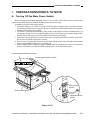
PREPARATIONS/POINTS TO
NOTE .......................................... 3-1
A. Turning Off the Main Power
Switch .................................... 3-1
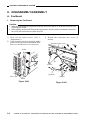
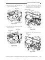
DISASSEMBLY/ASSEMBLY ...... 3-2
A.
B.
C.
D.
Fax Board .............................. 3-2
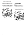
NCU PCB .............................. 3-7
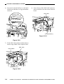
Battery Board ......................... 3-8
Installing the Expansion Board
Base Unit ............................. 3-11
CHAPTER 4 SERVICE MODE
I.
II.
SERVICE MODE ........................ 4-1
A. Service Data .......................... 4-1
B. Service Mode ......................... 4-2
C. Test Mode (#10 TEST) ......... 4-36
SERVICE REPORT .................. 4-49
A. System Dump List .......... 4-49
B. Error Transmission
Report ............................ 4-51
C. Error Reception Results
Report (for servicing) .... 4-52
D. Default Setting List ......... 4-53
CHAPTER 5 ERROR CODE
I.
USER ERROR CODES ............. 5-1
II.
SERVICE ERROR CODES ........ 5-5
APPENDIX
A.
B.
C.
iv
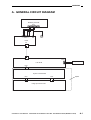
GENERAL CIRCUIT
DIAGRAM .................................. A-1
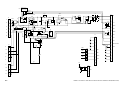
NCU CIRCUIT DIAGRAM ......... A-3
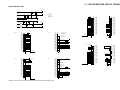
SYSTEM MOTHER CIRCUIT
DIAGRAM .................................. A-5
D.
MODULAR UNIT CIRCUIT
DIAGRAM .................................. A-7
COPYRIGHT © 1999 CANON INC. CANON SUPER G3 FAX BOARD-F1 REV.0 MAY 1999 PRINTED IN JAPAN (IMPRIME AU JAPON)
CHAPTER 1
GENERAL DESCRIPTION
I.
II.
III.
IV.
OUTLINE OF THE PRODUCT ... 1-1
SPECIFICATIONS ...................... 1-2
A. Standards and Performance .... 1-2
NAMES OF PARTS .................... 1-8
A. Location of the FAX Board ..... 1-8
CONTROL PANEL ..................... 1-9
A. Control Panel ......................... 1-9
B. Additional Functions /
Making Fax Settings ............ 1-10
C. Common Settings ................ 1-13
V.
D. Master Password ................. 1-15
POINTS TO NOTE FOR
SERVICING .............................. 1-16
A. Battery Backup .................... 1-16
B. Types of Backup Data .......... 1-17
C. Printing the Backup Data
Information ........................... 1-18
D. Removing / Initializing Data
in Service Mode ................... 1-19
COPYRIGHT © 1999 CANON INC. CANON SUPER G3 FAX BOARD-F1 REV.0 MAY 1999 PRINTED IN JAPAN (IMPRIME AU JAPON)
CHAPTER 1 GENERAL DESCRIPITON
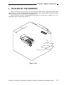
I. OUTLINE OF THE PRODUCT
The FAX Board possesses image processing functions which enable a digital black-and-white
copier to serve as a fax (transmission/reception) machine and communications functions which
enable its host copier to be connected to a telephone line.
The FAX Board is capable of transmitting image data at 33.6 kbps (max.), thanks to its V.34compatible modem complying with ITU-T.
Figure 1-101
COPYRIGHT © 1999 CANON INC. CANON SUPER G3 FAX BOARD-F1 REV.0 MAY 1999 PRINTED IN JAPAN (IMPRIME AU JAPON)
1-1
CHAPTER 1 GENERAL DESCRIPITON
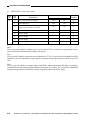
II. SPECIFICATIONS
A. Standards and Performance
The FAX Board is designed to comply with the standards and performance levels indicated.
(Scanner and printer functions are as indicated for the GP405/335.)
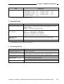
1. Communication System
Item
Description
Type certification
Model
GP405/335
Applicable line
General subscriber telephone network, fax communication network
(Class 2 terminal)
Number of lines
PSTN: 1 line
Communication method
Half-duplex, full duplex (V. 34)
Transmission speed (bps)
33.6 k, 31.2 k, 28.8 k, 26.4 k, 24.0 k, 21.6 k, 19.2 k, 16.8 k,
14.4 k, 12.0 k, 9.6 k, 7.2 k, 4.8 k, 2.4 k
Modulation method (image
transmission)
ITU-T
ITU-T
ITU-T
ITU-T
Modulation speed
(baud rate)
2.400, 3.000, 2.743, 2.800, 3.429 (for V. 34 only)
G3 protocol signal
ITU-T V.21 (300 bps)
ITU-T V.34 (1200 bps)
Coding method
JBIG, MMR, MR, MH
Communication
protocol
ITU-T T. 30 binary protocol/ECM method
ITU-T V. 8 protocol
V. 34 protocol/ECM method
G3 independent auto
abbreviation protocol
CEP I, II
Transmission output level
-8 to -15 dBm
Minimum reception
sensitivity level
-43 dBm
Modem IC
Reciprocal communication
Rockwell R288F
G3 (no G2/G1/MF)
Error correction
ITU-T ECM method (may be disabled)
1-2
V.34
V.33
V.17
V.29
(33.6 kbps to 2.4 kbps),
(14.4 k/12.0 kbps)
(14.4 k/12.0 kbps/TC9.6 k/TC7.2 kbps)
(9.6 k/7.2 kbps), ITU-T V.27ter (4.8 k/2.4 kbps)
COPYRIGHT © 1999 CANON INC. CANON SUPER G3 FAX BOARD-F1 REV.0 MAY 1999 PRINTED IN JAPAN (IMPRIME AU JAPON)
CHAPTER 1 GENERAL DESCRIPITON
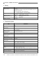
Description
Item
Transmission time*
JBIG/33.6 kbps:
ECM-MMR/33.6 kbps:
ECM-MMR/14.4 kbps:
ECM-MMR/9.6 kbps:
G3 MR/14.4 kbps:
3
2
6
9
2
sec
sec
sec
sec
sec
G3 MH/14.4 kbps:
G3 MR/9.6 kbps:
G3 MH/9.6 kbps:
13 sec
18 sec
19 sec
*Using Canon FAX Standard Chart No. 1.
2. Reading System
Item
Description
Transmission original size
A3, A4, A4R, A5, A5R, B4, B5, B5R, LTR, LTRR, LGL, 11x17,
STMT, STMTR
DADF:
two-sided original possible
Scanning line
concentration
Standard: 8 dots/mm x 3.85 lines/mm
Fine:
8 dots/mm x 7.7 lines/mm
Super Fine: 8 dots/mm x 15.4 lines/mm
Ultra Fine: 16 dots/mm x 15.4 lines/mm
(in direct transmission, 200 dpi, 400 dpi priority)
Reading density
adjustment*
3 levels + AE (in user mode, 9 levels; for text mode, ABC)
Halftone
Photo mode (256 gradations), text/photo mode (Auto Adjust)
*In AE mode, ABC correction is executed.
3. Recording System
Item
Description
Maximum original size
A3 (297 x 420 mm)
Recording paper size
A3, A4, A4R, A5, A5R, B4, B5, B5R, LTR, LTRR, LGL, 11x17,
STMT, STMTR (cassette pick-up only; 6 cassettes max.)
Maximum reception size
A3 (297 x 420 mm)
Scanning line
concentration (recording)
Main scanning: 600 dpi (reception)
Test shot
Provided
Sub scanning: 600 dpi
COPYRIGHT © 1999 CANON INC. CANON SUPER G3 FAX BOARD-F1 REV.0 MAY 1999 PRINTED IN JAPAN (IMPRIME AU JAPON)
1-3
CHAPTER 1 GENERAL DESCRIPITON
4. Memory
Item
Description
Image memory
Standard:
32 MB (about 640 pages; using Canon FAX Standard Chart No. 1)
Expansion (accessory)
32 MB (64 MB max.; about 1000 pages)
32 + 3 2 MB (96 MB max.; about 1000 pages)
Page memory
Standard:
Expansion:
14 MB (Standard/Fine resolution)
23 MB (approx.; accessory)
Back-up memory
(against power shortage)
Type:
Discharge:
Contents:
lithium ion secondary battery
3 hr (approx.)
image data
Memory indicator
Provided
5. Transmission System
Item
Description
Memory transmission
Provided (100 items max.; direct transmission when memory is
full)
Direct (manual)
transmission
Provided
Broadcasting
Provided (216 destinations max.; 60 for one-touch; 140 for speed;
16 for keypad)
Memory polling
transmission
Fixed time multi polling
Provided (memory box)
Confidential function
(address-specific
transmission)
Provided (by specifying address; ITU-T standards)
Time sharing dial
Provided
Transmission reservation
Provided
Address-specific collective
transmission
Provided
Mail post transmission
Timer destination-specific collective transmission (200 max.; onetouch + speed; 5 time settings)
2-on-1 transmission
Provided (w/ DADF-A1 only)
Timer transmission
Provided (200 destinations max.; 32 time settings)
Rotation transmission
Provided
Provided (w/ DADF-A1 only)
Stamp
Provided (1 setting only)
READ stamp, SENT stamp (in direct transmission mode only)
Dual access
Provided
Interrupt transmission
Provided (direct transmission)
Error re-transmission
Provided (memory reference)
1-4
COPYRIGHT © 1999 CANON INC. CANON SUPER G3 FAX BOARD-F1 REV.0 MAY 1999 PRINTED IN JAPAN (IMPRIME AU JAPON)
CHAPTER 1 GENERAL DESCRIPITON
6. Reception System
Item
Description
Manual reception
Provided
Confidential reception
Provided (using memory box)
Memory reception
Provided (640 pages* approx.; automatic output)
Forced memory reception
Provided (time may be specified)
Multi polling reception
216 destinations max.
Rotation reception
Provided
Number of printouts
(received pages)
1 to 99
Received image reduction
Provided Reduction ratio: 97%, 95%, 90%, 75%
Auto or fixed may be selected
Vertical/horizontal or vertical only may be selected
Cassette switch
(A, B, C, D)
A:
B:
C:
D:
Reception sequential
printing
Provided
Reception two-sided
printing
Provided (A4, A4R, B4, A3; w/ duplexing unit only)
n-on-1 recording
A5 + A5 Õ A4; B5 + B5 Õ B4; A4 + A4 Õ A3 (n being 3 max.;
for extra-length page only)
Forwarding
Provided (time may be specified; source may be specified)
Memory box
Provided (confidential, relay, fixed time, transmission bulletin,
general purpose)
Linear reduce/enlarge
reception output
Provided (long-size page reduced to default size by 75% to 100%)
Reception footer
Provided (records time of reception)
reduced recording
margin recording (same paper configuration)
reduced recording (different paper configuration)
margin recording (on larger paper to suit received page)
COPYRIGHT © 1999 CANON INC. CANON SUPER G3 FAX BOARD-F1 REV.0 MAY 1999 PRINTED IN JAPAN (IMPRIME AU JAPON)
1-5
CHAPTER 1 GENERAL DESCRIPITON
7. Dialing
Description
Item
One-touch dial
60 destinations; 120 characters max. (telephone number), 24
characters
Speed dial
140 destinations, 120 characters max. (telephone number), 24
characters
Group dial
119 groups (may be of one-touch/speed numbers)
Keypad dial
On-hook/off-hook
Auto dial
2 min (may be between 2 and 99 min)
2 times (may be between 1 and 15)
At time of error, only on page 1 and error page (may be all pages
or otherwise)
Electronic directory
Provided
8. Communications Control System
Description
Item
Reports
Communications control report (40 communications)
Transmission results report
Reception results report
Multiple communications results report
Memory clear report
One-touch dial telephone number list 1, 2
Speed dial telephone number list 1, 2
User data list
System data list
System dump list
Communications reservations list
group dial telephone numbers list
error transmissions report
memory box receptions report
originals list
Caller name
Provided (99 names max.)
Memory reference
The following are possible:
• generating list of originals in memory
• printing originals in memory
• clearing memory
• re-transmitting
• indicating list of communication reservations (reservation
may be canceled)
• indicating communications results
Group-by-group control
Group code, password (100 each; 4-character number)
1-6
COPYRIGHT © 1999 CANON INC. CANON SUPER G3 FAX BOARD-F1 REV.0 MAY 1999 PRINTED IN JAPAN (IMPRIME AU JAPON)
CHAPTER 1 GENERAL DESCRIPITON
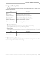
9. Transmission Original Editing System
Edit transmission
Item
Description
Two-sided reading
Provided (w/ DADF only)
2-on-1
Provided (w/ DADF only)
Reduction/
enlargement
Provided
Specifications subject to change for product improvement.
COPYRIGHT © 1999 CANON INC. CANON SUPER G3 FAX BOARD-F1 REV.0 MAY 1999 PRINTED IN JAPAN (IMPRIME AU JAPON)
1-7
CHAPTER 1 GENERAL DESCRIPITON
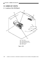
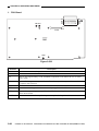
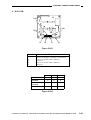
III. NAMES OF PARTS
A. Location of the FAX Board
[5]
[2]
[4]
[1]
[3]
[1]
[2]
[3]
[4]
[5]
FAX PCB
System Motherboard
MJ(modular jack) PCB
Battery board
NCU PCB
Figure 1-301
1-8
COPYRIGHT © 1999 CANON INC. CANON SUPER G3 FAX BOARD-F1 REV.0 MAY 1999 PRINTED IN JAPAN (IMPRIME AU JAPON)
CHAPTER 1 GENERAL DESCRIPITON
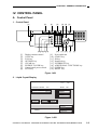
IV. CONTROL PANEL
A. Control Panel
1. Control Panel
[1]
[2]
[3]
COPY
[4]
FAX
[5] [6]
OPTIONS
ON/OFF
1
2
3
4
5
6
7
8
9
0
[16][15][14][13]
[1]
[2]
[3]
[4]
[5]
[6]
[7]
[8]
Display contrast control
COPY key
FAX key
OPTIONS key
CLEAR key
ENERGY SAVER key
Control panel power switch
STOP key
C
ID
[12]
[9]
[10]
[11]
[12]
[13]
[14]
[15]
[16]
[7]
[11] [10]
[9]
[8]
Power indicator
START key
ID key
Number keys
INTERRUPT key
ADDITIONAL FUNCTIONS key
GUIDE key
RESET key
Figure 1-401
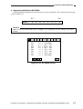
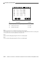
2. Liquid Crystal Display
Ready to send
STANDARD STANDARD
TEXT
RESOL DENSITY
IMAGE
QUALITY
07 / 31
15 : 00
AUTO
STMT
AUTO
RX
DIRECT
STAMP
CODED
DIALING
ON-HOOK
REDIAL
SPECIAL
FEATURES
FAX
MONITOR
Dialing...
Figure 1-402
COPYRIGHT © 1999 CANON INC. CANON SUPER G3 FAX BOARD-F1 REV.0 MAY 1999 PRINTED IN JAPAN (IMPRIME AU JAPON)
1-9
CHAPTER 1 GENERAL DESCRIPITON
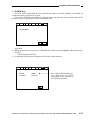
B. Additional Functions / Making FAX Settings
The following diagram shows various fax settings and their factory defaults. For details, see the
User’s Manual.
USER SETTINGS
UNIT TELEPHONE #
UNIT NAME
SENDER’S NAME
TX TERMINAL ID
ON
DENSITY CONTROL
5
TEL LINE TYPE
TOUCH TONE
AUDIBLE TONES
VOLUME CONTROL
SET DIRECTORY GENERAL CONTENTS
STANDARD KEY1 SETTING
STANDARD KEY2 SETTING
STANDARD SETTINGS
STORE DESTINATIONS
ONE-TOUCH DIALING
CODED DIALING
GROUP DIALING
TX SETTINGS
ECM TX
ON
PAUSE TIME
2SEC
AUTO REDIAL
ON
BATCH TX
ON
ERASE FAILED TX
ON
TIME OUT
ON
STAMP DOCUMENT
DIRECT&MEMORY TX
RAPID DIRECT TX
ON
RX SETTINGS
ECM RX
INCOMING RING
MANUAL/AUTO SWITCH
MEMORY RX
RX PAGE FOOTER
SYSTEM SETTINGS
RX RESTRICT
TX START SPEED
RX START SPEED
RX PASSWORD
PIN CODE ACCESS
FILE SETTINGS
MEMORY BOX STORE/SET
PRESET POLLING SETTING
TRANSFER SETTING
MEMORY LOCK SETTING
1-10
ON
OFF
OFF
ON
OFF
OFF
33600 bps
33600 bps
OFF
OFF
OFF
OFF
COPYRIGHT © 1999 CANON INC. CANON SUPER G3 FAX BOARD-F1 REV.0 MAY 1999 PRINTED IN JAPAN (IMPRIME AU JAPON)
CHAPTER 1 GENERAL DESCRIPITON
PRINTER SETTINGS
# OF RX COPIES
SELECT CASSETTE
RX REDUCTION
TWO-SIDED PRINT
N ON 1 LOG
REPORT SETTINGS
TX REPORT
RX REPORT
MEMORY BOX REPORT
ACTIVITY REPORT
PRINT LISTS
1-TOUTCH SPEED DIAL LIST 1
1-TOUTCH SPEED DIAL LIST 2
CODED SPEED DIAL LIST 1
CODED SPEED DIAL LIST 2
GROUP DIAL LIST
USER’S DATA LIST
1 COPIES
ON
OFF
OFF
FOR ERROR ONLY
OFF
ON
COPYRIGHT © 1999 CANON INC. CANON SUPER G3 FAX BOARD-F1 REV.0 MAY 1999 PRINTED IN JAPAN (IMPRIME AU JAPON)
1-11
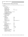
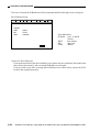
C. Common Settings
The following are items that relate to fax functions from those which are used in common by copier and fax systems.
Level 1
CUSTOM COMMON SETTINGS
Level 2
Factory default
INITIAL FUNCTION
SYSTEM DIFF SIZE ORIGINAL
DRAWER ELIGIBILITY FOR APS/ADS
STACK BYPASS
1st
2nd
TRAY
multi output tray 3
A
B
C
PRINTING PRIORITY
COPY
FAX
PRINTER
SET SYSTEM SETTING PASSWORD
RESTRICT USE OF FAX WITH CONTROL CARD
DEPT. ID MANAGEMENT
TIMER SETTINGS
STORE DEPT. ID/PASSWORD
COPY TOTALS
DATE & TIME SETTINGS
AUTO SLEEP TIME
COPYRIGHT © 1999 CANON INC. CANON SUPER G3 FAX BOARD-F1 REV.0 MAY 1999 PRINTED IN JAPAN (IMPRIME AU JAPON)
copier
ON
Uses
To select the basic screen at power-on (copier or fax).
To enable/disable placement of originals of different lengths in sub scanning direction on RDF
(other than copier function).
To enable/disable use of each cassette for cassette auto selection for copier, fax, and printer functions.
OFF
ON
ON
To assign the special tray of a sorter (accessory) to a function (copier, fax, or printer).
copier
fax/printer
1
2
3
none
no
no
none
User's Manual
none
5 min
To set an ID for the system controller (4 digit max.).
To specify whether to limit the number of persons given access to the fax using a control card (accessory).
To specify whether to limit the number of persons given access to the copier or fax or to control the number
of sheets used.
To store group ID and ID numbers for group-by-group control.
To enable counting the sheets used and printing of lists (w/ fax function only) according to group.
To set the current date and time.
To set the time to auto-sleep
(1 min to 8 hr; printing is enabled in response to an incoming file even in sleep state).
1-13
CHAPTER 1 GENERAL DESCRIPITON
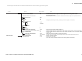
D. Master Password
A password may be one used for making various settings for such functions as confidential
boxes and memory boxes or one used for group-by-group control.
The one called "master password" is used during servicing work or in the even that the user
should forget a particular password.
Caution:
The use of the master password is restricted to the service person. Exercise care not to disclose
it to the user.
Mater Password: 4559769
COPYRIGHT © 1999 CANON INC. CANON SUPER G3 FAX BOARD-F1 REV.0 MAY 1999 PRINTED IN JAPAN (IMPRIME AU JAPON)
1-15
CHAPTER 1 GENERAL DESCRIPITON
V. POINTS TO NOTE FOR SERVICING
A. Battery Backup
The host copier and the board itself are equipped with a data backup function to protect against
loss of data at time of a power outage or when the main power remains off; all data is retained in
memory for a specific period of time even when the power is turned off.
Image processor PCB
Memory type
Control memory
Image memory
Back-up battery type
Lithium battery
Vanadium lithium secondary battery
The back-up battery used on the board is a vanadium lithium secondary battery capable of
backing up image data for about three hours, provided that the copier has previously been powered
for three days continuously under normal temperature and humidity conditions.
If the battery fails to back up data half this length of time, it is likely to have reached the end of its
life or the environment is likely to have a problem.
The battery ends its service when it has been recharged and discharged (100%) 40 times (at
25ºC). When its life is over, the existing image data will all be lost.
Important:
If you need to turn off the power for servicing work, be sure to print out the image data in
advance.
n Memory Clear List
If a memory clear list has automatically been printed as a result of turning on the host copier, the
image data indicated on the list is data the memory failed to back up. The image data retention control
information is automatically deleted after printing the list.
Caution:
The lithium battery and the vanadium lithium secondary battery contain flammable properties
(lithium, organic solvents). Do not throw them into fire to avoid explosion or combustion.
Also, do not disassemble them to avoid damaging the skin by contact with organic solvents.
Be sure to dispose of them appropriately (as by separating from others).
1-16
COPYRIGHT © 1999 CANON INC. CANON SUPER G3 FAX BOARD-F1 REV.0 MAY 1999 PRINTED IN JAPAN (IMPRIME AU JAPON)
CHAPTER 1 GENERAL DESCRIPITON
B. Types of Backup Data
1. User Data
The user may press the User Mode key on the control panel and then the Fax Settings key to
change the following items.
Item
Description
Basics
User telephone number, and others.
Report settings
Transmission results report, and others.
Transmission settings
ECM transmission, pause length, and others.
Reception settings
ECM reception, reception mode, and others.
Print settings
Cassette selection, image reduction, and others.
Memory control settings
Memory box, forwarding, and others.
System control settings
Transmission start speed, and others.
Dial settings
One-touch dial, speed dial, and others.
2. Service Soft Switches
The service person may make use of service mode to change various settings:
ADJUST, FUNCTION (parts thereof), FAX (settings thereof)
3. Control Data
Control data is data automatically stored in memory recording the operating states of the board.
Item
Description
Communication results
Record of the last 40 communications (transmission/reception).
System dump record
State of past communications, history of error communications,
and others.
n Deletion/Initializing of Data 1, 2, or 3
If any of the above backup data items should be deleted/initialized, all registration data will be
lost and all settings will be returned to factory settings.
COPYRIGHT © 1999 CANON INC. CANON SUPER G3 FAX BOARD-F1 REV.0 MAY 1999 PRINTED IN JAPAN (IMPRIME AU JAPON)
1-17
CHAPTER 1 GENERAL DESCRIPITON
4. Image Data Backed Up by the Secondary Battery
The user may press the User Mode key on the control panel and then the Fax Settings key to
change the following items.
Item
Transmission image
Communication mode
Transmission (memory transmission, broadcasting transmission)
Timer transmission
Timer broadcasting transmission
Polling transmission
Relay broadcasting transmission
Reception image
Confidential reception
Memory reception
Forced memory reception
C. Printing the Backup Data Information
The data backed up in control memory may be listed and printed out.
List
Item
User data
1-touch speed dial list 1
1-touch speed dial list 2
coded speed dial list 1
coded speed dial list 2
group dial list
user’s data list
Service soft switch
system data list
Control data
system dump list
activity report
1-18
COPYRIGHT © 1999 CANON INC. CANON SUPER G3 FAX BOARD-F1 REV.0 MAY 1999 PRINTED IN JAPAN (IMPRIME AU JAPON)
CHAPTER 1 GENERAL DESCRIPITON
D. Removing / Initializing Data in Service Mode
Some data in control memory may be removed/initialized accordingly as described using service
soft switch #8 CLEAR. For details, see 11. "Initializing the Settings (#8 CLEAR)" in Chapter 4.
Caution:
Be sure to print out the backup data information list before starting the work.
COPYRIGHT © 1999 CANON INC. CANON SUPER G3 FAX BOARD-F1 REV.0 MAY 1999 PRINTED IN JAPAN (IMPRIME AU JAPON)
1-19
CHAPTER 2
OPERATION AND TIMING
I.
II.
III.
IV.
BASIC OPERATION ................... 2-1
A. Functional Construction ......... 2-1
B. Control Block ......................... 2-2
C. Sleep Mode ........................... 2-3
D. Control Card .......................... 2-5
READING SYSTEM ................... 2-6
A. Reading Originals .................. 2-6
B. Reading Operation ................ 2-7
C. Memory .................................. 2-8
D. Reading/SENT Stamp ......... 2-10
E. Memory Full Condition ........ 2-11
F. Basic Editing Functions ....... 2-12
G. Test Shot .............................. 2-14
H. Reduction/Enlargement ....... 2-15
RECORDING SYSTEM............ 2-16
A. Recording System ............... 2-16
B. Image Rotation .................... 2-35
COMMUNICATION SYSTEM ... 2-36
A. Image Signal Transmission
Speed .................................. 2-36
B. Canon Express Protocol ...... 2-38
C. JBIG Image Compression
Coding Method .................... 2-39
D.
E.
F.
G.
V.
V.8/V.34 Procedure .............. 2-55
Rapid Transmission ............. 2-71
Direct Transmission ............. 2-73
Memory Transmission
Reservation ......................... 2-74
H. Broadcasting ....................... 2-74
I. Timer Transmission/
Timer Broadcasting ............. 2-75
J. Polling Reception/
Multiple Polling Reception ... 2-75
K. Timer Polling Reception/
Timer Multiple Polling
Reception ............................ 2-76
L. Paper Size Declaration in
Reception Mode .................. 2-77
ARRANGEMENT AND
FUNCTIONS OF ELECTRICAL
PARTS ...................................... 2-78
A. Fax PCBs ............................ 2-78
B. Variable Resistors (VR),
Light-Emitting Diodes (LED),
and Check Pins by PCB ...... 2-79
COPYRIGHT © 1999 CANON INC. CANON SUPER G3 FAX BOARD-F1 REV.0 MAY 1999 PRINTED IN JAPAN (IMPRIME AU JAPON)
CHAPTER 2 OPERATION AND TIMING
I.
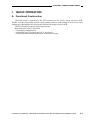
BASIC OPERATION
A. Functional Construction
The FAX board is controlled by the CPU mounted on the copier's image processor PCB.
Further, such fax-related data as service mode settings and user mode settings as well as one-touch
dialing/speed dialing data are stored in the RAM on the image processor PCB.
The FAX board provides the following functions:
Basic Functions of the FAX Board
• Controlling communication.
• Controlling the G3 protocol and V.8/V.34 protocol.
• Performing modulation/demodulation (modem) processing.
COPYRIGHT © 1999 CANON INC. CANON SUPER G3 FAX BOARD-F1 REV.0 MAY 1999 PRINTED IN JAPAN (IMPRIME AU JAPON)
2-1
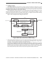
CHAPTER 2 OPERATION AND TIMING
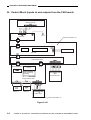
B. Control Block (inputs to and outputs from the FAX board)
Modular unit PCB
MT15
NCU PCB
Super G3 FAX Board - F1
Fax control
Modem
Speaker
FAX PCB
System Mother PCB
Memory (standard)
IP-CPU
Image processing
Binary processing
Smoothing
Coding/decoding processing
Composite Power
Image Processor PCB
Extension
Memory 1
Extension
Memory 2
Battery PCB
Super G3 FAX Board - F1
Figure 2-101
2-2
COPYRIGHT © 1999 CANON INC. CANON SUPER G3 FAX BOARD-F1 REV.0 MAY 1999 PRINTED IN JAPAN (IMPRIME AU JAPON)
CHAPTER 2 OPERATION AND TIMING
C. Sleep Mode
The board switches among four types of state according to how power is supplied: power-off,
sleep 1, sleep 2, and standby.
State
Main power off
IP-CPU*
OFF
LCD
OFF
Fixing heater
OFF
Sleep 3
Sleep 2
ON
Available
operation
Retention by
battery
None
Retention by
power supply
FAX data
transmission/
reception
Pre-heat
Sleep 1
Standby
Image memory
for fax***
ON**
FAX data
transmission/
reception, printing
ON
*CPU for the image processor PCB.
**Includes the state in which pre-heating mode is ended and the fixing heater reaches a specific
temperature.
Figure 2-102
COPYRIGHT © 1999 CANON INC. CANON SUPER G3 FAX BOARD-F1 REV.0 MAY 1999 PRINTED IN JAPAN (IMPRIME AU JAPON)
2-3
CHAPTER 2 OPERATION AND TIMING
2. Transition to Sleep Mode
a. Transition to Sleep Mode
Standby
A fax output is generated.
<The control panel power switch is pressed.>
<The time-out mechanism as set in "timer"* occurs.>
No fax output is
being made.
<The Save Power
key is pressed.>
Sleep 1
The fax output
has been generated.
Sleep 2
Save power mode starts.
The mode of consuming power
varies according to the setting made
by the Save Power key (-10%, -25%,
-40%).
Sleep 3
The fixing heater turns off.
b. Transition from Sleep Mode
Standby
• The Save Power key is pressed.
• Off-hook state occurs.
• The control panel power switch is pressed.
• A function key is pressed.
• The feeder cover is opened.
• An original is detected in the feeder.
Sleep 1
A fax output starts
to be generated.
Sleep 2
Save power mode starts.
The mode of consuming power
varies according to the setting made
by the Save Power key (-10%, -25%,
-40%).
Sleep 3
The fixing heater turns off.
* timer: auto power-off time, weekly timer.
Figure 2-103
2-4
COPYRIGHT © 1999 CANON INC. CANON SUPER G3 FAX BOARD-F1 REV.0 MAY 1999 PRINTED IN JAPAN (IMPRIME AU JAPON)
CHAPTER 2 OPERATION AND TIMING
D. Control Card
When the control card is used, the following settings may be made to restrict the use of fax
functions:
user mode → common setting → fax control card restriction
→ Checks the control card.
The settings made this way apply to fax operations only, and do not affect automatic reception
and automatic generation of received files.
COPYRIGHT © 1999 CANON INC. CANON SUPER G3 FAX BOARD-F1 REV.0 MAY 1999 PRINTED IN JAPAN (IMPRIME AU JAPON)
2-5
CHAPTER 2 OPERATION AND TIMING
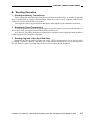
II. READING SYSTEM
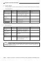
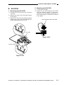
A. Reading Originals
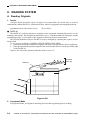
1. Feeder
A digital black-and-white copier designed to accommodate the board may be used in
combination with the DADF-A1 (document feeder), which is equipped with a stamping function.
reproduction ratio with a feeder in use:
50% to 200%
■ DADF-A1
The DADF-A1 picks up and places originals on the copyboard automatically one by one for
reading by the scanner. The originals are placed face-up (i.e., with the printed side facing up), and the
topmost page (page 1) of the stack of fax originals is picked up first for transmission.
The pick-up method used by the DADF-A1 may be changed by operating the copier's service
mode switch.
To set, operate as follows: COPIER>OPTION>USER>FACE-DWN.
1: picks up and reads the bottommost original of the stack first and returns it to the original tray.
0: picks up and reads the topmost original of the stack first and delivers it to the tray on the right
of the DADF-A1.
Figure 2-201 shows the operation when the mode is set to "0."
1
2
3
4
Originals
(face-up)
DADF-A1
1
Scanner (moving)
Figure 2-201
2. Copyboard Mode
In copyboard mode, an original is manually placed on the copyboard glass for reading.
2-6
COPYRIGHT © 1999 CANON INC. CANON SUPER G3 FAX BOARD-F1 REV.0 MAY 1999 PRINTED IN JAPAN (IMPRIME AU JAPON)
CHAPTER 2 OPERATION AND TIMING
B. Reading Operation
1. Reading for Memory Transmission
Each original placed on the copyboard glass is read and stored in memory. A number of originals
may be transmitted in a single communication. When the feeder is used, originals stacked in the
feeder are read one after another in sequence.
The originals read in copyboard mode and those read using the feeder cannot be combined.
2. Reading for Direct Transmission
A single original placed on the copyboard glass is read in response to a press on the Start key. If
the feeder is used, all originals stacked in the feeder will be read.
As in the case of reading for memory transmission, originals read in copyboard mode and those
read using the feeder cannot be combined.
3. Reading Originals of Non-Specified Sizes
Originals are read in respect of the size (A/B-, INCH-configuration) set in service mode
(COPIER > OPTION > BODY > MODEL-SZ). If the original in question is of a size different from
the specified size, part of its image may not be read or its center may be displaced.
COPYRIGHT © 1999 CANON INC. CANON SUPER G3 FAX BOARD-F1 REV.0 MAY 1999 PRINTED IN JAPAN (IMPRIME AU JAPON)
2-7
CHAPTER 2 OPERATION AND TIMING
C. Memory
The copier is equipped with two types of memories: the "page memory" is used to store images
(read or received) temporarily for processing in preparation for printing; and the "image memory" is
used to store transmission/reception image data after coding.
1. Page Memory
The page memory stores image data which has been processed for reproduction ratio, resolution,
image quality, and binary coding according to the selected fax mode. The page memory may be
expanded by 23 MB through installation of an accessory memory.
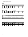
2. Image Memory
The image memory is as large as 32 MB (standard), and is used to store transmission/reception
image data after coding (equivalent of about 640 pages of Canon FAX Standard Chart No. 1). The
image memory may be expanded by 32 MB or 64 MB (32 + 32 MB) through installation of an
accessory memory.
The image memory is backed up by a lithium ion secondary battery, so that its contents may be
retained in the event that the copier loses its power because of a power shortage.
When the image memory becomes full during memory transmission or reading operation, the
mode will automatically switch to direct transmission. (See "Processing in a Memory Full
Condition.")
Caution:
Take note of the following when expanding the image memory:
1. Generate output of the contents of the existing memory.
2. Turn SW2 on the FAX Board off to deprive the image memory of power.
3. Install the additional memory.
4. After the work, turn on SW2 (i.e., slide it to the left).
2-8
COPYRIGHT © 1999 CANON INC. CANON SUPER G3 FAX BOARD-F1 REV.0 MAY 1999 PRINTED IN JAPAN (IMPRIME AU JAPON)
CHAPTER 2 OPERATION AND TIMING
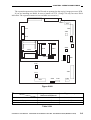
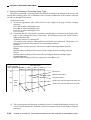
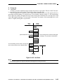
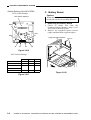
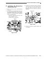
The expansion memories of the FAX board are arranged on the copier's image processor PCB.
If you are installing one RAM, be sure to install it to J723. (Using J724 only can cause E604
indication. The expansion memories are available as accessories.)
J715
J716
J720
J717
J702
J714
J703
J701
J713
J723
J704
J722
J724
J705
J721
SW702
J706
2 1 3
OFF
ON
SW701
J712
J707
J711
J710
J709
J718
J708
Figure 2-202
Image memory
Minimum to Maximum
Page memory
Standard (32 MB)
About 1 to 10 MB
About 14 MB
+32MB (64MB)
About 1 to 33 MB
About 23 MB
+32MB x 2 (96MB)
About 1 to 66 MB
About 23 MB
Table 2-201
COPYRIGHT © 1999 CANON INC. CANON SUPER G3 FAX BOARD-F1 REV.0 MAY 1999 PRINTED IN JAPAN (IMPRIME AU JAPON)
2-9
CHAPTER 2 OPERATION AND TIMING
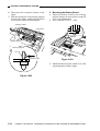
D. Reading/SENT Stamp (DADF-A1 only)
The stamping mechanism is part of the feeder (DADF-A1), and may be READ stamp or SENT
stamp.
A single stamp is used for both, and is designed to put a pink dot 3 mm in diameter.
The stamping mechanism is enabled by operating "transmission settings" of "additional
functions." It functions as follows:
• It does not operate in copier, test shot, or copyboard mode.
• It prohibits advance feed when picking up originals.
• It puts a stamp on both originals in 2-on-1 read mode.
• It puts a stamp on the face only when reading a two-sided original.
• It starts direct transmission mode when combined with rapid transmission mode, and uses the
SENT stamp.
1. SENT Stamp
A stamp is put in response to the receipt acknowledge signal from the receiving machine.
It is available only for direct transmission.
2. READ Stamp
A stamp is put when the image read by the scanner has been stored in the image memory.
The location of the stamp when the DADF is used will be as follows:
Original
Center of original
Feeding direction
50 mm
(approx.)
23 mm (approx.)
Figure 2-203 Stamp Location (DADF-A1)
2-10
COPYRIGHT © 1999 CANON INC. CANON SUPER G3 FAX BOARD-F1 REV.0 MAY 1999 PRINTED IN JAPAN (IMPRIME AU JAPON)
CHAPTER 2 OPERATION AND TIMING
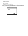
E. Memory Full Condition
1. Outline
If the image memory becomes full while reading is under way for memory transmission (as
detected by the CPU on the IP PCB), direct transmission mode will automatically be used starting
with the page in question.
Such modes as timer transmission and broadcasting, which are based on memory transmission,
however, cannot rely on direct transmission even if the memory becomes full. In these modes, the
image data that occurs after the detection of the condition will be discarded without transmission.
2. Messages
• memory running out
The message appears when the remaining memory reaches 10% or less. If the size of the
upcoming data is less than the remaining memory, storage may be continued.
• memory full
The message appears when the CPU finds the RAM to be full. After this message has
appeared, all transmissions will be direct transmissions.
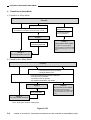
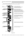
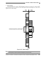
3. Sequence of Operations
Figure 2-204 shows the sequence of operations that take place when the CPU detects a memory
full condition, i.e., shifting to direct transmission mode (3 transmission originals; memory full
detected when reading the 3rd page):
Direct transmission starts
Reading
Transmitting calling
1
2
3
1
2
3
1, 2, and 3 indicate the number of originals.
Figure 2-204
COPYRIGHT © 1999 CANON INC. CANON SUPER G3 FAX BOARD-F1 REV.0 MAY 1999 PRINTED IN JAPAN (IMPRIME AU JAPON)
2-11
CHAPTER 2 OPERATION AND TIMING
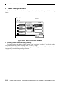
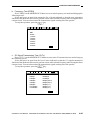
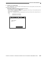
F. Basic Editing Functions
The basic screen for fax mode allows setting a resolution, density, and image quality for reading
images.
11/11 11 : 11
AUTO
Ready to send.
=
IMAGE
QUALITY
RESOL.
DENSITY
STANDARD
DARK
TEXT
FINE
STD
TEXT /
PHOTO
SUPER
FAIN
LIGHT
PHOTO
ULTORA
FINE
DONE
FAX
MONITOR
Figure 2-205 Basic Screen for Fax Mode
1. Reading Image Quality/Reading Density
The image quality may be any of three settings: 'text', 'text/photo', or 'photo'. The density, on the
other hand, may be any of three settings: 'dark', 'normal', or 'light'.
The images are subjected to binary processing on the image processor PCB according to the
image quality selected during reading operation.
2-12
COPYRIGHT © 1999 CANON INC. CANON SUPER G3 FAX BOARD-F1 REV.0 MAY 1999 PRINTED IN JAPAN (IMPRIME AU JAPON)
CHAPTER 2 OPERATION AND TIMING
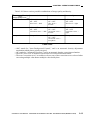
Table 2-202 shows various possible combinations of image quality and density.
Density
dark
normal
light
Image quality
text
ABC = ON
AE = OFF
slice level = dark
ABC = ON
AE = OFF
slice level =
normal
ABC = ON
AE = OFF
slice level = light
photo
ABC = OFF
AE = OFF
correction curve = dark
Not possible
Not possible
ABC = OFF
AE = OFF
correction curve =
normal
ABC = OFF
AE = OFF
correction curve =
text/photo
ABC = OFF
AE = OFF
correction curve =
light
Not possible
Table 2-202
• ABC stands for "Auto Background Control," and is an automatic density adjustment
mechanism which places priority on speed.
• AE stands for "Automatic Exposure," and is an automatic density correction mechanism.
• The term "slice level" as used here refers to the level selected for binarization.
• The term "correction curve" as used here refers to any of the correction curves selected when
converting multiple-value data to multiple-value density data.
COPYRIGHT © 1999 CANON INC. CANON SUPER G3 FAX BOARD-F1 REV.0 MAY 1999 PRINTED IN JAPAN (IMPRIME AU JAPON)
2-13
CHAPTER 2 OPERATION AND TIMING
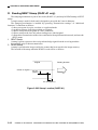
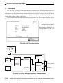
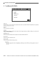
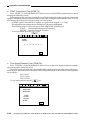
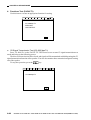
G. Test Shot
In a test shot, an image is read using the same conditions used for actual transmission: the
memory is stored in memory once and then printed out. For this reason, the quality and arrangement
of the image may be checked prior to actual transmission. It may also be used to look for an error in
mechanisms from reading to storing in memory. Figures 2-206 and 2-207 show the Test Shot screen
and the flow of image signals, respectively.
The Test Shot screen may be brought up by pressing "SPECIAL FEATURES" and then "TEST
PRINT."
Do you wish to test print ?
RESOL.
DENSITY
IMAGE
QUALITY
DOCUMENT
SIZE
C
:
:
:
:
Note that the resolution,
density, and image quality are
determined according to the
settings made on the Fax
Basic screen.
STANDARD
STANDARD
TEXT
AUTO
START
TEST PRINT
FAX
MONITOR
Figure 2-206 Test Shot Screen
Scanning
lamp
CCD
Scanner
Image processor PCB
Analog
processor
PCB
Image
processing
circuit
Standard
memory (32 MB)
Binary
processing
Expansion
memory (32 MB)
Resolution
conversion
Laser
driver PCB
FAX functions
control
Smoothing
Expansion
memory (32 MB)
Figure 2-207 Flow of Image Signals in Test Shot Mode
2-14
COPYRIGHT © 1999 CANON INC. CANON SUPER G3 FAX BOARD-F1 REV.0 MAY 1999 PRINTED IN JAPAN (IMPRIME AU JAPON)
CHAPTER 2 OPERATION AND TIMING
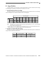
H. Reduction/Enlargement
Images are processed for reduction/enlargement by the image processor for both transmission
and reception. For ratios, see Table 2-203.
Ratio
Transmission
50% to 200%
Reception
97%, 95%, 90%, 75%
(as set in user mode and service mode)
Table 2-203 Reduction/Enlargement for Transmission/Reception
COPYRIGHT © 1999 CANON INC. CANON SUPER G3 FAX BOARD-F1 REV.0 MAY 1999 PRINTED IN JAPAN (IMPRIME AU JAPON)
2-15
CHAPTER 2 OPERATION AND TIMING
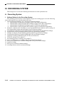
III. RECORDING SYSTEM
When images are received, the following mechanisms are used to print them out:
A. Recording System
1. Settings Related to the Recording System
The recording system used to record reception images on recording paper covers the following
items, which may be set to suit the needs of the user:
1. Cassette Selection Switch A, B, C, D (fax specifications settings)
a. enable/disable dividing and recording on paper of the same configuration
b. enable/disable creating a margin and recording on paper of the same configuration
c. enable/disable dividing and recording on paper of a different configuration
d. enable/disable creating a margin and recording on paper of a different configuration
2. automatic reduction and recording on receiving machine/fixed reduction and recording on
receiving machine (image reduction under fax specifications settings)
3. reception footer function (reception information recording under fax specifications settings)
4. forced memory mode (printing prohibition under fax specifications settings)
5. multiple sets output (reception printing quantity under fax specifications settings)
6. reception start function (reception printing under fax specifications settings)
7. reduction recording prohibition to A4 or LTR (service data #7)
8. LTR/LGL priority (service data #7)
9. sub scanning priority recording (service data #7)
10. n-on-1 recording (n-on-1 recording under fax specifications settings)
11. delivery tray selection (two-sided recording under fax specifications settings)
12. rotation recording
13. delivery tray selection (common settings)
14. recording cassette selection (common settings)
2-16
COPYRIGHT © 1999 CANON INC. CANON SUPER G3 FAX BOARD-F1 REV.0 MAY 1999 PRINTED IN JAPAN (IMPRIME AU JAPON)
CHAPTER 2 OPERATION AND TIMING
1.1 Cassette Switch A, B, C, D
For details, see 2. "Selecting Recording Paper" on p. 2-24.
1.2 Receiving Side Automatic/Fixed Reduction for Recording
a. Receiving Side Automatic Reduction for Recording
If the page of received data is longer than the default page, the image will be reduced (within the
specified maximum reduction ratio) for recording so that the page will not be divided.
b. Receiving Side Default Reduction for Recording
All received pages are always reduced for recording.
ADDITIONAL FUNCTIONS > CUSTOM FAX SETTINGS > PRINTER SETTINGS > RX REDUCTION
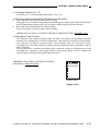
1.3 Reception Footer Function
The reception footer function adds the date and time of reception, and sequential and page
numbers to the trailing edge of each recording sheet. This function is used for received images
only, and does not apply to test shot mode or stored images. The size of the footer varies
according to the selected resolution: it is about 4 mm at standard resolution, and about 3 mm in
other resolutions.
The reception footer is added to the trailing edge (within the effective recording area) of each
recording sheet regardless of the length of the reception page. When a footer is added, the
reception page recording will be smaller than otherwise.
ADDITIONAL FUNCTIONS > CUSTOM FAX SETTINGS >
RX SETTINGS > RX PAGE FOOTER
Received page
Recording area
Reception footer
Figure 2-301
COPYRIGHT © 1999 CANON INC. CANON SUPER G3 FAX BOARD-F1 REV.0 MAY 1999 PRINTED IN JAPAN (IMPRIME AU JAPON)
2-17
CHAPTER 2 OPERATION AND TIMING
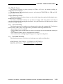
1.4 Forced Memory Reception
This function operates to store received images in memory without printing.
ADDITIONAL FUNCTIONS > CUSTOM FAX SETTINGS > FILE SETTINGS >
MEMORY LOCK SETTING
1.5 Multiple Quantity Output (reception printing quantity)
This function operates to generate received images for a specified quantity.
The function is effective for confidential, relay, and forced memory modes.
1.6 Reception Sort Printing
This function operates to receive and store all pages of a single communication in memory, and
then generates the file starting with the last page.
If the copier is equipped with a face-down delivery mechanism, the output will be in the order of
reception regardless of the settings made as part of user data (no reception sort). In n-on-1 mode,
reception sort will not be performed.
(The foregoing becomes effective according to COPIER>OPTION>USER>FAX-PRT in
service mode.)
ADDITIONAL FUNCTIONS > CUSTOM FAX SETTINGS >
PRINTER SETTINGS > RX REDUCTION
1.7 Reduction Prohibition to A4/LTR
This function operates to prohibit reduction to A4/LTR paper even if the received image (Aconfiguration) falls within the reduction range. The function prohibits automatic reduction to A4 or
LTR only, and allows automatic reduction to other sizes.
Service Soft Switch Settings
#7 PRINTER SW05: yes, no
2-18
COPYRIGHT © 1999 CANON INC. CANON SUPER G3 FAX BOARD-F1 REV.0 MAY 1999 PRINTED IN JAPAN (IMPRIME AU JAPON)
CHAPTER 2 OPERATION AND TIMING
1.8 LTR/LGL Priority
This function operates to place priority on LTR or LGL over A4 when recording Aconfiguration received pages.
This function may be enabled using a service soft switch (#7 PRINTER) for LTR and LGL
independently of each other.
1.9 Sub Scanning Priority
This function operates to place priority on a sheet with a long sub scanning side having the same
width as the received page.
For instance, if B4 and A4 sheets are set when an A4 page with a long side is received (A4
reduction prohibited, sub scanning direction B4 or less), this function avoids division into A4 but
records on a single B4 sheet.
1.10 n-On-1 Recording
This function operates to combine received pages with a short sub scanning side. The function
prints as many as three pages on a single sheet, provided the following conditions exist:
• In user mode, n-on-1 is enabled.
• The recording paper is not the same size as the received page, but can accommodate as many as
n pages.
• The resolution of the n pages is an appropriate resolution.
• The combined sub scanning lengths of n pages fit a single recording sheet.
1.11 Two-Sided Recording
This function operates to record two received pages on a single recording sheet.
ADDITIONAL FUNCTIONS > CUSTOM FAX SETTINGS >
PRINTER SETTINGS > TWO-SIDED PRINT, N ON 1 LOG
COPYRIGHT © 1999 CANON INC. CANON SUPER G3 FAX BOARD-F1 REV.0 MAY 1999 PRINTED IN JAPAN (IMPRIME AU JAPON)
2-19
CHAPTER 2 OPERATION AND TIMING
1.12 Selecting the Delivery Tray
This function enables the selection of a tray for delivery if the Multi Output Tray-3 is installed.
Select a tray in user mode (common settings).
1.13 Pick-Up Cassette Selection (turning on/off cassette auto selection)
This function operates to select the cassette used as the source of recording sheets. The function
specifies a cassette size, and is also used to specify a paper size for reception.
2-20
COPYRIGHT © 1999 CANON INC. CANON SUPER G3 FAX BOARD-F1 REV.0 MAY 1999 PRINTED IN JAPAN (IMPRIME AU JAPON)
CHAPTER 2 OPERATION AND TIMING
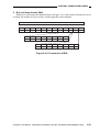
2. Selecting Recording Sheets
a. Outline
When the default service data is effective, recording sheets are selected based on the cassette
selection switch settings (A through D) in reference to the following descriptions:
Priority
Description
1
Sheet whose main scanning length is the
same as the print size length and which
can accommodate all the image.
2
Sheet whose main scanning length is not
the same as the print size length but can
accommodate all the image.
3
Sheet whose main scanning length is the
same as the print size length and which
allows a minimum number of divisions.
Sheet whose main scanning length is not
the same as the print size length but
which allows a minimum number of
divisions.
4
Remarks
If it takes multiple sheets to print all the
image, a sheet whose sub scanning
length is closest to the print size length
(minimum size) will be selected.
If it takes multiple sheets to print all the
image and if different sheets allow a
minimum number of divisions, the sheet
with the shortest sub scanning length
will be selected. The second and
subsequent pages will be printed on the
same type of sheet.
Reference:
If sheets of the same size are set, the order of priority will be as follows:
[3]
[5]
[1]
[1]
[2]
[2]
[3]
[4]
[7]
[1]
[2]
[3]
[4]
[5]
[6]
Figure 2-302 (DADF-A1 Model)
• If the selected sheets run out during printing, the sheets with the second priority will
automatically be selected.
• If no sheet exists for printing, memory reception will be used.
COPYRIGHT © 1999 CANON INC. CANON SUPER G3 FAX BOARD-F1 REV.0 MAY 1999 PRINTED IN JAPAN (IMPRIME AU JAPON)
2-21
CHAPTER 2 OPERATION AND TIMING
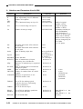
b. Cassette Selection Switch
This function operates to select specific recording sheets to suit the needs of the user. As many as
four cassette selection switches (A through D) exist as described in the following table.
If printing on recording sheets of the same size as the received pages is desired, be sure to shift all
cassette size switches A through D to OFF.
Switch (function)
Description
Switch A (divide and
record on paper of same
configuration)
Enables (ON) or disables (OFF) dividing and recording on sheets
of the same configuration but whose sub scanning direction is
shorter than received pages (default size image).
Switch B (create margin
and record on paper of
same configuration)
Enables (ON)/disables (OFF) creating a margin and recording on
sheets of the same configuration but one size larger than the
received page.
Switch C (reduce and
record B image on A
paper)
Enable (ON)/disables (OFF) reducing and recording pages of Bconfiguration on sheets of A configuration.
Switch D (reduce and
record A page on B paper)
Enables (ON)/disables creating a margin and record received pages
of A configuration on sheets of B configuration.
2-22
COPYRIGHT © 1999 CANON INC. CANON SUPER G3 FAX BOARD-F1 REV.0 MAY 1999 PRINTED IN JAPAN (IMPRIME AU JAPON)
CHAPTER 2 OPERATION AND TIMING
c. Recording Paper
The FAX Board automatically selects the first recording sheet (cassette) that satisfies the
following conditions; if none of the conditions is met, the board indicates a message to that effect, and
starts memory reception (waiting for output).
Priority
Description
1
Has the same main scanning length. Is smallest of those capable of accommodating
all the image (in Direct or by reduction up to maximum ratio).
2
Has the same main scanning length. Is the smallest of those capable of
accommodating images after discarding as much of the image as allowed (in
Direct).
3
Has the same main scanning length. Is the smallest of those capable of
accommodating all the image with the least number of divisions.
4
Has a greater main scanning length. Is the smallest of those capable of
accommodating all the image (in Direct).
5
Accommodates all the image by fixed reduction.
6
Has a greater main scanning length. Is the smallest of those capable of
accommodating all the image with the least number of divisions (in Direct).
7
Accommodates all the image with the least number of divisions (by fixed
reduction).
Reference:
1. If several cassettes contain the sheets of the same size, priority will be given to A4 over A4R
(priority on printing speed). Further, a higher cassette will be given priority over a lower
one.
2. If division is performed, the second and subsequent pages will be printed on sheets.
3. If all of the following conditions are met, n-on-1 recording will be executed:
• "n-on-1 record" is selected as part of user data.
• The main scanning length of n received pages is the same.
• The resolution of the n received pages is the same.
• The combined sub scanning lengths of n received pages fit a single page.
4. If all of the following conditions are met, two-sided recording will be executed.
• "two-sided recording" is set to "Yes" as part of the user data.
• Each pair of received pages is of the same size as the sheets in the selected cassette.
• Each pair of received pages is part of a single communication.
5. In addition, service switches may be used to prohibit reducing and printing to A4,
prohibiting reducing and printing to LTR, giving priority to sub scanning, giving priority to
LTR, and giving priority to LGL.
COPYRIGHT © 1999 CANON INC. CANON SUPER G3 FAX BOARD-F1 REV.0 MAY 1999 PRINTED IN JAPAN (IMPRIME AU JAPON)
2-23
CHAPTER 2 OPERATION AND TIMING
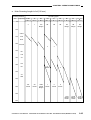
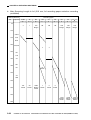
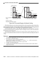
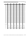
d. Priority of Selecting a Recording Paper Type
The priority of printing or printing mode is determined according to the settings of the service soft
switch and recording paper size in addition to the selected combination of the cassette selection
switches A through D (user data).
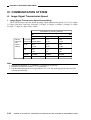
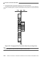
Guide to the Charts
(1) Selects the appropriate table with reference to the length of the page in main scanning
direction.
·
If it is A4 in main scanning direction
·
If it is B4 in main scanning direction
·
If it is A3 in main scanning direction
·
If it is a report
(2) Checks the data for each cassette containing recording paper in reference to the length of the
page in sub scanning direction (vertical axis). The notations used in the charts (frames)
indicate the following:
·
Alphabet Characters (A through D)
Correspond to the cassettes A through D selected by the user soft switch. The absence of a
notation is interpreted as the absence of constraining conditions.
·
Numbers
Represent the levels of priority, with a lower number indicating a higher priority.
·
Margin
Indicates that recording will be executed with a margin in main scanning direction.
·
Divide
Indicates that recording will be executed by dividing the data into multiple pages.
·
Default Reduction
Indicates that recording will be by reduction (as from B4 to A4).
Length in sub
scanning direction
mm
Paper size
Recording paper
STMT
A5
B5
LTR
(216 140mm) (210 148mm) (257 182mm) (216 279mm)
50
Priority level
2
100
STMT
150
A4/2
1
11D
Margin
4B
Cassette select switch
Recording method
Length in sub scanning direction at Direct ratio
Length in sub scanning direction at 75% ratio
B4/2
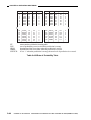
(3) The recording paper satisfying the conditions given in (2) and with the highest priority level
is used. If none satisfies the conditions, memory reception will be selected and no output is
generated.
2-24
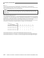
COPYRIGHT © 1999 CANON INC. CANON SUPER G3 FAX BOARD-F1 REV.0 MAY 1999 PRINTED IN JAPAN (IMPRIME AU JAPON)
CHAPTER 2 OPERATION AND TIMING
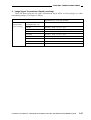
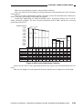
a. Main Scanning Length Is A4 (210 mm)
Length in sub
scanning direction
mm
Paper size
Recording paper
A4
LGL
A3
11 17
B5
LTR
STMT
A5
B4
(216 140mm) (210 148mm) (257 182mm) (216 297mm) (210 297mm) (216 356mm) (257 364mm) (210 420mm) (216 432mm)
50
2
1
11D
Margin
4B
3B
4
3
5B
5B
Margin
5B
Margin
5B
Margin
17AD
Margin
Divide
16AD
Margin
Divide
15AD
Margin
Divide
100
STMT
150
A4/2
B4/2
200
A5,A3/2
250
B5
LTR
300
A4
LGL
350
B4
7A
Divide
5
400
A3
LGR
450
500
10A
Divide
9A
Divide
18AD
Divide
Margin
7
Divide
6
Divide
8
Divide
550
600
COPYRIGHT © 1999 CANON INC. CANON SUPER G3 FAX BOARD-F1 REV.0 MAY 1999 PRINTED IN JAPAN (IMPRIME AU JAPON)
2-25
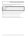
CHAPTER 2 OPERATION AND TIMING
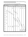
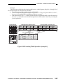
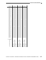
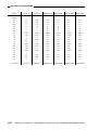
b. Main Scanning Length Is A4 (210 mm; A4 recording paper reduction recording
prohibited)
Length in sub
scanning direction
mm
Paper size
Recording paper
A4
LGL
A3
11 17
B5
A5
LTR
B4
STMT
(216 140mm) (210 148mm) (257 182mm) (216 279mm) (210 297mm) (216 356mm) (257 364mm) (210 420mm) (216 432mm)
50
2
1
11D
Margin
4B
3B
4
3
5B
12D
Margin
13D
Margin
14D
Margin
17AD
Margin
Divide
15AD
Margin
Divide
15AD
Margin
Divide
100
STMT
150
A4/2
B4/2
200
A5,A3/2
250
B5
LTR
300
A4
LGL
350
7A
Divide
B4
5
400
A3
LGR
450
500
10A
Divide
9A
Divide
18AD
Margin
Divide
7
Divide
6
Divide
8
Divide
550
600
2-26
COPYRIGHT © 1999 CANON INC. CANON SUPER G3 FAX BOARD-F1 REV.0 MAY 1999 PRINTED IN JAPAN (IMPRIME AU JAPON)
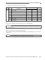
CHAPTER 2 OPERATION AND TIMING
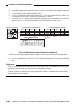
c. Main Scanning Length Is A4 (210 mm; LTR recording paper reduction recording
prohibited)
Length in sub
scanning direction
mm
Paper size
Recording paper
STMT
B5
A5
LTR
B4
A4
LGL
A3
11 17
(216 140mm) (210 148mm) (257 182mm) (216 279mm) (210 297mm) (216 356mm) (257 364mm) (210 420mm) (216 432mm)
50
2
1
11D
Margin
4B
3B
4
3
5B
12D
Margin
13D
Margin
14D
Margin
17AD
Margin
Divide
15AD
Margin
Divide
15AD
Margin
Divide
100
STMT
150
A4/2
B4/2
200
A5,A3/2
250
B5
LTR
300
A4
LGL
350
B4
7A
Divide
5
400
A3
LGR
450
500
10A
Divide
9A
Divide
18AD
Margin
Divide
7
Divide
6
Divide
8
Divide
550
600
COPYRIGHT © 1999 CANON INC. CANON SUPER G3 FAX BOARD-F1 REV.0 MAY 1999 PRINTED IN JAPAN (IMPRIME AU JAPON)
2-27
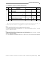
CHAPTER 2 OPERATION AND TIMING
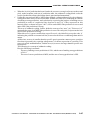
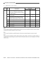
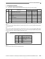
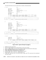
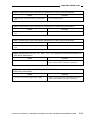
d. Main Scanning Length Is A4 (210 mm; priority on LTR/LGL)
Length in sub
scanning direction
mm
Paper size
Priority on LTR
Priority on LGL
Priority on LTR + LGL
LTR
LGL
LTR
LTR
LGL
A4
A4
LGL
A4
(216 279mm) (210 297mm) (216 297mm) (216 279mm) (210 297mm) (216 297mm) (216 279mm) (210 297mm) (216 297mm)
50
3B
4B
5B
4B
5B
4
3
3B
3B
5B
3
5
4B
100
STMT
150
A4/2
B4/2
200
A5,A3/2
4
3
250
B5
LTR
300
A4
LGL
5
350
B4
6A
Divide
7A
Divide
3
6A
Divide
6
Divide
6
Divide
4
400
A3
LGR
450
500
6
Divide
7
Divide
8
Divide
7
Divide
8
Divide
8
Divide
7
Divide
550
600
2-28
COPYRIGHT © 1999 CANON INC. CANON SUPER G3 FAX BOARD-F1 REV.0 MAY 1999 PRINTED IN JAPAN (IMPRIME AU JAPON)
CHAPTER 2 OPERATION AND TIMING
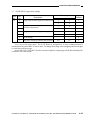
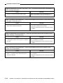
e. Main Scanning Length Is A4 (210 mm; priority on sub scanning)
Length in sub
scanning direction
mm
Paper size
Recording paper
STMT
A5
B5
LTR
B4
A4
LGL
A3
11 17
(216 140mm) (210 148mm) (257 182mm) (216 279mm) (210 297mm) (216 356mm) (257 364mm) (210 420mm) (216 432mm)
50
2
1
6D
Margin
4B
3B
4
3
5B
7D
Margin
8D
Margin
9D
Margin
13AD
Margin
Divide
14AD
Margin
Divide
15AD
Margin
Divide
100
STMT
150
A4/2
B4/2
200
A5,A3/2
250
B5
LTR
300
A4
LGL
350
B4
5
400
A3
LGR
450
500
17A
Divide
16A
Divide
18AD
Margin
Divide
11Divide
10Divide
12
Divide
550
600
COPYRIGHT © 1999 CANON INC. CANON SUPER G3 FAX BOARD-F1 REV.0 MAY 1999 PRINTED IN JAPAN (IMPRIME AU JAPON)
2-29
CHAPTER 2 OPERATION AND TIMING
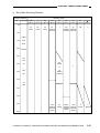
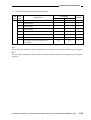
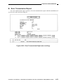
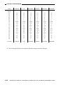
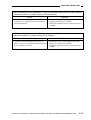
f.
Main Scanning Length Is B4 (257 mm)
Length in sub
scanning direction
mm
Paper size
Recording paper
A4
LGL
A4
LGL
LTR
LTR
A4
LTR
LGL
(216 279mm) (210 297mm) (216 297mm) (216 279mm) (210 297mm) (216 297mm) (216 279mm) (210 297mm) (216 297mm)
50
2
1
11C
Default
reduction
4B
3B
4
3
5B
12D
Margin
13D
Margin
14D
Margin
17AD
Margin
Divide
16AD
Margin
Divide
15AD
Margin
Divide
100
STMT
150
A4/2
B4/2
200
A5,A3/2
250
B5
LTR
300
A4
LGL
350
B4
5
7A
Divide
400
A3
LGR
450
500
10A
Divide
9A
Divide
18AC
Default
reduction
Divide
7
Divide
6
Divide
8
Divide
550
600
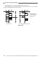
Note: If this mode is used, the output will be limited to A4 even when a B5 cassette exists.
2-30
COPYRIGHT © 1999 CANON INC. CANON SUPER G3 FAX BOARD-F1 REV.0 MAY 1999 PRINTED IN JAPAN (IMPRIME AU JAPON)
CHAPTER 2 OPERATION AND TIMING
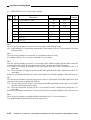
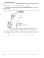
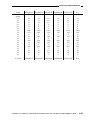
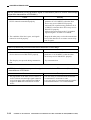
g. B4 in Main Scanning Direction
Length in sub
scanning direction
mm
Paper size
Recording paper
STMT
LTR
A5
B5
B4
A3
A4
LGL
11 17
(216 140mm) (210 148mm) (257 182mm) (216 279mm) (210 297mm) (216 356mm) (257 364mm) (210 420mm) (216 432mm)
50
No
output
No
output
No
output
9C
Default
reduction
1
10C
6C
Default Default
reduction reduction
2B
3
5
Divide
4
Divide
100
STMT
150
A4/2
B4/2
200
A5,A3/2
250
B5
LTR
300
8A
Divide
A4
2
or
LGL
7A
Default
reduction
350
B4
400
A3
LGR
450
500
550
12AC
Default
reduction
Divide
6A
Divide
13AC
11AC
Default Default
reduction reduction
Divide
Divide
600
COPYRIGHT © 1999 CANON INC. CANON SUPER G3 FAX BOARD-F1 REV.0 MAY 1999 PRINTED IN JAPAN (IMPRIME AU JAPON)
2-31
CHAPTER 2 OPERATION AND TIMING
h. B4 in Main Scanning Direction (priority on sub scanning direction)
Length in sub
scanning direction
mm
Paper size
Recording paper
LTR
LTR
A5
B5
A4
A4
LGL
11 17
B4
(216 140mm) (210 148mm) (257 182mm) (216 279mm) (210 297mm) (216 356mm) (257 364mm) (210 420mm) (216 432mm)
50
No
output
No
output
1
9C
Default
reduction
2D
Margin
10C
Default
reduction
3B
7D
Margin
5
Margin
11AD
Margin
Divide
6
Margin
Divide
100
STMT
150
A4/2
B4/2
200
A5,A3/2
250
B5
LTR
300
8C
Default
reduction
A4
3
LGL
350
B4
400
A3
LGR
450
500
4A
Divide
13AC
12AC
14AC
Default
Default
Default
reduction reduction reduction
Divide
Divide
Divide
550
3
Divide
600
2-32
COPYRIGHT © 1999 CANON INC. CANON SUPER G3 FAX BOARD-F1 REV.0 MAY 1999 PRINTED IN JAPAN (IMPRIME AU JAPON)
CHAPTER 2 OPERATION AND TIMING
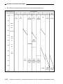
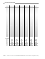
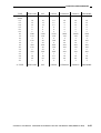
i.
Main Scanning Length Is A3 (297 mm)
Length in sub
scanning direction
mm
Paper size
Recording paper
LTR
LTR
A5
B5
A3
A4
LGL
11 17
B4
(216 140mm) (210 148mm) (257 182mm) (216 279mm) (210 297mm) (216 356mm) (257 364mm) (210 420mm) (216 432mm)
50
No
output
No
output
1
10C
Default
reduction
2D
Margin
11C
Default
reduction
3B
5D
Margin
4
Margin
8AD
Margin
Divide
6
Margin
Divide
100
STMT
150
A4/2
B4/2
200
A5,A3/2
250
B5
LTR
300
9C
Default
reduction
A4
3
LGL
350
B4
400
A3
LGR
450
500
15A
Divide
13AC
12AC
14AC
Default Default
Default
reduction reduction reduction
Divide
Divide
Divide
550
7Divide
600
COPYRIGHT © 1999 CANON INC. CANON SUPER G3 FAX BOARD-F1 REV.0 MAY 1999 PRINTED IN JAPAN (IMPRIME AU JAPON)
2-33
CHAPTER 2 OPERATION AND TIMING
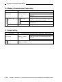
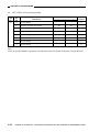
Report
Length in sub
Recording paper
scanning direction
A5
STMT
B5
LTR
A4
LGL
B4
A3
11 17
mm
Paper
(216 140mm) (210 148mm) (257 182mm) (216 279mm) (210 297mm) (216 356mm) (257 364mm) (210 420mm) (216 432mm)
size
Not
No
No
No
2
1
3
4
5
6
relevant output
output
output
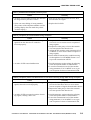
Report (priority on LTR)
Length in sub
Recording paper
scanning direction
B5
LTR
A4
LGL
B4
A3
11 17
A5
STMT
mm
Paper
(216 140mm) (210 148mm) (257 182mm) (216 279mm) (210 297mm) (216 356mm) (257 364mm) (210 420mm) (216 432mm)
size
Not
relevant
No
output
No
output
No
output
1
2
3
4
5
6
Caution:
In report mode, the output will be on a single sheet of paper without extra-length processing
even if the data has an image (e.g., transmission result report).
If the image is longer in main scanning direction than the recording paper, the extra area will be
lost. As can be learned from the table, selection is made regardless of the size of the image
added.
Report (B5 reduction)
Length in sub
Recording paper
scanning direction
A5
STMT
B5
LTR
LTR
A4
LGL
B4
11 17
mm
Paper
(216 140mm) (210 148mm) (257 182mm) (216 279mm) (216 140mm) (210 297mm) (216 356mm) (257 364mm) (216 432mm)
size
Not
relevant
2-34
No
output
No
output
Reduced
printing
2
1
3
4
5
6
COPYRIGHT © 1999 CANON INC. CANON SUPER G3 FAX BOARD-F1 REV.0 MAY 1999 PRINTED IN JAPAN (IMPRIME AU JAPON)
CHAPTER 2 OPERATION AND TIMING
B. Image Rotation
In image rotation, a received image is rotated automatically to suit the orientation of the existing
recording paper for printing; an image may be rotated by 90º or 180º.
1. Normal Rotation (surface recording)
The image is rotated 0º or 90º based on the combination of the orientation of the received image
(main scanning direction) and the orientation of the recording paper.
Main scanning
direction
Recording paper
A4R
A5R
A5
B5R
B5
A4R
A4
B4
A3
90°
0°
90°
0°
0°
90°
0°
0°
90°
0°
0°
90°
0°
0°
90°*
0°*
0°
0°
B4
A3
Note:
The paper sizes are shown in the way they are presented on p. 2-25 (i.e., A4 is 210 mm
long in main scanning direction).
* If an A3 page (297-mm, length in main scanning direction) is received by reduction to A4, it
will be treated as if it is an A4R (length in main scanning direction).
2. Rotation for Double-Sided Recording
Rotation of an image for printing on the back of a double-sided sheet depends on whether the
image on the face has been rotated or not.
Face not rotated
Face rotated
Face
0°
90°
Back
180°
90°
COPYRIGHT © 1999 CANON INC. CANON SUPER G3 FAX BOARD-F1 REV.0 MAY 1999 PRINTED IN JAPAN (IMPRIME AU JAPON)
2-35
CHAPTER 2 OPERATION AND TIMING
IV. COMMUNICATION SYSTEM
A. Image Signal Transmission Speed
1. Image Signal Transmission Speed (transmitting)
The FAX Board provides the following image signal transmission speeds: at V.34, 33.6 kbps,
31.2 kbps, 28.8 kbps, 26.4 kbps, 24.0 kbps, 21.6 kbps, 19.2 kbps, 16.8 kbps, 14.4 kbps, 12.0 kbps,
9.6 kbps, 7.2 kbps, 4.8 kbps, and 2.4 kbps.
Declaration by receiving machine
Higher
Device
transmission
speed
setting
Lower
Order of priority
V.34
V.17
V.33
V.34
V.17
V.33
Auto (V.34) 33.6K (MAX)
14.4K
14.4K
14.4K
V.17
V.17
V.33
14.4K
14.4K
14.4K
V.17
V.17
V.33
12K
12K
12K
TC9600
TC9600
TC9600
TC9600
TC7200
TC7200
TC7200
TC7200
V.34 (max)
12K
Note:
1. If speeds are identical, V.17 and then V.33 will be given priority.
2. In abbreviated protocol mode, V.17 is prohibited.
3. If both transmitting and receiving machines use V.34, the most appropriate speed will be
selected automatically.
2-36
COPYRIGHT © 1999 CANON INC. CANON SUPER G3 FAX BOARD-F1 REV.0 MAY 1999 PRINTED IN JAPAN (IMPRIME AU JAPON)
CHAPTER 2 OPERATION AND TIMING
2. Image Signal Transmission Speed (receiving)
The FAX Board provides the same transmission speed when receiving images as when
transmitting images (33.6 kbps to 2.4 kbps).
Declaration by receiving machine
Device
transmission
speed settings
V.34 (2.4 K to 33.6 K)
V.27ter + V.29 + V.33 + V.17 + V.34
(automatically set)
14.4K
V.27ter + V.29 + V.33 + V.17
12K
V.27ter + V.29 + V.33 + V.17
TC9600
V.27ter + V.29 + V.33 + V.17
TC7200
V.27ter + V.29 + V.33 + V.17
9600
V.27ter + V.29
7200
V.27ter + V.29
4800
V.27ter
2400
V.27ter fallback mode
COPYRIGHT © 1999 CANON INC. CANON SUPER G3 FAX BOARD-F1 REV.0 MAY 1999 PRINTED IN JAPAN (IMPRIME AU JAPON)
2-37
CHAPTER 2 OPERATION AND TIMING
B. Canon Express Protocol (CEP)
1. Transmission
• For one-touch/speed dial transmission, the image transmission speed as determined by the
effective transmission method will be used.
• For keypad dial transmission, the transmission start speed as determined by the system control
function will be used.
CEP
Image transmission speed by
transmission method (one-touch/speed
dial transmission)
Transmission start speed of system
control function (keypad dial
transmission)
33600bps
14.4kbps
9.6kbps
4.8kbps
33600bps
14.4kbps
9.6kbps
7.2kbps
4.8kbps
2.4kbps
Yes
No
No
No
CEP II
2. Reception
• The transmission start speed as determined by the system control function will be used.
Reception start speed as determined by system control
function
33.6kbps
14.4kbps
9.6kbps
7.2kbps
4.8kbps
2.4kbps
CEP
Yes
No
CEP II
No
Reference:
CEP II is the result of modifying the pre-procedure of the canon express protocol with a view to
reducing communication time. It uses the same high-speed protocol and post-procedure as
CEP.
CEP II is effective only between Canon machines equipped with the function. If a machine is
equipped with CEP only, control will automatically be switched to CEP.
2-38
COPYRIGHT © 1999 CANON INC. CANON SUPER G3 FAX BOARD-F1 REV.0 MAY 1999 PRINTED IN JAPAN (IMPRIME AU JAPON)
CHAPTER 2 OPERATION AND TIMING
C. JBIG Image Compression Coding Method
1. Outline of the JBIG Image Compression Coding Method
The JBIG image compression coding method is a new way of coding binary image data (black
and white) developed by the Joint Bi-Level Image Experts Group, and its rules are standardized as
part of ITU-T T.82/5.85.
The JBIG image compression coding method provides a higher rate of compression than the
existing MMR coding method (1.1 to 30 times as high) when handling text, pseudo halftone with
limited black-and-white continuity, and halftone processed by a dither method. It can also be
characterized by the fact that the size of coding after compression will not exceed the initial size of
data and by its ability to reproduce original images progressing during decoding as in the case of the
existing MR/MMR method (i.e., fully reversible).
The JBIG image compression coding method is either of two types: progressive bi-level image
compression designed for image data base searches (standardized in ITU-T T.82) and single
progressive sequential bi-level image compression designed for fax communication (standardized in
ITU-T T.82 and T.85). Figure 2-401 shows conceptual diagrams of these two methods.
Progressive transmission
Sequential transmission
Figure 2-401 Conceptual Diagrams
COPYRIGHT © 1999 CANON INC. CANON SUPER G3 FAX BOARD-F1 REV.0 MAY 1999 PRINTED IN JAPAN (IMPRIME AU JAPON)
2-39
CHAPTER 2 OPERATION AND TIMING
Reference:
The following is an outline of the progressive bi-level image compression method:
An original image is read at a high resolution. The result is converted to a low resolution, and
the resulting data is coded (compressed) and transmitted. The data is such that, upon reception,
it immediately provides an overall “impression” of the original image, although at a low
resolution.
Data used to improve the resolution of the image contained in the previously sent data follows.
Using this data, the previously sent data (low resolution) is decoded on the receiving side. As
decoding progresses, the initial low-resolution image will taken on a higher resolution.
In practical uses, the receiving side (e.g., CRT screen) can immediately recognize the image,
and can monitor it while the image as the resolution increases. As needed, the receiving side
may suspend reception of the image at any time.
This method of image compression is based on low-resolution images to code high-resolution
images, and requires a page buffer to hold low-resolution images.
2. Single Progression Sequential Bi-Level Image Compression
The following is an outline of the single progression sequential bi-level image compression
method.
While the progressive bi-level image compression method uses multiple layers of resolution on a
page basis (from low-resolution layer to high-resolution layer) for coding and decoding, the single
progression sequential bi-level image compression codes an image from left to right and from top to
bottom in units of horizontal bands (or lines) referred to as “stripes” (hence, the name “sequential”).
This method is called “single progression” because it codes and decodes on the basis of a single
resolution layer.
Reference:
In this method, data is coded in units of stripes, so that it requires a far smaller buffer than a page
buffer.
An image is coded and the resulting coded image data is organized as follows:
2-40
COPYRIGHT © 1999 CANON INC. CANON SUPER G3 FAX BOARD-F1 REV.0 MAY 1999 PRINTED IN JAPAN (IMPRIME AU JAPON)
CHAPTER 2 OPERATION AND TIMING
3. Coding an Image
In the single progression sequential bi-level image compression method, a coding device is used
to code an image based on the result of comparison between the current line and the immediately
preceding line and on the result of prediction about the level of the pixel in question using a model
template (to find out whether it will be white or black).
The learning table used for prediction is corrected each time the model template moves to the
next pixel, thereby improving the rate of correct prediction. In this method of coding, a correct
prediction will not increase the size of coding. In this respect, it is highly important that the learning
table improve itself as it processes data for correct predictions.
Figure 2-402 is a diagram of the coding procedure used.
Coder
Compares current line and
immediately preceding line
Image data input
Typical prediction
If non-match
Predicting for
pixel in question
Model template
Flag output (match/non-match)
Arithmetic coding
Image data outlet
(coded by JBIG)
Actual pixel in question
(for comparison against prediction)
Pixel pattern (10 bits)
Prediction for pixel in question
in relation to image pattern (10 bits)
Learning table
Refers to prediction and
status
Result of prediction
Status for next based on result of
prediction and Reference to prediction (learning)
Reference of area for
status in question
Rate of probability
table
Prediction for next in relation to
result of prediction
Figure 2-402 Coder and the Flow of JBIG Coding
1. In the typical prediction block, the current line and the immediately preceding line are compared
to find out if the latter matches the former. According to the result of this process, a flag (1 bit; 0
for match, 1 for non-match) is attached to the head of each line.
If a match was identified, the flag (only) is coded by the arithmetic coding block as a pseudo
image, without coding the pixels of the line being processed at the time. If a non-match was
identified, the pixels of the line being processed at the time are coded by the arithmetic coding
block using the model template and the learning table and based on the result of compression
between the prediction (white or black) of the pixels in question and the actual levels.
COPYRIGHT © 1999 CANON INC. CANON SUPER G3 FAX BOARD-F1 REV.0 MAY 1999 PRINTED IN JAPAN (IMPRIME AU JAPON)
2-41
CHAPTER 2 OPERATION AND TIMING
Reference:
If a match is made, the line being processed will be referred to as “being typical.” If a non-match
is made, on the other hand, the line will be referred to as “not being typical.”
When making a prediction for the first line of an image, the background is used as representing
the immediately preceding line.
b. Figure 2-403 shows model templates (enclosed by thick lines). Combinations of pixels (pixel
pattern; 10 bits) are communicated to the arithmetic coding block.
All 1-bit pixel patterns of the template exist within the learning table, and are used by the
arithmetic coding block when referring to prediction levels of pixels in question and status
numbers in the learning table according to each pixel pattern.
AT
AT
?
3-line model template
?
2-line model template
Figure 2-403 Model Templates
Reference:
The choice between the 3-line model template and the 2-line model template is determined by
LRLTWO found within the 2-level image header (BIH).
A pixel represented by “?” is a pixel to be coded, and is outside the template.
A pixel represented by “AT” is a special pixel called an “AT pixel.”
An AT pixel makes a template adaptable by changing its position, and will prove to be highly
effective when coding an image consisting of cyclic lines (e.g., dither image).
The position of the AT pixel in the diagram is the initial position of any AT pixel. The board,
however, will keep the AT pixel at its initial position so that it will not make use of an adaptable
type template.
2-42
COPYRIGHT © 1999 CANON INC. CANON SUPER G3 FAX BOARD-F1 REV.0 MAY 1999 PRINTED IN JAPAN (IMPRIME AU JAPON)
CHAPTER 2 OPERATION AND TIMING
c. The learning table, as shown below, consists of all 10-bit pixel patterns from the model template
and the prediction levels and status numbers corresponding to these image patterns.
The prediction level and the status number of the pixel in question are compared against the
actual pixel by the arithmetic coding block each time the model template moves to the next pixel.
The result of comparison (whether the prediction is correct or wrong) is checked against the rate
of probability table based on the status number, thereby correcting (learning) the prediction level
and the status number to be used for the same pattern for the future.
As learning advances, the rate of making correct predictions by the learning table will increase,
while the need of coding will decrease.
1
2
3
4
5
6
7
9
10
?
8
1
2
3
4
5
7
8
9
10
?
3-line model template
6
2-line model template
Figure 2-404 Position of a Pixel within a Model Template
Pixel pattern within model template
000h
001h
002h
003h
004h
005h
0
1
2
3
4
5
1
0
0
0
0
0
0
2
0
0
0
0
0
0
3
0
0
0
0
0
0
4
0
0
0
0
0
0
5
0
0
0
0
0
0
6
0
0
0
0
0
0
7
0
0
0
0
0
0
8
0
0
0
0
1
1
9
0
0
1
1
0
0
3FBh
3FCh
3FDh
3FEh
3FFh
1019
1020
1021
1022
1023
1
1
1
1
1
1
1
1
1
1
1
1
1
1
1
1
1
1
1
1
1
1
1
1
1
1
1
1
1
1
1
1
1
1
1
0
1
1
1
1
1
0
0
1
1
Hexadecimal Decimal
Prediction Status
level of pixel
10 in question number (ST)
0
0 (white)
0
1
0
0 (white)
0
0
0 (white)
1
0
0 (white)
0 (white)
0
0
0
0 (white)
1
1
0
1
0
1
0 (white)
0 (white)
0 (white)
0 (white)
0 (white)
0
0
0
0
0
Table 2-401 Learning Table (initial settings)
COPYRIGHT © 1999 CANON INC. CANON SUPER G3 FAX BOARD-F1 REV.0 MAY 1999 PRINTED IN JAPAN (IMPRIME AU JAPON)
2-43
CHAPTER 2 OPERATION AND TIMING
ST:
LSZ:
NLPS:
NMPS:
SWITCH:
ST
LSZ
NLPS
ST
LSZ
NLPS
0
1
2
3
4
5
6
7
8
5A1Dh
2586h
1114h
080Bh
03D8h
01DAh
00E5h
006Fh
0036h
1
14
16
18
20
23
25
28
30
NMPS SWITCH
1
2
3
4
5
6
7
8
9
1
0
0
0
0
0
0
0
0
57
58
59
60
61
62
63
64
65
01A4h
0160h
0125h
00F6h
00CBh
00ABh
008Fh
5B12h
4D04h
55
56
57
58
59
61
61
65
80
NMPS SWITCH
58
59
60
61
62
63
32
65
66
0
0
0
0
0
0
0
1
0
49
50
51
52
53
54
55
56
0706h
05CDh
04DEh
040Fh
0363h
02D4h
025Ch
01F8h
79
48
50
50
51
52
53
54
50
51
52
53
54
55
56
57
0
0
0
0
0
0
0
0
106
107
108
109
110
111
112
50E7h
4B85h
5597h
504Fh
5A10h
5522h
59EBh
108
109
110
111
110
112
112
107
103
109
107
111
109
111
0
0
0
0
1
0
1
status number within the learning table.
rate of probability (area) at which the prediction is wrong.
destination of the next status when the prediction is wrong.
destination of the next status when the prediction is correct.
if it is ‘1’ when the prediction is wrong, the next level of prediction is reversed.
Table 2-402 Rate of Probability Table
2-44
COPYRIGHT © 1999 CANON INC. CANON SUPER G3 FAX BOARD-F1 REV.0 MAY 1999 PRINTED IN JAPAN (IMPRIME AU JAPON)
CHAPTER 2 OPERATION AND TIMING
Example:
The following explains how the learning table works; in the diagrams, the pixels 1 through 10 of
the model template are all assumed to be white:
1. The pixel pattern of the model template will be 000h.
2. The level of prediction against the pixel in question “?” of the pixel pattern 000h is “white”;
however, it is actually black, making the prediction “wrong.”
3. Since the status ST is “0”, a check against the rate of probability table causes the status to
move to “1,” and at the same time the next prediction will be made “black” by reversing the
present prediction.
Original image
Learning table of present pixel
Pixel
pattern
000h
001h
002h
Level of
Actual Correct/
prediction level
wrong
0 (white) 1 (Black) Wrong
0 (white)
0 (white)
Status
ST
0
0
0
Learning table of present pixel
Pixel
pattern
000h
001h
002h
Level of
prediction
1 (black)
0 (white)
0 (white)
Actual Correct/
level
wrong
Status
ST
1
0
0
Rate of probability table
1 2 3
4 5 6 7 8
9 10 ?
ST
0
1
2
3
LSZ
5A1Dh
2586h
1114h
080Bh
NLPS
1
14
16
18
NMPS
1
2
3
4
SWITCH
1
0
0
0
? is actually black.
Figure 2-405 Learning Table Operation (example 1)
COPYRIGHT © 1999 CANON INC. CANON SUPER G3 FAX BOARD-F1 REV.0 MAY 1999 PRINTED IN JAPAN (IMPRIME AU JAPON)
2-45
CHAPTER 2 OPERATION AND TIMING
4. The model template moves to the next pixel. At this time, the pixels 1 through 9 are white and
the pixel 10 is black in the model template.
5. The pixel pattern of the model template is 001h.
6. The level of prediction for the pixel in question “?” of the pixel pattern 001h is “white,” and
the actual pixel is also white. As such, the prediction is “correct.”
7. The status ST is “0,” and the result of a check against the rate of probability causes the next
status to move to “1” while keeping the next level of prediction “white” as it is.
Move to next pixel
1 2 3
4 5 6 7 8
9 10 ?
? is actually white.
Learning table of present pixel
Pixel
pattern
000h
001h
002h
Level of
Actual Correct/ Status
prediction value
wrong
ST
1 (black)
1
0 (white) 0 (white) Correct
0
0 (white)
0
Learning table for next pixel
Pixel
pattern
000h
001h
002h
Level of
Actual
prediction value
1 (black)
1 (black)
0 (white)
Correct/ Status
wrong
ST
Rate of probability table
ST
0
1
2
3
LSZ
5A1Dh
2586h
1114h
080Bh
NLPS
1
14
16
18
NMPS SWITCH
1
1
2
0
3
0
4
0
Figure 2-406 Learning Table Operation (example 2)
In this way, the learning table continues to improve on its rate of making correct predictions.
d. The rate of probability is from ITU-T T.83. Unlike the learning table, its contents remain the
same.
Reference:
The rate of probability table shown in Table 2-402 expresses the rate of making correct/wrong
predictions in terms of an area in reference to each applicable status.
When correct predictions continue, a status number which makes the area smaller will be
selected; on the other hand, when wrong predictions continue, a status number which makes
the area larger will be selected.
2-46
COPYRIGHT © 1999 CANON INC. CANON SUPER G3 FAX BOARD-F1 REV.0 MAY 1999 PRINTED IN JAPAN (IMPRIME AU JAPON)
CHAPTER 2 OPERATION AND TIMING
e. When the level of prediction has been found to be correct or wrong in reference to the actual
pixel, model template, and rate of prediction table, the arithmetic coding block codes the
result of prediction so that coded image data is generated and transmitted.
f. Unlike the conventional MH or MR coding method, coding (arithmetic) by the arithmetic
coding block does not use a conversion table. It rather uses LSZ (area, indicating an estimate
of making a wrong prediction), and codes data by expressing the progress of making correct
prediction in terms of a numerical line (between 0 and 1.0). Codes expressed on this
numerical line, as shown in Figure 2-407, will be under MPS if the prediction is correct and
under LPS if the prediction is wrong.
This way of arithmetic coding, further, holds the concept of an “area” (A). This area (A)*2
represents the area (A) of MPS if the prediction is correct for each pixel; it represents the area
of LPS if the prediction is wrong.
When this area (A) grows smaller than a specific area*3, the initial bit (except the code ‘0’
indicating the position on a numerical line) is moved to the left as a coded image data unit for
output.
At this time, an area (A) smaller than the specific area in question cannot express a position
finer than it presently can, requiring enlargement*4 for better expression of a position. This
process is called “standardization,” and the area (A) is set to a size larger than the specific area
in question*3.
The following is a concept of arithmetic coding:
Here the following is assumed:
·
The rate of making correct predictions is 50%, and the rate of making wrong predictions
is 50%.*1
·
The area of correct predictions is MPS, and the area of wrong predictions is LPS.
COPYRIGHT © 1999 CANON INC. CANON SUPER G3 FAX BOARD-F1 REV.0 MAY 1999 PRINTED IN JAPAN (IMPRIME AU JAPON)
2-47
CHAPTER 2 OPERATION AND TIMING
Position (binary)
1.000
0.0011
0.111
LPS
0.110
0.101
Stan-
Area A1
0.100
Area A2
Area A3
0.011
LPS
0.010
MPS
0.001
MPS
1st
2nd
3rd
4th
Correct Correct Correct Correct
0.001001
0.00100010
LPS
LPS
MPS
MPS
0.0010
0
Pixel in question for
coding
0.001010
dardized
area
5th
6th
Correct Correct
7th
Correct
8th
Correct
Position of code of
each pixel by arithmetic coding
Figure 2-407 Conceptual Diagram of Arithmetic Coding
When the prediction is correct, the present data will have the same position on the numerical line
as the previously coded data, characterizing the arithmetic coding method by the absence of the need
for an additional bit used to express the position. This fact helps increase the rate of compression if
correct predictions continue (i.e., not resulting in an increased volume of coding).
If wrong predictions continue, on the other hand, additional bits will be needed to express the
positions of wrong predictions, causing the volume of coding to increase, while at the same time
decreasing the rate of compression.
The learning table continues to learn and correct table parameters while coding takes place so as
to make correct predictions and increase the rate of compression without increasing the volume of
coding.
Reference:
*1 The actual rate of probability varies depending on the applicable status, since it is affected
by the share of LSZ in the area A.
*2 The actual area is 8000 to 10000 (hexadecimal).
If the prediction is correct, the area A will be as follows:” A1 = 10000 (hexadecimal) LSZ, A2 = A1 - LSZ, A3 = A2 - LSZ.
If the prediction is wrong, the area A will be equal to LSZ.
*3 Actually, it is 8000 (hexadecimal).
*4 Actually, the hexadecimal value is shifted to the left and doubled so that it will be 8000 or
higher (hexadecimal).
2-48
COPYRIGHT © 1999 CANON INC. CANON SUPER G3 FAX BOARD-F1 REV.0 MAY 1999 PRINTED IN JAPAN (IMPRIME AU JAPON)
CHAPTER 2 OPERATION AND TIMING
When correct predictions continue, coding will be as follows:
Here, the value of LSZ consisting of correct predictions will be assumed to be 100*1 (decimal)
for all statuses.
The area A will be within 8000 to 10000*2 (decimal), and uses the initial bit when it falls below
8000*3 (decimal), generating a coded image data output.
At this time, adjustments are made (by adding 1000*4, decimal) so that the area A will be
8000*3 (decimal) or higher. The area of correct predictions will be MPS, and the area of wrong
predictions will be LPS.
Position (binary)
1.0000
0.1111
0.1110
0.1101
0.1100
0.1011
0.1010
0.1001
0.1000
0.0111
0.0101
0.0100
0.0011
0.0010
0.0001
0
LPS
LPS
Area A1 Area A2
MPS
MPS MPS MPS MPS MPS
Standardization
MPS
MPS
1
2
3
4
Number of pixel
selected for coding Correct Correct Correct Correct
0
0
0
0
Position of coding
Initial value of area 10000 9900 9800 9700
Standardization
New initial value
LSZ
100
100 100 100
Area A
9900 9800 9700 9600
Coding output
No
No
No
No
Output coding
MPS
MPS
5
6
Correct Correct
0
0
9600 9500
19
20
21
Correct Correct Correct
0
0
0
8200 8100 8000
100
100
9500 9400
No
No
100 100
8100 8000
No
No
100
7900
Yes
1bit0
23
Correct
0
7900 8900
1000
8900
100 100
8900 8800
No
Figure 2-408 Correct Predictions Continue
In this case, the code of 1 bit is generated when the area A grows to be less than 8000 at the 21st
pixel.
This way, the length of a code output will be short, and the rate of compression will be high.
COPYRIGHT © 1999 CANON INC. CANON SUPER G3 FAX BOARD-F1 REV.0 MAY 1999 PRINTED IN JAPAN (IMPRIME AU JAPON)
2-49
CHAPTER 2 OPERATION AND TIMING
4. Construction of Image Data by JBIG Image Compression Coding
An image is coded in units of blocks called “stripes” as shown in Figure 2-409.
Width of original (XD)
BIH
Length of stripe
BID
BID
Length of
original (YD)
Header
Floating
marker code
SDE
Floating
marker code
SDE
Stripe
Stripe
JBIG coding
BID
Original
Floating
marker code
SDE
Stripe
JBIG coding
Figure 2-409 Construction of JBIG Image Data
When coding is done, the image data is called “BIE” (Bi-level Image Entity), and consists of a bilevel image header (BIH) and bi-level image data (BID) as shown:
BIH (bi-level image header)
BIE (actual bi-level as it is)
BID (bi-level image data)
BID (bi-level image data)
Figure 2-410 Construction of BIE
2-50
COPYRIGHT © 1999 CANON INC. CANON SUPER G3 FAX BOARD-F1 REV.0 MAY 1999 PRINTED IN JAPAN (IMPRIME AU JAPON)
CHAPTER 2 OPERATION AND TIMING
5. Bi-Level Image Header (BIH)
BIH may be expressed as the diagrams shown in Figure 2-411, and is used to indicate the size of
an image, the number of lines per stripe, and the applicable model template.
BIE (bi-level image header)
DL
1byte
D
1byte
P
1byte
FILL
1byte
XD
1byte
YD
1byte
L0
1byte
1bit
1bit
1bit
1bit
HITOLO
1bit
SEQ ILEAVE SMID
1bit
1bit
1bit
1bit
Mx
1byte
My
1byte
Orber Option DPTABLE
1byte 1byte 1byte
LRLTWO VLENGHTH TPDON TPBON DPON DPPRIV DPLAST
1bit
1bit
1bit
1bit
1bit
1bit
1bit
Figure 2-411 Construction of BIG
COPYRIGHT © 1999 CANON INC. CANON SUPER G3 FAX BOARD-F1 REV.0 MAY 1999 PRINTED IN JAPAN (IMPRIME AU JAPON)
2-51
CHAPTER 2 OPERATION AND TIMING
6. Notations and Parameters Used in BIH
Description
Notation
Parameter
DL
D
P
FILL
XD
Initial layer for transmission
Layer representing size of difference
Number of bit planes
Fill
Size of horizontal image on layer D
Fixed to 0x00
Fixed to 0x00
Fixed to 0x01
Fixed to 0x00
0xXXXXXXXX
YD
Size of vertical image on layer D
0xXXXXXXXX
L0
Number of lines per stripe
0xXXXXXXXX
Mx
0xXX
Order
Maximum horizontal offset allowed
for AT pixel
Maximum horizontal offset allowed
for AT pixel
Order of linking stripe data
Option
Option
My
DPTABLE Private DP table
HITOLO Order of transmission of layers
repesenting size of difference
SEQ
Indication of multiple-layer sequential
coding
ILEAVE Order of transmission of interleaved
multiple-bit planes
SMID
Order of transmission of stripes
LRLGTH Number of standard lines for model
template
VLENGTH Indication of permission to use
NEWLEN marker code
TPDON
Width of original
(number of bits)
Length of original
(number of lines)
In principle, 128 lines per
stripe (0x00000080).
If the destination is
capable of option mode,
stripes with a different
number of lines may be
used (as changed by bit
79 of DIS).
0 to 127 pixels
0xXX
most significant 4
bits fixed to 0
most significant 1
bit fixed to 0
0 or 1728 bytes
1 bit fixed to 0
1 bit fixed to 0
1 bit fixed to 0
1 bit fixed to 0
1 bit 0/1
0:
1:
0:
1 bit 0/1
1:
1 bit fixed to 0
TPBON
Use of TP for making typical
prediction for layer representing
amount of difference
Use of TP for base layer
DPON
DPPRIV
Use of DP for definitive prediction
Use of private DP table
1 bit fixed to 0
1 bit fixed to 0
DPLAST
Use of last DP table
2-52
Remarks
3-line
2-line
NEWLEN not
permitted
NEWLEN
permitted
1 bit 0/1
When DPON is ‘1’, has
meaning
When DPON is ‘1’, has
meaning
COPYRIGHT © 1999 CANON INC. CANON SUPER G3 FAX BOARD-F1 REV.0 MAY 1999 PRINTED IN JAPAN (IMPRIME AU JAPON)
CHAPTER 2 OPERATION AND TIMING
7. Bi-Level Image Data (BID)
BID is constructed as shown in Figure 2-412, and as many RID units exist as there are stripes.
BID consists of a combination of a floating marker code and an image data block which has been
processed by JBIG image compression coding called “SDE” (stripe data entity).
Stripe
BID (binary image data block)
Stripe
BIM (binary image data block)
SDE (stripe data body)
Floating marker code
ESC Marker code Parameter
1byte
1byte 1byte
PSCD
Variable
ESC
1byte
Floating marker doce
SDE
SDNORRM/SDRST
1byte
RESERVE
Image data
Variable
ABORT
ESC STUFF
1byte Variable
NEWLEN Original length
4byte
ATMOVE Shift start line Shift position(X) Shift position(Y)
4byte
1byte
1byte
COMMENT Comment length
4byte
Figure 2-412 Construction of BID
8. Symbols and Parameters Used by BID
a. Floating Marker Code
The floating marker code is set at the head of a stripe data (SDE) unit.
To distinguish the floating marker code from another type of code, ESC (escape code; 0xFF) is
always attached at the head.
A floating marker code consists of a marker code and a parameter. The notation “0x” of each
marker code indicates that the number that follows is a hexadecimal number.
ABORT (0x05)
Indicates suspension of the code and may appear anywhere in a code.
ESC
0x05
COPYRIGHT © 1999 CANON INC. CANON SUPER G3 FAX BOARD-F1 REV.0 MAY 1999 PRINTED IN JAPAN (IMPRIME AU JAPON)
2-53
CHAPTER 2 OPERATION AND TIMING
ATMOVE (0x06)
Indicates the line on which the shift of the AT pixel starts and the direction of the shift.
ESC 0x06 Line to start (4 byte) Destination of shift (X) Destination of shift (Y)
COMMENT (private comment; 0x07)
Accepts a comment written at will.
ESC 0x06 Length of comment (4 bytes)
NEWLEN (new line; 0x04)
Defines the length of an original once again. Is available only when VLENGTH=ON.
ESC 0x06 Length of original (4 bytes)
RESERVE (0x01)
Is available for special uses only.
ESC
0x01
b. Stripe Data Block
PSCD (protected stripe coding data)
PSCD is the block that remains when the last two bytes (ESC and SDNORM or SDRST)
have been removed, and contains image data which has been processed by the JBIG image
compression method.
Image Data
Image data is the result of processing by the JBIT image compression coding method.
STUFF
Image data is variable, and is adjusted by transmitting STUFF:0 so as to keep it in units of byte
or word (2 bytes).
SDNORM (stripe data end: 0x02)
Indicates the end of stripe data.
ESC
0x02
SDRST (resetting at end of stripe data; 0x03)
Indicates the end of stripe data. ATMOVE and all others will be initialized.
ESC
0x03
Reference:
If the code of image data is 0xFF, 0x00 is always attached at the end of the code of image data
0xFF so as to distinguish it from ESC (0xFF).
2-54
COPYRIGHT © 1999 CANON INC. CANON SUPER G3 FAX BOARD-F1 REV.0 MAY 1999 PRINTED IN JAPAN (IMPRIME AU JAPON)
CHAPTER 2 OPERATION AND TIMING
D. V.8/V.34 Procedure
Reductions have been made to the image transmission time using a V.34 standard modem
complying with ITU-T (maximum transmission speed of 33600 bps).
1. V.8 Procedure
The V.8 procedure starts a communication as if the type of device (existing modem, fax, Vseries modem) is not a factor. (See Figure 2-401.)
n Receiving Modem Not Provided with V.8
The normal modem connection sequence will be executed.
n Receiving Modem Provided with V.8
The appropriate modulation method from among the following will be selected and
executed. If both transmitting and receiving devices declare V.34, a switch-over is made to
V.34. (Execution of V.34 requires execution of the V.8 procedure.)
Possible Modulation Methods
1. V.21
2. V.27ter
3. V29 half duplex, G3FAX, T30, etc.
4. V.17
5. V.32bis or V.32
6. V.34 half duplex, V.34 full duplex
Answer tone
Callee
Communicates
possible modulation methods
Caller
Communicates
possible modulation methods
Callee
Caller
V.8 answer
tone
Normal procedure
V.34 procedure
Callee Supporting V.8
Callee Not Supporting V.8
Figure 2-413 V.8 Starting Procedure
COPYRIGHT © 1999 CANON INC. CANON SUPER G3 FAX BOARD-F1 REV.0 MAY 1999 PRINTED IN JAPAN (IMPRIME AU JAPON)
2-55
CHAPTER 2 OPERATION AND TIMING
2. V.34 Modem
The high-speed modem communication procedure recommended by ITU-T is referred to as
"V.34," and may be described as follows:
a. It communicates using half-duplexing mode of a 33.6 kbps modem complying with ITU-T.
b. It automatically selects the most appropriate transmission speed (14 types; every 24000 bps
between 2400 bps and 33600 bps).
transmission speed = data speed (ITU-T recommendation) = data speed
c. It uses ECM.
d. It executes a start-up using the V.8 procedure (V.34, phase 1).
e. A V.34 modem is equipped with a modem circuit of the old recommendation to enable
connection with existing modems (upward compatible).
f. In addition to the increased modulation speed, it enables increases in overall speed (not only in
segments but also in continuous data transmission) using the following:
f.1 Pre-Emphasis Technology
It transmits data by raising the transmission level of the higher-frequency band, which is
subject to noise, thereby improving the S/N ratio.
f.2 Probing Technology
The transmitting device generates tone signals (probing tones) for use by the receiving
device to measure the characteristics of the line, thereby adapting the modem to the existing
line conditions.
g. It uses a full duplex mode for the pre-procedure/post-procedure of the V.8 and V.34 protocols,
thereby increasing the speed of executing procedures.
h. Its modulation speed (baud rate) may be 2400, 3000, or 3200 symbols/sec (required), or 2743,
2800, or 3429 symbols/sec (optional), allowing more varied choice of a data transmission speed
than past modems.
modulation speed (baud rate) = symbol speed (ITU-T recommendation)
2-56
COPYRIGHT © 1999 CANON INC. CANON SUPER G3 FAX BOARD-F1 REV.0 MAY 1999 PRINTED IN JAPAN (IMPRIME AU JAPON)
CHAPTER 2 OPERATION AND TIMING
Memo
1. To select V.17 instead of V.8/V.34, you may operate as follows:
• Select "No" for ECM (additional functions Õ custom fax settings Õ rx settings).
• Set the transmission speed to 14.4 kbps or lower.
• Select "No" to ECM (additional functions Õ custom fax settings Õ tx settings).
2. A procedure (late start) for switching from V.21 to V.8/V.34.
3. If an error occurs in V.34 communication, redialing will be by V.17.
COPYRIGHT © 1999 CANON INC. CANON SUPER G3 FAX BOARD-F1 REV.0 MAY 1999 PRINTED IN JAPAN (IMPRIME AU JAPON)
2-57
CHAPTER 2 OPERATION AND TIMING
Figure 2-402 shows the standard procedure used by V.8/V.34. In V.34, the transmission speed is
selected after selecting a modulation speed so as to use the best circuit condition.
TX
(phase 1)
Network interaction
RX
CNG
Line closed
ANSam
V.8
CM
CJ
(phase 2)
Probing/ranging
JM
INFO0c INFO0a
A
B
A
B
L1
L2
A
B
INFO0h
(phase 3)
Equalizer and echo
canceler training
S
S
PP
TRN
(phase 4)
Last training
PPh
ALT
MPh
MPh
E
Control channel
flags
NSS
TSI
DCS
flags
"1"
(determining modulation speed)
Both declare possible modulation speeds,
frequencies and other modem capabilities,
the receiving device determines the modulation
speed based on the results of receiving the
probing signal coming from the transmitting device.
The receiving device sends a training signal
for determination of the transmission speed.
PPh
ALT
MPh
MPh
E
NSF
CSI
DIS
(determining the transmission speed)
The most appropriate transmission speed is
determined based on how the training signal
has been received.
V.34
Image data
The same pre-procedure as used in normal
T.30 is executed in 1200 bps.
flags
CFR
flags
S
S
PP
B1
Primary channel
(declaring modulation mode)
Both declare possible modulation modes.
Both declare the presence of V.34,
and a switch-over is made to V.34.
A training signal is sent using the selected
parameter, and image data is sent thereafter.
Image
data
Tum-Off
Sh
Sh
ALT
E
Communication
end procedure
flags
Sh
Sh
ALT
E
flags
MCF
DCN
flags
PPS-EOP
The same post-procedure as used in normal
T.30 is executed in 1200 bps.
"1"
Line released
Line released
Figure 2-414
2-58
COPYRIGHT © 1999 CANON INC. CANON SUPER G3 FAX BOARD-F1 REV.0 MAY 1999 PRINTED IN JAPAN (IMPRIME AU JAPON)
CHAPTER 2 OPERATION AND TIMING
3. Details of the Procedures
a. Network Interruption (phase 1)
V.8 is executed as the start-up procedure for high-speed modem V.34.
In V.8, the most appropriate modulation method (V series modem mode) that is possible between
transmitting and receiving devices is determined.
•
Transmitting Device
Signal
•
Notation
Description
Remarks
Start tone
CNG
Is a 1100-Hz tone signal
prescribed by T.30 indicating that
the device is a fax initiating an
automatic ring.
Start menu signal
CM
Indicates possible modulation
methods (V.21, V.27ter, V.29,
V17, V.34, etc.).
Modulated by V.21 (L).
Modulation speed:
300 bps
CM end terminal
CJ
Indicates detection of a JM signal
and the end of a CM signal.
Modulated by V.21 (L).
Transmission speed:
300 bps
Start indication
signal
CI
Indicates general communication
functions.
Sent when resuming the V.8
procedure.
For late start, see Figure
2-403.
Modulated by V.21 (L).
Transmission speed:
300 bps
Notation
AMSam
Description
Communicates the type of
terminal (fax) and communicates
possible modulation methods in
response to the modulation
methods communicated by the
CM signal form the transmitting
device.
Remarks
Modulated by V.21
(H).
Receiving Device
Signal
Common menu
signal
JM
Transmission speed:
300 bps
V21 (L): Low-range channel defined by V.21; 1080/100 Hz (980 Hz: 1, 1180 Hz: 0).
V21 (H): High-range channel defined by V.21; 1750/100 Hz (1650 Hz: 1, 1850 Hz: 0).
COPYRIGHT © 1999 CANON INC. CANON SUPER G3 FAX BOARD-F1 REV.0 MAY 1999 PRINTED IN JAPAN (IMPRIME AU JAPON)
2-59
CHAPTER 2 OPERATION AND TIMING
b. Probing/Ranging (phase 2)
The characteristics of the line are measured, and such modulation-related parameters as
modulation speed are set.
•
Transmitting Device
Signal
•
Notation
INFO sequence
INFO0c
Tone B
B
Tone B
B
Line probing
signal L1
L1
Line probing
signal L2
L2
Description
Remarks
Communicates modem
capabilities such as modulation
speed, frequency (high and low
ranges used in measuring line
characteristics) and requests
adjustments.
Uses 1200 Hz tone signals.
Synchronizes modems.
Transmission speed:
600 bps
Is a tone signal used to interpret
the line characteristics in probing.
"Probing" refers to
measuring of line
characteristics.
Tone signals in 150-Hz
increments between
150 Hz and 3750 Hz.
Description
Remarks
B is a signal resulting
from rotating the phase
of B by 180°.
Receiving Device
Notation
Signal
INFO sequence
INFO0a
Communicates modulation
speeds, transmission frequencies,
and other modem capabilities.
Transmission speed:
600 bps
Tone A
A
Uses 2400-Hz tone signal.
Synchronizes modems.
Tone A
A
A is the result of
rotating the phase of A
by 180°.
INFO sequence
INFO0h
Communicates the modulation
speed and the pre-emphasis filter
used for data transmission based
on the results of interpretation
made by the line probing signal
coming from the transmitting
device.
Transmission speed:
600 bps
2-60
COPYRIGHT © 1999 CANON INC. CANON SUPER G3 FAX BOARD-F1 REV.0 MAY 1999 PRINTED IN JAPAN (IMPRIME AU JAPON)
CHAPTER 2 OPERATION AND TIMING
c. Equalizer and Echo Canceler Training (phase 3)
Training (adjustment) is executed to optimize the functions of filters (e.g., equalizer) using the
parameters set in phase 2.
•
Transmitting device
Notation
Signal
Description
S signal
S
Executes short training.
S signal
S
PP signal
PP
Used for training of an equalizer
by the receiving modem.
TRN signal
TRN
Used to determine the
transmission speed by the
receiving device.
Remarks
S is the result of
rotating the phase of S
by 180°.
d. Last Training (phase 4)
The maximum data transmission speed is selected, a trellis coder is selected, and possible data
speeds are selected.
•
Transmitting/Receiving Devices
Signal
Notation
PPh signal
PPh
ALT signal
ALT
Modulation
parameter
MPh
E sequence
E
Description
Remarks
Used for training of an equalizer
by the receiving modem.
Communicates the maximum data
transmission speed, type of trellis
coding, type of pre-coding, and
other parameters used for data
transmission.
20-bit sequence
COPYRIGHT © 1999 CANON INC. CANON SUPER G3 FAX BOARD-F1 REV.0 MAY 1999 PRINTED IN JAPAN (IMPRIME AU JAPON)
2-61
CHAPTER 2 OPERATION AND TIMING
e. Control Channel
A T.30 procedure, as used in existing methods, is executed at a transmission speed of 1200 bps.
•
Transmitting Device
Signal
•
Notation
Description
Remarks
Flag
flags
Maintains synchronized state.
7E (H)
Non-standard
function settings
NSS
In response to NSF coming from
the receiving device, selects a
possible mode for reception.
Communication
terminal
identification
TSI
Communicates the telephone
number of the transmitting device.
Digital command
signal
DCS
Specifies possible modes for
communication.
1
Makes a declaration for switching
to a high-speed.
Sends 1s continuously.
Description
Remarks
Receiving Device
Signal
Notation
Non-standard
function
NSF
T functions, user abbreviation,
manufacturer code, and others.
Callee terminal
identification
CSI
Communicates the telephone
number of the receiving device.
Digital
identification
signal
DIS
Communicates ITU-Tstandard
functions.
Flag
flags
Maintains synchronized state.
Reception ready
CFR
Communicates that the modem
has been trained and is ready to
receive image data.
7E (H)
Memo:
In control channel exchanges, the transmitting and receiving devices generate signals of
different frequencies. As any signals echoed back would be a different frequency, the
exchanges would be echo-free.
2-62
COPYRIGHT © 1999 CANON INC. CANON SUPER G3 FAX BOARD-F1 REV.0 MAY 1999 PRINTED IN JAPAN (IMPRIME AU JAPON)
CHAPTER 2 OPERATION AND TIMING
f.
Primary Channel
Training is executed using the parameters set in phase 4 at a transmission speed of 1200 bps.
•
Transmitting Device
Notation
Signal
Description
S signal
S
Short training
S signal
S
PP signal
PP
Is used to train an equalizer by the
receiving modem.
Sequence B1
B1
Is a data frame for scrambling
sent at the end of a start-up.
Remarks
S is the result of
rotating the phase of S.
g. Image Data
Image data is sent.
•
Transmitting Device
Signal
Image data
Notation
Image data
Turn-off
Description
Remarks
Is coded image data.
Sends scrambled 1s for
35 ms.
COPYRIGHT © 1999 CANON INC. CANON SUPER G3 FAX BOARD-F1 REV.0 MAY 1999 PRINTED IN JAPAN (IMPRIME AU JAPON)
2-63
CHAPTER 2 OPERATION AND TIMING
h. Communication End Procedure
A single session of communication is ended at a speed of 1200 bps.
•
Transmitting Device
Notation
Signal
•
Description
Sh signal
Sh
Sh signal
Sh
ALT signal
ALT
E sequence
E
Transmission end
signal
PPS-EOP
Ends transmission of a single
page.
Flag
flags
Maintains synchronized state.
Suspension signal
DCN
Instruct release of the line.
Remarks
Executes short training.
7E (H)
Receiving Device
Signal
Notation
Description
Sh signal
Sh
Sh signal
Sh
ALT signal
ALT
E sequence
E
Flag
flags
Maintains synchronized state.
Message
acknowledgment
DCN
Indicates that image data has been
received and is ready to receive
the next file.
2-64
Remarks
Is short training.
7E (H)
COPYRIGHT © 1999 CANON INC. CANON SUPER G3 FAX BOARD-F1 REV.0 MAY 1999 PRINTED IN JAPAN (IMPRIME AU JAPON)
CHAPTER 2 OPERATION AND TIMING
4. Protocols
a. Late Start
At times, poor line condition can prevent the start of the V.8 procedure. What is called "late start"
is a procedure used to switch to the V.8 procedure after closing the line.
The receiving device switches to the V.8 procedure upon detection of a CM signal while it is
generating ANSam signals. If a switch to the V.8 procedure cannot be made (i.e., the transmitting
device does not send a CM signal) because of the existing line condition, the receiving device will
send a DIS signal including a "V.8 procedure" declaration. In response, the transmitting device will
send a CI signal, starting the V.8 procedure.
TX
RX
Line closed
ANSam
CNG
(DIS identification not made)
NSF
CSI
DIS
CNG
The receiving device sends a DIS signal
including a "V.8 procedure" declaration.
NSF
CSI
DIS
The transmitting device sends a Ci signal to
the receiving device for an ANSam signal.
CI
ANSam
CM
CJ
V.8
JM
Figure 2-415 Late Start
Note:
The shaded signals need special attention among those in the procedure.
COPYRIGHT © 1999 CANON INC. CANON SUPER G3 FAX BOARD-F1 REV.0 MAY 1999 PRINTED IN JAPAN (IMPRIME AU JAPON)
2-65
CHAPTER 2 OPERATION AND TIMING
b. Page-to-Page Sequence
A page-to-page sequence is a sequence used between pages, i.e., if a page exists at the end of
image data transmission. In the V.34 procedure (for ECM transmission), the page-to-page sequence
consists of the following:
TX
RX
Image
data
Turn-Off
Sh
Sh
Sh
ALT
Sh
ALT
E
PPS-MPS
E
flags
flags
MCF
"1"
flags
S
S
PP
B1
Image
data
Turn-Off
Figure 2-416 Page-to-Page Sequence
Note:
The shaded signals need special attention among those in the procedure.
2-66
COPYRIGHT © 1999 CANON INC. CANON SUPER G3 FAX BOARD-F1 REV.0 MAY 1999 PRINTED IN JAPAN (IMPRIME AU JAPON)
CHAPTER 2 OPERATION AND TIMING
c. Mode Change
The transmitting device sends a PPS-EOM signal, while the receiving device sends an MCF
signal. Thereafter, the receiving device sends a DIS signal and the transmitting device sends a DCS
signal to cause a mode change.
TX
RX
Image
data
Turn-Off
Sh
Sh
Sh
ALT
Sh
ALT
E
PPS-EOM
E
flags
MCF
If both are Canon devices, a special procedure
is executed omitting some of the exchanges.
flags
flags
NSF
CSI
DIS
NSS
TSI
DCS
flags
flags
CFR
"1"
flags
S
S
PP
B1
Image
data
Turn-Off
Figure 2-417 Mode Change
Note:
The shaded signals need special attention among those in the procedure.
COPYRIGHT © 1999 CANON INC. CANON SUPER G3 FAX BOARD-F1 REV.0 MAY 1999 PRINTED IN JAPAN (IMPRIME AU JAPON)
2-67
CHAPTER 2 OPERATION AND TIMING
d. Changing the Data Transmission Speed (by the receiving device)
In response to the Sh signal from the transmitting device, the receiving device sends a PPh signal.
Thereafter, the MPh sequence executed by both modems will determine a new data transmission
speed.
TX
RX
Image
data
Turn-Off
Sh
Sh
PPh
ALT
PPh
ALT
MPh
MPh
E
PPS-NULL
flags
flags
PPR
ALT
MPh
MPh
E
flags
"1"
S
S
PP
B1
Image
data
Turn-Off
Figure 2-418 Changing the Data Transmission Speed (by receiving device)
Note:
The shaded signals need special attention among those in the procedure.
2-68
COPYRIGHT © 1999 CANON INC. CANON SUPER G3 FAX BOARD-F1 REV.0 MAY 1999 PRINTED IN JAPAN (IMPRIME AU JAPON)
CHAPTER 2 OPERATION AND TIMING
e. Changing the Data Transmission Speed (by the transmitting device)
After transmitting image data, the transmitting device sends a PPh signal, and the receiving side
also sends back a PPh signal. Thereafter, the MPh sequence is executed by both modems to
determine a new data transmission speed.
TX
RX
Image
data
Turn-Off
PPh
ALT
MPh
MPh
E
PPS-EOM
PPh
ALT
MPh
MPh
E
flags
MCF
flags
flags
NSF
CSI
DIS
TSI
flags
DCS
flags
"1"
CFR
flags
S
S
PP
B1
Image
data
Turn-Off
Figure 2-419 Changing the Data Transmission Speed (by transmitting device)
Note:
The shaded signals need special attention among those in the procedure.
COPYRIGHT © 1999 CANON INC. CANON SUPER G3 FAX BOARD-F1 REV.0 MAY 1999 PRINTED IN JAPAN (IMPRIME AU JAPON)
2-69
CHAPTER 2 OPERATION AND TIMING
f.
Switching to the V.17 Procedure (instead of from V.8 to V.34)
If the transmitting device is not provided with a V.34 procedure, the absence of a CM signal in
response to an ANSam signal will cause a time-out.
TX
RX
CNG
TX
CNG
Line closed
ANSam
RX
Line closed
V.8
ANSam
V.8
CM
CJ
JM
INFO0c
INFO0a
B
A
A
B
Switching to V.34
CNG
V.17
V.34
The absence of CM
causes a time-out on
the receiving device.
Executes V.17.
NSF
CSI
DIS
V.34 Is Not Available in One Device
Figure 2-420
2-70
COPYRIGHT © 1999 CANON INC. CANON SUPER G3 FAX BOARD-F1 REV.0 MAY 1999 PRINTED IN JAPAN (IMPRIME AU JAPON)
CHAPTER 2 OPERATION AND TIMING
E. Rapid Transmission
The FAX Board provides as many as five transmission modes: memory transmission, memory
full transmission, direct transmission (synchronized with page reading), rapid transmission, and
memory full rapid transmission. Of these, rapid transmission and memory full transmission are
executed as follows:
1. Outline
Rapid transmission is a mode of transmission which combines the advantages of direct
transmission and memory transmission. When a line connection has been made and the reception
capabilities of the receiving device has been confirmed by obtaining a DIS signal, all pages are read
and sent.
To start the mode, the transmitting device rings the receiving device. After receiving a DIS
signal, it starts to accumulate data (initially, it must be ready for fax communication).
The transmitting device reads pages without reference to transmission. For this reason, rapid
transmission requires less total communication time than direct transmission and less time than
memory transmission between the start of reading and the end of transmission.
a. Rapid Transmission
In this mode, reading starts without reference to transmission (non-synchronous) as soon as a
DIS signal is received in response to a ring and after a line connection.
b. Rapid Transmission (memory full)
This mode is initiated as in normal rapid transmission but in the event that the memory becomes
full. The pages that have been stored by advance reading will be transmitted, direct transmission
mode will be used for the subsequent pages. If the memory becomes full while reading the first
page, direct transmission will be used starting with the first page.
2. Conditions for Rapid Transmission
Rapid transmission is used for the following conditions (all conditions must exist at the same
time):
a. A single destination is used.
b. "rapid direct tx" is set to "Yes." (See the next page.)
c. Direct transmission is selected.
d. The stamping function is turned off.
e. No specific time has been specified.
Note:
If the stamping function is turned on, direct transmission will be used and a SENT stamp will be
put on the pages.
COPYRIGHT © 1999 CANON INC. CANON SUPER G3 FAX BOARD-F1 REV.0 MAY 1999 PRINTED IN JAPAN (IMPRIME AU JAPON)
2-71
CHAPTER 2 OPERATION AND TIMING
3. Sequence (reading/transmission)
Each mode uses its own reading and transmission sequence as shown in Figure 2-409.
Memory
transmission
Reading
1
2
3
Ring
Transmission
Memory
transmission
(memory full)
Reading
Direct
transmission
Reading
1
2
Transmission
Reading
Ring
Reading
2
2
Memory full
3
3
2
Transmission Ring
3
3
1
1
3
3
1
Transmission Ring
Rapid
transmission
(memory full)
2
2
2
3
3
1
1
1
2
Memory full
Transmission Ring
Rapid
transmission
1
1
Direct
transmission
2
3
Figure 2-421 Reading/Transmission Sequence
4. Settings
Settings for rapid transmission are made using "fax specifications settings" in user mode.
additional functions > custom fax settings > tx settings >rapid direct tx
ON:
OFF:
2-72
selects rapid transmission.
selects normal direct transmission.
COPYRIGHT © 1999 CANON INC. CANON SUPER G3 FAX BOARD-F1 REV.0 MAY 1999 PRINTED IN JAPAN (IMPRIME AU JAPON)
CHAPTER 2 OPERATION AND TIMING
F. Direct Transmission
Description
Ring time
Suspension
Single
None
Press on
Stop key
Original
pulled out
Before pre-selected
operation
Returns to standby
After pre-selected
operation
Returns to standby
Before pre-selected
operation
If an original exists at the end of a preselected operation, a message will appear to
that effect on the LCD; thereafter, the mode
returns to default and then to standby after a
time-out.
After pre-selected
operation
Returns to standby immediately.
1. end of pre-selected operation
Refers to a state that occurs when an original has been set after a transmission mode or a
destination has been selected.
2. destination
Refers to a press on the one-touch or speed dial or a press on the Start key after a press on the
keypad.
3. after pre-selected operation
Refers to the state that occurs between the end of a pre-selected operation and the end of the
transmission task initiated by the operation or to a redial wait period.
4. Direct transmission is given priority over memory transmission.
5. In the following cases, memory transmission reservation mode will be selected over direct
transmission.
a. Multiple destinations are specified.
b. A specific time is specified using the Timer key.
COPYRIGHT © 1999 CANON INC. CANON SUPER G3 FAX BOARD-F1 REV.0 MAY 1999 PRINTED IN JAPAN (IMPRIME AU JAPON)
2-73
CHAPTER 2 OPERATION AND TIMING
G. Memory Transmission Reservation
1 description
Number of destination
(high)
Call timing
Priority (middle)
(low)
Time selected for timer transmission.
Time stored in the one-touch dial/speed dial
function.
Memory full
Press on Stop key
Call timing
Interruption
Immediate.
Specified
Generates an error sound, indicates a message
on the LCD, and returns to stanby.
Not specified
Shifts to memory over-flow (direct)
transmission.
Before storage
Returns to standby.
H. Broadcasting
Destination
Call timing
216 destinations (one-touch dial + speed dial + keypad dial)
(high)
Timing stored in the group function.
Priority (middle)
(low)
Time stored in the one-touch dial/speed dial
function.
Interruption
Immediate.
2-74
Memory full
Generates an error sound, indicates "Memory Full" on the LCD, and
returns to standby.
COPYRIGHT © 1999 CANON INC. CANON SUPER G3 FAX BOARD-F1 REV.0 MAY 1999 PRINTED IN JAPAN (IMPRIME AU JAPON)
CHAPTER 2 OPERATION AND TIMING
I.
Timer Transmission/Timer Broadcasting
Destination
Broadcasting
Specified ring time
Suspension Memory
full
Press on
Stop key
Changing time/address
216
(one-touch dial + speed dial + keypad)
Normal
1
By operator (24-hour format)
Generates an error sound, and indicates a message to that effect, and
returns to standby.
Before start of
storage
Before start of
communication
Returns to standby
After start of
communication
Possible
Possible
Note:
• These functions operate always in relation to memory transmission reservation mode.
J. Polling Reception/Multiple Polling Reception
Destination
Time of ring
216
(one-touch dial + speed dial + keypad)
Normal
1
As specified (24-hour format)
Multiple
COPYRIGHT © 1999 CANON INC. CANON SUPER G3 FAX BOARD-F1 REV.0 MAY 1999 PRINTED IN JAPAN (IMPRIME AU JAPON)
2-75
CHAPTER 2 OPERATION AND TIMING
K. Timer Polling Reception/Timer Multiple Polling Reception
Destination
Multiple
Time of ring
Normal
1
As specified (24-hour format)
Change of time
Timer polling
216
(one-touch dial + speed dial + keypad)
Before start of
communication
Not possible
After start of
communication
Not possible
As specified (24-hour format)
Note:
• Timer polling reception/timer multiple polling reception are functions enabled by setting the
timer polling function in user data.
• Polling reception is initiated at a specified time every day.
2-76
COPYRIGHT © 1999 CANON INC. CANON SUPER G3 FAX BOARD-F1 REV.0 MAY 1999 PRINTED IN JAPAN (IMPRIME AU JAPON)
CHAPTER 2 OPERATION AND TIMING
L. Paper Size Declaration in Reception Mode
The relationship between paper size (as declared) and cassette size is as follows:
If "Yes" is selected for "memory reception" in "fax specifications settings," the cassette size will
be used as the paper size for declaration regardless of the presence/absence of recording paper.
However, if the cassettes are all A4 or smaller, A4 will be used for declaration.
If "No" is selected for "memory reception," the cassette with recording paper will be used for
declaration.
a. declaration by DIS:
See the table.
b. declaration by NSF/NSC: Yes
ADDITIONAL FUNCTIONS >
CUSTOM FAX SETTINGS > RX SETTINGS >
REMOTE RX, MEMORY RX
Cassette
Possible paper sizes
A4
A4
LTR
A4
LGR
A4
B4
B4
A3
A3
11x17
A3
A5
None
B5
STMT
B4
None
COPYRIGHT © 1999 CANON INC. CANON SUPER G3 FAX BOARD-F1 REV.0 MAY 1999 PRINTED IN JAPAN (IMPRIME AU JAPON)
2-77
CHAPTER 2 OPERATION AND TIMING
V. ARRANGEMENT AND FUNCTIONS OF
ELECTRICAL PARTS
A. Fax PCBs
[5]
[2]
[4]
[6]
[7]
[1]
[8]
[9]
[3]
Figure 2-501
Ref.
Name
1
FAX PCB
Description
Controls fax functions.
2
System motherboard
Connects buses.
3
Modular PCB
Provides a modular jack.
4
Battery PCB
Backs up images during power shortages.
5
NCU
Controls network functions.
6
7
Speaker
Image processor PCB (copier)
Generates acknowledgment/warning sounds.
Performs image processing, binary processing,
smoothing, and coding/decoding.
8
Expansion memory (accessory)
Serves as extra memory (image memory, page memory).
9
Expansion memory (accessory)
Serves as extra memory (image memory, page memory).
2-78
COPYRIGHT © 1999 CANON INC. CANON SUPER G3 FAX BOARD-F1 REV.0 MAY 1999 PRINTED IN JAPAN (IMPRIME AU JAPON)
CHAPTER 2 OPERATION AND TIMING
B. Variable Resistors (VR), Light-Emitting Diodes (LED), and
Check Pins by PCB
Of the VRs and LEDs, and check pins used on the FAX Board, those needed for servicing in the
field are discussed.
Caution:
1. Some of the LEDs hold current and emit dim light. This is a normal condition, and must be
kept in mind.
2. VRs that may be used in the field:
VRs that must not be used in the field:
Caution:
Do not touch any of the VRs or check pins not discussed herein. They are for factory use only,
and require special tools and instruments for high accuracy.
COPYRIGHT © 1999 CANON INC. CANON SUPER G3 FAX BOARD-F1 REV.0 MAY 1999 PRINTED IN JAPAN (IMPRIME AU JAPON)
2-79
CHAPTER 2 OPERATION AND TIMING
1. FAX Board
A1
B1
C1
D1
VR2 VR1
A24
B24
C24 FU1
D24
J8301
2
1
30
29
J8302
1
2
J8303
LED1
Figure 2-502
Description
Notation
J2
Serves as connector for speaker
J3
Serves as connector for NCU interface
J4
Serves for page memory (3 M; standard). Expansion will enable the use of Ultra
Fine mode.
Serves for image memory (3 MB, 9 MB). After expansion, space for transmission/
reception will increase.
J5
J100
Serves as interface connector to FAX Motherboard.
LED1
Remains on as long as boards are normally supplied with 5 V.
SW2
Used when expanding memory. Turn it off before starting the work; then, turn it on
after the network.
BAT1
Serves as vanadium battery. It keeps memory backed up for 24 hours.
2-80
COPYRIGHT © 1999 CANON INC. CANON SUPER G3 FAX BOARD-F1 REV.0 MAY 1999 PRINTED IN JAPAN (IMPRIME AU JAPON)
CHAPTER 2 OPERATION AND TIMING
2. NCU PCB
SW2
SW1
SW3
J5
J3
J4
J2
Figure 2-503
Notation
J1
J2
J3
J4
J5
Function
Serves as interface connector to Fax PCB
Serves as circuit cable connector
reserved
Serves as circuit cable connector
reserved
SW1
SW2
SW2
EC (GENERAL)
A
A
A
SWEDEN
A
B
B
UK/AUSTRALIA/
B
A
A
-
-
-
OCEANIA
FRANCE
Figure 2-504
COPYRIGHT © 1999 CANON INC. CANON SUPER G3 FAX BOARD-F1 REV.0 MAY 1999 PRINTED IN JAPAN (IMPRIME AU JAPON)
2-81
CHAPTER 3
MECHANICAL SYSTEM
I.
II.
PREPARATIONS/POINTS TO
NOTE .......................................... 3-1
A. Turning Off the Main Power
Switch .................................... 3-1
DISASSEMBLY/ASSEMBLY ...... 3-2
A.
B.
C.
D.
Fax Board .............................. 3-2
NCU PCB .............................. 3-7
Battery Board ......................... 3-8
Installing the Expansion Board
Base Unit ............................. 3-11
COPYRIGHT © 1999 CANON INC. CANON SUPER G3 FAX BOARD-F1 REV.0 MAY 1999 PRINTED IN JAPAN (IMPRIME AU JAPON)
CHAPTER 3 MECHANICAL SYSTEM
I.
PREPARATIONS/POINTS TO NOTE
A. Turning Off the Main Power Switch
Before starting disassembly/assembly work, be sure to turn off the main power switch of the
copier in which the board is installed, and disconnect the power plug.
In addition, keep the following in mind:
1. When the main power switch is turned off, the backup secondary battery used to retain the
fax memory images starts to operate. Be sure to finish the work within one hour if it requires
turning off the main power switch.
2. Check the Communications Memory lamp on the control panel to find out whether there is a
fax memory image. If it is on, indicating the presence of an image, print out the image before
turning off the main power switch and disconnecting the power plug.
3. Some units remain powered even when the copier’s control panel power switch is turned off.
Be sure to turn off the main power switch.
4. Exercise care. Opening the front door will not turn off the power when both the control panel
power switch and the main power switch are on.
5. If the Communications Memory lamp is flashing while the handset (accessory) is being used,
check to find make sure that the LINE modular jack is securely fitted in place.
Communications Memory lamp
Control panel power switch
COPY
FAX
OPTIONS
Main power
switch
Main power lamp
Cassette heater
switch
Figure 3-101
COPYRIGHT © 1999 CANON INC. CANON SUPER G3 FAX BOARD-F1 REV.0 MAY 1999 PRINTED IN JAPAN (IMPRIME AU JAPON)
3-1
CHAPTER 3 MECHANICAL SYSTEM
II. DISASSEMBLY/ASSEMBLY
A. Fax Board
1. Removing the Fax Board
Caution:
1. When disconnecting the connectors from the fax PCB or the NCU PCB, take extra care not
to damage the PCBs.
2. When pulling out the fax PCB from the extension kit, check to make sure that the connectors
have fully been disconnected from the PCB.
1) Turn off the main power. (See I.
“Preparations.”)
2) If the machine has been equipped with a
printer extension function, detach the PDL
face cover and the rear cover (4 screws).
3) Detach the extension case cover (5
screws).
Extension case cover
Screw
Screws
Flywheel
PDL cover
Screws
Screw
Figure 3-201
3-2
Figure 3-202
COPYRIGHT © 1999 CANON INC. CANON SUPER G3 FAX BOARD-F1 REV.0 MAY 1999 PRINTED IN JAPAN (IMPRIME AU JAPON)
CHAPTER 3 MECHANICAL SYSTEM
4) Remove the screw, and disconnect the
right end of the ARG cable.
ARG cable
6) Pull out the fax PCB halfway from the
extension kit; then, disconnect the two
modular harnesses from the NCU PCB.
Speaker cable
NCU doard
Modular harness
Screw(w/washer)
Figure 3-203
5) Free the ARG cable from the edge saddle
shown in the figure.
ARG cable
Fax board
Figure 3-205
Edge saddle
7) Disconnect the ARG cable shown in the
figure.
FAX board
ARG cable
Modular harness
Figure 3-204
Figure 3-206
COPYRIGHT © 1999 CANON INC. CANON SUPER G3 FAX BOARD-F1 REV.0 MAY 1999 PRINTED IN JAPAN (IMPRIME AU JAPON)
3-3
CHAPTER 3 MECHANICAL SYSTEM
8) Disconnect the speaker connector from the
fax PCB.
9) Check to make sure that no connector is
connected to the fax PCB or the NCU
PCB; then, pull out the fax PCB from the
extension kit with care.
FAX board
Speaker cable
2. Installing the Fax Board
Caution:
When fitting the modular harness or the
ARG cable to the fax board, be sure to
support the connector from below so as
not to deform the PCB.
1) Insert the fax board halfway into the
topmost slot of the expansion unit.
2) Mount the speaker cable to the fax PCB.
FAX board
Speaker cable
Figure 3-207
Push halfway in.
Figure 3-208
3-4
COPYRIGHT © 1999 CANON INC. CANON SUPER G3 FAX BOARD-F1 REV.0 MAY 1999 PRINTED IN JAPAN (IMPRIME AU JAPON)
CHAPTER 3 MECHANICAL SYSTEM
3) While supporting the back of J2 on the
NCU PCB, mount the ARG cable. (Be
sure no to apply excess force to the PCB.)
FAX board
ARG cable
4) Put the speaker cable into the wire holder.
5) Connect the connector of the modular
harness to the NCU PCB.
When connecting the connector, be sure to
support the back of the PCB so as to avoid
deforming the PCB.
Speaker cable
NCU board
Modular harness
Figure 3-209
Modular harness
Connector
Figure 3-210
COPYRIGHT © 1999 CANON INC. CANON SUPER G3 FAX BOARD-F1 REV.0 MAY 1999 PRINTED IN JAPAN (IMPRIME AU JAPON)
3-5
CHAPTER 3 MECHANICAL SYSTEM
6) Insert the fax board halfway in, and check
to make sure that there is no gap around the
connector.
8) Secure the tip of the ARG cable in place as
shown with the screw that comes with the
board.
ARG cable
Check to make
sure there is no gap.
Screw(w/washer)
Figure 3-213
FAX board
Figure 3-211
7) Fit the ARG cable and the modular harness
into the edge saddle of the expansion unit.
ARG cable
Edge saddle
Modular harness
Figure 3-212
3-6
COPYRIGHT © 1999 CANON INC. CANON SUPER G3 FAX BOARD-F1 REV.0 MAY 1999 PRINTED IN JAPAN (IMPRIME AU JAPON)
CHAPTER 3 MECHANICAL SYSTEM
B. NCU PCB
1. Removing the NCU PCB
1) Detach the fax board from the extension
case unit.
2) Release the claws of the flat cable shown
in the figure.
3) Release the head of the locking support
found between the NCU PCB and the fax
PCB, and detach the NCU PCB.
2. Mounting the NCU PCB
1) Connect the flat cable.
2) Mount the fax PCB and the NCU PCB
using the locking support. At this time,
check to make sure that the protrusion on
the locking support is mounted as indicated
in the figure.
Check how the head is mounted.
Flat cable
Figure 3-215
Locking support
Figure 3-214
COPYRIGHT © 1999 CANON INC. CANON SUPER G3 FAX BOARD-F1 REV.0 MAY 1999 PRINTED IN JAPAN (IMPRIME AU JAPON)
3-7
CHAPTER 3 MECHANICAL SYSTEM
<Switch Setting of the NCU PCB>
· NCU Switch Settings
C. Battery Board
Caution:
When mounting or removing the battery
board, take care not to touch the BD unit.
NCU Switch Settings
SW2
SW1
1. Removing the Battery Board
1) Check to make sure that the
Communications Memory lamp is off.
Then, turn of the main power.
2) Remove the copyboard glass retainer
(right), and detach the copyboard glass.
SW3
Copyboard glass retainer
Screws
Copyboard glass
J5
J3
J4
J2
Figure 3-216
· NCU Switch Settings
SW1
SW2
SW2
EC (GENERAL)
A
A
A
SWEDEN
A
B
B
UK/AUSTRALIA/
B
A
A
-
-
-
OCEANIA
FRANCE
Figure 3-218
Figure 3-217
3-8
COPYRIGHT © 1999 CANON INC. CANON SUPER G3 FAX BOARD-F1 REV.0 MAY 1999 PRINTED IN JAPAN (IMPRIME AU JAPON)
CHAPTER 3 MECHANICAL SYSTEM
3) Remove the small cover from the IP cover.
Screw
5) Free the harness guide of the scanner from
the hooks.
Harness guide
Small cover
Hooks
Figure 3-219
4) Slide SW702 to ‘2’ (OFF).
Figure 3-221
SW702
Figure 3-220
COPYRIGHT © 1999 CANON INC. CANON SUPER G3 FAX BOARD-F1 REV.0 MAY 1999 PRINTED IN JAPAN (IMPRIME AU JAPON)
3-9
CHAPTER 3 MECHANICAL SYSTEM
6) Disconnect the connector shown in the
figure.
7) Push the protrusion of the locking support
shown in the figure, and detach the board
as if to pull it off the locking support.
2. Mounting the Battery Board
1) Mount the battery board to the locking
support, taking care not to place it on the IP
cover or any metal plate.
2) Then, slide SW702 to ‘3’ (ON).
Scanner cable
Connector
SW702
Battery board
Locking support
Push the claw.
Figure 3-223
3) Mount the harness guide, small cover, and
copyboard glass retainer (right).
Figure 3-222
3-10
COPYRIGHT © 1999 CANON INC. CANON SUPER G3 FAX BOARD-F1 REV.0 MAY 1999 PRINTED IN JAPAN (IMPRIME AU JAPON)
CHAPTER 3 MECHANICAL SYSTEM
D. Installing the Expansion
Board Base Unit
1) Remove the four screws, and detach the
rear cover.
2) As shown in the Installation Procedure for
the expansion board base unit, install the
expansion board unit to the copier.
(However, do not mount the expansion
case cover at this point.)
· Install the expansion base unit to the
copier with three screws.
· Connect the two connectors.
Screws
3) Put the two connected connectors through
the gap on the left of the expansion base
unit, and make sure that the connector
harnesses will not interfere with the
flywheel.
Connectors
Push in.
Push in.
Figure 3-225
2-pin connector
4) Mount the speaker, speaker holder, and
wire holder.
7-pin connector
Figure 3-224
COPYRIGHT © 1999 CANON INC. CANON SUPER G3 FAX BOARD-F1 REV.0 MAY 1999 PRINTED IN JAPAN (IMPRIME AU JAPON)
3-11
CHAPTER 4
SERVICE MODE
I.
II.
SERVICE MODE ........................ 4-1
A. Service Data .......................... 4-1
B. Service Mode ......................... 4-2
C. Test Mode (#10 TEST) ......... 4-36
SERVICE REPORT .................. 4-49
A. System Dump List ................ 4-49
B. Error Transmission
Report .................................. 4-51
C. Error Reception Results
Report (for servicing) .......... 4-52
D. Default Setting List............... 4-53
COPYRIGHT © 1999 CANON INC. CANON SUPER G3 FAX BOARD-F1 REV.0 MAY 1999 PRINTED IN JAPAN (IMPRIME AU JAPON)
CHAPTER 4 SERVICE MODE
I.
SERVICE MODE
A. Service Data
1. Outline
Service data consists of the following nine items (#1 through #9). In addition, test mode (#10
TEST) may be used.
# SSSW: service soft switch
Use it to register/set basic fax functions (e.g., error control, echo prevention, communication
problem prevention).
#2 MENU: menu switch settings
Use it to register/set functions needed at time of installation (e.g., NL equalizer, output level).
#3 NUMERIC Param: numeric parameter settings
Use it to enter numeric parameters.
#4 NCU: (subject to limitation)
Use it to set various items as a group to reflect #5 TYPE settings.
#5 TYPE: site settings
Use it to set the type so that the service data will be set to comply with the communication
standards of the country of installation.
#6 GENESIS (subject to limitation)
Do not change the original settings, or the reading image quality may be lost.
#7 PRINTER: printer functions settings
Use it to register/set basic printer functions (for servicing work; e.g., conditions for reducing
received images).
#8 CLEAR: data initialization mode settings
Use it to initialize each data item to its default setting.
#9 ROM: ROM control
Is disabled. (The settings may be checked under DISPLAY in copier service mode *1*).
Use it to execute various tests. (For details, see I.B "Test Mode.")
#10 TEST
Use it to execute various tests. (For details, see I.B "Test Mode.")
COPYRIGHT © 1999 CANON INC. CANON SUPER G3 FAX BOARD-F1 REV.0 MAY 1999 PRINTED IN JAPAN (IMPRIME AU JAPON)
4-1
CHAPTER 4 SERVICE MODE
B. Service Mode
1.
1)
2)
3)
Starting Service Mode and Making Selections
Press the asterisk key ' ' on the control panel.
Press '2' and '8' on the keypad at the same time.
Press the asterisk key ' ' on the control panel.
• The display changes to the screen shown in Figure 14-804, indicating the connected
accessories (FEEDER, SORTER, FAX)
COPIER
FEEDER
COPIER
Copier service mode
FEEDER
DADF service mode
SORTER
Finisher service mode
FAX
Fax service mode
SORTER
FAX
Figure 4-101
4-2
COPYRIGHT © 1999 CANON INC. CANON SUPER G3 FAX BOARD-F1 REV.0 MAY 1999 PRINTED IN JAPAN (IMPRIME AU JAPON)
CHAPTER 4 SERVICE MODE
b. Keys
The #1 SSSW screen is used as an example. The functions of the keys and operations are
common to all screens.
Sssw Menu Num Ncu Type Genesis Print
Clear Test Report
<READY>
SW01
SW02
SW03
SW04
SW05
SW06
SW07
SW08
0
0
0
0
0
0
0
0
0
0
0
0
0
0
0
0
0
0
0
0
0
0
0
0
0
0
0
0
0
0
0
0
0
0
0
0
0
0
0
0
0
0
0
0
0
0
0
0
0
0
0
0
0
0
0
0
0
0
0
0
0
0
0
0
OK
Next Page/ Previous Page key
OK key
Figure 4-102
·
·
·
·
For the bit switch, to change '0' to '1' (or '1' to '0'), press the appropriate bit (number) directly.
To change a value or to execute an item, press the OK key.
To enter a value, use the keypad.
To move back by a level, press the Reset key.
COPYRIGHT © 1999 CANON INC. CANON SUPER G3 FAX BOARD-F1 REV.0 MAY 1999 PRINTED IN JAPAN (IMPRIME AU JAPON)
4-3
CHAPTER 4 SERVICE MODE
3. Service Mode Menu List
#1 SSSW
#2 MENU
4-4
SW01
SW02
SW03
SW04
SW05
SW06
SW07
SW08
SW09
SW10
SW11
SW12
SW13
SW24
SW25
SW26
SW27
SW28
SW29
SW30
error/copy control
setting prohibited
echo prevention settings
communication problem prevention settings
standard function <DIS signal>settings
reading conditions settings
closed connection function setting
closed connection ID settings
display settings
remote control
operation settings
page timer settings
setting prohibited
setting prohibited (SW13 to SW24)
pin code function setting
report display function settings
transmission function setting
setting prohibited
V.8/V.34 procedure setting
setting prohibited
setting prohibited
NL EQ
MONITOR
ATT(P)
V34 BAUD
V34 SPEED
PCI FREQUENCY
DATE
NL equalizer
telephone line monitor
transmission level (ATT)
V.34 modulation speed upper limit
V.34 data speed upper limit
pseudo CI signal frequency
date display
COPYRIGHT © 1999 CANON INC. CANON SUPER G3 FAX BOARD-F1 REV.0 MAY 1999 PRINTED IN JAPAN (IMPRIME AU JAPON)
CHAPTER 4 SERVICE MODE
#3 NUMERIC
param.
001
002
003
004
005
006
007
008
009
010
011
012
013
014
015
016
017
018
019
020
021
022
023
024
025
026
027
028
029
030
reserved
RTN signal transmission condition (1)
RTN signal transmission condition (2)
RTN signal transmission condition (3)
NCC pause length (before ID code)
NCC pause length (after ID code)
reserved
reserved
comparison of digits (caller and callee telephone numbers)
line connection identification time
reserved
reserved
reserved
reserved
reserved
reserved
reserved
reserved
reserved
reserved
reserved
reserved
reserved
reserved
reserved
reserved
reserved
reserved
reserved
reserved
COPYRIGHT © 1999 CANON INC. CANON SUPER G3 FAX BOARD-F1 REV.0 MAY 1999 PRINTED IN JAPAN (IMPRIME AU JAPON)
4-5
CHAPTER 4 SERVICE MODE
#7 PRINTER
SSSW
SW01
SW02
SW03
SW04
SW05
SW06
SW07
SW08
SW09
SW10
SW11
SW12
reserved
reserved
reserved
reserved
reduction/cassette selection setting
reduction setting
reserved
reserved
reserved
reserved
recording control setting
reserved
reserved (SW12 through SW20)
SW20 reserved
NUMERIC Param.
01 longer image reception printing
missing image area
02 reserved
03 reserved
04 leaning edge margin
05 trailing edge margin
06 reserved
reserved (06 through 30)
30 reserved
#8 CLEAR
4-6
TEL
USSW SW
SERVICE SW
NCU
SERVICE DATA
REPORT
ALL
COUNTER
COPYRIGHT © 1999 CANON INC. CANON SUPER G3 FAX BOARD-F1 REV.0 MAY 1999 PRINTED IN JAPAN (IMPRIME AU JAPON)
CHAPTER 4 SERVICE MODE
4. Registering Bit Switch (#1 SSSW)
Each registration/settings item of the bit switch consists of eight bits. They indicate the following,
each bit either 0 or 1.
Bit 7
AW01
0
Bit 0
0
0
0
0
0
0
0
Caution:
Some service data items must not be changed. If so instructed, do not change any default
settings.
Sssw Menu Num Ncu Type Genesis Print
Clear Test Report
<1/4>
001
002
003
004
005
006
007
008
<READY>
0 < - ( 0){ 0~9999}
10 < - ( 10){ 1~ 99}
15 < - ( 15){ 2~ 99}
12 < - ( 12){ 1~ 99}
4 < - ( 4){ 1~ 99}
4 < - ( 4){ 1~ 60}
0 < - ( 0){ 0~ 60}
0 < - ( 0){ 0~9999}
OK
Figure 4-103 #1 SSSW Screen
COPYRIGHT © 1999 CANON INC. CANON SUPER G3 FAX BOARD-F1 REV.0 MAY 1999 PRINTED IN JAPAN (IMPRIME AU JAPON)
4-7
CHAPTER 4 SERVICE MODE
#1
SSSW-SW01 error/copy control
SW
No.
Bit
No.
01
0
Description
Bit setting
Default
1
0
Error code for service person
Yes
No
0
1
Error dump list
Yes
No
0
2
ID No. for transfer of confidential reception
image as part of memory control
No
No
3
Do not change
0
4
Do not change
0
5
Do not change
0
6
Do not change
0
7
Do not change
0
0
Bit 0
Use it to specify whether to indicate service error codes. If "Yes" is selected, an appropriate service
error code will be indicated on the display and reports.
Bit 1
Use it to specify whether to generate an error dump list. If "Yes" is selected, an error dump list will be
attached to an error transmission report and the reception results report generated in the event of an
error.
Bit 2
Use it to specify whether to require input of an ID No. when transferring, deleting, or printing a
confidential reception image using the Memory Reference key. When "No" is selected, confidential
reception images may be transferred, deleted, or printed without an ID No. input.
4-8
COPYRIGHT © 1999 CANON INC. CANON SUPER G3 FAX BOARD-F1 REV.0 MAY 1999 PRINTED IN JAPAN (IMPRIME AU JAPON)
CHAPTER 4 SERVICE MODE
#1
SSSW-SW03: echo prevention settings
Bit setting
SW
No.
Bit
No.
03
0
Do not change
1
Echo protect tone by high-speed transmission
2
Do not change
0
3
Do not change
0
4
Transmission mode: international (1)
Yes
No
0
5
Transmission mode: international transmission (2) or domestic transmission (3)
Yes
No
0
6
Transmission mode
7
Tonal signal before CED signal transmission
Description
1
0
Default
0
Yes
No
International (3) International (2)
Yes
No
0
0
0
Bit 1
Use it to specify whether to transmit an echo protect tone for high-speed transmission V.29 (9600 bps
or 7200 bps) modem signals.
If an error tends to occur often at time of transmission because of line condition, select "Yes" for echo
protect tone. When "Yes" is selected, a non-modulation carrier will be transmitted for about 200 ms
as a sync signal to precede image data.
Memo
The following is a list of error codes that may occur at time of transmission because of line
condition:
##100, ##104, ##281, ##282, ##283, ##750, ##755, ##760, ##765
Bit 7
Use it to specify whether to transmit a tonal signal (1080 Hz) before transmitting a CED signal. If an
error tends to occur when receiving data from overseas, select "Yes."
Memo
The following is a list of error codes that may occur at time of reception because of an echo:
#005, #101, #106, #107, #114, #200, #201, #790
COPYRIGHT © 1999 CANON INC. CANON SUPER G3 FAX BOARD-F1 REV.0 MAY 1999 PRINTED IN JAPAN (IMPRIME AU JAPON)
4-9
CHAPTER 4 SERVICE MODE
Bit 4, 5, 6
Use it to select transmission mode: international (1), international (2), or international (3).
Select an appropriate mode using dial registration or service soft switch if an error tends to occur
often when transmitting data to an overseas destination.
Memo
The following is a list of error codes that may occur at time of transmission because of an echo.
#005, #100, #101, #102, #104, #201, #280, #281, #283, #284, #750, #760, #765, #774, #779,
#784, #794
dial registration settings (user level)
Select "international transmission (1)" when using transmission mode registration for one-touch dial
or speed dial. If an echo still occurs, select "international transmission (2)," and "international
transmission (3)" in the order indicated. The transmission mode selected under one-touch dial/speed
dial registration will be given priority over the settings made by the service soft switch.
When a transmission mode is selected using this switch, an international transmission mode may be
selected also for transmission using the keypad. For settings, see the following table.
Bit
*
6
0
5
0
4
1
3
0
2
0
*
0
0
international transmission (2)
*
0
1
0
0
0
*
0
international transmission (3)
*
1
1
0
0
0
*
0
Transmission mode
international transmission (1)
7
1
international transmission (1): Ignores the first DIS signal sent by the other device.
international transmission (2): Transmits a 1850-Hz tonal signal when transmitting the DIS signal.
international transmission (3): Transmits a 1650-Hz tonal signal when transmitting the DIS signal.
4-10
COPYRIGHT © 1999 CANON INC. CANON SUPER G3 FAX BOARD-F1 REV.0 MAY 1999 PRINTED IN JAPAN (IMPRIME AU JAPON)
CHAPTER 4 SERVICE MODE
#1
SSSW-SW04 communication problem prevention settings
Bit setting
SW
No.
Bit
No.
04
0
Do not change
0
1
Do not change
0
2
Number of last flag sequences (procedure
signal)
2
1
0
3
Reception mode after transmission of
CFR signal
Time length in which low-speed signal is
ignored after transmission of CFR signal
High speed
High speed/
Low Speed
0
1500ms
700ms
0
4
Description
1
0
Default
5
Check on frequency of CI signal at time of
setting PBX
Yes
No
0
6
CNG signal for manual transmission
No
Yes
0
7
CED signal at time of manual reception
No
No
1
Bit 2
Use it to select the appropriate number of last flag sequences for the procedure signal (300 bps). If the
procedure signal sent by the device is not received normally by the other device, set it to "2."
Memo
The following is a list of error codes that may occur at time of transmission:
##100, ##280, ##281, ##750, ##753, ##754, ##755, ##758, ##759, ##760, ##763, ##764,
##765, ##768, ##769, ##770, ##773, ##775, ##778, ##780, ##783, ##785, ##788,
COPYRIGHT © 1999 CANON INC. CANON SUPER G3 FAX BOARD-F1 REV.0 MAY 1999 PRINTED IN JAPAN (IMPRIME AU JAPON)
4-11
CHAPTER 4 SERVICE MODE
Bit 3
Use it to select an appropriate reception mode after transmission of the CFR signal.
If an error tends to occur often because of line condition during reception, select "high-speed" and, at
the same time, select "No" to "ECM reception."
Memo
The following is a list of error codes that may occur because of line condition during reception:
##107, ##114, ##201
Before changing this bit, be sure to change bit 4; if an error still occurs after changing bit 4,
change this bit.
If "high-speed" is selected, only high-speed (image) signals will be received after transmission
of a CFR signal.
Bit 4
Use it to set a time length during which low-speed signals are ignored after transmission of the CFR
signal.
If the line condition is poor and reception of image signals is difficult, select "1500 ms."
Bit 6
Use it to specify whether to transmit a CNG signal at time of manual transmission.
Bit 7
Use it to specify whether to transmit a CED signal at time of manual transmission.
If the other device does not start transmission in response to manual reception mode, select "Yes."
4-12
COPYRIGHT © 1999 CANON INC. CANON SUPER G3 FAX BOARD-F1 REV.0 MAY 1999 PRINTED IN JAPAN (IMPRIME AU JAPON)
CHAPTER 4 SERVICE MODE
#1
SSSW-SW5: standard function (DIS signal) settings
Bit setting
SW
No.
Bit
No.
05
0
1
Do not change
Do not change
0
0
2
Do not change
0
3
Transmit bits after bit 33 of DIS signal
No
Yes
0
4
Cut paper declaration by DIS signal
Yes
No
0
5
Do not change
0
6
Do not change
0
7
Do not change
0
Description
1
0
Default
Bit 3
Use it to specify whether to transmit bits that follow bit 33 of the DIS signal.
Caution:
If you select "No," the Super Fine or memory box functions will be disabled for reception from
a non-Canon device.
Bit 4
Use it to specify the use of cut paper for the DIS signal.
If a long-size page is to be received after having it divided by the transmitting device, be sure to select
"A4/B4 size."
Memo
Some devices (transmitting) may not be designed to divide long-size pages.
COPYRIGHT © 1999 CANON INC. CANON SUPER G3 FAX BOARD-F1 REV.0 MAY 1999 PRINTED IN JAPAN (IMPRIME AU JAPON)
4-13
CHAPTER 4 SERVICE MODE
#1
SSSW-SW6 reading conditions settings
Bit setting
SW
No.
Bit
No.
06
0
1
Do not change
Do not change
0
0
2
Do not change
0
3
Do not change
0
4
Do not change
0
5
Do not change
0
6
Do not change
0
7
Photo + Super Fine/Ultra Fine
Description
1
Yes
0
No
Default
1
Bit 7
Use it to select an appropriate combination with photo mode: Super Fine or Ultra Fine.
Caution:
The absence (for some reason) of a memory serving as the page memory will disable Ultra Fine
or Super Fine.
4-14
COPYRIGHT © 1999 CANON INC. CANON SUPER G3 FAX BOARD-F1 REV.0 MAY 1999 PRINTED IN JAPAN (IMPRIME AU JAPON)
CHAPTER 4 SERVICE MODE
#1
SSSW-SW07: closed area connection function setting
Bit setting
SW
No.
Bit
No.
07
0
Do not change
0
1
Do not change
0
2
Do not change
0
3
Transmit bits after bit 33 of DIS signal
0
4
Cut paper declaration by DIS signal
0
5
Do not change
0
6
Closed area connection reception
Yes
No
0
7
Closed area connection transmission
Yes
No
0
Description
1
0
Default
The closed area connection function is intended for communication with specific faxes only, and
is effective only if the other device is equipped with a closed area connection function.
Bit 6
Use it to enable/disable the closed area connection reception function.
If reception from specific faxes is wanted, select "Yes," and set the ID used by such faxes. To set the
ID, use the eight bits of SW08.
bit 7
Use it to enable/disabled the closed connection transmission function.
If transmission to specific faxes is wanted, select "Yes," and set the ID used by such faxes. To set the
ID, use the eight bits of SW08.
If the selected ID does not match the same ID as the other device, error code #039 will be indicated.
COPYRIGHT © 1999 CANON INC. CANON SUPER G3 FAX BOARD-F1 REV.0 MAY 1999 PRINTED IN JAPAN (IMPRIME AU JAPON)
4-15
CHAPTER 4 SERVICE MODE
#1
SSSW-SW08: closed area connection ID settings
Bit setting
SW
No.
Bit
No.
08
0
Closed area connection ID bit 0
0
1
Closed area connection ID bit 1
0
2
Closed area connection ID bit 2
0
3
Closed area connection ID bit 3
0
4
Closed area connection ID bit 4
0
5
Closed area connection ID bit 5
0
6
Closed area connection ID bit 6
Yes
No
0
7
Closed area connection ID bit 7
Yes
No
0
Description
1
0
Default
To make sure of the closed area connection function, be sure to set the same ID as the other
device.
4-16
COPYRIGHT © 1999 CANON INC. CANON SUPER G3 FAX BOARD-F1 REV.0 MAY 1999 PRINTED IN JAPAN (IMPRIME AU JAPON)
CHAPTER 4 SERVICE MODE
#1
SSSW-SW09 display settings
SW
No.
Bit
No.
Description
09
0
Bit setting
Default
1
0
Communication results display (normal end)
Yes
No
0
1
Communication results display (error end)
Yes
No
0
2
Do not change
0
3
Do not change
0
4
Do not change
0
5
Continuous polling reception
6
Do not change
0
7
Do not change
0
Yes
No
0
Bit 0
Use it to specify whether to turn off the results indication in 10 sec for a normal end.
Yes: Keeps the results until a key (any) is pressed.
No: Turns off the results in 10 sec after a normal end.
Bit 1
Use it to specify whether to turn off the results indication in 10 sec for an error end.
Yes:Keeps the results until a key (any) is pressed.
No: Turns off the results in 10 sec after an error end.
Bit 5
Use it to specify whether to use continuous polling reception.
Yes:Keeps ringing until the Stop key is pressed.
No: Disables continuous polling reception.
COPYRIGHT © 1999 CANON INC. CANON SUPER G3 FAX BOARD-F1 REV.0 MAY 1999 PRINTED IN JAPAN (IMPRIME AU JAPON)
4-17
CHAPTER 4 SERVICE MODE
#1
SSSW-SW10 remote control
SW
No.
Bit
No.
10
0
1
Description
Bit setting
Default
1
0
Transfer of memory reception image,
transfer of confidential reception image,
and transfer of polling transmission image
by remote control
No
Yes
0
No
Yes
0
2
Transfer of memory reception image by
remote control
Image memory after transfer of memory
reception image or after transfer of confidential reception image by remote control
No
Yes
0
3
Do not change
0
4
Do not change
0
5
Do not change
0
6
Do not change
0
7
Do not change
0
Bit 0
Use it to specify whether to prohibit transfer of data in wait state (polling; memory reception image,
confidential reception image) by remote control.
Bit 1
Use it to specify whether to prohibit transfer of memory reception images by remote control.
Bit 2
Use it to specify whether to delete image memory after transfer of memory reception images or
confidential reception images by remote control. (If transfer ends in error, the settings for error data
will be used.)
4-18
COPYRIGHT © 1999 CANON INC. CANON SUPER G3 FAX BOARD-F1 REV.0 MAY 1999 PRINTED IN JAPAN (IMPRIME AU JAPON)
CHAPTER 4 SERVICE MODE
#1
SSSW-SW12: page timer settings
SW
No.
Bit
No.
Description
12
0
1-page time-out time length for transmission
3
4
Default
1
0
1
0
1
0
1
1
1-page time-out time length for transmission (HT transmission)
1
0
0
1
0
0
1-page time-out time length for reception
1
0
0
1
0
0
1
2
Bit setting
5
6
Do not change
7
Page timer setting by transmission/reception
0
Yes
No
0
Use it to set the page timer. The FAX Board is designed so it stops communication if
transmission/reception takes 32 min or more. To change the setting, select an appropriate time length
by referring to the next page.
If you select "No" using bit 7, the time-out time length for a single page will be determined by Bit
0 and Bit 1 for either mode.
COPYRIGHT © 1999 CANON INC. CANON SUPER G3 FAX BOARD-F1 REV.0 MAY 1999 PRINTED IN JAPAN (IMPRIME AU JAPON)
4-19
CHAPTER 4 SERVICE MODE
Time-Out Time Length for Transmission/Reception
Bit
Time-out time length
8 min
7
6
5
4
3
2
1
0
*
*
*
*
*
*
*
*
*
*
*
*
*
*
*
*
*
*
*
*
0
0
0
0
1
1
0
1
1
16 min
0
32 min
0
64 min
0
Time-Out Time Length for Transmission (no image mode setting)
Bit
Time-out time length
8 min
7
6
5
4
3
2
1
0
1
*
*
*
*
*
*
*
*
*
*
*
*
*
*
*
*
*
*
*
*
0
0
0
1
1
0
1
1
1
0
*
*
*
*
16 min
1
32 min
1
64 min
1
Time-Out Time Length for Transmission (image mode AA)
Bit
Time-out time length
8 min
7
6
5
4
3
1
*
*
*
*
*
*
*
*
0
2
0
0
1
1
0
1
1
*
*
*
*
3
2
1
0
*
*
*
*
*
*
*
*
*
*
*
*
*
*
*
*
16 min
1
32 min
1
64 min
1
*
*
*
*
7
6
5
1
*
*
*
*
0
4
0
0
1
1
0
1
1
Time-Out Time Length for Reception
Bit
Time-out time length
8 min
4-20
16 min
1
32 min
1
64 min
1
COPYRIGHT © 1999 CANON INC. CANON SUPER G3 FAX BOARD-F1 REV.0 MAY 1999 PRINTED IN JAPAN (IMPRIME AU JAPON)
CHAPTER 4 SERVICE MODE
#1
SSSW-SW24: pin code function setting
SW
No.
Bit
No.
24
0
Description
Bit setting
Default
PIN CODE function
1
Yes
0
No
1
Forced PIN CODE function
Yes
No
0
0
2
Forced PIN CODE mode
Prefix
Suffix
0
3
Do not change
0
4
Do not change
0
5
Do not change
0
6
Do not change
0
7
Do not change
0
Bit 0
When connected to a PBX which has restriction function, set 'PIN (Personal Identification Number)
CODE function' to 'Yes'.
Bit 1
When “Yes” is selected, allows entry of the PIN CODE number even if the PIN CODE button is not
pressed.
(When the Bit 0 “PIN CODE function” is set to 'Yes', this bit is enableds.)
Bit 2
Selects whether the PIN CODE number is entered prior to, or after the telephone number. When set
to “1” the other party’s number is sent while dialing, after having sent the PIN CODE.
(When the Bit 1 'Forced PIN CODE function' is set to 'Yes', this bit is enabled.)
COPYRIGHT © 1999 CANON INC. CANON SUPER G3 FAX BOARD-F1 REV.0 MAY 1999 PRINTED IN JAPAN (IMPRIME AU JAPON)
4-21
CHAPTER 4 SERVICE MODE
#1
SSSW-SW25: report display function settings
Bit setting
1
0
Callee
Callee
SW
No.
Bit
No.
25
0
Transmission telephone number indicated
on report
1
Callee abbreviation indicated on report
2
Do not change
0
3
Do not change
0
4
Do not change
0
5
Continuous polling reception
6
Do not change
0
7
Do not change
0
Description
Yes
Yes
No
No
Default
0
0
0
Bit 0
Use it to specify which telephone number should be indicated on the report after transmission.
Caller: Indicates the telephone number of the caller.
Callee: Indicates the telephone number (CSI signal data) from the other device.
Memo
If a ring is made not using the one-touch dial or speed dial function, the telephone number (CSI
signal data) from the other device will be indicated on the report even if "caller" has been
selected.
Bit 1
Use it to specify which abbreviation should be indicated on the report after transmission.
Registered:
Indicates the abbreviation of the other device registered under one-touch dial or
speed dial directories.
Other device:
Indicates the abbreviation (SF signal data) from the other party.
Memo
If no appropriate abbreviation has been registered under the one-touch dial number or the speed
dial number used for ringing, the abbreviation (NSF signal data) from the other device will be
indicated even if "registered device" has been selected.
4-22
COPYRIGHT © 1999 CANON INC. CANON SUPER G3 FAX BOARD-F1 REV.0 MAY 1999 PRINTED IN JAPAN (IMPRIME AU JAPON)
CHAPTER 4 SERVICE MODE
#1 SSSW-SW26: transmission function settings
Bit setting
SW
No.
Bit
No.
26
0
Do not change
0
1
Do not change
0
2
Do not change
0
3
Do not change
0
4
Do not change
0
5
Do not change
0
6
Other device prohibit for broadcasting
One
All
0
7
Error report at time of suspension of
transmission
No
Yes
0
Description
1
0
Default
Bit 6
Use it to specify whether to stop communication to all other devices when broadcasting is stopped.
Bit 7
Use it to specify whether to generate an error report when transmission is stopped by pressing the
Stop key.
COPYRIGHT © 1999 CANON INC. CANON SUPER G3 FAX BOARD-F1 REV.0 MAY 1999 PRINTED IN JAPAN (IMPRIME AU JAPON)
4-23
CHAPTER 4 SERVICE MODE
#1
SSSW-SW28: V.8/V.34 procedure settings
SW
No.
Bit
No.
28
0
1
V.8 procedure for caller
V.8 procedure for callee
2
Description
Bit setting
Default
1
No
0
Yes
No
Yes
0
0
V.8 late start for caller
No
Yes
0
3
V.8 procedure for caller
No
Yes
0
4
Fall back from V.34 receiving device
No
Yes
0
5
Reserved
0
6
Reserved
0
7
Reserved
0
Bit 0
Use it to specify whether to execute the V.8 procedure when making a ring.
No: Starts with the V.21 procedure without the V.8 procedure even if a V.8 procedure is received
from the callee.
Bit 1
Use it to specify whether to execute the V.8 procedure at time of a ring.
Yes: Starts with the V.21 procedure without the V.8 procedure.
Bit 2
Use it to specify whether to execute V.8 procedure if the ANSam signal from the callee cannot be
recognized but the callee declares the presence of the V.8 procedure in the DIS signal.
Yes: Sends a CI signal in response to the DIS signal from the callee, and executes the V.8
procedure.
No: Does not send a CI signal in response to the DIS signal from the callee, and executes the V.21
procedures.
In the case of manual transmission, V.8 late start will not be executed regardless of how the bit is set.
Bit 3
Use it to specify whether to declare the presence of the V.8 procedure for the DIS signal to be sent
when the caller cannot recognize the ANSam.
Yes: Declares the presence of the V.8 procedure in the DIS signal and executes the V.8 procedure
after the caller transmits a CI signal.
No: Does not declare the presence of the V.8 procedure for the CI signal and executes the V.21
procedure.
In the case of manual transmission, V.8 late start will not be executed regardless of how the bit is set.
Bit 4
Use it to specify whether to prohibit fall back initiated by the V.34 receiving device.
Yes: Prohibits fall back initiated by the receiving device.
4-24
COPYRIGHT © 1999 CANON INC. CANON SUPER G3 FAX BOARD-F1 REV.0 MAY 1999 PRINTED IN JAPAN (IMPRIME AU JAPON)
CHAPTER 4 SERVICE MODE
5. Menu Switch Settings (#2 MENU)
Sssw Menu Num Ncu Type Genesis Print Clear Test Report
<READY>
<1/1>
NL EQ
OFF
MONITOR
ATT(P)
DIAL
10
V34 BAUD
V34 SPEED
3429baud
PCI EREQUENCY
3360bps
25Hz
DATE
MM/DD YY
OK
Function
Settings
NL EQ
NL equalizer
ON/OFF
MONITOR
Telephone line monitor
DIAL/SERVICEMAN/OFF
ATT (P)
Transmission level (ATT)
0 to 15
V34 BAUD
V.34 modulation speed upper limit
2400 to 3429
V34 SPEED
V.34 data speed upper limit
2400 to 33600
PCI FREQUENCY Pseudo CI signal frequency
50Hz/25Hz/17Hz
DATE
‘YY MM/DD,MM DD/YY,
DD/MM ’YY
NL EQ
Date format
Use it to turn on or off the NL EQNL equalizer.
If an error tends to occur often because of line condition, be sure to turn it on.
Memo
The following is a list of errors that may occur because of line condition at time of transmission.
##100, ##101, ##102, ##104, ##201, ##281, ##282, ##283, ##750, ##755, ##765, ##774,
##779, ##784, ##789
The following is a list of error codes that may occur because of line condition at time of
reception:
##103, ##107, ##114, ##201, ##790, ##793
MONITOR:
DIAL:
Use it to set the telephone line monitor function.
Use it to turn on the telephone line circuit monitor sound from the speaker
between start of transmission and DIS.
SERVICEMAN: Use it to turn on the monitor sound of the telephone line from the speaker
between start and end of communication.
OFF:
Use it to turn off the monitor sound of the telephone line from the speaker.
COPYRIGHT © 1999 CANON INC. CANON SUPER G3 FAX BOARD-F1 REV.0 MAY 1999 PRINTED IN JAPAN (IMPRIME AU JAPON)
4-25
CHAPTER 4 SERVICE MODE
ATT:
Use it to set the transmission level (ATT).
If an error tends to occur often because of line condition, increase the transmission level.
Memo
The following is a list of error codes that may occur because of line condition:
##100, ##101, ##102, ##104, ##201, ##280, ##281, ##282, ##283, ##284, ##750, ##752,
##754, ##755, ##757, ##759, ##760, ##762, ##764, ##765, ##767, ##769, ##770, ##772,
##774, ##775, ##777, ##779, ##780, ##782, ##784, ##785, ##787, ##789
The following is a list of error codes that may occur because of line condition.
##103, ##106, ##107, ##201, ##793
V.34 BAUD:
V.34 SPEED:
PCI FREQUENCY:
4-26
Use it to set the upper limit for the modulation speed (baud rate) for the V.34
primary channel.
Use it to set the upper limit for the data transmission speed for the V.34
primary channel between 2.4 k and 33.6 kbps in 2400-bps increments.
Use it to set the frequency for the pseudo CI signal.
With some external telephones, a ring may not be sounded when the FAX/
TEL switch function is triggered. If the sound is not heard, be sure to change
the frequency of the pseudo CI signal.
COPYRIGHT © 1999 CANON INC. CANON SUPER G3 FAX BOARD-F1 REV.0 MAY 1999 PRINTED IN JAPAN (IMPRIME AU JAPON)
CHAPTER 4 SERVICE MODE
6. Various Numerical Settings (#3 NUMERIC Param.)
Sssw Menu Num Ncu Type Genesis Print Clear Test Report
<1/4>
001
002
003
004
005
006
007
008
0<-(
10<-(
15<-(
12<-(
4<-(
4<-(
0<-(
0<-(
<READY>
0){ 0~9999}
10){ 1~ 99}
15){ 2~ 99}
12){ 1~ 99}
4){ 1~ 60}
4){ 1~ 60}
0){ 0~9999}
0){ 0~9999}
OK
No.
Description
Settings
02
03
04
05
06
09
10
RTN signal transmission condition (1)
TN signal transmission condition (2)
RTN signal transmission condition (3)
NCC pause length (before ID code)
NCC pause length (after ID code)
comparison between caller and callee telephone numbers
line connection identification time length
1
2
1
1
1
0
0
to 99 (%)
to 99 (times)
to 99 (lines)
to 60 (sec)
to 60 (sec)
to 20 (digits)
to 9999 (x 10ms)
COPYRIGHT © 1999 CANON INC. CANON SUPER G3 FAX BOARD-F1 REV.0 MAY 1999 PRINTED IN JAPAN (IMPRIME AU JAPON)
4-27
CHAPTER 4 SERVICE MODE
No. 02, 03, 04
Use it to specify RTN signal transmission conditions. If an error tends to occur often as a result of
transmitting an RTN signal at time of reception, increase the parameters to relax the RTN signal
transmission conditions.
Memo
The following errors may occur as a result of transmitting an RTN signal at time of reception:
##104, ##107, ##114, ##201.
The RTN signal transmission condition (1) represents the ratio of error lines to total lines on a
single received page.
The RTN signal transmission condition (2) represents the reference value** for a burst error*.
The RTN signal transmission condition (3) represents the number of errors (falling short of the
burst error standard value).
*Transmission error continuing over several lines.
**If '15' is set, for instance, a transmission error continuing over 15 lines will be identified as a
burst error.
If any of the conditions is detected while receiving image data, the device will send an RTN
signal after it has received a procedure signal of the transmitting device. Increasing these
parameters will accordingly hinder transmission of the RTN signal.
No. 05
Use it to set the length of the pause which will automatically be inserted between an access code and
an ID code when a number is dialed using the NCC (New Common Carrier) line.
No. 06
Use it to set the length of the pause which will automatically be inserted between an ID code and the
telephone number of the callee.
No. 09
Use it to set the number of digits for comparison between the TSI of the other device and the
appropriate telephone number registered under the one-touch dial or speed dial directory (when
restrictions are imposed on destination telephone numbers in relation to the direct mail prevention
function or the memory box function).
Be sure to change, if necessary, this parameter before registering telephone numbers.
No. 10
Use it to set the time length for line connection identification. Raise the parameter if an error tends to
occur often because of line condition.
Memo
The following errors may occur because of line condition: ##005, ##018.
The time length of connection identification is between the transmission of the dial signal and
the termination of the line for the transmitting device, while it is between the transmission of the
DIS signal and the termination of the line for the receiving device.
4-28
COPYRIGHT © 1999 CANON INC. CANON SUPER G3 FAX BOARD-F1 REV.0 MAY 1999 PRINTED IN JAPAN (IMPRIME AU JAPON)
CHAPTER 4 SERVICE MODE
7. NCU Settings (#4 NCU)
a. 10. SPECIAL (special switch settings)
#4 NCU-SW01: data decoding method/independent abbreviation procedure settings
SW
No.
Bit
No.
01
0
Bit setting
Description
Default
1
0
MR, MMR coding method
No
Yes
0
1
MMR coding method
No
No
0
2
CEP
No
Yes
0
3
CEP II
No
Yes
0
4
Do not change
0
5
Do not change
0
6
Do not change
0
7
Do not change
0
Bit 0, 1
Use it to select a data coding method for communication. If 'No' is selected, the MH coding method
will solely be used.
Bit 1
Use it to select a data coding method for communication. If 'No' is selected, the MH or MR coding
method will solely be used. If a faulty image occurs as a result of selecting the MMR coding method,
be sure to select 'No'. This bit is effective when bit 0 is 'No'.
Memo
The coding method will be as follows based on combinations of bit 0 and bit 1:
Bit 0
Bit 1
0
0
MMR or MR or MH
0
1
MR or MH
1
0
MH
1
1
MH
Coding method selected
Bit 2, 3
Use it to select CEP or CEP II for communication.
COPYRIGHT © 1999 CANON INC. CANON SUPER G3 FAX BOARD-F1 REV.0 MAY 1999 PRINTED IN JAPAN (IMPRIME AU JAPON)
4-29
CHAPTER 4 SERVICE MODE
#4
NCU-SW04: end sound ring setting
Bit setting
SW
No.
Bit
No.
04
0
Do not change
1
Memory reception end sound
2
Do not change
1
3
Do not change
0
4
Do not change
0
5
Do not change
0
6
Do not change
0
7
Do not change
0
Description
1
Yes
0
No
Default
0
0
Bit 1
Use it to specify whether to generate a sound at the end of reception in memory reception mode.
4-30
COPYRIGHT © 1999 CANON INC. CANON SUPER G3 FAX BOARD-F1 REV.0 MAY 1999 PRINTED IN JAPAN (IMPRIME AU JAPON)
CHAPTER 4 SERVICE MODE
8. Site Settings (#5 TYPE)
When the type shown on the display is set, all the service data is set to match each country’s
domestic telecommunication standards.
The initial screen for Type will be as shown below.
The screen highlights to indicate the currently selected item. For the purpose of explanation, the
item EUROPE is selected on the sample screen.
Sssw Menu Num Ncu Type Genesis Print Clear Test Report
<1/1>
<READY>
TYPE SELECT = EUROPE
Selecting TYPE SELECT will bring up the Type Setting screen shown below.
Sssw Menu Num Ncu Type Genesis Print Clear Test Report
<2/2>
EUROPE
U.K.
SWEDEN
SWISS
AUSTRIA
DENMARK
NORWAY
HOLLAND
<READY>
BELGIUM
AUSTRALIA
FINLAND
N.Z.
ITALY
SPAIN
PORTUGAL
IRELAND
OK
9. GENESIS Settings (#6 GENESIS)
Do not change the settings. Otherwise, the image quality may be lost.
COPYRIGHT © 1999 CANON INC. CANON SUPER G3 FAX BOARD-F1 REV.0 MAY 1999 PRINTED IN JAPAN (IMPRIME AU JAPON)
4-31
CHAPTER 4 SERVICE MODE
10. Printer Parameter Settings (#7 PRINTER)
a. Service Soft Switch Settings
#7 PRINTER-SW05 (reduction, cassette selection)
SW
No.
Bit
No.
05
0
Bit setting
Description
Default
1
0
Priority on LTR
Yes
No
1
1
Priority on LGL
Yes
No
1
2
Do not change
0
3
Do not change
0
4
Reduction and printing on A
No
Yes
0
5
Reduction and printing on LTR
No
Yes
0
6
Do not change
7
Priority to sub scanning
0
Yes
No
0
Bit 0
Use it to specify whether to give priority to LTR over LTR or LGL when data which may be printed
on either by division is received.
Bit 1
Use it to specify whether to give priority to LGL over A4 or LTR when data which may be printed
on either by division is received.
The order of priority will be as follows according to the bit 0 and 1 settings:
Bit 0
Bit 1
0
0
A4
0
1
1
1
Order of priority
LTR
LGL
LTR
A4
LGL
0
LGL
LTR
A4
1
LTR
LGL
A4
If sub scanning is given priority, the order will be LTR
to 0.
A4
LGL even when bit 1 and 1 are set
Bit 4
Use it to specify whether to reduce and print on A4 paper.
If printing on non-A4 paper without reduction is desired when a long-size page is received, be sure to
select 'No'.
Bit 5
Use it to specify whether to reduce and print on LTR paper.
If printing on non-LTR paper without reduction is desired for a long-size page, be sure to select 'No'.
Bit 7
Use it to specify whether to place priority on sub scanning direction.
Yes:If B4 and A4 are set and an A4 long-size page* is received, prints on B4.
No: If B5R and A4 are set and an B4 page is received, divides and prints on B5R.
*Page B4 or less in length and which cannot be reduced for printing on A4.
4-32
COPYRIGHT © 1999 CANON INC. CANON SUPER G3 FAX BOARD-F1 REV.0 MAY 1999 PRINTED IN JAPAN (IMPRIME AU JAPON)
CHAPTER 4 SERVICE MODE
#7
PRINTER-SW06 (reduction setting)
Bit setting
SW
No.
Bit
No.
06
0
Reduction for division
1
Do not change
1
2
Do not change
0
3
Do not change
0
4
Do not change
0
5
Do not change
0
6
Do not change
0
7
Do not change
0
Description
1
0
No
Yes
Default
0
Bit 0
Use it to specify whether to reduce a received long-size page if it may be divided and printed by
reduction by the highest percentage (70%).
No: Divides and prints on the next page (100%).
Yes:Reduces for division and prints on the page.
#7
PRINTER-SW11 (recording control setting)
Bit setting
SW
No.
Bit
No.
11
0
Do not change
1
Do not change
2
Printing after recognition of reception
printing
3
Do not change
0
4
Do not change
0
5
Do not change
0
6
Do not change
0
7
Do not change
0
Description
1
0
Default
0
0
Yes
No
0
Bit 2
Yes:Prints after recognition of a reception file.
No: Prints after recognition of each reception page.
COPYRIGHT © 1999 CANON INC. CANON SUPER G3 FAX BOARD-F1 REV.0 MAY 1999 PRINTED IN JAPAN (IMPRIME AU JAPON)
4-33
CHAPTER 4 SERVICE MODE
Sssw Menu Num Ncu Type Genesis Print Clear Test Report
<NUM>
001
002
003
004
005
006
007
008
<1/4>
12 < — (
0<—(
0<—(
3<—(
3<—(
0<—(
0<—(
0<—(
12){
0){
0){
3){
3){
0){
0){
0){
<READY>
0 ~ 9999}
0 ~ 9999}
0 ~ 9999}
0 ~ 9999}
0 ~ 9999}
0~
0}
0~
0}
0~
0}
OK
No.
Description
Settings
01
Missing image area of long-size page
0 to 9999
04
Leading edge margin
0 to 9999
05
Trailing edge margin
0 to 9999
No. 1
Use it to specify the size of a blank when printing a long-size page.
If the trailing edge of a received page is needed when a page longer than the effective recording area
is received, be sure to lower the parameter to limit the area.
Bit 4
Use it to set the leading edge margin for effective recording length.
Bit 5
Use it to set the trailing edge margin for effective recording length.
4-34
COPYRIGHT © 1999 CANON INC. CANON SUPER G3 FAX BOARD-F1 REV.0 MAY 1999 PRINTED IN JAPAN (IMPRIME AU JAPON)
CHAPTER 4 SERVICE MODE
11. Initializing the Settings (#8 CLEAR)
Each data item may be initialized independently of others as follows. The default setting
(effective at time of shipment) will take the place of each setting and parameter.
Item
SERVICE SW
Data item
Contents registered under TEL registration:
one-touch dial, speed dial, group dial.
Contents of memory control (user data)
Contents registered under user data and SSSW#1 through #3
The contents of memory control (user data) will not be cleared.
The image data stored in memory will be cleared.
User data and contents of SSSW#1 through #3, #6, #7
NCU
Contents of SSSW#4
SERVICE DATA
Contents of system dump list
REPORT
Contents of communications control report
ALL
All settings/registered data items
COUNTER
Reading page count/communication control numbers
TEL
USSW SW
12. Displaying ROM Information (#9 ROM)
This item serves the same function as the function under DISPLAY 04 in the copier's service
mode (*1*).
To check the ROM version, be sure to execute DISPLAY 04 in the copier's service mode.
(The program used to control the fax functions is the ROM DIMM mounted on the copier's
image processor PCB.)
COPYRIGHT © 1999 CANON INC. CANON SUPER G3 FAX BOARD-F1 REV.0 MAY 1999 PRINTED IN JAPAN (IMPRIME AU JAPON)
4-35
CHAPTER 4 SERVICE MODE
C. Test Mode (#10 TEST)
Sssw Menu Num Ncu Type Genesis Print Clear Test Report
<1/1>
<READY>
D-RAM
PRINT
MODEM NCU
FACULTU
DATE SET
OK
D-RAM
Use it to make a write/read check on data for the entire area of the D-RAM. If installed, an expansion
memory will also be covered.
PRINT
Use it to generate a test print.
VIDEO
Use it to store images read by the scanner in the image memory without coding, or to print such
images from the memory.
MODEM NCU
Use it to execute transmission/reception test on the modem and NCU.
FACULTY
Use it to execute a functions test.
DATA SET
Not used in the field (for factory only).
Operation
· Press the appropriate item to highlight, and then press the OK key to bring up the screen of
the item.
4-36
COPYRIGHT © 1999 CANON INC. CANON SUPER G3 FAX BOARD-F1 REV.0 APR. 1999 PRINTED IN JAPAN (IMPRIME AU JAPON)
CHAPTER 4 SERVICE MODE
1. D-RAM Test
Use it to make a write/read check on data for the entire area of the D-RAM. If installed, an
expansion memory will also be covered.
Executing a D-RAM test will delete all image data in the memory. If any image exists in the
memory, be sure to generate it before executing the item.
Sssw Menu Num Ncu Type Genesis Print Clear Test Report
<D-RAM>
<1/1>
<READY>
VIDEO RAM
OK
Operation
1) Bring up the above screen. Press ‘VIDEO RAM’ on the screen to highlight, and then press the
OK key.
· The D-RAM test will start.
2) See that the following screen appears to show the result of the test.
Sssw Menu Num Ncu Type Genesis Print Clear Test Report
<D-RAM>
<VIDEO RAM>
D-RAM
complete
<1/1>
64MB
(no error)
<READY>
Size of the D-RAM (in bytes).
The indication will differ
depending on the presence of
an expansion memory.
COPYRIGHT © 1999 CANON INC. CANON SUPER G3 FAX BOARD-F1 REV.0 APR. 1999 PRINTED IN JAPAN (IMPRIME AU JAPON)
4-37
CHAPTER 4 SERVICE MODE
If an error is found, the D-RAM test will be suspended and the following screen will appear:
Error Display Screen
Sssw Menu Num Ncu Type Genesis Print Clear Test Report
<D-RAM>
D-RAM
WRT
RD
ADR
<VIDEO RAM>
=5555
=FFFF
=400000
<1/1>
<READY>
Error Indications
D-RAM: type of RAM
in error
WRT:
data written
RD:
data read
ADR:
address
Action to Take in Response
· If an expansion memory has been installed, poor contact may be considered. Disconnect and
then connect the memory, and execute the D-RAM test once again.
· If an error still occurs after executing the D-RAM test two to three times, replace the FAX
board or the expansion memory.
4-38
COPYRIGHT © 1999 CANON INC. CANON SUPER G3 FAX BOARD-F1 REV.0 APR. 1999 PRINTED IN JAPAN (IMPRIME AU JAPON)
CHAPTER 4 SERVICE MODE
2. PRINT Test
The following parameters will be used for the test pattern:
Recording size:
A4H
Resolution:
Fine
Pattern:
Ami Pattern (for factory)
Stripes (vertical lines)
Bias (diagonal lines)
Rotation:
Rotation is executed if for A4H; it is not executed if for A4R.
Sssw Menu Num Ncu Type Genesis Print Clear Test Report
<PRINT>
<1/1>
<READY>
AMI PATTERN
STRIPES
BIAS
OK
Operation
1) Select and press the print pattern you want from among the items indicated on the screen; then,
press the OK key.
· A test print will be generated.
COPYRIGHT © 1999 CANON INC. CANON SUPER G3 FAX BOARD-F1 REV.0 APR. 1999 PRINTED IN JAPAN (IMPRIME AU JAPON)
4-39
CHAPTER 4 SERVICE MODE
3. MODEM NCU Test
The modem and NCU will be tested for transmission and reception. This mode consists of the
following six items:
Modem NCU Menu Screen
Sssw Menu Num Ncu Type Genesis Print Clear Test Report
<MODEM NCU>
<1/1>
<READY>
RELAY
FREQ
G3 Tx
DTMF Tx
TONE Tx
V.34 G3 Tx
a. Relay Test (RELAY)
Press ‘RELAY’ on the MODEM NCU Menu screen, and then press the OK key so that relay
mode will start and the following screen will appear.
The relay is turned on and off in response to a press on each item.
Sssw Menu Num Ncu Type Genesis Print Clear Test Report
<MODEM NCU>
<RELAY>
<1/2>
<READY>
CML=OFF
P=OFF
S=OFF
H=ON
D=OFF
CMP=OFF
NZ=OFF
4-40
COPYRIGHT © 1999 CANON INC. CANON SUPER G3 FAX BOARD-F1 REV.0 APR. 1999 PRINTED IN JAPAN (IMPRIME AU JAPON)
CHAPTER 4 SERVICE MODE
b. Frequency Test (FREQ)
Press ‘FREQ’ on the MODEM NCU Menu screen to start frequency test mode and bring up the
following screen:
Select and press an item from among the list of items indicated so that the tone generation
function of the modem will be used to generate a tone at the selected frequency after closing the direct
current circuit. You can also monitor the transmission signals coming out of the speaker.
To stop the operation, press the
key.
Sssw Menu Num Ncu Type Genesis Print Clear Test Report
<MODEM NCU> <FREQ>
<1/1>
<READY>
RBT
462Hz
1100Hz
1300Hz
1500Hz
1650Hz
1850Hz
2100Hz
c. G3 Signal Transmission Test (G3 Tx)
Press ‘G3 Tx’ on the MODEM NCU Menu screen to start G3 transmission test and to bring up
the following screen:
Select and press an item from the list of items indicated so that the G3 signal transmission
function of the modem will be used to generate a tone at the selected frequency after closing the direct
current circuit. You can also monitor the transmission signals coming out of the speaker.
To stop the operation, press the
key.
Sssw Menu Num Ncu Type Genesis Print Clear Test Report
<MODEM NCU> <G3 Tx>
300bps
2400bps
4800bps
7200bps
9600bps
TC7200bps
TC9600bps
<1/1>
<READY>
12000bps
14400bps
300bps(ALL0)
300bps(ALL1)
300bps(1:1)
300bps(1:4)
300bps(4:1)
COPYRIGHT © 1999 CANON INC. CANON SUPER G3 FAX BOARD-F1 REV.0 APR. 1999 PRINTED IN JAPAN (IMPRIME AU JAPON)
4-41
CHAPTER 4 SERVICE MODE
d. DTMF Transmission Test (DTMF Tx)
Press ‘DTMF Tx’ on the MODEM NCU Menu screen to start DTMF transmission test and to
bring up the following screen:
Select and press an item from among the list of items indicated so that signals are transmitted
using the DTMF transmission function of the modem after closing the direct current circuit. You can
also monitor the transmission signals coming out of the speaker.
· A DTMF signal is transmitted in response to a press on the keypad, *, or # key.
· The indication representing the key that has been pressed is highlighted.
· The following may be selected to specify how long DTMF is transmitted:
LONG:
transmit until the next key is pressed.
SHORT: transmit for about 100 msec.
· To stop operation, press the
key.
Sssw Menu Num Ncu Type Genesis Print Clear Test Report
<MODEM NCU> <DTMG Tx>
<1/1>
<READY>
LONG
SHORT
0 1 2 3 4 5 6 7 8 9 * #
e. Tone Signal Reception Test (TONE Rx)
Press ‘TONE Rx’ on the MODEM NCU Menu screen to start tone signal reception test mode
and to bring up the following screen.
The direct current circuit will be closed, and DTMF signals are detected at the selected frequency
using the tone detection function and the DTMF reception function of the modem. The frequencies
are as follows:
462 ±14 Hz
1100 ±30 Hz
2100 ±25 Hz
To stop the operation, stop the
key.
Sssw Menu Num Ncu Type Genesis Print Clear Test Report
<MODEM NCU> <TONE Rx>
<1/1>
<READY>
EXTERNAL
INTERNAL
440Hz=
1100Hz=
1300Hz=
DTMF
4-42
COPYRIGHT © 1999 CANON INC. CANON SUPER G3 FAX BOARD-F1 REV.0 APR. 1999 PRINTED IN JAPAN (IMPRIME AU JAPON)
CHAPTER 4 SERVICE MODE
f.
V.34 G3 Signal Transmission Test (V.34 G3 Tx)
Press ‘V.34 G3 Tx’ on the MODEM NCU Test Menu screen to start V.34 G3 signal
transmission test mode and to bring up the following screen.
Select a transmission speed and a modulation speed (baud rate) to transmit V.34 G3 transmission
signals to the telephone line terminal and the speaker.
To stop the operation, press the
key.
Sssw Menu Num Ncu Type Genesis Print Clear Test Report
<D-RAM>
D-RAM
WRT
RD
ADR
<VIDEO RAM>
<1/1>
<READY>
=5555
=FFFF
=400000
COPYRIGHT © 1999 CANON INC. CANON SUPER G3 FAX BOARD-F1 REV.0 APR. 1999 PRINTED IN JAPAN (IMPRIME AU JAPON)
4-43
CHAPTER 4 SERVICE MODE
4. Functions Test (FACULTY)
Use this item to execute an appropriate function for testing.
Sssw Menu Num Ncu Type Genesis Print Clear Test Report
<FACULTY>
<1/1>
<READY>
G3 4800bps Tx
SPEAKER
LINE DETECT
a. G3 Signal Transmission Test (G3 4800 bps Tx)
Press ‘G3 4800 Tx’ on the FACULTY TEST menu screen to start G3 signal transmission test
mode and bring up the following screen.
The direct current circuit will be closed, and signals will be transmitted at 4800 bps using the G3
signal transmission function of the speaker. You can also monitor these transmission signals coming
out of the speaker.
To stop the operation, press the
key.
Sssw Menu Num Ncu Type Genesis Print Clear Test Report
<FACULTY> <G3 4800bps Tx> <1/1>
<READY>
G3 4800bps Tx
4-44
COPYRIGHT © 1999 CANON INC. CANON SUPER G3 FAX BOARD-F1 REV.0 APR. 1999 PRINTED IN JAPAN (IMPRIME AU JAPON)
CHAPTER 4 SERVICE MODE
b. Speaker Test (SPEAKER)
Press ‘SPEAKER’ on the FACULTY TEST Menu screen to start speaker test mode and to
bring up the following screen:
The speaker will generate sounds at the selected frequency.
To stop the operation, press the
key.
· Press ‘FREQ’ to highlight and then the appropriate arrow key to increase/decrease the
frequency at 100-Hz intervals.
· Press ‘VOL’ to highlight and then the appropriate arrow key to increase the volume between 1
and 8.
1:
minimum level of sound
8:
maximum level of sound
Sssw Menu Num Ncu Type Genesis Print Clear Test Report
<FACULTY>
<SPEAKER>
<1/1>
<READY>
FREQ=400Hz
VOL =1
COPYRIGHT © 1999 CANON INC. CANON SUPER G3 FAX BOARD-F1 REV.0 APR. 1999 PRINTED IN JAPAN (IMPRIME AU JAPON)
4-45
CHAPTER 4 SERVICE MODE
c. Line Test (LINE DETECT)
Press ‘LINE TEST’ on the FACULTY TEST Menu screen to start line mode and to bring up the
following screen.
Use this mode to execute testing on the sensors associated with the NCU and frequency counter.
Sssw Menu Num Ncu Type Genesis Print Clear Test Report
<FACULTY> <LINE DETECT>
<DETECT 1>
LINE DETECT 1
LINE DETECT 2
LINE DETECT 3
(1) LINE DETECT 1
Press ‘LINE DETECT 1’ on the Line Test Menu screen to highlight and then the OK key to
bring up the following screen:
Use this function to check CI and FC from the line and the state (on/off) of hooking.
For CI, the applicable frequency is also indicated (0 with CI off, ‘0’; with CI on, its frequency).
Sssw Menu Num Ncu Type Genesis Print Clear Test Report
<FACULTY> <LINE DETECT>
C1
CI FREQ
HOOK
FC
4-46
<READY>
=OFF
=0Hz
=ON
=OFF
COPYRIGHT © 1999 CANON INC. CANON SUPER G3 FAX BOARD-F1 REV.0 APR. 1999 PRINTED IN JAPAN (IMPRIME AU JAPON)
CHAPTER 4 SERVICE MODE
(2) LINE DETECT 2
Press ‘LINE DETECT 2’ on the Line Test Menu screen to highlight and then the OK key to
bring up the following screen:
Use this item to turn on CNL or P relay so as to check the presence of signals or the frequency of
signals from the line using the tonal counter.
Sssw Menu Num Ncu Type Genesis Print Clear Test Report
<FACULTY> <LINE DETECT>
SIG
FREQ=0Hz
LVL
<DETECT 2>
=OFF
=0
· Be sure to select the appropriate level for use during detection.
Level of detection (dbm)
Level 0
-25.96 or higher
Level 1
-30.66 or higher
Level 2
-32.96 or higher
Level 3
-35.96 or higher
Level 4
-38.46 or higher
Level 5
Level 6
-40.96 or higher
-44.70 or higher
Level 7
-9.71 or higher
COPYRIGHT © 1999 CANON INC. CANON SUPER G3 FAX BOARD-F1 REV.0 APR. 1999 PRINTED IN JAPAN (IMPRIME AU JAPON)
4-47
CHAPTER 4 SERVICE MODE
(3) LINE DETECT 3
Press ‘LINE DETECT 3’ on the Line Test Menu screen to bring up the following screen:
Use this item to check CNG signals by PLL.
When this item is executed, a direct current is supplied between L1 and L2, and the extension
telephone is put off hook; signals are then introduced from the line or the extension telephone at 1100
Hz (CNG). Upon detection of a signal, the screen will indicate ‘ON’.
Sssw Menu Num Ncu Type Genesis Print Clear Test Report
<FACULTY> <LINE DETECT>
<DETECT 3>
CNG=OFF
4-48
COPYRIGHT © 1999 CANON INC. CANON SUPER G3 FAX BOARD-F1 REV.0 APR. 1999 PRINTED IN JAPAN (IMPRIME AU JAPON)
CHAPTER 4 SERVICE MODE
II. SERVICE REPORT
A. System Dump List
The system dump list provides a history of past communications and error communications.
*1
*2
*3
*4
*5
*6
*7
*8
Figure 4-201
1: Where RX standards for the total number of received pages, and TX stands for the total number
of transmitted pages.
2: Where DOC stands for the number of pages sent in direct transmission mode, and MEM stands
for the number of pages sent in memory transmission mode.
3 Indicates the number of pages sent/received by original size.
4: Indicates the number of pages sent/received by mode.
5: Indicates the number of pages sent/received by modem speed (Standard, Fine, Super Fine, Ultra
Fine).
6: Indicates the number of pages sent/received by coding method.
7: Indicates the number of communications pages sent/received by mode (MF2 refers to F Net for
1300 Hz communications).
8: Indicates the number of error codes.
Display Example
##280
1
7
3
0
0
Number
Number
Number
of ##280
of ##281
of ##282
errors
errors
errors
COPYRIGHT © 1999 CANON INC. CANON SUPER G3 FAX BOARD-F1 REV.0 APR. 1999 PRINTED IN JAPAN (IMPRIME AU JAPON)
4-49
CHAPTER 4 SERVICE MODE
Provides information on errors in the most recent three communications.
Figure 4-202 System Dump List (page 2)
1:
2:
3:
4:
5:
6:
7:
8:
Indicates a service error code.
Where START TIME represents date and time (in 24-hour format).
Where OTHER PARTY represents the telephone number received from the other party.
Where MAKER CODE represents a manufacture code.
Where MACHINE CODE represents a model code.
Indicates DIS, DCS, or DTC bit 1 through bit 48 received.
Indicates DIS, DCS, or DTC bit 1 through bit 48 sent.
Where RX represents the received procedure signal, and TX represents the transmitted
procedure signal.
4-50
COPYRIGHT © 1999 CANON INC. CANON SUPER G3 FAX BOARD-F1 REV.0 APR. 1999 PRINTED IN JAPAN (IMPRIME AU JAPON)
CHAPTER 4 SERVICE MODE
B. Error Transmission Report
An error transmission report consists of an error transmission report with the attachment of
service error codes and error dump lit.
Figure 4-203 Error Transmission Report (for servicing)
COPYRIGHT © 1999 CANON INC. CANON SUPER G3 FAX BOARD-F1 REV.0 APR. 1999 PRINTED IN JAPAN (IMPRIME AU JAPON)
4-51
CHAPTER 4 SERVICE MODE
C. Error Reception Results Report (for servicing)
A reception results report is a reception results report with the attachment of service error codes
and error dump list.
Figure 4-204 Error Reception Results Report (for servicing)
4-52
COPYRIGHT © 1999 CANON INC. CANON SUPER G3 FAX BOARD-F1 REV.0 APR. 1999 PRINTED IN JAPAN (IMPRIME AU JAPON)
CHAPTER 4 SERVICE MODE
D. Default Setting List
TYPE
EUROPE
U.K.
SWEDEN
SWISS
AUSTRIA
DENMARK
#1 SSSW
SW01
SW02
SW03
SW04
SW05
SW06
SW07
SW08
SW09
SW10
SW11
SW12
SW13
SW14
SW15
SW16
SW17
SW18
SW19
SW20
SW21
SW22
SW23
SW24
SW25
SW26
SW27
SW28
SW29
SW30
00000000
00000000
00000000
10000000
00000000
10000000
00000000
00000000
00000000
00000000
00000000
00000011
00000000
00000000
00000000
00000000
00000000
00000000
10011000
00000000
00000000
00000000
00000000
00000000
00000000
00000000
00000000
00000000
00000000
00000000
00000000
00000000
00000000
10000000
00000000
10000000
00000000
00000000
00000000
00000000
00000000
00000011
00000000
00000000
00000000
00000000
00000000
00000000
10011000
00000000
00000000
00000000
00000000
00000000
00000000
00000000
00000000
00000000
00000000
00000000
00000000
00000000
00000000
10000010
00000000
10000000
00000000
00000000
00000000
00000000
00000000
00000011
00000000
00000000
00000000
00000000
00000000
00000000
10011000
00000000
00000000
00000000
00000000
00000000
00000000
00000000
00000000
00000000
00000000
00000000
00000000
00000000
00000000
10000010
00000000
10000000
00000000
00000000
00000000
00000000
00000000
00000011
00000000
00000000
00000000
00000000
00000000
00000000
10011000
00000000
00000000
00000000
00000000
00000000
00000000
00000000
00000000
00000000
00000000
00000000
00000000
00000000
00000000
10000010
00000000
10000000
00000000
00000000
00000000
00000000
00000000
00000011
00000000
00000000
00000000
00000000
00000000
00000000
10011000
00000000
00000000
00000000
00000000
00000000
00000000
00000000
00000000
00000000
00000000
00000000
00000000
00000000
00000000
10000000
00000000
10000000
00000000
00000000
00000000
00000000
00000000
00000011
00000000
00000000
00000000
00000000
00000000
00000000
10011000
00000000
00000000
00000000
00000000
00000000
00000000
00000000
00000000
00000000
00000000
00000000
#2 MENU
05:
06:
07:
08:
09:
10:
35:
OFF
DIAL
10
3429
33600bps
25Hz
DDMMYY
OFF
DIAL
10
3429
33600bps
25Hz
DDMMYY
OFF
DIAL
10
3429
33600bps
25Hz
YYMMDD
OFF
DIAL
10
3429
33600bps
25Hz
DDMMYY
OFF
DIAL
9
3429
33600bps
25Hz
DDMMYY
OFF
DIAL
10
3429
33600bps
25Hz
DDMMYY
COPYRIGHT © 1999 CANON INC. CANON SUPER G3 FAX BOARD-F1 REV.0 APR. 1999 PRINTED IN JAPAN (IMPRIME AU JAPON)
4-53
CHAPTER 4 SERVICE MODE
TYPE
NORWAY
HOLAND
BELGIUM
AUSTRALIA
FINLAND
N.Z.
#1 SSSW
SW01
SW02
SW03
SW04
SW05
SW06
SW07
SW08
SW09
SW10
SW11
SW12
SW13
SW14
SW15
SW16
SW17
SW18
SW19
SW20
SW21
SW22
SW23
SW24
SW25
SW26
SW27
SW28
SW29
SW30
00000000
00000000
00000000
10000010
00000000
10000000
00000000
00000000
00000000
00000000
00000000
00000011
00000000
00000000
00000000
00000000
00000000
00000000
10011000
00000000
00000000
00000000
00000000
00000000
00000000
00000000
00000000
00000000
00000000
00000000
00000000
00000000
00000000
10000010
00000000
10000000
00000000
00000000
00000000
00000000
00000000
00000011
00000000
00000000
00000000
00000000
00000000
00000000
10011000
00000000
00000000
00000000
00000000
00000000
00000000
00000000
00000000
00000000
00000000
00000000
00000000
00000000
00000000
10000000
00000000
10000000
00000000
00000000
00000000
00000000
00000000
00000011
00000000
00000000
00000000
00000000
00000000
00000000
10011000
00000000
00000000
00000000
00000000
00000000
00000000
00000000
00000000
00000000
00000000
00000000
00000000
00000000
00000000
10000000
00000000
10000000
00000000
00000000
00000000
00000000
00000000
00000011
00000000
00000000
00000000
00000000
00000000
00000000
10011000
00000000
00000000
00000000
00000000
00000000
00000000
00000000
00000000
00000000
00000000
00000000
00000000
00000000
00000000
10000000
00000000
10000000
00000000
00000000
00000000
00000000
00000000
00000011
00000000
00000000
00000000
00000000
00000000
00000000
10011000
00000000
00000000
00000000
00000000
00000000
00000000
00000000
00000000
00000000
00000000
00000000
00000000
00000000
00000000
10000000
00000000
10000000
00000000
00000000
00000000
00000000
00000000
00000011
00000000
00000000
00000000
00000000
00000000
00000000
10011000
00000000
00000000
00000000
00000000
00000000
00000000
00000000
00000000
00000000
00000000
00000000
#2 MENU
05:
06:
07:
08:
09:
10:
35:
OFF
DIAL
10
3429
33600bps
25Hz
DDMMYY
OFF
DIAL
10
3429
33600bps
25Hz
DDMMYY
OFF
DIAL
6
3429
33600bps
25Hz
DDMMYY
OFF
DIAL
10
3429
33600bps
25Hz
DDMMYY
OFF
DIAL
10
3429
33600bps
25Hz
DDMMYY
OFF
DIAL
13
3429
33600bps
25Hz
DDMMYY
4-54
COPYRIGHT © 1999 CANON INC. CANON SUPER G3 FAX BOARD-F1 REV.0 APR. 1999 PRINTED IN JAPAN (IMPRIME AU JAPON)
CHAPTER 4 SERVICE MODE
TYPE
ITALY
SPAIN
PORTUGAL
IRELAND HONG KONG MALAYSIA
#1 SSSW
SW01
SW02
SW03
SW04
SW05
SW06
SW07
SW08
SW09
SW10
SW11
SW12
SW13
SW14
SW15
SW16
SW17
SW18
SW19
SW20
SW21
SW22
SW23
SW24
SW25
SW26
SW27
SW28
SW29
SW30
00000000
00000000
00000000
10000010
00000000
10000000
00000000
00000000
00000000
00000000
00000000
00000011
00000000
00000000
00000000
00000000
00000000
00000000
10011000
00000000
00000000
00000000
00000000
00000000
00000000
00000000
00000000
00000000
00000000
00000000
00000000
00000000
00000000
10000010
00000000
10000000
00000000
00000000
00000000
00000000
00000000
00000011
00000000
00000000
00000000
00000000
00000000
00000000
10011000
00000000
00000000
00000000
00000000
00000000
00000000
00000000
00000000
00000000
00000000
00000000
00000000
00000000
00000000
10000000
00000000
10000000
00000000
00000000
00000000
00000000
00000000
00000011
00000000
00000000
00000000
00000000
00000000
00000000
10011000
00000000
00000000
00000000
00000000
00000000
00000000
00000000
00000000
00000000
00000000
00000000
00000000
00000000
00000000
10000000
00000000
10000000
00000000
00000000
00000000
00000000
00000000
00000011
00000000
00000000
00000000
00000000
00000000
00000000
10011000
00000000
00000000
00000000
00000000
00000000
00000000
00000000
00000000
00000000
00000000
00000000
00000000
00000000
00000000
10000000
00000000
10000000
00000000
00000000
00000000
00000000
00000000
00000011
00000000
00000000
00000000
00000000
00000000
00000000
10011000
00000000
00000000
00000000
00000000
00000000
00000000
00000000
00000000
00000000
00000000
00000000
#2 MENU
05:
06:
07:
08:
09:
10:
35:
OFF
DIAL
6
3429
33600bps
25Hz
DDMMYY
OFF
DIAL
10
3429
33600bps
25Hz
DDMMYY
OFF
DIAL
6
3429
33600bps
25Hz
DDMMYY
OFF
DIAL
10
3429
33600bps
25Hz
DDMMYY
OFF
OFF
DIAL
DIAL
10
10
3429
3429
33600bps 33600bps
25Hz
25Hz
DDMMYY DDMMYY
00000000
00000000
00000000
10000000
00000000
10000000
00000000
00000000
00000000
00000000
00000000
00000011
00000000
00000000
00000000
00000000
00000000
00000000
10011000
00000000
00000000
00000000
00000000
00000000
00000000
00000000
00000000
00000000
00000000
00000000
COPYRIGHT © 1999 CANON INC. CANON SUPER G3 FAX BOARD-F1 REV.0 APR. 1999 PRINTED IN JAPAN (IMPRIME AU JAPON)
4-55
CHAPTER 4 SERVICE MODE
TYPE
HUNGARY
SAF
CHINA
GERMAN
FRANCE
SINGAPORE
#1 SSSW
SW01
SW02
SW03
SW04
SW05
SW06
SW07
SW08
SW09
SW10
SW11
SW12
SW13
SW14
SW15
SW16
SW17
SW18
SW19
SW20
SW21
SW22
SW23
SW24
SW25
SW26
SW27
SW28
SW29
SW30
00000000
00000000
00000000
10000000
00000000
10000000
00000000
00000000
00000000
00000000
00000000
00000011
00000000
00000000
00000000
00000000
00000000
00000000
10011000
00000000
00000000
00000000
00000000
00000000
00000000
00000000
00000000
00000000
00000000
00000000
00000000
00000000
00000000
10000000
00000000
10000000
00000000
00000000
00000000
00000000
00000000
00000011
00000000
00000000
00000000
00000000
00000000
00000000
10011000
00000000
00000000
00000000
00000000
00000000
00000000
00000000
00000000
00000000
00000000
00000000
00000000
00000000
00000000
10000000
00000000
10000000
00000000
00000000
00000000
00000000
00000000
00000011
00000000
00000000
00000000
00000000
00000000
00000000
10011000
00000000
00000000
00000000
00000000
00000000
00000000
00000000
00000000
00000000
00000000
00000000
00000000
00000000
00000000
10000010
00000000
10000000
00000000
00000000
00000000
00000000
00000000
00000011
00000000
00000000
00000000
00000000
00000000
00000000
10011000
00000000
00000000
00000000
00000000
00000000
00000001
00000000
00000000
00000000
00000000
00000000
00000000
00000000
00000000
10000010
00000000
10000000
00000000
00000000
00000000
00000000
00000000
00000011
00000000
00000000
00000000
00000000
00000000
00000000
10011000
00000000
00000000
00000000
00000000
00000000
00000001
00000000
00000000
00000000
00000000
00000000
00000000
00000000
00000000
10000000
00000000
10000000
00000000
00000000
00000000
00000000
00000000
00000011
00000000
00000000
00000000
00000000
00000000
00000000
10011000
00000000
00000000
00000000
00000000
00000000
00000000
00000000
00000000
00000000
00000000
00000000
#2 MENU
05:
06:
07:
08:
09:
10:
35:
OFF
DIAL
10
3429
33600bps
25Hz
YYMMDD
OFF
DIAL
10
3429
33600bps
25Hz
DDMMYY
OFF
DIAL
10
3429
33600bps
25Hz
DDMMYY
OFF
DIAL
8
3429
33600bps
25Hz
DDMMYY
OFF
OFF
DIAL
DIAL
10
10
3429
3429
33600bps
33600bps
25Hz
25Hz
DDMMYY DDMMYY
4-56
COPYRIGHT © 1999 CANON INC. CANON SUPER G3 FAX BOARD-F1 REV.0 APR. 1999 PRINTED IN JAPAN (IMPRIME AU JAPON)
CHAPTER 4 SERVICE MODE
TYPE
CZECH
SLOVENIA
KOREA
#1 SSSW
SW01
SW02
SW03
SW04
SW05
SW06
SW07
SW08
SW09
SW10
SW11
SW12
SW13
SW14
SW15
SW16
SW17
SW18
SW19
SW20
SW21
SW22
SW23
SW24
SW25
SW26
SW27
SW28
SW29
SW30
00000000
00000000
00000000
10000000
00000000
10000000
00000000
00000000
00000000
00000000
00000000
00000011
00000000
00000000
00000000
00000000
00000000
00000000
10011000
00000000
00000000
00000000
00000000
00000000
00000000
00000000
00000000
00000000
00000000
00000000
00000000
00000000
00000000
10000000
00000000
10000000
00000000
00000000
00000000
00000000
00000000
00000011
00000000
00000000
00000000
00000000
00000000
00000000
10011000
00000000
00000000
00000000
00000000
00000000
00000000
00000000
00000000
00000000
00000000
00000000
00000000
00000000
00000000
10000000
00000000
10000000
00000000
00000000
00000000
00000000
00000000
00000011
00000000
00000000
00000000
00000000
00000000
00000000
10011000
00000000
00000000
00000000
00000000
00000000
00000000
00000000
00000000
00000000
00000000
00000000
#2 MENU
05:
06:
07:
08:
09:
10:
35:
OFF
DIAL
10
3429
33600bps
25Hz
DDMMYY
OFF
DIAL
10
3429
33600bps
25Hz
DDMMYY
OFF
DIAL
10
3429
33600bps
25Hz
DDMMYY
COPYRIGHT © 1999 CANON INC. CANON SUPER G3 FAX BOARD-F1 REV.0 APR. 1999 PRINTED IN JAPAN (IMPRIME AU JAPON)
4-57
CHAPTER 4 SERVICE MODE
TYPE
EUROPE
U.K.
SWEDEN
SWISS
AUSTRIA
DENMARK
#3 NUMERIC
Param
02:
03:
04:
05:
06:
09:
10:
15:
16:
17:
18:
19:
20:
21:
22:
23:
24:
25:
26:
10
15
12
0
0
6
3500
120
4
100
0
400
100
0
400
7
10
60
5
10
15
12
4
1
6
3500
120
2
40
20
200
40
20
200
7
10
60
5
10
15
12
0
0
6
6000
120
4
100
0
400
100
0
400
7
10
60
5
10
15
12
0
0
6
8500
120
2
100
0
400
100
0
400
7
10
60
5
10
15
12
0
0
6
5500
120
2
100
0
400
100
0
400
7
10
60
5
10
15
12
0
0
6
3500
120
4
75
0
250
100
0
400
7
10
60
5
#5 TYPE
EUROPE
U.K.
SWEDEN
SWISS
AUSTRIA
DENMARK
#3 No.16 through 26 and 30 are dimmed, and their settings cannot be changed.
4-58
COPYRIGHT © 1999 CANON INC. CANON SUPER G3 FAX BOARD-F1 REV.0 APR. 1999 PRINTED IN JAPAN (IMPRIME AU JAPON)
CHAPTER 4 SERVICE MODE
TYPE
NORWAY
HOLLAND
BELGIUM
AUSTRALIA
FINLAND
N.Z.
#3 NUMERIC
Param
02:
03:
04:
05:
06:
09:
10:
15:
16:
17:
18:
19:
20:
21:
22:
23:
24:
25:
26:
10
15
12
0
0
6
4600
120
2
30
30
400
30
30
400
7
10
60
5
10
15
12
0
0
6
6000
120
4
100
0
400
100
0
400
7
10
60
5
10
15
12
0
0
6
3500
120
2
100
0
300
100
0
300
7
10
60
5
10
15
12
0
0
6
3500
120
4
100
0
400
100
0
400
7
10
60
5
10
15
12
0
0
6
5500
120
4
100
0
400
100
0
400
7
12
60
5
10
15
12
0
0
6
3500
120
2
40
20
200
40
20
200
7
10
60
5
#5 TYPE
NORWAY
HOLLAND
BELGIUM
AUSTRALIA
FINLAND
N.Z.
COPYRIGHT © 1999 CANON INC. CANON SUPER G3 FAX BOARD-F1 REV.0 APR. 1999 PRINTED IN JAPAN (IMPRIME AU JAPON)
4-59
CHAPTER 4 SERVICE MODE
TYPE
ITALY
SPAIN
PORTUGAL
#3 NUMERIC
Param
02:
03:
04:
05:
06:
09:
10:
15:
16:
17:
18:
19:
20:
21:
22:
23:
24:
25:
26:
10
15
12
0
0
6
5500
120
2
30
30
400
30
30
400
7
10
60
5
10
15
12
15
3
6
3500
120
4
150
0
300
150
0
300
7
10
60
5
10
15
12
0
0
6
3500
120
4
40
20
200
40
20
200
7
10
60
5
#5 TYPE
ITALY
SPAIN
PORTUGAL
4-60
IRELAND HONG KONG MALAYSIA
10
15
12
0
0
6
3500
120
4
40
20
200
40
20
200
7
10
60
5
10
15
12
4
1
6
3500
120
4
40
20
200
40
20
200
7
10
60
5
10
15
12
0
0
6
3500
120
4
100
0
400
100
0
400
7
10
60
5
IRELAND HONG KONG MALAYSIA
COPYRIGHT © 1999 CANON INC. CANON SUPER G3 FAX BOARD-F1 REV.0 APR. 1999 PRINTED IN JAPAN (IMPRIME AU JAPON)
CHAPTER 4 SERVICE MODE
TYPE
HUNGARY
SAF
CHINA
GERMAN
FRANCE
SINGAPORE
#3 NUMERIC
Param
02:
03:
04:
05:
06:
09:
10:
15:
16:
17:
18:
19:
20:
21:
22:
23:
24:
25:
26:
10
15
12
0
0
6
3500
120
4
100
0
400
100
0
400
7
10
60
5
10
15
12
0
0
6
3500
120
4
40
20
200
40
20
200
7
10
60
5
10
15
12
0
0
6
3500
120
4
100
0
400
100
0
400
7
10
60
5
10
15
6
0
0
6
6000
120
4
40
20
200
100
0
200
9
10
60
5
10
15
12
0
0
6
14000
120
2
30
30
400
150
0
300
7
10
60
5
10
15
12
0
0
6
3500
120
4
100
0
400
100
0
400
7
10
60
5
#5 TYPE
HUNGARY
SAF
CHINA
GERMAN
FRANCE
SINGAPORE
COPYRIGHT © 1999 CANON INC. CANON SUPER G3 FAX BOARD-F1 REV.0 APR. 1999 PRINTED IN JAPAN (IMPRIME AU JAPON)
4-61
CHAPTER 4 SERVICE MODE
TYPE
CZECH
SLOVENIA
KOREA
#3 NUMERIC
Param
02:
03:
04:
05:
06:
09:
10:
15:
16:
17:
18:
19:
20:
21:
22:
23:
24:
25:
26:
10
15
12
0
0
6
5500
120
4
100
0
400
100
0
400
7
10
60
5
10
15
12
0
0
6
5500
120
4
100
0
400
100
0
400
7
10
60
5
10
15
12
0
0
6
3500
120
4
40
20
200
40
20
200
6
10
60
3
#5 TYPE
CZECH
SLOVENIA
KOREA
4-62
COPYRIGHT © 1999 CANON INC. CANON SUPER G3 FAX BOARD-F1 REV.0 APR. 1999 PRINTED IN JAPAN (IMPRIME AU JAPON)
CHAPTER 4 SERVICE MODE
#7 PRINTER
The following settings are used in common in all countries.
2. Parameter
1. Bit SW
TYPE
#7 PRINTER
SW01
SW02
SW03
SW04
SW05
SW06
SW07
SW08
SW09
SW10
SW11
SW12
SW13
SW14
SW15
SW16
SW17
SW18
SW19
SW20
TYPE
00000000
00000000
00000000
00000000
10000000
00000010
00000000
00000000
00000000
00000000
00000000
00000000
00000000
00000000
00000000
00000000
00000000
00000000
00000000
00000000
01:
02:
03:
04:
05:
06:
07:
08:
09:
10:
11:
12:
13:
14:
15:
16:
17:
18:
19:
20:
21:
22:
23:
24:
25:
26:
27:
28:
29:
30:
12
0
0
3
3
0
0
0
0
0
0
0
0
0
0
0
0
0
0
0
0
0
0
0
0
0
0
0
0
0
COPYRIGHT © 1999 CANON INC. CANON SUPER G3 FAX BOARD-F1 REV.0 APR. 1999 PRINTED IN JAPAN (IMPRIME AU JAPON)
4-63
CHAPTER 5
ERROR CODE
I.
USER ERROR CODES ............. 5-1
II.
SERVICE ERROR CODES ........ 5-5
COPYRIGHT © 1999 CANON INC. CANON SUPER G3 FAX BOARD-F1 REV.0 MAY 1999 PRINTED IN JAPAN (IMPRIME AU JAPON)
CHAPTER 5 ERROR CODE
I. USER ERROR CODE
#001 (transmission) original jam
Cause
Action
• An original is trapped.
• Remove the original, and start over.
• The size/thickness of the original is out of
spec.
1. Make a copy in book mode, and send; or,
send in book mode.
2. If the original is thin, send in book mode.
• A fault exists in the internal mechanism.
See the descriptions under "Detecting Original
Jams" in the RDF-G1 Service Manual.
#003 (transmission/reception) 1 page copying, transmission/reception time-over
Cause
Action
• A single page is 1 m or more or copying/transmission takes more than a specific time length
(32 min).
1. Make a copy in book mode, and copy/send by
dividing the original.
2. Using bit 0 and bit 1 of SW12 in #1 SSSW,
increase the setting of the page timer.
• Reception takes more than a specific time
length (32 min).
1. Request the other party to send the original by
dividing it.
2. Contact the other party to find out the causes.
3. Using bit 0 and bit 1 of SW12 in #1 SSSW,
increase the setting of the page timer.
• A fault exists in the internal mechanism.
See the descriptions under "Detecting Original
Jams" in the RDF-G1 Service Manual.
COPYRIGHT © 1999 CANON INC. CANON SUPER G3 FAX BOARD-F1 REV.0 MAY 1999 PRINTED IN JAPAN (IMPRIME AU JAPON)
5-1
CHAPTER 5 ERROR CODE
#005 (transmission/reception) initial identification (T0/T1) time-over
Cause
Action
• The tone/pulse setting is wrong.
• Set the tone/pause settings correctly.
• The time that passes before a connection to
the other party is made is too long.
1. Put a longer pause when setting auto dial so
as to delay the start of the timer.
2. Put a delay to the T1 timer using 10 of #3
NUMERIC Param. so as to avoid time-over.
• The other device does not respond.
• Contact the other party to find out the cause.
• The acknowledgment signal cannot be detected after transmission of the DIS signal.
• Put a delay to the T1 timer (reception) using
11 of #3 NUMERIC Param. so as to avoid
time-over.
• The communication mode of the other device
does not mach.
• Each model may use a different communication mode.
• The second ring does not arrive for transmission to F Net.
1. During transmission, the other device malfunctions because of an echo.
2. During reception, the device malfunctions
because of an echo.
#009 (reception) recording paper jam/absence of recording paper
Cause
Remedy
• Recording paper jammed.
• Remove the jam.
• Recording paper has run out.
• Set recording paper.
• A fault exists in the internal mechanism.
1. Check the actuator of the upper cassette delivery sensor (Q1604)/lower cassette delivery
sensor (Q1605) for damage and deformation.
2. Provide measures against feeding problems
described in the Service Manual of the host
copier.
3. Replace the pick-up unit circuit.
4. Replace the DC controller PCB.
5-2
COPYRIGHT © 1999 CANON INC. CANON SUPER G3 FAX BOARD-F1 REV.0 MAY 1999 PRINTED IN JAPAN (IMPRIME AU JAPON)
CHAPTER 5 ERROR CODE
#011 (reception) polling reception error
Cause
Action
• No original exists in the other device.
• Request the other party to set the original
properly.
• The original is not set properly at time of transmission, initiating polling reception.
• Set the original properly for transmission.
#012 (transmission) no recording paper in the other device
Cause
• No recording paper exists in the other device.
Action
• Request the other party to set recording paper.
#018 (transmission/reception) auto ring error
Cause
Action
• The tone/pulse settings are wrong.
• Set the tone/pulse settings correctly.
• The time length of line connection is too long.
1. Put a longer pause when setting auto dial,
thereby delaying the start of the timer.
2. Put a delay to the T1 timer using 10 of #3
NUMERIC Param., thereby preventing a timeover.
• The other device was busy, causing a time-over.
• Try ringing again.
• The other device is not connected or is turned
off, causing a time-over.
• Contact the other party to find out the cause.
• No recording paper exists in the other device,
causing a time-over.
• Request the other party to set recording paper.
• The No. 2 ring does not arrive for transmission
to F Net.
• Find out if subscription to F Net has been
made, and report a line fault to the telephone
company.
COPYRIGHT © 1999 CANON INC. CANON SUPER G3 FAX BOARD-F1 REV.0 MAY 1999 PRINTED IN JAPAN (IMPRIME AU JAPON)
5-3
CHAPTER 5 ERROR CODE
#022 (transmission) ringing failure
Cause
• For broadcasting or multiple polling reception,
the telephone number of the other device is
not registered in the auto dial directory.
Action
• Register the telephone number of the other
party.
#037 (reception) image memory full during reception
Cause
• The amount of data is too large in reception.
Remedy
• Delete unnecessary image data, and request
for re-transmission.
#995 (transmission) memory transmission reservation canceled
Cause
• The user canceled the memory transmission
reservation.
Remedy
• Try re-transmission.
Caution:
If the communication memory lamp on the control panel is flashing, suspect that the handset
(accessory) is in off-hook condition while the LINE modular jack is not fully inserted.
To correct the problem, check the connection of the LINE modular jack, and put the handset
into off-hook condition.
5-4
COPYRIGHT © 1999 CANON INC. CANON SUPER G3 FAX BOARD-F1 REV.0 MAY 1999 PRINTED IN JAPAN (IMPRIME AU JAPON)
CHAPTER 5 ERROR CODE
II. SERVICE ERROR CODES
•
G3 Mode Error code
##100 (transmission) excess re-transmissions of procedure signal during transmission
Cause
Remedy
• If after transmission of Q following image data,
The line condition is poor, and the other device
cannot receive image data or the Q signal
properly.
• Increase the transmission level of the modem
using parameter 07 of #MENU so that the
other device may receive image data or Q
properly.
2. Lower "transmission speed" under "system
control" in user mode.
3. Adjust the NL equalizer using parameter 05 of
#2 MENU so that the other device may receive
image data or Q properly.
4. Add an echo protect tone to the V.29 modem
signal using bit 1 of SW03 in #1 SSSW.
• If after transmission of TCF preceding image
data,
The level of transmission is low, and the other
device cannot receive the signals properly.
• If after transmission of TCF preceding image
data,
Raise the transmission level of the modem
using parameter 07 of #2 MENU so that the
other device may receive the signals properly.
• If after transmission of TCF preceding image
data,
The other device malfunctioned because of an
echo.
• If after transmission of TCF preceding image
data,
1. Provide measures by referring to the descriptions for S#1 SSSW SW03.
2. Put a longer pause to the telephone number
when registering for auto dial so as to avoid
response to the first DIS from the other device.
3. Press the Start key only after hearing the first
DIS from the other device in manual ringing.
COPYRIGHT © 1999 CANON INC. CANON SUPER G3 FAX BOARD-F1 REV.0 MAY 1999 PRINTED IN JAPAN (IMPRIME AU JAPON)
5-5
CHAPTER 5 ERROR CODE
##101 (transmission/reception) mismatch of modem speeds
Cause
Remedy
• During transmission
The other device uses a different modem
speed.
• During transmission,
Different modems may use different speeds,
eliminating remedies.
• During transmission
The speeds fail to match when a fall-back
occurs.
• During transmission,
1. Raise the transmission level of the modem
using parameter 07 of #2 MENU so that the
other device may receive TCF properly.
2. Adjust the NL equalizer using parameter 05 of
#2 MENU so that the other device may receive
TCF properly.
3. Put a longer pause at the end of the telephone
number when registering for auto dial so as to
avoid responding to the first DIS from the
other device.
4. Press the Start key only after hearing the first
DIS from the other device.
• During reception
The other party uses a different modem
speed.
• During reception,
Each different modem uses a different speed,
eliminating remedies.
##102 (transmission) fault-back fails during transmission
Cause
Remedy
• The line has poor condition, preventing proper
transmission of TCF.
1. Raise the transmission level of the modem
using parameter 07 of #2 MENU so that the
other device may receive TCF properly.
2. Adjust the NL equalizer using parameter 05 of
#2 MENU so that the other device may receive
TCF properly.
• The other device malfunctioned because of an
echo.
1. Provide measures against echoes by referring
to the descriptions for #1 SSSW SW03.
2. Put a longer pause to the end of the telephone
number when registering for auto dial so as to
prevent responding to the first DIS.
3. Press the Start key only after hearing the first
DIS from the other device in manual ringing.
4. Request the other party to lower the transmission level so as not to receive an echo.
5-6
COPYRIGHT © 1999 CANON INC. CANON SUPER G3 FAX BOARD-F1 REV.0 MAY 1999 PRINTED IN JAPAN (IMPRIME AU JAPON)
CHAPTER 5 ERROR CODE
##103 (reception) EOL not detected for 5 sec during reception
Cause
Remedy
• The line condition is poor, and the image signal cannot be received properly.
1. Raise the transmission level of the modem
using parameter 07 of #2 MENU to ensure
proper reception of image signals.
2. Request the other party to lower the transmission start speed.
3. Adjust the NL equalizer using parameter 05 of
#2 MENU so as to ensure proper reception of
image signals.
• An echo of CFR caused malfunction.
1. Provide measures against echoes by referring
to the descriptions under #1SSSW SW03.
2. Lower the transmission level of the modem
using parameter 07 of #2 MENU so as to prevent reception of echoes of CFR.
##104 (transmission) RTN or PIN received during transmission
Cause
• The condition of the line is poor, and the other
party cannot receive image signals properly.
• The other device malfunctioned as a result of
echoes.
Remedy
1. Raise the transmission level of the modem
using parameter 07 of #2 MENU so that the
other device can receive image signals properly.
2. Lower "transmission start speed" under "system control" in user mode.
3. Attach an echo protect tone to the V.29
modem signal using bit 1 of SW03 under #1
SSSW.
4. Request the other party to relax the RTN
transmission conditions so that the other
device will not transmit RTN.
5. Adjust the NL equalizer using parameter 05 of
#2 MENU so that the other device may receive
image signals properly.
1. Provide measures against echoes by referring
to the descriptions under #1 SSSW SW03.
2. Add a longer pause at the end of the telephone number when registering for auto dial
so as to prevent responding to the first DIS
from the other device.
3. Press the Start key after hearing the first DIS
from the other device in manual ringing.
4. Request the other party to lower the transmission level of the other device so that the other
device will not receive echoes.
COPYRIGHT © 1999 CANON INC. CANON SUPER G3 FAX BOARD-F1 REV.0 MAY 1999 PRINTED IN JAPAN (IMPRIME AU JAPON)
5-7
CHAPTER 5 ERROR CODE
##106 (reception) procedure signal not received for 6 sec during reception
Cause
Remedy
• The condition of the line is poor, and the procedure signal from the other party cannot be
received properly.
• Request the other party to raise the transmission level of the other device to ensure correct
reception of the procedure signal.
• The condition of the line is poor, and the other
device cannot receive image signals properly.
• Raise the transmission level of the modem
using parameter 07 of #2 MENU so that the
other device may receive signals properly.
• An echo caused malfunction.
1. Provide measures against echoes by referring
to the descriptions under #1 SSSW SW03.
2. Lower the transmission level of the modem
using parameter 07 of #2 MENU so as to prevent reception of echoes of transmitted CFR.
##107 (reception) fall-back not possible on transmitting device during reception
Cause
Remedy
• The condition of the line is poor, and the signals from the other device cannot be received
properly after starting 2400 bit/sec reception
mode.
1. Request the other party to raise the transmission level of the other device so as to ensure
correct reception of signals from the other
device.
2. Adjust the NL equalizer using parameter 05 of
#2 MENU so that the other device may receive
TCF properly.
3. Relax the RTN transmission conditions using
02 through 04 of #3 NUMERIC Pram. so as to
prevent transmission of RTN.
• An echo caused malfunction.
1. Provide measures against echoes by referring
to the descriptions under #1 SSSW SW03.
2. Lower the transmission level of the modem
using parameter 07 of #2 MENU.
##109 (transmission) non-DIS, -DTC, -FIT, -CFR, -CRP received after transmission of DCS
during transmission, causing excess procedure signal re-transmission
Cause
• An error occurred in the procedure signal.
5-8
Remedy
• Make a recording of the exchange procedure
sound on DAT and request the technology
center for analysis.
COPYRIGHT © 1999 CANON INC. CANON SUPER G3 FAX BOARD-F1 REV.0 MAY 1999 PRINTED IN JAPAN (IMPRIME AU JAPON)
CHAPTER 5 ERROR CODE
##111 (transmission/reception) memory error
Cause
Remedy
• An error occurred when printing data stored in
the image memory because of noise.
• Print out all data, and execute all-clear; then,
store the data once again.
• Noise can cause dialing of wrong numbers.
(The pointer of the telephone number used for
printing/display does not match the pointer
used for ringing.)
• Replace the fax PCB.
##114 (reception) RTN transmitted during reception
Cause
Remedy
• The condition of the line is poor, and image
signals from the other device cannot be
received properly.
1. Request the other device to raise the transmission level so as to ensure correct reception of
image signals.
2. Request the other party to lower the transmission start speed of the other device.
3. Adjust the NL equalizer using parameter 05 of
#2 MENU so as to ensure correct reception of
image signals.
4. Relax the RTN transmission conditions using
02 through 04 of #3 NUMERIC Param. so as
to prevent transmission of RTN.
• An echo of CFR caused malfunction.
1. Provide measures against echoes by referring
to the descriptions under #1 SSSW SW03.
2. Lower the transmission level of the modem
using parameter 07 of #2 MENU so as to prevent reception of echoes of transmitted CFR.
##200 (reception) carrier not detected for 5 sec while receiving image data during reception
Cause
Remedy
• The condition of the line is poor, and image
signals cannot be received properly.
1. Request the other party to raise the transmission level of the other device so as to ensure
correct reception of signals from the other device.
2. Request the other party to lower the transmission start speed of the other device.
• An echo of CFR prevented reception of training signals, causing a time-over.
1. Provide measures against echoes by referring
to the descriptions under #1 SSSW SW03.
2. Lower the transmission level of the modem
using parameter 07 of #2 MENU so as to prevent reception of echoes of transmitted CFR.
COPYRIGHT © 1999 CANON INC. CANON SUPER G3 FAX BOARD-F1 REV.0 MAY 1999 PRINTED IN JAPAN (IMPRIME AU JAPON)
5-9
CHAPTER 5 ERROR CODE
##201 (transmission/reception) DCN received outside normal binary procedure
Cause
Remedy
• The other party is not ready to receive data.
(no recording paper)
• Request the other party to make the other
device ready for reception. (by setting recording paper)
• The user TEL has not been registered (the
other device is RICHO 3000L).
• Register an appropriate user TEL.
• The password does not match for polling
reception.
• If the other device is of the same model, contact
the other party to match the passwords. If the
other device is a non-Canon device, contact the
other party to set the device for polling transmission.
• No original is set for transmission.
• Set an original, and request the other party to
ring once again.
• Reception was attempted, but recording paper
does not exist.
• Set recording paper.
• The condition of the line is poor, and the other
device cannot receive procedure signals properly.
• Raise the transmission level of the modem using
parameter 07 of #2 MENU so that the other
device may receive the procedure signals
properly.
• An echo caused malfunction.
1. Provide measures against echoes by referring to
the descriptions under #1 SSSW SW03.
2. Lower the transmission level of the mode using
parameter 07 of #2 MENU so as to prevent
reception of echoes.
• Image signals or Q signal cannot be received,
and the other (transmitting) device suffered an
excess procedure signal re-transmission.
1. Request the other party to raise the transmission
level of the other device so as to enable correct
reception of signals.
2. Adjust the NL equalizer using parameter 05 of
#2 MENU so as to enable correct reception of
signals.
3. Request the other party to lower the transmission
start speed of the other device.
• The condition of the line is poor, and the other
device cannot use a fall-back.
1. Relax the RTN transmission condition using 02
through 04 of #3 NUMERIC Param. so as to prevent transmission of RTN.
2. Adjust the NL equalizer using parameter 05 of
#2 MENU so as to ensure correct reception of
signals.
5-10
COPYRIGHT © 1999 CANON INC. CANON SUPER G3 FAX BOARD-F1 REV.0 MAY 1999 PRINTED IN JAPAN (IMPRIME AU JAPON)
CHAPTER 5 ERROR CODE
##220 (transmission/reception) system error (main program out of control)
Cause
• Noise caused the CPU to operate.
Remedy
• Turn off and then on the power.
##224 (transmission/reception) error in procedure signal in G3 mode
Cause
• An error occurred in the procedure signal.
Remedy
• Make a recording of the communication procedure sound on DAT, and have it analyzed.
##232 (transmission) malfunction of fax PCB
Cause
• The operation of the UPI used to control
ENCODE failed to end normally.
Remedy
• Replace the fax PCB.
##237 (reception) fax PC malfunction
Cause
• The UPI used to control DECODE did not end
normally.
Remedy
• Replace the fax PCB.
##238 (reception) PRINT control unit malfunction
Cause
• The UPI used to control PRINT did not end
normally.
Remedy
• Replace the fax PCB.
COPYRIGHT © 1999 CANON INC. CANON SUPER G3 FAX BOARD-F1 REV.0 MAY 1999 PRINTED IN JAPAN (IMPRIME AU JAPON)
5-11
CHAPTER 5 ERROR CODE
##261 (transmission/reception) system error between modem and gate array
Cause
• A fault exists in the internal unit (when RS is
set to 1, CS fails to turn 1).
Remedy
• Replace the fax PCB (faulty modem).
##280 (transmission) excess procedure re-transmission during transmission
Cause
Remedy
• The transmission level is too low and, after
transmission of TCF, the other device cannot
receive signals properly.
• Raise the transmission level of the modem
using parameter 07 of #2 MENU.
• The other device caused the other party to
malfunction.
1. Provide measures against echoes by referring
to the descriptions under #1 SSSW SW03.
2. Add a longer pause at the end of the telephone
line when registering for auto dial so as to prevent responding to the first DIS from the other
device.
3. Press the Start key after hearing the first DIS
from the other device in manual ringing.
4. Request the other party to lower the transmission level of the other device so that the other
party will not receive echoes.
##281 (transmission) excess procedure signal re-transmission during transmission
Cause
• The condition of the line is poor, and image
signals or EOP is not transmitted properly, preventing correct reception of signals after transmission of EOP.
5-12
Remedy
1. Raise the transmission level of the modem
using parameter 07 of #2 MENU so that the
other device may receive image signals or EOP
properly.
2. Lower "transmission start speed" of "system
control" in user mode.
3. Adjust the NL equalizer using parameter 05 of
#2MENU so that the other device may receive
image signals properly.
4. Attach an echo protect tone to the V.29 modem
signal using bit 1 of SW03 of #1 SSSW.
COPYRIGHT © 1999 CANON INC. CANON SUPER G3 FAX BOARD-F1 REV.0 MAY 1999 PRINTED IN JAPAN (IMPRIME AU JAPON)
CHAPTER 5 ERROR CODE
##285 (transmission) DCN received after transmission of EOP during transmission
Cause
• The Stop key was pressed during communication.
Remedy
• Try re-transmission.
##286 (transmission) DCN received after transmission of EOM during transmission
Cause
• The Stop key was pressed during communication.
Remedy
• Try re-transmission.
##287 (transmission) DCN received after transmission of MPS during transmission
Cause
• The Stop key was pressed during communication.
Remedy
• Try re-transmission.
##288 (transmission) non-PIN, -PIP, -MCF, -RTP, -RTN signal received after transmission of
EOP during transmission
Cause
• An error occurred in the procedure signal.
Remedy
• Make a recording of the communication procedure sound on DAT, and have it analyzed.
##289 (transmission) non-PIN, -PIP, -MCF, -RTP, -RTN signal received after transmission of
EOM during transmission
Cause
• An error occurred in the procedure signal.
Remedy
• Make a recording of the communication procedure sound on DAT, and have it analyzed.
COPYRIGHT © 1999 CANON INC. CANON SUPER G3 FAX BOARD-F1 REV.0 MAY 1999 PRINTED IN JAPAN (IMPRIME AU JAPON)
5-13
CHAPTER 5 ERROR CODE
##290 (transmission) non-PIN, -PIN, -MCF, -RTP, -RTN signal received after transmission of
MPS during transmission
Cause
• An error occurred in the procedure signal.
Remedy
• Make a recording of the communication procedure sound on DAT, and have it analyzed.
##671 (reception) line released by T1 time-out (procedure fails to move to 2 after detection of
CM signal of caller during V.8
Cause
Remedy
• The line of the caller broke in phase 1, or signals • Prohibit the V.8/V.34 procedure of the caller
of the caller cannot be detected.
using bit 1 of SW28 of #1 SSSW.
• Adjust the transmission level to between 0 and
-15 dBm.
##672 (transmission) line released by T1 time-out (procedure fails to move to phase 3 from
phase 2 during V.34 transmission)
Cause
Remedy
• The line of the receiving device broke in phase
2, and signals of the receiving device cannot be
received.
• Prohibit V.8/V.34 procedure of the caller using
bit 0 of SW28 of #1 SSSW.
• Adjust the transmission level to between 0 and
-15 dBm.
##673 (reception) line released by T1 time-out (procedure fails to move to phase 3 from
phase 2 in V.34 reception)
Cause
• The line of the transmitting device broke in
phase 2, or signals of the transmitting device
cannot be detected.
5-14
Remedy
• Prohibit V.8/V.34 procedure using bit 1 of SW28
of #1 SSSW.
• Adjust the transmission level to between 0 and
15 dBm.
COPYRIGHT © 1999 CANON INC. CANON SUPER G3 FAX BOARD-F1 REV.0 MAY 1999 PRINTED IN JAPAN (IMPRIME AU JAPON)
CHAPTER 5 ERROR CODE
##674 (transmission) line released by T1 time-out (procedure fails to move to control channel
onward from phase 3 or phase 4 during V.34 transmission)
Cause
• The line of the receiving device broke in phase
3 or phase 4, or signals of the receiving device
cannot be detected.
Remedy
• Prohibit the V.8/V.34 procedure of the caller
using bit 0 of SW28 of #1 SSSW.
Adjust the transmission level to between 0 and
-15 dBm.
##675 (reception) line released by T1 time-out (procedure fails to move to control channel
onward from phase 3 or phase 4 during V.34 reception)
Cause
Remedy
• The line of the transmitting device broke in
• Prohibit the V.8/V.34 procedure of the callee
phase 3 or phase 4, of signals of the transmitting
using bit 1 of SW28 of #1 SSSW.
device cannot be detected.
Adjust the transmission level to between 0 and
-15 dBm.
COPYRIGHT © 1999 CANON INC. CANON SUPER G3 FAX BOARD-F1 REV.0 MAY 1999 PRINTED IN JAPAN (IMPRIME AU JAPON)
5-15
CHAPTER 5 ERROR CODE
##750 (transmission) excess procedure signal re-transmission (failure to receive acknowledge
signal after transmission of PPS-NULL)
Cause
Remedy
• The condition of the line is poor, and PPSNULL cannot be transmitted properly.
1. Raise the transmission level of the modem using
parameter 07 of #2 MENU so that the other
device may receive PPS-NULL properly.
2. Adjust the NL equalizer using parameter 05 of
#2 MENU so that the other device may receive
PPS-NULL properly.
3. Add an echo protect tone to the V.29 modem
signal using bit 1 of SW03 of #1 SSSW.
• The condition of the line is poor, and signals
cannot be received properly.
• Request the other party to raise the transmission
level of the other device to ensure correct reception of signals.
##752 (transmission) DCN received after transmission of PPS-NULL
Cause
Remedy
• The condition of the line is poor, and the other
device cannot receive PPS-NULL properly.
• Raise the transmission level of the modem using
parameter 07 of #2 MENU so that the other
device may receive PPS-NULL properly.
• The Stop key was pressed during communication.
• Try re-transmission.
##753 (transmission) excess procedure signal re-transmission or T5 time-over (60 sec) after
transmissions of PPS-NULL
Cause
Remedy
• The page buffer of the other device is full or is
in use so that an acknowledge signal cannot be
received properly after transmission of RR in
response to RNR after transmission of PPSNULL.
1. Turn the setting of 'CUSTOM FAX SETTINGS >
TX SETTINGS > ECM TX' to 'OFF'.
2. Lower the setting of 'CUSTOM FAX SETTINGS >
SYSTEM SETTINGS > TX START SPEED'.
5-16
COPYRIGHT © 1999 CANON INC. CANON SUPER G3 FAX BOARD-F1 REV.0 MAY 1999 PRINTED IN JAPAN (IMPRIME AU JAPON)
CHAPTER 5 ERROR CODE
##754 (transmission) excess procedure signal re-transmission after transmission of PPS-NULL
Cause
Remedy
• The condition of the line is poor and, although
PPR has been received four times after transmission of PPS-NULL and then CTC has been
transmitted, the other device cannot receive it
properly.
• Raise the transmission level of the modem using
parameter 07 of #2 MENU so that the other
device may receive CTC properly.
• The condition of the line is poor and, although • Request the other party to raise the transmission
level of the other device.
PPR has been received four times after transmission of PPS-NULL and CTC has been transmitted, the acknowledge signal cannot be
received properly.
##755 (transmission) excess procedure signal re-transmission after transmission of PPSMPS (acknowledge signal not received)
Cause
Remedy
• The condition of the line is poor, and PPS-MPS 1. Raise the transmission level of the modem using
parameter 07 of #2 MENU so that the other
is not transmitted properly.
device may receive PPS-MPS properly.
2. Adjust the NL equalizer using parameter 05 of
#2 MENU so that the other device may receive
PPS-MPS properly.
3. Add an echo protect tone to the V.29 modem
using bit 1 of SW03 of #1 SSSW.
• The condition of the line is poor, and signals
cannot be received properly.
• Request the other party to raise the level of the
other device to ensure correct reception of signals.
##757 (transmission) DCN received after transmission of PPS-MPS
Cause
Remedy
• The condition of the line is poor, and the other
party cannot receive PPS-MPS properly.
• Raise the transmission level of the modem using
parameter 07 of #2 MENU so that the other party
may receive PPS-MPS properly.
• The Stop key was pressed during communication.
• Try re-transmission.
COPYRIGHT © 1999 CANON INC. CANON SUPER G3 FAX BOARD-F1 REV.0 MAY 1999 PRINTED IN JAPAN (IMPRIME AU JAPON)
5-17
CHAPTER 5 ERROR CODE
##758 (transmission) excess procedure signal re-transmission or T5 time-over (60 sec) after
transmission of PPS-MPS
Cause
Remedy
• The page buffer of the other device is full or is 1. Turn the setting of 'CUSTOM FAX SETTINGS >
TX SETTINGS > ECM TX' to 'OFF'.
in use and, although RNR has been received
after transmission of PPS-MPS, an acknowledge 2. Lower the setting of 'CUSTOM FAX SETTINGS >
signal cannot be received properly after transmis- SYSTEM SETTINGS > TX START SPEED'.
sion of RR.
##759 (transmission) excess procedure signal re-transmission after transmission of PPS-MPS
Cause
Remedy
• The condition of the line is poor and, Although • Raise the transmission level of the modem using
PPR has been received four times after transmis- parameter 07 of #2 MENU so that the other
sion of PPS-MPS and CTC has been transmitted, device may receive CTC properly.
the other party cannot receive the signal properly.
• Ask the transmission level of the other device to
• The condition of the line is poor and, although
PPR has been received four times after transmis- ensure correct reception of signals.
sion of PPS-MPS, an acknowledge signal cannot
be received after transmission of CTC.
##760 (transmission) excess procedure signal re-transmission after transmission of PPSEOM (acknowledge signal not received)
Cause
Remedy
• The condition of the line is poor, and the other
device cannot receive PPS-EOM properly.
1. Raise the transmission level of the modem using
parameter 07 of #2 MENU so that the other
device may receive PPS-EOM properly.
2. Adjust the NL equalizer using parameter 05 of
#2 MENU so that the other device may receive
PPS-EOM properly.
3. Attach an echo protect tone to the V.29 modem
signal using bit 1 of SW03 of #1 SSSW.
• The condition of the line is poor, and signals
cannot be received properly.
• Request the other party to raise the transmission
level of the other device.
5-18
COPYRIGHT © 1999 CANON INC. CANON SUPER G3 FAX BOARD-F1 REV.0 MAY 1999 PRINTED IN JAPAN (IMPRIME AU JAPON)
CHAPTER 5 ERROR CODE
##762 (transmission) DCN received after transmission of PPS-EOM
Cause
• The condition of the line is poor, and the other
device cannot receive PPS-EOM properly.
Remedy
• Raise the transmission level of the modem using
parameter 07 of #2 MENU so that the other party
may receive PPS-EOM properly.
• The Stop key was pressed during communication. • Try re-transmission.
##763 (transmission) excess procedure signal re-transmission or T5 time-over (60 sec) after
transmission of PPS-EOM
Cause
Remedy
• The page buffer of the other device is full or is 1. Turn the setting of 'CUSTOM FAX SETTINGS >
in use and, although RNR has been received after TX SETTINGS > ECM TX' to 'OFF'.
2. Lower the setting of 'CUSTOM FAX SETTINGS >
transmission of PPS-EOM, an acknowledge
SYSTEM SETTINGS > TX START SPEED'.
signal cannot be received after transmission of
RR.
##764 (transmission) excess procedure signal re-transmission after transmission of PPS-EOM
Cause
Remedy
• Raise the transmission level of the modem using
• The condition of the line is poor and, although
PPR has been received four times after transmis- parameter 07 of #2 MENU so that the other
sion of PPS-EOM and CTC has been transmitted, devicemay receive CTC properly.
the other device cannot receive the signals
properly.
• The condition of the line is poor and, although
CTC has been transmitted after receiving PPR
four times and transmission of PPS-EOM has
been transmitted, an acknowledge signal cannot
be received properly.
• Request the other party to raise the transmission
level of the other device to ensure correct reception of signals.
COPYRIGHT © 1999 CANON INC. CANON SUPER G3 FAX BOARD-F1 REV.0 MAY 1999 PRINTED IN JAPAN (IMPRIME AU JAPON)
5-19
CHAPTER 5 ERROR CODE
##765 (transmission) excess procedure signal re-transmission after transmission of PPS-EOP
(acknowledge signal not received)
Cause
Remedy
• The condition of the line is poor, and the other
device cannot receive PPS-EOP properly.
1. Raise the transmission level of the modem using
parameter 07 of #2 MENU so that the other
device may receive PPS-EOP properly.
2. Adjust the NL equalizer using parameter 05 of
#2MENU so that the other device may receive
PPS-EOP properly.
3. Attach an echo protect tone to the V.29 modem
signal using bit 1 of SW03 of #1 SSSW.
• The condition of the line is poor, and signals
cannot be received properly.
• Request the other party to raise the transmission
level of the other device to ensure correct reception signals.
##767 (transmission) DCN received after transmission of PPS-EOP
Cause
• The condition of the line is poor, and the other
device cannot receive PPS-EOP properly.
Remedy
• Raise the transmission level of the modem using
parameter 07 of #2 MENU so that the other
device may receive PPS-EOP properly.
• The Stop key was pressed during communication. • Try re-transmission.
##768 (transmission) excess procedure signal re-transmission or T5 time-over (60 sec) after
transmission of PPS-EOP
Cause
Remedy
• The page buffer of the other device is full or is 1. Turn the setting of 'CUSTOM FAX SETTINGS >
in use and, although RNR has been received after TX SETTINGS > ECM TX' to 'OFF'.
transmission of PPS-EOP, an acknowledge signal 2. Lower the setting of 'CUSTOM FAX SETTINGS >
SYSTEM SETTINGS > TX START SPEED'.
cannot be received after transmission of RR.
5-20
COPYRIGHT © 1999 CANON INC. CANON SUPER G3 FAX BOARD-F1 REV.0 MAY 1999 PRINTED IN JAPAN (IMPRIME AU JAPON)
CHAPTER 5 ERROR CODE
##769 (transmission) excess procedure signal re-transmission after transmission of PPS-EOP
Cause
• The condition of the line is poor and, although
CTC has been transmitted after receiving PPR
four items after transmission of PPS-EOP, the
other device cannot receive the signal.
Remedy
• Raise the transmission level of the modem using
parameter 07 of #2 MENU so that the other
device may receive CTC properly.
• Request the other party to raise the transmission
• The condition of the line is poor and, although
PPR has been received four times after transmislevel of the other device.
sion of PPS-EOP, an acknowledge signal cannot
be received properly after transmission of CTC.
##770 (transmission) excess procedure signal re-transmission after transmission of EORNULL (acknowledge signal not received)
Cause
Remedy
• The condition of the line is poor, and the other
device cannot receive EOR-NULL properly.
• Raise the transmission level of the modem using
parameter 07 of #2 MENU so that the other party
may receive EOR-NULL.
• The condition of the line is poor, and signals
cannot be received properly.
• Request the other party to raise the transmission
level of the other device to ensure correct reception of signals.
##772 (transmission) DCN received after transmission of EOR-NULL
Cause
• The condition of the line is poor, and the other
device cannot receive EOR-NULL properly.
Remedy
• Raise the transmission level of the modem using
parameter 07 of #2 MENU so that the other
device may receive EOR-NULL properly.
• The condition of the line is poor, and signals
cannot be received properly.
COPYRIGHT © 1999 CANON INC. CANON SUPER G3 FAX BOARD-F1 REV.0 MAY 1999 PRINTED IN JAPAN (IMPRIME AU JAPON)
5-21
CHAPTER 5 ERROR CODE
##780 (transmission) excess procedure signal re-transmission after transmission of EOREOM (acknowledge signal not received)
Cause
Remedy
• The condition of the line is poor, and the other
device cannot receive EOR-EOM.
• Raise the transmission level of the modem using
parameter 07 of #2 MENU so that the other
device may receive EOR-EOM properly.
• The condition of the line is poor, and signals
cannot be received.
• Request the other party to raise the transmission
level of the other device to ensure correct reception of EOR-EOM.
• Try re-transmission.
##782 (transmission) DCN reception after transmission of EOR-EOM
Cause
Remedy
• The line condition is poor, and the other device
cannot receive EOR-EOM correctly.
• Raise the transmission level of the modem using
parameter 07 of #2MENU to ensure proper reception of EOP-EOM by the other device.
• The Stop button is pressed during communication.
• Try re-transmission.
##783 (transmission) excess procedure signal re-transmission or T5 time-over (60 sec) after
transmission of PPS-EOM
Cause
Remedy
• The page buffer of the other device is full or is 1. Turn the setting of 'CUSTOM FAX SETTINGS >
TX SETTINGS > ECM TX' to 'OFF'.
in use and, although RNR has been received
after transmission of PPS-EOM, an acknowledge 2. Lower the setting of 'CUSTOM FAX SETTINGS >
SYSTEM SETTINGS > TX START SPEED'.
signal cannot be received after transmission of
RR.
5-22
COPYRIGHT © 1999 CANON INC. CANON SUPER G3 FAX BOARD-F1 REV.0 MAY 1999 PRINTED IN JAPAN (IMPRIME AU JAPON)
CHAPTER 5 ERROR CODE
##784 (transmission) ERR received after transmission of EOR-EOM
Cause
Remedy
• The condition of the line is poor, and the other
device cannot receive image signals often.
1. Raise the transmission level of the modem using
parameter 07 of #2 MENU so that the other
device may receive image signals properly.
2. Adjust the NL equalizer using parameter 05 of
#2 MENU so that the other device may receive
image signals properly.
• The other device malfunctioned because of an
echo.
1. Provide measures against echoes by referring to
31 SSSW SW03.
2. Add a longer pause to the end of the telephone
number when registering under auto dial to prevent responding to the first DIS from the other
device.
3. Press the Start key after hearing the first DIS
from the other device in manual ringing.
4. Request the other party to lower the transmission
level of the other device so that the other device
will not receive echoes.
##785 (transmission) excess procedure signal re-transmission after transmission of EOREOP (acknowledge signal not received)
Cause
Remedy
• The line condition is poor, and the other device
cannot receive EOR-EOM correctly.
• Raise the transmission level of the modem using
parameter 07 of #2 MENU so that the other
device may receive EOR-EOP properly.
• The Stop button is pressed during communication.
• Request the other party to raise the level of the
other device so that signals may be received
properly.
##787 (transmission) DCN received after transmission of ERO-EOP
Cause
Remedy
• The condition of the line is poor, and the other
device cannot receive EOR-EOP properly.
• Raise the transmission level of the modem using
parameter 07 of #2 MENU so that the other
device may receive EOR-EOP properly.
• The Stop key was pressed during communication.
• Try re-transmission.
COPYRIGHT © 1999 CANON INC. CANON SUPER G3 FAX BOARD-F1 REV.0 MAY 1999 PRINTED IN JAPAN (IMPRIME AU JAPON)
5-23
CHAPTER 5 ERROR CODE
##788 (transmission) excess procedure signal re-transmission or T5 time-over (60 sec) after
transmission of EOR-EOP
Cause
Remedy
• The page buffer of the other device is full or is 1. Turn the setting of 'CUSTOM FAX SETTINGS >
TX SETTINGS > ECM TX' to 'OFF'.
in use and, although RNR has been received
after transmission of EOR-EOP, an acknowledge 2. Lower the setting of 'CUSTOM FAX SETTINGS >
SYSTEM SETTINGS > TX START SPEED'.
signal cannot be received after transmission of
RR.
##789 (transmission) ERR received after transmission of EOR-EOP
Cause
Remedy
• The condition of the line is poor, and the other
device cannot receive image signals often.
1. Raise the transmission level of the modem using
parameter 07 of #2 MENU so that the other
device may receive image signals properly.
2. Adjust the NL equalizer using parameter 05 of
#2 MENU so that the other device may receive
image signals properly.
• The other device malfunctioned because of an
echo.
1. Provide measures against echoes by referring to
the descriptions under #1 SSSW SW03.
2. Attach a longer pause at the end of the telephone
number when registering under auto dial to prevent responding to the first DIS from the other
device.
3. Press the Start key after hearing the first DIS
from the other device in manual ringing.
4. Request the other party to lower the transmission
level of the other device so that the other device
will not receive echoes.
##790 (reception) ERR transmitted after reception of EOR-Q
Cause
Remedy
• The condition of the line is poor, and the other
device often cannot receive image signals properly.
1. Request the other party to raise the transmission
level of the modem of the other device so as to
ensure correct reception of image signals.
2. Adjust the NL equalizer using parameter 05 of
#2 MENU to ensure correct reception of image
signals.
• The other device malfunctioned because of an
echo.
• Provide measures against echoes by referring to
the descriptions under #1 SSSW SW03.
5-24
COPYRIGHT © 1999 CANON INC. CANON SUPER G3 FAX BOARD-F1 REV.0 MAY 1999 PRINTED IN JAPAN (IMPRIME AU JAPON)
CHAPTER 5 ERROR CODE
##793 (reception) time-over by failure to detect effective frame during reception of high-speed
signals
Cause
Remedy
• The condition of the line is poor, and the other
device cannot receive signals properly.
1. Raise the transmission level of the modem using
parameter 07 of #2 MENU so that the other
device may receive signals properly.
2. Adjust the NL equalizer using parameter 05 of
#2 MENU so that the other device may receive
signals properly.
• The condition of the line is poor, and signals
cannot be received properly.
1. Request the other party to lower the start speed
of the other device.
2. Request the other party to raise the transmission
level of the other device to ensure correct reception of signals.
• The communications coding was busy.
1. Turn off and then on the power.
2. Replace the fax PCB.
##795 (transmission/reception) error in decoding for communication
Cause
• The communications coding was busy.
Remedy
1. Turn off and then on the power.
2. Replace the fax PCB.
##799 (transmission) system error
Cause
• EOR was about to be transmitted in an abbreviated procedures.
Remedy
1. Turn off and then on the power.
2. Replace the fax PCB.
COPYRIGHT © 1999 CANON INC. CANON SUPER G3 FAX BOARD-F1 REV.0 MAY 1999 PRINTED IN JAPAN (IMPRIME AU JAPON)
5-25
APPENDIX
A.
B.
GENERAL CIRCUIT
DIAGRAM .................................. A-1
NCU CIRCUIT DIAGRAM ......... A-3
C.
D.
SYSTEM MOTHER CIRCUIT
DIAGRAM .................................. A-5
MODULAR UNIT CIRCUIT
DIAGRAM .................................. A-7
COPYRIGHT © 1999 CANON INC. CANON SUPER G3 FAX BOARD-F1 REV.0 MAY 1999 PRINTED IN JAPAN (IMPRIME AU JAPON)
APPENDIX
A. GENERAL CIRCUIT DIAGRAM
Modular jack PCB
J8321
1 2 3 4 5 6 7 8
L2R
L1R
T2
T1
1 2 3 4 5
J3R
J2R
MT15
NCU
J1R
30
40
J8302
J8303
Speaker
FAX PCB
J8301
30
J8004
System motherboard
J8002
J8005
30
30
J715
J716
Copier
Image processor PCB
COPYRIGHT © 1999 CANON INC. CANON SUPER G3 FAX BOARD-F1 REV.0 MAY 1999 PRINTED IN JAPAN (IMPRIME AU JAPON)
A-1
B. NCU CIRCUIT DIAGRAM
L1
L2
GND
AOUT
O2
O1
Vcc
HFS113F017A1
IC1
OUT0
OUT1
AOUT
C5
W
1
3
4
5
D4
R22
12
10
9
8
4
D2
K
S
N.C. D1
3 2 1
6
5
4
Q1
R23
RL1
DB1
4 5 6
R30
R1
C12
CMLD
AR1
DB2
R11
IC3
16
15
6
1
2
Rkey
1
1
3
4
5
IC5
D3
2
R27
R28
R7
R3
4
R12
IC2
5
J5
2
RL4
C13
R29
C7cnt
OFF HOOK
HRD
C8cnt
C16
R6
DB3
R
T11
T12
SW1
A
5
4
3
DB5
A
A
A
2
B
SW2
3
13
4
12
5
11
6
T22
C6
10
7
9
8
C7
4
C8
3
2
16
1
15
2
W
R10
SW1
SW2
SW3
GENERAL
A
A
A
SWEDEN
A
B
A
B
A
B
EC
U.K
AUSTRALIA
A.E.
18
20
PRD
SRD
ResA
CMLD
Q11
Q12
21
22
14
3
13
4
HRD
ResC.AST
CNG
A GND
12
5
11
6
10
7
9
8
C1
10
NO RING
11
23
Q14
24
DC R
Rkey
PRD
NZ
SRD
ResA
CMLD
HRD
Q3
12
13
14
J1
OUT
CI IN
XHOFF HOOK
R KEY
NZ
CIST2
ResB
15
CIST1
ResC, AST
16
AST
25
+5V
27
C9
+5V
C17
28
R19
IC4
9
VCC1
26
R18
IC4
Q13
ResB
R17
IC4
DB8
Set Up For TEL POSITION
Q9
C2
DCRES
NZ
R16
IC4
DB6
1
17
8
R15
IC3
DB7
T21
7
19
R14
IC3
R20
J3
R
14
R21
R9
B
SW3
1
J1
NORING
R13
IC3
R8
B
VZ3
R26
W
ZD1
R5
6
A GND
+
IC6
J4
Q8
CI det
R25
5V A
1
R24
C15
3
C3
PRD
+5V
SIG
1
+5V
12
10
9
8
T2
3
VZ2
A
S
T1
2
VZ1
J6
1
2
3
D2
R
5
1
RL2
A
3
L1
2
+5V
L3
K
L2
AR2
L2
+5V
N.C. D1
L1
4
C1
J1
+
J2
T1
+
R2
SRD
RL3
+
C11
C4
GND
29
30
When You set up SWEDEN,
You may use CT-14 or 17 for SWEDEN.
COPYRIGHT © 1999 CANON INC. CANON SUPER G3 FAX BOARD-F1 REV.0 MAY 1999 PRINTED IN JAPAN (IMPRIME AU JAPON)
A-3
L1
L2
GND
AOUT
O2
O1
Vcc
HFS113F017A1
IC3
OUT0
OUT1
AOUT
C11
T1
SRD
J1
C7
VZ1
J6
K
S
N.C. D1
6
5
4
3
T2
Q2
5
4
RL1 DB1
R1
R2
4
C6
R11
6
7
1
OFF HOOK
HRD
J1
8
17
9
CI det
R10
C8
18
10
IC2
19
Rkey
R8
Q5
22
CMLD
Q6
23
2
HRD
A
21
3
R7
W
Q4
4
SRD
T12
Q7
24
1
R
T22
W
A-4
12
PRD
13
SRD
14
CMLD
15
HRD
16
VCC1
OUT
CI IN
XHOFF HOOK
R KEY
26
+5V
4
3
+5V
+
27
T21
A GND
25
C4
J3
Q3
20
PRD
T11
11
ZD1
J4
R
CNG
R14
C9
5
A GND
J5
2
RL4
12
10
9
8
2
1
3
4
5
IC2
5V A
C1
5
R9
R12
R13
Rkey
6
3
PRD
+5V
D2
C5
4 5 6
R15
R3
SIG
1
R4
CMLD
AR1
DB2
IC1
1
R5
D2
2
+
1
3
4
5
D1
12
10
9
8
4
A
S
W
3
VZ2
1
2
3
3 2 1
D2
T2
2
RL2
A
T1
1
3
5
+5V
L1
+5V
K
R
4
L2
N.C. D1
L2
AR2
RL3
2
Q1
+
J2
L1
C3
R6
7
6
+
1
C2
C10
28
GND
2
29
1
30
COPYRIGHT © 1999 CANON INC. CANON SUPER G3 FAX BOARD-F1 REV.0 MAY 1999 PRINTED IN JAPAN (IMPRIME AU JAPON)
C. SYSTEM MOTHER CIRCUIT DIAGRAM
System Mother (1/2)
+3.3V
J8001
2
+2
6
C8004
+5V
1
1
C8003
C8002
1
1
C8001
5
J8002 : IP
J8003 : PDL
J8004 : FAX
J8005 : IP
J8006 : SCSI
+2
+2
J8001
4
J8001
+5V
A-WAIT
J8001
7
J8001
NCU GND
2
1
1
1
C8007
J8001
1
A-D11
A-D10
A-D9
A-D8
2
FU1
2
RGV15
C8006
2
J8001 1
C8005
+2
1
2+
1
3
A-D15
A-D14
A-D13
A-D12
C8008
-12V
2
A-D7
A-D6
A-D5
A-D4
FU2
J8002
J8003
J8003
J8003
J8003
J8003
J8003
J8003
J8003
J8003
J8003
J8003
J8003
J8003
J8003
J8003
J8003
J8003
J8003
J8003
J8003
J8003
J8003
J8003
J8003
A24
A23
A22
A21
A20
A19
A18
A17
A16
A15
A14
A13
A12
A11
A10
A9
A8
A7
A6
A5
A4
A3
A2
A1
J8002
A-WAIT
J8003
J8003
J8003
J8003
J8003
J8003
J8003
J8003
J8003
J8003
J8003
J8003
J8003
J8003
J8003
J8003
J8003
J8003
J8003
J8003
J8003
J8003
J8003
J8003
A-D15
A-D14
A-D13
A-D12
A-D11
A-D10
A-D9
A-D8
A-D7
A-D6
A-D5
A-D4
A-D3
A-D2
A-D1
A-D0
WHRL
A-D[15:0]
C24
C23
C22
C21
C20
C19
C18
C17
C16
C15
C14
C13
C12
C11
C10
C9
C8
C7
C6
C5
C4
C3
C2
C1
IP 5V (PDL USE)
PDL VSYNC
PDL HSYNC
A-D3
A-D2
A-D1
A-D0
A-D[15:0]
J8003
J8003
J8003
J8003
J8003
J8003
J8003
J8003
J8003
J8003
J8003
J8003
J8003
J8003
J8003
J8003
J8003
J8003
J8003
J8003
J8003
J8003
J8003
J8003
B24
B23
B22
B21
B20
B19
B18
B17
B16
B15
B14
B13
B12
B11
B10
B9
B8
B7
B6
B5
B4
B3
B2
B1
PDL I/F USE
A-RDB1
A-HWRB1
A-LWRB1
IP PRDY
PDL PRDY
A-A14
A-A13
A-A12
A-A11
A-A10
A-A9
A-A8
A-A7
A-A6
A-A5
A-A4
A-A3
A-A2
A-A1
J8003
J8003
J8003
J8003
J8003
J8003
J8003
J8003
J8003
J8003
J8003
J8003
J8003
J8003
J8003
J8003
J8003
J8003
J8003
J8003
J8003
J8003
J8003
J8003
D24
D23
D22
D21
D20
D19
D18
D17
D16
D15
D14
D13
D12
D11
D10
D9
D8
D7
D6
D5
D4
D3
D2
D1
TONE
AINT-FAX0
AINT-FAX1
SNSV-FAX1
SNSV-FAX0
SNSG-FAX
SNSG-G4
SNSV-G4
-12V
C24
C23
C22
C21
C20
C19
C18
C17
C16
C15
C14
C13
C12
C11
C10
C9
C8
C7
C6
C5
C4
C3
C2
C1
J8004
J8004
J8004
J8004
J8004
J8004
J8004
J8004
J8004
J8004
J8004
J8004
J8004
J8004
J8004
J8004
J8004
J8004
J8004
J8004
J8004
J8004
J8004
J8004
TONE
CLK 400
AKI
AINT-FAX0
AINT-FAX1
PDL INT0
PDL INT1
SNSV-FAX1
SNSV-FAX0
SNSG-FAX
SNSG-G4
SNSV-G4
PDL I/F SNS*
PDL I/F SNS
+5V
FAX I/F USE
A-RDB1
A-HWRB1
A-LWRB1
CPU CLK
A-A14
A-A13
A-A12
A-A11
A-A10
A-A9
J8002
J8004
J8004
J8004
J8004
J8004
J8004
J8004
J8004
J8004
J8004
J8004
J8004
J8004
J8004
J8004
J8004
J8004
J8004
J8004
J8004
J8004
J8004
J8004
J8004
TO PDL VD1
TO PDL VD0
SRDY
A-A8
A-A7
A-A6
A-A5
A-A4
A-A3
A-A2
A-A1
+5V
J8002
WHRL
A24
A23
A22
A21
A20
A19
A18
A17
A16
A15
A14
A13
A12
A11
A10
A9
A8
A7
A6
A5
A4
A3
A2
A1
IP5VFAX
PDL VCLK
PDL PVSYNC
PDL PHSYNC
FROM PDL VD1
FROM PDL VD0
P-RDY
PDL FAN LOCK
A-A[14:1]
B24
B23
B22
B21
B20
B19
B18
B17
B16
B15
B14
B13
B12
B11
B10
B9
B8
B7
B6
B5
B4
B3
B2
B1
+5V
J8004
J8004
J8004
J8004
J8004
J8004
J8004
J8004
J8004
J8004
J8004
J8004
J8004
J8004
J8004
J8004
J8004
J8004
J8004
J8004
J8004
J8004
J8004
J8004
IP5VFAX
ACS-FAX0
ACS-FAX1
BUF-D
FAX-DREQ
FAX-DACK
FAX-RST
RGV15
D24
D23
D22
D21
D20
D19
D18
D17
D16
D15
D14
D13
D12
D11
D10
D9
D8
D7
D6
D5
D4
D3
D2
D1
J8004
J8004
J8004
J8004
J8004
J8004
J8004
J8004
J8004
J8004
J8004
J8004
J8004
J8004
J8004
J8004
J8004
J8004
J8004
J8004
J8004
J8004
J8004
J8004
ACS-FAX0
ACS-FAX1
PDL CS0
PDL CS1
PDL BUF
BUF-D
FAX-DREQ
FAX-DACK
FAX-RST
PDL RST +3.3V
PDL I/F USE
A-A[14:1]
COPYRIGHT © 1999 CANON INC. CANON SUPER G3 FAX BOARD-F1 REV.0 MAY 1999 PRINTED IN JAPAN (IMPRIME AU JAPON)
A-5
System Mother (2/2)
+5V
J8005
J8005
J8005
J8005
J8005
J8005
J8005
J8005
J8005
J8005
J8005
J8005
J8005
J8005
J8005
J8005
J8005
J8005
J8005
J8005
J8005
J8005
J8005
J8005
J8005
J8005
J8005
J8005
J8005
J8005
J8005
J8005
J8005
J8005
J8005
J8005
J8005
J8005
J8005
J8005
J8005
J8005
J8005
J8005
J8005
J8005
J8005
J8005
A-6
A24
A23
A22
A21
A20
A19
A18
A17
A16
A15
A14
A13
A12
A11
A10
A9
A8
A7
A6
A5
A4
A3
A2
A1
B24
B23
B22
B21
B20
B19
B18
B17
B16
B15
B14
B13
B12
B11
B10
B9
B8
B7
B6
B5
B4
B3
B2
B1
WAITN
DVSS
D15
D14
D13
D12
DVSS
D11
D10
D9
D8
DVSS
DVSS
D7
D6
D5
D4
DVSS
D3
D2
D1
D0
DVSS
WHRL
RESTN
DVSS
RDN
HWRN
LWRN
DVSS
BUFN
CSN
DVSS
A12
A11
A10
A9
DVSS
A8
A7
A6
A5
DVSS
A4
A3
A2
A1
DVSS
A24
A23
A22
A21
A20
A19
A18
A17
A16
A15
A14
A13
A12
A11
A10
A9
A8
A7
A6
A5
A4
A3
A2
A1
B24
B23
B22
B21
B20
B19
B18
B17
B16
B15
B14
B13
B12
B11
B10
B9
B8
B7
B6
B5
B4
B3
B2
B1
J8006
J8006
J8006
J8006
J8006
J8006
J8006
J8006
J8006
J8006
J8006
J8006
J8006
J8006
J8006
J8006
J8006
J8006
J8006
J8006
J8006
J8006
J8006
J8006
J8005
J8005
J8005
J8005
J8005
J8005
J8005
J8005
J8005
J8005
J8005
J8005
J8005
J8005
J8005
J8005
J8005
J8005
J8005
J8005
J8005
J8005
J8005
J8005
J8006
J8006
J8006
J8006
J8006
J8006
J8006
J8006
J8006
J8006
J8006
J8006
J8006
J8006
J8006
J8006
J8006
J8006
J8006
J8006
J8006
J8006
J8006
J8006
J8005
J8005
J8005
J8005
J8005
J8005
J8005
J8005
J8005
J8005
J8005
J8005
J8005
J8005
J8005
J8005
J8005
J8005
J8005
J8005
J8005
J8005
J8005
J8005
C24 IP5VSCSI
ENBN
C23
C22 FIFOWEN
C21 FIFOREN
BIN1
C20
C19 SVD15
C18 SVD14
C17 SVD13
C16 SVD12
C15 SVD11
C14 SVD10
SVD9
C13
SVD8
C12
BIN0
C11
SVD7
C10
SVD6
C9
SVD5
C8
SVD4
C7
SVD3
C6
SVD2
C5
SVD1
C4
SVD0
C3
DVSS
C2
AKI
C1
D24
D23
D22
D21
D20
D19
D18
D17
D16
D15
D14
D13
D12
D11
D10
D9
D8
D7
D6
D5
D4
D3
D2
D1
AKI
DVSS
R8001
DVSS
R8002
DVSS
HSYNC
VSYNC0
VSYNC1
SNV-SCSI
SNG-SCSI
INT-ED
DVSS
PVD7
PVD6
PVD5
PVD4
DVSS
PVD3
PVD2
PVD1
PVD0
DVSS
AKI
C24
C23
C22
C21
C20
C19
C18
C17
C16
C15
C14
C13
C12
C11
C10
C9
C8
C7
C6
C5
C4
C3
C2
C1
D24
D23
D22
D21
D20
D19
D18
D17
D16
D15
D14
D13
D12
D11
D10
D9
D8
D7
D6
D5
D4
D3
D2
D1
J8006
J8006
J8006
J8006
J8006
J8006
J8006
J8006
J8006
J8006
J8006
J8006
J8006
J8006
J8006
J8006
J8006
J8006
J8006
J8006
J8006
J8006
J8006
J8006
J8006
J8006
J8006
J8006
J8006
J8006
J8006
J8006
J8006
J8006
J8006
J8006
J8006
J8006
J8006
J8006
J8006
J8006
J8006
J8006
J8006
J8006
J8006
J8006
+5V
VCLK
10MCLK
COPYRIGHT © 1999 CANON INC. CANON SUPER G3 FAX BOARD-F1 REV.0 MAY 1999 PRINTED IN JAPAN (IMPRIME AU JAPON)
D. MODULAR UNIT CIRCUIT DIAGRAM
J8323
T1
1
11
R
1
10
L1
L2
2
1
2
2
L1
3
4
J8323
12
3
J8323
J8321
1
J8321
2
J8322
J8322
J8321
9
L2
4
2
LINE
1
T1
J8321
J8323
8
W
1
L3
2
5
J8321
J8323
7
T2
1
L4
2
6
J8321
J8323
6
TEL
J8323
5
R
7
J8321
J8323
4
T11
8
J8321
J8323
3
T12
9
J8321
J8323
2
W
10
J8321
J8323
1
A
11
J8321
COPYRIGHT © 1999 CANON INC. CANON SUPER G3 FAX BOARD-F1 REV.0 MAY 1999 PRINTED IN JAPAN (IMPRIME AU JAPON)
A-7
Prepared by
Office Imaging Products Technical Support Division
CANON INC.
Printed in Japan
Imprimé au Japon
REVISION 0 (MAY 1999) (30809)
5-1, Hakusan 7-chome,Toride, Ibaraki 302-8501 Japan
This publication is printed on
70% reprocessed paper.
PRINTED IN JAPAN (IMPRIME AU JAPON)
0996S9.9-1